Embed Size (px)
Citation preview

Slide 1
PETE 411Well Drilling
Lesson 36 Torque and Drag Calculations

Slide 2
Torque and Drag Calculations
u Frictionu Loggingu Hook Loadu Lateral Loadu Torque Requirementsu Examples

Slide 3
Assignments:
PETE 411 Design Projectdue December 3, 2001, 5 p.m.
HW#17 Due Monday, Nov. 26
Slide 4
Frictionless, Inclined, Straight Wellbore:
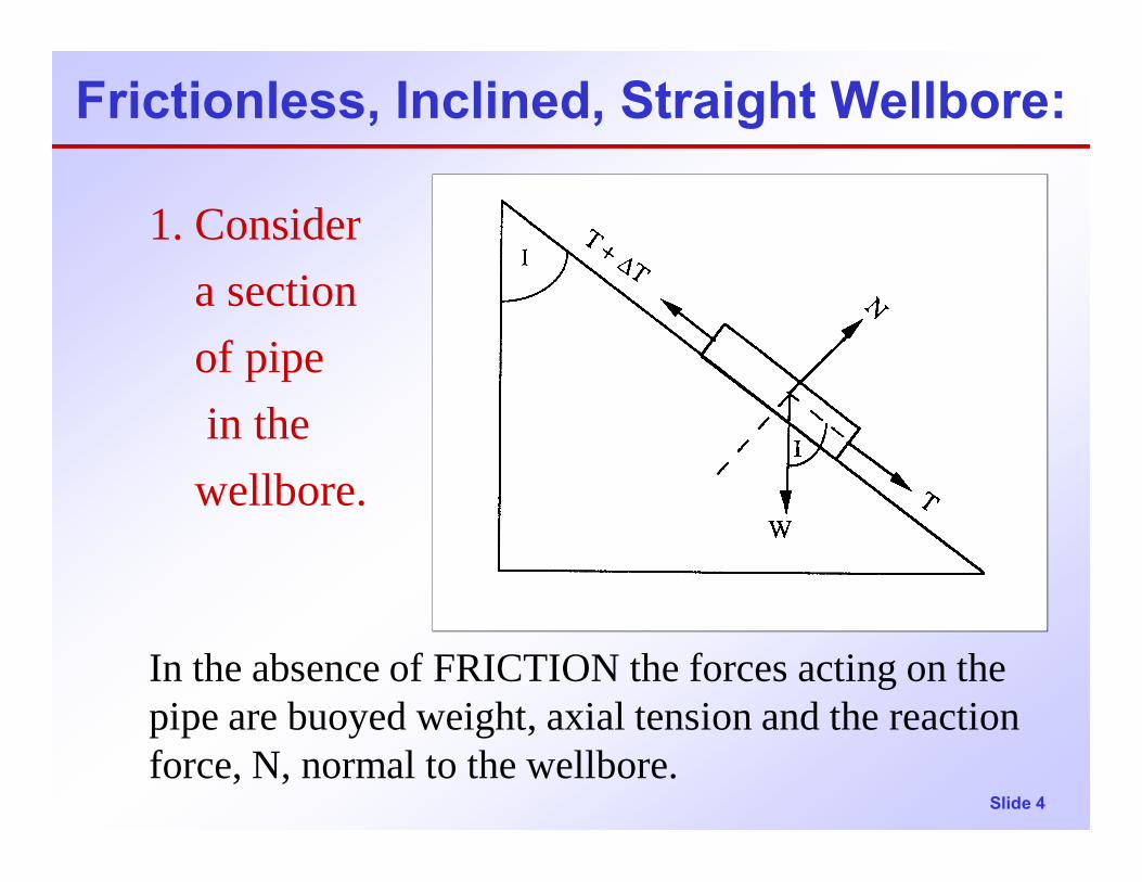
1. Consider a section of pipe in the
wellbore.
In the absence of FRICTION the forces acting on the pipe are buoyed weight, axial tension and the reaction force, N, normal to the wellbore.

Slide 5
Frictionless, Inclined, Straight Wellbore:
pipe.ROTATING for used are equations
(2) : wellbore to 0
(1) : wellborealong 0
ar
These
F
F
∑
∑
⊥=
= IcosWT =∆
IsinWN =
Slide 6
Effect of Friction (no doglegs):
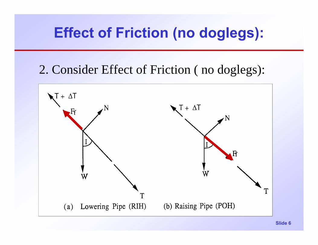
2. Consider Effect of Friction ( no doglegs):
Slide 7
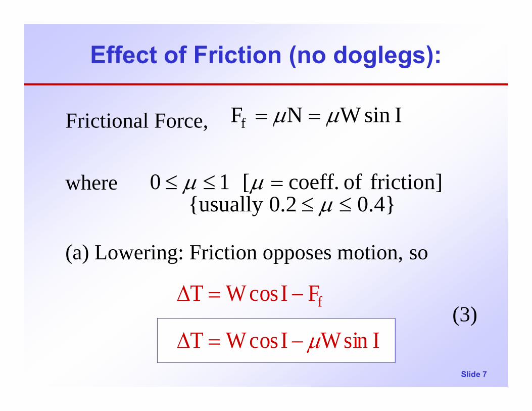
Effect of Friction (no doglegs):
Frictional Force,
where
(a) Lowering: Friction opposes motion, so
(3)
0.4}0.2{usually friction] of coeff.[ 10
IsinWNF f
≤≤=≤≤
==
µµµ
µµ
IsinWIcosWT
FIcosWT f
µ−=∆
−=∆
Slide 8
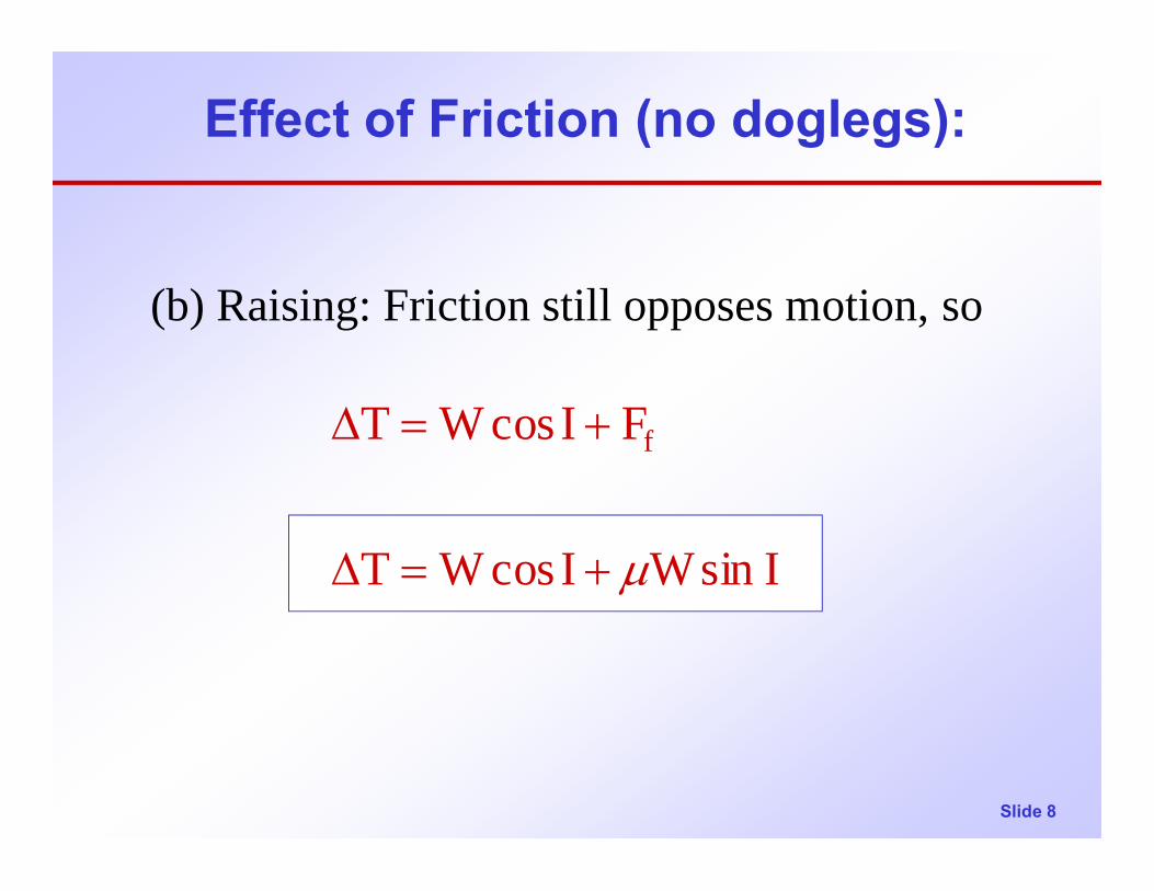
Effect of Friction (no doglegs):
(b) Raising: Friction still opposes motion, so
IsinWIcosWT
FIcosWT f
µ+=∆
+=∆
Slide 9
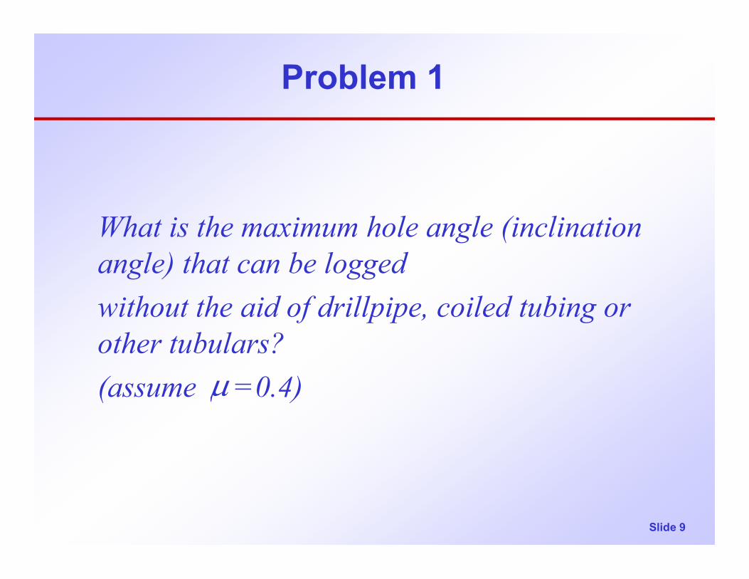
Problem 1
What is the maximum hole angle (inclination angle) that can be logged without the aid of drillpipe, coiled tubing or other tubulars? (assume =0.4)µ

Slide 10
Solution
From Equation (3) above,(3)
When pipe is barely sliding down the wellbore,
IsinWIcosWT µ−=∆
0T ≅∆
IsinW4.0IcosW0 −=∴

Slide 11
Solution
This is the maximum hole angle (inclination) that can be logged without the aid of tubulars.
Note:
o68.2I
2.5Ior tan 4.0Icot
=
==∴
Icot=µ

Slide 12
Problem 2
Consider a well with a long horizontal section. An 8,000-ft long string of 7” OD csg. is in the hole. Buoyed weight of pipe 30 lbs/ft. = 0.3
(a) What force will it take to move this pipe along the horizontal section of the wellbore?
(b) What torque will it take to rotate this pipe?
≅ µ

Slide 13
Problem 2 - Solution - Force
(a) What force will it take to move this pipe along the horizontal section of the wellbore?
F = ? F = 0N
W
N = W = 30 lb/ft * 8,000 ft = 240,000 lb
F = µN = 0.3 * 240,000 lb = 72,000 lb
Force to move pipe, F = 72,000 lbf

Slide 14
Problem 2 - Solution - Force
(b) What torque will it take to rotate this pipe?
As an approximation, let us assume that the pipelies on the bottom of the wellbore.
Then, as before, N = W = 30 lb/ft * 8,000 ft = 240,000 lbTorque = F*d/2 = µNd/2 = 0.3 * 240,000 lb * 7/(2 * 12) ft
Torque to rotate pipe, T = 21,000 ft-lbf
F
T
d/2

Slide 15
Problem 2 - Equations - Horizontal
Torque, T = µWd/(24 ) = 21,000 ft-lbf
F = µN T = F * dN = W
W
Force to move pipe, F = µW = 72,000 lbf
An approximate equation, with W in lbf and d in inches

Slide 16
Horizontal - Torque
A slightly more accurate equation for torque in a horizontal wellbore may be obtained by taking into consideration the fact that a rotating pipe will ride up the side of the wellbore to some angle φ.
Taking moments about the point P:Torque, T = W * (d/2) sin φ in-lbf
Where φ = atan µ = atan 0.3 = 16.70o
T = 240,000 * 7/24 * 0.2873 = 20,111 ft-lbf
FT
d/2 φP
W
Slide 17
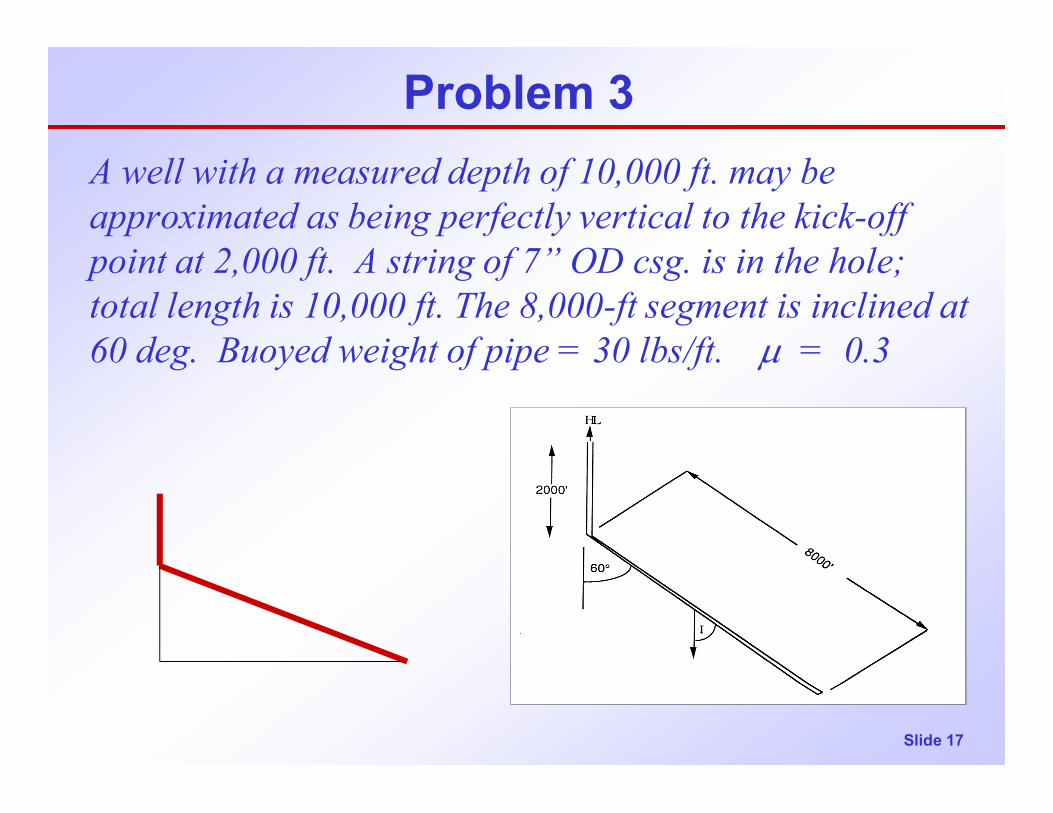
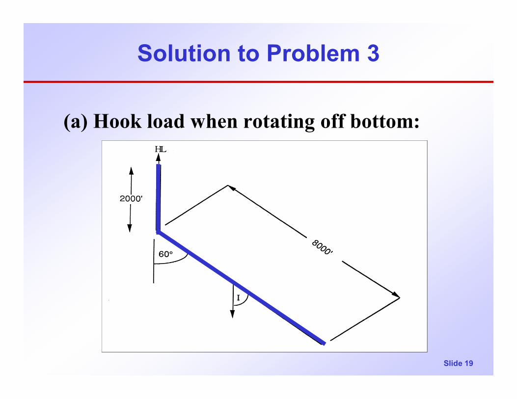
Problem 3A well with a measured depth of 10,000 ft. may be approximated as being perfectly vertical to the kick-off point at 2,000 ft. A string of 7” OD csg. is in the hole; total length is 10,000 ft. The 8,000-ft segment is inclined at 60 deg. Buoyed weight of pipe = 30 lbs/ft. µ = 0.3
Slide 18
Problem 3
Please determine the following:
(a) Hook load when rotating off bottom(b) Hook load when RIH(c) Hook load when POH(d) Torque when rotating off bottom
[ ignore effects of dogleg at 2000 ft.]
Slide 19
Solution to Problem 3
(a) Hook load when rotating off bottom:
Slide 20
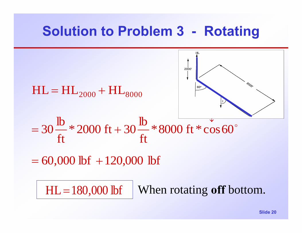
Solution to Problem 3 - Rotating
When rotating off bottom.
lbf 120,000lbf 000,60
60cos*ft 8000*ftlb30ft 2000*
ftlb30
HLHLHL5.0
80002000
+=
+=
+=
↓o
lbf 000,180HL =
Slide 21
Solution to Problem 3 - lowering
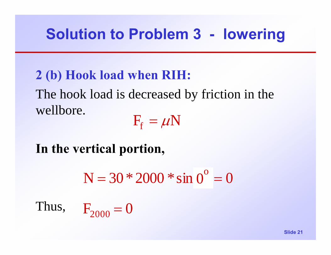
2 (b) Hook load when RIH:The hook load is decreased by friction in the wellbore.
In the vertical portion,
Thus, 0F
0osin*2000*30N
2000
o
=
==
NFf µ=
0o
Slide 22
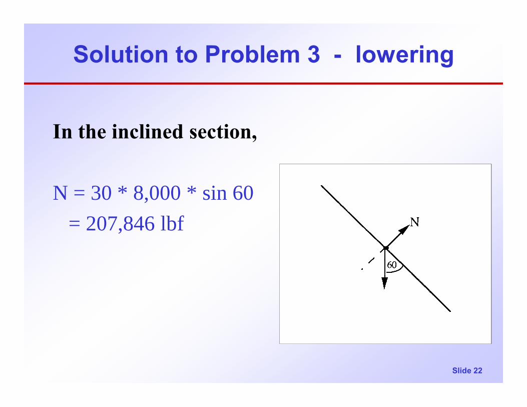
Solution to Problem 3 - lowering
In the inclined section,
N = 30 * 8,000 * sin 60= 207,846 lbf
Slide 23
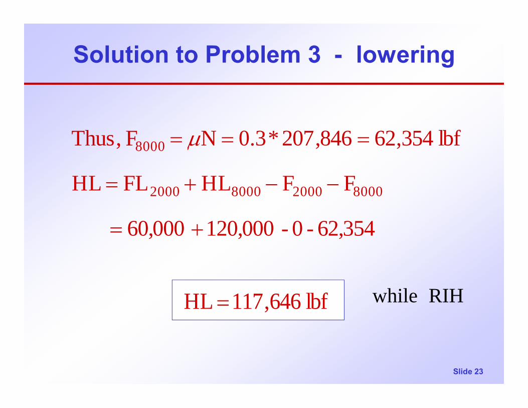
Solution to Problem 3 - lowering
62,354-0-120,00060,000
FFHLFLHL
lbf 354,62846,207*3.0NF ,Thus
8000200080002000
8000
+=
−−+=
=== µ
lbf 646,117HL = RIH while
Slide 24
Solution to Problem 3 - raising
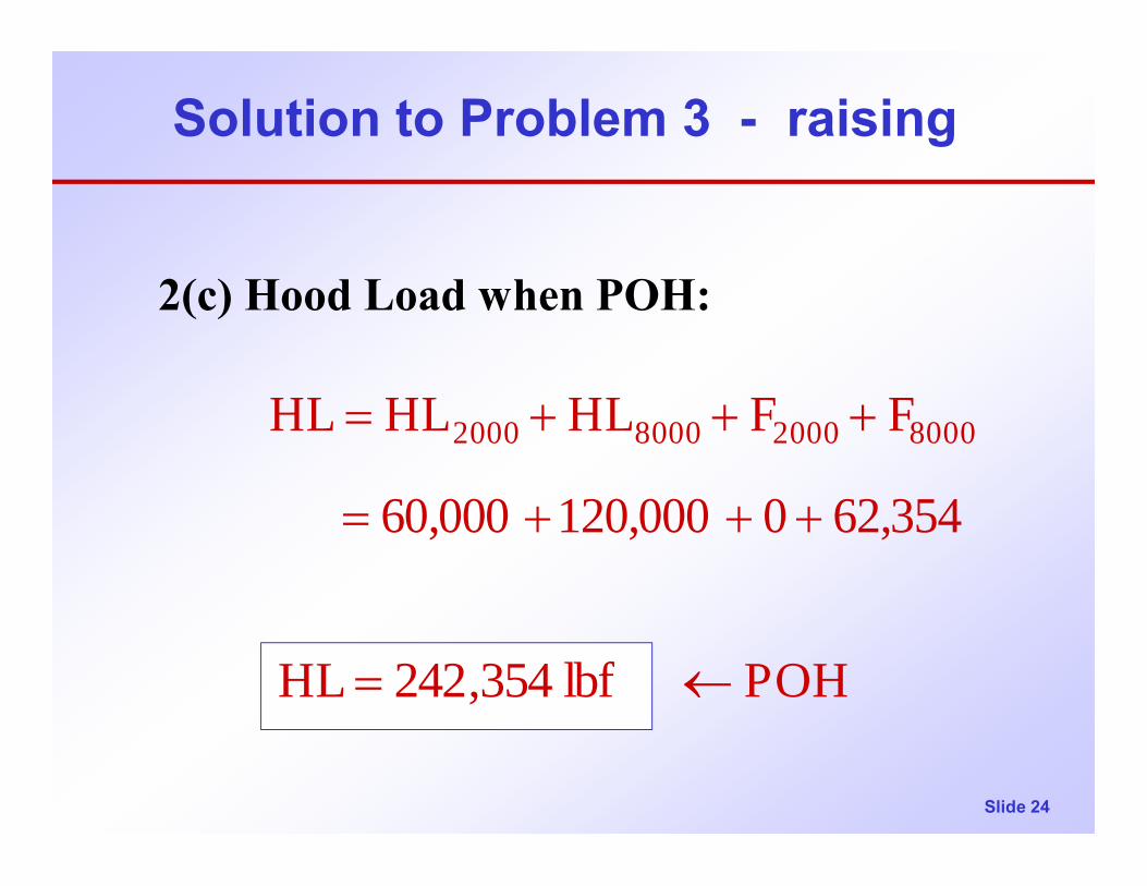
2(c) Hood Load when POH:
62,3540120,00060,000
FFHLHLHL 8000200080002000
+++=
+++=
POH lbf 354,242HL ←=
Slide 25
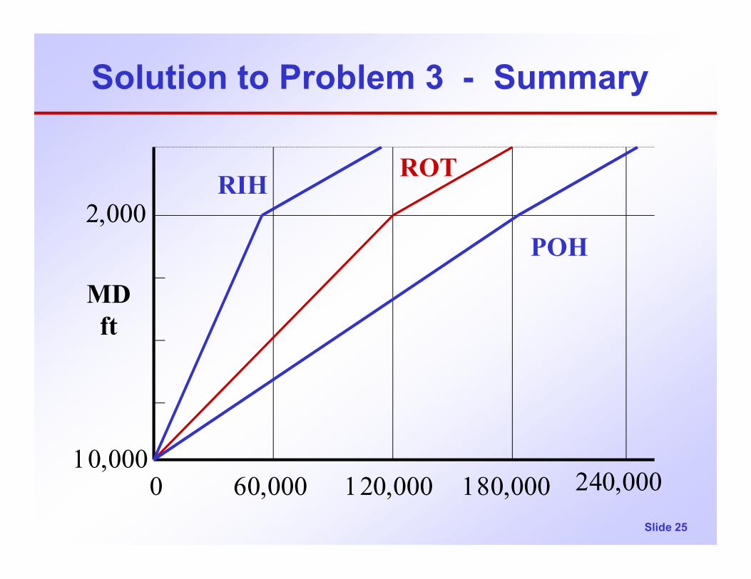
Solution to Problem 3 - Summary
2,000
10,000
MDft
60,000 120,000 180,000 240,000
RIH ROT
POH
0
Slide 26
Solution to Problem 3 - rotating
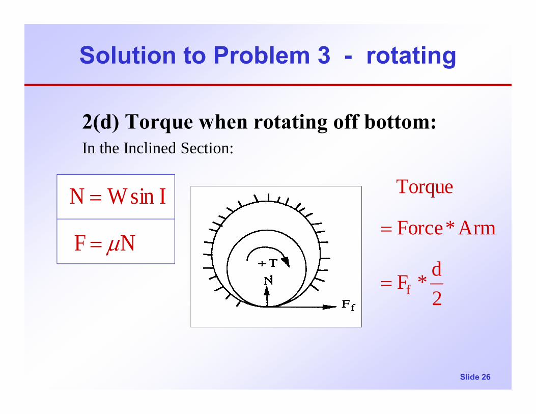
2(d) Torque when rotating off bottom:In the Inclined Section:
NF
IsinWN
µ=
=
2d*F
Arm*Force
Torque
f=
=
Slide 27
Solution to Problem 3 - rotating
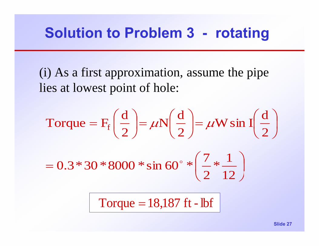
(i) As a first approximation, assume the pipe lies at lowest point of hole:
=
=
=
=
121*
27*60sin*8000*30*3.0
2dIsinW
2dN
2dFTorque f
o
µµ
lbf-ft 187,18Torque =

Slide 28
Solution to Problem 3 - rotating
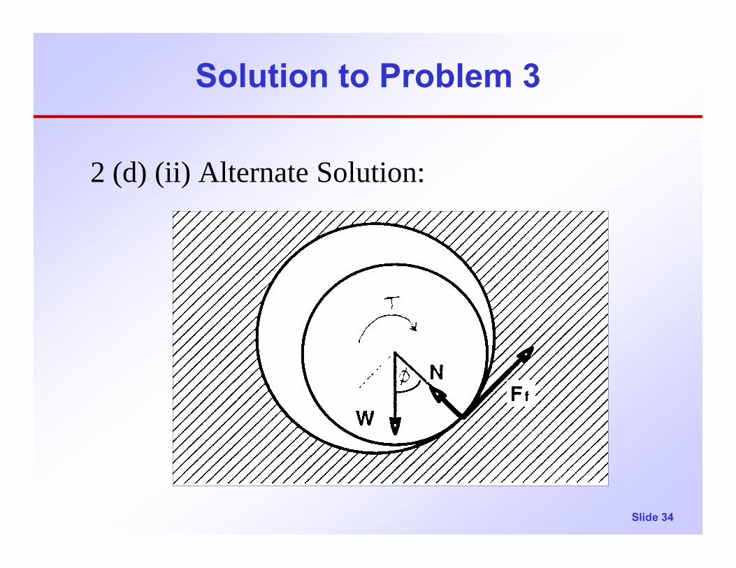
(ii) More accurate evaluation:Note that, in the above figure, forces are not balanced; there is no force to balance the friction force Ff.
The pipe will tend to climb up the side of the wellbore…as it rotates
Slide 29
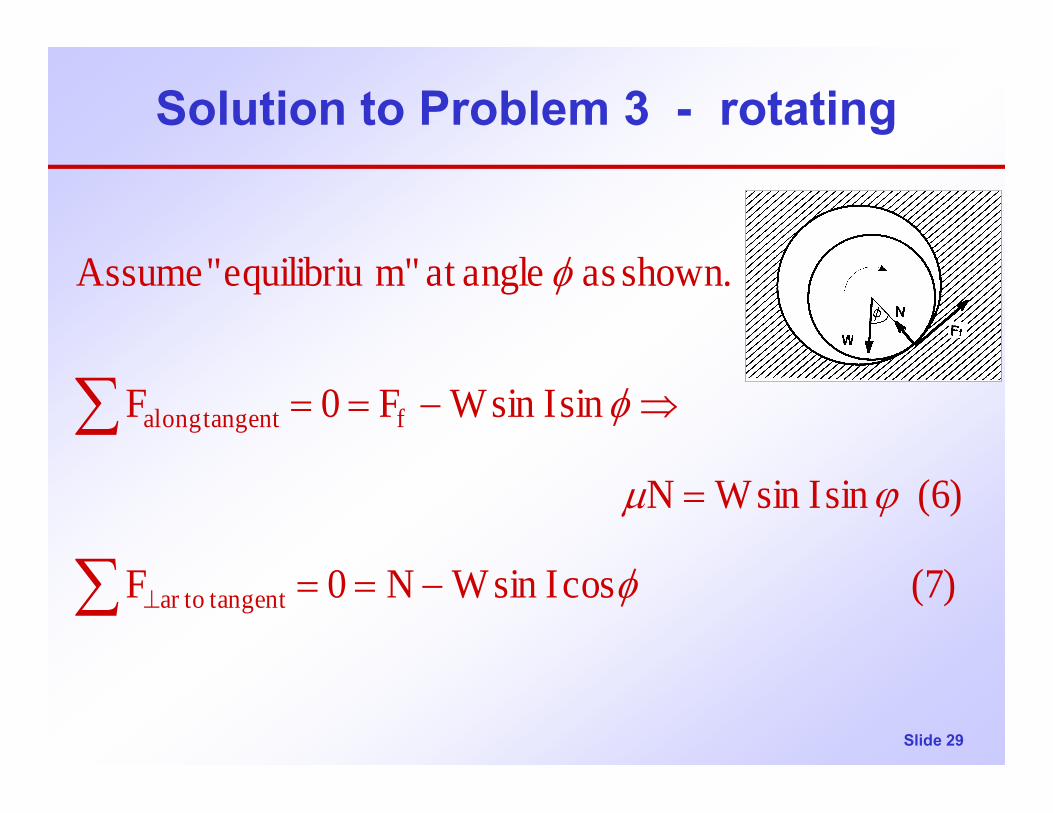
Solution to Problem 3 - rotating
∑
∑
−==
=
⇒−==
⊥ (7) cosIsinWN0F
(6) sinIsinWN
sinIsinWF0F
shown. as angleat m"equilibriu" Assume
tangentar to
f tangentalong
φ
ϕµ
φ
φ
Slide 30
Solution to Problem 3 - rotating
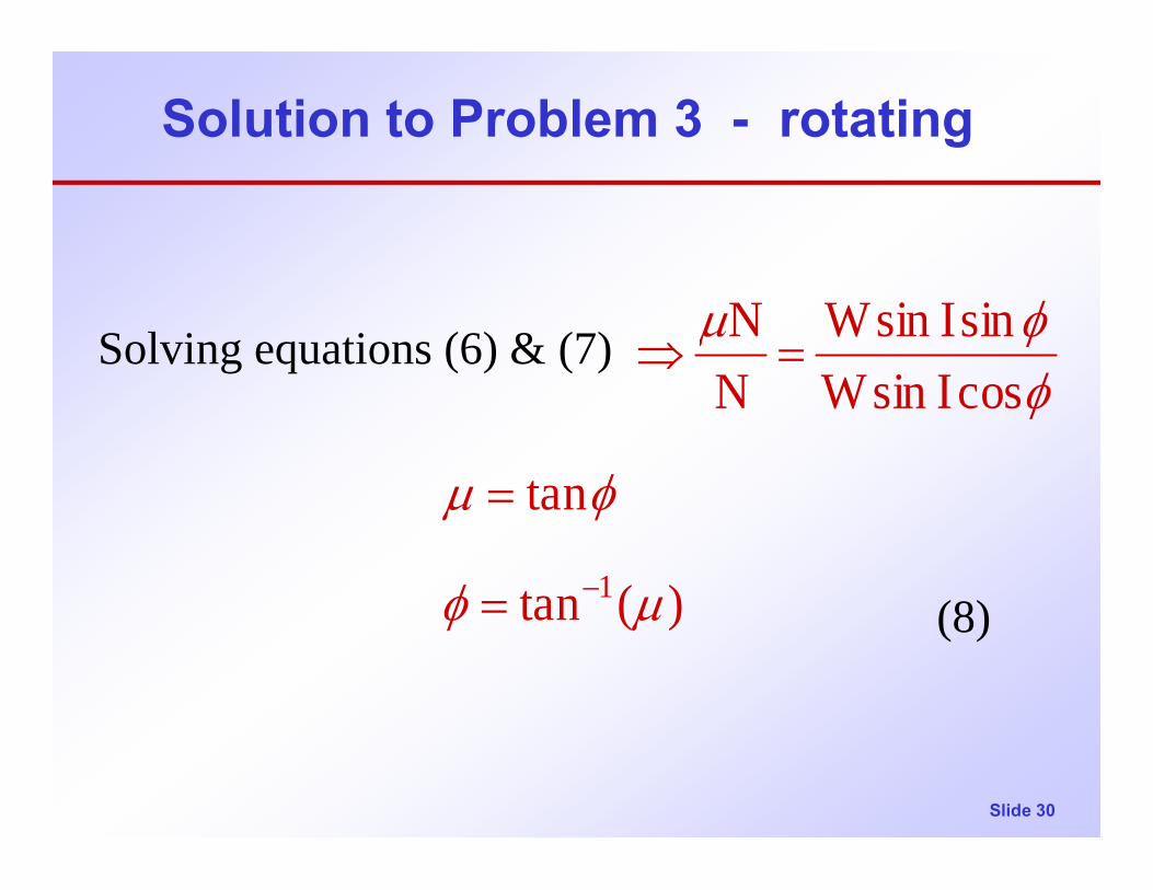
Solving equations (6) & (7)
(8))(tan
tan
cosIsinWsinIsinW
NN
1 µφ
φµ
φφµ
−=
=
=⇒

Slide 31
Solution to Problem 3 - rotating
(ii) continuedTaking moments about the center of the pipe:
Evaluating the problem at hand:
From Eq. (8),
2d*FT f=
o70.16
)3.0(tan)(tan 11
=
== −−
φ
µφ
Slide 32
Solution to Problem 3 - rotating
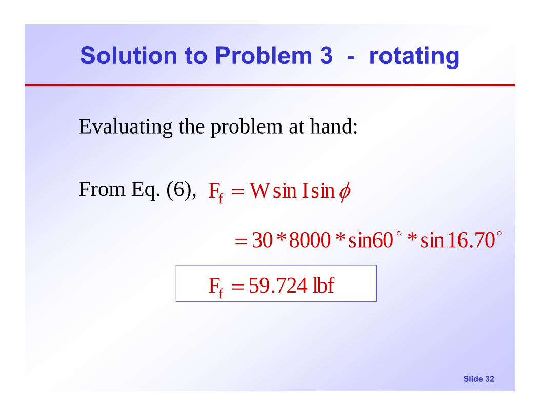
Evaluating the problem at hand:
From Eq. (6),
lbf 724.59F
70.16sin*sin60*8000*30
sinIsinWF
f
f
=
=
=
oo
φ

Slide 33
Solution to Problem 3 - rotating
Evaluating the problem at hand:
From Eq. (9),
lbf-ft 420,17Torque
121*
27*59,724
2d*FT f
=
=
=
Slide 34
Solution to Problem 3
2 (d) (ii) Alternate Solution:
Slide 35
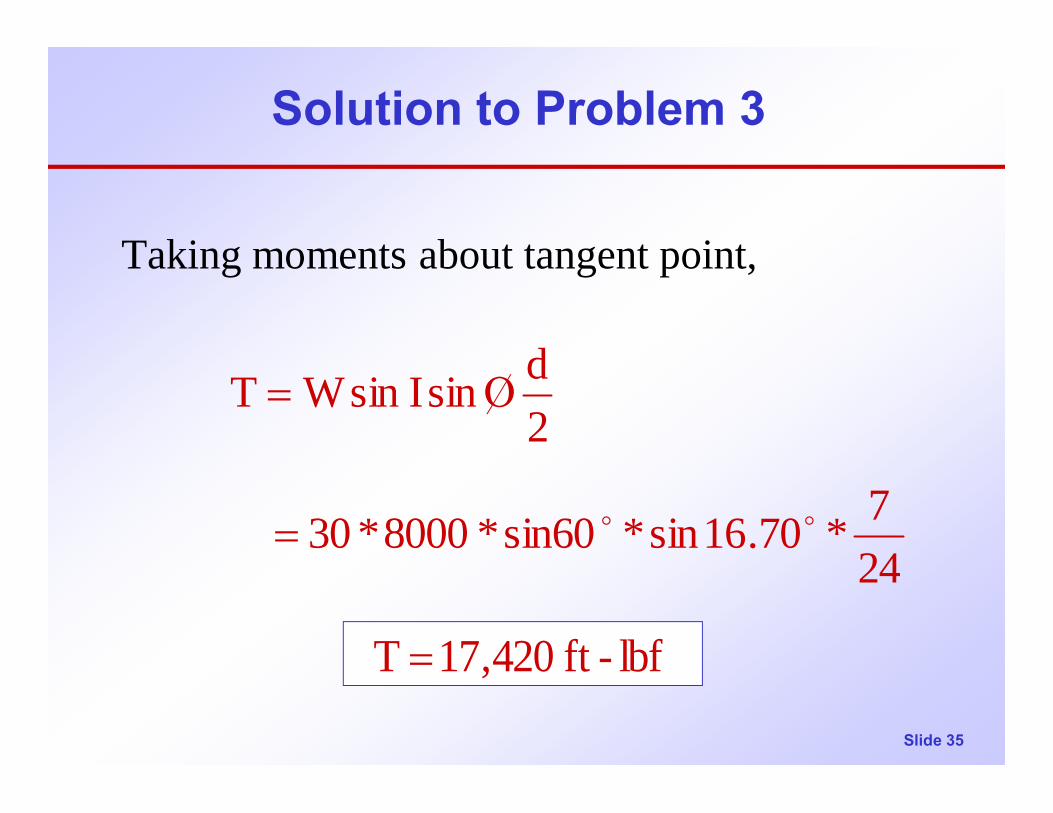
Solution to Problem 3
Taking moments about tangent point,
247*70.16sin*sin60*8000*30
2dsinIsinWT
oo=
Ο=
lbf-ft 420,17T =

Slide 36
Solution to Problem 3
Note that the answers in parts (i) & (ii) differ by a factor of cos φ
9578.070.16coscos == φφ

Slide 37
Effect of Doglegs
(1) Dropoff Wellbore angle dogleg=δ
Slide 38
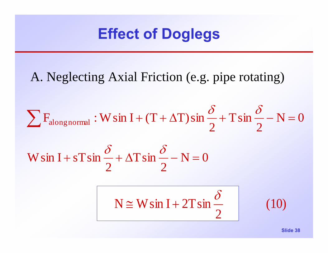
Effect of Doglegs
A. Neglecting Axial Friction (e.g. pipe rotating)
0N2
sinT2
sinsTIsinW
0N2
sinT2
sin)TT(IsinW:F normal along
=−∆++
=−+∆++∑δδ
δδ
(10) 2
sinT2IsinWN δ+≅
Slide 39
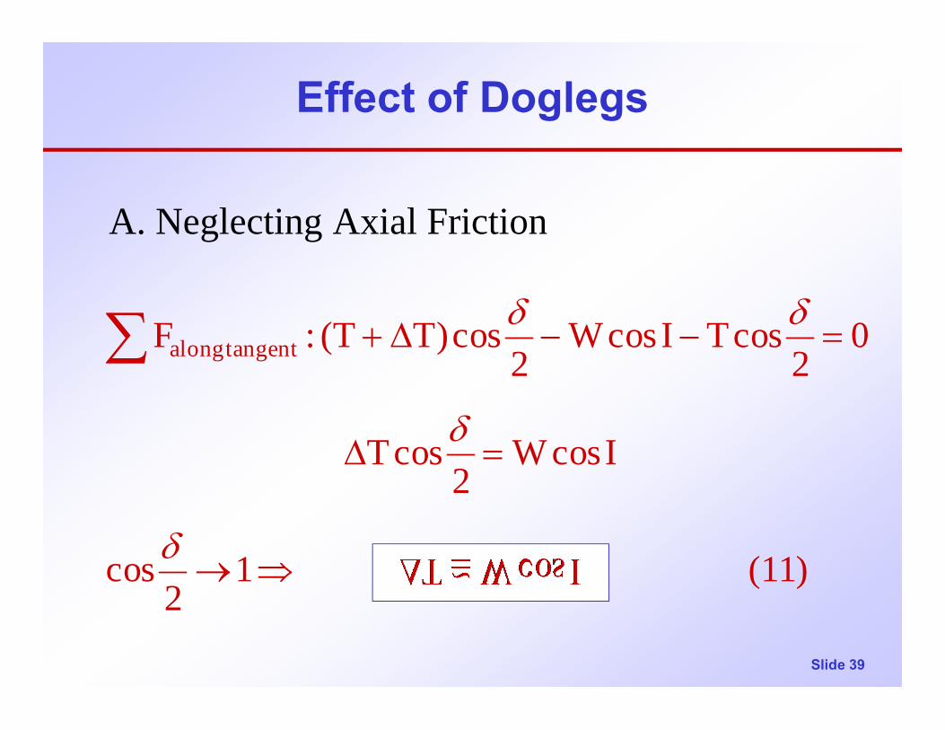
Effect of Doglegs
A. Neglecting Axial Friction
(11) 12
cos
IcosW2
cosT
02
cosTIcosW2
cos)TT(:F tangentalong
⇒→
=∆
=−−∆+∑
δ
δ
δδ

Slide 40
Effect of Doglegs
B. Including Friction (Dropoff Wellbore)
While pipe is rotating
(10)&(11)
WcosIT
2sinT2IsinWN
=∆
+=δ

Slide 41
Effect of Doglegs
B. Including FrictionWhile lowering pipe (RIH)
(as above)
i.e. (12)
2sinT2IsinWN δ
+=
NIcosWT µ−=∆
)2
sinT2IsinW(IcosWT δµ +−=∆

Slide 42
Effect of Doglegs
B. Including FrictionWhile raising pipe (POH)
(13)
(14)
NIcosWT µ+=∆
)2
sinT2IsinW(IcosWT δµ ++=∆
)2
sinT2IsinW(2d
2dNTorque δµµ +
≅
=

Slide 43
Effect of Doglegs
(2) Buildup Wellbore angle dogleg=δ
Slide 44
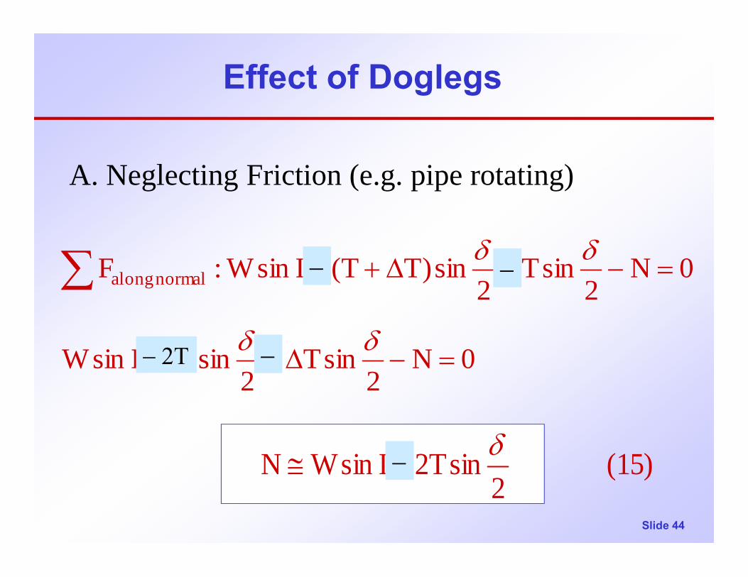
Effect of Doglegs
A. Neglecting Friction (e.g. pipe rotating)
0N2
sinT2
sinsTIsinW
0N2
sinT2
sin)TT(IsinW:F normal along
=−∆++
=−+∆++∑δδ
δδ
(15) 2
sinT2IsinWN δ+≅
−
− 2Τ
−
−
−

Slide 45
Effect of Doglegs
A. Neglecting Axial Friction
(16) 12
cos
IcosW2
cosT
02
cosTIcosW2
cos)TT(:F tangentalong
⇒→
=∆
=−−∆+∑
δ
δ
δδ
Slide 46
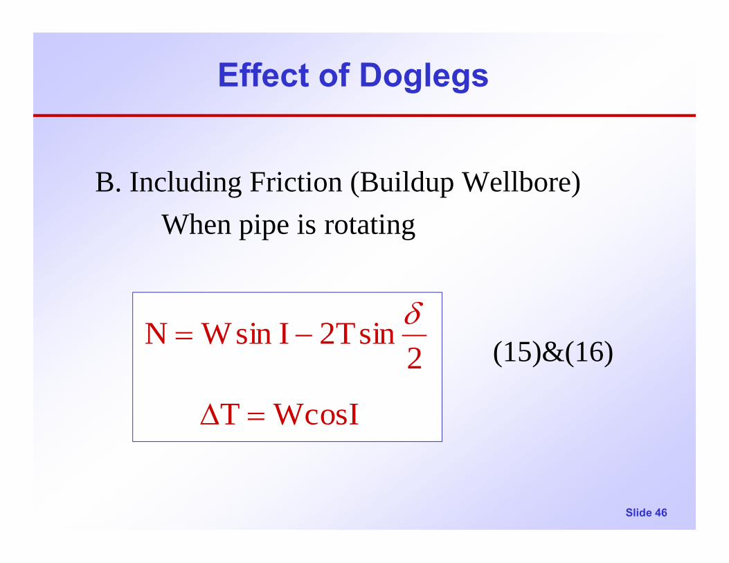
Effect of Doglegs
B. Including Friction (Buildup Wellbore)When pipe is rotating
(15)&(16)
WcosIT
2sinT2IsinWN
=∆
−=δ
Slide 47
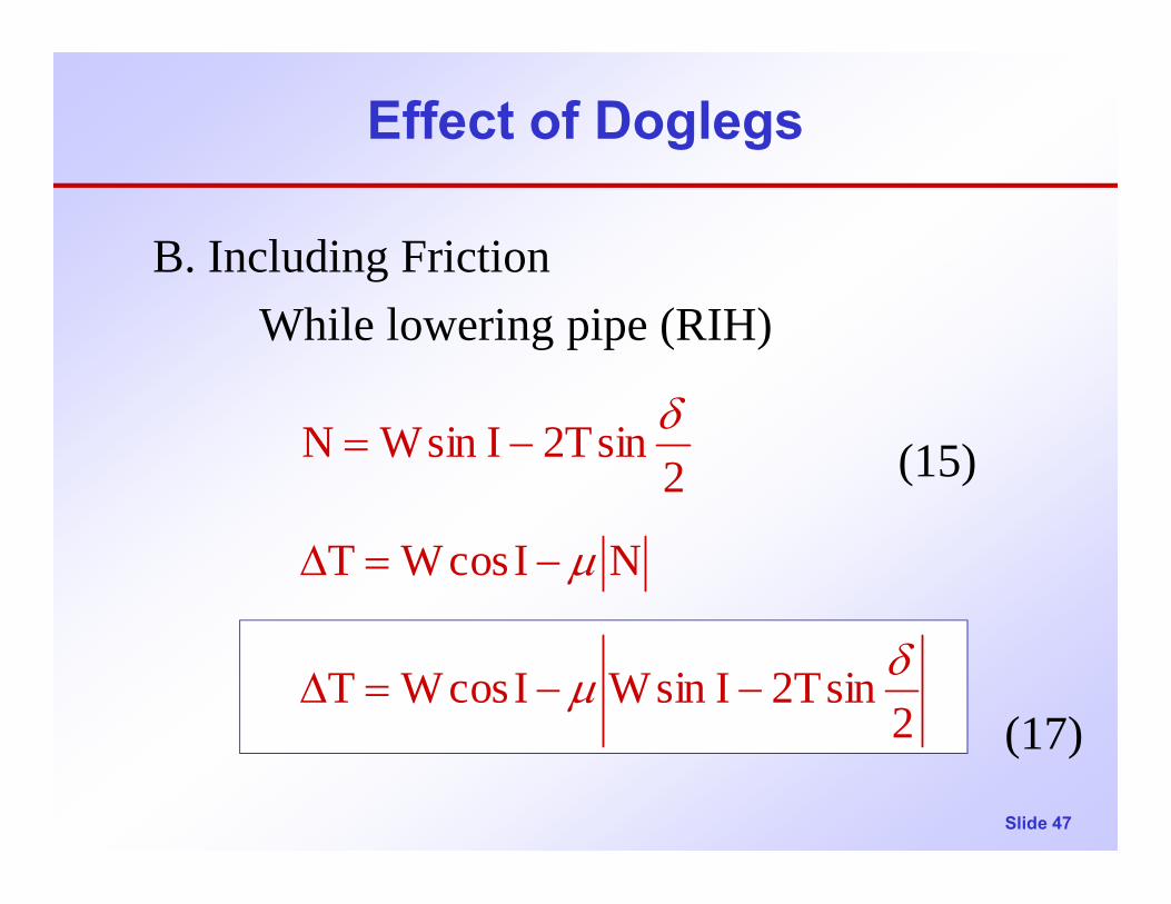
Effect of Doglegs
B. Including FrictionWhile lowering pipe (RIH)
(15)
(17)2sinT2IsinWIcosWT
NIcosWT
2sinT2IsinWN
δµ
µ
δ
−−=∆
−=∆
−=

Slide 48
Effect of Doglegs
While raising pipe (POH)
(18)
(19)2sinT2IsinW
2d
2dNTorque
22Tsin-WsinIWcosIT .e.i
NIcosWT
δµµ
δµ
µ
−
≅
=
+=∆
+=∆
Slide 49
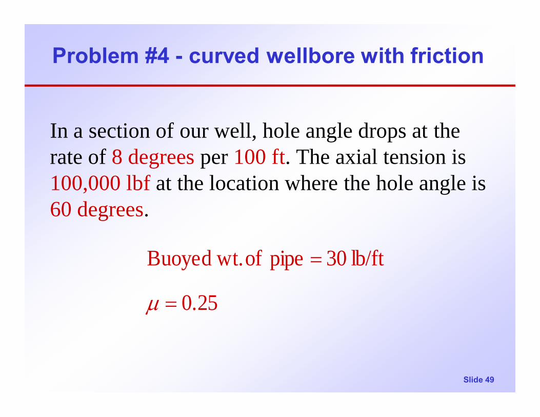
Problem #4 - curved wellbore with friction
In a section of our well, hole angle drops at the rate of 8 degrees per 100 ft. The axial tension is 100,000 lbf at the location where the hole angle is 60 degrees.
0.25
lb/ft 30pipe of wt.Buoyed
=
=
µ

Slide 50
Evaluate the Following:
(a) What is the axial tension in the pipe 100 ft. up the hole if the pipe is rotating?
(b) What is the axial tension in the pipe 100 ft up the hole if the pipe is being lowered into the hole?
(c) What is the axial tension in the pipe 100 ft up the hole if the pipe is being pulled out of the hole?
(d) What is the lateral load on a centralizer at incl.=64 if the centralizer spacing is 40 ft? o

Slide 51
Solution 4 (a)
(a) Axial tension 100 ft up hole when pipe is rotating :
Pipe is rotating so frictional effect on axial load may be neglected.
o64I2
6860I
AVG
AVG
=
+=
Slide 52
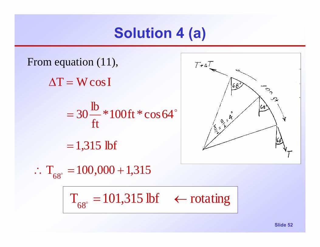
Solution 4 (a)
From equation (11),
315,1000,100T
lbf 1,315
64cos*ft100*ftlb30
IcosWT
68 +=∴
=
=
=∆
o
o
rotating lbf 315,101T68 ←=o
Slide 53
Solution 4 (b)
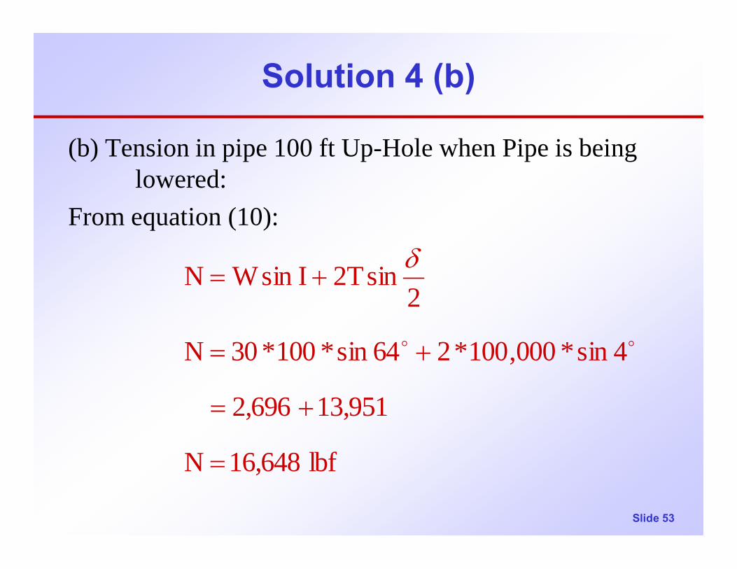
(b) Tension in pipe 100 ft Up-Hole when Pipe is being lowered:
From equation (10):
lbf 16,648N
13,9512,696
4sin*000,100*264sin*100*30N
2sinT2IsinWN
=
+=
+=
+=
oo
δ

Slide 54
Solution 4 (b)
From equation 10,
From equation 12,
NIcosWT µ−=∆
lbf 162,4F
16,648*0.25NForceFriction
f =
== µ
Slide 55
Solution 4 (b)
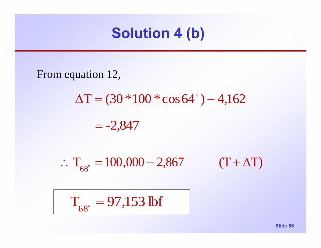
From equation 12,
T)(T 867,2000,100T68 ∆+−=∴ o
lbf 153,97T68 =o
-2,847
162,4)64cos*100*30(T
=
−=∆ o

Slide 56
Solution 4 (c)
(c) Tension in Pipe 100 ft Up-Hole when pipe is being raised:From equation (10),
lbf 16,648N
13,9512,696
4sin*000,100*264sin*100*30N
2sinT2IsinWN
=
+=
+=
+=
oo
δ

Slide 57
Solution 4 (c)
lbf 162,4F
16,648*0.25NForceFriction
f =
== µ
From equation 12,
NIcosWT µ+=∆

Slide 58
Solution 4 (c)
From equation 12,
T)(T 5477000,100T
lbf 5477
162,4)64cos*100*30(T
68 ∆++=∴
=
+=∆
o
o
lbf 477,105T68 =o
Slide 59
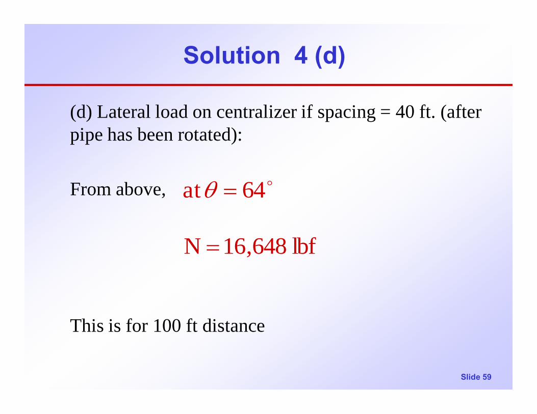
Solution 4 (d)
(d) Lateral load on centralizer if spacing = 40 ft. (after pipe has been rotated):
From above,
This is for 100 ft distance
lbf 648,16N
64 at
=
= oθ

Slide 60
Solution 4 (d)
for 40 ft distance,
i.e., Lateral load on centralizer,
∴
lbf 6,659 10040*648,16N .centr
=
=
lbf 1200ftlb30*pipe offt 40 :Note
lbf 659,6N .centr
=
=
Slide 61
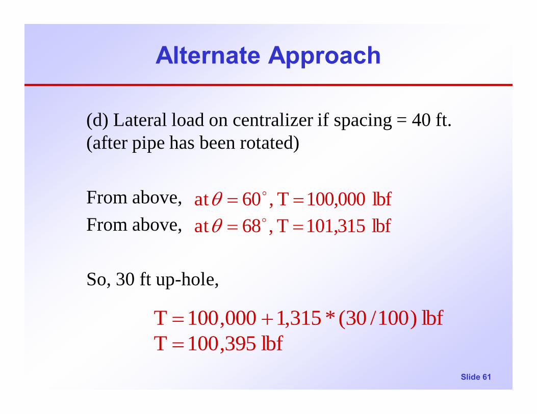
Alternate Approach
(d) Lateral load on centralizer if spacing = 40 ft. (after pipe has been rotated)
From above,From above,
So, 30 ft up-hole,
lbf 101,315T ,68at lbf 100,000T ,60 at
====
o
o
θθ
lbf 395,100Tlbf )100/30(*315,1000,100T
=+=
Slide 62
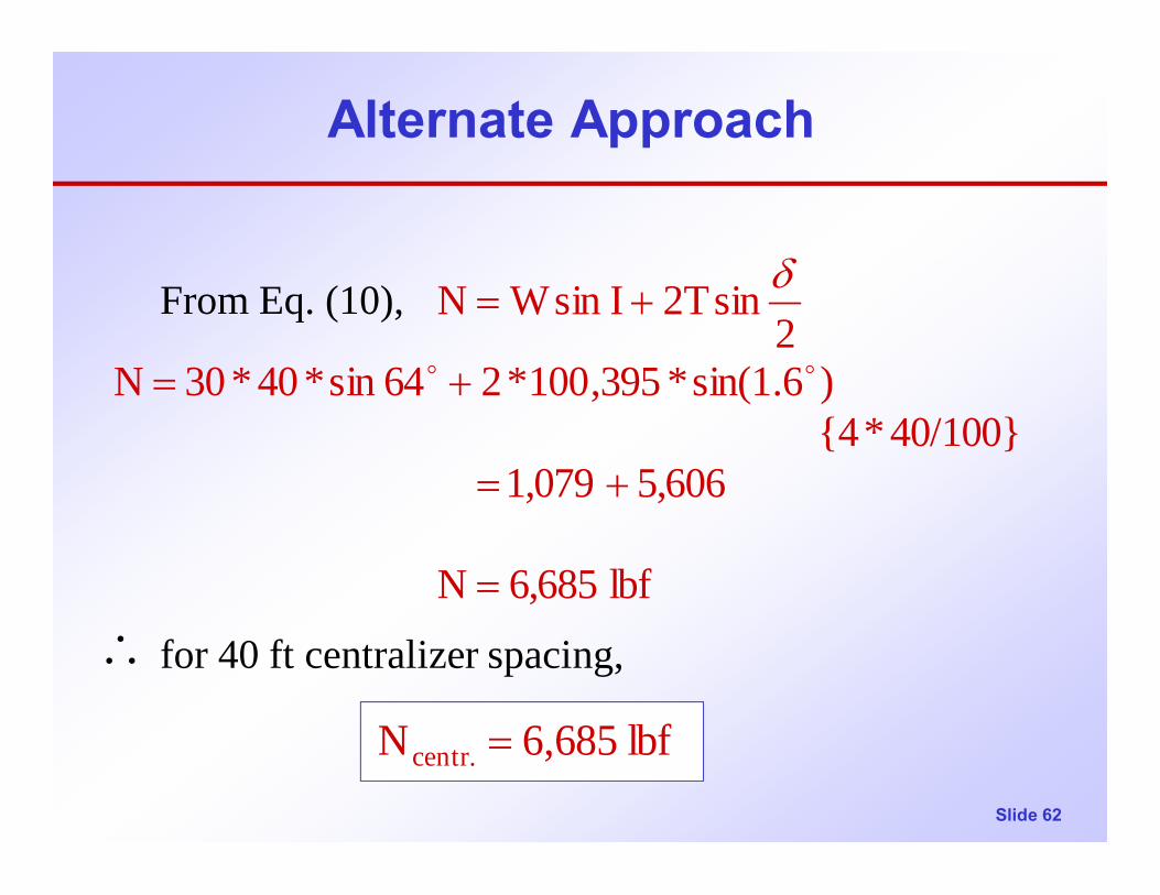
Alternate Approach
From Eq. (10),
for 40 ft centralizer spacing,
lbf 6,685N
5,6061,079 40/100}*{4
)6.1sin(*395,100*264sin*40*30N2
sinT2IsinWN
=
+=
+=
+=oo
δ
lbf 685,6N .centr =
∴