Embed Size (px)
Citation preview
Caltrans English CADD Users Manual
3.6 Roadway Design
A) Introduction CAiCE is the roadway design software used for surveying and roadway design work at Caltrans. It has been the standard software used for surveying work since the early 1990’s and for roadway design applications since 1999. MicroStation is the standard drafting software and has been used by all functional units since 1995. Caltrans has developed custom resource files for both applications to maximize the efficiency of the CADD System. These resource files are based on information from the various guidance and policy documents such as the Highway Design Manual and the Plans Preparation Manual. The purpose of this section is to provide requirements and guidance to the engineer and surveyor in the use of these CADD tools as they relate to the roadway design process. It is recommended that CAiCE users document their work. The suggested method of documentation is to create a text file named "Readme.txt" and saving it in the project directory. This file is known as a "read me" file. During the design processes many files are created at different times representing different things. A “read me” file documents the points, alignments, surfaces, cross-sections, etc. along with when they were created, by whom, and what they represent. The documentation becomes an invaluable source of information for the users of the project data. Caltrans projects are active for several years, often longer. How the project is organized must be readily apparent for a long period, often after the original operators are no longer available. This problem is minimized when a “read me” file is maintained in the project.
B) Caltrans CAiCE Standard Resource Files The following CAiCE resource files are available to the user, 1) Caltrans CAiCE Feature Tables
The feature code is the attribute that provides the most intelligence about objects in a CAiCE project database. Items that may be assigned feature codes include every type of geometry and survey object, points and surface links in cross section files, and DTM breaklines and triangles. The feature table is the primary tool in CAiCE for automating the assignment of graphical attributes to database objects when they are displayed. Graphical attributes and characteristics are based on the feature code of each object. Feature codes are also used to identify the source of an object. For example, an edge of pavement object can be an existing feature created from survey and photogrammetric data and it can be a new feature in the roadway design. Different feature codes can be used to differentiate the edge of pavement objects. The code EP would be used when stored from survey data, PEP when stored from photogrammetric data, and DEP when created as a design element.
April 11, 2008 Page 3.6-1

Caltrans English CADD Users Manual
a) Roadway & Topographic Feature Codes (caltransE.ftb) The roadway and topographic feature codes are to be used for the development of project plan sheets. See Appendix A7 for a listing of the feature codes and associated attributes in the CAiCE feature table.
b) Right of Way (R/W) Mapping Products Feature Codes (Caltrans-RW_e50.ftb, Caltrans-RW_e100.ftb, and Caltrans-RW_e200.ftb) The R/W feature codes are to be used for the development of R/W Mapping Products only. See Appendix A8 for a listing of the feature codes and associated attributes in the CAiCE feature tables.
2) Caltrans CAiCE Superelevation Tables for superelevation definition 3) Caltrans CAiCE Fragment Libraries for cross section design 4) Caltrans CAiCE Macro Libraries for various CADD tasks including, but not limited
to plotting cross sections and slope stake note generation 5) Various Caltrans CAiCE design tables and initialization files including, but not
limited to plot cross section initialization files, minimum radius tables, profile tables and sight distance tables
C) Caltrans MicroStation Standard Resource Files
The MicroStation resource files are discussed in Chapter 2 of this manual. D) Existing Topography
The products of topographic surveys are the basis for planning studies and engineering designs. Existing topography can be a combination of photogrammetric data and field collected survey data, including data collected by conventional methods, Vangarde, and laser scanners. There are two standard products, topographic maps and topographic data included in a roadway design project. Photogrammetric data is administered and processed by the Office of Photogrammetry. The resulting topographic maps conform to the standards outlined in Standards and Symbols for Photogrammetric Mapping (SSPM) and Standard Plan A10D. The standards of the resulting roadway design projects are provided in this section. Field collected survey data is collected in accordance with Chapter 11 of the Surveys Manual. The standards for the resulting topographic maps and roadway design products are provided in this section.
April 11, 2008 Page 3.6-2
Caltrans English CADD Users Manual
1) Best Practices & things to think about a) A “read me” document should be delivered with the topographic products
providing the following information: • Project Units • Horizontal and Vertical Datums • MicroStation Design Plane • A brief explanation of data included • Other information as necessary
b) A Caltrans developed CAiCE macro, “Create Topo DGN” in the CaltransLandSurveys.lib, is available to automate the display of data for the creation of a topographic map.
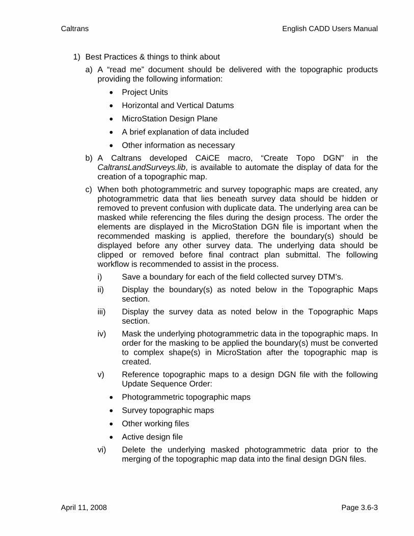
c) When both photogrammetric and survey topographic maps are created, any photogrammetric data that lies beneath survey data should be hidden or removed to prevent confusion with duplicate data. The underlying area can be masked while referencing the files during the design process. The order the elements are displayed in the MicroStation DGN file is important when the recommended masking is applied, therefore the boundary(s) should be displayed before any other survey data. The underlying data should be clipped or removed before final contract plan submittal. The following workflow is recommended to assist in the process. i) Save a boundary for each of the field collected survey DTM’s. ii) Display the boundary(s) as noted below in the Topographic Maps
section. iii) Display the survey data as noted below in the Topographic Maps
section. iv) Mask the underlying photogrammetric data in the topographic maps. In
order for the masking to be applied the boundary(s) must be converted to complex shape(s) in MicroStation after the topographic map is created.
v) Reference topographic maps to a design DGN file with the following Update Sequence Order:
• Photogrammetric topographic maps • Survey topographic maps • Other working files • Active design file
vi) Delete the underlying masked photogrammetric data prior to the merging of the topographic map data into the final design DGN files.
April 11, 2008 Page 3.6-3

Caltrans English CADD Users Manual
2) Topographic Maps a) Photogrammetric data
See Standards and Symbols for Photogrammetric Mapping (SSPM) and 2006 Standard Plans for the required standards.
b) Field collected survey data The roadway design software should be used to compile, edit, and display the survey data. The use of the Caltrans roadway design resource files, i.e. CAiCE Feature Table, ensures that objects pertinent to the contract plans will be displayed on the appropriate MicroStation level with the correct cell, color, line weight, etc. All other data that may assist in the design process but will not be displayed on the contract plans can be displayed on non-plotting levels as described below. See the Surveys category of Appendix 7 in this manual for a complete listing and description of the linear and point CAiCE feature codes. i) Format & Attributes
It is important to place elements in CAiCE at a size that is appropriate for the printed map. In general Caltrans prints maps at a scale of 1" = 50'. The standard practice for this scale is to display linestyles at a scale of 3.937, and cells at a scale of 1. See sections 2.7 and 2.9 for more information about linestyles and cells. All text annotation for contours and points will use the font CTFont1. See section 2.4 for more information about the differences in levels between V7 format DGN files and V8 format DGN files.
Linear Feature Attributes Table
Feature Linestyle Weight Color Level All Survey Features except BB, FB, FDLINE, RBRK, TOE, TOP
See Appendix 7 for appropriate attributes
BB, FB, FDLINE, RBRK, TOE, TOP
1 0 0 71 Survey misc breaklines *
Boundary(s) of Survey Data **
su-MANL 0 250 74 Survey boundary *
* Level name for V8 format DGN files. When creating V7 format DGN files an undefined level between 1 – 63 shall be used. ** All boundaries should be closed linear shapes. After the topographic map is created they should be converted in MicroStation to a shape with a Fill Color of 250.
April 11, 2008 Page 3.6-4
Caltrans English CADD Users Manual
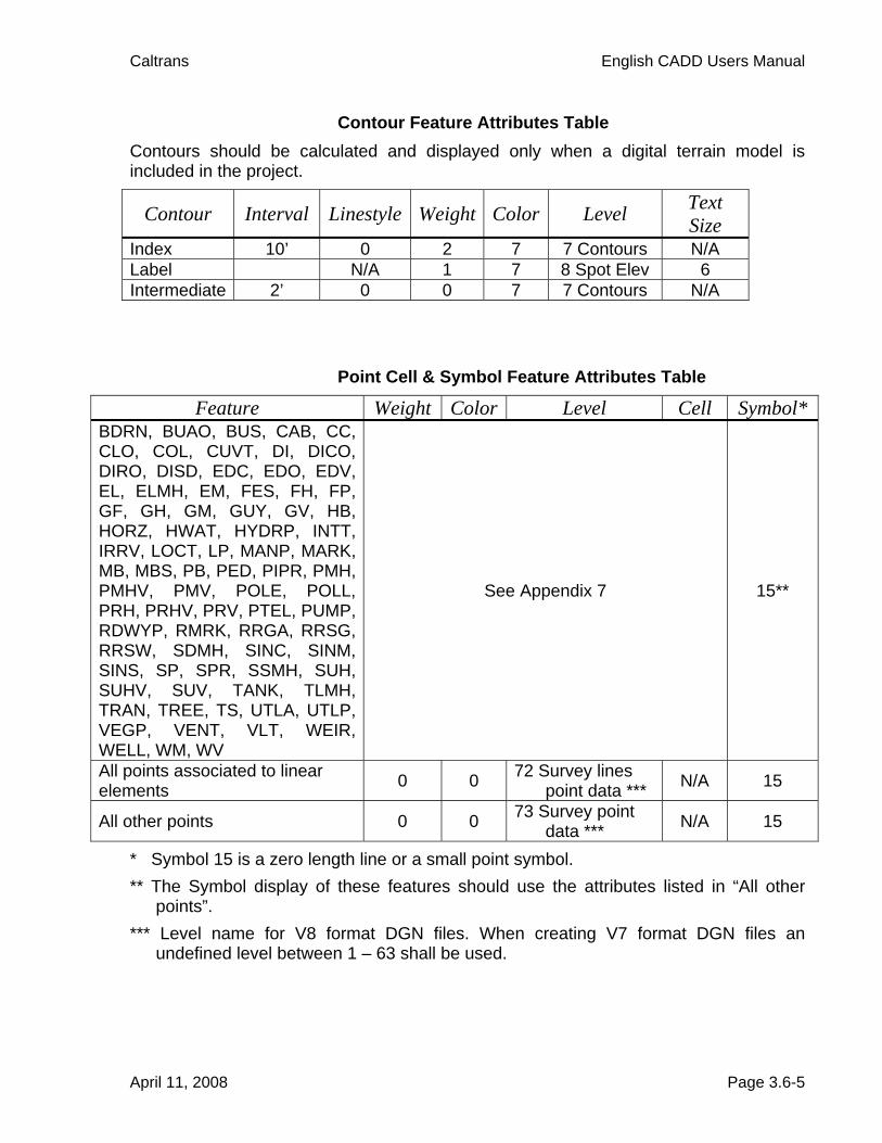
Contour Feature Attributes Table Contours should be calculated and displayed only when a digital terrain model is included in the project.
Contour Interval Linestyle Weight Color Level Text Size
Index 10’ 0 2 7 7 Contours N/A Label N/A 1 7 8 Spot Elev 6 Intermediate 2’ 0 0 7 7 Contours N/A
Point Cell & Symbol Feature Attributes Table
Feature Weight Color Level Cell Symbol* BDRN, BUAO, BUS, CAB, CC, CLO, COL, CUVT, DI, DICO, DIRO, DISD, EDC, EDO, EDV, EL, ELMH, EM, FES, FH, FP, GF, GH, GM, GUY, GV, HB, HORZ, HWAT, HYDRP, INTT, IRRV, LOCT, LP, MANP, MARK, MB, MBS, PB, PED, PIPR, PMH, PMHV, PMV, POLE, POLL, PRH, PRHV, PRV, PTEL, PUMP, RDWYP, RMRK, RRGA, RRSG, RRSW, SDMH, SINC, SINM, SINS, SP, SPR, SSMH, SUH, SUHV, SUV, TANK, TLMH, TRAN, TREE, TS, UTLA, UTLP, VEGP, VENT, VLT, WEIR, WELL, WM, WV
See Appendix 7 15**
All points associated to linear elements 0 0 72 Survey lines
point data *** N/A 15
All other points 0 0 73 Survey point data *** N/A 15
* Symbol 15 is a zero length line or a small point symbol. ** The Symbol display of these features should use the attributes listed in “All other
points”. *** Level name for V8 format DGN files. When creating V7 format DGN files an
undefined level between 1 – 63 shall be used.
April 11, 2008 Page 3.6-5

Caltrans English CADD Users Manual
• Point Annotation Attributes Table:
Feature Weight Color Level Text SizeOnly the Name of the following features: PMH, PMHV, PMV, PRH, PRHV, PRV, SUH, SUHV, SUV
See Appendix 7 6.0
All other annotation of the following features: PMH, PMHV, PMV, PRH, PRHV, PRV, SUH, SUHV, SUV
0 0 73 Survey point data * 0.3
All points associated to linear elements 0 0 72 Survey lines
point data * 0.3
All other points 0 0 73 Survey point data * 0.3
* Level name for V8 format DGN files. When creating V7 format DGN files an undefined level between 1 – 63 shall be used.
• Point Annotation Location Table
Name Elevation Description Comment ΔX=0.0 ΔY=1.0 Right Justified
ΔX=0.0 ΔY=-1.5 Right Justified
ΔX=0.5 ΔY=-1.5 Left Justified
ΔX=0.5 ΔY=-3.0 Left Justified
* The location of the annotation is relative to coordinates of the point.
April 11, 2008 Page 3.6-6
Caltrans English CADD Users Manual
3) Existing Topography in a Roadway Design Project In a roadway design project the existing topography is typically comprised of points, linear elements, and digital terrain models (DTM’s). Most of the points and linear elements are used to generate the DTM but a project may contain some elements that are not appropriate for a DTM, e.g. overhead power lines, culvert flow lines, etc. a) Best Practices & things to think about
i) Descriptive information is typically included in the Description of many of the survey-collected points to provide information pertinent to the design process.
ii) It is recommended that users organize a project by grouping different topographic data sets into CAiCE Segments. This is useful for many reasons. It helps users filter the data by segment while knowing the different accuracies of the data they are working with, e.g. segments W12 – W16 contain photogrammetric data from the corresponding DGN file while segments F3 – F9 contain survey data from different survey requests. At Caltrans, projects are active for several years and often longer. How the project is organized today must be readily apparent for a long period, often after the original operators are no longer available. This problem is minimized when data is grouped in segments and noted in the “read me” file.
iii) Appropriate coding of data helps users identify the elements. iv) All DTM’s should be coded as EXIST unless requested otherwise. v) Resolve crossing breaklines to the following elevation differences:
(1) Survey Data • 0.00’
(2) Photogrammetric Data • 0.50’ – within the highway right of way and on any hard surfaces • 1.00’ – all other areas
vi) Limit DTM sizes to approximately 500,000 DTM points unless a request is made for a larger DTM.
vii) DTM’s for ground data and bridge data should be created as separate DTM’s.
April 11, 2008 Page 3.6-7

Caltrans English CADD Users Manual
E) Horizontal Alignments Horizontal alignments can be simple graphical elements depicting the approximate location of an object or they can tightly control the location of an object, i.e. the layout line of a retaining wall. When a horizontal element is a constraint in the design of a facility and will be used in the construction stakeout process, it should be developed within the roadway design software with the appropriate state plane coordinate system. This ensures the ability to generate traverse reports and the ability to transfer the data electronically. This section distinguishes between two different types of horizontal alignments, roadway alignments and other alignments, in order to address specific concerns related to each. 1) Roadway Alignments
A horizontal alignment is the mathematical definition of the horizontal path of a highway or roadway. For most roadway alignments at Caltrans this consists of straight-line sections that connect tangentially to circular curve sections. The roadway alignment is directional in that a stationing or length is recorded from the beginning of the alignment to the end. Surveyors and engineers build the roadway using these alignments. Further discussion and Caltrans design policy on horizontal alignments can be found in Chapter 200 of the Highway Design Manual (HDM) http://www.dot.ca.gov/hq/oppd/hdm/pdf/english/chp0200.pdf a) Best Practices & things to think about
i) Existing and New Alignments (1) Alignments are the backbone of contract plans as well as other record
maps, i.e. Records of Surveys that are recorded at the County Offices. For this reason, it is important to make sure that the alignments are as accurate as possible and meet the following minimum criteria: • Tangency at least to the nearest tenth of a second, 00.0” • Coincidence between compound and reversing curves to the
nearest hundredth of a foot, 0.01’ • Minimum and greater radius values
ii) Existing Alignments (1) Consult with the District Surveys office for existing alignments in
electronic format. (2) Research as-builts for existing alignments. If conversion is needed for
units or datum, seek assistance from the District Survey office. (3) Develop alignment from a combination of as-builts and project control. (4) Priority of project control:
(a) Original project control, documented and archived in the District Survey office
April 11, 2008 Page 3.6-8

Caltrans English CADD Users Manual
(b) Centerline monuments, documented and archived in the District Surveys office (lead and tacks or tags, chiseled crosses, etc.)
(c) Reference ties to centerline (d) Right of way monuments and found points with ties to centerline (e) Field collected survey data
(5) Priority of field collected survey data: (a) Concrete features (edge of PCC, back of sidewalk, lip, etc.) (b) Asphalt features (edge of pavement) (c) Dirt or stripe features – data of this type should only be used
when project control and other field survey data is unavailable. iii) New Alignments
(1) Follow requirements as specified in Highway Design Manual, Chapter 200, Topic 203 – Horizontal Alignment
(2) The more important factors in determining the curve radius are roadway type and design speed
(3) Use customized tables developed from the HDM with roadway design software for determining minimum radius values
iv) Naming Convention Recommendations (1) The alignment name should include the type of roadway, interstate,
state route, county route, etc., and the route number. For example, I15 for Interstate 15 and SR20 for state route 20
(2) At intersections, (a) the alignment name of the street should include the entire street
name, if possible, or use the first three or more letters followed by 1. For example, MAPLE1 for Maple Street.
(b) the alignment name of the ramps should include the first two letters of the street name and the quadrant number, as shown in the diagram.
April 11, 2008 Page 3.6-9
Caltrans English CADD Users Manual
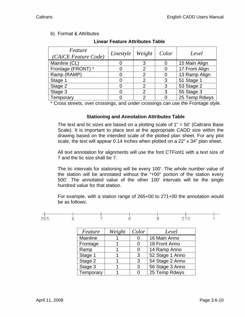
b) Format & Attributes Linear Feature Attributes Table
Feature (CAiCE Feature Code) Linestyle Weight Color Level
Mainline (CL) 0 3 0 15 Main Align Frontage (FRONT) * 0 2 0 17 Front Align Ramp (RAMP) 0 2 0 13 Ramp Align Stage 1 0 2 3 51 Stage 1 Stage 2 0 2 3 53 Stage 2 Stage 3 0 2 3 55 Stage 3 Temporary 0 2 0 25 Temp Rdwys * Cross streets, over crossings, and under crossings can use the Frontage style.
Stationing and Annotation Attributes Table
The text and tic sizes are based on a plotting scale of 1” = 50’ (Caltrans Base Scale). It is important to place text at the appropriate CADD size within the drawing based on the intended scale of the plotted plan sheet. For any plot scale, the text will appear 0.14 inches when plotted on a 22” x 34” plan sheet. All text annotation for alignments will use the font CTFont1 with a text size of 7 and the tic size shall be 7. The tic intervals for stationing will be every 100’. The whole number value of the station will be annotated without the “+00” portion of the station every 500’. The annotated value of the other 100’ intervals will be the single hundred value for that station. For example, with a station range of 265+00 to 271+00 the annotation would be as follows:
Feature Weight Color Level Mainline 1 0 16 Main Anno Frontage 1 0 18 Front Anno Ramp 1 0 14 Ramp Anno Stage 1 1 3 52 Stage 1 Anno Stage 2 1 3 54 Stage 2 Anno Stage 3 1 3 56 Stage 3 Anno Temporary 1 0 25 Temp Rdwys
April 11, 2008 Page 3.6-10

Caltrans English CADD Users Manual
2) Other Alignments Other alignments represent all other linear elements that are an integral part of the design and construction stakeout processes. Typical elements include, but are not limited to:
• Flow line of curb returns and islands • Pullouts that are not parallel with roadway alignments • Fence lines not controlled by right of way • Right of Way
Right of way requirements are initially developed early in the design process and are further refined by the surveyor performing the right of way engineering. These elements are used to acquire and document property; the roadway design software should therefore be used for the development and subsequent electronic transfer of this data.
• Structural Systems Retaining walls and sound walls are typical structural systems. It is best to develop the layout lines of these systems in the roadway design software rather than creating a simple graphic element. These designed objects are needed during the design and construction stakeout processes.
• Bridge Systems Bridge foundation plans typically include layout lines of wing walls, abutments, and bents. These plans, in a geographically correct DGN file, are useful during the design and construction stakeout processes.
• Drainage Systems Typical drainage systems are pipes, culverts, and in-stream and channel facilities. It is best to develop the layout lines of these systems in the roadway design software rather than creating a simple graphic element. These designed objects are needed during the design and construction stakeout processes. Develop plan views for drainage systems showing drainage features, manholes and drainage inlets.
a) Best Practices & things to think about i) The roadway design software should be used for the development and
subsequent electronic transfer of this data when the alignment is not parallel with or controlled by a roadway alignment.
April 11, 2008 Page 3.6-11
Caltrans English CADD Users Manual
ii) When the alignment is parallel with and/or concentric to a roadway alignment, the same concerns about tangency and coincidence should be respected. • Tangency to the nearest tenth of a second, 00.0” • Coincidence between compound and reversing curves to the
nearest hundredth of a foot, 0.01’ iii) If it is not feasible to develop the alignment with the roadway design
software then a layout of the graphical elements must be provided in a geographically correct DGN file.
iv) When stationing is applied to an alignment of a structural system, the stationing pattern should reflect the structures numbering system, i.e. Retaining Wall 7 starts at 70+00.
b) Format & Attributes See Sections 2.4, 2.6, 2.7, and 2.8 for information about the attributes and annotation associated with linear elements.
F) Vertical Alignments
The vertical alignment is the mathematical definition of the vertical path of a horizontal alignment of the highway or roadway. The vertical alignment is always associated with a horizontal alignment and consists of tangent sections (grades) that connect tangentially to parabolic vertical curve sections. It is defined by vertical points of intersection (VPI’s) that are in turn defined by the horizontal alignment stationing and elevation. The vertical alignment is drawn in profile view. Requirements for vertical curves are given in terms of minimum curve length and are based on design speed, difference in grade, and adequate sight distance. The vertical alignment is needed by surveyors to set the elevation of the roadway. Further discussion and Caltrans design policy on vertical alignments can be found in Chapter 200 of the Highway Design Manual, http://www.dot.ca.gov/hq/oppd/hdm/pdf/english/chp0200.pdf
1) Roadway Vertical Alignments
a) Best Practices & things to think about i) Naming Convention Recommendations
(1) Each vertical alignment is intrinsically tied to a horizontal alignment through assigned stationing. The name of the vertical alignment should be the same as the name of the alignment to which it is associated. For example, SR20 for the name of the vertical alignment to match the horizontal alignment name of SR20.
April 11, 2008 Page 3.6-12

Caltrans English CADD Users Manual
ii) Existing Vertical Alignments (Terrain Profiles) (1) In certain rehabilitation projects it is acceptable to use existing ground
elevations as the points of intersection (PI’s) for the vertical alignment when no vertical curve correction is needed. In this case it is best to use the original ground elevation from each cross section and station where a template is to be applied.
(2) When using existing ground data as the vertical alignment make sure to check the profiles of the finished grade at the centerline and edge of traveled way to assure a smooth profile for traffic. Avoid small series of dips by adding a leveling course.
iii) New Vertical Alignments (Design Profiles) (1) Follow requirements as specified in Highway Design Manual, Chapter
200, Topic 204 – Grade (2) Use customized tables developed from the HDM with roadway design
software to assist in determining minimum vertical curve lengths. (3) When the alignment is complete make sure to check that the alignment
is, at least, within minimum and maximum sustained grades and using the minimum curve length specified for the design speed.
(4) Offset alignments are not stationed, nor are they typically shown on the profile sheet. However, if it were a split roadway, the left and right profiles would use the centerline stationing with a callout, i.e. 30’ left of SR20.
2) Other Vertical Alignments Other vertical alignments represent all other vertical elements that are an integral part of the design and construction stakeout processes. Typical elements include, but are not limited to:
• Drainage Systems Typical drainage systems are pipes, culverts, and in-stream and channel facilities.
• Barriers a) Best Practices & things to think about
i) Drainage Profiles (1) Develop profiles for all drainage systems that will be modified or added
showing existing ground, proposed ground and the drainage feature. (2) Profile annotation includes the roadway profile grade station, skew
angle, if any, station and offset to end points, bends, risers, drain inlets, and wing walls. For larger lengths of pipe a centerline bearing is beneficial.
April 11, 2008 Page 3.6-13

Caltrans English CADD Users Manual
ii) Barrier Profiles (1) It is recommended that a profile of the grade at the base of the barrier
be created and reviewed to ensure that the top of the barrier is consistent with the edge of traveled way and will be constructed without dips. If necessary, i.e. at drainage swales, corrections should be made on the grade.
3) Format & Attributes Roadway Profile Attributes Table
Feature Linestyle Weight Color Level Roadway Profile 0 1 0 60 Nongeo Data Original Ground 3 1 0 60 Nongeo Data
Drainage System Profile Attributes Table
Feature Linestyle Weight Color Level Drainage Profile 0 1 0 60 Nongeo Data Original Ground 3 1 0 60 Nongeo Data Finished Grade 0 1 0 60 Nongeo Data
Stationing and Annotation Attributes Table
The text is based on a plotting scale of 1” = 50’ (Caltrans Base Scale). It is important to place text at the appropriate CADD size within the drawing based on the intended scale of the plotted plan sheet. For any plot scale, the text will appear 0.14 inches when plotted on a 22” x 34” plan sheet. All text annotation for vertical alignments will use the font CTFont1 and have a text size of 7.
Feature Weight Color Level
Labels 1 0 60 Nongeo Data Name 1 0 60 Nongeo Data Profile 1 0 60 Nongeo Data
April 11, 2008 Page 3.6-14

Caltrans English CADD Users Manual
G) Superelevation and Cross Slope Through horizontal curved sections, the cross slope of the roadbed is sloped to counter the affects of radial forces developed as the vehicle travels through the curve. The cross slope of the roadbed through a curved sections is referred to as a “superelevated” section. The superelevation diagram is necessary for the construction engineers and surveyors to set the cross slope of the roadbed. Caltrans has developed a table that prescribes the superelevation rates based on roadway type (design speed) and horizontal curve radius. This table is found in the HDM, Superelevation Rates Table 202.2. Along tangent sections, the roadway cross section is sloped at 2% away from the centerline to provide for drainage of the surface water. This is called a normal crown section. The change from a cross slope of the roadbed in a tangent section to a superelevated section in a curve requires a transition length. The rates at which the cross slopes can change per distance along the roadway can be found in the HDM. Factors determining the transition lengths are the total change in cross slope and the width of the roadway, The Superelevation Transition and Runoff Lengths is found in the HDM, Table 202.5. Caltrans has CAiCE tables that can aid in the development of superelevation definitions that meet department standards. 1) Best Practices & things to think about
a) Existing Cross Slopes i) Roadway design software allows the engineer to sample existing cross
slopes and build new roadway elements, such as lanes and shoulders, to match existing cross slopes. In these cases it is important for the engineer to consider the following:
• Monitor the longitudinal profile of the outside edge of that element to make sure it remains smooth and that the cross slopes fluctuate at a constant rate of change between stations.
• Make sure that the slope of the roadbed is within allowable limits as found in the HDM.
• Keep in mind where drainage inlets and low spots will be located. b) New or Corrected Cross Slope and Superelevation
i) Use the roadway design software to generate superelevation definitions based on tables defined in the HDM.
ii) Take the time to carefully review the superelevation definitions, transition values, and cross slope standards against HDM Topic 202 – Superelevation, Topic 301 – Traveled Way standards and Topic 302 – Shoulder Standards.
iii) In cases where the roadway consists of three or more lanes sloped in the same direction, refer to the HDM Topic 833 – Roadway Cross Sections.
April 11, 2008 Page 3.6-15

Caltrans English CADD Users Manual
iv) The prefix of superelevation geometry lines should include the horizontal alignment name followed by SE. For example, • With a ramp named MA1 the prefix for the geometry lines would be
MA1SE • With a mainline named SR20 the prefix for the geometry lines
would be SR20SE
2) Format & Attributes for Superelevation Diagram The superelevation diagram is drawn on the profile sheet above the profile or separately on a superelevation sheet.
Linear Feature Attributes Table
Feature Linestyle Weight Color Level Left ES 0 1 0 60 Nongeo Data Right ES 0 1 0 60 Nongeo Data Left ETW 0 1 0 60 Nongeo Data Right ETW 0 1 0 60 Nongeo Data Axis/Rotation pp-axis 3 0 60 Nongeo Data
Annotation Attributes Table
The text is based on a plotting scale of 1” = 50’ (Caltrans Base Scale). It is important to place text at the appropriate CADD size within the drawing based on the intended scale of the plotted plan sheet. For any plot scale, the text will appear 0.14 inches when plotted on a 22” x 34” plan sheet. All text annotation for superelevation diagram will use the font CTFont1 and have a text size of 7.
Feature Weight Color Level All annotation 1 0 60 Nongeo Data
April 11, 2008 Page 3.6-16

Caltrans English CADD Users Manual
H) Alternate Design Techniques While cross section design methods lend themselves well for roadway design, site design or three dimensional (3D) design techniques may be useful for other types of civil facilities. Site design techniques are available that will let the user define the elevation along the path of a shape, specify parameters of cut/fill slopes, and work with existing terrain surfaces to extend slopes from the path of the shape. The end result is a set of points and breaklines that are used to create a proposed surface. A combination of cross sections, alignments, and profiles can be created from the resulting surface for construction staking purposes. Examples of facilities that can be designed with these techniques include:
• Bridge fill cone areas • Intersections with multiple layout lines that require more detailed
information than slope stake listings • Building pads • Retention ponds • Berms, dikes & levees • Stockpiles & borrow pits • General landscaping and contour grading • Parks • Parking lots
1) Best Practices & things to think about a) When designing a facility with site design techniques the engineer is better
able to visualize the finished product, generate accurate quantities, and produce contour grading plans.
b) Site design techniques in CAiCE involve the creation of breaklines and points from a geometry chain with an associated profile or fixed elevation, from survey chains, and specified slopes that extend to an existing surface or a defined elevation.
c) Key features used in site design techniques: i) Breakline Features
Breakline features represent groups of DTM points with an important linear relationship. When a DTM is triangulated, breakline features are honored in such a way that no triangle edge (triangle leg) will cross the path defined by the breakline feature. Breakline features thus promote a more accurate triangulated model. Typical breaklines are the hinge of a retention pond, the bottom of a ditch, the edge of a curb, etc.
ii) Random Point Features Random point features represent distinct points with no significant linear relationship. Therefore random features can be displayed in profiles or
April 11, 2008 Page 3.6-17

Caltrans English CADD Users Manual
cross sections. Point density intervals cannot be applied to a random feature.
d) General workflow i) Define the position of the shape as an open or closed figure ii) Define the slope parameters iii) Create the point and breakline features iv) Store the surface v) Enhance the surface with user defined contours
e) Angle vs. curve solutions When angle points are used to define the shape, slopes are generated by extending a series of radial lines at a defined angle increment, all beginning at the angle point. If a curve is used to define the shape, slopes are placed at station increments on the curve.
f) Enhance design surfaces with user defined contours Often, the most natural way for an engineer to design a surface is to “sketch” the proposed grade contours. This can be done by saving the “sketched” contours as survey chains and adding them to the surface.
g) Modeling building pads A shape is created at the finished grade elevation to define the perimeter of the pad. The required slope parameters are then applied to create a surface that extends outward to intersect with the existing terrain.
h) Modeling retention ponds A shape is created at the existing terrain elevation to define the outer perimeter of the pond. The required slope parameters are then applied to create a surface that extends inward to a fixed elevation, resulting in a flat-bottomed pond.
i) Modeling dikes or levees A shape is created at the top of the dike that will define the centerline of the model. The shape can be offset to create a flat top. The required slope parameters are then applied to create a surface that extends on both sides of the shape.
2) Format & Attributes (see next section “Digital Design Model”)
April 11, 2008 Page 3.6-18
Caltrans English CADD Users Manual
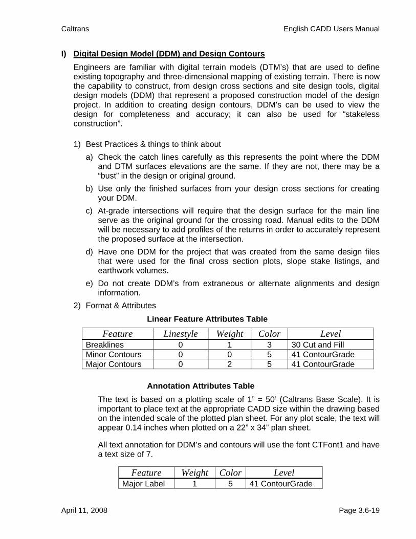
I) Digital Design Model (DDM) and Design Contours Engineers are familiar with digital terrain models (DTM’s) that are used to define existing topography and three-dimensional mapping of existing terrain. There is now the capability to construct, from design cross sections and site design tools, digital design models (DDM) that represent a proposed construction model of the design project. In addition to creating design contours, DDM’s can be used to view the design for completeness and accuracy; it can also be used for “stakeless construction”.
1) Best Practices & things to think about a) Check the catch lines carefully as this represents the point where the DDM
and DTM surfaces elevations are the same. If they are not, there may be a “bust” in the design or original ground.
b) Use only the finished surfaces from your design cross sections for creating your DDM.
c) At-grade intersections will require that the design surface for the main line serve as the original ground for the crossing road. Manual edits to the DDM will be necessary to add profiles of the returns in order to accurately represent the proposed surface at the intersection.
d) Have one DDM for the project that was created from the same design files that were used for the final cross section plots, slope stake listings, and earthwork volumes.
e) Do not create DDM’s from extraneous or alternate alignments and design information.
2) Format & Attributes Linear Feature Attributes Table
Feature Linestyle Weight Color Level Breaklines 0 1 3 30 Cut and Fill Minor Contours 0 0 5 41 ContourGrade Major Contours 0 2 5 41 ContourGrade
Annotation Attributes Table The text is based on a plotting scale of 1” = 50’ (Caltrans Base Scale). It is important to place text at the appropriate CADD size within the drawing based on the intended scale of the plotted plan sheet. For any plot scale, the text will appear 0.14 inches when plotted on a 22” x 34” plan sheet. All text annotation for DDM’s and contours will use the font CTFont1 and have a text size of 7.
Feature Weight Color Level Major Label 1 5 41 ContourGrade
April 11, 2008 Page 3.6-19

Caltrans English CADD Users Manual
J) Design Cross Sections Design cross sections are developed from the roadway design software as it applies typical sections at specific station intervals within given station limits. The cut/fill and roadbed slopes will change as the horizontal and vertical alignment, super elevation, and existing ground changes from station to station. Cross sections are an integral part of the design and construction staking processes. They are needed by the engineer to help determine quantities of earthwork, structural roadway material, and right of way impacts or requirements. Surveyors and construction engineers utilize the cross sections and resulting slope stake listings throughout the construction of the project. 1) Best Practices & things to think about
a) Cross sections, slope stake listings and earthwork quantities should be produced concurrently and based on identical design data depicted on the contract plans.
b) Slope stake listings and earthwork quantities are a direct result of the design cross sections.
c) Cross sections should be available for use by others as noted in Appendix QQ of the Project Development Procedures Manual (PDPM).
d) A Caltrans developed CAiCE macro, Plot_Sections.lib, should be used to produce acceptable cross sections.
e) A typical cross section shows the pavement structure within a specified station limit range whereas a design cross section shows the cross-slope and earthwork at a specific station.
f) Design cross sections will show finished grades, sub grades, original ground, existing and proposed edge of traveled way, existing and proposed edge of pavement, hinge point and catch point. Include offsets to right of way if the slope catch point is within 15’ of the right of way.
g) Provide cross sections for interim construction phases when projects with stage construction require partial fills, cuts, or detour work.
h) Refrain from the use of “Pavement Plane Projection” or “Match Existing Cross Slope” when topographic data is available unless approved by the Project Surveyor.
April 11, 2008 Page 3.6-20

Caltrans English CADD Users Manual
i) When two alignments are converging or diverging, develop a match line
between slopes until the catch lines become completely separated. See images below.
Section A-A
April 11, 2008 Page 3.6-21

Caltrans English CADD Users Manual
j) Identify shear key location and final grades for rock slope protection (RSP)
areas other than culverts. The typical below depicts an RSP area that should be identified on the cross sections.
k) The prefix of scan lines used to develop cross sections should include the horizontal alignment name followed by XS. For example,
• To develop cross sections of a ramp named MA1 the prefix for the scan lines would be MA1XS.
• To develop cross sections of a mainline named SR20 the prefix for the scan lines would be SR20XS.
l) The cross section file name should include the horizontal alignment name followed by “exist” or “design” as appropriate. For example,
• The design cross sections for a ramp named MA1 would be named MA1_design.EAR.
• The design cross sections for a mainline named SR20 would be named SR20_design.EAR.
April 11, 2008 Page 3.6-22

Caltrans English CADD Users Manual
2) Format & Attributes a) The recommended scale for cross sections is 1” = 10’ for rural areas and 1” =
5’ for Urban areas or depending on the cross section width along the project. The scale will be consistent for a given alignment. The vertical and horizontal scales should be the same. The sheet may be oriented in either landscape or portrait views but must remain consistent throughout the job.
b) The cross section sheets must include the alignment name and stationing, sheet number and total number of sheets, District-County-Route, Expenditure Authorization (EA), vertical and horizontal scale, date of cross section plots, and the statement “Design Study Only”. The alignment name and stationing must be shown for each cross section and sheets must be arranged in order of increasing station.
Linear Feature Attributes Table
Feature Linestyle Weight Color Level New Cross Sections elements
0 2 Var 60 Nongeo Data
Existing Ground 1 2 4 60 Nongeo Data Major Grid 0 2 2 11 Undefined Minor Grid 0 0 3 9 Profile Grid Frame 0 0 0 10 Sheet Format Border 0 3 0 10 Sheet Format Leaders 0 1 0 60 Nongeo Data
April 11, 2008 Page 3.6-23
Caltrans English CADD Users Manual
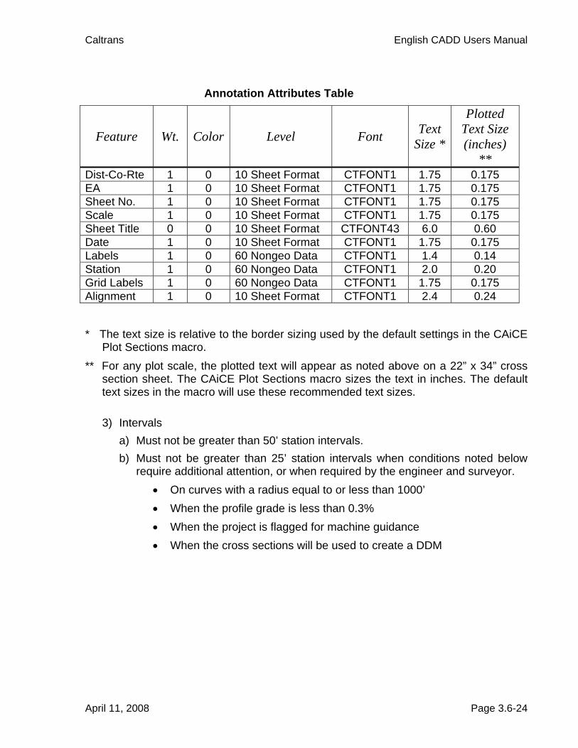
Annotation Attributes Table
Feature Wt. Color Level Font Text Size *
Plotted Text Size (inches)
** Dist-Co-Rte 1 0 10 Sheet Format CTFONT1 1.75 0.175 EA 1 0 10 Sheet Format CTFONT1 1.75 0.175 Sheet No. 1 0 10 Sheet Format CTFONT1 1.75 0.175 Scale 1 0 10 Sheet Format CTFONT1 1.75 0.175 Sheet Title 0 0 10 Sheet Format CTFONT43 6.0 0.60 Date 1 0 10 Sheet Format CTFONT1 1.75 0.175 Labels 1 0 60 Nongeo Data CTFONT1 1.4 0.14 Station 1 0 60 Nongeo Data CTFONT1 2.0 0.20 Grid Labels 1 0 60 Nongeo Data CTFONT1 1.75 0.175 Alignment 1 0 10 Sheet Format CTFONT1 2.4 0.24
* The text size is relative to the border sizing used by the default settings in the CAiCE
Plot Sections macro. ** For any plot scale, the plotted text will appear as noted above on a 22” x 34” cross
section sheet. The CAiCE Plot Sections macro sizes the text in inches. The default text sizes in the macro will use these recommended text sizes.
3) Intervals
a) Must not be greater than 50’ station intervals. b) Must not be greater than 25’ station intervals when conditions noted below
require additional attention, or when required by the engineer and surveyor. • On curves with a radius equal to or less than 1000’ • When the profile grade is less than 0.3% • When the project is flagged for machine guidance • When the cross sections will be used to create a DDM
April 11, 2008 Page 3.6-24
Caltrans English CADD Users Manual
c) Cross section shall be created at the following key stations: • Begin and end of curves • Begin and end of roadway tapers, including parabolic increments • Roadway pullouts, including all corners • Angle point locations • Begin and end of super transitions • Guardrail flares at the end of flare • Begin and end of curb returns • Begin and end of approach slabs to bridges • Begin and end of bridge • Major sign locations
d) Tapered sections at on/off ramp connections shall be included in the main line cross sections up to and including the gore point (23’). The remaining portion of each ramp is to be listed separately.
e) Depending upon the project, additional cross sections may be required. The Project Surveyor and Engineer shall determine the need when the Survey File Checklist, Appendix QQ of the Project Development Procedures Manual (PDPM), is reviewed.
4) Key Points a) Grade breaks necessary for staking finish roadbeds shall be annotated with
offset from the mainline and elevation. See the table on the following page for a listing of recommended grade breaks and associated labels. Note: When fragments do not use these codes by default, the stake point fragment may be used in the design process to generate these labels for cross section and slope stake listings. A Caltrans developed CAiCE macro, “Modify EAR for Stakeout” in the CaltransLandSurveys.lib, is also available that will modify the grade break labels in the cross section file.
April 11, 2008 Page 3.6-25

Caltrans English CADD Users Manual
Grade Break
Label Description BAR Barrier – used for both faces. If point is coincidental with ES then
use BAR. BEN Bench – used for both edges BKWALL Back of wall BKCURB * Back of curb – typically not staked by Surveys but this provides
clarifying information for Construction BKSW Back of sidewalk CL Centerline CONFM Conform CONT Contour grading lines CP Catch point – intersection of design surface with existing surface EP Edge of pavement – only for use with miscellaneous roadway
sections including bike paths, rest stops, dike pads, etc. ES Edge of shoulder ETW Edge of traveled way FL Paved or unpaved flow line FSW Front of sidewalk FWALL Face of wall HP Hinge point – top of slopes within the design surface LL * Lane line – also used for Pavement Structure change LOL Layout line for retaining, sound, or wing walls ML Match line PG Profile grade R/W Right of way RSP Rock Slope Protection S/C Saw cut line SL * String line – the plane of the traveled way TBERM Top of berm TCURB * Top of curb – typically not staked by Surveys but this provides
clarifying information for Construction TDIKE * Top of dike – typically not staked by Surveys but this provides
clarifying information for Construction TDITCH Top of ditch TOE Toe – bottom of slopes within the design surface, not the catch
point TWALL Top of wall
* On request only See Chapter 2 of the Plans Preparation Manual for acceptable format examples
April 11, 2008 Page 3.6-26


