Embed Size (px)
Citation preview

Rule
sG
uid
ance
2017Rules for the Classification of Steel Ships
Part 5 Machinery Installations
2017Guidance Relating to the Rules for the Classification of Steel ships
Part 5 Machinery Installations

2017
Rules for the Classification of Steel Ships
Part 5
Machinery Installations
RA-05-E KR

- i -
APPLICATION OF PART 5 "MACHINERY INSTALLATIONS"
1. Unless expressly specified otherwise, the requirements in the rules apply to ships for which con-
tracts for construction are signed on or after 1 July 2017.
2. The amendments to the Rules for 2016 edition and their effective date are as follows;
Effective Date 1 July 2016 (date of application for certification, related Circular No. : 2016-7-E)
CHAPTER 1 GENERAL
Section 1 General
- 102. 26, 27, 28 have been amended.
Section 3 Tests and Inspections
- 301. 2 has been amended and 4 has been newly added.
CHAPTER 2 MAIN AND AUXILIARY ENGINES
Section 2 Internal Combustion Engines
- 211. 1 and Table 5.2.4 have been amended.
Effective Date 1 July 2016 (date of application for certification of the new turbocharger type, related
Circular No. : 2016-7-E)
CHAPTER 1 GENERAL
Section 2 Plans and Documents
- 211. has been newly added.
CHAPTER 2 MAIN AND AUXILIARY ENGINES
Section 2 Internal Combustion Engines
- 211. 2 (1) has been amended and (4) has been deleted.
Effective Date 1 January 2017 (related Circular No. : 2016-15-E)
CHAPTER 3 PROPULSION SHAFTING AND POWER TRANSMISSION SYSTEMS
Section 2 Shaftings

- ii -
- 203. has been amended.
CHAPTER 4 TORSIONAL VIBRATION OF SHAFTINGS
Section 2 Allowable Limit of Vibration Stresses
- 202. 1 (1) has been amended.
CHAPTER 6 AUXILIARIES AND PIPING ARRANGEMENT
Section 1 General
- 104. 5 has been amended.
CHAPTER 7 STEERING GEARS
Section 5 Testing
- 503. 1 (1) has been amended.
Effective Date 1 January 2017 (date of the application for approval, related Circular No. :
2016-15-E)
CHAPTER 3 PROPULSION SHAFTING AND POWER TRANSMISSION SYSTEMS
Section 4 Power Transmission Systems
- 401. 1 and 5 have been amended.
Effective Date 1 July 2017
CHAPTER 1 GENERAL
Section 1 General
- 102. 29 has been amended.
Section 4 Spare Parts and Tools
- 401. 1 has been amended.
- 402. has been amended.
- 403. 404. 405. 406. 407. have been moved to the Guidance.
- Table 5.1.7 ~ 5.1.12 have been moved to the Guidance.
CHAPTER 2 MAIN AND AUXILIARY ENGINES
Section 1 General

- iii -
- 101. 1 and 3 have been amended.
CHAPTER 5 BOILERS AND PRESSURE VESSELS
Section 3 Pressure Vessels
- 303. 3 has been amended.
- 303. (3) has been newly added.
- 313. 1 has been amended and Table 5.5.16 has been newly added.
CHAPTER 6 AUXILIARIES AND PIPING ARRANGEMENT
Section 4 Bilge and Ballast System
- 403. 6 has been amended.
Section 13 Hydraulic System
- Newly added.
Section 14 Tests and Inspections
- Section number has been changed according to Section 13 Hydraulic System
newly added.
CHAPTER 7 STEERING GEARS
Section 3 Controls
- 301. 2 (4) has been deleted.
- 302.(Failure detection and response of all types of steering control systems) has
been newly added.
CHAPTER 8 WINDLASSES AND MOORING WINCHES
Section 1 General
- 102. 1 and 2 have been amended.

- v -
CONTENTS
CHAPTER 1 GENERAL ······································································································· 1
Section 1 General ··············································································································· 1
Section 2 Plans and Documents ························································································ 6
Section 3 Tests and Inspections ······················································································ 14
Section 4 Spare Parts and Tools ····················································································· 14
CHAPTER 2 MAIN AND AUXILIARY ENGINES ························································· 17
Section 1 General ············································································································· 17
Section 2 Internal Combustion Engines ·········································································· 18
Section 3 Steam Turbines ································································································ 32
Section 4 Gas Turbines ···································································································· 35
CHAPTER 3 PROPULSION SHAFTING AND POWER TRANSMISSION
SYSTEMS ····································································································· 39
Section 1 General ············································································································· 39
Section 2 Shaftings ··········································································································· 39
Section 3 Propellers ·········································································································· 44
Section 4 Power Transmission Systems ·········································································· 47
CHAPTER 4 TORSIONAL VIBRATION OF SHAFTINGS ········································· 55
Section 1 General ············································································································· 55
Section 2 Allowable Limit of Vibration Stresses ··························································· 55
CHAPTER 5 BOILERS AND PRESSURE VESSELS ················································ 61
Section 1 Boilers ··············································································································· 61
Section 2 Thermal Oil Heaters ························································································ 94
Section 3 Pressure Vessels ······························································································· 95
Section 4 Welding for Boilers and Pressure Vessels ·················································· 103
CHAPTER 6 AUXILIARIES AND PIPING ARRANGEMENT ·································· 109
Section 1 General ·········································································································· 109
Section 2 Air Pipes, Overflow Pipes and Sounding Devices ··································· 130
Section 3 Sea Suction and Overboard Discharge ······················································· 133
Section 4 Bilge and Ballast System ············································································ 136
Section 5 Feed Water and Condensate System for Boiler ········································ 142
Section 6 Steam and Exhaust Gas Piping ·································································· 143
Section 7 Cooling System ···························································································· 144
Section 8 Lubricating Oil System ················································································ 145
Section 9 Fuel Oil System ··························································································· 146
Section 10 Thermal Oil System ···················································································· 150
Section 11 Compressed Air System ·············································································· 151
Section 12 Refrigerating Machinery ·············································································· 152
Section 13 Hydraulic System ························································································· 155
Section 14 Tests and Inspections ··················································································· 156

- vi -
CHAPTER 7 STEERING GEARS ·················································································· 159
Section 1 General ··········································································································· 159
Section 2 Performance and Arrangement ······································································ 160
Section 3 Controls ·········································································································· 163
Section 4 Materials, Constructions and Strength ·························································· 164
Section 5 Testing ············································································································ 168
Section 6 Additional Requirements Concerning Tankers of 10,000 Gross Tonnage
and Upwards and Other Ships of 70,000 Gross Tonnage and
Upwards ·········································································································· 169
CHAPTER 8 WINDLASSES AND MOORING WINCHES ······································· 173
Section 1 General ··········································································································· 173
Section 2 Windlasses ······································································································ 173
Section 3 Mooring Winches ··························································································· 175
Pt 5 Machinery Installations
Ch 1 General Pt 5, Ch 1
Rules for the Classification of Steel Ships 2017 1
CHAPTER 1 GENERAL
Section 1 General
101. Application
1. The requirements of this Part apply to the machinery installations intended for the ships which have no special limitations for their service area and purpose. For machinery installations intended for the ships having any limitations for their service area or intended for the small ships, the re-quirements in this Part may be modified. Special consideration is to be given to the ships with any limitations for their purpose. 【See Guidance】
2. The machinery installations which do not comply with the requirements of this Part may be ac-cepted, provided that they are considered acceptable by the Society.
3. For the strength and construction of the parts of machinery on which the requirements of the Rules cannot be applied, the manufacturer is to submit for approval the detailed methods of strength cal-culation and data to the Society and the reliability for the strength of the parts may be decided from the results of measuring strain or deformation of them by means of a proper loading method approved by the Society. For machinery of new design, the Society may request plans and design data of more detailed parts to be submitted in addition to those specified in the Rules. 【See Guidance】
4. Since the formulae for the strength of the parts of machinery in the Rules are based upon the con-sideration that there is no dangerous vibration in the installation within the range of operating speeds, the manufacturers of the machinery are required to pay special attention to this point and take responsibility in the application of these formulae.
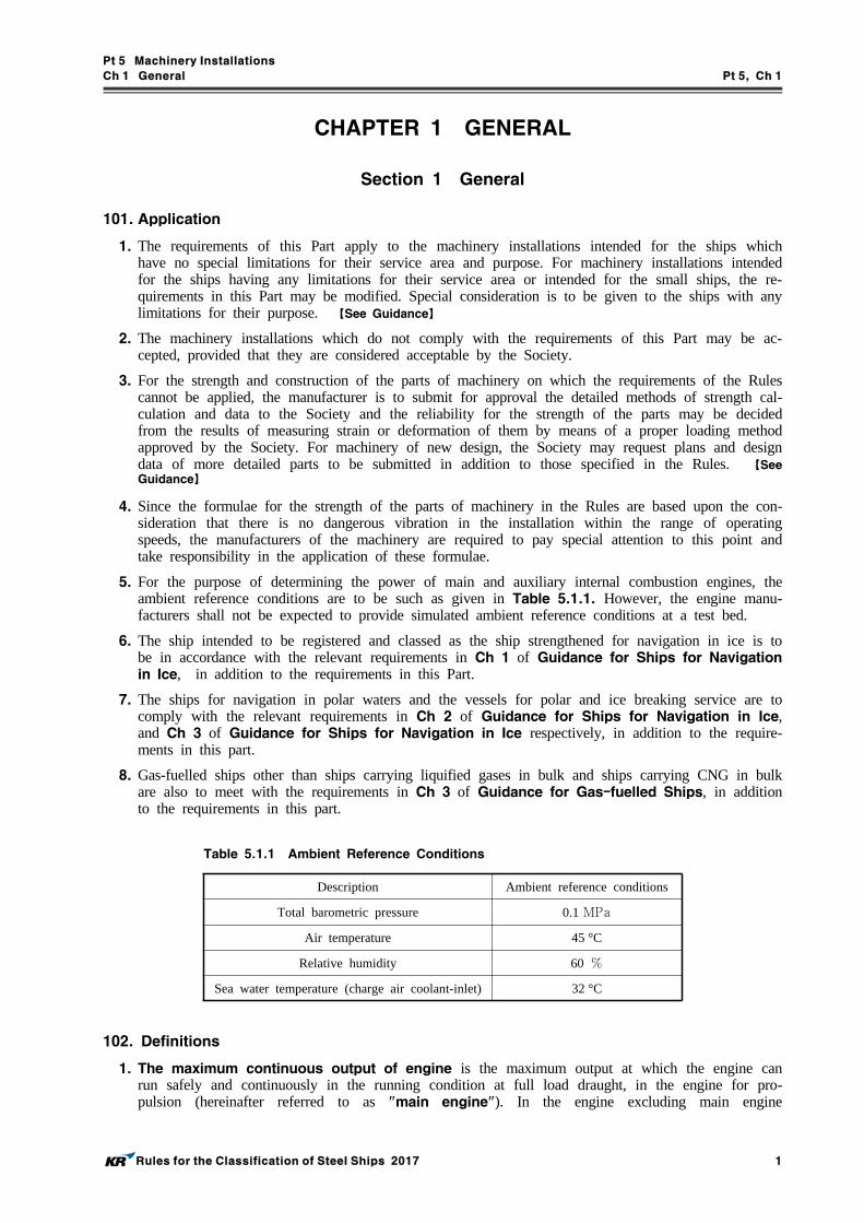
5. For the purpose of determining the power of main and auxiliary internal combustion engines, the ambient reference conditions are to be such as given in Table 5.1.1. However, the engine manu-facturers shall not be expected to provide simulated ambient reference conditions at a test bed.
6. The ship intended to be registered and classed as the ship strengthened for navigation in ice is to be in accordance with the relevant requirements in Ch 1 of Guidance for Ships for Navigation in Ice, in addition to the requirements in this Part.
7. The ships for navigation in polar waters and the vessels for polar and ice breaking service are to comply with the relevant requirements in Ch 2 of Guidance for Ships for Navigation in Ice, and Ch 3 of Guidance for Ships for Navigation in Ice respectively, in addition to the require-ments in this part.
8. Gas-fuelled ships other than ships carrying liquified gases in bulk and ships carrying CNG in bulk are also to meet with the requirements in Ch 3 of Guidance for Gas-fuelled Ships, in addition to the requirements in this part.
Description Ambient reference conditions
Total barometric pressure 0.1 MPaAir temperature 45 °C
Relative humidity 60
Sea water temperature (charge air coolant-inlet) 32 °C
Table 5.1.1 Ambient Reference Conditions
102. Definitions
1. The maximum continuous output of engine is the maximum output at which the engine can run safely and continuously in the running condition at full load draught, in the engine for pro-pulsion (hereinafter referred to as "main engine"). In the engine excluding main engine

Pt 5 Machinery Installations
Ch 1 General Pt 5, Ch 1
2 Rules for the Classification of Steel Ships 2017
(hereinafter referred to as "auxiliary engine"), the maximum continuous output of engine is the maximum output at which the engine can run safely and continuously in the intended condition.
2. Number of maximum continuous revolutions is the number of revolutions at the maximum continuous output.
3. Propeller shaft Kind 1 or Stern tube shaft Kind 1 is the shaft which is provided with effective measures against corrosion by sea water, or the shaft which is made of approved corrosion resist-ance material. The propeller shaft or stern tube shaft other than specified above is Kind 2.
4. Design pressure is a pressure used in the calculations made to determine the scantlings of each component and is the maximum permissible working pressure to the component. However, the de-sign pressure is to be not less than the highest set pressure of any relief valve.
5. Essential auxiliaries are the auxiliary machinery for important use, and are those for propulsion of ships and for safety of lives and ships or those for facilities in relation to the purpose of ships. 【See Guidance】
6. Boiler is the plant which generates steam or hot water by means of flame, combustion gas or oth-er hot gases, including the equipment subject to a boiler.
7. Main boiler means the boiler used in moving the propulsion steam engines.
8. Essential auxiliary boiler means the auxiliary boiler other than the main boiler, which is used in supplying steam need for operating generators, auxiliary machinery in relation to the propulsion of ships, safety of lives and ships or the purpose of ships.
9. Exhaust gas boiler is a boiler which generates steam or hot water solely by exhaust gas from in-ternal combustion engine and has a steam space or a hot well and has an outlet of steam or hot water.
10. Exhaust gas economizer is the equipment without any steam space or hot well which generates steam or hot water solely by exhaust gas from internal combustion engine and supplies to other boiler.
11. Thermal oil installation is the arrangement in which thermal oil is heated and circulated for the purpose of heating cargo or fuel oil or for production of steam and hot water for auxiliary purpose.
12. Pressure vessel is a vessel which contains gas or liquid, intended for the pressure exceeding the atmospheric pressure at its top. It includes heat exchangers and does not contact with flame, combustion gas or hot gas.
13. Equipment subject to a boiler means the superheaters, reheaters and economizers (where a stop valve is fitted between them and the main body of the boiler) and the equivalent.
14. Attachment of boiler and pressure vessel means the following; (1) Flanges, stand pipes and distance pieces attached directly to boilers, equipment subject to a boil-
er, and pressure vessels(2) Valves attached directly to boilers, equipment subject to a boiler, and pressure vessels
15. Valve attached directly to boilers and pressure vessels is the valve attached to body of boilers or pressure vessels by stud bolts, flange, stand pipe or distance piece, and includes the screw down check valve specified in Ch 5, 127. 1.
16. Stand pipe means the following attached directly to body of boilers and pressure vessels;(1) Pipe and nozzle(2) Penetration piece consisting of flange and pipe attached directly to boilers and pressure vessels
for the purpose of fitting the valve attached directly to body of boilers and pressure vessels.(3) Rings for installation of manhole, mud holes and peep holes
17. Distance piece in boilers and pressure vessels is a piece used for keeping the distance be-tween flange or stand pipe attached directly to boilers and pressure vessels, and valve attached di-rectly to boilers and pressure vessels, or gauges.
18. Essential pressure vessel is a pressure vessel having relevance to main engines, essential auxil-iary boilers, auxiliary machinery having relevance to propulsion, auxiliary machinery having rele-

Pt 5 Machinery Installations
Ch 1 General Pt 5, Ch 1
Rules for the Classification of Steel Ships 2017 3
Group Power (kW )
Category A ≤ 1000
Category B 1000 < ≤ 2500
Category C 2500 <
vance to safety of lives and ships, and auxiliary machinery having relevance to service of ships.
19. Nominal pressure of the boiler with superheater is the maximum steam pressure of super-heater outlet designed by the manufacturer or the owner, and is used the standard for setting the safety valve of superheater.
20. Heating surface area of a boiler is the area calculated on the combustion gas side surface where one side is exposed to combustion gas and the other side to water, but the heating surface of superheater, reheater, economizer or exhaust gas economizer is excluded, unless specially specified.
21. Dead ship condition means a condition under which : (1) the main propulsion plant, boilers and auxiliaries are not in operation due to the loss of the
main source of electrical power, and(2) in restoring the propulsion, no stored energy for starting the propulsion plant, the main source
of electrical power and other essential auxiliary machinery is assumed to be available. It is as-sumed that means are available to start the emergency generator at all times.
22. Piping system is a general term of pipes, valves and pipe fittings. 【See Guidance】
23. Flexible hose assembly is the short length of metallic or non-metallic hose normally with pre fabricated end fittings ready for installation.
24. Ship-side valve means the valve attached to bottom or side of ship in accordance with Ch 6, 301. 1.
25. Navigable speed means a speed at which the ship is capable of steering by the rudder and be-ing kept navigability for an extended period of time (period required to get the nearest port for re-pairs). Normally, the greater of 7 knots or a speed corresponding to 1/2 of the speed specified in Pt 3, Ch. 1 120. at the ship’'s full loaded draught may be regarded as a navigable speed.
26. KR Certificate (KRC) is a document issued by the Society stating below.(1) Conformity with the requirements of the Rules(2) The tests and inspections have been carried out on the certified product itself, or on samples
taken from the certified product itself.(3) The inspection and tests were performed in the presence of the Surveyor or in accordance with
quality assurance system.27. Work’s Certificate (W) is a document signed by the manufacturer stating below.
(1) Conformity with the requirements(2) The tests and inspections have been carried out on the certified product itself, or on samples
taken from the raw material, used for the product to be certified.(3) The tests were witnessed and signed by a qualified representative of the applicable department
of the manufacturer.28. Test Report (TR) is a document signed by the manufacturer stating below.
(1) Conformity with the requirements(2) The tests and inspections have been carried out on samples from the current production.
29. Turbochargers are categorized in three groups depending on engine power (at MCR) supplied by a group of cylinders served by the actual turbocharger as shown in the following table (e.g. for a V-engine with one turbocharger for each bank the size is half of the total engine power). The re-quirements of documents, tests, etc. escalate with the group of the turbochargers. (2017)

Pt 5 Machinery Installations
Ch 1 General Pt 5, Ch 1
4 Rules for the Classification of Steel Ships 2017
103. Construction, materials and installation
1. The construction, installation, lubricating system and cooling system of machinery are to be such that they cause no hindrance to their proper operations under the condition as given in Table 5.1.2.
2. All components and systems of machinery are to be designed to ensure proper operation under the temperature conditions given in Table 5.1.3.
3. Means are to be provided to ensure that machinery installations can be brought into operation from the dead ship condition without external aid.
4. Materials intended for the main parts of machinery are to be of fine quality in accordance with the requirements of Pt 2, Ch 1. The process of manufacturing each part is to be in accordance with the best method based on the past experiences and results. The materials other than those pre-scribed in the Rules may, however, be used where sufficient data are submitted in connection with the design and are specially approved.
Type of machinery installations
Angle of inclination (deg)(2)
Athwart-ships Fore-and-aft
Static Dynamic Static Dynamic
Main and auxiliary machinery 15 22.5 5(4) 7.5
Safety equipment (emergency power installations, emergency fire pumps and their devices)Switch gear(1) (electrical and electronic appliances and remote control systems)
22.5(3) 22.5(3) 10 10
NOTES:(1) Up to an angle of inclination of 45° no undesired switching operation or operational changes may occur.(2) Athwartships and fore-and-aft inclinations may occur simultaneously.(3) In ships for the carriage of liquefied gases and of chemicals the emergency power supply must also remain
operable with the ship flooded to a final athwartships inclination up to a maximum of 30 degrees.(4) Where the length of the ship exceeds 100 m , the fore-and-aft static angle of inclination may be taken as
500/ degrees. ( : Length of the ship as defined in Part 3, Ch 1, 102. of the Rules, m )
Table 5.1.2 Angle of inclination
Installed location Temperature range(°C)
Air
In enclosed spaces 0~45(1)
On machinery components, boilers in spaces subject to higher or lower temperature
According to specific local conditions
On the open deck -25~45(1)
Sea water - 32(1)
NOTE:(1) The Society may approve other temperatures in the case of ships intended for restricted service.
Table 5.1.3 Temperature conditions
5. Astern power for main propulsion
(1) In order to maintain sufficient maneuverability and secure control of the ship in all normal cir-cumstances, the main propulsion machinery is to be capable of reversing the direction of thrust so as to bring the ship to rest from the maximum service speed. The main propulsion machi-nery is to be capable of maintaining in free route astern at least 70 % of the ahead revolutions

Pt 5 Machinery Installations
Ch 1 General Pt 5, Ch 1
Rules for the Classification of Steel Ships 2017 5
corresponding to the maximum continuous ahead power.(2) For the main propulsion systems with reversing gears, controllable pitch propellers or electric
propeller drive, running astern should not lead to the overload of propulsion machinery.(3) The reversing characteristics of the propulsion plants are to be demonstrated and recorded during
trials.(4) Where steam turbines are used for main propulsion, they are to be capable of maintaining in
free route astern at least 70 % of the ahead revolutions corresponding to the maximum con-tinuous ahead power for a period of at least 15 minutes. The astern trial is to be limited to 30 minutes or in accordance with manufacturer's recommendation to avoid overheating of the tur-bine due to the effects of "windage" and friction.
6. The rotating, reciprocating and high temperature parts and electrically charged parts are to be ar-ranged with suitable protections for the safety of watchmen, operators or men neighbouring to these parts. Nuts of important parts and moving parts are to be well secured by effective means to pre-vent from loosening.
7. All surfaces of machinery installations with high temperature above 220 °C e.g. steam, thermal oil and exhaust gas lines, silencers, exhaust gas boilers, turbo blowers, etc and which may be impinged as a result of leakage of flammable fluid, are to be effectively insulated with non-combustible ma-terial to prevent the ignition of combustible materials coming into contact with them. Where the in-sulation is oil absorbent or may permit the penetration of oil, the insulation are to be encased in steel sheathing or equivalent material. 【See Guidance】
104. Automatic control device
Automatic or remote control devices for propelling machinery, essential auxiliaries or cargo handling gears, and specifically, the facilities of unmanned operation of engines are to be in accordance with the requirements of Pt 6, Ch 2.
105. Anti-freezing devices
The machinery fitted in ships which may serve in cold districts are to be provided with equipment for prompt starting and adequate devices to prevent the fuel oil or lubricating oil from coagulation. Suction and discharge openings to sea are to be suitably protected from becoming blocked up with ice.
106. Communication between navigating bridge and machinery spaces
At least two independent means are to be provided for communicating orders from the navigating bridge to the position in the machinery space or in the control room from which the speed and di-rection of thrust of the propellers are normally controlled. One of these are to be an engine-room telegraph which provides visual indication of the orders and responses both in the machinery spaces and on the navigating bridge. Appropriate means of communication are to be provided from the navigating bridge and the engine-room to any other position from which the speed or direction of thrust of the propellers may be controlled. 【See Guidance】
107. Engineers' alarm
An engineers' alarm is to be provided to be operated from the engine control room or at the ma-noeuvring platform as appropriate and is to be clearly audible in the engineers accommodation.
108. Ventilating systems in machinery spaces
1. Machinery spaces of Category A are to be adequately ventilated so as to ensure that when machi-nery or boilers therein are operating at full power in all weather conditions including heavy weath-er, an adequate supply of air is maintained to the spaces for the safety and comfort of personnel and the operation of the machinery. And other machinery space is to be adequately ventilated ap-propriate for the purpose of that machinery space.
2. In addition to the requirements in Pt 4, Ch 4. 402., for machinery space requiring continuous ven-tilation such as machinery space Category A and emergency generator room, coamings of ven-tilators in an exposed position on the freeboard deck or superstructure deck are to be extended to

Pt 5 Machinery Installations
Ch 1 General Pt 5, Ch 1
6 Rules for the Classification of Steel Ships 2017
more than 4.5 m above the deck in position 1 and extended to more than 2.3 m above the deck in position 2 in accordance with ICLL. However, this requirements are to apply to emergency gen-erator room, if the room is considered as buoyant in the stability calculation or an opening leading below is installed in the room. 【See Guidance】
3. The definition of machinery space is to be referred to Pt 8, Ch 1, 103. 30.
Section 2 Plans and Documents
201. Plans and documents
1. Before the work is commenced, the shipyards or the manufacturers of machinery are to submit plans in triplicate and a copy of documents, specified in this Section, to the Society for approval. Where, however, the machinery is considered acceptable by the Society or is of the similar model already approved by the Society, the submission of plans and documents may be partially or whol-ly omitted according to the discretion of the Society. The plans intended for approval are to be contained such descriptions to be clearly stated the materials used, scantlings, arrangements, method of fixing and other matters in compliance with the requirements of the Rules. The Society, where considered necessary, may require further plans and documents other than those specified in this Section.
202. Plans and documents to be submitted by the shipyard 【See Guidance】
1. Plans for approval
(1) Machinery room arrangement.(2) Installation of main engine, reduction gear, reversing gear and boiler.(3) Shaft arrangement(including the structural details of strut)(4) Various piping diagrams on board and in engine room of the ship.(5) Details of fuel oil tanks not built in as the part of hull(6) Calculation sheets for torsional vibration.(See Ch 4, Sec 1)
2. Documents
(1) Machinery part specification, and specification and instructions in connection with automation.(2) List of particulars on main engine, boiler, shaft arrangement, main auxiliaries, etc. in engine
room.(3) Material specifications for main component parts.(4) strength calculations for main component parts.(5) Shafting alignment calculations.(where considered necessary by the Society)
203. Plans and documents to be submitted by the licensor and licensee of internal combustion engines 【See Guidance】
1. Documents to be submitted by the designer/licensor(hereinafter referred to as "licensor") and the manufacturers/licensee(hereinafter referred to as "licensee") are to be in accordance with Table 5.1.4 for approval, Table 5.1.5 for information. A complete set of drawings and data given in Table 5.1.6 are to be provided for attending Surveyor's review at his request for test and inspection.
2. The procedure of documents submission and approval between engine licensor, licensee and the Society is to comply with Annex 5-12 of the Guidance.

Pt 5 Machinery Installations
Ch 1 General Pt 5, Ch 1
Rules for the Classification of Steel Ships 2017 7
No. Drawings and data
1 Bedplate and crankcase of welded design, with welding details and welding instructions(1) (2)
2 Thrust bearing bedplate of welded design, with welding details and welding instructions(1)
3 Bedplate/oil sump welding drawings(1)
4 Frame/framebox/gearbox of welded design, with welding details and instructions(1) (2)
5 Engine frames, welding drawings(1) (2)
6 Crankshaft, details, each cylinder No.
7 Crankshaft, assembly, each cylinder No.
8 Crankshaft calculations (for each cylinder configuration)
9 Thrust shaft or intermediate shaft (if integral with engine)
10 Shaft coupling bolts
11 Material specifications of main parts with information on non-destructive material tests and pressure tests(3)
12
Schematic layout or other equivalent documents on the engine of:
Starting air system
13 Fuel oil system
14 Lubricating oil system
15 Cooling water system
16 Hydraulic system
17 Hydraulic system (for valve lift)
18 Engine control and safety system
19 Shielding of high pressure fuel pipes, assembly(4)
20 Construction of accumulators (common rail) (for electronically controlled engine)
21 Construction of common accumulators (common rail) (for electronically controlled engine)
22 Arrangement and details of the crankcase explosion relief valve(5)
23 Calculation results for crankcase explosion relief valves
24 Details of the type test program and the type test report(7)
25 High pressure parts for fuel oil injection system(6)
26 Oil mist detection and/or alternative alarm arrangements
27 Details of mechanical joints of piping systems
28 Documentation verifying compliance with inclination limits given in 103. 1.
29 Documents of computer-based systems as required in Pt 6, Ch 2, 101. 3. (7)
(Notes)(1) For approval of materials and weld procedure specifications. The weld procedure specification is to include
details of pre and post weld heat treatment, weld consumables and fit-up conditions.(2) For each cylinder for which dimensions and details differ.(3) For comparison with the requirement of the Society for material, NDT and pressure testing as applicable.(4) All engines.
(5) Only for engines of a cylinder diameter of 200 mm or more, or a crankcase volume of 0.6 m or more.(6) The documentation to contain specifications for pressures, pipe dimensions and materials.(7) The type test report may be submitted shortly after the conclusion of the type test.
Table 5.1.4 Documents of internal combustion engines to be submitted for approval

Pt 5 Machinery Installations
Ch 1 General Pt 5, Ch 1
8 Rules for the Classification of Steel Ships 2017
No. Drawings and data
1 Engine particulars (e.g. Data sheet with general engine information (to be submitted in accordance with separate sheet required by the Society as possible), Project Guide, Marine Installation Manual)
2 Engine cross section
3 Engine longitudinal section
4 Bedplate and crankcase of cast design
5 Thrust bearing assembly(1)
6 Frame/framebox/gearbox of cast design(2)
7 Tie rod
8 Connecting rod
9 Connecting rod, assembly(3)
10 Crosshead, assembly(3)
11 Piston rod, assembly(3)
12 Piston, assembly(3)
13 Cylinder jacket/ block of cast design(2)
14 Cylinder cover, assembly(3)
15 Cylinder liner
16 Counterweights (if not integral with crankshaft), including fastening
17 Camshaft drive, assembly(3)
18 Flywheel
19 Fuel oil injection pump
20 Shielding and insulation of exhaust pipes and other parts of high temperature which may be impinged as a result of a fuel system failure, assembly
21 For electronically controlled engines, construction and arrangement of:
Control valves
22 High-pressure pumps
23 Drive for high pressure pumps
24 Operation and service manuals(4)
25 FMEA (for engine control system)(5)
26 Production specifications for castings and welding (sequence)
27 Evidence of quality control system for engine design and in service maintenance
28 Quality requirements for engine production
29 Type approval certification for environmental tests, control components(6)
(Notes)(1) If integral with engine and not integrated in the bedplate.(2) Only for one cylinder or one cylinder configuration.(3) Including identification (e.g. drawing number) of components.(4) Operation and service manuals are to contain maintenance requirements (servicing and repair) including de-
tails of any special tools and gauges that are to be used with their fitting/settings together with any test re-quirements on completion of maintenance.
(5) Where engines rely on hydraulic, pneumatic or electronic control of fuel injection and/or valves, a failure mode and effects analysis (FMEA) is to be submitted to demonstrate that failure of the control system will not result in the operation of the engine being degraded beyond acceptable performance criteria for the engine. The FMEA reports required will not be explicitly approved by the Society.
(6) Tests are to demonstrate the ability of the control, protection and safety equipment to function as intended under the specified testing conditions per Ch 3, Sec 23 of the "Guidance for Approval of Manufacturing Process and Type Approval, Etc."
Table 5.1.5 Documents of Internal combustion engines to be submitted for information

Pt 5 Machinery Installations
Ch 1 General Pt 5, Ch 1
Rules for the Classification of Steel Ships 2017 9
No. Drawings and data
1Engine particulars as per data sheet (to be submitted in accordance with separate sheet required by the Society as possible)
2 Material specifications of main parts with information on non-destructive material tests and pressure tests(1)
3 Bedplate and crankcase of welded design, with welding details and welding instructions(2)
4 Thrust bearing bedplate of welded design, with welding details and welding instructions(2)
5 Frame/framebox/gearbox of welded design, with welding details and instructions(2)
6 Crankshaft, assembly and details
7 Thrust shaft or intermediate shaft (if integral with engine)
8 Shaft coupling bolts
9 Bolts and studs for main bearings
10 Bolts and studs for cylinder heads and exhaust valve (two stroke design)
11 Bolts and studs for connecting rods
12 Tie rods
13
Schematic layout or other equivalent documents on the engine of:(3)
Starting air system
14 Fuel oil system
15 Lubricating oil system
16 Cooling water system
17 Hydraulic system
18 Hydraulic system (for valve lift)
19 Engine control and safety system
20 Shielding of high pressure fuel pipes, assembly(4)
21 Construction of accumulators for hydraulic oil and fuel oil
22 High pressure parts for fuel oil injection system(5)
23 Arrangement and details of the crankcase explosion relief valve(6)
24 Oil mist detection and/or alternative alarm arrangements
25 Cylinder head
26 Cylinder block, engine block
27 Cylinder liner
28 Counterweights (if not integral with crankshaft), including fastening
29 Connecting rod with cap
30 Crosshead
31 Piston rod
32 Piston, assembly(7)
33 Piston head
34 Camshaft drive, assembly(7)
35 Flywheel
36 Arrangement of foundation (for main engines only)
Table 5.1.6 Documents of internal combustion engines to be submitted for inspection

Pt 5 Machinery Installations
Ch 1 General Pt 5, Ch 1
10 Rules for the Classification of Steel Ships 2017
No. Drawings and data
37 Fuel oil injection pump
38Shielding and insulation of exhaust pipes and other parts of high temperature which may be impinged as a result of a fuel system failure, assembly
39 Construction and arrangement of dampers
40For electronically controlled engines, assembly drawings or arrangements of:
Control valves
41 High-pressure pumps
42 Drive for high pressure pumps
43 Valve bodies, if applicable
44 Operation and service manuals(8)
45 Test program resulting from FMEA (for engine control system)(9)
46 Production specifications for castings and welding (sequence)
47 Type approval certification for environmental tests, control components
48 Quality requirements for engine production
(Notes)(1) For comparison with Society requirements for material, NDT and pressure testing as applicable.(2) For approval of materials and weld procedure specifications. The weld procedure specification is to include
details of pre and post weld heat treatment, weld consumables and fit-up conditions.(3) Details of the system so far as supplied by the engine manufacturer such as: main dimensions, operating me-
dia and maximum working pressures.(4) All engines.(5) The documentation to contain specifications for pressures, pipe dimensions and materials.
(6) Only for engines of a cylinder diameter of 200 mm or more, or a crankcase volume of 0.6 m or more.(7) Including identification (e.g. drawing number) of components.(8) Operation and service manuals are to contain maintenance requirements (servicing and repair) including de-
tails of any special tools and gauges that are to be used with their fitting/settings together with any test re-quirements on completion of maintenance.
(9) Required for engines that rely on hydraulic, pneumatic or electronic control of fuel injection and/or valves.
Table 5.1.6 Documents of internal combustion engines to be submitted for inspection (continued)

Pt 5 Machinery Installations
Ch 1 General Pt 5, Ch 1
Rules for the Classification of Steel Ships 2017 11
204. Plans and documents to be submitted by the manufacturers of steam turbines 【See Guidance】
1. Plans for approval
(1) Sectional assembly.(2) Turbine casings, rotors and turbine blades.(3) Details of turbine installation.(4) Sectional assembly of main condenser.(5) Welding details for main component parts.
2. Documents
(1) Main particulars of turbines at maximum continuous output (output, number of revolutions per minute of turbine rotor, steam pressure and temperature in steam chests, vacuum of condenser or status of exhaust chamber).
(2) Critical speed of turbine rotors, number of blades in each stage, the number of nozzles in each stage and its arrangement, various piping diagrams, diagrams of control and safety device sys-tem, the other data where this Society considers necessary.
(3) Material specifications of main component parts.(4) Data regarding calculations for torsional vibration of shaftings.(See Ch 4, Sec 1)(5) Strength calculation for turbine rotors and blades.
205. Plans and documents to be submitted by the manufacturers of gas turbine
1. Plans for approval
(1) Sectional assembly(2) Discs (and/or rotors) of turbine and compressor(3) Combustion chambers(4) Details of fixing of moving and stationary blades(5) Shaft couplings and bolts(6) Piping arrangements fitted to turbine (including fuel oil, lubricating oil, cooling water, pneumatic
and hydraulic system, and indicating pipe materials, pipe sizes and service pressures)(7) Pressure vessels and heat exchangers (classified in Class I and Class II defined in Ch 5) at-
tached to turbine(8) Details of turbine installation(9) Turbine Particulars (type and product number of turbine, power and number of revolutions per
minute of turbine and compressors at maximum continuous rating, gas pressure and temperatures at turbine inlet and outlet, pressure losses in inlet and exhaust ducts, ambient condition intended for operation, service fuel oil and lubricating oil)
(10) Welding details of principal components(11) Critical speeds of turbine rotors and compressors(12) Number of moving blades in each stage(13) Number and arrangements of stationary blades
2. Documents
(1) Material specifications of principal components(2) General arrangement(3) Starting arrangement (attached to turbine)(4) Inlet air and exhaust gas arrangements(5) Diagram of turbine control systems(6) Calculation sheets for strength of principal components(7) Calculation sheets for vibration of turbine blades(8) Operation instructions for fuel oil control systems(9) Illustrative drawing of cooling method for each part of turbine(10) Maintenance instructions
206. Plans and documents to be submitted by the manufacturers of shafting system
1. Plans for approval
(1) Thrust shaft.

Pt 5 Machinery Installations
Ch 1 General Pt 5, Ch 1
12 Rules for the Classification of Steel Ships 2017
(2) Intermediate shaft.(3) Propeller shaft.(4) Stern tube, stern tube bearing and strut bearing.(5) Coupling and coupling bolts.(6) Propeller.
2. Documents
(1) Specified data for the calculation of shaft system.(2) Data regarding calculations for torsional vibration of shaftings.(See Ch 4, Sec 1)(3) Strength calculations for main component parts.
207. Plans and documents to be submitted by the manufacturers of power transmission system
1. Plans for approval
(1) Sectional assembly.(2) Construction plan for the main component parts for gears, gear shafts, flexible coupling and
flexible shafts.(3) Welding details for main component parts.(4) Piping arrangements fitted to the power transmission system.
2. Documents
(1) Main particulars (transmitted power and revolutions per minute for each pinion at maximum continuous output, number of teeth in each gear, module, pitch circle diameters, pressure angle of teeth, helix angles, face widths, centre distances, tool tip radius, shape of teeth backlash, amount of profile shift, amount of profile and tooth trace, finishing method of tooth flank, and its modification are to be stated).
(2) Material specifications for power transmitting parts (chemical properties, heat treatment, quality of material, mechanical properties and its test method are to be stated).
(3) Strength calculations for main component parts.(4) Data regarding calculations for torsional vibration of shaftings.(See Ch 4, Sec 1)
208. Plans and documents to be submitted by the manufacturers of boilers, Class 1 and 2 pressure vessels 【See Guidance】
1. Plans for approval
(1) General arrangement of boiler and pressure vessel.(2) Details of boiler shells and headers.(3) Details of washers for mountings and nozzles.(4) Arrangement and details for boiler tubes, superheater, reheater, economizer and/or exhaust gas
heater.(5) Arrangement or its diagrams for air preheater and boiler mountings.(6) Assembly of safety valve and assembly of relief valve.(7) Welding details of main component parts.(8) Detail of bursting disk (if installed)
2. Documents
(1) Main particulars (kind, type, design pressure and temperature, steam pressure and temperature at superheater outlet, maximum designed evaporation per hour, radiant heating surface, contact heat-ing surface, temperature of feed water, furnace volume, fuel consumption at maximum evapo-ration, burning capacity and number of oil burners, setting pressure of safety valve are to be stated).
(2) Strength calculations for main component parts.(3) Operation instructions (shell type exhaust gas economizer only)
209. Plans and documents to be submitted by the manufacturers of refrigerating machi-nery
1. Plans for approval

Pt 5 Machinery Installations
Ch 1 General Pt 5, Ch 1
Rules for the Classification of Steel Ships 2017 13
(1) Piping diagrams of refrigerating systems for provision chambers and air conditioning installations(2) Drawings of pressure vessels exposed to a pressure of the primary refrigerant
2. Documents
(1) The particulars of refrigerating machinery
210. Plans and documents to be submitted by the manufacturers of essential auxiliaries 【See Guidance】
1. Plans for approval
(1) Sectional assembly (materials of main component parts are to be stated).(2) Construction plan for shafts
2. Documents
(1) Main particulars (kind of prime mover, output, number of revolutions, capacity, and principal di-mensions are to be stated).
3. For steering gears and windlasses, plans and documents in accordance with Ch 7, 103. and Ch 8, 202., respectively.
211. Plans and documents to be submitted by the manufacturer of turbocharger (2017)
1. Category A
(1) Containment test report(2) Cross sectional drawing with principal dimensions and names of components
2. Category B and C
(1) Cross sectional drawing with principal dimensions and materials of housing components for con-tainment evaluation.
(2) Documentation of containment in the event of disc fracture.(3) Operational data and limitations such as Maximum permissible operating speed, alarm level for
over-speed, maximum permissible exhaust gas temperature before turbine, alarm level for exhaust gas temperature before turbine, minimum lubrication oil inlet pressure, lubrication oil inlet pres-sure low alarm set point, maximum lubrication oil outlet temperature, lubrication oil outlet tem-perature high alarm set point, maximum permissible vibration levels (both self- and externally generated vibration).
(4) Arrangement of lubrication system, all variants within a range.
3. Category C
(1) Drawings of the housing and rotating parts including details of blade fixing.(2) Material specifications (chemical composition and mechanical properties) of all parts in (1).(3) Welding details and welding procedure of mentioned parts in (1), if applicable.(4) Documentation of safe torque transmission when the disc is connected to the shaft by an inter-
ference fit.(5) Information on expected lifespan, considering creep, low cycle fatigue and high cycle fatigue.(6) Operation and maintenance manuals

Pt 5 Machinery Installations
Ch 1 General Pt 5, Ch 1
14 Rules for the Classification of Steel Ships 2017
Section 3 Tests and Inspections
301. Shop Tests
1. Before installation on board, machinery installations are to be tested and inspected at the plant pro-vided with sufficient facilities necessary for the tests in accordance with the relevant requirements of each Chapter and shop trials deemed appropriate by the Society are to be carried out. 【See
Guidance】
2. For the acceptance of Work's certificate (W), the manufacturer is in principle to have the manu-facturer approval in accordance with Ch 6 of Guidance for Approval of Manufacturing Process and Type Approval, Etc. (2017) 【See Guidance】
3. The manufacturer who intend to issue Work's certificate (W) or Test Report (TR) are to carry out tests and inspections on their responsibility. The acceptance by the Society shall not absolve the manufacturer from this responsibility.
4. The Surveyor is to review Work's certificate (W) and Test Report (TR) for compliance with the agreed or approved specifications. Where the Rules require Work's certificate (W) or Test Report (TR), the surveyor may at any time require the tests to be carried out in his presence or that the surveyor check elements of the production control. (2017)
302. On board tests
After installation on board, machinery installations are to be tested and inspected in accordance with the relevant requirements of each chapter, and those are to be verified at the sea trials that they have normal functions and are free from excessive vibrations.
303. Omission of tests
Where machinery installations or materials have certificates which are considered appropriate by the Society, a part or all of the tests may be omitted.
304. Additional tests
The Society may require, when deemed necessary, other tests and inspections than those prescribed in this Part or the records of the tests carried out by the manufacturer.
305. Inspections based on Quality Assurance Scheme for Machinery
Where the machinery installations are manufactured by an approval of quality assurance system specified in Guidance for Approval of Manufacturing Process and Type Approval, etc., a part or all of tests and inspections in the presence of the Society's Surveyor may be entrusted to the manufacturer.
Section 4 Spare Parts and Tools
401. Application 【See Guidance】
1. In general the spare parts and tools recommended by the Society are to be furnished in the engine room or other convenient places on board. The ships restricted in service area or fishing vessels are to comply with the special requirements given by the Society. (2017)
2. Where two or more machinery of same dimension, type and for same service are installed and their parts are exchangeable, the spare parts for one machinery may be acceptable. Where machi-nery installations whose number exceeds the required number and each capacity is adequate under the normal service condition of the ship, no spare parts are required for the machinery.

Pt 5 Machinery Installations
Ch 1 General Pt 5, Ch 1
Rules for the Classification of Steel Ships 2017 15
402. Description and Number of spare parts (2017) 【See Guidance】
Description and number of spare parts for main and essential auxiliary engines, main and essential auxiliary steam turbines, shafting and power transmission system, boilers, essential auxiliaries, vari-ous tools and instruments are to be as recommended by the Society.

Pt 5 Machinery Installations
Ch 2 Main and Auxiliary Engines Pt 5, Ch 2
Rules for the Classification of Steel Ships 2017 17
CHAPTER 2 MAIN AND AUXILIARY ENGINES
Section 1 General
101. Application
1. The requirements of this Chapter apply to main engines and auxiliary engines driving generators and essential auxiliaries. For the small auxiliary engines, some requirements of this Part may be modified appropriately provided that the Society considers it acceptable. (2017) 【See Guidance】
2. Engines driving generators for electric propulsion are to comply with the requirements in Pt 6, Ch 1, Sec 16 in addition to the relevant requirements of this Chapter.
3. Internal combustion engines driving emergency generators are to comply with the requirements in Pt 6, Ch 1, 203. in addition to the relevant requirements of this Chapter. (2017)
4. Piping arrangements
Piping arrangements are also to comply with the requirements of Ch 6 in addition to the require-ments of this Chapter.
5. Welding
Where main component parts of engines are to be welded, the Society, when considered necessary, may request preliminary tests or appropriate form of tests in connection with the work before the work is commenced. Welding methods, etc., are also to be approved. These requirements are also applicable in case of welding repairs to these parts. 【See Guidance】
6. Instruments
Tachometers, pressure gauges and thermometers which are necessary for safe operation are to be provided on main propulsion and auxiliary engines.
7. Electronic controlled diesel engines
Electronically controlled diesel engines for the main propulsion engines are to be in accordance with the separated requirements of the Society, in addition to the requirements prescribed in this Chapter. 【See Guidance】

Pt 5 Machinery Installations
Ch 2 Main and Auxiliary Engines Pt 5, Ch 2
18 Rules for the Classification of Steel Ships 2017
Section 2 Internal Combustion Engines
201. Materials
1. Tests
Materials intended for the parts marked in Table 5.2.4 are to be tested and inspected to comply with the requirements of Pt 2, Ch 1.
2. Cylinders, cylinder liners, cylinder covers, pistons and other parts subject to high temperature or pressure are to be of materials suitable for the stress and temperature to which they are exposed.
202. Construction and installation
1. Mounting
(1) Frames and bed plates are to be of rigid and oiltight construction.(2) The engine bed is to be securely mounted to the bedplate with a sufficient number of mount-
ing bolt so as to withstand to the static and dynamic forces imposed by the engine. And, the mounting bolts are to have sufficient strength to withstand the axial force calculated on the basis of torque recommended by an engine manufacture (where the bolts are tightened by hy-draulic pressure, on the basis of hydraulic pressure recommended by an engine manufacture). 【See Guidance】
(3) Resin chocks or resilient mounting are to be subjected to the type approval by the Society.(4) When mounting the engine, the surface pressure of resin chock under the axial force calculated
on the basis of torque recommended by an engine manufacture (where the bolts are tightened by hydraulic pressure, on the basis of hydraulic pressure recommended by an engine manu-facture) is to be within the approved value in type approval and the thickness is to be not less than the approved value in type approval.
2. Fire precaution Where the structures above engines and their surroundings are constructed with inflammable materials such as wood and the like, adequate measures are to be for the protection against fire.
3. Exhaust gas turbocharger
(1) For main engines fitted with exhaust gas turbocharger, means are to be provided to ensure that the engine can be operated with sufficient power to give the ship a navigable speed in case of failure of one of the turbochargers.
(2) Where the main engine can not be operable only with the exhaust gas turbochargers in case of starting or low speed range, at least 2 auxiliary scavenging blowers are to be provided. And, the capacity of each auxiliary scavenging blower is to be capable of operating of the main en-gine until its output increases as the exhaust gas turbochargers show their function enough, even when 1 auxiliary scavenging blower is inoperative.
(3) The component lifetime and the alarm level for speed shall be based on 45°C air inlet temperature. The air inlet of turbochargers shall be fitted with a filter.
(4) Turbochargers shall fulfil containment in the event of a rotor burst. This means that at a rotor burst no part may penetrate the casing of the turbocharger or escape through the air intake. For documentation purposes (test/calculation), it shall be assumed that the discs disintegrate in the worst possible way. For category B and C, containment shall be documented by testing. Fulfilment of this requirement can be awarded to a generic range of turbochargers based on testing of one specific unit. Testing of a large unit is preferred as this is considered con-servative for all smaller units in the generic range. In any case, it must be documented (e.g. by calculation) that the selected test unit really is representative for the whole generic range.(A) The minimum test speeds, relative to the maximum permissible operating speed, are 120 %
for the compressor, 140 % or the natural burst speed for the turbine, whichever is lower. Containment tests shall be performed at working temperature.
(B) Where deemed as appropriate by the Society, a numerical analysis (simulation) of sufficient containment integrity of the casing based on calculations by means of a simulation model may be accepted in lieu of the practical containment test. 【See Guidance】
(5) For category C, in cases where the disc is connected to the shaft with interference fit, doc-umentation is required to substantiate the disc's capability to transmit the required torque throughout the operation range, meaning: maximum speed, maximum torque, maximum gradient

Pt 5 Machinery Installations
Ch 2 Main and Auxiliary Engines Pt 5, Ch 2
Rules for the Classification of Steel Ships 2017 19
and minimum interference fit.
4. Fuel oil valve
Fuel oil injection valves to cylinders are to be arranged operable by hand or other means without interrupting the oil supply, while the engine stops.
5. Starting arrangement
(1) Where compressed air is used for engine starting, the starting arrangements are to comply with the requirements of Ch 6, Sec 11.
(2) Where the main engine is arranged for electric starting, two separate batteries are to be fitted and cannot be connected in parallel. Each battery is to be capable of starting the main engine when in cold and ready to start conditions and the combined capacity of the batteries is to be sufficient without recharging to provide within 30 m i n u tes the number of starts of main en-gines as required in Ch 6, 1101. 1.
(3) Where the auxiliary engine is arranged for electric starting, two separate batteries are to be fitted. The capacity of the batteries for starting the auxiliary engine is to be sufficient for at least three starts for each engine when in cold and ready to start conditions. In the case of a single auxiliary engine only one battery may be required.
(4) Electric starting arrangements for auxiliary engines may be supplied by separate circuits from starting batteries of the main engine when such are provided. In this case, the capacity of the batteries for starting the main engine is to be more than sum of the capacity required in (2) and (3) above, and the amount consumed for engine monitoring purposes.
(5) The starting batteries are to be used for starting and the engine's own monitoring purposes only. Provision is to be made to maintain continuously the stored energy at all times.
(6) Starting arrangement and capacity of prime movers driving emergency generating sets are to be in accordance with the requirements in Pt 6, Ch 1, 203.
6. Lubricating oil arrangements
(1) Where the crankcases are of closed type, they are to be arranged so that the contained oil may be drained at any time. Lubricating oil drain pipes from the engine sump to the drain tank are to be submerged at their outlet ends.
(2) Lubricating oil pipe lines are to be provided with a pressure gauge or other appropriate means at a suitable position to indicate that the proper circulation is maintained.
(3) Lubricating devices for rotor shafts of exhaust gas turbochargers are to be designed so that the lubricating oil may not be drawn into the charging air.
7. Cooling arrangements
(1) Provision is to be made for an uniform supply of cooling water or oil to each cylinder and piston. Drain cocks are to be fitted to water jackets and water pipe lines at their lowest positions.
(2) Cooling water or oil from each cylinder is to be arranged to discharge from the highest posi-tion and thermometer is to be fitted at the outlet.
203. Safety devices
1. Governors
(1) Each main engine is to be provided with a speed governor so adjusted that the engine speed can not exceed the maximum continuous revolutions by more than 15. In addition to the nor-mal governor, each main engine having a maximum continuous output of 220 kW and above, and which can be declutched or which drives a controllable pitch propeller, is to be provided with a separate over-speed protective device so adjusted that the speed can not exceed the max-imum continuous revolutions by more than 20 .
(2) Engines driving generators are to be provided with governors complying with the requirements of Pt 6, Ch1, 302. 2 and 3. In addition to the normal governor, each auxiliary engine driving electric generator and having a maximum continuous output of 220 kW and above is to be pro-vided with a separate overspeed protective device so adjusted that the speed can not exceed the maximum continuous revolutions by more than 15 .
2. Protection from overpressure of cylinder Each cylinder of engines having a bore exceeding 230 mm is to be provided with an effective sentinel valve, a relief valve adjusted to operate at not

Pt 5 Machinery Installations
Ch 2 Main and Auxiliary Engines Pt 5, Ch 2
20 Rules for the Classification of Steel Ships 2017
more than 40 above the combustion pressure at the maximum continuous output, effective warn-ing devices of an approved type for overpressure or other acceptable means. 【See Guidance】
3. Crankcase door
(1) Crankcase construction and crankcase doors are to be of sufficient strength to withstand antici-pated crankcase pressures that may arise during a crankcase explosion taking into account the installation of explosion relief valves. Crankcase doors are to be fastened sufficiently securely for them not be readily displaced by a crankcase explosion.
(2) A warning notice is to be fitted either on the control stand or, preferably, on a crankcase door on each side of the engine. This warning notice is to specify that, "whenever overheating is suspected within the crankcase, the crankcase doors or sight holes are not to be opened before a reasonable time, sufficient to permit adequate cooling after stopping the engine".
4. Relief valve of crankcase 【See Guidance】
(1) Internal combustion engines having a cylinder bore of 200 mm and above or a crankcase vol-ume of 0.6 m and above shall be provided with relief valves of an approved type, for the pur-pose of relieving the excess pressure in the event of an internal explosion.
(2) The number and location of the relief valves are as follows.(A) Engines having cylinder bore not exceeding 250 mm are to have at least one valve near
each end, but, over eight crankthrows, an additional valve is to be fitted near the middle of the engine.
(B) Engines having a cylinder bore exceeding 250 mm but not exceeding 300mm are to have at least one valve in way of each alternate crankthrow, with a minimum of two valves.
(C) Engines having a cylinder bore exceeding 300mm are to have at least one valve in way of each main crankthrow.
(3) The free area of each relief valve is to be not less than 45 cm. The combined free area of the valves fitted on an engine must not be less than 115 cm per cubic metre of the crankcase gross volume. The total volume of the stationary parts within the crankcase may be discounted in estimating the crankcase gross volume (rotating and reciprocating components are to be in-cluded in the gross volume).
(4) Crankcase explosion relief valves are to be provided with lightweight spring-loaded valve discs or other quick-acting and self closing devices to relieve a crankcase of pressure in the event of an internal explosion and to prevent the in rush of air thereafter.
(5) The valve discs in crankcase explosion relief valves are to be made of ductile material capable of withstanding the shock of contact with stoppers at the full open position.
(6) Crankcase explosion relief valves are to be designed and constructed to open quickly and be fully open at a pressure not greater than 0.02 MPa.
(7) Crankcase explosion relief valves are to be provided with a flame arrester that permits flow for crankcase pressure relief and prevents passage of flame following a crankcase explosion.
(8) Additional relief valves are to be fitted in separate spaces of crankcase such as gear or chain case of camshaft or similar drives, when the gross volume of such spaces exceeds 0.6 m.
5. Ventilation of crankcase
(1) Ventilation of crankcase, and any arrangement which could produce a flow of external air with-in the crankcase, is in principle not permitted except for dual fuel engines where crankcase ven-tilation is to be provided to prevent the accumulation of leaked gas.
(2) Crankcase ventilation pipes, where provided, are to be as small as practicable to minimize the in rush of air after a crankcase explosion.
(3) If a forced extraction of the oil mist atmosphere from the crankcase is provided (for mist de-tection purposes for instance), the vacuum in the crankcase is not to exceed 25 mm of water head.
(4) To avoid interconnection between crankcases and the possible spread of fire following an ex-plosion, crankcase ventilation pipes and oil drain pipes for each engine are to be independent of any other engine.
6. Protective devices for scavenge manifolds
(1) For crosshead type engines, scavenge spaces in open connection to the cylinders are to be con-nected to an approved fire extinguishing system, which is to be entirely separate from the fire extinguishing system of the engine room.
(2) Scavenge spaces in open connection to the cylinders are to be provided with explosion relief

Pt 5 Machinery Installations
Ch 2 Main and Auxiliary Engines Pt 5, Ch 2
Rules for the Classification of Steel Ships 2017 21
Description Rated Speed R (rpm)
Low speed R < 300
Medium speed 300 ≤ R < 1400
High speed 1400 ≤ R
valves for preventing an overpressure in the event of explosion and minimizing the possibility of injury to personnel.
7. Protection of starting air pipes The starting air mains are to be protected against the explosion arising from improper functioning of starting valves by the following arrangements:(1) An isolating non-return valve or equivalent thereto is to be provided at the starting air supply
connection to each engine.(2) In direct reversing engines having a main starting manifold, a bursting disc or flame arrester is
to be fitted at the starting valve on each cylinder; in non-reversing engines having a main start-ing manifold, at least one such device is to be fitted at the supply inlet to the starting air manifold on each engine. However, the above mentioned device may be omitted for engines having bore not exceeding 230 mm .
8. Alarms of lubricating oil system
Lubricating system to be used for main and auxiliary engines above 37 kW is to be provided with alarm devices which give visual and audible alarm in the event of failure of lubricating oil pres-sure supply or appreciable reduction in pressure of the lubricating oil supply.
9. Protection of high pressure fuel pipe All external high pressure fuel delivery lines between the high pressure fuel pumps and fuel injectors are to comply with the requirements specified in Pt 8, Ch 2, 102. 5 (2).
10. Oil mist detection arrangements of crankcase
(1) Following engines are to be provided with oil mist detection arrangements(or engine bearing temperature monitors or equivalent devices) obtained type approval. 【See Guidance】
(A) Low speed diesel engines of 2,250 kW and above or having cylinders of more than 300 mm bore : alarm and slow down purposes.
(B) Medium and high speed diesel engines of 2,250 kW and above or having cylinders of more than 300 mm bore : alarm and automatic shutoff purposes.
The definition of low, medium and high speed engines is given in Table 5.2.1.
Table 5.2.1 The definition of diesel engines according to rated speed
(2) The oil mist detection arrangements are to be installed in accordance with the engine designer's and oil mist manufacturer's instructions and recommendations. 【See Guidance】
(3) Oil mist detection and alarm information is to be capable of being read from a safe location away from the engine.
(4) Each engine is to be provided with its own independent oil mist detection arrangements and a dedicated alarm.
(5) Oil mist detection, and alarm systems are to be capable of being tested on the test bed of shop and onboard under engine at standstill and engine running at normal operating conditions.
(6) Alarms and shutdowns for the oil mist detection system and the system arrangements are to be in accordance with the requirements in Pt 9, Ch 3, Sec 3.
(7) The equipment together with detectors is to be tested when installed on the test bed of shop and on board ship to demonstrate that the detection and alarm system functionally operates.
(8) Where alternative methods are provided for the prevention of the build-up of oil mist that may lead to a potentially explosive condition within the crankcase, the details are to be submitted for consideration. 【See Guidance】
11. Alarms of exhaust gas turbocharger For all turbochargers of Categories B and C, indications and alarms as listed in the Table 5.2.2 are required. Indications may be provided at either local or remote locations.

Pt 5 Machinery Installations
Ch 2 Main and Auxiliary Engines Pt 5, Ch 2
22 Rules for the Classification of Steel Ships 2017
Monitored Parameters[H=high L=low]
Category B Category CNotes
Alarm Indication Alarm Indication
Speed H(4) ○(4) H(4) ○(4)
Exhaust gas at each turbocharger inlet, temperature
H(1) ○(1) H ○High temp. alarms for each cylinder at engine is acceptable.(2)
Lub. oil at turbocharger outlet, temperature
H ○If not forced system, oil temperature near bearings.
Lub. oil at turbocharger inlet, pressure
L ○ L ○ Only for forced lubrication systems.(3)
(Notes)(1) For Category B turbochargers, the exhaust gas temperature may be alternatively monitored at the turbo-
charger outlet, provided that the alarm level is set to a safe level for the turbine and that correlation be-tween inlet and outlet temperatures is substantiated.
(2) Alarm and indication of the exhaust gas temperature at turbocharger inlet may be waived if alarm and in-dication for individual exhaust gas temperature is provided for each cylinder and the alarm level is set to a value safe for the turbocharger.
(3) Separate sensors are to be provided if the lubrication oil system of the turbocharger is not integrated with the lubrication oil system of the engine or if it is separated by a throttle or pressure reduction valve from the engine lubrication oil system.
(4) On turbocharging systems where turbochargers are activated sequentially, speed monitoring is not required for the turbochargers being activated last in the sequence, provided all turbochargers share the same intake air filter and they are not fitted with waste gates.
Table 5.2.2 Indications and alarms of exhaust gas turbocharger
204. Crankshafts
1. Application
The following requirements are to be applied to the crankshafts of diesel engines. For the crank shafts of internal combustion engines other than diesel engines, special consideration will be given.
2. Required diameter
The required diameter of crankpins or journals is not to be less than that given by the following formula:
mm , = 10-2 , = 10-2
where:
= Diameter of cylinder (mm )
= Length of stroke (mm )
= Span of bearings adjacent to crank measured from centre to centre (mm )
= Maximum pressure in cylinder (MPa)
= Indicated mean effective pressure (MPa)
and = Coefficients given in Table 5.2.3 for engines having equal firing intervals (in case of
vee engines, equal firing intervals on each bank). Special consideration will be given
to the values of and for engines having unequal firing intervals or not covered
by the Table.

Pt 5 Machinery Installations
Ch 2 Main and Auxiliary Engines Pt 5, Ch 2
Rules for the Classification of Steel Ships 2017 23
(1) Single Acting ln-line Engine
Number of cylinders 1 2 3 4 5 6 7 8 9 10 11 12
2-stroke cycle
1.00
8.8 8.8 10.0 11.1 11.4 11.7 12.0 12.3 12.6 13.4 14.2 15.0
4-stroke cycle
1.25
4.7 4.7 4.7 4.7 5.4 5.4 6.1 6.1 6.8 6.8 7.4 7.4
(2) Single Acting Vee Engine with Parallel Connecting Rods
Number of cylinders
Minimum firing interval between two cylinders on one crankthrow
45° 60° 90° 270° 300° 315°
2 stroke cycle
68
101214161820
1.05
17.017.019.020.522.023.524.024.5
1.00
12.615.718.721.621.621.621.624.2
1.00
17.020.520.520.520.523.023.023.0
4 stroke cycle
68
101214161820
1.60
4.15.56.77.58.49.3
10.111.5
1.47
4.05.57.08.29.2
10.111.114.0
1.40
4.05.56.57.58.59.510.511.5
1.40
4.05.56.57.58.59.5
10.511.5
1.30
4.45.36.16.97.58.28.89.5
1.20
4.35.25.96.67.37.98.59.2
Table 5.2.3 Coefficients and 【See Guidance】
205. Dimensions of crank arms
1. Solid shaft
For solid shafts, the thickness and breadth of crank arms are to comply with the following formula or the conditions shown in Fig 5.2.1 in connection with the diameters of crankpin and journal. However, the thickness of crank arms is not to be less than 0.36 times the diameter of crankshaft. When the actual diameter of crankshaft is larger than the minimum required diameter of crankshaft, the left side of the following formula may be multiplied by
. 【See Guidance】
≤
where:
= Breadth of crank arm (mm )
= Thickness of crank arm (mm )
= Actual diameter of crankpin or journal (mm )
= Minimum required diameter of crankshaft (mm )

Pt 5 Machinery Installations
Ch 2 Main and Auxiliary Engines Pt 5, Ch 2
24 Rules for the Classification of Steel Ships 2017
Fig 5.2.1 Relationship between and
2. The fillet radius at the root of crank arms with crankpins or journals in solid crank shaft is not to be less than 0.05 times the actual diameter of the crankpins or journals respectively.
3. Semi-built-up crankshaft
In semi-built-up crankshafts, the dimensions of crank arms in way of the shrinkage fit are to com-ply with the following formulae. However, the dimensions of crank arms in way of the fillet parts with crankpin are to be in accordance with the requirements of Pars 1 and 2. 【See Guidance】
≥
×
≥
where:
, = Thickness of crank arm measured parallel to the axis (mm )
= 10 for 2 cycle in-line engines
= 16 for 4 cycle in-line engines
= 10-2 BPi S (see 204. 2)
, but in case of the hollow shaft, is to be multiplied by
×
for hollow shafts
= Diameter of the hole at shrinkage fit (mm )
= Minimum required diameter of crankshaft specified in 204. 2 (mm )
4. Built-up crankshaft
In built-up crankshafts, the dimensions of crank arms in way of the shrinkage fit are to be in ac-cordance with the requirements of Par 3. 【See Guidance】

Pt 5 Machinery Installations
Ch 2 Main and Auxiliary Engines Pt 5, Ch 2
Rules for the Classification of Steel Ships 2017 25
5. Shrinkage interference
In case of built-up or semi-built-up crankshafts, crank arms are to be securely shrunk on the crank-pins or journals. The shrinkage interference "" is to be as given below.
․ ≤ ≤
․
where:
= Specified minimum yield stress of material for crank web (Nmm )
= Young's modulus (Nmm )
, = As specified in Par 3.
206. Material consideration
Where it is proposed to make the crankshafts or arms by carbon steel or low alloy steel having a specified tensile strength greater than 440 Nmm, the diameter of crankshafts may be reduced by multiplying the following coefficient, . This provision, however, is not to be applied to in 205. 3 and for other materials will be determined in each case by the Society. 【See Guidance】
where:
= Specified minimum tensile strength of proposed material. For the high tensile strength exceed-
ing 1,000 Nmm, is to be taken as 1,000 Nmm.
207. Hollow shaft
Where crankpins or journals are hollow, the required outside diameter of the hollow shaft is not to be less than that obtained from the formula in 204. 2 multiplying by the following coefficient ex-cept where the inside diameter is less than one-third of the outside diameter.
where:
for hollow shafts.
208. Special consideration
Special consideration may be given to the diameter of crankshafts or the dimensions of the arms not complying with the requirements of the Rules, if the detailed data and calculations on the strength of these shafts or arms are submitted. In special cases where different manufacturing meth-ods are made, the detailed information connected there-with and test results concerned are to be submitted to the Society for consideration. Where they are considered superior to the material strength available by the ordinary manufacturing methods, the diameter of crankshafts and di-mensions of crank arms may be reduced. 【See Guidance】

Pt 5 Machinery Installations
Ch 2 Main and Auxiliary Engines Pt 5, Ch 2
26 Rules for the Classification of Steel Ships 2017
209. Flywheel shafts and other shafts
Where flywheels or eccentric sheaves for pumps are fitted on crankshafts or additional shafts be-tween the aftermost journal bearing and the thrust shaft, the shaft diameter in way of the part is not to be less than the required diameter of the crankshaft determined by the formula in 204. 2.
210. Shaft couplings and coupling bolts
1. The required diameter of coupling bolts between crankshafts and thrust shaft, and others mentioned in 209. at the joining faces of the coupling is to be determined by the following formula:
⋅
mm
where:
= Diameter of coupling bolts (mm )
= Number of bolts
= Diameter of pitch circle (mm )
= Required diameter of crankshaft determined by the formula in 204. 2 (mm )
= Specified minimum tensile strength of proposed material (Nmm ). For the tensile strength
exceeding 1,000 Nmm, is to be taken as 1,000 Nmm .
2. The thickness of shaft coupling flanges at the pitch circle of bolt holes is not to be less than the required diameter of coupling bolts given in Par 1. The fillet radius at the root of shaft coupling is not to be less than 0.08 times the actual diameter of applicable shaft. Where, however, the cur-vature at fillet is recessed in way of nuts and bolt heads, the radius of curvature is to be 0.125times and above the diameter of the shaft at flanged coupling.
3. Where the shaft couplings are separate from the shaft, the couplings are to be of forged or cast steel and are to have strength enough to resist the transmitting torque of shaft and the astern pull. In this case, the shaft is to be of construction to avoid excessive stress concentration.

Pt 5 Machinery Installations
Ch 2 Main and Auxiliary Engines Pt 5, Ch 2
Rules for the Classification of Steel Ships 2017 27
211. Tests and Inspections
1. Test of engine components
(1) The engine manufacturer is in principle to have the manufacturer approval in accordance with Ch 6 of Guidance for Approval of Manufacturing Process and Type Approval, Etc. The engine manufacturer is to have a quality control system that is suitable for the actual engine types to be certified by the Society. The quality control system is also to apply to any sub-suppliers. The Society reserves the right to review the system or parts thereof. Materials and components are to be produced in compliance with all the applicable production and quality in-structions specified by the engine manufacturer. (2017) 【See Guidance】
(2) The manufacturer is not exempted from responsibility for any relevant tests and inspections of those parts for which documentation is not explicitly requested by the Society. Manufacturing works is to be equipped in such a way that all materials and components can be consistently produced to the required standard. This includes production and assembly lines, machining units, special tools and devices, assembly and testing rigs as well as all lifting and transportation devices. (2017)
(3) Engine components are to be tested and inspected in accordance with Table 5.2.4. For compo-nents and materials not specified in Table 5.2.4, consideration will be given by the Society upon full details being submitted and reviewed.

Pt 5 Machinery Installations
Ch 2 Main and Auxiliary Engines Pt 5, Ch 2
28 Rules for the Classification of Steel Ships 2017
Table 5.2.4 Test and inspection of engine components (2017)
ComponentMaterial
properties(1)
Non-destructive
examination(2)
Hydraulic testing(3)
Dimensional inspection, includingsurface
condition
Visual inspection(surveyor)
Applicable to engines(6)
Component certificate
Welded bedplate W(C+M) W(UT+CD)fit-up +
post-welding
All KRC
Bearing transversegirders GS
W(C+M) W(UT+CD) X All KRC
Welded frame box W(C+M) W(UT+CD)fit-up +
post-welding
All KRC
Cylinder block GJL W(5) CH
Cylinder block GJS W(5) CH
Welded cylinder frames
W(C+M) W(UT+CD)fit-up +
post-welding
CH KRC
Engine block GJL W(5) >400kWcyl
Engine block GJS W(M) W(5) >400kWcyl
Cylinder liner W(C+M) W(5) D>300 mmCylinder head GJL W D>300 mmCylinder head GJS W D>300 mmCylinder head GS W(C+M) W(UT+CD) W X D>300 mm KRC
Forged cylinder head W(C+M) W(UT+CD) W X D>300 mm KRC
Piston crown GS W(C+M) W(UT+CD) X D>400 mm KRC
Forged piston crown W(C+M) W(UT+CD) X D>400 mm KRC
Crankshaft: made inone piece KRC(C+M) W(UT+CD) W
R a n d o m , of filletsand oil bores
All KRC
Semi-built crankshaft
Crank throw KRC(C+M) W(UT+CD) W
R a n d o m , of filletsand shrinkfittings
All
KRCForged main journal and jour-nals with flange
KRC(C+M) W(UT+CD) WR a n d o m , of shrink fittings
All
Exhaust gas valve cage
W CH
Piston rod, if applicable
KRC(C+M)
W(UT+CD)CD again after final machining(grinding)
Random D>400 mm KRC

Pt 5 Machinery Installations
Ch 2 Main and Auxiliary Engines Pt 5, Ch 2
Rules for the Classification of Steel Ships 2017 29
Table 5.2.4 Test and inspection of engine components (continued)
ComponentMaterial
properties(1)
Non-destructive
examination(2)
Hydraulic testing(3)
Dimensional inspection, includingsurface
condition
Visual inspection(surveyor)
Applicable to engines(6)
Component certificate
Cross head KRC(C+M)
W(UT+CD)CD again after final machining
(grinding and polishing)
Random CH KRC
Connecting rod withcap
KRC(C+M) W(UT+CD) W
Random, of all surfaces, in particular those shotpeened
All KRC
Coupling bolts forcrankshaft
KRC(C+M) W(UT+CD) WRandom, of interference fit
All KRC
Bolts and studs formain bearings
W(C+M) W(UT+CD) D>300 mmBolts and studs forcylinder heads
W(C+M) W(UT+CD) D>300 mmBolts and studs forconnecting rods
W(C+M) W(UT+CD)TR of thread
makingD>300 mm
Tie rod W(C+M) W(UT+CD)TR of thread
makingRandom CH KRC
High pressure fuelinjection pump body
W D>300 mmTR D≤300 mm
High pressure fuelinjection valves (only for those not autofretted)
W D>300 mm
TR D≤300 mm
High pressure fuelinjection pipes includ-ing common fuel rail
W(C+M)
W for those that
are not au-tofretted
D>300 mm
TR for those that
are not au-tofretted
D≤300 mm
High pressure com-mon servo oil system
W(C+M)
W D>300 mm
TR D≤300 mmCooler, both sides(4) W(C+M) W D>300 mm

Pt 5 Machinery Installations
Ch 2 Main and Auxiliary Engines Pt 5, Ch 2
30 Rules for the Classification of Steel Ships 2017
ComponentMaterial
properties(1)
Non-destructive
examination(2)
Hydraulic testing(3)
Dimensional inspection, includingsurface
condition
Visual inspection(surveyor)
Applicable to engines(6)
Component certificate
Accumulator of com-mon rail fuel or servo oil system
W(C+M) W
All engines with accumu-lators with a capacity of
>0.5
Piping, pumps, actua-tors, etc. for hydraulic drive of valves, if applicable
W(C+M) W>800
kWcyl
Engine driven pumps (oil, water, fuel, bilge)
W>800
kWcyl
Bearings for main,crosshead, and crankpin
TR(C)
TR (UT for full contact
between basic material and
bearing metal)
W>800
kWcyl
NOTES:C : Chemical composition M : Mechanical properties CD : Crack detection by Magnetic particle test or liquid penetrant testUT : Ultrasonic testing CH : Crosshead enginesGJL : Grey iron casting GJS : Spheroidal graphite iron castingGS : Steel casting D : Cylinder bore diameterKRC : KR Certificate W : Work's certificate (refer to Ch 1, 301. 2)TR : Test reportX : Visual examination of accessible surfaces by the Surveyor
(1) Material properties include chemical composition and mechanical properties, and also surface treatment such as surface hardening (hardness, depth and extent), peening and rolling (extent and applied force).
(2) Non-destructive examination means e.g. ultrasonic testing, crack detection by magnetic particle tests or liquid penetrant tests.
(3) Hydraulic testing is applied on the water/oil side of the component. Items are to be tested by hydraulic pres-sure at the pressure equal to 1.5 times the maximum working pressure. High pressure parts of the fuel in-jection system are to be tested by hydraulic pressure at the pressure equal to 1.5 maximum working pressure or maximum working pressure plus 300 bar, whichever is the less. Where design or testing features may re-quire modification of these test requirements, special consideration may be given.
(4) Charge air coolers need only be tested on the water side.(5) Hydraulic testing is also required for those parts filled with cooling water and having the function of con-
taining the water which is in contact with the cylinder or cylinder liner.(6) For the small auxiliary engines at discretion of the Society, Ch 2, 101. 1 is to be applied.
Table 5.2.4 Test and inspection of engine components (continued)

Pt 5 Machinery Installations
Ch 2 Main and Auxiliary Engines Pt 5, Ch 2
Rules for the Classification of Steel Ships 2017 31
2. Test of turbochargers (2017)
(1) Turbochargers for category B and C are to be type approved by the Society.(2) Individual turbochargers for category B and C are to be tested according to the followings.
(A) Chemical composition of material for the rotating parts.(B) Mechanical properties of the material of a representative specimen for the rotating parts and
the casing.(C) UT and crack detection, dimensional inspection of rotating parts.(D) Dynamic balancing test of rotor.(E) Hydraulic testing of cooling spaces to 4 bars or 1.5 times maximum working pressure,
whichever is higher.(F) Overspeed test of all compressor wheels for a duration of 3 minutes at either 20 % above
alarm level speed at room temperature or 10 % above alarm level speed at 45°C inlet tem-perature when tested in the actual housing with the corresponding pressure ratio. The over-speed test may be waived for forged wheels that are individually controlled by an approved non-destructive method.
(G) A mechanical running test of each turbocharger for the duration of 20 minutes at maximum speed and operation temperature is to be carried out. However, the duration of the running test may be reduced by the Society in consideration of the results of running test, etc.
(H) For manufacturers who have facilities in their works for testing the turbochargers on an engine, for which the turbocharger is intended, the shop test prescribed in (G) above may be replaced by a test run of 20 minutes duration at 10 % over load of maximum continuous output of the engine.
(3) Turbochargers are to have following certificates for the tests in (2).(A) For category C, KR certificate (KRC)(B) For category B, Work's certificate (W)
3. Type approval of engine
For diesel engines with novel design features or those with no service records, in case where deemed necessary by the Society, they are to be type approved in accordance with the procedure as deemed appropriate by the Society. 【See Guidance】
4. Shop trials
The purpose of the shop trials is to verify design premises such as power, safety against fire, ad-herence to approved limits (e.g. maximum pressure), and functionality and to establish reference values or base lines for later reference in the operational phase. Shop trials deemed appropriated by the Society are to be carried out. 【See Guidance】
5. On-board tests
The purpose of the on-board testing is to verify compatibility with power transmission and driven machinery in the system, control systems and auxiliary systems necessary for the engine and in-tegration of engine / shipboard control systems, as well as other items that had not been dealt with in shop trials. On-board tests deemed appropriated by the Society are to be carried out. 【See Guidance】

Pt 5 Machinery Installations
Ch 2 Main and Auxiliary Engines Pt 5, Ch 2
32 Rules for the Classification of Steel Ships 2017
Section 3 Steam Turbines
301. Emergency propulsion
Ships equipped with steam turbines are to be provided with means to maintain emergency pro-pulsion in the event of failure of one main boiler.
302. Materials
1. Materials intended for turbine rotors, blades and turbine casings are to comply with the require-ments of Pt 2, Ch 1.
2. Turbine casings and associated components that are subjected to high temperature and pressure are to be made of the material suitable for the stresses and heat to which they are exposed, and are to be properly heat-treated to remove residual stresses. Cast iron is not to be used where the max-imum working temperature exceeds 230 °C.
303. General construction
1. Steam turbine cylinders are to be provided with suit-able drain devices.
2. Built-up turbine rotors of shrinkage fit type are to be properly secured by keys, dowel pins, or oth-er approved means.
3. Thermal expansion
The structure of the parts of a turbine is to have proper fits and clearances, and to be free from distortions and other harmful deformations against thermal expansion. Turbines are to be installed on the seatings without excessive restriction against thermal expansion.
4. Devices for emergency operation of propulsion steam turbines
(1) In single screw ships fitted with cross compound steam turbines, the arrangements are to be such as to enable safe navigation when the steam supply to any one of the turbines is required to be isolated. For this emergency operation purpose, the steam may be led directly to the L.P. turbine and either the H.P. or M.P. turbine can exhaust direct to the condenser. Adequate ar-rangements and controls are to be provided for these operating conditions so that the pressure and temperature of the steam will not exceed those which the turbines and condenser can safely withstand.
(2) The necessary pipes and valves for these arrangements are to be readily available and properly marked.
(3) The permissible power and speeds when operating without one of the turbines(all combinations) is to be specified and information provided on board.
(4) The operation of the turbines under emergency conditions is to be assessed for the potential in-fluence on shaft alignment and gear teeth loading conditions.
5. Efficient steam strainers are to be provided close to the inlets to ahead and astern high pressure turbines or alternatively at the inlets to manoeuvring valves.
6. The turning gear of propulsion steam turbines is to be driven by independent power and where driven by electric motors, they shall be of the continuous rated.
304. Safety devices
1. All main and auxiliary turbines are to be provided with overspeed protective devices to prevent the design speed from being exceeded by more than 15 . Where two or more turbines are coupled to the same main gear wheel set, the Society may agree that only one overspeed protective device be provided for all the turbines. Where main turbine installation incorporates a coupling which can be declutched or which drives a controllable pitch propeller, a separate speed governor in addition to the overspeed protective device is to be fitted and is to be capable of controlling the speed of un-loaded turbine without bringing the overspeed protective device into action. Turbines driving electric generator are to be provided with governors complying with the requirements of Pt 6, Ch 1, 302. 2 and 3, in addition to the above.
2. Steam turbines are to be provided with a quick acting device which will automatically shut off the

Pt 5 Machinery Installations
Ch 2 Main and Auxiliary Engines Pt 5, Ch 2
Rules for the Classification of Steel Ships 2017 33
steam supply in the case of dangerous lowering of oil pressure in bearing lubricating system, and the device is also to be manually operated. 【See Guidance】
3. Propulsion steam turbines and main turbogenerators are to be provided with a satisfactory emer-gency supply of lubricating oil which will come into use automatically when the pressure drops be-low predetermined value. The emergency supply may be obtained from a gravity tank containing sufficient amount of oil to maintain adequate lubrication until the turbine is brought to rest or by equivalent means. For other safety devices of lubricating systems, the requirements of Ch 6, Sec 8, are to be applied.
4. Main turbines are to be provided with devices which automatically shut off the steam supply for ahead turbines in the case of low main condenser vacuum and the device is also to be manually operated.
5. Where the exhaust steam is extracted from turbine cylinders, approved means are to be provided to prevent the steam flowing backward to cylinders. A sentinel relief valve is to be fitted at the ex-haust end of all turbines.
305. Turbine rotors
1. Turbine rotors (or discs) are to be so designed that excessive vibration may not occur within the operating range of speeds, and since the strength calculation of following Par 2 does not include the factors of creep and others of the materials, special considerations are to be given by each manufacture to these points, as considered necessary.
2. Mean tangential stress
Mean tangential stress of turbine rotors (or discs) is to satisfy the following conditions.
mm
≤
, ≤
where:
= Mean tangential stress (Nmm) = Number of maximum continuous revolutions per minute divided 1,000 (rpm/1,000)
= Sectional area of wheel profile on one side of axis of rotation (cm) = Moment of inertia of area on one side of axis of rotation (cm) = Specific weight of turbine rotor (or disc) material. (kgcm) = Total weight of blade including roots (kg)
= Distance between the center of gravity of blade (including root) and the center line of
shaft (cm )
= Specified minimum yield stress or proof stress of the material (Nmm) = Specific minimum tensile strength of the material (Nmm)
306. Strength and sectional area of turbine blades
Turbine blades are to be so designed as to avoid abrupt changes in section and to provide an am-ple amount of stiffness to minimize deflection and vibration. The minimum sectional area at the root of the blade is to be determined by the following formula: 【See Guidance】
cm

Pt 5 Machinery Installations
Ch 2 Main and Auxiliary Engines Pt 5, Ch 2
34 Rules for the Classification of Steel Ships 2017
where:
= Weight of one blade (kg)
= Number of maximum continuous revolutions per minute divided by 1,000 (rpm /1,000)
= Distance between the centre of gravity of blade and centre line of shaft (cm )
= Specified minimum tensile strength of blade material (Nmm)
307. Tests and inspections
1. Hydraulic test
Turbines and accessory parts are to be tested by hydraulic pressures given in Table 5.2.5.
2. Balancing test
Turbine rotors are to be dynamically balanced after attaching the blades.
3. Shop trials
The shop trials for steam turbines for main propulsion are to be carried out according to the pro-gramme as deemed appropriate by the Society, and the performance test for safety devices is to be included in the details of programme. 【See Guidance】
4. On-board tests
(1) A fit up test, to ensure the availability of the operation in compliance with 303. 4. (1) and (2), is to be carried out prior to the sea trials. This test may be carried out at the shop tests.
(2) The sea trials for steam turbines for main propulsion are to be carried out according to the programme as deemed appropriate by the Society. The steam turbines are to be sufficiently able to ensure their function and reliable under all service conditions, and are not to be set up any abnormal vibration at the engine working speed. However, for the steam turbines certified and carried out the shop tests, the on-board tests may be considered appropriately at the discretion of the Society. 【See Guidance】
Item Test pressure Remark
Turbine cylinders, high pressure turbine steam chests, steam receivers
1.5 or 0.2 MPa, whichever is the greater
= Design pressure (MPa)
Steam strainers, manoeuvring valve chests, other accessories
2
Main condenser
Steam space 0.1 MPa -
Water space MPa or 0.2 MPa, which-ever is the greater
Where the scoop system is adopted, MPa or 0.35 MPa, which-ever is the greater.
NOTES: = Maximum discharge pressure which the circulating pumps can develop with the discharge valve closed.
(MPa) = Maximum suction pressure which is developed under the full draught condition. (MPa)
Table 5.2.5 Test Pressure

Pt 5 Machinery Installations
Ch 2 Main and Auxiliary Engines Pt 5, Ch 2
Rules for the Classification of Steel Ships 2017 35
Section 4 Gas Turbines
401. Materials, Construction and Strength
1. Materials
(1) Materials of the components of gas turbine specified below (hereinafter referred to as the princi-pal components of gas turbine) are to comply with the requirements in Pt 2, Ch 1.(A) Discs (or rotor), stationary blades and moving blades of turbine(B) Discs, stationary blades and moving blades of compressor(C) Turbine and compressor casings(D) Combustion chambers(E) Turbine output shaft(F) Connecting bolts for main components of turbine(G) Shaft coupling and bolts(H) Pipes, valves and fittings attached to gas turbine classified in Class I or Class II in Pt 5, Ch 6.
(2) The principal components of gas turbine (excluding bolts, pipes, valves and fittings) are to be subjected to the non-destructive tests specified in Pt 2, Ch 1, 501. 10 and 601. 10.
(3) The materials used in high temperature parts are to have properties suitable for the design per-formance and service life against corrosions, thermal stresses, creeps and relaxations. In case where the base material coated with corrosion-resistant surfacing, the coating material is to have such properties that it is hardly detached from the base material as well as not to impair the strength of the base material.
2. Construction and installations
(1) Gas turbines are to be so designed that no excessive vibration and surging are induced within the speed range of normal operation.
(2) Each part of a gas turbine is to have such constructions as no detrimental deformations caused by their thermal expansion.
(3) Where the main components of gas turbines are of welded construction, they are to comply with the requirements in Ch 5, Sec 4.
(4) In the event of failure of the main source of electrical power, the gas turbines for main pro-pulsion are to be so designed as not to cause gas generator to stop, or to enable to restart im-mediately after the gas generator stopping.
(5) Gas turbines are to be installed on the seatings so that no excessive structural constraints are caused by thermal expansion.
402. Safety devices
1. Governors and overspeed protective devices
(1) Main gas turbines are to be provided with over speed protective devices to prevent the turbine speed from exceeding more than 15 of the maximum continuous speed. Where a main gas turbine incorporates a reverse gear, electric transmission, controllable pitch propeller or other free-coupling arrangement, a speed governor independent of the over speed protective device is to be fitted and is to be capable of controlling the speed of the unloaded gas turbine without bringing the over speed protective device into operation.
(2) The governors of gas turbines to drive generators are to conform to the requirements in Pt 6, Ch 1, 302. 2. However, when gas turbines used for main propulsion machinery in electric pro-pulsion ships are used to drive generators to supply electric power exclusively to propulsion motors, the requirements in Pt 6, Ch 1, 1602. 2. are to be applied.
2. Emergency stopping devices
(1) Hand trip gear for shutting off the fuel in an emergency is to be provided at the maneuvering station.
(2) Gas turbines are to be provided with automatic fuel oil shut-off devices that operate in the fol-lowing cases. In addition, means are to be provided so that alarms will be issued at the control station when the automatic fuel oil shut-off devices come into action.(A) Overspeed(B) Unaccepted lubricating oil pressure drop

Pt 5 Machinery Installations
Ch 2 Main and Auxiliary Engines Pt 5, Ch 2
36 Rules for the Classification of Steel Ships 2017
(C) Unacceptable lubricating oil pressure drop of reduction gear(D) Loss of flame during operation(E) Excessive vibration(F) Excessive axial displacement of each rotor (Except for gas turbines with rolling bearings)(G) Excessive high temperature of exhaust gas(H) Excessive high vacuum pressure at the compressor inlet
3. Alarms
Audible and visible alarming devices listed in Table 5.2.6 are to be provided.
Monitored parameter Alarm Shutdown
Overspeed ○ ○
Unaccepted lubricating oil pressure drop ○ ○
Unaccepted lubricating oil pressure drop of reducing gear ○ ○
High differential pressure across lubricating oil filter ○
High lubricating oil temperature ○
Low oil fuel supply pressure ○
High oil fuel temperature ○
High cooling medium temperature ○
High bearing temperature ○
Loss of flame during operation ○ ○
Automatic starting failure ○
Excessive vibration ○ ○
Excessive axial displacement of each rotor(Except for gas turbines with rolling bearings)
○ ○
Excessive high temperature of exhaust gas ○ ○
Excessive high vacuum pressure at the compressor inlet ○ ○
Loss of control system ○
NOTES :(1) Alarms are to be activated at the suitable setting points prior to arriving the critical
condition for the activation of shutdown devices.(2) Suitable alarms are to be operated by the activation of shutdown devices.
Table 5.2.6 Alarming Device
4. Automatic temperature controls
The following turbine services are to be fitted maintain steady state conditions throughout the nor-mal operating range of the main gas turbine :(1) Lubricating oil supply(2) Oil fuel supply (or automatic control of oil fuel viscosity as alternative)(3) Exhaust gas
5. Fire detection and extinction in acoustic enclosures
Where an acoustic enclosure is fitted which completely surrounds the gas generator and the high pressure oil pipes, a fire detection and extinguishing system is to be provided for the enclosure.
403. Associated Installations
1. Air inlet systems
The air inlet system is to have such construction and arrangement that intrusion of harmful par-ticles and water into the compressor can be minimized. Additionally, means are to be provided so that the detrimental effects caused by salt deposits in suction air can be minimized.

Pt 5 Machinery Installations
Ch 2 Main and Auxiliary Engines Pt 5, Ch 2
Rules for the Classification of Steel Ships 2017 37
2. Exhaust gas arrangement
(1) The open ends of exhaust gas pipes are to be located so as to prevent exhaust gas from enter-ing into the air inlet system.
(2) Boilers and heat exchangers utilizing the exhaust heat of gas turbines are additionally to comply with the requirements specified in Ch 5.
(3) Exhaust gas arrangement is correspondingly to comply with the requirements specified in Ch 6, 602..
3. Starting arrangements
(1) Automatic purgingPrior to commencing the ignition process, automatic purging is to be required for all starts and restarts. The purge phase is to be of sufficient duration to clear all parts of turbine of accumu-lation of liquid or gaseous fuel.
(2) Preset timeStarting control system is to be fitted with ignition detection devices. If light off does not occur within a preset time, the control system is to automatically abort the ignition, shutoff the main fuel valve, and commence a purge phase.
(3) Where compressed air or batteries are used for starting, the starting arrangement is correspond-ingly to comply with the requirements in Ch 2, 202. 5.
4. Ignition arrangements
(1) Each device in ignition arrangements is to be composed of two or more systems independent with each other.
(2) The cable of electric ignition device is to have good electrical insulation and to be laid in such a way that it is hardly damaged.
(3) Ignition distributors are to be of explosion-proof construction or to be provided with proper shielding. No coils for ignition device are to be situated in areas where explosive gases may be accumulated.
5. Fuel oil arrangements
(1) Sufficient consideration is to be given to the prevention of clogging of the fuel manifolds and fuel nozzles due to solid particles contained in the fuel, and also to the prevention of corrosions of turbine blades and other parts due to salts and similar corrosive substances.
(2) The fuel oil arrangements are additionally to comply with the requirements in Ch 6, Sec 9.
6. Lubricating oil arrangements
(1) Gas turbines for main propulsion are to be provided with an effective emergency supply of lu-bricating oil which comes into service automatically and has sufficient amount of oil to ensure adequate lubrication until the turbine is brought to rest, in case of failure of the lubricating oil supplying system. The emergency supply may be obtained from a gravity tank or from an aux-iliary lubricating oil pump driven by the turbine.
(2) Lubricating oil arrangements are additionally to comply with the requirements in Ch 6, Sec 8.
404. Tests and inspections
1. Hydraulic test
For gas turbines and their accessories hydrostatic tests are to be carried out at pressures specified below.(1) Casing : 1.5 times the design pressure(2) Piping system : Pressures specified in Ch 6, 1404.
2. Balancing test
For rotating assemblies of turbines and compressors, dynamic balancing tests are to be carried out after their assembly.
3. Overspeed test
For turbine rotors, excess speed tests are to be carried out at 115 % of the maximum continuous rotational speed or over at least for 2 minutes after completion of manufacture.

Pt 5 Machinery Installations
Ch 2 Main and Auxiliary Engines Pt 5, Ch 2
38 Rules for the Classification of Steel Ships 2017
4. Shop trials
For gas turbines, shop tests are to be carried out including the test of safety devices specified in 402. above by the test procedure deemed appropriate by the Society. In this case the Society may request tests regarding starting characteristics and critical speeds of rotor shafts.
5. On-board tests
The sea trials for gas turbines for main propulsion are to be carried out according to the pro-gramme approved by the Society. The gas turbines are to be sufficiently able to ensure their func-tion and reliable under all service condition, and are not to be set up any abnormal vibration at the engine working speed. However, for the gas turbines certified and carried out the shop tests, the on-board tests may be considered appropriately at the discretion of the Society.
Pt 5 Machinery Installations
Ch 3 Propulsion Shafting and Power Transmission Systems Pt 5, Ch 3
Rules for the Classification of Steel Ships 2017 39
CHAPTER 3 PROPULSION SHAFTING AND POWER TRANSMISSION SYSTEMS
Section 1 General
101. Welded construction components
Where the main components are to be welded, the Society may require the preliminary test and other tests for the fabrication of welding before the work is commenced when considered specifi-cally necessary. The welding procedure is to be approved. This requirement also applies to repair of main component parts by welding. 【See Guidance】
102. Other propulsion and maneuvering machinery
The propulsion and maneuvering machinery not specified in this chapter are to comply with the special requirements given by the Society. 【See Guidance】
103. Installation of propulsion shafting system
1. Where resin chocks are used for the power transmission systems, stern tube, shaft bearing, etc., their arrangements and installation procedures, materials specification, etc. are to be approved by the Society.
2. Where propeller shaft or stern tube shaft is to be supported by the strut, this strut is to have suffi-cient strength.
3. Propulsion shafting systems are to be installed so that the excessive bending stress and shear stress are not occurred on the shaft and the appropriate reactive force is acted on each bearing.
Section 2 Shaftings
201. Application
1. The requirements of this Section apply to the shaftings of ships having diesel engines, steam tur-bines and gas turbines as their main engines and of ships of electric propulsion.
2. Where alternative calculation methods other than this section are used for calculating dimensions of shafts, they are considered appropriate by the Society. 【See Guidance】
202. Materials
1. The materials for intermediate shaft, thrust shaft, stern tube shaft, propeller shaft, shaft coupling and coupling bolts are to comply with the requirements for steel forging of Pt 2, Ch 1. Built-up type shaft couplings may be of steel castings conforming to the requirements in Pt 2, Ch 1.
2. The elongation of the material(L-direction) in Par 1 is not to be less than 16 % except when an approval is specially obtained by the Society. 【See Guidance】
3. Where shafts may experience vibratory stresses close to the permissible stresses for transient oper-ation, the materials are to have a specified minimum ultimate tensile strength() of 500 Nmm. Otherwise materials having a specified minimum ultimate tensile strength of 400 Nmm may be used.
203. Intermediate shaft and thrust shaft
The diameters of intermediate shaft and thrust shaft are not to be less than those obtained by the following formula: 【See Guidance】

Pt 5 Machinery Installations
Ch 3 Propulsion Shafting and Power Transmission Systems Pt 5, Ch 3
40 Rules for the Classification of Steel Ships 2017
․
×
mm
where:
= Shaft output of engine at maximum continuous output (kW )
= Number of shaft revolution at maximum continuous output (rpm )
= Factor for the type of propulsion installations
․ 95 for intermediate shafts in turbine installation, diesel installations with hydraulic(slip type)
couplings, electric propulsion installations
․ 100 for all other diesel installations and all propeller shafts
= Specified minimum tensile strength (Nmm) of proposed material. For the minimum specified
tensile strength of carbon steels exceeding 760 Nmm, T is to be taken 760 Nmm and for
the minimum specified tensile strength of alloy steels exceeding 800 Nmm, T is to be taken
800 Nmm unless specially approved by the Society. (2017)
= Factor for different shaft design features, the values given by Table 5.3.1.
For intermediate shafts with For thrust shafts with
Integral coupling flange
Shrink fit coupling
flangeKeyways Radial holes
Longitudinal slots
On both side of
thrust collar
In way of bearing when a roller bearing is used
1.00 1.00(1) 1.10(2) 1.10(3) 1.20(4) 1.10 1.10
NOTES:
(1) K 1 refer to the plain shaft section only. Where shafts may experience vibratory stresses close to the permis-sible stresses for continuous operation, an increase of 1 to 2 % in diameter to the shrink fit diameter and a blending radius nearly equal to the change in diameter are to be provided,
(2) After a length of not less than 0.2 from the end of the keyway the shaft diameter may be reduced to the diameter calculated with =1.0. The fillet radius in the transverse section of keyway bottom is to be 0.0125 or more. However, keyways are in general not to used in installations with a barred speed range.
(3) Diameter of radial hole not to exceed 0.3 When a transverse hole intersects an eccentric axial hole(see below), the values is to be determined by the Society based on the submitted data in each case.
(4) Subject to limitations as slot length()/outside diameter( ) < 0.8 and inner diameter()/outside diameter( ) < 0.7 and slot width( )/outside diameter( ) > 0.15. The end rounding of the slot() is not to be less than /2. An edge rounding should preferably be avoided as this increases the stress concentration slightly. The number of slots is to be 1, 2 or 3 and they are to be arranged 360, 180 or 120 degrees apart from each other respectively.
Table 5.3.1 Values of

Pt 5 Machinery Installations
Ch 3 Propulsion Shafting and Power Transmission Systems Pt 5, Ch 3
Rules for the Classification of Steel Ships 2017 41
204. Propeller shaft and stern tube shaft
1. The diameter of propeller shaft and stern tube shaft is not to be less than that obtained by the fol-lowing formula:
×
×
mm
where:
, = As specified in 203.
= Factor concerning different shaft design features, the values given by Table 5.3.2
= Specified minimum tensile strength (Nmm). For the tensile strength exceeding 600
Nmm, is to be taken as 600 Nmm.
Portion(1) Propeller fitting method(2) (4)
1. The portion between the forward face of the propeller hub (or shaft flange) and the forward edge of the aftermost shaft bearing, or 2.5 (4.0 in water-lubricated), which-ever is the greater.
Keyed 1.26
Keyless fitting by shrink fit 1.22
Flange(3) 1.22
2. Excluding the portion given in 1 above, the portion in the direction toward the bow up to the fore end of the forward stern tube seal.
1.15
NOTES: (1) Transitions of diameters between portions are to be designed with either a smooth taper or a blending radius.(2) Other propeller fitting methods are subject to special consideration.(3) The fillet radius in the base of the flange is to be at least the order of 0.125 .
(4) is applied to the shafts to which type approved measures against corrosion by sea water are taken. The diameters of Kind 1 shaft made of approved corrosion-resistant materials and Kind 2 shaft are taken are to be dealt with as considered appropriate by the Society. 【See Guidance】
Table 5.3.2 Value of K 2
2. Reducing diameter
The shaft diameter of the portion located forward of the fore end of the forward stern tube seal, may be gradually reduced at the coupling to the value determined in Par 1 with the values of replaced by the same as intermediate shafts in Table 5.3.1. 【See Guidance】
3. Sleeves
(1) Propeller shafts or stern tube shafts which are not made of corrosion resistant materials and run in seawater are to be protected against contact with sea water by sea water resistant metal sleeves.
(2) Manufacturing of sleevesSleeves are to be of bronze of high grade, stainless steel or above its equivalent thereto and free from porosity and other defects.
(3) thickness of sleeves(A) The thickness of bronze sleeves fitted with propeller shafts and stern tube shafts is not to
be less than that given by the following formula.
mm mm Where :
Pt 5 Machinery Installations
Ch 3 Propulsion Shafting and Power Transmission Systems Pt 5, Ch 3
42 Rules for the Classification of Steel Ships 2017
: Thickness of sleeves in contact with stern tube bearing of strut bearing (mm )
: Thickness of sleeves of other parts than the above (mm )
: Minimum required diameter of propeller shaft (mm )
(B) The thickness of stainless steel sleeves fitted with propeller shafts and stern tube shafts is not to be less than one-half that required for bronze sleeves or 6.5 mm , whichever is greater.
(4) Security of sleeves(A) Sleeves are to be shrunk or forced on the shaft by pressure and they are not to be secured
by pins or bolts.(B) Sleeves are to be made in a single piece. if made of two or more lengths, the jointing of
the separate pieces is to be done by an approved method of the Society.
4. Taper of propeller shaft cone
The propeller shaft cone is to be provided with the 1/10 (the 1/15 in keyless propeller) or less tap-er at the stern end of the propeller shaft.
5. Key of propeller shaft
(1) Key and keywayWhere a key is provided to the taper part of the propeller shaft, the key is to be tightly fitted in the keyway and to be secured by use of a set bolt. Sufficient radius is to be provided at the bottom fillet, in general, the fore end of the keyway is to be made a spoon shaped ending. For fitting part of small ship's propeller, it may be complied with KS V 4811.
(2) Set bolt for keyTwo screw pins are to be provided for securing the key in the keyway, and the forward set bolt is to be placed at least one-third of the length of the key from the end. The depth of the tapped holes for the set bolt is not to exceed the bolt diameters, and the edges of the holes are to be bevelled slightly.
205. Hollow shaft
In accordance with the kind of shafts, the outside diameter of hollow shaft is not to be less than that given by the corresponding formula specified in 203. and 204. multiplying by the following coefficient . For the not exceeding 0.04, is to be taken as 1.
where:
for hollow shafts
206. Stern tube bearing and sealing device
1. The length of stern bearing in the stern tube or of strut bearing supporting the weight of propeller is to comply with the following requirements.(1) The bearings are to be type approved by the Society in their materials, construction and lu-
bricating arrangements when rubber or synthetic materials are used.(2) For sea water lubricated bearings of lignum vitae, rubber or synthetic materials, the length of
the bearing is to be not less than 4 times the required diameter of the shaft in way of the bearing. However when rubber or synthetic materials are used, where the material has been pro-ven satisfaction of society through testing and operating experience, consideration may be given to an increased bearing pressure or a lessened bearing length. In this case, the length of the bearing is to be not less than 2 times the required diameter of the shaft in way of the bearing.
(3) For oil lubricated bearings of white metal or synthetic materials, the length of the bearing is to be not less than 2 times the required diameter of the shaft in way of the bearing. The length of the bearing may be less provided the nominal bearing pressure is not more than 0.8 MPa as de-

Pt 5 Machinery Installations
Ch 3 Propulsion Shafting and Power Transmission Systems Pt 5, Ch 3
Rules for the Classification of Steel Ships 2017 43
termined by static bearing reaction calculation taking into account shaft and propeller weight which is deemed to be exerted solely on the aft bearing divided by the projected area of the shaft. For oil lubricated bearings of synthetic materials, the length of the bearing may be less provided the nominal bearing pressure is not more than 0.6 MPa as determined by static bearing reaction calculation taking into account shaft and propeller weight which is deemed to be ex-erted solely on the aft bearing divided by the projected area of the shaft. However, the mini-mum length is to be not less than 1.5 times the actual diameter. 【See Guidance】
(4) The oil lubricated stern tube is always to be filled with oil and the lubricating oil is to be cooled by submerging the stern tube in the water of the after peak tank or by other suitable means. Means for ascertaining the temperature of the oil in the stern tube are also to be provided. Where a gravity tank supplying lubricating oil to the stern tube bearing is fitted, it is to be located above the load water line and provided with a low level alarm device. Adequate means are to be provided to supply ample amount of sea water for lubrication and cooling in the sea water lubricated stern tube.
2. The sealing devices other than gland packing type sea water sealing device are to be type approved by the Society in their materials, construction and arrangement.
207. Shaft coupling and coupling bolts
1. Coupling bolt
The diameter of the coupling bolts at joining face of the couplings is not to be less than that giv-en the following formula:
××
mm
where:
= Minimum required diameter of intermediate shaft calculated with =1.0 (mm )
= Number of bolts
= Diameter of pitch circle (mm )
= Specified minimum tensile strength of the intermediate shaft material (Nmm) = Specified minimum tensile strength of bolt material, while in general ≤ ≤ , but
not higher than 1,000 Nmm.2. Shaft coupling
(1) The thickness of coupling flange at the pitch circle is not to be less than that obtained by the following formulae, whichever is the greater.
mm mm
where:
= Minimum required diameter of bolts calculated for the material having the same ten-
sile strength as the corresponding shaft
= Minimum required diameter of corresponding shaft
(2) The fillet radius at the base of the flange is not to be less than 0.08 times the diameter of the shaft. Where the fillet is recessed in way of nuts and bolt heads, the fillet radius at the base of the flange is not to be less than 0.125 times the diameter of the shaft.
3. Built-up type couplings
Where the shaft couplings are separate from the shaft, the couplings are to have strength enough to
Pt 5 Machinery Installations
Ch 3 Propulsion Shafting and Power Transmission Systems Pt 5, Ch 3
44 Rules for the Classification of Steel Ships 2017
resist the transmitting torque of shaft and the astern pull. In this case, the shaft is to be of con-struction to avoid excessive stress concentration.
208. Tests and inspections
1. Hydraulic test of stern tube
Stern tubes are to be tested by hydraulic pressure of 0.2 MPa after manufacturing.
2. Leakage test
The oil sealing devices in stern tubes are to be tested for leakage under working oil pressure after being installed in ships.
3. Hydraulic test of sleeve
Propeller shaft sleeves and stern tube shaft sleeves are to be tested by hydraulic pressure of 0.1MPa before they are to be shrunk or forced on the shaft.
Section 3 Propellers
301. Application
The requirements of this Section apply to screw propellers. The structure and strength of propellers of special design are to be in accordance with the requirements which the Society considers appropriate. 【See Guidance】
302. Materials
The materials of propellers and blade fixing bolts of built-up propeller are to be in accordance with the requirements of Pt 2, Ch 1. 【See Guidance】
303. Thickness of blade 【See Guidance】
1. The thicknesses of the propeller blades for solid propellers and controllable pitch propellers (fillet at the root of the blades is not to be considered in the determination of blade thickness) are not to be less than obtained from the formula in Table 5.3.3. In case of high speed ship, the higher re-quirement may be requested.
2. For the controllable pitch propellers of tugs, trawlers or other special duty ships with similar oper-ating profiles, the diameter/pitch ratio for the maximal bollard pull has to be used in formula. For the controllable pitch propellers of other ships, the diameter/pitch ratio applicable to open-water navigation at maximum engine power(MCR) can be used in formula.
3. Consideration
For the blades of different materials from those specified in Table 5.3.3, the value of will be determined by the Society in each case. For propellers having a diameter of 2.5 m and less, the value of may be taken as the value in Table 5.3.3 multiplied by the following factors.
for ≤ 2.0 m : 1.2for > 2.0 m : 2.0 - 0.4
: Diameter of propeller

Pt 5 Machinery Installations
Ch 3 Propulsion Shafting and Power Transmission Systems Pt 5, Ch 3
Rules for the Classification of Steel Ships 2017 45
Thickness of blade (mm )
․ ․ ․ ․
: Maximum continuous output of main propulsion machinery (kW )
: Number of blades : Number of maximum continuous revolution per
minute devided by 100 : Section modulus values at the blade position
(Actual section modulus÷), where ex-
ceeds 0.1, is to be taken as 0.1
: Width of blade at the radius (m )(x : 0.25, 0.35, 0.6)
: Radius of propeller (m ) : Radius position having no dimension : Actual thickness of Blades (m ), : Coefficient given by the following table
Coefficient
xSolid propeller Controllable pitch propeller
0.25
․ ․ ․
0.35
․ ․ ․
0.6
․ ․ ․
․ ․ ․
: Diameter of propeller (m ) : Rake of blade at propeller shaft center line
(Distance between a cross of perpendicular line of blade tip and a cross of extension line of back-face at shaft center line in the projection of max-imum thickness section of the blade) (m )
: Pitch at the radius (m )( : 0.25, 0.35, 0.6, 0.7)
: Expanded area ratio
: Expanded area of propeller
: Values given by the following table
Materials
Grey cast iron 0.6
Cast steel
RSC 420.9
RSC 46
RSC 49 1.0
Copper alloy casting
CU 11.15
CU 2
CU 3 1.3
CU 4 1.15
Table 5.3.3 Thickness of Blade
Pt 5 Machinery Installations
Ch 3 Propulsion Shafting and Power Transmission Systems Pt 5, Ch 3
46 Rules for the Classification of Steel Ships 2017
304. Blade Fixing of built-up type or controllable pitch propeller 【See Guidance】
1. The blades are to be fitted tightly into the boss (or pitch control gear) by bolts, and the bolts are to be secured by appropriate means to prevent from loosening. Blade fixing bolts are to have suffi-cient strength as considered appropriate by the Society, and corrosion resistant materials are to be used or effective means precluding their direct contact with sea water are to be provided.
2. Bolt fixing part of the blade flange and blade flange fixing part of boss are to be provided with the recesses or an equivalent means, and the recesses for bolt fixing part of flange are to be so provided that it has no significant influence to the strength at the root of blades.
3. The face of the blade flange is to be fitted tightly to the face of the boss (or pitch control gear), and the circumferential clearance of the edge of flange is to be kept to a minimum.
305. Fitting of propeller 【See Guidance】
1. The propeller is to be force-fitted on the taper of the propeller shaft or to be firmly fixed to the shaft by other appropriate means. Propeller, on force fitting or drawing out, is not to be heated partially to a high temperature.
2. Where the propeller is force-fitted to the propeller shaft without the use of a key, the calculation sheets of the pull-up length are to be submitted for approval. Where the propeller is bolted to the shaft, the blade fixing bolts are to have sufficient strength.
3. Anti-corrosion
Effective constructions are to be provided to prevent sea water from having access to the part be-tween propeller cap or propeller boss and propeller shaft.
306. Hydraulic oil pump
Where, in controllable pitch propeller, pitch controlling devices are operated by hydraulic oil pump, a stand-by oil pump or other suitable means are to bo provided so that the ship can keep the nor-mal voyage condition in the event of failure of the oil pump.
307. Tests and inspections 【See Guidance】
1. Balancing tests
Propellers are to be subjected to static balancing tests.
2. Contact tests
Where the propeller is force-fitted to the taper of the propeller shaft cone, the contact marking be-tween the mating surfaces is to be verified by contact facing-up test or other suitable means.
3. Confirmation of the pull-up length
Where a propeller is force-fitted to the propeller shaft without the use of a key, the pull-up length is to be confirmed and recorded.

Pt 5 Machinery Installations
Ch 3 Propulsion Shafting and Power Transmission Systems Pt 5, Ch 3
Rules for the Classification of Steel Ships 2017 47
Section 4 Power Transmission Systems
401. General
1. Application
The requirements of this Section apply to power transmission systems which transmit a maximum continuous power not less than 100 kW for main propulsion machinery or prime movers driving generators (excluding emergency generator) or essential auxiliaries for propulsion and safety of ships. (2017)
2. Special requirement
The construction of other power transmission systems not specified in this Section is to be such that the Society considers appropriate, functioning safely and reliably and having sufficient strength against transmitted power.
3. Hydraulic pump or air compressor, etc.
Where the clutching device of power transmission systems for propulsion is operated with hydraulic oil or air pressure, the stand-by hydraulic oil pumps or air compressor which can be used at any time or any other appropriate unit is to be provided, thereby to ensure that a ship can keep the normal service condition. However, in the case of small ships the requirement for this stand-by unit can be dispensed with at the discretion of the Society. 【See Guidance】
4. Electro-magnetic slip coupling
The electro-magnetic slip couplings are also to comply with the requirements of Pt 6, Ch 1, 1603. 4.
5. Materials
The materials used for main components of the power transmission system are to comply with the requirements in Pt 2, Ch 1. (2017) 【See Guidance】
402. General construction of gearing 【See Guidance】
1. Gear of built-up type
Where a gear is of built-up type, the rim is to be of a thickness to ensure sufficient strength and is to have an enough shrinkage fit against transmitted power. Where shrinkage fit is made after cutting of the teeth, the construction is to be such as to fully guarantee the accuracy of gearing, or the final tooth finishing is to be carried out after the shrinkage fit. Where gears are of welded construction, they are to have sufficient rigidity and are to be stress relieved before cutting of the teeth.
2. Casing
Gear casings are to have sufficient rigidity, and their construction is to be such that all possible fa-cility is provided for inspection and maintenance. Where the casing is of welded structure, its con-struction and materials are to be approved by the Society.
3. Machining
Gear teeth are to be machined by hobbing machines of high accuracy, and it is recommended that the finishing, if available, is to be carried out as far as possible in a temperature controllable room. After the final machining, both edges of the teeth or any other sharp parts are to be prop-erly hand finished. The surface hardening processes are to be carried out considering the influence of the thermal deformation to ensure that the necessary flank hardness and depth of hardened zone are obtained.
4. Other components of gears
Other components of the gears are also to be of reliable quality and their attachment are to be so arranged that they have no influence to the centers of gear shafts.

Pt 5 Machinery Installations
Ch 3 Propulsion Shafting and Power Transmission Systems Pt 5, Ch 3
48 Rules for the Classification of Steel Ships 2017
5. Noise
Gears are to be adjusted to give minimum noise in the normal range of revolution.
6. Lubricating oil arrangement
(1) Lubricating oil arrangement is also to comply with the requirements of Ch 6, Sec 8. Oil strainers used for gearing are to be those with a magnet if available.
(2) The gearing of the forced lubrication system with the driving units above 37 kW are to be pro-vided with alarm devices which give visual and audible alarm in the event of failure of lu-bricating oil pressure supply or appreciable reduction in pressure of lubricating oil supply. For the lubricating oil arrangements other than forced lubrication system, suitable means are to be provided to ascertain oil level in sump.
403. Allowable tangential load for gears
1. Application
These provisions are applied to the external tooth cylindrical gears having an involute tooth profile. The external tooth cylindrical gears having tooth profiles other than the involute tooth profile are to comply with the requirements which the Society deems appropriate. 【See Guidance】
2. Allowable tangential load by bending strength
Allowable tangential loads decided for the bending strength of the teeth are to conform to the fol-lowing condition: 【See Guidance】
≤
= Tangential loads of gears at maximum continuous output, being the value to be obtained
from the following formula:
× Ncm
where:
= Output which the pinion shares at maximum continuous output (kW )
= Revolutions of the pinion at maximum continuous output (rpm )
= Pitch circle diameter of the pinion (cm )
= Effective face width of the gears on the pitch circle of the shaft parallel section (cm )
= Allowable tangential loads decided for the bending strength, being obtained from the fol-
lowing formula:
․ × Ncm
= External load magnification coefficient, being the value to be decided for the size of
fluctuating loads working on the gears and to be given by the following formula.
Where the value of can not be calculated, the values in Table 5.3.4 may be used.

Pt 5 Machinery Installations
Ch 3 Propulsion Shafting and Power Transmission Systems Pt 5, Ch 3
Rules for the Classification of Steel Ships 2017 49
= Instantaneous maximum tangential loads occurring within the continuous revolu-
tion range (Ncm )
Driving engineConstruction or method of
connection
(3)
Gear for propulsion Gear for auxiliaries
Steam turbine or electric motor
Single stage reduction gear 1.00 1.15
Multiple stage reduction gear
1.00(1), 1.10(2) 1.15
Internal combustion engine
Hydro-dynamic or electro-magnetic coupling
1.00 1.15
High elastic coupling 0.90 1.05
Elastic coupling 0.80 0.95
Rigid coupling 0.50 0.60
NOTES:(1) marked is applicable only to the gearing connected directly with the propulsion shaft system.(2) marked is applicable only to the gearing connected directly with the propulsion shaft system through effec-
tive flexible couplings.(3) Where one pinion meshes with more than two wheels, 0.9 times these values may be applied as the value
of .
Table 5.3.4 Values of
= Internal load magnification value, being the value to be derived from the following formula
or Fig 5.3.1 which is dependent on the accuracy of gears and their overlap ratio.
×
where:
= Pitch circle diameter of gears (cm )
= Number of revolution per minute of gears divided by 1,000 (rpm /1,000)
= Value given in Table 5.3.5.
= Load magnification coefficient, being the value to be derived from the following formula
or Fig 5.3.2 which is dependent on the face width and pitch circle diameter.
Expected accuracy of finishing gears
≥1.25 <1.25
Those corresponding to finishing by shaving or grinding 0.044 0.088
those corresponding to finishing by hobbing 0.11 0.22
sin = Face width (in case of double helical gears, the face width is for one side) (cm ) = Helix angle = Normal module
Table 5.3.5 Values of

Pt 5 Machinery Installations
Ch 3 Propulsion Shafting and Power Transmission Systems Pt 5, Ch 3
50 Rules for the Classification of Steel Ships 2017
Fig 5.3.1 Values of K2
Fig 5.3.2 Values of K3
where:
= Total face width of pinions (in case of double helical gears, central gap is in-
cluded) (cm )
= Pitch circle diameter of pinion (cm )
= Value given by Table 5.3.6.

Pt 5 Machinery Installations
Ch 3 Propulsion Shafting and Power Transmission Systems Pt 5, Ch 3
Rules for the Classification of Steel Ships 2017 51
When one pinion meshes with one wheel 0.01
When two wheels mesh with one pinion in the direction of the diameter 0.003
Table 5.3.6 Values of
= Number of teeth
= The value related mainly to the material of gears, given by the following formula. In
case of ahead idle gears and astern gears, however, 0.7 times and 1.2 times re-
spectively such value are regarded as values. In any case, value is not to ex-
ceed 25.
Gears to which surface hardening process was applied including bottom land:
Other gears :
×
×
where:
= Specified minimum tensile strength of gear material (Nmm) = Specified minimum yield stress of gear material (Nmm) = Ratio between the tooth tip radius and module
= Normal module
3. Tangential load by surface durability
The tangential loads of gears decided for surface durability of the teeth flank are to conform to the following condition, but these are not applicable to astern gears.
≤
= As specified in Par 2.
= Allowable tangential loads decided for the surface durability of the teeth flank and ob-
tained by the following formula:
Ncm
where:
, , = As specified in Par 2.
= Decided by the material of gears and as given by the following formula:

Pt 5 Machinery Installations
Ch 3 Propulsion Shafting and Power Transmission Systems Pt 5, Ch 3
52 Rules for the Classification of Steel Ships 2017
Combination of gears both of which have been subjected to surface hardening process:
Combination of other gears:
where:
= Specified minimum tensile strength of wheel material (Nmm) = Hardness of tooth face of pinion (Brinell hardness HBW)
= Hardness of tooth face of wheel (Brinell hardness HBW)
= Lubricating coefficient, being the value decided for the following formula or Fig
5.3.3, which is dependent on pitch circle diameter and number of revolution. In case
of meshing with hardened gears, however, = 0.53.
Fig 5.3.3 Values of K4
․
where :
= Pitch circle diameter of gears (cm )
= Number of revolution per minute of gears divided by 1,000 (rpm /1,000)
= Gear ratio (number of teeth of wheel/number of teeth of pinion)
= Pitch circle diameter of pinion (cm )

Pt 5 Machinery Installations
Ch 3 Propulsion Shafting and Power Transmission Systems Pt 5, Ch 3
Rules for the Classification of Steel Ships 2017 53
4. Consideration
The Society may approve special gearing devices, notwithstanding the requirements of Pars 2 and 3, provided that the detailed data for design, machining, using and calculations on the strength are submitted. 【See Guidance】
404. Gear shaft
1. Gear shaft
The diameter of gear shafts by which power is transmitted is not to be less than the value given by the formula in 203. In this case, and n in this formula represent respectively the output and the number of revolutions of the shaft at the maximum continuous output. For the tensile strength exceeding 1,000 Nmm in the pinion shafts, is to be taken as 1,000 Nmm. However, the di-ameter between the wheel shaft bearings is not to be less than the above values that multiplied by coefficient given in Table 5.3.7.
Arrangement of pinions
When one pinion is gearing, or when two pinions which are arranged at an angle less than 120° each other are gearing
1.16
When two pinions which are arranged at an angle more than 120° each other are gearing 1.10
Table 5.3.7 Values of
2. Pinion shaft
The diameter of pinion shaft is to have sufficient rigidity against the bending force generated by meshing of gears.
405. Flexible shaft
The diameter of flexible shaft is not to be less than that given by the following formula:
×
mm
where:
= Output shared by flexible shaft at the maximum continuous output (kW )
= Number of revolution per minute of flexible shaft at the maximum continuous output (rpm )
= Specified minimum tensile strength of shaft material (Nmm)
406. Shaft couplings
1. Shaft couplings and coupling bolts
The dimensions of couplings and coupling bolts are applied to the related requirements in 207. In case where they support heavy materials in cantilever style, they are to be designed so as to have sufficient strength to resist the weight.
2. Flexible couplings
The flexible couplings are to have sufficient strength against the torque to be transmitted to the shaft, and the constructions and materials are to be type approved by the Society.

Pt 5 Machinery Installations
Ch 3 Propulsion Shafting and Power Transmission Systems Pt 5, Ch 3
54 Rules for the Classification of Steel Ships 2017
407. Tests and inspections
1. Finishing accuracy
For the parts subjected to surface hardening process, the hardened depth are to be measured on sample materials, and hardness test and suitable non-destructive tests are to be carried out. The fin-ishing accuracy of final machining of gears is to be measured minutely.
2. Dynamical balancing test
In the case of gears where the value given by the following formula exceeds 50, dynamic balanc-ing tests are to be carried out, except for the case where specially approved by the Society to omit such test.
where:
= Pitch circle diameter of the gear (cm )
= Number of revolution of the gear (rpm )
3. Contact marking of teeth
The contact marking of the teeth of all gearing is to be verified under appropriate loads by coating suitable paint thinly and uniformly. And, in the case of propulsion gears where the total face width (in the case of double helical gears, the central gap is included) exceeds 300 mm or where the ra-tio between the total face width and pitch circle diameter of the pinion exceeds 2, the contact marking of the teeth is to be verified at sea trial by coating with paint capable of verifying the contact marking on teeth flank thinly and uniformly.

Pt 5 Machinery Installations
Ch 4 Torsional Vibration of Shaftings Pt 5, Ch 4
Rules for the Classification of Steel Ships 2017 55
CHAPTER 4 TORSIONAL VIBRATION OF SHAFTINGS
Section 1 General
101. Application
1. The requirements of this Chapter apply to power transmission systems for propulsion and propulsion shafting systems, shafting systems to transmit power from main engines to generators, crankshafts of diesel engines used as main engines and shafting systems of generators driven by diesel engines.
2. Where alternative calculation methods other than this section are used for calculating dimensions of allowable torsional vibration stresses, they are to be complied with the requirements in Ch 3, 201.2.
102. Data to be submitted
1. For the shafting of ships, the calculation sheets for the torsional vibration are to be submitted in accordance with Ch 1, 202. and are to include the following particulars:(1) Natural frequencies and modes for one node and two nodes vibration, also more nodes vibration
if necessary.(2) Estimated vibratory stresses for shafting system at each resonant critical within a speed range up
to 120 % of the maximum continuous revolutions, and estimated torsional vibration stresses for the frank appearing at each non-resonant critical in the service speed range caused by a reso-nance having its critical speed above 120 % of the maximum continuous revolutions.
(3) Estimated vibratory torques for shafting system, gearings and flexible couplings.(4) For propulsion shafts, estimated vibratory stresses for operation with any one cylinder misfir-
ing(i.e. no injection but with compression)
2. Notwithstanding the requirements specified in Par 1, submission of the torsional vibration calcu-lation sheets may be omitted in the following cases provided that approval of the Society is ob-tained:(1) In case where the shafting system is of the same types as previously approved one.(2) In case where there is a slight alternation in specifications of the vibration system, and the fre-
quency and torsional vibration stress can be deduced with satisfactory accuracy on the basis of the previous result of calculations or measurements.
(3) In case where the maximum continuous output of engine is 100 kW and below.
103. Measurements
1. The alternating torsional stress amplitude can be measured on a shaft in a relevant condition over a repetitive cycle.
2. For the shafting systems where the submission of the torsional vibration calculation sheets is re-quired, measurements to confirm correctness of the estimated value are to be carried out. However, where the submission of the calculation sheets is omitted according to the requirement in 102. 2, and the Society considers that there is no critical vibration within the service speed range, the measurement of torsional vibration may be omitted.
Section 2 Allowable Limit of Vibration Stresses
201. Crankshafts 【See Guidance】
The torsional vibration stresses on the crankshafts of main propulsion diesel engines are to be in accordance with the following requirements. However, where the strength calculation for crankshafts is carried out according to the special requirements given by the Society, these stresses are to com-ply with this special requirements.

Pt 5 Machinery Installations
Ch 4 Torsional Vibration of Shaftings Pt 5, Ch 4
56 Rules for the Classification of Steel Ships 2017
1. For continuous operation within the range below the maximum continuous revolution, the torsional vibration stresses are not to exceed given in following.(1) For 4 cycle in-line diesel engines and 4 cycle vee type diesel engines with firing intervals of
45° or 60°, the value of is given by the following formula:
(≤ ≤ )
(2) For 2 cycle diesel engines and 4 cycle vee type diesel engines other than shown in (1) above, the value of is given by the following formula:
(≤ ≤ )
where:
= Allowable limit of torsional vibration stresses for continuous operation (Nmm) = Ratio of the number of revolutions to the number of maximum continuous revolutions.
2. Within the range below and at 80 % of the maximum continuous revolutions, the torsional vibration stresses not exceeding given in the following formula may be accepted, only for transient oper-ation by passing through rapidly the range where the stresses exceed :
(≤ ≤ )
where:
= Allowable limit of torsional vibration stresses for transient operation (Nmm)3. The torsional vibration stresses are not to exceed given in the following, within the range from
the maximum continuous revolutions to 115 %.(1) For 4 cycle in-line diesel engines and 4 cycle vee type diesel engines with firing intervals of
45° or 60°, the value of is given by the following formula:
(≤ ≤ )
(2) For 2 cycle diesel engines and 4 cycle vee type diesel engines other than shown in (1) above, the value of is given by the following formula:
(≤ ≤ )
where:
= Allowable limit of torsional vibration stresses in the range over the maximum con-
tinuous revolutions (Nmm)§ = As specified in Par 1.
4. In case where the specified minimum tensile strength of the shaft material exceeds 440 Nmm, or its yield strength exceeds 225 , the values of , and given in Pars 1 to 3 may be increased by multiplying the factor given in the following formula:(1) For and

Pt 5 Machinery Installations
Ch 4 Torsional Vibration of Shaftings Pt 5, Ch 4
Rules for the Classification of Steel Ships 2017 57
(2) For
where:
= Correction factor for allowable limit of torsional vibration stresses concerning the shaft
material
= Specified minimum tensile strength of shaft material (Nmm). However, in case
where the specified minimum tensile strength exceeds 590 Nmm for carbon steel
forgings, or 835 Nmm for low alloy steel forgings, the value of for calculating
is to be as deemed appropriate by the Society.
= Specified minimum yield stress of the shaft material (Nmm).
202. Intermediate shafts, thrust shafts, propeller shafts and stern tube shafts
1. For ships equipped with main propulsion diesel engine, the torsional vibration stresses on the inter-mediate shafts, thrust shafts, propeller shafts and stern tube shafts are to be in accordance with the following requirements (1) and (2). 【See Guidance】
(1) For continuous operation, the torsional vibration stresses are not to exceed given in the fol-lowing formulae. Where propeller shafts and stern tube shafts are made of the approved corro-sion resistant materials, the formulae is to be as deemed appropriate by the Society. (2017)
(≤ ≤ )
(≤ ≤ )
where:
= Allowable limit of torsional vibration stresses for continuous operation Nmm. = As specified in 201. 1.
= Specified minimum tensile strength of shaft material (Nmm). However, the values of
for using in the formulae is not to exceed 600 Nmm for carbon steel forgings, and not
to exceed 800 Nmm unless specially approved by the Society for low alloy steel forgings
in intermediate shafts and thrust shafts, and not to exceed 600 Nmm in propeller shafts
and stern tube shafts. (2017)
= Coefficient concerning to the type and shape of the shaft, given in Table 5.4.1.
= Coefficient concerning to the shaft size and determined by the following formula:
= Diameter of the shaft (mm )

Pt 5 Machinery Installations
Ch 4 Torsional Vibration of Shaftings Pt 5, Ch 4
58 Rules for the Classification of Steel Ships 2017
Intermediate shaft Thrust shaftsPropeller
shaft Stern tube
shaft
Integral coupling flanges
Shrink fit coupling flanges
Keyways(tapered
connection)
Keyways (cylinderical connection)
Radial hole
Longitudinal slot
On both sides of
thrust collar
In way of bearing when a roller
bearing is used-
1.0 1.0 (1)
0.6 (2)
0.45 (2)
0.50 (3)
0.30 (4)
(5)
0.85 0.85 0.55 (6)
0.8
NOTE:(1) refer to the plain shaft section only. Where shafts may experience vibratory stresses close to the per-
missible stresses for continuous operation, an increase of 1 to 2 % in diameter to the shrink fit diameter and a blending radius nearly equal to the change in diameter are to be provided,
(2) Keyways are in general not to used in installations with a barred speed range.(3) Diameter of radial bore not to exceed 0.3 When a transverse hole intersects an eccentric axial hole(see
below), the values is to be determined by the Society based on the submitted data in each case.
(4) Subject to limitations as slot length()/outside diameter( ) < 0.8 and inner diameter()/outside diameter( ) < 0.7 and slot width( )/outside diameter( ) > 0.15. The end rounding of the slot() is not to be less than /2. An edge rounding should preferably be avoided as this increases the stress concentration slightly. The number of slots is to be 1, 2 or 3 and they are to be arranged 360, 180 or 120 degrees apart from each other respectively.
(5) = 0.3 is an approximation within the limitations in (4) above. More accurate estimate of , the stress concentration factor(scf) may be determined by direct application of FE calculation or to be as deemed ap-propriate by the Society.
(6) Application to the portion of the propeller shaft between the forward edge of the aftermost shaft bearing and the forward face of the propeller boss(or propeller flange), but not less than 2.5 . Where ; : re-quired diameter of propeller shaft or stern tube shaft.
Table 5.4.1 Values of
(2) Within the range below 80 of the maximum continuous revolutions, the torsional vibration stresses not exceeding given in the following formula may be accepted, only for transient op-eration by passing through rapidly the range where the stresses exceed .
where:
= Allowable limit of torsional vibration stresses for transient operation (Nmm), = As specified in (1)
2. For main propulsion system formed by steam turbines, gas turbines, diesel engines having slide couplings such as electro-magnetic coupling or fluid couplings, or electric propulsion systems, al-lowable limits of the torsional vibration stress on the intermediate shafts, thrust shafts, propeller shaft and stern tube shafts are to be as deemed appropriate by the Society. 【See Guidance】

Pt 5 Machinery Installations
Ch 4 Torsional Vibration of Shaftings Pt 5, Ch 4
Rules for the Classification of Steel Ships 2017 59
203. Shafting system of generators
1. Torsional vibration stresses on the crankshafts of diesel engines to drive generators are to be in ac-cordance with the following requirements (1) and (2). However, where the strength calculation for crankshafts is carried out according to the special requirements given by the Society, these stresses are to comply with the special requirements. 【See Guidance】
(1) The torsional vibration stresses are not to exceed given in the following, within the range from 90 % to 110 % of the maximum continuous revolutions.(A) For 4 cycle in-line diesel engines and 4 cycle vee type diesel engines with firing intervals
of 45° or 60°, the value of is given by the following formula:
Nmm
(B) For 2 cycle diesel engines and 4 cycle vee type diesel engines other than shown in (A), the value of is given by the following formula:
Nmm
(2) Within the range below and at 90 % of the maximum continuous revolutions, the torsional vi-bration stresses not exceeding given in the following formula may be accepted, only for tran-sient operation by passing through rapidly the range where the stresses exceed .
Nmm
2. The torsional vibration stresses on the generator shafts driven by diesel engines are to be in ac-cordance with the following requirements (1) and (2).(1) The torsional vibration stresses are not to exceed given in the following, within the range
from 90 % to 110 % of the maximum continuous revolutions.
Nmm
(2) Within the range below and at 90 % of the maximum continuous revolutions, the torsional vi-bration stresses not exceeding given in the following formula may be accepted, only for tran-sient operation by passing through rapidly the range where the stresses exceed .
Nmm
3. In case where the specified minimum tensile strength of the shaft material exceeds 440 Nmm, or its yield strength exceeds 225 Nmm, the values of and given in Pars 1 and 2 may be in-creased by multiplying the factor given in 201. 4.
204. Avoidance of major criticals
The major criticals of one node vibration in in-line diesel engine, e.g. the n th and /2th order for 4 cycle and the th order for 2 cycle (n denotes the number of cylinders), are not to exist within the following speed range except when an approval is specifically obtained by the Society:
For main propulsion shafting system ≤ ≤
For generator shafting system ≤ ≤
where

Pt 5 Machinery Installations
Ch 4 Torsional Vibration of Shaftings Pt 5, Ch 4
60 Rules for the Classification of Steel Ships 2017
= Ratio of the number of revolutions at the major critical to the maximum continuous revolutions
205. Detailed evaluation for strength
Special consideration will be given to the allowable limit of torsional vibration stresses not comply-ing with the requirements in 201. to 203. provided that detailed data and calculations are sub-mitted to the Society and considered appropriate. 【See Guidance】
206. Barred speed range
1. In case where the torsional vibration stresses exceed the allowable limit specified in 201. to 203., the barred speed ranges are to be imposed in accordance with the following. The barred speed ranges are to be marked with red zones on the engine tachometers for passing through the ranges as rapidly as possible.(1) the barred speed ranges are to be imposed between the following speed limits.
≤≤
where:
= The number of revolutions to be barred (rpm )
= The number of revolutions at the resonant critical (rpm )
= Ratio of the number of revolutions at the resonant critical to the maximum continuous
revolutions
(2) For controllable pitch propellers, both full and zero pitch conditions are to be considered.(3) Restricted speed ranges in one cylinder misfiring conditions are to enable safe navigation even
where the ship is provided with one propulsion engine.2. In case where there are problems such as chattering or generation of heat caused by excessive al-
ternating torque arising from the torsional vibration in the gears and flexible couplings, the require-ment for those speed ranges is to comply with preceding Par 1. However, excessive alternating torque is not to be occurred in the speed range specified in 204.
3. In case where the range in which the stresses exceed the allowable limit specified in 201. to 203. is verified by measurements, such range may be taken as the barred speed range for avoiding continuous operation, notwithstanding the required range specified in the preceding Par 1, having regard to the tachometer accuracy.

Pt 5 Machinery Installations
Ch 5 Boilers and Pressure Vessels Pt 5, Ch 5
Rules for the Classification of Steel Ships 2017 61
CHAPTER 5 BOILERS AND PRESSURE VESSELS
Section 1 Boilers
101. Application
1. The requirements in this Section apply to welded type boilers and their accessories, provided that the following are excluded from the scope.(1) Steam boilers with design pressure not exceeding 0.1 MPa and heating surface not exceeding
1 m.(2) Hot water boilers with design pressure not exceeding 0.1 MPa and heating surface not exceeding
8 m.2. In cases where boilers are of unconventional construction and the requirements of this Section are
unsuitable to be applied, the manufacturer is to submit the detailed plans, data and strength calcu-lations for the construction to the Society for its approval. 【See Guidance】
102. Materials
1. The materials used in the construction of the pressure parts of boilers are to comply with the fol-lowing requirements.(1) All materials used for boilers are to comply with the requirements in Pt 2, Ch 1.(2) The materials of fittings for boilers and piping systems are to comply with the requirements in Pt 2. Ch 1. However, where deemed as appropriate by the Society, the Society may accept to use the materials which meet Korean Industrial standards or equivalent. 【See Guidance】
(3) In case where heat treatment, such as hot working or stress relieving, is carried out on steel plates during the manufacturing process of boilers, the manufacturer is to inform of such in-tention with an order for the materials. What are expected of the manufacturer of steel plates in this case, are prescribed in Pt 2, Ch 1, 302.3.
(4) Appropriate heat treatments are to be carried out on the cold-formed steel plates, where it is considered that the cold-forming affects the safety of boiler.
2. Cast steel may be used in the shell plates or the end plates of the boilers where the thickness does not exceed 50 mm and the maximum working temperature does not exceed 350 °C. 【See Guidance】
3. Steel tubes
(1) Tubes used for boilers, which are subjected to the internal pressure and come in contact with fire or combustion gas, are to be either seamless steel tubes or electric resistance welded steel tubes.
(2) RSTH 33 as electric resistance welded steel tubes may be used for a boiler which has the de-sign pressure of 2 MPa or below, at the places where wall temperatures are estimated to be 350 °C or below.
(3) RSTH 35 and RSTH 42 as electric resistance welded steel tubes may be used for a boiler which has the design pressure of 3 MPa or below, at the place where wall temperatures are estimated to be 400 °C or below.
4. Pipe fittings for boiler
(1) Stand pipes, flanges or distance pieces attached directly to boiler drums are to be made of steel.
(2) Except for those specified in (1), valve chests or other pipe fittings which are connected to a boiler and are subjected to its pressure, are to be made of steel. Materials and service limi-tations are to comply with Ch 6, 103. of the Rules.
103. Type of joint
Longitudinal and circumferential joints of boilers are to be of the approved double welded butt joints. However, for cylindrical shells of small diameter, where the inside welding is considered dif-ficult, the joints may be of the single welded butt joint subject to the approval by the Society.

Pt 5 Machinery Installations
Ch 5 Boilers and Pressure Vessels Pt 5, Ch 5
62 Rules for the Classification of Steel Ships 2017
104. Welding method for each part
The welding methods to be adopted for each part are to be as those shown in Fig 5.5.1 or the equivalent. The definitions of representative symbols are stated at the end of the figures.(Unit : mm )
105. Efficiencies of joints
The values of efficiencies of joints for the shells of boilers are to be as follows in relation to their application and type of joints.(1) For seamless shells : = 1.00(2) For welded shells :
(A) Double welded butt joints : = 1.00(B) Other cases : = 0.90
106. Ligament efficiency
1. The efficiency of longitudinal ligament (hereinafter referred to as "longitudinal efficiency") along the row of tube holes of shell plate having a row parallel or nearly parallel to the shell axis, or of shell or tube plate having several parallel rows with sufficient distance to each other, is to be de-termined by the following formula.(1) In case where the pitch of tube holes is uniform (See Fig 5.5.2(a))
where :
= Efficiency of ligament
= Pitch of tube holes (mm )
= Diameter of tube holes (mm )
(2) In case where the pitch of tube holes is irregular (see Fig 5.5.2(b))
where :
, = As specified in (1)
= Total length between centres corresponding to n consecutive ligaments (mm )
= Number of tube holes in length
2. The efficiency of circumferential ligament (hereinafter referred to as "circumferential efficiency") at the part of tube holes drilled in the circumferential direction of the shell is to be calculated in a similar manner to that prescribed in Par 1 and is to be at least 0.50 times the efficiency of longi-tudinal ligaments. In this case, the pitches of tube holes in the circumferential direction are to be measured either on the flat plate before rolling or along the median line of plate thickness after rolling.
3. The efficiency of ligament at the part of tube holes drilled in the diagonal direction of the shell is to be determined by the following formula.(1) Where tube holes drilled in the diagonal direction of the shell as shown in Figs 5.5.2 (c) and
(d) : The value calculated by the following formula or longitudinal efficiency, whichever is low-er, is to be used as the lowest efficiency of ligaments. (see Fig 5.5.3)

Pt 5 Machinery Installations
Ch 5 Boilers and Pressure Vessels Pt 5, Ch 5
Rules for the Classification of Steel Ships 2017 63
cos cos
cos sin
cos sin ․ cos
cos
sin
where :
= Efficiency of ligament
= As given in Figs 5.5.2 (c), (d) and (e)
, = As given in Figs 5.5.2 (c), (d) and (e) (mm )
= Diameter of tube holes (mm )
(2) For the above requirements in (1), where the tube holes are arranged in a regular staggered spacing as shown in Fig 5.5.2 (e) :The value calculated by above formula, twice the circumferential efficiency or longitudinal effi-ciency, whichever is the lowest, is to be used as the lowest efficiency of ligament. (see Fig 5.5.4)
4. Where the efficiency of tube plate cannot be obtained by the above requirements due to the special pattern of tube holes, the manufacturer may submit to the Society for its approval an alternative method of calculating the efficiency.

Pt 5 Machinery Installations
Ch 5 Boilers and Pressure Vessels Pt 5, Ch 5
64 Rules for the Classification of Steel Ships 2017
Welding part
Symbol Welding mode Remark
1 A ≥ (but, need not be more than 38mm .). Where ≤ , the above mentioned value may be reduced.
1 B
2 A(1) = see Table 5.5.4(2) ≥
2 B(1) ≥ (2) ≥
2 C
(1) ≥ (but, not less than 5 mm )(2) ≥ (3) In welding the part ⓐ, such welding
process as should have a good pene-tration to the root is to be employed.
(4) End plates or cover plates are to be made of forged steel.
2 D Same as above
Fig 5.5.1 Examples of Welded Joints

Pt 5 Machinery Installations
Ch 5 Boilers and Pressure Vessels Pt 5, Ch 5
Rules for the Classification of Steel Ships 2017 65
Welding part
Symbol Welding mode Remark
2 E
(1) ≥ (2) ≥(3) For the part ⓐ, the same is required as
above.(4) End plates or cover plates are to be
made of forged steel.
2 F
(1) ≥ (2) ≥(3) Where the welding of part ⓐ is consid-
ered difficult, the backing strip is to be used or the welding process which should have a good penetration to the root is to be employed.
2 G
≥
2 H
2 I
(1) ≥ (2) ≥ (but, need not be over 6.5 mm )(3) ≥
2 J
(1) Tube headers only.(2) ≥ (circular only)(3) is not to be less than 2 or 1.25, whichever is the larger.
(4) ≥ (but, need not be over 6.5 mm )
Fig 5.5.1 Examples of Welded Joints (continued)

Pt 5 Machinery Installations
Ch 5 Boilers and Pressure Vessels Pt 5, Ch 5
66 Rules for the Classification of Steel Ships 2017
Welding part
Symbol Welding mode Remark
3 A
(1) To be applied for welding of boiler front.
(2) Light fillet welding is to be employed for part ⓐ, (throat depth 4~6 mm )
(3) is to be 10°~20° (4) 5 ≦ ≦ 10
3 B
(1) To be applied for welding of boiler front.
(2) ≥ (3) ≥
3 C
(1) To be applied for welding of boiler front.
(2) ≥ (3) is to be 10°~20° (4) 5 ≦ ≦ 10
3 D To be applied for welding of boiler rear.
4 A
4 B
(1) ≥(2) The welded surface is not be lower than
the plate surface.
4 C
4 D
Fig 5.5.1 Examples of Welded Joints (continued)

Pt 5 Machinery Installations
Ch 5 Boilers and Pressure Vessels Pt 5, Ch 5
Rules for the Classification of Steel Ships 2017 67
Welding part
Symbol Welding mode Remark
4 E
(1) ≥ Where : = Inside diameter of shell (mm ) = Design pressure (MPa) = Thickness of foundation ring (mm )
(2) Where ≦ 750 : ≧ 50 Where > 750 : ≧ 60
(3) In welding the part ⓐ, such welding process as should have a good pene-tration to the root is to be employed.
5 A
(1) In case of < 60, to be applied.(2) ≥ (3) The seal welding is to be employed for
part ⓐ.
5 B
(1) ≥
(2) , ≥
(but, the minimum is 6.5 mm )
5 C
6 A (1) ≧ 6.5 or 0.7, whichever is the smaller.
(2) ≥
(3) , ≥
(but, the minimum is 6.5 mm )
(4) ≥ 6 B
Fig 5.5.1 Examples of Welded Joints (continued)

Pt 5 Machinery Installations
Ch 5 Boilers and Pressure Vessels Pt 5, Ch 5
68 Rules for the Classification of Steel Ships 2017
Welding part Symbol Welding mode Remark
6 C
(1) ≧ 6.5 or 0.7, whichever is the smaller.
(2) ≥
(3) , ≥
(but, the minimum is 6.5 mm )
(4) ≥
6 D
6 E
6 F
7 A
(1) ≥ , means the pitch of stay
(same in the following)
(2) ≥
(3) For the part marked ※, the light fillet welding (throat depth 4~6 mm ) or caulking from the plate side is to be done to fill up the gap.
7 B
(1) ≥
(2) ≥
(3) The part marked with ※ is to be treated as mentioned above.
Fig 5.5.1 Examples of Welded Joints (continued)

Pt 5 Machinery Installations
Ch 5 Boilers and Pressure Vessels Pt 5, Ch 5
Rules for the Classification of Steel Ships 2017 69
Welding part Symbol Welding mode Remark
、
7 C
7 D On the side exposed to flame, ≦ 10.0
7 E
(1) ≥(2) To be welded after expanding the
tube, and after the welding the tube is to be further expanded slightly.
7 F
(1) ≥(2) To be welded after expanding the
tube, and after the welding the tube is to be further expanded slightly.
(3) On the side exposed to flame, ≦ 10
7 G(1) ≥ (2) On the side exposed to flame, ≤ (3) To be welded after expanding the tube
NOTES : : Actual thickness of shell plate : Actual thickness of formed end plate : Actual thickness of flat end plate or cover
plate : Required thickness of seamless shell : Actual thickness of tube plate or flat end
plate (formed end plate)
: Actual thickness of flue or furnace plate, actual thickness of the flange on a forged head at the large end.
: Actual thickness of nozzle : Smaller value of thickness of plates to be welded,
however, the maximum value being 20 mm : Actual thickness of stay tube or tube.
Fig 5.5.1 Examples of Welded Joints (continued)

Pt 5 Machinery Installations
Ch 5 Boilers and Pressure Vessels Pt 5, Ch 5
70 Rules for the Classification of Steel Ships 2017

Pt 5 Machinery Installations
Ch 5 Boilers and Pressure Vessels Pt 5, Ch 5
Rules for the Classification of Steel Ships 2017 71
107. Allowable stress
1. The metal temperature at the heating surface, used to evaluate the allowable stress is to be taken as not less than the planned maximum temperature of the internal fluid increased by the temper-ature indicated in Table 5.5.1.
Heating surface in generalHeated by contact 25 °C
Heated by radiation 50 °C
Heating surface of superheaterHeated by contact 35 °C
Heated by radiation 50 °C
Heating surface of economizer - 25 °C
Table 5.5.1 Increase of Material Temperature
2. The allowable stresses which are used for the calculation of strength in this Section are to be as follows.(1) The allowable stress of carbon steel (including carbon manganese steel, hereinafter the same be-
ing referred in this Section) and low alloy steels excluding cast steels is not to be greater than obtained from the following formulae, whichever is the smallest. The allowable stress at each metal temperature may also be in accordance with the values given in Table 5.5.2 instead of

Pt 5 Machinery Installations
Ch 5 Boilers and Pressure Vessels Pt 5, Ch 5
72 Rules for the Classification of Steel Ships 2017
the following formulae.
where :
= Specified minimum tensile strength at room temperature (Nmm) = Average stress to produce rupture in 100,000 hours at the design temperature (Nmm) = Specified minimum yield stress or 0.2 percent proof stress (Nmm )
= Average stress to produce an elongation (creep) of 1 % in 100,000 hours at metal
temperature (Nmm)(2) The allowable stress of cast steels is to be 80 % of the value obtained by the formula in (1) or
the value given in Table 5.5.2.(3) The allowable stress of materials other than those specified in (1) and (2) will be considered in
each case by the Society taking account of the mechanical properties of the materials.
Kind of materials
Allowable stress Nmm (1)
250 °C and
below
300°C
350°C
375°C
400°C
425°C
450°C
475°C
500°C
525°C
550°C
575°C
Steel plates for boiler
RSP 42 110 104 103 96 88 76 57 39
RSP 46 122 117 113 106 95 80 58 39
RSP 49 124 122 121 114 102 84 58 39
RSP 46A 122 117 113 113 113 108 101 90 69 48
RSP 49A 124 122 121 121 121 117 106 91 69 48
RSP 56A 157 147 137 137 137 131 119 99 69 48
Steels for header
RBH-1 105 104 103 97 88 76 57 39
RBH-2 117 115 113 106 95 80 58 39
RBH-3 102 99 96 96 96 93 91 87 67
RBH-4 106 104 103 103 103 102 98 92 74
RBH-5 106 104 103 103 103 102 98 92 81 64
RBH-6 106 104 103 103 103 102 98 92 81 64
Steel tubes for boiler (2)
RSTH 33 86 84 81 78 74
RSTH 35 88 87 86 82 76 66 53
RSTH 42 113 104 103 97 88 76 57
RSTH 12 102 99 96 96 96 94 91 87 69
RSTH 22 106 104 103 103 103 102 98 92 81 64 44
RSTH 23 106 104 103 103 103 102 98 92 81 64 47 34
RSTH 24 106 104 103 103 103 102 98 92 81 64 48 34
Forged Steel(3) 1/4 of specified minimum tensile strength of material (where 350 °C and below)
Cast steel(3) 1/5 of specified minimum tensile strength of material (where 350 °C and below)
NOTES :(1) In case where the temperature of a material is between those indicated in the Table, the value of allowable
stress is to be determined by interpolation.(2) For the electric-resistance welded steel tubes, the values of are to be 85 of these values.(3) Materials specified in Pt 2, Ch 1.
Table 5.5.2 Allowable Stress (f)

Pt 5 Machinery Installations
Ch 5 Boilers and Pressure Vessels Pt 5, Ch 5
Rules for the Classification of Steel Ships 2017 73
108. General construction and strength
1. Because the formulae of this Section do not take into account such additional stresses as load from boiler fittings, localized stress, repeated load, thermal stress and so on, some measures such as in-creasing the size, etc. are to be taken, in case those effects are considered to exist.
2. Economizer, exhaust-gas economizer and their accessories, and fittings on feed water pipes are to be designed to stand a pressure 1.25 times the design pressure of the boiler. Where, however, it is difficult to comply with the above, they may be designed basing upon the maximum working pres-sure of the feed water pump or the boiler water circulating pump concerned.
3. Where part of the boiler drum and tube header is of the construction exposed to flames or high temperature gas, the part is to be suitably insulated with non-combustible material and sheathed with steel or other non-combustive material. In case where a part of the flue gas duct is composed of the end plate at the vapour space of the cylindrical boiler, the exposure of that part of flame is to be avoided by preparing an intercepting plate.
4. The construction of shell type economizer is to be such that the inspection of welding part of the tube plate to shell plate can be easily carried out. And shell type economizer is to be provided with removable lagging at the welding part of the tube plate to shell plate to enable ultrasonic ex-amination of the part even during subsequent surveys.
5. The fixed parts of the flue tube of the vertical boilers are to be so designed that deformation of the flue tube induced by the thermal expansion of the hemispherical furnace may not be extremely restricted.
6. Sufficient consideration is to be given to (1) and (2) to prevent overheat of the water tubes for the boilers having a high carolific capacity of combustion chamber :(1) Boiler water is to sufficiently circulate to the water tubes(2) Proper means such as water softner, etc. are to be provided, if necessary, to prevent attachment
of scales.7. Consideration is to be given to prevent exhaust gas boilers and exhaust gas economizers, from be-
ing damaged by a soot fire.
109. Shell plates and end plates
1. The thickness of shell plates or end plates is not to be less than the required thickness prescribed in Table 5.5.3 and further is not to be less than 6 mm . The thickness of the formed end plate except for the full hemispherical end plate is not to be less than the thickness (calculated by using the efficiency equal to 1.00) of the shell to which the end plate is attached.
2. The required thickness of the end plate having openings for which reinforcement is required is to comply with the following :(1) In case where the openings are reinforced in accordance with the requirements in 115. 2 the re-
quired thickness is to be calculated by the previous paragraph.(2) Where an end plate has a flanged-in manhole or access opening with a maximum diameter ex-
ceeding 150 mm , and the flanged-in reinforcement complies with the requirements in 115. 6, the thickness is to be calculated as follows :(A) Dished or hemispherical end plates : The thickness is to be increased by not less than 15
% (if the calculated value is less than 3 mm , the value is to be taken to 3 mm ) of the re-quired thickness calculated by the formula in Table 5.5.3. In this case, where the inside crown radius of the end plate is smaller than 0.80 times the inside diameter of the shell, the value of the inside crown radius in the formula is to be 0.80 times the inside diameter of the shell. In calculating the thickness of the end plate having two manholes in accord-ance with this (A), the distance between the two manholes is not to be less than 1/4 of the outside diameter of the end plate.
(B) Semi-ellipsoidal end plates : The same requirements in Table 5.5.3 are to be applied. However, in this case is to be 0.80 times the inside diameter of shell and to be 1.77.
3. The required thickness of end plates subject to pressure on the convex sides is not to be less than that obtained from the formula for end plates subject to pressure on the concave sides provided that the value of design pressure , in the formula is taken as 1.67 times .

Pt 5 Machinery Installations
Ch 5 Boilers and Pressure Vessels Pt 5, Ch 5
74 Rules for the Classification of Steel Ships 2017
Shell plates and end plates Thickness (mm )
Shell plates
Cylindrical
Spherical
End plates
Dished(1)
Semi-spherical
Semi-ellipsoidal(2)
= Design pressure (MPa) = Minimum value of the efficiencies prescribed in 105. and 106.
= Allowable stress prescribed in 107. 2. (Nmm) = Inside diameter of shell (mm ) = Inside length of the major axis (mm ) = Inside radius of shell (mm ) = Inside crown radius (mm )
= Inside knuckle radius (mm ).
NOTES :(1) The inside crown radius of dished end plate is not to be greater than the outside diameter of the flanged
part of the end plate. The inside knuckle radius of end plate is not to be less than 6 % of the outside di-ameter of the flanged part of the end plate or 3 times the thickness of the end plate, whichever is greater.
(2) Half the minor axis inside the semi-ellipsoidal end plate is not to be less than 1/2 of half the inside major axis of the end plate.
Table 5.5.3 Thickness of Shell Plates and End Plates
110. Flat end plates or cover plates without stay or other supports
The required thickness of flat end plates and cover plates without stay or other supports is not to be less than that obtained by the following formula :
mm
where :
, = As specified in Table 5.5.3.
= Inside diameter of end plate at flange part in case of circular type (mm )
= Inside length of the shortest of the spans in case of non-circular type (mm )
= 1.00 for circular type
for non-circular type (but, need not exceed 1.6)
= Inside length of the greatest of the spans perpendicular to in case of noncircular end
plates(mm )
= Constant determined by the fixing method and given in Table 5.5.4.

Pt 5 Machinery Installations
Ch 5 Boilers and Pressure Vessels Pt 5, Ch 5
Rules for the Classification of Steel Ships 2017 75
Fixing method 1
In case 2A in Fig 5.5.11) In case is not restricted (circular or non-circular), = 0.50
2) Where ≥ ×
(circular only), = 0.39
In case 2B in Fig 5.5.1 Circular or non-circular, = 0.50
In case 2C, 2D, 2E, 2G, 2H in Fig 5.5.1 Circular, = 0.55. Non-circular, = 0.70
In case 2F, 2J in Fig 5.5.1 Circular or non-circular, = 0.70
In case 2I in Fig 5.5.1 Circular only, = 0.55
Table 5.5.4 Constant
111. Flat plates or tube plates with stay or other supports
1. The required thickness of tube plates and flat plates is not to be less than 10 mm for tube plates and 6 mm for flat plates, regardless of the following paragraphs.
2. The required thickness of flat plates supported by stays or stay tubes, arranged regularly is not to be less than that obtained by the following formula :
mm
where :
= Design pressure (MPa)
= Allowable stress prescribed in 107. 2. (Nmm )
=
= Horizontal pitch of stays or stay tubes (mm )
= Vertical pitch of stays or stay tubes (mm )
= Constant determined by the fixing methods of stays or stay tubes and given in Table
5.5.5. In case where various fixing methods are used, the value is to be the mean of
the constants for the respective methods.
Fixing method of stay or stay tube
In case the plates are exposed to
flame
In case the plates are not exposed to
flame
In case the stays are inserted into the plate as 7 A in Fig 5.5.1 0.38 0.35
In case the stays are inserted into the plate as 7 B in Fig 5.5.1 0.40 0.37
In case the stays are inserted into the plate as 7 C in Fig 5.5.1 0.44 0.41
In case the stays are inserted into the plate as 7 D in Fig 5.5.1 0.53 0.50
In case the stay tubes are inserted into the plate as 7 E in Fig 5.5.1 0.45 0.42
In case the stay tubes are inserted into the plate as 7 F in Fig 5.5.1 0.52 0.49
In case the stay tubes are inserted into the plate as 7 G in Fig 5.5.1 0.52 0.49
Table 5.5.5 Constant

Pt 5 Machinery Installations
Ch 5 Boilers and Pressure Vessels Pt 5, Ch 5
76 Rules for the Classification of Steel Ships 2017
3. At tube nests of tube plates supported by stay tubes arranged regularly, the required thickness of tube plates is not to be less than that obtained by the following formula : 【See Guidance】
mm
where :
, = As specified in Par 2.
= Average length of four sides of the quadrilateral composed by four centre points of stay
tubes at the corresponding parts (mm )
= Constants determined by Table 5.5.6.
Fixing methods of stay tubes
In case the plates are exposed to
flame
In case the plates are not exposed to
flame
In case the stay tubes are inserted into the plate as 7 E in Fig 5.5.1 0.54 0.51
In case the stay tubes are inserted into the plate as 7 F in Fig 5.5.1 0.61 0.57
In case the stay tubes are inserted into the plate as 7 G in Fig 5.5.1 0.61 0.57
Table 5.5.6 Constant
4. For the calculation of the required thickness of the flat plate in case where points of supports of stays or stay tubes are irregularly pitched, draw a maximum circle that passes through at least three points of supports with no point inside and the diameter of the circle is to be used as in the formula in Par 2, or is to be used as in the formula in Par 3.
5. In case where the above formulae are applied, the commencement of curvature of the flange or the inside plain ends welded on shell or furnaces are to be regarded as points of supports, and the val-ue of constant in Par 2 is determined by Table 5.5.7.
Item
In case exposed to flame
In case not exposed to flame
The commencement of curvature. However, when the inner ra-dius of the curvature is greater than 2.5 times the thickness of the plate, the points located at a distance of 3.5 times the thickness of plate from outer surface of the flange may be considered as a commencement of the curvature.
0.39 0.36
The inside plain ends welded on shell or furnaces 0.47 0.43
Table 5.5.7 Constant
112. Tube plates of vertical boiler
For vertical boilers where the smoke tubes are arranged horizontally, the required thickness of tube plate at the tube nests is not to be less than that obtained from the following formula or than that given by 111.3, whichever is greater.
Pt 5 Machinery Installations
Ch 5 Boilers and Pressure Vessels Pt 5, Ch 5
Rules for the Classification of Steel Ships 2017 77
mm
where :
, = As specified in 111. 2.
= Twice the distance between the axis of shell and the centre of the outer row of tube holes
(mm )
= Vertical pitch of smoke tubes (mm ).
= Diameter of tube holes (mm ).
113. Tube plates of boilers with wet combustion chamber
The required thickness of rear tube plate in boiler with wet combustion chamber subjected to com-pression due to the pressure on the top plate is not to be less than that obtained by the following formula or than that obtained from 111. 3, whichever is the greater.
mm
where :
= Design pressure (MPa)
= Breadth at the top of combustion chamber (Inside distance between rear tube plate and back
chamber plate) (mm )
= Horizontal pitch of smoke tube (mm )
= Inside diameter of ordinary smoke tube (mm )
114. Manholes, mud holes and peep holes 【See Guidance】
1. Manholes or mud holes are to be provided for boilers in a location where they do not come in the way on inspecting and cleaning of each portion of the boiler. The clear opening of manholes is to be not less than 300 mm by 400 mm . A mudhole opening in a boiler shell is not to be less than 60 mm by 90mm . Where, due to size or interior arrangement of a boiler, it is impractical to pro-vide a manhole or other suitable opening for direct access, there are to be two or more suitable openings through which the interior can be inspected.
2. The manhole cover of internal type is to be provided with a spigot which has a clearance of not more than 1.5mm all round.
3. The minor axis of the oval opening to be provided on the shell plate is to be parallel to the lon-gitudinal direction of the drum, except for the case where specially approved by the Society.
4. For the vertical boilers having cross tubes, a mud hole or some other proper attachment is to be provided for the purpose of cleaning the tube interior. Where, however, the diameter of the cross tubes is large, there are to be peep holes in the shell opposite to one end of each tube sufficiently

Pt 5 Machinery Installations
Ch 5 Boilers and Pressure Vessels Pt 5, Ch 5
78 Rules for the Classification of Steel Ships 2017
large to permit the tube to be examined and cleaned in the easiest accessible position.
5. The caps of the peep holes of headers are to be rigid in construction, and the repetition of cover-ing and uncovering is not to impair safety. In case where the cap is bolted, it is to be of such construction that the breakage of the bolts does not cause danger.
115. Reinforcement of openings
1. Openings in the shell are to be reinforced in accordance with the following Paragraph except single openings having a maximum diameter of not larger than 1/4 of the inside diameter of the shell and of not larger than 60 mm and the shell plate having margin in thickness for which no reinforce-ment is needed.
2. For openings in shell plates and formed end plates, reinforcement is to be provided in such a man-ner that the area of its cross section through the centre of the opening and normal to the surface of the opening is not less than that calculated by the following formula:
mm
where :
= Maximum diameter of the finished opening in the longitudinal cross section for the shell
plate or in the cross section for the end plate (mm )
= Required thickness for a seamless shell or for a blank end plate (mm ), except that, where
the opening and its reinforcement are entirely within the spherical portion of a dished end
plate, is the thickness required for a seamless hemispherical end having the equal radi-
us to the spherical portion of the head plate, and where the opening and its reinforcement
are in semi-ellipsoidal end plate and are located entirely within a circle the centre of
which coincides with the centre of the end plate and the diameter of which is equal to 80
% of the shell inside diameter, is the thickness required for a seamless hemispherical
head plate of a radius equal to 90 % of the shell inside diameter.
3. Where the flat head plates or cover plates prescribed in 110. have openings with a diameter not exceeding one-half of the end plate diameter or the shortest span, the end plates are to have a to-tal cross-sectional area of reinforcement not less than that given by the following formula :
mm
where :
= Maximum diameter of holes (mm )
= Required thickness calculated from the formula prescribed in 110. (mm )
4. Effective limits of reinforcement
Reinforcement is to be provided within its effective limits. The limits of reinforcement are des-ignated as the boundaries which are surrounded by two lines parallel to the centre line of the opening expressed by and two lines vertical to inner and outer surfaces of the plate containing the centre of the opening expressed by . The values of and may be taken as follows : (Also see Fig 5.5.5)

Pt 5 Machinery Installations
Ch 5 Boilers and Pressure Vessels Pt 5, Ch 5
Rules for the Classification of Steel Ships 2017 79
where :
= or (), whichever is greater (mm )
= 2.5 or (2.5), whichever is smaller (mm )
d = Diameter of opening in the cross section where reinforcement is intended (mm )
= Actual thickness of the shell or end plate (mm )
= Actual thickness of stand pipe (mm )
= Actual thickness of reinforcement plate (mm )
5. The area available for reinforcement
The area available for reinforcement in the shell or end plate may be obtained as follows :
The total of these areas in each case is not to be less than the required sectional area of re-inforcement given in Par 2 or Par 3. Where the opening requiring reinforcement passes through a joint in the shell or end plate, the actual area of the reinforcement is to be such that the efficiency of the joint is fully taken into account
mm mm mm mm = Total section area of weld metal in one side (mm)≤
where :
, , , , , = As specified in Par 4.
= As specified in Par 2 or 3.
= Thickness of stand pipe provided as calculated from the formula in Ch 6, 102. 6 minus
corrosion allowance (mm )
= Length of stand pipe within the effective limit where provided inside of the shell or end
plate (mm )

Pt 5 Machinery Installations
Ch 5 Boilers and Pressure Vessels Pt 5, Ch 5
80 Rules for the Classification of Steel Ships 2017
= Length of reinforcement in one side appearing in the cross section (mm )
or
or (Provided that ≤1.0)
6. Where the end plate is bent around the manhole to form a flange, the depth of flange is not to be less than that obtained by the following formula :Where the thickness of end plate is not more than 38 mm :
mm
Where the thickness of end plate exceeds 38 mm :
mm
where :
= Depth of flange measured along the major axis of opening from the outer surface of end
plate (mm )
= The required thickness of end plate (mm )
116. Flues, furnaces, ogee rings and cross tubes
1. The thickness of flues is not to be less than that given by the following Paragraph and in no case is to be less than 5 mm and more than 22 mm .
2. The thickness of corrugated furnace plates is not to be less than that obtained by the following formula :
mm
where :
= Design pressure (MPa)
= Minimum outside diameter measured at corrugated part of furnace (mm )
= Constant determined by Table 5.5.8.
Furnaces
Morison, Deighton, Fox and similar furnaces 107
Leeds forge bulb furnaces 104
Table 5.5.8 Constant
3. The required thickness of plain cylindrical furnace or cylindrical bottom of combustion chambers which are not reinforced by stays or other means is not to be less than that obtained by the fol-lowing formulae, whichever is greater. 【See Guidance】
mm T
PDL mm

Pt 5 Machinery Installations
Ch 5 Boilers and Pressure Vessels Pt 5, Ch 5
Rules for the Classification of Steel Ships 2017 81
where :
= Design pressure (MPa)
= External diameter of furnace or combustion chamber bottom (mm )
= Length of furnace or depth of combustion chamber bottom (mm )
The length of furnace, however, is measured from commencement of curvature where the
furnace plates are flanged and jointed to other plates, reinforcing rings, etc.
4. The required thickness of a hemispherical furnace without stays or other means is not to be less than that obtained by the following formula :
mm
where :
= Design pressure (MPa)
= Outside radius of hemispherical furnace (mm )
5. The required thickness of furnace supported by stays or other means or cylindrical steel plates ex-posed to flame is to be determined in accordance with the following requirements, choosing the value whichever is greater.(1) The sum of the thickness calculated by the formula in Par 3 and that given by the formula in 111. 2 using 0.50 times the design pressure specified.
(2) The sum of the thickness calculated by the formula in 111.2 and that given by the formula in Par 3 using 0.50 times the design pressure specified, whichever is the greater.
6. Ogee rings
Where ogee rings are used to connect the furnace bottom of vertical boiler to shell and to sustain the whole load of the furnace, the required thickness of ogee rings is not to be less than that ob-tained by the following formula :
mm
where :
= Design pressure (MPa)
= Inside diameter of boiler shell (mm )
= Outside diameter of the lower part of the furnace at the joint with ogee ring (mm )
7. Cross tubes
In cross tube boilers, the required thickness of cross tubes is not to be less than that obtained by the following formula. In no case, however, the thickness of cross tubes is to be less than 9.5 mm .
mm
where :
= Design pressure (MPa)
= Inside diameter of cross tubes (mm )

Pt 5 Machinery Installations
Ch 5 Boilers and Pressure Vessels Pt 5, Ch 5
82 Rules for the Classification of Steel Ships 2017
117. Stays, stay tubes and girders
1. The required diameter of stays or stay tubes is not to be less than that obtained by the following formula. However, the thickness of stay tube is not to be less than 6.0 mm for those in bounding rows of tube nests, nor 4.5 mm for others. 【See Guidance】
mm
where :
= Design pressure (MPa)
= Area of plate supported by one stay or stay tube (mm)
, for stay tube
= 0, for stays
, = Constants determined by Table 5.5.9.
Description
Longitudinal stays without screws 0.127 3
Screwed stays 0.139 3
Stay tubes 0.158 0
Table 5.5.9 Constant and
2. Where stays are fitted diagonally, the required diameter of the stay is not to be less than that ob-tained from the formula in Par 1 with the value of substituted by given in the following formula :
where :
= Length of diagonal stay (mm )
= Length of line, drawn perpendicular to boiler head or surface supported, to center of palm
of diagonal stay (mm )
3. The required thickness of girders, or sum of the thickness in case of double plate construction sup-porting top plates of combustion chambers is not to be less than that obtained by the following formula :
mm
where :
= Design pressure (MPa)
= Width of combustion chamber at upper part (the inside distance between rear tube plate
and back plate of combustion chamber) (mm )
= Pitch of girders (mm )

Pt 5 Machinery Installations
Ch 5 Boilers and Pressure Vessels Pt 5, Ch 5
Rules for the Classification of Steel Ships 2017 83
= Spacing of stay bolts supporting girder (mm ). For the welding type, is to be 0.
= Specified minimum tensile strength of the girder material (Nmm) = Depth of girder at centre (mm )
= Constants determined by Table 5.5.10.
Description
Bolt type
The number () of stay bolts in each girder is odd ×
The number () of stay bolts in each girder is even ×
Welding type 31
Table 5.5.10 Constant
4. For top and side plates of combustion chambers in boiler with wet combustion chamber, the dis-tance between outer row of the nearest stay to tube plate or back plate and the commencement of curvature of tube plate or back plate is to be not more than the value of "" calculated by sub-stituting design pressure in the formula of 111. 2.
5. Where the outer radius of curvature at the flange part joining the top and side plates of combus-tion chambers is less than one-half the allowable pitch, , of the girder calculated by substituting design pressure in the formula in Par 3, the distance measured from the inside surface of side plate to the centre of girder adjacent to the side plate is not to be greater than the allowable pitch, , of the girder. Where this radius is greater than one-half the value of , the distance from the beginning point of the curvature at the flange part to the centre of the girder is not to be greater than one-half the value of .
118. Headers
1. The required thickness of cylindrical headers is not to be less than that obtained by the formula in Table 5.5.3.
2. The required thickness of square headers is not to be less than that obtained by the following for-mula :
mm
where :
= Design pressure (MPa)
= Allowable stress prescribed in 107. 2 (Nmm) = Inside breadth measured between supports of flat surface for the strength calculation (mm )
= Inside breadth of another side adjacent to (mm )
= 2.0, where holes are not arranged in succession
= 1.0 + , where holes are arranged in succession.
= Longitudinal efficiency of openings arranged in succession choosing the least value ob-
tained in accordance with 106.
3. Where the shape and dimension of the openings provided on headers are irregular, the minimum shell thickness of headers is to be specially considered by the Society.

Pt 5 Machinery Installations
Ch 5 Boilers and Pressure Vessels Pt 5, Ch 5
84 Rules for the Classification of Steel Ships 2017
4. Thickness of part of peep holes of tube header
The peep holes of tube headers are to be well machined so that they may be effectively covered. In this case, the thickness of the tube headers may be 1.0 mm less than that calculated by the for-mula in Par 2, but is not to be less than 9 mm .
119. Stand pipes
The thickness of stand pipes welded to shell is not to be less than either the value of 1/25 of the outside diameter of the stand pipes plus 2.5 mm or the value calculated by the formula in Ch 6, 102. 6. However, it need not exceed the required thickness of the shell at the part where the stand pipe is attached.
120. Boiler tubes
1. The thickness of the boiler tubes is not to be less than that given by the formula in Par 2, and not to be less than 2mm for the tubes less than 30 mm in outside diameter and not to be less than 2.5 mm for the tubes more than 30 mm in outside diameter. For tubes to be expanded or bent, their thickness is to be increased to compensate for thickness reduction due to expansion or bending.
2. The required thickness of smoke tubes for boilers is to be calculated by the following formula (1). And, the required thickness of water tubes, evaporating tubes, and superheater tubes subjected to the internal pressure of boilers is to be calculated by the following formula (2).
(1) mm
(2)
mm
where :
= Design pressure (MPa)
= Outside diameter of tube (mm )
= Allowable stress prescribed in 107. 2 (Nmm)3. Tube holes
Tube holes in the tube plates of drums are to be formed in such a way that the tubes can be ef-fectively tightened in them. Where the tubes are practically normal to the tube plates, the parallel seating of the holes is not to be less than 10 mm in depth. Where the tube ends are not normal to the tube plate, the depth of the holes perpendicular to the tube plate is not to be less than 10mm for tubes not exceeding 60 mm in outside diameter, and not to be less than 13 mm for tubes exceeding 60 mm in outside diameter.
4. Fixing
All tubes are to be tightly attached to the tube plate by expanding or other suitable methods and the ends are to project through the tube plate not less than 6 mm , except where being attached by welding. Both ends of tubes are to be fixed to tube plates in such a manner that they will never fall off. When fixing them simply with the tube end expanded in a flare shape, the taper is to be 30° or more.
121. Bolting methods of cover plates
1. Bolting methods of attaching unstayed cover plates are to follow the examples in Fig 5.5.6 or oth-er methods with the equivalent effectiveness, and the required thickness of unstayed cover plates is not to be less than that obtained by the following formulae.(1) In case where a full-face gasket is used : (Fig 5.5.6 A)

Pt 5 Machinery Installations
Ch 5 Boilers and Pressure Vessels Pt 5, Ch 5
Rules for the Classification of Steel Ships 2017 85
mm
(2) In case where it is necessary to consider a moment due to gasket reaction : (Fig 5.5.6 B)
For circular plate :
mm
For non-circular plate :
mm
where :
= Design pressure (MPa)
= Allowable stress given in 107. 2 (Nmm) = Diameter of circular plate or the shortest span of non-circular plate measured as in-
dicated in Fig 5.5.6 (mm )
= Longest span of non-circular plate measured perpendicular to the shortest span
(mm )
= Constant depending on attaching methods given in Fig 5.5.6.
(but, need not exceed 2.5)
= Total bolt load (N)
= Length of non-circular curve through the centres of bolts (mm )
= Arm length due to gasket reaction, equal to radial distance from the centre line of
bolts to the line of gasket reaction (mm )

Pt 5 Machinery Installations
Ch 5 Boilers and Pressure Vessels Pt 5, Ch 5
86 Rules for the Classification of Steel Ships 2017
122. Boiler mountings
1. The requirements in this Section apply to the fittings attached to boilers, such as valves, except where otherwise specified, and the requirements in Ch 6 and Pt 6, Ch 2 also apply respectively to the portions of boiler fittings that have close relation with piping systems and to the boilers that employ automatic and/or remote control.
2. Valves having nominal diameter not less than 50 are to be of the outside-screw and yoke-ris-ing-spindle type closing to the right hand with the bolted bonnet. Valves are to be fitted with an indicator to show whether the valve is opened or closed, except for the rising stem type.
3. All valves and cocks attached directly to a boiler are to be attached to the boiler with flange or by welding. Where stand pipes or distance pieces are used between the shell and mountings, they are to be as short as practicable. Where the thickness of boiler plate is 12 mm or above, or where a special stand for screwing is welded to the plate, the valves or cocks may be effectively attached to the boiler by pipe thread having a nominal diameter of 32 and under. Where valves or cocks are attached to the boiler by stud bolts, the depth of threaded part inside the bolt holes is not to be less than diameter of bolt. The holes, however, are not to penetrate the whole thickness of the boiler plate.
123. The quantity and capacity of safety valves and relief valves
1. Boilers are to be fitted with not less than 2 spring loaded safety valves. However, only 1 safety valve may be accepted for the following boilers :
(1) Boilers with heating surface of less than 10 m (2) Boilers with the design pressure of not more than 1 MPa, provided that they are equipped with
a pressure controlling device and a device which cuts off fuel supply automatically at a pres-sure not exceeding the design pressure.
2. Safety valve with spring pilot valve may be used in lieu of spring loaded safety valve. The safety valve with spring pilot valve is to operate satisfactorily with the steam pressure.
3. In case where the boiler is provided with a superheater, at least one safety valve is to be fitted up at the outlet of the superheater.
4. Total area of safety valve seats
The total area of safety valve seats(for full bore valve, the required nozzle throat area) is not to be less than the required area given by the following formula. And, the seat diameter of safety valves is to be 25 mm or over, unless it is specially approved. For any boiler with an exhaust gas econo-mizer which is so designed that it may be additionally heated while in use, the required area of the safety valves is to be calculated with the aggregated value of maximum evaporating capacity of boiler and evaporating capacity of exhaust gas economizer. But, the safety valves of the boiler hav-ing a superheater are to comply with Par 6.(1) For saturated steam
mm
where :
= Required area of safety valve seats (mm) = Designed maximum evaporating capacity (kghr)
= Set pressure of safety valve (MPa)
= Values given by Table 5.5.11.

Pt 5 Machinery Installations
Ch 5 Boilers and Pressure Vessels Pt 5, Ch 5
Rules for the Classification of Steel Ships 2017 87
Type of safety valves Remarks
Ordinary type ( 15 < ≤ 24 ) 20.8
: Diameter of throat (mm ) : Lift (mm ) : Inside diameter of valve seat (mm )
High lift type ( 7 < ≤ 15 ) 10.0
Improved high lift type ( ≤ 7 ) 5.0
Full bore type ( ≥ 1.15 ) 3.34
NOTES :1. Where is less than the above values, is to be approved by the Society.
Table 5.5.11 Values of
(2) For superheated steamThe area is to be the value calculated by the formula in (1), multiplied by
5. Area of steam passages
(1) The required areas of steam passages of the ordinary type safety valve at the chest inlet and outlet are not to be less than 0.5 times and 1.1 times the required valve seat area respectively.
(2) The required areas of steam passages of the high lift type safety valve at the chest inlet and outlet are not to be less than the same and 2 times the required valve seat area respectively.
(3) The required areas of steam passages of the improved high lift type safety valve at the chest inlet and outlet are not to be less than 1.1 times and 2 times the steam passage area when the valve lift is 1/7 of the valve seat diameter respectively.
(4) The area of steam passage at the valve seat for the full bore safety valve is not to be less than 1.05 times the area at the throat, when the valve is open. Further, the areas of steam pas-sages at the valve inlet and the nozzle are not to be less than 1.7 times the area at the throat, and the minimum steam passage area at the outlet is not to be less than 2 times the area at the valve seat when the valve is open.
6. Safety valve of superheater and reheater
(1) Where a superheater is considered as an integral part of a boiler with no intervening valve be-tween the superheater and the boiler, the area of superheater safety valve seats may be included in determining the required total area of safety valve seats for the boiler as a whole, but is not to be credited of more than 25 of the total capacity required in Par 4.
(2) The discharge capacity of the superheater safety valve is to be such that when main steam sup-ply at normal load is shut down in an emergency, the superheater does not receive damages. In cases where this purpose cannot be achieved, the installation is to be provided so that a part of the fuel supply to the boiler is automatically shut down in emergency.
(3) One or more safety valves are to be fitted at the inlet and the outlet respectively of the in-dependent reheater or the independent superheater, and the total discharge capacity is not to be less than the maximum passing steam quantity. The total discharge capacity of the safety valve provided at its outlet is not to be less than the quantity necessary to keep the steam temper-ature of the independent reheater or independent superheater not more than the designed point. However, for the independent superheater connected directly to the boiler which is designed with the same design pressure as that of the boiler, one or more safety valves are to be fitted at its outlet, and the total discharge capacity is not to be less than the quantity necessary to keep the steam temperature of the independent superheater not more than the designed point.
7. For the economizer and exhaust gas economizer equipped with a cutoff device from the boiler, one or more relief valves that are capable of discharging the quantity not lower than that calculated from the maximum absorbable energy are to be fitted. But, for shell type exhaust gas economizer having a total heating surface of 50 m or more, two or more relief valves that are capable of dis-charging the quantity not lower than that calculated from the maximum absorbable energy are to be fitted.

Pt 5 Machinery Installations
Ch 5 Boilers and Pressure Vessels Pt 5, Ch 5
88 Rules for the Classification of Steel Ships 2017
124. Construction and tests of safety valves and relief valves 【See Guidance】
1. The safety valves and relief valves are to be so constructed that the springs and valves cannot be overloaded from outside and in case of fracture of the springs cannot spring out of their cages.
2. The valve springs are to be so set that the amount of contraction in length is not less than one-tenth the diameter of the valve seat, and the spring is to be such that the amount of perma-nent set will not exceed 1 of the free length after it is fully compressed at cold state for 10m inutes.
3. The safety valves and relief valves are to be provided with easing gears which will surely open the valves in case of emergency and their handles are to be placed in a safe and easily accessible location.
4. The safety valves and relief valves are to be attached directly to boiler shells, headers, outlet con-nections of the superheater, or shells of shell type exhaust gas economizer by flanges or welded joints and the chests are to be of such type that they are not used in common with those of other valves. However, superheater safety valves may be fitted to the stand pipes or distance pieces at-tached at the outlet.
5. Waste steam pipe
(1) The waste steam pipe of the safety valve and relief valve is to be of such construction that back pressure does not interfere with operation of the valve. The inside diameter of the waste steam pipe is not to be less than the diameter of the valve outlet, and is to be designed at the pressure 1/4 or more of the setting pressure of the safety valve or relief valve.
(2) Where a common waste steam pipe is provided for two or more safety valves, the cross sec-tional area of the common pipe is not to be less than the aggregate area of required outlet area of each safety valve and where a common waste steam pipe is provided for two or more relief valves, the cross sectional area of the common pipe is not to be less than the aggregate area of required outlet area of each relief valve. The waste steam pipes of boiler safety valves are to be separated from pipe lines containing drains such as waste steam pipes of relief valves for exhaust gas economizer or steam blow-out pipes to the atmosphere.
6. Drain
To avoid the accumulation of condensate on the outlet side of safety valves, the discharge pipes or safety valve housings are to be fitted with drainage arrangements from the lowest part, directed with continuous fall to a position clear of the economizer where it will not pose threats to either personnel or machinery. No valves or cocks are to be fitted in the drainage arrangements.
7. Setting
The safety valve or relief valve is to be set in accordance with the following requirements at the completion of manufacturing at the factory and after the installation in the ship. And the valve is to operate satisfactorily while relieving at its setting pressure.(1) The safety valve of the boiler drum is to be set to relieve steam automatically at a pressure
not exceeding the design pressure. In no case is the relief pressure to be greater than the de-sign pressure of the steam piping or that of the machinery connected to the boiler plus the pressure drop in the steam piping.
(2) Where a superheater is fitted, the superheater safety valve is to be set to relieve at a pressure no greater than the design pressure of the steam piping or the design pressure of the machinery connected to the superheater plus pressure drop in the steam piping. In no case is the super-heater safety valve to be set at a pressure greater than the design pressure of the superheater. The superheater safety valve is to be set to relieve steam automatically at a pressure not greater than the value which is obtained by subtracting the setting pressure of the safety valve or valves at the boiler drum by the value of 0.035 MPa plus the steam pressure drop in the super-heater at the rated load.
(3) The relieving pressure of the safety valve at the outlet of the superheater is to be set lower than that at the inlet.
(4) The relieving pressure of the relief valve provided to the economizer or exhaust gas economizer is to be set at a pressure not exceeding the design pressure.
Pt 5 Machinery Installations
Ch 5 Boilers and Pressure Vessels Pt 5, Ch 5
Rules for the Classification of Steel Ships 2017 89
8. Accumulation test
The accumulation test of the boiler is to be conducted in the methods specified below. However, in case the data on the evaporation of the boiler submitted to the Society has been approved, the accumulation test prescribed in (1) may be omitted.(1) When the safety valve blows under the maximum firing condition of the boiler with the stop
valves closed except for the valves for steam supply to the machinery necessary to the oper-ation of the boiler, the accumulation of pressure in the boiler drum is not to exceed 110 of the design pressure. In this case, however, the feed water necessary to maintain a safe water level may be supplied.
(2) For the oil burning boiler with superheater, where the accumulation test might endanger the su-perheater with possible overheating, the operation test of the installation by merely shutting down quickly the main steam supply under the maximum output of the boiler, as specified in 123. 6 (2).
9. In case the calculated discharge capacity of the safety valve does not comply with the requirement of 123. 4 on account of the reduction of the design pressure for the boiler, it may be accepted provided the accumulation test required by Par 8, (1) of the preceding Paragraph has been carried out with satisfactory results.
125. Low water level safety device
Boiler is to be fitted with a low water level safety device which is capable of shutting off auto-matically the oil supply to the burners when the water level falls to a predetermined level higher than the critical level. The water level detector for this device is to be independent of water level detector for the feed water control system. For forced circulation boilers or once-through boilers, the safety device may be omitted, provided that the boiler is fitted with safety device specified in 129. 2.

Pt 5 Machinery Installations
Ch 5 Boilers and Pressure Vessels Pt 5, Ch 5
90 Rules for the Classification of Steel Ships 2017
126. Steam stop valves
1. Main and auxiliary steam stop valves are to be fitted to the boiler shells at all steam outlets of boilers. Where a superheater is fitted as an integral part of a boiler, superheater steam stop valve is to be fitted at the superheater outlet side in order to prevent damage to the superheater.
2. Where the steam discharge pipes of two or more boilers are connected to each other, two stop valves are to be fitted between the boiler and the connecting part and the stop valve adjoining to the boiler is to be of the screw down check valve.
3. Where the diameter of steam stop valves exceeds 150 mm nominal diameter, by-pass valve is to be arranged as far as practicable for plant warm-up purpose.
127. Feed water connection and valves
1. A feed stop valve attached directly to the boiler is to be fitted to feed openings and a screw down check valve is to be provided as close to the stop valve as practicable. An approved feed water regulator may, however, be fitted between the check and stop valves.
2. Notwithstanding the requirement in Par 1, where the boiler has an economizer which is recognized as integral part of the boiler, the stop valves may be provided directly at the economizer inlet. In this case a screw-down check valve is to be provided as close to the stop valve as practicable.
3. Boilers fitted with economizers are to be provided with a check valve located in the feed water line between the economizer and the boiler drum. This check valve is to be located as close to the boiler drum feed water inlet openings as possible. When a by-pass is provided for the economizer, the check valve is to be of the stop-check type.
4. The part of the drum shell where feed water is discharged into the boiler is to be so arranged that a remarkable thermal stress may not occur due to direct contact of the feed water to the shell plate. This requirement is also to be applied to the parts of the boiler drum having desuperheater where the superheated steam pipes are penetrated through the drum.
5. Feed water discharge in the drum is to be distributed as far apart as practicable so that it may not impinge directly on the heating surfaces of the boiler at high temperature.
128. Blowoff valves and blowoff piping
1. Design
The design pressure of blowoff piping is not to be less than 1.25 times the design pressure of the boiler.
2. Blowoff valves
The boiler is to be provided with a blowoff valve mounted directly on its drum so that the boiler water may be discharged from the bottom of its water space ; its nominal diameter is not to be less than 25A but not more than 65A, except that for boilers with heating surface of 10 m or less, the blowoff valve may be 20A in nominal diameter. Blowoff valves are to be of such con-struction that they are free from accumulation of scale and other sediments.
3. Blowoff pipe
(1) Where two or more boilers are installed and the blow off pipe of each boiler is connected to each other, screw-down check valves are to be fitted in each pipe line.
(2) Where the blowoff pipes are exposed to flame or high temperature gases, they are to be pro-tected by thermal insulation materials.
129. Water level indicator
1. Each boiler is to be provided with at least two water level indicators independently, one of which is to be a glass water level gauge and the other is to comply with either of the following requirements. And, water level indicators other than glass water level gauge are to be type ap-proved by the Society.

Pt 5 Machinery Installations
Ch 5 Boilers and Pressure Vessels Pt 5, Ch 5
Rules for the Classification of Steel Ships 2017 91
(1) Glass water level gauge located where the water level is easily read by the operator in his working area.
(2) Remote water level indicator, but, for the boiler whose design pressure is 1 MPa or under, this may be replaced with a level alarm device. In this case, remote water level indicator or de-tector for high and low water level alarm device is to be independent of the detector for the low water level safety device required in 125.
2. For forced circulation or once-through boilers, where Par 1 is not applicable for the indication of water level, a suitable level detector and the low water level safety device which are comprised of two detectors so designed to prevent the overheating of any part of the boiler by lack of water supply is to be provided. 【See Guidance】
3. In cases the water space in the boiler is long in the transverse direction of the ship, or an ex-cessive difference in water level is feared to occur, the level indicators prescribed in Par 1 are to be provided on both ends of the water space.
4. Construction of glass water level gauge is to be of the built-up rectangular-section box type(dou-ble-plate type) specified in the Korean Industrial Standards or equivalent standards or the equiv-alent approved by the Society.
5. The lowest visible part of the glass water gauge is to be at least 50 mm above the lowest permis-sible water level. The visible range of the remote level indicator is to be such that it covers all the possible water levels as related to the water level control in the boiler.
6. Each water gauge is to be fitted with shut-off valve or cock on the top and bottom, and drain valve at the bottom. Where top and bottom shut-offs of the watergauge are cocks, and where the water gauge or the water column is connected by the pipe to the boiler drum, the stop valves are to be fitted to the boiler drum.
7. The water column to which the water gauge is attached is to be strongly supported so that it may maintain its correct position. The inside diameter of the water column is to be 45 mm or over and the draining device with nominal diameter 20A or over is to be attached to the bottom of column. The connection pipes to the boiler drum are to be 15A or over for water gauge, and 25A or over for the water column in nominal diameter.
8. The connection pipes from the water column to the boiler are not to penetrate the flue, unless they are enclosed all through the flue and further the air passage of not less than 50 mm is provided around the pipes.
130. Pressure gauges and thermometers
1. The boiler drum, the superheater outlet and shell type exhaust gas economizer are to be provided with pressure gauges. These gauges are to be such that they have a scale 1.5 times and above the pressure at which the safety valves or relief valves are set and are to be placed where they can easily be observed. And they are also to be located such that the pressure can be easily read even from a position where the pressure can be controlled. In the scale of the pressure gauges, the ap-proved working pressure and the working pressure at the superheater outlet are to be marked. A thermometer is to be provided at the outlet of superheater or reheater.
2. The pressure gauge is to be provided with a device to which a test pressure gauge for the in-dicator can be attached while the boiler is in operation, unless it is already equipped with a pres-sure gauge tester.
131. Monitoring of boiler water quality
1. Each boiler is to be provided with a boiler water takeout valve or cock in a convenient position of the body and the valve or cock is to be independent from a water gauge.
2. Boilers are to be provided with means such as water analyzer or other suitable device to supervise and control the quality of the feed water and boiler water.

Pt 5 Machinery Installations
Ch 5 Boilers and Pressure Vessels Pt 5, Ch 5
92 Rules for the Classification of Steel Ships 2017
132. Draught fans
The boilers are to be provided with draught fans with a capacity sufficient for the designed max-imum steam evaporation of the boiler and for the stable combustion in the boiler within its service range. An alternative means which is available to ensure the normal navigation and cargo heating that is required continuously is to be provided, in the case of failure of the draught fan.
133. Safety devices and alarm devices
1. Fuel oil shut-off device
Each boiler is to be fitted with a safety device which is capable of shutting off automatically the fuel supply to all burners in the cases of the following :(1) When automatic ignition fails.(2) When the flame vanishes (in this case, the fuel oil supply is to be shut-off within 4 seconds af-
ter the extinguishing of flame).(3) When the water level falls.(4) When the combustion air supply stops.(5) When the fuel oil supply pressure to the oil burners falls in the case of pressure atomizing, or
when the steam pressure to the burners falls in steam atomizing.(6) When considered necessary by the Society.
2. Alarm device
(1) Each boiler is to be provided with an alarm device which operates when the water level in the drum falls.
(2) In addition to the above, the main boilers are to be provided with alarm devices which operate in the following cases :(A) When combustion air supply reduces, or when the draught fan stops.(B) When the fuel oil supply pressure to the burner falls, in the case of pressure atomizing, or
when the steam pressure to burner falls, in steam atomizing.(C) When the water level in boiler drum reaches to a high level.(D) When the steam temperature at the superheater outlet rises, if the superheater is provided.(E) When the exhaust gas temperature at the outlet of the gas type air preheater or economizer
rises.Ff) When the flame vanishes
(3) For auxiliary boiler supplying steam to the turbines driving main generators, alarm devices which operate when the water level in the boiler drum reaches to a high level are to be pro-vided in addition to those alarm devices given in (1).
134. Boiler installation
1. Boilers are to be efficiently insulated as far as possible and so arranged that all exterior parts, after lagging is removed, may be readily inspected or repaired. Boilers are to be so installed as to mini-mize the effect of the following loads or external forces.(1) Ship motion or vibrations caused by machinery installations.(2) External forces caused by the piping and supporting members fitted on the boiler.(3) Thermal expansions due to temperature fluctuation.
2. Distance between boilers and fuel oil tanks
The distance between boilers and fuel oil tanks is to be 610 mm or more at the rear ends of the boilers and 457 mm or more at the other parts in order to prevent the oil temperature in the tanks from reaching the flash point of the oil. However, at the cylindrical part of a cylindrical boiler or the casing corners of a water tube boiler, the distance may be reduced down to 230 mm .
3. Water tube boilers
Water tube boilers are to be so arranged as to prevent the fuel oil from leaking into the bilge wells out of boiler bottom.

Pt 5 Machinery Installations
Ch 5 Boilers and Pressure Vessels Pt 5, Ch 5
Rules for the Classification of Steel Ships 2017 93
4. Dampers
In case dampers are installed in the funnels or uptakes of boilers, their openings are not to be re-duced to more than 2/3 of the flue area when closed. They are to be capable of locking in any open position and the degree of the opening is to be clearly indicated.
5. Boiler casings
The boiler casings, the joints of funnels, and the covers of openings are to be so arranged as to prevent flue gas from leaking into the engines or boiler rooms.
6. Valves and cocks
All valve and cocks attached to boilers are to be so arranged as to have proper space around each of them in order to give facilities for their handling and repairing.
135. Drainage of superheaters and reheaters
Drain valves or cocks are to be arranged in the positions proper for draining water completely from the superheaters or reheaters.
136. Tests and Inspections
1. Hydraulic tests
Boilers, valves and cocks attached directly to a boiler, and water level indicators are to be tested by the hydraulic pressure specified in Table 5.5.12 after construction in the presence of the Surveyor. 【See Guidance】
2. Tests and inspections of boiler
For the tests and inspections of the safety valves and accumulation tests of boilers, the require-ments in 124. 7 and 8 are to be applied. Where boilers are automatically operated or remote-con-trolled, the requirements in Pt 6, Ch 2, Sec 1 are to be applied.
Item Test pressure
Boiler, superheater, reheater and the equivalent 1.5 times the design pressure
Economizer, exhaust gas economizer 1.5 times the design pressure in accordance with 108. 2.
Valves and cocks attached directly to a boiler, superheater, reheater and the equivalent
2 times the design pressure of the boiler
Valves and cocks attached directly to a economizer and exhaust gas economizer
2 times the design pressure in accordance with 108. 2.
Blow-off valves 2.5 times the design pressure of the boiler
Water level indicators 2 times the design pressure of the boiler
Table 5.5.12 Test Pressure

Pt 5 Machinery Installations
Ch 5 Boilers and Pressure Vessels Pt 5, Ch 5
94 Rules for the Classification of Steel Ships 2017
Section 2 Thermal Oil Heaters
201. Application
The thermal oil heaters heated by flame or combustion gas are to comply with the relevant require-ments specified in Sec 1 (in this case the term "boiler" is to be read as "thermal oil heater") as well as the requirements in this Section.
202. Safety devices for thermal oil heaters heated by flame
1. Temperature regulators are to be provided to control the temperature of the thermal oil within the predetermined range.
2. The master valve of the expansion tank is to be kept always open, and the burning system is to be interlocked in such a way that it does not start when the master valve is closed.
3. Safety valve or pressure relief pipe of sufficient capacity is to be provided.
4. The discharge pipes from the safety valve or the pressure relief pipe specified in Par 3 are to have their open ends in the thermal oil tank with sufficient capacity.
5. The following safety devices are to be provided :(1) Prepurging system for preventing explosion of the furnace gas.(2) Fuel oil shut-off systems which operate in the following cases :
(A) When the temperature of the thermal oil rises abnormally.(B) When the flow rate of the thermal oil falls or when the pressure difference of the thermal
oil between the inlet and outlet of the heater falls.(C) When the level of the thermal oil in the expansion tank falls abnormally.
203. Safety devices for thermal oil heaters directly heated by the exhaust gas of en-gines
1. Safety devices etc., are to comply with the requirements in 202. 1, 3 and 4.
2. The master valve of an expansion tank is to be kept normally open and, such a interlocking device that exhaust gas does not enter into the heater where the master valve is closed, is to be provided.
3. A by-pass damper is to be provided at the exhaust gas inlet of the thermal oil heater so that the engine can be operable even when the supply of the exhaust gas to the heater is shut-off.
4. Means are to be provided to prevent the leakage oil form thermal oil heaters or water used for fire fighting from flowing into the exhaust gas duct of the engine.
5. Stop valves are to be provided at the inlet and outlet of thermal oil of the thermal oil heater.
6. Audible-visible alarm is to be provided to warn on the following occasions and relayed to the monitoring station.(1) When a fire breaks out in the thermal oil heater(2) When abnormal high temperature of the thermal oil arises(3) When the thermal oil leaks within the thermal oil heater(4) When the flow rate of thermal oil falls, or when the pressure difference of the thermal oil be-
tween the inlet and outlet of the heater decreases(5) When the liquid level in the expansion tank drops abnormally
7. A fixed fire extinguishing and cooling system as deemed appropriate by the Society is to be provided. 【See Guidance】
204. Thermal oil piping systems
Piping systems for thermal oil heaters are to comply with Ch 6, Sec 10.

Pt 5 Machinery Installations
Ch 5 Boilers and Pressure Vessels Pt 5, Ch 5
Rules for the Classification of Steel Ships 2017 95
Section 3 Pressure Vessels
301. Application
1. The requirements in this Section apply to pressure vessels and their fittings intended for marine service, provided that pressure vessels belong to Class 3 (PV-3) which are not used for important purposes are excluded.
2. In cases where pressure vessels are of unconventional construction and the requirements of this Section are unsuitable to be applied, the manufacturer is to submit the detailed drawings, data and strength calculations for the construction to the Society for its approval.
3. The pressure vessels concerned in (1) to (3) are also to comply with the requirements in this Chapter except specially specified.(1) Pressure vessels used for liquefied gas (Pt 7, Ch 5).(2) Pressure vessels used for the refrigerating machinery (Requirements in Ch 6, Sec 12 and Pt 9, Ch 1).
(3) Other pressure vessels used for inflammable gas or liquid are to comply with the separate re-quirements to the Society about the property and working condition of gas and liquid.
302. Classification
1. Class 1 pressure vessels (Symbol PV-1) 【See Guidance】
(1) Steam generators whose design pressure exceed 0.35 MPa.(2) Pressure vessels in which inflammable high pressure gas having the vapour pressure not less
than 0.2 MPa at 38 °C (hereinafter referred to as "inflammable high pressure gas") is contained. However, the requirements for "PV-2" may be applied to the pressure vessels with the capacity of 0.5 m or under with respect to their materials, construction and welding.
(3) Pressure vessels whose shell plates exceed 38 mm in thickness, and/or whose design pressures exceed 4 MPa, and /or whose maximum working temperatures exceed 350 °C. However, the pressure vessels in which the shell plates exceed 38 mm in thickness and/or the design pressure exceed 4 MPa are classified as "PV-2", provided that they are subject to hydraulic pressure or water pressure at the atmospheric temperature.
(4) Pressure vessels contained ammonia or toxic gases.
2. Class 2 pressure vessels (Symbol PV-2)
(1) Steam generators whose design pressure do not exceed 0.35 MPa.(2) Pressure vessels whose shell plate exceed 16 mm in thickness, and/or whose design pressure ex-
ceed 1 MPa, and/or whose maximum working temperature exceed 150 °C.
3. Class 3 pressure vessels (Symbol PV-3)
Pressure vessels not included in Class 1 and 2.
303. Materials (2017) 【See Guidance】
1. The materials used in the construction of the pressure parts of pressure vessels are to comply with following requirements.(1) All materials used for Class 1 and Class 2 pressure vessels are to comply with the requirements
in Pt 2, Ch 1. However, for the following Class 2 pressure vessels, the materials may be in accordance with the requirements in (2) below :(A) Vessels of which design pressure is less than 0.7 MPa.(B) Vessels whose design pressure and maximum working temperature are not more than 2 MPa
and 150 °C respectively, and whose internal capacity is not more than 0.5 m.(2) The materials used for Class 3 pressure vessels are to be materials specified in the Korean
Industrial Standards in accordance with the usage, or equivalent thereto.(3) The materials of fittings for a pressure vessel are to comply with the requirements in Pt 2, Ch 1. However, where deemed as appropriate by the Society, the Society may accept to use the materials which meet Korean Industrial Standards or equivalent.

Pt 5 Machinery Installations
Ch 5 Boilers and Pressure Vessels Pt 5, Ch 5
96 Rules for the Classification of Steel Ships 2017
(4) In case where the heat treatment, such as hot working or stress relieving, is carried out on steel plates during the manufacturing process of pressure vessels, the manufacturer is to inform of such intention with an order for the materials. What are expected of the manufacturer of steel plates in this case, are prescribed in Pt 2, Ch 1, 303. 3.
(5) Appropriate heat treatments are to be carried out on the cold-formed steel plates, where it is considered that the cold-forming affects the safety of pressure vessel.
2. Materials of cast steel and grey iron casting are to be used for the construction of pressure vessels, according to the following items.(1) Cast steel may be used in pressure vessels.(2) Grey iron castings may be used in the pressure vessels where the working temperature does not
exceed 220 °C and the design pressure does not exceed 1 MPa. However, grey iron castings are not to be used for the pressure vessels which contain inflammable or toxic liquid or gas.
(3) Special cast iron such as nodular graphite cast iron etc. may be used for the pressure vessels with the maximum working temperature not exceeding 350 °C and the design pressure not ex-ceeding 1.8 MPa where approved by the Society.
304. Type of joint
1. Class 1 pressure vessels
Longitudinal and circumferential joints of Class 1 pressure vessels are to be of the approved double welded butt joints. However, for cylindrical shells of small diameter, where the inside welding is considered difficult, the joints may be of the single welded butt joint subject to the approval by the Society.
2. Class 2 pressure vessels
(1) Longitudinal joints : They are to be the same as the case of Class 1 pressure vessels.(2) Circumferential joints : They are to be of double welded butt joints or single welded butt joints
with backing strip. However, for shell plates of 16mm or under in thickness, they may be of single welded butt joints.
3. Class 3 pressure vessels
(1) Longitudinal joints : Double welded butt joints or single welded butt joints with backing strip are to be applied. However, for plates of 9 mm or below in thickness, both sides welded full fillet lap joints may be accepted, and for plates of 6 mm or below in thickness, single welded butt joints may be accepted.
(2) Circumferential joints : Single welded butt joints or one side welded full fillet lap joints may be accepted.
305. Welding method for each part
The welding methods are to be in accordance with 104.
306. Efficiencies of joints
The values of efficiencies of joints for pressure vessels are to be as follows in relation to their ap-plication and type of joints.(1) For seamless shells : = 1.00(2) For welded shells : is to be as given in Table 5.5.13.(3) Where electric resistance welded steel pipes are used for the shell : is to be the same as
double-welded butt joint in Table 5.5.13. (2017)

Pt 5 Machinery Installations
Ch 5 Boilers and Pressure Vessels Pt 5, Ch 5
Rules for the Classification of Steel Ships 2017 97
Kind of radiographic testingType of joint
Full radiographic testing carried out
Spot radiographic testing carried out
No radiographic testing carried out
Double-welded butt joint or the butt welded joint considered equivalent by the Society
1.00 0.85 0.75
Single-welded butt joint where the backing strip is left unremoved or the single-welded butt joint considered equivalent by the Society
0.90 0.80 0.70
Single welded butt joint without backing strip ─ ─ 0.60
Double-welded full fillet lap joint ─ ─ 0.55
Single fillet welded lap joint ─ ─ 0.45
Table 5.5.13 Efficiencies of Joints,
307. Allowable stress
1. The allowable stress of the materials used at room temperature is to be determined by the follow-ing items.(1) The allowable stress of carbon steel (including carbon manganese steel) and low alloy steels ex-
cluding cast steels is not to be taken to be greater than obtained from the following formulae, whichever is the smaller. For pressure vessels used for liquefied gas, the values of denominator for and are to be 3.0 and 2.0, respectively.
where :
= Specified minimum tensile strength at room temperature (Nmm) = Specified minimum yield stress or 0.2 proof stress (Nmm)
(2) The allowable stress of the electric resistance welded steel tubes except where they are used for the shell of pressure vessels is to be taken to the value specified in (1) when subjected to the ultrasonic testing or any other compatible flaw detection approved by the Society for the entire length of the weld, and other cases 85 of the value specified in (1).
(3) The allowable stress of cast steel is to be taken to the value obtained by (1) multiplied by the coefficients given in Table 5.5.14.
Type of test Coefficient
When no radiographic test or any other alternative testing is carried out 0.7
When spot radiographic test or alternative testing is carried out 0.8
When the above tests are carried out on all parts 0.9
Table 5.5.14 Coefficients to be multiplied to Allowable Stress of Cast Steels
(4) The allowable stress of cast iron is to be taken to 1/8 of the specified minimum tensile strength. However, the allowable stress of special cast iron approved by the Society may be taken to 1/6 of the specified minimum tensile strength.
(5) The allowable stress of austenitic stainless steel is to be taken to the following or , which-ever is the smaller.

Pt 5 Machinery Installations
Ch 5 Boilers and Pressure Vessels Pt 5, Ch 5
98 Rules for the Classification of Steel Ships 2017
where :
, = As specified in (1)
(6) The allowable stress of aluminium alloy is to be taken to the following or , whichever is the smaller.
where :
, = As specified in (1)
2. For the allowable stress of materials used for pressure vessels for high temperature service, the re-quirements in 107. or the value deemed appropriate by the Society apply.
3. The allowable tensile stress is to conform to the requirements in Pars 1 and 2. However, the al-lowable tensile stress of bolts is to comply with the following requirements :(1) In case where bolts are used at room temperature, the value is to be taken to the following (A)
or (B), whichever is the smaller. However, for bolts complying with the requirements in the recognized standards the value may be 1/3 of the proof load stress specified therein. 【See Guidance】
(A)
(B)
where :
, = As specified in (1)
(2) In case where bolts are used at high temperature, the value will be considered by the Society in each case.
4. The allowable bending stress is to comply with the following requirements :(1) In case where the materials are used at room temperature, the requirements in Par 1 are to be
complied with. However, for cast iron or cast steel, the value is to be taken to 1.2 times thereof.
(2) In case where the materials are used at high temperature, the value will be considered by the Society in each case.
5. The allowable shearing stress for the mean primary shearing stress in the section subjected to shearing load is to be taken to 80 of the allowable tensile stress.
6. The allowable compression stress in the cylindrical shell of pressure vessels used at room temper-ature subject to a load causing compression stress in longitudinal direction is to be taken to the following (1) or (2), whichever is the smaller :(1) The value specified in Par 1.(2) The allowable buckling stress by the following formula :
where :
= Allowable buckling stress (Nmm) = Modulus of longitudinal elastisity at room temperature (Nmm)

Pt 5 Machinery Installations
Ch 5 Boilers and Pressure Vessels Pt 5, Ch 5
Rules for the Classification of Steel Ships 2017 99
= Net thickness of shell plate excluding corrosion allowance from the actual shell plate
(mm )
= Average shell diameter (mm )
7. The allowable stress for various stresses of carbon steel or carbon manganese steel used for the shell of pressure vessels formed by rotating unit when detailed calculations are carried out, may be as follows :
≤
≤
≤
≤
≤
≤
where :
= Equivalent primary general membrane stress (Nmm) = Equivalent primary local membrane stress (Nmm) = Equivalent primary bending stress (Nmm) = Equivalent secondary stress (Nmm)
308. General construction and strength 【See Guidance】
1. Because the formulae of this Section do not take into account such additional stresses as load from fittings, localized stress, repeated load, thermal stress and so on, some measures such as increasing the size, etc. are to be taken, in case those effects are considered to exist.
2. In the provisions in this Section, the design pressure of the pressure vessels used for refrigerating machinery, inflammable high pressure gases or of those subjected to delivery pressure of the boiler feed pump is not to be less than the values given below ;(1) For pressure vessels used for refrigerating machinery, Pt 9, Ch 1, 102. 5 is to be applied de-
pending on kinds of the refrigerants.(2) Design pressure of pressure vessels used for liquefied gases, storaged under pressurized condition
at atmospheric temperature or near it, is not to be less than the following, whichever is the greatest :(A) Vapour pressure of the gas at 45 °C.(B) Maximum working pressure to be expected.(C) 0.7 MPa.
(3) For pressure vessels subjected to delivery pressure of boiler feed water pump, the allowable pressure is to be 1.25 times the design pressure of the boiler. Where, however, this is not ap-plicable, the maximum working pressure of the feed water pump may be taken.
309. Shell plates and end plates
1. The thickness of shell plates or end plates is not to be less than the required thickness prescribed in Table 5.5.15 and further is not to be less than 5 mm except where specially approved by the Society in consideration of the diameter, pressure, temperature, materials, etc.
2. The required thickness of the end plate having openings for which reinforcement is required is to comply with the following :(1) In case where the openings are reinforced in accordance with the requirements in 115. 2 the
required thickness is to be calculated by Table 5.5.15.(2) Where an end plate has a flanged-in manhole or access opening with a maximum diameter of
which exceeds 150mm and flanged-in reinforcement of which complies with the requirements in 115. 6, the thickness is to be calculated as follows :
Pt 5 Machinery Installations
Ch 5 Boilers and Pressure Vessels Pt 5, Ch 5
100 Rules for the Classification of Steel Ships 2017
(A) Dished or hemi-spherical end plates : The thickness is to be increased by not less than 15 of the required thickness by Table 5.5.15 using the design pressure or 3 mm , whichever is greater. In this case, where the inside crown radius of the end plate is smaller than 0.80 times the inside diameter of the shell, the value of the inside crown radius in the formula is to be 0.80 times the inside diameter of the shell. In calculating the thickness of the end plate having two manholes in accordance with above paragraph, the distance between the two manholes is not to be less than 1/4 of the outside diameter of the head plate.
(B) Semi-ellipsoidal end plates : The requirements in Table 5.5.15 are to be applied. However, in this case is to be 0.80 times the inside diameter of shell and E to be 1.77.
3. The required thickness of end plates subject to pressure on the convex sides is not to be less than that obtained from the formula for end plates subject to pressure on the concave sides provided that the value of design pressure in the formula is taken as 1.67 times .
Shell plates and end plates The required thickness (mm )
Shell plates
Cylindrical
Spherical
End plates
Dished(1)
Semi-spherical
Semi-ellipsoidal(2)
= Design pressure (MPa) = Minimum value of the efficiencies prescribed in 306.
= Allowable stress prescribed in 307. (Nmm) = Inside diameter of shell (mm ) = Inside length of the major axis (mm ) = Radius of shell (mm ) = Inside crown radius (mm ).
= Inside knuckle radius (mm ).
NOTES :(1) The inside crown radius of dished end plate is not to be greater than the outside diameter of the flanged
part of the end plate. The inside knuckle radius of the plate is not to be less than 6 of the outside di-ameter of the flanged part of the end plate or 3 times the thickness of the end plate, whichever is greater.
(2) Half the minor axis inside the semi-ellipsoidal end plate is not to be less than 1/2 of half the inside major axis of the end plate.
Table 5.5.15 The Thickness of Shell Plates and End Plates
310. Flat end plates or cover plates without stay or other supports
The required thickness of flat end plates or cover plates without stay or other supports is to be in accordance with 110. 【See Guidance】
311. Flat plates or tube plates with stay or other supports
The required thickness of flat plates or tube plates with stay or other supports is to be in accord-

Pt 5 Machinery Installations
Ch 5 Boilers and Pressure Vessels Pt 5, Ch 5
Rules for the Classification of Steel Ships 2017 101
Table 5.5.16 The number of Manholes, Cleaning holes and Inspection holes (2017)
Internal diameter of shell The number of holes
ID ≤ 300 mmOne or more inspection holes (If two or more detachable pipe connections not less than 20mm are installed, the inspection hole can be omitted.)
300 mm < ID ≤ 450 mm Two or more cleaning holes, or Two or more inspection holes
450 mm < ID ≤ 900 mmOne or more manholes, orTwo or more cleaning holes, or Two or more inspection holes
900 mm < IDOne or more manholes, orTwo or more cleaning holes
ance with 111.
312. Bolting methods of cover plates
The required thickness of cover plates is to be in accordance with 121.
313. Manholes, cleaning holes and inspection holes
1. Pressure vessels are to be provided with manholes or cleaning holes or inspection holes on the shell plates or end plates for inspection and maintenance in accordance with Table 5.5.16. (2017) 【See Guidance】
(1) The size of the manholes is to be not less than 300 mm by 400 mm (in case of circular in-ternal diameter is to be not less than 400 mm ).
(2) The size of the mud holes is to be not less than 75 mm by 100 mm (in case of circular in-ternal diameter is to be not less than 100 mm ). and 100mm by 150 mm (in case of circular internal diameter is to be not less than 150 mm ) where the internal diameter of shell exceeds 750 mm .
(3) The size of the inspection holes is to be not less than 50 mm .
2. The construction of holes and covers is to be in accordance with 114. 2 and 3.
314. Reinforcement of openings
Openings in the shell and end plate are to be reinforced in accordance with 115.
315. Stand pipes
The thickness of stand pipes welded to shell is to be in accordance with 119.
316. Required thickness of tubes for heat exchangers
The materials of the tubes for heat exchangers are to be suitable for their purposes, and the re-quired thickness is to be calculated by the following formula.
mm
where ;
= Design pressure (MPa)
= Allowable stress. As given in 307. 1, Ch.6 Table 5.6.7. or Ch.6 Table 5.6.8.
= Outside diameter of tube (mm )

Pt 5 Machinery Installations
Ch 5 Boilers and Pressure Vessels Pt 5, Ch 5
102 Rules for the Classification of Steel Ships 2017
= Corrosion allowance mentioned below :
1.0 mm for steel tube
0.3 mm for copper or copper alloy tube
0 mm for austenite stainless steel and approved corrosion resistance materials
T : Actual thickness of tube (mm )
= Efficiencies of joints mentioned below :
1.0 for seamless tubes
0.85 for electric resistance welded tubes.
317. Relief valves on pressure vessels
1. For pressure vessels in which pressure may exceed the design pressure under working condition and a pressure vessel where an additional hazard may be created by exposure of the pressure vessel to a fire or other unexpected source of external heat, a pressure relieving device is to be provided to prevent the pressure from exceeding the design pressure. However, if an air reservoir is provided with a fusible plug with melting point of approximately 100 °C to release the pressure automatically in the case of a fire, the pressure relieving device may be omitted.
2. A heat exchanger or other similar pressure vessels, where internal pressure may exceed the design pressure due to internal failure or other, is to be provided with a suitable relief valve.
3. A steam generator which comes under PV-1 is to be provided with a safety valve prescribed in 123. and 124.
4. There is to be no stop valve between a pressure vessel and a relief valve or other relieving de-vices, except where approved by the Society.
5. A rupture disc may be installed between a pressure vessel and a relief valve or at a discharge line of the relief valve. In this case, the bursting pressure of the rupture disc is not to exceed the set-ting pressure of the relief valve. In addition, the discharge capacity of the rupture disc is to be the same as the relief valve or larger.
318. Arrangement of pressure vessels
Pressure vessels and their fittings are to be arranged at places convenient for operation, repair and inspection.
319. Tests and inspections
1. Hydraulic tests
Pressure vessels and their fittings attached directly to a pressure vessel are to be subjected to hy-draulic test according to Table 5.5.17 after construction in the presence of the Surveyor. 【See Guidance】
Item Test pressure
Class 1 and Class 2 pressure vessels 1.5 times the design pressure
Heat exchangers and other special vessels not applicable to the above
To be determined in each case
Fittings attached directly to Class 1 and Class 2 pressure vessels
2 times the design pressure of the pressure vessel
NOTE :(1) Class 3 pressure vessels considered necessary by the Society are to be subjected to hydraulic test.
Table 5.5.17 Hydraulic Test Pressure

Pt 5 Machinery Installations
Ch 5 Boilers and Pressure Vessels Pt 5, Ch 5
Rules for the Classification of Steel Ships 2017 103
Section 4 Welding for Boilers and Pressure Vessels
401. General
1. The manufacturers of welded boiler, Class 1 and Class 2 pressure vessels are to obtain the appro-val of manufacturing process and to submit to the Society for approval the detailed construction drawings and welding procedures as specified in Ch 1, 208. 1 (7) (quality of materials, welding method, specification of welding materials, type of edge preparation, heat treatment, test methods are to be shown) before the commencement of the work. Unless specially specified otherwise, the following requirements are also to be applied to welded construction.
2. Welding procedure qualification test
The manufacturers are to submit the detailed data in connection with the welding work for exami-nation of the Society and also conduct the welding procedure qualification tests specified by the Society if they plan to construct boilers or pressure vessels with welded structure for the first time, or if they adopt a new welding method, and if they change types of base metals, types of welding materials, or types of joints. But, for minor changes in the welding process, the test may be omit-ted if approved by the Surveyor. 【See Guidance】
3. General requisites for welded construction 【See Guidance】
General requisites for welded construction are as follows :(1) Welding method and welding materials : Welding is to be carried out in accordance with the
previously approved welding plans using approved electrodes, approved automatic welding mate-rials or other equivalent materials.
(2) Welders : All important weldings are to be carried out by welders holding Society's qualification.
(3) Base materials: Unless specially approved otherwise, the base materials used are conform to the requirements of Pt 2, Ch 1 and the carbon content is not to exceed 0.35 .
402. Welding workmanship
1. V-out
The dimension and shape of the edges to be joined is to be such that the welding can be carried out without failure. The welded joint portion is to be designed so as not to be subjected to direct bending stress.
2. Plates of unequal thickness
Where plates of unequal thickness are to be jointed in a longitudinal butt weld of a shell, the thicker plate is as a rule to be reduced by machining both surfaces to the thickness of thinner plate with an inclination of not more than 1/4 so as to coincide the centre lines of both plates. Where the reduction in thickness is made on one surface, the distance between the centre line of weld and the commencement of the inclination is to be at least equal to the thickness of the thin-ner plate.
3. Joints
Details of welded joints of essential members are to be as required in 104. or other equivalent methods with equal effectiveness.
4. Application
The details of welding workmanship are to conform to the requirements of Pt 2, Ch 2, Sec 3 as far as practicable in addition to the requirements specified in the following Articles.
5. Misalignment
The butting edges of the plates are to be in line within a limit of the following misalignment:(1) Longitudinal joints
1 mm for plates of 20 mm and under in thickness. 5 % of plate thickness for plates of over 20 mm but less than 60 mm in thickness.3 mm for plates of 60 mm and over in thickness.

Pt 5 Machinery Installations
Ch 5 Boilers and Pressure Vessels Pt 5, Ch 5
104 Rules for the Classification of Steel Ships 2017
(2) Circumferential joints1.5 mm for plates of 15 mm and under in thickness. 10 % of the plate thickness for plates of over 15 mm but less than 60 mm in thickness. 6 mm for plates of 60 mm and over in thickness.
6. Deformation
Deformation of all boilers and pressure vessels of cylindrical type is to be measured on completion of the welding or after heat treating if heat treatment is required. The difference between the max-imum and minimum in inside diameter of any section of the shell is to be within a limit of 1 of the designed diameter and there is to be no flat part on welded line.
403. Heat treatment
1. Boilers and Class 1 pressure vessels
Boilers and Class 1 pressure vessels are to be heat-treated after the joints of shells, end plates and all fitting such as stand pipes or reinforcements, are welded in place. But, for fusion-welded corru-gated furnace, heat treatment may be dispensed with because the heating necessary for forming the corrugation after welding is considered to be sufficient stress relieving.
2. Class 2 pressure vessels
Class 2 pressure vessels corresponding to the following are to be subjected to stress relieving heat treatment.(1) The thickness of shell plates exceeds 30 mm .(2) The thickness of shell plates is not less than 16 mm and is greater than the value of de-
termined by the following formula :
where:
= The inside diameter of the shell (mm )
3. Omission of stress relief
In case corresponding to the following stress relieving may be omitted.(1) In case where the material having a superior notch toughness is specially used and approved by
the Society. 【See Guidance】
(2) Subsequent stress relieving is not necessary to the pressure vessels which have been carried out stress relieving, even if fillet weld is applied as described below:(A) Seal welding not feared to induce a remarkable strain.(B) Intermittent welding for attaching fittings provided that the welds do not exceed 6 mm in
throat thickness and 50 mm in length, and have an interval of 50 mm or larger.(3) The stress relieving for following parts may be omitted in case where the thickness of the
welded part is not more than 19 mm for carbon steel or carbon manganese steel, or not more than 13mm for alloy steel.(A) welded joint between tubes, tubes and tube flanges, and tubes and headers(B) Circumferential joints of headers(C) Welded parts specially approved by the Society
4. Furnace
Heat treatment is to be carried in a furnace capable of readily adjusting the temperature and of maintaining the adjusted temperature. At least 2 thermometers are to be provided to measure or re-cord the temperature in the furnace.
5. Procedure of post weld heat treatment
The welds of boilers and Class 1 pressure vessels using carbon steel, carbon manganese steel and low alloy steel as the base metal are to be heated to a stress relieving temperature, maintained at

Pt 5 Machinery Installations
Ch 5 Boilers and Pressure Vessels Pt 5, Ch 5
Rules for the Classification of Steel Ships 2017 105
that temperature for a period of at least one hour per 25mm of thickness and allowed to cool down slowly to a temperature of 400 °C or below in the furnace and thereafter in a still atmosphere. The stress relieving temperature is in general to be taken as 625 °C ± 25 °C but to be suitably adjusted to the material used.
6. Area of heat treatment
Where the heat treatment of a boiler and a pressure vessel cannot be accomplished at one time due to an insufficient size of the furnace, it may be carried out twice or more times, but in this case, care is to be taken to assure that sufficient area between each heat treated section is overlapped in the process of heat treatment. This provision may also be applied when a structure in sections heat-treated is welded together, in which case the joints between the sections are to be heat treated to an entire bend with width of at least six times the plate thickness on each side of the seams.
7. Local heat treatment
Stress-relieving heat treatment for reinforcements or other welded connections on heat treated boilers and pressure vessels may be carried out locally by heating a circular area around such connections provided that any part of the welded edge thereof is not less than 12 times the thickness of the plate from the nearest adjacent welded joint or other element that would tend to resist the free ex-pansion of the heated area. The width of heat treatment area measured from the welded seam is to be at least 6 times the thickness of the plates. However, this width is not to be less than 125 mm .
8. Special heat treatment
Where the heat treatment is carried out on special materials and by special procedures, the require-ments are to be specially considered by the Society according to the type of base metal and weld-ing materials, and welding procedures. In case of need, another effectiveness test of heat treatment could be required by the Society.
404. Radiographic examination 【See Guidance】
1. Fully radiographed
For boilers and pressure vessels whose joint efficiency has been determined subject to a fully ra-diographic examination specified in 306., the entire length of both longitudinal and circumferential welded joints is to be subjected to radiographic examination (hereinafter referred to as "fully ra-diographed").
2. Spot radiographed
For pressure vessels whose joint efficiency has been determined subject to spot radiographic exami-nation specified in 306., the radiographic examination is to be carried out in accordance with the following requirements (hereinafter referred to as "spot radiographed"):(1) The length which is not less than 20 of the longitudinal joints (minimum 300mm ) and the
intersecting part of the circumferential joints with the longitudinal joints which were welded by the same method and by the same welder, are to be spot radiographed.
(2) The locations to be spot radiographed are to be chosen by the Surveyor.
3. Reinforcement of welding
The reinforcement of the welding at the joints on which the radiographic examination is to be car-ried out is to be machined down to a plane surface to enable the examination. In this case, the height of reinforcement is not to exceed the following values:(1) Double welded butt joints:
Thickness of base plate (mm ) Height of reinforcement (mm )
≤ 12 1.5
12 < ≤ 25 2.5
> 25 3.0
(2) Single welded butt joints: 1.5 mm and under, regardless of the plate thickness.

Pt 5 Machinery Installations
Ch 5 Boilers and Pressure Vessels Pt 5, Ch 5
106 Rules for the Classification of Steel Ships 2017
4. Radiograph film
The radiographic technique employed is to be such as to detect as small as 2 of the welding depth, and the thickness of the penetrameter corresponding to 2 of the thickness of the base metal is to be clearly shown on the radiograph film. Each radiograph film is to be marked clearly as to the relative position of the weld seams to the radiograph position, and the following items are to be included in the report of radiographic examination:(1) Thickness of material (flush or reinforced).(2) Distance from radiation source to weld surface.(3) Distance from film to weld surface.(4) Type of penetrameter used.
5. Re-radiographed
The radiograph films are to be submitted to the Surveyor. There are to be no defects, such as crack, long cavity, slag inclusion, etc. If there are defects, the area is to be chipped off and to be rewelded and radiographed again. When spot radiographed is used, additional radiographic examina-tion is to be carried out on both sides of the original spot in accordance with the indication of the Surveyor.
405. Welding workmanship approval tests for boilers and Class 1 pressure vessels
1. Test plates
Where the boilers and Class 1 pressure vessels are to be welded the approval test is to be in ac-cordance with the following requirements, and test plates of sufficient size are to be prepared in order to make test specimens specified by the requirements in Par 2.(1) The test plate is to be attached to the shell in such a manner that the centre of weld coincide
with that of the longitudinal joint of the shell and that the welding is carried out continuously from the welding of the longitudinal joint of the shell. The test plates are to be adequately sup-ported during welding in order to minimize any deformation.
(2) The test plate for the circumferential joints of shells are to be made separately under the same welding conditions as the circumferential joint. However, test plates for the circumferential joints are not required except where the shell has no longitudinal joints or welding procedure for the circumferential joints is very much different from that for the longitudinal joints.
(3) The material for the test plates is in general to be taken from a part of the structure.(4) The test plate is to be subjected to the same post weld heat treatment as in the actual welding
of the shell.
2. Mechanical tests
Mechanical tests for test plate are to be in accordance with the following.(1) The kind, number and dimension of test specimens are to be as shown in Table 5.5.18.
However, the impact tests are to be carried out, where stress relieving was omitted in accord-ance with 403. 3 (1) or alloy steel was used.
(2) Face bend and root bend test are to be conducted for the test plate not more than 19 mm in thickness and side bend test is to be conducted for the test plate exceeds 19 mm .
Kind of test specimenNumber of test
specimenDimension of test specimen
Tensile test for joint 1 As specified in Table 2.2.1 of Pt 2, Ch 2 (R 2A Type)
Guide bend test 1 As specified in Table 2.2.2 of Pt 2, Ch 2
Charpy impact test 3 As specified in Table 2.1.3 of Pt 2, Ch 1
Macro-etching test 1 ─
Table 5.5.18 Test Specimen

Pt 5 Machinery Installations
Ch 5 Boilers and Pressure Vessels Pt 5, Ch 5
Rules for the Classification of Steel Ships 2017 107
3. Tensile test for welded joints
The tensile strength is not to be less than the minimum tensile strength specified for the base metal. However, if the test specimen breaks at the base metal but the specimen shows no sign of defect in the welded joint, and tensile strength is not less than 95 % of the specified minimum ten-sile strength for the base metal, the test may be considered to be satisfactory. 【See Guidance】
4. Guide bend test
The test specimen is to be put on the guide bend jig shown in Fig 2.2.1 of Pt 2, Ch 2, so as to coincide with the centre line of the weld at the centre of the jig. For the side bend test, the test specimen is to be bent with one of both sides in tension, and for the root bend test, with the nar-row side of the weld in tension. In all cases, the test specimens are to be bent in the jig through an angle of 180 degrees with internal radius of 20 mm . Cracks exceeding 3 mm in length or any other defect are not to be observed on the outer surface of the weld; however, any crack at cor-ners of the test piece may not be considered as a failure.
5. Impact test
The impact test specimen is to be sampled from the welded joint portions such that its longitudinal axis is at right angle to the weld line and its surface is 5 mm inside from the surface of the plate. The notch on the test specimen is to coincide with the centre of the weld line and to be on the surface at right angle to the plate surface. The mean value of absorbed energy of three test speci-mens is not to be smaller than the standard value approved by the Society. 【See Guidance】
6. Macro-etching test
Cracks, lack of fusion, incomplete penetration or any other defect are not to be observed.
406. Welding workmanship approval tests for Class 2 pressure vessels
In case the important parts of Class 2 pressure vessels are welded, the workmanship tests pre-scribed for Class 1 pressure vessels are to be carried out. The guide bend test of the requirements in 405. 2, however, are not necessary.
407. Retests and modification
1. Retest
If the result of any test does not conform to the requirements, two additional test specimens may be taken from the same test plate for each failure. In the case of retests, both of the test speci-mens are to conform to the requirements. Retest is allowed in the following cases :(1) In case the results of tensile and impact tests are not less than 90 of the value specified in
the requirements.(2) In case guide bend test fails to meet the requirements from the cause due to defects found in
the part excepting the welded parts.
2. Modification of test
The workmanship tests for pressure vessels may be modified at the discretion of the Surveyor tak-ing account of their past performances.

Pt 5 Machinery Installations
Ch 6 Auxiliaries and Piping Arrangement Pt 5, Ch 6
Rules for the Classification of Steel Ships 2017 109
CHAPTER 6 AUXILIARIES AND PIPING ARRANGEMENT
Section 1 General
101. General
1. Application 【See Guidance】
(1) The requirements in this Chapter apply to the materials, design, fabrication, tests and piping ar-rangement of auxiliaries and piping systems.
(2) The requirements in this Chapter may be modified for ships having special limitation for their service and usage and for small ships.
2. Related requirements
In addition to the requirements in this Chapter, the following relevant requirements are to be com-plied with.(1) For piping systems of ships to be registered as those strengthened for navigation in ice, Ch 1
of Guidance for Ships for Navigation in Ice; For piping systems of the ships for navigation in polar waters, Ch 2 of Guidance for Ships for Navigation in Ice; For piping systems of the vessels for polar and ice breaking service, Ch 3 of Guidance for Ships for Navigation in Ice.
(2) For steering gears, Pt 5, Ch 7; For windlasses and mooring winches, Pt 5, Ch 8. (3) For automatic and remote control systems, Pt 6, Ch 2.(4) For pumping arrangements of oil tankers, Pt 7, Ch 1, Sec. 10; For drainage of ore holds of
ore carriers, Pt 7, Ch 2 Sec. 2; For water level detection & alarms and drainage & pumping systems for bulk carriers and single hold cargo ships, Pt 7, Ch 3 Sec. 14; For cargo handling facilities and piping systems of liquefied gas carriers and chemical carriers, Pt 7, Ch 5 and Ch 6.
3. Definition 【See Guidance】
(1) Design pressure is the maximum working pressure of a medium inside pipes and is not to be less than the following pressures given in (A) to (H).(A) For pipings fitted with a relief valve or other overpressure protective device, the pressure
based on the set pressure of the relief valve or overpressure protective device. However, for steam pipings connected to the boiler or pipings fitted to pressure vessel, the design pres-sure of the boiler or the pressure vessel.
(B) For piping on the discharge side of the pumps, the pressure based on the delivery pressure of the pump with the valve on the discharge side closed running the pump at rated speed. However, for pumps having a relief valve or overpressure protective device, the pressure based on its set pressure.
(C) For feed water pipings on the discharge from the feed water pumps to feed water check valves, the pressure of the 1.25 times the design pressure of the boiler or the pump pres-sure against a shut valve, whichever is the greater.
(D) For pipings without relief valves on the low pressure side of pressure reducing valves, the pressure as the design pressure on the high-pressure side of the pressure reducing valve.
(E) For boiler blow-off pipings, the pressure of 1.25 times the design pressure of the boiler.(F) For refrigerating machinery pipings, the pressure prescribed in Pt 9, Ch 1, 102. 5.(G) For pipes containing fuel oil, the design pressure is to comply with the following
requirements.(a) Where the working pressure is not more than 0.7 MPa and the working temperature is
not more than 60 °C : 0.3 MPa or max. working pressure, whichever is greater(b) Where the working pressure is not more than 0.7 MPa and the working temperature ex-
ceeds 60 °C : 0.3 MPa or max. working pressure, whichever is greater(c) Where the working pressure exceeds 0.7 MPa and the working temperature is not more
than 60 °C : max. working pressure(d) Where the working pressure exceeds 0.7 MPa and the working temperature exceeds
60 °C : 1.4 MPa or max. working pressure, whichever is greater

Pt 5 Machinery Installations
Ch 6 Auxiliaries and Piping Arrangement Pt 5, Ch 6
110 Rules for the Classification of Steel Ships 2017
(H) Where it is impracticable to adopt the above values, the design pressure is to be specially considered by the Society in each case.
(2) The design temperature in this Chapter is the highest working temperature of the medium. However, for piping systems intended for lower temperature services than the room temperature, the design temperature is the lowest working temperature of the medium.
4. Classes of piping systems
(1) For the purpose of testing, type of joint to be adopted, heat treatment and welding procedure, piping systems are subdivided into three classes as indicated in Table 5.6.1 depending upon the service, design pressure and design temperature of the medium.
(2) Piping systems for other media than specified in Table 5.6.1 are to be specially considered by the Society depending upon the nature of the mediums and their service conditions.
Class of pipingService
Class I Class II Class III
Steam>1.6 or >300
Any pressure-temperature combination not belong to Class I or III
≤0.7 and ≤170
Thermal oil ≤0.7 and ≤150
Fuel oilLubricating oilFlammable hydraulic oil
>1.6 or >150Any pressure-temperature combination not belong to Class I or III
≤0.7 and ≤60
Other media(1) >4.0 or >300Any pressure-temperature combination not belong to Class I or III
≤1.6 and ≤200
NOTES;(1) Other media : water, air, gases, non-flammable hydraulic oil(2) = Design Pressure (MPa), = Design temperature (℃)(3) Cargo oil pipes belong to Class Ⅲ.(4) Open ended pipes(drains, overflows, vents, exhaust gas lines, boiler escape pipes) belong to Class Ⅲ.(5) Piping systems for R 717 (NH 3) used as a primary refrigerant belonging to Class Ⅰ, and for R22, R 134a,
R 404A , R 407C , R 410A and R 507A used as a primary refrigerant belonging to Class Ⅲ.
Table 5.6.1 Classes of Piping Systems
5. Structure, materials and strength for auxiliaries
(1) Materials for auxiliaries 【See Guidance】
(A) The shaft materials of essential auxiliaries driven by prime movers having output of 100kW or more are to comply with the requirements in Pt 2, Ch 1 of the Rules.
(B) The materials used for essential parts of auxiliary machinery are to be manufactured by the manufacturer approved by the Society and complied with Korean Industrial Standards or equivalent, unless the Society specially considers necessary.
(2) Strength of shafts for auxiliariesExcept crankshaft, the diameters of shafts for essential auxiliaries are not to be less than those obtained by the formula specified in Ch 3, 203. And for electric motor or hydraulic driving, P and F in this formula are to be as follows;
P : Output of prime mover driving essential auxiliaries (kW)
F : Factor, 95
(3) Power transmission systems which transmit power from prime movers driving essential auxil-iaries for propulsion and safety of ships are to be complied with requirements specified in Ch 3, Sec.4.
6. Incinerators of waste oil and waste substance, gas bottles and piping systems of gas welding equip-ment are to be specially considered by the Society in each case. 【See Guidance】

Pt 5 Machinery Installations
Ch 6 Auxiliaries and Piping Arrangement Pt 5, Ch 6
Rules for the Classification of Steel Ships 2017 111
102. Pipes
1. Materials
Materials for pipes are to be suitable for the medium and service for which the pipes are intended and are to be of the materials complying with the following requirements.(1) The materials for pipes belonging to Class I or Class II are, as a rule, to be manufactured and
tested in accordance with the appropriate requirements of Pt 2, Ch 1.(2) The materials for pipes belonging to Class III piping systems are to be manufactured and tested
in accordance with Korean Industrial Standards or equivalent.
2. Service limitations for steel pipes
(1) Grade 1 and Grade 2 specified in Pt 2, Ch 1, 402. are not to be used for pipes whose design temperature exceeds 350 °C. However, they may be used up to 400 °C if the value of the al-lowable stress is guaranteed.
(2) Grade 3, RST 338 and RST 342 are not to be used for the pipes whose design temperature ex-ceeds 450 °C and Grade 3, RST 349 is not to be used for pipes whose design temperature ex-ceeds 425 °C.
(3) Grade 4, RST 412 is not to be used for pipes whose design temperature exceeds 500 °C and Grade 4, RST 422, RST 423 and RST 424 are not to be used for pipes whose design temperature exceeds 550 °C.
(4) Carbon steel pipes for ordinary piping (KS D 3507, SPP) may be used for Class II and Class III piping systems having a design pressure up to 1 MPa with a design temperature up to 230 °C. 【See Guidance】
3. Service limitations for copper and copper alloy pipes 【See Guidance】
(1) Copper and copper alloy pipes are to be seamless drawn pipes or pipes fabricated by the proce-dure approved by the Society.
(2) Copper pipes for Class I and II are to be seamless.(3) The design temperature of the pipes is not to exceed 200 °C for phosphorous-deoxidized copper
and brass, and 300 °C for copper-nickel in Table 5.6.7.(4) Copper and copper alloy pipes which are considered inappropriate by the Society are not to be
used for piping system.
4. Service limitations for cast iron pipes
Spheroidal or nodular graphite iron castings according to Pt 2, Ch 1 may be accepted for bilge, ballast and cargo oil piping.
5. Special material pipes, expansion pipes and flexible pipes
(1) Such special materials as rubber hoses, plastic pipes, vinyl pipes, aluminium alloys, etc, notwith-standing the provision in Pars 2, 3 and 4 above, may be used where approved by the Society taking into account safety against fire and flooding as well as their service conditions.
(2) Expansion pipes and flexible pipes of metallic or non-metallic material may be installed between two points to provide flexibility for proper operation of the machinery, and they are to be as deemed appropriate by the Society.
6. Required wall thickness of pipes
(1) The minimum wall thickness of steel pipes is not to be less than the greater of the minimum wall thickness calculated by Par 7 or the minimum wall thickness shown in Table 5.6.2. and 5.6.3.
(2) The minimum wall thickness of copper and copper alloy pipes is not to be less than the greater of the minimum wall thickness calculated by Par 7 or the minimum wall thickness shown in Table 5.6.4.
(3) The minimum wall thickness of austenitic stainless steel pipes is not to be less than the greater of the minimum wall thickness calculated by Par 7 or the minimum wall thickness shown in Table 5.6.5.
7. Minimum calculated wall thickness of pipes
(1) The minimum calculated wall thickness of straight pipes subject to internal pressure is to be de-termined by the following formula:

Pt 5 Machinery Installations
Ch 6 Auxiliaries and Piping Arrangement Pt 5, Ch 6
112 Rules for the Classification of Steel Ships 2017
mm
where:
= Strength thickness specified in (3) (mm )
= Corrosion allowance specified in Tables 5.6.6 and 5.6.7 (mm )
= Negative manufacturing tolerance ()

Pt 5 Machinery Installations
Ch 6 Auxiliaries and Piping Arrangement Pt 5, Ch 6
Rules for the Classification of Steel Ships 2017 113
Nominal diameter
()
Pipes in
general
1. Air, overflow and sounding pipes for structural tanks
2. Over board scupper pipes
Bilge, ballast and sea water pipes
1. Bilge pipes, overflow pipes, air pipes, sounding pipes and fresh water pipes passing through ballast or fuel oil tanks
2. Ballast pipes passing through fuel oil tanks
3. Fuel oil pipes passing through ballast tank
4. Air pipes on exposed deck(position I or II)
Overboard scupper pipes to be omitted the nonreturn valve
1. Ballast piping passing through cargo tanks(1)
2. Cargo oil pipes passing through segregated ballast tanks(2)
6 1.68 1.8
10 1.815 2.0 3.220 2.0 3.225 2.0 3.232 2.0 4.5 3.6 6.340 2.3 4.5 3.6 6.350 2.3 4.5 4.0 6.3 6.365 2.6 4.5 4.5 6.3 7.0 6.380 2.9 4.5 4.5 7.1 7.6 7.190 2.9 4.5 4.5 7.1 8.0 7.1
100 3.2 4.5 4.5 8.0 8.6 8.6125 3.6 4.5 4.5 8.0 8.8 9.5150 4.0 4.5 4.5 8.8 10.0 11.0175 4.5 5.3 5.3 8.8 10.0 11.8200 4.5 5.8 5.8 8.8 12.5 12.5225 5.0 6.2 6.2 8.8 12.5 12.5250 5.0 6.3 6.3 8.8 12.5 12.5300 5.6 6.3 6.3 8.8 12.5 12.5350 5.6 6.3 6.3 8.8 12.5400 6.3 6.3 6.3 8.8 12.5450 6.3 6.3 6.3 8.8 12.5
NOTES:1. Diameter and thickness according to other national or international standards recognized by the Society may
be accepted.2. Where pipes and any integral pipe joints are protected against corrosion by means of coating, lining etc., the
thickness may be reduced by an amount up to not more than 1 mm .3. For sounding pipes, except those for flammable cargoes, the minimum wall thickness in air, overflow and
sounding pipes for structural tanks is intended to apply only to the part outside the tank.4. The minimum thicknesses listed in this table are the nominal wall thickness. No allowance needs to be made
for negative tolerance or for reduction in thickness due to bending.5. For threaded pipes, where allowed, the minimum wall thickness is to be measured at the bottom of the
thread.6. (1) and (2) in this Table apply to the pipes passing through dangerous zone and the minimum wall thickness
of following pipes is not to be less than 16 mm :(A) Overboard discharge pipes(bilge and ballast pipes) passing through cargo oil tanks.(B) In case where ballast pipes passing through cargo oil tanks are led to ballast tank located forward of
the collision bulkhead.7. The minimum wall thickness for pipes larger than 450 nominal size is to be in accordance with a national
or international standard recognized by the Society and in any case not less than the minimum wall thickness of the appropriate column indicated for 450 pipe size.
8. The air pipes located within the forward 0.25 are to be complied with the requirements of Pt 4, Ch 9, 303. 1.
Table 5.6.2 Minimum Wall Thickness for Steel Pipes (mm ) 【See Guidance】

Pt 5 Machinery Installations
Ch 6 Auxiliaries and Piping Arrangement Pt 5, Ch 6
114 Rules for the Classification of Steel Ships 2017
Nominal diameter ()
Fire extinguishing CO2 pipes
From bottles to distribution station
From distribution station to nozzle
15 3.2 2.6
20 3.2 2.6
25 4.0 3.2
32 4.0 3.2
40 4.0 3.2
50 4.5 3.6
65 5.0 3.6
80 5.6 4.0
90 6.3 4.0
100 7.1 4.5
125 8.0 5.0
150 8.8 5.6
NOTES:1. Pipes are to be galvanized at least inside, except those fitted in the engine room where galvanizing
may not be required at the discretion of the Society.2. For threaded pipes, where allowed, the minimum wall thickness is to be measured at the bottom of the
thread. 【See Guidance】
3. The external diameters and thicknesses have been selected from ISO Recommendations R 336 for smooth welded and seamless steel pipes. Diameter and thickness according to other national or interna-tional standards may be accepted.
4. For larger diameters specified in this table, the minimum wall thickness will be subject to special con-sideration by the Society.
5. The minimum thicknesses listed in this table are the nominal wall thickness. No allowance needs to be made for negative tolerance or for reduction in thickness due to bending.
Table 5.6.3 Minimum Wall Thickness for Steel Pipes for CO2 fire extinguishing (mm )
External diameter (mm)
Copper pipesCopper alloy
pipes
8 ~ 1012 ~ 22
25 ~ 44.550 ~ 76.188.9 ~ 108133 ~ 159
193.7 ~ 267273 ~ 457
(470)508
1.01.21.52.02.53.03.54.04.04.5
0.81.01.21.52.02.53.03.53.54.0
NOTES: Diameter and thickness according to national or
international standards recognized by the Society may be accepted.
Table 5.6.4 Minimum Wall Thickness for Copper and Copper Alloy Pipes (mm )
External diameter Minimum wall thickness
10.2 ~ 17.2 1.0
21.3 ~ 48.3 1.6
60.3 ~ 88.9 2.0
114.3 ~ 168.3 2.3
219.1 2.6
273.0 2.9
323.9 ~ 406.4 3.6
over 406.4 4.0
NOTES: Diameters and thicknesses according to na-
tional or international standards recognized by the Society may be accepted.
Table 5.6.5 Minimum wall thickness for auste-nitic stainless steel pipes (mm )

Pt 5 Machinery Installations
Ch 6 Auxiliaries and Piping Arrangement Pt 5, Ch 6
Rules for the Classification of Steel Ships 2017 115
Piping service
Superheated steam systems 0.3
Saturated steam systems 0.8
Steam coil systems in cargo tanks 2.0
Steam coil systems in fuel oil tanks 1.0
Feed water for boilers in open circuit systems 1.5
Feed water for boilers in closed circuit systems 0.5
Blow-off (for boilers) systems 1.5
Compressed air systems 1.0
Lubricating and hydraulic oil systems 0.3
Fuel oil systems 1.0
Cargo oil systems 2.0
Refrigerating plants 0.3
Fresh water systems 0.8
Sea water systems 3.0
NOTES:1. For pipes passing through tanks, an additional corrosion allowance is to be considered according to the
figures given in the Table, and depending on the external medium, in order to account for the external corrosion.
2. Where pipes and any integral pipe joints are protected against corrosion by means of coating, lining, etc., the corrosion allowance may be reduced by not more than 50 %.
3. In the case of use of special alloy steel with sufficient corrosion resistance, the corrosion allowance may be reduced to zero.
4. For other systems than specified in this Table, the corrosion allowance is to comply with Korea Industrial Standards or equivalent.
5. For sea water systems, steel pipes whose nominal diameter is 25 or below, the corrosion allowance may be reduced to 1.5 mm .
Table 5.6.6 Corrosion Allowance for Steel Pipes (mm )
Pipe material
Phosphorus-deoxidized copper seamless pipes and brass seamless pipes specified in Table 5.6.9
0.8
Copper nickel seamless pipes specified in Table 5.6.9 0.5
NOTE: For media without corrosive action in respect of the material employed, the corrosion allowance may be
reduced to zero.
Table 5.6.7 Corrosion Allowance for Copper and Copper Alloy Pipes (mm )
(2) Where pipes are bent, the minimum calculated wall thickness, , before bending is to be de-termined by the following formula.
mm
where:

Pt 5 Machinery Installations
Ch 6 Auxiliaries and Piping Arrangement Pt 5, Ch 6
116 Rules for the Classification of Steel Ships 2017
= Bending allowance specified in (4) (mm )
, , = As defined in (1)
(3) The strength thickness is to be determined by the following formula:
mm
where:
= Design pressure (MPa)
= Outer diameter of pipe (mm )
= Allowable stress specified in (5) (Nmm) = Efficiency factor
․Seamless pipes -------------------------- 1.00
․Electric resistance welded pipes ---- 0.85 (1.0 may be adopted for those which are
considered as equivalent to seamless pipes.)
․For other welded pipes and forge butt welded pipes, the Society will consider an effi-
ciency factor value depending upon the welding procedure.
(4) The bending allowance, , is not be less than calculated by the following formula, except where it can be demonstrated that the minimum wall thickness at any point after bending is not to be less than the minimum calculated wall thickness of straight pipe:
× mm
where:
= Outer diameter of pipe (mm )
= Radius of curvature of a pipe bend at the centre line of the pipe (mm )
However, ≥
= Strength thickness specified in (3) (mm )
(5) Allowable stress(A) The allowable stress for carbon steel and alloy steel pipes is in general to be chosen as the
lowest of the following values:
where:
= Specified minimum yield stress or 0.2 percent proof stress (Nmm)= Specified minimum tensile strength at room temperature (Nmm) = Average stress to produce rupture in 100,000 hours at the design temperature (Nmm)
(B) For steel pipes for pressure piping prescribed in Pt 2, Ch 1 the allowable stresses may be obtained from Table 5.6.8.
(C) The allowable stresses for copper and copper alloy pipes are to be obtained from Table 5.6.9.

Pt 5 Machinery Installations
Ch 6 Auxiliaries and Piping Arrangement Pt 5, Ch 6
Rules for the Classification of Steel Ships 2017 117
DesignTemperature
°CKinds Symbols
100or
less150 200 250 300 350 375 400 425 450 475 500 525 550
Grade 1RST 138 123 114 105 96 87 78
RST 142 138 129 118 107 96 90
Grade 2
RST 238 123 114 105 96 87 78
RST 242 138 129 118 107 96 90
RST 249 156 145 133 122 117 113
Grade 3
RST 338 123 114 105 96 87 78 75 70 63 56
RST 342 138 129 118 107 96 90 87 84 71 57
RST 349 156 145 133 122 117 113 105 96 77
Grade 4
RST 412 119 112 105 97 89 85 83 80 77 73 70 65
RST 422 121 116 111 105 99 93 91 89 85 80 76 71 55 38
RST 423 121 116 111 105 99 93 91 89 85 80 76 71 57 40
RST 424 121 116 111 105 99 93 91 89 85 80 76 71 57 41
NOTES: Intermediate values are to be determined by interpolation.
Table 5.6.8 Allowable Stress of Steel Pipes for Pressure Piping Nmm
Design Temp.°C
Kind of Materials
50 or below
75 100 125 150 175 200 225 250 275 300
Phosphorous- deoxidized
copper seamless pipes
C 1201C 1220
41 41 40 40 34 27.5 18.5
Brass seamless pipes for
condenser and heat exchanger
C 4430 68 68 68 68 68 67 24
C 6870C 6871C 6872
78 78 78 78 78 51 24.5
Copper nickel seamless pipes for condenser
and heat exchanger
C 7060 68 68 67 65.5 65 62 59 56 52 48 44
C 7100 73 72 72 71 70 70 67 65 63 60 57
C 7150 81 79 77 75 73 71 69 67 65.5 64 62
NOTES:1. Intermediate values are to be determined by interpolation.2. Kind of materials are to be in compliance with KS D 5301.3. Allowable stress for materials not specified in the Table is to comply with Korea Industrial Standards or
equivalent.
Table 5.6.9 Allowable Stress of Copper and Copper Alloy Pipes Nmm

Pt 5 Machinery Installations
Ch 6 Auxiliaries and Piping Arrangement Pt 5, Ch 6
118 Rules for the Classification of Steel Ships 2017
103. Valves and fitting 【See Guidance】
1. Materials
Materials for valves and pipe fittings are to be suitable for the medium and service for which the pipes are intended and are to be of the materials complying with the following requirements.(1) The materials of valves and fittings belonging to Class I and Class II piping systems, ship-side
valves and fittings, and valves on the collision bulkhead are, as a rule, to comply with the rele-vant requirement of Pt 2, Ch 1. However, the Society may accept to use valves and fittings made of materials which meet Korean Industrial Standards or equivalent.
(2) The materials for valves and pipe fittings belonging to Class III piping systems are to be manu-factured and tested in accordance with the requirements of acceptable Korean Industrial Standards or equivalent.
2. Service limitations for carbon and low alloy steel
Carbon steel castings and steel forgings are not to be used for valves and pipe fittings in the pip-ing system whose design temperature exceeds 425 °C. Low alloy steel castings and low alloy steel forgings are not to be used for valves and pipe fittings in the piping system whose design temper-ature exceeds 550 °C.
3. Service limitations for copper alloy
Valves and pipe fittings made of copper alloy are not to be used for valves and pipe fittings with a design temperature over 200 °C. However, special bronze suitable for high temperature can be used for valves and pipe fittings with a design temperature of 260 °C or less
4. Service limitations for cast iron for valves and pipe fittings
(1) Valves and pipe fittings made of cast iron with an elongation of 12 % or above can be used for valves and pipe fittings in the piping system with a design temperature of 350 °C or less, and they may be used only where deemed appropriate by the Society.
(2) Valves and pipe fittings made of cast iron with an elongation of less than 12 % are not to be used for the following piping system.(A) Ship-side valves and fittings.(B) Valves fitted on the collision bulkhead.(C) Valves fitted on the external wall of fuel tanks and subjected to the static head of internal
fluid.(D) Valves and pipe fittings for boiler blow-off piping.(E) Valves fitted on shore connection for cargo pipings of inflammable liquid.(F) Valves and pipe fittings for piping liable to be subjected to water hammer, excessive strain
or vibration.(G) Valves and pipe fittings whose design temperature exceeds 220 °C.(H) Valves and pipe fittings used for pipes of Class II.(I) Valves and pipe fittings for clean ballast piping systems which penetrate cargo oil tanks and
reach the forepeak tank.(J) Valves and pipe fittings used for cargo oil pipelines exceeding design pressure of 1.6 MPa.
(3) Cast iron products are not to be used for valves and pipe fittings in the piping system belong-ing to Class I, unless specially approved by the Society.
5. Construction of valves and pipe fittings
Valves, pipe fittings, gaskets and packings are to be suitable for the condition of use and to have a construction specified in Korean Industrial Standards or equivalent construction thereto. The di-mensions of flanges and relative bolts are to be chosen in accordance with Korean Industrial Standards or equivalent. For special applications, when the temperature, the pressure and the size of the flange have values above certain limits, to be fixed, the complete calculation of bolts and flanges is to be carried out.

Pt 5 Machinery Installations
Ch 6 Auxiliaries and Piping Arrangement Pt 5, Ch 6
Rules for the Classification of Steel Ships 2017 119
104. Type of connections
1. Direct connection of pipe lengths
Direct connection of pipe lengths is to be made by direct welding, flanges, threaded joints or me-chanical joints, and is to be of a recognized standard or of a design proven to be suitable for the intended purpose and acceptable to the Society. 【See Guidance】
2. Welded connections
(1) Butt welded joints(A) Butt welded joints are to be of full penetration type generally with or without special pro-
vision for a high quality of root side. The expression "special provision for a high quality of root side" means that butt welds were accomplished as double welded or by use of a backing ring or inert gas back-up on first pass, or other similar methods accepted by the Society.
(B) Butt welded joints with special provision for a high quality of root side may be used for piping of any Class, any outside diameter.
(C) Butt welded joints without special provision for a high quality of root side may be used for piping systems of Class II and III irrespective of outside diameter.
(2) Slip-on sleeve and socket welded joints 【See Guidance】
(A) Slip-on sleeve and socket welded joints are to have sleeves, sockets and weldments of ad-equate dimensions conforming to the Society Rules or recognized Standard.
(B) Slip-on sleeve and socket welded joints may be used in Class III systems, any outside diameter.
(C) Slip-on sleeve and socket welded joints may be allowed by the Society for piping systems of Class I and II having nominal diameter 80 and below except for piping systems con-veying toxic media or services where fatigue, severe erosion or crevice corrosion is expected to occur.
3. Flange connections 【See Guidance】
(1) The dimensions and configuration of flanges and bolts are to be chosen in accordance with rec-ognized standards.
(2) Gaskets are to be suitable for the media being conveyed under design pressure and temperature conditions and their dimensions and configuration are to be in accordance with recognised standards.
(3) For non-standard flanges, the dimensions of flanges and bolts are to be subject to special consideration.
(4) Typical examples of flange attachments are shown in Fig 5.6.1. However, other types of flange attachments may be considered by the Society in each particular case.
(5) Flange attachments are to be in accordance with Korean Industrial Standards or equivalent that are applicable to the piping system and are to recognize the boundary fluids, design pressure and temperature conditions, external or cyclic loading and location.
4. Slip-on threaded joints 【See Guidance】
(1) Slip-on threaded joints having pipe threads where pressure-tight joints are made on the threads with parallel or tapered threads, are to comply with requirements of a recognized national or in-ternational standard.
(2) Slip-on threaded joints may be used for outside diameters as stated below except for piping sys-tems conveying toxic or flammable media or services where fatigue, severe erosion or crevice corrosion is expected to occur.(A) Threaded joints in CO 2 systems are to be allowed only inside protected spaces and in CO 2
cylinder rooms.(B) Threaded joints for direct connectors of pipe lengths with tapered thread are to be allowed
for:(a) Class I, outside diameter not more than 33.7 mm .(b) Class II and Class III, outside diameter not more than 60.3 mm .
(C) Threaded joints with parallel thread are to be allowed for Class III, outside diameter not more than 60.3 mm .
(D) In particular cases, sizes in excess of those mentioned above may be accepted by the Society if in compliance with Korean Industrial Standards or equivalent.

Pt 5 Machinery Installations
Ch 6 Auxiliaries and Piping Arrangement Pt 5, Ch 6
120 Rules for the Classification of Steel Ships 2017
5. Mechanical joints (2017)
These requirements are applicable to pipe unions, compression couplings, slip-on joints as shown in Fig 5.6.2. Similar joints complying with these requirements may be acceptable.

Pt 5 Machinery Installations
Ch 6 Auxiliaries and Piping Arrangement Pt 5, Ch 6
Rules for the Classification of Steel Ships 2017 121
Type of flange Example of attachments
Type A
Welding neck flange Loose flange with welding neck
Type B
Slip-on welding flange-fully welded
Type C
Slip-on welding flange
Type D
Slip-on threaded flange-conical thread
Type E
Lap joint flange-on flanged pipe
NOTE : For type D, the pipe and flange are to be screwed with a tapered thread and the diameter of the screw portion
of the pipe over the thread is not to be appreciably less than the outside diameter of the unthreaded pipe. For certain types of thread, after the flange has been screwed hard home, the pipe is to be expanded into the flange.
Fig 5.6.1 Examples of Flange Attachments

Pt 5 Machinery Installations
Ch 6 Auxiliaries and Piping Arrangement Pt 5, Ch 6
122 Rules for the Classification of Steel Ships 2017
Type of mechanical
jointsExamples of mechanical joints
Type of mechanical
jointsExamples of mechanical joints
Pipe union Slip-on joints
Welded and brazed types
Grip type
Compression couplings
Machine grooved type
Swage type
Press type
Slip typeBite type
Flared type
Fig 5.6.2 Examples of Mechanical Joints
(1) Mechanical joints including pipe unions, compression coupling, slip-on joints and similar joints are to be of approved type for service conditions and the intended application.
(2) Where the application of mechanical joints results in reduction in pipe wall thickness, this is to be taken into account in determining the minimum wall thickness of the pipe to withstand the design pressure.
(3) Material of mechanical joints is to be compatible with the piping material and internal and ex-ternal media.
(4) Mechanical joints are to be tested where applicable, to a burst pressure of 4 times the design pressure. For design pressures above 20 MPa, the required burst pressure will be specially con-sidered by the Society.
(5) Mechanical joints are to be of fire resistant type as required by Table 5.6.10.

Pt 5 Machinery Installations
Ch 6 Auxiliaries and Piping Arrangement Pt 5, Ch 6
Rules for the Classification of Steel Ships 2017 123
Systems
Kind of connections
Pipe UnionsCompression
CouplingsSlip-on joints
Flammable fluids (Flash point ≤ 60 °C)
1 Cargo oil lines(4) ○ ○ ○
2 Crude oil washing lines(4) ○ ○ ○
3 Vent lines(3) ○ ○ ○
4 Water seal effluent lines ○ ○ ○
5 Scrubber effluent lines ○ ○ ○
6 Main lines(2)(4) ○ ○ ○
7 Distributions lines(4) ○ ○ ○
Flammable fluids (Flash point 〉60 °C)
8 Cargo oil lines(4) ○ ○ ○
9 Fuel oil lines(3)(2) ○ ○ ○
10 Lubricating oil lines(2)(3) ○ ○ ○
11 Hydraulic oil(2)(3) ○ ○ ○
12 Thermal oil(2)(3) ○ ○ ○
Sea water
13 Bilge lines(1) ○ ○ ○
14Water filled fire extinguishing systems, e.g.
sprinkler systems(3) ○ ○ ○
15Non water filled fire extinguishing systems, e.g.
foam, drencher systems(3) ○ ○ ○
16 Fire main (not permanently filled)(3) ○ ○ ○
17 Ballast system(1) ○ ○ ○
18 Cooling water system(1) ○ ○ ○
19 Tank cleaning services ○ ○ ○
20 Non-essential systems ○ ○ ○
Table 5.6.10 Application of Mechanical Joints
(6) Mechanical joints, which in the event of damage could cause fire or flooding, are not to be used in piping sections directly connected to the ship’s side below the bulkhead deck of pas-senger ships and freeboard deck of cargo ships or tanks containing flammable fluids.
(7) The number of mechanical joints in flammable fluid systems is to be kept to a minimum.(8) Piping in which a mechanical joint is fitted is to be adequately adjusted, aligned and supported.
Supports or hangers are not to be used to force alignment of piping at the point of connection.(9) Slip-on joints are not to be used in pipelines in cargo holds, tanks, and other spaces which are
not easily accessible, unless approved by the Classification Society. Application of these joints inside tanks may be permitted only for the same media that is in the tanks. Usage of slip type slip-on joints as the main means of pipe connection is not permitted except for cases where compensation of axial pipe deformation is necessary.
(10) Application of mechanical joints and their acceptable use for each service is indicated in Table 5.6.10; dependence upon the Class of piping and pipe dimensions is indicated in Table 5.6.11. In particular cases, sizes in excess of those mentioned above may be accepted by the Classification Society if in compliance with a recognized national and/or international standard.

Pt 5 Machinery Installations
Ch 6 Auxiliaries and Piping Arrangement Pt 5, Ch 6
124 Rules for the Classification of Steel Ships 2017
Systems
Kind of connections
Pipe UnionsCompressionCouplings6) Slip-on joints
Fresh water
21 Cooling water system(1) ○ ○ ○
22 Condensate return(1) ○ ○ ○
23 Non-essential system ○ ○ ○
Sanitary/Drains/Scuppers
24 Deck drains (internal)(6) ○ ○ ○4)
25 Sanitary drains ○ ○ ○
26Scuppers and discharge
(overboard)○ ○ -
Sounding/Vent
27 Water tanks/Dry spaces ○ ○ ○
28 Oil tanks (f.p. 〉60 °C)(2)(3) ○ ○ ○
Miscellaneous
29 Starting/Control air1) ○ ○ -
30Service air
(non-essential)○ ○ ○
31 Brine ○ ○ ○
32 CO2 system1) ○ ○ -
33 Steam ○ ○ ○(5)
Abbreviations ○ : Application is allowed, - : Application is not allowed
NOTES - Fire resistance capabilityIf mechanical joints include any components which readily deteriorate in case of fire, they are to be of an ap-proved fire resistant type under consideration of the following footnotes:1) Inside machinery spaces of category A - only approved fire resistant types.2) Not inside machinery spaces of category A or accommodation spaces. May be accepted in other machinery
spaces provided the joints are located in easily visible and accessible positions.3) Approved fire resistant types except in cases where such mechanical joints are installed on exposed open
decks, as defined in SOLAS II-2/Reg. 9.2.3.3.2.2(10) and not used for fuel oil lines.4) Only in pump rooms and open decks - only approved fire resistant types.
NOTES - General5) Slip type slip-on joints as shown in Fig 5.6.2. May be used for pipes on deck with a design pressure of 10
bar or less.6) Only above bulkhead deck of passenger ships and freeboard deck of cargo ships.
Table 5.6.10 Application of Mechanical Joints (continued)

Pt 5 Machinery Installations
Ch 6 Auxiliaries and Piping Arrangement Pt 5, Ch 6
Rules for the Classification of Steel Ships 2017 125
Type of joints Classes of piping systems
Class Ⅰ Class Ⅱ Class Ⅲ
Pipe Unions
Welded and brazed type ○(OD≤60.3 mm ) ○(OD≤60.3 mm ) ○
Compression Couplings
Swage type ○ ○ ○
Bite type ○(OD≤60.3 mm ) ○(OD≤60.3 mm ) ○
Flared type ○(OD≤60.3 mm ) ○(OD≤60.3 mm ) ○
Press type - - ○
Slip-on joints
Machine grooved type ○ ○ ○
Grip type - ○ ○
Slip type - ○ ○
Abbreviations ○ : Application is allowed - : Application is not allowed
Table 5.6.11 Application of mechanical joints depending upon the class of piping

Pt 5 Machinery Installations
Ch 6 Auxiliaries and Piping Arrangement Pt 5, Ch 6
126 Rules for the Classification of Steel Ships 2017
105. Welding of pipes and pipe fittings
1. Scope and documentation
(1) The following requirements apply to the fabrication of Class I and II piping systems operating at ambient or high temperature and made of steel of the types given below. If necessary, these requirements may be applied also to the Class III piping systems and to repair welding pipelines.(A) carbon and carbon-manganese steels having minimum tensile strength 320, 360, 410, 460
and 490 Nmm.(B) low alloy carbon-molybdenum, chromium-molybdenum, chromium-molybdenum-vanadium
steels having chemical composition 0.3 Mo; 1 Cr - 0.5 Mo; 2.25 Cr - 1 Mo; 0.5 Cr - 0.5 Mo -0.25 V.
(2) The manufacturers are to submit to the Society for its approval the detailed construction draw-ings and welding procedures (quality of materials, welding method, specification of welding ma-terials, type of edge preparation, heat treatment, test methods are to be shown) before the com-mencement of the work.
2. Welding workmanship
(1) Welding is to be carried out in accordance with the previously approved welding procedures us-ing approved electrodes, approved automatic welding materials or other equivalent materials. Tack welds are to be made with an electrode suitable for the base metal; tack welds which form part of the finished weld are to be made using approved welding procedures. When weld-ing materials requiring preheating, the same preheating is to be applied during tack welding.
(2) Welding is to be carried out at welding shops, in principle, and by the welders holding the Society's qualification specified in Pt 2, Ch 2, Sec 5.
(3) Base materials used in the welding work, unless otherwise specifically approved, are to conform to the requirements in Pt 2, Ch 1, and further the carbon content is not to exceed 0.35 .
(4) Edge preparation is to be in accordance with recognized standards and/or approved drawings. The preparation of the edges is to be preferably carried out by mechanical means. When flame cutting is used, care is to be taken to remove the oxide scales and any notch due to irregular cutting by matching grinding or chipping back to sound metal.
3. Welded connections
(1) Welded butt joints are to be of the full penetration type. For Class I pipes, special provisions are to be taken to ensure a high quality of the root side.
(2) If the parts to be joined differ in wall thickness, the thicker wall is to be gradually tapered to that of the thinner of the butt joint with a slope not steeper than 1/4.
(3) Mis-alignment of jointsThe tolerances on the alignment of the pipes to be welded are to be as follows.(A) Where the pipes welded with backing ring: 0.5 mm(B) Where the pipes welded without backing ring:
(a) In the case of the inside diameter less than 150 mm and up to 6 mm in thickness, 1mm or 25 of the thickness, whichever is less.
(b) In the case of the inside diameter less than 300 mm and up to 9.5 mm in thickness, 1.5 mm or 25 of the thickness, whichever is less.
(c) In the case of the inside diameter 300 mm and over, or over 9.5 mm in thickness, 2mm or 25 of the thickness, whichever is less.
(4) Branches may be attached to pressure pipes by means of welding provided that the pipe is re-inforced at the branch by a compensating plate or collar or other approved means, or alter-natively that the thicknesses of pipe and branch are increased to maintain the strength of the pipe. 【See Guidance】
4. Preheating of welds
When pipes are welded, pipes are to be preheated adequately depending on the kinds and thickness of materials as specified in Table 5.6.12.

Pt 5 Machinery Installations
Ch 6 Auxiliaries and Piping Arrangement Pt 5, Ch 6
Rules for the Classification of Steel Ships 2017 127
Kind of material Thickness of welds (mm ) Minimum preheating temperature(°C)
Grade 1Grade 2Grade 3
≤ ≥ 20(1) 50
≥ 20(1) 100
Grade 4
RST 412 > 13(1) 100
RST 422RST 423
< 13 100
≥ 13 150
RST 424(2) < 13 150
≥ 13 200
NOTES:1. Kind of materials are to be in accordance with the requirements in Pt 2, Ch 1, 402.2. (1) and (2) marked in this Table are as follows :(1) For welding in ambient temperature below 0 °C, the minimum preheating temperature is required in-
dependent of the thickness unless specifically approved by the Society.(2) For these materials, preheating may be omitted for thicknesses up to 6 mm if the results of hardness test
carried out on welding procedure qualification are considered acceptable by the Society.
Table 5.6.12 Preheating of Welds
5. Post weld heat treatment
(1) The heat treatments are not to impair the specified properties of the materials; verifications may be required to this effect as necessary. The heat treatments are preferably to be carried out in suitable furnaces provided with temperature recording equipment. However, localized heat treat-ments on a sufficient portion of the length way of the welded joint, carried out with approved procedures, also can be accepted.
(2) After the welding(excluding the oxy-acetylene welding process), the pipes specified in Table 5.6.13 are to be subject to post weld heat treatment according to the kinds of materials for re-lieving the residual stress. The post weld heat treatment is to consist in heating the piping slowly and uniformly to a temperature within the range indicated in the Table 5.6.13, and soaking at this temperature for a suitable period(in general, one hour per 25 mm of thickness with minimum of half an hour), cooling slowly and uniformly in the furnace to a temperature not exceeding 400 °C and subsequently cooling in a still atmospheric temperature. In any case, the heat treatment temperature is not to be higher than °C, where is the temperature of the final tempering treatment of the material.
(3) After the oxy-acetylene welding, the pipes specified in Table 5.6.14 are to be subject to post weld heat treatment according to the kinds of materials.
(4) Post weld heat treatment of pipes and pipe fittings made of materials other than those specified in (1), (2) and (3) above is to be made as deemed appropriate by the Society according to the kinds of base metals, welding materials, welding procedure and so on.

Pt 5 Machinery Installations
Ch 6 Auxiliaries and Piping Arrangement Pt 5, Ch 6
128 Rules for the Classification of Steel Ships 2017
Kind of material Thickness of welds (mm ) Minimum preheating temperature (°C)
Grade 1Grade 2Grade 3
≥ 15(2),(3) 550 ~ 620
Grade 4
RST 412 ≥ 15(2) 550 ~ 620
RST 422RST 423
> 8 620 ~ 680
RST 424 any (1) 650 ~ 720
NOTES:1. Kind of materials is to be in accordance with the requirements in Pt 2, Ch 1, 402.2. (1) ~ (3) in this Table are as following.
(1) Post weld heat treatment may be omitted for pipes having thickness ≤ 8 mm , diameter ≤ 100 mm and design temperature ≤ 450 °C.
(2) When steels with specified Charpy V notch impact properties at low temperature are used, the above thickness which post welded heat treatment is to be applied may be increased by special consideration of the Society.
(3) For C and C-Mn steels, stress relieving heat treatment may be omitted up to 30 mm thickness by spe-cial consideration of the Society.
Table 5.6.13 Pipes Requiring Post Weld Heat Treatment
Kind of Material Heat treatment and temperature (°C)
Grade 1, Grade 2, Grade 3 Normalizing 880 to 940
Grade 4
RST 412 Normalizing 900 to 940
RST 422, RST 423 Normalizing 900 to 960, Tempering 640 to 720
RST 424 (2.25 Cr - 1 Mo) Normalizing 900 to 960, Tempering 650 to 780
RRST 424 (0.5 Cr - 0.5 Mo - 0.25 V) Normalizing 930 to 980, Tempering 670 to 720
Table 5.6.14 Heat Treatment after Forming and Welding of Pipes
106. Forming of pipes and heat treatment after forming
1. Hot forming of pipes of Class I and Class II is to be generally carried out in the temperature range of 1,000 °C ~ 850 °C. However, the temperature may decrease to 750 °C during the forming process. For steel pipes of Grade 4, the stress relieving heat treatment is to be carried out accord-ing to the requirements specified in Table 5.6.13. 【See Guidance】
(1) When the hot forming is carried out within this temperature range, a subsequent new heat treat-ment in accordance with is required for RST 422, RST 423 and RST 424. No subsequent heat treatment is required for Grade 1 through 3 and RST 412.
(2) When the hot forming is carried outside the above temperature range, a subsequent new heat treatment in accordance with Table 5.6.14 is generally required for all grades.
2. When pipes of Class I and Class II are subjected to cold-forming, a stress relieving heat treatment in accordance with Table 5.6.13 is required for all grades other than carbon and carbon-manganese steels with minimum tensile strength 320, 360 and 410 Nmm. After cold forming, when ≤ (where is the mean bending radius and is the outside diameter of pipe), consideration is to be given to a complete heat treatment in accordance with Table 5.6.14.
107. General requirements for piping arrangement
1. Installation
(1) Pipes are to be arranged in good and systematic order to facilitate the removal of pipes and fit-tings as well as the maintenance of machinery.

Pt 5 Machinery Installations
Ch 6 Auxiliaries and Piping Arrangement Pt 5, Ch 6
Rules for the Classification of Steel Ships 2017 129
(2) Ample provision is to be made to take care of expansion or contraction stresses in pipes due to temperature changes or deflection of the hull.
(3) Piping arrangements are to be so made as not to give effects on the performance of machinery due to the stay of drain and air or the pressure loss in pipes.
(4) The support of the pipe system is to be such that detrimental vibrations do not arise in the system.
(5) Heavy pipes, valves and fittings are to be supported in such a way that their weight does not cause large additional stresses in adjacent piping and connected machinery.
(6) So far as practicable, pipes are not to be led in the vicinity of electrical equipment such as generators, motors, switchboards, control gears, etc. Where it is not practicable, all detachable pipe joints are to be at a safe distance from the electrical equipment, unless provision is made to prevent any leakage from pouring on the equipment. 【See Guidance】
(7) Oil pipes (fuel oil, lubricating oil, cargo oil and other oil) are not to be led upright the boiler, steam pipes, exhaust gas pipes, silencer and the other areas which are in a high temperature, and so far as practicable, to be isolated from the above systems.
(8) Hydraulic unit having working pressure above 1.5 MPa and having potential of oil leakage com-ing contact with hot surfaces, electrical installations or other sources of ignition, is to preferably be placed in separate spaces. If it is impracticable to locate such units in a separate space, ad-equate shielding is to be provided.
2. Protection of pipes and fittings
(1) All pipes, valves, cocks, pipe fittings, valve operating rods and handles are to be effectively se-cured and adequately protected for those liable to be damaged, and for those installed in cargo holds and chain lockers. Where a casing is provided for protection, it is to be so constructed as to be easily removed for inspection.
(2) All pipes including bilge, air and sounding pipes in refrigerating spaces are to be well insulated so that water in pipes may not freeze. 【See Guidance】
(3) For pipes arranged in the positions inaccessible for maintenance and inspection, due consid-eration such as corrosion protection is to be given to prevent corrosion.
3. Relief valves
All pipe lines which may be exposed to pressures greater than the design pressure are to be safe-guarded by suitable relief valves or equivalent safety devices.
4. Pressure gauges and thermometers 【See Guidance】
(1) Pressure gauges and thermometers are to be provided on piping systems where deemed necessary.
(2) Cocks or valves are to be provided at the root of pressure measuring devices for isolating them from the pipes under a pressurized condition.
(3) Where thermometers are fitted in fuel oil, lubricating oil and other flammable oil piping or ap-paratuses, the thermometer is to be put in a safe protective pocket to prevent oil from spraying in case of fracture or removal of the thermometer.
5. Gaskets and packings for piping
Gaskets and packings used for flanges, pipe joints, valve covers, valves spindles, etc. in piping sys-tems are to be selected carefully by taking account of the kinds of fluids, operating conditions and the type of flange contact surfaces. 【See Guidance】
6. Slip joints
Slip joints are not to be used in pipe lines in cargo holds, deep tanks and other spaces which are not easily accessible, unless otherwise specified. 【See Guidance】
7. Penetrations through bulkheads, decks, etc.
Where pipes are led through watertight bulkheads, decks, boundary plates of deep tanks and inner bottom plating, arrangements are to be made to ensure the integrity of the watertightness of the structure. 【See Guidance】
8. Watertight bulkheads 【See Guidance】
(1) Valves or cocks such as drain valves, which do not constitute a part of any pipe line are not

Pt 5 Machinery Installations
Ch 6 Auxiliaries and Piping Arrangement Pt 5, Ch 6
130 Rules for the Classification of Steel Ships 2017
to be fitted on the collision bulkhead.(2) Except as provided in para. (3), the collision bulkhead may be pierced below the bulkhead deck
by not more than one(1) pipe for dealing with fluid in the forepeak tank in principle and the pipe is to be fitted with a screw-down valve capable of being operated from above the bulk-head deck, the valve chest being secured inside the forepeak to the collision bulkhead. The valve, however, may be fitted on the after side of the collision bulkhead provide that the valves are readily accessible under all service conditions and the space in which they are located is not a cargo space.
(3) If the fore peak is divided to hold two different kinds of liquids, the Society may allow the collision bulkhead to be pierced below the bulkhead deck by two pipes complying with para. (2), provided that the Society is satisfied that there is no practical alternative to the fitting of such a second pipe and that, having regard to the additional subdivision provided in the fore-peak, the safety of the ship is maintained.
(4) Valves and cocks, such as drain valves, which do not constitute a part of any pipe lines may be fitted to watertight bulkheads other than the collision bulkhead, provided that they are readily accessible at any time for the inspection. Such valves and cocks are to be operable from above the bulkhead deck and to be provide with an indicator to show whether they are open or closed, except where the valves or cocks are secured at the fore or after bulkhead inside the engine room. In addition, the operation rod is to be so constructed that the weight of it is not supported by the valve or cock.
9. Prohibition of carriage of oil in forepeak tanks
In ships of 400 gross tonnage and above, compartments forward of the collision bulkhead are not to be arranged for the carriage of oil or other liquid substances which are flammable.
10. Marking
(1) The pipes located in the space where deemed necessary for safety are to be marked with dis-tinctive colour. 【See Guidance】
(2) The valves for piping systems which are available for fire extinguishing aboard ship are to be marked with red paint.
11. Pipe cleaning
Piping systems are to be cleaned after fabrication or installation in ships where considered necessary.
12. Sea water and fresh water pipings
Sea water pipes are to be led separately as far as possible from fresh water pipes. Where such leading is not practicable, care is to be taken to prevent the accidental contamination of fresh water with sea water. 【See Guidance】
Section 2 Air Pipes, Overflow Pipes and Sounding Devices
201. Air pipes
1. General
(1) Air pipes are to be fitted to all tanks, cofferdams and tunnels. 【See Guidance】
(2) Tanks are to be provided with two or more air pipes as far apart as possible. Where the tanks are less than 7 m both in length and in width or having inclined top plates, one air pipe may be fitted at the highest part of the tanks.
(3) Where the tank top is of unusual or irregular profile, special consideration is to be given to the number and position of the air pipes.
(4) Air pipes are to be arranged to be self-draining under normal conditions of trim and to be clearly marked at the upper end.
(5) Air pipes for fuel oil service, settling and lubrication oil tanks are to be such that in the event of a broken air pipe this is not directly to lead to the risk of ingress of seawater splashes or rain water. 【See Guidance】

Pt 5 Machinery Installations
Ch 6 Auxiliaries and Piping Arrangement Pt 5, Ch 6
Rules for the Classification of Steel Ships 2017 131
2. Termination of air pipe outlets
Air pipe to double bottom tank, deep tanks, cofferdams or tanks which can be run up from the sea are to be led to above the bulkhead deck. The position of open ends of air pipes are to be in ac-cordance with the following requirements depending on the kinds of tanks.(1) Air pipes to fuel oil and cargo oil tanks, cofferdams adjacent to their tanks and all tanks which
can be pumped up are to be led to the open area.(2) The open ends of air pipes to fuel oil and cargo oil tanks are to be situated where no danger
will be incurred from issuing oil or vapour when the tank is being filled.(3) Air pipes from lubricating oil tanks may terminate in the machinery space, provided that the
open ends are so situated that issuing oil or gas cannot come into contact with electrical equip-ment or heated surfaces. However, air pipes from the heated lubricating oil tanks are to be led to the open area.
(4) Air pipes from fresh water tanks may terminate in the machinery space.
3. Protection of air pipe outlets
(1) All openings of air pipes extending above weather decks are to be provided with an automatic type closing devices. All automatic type closing devices are to be type approved by the Society.
(2) The open ends of air pipes to fuel oil and cargo oil tanks are to be furnished with the flame-screens which can be readily removed for cleaning or renewal and deemed appropriate by the Society. The clear area through the mesh of the flame-screens is not to be less than the re-quired sectional area of the air pipe. 【See Guidance】
4. Size of air pipes
(1) The aggregated sectional area of air pipes to tanks which can be pumped up is not to be less than 1.25 times the aggregated sectional area of filling pipes. Where the tank is provided with an overflow pipe, the aggregated sectional area of air pipes is to be accordance with the re-quirements which the Society considers appropriate. 【See Guidance】
(2) The internal diameters of air pipes to cofferdams or tanks which form part of ship's structure are not to be less than 50 mm .
5. Height of air pipes
Where air pipes extend above the freeboard and superstructure decks, the exposed parts of the pipes are to be of substantial construction; the height from the upper surface of the deck to the point where water may have access below is to be at least as given in the following table: Where these height may interfere with the working of the ship, a lower height may be accepted, provided that the Society is satisfied that the closing arrangement and other circumstances justify the lower height. 【See Guidance】
Location Height of coaming
On the freeboard deck 760 mmOn the superstructure deck 450 mm
202. Overflow pipes
1. General
(1) Where tanks which can be pumped up come under either one of the following categories, over-flow pipes of steel are to be fitted:(A) Where the cross-sectional area of the air pipes does not comply with the requirements in 201. 4 (1).
(B) Where there is any opening below the open ends of air pipes fitted to tanks. 【See Guidance】
(C) Fuel oil settling tank and fuel oil service tank.(2) Overflow pipes are to be arranged to be readily visible and self-draining under normal con-
ditions of trim and to be clearly marked at the upper end.

Pt 5 Machinery Installations
Ch 6 Auxiliaries and Piping Arrangement Pt 5, Ch 6
132 Rules for the Classification of Steel Ships 2017
2. Termination of overflow pipes
(1) In case of fuel oil and lubricating oil tanks, the overflow pipe is to be led to an overflow tank of adequate capacity or to a storage tank having a space reserved for overflow purposes.
(2) A sight glass is to be provided in the overflow pipe at a readily visible position or, alter-natively, an alarm device is to be provided to give warning either when the tanks are over-flowing or when the oil reaches a predetermined level in the tanks.
(3) Overflow pipes from tanks, other than fuel oil, cargo oil and lubricating oil tanks, are to be led to the open air or to suitable tanks where the overflows can be disposed of.
3. Size of overflow pipes
The total cross-sectional area of the overflow pipes is not to be less than 1.25 times the effective area of the filling pipes. In any case, the minimum internal diameter for overflow pipes is not to be less than 50 mm .
4. Prevention of counter-flow of overflow lines
(1) The overflow system is to be so arranged that water from the sea cannot enter through the overflow main line into tanks located in other watertight compartments in the event of any tank being damaged.
(2) Where overflows from tanks which are used for the alternative carriage of oil, ballast water, general cargo, etc., are connected to an overflow system, arrangements are to be made to pre-vent the entering of liquid or vapour from other tanks into the tank carrying general cargo, or to prevent the entering of oil different quality or ballast water from other tanks into the tank carrying oil.
(3) Overflow pipes discharging through the ship's sides are to extend above the load line and are to be provided with non-return valves fitted on the ship's sides. Where the overflow pipes do not extend above the freeboard deck, the opening at the shell is to be protected against sea water ingress in accordance with the same provisions as that for overboard gravity drain from watertight spaces described in 302. 4. In this connection, the ver-tical distance of the 'inboard end' from the summer load water line may be taken as the height from the summer load water line to the level that the sea water has to rise to find its way in-board through the overboard pipe.Where, in accordance with 302. 4, a non-return valve with positive means of closing is re-quired, means is to be provided to prevent unauthorized operation of this valve. This may be a notice posted at the valve operator warning that it may be shut by authorized personnel only.
203. Sounding devices
1. General
(1) All tanks, cofferdams and other compartments which are not at all times readily accessible are to be provided with sounding pipes. 【See Guidance】
(2) In cargo holds, sounding pipes are to be fitted to the bilges on each side and as near the suc-tion pipe rose boxes as practicable.
(3) All sounding pipes are to be clearly marked at the upper end.(4) In addition to this requirements, the relevant requirements in Pt 8, Ch 2, Sec 1 are to be
complied with.
2. Termination of sounding pipes
(1) Sounding pipes are to be led to positions above the bulkhead deck which are at all times read-ily accessible and are to be provided with effective closing means at the upper end. 【See Guidance】
(2) In machinery spaces and shaft tunnels where it is not always practicable to extend the sounding pipes above the bulkhead deck, short sounding pipes extending to readily accessible positions above the platform may be fitted. In this case, the following closing means are to be fitted to the upper end of the pipes according to the kinds of tanks:(A) Sounding pipes to fuel oil tank, lubricating oil tank and other flammable oil storage tank
are to comply with relevant requirements in Pt 8, Ch 2, Sec 1.(B) Sounding pipes to other tanks mentioned in (A) and cofferdams are to be fitted with sluice
valves, cocks or screw caps attached to the pipes by chains.

Pt 5 Machinery Installations
Ch 6 Auxiliaries and Piping Arrangement Pt 5, Ch 6
Rules for the Classification of Steel Ships 2017 133
3. Construction of sounding pipes 【See Guidance】
(1) Sounding pipes are to be arranged as straight as practicable, and if curved, the curvature must be sufficiently easy to permit the ready passage of the sounding rod or chain.
(2) Striking plates of adequate thickness and size are to be fitted under open ended sounding pipes. Where sounding pipes having closed ends are employed, the closing plugs are to be of sub-stantial construction.
(3) The inside diameter of sounding pipes is not to be less than 32 mm . But the inside diameter of sounding pipes passing through a refrigerated chamber cooled down 0 °C or below is not to be less than 65 mm .
4. Sounding devices other than sounding pipes
(1) Level indicating devices of approved type may be used in lieu of sounding pipes for sounding tanks. Where a remote level indicating system is installed in lieu of sounding pipes, an emer-gency means (i.e. a manholes always accessible and checkable or a secondary means of sound-ing) is to be provided for checking of level in the event of failure of the system.
(2) These devices are to be tested at the working condition on completion of the installation.(3) Glass gauges used for tanks carrying fuel oils, lubricating oils and other flammable oils are to
comply with the requirements specified in Pt 8, Ch 2, 102. 3 (5) (B) and (C).
Section 3 Sea Suction and Overboard Discharge
301. Ship-side valves and fittings
1. Installation
(1) All sea suction and overboard discharge pipes are to be fitted with valves or cocks secured di-rect to the shell plating or to the plating of fabricated steel water boxes attached to the shell plating.
(2) These valves or cocks are to be fitted up to the doublings which are welded to shell plating or sea chest by using stud bolts not piercing the shell plating, or to the distance pieces attached to shell plating by using bolts. In this case, the distance pieces attached to shell plating are to be extended passing through the shell plating. And the doublings on which overboard discharge valves or cocks are fitted are to have spigots.
(3) The protecting rings are to be provided on the outside of shell plating on which these blow-off valves or cocks of boiler and evaporators are attached. And the distance pieces attached to shell plating or spigots are to be extended passing through these protecting rings.
2. Construction of distance pieces 【See Guidance】
Distance pieces attached to the shell plating are to be of rigid construction and as short as practicable.
3. Sea suction and overboard discharge valves 【See Guidance】
(1) Sea suction and overboard discharge valves or cocks are in all cases to be fitted in easily ac-cessible position. Indicators are to be provided local to the valves or cocks showing whether they are open or shut.
(2) Sea suction valves are to be so located as to minimize the possibility of blanking off the suc-tion and the valve spindles are to be extended above the lower platform. Power operated sea inlet valves are to be arranged for manual operation in the event of failure of the power supply.
(3) Blow-off valves or cocks of boiler and evaporators are to be fitted on the accessible ship's side and are to be provided with indicators showing whether they are open or shut, Cock handles are not to be capable of being removed unless the cocks are shut and if valves are fitted, the hand wheels are to be suitably retained on the spindle.
4. Location of overboard discharges
The location of overboard discharges is not to be such that water can be discharged into life boats when launched. Where such location is unavoidable, special consideration is to be given to prevent

Pt 5 Machinery Installations
Ch 6 Auxiliaries and Piping Arrangement Pt 5, Ch 6
134 Rules for the Classification of Steel Ships 2017
the discharge water from entering into the life boats. 【See Guidance】
302. Construction of sea chests
1. Sea chests forming part of the ship's structure are to be as compact as possible and of rigid con-struction with no air to stay inside.
2. Gratings are to be fitted at all openings in the ship's side for sea inlet valves or sea chest. The net area through the gratings is to be not less than twice that of the valves connected to the sea inlets, and provision is to be made for clearing the gratings by use of low pressure steam or compressed air.
303. Scuppers and sanitary discharge
1. General
Scuppers, sanitary discharges or similar openings led through the ship's side are to have, as far as possible, one common discharge; if this is impracticable, it is recommended to minimize the num-ber of discharge openings by other means. In general, however, different systems of overboard dis-charges are not to be connected to each other unless specially approved by the Society.
2. Scupper
(1) Scuppers sufficient in number and size to provide effective drainage are to be fitted in all decks.
(2) Where scuppers penetrate shell plating or superstructure side plating, suitable reinforcement is to be made at the penetrating parts.
3. Scuppers of exposed decks
Scuppers draining weather decks and spaces within superstructures or deck houses not fitted with efficient weathertight doors are to be led overboard.
4. Non-return valves of scuppers and sanitary pipes
Scuppers and sanitary pipes from spaces below the freeboard deck or from spaces within enclosed superstructures or enclosed deckhouses on the freeboard deck are to be led to the bilges or to suit-able sanitary tanks. Alternatively, they may be led to overboard where they are provided with valves in accordance with the following requirements. 【See Guidance】
(1) Each separate discharge is to have one automatic non-return valve with a positive means of closing it from a position above the freeboard deck or, alternatively, one automatic non-return valve having no positive closing means and one stop valve controlled from above the freeboard deck. However, where the scuppers lead overboard through the shell plating in way of manned engine room, the fitting to the shell plating of a locally operated positive closing valve, together with a non-return valve inboard, will also be accepted. The means for operating the positive ac-tion valve from above the freeboard deck are to be readily accessible and provided with an in-dicator showing whether the valve is open or closed.
(2) Where, however, the vertical distance from the load line to the inboard end of the scupper pipe exceeds 0.01 ( : length for freeboard specified in Pt 3, Ch 1 of the Rules), the scupper pipe may have two automatic non-return valves without positive means of closing in lieu of valves prescribed in (1). In this case, the inboard valve is to be located above the level of the tropical load line and always accessible for inspection under service condition. If this is not practicable, the inboard valve need not be located above the tropical load line, provided that a locally controlled stop valve is fitted between the two automatic non-return valves.
(3) Where the vertical distance from the summer load water line to the inboard end of the dis-charge pipe exceeds 0.02 , a single automatic non-return valve without positive means of clos-ing may be fitted.
5. Scupper pipes from the enclosed cargo spaces on the freeboard deck
Notwithstanding the requirements in above Par 4., scupper pipes from the enclosed cargo spaces on the freeboard deck are to be in accordance with the following requirements.

Pt 5 Machinery Installations
Ch 6 Auxiliaries and Piping Arrangement Pt 5, Ch 6
Rules for the Classification of Steel Ships 2017 135
(1) Where the freeboard to the freeboard deck is such that the deck edge is immersed when the ship heels more than 5°, scupper pipes are to be led directly overboard, fitted in accordance with the requirement specified in above Par 4. 【See Guidance】
(2) Where the freeboard to the freeboard deck is such that the deck edge is immersed when the ship heels 5° or less, scupper pipes are to be in accordance with the following requirements.(A) Scupper pipes are to be led directly to inboard bilge wells.(B) High water level alarm is to be provided in the bilge wells to where scupper pipes are led.(C) Where the enclosed cargo space is protected by a carbon dioxide fire-extinguishing system,
the deck scuppers are to be fitted with means to prevent the escape of the smothering gas.
6. Overboard scuppers
Scuppers and discharge pipes originating at any level and penetrating the shell plating either more than 450 mm below the freeboard deck or less than 600 mm above the summer load waterline, are to be provided with an automatic non-return valve at the shell plating. This valve, unless required by Par 4, may be omitted provided that the pipe thickness is in accordance with the Table 5.6.2.
7. Deck wash and sanitary pipes
Sea water pipes for deck wash and sanitary pipes are not to be led through cargo holds except where specially approved for unavoidable cases.
8. Garbage chute
(1) For garbage chute, two gate valves instead of the non-return valve with a positive means of closing from a position above the freeboard deck which comply with the following requirements are acceptable.(A) Two gate valves are to be controlled from the working deck of the chute.(B) The lower gate valve is to be controlled from a position above the freeboard deck. An in-
terlock system between the two valves is to be arranged. (C) The inboard end is to be located above the waterline formed by an 8.5° heel to port or
starboard at a draft corresponding to the assigned summer freeboard, but not less than 1,000mm above the summer waterline. Where the inboard end exceeds 0.01 above the summer waterline, valve control from the freeboard deck is not required, provided the in-board gate valve is always accessible under service conditions.
(2) A hinged weathertight cover at the inboard end of the chute together with a discharge flap may be acceptable in lieu of the upper and lower gate valves complying with the requirements in (1). In this case, the cover and flap are to be arranged with an interlock so that the discharge flap cannot be operated until the hopper cover is closed.
(3) The entire chute, including the cover, is to be constructed of material of substantial thickness. (4) The controls for the gate valves and/or hinged covers are to be clearly marked: “Keep closed when not in use”.
(5) For ships applied to damage stability requirements, following requirements are to be satisfied where the inboard end of the chute is below the freeboard deck.(A) The inboard end hinged cover/valve is to be watertight.(B) The screw-down non-return valve is to be fitted in an easily accessible position above the
deepest load line and is to be controlled from a position above the bulkhead deck and pro-vided with open/closed indicators. The valve control is to be clearly marked: “Keep closed when not in use”.

Pt 5 Machinery Installations
Ch 6 Auxiliaries and Piping Arrangement Pt 5, Ch 6
136 Rules for the Classification of Steel Ships 2017
Section 4 Bilge and Ballast System
401. General
1. Application
(1) The requirements of this Section apply to the bilge and ballast system on the ship not less than 50 m in length.
(2) Bilge and ballast system of passenger ship, special ship and the ship less than 50 in length are to be in accordance with the discretion of the Society.
2. Piping arrangement 【See Guidance】
(1) An efficient bilge pumping system is to be provided, capable of pumping from and draining any watertight compartment other than a space permanently appropriate for the carriage of liquid and for which other efficient means of pumping are provided, under all practical conditions and these suctions are, except where otherwise stated, to be branch bilge suctions connected to a main bilge line.
(2) An efficient ballast piping system is to be provided, capable of pumping ballast water into and from any tanks for carriage of ballast water under all practical conditions.
(3) In addition to the requirements in this chapter, following requirements for the drainage system are to comply with:(A) Where means of cooling the under deck cargo space for dangerous goods by an arrangement
of fixed spraying nozzles etc. are installed, Pt 8, Ch 5, 201. 1 (3);(B) Where a fixed pressure water-spraying system is installed in the ro-ro space for dangerous
goods, Pt 8, Ch 5, 201. 9; (C) Where a fixed pressure water-spraying system is installed in the vehicle, special category
and ro-ro spaces, Pt 8, Ch 13, 501. 4 and 5.
402. Drainage of compartment other than machinery spaces
1. Cargo holds
(1) In ships having only one hold, and this over 33 m in length, bilge suctions are to be fitted in suitable positions in the fore and after suctions of the hold.
(2) Where the inner bottom plating extends to the ship's side, the bilge suctions are to be led to wells placed at the wings and also at the center line if the top plating has inverse camber. But in the case of fishing vessels, a single well may be accepted.
(3) Where close ceiling or continuous gusset plates are fitted over the bilges, arrangements are to be made whereby water in a hold compartment may find its way to the suction pipes.
(4) Bilge pipe arrangement in refrigerating chambers of ships except those to be registered according to Pt 1, Ch 1, Sec 13, is to be in accordance with the requirements in Pt 9, Ch 1, Sec 5.
2. Tanks
(1) All tanks including double bottom tanks are to be provided with suction pipes, led to suitable power pumps, from the after end of each tank. Where fore and after peak tanks are used as fresh water tanks and small capacity, a hand pump may be substituted.
(2) All ballast tanks are to be connected to at least two(2) power driven ballast pumps. One of which may be driven by the propulsion unit. Bilge, sanitary and general service pumps driven by independent power may be accepted as independent power ballast pumps, provided that they are connected properly to the line. However, gravity discharge from top side tanks are to be complied with 303. 2 (1) (B) of the Guidance. And, where cargo pump is arranged for de-ballasting in emergency as Pt 7, Ch 1, 1003. 2 (2), the cargo pump may be accepted as one(1) independent power ballast pumps,
3. Dry compartment other than cargo holds
(1) Bilge of chain lockers, fore and after peaks not used as tanks or deck forming the top of these tanks may be drained by eductors or hand pumps. These eductors or hand pumps are to be ca-pable of being operated at any time from accessible position above the summer load water line.
(2) If steering gear compartments or other small enclosed spaces situated in the after peak compart-

Pt 5 Machinery Installations
Ch 6 Auxiliaries and Piping Arrangement Pt 5, Ch 6
Rules for the Classification of Steel Ships 2017 137
ment are adequately isolated from the adjacent decks and are capable of draining by gravity, they may be drained to the shaft tunnel or the machinery space by scuppers. In this cases, these pipes are not to be more than 65 A in nominal diameter and are to be provided with a quick-acting self-closing valve located in an accessible position.
4. Maintenance of integrity of bulkheads
(1) The intactness of the machinery space bulkhead, and of tunnel plating required to be of water-tight construction, is not to be impaired by the fitting of scuppers discharging to machinery space or tunnels from adjacent compartments which are situated below the bulkhead deck. These scuppers may, however, be led into a strongly constructed scupper drain tank situated in the machinery space or tunnel, but closed to these spaces and drained by means of a suction of ap-propriate size led from the main bilge line through a screw-down non-return valve.
(2) The air pipe of scupper drain tank is to be led above the bulkhead deck, and provision is to be made for ascertaining the level of water in the tank.
(3) Where one tank is used for the drainage of several watertight compartments, the scupper pipes are to be provided with screw-down non-return valves.
403. Drainage of machinery spaces 【See Guidance】
1. Machinery space with double bottom
(1) Where the double bottom extends to the full length of the machinery space and the bilge ways are to be formed at both wings, one branch bilge suction and one direct bilge suction are to be provided at each side.
(2) Where the double bottom plating extends the full length and breadth of the compartment, one branch bilge suction and one direct bilge suction are to be led to each of two bilge wells, situ-ated one at each side.
2. Machinery space without double bottom
(1) Where there is no double bottom and the rise of floor is not less than 5°, one branch and one direct bilge suction are to be led to accessible positions as near the centerline as practicable.
(2) In ships where the rise of floor is less than 5°, additional bilge suctions are to be provided at the wings.
3. Additional bilge suctions
Additional bilge suctions are to be provided where considered necessary in connection with the ar-rangement of machinery room, ship's bottom structure or machinery layout.
4. Separate machinery spaces
Where the machinery space if divided by a watertight bulkhead to separate the boiler room or the auxiliary engine room from the main engine room, the bilge pipe arrangements in the boiler room and the auxiliary engine room are to be in accordance with the requirements of Par 1 or 2. However, only one direct bilge suction is enough though there is a double bottom.
5. Direct bilge suction
(1) The direct bilge suctions provided in machinery rooms are to be connected directly to the pumps driven by independent power specified in 405. 1 and their arrangements are to be such that they can be used independently of all other piping lines.
(2) The inside diameter of direct bilge suction pipes is not to be less than the inside diameter of main bilge pipes required. Where direct bilge suction is provided on each side of the machinery room with double bottom and also the emergency bilge suction is provided, the inside diameter of the direct bilge suction pipe at the side where the emergency bilge suction is provided, may be reduced to the required inside diameter of bilge suction branch pipe.
(3) Where the separate machinery spaces are of small dimensions, the sizes of the direct bilge suc-tions to these spaces will be specially considered.
6. Emergency bilge suction (2017)
(1) In addition to the bilge branch suctions and direct bilge suctions, an emergency bilge suction is to be provided in each main machinery space.
(2) This suction with a screw-down non-return valve having a hand wheel which is easily operable from above the platform in the machinery space is to be led to the main cooling water pump

Pt 5 Machinery Installations
Ch 6 Auxiliaries and Piping Arrangement Pt 5, Ch 6
138 Rules for the Classification of Steel Ships 2017
or main circulating pump and the suction is to be led to a suitable level in the machinery space.
However, where the pumps which is larger than the main cooling water pump are provided, the emergency bilge suction may be led to the largest available power pump, which is not a bilge pump as specified in 405. 1.
(3) The pump specified in (2) is to have a capacity not less than that required for a bilge pump specified in 405. 2 and it is to be driven by independent power.
(4) Where two or more cooling water pumps are provided, the emergency bilge suction pipe is to be directly connected to the largest main cooling water pump.
(5) In ships with steam propelling machinery, the internal diameter of suction pipe is not to be less than two-thirds of the diameter of that of the main circulating pump suction. In other ships, the suction is to be the same size as the diameter of the pump suction which is connected to the emergency bilge suction.
(6) Where the pump to which the emergency bilge suction is connected is of self-priming type, the direct bilge suction arranged on the same side of the ship as the emergency bilge suction may be omitted.
404. Size of bilge suction pipes. 【See Guidance】
1. Main bilge line
The internal diameter of the main bilge line is to be not less than that required by the follow-ing formula, to the nearest standard pipes, but in no case is the diameter to be less than that re-quired for any branch bilge suction:
mm
where:
, , = Length, breadth and depth of ship, respectively (m ), defined in Pt 3, Ch 1.
2. Branch bilge suction
The internal diameter of the branch bilge suction pipes is not to be less than that required by the following formula, to the nearest standard pipes, but in no case is the diameter to be less than 50 except that for drainage of a small compartment, it may be reduced to 40 mm , where con-sidered acceptable by the Society.
mm
where:
= Length of the compartment which shall be drained by branch pipe (m )
, = Breadth and depth of ship, respectively (m ), defined in Pt 3, Ch 1.
3. Main bilge line of tanker and similar ships
In oil tankers, where bilge pumps in the machinery space are exclusively used for the bilge drain-age of the machinery space, the internal diameter of main bilge suction pipes may be reduced to the value obtained from the following formula.
mm
where:
= Length of engine room (m )
, = Breadth and Depth of ship, respectively (m ), defined in Pt 3, Ch 1.

Pt 5 Machinery Installations
Ch 6 Auxiliaries and Piping Arrangement Pt 5, Ch 6
Rules for the Classification of Steel Ships 2017 139
4. Common bilge suction pipes
(1) The internal sectional area of common bilge suction pipes connecting two or more branch bilge suction pipes to the main bilge line is not to be less than the sum of internal sectional areas of the largest two branch bilge suction pipes, but need not be greater than the internal sectional area of the main bilge line.
(2) Where permitted, common-main type bilge system is to have the fore-and-after piping installed inboard of 20 % of the molded beam of the vessel. The control valves required in the branches from the bilge main are to be accessible at all times and are to be of the stopcheck type with an approved type of remote operator. Remote operators may be located in a manned machinery space, or from an accessible position above the freeboard deck, or from underdeck walkways. Remote operators may be of the hydraulic, pneumatic or reach-rod type.
5. Peak tanks and shaft tunnels
The internal diameter of bilge pipes in peak tanks and shaft tunnels is not to be less than 65 mm . However, in ships of 60 m or less in length, the internal diameter may be reduced to 50 mm .
6. Where bilge suctions are provided at the fore and after part of cargo hold in accordance with the requirements in 402. 1 (1), the internal diameter of the branch bilge suction pipe at the fore part may be reduced to 0.7 times that obtained from the formula in Par 2.
405. Bilge pumps 【See Guidance】
1. Number of pumps
(1) All ships are to be provided in their machinery rooms with at least two sets or two groups of independent power bilge pumps connected to the bilge main. In ships of 90 m in length and under, one of these pumps may be driven by the main engines.
(2) Ballast, sanitary and general service pumps driven by independent power may be accepted as in-dependent power bilge pumps, provided that they are connected properly to the main bilge line.
(3) One of the independent power bilge pumps prescribed in (1) may be substituted by an eductor in connection with a sea water pump other than bilge pump where considered acceptable by the Society. In this case, the capacity of the eductor is to comply with the requirement in Par 2.
2. Capacity of pumps
(1) The capacity, , of each bilge pumping unit or bilge pump is not to be less than that required by the following formula.
mhr
where:
= Required internal diameter of main bilge line (mm )
(2) Where one bilge pump or pumping unit is of slightly less than the required capacity, the defi-ciency may be made good by an excess capacity of the other unit. But in any cases the ca-pacity of this pump is to be more than 70 of the required capacity.
3. Self-priming type
All power pumps required in Par 1 are to be of the self-priming or the equivalent type and are to be so arranged that they are immediately operable when in use.
4. Connection of bilge pumps and suction pipes
All of the power pumps prescribed in Par 1 are to be arranged for discharging bilge from all holds, engine room and shaft tunnel. Where, however, an eductor is used exclusively for bilge drainage in a hold, the bilge suction pipe of this hold need not be connected to the bilge pumps prescribed in Par 1. In this case, the eductor is to be so arranged as to be driven by two or more pumps. Capacity of the sea water pump for sending driving water to the eductor, capacity of the eductor, internal diameter of the suction pipe are to be considered appropriate by the Society.

Pt 5 Machinery Installations
Ch 6 Auxiliaries and Piping Arrangement Pt 5, Ch 6
140 Rules for the Classification of Steel Ships 2017
5. Pump connections
(1) The bilge pumps may be used for ballast, fire or general service duties of an intermittent nature.
(2) The connections at the bilge pumps are to be such that one unit may continue in operation when the other pump is being opened up for overhaul.
(3) Pumps required for essential services are not to be connected to a common suction or discharge chest or pipe unless the arrangements are such that the working of any of the pumps so con-nected is unaffected by the other pumps being in operation at the same time.
406. Pipe systems and their fittings 【See Guidance】
1. Isolation of bilge system
Bilge suction pipes used for draining cargo holds, machinery room and shaft tunnels are to be en-tirely separate from pipes other than the bilge suction pipes.
2. Prevention of communication between compartments
The arrangement of bilge system is to be such as to prevent the ingress of water or oil in-advertently from the sea or the tanks to machinery spaces, dry cargo spaces or other similar com-partments, or of bilge passing from one watertight compartment to another. For this purpose, screw-down non-return valves or cocks are to be provided as follow.(1) Screw-down non-return valves or cocks which bilge and water or oil are not to be communi-
cated at same time, are to be provided at the bilge pipes connected to the pump drawing water or oil.
(2) Screw-down non-return valves are to be provided between each branch bilge suction and dis-tribution chests.
3. Bilge pipes in way of double bottom tanks
Bilge pipes passing through double bottom tanks are to be led through oiltight or watertight pipe tunnel or alternatively, are to be of sufficient thickness complying with the requirements in Table 5.6.2.
4. Bilge pipes or ballast pipes in way of deep tanks
Bilge pipes passing through deep tanks and ballast pipes passing through deep tanks except for bal-last tanks are to be led through an oiltight or watertight pipe tunnel or alternately, are to be of sufficient thickness complying with the requirements in Table 5.6.2 and all joint of them are to be welded, and they are to be properly installed taking sufficient care of leakage, expansion and contraction.
5. Valves and valve boxes
(1) All valves, valve boxes or cocks which are fitted to the bilge piping are to be provided at easi-ly accessible locations in any condition of the ship.
(2) Bilge pipes passing through double bottoms, side tanks, bilge hopper tanks or void spaces, where there is a possibility of damage of these pipes due to grounding or collision, are to be provided with non-return valves near the bilge suctions or stop valves capable of being closed from readily accessible positions.
6. Pipes in various purpose deep tanks
(1) Where a hold is intended for carrying ballast water and cargo alternately, adequate provisions such as blank flange or spool piece are to be made in the ballast piping system to prevent in-advertent ingress of sea water through ballast pipes when carrying cargo and in the bilge piping system to prevent inadvertent discharge of ballast water through bilge pipes when carrying bal-last water.
(2) Where a tank is intended to be used both for fuel oil and ballast water, adequate provisions such as blank flange or spool piece are to be made to prevent mixing of fuel oil and ballast water in the ballast pipe when carrying fuel oil and in the fuel oil pipe when carrying ballast water.

Pt 5 Machinery Installations
Ch 6 Auxiliaries and Piping Arrangement Pt 5, Ch 6
Rules for the Classification of Steel Ships 2017 141
7. Ballast piping system
(1) Ballast piping system is to be provided with a suitable provision such as a non-return valve or a stop valve which can be kept closed at all times excluding the time of ballasting and de-bal-lasting and which is provided with an indicator to show whether it is open or closed, in order to prevent the possibility of water inadvertently passing from the sea to the ballast tanks or of ballast passing from one ballast tank to another. Where butterfly valves(except remote control valves) are used, they are to be of type with pos-itive holding arrangements, or equivalents, that will prevent movement of the valve position due to vibration or flow of fluids.
(2) Remote control valves, where fitted, are to be arranged so that they will close and remain closed in the event of loss of control power. Alternatively, the remote control valves may re-main in the last ordered position upon loss of power, provided that there is a readily accessible manual means to the valves upon loss of power. Remote control valves are to be clearly identified as to the tanks they serve and are to be pro-vided with position indicators at the ballast control station.
8. Mud boxes
All bilge suction pipes in the machinery room are to be provided with mud boxes, having straight tail pipes to bilges and fitted with covers which can be readily opened or closed and placed at easily accessible positions above the floor level of the machinery room. For emergency bilge suc-tion pipes these requirements may not be complied with.
9. Rose boxes
All bilge suction branch pipes of such cargo holds and spaces other than machinery compartment are to be fitted at their open ends with rose boxes which can be cleaned without disconnecting the flanges of the suction pipes. The diameter of suction holes on the rose boxes is not to be greater than 10mm and the total open area of perforation is not to be less than three times that of the suction pipe.
10. Bilge wells
(1) Bilge wells are to be constructed of steel and not less in capacity than 0.17 m. However, where the spaces to be drained are of small dimensions, steel bilge hats of reasonable capacity may be fitted.
(2) The depth of bilge wells constructed in double bottom and the vertical distance between the bottom shell plating and the bottom plate of bilge wells are to comply with the requirements in Pt 3, Ch 7, 103.
11. Manhole
Where accessible manholes to the bilge well of cargo holds are necessary, they are to be fitted as near bilge suctions as practicable. It is to be avoided to provide the above manholes in the fore and after bulkheads and tank top plating of the machinery space. Where, however, this arrangement is necessary, a manhole cover of the hinged type is to be fitted and notice plate indicating "To be kept shut except when access is required", is to be posted up in well observable position near the manholes.

Pt 5 Machinery Installations
Ch 6 Auxiliaries and Piping Arrangement Pt 5, Ch 6
142 Rules for the Classification of Steel Ships 2017
Section 5 Feed Water and Condensate System for Boiler
501. Feed water pumps 【See Guidance】
1. Ships equipped with main boiler for steam propulsion and essential auxiliary boiler for driving of essential auxiliaries are to be provided with at least two independent power driven feed water pumps. One feed pump may, however, be accepted in case of auxiliary boiler other than the essen-tial auxiliary boiler.
2. Each pump is to be of the capacity sufficient to supply water to the boilers under designed full load conditions.
3. The feed pumps are to be driven by independent prime movers.
4. The feed pumps are to be used exclusively for feed purposes.
502. Feed water piping 【See Guidance】
1. For all main and auxiliary boilers which are required for essential services, at least two separate means of feed are to be provided between the pumps and each boiler. However, a single pene-tration in the steam drum is acceptable. In this case, the screw down check valve in Ch 5, 127. is to be installed in each of the two feed lines.
2. One feed water system may be accepted in case of auxiliary boilers other than the essential auxil-iary boilers. In this case, feed water regulator, feed water heater and de-oiler installed on discharge piping of feed water pumps are to be provided with a by-pass valve.
3. A feed water regulator capable of automatically controlling the feed rate is to be provided on the feed water system of main boiler or essential auxiliary boiler.
4. Where auxiliary boiler other than essential auxiliary boiler is controlled automatically, a feed water regulator capable of automatically controlling the feed rate is to be provided on the feed water piping.
503. Condensate pumps
1. At least two independent condensate pumps are to be provided for dealing with condensate from the main condenser.
2. Each of these condensate pumps is to have a capacity to deal with the maximum designed rate of condensate from the condenser.
504. Piping
1. Where two feed pumps or two condensate pumps are required, these pumps are to be installed such that one pump may continue in operation when the other pump is being opened up for overhaul.
2. The pipe lines connected to boiler feed water or drinking fresh water tanks are to be entirely sepa-rate from oil pipe lines or pipe lines for oily water.
3. Boiler feed water pipes are not to be led through tanks which contain oil, nor are oil pipes to be led through boiler feed water tanks.
505. Distilling plant and feed water tank
1. In ships with main boilers, at least one distilling plant with a sufficient capacity is to be provided.
2. All ships with boilers are to be provided with feed water tanks of sufficient capacity.

Pt 5 Machinery Installations
Ch 6 Auxiliaries and Piping Arrangement Pt 5, Ch 6
Rules for the Classification of Steel Ships 2017 143
Section 6 Steam and Exhaust Gas Piping
601. Steam piping 【See Guidance】
1. Piping
(1) In all steam piping systems, provision is to be made for expansion and contraction to take place without unduly straining the pipes.
(2) Water pockets in the steam flow lines are to be avoided as far as practicable in order to pre-vent water hammer in the system. If this cannot be avoided, drain cocks or valves are to be fitted in such places that the pipes may be efficiently drained while in operation.
(3) Steam pipes are not to be led through cargo spaces without special approval.(4) If a steam pipe or fitting may receive steam from any source at a higher pressure than that for
which it is designed a suitable reducing valve, relief valve and pressure gauge are to be fitted.
2. Steam supply to auxiliary machinery
In ships with two or more boilers, the arrangement of steam piping for auxiliaries is to be such that it is possible to supply steam from at least two boilers to the essential auxiliaries, prime mov-ers thereof and steam whistle.
3. Oil heating pipes
Where steam is used for heating of fuel oil or lubricating oil, the steam drain pipes are to be led to observation tanks in a well-lighted and accessible position in machinery spaces.
602. Exhaust gas piping
1. Exhaust gas pipes for internal combustion engines 【See Guidance】
(1) Exhaust gas pipes and silencers are to be water cooled or effectively insulated against heat. Silencers are to be so arranged that they may be easily cleaned.
(2) In principle, exhaust gas pipes of two or more engines are not to be connected together. But if the pipes have to be led to a common silencer, effective means are to be arranged to prevent the return of exhaust gases to the cylinders of non-operating engines.
(3) Boiler uptakes and engine exhaust lines are not to be connected, except when specially ap-proved as in the case where the boilers are arranged to utilize the waste heat from the engines.
(4) Exhaust gas lines led overboard near the water line are to be provided with suitable device to prevent water from being siphoned back to the cylinders.
2. Exhaust gas pipes for boilers
Exhaust gas pipes for boilers are to be complied with Ch 5, 134. 4.
Pt 5 Machinery Installations
Ch 6 Auxiliaries and Piping Arrangement Pt 5, Ch 6
144 Rules for the Classification of Steel Ships 2017
Section 7 Cooling System
701. Main cooling pumps
1. Cooling system for the main engines, essential auxiliary engines and various attached coolers are to be provided with the main cooling water pumps to have sufficient capacity for supplying the cool-ing water under working condition at the maximum continuous output.
2. In steam turbine ships, adequately installed scoop arrangement may be accepted in place of main cooling water pumps.
3. Main cooling pumps may be driven either directly by main or auxiliary engines or by independent prime movers.
702. Stand-by cooling water pumps 【See Guidance】
1. Cooling system for the main engines, essential auxiliary engines and various attached coolers are to be provided with stand-by cooling water pump in addition to the main cooling pump to have suffi-cient capacity for supplying the cooling water under normal service condition.
2. Stand-by cooling pumps are to be driven by independent prime movers.
3. In ships having steam turbines as their main engines and provided with the scoop arrangement in place of main cooling pumps, their main condensers are to be so arranged as to be sufficiently cooled with other cooling systems while ships run at low speed, in addition to the cooling system by stand-by cooling pumps.
4. Where duplicate essential auxiliary engines are provided with exclusive cooling pump respectively, stand-by cooling pump need not be provided.
5. Where any suitable independent power driven pump for other purposes is available as a stand-by cooling pump, this pump may be regarded as a stand-by cooling pump.
6. Where fresh water is employed for the cooling, the stand-by fresh water cooling pump need not be fitted if there is suitable connections with sea water cooling system.
7. Where two or more main engines are provided, each of them having a built-in main cooling pump, and where it is possible to give a navigable speed even if one of the pumps is out of use, the stand-by cooling pumps may be dispensed with on condition that one complete spare pump is car-ried on board.
8. Where engines with a built-in main cooling pump in a small ship, a stand-by cooling pump may be omitted.
703. Sea inlets
Sea water cooling systems for the main engine and prime mover driving the essential auxiliaries needed to propel the ship, are to be connected to at least two sea inlets, on opposite sides and close to the ships bottom. 【See Guidance】
704. Strainer
Where sea water is used for the direct cooling of the main engine and essential auxiliary engine, strainers which are arranged to be capable of being cleaned without stopping the supply of filtered cooling water to the respective engines are to be provided between the sea suction valve and the cooling sea water pump. In small ships. however, these strainers may be omitted with approval of the Society. 【See Guidance】
705. Using lubricating oil or fuel oil
Where lubricating oil or fuel oil is used for cooling the machinery, the lubricating oil system or fuel oil systems are to be complied with Sec 8 or 9 respectively.

Pt 5 Machinery Installations
Ch 6 Auxiliaries and Piping Arrangement Pt 5, Ch 6
Rules for the Classification of Steel Ships 2017 145
Section 8 Lubricating Oil System
801. General
In addition to the requirements in this section, the relevant requirements in Pt 8, Ch 2, Sec 1 are to be complied with.
802. Lubricating oil pumps 【See Guidance】
1. Main engines, propulsion shaftings and their power transmission systems, and auxiliary machinery essential for the propulsion and their prime movers are to be provided with main lubricating oil pumps of sufficient capacity to maintain the supply of oil at the maximum continuous output and stand-by lubricating oil pumps of sufficient capacity to supply oil under normal service condition.
2. The main lubricating oil pumps may be driven either directly by main engines or by independent prime movers. Stand-by lubricating oil pump, however, are to be driven by independent prime movers.
3. Where two or more main engines, propulsion shaftings and their power transmission systems are provided, and where each of them has a built-in main lubricating oil pump and when it is possible to give a navigable speed even if one of them is out of use, the stand-by lubricating oil pumps may be dispensed with on condition that one complete spare pump is carried on board.
4. Where duplicate essential auxiliary engines are provided with exclusive lubricating oil pump re-spectively stand-by pump may be omitted.
5. Where any suitable independent power driven pump for other purposes is available as a stand-by lubricating oil pump, this pump may be regarded as a stand-by lubricating oil pump.
6. For engines having maximum continuous output not exceeding 257 kW with a built-in main lu-bricating oil pump, a stand-by lubricating oil pump may be omitted with the approval of the Society.
7. Main lubricating oil pumps and their corresponding stand-by lubricating oil pumps are to be easily changed over each other.
803. Piping 【See Guidance】
1. Lubricating oil pipings are to be entirely separate from other piping system except where specially approved by the Society.
2. For ships of 100 m and above in length where a double bottom is used as a lubricating oil sump tank, a stop valve is to be provided between the engine and the lubricating oil sump tank and is to be so arranged as to facilitate its operation from the engine room floor.
804. Lubricating oil filters and purifiers 【See Guidance】
1. Where forced lubrication system (including gravity supply from head tank) is adopted for lu-brication of engines, lubrication oil filters are to be provided.
2. The filters used for the lubricating oil systems of main engine, power transmission of propeller shafting and controllable pitch propeller system are to be capable of being cleaned without stopping the supply of filtered lubricating oil.
3. Where diesel engines for propulsion burning residual oil fuel as define ISO 8217, lubricating oil purifiers are to be provided in ships additional to the filters required in 1.
805. Lubricating oil drain
Metallic drip trays with sufficiently deep coaming are to be provided under lubricating oil pumps, lubricating oil filters, lubricating oil tanks and other lubricating oil appliances which are often opened up for cleaning or adjustment, and leaked oil and/or discharged drain are to be led to lu-bricating oil drain tanks. If it is impossible to lead them from each drip tray to a lubricating oil

Pt 5 Machinery Installations
Ch 6 Auxiliaries and Piping Arrangement Pt 5, Ch 6
146 Rules for the Classification of Steel Ships 2017
drain tank, coaming of each drip tray is to be made deep and every possible means is to be taken to ensure that no drain is left behind at any time.
Section 9 Fuel Oil System
901. General
1. In addition to the requirements in this section, the relevant requirements in Pt 8, Ch 2, Sec 1 are to be complied with.
2. Arrangement of fuel oil systems 【See Guidance】
(1) The compartments in which fuel oil burning systems, fuel oil settling and service tanks, fuel oil purifiers, etc. are located, are to be readily accessible and well ventilated.
(2) Fuel oil tanks, fuel oil pumps, fuel oil filters, etc. are not to be located right above or near units of high temperature including boilers, steam pipe lines, exhaust pipe lines, silencers, etc.
(3) The distance of separation between fuel oil tanks and boilers is to be complied with the re-quirements Ch 5, 134. 2.
(4) As far as practicable, fuel oil pipes are to be located far from hot surfaces and electrical equip-ments, but where this is impracticable, the pipe joints are not to be located above nor near such ignition sources. The pipes are to be led in well lighted and readily visible positions.
(5) Valves, cocks and other fittings fitted on fuel oil tanks are to be located in safe positions so as to protect them from the external damage.
(6) All valves or cocks connected to fuel oil system in machinery spaces or boiler spaces are to be capable of being operated from the floor.
3. Fuel oil pipes and their fittings
(1) Fuel oil pipes are to be of steel. Fuel oil pipes intended for the design temperature above 60°C and the design pressure above 1 MPa are to be seamless steel pipes or pipes fabricated with the approved procedure.
(2) The valves and fittings used for the fuel oil system with a design temperature above 60 °C and a design pressure above 1 MPa are to be of not to be less than 1.6 MPa in nominal pressure of Korean Industry Standard or national industry standard. The valves and fittings used for fuel oil transfer piping lines, fuel oil suction piping lines and other low pressure fuel oil piping lines are not to be less than 0.5 MPa in nominal pressure.
(3) Packings for pipe joints are to be both heat and oil resisting and to be as thin as practicable.(4) Where union joints are used for short pipes connecting fuel oil injection pipes for internal com-
bustion engines or boiler burners, they are to be of specially robust construction and to have metal contact of conical or spherical shape.
(5) Oil fuel lines are to be screened or otherwise suitably protected to avoid as far as practicable oil spray or oil leakages onto hot surfaces, into machinery air intakes, or other sources of ignition. The number of joints in such piping systems are to be kept to a minimum. 【See Guidance】
4. Drainage system 【See Guidance】
(1) Metallic drip trays with sufficiently deep coaming are to be provided under burners, fuel oil pumps, fuel oil filters, fuel oil tanks such as fuel oil settling and service tanks, and other fuel oil appliances which are opened up for cleaning or maintenance.
(2) Fuel oil settling tanks and service tanks are to be provided with drain valves or cocks on their bottoms.
(3) Where drain valves or cocks are fitted to fuel oil tanks, the valves or cocks are to be of self-closing type.
(4) Oil in the drip trays and from drain valves is to be led to suitable oil drain tanks not forming part of an overflow system.
(5) Suitable appliances are to be provided for disposing fuel oil drains stored in the drain tanks.
5. Construction of fuel tanks
Fuel oil tanks which do not form part of ship's structure are to be so constructed that they can be readily inspected and cleaned, and the thickness of plating of the tank is not to be less than 5mm , but in case of small tanks may be reduced to 3 mm . 【See Guidance】

Pt 5 Machinery Installations
Ch 6 Auxiliaries and Piping Arrangement Pt 5, Ch 6
Rules for the Classification of Steel Ships 2017 147
6. Tank filling pipes
(1) Filling pipes of fuel oil tanks from outboard are to be of exclusive use and to be led above decks as far as possible, and to be provided with strong covers at their open ends.
(2) Where fuel oil filling pipes are fitted not on nor near the top of fuel oil tanks, non-return valves are to be directly fitted to the tanks, or alternatively, valves or cocks having remote closing means specified in Pt 8, Ch 2, 102. 3 (4) are to be provided.
(3) Notwithstanding the requirements in (1), where fuel oil filling pipes are connected to suction pipes, stop valves are to be provided on the filling pipes. And additional non-return valves are to be provided where the tanks are situated on a higher position than the double bottom and fuel oil may flow to other fuel oil tanks through the filling pipes thereto and overflow from the openings of sounding pipes, etc.
7. Valves for tank suction pipe
(1) All suction pipes from double bottom fuel oil tanks are to be provided with stop valves or cocks which are capable of controlling in engine room.
(2) The relevant requirements in Pt 8, Ch 2, 102. 3 (4) are to be complied with.
8. Fuel oil pumps
(1) Stop valves or cocks are to be fitted on both the suction and delivery sides of fuel oil pumps to overhaul these pumps.
(2) All pumps which are capable of developing a pressure exceeding the design pressure of the sys-tem are to be provided with relief valves arranged discharge back to the suction side of the pump. However, pressure relief valves may not be fitted when the system is served only by centrifugal pumps, so designed that the pressure delivered can not exceed that for which the piping is designed.
(3) The power supply to the fuel oil transfer pump, fuel oil burning pump, fuel valve cooling oil pump, other similar fuel oil pumps and fuel oil purifiers is to be capable of being stopped from a remote position which will always be accessible in the event of fire taking place in the com-partment in which they are situated or its neighbourhood, as well as from the compartment itself.
9. Fuel oil transfer pumps 【See Guidance】
(1) In ships where a power pump is used for pumping up to the settling and service tanks, at least, two independent power fuel oil pumps are to be provided, and these pumps are to be connected ready for use. In case of small ships, however, a manual pump of proper capacity may be used in lieu of power pump.
(2) Where any suitable fuel oil pump being driven by an independent prime mover for other pur-poses is available as one of the transfer pumps, this pump may be regarded as a fuel oil trans-fer pump.
10. Fuel oil piping 【See Guidance】
(1) Fuel oil piping systems are to be entirely separated from other piping systems as far as practicable. Should it be unavoidable to interconnect to other systems, effective means are to be provided to prevent the accidental contamination with other liquids.
(2) Where it is intended to carry fuel oil and ballast water in the same compartment alternately, the pipes are to be so arranged that the fuel oil can be pumped from any one compartment at the same time as the ballast water is being discharged from any other compartment. Where settling or service tanks are provided, each having a capacity sufficient to permit 12 hours normal serv-ice without replenishment, the above requirement may be modified.
(3) Pipelines intended for serving the oil fuel tanks are not to pass through the cargo and slop tanks and are to have no connection with pipelines serving the cargo and sloptanks.
11. Fuel oil heating systems
(1) Heating arrangements in tanks(A) Flash point
Fuel oil in storage tanks is not to be heated within 10 °C below its flash point, except that where fuel oil in service tanks, settling tanks and any other tanks in the supply system is heated, the following arrangements are to comply with :(a) The length of the air pipes from such tanks and a cooling device is to be sufficient for
cooling the vapours to below 60°C, or the outlet of the air pipes is to be located 3m

Pt 5 Machinery Installations
Ch 6 Auxiliaries and Piping Arrangement Pt 5, Ch 6
148 Rules for the Classification of Steel Ships 2017
away from a source of ignition.(b) Air pipes are to be fitted with the flame-screens.(c) There are no openings from the vapor space of the fuel tanks leading into machinery
spaces, except for bolted manholes.(d) Enclosed spaces, such as workshops, accommodation spaces, etc., are not to be located
directly over the fuel tanks, except for vented cofferdams.(e) Electrical equipment is not to be fitted in the vapour space of the tanks, unless it is to
be certified to be intrinsically safe.(B) Fuel oil temperature control
All heated fuel oil tanks located within machinery spaces are to be fitted with a temperature indicator. Means of temperature control are to be provided to prevent overheating of fuel oil, in accordance with (A) above. However, electric heaters are to be provided with auto-matic temperature controlling devices.
(C) Temperature of heating mediaWhere heating is by means of fluid heating medium(steam, thermal oil, etc.), a high temper-ature alarm is to be fitted to warn of any high medium temperature. This alarm may be omitted if the maximum temperature of the heating medium can, in no case, exceed 220 °C.
(D) Steam heatingTo guard against possible contamination of boiler feed water, where fuel oil tanks are heat-ed by steam heating coils, steam condensate returns are to be led to an observation tank, or other approved means, to enable detection of oil leaking into the steam system.
(E) Electric heating(a) Where electric heating is installed, the heating elements are to be arranged to be sub-
merged at all times during operation, and are to be fitted with an safety temperature switch of preventing the surface temperature of the heating element from exceeding 220°C. This safety temperature switch is to be independent of the fuel oil temperature con-trol specified in (B) above. Additionally, this safety temperature switch is to cut off the electrical power supply in the event of excessive temperature and is to be provided with manual reset.
(b) Double bottom tanks and deep tanks are not to be provided with electric heaters, unless approved by the Society.
(F) UMA and CMA shipsFuel oil tanks provided with heating arrangements are to be fitted with the following alarms at the centralized control station.(a) High temperature alarm and temperature display for the heated fuel oil in the settling
and service tanks.(b) High temperature alarm for the fluid heating medium (steam, thermal oil, etc.) for fuel oil
tanks, where the maximum temperature of the heating medium would exceed 220 °C .(2) Heaters
(A) Fuel oil temperature controlAll heaters are to be fitted with a fuel oil temperature indicator and a means of temperature control.
(B) Heating media and electric heatingThe requirements specified in (1) (C), (D) and (E) (a)are also applicable to fuel oil heaters.
(C) Relief valveRelief valves are to be fitted on the fuel oil side of the heaters. The discharge from the re-lief valve is to be led to a safe location.
(D) UMA and CMA shipsFuel oil heaters are to be fitted with the following alarms at the centralized control station.(a) Fuel oil high temperature (or low viscosity) alarm(b) High temperature alarm for the fluid heating medium (steam, thermal oil, etc.) for fuel
oil heater, where the maximum temperature of the heating medium would exceed 220℃.12. Where the fuel oil cooling system(eg., Chiller unit) is provided in ships, at least two independent
power driven cooling pumps are to be provided.
13. Oil tanks for galleys
Oil tanks provided for galleys are not to be installed in the galley space and are to be fitted with filling and air pipes of approved construction. Stop valve is to be fitted on the fuel oil supply line at an easily accessible location so that the valve can be readily shut in case of fire in the galley.

Pt 5 Machinery Installations
Ch 6 Auxiliaries and Piping Arrangement Pt 5, Ch 6
Rules for the Classification of Steel Ships 2017 149
14. Fuel oil service tanks
Two fuel oil service tanks for each type of fuel used on board necessary for propulsion and vital systems or equivalent arrangements are to be provided with a capacity of at least 8 hours at max-imum continuous rating of the propulsion plant and normal operating load at sea of the generating plant. 【See Guidance】
902. Burning systems for boiler 【See Guidance】
1. Burning system
(1) Where the main boiler is provided with the combustion system of pressurized fuel injection type, at least two oil burning units, each unit comprising a burning pump, a suction filter, a discharge filter and a heater, are to be provided, and each unit is to be capable of supplying oil for generating steam of required quality even in the case of failure of one unit.
(2) As for essential auxiliary boiler and other boilers to supply steam for fuel oil heating necessary for the operation of the main engine or cargo heating that is required continuously, the burning systems are to be provided in accordance with the requirements in (1) above. However, where the alternative means, such as exhaust gas economizer, heating equipments, etc., are available to ensure the normal navigation and cargo heating with the burning system being out of operation only one unit of burning system will be accepted.
2. Oil feeding by gravity
Where in main boiler or essential auxiliary boiler oil is fed to the burners by gravity, the fuel oil filters are to be capable of being cleaned without stopping the supply of fuel oil.
3. Cold starting
In main or essential auxiliary boiler, a suitable cold starting device which does not require power from the shore is to be provided.
4. Burners
(1) Boiler burners are to be so arranged that they cannot be removed unless the fuel supply is cut off and also that the fuel oil cannot be supplied unless the burners are set correctly.
(2) Boilers designed to use both exhaust gas and fuel oil, are to be provided with devices which will not allow the supply of fuel oil unless the gas in the exhaust gas pipe is cut off.
5. Piping arrangement for fuel oil burning pumps
Fuel oil pipings of burning pumps are not to be connected with other piping lines than those for fuel oil.
6. Automatic combustion systems
Where the automatic control and/or remote control are used with boilers, the burning systems are to be in accordance with the requirements in Pt 6, Ch 2 in addition to the requirements in this Chapter.
903. Fuel oil supply system of internal combustion engines 【See Guidance】
1. Fuel oil supply pumps
(1) For main engines and essential auxiliary engines, one stand-by fuel oil supply pump driven by independent power having a sufficient capacity to maintain the supply of fuel under normal service condition is to be provided in addition to the main fuel oil supply pump which has a sufficient capacity for suppling the fuel oil under working condition at the maximum continuous output.
(2) Where any fuel oil pump driven by independent power source intended for other purposes is available as a stand-by fuel oil supply pump, this pump may be regarded as a stand-by fuel oil supply pump.
(3) As for the internal combustion engines driving the auxiliary machinery for important use requir-ing main and stand-by and where each engine is provided with a fuel oil supply pump, the

Pt 5 Machinery Installations
Ch 6 Auxiliaries and Piping Arrangement Pt 5, Ch 6
150 Rules for the Classification of Steel Ships 2017
stand-by fuel oil supply pump may be omitted.(4) For engines having maximum continuous output not exceeding 370 kW with a built-in main
fuel oil supply pump, a stand-by fuel oil supply pump may be omitted subject to the approval by the Society.
(5) Main fuel oil supply pumps may be driven by engines or independent power, but stand-by fuel oil supply pumps are to be driven by independent power sources.
(6) Where two or more main propulsion machinery is provided, and where each of them has a built-in main fuel oil supply pump and when it is possible to give a navigable speed even if one of them is out of use, stand-by fuel oil supply pump may be dispensed with on condition that one complete spare pump is carried on board.
2. Fuel oil filters
(1) Fuel oil filters are to be provided on fuel oil supply piping lines for internal combustion engines. These fuel oil filters under pressure for diesel engines are to be located such that, in the event of oil leakage, they can not be sprayed onto the exhaust manifold.
(2) The filters for internal combustion engines for propulsion are to be capable of being cleaned without stopping the supply of filtered fuel oil.
3. Fuel oil heating devices and fuel oil purifying devices
Where low grade oil is used as fuel oil, suitable fuel oil heating devices and fuel oil purifying de-vices are to be provided.
Section 10 Thermal Oil System
1001. Application
1. Thermal oil piping systems are to be complied with the requirements specified in 201., 901. 2, 4, 6 (2), 7 and 8 (1).
2. In addition to the requirements of this Section, these systems are to comply with the requirements in Pt 8, Ch 2, 104. of the Rules.
1002. Thermal oil piping system
1. Expansion tanks are to be provided with liquid level indicator.
2. Circulating pumps are to be provided with a pressure measuring device at a suitable position on the delivery and suction sides.
3. The inlet and outlet valves on thermal oil heaters are to be controllable from outside the compart-ment where they are installed. As an alternative, an arrangement for quick gravity drainage of the thermal oil contained in the system into a collecting tank is acceptable.
1003. Pumps for thermal oil system 【See Guidance】
1. The thermal oil system for important use is to be provided with two thermal oil circulating pumps and two fuel oil burning pumps. However, only one fuel oil burning pump will be accepted, where alternative means are available to ensure the normal navigation and cargo heating in case of failure of the pump.
2. Circulating pumps are to be capable of being stopped from a suitable position other than a space in which thermal oil heaters are situated.
1004. Heating of liquid cargoes with flash points below 60℃
1. Heating of liquid cargoes with flash points below 60 °C is to be arranged by means of a separate secondary system, located completely within the cargo area. However, a single circuit system may be accepted, where the thermal oil systems are satisfied with the following whole conditions:

Pt 5 Machinery Installations
Ch 6 Auxiliaries and Piping Arrangement Pt 5, Ch 6
Rules for the Classification of Steel Ships 2017 151
(1) The system is to be arranged so that a positive pressure in the coil is at least 3 m water col-umn above the static head of the cargo when circulating pump is not in operation.
(2) The thermal oil system expansion tank is to be fitted with high and low level alarms.(3) Means is to be provided in the thermal oil system expansion tank for detection of flammable
cargo vapours. Portable equipment may be accepted.(4) Valves for the individual heating coils are to be provided with locking arrangement to ensure
that the coils are under static pressure from thermal oils at all times.
Section 11 Compressed Air System
1101. Compressed air starting devices 【See Guidance】
1. Number and capacity of main air reservoirs
(1) Where the main engines are arranged for starting by compressed air, at least two starting air reservoirs of about equal capacity are to be fitted. These reservoirs are to be connected ready for use.
(2) The total capacity of air reservoirs is to be sufficient to provide, without their being re-plenished, not less than 12 consecutive starts altering between Ahead and Astern of each main engine of the reversible type, and not less than 6 consecutive starts of each main non-reversible type engine. The number of starts refers to engine in cold and ready to start conditions.
(3) Where the auxiliary engines are designed for starting by compressed air, two separate auxiliary air reservoirs which are to be sufficient for at least three starts for each auxiliary engine when in cold and ready to start conditions are to be fitted, or starting air for auxiliary engines is to be supplied by separate piping from main air reservoirs. In case where only one auxiliary reser-voir is fitted, starting air pipes are to be connected with main air reservoir.
(4) Where the auxiliary engines are designed for starting by the main air reservoirs, the capacity of the main air reservoirs is to be more than sum of the capacity required in (2) and (3) above, and the amount consumed for engine control systems, whistle, etc.
(5) For multi-engine installations, the number of starts required for each engine is to be determined as deemed appropriate by the Society.
2. Number and total capacity of air compressors
(1) Where the main engines are designed for starting by compressed air, at least two starting air compressors are to be provided and arranged so as to be able to charge each reservoir.
(2) At least one of them is to be driven by a prime mover other than main engines. Where cylin-ders are provided with air charging valves by the small engine, the charging valves may be considered as equivalent to an air compressor driven by the main engine.
(3) The total capacity of air compressors is to be sufficient to supply air in the reservoirs from at-mospheric pressure to the pressure required for the consecutive starts prescribed in Par 1 within one hour.
3. Emergency air compressors
(1) Where prime movers driving air compressors specified in Par 2 are arranged for air starting, an independent power driven emergency air compressor is to be provided.
(2) The prime movers driving the emergency air compressor are to be capable of starting without compressed air.
(3) The capacity of the emergency air compressor is to be sufficient to start the prime movers of the air compressor prescribed in Par 2. For this purpose, a small air reservoir for emergency air compressor may be provided.
(4) In case of a small installation, a manual air compressor of adequate capacity may be accepted as an emergency air compressor.
4. Arrangement of starting air piping
(1) All discharge pipes from starting air compressors are to be led directly to starting air reservoirs.(2) All starting pipes from the air reservoirs to main or auxiliary engines are to be entirely separate
from the said compressor discharge system.

Pt 5 Machinery Installations
Ch 6 Auxiliaries and Piping Arrangement Pt 5, Ch 6
152 Rules for the Classification of Steel Ships 2017
1102. Construction and safety devices
1. Construction, materials, strength and safety device of air compressors
(1) Provision is to be made to the arrangement of air compressor to reduce the entry of oil into compressed air to a minimum.
(2) Air coolers of air compressors are to be so constructed and arranged that they can be easily overhauled for inspection.
(3) Materials used for shafts and essential parts of air compressor are to be in accordance with 101. 5 (1).
(4) The strength of crankshafts of air compressors is to be in accordance with 1102. of the Guidance and the strength of shafts other than crankshafts is to be in accordance with 101. 5 (2). 【See Guidance】
(5) Each air compressor is to be provided with a relief valve to prevent that the pressure of cylin-der exceeds the design pressure.
2. Construction and safety device of air reservoirs.
(1) Relief devices and other fittings for air reservoirs are to comply with the requirements in Ch 5, 317.
(2) Air reservoirs are to be so constructed and arranged that they can be readily opened up for cleaning and inspection, and to be provided with drainage arrangement at a suitable position permitting drain to be effectively blown out under extreme condition of trim.
(3) All air reservoirs are to be provided with pressure gauges at the position where it can be easily seen.
Section 12 Refrigerating Machinery
1201. General 【See Guidance】
1. Application
(1) The requirements in this Section apply to the refrigerating machinery of refrigerating chamber using the primary refrigerants listed below and forming the refrigerating cycle used for re-frigeration, etc.. However, the refrigerating machinery with compressors of 7.5 kW or less and the refrigerating machinery using primary refrigerants other than those listed below are to be as deemed appropriate by the Society.
R 22 : CHClF2 R 134a : CH2FCF3 R 404A : R 125/R 143a/R 134a (44/52/4 wt% ) CHF2CF3/CH3CF3/CH2FCF3 R 407C : R 32/R 125/R 134a(23/25/52 wt% ) CH2F2/CHF2CF3/CH2FCF3 R 410A : R 32/R 125 (50/50 w t% ) CH2F2/CHF2CF3 R 507A : R 125/R 143a(50/50 w t% ) CHF2CF3/CH3CF3
(2) For items especially provided in this Section, the requirements in this Section are applied in lieu of the requirements in Ch 5 and 6.
1202. Design of refrigerating machinery
1. General
The design pressure of pressure vessels and piping systems and the class of pipes used for re-frigerating machinery are as follows :(1) The design pressure of the pressure vessels and piping systems used for the refrigerating machi-
nery and exposed to a pressure of the refrigerant is not to be less than the pressure in Table 5.6.15 depending on the kind of the refrigerants.
(2) Pipes for the refrigerants specified in Table 5.6.15 are to be classified into Class III.

Pt 5 Machinery Installations
Ch 6 Auxiliaries and Piping Arrangement Pt 5, Ch 6
Rules for the Classification of Steel Ships 2017 153
2. Locations
Refrigerating machinery compartments are to be provided with efficient arrangements of drainage and ventilation, and separated by gastight bulkheads from the adjacent refrigerated chambers.
Refrigerants High Pressure side (MPa) Low Pressure side (MPa)
R 22 1.9 1.5
R 134a 1.4 1.1
R 404A 2.5 2.0
R 407C 2.4 1.9
R 410A 3.3 2.6
R 507A 2.5 2.0
NOTES:(1) High Pressure side : The pressure part from the compressor delivery side to the expansion valve.(2) Low Pressure side : The pressure part from the expansion valve to the compressor suction valve. In case
where a multistage compression system is adopted, the pressure part from the lower-stage delivery side to the higher-stage suction side is to be included.
Table 5.6.15 Design pressure of pressure vessels and piping systems for refrigerating machinery
3. Materials
(1) Materials used for the refrigerating machinery are to be suitable for the refrigerant used, the de-sign pressure, the minimum working temperature, etc.
(2) Materials used for the primary refrigerant pipes, valves and their fittings are to comply with the requirements in 102. 1. to 5. and 103. 1. to 5. according to the classes of pipes specified in 1202. 1 (2).
(3) Materials used for the pressure vessels exposed to the refrigerant pressure(condensers, receivers and other pressure vessels) are to comply with the requirements in Ch 5, 303. to 307. accord-ing to the classes of pressure vessels specified in Ch 5, 302.
(4) Materials used for essential parts of refrigerating compressor are to be in accordance with 101. 5 (1).
(5) The following materials are not to be used for the parts of refrigerating machinery.(A) Aluminium alloy containing magnesium over 2 % for parts to be contacted with primary
refrigerants.(B) Pure aluminium less than 99.7 % for parts to be usually contacted with water without corro-
sion protection.(6) The service limitations of valves made of iron castings are shown in Table 5.6.16. Although
utilizing of iron castings is permitted by the Table, they are not to be used for valves in pip-ings having a design temperature below 0 °C or exceeding 220 °C. However, where the normal working pressure of the piping is not exceeding 1/2.5 times the design pressure, the temperature limitations may be lowered to -50 °C.
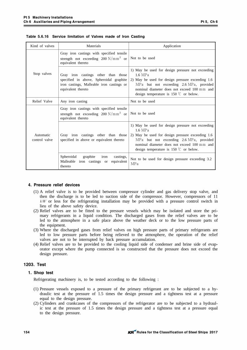
Pt 5 Machinery Installations
Ch 6 Auxiliaries and Piping Arrangement Pt 5, Ch 6
154 Rules for the Classification of Steel Ships 2017
Kind of valves Materials Application
Stop valves
Gray iron castings with specified tensile
strength not exceeding 200 Nmm or equivalent thereto
Not to be used
Gray iron castings other than those specified in above, Spheroidal graphite iron castings, Malleable iron castings or equivalent thereto
1) May be used for design pressure not exceeding 1.6 MPa
2) May be used for design pressure exceeding 1.6MPa but not exceeding 2.6 MPa, provided nominal diameter does not exceed 100 mm and design temperature is 150 ℃ or below.
Relief Valve Any iron casting Not to be used
Automaticcontrol valve
Gray iron castings with specified tensile
strength not exceeding 200 Nmm or equivalent thereto
Not to be used
Gray iron castings other than those specified in above or equivalent thereto
1) May be used for design pressure not exceeding 1.6 MPa
2) May be used for design pressure exceeding 1.6MPa but not exceeding 2.6 MPa, provided nominal diameter does not exceed 100 mm and design temperature is 150 ℃ or below.
Spheroidal graphite iron castings, Malleable iron castings or equivalent thereto
Not to be used for design pressure exceeding 3.2MPa
Table 5.6.16 Service limitation of Valves made of Iron Casting
4. Pressure relief devices
(1) A relief valve is to be provided between compressor cylinder and gas delivery stop valve, and then the discharge is to be led to suction side of the compressor. However, compressors of 11 or less for the refrigerating installation may be provided with a pressure control switch in lieu of the above safety device.
(2) Relief valves are to be fitted to the pressure vessels which may be isolated and store the pri-mary refrigerants in a liquid condition. The discharged gases from the relief valves are to be led to the atmosphere in a safe place above the weather deck or to the low pressure parts of the equipment.
(3) Where the discharged gases from relief valves on high pressure parts of primary refrigerants are led to low pressure parts before being relieved to the atmosphere, the operation of the relief valves are not to be interrupted by back pressure accumulation.
(4) Relief valves are to be provided to the cooling liquid side of condenser and brine side of evap-orator except where the pump connected is so constructed that the pressure does not exceed the design pressure.
1203. Test
1. Shop test
Refrigerating machinery is, to be tested according to the following :
(1) Pressure vessels exposed to a pressure of the primary refrigerant are to be subjected to a hy-draulic test at the pressure of 1.5 times the design pressure and a tightness test at a pressure equal to the design pressure.
(2) Cylinders and crankcases of the compressors of the refrigerator are to be subjected to a hydraul-ic test at the pressure of 1.5 times the design pressure and a tightness test at a pressure equal to the design pressure.

Pt 5 Machinery Installations
Ch 6 Auxiliaries and Piping Arrangement Pt 5, Ch 6
Rules for the Classification of Steel Ships 2017 155
2. Test after installation on board
The piping systems which are exposed to a pressure of the primary refrigerant are, after installed on board, to be subjected to a leak test at the pressure of 90 % of the design pressure.
Section 13 Hydraulic System (2017)
1301. General
1. Application(1) Hydraulic system is to be applied in following equipments - Windlass, Winch, Deck crane,
Bow thruster, Side thruster, Stabilizer, Open-closed devices for valves (associated with sea bal-last, cargo pipes)& etc., watertight, hatch cover and gangway. The other equipments where deemed necessary by the Society are to be reviewed at that time.
(2) In addition to the requirements in this section, the relevant requirements in Pt 8, Ch 2, Sec 1 are to be complied with.
(3) For powered riven steering gears, the relevant requirements in Ch 7 are to be complied with.
1302. System design
(1) Hydraulic pipings are to be separate from other piping system except lubricating oil systems. (2) Hydraulic unit having working pressure above 1.5 MPa and having potential of oil leakage com-
ing contact with hot surfaces, electrical installations or other sources of ignition, is to preferably be placed in separate spaces. If it is impracticable to locate such units in a separate space, ad-equate shielding is to be provided.
(3) Relief valves are to be fitted to protect the system from overpressure. Setting pressure of it is not to be less than the design pressure of it and relieving capacity is not to be less than full pump flow with a maximum pressure rise in the system of not more than 10% of the relief valve setting.
1303. Hydraulic oil storage tanks
(1) Hydraulic oil tanks are not to be situated where spillage or leakage therefrom can constitute a hazard by falling on heated surfaces in excess of 220℃.
(2) For air vent and sounding device of hydraulic oil tanks, Sec 2 are to be complied with.
1304. Tests and inspections
1. Valves and pipe fittings
(1) Valves, pipes, and fittings belonging to Class I or Class II are to be hydraulically tested at the pressure of 1.5 times relief valve setting pressure, and that pressure is to be punched, by the manufacturer. However, test pressure need not be more than design pressure plus 7MPa.
2. Hydraulic pump, motor & cylinder
(1) The pressure side of hydraulic pump, motor & cylinder to be hydraulically tested at the pres-sure of 1.5 times relief valve setting pressure, and that pressure is to be punched, by the manufacturer. However, test pressure need not be more than design pressure plus 7MPa.
3. Testing of piping systems on board
(1) Verify that no leakage is found in operation condition of devices, operation of various safety devices and use of piping arrangements after installed on board.
Pt 5 Machinery Installations
Ch 6 Auxiliaries and Piping Arrangement Pt 5, Ch 6
156 Rules for the Classification of Steel Ships 2017
Section 14 Tests and Inspections
1401. Tests of auxiliary machinery
1. Hydrostatic Tests
(1) The pressure receiving portions of the essential auxiliary are to be tested to a hydrostatic pres-sure of 1.5 times the design pressure after having been machine-finished, except where otherwise specified. The test pressure, however, is not to be less than 0.2 MPa. 【See Guidance】
(2) The compressor cylinders and crankcases of the refrigerating machinery subject to the require-ments in Sec 12 are to be tested to hydrostatic pressure of 1.5 times the pressure specified in Pt 9, Ch 1, 102. 5, respectively and additionally be subjected to tightness tests for the pressure respectively stipulated in the same Article.
2. Capacity Tests
(1) Capacity tests of auxiliary machinery required to check capacity such as pumps, air com-pressors, blowers and fans etc. are to be carried out at design condition (rated speed and pres-sure head, viscosity, etc.). However, for the auxiliary machinery designed the same as an auxil-iary machinery approved by the Society and having satisfactory in-service experience, consid-eration may be given to waiving the capacity test.
1402. Hydrostatic tests of valves and pipe fittings 【See Guidance】
1. Valves and pipe fittings belonging to Class I and Class II piping are to be subjected to a hydro-static test at the pressure of 1.5 times the design pressure. However, the hydrostatic test may be omitted according to the discretion of the Society.
2. Ship-side valves and cocks fitted at the ship side below the load waterline are to be subjected to a hydrostatic test at the pressure of 0.5 MPa.
1403. Hydrostatic tests of fuel tanks
Fuel oil tanks with their fittings which do not form part of ship's structure are, after having been constructed, to be tested to a hydrostatic pressure corresponding to a head of water not less than 2.5 m above the top plates. 【See Guidance】
1404. Tests on workmanship of pipes 【See Guidance】
1. Welding procedure qualification tests
The manufacturers are to submit the detailed data in connection with the welding work for exami-nation by the Society and also to conduct the welding procedure qualification test specified by the Society where they plan to joint pipes to pipes, pipes to valves or pipes to fittings belonging to Class I and Class II piping system by welding for the first time, or where they adopt a new weld-ing method, and where they change quality of base metals, grade of welding materials or type of joint. But, for minor changes in the welding process, the test may be omitted complying with the requiremets in Pt 2, Ch 2 407. of the Rules, where approved by the Society.
2. Non-destructive tests
(1) For butt welded joints of Class I pipes with a nominal diameter exceeding 65A, fully radio-graphic examination is to be carried out.
(2) For butt welded joints of Class I pipes with a nominal diameter not exceeding 65A and of Class II pipes with a nominal diameter exceeding 90A, at least 10 spot radiography examina-tion is to be carried out.
(3) More stringent requirements may be applied at the Society's discretion depending on the kinds of materials, welding procedure and controls during the fabrication. An approved ultrasonic test-ing procedure may be accepted, at the Society's discretion, in lieu of radiography testing when the conditions are such that a comparable level of weld quality is assured.
(4) Fillet welds of flange pipe connections are to be examined by the magnetic particle method or by other appropriate non-destructive methods, in case of Class I pipes. In other cases, magnetic
Pt 5 Machinery Installations
Ch 6 Auxiliaries and Piping Arrangement Pt 5, Ch 6
Rules for the Classification of Steel Ships 2017 157
particle examination or equivalent non-destructive testing may be required at the discretion of the Surveyor.
(5) The Society may require other particular testing considering welding procedures or properties of welding consumables.
(6) Radiographic examination methods are to comply with the requirements in Ch 5, 404. 3 to 5.(7) Radiographic and ultrasonic examination are to be performed with an appropriate technique by
trained operators. At the request of the Society, complete details of the radiographic and ultra-sonic technique are to be submitted for approval.
(8) Magnetic particle examination is to be performed with suitable equipment and procedures, and with a magnetic flux output sufficient for defect detection. The equipment is to be required to be checked using standard samples.
3. Hydrostatic tests
(1) All Class I and II pipes and all steam pipes, feed water pipes, compressed air pipes and fuel oil pipes having a design pressure greater than 0.35 MPa are to be subjected to hydrostatic tests together with the welded fittings, after completion of manufacture but before insulation or coat-ing, at a pressure of 1.5 times the design pressure. However, where joints between pipes and valves are welded on board, the hydrostatic test may be omitted provided non-destructive tests deemed appropriate by the Society are carried out.
(2) For steel pipes and intergral fittings having a design temperatures above 300 °C, the test pres-sure() is to be determined by the following formula but need not exceed 2 times the design pressure.
MPa
where:
= Allowable stress at 100 °C (Nmm) = Allowable stress at the design temperature (Nmm) = Design pressure (MPa)
The test pressure may be reduced to 1.5 times the design pressure, in order to avoid excessive stress in way of bends, T-pieces, etc.
(3) In any case the membrane stress is not to exceed 90 % of the specified yield stress at the test-ing temperature.
(4) When, for technical reasons, it is not possible to carry out complete hydro-testing before assem-bly on board, for all sections of piping, proposals are to be submitted for approval to the Society for testing the closing lengths of piping, particularly in respect to the closing seams.
(5) The hydrostatic test of piping referred in (1) may be carried out after installation on board. In this case, the test is to be carried out together with the welded fittings at a pressure described in (1) or (2) after completion of manufacture but before insulation or coating and this test may be carried out in conjunction with the test required under 1405.
(6) Pressure testing of small bore pipes (outside diameter less than 15 mm ) may be waived at the discretion of the Society depending on the application.
1405. Tests of piping systems on board
1. Piping systems are, after installation on board, to be tested in accordance with the fol-lowing requirements.
(1) All piping systems specified in this Chapter are to be tested for effectiveness together with ma-chinery under the working conditions and checked for leakage.
(2) Fuel oil piping systems and heating coil in tanks are to be tested by hydrostatic pressure not less than 1.5 times the design pressure but in no case less than 0.4 MPa. 【See Guidance】

Pt 5 Machinery Installations
Ch 7 Steering Gears Pt 5, Ch 7
Rules for the Classification of Steel Ships 2017 159
CHAPTER 7 STEERING GEARS
Section 1 General
101. Application 【See Guidance】
1. The requirements in this Chapter apply to powered riven steering gears. For small ships, however, the requirements in 102., 103., 105., 301. 3 and 409. may be modified.
2. Manual steering gears are to be of the construction approved by the Society, and to be tested and examined to the satisfaction of the Society.
102. Terminology
1. The terms used in this Chapter are defined as follows:(1) Main steering gear is the machinery such as rudder actuators, steering gear power units, if
any, and ancillary equipment and the means of applying torque to the rudder stock (e.g. tiller) necessary for effecting movement of the rudder for the purpose of steering the ship under nor-mal service conditions.
(2) Auxiliary steering gear is the equipment other than any part of the main steering gear neces-sary to steer the ship in the event of failure of the main steering gear but not including the tiller or components serving the same purpose (hereinafter referred to as "tiller, etc.").
(3) Steering gear power unit (hereinafter referred to as "power unit") is:(A) in the case of electric gear, an electric motor and its associated electrical equipment; 【See Guidance】
(B) in the case of electro-hydraulic steering gear, a hydraulic pump, electric motor and its asso-ciated electrical equipment; and
(C) in the case of hydraulic steering gear other than those in (B), a hydraulic pump and its driving engine.
(4) Power actuating system is the hydraulic equipment provided for supplying power to turn the rudder stock, comprising a power unit or units, together with the associated hydraulic pipes and fittings, and a rudder actuator. The power actuating system may share common mechanical com-ponents, i.e., tiller, etc.
(5) Rudder actuator is the component which converts directly hydraulic pressure into mechanical action to move the rudder.
(6) Control system is the equipment by which orders are transmitted from the navigating bridge to the power units. Steering gear control systems comprise transmitters, receivers, hydraulic con-trol pumps and their associated motors, motor controllers, piping and cables.
103. Plans and documents
1. Plans and documents to be submitted are as follows:(1) Plans
(A) General arrangements of steering gear(B) Details of tiller, etc.(C) Assembly and details of power units(D) Assembly and details of rudder actuators(E) Piping diagram of hydraulic pipes; Arrangements of control systems(F) Diagram of hydraulic and electrical systems (including alarm devices and automatic steering
gear)(G) Arrangements and diagram of an alternative source of power(H) Diagram of a rudder angle indicator
(2) Documents(A) Particulars(B) Calculation sheet of the strength of essential parts(C) Operating instructions (including plans showing the change-over procedure for power units
and control systems, plans showing the sequence of automatic supply of power from an al-

Pt 5 Machinery Installations
Ch 7 Steering Gears Pt 5, Ch 7
160 Rules for the Classification of Steel Ships 2017
ternative source of power; and the type, particulars and an assembly of the power source in the case that the alternative source of power is an independent source of power) 【See Guidance】
(D) Manuals for countermeasures to be taken at the time of a single failure of the power ac-tuating system.
104. Display of operating instructions
1. Simple operating instructions with a block diagram showing the change-over procedures for power units and control systems are to be displayed on the navigating bridge and in the steering gear compartment of a ship equipped with power-operated steering gears.
2. Where the system failure alarms according to 301. 4 are provided, instructions for emergency pro-cedures when the alarm is activated, are to be displayed on the navigating bridge. 【See Guidance】
105. Related requirements
1. The strength of the pressure vessels such as accumulators, etc. used in power actuating systems is to comply with the relevant requirements in Ch 5 in addition to this Chapter.
2. Hydraulic piping systems used in the power actuating systems are to comply with the relevant re-quirements in Ch 6 in addition to this Chapter.
3. Electrical equipment for steering gear are to comply with the relevant requirements in Pt 6, Ch 1 in addition to this Chapter.
Section 2 Performance and Arrangement
201. Number of steering gears
1. Unless expressly provided otherwise, every ship is to be provided with a main steering gear and an auxiliary steering gear. The main steering gear and the auxiliary steering gear are to be so arranged that the failure of one of them will not render the other one inoperative. 【See Guidance】
2. Where the main steering gear comprises two or more identical power units, the auxiliary steering gear need not be fitted provided that:(1) The main steering gear is capable of operating the rudder as required 202. (1) while operating
with all power units. In a passenger ship, the main steering gear is capable of operating the rudder as required by 202. (1) while any one of the power units is out of operation;
(2) The main steering gear is so arranged that after a single failure in its piping system or in one of the power units the defect can be isolated so that steering capability can be maintained or speedily regained. Steering gears other than of the hydraulic type will be considered by the Society in each case.
202. Performance of main steering gear 【See Guidance】
1. The main steering gear is to be capable of putting the rudder over from 35 degrees on one side to 35 degrees on the other side with the ship at its load draught and running ahead at the speed specified in Pt 3, Ch 1, 120. and, under the same conditions, from 35 degrees on either side to 30degrees on the other side in not more than 28 seconds.
2. The main steering gear is to be operated by power where necessary to meet the requirements in 1. and in any case when the diameter of upper rudder stock is required in Pt 4, Ch 1 to be over 120 mm (excluding the additional for strengthening for navigation in ice, the same being referred hereinafter).
3. The main steering gear is to be so designed that they will not be damaged at maximum astern speed. However, this design requirement need not be provided by trials at maximum astern speed and maximum rudder angle.

Pt 5 Machinery Installations
Ch 7 Steering Gears Pt 5, Ch 7
Rules for the Classification of Steel Ships 2017 161
203. Performance of auxiliary steering gear 【See Guidance】
1. The auxiliary steering gear is to be capable of putting the rudder over from 15 degrees on one side to 15 degrees on the other side in not more than 60 seconds with the ship at its load draught and running ahead at one half of the speed specified in Pt 3, Ch 1, 120. or 7 knots, whichever is the greater, and capable of being brought speedily into action in an emergency.
2. The auxiliary steering gear is to be operated by power where necessary to meet the requirement in 1. and in any case when the diameter of upper rudder stock is required in Pt 4, Ch 1 to be over 230 mm .
204. Piping
1. The hydraulic piping system is to be arranged so that transfer between power units can be readily effected.
2. Suitable arrangements to maintain the cleanliness of the hydraulic fluid are to be provided taking into consideration the type and design of the power actuating system.
3. Arrangements for bleeding air from the power actuating system are to be provided where necessary.
4. Relief valves are to be fitted to any part of the hydraulic system which can be isolated and in which pressure can be generated from the power source or from external forces. The setting pres-sure of the relief valves is not to be less than 1.25 times the maximum working pressure but not to exceed the design pressure. The minimum discharge capacity of the relief valves are not to be less than total capacity of pumps which provide power for the actuator, increased by 10 %. Under such conditions the rise in pressure is not to exceed 10 % of the setting pressure. In this regard, due consideration is to be given to the extreme foreseen ambient conditions in respect of oil viscosity.
5. A low level alarm is to be provided for each hydraulic fluid reservoir to give the earliest practi-cable indication of hydraulic fluid leakage. This alarm is to be audible and visual and to be given on the navigating bridge and at a position from which the main engine is manually controlled. 【See Guidance】
6. A fixed storage tank having sufficient capacity to recharge at least one power actuating system in-cluding the reservoir is to be provided, where the main steering gear is operated by hydraulic power. The storage tank is to be permanently connected by piping in such a manner that the hy-draulic system, can be readily recharged from a position within the steering gear compartment and is to be provided with a contents gauge. 【See Guidance】
7. Where the steering gear is so arranged that more than one system (either power or control) can be simultaneously operated, the risk of hydraulic locking caused by single failure is to be considered.
205. Re-start and power-failure alarm of power units
1. Main and auxiliary steering gear power units are to be :(1) arranged to re-start automatically when power is restored after a power failure and(2) capable of being brought into operation on the navigation bridge. In the event of a power fail-
ure to any one of the power units, an audible and visual alarm is to be given on the navigat-ing bridge.
206. Alternative source of power 【See Guidance】
1. Where the diameter of upper rudder stock is required in Pt 4, Ch. 1 to be over 230 mm , an al-ternative source of power supply to steering gears is to be provided in accordance with the follow-ing:(1) The alternative source of power is to be either:
(A) emergency source of electric power; or(B) independent source of power located in the steering gear compartment and used only for
this purpose.(2) The alternative source of power is to be capable of automatically supplying, within 45 seconds,

Pt 5 Machinery Installations
Ch 7 Steering Gears Pt 5, Ch 7
162 Rules for the Classification of Steel Ships 2017
alternative power to the power unit and its associated control system and the rudder angle indicator. In every ship of 10,000 gross tonnage and upwards, the alternative source of power is to have a capacity for at least 30 m inutes of continuous operation of the steering gear and in any other ship for at least 10 minutes.
(3) Steering gears operated by the alternative power supply are to be capable of operating the rud-der as required by 203.
(4) The automatic starting arrangement for the generator or the prime mover of the pump used as the independent source of power specified in (1) (B) is to comply with the requirements for starting device and performance in Pt 6, Ch 1, 203, 6.
207. Electrical installations for electric and electro-hydraulic steering gear 【See Guidance】
1. Cables used in power circuits required to be installed in duplicate by this Chapter are to be sepa-rated as far as practicable throughout the length.
2. Means for indicating that the power units are running are to be installed on the navigating bridge and at the position from which the main engine is normally controlled.
3. Each electric or electro-hydraulic steering gear comprising one or more power units is to be served by at least two exclusive circuit fed directly from the main switchboard. However, one of the cir-cuits may be supplied through the emergency switchboard.
4. An auxiliary electric or electro-hydraulic steering gear associated with a main electric or elec-tro-hydraulic steering gear may be connected to one of the circuits supplying this main steering gear. The circuits are to have adequate rating for supplying all motors which can be simultaneously connected to them and may be required to operate simultaneously.
5. Short circuit protection and overload alarm are to be provided for such circuits and motors. The overload alarm is to be both audible and visual and to be situated in a conspicuous position in the place from which the main engine is normally controlled.
6. Protection against excess current including starting current, if provided, is to be for not less than twice the load current of the motor or circuit so protected, and to be arranged to permit the pas-sage of the appropriate starting currents.
7. Where a three-phase supply is used an alarm is to be provided that will indicate failure of any one of the supply phases. The alarm is to be both audible and visual and to be situated in a con-spicuous position in the place from which the main engine is normally controlled.
8. When in a ship of less than 1,600 gross tonnage an auxiliary steering gear which is required by 203. to be operated by power is not electrically powered or is powered by an electric motor pri-marily intended for other services, the main steering gear may be fed by one circuit from the main switchboard. Where such an electric motor primarily intended for other services is arranged to pow-er such an auxiliary steering gear, the requirements in Pars 5 to 7 may be waived by the Society if satisfied with the protection arrangement together with the requirements in 205. and 301. 1 (3) applicable to auxiliary steering gear.
208. Position of steering gears
1. The steering gear is to be installed in an enclosed compartment readily accessible and, as far as possible, separated from machinery spaces.
2. The steering gear compartment is to be provided with suitable arrangements to ensure working ac-cess to steering gear machinery and controls. These arrangements are to include handrails and gra-tings or other non-slip surfaces to ensure suitable working conditions in the event of hydraulic fluid leakage.
209. Means of communication
A means of communication is to be provided between the navigating bridge and the steering gear compartment. 【See Guidance】

Pt 5 Machinery Installations
Ch 7 Steering Gears Pt 5, Ch 7
Rules for the Classification of Steel Ships 2017 163
210. Rudder angle indicator
1. The angular position of rudder is to be indicated in the navigating bridge. The rudder angle in-dicator is to be independent of the control system.
2. The angular position of rudder is to be recognizable in the steering gear compartment.
Section 3 Controls
301. General 【See Guidance】
1. Steering gear control is to be provided:
(1) for the main steering gear, both on the navigating bridge and in the steering gear compartment;(2) where the main steering gear is arranged in accordance with the requirements in 201. 2. by
two independent control systems, both operable from the navigating bridge. This does not re-quire duplication of the steering wheel or steering lever. Where the control system consists of a hydraulic telemotor, a second independent system need not be fitted.
(3) for the auxiliary steering gear, in the steering gear compartment and, if power operated, it is al-so to be operable from the navigating bridge and to be independent of the control system for main steering gear.
2. Any main and auxiliary steering gear control system operable from the navigating bridge is to com-ply with the following: (2017)(1) If electric, it is to be served by its own separate circuit supplied from a steering gear power
circuit from a point within the steering gear compartment, or directly from switchboard busbars supplying that steering gear power circuit at a point on the switchboard adjacent to the supply to the steering gear power circuit.
(2) Means are to be provided in the steering gear compartment for disconnecting any control system operable from the navigating bridge from the steering gear it serves.
(3) The system is to be capable of being brought into operation from a position on the navigating bridge.
(4) Short circuit protection only is to be provided for steering gear control supply circuits.
3. Cables and pipes of control systems required to be in duplicate by this Chapter are to be separated as far as practicable throughout their length.
4. For the steering gears which are so arranged that more than one system (either power or control) can be simultaneously operated, where hydraulic locking, caused by a single failure, may lead to loss of steering, an audible and visual alarm, which identifies the failed system, is to be provided on navigation bridge.
302. Failure detection and response of all types of steering control systems (2017)
1. Failure detection
(1) The most probable failures that may cause reduced or erroneous system performance are to be automatically detected and at least the following failure scenarios are to be considered:(A) Power supply failure(B) Earth fault on AC and DC circuits(C) Loop failures in closed loop systems, both command and feedback loops (normally short cir-
cuit, broken connections and earth faults)(D) Data communication errors(E) Programmable system failures (Hardware and software failures)(F) Hydraulic locking(G) Deviation between rudder order and feedback. Deviation alarm is to be initiated if the rud-
der’s actual position does not reach the set point within acceptable time limits for the closed loop control systems (e.g. follow-up control and autopilot). Deviation alarm may be caused by mechanical, hydraulic or electrical failures.

Pt 5 Machinery Installations
Ch 7 Steering Gears Pt 5, Ch 7
164 Rules for the Classification of Steel Ships 2017
(2) All failures detected are to initiate audible and individual visual alarm on the navigation bridge.2. System response upon failure
The failures (as defined but not limited to those in 1. (1)) likely to cause uncontrolled movements of rudder are to be clearly identified. In the event of detection of such failure, the rudder is to stop in the current position. Alternatively the rudder can be set to return to the midship/neutral po-sition in the event of a failure.
303. Change-over from automatic to manual steering
The steering gears of a ship provided with an automatic pilot are to be capable of immediate change-over from automatic to manual steering. 【See Guidance】
Section 4 Materials, Constructions and Strength
401. Materials
1. Materials used in the steering gears are to be sound, flawless and adequate for their service conditions.
2. Materials used for cylinders and housings of rudder actuators, pipings subjected to a hydraulic pres-sure and all components transmitting mechanical forces to the rudder stock are to be of steel or other approved ductile material, comply with the requirements in Pt 2, Ch 1. In general such ma-terials are not to have a minimum elongation of less than 12 nor a specified minimum tensile strength in excess of 650 Nmm. This does not apply to the materials for valves and bolts where approved by the Society.
3. Materials used for bolts for assembling split type tillers and bolts for securing the vanes to the bosses of rotary vane type rudder actuators are to be forged steels or rolled steels comply with the requirements in Pt 2, Ch 1.
4. Materials used for major parts other than those mentioned in Pars 2 to 3 are to comply with the requirements in recognized standards. 【See Guidance】
5. Materials other than those mentioned in Pars 2 to 4 may be used where approved by the Society.
402. Welds
1. All welded joints of the parts of power actuating systems are to be such that there are no in-complete penetration and other injurious defects.
2. Welded joints in parts subjected to the internal pressure of the power actuating system are to have sufficient strength.
403. General construction of steering gear
1. The steering gears are to be of sufficient strength and reliability.
2. Configurations of major parts of the steering gear are to be determined to avoid local concentration of stress.
3. The design pressure for calculations to determine the scantlings of piping and other steering gear components subjected to internal hydraulic pressure is to be at least 1.25 times the maximum work-ing pressure to be expected under the operational conditions specified in 202. 1 taking into account any pressure which may exist in the low pressure side of the system. The design pressure is not to be less than the relief valve setting pressure.

Pt 5 Machinery Installations
Ch 7 Steering Gears Pt 5, Ch 7
Rules for the Classification of Steel Ships 2017 165
4. Special consideration is to be given to the suitability of any essential component which is not duplicated. Any such essential component is, where appropriate, to utilize anti-friction bearings such as ball bearings, roller bearings or sleeve bearings which are to be permanently lubricated or pro-vided with lubrication fittings.
5. Where considered necessary, fatigue analysis is to be carried out to the piping and components, taking into account pulsating pressure due to dynamic loads. Both the cases of high cycle and cu-mulative fatigue are to be considered.
404. Strength of rudder actuators
1. Strength of all components of rudder actuators subjected to an internal pressure, except for the al-lowable stress specified in this Chapter, is to comply with relevant requirements in Ch 5.
2. In the strength calculations specified in Par 1, the allowable stress for the equivalent primary gen-eral membrane stress is not to be greater than the following values (1) or (2), whichever is the smaller:
(1)
(2)
where: = Specified minimum tensile strength of the material (Nmm) = Specified minimum yield stress or 0.2 proof stress of the material (Nmm), = As given in the following Table 5.7.1.
Steel Cast steel Nodular cast iron
3.5 4 5
1.7 2 3
Table 5.7.1 Constants of and
405. Oil seals in rudder actuators
1. Oil seals between non-moving parts, forming part of the external pressure boundary, are to be of the metal upon metal type or of an equivalent type.
2. Oil seals between moving parts, forming part of the external pressure boundary, are to be dupli-cated, so that the failure of one seal does not render the actuator inoperative. Alternative arrange-ments providing equivalent protection against leakage will be accepted where approved by the Society.
406. Flexible pipes
Flexible hose assemblies specified in Ch 6, 102. 5 are to be used in piping systems where flexi-bility is required.
407. Tillers etc.
1. The scantlings of tillers, etc. of forged steels or cast steels which transfer power from the rudder actuator to the rudder stock, are to be so determined as the bending stress is not exceeding 118/ (Nmm) and the shearing stress is not exceeding 68/ (Nmm) when the rudder torque is applied.

Pt 5 Machinery Installations
Ch 7 Steering Gears Pt 5, Ch 7
166 Rules for the Classification of Steel Ships 2017
where :
: Rudder torque specified in Pt 4, Ch 1, Sec 3. (N-m)
: Material coefficient of the tiller, specified in Pt 4, Ch 1, 102. 1.
2. Notwithstanding the requirement specified in Par 1, the scantlings of rapson-slide type or trunk pis-ton type tillers may be determined according to the following. 【See Guidance】
(1) The vertical section of each side of tiller boss at the center line of rudder stock is to comply with the following formula ;
≥
≥
where :
: Outer diameter of boss (mm)
: Inner diameter of boss (mm)
: Depth of boss (mm)
and : Refer to Par 1.
(2) The section modulus of arm about the vertical axis is to be not less than that obtained from the following formula ;
(mm)
where :
: Distance from the center of rudder stock to the section (mm).
: Length of tiller arm measured from the center of rudder stock to the point of applica-
tion of the driving force (mm). In case where the length varies in accordance with
rudder angle, is the maximum length within 35 degrees of rudder angle.
and : Refer to Par 1.
(3) The sectional area of arm at its outer end is to be not smaller than that obtained from the following formula ;
(mm)
where :
: Length of tiller arm measured from the center of rudder stock to the point of applica-
tion of the driving force (mm). In case where the length varies in accordance with
rudder angle, is the length at 0 degrees of rudder angle.
and : Refer to Par 1.
(4) In case of tiller having two arms, where power units are connected to each arm and these two power units are driven simultaneously, the scantlings of arms may be suitably reduced from those required in (2) and (3).
3. Notwithstanding the requirement specified in Par 1, the scantlings of rotary vane type rudder actua-tor of forged steels or cast steels may be determined according to the following requirements, in addition to the requirements specified in 404.(1) Scantlings of the boss are to comply with the requirement specified in 2 (1). However, is
material coefficient of boss of the rotary vane type rudder actuator, specified in Pt 4, Ch 1, 102. 1.

Pt 5 Machinery Installations
Ch 7 Steering Gears Pt 5, Ch 7
Rules for the Classification of Steel Ships 2017 167
(2) The section modulus about the vertical axis and the sectional area of vane is to be not less than that obtained from the following formula; 【See Guidance】
(mm)
(mm)
where :
: Outer diameter of boss (mm)
: Breadth of vane measured from outer surface of boss (mm)
: Number of vanes
: Refer to Par 1.
: Material coefficient of the tiller, specified in Pt 4, Ch 1, 102. 1.
4. Tillers, etc. are to be coupled, using a key, to the rudder stock firmly by shrinkage fitting, force fitting or bolted method. However, tillers, etc. may be coupled without a key, in the case where the fitting methods which are acceptable to the Society are used. 【See Guidance】
5. Where bosses of tiller which are separated to two pieces are bolted, there are to be at least two bolts on each side of the head. Required diameter of the bolts at the bottom of threads is not to be less than that obtained from the following formula. In such a case, the thickness of coupling flange is not to be less than three-fourths of the diameter of the bolts.
(mm)
where :
: Refer to Par 1.
: Material coefficient of the bolts, specified in Pt 4, Ch 1, 102. 1.
: Number of bolts on each side of the head.
: Distance from the center of rudder stock to the center of bolt (cm).
6. Scantlings of tiller, etc. of nodular graphite cast iron are to be determined so as not to be applied with bending stress exceeding 94/ (Nmm) and shearing stresses exceeding 54/ (Nmm) under the rudder torque applied. Alternatively, the scantlings may be determined according to the re-quirements specified in Par 2 or 3, using 1.2 times the rudder torque for calculating.
408. Stoppers
1. Tillers are to be provided with the suitable stopping arrangement to restrict the rudder movement. This arrangement may be an integral part of the rudder actuator.
2. Steering gears are to be provided with positive arrangements, such as limit switches, for stopping the gear before the rudder stops are reached. These arrangements are to be synchronized with the gear itself and not with the steering gear control. These arrangements, however, may be operated through a mechanical links such as a floating levers.
3. Suitable brake arrangements are to be provided to tillers to keep the rudder steady in the event of an emergency. In the case of hydraulic steering gear, where the rudder can be stopped safely by closing the oil pressure valves, this brake arrangement will not be required.

Pt 5 Machinery Installations
Ch 7 Steering Gears Pt 5, Ch 7
168 Rules for the Classification of Steel Ships 2017
409. Buffers
Steering gears other than of hydraulic type are to be provided with spring buffers or other suitable buffer arrangements to relieve the gear from shocks given by the rudder. 【See Guidance】
Section 5 Testing
501. Shop tests
1. Pressure vessels and piping systems are to be subjected to tests in accordance with the require-ments in Ch 5 and 6, in addition to the tests specified in this Section.
2. All pressure parts are to be subjected to pressure tests with a pressure equal to 1.5 times the de-sign pressure.
3. Each type of pumps used as a power unit is to be subjected to a running test for a duration of not less than 100 hours. The test arrangements are to be such that the pump may run in idle con-dition, and at maximum delivery capacity at maximum working pressure. The passage from one condition to another is to occur at least as quickly as on board. During the test, idling periods are to be alternated with periods at maximum delivery capacity at maximum working pressure. During the whole test no abnormal heating, excessive vibration or other irregularities are permitted. After the test, the pump is to be disassembled to ascertain that there is no abnormality. The test may be waived for a power unit which has been proved to be reliable in marine service.
502. Testing after installation
1. Hydraulic piping systems are after installed on board to be subjected to a leak test at a pressure at least equal to the maximum working pressure.
2. The steering gear is after installed on board to be subjected to the running test.
503. Sea trials
1. The steering gears are to be subjected to the following tests during sea trials. However, the tests required in (4), (7) and (8) may be carried out at the time when a vessel is being anchored or at dockside.(1) Tests on the steering capabilities specified in 202. and 203. For controllable pitch propellers,
the propeller pitch is to be at the maximum design pitch approved for number of maximum continuous ahead revolution at the main steering gear trial.Where it is impractical to demonstrate compliance with this requirement during sea trials with the ship at its full load draught and running ahead at the speed corresponding to the number of maximum continuous revolutions of the main engine and maximum design pitch(for the auxiliary steering gear, running ahead at one half of the speed corresponding to the number of maximum continuous revolutions of the main engine and maximum design pitch or 7 knots, whichever is greater), it may demonstrate compliance with this requirement by one of the following methods. (2017) 【See Guidance】
(A) During sea trials the ship is at even keel and the rudder fully submerged whilst running ahead at the speed corresponding to the number of maximum continuous revolutions of the main engine and maximum design pitch(for the auxiliary steering gear, running ahead at one half of the speed corresponding to the number of maximum continuous revolutions of the main engine and maximum design pitch or 7 knots, whichever is greater); or
(B) Where full rudder immersion during sea trials cannot be achieved, an appropriate ahead speed shall be calculated using the submerged rudder blade area in the proposed sea trial loading condition. The calculated ahead speed shall result in a force and torque applied to the main steering gear which is at least as great as if it was being tested with the ship at its full load draught and running ahead at the speed corresponding to the number of max-imum continuous revolutions of the main engine and maximum design pitch(for the auxiliary steering gear, running ahead at one half of the speed corresponding to the number of max-

Pt 5 Machinery Installations
Ch 7 Steering Gears Pt 5, Ch 7
Rules for the Classification of Steel Ships 2017 169
imum continuous revolutions of the main engine and maximum design pitch or 7 knots, whichever is greater); or
(C) The rudder force and torque at the sea trial loading condition have been reliably predicted and extrapolated to the full load condition. 【See Guidance】
(2) Running tests of the power units, including transfer between power units.(3) Tests on the isolation of one power actuating system, checking the time for regaining steering
capability.(4) Tests on the hydraulic fluid recharging system.(5) Tests on the emergency power supply required by 206.(6) the steering gear controls, including transfer of control and local control(7) Tests on the means of communication between the navigating bridge and the steering gear
compartment.(8) Tests on the functioning of indicators for the alarms, rudder angle indicator and power units.(9) Where the steering gear is designed to avoid hydraulic locking, this feature is to be
demonstrated. 【See Guidance】
Section 6 Additional Requirements Concerning Tankers of 10,000Gross Tonnage and Upwards and Other Ships of 70,000
Gross Tonnage and Upwards
601. Main steering gears
1. In every oil tanker, ships carrying liquefied gases or dangerous chemicals in bulk (hereinafter re-ferred to as "tankers" in this Section) of 10,000 gross tonnage and upwards and in every other ship of 70,000 gross tonnage and upwards, the main steering gear is to comprise two or more equivalent power units complying with the requirements in 201. 2.
2. The steering gear in every tanker of 10,000 gross tonnage and upwards is to comply with the fol-lowing:(1) The main steering gear is to be so arranged that in the event of loss of steering capability due
to a single failure in any part of one of the power actuating system of the main steering gear, excluding failure in the tiller, etc. and seizure in the rudder actuator, steering capability is to be regained in not more than 45 seconds after the loss of one power actuating system.
(2) The main steering gear is to comprise either:(A) Two independent and separate power actuating systems, each capable of meeting the re-
quirements in 202. 1; or(B) at least two equivalent power actuating systems which, acting simultaneously in normal op-
eration, are to be capable of meeting the requirements in 202. 1. In this case, the following requirements of (a) and (b) are also to be met:(a) Loss of hydraulic fluid from one system is to be capable of being detected and the de-
fective system automatically isolated so that the other actuating system or systems are to remain fully operational.
(b) Where necessary to obtain steering capability, interconnection of hydraulic power actuat-ing systems is to be provided.
(3) Steering gears other than of the hydraulic type will be considered by the Society in each case.
602. Controls
In the case of tankers of 10,000 gross tonnage or upwards, the modification for the hydraulic tele-motor permitted in 301. 1 (2) is not to be applied.
603. Number and strength of rudder actuators
1. For tankers of 10,000 gross tonnage and upwards, but of less than 100,000 tons deadweight, a sin-gle rudder actuator may be permitted provided that:(1) Following loss of steering capability due to a single failure of any part of the piping system or
in one of the power units, steering capability is to be regained within 45 seconds;

Pt 5 Machinery Installations
Ch 7 Steering Gears Pt 5, Ch 7
170 Rules for the Classification of Steel Ships 2017
(2) Special consideration is to be given to stress analysis for the design including fatigue analysis and fracture mechanics analysis, as appropriate, to the material used, to the installation of seal-ing arrangements and to testing and inspection and to the provision of effective maintenance. In this case, the high cycle fatigue and cumulative fatigue are to be considered.
(3) Isolating valves are to be directly mounted on the rudder actuator so as to isolate the rudder actuator from the hydraulic oil in the piping systems; and
(4) Relief valves for protecting the rudder actuator against overpressure as required in 204. 4 are to be provided.
2. For tankers of 10,000 gross tonnage and upwards, but less than 100,000 tons deadweight and equipped with a single rudder actuator, the strength of the rudder actuator is to comply with the following requirements in addition to those of 404.(1) A detailed calculation of the major parts of the rudder actuator is to be carried out to confirm
their strength.(2) A detailed stress analysis of the parts of rudder actuators subject to hydraulic pressure is to be
carried out to confirm the strength sufficient to withstand the design pressure.(3) Where considered necessary because of the design complexity or manufacturing procedures, a fa-
tigue analysis and fracture mechanics analysis are to be carried out. In this case, the high cycle fatigue and cumulative fatigue are to be considered. In connection with these analyses, all fore-seen dynamic loads are to be taken into account. Where considered necessary by the Society, experimental stress analysis may be required in addition to, or in lieu of, theoretical calculations.
(4) For the purpose of determining the general scantlings of parts of rudder actuators subject to in-ternal hydraulic pressure, the allowable stresses are to comply with:
≤ ≤ ≤ ≤ ≤
where: = Equivalent primary general membrane stress (Nmm) = Equivalent primary local membrane stress (Nmm) = Equivalent primary bending stress (Nmm) = Lesser of or
= Specified minimum tensile strength of material (Nmm) = Specified minimum yield stress of 0.2 % proof stress of material (Nmm), = As given in the following Table
Rolled or forged steel Cast steel Nodular cast iron
4 4.6 5.8
2 2.3 3.5
(5) Where the parts of rudder actuators subject to hydraulic pressure are subjected to a burst test at the minimum bursting pressure specified below and they are confirmed to withstand this test, the detailed stress analysis required by (2) may be omitted. Where, however, considered neces-sary because of the design complexity or manufacturing procedures, the detailed stress analysis required by (2) is to be carried out notwithstanding the above.
×
MPa

Pt 5 Machinery Installations
Ch 7 Steering Gears Pt 5, Ch 7
Rules for the Classification of Steel Ships 2017 171
where:
= Minimum bursting pressure (MPa)
= Design pressure (MPa)
= As given in (4)
= Actual tensile strength of the material (Nmm) = Specified minimum tensile strength of the material (Nmm)
604. Non-destructive tests
For tankers of 10,000 gross tonnage and upwards, but less than 100,000 tons deadweight and equip-ped with a single rudder actuator, the rudder actuator is to be subjected to suitable and complete non-destructive testing to detect both surface flaw and volumetric flaws. The procedure and accept-ance criteria for the non-destructive testing will be considered by the Society in each case. Where considered necessary, fracture mechanics analysis is to be used for determining maximum allowable flaw size. 【See Guidance】

Pt 5 Machinery Installations
Ch 8 Windlasses and Mooring Winches Pt 5, Ch 8
Rules for the Classification of Steel Ships 2017 173
CHAPTER 8 WINDLASSES AND MOORING WINCHES
Section 1 General
101. Application
1. The requirements in this Chapter apply to electric driven, steam reciprocating engine driven or hy-draulic driven windlasses and mooring winches. The requirements of windlasses and mooring winch-es manually operated as the main driving power are to be to the satisfaction of the Society. 【See Guidance】
2. In addition to complying with the requirements in this Chapter, those are to be applied with appro-priate modifications respectively such as follows: For power transmission gears, Ch 3; For pressure vessels and hydraulic pumps, Ch 5; For piping arrangements, Ch 6.
102. Materials
1. Materials used in the major parts of windlasses and mooring winches are to be of steel forgings, steel castings or equivalent thereto which meet Korean Industrial standards or equivalent. (2017) 【See Guidance】
2. However, materials of shafts and gears of windlasses which transmit a power not less than 100 kW are to comply with requirements in Pt 2, Ch 1 of Rules. (2017)
Section 2 Windlasses
201. Definitions
1. The working load, derived from the nominal diameter and the grade of anchor chain cables, is the tensile force exerted upon the cable lifter in the tangential direction when the anchor and anchor chain cable are being hoisted.
2. The overload pull is the necessary temporary overload capacity of the windlass, and to be not less than 1.5 times the working load.
3. The holding load is the maximum static load on the anchor chain cables which the cable lifter brake should withstand.
4. Nominal speed is the average speed of recovery of 55 m (two lengths) of anchor chain cables when 82.5 m (three lengths) of the cables are submerged and freely suspended at commencement of lifting.
5. The breaking test load of the anchor chain cables is the minimum breaking test load specified in Pt 4, Table 4.8.8.
202. Plans and documents
1. Plans and documents to be submitted are as follows:(1) Plans
(A) General arrangement(B) Sectional drawings(C) Diagram of steam and hydraulic systems(D) Diagram of electric systems and arrangement of control systems(E) Detail drawings of gears and driving shafts of power transmission gears
(2) Documents(A) Particulars for major parts(B) Particulars for material of power transmission parts(C) Calculation sheet for the strength of major parts

Pt 5 Machinery Installations
Ch 8 Windlasses and Mooring Winches Pt 5, Ch 8
174 Rules for the Classification of Steel Ships 2017
203. Design, construction and equipment
1. Type of drive
The drive of windlasses with two cable lifters is to be of the type capable of hauling up both an-chors simultaneously.
2. Strength
(1) The parts for the windlass proper such as the bedplate, cable lifter, cable lifter shaft, bearing frame, brake gear, holding down bolt, etc. are to have such strength that the stress on these parts is below the yield points of the materials when sustaining the holding load on the cable lifter specified in Table 5.8.1.
(2) The driving section of windlass is to have such strength that the stress on each part is below 40 % of the yield points of the materials used when the working load specified 204. 1. is applied.
Division of chain cable stopper Holding load
with chain cable stopper B.T.L×0.45
without chain cable stopper B.T.L×0.8
NOTES: B.T.L. : Breaking test load of anchor chain cable
Table 5.8.1
3. Construction and equipment
(1) Construction(A) The windlasses are to be so designed as to ensure smooth operation of the components in
consideration of impact such as waves. The closed portions of the windlass installed on ex-posed decks are to have suitable watertight construction.
(B) The cable lifters are to be provided with 5 teeth at minimum, and the revolution speed of the anchor chain cable lifter is to be controllable.
(2) Equipment(A) Protective devices and safety devices
Prime movers and gearing are to be provided with protective devices and safety devices against excessive torque and shock as follows;(a) Overpressure preventive devices for hydraulic equipment(b) Slipping clutches between electric motor and reduction gear(c) Protective devices for the electric motor against overload(d) Covers for open gear
(B) ClutchesWindlasses are to be fitted with clutches between the cable lifter and the driving shaft. Power operated clutches are to be declutchable by hand.
(C) Brake systems(a) Electric windlasses are to be provided with an automatic control brake system which
operates when the control handle is in the "Off" position or when the power supply is cut off. The automatic breaking system is to be capable of sustaining 130 of the working load.
(b) Each cable lifter is to be fitted with a hand-brake system, which may be remotely con-trolled, capable of applying a brake torque sufficient to maintain a load equal to the holding load specified in 201. 3.
(D) Emergency stop mechanismEach remotely controlled windlass is to be fitted with a quick acting local emergency stop mechanism.

Pt 5 Machinery Installations
Ch 8 Windlasses and Mooring Winches Pt 5, Ch 8
Rules for the Classification of Steel Ships 2017 175
204. Performance
1. Windlasses are to be capable of lifting anchor and anchor chain at a nominal speed of at least 0.15 ms.
2. The windlasses are to be capable of continuous operation for a period of 30 minutes under the working load specified in Table 5.8.2 and be capable of operating under the overload for a period of 2 minutes at a correspondingly reduced lifting speed.
Kind of chain cable Working load (N)
Grade 1 chain 37.5
Grade 2 chain 42.5
Grade 3 chain 47.5
NOTES :1. is the diameter of chain cable (mm ).2. Studless chain cables are to be to the satisfaction of the Society.
Table 5.8.2 Working Load
205. Tests and Inspections 【See Guidance】
1. Windlasses are to be carried out following tests after construction, which are in accordance with the procedures as deemed appropriate by the Society.(1) No load test(2) Load test(3) Brake test
Section 3 Mooring Winches
301. Relevant requirements
1. The relevant requirements such as the design, etc. for mooring winch are to comply with (KS V) ISO 3730 or other recognized standards which deemed appropriate by the Society.
302. Test and inspections
1. Mooring winches are to be subjected to the following tests after their installation on board :(1) Running test
The winch is to be run for 10 m inutes at no load speed, 5 m inutes continuously in each direction.
(2) BearingsBearing temperature rises shall be checked.

2017
Guidance Relating to the Rules for the Classification of Steel Ships
Part 5
Machinery Installations
GA-05-E KR

APPLICATION OF THE GUIDANCE
This "Guidance relating to the Rules for the Classification of Steel Ships" (hereafter called as the Guidance) is prepared with the intent of giving guidelines as to the treatment of the various provisions for items required the unified interpretations and items not specified in details in the Rules, and the requirements specified in the Guidance are to be ap-plied, in principle, in addition to the various provisions in the Rules.As to any technical modifications which can be regarded as equivalent to any requirements in the Guidance, their flexible application will be prop-erly considered.

- i -
APPLICATION OF PART 5 "MACHINERY INSTALLATIONS"
1. Unless expressly specified otherwise, the requirements in the Guidance apply to ships for which
contracts for construction are signed on or after 1 July 2017.
2. The amendments to the Guidance for 2016 edition and their effective date are as follows;
Effective Date 1 July 2016 (related Circular No. : 2016-7-E)
CHAPTER 3 PROPULSION SHAFTING AND POWER TRANSMISSION SYSTEMS
Section 4 Power Transmission Systems
- 406. has been amended.
Effective Date 1 July 2016 (date of application for certification, related Circular No. : 2016-7-E)
CHAPTER 1 GENERAL
Section 3 Tests and Inspections
- 301. 3 has been amended, 2 and 4 have been newly added.
CHAPTER 2 MAIN AND AUXILIARY ENGINES
Section 2 Internal Combustion Engines
- 211. 2 has been amended. (exemption of the manufacturer approval)
Effective Date : 11 July 2016 (based on the application date for survey, related Circular
No.: 2016-10-E)
<ANNEX>
Annex 5-11 Redundant propulsion and steering system
- 1 (2) (E), (F), (I) and (J) have been newly added.
- 1 (3) has been amended.
- 2 (1) (B) has been amended.
- 2 (1) (E) to (J) have been newly added.
- Fig 1 has been amended.
- 4 has been amended.

- ii -
Effective Date 1 January 2017 (related Circular No. : 2016-15-E)
CHAPTER 2 MAIN AND AUXILIARY ENGINES
Section 2 Internal Combustion Engines
- 211. 2 has been amended. (the manufacturer approval of engine manufacturer)
CHAPTER 3 PROPULSION SHAFTING AND POWER TRANSMISSION SYSTEMS
Section 2 Shaftings
- 202. 1 has been newly added.
- 203. 3 has been newly added.
CHAPTER 4 TORSIONAL VIBRATION OF SHAFTINGS
Section 2 Allowable Limit of Vibration Stresses
- 202. 2 has been newly added.
CHAPTER 7 STEERING GEARS
Section 5 Testing
- 503. 2 has been newly added.
Effective Date 1 January 2017 (date of the application for approval, related Circular No. :
2016-15-E)
CHAPTER 3 PROPULSION SHAFTING AND POWER TRANSMISSION SYSTEMS
Section 4 Power Transmission Systems
- 401. 2 has been amended.
Effective Date 1 July 2017
CHAPTER 1 GENERAL
Section 1 General
- 102.2.(1) has been amended.
Section 2 Plans and Documents
- 202. 2 has been amended.

- iii -
Section 4 Spare Parts and Tools
- 401. 1 and 2 have been amended.
- 402. has been amended.
- 405. 406. 407. have been deleted. (moved to 402.)
- Table 5.1.1 ~ 5.1.6 have been newly added.
CHAPTER 2 MAIN AND AUXILIARY ENGINES
Section 1 General
- 101. 1 has been amended.
Section 2 Internal Combustion Engines
- 211. 3 has been amended.
CHAPTER 3 PROPULSION SHAFTING AND POWER TRANSMISSION SYSTEMS
Section 3 Propellers
- 302. has been amended.
CHAPTER 5 BOILERS AND PRESSURE VESSELS
Section 3 Pressure Vessels
- 313. has been amended.
CHAPTER 6 AUXILIARIES AND PIPING ARRANGEMENT
Section 1 General
- 102.2(2). has been amended.
- 102.3(1). has been amended.
Section 2 Air Pipes, Overflow Pipes and Sounding Devices
- Fig.5.6.3 has been amended.
- 201.4 has been amended.
Section 3 Sea inlet and Overboard Discharge
- 301.1 has been amended.
Section 6 Steam and Exhaust Gas Piping
- 602.3 has been amended.
Section 14 Tests and Inspections
- Section number has been changed according to Section 13 Hydraulic System
newly added.
CHAPTER 7 STEERING GEARS
Section 2 Performance and Arrangement

- iv -
- 201. 3 has been amended and 4 has been newly added.
- 207. 3 has been newly added.
Section 3 Controls
- 301. 3 has been deleted.
CHAPTER 8 WINDLASSES AND MOORING WINCHES
Section 1 General
- 102. 1 has been amended.
<ANNEX>
Annex 5-5 Requirements of Equipment for Gas welding
- 4 (3) has been amended.
Annex 5-6 Plastic Piping System
- 3 (1) has been amended.
Annex 5-10 Selective Catalytic Reduction System Using Ammonia Solutions or Urea
Solutions as the Reductant Agents
- 2 & 6 have been amended.
Annex 5-11 Redundant Propulsion and Steering System
- 3 (1) (A) has been amended.
Annex 5-14 Shaft Alignment
- Annex 5-14 has been established.
Annex 5-15 Exhaust Gas Cleaning System
- Annex 5-15 has been established.

- v -
CONTENTS
CHAPTER 1 GENERAL ·····································································································1
Section 1 General ················································································································· 1
101. Application ···················································································································· 1
102. Definitions ····················································································································· 2
103. Construction, materials and installation ······································································· 3
106. Communication between Navigating Bridge and Machinery Space ························· 3
108. Ventilating systems in machinery spaces ································································· 3
Section 2 Plans and Documents ······················································································ 3
202. Plans and documents to be submitted by the shipyard ············································ 3
203. Plans and documents to be submitted by the manufacturers of internal combustion
engines ·························································································································· 4
204. Plans and documents to be submitted by the manufacturers of steam turbines ····· 4
208. Plans and documents to be submitted by the manufacturers of boilers, Class 1
and 2 pressure vessels ································································································· 5
210. Plans and documents to be submitted by the manufacturers of essential
auxiliaries ······················································································································ 5
Section 3 Tests and Inspections ······················································································ 6
301. Shop trials ····················································································································· 6
Section 4 Spare Parts and Tools ····················································································· 6
401. Application ···················································································································· 6
402. Description and Number of spare parts ····································································· 6
CHAPTER 2 MAIN AND AUXILIARY ENGINES ····················································11
Section 1 General ··············································································································· 11
101. Application ·················································································································· 11
Section 2 Internal Combustion Engines ········································································ 11
202. Construction and installation ······················································································ 11
203. Safety devices ············································································································· 12
204. Crank shafts ················································································································ 13
205. Dimensions of crank arms ························································································· 14
206. Material consideration ································································································ 15
208. Special consideration ·································································································· 15
211. Tests and inspections ································································································· 18
Section 3 Steam Turbines ································································································ 25
304. Safety devices ············································································································· 25
306. Strength and sectional area of turbine blades ·························································· 25
307. Tests and inspections ································································································· 25

- vi -
CHAPTER 3 PROPULSION SHAFTING AND POWER TRANSMISSION
SYSTEMS ···································································································27
Section 1 General ··············································································································· 27
101. Welded structure component ······················································································ 27
102. Other propulsion and maneuvering machinery ························································· 27
Section 2 Shafting ··············································································································· 27
201. Application ·················································································································· 27
203. Intermediate shaft and thrust shaft ············································································ 27
204. Propeller shaft and stern tube shaft ·········································································· 27
206. Stern tube bearing and sealing devices ···································································· 30
207. Shaft coupling and coupling bolts ············································································ 31
Section 3 Propellers ··········································································································· 34
301. Application ·················································································································· 34
302. Materials ······················································································································ 34
303. Thickness of blades ···································································································· 34
304. Blade fixing of built-up type or controllable pitch propeller ······························· 35
305. Fitting of propeller ····································································································· 37
307. Tests and inspections ································································································· 39
Section 4 Power Transmission Systems ······································································ 40
401. General ························································································································ 40
402. General construction of gearing ·············································································· 40
403. Allowable tangential load for gears ·········································································· 40
406. Shaft couplings ··········································································································· 40
407. Tests and inspections ································································································· 40
CHAPTER 4 TORSIONAL VIBRATION OF SHAFTING ·······································43
Section 2 Allowable Limit of Vibration Stresses ························································ 43
201. Crankshafts ·················································································································· 43
202. Intermediate shafts, thrust shafts, propeller shafts and stern tube shafts ··············· 43
203. Shafting system of generators ··················································································· 45
205. Detailed evaluation for strength ················································································ 45
CHAPTER 5 BOILERS AND PRESSURE VESSELS ············································47
Section 1 Boilers ················································································································· 47
101. Applications ················································································································· 47
102. Materials ······················································································································ 47
111. Flat plates or tube plates with stay or other supports ··········································· 47
114. Manholes, mud holes and peep holes ······································································ 48
116. Flues, furnaces, ogee rings and cross tubes ···························································· 48
117. Stays, stay tubes and girders ···················································································· 48
124. Construction and tests of safety valves ···································································· 49
129. Water level indicator ·································································································· 49

- vii -
136. Tests and inspections ································································································· 49
Section 2 Thermal Oil Heaters ························································································ 49
203. Safety devices for thermal oil heaters directly heated by the exhaust gas of
engines ······················································································································ 49
Section 3 Pressure Vessels ····························································································· 49
302. Classification ··············································································································· 49
303. Materials ······················································································································ 50
307. Allowable stress ·········································································································· 50
308. General construction and strength ············································································· 50
310. Flat end plates or tube plates without stay or other supports ······························· 51
313. Manholes, mud holes and peep holes ······································································ 52
319. Tests and inspections ································································································· 52
Section 4 Welding for Boilers and Pressure Vessels ··············································· 52
401. General ························································································································ 52
403. Heat treatment ············································································································ 52
404. Radiographic examination ·························································································· 52
405. Welding workmanship approval tests for boilers and Class 1 pressure vessels ··· 52
CHAPTER 6 AUXILIARIES AND PIPING ARRANGEMENT ·······························55
Section 1 General ··············································································································· 55
101. General ························································································································ 55
102. Pipes ···························································································································· 55
103. Valves and fittings ····································································································· 57
104. Type of connection ···································································································· 59
105. Welding of pipes and pipe fittings ··········································································· 60
106. Post weld heat treatment ··························································································· 60
107. General requirements for piping arrangement ·························································· 60
Section 2 Air Pipes, Overflow Pipes and Sounding Devices ································· 62
201. Air pipes ····················································································································· 62
202. Overflow pipes ··········································································································· 63
203. Sounding devices ········································································································ 63
Section 3 Sea Inlet and Overboard Discharge ··························································· 65
301. Ship-side valves and fittings ····················································································· 65
303. Scuppers and sanitary discharge ················································································ 65
Section 4 Bilge and Ballast System ·············································································· 66
401. General ························································································································ 66
402. Drainage of compartment other than machinery spaces ·········································· 67
404. Size of bilge suction pipes ························································································ 68
405. Bilge pumps ················································································································ 69
406. Pipe systems and their fittings ·················································································· 70
Section 5 Feed Water and Condensate System for Boiler ···································· 70

- viii -
501. Feed water pumps ······································································································ 70
502. Feed water piping ······································································································ 70
Section 6 Steam and Exhaust Gas Piping ·································································· 71
601. Steam piping ··············································································································· 71
602. Exhaust gas piping ····································································································· 71
Section 7 Cooling System ································································································ 72
702. Stand-by cooling water pumps ·················································································· 72
703. Sea inlets ···················································································································· 72
704. Strainers ······················································································································· 72
Section 8 Lubricating Oil System ··················································································· 73
802. Lubricating oil pumps ································································································ 73
803. Piping ·························································································································· 73
804. Lubricating oil filters and purifiers ··········································································· 73
Section 9 Fuel Oil System ······························································································· 73
901. General ························································································································ 73
902. Burning systems for boiler ························································································ 76
903. Fuel oil supply system of internal combustion engines ·········································· 77
Section 10 Thermal Oil System ······················································································ 77
1003. Pumps for thermal oil system ················································································· 77
Section 11 Compressed Air System ·············································································· 77
1101. Compressed air starting devices ·············································································· 77
1102. Construction and safety devices ·············································································· 78
Section 12 Refrigerating Machinery ·············································································· 83
1201. General ······················································································································ 83
Section 14 Tests and Inspections ················································································ 85
1401. Tests of auxiliary machinery ··················································································· 85
1402. Hydrostatic tests of valves and pipe fittings ························································· 86
1403. Hydrostatic tests of fuel tanks ················································································ 86
1404. Tests on workmanship of pipes ·············································································· 86
1405. Tests of piping system on board ············································································ 86
CHAPTER 7 STEERING GEARS ·················································································89
Section 1 General ··············································································································· 89
101. Application ·················································································································· 89
102. Terminology ················································································································ 89
103. Drawings and documents ··························································································· 89
104. Display of operating instructions ············································································· 89
Section 2 Performance and Arrangement ···································································· 89
201. Number of steering gears ·························································································· 89
202. Performances of main steering gear ········································································· 90

- ix -
203. Performances of auxiliary steering gear ··································································· 90
204. Piping ·························································································································· 90
206. Alternative source of power ······················································································ 90
207. Electric installations for electric and electro-hydraulic steering gear ····················· 91
209. Means of communication ··························································································· 91
Section 3 Controls ··············································································································· 91
301. General ························································································································ 91
303. Change over from automatic to manual steering ····················································· 94
Section 4 Materials, Constructions and Strength ······················································· 94
401. Materials ······················································································································ 94
407. Tillers, etc. ·················································································································· 94
409. Buffers ························································································································· 94
Section 5 Testing ················································································································ 95
503. Sea trials ····················································································································· 95
Section 6 Additional Requirements Concerning Tankers of 10,000 Gross
Tonnage and Upwards and Other Ships of 70,000 Gross Tonnage
and Upwards ····································································································· 96
604. Non-destructive tests ··································································································· 96
CHAPTER 8 WINDLASSES AND MOORING WINCHES ·····································97
Section 1 General ··············································································································· 97
101. Application ·················································································································· 97
102. Materials ······················································································································ 97
Section 2 Windlasses ········································································································· 97
205. Tests and Inspections ································································································· 97
<ANNEX>
Annex 5-1 Requirements for the Water-jet Propulsion Systems and Azimuth or
Rotatable Thrusters ························································································ 99
Annex 5-2 Guidance for Calculation of Crankshaft Stress (1) ··································· 113
Annex 5-3 Guidance for Calculation of Crankshaft Stress (2) ··································· 116
Annex 5-4 Strength Calculation for Gears of Power Transmission Systems ············· 137
Annex 5-5 Requirements of Equipment for Gas welding ··········································· 153
Annex 5-6 Plastic Piping System ·················································································· 155
Annex 5-7 Control and Safety System for Dual Fuel Diesel Engines ······················ 162
Annex 5-8 The Additional Requirements on Electronically-Controlled Diesel
Engines ········································································································· 165
Annex 5-9 Flexible Pipes ······························································································· 168
Annex 5-10 Selective Catalytic Reduction System Using Ammonia Solutions or
Urea Solutions as the Reductant Agents ··················································· 170
Annex 5-11 Redundant Propulsion and Steering System ··············································· 178
Annex 5-12 Documents for the Approval of Diesel Engines ······································· 184

- x -
Annex 5-13 Exhaust Gas Recirculation System ····························································· 195
Annex 5-14 Shaft Alignment ··························································································· 203
Annex 5-15 Exhaust Gas Cleaning System ···································································· 206

Pt 5 Machinery Installations
Ch 1 General Pt 5, Ch 1
Guidance Relating to the Rules for the Classification of Steel Ships 2017 1
CHAPTER 1 GENERAL
Section 1 General
101. Application
1. In application to 101. 1 of the Rules, where redundant propulsion systems and steering systems are installed, the requirements in Annex 5-11 may be applied additionally.
2. In application to 101. 2 of the Rules, the term “considered acceptable by the Society” means that permits to use the machinery installation which are deemed to be equivalent in accordance with Pt 1, Ch 1, 104. of the Guidance, in case that determined the application of any specific require-ments of this Rules unreasonable or unnecessary.
3. In application to 101. 3 of the Rules, the thrusters may be in accordance with the following;(1) Thrusters
(A) ApplicationThese requirements apply to the thrusters and their control units (hereinafter called "thrusters").
(B) Plans and documentsBefore the work is commenced, the manufacturers are to submit the following plans and documents in triplicate to the Society for approval.(a) General arrangement of thruster(b) Sectional assembly (including materials of principal component)(c) Controlling diagrams(d) Shaft arrangement and sealing devices(e) Propeller(f) Power transmission gear arrangement(g) Piping arrangement(h) Main particulars (kind of prime mover, output, number of revolution, capacity, etc. are
to be stated)(i) Plans and documents considered necessary by the Society
(C) MaterialsThe materials used in the principal component, in principle, are to be complied with the re-quirements of Pt 2, Ch 1 of the Rules. However, the Society may accept to be used of the materials which comply with Korean Industrial Standard or standard considered as equivalent thereto.
(D) Shop tests(a) The test requirements of shafting, propellers and power transmission gears are to be ap-
plied appropriate modifications respectively such as follows;For shafting, Ch 3, Sec 2 of the Rules; For propellers, Ch 3, Sec 3 of the Rules;For power transmission gears Ch 3, Sec 4 of the Rules.
(b) The hydraulic tests for hydraulically pressurised parts of equipment and piping systems are to be in accordance with the requirements of Ch 6 of the Rules. However, theses shop tests may be substituted for the tests carried out by the manufacturer.
(c) The test requirements of piping system are to be applied appropriate modifications of Ch 6 of the Rules.
(d) The requirements of electrical installations are to be applied appropriate modifications of Pt 6, Ch 1 of the Rules.
(E) On board testsThe performance test and the safety device test for thruster are to be carried out.

Pt 5 Machinery Installations
Ch 1 General Pt 5, Ch 1
2 Guidance Relating to the Rules for the Classification of Steel Ships 2017
102. Definitions
1. The essential auxiliaries given in 102. 5 of the Rules are as follows;(1) Auxiliary machinery essential for main propulsion
(A) For ships equipped with an internal combustion engine as main engine(a) For cooling water system
Jacket cooling water pumps, piston cooling water (oil) pumps, fuel valve cooling water (oil) pumps, turbo-charger cooling water pumps, cooler cooling water pumps, generator engine cooling water (oil) pumps, air compressor cooling water pumps, cooling pumps for fuel oil
(b) For fuel oil systemFuel oil supply (booster) pumps, fuel oil transfer pumps
(c) For lubricating oil system Lubricating oil pumps, cam shaft lubricating oil pumps, turbo-charger lubricating oil pumps, reduction gear lubricating oil pumps
(d) Hydraulic oil pumps (a pump to supply hydraulic oil to the hydraulic circuit for driving or controlling the equipment having relevance to main propulsion)ex) a controllable pitch propeller hydraulic oil pump
(e) Air compressors (excluding air compressor for emergency use)(f) For auxiliary boilers
Feed water pumps, boiler water circulating pumps, exhaust gas economizer feed water pumps, draught fans for boiler, burner units
(g) Other Auxiliary blowers for main engine
(h) Other auxiliary machinery as deemed essential by the Society(B) For ships equipped with a steam turbine as main engine
(a) For feed water, condensed water and drain system Feed water pumps, condensate water pumps and drain pumps
(b) For cooling water systemCirculating water pumps
(c) For fuel oil systemBurning pumps, fuel oil transfer pumps, fuel oil service pumps
(d) For lubricating oil system Lubricating oil pumps
(e) Hydraulic oil pumps (a pump to supply hydraulic oil to the hydraulic circuit for driving or controlling the equipment having relevance to main propulsion)ex) a controllable pitch propeller oil pump
(f) OthersVacuum pumps for condenser, gland steam exhaust fans, boiler draught fans, fresh water generators, control air compressors
(g) Other auxiliary machinery as deemed essential by the Society(2) Auxiliary machinery for the safety of life and ship
(A) PumpsBilge pumps, ballast pumps, fire pumps (including fire pump for emergency use, fixed fire extinguishing system and associated system), eductors provided instead of bilge pump
(B) For the maneuvering of shipSteering gears, thrusters, stabilizers
(C) Deck machineryWindlasses
(D) Ventilating fans (installed in hazardous area due to flammable gases or gases harmful to the health such as cargo oil pump room of oil tanker, etc.), ventilating fans for cargo oil tank of oil tankers
(E) Machinery for gas free, machinery for inert gas system (including nitrogen generator system)(F) Other auxiliary machineries as deemed essential by the Society
(3) Auxiliary machinery having relevance to specific service of ships(A) Cargo handling machinery subject to Pt 9, Ch 2 of the Rules
Hydraulic pump for cargo handling machinery(B) Auxiliary machineries for oil tankers, ships carrying liquefied gases in bulk, ships carrying
dangerous chemicals in bulk

Pt 5 Machinery Installations
Ch 1 General Pt 5, Ch 1
Guidance Relating to the Rules for the Classification of Steel Ships 2017 3
Cargo pumps, stripping pumps, tank cleaning pumps, gas compressors, pumps for gas cool-ing system, gas refrigerating compressors
(C) Refrigerating machineryCompressors, liquid pump and condenser cooling pumps used for cargo refrigerating machi-nery (including items subject to Pt 9, Ch 1 of the Rules)
(D) Other auxiliary machineries as deemed essential by the Society2. Pipe fittings given in 102. 22 of the Rules mean the following;
(1) Pipe connection units(A) Pipe flanges and pipe pieces(elbow, reducer, tee, bend, socket, etc.), etc.(B) Mechanical joints (2017)
(2) Fittings installed on a piping arrangement (strainers, separators, flow meters, viscosity meters, etc.)
103. Construction, materials and installation
In application to 103. 7 of the Rules, where insulation for surfaces of machinery installations e.g. turbo blowers, etc, is difficult, consideration will be given to the discretion of the Society.
106. Communication between Navigating Bridge and Machinery Space
The telegraph is required in any case, even if the remote control of the engine is foreseen, irre-spective of the fact that the engine room is attended or not.
108. Ventilating systems in machinery spaces
1. In application to 108. 2 of the Rules, where due to ship size and arrangement the requirements are not practicable, lesser heights for ventilator coamings may be accepted on condition that the requirements of following (1) and (2) are satisfied with:(1) Ventilation systems are to be fitted with weathertight closing appliances in accordance with Pt 4. Ch 4. 406. of the Rules.
(2) Other suitable arrangements to ensure an uninterrupted, adequate supply of ventilation to these space are to be provided.
Section 2 Plans and Documents
202. Plans and documents to be submitted by the shipyard
1. Plans for approval
(1) The following are to be stated in the various piping diagrams for the purpose of reviewing to be satisfied with the requirements of Pt 5, Ch 6 of the Rules.(A) Material, nominal diameter or outside diameter, thickness and design pressure of pipes(B) Kind, material and nominal diameter or outside diameter of valves, cocks and pipe fittings(C) Kind, particular, capacity, etc. of auxiliaries and their prime mover(D) Total capacity of tanks(E) Design temperature of superheaters, if provided
(2) Type, capacity, kind, and output of essential auxiliaries and their prime mover and related equipment are to be stated in the machinery particulars.
(3) The following are to be stated on drawings of scupper piping arrangement;(A) Designed load line(B) Line of 0.01 and 0.02 above the designed load line(C) Line of 600 mm above the designed load line(D) Line of 450 mm below the free-board deck
(4) In application to 202. 1 (5) of the Rules, following may be applied.(A) In case of fuel oil tanks not more than 1 m (0.5 m in case of ships subject to SOLAS),
submission of the plans for the tanks may be omitted.(B) Where the shipyards are submitted the manufacturing practice for tanks and the manufactur-
ing practice are approved by the Society, the manufacturing practice may be considered as

Pt 5 Machinery Installations
Ch 1 General Pt 5, Ch 1
4 Guidance Relating to the Rules for the Classification of Steel Ships 2017
the details of the tanks.2. In application to 202. 2 (5) of the Rules, where considered necessary by the Society and the re-
quirements for shaft alignment are to comply with Annex 5-14. (2017)
203. Plans and documents to be submitted by the manufacturers of internal combustion engines
1. In application to 203. 1, the plans and documents to be submitted for reference of all type of en-gines intended to be installed for the first time on the ship which is going to be registered by the Society, are as follows ;(1) Plans
. General arrangement (the length, width, height and weight are to be entered)
. Cylinder cover, cylinder liner, cylinder block, piston crown, piston skirt, guide ring
. Piston pin
. Frame and intermediate frame
. Scavenging air chamber installed below cylinder block
. Camshaft drive
. Cam and cam shaft assembly
. Fuel oil pump
. Valve driving mechanism
. Diagram of engine control
. Tie rod (including coupling and set-screw)
. Main bearing bolt and cylinder cover fixing bolt (including valve box fixing bolt)
. Construction and arrangement of relief valve for cylinder
. Construction and arrangement of bracing of the engine
. Construction and arrangement of damper and detuner
. Construction and arrangement of balancer or compensator
. Flywheel (in case of a power transmission component)
. Other construction and arrangement as deemed necessary by the Society(2) Documents
. Operation and service manual of engine (including inspection and maintenance instruction)
. Review sheets on bracing, balancing and prevention of vibration of the engine (including cal-culation sheets)
. Data for vibration of engine (construction and arrangement of dampers, detuners, balancers or compensators, and data regarding calculations for torsional(see Ch 4, Sec 1 of the Rules) and axial vibration of shafting)
(A) Whenever the manufacturers propose modification of construction, particulars or materials, the reasons of modification, and the associated plans and documents are to be submitted by the manufacturer.
(B) Where the particulars, list and application for omission of plans and document for approval are submitted, the submission of plans and documents same as the approved engine type may be omitted. The list is to include the subject of approved plans and documents relation to the components and units specified in 203. Table 5.1.4 and Table 5.1.5 of the Rules, and 203. of the Guidance, engine serial number, name of shipyard and hull number.
2. In application to 203. Table 5.1.5 and Table 5.1.6 of the Rules, the special sheet required by the Society is given in Annex 5-12, Table 1.
204. Plans and documents to be submitted by the manufacturers of steam turbines
1. The various piping diagrams given in 204. 2 of the Rules are to include the piping diagrams of steam, lubricating oil, drain, and are to be stated materials, dimension and working pressure for pipes belonging to Class I or II according to requirements of Pt 5, Ch 6 of the Rules.
2. Whenever the manufacturers propose modification of construction, particulars or materials, the rea-sons of modification and the associated plans and documents are to be submitted by the manufacturer.
3. The plans and documents to be submitted for reference of all type of steam turbine intended to be installed for the first time on the ship which is going to be registered by the Society, are as fol-lows;

Pt 5 Machinery Installations
Ch 1 General Pt 5, Ch 1
Guidance Relating to the Rules for the Classification of Steel Ships 2017 5
(1) Plans given in 204. 1 of the Rules(2) Documents given in 204. 2 of the Rules, steam condition at every stage at the continuous max-
imum output, natural frequencies of blade and nozzle (whichever calculated values or measured values), and operation and service manual of stem turbine
4. Where the application for omission of plans and document for approval are submitted according to the requirements of 203. 1 (2) (B) of the Guidance, the submission of those same as the plans and documents for approved type of steam turbine may be omitted.
208. Plans and documents to be submitted by the manufacturers of boilers, Class 1 and 2 pressure vessels
1. The submission of plans and documents for approval of air inter-cooler of internal combustion en-gines may be waived.
2. Operation instructions specified in 208. 2. (3) of the Rules is to be include following items. (1) Feed water treatment and sampling arrangements(2) Operating temperatures(exhaust gas and feed water temperatures)(3) Operating pressure(4) Inspection and cleaning procedures(5) Records of maintenance and inspection(6) The need to maintain adequate water flow through the economizer under all operating conditions(7) Periodical operational checks of the safety devices to be carried out by the operating personnel
and to be documented accordingly(8) Procedures for using the exhaust gas economizer in the dry condition(9) Procedures for maintenance and overhaul of safety valves
210. Plans and documents to be submitted by the manufacturers of essential auxiliaries
1. In application to 210. of the Rules, the essential auxiliaries required approval of the Society are following;(1) Air compressors (except air compressor for emergency use)(2) Fresh water generators (in case of ships equipped with main boiler)(3) Pumps (in case where the output of prime mover is not less than 100 kW)(4) Draught fans for boiler and auxiliary blowers for main engine (in case where the output of
prime mover is not less than 100 kW)(5) Draught fans installed in cargo oil pump room and cargo space of tankers intended to carry oils
having a flash point not exceeding 60 °C.(6) Auxiliaries for maneuvering (steering gears, side thrusters, stabilizers, etc.)(7) Deck auxiliaries (windlasses)(8) Cargo handling machinery subject to Pt 9, Ch 2 of the Rules (9) Auxiliary machinery for oil tankers, ships carrying liquefied gases in bulk, and ships carrying
dangerous chemicals in bulk (Cargo pumps, stripping pumps, tank cleaning pumps, gas com-pressors, pumps for gas cooling system, gas refrigerating compressors)
(10) Refrigerating machinery (excluding refrigerating machinery having both R 22, R 134a, R 404A , R 407C , R 410A and R 507A as primary refrigerant and prime mover with output of 7.5 kW or less)

Pt 5 Machinery Installations
Ch 1 General Pt 5, Ch 1
6 Guidance Relating to the Rules for the Classification of Steel Ships 2017
Section 3 Tests and Inspections
301. Shop trials
1. In application to 301. 1 of the Rules, auxiliary to be inspected means only the essential auxiliaries. For the items of tests and inspections not specified in the Rules or Guidance, consideration will be given to the discretion of the Society.
2. In case that the manufacturer has an approval of quality assurance system or KR certificate (KRC) after testing in the presence of surveyor, the manufacturer approval in accordance with 301. 2 of the Rules may be dispensed. (2017)
3. In application to 301. 2 of the Rules, if the manufacturer who intend to issue Work's certificate (W) does not have the manufacturer approval in accordance with Ch 6 of Guidance for Approval of Manufacturing Process and Type Approval, Etc. and also not have the exemption in ac-cordance with 2, the manufacturer is to carry out tests and inspections in the presence of the Surveyor. In this case, KR Certificate (KRC) is issued by the Society. (2017)
4. In application to 301. 2 of the Rules, A Work’s Certificate (W) may be considered equivalent to a Society Certificate under the following cases. (2017)(1) The test was witnessed by the Society Surveyor, or(2) An quality assurance system agreement is in place between the Society and the manufacturer or
material supplier, or(3) The Work’s certificate (W) is supported by tests carried out by an accredited third party that is
accepted by the Society and independent from the manufacturer and/or material supplier.
Section 4 Spare Parts and Tools
401. Application
1. For the kind and number of spare parts recommended by the Society in Ch 1, 401. 1 of the Rules, each table in this section is to be applied in general and the Regulations and Instructions regarding Machinery Installations of Ship's of the Korean Government is to be applied for ships with smooth water service or coastal service or fishing vessel. However, the requirements of this section are for general guidance purpose and in general are not mandatory for classification. Kind and number of spare parts specified in this section may be added or reduced when deemed appro-priate by the Society in consideration of the design, recommendations of the manufacturer, the dis-cussion with owner, production records of the same type machinery and maintenance method. (2017)
2. The prime movers for auxiliaries to be furnished spare parts are those essential for main propulsion specified in 102. of the Guidance.
402. Description and Number of spare parts (2017)
1. Internal combustion engine Description and number of spare parts for main and essential auxil-iary engines are to be as given in Table 5.1.1 of the Guidance. At the request of the Owners, the spare parts of camshaft driving gears, chains and bearings may be omitted according to the dis-cretion of the Society.
2. Steam turbine Description and number of spare parts for main and essential auxiliary steam tur-bines are to be as given in Table 5.1.2 of the Guidance.
3. Shafting and power transmission system Description and number of spare parts for shafting and power transmission system are to be as given in Table 5.1.3 of the Guidance.
4. Boiler Description and number of spare parts for boilers are to be as given in Table 5.1.4 of the Guidance. Description and number of spare parts for steam heating type steam generator are to be applied appropriate modifications of Table 5.1.4 of the Guidance except oil burner complete.

Pt 5 Machinery Installations
Ch 1 General Pt 5, Ch 1
Guidance Relating to the Rules for the Classification of Steel Ships 2017 7
5. Essential auxiliary
(1) Description and number of spare parts for essential auxiliaries are to be as given in Table 5.1.5 of the Guidance.
(2) In the case that a scoop is provided instead of a circulating pump at the ships equipped with a main steam turbine, the spare parts for reserve circulating pump are to be furnished.
(3) The spare parts for exhaust gas economizer circulating water pump and independent ballast pump may not be furnished.
6. Tools and instruments All ships are to be provided with various tools and instruments as shown in Table 5.1.6 of the Guidance. Indicators and bridge gauges or equivalent thereto are in-cluded in the special tools and instruments for maintenance or repair work of the machinery.

Pt 5 Machinery Installations
Ch 1 General Pt 5, Ch 1
8 Guidance Relating to the Rules for the Classification of Steel Ships 2017
Item Remarks
Number required
Main engine
Aux. engine
Cylinder coverCylinder cover, complete with all valves, joint rings and gaskets. 1 -
Cylinder cover bolts and nuts, for one cylinder 1/2 set -
Cylinder liner Cylinder liner, complete with joint rings and gaskets 1 -
Pistons
Crosshead type : Piston of each type fitted, complete with piston rod, stuff-ing box, skirt, rings, studs and nuts
1-
Trunk piston type : Piston of each type fitted, complete with skirt, rings, studs, nuts, gudgeon pin and connecting rod.
1 -
Piston rings Piston rings for one cylinder 1 set 1 set
Piston coolingTelescopic cooling pipes and fittings or their equivalent, for one cylinder unit
1 set 1 set
Cylinder valves
Exhaust valves, complete with casings, seats, springs and other fittings for one cylinder
2 sets 2 sets
Air inlet valves, complete with casings, seats, springs and other fittings for one cylinder.
1 set 1 set
Starting air valve, complete with casing, seat, springs and other fittings 1 1
Relief valve, complete with casing, springs and other fittings 1 1
Fuel valves, complete with casings, springs and other fittings for one engine (For engine with 3 or more fuel valves per cylinder, 2 fuel valves complete per cylinder and other fuel valves need no casing)
1 set 1/2 set
Fuel injection pumps
Fuel injection pump, complete. When replacement at sea is practicable, a complete set of working parts for one pump (plunger, sleeve, valves, springs, etc.), or equivalent high pressure fuel pump
1 1
Fuel injection piping
High pressure double wall fuel pipe of each size and shape fitted, complete with couplings
1 1
Main bearingsMain bearings or shells for one bearing of each size and type fitted, com-plete with shims, bolts and nuts
1 set 1 set
Connecting rod bearings
Bottom-end bearings or shells of each size and type fitted, complete with shims, bolts and nuts for one cylinder
1 set 1 set
Top-end bearings or shells of each size and type fitted, complete with shims, bolts and nuts for one cylinder
1 set -
Trunk piston type : Gudgeon pin with bush for one cylinder - 1 set
Cylinder lubricators
Lubricator, complete, of the largest size, with its driving chain or gear wheels, or equivalent spare part kit
1 -
Scavenging system
Suction and delivery valves for one pump of each type fitted, complete 1 set -
Gaskets and packings
Special gaskets and packings of each size and type fitted, for cylinder covers and cylinder liners for one cylinder
- 1 set
Table 5.1.1 Spare Parts for Internal Combustion Engines

Pt 5 Machinery Installations
Ch 1 General Pt 5, Ch 1
Guidance Relating to the Rules for the Classification of Steel Ships 2017 9
Item Remark Number required
Turbine shaftCarbon sealing rings, where fitted, with springs for each size sealing rings and type of gland, for one engine
1 set
Oil filtersStrainer baskets or inserts, for filters of special design, of each type and size
1 set
Table 5.1.2 Spare Parts for Steam Turbines
Item Remarks Number required
Main thrustbearing
Pads for one face of tilting pad type thrust with liners, or rings for turbine adjusting block with assorted liners, for one engine. When the pad of one face differ from those of the other, a complete set of pads are to be provided.
1 set
Complete thrust shoe for one face of solid ring type 1
Inner and outer race with roller, where roller thrust bearings are fitted 1
Reduction and/or reversing gear
Complete bearing bush, of each size fitted in the gear case assembly 1 set
Roller or ball race, of each size fitted in the gear case assembly 1 set
Table 5.1.3 Spare Parts for Shafting and Power Transmission System
Item Remarks Number required
Safety valve spring of each size Including superheater safety valve springs 1
Oil burner nozzles, complete, for one boiler 1 set
Round type water gauge glasses Including packings 12
Flat type water gauge glasses 2
Flat type water gauge frame 1
NOTES: The number of water gauge glasses of round type and flat type are required to be the number in this Table for each boiler. The number of flat type water gauge frames is required to be one for two boilers.
Table 5.1.4 Spare Parts for Boilers
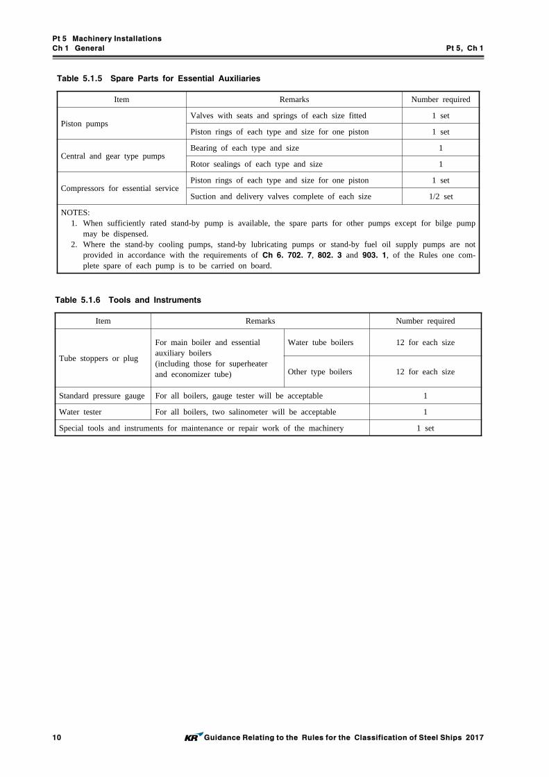
Pt 5 Machinery Installations
Ch 1 General Pt 5, Ch 1
10 Guidance Relating to the Rules for the Classification of Steel Ships 2017
Item Remarks Number required
Piston pumpsValves with seats and springs of each size fitted 1 set
Piston rings of each type and size for one piston 1 set
Central and gear type pumpsBearing of each type and size 1
Rotor sealings of each type and size 1
Compressors for essential servicePiston rings of each type and size for one piston 1 set
Suction and delivery valves complete of each size 1/2 set
NOTES: 1. When sufficiently rated stand-by pump is available, the spare parts for other pumps except for bilge pump
may be dispensed.2. Where the stand-by cooling pumps, stand-by lubricating pumps or stand-by fuel oil supply pumps are not
provided in accordance with the requirements of Ch 6. 702. 7, 802. 3 and 903. 1, of the Rules one com-plete spare of each pump is to be carried on board.
Table 5.1.5 Spare Parts for Essential Auxiliaries
Item Remarks Number required
Tube stoppers or plug
For main boiler and essential auxiliary boilers(including those for superheater and economizer tube)
Water tube boilers 12 for each size
Other type boilers 12 for each size
Standard pressure gauge For all boilers, gauge tester will be acceptable 1
Water tester For all boilers, two salinometer will be acceptable 1
Special tools and instruments for maintenance or repair work of the machinery 1 set
Table 5.1.6 Tools and Instruments

Pt 5 Machinery Installations
Ch 2 Main and Auxiliary Engines Pt 5, Ch 2
Guidance Relating to the Rules for the Classification of Steel Ships 2017 11
Classification Torque factor valueStandard deviation of Torque factor value
Where surface treatment is applied to nut
To be taken as 0.11. However, where manufacture submit data of test for torque
factor value, it may be adjusted at the range of 0.11~0.15.
Not more than 0.010
Where only anticorrosive paint is applied to nut but surface treatment is not applied
To be taken as 0.15. However, where manufacture submit data of test for torque
factor value, it may be adjusted at the range of 0.15~0.19.
Not more than 0.013
CHAPTER 2 MAIN AND AUXILIARY ENGINES
Section 1 General
101. Application
1. In application to 101. 1 of the Rules, the small auxiliary engines may apply to the following; (2017)(1) For auxiliary engines having output of less than 100 kW driving generators (including emergency
generator) or essential auxiliaries.(A) The submission of plans and documents may be omitted. However, plans or documents to
confirm that the engines are comply with requirements in Ch 1, 103. 1 and Ch 2, 203. 9 of the Rules, are to be submitted to attending Surveyor.
(B) Materials used in the main components may comply with Korean Industrial Standards or equivalent.
(C) For tests except visual inspections of engine assembly and shop tests, if manufacturers carry out internal tests and submit test reports, the presence of the Surveyor may be omitted.
(2) The requirements for the plans and documents, materials, tests of auxiliary engines driving cargo handling machinery are in accordance with Pt 9, Ch 2 of the Rules.
2. Welding In application to 101. 5 of the Rules, the general requirements for principal component with welded construction are to be comply with Ch 5, Sec 4 of the Rules.
3. Electronically controlled diesel engines In application to 101. 7 of the Rules, the additional requirements specified otherwise by the Society are to be in accordance with Annex 5-8 of the Guidance.
Section 2 Internal Combustion Engines
202. Construction and installation
1. In application to 202. 1 (2) of the Rules, the strength of each bolt is to be satisfied to following formula.(1) Where the torque control tightening method is applied, following formula are to be met with.
∙
× ,
Here,
: Axial force of bolt (axial direction tension force applied to the bolt tightened by torque)(N)
: Torque recommended by an engine manufacture (moment tightening nut) (N·m)
: Torque factor value, to be taken as following Table.
: Nominal dimension of screw outer diameter of bolt (mm)

Pt 5 Machinery Installations
Ch 2 Main and Auxiliary Engines Pt 5, Ch 2
12 Guidance Relating to the Rules for the Classification of Steel Ships 2017
: Minimum section area of screw of bolt (mm2)
: Specified minimum yield strength of bolt material (N/mm2)
(2) Where the hydraulic tightening method is applied, following formula are to be met with.
×× ,
Here,
: Axial force of bolt(axial direction tension force applied to the bolt calculated from tighten-
ing hydraulic pressure) (N)
: Hydraulic pressure of hydraulic tension device (N/mm2)
: Effective piston area of hydraulic tension device) (mm2)
: Hydraulic coefficient for setting and resilience behaviour, to be taken as 0.85. However,
where is different form this value, it may be accepted if detailed review report is sub-
mitted to the Society and deemed appropriate by the Society.
, : To be followed to (1).
2. In application to 202. 3 (4) (B) of the Rules, where deemed as appropriate by the society means to be satisfied with followings.(1) The numerical simulation model has been tested and its suitability/accuracy has been proven by
direct comparison between calculation results and the practical containment test for a reference application (reference containment test). This test shall be performed at least once by the manu-facturer for acceptance of the numerical simulation method in lieu of tests.
(2) The corresponding numerical simulation for the containment is performed for the same speeds as specified for the containment test.
(3) Material properties for high-speed deformations are to be applied in the numeric simulation. The correlation between normal properties and the properties at the pertinent deformation speed are to be substantiated.
(4) The design of the turbocharger regarding geometry and kinematics is similar to the turbocharger that was used for the reference containment test. In general, totally new designs will call for a new reference containment test.
203. Safety devices
1. Control and safety systems for dual fuel diesel engines are to comply with the requirements given in Annex 5-7.
2. In application to 203. 2 of the Rules, other acceptable means may includes methods to prevent over pressure by tension of cylinder head bolts.
3. In application to 203. 4 of the Rules, manual and name plate for relief valves of crankcase are to be in accordance with the following.(1) A copy manufacturer's installation and maintenance manual that is pertinent to the size and type
of relief valve being supplied for installation on a particular engine is to be provided on board ship. The manual is to contain the following information.(A) Description of valve with details of function and design limits(B) Installation instructions(C) Maintenance in service instructions to include testing and renewal of any sealing arrange-
ments(D) Actions required after a crankcase explosion
(2) Relief valves are to be provided with suitable markings that include the following information.(A) Name and address of manufacturer(B) Designation and size(C) Month/Year of manufacture

Pt 5 Machinery Installations
Ch 2 Main and Auxiliary Engines Pt 5, Ch 2
Guidance Relating to the Rules for the Classification of Steel Ships 2017 13
(D) Approved installation orientation4. In application to 203. 10 (1) of the Rules, bearing temperature monitors or equivalent devices are
to be in accordance with the following.(1) Bearing temperature monitors of low speed diesel engines are to be capable of monitoring tem-
perature(or oil outlet temp.) of main bearing, crank bearing and crosshead bearing. (2) Bearing temperature monitors of medium and high speed diesel engines are to be capable of
monitoring temperature(or oil outlet temp.) of main bearing and crank bearing.(3) An equivalent device could be interpreted as measures applied to high speed engines where spe-
cific design features to preclude the risk of crankcase explosions are incorporated.
5. In application to 203. 10 (1) of the Rules, where an overriding for automatic shutoff arrangements is installed, the documents on the consequences are to be submitted to this Society for approval.
6. In application to 203. 10 (2) of the Rules, the engine designer's and oil mist manufacturer's in-structions are to be included the following particulars.(1) Schematic layout of engine oil mist detection and alarm system showing location of engine
crankcase sample points and piping or cable arrangements together with pipe dimensions to detector.
(2) Evidence of study to justify the selected location of sample points and sample extraction rate (if applicable) in consideration of the crankcase arrangements and geometry and the predicted crank-case atmosphere where oil mist can accumulate.
(3) The manufacturer's maintenance and test manual.(A copy of the manual is to be provided on board ship.)
(4) Information relating to type or in-service testing of the engine with engine protection system test arrangements having approved types of oil mist detection equipment.
7. In application to 203. 10 (8) of the Rules, the details are to be submitted for consideration are to be in accordance with the following.(1) Engine particulars (type, power, speed, stroke, bore and crankcase volume, etc.)(2) Details of arrangements prevent the build up of potentially explosive conditions within the
crankcase, e.g., bearing temperature monitoring, oil splash temperature, crankcase pressure mon-itoring, recirculation arrangements.
(3) Evidence to demonstrate that the arrangements are effective in preventing the build up of poten-tially explosive conditions together with details of in-service experience.
(4) Operating instructions and the maintenance and test instructions.
204. Crank shafts
1. Minimum diameter in application to Table 5.2.3 of Rules, coefficients A and B for engines hav-ing unequal firing intervals are to be in accordance with the following;(1) 4-stroke cycle in-line engines

Pt 5 Machinery Installations
Ch 2 Main and Auxiliary Engines Pt 5, Ch 2
14 Guidance Relating to the Rules for the Classification of Steel Ships 2017
(2) 2-stroke cycle vee engines
205. Dimensions of crank arms
The dimensions of the crank arms breadth , crank arms thickness and radius in fillet are to be in accordance with the following;
1. Solid crankshaft
(1) In application to 205. 1 of the Rules, as for , the breadth on the perpendicular bisector of the line between the crankpin center and journal center is to be used. As for , the thickness at the same section as is to be used, and the recess need not be accounted in the thickness even when it is provided. As for , the radius connecting to the crankpin or journal is to be used when a composite radius is provided.
(2) When the diameters of crankpin and journal are different each other, their and are to be in accordance with 205. 1 or Fig 5.2.1 of the Rules.

Pt 5 Machinery Installations
Ch 2 Main and Auxiliary Engines Pt 5, Ch 2
Guidance Relating to the Rules for the Classification of Steel Ships 2017 15
2. Semi-built-up crankshaft
In application to 205. 3 of the Rules as for , the breath on the line perpendicularly interested to the line between the crankpin center and journal center and tangent to the crankpin is to be used. As for , the thickness at the same section as is to be used, and the recess need not be ac-counted in the thickness even when it is provided, and the ring around the shringkage hole is not to be included in the thickness. As for , the radius connecting to the crankpin or journal is to be used when a composite radius is provided. and are given in Fig 5.2.1 of the Guidance.
3. In application to 205. 3 and 4 of the Rules the thickness of crankarm in way of the shrinkage fit as Fig 5.2.1 (d) of the Guidance is to comply with the following formula instead of 205. 3 of the Rules;
∙∙∙∙∙∙≥
≥
206. Material consideration
In the application 206. of the Rules, in case where the semi-built-up crankshaft made of the mate-rials having a specified tensile strength less than 440 Nmm, the coefficient may be 1.
208. Special consideration
1. The requirements of 208. of the Rules are in accordance with the following;(1) The definition and approval test for “manufacturing process of the different manufacturing meth-
ods of forged crankshaft” are to be in accordance with Ch 2, Sec 5 of the "Guidance for Approval of Manufacturing Process and Type Approval, Etc."
(2) The diameter of crankshaft manufactured by the different manufacturing methods mentioned pre-vious (1) may be reduced by multiplying dc by the less coefficient between kr and kp.(A) In case where the crankshaft are manufacturers by such a special method approved by the
Society that the forging grain-flow is continuous, and the product quality is stable, and the fatigue strength is considered to be improved by 20 % or more compared with that in free forging process;
(B) In case where the crankshaft are manufactured by such a special method approved by the Society that a surface hardening is provided and the product quality is stable, and a superi-ority is considered in the fatigue strength;
: Degree of improvement in strength approved by the Society relative to the surface
hardening ()
(3) In case 205. 3 and 210. 1 of the Rules, the previous (2) is not to be applied.2. In case where the diameter of crankshaft, dimension of crankarm and radius in fillet are less than
the valves required in 204. and 205. of the Rules, the requirements of 208. of the Rules are in accordance with the following (refer to Fig 5.2.2 of the Guidance).

Pt 5 Machinery Installations
Ch 2 Main and Auxiliary Engines Pt 5, Ch 2
16 Guidance Relating to the Rules for the Classification of Steel Ships 2017
(1) When it is not satisfied with 204. 2 of the Rules;In case where the diameter of crankpins or journals is less than the required diameter given in 204. 2 of the Rules and considered according to 206., 207. of the Rules and 208. 1 (2) of the Guidance, consideration will be given in each case on basis of the stress levels in fillets, the torsional stress levels in parallel parts, friction force of shrinkage fitted parts, material, etc. In this connection, the stress levels in fillets are to be in accordance with the following (A) or (B).(A) In case where the torsional stress in crankpins and journals are evaluated without carrying
out a forced vibration calculation including the stern shaftings;The diameter of pin may be acceptable where the value of equivalent stress amplitude de calculated by the Annex 5-2 (Guidance for calculation of crankshaft stress(1)) is not more than the allowable stress s obtained from the formula below with the coefficient shown in Table 5.2.1 of the Guidance.
⋅⋅ Nmm
σa
N/㎟
Cycle 2 cycle 4 cycle
Type of crankshaft Semi-built-up Solid Solid
Solid Shaft Diameter(d)
≥200 53.9 53.9(※) 83.3
200>≥100 ─ 132.3 - /4
100> ─ 107.8
NOTES : d is the actual diameter of crankpin or journal whichever is larger.(※) In case engine bed other than welded type, may be applied 83.3.
fm
1+23 (Ts440-1)
NOTES : T s is the minimum specified tensile strength (Nmm) of crankshaft materials.
fs
Manufacturing method
Ordinary methodMethod meeting (A) for K r specified
in 208. 1. (2) of the GuidanceMethod meeting (B) for K specified
in 208. 1. (2) of the Guidance
1 1.15 1 + /100
NOTES : signifies the degree of strength improvement() approved by the Society relative to surface hardening.
N/mm 2
Main bearing material
White metal Tri-metal or kelmet
0 9.8
Table 5.2.1 Coefficient of Allowable Stress at Fillet

Pt 5 Machinery Installations
Ch 2 Main and Auxiliary Engines Pt 5, Ch 2
Guidance Relating to the Rules for the Classification of Steel Ships 2017 17
(B) In case where the torsional stress in crankpins and journals are evaluated by carrying out a forced vibration calculation in including the stern shafting: The diameter may be acceptable where the value of the acceptability factor calculated by the Annex 5-3 (Guidance for calculation of crankshaft stress(2)) is comply with the follow-ing formula.
≥ 1.15
(2) In case where the dimensions of crankarms fail to meet the requirements 205. of the Rules;(A) The dimension of crankarms may be acceptable where the actual diameters of crankpins
and journals are not less than the required diameter calculated by 204. of the Guidance by replacing M and T with those specified below. In this case, the dimensions are to be within the following ranges. And, b, t and r are specified in 205. of the Guidance.
×
×
Where :
≤ ≤ ≤
≤ ≤
≤
≤
≤ ≤
≤
× × × × × (Stress concentration factor for bending)
⋅⋅⋅⋅⋅
≥
⋅⋅⋅⋅⋅ and
⋅⋅⋅⋅⋅ and
≤
× × × (Stress concentration factor for torsion)
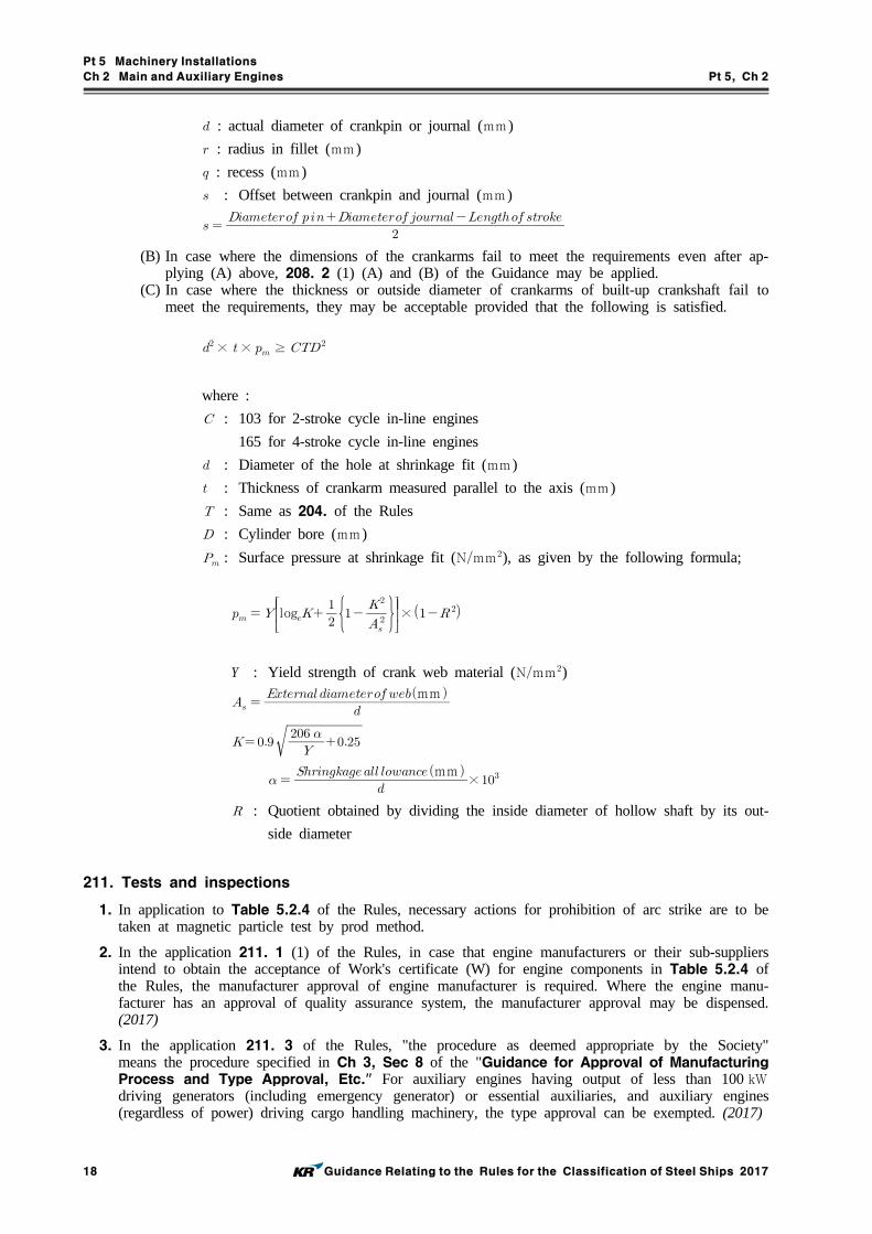
Pt 5 Machinery Installations
Ch 2 Main and Auxiliary Engines Pt 5, Ch 2
18 Guidance Relating to the Rules for the Classification of Steel Ships 2017
: actual diameter of crankpin or journal (mm )
: radius in fillet (mm )
: recess (mm )
: Offset between crankpin and journal (mm )
(B) In case where the dimensions of the crankarms fail to meet the requirements even after ap-plying (A) above, 208. 2 (1) (A) and (B) of the Guidance may be applied.
(C) In case where the thickness or outside diameter of crankarms of built-up crankshaft fail to meet the requirements, they may be acceptable provided that the following is satisfied.
× × ≥
where :
: 103 for 2-stroke cycle in-line engines
165 for 4-stroke cycle in-line engines
: Diameter of the hole at shrinkage fit (mm )
: Thickness of crankarm measured parallel to the axis (mm )
: Same as 204. of the Rules
: Cylinder bore (mm )
: Surface pressure at shrinkage fit (Nmm), as given by the following formula;
log
×
Y : Yield strength of crank web material (Nmm)
mm
mm ×
: Quotient obtained by dividing the inside diameter of hollow shaft by its out-
side diameter
211. Tests and inspections
1. In application to Table 5.2.4 of the Rules, necessary actions for prohibition of arc strike are to be taken at magnetic particle test by prod method.
2. In the application 211. 1 (1) of the Rules, in case that engine manufacturers or their sub-suppliers intend to obtain the acceptance of Work's certificate (W) for engine components in Table 5.2.4 of the Rules, the manufacturer approval of engine manufacturer is required. Where the engine manu-facturer has an approval of quality assurance system, the manufacturer approval may be dispensed. (2017)
3. In the application 211. 3 of the Rules, "the procedure as deemed appropriate by the Society" means the procedure specified in Ch 3, Sec 8 of the "Guidance for Approval of Manufacturing Process and Type Approval, Etc." For auxiliary engines having output of less than 100 kW driving generators (including emergency generator) or essential auxiliaries, and auxiliary engines (regardless of power) driving cargo handling machinery, the type approval can be exempted. (2017)

Pt 5 Machinery Installations
Ch 2 Main and Auxiliary Engines Pt 5, Ch 2
Guidance Relating to the Rules for the Classification of Steel Ships 2017 19
4. In the application 211. 4 and 5 of the Rules, safety precautions and general are to be in accord-ance with the following.(1) Before any test run is carried out, all relevant equipment for the safety of attending personnel
is to be made available by the manufacturer/shipyard and is to be operational. This applies es-pecially to crankcase explosive conditions protection, but also to over-speed protection and any other shut down function. The overspeed protective device is to be set to a value, which is not higher than the overspeed value that was demonstrated during the type test for that engine. This set point shall be verified by the surveyor.
(2) Before any official testing, the engines shall be run-in as prescribed by the engine manufacturer. Adequate test bed facilities for various load points shall be provided. All fluids used for testing purposes such as fuel, lubrication oil and cooling water are to be suitable for the purpose intended, e.g. they are to be clean, preheated if necessary and cause no harm to engine parts. This applies to all fluids used temporarily or repeatedly for testing purposes only.
(3) When no-load operating is carried out for adjusting the engine maneuvering conditions, the fuel delivery system, maneuvering system and safety devices are to be properly adjusted before operating.
(4) Engines are to be inspected for the following.(A) Jacketing of high-pressure fuel oil lines including the system used for the detection of leak-
age(B) Screening of pipe connections in piping containing flammable liquids(C) Insulation of hot surfaces by taking random temperature readings that are to be compared
with corresponding readings obtained during the type test. This shall be done while running at the rated power of engine. Use of contact thermometers may be accepted at the dis-cretion of the attending Surveyor. If the insulation is modified subsequently to the Type Approval Test, the Society may request temperature measurements by use of Infrared Thermoscanning Equipment. Equivalent measurement equipment may be used. Readings ob-tained are to be randomly verified by use of contact thermometers.
(D) These inspections are normally to be made during the works trials by the manufacturer and the attending surveyor, but at the discretion of the Society parts of these inspections may be postponed to the shipboard testing.
5. In the application 211. 4 of the Rules, shop trials deemed appropriated by the Society mean to be in accordance with the following.(1) The programme shown in Table 5.2.2 of the Guidance is to be used as a standard for shop
trial of diesel engines. In this case, the details for the programme are to be referred to speci-fied below. Additional test items may be requested according to the discretion of the Society.(A) For main engines of diesel ships and electric propulsion ships;
KS V 4314 (Shop Test Code for Marine Internal Combustion Engine for Propelling Use) or standards considered as equivalent thereto
(B) For diesel engines driving main generators or essential auxiliaries;KS V 4316 (Water-Cooled Four Cycle Marine Diesel Engines for Electrical Generator) or standards considered as equivalent thereto
(2) Records(A) The following environmental test conditions are to be recorded
(a) Ambient air temperature(b) Ambient air pressure(c) Atmospheric humidity
(B) For each required load point, the following parameters are normally to be recorded(a) Power and speed(b) Fuel index (or equivalent reading)(c) Maximum combustion pressures (only when the cylinder heads installed are designed for
such measurement)(d) Exhaust gas temperature before turbine and from each cylinder(e) Charge air temperature(f) Charge air pressure(g) Turbocharger speed
(C) Calibration records for the instrumentation are, upon request, to be presented to the attend-ing Surveyor.
(D) For all stages at which the engine is to be tested, the pertaining operational values are to

Pt 5 Machinery Installations
Ch 2 Main and Auxiliary Engines Pt 5, Ch 2
20 Guidance Relating to the Rules for the Classification of Steel Ships 2017
be measured and recorded by the engine manufacturer. All results are to be compiled in an acceptance protocol to be issued by the engine manufacturer. This also includes crankshaft deflections if considered necessary by the engine designer.
(E) In each case, all measurements conducted at the various load points are to be carried out at steady state operating conditions. However, for all load points provision should be made for time needed by the Surveyor to carry out visual inspections.
(3) Turbocharger matching with engine(A) Compressor chart
Turbochargers shall have a compressor characteristic that allows the engine, for which it is intended, to operate without surging during all operating conditions and also after extended periods in operation. For abnormal, but permissible, operation conditions, such as misfiring and sudden load reduction, no continuous surging shall occur. In this section, surging and continuous surging are defined as follows: Surging means the phenomenon, which results in a high pitch vibration of an audible level or explosion-like noise from the scavenger area of the engine. Continuous surging means that surging happens repeatedly and not only once.
(B) Surge margin verificationCategory C turbochargers used on propulsion engines are to be checked for surge margins during the engine workshop testing as specified below. These tests may be waived if suc-cessfully tested earlier on an identical configuration of engine and turbocharger (including same nozzle rings).(a) For 4-stroke engines
The following shall be performed without indication of surging.(i) With maximum continuous power and speed (=100 %), the speed shall be reduced
with constant torque (fuel index) down to 90 % power.(ii) With 50 % power at 80 % speed (= propeller characteristic for fixed pitch), the
speed shall be reduced to 72 % while keeping constant torque (fuel index).(b) For 2-stroke engines
The surge margin shall be demonstrated by at least one of the following methods.(i) The engine working characteristic established at workshop testing of the engine shall
be plotted into the compressor chart of the turbocharger (established in a test rig). There shall be at least 10 % surge margin in the full load range, i.e. working flow shall be 10 % above the theoretical (mass) flow at surge limit (at no pressure fluc-tuations).
(ii) Sudden fuel cut-off to at least one cylinder shall not result in continuous surging and the turbocharger shall be stabilized at the new load within 20 seconds. For ap-plications with more than one turbocharger the fuel shall be cut-off to the cylinders closest upstream to each turbocharger. This test shall be performed at two different engine loads as following.① The maximum power permitted for one cylinder misfiring.② The engine load corresponding to a charge air pressure of about 0.6 bar (but
without auxiliary blowers running).(iii) No continuous surging and the turbocharger shall be stabilised at the new load
within 20 seconds when the power is abruptly reduced from 100 % to 50 % of the maximum continuous power.
(4) Integration testsFor electronically controlled engines, integration tests are to be made to verify that the response of the complete mechanical, hydraulic and electronic system is as predicted for all intended op-erational modes and the tests considered as a system are to be carried out at the works. If such tests are technically unfeasible at the works, however, these tests may be conducted during sea trial. The scope of these tests is to be agreed with the Society for selected cases based on the FMEA.
6. In the application 211. 5 of the Rules, on-board tests deemed appropriated by the Society mean to be in accordance with the following.(1) The Table 5.2.3 of the Guidance is to be used as a standard for the details of on-board test
programme or sea trial programme for diesel engines. Additional tests may be carried out ac-cording to KS V 0811 (Sea Trials Code for Machinery Department) where considered necessary by the Society. The details of the programme are referred to KS V 0811 or standards consid-ered as equivalent thereto, and the overhaul inspection for cylinder assembly may be carried out where considered necessary by the Society.

Pt 5 Machinery Installations
Ch 2 Main and Auxiliary Engines Pt 5, Ch 2
Guidance Relating to the Rules for the Classification of Steel Ships 2017 21
(2) Barred speed rangeWhere a barred speed range is required, passages through this barred speed range, both accel-erating and decelerating, are to be demonstrated as following. The times taken are to be re-corded and are to be equal to or below those times stipulated in the approved documentation, if any. This also includes when passing through the barred speed range in reverse rotational direc-tion, especially during the stopping test.(A) Applies both for manual and automatic passing-through systems.(B) The ship’s draft and speed during all these demonstrations is to be recorded. In the case of
a controllable pitch propeller, the pitch is also to be recorded.(C) The engine is to be checked for stable running (steady fuel index) at both upper and lower
borders of the barred speed range. Steady fuel index means an oscillation range less than 5% of the effective stroke (idle to full index).

Pt 5 Machinery Installations
Ch 2 Main and Auxiliary Engines Pt 5, Ch 2
22 Guidance Relating to the Rules for the Classification of Steel Ships 2017
Use of engines
Test items
Propulsion engines driv-ing propeller or im-peller only(1)
Engines driving gen-erators for electric propulsion and main power supply(2)
Propulsion engines al-so driving power take off (PTO) generator(3)
Engines driving es-sential auxiliaries(1)
110 % power run
15 minutes at the speed of 1.032 times of the rated engine speed or after steady conditions have been reached, whichever is shorter
15 minutes at the rated engine speed
15 minutes at the rat-ed engine speed
15 minutes at the rat-ed engine speed
Approved intermittentoverload (if applicable)
testing for duration as agreed with the manu-facturer
-testing for duration as agreed with the man-ufacturer
testing for duration as agreed with the man-ufacturer
Load tests
100 % power run(4)
60 minutes at the rated engine speed
60 minutes at the rated engine speed
60 minutes at the rat-ed engine speed
30 minutes at the rat-ed engine speed
90 % or Nominal con-tinuous cruise power run(5)
20 minutes at engine speed in accordance with characteristics of propeller
-
20 minutes at engine speed in accordance with characteristics of propeller or the rated engine speed
-
75 % power run
20 minutes at the rated engine speed
20 minutes at engine speed in accordance with the nominal power consumption curve
50 % power run
25 % power run(5)
Reverse maneuvering test(6) ○ - - -
Governor characteristics test
○ ○ ○ ○
Performance test of alarm and safety devices
○ ○ ○ ○
Overhaul inspection(7) ○ ○ ○ ○
NOTES : 1. For electronically controlled diesel engines, integration tests are to be carried out in accordance with 211. 5 (4) of
the Guidance.2. (1) through (7) in this Table are subject to the following;
(1) For 110 % power run of propulsion engines, only required once for each different engine/turbocharger configuration. After the trials, the fuel delivery system is to be blocked so as to limit the engines to run at not more than 100 power, unless intermittent overload power is approved by the Society.
(2) After running on the test bed, the fuel delivery system is to be adjusted so that full power plus a 10 % margin for transient regulation can be given in service after installation onboard. The transient overload capability is re-quired so that the required transient governing characteristics are achieved also at 100 % loading of the engine, and also so that the protection system utilised in the electric distribution system can be activated before the en-gine stalls.
(3) After running on the test bed, the fuel delivery system is to be adjusted so that full power plus a margin for transient regulation can be given in service after installation onboard. The transient overload capability is re-quired so that the electrical protection of downstream system components is activated before the engine stalls. This margin may be 10 % of the engine power but at least 10 % of the PTO power.
(4) The readings are to be taken twice at an interval of at least 30 minutes.(5) The test item may be dispensed with when deemed appropriate by the Society.(6) The test item applies only to direct reversible engines.(7) The overhaul inspection for one cylinder assembly is to be carried out, but the scope of overhaul inspection
may be extended according to the discretion of the attending Surveyor.
Table 5.2.2 Programme for Shop Trials of Internal Combustion Engine

Pt 5 Machinery Installations
Ch 2 Main and Auxiliary Engines Pt 5, Ch 2
Guidance Relating to the Rules for the Classification of Steel Ships 2017 23
Use of engines
Test items
Propulsion engines
driving propeller or
impeller only(1)
Engines driving gen-
erators for electric
propulsion and main
power supply(2)
Propulsion engines
also driving power
take off (PTO) gen-
erator
Engines driving es-sential auxiliaries
110 % power run(3)
30 minutes at the speed of 1.032 times of the rated engine speed
10 minutes at the 110 % rated elec-trical power of gen-erator
- -
Approved intermittent
overload (if applicable)
testing for duration
as agreed with the
manufacturer
- -
testing for duration
as agreed with the
manufacturer
Load tests
100 % power run
4 hours at the rated engine speed
1 hour at the 100 % rated electrical pow-er of generator
4 hours at the rated engine speed
30 minutes at the rated engine speed
90 % or Nominal con-tinuous cruise
power run
2 hours at engine speed corresponding to nominal con-tinuous cruise power
- 2 hours at 100% propeller branch power at rated en-gine speed(4),1 hours at 100% PTO branch power at rated engine speed
-75 % power
runreasonable hours at the rated engine speed for 1 or 2 kind of power run
-50 % power
run
25 % power run
Minimum engine speed
test○ - - -
Starting maneuvering
test(5) ○ ○ ○ ○
Reverse maneuvering
test(6) ○ - - -
UMA test(7) ○ ○ ○ ○
Alarms and safety
devices test(8) ○ ○ ○ ○
Test for fitness of fuel
oil(9) ○ ○ ○ ○
Table 5.2.3 Programme for Sea Trials (on-board tests) of Internal Combustion Engine

Pt 5 Machinery Installations
Ch 2 Main and Auxiliary Engines Pt 5, Ch 2
24 Guidance Relating to the Rules for the Classification of Steel Ships 2017
NOTES: (1) through (9) in this Table are subject to the following;(1) For controllable pitch propellers, the tests are to be carried out at the maximum achievable power if 100 %
cannot be reached, the tests are to be carried out at the various pitches.(2) Each engine is to be tested 100 % electrical power for at least 60 min and 110 % of rated electrical power
of the generator for at least 10 min. This may, if possible, be done during the electrical propulsion plant test, which is required to be tested with 100 % propulsion power (i.e. total electric motor capacity for pro-pulsion) by distributing the power on as few generators as possible. The duration of this test is to be suffi-cient to reach stable operating temperatures of all rotating machines or for at least 4 hours. When some of the gen. set(s) cannot be tested due to insufficient time during the propulsion system test mentioned above, those required tests are to be carried out separately. Demonstration of the generator prime movers’ and gov-ernors’ ability to handle load steps as described in Pt 6, Ch 1, 202. 2 of the Rules.
(3) The test may be dispensed with when deemed appropriate by the Society in consideration of the result of the shop trials.
(4) The test is to be carried out unless already covered in 100 % power run.(5) The direct reversible engines are to be carried out ahead and astern starting repeatedly without replenishment,
and the other engines are to be carried out starting and stop repeatedly without replenishment.(6) For controllable pitch propellers in reverse pitch, for the direct reversible engine in reverse rotational direc-
tion during stopping tests, passages through the barred speed range are to be demonstrated in accordance with 211. 6 (2) of the Guidance.
(7) The test is to be carried out for ships which are going to be registered as ships provided with unattended machinery automatic systems.
(8) The monitoring and alarm systems are to be checked to the full extent for all engines, except items already verified during the works trials.
(9) The test is to be carried out for the engines used residue oil or equivalent thereto. However, the test may be dispense with when deemed appropriate by the Society or in the case of that the fitness was certified at the shop trial.
Table 5.2.3 Programme for Sea Trials (on-board tests) of Internal Combustion Engine (continued)

Pt 5 Machinery Installations
Ch 2 Main and Auxiliary Engines Pt 5, Ch 2
Guidance Relating to the Rules for the Classification of Steel Ships 2017 25
Section 3 Steam Turbines
304. Safety devices
It is recommended that the main turbines are provided with a quick acting device which automati-cally shut off the steam supply in case of unacceptable axial displacement of the turbine rotor in addition to the devices mentioned in 304. 2 and 3 of the Rules.
306. Strength and sectional area of turbine blades
When the calculations for vibration stress for the blade or the specified 0.01 proof-stress of the blade material are submitted to the Society and are deemed appropriate by the Society, the values of 2 times the specified 0.01 proof-stress for the blade material may be applied instead of S in the formula given in 306. of the Rules.
307. Tests and inspections
1. In the application 307. 3 of the Rules, the programme as deemed appropriate by the Society means KS V 4211 (Shop Test Code of Marine Steam Engine for Propelling Use) or standards con-sidered as equivalent thereto are to be used as a standard.
2. In the application 307. 4 (2) of the Rules, the programme as deemed appropriate by the Society means KS V 0811 (Sea Trials Code for Machinery Department) or standards considered as equiv-alent thereto are to be used as a standard.

Pt 5 Machinery Installations
Ch 3 Propulsion Shafting and Power Transmission Systems Pt 5, Ch 3
Guidance Relating to the Rules for the Classification of Steel Ships 2017 27
CHAPTER 3 PROPULSION SHAFTING AND POWER TRANSMISSION SYSTEMS
Section 1 General
101. Welded structure component
In application to 101. of the Rules, the general requirements for major parts with welded con-struction are to apply appropriate modifications of Ch 5, Sec 4 of the Rules.
102. Other propulsion and maneuvering machinery
In application to 102. of the Rules, water-jet propulsion systems and azimuth or rotatable thrusters may be complied with the following ;
1. Water-jet propulsion systems and azimuth or rotatable thrusters water-jet propulsion sys-tems or azimuth or rotatable thrusters are to comply with the requirements given in Annex 5-1.
Section 2 Shafting
201. Application
1. In application to 201. 2. of the Rules, the alternative calculation methods are considered appro-priate by the Society are to be in accordance with the following.(1) Any alternative calculation method is to include all relevant loads on the complete dynamic
shafting system under all permissible operating conditions.(2) Consideration is to be given to the dimensions and arrangements of all shaft connections.(3) An alternative calculation method is to take into account design criteria for continuous and tran-
sient operating loads (dimensioning for fatigue strength) and for peak operating loads (dimensioning for yield strength).
(4) The fatigue strength analysis may be carried out separately for different load assumptions as follows.(A) Low cycle fatigue criterion (typically < )(B) High cycle fatigue criterion (typically >> )(C) The accumulated fatigue due to torsional vibration when passing through a barred speed
range or any other transient condition
202. Materials
1. In application to 202. 2 of the Rules, the term "when an approval is specially obtained by the Society" means that includes the cases of obtaining approval in accordance with Pt 2, Ch 1, 601. 18 of the Rules. (2017)
203. Intermediate shaft and thrust shaft
1. In case the ships engaged in smooth water service area, the values of F in formula given in 203. of the Rules may be taken as 95.
2. The diameter of shafts may be reduced on the basis of the application to 204. 2 of the Rules.
3. In application to 203. of the Rules, the term "specially approved by the Society" means that ob-tains an approval in accordance with Pt 2, Ch 1, 601. 18 of the Rules. Specified minimum tensile strength of approved alloy steels can be used in the calculation. (2017)
204. Propeller shaft and stern tube shaft
1. In application to Table 5.3.2 NOTE (4) of the Rules, the required diameters of Kind 1 shaft made of approved corrosion-resistant materials and kind 2 shaft are to be determined by the following
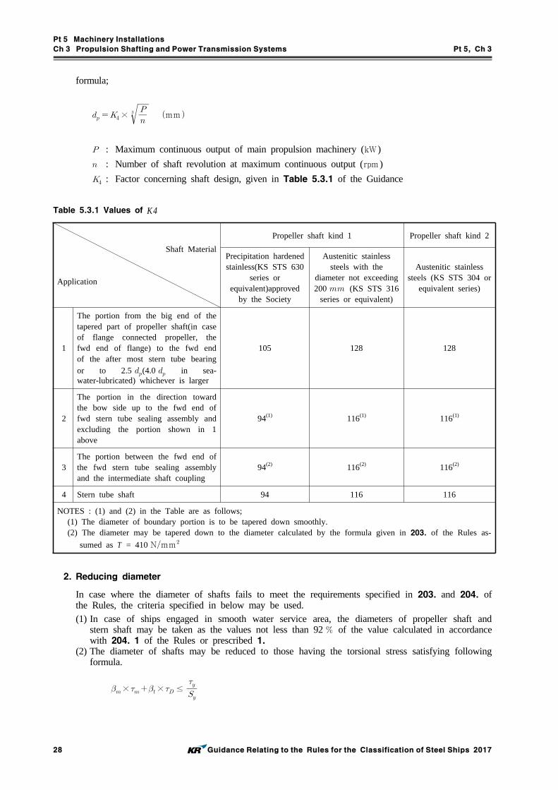
Pt 5 Machinery Installations
Ch 3 Propulsion Shafting and Power Transmission Systems Pt 5, Ch 3
28 Guidance Relating to the Rules for the Classification of Steel Ships 2017
formula;
×
mm
: Maximum continuous output of main propulsion machinery (kW)
: Number of shaft revolution at maximum continuous output (rpm )
: Factor concerning shaft design, given in Table 5.3.1 of the Guidance
Shaft Material
Application
Propeller shaft kind 1 Propeller shaft kind 2
Precipitation hardened stainless(KS STS 630
series or equivalent)approved
by the Society
Austenitic stainless steels with the
diameter not exceeding 200 (KS STS 316
series or equivalent)
Austenitic stainless steels (KS STS 304 or
equivalent series)
1
The portion from the big end of the tapered part of propeller shaft(in case of flange connected propeller, the fwd end of flange) to the fwd end of the after most stern tube bearing or to 2.5 (4.0 in sea-water-lubricated) whichever is larger
105 128 128
2
The portion in the direction toward the bow side up to the fwd end of fwd stern tube sealing assembly and excluding the portion shown in 1 above
94(1) 116(1) 116(1)
3The portion between the fwd end of the fwd stern tube sealing assembly and the intermediate shaft coupling
94(2) 116(2) 116(2)
4 Stern tube shaft 94 116 116
NOTES : (1) and (2) in the Table are as follows;(1) The diameter of boundary portion is to be tapered down smoothly.(2) The diameter may be tapered down to the diameter calculated by the formula given in 203. of the Rules as-
sumed as T = 410 Nmm
Table 5.3.1 Values of K4
2. Reducing diameter
In case where the diameter of shafts fails to meet the requirements specified in 203. and 204. of the Rules, the criteria specified in below may be used.(1) In case of ships engaged in smooth water service area, the diameters of propeller shaft and
stern shaft may be taken as the values not less than 92 of the value calculated in accordance with 204. 1 of the Rules or prescribed 1.
(2) The diameter of shafts may be reduced to those having the torsional stress satisfying following formula.
× × ≤

Pt 5 Machinery Installations
Ch 3 Propulsion Shafting and Power Transmission Systems Pt 5, Ch 3
Guidance Relating to the Rules for the Classification of Steel Ships 2017 29
× ≤
: Average torsional stress on the shaft. However, in case where the average bending
stress acts on the shaft, it is to be accordance with the following formula.
: Equivalent average torsional stress (Nmm) : Average bending stress (Nmm)
: Notch parameter for static stress
: Variable torsional stress on shaft. However, where the variable bending stress acts on
the shaft, it is to be accordance with the following formula.
×
: Equivalent variable torsional stress (Nmm) : Variable bending stress (Nmm) : Notch parameter for bending stress
: Notch parameter for torsional stress
: Torsional yield strength of shaft material (Nmm) : Safety factor for yield strength
: Torsional fatigue strength of shaft material when average stress m (or me) is loaded
on (Nmm) : Safety factor for fatigue strength
(3) In above (2), the torsional fatigue strength and torsional yield strength of shaft are determinated by the Society through considering the materials, heat-treatment and surface treatment and re-viewing the submitted documents. The safety factors for fatigue and yield are determinated by the Society through considering the using purpose and conditions of shaft.
206. Stern tube bearing and sealing devices
In application to 206. 1. (3) of the Rules, where the length of oil lubricated bearings is less than 2 times the required calculation diameter of the propeller shaft in way of the bearing, the following are to be satisfied with.(1) Improvement in condition of bearing loads
The relative contact condition between propeller shaft and its bearing in the longitudinal direc-tion is to be improved by employing the slope alignment (including the slope boring) and uni-form distribution of bearing loads are to be ensured. For approval of the above, an slop align-ment calculation sheet (bending moment, bending stress bearing pressure, bearing load, amount of deflection, angle of inclination, etc.) satisfying the following, and installation instruction is to be submitted.(A) Alignment calculation only dealing with the static external force may be accepted (the re-
view for shaft alignment variation due to dynamic force such as variation of bending mo-ment, bending stress and etc. is not accepted).
(B) At any position on the propeller shaft static bending moment (absolute value) is not to ex-ceed the value at the aft end of the stern tube bearing.
(2) Improvement in lubricating oil and condition of lubricatingFor improving the lubricating condition of stern tube bearing, the following measures are to be taken;

Pt 5 Machinery Installations
Ch 3 Propulsion Shafting and Power Transmission Systems Pt 5, Ch 3
30 Guidance Relating to the Rules for the Classification of Steel Ships 2017
(A) The lubricating oil inlet is to be provided at the aft end of the bearing for ensuring the forced circulation of the lubricating oil.
(B) To be use lubricating oil with superior resistance against burning out bearing and character-istic being easy to emulsify (being difficult to separate). However, additaments for lubricat-ing oil are to be considered the fitness with sealing materials for stern tube sealing device such as rubber.
(C) Damage found of bearings at early stageFor finding of bearings burned out at early stage and preventing of extension of the dam-age, at least one(1) temperature sensor in bearing shell and high temperature alarm (Set point 60 or below) are to be provided.
(D) Low level alarm is to be provided in the lubricating oil tank.
207. Shaft coupling and coupling bolts
1. In application to 207. 3 of the Rules, may be in compliance with following calculations. However, when manufacturers and designers submit separate calculations it may be acceptable with the appro-val by the Society. (1) When fitting the keyless shrunk assembly, the axial pull-up of the shaft coupling hub(hereinafter
refered to as "hub") in relation to the shaft or intermediate sleeve, as soon as the contact area between mating surfaces is checked after eliminating the clearance, may be determined by the following formula. (refer to Fig 5.3.1)
(mm)
= material and shape factor of the assembly, determined by the following formula,
For assemblies with a steel shaft having no axial bore, the factor may be obtained
from Table 5.3.2 using linear interpolation.
= modulus of elasticity of the hub material (Nmm) = modulus of elasticity of the shaft material (Nmm) = Poisson's ratio for the hub material
= Poisson's ratio for the shaft material (for steel =0.3)
= mean factor of outside hub diameter
= mean factor of shaft bore
= mean internal hub diameter in way of contact with the shaft or intermediate sleeve
(mm)

Pt 5 Machinery Installations
Ch 3 Propulsion Shafting and Power Transmission Systems Pt 5, Ch 3
Guidance Relating to the Rules for the Classification of Steel Ships 2017 31
= mean outside shaft diameter in way of contact with the hub or intermediate sleeve
(mm)
without intermediate sleeve,
, , therefore
with intermediate sleeve,
≠, ≠, ≠ therefore ≠
= active length of the shaft cone or sleeve at the contact with the hub (mm)
= taper of the hub
= power transmitted by assembly (kW)
= speed (rpm)
= propeller thrust at ahead speed (kN) (In case that the thrust directly transfer to the
coupling)
= thermal coefficient of liner expansion of the hub material (℃)
= thermal coefficient of liner expansion of the shaft material (℃)
= temperature of the assembly in service conditions (℃)
= temperature of the assembly in the course of fitting (℃)
= 1 for assemblies without intermediate sleeve
= 1.1 for assemblies with the use of intermediate sleeve

Pt 5 Machinery Installations
Ch 3 Propulsion Shafting and Power Transmission Systems Pt 5, Ch 3
32 Guidance Relating to the Rules for the Classification of Steel Ships 2017
Factor × , Steel shaft , × (Nmm),
Factor
y
Copper alloy hub with (Nmm) Steel hub with
×
(Nmm)× × × × × × ×
1.2
1.3
1.4
1.5
1.6
1.7
1.8
1.9
2.0
2.1
2.2
2.3
2.4
6.34
4.66
3.83
3.33
3.01
2.78
2.62
2.49
2.39
2.30
2.23
2.18
2.13
5.79
4.26
3.52
3.07
2.77
2.48
2.38
2.29
2.20
2.13
2.06
2.01
1.97
5.34
3.95
3.25
2.83
2.57
2.38
2.23
2.13
2.05
1.98
1.92
1.88
1.84
4.96
3.66
3.03
2.64
2.40
2.22
2.09
1.99
1.92
1.86
1.79
1.75
1.72
4.63
3.43
2.83
2.48
2.24
2.09
1.97
1.88
1.80
1.74
1.69
1.65
1.62
4.34
3.22
2.67
2.34
2.12
1.97
1.86
1.77
1.70
1.65
1.60
1.57
1.54
4.09
3.04
2.52
2.21
2.01
1.87
1.76
1.68
1.62
1.57
1.53
1.49
1.46
3.18
2.38
1.98
1.74
1.59
1.49
1.41
1.35
1.29
1.25
1.22
1.19
1.17
Table 5.3.2 Factor
Fig 5.3.1 Details of shaft couplings
(2) When assembling steel couplings and shafts with cylindrical mating surfaces, the interference fit may be determined by the following formula.
(mm)
Other terms are as defined in (1).

Pt 5 Machinery Installations
Ch 3 Propulsion Shafting and Power Transmission Systems Pt 5, Ch 3
Guidance Relating to the Rules for the Classification of Steel Ships 2017 33
표 5.3.3 Factor
1.2
1.3
1.4
1.5
1.6
1.7
1.8
6.11
4.48
3.69
3.22
2.92
2.70
2.54
1.9
2.0
2.1
2.2
2.3
2.4
2.42
2.33
2.26
2.20
2.15
2.11
(3) For the hub in keyless assemblies with the shafts, the following condition may be met.
≤
= shape factor of the hub determined by the formula
The factor A may be obtained from Table 5.3.3 by linear interpolation.
for assemblies with conical mating surfaces.
= actual pull-up of the hub in the course of fitting at a temperature , ≥
(mm)
for assemblies with cylindrical mating surfaces.
= actual interference fit of the assembly with cylindrical mating surfaces,
≥ (mm)
= yield stress of the hub material, (Nmm)Other terms are as defined in (1).

Pt 5 Machinery Installations
Ch 3 Propulsion Shafting and Power Transmission Systems Pt 5, Ch 3
34 Guidance Relating to the Rules for the Classification of Steel Ships 2017
Section 3 Propellers
301. Application
1. For the propellers such as following, the Society may request the submission of calculation sheets for stress of blades.(1) Propellers having special type blade such as nozzle propeller, jacket propeller, etc.(2) Propellers for special purpose ships such as tug boat, stern trawler, pusher, etc.(3) Propellers having pitch ratio of more than 0.8 at the radius 0.25 .(4) Specially designed propellers for improving propelling efficiency.
302. Materials
For separate propeller hubs and blade bolts not used for main propulsion, or for components of controllable pitch propeller not transmitted propulsion torque such as crank disc, push pull rod, ac-tuator cylinder and cross head etc. in case that manufacturers carry out internal test and submit the test report, the test witnessed by the Surveyor may be omitted. (2017)
303. Thickness of blades
1. The thickness of skewed propeller blades more than 25° of skew angle is to comply with the fol-lowing requirements depending on skew angle (the angle, on the expanded blade drawing, between the line connecting the center of the propeller shaft with the point at the blade tip on the center line of blade width and the tangential line drawn from the center of the propeller shaft to center line of blade width(See Fig 5.3.2)(1) In case where the skew angle exceeds 25° but is 60° or less
(A) The blade thicknesses at a radius of 0.25 (0.35 for controllable pitch propellers) and 0.6 are not to be less than the values obtained by multiplying the values () calculated by the formula in 303. of the Rules, by the coefficient A given in the formula below;
: Skew angle (°)
: 0.2 at 0.25 (0.35 for controllable pitch propeller)
0.6 at 0.6
(B) Blade thickness at any radius between 0.6 and 0.9 is not to be less than the value determined by the following formula.
mm
: Diameter of propeller (mm )
: Radius position having no dimension
: blade thickness at 0.6 as required in (A) above
(2) In case where the skew angle exceeds 60°On the basis of the precise calculation sheet on propeller strength submitted by the manufacturer or designer, the blade thickness is to be determined under the satisfaction of the Society.

Pt 5 Machinery Installations
Ch 3 Propulsion Shafting and Power Transmission Systems Pt 5, Ch 3
Guidance Relating to the Rules for the Classification of Steel Ships 2017 35
Fig 5.3.2 Skew Angle
304. Blade Fixing of built-up type or controllable pitch propeller
1. In 304. 1 of the Rules, the diameter of blade fixing bolts is not to be less than the value calcu-lated by the following formula. In this case, the value of may be taken as the values specified in Fig 5.3.3 of the Guidance.
⋅
⋅
where;
: Required diameter of blade fixing bolt (mm )
: Value given by the following formula.
×
: Maximum continuous output of main propulsion machinery (kW)
: Number of blades
: Number of maximum continuos revolution per minute divided by 100 (rpm /100)
: Values given by the following formula
: Ratio of the radius at the boundary between blade flange and the boss (or pitch
control gear) to propeller radius (see Fig 5.3.3 of the Guidance). Where
0.3, the ratio is to be taken as 0.3.
: Diameter of propeller (m )
: Pitch at radius of 0.7 (m ), ( = Radius of propeller)
: Mean value of and (cm )
and show the length of the perpendicular lines constructed to the line which
passes through the rotating center of blade flange and has an inclination compatible

Pt 5 Machinery Installations
Ch 3 Propulsion Shafting and Power Transmission Systems Pt 5, Ch 3
36 Guidance Relating to the Rules for the Classification of Steel Ships 2017
with the pitch angle at 0.7 , from the center of bolts located on each edge side in
face side when the pitch angle is . (see Fig 5.3.4 of the Guidance)
: Centrifugal force (N) of propeller blade given by the following formula:
× ′
: Mass of one blade (kg)
′ : Distance between center of gravity of blade and propeller shaft center line (cm )
: Number of bolts on the face side of blade
: Allowable stress of bolt material given by the following formula (Nmm)
×
: Specified tensile strength of bolt material (Nmm). Where > 800 Nmm, it is
to be taken as 800 Nmm.
2. In 304. 2 of the Rules, the thickness of flange for bolt fixing part is to be not less than the value calculated by the following formula (the thickness as measured from the seat of fixing bolt or nut to the boundary face between the flange and the boss (or the pitch control gear):
Where;
: Thickness of flange (mm ) (see Fig 5.3.3 of the Guidance)
: Required diameter of bolt calculated by the formula specified in (1) (mm )
Fig 5.3.3 Measuring Method of Blade Fixing Bolt Dimension
Fig 5.3.4 Determination of L
3. In 304. 3 of the Rules, the blades are to be fixed securely to the boss (or the pitch control gear)

Pt 5 Machinery Installations
Ch 3 Propulsion Shafting and Power Transmission Systems Pt 5, Ch 3
Guidance Relating to the Rules for the Classification of Steel Ships 2017 37
by giving the fixing bolts the adequate initial fixing force. It is to be regarded as the standard practice that the initial fixing force complies with the following condition;
∙
⋅
where
: Initial fixing force (N)
: Yield strength or 0.2 proof strength of bolt material (Nmm)Other symbols are the same as in the formula shown in 1.
305. Fitting of propeller
1. In 305. 1 of the Rules, the heating temperature of propeller boss at drawing out is to be not more than 100 °C.
2. In application 305. 2 of the Rules, keyless forced fitting propellers are to satisfy the following.(A) General
(a) The formula, etc., given herein are not applicable for propellers where a sleeve is introduced between propeller shaft (hereinafter referred to as "shaft") and propeller boss (hereinafter re-ferred to as "boss").
(b) The taper of the shaft cone is not to exceed 1/15.(c) Prior to final pull-up, the contact area between the mating surface is to be checked and is
not to be less than 70 of the theoretical contact area. Non-contact bands extending cir-cumferentially around the boss or over the full length of the boss are not acceptable.
(d) After final pull-up, the propeller is to be secured by a nut on the propeller shaft. The nut is to be secured to the shaft.
(e) The factor of safety against friction slip at 35 °C is not to be less than 2.8 under the action of rated torque at corresponding power and speed plus pulsating torque due to torsional.
(f) For the oil injection method the coefficient of friction is to be 0.13 for bosses made of bronze and steel.
(g) The maximum equivalent uniaxial stress (Nmm) in the boss at 0 °C based on the Mises-Hencky criterion should not exceed 70 of the yield point or 0.2 proof-stress (0.2 offset yield strength) for the propeller. For cast iron the value should not exceed 30 of the nominal tensile strength.
(B) MaterialsModulus of elasticity, Poisson's ratio and coefficient of linear expansion of materials are in ac-cordance with the Table 5.3.4 of the Guidance.
Kind of materialModulus of elasticity
(Nmm)Poisson's
ratioCoefficient of linear
expansion (mmmm °C)
Steel castings and steel forgings 20.6×10⁴ 0.29 12.0×10⁻⁶
Cast iron 9.8×10⁴ 0.26 12.0×10⁻⁶
High strength brass casting, CU1, CU2 10.8×10⁴ 0.33 17.5×10⁻⁶
Aluminium bronze casting, CU3, CU4 11.8×10⁴ 0.33 17.5×10⁻⁶
Table 5.3.4 Modulus of Elasticity, Poisson's Ratio and Coefficient of Linear Expansion
(C) Calculations for pull-up length and pull-up load (a) The formulae are applicable for solid shafts only.(b) Pull-up length
(i) Corresponding minimum pull-up length at 35 °C (mm ) :

Pt 5 Machinery Installations
Ch 3 Propulsion Shafting and Power Transmission Systems Pt 5, Ch 3
38 Guidance Relating to the Rules for the Classification of Steel Ships 2017
(ii) Minimum pull-up length at temperature ( < 35 °C) (mm )
(iii) Corresponding maximum permissible pull-up length at 0 °C (mm )
max max
Where
: Minimum required surface pressure at 35 °C (Nmm)
: Factor of safety against friction slip at 35 °C
: Thrust() (if not given, calculate P35 with the value calculated by the fol-
lowing formulas and take the value which make P35 grater)
or ×
: Maximum continuous output (kW)
: Ship speed at maximum continuous output (Knots)
: Mean propeller pitch (mm )
: Number of revolution at maximum continuous output (rpm )
: 100 theoretical contact area between boss and shaft, as read from drawings
and disregarding oil grooves (mm) : Values according to the following formula
: Coefficient of friction between mating surfaces
: Half taper of tail-shaft (e.g. taper = 1/15, = 1/30)
: Shear force at interface (N)
: Constant,
1 : for turbines, geared diesel drives, electric drives and for direct diesel
drives with a hydraulic or an electromagnetic or high elasticity coupling

Pt 5 Machinery Installations
Ch 3 Propulsion Shafting and Power Transmission Systems Pt 5, Ch 3
Guidance Relating to the Rules for the Classification of Steel Ships 2017 39
1.2 : for a direct diesel drive
: Troque transmitted according to maximum continuous output (Nmm )
: Diameter of tail-shaft at the midpoint of the taper in the axial direction (mm )
: Values according to the following formula
: Mean outer diameter of propeller boss at the axial position corresponding to
(mm )
: Modulus of elasticity of boss material (Nmm) : Poisson s ratio for boss material
: Modulus of elasticity of shaft material (Nmm) : Poisson s ratio for shaft material
: Coefficient of linear expansion of boss material (mmmm °C)
: Coefficient of linear expansion of shaft material (mmmm °C)
max : Maximum permissible surface pressure at 0 °C (Nmm)
max
: Yield point or 0.2 proof stress (0.2 offset yield strength) boss material
(Nmm)(c) Minimum pull-up load at temperature °C (N)
where
: Corresponding minimum surface pressure at temperature °C (Nmm)
3. When the propeller is forced fitted to the propeller shaft by hydraulic force, the confirmation of the pull-up length specified in 307. 3 of the Rules is to be made assuming that the true relative start point is the point where the pull-up load equal zero on the approximate line drawn in the meas-ured points plotted on the chart of the relation between pull-up length and load. And when the propeller is forced fitted to the propeller shaft after second times, the pull-up length is to be con-firmed by the calculations and the records drawn up at the previous time.
307. Tests and inspections
1. Static balancing test for propellers The unbalanced mass at a static balancing test of propeller is not to exceed the value determined by the following formula;
⋅ or ⋅

Pt 5 Machinery Installations
Ch 3 Propulsion Shafting and Power Transmission Systems Pt 5, Ch 3
40 Guidance Relating to the Rules for the Classification of Steel Ships 2017
where
: Unbalanced mass referred to the circumference of the propeller (kg)
: Mass of propeller (kg)
: Radius of propeller (m )
: Number of propeller revolution at the maximum continuos output (rpm )
and : Given in the following table
Class* S I II III
CK
150.0005
250.001
400.001
750.001
NOTE: * Refer to ISO 484/1-1981
Section 4 Power Transmission Systems
401. General
1. "Small ships" given in 401. 3 of the Rules means ships having length not more than 50 m .
2. The main components specified in 401. 5 of the Rules mean the following. (2017)(1) Shafts and gears of power transmission system(2) Couplings and coupling bolts of power transmission system(3) Clutches of power transmission system
402. General construction of gearing
The general requirements for the major parts with welded construction are to apply Pt 2, Ch 2 of the Rules.
403. Allowable tangential load for gears
1. In application to 403. 1 of the Rules, the term “which the Society deems appropriate" is to com-ply with AGMA, ISO or equivalent.
2. In gearing for main propulsion internal combustion engines having maximum continuos output not more than 257 kW and maximum continuos revolution not less than 1,300 rpm , where the coupling complied with the following (1) or (2) is provided between engines and gearing, and the gearing and coupling are of type having actual examples used on ships, the value of given in 403. 2 of the Rules may be taken as 1.0.(1) High elasticity couplings(2) Elasticity coupling not existed resonance rpm occurring critical fluctuation at revolution ratio 0.4
through 1.15 3. In application 403. 4 of the Rules, the strength calculation for gears of power transmission systems
may be in accordance with Annex 5-4 of the Guidance.
406. Shaft couplings (2017)
1. In the application 406. 2 of the Rules, in case of the metallic coupling not used for main pro-pulsion, the type approval may be dispensed.
407. Tests and inspections
1. In application to 407. 2 of the Rules, the permissible residual unbalance of the dynamic bal-ancing test for gears is not to exceed the value of the following equation according to (KS B) ISO

Pt 5 Machinery Installations
Ch 3 Propulsion Shafting and Power Transmission Systems Pt 5, Ch 3
Guidance Relating to the Rules for the Classification of Steel Ships 2017 41
1940-1.
×
∙∙ (g∙mm )
( ∙) : the numerical value of the balance (mms) and obtained by the following value.
In case of ≤ : ( ∙) = 6.3
In case of : ( ∙) = 2.5
: number of revolution of the gear (rpm )
: the rotor mass (kg)
: the angular velocity of the service speed. (rads)

Pt 5 Machinery Installations
Ch 4 Torsional Vibration of Shaftings Pt 5, Ch 4
Guidance Relating to the Rules for the Classification of Steel Ships 2017 43
CHAPTER 4 TORSIONAL VIBRATION OF SHAFTING
Section 2 Allowable Limit of Vibration Stresses
201. Crankshafts
1. In application to 201. of the Rules, the strength calculation for crankshafts is carried out according to the special requirements given by the Society means Annex 5-3. For the allowable limit of vi-bration stresses, the nominal alternating torsional stresses() specified in Annex 5-3, 2. (2) (A) are to be applied in the operational speed range of the engine. Where barred speed ranges are im-posed, the allowable torsional vibration stresses in the ranges may be specially considered.
2. In application to 201. 4 of the Rules, in case where the specified minimum tensile strength of the crankshaft exceeds 590 Nmm for carbon steel forging, or 835 Nmm for low alloy steel forging, the value of given in formula for is to be in accordance with the following.
(1)The value of is to be taken as 590 Nmm for carbon steel forging, and 835 Nmm for low alloy steel forging. However (2) below is to be excepted.
(2)Where the crankshaft approved by Ch 2, Sec 5, 503. 2 of the "Guidance for Approval of Manufacturing Process and Type Approval, etc." for torsional fatigue strength of crankshaft, the value of is to be taken as the value added the fatigue strength improved.
202. Intermediate shafts, thrust shafts, propeller shafts and stern tube shafts
1. The allowable limit of torsional vibration stress for propeller shafts made of the approved corrosion resistance materials is to be calculated by the following formula in place of the formula for τ
1
shown in 202. 1 (1) of the Rules.
≤
: Allowable limit of torsional vibration stress at the continuos operation (Nmm) : Ratio of the number of revolution to the number of maximum continuos revolution
A , B , C : Constant dependent on shaft materials given in Table 5.4.1 of the Guidance
Precipitation hardened stainless steel Austenitic stainless steel(KS STS 304 or equivalent)
A 61.1 40.7
B 47.3 30.5
C 22.8 16.0
NOTES : For material other than above, the values are to be determined on each case.
Table 5.4.1 Values of A, B and C
2. In application to 202. 1 (1) of the Rules, the term "specially approved by the Society" means that obtains an approval in accordance with Pt 2, Ch 1, 601. 18 of the Rules. Specified minimum ten-sile strength of approved alloy steels can be used in the calculation. (2017)
3. In the application 202. 2 of the Rules, the allowable limits of torsional vibration stress are to be calculated by applying the values of given in the Table 5.4.2 of the Guidance in lieu of the formula specified in 202. 1 of the Rules.

Pt 5 Machinery Installations
Ch 4 Torsional Vibration of Shaftings Pt 5, Ch 4
44 Guidance Relating to the Rules for the Classification of Steel Ships 2017
Intermediate shaft
Integral flange couplings 0.75
Shrink fit couplings 0.75
Keyways 0.45
Thrust shaft
On both sides of the thrust collar 0.65
In way of axial bearings where a roller bearing is used as a thrust bearing
0.65
Propeller shaft and stern tube shaft - 0.35
NOTE : The value of CK other than above is to be determined by the Society in each case.
Table 5.4.2 Values of CK
4. In application to Table 5.4.1 NOTE (5) of the Rules, “as deemed appropriate by the Society” is to be in accordance with the following.
: stress concentration factor at the end of slots defined as the ratio between the maximum
local principal stress and times the nominal torsional stress determined for the hollow
shaft without slots.
∙
∙
: slot length (mm )
: slot width (mm )
: inside diameter of the hollow shaft at the slot (mm )
: outside diameter of the hollow shaft (mm )
: stress concentration factor of radial holes(in this context = hole diameter) de-
termined by the following formula
∙
∙
∙
∙
or simplied to
However, this formula for above stress concentrate factor applies to the following slots.
(A) Slots at 120 or 180 or 360 degrees apart
(B) Slots with semicircular ends (A multi-radii slot end is not included in this empirical for-
mula)
(C) Slots with no edge rounding(except chamfering)

Pt 5 Machinery Installations
Ch 4 Torsional Vibration of Shaftings Pt 5, Ch 4
Guidance Relating to the Rules for the Classification of Steel Ships 2017 45
203. Shafting system of generators
1. In application to 203. of the Rules, the strength calculation for crankshafts is carried out according to the special requirements given by the Society means Annex 5-3. For the allowable limit of vi-bration stresses, the nominal alternating torsional stresses() specified in Annex 5-3, 2. (2) (A) are to be applied in the operational speed range of the engine. Where barred speed ranges are im-posed, the allowable torsional vibration stresses in the ranges may be specially considered.
205. Detailed evaluation for strength
Where the torsional vibration stress acted on shaft is satisfied with requirements of Ch 3, 204. 2 (2) of the Guidance, according to the requirements of Ch 3, 204. 2 (2) of the Guidance may be taken instead of given in Pt 5, Ch 4 of the Rules at the calculation for allowable limit of torsional vibration stress.

Pt 5 Machinery Installations
Ch 5 Boilers and Pressure Vessels Pt 5, Ch 5
Guidance Relating to the Rules for the Classification of Steel Ships 2017 47
CHAPTER 5 BOILERS AND PRESSURE VESSELS
Section 1 Boilers
101. Applications
1. In application to 101. 2 of the Rules, small boilers having design pressure less than 0.35 MPa (hereinafter referred to as "small boiler") may be in accordance with the following regardless of requirements in Ch 5, Sec 1 of the Rules.(1) Materials, construction, strength and accessories of small boilers
(A) Materials, construction, strength and accessories of small boilers are to be complied with Korean Industrial Standards or equivalent.
(B) Safety valve or pressure relief pipe having sufficient capacity is to be fitted.(C) Safety devices for the following are to be fitted.
(a) Draught fan for pre-purging to prevent the gas explosion in furnace(b) Fuel oil shut-off device in the case of flame vanishes, automatic ignition fails or com-
bustion air supply stops(c) Fuel oil shut-off device when the fuel oil supply pressure to the oil burners falls in
case of pressure atomizing(d) Fuel oil shut-off device for preventing from overheating of boilers when the water level
falls(2) Tests
(A) The pressure receiving portions are to be tested to a hydrostatic pressure of 2 times the de-sign pressure. However, the test pressure is not to be less than 0.2 MPa
(B) Performance test for the safety devices mentioned above (1) (C) are to be carried out.
102. Materials
1. In application to 102. 1 (2) of the Rules, "where deemed appropriate by the Society" means the fittings having design pressure less than 3 MPa and nominal diameter less than 100 A.
2. In application to 102. 2 of the Rules, the cast steels used for body of the boilers are to be en-sured that the materials have not any harmful defect through radiographic examination and magnetic particle test. Test methods and judgement standards are to be in accordance with the following.(1) The radiographic examination is to be carried out according to " 0227 (method of radio-
graphic examination for cast steels and classification of grade for radiograph film)", and if there is crack, the cast steel is to be rejected. The defects specified in 0227 such as blow holes, sand spots, inclusions and concavity are to be accepted only defects of Grade 1.
(2) The magnetic particle test is to be carried out according to " 0213 (method of magnetic particle test for steels and classification of grade for defect shape of magnetic particle)", the de-fects specified in 0213 are to be accepted only defects of Grade 1 or Grade 2.
(3) The cast steels rejected by above (1) and (2)may be repaired. Repairing method by welding is to comply with Pt 2, Ch 1, 501. 11 of the Rules.
111. Flat plates or tube plates with stay or other supports
1. Where the required thickness at the portion including water tube holes of the tube plates of a dry combustion cylindrical boiler is calculated by the formula specified in 111. 3 of the Rules, the val-ue of in the formula for the supports adjacent to water tube holes is to be divided by the square of the rate of strength reduction obtained by the following formula.
where
: Rate of strength reduction

Pt 5 Machinery Installations
Ch 5 Boilers and Pressure Vessels Pt 5, Ch 5
48 Guidance Relating to the Rules for the Classification of Steel Ships 2017
: Pitch of water tube holes (mm )
: Diameter of water tube holes (mm )
114. Manholes, mud holes and peep holes
1. In application to 114. 3 of the Rules, the term “where specially approved by the Society" means that the detailed strength calculation is submitted and approved by the Society.
2. The required thickness of manhole covers is to be determined by the formula below. However, the thickness at the center is not to be made 14 mm or less. In case where a groove is provided at the periphery of a manhole cover, the thickness of such a part may be reduced to 2/3 of that of the central area.
where
: Required thickness of manhole cover (mm )
: Design pressure (MPa)
: Allowable stress specified in the Rules (Nmm) : Length of minor axis of manhole (mm )
: Value given in Fig 5.5.1 of the Guidance. In Fig 5.5.1 of the Guidance, a stands for the
length of major axis of manhole (mm ), and when is 1, is to be 9. In the case of
the corrugated manhole cover, and are to be taken as shown in Fig 5.5.2 of the
Guidance.
Fig 5.5.1 Values of c Fig 5.5.2 a and b of Corrugated Manhole Cover
116. Flues, furnaces, ogee rings and cross tubes
1. The required thickness of plain cylindrical furnaces supported with stays or other members is to be calculated by the formula in 116. 3 of the Rules by regarding the effective length between the stays as in the formula.
117. Stays, stay tubes and girders
1. The required diameter () of stays or stay tubes specified in 117. 1 of the Rules is to be de-termined as follows.

Pt 5 Machinery Installations
Ch 5 Boilers and Pressure Vessels Pt 5, Ch 5
Guidance Relating to the Rules for the Classification of Steel Ships 2017 49
(1) When the adjacent support is a stay or stay tube, the boundary is considered as the perpendicu-lar bisector of the line connecting the both support points.
(2) When the adjacent support is curved flange or welded joint, the boundary is considered as the locus of the center of inscribed circle to the support point in question and the commencement line of curvature or the inside plain ends welded on shell or furnaces specified in 111. 5 of the Rules.
(3) At the corner part of smoke tube nests, the calculation may be carried out by regarding the half of the sum of two area supported by stays or stay tubes adjacent each other.
(4) The areas of stay, stay tube and smoke tube included in the concerned area are to exclude from the area specified in above (1) through (3).
124. Construction and tests of safety valves
1. In application to 124. 8 of the Rules, the duration of accumulation test is to be in accordance with the following.(1) For water tube boilers : 7 minutes(2) For smoke tube boilers : 15 minutes
129. Water level indicator
1. In application to 129. 2 of the Rules, exhaust gas boilers are to be provided with a glass water level gauge, and a remote water level indicator or a high/low water level alarm device.
136. Tests and inspections
1. Hydraulic test
(1) The hydraulic test of desuperheaters installed within water drum or steam drum of boiler is to be carried out at 1.5 times or more the design pressure of the boiler when a steam stop valve is provided at the inlet of desuperheater, and 1.5 times or more the assumed pressure difference when a stop valve is provided only at the outlet of the desuperheater. However, test pressure is not to be less than 2 MPa.
(2) In the hydraulic tests for boilers the test pressure for the hydraulic test of boiler tubes and con-necting pipes after completion of welding and assembly may be modified to 1.25 times the de-sign pressure, in case where parts or members such as drums, headers, and others are subjected to hydraulic test individually at a test pressure of 1.5 times the design pressure.
Section 2 Thermal Oil Heaters
203. Safety devices for thermal oil heaters directly heated by the exhaust gas of en-gines
In application to 203. 7 of the Rules, “Fixed fire extinguishing and cooling system as deemed ap-propriate by the Society” means the combination of fixed gas fire-extinguishing systems and the systems for cooling the heating coil, header, casing, etc., and the heater itself such as water-spray. The fixed fire extinguishing cooling system can be a water-drenching system able to discharge co-pious amounts of water. In this case, the suitable means for collection and drainage, to prevent the water from flowing into the diesel engines, are to be provided on exhaust ducting below the heater, and the drainage is to be led to suitable places.
Section 3 Pressure Vessels
302. Classification
1. The low pressure steam generators belong to Class 1 are to be provided with the following accessories.(1) Water level indicators : 1 set of glass water level gauge

Pt 5 Machinery Installations
Ch 5 Boilers and Pressure Vessels Pt 5, Ch 5
50 Guidance Relating to the Rules for the Classification of Steel Ships 2017
(2) Safety valves : To be applied with appropriate modifications of the requirements of the boilers.(3) Peep holes : To be applied with appropriate modifications of the requirements of the boilers.(4) Boiler water blow-off valves : To be applied with appropriate modifications of the requirements
of the boilers.(5) Relief valve : To be applied with appropriate modifications of the requirements of the boilers.(6) Pressure gauges : To be applied with appropriate modifications of the requirements of the
boilers.(7) Thermometers : To be applied with appropriate modifications of the requirements of the boilers.
303. Materials
1. In application to 303. 2 of the Rules, body of pressure vessels used for noxious substances is not to be used special iron castings.
2. When the steel castings are used for the body of Class 1 or Class 2 pressure vessels, non-destruc-tive test methods and judgement standards are to be in accordance with the following.(1) The radiographic examination is to be carried out according to " 0227 (method of radio-
graphic examination for steel castings and classification of grade for radiograph film)" and if there is crack, to be rejected. The defects specified in 0227 such as blowholes, sand spots, inclusions and concavity are to be accepted only defects of Grade 1. However, in the case of Class 2 pressure vessels, the defects specified in 0227 such as blowholes, sand spots and inclusions found on test portions of thickness more than 25 mm may be accepted de-fects of Grade 1 and Grade 2.
(2) The magnetic particle test is to be carried out according to " 0213 (method of magnetic particle test for steels and classification of grade for defect shape of magnetic particle)", the de-fects specified in 0213 are to be accepted only defects of Grade 1 or Grade 2.
(3) The penetration inspection is to be carried out according to " 0816 (method of penetration inspection and classification of grade for defect shape)", the judgement standards of defects are to be applied with appropriate modifications the above (2).
(4) The steel castings rejected by above (1) through (3) may be repaired. Repairing method by welding is to comply with Pt 2, Ch 1, 501. 11 of the Rules.
3. The materials used for fitting are restricted to the following;(1) The gray iron castings are not for fitting of pressure vessels intended for containing inflammable
or toxic substances.(2) The special iron castings are not used for fittings for pressure vessels intended for containing
toxic substances.4. In application to 303. 1 (3) of the Rules, "where deemed as appropriate by the Society" means the
fittings having design pressure less than 3 MPa and nominal diameter less than 100 A.
307. Allowable stress
1. In application to 307. 3 (1) of the Rules, the term "complying with the requirements in the recog-nized standards" means that comply with Korean Industrial Standards or equivalent thereto.
308. General construction and strength
1. Construction of fitting is to comply with the following.(1) Fittings such as valves, flanges, and bolts, nuts, gaskets, etc. are to have the construction and
dimension conforming to the recognized standards and they are to conform to the service con-ditions specified in such standards.
(2) Fittings are to be attached to shells of Class 1 and Class 2 pressure vessels by flanged joint or by welding. However, in case where the thickness of the shell is over 12 mm or in case where a seat for screwing is fitted to the shell, the fittings of not more than 32 in nominal diame-ter may be attached to the shell by screwing.

Pt 5 Machinery Installations
Ch 5 Boilers and Pressure Vessels Pt 5, Ch 5
Guidance Relating to the Rules for the Classification of Steel Ships 2017 51
310. Flat end plates or tube plates without stay or other supports
1. The thickness of tube plates for heat exchangers without tube stays is to comply with the following requirements:(1) Except for floating head, the required thickness of flat tube plates without tube stays for the
heat exchangers and the like is to be either of the values calculated by the following formula, whichever is the greater;
where
: Design pressure (MPa)
: Allowable bending stress of material (Nmm) : Allowable shearing stress of material (Nmm) : Factor determined by the supporting method of tube end plate. Where the tube plates
are not integral with the shell, this value is to be taken to 1.0 when straight tubes are
used and 1.25 when U-tubes are used. Where the tube plates are integral with the
shell, the values are shown in Fig 5.5.3 of the Guidance.
: Diameter of outer circle of tube end plate (mm ), i.e., in case where the tube end
plate is bolted to flange, is the diameter of a circle passing through the position to
which gasket reaction is acted; where tube end plate is fixed to the shell, is the in-
side diameter of the shell (corrosion allowance is to be deducted)
: Area of a polygon obtained by connecting the center of outermost tube holes (mm) (see Fig 5.5.4 of the Guidance)
: Length obtained by deducting the sum of tube hole diameters of the outermost tubes
from the length of the outer periphery of the forementioned polygon (mm )
: 1.0 mm as corrosion allowance. In case where corrosion resistance materials are used,
where effective corrosion control measures are taken or when there is no possibility of
corrosion, a may be taken as 0.
(2) In obtaining the thickness in (1), calculations are to be carried out on both sides by using re-spective , and . However, in case where differential pressure calculation is carried out, consideration will be given by the Society in each case.
Fig 5.5.3 Value of C
Fig 5.5.4 Polygon Used for Tube Plate Calculation

Pt 5 Machinery Installations
Ch 5 Boilers and Pressure Vessels Pt 5, Ch 5
52 Guidance Relating to the Rules for the Classification of Steel Ships 2017
313. Manholes, cleaning holes and inspection holes
In application to 313. 1 of the Rules, the number and size of manholes, cleaning holes or in-spection holes may be applied with Korean Industrial Standards or standards considered as equiv-alent thereto according to the discretion of the Society. (2017)
319. Tests and inspections
1. In application to 319. 1 Table 5.5.17 of the Rules, the Class 3 pressure vessels which deemed necessary by the Society mean vessels satisfied with the following (1) or (2).
(1) Design pressure (MPa) × Capacity (m) ≥ 1(2) Heat exchangers (fresh water coolers, lubricating oil coolers, hydraulic oil coolers, lubricating oil
heater, fuel oil heaters, condensors, feed water heaters, air coolers, etc.) and air tanks (control air tank, etc.) for operating the following; and other essential pressure vessels :(A) Main propulsion engines, essential auxiliary engines and propulsion shafting systems(B) Motors and electric power converters for electric propulsion unit(C) Boilers and thermal oil installations (main boilers, essential auxiliary boilers, boilers and
thermal oil heaters for main propulsion engine fuel oil heating and for heating of cargo to be usually heated)
Section 4 Welding for Boilers and Pressure Vessels
401. General
1. Welding procedure qualification tests In application to 401. 2 of the Rules, the welding pro-cedure qualification tests are to comply with Pt 2, Ch 2, Sec 4 of the Guidance.
2. In application to 401. 3 (3) of the Rules, the requirements of base metals for welding are to be in accordance with the following.(1) Base metals used in the welding work are to be those suitable for welding. And the carbon
content is not to exceed 0.23 for carbon steel and low alloy steel castings and forging, or 0.35 for other materials. When approved by the Society in consideration of the welding con-ditions, the carbon content may be increased to the value approved.
(2) The upper limit of the carbon equivalent for high tensile steels as base material is to be as deemed appropriate by the Society.
403. Heat treatment
1. Omission of stress relief In application to 403. 3 (1) of the Rules, the required conditions for omitting stress relieving in case where the material having superior notch toughness is used, are to be as specified below:(1) The base metal is to be of steel plate with the specified impact value of 47.1 J or more by the
use of test specimens 4 at a temperature of 0 °C.(2) The plate thickness of the material is to be 40 mm or less.(3) Regardless above (1) and (2), in case of the pressure vessels specially designed or used for spe-
cial condition, the necessity of stress relieving is to be determined at every time of test.
404. Radiographic examination
1. In application to 404. of the Rules, ultrasonic examination may be substituted for radiographic ex-amination subject to the approval by the Society.
405. Welding workmanship approval tests for boilers and Class 1 pressure vessels
1. In application to 405. 3 of the Rules, when the capacity of tensile test equipment is insufficient, the thickness of tensile test specimens may be reduced to thickness which can be carried out the test. However, when the distribution of strength is identified by the welding procedure qualification test and etc., the tensile test for representative specimens may be substituted for the tensile tests.

Pt 5 Machinery Installations
Ch 5 Boilers and Pressure Vessels Pt 5, Ch 5
Guidance Relating to the Rules for the Classification of Steel Ships 2017 53
2. In application to 405. 5 of the Rules, "the standard value approved by the Society" means the im-pact test values specified in Pt 2, Ch 2, Table 2.2.7 and 2.2.8 of the Rules, and in case when materials are not specified in the Tables, that means the impact values of base metal. However, in case where the impact values for base metals are not specified, impact test may be omitted subject to the approval by the Society.

Pt 5 Machinery Installations
Ch 6 Auxiliaries and Piping Arrangement Pt 5, Ch 6
Guidance Relating to the Rules for the Classification of Steel Ships 2017 55
CHAPTER 6 AUXILIARIES AND PIPING ARRANGEMENT
Section 1 General
101. General
1. Application In application to 101. 1 of the Rules, the construction of auxiliaries is accordance with the following.(1) The auxiliaries are to have the sufficient strength and adapt to purpose of service, and they are
to be maintained and checked easily and made of materials adequate for service.(2) Bearing bolt of auxiliaries, bolts and nuts of moving parts are to be well secured by effective
means to prevent from slaking such as split pin or equivalent.(3) The auxiliaries and piping systems, as practicable as, are not to leak gases harmful to operators
or inflammable gases.(4) The auxiliaries are installed in the space where the gases mentioned in (3) can be discharged
rapidly.(5) The rotating parts, reciprocating parts and high temperature parts are to be arranged with suit-
able protection means for the safety of watchmen, operators or men neighbouring to these parts.
2. Definitions The definitions are in accordance with the following and 101. 3 of the Rules;(1) The planned discharge pressure of 1.1 times is to be used as the standard for design pressure
of piping systems on the discharge side for positive displacement pumps.(2) The range for applying to design pressure specified in 101. 3 (1) (A) and (B) of the Rules is
in accordance with the following;(A) For piping systems on the discharge side of ballast pumps or cargo oil pumps, from piping
systems on the discharge side of pumps to inlet valves of ballast tanks or cargo oil tanks and joints of shore connection. However, where the ships discharge ballast water through sea chests, piping systems to sea chests are to be included.
(B) For piping systems for operating oil, from hydraulic winches and hydraulic operating valves to the nearest stop valves.
(3) The design pressure of piping systems on the discharge side of circulating water pumps for ex-haust gas economizer is applied appropriate modifications of the definitions for design pressure of feed water pump specified in 101. 3 (1) (C) of the Rules.
3. Structure, materials and strength for auxiliaries
In application to 101. 5 (1) of the Rules, "the Society specially considers necessary" is to be in accordance with the following;(1) For the special auxiliaries specially considered necessary by the Society, the materials are to be
determined case by case by the Society.4. In application to 101. 6. of the Rules, the term "be considered by the Society" means the follow-
ing requirements.(1) Gas bottles and piping systems for gas welding equipment are to comply with the requirements
of Annex 5-5.(2) Incinerators for waste oil and waste substance are to comply with the related International
Conventions or the requirements of flag state.
102. Pipes
1. Materials
(1) The carbon steel pipes for ordinary piping marked as pipes produced at the manufacturing process approval factory of the Society may be used for Class II on the assumption that the re-quirement specified in 102. 2. (4) of the Rules.
2. Service limitations for copper and copper alloy pipes In application to 102. 3 of the Rules, service limitations for copper and copper alloy pipes are to be in accordance with the following;(1) Copper pipes are not to be used for the following;
(A) Pipes of which design temperature exceeds 200 °C (excluding pipes for gauging)(B) Fuel oil pipes (excluding pipes arranged in tanks, pipes for gauging, drain pipes, air purge
pipes, and short pipes from fuel oil burning pumps to combustion units)

Pt 5 Machinery Installations
Ch 6 Auxiliaries and Piping Arrangement Pt 5, Ch 6
56 Guidance Relating to the Rules for the Classification of Steel Ships 2017
(C) Lubricating oil pipes (excluding pipes arranged in tanks, pipes for gauging, drain pipes, air purge pipes, and pipes arranged in spaces except machinery spaces)
(D) Hydraulic oil pipes (excluding pipes arranged in tanks, pipes for gauging, drain pipes and air purge pipes)
(E) Thermal oil pipes (excluding pipes arranged in tanks, pipes for gauging, drain pipes and air purge pipes)
(F) Cargo oil pipes (excluding pipes arranged in tanks, pipes for gauging, drain pipes and air purge pipes)
(G) Bilge pipes (excluding pipes for gauging, drain pipes and air purge pipes)(H) Ballast water pipes (excluding pipes for gauging and air purge pipes)(I) Pipes for fire extinguishing (excluding pipes for gauging)(J) Pipes which directly affect water ingress by damage when fire(application range is cooling
sea water pipes installed below the load water line in machinery space category A excluding pipes for gauging, drain pipes and air purge pipes).
(K) Air pipes (including starting air pipes)(L) Overflow pipes(M)Sounding pipes (excluding pipes in the sounded compartments)(N) Pipes considered necessary by the Society
(2) Copper alloy pipes are not to be used for the following;(A) Pipes of which design temperature exceeds 200 °C (excluding pipes for gauging), white cop-
per pipes of which design temperature exceeds 300 °C (excluding pipes for gauging)(B) Fuel oil pipes (excluding pipes arranged in tanks, pipes for gauging, drain pipes and air
purge pipes)(C) Lubricating oil pipes (excluding pipes arranged in tanks, pipes for gauging, drain pipes, air
purge pipes, and pipes arranged in spaces except machinery spaces)(D) Hydraulic oil pipes (excluding pipes arranged in tanks, pipes for gauging, drain pipes, air
purge pipes and pipes arranged in spaces exept machinery spaces)(E) Control oil pipes (excluding pipes arranged in tanks, pipes for gauging, drain pipes and air
purge pipes)(F) Thermal oil pipes (excluding pipes arranged in tanks, pipes for gauging, drain pipes, and air
purge pipes and pipes arranged in spaces except machinery spaces)(G) Cargo oil pipes (excluding pipes arranged in tanks, pipes for gauging, drain pipes and air
purge pipes)(H) Pipes for fire extinguishing (excluding pipes for gauging)(I) Pipes which directly affect water ingress by damage when fire(application range is cooling
sea water pipes installed below the load water line in machinery space category A(it can be used only copper-nickel) excluding pipes for gauging, drain pipes and air purge pipes) (2017)
(J) Control air pipes of auxiliaries and valves being used for fire extinguishing (excluding drain pipes)
(K) Any pipe penetrating either A class division or B class division(L) Pipes specified in above (1) (G), (H), (K) through (N)
(3) Copper and copper alloy pipes for gauging are to be of short only.
3. Use of special materials and flexible pipes In application to 102. 5 of the Rules, the follow-ing are to apply.(1) In case where plastic pipes are used, plastic piping system are to comply with the requirements
given in the Annex 5-6. (2017)(2) When aluminium alloy pipes are used, the following requirements are to be complied with;
(A) Aluminium alloy pipes are, as a rule, to be in accordance with the requirements of the standards deemed appropriate by the Society, and are to be of seamless drawn pipes or seamless extruded pipes.
(B) The pipes for the following are not to be of aluminium alloy;(a) As a rule, pipes with a design temperature exceeding 150 °C(b) Pipes specified in above 2. (2) (B) through (L)
(C) The required wall thickness of aluminium alloy pipes subject to internal pressure are to be in accordance with the following;The wall thickness of pipes is to be determined by the formula in 102. 6 of the Rules. In this case, the allowable stress is to be of the minimum value of the following values. However, when the design temperature is not in the creep region of the material, no consid-

Pt 5 Machinery Installations
Ch 6 Auxiliaries and Piping Arrangement Pt 5, Ch 6
Guidance Relating to the Rules for the Classification of Steel Ships 2017 57
eration may be required for the value of .
Where
: Specified minimum tensile strength (Nmm) of the material at room temperature
(less than 50 °C)
: 0.2 proof strength (Nmm) of the material at the design temperature
: Mean value of creep breaking stress (Nmm) of the material after 100,000 hours
at the design temperature
(3) Expansion pipes(including end connection parts) and flexible pipes(including end connection parts) of metallic or non-metallic material, used for the pipes of Class 1 or class 2 or used for pipes likely to cause fire or flooding in case of their fracture, are to be of approved type. And flexible pipes(including end connection parts) are to be in accordance with the requirements giv-en in the Annex 5-9.
4. Required wall thickness of pipes
(1) The column "Overboard scupper pipes" in Table 5.6.2 of the Rules is applied to ships having length of 24 m or over, and international service area.
(2) The requirement of "threaded pipes" in Table 5.6.3 NOTES 2. of the Rules is not applied to pipes from distribution stations to nozzles on piping for fire fighting.
(3) The minimum wall thickness of exposed parts of air pipes opened on free-board deck or super-structure of ships having length of 24 m or over, and international service area is to be in ac-cordance with the following;(A) For the air pipes installed on position I or position II of exposed deck openings defined in Pt 4, Ch 2, 102. of the Rules, and induced to compartments under freeboard deck, en-closed super-structure or enclosed deck house, the relevant column of "Air pipes on exposed deck" in Table 5.6.2 of the Rules is applied.
(B) For the pipes other than above (A), the relevant column of "Air, overflow and sounding pipes for hull structural tanks" in Table 5.6.2 of the Rules is applied.
(4) The corrosion allowance for pipes used for fire fighting may be reduced to zero.
103. Valves and fittings
1. In application to 103. 1. (1) and 4. (1) of the Rules, "the Society may accept to use valves and fittings made of materials which meet Korean Industrial Standards or Equivalent." means the fol-lowing valves and fittings.
Materials Design Temperature (°C)Nominal diameter () : ADesign pressure () : MPa
Carbon and low alloy steel, cast iron with an elongation of 12 or above
<300 and ≤50 or × ≤ 250
Copper alloy <200 and ≤ 50 or × ≤ 150
2. The materials for pipes, valves, cocks and fittings of piping systems used for ships having length less than 30 m may be manufactured and tested in accordance with Korean Industrial Standards or standards considered as equivalent thereto.
3. Service limitations for cast iron for valves and pipe fittings In application to 103. 4 (3) of the Rules, the gray cast iron may be used for the following piping system.(1) The valves and pipe fittings used in cargo oil lines within cargo tanks of tankers.(2) The valves and pipe fittings used in piping systems on open deck for flammable liquid cargo
which has not any other risks.

Pt 5 Machinery Installations
Ch 6 Auxiliaries and Piping Arrangement Pt 5, Ch 6
58 Guidance Relating to the Rules for the Classification of Steel Ships 2017
4. Rubber seat butterfly valves are to be dealt with under the following requirements ;(1) Application
Rubber seat butterfly valves (hereinafter referred to as the butterfly valve) may not to be used for the applications below. However, they may be used according to the discretion of the Society.(A) Outlet valves fitted to the tank carrying flammable or combustible liquid (e.g., fuel oil,
crude oil, etc.) and subjected to the liquid head, installed in the engine room or area sus-ceptible to fire. However, they may be as those installed within the cargo oil tanks or out-let valves leading to the pump room of oil tankers.
(B) Valves in piping system with a design pressure exceeding 1.6 MPa(C) Valves in piping system with a design temperature exceeding 70 °C(D) Valves in piping system handling special liquids other than water and oil(E) Valves in the fuel oil piping system within the engine room in case they have such a con-
struction that the internal lining rubber is extended to the abutting face of flange for using as a gasket.
(2) Construction and marking of productThe construction of butterfly valves is to conform to the following requirements ;(A) Stopper can be engaged at the designed "Open" and "Shut" positions.(B) Valves serving at intermediate valve disc position can be kept the position with the locking
system not to be loosened between "Open" and "Shut" by vibration, mechanical impact or liquid flow, etc..
(C) The valve can be one-man-operated.(D) Means are to be provided to indicate the valve disc position.(E) The valve stem is to have a sufficient strength and the valve disc is to be fitted to the
valve stem in such a way of hardly loosening.(F) The materials of the main parts of the valve are to have sufficient corrosion resistance and
wear resistance in consideration of its intended use.(G) Butterfly valves used as seawater suction valves or overboard discharge valves are, in princi-
ple, to be of the flange type.(H) Marking of product
The butterfly valve is to be marked with the following items at a conspicuous place of the product:(a) Kind of liquid(b) Design pressure(c) Material of valve box(d) Nominal diameter(e) Name of manufacturer
(3) Tests and InspectionsThe butterfly valve is to be tested and inspected in accordance with the following. However, where the attendance of the surveyor is required by the Rules, tests and inspections are to be in accordance with the relevant requirements.(A) Material test
Material test is to comply with the requirement given in 103. 1.(B) Hydrostatic test for valves
Valves are to be subjected to a hydrostatic test at the pressure not less than 1.5 times the design pressure. However, the ship-side valves are to be subjected to a hydrostatic test at the pressure of 0.5 MPa. (in way of valves with rubber lining, to be tested after lining)
(C) Leak test for valvesValves are to be subjected to a leak test by 1.1 times the design pressure at each sides. Valves with special seat construction are to be subjected to tests according to the construction. However, leak test of pressure side only may be accepted where deemed nec-essary by the Society.
(D) Operating testOperating tests are to be carried out appropriate times.
(E) Visual inspectionVisual inspections for valve seat and valve disc are to be carried out after tests specified in (B) and (C).
(F) The attending surveyor may request documents relating to inspections for rubber materials used for seat and lining.

Pt 5 Machinery Installations
Ch 6 Auxiliaries and Piping Arrangement Pt 5, Ch 6
Guidance Relating to the Rules for the Classification of Steel Ships 2017 59
5. Construction and standard of pipe fittings
(1) Standards for pipe flangesStandards for pipe flanges are to be in accordance with the following;(A) In 103. 5 of the Rules, "construction specified in Korean Industrial Standards" means those
complying with the requirements of " 1501-1503, 1506, 1507, 1509-1511, 1519, 1521 and 1540"
(B) Where pipe flanges complying with " 16-150~2500 " specified in are used, the material, size and type of weld joints may be taken as equivalent to those complying with the Rules.
(2) Nominal diameter (The following applies same-wise to "nominal diameter of pipes" used in Pt 5, Ch 6 of the Rules)Nominal diameters of pipes are to be in accordance with the following;(A) For the pipes having their nominal diameter specified in , the pipes having the nominal
diameter specified in the Rules or the Guidance are to be taken for those having same nominal diameter in .
(B) For the pipes having their nominal diameter not specified in , the pipes having "nominal diameter 00 mm " specified in the Rules or the Guidance are to be taken for those having corresponding "out-diameter xx mm" in , being replaced by the relation between the nominal diameters and the outside diameters of pipes in .
(3) Pipe flangesFlanges specified in " 1503, 1511 and 1521" may be used at the pressure specified in " 1501".
104. Type of connection
1. Welded connections
In application to 104. 2. (2) of the Rules, ‘nominal diameter 80 and below’ means outside di-ameter ≤ 89.1 mm .
2. Flange connections
(1) The type of pipe joint with a bell-mouthed pipe end as shown in Fig 5.6.1 of the Guidance may be used for pipes in pipes in Class Ⅲ and pipes in Class I or II with a design pressure of 1 MPa or less and with a nominal diameter of 50 A or less.
Fig 5.6.1 Fig 5.6.2
(2) The one side welded flange joint shown in Fig 5.6.2 of the Guidance may be used for drink-ing water piping, scupper piping and sanitary piping located above the load line, drain piping, overflow piping, air vent piping, exhaust gas piping, gas vent piping of crank chambers, exhaust steam piping and foam fire extinguishing agent discharge piping having an open end. For pipes in Class Ⅲ used for pipes other than above, they may be used for pipes with a nominal diam-eter of 40 A or less other than for flammable oils.
(3) In application to 104. 3. (4) of the Rules, the term " particular case" means the type of flange other than typical examples of flange attachments are shown in Fig 5.6.1.
(4) In application to 104. 3. (5) of the Rules, application of flange connections is to comply with Guidance Table 5.6.1.

Pt 5 Machinery Installations
Ch 6 Auxiliaries and Piping Arrangement Pt 5, Ch 6
60 Guidance Relating to the Rules for the Classification of Steel Ships 2017
3. Slip-on threaded joints
In application to 104. 1 of the Rules, threaded pipe joints may be used in pipes having small di-ameter for gauging devices.
4. Solder
In application to 104. 1 of the Rules, non-ferrous metal valves and fittings may be soldered to non-ferrous metal pipes. Where design pressure 0.7 MPa or below and the design temperature does not exceed 93 °C, ordinary solder may be used. When pipe flanges are soldered to copper pipes, the procedure for soldering is to comply with the following.(1) The portion to be soldered is to be provided with a suitable molten pool and the pipe end is
to be bell mouthed.(2) Fillet welding is not recommendable for connecting a copper pipe with pipe flange. However,
this recommendation may be waived when special soldering method such as silver soldering or TIG welding is applied.
(3) Copper pipes connected by soldering may be used for applications when the design temperature is 200 °C or below.
Table 5.6.1 Typical Application of Flange Connections
ServiceClass of piping
Steam(1) and thermal oil Fuel and lubricating oilAir(1), Water(1), Hydraulic oil(1)
and gas(1)
I A, B(2) A, B A, B
II A, B, C, D(3) A, B, C A, B, C, D(3)
III A, B, C, D A, B, C A, B, C, D, E(4)
NOTES:1. (1) to (4) marked in this Table are as follows.
(1) Type A joints are to be used for pipes whose design temperature exceeds 400°C.(2) Type B joints may be used for pipes having a nominal diameter not exceeding 150A only.(3) Types D and E joints are not to be used for pipes whose design temperature exceeds 250°C.(4) Type E joints may be used for water pipes or pipes with an open end.
2. Type A, B or C joints may be used for refrigerant piping of ammonia.
5. In application to 104. 5. (5) of the Rules, following burst pressure may be tested. However, for design pressure with more than 20 MPa but less than 120 MPa, the burst pressures may be ob-tained by linear interpolation.(1) Design pressure below 20 MPa : 4 times of design pressure(2) Design pressure not less than 120 MPa : 2 times of design pressure
105. Welding of pipes and pipe fittings
In application to 105. 3. (4) of the Rules, branches may be attached to pressure pipes by means of welding without an additional reinforcement or an increase of the thicknesses provided that the pipes are meet the requirement of reinforcement of openings in accordance with Ch.5 115. of the Rules.
106. Post weld heat treatment
1. Nevertheless the requirements of 106. 1 of the Rules, for pipes for pressure gauge equipped with pipe systems belonging to Class I or Class II, the post weld heat treatment may be omitted after considering temperature of fluid.
107. General requirements for piping arrangement
1. Installation In application to 107. 1 (6) of the Rules, where pipes are inevitably led in the vi-cinity of electrical equipment, it is to be also complied with requirements of Part 6, 401. 1 of the Guidance.

Pt 5 Machinery Installations
Ch 6 Auxiliaries and Piping Arrangement Pt 5, Ch 6
Guidance Relating to the Rules for the Classification of Steel Ships 2017 61
2. Protection of pipes and fittings In application to 107. 2 (2) of the Rules, drain traps are to be provided on the scuppers from refrigerating spaces.
3. Pressure gauges and temperature gauges In application to 107. 4 of the Rules, pressure gauges and temperature gauges, as a general rule, are to be installed in accordance with " 7013 and 7014".
4. Gaskets and packings In application to 107. 5 of the Rules, packings for flanges, pipe fittings, valve covers and valve stems, as a general rule, are to be installed in accordance with the national standard or equivalent standards.
5. Slip joints In application to 107. 6 of the Rules, the slip joints are to be complied with the following.(1) The joints of bilge suction piping and ballast piping led to cargo hold are to be flanged con-
nections or welding type joints. However, slip joints may be used where deemed appropriate by the Society.
(2) For the pipes within the tanks containing the same liquid as that drawn through the piping, slip joints may be used.
(3) Slip joints may be used for the cargo oil pipes, but are not to be used within the ballast tanks through which the pipes are passing.
6. Penetration of pipes In application to 107. 7 of the Rules, valve stems of various valves are, in principle, not to penetrate through the part subjected to liquid head such as the bottom plate of wing tanks and top plate of double bottom used for tanks. In case where such penetrations are un-avoidable, considerations are to be taken by providing such means as protection pipe to prevent liq-uid head from imposing on the stuffing box.
7. Watertight Bulkhead
(1) In application to 107. 8 of the Rules, suction pipes of the stern tank are to be fitted with stop valves at the fore side of the bulkhead.
(2) In application to 107. 8. (2) of the Rules, ships of less than 500 gross tonnage and engaged in under coastal services may be also loosened as follows.(A) The number of the pipe passing through the collision bulkhead may be not applied.(B) If it is not possible to install a screw down valve, a butterfly valve may be fitted. In this
cases, a butterfly valve is to be of type with positive holding arrangements, or equivalents, that will prevent movement of the valve position due to vibration or flow of fluids.
8. Sea water and fresh water piping In application to 107. 12 of the Rules, Where the piping are unavoidably used both as sea water service and fresh water service, the stop valve is to be provided on each suctions, with a notice plate suitably put so as to prevent from mishandling.
9. When equipment for gas welding are provided on-board, it is to comply with Annex 5-5 of the Guidance.
10. Marking In application to 107. 10 (1) of the Rules, markings for identification of pipes, as a general rule, are to be in accordance with " 7015 (Identification of Pipes for Vessels)" or " ISO 14726-1. 2(Ships and marine technology - Identification colors for the content of piping systems)".

Pt 5 Machinery Installations
Ch 6 Auxiliaries and Piping Arrangement Pt 5, Ch 6
62 Guidance Relating to the Rules for the Classification of Steel Ships 2017
Section 2 Air Pipes, Overflow Pipes and Sounding Devices
201. Air pipes
1. General
(1) In application to 201. 1 (1) of the Rules, for a normally inaccessible small void compartment such as an echo sounder recess, air pipes may be omitted under the approval of the Society. For such arrangements, a warning notice is to be located in a prominent position specifying the precautions for ventilation to be taken prior opening the manhole and entering the small void compartment.
(2) In application to 201. 1 (5) of the Rules, the examples of the construction preventing direct in-gress of seawater splashes or rain water are as shown in Fig 5.6.3 of the Guidance. This re-quirement applies only to ships subject to the requirements of the SOLAS. However, where air pipes are located in higher position than the upper deck and are considered not to be damaged by wave or other external force such as fuel oil tank and lubricating oil tank for emergency generator, this may be omitted.
Fig 5.6.3 The Example of Construction Preventing Direct Ingress of Seawater Splashes or Rain Water (2017)
2. Protection of air pipe outlets
(1) In application to 201. 3 (2) of the Rules, the wording "the flame-screens which deemed appro-priate by the Society" is to comply with the following.(A) to be made of corrosion resisting material(B) to comprise two fitted screens of at least 20 × 20 m esh spaced 25.4 ± 12.7 mm apart or sin-
gle fitted screen of at least 30 × 30 m esh, or to have a performance equivalent thereto.
3. Size of air pipes
In application to 201. 4 (1) of the Rules, the air pipes for the tank is provided with an overflow pipe are to comply with the following.(1) Where the aggregated sectional area of overflow pipes in the tank is greater than 1.25 times the
effective area of the filling pipes, the air pipes may be omitted. In this time, the sectional area of air pipes in the overflow tank is not less than the aggregated sectional area of overflow pipes.
(2) For the tanks which are provided with common overflow pipes, the air pipes in each tank may be omitted where the sectional area of overflow pipes from each tank is greater than 1.25 times the effective area of filling pipes from each tank, and the sectional area of common overflow pipes and the sectional area of air pipes of the overflow tank are greater than 1.25 times the

Pt 5 Machinery Installations
Ch 6 Auxiliaries and Piping Arrangement Pt 5, Ch 6
Guidance Relating to the Rules for the Classification of Steel Ships 2017 63
aggregated sectional area of the filling pipe of each tank which filled simultaneously. However, the sectional area of common overflow pipes and the sectional area of air pipes of the overflow tank are need not to exceed 1.25 times the sectional area of common filling pipes.
(3) In application to (1) and (2) above, where overflows from the tanks such as fuel oil settling tank, fuel oil service tank, etc. are led to other tank with air pipes, suitable means are to be provided so that the air in the highest portion of these tanks is vented to other tank with air pipes. (refer to Fig 5.6.4 of the Guidance).
Fig 5.6.4 Example of Details of Overflow Pipe
4. Height of air pipes
(1) In application to 201. 5 of the Rules, the height of air pipes above deck is to be measured as shown in Fig 5.6.5 of the Guidance.
(2) In application to 201.5 of the Rules, height of air pipes are to be as below. (2017)(A) 760 mm on the freeboard deck or other exposed decks lower than one standard height of
superstructure above the freeboard deck; and(B) 450 mm on other exposed decks lower than two standard heights of superstructure above
freeboard deck. (C) Exposed decks is included top decks of superstructures, deckhouses, companionways and
other similar deck structures.(D) Where these height interfere with the working of the ships, such as ships not engaging on
international voyages, tug boat, barge, etc., a lower height may be accepted, provided that the automatic closing device approved by the Society is fitted. In such cases, the minimum height may be reduced from 760mm on (A) to 450 mm and from 450mm on (B) to 300mm .
202. Overflow pipes
In application to 202. 1 (1) (B) of the Rules, opening below the open ends of air pipes fitted to tanks means openings having permanent air gap such as a float sounding system. And such open-ings are to be situated above the highest point of the overflow piping.
203. Sounding devices
1. In application to 203. 1 (1) of the Rules, sounding devices may be complied with following. (1) For a normally inaccessible small void compartment such as an echo sounder recess, sounding
pipes may be omitted under the approval of the Society. For such arrangements, means for sampling such as plugs or cocks are to be provided to the manhole and a warning notice is to be located in a prominent position specifying the precautions for checking flooding of the com-partment to be taken prior opening the manhole.
(2) Special shaped voids, etc. which installation of sounding pipes or other sounding devices is im-practicable as structural reason may be provided with a bilge alarm instead of sounding pipe under the approval of the Society.

Pt 5 Machinery Installations
Ch 6 Auxiliaries and Piping Arrangement Pt 5, Ch 6
64 Guidance Relating to the Rules for the Classification of Steel Ships 2017
2. Termination of sounding pipes In application to 203. 2 (1) of the Rules, short sounding pipes with closing means at the upper end comply with the following may be led to the readily acces-sible positions below bulkhead deck.(1) Sounding pipes to fuel oil tank and other flammable oil storage tank are to be fitted with
self-closing blanking devices and with a small-diameter self-closing control cock located below the blanking device.
(2) Sounding pipes to other tanks mentioned in (1) and cofferdams are to be fitted with sluice valves, cocks or screw caps attached to the pipes by chains.
(3) Sounding pipes to the tanks and cofferdams located in double bottom are to be fitted with self-closing blanking devices.
3. Construction of sounding pipes In application to 203. 3 of the Rules, construction of sound-ing pipes is to be complied with the following.(1) In case where elbow type sounding pipe is unavoidable to use, sufficient support is to be pro-
vided for the arm of the pipe. (2) The standard thickness value of striking plate is approximately 10 mm for ships having length
less than 30 m and 12 mm for ships having length 30 m or over. (refer to Fig 5.6.6 of the Guidance)
Fig 5.6.5 The Height of Air Pipe
Fig 5.6.6 Example of Elbow Type Sounding Pipe Arrangement

Pt 5 Machinery Installations
Ch 6 Auxiliaries and Piping Arrangement Pt 5, Ch 6
Guidance Relating to the Rules for the Classification of Steel Ships 2017 65
Section 3 Sea inlet and Overboard Discharge
301. Ship-side valves and fittings
1. Construction of distance pieces In application to 301. 2 of the Rules, distance pieces are to be complied with the national standard or equivalent standards and it is to be of the butt welded joints. The flanged joints may be omitted under the approval of the Society where distance pieces are comply with the below requirements and documents demonstrating it are submitted. (2017)(1) It is to be passed through above load line.(2) It is not to be affect to ship's safety where distance pieces is damaged.(3) Piping system corresponding to a nominal pressure one rank higher than that according to the
design pressure are to be used.2. Location of overboard discharges In application to 301. 4 of the Rules, location of overboard
discharges is to be complied with the following.(1) The wording "overboard discharges" means the discharge opening subjected to pressure by the
pump and not including those for natural gravitational discharge.(2) The wording "such location" means the area other than that hatched in Fig 5.6.7 of the
Guidance.(3) Where the location of overboard discharges is to be such that water can be discharged into life
boats when launched, either of the following means is to be provided.(A) Means to guide the water flow to the shell plating.(B) Means to stop water discharge which is able to be operated from the weather deck and in
the vicinity of the installed place of the lifeboat.
Fig 5.6.7
303. Scuppers and sanitary discharge
1. Scuppers of exposed decks In application to 303. 3 of the Rules, scuppers piping within su-perstructures are not to be connected to the scupper piping of exposed decks.
2. Non-return valves of scuppers and sanitary pipes In application to 303. 4 of the Rules, dis-charge from spaces under the freeboard deck is to comply with the following.(1) Discharge from under the freeboard deck
(A) Inboard open end of scuppers(a) Where discharge of bilge from the small compartments at fore and stern (steering gear
room, boatswain's store, chain locker, etc.) is carried out by hand pumps or ejectors, "the vertical distance to the inboard opening end of scupper" means the vertical distance to the position located highest in the system of such discharge pipes.
(b) Inboard open end of scupper pipes in case where timber load lines are marked, the ver-tical distance to the inboard open end is to be measured from the timber summer load line.
(B) Overboard discharge pipes which are always closed during navigation.Requirements of 303. 4 of the Rules are to be applied to normally opened discharge pipes during a voyage, but, in case normally closed discharge pipes, except when discharging, dur-ing a voyage such as gravity discharge of top side tank, a screw down stop valve with opened/close indicator being operable from a position easily accessible on the freeboard deck may be used.
(C) Overboard discharge pipesDischarge pipes passing through cargo hold are to be of steel pipe with SCH.160 or 16 mm of wall thickness and above, or are to be protected appropriately.

Pt 5 Machinery Installations
Ch 6 Auxiliaries and Piping Arrangement Pt 5, Ch 6
66 Guidance Relating to the Rules for the Classification of Steel Ships 2017
3. Scupper pipes from the enclosed cargo spaces on the freeboard deck
In application to 303. 5 (1) of the rules, where the freeboard to the freeboard deck is such that the deck edge is immersed when the ship heels more than 5°, the drainage of the enclosed cargo spaces on the freeboard deck to suitable spaces below deck is also permitted, provided such drain-age is arranged in accordance with the requirements in 303. 5 (2) of the Rules.
Section 4 Bilge and Ballast System
401. General
1. Application Bilge piping of ships having length less than 50 m is to comply with the following. However, requirements not specified in the following are to be in accordance with the Rules.(1) Number of bilge pumps
Number of bilge pumps are to be in accordance with Table 5.6.2 of the Guidance.(2) Capacity of bilge pump
The independent power bilge pump specified Table 5.6.2 of the Guidance, is to have capacity not less than that obtained from the formula in 405. 2 of the Rules. However, it may be added to the capacity of a independent power bilge pump given in (1) above.
Length of ship(L)
Power bilge pumpManual pump
RemarksMain engine driven pump
Independent power pump
m 1 set ─ 1 set
The main engine driven pump may be omitted according to the discretion of the Society. In case ships less than 10 m , a bucket may be provided instead of a pump.(※)
m≤ L m 1 set 1 set ─
2 sets of manual pumps may be provided in-stead of the main engine driven pump. Where ships is difficult to be provided with the in-dependent power pump, the independent power pump may be omitted by considering piping system and capacity of other pumps.(※)
m≤ L m 1 set 1 set ─2 sets of manual pumps may be provided in-stead of the main engine driven pump.
(Note)1. The requirement with mark (※) is to be applied to ships other than passenger ship.2. In this Table, power pump may be provided instead of manual pump, and independent power pump may be
provided instead of main engine driven pump.3. In ships having length 25 m or over, but less than 30 m , the requirement for omission of independent pow-
er pump is to be applied to ships difficult to be provided with the independent power pump, provided with main engine driven pump having capacity more than suction capacity required by independent power pump, and arranged bilge piping in all compartment required bilge discharge. Where the hand pump is substituted for main engine driven pump, the independent power pump may be omitted.
4. In ships having coastal service area, the bilge pump for oil filtering equipment may be recognized as a manual bilge pump.
5. All power pumps and manual pumps are to discharge bilge from cargo hold, engine room and shaft tunnel.
Table 5.6.2 Number of Bilge Pumps
(3) Internal-diameter of bilge suction pipesMain bilge suction pipes, direct bilge suction pipes and bilge suction branch pipes are to be of internal diameters not less than the diameter obtained from the following formula (A) through (C).

Pt 5 Machinery Installations
Ch 6 Auxiliaries and Piping Arrangement Pt 5, Ch 6
Guidance Relating to the Rules for the Classification of Steel Ships 2017 67
(A) Main bilge suction pipes or direct bilge suction pipes(a) For ships having length less than 25 m
× mm
(b) For ships having length 25 m or over, but less than 35 m
× mm (c) For ships having length 35 m or over
mm (However, d is not to be less than 50 mm .)
(B) Bilge suction branch pipes(a) For ships having length 35 m or over
′ mm
(b) In ships having international service area, internal diameter of bilge suction branch pipes is not to be less than 50 mm , but, internal diameter of bilge suction pipe for small compartments may be 40 mm according to the discretion of the Society.
(c) Internal diameter of bilge suction branch pipes for bow and stern tanks and shaft tunnel may be reduced to 50 mm in ships having length 35 m or over, and to internal diame-ter approved by the Society in ships having length less than 35 m .
(C) In ships having length 35 m or over, internal diameter of main bilge suction pipes is not to be less than the largest value for bilge suction branch pipe obtained from the formula speci-fied in (B).
(4) Direct bilge suction pipeNevertheless above (A), the internal diameter of direct bilge suction pipes may be reduced ap-propriately according to the discretion of the Society.
(5) Emergency bilge suction pipeEmergency bilge suction pipes are to comply with the following.(A) Ships provided with steam turbine as main engine are to be provided with emergency bilge
suction pipes complied with the Rules.(B) Ships provided with diesel engine as main engine may be omitted according to the dis-
cretion of the Society.(6) Bilge pipe in engine room
Bilge pipes made of copper may be used.2. In application to 401. 2 (1) of the Rules, where void spaces and cofferdams do not affect to ship's
stability and are located above the load water line, the spaces may be drained by installation of a separate bilge pump(a portable pump may be accepted) or by gravity, instead of fixed bilge piping system connected to main bilge line. However, where draining by gravity, this pipe is to be pro-vide with a quick-acting self-closing valve located in a readily accessible position.
402. Drainage of compartment other than machinery spaces
1. Omission of bilge suction pipes For small compartment such as echo sounder recess, the pro-vision of bilge suction pipes may be omitted under the approval of the Society.
2. Bilge scuppers in special case In case where hold bilges are drained to the engine room or shaft tunnel adjacent thereto through the watertight construction as specified in Fig 5.6.8 of the guidance, the bilge drainage piping is to be led to spaces readily accessible and self-closing valve or cock is to be provided. Where such bilge is led to the watertight bilge tanks, the above men-tioned valve or cock may be omitted, but where the hold is located under the load line, non-return valve is to be provided. In case where hold bilges are led to the shaft tunnel, no sounding pipe may be provided, but the diameter of the drainage pipe is not to be less than the value specified for bilge suction pipe.

Pt 5 Machinery Installations
Ch 6 Auxiliaries and Piping Arrangement Pt 5, Ch 6
68 Guidance Relating to the Rules for the Classification of Steel Ships 2017
3. Bilge well high water level alarms For ships being within the application limits of regulation XII/4.2 of SOLAS, which have been constructed with an insufficient number of transverse water-tight bulkheads to satisfy the regulation, it is provided with bilge well high water level alarms in all cargo holds, or in cargo conveyor tunnels, as appropriate, giving an audible and visual alarm on the navigation bridge.
404. Size of bilge suction pipes
1. Main bilge pipes
(1) Internal diameter of main bilge pipes is not to be less than 60 mm in ship engaged in interna-tional service area, and not to be less than 50 mm in ships having length 35m or over.
(2) The standard pipes of internal diameter nearest to the calculated diameter may be used. (3) In application to above (2), standard pipes of one grade higher diameter are to be used in the
following cases.(A) When the calculated value of internal diameter is not greater than 110 mm, in case where
the diameter of such standard pipes is small of the calculated value by 6 mm or over.(B) When the calculated value of internal diameter is greater than 110 mm, in case where the
diameter of such standard pipes is small of the calculated value by 13 mm or over.
2. Bilge suction branch pipes In application to 404. 2 of the Rules, the bilge suction branch pipes are to be complied with the following.(1) For bilge suction piping of hold bilges, the main bilge suction system (Christmas tree system)
is, in principle, not to be adopted. In case where such an arrangement is unavoidable, the ship is to be ensured satisfying the one-sub-division flooding condition. The internal diameter of bilge suction pipe in such a system is to be calculated according to the Fig 5.6.9 of the Guidance.
Fig 5.6.8 Example of Hold Bilge Drainage Line through the Watertight Construction
Fig 5.6.9 Example of Main Bilge Suction System for Hold Bilge Suction Line
(A) Pipes , , and are to be calculated as bilge suction branch pipe respectively by sub-stituting , , and to .
(B) Pipe is to be calculated as main bilge line by regarding the sum of as , and the sectional area of pipe is to be sum of sectional areas of pipe and or more.
(C) Pipe F is to be calculated as main bilge line by regarding the sum of as , and the sectional area of pipe is to be sum of sectional areas of the largest two bilge suction branch pipes among , and .
(D) Pipe is to be calculated as main bilge line by regarding the sum of as , and the sectional area of pipe is to be sum of sectional areas of the largest two bilge suction branch pipes among , , and . In this case, a screw-down type non-return valve is to be provided at the suction of each branch piping. In case where the installed position of such valve is not readily accessible, a remote control device is to be provided.
(2) Internal diameter of bilge suction pipe of a ship with double hull construction. In ships with double hull construction, the inside diameter of bilge suction pipe may be de-termined by using the distance between the inner hull in place of the breadth of a ship.
(3) In case of 401. 2 (3) of the Rules, internal diameter of the bilge branch suction pipes is to have a capacity of not less than 125 of the capacity required in water spraying system, etc.
(4) The term "it may be reduced to 40 mm , where considered acceptable by the Society" specified in 404. 2. of the Rules means those ships not engaged on international voyages and the in-ternal diameter of the branch bilge suction pipes by the formula specified in 404. 2. of the

Pt 5 Machinery Installations
Ch 6 Auxiliaries and Piping Arrangement Pt 5, Ch 6
Guidance Relating to the Rules for the Classification of Steel Ships 2017 69
Rules is to be 40 mm or less.
405. Bilge pumps
1. Number of bilge pumps (1) Ships other than passenger ship may be provided with a bilge eductor instead of 1 set of bilge
pump required 405. 1 of the Rules. In this case, pump supplying sea water to bilge eductor is to be pump other than main cooling water pump.
(2) Minimum number of combined using pumps for essential services (fire pump, ballast pump, bilge pump and auxiliary gas scrubber pump)of non-continuous nature in ships of 500 and over are in accordance with the following.(A) On tankers provided with inert gas system, a minimum of 4 pumps, including an emergency
fire pump, are to be required.(B) On other cargo ships and tankers not provided with inert gas system, a minimum of 3
pumps, including an emergency fire pump, are to be required.2. The wording "to be considered appropriate by the Society" specified in 405. 4 of the Rules means
as below.(1) Internal diameter of bilge suction pipes
The internal diameter of bilge suction pipes is not to be less than the value obtained by the following formula.
mm
Where
: Internal diameter of bilge suction pipe (mm ) : Length of cargo hold (m ) : Breadth of cargo hold (m ) : depth of ship (m )
(2) Suction capacity of eductorThe suction capacity of eductors is to be not less than that obtained from the formula.
× mh
where
: Bilge suction capacity of eductor (mh)
: Same as in (1) above
(3) Amount of driving water for eductorThe eductor is to be so arranged as to be driven by two or more units of pumps. In case where bilges in two or more cargo holds are discharged by the eductors driven by these pumps, the amount of driving water of each pump is to be sufficient to draw bilges in at least two cargo holds simultaneously with the suction capacity as specified in (2) above.
(4) Eductor driving water stop valve and bilge discharge valve are to be provided. These valves are to be operable from a position on the bulkhead deck or upward, except where these valves are provided in the engine room.
(5) Bilge high level alarm device(A) To prevent the back-flow of the eductor driving water to the bilge wells, a bilge high level
alarm device is to be provided in each bilge well which activates the alarm when the back-flow occurs. The bilge high level alarm device is to activate audible and visible alarm in a normally manned position at which the cargo hold whose bilge level in the bilge well becomes high can be identified. Instead of a alarm device, screw-down non-return valves may be fitted to near the open ends of bilge suction pipes in cargo holds.
(B) The circuit of bilge high level alarm device is to have a self-monitoring function or at least two independent circuits are to be arranged in each cargo hold.
(C) The bilge high level alarm device in cargo holds loaded with coal is to comply with the requirements in Pt 7, Ch 3, 1602. of the Rules.

Pt 5 Machinery Installations
Ch 6 Auxiliaries and Piping Arrangement Pt 5, Ch 6
70 Guidance Relating to the Rules for the Classification of Steel Ships 2017
(6) Eductor driving water pipes passing through a side tankIn ships omitted bulkhead subject to double bottoms, where eductor driving water pipes pass through a side tank, open end of bilge suction pipes is provided with a non-return valve. And eductor driving water pipes, bilge discharge pipes and eductors in side tanks, as far as practi-cable, are to be located in the vicinity of longitudinal bulkhead of cargo hold side.
(7) Rose boxes at bilge suction endsThe rose boxes provided at bilge suction ends are to be of adequate ones matching the bilge suction capacity of eductor and comply with the requirements specified in 406. 9 of the Rules.
(8) Protection of bilge piping system in cargo holdsThe eductor driving water piping, bilge discharge piping and eductor are to be so arranged as not to be damaged by cargo.
(9) Common use of eductor driving water with fire waterIn case where eductor driving water is taken from the fire piping, consideration is to be so giv-en that no adverse effect is cause on the fire-fighting function.
406. Pipe systems and their fittings
1. Bilge suction pipes and ballast suction pipes passing through deep tanks In application to 406. 4 of the Rules, the bilge suction pipes and ballast suction pipes passing through deep tanks are to be dealt with under the following requirements.(1) For the bilge suction pipes passing through deep tank serving as the exclusive ballast tank,
welded pipe joints may not be required if flange joints corresponding to a nominal pressure one rank higher than that according to the design pressure are used.
(2) In case where gravitational ballasting/deballasting is intended by using sea chests provided in the exclusive ballast tanks, double stop valves being operable from a position on the freeboard deck are to be provided.
(3) Suction pipes such as the bilge suction pipes and ballast suction pipes are not to pass through deep tanks carrying cargo oil, except that in case where th pipes are installed in pipe tunnel provided within the deep tanks.
(4) In the application of the requirements specified in (1) to (3) above, bilge hoppers are to be re-garded as deep tanks.
2. Mud box In application to 406. 8 of the Rules, where ships having length less than 50 m , a rose box is provided instead of a mud box fitted in open end of bilge suction pipes and reserve bilge suction pipes according to the discretion of the Society.
Section 5 Feed Water and Condensate System for Boiler
501. Feed water pumps
1. Where feed water system of main boilers is group system, a stand-by feed water pump having ca-pacity same as one set among feed water pumps in the group is to be provided. And, when one set among feed water pumps in the group is out of order during operating, the stand-by feed water pump is to be easily operated instead of it.
2. In essential auxiliary boilers having heat surface area 50 m or less, a injector may be provided in-stead of one set among two sets of feed water pump.
502. Feed water piping
1. In application to 502. 1 of the Rules, the examples of a single penetration in the steam drum from two separate means of feed are as shown in Fig 5.6.10 of the Guidance.

Pt 5 Machinery Installations
Ch 6 Auxiliaries and Piping Arrangement Pt 5, Ch 6
Guidance Relating to the Rules for the Classification of Steel Ships 2017 71
Fig 5.6.10
2. In application to 502. 1 of the Rules, where two or more adequately sized boilers are installed and the feed water for each of these boilers is supplied by a single feed water pipe, the level of re-dundancy for the piping of the feedwater system is considered to comply with 502. 1 of the Rules.
3. One feed water system may be accepted to provide for small package type auxiliary boilers which are required for essential services according to the discretion of the Society. In this case, one set of spare feed water pump is to be provided and when feed water pump is out of order, the spare feed water pump is to be easily exchanged for it.
4. Essential auxiliary boilers or other boilers intended to supply steam for fuel oil heating necessary for the operation of the main propulsion or cargo heating that is required continuously are to be provided with feed water systems in accordance with 501. and 502. of the Rules. The require-ments in 501. 1, 2 and 502. 1 of the Rules need not to be applied provided that an alternative means is available to ensure the normal navigation and cargo heating with the feed water system being out of operation. For an auxiliary boiler used exclusively for the fuel oil heating necessary for the operation of main propulsion machinery and the cargo heating requiring continuously, only one feed water system may be accepted when one complete spare unit of feed water pump and one set of feed water check valve capable of being replaced in a short period of time.
Section 6 Steam and Exhaust Gas Piping
601. Steam piping
1. Piping In application to 601. 1 of the Rules, steam piping is to comply with the following.(1) Steam heating pipes are to be so supported as not to be in direct contact with the hull mem-
bers such as floor plates, etc.(2) In principle, steam pipes are not to be led through cargo holds, but where it is impracticable to
avoid this arrangement, pipes are to be insulated and protected by steel plate and, all joints are to be welded.
(3) Steam piping for steam turbine is to be in accordance with Ch 2 of the Rules.(4) Steam piping for boiler safety valves is in accordance with Ch 5 of the Rules.
2. Where main steam lines of two or more boilers connected to common steam line, main steam valve of each boiler is to be screw down check valve and a stop valve is to be fitted between the screw down check valve and the common steam line.
3. Oil heating pipes In application to 601. 3 of the Rules, where oil heating pipe is jointed be-tween heating main line and heating branch line for cargo oil tanks, duplicate stop valves or spec-tacle flanges are to be fitted in the heating branch line.
602. Exhaust gas piping
1. In application to 602. 1 of the Rules, the Selective Catalytic Reduction(SCR) system using ammo-nia solution or urea solution as the reductant agents is to comply with requirements in Annex 5-10 in addition to those in this Chapter.

Pt 5 Machinery Installations
Ch 6 Auxiliaries and Piping Arrangement Pt 5, Ch 6
72 Guidance Relating to the Rules for the Classification of Steel Ships 2017
2. In application to 602. 1 of the Rules, the ships provided the Exhaust Gas Recirculation(EGR) sys-tem are to comply with requirements in Annex 5-13 in addition to those in this Chapter.
3. In application to 602 of the Rules, the ships provided the Exhaust Gas Cleaning(EGC) system are to comply with requirements in Annex 5-15 in addition to those in this Chapter. (2017)
Section 7 Cooling System
702. Stand-by cooling water pumps
1. In application to 702. 3 of the Rules, the capacity of stand-by circulating pump in ships with main turbine propulsion machinery is to be of assuring sufficient engine output to develop speed of the ship to 7 knots or over, and speed effectively capable of steering.
2. In application to 702. of the Rules, ships complied with the following as ships having a gross ton-nage less than 500 tons may be omitted to provide the stand-by cooling pump.(1) Ships engaged in smooth water service.(2) Ships engaged in coastal service area, and equipped with two sets of main engine and in-
dependent cooling water pump for each main engine.3. In application to 702. 7 of the Rules, high speed rotating engine of specific construction which
can not be changed to spare pump without complete engine overhaul may be omitted to provide with spare pump.
4. In application to 702. 8 of the Rules, engines in small ship means a main engine or a auxiliary engine which are installed in ships having length less than 30 m . In case of a main engine, one set of spare pump is to be provided.
703. Sea inlets
Two sea inlets are located at bottom plate and, as far as practicable, are to be departed from each other to ship sides.
704. Strainers
1. In application to 704. of the Rules, "the strainers which can be cleaned without interruption to the cooling water supply" is to comply with the following.(1) For multi propeller ships and where single strainer is fitted between the sea water suction
valves and the cooling water pump of internal combustion engine which coupled with each shafting system
(2) Where two or more the independent driven engines are coupled with one shafting system and single strainer is fitted in the individual engine
(3) Where two or more internal combustion engines driving essential auxiliary machinery are in-stalled and single strainer is fitted in the individual engine
2. In application to 704. of the Rules, "in small ship, the strainers may be omitted with approval of Society" is to comply with the following.(1) In ships having length lass than 30 m , internal combustion engine driving main engine and es-
sential auxiliary machinery may be omitted to provide the strainers.(2) In ships having length lass than 30 m or over, and less than 50 m , internal combustion engine
driving essential auxiliary machinery may be omitted to provide the strainers.

Pt 5 Machinery Installations
Ch 6 Auxiliaries and Piping Arrangement Pt 5, Ch 6
Guidance Relating to the Rules for the Classification of Steel Ships 2017 73
Section 8 Lubricating Oil System
802. Lubricating oil pumps
1. In 802. of the Rules, ships complied with the following as ships having gross tonnage less than 500 tons may be omitted to provide the stand-by lubricating oil pump.(1) Ships engaged in smooth water service.(2) Ships engaged in coastal service area, and equipped with two sets of main engine and in-
dependent lubricating oil pump for each main engine.2. In application to 802. 3 of the Rules, high speed rotating engine of specific construction which
can not be changed to spare pump without complete engine overhaul may be omitted to provide with spare pump.
3. In application to 802. 6 of the Rules, the engine means a main engine or an auxiliary engine. In case of a main engine, one set of spare pump is to be provided.
803. Piping
Where steam heaters or heaters using other heating media are provided in lubricating oil systems, the heaters are to comply with 901. 11 (1) and (2) of the Rules.
804. Lubricating oil filters and purifiers
1. In application to 804. 2 of the Rules, the following may be accepted as "filters capable of being cleaned without stopping the supply of filtered lubricating oil".(1) Auto cleaner or self cleaning filter(2) Where single filter capable of being readily replaced or cleaned is fitted and by-pass line is
provided in the ships engaged in smooth water service or coastal service.(3) In case where a high-rotating-speed internal combustion engine of specific construction has sin-
gle filter and differential pressure alarm device for the filter, and is provided with automatic lu-bricating oil feed line, and the Society considers appropriate.
(4) For multi propeller ships and where single filter is fitted in each engine which coupled with each shafting system.
(5) Where two or more the independent driven engines are coupled with one shafting system and single filter fitted in the individual engine.
2. In application to 804. 3 of the Rules, where any one of following is fulfilled, lubricating oil puri-fiers or equal effective filters may be omitted. (1) In case where ships engaged in coastal service area have lubricating oil storage tank with suffi-
cient capacity to exchange the system lubricating oil one time. (2) In case where ships provided two or more main engines having the independent lubricating oil
system, ships are to be obtained a navigable speed even if one of them is out of use and pro-vided lubricating oil storage tank with sufficient capacity to exchange the system lubricating oil at least one time for one main engine.
(3) In case where fishing vessels have lubricating oil storage tank with sufficient capacity to ex-change the system lubricating oil one time regardless of tonnage and navigation area.
Section 9 Fuel Oil System
901. General
1. Arrangement of fuel oil system In application to the 901. 2 of the Rules, it is recommendable for fuel oil tanks not to be installed above main engine, auxiliary boiler and such others as far as practicable in consideration of oil leakage from tanks and accumulation of inflammable gas. In case where installation of oil tanks above the high temperature units is unavoidable, the following re-quirements are to apply, in addition to the relevant requirements provided in Pt 5, Ch 6, Sec 1 and Sec 9 of the Rules. The existing ships, if they are of such consideration as mentioned above, are to be reconstructed accordingly as far as practicable.

Pt 5 Machinery Installations
Ch 6 Auxiliaries and Piping Arrangement Pt 5, Ch 6
74 Guidance Relating to the Rules for the Classification of Steel Ships 2017
(1) Provision of means such as to install, if necessary, mechanical ventilation ducts and others, is to be considered, for the purpose of improving ventilation at the compartment installed the tanks.
(2) Drip trays are to have an adequate area as well as a sufficient depth. The trays are recom-mended to have their surface made less by increasing its depth than its area when the trays are intended to increase their volume.
(3) Oil drains from drip trays to oil drain tanks through drain pipes having suitable diameter. In this case, care is to be taken to arrange the pipes shortest possible with ample declivity and to permit no oil to stay in pipes. Drain tanks are to be equipped with the sounding gauge or to be of the construction being capable of sounding its depth.
(4) The overflow pipes fitted to fuel oil tanks are to comply with the requirements provided in the following. (A) The fuel oil tanks having its opening within machinery space like the case of fitting internal
mount type float gauge into fuel oil tank, are to be provided with the overflow pipes hav-ing their aggregate sectional area 1.25 times or above as much the aggregate sectional area of filling pipes to such tanks.
(B) The highest point of overflow pipes is to be located lower than the opened portion of fuel oil tank.
(C) Overflow pipes are to be short and declined as far as possible.(D) Overflow pipes are to be fitted with non-return valve at a suitable position in order to pre-
vent oil or water from counter-flowing into fuel oil tank when the tanks to receive overflow oil are being filled with oil or water. The non-return valve intended for this purpose is not to be of screw-down type. In case, however, the use of such type is necessary, suitable no-tice plate is to be affixed to the valve.
(E) Excepting the non-return valves specified in the preceding (d), no stop valve is to be fitted to overflow pipes.
(F) Overflow pipes and drain pipes are not to be connected mutually.(5) Exhaust gas manifolds in the vicinity of which are installed fuel oil tanks, are to be adequately
insulated for heat and further be covered, including their flanges, with the oil tight metal casing or with the cloth specially coated by oil resistant compound.
2. Fuel oil pipes and their fittings In application to 901. 3 (5) of the Rules, "hot surfaces" means all surfaces with temperatures above 220 °C.
3. Drainage system In 901. 4 of the Rules, the drainage systems are to be complied with the following.(1) Fuel oil heaters having possibility to get pressure exceeding its maximum working pressure are
to be provided with an relief valve, and the relieved drain is to be led to drain tanks or alter-natively be disposed of by other means so as not to get scattered.
(2) In case where fuel oil tanks are unavoidably installed intermediately above the high temperature units, fuel oil drain is to be comply with the requirements in above 1 (2) and (3).
4. Construction of fuel oil tanks In application to 901. 5 of the Rules, "small tanks" means fuel oil tanks having 1 m or less in its full capacity.
5. Fuel oil transfer pumps In application to 901. 9 of the Rules, the following may be accepted.(1) The fuel oil transfer pumps may be in accordance with the following.
(A) For main engine with output 368 kW or above but less than 1,471 kW or ships having length less than 50 m , the main fuel oil transfer pump is to be a power pump. Stand-by pump may be acceptable by hand pump.
(B) Where main engine output is 368 kW or less, hand pump may be acceptable.(C) In case of ships equipped with two or more engines, the main engine output means total
output of the engines.(2) In case of ships engaged in smooth water service, 1 set of fuel oil transfer pump may be
acceptable.
6. Fuel oil piping In application to 901. 10 of the Rules, for tanks used in common service with fuel oil tanks and ballast tanks, piping arrangement is to be made in such a way that either fuel oil or ballast water can be drawn individually under any circumstances. (refer to Fig 5.6.11 of the Guidance)

Pt 5 Machinery Installations
Ch 6 Auxiliaries and Piping Arrangement Pt 5, Ch 6
Guidance Relating to the Rules for the Classification of Steel Ships 2017 75
Fig 5.6.11 Example of Piping Arrangement for Fuel Oil Tank andBallast Tank in Common Service
7. No fuel oil pipes are to be led through drinking water tanks, and no drinking water pipes are to be led through fuel oil tanks.
8. In application to 901. 13 of the Rules, the example of two fuel oil service tanks for each type of fuel oil used on board are as shown in Fig 5.6.12 of the Guidance. This requirement applies only to ships subject to the requirements of the SOLAS.

Pt 5 Machinery Installations
Ch 6 Auxiliaries and Piping Arrangement Pt 5, Ch 6
76 Guidance Relating to the Rules for the Classification of Steel Ships 2017
(1) Example 1
(A) Requirement according to SOLAS : main, auxiliary engines and boilers operating with Heavy Fuel Oil(HFO)
(one fuel ship)
HFO service tank
capacity for at least 8 h
Main engine + Aux. engine +
Aux. boiler
HFO service tank
capacity for at least 8 h
Main engine + Aux. engine +
Aux. boiler
MDO tank
For initial cold starting or repair
work of engines/boiler
(B) Equivalent arrangement
HFO service tank
capacity for at least 8 h
Main engine + Aux. engine +
Aux. boiler
MDO service tank
capacity for at least 8 h
Main engine + Aux. engine +
Aux. boiler
(Note) 1. this arrangement only appies where main and auxiliary engines can operate with heavy fuel oil under all load
conditions and, in the case of main engines, during maneuvering. 2. For pilot burners of auxiliary boilers of provided, an additional MDO tank for 8 hours may be necessary.
(2) Example 2
(A) Requirement according to SOLAS : main engines and auxiliary boilers operating with Heavy Fuel Oil(HFO),
auxiliary engines operating with Marine Diesel Oil(MDO)
HFO service tank
capacity for at least 8 h
Main engine+Aux. boiler
HFO service tank
capacity for at least 8 h
Main engine+Aux. boiler
MDO service tank
capacity for at least 8 h
Aux. engine
MDO service tank
capacity for at least 8 h
Aux. engine
(B) Equivalent arrangement
HFO service tank
capacity for at least 8 h
Main engine+Aux. boiler
MDO service tank
Capacity for at least the highest of :
․ 4 h Main engine+Aux. engine+Aux.
boiler
or
․ 8 h Aux. engine+Aux. boiler
MDO service tank
Capacity for at least the highest of :
․ 4 h Main engine+Aux. engine+Aux.
boiler
or
․ 8 h Aux. engine+Aux. boiler
(Note) 1. The arrangements in above apply, provided the propulsion and vital systems which use two type of fuel
support rapid change over and are capable of operating in all normal operating conditions at sea with both types of fuel(MDO and HFO).
2. Service tank is a fuel oil tank which contains only fuel of a quality ready for use. use of a setting tank with or without purifiers, or purifiers alone, and one service tank is not acceptable as an equivalent arrangement to two service tank.
Fig 5.6.12 Example of Application for Fuel Oil Service Tank
902. Burning systems for boiler
1. Burning system For an auxiliary boiler used exclusively for the fuel oil heating necessary for the operation of main propulsion machinery or the cargo heating requiring continuously, only one burning system may be accepted, when one complete spare unit of burning pump capable of being replaced in a short period of time is equipped, notwithstanding the requirements in 902. 1 (2) of the Rules.
2. For small package type auxiliary boilers, where it is difficult to arrange two burning systems, one burning system may be accepted. In this case, one set of spare burning pump is to be provided and when burning pump is out of order, the spare burning system is to be easily exchanged for it.

Pt 5 Machinery Installations
Ch 6 Auxiliaries and Piping Arrangement Pt 5, Ch 6
Guidance Relating to the Rules for the Classification of Steel Ships 2017 77
903. Fuel oil supply system of internal combustion engines
1. Fuel oil supply pumps In application to 903. 1 of the Rules, the following are to apply.(1) In case of ships complied with the following as ships having gross tonnage less than 500 tons
may be omitted to provide the stand-by fuel oil supply pump.(A) Ships engaged in smooth water service(B) Ships engaged in coastal service area, and equipped with two sets of main engine and in-
dependent fuel oil supply pump for each main engine.(2) In application to 903. 1 (4) of the Rules, the engine means a main engine or an auxiliary
engine. In case of a main engine, one set of spare pump is to be provided.(3) In ships engaged in smooth water service area and coastal service area, where internal combus-
tion engines use lighting fuel oil supplied by gravity, the fuel oil supply pump may be omitted. (4) In application to 903. 1 (6) of the Rules, engine of specific construction which can not be
changed to spare pump without complete engine overhaul may be omitted to provide with spare pump.
2. Fuel oil filters In Application to 903. 2 (2) of the Rules, "the filters are to be capable of being cleaned without stopping the supply of filtered fuel oil" is to comply with the following.(1) Auto cleaner or self cleaning filter(2) For multi propeller ships and where single filter is fitted in each engine which coupled with
each shafting system.(3) Where two or more the independent engines are coupled with one shafting system and single
filter fitted in the individual engine.3. Fuel oil heaters and purifiers In application to 903. 3 of the Rules, in principle, "low grade
oil" means heavy oil which have a kinematic viscosity(50 ℃, cSt) more than 150.
Section 10 Thermal Oil System
1003. Pumps for thermal oil system
1. The wording “the thermal oil system for important use" specified in 1003. 1 of the Rules means the one in which thermal oil is used for either of the following :(1) The fuel oil heating necessary for the operation of main propulsion machinery(2) The cargo oil heating requiring continuously
2. Notwithstanding the requirements in 1003. of the Rules, the thermal oil system for important use may be provided with only one fuel oil burning pump where one complete spare unit of the pump capable of being replaced in a short period of time is placed onboard.
Section 11 Compressed Air System
1101. Compressed air starting devices
1. Number and total capacity of main air reservoirs In 1101. 1 of the Rules, the total capacity of the starting air reservoirs is to be sufficient to provide, without replenishment, not less than the number of consecutive starts as specified in the following.(1) For direct reversible engines
where;
: Total number of starts of each engine
: Constant determined by the arrangement of main propulsion engines and shafting sys-
tem, where the following values are to be referred to as the standard.

Pt 5 Machinery Installations
Ch 6 Auxiliaries and Piping Arrangement Pt 5, Ch 6
78 Guidance Relating to the Rules for the Classification of Steel Ships 2017
= 1.0
For single screw ships, where one engine is coupled with the shaft either directly or through reduction gears
= 1.5For twin screw ships, where two engines are coupled with the shafts either di-rectly or through reduction gear, or for single screw ships, where two engines are coupled with the shaft through deductable coupling provided between engine and reduction gear
= 2.0For single screw ships, where two engines are coupled with the shaft without any declutchable coupling between engine and reduction gear
= 2.3For triple screw ships, where three engines are coupled with the shaft either di-rectly or through reduction gear, or for single screw ships, where four engines are coupled with the shaft through declutchable coupling provided between engine and reduction gear, or for twin screw ships, where four engines are coupled with the shaft through declutchable coupling provided between engine and reduction gear
= 3.0For twin screw ships, where four engine are coupled with the reduction gear di-rectly
(2) For non-reversible type engines, 1/2 of the total number of starts specified in above may be accepted.
(3) For electric propulsion ships
: Total number of starts of engine
: Number of engines and it is not necessary for the value of to exceed 3.
2. In application to 1101. 1 (4) of the Rules, “the amount consumed for engine control systems, whistle, etc.” means the quantity naturally consumed by other consumers such as control systems, whistle during the specified number of starting and operation of whistle which assumes the re-stricted visibility, etc. during the sea going is not considered.
3. Number and total capacity of air compressors In application to 1101. 2 and 3 of the Rules, the following are to apply.(1) "Small engines" mean engines having output 368 kW or less.(2) In case where the capacity of compressors are different, the compressor having a little capacity
is to supply within one hours air sufficient to provide not less than 4 consecutive starts for di-rect reversible engines, and 2 consecutive starts for in-direct reversible engines.
(3) The compressor driven by engine capable to manual start may be accepted to use for emergency.
(4) In case of ships equipped with diesel engine having output 88 kW or less, a manual operating compressor may be considered as equivalent to one unit among the compressors. Ships engaged in smooth water service area may be accepted to be provided with only a compressor.
4. Emergency air compressor
In application to 1101. 3 of the Rules, where the motor driving air compressor is powered by the emergency generator, emergency air compressor may be omitted.
1102. Construction and safety devices
1. In application to 1102. 1 (4) of the Rules, the strength of crankshaft of air compressor is to com-ply with the following (1) or (2). However, for other cases, special consideration may be given to

Pt 5 Machinery Installations
Ch 6 Auxiliaries and Piping Arrangement Pt 5, Ch 6
Guidance Relating to the Rules for the Classification of Steel Ships 2017 79
the diameter of crank shafts, if the detailed data and calculations on the strength of crank shafts are submitted.(1) The required diameters of journals and crank pins are not to be less than that given by the
following formula.
∙ ∙ ∙∙∙∙∙ (mm )
D = Cylinder bore for single-stage compressors (mm )
= : Cylinder bore of the second stage in two-stage compressors with separate pis-
tons
= ∙ : for two stage compressors with a stepped piston as in Fig 5.6.13 of the
Guidance
= : for two stage compressors with a differential piston as in Fig
5.6.14 of the Guidance
: Design pressure, applicable up to 40 (bar)
: Piston stroke (mm )
: a value of distance between main bearing centers (mm ) X following factor.
① Where one crank is located between two bearings : 1.0
② Where two cranks at different angles are located between two main bearings : 0.85
③ Where 2 or 3 connecting rods are mounted on one crank : 0.95
: ① Where the cylinders are in line : 1.0
② V or W type
- where the cylinders are at 90° : 1.2
- where the cylinders are at 60° : 1.5
- where the cylinders are at 45° : 1.8
: Coefficient according to Table 5.6.3 of the Guidance
: Number of cylinders
: Material factor according to Table 5.6.4 or Table 5.6.5 of the Guidance
: Specified minimum tensile strength (Nmm)
Fig 5.6.13
Fig 5.6.14

Pt 5 Machinery Installations
Ch 6 Auxiliaries and Piping Arrangement Pt 5, Ch 6
80 Guidance Relating to the Rules for the Classification of Steel Ships 2017
1 2 4 6 ≥ 8
1.0 1.1 1.2 1.3 1.4
Table 5.6.3 Values of
400 1.03
440 0.94
480 0.91
520 0.85
560 0.79
600 0.77
640 0.74
≥ 680 0.70
7201) 0.66
≥ 7601) 0.64
1) Only for forged crank shafts.
Table 5.6.4 Values of for steel shaft
370 1.20
400 1.10
500 1.08
600 0.98
700 0.94
≥ 800 0.90
Table 5.6.5 Values of for nodular cast iron shafts
(2) Crankshafts are to include a satisfactory safety factor against fatigue failures. Various calcu-lation methods may be used. Following gives one method for evaluation of safety against fa-tigue in the arm fillets. The method applies for crankshafts made of forged and cast steel and nodular cast iron intended for one or multistage compressors with the cylinders arranged in line, V or W. (A) The stresses in the crankpin fillet is to fulfil the following criterion:
≤
= the bending stress amplitude in the fillet (Nmm) = the fatigue strength (Nmm) = the minimum safety factor
For the fatigue criteria mentioned below, the following minimum safety factor applies:

Pt 5 Machinery Installations
Ch 6 Auxiliaries and Piping Arrangement Pt 5, Ch 6
Guidance Relating to the Rules for the Classification of Steel Ships 2017 81
= 1.4
This safety factor includes the influence of torsional stresses in the fillets, which for the sake of simplicity are neglected in this method.The fatigue strength is to be calculated as follows:
= ultimate tensile strength of the material (Nmm) = material factor according to Table 5.6.6 of the Guidance
materials
Forged steel 1.0
Cast steel 0.8
Nodular cast iron 0.9
Table 5.6.6 material factor
The bending stress amplitude is to be evaluated as follows:
0.7 = factor to correlate the pulsating bending stress range into an equivalent single am-
plitude reversed stress
= fatigue notch factor for bending
(Nmm)
= bending moment in the middle of the arm nearest the center of the bearing
span
= cylinder bore (mm), = design pressure (MPa).
For multicylinder arrangements on one bearing span, use the maximum of the
individual .
= distance between the centers of two bearings (mm), (see Fig 5.6.15 of the
Guidance)
= distance from the center of a bearing to the center of the arm nearest the
center of the bearing span (mm), (see Fig 5.6.15 of the Guidance)
≥ , (mm)
= design factor according to Table 5.6.7 of the Guidance
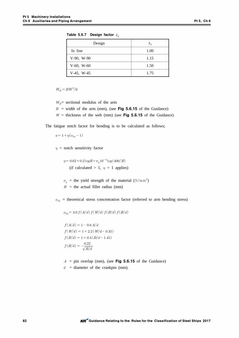
Pt 5 Machinery Installations
Ch 6 Auxiliaries and Piping Arrangement Pt 5, Ch 6
82 Guidance Relating to the Rules for the Classification of Steel Ships 2017
Design
In line 1.00
V-90, W-90 1.15
V-60, W-60 1.50
V-45, W-45 1.75
Table 5.6.7 Design factor
= sectional modulus of the arm
= width of the arm (mm), (see Fig 5.6.15 of the Guidance)
= thickness of the web (mm) (see Fig 5.6.15 of the Guidance)
The fatigue notch factor for bending is to be calculated as follows;
= notch sensitivity factor
log log(if calculated > 1, = 1 applies)
= the yield strength of the material (Nmm) = the actual fillet radius (mm)
= theoretical stress concentration factor (referred to arm bending stress)
= pin overlap (mm), (see Fig 5.6.15 of the Guidance)
= diameter of the crankpin (mm).

Pt 5 Machinery Installations
Ch 6 Auxiliaries and Piping Arrangement Pt 5, Ch 6
Guidance Relating to the Rules for the Classification of Steel Ships 2017 83
Fig 5.6.15 Crank throw for air compressor
Section 12 Refrigerating Machinery
1201. General
1. Application
(1) In application to 1201. 1 (1) of the Rules, "the refrigerating machinery forming refrigerating cy-cle“ contains compressor, condenser, receiver, evaporator, pipings and associated equipments, etc.
(2) The refrigerating machinery with compressors of 7.5 kW or less using R22, R 134a, R 404A , R407C , R 410A or R 507A as the primary refrigerant is to be suitable for use, service condition and environment on board.
(3) Refrigerating machinery using R 717 as the primary refrigerant is to comply with the require-ments specified in (4) to (14) given below, in addition to those specified in the Rules.
(4) Plans and documents to be submitted, in addition to those specified in Pt 5, Ch 1, 209. of the Rules are generally as the following :(A) R 717 Refrigerant Piping Diagram(B) Gas Detector Arrangement(C) General Arrangement of Refrigerating Machinery Compartment
(5) General requirements of ammonia refrigerating machinery(A) Pressure vessels used in refrigerating machinery is to be classed into Class 1 pressure ves-
sels specified in Pt 5, Ch 5, Sec 3 of the Rules, and the primary refrigerant pipes (hereinafter referred to as refrigerant pipes) are to be classified into Class I pipes specified in Pt 5, Ch 6, Sec 1 of the Rules.
(B) The design pressure of pressure vessels and pipes which form the refrigerating machinery is not to be less than 2.3 MPa at the high pressure side and not to be less than 1.8 MPa at the low pressure side.
(6) Materials of ammonia refrigerating machinery(A) Material capable of highly corrosion (copper, zinc, cadmium, or their alloys) and materials
containing mercury are not to be used at locations where ammonia comes into contact.(B) Nickel steel is not to be used in pressure vessels and piping systems.(C) Cast iron valves are not to be used in the refrigerant piping system.(D) Material for sea water-cooled condenser is to be selected considering the corrosion due to
sea water.(E) Where flat tanks of quick freezers(contact freezers) are manufactured by extrusion molding
of aluminium alloy, the material is to be approved in accordance with Ch 2, Sec 6 of "Guidance for approval of Manufacturing Process and Type Approval, Etc".
(7) Piping arrangement of ammonia refrigerating machinery(A) Refrigerant piping is not to pass through accommodation spaces. (B) Pipe joints of the refrigerant piping system are to be butt welded as far as practicable.(C) The refrigerant gas discharged from a pressure relief valve is to be absorbed in water, ex-
cept when leading the gas to the low pressure side.(D) If liquid level gauges made of glass are used at locations where pressure exists permanently,
they are to comply with the following requirements ;(a) Flat type glass is to be used in the liquid level gauge, and the construction is to be
such that the gauge is adequately protected against external impacts.

Pt 5 Machinery Installations
Ch 6 Auxiliaries and Piping Arrangement Pt 5, Ch 6
84 Guidance Relating to the Rules for the Classification of Steel Ships 2017
(b) The construction of the stop valve for the liquid level gauge is to be such that the flow of liquid is automatically cut off if the glass breaks.
(E) The gas discharged from the purging valve is not to be discharged directly to the atmos-phere, but absorbed in water.
(F) The discharge pipes of cooling sea water for the condenser is to be used the independent pipes. The piping is to be led directly overboard without passing through accommodation spaces.
(8) Control and alarm system of ammonia refrigerating machineryRefrigerant compressors are to be provided with means for automatically stopping the com-pressor when the pressure on the high pressure side of the refrigerant piping system becomes excessively high. Also, an alarm system which generates visible and audible alarms when this means are in operation is to be installed in the refrigerating machinery compartment and mon-itoring position.
(9) Ammonia refrigerating machinery compartment(A) The compartment where the compressor, receiver and condenser are installed (hereinafter re-
ferred to as refrigerating machinery compartment) is to be special compartment isolated by gastight bulkheads and decks from all other compartments so that leaked ammonia does not enter other compartments. Also, the refrigerating machinery compartment is to be pro-vided with doors which comply with the following requirements :(a) Except for small compartments, at least two access doors are to be provided in the re-
frigerating machinery compartment as far apart as possible from each other. (b) Access doors not leading to weather deck are to be of high tightly and self-closing
type.(c) Access doors are to be capable of being operated easily and are to open outward.
(B) Penetrations on gastight bulkheads and decks where cables and piping from the refrigerating machinery compartment pass through, are to be of gastight construction.
(C) Passages leading to the refrigerating machinery compartment are to be isolated from accom-modation spaces, hospital room or control room by gastight bulkheads and decks.
(D) An independent drainage system is to be provided in the refrigerating machinery compart-ment so that the drainage is not discharged into open bilge wells or bilge ways of other compartments.
(10) Ammonia gas expulsion system A gas expulsion system consisting of ventilation system and water screening system is to be
installed in the refrigerating machinery compartment, in accordance with (A) to (B) below so that gas leaked out accidentally can be expelled quickly from the refrigerating machinery compartment.(A) A exhaust type mechanical ventilation system which complies with the following require-
ments as a rule, is to be installed in the refrigerating machinery compartment so that this space can be ventilated all the time.
(a) The ventilation system is to have adequate capacity to ensure at least 30 air changes per hour in the refrigerating machinery compartment.
(b) The ventilation system is to be independent of other ventilation systems on board the ship, and is to be capable of being operated from outside the refrigerating machinery compartment.
(c) Exhaust outlets are to be installed properly so as to prevent exhaust air from flowing in through air intake openings, openings of accommodation spaces, service spaces and con-trol stations.
(d) Ventilation fan of non-sparking type is to be provided and complied with the require-ments specified in Pt 8, Ch 3, 104. of the Rules.
(B) All doors of the refrigerating machinery compartment are to be provided with water screen-ing system which can be operated from outside the compartment.
(11) Ammonia gas detection and alarm systems For crew's safety, fixed type ammonia gas detection and alarm systems are to be provided to activate alarms inside and outside of the refrigerating machinery compartment. And, the de-tector is to activate an alarm when the ammonia gas concentration exceeds 25ppm.
(12) Electrical equipment for ammonia refrigerating machinery(A) Electrical equipment in the refrigerating machinery compartment required to be operated in
the event of leakage accidents, gas detection and alarm system and emergency lights are to be of certified safe types for use in the flammable atmosphere concerned.

Pt 5 Machinery Installations
Ch 6 Auxiliaries and Piping Arrangement Pt 5, Ch 6
Guidance Relating to the Rules for the Classification of Steel Ships 2017 85
(B) In addition to the alarm systems in (11), an leakage alarm is to be activated at the ammo-nia gas concentration not more than 4.5% in refrigerating machinery compartment. And, electrical equipment in the refrigerating machinery compartment other than certified safe types, are required to switch off automatically by means of circuit breakers outside the re-frigerating machinery compartment when the gas concentration is sustained over an ap-pointed periods
(13) Safety and protective equipment for ammonia refrigerating machinery Safety and protective equipment for ammonia refrigerating machinery as given below, as a rule, are to be provided, and are to be stored at locations outside the refrigerating machinery com-partment so that they can be easily retrieved in the event of leakage of the refrigerant. Storage locations are to be marked with signs so that they can be identified easily.
(A) Protective clothing (helmet, safety boots, gloves, etc.) × 2(B) Self-contained breathing apparatus (capable of functioning for at least 30 minutes) × 2(C) Protective goggles × 2(D) Eye washer × 1(E) Boric acid(F) Emergency electric torch × 2(G) Electric insulation resistance meter × 1
(14) Requirements for fishing vessels, etc.(A) Refrigerating installations provided in fishing vessels of length under 55 m or refrigeration
machinery retaining ammonia not more than 25 kg are to be according to (a) to (e) given below, notwithstanding (9) to (13).(a) Refrigerating machinery may be installed in the engine room. In this case, drain trays
are to be provided at a position lower than the refrigerating machinery.(b) Ammonia gas exclusion system is to comply with the following.
(i) Ventilation system with special hoods above the refrigerating machinery is to be provided for exhaust capable of ventilation without accumulation of ammonia gas. The fans of the ventilation systems are to be independent of those of engine room ventilation systems.
(ii) A water sprinkler system capable of absorbing enough leaked ammonia gas is to be provided in the vicinity of the space where the refrigerating machinery is installed. Sprinkler hoses and water spraying nozzles are to be positioned so that water can be dispersed quickly when a leak occurs.
(c) Ammonia gas detection and alarm systems are to be provided to activate visible and au-dible alarms in the monitoring room (or control room) and engine room entrance. And, the detector is to activate an alarm when the ammonia gas concentration exceeds 25ppm. In this case, the detectors are to be installed in the vicinity of the upper parts of the refrigerating machinery, exhaust outlets and other locations deemed necessary by the Society.
(d) As far as possible, electrical equipment are not to be installed in the vicinity of the refrigerating machinery.
(e) Two(2) sets of protective clothing (helmet, safety boots, gloves, etc.) and two(2) sets of self-contained breathing apparatus (capable of functioning for at least 30 minutes) are to be provided. And, if the escape route from the monitoring room (or control room) pass-es through the engine room, one of the self-contained breathing apparatus sets is to be provided in the monitoring room (or control room).
(B) Above (A) may be applied to the refrigerating installations provided in fishing vessels of length 55 m and above only when the administration specially accepts installations of the ammonia refrigerating installations in machinery spaces.
Section 14 Tests and Inspections
1401. Tests of auxiliary machinery
In application to 1401. 1 (1) of the Rules, "where otherwise specified" means those specified in other Chapters and Table 5.6.6 of the Guidance.

Pt 5 Machinery Installations
Ch 6 Auxiliaries and Piping Arrangement Pt 5, Ch 6
86 Guidance Relating to the Rules for the Classification of Steel Ships 2017
Item Hydrostatic test pressure
Hydrulic motor 1.5 times the design pressure of hydraulic pump
Table 5.6.6
1402. Hydrostatic tests of valves and pipe fittings
1. In application to 1402. 1 of the Rules, the hydrostatic test of following valves and pipe fittings may be omitted.(1) Pipe flanges and pipe pieces(elbow, reducer, tee, bend, socket, etc.), etc.(2) Valves and pipe fittings not exceeding 25 A
2. In application to 1402. 2 of the Rules, the valve means valve body.
3. Considering the characteristics and purpose of valves, scoop valves may be subjected to a leak test at pressure side only.
4. Dimension and visual inspection may be omitted for the valves and pipe fittings not exceeding 25.
1403. Hydrostatic tests of fuel tanks
1. When hydrostatic test is replaced by gastight tests, the pressure of gastight test is to be 0.02 MPa.
1404. Tests on workmanship of pipes
1. Welding procedure qualification tests Welding procedure qualification tests specified in 1404. 1 of the Rules are to comply with Pt 2, Ch 2, Sec 4 of the Guidance.
2. Welding joints of hydraulic pipes belong to Class I and passed through the spaces other than en-gine room, cargo pump room, steering gear room and accommodation space may be applied with the requirements for pipes belong to Class II specified in 1404. 2 of the Rules.
3. RST 422, 423 or 424 used for design temperature 550 °C and over, and belong to Grade 4 of steel pipes for pressure piping, specified in Pt 2, Ch 1 of the Rules and over are to be carried out hy-drostatic test by 2 times the design pressure. However, the test pressure is not required to be more than the value calculated by the following formula. And in case where a bent of pipes, tee, etc. have a risk of excessive stress at the test, the test pressure may be reduced to 1.5 times the design pressure.
MPa
where
: Outside diameter of pipe (mm )
: Thickness of pipe (mm )
4. When water residue by the hydraulic test completion of shipboard installation of piping systems may not be desirable, the hydraulic test may be omitted in case where adequate non-destructive tests are carried out on welded joints with results free from defects.
5. In application to 1404. 3. (6) of the Rules, the term "at the discretion of the Society depending on the application" means the following requirements, etc. (1) As piping systems without welding processing, hydrostatic test of piping systems except that
conveying toxic media or services where fatigue, severe erosion or crevice corrosion, etc is ex-pected to occur may be waived.
1405. Tests of piping system on board
1. In application to 1405. 1. (2) of the Rules, "tests by hydrostatic pressure" are to be in accordance

Pt 5 Machinery Installations
Ch 6 Auxiliaries and Piping Arrangement Pt 5, Ch 6
Guidance Relating to the Rules for the Classification of Steel Ships 2017 87
with the following.(1) In principle, tests by hydrostatic pressure are to be carried out hydrostatic tests using liquid
such as water, etc.(2) In general, airtight tests instead of hydrostatic test are not permitted. Where it is impracticable
to carry out the required hydrostatic test, airtight tests may be considered.(3) In such case, the procedure for carrying out the airtight test, having regard to safety of person-
nel, is to be submitted to the Surveyor.

Pt 5 Machinery Installations
Ch 7 Steering Gears Pt 5, Ch 7
Guidance Relating to the Rules for the Classification of Steel Ships 2017 89
CHAPTER 7 STEERING GEARS
Section 1 General
101. Application
Manual steering gears are to be in accordance with the requirements of Pt 5, Ch 7, Sec 1, 201. through 203., 208. through 210., 301., Sec 4 (excluding 409. 2) and Sec 5 of the Rules and the relevant requirements of the Guidance.
102. Terminology
In 102. 1 (3) (A) of the Rules, the motor for electric steering gears is to be considered as part of power unit and actuator.
103. Drawings and documents
Operating instructions for hydraulic type steering gear are to include informations about importance of hydraulic fluid quality and its influence to probability of hydraulic locking possibility of two si-multaneously operated power units. The operating instructions of same contents as above-mentioned ones, are to be kept on the bridge.
104. Display of operating instructions
In application to 104. 2 of the Rules, the “appropriate instructions for emergency procedures” are to simply indicate emergency procedures corresponding to the design of steering gear (for example, to shut down the failed system indicated by the alarming system), and are to be fitted at a suitable place on steering control post on the navigation bridge where applicable.
Section 2 Performance and Arrangement
201. Number of steering gears
1. In case where ships whose required upper stock diameter is not more than 120 mm according to Pt 4, Ch 1 of the Rules and engaged in the service in smooth water area, or ships with a gross ton-nage less than 50 tons, provide that spare parts liable to wear down such as packings, bearings are provided where the main steering gear is operated by power, the auxiliary steering gear required by 201. of the Rules may be omitted.
2. In case where the auxiliary steering gear as specified in 201. 1 of the Rules is of hydraulic type, the rudder actuator can serve in common with that for the main steering gear. Further, part of the hydraulic piping of the rudder actuator of the main steering gear may be used in common with that for the auxiliary steering gear. In this case, but the pipe length of the part of common use is to be as short as practicable.
3. In application to 201. 1 of Rules, for a ship fitted with alternative propulsion and steering systems, such as but not limited to azimuthing propulsors or water jet propulsion systems, the main steering arrangement and the auxiliary steering arrangement shall be so arranged that the failure of one of them will not render the other one inoperative.
For a ship fitted with multiple steering systems, such as but not limited to azimuthing propulsors or water jet propulsion systems, each of the steering systems is to be equipped with its own dedicated steering gear satisfied the following. (2017)(1) Each of the steering systems is fulfilling the requirements for main steering gear (as given in 202. 2).
(2) Each of the steering systems is provided with an additional possibility of positioning and lock-ing the failed steering system in a neutral position after a failure of its own power unit and actuator.
4. In application to 201. 2 of Rules, for a ship fitted with multiple steering systems, such as but not

Pt 5 Machinery Installations
Ch 7 Steering Gears Pt 5, Ch 7
90 Guidance Relating to the Rules for the Classification of Steel Ships 2017
limited to azimuthing propulsors or water jet propulsion systems, an auxiliary steering gear need not be fitted in case that satisfied with the following. (2017)(1) In a passenger ship, each of the steering systems is capable of satisfying the requirements in 202. 2 of the Guidance while any one of the power units is out of operation.
(2) In a cargo ship, each of the steering systems is capable of satisfying the requirements in 202. 2 of the Guidance while operating with all power units.
The above capacity requirements apply regardless whether the steering systems are arranged with common or dedicated power units.(3) Each of the steering systems is to be arranged so that after a single failure in its piping or in
one of the power units, ship steering capability (but not individual steering system operation) can be maintained or speedily regained (e.g. by the possibility of positioning the failed steering system in a neutral position in an emergency, if needed).
202. Performances of main steering gear
1. In application to 202. 2 of the Rules, the diameter specified in Pt 4, Ch 1 of the Rules is to be taken as having been calculated for upper rudder stock of mild steel with a yield strength of 235Nmm (i.e. with a material factor = 1).
2. For ships fitted with non-traditional steering arrangements, such as but not limited to azimuthing propulsors or water jet propulsion systems, the main steering arrangements are to be:(1) of adequate strength and capable of steering the ship at maximum ahead service speed which is
to be demonstrated;(2) capable of changing direction of the ship’'s directional control system from one side to the other
at declared steering angle limits at an average rotational speed of not less than 2.3 °/s with the ship running ahead at maximum ahead service speed;
(3) for all ships, operated by power;(4) so designed that they will not be damaged at maximum astern speed.
203. Performances of auxiliary steering gear
1. In application to 203. 2 of the Rules, the diameter specified in Pt 4, Ch 1 of the Rules is to be taken as having been calculated for upper rudder stock of mild steel with a yield strength of 235Nmm (i.e. with a material factor = 1).
2. For ships fitted with non-traditional steering arrangements, such as but not limited to azimuthing propulsors or water jet propulsion systems, the auxiliary steering arrangements are to be :(1) of adequate strength and capable of steering the ship at navigable speed and of being brought
speedily in to action in an emergency;(2) capable of changing direction of the ship’'s directional control system from one side to the other
at declared steering angle limits at an average rotational speed, of not less than 0.5 °/s with the ship running ahead at one half of the maximum ahead service speed or 7 knots, whichever is the greater;
(3) operated by power where necessary to meet the requirements of (2) and in any ship having power of more than 2,500 kW propulsion power per thruster unit.
204. Piping
1. In case of steering gears complied with the following, the requirements of 204. 5 and 6 of the Rules may not be applied.(1) Steering gears equipped in ships with a gross tonnage less than 500 tons(2) Steering gears equipped in ships engaged in domestic coastal or smooth water service area
(excluding where auxiliary steering gear is omitted by 201. 2 of the Rules)
206. Alternative source of power
1. In case of steering gears complied with the following, the requirements of 206. of the Rules may not be applied.(1) Steering gears equipped in ships with a gross tonnage less than 500 tons, or

Pt 5 Machinery Installations
Ch 7 Steering Gears Pt 5, Ch 7
Guidance Relating to the Rules for the Classification of Steel Ships 2017 91
(2) Steering gears equipped in ships engaged in domestic coastal or smooth water service area2. For ships fitted with non-traditional steering arrangements, such as but not limited to azimuthing
propulsors or water jet propulsion systems, alternative source of power is to be met the following :(1) Where the propulsion power exceeds 2,500 kW per thruster unit, an alternative power supply,
sufficient at least to supply the steering arrangements which complies with the requirements in 203. 2 of the Guidance and also its associated control system and the steering system response indicator, is to be provided automatically within 45s.
(2) In every ship of 10,000 gross tonnage and upwards, the alternative power supply is to have a capacity for at least 30 min of continuous operation and in any other ship for at least 10 min.
(3) The alternative source of power is to be either:(A) emergency source of electric power; or(B) an independent source of power located in the steering gear compartment and used only for
this purpose.
207. Electric installations for electric and electro-hydraulic steering gear
1. In case of manual auxiliary steering gears for a ship which SOLAS is not applicable to, the power supply circuit from the main switchboard to the steering gear may be one circuit.
2. In case of steering gears complied with the following, the requirements of 207. 1, 5 (excluding short circuit protection) and 7 of the Rules may not be applied.(1) Ships with a gross tonnage less than 500 tons, or(2) Ships engaged in domestic coastal or smooth water service area
3. For a ship fitted with multiple steering systems, the requirements in 207. 3 and 4 of the Rules are to be applied to each of the steering systems. (2017)
4. In application to 207. 5 and 6 of the Rules, steering gear motor circuits which are limited to full load current via an electronic converter are exempt from the requirement to provide protection against excess current, including starting current, of not less than twice the full load current of the motor. In this case, the required overload alarm is to be set to a value not greater than the normal load of the electronic converter.
209. Means of communication
1. Means of communication between the navigating bridge and the steering gear compartment are not to depend solely on the shipboard telephone system for general purpose.
2. In case of ships complied with the following, the means of communication specified in 209. of the Rules and above 1 may be alternated with appropriate means of communication.(1) Ships with a gross tonnage less than 500 tons, or(2) Ships engaged in domestic coastal or smooth water service area
Section 3 Controls
301. General (2017)
1. It may be acceptable that only one set of floating lever or other mechanical follow-up control sys-tem is provided.
2. The control system specified in the requirements of 301. 1 (2) of the Rules is to comply with fol-lowing requirements.(1) The control system is in principle to be of the follow-up type.(2) Control systems and components are to be so designed and arranged that the failure of one of
them will not render the other one inoperative.(A) Wires, terminals and the components for duplicated steering gear control systems installed in
units, control boxes, switchboards or bridge consoles are to be separated as far as practicable. Where physical separation is not practicable, separation may be achieved by means of a fire retardant plate.

Pt 5 Machinery Installations
Ch 7 Steering Gears Pt 5, Ch 7
92 Guidance Relating to the Rules for the Classification of Steel Ships 2017
(B) All electric components of the steering gear control systems are to be duplicated. This dose not require duplication of the steering wheel or steering lever.
(C) If a joint steering mode selector switch (uniaxial switch) is employed for both steering gear control systems, the connections for the circuits of the control systems are to be divided ac-cordingly and separated from each other by an isolating plate or by air gap.
(D) In the case of double follow-up control, the amplifiers are to be designed and fed so as to be electrically and mechanically separated.
(E) Control circuits for additional control systems, e.g. steering lever or autopilot are to be de-signed for all-pole disconnection.
(F) The feed-back units and limit switches, if any, for the steering gear control systems are to be separated electrically and mechanically connected to the rudder stock or actuator separately.
(G) Hydraulic system components in the power actuating or hydraulic servo systems controlling the power systems of the steering gear (e.g. solenoid valves, magnetic valves) are to be considered as part of the steering gear control system and are to be duplicated and separated. Hydraulic system components in the steering gear control system that are part of a power unit may be regarded as being duplicated and separated when there are two or more separate power units provided and the piping to each power unit can be isolated.
3. Amplifiers, relays, etc., included in the control system may be used also for the automatic pilot systems.
4. In electro-hydraulic steering gears equipped with power units comprising variable-displacement pumps, two sets each of hydraulic servo cylinders and associated hydraulic system (including pump driving electric motors and control equipment) or electric servo motors for controlling displacement of the pump plungers are to be provided.
5. In case of ships complied with the following, the means of communication specified in 301. 3 of the Rules may not be applied.(1) Ships with a gross tonnage less than 500 tons, or(2) Ships engaged in domestic coastal or smooth water service area
6. In application to 301. 4 of the Rules, in general, following cases are not considered as the case of “where hydraulic locking, caused by a single failure, may lead to loss of steering”.(1) Steering systems with performance at least equal to that required for an auxiliary steering gear
are fitted as stand-by systems and are operable from navigating bridge. In this case, the stand-by systems are so designed not to run parallel using an interlocking devices, etc.
(2) Not less than 3 systems are operated parallel and, in the case of a single failure, steering capa-bility at least equal to that required for an auxiliary steering gears are maintained.
(3) Steering gears designed to avoid leading to loss of steering by by-passing the failed system au-tomatically using duplicated control valve system. This arrangement is subject to special consid-eration with respect to reduced reliability due to increased complexity.
7. In application to 301. 4 of the Rules, the "audible and visual alarm, which identifies the failed system" is to be activated in following conditions in general.(1) Position of the variable displacement pump control system does not correspond with given order.(2) Incorrect position of 3-way full flow valve or similar in constant delivery pump system is
detected.8. The location of sensors of alarm specified in aforementioned 7, are to be as near actuator as
possible. For the part of steering gears, where two or more pumps are mechanically interconnected by floating bar or similar, their breakage may not be considered. The example of acceptable loca-tion of alarm sensors are indicated in Fig 5.7.1.

Pt 5 Machinery Installations
Ch 7 Steering Gears Pt 5, Ch 7
Guidance Relating to the Rules for the Classification of Steel Ships 2017 93
(a) Separated system
: denoted location of alarm sensors
1. Main pump of variable displacement type.
2. Pilot pump
3. Control actuator
4. Control linkage
5. Solenoid controlled 3-way valve.
6. Solenoid.
(b) Mechanically interconnected system
(Note)
Where systems are so designed not to run 1A
& 1B IN (a) nor 2A & 2B in (b), the alarm
devices are not required.
Fig 5.7.1 Example location of hydraulic locking alarm sensors

Pt 5 Machinery Installations
Ch 7 Steering Gears Pt 5, Ch 7
94 Guidance Relating to the Rules for the Classification of Steel Ships 2017
303. Change over from automatic to manual steering
1. At any rudder angle, the change over from automatic to manual steering is to be available within 3 seconds by two attempts of control operation at the most.
2. The change over from automatic to manual steering is to be available under any circumstances in-cluding the case of failure of the automatic pilot.
3. The device to change over from automatic to manual steering is to be installed close to the normal steering position.
Section 4 Materials, Constructions and Strength
401. Materials
1. In application to 401. 4 of the Rules, the term "comply with the requirements in the recognized standards" means that comply with Korean Industrial Standards or equivalent thereto.
407. Tillers, etc.
1. In the case where the scantlings of arms are reduced in accordance with 407. 2 (4) of the Rules, following requirements are to be complied with. (1) For the tillers designed so that equal torque is applied on each arm : Required values of section
modulus Z and sectional area A specified in 407. 2 (2) and (3) of the Rules respectively, may be divided by number of arms ().
(2) For the tillers designed so that unequal torque is applied on each arm : Required values of sec-tion modulus Z and sectional area A specified in 407. 2 (2) and (3) of the Rules respectively, may be multiplied by . Where, “” means the ratio of the torque applied to the arm to the total torque.
2. The scantling of tillers for the exclusive use of auxiliary steering gear are to have the strength as-sures 1/2 or more of that specified in the requirements of 407. 2 of the Rules.
3. In application to 407. 3 (2) of the Rules, B(breadth of vane) is to be referred to Fig 5.7.2 of the Guidance.
Fig 5.7.2 Rotary vane type rudder actuator
4. The wording “where the fitting methods which are acceptable to the Society" specified in 407. 4 of the Rules means a method which is comply with the "Cone couplings of rudder stocks and rud-der main pieces" specified in Pt 4, Ch 1, 703. 2 of the Rules.
409. Buffers
In case of ships having smooth water service area and ships with a gross tonnage less than 500tons, the buffers required by 409. of the Rules may be omitted.

Pt 5 Machinery Installations
Ch 7 Steering Gears Pt 5, Ch 7
Guidance Relating to the Rules for the Classification of Steel Ships 2017 95
Section 5 Testing
503. Sea trials
1. In Application to 503. 1 (1) of the Rules, the trials for steering capabilities may be conducted in accordance with procedures in Section 6.1.5.1 of ISO 19019.
2. For 503. 1 (1) (C) of the Rules, it is to comply with one of the following methods. (2017)(1) The rudder torque at the trial loading condition have been reliably predicted (based on the sys-
tem pressure measurement) and extrapolated to the full load draught condition using the follow-ing method to predict the equivalent torque and actuator pressure at the full load draught.
∙
where :
= Extrapolation factor
= Rudder stock moment for the full load draught and maximum service speed condition
= Rudder stock moment for the trial condition
= Total immersed projected area of the movable part of the rudder in the full load con-
dition
= Total immersed projected area of the movable part of the rudder in the trial condition
= Contractual design speed of the vessel corresponding to the maximum continuous rev-
olutions of the main engine at the full load draught
= Measured speed of the vessel (considering current) in the trial condition
Where the rudder actuator system pressure is shown to have a linear relationship to the rudder stock torque the above equation can be taken as:
∙
where :
= Estimated steering actuator hydraulic pressure in the deepest full load condition
= Maximum measured actuator hydraulic pressure in the trial condition
Where constant volume fixed displacement pumps are utilised then the regulations can be deemed satisfied if the estimated steering actuator hydraulic pressure at the full load draught is less than the specified maximum working pressure of the rudder actuator. Where a variable de-livery pump is utilised pump data should be supplied and interpreted to estimate the delivered flow rate corresponds to the full load draught in order to calculate the steering time and allow it to be compared to the required time. Where is greater than there is no need for extrapolation methods to be applied.
(2) Alternatively the designer or builder may use computational fluid dynamic(CFD) studies or ex-perimental investigations to predict the rudder stock moment at the full load draught condition and service speed. These calculations or experimental investigations are to be to the satisfaction of the Society.
3. In application to 503. 1 (9) of the Rules, the wordings “steering gear is designed to avoid hydraul-ic locking” means steering gears designed not to run parallel using an interlocking devices, etc. or steering gears designed to maintain their steering capability or to recover them by by-passing the

Pt 5 Machinery Installations
Ch 7 Steering Gears Pt 5, Ch 7
96 Guidance Relating to the Rules for the Classification of Steel Ships 2017
failed system automatically. For the steering systems which are dispensed with the consideration of hydraulic locking because of that considerations of the breakages at mechanical linkage of floating bar or similar are waived, these demonstrations may not be carried out.
Section 6 Additional Requirements Concerning Tankers of 10,000 GrossTonnage and Upwards and Other Ships of 70,000 Gross Tonnage and Upwards
604. Non-destructive tests
In application to 604. of Rules, where the procedure and acceptance criteria for the non-destructive testing considered by the Society means that the requirement may be in accordance with Pt 2, Annex 2-2 & Annex 2-5 of the Guidance considering their materials, kinds, shapes and stress condition be subjected.

Pt 5 Machinery Installations
Ch 8 Windlasses and Mooring Winches Pt 5, Ch 8
Guidance Relating to the Rules for the Classification of Steel Ships 2017 97
CHAPTER 8 WINDLASSES AND MOORING WINCHES
Section 1 General
101. Application
1. In application to 101. 1 of the Rules, manual operating windlasses are to be complied with the following.(1) In the case of windlasses complied with the following, the manual operating windlasses may be
accepted.(A) In the case of windlasses for anchor with weight 250 kgf or less(B) In the case of windlasses for anchors with weight 500 kgf or less equipped on barges en-
gaged in domestic service area and ships engaged in smooth water service area(2) Manual operating windlasses are to be capable of lifting anchor and chain at the nominal speed
of at least 0.033 ms. In this case, the human power driving them is to be 147 N or less when their crank radius of 350 mm is rotated about 30 rpm .
(3) Materials used in the major parts are complied with Korean Industrial Standards or other recog-nized standards.
(4) For manual operating windlasses, brake test and load test are to be carried out. The test proce-dures are to be applied with appropriate modifications of the requirements of 205. 2 of the Guidance. However, the nominal speed and the human power driving them are to be applied with (2) above.
102. Materials
1. In application to 102. 1 of the Rules, "major parts" means the following.(1) Driving shafts and gears of power transmission system (Mooring winch)(2) Chain lifters and shafts of chain lifter (Windlass)(3) Rope drums and shafts of rope drum (Mooring winch)(4) Brake bands and spindles(5) Chain stoppers (Windlass)
Section 2 Windlasses
205. Tests and Inspections
1. No load test
Windlasses are to be run without load in normal and reverse direction, for a sum of each 15 m i-nutes, under the rated voltage at the rotating speed equivalent to the rated speed at the shop. During the test, tightness against oil leakage, temperature of bearings and presence of abnormal noise are to be checked. However, when it is difficult to be carried out the test at the shop, the test may be carried out on board.
2. Brake test and load test
Windlasses are, after installation on board, to be tested and checked about the following at the lo-cation ensured depth of water deeper than the total length of 3 lengths of anchor chain and anchor.(1) Brake test
The anchor chain cable is to be hoisted to the position that the anchors are submerged in wa-ter, and the anchor is to be fallen freely until getting to sea-bed. At this time, brake systems are to be checked every 1/2 length. In this case, it is considered as a standard that braking dis-tance of brake systems is to be 7 m or less.
(2) Load testEach windlass is to be conducted load test as follows;(A) At the condition that 3 lengths of chain cable is submerged in water but anchor is not got
to sea-bed, 2 lengths of anchor chain are to be hoisted. In this time, it is to be confirmed that the average speeds are 0.15 ms or over.
Pt 5 Machinery Installations
Ch 8 Windlasses and Mooring Winches Pt 5, Ch 8
98 Guidance Relating to the Rules for the Classification of Steel Ships 2017
(B) Particulars required identification of capability, utility, and conditions for constructions and components of the windlass are to be checked during load test.
(3) In the case where the depth of water deeper than the total length of 3 lengths of anchor chain and anchor is difficult to be ensured geographically at sea trial, load test may be carried out according to the following. However, in this case, the tests are to be carried out at the deepest area among the sea trial area.(A) Symmetrical double cable-lifter windlasses
(a) The anchor chain cable of each side is to be lifted until the position that the anchor gets to the surface of water. And the anchor of each side is to be fallen in the water until 1 length of chain cable is submerged in water but anchor is not got to sea-bed.
(b) The average speeds are to be measured when each 1 length of both sides anchor chain is lifted simultaneously, and are to be 0.15 ms or over at the conditions mentioned above (a).
(B) Single cable lifter windlassesAverage speed is to be measured by anyone among the following after identifying the above (A) (a).(a) Where windlass is capable to lift simultaneously anchor chain cable of both sides by
use of independent hydraulic pump unit of one side, the average speed is to be 0.15ms or over at the test mentioned in above (A) (a) making use of a hydraulic pump unit of one side.
(b) Where windlass is incapable to lift simultaneously anchor chain cable of both sides by use of independent hydraulic pump unit of one side, the average speed of recovery of chain cables, when the maximum length of anchor chain cables are submerged but free-ly suspended at commencement of lifting is to be 0.15 ms or over by comparing with the measurements for capability particulars and the estimated performance curve. In case of where the result is doubted by comparing with performance curve, it may be carried out retesting.
(c) Single cable lifter windlasses driven by electric motor or steam are to be applied with appropriate modifications of the requirements of (b) above.
(C) Couple windlassesCouple windlasses are to be applied with appropriate modifications of the requirements of above (A). In this case, 2 sets of prime mover may be used for lifting anchors of one side or both sides simultaneously.
Pt 5 Machinery Installations
Annex 5-1 Requirements for the Water-jet Propulsion Systems and Azimuth or Rotatable Thrusters Pt 5, Annex 5-1
Guidance Relating to the Rules for the Classification of Steel Ships 2017 99
ANNEX
Annex 5-1 Requirements for the Water-jet Propulsion Systems and Azimuthor Rotatable Thrusters
1. Water-jet propulsion systems
(1) General(A) The requirements in this Guidance apply to the water-jet propulsion systems intended for
main propulsion and steering driven by high speed engines.(hereinafter referred to as the propulsion systems).
(B) For items not specified in this Guidance, the relevant requirements specified in Pt 5 and Pt 6 of the Rules apply.
(C) Propulsion systems of special type or other which have unavoidable but justifiable reasons precluding the due compliance with the requirements of this Guidance are to be examined in consideration of each design.
(D) The following requirements need not be applied to those propulsion systems without steer-ing arrangements.(a) (4) (B) (d)(b) (4) (C) (c), (d) and (g) (c) (4) (E) and (F)(d) (4) (G) (a), (b), (e), (f) and (g) (e) (4) (H) (c) and (d)
(E) EquivalencyPropulsion systems which do not comply with the requirements of this Guidance may be ac-cepted provided that they are deemed by the Society to be equivalent to those specified in this Guidance.
(F) TerminologyThe terms used in this Guidance are defined as follows:(a) Water-jet propulsion system is a system, including the following components, which re-
ceives water through inlet ducts and discharges it through a nozzles at an increased ve-locity to produce propulsive thrust.(i) Shaftings (main shafts, bearings, shaft couplings, coupling bolts and sealing devices)(ii) Water intake duct(iii) Water pump unit(iv) steering and reversing systems
(b) Impeller is a rotating assembly provided with blades to give energy to the water.(c) Main shaft is a shaft that transmits power to the impeller blades.(d) Water intake duct is the portion that leads the water drawn from the water intake to
the impeller inlet.(e) Nozzle is the portion that injects the rectified water from the impeller.(f) Deflecter is the device serving as a rudder by leading the water injected from the noz-
zle either to port or to starboard.(g) Reverser is the device to thrust the ship to go astern by reversing the flow direction
of the water injected from the nozzle.(h) High speed engine is the high-rotating-speed internal combustion engine specified in Pt 1, Ch 2, 303. 3 of the Guidance or gas turbine.
(i) Water pump units are consist of impellers, impeller casings, stators, stator casings, noz-zles, bearings, bearing housing and sealing devices.
(j) Stators are assemblies composed of rows of stationary vanes that reduce any swirl add-ed to water by impellers.
(k) Steering and reversing systems are those systems consisting of deflectors, reversers and hydraulic power systems driving defectors or reversers.
(l) Hydraulic power systems are systems composed of hydraulic pumps and electric mo-tors or engines for driving defectors or reversers.
(2) Drawings and Data to be Submitted Before the work is commenced, the manufacturers of propulsion systems are to submit drawing in triplicate and a copy of data specified below, to the Society for approval.

Pt 5 Machinery Installations
Annex 5-1 Requirements for the Water-jet Propulsion Systems and Azimuth or Rotatable Thrusters Pt 5, Annex 5-1
100 Guidance Relating to the Rules for the Classification of Steel Ships 2017
(A) Plans(a) Particulars, Specifications, Material specifications, Detail of welding procedures(b) General arrangement and sectional assembly (showing the materials and dimensions of
various parts including the water intake duct, etc.)(c) Shafting arrangement (showing the arrangements, shapes and construction of the main
engine, gear, clutch, coupling, main shaft, main shaft bearing, thrust bearing, sealing de-vice, impeller, etc.)
(d) Details of water intake duct(e) Construction of impeller (showing the detailed blade sections, the maximum diameter of
blade from the centre of the main shaft, number of blades, and material specifications)(f) Details of bearing and sealing device (including thrust bearing), in the case of roller
bearing, together with specifications of such bearings and the calculation sheets for the life times of roller bearings.
(g) Details of deflectors and reversers(h) Piping diagrams (hydraulic systems, lubricating systems, cooling water systems and etc.)(i) Arrangements of control systems and diagram of hydraulic and electrical systems
(including safety devices, alarm devices and automatic steering) (j) Arrangements and diagram of an alternative source of power(k) Diagram of indication devices for deflector positions(l) Details of hydraulic actuators
(B) Data(a) Torsional vibration calculation sheets and calculation sheets of the bending natural fre-
quency when bending vibration due to self-weight is expected(b) Strength calculation sheets for deflector and reverser(c) Others considered to be necessary by the Society
(3) Materials, Construction and Strength(A) Materials
The materials of parts of the propulsion system are to be suitable for respective uses in-tended, and the following important components are to comply with the requirements in Pt 2, Ch 1 of the Rules. However, the Society may accept to use those made of materials which comply with Korean Industrial Standards or standards as considered equivalent therto.(a) Main shaft(b) Nozzle and impeller(c) Impeller casings, stator casings and bearing housings(d) Water intake duct which are composing a part of shell plating (including shaft cover) (e) Mounting flanges and bolts of water-jet pump units (including shaft coupling and cou-
pling bolts)(f) Deflectors and reversers
(B) Construction and strength(a) Main shaft
The minimum diameter of the main shaft is to be not less than the value determined by the following formula:
⋅
where
: Required diameter of main shaft (mm )
: Maximum continuous output of main engine (kW)
: Number of revolutions of main shaft at the maximum continuous output
(rpm )
: Values shown in Table 1

Pt 5 Machinery Installations
Annex 5-1 Requirements for the Water-jet Propulsion Systems and Azimuth or Rotatable Thrusters Pt 5, Annex 5-1
Guidance Relating to the Rules for the Classification of Steel Ships 2017 101
Position
Fitting method
Shaft material
Fitting part of shaft with impeller and shaft coupling
Other positionsWith key way With spline
With flange coupling
Force fitting
Carbon steel or low alloy steel
Shaft of Class 2 105 108 102 102 105
Shaft of Class 1 =100=80
in Note
=102=82
in Note
=98=78
in Note
=100=80
in NoteAustenitic stainless steel
Precipitation hardened stainless steel 80 82 78 78 80
NOTES For ≤ ≤
For
: Specified yield point or 0.2 of proof strength of shaft material (Nmm)
Table 1 Values of k according to Fitting Method
(b) Shaft couplings and coupling bolts(i) The minimum diameter of the shaft coupling bolts at the joining face of the cou-
plings is to be not less than the value determined by the following formula:
⋅
where
: Required diameter of shaft coupling bolt (mm )
: Number of bolts
: Pitch circle diameter (mm )
: Specified tensile strength of bolt material (Nmm)(ii) The thickness of the shaft coupling flange at the pitch circle is not to be less than
the required diameter of shaft coupling bolts determined by the formula in (i) above. However, it is not to be less than 0.2 times the required diameter of the corre-sponding shaft.
(iii) The fillet radius at the base of the flange is not to be less than 0.08 times the di-ameter of the shaft. The fillets are to have a smooth finish. Where the fillet is re-cessed in way of nuts and bolt heads, the fillet radius at the base of the flange is not to be less than 0.125 times the diameter of the shaft.
(c) Water intake duct, etc.The water intake duct, impeller casing and nozzle are to have strength according to the design pressure, and consideration is to be given for corrosion.
(d) Impeller bladeThe strength of the impeller blade at root is to be determined so that the following for-mula is satisfied. In this case, the allowable stress value of the material is, in principle, to be 1/1.8 of the specified yield point (or 0.2 of proof strength).
≥
××
where

Pt 5 Machinery Installations
Annex 5-1 Requirements for the Water-jet Propulsion Systems and Azimuth or Rotatable Thrusters Pt 5, Annex 5-1
102 Guidance Relating to the Rules for the Classification of Steel Ships 2017
Carbon steel or low alloy steelAustenitic
stainless steel
Martensite precipitation hardened type stainless steelShaft of Kind 1 Shaft of Kind 2
A 24.3 9.0 26.4 39.6
B 24.1 6.2 26.4 37.1
C 4.8 4.0 5.0 9.6
Table 2 Values of A, B and C
: Allowable stress of impeller material (Nmm) : Maximum continuous output of main engine (kW)
: Value obtained by dividing the number of revolutions of impeller by 100 (rpm/100)
: Number of impeller blades
: Width of impeller blade at root (mm )
: Maximum thickness of impeller blade at root (mm )
: Diameter of impeller (mm )
(C) Torsional vibration and bending vibration of main shaft(a) General
(i) Notwithstanding the requirements specified in above (2) (I) concerning to submission of the torsional vibration calculation sheets for the main shafting systems, sub-mission of those may be omitted in cases where the shafting system is of the same type as previously approved one or it can be readily assumed that the shafting sys-tem has no excessive vibration stress.
(ii) Measurements of torsional vibration to confirm accuracy of the estimated value are to be carried out. In cases, however, submission of the torsional vibration calculation sheets is omitted according to the requirements in above (1), or the Society consid-ers that there is no critical vibration within the service speed range, the measure-ment of torsional vibration may be omitted.
(b) Allowable limit of torsional vibration stressThe torsional vibration stress of the shafting system is to be in accordance with the fol-lowing requirements within the service speed range of the shafting system.(i) The torsional vibration stresses produced when the revolutions of the engine are
within the range from 80 to 105 of maximum continuous revolutions are not to exceed given in following :
≤ and
where
: Allowable limit of torsional vibration stresses for the range of 0.8 < ≤1.05
(Nmm) : Ratio of the number of maximum continuous revolutions to the number of
service revolution of the engine
, and : Values shown in Table 2
In case where the specified tensile strength of materials of carbon steel shafts or low alloy steel shafts of Kind 1 exceeds 400 Nmm the value of may be in-creased by multiplying the factor given in the following formula:

Pt 5 Machinery Installations
Annex 5-1 Requirements for the Water-jet Propulsion Systems and Azimuth or Rotatable Thrusters Pt 5, Annex 5-1
Guidance Relating to the Rules for the Classification of Steel Ships 2017 103
where
: Correction factor
: Specified tensile strength of main shaft material (Nmm)(ii) The torsional vibration stresses of the main shaft within the range below and at 80 of the maximum continuous revolutions of the engine are not to exceed given in following. In case where torsional vibration stresses exceed the value calculated by the formula of shown in (i), the barred speed ranges are to be imposed. In this case, the formula for 1 is the one for the range of ≤ 0.9.
where
: Allowable limit of torsional vibration stresses for the range of ≤ 0.8
(Nmm)(c) Bending vibration
For the main shafting system of the propulsion system, consideration is to be given to natural vibrations due to bending of the shafting system.
(4) System design(A) Number of propulsion systems
(a) In general, a minimum of two propulsion systems are to be provided for ships. Propulsion systems are to be designed so that the failure of any one system does not result in the performance of all of the other systems. As a result, the requirements for auxiliary steering gear specified in Ch 7, Sec 2 of the Rules may not apply to pro-pulsion systems.
(b) In cases where the ship is not engaged in international voyage, a single propulsion sys-tem installation may be considered notwithstanding the requirements specified in above (a). In this case, the functions of propulsion, steering and reversing are to be designed with redundancy in the following arrangements:(i) A minimum of two prime movers are to be provided.(ii) A minimum of two hydraulic power systems for steering and reversing are to be
provided.(iii) Electric supply is to be maintained or restored immediately in cases where there is
a loss of any one of the main generators in service so that the functioning of at least one of the propulsion system, including their prime movers, is maintained by the arrangements specified in (4) (E).
(B) Steering and Reversing Systems(a) Deflectors are, in principle, to be capable of changing direction of the ship's directional
control systems from one side to the other at declared steering angle limits at an aver-age rotational speed of not less than 2.3 degrees/s with the ship running ahead at speeds specified in Pt 3, Ch 1, 120. of the Rules. The wording "declared steering an-gle limits"refers to the operational limits of deflectors in terms of maximum steering an-gle according to manufacturer guidelines for safe operation.
(b) The reverser is to be such that it provide sufficient power for going astern to secure proper control of the ship in all normal circumstances, and when transferred from ahead to astern runs, it is to have an astern power to provide effective breaking for the ship.
(c) The reverser is to have sufficient strength against the thrust at the maximum astern power output.
(d) The design pressure for calculations to determine the scantlings of piping and other steering gear components of hydraulic power systems subject to internal hydraulic pres-sure are to be at least 125% of the maximum working pressure expected under the worst permissible operating condition, taking into account any pressure which may exist in the low pressure side of systems. Design pressures are no to be less than relief valve setting pressures.
(C) Hydraulic system(a) The strength of the pressure vessels such as accumulators, etc. used in power actuating
systems is to comply with the relevant requirements in Ch 5 in addition to this Annex.

Pt 5 Machinery Installations
Annex 5-1 Requirements for the Water-jet Propulsion Systems and Azimuth or Rotatable Thrusters Pt 5, Annex 5-1
104 Guidance Relating to the Rules for the Classification of Steel Ships 2017
(b) Hydraulic piping systems used in the power actuating systems are to comply with the relevant requirements in Ch 6 in addition to this Annex.
(c) The strength of hydraulic actuators is to comply with the requirements specified in Ch 7, 404. of the Rules.
(d) The construction of oil seals in hydraulic actuators is to comply with the requirements specified in Ch 7, 405. of the Rules.
(e) Suitable arrangements to maintain the cleanliness of the hydraulic fluid are to be pro-vided taking into consideration the type and design of the power actuating system.
(f) Arrangements for bleeding air from the power actuating system are to be provided where necessary.
(g) Relief valves are to be fitted to any part of the hydraulic system which can be isolated and in which pressure can be generated from the power source or from external forces. The setting pressure of the relief valves is not to be less than 1.25 times the maximum working pressure but not to exceed the design pressure. The minimum discharge ca-pacity of the relief valves are not to be less than total capacity of pumps which pro-vided power for hydraulic actuators. Under such conditions the rise in pressure is not to exceed 10 % of the setting pressure. In this regard, due consideration is to be given to the extreme foreseen ambient conditions in respect of oil viscosity.
(h) A low level alarm is to be provided for each hydraulic fluid reservoir to give the ear-liest practicable indication of hydraulic fluid leakage. This alarm is to be audible and visual and to be given on the navigating bridge and at a position from which the main engine is manually controlled.
(i) In cases where flexible hoses are used for hydraulic power systems, the construction and strength of such flexible hoses are to comply with the requirements specified in Ch 6, 102. 5. of the Rules.
(D) Stoppers(a) Propulsion systems are to be provided with stoppers for deflectors in order to limit
steering angles.(b) Propulsion systems are to be provided with positive arrangements, such as limit
switches, for stopping deflectors before the stoppers are reached. These arrangements are to be activated by the actual movements of deflectors and not through control systems for steering. Mechanical links may be used for this purpose.
(E) Main source of electrical power(a) Where the main source of electrical power is necessary for propulsion, steering and re-
versing of the ship, the system is to be so arranged that electric supplies to relevant equipment are maintained, or restored immediately in the case of a loss of any one of the generators in service, to ensure the functions of propulsion, steering and reversing of at least one of the propulsion systems, its associated control systems and its indication devices for deflectors positions by the following arrangements:(i) Where the electrical power is normally supplied by one generator, adequate provi-
sions are to be made for automatic starting and connecting to main switchboards of standby generators of sufficient capacity to maintain the functions of the above with automatic restarting of important auxiliaries including sequential operations in cases where there is a loss of electrical power of the generator in operation.
(ii) Where the electrical power is normally supplied by more than one generator simul-taneously in parallel operations, provisions are to be made to ensure that, in cases where there is a loss of electrical power of one of generating sets, the remaining ones are kept in operation to maintain the functions of the above.
(F) Where the propulsion power exceeds 2,500 kW per thruster unit, an alternative source of power is to be provided in accordance with the following:(a) Any alternative source of power is to be capable of automatically supplying alternative
power within 45 seconds to the deflector and its associated control system and its in-dication devices for deflector positions.
(b) In every ship of 10,000 gross tonnage and upwards, the alternative power supply is to have a capacity for at least 30 min of continuous operation and in any other ship for at least 10 min.
(c) The alternative source of power is to be either:(i) emergency source of electric power; or

Pt 5 Machinery Installations
Annex 5-1 Requirements for the Water-jet Propulsion Systems and Azimuth or Rotatable Thrusters Pt 5, Annex 5-1
Guidance Relating to the Rules for the Classification of Steel Ships 2017 105
(ii) an independent source of power located in the steering gear compartment and used only for this purpose.
(d) The alternative source of power is to be capable of changing direction of the ship's di-rectional control system from one side to the other at declared steering angle limits at an average rotational speed of not less than 0.5 degree/s with the ship running ahead at one half of the speeds specified in Pt 3, Ch 1, 120. of the Rules or 7 knots, which-ever is greater.
(e) Automatic starting arrangements for generators or prime movers of pumps used as the independent source of power specified in (c) (ii) are to comply with the requirements for starting devices and performance in Pt 6, Ch 1, 203, 6. of the Rules.
(G) Electrical Installations for Steering and Reversing Systems Where hydraulic pumps for hydraulic power systems are driven by electric motors, electrical
installations for steering and reversing systems are to comply with the following require-ments :(a) Each propulsion systems is to be served separately by exclusive circuits fed directly
from main switchboards. In cases where three or more propulsion systems are provided, these exclusive circuits may be composed of at least two systems. One of these circuits may be supplied through the emergency switchboard.
(b) Cables used in those exclusive circuits required in above (a) are to be separated as far as practicable throughout their length.
(c) Audible and visual alarms are to be given on navigation bridges in the event of any power failure to electric motors for hydraulic pumps.
(d) Means for indicating that electric motors for hydraulic pumps are running are to be in-stalled on navigation bridges and positions from which main engines are normally controlled.
(e) Short circuit protection and overload alarms are to be provided for such circuits and motors respectively. Overload alarms are to be both audible and visible and are to be situated in conspicuous positions in places from which main engines are normally controlled.
(f) Protection against excess current, including starting currents, if provided, is to be for not less than twice the full load current of those motors or circuits so protected, and to be arranged to permit the passage of any appropriate starting currents.
(g) Where a three-phase supply is used, alarms are to be provided that will indicate failure of any one of the supply phases. Such alarms are to be both audible and visible and are to be situated in conspicuous positions in places from which main engines are nor-mally controlled.
(h) Where the propulsion power does not exceed 2,500kW per thruster unit and emergency generators are provided, one hydraulic power system for the steering system (including associated control systems) is to be served by exclusive circuits fed directly from emer-gency switchboards. In this cases, those exclusive circuits supplied through the emer-gency switchboards specified in above (a) may be used as this circuit.
(H) Controls(a) The requirements for controls not specified in herein (H) are to be complied with the
requirements specified in Ch 7, Sec 3 of the Rules.(b) Reversing systems are to be controlled in local control stations for main propulsion or
in steering stations. Means are to be provided in local control stations for main pro-pulsion or in steering stations for disconnecting any control systems, operable from navi-gation bridges, from reversing systems they serve.
(c) In the event of any failure of remote control devices for reversing systems, preset posi-tions of reversers are to be maintained until control of such systems can be gained at local control stations for main propulsion or in steering stations.
(d) Independent control devices are to be provided for propulsion systems. Where multiple propulsion systems are designed to operate simultaneously, they may be control by a single device such as a joystick.
(e) Those control devices specified in above (d) are to be so designed that any failure of one such control device does not result in the failure of the others.
(f) For those items concerned with safety, alarms and control devices for propulsion systems not specified in herein (H), the related requirements specified in Pt 9, Ch 3 of the Rules are to apply.

Pt 5 Machinery Installations
Annex 5-1 Requirements for the Water-jet Propulsion Systems and Azimuth or Rotatable Thrusters Pt 5, Annex 5-1
106 Guidance Relating to the Rules for the Classification of Steel Ships 2017
(I) Indication Devices(a) Indication devices for deflector positions
(i) Deflector positions are to be indicated on navigation bridges and in steering stations.(ii) Indication devices for deflector positions are to be independent of control systems.
(b) Indication devices for reverser positions Reverser positions are to be indicated on navigation bridges and at control stations in-
cluding steering stations and monitoring stations for propulsion systems.(c) Indication devices for impeller speed Impeller speeds are to be indicated on navigation bridges and at control stations includ-
ing steering stations and monitoring stations for propulsion systems.(J) Lubricating Oil Systems
(a) Lubricating oil systems for propulsion systems are to comply with those relevant require-ments specified in Ch 6, Sec 8 of the Rules.
(b) Lubricating oil arrangements of propulsion systems are to be provided with alarm de-vices which give visible and audible alarms on navigation bridge and at positions from which main engines are normally controlled in the event of any failure of the supply of lubricating oil or an appreciable reduction of lubricating oil pressure.
(K) Display of Operating Instruction, etc. is to be complied with the requirements specified in Ch 7, 104. of the Ruels.
(L) Sealing Devices The materials, constructions and arrangements of sealing devices for shaftings and water-jet
pump units, other than gland packing type sea water sealing devices, are to be approved by the Society.
(M) For ships with the Class Notation "Coasting Service", "smooth water service", which are not engaged in international voyages, or whose gross tonnage is less than 500 tons, the fol-lowing requirements are not necessary.(a) The requirements specified in (4) (C) (h)(b) The requirements specified in (4) (E) and (F)(c) The requirements specified in (4) (G) (b), (e) (excluding short circuit protection) and (g)
(5) Tests and Inspections(A) Shop tests
(a) Hydrostatic tests at pressures 1.5 times design pressure for impeller casings, stator cas-ings and bearing housings are to be carried out.
(b) Hydrostatic tests are to be carried out at a pressure of at least 0.2 MPa or 1.5 times the design pressure whichever is higher for the forward bearing tube of the main shaft and the sealing device.
(c) The tests specified in Ch 7, 501. of the Rules for hydraulic power systems are to be carried out.
(d) Performance tests of control, safety and alarm devices are to be carried out.(B) Tests after installation on board
(a) Verification of steering performance and operating test of reverser specified in (4) (B) are to be carried out.
(b) Measurement of torsional vibration is to be in accordance with Ch 4, 103. of the Rules.
(c) Leak tests of hydraulic piping systems at pressures at least equal to the maximum work-ing pressure after installed on board are to be carried out.
(d) Leak tests of sealing devices for water-jet pump units at working oil pressure are to be carried out.
(e) Operation tests of propulsion systems as far as practicable are to be carried out.(C) Sea trials
(a) In the Classification Survey of ships, the following tests are to be carried out during sea trials, in substitution for those tests specified in Ch 7, 503. of the Rules. However, those tests other than tests required in (i) and (ii) may be carried out either at dockside or in dry dock.(i) Tests on steering capabilites specified in (4) (B).(ii) Test on operation of controls for steering and reversing systems, including tests on
change-overs of control systems between navigation bridges and steering stations, and change-overs between manual steering and automatic steering, if provided.

Pt 5 Machinery Installations
Annex 5-1 Requirements for the Water-jet Propulsion Systems and Azimuth or Rotatable Thrusters Pt 5, Annex 5-1
Guidance Relating to the Rules for the Classification of Steel Ships 2017 107
(iii) Tests on measures for maintaining power supplies and on the alternative source of power required by (4) (E) and (F).
(iv) Tests on means of communication between navigation bridges and steering stations, and between engine rooms and steering stations.
(v) Tests on the functioning of relief valves for preventing over-pressure.(vi) Tests on the functioning of alarm and safety devices, and indication devices for de-
flector positions, reverser positions and impeller speed, and running indicators of electric motors for hydraulic power systems.
(vii) Tests on the functioning of stoppers.
2. Azimuth or rotatable thrusters
(1) General(A) The requirements in this Guidance apply to ships equipped with azimuth or rotatable thrust-
ers intended for main propulsion. (hereinafter referred to as "thrusters")(B) For items not specified in this Guidance, the relevant requirements specified in Pt 5 and Pt 6 of the Rules apply.
(C) Propulsion systems of special type or others which have unavoidable but justifiable reasons precluding the due compliance with the requirements of this Guidance are to be examined in consideration of each design.
(D) EquivalencyPropulsion systems which do not comply with the requirements of this Guidance may be ac-cepted provided that they are deemed by the Society to be equivalent to those specified in this Guidance.
(E) Terminology The terms used in this Guidance are defined as follows:
(a) Thrusters are propulsion units with steering functions enabled by their own capability of azimuthing. Thrusters are made up of the following components:(i) Propellers(ii) propeller shafts(iii) Gears, clutches and gear shafts for transmission of propulsion torque (when in-
tegrated in thrusters)(iv) Azimuth thruster casings(v) Azimuth steering gears(vi) Control systems
(b) Azimuth thruster casings are watertight structures that include steering columns (or struts), propeller pods, propeller nozzles and nozzle supports.
(c) Azimuth steering gears are devices for applying steering torque to thrusters, and in-clude electric motors, hydraulic pumps, hydraulic systems, hydraulic motors and gear as-semblies for azimuth steering gears.
(2) Drawings and data to be submittedBefore the work is commenced, the manufacturers of propulsion systems are to submit drawing in triplicate and a copy of data specified below, to the Society for approval.(A) Drawings
(a) Particulars, specifications, material specifications, details of welding procedures(b) General arrangement and sectional assembly (showing the materials and dimensions of
various parts including nozzle ring)(c) Details of shafting arrangement, gears, shaft couplings, coupling bolts, clutch and gear
shafts(d) Details of steering systems (details of actuating systems, gear assemblies, bearings and
sealing devices for azimuth steering gears)(e) Specification of bearings(f) Piping systems (hydraulic systems, lubricating systems, cooling water systems and etc.)(g) Details of azimuth thruster casings(h) Arrangements of control systems and diagram of hydraulic and electrical systems
(including safety devices, alarm devices and automatic steering)(i) Arrangements and diagrams of an alternative source of power(j) Diagrams of indication devices for azimuth angles

Pt 5 Machinery Installations
Annex 5-1 Requirements for the Water-jet Propulsion Systems and Azimuth or Rotatable Thrusters Pt 5, Annex 5-1
108 Guidance Relating to the Rules for the Classification of Steel Ships 2017
(B) Data(a) Data for strength calculation according to kind of main propulsion engine(b) Torsional vibration calculation sheets of shafting(c) Strength calculations for main component parts(d) Operating manual(e) service life calculations of roller bearings and propeller pull-up length calculations sheets,
etc.(f) Others considered to be necessary by the Society
(3) Materials, constructions and strength(A) Materials, constructions and strength of shafting arrangement, propellers, gears and steering
systems are to be applied with appropriate modifications of the relevant requirements of Ch 3, Ch 4 and Ch 7 of the Rules.
(B) Materials, constructions and strength of piping systems and auxiliaries are to be applied with appropriate modifications of the relevant requirements of Ch 6 of the Rules.
(C) Materials used for azimuth thruster casings and bedplates for supporting thrusters are to comply with the requirements in Pt 2, Ch 1 of the Rules.
(4) System design(A) Thrusters
(a) In general, a minimum of two thrusters is to be provided for ships. Thrusters are to be designed so that the failure of one thruster does not result in the performance of any other thrusters. As a result, the requirements for auxiliary steering gear as specified in Ch 7, Sec 2 of the Rules do not apply to thrusters.
(b) In cases where the ship is not engaged in international voyage, a single thruster in-stallation may be considered notwithstanding the requirements specified in above (a). In this case, the functions of propulsion, steering and reversing are to be designed with re-dundancy in the following arrangements:(i) A minimum of two prime movers is to be provided.(ii) A minimum of two independent azimuth steering gears is to be provided. However,
such azimuth steering gears may have only one gear wheel.(iii) Electric supplies are to be maintained or restored immediately in the case of loss
of any main generator in service so that the functions of at least one of thrusters, including its prime movers, are maintained by the arrangements specified in (4) (E).
(c) The installation and construction of thrusters are to be such that ship stability is not ad-versely affected even when sea water enters azimuth thruster casings and floods com-partments where they are installed.
(d) Sealing devices are to be provided in cases where thrusters penetrate hull structures to prevent any sea water from entering ships.
(B) Azimuth steering gears(a) Design pressure for calculations to determine the scantlings of piping and other compo-
nents of hydraulic power systems of azimuth steering gears subject to internal hydraulic pressure are to be at least 125% of the maximum working pressure expected under the worst permissible operation conditions after taking into account any pressure which may exist in low pressure sides of such systems. Design pressures are not to be less than re-lief valve setting pressures.
(b) The steering arrangement of thrusters are to be capable of changing direction of the ship's directional control system from one side to the other at declared steering angle limits at an average rotational speed of not less than 2.3 degree/s with the ship running ahead at speeds specified in Pt 3, Ch 1, 120. of the Rules. The wording "declared steering angle limits" refers to the operational limits in terms of maximum steering an-gle according to manufacturer guidelines for safe operation.
(c) In addition to the requirements specified in above (b), the rate of turning for azimuth steering gears is to be not less than 1.0 rpm in static conditions of ships if astern pow-er is obtained by turning thrusters.
(C) Hydraulic systems Hydraulic power-actuated azimuth steering gears are to be provided with the following ar-
rangements:(a) Suitable arrangements to maintain the cleanliness of hydraulic fluids are to be provided
after taking into consideration the types and designs of such hydraulic systems.

Pt 5 Machinery Installations
Annex 5-1 Requirements for the Water-jet Propulsion Systems and Azimuth or Rotatable Thrusters Pt 5, Annex 5-1
Guidance Relating to the Rules for the Classification of Steel Ships 2017 109
(b) Arrangements for bleeding air from hydraulic systems are to be provided where necessary.
(c) Relief valves are to be fitted to any part of hydraulic systems which can be isolated and in which pressure can be generated from power sources or from external forces. The setting pressure of such relief valves is not to be less than 1.25 times the max-imum working pressure but not to exceed the design pressure. The minimum discharge capacity of relief valves are not to be less than 110% of the total capacity of pumps which provide power for hydraulic motors. Under such conditions, any rise in pressure is not to exceed 10% of the setting pressure. In this regard, due consideration is to be given to any extreme foreseen ambient conditions in respect to oil viscosity.
(d) Low level alarms are to be provided for hydraulic fluid tanks to give the earliest practi-cable indication of any hydraulic fluid leakage. These alarm are to be audible and visu-al and to be given on navigation bridge and at positions from which main engines ar normally controlled.
(e) In cases where flexible hoses are used for hydraulic power systems, the construction and strength of such flexible hoses are to comply with the requirements specified in Ch 6, 102. 5 of the Rules.
(f) The strength of the pressure vessels such as accumulators, etc. used in power actuating systems is to comply with the relevant requirements in Ch 5 in addition to this Annex.
(g) Hydraulic piping systems used in the power actuating systems are to comply with the relevant requirements in Ch 6 in addition to this Annex.
(D) Sealing devices Sealing devices for steering parts of azimuth steering gears are to be approved by the soci-
ety in their materials, construction and arrangement.(E) Electric installations
(a) For items not specified in this herein (E), the relevant requirements specified in Pt 6 of the Rules apply.
(b) Thrusters are to be served separately by exclusive circuits fed directly from main switchboards. In cases where three or more thrusters are provided, such exclusive cir-cuits may be composed of at least two systems. Either one circuit may be supplied through emergency switchboards.
(c) Cables used in those exclusive circuits required in above (b) are to be separated, as far as practicable, throughout their length.
(d) Audible and visual alarms are to be given on navigation bridges and at positions from which main engines are normally controlled in the event of any power failure to electric motors for propulsion and steering.
(e) Where the main source of electrical power is necessary for propulsion and steering of the ship, the system is to be so arranged that electric supplies to relevant equipment are maintained, or restored immediately in the case of a loss of any one of the generators in service, to ensure the functions of propulsion and steering of at least one thruster, its associated control systems and its indication devices for azimuth angles by the following arrangements:(i) Where the electrical power is normally supplied by one generator, adequate provi-
sions are to be made for the automatic starting and the connecting to main switch-boards of standby generators of sufficient capacities to maintain the functions of the above with automatic restarting of important auxiliaries, including sequential oper-ations, in cases of loss of electrical power to generators in operation.
(ii) Where the electrical power is normally supplied by more than one generator simul-taneously in parallel operations, provisions are to be made to ensure that, in cases where there is a loss of electrical power to one of such generating sets, the remain-ing ones are kept in operation to maintain the functions of those above.
(F) Where the propulsion power exceeds 2,500 kW per thruster unit, an alternative source of power is to be provided in accordance with the following:(a) Any alternative source of power is to be capable of automatically supplying alternative
power within 45 seconds to the steering arrangement and its associated control system and its indication devices for azimuth angle. In every ship of 10,000 gross tonnage and upwards, the alternative power supply is to have a capacity for at least 30 min of con-tinuous operation and in any other ship for at least 10 min.
Pt 5 Machinery Installations
Annex 5-1 Requirements for the Water-jet Propulsion Systems and Azimuth or Rotatable Thrusters Pt 5, Annex 5-1
110 Guidance Relating to the Rules for the Classification of Steel Ships 2017
(b) The alternative source of power is to be either:(i) emergency source of electric power; or(ii) an independent source of power located in the steering gear compartment and used
only for this purpose.(c) The alternative source of power is to be capable of changing direction of the ship's di-
rectional control system from one side to the other at declared steering angle limits at an average rotational speed of not less than 0.5 degree/s with the ship running ahead at one half of the speeds specified in Pt 3, Ch 1 120. of the Rules or 7 knots, which-ever is greater.
(d) Automatic starting arrangements for generators or prime movers of pumps used as the independent source of power specified in (a) (ii) are to comply with the requirements for starting devices and performance in Pt 6, Ch 1, 203, 6. of the Rules.
(G) Electrical installations for azimuth steering gears Electrical installations for azimuth steering gears are to comply with the following require-
ments :(a) Means for indicating that electric motors for steering are running are to be installed on
navigation bridges and those positions from which main engines are normally controlled.(b) Short circuit protection and overload alarms are to be provided for such circuits and
motors respectively. Overload alarms are to be both audible and visible and are to be situated in conspicuous positions in those places from which main engines are normally controlled.
(c) Any protection against excess current, including starting currents, if provided, is to be for not less than twice the full load current of motors or circuits so protected, and is to be arranged to permit passage of appropriate starting currents.
(d) Where a three-phase supply is used, alarms are to be provided that will indicate failure of any one of the supply phases. Such alarms are to be both audible and visible and are to be situated in conspicuous positions in places from which main engines are nor-mally controlled.
(e) Where the propulsion power does not exceed 2,500kW per thruster unit and emergency generators are provided, one azimuth steering gear (including associated control systems) is to be served by exclusive circuits fed directly from emergency switchboards. In this cases, those exclusive circuits supplied through the emergency switchboards specified in (4) (E) (b) may be used as this circuit.
(H) Controls(a) The requirements for controls not specified in herein (H) are to be complied with the
requirements specified in Ch 7, Sec 3 of the Rules.(b) Independent control devices are to be provided for thrusters. Where multiple thrusters
are designed to operate simultaneously, they may be control by a single device such as a joystick.
(c) Those control devices specified in above (b) are to be so designed that a failure of any one control device does not result in the failure of the others.
(d) The following instruments are to be provided on navigation bridges and at all control stations of thrusters.(i) Indication devices for propeller speeds and direction of rotation in the cases of fixed
pitch propellers(ii) Indication devices for propeller speeds and pitch positions in the case of control-
lable pitch propellers(iii) Indication devices for azimuth angles
(e) Indication devices for those azimuth angles specified in above (d) (iii) are to be in-dependent of control systems.
(f) For those items concerned with safety, alarms and control devices for propulsion systems not specified in herein (H), the related requirements specified in Pt 9, Ch 3 of the Rules are to apply.
(I) Lubricating system(a) Lubricating oil systems for thrusters are to comply with the relevant requirement speci-
fied in Ch 6, Sec. 8 of the Rules. (b) Lubricating oil arrangements of thrusters are to be provided with alarm devices which
give visible and audible alarms on navigation bridges and at positions from which main engines are normally controlled in the event of any failure of the supply of lubricating

Pt 5 Machinery Installations
Annex 5-1 Requirements for the Water-jet Propulsion Systems and Azimuth or Rotatable Thrusters Pt 5, Annex 5-1
Guidance Relating to the Rules for the Classification of Steel Ships 2017 111
oil or any appreciable reduction of lubricating oil pressure.(J) Cooling systems Cooling systems of thrusters are to comply with the requirements specified in Ch 6, Sec. 7
of the Rules.(K) Position of Thrusters Position of thrusters are to comply with the requirements specified in Ch 7, 208. of the
Rules.(L) Display of operating instructions, etc. are to comply with the requirements specified in Ch 7, 104. of the Rules.
(M) For ships with the Class Notation "Coasting Service", "smooth water service", which are not engaged in international voyages, or whose gross tonnage is less than 500 tons, the fol-lowing requirements are not necessary.(a) The requirements specified in (4) (C) (d), (E) (c) and (e), (F)(b) The requirements specified in (4) (G) (b) (excluding short circuit protection) and (d)(c) Those requirements for auxiliary fans specified in (5) (D) (e) and (g)
(5) Additional requirements for thrusters which incorporate electric motors in propeller pods(A) Means to detect any ingress of sea water into propeller pods are to be provided, and audi-
ble and visual alarms are to be given on navigation bridges and at positions from which main engines are normally controlled.
(B) Means for discharging sea water from propeller pods are to be provided.(C) Where cooling fans are provided for propulsion motors, main cooling fans with sufficient
capacities at maximum output of propulsion motors as well as auxiliary cooling fans with sufficient capacities at normal output of propulsion motors are to be provided. These cooling fans are to be arranged so that they can easily changed over. However, such auxiliary fans may be omitted provided that exclusive cooling fans are provided for thrusters.
(D) Where cooling fans are provided for propulsion motors, control means for stopping such fans and closing any inlets and outlets of air for such fans from safe positions in the case of fire, are to be provided.
(6) Tests and inspections(A) Shop tests
(a) Tests and inspections of shafting arrangement, propellers, gears and steering systems are to be applied with appropriate modifications of the relevant requirements of Ch 3 and Ch 7 of the Rules.
(b) Tests and inspections of piping systems and auxiliaries are to be applied with appro-priate modifications of the relevant requirements of Ch 6 of the Rules.
(c) After assembly, pressure tests of azimuth thruster casings are to be carried out at the larger of 0.2 MPa and the following pressure of a water head equivalent to 1.5 D or 2d, whichever is smallerwhere(i) D : The depth of ship (m)(ii) d : The design maximum load draught (m)
However, airtight tests at pressures of 0.05 MPa for propeller nozzles may be acceptable.
(B) On-board tests and inspections(a) Torsional vibration of shafting are to be applied with the requirements of Ch 4, 103.
of the Rules.(b) Operating tests of various parts are to be carried out according to operating manual.(c) Leak tests of sealing devices for propeller shafts and azimuth steering gears are to be
carried out at working oil pressure after installation on board.(d) Leak tests of hydraulic systems for azimuth steering gears are to be carried out at pres-
sures at least equal to maximum working pressures after installation on board. However, when it is difficult to carry out such tests after installation on board, such tests may be carried out as shop tests.
(e) Operation tests of thrusters as far as practicable(f) Function tests on those arrangements specified in above (5) (excluding those discharging
devices)(C) Sea trials
(a) In the Classification Survey of ships, the following tests are to be carried out during sea trials, in substitution for those tests specified in Ch 7, 503. of the Rules. However,

Pt 5 Machinery Installations
Annex 5-1 Requirements for the Water-jet Propulsion Systems and Azimuth or Rotatable Thrusters Pt 5, Annex 5-1
112 Guidance Relating to the Rules for the Classification of Steel Ships 2017
those tests other than tests required in (i) and (ii) may be carried out either at dockside or in dry dock. Also, when it is difficult to carry out tests on the functioning of relief valves after installation on board, these tests may be carried out as shop tests.(i) Tests on steering capability specified in (4) (B) (b) and (c)(ii) Tests on the operation of controls for steering, including tests on change-overs of
control systems between navigation bridges and azimuth thruster compartments, and change-overs between manual steering and automatic steering, if provided.
(iii) Tests on measures for maintaining power supplies and on the alternative source of power required in (4) (F).
(iv) Tests on means of communication between navigation bridges and the azimuth thruster compartments, and between engine rooms and azimuth thruster compartments.
(v) Tests on the functioning of relief valves for preventing over-pressure.(vi) Tests on the functioning of alarm and safety devices as well as indication devices
for azimuth angles, propeller speeds and direction of rotation and pitch positions, and running indicators of electric motors for azimuth steering gears.

Pt 5 Machinery Installations
Annex 5-2 Guidance for Calculation of Crankshaft Stress (1) Pt 5, Annex 5-2
Guidance Relating to the Rules for the Classification of Steel Ships 2017 113
Annex 5-2 Guidance for Calculation of Crankshaft Stress (1)
The direct calculation method of the local stress at crankpin fillet or crankjournal fillet of the crankshaft is as follows:(1) Stress af fillet due to bending moment is to be obtained by the following formula:
--------------- (1)
-------------- (2)
where
: Axial stress due to bending moment at fillet
: Circumferential stress due to bending moment at fillet
: Stress concentration factor for bending, as shown in Ch 2, 208. 2 (2) of the
Guidance
: Section modules of crankpin or journal
: Bending moment at the centre of the arm thickness, normal to the crankplane
(A) As external forces acting on the crankshaft, combustion pressure, and inertial forces of recip-rocating and unbalanced rotating mass may only be considered. It is assumed that external force acts on the centre of crankpin bearing as a concentrated load, and the shaft is sup-ported at the centre of each main bearing.
(B) Bending moment () at the support is to be determined by solving a set of simultaneous continuous beam equations taking account of the deflection of support due to reaction force. (See Fig 1)Calculation is to be developed in such a way that at least one each span directly afore and abaft the crank throw under consideration are included.
× ×
× ×
× ×
×× × × ------ (3)

Pt 5 Machinery Installations
Annex 5-2 Guidance for Calculation of Crankshaft Stress (1) Pt 5, Annex 5-2
114 Guidance Relating to the Rules for the Classification of Steel Ships 2017
Fig 1 Continuous Beam
(C) Bending moment on the centre of crank web () is to be obtained by the following for-mulae: (see Fig 2)
∙
∙ -------------------- (4)
Fig 2 Bending Moment at Arbitrary Point
(2) The torsional stress at fillet due to twisting moment is to be obtained by the following formula:
-------------------------- (5)
where
: Torsional stress in fillet at the root of arms
KT : Stress concentration factor for torsion, as specified in Ch 2, 208. 2 (2) of the
Guidance
: Polar section modulus of crankpin or journal
: Twisting moment acting on crankpin or journal, which is to be determined by sum-
ming up sequentially from the side on the free end. External forces to be considered
are the same as in the case of bending moment.

Pt 5 Machinery Installations
Annex 5-2 Guidance for Calculation of Crankshaft Stress (1) Pt 5, Annex 5-2
Guidance Relating to the Rules for the Classification of Steel Ships 2017 115
(3) Principal stress is to be obtained by the following formula :
±
------ (6)
----------------------- (7)
where
: Maximum principal stress at fillet
: Minimum principal stress at fillet
: Inclination of against axial direction
(4) Single amplitude of equivalent stress is to be determined as follows.The calculations specified in (1) through (3) are to be carried out for every 10° of crank angle; is to be calculated by the following formula (8) through combining these values and the maximum value thus obtained is to be taken as the single amplitude of equivalent stress se of the crankthrow.
cossin ------------------- (8)
where
, : and obtained when shaft revolution angle is
, : and obtained when shaft revolution angle is

Pt 5 Machinery Installations
Annex 5-3 Guidance for Calculation of Crankshaft Stress (2) Pt 5, Annex 5-3
116 Guidance Relating to the Rules for the Classification of Steel Ships 2017
Annex 5-3 Guidance for Calculation of Crankshaft Stress (2)
1. General
(1) ScopeThis Guidance is to apply to solid-forged and semi-built-up crankshafts of forged or cast steel, with one crankthrow between main bearings.
(2) Principles of calculation(A) The design of crankshafts is based on an evaluation of safety against fatigue in the highly
stressed areas.(B) The calculation is based on the assumption that the areas exposed to highest stresses are as
follows.(a) Fillet transitions between the crankpin and web as well as between the journal and web(b) Outlets of crankpin oil bores
(C) When journal diameter is equal or larger than the crankpin one, the outlets of main journal oil bores are to be formed in a similar way to the crankpin oil bores, otherwise separate documentation of fatigue safety may be required.
(D) Calculation of crankshaft strength consists initially in determining the nominal alternating bending and nominal alternating torsional stresses which, multiplied by the appropriate stress concentration factors, result in an equivalent alternating stress(uni-axial stress). This equiv-alent alternating stress is then compared with the fatigue strength of the selected crankshaft material. This comparison will show whether or not the crankshaft concerned is dimensioned adequately.
2. Calculation of Stresses
(1) Calculation of alternating stresses due to bending moments and radial forces(A) Assumption
(a) The calculation of alternating stresses is based on a statically determined system, com-posed of a single crankthrow supported in the centre of adjacent main journals and sub-ject to gas and inertia forces. The bending length is taken as the length between the two main bearing midpoints(distance , see Fig 1 and Fig 2).
(b) The bending moments(, ) are calculated in the relevant section based on trian-gular bending moment diagrams due to the radial component() and tangential compo-nent() of the connecting-rod force, respectively(see Fig 1).
(c) For crankthrows with two connecting-rods acting upon one crankpin, the relevant bend-ing moments are obtained by superposition of the two triangular bending moment dia-grams according to phase(see Fig 2).
(d) Bending moments and radial forces acting in web(i) The bending moment() and the radial force() are taken as acting in the cen-
tre of the solid web(distance ) and are derived from the radial component of the connecting-rod force.
(ii) The alternating bending and compressive stresses due to bending moments and radial forces are to be related to the cross-section of the crank web. This reference section results from the web thickness() and the web width()(see Fig 3).
(iii)Mean stresses are neglected.

Pt 5 Machinery Installations
Annex 5-3 Guidance for Calculation of Crankshaft Stress (2) Pt 5, Annex 5-3
Guidance Relating to the Rules for the Classification of Steel Ships 2017 117
Fig 1 Crankthrow for in line engine Fig 2 Crankthrow for Vee engine with 2 adjacent connecting-rods
= Distance between main journal centre line and crankweb center(see also Fig 3 for crankshaft without overlap) = Distance between main journal centre line and connecting-rod centre = Distance between two adjacent main journal centre lines

Pt 5 Machinery Installations
Annex 5-3 Guidance for Calculation of Crankshaft Stress (2) Pt 5, Annex 5-3
118 Guidance Relating to the Rules for the Classification of Steel Ships 2017
Fig 3 Reference area of crankweb cross section
(e) Bending acting in outlet of crankpin oil bore(i) The two relevant bending moments are taken in the crankpin cross-section through
the oil bore.
: is the bending moment of the radial com-
ponent of the connecting-rod force
: is the bending moment of the tangential
component of the connecting-rod force
Fig 4 Crankpin section through the oil bore

Pt 5 Machinery Installations
Annex 5-3 Guidance for Calculation of Crankshaft Stress (2) Pt 5, Annex 5-3
Guidance Relating to the Rules for the Classification of Steel Ships 2017 119
(ii) The alternating stresses due to these bending moments are to be related to the cross-sectional area of the axially bored crankpin.
(iii)Mean bending stresses are neglected.
(B) Nominal alternating bending and compressive stresses in web(a) The methods of calculation are as follows.
(i) The radial and tangential forces due to gas and inertia loads acting upon the crank-pin at each connecting-rod position will be calculated over one working cycle.
(ii) Using the forces calculated over one working cycle and taking into account of the distance from the main bearing midpoint, the time curve of the bending moments( , , ) and radial forces( ) - as defined in (1) (A) (d) and (e) - will then be calculated.
(iii)In case of V-type engines, the bending moments - progressively calculated from the gas and inertia forces - of the two cylinders acting on one crankthrow are super-posed according to phase. Different designs (forked connecting-rod, articulated-type connecting-rod or adjacent connecting-rods) shall be taken into account.
(iv)Where there are cranks of different geometrical configurations in one crankshaft, the calculation is to cover all crank variants.
(v) The decisive alternating values are to be calculated according to the following for-mula:
± maxmin
where
: Alternative values considered as alternating force, moment or stress
max : Maximum value within one working cycle
min : Minimum value within one working cycle
(b) The calculation of the nominal alternating bending and compressive stresses is as follows.
±
∙∙
±
∙
where,
: Nominal alternating bending stress related to the web (Nmm) : Alternating bending moment related to the center of the web (N∙m )
(see Fig 1 and Fig 2)
± maxmin
: Section modulus related to cross-section of web (mm)
∙
: Empirical factor considering to some extent the influence of adjacent crank
and bearing restraint with : = 0.8 for 2-stroke engines
= 1.0 for 4-stroke engines

Pt 5 Machinery Installations
Annex 5-3 Guidance for Calculation of Crankshaft Stress (2) Pt 5, Annex 5-3
120 Guidance Relating to the Rules for the Classification of Steel Ships 2017
: Nominal alternating compressive stress due to radial force related to the
web (Nmm) : Alternating radial force related to the web (N) (see Fig 1 and Fig 2)
± maxmin
: Area related to cross-section of web (mm)
∙
(c) The calculation of nominal alternating bending stress in outlet of crankpin oil bore is as follows.
±
∙
where,
: Nominal alternating bending stress related to the crank pin diameter
(Nmm) : Alternating bending moment calculated at the outlet of crankpin oil bore
(∙)
± maxmin
∙cos ∙sin and (°) angular position
(see Fig 4)
: Section modulus related to cross-section of axially bored crankpin (mm)
(C) Alternating bending stresses in fillets(a) The calculation of stresses for the crankpin fillet is to be carried out as the following
formula:
±∙
where,
: Alternating bending stress in crankpin fillet (Nmm) : Stress concentration factor for bending in crankpin fillet (see 3. (2))
(b) The calculation of stresses for the journal fillet is to be carried out as the following formula(not applicable to semi-built crankshaft):
±∙ ∙
where,
: Alternating bending stress in journal fillet (Nmm) : Stress concentration factor for bending in journal fillet (see 3. (2))

Pt 5 Machinery Installations
Annex 5-3 Guidance for Calculation of Crankshaft Stress (2) Pt 5, Annex 5-3
Guidance Relating to the Rules for the Classification of Steel Ships 2017 121
: Stress concentration factor for compression due to radial force in journal fillet
(see 3. (2))
(D) The calculation of alternating bending stresses in outlet of crankpin oil bore is to be carried out as the following formula:
±∙
where,
: alternating bending stress in outlet of crankpin oil bore (Nmm) : stress concentration factor for bending in crankpin oil bore (see 3. (2))
(2) Alternating torsional stresses(A) Nominal alternating torsional stresses
(a) The maximum and minimum torques are to be ascertained for every mass point of the complete dynamic system and for the entire speed range by means of a harmonic syn-thesis of the forced vibrations from the 1st order up to and including the 15th order for 2-stroke cycle engines and from the 0.5th order up to and including the 12th order for 4-stroke cycle engines.
(b) The allowance must be made for the damping that exists in the system and for un-favourable conditions such as misfiring in one of the cylinders.
(c) The speed step calculation shall be selected in such a way that any resonance found in the operational speed range of the engine shall be detected.
(d) Where barred speed ranges are necessary, they shall be arranged so that satisfactory op-eration is possible despite their existence. There are to be no barred speed ranges above a speed ratio of λ ≥ 0.8 for normal firing conditions.
(e) The nominal alternating torsional stress in every mass point, which is essential to the assessment, results from the following equation.
±
∙
where,
: Nominal alternating torsional stress referred to crankpin or journal (Nmm) : Maximum alternating torque (N∙m )
± maxmin
max : Maximum value of the torque (N∙m )
min : Minimum value of the torque (N∙m )
: Polar section modulus related to cross-section of axially bored crankpin or
bored journal ()
는
(f) For the purpose of the crankshaft assessment, the nominal alternating torsional stress
considered in further calculations is the highest calculated value, according to above method, occurring at the most torsionally loaded mass point of the crankshaft system. Where barred speed ranges exist, the torsional stresses within these ranges are not to be considered for assessment calculations.
(g) The approval of crankshaft will be based on the installation having the largest nominal

Pt 5 Machinery Installations
Annex 5-3 Guidance for Calculation of Crankshaft Stress (2) Pt 5, Annex 5-3
122 Guidance Relating to the Rules for the Classification of Steel Ships 2017
alternating torsional stress (but not exceeding the maximum figure specified by engine manufacturer).
(B) Alternating torsional stresses in fillets and outlet of crankpin oil bore(a) The calculation of stresses for the crankpin fillet is to be carried out as the following
equation.
±∙
where,
: Alternating torsional stress in crankpin fillet (Nmm) : Atress concentration factor for torsion in crankpin fillet (see 3. (2))
: Nominal alternating torsional stress related to crankpin diameter (Nmm)(b) The calculation of stresses for the journal fillet is to be carried out as the following
equation(not applicable to semi-built crankshafts).
±∙
where,
: Alternating torsional stress in journal fillet Nmm(Nmm) : Stress concentration factor for torsion in journal fillet (see 3. (2))
: Nominal alternating torsional stress related to journal diameter (Nmm)(c) The calculation of stresses for the outlet of the crankpin oil bore is to be carried out as
the following equation.
±∙
where,
: Alternating stress in outlet of crankpin oil bore due to torsion (Nmm) : Stress concentration factor for torsion in outlet of crankpin oil bore (see 3. (2))
: Nominal alternating torsional stress related to crankpin diameter (Nmm)
3. Stress Concentration Factors
(1) General(A) The stress concentration factors are evaluated by means of the formulae according to 3 (2),
(3) and (4) applicable to the fillets and crankpin oil bore of solid forged web-type crank-shafts and to the crankpin fillets of semi-built crankshafts only. It must be noticed that stress concentration factor formulae concerning the oil bore are only applicable to a radially drilled oil hole. All formulae are based on investigations of FVV (Forschungsvereinigung Verbrennungskraftmaschinen) for fillets and on investigations of ESDU(Engineering Science Data Unit) for oil holes(All crank dimensions necessary for the calculation of stress concen-tration factors are shown in Fig 5).
Where the geometry of the crankshaft is outside the boundaries of the analytical stress con-centration factors (SCF), the calculation method detailed in Appendix III may be undertaken.
(B) The stress concentration factor for bending (, ) is defined as the ratio of the maximum equivalent stress (VON MISES) - occurring in the fillets under bending load - to the nomi-nal bending stress related to the web cross-section (see Appendix I).
(C) The stress concentration factor for compression () in the journal fillet is defined as the ratio of the maximum equivalent stress (VON MISES) - occurring in the fillet due to the radial force - to the nominal compressive stress related to the web cross-section.
(D) The stress concentration factor for torsion (, ) is defined as the ratio of the maximum equivalent shear stress - occurring in the fillets under torsional load - to the nominal tor-

Pt 5 Machinery Installations
Annex 5-3 Guidance for Calculation of Crankshaft Stress (2) Pt 5, Annex 5-3
Guidance Relating to the Rules for the Classification of Steel Ships 2017 123
sional stress related to the axially bored crankpin or journal cross-section(see Appendix I).(E) The stress concentration factors for bending() and torsion() are defined as the ratio of
the maximum principal stress - occurring at the outlet of the crankpin oil-hole under bend-ing and torsional loads - to the corresponding nominal stress related to the axially bored crankpin cross section(see Appendix II).
(F) When reliable measurements and/or calculations are available, which can allow direct assess-ment of stress concentration factors, the relevant documents and their analysis method have to be submitted to the Society in order to demonstrate their equivalence to present rules evaluation.
Fig 5 Crank dimension
(G) The symbols mean as follows. : Crankpin diameter (mm )
: Diameter of axial bore in crankpin (mm )
: Diameter of oil bore in crankpin (mm )
: Fillet radius of crankpin (mm )
: Recess of crankpin fillet (mm )
: Journal diameter (mm )
: Diameter of axial bore in journal (mm )
: Fillet radius of journal (mm )
: Recess of journal fillet (mm )
: Pin eccentricity (mm )
: Pin overlap (mm )
: web thickness (mm )
: web width (mm )
In the case of 2 stroke semi-built crankshafts :
- When > , the web thickness() must be considered as equal to :
(refer to Fig 3)
- Web width() must be taken in way of crankpin fillet radius centre according to
Fig 3.

Pt 5 Machinery Installations
Annex 5-3 Guidance for Calculation of Crankshaft Stress (2) Pt 5, Annex 5-3
124 Guidance Relating to the Rules for the Classification of Steel Ships 2017
The following related dimensions will be applied for the calculation of stress concentration factors in :
Crankpin fillet Journal fillet
(0.03 ≤ ≤ 0.13) (0.03 ≤ ≤ 0.13)
( ≤ 0.5)
(0.2 ≤ ≤ 0.8) (crankshafts with overlap)
(0.2 ≤ ≤ 0.8) (crankshafts without overlap)
(1.1 ≤ ≤ 2.2)
(0 ≤ ≤ 0.2)
(0 ≤ ≤ 0.8)
(0 ≤ ≤ 0.8)
(H) Low range of can be extended down to large negative values provided that :- If calculated (recess) < 1 then the factor (recess) is not to be considered ((recess) = 1)- If < -0.5 then ( , ) and (, ) are to be evaluated replacing actual value of
by -0.5.(2) Stress concentration factors for crankpin fillet
(A) The stress concentration factor for bending() is given as follows.
∙∙∙∙∙∙∙
where,
∙∙∙∙
∙∙∙∙∙
∙∙∙∙∙
∙
∙∙
∙
∙∙ ∙
∙∙ ∙
∙∙
(B) The stress concentration factor for torsion() is given as follows.
∙∙∙
where,
∙∙ ∙
(3) Stress concentration factors for journal fillet (not applicable to semi-built crankshaft)(A) The stress concentration factor for bending ( ) is given as follows.

Pt 5 Machinery Installations
Annex 5-3 Guidance for Calculation of Crankshaft Stress (2) Pt 5, Annex 5-3
Guidance Relating to the Rules for the Classification of Steel Ships 2017 125
∙∙∙∙∙∙∙
where,
∙∙∙∙∙
∙∙∙
∙
∙∙
∙
∙∙
∙∙
∙∙
(B) The stress concentration factor for compression () due to the radial force is given as follows.
∙∙∙∙∙∙
where,
∙∙
∙
∙
∙∙
∙∙
(C) The stress concentration factor for torsion () is given as follows.(a) If the diameters and fillet radii of crankpin and journal are the same.
(b) If crankpin and journal diameters and/or radii are of different sizes.
∙∙∙
where,
, and are to be determined in accordance with item 3 (2), how-
ever, the radius of the journal fillet is to be related to the journal diameter :
(D) The stress concentration factor for outlet of crankpin oil bore(a) The stress concentration factor for bending() is given as follows.
∙∙
(b) The stress concentration factor for torsion() is given as follows.
∙∙

Pt 5 Machinery Installations
Annex 5-3 Guidance for Calculation of Crankshaft Stress (2) Pt 5, Annex 5-3
126 Guidance Relating to the Rules for the Classification of Steel Ships 2017
4. Additional Bending Stresses
(1) In addition to the alternating bending stresses in fillets further bending stresses due to misalign-ment and bedplate deformation as well as due to axial and bending vibrations are to be consid-ered by applying additional bending stresses() as given by table.
Type of engine (Nmm)Crosshead engines ± 30
(1)
Trunk piston engines ± 10
NOTES : The additional stress of ± 30 Nmm is composed of two components.
1) An additional stress of ± 20 Nmm resulting from axial vibration
2) An additional stress of ± 10 Nmm resulting from misalignment/bedplate deformation
(2) It is recommended that a value of ± 20 Nmm be used for the axial vibration component for assessment purposes where axial vibration calculation results of the complete dynamic system (engine/shafting/gearing/propeller) are not available.
(3) Where axial vibration calculation results of the complete dynamic system are available, the cal-culated figures may be used instead.
5. Calculation of Equivalent Alternating Stress
(1) General(A) In the fillets, bending and torsion lead to two different biaxial stress fields which can be
represented by a Von Mises equivalent stress with the additional assumptions that bending and torsion stresses are time phased and the corresponding peak values occur at the same location(see Appendix I). As a result the equivalent alternating stress is to be calculated for the crankpin fillet as well as for the journal fillet by using the Von Mises criterion.
(B) At the oil hole outlet, bending and torsion lead to two different stress fields which can be represented by an equivalent principal stress equal to the maximum of principal stress result-ing from combination of these two stress fields with the assumption that bending and tor-sion are time phased(see Appendix II).
(C) The above two different ways of equivalent stress evaluation both lead to stresses which may be compared to the same fatigue strength value of crankshaft assessed according to Von Mises criterion.
(2) The equivalent alternating stress for the crankpin fillet is calculated in accordance with the for-mulae given.
± ∙
(3) The equivalent alternating stress for the journal fillet is calculated in accordance with the for-mulae given.
± ∙
(4) The equivalent alternating stress for the outlet of crankpin oil bore is calculated in accordance with the formulae given.
±
∙
where,
: equivalent alternating stress (Nmm)for other parameters see 2, (1) (C), 2. (2) (B) and 4.

Pt 5 Machinery Installations
Annex 5-3 Guidance for Calculation of Crankshaft Stress (2) Pt 5, Annex 5-3
Guidance Relating to the Rules for the Classification of Steel Ships 2017 127
6. Fatigue Strength
(1) Fatigue strength related to the crankpin diameterThe fatigue strength related to the crankpin diameter may be evaluated by means of the follow-ing formula.
±∙∙ ∙
∙
∙
where,
(in the fillet area)
(in the oil bore area)
(2) Fatigue strength related to the journal diameter(A) The fatigue strength related to the journal diameter may be evaluated by means of the fol-
lowing formula.
±∙∙ ∙
∙
∙
where,
: Allowable fatigue strength of crankshaft (Nmm) : Factor for different types of crankshafts without surface treatment. Values great-
er than 1 are only applicable to fatigue strength in fillet area.
= 1.05 for continuous grain flow forged or drop-forged crankshafts
= 1.0 for free form forged crankshafts (without continuous grain flow)
Factor for cast steel crankshafts with cold rolling treatment in fillet area
= 0.93 for cast steel crankshafts manufactured by companies using approved
cold rolling process of the Society
: minimum tensile strength of crankshaft material (Nmm)For other parameters see 3. (1). However, for calculation purposes , or are to be taken as not less than 2 mm .
(B) When a surface treatment process is applied, it must be approved by the Society.(C) Surfaces of the fillet, the outlet of the oil bore and inside the oil bore(down to a minimum
depth equal to 1.5 times the oil bore diameter) shall be smoothly finished.(3) Alternative method
(A) The fatigue strength of the crankshaft can be determined by experiment based either on full size crankthrow (or crankshaft) or on specimens taken from a full size crankthrow.
(B) The experimental procedure for fatigue evaluation of specimens and fatigue strength of crankshaft assessment have to be submitted for approval to the Society(method, type of specimens, number of specimens(or crankthrows), number of tests, survival probability, con-fidence number,.…).
7. Acceptability Criteria
The sufficient dimensioning of a crankshaft is confirmed by a comparison of the equivalent alternat-ing stress and the fatigue strength. This comparison has to be carried out for the crankpin fillet, the journal fillet, the outlet of crankpin oil bore and is based on the formula.
≥ 1.15
where,
: Acceptability factor

Pt 5 Machinery Installations
Annex 5-3 Guidance for Calculation of Crankshaft Stress (2) Pt 5, Annex 5-3
128 Guidance Relating to the Rules for the Classification of Steel Ships 2017
8. Calculation of Shrink-fits of Semi-built crankshaft
(1) General(A) All crank dimensions necessary for the calculation of the shrink-fit are shown in Fig 6.
Fig 6 Crankthrow of semi-built crankshaft
(B) the symbols means as follows. : Outside diameter of web or twice the minimum distance( ) between centre-line of
journals and outer contour of web, whichever is less (mm )
: Shrink diameter (mm )
: Journal diameter (mm )
: Diameter of axial bore in journal (mm )
: Length of shrink-fit (mm )
: Fillet radius of journal (mm )
: Distance between the adjacent generating lines of journal and pin (mm )
- ≥ ∙
- Where is less than 0.1․ special consideration is to be given to the effect
of the stress due to the shrink-fit on the fatigue strength at the crankpin fillet.
(C) Respecting the radius of the transition from the journal to the shrink diameter, the following should be complied with :
≥ ∙
and
≥ ∙
where the greater value is to be considered.
(D) The actual oversize() of the shrink-fit must be within the limits min and max calculated in accordance with 8 (3) and (4).
(E) In the case where 8 (2) condition cannot be fulfilled then 8 (3) and 8 (4) calculation meth-ods of min and max are not applicable due to multizone-plasticity problems. In such case min and max have to be established based on FEM calculations.
(2) Maximum permissible hole in the journal pin(A) The maximum permissible hole diameter in the journal pin is calculated in accordance with
the following formula:

Pt 5 Machinery Installations
Annex 5-3 Guidance for Calculation of Crankshaft Stress (2) Pt 5, Annex 5-3
Guidance Relating to the Rules for the Classification of Steel Ships 2017 129
∙∙∙
∙∙
∙∙max
: Safety factor against slipping, however a value not less than 2 is to be taken
unless documented by experiments.
max : A bsolute maximum value of the torque(max) in accordance with 2 (2) (A)
(N∙m )
: Coefficient for static friction, however a value not greater than 0.2 is to be tak-
en unless documented by experiments.
: Minimum yield strength of material for journal pin (Nmm)(B) This condition serves to avoid plasticity in the hole of the journal pin.
(3) Necessary minimum oversize of shrink-fitThe necessary minimum oversize is determined by the greater value calculated according to the following formula:
min ≥∙
min ≥∙
∙∙∙
∙max∙ ∙
∙
where,
min : Minimum oversize (mm )
: Young's modulus (Nmm) : Minimum yield strength of material for crank web (Nmm) : Web ratio,
: Shaft ratio,
(4) Maximum permissible oversize of shrink-fit(A) The maximum permissible oversize is calculated according to the following formula:
max ≤∙
(B) This condition serves to restrict the shrinkage induced mean stress in the fillet.

Pt 5 Machinery Installations
Annex 5-3 Guidance for Calculation of Crankshaft Stress (2) Pt 5, Annex 5-3
130 Guidance Relating to the Rules for the Classification of Steel Ships 2017
<Appendix I Definition of Stress Concentration Factors in crankshaft fillets>
<Appendix II Stress Concentration factors and distribution at the edge of oil drillings>

Pt 5 Machinery Installations
Annex 5-3 Guidance for Calculation of Crankshaft Stress (2) Pt 5, Annex 5-3
Guidance Relating to the Rules for the Classification of Steel Ships 2017 131
<Appendix III Alternative method for calculation of Stress Concentration Factors in the arm fillet radii of crankshafts by utilizing Finite Element Method>
1. General
(1) The objective of the analysis is to develop Finite Element Method (FEM) calculated figures as an alternative to the analytically calculated Stress Concentration Factors (SCF) at the crankshaft fillets. The analytical method is based on empirical formulae developed from strain gauge meas-urements of various crank geometries and accordingly the application of these formulae is lim-ited to those geometries.
(2) The SCF's calculated according to this Appendix are defined as the ratio of stresses calculated by FEM to nominal stresses in both journal and pin fillets. When used in connection with the present method or the method for calculation by utilizing FEM, von Mises stresses is to be cal-culated for bending and principal stresses for torsion.
(3) The procedure as well as evaluation guidelines in this Appendix are valid for both solid cranks and semi-built cranks (except journal fillets).
(4) The analysis is to be conducted as linear elastic FE analysis, and unit loads of appropriate mag-nitude are to be applied for all load cases.
(5) The calculation of SCF at the oil bores is not covered by this Appendix.(6) It is advised to check the element accuracy of the FE solver in use, e.g. by modeling a simple
geometry and comparing the stresses obtained by FEM with the analytical solution for pure bending and torsion.
(7) Boundary Element Method (BEM) may be used instead of FEM.
2. Model requirements
(1) Element mesh recommendationsIn order to fulfil the mesh quality criteria, it is advised to construct the FE model for the eval-uation of Stress Concentration Factors according to the following recommendations:(A) The model consists of one complete crank, from the main bearing centerline to the opposite
side main bearing centerline.(B) Element types used in the vicinity of the fillets:
(a) 10 node tetrahedral elements(b) 8 node hexahedral elements(c) 20 node hexahedral elements
(C) Mesh properties in fillet radii. The following (D) and (E) applies to ±90 degrees in circumferential direction from the crank plane.
(D) Maximum element size a = r/4 through the entire fillet as well as in the circumferential direction. When using 20 node hexahedral elements, the element size in the circumferential direction may be extended up to 5a. In the case of multi-radii fillet, r is the local fillet radius. (If 8 node hexahedral elements are used even smaller element size is required to meet the quality criteria.)
(E) Recommended manner for element size in fillet depth direction: (a) First layer thickness equal to element size of a(b) Second layer thickness equal to element to size of 2a(c) Third layer thickness equal to element to size of 3a
(F) Minimum 6 elements across web thickness.(G) Generally the rest of the crank should be suitable for numeric stability of the solver.(H) Counterweights only have to be modeled only when influencing the global stiffness of the
crank significantly.(I) Modeling of oil drillings is not necessary as long as the influence on global stiffness is
negligible and the proximity to the fillet is more than 2r (see Fig 7).(J) Drillings and holes for weight reduction have to be modeled.(K) Sub-modeling may be used as far as the software requirements are fulfilled.

Pt 5 Machinery Installations
Annex 5-3 Guidance for Calculation of Crankshaft Stress (2) Pt 5, Annex 5-3
132 Guidance Relating to the Rules for the Classification of Steel Ships 2017
Fig 7 Oil bore proximity to fillet
(2) MaterialAnnex 5-3 does not consider material properties such as Young’'s Modulus () and Poisson’'s ratio (). In FE analysis those material parameters are required, as strain is primarily calculated and stress is derived from strain using the Young’ Modulus and Poisson’ ratio.Reliable values for material parameters have to be used, either as quoted in literature or as measured on representative material samples.For steel the following is advised : = 2.05·105 MPa and = 0.3.
(3) Element mesh quality criteriaIf the actual element mesh does not fulfil any of the following criteria at the examined area for SCF evaluation, then a second calculation with a refined mesh is to be performed.(A) Principal stresses criterion
The quality of the mesh should be assured by checking the stress component normal to the surface of the fillet radius. Ideally, this stress should be zero. With principal , and , the following criterion is required:
min ≺ max
(B) Averaged/unaveraged stresses criterionThe criterion is based on observing the discontinuity of stress results over elements at the fillet for the calculation of SCF. Unaveraged nodal stress results calculated from each ele-ment connected to a node should differ less than by 5 % from the 100 % averaged nodal stress results at this node at the examined location.
3. Load cases
To substitute the analytically determined SCF in Annex 5-3 the following load cases have to be calculated.(1) Torsion
In analogy to the testing apparatus used for the investigations made by FVV, the structure is loaded pure torsion as per Fig 8. In the model surface warp at the end faces is suppressed.Torque is applied to the central node located at the crankshaft axis. This node acts as the mas-ter node with 6 degrees of freedom and is connected rigidly to all nodes of the end face. Boundary and load conditions are valid for both in-line and V-type engines.
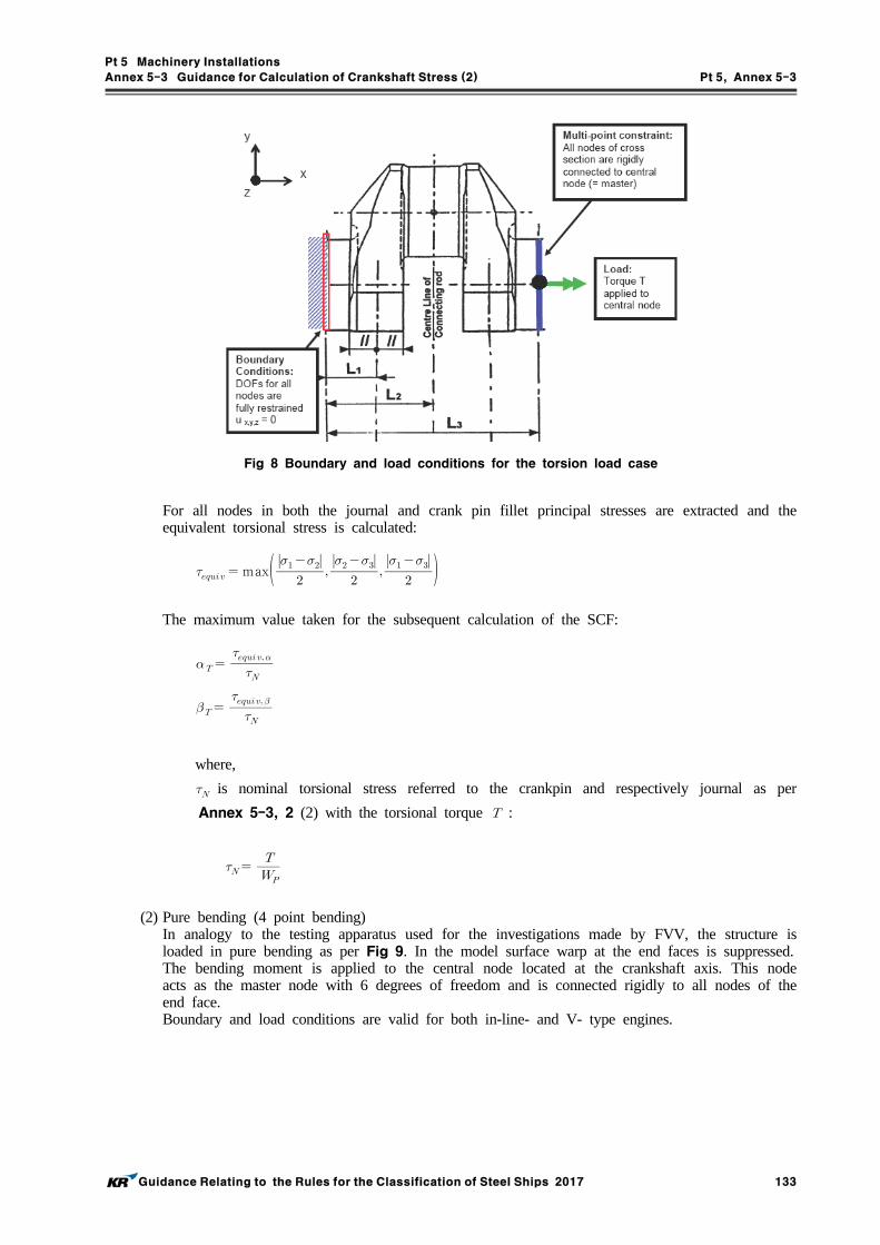
Pt 5 Machinery Installations
Annex 5-3 Guidance for Calculation of Crankshaft Stress (2) Pt 5, Annex 5-3
Guidance Relating to the Rules for the Classification of Steel Ships 2017 133
Fig 8 Boundary and load conditions for the torsion load case
For all nodes in both the journal and crank pin fillet principal stresses are extracted and the equivalent torsional stress is calculated:
max
The maximum value taken for the subsequent calculation of the SCF:
where,
is nominal torsional stress referred to the crankpin and respectively journal as per
Annex 5-3, 2 (2) with the torsional torque :
(2) Pure bending (4 point bending)In analogy to the testing apparatus used for the investigations made by FVV, the structure is loaded in pure bending as per Fig 9. In the model surface warp at the end faces is suppressed. The bending moment is applied to the central node located at the crankshaft axis. This node acts as the master node with 6 degrees of freedom and is connected rigidly to all nodes of the end face. Boundary and load conditions are valid for both in-line- and V- type engines.

Pt 5 Machinery Installations
Annex 5-3 Guidance for Calculation of Crankshaft Stress (2) Pt 5, Annex 5-3
134 Guidance Relating to the Rules for the Classification of Steel Ships 2017
Fig 9 Boundary and load conditions for the pure bending load case
For all nodes in both the journal and pin fillet von Mises equivalent stresses are extracted. The maximum value is used to calculate the SCF according to:
Nominal stress is calculated as per Annex 5-3, 2 (1) (B) (b) with the bending moment M:
(3) Bending with shear force (3-point bending)(A) This load case is calculated to determine the SCF for pure transverse force (radial force,
) for the journal fillet.(B) In analogy to the testing apparatus used for the investigations made by FVV, the structure
is loaded in 3-point bending as per Fig 10. In the model, surface warp at the both end faces is suppressed. All nodes are connected rigidly to the centre node; boundary conditions are applied to the centre nodes. These nodes act as master nodes with 6 degrees of freedom.
(C) The force is applied to the central node located at the pin centre-line of the connecting rod. This node is connected to all nodes of the pin cross sectional area. Warping of the sec-tional area is not suppressed.
(D) Boundary and load conditions are valid for in-line and V-type engines. V-type engines can be modeled with one connecting rod force only. Using two connecting rod forces will make no significant change in the SCF.
(E) The maximum equivalent von Mises stress in the journal fillet is evaluated. The SCF in the journal fillet can be determined in two ways as shown below.(a) Method 1
This method is analogue to the FVV investigation. The results from 3-point and 4-point bending are combined as follows:
∙ ∙

Pt 5 Machinery Installations
Annex 5-3 Guidance for Calculation of Crankshaft Stress (2) Pt 5, Annex 5-3
Guidance Relating to the Rules for the Classification of Steel Ships 2017 135
where:
: as found by the FE calculation.
: nominal bending stress in the web centre due to the force [N] applied
to the centre-line of the actual connecting rod, see Fig 11.
: as determined in para (2).
where,
is the radial (shear) force in the web due to the force [N] applied to the
centre-line of the actual connecting rod, see also Fig 1 and Fig 2 in Annex
5-3.
(b) Method 2This method is not analogous to the FVV investigation. In a statically determined sys-tem with one crank throw supported by two bearings, the bending moment and radial (shear) force are proportional. Therefore the journal fillet SCF can be found directly by the 3-point bending FE calculation. The SCF is then calculated according to the following.
For symbols see (a).
When using this method the radial force and stress determination in Annex 5-3 be-comes superfluous. The alternating bending stress in the journal fillet as per Annex 5-3, 2 (1) (C) is then evaluated:
± ∙
Note: that the use of this method does not apply to the crankpin fillet and this SCF must not be used in connection with calculation methods other than those assuming a statically determined system as in Annex 5-3.

Pt 5 Machinery Installations
Annex 5-3 Guidance for Calculation of Crankshaft Stress (2) Pt 5, Annex 5-3
136 Guidance Relating to the Rules for the Classification of Steel Ships 2017
Fig 10 Boundary and load conditions for the 3-point bending load case of an inline engine.
Fig 11 Load applications for in-line and V-type engines.

Pt 5 Machinery Installations
Annex 5-4 Strength Calculation for Gears of Power Transmission Systems Pt 5, Annex 5-4
Guidance Relating to the Rules for the Classification of Steel Ships 2017 137
Annex 5-4 Strength Calculation for Gears of Power Transmission Systems
1. General
(1) ApplicationThis Guidance is to apply to enclosed gear used for transmission system which transmit power from main propulsion machinery and prime movers driving generators and essential auxil-iaries(excluding auxiliary machinery for specific use etc,).
(2) Basic principles(A) The methods for calculation of strength of gears specified in this Guidance deal with sur-
face durability(pitting) and tooth root bending strength.(B) All influence factors related to strength are defined regarding their physical interpretation.
Some of the influence factors are determined by the gear geometry or have been established by conventions. Other factors, which are approximations, can be calculated according to methods acceptable to the Society.
2. Symbols and units
: Center distance (mm )
: Common facewidth (mm )
: Facewidth of pinion, wheel (mm )
: Tooth mesh stiffness (mean total mesh stiffness per unit face width) (Nmm∙ m )
: Reference diameter (mm )
: Reference diameter of pinion, wheel (mm )
: Tip diameter of pinion, wheel (mm )
: Base diameter of pinion, wheel (mm )
df1,2 : Root diameter of pinion, wheel (mm )
: Working diameter of pinion, wheel (mm )
: Nominal tangential load (N)
: Nominal tangential load on base cylinder in the transverse section ()
: Total tooth alignment deviation (mm )
: Actual longitudinal tooth flank deviation before running (mm )
: Actual longitudinal tooth flank deviation after running (mm )
: Nominal tangential tooth load (N)
: Maximum base pitch deviation of wheel (m )
: Face pitch deviation (m )
: Tooth flank misalignment due to manufacturing errors (mm )
: Tooth flank misalignment due to wheel and pinion deflections (mm )
: Total depth of tooth (mm )
: Bending moment arm for tooth root bending stress for application of load at the outer point
of single tooth pair contact (mm )
: Nominal module (mm )
: Transverse module (mm )
: Rotational speed of pinion, wheel (rpm )
: Maximum continuous power transmitted by the gear set (kW)
: Surface roughness (mm )
: Mean peak to-valley roughness of tooth root fillets (m )
: Mean peak to-valley roughness of tooth root fillets for pinion, wheel after running (m )

Pt 5 Machinery Installations
Annex 5-4 Strength Calculation for Gears of Power Transmission Systems Pt 5, Annex 5-4
138 Guidance Relating to the Rules for the Classification of Steel Ships 2017
: Mean peak to-valley roughness of tooth root fillets with relative radius of curvature 10 mm
at the pitch of center distance =100 mm : Notch parameter
: Root fillet radius in the critical section (mm )
: Torque in way of pinion, wheel (N∙m )
: Gear ratio
: Linear velocity at pitch diameter (m /s)
: Addendum modification coefficient of pinion, wheel
: Running in base pitch allowance (m )
: Running in base pitch allowance of pinion, wheel (mm )
: Running in allowance (m )
: Number of teeth
: Number of teeth of pinion, wheel
: Virtual number of teeth
: Virtual number of teeth of pinion, wheel
: Nominal pressure angle at reference cylinder (degree)
: Transverse pressure angle at ref. cylinder (degree)
: Transverse pressure angle at working pitch cylinder (degree)
: Pressure angle at the outer point of single tooth pair contact in the normal section
(degree)
: Helix angle at reference cylinder (degree)
: Helix angle at base cylinder (degree)
: Transverse contact ratio
: Overlap ratio
: Total contact ratio
: Root fillet radius in the critical section (mm )
: Tensile strength (Nmm) : Allowance value
3. Geometrical definitions
and are positive for external gearing, and are negative for internal gearing. is positive for external gears, and is negative for internal gears. The absolute value of the gear ratio, defined as follows, is always greater or equal to the unity.
The pinion is defined as the gear with the smaller number of teeth.In the equation of surface dura-bility is the common facewidth on the pitch diameter. In the equation of tooth root bending stress and are the facewidth at the respective tooth roots.
tan tan costan tan cos cos
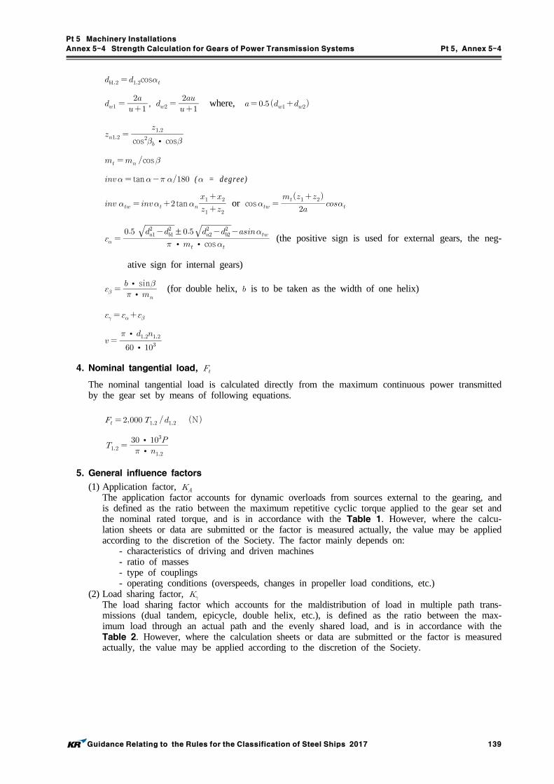
Pt 5 Machinery Installations
Annex 5-4 Strength Calculation for Gears of Power Transmission Systems Pt 5, Annex 5-4
Guidance Relating to the Rules for the Classification of Steel Ships 2017 139
cos
,
where,
cos∙cos
cos tan ( = degree)
tan
or cos
∙∙cos ±
(the positive sign is used for external gears, the neg-
ative sign for internal gears)
∙
∙sin (for double helix, is to be taken as the width of one helix)
∙∙
4. Nominal tangential load,
The nominal tangential load is calculated directly from the maximum continuous power transmitted by the gear set by means of following equations.
N
∙
∙
5. General influence factors
(1) Application factor, The application factor accounts for dynamic overloads from sources external to the gearing, and is defined as the ratio between the maximum repetitive cyclic torque applied to the gear set and the nominal rated torque, and is in accordance with the Table 1. However, where the calcu-lation sheets or data are submitted or the factor is measured actually, the value may be applied according to the discretion of the Society. The factor mainly depends on:
- characteristics of driving and driven machines - ratio of masses- type of couplings- operating conditions (overspeeds, changes in propeller load conditions, etc.)
(2) Load sharing factor, The load sharing factor which accounts for the maldistribution of load in multiple path trans-missions (dual tandem, epicycle, double helix, etc.), is defined as the ratio between the max-imum load through an actual path and the evenly shared load, and is in accordance with the Table 2. However, where the calculation sheets or data are submitted or the factor is measured actually, the value may be applied according to the discretion of the Society.

Pt 5 Machinery Installations
Annex 5-4 Strength Calculation for Gears of Power Transmission Systems Pt 5, Annex 5-4
140 Guidance Relating to the Rules for the Classification of Steel Ships 2017
Driving engine Construction or method of connection
Main propulsion
Diesel engine with hydraulic or electromagnetic slip coupling 1.00
Diesel engine with high elasticity coupling 1.30
Diesel engine with other couplings 1.50
Auxiliary
Electric motor, diesel engine with hydraulic or electromagnetic slip coupling
1.00
Diesel engine with high elasticity coupling 1.20
Diesel engine with other couplings 1.40
Table 1 Application Factor,
Planetary gears
up to 3 1.0
4 1.2
5 1.3
6 and over 1.4
Table 2 Load sharing factor,
(3) Internal Dynamic factor, The dynamic factor which accounts for internally generated dynamic loads due to vibrations of pinion and wheel against each other, is defined as the ratio between the maximum load which dynamically acts on the tooth flanks and the maximum externally applied load (). The factor mainly depends on followings.
- transmission errors (depending on pitch and profile errors)- masses of pinion and wheel- gear mesh stiffness variation as the gear teeth pass through the meshing cycle- transmitted load including application factor- pitch line velocity- dynamic unbalance of gears and shaft- shaft and bearing stiffness- damping characteristics of the gear system
(A) Application(a) In case of all the following conditions are satisfied.
(i) running velocity in the subcritical range:
∙
(ii) spur gears ( ) and helical gears with ≤ (iii) pinion with relatively low number of teeth, (iv) solid disc wheels or heavy steel gear rim
(b) all types of gears if ∙
as well as to helical gears where .
(c) For gears other than (a), (b), reference is to be made to Method B outlined in the ref-erence standard ISO 6336-1.
(B) Calculation formula(a) For spur gears and for helical gears with overlap ratio ≥

Pt 5 Machinery Installations
Annex 5-4 Strength Calculation for Gears of Power Transmission Systems Pt 5, Annex 5-4
Guidance Relating to the Rules for the Classification of Steel Ships 2017 141
Kind of gear
( 1328 grades of accuracy)
3* 4* 5* 6* 7* 8*
Spur gear 2.1 3.9 7.5 14.9 26.8 39.1
Helical gear 1.9 3.5 6.7 13.3 23.9 34.8
NOTE * ISO grades of accuracy according to 1328. In case of mating gears with different
grades of accuracy the grade corresponding to the lower accuracy is to be used.
Table 3 Values of
∙
∙
If (N/mm), this value is assumed to
(N/mm).
Numerical values for the factor are to be as specified in the Table 3.
For all accuracy grades the factor is to be in accordance with the following.
For spur gears,
For helical gears,
Factor is to be in accordance with the following.
If ∙
≤ then
If ∙
then ∙∙
(b) For helical gears with overlap ratio the value is determined by linear inter-polation between values determined for spur gears () and helical gears () in ac-cordance with:
Where, is the value for spur gears, in accordance with (a). is the value for helical gears, in accordance with (a).
(4)Face load distribution factors The face load distribution factors, for contact stress, for tooth root bending stress, ac-count for the effect of non-uniform distribution of load across the facewidth. and are de-fined as follows:
The mean bending stress at tooth root relates to the considered face width. can be expressed as a function of the factor . The factors and mainly depend on:
- gear tooth manufacturing accuracy - errors in mounting due to bore errors - bearing clearances - wheel and pinion shaft alignment errors

Pt 5 Machinery Installations
Annex 5-4 Strength Calculation for Gears of Power Transmission Systems Pt 5, Annex 5-4
142 Guidance Relating to the Rules for the Classification of Steel Ships 2017
- elastic deflections of gear elements, shafts, bearings, housing and foundations which support the gear elements
- thermal expansion and distortion due to operating temperature - compensating design elements (tooth crowning, end relief, etc.)
The face load distribution factors, for contact stress, and for tooth root bending stress, are to be determined according to the Method C outlined in the ISO 6336-1 standard. However, where the calculation sheets or data are submitted or the factors are measured actually, the values may be applied according to the discretion of the Society.
(A) In case the hardest contact is at the end of the face width is given by the following equations.
: face width/tooth height ratio, the minimum of or .
(For double helical gears, the face width of only one helix is to be used.
When <3 the value =3 is to be used.)
(B) In case of gears where the ends of the face width are lightly loaded or unloaded (end relief or crowning).
(5) Transverse load distribution factors for surface durability and bending strength, , The transverse load distribution factors, for contact stress and for tooth root bending stress, account for the effects of pitch and profile errors on the transversal load distribution be-tween two or more pairs of teeth in mesh, and are to be determined according to Method B outlined in ISO 6336-1. However, where the calculation sheets or data are submitted or the fac-tors are measured actually, the values may be applied according to the discretion of the Society. The factors and mainly depend on followings.
- total mesh stiffness- total tangential load , , , , - base pitch error- tip relief- running-in allowances
6. Surface durability
The criterion for surface durability is based on the Hertz pressure on the operating pitch point or at the inner point of single pair contact. The contact stress is to be equal to or less than the permissible contact stress .(1) Basic equations
(A) Contact stress,
≤
: Pinion
: Wheel
: Basic value of contact stress for pinion and wheel

Pt 5 Machinery Installations
Annex 5-4 Strength Calculation for Gears of Power Transmission Systems Pt 5, Annex 5-4
Guidance Relating to the Rules for the Classification of Steel Ships 2017 143
: Single pair tooth contact factor for pinion
: Single pair tooth contact factor for wheel
: Zone factor
: Elasticity factor
: Contact ratio factor
: Contact ratio factor
: Nominal tangential load
(B) Allowable contact stress,
: Endurance limit for contact stress
: Life factor for contact stress
: Lubrication factor
: Velocity factor
: Roughness factor
: Hardness ratio factor
: Size factor for contact stress
: Safety factor for contact stress
(2) Single pair tooth contact factor, , Single pair tooth contact factors, for pinion and for wheel account for the influence of the tooth flank curvature on contact stresses at the inner point of single pair contact in relation to zone factor, and are to be determined as follows.(A) For spur gears
= or 1, whichever is the larger value
= or 1, whichever is the larger value
tan
tan
(B) For helical gears(a) When ≥ 1
= = 1
(b) When < 1, and can be determined as follows;
≥
≥
and : same as (A)
(c) For internal gears,

Pt 5 Machinery Installations
Annex 5-4 Strength Calculation for Gears of Power Transmission Systems Pt 5, Annex 5-4
144 Guidance Relating to the Rules for the Classification of Steel Ships 2017
(3) Zone factor, The zone factor, accounts for the influence on the Hertzian pressure of tooth flank curvature at pitch point and transforms the tangential load at the reference cylinder to the normal load at the pitch cylinder, and is to be determined as follows.
cos tan cos
(4) Elasticity factor, The elasticity factor is the value haven relevance with the material properties affected contact stress, and is to be determined as follows.(A) For steel pinions and wheels ( = 206,000 Nmm, = 0.3)
: Modulus of elasticity (Nmm) : Poisson's ratio
(B) In other cases, reference is to be made to the reference standard ISO 6336-2.
(5) Contact ratio factor, The contact ratio factor, , account for the influence of transverse contact ratio and the overlap ratio on the specified surface load of gears, and is to be determined as follows. (A) For spur gear
(B) For helical gears
For < 1,
For ≥ 1,
(6) Helix angle factor, The helix angle factor, , account for the influence of helix angle on surface durability, allow-ing for such variable as the distribution of load along the lines of contact, is dependent only on the helix angle and is to be determined as follows.
cos
(7) Endurance limit for contact stress, For a given material, is the limit of repeated contact stress which can be permanently endured. The value of can be regarded as the level of contact stress which the material will endure without pitting for at least × load cycles. The endurance limit mainly depends on followings.
- material composition, cleanliness and defects- mechanical properties - residual stresses - hardening process, depth of hardened zone, hardness gradient - material structure (forged, rolled bar, cast)
The endurance limit for contact stress , is to be determined, in general, making refer-ence to values indicated in the standard ISO 6336-5, for material quality MQ. (A) Pitting is defined by followings.

Pt 5 Machinery Installations
Annex 5-4 Strength Calculation for Gears of Power Transmission Systems Pt 5, Annex 5-4
Guidance Relating to the Rules for the Classification of Steel Ships 2017 145
(a) For not surface hardened gears, Pitted area > 2 % of total active flank area
(b) For surface hardened gears, Pitted area > 0.5 % of total active flank area, or > 4 % of one particular tooth flank area.
(B) The values are to correspond to a failure probability of 1% or less.
(8) Life factor, The life factor , accounts for the higher permissible contact stress in case a limited life (number of cycles) is required. The factor mainly depends on followings.
- material and heat treatment - number of cycles - influence factors (, , , , )
The life factor, , can is to be determined according to Method B outlined in the reference standard ISO 6336-2
(9) Influence factor of lubrication film on contact stress, , , The lubricant factor, , accounts for the influence of the type of lubricant and its viscosity. The velocity factor, , accounts for the influence of the pitch line velocity. The roughness fac-tor, , accounts for the influence of the surface roughness on the surface endurance capacity. The factors may be determined for the softer material where gear pairs are of different hardness. The factors mainly depend on followings.
- viscosity of lubricant in the contact zone- the sum of the instantaneous velocities of the tooth surfaces- load- relative radius of curvature at the pitch point- surface roughness of teeth flanks- hardness of pinion and gear
(A) Lubricant factor, The lubricant factor, , is to be determined as follows.
:The values specified in the following.
For 850 ≤ ≤ 1200 Nmm
For < 850 Nmm, = 0.83
For > 1,200 Nmm, = 0.91
: nominal kinematic viscosity of the oil at 40 ℃ (mms)
(B) Velocity factor, The velocity factor, , is to be calculated from the following equations.
:The values specified in the following.

Pt 5 Machinery Installations
Annex 5-4 Strength Calculation for Gears of Power Transmission Systems Pt 5, Annex 5-4
146 Guidance Relating to the Rules for the Classification of Steel Ships 2017
(C) Roughness factor, The roughness facto, , is to be calculated from the following equations;
Where,
The peak-to-valley roughness determined for the pinion and for the wheel
are mean values for the peak-to-valley roughness measured on several tooth
flanks ( as defined in the reference standard ISO 6336-2)
If the roughness stated is an arithmetic mean roughness, i.e. Ra value(=CLA value)
(=AA value) the following approximate relationship can be applied:
(relative radius of curvature)
tan (also for internal gears, negative sign)
: The values specified in the following.
a) For 850 ≤ ≤ 1,200 Nmm, = 0.32 - 0.0002 b) For < 850 Nmm, = 0.150
c) For > 1200 Nmm, = 0.080
(10) Hardness ratio factor, The hardness ratio factor, , accounts for the increase of surface durability of a soft steel gear meshing with a significantly harder gear with a smooth surface, in the following cases. (A) Surface-hardened pinion with through-hardened wheel
(a) For ,
∙
(b) For ≤≤ ,
∙
(c) For ,

Pt 5 Machinery Installations
Annex 5-4 Strength Calculation for Gears of Power Transmission Systems Pt 5, Annex 5-4
Guidance Relating to the Rules for the Classification of Steel Ships 2017 147
Where,
: Brinell hardness of the tooth flanks of the softer gear of the pair : equivalent roughness (m )
∙
∙∙
:nominal kinematic viscosity of the oil at 40 ℃ (mms)
: relative radius of curvature (refer to (9), (C))
(B) Through-hardened pinion and wheel When the pinion is substantially harder than the wheel, the work hardening effect increases the load capacity of the wheel flanks. applies to the wheel only, not to the pinion.(a) For ,
(b) For ≤ ≤ ,
∙(c) For ,
∙
(d) For gear ratio , (e) In any case, if calculated ,
(11) Size factor, The size factor, , accounts for the influence of tooth dimensions on permissible contact stress and reflects the non-uniformity of material properties. The factor mainly depends on followings.
- material and heat treatment - tooth and gear dimensions - ratio of case depth to tooth size - ratio of case depth to equivalent radius of curvature
For through-hardened gears and for surface-hardened gears with adequate casedepth relative to tooth size and radius of relative curvature = 1. When the casedepth is relatively shallow then a smaller value of should be chosen.
(12) Safety factor for contact stress, The safety factor for contact stress, , is the values specified in the follows. However, where the calculation sheets or data are submitted or the factor is measured actually, the value may be applied according to the discretion of the Society.(A) Main propulsion gears : 1.20(B) Auxiliary gears : 1.15
7. Bending strength
The criterion for tooth root bending strength is the permissible limit of local tensile strength in the root fillet. The root stress, and the permissible root stress, is to be calculated separately for the pinion and the wheel. must not exceed . The following formulae and definitions apply to gears having rim thickness greater than 3.5 . The result of rating calculations made by following this method are acceptable for normal pressure angles up to 25 ° and reference helix angles up to 30°. For larger pressure angles and large helix angles, the calculated results should be confirmed by experience as by Method A of the reference standard ISO 6336-3(1) Basic equations
(A) Tooth root bending stress for pinion and wheel, (Nmm)

Pt 5 Machinery Installations
Annex 5-4 Strength Calculation for Gears of Power Transmission Systems Pt 5, Annex 5-4
148 Guidance Relating to the Rules for the Classification of Steel Ships 2017
≤
: Tooth form factor
: Stress correction factor
: Helix angle factor
: Rim thickness factor
: Deep tooth factor
, , , , , : refer to Par 4, Par 5
(B) Permissible tooth root bending stress for pinion and wheel, (Nmm)
: Bending endurance limit
: Design factor
: Life factor
: Relative notch sensitivity factor
: Relative surface factor
: Size factor
: Safety factor for tooth root bending stress
(2) Tooth form factor, The tooth form factor, , is the values calculated by the following formula. (refer to Fig 1)
cos
Fig 1 For the Calculation of , and
For the calculation of , and , the procedure outlined in the reference standard ISO 6336-3 (Method B) is to be used.
(3) Stress correction factor, The stress correction factor, , is used to convert the nominal bending, and is the values cal-culated by the following formula. (having range of validity: 1 ≤ < 8)

Pt 5 Machinery Installations
Annex 5-4 Strength Calculation for Gears of Power Transmission Systems Pt 5, Annex 5-4
Guidance Relating to the Rules for the Classification of Steel Ships 2017 149
(4) Helix angle factor, The helix angle factor, , account for the influence of helix angle on bending stress, and is the values calculated by the following formula. However, 1.0 is substituted for when > 1, 30° is substituted for when > 30°.
(5) Rim thickness factor, The rim thickness factor, , is a simplified factor used to de-rate thin rimmed gears. For crit-ically loaded applications, this method should be replaced by a more comprehensive analysis. Factor is to be determined as follows.(A) For external gears,
In case of ≥ ,
In case of , ∙ ln
Where,
: rim thickness of external gears, (mm)
The case of ≤ is to be avoided.
(B) For internal gears,
In case of ≥ ,
In case of , ∙ ln
Where,
: rim thickness of internal gears (mm)
The case of ≤ is to be avoided.
(6) Deep tooth factor, The deep tooth factor, , adjusts the tooth root stress to take into account high precision gears and contact ratios within the range of virtual contact ratio ≤ ≤ .
Where,
cos
Factor is to be determined as follows.In case of ISO accuracy grade ≤ 4 and ,
In case of ISO accuracy grade ≤ 4 and ≤ ,
∙
In all other cases,
(7) Bending endurance limit, For a given material, is the local tooth root stress which can be permanently endured. According to the reference standard ISO 6336-5 the number of × cycles is regarded as

Pt 5 Machinery Installations
Annex 5-4 Strength Calculation for Gears of Power Transmission Systems Pt 5, Annex 5-4
150 Guidance Relating to the Rules for the Classification of Steel Ships 2017
the beginning of the endurance limit. is defined as the unidirectional pulsating stress with a minimum stress of zero(disregarding residual stresses due to heat treatment). Other conditions such as alternating stress or prestressing etc. are covered by the design factor . The val-ues are to correspond to a failure probability 1% or less. The endurance limit mainly depends on followings.
- material composition, cleanliness and defects- mechanical properties- residual stresses- hardening process, depth of hardened zone, hardness gradient- material structure (forged, rolled bar, cast)
The bending endurance limit, is to be determined, in general, making reference to values indicated in the reference standard ISO 6336-5, for material quality MQ.
(8) Design factor, The design factor, , takes into account the influence of load reversing and shrinkfit prestress-ing on the tooth root strength. The design factor, , for load reversing, can be determined as follows. However, for shrinkfit, The design factor is the value according to the calculation sheets or data submitted to the Society and recognized appropriateness by the Society.
= 1 : In general (For gears with uniformed load direction and not shrinkfit)
= 0.9 : For gears with occasional part load in reverse direction, such as main wheel in
reversing
= 0.7 : For idler gears
(9) Life factor, The life factor, , accounts for the higher tooth root bending stress permissible in case a lim-ited life (number of cycles) is required. The factor mainly depends on followings.
- material and heat treatment - number of load cycles (service life) - influence factors (, , )
The life factor, , is to be determined according to Method B outlined in the reference stand-ard ISO 6336-3.
(10) Relative notch sensitivity factor, The relative notch sensitivity factor, , indicates the extent to which the theoretically con-centrated stress lies above the fatigue endurance limit. The factor mainly depends on material and relative stress gradient and is to be determined as follows.
′′
Where,
′ : slip-layer thickness accodring to Table 4 (mm)

Pt 5 Machinery Installations
Annex 5-4 Strength Calculation for Gears of Power Transmission Systems Pt 5, Annex 5-4
Guidance Relating to the Rules for the Classification of Steel Ships 2017 151
Material ′ (mm)
Case hardened steels, flame or induction hardened steels 0.0030
Through-hardened steels(1), yield point
500 N/mm2 0.0281
600 N/mm2 0.0194
800 N/mm2 0.0064
1000 N/mm2 0.0014
Nitrided steels 0.1005
(Note) (1) The given values of ′ can be interpolated for values of not stated above
Table 4 Slip-layer thickness (mm)
Remarks
< 1 1 ≤ ≤ 40
1.120 1.674 - 0.529( + 1)0.1 Case hardened steels, through - hardened steels
( ≥ 800Nmm)
1.070 5.306 - 4.203( + 1)0.01Normalized steels ( < 800Nmm)
1.025 4.299 - 3.259( + 1)0.0058Nitrided steels
NOTE : same as Par 6 (9) (C)
Table 5 Relative Surface Factor,
(11) Relative surface factor, The relative surface factor, , takes into account the dependence of the root strength on the surface condition in the tooth root fillet, and is the values specified in the Table 5. The meth-od applied here is only valid when scratches or similar defects deeper than are not present. If the roughness stated is an arithmetic mean roughness, i.e. value (=CLA value) (=AA value), the following approximate relationship can be applied.
(12) Size factor, The size factor, , takes into account the decrease of strength with increasing size. The factor mainly depends on followings.
- material and heat treatment - tooth and gear dimensions - ratio of case depth to tooth size
The Size factor, , is the values calculated in accordance with the Table 6.

Pt 5 Machinery Installations
Annex 5-4 Strength Calculation for Gears of Power Transmission Systems Pt 5, Annex 5-4
152 Guidance Relating to the Rules for the Classification of Steel Ships 2017
Remarks Range
Generally ≤ 5 1
Normalized and through-hardened steels 5 < < 30 1.03 - 0.06
≥ 30 0.85
Surface hardened steels5 < < 25 1.05 - 0.010
≥ 25 0.8
Table 6 Size Factor,
(13) Safety factor for tooth root bending stress, The safety factor for tooth root bending stress, , is the values specified in the following. However, the safety factor for tooth root bending stress is the value according to the calculation sheets or data submitted to the Society and recognized appropriateness by the Society. (A) Main propulsion gears : 1.55(B) Auxiliary gears : 1.40

Pt 5 Machinery Installations
Annex 5-5 Requirements of Equipment for Gas welding Pt 5, Annex 5-5
Guidance Relating to the Rules for the Classification of Steel Ships 2017 153
Annex 5-5 Requirements of Equipment for Gas welding
1. Gas bottles and piping systems are to be satisfied with the following :(1) Materials for piping systems are to comply with the standards recognized by the Society(2) The Society may accept to use bottles manufactured according to the Korean Government Rules
for Safety Management of Gas in spite of Pt 5, Ch 5 of the Rules. (3) For pipes, valves and pipe fittings, hydraulic tests may be omitted carrying.
2. Location of gas bottles is to be as specified below :(1) Gas bottles are not to be located in machinery spaces of category A and accommodation spaces. (2) Acetylene gas bottles are to be located in the area where the temperature can be maintained at
38 ℃ or less.(3) Gas bottles are to be stored in areas not exposed to direct sun beam and also safe against
waves, flame and high temperature.(4) Except when located in a store room, gas bottles are to be placed in areas sufficiently distant
from accommodation spaces and openings from which hydrocarbon gases, etc. are likely to flow out.
(5) Gas bottles are to be stored at areas of good ventilation free from stagnation of leaked gases. (6) The store room of gas bottles is to have such a construction as to allow access only from the
weather deck.
3. Gas bottles are to be so stored that the safety against ship motions and vibrations is ensured, and they are to stand upright as far as practicable. Acetylene bottles and oxygen bottles are to be store apart to the extent practicable. Further, means are to be provided so that gas bottles can be trans-ferred quickly in case of fire.
4. In case where permanent piping is arranged between the gas bottles and working area, the follow-ing requirements are to be complied with : (1) Steel pipes are to be used for acetylene gas piping, and steel or copper pipes are to be used
for oxygen gas piping. Use of flexible joints made of non-metal material ensleeved in metal sheath in part of the piping may be accepted.
(2) No cast iron is to be used as the material of valves and pipe fittings. Further, no copper or copper alloy with a copper content exceeding 62 is to be used as the material of valves and pipe fittings in the acetylene gas piping.
(3) The procedures of piping arrangement are to be as specified below : (A) Acetylene gas piping and oxygen gas piping are not to be led through enclosed spaces
which are susceptible to fire. But, in case where it can be led through enclosed space, the following comply; (2017)(a) Provision of effective mechanical exhaust ventilation.(b) Pipe connection with butt-welding(c) Pipes are to be protected from mechanical damage where necessary.
(B) Except when used in a working area, gas bottles are to be kept closed by stop valves which are fitted in a store room, and warning notices to this effect are to be placed in a store room and working area. (2017)
(C) Joints between pipes and pipe fittings are to be of welded joint or flange joint as far as practicable.
(D) For clear distinction of the acetylene gas piping system and oxygen gas piping system, the piping systems are to be provided with adequate means of identification.
5. In case where rubber hoses are used, the following apply:(1) Hoses are to comply with 6543 for acetylene gas and 6557 for oxygen gas, or
equivalent.(2) The joint methods between rubber hose and permanently installed pipes are to comply with 4604, or equivalent.

Pt 5 Machinery Installations
Annex 5-5 Requirements of Equipment for Gas welding Pt 5, Annex 5-5
154 Guidance Relating to the Rules for the Classification of Steel Ships 2017
6. After completion of shipboard installation, piping systems are to be subjected to air-tightness test at a pressure of 1.25 times or more of the maximum working pressure of the pressure regulator (refer to 4603).

Pt 5 Machinery Installations
Annex 5-6 Plastic Pipes Pt 5, Annex 5-6
Guidance Relating to the Rules for the Classification of Steel Ships 2017 155
Annex 5-6 Plastic Piping System
1. Application
(1) The requirements in this Annex apply to plastic pipes/piping systems on ships.(2) Plastic pipes may be used for Class III piping system. Proposals for the use of plastic pipes in
Class I and Class II piping system will be specially considered.(3) The requirements in this Annex are not applicable to flexible pipes and hoses and mechanical
couplings used in metallic piping systems.
2. Definitions
(1) Plastic(s) is both thermoplastic and thermosetting plastic materials with or without reinforcement, such as PVC and fibre reinforced plastics - FRP.
(2) Fire endurance is the capability of piping to maintain its strength and integrity (i.e. capable of performing its intended function) for some predetermined period of time while exposed to fire.
3. Materials
(1) PVC and GRP piping system are to be those approved by the Society in accordance with "Guidance for Approval of Manufacturing Process and Type Approval, etc." and ad-equate for their service conditions. (2017)
(2) Notwithstanding the requirement in (1), pipes complying with the recognized standards e.g. Korean Industrial Standards and equivalent standard having self-extinguishing property and ad-equate for their service condition may be used for drinking water pipes, domestic water pipes (including hot water pipes) and sanitary pipes within accommodation spaces and engine room and deck scuppers within the identical spaces.
4. General requirements
The specification of piping is to be in accordance with a recognised national or international stand-ard approved by the Society. In addition, the following requirements apply:(1) Strength
(A) The strength of the pipes is to be determined by a hydrostatic test failure pressure and col-lapse pressure of a pipe specimen under the following standard conditions. The hydrostatic test failure pressure and collapse pressure may be determined by testing or may be de-termined by a combination of testing and calculation., where deemed appropriate by the Society.
atmospheric pressure : 0.1 MParelative humidity : 30 fluid temperature: 25 ℃
(B) The strength of fittings and joints is to be not less than that of the pipes.(C) The design pressure is to be specified with due regard for design temperatures in accordance
with Manufacturer's recommendations.(D) Internal pressure
The internal pressure of pipes is to be not lesser of the following, and is to be more than the design pressure of system intended to use the pipes.
≤
or ≤
: Internal Pressure
: Short-term hydrostatic test failure pressure
: Short-term hydrostatic test failure pressure (> 100,000 h)

Pt 5 Machinery Installations
Annex 5-6 Plastic Pipes Pt 5, Annex 5-6
156 Guidance Relating to the Rules for the Classification of Steel Ships 2017
(E) External pressureExternal pressure is to be determined by the following.
≤
: External pressure
: Pipe collapse pressure. In no case is the collapse pressure to be less than 0.3
MPa.
The design external pressure is a sum of the vacuum inside the pipe and a head of liquid acting on the outside of the pipe.
(2) Axial strength(A) The sum of the longitudinal stresses due to pressure, weight and other loads is not to ex-
ceed the allowable stress in the longitudinal direction.(B) In the case of fibre reinforced plastic pipes, the sum of the longitudinal stresses is not to
exceed half of the nominal circumferential stress derived from the nominal internal pressure condition prescribed in (1) (D) above.
(3) Impact Resistance(A) Plastic pipes and joints are to have a minimum resistance to impact in accordance with rec-
ognised national or international standards.(B) After the test, the specimen is to be subjected to hydrostatic pressure equal to 2.5 times the
design pressure for at least 1 hour.(4) Temperature
(A) The design temperature depending on the working pressure is to be in accordance with Manufacturer's recommendations, but in each case it is to be at least 20 ℃ lower than the minimum heat distortion temperature of the pipe material, determined according to ISO 75 method A, or equivalent.
(B) The minimum heat distortion temperature is to be not less than 80 ℃.
5. Requirements for pipes/piping systems depending on service and/or locations
(1) Fire endurance(A) Pipes and their associated fittings whose integrity is essential to the safety of ships are re-
quired to meet the minimum fire endurance requirements of Appendix 1 or 2, as applicable, of IMO Res A.753 (18).
(B) Depending on the capability of a piping system to maintain its strength and integrity, there exist three different levels of fire endurance for piping systems.(a) Level 1(L1) : Piping having passed the fire endurance test specified in Appendix 1 of
IMO Res. A. 753 (18) for a duration of a minimum of one hour without loss of in-tegrity in the dry condition is considered to meet level 1 fire endurance standard.
(b) Level 2(L2) : Piping having passed the fire endurance test specified in Appendix 1 of IMO Res. A 753 (18) for a duration of a minimum of 30 minutes in the dry condition is considered to meet level 2 fire endurance standard.
(c) Level 3(L3) : Piping having passed the fire endurance test specified in Appendix 2 of IMO Res. A .753 (18) for a duration of a minimum of 30 m inutes in the wet condition is considered to meet level 3 fire endurance standard.
(C) Permitted use of piping depending on fire endurance, location and piping system is given in Table 1.
(2) Flame spread(A) All pipes, except those fitted on open decks and within tanks, cofferdams, pipe tunnels and
ducts are to have low surface flame spread characteristics not exceeding average values specified in Ch 3, 2604. 3 of the "Guidance for Approval of Manufacturing Process and Type Approval, etc.".
(B) Surface flame spread characteristics are to be determined using the procedure specified in Ch 3, 2604. 3 of the "Guidance for Approval of Manufacturing Process and Type Approval, etc." with regard to the modifications due to the curvilinear pipe surfaces as listed in Appendix 3 of IMO Resolution A.753 (18).
(C) Surface flame spread characteristics may also be determined using the text procedures given

Pt 5 Machinery Installations
Annex 5-6 Plastic Pipes Pt 5, Annex 5-6
Guidance Relating to the Rules for the Classification of Steel Ships 2017 157
in national or international standards.(3) Fire protection coatings
(A) Where a fire protective coating of pipes and fittings is necessary for achieving the fire en-durance level required, it is to meet the following requirements:(a) The pipes are generally to be delivered from the manufacturer with the protective coat-
ing on.(b) The fire protection properties of the coating are not to be diminished when exposed to
salt water, oil or bilge slops. It is to be demonstrated that the coating is resistant to products likely to come into contact with the piping.
(c) In considering fire protection coatings, such characteristics as thermal expansion, resist-ance against vibrations, and elasticity are to be taken into account.
(d) The fire protection coatings are to have sufficient resistance to impact to retain their integrity.
(4) Electrical conductivityWhere electrical conductivity is to be ensured, the resistance of the pipes and fittings is not to exceed 1 × 10⁵
m .(5) Durability against chemicals
The pipes are to be resistant to any chemical substances expected during service.
6. Installation
(1) Supports(A) Selection and spacing of pipe supports in shipboard systems are to be determined as a
function of allowable stresses and maximum deflection criteria. Support spacing is not to be greater than the pipe Manufacturer's recommended spacing. The selection and spacing of pipe supports are to take into account pipe dimensions, mechanical and physical properties of the pipe material, mass of pipe and contained fluid, external pressure, operating temper-ature, thermal expansion effects, loads due to external forces, thrust forces, water hammer, vibrations, maximum accelerations to which the system may be subjected. Combination of loads is to be considered.
(B) Each support is to evenly distribute the load of the pipe and its contents over the full width of the support. Measures are to be taken to minimize wear of the pipes where they contact the supports.
(C) Heavy components in the piping system such as valves and expansion joints are to be in-dependently supported.
(2) Expansion(A) Suitable provision is to be made in each pipeline to allow for relative movement between
pipes made of plastic and the steel structure, having due regard to:(a) The difference in the coefficients of thermal expansion;(b) deformations of the ship's hull and its structure.
(B) When calculating the thermal expansions, account is to be taken of the system working temperature and the temperature at which assembly is performed.
(3) External loads(A) When installing the piping, allowance is to be made for temporary point loads, where
applicable. Such allowances are to include at least the force exerted by a load (person) of 100 kg at mid-span on any pipe of more than 100 m m nominal outside diameter.
(B) Besides for providing adequate robustness for all piping including open-ended piping a mini-mum wall thickness, complying with 4 (1) above, may be increased upon the demand of the Society taking into account the conditions encountered during service on board ships.
(C) Pipes are to be protected from mechanical damage where necessary.(4) Strength of connections
(A) The strength of connections is to be not less than that of the piping system in which they are installed.
(B) Pipes may be assembled using adhesive-bonded, welded, flanged or other joints.(C) Adhesives, when used for joint assembly, are to be suitable for providing a permanent seal
between the pipes and fittings throughout the temperature and pressure range of the intended application.
(D) Tightening of joints is to be performed in accordance with Manufacturer's instructions.

Pt 5 Machinery Installations
Annex 5-6 Plastic Pipes Pt 5, Annex 5-6
158 Guidance Relating to the Rules for the Classification of Steel Ships 2017
Piping system Location
A B C D E F G H I J K
Machinery spaces of category
A
Other machinery spaces &
pump rooms
Cargo pump rooms
Ro/Ro cargo holds
Other dry
cargo holds
Cargo tanks
Fuel oil
tanks
Ballast water tanks
Cofferdams void spaces pipe tunnel
& ducts
Accommodation service & control
spaces
Open decks
Cargo (Flammable cargos, f.p ≤ 60 °C)1. Cargo lines NA NA L1 NA NA O NA O10 O NA L12
2. Crude oil washing lines NA NA L1 NA NA O NA O10 O NA L12
3. Vent lines NA NA NA NA NA O NA O10 O NA X
Inert gas4. Water seal effluent lines NA NA O1 NA NA O1 O1 O1 O1 NA O5. Scrubber effluent lines O1 O1 NA NA NA NA NA O1 O1 NA O6. Main lines O O L1 NA NA NA NA NA O NA L16
7. Distribution lines NA NA L1 NA NA O NA NA O NA L12
Flammable liquids (f.p > 60 °C)8. Cargo lines X X L1 X X NA3 O O10 O NA L19. Fuel oil X X L1 X X NA3 O O O L1 L110. Lubricating oil X X L1 X X NA NA NA O L1 L111. Hydraulic oil X X L1 X X O O O O L1 L1
Seawater1
12. Bilge main & branches L17 L17 L1 X X NA O O O NA L113. Fire main water spray L1 L1 L1 X NA NA NA O O NA L114. Foam system L1 L1 L1 NA NA NA NA NA O L1 L115. Sprinkler system L1 L1 L3 X NA NA NA O O L3 L316. Ballast L3 L3 L3 L3 X O10 O O O L2 L217. Cooling water, essential services L3 L3 NA NA NA NA NA O O NA L218. Tank cleaning services fixed machines NA NA L3 NA NA O NA O O NA L32
19. Non-essential system O O O O O NA O O O O O
Freshwater20. Cooling water essential services L3 L3 NA NA NA NA O O O L3 L321. Condensate return L3 L3 L3 O O NA NA NA O O O22. Non-essential system O O O O O NA O O O O O
Sanitary/Drain/Scuppers23. Deck drains (internal) L14 L14 NA L14 O NA O O O O O24. Sanitary drains (internal) O O NA O O NA O O O O O
Table 1 Fire Endurance Requirements Matrix

Pt 5 Machinery Installations
Annex 5-6 Plastic Pipes Pt 5, Annex 5-6
Guidance Relating to the Rules for the Classification of Steel Ships 2017 159
Piping system Location
A B C D E F G H I J K
Machinery spaces of category
A
Other machinery spaces &
pump rooms
Cargo pump rooms
Ro/Ro cargo holds
Other dry
cargo holds
Cargo tanks
Fuel oil
tanks
Ballast water tanks
Cofferdams void spaces pipe tunnel
& ducts
Accommodation service & control
spaces
Open decks
25. Scuppers and discharges (overboard) O1,8 O1,8 O1,8 O1,8 O1,8 O O O O O1,8 O
Sounding/Air26. Watertanks/ dry spaces O O O O O O10 O O O O O27. Oil tanks (f.p > 60 °C) X X X X X X3 O O10 O X X
Miscellaneous28. Control air L15 L15 L15 L15 L15 NA O O O L15 L15
29. Service air (non-essential) O O O O O NA O O O O O30. Brine O O NA O O NA NA NA O O O31. Auxiliary low pressure steam (≤ 7 MPa) L2 L2 O9 O9 O9 O O O O O9 O9
Abbreviations :L1 Fire endurance test (IMO Resolution A.753(18), Appendix 1) in dry conditions, 60 m in.L2 Fire endurance test (IMO Resolution A.753(18), Appendix 1) in dry conditions, 30 m in.L3 Fire endurance test (IMO Resolution A.753(18), Appendix 2) in wet conditions, 30 m in.0 No fire endurance test requiredNA Not applicableX Metallic materials having a melting point greater than 925 °C
Footnotes :1. Where non-metallic piping is used, remotely controlled valves to be provided at ship's side (valve is to be
controlled from outside space).2. Remote closing valves to be provided at the cargo tanks.3. When cargo tanks contain flammable liquids with f.p. > 60 °C, "O may replace "NA or "X".4. For drains serving only the space concerned, "O may replace "L1"5. When controlling functions are not required by statutory requirements or guidelines, "O may replace "L1"6. For pipe between machinery space and deck water seal, "O may replace "L1"7. For passenger vessels, "X is to replace "L1".8. Scuppers serving open decks in positions 1 and 2, as defined in regulation 13 of the International
Convention on Load Lines, 1966, are to be "X throughout unless fitted at the upper end with the means of closing capable of being operated from a position above the freeboard deck in order to prevent downflooding.
9. For essential services, such as fuel oil tank heating and ship's whistle, "X is to replace "O".10. For tankers where compliance with paragraph 3 (f) of regulation 13F of Annex I of MARPOL 73/78 is re-
quired, "NA is to replace "O".
Table 1 Fire Endurance Requirements Matrix (continued)

Pt 5 Machinery Installations
Annex 5-6 Plastic Pipes Pt 5, Annex 5-6
160 Guidance Relating to the Rules for the Classification of Steel Ships 2017
Location definitions- A (Machinery spaces of category A) : Machinery spaces of category A as defined in SOLAS* regulation
II-2/3.19.- B (Other machinery spaces and pump rooms) : Spaces, other than category A machinery spaces and cargo
pump rooms, containing propulsion machinery, boilers, steam and internal combustion engines, generators and major elec-trical machinery, pumps, oil filling stations, refrigerating, stabilizing, ventilation and air-conditioning machinery, and similar spaces, and trunks to such spaces.
- C (Cargo pump rooms) : Spaces containing cargo pumps and entrances and trunks to such spaces.- D (Ro-ro cargo holds) : Ro-Ro cargo holds are Ro-Ro cargo spaces and special category spaces as defined in
SOLAS* regulation II-2/3.14 and 3.18.- E (Other dry cargo holds) : All spaces other than Ro-Ro cargo holds used for non-liquid cargo and trunks to
such spaces.- F (Cargo tanks) : All spaces used for liquid cargo and trunks to such spaces.- G (Fuel oil tanks) : All spaces used for fuel oil (excluding cargo tanks) and trunks to such spaces.- H (Ballast water tanks) : All spaces used for ballast water and trunks to such spaces.- I (Cofferdams, voids, etc.) : Cofferdams and voids are those empty spaces between two bulkheads separating
two adjacent compartments.- J (Accommodation, service) : Accommodation spaces, service spaces and control stations as defined in SOLAS
* regulation II-2/3.10, 3.12, 3.22.- K (Open decks) : Open deck spaces as defined in SOLAS* regulation II-2/9.2.2.3.2.2.(5).
* SOLAS 74 as amended by the 1978 SOLAS Protocol and the 1981 and 1983 amendments (consolidated text).
Table 1 Fire Endurance Requirements Matrix (continued)
(5) Installation of Conductive Pipes(A) Piping system for fluids with conductivity less than 1,000 pico siemens per metre (pSm )
such as refined products and distillates use is to be made of conductive pipes.(B) Regardless of the fluid being conveyed, plastic piping is to be electrically conductive if the
piping passes through a hazardous area. The resistance to earth from any point in the piping system is not to exceed 1 × 10⁶
. It is preferred that pipes and fittings be homogeneously conductive. Pipes and fittings having conductive layers are to be protected against a possi-bility of spark damage to the pipe wall. Satisfactory earthing is to be provided.
(C) After completion of the installation, the resistance to earth is to be verified. Earthing wires are to be accessible for inspection.
(6) Application of Fire Protection Coatings(A) Fire protection coatings are to be applied on the joints, where necessary for meeting the re-
quired fire endurance prescribed 5. (3) above, after performing hydrostatic pressure tests of the piping system.
(B) The fire protection coatings are to be applied in accordance with Manufacturer's recom-mendations, using a procedure approved in each particular case.
(7) Penetration of divisions(A) Where plastic pipes pass through "A" or "B" class divisions, arrangements are to be made
to ensure that the fire endurance is not impaired. These arrangements are to be tested in ac-cordance with fire test procedures for "A" and "B" bulkheads specified in Ch 3, 2604. 2 of the "Guidance for Approval of Manufacturing Process and Type Approval, etc.".
(B) When plastic pipes pass through watertight bulkheads or decks, the watertight integrity of the bulkhead or deck is to be maintained.
(C) If the bulkhead or deck is also a fire division and destruction by fire of plastic pipes may cause the inflow of liquid from tanks, a metallic shut-off valve operable from above the freeboard deck is to be fitted at the bulkhead or deck.
(8) Control during installation(A) Installation is to be in accordance with the Manufacturer's guidelines.(B) Prior to commencing the work, joining techniques are to be approved by the Society.(C) The tests and examinations specified in this Annex are to be completed before shipboard
piping installation commences.

Pt 5 Machinery Installations
Annex 5-6 Plastic Pipes Pt 5, Annex 5-6
Guidance Relating to the Rules for the Classification of Steel Ships 2017 161
(D) The personnel performing this work are to be properly qualified and certified to the sat-isfaction of the Society.
(E) The procedure of making bonds is to include:(a) Materials used,(b) Tools and fixtures,(c) Joint preparation requirements,(d) Cure temperature,(e) Dimensional requirements and tolerances, and(f) Tests acceptance criteria upon completion of the assembly.
(F) Any change in the bonding procedure which will affect the physical and mechanical proper-ties of the joint is to require the procedure to be requalified.
(9) Bonding procedure quality testing(A) A test assembly is to be fabricated in accordance with the procedure to be qualified and it
is to consist of at least one pipe-to-pipe joint and one pipe-to-fitting joint.(B) When the test assembly has been cured, it is to be subjected to a hydrostatic test pressure
at a safety factor 2.5 times the design pressure of the test assembly, for not less than one hour. No leakage or separation of joints is allowed. The test is to be conducted so that the joint is loaded in both longitudinal and circumferential directions.
(C) Selection of the pipes used for test assembly, is to be in accordance with the following:(a) When the largest size to be joined is 200 A nominal outside diameter, or smaller, the
test assembly is to be the largest piping size to be joined.(b) When the largest size to be joined is greater than 200 A nominal outside diameter, the
size of the test assembly is to be either 200 A or 25 of the largest piping size to be joined, whichever is greater.
(D) Bonding operator performance qualification testsWhen conducting performance qualifications, each bonder and each bonding operator are to make up test assemblies prescribed in (A) through (C), the size and number of which are to be as required above.
(10) Shop tests(A) Plastic pipes except for piping systems specified in 3 (2) above are to be subjected to the
following tests and measurements of dimension after the manufacturer. The number of test specimens, testing procedures, results, procedures of measurement of dimension and tolerance are to be complied with the manufacturer's approved by the Society.(a) Tensile test(b) Hydrostatic test of each pipe/fitting(A hydrostatic pressure is to be not less than 1.5
times the nominal pressure). Alternatively, where pipe/fittings are not employing hand lay up techniques and are manufactured in accordance with Korean Industrial Standards or equivalent by manufacturer who has an effective quality system accepted by this Society, the hydrostatic pressure test may be carried out in accordance with the standards.
(c) Outside diameter and wall thickness measurements(d) Ascertainment of uniform quality and no harmful defect(f) Electric conductivity test(only for pipes required for electric conductivity by specified in 5 (4) above)
(g) Depending upon the intended application, the Society may require the pressure testing of each pipe/fitting.
(B) For tests and measurements specified in (A), in case where the manufacture has been as-sessed in accordance with Pt 1, Annex 1-11 of the Guidance, testing items under the Surveyor's attendance may be omitted. In this case, the Society's surveyor may require sub-mission of the test results.
(11) Testing after installation on board(A) Piping systems for essential services are to be subjected to a test pressure not less than 1.5
times the design pressure or 0.4 MPa whichever is greater.(B) Piping systems for non-essential services are to be checked for leakage under operational
conditions.(C) For piping required to be electrically conductive, earthing is to be checked and random re-
sistance testing is to be conducted.

Pt 5 Machinery Installations
Annex 5-7 Control and Safety System for Dual Fuel Diesel Engines Pt 5, Annex 5-7
162 Guidance Relating to the Rules for the Classification of Steel Ships 2017
Annex 5-7 Control and Safety System for Dual Fuel Diesel Engines
1. Application
In addition to the requirements of Pt 5, Ch 2, Sec 2 of the Rules and Pt 7, Ch 5, Sec 5 and Sec 16 of the Rules, as far as found applicable, the following requirements are to be applied to dual-fuel diesel engines utilizing high pressure Methane gas fuel injection (hereinafter referred to as DFD engines).
2. Operation mode
(1) DFD engines are to be of the dual-fuel type employing pilot fuel ignition and to be capable of immediate change-over to oil fuel only.
(2) Only oil fuel is to be used when starting the engine.(3) Only oil fuel is, in principle, to be used when the operation of an engine is unstable, and/or
during maneuvering and port operations.(4) In case of shut-off of the gas fuel supply, the engines are to be capable of continuous oper-
ation by oil fuel only.
3. Protection of crankcase
(1) Crankcase relief valves are to be fitted in way of each crank throw. The construction and oper-ating pressure of the relief valves are to be determined considering explosions due to gas leaks.
(2) If a trunk piston type engine is used as DFD engine, the crankcase is to be protected by the following measures.(A) Ventilation is to be provided to prevent the accumulation of leaked gas, the outlet for
which is to be led to a safe location in the open through flame arrester.(B) Gas detecting or equivalent equipment(It is recommended that means for automatic injection
of inert gas are to be provided.)(C) Oil mist detector
(3) If a cross-head type engine is used as DFD, the crankcase is to be protected by oil mist de-tector or bearing temperature detector.
4. Protection for piston underside space of cross-head type engine
(1) Gas detecting or equivalent equipment is to be provided for piston underside space of cross-head type engine.
5. Engine Exhaust System
(1) Explosion relief valves or other appropriate protection system against explosion are to be pro-vided in the exhaust, scavenge and air inlet manifolds.
(2) The exhaust gas pipes from DFD engines are not to be connected to the exhaust pipes of other engines or systems.
6. Starting air line
(1) Starting air branch pipes to each cylinder are to be provided with effective flame arresters.
7. Combustion Monitoring
(1) A failure mode and effect analysis (FMEA) examining all possible faults affecting the combus-tion process is to be submitted.
(2) Details of required monitoring will be determined based on the outcome of the analysis.
8. Gas fuel supply to engine
(1) Flame arresters are to be provided at the inlet to the gas supply manifold for the engine.(2) Arrangements are to be made so that the gas supply to the engine can be shut-off manually
from starting platform or any other control position.

Pt 5 Machinery Installations
Annex 5-7 Control and Safety System for Dual Fuel Diesel Engines Pt 5, Annex 5-7
Guidance Relating to the Rules for the Classification of Steel Ships 2017 163
(3) The arrangement and installation of the gas piping are to provide the necessary flexibility for the gas supply piping to accommodate the oscillating movements of DFD engine, without risk of fatigue failure.
9. Gas fuel supply piping systems
(1) Gas fuel piping may pass through or extend into machinery spaces or gas-safe spaces other than accommodation spaces, service spaces and control stations provided that they fulfil one of the following :(A) The system complying with Pt 7, Ch 5, 1604. 3. (1) of the Rules, and in addition, with
(a), (b and (c) given(a) The pressure in the space between concentric pipes is monitored continuously. Alarm is
to be issued and automatic valves specified in Pt 7, Ch 5, 1604. 5 of the Rules(here-inafter referred to as "interlocked gas valves") and the master gas fuel valves speci-fied in Pt 7, Ch 5, 1604. 6 of the Rules(hereinafter referred to as "master gas valve") are to be closed before the pressure drops to below the inner pipe pressure (however, an interlocked gas valve connected to vent outlet is to be opened).
(b) Construction and strength of the outer pipes are to comply with the requirements of Pt 7, Ch 5, 502. of the Rules.
(c) It is to be so arranged that the inside of the gas fuel supply piping system between the master gas valve and the DFD engine is to be automatically purged with inert gas, when the master gas valve is closed; or
(B) The system complying with Pt 7, Ch 5, 1604. 3. (2) of the Rules, and in addition, with (a) through (c) given below.(a) Materials, construction and strength of protection pipes or ducts and mechanical ven-
tilation systems are to be sufficiently durable against bursting and rapid expansion of high pressure gas in the event of gas pipe burst.
(b) The air intakes of mechanical ventilating systems are to be provided with non-return de-vices effective for gas fuel leaks. However, if a gas detector is fitted at the air intakes, these requirements may be dispensed with.
(c) The number of flange joints of protective pipes or ducts is to be minimized; or(C) Alternative arrangements to those given in paragraph (A) and (B) will be specially consid-
ered based upon an equivalent level of safety.(2) High pressure gas piping system are to be ensured to have sufficient constructive strength by
carrying out stress analysis taking into account the stresses due to the weight of the piping sys-tem including acceleration load when significant, internal pressure and loads induced by hog and sag of the ships.
(3) All valves and expansion joints used in high pressure gas fuel supply lines are to be of an ap-proved type.
(4) Joints on entire length of the gas fuel supply lines are to be butt-welded joints with full pene-tration and to be fully radiographed, except where specially approved by the Society.
(5) Pipe joints other than welded joints at the locations specially approved by the society are to comply with the appropriate standards recognised by the society, or those whose structural strength has been verified through tests and analysis as deemed appropriate by the Society.
(6) For all butt-welded joints of high pressure gas fuel supply lines, post-weld heat treatment are to be performed depending on the kind of material.
10. Shut-off of gas fuel supply
(1) In addition to the causes specified in Pt 7, Ch 5, 1604. 5. of the Rules, supply of gas fuel to DFD engines is to be shut off by the interlocked gas valves in case following abnormality oc-curs;(A) Abnormality specified in 7. (1) above.(B) DFD engine stops from any cause(C) Abnormality specified in 9. (1) (A) (a) above.
(2) In addition to the causes specified in Pt 7, Ch 5, 1604. 6. of the Rules, the master gas valve is to be closed in case of any of the following:(A) Oil mist detector or bearing temperature detector specified in 3. (2) (B) and 3. (3) above
detects abnormality.(B) Any kind of gas fuel leakage is detected.
Pt 5 Machinery Installations
Annex 5-7 Control and Safety System for Dual Fuel Diesel Engines Pt 5, Annex 5-7
164 Guidance Relating to the Rules for the Classification of Steel Ships 2017
(C) Abnormality specified in 9. (1) (A) (a) above(D) Abnormality specified in 11. (1) below
(3) The master gas valve is recommended to close automatically upon activation of the interlocked gas valves.
11. Emergency stop of the DFD engines
(1) DFD engine is to stopped before the gas concentration detected by the gas detectors specified in Pt 7, Ch 5, 1604. 2. of the Rules reached 60 of lower flammable limit.
12. Gas fuel make-up plant and related storage tanks
(1) Construction, control and safety system of high pressure gas compressors, pressure vessels and heat exchangers constituting a gas fuel make-up plant are so arranged as to the satisfaction of the Society.
(2) The possibility for fatigue failure of the high pressure gas piping due to vibration is to be considered.
(3) The possibility for pulsation of gas fuel supply pressure caused by the high pressure gas com-pressor is to be considered.

Pt 5 Machinery Installations
Annex 5-8 The Additional Requirements on Electronically-Controlled Diesel Engines Pt 5, Annex 5-8
Guidance Relating to the Rules for the Classification of Steel Ships 2017 165
Annex 5-8 The Additional Requirements on Electronically-Controlled Diesel Engines
1. Application
The requirements in this Guidance apply to electronically-controlled diesel engines in addition to the requirements prescribed in Pt 5, Ch 2 of the Rules.
2. Definitions
(1) Accumulator is a small pressure vessel provided for each cylinder which provides hydraulic oil to the actuator attached to the fuel injection device or the exhaust valve driving gear.
(2) Common accumulator is a pressure vessel common to all cylinders for providing hydraulic oil or pressurized fuel oil.
(3) Control valve is a component to control the delivery of hydraulic oil to drive the actuator, as a generic name of on-off-controlled solenoid valve, proportional-controlled valve or variable-con-trolled valve, etc.
(4) Fuel oil pressure pump is a pump to provide pressurized fuel oil for the common accumulator.(5) Hydraulic oil pressure pump is a pump to provide hydraulic oil for the equipment, e.g. fuel in-
jection devices, exhaust valve driving gears or control valves, through the common accumulator.(6) Functional block is a block to classify all items structuring the whole system into the groups of
systems, sub-systems, components, assemblies and parts, functionally(7) Reliability block diagram is a logical figure showing the relations between the functional blocks
and the analytic level.(8) Normal operation of the main propulsion machinery is an operation at normal out-put condition,
under using the governor and all safety devices.(9) High-pressure piping is a piping in the downstream of the fuel oil pressure pump or hydraulic
oil pressure pump.
3. Plans and Documents
The following plans and documents are to be submitted. However, for systems and equipment hav-ing particular construction, the Society may require to submit other plans and documents.(1) Plans and documents for approval
(A) Construction of accumulators(B) Construction of common accumulators
(2) Plans and documents for reference(A) Construction of control valve(B) Construction of fuel oil high-pressure pumps(C) Construction of hydraulic oil pressure pumps(D) Construction of step-up gear (if application)(E) Results of Failure Mode Effective Analysis (including reliability block diagrams)
4. Construction and Associated Installations
(1) GeneralEssential components are to be so arranged that the normal operation of the main propulsion machinery is capable of being sustained or restored even though one of them becomes in-operable, except where special consideration is given by the Society to the reliability of a single arrangement. A single component provided for each cylinder, of which spare is not required, may be acceptable in case where the failed part can be isolated.
(2) Control valves(A) Control valves are to be capable of retaining the expected functions for a period prescribed
by the manufacturer. In principle, this period is to be set up at least 3 years.(B) Control valves are to be independently provided for each function(e.g. fuel injection, exhaust
valve driving).(3) Accumulators and common accumulators
(A) Accumulators and Common Accumulators are to comply with the requirements in Pt 5, Ch 5, Sec 3 of the Rules.

Pt 5 Machinery Installations
Annex 5-8 The Additional Requirements on Electronically-Controlled Diesel Engines Pt 5, Annex 5-8
166 Guidance Relating to the Rules for the Classification of Steel Ships 2017
(B) Accumulators are to be capable of retaining the expected functions for a period prescribed by the manufacturer. In principle, this period is to be set up at least 3 years.
(C) Common Accumulators are to be independently provided at least two in different uses, in principle. In case where the result of fatigue analysis upon the fluctuating stress is submitted and approved by the Society, a single arrangement may be acceptable.
(4) Fuel Oil Piping System and Hydraulic Oil Piping System(A) Piping systems are to comply with the requirements in Pt 5, Ch 6, Sec 1 of the Rules.(B) Fuel oil pressure pumps and hydraulic oil pressure pumps are to be independently provided
at least two in different uses respectively. In this case, even though one of the pumps be-comes inoperable, the remained pumps are capable of supplying a sufficient amount of oil at the maximum continuous output of the main propulsion machinery. These pumps are to be connected ready for use anytime.
(C) The piping arrangement from the fuel oil pressure pump to the fuel injection device and from the hydraulic oil pressure pump to the exhaust valve driving gear is to be protected with a jacketed piping system or an oil tight enclosure, to prevent the spread oil from igniting.
(D) The common piping arrangement from a fuel oil pressure pump or a hydraulic oil pressure pump to a common accumulator, from a common accumulator to an other common accumu-lator and from a common accumulator to the position where distributed to each cylinder is to be independently provided at least two in different uses, respectively. In case where the result of fatigue analysis upon the fluctuating stress is submitted and approved by the Society, a single arrangement may be acceptable.
(E) Valves or cocks provided on a piping connected to an equipment, e.g. an accumulator or a pump, are to be located as close to the equipment as practicable.
(F) In the high-pressure piping, a high-pressure alarm is to be provided. A relief valve is also to be provided at the proper position, so as to lead the released oil to the lower-pressure side.
(G) In case where a pressure gauge using a bourdon-tube is provided in a high-pressure piping, it is to be of one to comply with a recognized industrial standard, e.g. ISO, and of vi-bration-proof and heat-resistant type.
5. System Design
(1) Electronic control system(A) In case of a single failure in any part of equipment or circuit, the system is to be so ar-
ranged that the function of the whole system is capable of being sustained or restored.(B) Controllers for the system are to comply with the following.
(a) At least two main controllers which are integrated to control every function, e.g. fuel injection, exhaust valve drive, cylinder lubrication and supercharge, are to be provided.
(b) Notwithstanding the requirement in (a) above, a single main controller may be accept-able, in case where the normal operation of the main propulsion machinery is available by using a control system independent from the main controller.
(C) Sensors essential for the operation of the main propulsion machinery, e.g. for the following uses, are to be independently provided at least two. In case where the normal operation for the main propulsion machinery is available without any feedback from these sensors, a sin-gle arrangement may be acceptable.(a) Number of revolutions(b) Crank angle(c) Pressure of fuel in common accumulators
(D) The power for the control system is to be supplied from two independent sources, one of which is to be a battery supply, and through two independent circuits.
(E) The power for driving solenoid valves is to be supplied from two independent sources, and through two independent circuits.
(F) An electronic-control system of the main propulsion machinery to comply with the require-ments prescribed in 5. (1) (A) through (E) is regarded as the one to comply with the fol-lowing requirements.(a) Pt 6, Ch 2, 201. 4. (5) (A) of the Rules(b) Pt 6, Ch 2, 202. 2. (3) (C) of the Rules

Pt 5 Machinery Installations
Annex 5-8 The Additional Requirements on Electronically-Controlled Diesel Engines Pt 5, Annex 5-8
Guidance Relating to the Rules for the Classification of Steel Ships 2017 167
(2) Failure Mode Effective Analysis(FMEA)Failure Mode Effective Analysis(FMEA) is to be carried out for the electronic control system in order to confirm that any one equipment or circuit in the system which becomes out of func-tion may not cause any malfunction or deterioration in the other equipment or circuits. The process of Failure Mode Effective Analysis refers to IACS Recommendation 138 (FMEA process for diesel engine control systems).
6. Others
(1) Safety measures(A) Means are to be provided to stop the main propulsion machinery at a local position in ad-
dition to the emergency stopping device in Pt 6, Ch 2, 202. 2. (3) (E) of the Rules.(B) Means are to be provided to prevent fuel oil from continuously flowing into a cylinder due
to a failure of a control valve.(2) Spare parts
The spare parts for the electronically-controlled diesel engine are to be in accordance with Table 1.
Items Number required Remarks
Control valves Each 1 in different types
Accumulators diaphragms Each 2 in different types
Sensors provided for each cylin-der
Each 1 in different types
spare parts may be omitted where the normal operation of the main propulsion machinery is available without these sensors.
Table 1 Spare Parts

Pt 5 Machinery Installations
Annex 5-9 Flexible Pipes Pt 5, Annex 5-9
168 Guidance Relating to the Rules for the Classification of Steel Ships 2017
Annex 5-9 Flexible Pipes
1. Scope
(1) The requirements apply to flexible pipes of metallic or non-metallic material intended for a per-manent connection between a fixed piping system and items of machinery. The requirements may also be applied to temporary connected flexible pipes or hoses of portable equipment.
(2) Flexible pipe assemblies may be accepted for use in oil fuel, lubricating, hydraulic and thermal oil systems, fresh water and sea water cooling systems, compressed air systems, bilge and bal-last systems, and Class III steam systems where they comply with the requirements. flexible pipes in high pressure fuel oil injection systems are not to be accepted.
(3) These requirements for flexible pipe assemblies are not applicable to hoses intended to be used in fixed fire extinguishing systems.
2. Design and construction
(1) Flexible pipes are to be designed and constructed in accordance with Korean Industrial Standards or equivalent.
(2) Flexible pipes constructed of rubber materials and intended for use in bilge, ballast, compressed air, oil fuel, lubricating, hydraulic and thermal oil systems are to incorporate a single, double or more closely woven integral wire braid or other suitable material reinforcement. Flexible hoses of plastics materials for the same purposes, such as Teflon or Nylon, which are unable to be reinforced by incorporating closely woven integral wire braid are to have suitable material re-inforcement as far as practicable. Where rubber or plastics materials hoses are to be used in oil supply lines to burners, the hoses are to have external wire braid protection in addition to the reinforcement mentioned above. Flexible pipes for use in steam systems are to be of metallic construction.
(3) Flexible pipes are to be completed with approved end fittings in accordance with manufacturer’s specification. The end connections that do not have a flange are to comply with 104. 5 of the Rules and each type of hose/fitting combination is to be subject to prototype testing to the same standard as that required by the hose with particular reference to pressure and impulse tests.
(4) The use of hose clamps and similar types of end attachments is not acceptable for flexible pipes in piping systems for steam, flammable media, starting air systems or for sea water sys-tems where failure may result in flooding. In other piping systems, the use of hose clamps may be accepted where the working pressure is less than 0.5 MPa and provided there are double clamps at each end connection.
(5) Flexible pipe assemblies intended for installation in piping systems where pressure pulses and/or high levels of vibration are expected to occur in service, are to be designed for the maximum expected impulse peak pressure and forces due to vibration. The tests required by 4. are to take into consideration the maximum anticipated in-service pressures, vibration frequencies and forces due to installation.
(6) Flexible pipe assemblies constructed of non-metallic materials intended for installation in piping systems for flammable media and sea water systems where failure may result in flooding, are to be of fire-resistant type. Fire resistance is to be demonstrated by testing to ISO 15540(or KS V 0820) and ISO 15541(or KS V 0821).
(7) Flexible pipe assemblies are to be selected for the intended location and application taking into consideration ambient conditions, compatibility with fluids under working pressure and temper-ature conditions consistent with the manufacturer’s instructions and any requirements of the Society.
3. Installation
(1) In general, flexible pipes are to be limited to a length necessary to provide for relative move-ment between fixed and flexibly mounted items of machinery/equipment or systems.
(2) Flexible pipe assemblies are not to be installed where they may be subjected to torsion de-formation(twisting) under normal operating conditions.
(3) The number of flexible pipes, in piping systems mentioned in 1. (2) of the Guidance is to be kept to minimum and to be limited for the purpose stated in 1. (1) of the Guidance.

Pt 5 Machinery Installations
Annex 5-9 Flexible Pipes Pt 5, Annex 5-9
Guidance Relating to the Rules for the Classification of Steel Ships 2017 169
(4) Where flexible pipes are intended to be used in piping systems conveying flammable fluids that are in close proximity of heated surfaces the risk of ignition due to failure of the pipe assem-bly and subsequent release of fluids is to be mitigated as far as practicable by the use of screens or other similar protection to the satisfaction of the Society.
(5) Flexible pipes are to be installed in clearly visible and readily accessible locations.(6) The installation of flexible pipe assemblies is to be in accordance with the manufacturer’s in-
structions and use limitations with particular attention to the following.(A) Orientation(B) End connection support (where necessary)(C) Avoidance of hose contact that could cause rubbing and abrasion(D) Minimum bend radii
4. Marking
(1) Flexible pipes are to be permanently marked by the manufacturer with the following details.(A) Hose manufacturer’s name or trademark(B) Date of manufacture (month/year)(C) Designation type reference(D) Nominal diameter(E) Pressure rating(F) Temperature rating
(2) Where a flexible pipe assembly is made up of items from different manufacturers, the compo-nents are to be clearly identified and traceable to evidence of prototype testing.

Pt 5 Machinery Installations
Annex 5-10 Selective Catalytic Reduction System Using Ammonia Solutions or Urea So lutions as the Reductant Agents Pt 5, Annex 5-10
170 Guidance Relating to the Rules for the Classification of Steel Ships 2017
Annex 5-10 Selective Catalytic Reduction System Using Ammonia Solutions or Urea Solutions as the Reductant Agents
1. General
(1) Application(A) This Annex applies to the SCR systems, reductant agent tanks and piping systems of reduc-
tant agents, etc. using ammonia solutions or urea solutions as the reductant agents to reduce NOx emission from diesel engines. In cases where agents other than those mentioned above are used, they are to be as deemed appropriate by the Society.
(B) This Annex covers only the safety requirements for the installation of SCR systems, the performance and tests, etc. related to SCR systems to reduce NOx emission are to comply with MARPOL Annex VI and Marine Environment Management Act.
(C) The requirements in this Annex are to apply in addition to the other requirements of the Rules.
(D) Where a ship designed for the reduction of NOx emissions by the use of Selective Catalytic Reduction system is designed, constructed and tested in accordance with this Annex, the EEAS-SCR notation may be assigned.
(2) Definitions The definitions of terms are to be followed to the Rules, unless otherwise specified below.
(A) SCR system means a system consisting of a an SCR chamber and a reductant injection system.
(B) SCR chamber means an integrated unit, which contains the catalyst blocks, and into which flows exhaust gas and reductant, and which receives the reductant agent supply from the reductant agent injection system.
(C) Catalyst block means a block of certain dimension through which exhaust gas passes and which contains catalyst composition on its inside surface to reduce NOx from exhaust gas.
(D) Reductant injection system means a system, which consists of the pumps to supply re-ductant to the nozzles, the nozzles to spray reductant into the exhaust gas stream and control devices of the spray.
(E) Control system means a system, which adjust quantity of the reductant agent required de-pending on the changes of engine load and speed, and which supply to the reductant in-jection system by compressed air and control the operation of the soot blowing system, in-cludes the system to control the changeable device of exhaust gas.
(F) Soot blowing system means a system, which blows soot accumulated inside the catalyst block using the air or steam.
(G) Ammonia slip means that ammonia is released into the atmosphere without being com-pletely consumed at the catalytic reaction.
2. Plans and Data (2017)
(1) Plans and specifications covering the Selective Catalytic Reduction(SCR) system are to be sub-mitted and are, as applicable, to include: (A) General arrangement of the SCR installation, layout, and systems (B) Documentation detailing the SCR specification (C) Documentation demonstrating the 4.(2).(A)(D) Material specifications for the SCR equipment and associated systems, including blowers,
pumps, valves, storage/process tanks, residue tanks, piping(E) Arrangement and capacity of tanks for reductant agents storage(F) Details of all piping systems(G) Descriptions and schematic diagrams for the control and monitoring systems(H) Details of damper/bypass valves(I) Operating and maintenance instruction manuals, including MSDS sheets and details for han-
dling of hazardous and non-hazardous chemicals used in the SCR system (N) Documentation detailing the effect on Load Line and Stability of the exhaust gas cleaning
system(retrofit only)(O) Documentation detailing the effect on electric load(retrofit only)

Pt 5 Machinery Installations
Annex 5-10 Selective Catalytic Reduction System Using Ammonia Solutions or Urea So lutions as the Reductant Agents Pt 5, Annex 5-10
Guidance Relating to the Rules for the Classification of Steel Ships 2017 171
3. System design
(1) General(A) The piping system which may contain ammonia solution and urea solution is to comply
with the requirements of the Rules in addition to the requirements of this Annex. (B) The control system of the reductant injection system is to be in accordance with the re-
quirements in Pt 6, Ch 2 of the Rules, automatic and remote control system is to be in accordance with the requirements in Pt 9, Ch 3 of the Rules.
(C) Structural materials used for SCR systems and reductant agent tank construction, together with associated piping, pumps, valves, vents and their component materials, are to be suit-able at the temperature and pressure for the reductant agent to be carried.
(2) SCR system(A) SCR chamber
(a) SCR chamber is to be arranged so that the back pressure of the exhaust pipes connect-ing the SCR chamber to the engine does not exceed the allowable back pressure recom-mended by the engine manufacturer.
(b) Changeable device of exhaust gas piping(i) In cases where exhaust gas piping system of the engines can be changed over from
ordinary exhaust gas piping to piping connected to the SCR system, the branch pipe is to be provided with the changeable damper.
(ii) The changeable damper is to be fitted with interlock devices, etc. to prevent the closing of both the exhaust gas piping of ordinary use and the piping supplying ex-haust gas to the SCR chamber in the same time.
(iii) The changeable damper is to be fitted with the indicators showing the exhaust gas piping being used.
(c) Catalyst blocks are to be constructed which can be easily replaced. Sufficient space for replacing catalyst blocks is to be provided on board ship.
(d) Consideration is to be given to SCR chambers so that the degradation of catalytic re-action by the adherence of soot, etc. is prevented.
(B) Reductant injection system(a) Injection control system
(i) Reductant injection system is to be provided with interlock devices so that the re-ductant solution can not be injected in cases where the temperature of exhaust gas at the inlet of the SCR chamber is below the design temperature specified by the manufacturer.
(ii) The amount of injected reductant is to be appropriately controlled depending upon the load of the engines or quantity of NOx emissions in consideration of the tem-perature of the exhaust gas at the inlet of the SCR chamber and the sulphur content concentration in the fuel oil.
(iii) The amount of injected reductant is to be appropriately controlled in order to pre-vent from occuring the ammonia slip.
(b) Devices for monitoring amount of injected reductant Devices for monitoring the amount of reductant injected when using the SCR system are
to be provided at the monitoring stations for engine. (c) Injecting position of reductant agents The reductant is to be injected at the proper positions inside the exhaust gas piping so
that the ammonia gas is able to inflow uniformly.(d) Safety and alarm devices The reductant injection system is to be provided with safety and alarm devices to pre-
vent the injection of reductant when the temperature at the outlet of engines or the inlet of the SCR chamber exceeds the preset level in order to avoid any self-ignition of am-monia gas caused by an abnormal rise in exhaust gas temperature.

Pt 5 Machinery Installations
Annex 5-10 Selective Catalytic Reduction System Using Ammonia Solutions or Urea So lutions as the Reductant Agents Pt 5, Annex 5-10
172 Guidance Relating to the Rules for the Classification of Steel Ships 2017
Figure 1 Selective Catalytic Reduction system
(C) Storage and Supply system of reductant agents(a) Construction and Arrangement
(i) Compartment excluding machinery spaces provided with reductant agent storage tanks(excluding solid urea storage tanks) and reductant injection systems, etc. are not to be adjacent to accommodation spaces, service spaces or control stations.
(ii) Piping systems for the supply, transfer, injection or discharge of the reductant agent are not to pass through accommodation spaces, service spaces or control spaces.
(iii) Piping systems for the supply, transfer, fill, or discharge of the reductant agent are not to pass through liquid storage tanks.
(iv) The supply and transfer pipes of reductant agents, other than the reductant agent injection nozzles, are not to be located immediately above or near units of high temperature including boilers, steam pipelines and exhaust manifolds, silencers or other equipment required to be insulated as specified in Pt 8, Ch 2, 102. 6 of the Rules. As far as practicable, supply and transfer pipes are to be arranged far apart from hot surfaces, electrical installations or other sources of ignition and are to be screened or otherwise suitably protected to avoid reductant agent spray or leakage onto the sources of ignition.
(v) Drain trays of adequate size are to be provided at a position which is lower than the reductant agent storage tanks, reductant injection systems and etc. in the SCR system compartment so that reductant agent does not leak outside the compartment.
(b) Closing and Shut-off devices(i) Reductant agent pipes, which, if damaged, would allow reductant agent to escape
from a storage tank situated above the double bottom, are to be fitted with a cock or valve directly on the tank capable of being closed from a safe position outside the space concerned in the event of a fire occurring in the space in which such tanks are situated. In the special case of deep tanks situated in any shaft or pipe tunnel or similar space, valves on the tank are to be fitted, but control in the event of fire may be effected by means of an additional valve on the pipe or pipes out-side the tunnel or similar space. If such an additional valve is fitted in a machinery space, it is to be operated from a position outside this space.
(ii) Shut-off devices are to be provided with the reductant agent supply pumps. Such devices are to be installed outside of the space concerned, where they will not be cut off in the event of fire in the space they serve, in addition to being installed inside such space.
(iii) In cases where exhaust gas heating devices which are fitted with burners and blowers are installed, burners and air supply systems are to be provided with shut-off devices capable of being operated from outside the spaces in case of a fire, in addition to those installed inside the space.

Pt 5 Machinery Installations
Annex 5-10 Selective Catalytic Reduction System Using Ammonia Solutions or Urea So lutions as the Reductant Agents Pt 5, Annex 5-10
Guidance Relating to the Rules for the Classification of Steel Ships 2017 173
(D) Exhaust gas heating device(a) General In cases where exhaust gas heating devices are installed in order to raise the temper-
ature of the exhaust gas from engines, the requirements in this guidance are to be com-plied with. Exhaust gas heating devices which are not equipped with burners are to con-form to requirements deemed appropriate by the Society.
(b) Construction and Arrangement(i) Exhaust gas heating devices are to be arranged so that the pressure in exhaust gas
pipes does not exceed the allowable back pressure recommended by the engine manufacturer.
(ii) Suitable means are to be taken to prevent the frame of the burner from coming in direct contact with the exhaust gas from the engines.
(iii) Suitable means to prevent the accumulation of unburnt fuel from engines in ex-haust gas heating devices when the SCR system is not in use or to prevent the un-burnt fuel from engines from exploding when the burner is injected are to be taken. In cases where the damper is installed in the flue gas line of the exhaust gas heat-ing device, indicators are to be provided local to the damper showing whether they are open or shut.
(iv) Temperature measuring devices of the combustion gas at the outlet of the exhaust gas heating device or of the exhaust gas at the inlet of SCR systems are to be provided.
(v) Air supply system of adequate capacity is to be provided so that the temperature of the exhaust gas rises to the required level.
(vi) Means to clean and inspect the combustion chambers and gas flue lines of exhaust are to be provided.
(vii) The construction and control of burners are to comply with the requirements in the following : ① The fuel supply is to be appropriately controlled so that the temperature of the
exhaust gas from engines is heated to a temperature on which the catalytic agent is able to activate effectively.
② Combustion chamber is to be pre-purged by air before ignition. ③ In cases where an automatic ignition system is installed, the burners are to be
arranged so that the fuel supply does not precede the ignition spark. ④ In cases where an automatic fuel supply system is installed, the burners are to
be capable of controlling the amount of fuel supplied. ⑤ In cases where an automatic combustion control device is installed, the main
burner and pilot burner, etc. are to operate in accordance with designed proce- dures.
(c) Installation Exhaust gas heating devices are to be fitted so as to minimize the effects of the follow-
ing loads or external forces : (i) Ship motions or any vibrations caused by machinery installations (ii) External forces caused by the piping and supporting members fitted on the exhaust
gas heating device(iii) Thermal expansions due to temperature fluctuation
(d) Safety and Alarm devices(i) Fuel oil shut-off device Each exhaust gas heating device is to be provided with a safety device which is ca-
pable of shutting off automatically the fuel supply to all burners in the case of the following :① When the temperature of combustion gas at the outlet of the exhaust gas heat-
ing device or exhaust gas temperature at the inlet of SCR chamber exceeds the preset temperature of the normal operation of the SCR system
② When automatic ignition fails③ When the flame vanishes (in this case, the fuel oil supply is to be shut-off
with in 4 seconds after the extinguishing of flame) ④ When the combustion air supply stop⑤ When the fuel oil supply pressure to the oil burners falls in the case of pres-
sure atomizing, or when the steam pressure to the burners falls in steam atomiz-ing

Pt 5 Machinery Installations
Annex 5-10 Selective Catalytic Reduction System Using Ammonia Solutions or Urea So lutions as the Reductant Agents Pt 5, Annex 5-10
174 Guidance Relating to the Rules for the Classification of Steel Ships 2017
⑥ When considered necessary by the Society (ii) Alarm device
Each exhaust gas heating device is to be provided with an alarm device which op-erates in the following cases : ① When the temperature of combustion gas at the outlet of the exhaust gas heat-
ing device or exhaust gas temperature at the inlet of SCR chamber exceeds the preset temperature of the normal operation of the SCR system
② When combustion air supply reduces, or when the draught fan stops ③ When the fuel oil supply pressure to the oil burners falls in the case of pres-
sure atomizing, or when the steam pressure to the burners falls in steam atomiz-ing
④ When the flame vanishes ⑤ When the power supply to the alarm device stops ⑥ When considered necessary by the Society
4. Special requirements in cases where the urea solution is used as reductant agent
(1) Ventilation(A) The mechanical ventilation system is to be installed in the compartment where the urea sol-
ution storage tanks and urea injection systems are installed so that gas does not accumulate in the independent compartment.
(B) In cases where urea solution is transferred to a tank which forms part of the ship's hull, the enclosed spaces(excluding water tanks and oil tanks) adjacent to the urea solution tanks are to be provided with the mechanical ventilation which can be operated from outside the spaces.
(2) Venting system of urea solution storage tank(A) Effective venting systems are to be provided to the urea solution storage tank.
(B) The position of vent outlets for urea solution storage tanks are to be arranged at exposed decks where the crew does not normally approach in consideration of the emission of am-monia gas from the vent outlets in case of a fire near the tanks.
Figure 2 Selective Catalytic Reduction System using the urea as the reductant agent
5. Special requirements in cases where the ammonia solution is used as reductant agent
(1) Construction and Arrangement(A) The independent compartment where ammonia solution storage tanks or ammonia solution
injection systems, etc. are installed(hereinafter referred to as "ammonia solution in-stallation compartment" ) is to comply with the requirements in Pt 9, Ch 1, 404. 1 of the Rules.
(B) Where ammonia solution is transferred to the tanks which form part of the ship's hull, the following are to be complied with : (a) Requirements for both installation and design of the tank types are to comply with the

Pt 5 Machinery Installations
Annex 5-10 Selective Catalytic Reduction System Using Ammonia Solutions or Urea So lutions as the Reductant Agents Pt 5, Annex 5-10
Guidance Relating to the Rules for the Classification of Steel Ships 2017 175
requirements in Pt 7, Ch 6, Sec 4 of the Rules. In the guidance, the word "cargo" means ammonia solution.
(b) For location of the tanks, the vertical extent is to comply with the requirements in Pt 7, Ch 6, 205. 1 (2) of the Rules. And nowhere less than 760mm from the shell plating.
(c) The segregation of other spaces is to comply with the requirements in Pt 7, Ch 6, 301. 1 of the Rules.
(2) Materials(A) Materials capable of highly corrosion(copper, zinc, cadmium, or their alloys) and materials
containing mercury are to be not used at locations where ammonia comes in contact. (B) Nickel steel is not to be used in pressure vessels and piping systems. (C) Cast-iron valves are not to be used in the reductant agent piping system.
(3) Ventilation(A) Ventilation systems in the ammonia solution installation compartment are to comply with
the requirements in Pt 9, Ch 1, 405. 2 of the Rules. (B) In cases where the required air flow is not established and maintained by the exhaust ven-
tilation system, ammonia solution supply pumps are to stop automatically and main valves of ammonia solution tanks are to close automatically.
(4) Ammonia solution piping system Ammonia solution pipes are to be classified into Class I piping specified in Pt 5, Ch 6.
(5) Drain tanks(A) Drain tanks which comply with the following are to be installed at a lower position than
ammonia solution installation compartments. (a) In cases where the drainage accumulated in the tank is to be discharged overboard, it is
to be diluted or neutralized before discharge.(b) An drain trap is to be arranged to prevent the reverse flow of the gas from the tanks. (c) All the vent pipes of the tank are to be connected to the exhaust pipe of the ventilation
system.(6) Venting systems of ammonia solution storage tanks Each ammonia solution storage tank is to be fitted with a controlled tank venting system com-
plying with the requirements in Pt 7, Ch 6, 803. of the Rules. Where, the word "cargo" means ammonia solution.
(7) Ammonia solution supply system(A) Ammonia solution supply piping is not to pass through accommodation spaces, service
spaces or control stations. Ammonia solution supply piping may pass through or extend into spaces other than ones in spaces above provided they comply with the following: (a) Ammonia solution supply piping is to be installed within a ventilated pipe or duct. The
air space between the ammonia solution supply piping and the inner wall of this pipe or duct is to be equipped with mechanical exhaust ventilation having a capacity of at least 30 air changes per hour. The ventilation system is to be arranged to maintain a pressure less than the atmosphere pressure. The fan motors are to be placed outside the ventilated pipe or duct.
(b) The ventilation outlet is to be installed at the location specified in Pt 9, Ch 1, 405. 2 (1) (C) of the Rules.
(c) The ventilation system may double as the one required for ammonia solution installation compartments. In this case, the capacity of the system is to be of 30 air changes per hour for both the ammonia solution installation compartment and the space specified in (a) above.
(d) Continuous gas detection is to be provided to indicate leaks and to shut down the am-monia solution supply to the machinery space.
(e) Ammonia solution supply pumps are to stop automatically and main valves of ammonia solution tanks are to close automatically, if the required air flow in not established and maintained by the exhaust ventilation system.
(f) If ammonia solution leak occurs, the ammonia solution supply is not to be restored until the leak has been found and repaired. Warning notices to this effect are to be placed in a prominent position in the machinery spaces.
(g) Ammonia solution leaked from ammonia solution supply pipes is to be led to drain tanks. This drain tank can double as tanks which accumulate ammonia solution leaked

Pt 5 Machinery Installations
Annex 5-10 Selective Catalytic Reduction System Using Ammonia Solutions or Urea So lutions as the Reductant Agents Pt 5, Annex 5-10
176 Guidance Relating to the Rules for the Classification of Steel Ships 2017
from ammonia solution installation compartments. (B) The ammonia solution supply pipes arranged in ammonia solution installation compartments
need not comply with the requirements specified in (A) above.(8) Ammonia solution discharge system
(A) When it is necessary to remove the ammonia solution inside pipes for repairs to any leak-ing areas of the pipes, ammonia solution discharge piping is to be equipped with a means to temporarily discharge ammonia solution remained in the pipes to tanks.
(B) In cases where a drain tank is used as a means specified (A) above, the following are to be complied with: (a) Discharge piping is to be installed from the bottom of ammonia solution supply piping
to a drain tank, and a stop valve is to be fitted for the discharge piping. (b) The capacity of the drain tank is to be sufficient to storing the maximum volume of
ammonia solution which can remain in the pipes from the main valve of ammonia sol-ution tank to the injection nozzle. Drain tanks are to be equipped with a sounding device.
(9) Filling pipes of ammonia solution tank(A) Filling pipes of ammonia solution storage tank from outboard are to be of exclusive use
and to be led above decks as far as possible, and to be provided with a shut-off valve and a blank flange at their open ends. This piping is to be fitted at least 760mm inboard on the open deck and to be identified definitely.
(B) Fixed drip trays or portable drip trays are to be provided below the open end of the am-monia solution filling piping.
(C) Ammonia solution filling piping is to be installed on top or near the location of the ammo-nia solution storage tanks.
(D) Ammonia solution filling pipes are to be arranged to prevent the emission of gas remaining in the line after use or when not in use.
(10) Gas detection and alarm system(A) Gas detection and alarm systems are to be provided in ammonia solution installation com-
partments, spaces adjacent to ammonia solution storage tanks which form part of the ship's hull and the empty spaces in the double wall pipes or ducts specified in (7) (A) above complying with the following requirements : (a) The gas detector complying with the requirements given below, is to be installed on the
upper-side of each ammonia solution installation compartment and at the ventilation out-let of the double wall pipes or ducts. (i) The detectors are to activate an alarm when the gas concentration exceeds 25
ppm (ii) When the gas concentration exceeds 300ppm, the detector is to automatically stop
the ammonia solution supply pumps, automatically close the main valves of ammo-nia solution storage tanks, and activate the alarm.
(b) Regardless of (a) above, in cases where mechanical ventilation system for double wall pipes or ducts doubles as the one for the ammonia solution installation compartment, the gas detection and alarm system required for the double wall pipes or ducts may double as the one for the ammonia solution installation compartment.
(c) At least one portable gas detection instrument is to be provided for each ammonia sol-ution installation compartment.
(d) The alarm systems are to generate visible and audible alarms near the doors, within and outside the ammonia solution installation compartment and at monitoring locations.
(e) A manually-operated transmitter for leakage warnings is to be provided, near the doors and outside the ammonia solution installation compartment.
(B) Gas detection and alarm system complying with the following requirements are to be pro-vided in passages leading to the ammonia solution installation compartment. (a) The gas detectors are to activate the alarm system when the gas concentration exceeds
25 ppm. (b) The alarm systems are to generate visible and audible alarms in the passage and near
the doors of the ammonia solution installation compartment. (C) Detectors are to be capable of continuous detection and considered to be appropriate by the
Society.(11) Safety and protective equipment Ammonia solution installation compartments are to be provided with the safety and protective

Pt 5 Machinery Installations
Annex 5-10 Selective Catalytic Reduction System Using Ammonia Solutions or Urea So lutions as the Reductant Agents Pt 5, Annex 5-10
Guidance Relating to the Rules for the Classification of Steel Ships 2017 177
Figure 3 Selective Catalytic Reduction System using the urea as the reductant agent equipments complying with the requirements in Pt 9, Ch 1, 408. of the Rules, in cases where ammonia solution is used as the reductant agent.
6. Survey and Test (2017)
(1) General(A) These requirements apply to shop test and onboard test of EGC systems and associated
systems. Following tests may be incorporated with the tests required by Ch 2, 211. of the Rules
(2) Test(A) Inspection and verification that the foundations and attachments of the principal components
of the SCR equipment and associated systems are in accordance with the approved plans and particulars.
(B) Piping systems are to be examined and tested in accordance with Ch 6, Sec. 14 of the Rules.
(C) Electrical equipments are to be examined and tested in accordance with Pt 6, Ch 1 of the Rules.
(D) Instrumentation is to be tested to confirm proper operation as per its predetermined set points.
(E) Pressure relief and safety valves installed on the unit are to be tested.(F) Control system and shutdowns are to be tested for proper operation.

Pt 5 Machinery Installations
Annex 5-11 Redundant Propulsion and Steering System Pt 5, Annex 5-11
178 Guidance Relating to the Rules for the Classification of Steel Ships 2017
Annex 5-11 Redundant Propulsion and Steering System (2017)
1. General
(1) Application(A) The requirements are to apply to redundant propulsion systems, redundant steering systems
and their auxiliary systems in addition to those in related Rules. (B) Application of the requirements of this Annex is optional. Ships satisfying the requirements
of this Annex may be given a notation specified in paragraph (3) as additional special fea-ture notations.
(2) Definitions The definitions of terms are to be followed to the Rules, unless otherwise specially specified
below. (A) "Auxiliary system" means all support systems containing fuel oil system, lubricating oil
system, cooling water system, compressed air and hydraulic systems, etc. which are re-quired to run propulsion machinery and propulsors.
(B) "Propulsion machinery space" means any space containing machinery or equipment forming part of the propulsion systems.
(C) "Propulsion machinery" means a machinery(e.g. diesel engine, turbine, electrical motor, etc.) which develops mechanical energy to drive a propulsor.
(D) "Propulsion system" means a system which designed to provide thrust to ships, consisting of one or more propulsion machinery, one or more propulsors, all necessary auxiliaries and associated control, alarm and safety systems.
(E) "Main propulsion system" means a system that provides thrust to the ship in normal con-dition of operation. It includes the following systems:(a) the prime mover, including the integral equipment, driven pumps, etc.(b) the equipment intended to transmit the torque(c) the propulsion electric motor, where applicable(d) the equipment intended to convert the torque into thrust(e) the auxiliary systems necessary for operation(f) the control, monitoring and safety systems.
(F) "Alternative propulsion system" means a system that provides thrust of the ship in emer-gency conditions, when the main propulsion system becomes unavailable after a failure. It may be supplied either by a stand-by emergency engine or electric motor, or by a shaft generator, provided it has been designed for readily reversible operation as propulsion motor, in the case of loss of the main engine. The alternative propulsion system also includes the following associated systems:(a) the equipment intended to convert the torque into thrust(b) the auxiliary systems necessary for operation(c) the control, monitoring and safety systems.
(G) "Propulsor" means a device(e.g. propeller, waterjet, etc.) which imparts force to a column of water in order to propel a ship, together with any equipment(e.g. shafting, gearing, etc.) necessary to transmit the power from the propulsion machinery to the device.
(H) "Steering system" means a system designed to control the direction of movement of a ship, including the rudder, steering gear, etc.
(I) "Active components" means any component of the main propulsion system or alternative propulsion system that transmits mechanical effort (e.g gear), converts or transfers energy (e.g. heater) or generates electric signals for any purpose (e.g. control system). Pipes, cables, manually controlled valves and tanks are not to be considered as active components.
(J) "System failure" means any failure of an active component which is necessary for the op-eration of a propulsion system or power generation plant, including their auxiliary systems.
(3) Class notation Ships complied with the requirements of this Annex may be assigned one of the following ad-
ditional special feature notations. Multiple propulsion machinery can be configured as main pro-pulsion machinery and alternative propulsion machinery. (Refer to Fig 1)(A) RP1 : a ship fitted with multiple propulsion machinery but only a single propulsor and
steering system (B) RP2 : a ship fitted with multiple propulsion machinery and also multiple propulsors and
steering systems

Pt 5 Machinery Installations
Annex 5-11 Redundant Propulsion and Steering System Pt 5, Annex 5-11
Guidance Relating to the Rules for the Classification of Steel Ships 2017 179
(C) RP1-S : a ship fitted with only a single propulsor and steering system but having the pro- pulsion machinery arranged in separate spaces
(D) RP2-S : a ship fitted with multiple propulsors which has the propulsion machinery and pro- pulsors, and associated steering systems arranged in separate spaces
2. Approval of plan and documents
(1) In addition to the plans and data required by the rules, the following are to be submitted. The Society, where considered necessary, may require further plans and documents other than speci-fied in this Annex. (A) Results of computations showing that, upon any single failure in the propulsion and steering
systems, the vessel is able to meet the capability requirements of paragraph 3 (1), if appli-cable, with details of the computational methods used. Alternatively, the results of model testing are acceptable as evidence.
(B) Failure mode and effect analysis(FMEA) report(a) The integrity of the propulsion systems, steering systems and auxiliary service systems is
to be verified by means of a FMEA or equivalent method and is to show that a single failure will not compromise the capability requirements specified of paragraph 3 (1).
(b) FMEA for electric propulsion unit is to be carried out including related auxiliary equip-ment and control system and to be submitted.
(c) FMEA is to analyze impact on the entire system for all possible failure modes and con-tinuous failure. And FMEA is to detect these failures properly and to present an alternative.
(d) The general procedure of FMEA is to be in accordance with the relevant standard. (C) The test procedure to verify the complete redundant propulsion and steering systems during
the final sea trial. (D) For ships with RP1-S and RP2-S notation, a general arrangement detailing locations of all
machinery and equipment(including the routing of all associated power, control and commu-nication cables) necessary for the correct functioning of the propulsion and steering systems.
(E) Electrical load analysis, including alternative propulsion system conditions.(F) Machinery spaces general arrangement of the alternative propulsion system.(G) Diagrams of fuel oil system, cooling system, lubricating system, starting air system.(H) Description of the alternative propulsion system and interface with main propulsion system.(I) Torsional vibration calculation in alternative propulsion mode.(J) An operating manual with the description of the operations necessary to recover the pro-
pulsion and essential services in case of a single failure.
3. Performance requirements
(1) General (A) Upon a single failure in the redundant propulsion systems or steering systems, the vessel is
to be capable of advancing at a speed of not less than 7 knots when the vessel is at calm sea with clean bottom and at the full loaded draught with the engine running at maximum continuous rating, and steering performance is also to be capable of being maintained in ac-cordance with Pt 5, Ch 7, 202. of the Rules. (2017)
(B) The redundant propulsion systems and steering systems are to ready for operation at any time and are to be activated on demand.
(2) Single failure(A) The final consequence of any single failure is not to compromise the propulsion and steer-
ing performance required in (1) above.(B) Single failure criteria
(a) RP1 : The single failure criteria is applied to the propulsion machineries, their auxil-iary systems and control systems. This notation does not consider failure of the propulsor or rudder, or total loss of the propulsion machinery space or steering gear room in cases where fire or flood occurs.
(b) RP2 : The single failure criteria is applied to the propulsion machineries, propulsors, auxiliary systems, control systems and steering systems. This notation does not consider total loss of the propulsion machinery space or steering gear room in cases where fire or flood occurs.
(c) RP1-S : The single failure criteria is applied as for RP1 of (a) above, but a fire or

Pt 5 Machinery Installations
Annex 5-11 Redundant Propulsion and Steering System Pt 5, Annex 5-11
180 Guidance Relating to the Rules for the Classification of Steel Ships 2017
flood in one of the propulsion machinery spaces is also considered. (d) RP2-S : The single failure criteria is applied as for RP2 of (b), but a fire or flood in
one of the propulsion machinery spaces or steering gear room is also considered.
RP1RP2
RP1 (Alternate Design) RP2 (Alternate Design)
RP1-SRP2-S
Fig 1 Arrangement of redundant propulsion and steering system
4. System design
(1) For ships with RP1 notation(A) Propulsion machinery and propulsor
(a) At least two independent propulsion machineries are to be provided. As appropriate, a single failure in any one propulsion machinery or auxiliary system is not to result in propulsion performance inferior to that required by paragraph 3 (1) above.
(b) The propulsion machineries and auxiliary systems may be installed in the same pro-pulsion machinery space and the propulsion machineries may drive a single propulsor.
(c) Change-over from main propulsion to alternative propulsion(i) Means are to be provided to protect the crew from any risk of injury during the
change-over procedure from main propulsion to alternative propulsion.Where necessary, arrangements are to be made to:
- prevent any inadvertent starting of the engine- maintain the shafting in locked position.
(B) Steering systems(a) An independent steering system is to be provided for each propulsor. Each steering sys-
tem is to comply with the requirements in Pt 5, Ch 7 of the Rules.

Pt 5 Machinery Installations
Annex 5-11 Redundant Propulsion and Steering System Pt 5, Annex 5-11
Guidance Relating to the Rules for the Classification of Steel Ships 2017 181
(b) The rudder design is to be such that the ship can turn in either direction with one pro-pulsion machinery or one steering inoperable.
(C) Auxiliary systems(a) General
(i) At least two independent auxiliary systems(e.g. fuel oil, lubrication oil, cooling wa-ter, compressed air, control air and ventilation system, etc.) are to be provided and arranged such that a single failure will not result in propulsion performance inferior to that required by paragraph 3 (1) above. However, a single failure in the vital auxiliary machinery(e.g. pumps, heaters, etc.), excluding failure of fixed piping, is not to result in reduction of the full propulsion capability. In order to meet this re-quirements, it will be necessary to either cross-connect the auxiliary systems and size the components(pumps, heaters, etc.) to be capable of supplying two or more propulsion machineries simultaneously, or provide duplicate components(pumps, heat-ers, etc.) in each auxiliary system in case one fails.
(ii) The auxiliary systems serving the main propulsion and the alternative propulsion systems may have common components, be arranged for possible interconnection or serve other systems on board the ship provided that in case of any single failure af-fecting those systems, not more than one of the main or alternative propulsion sys-tems is disabled.
(iii) With the exception of the fuel oil service tank venting system, interconnections between auxiliary system will be considered, provided that the same are fitted with means(i.e., valves) to disconnect or isolate the systems from each other.
(b) Fuel oil(i) At least two fuel oil service tanks are to be arranged. Supply pipes from fuel oil
service tanks of redundant propulsion systems may be provided with an inter-connection fitted between service tank and pump of each system. The inter-connection is to be provided with a shut-off device, which is to be kept closed dur-ing normal operation. The indicators to show whether they are open or shut are to be provided at the navigation bridge and the centralized control station.
(ii) In cases where fuel oil system requires heating, the heating systems is to comply with redundancy requirements.
(c) Lubrication oil(i) Each propulsion systems is to have an independent lubrication oil circulation system.(ii) Where the a gear box is used for both main and alternative propulsions, its lubricat-
ing oil system is to be independent of the main engine one.(d) Cooling water
The seawater supply of redundant propulsion systems may be achieved via a common sea chest connection by means of a pump assigned to each propulsion systems. The systems are to be capable of being isolated by means of a shut-off valve in the con-nection line.
(e) Compressed airThe control air system is to be considered in view of the actual use of compressed air for control function. In cases where control air is found necessary for essential func-tions in the propulsion and steering systems, full redundant requirements are to be applied.
(D) Electrical distribution systems(a) Electrical power generation and distribution systems are to be arranged such that follow-
ing a single failure in the systems, the electrical power supply is maintained or immedi-ately restored to the extent that the requirements in paragraph 3 (1) above.
(b) Where the ship's essential equipment is fed from one main switchboard, the bus bars are to be divided into at least two parts. Where the sections are normally connected, detection of a short circuit on the bus bars is to result in automatic separation.
(c) The circuits supplying equipment essential to the operation of the propulsion and steer-ing systems are to be equally divided between the parts such that a loss of one part is not to compromise the performance required in paragraph 3 (1) above.
(d) A fully redundant power management system is to be provided so that each part of the switchboard can function independently.
(E) Control and monitoring systems(a) The control systems are to be operable both independently and in combination from the

Pt 5 Machinery Installations
Annex 5-11 Redundant Propulsion and Steering System Pt 5, Annex 5-11
182 Guidance Relating to the Rules for the Classification of Steel Ships 2017
bridge or the centralized control station. When two or more control stations are pro-vided, indicating lights are to be located at each control station to indicate which station is in control. Means are also to be provided to make incapable of being operated simul-taneously from different stations.
(b) The propulsion machinery and the propulsor are to be locally controlled in an emergency.(c) In case the alternative propulsion system is electrical, the automation system of electrical
motor is to be suitable for the electrical propulsion plant.(2) For ships with RP2 notation
The ships intended to be registered as ships provided with RP2 notation are to comply with the requirements specified in (2) in addition to the requirements specified in (1).(A) Propulsion machinery and propulsor
At least two propulsors are to be provided. In cases where a single failure of propulsors occurs, propulsion performance is to comply with the requirements in paragraph 3 (1) above. The propulsion machineries and auxiliary systems may be installed in the same pro-pulsion machinery space.
(B) Steering systemsIn cases where the steering systems failure, means are to be provided to secure rudders in the amidships position.
(3) For ships with RP1-S notationThe ships intended to be registered as ships provided with RP1-S notation are to comply with the requirements specified in (3) in addition to the requirements specified in (1).(A) Propulsion machinery and propulsor
The propulsion machineries and auxiliary systems are to be separated in such a way that to-tal loss of any one propulsion machinery space(due to fire or flood) will not result in pro-pulsion performance inferior to that required by paragraph 3 (1) above. The propulsion ma-chineries may, however, drive a single propulsor, and the main propulsion gear or main power transmitting gear is to be located outside the propulsion machinery spaces separated by a bulkhead satisfying the requirements in paragraph 5.
(B) Auxiliary systems(a) General
Independent auxiliary systems are to be installed in the separate propulsion machinery spaces. With the exception of fuel oil service tank venting systems, interconnections of auxiliary systems will be acceptable, provided that the required disconnection or iso-lation means are fitted at both sides of the bulkhead separating the propulsion machi-nery spaces. The indication system for opening/closing systems is to be provided at the navigation bridge and the centralized control station. Penetrations in the bulkhead sepa-rating the propulsion machinery spaces and steering gear room are not to compromise the fire and watertight integrity of the bulkhead.
(b) Fuel oilThe fuel oil service tanks are to be installed one in each of the separate propulsion machinery spaces.
(c) Cooling waterThe sea chests are to be installed one in each of the separate propulsion machinery spaces. The shut-off valve in the connection line is to be fitted directly or as close as possible to the partition bulkhead and be capable of being operated either from both machinery compartments or from a position outside the propulsion machinery spaces.
(d) Compressed airThe air compressors and air reservoirs are to be installed one in each of the separate propulsion machinery spaces.
(e) VentilationPropulsion machinery spaces are to be fitted with independent ventilation systems.
(C) Electrical distribution systems(a) The ship service power generators, their auxiliary systems, the switchboard sections and
the power management systems are to be located in at least two propulsion machinery spaces separated by watertight bulkheads with an A-60 fire classification. The power distribution system is to be so arranged that a fire or flooding of one propulsion machi-nery space is not to result in propulsion performance specified in paragraph 3 (1) above.
(b) Where an interconnection is provided between the separate propulsion machinery spaces,

Pt 5 Machinery Installations
Annex 5-11 Redundant Propulsion and Steering System Pt 5, Annex 5-11
Guidance Relating to the Rules for the Classification of Steel Ships 2017 183
a disconnection or isolation means are to be provided at both sides of the bulkhead separating the propulsion machinery spaces. The indicators to show whether they are open or shut are to be provided at the navigation bridge and the centralized control station.
(c) The power cables from the service generators in one propulsion machinery space are not to pass through the other propulsion machinery space containing the remaining service generators.
(d) Cabling to redundant equipment is not to run along the same route and is to run as far as practicable. When this is practically unavoidable, cables running together within an A-60 cable duct or equivalent fire protection, are accepted. This alternative is not ac-cepted in high fire risk areas(e.g. engine rooms and fuel treatment rooms).
(D) Control and monitoring systemsThe control and monitoring systems for the propulsor(e.g. controllable pitch propeller con-trol), including all associated cabling, is to be duplicated in each space, and fire or flooding of one space is not to adversely affect operation of the propulsor from the other space.
(E) Communication systemsThe communications cables to each control position are not to be routed through the same machinery space.
(4) For ships with RP2-S notationThe ships intended to be registered as ships provided with RP2-S notation are to comply with the requirements specified in (4) in addition to the requirements specified in (1), (2) (B) and (3) (B) to (E).(A) Propulsion machinery and propulsor
At least two propulsors are to be provided, and the propulsion systems are to be installed in separate spaces such that a single failure in one propulsor or a total loss of any one propulsion machinery space (due to fire or flood) will not result in propulsion performance inferior to that required by paragraph 3 (1) above.
(B) Steering systemsThe steering systems are to be separated such that a fire or flood in one steering gear room will not affect the steering systems in the other steering gear rooms, and the perform-ance is to be complied with the requirements in paragraph 3 (1) above.
5. System segregation
(1) Where failure is deemed to include loss of a complete propulsion machinery space due to fire or flooding(ships with RP-S notation), redundant components and systems are to be separated by watertight bulkheads with an A-60 fire classification.
(2) Two A-0 bulkheads separated by a space(cofferdam, tank etc.) which afford no substantial fire risk may be accepted as equivalent to A-60.
(3) In cases where the watertight door may be provided between the segregated propulsion machi-nery spaces, the watertight door is also to comply with the requirements specified in Pt 3, Ch 14, Sec 4 of the Rules. The indicators to show whether they are open or shut are to be pro-vided at the navigation bridge and the centralized control station.

Pt 5 Machinery Installations
Annex 5-12 Documents for the Approval of Diesel Engines Pt 5, Annex 5-12
184 Guidance Relating to the Rules for the Classification of Steel Ships 2017
Annex 5-12 Documents for the Approval of Diesel Engines
1. General
(1) Type approval certificateFor each type of engine that is required to be approved, a type approval certificate is to be ob-tained by the engine licensor. This process consists of the engine designer obtaining followings.(A) drawing and specification approval(B) conformity of production (C) approval of type testing programme(D) type testing of engines(E) review of the obtained type testing results(F) evaluation of the manufacturing arrangements(G) issue of a type approval certificate upon satisfactorily meeting the Rule requirements
(2) Engine certificateEach diesel engine manufactured for a shipboard application is to have an engine certificate. The certification process details for obtaining followings.(A) drawing approval of the engine application specific documents(B) submitting a comparison list of the production drawings to the previously approved engine
design drawings (C) forwarding the relevant production drawings and comparison list for the use of the Surveyors
at the manufacturing plant and shipyard(D) engine shop testing(E) the issuance of an engine certificate
2. Document flow for obtaining a type approval certificate
(1) For the initial engine type, the engine designer prepares the documentation in accordance with Table 5.1.4 and Table 5.1.5 of the Rules and forwards to the Society according to the agreed procedure for review and approval.
(2) Upon review and approval of the submitted documentation (evidence of approval), it is returned to the engine licenser.
(3) The engine designer arranges for a Surveyor to attend an engine type test and upon satisfactory testing the Society issues a type approval certificate.
(4) A representative document flow process for obtaining a type approval certificate is shown in Fig 1.
(5) After the Society has approved the engine type for the first time, which have undergone sub-stantive changes, such as strength, safety and performance will have to be resubmitted for con-sideration by the Society.
(6) The assignment of documents to Table 5.1.5 of the Rules for information does not preclude possible comments by the individual Society.
(7) Where considered necessary, the Society may request further documents to be submitted.
3. Document flow for engine certificate
(1) The engine type must have a type approval certificate. For the first engine of a type, the type approval process and the engine certification process may be performed simultaneously.
(2) Engines to be installed in specific applications may require the engine designer/licensor to mod-ify the design or performance requirements. The modified drawings are forwarded by the engine designer/licensor to the engine builder/licensee to develop production documentation for use in the engine manufacture in accordance with Table 5.1.6 of the Rules.
(3) The engine builder/licensee develops a comparison list of the production documentation to the documentation listed in Tables 5.1.4 and Tables 5.1.5 of the Rules. An example comparison list is provided in Table 2. If there are differences in the technical content on the licensee’s production drawings/documents compared to the corresponding licensor’s drawings, the licensee must obtain agreement to such differences from the licensor using the template in Table 3.
(4) The engine builder/licensee submits the comparison list and the production documentation to the Society according to the agreed procedure for review/approval.

Pt 5 Machinery Installations
Annex 5-12 Documents for the Approval of Diesel Engines Pt 5, Annex 5-12
Guidance Relating to the Rules for the Classification of Steel Ships 2017 185
(5) As the attending Surveyors may request the engine builder/licensee or their subcontractors to provide the actual documents indicated in the list, the documents are necessary to be prepared and available for the Surveyors.
(6) The attending Surveyors, at the engine builder/licensee/subcontractors, will issue product certifi-cates as necessary for components manufactured upon satisfactory inspections and tests.
(7) The engine builder/licensee assembles the engine, tests the engine with a Surveyor present. An engine certificate is issued by the Surveyor upon satisfactory completion of assembly and tests.
(8) A representative document flow process for obtaining an engine certificate is shown in Fig 2.(9) In addition to the documents listed in Table 5.1.6 of the Rules, the engine builder/licensee is
to be able to provide to the Surveyor performing the inspection upon request the relevant detail drawings, production quality control specifications and acceptance criteria. These documents are for supplemental purposes to the survey only.
Fig 1 Type Approval document flow

Pt 5 Machinery Installations
Annex 5-12 Documents for the Approval of Diesel Engines Pt 5, Annex 5-12
186 Guidance Relating to the Rules for the Classification of Steel Ships 2017
Fig 2 Engine Certificate document flow

Pt 5 Machinery Installations
Annex 5-12 Documents for the Approval of Diesel Engines Pt 5, Annex 5-12
Guidance Relating to the Rules for the Classification of Steel Ships 2017 187
Fig 2 Engine Certificate document flow (continued)

Pt 5 Machinery Installations
Annex 5-12 Documents for the Approval of Diesel Engines Pt 5, Annex 5-12
188 Guidance Relating to the Rules for the Classification of Steel Ships 2017
Table 1 Data Sheet with General Engine Information

Pt 5 Machinery Installations
Annex 5-12 Documents for the Approval of Diesel Engines Pt 5, Annex 5-12
Guidance Relating to the Rules for the Classification of Steel Ships 2017 189
Table 1 Data Sheet with General Engine Information (continued)
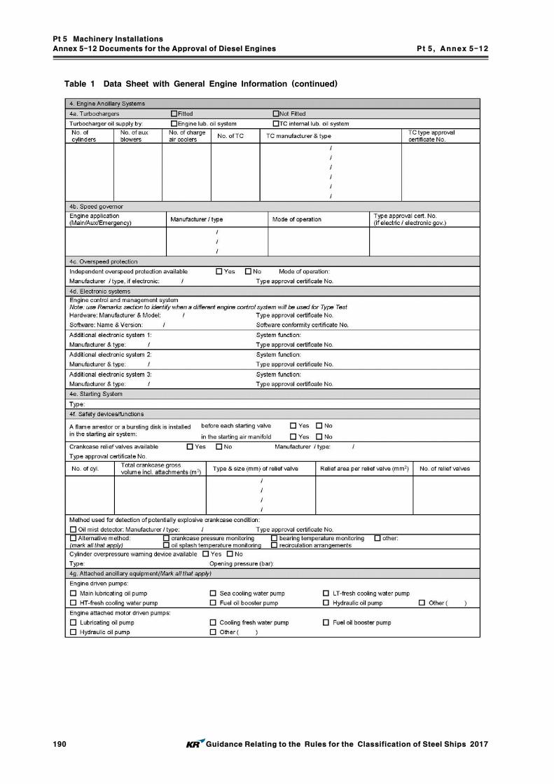
Pt 5 Machinery Installations
Annex 5-12 Documents for the Approval of Diesel Engines Pt 5, Annex 5-12
190 Guidance Relating to the Rules for the Classification of Steel Ships 2017
Table 1 Data Sheet with General Engine Information (continued)

Pt 5 Machinery Installations
Annex 5-12 Documents for the Approval of Diesel Engines Pt 5, Annex 5-12
Guidance Relating to the Rules for the Classification of Steel Ships 2017 191
Table 1 Data Sheet with General Engine Information (continued)

Pt 5 Machinery Installations
Annex 5-12 Documents for the Approval of Diesel Engines Pt 5, Annex 5-12
192 Guidance Relating to the Rules for the Classification of Steel Ships 2017
Table 1 Data Sheet with General Engine Information (continued)

Pt 5 Machinery Installations
Annex 5-12 Documents for the Approval of Diesel Engines Pt 5, Annex 5-12
Guidance Relating to the Rules for the Classification of Steel Ships 2017 193
Table 2 Tubular Listing of Licensor's and Licensee's Drawing and Data

Pt 5 Machinery Installations
Annex 5-12 Documents for the Approval of Diesel Engines Pt 5, Annex 5-12
194 Guidance Relating to the Rules for the Classification of Steel Ships 2017
Table 3 Sample Template for Confirmation of the Licensor's Acceptance of Licensee's Modifications

Pt 5 Machinery Installations
Annex 5-13 Exhaust Gas Recirculation system Pt 5, Annex 5-13
Guidance Relating to the Rules for the Classification of Steel Ships 2017 195
Annex 5-13 Exhaust Gas Recirculation system
1. General
(1) This requirements are to apply to Exhaust Gas Recirculation system and their auxiliary systems reducing diesel engine NOx emissions.
(2) For items not specified in this Annex, the relevant requirements specified in Pt 5 of the Rules apply.
(3) Where a ship designed for the reduction of NOx emissions by the use of Exhaust Gas Recirculation system is designed, constructed and tested in accordance with this Annex, the EEAS-EGR notation may be assigned. Where a ship provided EGR systems that incorporate en-gine systems that are designed for the purposes of removing the sulfur by-products from the ex-haust gases that originate from the fuel and incorporate, for example, water scrubbing and water cleaning systems, the EEAS-EGR may be assigned. Where a water treatment system is in-corporated in the EGR system, the washwater discharge criteria is to meet the requirements of IMO Res. MEPC.184(59).
2. Plans and Data
(1) Plans and specifications covering the EGR arrangements are to be submitted and are, as appli-cable, to include: (A) General arrangement of the EGR installation, layout, and systems (B) Documentation detailing the EGR specification and associated water treatment systems, in-
cluding details of EGR specific components such as coolers, blowers, valves, etc. (C) Hull plans showing the foundation and attachments of accessories to the vessel’s structure,
including scantlings, welding details, and foundation details of principal components (D) Material specifications for the EGR equipment and associated systems, including coolers,
blowers, pumps, valves, storage/process tanks, residue tanks, piping, distribution systems, sep-arators, and associated components, including a corrosion assessment detailing the corrosive effect of system liquids, vapors, and gases on the materials used in the exhaust emission abatement system
(E) Arrangement and capacity of tanks for storage, chemicals, process washwater, exhaust gas cleaning residues, etc.
(F) Details of all piping systems, including details of piping and associated components, design pressures, temperatures, insulation, and drip trays, where applicable
(G) Descriptions and schematic diagrams for the control and monitoring systems, including set points for abnormal conditions and details of the location and position at which exhaust emission or EGR rate monitoring and washwater monitoring are to be located
(H) Details of all electrical equipment installed for the EGR unit and associated systems, includ-ing computer-based systems
(I) Failure Modes and Effects Analysis (FMEA) to determine possible failures and their effects in the safe operation of the EGR exhaust emission abatement system
(J) Emergency shutdown arrangements (K) Operating and maintenance instruction manuals, including MSDS sheets and details for han-
dling of hazardous and non-hazardous chemicals used in the EGR exhaust emission abate-ment system
(L) Testing procedures during installation and commissioning trials (M) EGR FMEA integration test report
3. EGR Operation and Maintenance Manuals
(1) Detailed instruction manuals are to be provided onboard, covering the operations, safety, and maintenance requirements and occupational health hazards relevant to the EGR exhaust emission abatement equipment and associated systems.
(2) These manuals are to include, but not necessarily be limited to, the procedures and schedules for operation, inspection, testing, and maintenance of the EGR system and associated systems, the regular testing and maintenance procedures for the monitoring systems, safety shutoff sys-tems, and the integrity of backup systems, together with special instructions for the bunkering, storage, and use of hazardous and non-hazardous chemicals that may be used in the exhaust emission abatement system.

Pt 5 Machinery Installations
Annex 5-13 Exhaust Gas Recirculation system Pt 5, Annex 5-13
196 Guidance Relating to the Rules for the Classification of Steel Ships 2017
(3) The manuals may be produced as standalone documents or incorporated within the general en-gine operation and service manuals.
4. EGR System Configuration
(1) General (A) Exhaust Gas Recirculation is the process of recirculating a portion of the diesel engine ex-
haust gases, typically up to 40%, back to the engine cylinders for the purpose of reducing the amount of excess oxygen within the cylinder and thereby reducing engine NOx
emissions. (B) EGR systems are to be designed to enable continued operation of the engine at the times
the EGR system is not in operation, either through operational selection, equipment failure, or system deterioration through partial blocking/clogging.
(C) The response of the mechanical and electrical systems of the first EGR unit in a particular design series is to be demonstrated by the FMEA integration test.
(2) Compatibility with the Engine (A) Installation and operation of the EGR system is to be compatible with the engine and not
to cause any adverse effects on the engine performance such as excessive back pressures or temperatures during operation.
(B) The range of suitable fuels for which the EGR system is capable of continual operation, in particular with respect to sulfur content and other fuel elements known to cause fouling is-sues, is to be declared by the EGR manufacturer and included in the EGR specification documentation and instruction manuals.
(3) Redundancy (A) Redundancy of equipment is to be provided for those rotating and reciprocating components
that form part of the EGR essential supplementary systems, such as pumps, fans, blowers, etc.
(B) Consideration will be given to alternative means of compliance or operation to meet above (A) on a case-by-case basis. As applicable, documentation is to be submitted demonstrating that the reliability of the system or component provides continued serviceability of the ex-haust emission abatement system or the alternative means of operation provides continued compliance with the statutory environmental requirements, without compromising the vessel propulsion and maneuvering capability.
(4) Essential Services (A) For the purposes of design, construction, testing, and survey, EGR units and associated
components and systems are considered secondary essential services in accordance with the requirements specified in Pt 6, Ch 1, 101. 4 (13) of the Rules.
(5) Prevention of Flooding(A) For EGR systems that incorporate a wet washwater scrubbing process, arrangements are to
be provided to prevent the ingress of scrubber washwater into the engine under any circumstance.
(B) Monitoring, alarm, and shutdown arrangements are to be provided to prevent an abnormal rise of washwater level in the EGR scrubber unit.
(6) Exhaust emission abatement systems are to be designed for proper operation at the inclination requirements specified in Ch 1, 103. Table 5.1.2 of the Rules.
5. EGR System Equipment
(1) Pumps/Blowers (A) Where provided, blowers and pumps used in EGR SOx scrubber washwater, dosing, dis-
charge, etc., systems, essential for the continual operation of the EGR exhaust emission abatement system, are to be tested and certified in accordance with the requirements speci-fied in Ch 1, 210. and Ch 6 of the Rules.
(B) Unless alternative means of compliance in accordance with 4. (3) (B) of this Guide are ap-plicable, redundant washwater, dosing, discharge, etc., pumps, essential for the continual op-eration of the EGR water systems, are to be provided. There are to be at least two of these essential pumps, the capacity of the pumps, with any one pump out of service, is to be suf-ficient for continuous operation of the exhaust emission abatement system at full rating.
(C) Where ships fitted with two or more identical exhaust emission abatement systems, the pro-vision of a common standby pump (for each essential system) capable of serving all EGR

Pt 5 Machinery Installations
Annex 5-13 Exhaust Gas Recirculation system Pt 5, Annex 5-13
Guidance Relating to the Rules for the Classification of Steel Ships 2017 197
units will suffice rather than providing individual standby pumps for each EGR unit. (D) Unless alternative means of compliance in accordance with 4 (3) (B) of this Guide are ap-
plicable and where exhaust fans or blowers form part of the EGR system and are essential for continual operation of the exhaust emission abatement system at full rating, such fans or blowers are to be installed in a redundant arrangement. The number and power of the fans or blowers should be such that if one unit, or group of units, is out of service the capacity of the remaining units is not to be less than 100% of the total required.
(2) Heat Exchangers/EGR Exhaust Gas Coolers (A) Where provided, heat exchangers are to comply with the requirements specified in Ch 5, Sec. 3 of the Rules.
(3) Electrical System For items not specified in this Annex, the relevant requirements specified in Pt 6 of the Rules apply. (A) Electrical Motors and Controllers Motors and motor controllers are to be ceritified in accordnace with the relevant require-
ments specified in Pt 6 of the Rules.(B) Standby Pump/Fan In the event of failure of the essential exhaust emission abatement system pumps or
fans/blowers, the standby pump or fan/blower, where provided, is to be automatically started and put into service. This failure is to be alarmed at the local and remote control stations.
(C) Circuit Protection Devices Circuit breakers are to be installed for miscellaneous EGR system electrical loads and are
to be compatible with the prospective short circuit current level calculated at the switchboards.
6. EGR System Piping
(1) Exhaust Gas Piping Systems (A) Exhaust Gas Piping/Scrubber Materials and Installation
(a) Exhaust gas piping materials located before the EGR SOx scrubber, where fitted, may be of the same material specification as the standard engine exhaust gas piping.
(b) The sections of the scrubber that are subjected to washwater (e.g., the interior reaction chamber or washwater piping/nozzles, etc.) are to be constructed of suitable corrosion resistant materials.
(c) Exhaust gas piping materials used after the SOx scrubber unit are to be of a corrosion resistant material such as stainless steel.
(B) Exhaust Gas Piping Valves(a) Valves used in the EGR exhaust system are to comply with the relevant requirements
specified in Ch 6 of the Rules. The valves are to be constructed of corrosion resistant materials.
(b) The EGR exhaust system valves are to be arranged for automatic position control and position monitoring in association with the EGR control and monitoring system.
(c) Valves are to be installed in accessible locations, clear of or protected from obstructions, moving equipment, and hot surfaces, in order to permit regular inspection and periodic servicing.
(C) Insulation Hot surfaces of EGR systems or their associated equipment or systems likely to come into
contact with the crew during operation are to be suitably guarded or insulated. Where the surface temperatures are likely to exceed 220°C and where any leakage, under pressure or otherwise, of fuel oil, lubricating oil or other flammable liquid is likely to come into con-tact with the EGR unit or exhaust pipes, these surfaces are to be suitably insulated with non-combustible materials that are impervious to such liquids.
(2) Washwater Piping(A) Piping and Connections
(a) Where applicable, the EGR SOx washwater system pipe fittings and joints are to comply with the requirements specified in Ch 6 of the Rules.
(b) The piping material for the corrosive scrubber washwater system is to be selected based on the corrosive nature of the liquid media.

Pt 5 Machinery Installations
Annex 5-13 Exhaust Gas Recirculation system Pt 5, Annex 5-13
198 Guidance Relating to the Rules for the Classification of Steel Ships 2017
(B) Remote Control Valves (a) Upon loss of control power, the remote control valves are to remain in the last ordered
position, provided there is a readily accessible manual means to close the valves or are to fail safe in accordance with the FMEA.
(b) Remote control valves are to be clearly identified and are to be provided with position indicators at the local and EGR system remote control station, as applicable.
(c) Valves are to be installed in accessible locations, clear of or protected from obstructions, moving equipment, and hot surfaces, in order to permit regular inspection and/or peri-odic servicing.
(C) Overboard Discharges (a) The overboard discharges of any exhaust emission abatement system are not to be inter-
connected to other systems.(b) Special attention is to be paid to the corrosion resistivity of EGR washwater overboard
discharge piping. Where applicable, adequate arrangements are to be provided to prevent galvanic corrosion due to the use of dissimilar metals.
(c) Due consideration is to be given to the location of overboard discharges with respect to vessel propulsion features, such as thrusters or propellers.
(3) Chemical Treatment Piping Systems The requirements for the washwater chemical treatment system detailed in this paragraph are
based on the use of Caustic Soda (NaOH) in the EGR scrubber water treatment system, as applicable. If other chemicals are to be used, the requirements should be consistent with the in-tent of the requirements for Caustic Soda but would need to be assessed on a case-by-case basis. (A) Material
(a) The material of the NaOH related piping systems, NaOH storage tank, EGR resi-due/NaOH overflow tanks, drip trays, and any other components which may come into contact with the NaOH solution or sludge is to be of a suitable grade of stainless steel or other corrosion-resistant material established to be suitable for the application. Aluminum, zinc, brass, or galvanized steel components are not to be used.
(B) Bunkering of NaOH (a) The bunker station for NaOH is to be located on the open deck away from sources of
ignition and arranged such that a spill at a bunker station would not result in NaOH contacting or mixing with other incompatible materials. Alternatively, closed or semi-en-closed bunker stations may be approved subject to the provision of effective ventilation.
(b) Spill trays, which may be of the dry type or having means of drainage to the EGR res-idue/ NaOH overflow tank, are to be provided.
(C) Arrangement of Tank(a) The NaOH storage and EGC residue/NaOH overflow tank are not to be situated where
spillage or leakage therefrom can constitute a hazard by falling onto combustibles or heated surfaces. In particular, these tanks are not to be located over boilers or in close proximity to steam piping.
(D) Air Pipes, Overflow Pipes and Sounding Devices(a) The NaOH storage tank is to be provided with a fill line from the bunker station and a
shut off valve is to be provided at the bunkering station. Overflow and drains leading to the EGR residue/NaOH overflow tank are to enter at or near the top of the tank. However, if this is determined to be impracticable, these lines are to be fitted with a non-return valve at the EGR residue/NaOH overflow tank.
(b) The NaOH storage and EGR residue/NaOH overflow tanks are to be provided with air pipes complying with Ch 6, Sec. 2 of the Rules, and the outlets are to terminate in a safe location on weather deck.
(c) Means are to be provided to prevent NaOH from spilling or accidently overflowing from the storage and EGR residue/NaOH overflow tanks. These means may comply with the requirements specified in Ch 6, 202. 2, 3 and 4 of the Rules and tanks are to be fit-ted with a high level alarm.
(d) Sounding arrangements are to be provided for the NaOH storage and EGR resi-due/NaOH overflow tanks, and are to comply with the sounding requirements applicable to fuel oil tanks of Ch 6, 203. of the Rules and Pt 8, Ch 2, Sec 1 of the Rules. In addition to local level gauging(sounding pipe or level gauge), the NaOH storage and EGR residue/NaOH overflow tanks are to have remote level gauging indication at the

Pt 5 Machinery Installations
Annex 5-13 Exhaust Gas Recirculation system Pt 5, Annex 5-13
Guidance Relating to the Rules for the Classification of Steel Ships 2017 199
manned control station.(e) The NaOH storage and EGR residue/NaOH overflow tank are to be provided with local
and remote temperature monitoring arrangements. The remote temperature indication is to be installed at the manned control station.
(E) Spill Trays(a) Those areas of the NaOH storage and EGR residue/NaOH overflow tanks that could re-
sult in leakage, locations where leakage from pumps and other associated equipment such as strainers, heaters, flanges, valves, etc., which may require occasional dismantling for examination or maintenance may occur, and where leakage may otherwise normally be expected are to be located within spill trays.
(b) Either drainage arrangements for the spill tray that lead to the dedicated EGR residue/ NaOH overflow tank are to be provided or arrangements to activate an alarm in the event of spillage are to be provided. Where drainage arrangements are provided, the drain line to the EGR residue/NaOH overflow tank is to be fitted with a non-return valve.
(F) Miscellaneous Piping (a) The NaOH piping systems are to be independent of other ship service piping and
systems.(b) Piping systems for NaOH systems are not to be located in accommodation, service, or
control spaces.(c) Every pipe emanating from a tank containing NaOH, which, if damaged, would allow
NaOH to escape from the tank, is to be provided with a positive closing valve located directly on the tank. The positive closing valve is to be provided with means of closure both locally and from a readily accessible and safe position outside of the space.
(d) The pipe joints are to be kept to a minimum. The direct connections of pipe lengths are to be all welded except for necessary flanged connections to valves and other equipment.
(e) Supply, bunkering, and transfer lines for NaOH systems are not to be located over boil-ers or in close proximity to steam piping, exhaust systems, hot surfaces required to be insulated, or other sources of ignition.
(G) Ventilation (a) The NaOH storage and EGR residue/NaOH overflow tanks may be located within the
engine room or in a separate compartment. In either location, the area is to be served by an effective mechanical exhaust ventilation system. In addition, if located in a sepa-rate compartment, the ventilation system is to be capable of being controlled from out-side the compartment.
(H) Personnel Protection(a) For the protection of crew members, the vessel shall have on board suitable protective
equipment consisting of large aprons, rubber gloves with long sleeves, rubber boots, coveralls of chemical-resistant material, and tight-fitting chemical safety goggles or face shields or both.
(b) Safety instructions relating to precautions and corrective response actions are to be post-ed in the compartment containing NaOH and beside the entrance to the compartment.
(4) Residue System(A) The residues generated from the exhaust gas cleaning process are to be stored in a des-
ignated residue tank, separate from the engine room sludge tank, and arranged for discharge to appropriate shore reception facilities in accordance with MARPOL Annex I, Ch III, Reg.13. The EGR residue tank is to be so designed as to facilitate cleaning. Where EGR residue tanks used in closed loop chemical treatment systems are also used as the overflow tank for the NaOH storage tank, the additional requirements of 6 (3) of this Annex are to be applied.
(B) The material of the EGR residue tank is to be selected based on the corrosive nature of the EGR residue.
(C) The capacity of the EGR residue tank is to be based on the expected residue volumes ap-plicable to the exhaust gas cleaning process and the maximum period of voyage between ports where EGR residue can be discharged. In the absence of precise data, a figure of 30 days is to be used.
(D) The EGR residue tank is to be provided with air pipes complying with Ch 6, 201. of the Rules. The residue tank is to be arranged with a high level alarm.
Pt 5 Machinery Installations
Annex 5-13 Exhaust Gas Recirculation system Pt 5, Annex 5-13
200 Guidance Relating to the Rules for the Classification of Steel Ships 2017
(E) Sounding arrangements are to be provided for the EGR residue tank in accordance with Ch 6, 203. and Pt 8, Ch 2, Sec 1 of the Rules.
7. Control, Alarm, and Monitoring System
(1) General(A) The EGR control system is to be integrated with, or in direct communication with, the en-
gine control system. Control systems for associated systems, such as water treatment plants, may be connected to an integrated control system or may be a standalone system.
(B) The system is to be designed such that a single fault of a component will not lead to a potentially dangerous situation for human safety and the vessel. An FMEA or equivalent demonstrating the safety system design basis is to be submitted.
(2) Control and Monitoring System(A) Automatic control, monitoring, alarm, and safety functions are to be provided for the EGR
system so that operations remain within preset parameters for all engine operating conditions. Where vessels are provided with the automation equipment specified in Pt 9, Ch 3 of the Rules, the alarm and monitoring systems are to be integrated in the vessel’s centralized monitoring systems.
(B) The temperatures, pressures and flows in the EGR system and associated systems are to be controlled and monitored as follows:(a) A local control and monitoring system for the EGR system is to be provided to enable
safe operation, maintenance, and effective control in the event of an emergency or fail-ure of any remote controls.
(b) The design of the control system is to provide identification of faults in the equipment, as well as the process system. The control and monitoring systems are to comply with the requirements of Pt 9, Ch 3, 302. 4 of the Rules.
(c) Indications of parameters necessary for the safe and effective operation of the exhaust emission abatement process are to be provided at the local and, as applicable, remote control stations, as per Table 1 of this Annex and are to include the following parame-ters:(i) EGR system pump/fan/blower/motor operational status(ii) Status of any EGR system valves showing whether they are open or shut(iii) EGR system parameters for operational safety (iv) Level indication of EGR system tanks(v) Status of any EGR system alarms, shutdowns and Emergency Stop
(d) The computer-based control systems are to comply with the applicable requirements of Pt 6, Ch 2, 201. 7 of the Rules as a Category II system.
(C) Where power supply is electric, each of the control, monitoring and safety systems is to be supplied by a separate circuit. Each of these circuits is to be protected for short circuit and monitored for voltage failure.
(3) Safety Shutdown System(A) An independent shutdown system is to be provided. This safety shutdown system is to be
based on the following:(a) Means are to be provided to indicate the parameters causing shutdown.(b) Upon activation of the safety shutdown system, alarms are to be given at the normal
control position and at the local control position.(c) In the event where shutdown by the safety shutdown system is activated, the restart
should not occur automatically, unless after the system is reset.(B) Monitoring and safety shutdowns are to be in accordance with Table 1 of this Annex.

Pt 5 Machinery Installations
Annex 5-13 Exhaust Gas Recirculation system Pt 5, Annex 5-13
Guidance Relating to the Rules for the Classification of Steel Ships 2017 201
Table 1 Monitoring and Safety System Functions for EGR Systems
Parameters DisplayAlarm
ActivatedAutomatic EGR
Shutdown
EGR exhaust fan/blower motors Run Stop
EGR exhaust bypass, isolation, mixing valves, where provided
Position
Control-actuating medium of the EGR exhaust bypass or isolation valves
Run Fail
Exhaust gas temperature before/after EGR unit ● H O(HH)
Engine air intake O2 concentration(or EGR rate) ● L/H ●(HH/LL)
Differential pressure across EGR scrubber unit or
EGR circuit, as applicable ● H ●(HH)
EGR washwater pumps, alkali system pumps Run Stop
EGR washwater or alkali system valves Position
Control-actuating medium of the EGR washwater
and alkali system valves, where provided Run Fail
EGR washwater and alkali system supply
pressure ● Low ●(LL)
EGR washwater and alkali system supply
temperature ● H ●(HH)
Water level in EGR scrubber ● H ●(HH)
Alkali storage tank temperature ● L/H ●(HH)
Alkali storage tank level ● L/H ●(LL)
Alkali system drip tray level ● H ●(HH)
EGC residue tank level ● H ●(HH)
Control power supply Run Stop
Emergency shutdown ● ● ●
8. FMEA Integration Test
(1) An integration test is to be undertaken on the first EGR unit in a particular design series to verify that the operation and response of the complete EGR mechanical and electrical systems are as predicted for all operational modes. The scope of these tests is to be determined based on the FMEA required by 7 (1) (B) of this Annex.
9. Survey and Test
(1) General(A) These requirements apply to shop test and onboard test of EGR systems and associated
systems. Following tests may be incorporated with the tests required by Ch 2, 211. of the Rules

Pt 5 Machinery Installations
Annex 5-13 Exhaust Gas Recirculation system Pt 5, Annex 5-13
202 Guidance Relating to the Rules for the Classification of Steel Ships 2017
(2) Test(A) Inspection and verification that the foundations and attachments of the principal components
of the EGR equipment and associated systems are in accordance with the approved plans and particulars.
(B) Piping systems are to be examined and tested in accordance with Ch 6, Sec. 13 of the Rules.
(C) Electrical equipments are to be examined and tested in accordance with Pt 6, Ch 1 of the Rules.
(D) Instrumentation is to be tested to confirm proper operation as per its predetermined set points.
(E) Pressure relief and safety valves installed on the unit are to be tested.(F) Control system and shutdowns are to be tested for proper operation.
Pt 5 Machinery Installations
Annex 5-14 Shaft alignment Pt 5, Annex 5-14
Guidance Relating to the Rules for the Classification of Steel Ships 2017 203
Annex 5-14 Shaft Alignment (2017)
1. Application
(1) Shaft alignment calculations (if applicable, including stern tube boring details), shaft alignment procedures, and are to be submitted for review for any one of followings.(A) Propulsion shafting of the actual propeller shaft diameter not less than 400 mm(B) Propulsion shafting with reduction gears where the gear wheel is driven by two or more
ahead pinions(C) Propulsion shafting incorporating power take-off or power take-in(D) Propulsion shafting with no forward stern tube bearing
2. Shaft alignment calculations
The shaft alignment calculations are to include bearing reactions, shear forces and bending moments along the shafting and are to be performed for the maximum allowable alignment tolerances.(1) Where the hull deflections are accounted for in the analysis. The vessel conditions to be con-
sidered in the analysis should account for the following.(A) Drydock or after launching draft at cold static condition(B) Ballast draft at hot static condition(C) Full loaded draft at hot static condition
(2) Where the hull deflections are not accounted for in the analysis then the shaft alignment ver-ification is to comply with Par 5 (5) (D). Vessels where cargo/ballast load change is not sig-nificantly affecting the draft of the ship will be given special consideration. In no case are the calculated bearing reactions to exceed 80% of the maximum allowable manufacturer’s limit.
(3) The shaft alignment calculations are to show the following.(A) Bearing loads under all operating conditions are within the acceptable limits specified by
the bearing manufacturer. In addition, the aft most bearing (aft stern tube bearing or strut bearing) is to comply with Ch 3, 206. 1 of the Rules.
(B) Bearing reactions supporting the shaft are always positive. However, if additional measure-ments and analyses (such as whirling analysis) in accordance with Par 5 (5) (E) are carried out and confirmed that unloading of the bearing has no adverse effect on vessel operation, bearing reactions can be zero (unloaded).
(C) Shear forces and bending moments on propulsion equipment are within the limits specified by manufacturers.
(D) Shear forces and bending moments at the crankshaft flange are in accordance with the en-gine manufacturer’s limits.
(E) The designed relative slope between the shaft and the aft most bearing (aft stern tube bear-ing or strut bearing) is to be positive (the forward end of the bearing is to be above, or on the same elevation as the aft end of the bearing), and not to exceed × rad.
(F) Where stern tube bearing is force-fitted, based on the actual interference fit tolerances, the stern tube bearing fitting calculation, including fitting pressure and push-in distance, is to be submitted for review.
(G) Where the clearance calculation on aft and forward stern tube bearing is carried out, align-ment model showing only the propeller shaft on two stern tube bearings, is to be included in the shaft alignment calculations and submitted to the Society for review.
(H) The shaft alignment calculations are to identify the following corresponding to the condition in which they will be measured.(a) Gap and sag data, temporary support location, jack down location and force(b) Jack up location, jack up correction factor
3. Stern tube bearing slope boring
(1) The slope boring angle calculation (single or double slope) is to be based on a static afloat condition with a hot engine and fully immersed propeller.
(2) If the calculated relative slope between the shaft and the aft most bearing is greater than × rad, the relative slope is to be reduced by means of slope boring or bearing inclination.
(3) On alignment sensitive installations (e.g. tankers, bulkers and twin screw vessels) it is recom-mended to apply the double slope design on the aft stern tube bearings.

Pt 5 Machinery Installations
Annex 5-14 Shaft alignment Pt 5, Annex 5-14
204 Guidance Relating to the Rules for the Classification of Steel Ships 2017
(4) The slope boring verification procedure is to be submitted for review.
4. Shaft Alignment Procedure
The shaft alignment procedure is to be submitted for review and is to be based on the submitted shaft alignment calculations. As a minimum, the shaft alignment procedure is to include the following.(1) Bore sighting : The bore sighting procedure is to be conducted in two stages (A), (B) and to
be satisfied with (C), (D). Sufficient number of targets should be utilized during the sighting through to ensure accuracy in verification of bearing slopes. Target arrangement is to be in-cluded in the procedure submitted for review.(A) Bore sighting before stern tube bearings fitting (not applicable for stern tube bearings in-
stalled by resin chocking), is to be conducted on the stern tube bore to verify the following. Whenever applicable, it is recommended that all corrections are done by machin-ing the outside bush diameter, rather than correcting the stern tube bore.(a) The stern tube bore dimensions : in order to define dimensions and tolerance for the aft
and the forward stern tube bush outside diameters machining(b) The stern tube bore misalignment, vertical and horizontal : in order to define angular
corrections for stern tube bush outside diameter machining(B) Bore sighting after the stern tube bearings are fitted, is to verify the following. In cases
with no forward stern tube bearing, the intermediate shaft bearing should serve as a referent point to conduct sighting.(a) The aft stern tube bush slope : The measurement is to be taken with reference to the
forward stern tube bush.(b) The horizontal misalignment between aft and the forward stern tube bearing.
(C) The horizontal misalignment of all bearings is to be minimized and is not to exceed the clearance of adjacent bearings.
(D) The slope boring angle is to be verified relative to the straight line connecting both stern tube bearings. Acceptable tolerance is up to ±× rad, with the following restrictions.(a) The measured slope boring angle is never to result in misalignment greater than × rad.
(b) In case of a propulsion installation with no forward stern tube bearing, the intermediate shaft bearing should be chocked and its offset not changed after the bore sighting is complete.
(2) Stern tube bearing fitting pressure verification : The stern tube bearing fitting pressure should be verified to comply with calculated values.
(3) Stern tube bearing clearance measurement : The clearance measurements should be verified after the propeller shaft is fitted (before shaft unrestrained on the forward flange).
(4) Gap and sag : The gap and sag procedure is to be verified against the respective analysis (e.g. based on dry dock or light ship draft condition). Acceptable tolerances are ±0.1 mm.
(5) Bearing load measurements : Identification of the bearings at which the measurements are to be taken, the jack up locations, the data to be recorded and the procedures to be followed should be reported in the submittal.
(6) Stern tube bearing run-in procedure : For alignment sensitive installation (e.g. tankers, bulkers and twin screw vessels), it is recommended to conduct a run-in procedure before the stern tube bearings are exposed to higher service speeds and rudder angles.
5. Tests and inspections
The shaft alignment for all vessels is to be carried out in the presence of a Surveyor. The align-ment is to be verified in the afloat condition with superstructure in place and major welding work completed and is to be to the satisfaction of the attending Surveyor.
In addition, the vessels which are subjected to submission of shaft alignment calculations and pro-cedures in Par 1 are to comply with the following. (1) The alignment verification is to be carried out in accordance with the procedures. The align-
ment calculated data is to be verified and recorded, in the presence of the Surveyor for the following.(A) Stern tube sighting and slope boring (as applicable) before shaft fitting(B) Stern tube bearing fitting pressure and push-in distance as required in Par 4 (2)

Pt 5 Machinery Installations
Annex 5-14 Shaft alignment Pt 5, Annex 5-14
Guidance Relating to the Rules for the Classification of Steel Ships 2017 205
(C) Stern tube bearing clearance as required in Par 4 (3)(D) Gap and sag(E) Bearing reaction
(2) Stern tube run-in procedure as required in Par 4 (6) is recommended to be conducted, in the presence of the Surveyor.
(3) Stern tube sighting and slope boring (as applicable) before shaft fitting(A) Maximum allowable slope boring angle deviation is not to result in negative slope, and is
never to exceed relative slope of × rad.(B) In case of a propulsion installation with no forward stern tube bearing, the intermediate
shaft bearing is to be chocked and its offset not to be changed after the bore sighting is complete.
(C) In cases where sighting through and bearing positioning are conducted in block stage of the vessel construction, the verification of the following procedures is required.(a) Slope boring angle (as applicable)(b) Bearing vertical offset positioning(c) Engine vertical offset positioning(d) Gap and sag procedure
(D) Where a monitoring system is installed to verify the stern tube bearing misalignment, the waiver of above requirements (A), (B), (C) can be considered.
(4) Gap and sag verification(A) The gap and sag is to be measured at the drydock or after launching condition, unless
agreed to otherwise by the Society.(B) With assistance of the temporary supports the gap and sag needs to be simultaneously veri-
fied at all open flanges until gap and sag values are brought within acceptable tolerances of ±0.1 mm from the corresponding calculated values.
(5) Bearing load verification(A) The bearing load measurements are to be carried out at the drydock or lightship condition,
unless agreed to otherwise by the Society.(B) Bearing reactions are required to be verified and recorded by such means as hydraulic jack
and strain gauge method on all accessible shafting bearings as following. (a) Forward stern tube bearing(b) Intermediate shaft bearing(c) Minimum three aftmost main engine bearings (for directly coupled propulsion systems
only)(d) Main-gear shaft bearing
(C) Where hull deflections are accounted for in the analysis;(a) The measured values for the bearings are to be within ±20 % of the calculated values,
unless specifically approved otherwise.(b) In the case that the measured values are not within ±20 % of the calculated values, the
shaft alignment calculations are to be revised so as to reflect compliance and re-sub-mitted, or the provisions of (D) followed.
(D) Where hull deflections are not accounted for in the analysis, in addition to (A) and (B), bearing load measurements are to be taken in at least one additional service draft condition of the vessel with the aft peak tank full (ballast draft at hot static condition or full loaded draft at hot static condition) or other service condition as deemed appropriate by the Society. In no case are the measured bearing reactions to exceed 80% of the maximum al-lowable manufacturer’s limit.
(E) In the case that measurements in a particular service condition indicate that one of the bearings is unloaded, additional measurements and analyses, (such as whirling analysis) will be required to confirm unloading of the bearing has no adverse effect on vessel operation.
(F) Additional bearing load measurements may be required, as determined necessary by the Society.

Pt 5 Machinery Installations
Annex 5-15 Exhaust Gas Cleaning system Pt 5, Annex 5-15
206 Guidance Relating to the Rules for the Classification of Steel Ships 2017
Annex 5-15 Exhaust Gas Cleaning system (2017)
1. General
(1) This requirements are to apply to arrangements and system design of Exhaust Gas Cleaning system reducing SOx emissions of fuel oil combustion machinery except incinerator.
(2) For items not specified in this Annex, the relevant requirements specified in Pt 5 of the Rules apply.
(3) Where Exhaust Gas Cleaning system is designed, constructed and tested in accordance with this Annex, the EEAS-EGC notation may be assigned.
(4) The washwater discharge criteria is to meet the requirements of IMO Res. MEPC.259(68).
2. Plans and Data
(1) Plans and specifications covering the EGC arrangements are to be submitted and are, as appli-cable, to include: (A) General arrangement of the EGC installation, layout, and systems (B) Documentation detailing the EGC specification (C) Analyses demonstrating compatibility of the scrubber with the fuel oil combustion machinery(D) Hull plans showing the foundation and attachments of accessories to the vessel’s structure,
including scantlings, welding details, and foundation details of principal components (E) Material specifications for the EGC equipment and associated systems, including coolers,
blowers, pumps, valves, storage/process tanks, residue tanks, piping, distribution systems, sep-arators, and associated components, including a corrosion assessment detailing the corrosive effect of system liquids, vapors, and gases on the materials used in the exhaust emission abatement system
(F) Arrangement and capacity of tanks for storage, chemicals, process washwater, exhaust gas cleaning residues, etc
(G) Details of all piping systems, including details of piping and associated components, design pressures, temperatures, insulation, and drip trays, where applicable
(H) Descriptions and schematic diagrams for the control and monitoring systems, including set points for abnormal conditions and details of the location and position at which exhaust emission or EGC rate monitoring and washwater monitoring are to be located
(I) Details of all electrical equipment installed for the EGC unit and associated systems, includ-ing computer-based systems
(J) Emergency shutdown arrangements (K) EGC FMEA report (L) Operating and maintenance instruction manuals, including MSDS sheets and details for han-
dling of hazardous and non-hazardous chemicals used in the EGC system (M) Testing procedures during installation and commissioning trials (N) Documentation detailing the effect on Load Line and Stability of the exhaust gas cleaning
system(retrofit only)(O) Documentation detailing the effect on electric load(retrofit only)
(2) Documents required by IMO Res. MEPC.259(68) are to be additionally submitted.
Documents Scheme A Scheme B
SECP(SOx Emissions Compliance Plan) X X
SECC(SOx Emissions Compliance Certificate) X
ETM-A(EGC System-Technical Manual for Scheme A) X
ETM-B(EGC System-Technical Manual for Scheme B) X
OMM(Onboard Monitoring Manual) X X
EGC Record Book X X

Pt 5 Machinery Installations
Annex 5-15 Exhaust Gas Cleaning system Pt 5, Annex 5-15
Guidance Relating to the Rules for the Classification of Steel Ships 2017 207
3. EGC Operation and Maintenance Manuals
(1) Detailed instruction manuals are to be provided onboard, covering the operations, safety, and maintenance requirements and occupational health hazards relevant to the EGC equipment and associated systems.
(2) These manuals are to include, but not necessarily be limited to, the procedures and schedules for operation, inspection, testing, and maintenance of the EGC system and associated systems, the regular testing and maintenance procedures for the monitoring systems, safety shutoff sys-tems, and the integrity of backup systems, together with special instructions for the bunkering, storage, and use of hazardous and non-hazardous chemicals that may be used in the exhaust emission abatement system.
(3) The manuals may be produced as standalone documents or incorporated within the general en-gine operation and service manuals.
4. EGC System Configuration
(1) General (A) EGC systems are to be designed to enable continued operation of the engine at the times
the EGC system is not in operation, either through operational selection, equipment failure, or system deterioration through partial blocking/clogging.
(B) The exhaust pipings from a number of fuel oil combustion machinery may be led to a common SOx scrubber unit.
(C) The response of the mechanical and electrical systems of the first EGC unit in a particular design series is to be demonstrated by the FMEA integration test.
(2) Compatibility with the Engine (A) Installation and operation of the EGC system is to be compatible with the engine and not
to cause any adverse effects on the engine performance such as excessive back pressures or temperatures during operation.
(B) Details are to be submitted demonstrating the exhaust flow compatibility of the EGC unit with the connected fuel oil combustion machinery over the whole operational range of the fuel oil combustion machinery. This data is to be demonstrate that the operating parameters of the oil burning machinery are not to be exceed the approved design limits with the EGC system in operation. In the case of integrated scrubbers, this compatibility evaluation is to show that the EGC unit is capable of accommodating the maximum combined exhaust flows of all the connected oil burning equipment for the worst case scenario for that partic-ular ship arrangement and operational profile. Consideration will be given to those EGC units that incorporate extractive exhaust fans to maintain the fuel oil combustion machinery operating parameters within the approved design limits.
(3) Redundancy (A) Redundancy of equipment is to be provided for those rotating and reciprocating components
that form part of the EGC essential supplementary systems, such as pumps, fans, blowers, etc.
(B) Consideration will be given to alternative means of compliance or operation to meet above (A) on a case-by-case basis. As applicable, documentation is to be submitted demonstrating that the reliability of the system or component provides continued serviceability of the ex-haust gas cleaning system or the alternative means of operation provides continued com-pliance with the statutory environmental requirements, without compromising the vessel pro-pulsion and maneuvering capability.
(4) Essential Services (A) For the purposes of design, construction, testing, and survey, EGC units and associated
components and systems are considered secondary essential services in accordance with the requirements specified in Pt 6, Ch 1, 101. 4 (13) of the Rules.
(5) Essential Services EGC units that incorporate a wet washwater scrubbing process are to be capable of being oper-ated without the washwater system in operation or are to be installed with an exhaust bypass arrangement or changeover system to enable continued operation of the fuel oil combustion ma-chinery in the event the exhaust emission abatement system is not in operation, either through operational selection or equipment failure. As applicable, evidence of material suitability is to be submitted for dry running of SOx scrubbers.

Pt 5 Machinery Installations
Annex 5-15 Exhaust Gas Cleaning system Pt 5, Annex 5-15
208 Guidance Relating to the Rules for the Classification of Steel Ships 2017
(6) Prevention of Flooding(A) Arrangements are to be provided to prevent the ingress of scrubber washwater into the fuel
oil combustion machinery under any circumstance.(B) Monitoring, alarm, and shutdown arrangements are to be provided to prevent an abnormal
rise of washwater level in the EGC scrubber unit. (6) Exhaust gas cleaning systems are to be designed for proper operation at the inclination require-
ments specified in Ch 1, 103. Table 5.1.2 of the Rules.
5. EGC System Equipment
(1) Pumps/Blowers (A) Where provided, blowers and pumps used in EGC SOx scrubber washwater, dosing, dis-
charge, etc., systems, essential for the continual operation of the EGC exhaust emission abatement system, are to be tested and certified in accordance with the requirements speci-fied in Ch 1, 210. and Ch 6 of the Rules.
(B) Unless alternative means of compliance in accordance with 4. (3) (B) of this Guide are ap-plicable, redundant washwater, dosing, discharge, etc., pumps, essential for the continual op-eration of the EGC water systems, are to be provided. There are to be at least two of these essential pumps, the capacity of the pumps, with any one pump out of service, is to be suf-ficient for continuous operation of the exhaust emission abatement system at full rating.
(C) Where ships fitted with two or more identical exhaust emission abatement systems, the pro-vision of a common standby pump (for each essential system) capable of serving all EGC units will suffice rather than providing individual standby pumps for each EGC unit.
(D) Unless alternative means of compliance in accordance with 4. (3) (B) of this Guide are ap-plicable and where exhaust fans or blowers form part of the EGC system and are essential for continual operation of the exhaust emission abatement system at full rating, such fans or blowers are to be installed in a redundant arrangement. The number and power of the fans or blowers should be such that if one unit, or group of units, is out of service the capacity of the remaining units is not to be less than 100% of the total required.
(2) Heat Exchangers/EGC Exhaust Gas Coolers (A) Where provided, heat exchangers are to comply with the requirements specified in Ch 5, Sec. 3 of the Rules.
(3) Dry scrubber consumable equipment(A) For dry type exhaust gas cleaning systems, details of the granulate supply and discharge
systems are to be submitted. (B) Unless alternative means of compliance in accordance with 4 (3) (B) of this Guide are ap-
plicable, drive arrangements for the exhaust cleaning reductant consumable are to be ar-ranged in a redundant arrangement.
(4) Electrical SystemsFor items not specified in this Annex, the relevant requirements specified in Pt 6 of the Rules apply. (A) Electrical Motors and Controllers Motors and motor controllers are to be ceritified in accordnace with the relevant require-
ments specified in Pt 6 of the Rules.(B) Standby Pump/Fan In the event of failure of the essential exhaust gas cleaning system pumps or fans/blowers,
the standby pump or fan/blower, where provided, is to be automatically started and put into service. This failure is to be alarmed at the local and remote control stations.
(C) Circuit Protection Devices Circuit breakers are to be installed for miscellaneous EGC system electrical loads and are
to be compatible with the prospective short circuit current level calculated at the switchboards.
6. EGC System Piping
(1) Exhaust Gas Piping Systems (A) Exhaust Gas Piping/Scrubber Materials and Installation
(a) Exhaust gas piping materials located before the EGC SOx scrubber, where fitted, may be of the same material specification as the standard fuel oil combustion machinery exhaust gas piping.

Pt 5 Machinery Installations
Annex 5-15 Exhaust Gas Cleaning system Pt 5, Annex 5-15
Guidance Relating to the Rules for the Classification of Steel Ships 2017 209
(b) The sections of the scrubber that are subjected to washwater (e.g., the interior reaction chamber or washwater piping/nozzles, etc.) are to be constructed of suitable corrosion resistant materials.
(c) Exhaust gas piping materials used after the SOx scrubber unit are to be of a corrosion resistant material such as stainless steel.
(d) Exhaust gas pipings are to comply with sec 1 and sec 6 in Ch 6 of the Rules.(B) Exhaust Gas Piping Valves
(a) Valves used in the EGC system are to comply with the relevant requirements specified in Ch 6 of the Rules. The valves are to be constructed of corrosion resistant materials.
(b) Isolation and bypass valves used in EGC system exhaust piping systems are to prevent the passage of exhaust gases to other fuel oil combustion machinery or machinery spaces. Where bypass arrangements for the SOx scrubber unit are provided, the isolation and bypass valves are to be arranged in an interlocked, fail safe manner, such that free flow of exhaust gases to the atmosphere at all times is possible, either through the scrubber unit or through the bypass. Bypass valves are to be provided with a local po-sition indicator.
(c) Valves are to be installed in accessible locations, clear of or protected from obstructions, moving equipment, and hot surfaces, in order to permit regular inspection and periodic servicing.
(C) Interconnection of exhaust gas piping(a) Normally, exhaust pipes from diesel engines and flue gas pipes from oil-fired boilers are
to be routed separately and not interconnected. However, interconnected exhaust piping systems to a common EGC unit may be accepted subject to the arrangements preventing the passage or leakage of exhaust gases to other equipment or spaces that may then pose a safety risk to that equipment or health risk to the vessel’s crew or passengers.
(b) The integrated EGC system is to be designed not to exceed the backpressure limits specified by the connected engines or boilers.
(D) Insulation Hot surfaces of EGC units or their associated equipment or systems likely to come into contact with the crew during operation are to be suitably guarded or insulated. Where the surface temperatures are likely to exceed 220°C and where any leakage, under pressure or otherwise, of fuel oil, lubricating oil, or other flammable liquid is likely to come into con-tact with the EGC unit or exhaust pipes, these surfaces are to be suitably insulated with non-combustible materials that are impervious to such liquids.
(2) Washwater piping (A) Piping and Connections
(a) The EGC SOx washwater system pipe fittings and joints are to comply with the require-ments specified in Ch 6 of the Rules.
(b) The piping material for the corrosive scrubber washwater system is to be selected based on the corrosive nature of the liquid media.
(c) The means are to be provided to prevent clogging of washwater nozzles.(B) Remote Control Valves
(a) Upon loss of control power, the remote control valves are to remain in the last ordered position, provided there is a readily accessible manual means to close the valves or are to fail safe in accordance with the FMEA.
(b) Remote control valves are to be clearly identified and are to be provided with position indicators at the local and EGC system remote control station, as applicable.
(c) Valves are to be installed in accessible locations, clear of or protected from obstructions, moving equipment, and hot surfaces, in order to permit regular inspection and/or peri-odic servicing.
(C) Overboard Discharges (a) The overboard discharges of any EGC system are not to be interconnected to other
systems.(b) Special attention is to be paid to the corrosion resistivity of EGC washwater overboard
discharge piping. Where applicable, adequate arrangements are to be provided to prevent galvanic corrosion due to the use of dissimilar metals.
(c) Due consideration is to be given to the location of overboard discharges with respect to vessel propulsion features, such as thrusters or propellers.
Pt 5 Machinery Installations
Annex 5-15 Exhaust Gas Cleaning system Pt 5, Annex 5-15
210 Guidance Relating to the Rules for the Classification of Steel Ships 2017
(3) Chemical Treatment Piping Systems The requirements for the washwater chemical treatment system detailed in this paragraph are
based on the use of Caustic Soda (NaOH) in the EGC scrubber water treatment system, as applicable. If other chemicals are to be used, the requirements should be consistent with the in-tent of the requirements for Caustic Soda but would need to be assessed on a case-by-case basis. (A) Material
(a) The material of the NaOH related piping systems, NaOH storage tank, EGC resi-due/NaOH overflow tanks, drip trays, and any other components which may come into contact with the NaOH solution or sludge is to be of a suitable grade of stainless steel or other corrosion-resistant material established to be suitable for the application. Aluminum, zinc, brass, or galvanized steel components are not to be used.
(B) Bunkering of NaOH (a) The bunker station for NaOH is to be located on the open deck away from sources of
ignition and arranged such that a spill at a bunker station would not result in NaOH contacting or mixing with other incompatible materials. Alternatively, closed or semi-en-closed bunker stations may be approved subject to the provision of effective ventilation.
(b) Spill trays, which may be of the dry type or having means of drainage to the EGC res-idue/ NaOH overflow tank, are to be provided.
(C) Arrangement of Tank(a) The NaOH storage and EGC residue/NaOH overflow tank are not to be situated where
spillage or leakage therefrom can constitute a hazard by falling onto combustibles or heated surfaces. In particular, these tanks are not to be located over boilers or in close proximity to steam piping.
(D) Air Pipes, Overflow Pipes and Sounding Devices(a) The NaOH storage tank is to be provided with a fill line from the bunker station and a
shut off valve is to be provided at the bunkering station. Overflow and drains leading to the EGC residue/NaOH overflow tank are to enter at or near the top of the tank. However, if this is determined to be impracticable, these lines are to be fitted with a non-return valve at the EGC residue/NaOH overflow tank.
(b) The NaOH storage and EGC residue/NaOH overflow tanks are to be provided with air pipes complying with Ch 6, Sec. 2 of the Rules, and the outlets are to terminate in a safe location on weather deck.
(c) Means are to be provided to prevent NaOH from spilling or accidently overflowing from the storage and EGC residue/NaOH overflow tanks. These means may comply with the requirements specified in Ch 6, 202. 2, 3 and 4 of the Rules and tanks are to be fit-ted with a high level alarm.
(d) Sounding arrangements are to be provided for the NaOH storage and EGC resi-due/NaOH overflow tanks, and are to comply with the sounding requirements applicable to fuel oil tanks of Ch 6, 203. of the Rules and Pt 8, Ch 2, Sec 1 of the Rules. In addition to local level gauging(sounding pipe or level gauge), the NaOH storage and EGC residue/NaOH overflow tanks are to have remote level gauging indication at the manned control station.
(e) The NaOH storage and EGC residue/NaOH overflow tank are to be provided with local and remote temperature monitoring arrangements. The remote temperature indication is to be installed at the manned control station.
(E) Spill Trays(a) Those areas of the NaOH storage and EGC residue/NaOH overflow tanks that could re-
sult in leakage, locations where leakage from pumps and other associated equipment such as strainers, heaters, flanges, valves, etc., which may require occasional dismantling for examination or maintenance may occur, and where leakage may otherwise normally be expected are to be located within spill trays.
(b) Either drainage arrangements for the spill tray that lead to the dedicated EGC residue/ NaOH overflow tank are to be provided or arrangements to activate an alarm in the event of spillage are to be provided. Where drainage arrangements are provided, the drain line to the EGC residue/NaOH overflow tank is to be fitted with a non-return valve.

Pt 5 Machinery Installations
Annex 5-15 Exhaust Gas Cleaning system Pt 5, Annex 5-15
Guidance Relating to the Rules for the Classification of Steel Ships 2017 211
(F) Miscellaneous Piping (a) The NaOH piping systems are to be independent of other ship service piping and
systems.(b) Piping systems for NaOH systems are not to be located in accommodation, service, or
control spaces.(c) Every pipe emanating from a tank containing NaOH, which, if damaged, would allow
NaOH to escape from the tank, is to be provided with a positive closing valve located directly on the tank. The positive closing valve is to be provided with means of closure both locally and from a readily accessible and safe position outside of the space.
(d) The pipe joints are to be kept to a minimum. The direct connections of pipe lengths are to be all welded except for necessary flanged connections to valves and other equipment.
(e) Supply, bunkering, and transfer lines for NaOH systems are not to be located over boil-ers or in close proximity to steam piping, exhaust systems, hot surfaces required to be insulated, or other sources of ignition.
(G) Ventilation (a) The NaOH storage and EGC residue/NaOH overflow tanks may be located within the
engine room or in a separate compartment. In either location, the area is to be served by an effective mechanical exhaust ventilation system. In addition, if located in a sepa-rate compartment, the ventilation system is to be capable of being controlled from out-side the compartment.
(H) Personnel Protection(a) For the protection of crew members, the vessel shall have on board suitable protective
equipment consisting of large aprons, rubber gloves with long sleeves, rubber boots, coveralls of chemical-resistant material, and tight-fitting chemical safety goggles or face shields or both.
(b) Safety instructions relating to precautions and corrective response actions are to be post-ed in the compartment containing NaOH and beside the entrance to the compartment.
(4) Residue System(A) The residues generated from the exhaust gas cleaning process are to be stored in a des-
ignated residue tank, separate from the engine room sludge tank, and arranged for discharge to appropriate shore reception facilities in accordance with MARPOL Annex I, Ch III, Reg.13. The EGC residue tank is to be so designed as to facilitate cleaning. Where EGC residue tanks used in closed loop chemical treatment systems are also used as the overflow tank for the NaOH storage tank, the additional requirements of 6 (3) of this Annex are to be applied.
(B) The material of the EGC residue tank is to be selected based on the corrosive nature of the EGC residue.
(C) The capacity of the EGC residue tank is to be based on the expected residue volumes ap-plicable to the exhaust gas cleaning process and the maximum period of voyage between ports where EGC residue can be discharged. In the absence of precise data, a figure of 30 days is to be used.
(D) The EGC residue tank is to be provided with air pipes complying with Ch 6, 201. of the Rules. The residue tank is to be arranged with a high level alarm.
(E) Sounding arrangements are to be provided for the EGC residue tank in accordance with Ch 6, 203. and Pt 8, Ch 2, Sec 1 of the Rules.
7. Control, Alarm, and Monitoring System
(1) General(A) The EGC control system is to be integrated with, or in direct communication with, the en-
gine control system. (B) The system is to be designed such that a single fault of a component will not lead to a
potentially dangerous situation for human safety and the vessel. An FMEA or equivalent demonstrating the safety system design basis is to be submitted.
(2) Control and Monitoring System(A) Automatic control, monitoring, alarm, and safety functions are to be provided for the EGC
system so that operations remain within preset parameters for all engine operating conditions. Where vessels are provided with the automation equipment specified in Pt 9, Ch 3 of the

Pt 5 Machinery Installations
Annex 5-15 Exhaust Gas Cleaning system Pt 5, Annex 5-15
212 Guidance Relating to the Rules for the Classification of Steel Ships 2017
Rules, the alarm and monitoring systems are to be integrated in the vessel’s centralized monitoring systems.
(B) The temperatures, pressures and flows in the EGC system and associated systems are to be controlled and monitored as follows:(a) A local control and monitoring system for the EGC system is to be provided to enable
safe operation, maintenance, and effective control in the event of an emergency or fail-ure of any remote controls.
(b) The design of the control system is to provide identification of faults in the equipment, as well as the process system. The control and monitoring systems are to comply with the requirements of Pt 9, Ch 3, 302. 4 of the Rules.
(c) Indications of parameters necessary for the safe and effective operation of the exhaust gas cleaning process are to be provided at the local and, as applicable, remote control stations, as per Table 1 of this Annex and are to include the following parame-ters:(i) EGC system pump/fan/blower/motor operational status(ii) Status of any EGC system valves showing whether they are open or shut(iii) EGC system parameters for operational safety (iv) Level indication of EGC system tanks(v) Status of any EGC system alarms, shutdowns and Emergency Stop
(d) The computer-based control systems are to comply with the applicable requirements of Pt 6, Ch 2, 201. 7 of the Rules as a Category II system.
(C) Where power supply is electric, each of the control, monitoring and safety systems is to be supplied by a separate circuit. Each of these circuits is to be protected for short circuit and monitored for voltage failure.
(3) Safety Shutdown System(A) An independent shutdown system is to be provided. This safety shutdown system is to be
based on the following:(a) Means are to be provided to indicate the parameters causing shutdown.(b) Upon activation of the safety shutdown system, alarms are to be given at the normal
control position and at the local control position.(c) In the event where shutdown by the safety shutdown system is activated, the restart
should not occur automatically, unless after the system is reset.(B) Monitoring and safety shutdowns are to be in accordance with Table 1 of this Annex.
Pt 5 Machinery Installations
Annex 5-15 Exhaust Gas Cleaning system Pt 5, Annex 5-15
Guidance Relating to the Rules for the Classification of Steel Ships 2017 213
Table 1 Monitoring and Safety System Functions for EGC Systems
Parameters Display Alarm ActivatedAutomatic EGC
Shutdown
EGC exhaust fan/blower motors Run Stop
EGC exhaust bypass, isolation, mixing valves, where provided
Position
Control-actuating medium of the EGC exhaust bypass or isolation valves
Run Fail
Exhaust gas temperature before/after EGC unit ● H O(HH)
Exhaust gas pressure before/after Engines ● H ●(HH)
Differential pressure across EGC scrubber unit(Dry type only)
● H ●(HH)
EGC washwater pumps, alkali system pumps or supply system of dry system
Run Stop
EGC washwater or alkali system valves Position
Control-actuating medium of the EGC washwater and alkali system valves, where provided
Run Fail
EGC washwater and alkali system supply pressure ● Low ●(LL)
EGC washwater and alkali system supply temperature ● H ●(HH)
Water level in EGC scrubber ● H ●(HH)
Alkali storage tank temperature ● L/H ●(HH)
Alkali storage tank level ● L/H ●(LL)
Alkali system drip tray level ● H ●(HH)
EGC residue tank level ● H ●(HH)
Control power supply Run Stop
Emergency shutdown ● ● ●
8. FMEA Integration Test
(1) An integration test is to be undertaken on the first EGC unit in a particular design series to verify that the operation and response of the complete EGC mechanical and electrical systems are as predicted for all operational modes. The scope of these tests is to be determined based on the FMEA required by 7 (1) (B) of this Annex.
9. Survey and Test
(1) General(A) These requirements apply to shop test and onboard test of EGC systems and associated
systems. Following tests may be incorporated with the tests required by Ch 2, 211. of the Rules
(B) Where the unit or continous monitoring system type approval is needed, it is to be ap-proved by flag administration or Society accroding to IMO MEPC Res.259(68).
(2) Test(A) Inspection and verification that the foundations and attachments of the principal components
of the EGC equipment and associated systems are in accordance with the approved plans and particulars.
(B) Piping systems are to be examined and tested in accordance with Ch 6, Sec. 14 of the Rules.
(C) Electrical equipments are to be examined and tested in accordance with Pt 6, Ch 1 of the

Pt 5 Machinery Installations
Annex 5-15 Exhaust Gas Cleaning system Pt 5, Annex 5-15
214 Guidance Relating to the Rules for the Classification of Steel Ships 2017
Rules.(D) Instrumentation is to be tested to confirm proper operation as per its predetermined set
points.(E) Pressure relief and safety valves installed on the unit are to be tested.(F) Control system and shutdowns are to be tested for proper operation.

Rules for the Classification of Steel ShipsGuidance Relating to the Rules for the Classificationof Steel Ships
PART 5 MACHINERY INSTALLATIONS
Published by
KR
36, Myeongji ocean city 9-ro, Gangseo-gu,
BUSAN, KOREA
TEL : +82 70 8799 7114
FAX : +82 70 8799 8999
Website : http://www.krs.co.kr
CopyrightⒸ 2017, KR
Reproduction of this Rules and Guidance in whole or in parts is prohibited without permission of the publisher.