Embed Size (px)
Citation preview
Chapter 3(b): Digital SignalProcessing
3.1 Introduction to Digital Signal Processing3.2 Analogue to Digital Conversion Process3.3 Quantisation and Encoding3.4 Sampling of Analogue Signals3.5 Aliasing3.6 Digital to Analogue Conversion3.7 Introduction to digital filters
3.7.1 Non-Recursive Digital filters3.7.2 Recursive Digital filters
3.8 Digital filter Realisation3.8.1 Parallel Realisation3.8.2 Cascade Realisation
3.9 Magnitude and Phase Responses3.10 Minimum/Maximum/Mixed Phase Systems3.11 All-pass Filters3.12 Second Order Resonant Filter3.13 Stability of a Second Order Filter3.14 Digital Oscillators3.15 Notch FiltersProf
esso
r E. A
mbikair
ajah
UNSW, A
ustra
lia

Question 2A digital communication link caries binary-coded words representing samples of an inputsignalx(t) = 3 cos(600t) + 2 cos (1800t) . The link is operated at 10,000 bits/s and each inputsample is quantised into 1024 different voltage levels.
(a) What is the sampling frequency?
(b) What are the frequencies in the resulting discrete-time signal x(n)?
[2 marks]
[4 marks]
kHzf s 11000
10000,10
condsamples/seebits/sampl
bits/sec
levels1024210sampleperbitsofNo 10
HzfHzfAnswer
Hzxkfff
ff
HzfHzf
sk
s
100;300:
100100019002
900;300
21
0
2
21
aliasingbyaffectedisitThereforeis
Profes
sor E
. Ambik
airaja
h
UNSW, A
ustra
lia

Question 3Let x(t) have a spectrum X( f) as shown in figure 1.
The spectrum X() of the sampled signal x(t) is given by
If fs = 4 kHz, Sketch the digital spectrum X().
X(f)
f (kHz)2 4 6 8 10-8-10 -6 -4 -2
)(2;)2(1)( 1sf
k
fTT
kXT
X
Figure 1
[5 marks]
324)3(10
44)3(82
24)2(10
04)2(8
324310
44382
24210
0428
0
0
0
0
0
0
0
0
0
kxf
xfk
xf
xf
kxf
xfk
xf
xf
kfff sk
X()
2 4-4 -2
f (kHz)- 2 Prof
esso
r E. A
mbikair
ajah
UNSW, A
ustra
lia

3.7 Introduction to Digital Filters
There are two types of digital filters:
Recursive (there is at least one feedback path inthe filter)
Non-recursive (no feedback paths)
A linear time invariant discrete (LTD)system described by the following equationis commonly called a digital filter:
(3.9)10
L
kk
M
kk knybknxany
Feed forward FeedbackProf
esso
r E. A
mbikair
ajah
UNSW, A
ustra
lia

where x[n] is the input signal, y[n] is the
output signal. a0, a1, a2, ...., aM; b1, b2,
b3, ..., bL are constants (filter coefficients).These coefficients determine thecharacteristics of the system.
when bk = 0 the filter is said to benon-recursive type
when bk 0 recursive type.
(3.9)10
L
kk
M
kk knybknxany
Profes
sor E
. Ambik
airaja
h
UNSW, A
ustra
lia

3.7.1 Non Recursive Digital Filters (FIR)
If bk = 0, then the calculation of y[n] does notrequire the use of previously calculated samples ofthe output (see equation (3.9)).
This is recognised as a convolution sum.
knxanxanxaknxany M
M
kk
1100
M
k
knxkhny0Prof
esso
r E. A
mbikair
ajah
UNSW, A
ustra
lia

Therefore the impulse response is identical tothe coefficients, that is,
Any filter that has an impulse response offinite duration is called Finite ImpulseResponse (FIR) filter.
otherwise
Mnanh n
00
knxanxanxaknxany M
M
kk
1100
h(0) h(1) h(M)
Profes
sor E
. Ambik
airaja
h
UNSW, A
ustra
lia
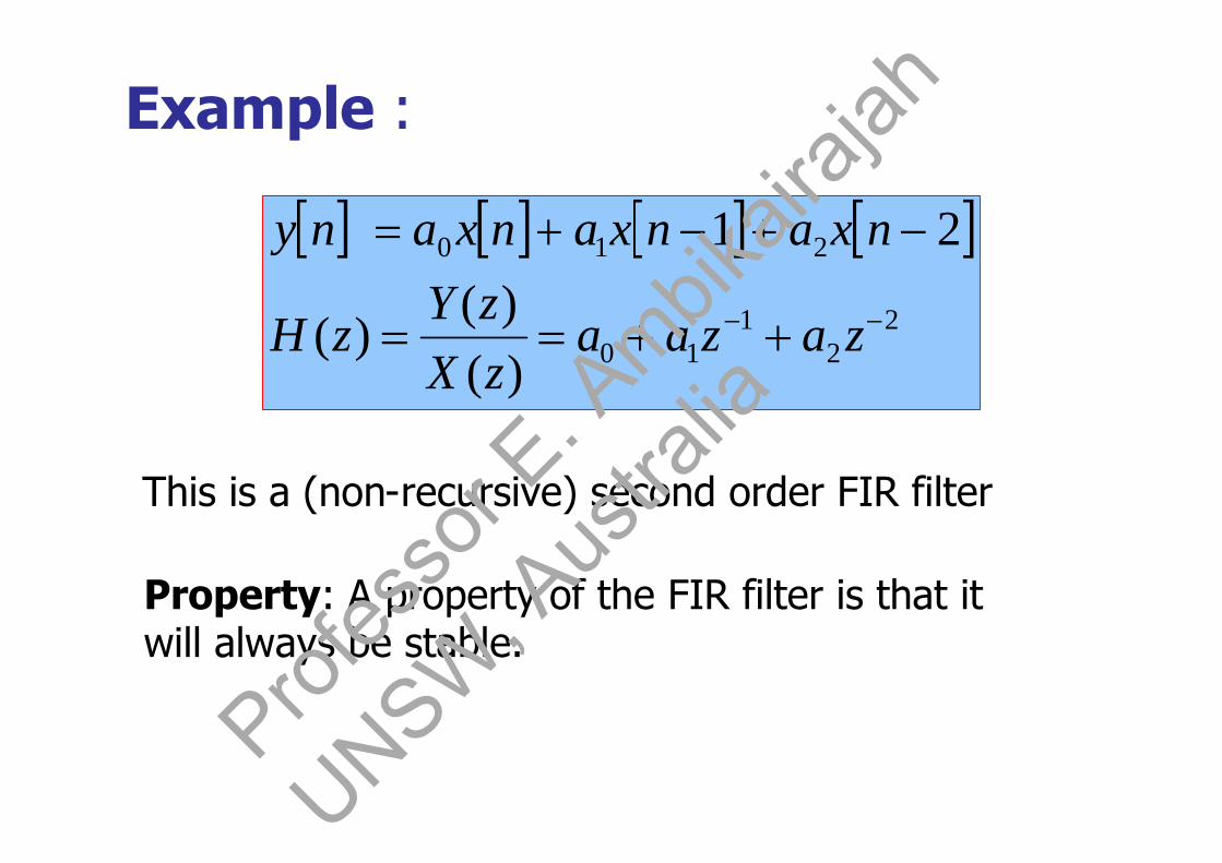
Example :
2
21
10
210
)()(
)(
21
zazaazXzY
zH
nxanxanxany
This is a (non-recursive) second order FIR filter
Property: A property of the FIR filter is that itwill always be stable.
Profes
sor E
. Ambik
airaja
h
UNSW, A
ustra
lia

(a) Stability requires that there should be nopoles outside the unit circle. This condition isautomatically satisfied since there are no poles at alloutside the origin. (In fact, all poles are located atthe origin.)
(b) Another property of non-recursive filter is that wemake filters with exactly linear phase characteristics [4]
Note: The ability to have an exactly linear phaseresponse is one of the most important properties ofa LTD system (filter). When a signal passes througha filter, it is modified in amplitude and/or phase.The nature and extent of the modification of thesignal is dependent on the amplitude and phasecharacteristics of the filter.Prof
esso
r E. A
mbikair
ajah
UNSW, A
ustra
lia

The phase delay or group delay of thefilter provides a useful measure of how thefilter modified the phase characteristic of thesignal. If we consider a signal that consists ofseveral frequency components (eg. speechwaveform) the phase delay of the filter is theamount of time delay each frequencycomponent of the signal suffers in goingthrough the filter.
(3.10))(
)(_
pTdelayphase
[the negative of the phase angle divided byfrequency]Prof
esso
r E. A
mbikair
ajah
UNSW, A
ustra
lia

The group delay on the other hand isthe average time delay the compositesignal suffers at each frequency as itpasses from the input to the output ofthe filter.
(3.11))(
)(_d
Tdelaygroup g
[the negative of the derivative of thephase with respect to frequency]Prof
esso
r E. A
mbikair
ajah
UNSW, A
ustra
lia

A constant group delay means that signalcomponents at different frequencies receivethe same delay in the filter.
A linear phase filter gives same time delay to allfrequency components of the input signal. A filterwith a nonlinear phase characteristic will cause aphase distortion in the signal that passes through it.
()
() = -
-
Figure 3.12. Phase response of a linear phasefilter
Profes
sor E
. Ambik
airaja
h
UNSW, A
ustra
lia

This is because the frequency components inthe signal will each be delayed by an amountnot proportional to frequency, therebyaltering their harmonic relationship. Such adistortion is undesirable in many applications,for example music, video etc.
A filter is said to have a linear phase responseif its phase response satisfies one of the followingrelationships:
(3.12)
ab
a
where ‘a’ and ‘b’ are constants.Profes
sor E
. Ambik
airaja
h
UNSW, A
ustra
lia
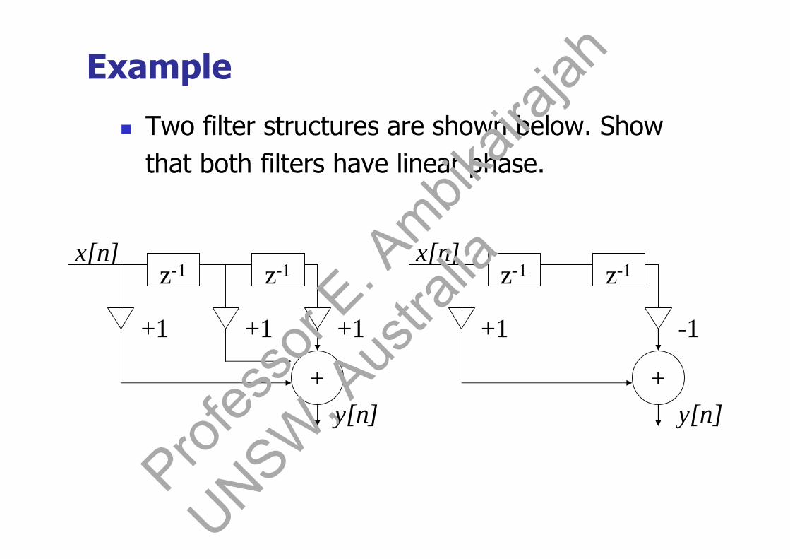
Example
Two filter structures are shown below. Showthat both filters have linear phase.
z-1 z-1
+1 +1 +1
+
x[n]z-1 z-1
+1 -1
+
x[n]
y[n]y[n]
Profes
sor E
. Ambik
airaja
h
UNSW, A
ustra
lia

z-1 z-1
+1 -1
+
x[n]
y[n]
cos21
1
1
1
21
2
21
j
jjj
jj
e
eee
eeH
zzzH
nxnxnxny
z-1 z-1
+1 +1 +1
+
x[n]
y[n]
sin2
sin2
22
1
1
2
2
2
2
2
j
jj
jjj
j
e
ee
jee
je
eH
zzH
nxnxny
phase: () = /2 - ,linear phase
phase: () = -,linear phaseProf
esso
r E. A
mbikair
ajah
UNSW, A
ustra
lia
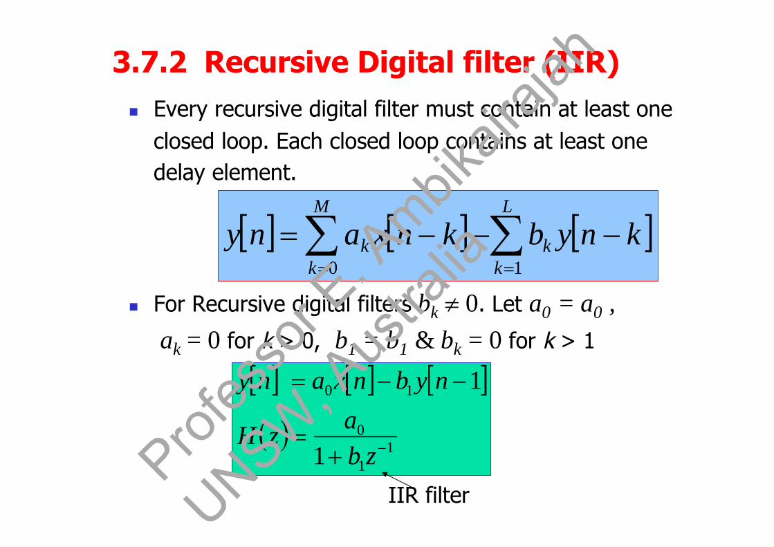
3.7.2 Recursive Digital filter (IIR) Every recursive digital filter must contain at least one
closed loop. Each closed loop contains at least onedelay element.
For Recursive digital filters bk 0. Let a0 = a0 ,ak = 0 for k > 0, b1 = b1 & bk = 0 for k > 1
L
kk
M
kk knybknxany
10
11
0
10
1
1
zbazH
nybnxany
IIR filterProf
esso
r E. A
mbikair
ajah
UNSW, A
ustra
lia

A recursive filter is an infinite impulseresponse filter (IIR).
Examples :2
21
10)( zazaazH
22
111
1)(
zbzbzH
22
11
22
11
11
)(
zbzbzaza
zH
Zeros only
Poles and Zeros
(2nd order FIR filter)
2nd order IIR filter (all pole filter)
IIR filter
Profes
sor E
. Ambik
airaja
h
UNSW, A
ustra
lia

Example :
The difference equation is: y[n] = x[n] + ay[n-1].
The DC gain of H(z) can be obtained by substituting = 0.
If dc gain is undesirable, introduce a constant gain
factor of (1-a), so that H(z) becomes
Note: Poles and zeros can be real or imaginary
101
1)( 1
a
azzH
aaeH j
11
11
|)( )0(0
111
)(
az
azH
dc gain = 1]1[][)1(][ naynxanyProf
esso
r E. A
mbikair
ajah
UNSW, A
ustra
lia

Example:
Consider a lowpass filter
(i) Determine ‘b’ so that |H(0)| = 1
(ii) Determine the 3dB bandwidth (here) for thenormalised filter in part (i)
101 abx[n],]ay[n-y[n]
Profes
sor E
. Ambik
airaja
h
UNSW, A
ustra
lia

(i) Y(z) = aY(z) z-1 + b X(z) 11)(
azb
zH
jaeb
zH
1)(
11
)0(
a
bH
cos21
1
)sin()cos1(
1)(
sin)cos1(1
11
)(
222 aa
a
aa
aH
jaaa
aea
H j
we have |H(0)| =1
b = 1 - a
Profes
sor E
. Ambik
airaja
h
UNSW, A
ustra
lia

Second Method:
2
2*2
cos21)1(
11
11
)()(|)(|aa
aae
aae
aHHH jj
222 |)0(|21|)(|1|)0(| H
cHH
(half-power point)
2
1
1
|H()|0 dB
3 dB
c
2cos21
1|)(|
aa
aH
Profes
sor E
. Ambik
airaja
h
UNSW, A
ustra
lia

21
1
|H()|2
c
aaa
aaa
c
c
214
cos
cos21)1(
21
21
2
2
Profes
sor E
. Ambik
airaja
h
UNSW, A
ustra
lia
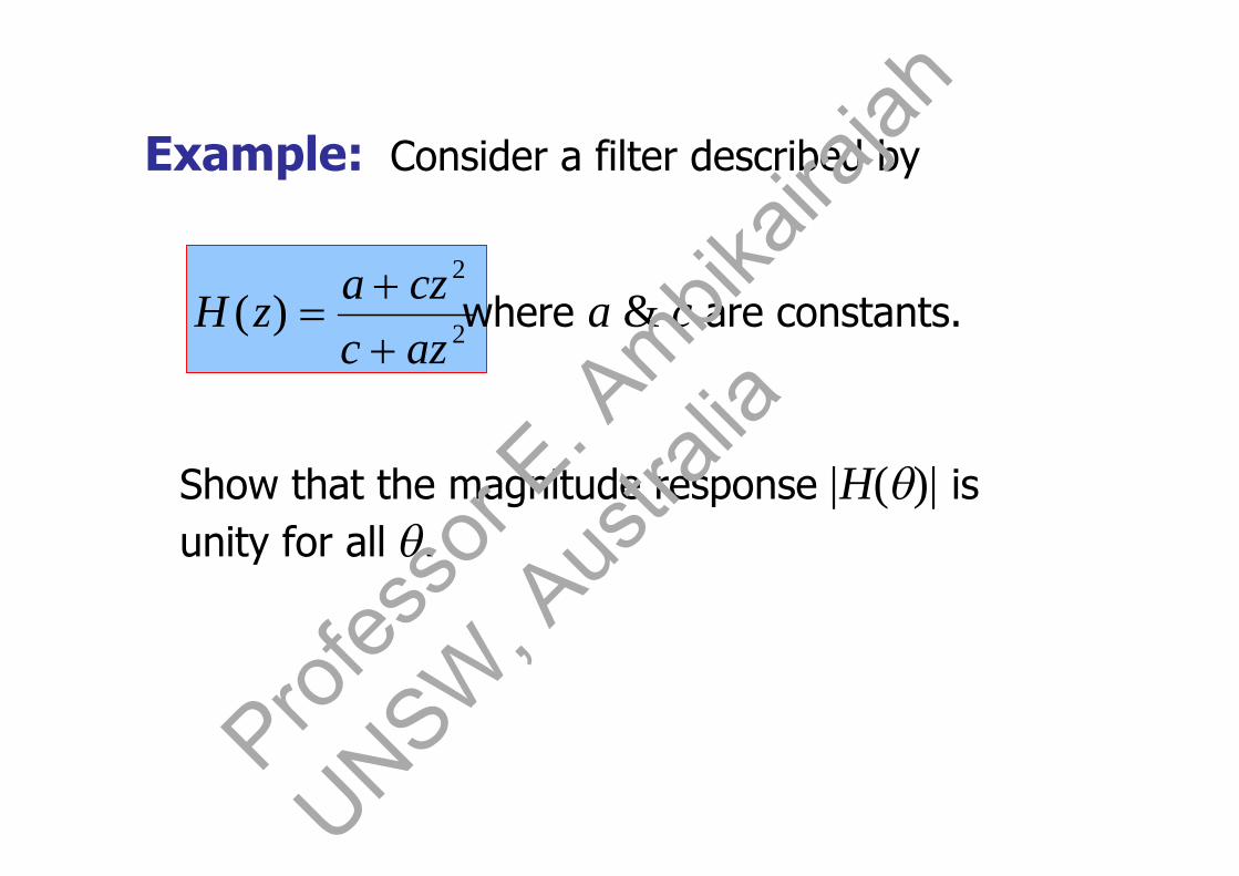
Example: Consider a filter described by
2
2
)(azccza
zH where a & c are constants.
Show that the magnitude response |H()| isunity for all .
Profes
sor E
. Ambik
airaja
h
UNSW, A
ustra
lia

1][][
)()(|)(|
2222
2222
2
2
2
2*2
jj
jj
j
j
j
j
eeaccaeeacac
ceaaec
ceaaec
HHH
|H()|
-
This is an all-pass filter.
Profes
sor E
. Ambik
airaja
h
UNSW, A
ustra
lia

3.8 Digital filter Realisation [11]
1
1
1)()(
)(
)()()(
1
1
0
1
0
10
10
structure
poles
L
k
kk
zeros
M
k
kkL
k
kk
M
k
kk
L
k
kk
M
k
kk
L
kk
M
kk
zbza
zb
za
zXzY
zH
zzYbzzXazY
knybkxany
2
0
1
1
1
structure
zeros
M
k
kk
poles
L
k
kk
zazb
Profes
sor E
. Ambik
airaja
h
UNSW, A
ustra
lia

-b1
-b2
-bL
X(z)+
z-1
z-1
z-1
a1
a2
aM
a0 Y(z)
z-1
z-1
z-1
Figure 3.13. Structure 1 or Direct Form 1
Profes
sor E
. Ambik
airaja
h
UNSW, A
ustra
lia
a1
a2
aM
-b1
-b2
-bL
a0X(z) Y(z)
+ +
z-1
z-1
z-1
z-1
z-1
z-1
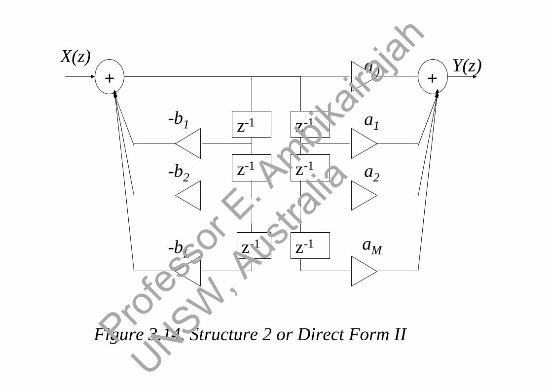
Figure 3.14. Structure 2 or Direct Form IIProfes
sor E
. Ambik
airaja
h
UNSW, A
ustra
lia

In the case when L = M, we have Canonic form realisation.
A discrete-time filter is said to be canonic if it contains theminimum numbers of delay elements necessary to realise theassociated frequency response.
a0
a1
a2
aM
-b1
-b2
-bL
X(z)+
z-1
z-1
z-1
Y(z)+
Figure 3.15. Canonic form
Profes
sor E
. Ambik
airaja
h
UNSW, A
ustra
lia

3.8.1 Parallel Realisation [11]
structureparallel
k
k
ii
LL
MM
zHzHzHzHzH
zbzbzbzazazaa
zH
_
3211
22
11
22
110
)(...)()()()(
1)(
(use partial fraction to obtain Hi(z))
Y(z)
…
H1(z)
H2(z)
Hk(z)
X(z)+
Figure 3.16. Parallel structureProf
esso
r E. A
mbikair
ajah
UNSW, A
ustra
lia

3.8.2 Cascade Realisation [11]
structurecascade
k
k
ii
LL
MM
zHzHzHzHzHzH
zbzbzbzazazaazH
_
3211
22
11
22
110
)(̂)...(̂)(̂)(̂)(̂)(
1)(
(Product of lower order transfer function ie. 1stor 2nd order sections)The cascade structure is the most popular form
Y(z)X(z)
Fig 3.17. Cascade structure
)(̂1 zH )(2̂ zH )(ˆ zH k
Profes
sor E
. Ambik
airaja
h
UNSW, A
ustra
lia
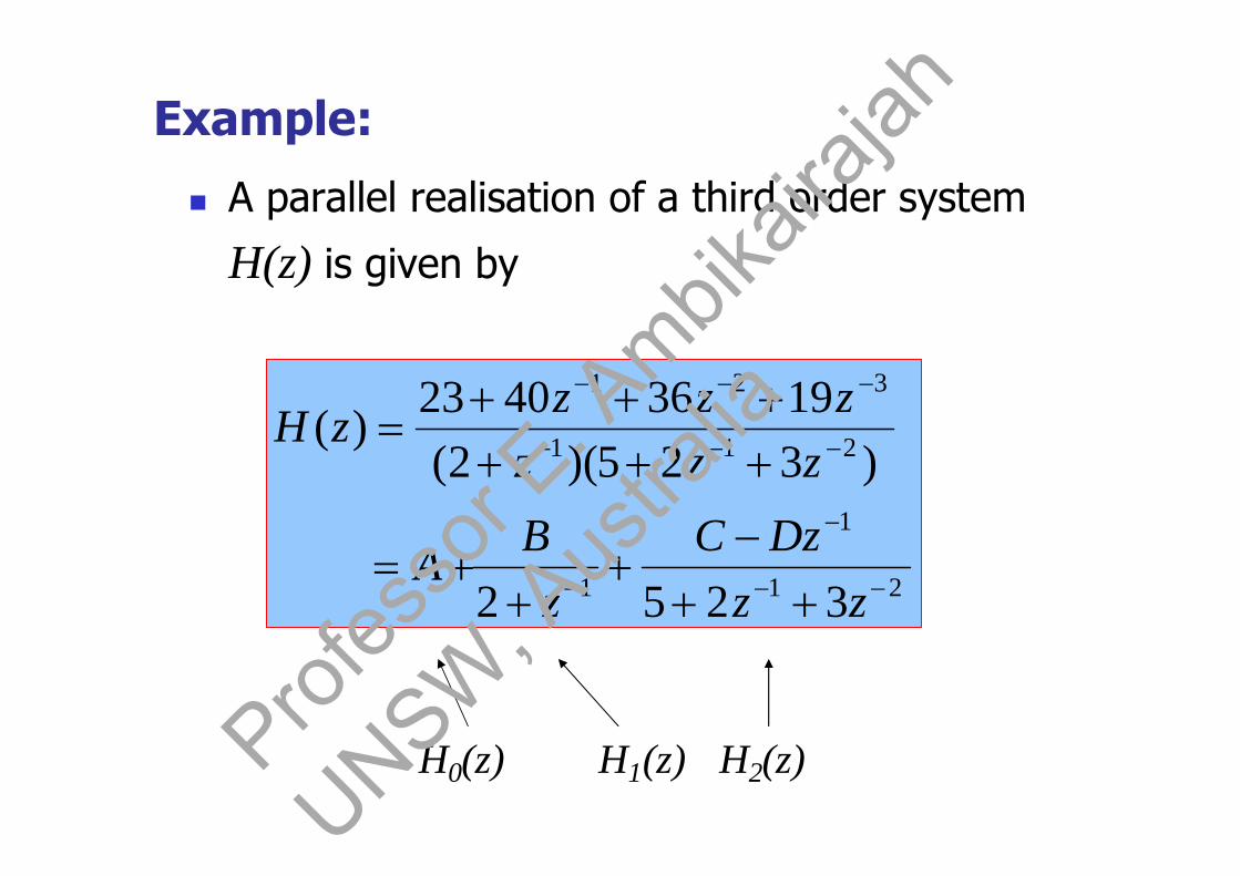
Example:
A parallel realisation of a third order system
H(z) is given by
21
1
1
211
321
3252
)325)(2(19364023
)(
zzDzC
zB
A
zzzzzz
zH
H0(z) H1(z) H2(z)Profes
sor E
. Ambik
airaja
h
UNSW, A
ustra
lia
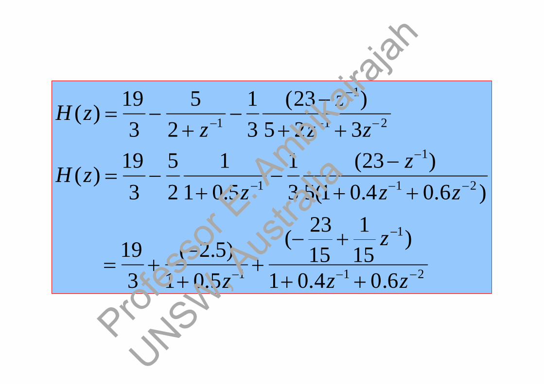
21
1
1
21
1
1
21
1
1
6.04.01
)151
1523
(
5.01)5.2(
319
)6.04.01(5)23(
31
5.011
25
319
)(
325)23(
31
25
319
)(
zz
z
z
zzz
zzH
zzz
zzH
Profes
sor E
. Ambik
airaja
h
UNSW, A
ustra
lia

-0.5
-0.4
-0.6
x[n]
+
z-1
z-1
+
-2.5
z-1
y[n]+ +
319
1523
151
Profes
sor E
. Ambik
airaja
h
UNSW, A
ustra
lia
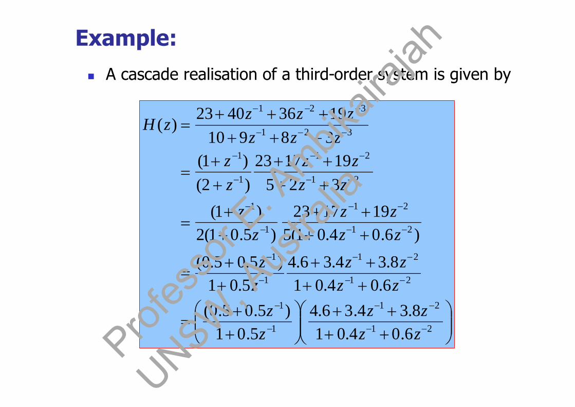
Example:
A cascade realisation of a third-order system is given by
21
21
1
1
21
21
1
1
21
21
1
1
21
21
1
1
321
321
6.04.018.34.36.4
5.01)5.05.0(
6.04.018.34.36.4
5.01)5.05.0(
)6.04.01(5191723
)5.01(2)1(
325191723
)2()1(
3891019364023
)(
zzzz
zz
zzzz
zz
zzzz
zz
zzzz
zz
zzzzzz
zH
Profes
sor E
. Ambik
airaja
h
UNSW, A
ustra
lia
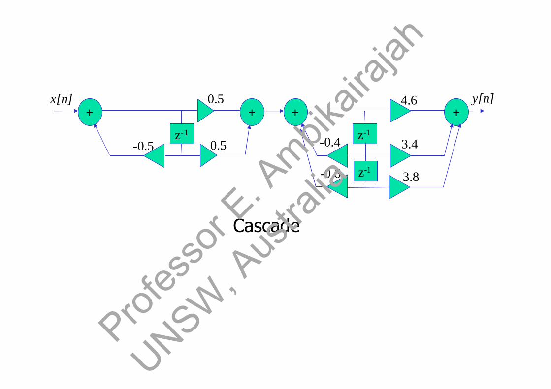
x[n] y[n]
0.5-0.5
0.5
z-1
+ +
3.4-0.4
4.6
z-1
+
3.8-0.6 z-1
+
Cascade
Profes
sor E
. Ambik
airaja
h
UNSW, A
ustra
lia
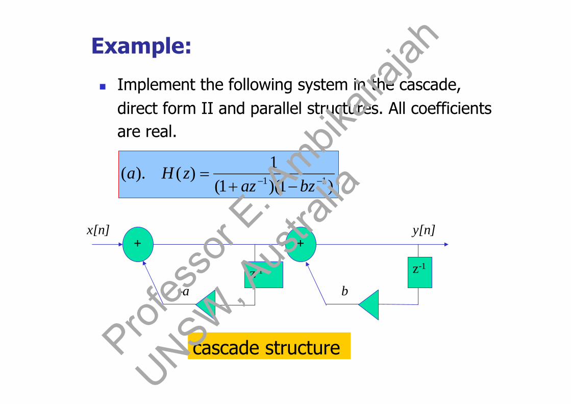
Example:
Implement the following system in the cascade,direct form II and parallel structures. All coefficientsare real.
)1)(1(1
)().( 11
bzazzHa
cascade structure
x[n] y[n]
-az-1
+
b
z-1
+
Profes
sor E
. Ambik
airaja
h
UNSW, A
ustra
lia

21)(11
)(
abzzbazH
y[n]x[n]+
-(a-b)z-1
+ab z-1
Direct form II
Profes
sor E
. Ambik
airaja
h
UNSW, A
ustra
lia

1111 1111)(
bzba
b
azba
a
bzB
azA
zH
Parallel structure
-a
b
x[n]
z-1
z-1
y[n]baa
bab
+
+
+
Profes
sor E
. Ambik
airaja
h
UNSW, A
ustra
lia

31)1(1
)()(
azzHb
a
x[n] y[n]
az-1
+
az-1
+
z-1
+
cascade structureS
No parallel structure exists because partialfraction expansion cannot be performed.Prof
esso
r E. A
mbikair
ajah
UNSW, A
ustra
lia

33221 3311
)(
zazaazzH
Direct Form II
a3
x[n] y[n]
3az-1
+
-3a2z-1
z-1
Profes
sor E
. Ambik
airaja
h
UNSW, A
ustra
lia
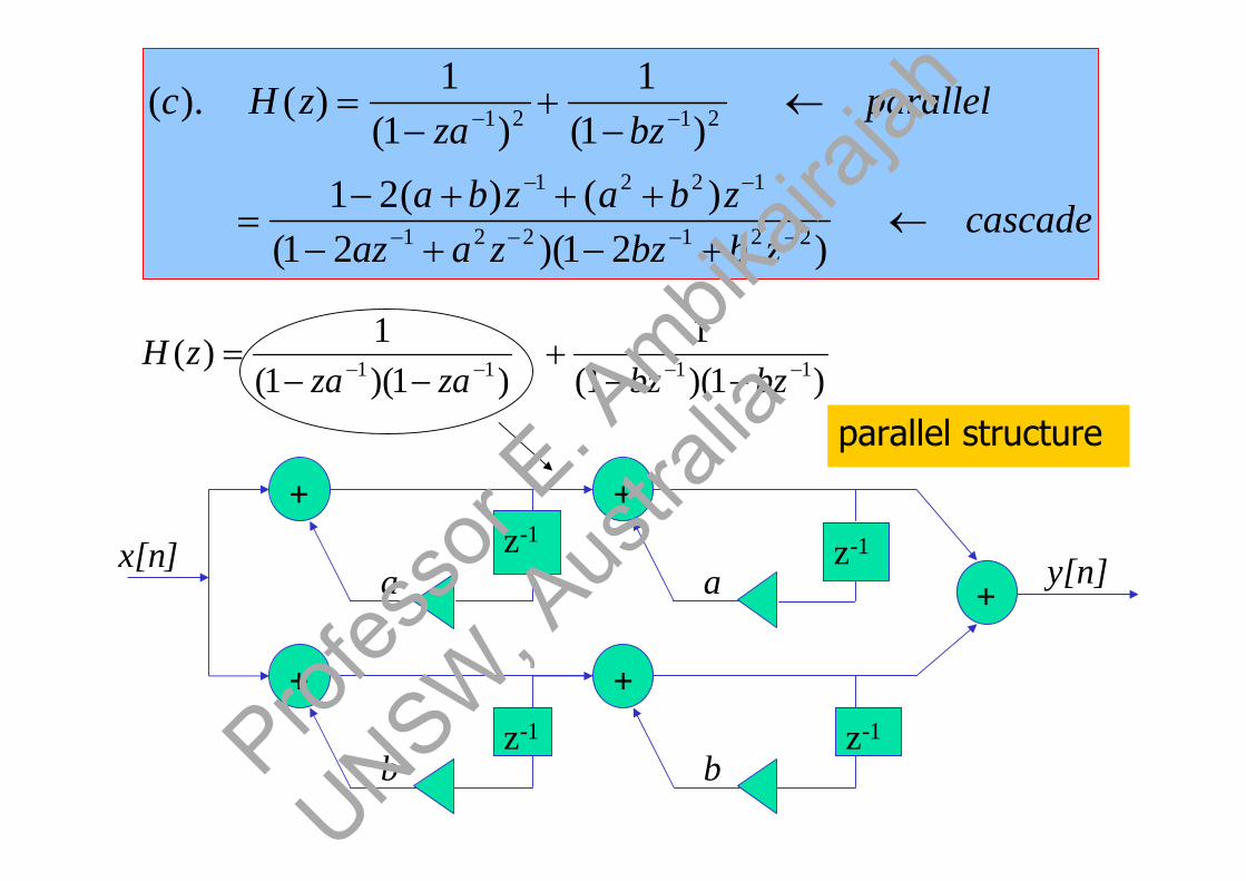
cascadezbbzzaaz
zbazba
parallelbzza
zHc
)21)(21()()(21
)1(1
)1(1
)().(
221221
1221
2121
)1)(1(1
)1)(1(1
)( 1111
bzbzzazazH
y[n]x[n]a
z-1+
az-1
+
parallel structure
+
bz-1
+
bz-1
+
Profes
sor E
. Ambik
airaja
h
UNSW, A
ustra
lia

-2(a+b)
a2+b2
y[n]+
2bz-1
-b2 z-1
+
2a z-1
-a2
x[n]
z-1
+
221221
2221
211
)21()()(21)(
zbbzzaazzbazbazH
Profes
sor E
. Ambik
airaja
h
UNSW, A
ustra
lia
3.9 Magnitude and Phase Response [11]
We can show that the magnitude response isan even function of frequency
The phase response is an odd function offrequency
Profes
sor E
. Ambik
airaja
h
UNSW, A
ustra
lia
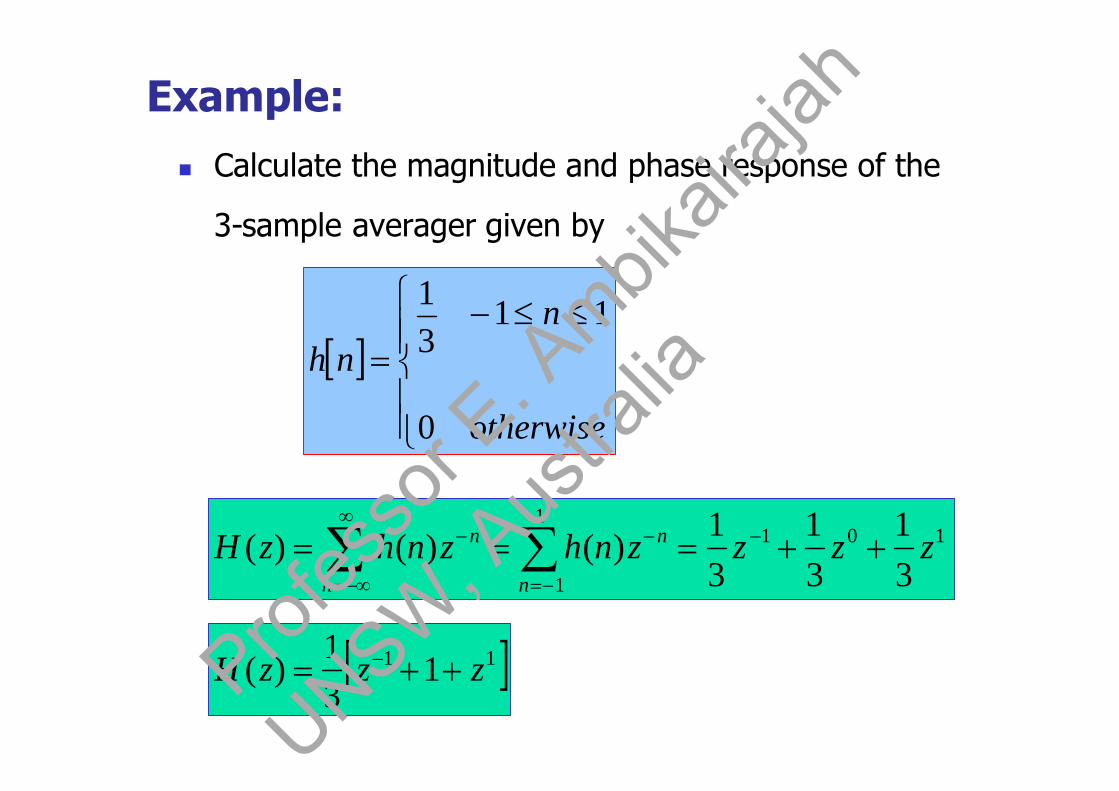
Example:
Calculate the magnitude and phase response of the
3-sample averager given by
otherwise
nnh
0
1131
n n
nn zzzznhznhzH 1011
1 31
31
31
)()()(
11 131
)( zzzH Profes
sor E
. Ambik
airaja
h
UNSW, A
ustra
lia

31
1131
)()(
jjjj
ezeeeezHH j
cos2131
)( H
Precautions must be taken when determining thephase response of a filter having a real-valuedtransfer function, because negative real valuesproduce an additional phase of radians.
Profes
sor E
. Ambik
airaja
h
UNSW, A
ustra
lia
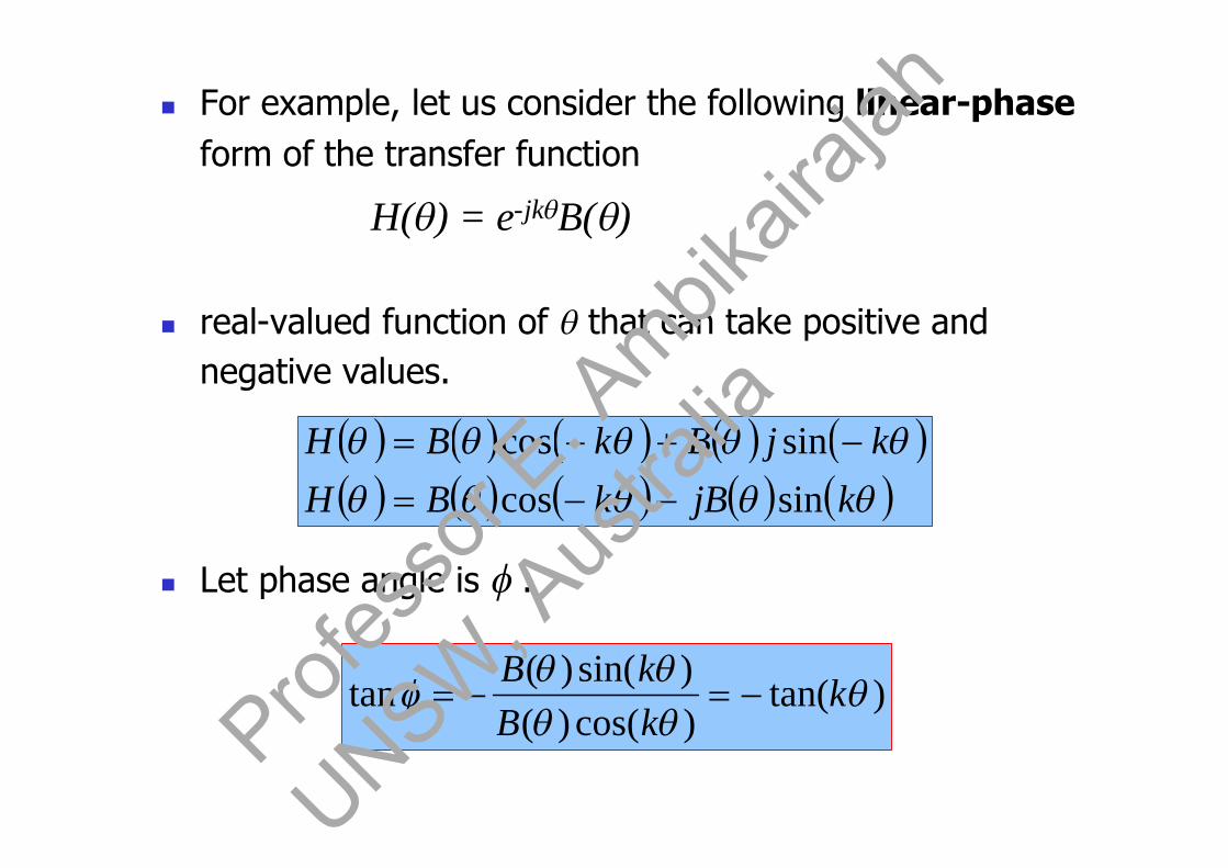
For example, let us consider the following linear-phaseform of the transfer function
H() = e-jkB()
real-valued function of that can take positive andnegative values.
Let phase angle is :
kjBkBH
kjBkBHsincossincos
)tan()cos()()sin()(
tan
kkBkB
Profes
sor E
. Ambik
airaja
h
UNSW, A
ustra
lia

The phase function () includes linear phaseterm and also accommodates for the signchanges in B(). Since -1 can be expressed as ,phase jumps of will occur at frequencieswhere B() changes sign.
If B() > 0, then () = -k.
If B() < 0, then () = -k..
tan= tan(-k) = -k or () = -k
phase angle
Profes
sor E
. Ambik
airaja
h
UNSW, A
ustra
lia

Let us get back to our example
32
32
32
32
and0)(0)(
0)(0)(
]cos21[31|)(|]cos21[
31)(
H
H
HH
Profes
sor E
. Ambik
airaja
h
UNSW, A
ustra
lia
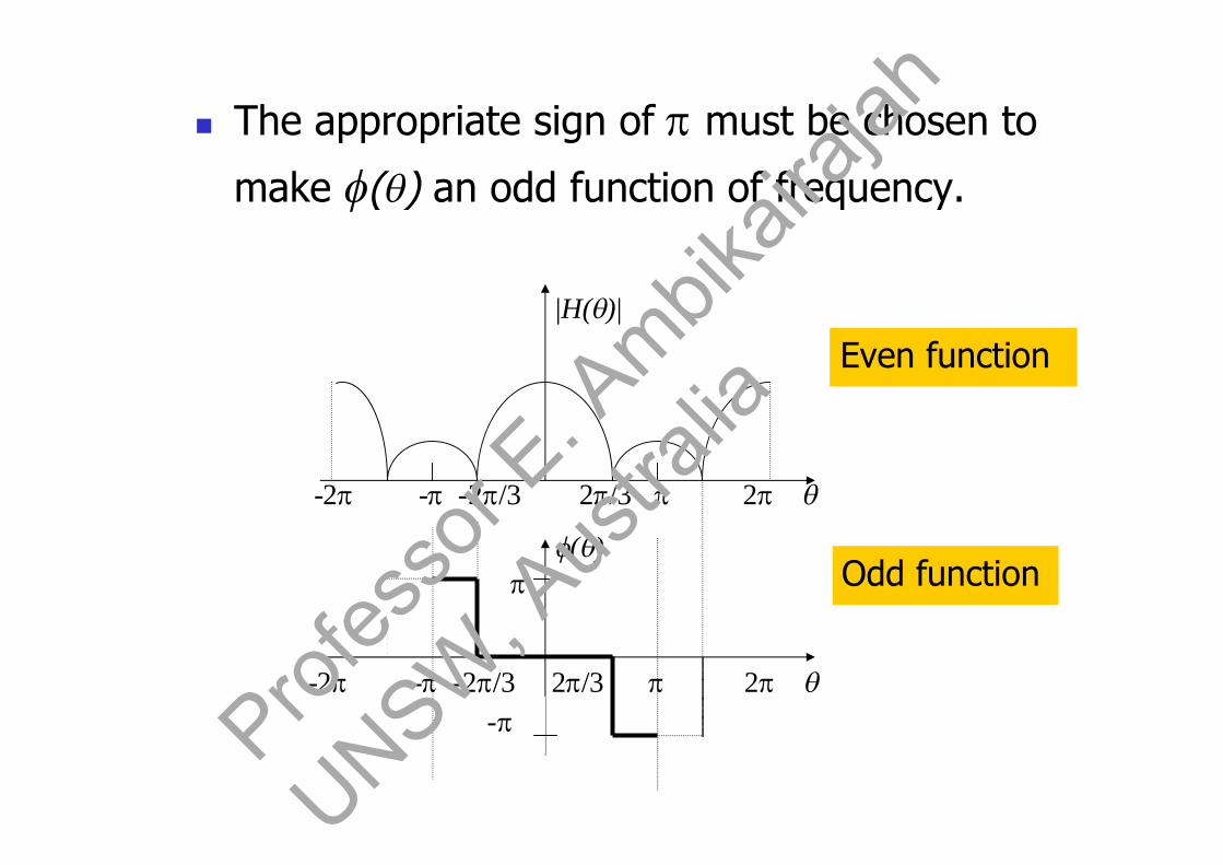
The appropriate sign of must be chosen to
make () an odd function of frequency.
()
-2 --2/3 2/3 2
|H()|
-2 --2/3 2/3 2
-
Odd function
Even function
Profes
sor E
. Ambik
airaja
h
UNSW, A
ustra
lia
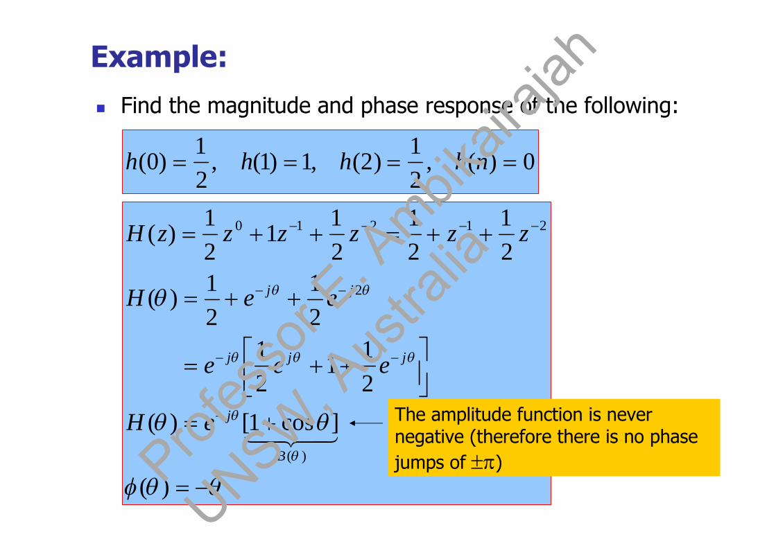
Example:
Find the magnitude and phase response of the following:
0)(,21
)2(,1)1(,21
)0( nhhhh
)(
]cos1[)(
21
121
21
21)(
21
21
21
121
)(
)(
2
21210
B
j
jjj
jj
eH
eee
eeH
zzzzzzH
The amplitude function is nevernegative (therefore there is no phasejumps of )Prof
esso
r E. A
mbikair
ajah
UNSW, A
ustra
lia

-
Even function2
|H()|
--
Odd function
()
Profes
sor E
. Ambik
airaja
h
UNSW, A
ustra
lia

Example :
10)(
01)(case
otherwisennn
()|H()|
1
- -
Profes
sor E
. Ambik
airaja
h
UNSW, A
ustra
lia

|H()|
1
-
-
()
-
k
(n-k)
n
h[n] = [n-k]H(z) = 1z-k
H() = 1e-jk
B() = 1 () = -k
Note: When phase exceeds range a jump of 2is needed tobring the phase back into range.
Profes
sor E
. Ambik
airaja
h
UNSW, A
ustra
lia

Phase Jumps: From the previous examples, wenote that there are two occasions for which thephase function experiences discontinuities or jumps.
(1) A jump of 2occurs to maintain the phase
function within the principal value range of [-and ]
(2) A jump of occurs when B() undergoes achange of sign
The sign of the phase jump is chosen such that theresulting phase function is odd and, after the jump, lies in
the range [-and ].Profes
sor E
. Ambik
airaja
h
UNSW, A
ustra
lia

Example: Magnitude and phase response ofcausal 3-sample average.
32
32
0)(
32
320)()(
]cos21[31
|)(||)(|;)(
]cos21[31
)(
131
31
31
31)(
31
31
31)(
otherwise020for
)(
221
31
B
B
BH
eH
eee
eeHzzzH
nnh
B
j
jjj
jj
-
()
-
1|H()|
- -/2 /2
2/3
-2/3
Phase is undefined at points |H()| = 0.Prof
esso
r E. A
mbikair
ajah
UNSW, A
ustra
lia

Example:
Determine and sketch the magnitude andphase response of the following filters:
4)(
8)(
121
)(
nxnyiiinxnxnyii
nxnxnyi
Profes
sor E
. Ambik
airaja
h
UNSW, A
ustra
lia

2sin
2sin
222
1
21]1[
21)(
]1[21
)()]()([21
)(
22
222
222
222
11
j
jjj
jjj
jjjj
e
ejee
jjee
e
eeeeH
zzHzXzzXzY
|H()|
-
/2
-/2
()
-
(i)
Profes
sor E
. Ambik
airaja
h
UNSW, A
ustra
lia

42
)(
4sin2
4sin222
1)(
1)()(
)()()(
)(
42
2444
48
88
B
j
jjjj
jj
e
eejjee
eeH
zzXzY
zXzzXzY
()
|H()|
/4 /2 3/2
-/2
/2
/4 /2 3/2
(ii)
Profes
sor E
. Ambik
airaja
h
UNSW, A
ustra
lia
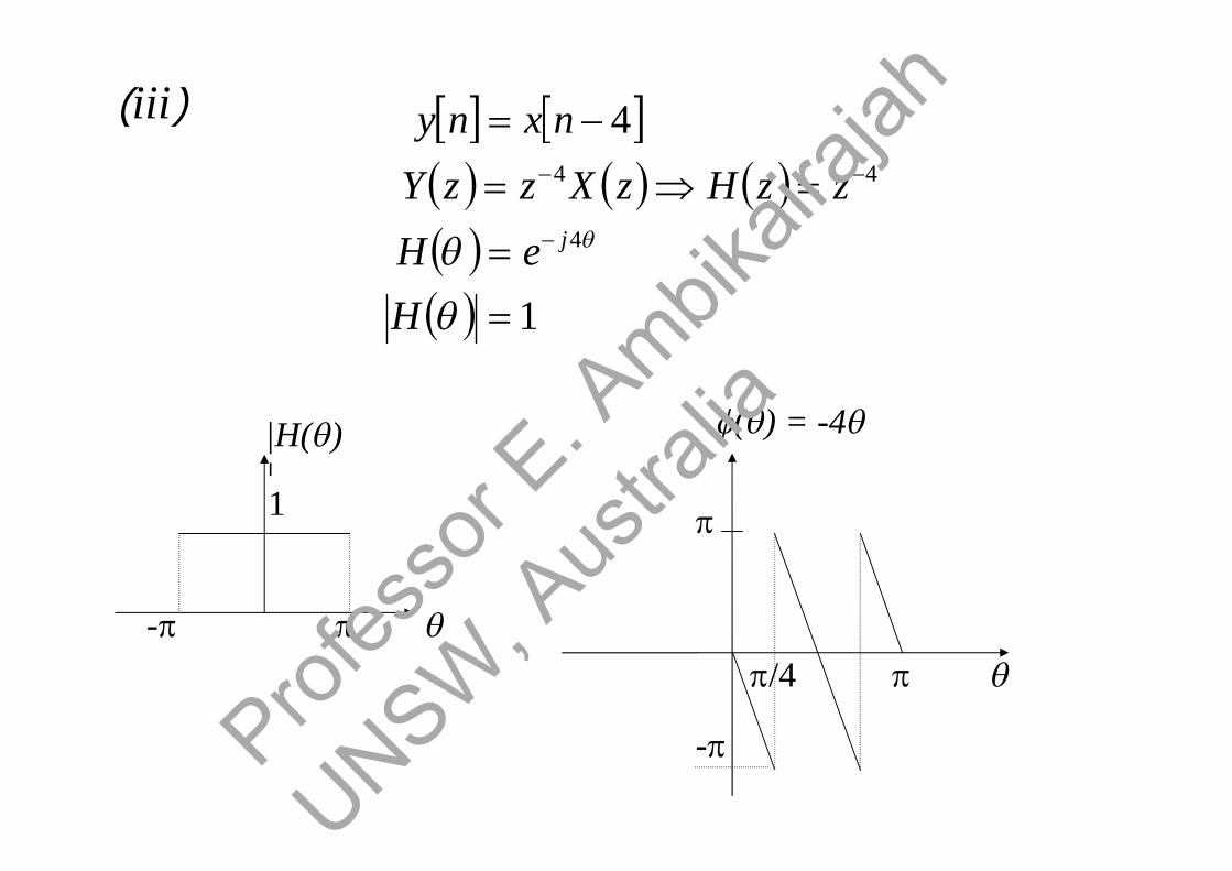
1
4
4
44
H
eH
zzHzXzzY
nxny
j
|H()|1
-
-
() = -4
/4
(iii)
Profes
sor E
. Ambik
airaja
h
UNSW, A
ustra
lia

Example: Determine and sketch the magnitude and phase
response of 1st order recursive filter (IIR filter)
1 naynxny
phaseaa
aa
aaa
aaa
aaja
aaa
aeae
aeH
aeH
azzH
zXzY
j
j
j
j
cos1sintan)(
cos1sin
cos21cos1
cos21sin
tan
cos21sin
cos21cos1
11
11)(
11)(
11)(
)()(
1
2
2
22
1
Profes
sor E
. Ambik
airaja
h
UNSW, A
ustra
lia

jj aeae
1
11
1
2cos211
|)(|aa
H
Even Symmetry|H()|
-
a= 0.5
()Odd Symmetry
-
Non-linear phase
Magnitude: |H()|2 = H()H*() [H*() is the complex conjugate]
Assuming 0 < a < 1
Profes
sor E
. Ambik
airaja
h
UNSW, A
ustra
lia

Examples :
The gain k0 can be selected as 1 – a, so that the
filter has unity gain at = 0.
In this case, (for unity gain at = 0).
FilterPass-Low1
11
)().( 110
1
az
aazk
zHa
1
1
02 11
)().(
azz
kzHb
Profes
sor E
. Ambik
airaja
h
UNSW, A
ustra
lia

The addition of a zero at z = -1 further attenuatesthe response of the filter at high frequencies
|H2()|
|H()|
-
Low-Pass Filter|H1()|
Profes
sor E
. Ambik
airaja
h
UNSW, A
ustra
lia

(c) We can obtain simple high-pass filters by reflecting(folding) the pole-zero locations of the low-passfilters about the imaginary axis in the z-plane.
1
1
3 11
21)(
azzazH
-
1
|H3()|High pass filter
Profes
sor E
. Ambik
airaja
h
UNSW, A
ustra
lia

1
1 14
nxnxnyzzH
1
1 15
nxnxny
zzH
(d)
(e)
High-Pass Filter
Low-Pass Filter
-
2|H5()|2
|H5()|2 = 2(1-cos)
Profes
sor E
. Ambik
airaja
h
UNSW, A
ustra
lia

|H6()|2 = 4(1-cos)2
-
4
|H6()|2
(f) 21
6 1 zzH
317 1 zzH
(g)|H7()|2 = 8(1-cos)3
-
8
|H7()|2
Profes
sor E
. Ambik
airaja
h
UNSW, A
ustra
lia

3.10 Minimum-phase, Maximum-phaseand Mixed phase systems [11]
Let us consider two FIR filters:
12
11
21
)(
211)(
zzH
zzH
21 ρ
|z|=1
= -0.5
|z|=1Profes
sor E
. Ambik
airaja
h
UNSW, A
ustra
lia

H2(z) is the reverse of the system H1(z). This is dueto the reciprocal relationship between the zeros of
H1(z) & H2(z).
The magnitude characteristics for the two filters are
identical because the roots of H1(z) & H2(z) arereciprocal.
cos45
|)(||)(|
21
)(&21
1)(
21
21
HH
eHeH jj
Profes
sor E
. Ambik
airaja
h
UNSW, A
ustra
lia
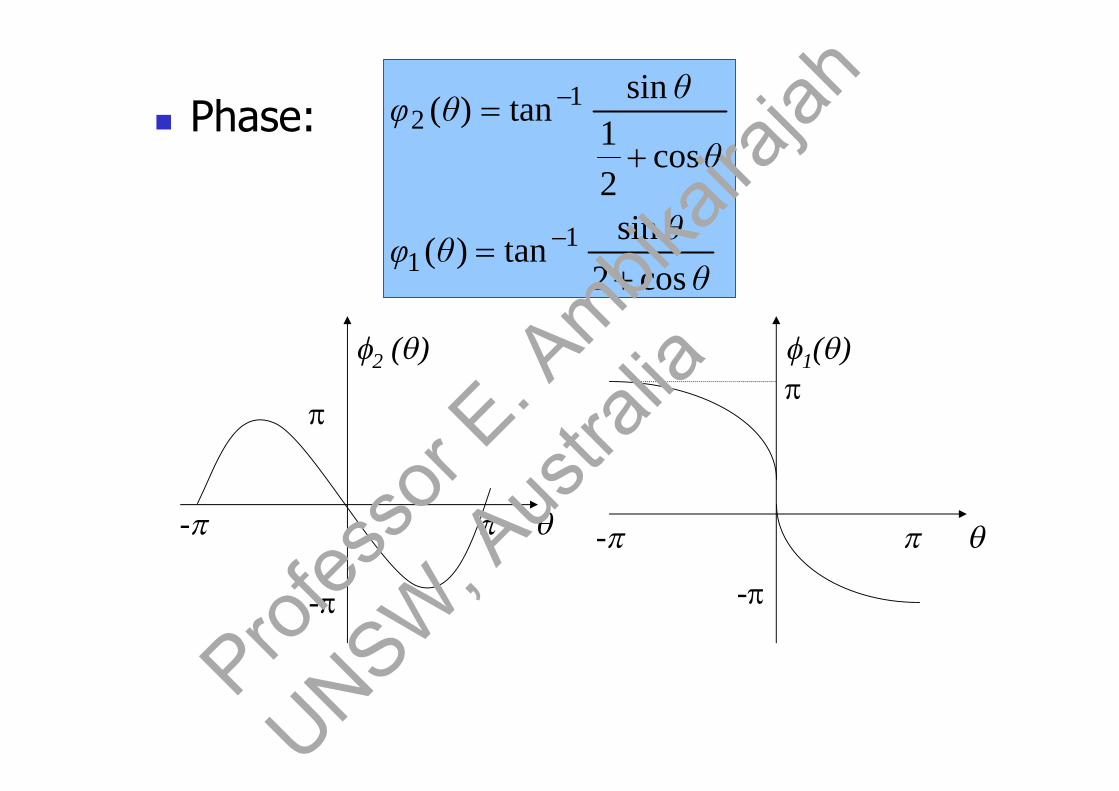
Phase:
θθ
θφ
θ
θθφ
cos2sin
tan)(
cos21
sintan)(
11
12
-
2 ()
-
-
1()
-
Profes
sor E
. Ambik
airaja
h
UNSW, A
ustra
lia
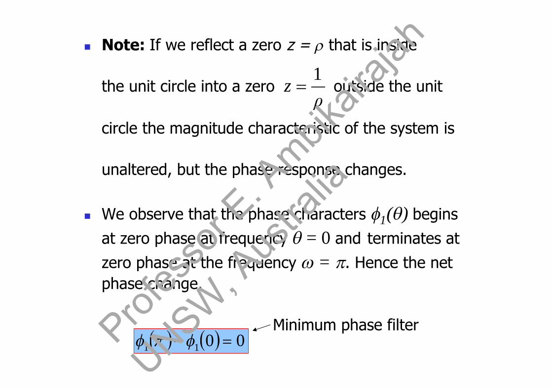
Note: If we reflect a zero z = that is inside
the unit circle into a zero outside the unit
circle the magnitude characteristic of the system is
unaltered, but the phase response changes.
We observe that the phase characters 1() begins
at zero phase at frequency = 0 and terminates at
zero phase at the frequency = . Hence the netphase change.
Minimum phase filter
ρz
1
0011 Profes
sor E
. Ambik
airaja
h
UNSW, A
ustra
lia

On the other hand, the phase characteristic for thefilter with the zero outside the unit circle undergoes anet phase change
As a consequence of these different phasecharacteristics, we call the first filter a minimum-phase system and the second system is called amaximum-phase system.
If a filter with M zeros has some of its zeros insidethe unit circle and the remaining outside the unitcircle, it is called a mixed-phase system.
radians012
Profes
sor E
. Ambik
airaja
h
UNSW, A
ustra
lia

A minimum-phase property of FIR filtercarries over to IIR filter.
Let us consider
is called minimum phase if all its poles andzeros are inside the unit circle.
)()(
)(zAzB
zH
|z|=1
Re(z)Minimum phase
Profes
sor E
. Ambik
airaja
h
UNSW, A
ustra
lia
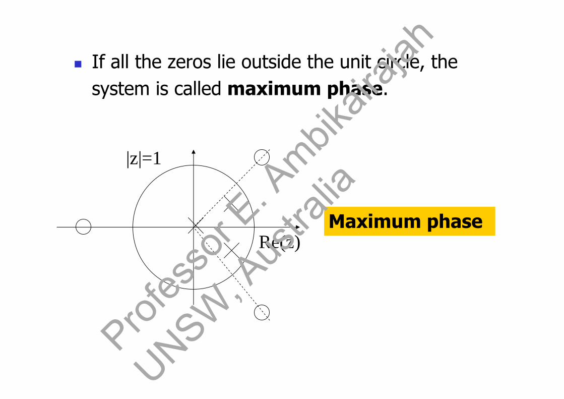
If all the zeros lie outside the unit circle, thesystem is called maximum phase.
|z|=1
Re(z)Maximum phase
Profes
sor E
. Ambik
airaja
h
UNSW, A
ustra
lia

If zeros lie both inside and outside the unitcircle, the system is called mixed-phase.
|z|=1
Re(z) Mixed phase
Profes
sor E
. Ambik
airaja
h
UNSW, A
ustra
lia

Note: For a given magnitude response,the minimum-phase system is thecausal system that has the smallestmagnitude phase at every frequency
(). That is, in the set of causal andstable filters having the samemagnitude response, the minimum-phase response exhibits the smallestdeviation from zero phase.Prof
esso
r E. A
mbikair
ajah
UNSW, A
ustra
lia

Example:
Consider a fourth-order all-zero filter containing adouble complex conjugate set of zeros located at
. The minimum-phase, mixed phase and maximum
phase system pole-zero patterns having identicalmagnitude response are shown below.
47.0
jez
|z|=1
4
mixed-phase
=0.72
24
|z|=1
Minimum-phase
|z|=1
4
maximum-phase
2
21/Profes
sor E
. Ambik
airaja
h
UNSW, A
ustra
lia

The magnitude response and the phase response ofthe three systems are shown below: The minimum-phase system seems to have the phase with thesmallest deviation from zero at each frequency.
|H()|
()
minimum phase
mixed-phase (In the case linear phase)
maximum phase
-
-2
-3
-4Profes
sor E
. Ambik
airaja
h
UNSW, A
ustra
lia

Example: A third order FIR filter has a transfer function
G(z) given by
From G(z), determine the transfer function of anFIR filter whose magnitude response is identical
to that of G(z) and has a minimum phaseresponse.
)25)(21216()( 1 zzzzG
)25
1)(34
1)(23
1(12)( 111 zzzzG
>1
)52)(43)(32()( 111 zzzzG
Profes
sor E
. Ambik
airaja
h
UNSW, A
ustra
lia

23
32
34
25
)52
1)(43
1)(32
1()(filterphaseMinimumThe 111 zzzkzP
lm(z)
Re(z)
|z|=1
-
- 43
52
Profes
sor E
. Ambik
airaja
h
UNSW, A
ustra
lia

3.11 All-Pass Filters [11]
An all-pass filter is one whose magnitude response isconstant for all frequencies, but whose phaseresponse is not identically zero.
[The simplest example of an all-pass filter is a pure
delay system with system function H(z) = z-k]
A more interesting all-pass filter is one that isdescribed by
where a0 = 1 and all coefficients are real.
LL
LLLL
zaza
zazazaazH
1
1
01
11
1
1)(
Profes
sor E
. Ambik
airaja
h
UNSW, A
ustra
lia
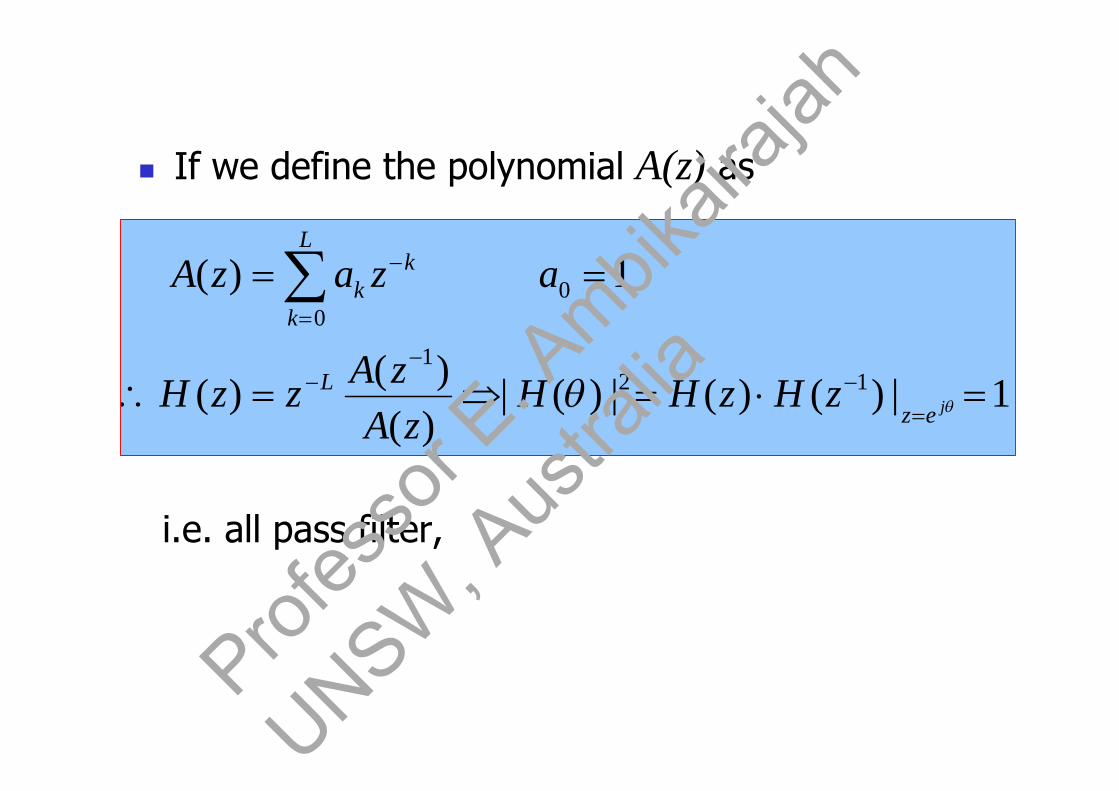
If we define the polynomial A(z) as
1|)()(|)(|)()()(
1)(
121
00
jezL
L
k
kk
zHzHHzA
zAzzH
azazA
i.e. all pass filter,
Profes
sor E
. Ambik
airaja
h
UNSW, A
ustra
lia

Furthermore, if z0 is a pole of H(z), then is a
zero of H(z) {ie. the poles and zeros are reciprocalsof one another}. The figure shown below illustratestypical pole-zero patterns for a single-pole, single-zero filter and a two-pole, two-zero filter.
0
1z
a1
|z|=1
0
All-pass filter
a
|z|=1
r
0
All pass filter
0
(1/r, 0)
(1/r, -0)
(r, -0)
1
1
1
11
)(
az
zazH |a| < 1 for stabilityProf
esso
r E. A
mbikair
ajah
UNSW, A
ustra
lia
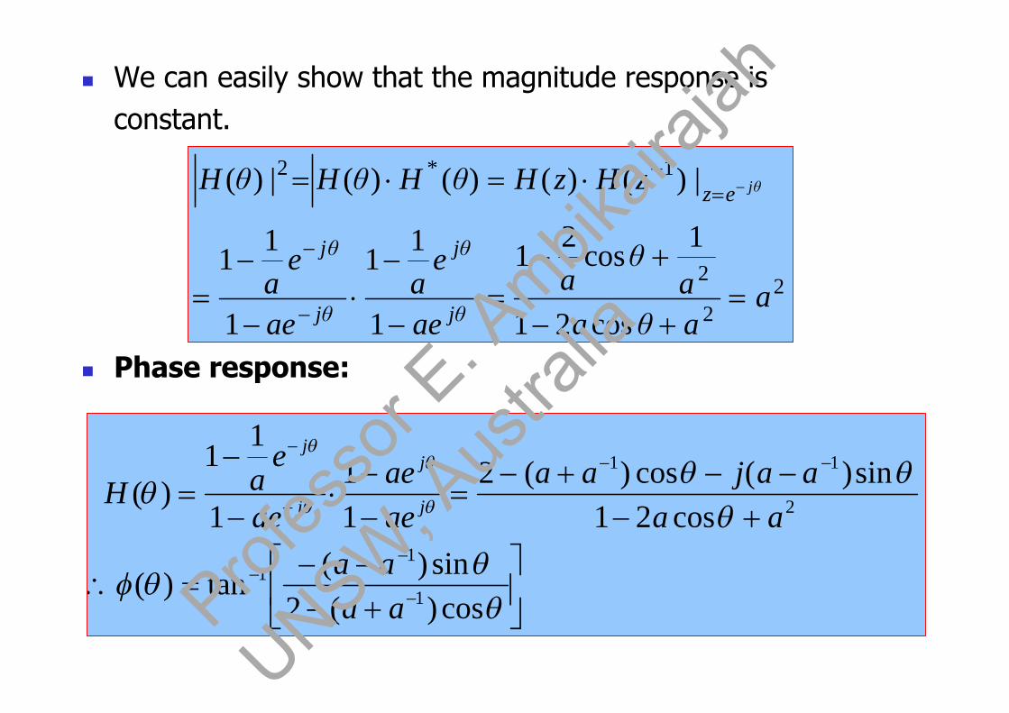
We can easily show that the magnitude response isconstant.
Phase response:
22
2
1*2
cos21
1cos
21
1
11
1
11
|)()()()(|)(
aaθaa
θa
ae
ea
ae
ea
zHzHθHθHθH
θj
θj
θj
θj
ez θj
cos)(2sin)(
tan)(
cos21sin)(cos)(2
11
1
11
)(
1
11
2
11
aaaa
aaaajaa
aeae
ae
eaH j
j
j
j
Profes
sor E
. Ambik
airaja
h
UNSW, A
ustra
lia

()
-
a = 0.5
a = -0.5 a= -0.8
When 0 < a < 1, the zero lies on the positive realaxis. The phase over 0 is positive, at = 0 itis equal to and decreases until = , where it iszero.
When -1< a < 0, the zero lies on the negative realaxis. The phase over 0 is negative, startingat 0 for = 0 and decreases to -at = .Prof
esso
r E. A
mbikair
ajah
UNSW, A
ustra
lia
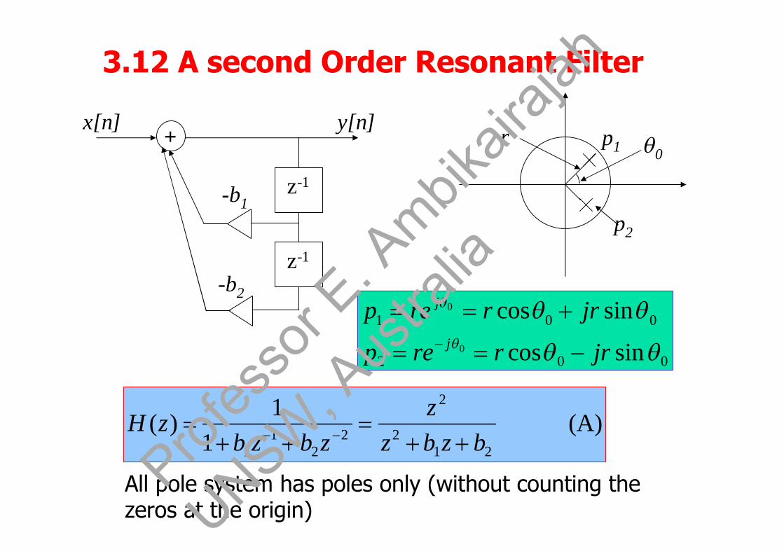
3.12 A second Order Resonant Filter
002
001
sincos
sincos0
0
jrrrep
jrrrepj
j
(A)1
1)(
212
2
22
11 bzbz
zzbzb
zH
z-1
z-1
+y[n]x[n]
-b1
-b2
0r p1
p2
All pole system has poles only (without counting thezeros at the origin)
Profes
sor E
. Ambik
airaja
h
UNSW, A
ustra
lia

(B)cos2)(
)(
))(())(()(
20
2
2
22
2
2
21
2
21
12
2
00
00
rzrzz
rzeerzz
zH
rezrezz
pzpzz
bzbzzzH
jj
jj
2201 ,cos2 rbrb
2
10 2 b
bCos
sff0
02
0 = resonant frequency
Comparing (A) and (B), we obtain
Profes
sor E
. Ambik
airaja
h
UNSW, A
ustra
lia
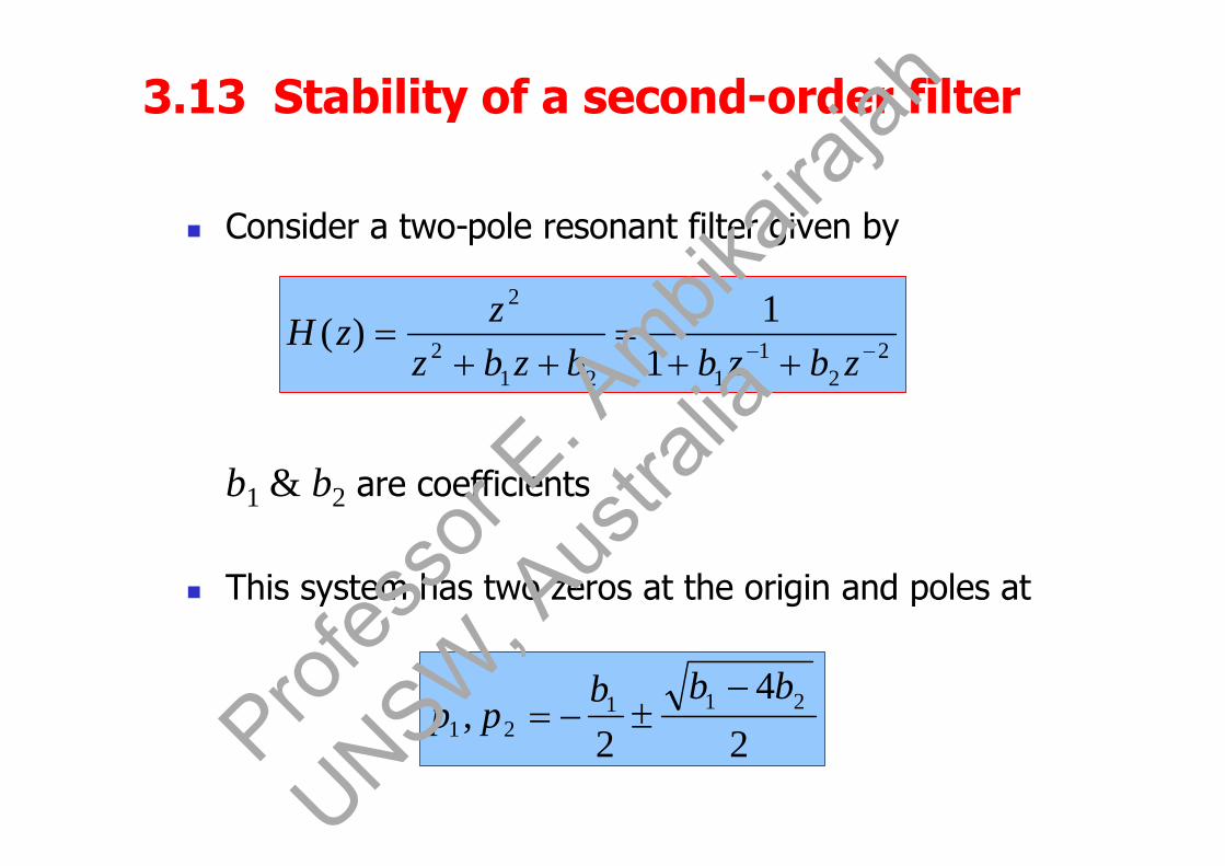
3.13 Stability of a second-order filter
Consider a two-pole resonant filter given by
b1 & b2 are coefficients
This system has two zeros at the origin and poles at
22
1121
2
2
11)(
zbzbbzbz
zzH
24
2, 211
21
bbbpp
Prof
esso
r E. A
mbikair
ajah
UNSW, A
ustra
lia
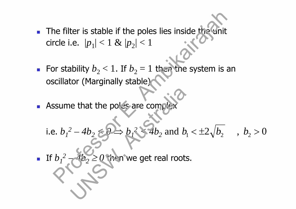
The filter is stable if the poles lies inside the unitcircle i.e. |p1| < 1 & |p2| < 1
For stability b2 < 1. If b2 = 1 then the system is anoscillator (Marginally stable)
Assume that the poles are complex
i.e. b12 – 4b2 < 0 b1
2 < 4b2 and
If b12 – 4b2 0 then we get real roots.
0,2 221 bbb
Profes
sor E
. Ambik
airaja
h
UNSW, A
ustra
lia

The stability conditions define a region in the
coefficient plane (b1, b2) which is in the form of atriangle (see below)
The system is only stable if and only if the point
(b1, b2) lie inside the stability triangle.
b1
b2
-2 -1 0 1 2
1
-1
Real Poles
Complex Conjugate Poles
112 bb112 bb
4
21
2b
bparabola
12 b
Profes
sor E
. Ambik
airaja
h
UNSW, A
ustra
lia

Stability Triangle
If the two poles are real then they must havea value between -1 and 1 for the system tobe stable.
01and01)2(4and4)2(
24and42
242
12
41
2121
212
212
21
21
12212
211
122
11
22
11
bbbbbbbbbb
bbbbbb
bbbb
bbb
Profes
sor E
. Ambik
airaja
h
UNSW, A
ustra
lia
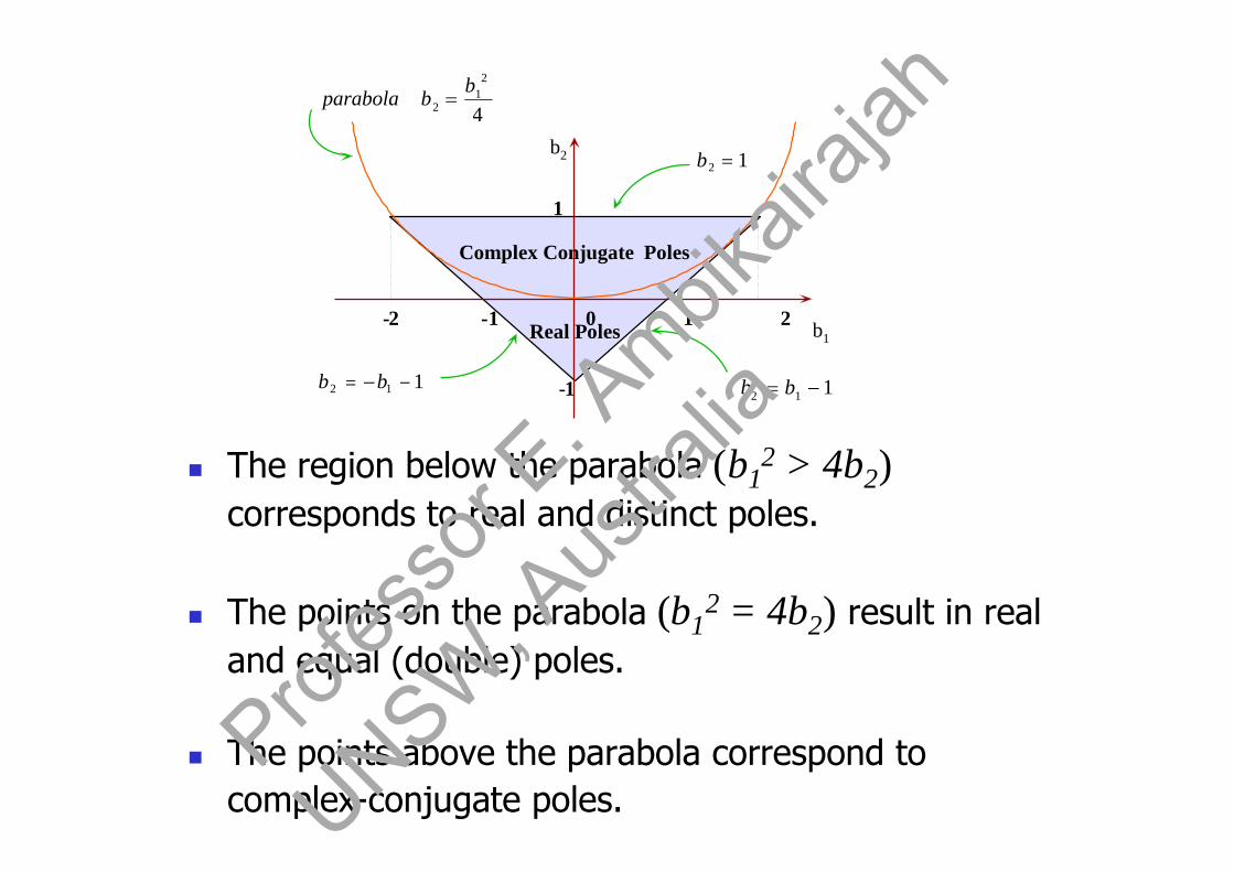
The region below the parabola (b12 > 4b2)
corresponds to real and distinct poles.
The points on the parabola (b12 = 4b2) result in real
and equal (double) poles.
The points above the parabola correspond tocomplex-conjugate poles.
b1
b2
-2 -1 0 1 2
1
-1
Real Poles
Complex Conjugate Poles
112 bb112 bb
4
21
2
bbparabola
12 b
Profes
sor E
. Ambik
airaja
h
UNSW, A
ustra
lia
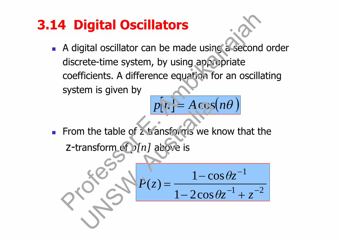
3.14 Digital Oscillators
A digital oscillator can be made using a second orderdiscrete-time system, by using appropriatecoefficients. A difference equation for an oscillatingsystem is given by
From the table of z-transforms we know that the
z-transform of p[n] above is
nAnp cos
21
1
cos21
cos1)(
zzθ
zθzP
Profes
sor E
. Ambik
airaja
h
UNSW, A
ustra
lia

Let21
1
cos21
cos1)()(
)(
zzθ
zθzXzY
zP
Taking inverse z-transform on both sides, we obtain
1cos21cos2 nxnxnynyny
No Input term for an oscillatorx[n] = 0, x[n-1] = 0
So the equation of the digital oscillator becomes
21cos2 nynyny Profes
sor E
. Ambik
airaja
h
UNSW, A
ustra
lia

So the equation of the digital oscillator becomes
21cos2 nynyny
and its structure is shown below.
b2 = -1
b1 = 2cos
y[n-2]y[n-1]+ z-1 z-1
y[n] = A cos(n)
Profes
sor E
. Ambik
airaja
h
UNSW, A
ustra
lia
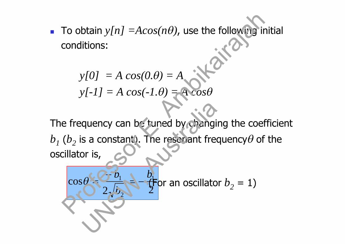
To obtain y[n] =Acos(n), use the following initialconditions:
y[0] = A cos(0.) = Ay[-1] = A cos(-1.) = A cos
The frequency can be tuned by changing the coefficient
b1 (b2 is a constant). The resonant frequencyof theoscillator is,
22cos 1
2
1 bbb
(For an oscillator b2 = 1)
Profes
sor E
. Ambik
airaja
h
UNSW, A
ustra
lia

Example: A digital sinusoidal oscillator is shown below.
(a) Assuming 0 is the resonant frequency of thedigital oscillator, find the values of b1 and b2 forsustaining the oscillation.
x[n]
-b1
+z-1
z-1
y[n] = A sin(n+1)
Profes
sor E
. Ambik
airaja
h
UNSW, A
ustra
lia
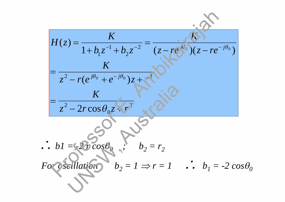
20
2
22
22
11
cos2
)(
))((1)(
00
00
rzrzK
rzeerzK
rezrezK
zbzbK
zH
jj
jj
b1 = -2 r cos0 ; b2 = r2
For oscillation b2 = 1 r = 1 b1 = -2 cos0Profes
sor E
. Ambik
airaja
h
UNSW, A
ustra
lia

(b). Write the difference equation for the above figure.Assuming
x[n] = (Asin0)[n], and y(-1) = y(-2) = 0.
Show, by analysing the difference equation, that theapplication of an impulse at n = 0 serves the purpose ofbeginning the sinusoidal oscillation, and prove that theoscillation is self-sustaining thereafter.
Profes
sor E
. Ambik
airaja
h
UNSW, A
ustra
lia

nAnynyny
nxnynybny
00
1
sin21cos2
21
y[0] = A sin0
y[1] = 2cos0 , Asin0 = A sin20
0 0 1
0 0
n = 0y[0] = 2cos0 y[-1] – y[-2] + A sin0 [0]
y[1] = 2cos0 y[0] –y[-1] + A sin0 [1]
n = 1
Profes
sor E
. Ambik
airaja
h
UNSW, A
ustra
lia

y[2] = 2 cos0 y[1] – y[0] + A sin0[2]= 2 cos0 Asin20 – A sin0= 2A cos0 [2 sin0cos0] - sin0= A sin0 [4 cos20 –1 ] = A[3sin0 – 4 sin30]
n = 2
where sin30 = 3sin0 – 4 sin30
y[2] = A sin30 and so forth.
Profes
sor E
. Ambik
airaja
h
UNSW, A
ustra
lia

By setting the input to zero and under certain initialconditions, sinusoidal oscillation can be obtainedusing the structure shown above. Find these initialconditions.
(x[n] = 0 for an oscillator)
n = 0 y[0] = 2cos0 y[-1] – y[-2]for oscillation, y[-1] = 0 no cosine terms
y[0] = -y[-2] y[-2] = -Asin0 (sine term is equired)
y[0] = 0-(-A sin0) = A sin0
Initial conditions:
nxnynyny 21cos2
y[-1] =0; y[-2] = -Asin0Profes
sor E
. Ambik
airaja
h
UNSW, A
ustra
lia

Sine and cosine oscillators [1] Sinusoidal oscillators can be used to deliver the
carrier in modulators. In modulation schemes, bothsines and cosines oscillators and needed. A structurethat delivers sines and cosines simultaneously isshown below:
y[n]= cos(n)
x[n]= sin(n)
-sin
sin
cos
cos
z-1
+
z-1
+
Profes
sor E
. Ambik
airaja
h
UNSW, A
ustra
lia
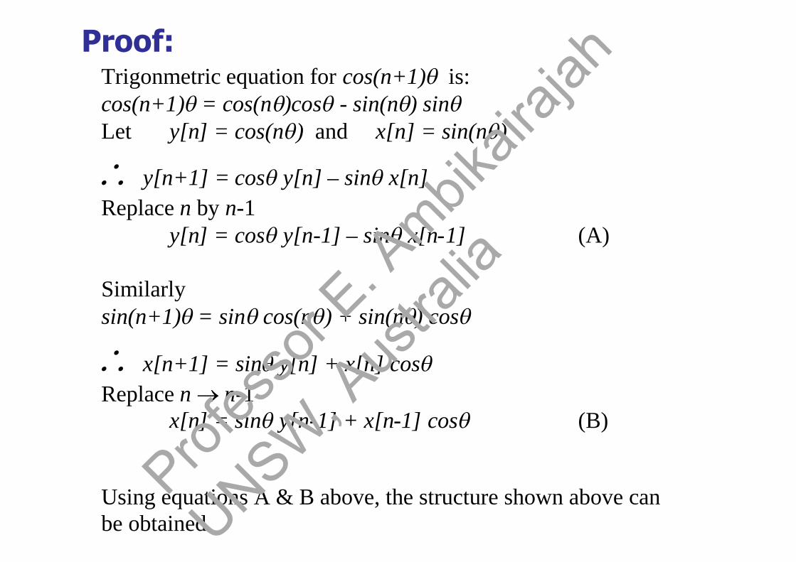
Proof:Trigonmetric equation for cos(n+1)is:cos(n+1)= cos(n)cos- sin(n) sinLet y[n] = cos(n) and x[n] = sin(n)
y[n+1] = cosy[n] – sinx[n]Replace n by n-1
y[n] = cosy[n-1] – sinx[n-1] (A)
Similarlysin(n+1)= sincos(n) + sin(n) cos
x[n+1] = siny[n] + x[n] cosReplace n n-1
x[n] = siny[n-1] + x[n-1] cos (B)
Using equations A & B above, the structure shown above canbe obtained.
Profes
sor E
. Ambik
airaja
h
UNSW, A
ustra
lia
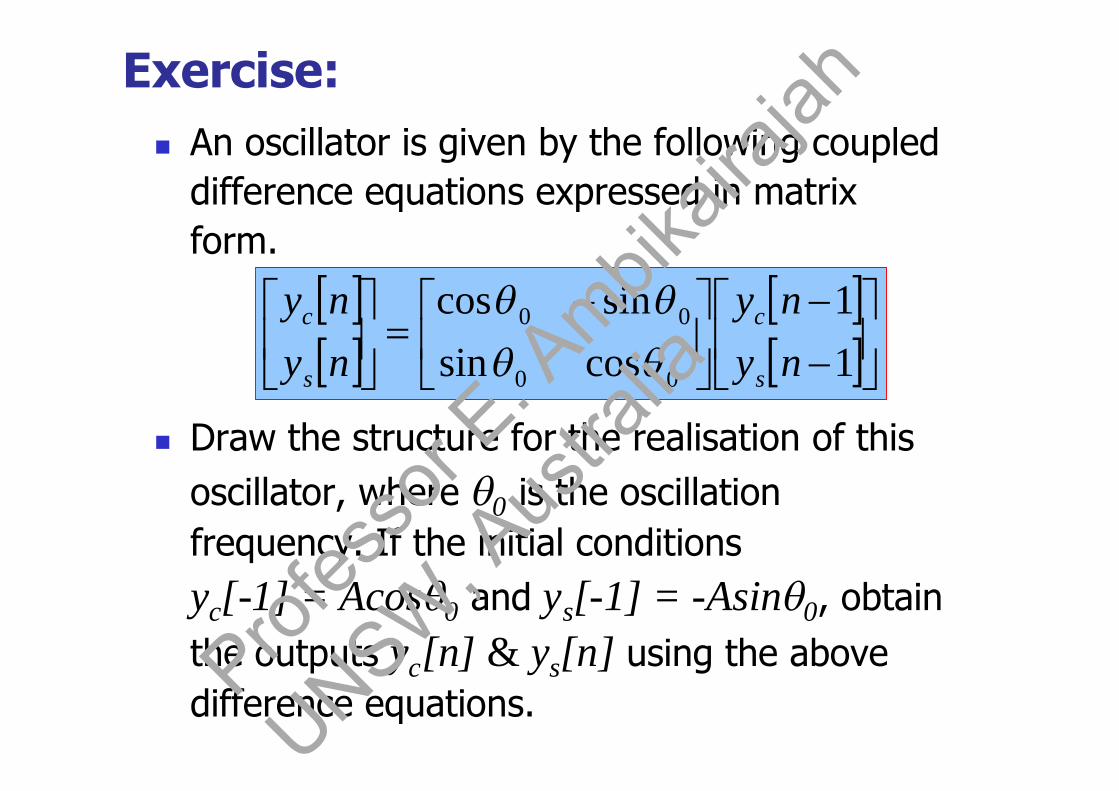
Exercise: An oscillator is given by the following coupled
difference equations expressed in matrixform.
Draw the structure for the realisation of thisoscillator, where 0 is the oscillationfrequency. If the initial conditionsyc[-1] = Acos0 and ys[-1] = -Asin0, obtainthe outputs yc[n] & ys[n] using the abovedifference equations.
11
cossinsincos
00
00
nyny
nyny
s
c
s
c
Profes
sor E
. Ambik
airaja
h
UNSW, A
ustra
lia

1cos1sin
1sin1cos
00
00
nynyny
nynyny
scs
scc
yc[n]
ys[n]
-sin0
sin0
cos0
cos0
z-1
z-1
+
+
Profes
sor E
. Ambik
airaja
h
UNSW, A
ustra
lia

n=0 ys[0] = sin0 (A cos0) + cos0 (-Asin0) = 0
n=0 yc[0] = cos0 (Acos0) - sin0(-Asin0) = A
n=1 yc[1] = cos0.A - sin0 .0 = Acos0
n=1 ys[1] = A sin0 + 0 = A sin0
n=2 yc[2] = cos0 yc[1] - sin0 ys[1]= cos0 A cos0 - sin0 A sin0 = A cos20
n = n yc[n] = A cos (n0)
similarly ys[n] = A sin(n0)Profes
sor E
. Ambik
airaja
h
UNSW, A
ustra
lia
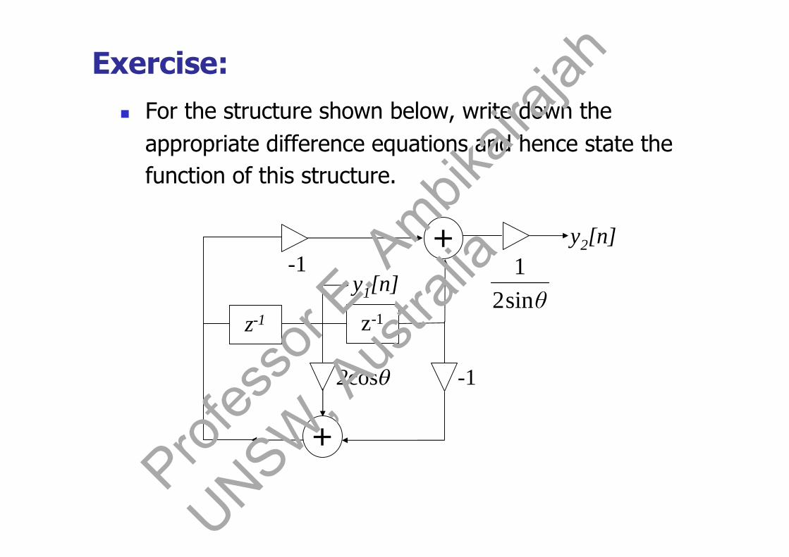
Exercise: For the structure shown below, write down the
appropriate difference equations and hence state thefunction of this structure.
θsin21
z-1
y1[n]
2cos
z-1
-1
-1y2[n]
+
+
Profes
sor E
. Ambik
airaja
h
UNSW, A
ustra
lia
3.15 Notch filters [4] When a zero is placed at a given point on the
z-plane, the frequency response will be zeroat the corresponding point. A pole on theother hand produces a peak at thecorresponding frequency point.
Poles that are close to the unit circle give riselarge peaks, where as zeros close to or onthe unit circle produces troughs or minima.Thus, by strategically placing poles and zeroson the z-plane, we can obtain sample lowpass or other frequency selective filters(notch filters).Prof
esso
r E. A
mbikair
ajah
UNSW, A
ustra
lia

Example:
Obtain, by the pole-zero placement method,the transfer function of a sample digital notchfilter (see figure below) that meets thefollowing specifications: [4]
Notch Frequency: 50Hz 3db width of the Notch: ±5Hz Sampling frequency: 500 Hz
sffr 1
|H(f)|
50 250 f (Hz)0
The radius , r of the poles is determined by :
Profes
sor E
. Ambik
airaja
h
UNSW, A
ustra
lia
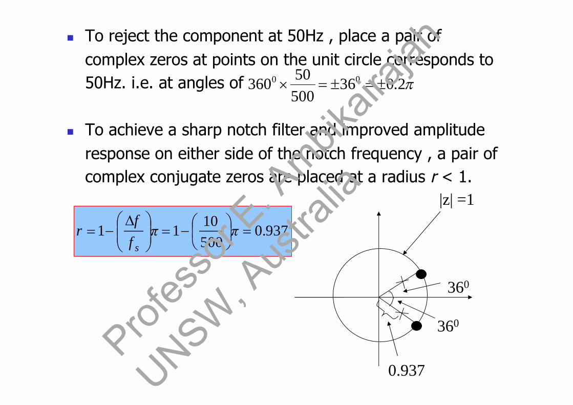
To reject the component at 50Hz , place a pair ofcomplex zeros at points on the unit circle corresponds to50Hz. i.e. at angles of
To achieve a sharp notch filter and improved amplituderesponse on either side of the notch frequency , a pair ofcomplex conjugate zeros are placed at a radius r < 1.
937.050010
11
ππ
ff
rs
360
360
0.937
|z| =1
2.03650050
360 00
Profes
sor E
. Ambik
airaja
h
UNSW, A
ustra
lia

21
21
2
2
2.02.02
2.02.02
2.02.0
2.02.0
878.05161.116180.11
)2.0cos(937.02878.0)2.0cos(21
)(937.0878.0)(1
937.0937.0)(
zzzz
zz
zeezeez
ezezezez
zH
jj
jj
jj
jj
Profes
sor E
. Ambik
airaja
h
UNSW, A
ustra
lia

Question 4A digital filter structure is shown below. Calculate the dc gain of the filter in terms of the filtercooefficients.
Z-1
Z-1
X(z) a0
a2
+
b1
b2
Y(z)
+
+
[3 marks]
M(z)
Q(z)
P(z)
21
200
22
11
120
11
22
220
10
11
21
2
12
12
22
1)(
1)(
)()(
)()()()(
)()()(
)()()()(
)()()(
)()()(
bbaa
H
zbzbzaa
zHzXzY
zzYbzzYbzzXazXa
zzMzXazY
zYbzzYbzzXazM
zzYbzzXazQ
zYbzXazP
Profes
sor E
. Ambik
airaja
h
UNSW, A
ustra
lia
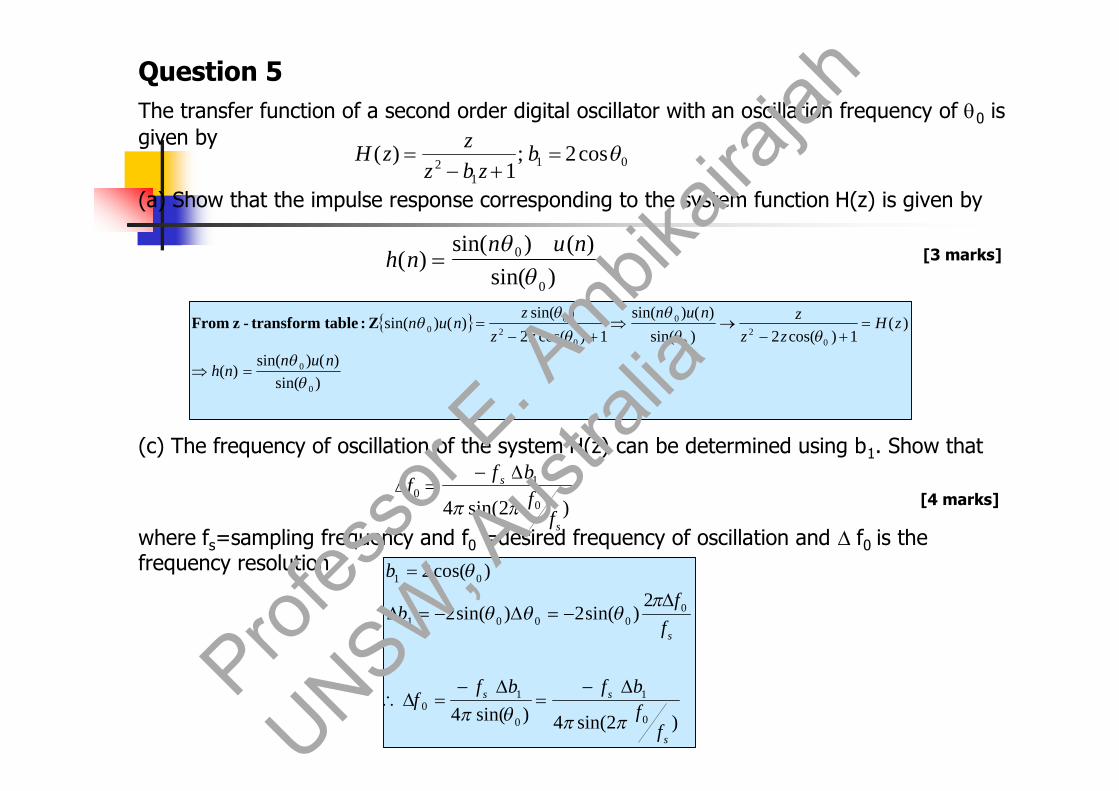
Question 5The transfer function of a second order digital oscillator with an oscillation frequency of 0 isgiven by
(a) Show that the impulse response corresponding to the system function H(z) is given by
(c) The frequency of oscillation of the system H(z) can be determined using b1. Show that
where fs=sampling frequency and f0 =desired frequency of oscillation and f0 is thefrequency resolution
011
2cos2;
1)(
b
zbzz
zH
)sin()()sin(
)(0
0
nun
nh
)2sin(4 0
10
s
s
ffbf
f
[3 marks]
[4 marks]
)sin()()sin(
)(
)(1)cos(2)sin(
)()sin(1)cos(2
)sin()()sin(
0
0
02
0
0
02
00
nunnh
zHzz
znunzz
znun
Z:tabletransform-zFrom
)2sin(4)sin(4
2)sin(2)sin(2
)cos(2
0
1
0
10
00001
01
s
ss
s
ffbfbf
f
ff
b
b
Profes
sor E
. Ambik
airaja
h
UNSW, A
ustra
lia

Question 6A difference equation for a particular filter is given by
y(n) = 0.12 x(n) – 0.1 x(n-2) + 0.82 x(n-3) – 0.1 x(n-4) + 0.12 x(n-6)
(a) Find the impulse response of the above filter
(b) Using minimum number of multiplications, draw an implementation for the above filter.
[2 marks]
[4 marks]
70)(
12.0)6(0)5(1.0)4(82.0)3(1.0)2(0)1(12.0)0(
nnh
hhhhhhh
for
)4()2(1.0)3(82.0)6()(12.0)( nxnxnxnxnxny
T T TT T T
+
+
+
y(n)
x(n)
0.82
-0.1
0.12x(n-3)
Implementation with 3 multiplications only
Profes
sor E
. Ambik
airaja
h
UNSW, A
ustra
lia

Question 7Determine and sketch the approximate magnitude response for each of the following filters:
(a) y(n) = x(n) + x(n-1)
(b) y(n) = x(n) – x(n-1)
[4 marks]
[4 marks]
)cos(22
))sin())cos(1()(
1)(
1)(
22
1
H
eH
zzHj
)cos(22
))sin())cos(1()(
1)(
1)(
22
1
H
eH
zzHj
)(H
-
2
)(H
-
2
Profes
sor E
. Ambik
airaja
h
UNSW, A
ustra
lia

Question 8The zero locations of four FIR transfer functions of order 6 are sketched below. Does any oneof the FIR filters have a linear-phase response? If so, which one?
Im(z)
Re(z)1-0.5-1-2 0.5
0.5
Figure 1
2 zeros Im(z)
Re(z)1-0.5-1-2 0.5
0.5
Figure 2
Reflected zero
Im(z)
Re(z)1-0.5-1 0.5
0.5
Figure 3
Reflected zero2 zeros
Im(z)
Re(z)1-0.5-1-2 0.5
0.5
Figure 4
2 zeros
2 zeros
2 zeros
[4 marks]
Profes
sor E
. Ambik
airaja
h
UNSW, A
ustra
lia
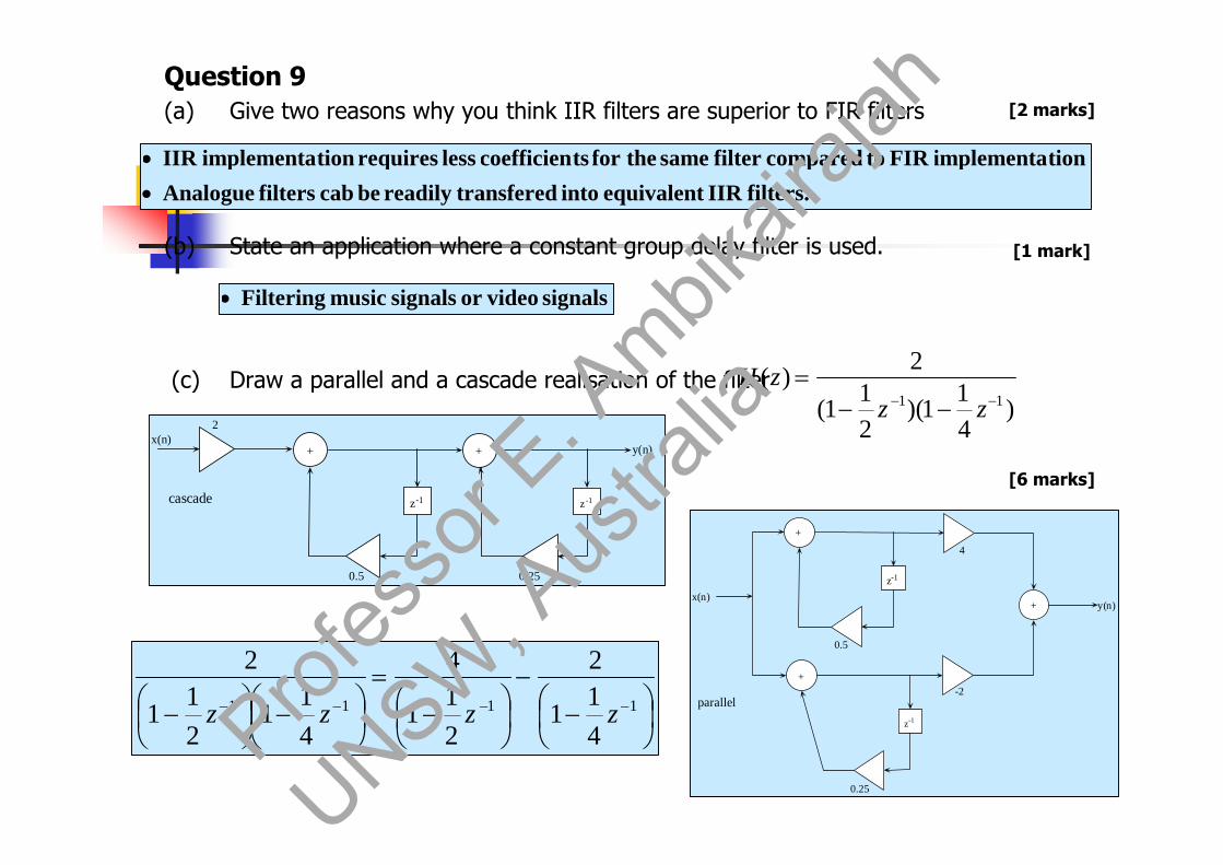
Question 9(a) Give two reasons why you think IIR filters are superior to FIR filters
(b) State an application where a constant group delay filter is used.
(c) Draw a parallel and a cascade realisation of the filter)
41
1)(21
1(
2)(
11
zzzH
[6 marks]
[1 mark]
[2 marks]
filters.IIRequivalentintotransferedreadilybecabfiltersAnalogue
tionimplementaFIRtocomparedfiltersamethefortscoefficienlessrequirestionimplementaIIR
signalsvideoorsignalsmusicFiltering
x(n)2
0.5
z-1
+
0.25
z -1
+ y(n)
cascade
x(n)
0.5
z-1
+
y(n)
parallel
0.25
z-1
+-2
4
+
1111
41
1
2
21
1
4
41
121
1
2
zzzz Profes
sor E
. Ambik
airaja
h
UNSW, A
ustra
lia
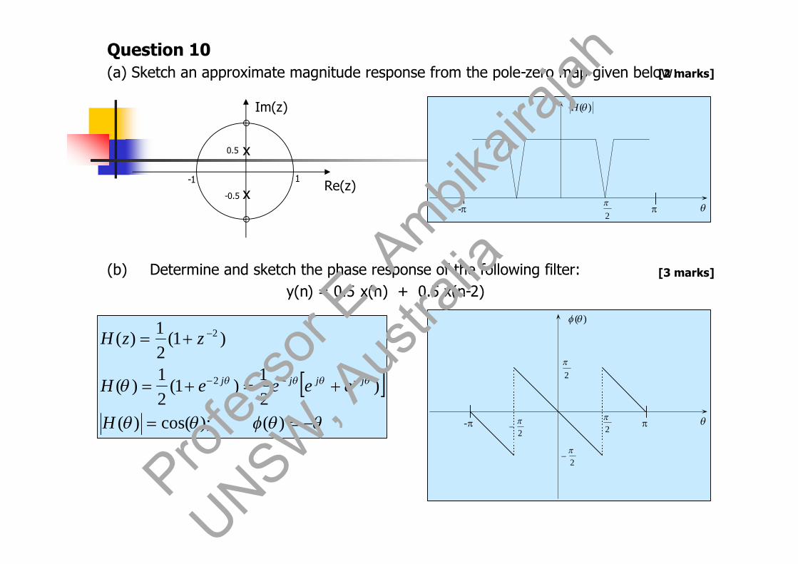
Question 10(a) Sketch an approximate magnitude response from the pole-zero map given below:
(b) Determine and sketch the phase response of the following filter:y(n) = 0.5 x(n) + 0.5 x(n-2)
Im(z)
Re(z)1
-0.5
-1
0.5 x
x
[2 marks]
[3 marks]
)(H
- 2
)();cos()(
)21
)1(21
)(
)1(21)(
2
2
H
eeeeH
zzH
jjjj
)(
- 2
2
2
2
Profes
sor E
. Ambik
airaja
h
UNSW, A
ustra
lia

Question 11(a) A third order FIR filter has a transfer function G(z) given by
From G(z), determine the transfer function of an FIR filter whose magnituderesponse is identical to that of G(z) and has a minimum phase response.
(b) Determine the magnitude response of the following filter and show that it has an all-pas characteristic.
)52)(43)(32()( 111 zzzzG
1)1(
)( 1
1
azaza
zH
[5 marks]
[3 marks]
)52
1)(43
1)(32
1(12)( 111 zzzzP
Re{z}-5/2 -4/3 -3/4 -2/5 2/3 3/2
Im{z}
reflecting
filterPass-All
11
1)()().(
1)(
1)()1(
21)(
2
22*
*2
jj
jj
j
j
j
j
aeaeaaeaea
HHH
aeeaH
aeeaHzzH )(H
-
1
)25
1)(34
1)(23
1(12)( 111 zzzzG
Profes
sor E
. Ambik
airaja
h
UNSW, A
ustra
lia

Question 12(a) State two important properties of lattice filters
(b) Determine the lattice filter coefficients corresponding to thefollowing
FIR filter:
(b) Draw a lattice structure implementation for the above filter H(z)
21
31
21)( zzzH )()(
)()(
11
)()(
11
1
zAofpolynomialreversetheiszB
tcoefficienreflectionk
zBzzA
kk
zBzA
EquationsFilterLattice
mm
m
m
m
m
m
m
m
[2 marks]
[4 marks]
[3 marks]
• Low sensitivity
• Modularity
;Answer31
23
23
)1(
23
1
31
1
31
32
91
21
21
)(1)()(
)(2
1231
)(31
21)(31
)2(31
2111
12
2121
22
2221
212
21222
kkkk
zzzzz
kzBkzA
zAm
zzzBzzzAkk
z-1
+
+
x(n)
z-1
+
+
y2(n)
w2 (n)
y1(n)
w1(n)
y0(n)
w0 (n)
k1
k1
k2
k 2Profes
sor E
. Ambik
airaja
h
UNSW, A
ustra
lia
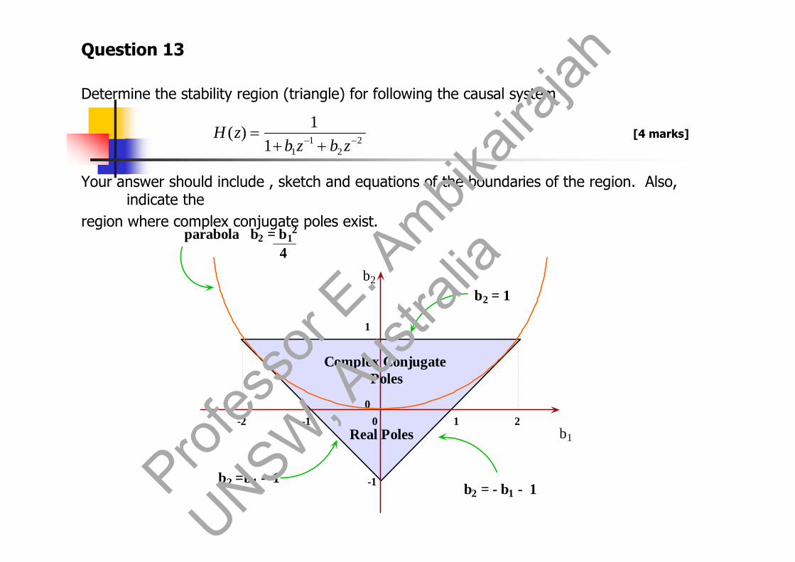
Question 13
Determine the stability region (triangle) for following the causal system
Your answer should include , sketch and equations of the boundaries of the region. Also,indicate the
region where complex conjugate poles exist.
22
111
1)(
zbzbzH [4 marks]
b1
b2
-2 -1 0 1 2
1
0
-1
b2 = 1
b2 =b1 - 1b2 = - b1 - 1
Real Poles
Complex ConjugatePoles
parabola b2 = b12
4
Profes
sor E
. Ambik
airaja
h
UNSW, A
ustra
lia

![µ ] v - Casa Montessori · µ ] v 7lwoxo , x x x x x x x x x x x x x x x x x x x x x x x x x x x x x x x x x x x x x x x x x x x x x x x x x x x x x x x x x x x x x x x x x x x x](https://img.dokumen.tips/doc/110x75/5e3041645d2be568cb68ec81/-v-casa-v-7lwoxo-x-x-x-x-x-x-x-x-x-x-x-x-x-x-x-x-x-x-x-x-x-x-x-x-x.jpg)