Embed Size (px)
Citation preview

SINUMERIK
SINUMERIK 840D sl / 828DMeasuring cycles
Programming Manual
Valid for:
Control system SINUMERIK 840D sl / 840DE sl / 828D
SoftwareCNC software version 4.7 SP2SINUMERIK Operate for PCU/PC version 4.7 SP2
10/20156FC5398-4BP40-5BA3
Preface
Fundamental safety instructions 1
Description 2
Measuring variants 3
Parameter lists 4Changes from cycle version SW4.4 and higher A
Appendix B

Legal informationWarning notice system
This manual contains notices you have to observe in order to ensure your personal safety, as well as to prevent damage to property. The notices referring to your personal safety are highlighted in the manual by a safety alert symbol, notices referring only to property damage have no safety alert symbol. These notices shown below are graded according to the degree of danger.
DANGERindicates that death or severe personal injury will result if proper precautions are not taken.
WARNINGindicates that death or severe personal injury may result if proper precautions are not taken.
CAUTIONindicates that minor personal injury can result if proper precautions are not taken.
NOTICEindicates that property damage can result if proper precautions are not taken.If more than one degree of danger is present, the warning notice representing the highest degree of danger will be used. A notice warning of injury to persons with a safety alert symbol may also include a warning relating to property damage.
Qualified PersonnelThe product/system described in this documentation may be operated only by personnel qualified for the specific task in accordance with the relevant documentation, in particular its warning notices and safety instructions. Qualified personnel are those who, based on their training and experience, are capable of identifying risks and avoiding potential hazards when working with these products/systems.
Proper use of Siemens productsNote the following:
WARNINGSiemens products may only be used for the applications described in the catalog and in the relevant technical documentation. If products and components from other manufacturers are used, these must be recommended or approved by Siemens. Proper transport, storage, installation, assembly, commissioning, operation and maintenance are required to ensure that the products operate safely and without any problems. The permissible ambient conditions must be complied with. The information in the relevant documentation must be observed.
TrademarksAll names identified by ® are registered trademarks of Siemens AG. The remaining trademarks in this publication may be trademarks whose use by third parties for their own purposes could violate the rights of the owner.
Disclaimer of LiabilityWe have reviewed the contents of this publication to ensure consistency with the hardware and software described. Since variance cannot be precluded entirely, we cannot guarantee full consistency. However, the information in this publication is reviewed regularly and any necessary corrections are included in subsequent editions.
Siemens AGDivision Digital FactoryPostfach 48 4890026 NÜRNBERGGERMANY
Document order number: 6FC5398-4BP40-5BA3Ⓟ 01/2016 Subject to change
Copyright © Siemens AG 2006 - 2015.All rights reserved

Preface
SINUMERIK documentationThe SINUMERIK documentation is organized in the following categories:
● General documentation
● User documentation
● Manufacturer/service documentation
Additional informationYou can find information on the following topics at www.siemens.com/motioncontrol/docu:
● Ordering documentation/overview of documentation
● Additional links to download documents
● Using documentation online (find and search in manuals/information)
Please send any questions about the technical documentation (e.g. suggestions for improvement, corrections) to the following address:
My Documentation Manager (MDM)Under the following link you will find information to individually compile OEM-specific machine documentation based on the Siemens content:
www.siemens.com/mdm
Training For information about the range of training courses, refer under:
● www.siemens.com/sitrain SITRAIN - Siemens training for products, systems and solutions in automation technology
● www.siemens.com/sinutrainSinuTrain - training software for SINUMERIK
FAQsYou can find Frequently Asked Questions in the Service&Support pages under Product Support. http://support.automation.siemens.com
Measuring cyclesProgramming Manual, 10/2015, 6FC5398-4BP40-5BA3 5

SINUMERIKYou can find information on SINUMERIK under the following link:
www.siemens.com/sinumerik
Target groupThis programming manual is intended for machine tool programmers for the SINUMERIK Operate software.
BenefitsWith the programming manual, the target group can develop, write, test, and debug programs and software user interfaces.
Standard scopeThis documentation only describes the functionality of the standard version. Additions or revisions made by the machine manufacturer are documented by the machine manufacturer.
Other functions not described in this documentation might be executable in the control. This does not, however, represent an obligation to supply such functions with a new control or when servicing.
For the sake of simplicity, this documentation does not contain all detailed information about all types of the product and cannot cover every conceivable case of installation, operation, or maintenance.
Technical Support You will find telephone numbers for other countries for technical support in the Internet under http://www.siemens.com/automation/service&support
Preface
Measuring cycles6 Programming Manual, 10/2015, 6FC5398-4BP40-5BA3

Table of contents
Preface.........................................................................................................................................................5
1 Fundamental safety instructions.................................................................................................................11
1.1 General safety instructions.....................................................................................................11
1.2 Industrial security...................................................................................................................12
2 Description..................................................................................................................................................13
2.1 Basics.....................................................................................................................................13
2.2 General prerequisites.............................................................................................................15
2.3 Behavior on block search, dry run, program testing, simulation............................................16
2.4 Reference points on the machine and workpiece..................................................................18
2.5 Definition of the planes, tool types.........................................................................................20
2.6 Probes that can be used........................................................................................................23
2.7 Probe, calibration body, calibration tool.................................................................................272.7.1 Measuring workpieces on milling machines, machining centers............................................272.7.2 Measuring tools on milling machines, machining centers......................................................282.7.3 Measuring workpieces at the turning machines.....................................................................302.7.4 Measuring tools at lathes.......................................................................................................33
2.8 Measurement principle...........................................................................................................35
2.9 Measuring strategy for measuring workpieces with tool offset...............................................41
2.10 Parameters for checking the measurement result and offset.................................................44
2.11 Effect of empirical value, mean value, and tolerance parameters.........................................49
2.12 Measuring cycle help programs.............................................................................................512.12.1 CYCLE116: Calculation of center point and radius of a circle...............................................512.12.2 CYCLE119: Arithmetic cycle for determining position in space.............................................532.12.3 CUST_MEACYC: User program before/after measurements are performed........................54
2.13 Miscellaneous functions.........................................................................................................562.13.1 Measuring cycle support in the program editor......................................................................562.13.2 Measuring result screens.......................................................................................................562.13.3 Logging..................................................................................................................................592.13.3.1 General..................................................................................................................................592.13.3.2 Control cycle CYCLE150.......................................................................................................602.13.3.3 Log "Last measurement"........................................................................................................632.13.3.4 Standard log...........................................................................................................................642.13.3.5 User log..................................................................................................................................652.13.3.6 Behavior during block search, simulation and for several channels......................................70
3 Measuring variants.....................................................................................................................................71
3.1 General requirements............................................................................................................713.1.1 Overview of the measuring cycles.........................................................................................71
Measuring cyclesProgramming Manual, 10/2015, 6FC5398-4BP40-5BA3 7

3.1.2 Selection of the measuring variants via softkeys (turning).....................................................733.1.3 Selection of the measuring variants via softkeys (milling)......................................................763.1.4 Result parameters..................................................................................................................78
3.2 Measure workpiece (turning)..................................................................................................793.2.1 General information................................................................................................................793.2.2 Calibrate probe - length (CYCLE973)....................................................................................803.2.3 Calibrate probe - radius on surface (CYCLE973)..................................................................823.2.4 Calibrate probe - calibrate in groove (CYCLE973).................................................................853.2.5 Turning measurement - front edge (CYCLE974)...................................................................913.2.6 Turning measurement - inside diameter (CYCLE974, CYCLE994).......................................943.2.7 Turning measurement - outside diameter (CYCLE974, CYCLE994).....................................993.2.8 Extended measurement.......................................................................................................105
3.3 Measure workpiece (milling)................................................................................................1073.3.1 General information..............................................................................................................1073.3.2 Calibrate probe - length (CYCLE976)..................................................................................1083.3.2.1 Function...............................................................................................................................1083.3.2.2 Calling the measuring version..............................................................................................1103.3.2.3 Parameters...........................................................................................................................1103.3.2.4 Result parameters................................................................................................................1113.3.3 Calibrate probe - radius in ring (CYCLE976).......................................................................1113.3.4 Calibrate probe - radius on edge (CYCLE976)....................................................................1163.3.5 Calibrate probe - radius between 2 edges (Cycle976).........................................................1183.3.5.1 Function...............................................................................................................................1183.3.5.2 Calling the measuring version..............................................................................................1203.3.5.3 Result parameters................................................................................................................1213.3.6 Calibrate probe - calibrate on ball (CYCLE976)...................................................................1223.3.7 Edge distance - set edge (CYCLE978)...............................................................................1253.3.8 Edge distance - align edge (CYCLE998).............................................................................1313.3.9 Edge distance - groove (CYCLE977)...................................................................................1383.3.10 Edge distance - rib (CYCLE977)..........................................................................................1433.3.11 Corner - right-angled corner (CYCLE961)...........................................................................1483.3.12 Corner - any corner (CYCLE961).........................................................................................1533.3.13 Hole - rectangular pocket (CYCLE977)................................................................................1583.3.14 Hole - 1 hole (CYCLE977)...................................................................................................1633.3.15 Hole - inner circle segment (CYCLE979).............................................................................1683.3.16 Spigot - rectangular spigot (CYCLE977)..............................................................................1733.3.17 Spigot - 1 circular spigot (CYCLE977).................................................................................1793.3.18 Spigot - outer circle segment (CYCLE979)..........................................................................1843.3.19 3D - align plane (CYCLE998)...............................................................................................1893.3.20 3D - sphere (CYCLE997).....................................................................................................1943.3.21 3D - 3 spheres (CYCLE997)................................................................................................1993.3.22 3D - angular deviation spindle (CYCLE995)........................................................................2053.3.23 3D - kinematics (CYCLE996)...............................................................................................2093.3.24 Expanded functionality CYCLE996......................................................................................2273.3.24.1 Checking the sphere diameter.............................................................................................2273.3.24.2 Scaling of rotary axis vectors V1 and V2.............................................................................2273.3.25 3D measuring on machines with orientation transformation................................................2283.3.26 Measuring the workpiece on a machine with combined technologies.................................2293.3.26.1 Measuring a workpiece on a milling/turning machine..........................................................2293.3.26.2 Measuring a workpiece on a turning/milling machine..........................................................2303.3.26.3 Allocating the trigger values.................................................................................................230
Table of contents
Measuring cycles8 Programming Manual, 10/2015, 6FC5398-4BP40-5BA3

3.3.26.4 Uniformity when using a 3D probe of type 710....................................................................231
3.4 Measure tool (turning)..........................................................................................................2323.4.1 General information..............................................................................................................2323.4.2 Calibrate probe (CYCLE982)...............................................................................................2343.4.3 Turning tool (CYCLE982).....................................................................................................2393.4.4 Milling tool (CYCLE982).......................................................................................................2433.4.5 Drill (CYCLE982)..................................................................................................................2503.4.6 Measure tool with toolholder that can be orientated............................................................255
3.5 Measure tool (milling)...........................................................................................................2573.5.1 General information..............................................................................................................2573.5.2 Calibrate probe (CYCLE971)...............................................................................................2593.5.3 Milling tool (CYCLE971).......................................................................................................2653.5.3.1 Measurement with stationary spindle...................................................................................2683.5.3.2 Measurement with rotating spindle......................................................................................2683.5.3.3 Cutting tooth breakage monitoring.......................................................................................2703.5.3.4 Calling the measuring version..............................................................................................2723.5.3.5 Parameters...........................................................................................................................2723.5.3.6 Result parameters................................................................................................................2733.5.3.7 Measuring the tool on machines with combined technologies.............................................2743.5.4 Drill (CYCLE971)..................................................................................................................2753.5.4.1 Calling the measuring version..............................................................................................2783.5.4.2 Parameters...........................................................................................................................2793.5.4.3 Result parameters................................................................................................................280
4 Parameter lists..........................................................................................................................................281
4.1 Overview of measuring cycle parameters............................................................................2814.1.1 CYCLE973 measuring cycle parameters.............................................................................2814.1.2 CYCLE974 measuring cycle parameters.............................................................................2834.1.3 CYCLE994 measuring cycle parameters.............................................................................2864.1.4 CYCLE976 measuring cycle parameters.............................................................................2884.1.5 CYCLE978 measuring cycle parameters.............................................................................2914.1.6 CYCLE998 measuring cycle parameters.............................................................................2934.1.7 CYCLE977 measuring cycle parameters.............................................................................2964.1.8 CYCLE961 measuring cycle parameters.............................................................................2994.1.9 CYCLE979 measuring cycle parameters.............................................................................3024.1.10 CYCLE997 measuring cycle parameters.............................................................................3054.1.11 CYCLE995 measuring cycle parameters.............................................................................3074.1.12 CYCLE996 measuring cycle parameters.............................................................................3094.1.13 CYCLE982 measuring cycle parameters.............................................................................3124.1.14 CYCLE971 measuring cycle parameters.............................................................................3154.1.15 CYCLE150 measuring cycle parameters.............................................................................317
4.2 Additional parameters..........................................................................................................319
4.3 Additional result parameters................................................................................................321
4.4 Parameter............................................................................................................................322
A Changes from cycle version SW4.4 and higher.......................................................................................325
A.1 Assignment of the measuring cycle parameters to MEA_FUNCTION_MASK parameters....325
A.2 Changes in the machine and setting data from SW 4.4.......................................................328
A.3 Complete overview of the changed cycle machine and cycle setting data..........................329
Table of contents
Measuring cyclesProgramming Manual, 10/2015, 6FC5398-4BP40-5BA3 9

A.4 Comparing GUD parameters (regarding measuring functions)............................................331
A.5 Changes to names of cycle programs and GUD modules...................................................335
B Appendix...................................................................................................................................................337
B.1 Abbreviations.......................................................................................................................337
B.2 Documentation overview......................................................................................................338
Glossary...................................................................................................................................................339
Index.........................................................................................................................................................345
Table of contents
Measuring cycles10 Programming Manual, 10/2015, 6FC5398-4BP40-5BA3

Fundamental safety instructions 11.1 General safety instructions
WARNING
Risk of death if the safety instructions and remaining risks are not carefully observed
If the safety instructions and residual risks are not observed in the associated hardware documentation, accidents involving severe injuries or death can occur.● Observe the safety instructions given in the hardware documentation.● Consider the residual risks for the risk evaluation.
WARNING
Danger to life or malfunctions of the machine as a result of incorrect or changed parameterization
As a result of incorrect or changed parameterization, machines can malfunction, which in turn can lead to injuries or death.● Protect the parameterization (parameter assignments) against unauthorized access.● Respond to possible malfunctions by applying suitable measures (e.g. EMERGENCY
STOP or EMERGENCY OFF).
Measuring cyclesProgramming Manual, 10/2015, 6FC5398-4BP40-5BA3 11

1.2 Industrial security
NoteIndustrial security
Siemens provides products and solutions with industrial security functions that support the secure operation of plants, solutions, machines, equipment and/or networks. They are important components in a holistic industrial security concept. With this in mind, Siemens’ products and solutions undergo continuous development. Siemens recommends strongly that you regularly check for product updates.
For the secure operation of Siemens products and solutions, it is necessary to take suitable preventive action (e.g. cell protection concept) and integrate each component into a holistic, state-of-the-art industrial security concept. Third-party products that may be in use should also be considered. For more information about industrial security, visit this address (http://www.siemens.com/industrialsecurity).
To stay informed about product updates as they occur, sign up for a product-specific newsletter. For more information, visit this address (http://support.automation.siemens.com).
WARNING
Danger as a result of unsafe operating states resulting from software manipulation
Software manipulation (e.g. by viruses, Trojan horses, malware, worms) can cause unsafe operating states to develop in your installation which can result in death, severe injuries and/or material damage.● Keep the software up to date.
You will find relevant information and newsletters at this address (http://support.automation.siemens.com).
● Incorporate the automation and drive components into a holistic, state-of-the-art industrial security concept for the installation or machine.You will find further information at this address (http://www.siemens.com/industrialsecurity).
● Make sure that you include all installed products into the holistic industrial security concept.
Fundamental safety instructions1.2 Industrial security
Measuring cycles12 Programming Manual, 10/2015, 6FC5398-4BP40-5BA3
Description 22.1 Basics
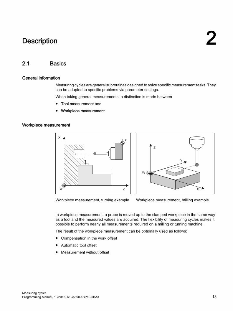
General informationMeasuring cycles are general subroutines designed to solve specific measurement tasks. They can be adapted to specific problems via parameter settings.
When taking general measurements, a distinction is made between
● Tool measurement and
● Workpiece measurement.
Workpiece measurement
Workpiece measurement, turning example Workpiece measurement, milling example
In workpiece measurement, a probe is moved up to the clamped workpiece in the same way as a tool and the measured values are acquired. The flexibility of measuring cycles makes it possible to perform nearly all measurements required on a milling or turning machine.
The result of the workpiece measurement can be optionally used as follows:
● Compensation in the work offset
● Automatic tool offset
● Measurement without offset
Measuring cyclesProgramming Manual, 10/2015, 6FC5398-4BP40-5BA3 13

Tool measurement
Tool measurement, turning tool example Tool measurement, drill example
In tool measurement, the selected tool is moved up to the probe and the measured values are acquired. The probe is either in a fixed position or is swung into the working area with a mechanism. The tool geometry measured is entered in the appropriate tool offset data set.
Description2.1 Basics
Measuring cycles14 Programming Manual, 10/2015, 6FC5398-4BP40-5BA3

2.2 General prerequisitesCertain preconditions must be met before measuring cycles can be used. These are described in detail in the SINUMERIK 840D sl Base Software and Operating Software.
Check the preconditions using the following checklist:
● Machine
– All machine axes are designed in accordance with DIN 66217.
– Machine data has been adapted.
● Starting position
– The reference points have been approached.
– The starting position can be reached by linear interpolation without collision.
● Display functions of the measuring cyclesA HMI/PCU or HMI/TCU is required for showing the measuring result displays and for measuring cycle support.
● Please observe the following when programming:
– Tool radius compensation is deselected before it is called (G40).
– The cycle is called no later than at the 5th program level.
– The measurement is also possible in a system of units that differs from the basic system (with technology data that has been switched over).For metric dimension system with active G70, G700.For inch dimension system with active G71, G710.
ReferencesSupplementary information for this documentation is provided in the following manuals:
● Commissioning Manual SINUMERIK 840D sl Base Software and Operating Software– /IM9/ SINUMERIK Operate
● /PG/, Programming Manual SINUMERIK 840D sl / 828D Fundamentals● /FB1/, Function Manual Basic Functions● /FB2/, Function Manual Expanded Functions● /FB3/, Function Manual Special Functions
Description2.2 General prerequisites
Measuring cyclesProgramming Manual, 10/2015, 6FC5398-4BP40-5BA3 15
2.3 Behavior on block search, dry run, program testing, simulation
FunctionThe measuring cycles are skipped during execution if one of the following execution modes is active:
● "Trial run" ($P_DRYRUN=1)● "Program test" ($P_ISTEST=1)● "Block search" ($P_SEARCH=1),
only if $A_PROTO=0.
Simulation and simultaneous recordingSetting the measuring cycles under a simulated environment
Setting data SD55618 $SCS_MEA_SIM_ENABLE= 0: The measuring cycles are exited without any function.= 1: The measuring cycles are executed. -Simulation in the HMI Operate editor:
Traversing motion is visualized.No measurement results and measurement result display are available.
-SinuTrain:For simultaneous recording, measurement results and measurement result dis‐play are available.For simultaneous recording traversing motion is visualized.
-For systems that exclusively work with simulated axes (e.g. virtual machines, test racks):For simultaneous recording, measurement results and measurement result dis‐play are available.For simultaneous recording traversing motion is visualized.The following settings should be noted:if MD13230 $MN_MEAS_PROBE_SOURCE = 1 to 4,then set MD10360 $MN_FASTIO_DIG_NUM_OUTPUTS >= 1.
= 2 to 8: Reserved= 9: Internal or for special applications, if MD13230 >=1
Measuring cycles and measurement results under a simulated environment (SinuTrain) are used for programming for training purposes if a real machine is not available. The measurement results also involve "simulated" values, which can also deviate from the setting in MD13213 MEAS_PROBE_OFFSET.
Description2.3 Behavior on block search, dry run, program testing, simulation
Measuring cycles16 Programming Manual, 10/2015, 6FC5398-4BP40-5BA3
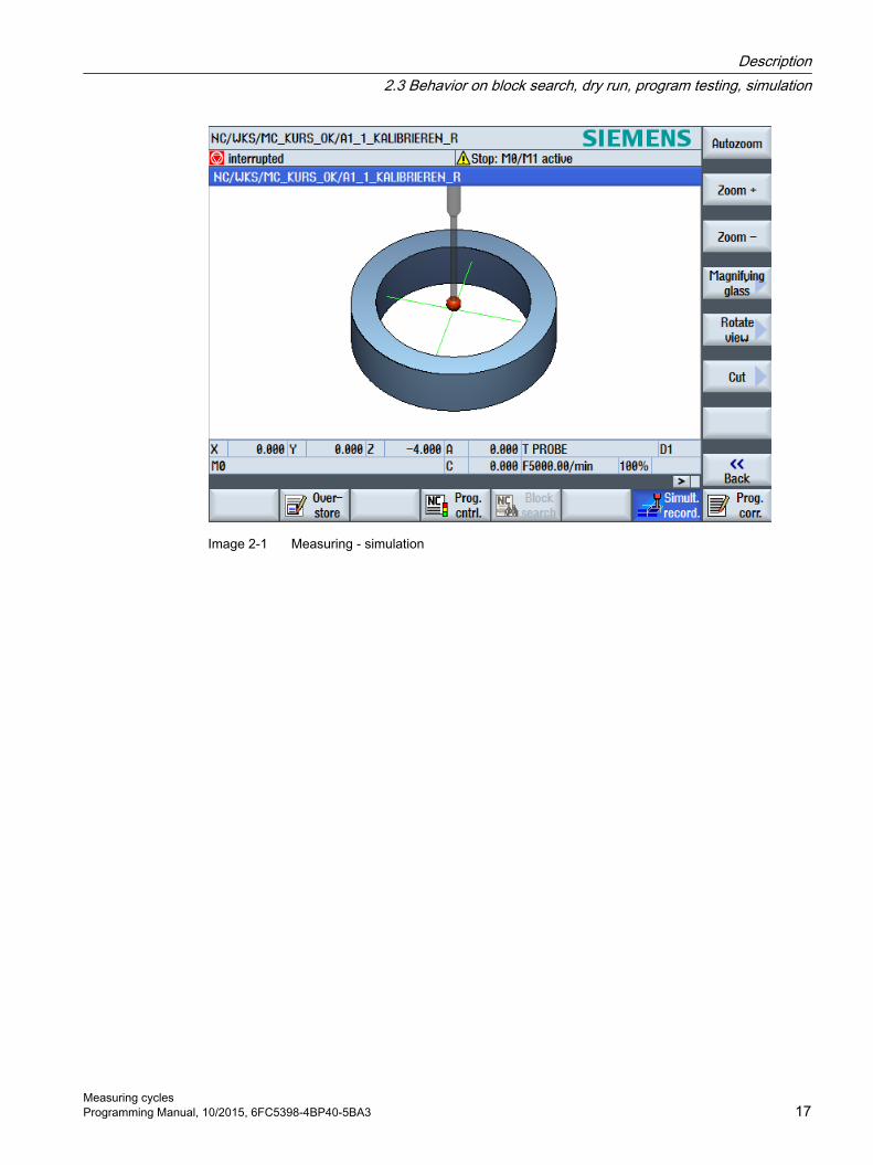
Image 2-1 Measuring - simulation
Description2.3 Behavior on block search, dry run, program testing, simulation
Measuring cyclesProgramming Manual, 10/2015, 6FC5398-4BP40-5BA3 17

2.4 Reference points on the machine and workpiece
General information Depending on the measuring task, measured values may be required in the machine coordinate system (MCS) or in the workpiece coordinate system (WCS).
For example: It may be easier to ascertain the tool length in the machine coordinate system.
Workpiece dimensions are measured in the workpiece coordinate system.
Where:
● M = machine zero in the machine coordinate system
● W = workpiece zero in the workpiece coordinate system
● F = tool reference point
Reference points
The position of tool reference point F in the machine coordinate system is defined with machine zero M as the machine actual value.
The position of the tip/cutting edge of the active tool in the workpiece coordinate system is displayed with the workpiece zero W as workpiece actual value. For a workpiece probe, the center or the end of the probe ball can be defined as the tool tip.
The work offset (WO) characterizes the position of the workpiece zero W in the machine coordinate system.
Work offsets (WO) comprise the components offset, rotation, mirroring and scaling factor (only the global basis work offset does not contain any rotation).
A distinction is made between the basis, work offset (G54 ... G599) and programmable work offset. The basic area contains further subsections – such as the basic work offset, channel-specific basic work offset and configuration-dependent work offsets (e.g. rotary table reference or basic reference).
Description2.4 Reference points on the machine and workpiece
Measuring cycles18 Programming Manual, 10/2015, 6FC5398-4BP40-5BA3

The specified work offsets are effective together as a chain and result in the workpiece coordinate system.
For "Correction in a work offset", in conjunction with measuring cycles, a distinction is made between two different cases.
Correction to the coarse offset:An absolute offset value is determined between the machine zero and the measured workpieces zero. This offset is written into the coarse component of the selected work offset and deleted in the fine component.
Correction to the fine offset:The measured difference is written as offset to the fine component of the selected work offset and is added to the course component.
The input window work offset coarse/fine in the automatic measuring cycle screens is activated using SD54760 $SNS_MEA_FUNCTION_MASK_PIECE, bit 10 = 1.
Note
Scale factors with a scaling value unequal to "1" are not supported by the measuring cycles! Mirroring functions are only permitted in conjunction with counterspindles on lathes.
The machine and workpiece coordinate system can be set and programmed separately in the "inch" or "metric" measuring system.
NoteTransformation● Measure workpiece
Workpiece measurements are always performed in the workpiece coordinate system. All descriptions relating to workpiece measurement refer to it!
● Measure toolWhen measuring tools with kinematic transformation active, a distinction is made between basic coordinate system and machine coordinate system.If kinematic transformation is deactivated, this distinction is made.All subsequent descriptions relating to tool measurement assume that kinematic transformation is disabled and therefore refer to the machine coordinate system.
Description2.4 Reference points on the machine and workpiece
Measuring cyclesProgramming Manual, 10/2015, 6FC5398-4BP40-5BA3 19
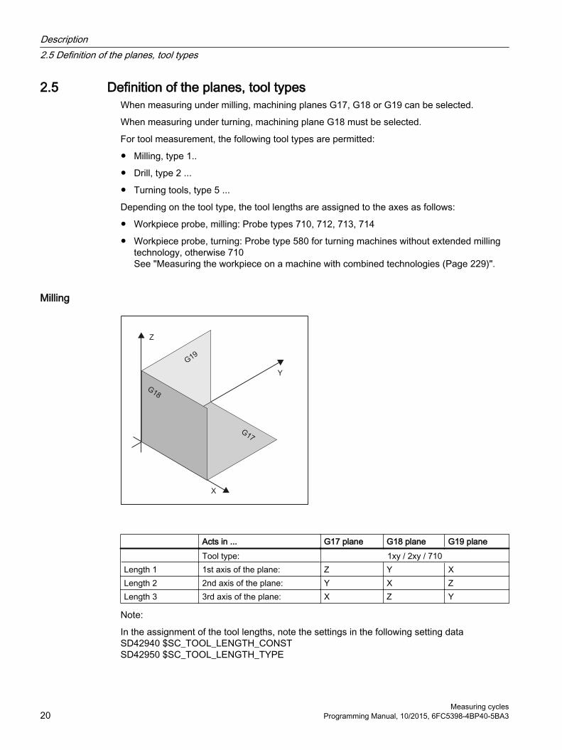
2.5 Definition of the planes, tool typesWhen measuring under milling, machining planes G17, G18 or G19 can be selected.
When measuring under turning, machining plane G18 must be selected.
For tool measurement, the following tool types are permitted:
● Milling, type 1..
● Drill, type 2 ...
● Turning tools, type 5 ...
Depending on the tool type, the tool lengths are assigned to the axes as follows:
● Workpiece probe, milling: Probe types 710, 712, 713, 714
● Workpiece probe, turning: Probe type 580 for turning machines without extended milling technology, otherwise 710See "Measuring the workpiece on a machine with combined technologies (Page 229)".
Milling
Acts in ... G17 plane G18 plane G19 plane Tool type: 1xy / 2xy / 710Length 1 1st axis of the plane: Z Y XLength 2 2nd axis of the plane: Y X ZLength 3 3rd axis of the plane: X Z Y
Note:
In the assignment of the tool lengths, note the settings in the following setting dataSD42940 $SC_TOOL_LENGTH_CONSTSD42950 $SC_TOOL_LENGTH_TYPE
Description2.5 Definition of the planes, tool types
Measuring cycles20 Programming Manual, 10/2015, 6FC5398-4BP40-5BA3

Example of plane definition for milling
Image 2-2 Example: Milling machine with G17
Turning
Turning machines generally only use axes Z and X and therefore:
G18 plane Tool type 5xy (turning tool, workpiece probe)Length 1 Acts in X (2nd axis of the plane)Length 2 Acts in Z (1st axis of the plane)
Description2.5 Definition of the planes, tool types
Measuring cyclesProgramming Manual, 10/2015, 6FC5398-4BP40-5BA3 21

G17 and G19 are used for milling on a turning machine. If there is no machine axis Y, milling can be implemented with the following kinematic transformations.
● TRANSMIT
● TRACYL
In principle, measuring cycles support kinematic transformations. This is stated more clearly in the individual cycles and measuring variants. Information about kinematic transformation can be found in the Programming Manual SINUMERIK 840D sl / 828D Fundamentals or in the documentation of the machine manufacturer.
Note
If a drill or milling cutter is measured on a lathe, in most cases, the channel-specific SD 42950 $SC_TOOL_LENGTH_TYPE = 2 is set: These tools are then length-compensated like a turning tool.
SINUMERIK controls have other machine and setting data that can influence the calculation of a tool.
References:
● /FB1/, Function Manual Basic Functions● /FB2/, Function Manual Expanded Functions● /FB3/, Function Manual Special Functions
Example of plane definition for turning
Image 2-3 Example: Lathe with G18
Description2.5 Definition of the planes, tool types
Measuring cycles22 Programming Manual, 10/2015, 6FC5398-4BP40-5BA3

2.6 Probes that can be used
General information To measure tool and workpiece dimensions, an electronic touch-trigger probe is required that provides a signal change (edge) when deflected with the required repeat accuracy.
The probe must operate virtually bounce-free.
Different types of probe are offered by different manufacturers.
Note
Please observe the information provided by the manufacturers of electronic probes and/or the machine manufacturer's instructions on the following points:● Electrical connection● Mechanical calibration of the probe● If a workpiece probe is used, both the direction of deflection and transmission of switching
signal to the machine column (radio, infrared or cable) must be taken into account. In some versions, transmission is only possible in particular spindle positions or in particular ranges. This can restrict the use of the probe.
Probes are distinguished according to the number of measuring directions.
● Multi-directional (multi probe)
● Mono-directional (mono probe)
Workpiece probe Tool probeMulti-directional (3D) Mono-directional Milling machines Lathes
The probes also differ in the form of the stylus tip:The measuring cycles support pin, L and star probes as autonomous tool types. The use of the probe types is referenced in the individual measuring cycles. The multi probe is universally applicable.
For a mono probe, the switching direction is tracked for each measurement by turning the spindle. This can lead to a longer program runtime.
Description2.6 Probes that can be used
Measuring cyclesProgramming Manual, 10/2015, 6FC5398-4BP40-5BA3 23

Workpiece probe types The following workpiece measuring probe types – as well as a calibration tool for calibrating tool probes – are provided in the tool management:
Image 2-4 Probe types in the tool management
Tool data from probesThe probes differ as a result of the tool type and their special attributes, e.g. switching directions.
A probe can encompass several tool types. For this purpose, several cutting edges (D1, D2, ...) should be created for the probe.
Example: Multi probe with a boom
D1 3D_PROBE Type 710D2 L_PROBE Type 713
The user must take into account the geometry of the probe when pre-positioning. To do this, you can read out individual tool data in the user program:
Example:
IF (($P_TOOLNO>0) AND ($P_TOOL>0)) R1= ($P_AD[6]) ; Reading: tool radius of the current toolENDIF
Correction angle"The probe is aligned in the +X direction using tool parameter "correction angle".
Description2.6 Probes that can be used
Measuring cycles24 Programming Manual, 10/2015, 6FC5398-4BP40-5BA3

3D probe (multi probe)
Display Properties CharacteristicApplication: UniversalType: $TC_DP1 = 710Tool length: in Z (for G17) 1)
Correction angle: $TC_DP10 = 0.0° to 359.9°Radius of the probe sphere
$TC_DP6
1) Workpiece measurement, length reference of the 3D probeThe tool length in the direction of the infeed axis (for G17: Z axis) is defined as the distance between the tool reference point in the tool adapter and a parameterized reference point on the probe sphere. The reference point can be set to the center of the sphere or the surface of the sphere using the following machine data: MD51740 $MN_MEA_FUNCTION_MASK, bit 1
Mono probe
Display Properties CharacteristicApplication: Alignment of the switching direction when
measuringType: $TC_DP1 = 712Tool length: in Z (for G17) 1)
Correction angle: $TC_DP10 = 0.0° to 359.9°Radius of the probe sphere
$TC_DP6
1) Workpiece measurement, length reference of mono probeThe tool length in the direction of the infeed axis (for G17: Z axis) is defined as the distance between the tool reference point in the tool adapter and a parameterized reference point on the probe sphere. The reference point can be set to the center of the sphere or the surface of the sphere using the following machine data: MD51740 $MN_MEA_FUNCTION_MASK, bit 1
As initial state for the measuring cycles it is defined that at spindle position 0° the switching direction of the mono probe in the machining plane is aligned in the axis direction +X. If an angular offset is required, then the value should be entered into tool parameter "Correction angle" ($TC_DP10).
Description2.6 Probes that can be used
Measuring cyclesProgramming Manual, 10/2015, 6FC5398-4BP40-5BA3 25

L probe
Display Properties CharacteristicApplication: Towing measurement in +ZType: $TC_DP1 = 713Tool length: in Z (for G17) 1)
Correction angle: $TC_DP10 = 0.0° to 359.9°Radius of the probe sphere:
$TC_DP6
Length of the boom: $TC_DP71) Workpiece measurement, length referenceThe tool length is defined as the distance between the tool reference point in the tool adapter and the probing point of the probe sphere in the +Z direction.
As initial state for the measuring cycles it is defined that at spindle position 0° the switching direction of the mono probe in the machining plane is aligned in the axis direction +X. If an angular offset is required, then the value should be entered into tool parameter "Correction angle" ($TC_DP10).
Star probe
Display Properties CharacteristicApplication: Measure: Hole parallel to the axis 1)
Type: $TC_DP1 = 714Tool length: in Z (for G17) 2)
Correction angle: $TC_DP10 = 0.0° to 359.9°Diameter of the star paral‐lel to the geometry axes:
$TC_DP6
Radius of the probe sphere:
$TC_DP7
1) The application only refers to measurements in the plane (for G17: XY plane). Measurement in the tool direction (for G17: Z direction) is not permitted using a star probe. If a measurement is to be made in the tool direction, a star element (boom) must be parameterized as an L probe ($TC_DP1 = 713).2) Workpiece measurement, length reference of star probeThe tool length is defined as the distance between the tool reference point in the tool adapter and the center point of one of the probe spheres.
The booms of the star probe should be aligned parallel to the geometry axes of the machining plane. If an angular offset is required, then the value should be entered into tool parameter "Correction angle" ($TC_DP10).
Assignment of the probe types
Probe type Lathes Milling and machining centers Tool measurement Workpiece measurement Workpiece measurementMulti-directional X X XMono-directional -- -- X
Description2.6 Probes that can be used
Measuring cycles26 Programming Manual, 10/2015, 6FC5398-4BP40-5BA3

2.7 Probe, calibration body, calibration tool
2.7.1 Measuring workpieces on milling machines, machining centers
Probe calibration All probes must be mechanically correctly adjusted before use. The switching directions must be calibrated before they are used in the measuring cycles for first-time. This also applies when changing the stylus tip of the probe.
When being calibrated, the trigger points (switching points), position deviation (skew), and active sphere radius of the workpiece probe are determined and entered into the data fields of the general setting data SD 54600 $SNS_MEA_WP_BALL_DIAM . There are 12 data fields.
Calibration can be realized in a calibration ring (known bore), on a calibration sphere or on workpiece surfaces, which have an appropriate geometrical precision and low surface roughness.
Use the same measuring velocity for calibrating and measuring. This applies in particular to the feedrate overide. If, in MD51740 $MNS_MEA_FUNCTION_MASK, bit 6 is set =1, then 100% feed rate override traversing velocity is used for the measuring blocks (MEAS) in the measuring cycles if the feedrate override is set > 0. If calibration is performed more than once on a calibration data set, the same measuring velocity must be set, otherwise the previous calibration will be declared as being invalid.
Measuring cycle CYCLE976 with different measuring versions is available to calibrate the probe.
MeasuringAll probe types can be used in conjunction with a spindle capable of positioning. This ensures that all milling measuring versions can be applied.
When positioning the probe, the measuring cycles always refer to the active master spindle. If several spindles exist, then this condition must be satisfied by the user. During the program runtime, this is possible using the SETMS NC command.
Example: SETMS(3); the third spindle is defined as master spindle.
If probes are used in conjunction with spindles that are not capable of positioning, restrictions are obtained regarding the measuring versions and probe types. For illegal measuring versions, alarms can be displayed during the cycle time.
At the calibration and measurement instant, the user must guarantee an identical orientation (spindle position) of the probe, for example by clamping or indexing.
If probes are fixed in a system, restrictions are obtained regarding the measuring versions and probe types. For illegal measuring versions, alarms can be displayed during the cycle time.
When the probe is mounted in the machine at a fixed position, a mechanical offset can exist in the three geometry axes between the center point of the probe sphere (tool tip) and the tool reference point.
Description2.7 Probe, calibration body, calibration tool
Measuring cyclesProgramming Manual, 10/2015, 6FC5398-4BP40-5BA3 27

This offset should be entered in the adapter dimension (basis dimension) of the tool data of the workpiece probe.
See alsoCalibrate probe - radius in ring (CYCLE976) (Page 111)
Calibrate probe - radius on edge (CYCLE976) (Page 116)
Calibrate probe - calibrate on ball (CYCLE976) (Page 122)
2.7.2 Measuring tools on milling machines, machining centers
Tool probe
Image 2-5 Measuring a milling cutter
Description2.7 Probe, calibration body, calibration tool
Measuring cycles28 Programming Manual, 10/2015, 6FC5398-4BP40-5BA3

Parameters of the tool probeSetting data
● For machine-related measurement/calibration:
– SD 54625 $SNS_MEA_TP_TRIG_MINUS_DIR_AX1
– SD 54626 $SNS_MEA_TP_TRIG_PLUS_DIR_AX1
– SD 54627 $SNS_MEA_TP_TRIG_MINUS_DIR_AX2
– SD 54628 $SNS_MEA_TP_TRIG_PLUS_DIR_AX2
– SD 54629 $SNS_MEA_TP_TRIG_MINUS_DIR_AX3
– SD 54630 $SNS_MEA_TP_TRIG_PLUS_DIR_AX3
● For machine-related measurement/calibration:
– SD 54640 $SNS_MEA_TPW_TRIG_MINUS_DIR_AX1
– SD 54641 $SNS_MEA_TPW_TRIG_PLUS_DIR_AX1
– SD 54642 $SNS_MEA_TPW_TRIG_MINUS_DIR_AX2
– SD 54643 $SNS_MEA_TPW_TRIG_PLUS_DIR_AX2
– SD 54644 $SNS_MEA_TPW_TRIG_MINUS_DIR_AX3
– SD 54645 $SNS_MEA_TPW_TRIG_PLUS_DIR_AX3
The default setting has data fields for 6 probes.
Calibration, calibration toolA probe must be calibrated before it can be used. To do this, when using measuring cycles in the AUTOMATIC mode, before calibration, the approximate values must be entered into the setting data listed above for the corresponding probe. Only then can the approximate position of the probe be identified in the measuring cycle.
Calibration involves precisely determining the trigger points (switching points) of the tool probe, and entering them in the corresponding parameters.
Calibration tool (type 725), milling (type 1xy) or drilling tool (2xy) can be used for calibration. The precise dimensions of the tool are known.
Measurement version Calibrate probe (CYCLE971) (Page 259) is provided for calibration.
NoteMeasuring velocities
It is recommended that the same measuring velocities are used for calibrating and measuring.
Description2.7 Probe, calibration body, calibration tool
Measuring cyclesProgramming Manual, 10/2015, 6FC5398-4BP40-5BA3 29

Tool parameters Calibrating tool probesTool type ($TC_DP1[ ]): 725, 1xy or 2xyLength 1 - geometry ($TC_DP3[ ]):
L1
Radius ($TC_DP6[ ]): rLength 1 - basic dimension ($TC_DP21[ ]):
only if required
All other tool parameters, such as wear, must be assigned a value of zero.
2.7.3 Measuring workpieces at the turning machines
Workpiece probeOn turning machines, the workpiece probes are treated as tool type 5xy with permissible cutting edge positions (SL) 5 to 8 and must be entered in the tool memory accordingly.
Lengths specified for turning tools always refer to the tool tip, except in the case of workpiece probes on turning machines where they refer to the probe center.
Probes are classified according to their position:
Workpiece probe SL 7
Entry in tool memory Workpiece probe for a latheTool type ($TC_DP1[ ]): 5xyCutting edge ($TC_DP2[ ]): 7Length 1 - geometry: L1Length 2 - geometry: L2Radius ($TC_DP6[ ]): rLength 1 - basic dimension ($TC_DP21[ ]):
only if required
Length 2 - basic dimension ($TC_DP22[ ]):
only if required
The wear and other tool parameters must be assigned the value 0.
Description2.7 Probe, calibration body, calibration tool
Measuring cycles30 Programming Manual, 10/2015, 6FC5398-4BP40-5BA3

Workpiece probe SL 8
Entry in tool memory Workpiece probe for a latheTool type ($TC_DP1[ ]): 5xyCutting edge ($TC_DP2[ ]): 8Length 1 - geometry: L1Length 2 - geometry: L2Radius ($TC_DP6[ ]): rLength 1 - basic dimension ($TC_DP21[ ]):
only if required
Length 2 - basic dimension ($TC_DP22[ ]):
only if required
The wear and other tool parameters must be assigned the value 0.
Workpiece probe SL 5 or SL 6
Entry in tool memory Workpiece probe for a latheTool type ($TC_DP1[ ]): 5xyCutting edge ($TC_DP2[ ]): 5 or 6Length 1 - geometry: L1Length 2 - geometry: L2Radius ($TC_DP6[ ]): rLength 1 - basic dimension ($TC_DP21[ ]):
only if required
Length 2 - basic dimension ($TC_DP22[ ]):
only if required
The wear and other tool parameters must be assigned the value 0.
Description2.7 Probe, calibration body, calibration tool
Measuring cyclesProgramming Manual, 10/2015, 6FC5398-4BP40-5BA3 31

Calibration, gauging block
Image 2-6 Calibrating a workpiece probe, example: Calibrating in the reference groove
A probe must be calibrated before it can be used. When being calibrated, the trigger points (switching points), position deviation (skew), and precise ball radius of the workpiece probe are determined and entered into the corresponding data fields of the general setting data SD 54600 $SNS_MEA_WP_BALL_DIAM .
The default setting has data fields for 12 probes.
Calibration of the workpiece probe on turning machines is usually performed with gauging blocks (reference grooves). The precise dimensions of the reference groove are known and entered in the associated data fields of the following general setting data:
● SD54615 $SNS_MEA_CAL_EDGE_BASE_AX1
● SD54616 $SNS_MEA_CAL_EDGE_UPPER_AX1
● SD54617 $SNS_MEA_CAL_EDGE_PLUS_DIR_AX1
● SD54618 $SNS_MEA_CAL_EDGE_MINUS_DIR_AX1
● SD54619 $SNS_MEA_CAL_EDGE_BASE_AX2
● SD54620 $SNS_MEA_CAL_EDGE_UPPER_AX2
● SD54621 $SNS_MEA_CAL_EDGE_PLUS_DIR_AX2
● SD54622 $SNS_MEA_CAL_EDGE_MINUS_DIR_AX2
The default setting has data fields for three gauging blocks. In the measuring cycle program, the selection is made using the number of the gauging block (S_CALNUM).
It is also possible to calibrate on a known surface.
Measuring cycle CYCLE973 with various measuring versions is ready for calibration.
Description2.7 Probe, calibration body, calibration tool
Measuring cycles32 Programming Manual, 10/2015, 6FC5398-4BP40-5BA3

See alsoCalibrate probe - length (CYCLE973) (Page 80)
Calibrate probe - radius on surface (CYCLE973) (Page 82)
Calibrate probe - calibrate in groove (CYCLE973) (Page 85)
2.7.4 Measuring tools at lathes
Tool probe
Image 2-7 Measuring a turning tool
Parameters of the tool probeSetting data:
● For machine-related measurement/calibration:
– SD 54626 $SNS_MEA_TP_TRIG_PLUS_DIR_AX1
– SD 54625 $SNS_MEA_TP_TRIG_MINUS_DIR_AX1
– SD 54627 $SNS_MEA_TP_TRIG_MINUS_DIR_AX2
– SD 54628 $SNS_MEA_TP_TRIG_PLUS_DIR_AX2
● For workpiece-related measurement/calibration:
– SD 54641 $SNS_MEA_TPW_TRIG_PLUS_DIR_AX1
– SD 54640 $SNS_MEA_TPW_TRIG_MINUS_DIR_AX1
– SD 54642 $SNS_MEA_TPW_TRIG_MINUS_DIR_AX2
– SD 54643 $SNS_MEA_TPW_TRIG_PLUS_DIR_AX2
The default setting has data fields for 6 probes.
In addition to turning tools, drills and mills can also be measured.
Description2.7 Probe, calibration body, calibration tool
Measuring cyclesProgramming Manual, 10/2015, 6FC5398-4BP40-5BA3 33

Calibration, gauging block
A probe must be calibrated before it can be used. To do this, when using measuring cycles in the AUTOMATIC mode, before calibration, the approximate values must be entered into the setting data listed above for the corresponding probe. Only then can the approximate position of the probe be identified in the measuring cycle.
Calibration involves precisely determining the trigger points (switching points) of the tool probe, and entering them in the corresponding parameters.
Calibration tool (type 585 or type 725) or turning tool (type 5xy) can be used for calibration. The precise dimensions of the tool are known.
Measurement version Calibrate probe (CYCLE982) (Page 234) is provided for calibration.
For lathes, the calibration tool is treated like a turning tool. Cutting edge positions 1 - 4 can be used for calibration. The lengths refer to the sphere equator, not to the sphere center.
Entry in tool memory Calibration tool for a tool probe on a latheTool type ($TC_DP1[ ]): 585, 725 or 5xyCutting edge ($TC_DP2[ ]): 3Length 1 - geometry: L1Length 2 - geometry: L2Radius ($TC_DP6[ ]): rLength 1 - basic dimension ($TC_DP21[ ]):
only if required
Length 2 - basic dimension ($TC_DP22[ ]):
only if required
All other parameters, such as wear, must be assigned a value of zero.
Description2.7 Probe, calibration body, calibration tool
Measuring cycles34 Programming Manual, 10/2015, 6FC5398-4BP40-5BA3

2.8 Measurement principle
Flying measurement
The principle of "flying measurement" is implemented in the SINUMERIK control. The probe signal is processed directly on the NC so that the delay when acquiring measured values is minimal. This permits a higher measuring speed for the prescribed measuring precision and time needed for measuring is reduced.
Connecting probesTwo inputs for connecting touch trigger probes are provided on the I/O device interface of the SINUMERIK control systems.
Machine manufacturerPlease observe the machine manufacturer’s instructions.
Description2.8 Measurement principle
Measuring cyclesProgramming Manual, 10/2015, 6FC5398-4BP40-5BA3 35

Measurement operation sequence using the example set edge (CYCLE978)
Image 2-8 Measurement operation sequence, example set edge (CYCLE978)
The sequence is described using the measuring version, set edge (CYCLE978). The sequence is essentially the same for the other measuring cycles.
The starting position for the measuring procedure is the position DFA in front of the specified set position (expected contour).
Image 2-9 Starting position
The starting position is calculated in the cycle based on parameter entries and probe data. The traversing distance from the pre-position, defined by the user program, to the starting position of the measuring distance is either traversed with rapid traverse G0 or with positioning speed G1 (depending on the parameter). From the starting position, the measuring velocity is effective, which is saved in the calibration data.
The switching signal is expected along path 2 · DFA as from the starting position. Otherwise, an alarm will be triggered or the measurement repeated.
Description2.8 Measurement principle
Measuring cycles36 Programming Manual, 10/2015, 6FC5398-4BP40-5BA3

The resulting maximum measuring position is available in the result parameters _OVR[ ] and _OVI[ ] of the measuring cycle.
At the instant the switching signal is output by the probe, the current actual position is stored internally "on-the-fly" as the actual value, the measuring axis is stopped and then the "Delete distance-to-go" function is executed.
The distance-to-go is the path not yet covered in the measuring block. After deletion, the next block in the cycle can be processed. The measuring axis travels back to the starting position. Any measurement repetitions selected are restarted from this point.
Measurement path DFAMeasurement path DFA defines the distance between the starting position and the expected switching position (setpoint) of the probe.
Measuring velocity As measuring feedrate, all of the measuring cycles use the value saved in the general setting data SD54611 after the calibration of the workpiece probe. A different measuring feedrate can be assigned for each calibration field [n].
To calibrate the measuring probe, either the measuring feedrate from the channel-specific setting data SD55630 $SCS_MEA_FEED_MEASURE is used (default value: 300 mm/min) or the measuring feedrate can be overridden in the input screen form at the calibration instant. To do this, bit 4 must be set to 1 in the general setting data SD54760 $SNS_MEA_FUNCTION_MASK_PIECE .
The maximum permissible measuring velocity is derived from:
● The deceleration behavior of the axis.
● The permissible deflection of the probe.
● The signal processing delay.
Deceleration distance, deflection of probe
NOTICE
Safe braking of the measuring axis
Safe deceleration of the measuring axis to standstill within the permissible deflection path of the probe must always be ensured. Otherwise damage will occur!
A delay t, typical for the control, is taken into account in signal processing (IPO cycle) for the time between detection of the switching signal and output of the deceleration command to the measuring axis: general machine data MD10050 $MN_SYSCLOCK_CYCLE_TIME and MD10070 $MN_IPO_SYSCLOCK_TIME_RATIO). This gives the braking distance component.
The following error of the measuring axis is reduced. The following error is velocity dependent and at the same time dependent on the control factor of the measuring axis (servo gain of the associated machine axis: servo gain factor).
Description2.8 Measurement principle
Measuring cyclesProgramming Manual, 10/2015, 6FC5398-4BP40-5BA3 37

The deceleration rate of the axis must also be taken into account.
Together they produce an axis-specific velocity-dependent deceleration distance.
The Kv factor is the axis MD 32200 $MA_POSCTRL_GAIN.
The maximum axis acceleration / deceleration rate a is saved in axis MD 32300 $MA_MAX_AX_ACCEL . It may have a lesser effect due to other influences.
Always use the lowest values of the axes involved in the measurement.
Measuring accuracy A delay occurs between detection of the switching signal from the probe and transfer of the measured value to the control. This is caused by signal transmission from the probe and is defined by the control hardware. In this time a path is traversed that falsifies the measured value. This influence can be minimized by reducing the measuring speed.
The rotation when measuring a milling tool on a rotating spindle has an additional influence. This can be compensated using compensation tables.
The measurement accuracy that can be obtained is dependent on the following factors:
● Repeat accuracy of the machine
● Repeat accuracy of the probe
● Resolution of the measuring system
Note
Precise measurement is only possible with a probe calibrated under the measurement conditions, i.e. working plane, orientation of the spindle in the plane and measuring velocity are the same for both measurement and calibration. Deviations result in measurement errors. If, in MD51740 $MNS_MEA_FUNCTION_MASK, bit 6 is set =1, then 100% feed rate override traversing velocity is used for the measuring blocks (MEAS) in the measuring cycles if the feedrate override is set > 0.
Description2.8 Measurement principle
Measuring cycles38 Programming Manual, 10/2015, 6FC5398-4BP40-5BA3
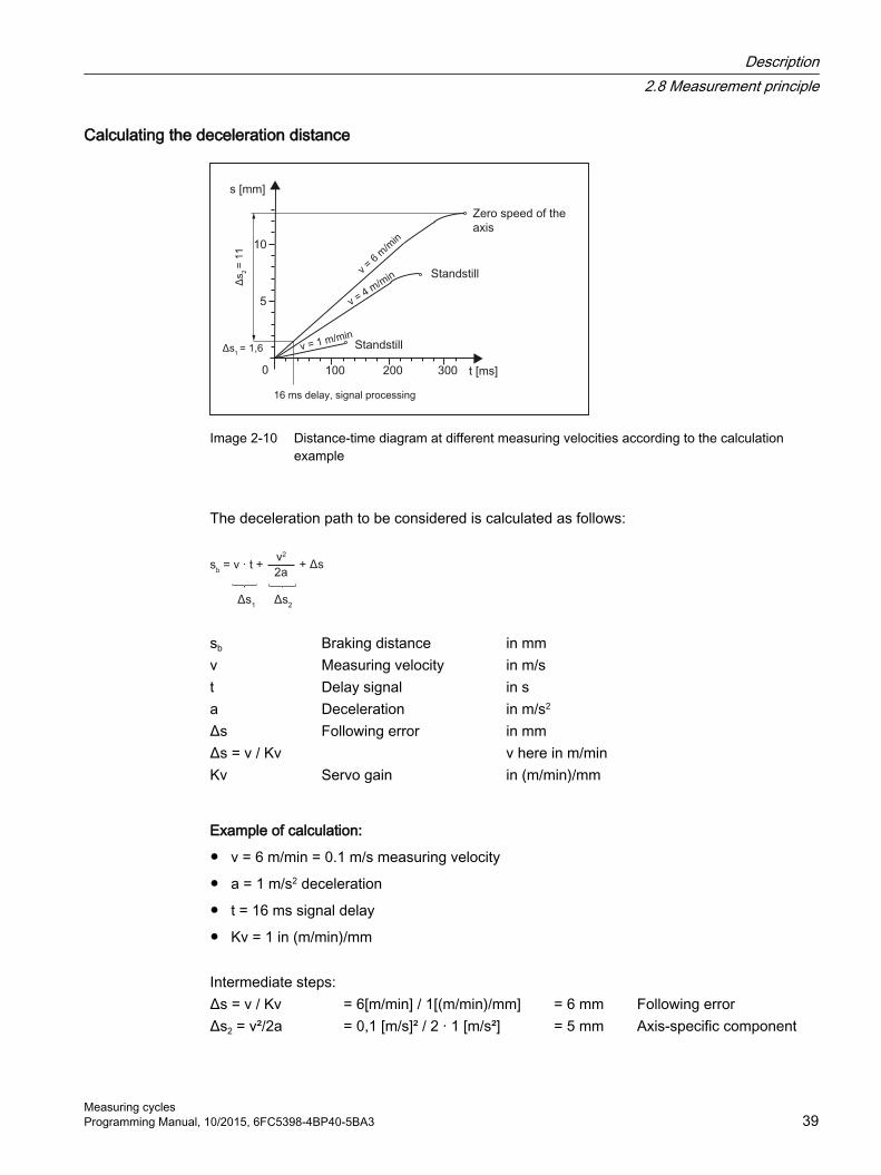
Calculating the deceleration distance
Image 2-10 Distance-time diagram at different measuring velocities according to the calculation example
The deceleration path to be considered is calculated as follows:
sb Braking distance in mmv Measuring velocity in m/st Delay signal in sa Deceleration in m/s2
Δs Following error in mmΔs = v / Kv v here in m/minKv Servo gain in (m/min)/mm
Example of calculation:
● v = 6 m/min = 0.1 m/s measuring velocity
● a = 1 m/s2 deceleration
● t = 16 ms signal delay
● Kv = 1 in (m/min)/mm
Intermediate steps:Δs = v / Kv = 6[m/min] / 1[(m/min)/mm] = 6 mm Following errorΔs2 = v²/2a = 0,1 [m/s]² / 2 · 1 [m/s²] = 5 mm Axis-specific component
Description2.8 Measurement principle
Measuring cyclesProgramming Manual, 10/2015, 6FC5398-4BP40-5BA3 39

Δs1 = v · t = 0,1 [m/s] · 0,016 [s] = 1,6 mm Percentage due to signal delay
Overall result:sb = Δs1 + Δs2 + Δs = 6 mm + 5 mm + 1,6 mm = 12,6 mm Braking distance
The deflection of the probe = braking distance to zero speed of the axis is 12.6 mm.
Description2.8 Measurement principle
Measuring cycles40 Programming Manual, 10/2015, 6FC5398-4BP40-5BA3

2.9 Measuring strategy for measuring workpieces with tool offsetThe actual workpiece dimensions must be measured exactly and compared with the setpoint values to be able to determine and compensate the actual dimensional deviations on the workpiece. An offset value can then be ascertained for the tool used for machining.
Function When taking measurements on the machine, the actual dimensions are derived from the path measuring systems of the position-controlled feed axes. For each dimensional deviation determined from the set and actual workpiece dimensions there are many causes which essentially fall into three categories:
● Dimensional deviations with causes that are n o t subject to a particular trend, e.g. positioning scatter of the feed axes or differences in measurement between the internal measurement (probe) and the external measuring device (micrometer, measuring machine, etc.). In this case, it is possible to apply empirical values, which are stored in separate memories. The set/actual difference determined is automatically compensated by the empirical value.
● Dimensional deviations with causes that a r e subject to a particular trend, e.g. tool wear or thermal expansion of the leadscrew.
● Accidental dimensional deviations, e.g. due to temperature fluctuations, coolant or slightly soiled measuring points.Assuming the ideal case, only those dimensional deviations that are subject to a trend can be taken into account for compensation value calculation. Since, however, it is hardly ever known to what extent and in which direction accidental dimensional deviations influence the measurement result, a strategy (sliding averaging) is needed that derives a compensation value from the actual/set difference measured.
Mean value calculation Mean value calculation in conjunction with measurement weighting has proven a suitable method.
When correcting a tool, it can be selected whether a correction is made based on the actual measurement, or whether an average value of the measurement differences should be generated over several measurements which is then used to make the correction.
The formula of the mean value generation chosen is:
k
D Mv Mv Mv i old
old new
- - =
Mvnew Mean value new = amount of compensationMvold Mean value prior to last measurementk Weighting factor for mean value calculationDi Actual/set difference measured (minus any empirical value)
The mean value calculation takes account of the trend of the dimensional deviations of a machining series. The weighting factor k from which the mean value is derived is selectable.
Description2.9 Measuring strategy for measuring workpieces with tool offset
Measuring cyclesProgramming Manual, 10/2015, 6FC5398-4BP40-5BA3 41

A new measurement result affected by accidental dimensional deviations only influences the new tool offset to some extent, depending on the weighting factor.
Computational characteristic of the mean value with different weightings k
Image 2-11 Mean value generation with influence of weighting k
● The greater the value of k, the slower the formula will respond when major deviations occur in computation or counter compensation. At the same time, however, accidental scatter will be reduced as k increases.
● The lower the value of k, the faster the formula will react when major deviations occur in computation or counter compensation. However, the effect of accidental variations will be that much greater.
● The mean value Mv is calculated starting at 0 over the number of workpieces i, until the calculated mean value exceeds the work offset range (S_TZL). From this limit on, the calculated mean value is applied as an offset.
● Once the mean value has been used for the offset, it is deleted from the memory. The next measurement then starts again with Mvold = 0.
Description2.9 Measuring strategy for measuring workpieces with tool offset
Measuring cycles42 Programming Manual, 10/2015, 6FC5398-4BP40-5BA3

Table 2-1 Example of mean value calculation and offset
Lower limit = 40 µm (S_TZL = 0.04)
Characteristic of the mean value for two different weighting factors
i Di
[µm]
Mvk = 3[µm]
Mvk = 2[µm]
1. measure‐ment
30 10 15
1 2
34
5
2. Measure‐ment
50 23,3 32,5
3. Measure‐ment
60 35,5 46,2 ③
4. Measure‐ment
20 30,3 10
5. Measure‐ment
40 32,6 25
6. Measure‐ment
50 38,4 37,5
7. Measure‐ment
50 42,3 ① 43,75 ④
8. Measure‐ment
30 10 15
9. Measure‐ment
70 30 42,5 ⑤
10. Measure‐ment
70 43,3 ② 35
For the measurements with marked fields, tool offset is performed with the mean value (calculated mean value >S_TZL):
● If k=3 in the 7th and 10th measurement (① and ②),
● If k=2 in the 3rd, 7th, and 9th measurement (③, ④ and ⑤).
Description2.9 Measuring strategy for measuring workpieces with tool offset
Measuring cyclesProgramming Manual, 10/2015, 6FC5398-4BP40-5BA3 43

2.10 Parameters for checking the measurement result and offsetFor constant deviations not subject to a trend, the dimensional deviation measured can be compensated by an empirical value in certain measuring variants.
For other compensations resulting from dimensional deviations, symmetrical tolerance bands are assigned to the set dimension which result in different responses.
Empirical value / mean value EVN (S_EVNUM) The empirical values are used to suppress dimensional deviations that are not subject to a trend.
Note
If empirical values are not to be applied, then S_EVNUM = 0 must be set.
The empirical values themselves are saved in channel-specific SD 55623 $SCS_MEA_EMPIRIC_VALUE .
EVN specifies the number of the empirical value memory. The actual/set difference determined by the measuring cycle is corrected by this value before any further correction measures are taken.
This is the case:
● For workpiece measurement with automatic tool offset.
● For single-point measurement with automatic WO correction.
● For tool measurement.
The mean value only refers to the workpiece measurement with automatic tool offset.
For an automatic tool offset, the mean value is generated from the measured difference of the previous and the actual measurement. This functionality has special significance within a machining series with measurements performed at the same measuring location.
The function does not have to be activated.
The mean values are stored in the channel-specific SD 55625 $SCS_MEA_AVERAGE_VALUE .The number of the mean value memory is transferred in the measuring cycle using variable S_EVNUM.
Safe area TSA (S_TSA) The safe area is effective for almost all measuring variants and does not affect the offset value; it is used for diagnostics.
Description2.10 Parameters for checking the measurement result and offset
Measuring cycles44 Programming Manual, 10/2015, 6FC5398-4BP40-5BA3

If this limit is reached then the following can be assumed:
● A probe defect, or
● An incorrect setpoint position, or
● An illegal deviation from the setpoint position can be assumed.
NoteAUTOMATIC mode
AUTOMATIC operation is interrupted and the program cannot continue. An alarm text appears to warn the user.
Dimension difference check DIF (S_TDIF) DIF is active only for workpiece measurement with automatic tool offset and for tool measurement.
This limit has no effect on generation of the compensation value either. When it is reached, the tool is probably worn and needs to be replaced.
Note
An alarm text is displayed to warn the operator and the program can be continued by means of an NC start.
This tolerance limit is generally used by the PLC for tool management purposes (twin tools, wear monitoring).
Tolerance of workpiece: Lower limit (S_TLL), upper limit (S_TUL) Both parameters are active only for tool measurement with automatic tool offset.
When measuring a dimensional deviation ranging between "2/3 tolerance of workpiece" (S_TMV) and "Dimensional difference control" (S_TDIF), this is regarded 100% as tool offset. The previous average value is erased.
This enables a fast response to major dimensional deviations.
Note
When the tolerance limit of the workpiece is exceeded, this is indicated to the user depending on the tolerance position "oversize" or "undersize".
2/3 tolerance of workpiece TMV (S_TMV)TMV is active only for workpiece measurement with automatic tool offset.
Description2.10 Parameters for checking the measurement result and offset
Measuring cyclesProgramming Manual, 10/2015, 6FC5398-4BP40-5BA3 45

Within the range of "Lower limit" and "2/3 workpiece tolerance" the mean value is calculated according to the formula described in Section "Measuring strategy".
Note
Mvnew is compared with the work offset range:● If Mvnew is greater than this range, compensation is corrected by Mvnew and the associated
mean value memory is cleared.● If Mvnew is less than this range, no compensation is carried out. This prevents excessively
abrupt compensations.
Weighting factor for mean value generation FW (S_K)FW is active only for workpiece measurement with automatic tool offset. The weighting factor can be used to give a different weighting for each measurement.
A new measurement result thus has only a limited effect on the new tool offset as a function of FW.
Work offset range TZL (S_TZL) TZL active for
● Workpiece measurement with automatic tool offset
● Tool measurement and calibration for milling tools and tool probes
This tolerance range corresponds to the amount of maximum accidental dimensional deviations. It has to be determined for each machine.
No tool compensation is made within these limits.
In workpiece measurement with automatic tool offset, however, the mean value of this measuring point is updated and re-stored with the measured actual/set difference, possibly compensated by an empirical value.
Description2.10 Parameters for checking the measurement result and offset
Measuring cycles46 Programming Manual, 10/2015, 6FC5398-4BP40-5BA3

The tolerance bands (range of permissible dimensional tolerance) and the responses derived from them are as follows:
● For workpiece measurement with automatic tool offset
Note
In measuring cycles, the workpiece setpoint dimension is placed in the middle of the permitted ± tolerance limit for reasons associated with symmetry.
● For tool measurement
Description2.10 Parameters for checking the measurement result and offset
Measuring cyclesProgramming Manual, 10/2015, 6FC5398-4BP40-5BA3 47

● For workpiece measurement with WO correction
● For workpiece probe calibration
● For tool probe calibration
Description2.10 Parameters for checking the measurement result and offset
Measuring cycles48 Programming Manual, 10/2015, 6FC5398-4BP40-5BA3
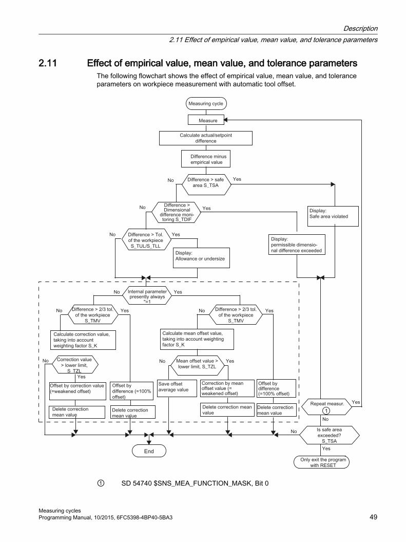
2.11 Effect of empirical value, mean value, and tolerance parametersThe following flowchart shows the effect of empirical value, mean value, and tolerance parameters on workpiece measurement with automatic tool offset.
① SD 54740 $SNS_MEA_FUNCTION_MASK, Bit 0
Description2.11 Effect of empirical value, mean value, and tolerance parameters
Measuring cyclesProgramming Manual, 10/2015, 6FC5398-4BP40-5BA3 49

Description2.11 Effect of empirical value, mean value, and tolerance parameters
Measuring cycles50 Programming Manual, 10/2015, 6FC5398-4BP40-5BA3

2.12 Measuring cycle help programs
2.12.1 CYCLE116: Calculation of center point and radius of a circle
Function This cycle calculates from three or four points positioned on one plane the circle they inscribe with center point and radius.
To allow this cycle to be used as universally as possible, its data is transferred via a parameter list.
An array of REAL variables of length 13 must be transferred as the parameter.
Image 2-12 Calculation of circle data from 4 points
ProgrammingCYCLE116 (_CAL[ ], _MODE)
Transfer parameters● Input data
Parameters Data type Meaning_CAL [0] REAL Number of points for calculation (3 or 4)_CAL [1] REAL 1. Axis of the plane of the first point_CAL [2] REAL 2. Axis of the plane of the first point_CAL [3] REAL 1. Axis of the plane of the second point_CAL [4] REAL 2. Axis of the plane of the second point_CAL [5] REAL 1. Axis of the plane of the third point_CAL [6] REAL 2. Axis of the plane of the third point
Description2.12 Measuring cycle help programs
Measuring cyclesProgramming Manual, 10/2015, 6FC5398-4BP40-5BA3 51

Parameters Data type Meaning_CAL [7] REAL 1. Axis of the plane of the fourth point_CAL [8] REAL 2. Axis of the plane of the fourth point
● Output data
Parameters Data type Meaning_CAL [9] REAL 1. Axis of the plane of the circle center point_CAL [10] REAL 2. Axis of the plane of the circle center point_CAL [11] REAL Circle radius_CAL [12] REAL Status for the calculation
0 = Calculation in progress1 = Error occurred
_MODE INTEGER Error number (61316 or 61317 possible)
Note
This cycle is called as a subroutine by, for example, measuring cycle CYCLE979.
Example
%_N_Circle_MPF DEF INT _MODE DEF REAL _CAL[13]= (3,0,10,-10,0,0,-10,0,0,0,0,0,0) ;3 points specified P1: 0,10
P2: -10,0P3: 0,-10
CYCLE116(_CAL[ ], _MODE) ;Result: _CAL[9]=0_CAL[10]=0_CAL[11]=10_CAL[12]=0_ALM=0
M0 STOPRE M30
Description2.12 Measuring cycle help programs
Measuring cycles52 Programming Manual, 10/2015, 6FC5398-4BP40-5BA3

2.12.2 CYCLE119: Arithmetic cycle for determining position in space
FunctionThis help cycle calculates, from three spatial setpoint positions (reference triangle), three spatial actual positions as well as the positional and angular deviation to the active frame. The offset is applied in the direction of the selected frame.
Cycle119 is separately called from measuring cycle CYCLE997 as subprogram or from a user program.
To universally use this cycle, its data are transferred via a parameter interface.
ProgrammingCYCLE119 (_SETPOINT, _MEASPOINT, _ALARM, _RES, _REFRAME,_COR, _RESLIM)
Parameter
Input data Data type Meaning_SETPOINT[3,3]
REAL Field for 3 setpoint positions in the sequence 1st, 2nd, 3rd, geometry axis (X, Y, Z).These points are the reference triangle.
_MEASPOINT[3,3]
REAL Field for 3 setpoint positions measured in the sequence 1st, 2nd, 3rd, geometry axis (X, Y, Z). This is really the spatial position of the defined triangle.
_COR INTEGER Compensation
Description2.12 Measuring cycle help programs
Measuring cyclesProgramming Manual, 10/2015, 6FC5398-4BP40-5BA3 53

Input data Data type Meaning Values: 0: No compensation 1...99: WO compensation in G54...G57, G505..G599 1000: WO compensation in last active channel basic frame according to MD
28081 1011 to 1026: WO compensation in channel basic frame 2000: WO compensation in system frame for scratching and setting actual
value ($P_SETFR). 9999: WO compensation in active frame, settable frame G54 to G57,
G505...G599 and/or with G500 in last active basic frame according to $P_CHBFRMASK
_RESLIM REAL Limit value for distortion (only relevant, if _COR >0 ). If _RES is below this value, then WO is compensated, otherwise an alarm is output.
The results of the calculation are stored in these transfer parameters.
Output data Data type Meaning_ALARM INTEGER Cycle alarm number for feedback signal.
(for cycle call, transfer value must be = 0.)_RES REAL Calculation result Val‐
ues:< 0: No frame was able to be calculated. Alarm (_ALARM > 0) is returned
>= 0: The calculation was successful. The size of the value a measure of the distor‐tion of the triangle, for example, due to measurement inaccuracies. It is the sum of the deviations of the individual points in mm.
_REFRAME FRAME Result frame, difference to the active frame. If this result frame is linked with the active frame, the measured triangle position is given the desired setpoint position (workpiece coordinates).
NoteFor correction
The frame to be corrected must not include any mirroring or scale factors. If there is no channel basic frame for G500, then a cyclic alarm (_ALARM>0) is output.
If cycle 119 is called by cycle 997, then the corrected frame is automatically activated.
If cycle 119 is separately called in a user program, the new data of the frame are activated outside the cycle when the G command of the associated adjustable frame (G500, G54 up to ...) is reprogrammed.
2.12.3 CUST_MEACYC: User program before/after measurements are performed
Function The CUST_MEACYC cycle is called in every measuring cycle before and after the measurement.
Description2.12 Measuring cycle help programs
Measuring cycles54 Programming Manual, 10/2015, 6FC5398-4BP40-5BA3

It can be used by users to program sequences necessary before starting a measurement (e.g. to activate the probe).
In the as-delivered state, this cycle contains a CASE statement that executes a jump to a label with subsequent M17 (end of subprogram) for each measuring cycle.
Example
_M977: ;before workpiece probe with CYCLE977(measure hole/shaft/groove/spigot)GOTOF _AM_WP_MES; ..... ; _AM_WP_MES:
;before workpiece general
; ; M17 ;end of cycle
From the jump labels, actions can be programmed, which should be executed at each CYCLE977 call (label _M977) all for general workpiece measurements (label _AM_WP_MES).
ReferencesCommissioning manual SINUMERIK 840D sl Basesoftware and Operating Software.
Description2.12 Measuring cycle help programs
Measuring cyclesProgramming Manual, 10/2015, 6FC5398-4BP40-5BA3 55

2.13 Miscellaneous functions
2.13.1 Measuring cycle support in the program editorThe program editor offers extended measuring cycle support for inserting measuring cycle calls into the program.
PrerequisiteHardware TCU or PCU.
FunctionThis measuring cycle support provides the following functionality:
● Measuring cycle selection via softkeys
● Input screen forms for parameter assignment with help displays
● Retranslatable program code is generated from the individual screen forms.
2.13.2 Measuring result screens
Function Measurement result displays can be shown automatically during a measuring cycle. The measurement result screen display can now be called in the program using cycle CYCLE150, which also controls the logging function.
Measuring result screens
ProcedureThe part program or ShopMill program to be processed has been created and is opened in the editor.
1. Press the "Meas. workpiece" or "Meas. tool" softkey.
2. Press the "Meas. result" softkey. The "Measurement re‐sult" input window opens.
3. Make the required selection in the toggle fields.
The display mode can be selected as follows in the screen for the measurement result display "on":
Description2.13 Miscellaneous functions
Measuring cycles56 Programming Manual, 10/2015, 6FC5398-4BP40-5BA3

- "automatically 8 s" ... The measurement result screen remains for a fixed time of 8 s- "NC Start" ... With the measurement result screen, the cycle is stopped using
M0, the measuring cycle is continued with NC Start and the measurement result screen deselected
- "for alarm" ... The measuring results screen is only displayed for cycle alarms 61303, 61304, 61305 and 61306.
These selection options correspond to the options that were previously available using SD55613 $SCS_MEA_RESULT_DISPLAY.
Measurement result screen display and logging function can be separately activated and deactivated. An additional CYCLE150 call should be programmed.
At the end of the program (channel RESET), the function is deactivated automatically, explicit programming is not required.
Note
For compatibility reasons, the previous option of controlling the measurement result screen display using setting data 55613 $SCS_MEA_RESULT_DISPLAY has been kept.
The measuring cycles can display different measuring result screens depending on the measuring variant:
● Calibrating tool probes
● Tool measurement
● Calibrating workpiece probes
● Workpiece measurement
Content of measuring result screensThe measuring results screens contain the following data:
Calibrating the tool probe
● Measuring cycle and measuring version
● Trigger values of axis directions and differences
● Probe number
● Safe area
Tool measurement
● Measuring cycle and measuring version
● Actual values and differences for tool offsets
● Safe area and permissible dimensional difference
● T name, D number
Description2.13 Miscellaneous functions
Measuring cyclesProgramming Manual, 10/2015, 6FC5398-4BP40-5BA3 57

Calibrating workpiece probes
● Measuring cycle and measuring version
● Trigger values of axis directions and differences
● Position deviation (probe skew) when calibrating in the plane
● Probe number
● Safe area
Workpiece measurement
● Measuring cycle and measuring version
● Setpoints, actual values and their differences
● Tolerance upper and lower limits (for tool offset)
● Offset value
● Probe number
● Safe area and permissible dimensional difference
● T name, D number and DL number or WO memory number for automatic offset
Example of measurement result display
Description2.13 Miscellaneous functions
Measuring cycles58 Programming Manual, 10/2015, 6FC5398-4BP40-5BA3

Program control for displaying and shutting down the measuring result displaysUsing the program control MRD "Display measurement result", programmed measuring result display calls can be simply activated or deactivated. To do this, the program does not have to be changed!
The program control MRD acts on all measuring result display calls, irrespective of whether they are implemented using CYCLE150 calls or by programming setting data 55613 $SCS_MEA_RESULT_DISPLAY in the program.
2.13.3 Logging
2.13.3.1 General
Function● Standard log
Output of the measurement results from the automatic measuring cycles in a log file.Each measuring method of the standard measuring cycles is assigned a fixed standard log with regard to the contents. The contents correspond to the measurement result display on the screen. User entries for the log contents are not required.
● User logOutput of user-relevant data as a separate log or supplement to the measurement log.The contents and format are the sole responsibility of the user. A predefined variable field is available which can take the contents of the log.
It is possible to log to external media, if they are available, on local drives, USB or in the part program memory. The log output can be in text format or in tabular format (column separator ";") for further processing in spreadsheet programs.
RequirementsIf the data is to be logged to external media or network drives, then the EES mode must be set (see "Commissioning Manual Sinumerik Operate (IM9)").
Contents of a standard log● Date/time (when the log was written), log name with path
● Measuring method
● The most important input values (that were entered in the screen form before measuring)
● Correction target
● Setpoints, measured values and differences
As many decimal places are logged as displayed on the screen. The terms and axis names also correspond to those displayed on the screen – but are written out (without abbreviations). The measurement unit mm/inch depends on the system of units active during the measurement.
Description2.13 Miscellaneous functions
Measuring cyclesProgramming Manual, 10/2015, 6FC5398-4BP40-5BA3 59

2.13.3.2 Control cycle CYCLE150
FunctionThe activation of the logging function is performed by simply programming the CYCLE150 call. The result display and logging can be selected separately and can be controlled independently. Parameters in CYCLE150 have a modal effect until the end of the program or reset, or until the cycle is called again.
ProcedureThe logging is activated and deactivated via the program through the appropriate parameterization of CYCLE150. This must be programmed once at the start of the measuring program. Only when the input parameters are changed must the programming be performed again before the respective measuring cycle call. At the end of the program (channel RESET), the functions are deactivated automatically, explicit programming is not required.
The part program or ShopMill program to be processed has been created and you are in the editor.
1. Press the "Meas. workpiece" or "Meas. tool" softkey.
2. Press the "Meas. result" softkey. The "Measurement Re‐sult" input window opens.
3. Make the required selection in the toggle fields (see follow‐ing table).
The screen form contains a selection field for activating and deactivating the measurement result display with the toggle states "Off"/"On". It also contains a selection field for activating and deactivating the logging with the toggle states "Off"/"On"/"Last measurement".
If both selections fields have the toggle state "Off", all the following input fields for the respective function are hidden.
Parameter
Parameter DescriptionMeasurement result display Off/OnDisplay mode autom. 8 s / NC start / for alarmLog Log type Standard log / User logLog format(for standard)
Text format / Tabular format(file extension TXT/CSV)
Log data New/AppendLog storage Directory / As part programName of log file File type set according to selection of log format
Description2.13 Miscellaneous functions
Measuring cycles60 Programming Manual, 10/2015, 6FC5398-4BP40-5BA3

Log typeThe existing infrastructure for the logging of the measurement results should also be made accessible to users for their own purposes - output of user logs. A distinction is therefore made between the standard log and the user log.
Log formatStandard logs can be output in two log formats, in text format and in tabular format. The text format is based on the display of the measurement results on the screen. The tabular format is a format that can be imported by Excel (or other spreadsheet programs). This allows the measurement result logs to be statistically processed.
The Text format / Tabular format selection is only available for standard logs. With user logs, the user is responsible for the formatting, i.e. the selection field is hidden for the user log.
Log dataA new log file can be created or an existing file appended. This is selected via Log data "New" or "Append". With "New", the existing file with the same name is deleted and a new file created during logging.
Log storageThe path can be specified explicitly or implicitly for the log storage, i.e. "Directory" or "As part program" can be selected.
With "As part program", the path of the higher-level NC program is automatically determined by the logging cycles and the log file is stored there. The following input field for the path is hidden. With "Directory", there is an additional input field in which the path is entered. The path does not have to be entered, it can be selected via a dialog which is opened via the additional VSK1 "Select directory".
Description2.13 Miscellaneous functions
Measuring cyclesProgramming Manual, 10/2015, 6FC5398-4BP40-5BA3 61

Image 2-13 Entry level in the selection dialog for log storage
This softkey "Select directory" only appears when "Directory" is set in the Log storage selection field.
Image 2-14 Selection dialog for log storage
All drives and paths available in the program manager can be selected.
● Local drive
● NC data (part program memory)
● Network drive(s), if connected
● USB (if available)
Only a path or an available file can be selected in the dialog.
If only a path is selected, the selection with the complete path is transferred to the screen form with the Accept softkey, but can be changed. The name of the log file is entered. If a file is selected, the full path and file name are transferred to the screen form, but can be changed.
Alternatively, the storage location can be entered.
Description2.13 Miscellaneous functions
Measuring cycles62 Programming Manual, 10/2015, 6FC5398-4BP40-5BA3

Examples of the selected storage location:
1. NC data -> Workpiece -> Workpiece "Logs"//NC/WCS.DIR/LOGS.WPD
2. Network drive logs//d:/Logs
3. USB -> measuring_cycle_logs//USB:/01/measuring_cycle_logs
Name of log fileThe log file name can be freely selected. It must comply with the rules for program names in the NC, or for program names when writing to external drives.
File typeThe following file types are supported:
● Text file - type TXT
● Tabular format – type CSV
These file types depend on the selected log format.
The file type cannot be changed, it is only displayed.
2.13.3.3 Log "Last measurement"
FunctionThe "Log last measurement" function is programmed by calling the logging CYCLE150 once. Measuring is not performed, instead the values of the last measurement which are still available in the result parameters of the measuring cycles (GUD variables) are used, and only a subcycle is called for the logging. This function only makes sense when log "Off" was selected during the measurement.
RequirementA standard log can only be output when a measuring cycle was previously active in automatic mode.
ProcedureA part program for logging "Last measurement" is created and is in the editor.
Description2.13 Miscellaneous functions
Measuring cyclesProgramming Manual, 10/2015, 6FC5398-4BP40-5BA3 63

1. Select Log "Last measurement" in the input field. 2. Supply additional parameters as described above.
3. Press the "Accept" softkey. The generated cycle call ap‐pears in the editor.
Programming example:CYCLE150(30,11012,"//NC/MPF.DIR/LAST_MEASURE.TXT")M30
2.13.3.4 Standard log
FunctionStandard logs display the results from measuring cycles in a clear log structure. The output is possible in text or tabular format. Contents and structure are predefined.
RequirementStandard logs are only possible in conjunction with measuring cycle calls.
Log contentsThe logs are generally created with fixed English texts. (The measurement result displays appear in the language that has been set for Operate.)
Logs of the measuring cycles have the following structures and contents:
● Header block - log header
– Date/time (when the log was created)
– Name and path of the log file
– Name of the part program from which the measuring function was called
– Workpiece number
● Value block - results per measuring point
– Number of the measuring point, measuring method as programmed, time of the measurementMeasuring method as text (e.g. "1 hole")
– Specification of the correction target, either measure only – no correction – orfor measuring methods with WO correction: Specification of the corrected WO, correction target (WO / fine offset) – orFor measuring methods with tool offset: Tool name, D number, tool type, correction target (length/radius, geometry/wear)
– Setpoints, measured values, differences with specification of the respective axis name or measurement objects (e.g. "Diameter") and the measurement unit
Description2.13 Miscellaneous functions
Measuring cycles64 Programming Manual, 10/2015, 6FC5398-4BP40-5BA3

ProcedureThe call of the control CYCLE150 is always at the start of the program. The respective measuring cycle calls are then programmed. If a different parameterization of CYCLE150 is required, it must be called again at the appropriate program position.
Programming example
N10 G54 N20 T710 D1 M6 ; Probe call... ; Positioning, etc.N50 CYCLE150(10,1001,"MESSPROT.TXT") ; Activate loggingN60 CYCLE997(109,1,1,10,1,5,0,45,0,0,0,5,5,5,10,10,10,0,1,,0,)
; 1st measurement
... ; Positioning, etc.N90 CYCLE978(200,,4000001,1,77,2,8,1,1,1,"END_MILL_D8",,0,1.01,0.1,0.1,0.34,1,10001,,1,0)
; 2nd measurement
... ; Positioning, etc.N120 CYCLE998(100105,10004,0,1,1,1,,1,5,201,1,10,,,,,1,,1,)
; 3. measurement
N140 M30
Log in tabular format"Tabular format" must be selected at "Log format" in the CYCLE150 screen form. This format can be imported into spreadsheet programs and processed further.
The "Tabular format" is defined by the following default settings:
Separation of the data fields: SemicolonDecimal character: PointDate format: yyyy-MM-ddNumber of decimal places: As on the screenTime format: hh:mm:ss
A log in tabular format contains the same information as in text format. For the statistical evaluation of measurement series, these logs require post processing in the respective spreadsheet programs.
2.13.3.5 User log
FunctionWith this function, the user freely defines the contents of the log lines and stores them in an array of string variables (string length 200).
Description2.13 Miscellaneous functions
Measuring cyclesProgramming Manual, 10/2015, 6FC5398-4BP40-5BA3 65

The contents of the string array are logged when a new CYCLE160 is called. The logging always begins with array index 0 and continues until an empty string (i.e. string length 0) is found.
For simple applications, an NCK-global array of string variables is predefined in the PGUD block:
DEF NCK STRING[200] S_LOGTXT[10]
This means that 10 lines can be immediately logged.
If this is not sufficient, the user can alternatively create a second string array of any length with the predefined name S_USERTXT[n] in a separate GUD block (e.g. MGUD or UGUD):
DEF NCK STRING[200] S_USERTXT[n]
The logging function checks whether the S_USERTXT array is available. If it is available, the contents of this array are logged, if not, the contents of S_LOGTXT.
At the program position where CYCLE160 is called, the logging is performed according to the logging destination set by the CYCLE150 call – exactly the same as the logging of measurement results.
This function can be used to output a complete user-specific log (without any reference to the measuring) or to insert additional lines in standard logs.
If additional lines are to be written in standard logs in tabular format, the user must ensure the column formatting in these strings (insert separators ";").
Procedure"User log" is selected in the CYCLE150 screen form for the log control.
There is no difference between text format and tabular format – the user determines the contents. The corresponding selection field is hidden for the user log.
If the path is entered, it is performed with the same dialog as for the standard log.
Description2.13 Miscellaneous functions
Measuring cycles66 Programming Manual, 10/2015, 6FC5398-4BP40-5BA3

Image 2-15 User log screen form
The following must be written in the part program:
● CYCLE150 call to activate the user log
● Assignment of the log contents to the predefined string variables
● CYCLE160 for the output of the log contents
CYCLE160 has no transfer parameters. The user must program it without a screen form.
Freely-definable user logProgramming example:
... N50 CYCLE150(10,1111,“MY_PROT.TXT“)
; Logging ON
N51 S_USERTXT[0]=REP("") ; Delete old data arrayN52 S_USERTXT[0]="MACHINE: ABC_12345"
; Compile log contents
N53 S_USERTXT[1]="LOGFILE COMPENSATION DATA"N54 S_USERTXT[2]=" " ; Programming of empty line: 1 x blankN55 S_USERTXT[3]="VALUE1 = "<<R101 N56 S_USERTXT[4]="VALUE2 = "<<R102 N60 CYCLE160 ; Write user log
Description2.13 Miscellaneous functions
Measuring cyclesProgramming Manual, 10/2015, 6FC5398-4BP40-5BA3 67

... M30
Log extract:
MACHINE: ABC_12345LOGFILE COMPENSATION DATA
VALUE1 = 123.456VALUE2 = 789.333Explanations:
● N50 … Logging is switched on
– Destination: In the same path as the calling program
– The log is appended
– Log type: User log
– Logging "on"
● N52 - N56 log content
● N60 … CYCLE160 call: Data is now written
● Value 1 and value 2 mirror the contents of the R-parameters R101 and R102 at the time of the log output.
Standard log with additional user dataProgramming example:
--- N50 CYCLE150(10,1001,…) ; Logging ON, write headerN51 S_LOGTXT[0]=REP("") ; Delete old data arrayN52 S_LOGTXT[0]="HOLE DM 20H7" ; Write user dataN53 S_LOGTXT[1]="LARGESTDIMENSION:20.021"
N54 S_LOGTXT[2]="SMALLESTDIMENSION:20.000"
N55 S_LOGTXT[3]="SPINDLETEMPERATURE:"<<R99<<" DEG"N60 CYCLE160 ; Write user data to logT="3D_PROBE_FR" D1 M6 G0 X0 Y0 Z5 N70 CYCLE977(201,,4000001,1,24,,,2,8,0,1,1,,,1," ",,0,1.01,1.01,-1.01,0.34,1,0,,1,1)
Description2.13 Miscellaneous functions
Measuring cycles68 Programming Manual, 10/2015, 6FC5398-4BP40-5BA3

... M30
Log extract:
**************************************************************************************************Date : 2013-08-05 Time: 11:59:10Protocol: /_N_WKS_DIR/_N_WP1_WPD/_PROT_TE_977_BOHR_TXTProgram : _N_TE_977_BOHR_MPF Workpiece no.: 123 *************************************************************************************************
HOLE DM 20H7LARGESTDIMENSION:20.021SMALLESTDIMENSION:20.000SPINDLETEMPERATURE:68.7 DEG
----------------------------------------------------------------------------------------------------------------1 : 977 / 101 Time: 11:58:10Results measure: 1 Hole / CYCLE977----------------------------------------------------------------------------------------------------------------Correction into: Work offset, coarse G508 Coarse [mm] Rotation [deg] --------------------------------------------------------------------------X -0.0200 0.0000 Y 0.0300 45.0000Z -0.0128 0.0000 --------------------------------------------------------------------------
Results: Setpoint Measured DifferenceX 12.9900 12.9700 -0.0200 mmY 7.5000 7.5300 0.0300 mmDiameter 24.0000 23.8400 -0.1600 mm---------------------------------------------------------------------------------------------------------------
Description2.13 Miscellaneous functions
Measuring cyclesProgramming Manual, 10/2015, 6FC5398-4BP40-5BA3 69

2.13.3.6 Behavior during block search, simulation and for several channels
Block searchIf during the block search, a cycle call for logging "On" is executed, this state is saved. The following measuring cycle calls that are run through in the block search mode do not log anything (because there are no measuring results). Logging is started as of the program start when the search target is reached.
Similarly, the state is also saved for a cycle call for logging "Off" during the block search, and then nothing logged as of the program start.
SimulationThe following behavior applies in the simulation of Operate:
Programs with calls for the logging function can be executed, but no logs are created.
During simulation, measuring cycles do not return any measurement results, they only show the traversing to the measuring points – and therefore there is nothing to log.
Several channelsIn principle, measuring programs with logging can run in two channels.
However, the user must ensure that the measuring and logging functions run in succession from channel to channel and do not overlap. This also applies to user logs.
Description2.13 Miscellaneous functions
Measuring cycles70 Programming Manual, 10/2015, 6FC5398-4BP40-5BA3

Measuring variants 33.1 General requirements
3.1.1 Overview of the measuring cycles
Function of the measuring cyclesThe following table describes all the measuring cycle functions for the turning and milling technologies.
Table 3-1 Measuring cycles
Measuring cy‐cle
Description Measuring versions
CYCLE973 2) This measuring cycle can be used to calibrate a workpiece probe on a surface on the workpiece or in a groove.
● Calibrate probe - length● Calibrate probe - radius on surface● Calibrate probe - probe in groove
CYCLE974 2) This measuring cycle can be used to determine the work‐piece zero in the selected measuring axis or a tool offset with 1-point measurement.
● Turning measurement - front edge● Turning measurement - inside diameter● Turning measurement - outside diameter
CYCLE994 2) This measuring cycle can be used to determine the work‐piece zero in the selected measuring axis with 2-point measurement. To do this, two opposite measuring points on the diameter are approached automatically in succession
● Turning measurement - inside diameter● Turning measurement - outside diameter
CYCLE976 Using this measuring cycle, a workpiece probe can be cali‐brated in a calibration ring or on a calibration ball completely in the working plane or at an edge for a particular axis and direction.
● Calibrate probe - length on surface● Calibrate probe - radius in ring● Calibrate probe - radius on edge● Calibrate probe - calibration on sphere
CYCLE961 This measuring cycle can be used to determine the position of a workpiece corner (inner or outer) and use this as work offset.
● Corner - right-angled corner● Corner - any corner
CYCLE977 This measuring cycle can be used to determine the center point in the plane as well as the width or the diameter.
● Edge distance - groove● Edge distance - rib● Hole - rectangular pocket● Hole - 1 hole● Spigot - rectangular spigot● Spigot - 1 circular spigot
CYCLE978 This measuring cycle can be used to measure the position of an edge in the workpiece coordinate system.
Edge distance - set edge
Measuring cyclesProgramming Manual, 10/2015, 6FC5398-4BP40-5BA3 71

Measuring cy‐cle
Description Measuring versions
CYCLE979 This measuring cycle can be used to measure the center point in the plane and the radius of circle segments.
● Hole - inner circle segment● Spigot - outer circle segment
CYCLE995 With this measuring cycle the angularity of the spindle on a machine tool can be measured.
3D - angular deviation spindle
CYCLE996 This measuring cycle can be used to determine transforma‐tion-relevant data for kinematic transformations with con‐tained rotary axes.
3D - kinematics
CYCLE997 This measuring cycle can be used to determine the center point and diameter of a ball. Furthermore, the center points of three distributed balls can be measured. The plane formed through the three ball center points, regarding its angular position, is determined referred to the working plane in the workpiece coordinate system.
● 3D - sphere● 3D - 3 spheres
CYCLE998 This measuring cycle can be used to determine the angular position of a surface (plane) referred to the working plane and the angle of edges in the workpiece coordinate system.
● Edge distance - align edge● 3D - align plane
CYCLE971 1) This measuring cycle can be used to calibrate a tool probe and measure the tool length and/or tool radius for milling tools.
● Calibrate probe● Measure tool
CYCLE982 2) This measuring cycle can be used to calibrate a tool probe and measure turning, drilling and milling tools on turning machines.
● Calibrate probe● Turning tool● Milling tool● Drill
1) Only for milling technology2) Only for turning technology
Measuring variants3.1 General requirements
Measuring cycles72 Programming Manual, 10/2015, 6FC5398-4BP40-5BA3
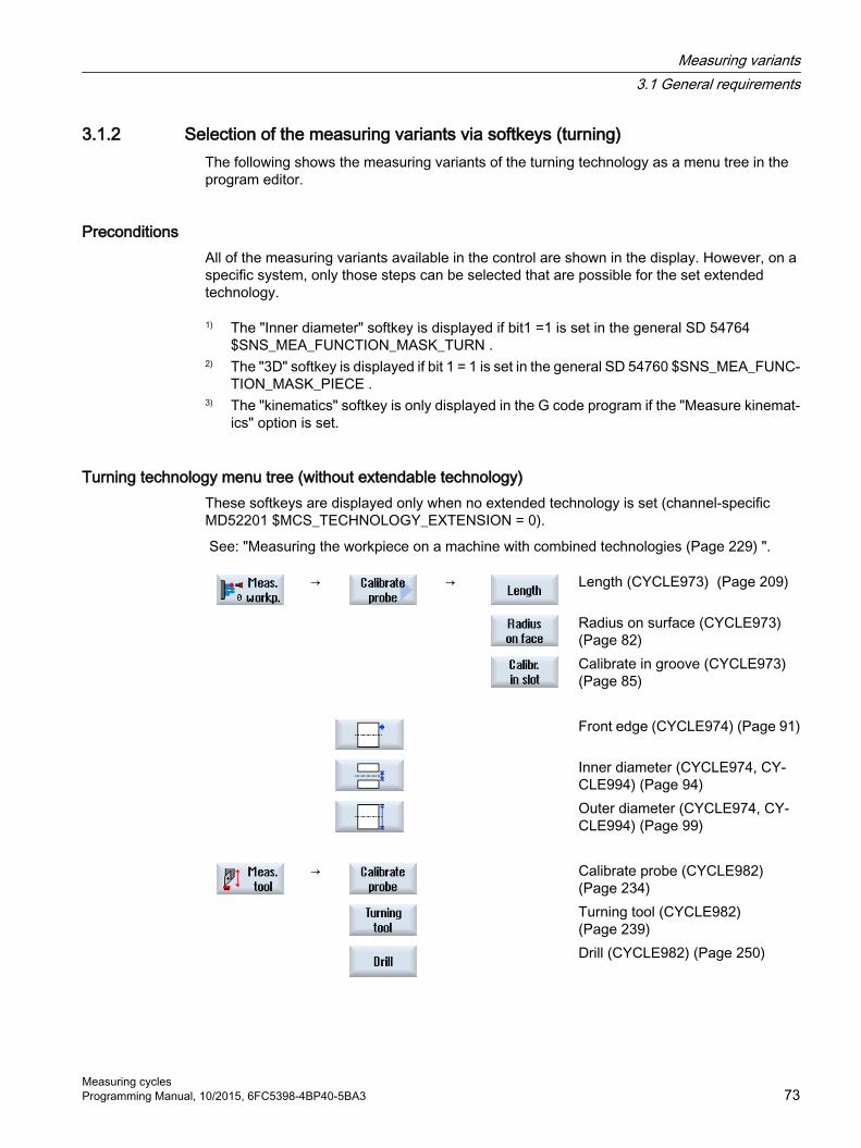
3.1.2 Selection of the measuring variants via softkeys (turning)The following shows the measuring variants of the turning technology as a menu tree in the program editor.
PreconditionsAll of the measuring variants available in the control are shown in the display. However, on a specific system, only those steps can be selected that are possible for the set extended technology.
1) The "Inner diameter" softkey is displayed if bit1 =1 is set in the general SD 54764 $SNS_MEA_FUNCTION_MASK_TURN .
2) The "3D" softkey is displayed if bit 1 = 1 is set in the general SD 54760 $SNS_MEA_FUNC‐TION_MASK_PIECE .
3) The "kinematics" softkey is only displayed in the G code program if the "Measure kinemat‐ics" option is set.
Turning technology menu tree (without extendable technology)These softkeys are displayed only when no extended technology is set (channel-specific MD52201 $MCS_TECHNOLOGY_EXTENSION = 0).
See: "Measuring the workpiece on a machine with combined technologies (Page 229) ".
→ → Length (CYCLE973) (Page 209)
Radius on surface (CYCLE973) (Page 82)
Calibrate in groove (CYCLE973) (Page 85)
Front edge (CYCLE974) (Page 91)
Inner diameter (CYCLE974, CY‐CLE994) (Page 94)
Outer diameter (CYCLE974, CY‐CLE994) (Page 99)
→ Calibrate probe (CYCLE982)
(Page 234) Turning tool (CYCLE982)
(Page 239) Drill (CYCLE982) (Page 250)
Measuring variants3.1 General requirements
Measuring cyclesProgramming Manual, 10/2015, 6FC5398-4BP40-5BA3 73

Turning technology with extended milling technology menu tree 4) The "Angular deviation spindle" softkey is exclusively displayed in the G code program.
These softkeys are displayed if the "Milling" extended technology is set (channel-specific MD52201 $MCS_TECHNOLOGY_EXTENSION = 2).
→ → Length (CYCLE973) (Page 80)
Radius in ring (CYCLE976) (Page 111)
Radius at edge (CYCLE976) (Page 116)
Calibrate on sphere (CYCLE976) (Page 122)
→ Front edge (CYCLE974) (Page 91)
1) Inner diameter (CYCLE974, CY‐CLE994) (Page 94)
Outer diameter (CYCLE974, CY‐CLE994) (Page 99)
→ Set edge (CYCLE978) (Page 125)
Align edge (CYCLE998) (Page 131)
Groove (CYCLE977) (Page 138)
Rib (CYCLE977) (Page 143)
→ Right-angled corner (CYCLE961)
(Page 148) Any corner (CYCLE961)
(Page 153) → Rectangular pocket (CYCLE977)
(Page 158) 1 hole (CYCLE977) (Page 163)
Inner circle segment (CYCLE979) (Page 168)
→ Rectangular spigot (CYCLE977)
(Page 173)
Measuring variants3.1 General requirements
Measuring cycles74 Programming Manual, 10/2015, 6FC5398-4BP40-5BA3

1 circular spigot (CYCLE977) (Page 179)
Outer circle segment (CYCLE979) (Page 184)
2) → Align plane (CYCLE998)
(Page 189) Sphere (CYCLE997) (Page 194)
3 spheres (CYCLE997) (Page 199)
4) Spindle angular displacement (CY‐CLE995) (Page 209)
3D kinematics (CYCLE996) (Page 209)
→ Calibrate probe (CYCLE982)
(Page 234) Turning tool (CYCLE982)
(Page 239) Milling tool (CYCLE982)
(Page 243) Drill (CYCLE982) (Page 250)
Measuring variants3.1 General requirements
Measuring cyclesProgramming Manual, 10/2015, 6FC5398-4BP40-5BA3 75

3.1.3 Selection of the measuring variants via softkeys (milling)The following shows the measuring variants for the milling technology as a menu tree in the program editor.
RequirementsAll of the measuring variants available in the control are shown in the display. However, on a specific system, only those steps can be selected that are possible for the set extended technology.
1) The "Inner diameter" softkey is displayed if bit1 =1 is set in the general SD 54764 $SNS_MEA_FUNCTION_MASK_TURN .
2) The "3D" softkey is displayed if bit 1 = 1 is set in the general SD 54760 $SNS_MEA_FUNC‐TION_MASK_PIECE .
3) The "Kinematics" softkey is only displayed in the G code program, if the "Measure kine‐matics" option is set.
4) The "Angular deviation spindle" softkey is exclusively displayed in the G code program.
Milling technology menu tree
→ → Length (CYCLE976)
Radius in ring (CYCLE976) (Page 111)
Radius at edge (CYCLE976) (Page 116)
Calibrate on sphere (CYCLE976) (Page 122)
→ Set edge (CYCLE978) (Page 125)
Align edge (CYCLE998) (Page 131)
Groove (CYCLE977) (Page 138)
Rib (CYCLE977) (Page 143)
→ Right-angled corner (CYCLE961)
(Page 148) Any corner (CYCLE961)
(Page 153) → Rectangular pocket (CYCLE977)
(Page 158)
Measuring variants3.1 General requirements
Measuring cycles76 Programming Manual, 10/2015, 6FC5398-4BP40-5BA3
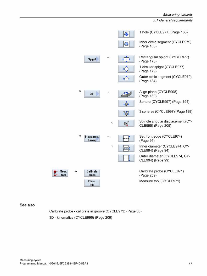
1 hole (CYCLE977) (Page 163)
Inner circle segment (CYCLE979) (Page 168)
→ Rectangular spigot (CYCLE977)
(Page 173) 1 circular spigot (CYCLE977)
(Page 179) Outer circle segment (CYCLE979)
(Page 184) 2) → Align plane (CYCLE998)
(Page 189) Sphere (CYCLE997) (Page 194)
3 spheres (CYCLE997) (Page 199)
4) Spindle angular displacement (CY‐CLE995) (Page 205)
4) → Set front edge (CYCLE974)
(Page 91) 1) Inner diameter (CYCLE974, CY‐
CLE994) (Page 94) Outer diameter (CYCLE974, CY‐
CLE994) (Page 99)
→ Calibrate probe (CYCLE971) (Page 259)
Measure tool (CYCLE971)
See alsoCalibrate probe - calibrate in groove (CYCLE973) (Page 85)
3D - kinematics (CYCLE996) (Page 209)
Measuring variants3.1 General requirements
Measuring cyclesProgramming Manual, 10/2015, 6FC5398-4BP40-5BA3 77

3.1.4 Result parameters
DefinitionResult parameters are measurement results provided by the measuring cycles.
Parameters Type Meaning_OVR[ ] REAL Result parameter - real number:
Setpoint values, actual values, differences, offset values, etc._OVI[ ] INTEGER Result parameter - integer
CallThe result parameters of the measuring cycles are saved in the channel-specific user variables. These can be called from the operating area as follows:
1. Press the "Parameter" softkey.
3. Press the "Using variable" softkey.The result parameters _OVR[ ] and _OVI[ ] are displayed in the "Channel-specific user variables" window.2. Press the the "Channel GUD" softkey.
Note
If not only SGUD variables exist, the "GUD selection" softkey must be used to select "SGUD".
Measuring versionsWhich result parameters are output from the measuring cycles, is described in the individual measuring versions.
For workpiece measurement with tool offset or offset in the WO, several measuring versions also supply result parameters, see Chapter Additional result parameters (Page 321).
Measuring variants3.1 General requirements
Measuring cycles78 Programming Manual, 10/2015, 6FC5398-4BP40-5BA3

3.2 Measure workpiece (turning)
3.2.1 General informationThe measuring cycles below are intended for use on turning machines.
NoteSpindle
Spindle commands in the measuring cycles always refer to the active master spindle of the control.
When using the measuring cycles at machines with several spindles, then the spindle involved must be defined as master spindle before the cycle call.
Note
Precise measurement is only possible with a probe calibrated under the measurement conditions, i.e. working plane and measuring velocity are the same for both measurement and calibration.
If the probe is used in the spindle for a driven tool, the spindle orientation must also be considered. Deviations can cause measuring errors.
References: /PG/ Programming Manual SINUMERIK 840D sl / 828D Fundamentals
Diameter programming, measuring systemThe measuring cycles used in turning work with the current plane G18.
Value specifications of the transverse axis (X) of the measuring cycles used in turning are performed in the diameter (DIAMON). The measuring cycles used in turning (CYCLE973, CYCLE974 and CYCLE994) also work internally with active diameter programming (DIAMON).
The measuring system (basic system) of the machine and the workpiece can be different.
The G700 command should be used when measuring the workpiece in INCHES on a metric machine.
The G710 command should be used when measuring the workpiece in mm on an "INCH" machine.
For information regarding measurement in conjunction with a 3rd axis, see Chapter Extended measurement (Page 105).
Note
A correspondence/assignment list of the measuring cycle parameters, machine and setting data used with regard to the measuring cycle versions 7.5, 2.6 and 4.4 can be found in the Appendix Changes from cycle version SW4.4 and higher (Page 325)!
Measuring variants3.2 Measure workpiece (turning)
Measuring cyclesProgramming Manual, 10/2015, 6FC5398-4BP40-5BA3 79
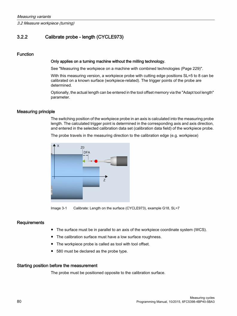
3.2.2 Calibrate probe - length (CYCLE973)
Function Only applies on a turning machine without the milling technology.
See "Measuring the workpiece on a machine with combined technologies (Page 229)".
With this measuring version, a workpiece probe with cutting edge positions SL=5 to 8 can be calibrated on a known surface (workpiece-related). The trigger points of the probe are determined.
Optionally, the actual length can be entered in the tool offset memory via the "Adapt tool length" parameter.
Measuring principleThe switching position of the workpiece probe in an axis is calculated into the measuring probe length. The calculated trigger point is determined in the corresponding axis and axis direction, and entered in the selected calibration data set (calibration data field) of the workpiece probe.
The probe travels in the measuring direction to the calibration edge (e.g. workpiece)
Image 3-1 Calibrate: Length on the surface (CYCLE973), example G18, SL=7
Requirements● The surface must be in parallel to an axis of the workpiece coordinate system (WCS).
● The calibration surface must have a low surface roughness.
● The workpiece probe is called as tool with tool offset.
● 580 must be declared as the probe type.
Starting position before the measurementThe probe must be positioned opposite to the calibration surface.
Measuring variants3.2 Measure workpiece (turning)
Measuring cycles80 Programming Manual, 10/2015, 6FC5398-4BP40-5BA3

Position after the end of the measuring cycleThe probe is at the distance of the selected measurement path (DFA) away from the calibration surface.
ProcedureThe part program or ShopTurn program to be processed has been created and you are in the editor.
1. Press the "Meas. workpiece" softkey.
2. Press the "Calibrate probe" softkey.
3. Press the "Length" softkey.The input window "Calibrate: Length at surface" opens.
Parameters
G code program ShopTurn programParameters Description Unit Parameters Description Unit
Calibration data set (1 - 12) - T Name of the probe -F Calibration and measuring fee‐
drateDistance/min
D Cutting edge number (1 - 9) -
Calibration data set (1 - 12) - β Tool alignment with swivel axis
● (0 degrees)● (90 degrees)● Value entry
Degrees
F Calibration and measuring fee‐drate
mm/min
Z Start point Z of the measurement mm X Start point X of the measurement mm Y Start point Y of the measurement mm
Parameters Description UnitAdapt tool length Adapt the probe length and trigger point:
● Yes● No (adapt trigger point only)
-
Measuring direc‐tion
Measuring axis (for G18):● +/- Z● +/- X
-
Z0 / X0 Reference point Z/X (corresponding to the measuring direction) mm
Measuring variants3.2 Measure workpiece (turning)
Measuring cyclesProgramming Manual, 10/2015, 6FC5398-4BP40-5BA3 81
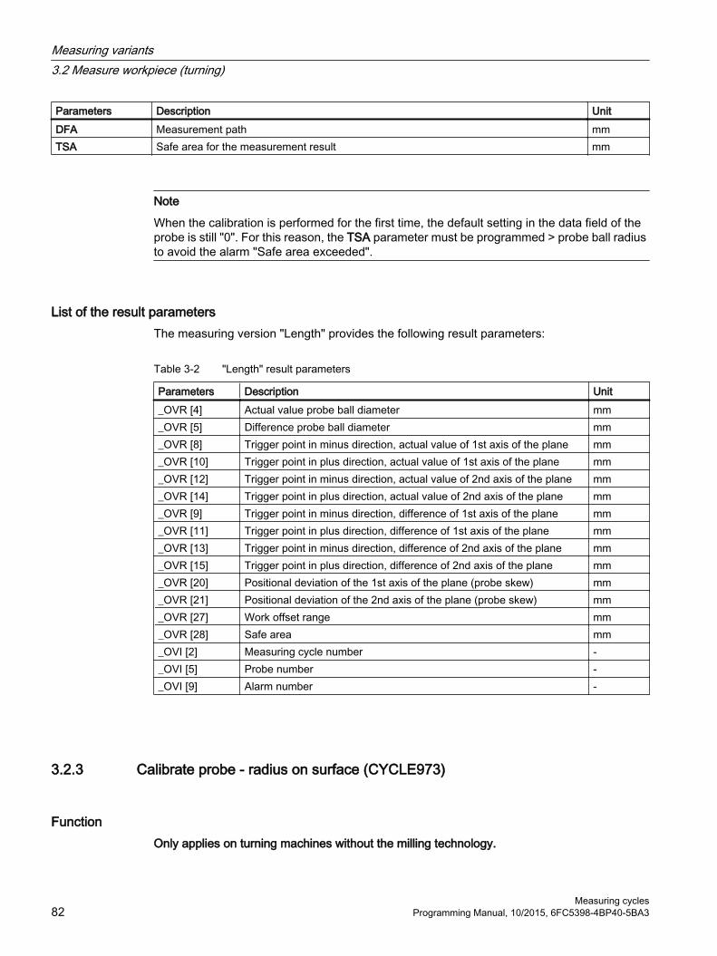
Parameters Description UnitDFA Measurement path mmTSA Safe area for the measurement result mm
Note
When the calibration is performed for the first time, the default setting in the data field of the probe is still "0". For this reason, the TSA parameter must be programmed > probe ball radius to avoid the alarm "Safe area exceeded".
List of the result parametersThe measuring version "Length" provides the following result parameters:
Table 3-2 "Length" result parameters
Parameters Description Unit_OVR [4] Actual value probe ball diameter mm_OVR [5] Difference probe ball diameter mm_OVR [8] Trigger point in minus direction, actual value of 1st axis of the plane mm_OVR [10] Trigger point in plus direction, actual value of 1st axis of the plane mm_OVR [12] Trigger point in minus direction, actual value of 2nd axis of the plane mm_OVR [14] Trigger point in plus direction, actual value of 2nd axis of the plane mm_OVR [9] Trigger point in minus direction, difference of 1st axis of the plane mm_OVR [11] Trigger point in plus direction, difference of 1st axis of the plane mm_OVR [13] Trigger point in minus direction, difference of 2nd axis of the plane mm_OVR [15] Trigger point in plus direction, difference of 2nd axis of the plane mm_OVR [20] Positional deviation of the 1st axis of the plane (probe skew) mm_OVR [21] Positional deviation of the 2nd axis of the plane (probe skew) mm_OVR [27] Work offset range mm_OVR [28] Safe area mm_OVI [2] Measuring cycle number -_OVI [5] Probe number -_OVI [9] Alarm number -
3.2.3 Calibrate probe - radius on surface (CYCLE973)
Function Only applies on turning machines without the milling technology.
Measuring variants3.2 Measure workpiece (turning)
Measuring cycles82 Programming Manual, 10/2015, 6FC5398-4BP40-5BA3

See "Measuring the workpiece on a machine with combined technologies (Page 229)".
With this measuring version, the radius of a workpiece probe with cutting edge positions SL=5 to 8 can be calibrated on a surface. The trigger points of the probe are determined.
The calibration surface is workpiece-related. It is only possible to calibrate in the selected axis and direction, which are perpendicular to this calibration surface.
Measuring principleThe determined switching position of the workpiece probe in the parameterized axis and direction, is calculated with the setpoint of the reference surface and from this the corresponding trigger point determined.
If no alarms occur, the trigger values are entered into the selected calibration data set of the workpiece probe.
The probe travels in the measuring direction to the reference surface (e.g. workpiece)
Image 3-2 Calibrate: radius at the surface (CYCLE973), example G18, SL=8
Requirements● The surface must be in parallel to an axis of the workpiece coordinate system (WCS).
● The calibration surface must have a low surface roughness.
● The workpiece probe is called as tool with tool offset.
● 580 must be declared as the probe type.
Starting position before the measurementThe probe must be positioned opposite to the calibration surface.
Measuring variants3.2 Measure workpiece (turning)
Measuring cyclesProgramming Manual, 10/2015, 6FC5398-4BP40-5BA3 83

Position after the end of the measuring cycleThe probe (ball radius) is the distance of the measurement path away from the calibration surface.
ProcedureThe part program or ShopTurn program to be processed has been created and you are in the editor.
1. Press the "Meas. workpiece" softkey.
2. Press the "Calibrate probe" softkey.
3. Press the "Radius on surface" softkey.The input window "Calibrate: Radius at surface" opens.
Parameters
G code program ShopTurn programParameter Description Unit Parameter Description Unit
Calibration data set (1 - 12) - T Name of the probe -F Calibration and measuring fee‐
drateDistance/min
D Cutting edge number (1 - 9) -
Calibration data set (1 - 12) - F Calibration and measuring fee‐
dratemm/min
β Tool alignment with swivel axis● (0 degrees)● (90 degrees)● Value entry
Degrees
X Start point X of the measure‐ment
mm
Y Start point Y of the measure‐ment
mm
Z Start point Z of the measure‐ment
mm
Parameters Description UnitMeasuring direction Measuring axis (for measuring plane G18)
● +/- Z● +/- X
-
Z0 / X0 Reference point Z/X (corresponding to the measuring direction) mmDFA Measurement path mmTSA Safe area for the measurement result mm
Measuring variants3.2 Measure workpiece (turning)
Measuring cycles84 Programming Manual, 10/2015, 6FC5398-4BP40-5BA3
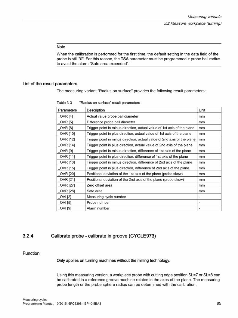
Note
When the calibration is performed for the first time, the default setting in the data field of the probe is still "0". For this reason, the TSA parameter must be programmed > probe ball radius to avoid the alarm "Safe area exceeded".
List of the result parametersThe measuring variant "Radius on surface" provides the following result parameters:
Table 3-3 "Radius on surface" result parameters
Parameters Description Unit_OVR [4] Actual value probe ball diameter mm_OVR [5] Difference probe ball diameter mm_OVR [8] Trigger point in minus direction, actual value of 1st axis of the plane mm_OVR [10] Trigger point in plus direction, actual value of 1st axis of the plane mm_OVR [12] Trigger point in minus direction, actual value of 2nd axis of the plane mm_OVR [14] Trigger point in plus direction, actual value of 2nd axis of the plane mm_OVR [9] Trigger point in minus direction, difference of 1st axis of the plane mm_OVR [11] Trigger point in plus direction, difference of 1st axis of the plane mm_OVR [13] Trigger point in minus direction, difference of 2nd axis of the plane mm_OVR [15] Trigger point in plus direction, difference of 2nd axis of the plane mm_OVR [20] Positional deviation of the 1st axis of the plane (probe skew) mm_OVR [21] Positional deviation of the 2nd axis of the plane (probe skew) mm_OVR [27] Zero offset area mm_OVR [28] Safe area mm_OVI [2] Measuring cycle number -_OVI [5] Probe number -_OVI [9] Alarm number -
3.2.4 Calibrate probe - calibrate in groove (CYCLE973)
Function Only applies on turning machines without the milling technology.
Using this measuring version, a workpiece probe with cutting edge position SL=7 or SL=8 can be calibrated in a reference groove machine-related in the axes of the plane. The measuring probe length or the probe sphere radius can be determined with the calibration.
Measuring variants3.2 Measure workpiece (turning)
Measuring cyclesProgramming Manual, 10/2015, 6FC5398-4BP40-5BA3 85

With the radius determination, a calibration is possible in one direction or in opposite directions of an axis. It is also possible to determine the positional deviation (skew) of the probe and the effective diameter of the probe sphere during calibration in opposite directions.
Measuring principleThe measured switching positions of the workpiece probe in the parameterized axis are taken into account together with the machine-related data of the selected calibration groove. From this data, the trigger points are calculated in the positive and negative directions as well as the position deviation in this axis and the effective probe sphere diameter. The trigger points always refer to the center of the probe sphere (TCP).
The probe moves in the selected measuring axis in both directions in the calibration groove.
Calibrate: Probe in groove (CYCLE973),example G18, SL=7
Calibrate: Probe in groove (CYCLE973),example G18, SL=8
Requirements● The workpiece probe must be called as tool with the associated tool offset.
● The machine-related geometrical dimensions of the selected calibration group must be saved before calibration in the corresponding general setting data.
Measuring variants3.2 Measure workpiece (turning)
Measuring cycles86 Programming Manual, 10/2015, 6FC5398-4BP40-5BA3

Geometry of the calibration groove, example G18, SL=7
Geometry of the calibration groove, example G18, SL=8
Table 3-4 General setting data for dimensions of the calibration groove
Calibration groove
General setting data Description
KN_0 SD 54621 $SNS_MEA_CAL_EDGE_PLUS_DIR_AX2
Calibration groove edge in the posi‐tive direction of the 2nd measuring axis.
KN_1 SD 54622 $SNS_MEA_CAL_EDGE_MI‐NUS_DIR_AX2
Calibration groove edge in the neg‐ative direction of the 2nd measuring axis.
KN_2 SD 54615 $SNS_MEA_CAL_EDGE_BASE_AX1
Calibration groove base of the 1st measuring axis
KN_3 SD 54617 $SNS_MEA_CAL_EDGE_PLUS_DIR_AX1
Calibration groove edge in the posi‐tive direction of the 1st measuring axis
KN_4 SD 54618 $SNS_MEA_CAL_EDGE_MI‐NUS_DIR_AX1
Calibration groove edge in the neg‐ative direction of the 1st measuring axis.
KN_5 SD 54620 $SNS_MEA_CAL_EDGE_UP‐PER_AX2
Upper calibration groove edge of the 2nd measuring axis
KN_6 SD 54619 $SNS_MEA_CAL_EDGE_BASE_AX2
Calibration groove base of the 2nd measuring axis
References: Commissioning Manual SINUMERIK Operate (IM9) / SINUMERIK 840D sl, Chapter "Measuring workpieces when turning".
Measuring variants3.2 Measure workpiece (turning)
Measuring cyclesProgramming Manual, 10/2015, 6FC5398-4BP40-5BA3 87

Starting position before the measurementThe starting position should be selected so that the selected workpiece probe can be positioned in the shortest possible distance, collision-free, with paraxial movements, in the reference groove corresponding to the active cutting edge position.
Position after the end of the measuring cycleWhen calibration with one calibration direction has been completed, the probe is positioned at the measurement distance (DFA) from the calibration surface. For calibration with two calibration directions, the probe is located at the start position after completion of the measuring operation.
ProcedureThe part program or ShopTurn program to be processed has been created and you are in the editor.
1. Press the "Meas. workpiece" softkey.
2. Press the "Calibrate probe" softkey.
3. Press the "Calibrate in groove" softkey.The input window "Calibrate: Probe in groove" opens.
Parameter
G code program ShopTurn programParameter Description Unit Parameter Description UnitPL Measuring plane (G17 - G19) - T Name of the probe -
Calibration data set (1 - 12) - D Cutting edge number (1 - 9) -F Calibration and measuring fee‐
drate Distance/min
Calibration data set (1 - 12) -
β Tool alignment with swivel axis● (0 degrees)● (90 degrees)● Input value
Degrees
F Calibration and measuring fee‐drate
mm/min
X Start position X of the measure‐ment
mm
Y Start position Y of the measure‐ment
mm
Z Start position Z of the measure‐ment
mm
Measuring variants3.2 Measure workpiece (turning)
Measuring cycles88 Programming Manual, 10/2015, 6FC5398-4BP40-5BA3

Parameter Description UnitCalibrate ● Length (calibrate probe length)
● Radius (calibrate probe radius)-
Calibration directions (only for "Radius" calibration)
● 1: Calibration in one direction● 2: Calibration in opposite directions
-
Measuring direction Measuring axis (corresponding to the measuring plane):● (+/-) Z● (+/-) X
-
Adapt tool length (only for "Length" calibration)
● No (adapt trigger point only)● Yes (adapt probe length and trigger point)
-
Calibration groove data set ● 1● 2● 3
-
DFA Measurement path mmTSA Safe area for the measurement result mm
Note
When the calibration is performed for the first time, the default setting in the data field of the probe is still "0". For this reason, the TSA parameter must be programmed > probe sphere radius to avoid the alarm "Safe area exceeded".
Measurement version, turning on a milling machine
ProcedureThe part program or ShopMill program to be processed has been created and you are in the editor.
1. Press the "Meas. workpiece" softkey.
2. Press the "Calibrate probe" softkey.
3. Press the "Calibrate in groove" softkey.The input window "Calibrate: Probe in groove" opens.
Parameter
ShopMill programParameter Description UnitT Name of the probe -D Cutting edge number (1 - 9) -
Calibration data set (1 - 12) -
Measuring variants3.2 Measure workpiece (turning)
Measuring cyclesProgramming Manual, 10/2015, 6FC5398-4BP40-5BA3 89

ShopMill programParameter Description Unitβ Tool alignment with swivel axis
● (0 degrees)● (90 degrees)● Input value
Degrees
F Calibration and measuring feedrate mm/minX Start position X of the measurement mmY Start position Y of the measurement mmZ Start position Z of the measurement mm
List of the result parametersThe measuring variant "Calibrate in groove" provides the following result parameters:
Table 3-5 "Calibrate in groove" result parameters
Parameters Description Unit_OVR [4] Actual value probe ball diameter mm_OVR [5] Difference probe ball diameter mm_OVR [8] Trigger point in minus direction, actual value of 1st axis of the plane mm_OVR [10] Trigger point in plus direction, actual value of 1st axis of the plane mm_OVR [12] Trigger point in minus direction, actual value of 2nd axis of the plane mm_OVR [14] Trigger point in plus direction, actual value of 2nd axis of the plane mm_OVR [9] Trigger point in minus direction, difference of 1st axis of the plane mm_OVR [11] Trigger point in plus direction, difference of 1st axis of the plane mm_OVR [13] Trigger point in minus direction, difference of 2nd axis of the plane mm_OVR [15] Trigger point in plus direction, difference of 2nd axis of the plane mm_OVR [20] Positional deviation of the 1st axis of the plane (probe skew) mm_OVR [21] Positional deviation of the 2nd axis of the plane (probe skew) mm_OVR [27] Work offset range mm_OVR [28] Safe area mm_OVI [2] Measuring cycle number -_OVI [5] Probe number -_OVI [9] Alarm number -
Measuring variants3.2 Measure workpiece (turning)
Measuring cycles90 Programming Manual, 10/2015, 6FC5398-4BP40-5BA3

3.2.5 Turning measurement - front edge (CYCLE974)
Function With this measuring variant, workpiece dimensions can be measured at edges in the direction of the infeed axis and offsets derived from these.
The measurement result and the measurement difference can be used for:
● Correction of a work offset
● Offset of a tool
● Measurement without offset
NoteExtended measurement
Information on measurement in conjunction with a third axis can be found in ChapterExtended measurement (Page 105).
Measuring principleThe measuring cycle determines the actual value of a measuring point at an edge of the turned part, relative to the workpiece zero.
The difference between the actual value (measured value) and a specified setpoint in the 1st axis of the plane is calculated (for G18: Z).
An extended tool offset in the summed and setup offsets is possible.
For the tool offset, generally empirical values can be included in the calculation.
Image 3-3 Measure: Front edge (CYCLE974)
Measuring variants3.2 Measure workpiece (turning)
Measuring cyclesProgramming Manual, 10/2015, 6FC5398-4BP40-5BA3 91

Requirements● The probe must be calibrated in the measuring direction and active as tool. The probe type
is 710 or 580.
● The cutting edge position can be 5 to 8 and must be suitable for the measurement task.
● If necessary, the workpiece must be positioned in the correct angular spindle position using spindle positioning (SPOS).
Starting position before the measurementThe probe must be positioned opposite to the surface/edge to be measured. Starting from this position, the measuring cycle always traverses the measuring axis in the direction of the setpoint.
Position after the end of the measuring cycleWhen the measuring process has been completed, the probe is positioned at the distance of the measurement path (DFA) from the measuring surface.
ProcedureThe part program or ShopTurn program to be processed has been created and you are in the editor.
1. Press the "Meas. workpiece" softkey.
2. Press the "Turning measurement" softkey.
3. Press the "Set front edge" softkey.The input window "Measure: Front edge" opens.
Parameter
G code program ShopTurn programParameter Description Unit Parameter Description Unit
Calibration data set (1 - 12) - T Name of the probe - D Cutting edge number (1 - 9) - Calibration data set (1 - 12) - β Tool alignment with swivel axis
● (0 degrees)● (90 degrees)● Input value
Degrees
Z Start position Z of the measurement mm X Start position X of the measurement mm Y Start position Y of the measurement mm
Measuring variants3.2 Measure workpiece (turning)
Measuring cycles92 Programming Manual, 10/2015, 6FC5398-4BP40-5BA3

Parameter Description UnitCorrection target ● Measuring only (no offset)
● Work offset (save measured values in an adjustable WO) 1)
● Tool offset (save measured value in the tool data)
-
TR Name of tool to be corrected -D Cutting edge number of tool to be corrected -Z0 Reference point Z mmDFA Measurement path mmTSA Safe area for the measurement result mmDimensional toler‐ance
Use dimensional tolerance (only for the "Tool offset" correction target)● Yes● No
-
TUL Workpiece upper tolerance limit (incremental to the setpoint, only for dimensional tolerance "Yes")
mm
TLL Workpiece upper tolerance limit (incremental to the setpoint, only for dimensional tolerance "Yes")
mm
1) Other parameters and correction targets can be set in the general SD 54760 $SNS_MEA_FUNCTION_MASK_PIECE .
Machine manufacturerPlease observe the machine manufacturer’s instructions.
Measurement version, turning on a milling machine
ProcedureThe part program or ShopMill program to be processed has been created and you are in the editor.
1. Press the "Meas. workpiece" softkey.
2. Press the "Turning measurement" softkey.
3. Press the "Set front edge" softkey.The input window "Measure: Front edge" opens.
Parameter
ShopMill programParameter Description UnitT Name of the probe -D Cutting edge number (1 - 9) -
Calibration data set (1 - 12) -
Measuring variants3.2 Measure workpiece (turning)
Measuring cyclesProgramming Manual, 10/2015, 6FC5398-4BP40-5BA3 93

ShopMill programParameter Description Unitβ Tool alignment with swivel axis
● (0 degrees)● (90 degrees)● Input value
Degrees
Z Start position Z of the measurement mmX Start position X of the measurement mmY Start position Y of the measurement mm
List of the result parametersThe measuring variant "Front edge" provides the following result parameters:
Table 3-6 "Front edge" result parameters
Parameters Description Unit_OVR [0] Setpoint value for measuring axis mm_OVR [1] Setpoint in 1st axis of the plane → only for S_MA=1 mm_OVR [2] Setpoint in 2nd axis of the plane → only for S_MA=2 mm_OVR [3] Setpoint in 3rd axis of the plane → only for S_MA=3 mm_OVR [4] Actual value for measuring axis mm_OVR [5] Actual value in 1st axis of the plane → only for S_MA=1 mm_OVR [6] Actual value in 2nd axis of the plane → only for S_MA=2 mm_OVR [7] Actual value in 3rd axis of the plane → only for S_MA=3 mm_OVR [16] Difference for measuring axis mm_OVR [17] Difference in 1st axis of the plane → only for S_MA=1 mm_OVR [18] Difference in 2nd axis of the plane → only for S_MA=2 mm_OVR [19] Difference in 3rd axis of the plane → only for S_MA=3 mm_OVI [0] D number or WO number -_OVI [2] Measuring cycle number -
For workpiece measurement with tool offset or correction in the work offset, additional parameters are displayed, seeAdditional result parameters (Page 321).
3.2.6 Turning measurement - inside diameter (CYCLE974, CYCLE994)
Function With this measuring method, the inside diameter of cylindrical workpieces can be measured. The diameter and radius programming are supported.
Measuring variants3.2 Measure workpiece (turning)
Measuring cycles94 Programming Manual, 10/2015, 6FC5398-4BP40-5BA3

The measurement result (measurement difference) can be used for:
● Correction in the work offset (only for 1-point measurements)
● Offset of a tool
● Measurement without offset
NoteExtended measurement
Information on measurement in conjunction with a third axis can be found in ChapterExtended measurement (Page 105).
Measuring principleThe measuring cycle determines the actual value of an inner diameter using a 1-point measurement or 2-point measurement symmetrically around the workpiece zero (center of rotation). The 2-point measurement is performed by reversing the spindle through 180 degrees of the workpiece or by making measurements above and below the center of rotation.
An extended tool offset in the summed and setup offsets is possible.
For the tool offset, generally empirical values can be included in the calculation.
Image 3-4 Measure: Inside diameter (CYCLE974)
Positioning "Travel below the center" (CYCLE994)For "Travel below the center", the inside diameter of the workpiece is measured using a 2-point measurement with the measuring cycle CYCLE994 . Two opposite measuring points symmetrical to the workpiece zero (center of rotation) are approached at a distance of the setpoint specified by the user.
A protection zone can be programmed, which should be taken into account when traversing. The user must take into account the ball radius of the probe when dimensioning the protection zone.
Measuring variants3.2 Measure workpiece (turning)
Measuring cyclesProgramming Manual, 10/2015, 6FC5398-4BP40-5BA3 95

Image 3-5 Positions of the probe when measuring the inner diameter using 2-point measurement (CYCLE994)
Measuring with reversal of the workpiece (CYCLE974)With this measuring method, the actual value of a workpiece with reference to the workpiece zero in the measuring axis is determined by acquiring two opposite points on the diameter.
The workpiece is positioned by the cycle before the first measurement at the angular position programmed in parameter α0. After the 1st measurement, the cycle also automatically generates the 180 degrees reversal before the second measurement. The mean value is calculated from both measured values.
A correction of the work offset (WO) is only possible when measuring without reversal (1-point measurement).
Requirements● The probe must be calibrated in the measuring direction.
● The probe of type 710 or 580 must be active.
● The cutting edge position can be 5 to 8 and must be suitable for the measurement task.
Starting position before the measurementThe probe should be positioned opposite the surface to be measured, above the turning center.
Position after the end of the measuring cycleThe probe is at a distance of the measuring path (DFA) from the measuring surface, above the turning center.
When "Travel under the center of rotation" is selected, after the end of the measuring cycle, the probe is at a distance of the measuring path (DFA) from the measuring surface, below the center of rotation.
Measuring variants3.2 Measure workpiece (turning)
Measuring cycles96 Programming Manual, 10/2015, 6FC5398-4BP40-5BA3

ProcedureThe part program or ShopTurn program to be processed has been created and you are in the editor.
1. Press the "Meas. workpiece" softkey.
2. Press the "Turning measurement" softkey.
3. Press the "Inside diameter" softkey.The input window "Measure: Inside diameter" opens.
Parameter
G code program ShopTurn programParameter Description Unit Parameter Description Unit
Calibration data set (1 - 12) - T Name of the probe - D Cutting edge number (1 - 9) - Calibration data set (1 - 12) - β Tool alignment with swivel axis
● (0 degrees)● (90 degrees)● Input value
Degrees
Z Start position Z of the measure‐ment
mm
X Start position X of the measure‐ment
mm
Parameter Description UnitCorrection target ● Measuring only (no offset)
● Work offset (save measured value in an adjustable WO) 1) 2)
● Tool offset (save measured value in the tool data)
-
TR Name of tool to be corrected -D Cutting edge number of tool to be corrected -∅ Inner diameter mmPositioning ● Measuring without reversal of the workpiece
● Measuring with reversal of the workpiece (180°) 3)
● Travel below center (measuring above and below the center of rotation)
-
α0 Starting angle for spindle reversal (only for positioning "with reversal") DegreesXR Retraction in X (diameter) mmZR (for G18) Retraction in Z mmDFA Measurement path mmTSA Safe area for the measurement result mm
Measuring variants3.2 Measure workpiece (turning)
Measuring cyclesProgramming Manual, 10/2015, 6FC5398-4BP40-5BA3 97

Parameter Description UnitDimensional toler‐ance
Use dimensional tolerance (only for the "Tool offset" correction target)● Yes● No
-
TUL Workpiece upper tolerance limit (incremental to the setpoint, only for dimensional tolerance "Yes")
mm
TLL Workpiece upper tolerance limit (incremental to the setpoint, only for dimensional tolerance "Yes")
mm
1) Only for positioning "without reversal"2) Other parameters and correction targets can be set in the general SD 54760 $SNS_MEA_FUNCTION_MASK_PIECE .3) The "Measurement with reversal of the workpiece" function is displayed if bit 0 is set in the general SD 54764
$SNS_MEA_FUNCTION_MASK_TURN.
Machine manufacturerPlease observe the machine manufacturer’s instructions.
Measurement version, turning on a milling machine
ProcedureThe part program or ShopMill program to be processed has been created and you are in the editor.
1. Press the "Meas. workpiece" softkey.
2. Press the "Turning measurement" softkey.
3. Press the "Set front edge" softkey.The input window "Measure: Front edge" opens.
Parameter
ShopMill programParameter Description UnitT Name of the probe -D Cutting edge number (1 - 9) -
Calibration data set (1 - 12) -β Tool alignment with swivel axis
● (0 degrees)● (90 degrees)● Input value
Degrees
Z Start position Z of the measurement mmX Start position X of the measurement mm
Measuring variants3.2 Measure workpiece (turning)
Measuring cycles98 Programming Manual, 10/2015, 6FC5398-4BP40-5BA3

List of the result parametersThe measuring variant "Inside diameter" provides the following result parameters:
Table 3-7 "Inside diameter" result parameters
Parameters Description Unit_OVR [0] Diameter setpoint (note measuring axis S_MA) mm_OVR [1] Diameter setpoint in 1st axis of the plane → only for S_MA=1 mm_OVR [2] Diameter setpoint in 2nd axis of the plane → only for S_MA=2 mm_OVR [3] Diameter setpoint in 3rd axis of the plane → only for S_MA=3 mm_OVR [4] Diameter actual value mm_OVR [5] Diameter actual value in 1st axis of the plane → only for S_MA=1 mm_OVR [6] Diameter actual value in 2nd axis of the plane → only for S_MA=2 mm_OVR [7] Diameter actual value in 3rd axis of the plane → only for S_MA=3 mm_OVR [16] Diameter difference mm_OVR [17] Diameter difference in 1st axis of the plane → only for S_MA=1 mm_OVR [18] Diameter difference in 2nd axis of the plane → only for S_MA=2 mm_OVR [19] Diameter difference in 3rd axis of the plane → only for S_MA=3 mm_OVI [0] D number -_OVI [2] Measuring cycle number -
For workpiece measurement with tool offset or correction in the work offset, additional parameters are displayed, seeAdditional result parameters (Page 321).
3.2.7 Turning measurement - outside diameter (CYCLE974, CYCLE994)
Function With this measuring method, the outer diameter of cylindrical workpieces can be measured. The diameter and radius programming are supported.
The measurement result (measurement difference) can be used for:
● Correction in the work offset (only for measuring without reversal, 1-point measurement)
● Offset of a tool
● Measurement without offset
NoteExtended measurement
Information on measurement in conjunction with a third axis can be found in ChapterExtended measurement (Page 105).
Measuring variants3.2 Measure workpiece (turning)
Measuring cyclesProgramming Manual, 10/2015, 6FC5398-4BP40-5BA3 99

Measuring principleThe measuring cycle determines the actual value of an outer diameter using a 1-point measurement or 2-point measurement symmetrically around the workpiece zero (center of rotation). The 2-point measurement is performed by reversing the spindle through 180 degrees of the workpiece or by making measurements above and below the center of rotation.
Measure: Outside diameter (CYCLE974) with/without reversal of the workpiece
Measure: Outside diameter (CYCLE994) above and below the turning center
Positioning "Travel below the center" (CYCLE994)For "Travel below the center", the outer diameter of the workpiece is measured using a 2-point measurement with the measuring cycle CYCLE994 . Two opposite measuring points symmetrical to the workpiece zero (center of rotation) are approached at a distance of the setpoint specified by the user. When traversing, a safety zone is taken into account. The user must take into account the ball radius of the probe when dimensioning the protection zone.
Measuring variants3.2 Measure workpiece (turning)
Measuring cycles100 Programming Manual, 10/2015, 6FC5398-4BP40-5BA3
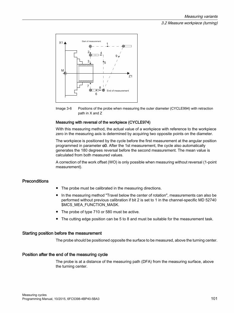
Image 3-6 Positions of the probe when measuring the outer diameter (CYCLE994) with retraction path in X and Z
Measuring with reversal of the workpiece (CYCLE974)With this measuring method, the actual value of a workpiece with reference to the workpiece zero in the measuring axis is determined by acquiring two opposite points on the diameter.
The workpiece is positioned by the cycle before the first measurement at the angular position programmed in parameter α0. After the 1st measurement, the cycle also automatically generates the 180 degrees reversal before the second measurement. The mean value is calculated from both measured values.
A correction of the work offset (WO) is only possible when measuring without reversal (1-point measurement).
Preconditions● The probe must be calibrated in the measuring directions.
● In the measuring method "Travel below the center of rotation", measurements can also be performed without previous calibration if bit 2 is set to 1 in the channel-specific MD 52740 $MCS_MEA_FUNCTION_MASK.
● The probe of type 710 or 580 must be active.
● The cutting edge position can be 5 to 8 and must be suitable for the measurement task.
Starting position before the measurementThe probe should be positioned opposite the surface to be measured, above the turning center.
Position after the end of the measuring cycleThe probe is at a distance of the measuring path (DFA) from the measuring surface, above the turning center.
Measuring variants3.2 Measure workpiece (turning)
Measuring cyclesProgramming Manual, 10/2015, 6FC5398-4BP40-5BA3 101

If "Travel under the center of rotation" was selected, after the end of the measuring cycle, the probe is at a distance of the measuring path (DFA) from the measuring surface, below the center of rotation.
ProcedureThe part program or ShopTurn program to be processed has been created and you are in the editor.
1. Press the "Meas. workpiece" softkey.
2. Press the "Turning measurement" softkey.
3. Press the "Outside diameter" softkey.The input window "Measure: Outer diameter" opens.
Parameter
G code program ShopTurn programParameter Description Unit Parameter Description Unit
Calibration data set (1 - 12) - T Name of the probe - D Cutting edge number (1 - 9) - Calibration data set (1 - 12) - β Tool alignment with swivel axis
● (0 degrees)● (90 degrees)● Input value
Degrees
Z Start position Z of the measurement mm X Start position X of the measurement mm
Parameter Description UnitCorrection target ● Measuring only (no offset)
● Work offset (save measured value in an adjustable WO) 1) 2)
● Tool offset (save measured value in the tool data)
-
TR Name of tool to be corrected -D Cutting edge number of tool to be corrected -∅ Outer diameter mmPositioning ● Measuring without reversal of the workpiece
● Measuring with reversal of the workpiece 3)
● Travel below center (measuring above and below the center of rotation)
-
α0 Starting angle for spindle reversal (only for positioning "Measuring with reversal") DegreesZR (for G18) Retraction in Z mmXR Retraction in X (in the diameter) mm
Measuring variants3.2 Measure workpiece (turning)
Measuring cycles102 Programming Manual, 10/2015, 6FC5398-4BP40-5BA3

Parameter Description UnitDFA Measurement path mmTSA Safe area for the measurement result mmDimensional toler‐ance
Use dimensional tolerance (only for the "Tool offset" correction target)● Yes● No
-
TUL Workpiece upper tolerance limit (incremental to the setpoint, only for dimensional tolerance "Yes")
mm
TLL Workpiece upper tolerance limit (incremental to the setpoint, only for dimensional tolerance "Yes")
mm
1) Only for positioning "Measuring without reversal"2) Other parameters and correction targets can be set in the general SD 54760 $SNS_MEA_FUNCTION_MASK_PIECE .3) The "Measurement with reversal of the workpiece" function is displayed if bit 0 is set in the general SD 54764
$SNS_MEA_FUNCTION_MASK_TURN .
Machine manufacturerPlease observe the machine manufacturer’s instructions.
Measurement version, turning on a milling machine
ProcedureThe part program or ShopMill program to be processed has been created and you are in the editor.
1. Press the "Meas. workpiece" softkey.
2. Press the "Turning measurement" softkey.
3. Press the "Outside diameter" softkey.The input window "Measure: Outer diameter" opens.
Parameter
ShopMill programParameter Description UnitT Name of the probe -D Cutting edge number (1 - 9) -
Calibration data set (1 - 12) -β Tool alignment with swivel axis
● (0 degrees)● (90 degrees)● Input value
Degrees
Z Start position Z of the measurement mmX Start position X of the measurement mm
Measuring variants3.2 Measure workpiece (turning)
Measuring cyclesProgramming Manual, 10/2015, 6FC5398-4BP40-5BA3 103

List of the result parametersThe measuring variant "Outside diameter" provides the following result parameters:
Table 3-8 "Outside diameter" result parameters
Parameters Description Unit_OVR [0] Diameter setpoint (note measuring axis S_MA) mm_OVR [1] Diameter setpoint in 1st axis of the plane → only for S_MA=1 mm_OVR [2] Diameter setpoint in 2nd axis of the plane → only for S_MA=2 mm_OVR [3] Diameter setpoint in 3rd axis of the plane → only for S_MA=3 mm_OVR [4] Diameter actual value mm_OVR [5] Diameter actual value in 1st axis of the plane → only for S_MA=1 mm_OVR [6] Diameter actual value in 2nd axis of the plane → only for S_MA=2 mm_OVR [7] Diameter actual value in 3rd axis of the plane → only for S_MA=3 mm_OVR [16] Diameter difference mm_OVR [17] Diameter difference in 1st axis of the plane → only for S_MA=1 mm_OVR [18] Diameter difference in 2nd axis of the plane → only for S_MA=2 mm_OVR [19] Diameter difference in 3rd axis of the plane → only for S_MA=3 mm_OVI [0] D number -_OVI [2] Measuring cycle number -
For workpiece measurement with tool offset or correction in the work offset, additional parameters are displayed, seeAdditional result parameters (Page 321).
Measuring variants3.2 Measure workpiece (turning)
Measuring cycles104 Programming Manual, 10/2015, 6FC5398-4BP40-5BA3

3.2.8 Extended measurement
Measuring in conjunction with a 3rd axis (Y) If a lathe has a 3rd axis, for technological reasons it can make sense to also use this as a measuring axis. In this case, pre-positioning and the measuring operation are realized in the 3rd axis (Y axis); however, the measuring result correction is entered in the tool and WO components of the 2nd geometry axis (X axis). The 3rd axis supports the radius and diameter programming according to the relationships of the 2nd geometry axis (X).
Note
The function of including the 3rd axis for lathes refers to the measuring cycles CYCLE974 and CYCLE994! This function must be enabled, see
References: Commissioning Manual SINUMERIK Operate (IM9) / SINUMERIK 840D sl, Chapter "Measuring workpieces when turning".
Extended bypass options for 2-point measurement (CYCLE994)If a lathe has a 3rd axis, then it can also be optionally used as a bypass axis.
The bypass strategies discussed in the following can be realized using the parameter assignment screen forms or the number of the measuring axis (Parameter S_MA).
Basis for the extended bypass strategy is that the 3rd axis has been enabled for measuring cycles.
S_MA, multi-digit = 102 S_MA, multi-digit = 1031. Axis of the plane is the bypass axis (Z)2nd axis of the plane, is the measuring axis (X)
1. Axis of the plane is the bypass axis (Z)3rd axis is the measuring axis (Y)
Probe with cutting edge position (SL)=7 Probe with SL=7
Measuring variants3.2 Measure workpiece (turning)
Measuring cyclesProgramming Manual, 10/2015, 6FC5398-4BP40-5BA3 105

S_MA, multi-digit = 302 S_MA, multi-digit = 2033. Axis is the bypass axis (Y)2nd axis of the plane, is the measuring axis (X)
2. Axis of the plane is the bypass axis (X)3rd axis is the measuring axis (Y)
Probe with SL=7 Probe with SL=7
Measuring variants3.2 Measure workpiece (turning)
Measuring cycles106 Programming Manual, 10/2015, 6FC5398-4BP40-5BA3

3.3 Measure workpiece (milling)
3.3.1 General information
Milling machinesThe measuring cycles below are intended for use on milling machines.
NoteSpindle
Spindle commands in the measuring cycles always refer to the active master spindle of the control.
When using the measuring cycles at machines with several spindles, then the spindle involved must be defined as master spindle before the cycle call.
Note
Precise measurement is only possible with a probe calibrated under the measurement conditions, i.e. working plane and measuring velocity are the same for both measurement and calibration.
If the probe is used in the spindle for a driven tool, the spindle orientation must also be considered. Deviations can cause measuring errors.
References: /PG/ Programming Manual SINUMERIK 840D sl / 828D Fundamentals
Plane definition, measuring systemThe measuring cycles under milling work with the active planes G17, G18 or G19.
The measuring system (basic system) of the machine and the workpiece can be different.
The G700 command should be used when measuring the workpiece in INCHES on a metric machine.
The G710 command should be used when measuring the workpiece in mm on an "INCH" machine.
Measuring variants3.3 Measure workpiece (milling)
Measuring cyclesProgramming Manual, 10/2015, 6FC5398-4BP40-5BA3 107

3.3.2 Calibrate probe - length (CYCLE976)
3.3.2.1 Function
Function Using this measuring method, the length of a workpiece probe can be calibrated in the tool axis on a known surface (reference area). This can be done, for example, on a workpiece.
Measuring principleThe probe travels in the measuring direction on the edge (e.g. workpiece)
Image 3-7 Calibrate: Length at edge (CYCLE976)
The length of the probe is determined corresponding to the setting in general MD 51740 $MNS_MEA_FUNCTION_MASK, bit 1. The setting determines whether the tool length refers to the probe sphere center or the probe sphere circumference.
In the "Tool length to sphere center" variant, a trigger value is entered in the calibration data according to the calibration direction.
References: Commissioning Manual SINUMERIK Operate (IM9) / SINUMERIK 840D sl, Chapter "Measuring cycles and measurement functions".
Measuring variants3.3 Measure workpiece (milling)
Measuring cycles108 Programming Manual, 10/2015, 6FC5398-4BP40-5BA3

Requirements● The probe must be active as tool.
● Probe type:
– 3D multi probe (type 710)
– Mono probe (type 712)
– L probe (type 713)
NoteL probe application (type 713)
Calibration in +Z (for towing measurement) is possible with the L probe.
The basic alignment of the L probe boom is toward +X (offset angle = 0). If the probe boom is to be aligned in a different direction in the measuring program, this can be performed through a rotation around the tool axis (e.g. ROT Z = 90).
● The probe length must be known in the program for collision-free positioning of the workpiece probe and entered in the tool offset memory.
● The sphere radius must be known exactly and entered in the tool data. For example, this can be implemented using a previous calibration in the ring or on the sphere (valid for type 710, 712).
● The calibration surface is perpendicular to the measuring axis or tool axis.
Starting position before the measurementThe probe must be positioned opposite to the calibration surface.
The distance between the probe and calibration surface should be approximately the same as the selected measurement path (DFA).
Position after the end of the measuring cycleAccording to the measuring direction (X, Y, Z), the distance between the probe in AUTOMATIC operation and the calibration surface is the same as the distance of the selected measurement path (DFA). In JOG operation, the start position is approached again.
Measuring variants3.3 Measure workpiece (milling)
Measuring cyclesProgramming Manual, 10/2015, 6FC5398-4BP40-5BA3 109

3.3.2.2 Calling the measuring version
ProcedureThe part program or ShopMill program to be processed has been created and you are in the editor.
1. Press the "Meas. workpiece" softkey.
2. Press the "Calibrate probe" softkey.
3. Press the "Length" softkey.The input window "Calibrate: Length at edge" opens.
3.3.2.3 Parameters
Parameters
G code program ShopMill programParameters Description Unit Parameters Description UnitPL Measuring plane (G17 - G19) - T Name of the probe -
Calibration data set (1 - 12) - D Cutting edge number (1 - 9) -F Calibration and measuring fee‐
drateDistance/min
Calibration data set (1 - 12) -
F Calibration and measuring fee‐drate
mm/min
X Start point X of the measurement mm Y Start point Y of the measurement mm Z Start point Z of the measurement mm
Parameters Description UnitAdapt tool length ● Yes (adapt probe length and trigger point)
● No (adapt trigger point only)-
Measuring direc‐tion
Measuring axis (+/-) Z (for measuring plane G17) -
Z0 Reference point Z (for measuring plane G17) mm DFA Measurement path mmTSA Safe area for the measurement result mm
Measuring variants3.3 Measure workpiece (milling)
Measuring cycles110 Programming Manual, 10/2015, 6FC5398-4BP40-5BA3

Note
When the calibration is performed for the first time, the default setting in the data field of the probe is still "0". For this reason, the TSA parameter must be programmed > probe ball radius to avoid the alarm "Safe area exceeded".
3.3.2.4 Result parameters
List of the result parametersThe measuring version "Length" provides the following result parameters:
Table 3-9 "Length" result parameters
Parameters Description Unit_OVR [4] Actual value probe ball diameter mm_OVR [5] Difference probe ball diameter mm_OVR [16] Trigger point in minus direction, actual value of 3rd axis of the plane mm_OVR [17] Trigger point in minus direction, difference of 3rd axis of the plane mm_OVR [18] Trigger point in plus direction, actual value of 3rd axis of the plane mm_OVR [19] Trigger point in plus direction, difference of 3rd axis of the plane mm_OVR [22] Probe length of the workpiece probe mm_OVR [27] Work offset range mm_OVR [28] Safe area mm_OVI [2] Measuring cycle number -_OVI [5] Probe number -_OVI [9] Alarm number -
3.3.3 Calibrate probe - radius in ring (CYCLE976)
Function Using this measurement version, the following data can be calibrated:
● Inclined position of the workpiece probe
● Trigger values
● Radius of the probe in a calibration ring (in axes of the plane)
The probe calibration in the ring can be on the basis of an unknown or known center point in the ring. With known center point, this corresponds to the starting position.
Measuring variants3.3 Measure workpiece (milling)
Measuring cyclesProgramming Manual, 10/2015, 6FC5398-4BP40-5BA3 111

Calibration is also possible taking into account a starting angle when using the "Start at ring center" calibration method. Any obstacles in the measuring path or at the measuring point can be avoided when using a starting angle.
Measuring principleCalibration always starts in the positive direction of the 1st axis of the actual machining plane. Eight calibration positions are to be acquired, divided into two passes. Depending on the probe type, the passes are made with a uniform spindle position or a reversal of 180 degrees.
During the calibration process, the center point of the calibration ring (corresponding to the calibration method) and its distance to the starting position are determined.
The calibration data / trigger values are significantly influenced in the result by the following variables:
● Physical probe ball radius
● Design of the probe
● Measuring velocity
● Calibration ring with corresponding accuracy
● Correct mounting of the calibrating ring
Image 3-8 Calibrate: Radius in ring (CYCLE976)
PreconditionsThe following requirements must be fulfilled for calibration in the ring:
● The probe must be active as tool.
● Probe type:
– 3D multi probe (type 710)
– Mono probe (type 712)
– Star-type probe (type 714)
Measuring variants3.3 Measure workpiece (milling)
Measuring cycles112 Programming Manual, 10/2015, 6FC5398-4BP40-5BA3

● Note: The arms of a star-type probe (type 714) must be positioned at 90 degree angle to each other.
● The exact diameter of the calibration ring is known.
Starting position before the measurementIf the measuring cycle is not started at the center of the ring, the workpiece probe sphere center must be positioned close to the center of the ring as well as to a calibration height within the calibration ring.
When starting the measuring cycle at the center of the ring, the workpiece probe sphere center must be positioned precisely at the ring center point as well as at a calibration height within the calibration ring.
Position after the end of the measuring cycleWhen calibration is complete, the probe center is at calibration height in the center of the ring.
Note
For extremely high demands placed on the measuring accuracy, it makes sense to accept the distance between the center point and starting position in the work offset and to perform an additional calibration using this optimization.
ProcedureThe part program or ShopMill program to be processed has been created and you are in the editor.
1. Press the "Meas. workpiece" softkey.
2. Press the "Calibrate probe" softkey.
3. Press the "Radius in ring" softkey.The input window "Calibrate: Radius in ring" opens.
Measuring variants3.3 Measure workpiece (milling)
Measuring cyclesProgramming Manual, 10/2015, 6FC5398-4BP40-5BA3 113

Parameter
G code program ShopMill programParameter Description Unit Parameter Description UnitPL Measuring plane (G17 - G19) - T Name of the probe -
Calibration data set (1 - 12) - D Cutting edge number (1 - 9) -F Calibration and measuring fee‐
drateDistance/min
Calibration data set (1 - 12) -
F Calibration and measuring fee‐drate
mm/min
X Start position X of the meas‐urement
mm
Y Start position Y of the meas‐urement
mm
Z Start position Z of the measure‐ment
mm
Parameter Description Unit∅ Ring diameter mmDFA Measurement path mmTSA Safe area for the measurement result mm
Note
When the calibration is performed for the first time, the default setting in the data field of the probe is still "0". For this reason, the TSA parameter must be programmed > probe ball radius to avoid the alarm "Safe area exceeded".
Measuring version, milling on a lathe
ProcedureThe part program or ShopTurn program to be processed has been created and you are in the editor.
1. Press the "Meas. workpiece" softkey.
2. Press the "Calibrate probe" softkey.
3. Press the "Radius in ring" softkey.The input window "Calibrate: Radius in ring" opens.
Measuring variants3.3 Measure workpiece (milling)
Measuring cycles114 Programming Manual, 10/2015, 6FC5398-4BP40-5BA3

Parameter
ShopTurn programParameter Description UnitT Name of the probe -D Cutting edge number (1 - 9) -
Calibration data set (1 - 12) -F Calibration and measuring
feedratemm/min
X Start position X of the measurement
mm
Y Start position Y of the measurement
mm
Z Start position Z of the meas‐urement
mm
List of the result parametersThe measuring variant "Radius in Ring" provides the following result parameters:
Table 3-10 "Radius in ring" result parameters
Parameters Description Unit_OVR [4] Actual value probe ball diameter mm_OVR [5] Difference probe ball diameter mm_OVR [6] Center point of calibration ring in 1st axis of the plane mm_OVR [7] Center point of calibration ring in 2nd axis of the plane mm_OVR [8] Trigger point in minus direction, actual value of 1st axis of the plane mm_OVR [9] Trigger point in minus direction, difference of 1st axis of the plane mm_OVR [10] Trigger point in plus direction, actual value of 1st axis of the plane mm_OVR [11] Trigger point in plus direction, difference of 1st axis of the plane mm_OVR [12] Trigger point in minus direction, actual value of 2nd axis of the plane mm_OVR [13] Trigger point in minus direction, difference of 2nd axis of the plane mm_OVR [14] Trigger point in plus direction, actual value of 2nd axis of the plane mm_OVR [15] Trigger point in plus direction, difference of 2nd axis of the plane mm_OVR [20] Positional deviation of the 1st axis of the plane (probe skew) mm_OVR [21] Positional deviation of the 2nd axis of the plane (probe skew) mm_OVR [24] Angle at which the trigger points were determined Degrees_OVR [27] Zero offset area mm_OVR [28] Safe area mm_OVI [2] Measuring cycle number -_OVI [5] Probe number -_OVI [9] Alarm number -
Measuring variants3.3 Measure workpiece (milling)
Measuring cyclesProgramming Manual, 10/2015, 6FC5398-4BP40-5BA3 115

3.3.4 Calibrate probe - radius on edge (CYCLE976)
Function With this measuring method, a workpiece probe can be calibrated in an axis and the direction selected by the user at a reference surface perpendicular to this. This can be done, for example, on a workpiece.
The determined trigger point is taken into the addressed calibration data field.
Measuring principleThe probe approaches the reference surface in the selected axis and direction.
The determined calibration value (trigger point + position deviation) and probe ball radius are transferred into the addressed calibration data fields.
Calibrate: Radius at edge (CYCLE976), cali‐bration direction
Preconditions● The probe must be active as tool.
● Tool type of the probe:
– 3D multi probe (type 710)
– Mono probe (type 712)
– Star-type probe (type 714)
– L probe (type 713)
Starting position before the measurementThe probe is positioned in the measuring height, approximately at the distance of the measurement path (DFA) opposite to the edge.
Measuring variants3.3 Measure workpiece (milling)
Measuring cycles116 Programming Manual, 10/2015, 6FC5398-4BP40-5BA3

Position after the end of the measuring cycleThe probe ball center is located in front of the reference edge by the distance of the measuring path.
ProcedureThe part program or ShopMill program to be processed has been created and you are in the editor.
1. Press the "Meas. workpiece" softkey.
2. Press the "Calibrate probe" softkey.
3. Press the "Radius at edge" softkey.The input window "Calibrate: Radius at edge" opens.
Parameter
G code program ShopMill programParameter Description Unit Parameter Description UnitPL Measuring plane (G17 - G19) - T Name of the probe -
Calibration data set (1 - 12) - D Cutting edge number (1 - 9) -F Calibration and measuring fee‐
drateDistance/min
Calibration data set (1 - 12) -
F Calibration and measuring fee‐drate
mm/min
X Start position X of the meas‐urement
mm
Y Start position Y of the meas‐urement
mm
Z Start position Z of the measure‐ment
mm
Parameter Description UnitCalibration directions ● 1: Calibration in one direction
● 2: Calibrations in opposite directions-
Measuring direction Measuring axis (for G17):● (+/-) X● (+/-) Y
-
DX /DY Distance between the edges (only for calibration directions "2") mmX0 / Y0 Reference point mmDFA Measurement path mmTSA Safe area for the measurement result mm
Measuring variants3.3 Measure workpiece (milling)
Measuring cyclesProgramming Manual, 10/2015, 6FC5398-4BP40-5BA3 117

Note
When the calibration is performed for the first time, the default setting in the data field of the probe is still "0". For this reason, the TSA parameter must be programmed > probe ball radius to avoid the alarm "Safe area exceeded".
List of the result parametersThe measuring variant "Radius on edge" provides the following result parameters:
Table 3-11 "Radius on edge" result parameters
Parameters Description Unit_OVR [4] Actual value probe ball diameter mm_OVR [5] Difference probe ball diameter mm_OVR [8] Trigger point in minus direction, actual value of 1st axis of the plane mm_OVR [10] Trigger point in plus direction, actual value of 1st axis of the plane mm_OVR [12] Trigger point in minus direction, actual value of 2nd axis of the plane mm_OVR [14] Trigger point in plus direction, actual value of 2nd axis of the plane mm_OVR [9] Trigger point in minus direction, difference of 1st axis of the plane mm_OVR [11] Trigger point in plus direction, difference of 1st axis of the plane mm_OVR [13] Trigger point in minus direction, difference of 2nd axis of the plane mm_OVR [15] Trigger point in plus direction, difference of 2nd axis of the plane mm_OVR [20] Positional deviation of the 1st axis of the plane (probe skew) mm_OVR [21] Positional deviation of the 2nd axis of the plane (probe skew) mm_OVR [24] Angle at which the trigger points were determined Degrees_OVR [27] Zero offset area mm_OVR [28] Safe area mm_OVI [2] Measuring cycle number -_OVI [5] Probe number -_OVI [9] Alarm number -
3.3.5 Calibrate probe - radius between 2 edges (Cycle976)
3.3.5.1 Function
FunctionWith this measuring version, a workpiece probe can be calibrated in an axis of the machining plane selected by the user, between two reference surfaces parallel to one another.
Measuring variants3.3 Measure workpiece (milling)
Measuring cycles118 Programming Manual, 10/2015, 6FC5398-4BP40-5BA3

Measuring principle The probe traverses with constant spindle alignment in the selected axis, between the reference surfaces. The traversing path must be at right angles to the reference surfaces.
The determined calibration value (trigger point + position deviation) and probe ball radius are transferred into the addressed calibration data fields.
Image 3-9 Calibrate: Radius between 2 edges (CYCLE976)
Preconditions● The probe must be active as tool.
● Tool type of the probe:
– 3D multi probe (type 710)
Starting position before the measurementThe probe must be positioned at the calibration height, approximately in the middle between the two edges.
Position after the end of the measuring cycleThe center of the probe is located in the middle between the two reference surfaces.
Measuring variants3.3 Measure workpiece (milling)
Measuring cyclesProgramming Manual, 10/2015, 6FC5398-4BP40-5BA3 119

3.3.5.2 Calling the measuring version
ProcedureThe part program or ShopMill program to be processed has been created and you are in the editor.
1. Press the "Meas. workpiece" softkey.
2. Press the "Calibrate probe" softkey.
3. Press the "Radius at edge" softkey.The input window "Calibrate: Radius at edge" opens.
4. In the selection field, Calibrate directions, select, "2".
Parameter
G code program ShopMill programParameter Description Unit Parameter Description UnitPL Measuring plane (G17 - G19) - T Name of the probe -
Calibration data set (1 - 12) - D Cutting edge number (1 - 9) -F Calibration and measuring fee‐
drateDistance/min
Calibration data set (1 - 12) -
F Calibration and measuring fee‐drate
mm/min
X Start position X of the meas‐urement
mm
Y Start position Y of the meas‐urement
mm
Z Start position Z of the measure‐ment
mm
Parameter Description UnitCalibration directions ● 1: Calibration in one direction
● 2: Calibrations in opposite directions-
Measuring direction Measuring axis (for G17):● (+/-) X● (+/-) Y
-
DX /DY Distance between the edges (only for calibration directions "2") mmX0 / Y0 Reference point mmDFA Measurement path mmTSA Safe area for the measurement result mm
Measuring variants3.3 Measure workpiece (milling)
Measuring cycles120 Programming Manual, 10/2015, 6FC5398-4BP40-5BA3

Note
When the calibration is performed for the first time, the default setting in the data field of the probe is still "0". For this reason, the TSA parameter must be programmed > probe ball radius to avoid the alarm "Safe area exceeded".
3.3.5.3 Result parameters
List of the result parametersThe measuring version "Radius between two edges" provides the following result parameters:
Table 3-12 "Radius between two edges" result parameters
Parameter Description Unit_OVR [4] Actual value probe ball diameter mm_OVR [5] Difference probe ball diameter mm_OVR [8] Trigger point in minus direction, actual value of 1st axis of
the planemm
_OVR [10] Trigger point in plus direction, actual value of 1st axis of the plane
mm
_OVR [12] Trigger point in minus direction, actual value of 2nd axis of the plane
mm
_OVR [14] Trigger point in plus direction, actual value of 2nd axis of the plane
mm
_OVR [9] Trigger point in minus direction, difference of 1st axis of the plane
mm
_OVR[11] Trigger point in plus direction, difference of 1st axis of the plane
mm
_OVR[13] Trigger point in minus direction, difference of 2nd axis of the plane
mm
_OVR[15] Trigger point in plus direction, difference of 2nd axis of the plane
mm
_OVR[20] Positional deviation of the 1st axis of the plane (probe skew) mm_OVR[21] Positional deviation of the 2nd axis of the plane (probe skew) mm_OVR[27] Work offset range mm_OVR[28] Safe area mm_OVI[2] Measuring cycle number -OVI[5] Probe number -OVI[9] Alarm number -
The result parameters are written to, which correspond to the selected axis.
Measuring variants3.3 Measure workpiece (milling)
Measuring cyclesProgramming Manual, 10/2015, 6FC5398-4BP40-5BA3 121

3.3.6 Calibrate probe - calibrate on ball (CYCLE976)
Function Using this measuring method, a workpiece probe can be calibrated at any position in space. This has a special meaning in conjunction with swivel functions and transformations.
The same calibration data is generated as for calibration in the ring:
● Inclined position of the workpiece probe
● Trigger values
● Radius of the probe ball
In addition, the probe length in the tool axis can be determined based on the machine data.
MD51740 $MNS_MEA_FUNCTION_MASK, Bit 1 (probe ball sensor or ball circumference)
The calibration sphere center is determined as supplementary result.
Measuring principleThe measurement sequence is divided into the following steps:
1. Determining the center point coordinates of the reference sphere
2. Determining the calibration data
This procedure can be made parallel to the axis by passing or moving around the reference sphere.
Image 3-10 Calibration at the sphere (CYCLE976), example of overtravel (intermediate positioning parallel to the axis)
Preconditions● The diameter of the reference sphere must be known.
● Tool type of the probe:
– 3D multi probe (type 710)
– Mono probe (type 712)
Measuring variants3.3 Measure workpiece (milling)
Measuring cycles122 Programming Manual, 10/2015, 6FC5398-4BP40-5BA3
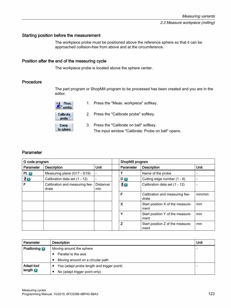
Starting position before the measurementThe workpiece probe must be positioned above the reference sphere so that it can be approached collision-free from above and at the circumference.
Position after the end of the measuring cycleThe workpiece probe is located above the sphere center.
ProcedureThe part program or ShopMill program to be processed has been created and you are in the editor.
1. Press the "Meas. workpiece" softkey.
2. Press the "Calibrate probe" softkey.
3. Press the "Calibrate on ball" softkey.The input window "Calibrate: Probe on ball" opens.
Parameter
G code program ShopMill programParameter Description Unit Parameter Description UnitPL Measuring plane (G17 - G19) - T Name of the probe -
Calibration data set (1 - 12) - D Cutting edge number (1 - 9) -F Calibration and measuring fee‐
drate Distance/min
Calibration data set (1 - 12) -
F Calibration and measuring fee‐drate
mm/min
X Start position X of the measure‐ment
mm
Y Start position Y of the measure‐ment
mm
Z Start position Z of the measure‐ment
mm
Parameter Description UnitPositioning Moving around the sphere
● Parallel to the axis● Moving around on a circular path
-
Adapt tool length
● Yes (adapt probe length and trigger point)● No (adapt trigger point only)
-
Measuring variants3.3 Measure workpiece (milling)
Measuring cyclesProgramming Manual, 10/2015, 6FC5398-4BP40-5BA3 123

Parameter Description UnitZS (for G17) Upper edge of the calibration sphere (only for adapt tool length "Yes") mm∅ Sphere diameter mmα0 Contact angle DegreesDFA Measurement path mmTSA Safe area for the measurement result mm
Measuring version, milling on a lathe
ProcedureThe part program or ShopTurn program to be processed has been created and you are in the editor.
1. Press the "Meas. workpiece" softkey.
2. Press the "Calibrate probe" softkey.
3. Press the "Calibrate on sphere" softkey.The input window "Calibration: Probe on sphere" opens.
ShopTurn programParameter Description UnitT Name of the probe -D Cutting edge number (1 - 9) -
Calibration data set (1 - 12) -F Calibration and measuring feedrate mm/minX Start position X of the measurement mmY Start position Y of the measurement mmZ Start position Z of the measurement mm
List of the result parametersThe measuring variant "Radius on sphere" provides the following result parameters:
Table 3-13 "Radius on sphere" result parameters
Parameters Description Unit_OVR [4] Actual value probe ball diameter mm_OVR [5] Difference probe ball diameter mm_OVR [8] Trigger point in minus direction, actual value of 1st axis of the plane mm_OVR [10] Trigger point in plus direction, actual value of 1st axis of the plane mm_OVR [12] Trigger point in minus direction, actual value of 2nd axis of the plane mm
Measuring variants3.3 Measure workpiece (milling)
Measuring cycles124 Programming Manual, 10/2015, 6FC5398-4BP40-5BA3

Parameters Description Unit_OVR [14] Trigger point in plus direction, actual value of 2nd axis of the plane mm_OVR [16] Trigger point in minus direction, actual value of 3rd axis of the plane mm_OVR [18] Trigger point in plus direction, actual value of 3rd axis of the plane mm_OVR [9] Trigger point in minus direction, difference of 1st axis of the plane mm_OVR [11] Trigger point in plus direction, difference of 1st axis of the plane mm_OVR [13] Trigger point in minus direction, difference of 2nd axis of the plane mm_OVR [15] Trigger point in plus direction, difference of 2nd axis of the plane mm_OVR [17] Trigger point in minus direction, difference of 3rd axis of the plane mm_OVR [19] Trigger point in plus direction, difference of 3rd axis of the plane mm_OVR [20] Positional deviation of the 1st axis of the plane (probe skew) mm_OVR [21] Positional deviation of the 2nd axis of the plane (probe skew) mm_OVR [22] Probe length of the workpiece probe mm_OVR [24] Angle at which the trigger points were determined Degrees_OVR [27] Work offset range mm_OVR [28] Safe area mm_OVI [2] Measuring cycle number -_OVI [5] Probe number -_OVI [9] Alarm number -
3.3.7 Edge distance - set edge (CYCLE978)
Function This measuring method determines the position of a paraxial edge in the workpiece coordinate system through 1-point measurement.
When using probes with side boom (L probe, type 713), towing measurement is possible in the positive direction of the tool axis.
With the "3D probe with spindle reversal" measuring method, measurement is performed in the axes of the plane as differential measurement. Two measurements are automatically carried out one after the other, one with a spindle position of 180 degrees, and one with 0 degrees. The special procedure for this measurement permits the use of an uncalibrated multi-directional probe. However, the correct tool radius of the probe must be determined once by calibrating the probe. Probe types 712, 713 and 714 are not suitable for this purpose. A positionable spindle is mandatory.
With the "Align 3D probe" measuring method, the switching direction of the probe is always aligned to the current measuring direction. This function is recommended when high demands are placed on the measuring accuracy. Probe types 712, 713 and 714 are not suitable for this purpose. A positionable spindle is mandatory.
Measuring variants3.3 Measure workpiece (milling)
Measuring cyclesProgramming Manual, 10/2015, 6FC5398-4BP40-5BA3 125

The measurement result (measurement difference) can be used as follows:
● Correction of a work offset
● Offset of a tool
● Measurement without offset
Measuring principleThe measuring cycle determines the actual value of a measuring point, taking into account the calibration values at one edge of the workpiece referred to its zero point.
The difference between the actual value (measured value) and a specified setpoint in the parameterized measuring axis is calculated.
Measure: Edge (CYCLE978) measuring direction: -X
Measure: Edge (CYCLE978) measuring direction: +Z (towing measurement)
Measuring variants3.3 Measure workpiece (milling)
Measuring cycles126 Programming Manual, 10/2015, 6FC5398-4BP40-5BA3

Preconditions● The probe must be active as tool.
● Tool type of the probe:
– 3D multi probe (type 710)
– Mono probe (type 712)
– L probe (type 713)
NoteL probe application (type 713)
Measurement in +Z (for towing measurement) is possible with the L probe.
The basic alignment of the L probe boom is toward +X (offset angle = 0). If the probe boom is to be aligned in a different direction in the measuring program, this can performed through a rotation around the tool axis (e.g. ROT Z = 90).
– Star-type probe (type 714)
When using the measuring version on lathes:
● Use probe type 710 or 580
● Set the length reference of the workpiece probe to the center of the probe ball:MD51740 $MNS_MEA_FUNCTION_MASK, bit 1 = 0
Note
The following measuring methods are only possible in the axes of the plane:● 3D probe with spindle reversal (differential measurement)● Align 3D probe
The probe types 712, 713 and 714 generally cannot be used for these measuring methods.
Starting position before the measurementThe probe should be positioned at a distance that is somewhat greater than the measurement path (DFA) with respect to the surface to be measured.
Position after the end of the measuring cycleAfter the measurement has been completed, the probe ball with its circumference is at a distance of the measuring path DFA with respect to the measuring surface.
Measuring variants3.3 Measure workpiece (milling)
Measuring cyclesProgramming Manual, 10/2015, 6FC5398-4BP40-5BA3 127

ProcedureThe part program or ShopMill program to be processed has been created and you are in the editor.
1. Press the "Meas. workpiece" softkey.
2. Press the "Edge distance" softkey.
3. Press the "Set edge" softkey.The input window "Measure: Edge" opens.
Parameter
G code program ShopMill programParameter Description Unit Parameter Description UnitMeasuring method
● Standard measuring method
● 3D probe with spindle reversal 1)
● Align 3D probe2)
- T Name of the probe -D Cutting edge number (1 - 9) -
PL Measuring plane (G17 - G19) - Measuring method
● Standard measuring method
● 3D probe with spindle reversal 1)
● Align 3D probe2)
-
Calibration data set (1 - 12)(only for measuring without spindle reversal)
- Calibration data set (1 - 12)(only for measuring without spindle reversal)
-
X Start position X of the meas‐urement
mm
Y Start position Y of the meas‐urement
mm
Z Start position Z of the measure‐ment
mm
Parameter Description UnitCorrection tar‐get
● Measuring only (no offset)● Work offset (save measured value in a settable WO) 3)
● Tool offset (save measured value in the tool data)
-
TR Name of tool to be corrected -D Cutting edge number of tool to be corrected -
Measuring variants3.3 Measure workpiece (milling)
Measuring cycles128 Programming Manual, 10/2015, 6FC5398-4BP40-5BA3

Parameter Description UnitMeasuring direc‐tion
Measuring axis● +/- X● +/- Y● +/- Z
-
X0 / Y0 / Z0 Setpoint (corresponding to the measuring direction) mmDFA Measurement path mmTSA Safe area for the measurement result mmDimensional tol‐erance
Use dimensional tolerance for tool offset (only for the "Tool offset" correction target)● Yes● No
-
TUL Workpiece upper tolerance limit (incremental to the setpoint, only for dimensional tolerance "Yes")
mm
TLL Workpiece upper tolerance limit (incremental to the setpoint, only for dimensional tolerance "Yes")
mm
1) The "3D probe with spindle reversal" function is shown if bit 16 is set in the general SD 54760 $SNS_MEA_FUNCTION_MASK_PIECE .
2) The "Align 3D probe" function is shown if bit 17 is set in the general SD 54760 $SNS_MEA_FUNCTION_MASK_PIECE .3) Other parameters and correction targets can be set in the general SD 54760 $SNS_MEA_FUNCTION_MASK_PIECE .
Machine manufacturerPlease observe the machine manufacturer’s instructions.
Measuring version, milling on a lathe
ProcedureThe part program or ShopTurn program to be processed has been created and you are in the editor.
1. Press the "Meas. workpiece" softkey.
2. Press the "Edge distance" softkey.
3. Press the "Set edge" softkey.The input window "Measure: Edge" opens.
Parameter
ShopTurn programParameter Description UnitT Name of the probe -D Cutting edge number (1 - 9) -
Measuring variants3.3 Measure workpiece (milling)
Measuring cyclesProgramming Manual, 10/2015, 6FC5398-4BP40-5BA3 129

ShopTurn programParameter Description UnitMeasuring method ● Standard measuring method
● 3D probe with spindle reversal 1)
● Align 3D probe2)
-
Calibration data set (1 - 12)(only for measuring without spindle reversal)
-
X Start position X of the measurement mmY Start position Y of the measurement mmZ Start position Z of the measurement mm
List of the result parametersThe measuring variant "Set edge" provides the following result parameters:
Table 3-14 "Set edge" result parameters
Parameters Description Unit_OVR [0] Setpoint value for measuring axis mm_OVR [1] Setpoint in 1st axis of the plane → only for S_MA=1 mm_OVR [2] Setpoint in 2nd axis of the plane → only for S_MA=2 mm_OVR [3] Setpoint in 3rd axis of the plane → only for S_MA=3 mm_OVR [4] Actual value for measuring axis mm_OVR [5] Actual value in 1st axis of the plane → only for S_MA=1 mm_OVR [6] Actual value in 2nd axis of the plane → only for S_MA=2 mm_OVR [7] Actual value in 3rd axis of the plane → only for S_MA=3 mm_OVR [16] Difference for measuring axis mm_OVR [17] Difference in 1st axis of the plane → only for S_MA=1 mm_OVR [18] Difference in 2nd axis of the plane → only for S_MA=2 mm_OVR [19] Difference in 3rd axis of the plane → only for S_MA=3 mm_OVR [21] Mean value mm_OVI [0] D number or WO number -_OVI [2] Measuring cycle number -_OVI [3] Measuring version -_OVS_TNAME Tool name -
For workpiece measurement with tool offset or correction in the work offset, additional parameters are displayed, seeAdditional result parameters (Page 321).
Measuring variants3.3 Measure workpiece (milling)
Measuring cycles130 Programming Manual, 10/2015, 6FC5398-4BP40-5BA3

3.3.8 Edge distance - align edge (CYCLE998)
Function The workpiece lies in any direction, i.e. not parallel to the workpiece coordinate system (WCS) on the work table. By measuring two points on the workpiece reference edge that you have selected, you determine the angle to the active coordinate system. You can correct this angle as a rotation either in a geometry axis or as translational offset in a rotary axis (rotary table) in any WO or in the active WO.
NoteMaximum measured angle
Using the "Align edge" measuring version, a maximum angle of +/- 45 degrees can be measured.
Measuring principleThe Align edge measuring variant is performed according to the 1-angle measurement principle:
● For a clamped workpiece that is rotated in the plane, the angular offset is in the rotary part of the geometry axis that is located perpendicular to the measuring plane.Example of G17 plane: Measuring axis X, offset axis Y
– Angular offset is realized in the Z rotation
– The rotation offset in the WO is performed so that the actual position of the edge (actual value) and the desired setpoint angle (α) in the workpiece coordinate system must be taken into account.
● For a workpiece on a rotary table, the angular offset is added to the translatory offset of the rotary axis (table axis). The correction only makes sense if the rotary axis rotates around the geometry axis that is located perpendicular to the measuring plane.Example of G17 plane: Measuring axis X, offset axis Y
– Angular offset is realized in the C axis. Rotary axis C rotates a rotary table around the Z axis.
– After the measurement, the rotary axis should be repositioned to align the workpiece.
– Example: G55 G0 C0.
Measuring variants3.3 Measure workpiece (milling)
Measuring cyclesProgramming Manual, 10/2015, 6FC5398-4BP40-5BA3 131

For both correction versions, the translational components the WO remain unchanged and should be redetermined after the edge has been aligned. This can be realized in a subsequent measuring program using the function "Set edge".
Measure: Align edge (CYCLE998), workpiece clamped in the plane
Measure: Align edge (CYCLE998), workpiece clamped on rotary table C axis
Measuring without spindle reversalPrecise measurement is only possible with a calibrated probe, i.e. machining plane, orientation of the spindle in the plane and measuring velocity are the same for both measurement and calibration. Deviations can cause additional measuring errors.
Measuring with spindle reversalWith measuring method "3D probe with spindle reversal", measuring point P1 is measured twice each with 180 degrees spindle reversal (probe rotated through 180 degrees) and 0 degrees. This means that the trigger points for the corresponding axis direction are currently being newly determined for this measurement (it is not necessary to calibrate the probe in the measuring direction). The measuring method "3D probe with spindle reversal" only makes sense for align edge of the axes in the working plane (for G17 XY).
The special procedure for this measurement permits the use of an uncalibrated multi-directional probe. Probe types 712, 713 and 714 are not suitable for this purpose. A positionable spindle is mandatory.
Preconditions● The probe must be called as a tool with a tool length compensation.
● Tool type of the probe:
– 3D multi probe (type 710)
– Mono probe (type 712)
Measuring variants3.3 Measure workpiece (milling)
Measuring cycles132 Programming Manual, 10/2015, 6FC5398-4BP40-5BA3

Note
Precisely determining the angle requires the corresponding surface quality at least at one of the measuring points. The distances between the measuring points should be selected as high as possible.
Note
The "3D probe with spindle reversal" function (differential measurement) is only possible in the axes of the plane. The probe types 712, 713 and 714 generally cannot be used for this measuring method.
Starting position before the measurementMeasuring axis and positioning axis (offset axis) can be preselected as required; however, they may not be the same.
Positioning taking into account a protection zone
● Protection zone = noThe probe is positioned in the measuring axis, as a maximum at the distance of measurement path DFA with respect to the surface to be measured in front of measuring point P1 at the measuring height.
● Protection zone = yesThe probe is positioned in the measuring axis as a maximum the distance from the measuring path DFA and the absolute value in parameter DX (for G17 and measuring axis X) with respect to the surface to be measured in front of measuring point P1 at the measuring height.
In both cases, when making the measurement, measuring point P1 must be able to be safely reached.
For the 1st measurement, if the distances from the reference edge are selected to be too large, then a measurement is not made.
Measuring variants3.3 Measure workpiece (milling)
Measuring cyclesProgramming Manual, 10/2015, 6FC5398-4BP40-5BA3 133

Intermediate positioning from measuring point P1 to measuring point P2Intermediate positioning "parallel to the edge"
Image 3-11 Aligning the edge (CYCLE998), intermediate positioning "parallel to the edge"
The probe travels parallel to the reference edge at the distance of parameter L2 in front of measuring point P2. In so doing, the angle from parameters α and TSA is taken into account. TSA contains the value for the maximum permissible angular deviation.
Intermediate positioning "parallel to the axis"
Image 3-12 Aligning the edge (CYCLE998), intermediate positioning "parallel to the axis"
The probe travels parallel to the positioning axis (offset axis) at a distance of parameter L2 in front of measuring point P2.
Position after the end of the measuring cycleAfter the end of measurement, the probe is at measuring point P2 at the distance of the measurement path DFA with respect to the measuring surface.
Measuring variants3.3 Measure workpiece (milling)
Measuring cycles134 Programming Manual, 10/2015, 6FC5398-4BP40-5BA3

ProcedureThe part program or ShopMill program to be processed has been created and you are in the editor.
1. Press the "Meas. workpiece" softkey.
2. Press the "Edge distance" softkey.
3. Press the "Align edge" softkey.The input window "Measure: Align edge" opens.
Parameter
G code program ShopMill programParameter Description Unit Parameter Description UnitMeasuring method
● Standard measuring method● 3D probe with spindle
reversal 1)
- T Name of the probe -D Cutting edge number (1 - 9) -
PL Measuring plane (G17 - G19) - Measuring method
● Standard measuring method
● 3D probe with spindle reversal 1)
-
Calibration data set (1 - 12)(only for standard measuring method)
- Calibration data set (1 - 12)(only for standard measuring method)
-
X Start position X of the meas‐urement
mm
Y Start position Y of the meas‐urement
mm
Z Start position Z of the measure‐ment
mm
Parameter Description UnitCorrection target ● Measuring only (no offset)
● Work offset (save measured values in a settable WO) 2)
-
Angular offset (only for "work offset")
Offset results in:● Coordinate system rotation● Rotary axis rotation C 3)
-
Positioning Position probe:● Parallel to the axis● Parallel to the edge
-
Measuring variants3.3 Measure workpiece (milling)
Measuring cyclesProgramming Manual, 10/2015, 6FC5398-4BP40-5BA3 135

Parameter Description UnitMeasuring direction Measuring axis
● (+/-) X● (+/-) Y● (+/-) Z
-
Positioning axis Offset axis (Note: Measuring axis and offset axis may not be the same!)● X● Y● Z
-
α Angle between positioning axis and edge 4) DegreesL2 Distance to the 2nd measuring point 5) mmProtection zone Use protection zone
● Yes● No
-
DX / DY / DZ(corresponding to the measuring direction)
Distance to the edge for measuring point 1 (only for protection zone "Yes") mm
DFA Measurement path mmTSA Safe area for the measurement result Degrees
1) The "3D probe with spindle reversal" function is shown if bit 16 is set in the general SD 54760 $SNS_MEA_FUNCTION_MASK_PIECE .
2) Other parameters and correction targets can be set in the general SD 54760 $SNS_MEA_FUNCTION_MASK_PIECE .3) To display the corresponding rotary axis as offset target, bit 6 must be set to 1 in the channel-specific MD 52207
$MCS_AXIS_USAGE_ATTRIB.If the offset (correction) involves more than one rotation around one of the geometry axes, then this offset cannot be executed by a rotary axis. Alarm 61403 "Correction of the work offset not executed" is output.4) By specifying the measuring axis in parameter measuring direction, then all three measuring planes are possible. Setpoint
angle α therefore refers to the positive direction of the offset axis and is negative in the clockwise sense, positive in the counter-clockwise sense. Setpoint angle α specifies the required angle between the edge and the positive direction of the offset axis. For α=0 (S_STA=0) , after correction, regarding the offset axis, the edge is parallel to the axis.When positioning "Parallel to the edge", angle α is also used for positioning. The positioning angle is generated together with parameter TSA. Parameter α should therefore only deviate a small amount from the measured angle!
5) With parameter L2 (S_ID) the distance in the offset axis between P1 and P2 is defined. Only positive values are permissible for L2. Accordingly, P1 should be selected in the offset axis at the beginning of the cycle.
Machine manufacturerPlease observe the machine manufacturer’s instructions.
Measuring variants3.3 Measure workpiece (milling)
Measuring cycles136 Programming Manual, 10/2015, 6FC5398-4BP40-5BA3

Measuring version, milling on a lathe
ProcedureThe part program or ShopTurn program to be processed has been created and you are in the editor.
1. Press the "Meas. workpiece" softkey.
2. Press the "Edge distance" softkey.
3. Press the "Align edge" softkey.The input window "Measure: Align edge" opens.
Parameter
ShopTurn programParameter Description UnitT Name of the probe -D Cutting edge number (1 - 9) -Measuring method ● Standard measuring method
● 3D probe with spindle reversal 1)
-
Calibration data set (1 - 12)(only for standard measuring method)
-
X Start position X of the measurement mmY Start position Y of the measurement mmZ Start position Z of the measurement mm
List of the result parametersThe measuring variant "Align edge" provides the following result parameters:
Table 3-15 "Align edge" result parameters
Parameters Description Unit_OVR [0] Angle setpoint Degrees_OVR [4] Angle actual value Degrees_OVR [16] Angle difference Degrees_OVR [20] Angle offset value Degrees_OVR [28] Safe area Degrees_OVR [30] Empirical value Degrees_OVI [0] WO number -_OVI [2] Measuring cycle number -_OVI [5] Probe number -_OVI [7] Empirical value memory number -_OVI [9] Alarm number -
Measuring variants3.3 Measure workpiece (milling)
Measuring cyclesProgramming Manual, 10/2015, 6FC5398-4BP40-5BA3 137

3.3.9 Edge distance - groove (CYCLE977)
Function This measuring version can be used to measure a groove in a workpiece. The groove width is measured and the groove center point determined. Measurements at an inclined groove are also possible. To do this, an angle corresponding to the actual angularity of the groove position should be entered into the parameterizing screen form. Probing at the groove edge always takes place at right angles. A protection zone can be defined in the groove.
With the "3D probe with spindle reversal" measuring method, measurement is performed in the axes of the plane as differential measurement. Two complete measurements of the groove are automatically carried out one after the other, one with a spindle position of 180 degrees, and one with 0 degrees. The special procedure for this measurement permits the use of an uncalibrated multi-directional probe. However, the correct tool radius of the probe must be determined once by calibrating the probe. Probe types 712, 713 and 714 are not suitable for this purpose. A positionable spindle is mandatory.
With the "Align 3D probe" measuring method, the switching direction of the probe is always aligned to the current measuring direction. This function is recommended when high demands are placed on the measuring accuracy. Probe types 712, 713 and 714 are not suitable for this purpose. A positionable spindle is mandatory.
The measurement result (measurement difference) can be used as follows:
● Correction of a WO so that the workpiece zero point is in relation to the groove center point.
● Offset of a tool
● Measurement without offset
Measuring principleOne point at each of the opposite edges of the slot are measured based on the selected measuring axis. The positive direction of the geometry axis is measured first.
From the two actual positions, taking into account the calibration values, the groove width is calculated.
The position of the groove center as workpiece zero is determined corresponding to the work offset selected to be corrected.
Measuring variants3.3 Measure workpiece (milling)
Measuring cycles138 Programming Manual, 10/2015, 6FC5398-4BP40-5BA3

The measured difference of the groove width is used as basic variable for a tool offset, the position of groove zero point, as basis of a work offset.
Measure: Groove (CYCLE977) Measure: Groove with protection zone (CY‐CLE977)
Preconditions● The probe must be active as tool.
● Tool type of the probe:
– 3D multi probe (type 710)
– Mono probe (type 712)
Note
The following measuring methods are only possible in the axes of the plane:● 3D probe with spindle reversal (differential measurement)● Align 3D probe
The probe types 712, 713 and 714 generally cannot be used for these measuring methods.
Measuring variants3.3 Measure workpiece (milling)
Measuring cyclesProgramming Manual, 10/2015, 6FC5398-4BP40-5BA3 139

Starting position before the measurementThe probe should be positioned with the probe ball center in the measuring axis approximately at the center of the groove and at the measuring height. For a protection zone, the probe ball should be positioned in the measuring axis approximately centered to the groove and at a height above the protection zone. With the infeed path that has been entered, it must be guaranteed that from this height the desired measuring height in the groove can be reached.
Note
If too large a measurement path DFA has been selected so that the protection zone is violated, then the distance is reduced automatically in the cycle. However, there must be sufficient room for the probe ball.
Position after the end of the measuring cycleWithout activated protection zone, the probe ball is at the measuring height in the center of the groove. With protection zone, the probe ball is centered with respect to the groove over the protection zone at the starting position of the measuring cycles.
ProcedureThe part program or ShopMill program to be processed has been created and you are in the editor.
1. Press the "Meas. workpiece" softkey.
2. Press the "Edge distance" softkey.
3. Press the "Groove" softkey.The input window "Measure: Groove" opens.
Measuring variants3.3 Measure workpiece (milling)
Measuring cycles140 Programming Manual, 10/2015, 6FC5398-4BP40-5BA3

Parameter
G code program ShopMill programParameter Description Unit Parameter Description UnitMeasuring method
● Standard measuring method
● 3D probe with spindle reversal 1)
● Align 3D probe2)
- T Name of the probe -D Cutting edge number (1 - 9) -
PL Measuring plane (G17 - G19) - Measuring method
● Standard measuring method
● 3D probe with spindle reversal 1)
● Align 3D probe2)
-
Calibration data set (1 - 12)(only for measuring without spindle reversal)
- Calibration data set (1 - 12)(only for measuring without spindle reversal)
-
X Start position X of the meas‐urement
mm
Y Start position Y of the meas‐urement
mm
Z Start position Z of the meas‐urement
mm
Parameter Description UnitCorrection tar‐get
● Measuring only (no offset)● Work offset (save measured values in an adjustable WO) 3)
● Tool offset (save measured values in the tool data)
-
TR Name of tool to be corrected -D Cutting edge number of tool to be corrected -Measuring axis Measuring axis (for G17):
● X● Y
-
W Groove width setpoint mmα0 Angle between measuring axis and workpiece DegreesProtection zone Use protection zone
● Yes● No
-
only for protection zone "Yes": WS Width of the protection zone mm DZ Infeed distance at measuring height (for G17) mmDFA Measurement path mmTSA Safe area for the measurement result mm
Measuring variants3.3 Measure workpiece (milling)
Measuring cyclesProgramming Manual, 10/2015, 6FC5398-4BP40-5BA3 141

Parameter Description UnitDimensional tol‐erance
Use dimensional tolerance for tool offset (only for the "Tool offset" correction target)● Yes● No
-
TUL Workpiece upper tolerance limit (incremental to the setpoint, only for dimensional tolerance "Yes")
mm
TLL Workpiece upper tolerance limit (incremental to the setpoint, only for dimensional tolerance "Yes")
mm
1) The "3D probe with spindle reversal" function is shown if bit 16 is set in the general SD 54760 $SNS_MEA_FUNCTION_MASK_PIECE .
2) The "Align 3D probe" function is shown if bit 17 is set in the general SD 54760 $SNS_MEA_FUNCTION_MASK_PIECE .3) Other parameters and correction targets can be set in the general SD 54760 $SNS_MEA_FUNCTION_MASK_PIECE .
Machine manufacturerPlease observe the machine manufacturer’s instructions.
Measuring version, milling on a lathe
ProcedureThe part program or ShopTurn program to be processed has been created and you are in the editor.
1. Press the "Meas. workpiece" softkey.
2. Press the "Edge distance" softkey.
3. Press the "Groove" softkey. The input window "Measure: Groove" opens.
Parameter
ShopTurn programParameter Description UnitT Name of the probe -D Cutting edge number (1 - 9) -Measuring method ● Standard measuring method
● 3D probe with spindle reversal 1)
● Align 3D probe2)
-
Calibration data set (1 - 12)(only for measuring without spindle reversal)
-
X Start position X of the measurement mmY Start position Y of the measurement mmZ Start position Z of the measurement mm
Measuring variants3.3 Measure workpiece (milling)
Measuring cycles142 Programming Manual, 10/2015, 6FC5398-4BP40-5BA3

List of the result parametersThe measuring variant "Groove" provides the following result parameters:
Table 3-16 "Groove" result parameters
Parameters Description Unit_OVR [0] Groove width setpoint mm_OVR [1] Setpoint, groove center in the 1st axis of the plane mm_OVR [2] Setpoint, groove center in the 2nd axis of the plane mm_OVR [4] Groove width actual value mm_OVR [5] Actual value, groove center in the 1st axis of the plane mm_OVR [6] Actual value, groove center in the 2nd axis of the plane mm_OVR [16] Groove width difference mm_OVR [17] Difference, groove center in the 1st axis of the plane mm_OVR [18] Difference, groove center in the 2nd axis of the plane mm_OVI [0] D number or WO number -_OVI [2] Measuring cycle number -_OVI [3] Measuring version -_OVS_TNAME Tool name -
For workpiece measurement with tool offset or correction in the work offset, additional parameters are displayed, seeAdditional result parameters (Page 321).
3.3.10 Edge distance - rib (CYCLE977)
Function This measuring variant can be used to measure a rib on a workpiece. The rib width is measured and the rib center point is determined.
Measurements at an inclined rib are also possible. To do this, an angle corresponding to the actual angularity of the rib position should be entered into the parameterizing screen form. Probing at the rib edge always takes place at right angles. A protection zone can be defined at the side of the rib.
With the "3D probe with spindle reversal" measuring method, measurement is performed in the axes of the plane as differential measurement. Two complete measurements of the rib are automatically carried out one after the other, one with a spindle position of 180 degrees, and one with 0 degrees. The special procedure for this measurement permits the use of an uncalibrated multi-directional probe. However, the correct tool radius of the probe must be determined once by calibrating the probe. Probe types 712, 713 and 714 are not suitable for this purpose. A positionable spindle is mandatory.
With the "Align 3D probe" measuring method, the switching direction of the probe is always aligned to the current measuring direction. This function is recommended when high demands
Measuring variants3.3 Measure workpiece (milling)
Measuring cyclesProgramming Manual, 10/2015, 6FC5398-4BP40-5BA3 143

are placed on the measuring accuracy. Probe types 712, 713 and 714 are not suitable for this purpose. A positionable spindle is mandatory.
The measurement result (measurement difference) can be used as follows:
● Correction of a WO so that the workpiece zero point is in relation to the rib center point.
● Offset of a tool
● Measurement without offset
Measuring principleOne point at each of the opposite edges of the rib are measured based on the selected measuring axis. The positive direction of the geometry axis is measured first. From the two actual positions, taking into account the calibration values, the rib width is calculated. The position of the rib center as workpiece zero is determined corresponding to the work offset selected to be corrected.
The measured difference of the rib width is used as basic variable for a tool offset, the position of rib zero point, as basis of a work offset.
Measure: Rib (CYCLE977) Measure: Rib with a protection zone (CY‐CLE977)
Preconditions● The probe must be active as tool.
● Tool type of the probe:
– 3D multi probe (type 710)
– Mono probe (type 712)
Measuring variants3.3 Measure workpiece (milling)
Measuring cycles144 Programming Manual, 10/2015, 6FC5398-4BP40-5BA3

Note
The following measuring methods are only possible in the axes of the plane:● 3D probe with spindle reversal (differential measurement)● Align 3D probe
The probe types 712, 713 and 714 generally cannot be used for these measuring methods.
Starting position before the measurementThe probe should be positioned with the probe ball center in the measuring axis approximately above the center of the rib. With the entered infeed path, it must be ensured that from the starting height the required measuring height at the rib is reached.
Note
If too large a measurement path DFA has been selected so that the protection zone is violated, then the distance is reduced automatically in the cycle. However, there must be sufficient room for the probe ball.
Position after the end of the measuring cycleThe probe ball is centered above the rib at the height of the starting position of the measuring cycles.
ProcedureThe part program or ShopMill program to be processed has been created and you are in the editor.
1. Press the "Meas. workpiece" softkey.
2. Press the "Edge distance" softkey.
3. Press the "Rib" softkey.The input window "Measure: Rib" opens.
Measuring variants3.3 Measure workpiece (milling)
Measuring cyclesProgramming Manual, 10/2015, 6FC5398-4BP40-5BA3 145

Parameter
G code program ShopMill programParameter Description Unit Parameter Description UnitMeasuring method
● Standard measuring method
● 3D probe with spindle reversal 1)
● Align 3D probe2)
- T Name of the probe -D Cutting edge number (1 - 9) -
PL Measuring plane (G17 - G19) - Measuring method
● Standard measuring method
● 3D probe with spindle reversal 1)
● Align 3D probe2)
-
Calibration data set (1 - 12)(only for measuring without spindle reversal)
- Calibration data set (1 - 12)(only for measuring without spindle reversal)
-
X Start position X of the meas‐urement
mm
Y Start position Y of the meas‐urement
mm
Z Start position Z of the measure‐ment
mm
Parameter Description UnitCorrection target ● Measuring only (no offset)
● Work offset (save measured values in an adjustable WO) 3)
● Tool offset (save measured values in the tool data)
-
TR Name of tool to be corrected -D Cutting edge number of tool to be corrected -Measuring axis Measuring axis (for measuring plane G17)
● X● Y
-
W Rib width setpoint mmα0 Angle between measuring axis and workpiece DegreesDZ Infeed distance at measuring height (for measuring plane G17) mmProtection zone Use protection zone
● Yes● No
-
WS Width of the protection zone (only for protection zone "Yes") mmDFA Measurement path mmTSA Safe area for the measurement result mm
Measuring variants3.3 Measure workpiece (milling)
Measuring cycles146 Programming Manual, 10/2015, 6FC5398-4BP40-5BA3

Parameter Description UnitDimensional toler‐ance
Use dimensional tolerance for tool offset● Yes● No
-
TUL Workpiece upper tolerance limit (incremental to the setpoint, only for dimensional tolerance "Yes")
mm
TLL Workpiece upper tolerance limit (incremental to the setpoint, only for dimensional tolerance "Yes")
mm
1) The "3D probe with spindle reversal" function is shown if bit 16 is set in the general SD 54760 $SNS_MEA_FUNCTION_MASK_PIECE .
2) The "Align 3D probe" function is shown if bit 17 is set in the general SD 54760 $SNS_MEA_FUNCTION_MASK_PIECE .3) Other parameters and correction targets can be set in the general SD 54760 $SNS_MEA_FUNCTION_MASK_PIECE .
Machine manufacturerPlease observe the machine manufacturer’s instructions.
Measuring version, milling on a lathe
ProcedureThe part program or ShopTurn program to be processed has been created and you are in the editor.
1. Press the "Meas. workpiece" softkey.
2. Press the "Edge distance" softkey.
3. Press the "Rib" softkey.The input window "Measure: Rib" opens.
Parameter
ShopTurn programParameter Description UnitT Name of the probe -D Cutting edge number (1 - 9) -Measuring method ● Standard measuring method
● 3D probe with spindle reversal 1)
● Align 3D probe2)
-
Calibration data set (1 - 12)(only for measuring without spindle reversal)
-
X Start position X of the measurement mmY Start position Y of the measurement mmZ Start position Z of the measurement mm
Measuring variants3.3 Measure workpiece (milling)
Measuring cyclesProgramming Manual, 10/2015, 6FC5398-4BP40-5BA3 147

List of the result parametersThe measuring variant "Rib" provides the following result parameters:
Table 3-17 "Rib" result parameters
Parameters Description Unit_OVR [0] Rib width setpoint mm_OVR [1] Rib center setpoint in the 1st axis of the plane mm_OVR [2] Rib center setpoint in the 2nd axis of the plane mm_OVR [4] Rib width actual value mm_OVR [5] Rib center actual value in the 1st axis of the plane mm_OVR [6] Rib center actual value in the 2nd axis of the plane mm_OVR [16] Rib width difference mm_OVR [17] Rib center difference in the 1st axis of the plane mm_OVR [18] Rib center difference in the 2nd axis of the plane mm_OVI [0] D number or WO number -_OVI [2] Measuring cycle number -_OVI [3] Measuring version -_OVS_TNAME Tool name -
For workpiece measurement with tool offset or correction in the work offset, additional parameters are displayed, seeAdditional result parameters (Page 321).
3.3.11 Corner - right-angled corner (CYCLE961)
Function This measuring variant can be used to measure a right-angled inside or outside corner of a workpiece. The measurements are performed paraxially to the active workpiece coordinate system.
In addition to the measurement, the position of the corner can be used as workpiece zero in a specified zero offset (ZO).
Measuring principleThe measuring cycle moves to three measuring points and determines the point of intersection of the resulting straight lines and the angle of rotation to the positive 1st axis of the actual plane. The corner to be calculated can be offset.
The result, the position of the corner is saved as an absolute value in the result parameters _OVR[ ] and optionally in the specified zero offset (offset and rotation). The measured corner
Measuring variants3.3 Measure workpiece (milling)
Measuring cycles148 Programming Manual, 10/2015, 6FC5398-4BP40-5BA3

is shifted by the values in setpoint parameter (X0, Y0 for G17) in the workpiece coordinate system in the plane.
Measure: Right-angled corner, inner (CY‐CLE961)
Measure: Right-angled corner, outer (CY‐CLE961)
Requirements● The probe must be called as a tool with a tool length compensation.
● Tool type of the probe:
– 3D multi probe (type 710)
– Mono probe (type 712)
Starting position before the measurementThe probe is at the measuring height or above the corner (see protection zone) compared to the corner to be measured or in front of the 1st measuring point.
The measuring points must be able to be approached from here collision-free.
The measuring points are derived from the programmed distances L1 to L3 and the pole position (XP, YP). When positioning, α0 (angle between the X axis and 1st edge in the machine coordinate system) is also taken into account.
The measuring cycle generates the required traversing blocks and performs the measurements at the measuring points P1 to P3, starting with P1.
Measuring variants3.3 Measure workpiece (milling)
Measuring cyclesProgramming Manual, 10/2015, 6FC5398-4BP40-5BA3 149

Positioning measuring points P1 to P3 taking into account a protection zone● Protection zone = no
The probe is pre-positioned at the measuring height and remains at this measuring height when measuring the corner. An outer corner is traversed around.
● Protection zone = yesThe probe is pre-positioned above the corner. When measuring, the 3rd axis of the plane (Z for G17) is moved by the value in parameter DZ to the measuring height and the corresponding measuring point is measured. After the measurement, the probe is raised by the value of parameter DZ and moves to the next measuring point, where it is lowered again.
Image 3-13 Protection zone = yes Traversing around the outer corner with DZ>0 (measuring height + DZ) for G17
Position after the end of the measuring cycleThe probe is at the starting position again (opposite the measured corner).
Depending on the protection zone parameter yes/no, the probe is at the measuring height or above the corner.
ProcedureThe part program or ShopMill program to be processed has been created and you are in the editor.
1. Press the "Meas. workpiece" softkey.
2. Press the "Corner" softkey.
3. Press the "Right-angled corner" softkey.The input window "Measure: Right-angled corner" opens.
Measuring variants3.3 Measure workpiece (milling)
Measuring cycles150 Programming Manual, 10/2015, 6FC5398-4BP40-5BA3

Parameter
G code program ShopMill programParameter Description Unit Parameter Description UnitPL Measuring plane (G17 - G19) - T Name of the probe -
Calibration data set (1 - 12) - D Cutting edge number (1 - 9) - Calibration data set (1 - 12) - X Start position X of the measure‐
mentmm
Y Start position Y of the measure‐ment
mm
Z Start position Z of the measure‐ment
mm
Parameter Description UnitCorrection target ● Measuring only (no offset)
● Work offset (save measured values in an adjustable WO) 1)
-
Position Type of corner: -Outside corner Inside corner -
Position of the cor‐ner
●●●●
●●●●
-
X0 Setpoint X of the corner (for measuring plane G17) mmY0 Setpoint Y of the corner (for measuring plane G17) mmXP Pole (for measuring plane G17) mmYP Pole (for measuring plane G17) mmα0 Angle between Y or Z axis and the 1st edge (for measuring plane G17) DegreesL1 Distance between the pole and measuring point P1 in the direction of the 1st axis of the
plane (for G17, X)mm
L2 Distance between the pole and measuring point P2 in the direction of the 1st axis of the plane
mm
L3 Distance between the pole and measuring point P3 in the direction of the 2nd axis of the plane (for G17, Y)
mm
Protection zone Use protection zone● Yes● No
-
DZ Infeed distance at measuring height (only for protection zone "Yes") mmDFA Measurement path mmTSA Safe area for the measurement result mm
1) Other parameters and correction targets can be set in the general SD 54760 $SNS_MEA_FUNCTION_MASK_PIECE .
Measuring variants3.3 Measure workpiece (milling)
Measuring cyclesProgramming Manual, 10/2015, 6FC5398-4BP40-5BA3 151

Machine manufacturerPlease observe the machine manufacturer’s instructions.
Measuring version, milling on a lathe
ProcedureThe part program or ShopTurn program to be processed has been created and you are in the editor.
1. Press the "Meas. workpiece" softkey.
2. Press the "Corner" softkey.
3. Press the "Right-angled corner" softkey.The input window "Measure: Right-angled corner" opens.
Parameter
ShopTurn programParameter Description UnitT Name of the probe -D Cutting edge number (1 - 9) -
Calibration data set (1 - 12) -X Start position X of the measurement mmY Start position Y of the measurement mmZ Start position Z of the measurement mm
List of the result parametersThe measuring variant "Right-angled corner" provides the following result parameters:
Table 3-18 "Right-angled corner" result parameters
Parameters Description Unit_OVR [4] Angle actual value to the 1st axis of the plane in the workpiece coordinate
system (WCS)Degrees
_OVR [5] Corner point actual value in the 1st axis of the plane in the WCS mm_OVR [6] Corner point actual value in the 2nd axis of the plane in the WCS mm_OVR [20] Angle actual value to the 1st axis of plane in the machine coordinate sys‐
tem (MCS) 1)Degrees
_OVR [21] Corner point actual value in the 1st axis of the plane in the MCS 1) mm_OVR [22] Corner point actual value in the 2nd axis of the plane in the MCS 1) mm_OVI [2] Measuring cycle number -_OVI [3] Measuring version -
Measuring variants3.3 Measure workpiece (milling)
Measuring cycles152 Programming Manual, 10/2015, 6FC5398-4BP40-5BA3

Parameters Description Unit_OVI [5] Probe number -_OVI [9] Alarm number -
1) For deactivated transformation, otherwise basic coordinate system
3.3.12 Corner - any corner (CYCLE961)
Function This measuring method can be used to measure the inside or outside corner of an unknown workpiece geometry. The measurements are performed paraxially to the active workpiece coordinate system.
In addition to the measurement, the position of the corner can be used as workpiece zero in a specified work offset (WO).
Measuring principleThe measuring cycle traverses to the four measuring points (P1 to P4) one after the other and establishes the point of intersection of the resulting straight lines and the angle of rotation to the reference edge of measuring points P1 and P2 to the 1st axis of the plane (X for G17) in the positive direction
The result (the position of the corner) is saved as an absolute value in the result parameters _OVR[ ] and optionally in the specified work offset (offset and rotation). The measured corner is shifted by the values in setpoint parameter (X0, Y0 for G17) in the workpiece coordinate system in the plane.
The position of points P1 and P2 in relation to each other determines the direction of the 1st axis of the plane of the new coordinate system.
Measure: Any corner, inside (CYCLE961) Measure: Any corner, outside (CYCLE961)
Measuring variants3.3 Measure workpiece (milling)
Measuring cyclesProgramming Manual, 10/2015, 6FC5398-4BP40-5BA3 153

Requirements● The probe must be called as a tool with a tool length compensation.
● Tool type of the probe:
– 3D multi probe (type 710)
– Mono probe (type 712)
Starting position before the measurementThe probe is at the measuring height or above the corner (see protection zone) compared to the corner to be measured or in front of the 1st measuring point.
The measuring points must be able to be approached from here collision-free.
The measuring cycle generates the required traversing blocks and performs the measurements at the measuring points P1 to P4, starting with P1.
Positioning measuring points P1 to P4 taking into account a protection zone
● Protection zone = noThe probe is pre-positioned at the measuring height and remains at this measuring height when measuring the corner. An outer corner is traversed around.
● Protection zone = yesThe probe is pre-positioned above the corner. When measuring, the 3rd axis of the plane (Z for G17) is moved by the value in parameter DZ to the measuring height, and the corresponding measuring point is measured. After the measurement, the probe is raised by the value of parameter DZ and moves to the next measuring point, where it is lowered again.
Image 3-14 Protection zone = yes: Traversing around the outer corner with DZ>0 (measuring height + DZ) for G17
Position after the end of the measuring cycleAfter the last measurement, the probe is at measuring point P4.
Depending on the protection zone parameter (yes/no), the probe is at the measuring height or above the corner.
Measuring variants3.3 Measure workpiece (milling)
Measuring cycles154 Programming Manual, 10/2015, 6FC5398-4BP40-5BA3

ProcedureThe part program or ShopMill program to be processed has been created and you are in the editor.
1. Press the "Meas. workpiece" softkey.
2. Press the "Corner" softkey.
3. Press the "Any corner" softkey.The input window "Measure: Any corner" opens
Parameter
G code program ShopMill programParameter Description Unit Parameter Description UnitPL Measuring plane (G17 -
G19)- T Name of the probe -
Calibration data set (1 - 12) - D Cutting edge number (1 - 9) - Calibration data set (1 - 12) - X Start position X of the measurement mm Y Start position Y of the measurement mm Z Start position Z of the measurement mm
Parameter Description UnitCorrection target ● Measuring only (no offset)
● Work offset (save measured values in an adjustable WO) 1)
-
Coordinate system ● Polar● Right-angled
-
Position Type of corner: -Outside corner Inside corner -
Position of the cor‐ner
●●●●
●●●●
-
X0 Setpoint X of the measured corner (X for G17) mmY0 Setpoint Y of the measured corner (X for G17) mmOnly for coordinate system = "Polar": XP Position of the pole in the 1st axis of the plane (X for G17) mmYP Position of the pole in the 2nd axis of the plane (Y for G17) mmα0 Angle between X axis and the 1st edge (for G17) DegreesL1 Distance to the start position of the 1st measurement mmL2 Distance to the start position of the 2nd measurement mmα1 Opening angle Degrees
Measuring variants3.3 Measure workpiece (milling)
Measuring cyclesProgramming Manual, 10/2015, 6FC5398-4BP40-5BA3 155

Parameter Description UnitL3 Distance to the start position of the 3rd measurement mmL4 Distance to the start position of the 4th measurement mmOnly for coordinate system = "Right-angled": X1 Start position X of the 1st measurement mmY1 Start position Y of the 1st measurement mmX2 Start position X of the 2nd measurement mmY2 Start position Y of the 2nd measurement mmX3 Start position X of the 3rd measurement mmY3 Start position Y of the 3rd measurement mmX4 Start position X of the 4th measurement mmY4 Start position Y of the 4th measurement mm Protection zone Use protection zone
● Yes● No
-
DZ Infeed distance at measuring height (only for protection zone "Yes") mmDFA Measurement path mmTSA Safe area for the measurement result mm
1) Other parameters and correction targets can be set in the general SD 54760 $SNS_MEA_FUNCTION_MASK_PIECE .
Machine manufacturerPlease observe the machine manufacturer’s instructions.
Note
The four measuring points or the measuring path DFA must be selected so that contour within the total path: 2 · DFA [in mm] is reached. Otherwise, no measurement will be able to be made.
Internally in the cycle, a minimum value of 20 mm for the measurement distance DFA is generated.
Measuring variants3.3 Measure workpiece (milling)
Measuring cycles156 Programming Manual, 10/2015, 6FC5398-4BP40-5BA3

Measuring version, milling on a lathe
ProcedureThe part program or ShopTurn program to be processed has been created and you are in the editor.
1. Press the "Meas. workpiece" softkey.
2. Press the "Corner" softkey.
3. Press the "Any corner" softkey.The input window "Measure: Any corner" opens
Parameter
ShopTurn programParameter Description UnitT Name of the probe -D Cutting edge number (1 - 9) -
Calibration data set (1 - 12) -X Start position X of the measurement mmY Start position Y of the measurement mmZ Start position Z of the measurement mm
List of the result parametersThe measuring variant "Any corner" provides the following result parameters:
Table 3-19 "Any corner" result parameters
Parameters Description Unit_OVR [4] Angle actual value to the 1st axis of the plane in the workpiece coordinate
system (WCS)Degrees
_OVR [5] Corner point actual value in the 1st axis of the plane in the WCS mm_OVR [6] Corner point actual value in the 2nd axis of the plane in the WCS mm_OVR [20] Angle actual value to the 1st axis of plane in the machine coordinate sys‐
tem (MCS) 1)Degrees
_OVR [21] Corner point actual value in the 1st axis of the plane in the MCS 1) mm_OVR [22] Corner point actual value in the 2nd axis of the plane in the MCS 1) mm_OVI [2] Measuring cycle number -_OVI [3] Measuring version -_OVI [5] Probe number -_OVI [9] Alarm number -
1) For deactivated transformation, otherwise basic coordinate system
Measuring variants3.3 Measure workpiece (milling)
Measuring cyclesProgramming Manual, 10/2015, 6FC5398-4BP40-5BA3 157
3.3.13 Hole - rectangular pocket (CYCLE977)
Function This measuring method can be used to measure a rectangular pocket in a workpiece. The pocket width and the pocket length are measured and the pocket center point is determined.
The measurements are always performed parallel to the geometry axis of the active plane. Measurements are also possible at a rectangular pocket rotated around the infeed axis. To do this, an angle corresponding to the real pocket position must be entered into the parameterization screen form. Probing at the sides of the pocket is always at right angles to these. A protection zone can be defined in the pocket.
With the "3D probe with spindle reversal" measuring method, measurement is performed in the axes of the plane as differential measurement. Two complete measurements of the rectangular pocket are automatically carried out one after the other, one with a spindle position of 180 degrees, and one with 0 degrees. The special procedure for this measurement permits the use of an uncalibrated multi-directional probe. However, the correct tool radius of the probe must be determined once by calibrating the probe. Probe types 712, 713 and 714 are not suitable for this purpose. A positionable spindle is mandatory.
With the "Align 3D probe" measuring method, the switching direction of the probe is always aligned to the current measuring direction. This function is recommended when high demands are placed on the measuring accuracy. Probe types 712, 713 and 714 are not suitable for this purpose. A positionable spindle is mandatory.
The measurement result (measurement difference) can be used as follows:
● Correction of a WO so that the workpiece zero point is in relation to the center point of the rectangle
● Offset of a tool
● Measurement without offset
Measuring variants3.3 Measure workpiece (milling)
Measuring cycles158 Programming Manual, 10/2015, 6FC5398-4BP40-5BA3

Measuring principleTwo opposite points in each of the two geometry axes of the plane are measured. The measurements start in the positive direction of the 1st geometry axis. From the four measured actual positions of the pocket sides, the pocket width and the pocket length are calculated, taking into account the calibration values. The position of the pocket center as workpiece zero is determined corresponding to the work offset selected to be corrected. The measuring differences of the side lengths are used as the basic quantity for a tool offset, the position of the pocket zero point as basis for the work offset.
Measure: Rectangular pocket (CYCLE977) Measure: Rectangular pocket with protection zone (CYCLE977)
Preconditions● The probe must be active as tool.
● Tool type of the probe:
– 3D multi probe (type 710)
– Mono probe (type 712)
– Star-type probe (type 714)
Note
The following measuring methods are only possible in the axes of the plane:● 3D probe with spindle reversal (differential measurement)● Align 3D probe
The probe types 712, 713 and 714 generally cannot be used for these measuring methods.
Measuring variants3.3 Measure workpiece (milling)
Measuring cyclesProgramming Manual, 10/2015, 6FC5398-4BP40-5BA3 159

Starting position before the measurementThe probe must be positioned at the position setpoint of the pocket center point. This position approached in the pocket represents the starting position and at the same time the setpoint for the offsets to be determined. For a protection zone, the position of the probe ball is at a height above the protection zone.
With the infeed path that has been entered, it must be guaranteed that from this height the desired measuring height in the pocket can be reached.
Note
If too large a measurement path DFA has been selected so that the protection zone is violated, then the distance is reduced automatically in the cycle. However, there must be sufficient room for the probe ball.
Position after the end of the measuring cycleWithout activated protection zone, at the end of the measuring cycle, the probe ball is at the measuring height in the center of the pocket.
With a protection zone, at the end of the measuring cycle, the probe ball is centered above the pocket at the height of the starting position of the measuring cycles.
ProcedureThe part program or ShopMill program to be processed has been created and you are in the editor.
1. Press the "Meas. workpiece" softkey.
2. Press the "Hole" softkey.
3. Press the "Rectangular pocket" softkey.The input window "Measure: Rectangular pocket" opens.
Measuring variants3.3 Measure workpiece (milling)
Measuring cycles160 Programming Manual, 10/2015, 6FC5398-4BP40-5BA3

Parameter
G code program ShopMill programParameter Description Unit Parameter Description UnitMeasuring method
● Standard measuring method
● 3D probe with spindle reversal 1)
● Align 3D probe2)
- T Name of the probe -D Cutting edge number (1 - 9) -
PL Measuring plane (G17 - G19) - Measuring method
● Standard measuring method
● 3D probe with spindle reversal 1)
● Align 3D probe2)
-
Calibration data set (1 - 12)(only for measuring without spindle reversal)
- Calibration data set (1 - 12)(only for measuring without spindle reversal)
-
X Start position X of the meas‐urement
mm
Y Start position Y of the meas‐urement
mm
Z Start position Z of the measure‐ment
mm
Parameter Description UnitCorrection tar‐get
● Measuring only (no offset)● Work offset (save measured values in an adjustable WO) 3)
● Tool offset (save measured values in the tool data)
-
TR Name of tool to be corrected -D Cutting edge number of tool to be corrected -W Pocket width setpoint mmL Pocket length setpoint mmα0 Angle between measuring axis and workpiece DegreesProtection zone Use protection zone
● Yes● No
-
WS Width of the protection zone (only for protection zone "Yes") mmLS Length of the protection zone (only for protection zone "Yes") mmDX / DY / DZ Infeed distance at measuring height (only for protection zone "Yes") mmDFA Measurement path mmTSA Safe area for the measurement result mmDimensional tol‐erance
Use dimensional tolerance for tool offset● Yes● No
-
Measuring variants3.3 Measure workpiece (milling)
Measuring cyclesProgramming Manual, 10/2015, 6FC5398-4BP40-5BA3 161

Parameter Description UnitTUL Workpiece upper tolerance limit (incremental to the setpoint, only for dimensional tolerance
"Yes")mm
TLL Workpiece upper tolerance limit (incremental to the setpoint, only for dimensional tolerance "Yes")
mm
1) The "3D probe with spindle reversal" function is shown if bit 16 is set in the general SD 54760 $SNS_MEA_FUNCTION_MASK_PIECE .
2) The "Align 3D probe" function is shown if bit 17 is set in the general SD 54760 $SNS_MEA_FUNCTION_MASK_PIECE .3) Other parameters and correction targets can be set in the general SD 54760 $SNS_MEA_FUNCTION_MASK_PIECE .
Machine manufacturerPlease observe the machine manufacturer’s instructions.
Measuring version, milling on a lathe
ProcedureThe part program or ShopTurn program to be processed has been created and you are in the editor.
1. Press the "Meas. workpiece" softkey.
2. Press the "Hole" softkey.
3. Press the "Rectangular pocket" softkey.The input window "Measure: Rectangular pocket" opens.
Parameter
ShopTurn programParameter Description UnitT Name of the probe -D Cutting edge number (1 - 9) -Measuring method ● Standard measuring method
● 3D probe with spindle reversal 1)
● Align 3D probe2)
-
Calibration data set (1 - 12)(only for measuring without spindle reversal)
-
X Start position X of the measurement mmY Start position Y of the measurement mmZ Start position Z of the measurement mm
Measuring variants3.3 Measure workpiece (milling)
Measuring cycles162 Programming Manual, 10/2015, 6FC5398-4BP40-5BA3

List of the result parametersThe measuring variant "Rectangular pocket" provides the following result parameters:
Table 3-20 "Rectangular pocket" result parameters
Parameters Description Unit_OVR [0] Rectangle length setpoint in the 1st axis of the plane mm_OVR [1] Rectangle length setpoint in the 2nd axis of the plane mm_OVR [2] Rectangle center point setpoint in the 1st axis of the plane mm_OVR [3] Rectangle center point setpoint in the 2nd axis of the plane mm_OVR [4] Rectangle length actual value in the 1st axis of the plane mm_OVR [5] Rectangle length actual value in the 2nd axis of the plane mm_OVR [6] Rectangle center point actual value in the 1st axis of the plane mm_OVR [7] Rectangle center point actual value in the 2nd axis of the plane mm_OVR [16] Rectangle length difference in the 1st axis of the plane mm_OVR [17] Rectangle length difference in the 2nd axis of the plane mm_OVR [18] Rectangle center point difference in the 1st axis of the plane mm_OVR [19] Rectangle center point difference in the 2nd axis of the plane mm_OVI [0] D number or WO number -_OVI [2] Measuring cycle number -_OVS_TNAME Tool name -
For workpiece measurement with tool offset or correction in the work offset, additional parameters are displayed, seeAdditional result parameters (Page 321).
3.3.14 Hole - 1 hole (CYCLE977)
Function This measuring method can be used to measure a hole in a workpiece. The hole diameter is measured as well as the hole center point determined. The measurements are always performed parallel to the geometry axis of the active plane.
With a starting angle, the measuring points can be shifted to the periphery of the hole through rotation around the infeed axis as center point.
A protection zone can be defined in the hole.
With the "3D probe with spindle reversal" measuring method, measurement is performed in the axes of the plane as differential measurement. Two complete measurements of the bore are automatically carried out one after the other, one with a spindle position of 180 degrees, and one with 0 degrees. The special procedure for this measurement permits the use of an uncalibrated multi-directional probe. However, the correct tool radius of the probe must be determined once by calibrating the probe. Probe types 712, 713 and 714 are not suitable for this purpose. A positionable spindle is mandatory.
Measuring variants3.3 Measure workpiece (milling)
Measuring cyclesProgramming Manual, 10/2015, 6FC5398-4BP40-5BA3 163

With the "Align 3D probe" measuring method, the switching direction of the probe is always aligned to the current measuring direction. This function is recommended when high demands are placed on the measuring accuracy. Probe types 712, 713 and 714 are not suitable for this purpose. A positionable spindle is mandatory.
The measurement result (measurement difference) can be used as follows:
● Correction of a WO so that the workpiece zero point is in relation to the center of the hole
● Offset of a tool
● Measurement without offset
Measuring principleTwo opposite points in each of the two geometry axes of the plane are measured. The hole diameter and the center point are calculated from these four measured actual positions, taking into account the calibration values. From the measuring points of the 1st geometry axis of the plane, the center of this axis is calculated and the probe positioned at this center. Starting from this center point, the two points in the 2nd geometry axis are measured, from which the hole diameter is determined. The measurements start in the positive direction of the 1st geometry axis. The measured difference of the hole diameter is used for a tool offset and the position of the hole zero point as basis for a work offset.
Measure: Hole (CYCLE977) Measure: Hole with protection zone (CY‐CLE977)
Preconditions● The probe must be active as tool.
● Tool type of the probe:
– 3D multi probe (type 710)
– Mono probe (type 712)
– Star-type probe (type 714)
Measuring variants3.3 Measure workpiece (milling)
Measuring cycles164 Programming Manual, 10/2015, 6FC5398-4BP40-5BA3

Note
The following measuring methods are only possible in the axes of the plane:● 3D probe with spindle reversal (differential measurement)● Align 3D probe
The probe types 712, 713 and 714 generally cannot be used for these measuring methods.
Starting position before the measurementThe probe must be positioned at the position setpoint of the hole center point. This position approached in the hole represents the starting position and at the same time the setpoint for the offsets to be determined.
For a protection zone, the center of the probe ball is at a height above the protection zone. With the infeed path that has been entered, it must be guaranteed that from this height the desired measuring height in the hole can be reached.
Note
If too large a measurement path DFA has been selected so that the protection zone is violated, then the distance is reduced automatically in the cycle. However, there must be sufficient room for the probe ball.
Position after the end of the measuring cycleWithout activated protection zone, the probe ball is at the measuring height in the center of the hole.
With a protection zone, the measuring cycle end position of the probe ball is centered above the hole at the height of the starting position.
Note
The range of the measuring cycle starting points with regard to the hole center point must be within the value of the measuring path DFA, otherwise, there is danger of collision or the measurement cannot be performed!
Measuring variants3.3 Measure workpiece (milling)
Measuring cyclesProgramming Manual, 10/2015, 6FC5398-4BP40-5BA3 165

ProcedureThe part program or ShopMill program to be processed has been created and you are in the editor.
1. Press the "Meas. workpiece" softkey.
2. Press the "Hole" softkey.
3. Press the "1 hole" softkey.The input window "Measure: 1 hole" opens.
Parameter
G code program ShopMill programParameter Description Unit Parameter Description UnitMeasuring method
● Standard measuring method
● 3D probe with spindle reversal1)
● Align 3D probe2)
- T Name of the probe -D Cutting edge number (1 - 9) -
PL Measuring plane (G17 - G19) - Measuring method
● Standard measuring method
● 3D probe with spindle reversal1)
● Align 3D probe2)
-
Calibration data set (1 - 12)(only for measuring without spindle reversal)
- Calibration data set (1 - 12)(only for measuring without spindle reversal)
-
X Start position X of the meas‐urement
mm
Y Start position Y of the meas‐urement
mm
Z Start position Z of the measure‐ment
mm
Parameter Description UnitCorrection tar‐get
● Measuring only (no offset)● Work offset (save measured values in an adjustable WO) 3)
● Tool offset (save measured values in the tool data)
-
TR Name of tool to be corrected -D Cutting edge number of tool to be corrected -∅ Hole diameter setpoint mmα0 Angle between measuring axis and workpiece Degrees
Measuring variants3.3 Measure workpiece (milling)
Measuring cycles166 Programming Manual, 10/2015, 6FC5398-4BP40-5BA3

Parameter Description UnitProtection zone
Use protection zone● Yes● No
-
∅S Diameter of the protection zone (only for protection zone "Yes") mmLS Length of the protection zone (only for protection zone "Yes") mmDX / DY / DZ Infeed distance at measuring height (only for protection zone "Yes") mmDFA Measurement path mmTSA Safe area for the measurement result mmDimensional tolerance
Use dimensional tolerance for tool offset● Yes● No
-
TUL Workpiece upper tolerance limit (incremental to the setpoint, only for dimensional tolerance "Yes")
mm
TLL Workpiece upper tolerance limit (incremental to the setpoint, only for dimensional tolerance "Yes")
mm
1) The "3D probe with spindle reversal" function is shown if bit 16 is set in the general SD 54760 $SNS_MEA_FUNCTION_MASK_PIECE .
2) The "Align 3D probe" function is shown if bit 17 is set in the general SD 54760 $SNS_MEA_FUNCTION_MASK_PIECE .3) Other parameters and correction targets can be set in the general SD 54760 $SNS_MEA_FUNCTION_MASK_PIECE .
Machine manufacturerPlease observe the machine manufacturer’s instructions.
Measuring version, milling on a lathe
Procedure
1. Press the "Meas. workpiece" softkey.
2. Press the "Hole" softkey.
3. Press the "1 hole" softkey.The input window "Measure: 1 hole" opens.
Parameter
ShopTurn programParameter Description UnitT Name of the probe -D Cutting edge number (1 - 9) -Measuring method ● Standard measuring method
● 3D probe with spindle reversal1)
● Align 3D probe2)
-
Measuring variants3.3 Measure workpiece (milling)
Measuring cyclesProgramming Manual, 10/2015, 6FC5398-4BP40-5BA3 167
ShopTurn programParameter Description Unit
Calibration data set (1 - 12)(only for measuring without spindle reversal)
-
X Start position X of the measurement mmY Start position Y of the measurement mmZ Start position Z of the measurement mm
List of the result parametersThe measuring variant "Hole" provides the following result parameters:
Table 3-21 "Hole" result parameters
Parameters Description Unit_OVR [0] Hole diameter setpoint mm_OVR [1] Hole center point setpoint in the 1st axis of the plane mm_OVR [2] Hole center point setpoint in the 2nd axis of the plane mm_OVR [4] Hole diameter actual value mm_OVR [5] Hole center point actual value in the 1st axis of the plane mm_OVR [6] Hole center point actual value in the 2nd axis of the plane mm_OVR [16] Hole diameter difference mm_OVR [17] Hole center point difference in the 1st axis of the plane mm_OVR [18] Hole center point difference in the 2nd axis of the plane mm_OVI [0] D number or WO number -_OVI [2] Measuring cycle number -_OVI [3] Measuring version -_OVS_TNAME Tool name -
For workpiece measurement with tool offset or correction in the work offset, additional parameters are displayed, seeAdditional result parameters (Page 321).
3.3.15 Hole - inner circle segment (CYCLE979)
Function This measuring version can be used to measure a circle segment from the inside. The diameter and the center point of the circle segment in the plane are determined.
With a starting angle, referred to the 1st geometry axis of the plane, the measuring points can be shifted along the circumference of the circle segment. The distance between the measuring points along the circumference is defined using an incremental angle.
With the "3D probe with spindle reversal" measuring method, measurement is performed in the axes of the plane as differential measurement. The special procedure for this measurement
Measuring variants3.3 Measure workpiece (milling)
Measuring cycles168 Programming Manual, 10/2015, 6FC5398-4BP40-5BA3

permits the use of an uncalibrated multidirectional probe. Probe types 712, 713 and 714 are not suitable for this purpose. A positionable spindle is mandatory.
With the "Align 3D probe" measuring method, the switching direction of the probe is always aligned to the current measuring direction. This function is recommended when high demands are placed on the measuring accuracy. Probe types 712, 713 and 714 are not suitable for this purpose. A positionable spindle is mandatory.
The measurement result (measurement difference) can be used as follows:
● Correction of a ZO so that the workpiece zero point is in relation to the circle segment center point.
● Offset of a tool
● Measurement without offset
Measuring principleThe circle segment can be measured with 3 or 4 measuring points. The intermediate positions to the measuring points are not approached along a circular path parallel to the geometry axis. The distance between the probe ball circumference and the hole corresponds to the measuring path DFA. The direction of the circular path is obtained from the sign of the incremental angle. The measuring path from the intermediate positions to the measuring points is radial to the hole periphery.
The circle segment obtained from the number of measuring points and the incremental angle must not exceed 360 degrees. The measured difference of the segment diameter is used as tool offset, the segment zero as a basis for a zero offset.
Image 3-15 Measure: Circle segment inner (CYCLE979), example 4 measuring points
Requirements● The probe must be active as tool.
● Tool type of the probe:
– 3D multi probe (type 710)
– Mono probe (type 712)
Measuring variants3.3 Measure workpiece (milling)
Measuring cyclesProgramming Manual, 10/2015, 6FC5398-4BP40-5BA3 169

Note
The following measuring methods are only possible in the axes of the plane:● 3D probe with spindle reversal (differential measurement)● Align 3D probe
The probe types 712, 713 and 714 generally cannot be used for these measuring methods.
Note
When measuring circle segments of < 90 degrees, it should be noted that, mathematically speaking, measuring points that deviate from the circular shape exert a particularly great influence on the accuracy of the results (center point, diameter).
For this reason, an especially high degree of care should be taken when measuring small circle segments. Good results can be attained if the following procedures are used:
The circle segment to be measured should be:● Free from machining residue.● Have as exact a circular form as possible, guaranteed by the machining technology.● Have as smooth a surface as possible, guaranteed by the machining technology.● Measured with high-quality probes, i.e. the shape of the probe ball is as homogeneous as
possible.● Measured with four points (setting via parameters).● Measured with a recently calibrated probe.
Starting position before the measurementThe probe should be positioned in the 3rd axis of the plane (tool axis) at the required measuring height, approx. at a distance of the measuring path DFA in front of the first measuring point.
Position after the end of the measuring cycleAfter measuring, the probe ball circumference is a distance of the measuring path DFA radially from the last measuring point at the measuring height.
Note
The range of the measuring cycle starting points with regard to the circle segment center point must be within the value of the measuring path DFA, otherwise, there is danger of collision or the measurement cannot be performed!
Measuring variants3.3 Measure workpiece (milling)
Measuring cycles170 Programming Manual, 10/2015, 6FC5398-4BP40-5BA3

ProcedureThe part program or ShopMill program to be processed has been created and you are in the editor.
1. Press the "Meas. workpiece" softkey.
2. Press the "Hole" softkey.
3. Press the "Inner circle segment" softkey.The input window "Measure: Inner circle segment" opens.
Parameter
G code program ShopMill programParameter Description Unit Parameter Description UnitMeasuring method
● Standard measuring method● 3D probe with spindle
reversal 1)
● Align 3D probe2)
- T Name of the probe -D Cutting edge number (1 - 9) -
PL Measuring plane (G17 - G19) - Measuring method
● Standard measuring method
● 3D probe with spindle reversal 1)
● Align 3D probe2)
-
Calibration data set (1 - 12)(only for measuring without spin‐dle reversal)
- Calibration data set (1 - 12)(only for measuring without spindle reversal)
-
X Start position X of the meas‐urement
mm
Y Start position Y of the meas‐urement
mm
Z Start position Z of the meas‐urement
mm
Parameter Description UnitCorrection target ● Measuring only (no offset)
● Work offset (save measured values in an adjustable WO) 3)
● Tool offset (save measured values in the tool data)
-
TR Name of tool to be corrected -D Cutting edge number of tool to be corrected -Qty. measuring points
Measurement with:● 3 points● 4 points
-
∅ Diameter of hole mm
Measuring variants3.3 Measure workpiece (milling)
Measuring cyclesProgramming Manual, 10/2015, 6FC5398-4BP40-5BA3 171

Parameter Description UnitXM Center point X (for measuring plane G17) mmYM Center point Y (for measuring plane G17) mmα0 Starting angle Degreesα1 Incrementing angle DegreesDFA Measurement path mmTSA Safe area for the measurement result mmDimensional toler‐ance
Use dimensional tolerance for tool offset● Yes● No
-
TUL Workpiece upper tolerance limit (incremental to the setpoint, only for dimensional tolerance "Yes")
mm
TLL Workpiece upper tolerance limit (incremental to the setpoint, only for dimensional tolerance "Yes")
mm
1) The "3D probe with spindle reversal" function is shown if bit 16 is set in the general SD 54760 $SNS_MEA_FUNCTION_MASK_PIECE .
2) The "Align 3D probe" function is shown if bit 17 is set in the general SD 54760 $SNS_MEA_FUNCTION_MASK_PIECE .3) Other parameters and correction targets can be set in the general SD 54760 $SNS_MEA_FUNCTION_MASK_PIECE .
Machine manufacturerPlease observe the machine manufacturer’s instructions.
Measuring version, milling on a lathe
ProcedureThe part program or ShopTurn program to be processed has been created and you are in the editor.
1. Press the "Meas. workpiece" softkey.
2. Press the "Hole" softkey.
3. Press the "Inner circle segment" softkey.The input window "Measure: Inner circle segment" opens.
Parameter
ShopTurn programParameter Description UnitT Name of the probe -D Cutting edge number (1 - 9) -
Measuring variants3.3 Measure workpiece (milling)
Measuring cycles172 Programming Manual, 10/2015, 6FC5398-4BP40-5BA3

ShopTurn programParameter Description UnitMeasuring method ● Standard measuring method
● 3D probe with spindle reversal 1)
● Align 3D probe2)
-
Calibration data set (1 - 12)(only for measuring without spindle reversal)
-
X Start position X of the measurement mmY Start position Y of the measurement mmZ Start position Z of the measurement mm
List of the result parametersThe measuring variant "Inner circle segment" provides the following result parameters:
Table 3-22 "Inner circle segment" result parameters
Parameters Description Unit_OVR [0] Hole diameter setpoint mm_OVR [1] Center point setpoint in the 1st axis of the plane mm_OVR [2] Center point setpoint in the 2nd axis of the plane mm_OVR [4] Hole diameter actual value mm_OVR [5] Center point actual value in the 1st axis of the plane mm_OVR [6] Center point actual value in the 2nd axis of the plane mm_OVR [16] Hole diameter difference mm_OVR [17] Center point difference in the 1st axis of the plane mm_OVR [18] Center point difference in the 2nd axis of the plane mm_OVI [0] D number or WO number -_OVI [2] Measuring cycle number -_OVI [3] Measuring version -_OVS_TNAME Tool name -
For workpiece measurement with tool offset or correction in the work offset, additional parameters are displayed, seeAdditional result parameters (Page 321).
3.3.16 Spigot - rectangular spigot (CYCLE977)
Function This measuring method can be used to measure a rectangular spigot on a workpiece. The spigot width and spigot length are measured as well as the spigot center point determined.
Measuring variants3.3 Measure workpiece (milling)
Measuring cyclesProgramming Manual, 10/2015, 6FC5398-4BP40-5BA3 173

The measurements are always performed parallel to the geometry axis of the active plane. Measurements are also possible at a rectangular spigot rotated around the infeed axis. To do this, an angle corresponding to the real spigot position must be entered in the parameterization axis. Probing at the sides of the spigot is always at right angles to these.
A protective zone can be defined around the spigot.
With the "3D probe with spindle reversal" measuring method, measurement is performed in the axes of the plane as differential measurement. Two complete measurements of the rectangular spigot are automatically carried out one after the other, one with a spindle position of 180 degrees, and one with 0 degrees. The special procedure for this measurement permits the use of an uncalibrated multi-directional probe. However, the correct tool radius of the probe must be determined once by calibrating the probe. Probe types 712, 713 and 714 are not suitable for this purpose. A positionable spindle is mandatory.
With the "Align 3D probe" measuring method, the switching direction of the probe is always aligned to the current measuring direction. This function is recommended when high demands are placed on the measuring accuracy. Probe types 712, 713 and 714 are not suitable for this purpose. A positionable spindle is mandatory.
The measurement result (measurement difference) can be used as follows:
● Correction of a WO so that the workpiece zero point is in relation to the center point of the rectangular spigot
● Offset of a tool
● Measurement without offset
Measuring principleTwo opposite points in each of the two geometry axes of the plane are measured. The measurements start in the positive direction of the 1st geometry axis. The spigot width and the spigot length are calculated from the four measured actual positions of the spigot sides, taking into account the calibration values. Corresponding to the work offset selected to be corrected, the position of the spigot center is determined as the workpiece zero. The measuring differences of the side lengths are used as the basic quantity for a tool offset, the position of the spigot zero point as basis for the work offset.
Measure: Rectangular spigot (CYCLE977) Measure: Rectangular spigot with protection zone (CYCLE977)
Measuring variants3.3 Measure workpiece (milling)
Measuring cycles174 Programming Manual, 10/2015, 6FC5398-4BP40-5BA3

Preconditions● The probe must be active as tool.
● Tool type of the probe:
– 3D multi probe (type 710)
– Mono probe (type 712)
– Star-type probe (type 714)
Note
The following measuring methods are only possible in the axes of the plane:● 3D probe with spindle reversal (differential measurement)● Align 3D probe
The probe types 712, 713 and 714 generally cannot be used for these measuring methods.
Starting position before the measurementThe probe must be positioned above the rectangular spigot at the position setpoint of the center point. This position approached above the spigot represents the starting position and at the same time the setpoint for the offsets to be determined.
With the infeed path that has been entered, it must be guaranteed that from the starting position height, the desired measuring height at the rectangular spigot can be reached.
A protection zone has no effect on the starting position.
Note
If too large a measurement path DFA has been selected so that the protection zone is violated, then the distance is reduced automatically in the cycle. However, there must be sufficient room for the probe ball.
Position after the end of the measuring cycleThe measuring cycle end position of the probe ball is centered above the spigot at the height of the measuring cycles starting position.
Note
The range of the cycle starting positions with regard to the spigot center point must be within the value of the measuring path DFA, otherwise, there is danger of collision or the measurement cannot be performed!
Measuring variants3.3 Measure workpiece (milling)
Measuring cyclesProgramming Manual, 10/2015, 6FC5398-4BP40-5BA3 175

ProcedureThe part program or ShopMill program to be processed has been created and you are in the editor.
1. Press the "Meas. workpiece" softkey.
2. Press the "Spigot" softkey.
3. Press the "Rectangular spigot" softkey.The input window "Measure: Rectangular spigot" opens.
Parameter
G code program ShopMill programParameter Description Unit Parameter Description UnitMeasuring method
● Standard measuring method
● 3D probe with spindle reversal 1)
● Align 3D probe2)
- T Name of the probe -D Cutting edge number (1 - 9) -
PL Measuring plane (G17 - G19) - Measuring method
● Standard measuring method
● 3D probe with spindle reversal 1)
● Align 3D probe2)
-
Calibration data set (1 - 12)(only for measuring without spindle reversal)
- Calibration data set (1 - 12)(only for measuring without spindle reversal)
-
X Start position X of the meas‐urement
mm
Y Start position Y of the meas‐urement
mm
Z Start position Z of the measure‐ment
mm
Parameter Description UnitCorrection target ● Measuring only (no offset)
● Work offset (save measured values in an adjustable WO) 3)
● Tool offset (save measured values in the tool data)
-
TR Name of tool to be corrected -D Cutting edge number of tool to be corrected -W Setpoint, spigot width mmL Setpoint, spigot length mmα0 Angle between measuring axis and workpiece Degrees
Measuring variants3.3 Measure workpiece (milling)
Measuring cycles176 Programming Manual, 10/2015, 6FC5398-4BP40-5BA3

Parameter Description UnitDZ Infeed distance at measuring height (for G17) mmProtection zone Use protection zone
● Yes● No
-
WS Width of the protection zone (only for protection zone "Yes") mmLS Length of the protection zone (only for protection zone "Yes") mmDFA Measurement path mmTSA Safe area for the measurement result mmDimensional toler‐ance
Use dimensional tolerance for tool offset● Yes● No
-
TUL Workpiece upper tolerance limit (incremental to the setpoint, only for dimensional tolerance "Yes")
mm
TLL Workpiece upper tolerance limit (incremental to the setpoint, only for dimensional tolerance "Yes")
mm
1) The "3D probe with spindle reversal" function is shown if bit 16 is set in the general SD 54760 $SNS_MEA_FUNCTION_MASK_PIECE .
2) The "Align 3D probe" function is shown if bit 17 is set in the general SD 54760 $SNS_MEA_FUNCTION_MASK_PIECE .3) Other parameters and correction targets can be set in the general SD 54760 $SNS_MEA_FUNCTION_MASK_PIECE .
Machine manufacturerPlease observe the machine manufacturer’s instructions.
Measuring version, milling on a lathe
ProcedureThe part program or ShopTurn program to be processed has been created and you are in the editor.
1. Press the "Meas. workpiece" softkey.
2. Press the "Spigot" softkey.
3. Press the "Rectangular spigot" softkey.The input window "Measure: Rectangular spigot" opens.
Parameter
ShopTurn programParameter Description UnitT Name of the probe -D Cutting edge number (1 - 9) -
Measuring variants3.3 Measure workpiece (milling)
Measuring cyclesProgramming Manual, 10/2015, 6FC5398-4BP40-5BA3 177

ShopTurn programParameter Description UnitMeasuring method ● Standard measuring method
● 3D probe with spindle reversal 1)
● Align 3D probe2)
-
Calibration data set (1 - 12)(only for measuring without spindle reversal)
-
X Start position X of the measurement mmY Start position Y of the measurement mmZ Start position Z of the measurement mm
List of the result parametersThe measuring variant "Rectangular spigot" provides the following result parameters:
Table 3-23 "Rectangular spigot" result parameters
Parameters Description Unit_OVR [0] Rectangle length setpoint in the 1st axis of the plane mm_OVR [1] Rectangle length setpoint in the 2nd axis of the plane mm_OVR [2] Rectangle center point setpoint in the 1st axis of the plane mm_OVR [3] Rectangle center point setpoint in the 2nd axis of the plane mm_OVR [4] Rectangle length actual value in the 1st axis of the plane mm_OVR [5] Rectangle length actual value in the 2nd axis of the plane mm_OVR [6] Rectangle center point actual value in the 1st axis of the plane mm_OVR [7] Rectangle center point actual value in the 2nd axis of the plane mm_OVR [16] Rectangle length difference in the 1st axis of the plane mm_OVR [17] Rectangle length difference in the 2nd axis of the plane mm_OVR [18] Rectangle center point difference in the 1st axis of the plane mm_OVR [19] Rectangle center point difference in the 2nd axis of the plane mm_OVI [0] D number or WO number -_OVI [2] Measuring cycle number -_OVI [3] Measuring version -_OVS_TNAME Tool name -
For workpiece measurement with tool offset or correction in the work offset, additional parameters are displayed, seeAdditional result parameters (Page 321).
Measuring variants3.3 Measure workpiece (milling)
Measuring cycles178 Programming Manual, 10/2015, 6FC5398-4BP40-5BA3

3.3.17 Spigot - 1 circular spigot (CYCLE977)
Function This measuring method can be used to measure a circular spigot on a workpiece.
The spigot diameter is measured and the spigot center point is determined. The measurements are always performed parallel to the geometry axis of the active plane.
With a starting angle, the measuring points can be shifted along the circumference of the spigot around the infeed axis as center of rotation.
A protective zone can be defined around the spigot.
With the "3D probe with spindle reversal" measuring method, measurement is performed in the axes of the plane as differential measurement. Two complete measurements of the spigot are automatically carried out one after the other, one with a spindle position of 180 degrees, and one with 0 degrees. The special procedure for this measurement permits the use of an uncalibrated multi-directional probe. However, the correct tool radius of the probe must be determined once by calibrating the probe. Probe types 712, 713 and 714 are not suitable for this purpose. A positionable spindle is mandatory.
With the "Align 3D probe" measuring method, the switching direction of the probe is always aligned to the current measuring direction. This function is recommended when high demands are placed on the measuring accuracy. Probe types 712, 713 and 714 are not suitable for this purpose. A positionable spindle is mandatory.
The measurement result (measurement difference) can be used as follows:
● Correction of a WO so that the zero point is in relation to the center point of the spigot
● Offset of a tool
● Measurement without offset
Measuring principleTwo opposite points in each of the two geometry axes of the plane are measured. The spigot diameter and the center point are calculated from these four measured actual positions, taking into account the calibration values. From the measuring points of the 1st geometry axis of the plane, the center of this axis is calculated and the probe positioned at this center.
Starting from this center point, the two points in the 2nd geometry axis are measured, from which the actual spigot diameter is determined. The measurements start in the positive
Measuring variants3.3 Measure workpiece (milling)
Measuring cyclesProgramming Manual, 10/2015, 6FC5398-4BP40-5BA3 179

direction of the 1st geometry axis. The measured difference of the spigot diameter is used as tool offset and the position of the spigot zero point as basis for a work offset.
Measure: Circular spigot (CYCLE977) Measure: Circular spigot with protection zone (CYCLE977)
Preconditions● The probe must be active as tool.
● Tool type of the probe:
– 3D multi probe (type 710)
– Mono probe (type 712)
– Star-type probe (type 714)
Note
The following measuring methods are only possible in the axes of the plane:● 3D probe with spindle reversal (differential measurement)● Align 3D probe
The probe types 712, 713 and 714 generally cannot be used for these measuring methods.
Starting position before the measurementThe probe must be positioned above the circular spigot at the position setpoint of the center point. This position approached above the spigot represents the starting position and at the same time the setpoint for the offsets to be determined.
With the infeed path that has been entered, it must be guaranteed that from the starting position height, the desired measuring height at the spigot can be reached.
Measuring variants3.3 Measure workpiece (milling)
Measuring cycles180 Programming Manual, 10/2015, 6FC5398-4BP40-5BA3

A protection zone has no effect on the starting position.
Note
If too large a measurement path DFA has been selected so that the protection zone is violated, then the distance is reduced automatically in the cycle. However, there must be sufficient room for the probe ball.
Position after the end of the measuring cycleThe measuring cycle end position of the probe ball is centered above the spigot at the height of the measuring cycles starting position.
Note
The range of the measuring cycle starting positions with regard to the spigot center point must be within the value of the measuring path DFA, otherwise, there is danger of collision or the measurement cannot be performed!
ProcedureThe part program or ShopMill program to be processed has been created and you are in the editor.
1. Press the "Meas. workpiece" softkey.
2. Press the "Spigot" softkey.
3. Press the "1 circular spigot" softkey.The input window "Measure: 1 circular spigot" opens.
Measuring variants3.3 Measure workpiece (milling)
Measuring cyclesProgramming Manual, 10/2015, 6FC5398-4BP40-5BA3 181

Parameter
G code program ShopMill programParameter Description Unit Parameter Description UnitMeasuring method
● Standard measuring method
● 3D probe with spindle reversal 1)
● Align 3D probe2)
- T Name of the probe -D Cutting edge number (1 - 9) -
PL Measuring plane (G17 - G19) - Measuring method
● Standard measuring method
● 3D probe with spindle reversal 1)
● Align 3D probe2)
-
Calibration data set (1 - 12)(only for measuring without spindle reversal)
- Calibration data set (1 - 12)(only for measuring without spindle reversal)
-
X Start position X of the measure‐ment
mm
Y Start position Y of the measure‐ment
mm
Z Start position Z of the measure‐ment
mm
Parameter Description UnitCorrection tar‐get
● Measuring only (no offset)● Work offset (save measured values in an adjustable WO) 3)
● Tool offset (save measured values in the tool data)
-
TR Name of tool to be corrected -D Cutting edge number of tool to be corrected -∅ Spigot diameter setpoint mmα0 Angle between measuring axis and workpiece DegreesDZ Infeed distance at measuring height (for G17) mmProtection zone Use protection zone
● Yes● No
-
∅S Diameter of the protection zone (only for protection zone "Yes") mmDFA Measurement path mmTSA Safe area for the measurement result mmDimensional tol‐erance
Use dimensional tolerance for tool offset● Yes● No
-
Measuring variants3.3 Measure workpiece (milling)
Measuring cycles182 Programming Manual, 10/2015, 6FC5398-4BP40-5BA3

Parameter Description UnitTUL Workpiece upper tolerance limit (incremental to the setpoint, only for dimensional tolerance
"Yes")mm
TLL Workpiece upper tolerance limit (incremental to the setpoint, only for dimensional tolerance "Yes")
mm
1) The "3D probe with spindle reversal" function is shown if bit 16 is set in the general SD 54760 $SNS_MEA_FUNCTION_MASK_PIECE .
2) The "Align 3D probe" function is shown if bit 17 is set in the general SD 54760 $SNS_MEA_FUNCTION_MASK_PIECE .3) Other parameters and correction targets can be set in the general SD 54760 $SNS_MEA_FUNCTION_MASK_PIECE .
Machine manufacturerPlease observe the machine manufacturer’s instructions.
Measuring version, milling on a lathe
ProcedureThe part program or ShopTurn program to be processed has been created and you are in the editor.
1. Press the "Meas. workpiece" softkey.
2. Press the "Spigot" softkey.
3. Press the "1 circular spigot" softkey.The input window "Measure: 1 circular spigot" opens.
Parameter
ShopTurn programParameter Description UnitT Name of the probe -D Cutting edge number (1 - 9) -Measuring method ● Standard measuring method
● 3D probe with spindle reversal 1)
● Align 3D probe2)
-
Calibration data set (1 - 12)(only for measuring without spindle reversal)
-
X Start position X of the measurement mmY Start position Y of the measurement mmZ Start position Z of the measurement mm
Measuring variants3.3 Measure workpiece (milling)
Measuring cyclesProgramming Manual, 10/2015, 6FC5398-4BP40-5BA3 183

List of the result parametersThe measuring variant "1 circular spigot" provides the following result parameters:
Table 3-24 "1 circular spigot" result parameters
Parameters Description Unit_OVR [0] Circular spigot diameter setpoint mm_OVR [1] Circular spigot center point setpoint in the 1st axis of the plane mm_OVR [2] Circular spigot center point setpoint in the 2nd axis of the plane mm_OVR [4] Circular spigot diameter actual value mm_OVR [5] Circular spigot center point actual value in the 1st axis of the plane mm_OVR [6] Circular spigot center point actual value in the 2nd axis of the plane mm_OVR [16] Circular spigot diameter difference mm_OVR [17] Circular spigot center point difference in the 1st axis of the plane mm_OVR [18] Circular spigot center point difference in the 2nd axis of the plane mm_OVI [0] D number or WO number -_OVI [2] Measuring cycle number -_OVI [3] Measuring version -_OVS_TNAME Tool name -
For workpiece measurement with tool offset or correction in the work offset, additional parameters are displayed, seeAdditional result parameters (Page 321).
3.3.18 Spigot - outer circle segment (CYCLE979)
Function This measuring version can be used to measure circle segment from the outside. The diameter and the center point of the circle segment in the plane are determined. With a starting angle, referred to the 1st geometry axis of the plane, the measuring points can be shifted along the circumference of the circle segment. The distance between the measuring points along the circumference is defined using an incremental angle.
With the "3D probe with spindle reversal" measuring method, measurement is performed in the axes of the plane as differential measurement. The special procedure for this measurement permits the use of an uncalibrated multidirectional probe. Probe types 712, 713 and 714 are not suitable for this purpose. A positionable spindle is mandatory.
With the "Align 3D probe" measuring method, the switching direction of the probe is always aligned to the current measuring direction. This function is recommended when high demands are placed on the measuring accuracy. Probe types 712, 713 and 714 are not suitable for this purpose. A positionable spindle is mandatory.
Measuring variants3.3 Measure workpiece (milling)
Measuring cycles184 Programming Manual, 10/2015, 6FC5398-4BP40-5BA3

The measurement result (measurement difference) can be used as follows:
● Correction of a ZO so that the workpiece zero point is in relation to the circle segment center point.
● Offset of a tool
● Measurement without offset
Measuring principleThe circle segment can be measured with three or four measuring points. The intermediate positions to the measuring points are not approached along a circular path parallel to the geometry axis. The distance between the probe ball circumference and the hole corresponds to the measuring path DFA. The direction of the circular path is obtained from the sign of the incremental angle. The measuring path from the intermediate positions to the measuring points is radial to the hole periphery.
The circle segment obtained from the number of measuring points and the incremental angle must not exceed 360 degrees. The measured difference of the segment diameter is used as tool offset, the segment zero point as a basis for a zero offset.
Image 3-16 Measure: Outer circle segment (CYCLE977)
Requirements● The probe must be active as tool.
● Tool type of the probe:
– 3D multi probe (type 710)
– Mono probe (type 712)
Measuring variants3.3 Measure workpiece (milling)
Measuring cyclesProgramming Manual, 10/2015, 6FC5398-4BP40-5BA3 185

Note
The following measuring methods are only possible in the axes of the plane:● 3D probe with spindle reversal (differential measurement)● Align 3D probe
The probe types 712, 713 and 714 generally cannot be used for these measuring methods.
Note
When measuring circle segments of < 90 degrees, it should be noted that, mathematically speaking, measuring points that deviate from the circular shape exert a particularly great influence on the accuracy of the results (center point, diameter).
For this reason, an especially high degree of care should be taken when measuring small circle segments. Good results can be attained if the following procedures are used:
The circle segment to be measured should be:● Free from machining residue.● Have as exact a circular form as possible, guaranteed by the machining technology.● Have as smooth a surface as possible, guaranteed by the machining technology.● Measured with high-quality probes, i.e. the shape of the probe ball is as homogeneous as
possible.● Measured with four points (setting via parameters).● Measured with a recently calibrated probe.
Starting position before the measurementThe probe should be positioned in the 3rd axis of the plane (tool axis) at the required measuring height, approx. at a distance of the measuring path DFA in front of the first measuring point.
Position after the end of the measuring cycleAt the end of the measurement, the probe ball circumference is a distance of the measuring path DFA radially from the last measuring point at the measuring height.
Note
The range of the measuring cycle starting points with regard to the circle segment center point must be within the value of the measuring path DFA, otherwise, there is danger of collision or the measurement cannot be performed!
Measuring variants3.3 Measure workpiece (milling)
Measuring cycles186 Programming Manual, 10/2015, 6FC5398-4BP40-5BA3

ProcedureThe part program or ShopMill program to be processed has been created and you are in the editor.
1. Press the "Meas. workpiece" softkey.
2. Press the "Spigot" softkey.
3. Press the "Outer circle segment" softkey.The input window "Measure: Outer circle segment" opens.
Parameter
G code program ShopMill programParameter Description Unit Parameter Description UnitMeasuring method
● Standard measuring method
● 3D probe with spindle reversal 1)
● Align 3D probe2)
- T Name of the probe -D Cutting edge number (1 - 9) -
PL Measuring plane (G17 - G19) - Measuring method
● Standard measuring method
● 3D probe with spindle reversal 1)
● Align 3D probe2)
-
Calibration data set (1 - 12)(only for measuring without spindle reversal)
- Calibration data set (1 - 12)(only for measuring without spindle reversal)
-
X Start position X of the measure‐ment
mm
Y Start position Y of the measure‐ment
mm
Z Start position Z of the measure‐ment
mm
Parameter Description UnitCorrection target ● Measuring only (no offset)
● Work offset (save measured values in an adjustable WO) 3)
● Tool offset (save measured values in the tool data)
-
TR Name of tool to be corrected -D Cutting edge number of tool to be corrected -Qty. measuring points
Measurement with:● 3 points● 4 points
-
Measuring variants3.3 Measure workpiece (milling)
Measuring cyclesProgramming Manual, 10/2015, 6FC5398-4BP40-5BA3 187

Parameter Description Unit∅ Diameter of spigot mmXM Center point X (for measuring plane G17) mmYM Center point Y (for measuring plane G17) mmα0 Starting angle Degreesα1 Incrementing angle DegreesDFA Measurement path mmTSA Safe area for the measurement result mmDimensional toler‐ance
Use dimensional tolerance for tool offset● Yes● No
-
TUL Workpiece upper tolerance limit (incremental to the setpoint, only for dimensional tolerance "Yes")
mm
TLL Workpiece upper tolerance limit (incremental to the setpoint, only for dimensional tolerance "Yes")
mm
1) The "3D probe with spindle reversal" function is shown if bit 16 is set in the general SD 54760 $SNS_MEA_FUNCTION_MASK_PIECE .
2) The "Align 3D probe" function is shown if bit 17 is set in the general SD 54760 $SNS_MEA_FUNCTION_MASK_PIECE .3) Other parameters and correction targets can be set in the general SD 54760 $SNS_MEA_FUNCTION_MASK_PIECE .
Machine manufacturerPlease observe the machine manufacturer’s instructions.
Measuring version, milling on a lathe
ProcedureThe part program or ShopTurn program to be processed has been created and you are in the editor.
1. Press the "Meas. workpiece" softkey.
2. Press the "Spigot" softkey.
3. Press the "Outer circle segment" softkey.The input window "Measure: Outer circle segment" opens.
Parameter
ShopTurn programParameter Description UnitT Name of the probe -D Cutting edge number (1 - 9) -
Measuring variants3.3 Measure workpiece (milling)
Measuring cycles188 Programming Manual, 10/2015, 6FC5398-4BP40-5BA3

ShopTurn programParameter Description UnitMeasuring method ● Standard measuring method
● 3D probe with spindle reversal 1)
● Align 3D probe2)
-
Calibration data set (1 - 12)(only for measuring without spindle reversal)
-
X Start position X of the measurement mmY Start position Y of the measurement mmZ Start position Z of the measurement mm
List of the result parametersThe measuring variant "Outer circle segment" provides the following result parameters:
Table 3-25 "Outer circle segment" result parameters
Parameters Description Unit_OVR [0] Circle segment diameter setpoint mm_OVR [1] Center point setpoint in the 1st axis of the plane mm_OVR [2] Center point setpoint in the 2nd axis of the plane mm_OVR [4] Circle segment diameter actual value mm_OVR [5] Center point actual value in the 1st axis of the plane mm_OVR [6] Center point actual value in the 2nd axis of the plane mm_OVR [16] Circle segment diameter difference mm_OVR [17] Center point difference in the 1st axis of the plane mm_OVR [18] Center point difference in the 2nd axis of the plane mm_OVI [0] D number or WO number -_OVI [2] Measuring cycle number -_OVI [3] Measuring version -_OVS_TNAME Tool name -
For workpiece measurement with tool offset or correction in the work offset, additional parameters are displayed, seeAdditional result parameters (Page 321).
3.3.19 3D - align plane (CYCLE998)
Function This measuring variant can be used to determine and correct the angular position of a three-dimensional inclined plane on a workpiece by measuring three points. The angles are in relation to the rotation around the axes of the active plane G17 to G19.
Measuring variants3.3 Measure workpiece (milling)
Measuring cyclesProgramming Manual, 10/2015, 6FC5398-4BP40-5BA3 189

The same requirements as for the simple angle measurement apply, see measuring version Align edge (Page 131).
Additional data are required for the setpoint input of the 2nd angle. A correction is made in the zero offset in the rotary components (rotation) of the specified zero offset (ZO).
The translatory components of the ZO remain unchanged, and should be corrected in a subsequent measurement (e.g. set edge, corner).
After the measurement, at suitable machines where orientation transformation (swiveling, TRAORI) is set up, the probe can be aligned perpendicular on the measuring plane (machining plane).
● Swiveling: See the Programming Manual SINUMERIK 840D sl/840D/840Di sl cycles, Chapter "Swiveling - CYCLE800".
● TRAORIG0 C3=1 ;align to tool axis Z for G17
Measuring principleThe "Align plane" measuring variant is performed according to the 2-angle measurement principle:
The angular offsets are in the rotary part of the geometry axes for a workpiece with a three-dimensional inclined plane.
Image 3-17 Measure: Align plane (CYCLE998)
NoteMaximum measured angle
The CYCLE998 measuring cycle is capable of measuring a maximum angle of -45 ... +45 degrees.
Measuring variants3.3 Measure workpiece (milling)
Measuring cycles190 Programming Manual, 10/2015, 6FC5398-4BP40-5BA3

Requirements● The probe must be called as a tool with a tool length compensation.
● Tool type of the probe:
– 3D multi probe (type 710)
– Mono probe (type 712)
Starting position before the measurementThe probe is pre-positioned over the 1st measuring point P1 in the axes of the plane (for G17: XY).
Positioning taking into account a protection zone● Protection zone "no"
The probe is positioned in the measuring axis as a maximum at the distance of measurement path DFA above the surface to be measured above measuring point P1 at the measuring height.
● Protection zone "yes"The measuring probe is positioned in the measuring axis as a maximum at the distance of measurement path DFA and the amount in parameter DZ (for G17 always measuring axis Z) above the surface to be measured above measuring point P1 at the measuring height.
In both cases, when making the measurement, measuring point P1 must be able to be safely reached.
For the 1st measurement, if the distances from the reference surface are selected to be too large, then a measurement is not made.
Measuring axis is always the 3rd axis of the plane (for G17: Z). Measuring point P1 should be selected in the plane so that the distance to the 2nd measuring point (L2) and to the 3rd measuring point (L3) results in positive values.
Positioning between measuring points P1, P2, P3
Intermediate positioning "parallel to the plane"The probe traverses parallel to the reference surface at the distance of parameter L2 to measuring point P2, or after the 2nd measurement at the distance of parameter L3, to measuring point P3. In so doing, the angle from parameters α and TSA is taken into account. TSA contains the value for the maximum permissible angular deviation.
After performing the measurement in P1, the probe is positioned to P2 in the 1st axis of the plane and in the 3rd axis of the plane (for G17 in X and Z) taking into account the angle β and a maximum deviation in TSA. After the measurement in P2 has been performed the probe is repositioned to P1 along the same path. The probe is positioned from P1 to P3 in the 2nd axis of the plane (for G17 in X and Y) and the 3rd axis of the plane taking into account angle α and maximum deviation in TSA and then a measurement performed.
Measuring variants3.3 Measure workpiece (milling)
Measuring cyclesProgramming Manual, 10/2015, 6FC5398-4BP40-5BA3 191

Intermediate positioning "parallel to the axis"Positioning from P1 to P2 is performed in the 1st axis of the plane, from P1 to P3 in the 2nd axis of the plane. With the starting position P1 in the 3rd axis of the plane (for G17 in Z), P2 and/or P3 must also be able to be reached without any collision.
Position after the end of the measuring cycleThe probe is at a distance of the measurement path above the last measuring point (P3).
ProcedureThe part program or ShopMill program to be processed has been created and you are in the editor.
1. Press the "Meas. workpiece" softkey.
2. Press the "3D" softkey.
3. Press the "Align plane" softkey.The input window "Measure: Align plane" opens.
Parameter
G code program ShopMill programParameter Description Unit Parameter Description UnitPL Measuring plane (G17 - G19) - T Name of the probe -
Calibration data set (1 - 12) - D Cutting edge number (1 - 9) - Calibration data set (1 - 12) - X Start position X of the measure‐
mentmm
Y Start position Y of the measure‐ment
mm
Z Start position Z of the measure‐ment
mm
Parameter Description UnitCorrection target ● Measuring only (no offset)
● Work offset (save measured values in an adjustable WO) 1)
-
Positioning Position probe:● Parallel to the axis● Parallel to the plane
-
α Inclination of the plane to the X axis (X for G17) DegreesL2X Distance to the 2nd measuring point in the direction of the X axis mmβ Inclination of the plane to the Y axis (Y for G17) Degrees
Measuring variants3.3 Measure workpiece (milling)
Measuring cycles192 Programming Manual, 10/2015, 6FC5398-4BP40-5BA3

Parameter Description UnitL3X Distance to the 3rd measuring point in the direction of the X axis mmL3Y Distance to the 3rd measuring point in the direction of the Y axis mmProtection zone Use protection zone
● Yes● No
-
DZ(only for protection zone "Yes")
Infeed path at the measuring height in the Z axis (for G17) mm
DFA Measurement path mmTSA Safe area for the measurement result mm
1) Other parameters and correction targets can be set in the general SD 54760 $SNS_MEA_FUNCTION_MASK_PIECE .
Machine manufacturerPlease observe the machine manufacturer’s instructions.
Measuring version, milling on a lathe
ProcedureThe part program or ShopTurn program to be processed has been created and you are in the editor.
1. Press the "Meas. workpiece" softkey.
2. Press the "3D" softkey.
3. Press the "Align plane" softkey.The input window "Measure: Align plane" opens.
Parameter
ShopTurn programParameter Description UnitT Name of the probe -D Cutting edge number (1 - 9) -
Calibration data set (1 - 12) -X Start position X of the measurement mmY Start position Y of the measurement mmZ Start position Z of the measurement mm
Measuring variants3.3 Measure workpiece (milling)
Measuring cyclesProgramming Manual, 10/2015, 6FC5398-4BP40-5BA3 193

List of the result parametersThe measuring variant "Align plane" provides the following result parameters:
Table 3-26 "Align plane" result parameters
Parameters Description Unit_OVR [0] Angle setpoint between workpiece surface and 1st axis of the plane of the
active WCSDegrees
_OVR [1] Angle setpoint between workpiece surface and 2nd axis of the plane of the active WCS
Degrees
_OVR [4] Angle actual value between workpiece surface and 1st axis of the plane of the active WCS
Degrees
_OVR [5] Angle actual value between workpiece surface and 2nd axis of the plane of the active WCS
Degrees
_OVR [16] Angle difference around the 1st axis of the plane Degrees_OVR [17] Angle difference around the 2nd axis of the plane Degrees_OVR [20] Angle offset value Degrees_OVR [21] Angle offset value around the 1st axis of the plane Degrees_OVR [22] Angle offset value around the 2nd axis of the plane Degrees_OVR [23] Angle offset value around the 3rd axis of the plane Degrees_OVR [28] Safe area Degrees_OVR [30] Empirical value Degrees_OVI [0] WO number -_OVI [2] Measuring cycle number -_OVI [5] Probe number -_OVI [7] Empirical value memory number -_OVI [9] Alarm number -_OVI [11] Status offset request -
3.3.20 3D - sphere (CYCLE997)
Function This measuring variant can be used to measure a sphere. Measuring can be parallel to the axis or on a circular path in the workpiece coordinate system.
The center point (position of the sphere) for a known diameter is determined from three or four measuring points at the circumference and one measuring point at the "north pole" of the sphere. With the selection "determine sphere diameter" and "no repeat measurement", using an additional measurement, the sphere diameter is correctly determined.
For the selection "Determine sphere diameter" and "With repeat measurement", the additional measurement is carried out in the 1st pass only.
Measuring variants3.3 Measure workpiece (milling)
Measuring cycles194 Programming Manual, 10/2015, 6FC5398-4BP40-5BA3

In the 2nd pass (repeat pass), the diameter is internally calculated without an additional measurement.
Measuring cycle CYCLE997 can measure the sphere and, in addition, automatically correct a work offset (WO) in the translational offsets of the three axes of the active plane on the basis of the position of the sphere center.
Measuring principleThe following description refers to the machining plane G17:
● Axes of the plane: XY
● Tool axis: Z
Beginning at the starting position, the setpoint of the sphere equator is approached initially in -X and then in -Z. Three or four points are measured at this measuring height.
Measure: Sphere (CYCLE997), Example of "paraxial" positioning
Measure: Sphere (CYCLE997), Example of positioning "on a circular path"
● Measuring version "Paraxial positioning":When positioning between measuring points (e.g. P1-> P2, P2->P3), the axis always retracts to the starting position (at the north pole of the sphere).The angular position when measuring measuring point P1 is defined using the probe angle α0 (starting angle)
● Measuring version "Positioning on a circular path":Positioning between measuring points (e.g. P1-> P2, P2->P3) is realized on a circular path at the same height as the equator of the sphere.With probe angle α0 (starting angle), the angular position when the measuring point P1 is defined; with α1 the incremental angle to P2 and further to P3 – and for the measuring version with four measuring points, to P4. The number of measuring points multiplied with the stepping angle α1 must not exceed 360 degrees.
Internally, the actual center point of circle XY is determined from these measured values (sphere center in the plane). Then with +Z and in XY, the axis traverses to the calculated "north pole" of the sphere. A measurement is made there in -Z.
Measuring variants3.3 Measure workpiece (milling)
Measuring cyclesProgramming Manual, 10/2015, 6FC5398-4BP40-5BA3 195

The complete center point of the sphere is calculated in the three axes of the plane (XYZ) from the measuring points.
In the case of a repeat measurement, the axis traverses to the precise equator of the sphere (from the 1st measurement); this improves the measurement result.
If, in addition to the sphere center point, also the actual sphere diameter is to be measured, then in the 1st measuring pass the cycle performs a supplementary measurement parallel to the axis at the equator in the +X direction.
If "Repeat measurement" is selected, in the 2nd pass (repeat pass), then an additional measurement is not performed, and the diameter is internally calculated.
The "Positioning on a circular path" measuring version should be preferably used, because this permits optimum positioning behavior. In addition, with this measuring version, when circling around the sphere, the probe can be aligned in the switching direction (see the "align probe" parameter).
Correction in a work offset (WO)The set-actual differences of the center point coordinates are calculated in the translatory part of the WO. During the correction, the determined sphere center point includes the specified setpoint position (workpiece coordinates, three axes) in the corrected WO.
Preconditions● The probe must be called as a tool with tool length compensation and be active.
● Tool type of the probe: 3D multi probe (type 710)
● The sphere diameter must be significantly greater than the sphere diameter of the probe stylus.
Starting position before the measurementThe probe must be positioned above the set sphere center point at a safe height.
The measuring cycle generates the traversing motion for approaching the measuring points itself and performs the measurements depending on the measuring version selected.
Note
The sphere to be measured must be mounted in such a way that when positioning the probe, the equator of the probe sphere of the measuring object can be reliably reached in the workpiece coordinate system and no collision with the sphere clamping occurs. By specifying a variable starting and incremental angle, when positioning on a circular path, this is also possible under difficult clamping conditions.
The measurement path in parameter DFA should be selected so large that all measuring points can be reached within total measurement path 2 DFA. Otherwise no measurement can be performed or the measurements are incomplete.
Measuring variants3.3 Measure workpiece (milling)
Measuring cycles196 Programming Manual, 10/2015, 6FC5398-4BP40-5BA3

Position after the end of the measuring cycleThe probe is above the determined sphere center point at a safe height (height at the starting position).
ProcedureThe part program or ShopMill program to be processed has been created and you are in the editor.
1. Press the "Meas. workpiece" softkey.
2. Press the "3D" softkey.
3. Press the "Sphere" softkey.The input window "Measure: Sphere" opens.
Parameter
G code program ShopMill programParameter Description Unit Parameter Description UnitPL Measuring plane (G17 -
G19)- T Name of the probe -
Calibration data set (1 - 12) - D Cutting edge number (1 - 9) - Calibration data set (1 - 12) - X Start position X of the measure‐
mentmm
Y Start position Y of the measure‐ment
mm
Z Start position Z of the measure‐ment
mm
Parameter Description UnitCorrection target ● Measuring only (no offset)
● Work offset (save measured values in an adjustable WO) 1)
-
Positioning Traverse around sphere:● Parallel to the axis● On circular path
-
Only for positioning "On circular path": Align probe Always align probe in the same contact direction
● No● Yes
-
Number of measuring points
Measuring the sphere with three or four measuring points at the sphere equator -
Measuring variants3.3 Measure workpiece (milling)
Measuring cyclesProgramming Manual, 10/2015, 6FC5398-4BP40-5BA3 197

Parameter Description UnitRepeat measurement Repeat measurement with determined values
● No● Yes
-
Determining the sphere diameter
● No● Yes
-
∅ Sphere diameter setpoint mmα0 Contact angle (only for positioning "On circular path") Degreesα1 Incremental angle (only for positioning "On circular path") DegreesXM Center point of the sphere on the X axis (for G17) mmYM Center point of the sphere on the Y axis mmZM Center point of the sphere on the Z axis mmDFA Measurement path mmTSA Safe area for the measurement result mm
1) Other parameters and correction targets can be set in the general SD 54760 $SNS_MEA_FUNCTION_MASK_PIECE .
Machine manufacturerPlease observe the machine manufacturer’s instructions.
Measuring version, milling on a lathe
ProcedureThe part program or ShopTurn program to be processed has been created and you are in the editor.
1. Press the "Meas. workpiece" softkey.
2. Press the "3D" softkey.
3. Press the "Sphere" softkey.The input window "Measure: Sphere" opens.
Parameter
ShopTurn programParameter Description UnitT Name of the probe -D Cutting edge number (1 - 9) -
Calibration data set (1 - 12) -X Start position X of the measurement mmY Start position Y of the measurement mmZ Start position Z of the measurement mm
Measuring variants3.3 Measure workpiece (milling)
Measuring cycles198 Programming Manual, 10/2015, 6FC5398-4BP40-5BA3

List of the result parametersThe measuring variant "Sphere" provides the following result parameters:
Table 3-27 "Sphere" result parameters
Parameters Description Unit_OVR[0] Sphere diameter setpoint mm_OVR[1] Center point coordinate setpoint in the 1st axis of the plane mm_OVR[2] Center point coordinate setpoint in the 2nd axis of the plane mm_OVR[3] Center point coordinate setpoint in the 3rd axis of the plane mm_OVR[4] Sphere diameter actual value mm_OVR[5] Center point coordinate actual value in the 1st axis of the plane mm_OVR[6] Center point coordinate actual value in the 2nd axis of the plane mm_OVR[7] Center point coordinate actual value in the 3rd axis of the plane mm_OVR[8] Sphere diameter difference mm_OVR[9] Center point coordinate difference in the 1st axis of the plane mm_OVR[10] Center point coordinate difference in the 2nd axis of the plane mm_OVR[11] Center point coordinate difference in the 3rd axis of the plane mm_OVR[28] Safe area mm_OVI[0] WO number -_OVI[2] Measuring cycle number -_OVI[5] Probe number -_OVI[9] Alarm number -_OVI[11] Status offset request -_OVI[12] Supplementary error data for alarm, internal measurement evaluation -
3.3.21 3D - 3 spheres (CYCLE997)
Function This measuring method can be used to measure three balls of equal size, fixed to a common base (workpiece).
Measuring individual balls is realized the same as when measuring one ball, see 3D ball (CYCLE997) (Page 194).
After measuring the 3rd ball, for a correction in a work offset (WO), the position of the workpiece on which the balls are mounted, is corrected as a rotation in the WO.
Measuring principleThe position of the center points of the three balls should be entered as a setpoint in parameters XM1 to ZM3 in the active workpiece coordinate system. The measurement begins with the 1st ball and ends with the 3rd ball.
Measuring variants3.3 Measure workpiece (milling)
Measuring cyclesProgramming Manual, 10/2015, 6FC5398-4BP40-5BA3 199

Positioning between the balls is realized along a straight line at the height of the starting position of the 1st ball. The parameter settings – such as the number of measuring points, determining the diameter, diameter – apply to all three balls.
Measure: 3 balls (CYCLE997), Example of "paraxial positioning"
Measure: 3 balls (CYCLE997), Example of "positioning on a circular path"
Correcting the work offset (WO)After the measurement of the 3rd ball, a work offset is calculated from the measured center points of the balls. This consists of translatory components (offset) and rotary components (rotation), and describes the position of the workpiece on which the balls are mounted.
During the correction, the triangle of the determined ball center points includes the specified center point setpoint position (workpiece coordinates). The sum of the deviations of the spheres to each other must be within the value of parameter TVL. Otherwise no correction is performed and an alarm is output.
Requirements● The probe must be called as a tool with tool length compensation and be active.
● Tool type of the probe: 3D multi probe (type 710)
● In the active WO, the approximate values for the position of the balls regarding offset and rotation are entered and activated. The value in the offset of the WO refers to the 1st ball.
● Only minor deviations from the actual position of workpiece from the cycle can be expected.
● The ball diameter must be significantly greater than the ball diameter of the probe stylus.
Measuring variants3.3 Measure workpiece (milling)
Measuring cycles200 Programming Manual, 10/2015, 6FC5398-4BP40-5BA3

Starting position before the measurementThe probe must be positioned above the setpoint ball center point of the 1st ball at a safe height.
Note
The measuring points must be selected so that there is no danger of a collision with a ball fixture or another obstacle during measuring or intermediate positioning.
The measurement path in parameter DFA should be selected so large that all measuring points can be reached within total measurement path 2 x DFA. Otherwise no measurement can be performed or the measurements are incomplete.
Position after the end of the measuring cycleThe probe is above the determined ball center point of the 3rd ball at a safe height (height at the starting position).
ProcedureThe part program or ShopMill program to be processed has been created and you are in the editor.
1. Press the "Meas. workpiece" softkey.
2. Press the "3D" softkey.
3. Press the "3 spheres" softkey.The input window "Measure: 3 spheres" opens.
Parameter
G code program ShopMill programParameter Description Unit Parameter Description UnitPL Measuring plane (G17 - G19) - T Name of the probe -
Calibration data set (1 - 12) - D Cutting edge number (1 - 9) - Calibration data set (1 - 12) - X Start position X of the meas‐
urementmm
Y Start position Y of the meas‐urement
mm
Z Start position Z of the measure‐ment
mm
Measuring variants3.3 Measure workpiece (milling)
Measuring cyclesProgramming Manual, 10/2015, 6FC5398-4BP40-5BA3 201

Parameter Description UnitCorrection target ● Measuring only (no offset)
● Work offset (save measured values in an adjustable WO) 1)
-
Positioning Traverse around sphere:● Parallel to the axis● On circular path
-
Only for positioning "On circular path": Align probe Always align probe in the same contact direction
● Yes● No
-
Number of measur‐ing points
Measuring the spheres with three or four measuring points at the equator of the spheres -
Repeat measure‐ment
Repeat measurement with determined values● Yes● No
-
Determining the sphere diameter
● Yes● No
-
∅ Sphere diameter setpoint mmα0 Contact angle (only for positioning "On circular path") Degreesα1 Incremental angle (only for positioning "On circular path") DegreesXM1 Center point of the 1st sphere X axis mmYM1 Center point of the 1st sphere Y axis mmZM1 Center point of the 1st sphere Z axis mmXM2 Center point of the 2nd sphere X axis mmYM2 Center point of the 2nd sphere Y axis mmZM2 Center point of the 2nd sphere Z axis mmXM3 Center point of the 3rd sphere X axis mmYM3 Center point of the 3rd sphere Y axis mmZM3 Center point of the 3rd sphere Z axis mmTVL Limit value of the minimum inside angle of the measured triangle of the three measure‐
ments of the rotary axes.-
DFA Measurement path mmTSA Safe area for the measurement result mm
1) Other parameters and correction targets can be set in the general SD 54760 $SNS_MEA_FUNCTION_MASK_PIECE .
Machine manufacturerPlease observe the machine manufacturer’s instructions.
Measuring variants3.3 Measure workpiece (milling)
Measuring cycles202 Programming Manual, 10/2015, 6FC5398-4BP40-5BA3

Measuring version, milling on a lathe
ProcedureThe part program or ShopTurn program to be processed has been created and you are in the editor.
1. Press the "Meas. workpiece" softkey.
2. Press the "3D" softkey.
3. Press the "3 spheres" softkey.The input window "Measure: 3 spheres" opens.
Parameter
ShopTurn programParameter Description UnitT Name of the probe -D Cutting edge number (1 - 9) -
Calibration data set (1 - 12) -X Start position X of the measurement mmY Start position Y of the measurement mmZ Start position Z of the measurement mm
List of the result parametersThe measuring variant "3 spheres" provides the following result parameters:
Table 3-28 "3 spheres" result parameters
Parameters Description Unit_OVR[0] Sphere diameter setpoint of 1st sphere mm_OVR[1] Center point coordinate setpoint in the 1st axis of the plane of the 1st
spheremm
_OVR[2] Center point coordinate setpoint in the 2nd axis of the plane of the 1st sphere
mm
_OVR[3] Center point coordinate setpoint in the 3rd axis of the plane of the 1st sphere
mm
_OVR[4] Sphere diameter actual value of 1st sphere mm_OVR[5] Center point coordinate actual value in the 1st axis of the plane of the 1st
spheremm
_OVR[6] Center point coordinate actual value in the 2nd axis of the plane of the 1st sphere
mm
_OVR[7] Center point coordinate actual value in the 3rd axis of the plane of the 1st sphere
mm
_OVR[8] Sphere diameter difference of the 1st sphere mm
Measuring variants3.3 Measure workpiece (milling)
Measuring cyclesProgramming Manual, 10/2015, 6FC5398-4BP40-5BA3 203

Parameters Description Unit_OVR[9] Center point coordinate difference in the 1st axis of the plane of the 1st
spheremm
_OVR[10] Center point coordinate difference in the 2nd axis of the plane of the 1st sphere
mm
_OVR[11] Center point coordinate difference in the 3rd axis of the plane of the 1st sphere
mm
_OVR[12] Sphere diameter actual value of 2nd sphere mm_OVR[13] Center point coordinate actual value in the 1st axis of the plane of the 2nd
spheremm
_OVR[14] Center point coordinate actual value in the 2nd axis of the plane of the 2nd sphere
mm
_OVR[15] Center point coordinate actual value in the 3rd axis of the plane of the 2nd sphere
mm
_OVR[16] Sphere diameter difference of the 2nd sphere mm_OVR[17] Center point coordinate difference in the 1st axis of the plane of the 2nd
spheremm
_OVR[18] Center point coordinate difference in the 2nd axis of the plane of the 2nd sphere
mm
_OVR[19] Center point coordinate difference in the 3rd axis of the plane of the 2nd sphere
mm
_OVR[20] Sphere diameter actual value of 3rd sphere mm_OVR[21] Center point coordinate actual value in the 1st axis of the plane of the 3rd
spheremm
_OVR[22] Center point coordinate actual value in the 2nd axis of the plane of the 3rd sphere
mm
_OVR[23] Center point coordinate actual value in the 3rd axis of the plane of the 3rd sphere
mm
_OVR[24] Sphere diameter difference of the 3rd sphere mm_OVR[25] Center point coordinate difference in the 1st axis of the plane of the 3rd
spheremm
_OVR[26] Center point coordinate difference in the 2nd axis of the plane of the 3rd sphere
mm
_OVR[27] Center point coordinate difference in the 3rd axis of the plane of the 3rd sphere
mm
_OVR[28] Safe area mm_OVI[0] WO number -_OVI[2] Measuring cycle number -_OVI[5] Probe number -_OVI[9] Alarm number -_OVI[11] Status offset request -_OVI[12] Supplementary error data for alarm, internal measurement evaluation -
Measuring variants3.3 Measure workpiece (milling)
Measuring cycles204 Programming Manual, 10/2015, 6FC5398-4BP40-5BA3

3.3.22 3D - angular deviation spindle (CYCLE995)
Function With this measuring method the angularity of a spindle to the machine tool is measured on a calibration ball. The measurement is carried out by combining the measuring methods "sphere" (CYCLE997) and "outer circle segment" (CYCLE979).
Based on the measured values, the angular deviation of the spindle to the axis of the plane is calculated.
With the measured angular deviations, the spindle can be mechanically aligned parallel to the tool axis or the corresponding tables for sag compensation can be updated.
If there are rotary axes, the determined angular data can be used to align the rotary axis. To do this, the result parameter (_OVR) of CYCLE995 must be used.
Measuring principleThe 1st measurement of the calibration ball is performed with CYCLE997 and measurement is repeated. The starting angle can be freely selected. The incremental angle between the measuring points should be set to 90 degrees. From two measuring points along the circumference and one measuring point at the "north pole" of the sphere (highest point), the center point (position of the ball) is determined. In addition, the diameter of the calibration ball can be determined.
The 2nd measurement is performed with CYCLE979 at the shaft of the probe at the distance of DZ. The starting angle and the incremental angle are taken from the 1st measurement. The measuring path and the safe area are also from the 1st measurement times a factor of 1.5. The center point of the probe shaft in the plane is determined.
For both measurements, the switching direction of the probe is corrected for each individual measurement.
The angular deviation in XY is calculated from the results of the two center points in XY and the distance between the two measurements in Z (for G17).
The tolerance parameter of the angular values is optionally checked (dimensional tolerance "yes").
Note:
The cycle CYCLE995 is based on the Renishaw AxiSet TM method based on the patent application, WO 2007068912 A1.
Measuring variants3.3 Measure workpiece (milling)
Measuring cyclesProgramming Manual, 10/2015, 6FC5398-4BP40-5BA3 205

It is recommended to use the Renishaw probe with maximum accuracy for the application of the CYCLE995.
Measure: Angular deviation, spindle (CY‐CLE995), 1st measurement
Measure: Angular deviation, spindle (CY‐CLE995), 2nd measurement
Requirements● The precision of the calibration ball should be better than 0.001 mm.
● An electronic program is loaded into the spindle with the longest possible stylus tip (>100 mm).
● The probe shaft should have a good surface quality (e.g. ground steel shaft).
Starting position before the measurementBefore the cycle is called, the probe must be positioned at the distance of the measuring path (DFA) above the mounted calibration ball (North Pole) so that this can be approached without any collisions at the circumference (equator).
Position after the end of the measuring cycleThe probe is located after the measuring cycle at the start position. In the probe direction (for G17 Z), the probe is at the distance of the measuring path (DFA) above the north pole.
Measuring variants3.3 Measure workpiece (milling)
Measuring cycles206 Programming Manual, 10/2015, 6FC5398-4BP40-5BA3

ProcedureThe part program to be processed has been created and you are in the editor.
1. Press the "Meas. workpiece" softkey.
2. Press the "3D" softkey.
3. Press the "Spindle angular displacement" softkey.The input window "Measure: Spindle angular deviation" opens.
Parameter
G code programParameter Description UnitPL Measuring plane (G17 - G19) -
Calibration data set (1 - 12) -Det. sphere diam. Determining the sphere diameter
● No● Yes
-
∅ Sphere diameter mmα0 Contact angle DegreesDZ Depth infeed for 2nd measurement mmDFA Measurement path mmTSA Safe area for the measurement result mmDimensional toler‐ance
Use dimensional tolerance● Yes● No
-
TUL Workpiece upper tolerance limit (incremental to the setpoint, only for dimensional tolerance "Yes")
mm
1) Other parameters and correction targets can be set in the general SD 54760$SNS_MEA_FUNCTION_MASK_PIECE .
Machine manufacturerPlease observe the machine manufacturer’s instructions.
Measuring variants3.3 Measure workpiece (milling)
Measuring cyclesProgramming Manual, 10/2015, 6FC5398-4BP40-5BA3 207

List of the result parametersThe measuring variant "machine geometry" provides the following result parameters:
Table 3-29 Result parameter "Machine geometry" (CYCLE995)
Parameters Description Unit_OVR [2] Actual angle between X and Z
(X = 1st axis of the plane for G17, Z = 3rd axis of the plane for G17)Degrees
_OVR [3] Actual angle between Y and Z (Y = 2nd axis of the plane for G17) Degrees_OVR [4] Distance in Z between the probe ball and measuring position at the probe
shaftmm
_OVR [5] Exceeding the tolerance between X and Z (for dimensional tolerance "Yes")
mm
_OVR [6] Exceeding the tolerance between Y and Z (for dimensional tolerance "Yes")
mm
_OVR [7] Spindle camber in XZ (XZ for G17) mm_OVR [8] Spindle camber in YZ (YZ for G17) mm_OVR [9] Upper tolerance limit of the measured angle values (_OVR[2], _OVR[3]) mm_OVI [2] Measuring cycle number -_OVI [3] Measuring version -_OVI [5] Number, probe calibration data field -_OVI [9] Alarm number -
Table 3-30 Intermediate results 1st measurement (calibration ball)
Parameters Description Unit_OVR [10] Setpoint calibration ball mm_OVR [11] Setpoint center point coordinate, 1st axis of the plane mm_OVR [12] Setpoint center point coordinate, 2nd axis of the plane mm_OVR [13] Setpoint center point coordinate, 3rd axis of the plane mm_OVR [14] Actual ball diameter mm_OVR [15] Actual value center point coordinate, 1st axis of the plane mm_OVR [16] Actual value center point coordinate, 2nd axis of the plane mm_OVR [17] Actual value center point coordinate, 3rd axis of the plane mm_OVR [18] Ball diameter difference mm_OVR [19] Difference center point coordinate, 1st axis of the plane mm_OVR [20] Difference center point coordinate, 2nd axis of the plane mm_OVR [21] Difference center point coordinate, 3rd axis of the plane mm
Measuring variants3.3 Measure workpiece (milling)
Measuring cycles208 Programming Manual, 10/2015, 6FC5398-4BP40-5BA3

Table 3-31 Intermediate results 2nd measurement (measuring probe shaft or 2nd probe ball at the shaft)
Parameters Description Unit_OVR [22] Setpoint calibration ball diameter mm_OVR [23] Center point setpoint in the 1st axis of the plane mm_OVR [24] Center point setpoint in the 2nd axis of the plane mm_OVR [25] Center point actual value in the 1st axis of the plane degrees_OVR [26] Center point actual value in the 2nd axis of the plane degrees_OVR [27] Center point difference in the 1st axis of the plane Degrees_OVR [28] Center point difference in the 2nd axis of the plane degrees
3.3.23 3D - kinematics (CYCLE996)
Function With the "Measure kinematics" measuring method (CYCLE996), it is possible to calculate the geometric vectors used to define the kinematic 5-axis transformation (TRAORI and TCARR) by measuring the ball position in space.
The measurement is essentially carried out by means of workpiece probes which scan three positions of a measuring ball on each rotary axis. The ball positions can be defined in accordance with user specifications so that they correspond to the geometric ratios on the machine. The only way of setting the ball positions is to reposition the rotary axis that is to be measured in each case.
Aside from the basic mechanics of the machine, no specific knowledge is required to use CYCLE996. No dimension drawings or machine location diagrams are necessary to carry out measuring.
References: /PGZ/ Programming Manual SINUMERIK 840D sl/840D/840Di sl Cycles, CYCLE800.
Possible fields of applicationThe measuring method "Measure kinematics" can be used to determine transformation-relevant data for kinematic transformations that contain rotary axes (TRAORI, TCARR).
● Redetermination of swivel data records
– Machine start-up
– Use of swivel-mounted workholders as TCARR
● Check of swivel data records
– Service following collisions
– Checking the kinematics during machining
Measuring variants3.3 Measure workpiece (milling)
Measuring cyclesProgramming Manual, 10/2015, 6FC5398-4BP40-5BA3 209

Kinematics with manual axes (manually adjustable rotary tables, swivel-mounted workholders) can be measured in the same way as kinematics with NC-controlled rotary axes.
When starting CYCLE996 a swivel data record must be parameterized with the basic data (kinematic type, see the Programming Manual SINUMERIK 840D sl/840D/840Di sl Cycles, CYCLE800). The measurement itself must be carried out without an active kinematic transformation.
RequirementsThe following requirements must be met in order to use CYCLE996 (Measure kinematics):
● Calibrated 3D probe (probe type 710).
● Mounted calibration ball.
● Oriented tool carrier has been set-up (general MD 18088: $MN_MM_NUM_TOOL_CARRIER > 0)
● The basic geometry of the machine (X, Y, Z) is rectangular and referenced.
● The right angle refers to the workpiece spindle and should be preferably checked using a test mandrel or with the CYCLE995 measuring cycle.
● Defined position of the rotary axes involved in the transformation.
● Defined traverse directions in compliance with the standard of all axes involved in the transformation according to ISO 841-2001 and/or DIN 66217 (right-hand rule).
● Linear and rotary axes must have their optimum dynamic settings. This applies especially, when the machine is to perform tool orientations during machining with active TRAORI.
● The probe must be calibrated precisely. The calibrated tool length of the probe is included directly in the calculated vectors of the kinematics.
● When measuring, the measuring method "Circling around the calibration ball with tracking of the switching direction" should be used.
Measuring principleThe "Measure kinematics" measuring method always requires the following procedure:
1. Measure a rotary axis (Page 0 )
2. Measure a second rotary axis (if this exists)
3. Calculate the swivel data records (calculate kinematics) (Page 0 )
4. Automatic or user-supported activation of the calculated data
The user (preferably the machine manufacturer) should ensure compliance with the specified sequence.
If the position of the calibration ball within the machine can be specified as an inherent part of the design, then it will be possible to store the entire kinematic measurement process (carried out using CYCLE996) as a part program, which is extremely advantageous. As a result, the user can carry out measurement of the kinematics under a set of predefined conditions at any given point in time.
Measuring variants3.3 Measure workpiece (milling)
Measuring cycles210 Programming Manual, 10/2015, 6FC5398-4BP40-5BA3
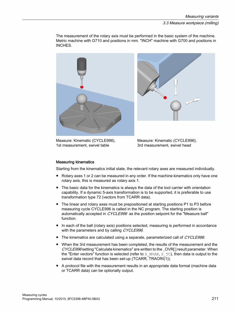
The measurement of the rotary axis must be performed in the basic system of the machine. Metric machine with G710 and positions in mm. "INCH" machine with G700 and positions in INCHES.
Measure: Kinematic (CYCLE996), 1st measurement, swivel table
Measure: Kinematic (CYCLE996), 3rd measurement, swivel head
Measuring kinematicsStarting from the kinematics initial state, the relevant rotary axes are measured individually.
● Rotary axes 1 or 2 can be measured in any order. If the machine kinematics only have one rotary axis, this is measured as rotary axis 1.
● The basic data for the kinematics is always the data of the tool carrier with orientation capability. If a dynamic 5-axis transformation is to be supported, it is preferable to use transformation type 72 (vectors from TCARR data).
● The linear and rotary axes must be prepositioned at starting positions P1 to P3 before measuring cycle CYCLE996 is called in the NC program. The starting position is automatically accepted in CYCLE996 as the position setpoint for the "Measure ball" function.
● In each of the ball (rotary axis) positions selected, measuring is performed in accordance with the parameters and by calling CYCLE996.
● The kinematics are calculated using a separate, parameterized call of CYCLE996.
● When the 3rd measurement has been completed, the results of the measurement and the CYCLE996 setting "Calculate kinematics" are written to the _OVR[ ] result parameter. When the "Enter vectors" function is selected (refer to S_MVAR, S_TC), then data is output to the swivel data record that has been set-up (TCARR, TRAORI(1)).
● A protocol file with the measurement results in an appropriate data format (machine data or TCARR data) can be optionally output.
Measuring variants3.3 Measure workpiece (milling)
Measuring cyclesProgramming Manual, 10/2015, 6FC5398-4BP40-5BA3 211

NoteRequirements for measuring the kinematics with active TRAORI or active TCARR● SD 55740: Set $SCS:MEA_FUNCTION_MASK, bit 8 = 1● Data record (swivel data or machine data) of the kinematics must be set up roughly (±1
mm).● The probe must be positioned perpendicular on the measuring plane at the individual
measuring points of the rotary axes. This can be performed with the swivel function (CYCLE800) or by positioning the rotary axes with TRAORI and then TOROT (for G17).
Input screen forms "kinematics"CYCLE996 has to be called three times in order to complete the entire measuring and vector calculation process for one rotary axis. Between cycle calls, the user must reposition the rotary axis to be measured. Any rotary axis that is not being measured must not be repositioned during the measurement procedure. The linear axes are positioned at the starting positions P1, P2, P3.
Using the respective softkeys, the 1st up to the 3rd measurement are called.
At the end of the 3rd measurement, a call calculates the vectors of the measured rotary axis. The requirement for this is that the 1st to 3rd measurements have been carried out for the respective rotary axis, and that the corresponding measurement results (center points of the calibration ball) have been saved. The vectors of the machine kinematics are then calculated in full when both rotary axes have been measured. The measurement counter, parameter _OVR[40], is displayed in the result bit or in the protocol.
Measurement for kinematics with swivel head:
1st measurement P1 (initial state)
2nd measurement P2 3rd measurement P3
With the 2nd and 3rd measurements, the rotary axis to be measured is rotated around the largest possible angle. The calibration ball position must be stationary during the measurements.
Starting position before the measurementA rotary axis is measured by calling CYCLE996 three times (measurements 1 to 3).
The probe ball must be able to reach the equator of the calibration ball. The 1st measurement must take place in the kinematics normal position. If a rotary axis rotates parallel to the spindle
Measuring variants3.3 Measure workpiece (milling)
Measuring cycles212 Programming Manual, 10/2015, 6FC5398-4BP40-5BA3

without offset in a head kinematics (fork head), the 1st measurement can be made with applied probe. The rotary axis that is not to be measured is not in the initial position of the kinematics.
The starting position of the probe must be approached by the user or from the user program (see example program). The probe must be prepositioned in the direction of the tool orientation (ORI) above the highest point of the calibration ball (probe aligned with ball center point). After approaching the starting position, the distance (D) from the calibration ball should be as short as possible.
Position after the end of the measuring cycleAfter each measurement (1 to 3) of a rotary axis, the probe is located above the calibration ball at a maximum distance of the measurement path DFA.
Measuring an individual rotary axisThe following steps must be carried out in order to measure a rotary axis:
● Mount the calibration ball on the machine table (user)
● Define and approach the three ball positions with the rotary axis that is to be measured (user)
● Specify and approach the three ball positions with the probe in a linear movement/in linear movements (user)
● Using CYCLE996, scan all three ball positions of the calibration ball with the probe.
Mounting the calibration ballIn the case of machinery, the calibration ball is to be installed on the machine table.
In order to measure kinematics for swivel-mounted workholders, the ball must be incorporated into the appropriate workholder. In all cases it must be ensured that the probe can approach and bypass the mounted calibration ball without collision in all the selected rotary axis positions.
Considering the need to avoid collisions, the calibration ball should be mounted as far as possible from the center of rotation of the rotary axis that is to be measured.
Measuring variants3.3 Measure workpiece (milling)
Measuring cyclesProgramming Manual, 10/2015, 6FC5398-4BP40-5BA3 213

If the three ball positions result in too small a triangle, this will negatively affect the accuracy of the procedure:
Calibration ball mounted sufficiently far from the center of rotation; large triangle can be clamped
Calibration ball mounted too near the center of rotation; clamped triangle is too small
Note
While measuring a rotary axis, the mechanical hold-down of the calibration ball must not be altered. It is only with table and mixed kinematics that different calibration ball mounting positions are permissible for the purpose of measuring the first and subsequent rotary axes.
Defining the rotary axis positionsThree measuring points (ball position) must be defined for each rotary axis. Please note that the positions of the ball in space (resulting from the three defined rotary axis positions) should lead to as large a triangle as possible being clamped.
Rotary axis positions sufficiently far away from one another; large triangle clamped
Rotary axis positions poorly selected; clamped triangle is too small
Measuring variants3.3 Measure workpiece (milling)
Measuring cycles214 Programming Manual, 10/2015, 6FC5398-4BP40-5BA3

The calculated inside angle of the rotary axis angle segment is monitored in the TVL parameter. Angle values of < 20 degrees can cause inaccuracies when calculating the kinematics.
Approaching the ball positionFirst of all, the probe must be positioned above the calibration ball at each of the three rotary axis positions defined by the user. The position must only be approached by traversing the linear axes (X, Y, Z). The positions themselves must be entered (set up) by the user. They should be determined manually using an active probe.
When selecting approach positions, please bear in mind that, within the context of automatic calibration ball scanning, the probe always moves in its preferred direction. Particularly where head and mixed kinematics are concerned, the starting position should be selected in a way that ensures alignment of the probe with the center point of the calibration ball in the approach position.
Starting position selected directly above the calibration ball
Starting position selected laterally above the cal‐ibration ball
Note
If the machine does not proceed as expected when the calibration ball is being scanned, the basic orientation and travel direction of the rotary axes should be checked. (Has DIN conformity been maintained when defining the axes?)
Measuring variants3.3 Measure workpiece (milling)
Measuring cyclesProgramming Manual, 10/2015, 6FC5398-4BP40-5BA3 215

Starting positionThe probe must be prepositioned in the direction of the tool orientation (ORI) above the highest point of the calibration ball (probe aligned with ball center point). The distance (A) to the calibration ball after approaching the starting position should correspond to the measuring path parameter (DFA).
Image 3-18 Starting position for the tool length in relation to the probe ball circumference
Note
Measuring the kinematics is also possible with active 5-axis transformation (TRAORI).
As a requirement for measuring the kinematics with active TRAORI, the vectors of the 5-axis transformation must be roughly set. The positions for measuring the kinematics are approached in the user program with active transformation. The transformation can be switched on or off during the actual measuring.
SD55740 $SCS_MEA_FUNCTION_MASKBit 8 = 0 Measure kinematics without active TRAORI or TCARRBit 8 = 1 Measure kinematics with active TRAORI or TCARR
Measuring an individual ball positionOnce the probe has been positioned in accordance with user specifications above the ball, either manually or by the part program (starting point of CYCLE996), the calibration ball is scanned by calling CYCLE996 and the current ball position is measured.
To this end, the user should parameterize and call CYCLE996 separately for each ball position.
Calculating and activating the swivel data setsAfter measuring the three ball positions that are required in each case for all the relevant rotary axes, the entire set of swivel data sets can be calculated by means of CYCLE996. CYCLE996 should be parameterized and called for this purpose.
Measuring variants3.3 Measure workpiece (milling)
Measuring cycles216 Programming Manual, 10/2015, 6FC5398-4BP40-5BA3

Correction targetIn the "Calculate kinematics" screen form, in the "offset target" field, for the vectors it can be set as to whether "only" a calculation should be made (only measuring) or whether the calculated vectors should be saved in the swivel data set. Before saving, the user can decide whether the calculated swivel data set should be displayed and changed. If the calculated swivel data set should not be displayed, the user can decide whether the swivel data set should be immediately overwritten. In all other cases, before saving the swivel data set, the operator is prompted to make a selection.
Table 3-32 Display options in the "Calculate kinematics" screen form
Parameter Measuring only Swivel data setDisplay data set Yes No No YesData set can be edited - - - Yes/noConfirm the change - - Yes/no -
- entry field is not displayed
In addition, the swivel data set can be saved as data file ("save data set").
The data file is saved in the actual NC data path (or workpiece) in which the measurement program is running. The file name corresponds to the name of the swivel data set, and is generated with a count index "_M1" to "_M99".
The data file contains the syntax of the parameters of the swivel data set of the NC function TCARR, e.g. :
$TC_CARR1[1]=-426.708853 $TC_CARR2[1]=-855.050806 … ;I1xyz.
If a transformation type <> 72 is set in the machine data for the dynamic transformation (TRAORI), the calculated vectors are saved in the protocol file also as machine data.
Saving the log fileWhen calculating the kinematics, before calling CYCLE996, the log cycle (CYCLE150) can be called. A log file is created with the measured and calculated vectors of the kinematics.
Tolerance limitsActivating tolerance limits when parameterizing CYCLE996 (compare Starting values – calculated values), allows conclusions to be drawn regarding unusual changes in the mechanical kinematic chain. The unintentional automatic overwriting of starting values can be avoided by adjusting the tolerance limits.
Note
The rotary axis vectors V1/V2 (orientation of the rotary axes) are never automatically overwritten.
Primarily, the calculated rotary axis vectors enable an assessment to be made regarding the mechanical desired/actual state of the kinematics. Depending on the kinematics configuration,
Measuring variants3.3 Measure workpiece (milling)
Measuring cyclesProgramming Manual, 10/2015, 6FC5398-4BP40-5BA3 217

even the smallest and corrected deviations in the position of the rotary axis vectors can result in large compensating movements.
Normalizing = setting a fixed valueThrough normalizing, a new fixed value can be calculated in an axis direction (XYZ) for each rotary axis. This is required particularly for table kinematics because the result of the kinematics calculation refers to the height of the calibration ball. For example, with the normalizing, the Z component can be calculated to the reference point of the workpiece table.
In head kinematics, the initial state of the 1st measurement of rotary axis 2 (if available, otherwise rotary axis 1) is calculated during the calculation of the kinematics. Normalizing is therefore usually not required for head kinematics. With orthogonal machine kinematics, the normalizing of a rotary axis only makes sense for a specific axis direction.
Example:Table kinematicsRotary axis 2(C) rotates around Z -> normalizing of rotary axis 2(C) in axis direction Z makes sense.
With normalizing "Yes", the value of the normalizing (fixed value) is written to the following linear vectors:
Rotary axis 1 Rotary axis 2Head kinematics I1 I3Table kinematics I2 I4Mixed kinematics I2 I4
Example:Table kinematics, rotary axis 1(A) rotates around X, rotary axis 2(C) rotates around Z.Normalizing of rotary axis 1(A) X=100 -> I2x=100Normalizing of rotary axis 2(Z) Z=0 -> I4z=0
NoteNormalizing (setting a fixed value) the vectors when measuring the kinematics
SD55740: $SCS_MEA_FUNCTION_MASK/ Bit 7 (corresponded to _CHBIT[29] activated)● Bit 7 = 0: Normalizing on the basis of the calculated orientation vectors (V1xyz, V2xyz)● Bit 7 = 1: Normalizing on the basis of the orientation vectors entered in the swivel data set
(TCARR) or with TRAORI, in the machine data.
It is recommended that SD55740 bit 7 = 1 be set, as a machine test has proved that this further improves the accuracy of the calculated offset vectors.
Measuring variants3.3 Measure workpiece (milling)
Measuring cycles218 Programming Manual, 10/2015, 6FC5398-4BP40-5BA3

ProcedureThe part program to be processed has been created and you are in the editor.
1. Press the "Meas. workpiece" softkey.
2. Press the "3D" softkey.
3. Press the "Kinematics" softkey.The "Measure: Kinematic" input window opens.
You can then open the following input windows via the following softkeys:1. Measure‐ment
(see Parameters of 1st to 3rd measurement (Page 0 ))
2. Measure‐ment3. Measure‐mentCalculate (see Calculate parameters (Page 0 ))
Parameters of 1st to 3rd measurement
G code programParameter Description UnitPL Measuring plane (G17 - G19) -
Calibration data set (1 - 12) -Positioning Traverse around sphere:
● Parallel to the axis● On circular path
-
Align probe (only for positioning "On circular path")
Always align probe 2) in the same contact direction:● Yes● No 2)
-
Rotary axis 1 Name of rotary axis 1 of the swivel data set -Rotary axis angle 1 Rotary axis angle during the measurement 1) DegreesRotary axis 2 Name of rotary axis 2 of the swivel data set -Rotary axis angle 2 Rotary axis angle during the measurement 1) Degrees∅ Ball diameter mmα0 Starting angle (only for "positioning on circular path") DegreesDFA Measurement path mmTSA Safe area for the measurement result mm
1) Only for manual or semi-automatic rotary axis of the swivel data set2) Note: Preferably the measuring method "Positioning on circular path" and "Align probe in contact direction" should be used
for the best measurement results.
Measuring variants3.3 Measure workpiece (milling)
Measuring cyclesProgramming Manual, 10/2015, 6FC5398-4BP40-5BA3 219

Calculate parameters
G code programParameter Description UnitPL Measuring plane (G17 - G19) -Correction target Only measuring (only calculate vec‐
tors)Swivel data set (calculate vectors and save to swivel data set)
-
Display data set Yes/No No Yes -Data set can be changed - - Yes/No -
Confirm the change - Yes/No - -Save data set Data set is saved in a protocol file Rotary axis 1 Name of rotary axis 1 of the swivel data set -Normalizing ● No (without normalizing)
● X (normalizing in direction X)● Y (normalizing in direction Y)● Z (normalizing in direction Z)
-
Value input Position value for normalizing mmRotary axis 2 Name of rotary axis 2 of the swivel data set -Normalizing ● No (without normalizing)
● X (normalizing in direction X)● Y (normalizing in direction Y)● Z (normalizing in direction Z)
-
Value input Position value for normalizing mmTolerance Use dimensional tolerance
● Yes● No
-
TLIN Max. tolerance of the offset vectors (only for tolerance "Yes") mmTROT Max. tolerance of the rotary axis vectors (only for tolerance "Yes") DegreesTVL Limit value of the minimum inside angle of the measured triangle of the three meas‐
urements of the rotary axis (see "Mounting the calibration" above).Degrees
Close vector chain ● Yes for kinematics mounted permanently on the machine● No for changeable kinematics (e.g. interchangeable heads)
-
- entry field is not displayed
NoteTVL
With TVL values < 20 degrees, scattering of the measured values can result in inaccuracies in the calculation of the kinematics.
Measuring variants3.3 Measure workpiece (milling)
Measuring cycles220 Programming Manual, 10/2015, 6FC5398-4BP40-5BA3

List of the result parametersThe measuring method "Calculate kinematics" provides the following result parameters:
Table 3-33 "Calculate kinematics" result parameters
Parameter Description Unit_OVR[1] Offset vector I1 $TC_CARR1[n] X component mm_OVR[2] Offset vector I1 $TC_CARR2[n] Y component mm_OVR[3] Offset vector I1 $TC_CARR3[n] Z component mm_OVR[4] Offset vector I2 $TC_CARR4[n] X component mm_OVR[5] Offset vector I2 $TC_CARR5[n] Y component mm_OVR[6] Offset vector I2 $TC_CARR6[n] Z component mm_OVR[7] Rotary axis vector V1 $TC_CARR7[n] X component _OVR[8] Rotary axis vector V1 $TC_CARR8[n] Y component _OVR[9] Rotary axis vector V1 $TC_CARR9[n] Z component _OVR[10] Rotary axis vector V2 $TC_CARR10[n] X component _OVR[11] Rotary axis vector V2 $TC_CARR11[n] Y component _OVR[12] Rotary axis vector V2 $TC_CARR12[n] Z component _OVR[15] Offset vector I3 $TC_CARR15[n] X component mm_OVR[16] Offset vector I3 $TC_CARR16[n]Y component mm_OVR[17] Offset vector I3 $TC_CARR17[n] Z component mm_OVR[18] Offset vector I4 $TC_CARR18[n] X component mm_OVR[19] Offset vector I4 $TC_CARR19[n] Y component mm_OVR[20] Offset vector I4 $TC_CARR20[n] Z component mm_OVI[2] Measuring cycle number -_OVI[3] Measuring method (S_MVAR) -_OVI[8] Number of swivel data set (S_TC) -_OVI[9] Alarm number -
The measurement results (calculated vectors) depend on the type of kinematics
Kinematics type Measuring resultHead kinematics 1)
I1 $TC_CARR1...3[n] Corresponds to
_OVR[1]..._OVR[3]I2 $TC_CARR4...6[n] _OVR[4]..._OVR[6]I3 $TC_CARR15...17[n] _OVR[15]..._OVR[17] _OVR[18]..._OVR[20] = 0Table kinematics 2)
I2 $TC_CARR4...6[n] Corresponds to
_OVR[4]..._OVR[6]I3 $TC_CARR15...17[n] _OVR[15]..._OVR[17]I4 $TC_CARR18...20[n] _OVR[18]..._OVR[20] _OVR[1]..._OVR[3] = 0Mixed kinematics3)
Measuring variants3.3 Measure workpiece (milling)
Measuring cyclesProgramming Manual, 10/2015, 6FC5398-4BP40-5BA3 221

Kinematics type Measuring resultI1 $TC_CARR1...3[n]
Corresponds to
_OVR[1]..._OVR[3]I2 $TC_CARR4...6[n] _OVR[4]..._OVR[6]I3 $TC_CARR15...17[n] _OVR[15]..._OVR[17]I4 $TC_CARR18...20[n] _OVR[18]..._OVR[20]
The result parameters that are not calculated = 01) Close vector chain I1=-(I3+I2); for fixed-mounted machine kinematics2) Close vector chain I4=-(I3+I2); for fixed-mounted machine kinematics3) Close vector chain I1=-I2 I4=-I3; for fixed-mounted machine kinematics
Table 3-34 Intermediate results _OVR[32] to _OVR[71]
Parameter Description Unit_OVR[32,33,34] 1) Linear vector of 1st rotary axis is not normalized mm_OVR[35,36,37] 1) Linear vector of 2nd rotary axis is not normalized mm_OVR[40] 2) Measurement counter
x0 = 1st measurement of 1st rotary axis startedx1 = 1st measurement of 1st rotary axis is OKx2 = 2nd measurement of 1st rotary axis is OKx3 = 3rd measurement of 1st rotary axis is OK0x = 1st measurement of 2nd rotary axis started1x = 1st measurement of 2nd rotary axis is OK2x = 2nd measurement of 2nd rotary axis is OK3x = 3rd measurement of 2nd rotary axis is OK33 = Both rotary axes measured
-
_OVR[41,42,43] 2) 1. measurement of 1st rotary axis mm_OVR[44,45,46] 2) 2. measurement of 1st rotary axis mm_OVR[47,48,49] 2) 3. measurement of 1st rotary axis mm_OVR[50] Tool length of the probe mm_OVR[51,52,53] 2) 1. measurement of 2nd rotary axis mm_OVR[54,55,56] 2) 2. measurement of 2nd rotary axis mm_OVR[57,58,59] 2) 3. measurement of 2nd rotary axis mm_OVR[60,61,62] Measuring positions, rotary axis 1 for 1st, 2nd, 3rd measurement Degrees_OVR[63,64,65] Measuring positions, rotary axis 2 for 1st, 2nd, 3rd measurement Degrees_OVR[66,67,68] Active rotation of the WO for 1st measurement of rotary axis 1 in
XYZDegrees
_OVR[69,70] Reserved -_OVR[71] Actual calibration ball diameter from the 1st measurement of rotary
axis 1mm
_OVR[72,73,74] Actual calibration ball diameter of the 1st, 2nd, 3rd measurement rotary axes 1
mm
_OVR[75,76,77] Actual calibration ball diameter of the 1st, 2nd, 3rd measurement rotary axes (if there is a rotary axis)(see note regarding SD55644 $SCS_MEA_KIN_DM_TOL)
mm
_OVR[98] Vector V1x after calculating as unit vector (without user-specific normalization)
Measuring variants3.3 Measure workpiece (milling)
Measuring cycles222 Programming Manual, 10/2015, 6FC5398-4BP40-5BA3

Parameter Description Unit_OVR[99] Vector V1y after calculating as unit vector _OVR[100] Vector V1z after calculating as unit vector _OVR[101] Vector V2x after calculating as unit vector (without user-specific
normalization)
_OVR[102] Vector V2y after calculating as unit vector _OVR[103] Vector V2z after calculating as unit vector
1) The linear vectors are assigned to the specific vectors of the kinematics (I1, I2, etc.) in accordance with the normalizing process.
2) Result parameters _OVR[41] up to _OVR[59] are saved in groups of 3. The values include the measured actual values of the 3 linear axes (XYZ) in the machine coordinate system MCS.
At the start of the 1st measurement, the intermediate results (sphere center points) of the rotary axis are deleted.At 1st measurement of 1st rotary axis → deletion of _OVR[41] ... _OVR[49]At 1st measurement of 2nd rotary axis → deletion of _OVR[51] ... _OVR[59]
Programming example
;Measure kinematics;Mixed kinematics with a B axis around Y and C axis around Z (MIXED_BC).;Calibration ball at 2*45 degrees, directly mounted on a table.;WO in G56. Only the position of the calibration ball;has to be specified in the initial state of the kinematics (B=0 C=0).;Determine G56 with measuring spigot in the JOG mode and approach in XY,;then set ball north pole Z=0.;Swivel data must be entered according to the machine drawing dimensions -> _SDA _SDE.;Intermediate positions are approached with active TRAORI.;To do this, using the online tool offset TOFFL, the TCP;is shifted to the center of the measuring ball. ;Measuring positions for MIXED_BC;P1 .. P3 rotary axis 1;P4 .. P6 rotary axis 2 DEF REAL _P1[2]=SET(0,0) ;Measuring point P1 rotary axis 1(B), rotary axis 2(C)DEF REAL _P2[2]=SET(45,0)DEF REAL _P3[2]=SET(-45,0)DEF REAL _P4[2]=SET(0,0)DEF REAL _P5[2]=SET(0,90)DEF REAL _P6[2]=SET(0,180) DEF REAL _BALL=25 ;Calibration ball diameterDEF REAL _SAVB=1 ;Safety clearance above the calibration ball ;Globally pre-assign measuring parameters_FA=_SAVB*3_TSA=_SAVB*4 REPEAT _SDA _SDE ;Read-in swivel data set
Measuring variants3.3 Measure workpiece (milling)
Measuring cyclesProgramming Manual, 10/2015, 6FC5398-4BP40-5BA3 223

MSG(" load transformation data. OK ?? ")M0STOPREMSG();GOTOF _MCA ;Only calculate kinematics _OVR[40] to _OVR[71] OK G17CYCLE800()ORIAXES ORIMKSTRAORIG56T="3D-TASTER" D1M6 IF (NOT $P_SEARCH) AND (NOT $P_ISTEST) AND (NOT $P_SIM) _OVR[40]=0 ;Zero the measuring counterENDIF ; --------------------- 1. Measurement, rotary axis 1N99 G1 G710 G90 Z30 FFWON F2000TOFFL=_BALL/2+_SAVB D1 B=_P1[0] C=_P1[1] ;Kinematics initial stateZ = _SAVBTOFFL=0 X0 Y0 ;Circle around the ballCYCLE996(10101,1,1,_BALL,0,0,0,0,0,0,0,0,_FA,_TSA,1,,1,)M1STOPRE TOROTM1Z=IC(-_FA+_SAVB)TOROTOFM1 ; --------------------- 2. Measurement, rotary axis 1G1 F2000 TOFFL=_BALL/2+_SAVB ;When repositioning, correct the tool onlineB=_P2[0] C=_P2[1] TOFFL=0 ;Disable online correction again;Circle around the ball, starting angle 45 degreesCYCLE996(10102,1,1,_BALL,45,0,0,0,0,0,0,0,_FA,_TSA,1,,1,)
Measuring variants3.3 Measure workpiece (milling)
Measuring cycles224 Programming Manual, 10/2015, 6FC5398-4BP40-5BA3
TOROT Z=IC(-_FA+_SAVB) ;Approach starting positionTOROTOF ;--------------------- 3. measurement, rotary axis 1G1 F2000TOFFL=_BALL/2+_SAVBD1 B=_P3[0] C=_P3[1]TOFFL=0CYCLE996(10103,1,1,_BALL,210,0,0,0,0,0,0,0,_FA,_TSA,1,,1,)TOROTZ=IC(-_FA+_SAVB)TOROTOF ;--------------------- 1. measurement, rotary axis 2;Initial state, 1st measurement, rotary axis 1 = 1st measurement, rotary axis 2_OVR[51]=_OVR[41] _OVR[52]=_OVR[42] _OVR[53]=_OVR[43]_OVR[75] = _OVR[72] ;accept actual diameter IF (NOT $P_SEARCH) AND (NOT $P_ISTEST) AND (NOT $P_SIM) _OVR[40]=_OVR[40]+10 ENDIF ;--------------------- 2. Measurement, rotary axis 2G1 F2000TOFFL=_BALL/2+_SAVBD1 B=_P5[0] C=_P5[1]TOFFL=0M1CYCLE996(20102,1,1,_BALL,0,0,0,0,0,0,0,0,_FA,_TSA,1,,1,)TOROTZ=IC(-_FA+_SAVB)TOROTOF ;--------------------- 3rd measurement, rotary axis 2TOFFL=_BALL/2+_SAVBG1 D1 C=_P6[1] F2000TOFFL=0CYCLE996(20103,1,1,_BALL,_STA1,0,0,0,0,0,0,0,_FA,_TSA,1,,1,)TOROTZ=IC(-_FA+_SAVB)TOROTOFENDIFG0 Z30 B0 C0 ;-------------------- Calculate kinematics
Measuring variants3.3 Measure workpiece (milling)
Measuring cyclesProgramming Manual, 10/2015, 6FC5398-4BP40-5BA3 225

_MCA:;Display data set. Save data set as protocol file;Normalizing rotary axis 2(C) on Z=0 -> table upper edgeCYCLE996(13001000,1,1,_BALL,_STA1,0,0,0,0,0.02,0.001,22,_FA,_TSA,1,,1,101)MSG("Kinematics measurement OK")M1M30 ;end of program ;-----------------------------------------------------_SDA: ;Swivel data set according to machine drawingTCARR=0 TRAFOOF TCARR=0 $TC_CARR1[1]=-25 $TC_CARR2[1]=0 $TC_CARR3[1]=-121;I1xyz$TC_CARR4[1]=25 $TC_CARR5[1]=0 $TC_CARR6[1]=121;I2xyz$TC_CARR7[1]=0 $TC_CARR8[1]=1 $TC_CARR9[1]=0 ;V1 axis B around Y$TC_CARR10[1]=0 $TC_CARR11[1]=0 $TC_CARR12[1]=-1 ;V2 axis C around Z$TC_CARR13[1]=0 $TC_CARR14[1]=0 $TC_CARR15[1]=0 $TC_CARR16[1]=0 $TC_CARR17[1]=0;I3xyz$TC_CARR18[1]=0 $TC_CARR19[1]=0 $TC_CARR20[1]=0;I4xyz$TC_CARR23[1]="M" $TC_CARR24[1]=0 $TC_CARR25[1]=0 $TC_CARR26[1]=0 $TC_CARR27[1]=0 $TC_CARR28[1]=0 $TC_CARR29[1]=0 $TC_CARR30[1]=-92 $TC_CARR31[1]=0 $TC_CARR32[1]=92 $TC_CARR33[1]=360 STOPRE NEWCONF _SDE:
Measuring variants3.3 Measure workpiece (milling)
Measuring cycles226 Programming Manual, 10/2015, 6FC5398-4BP40-5BA3

3.3.24 Expanded functionality CYCLE996
3.3.24.1 Checking the sphere diameterWhen measuring the calibration sphere (1.2.3. measurement) the measured diameter (actual diameter) of the calibration sphere is saved to the following result parameters:
_OVR[72] to _OVR[74]
Actual calibration sphere diameter 1.2.3. measurement rotary axis 1
_OVR[75] to _OVR[77]
Actual calibration sphere diameter 1.2.3. measurement rotary axis 2 (if a rotary axis exists)
When setting data 55644 $SCS_MEA_KIN_DM_TOL > 0, after the 1st measurement and when calculating the kinematics, the measured calibration sphere diameter is checked. If the deviation is greater than in setting data $SCS_MEA_KIN_DM_TOL, fault 62321 or 62322 is output.
62321 rotary axis 1: Tolerance, diameter calibration sphere between measurement %4 exceeded.
62322 rotary axis 2: Tolerance, diameter calibration sphere between measurement %4 exceeded.
3.3.24.2 Scaling of rotary axis vectors V1 and V2When calculating the kinematics, the vectors can be calculated as unit vector or as a user-specific vector. For user-specific rotary axis vectors, a vector component is always 1 or -1. The two remaining vector components are appropriately converted using a factor.
The function is activated using setting data 55740 $SCS_MEA_FUNCTION_MASK, bit 9.
Example: Swivel head with 45 degrees rotary axis
1. Vector V2xyz as unit vector calculating the kinematics (SD55740, bit 9=0):$TC_CARR10[1] = 0.7070974092$TC_CARR11[1] = -1.823908EX-06$TC_CARR12[1] = -0.7071161531
2. Vector V2xyz user-specific after calculating the kinematics (SD55740, bit 9=1)$TC_CARR10[1] = 0.9999734924$TC_CARR11[1] = -2.579361244EX-06$TC_CARR12[1] = 1
If SD55740, bit 9=1 is set, for comparison purposes, vectors V1 and V2 are saved in the result parameters _OVR[98] up to _OVR[103] before calculating the user-specific scaling. Result parameters _OVR[98] to _OVR[103] are also written to the measuring data file.
_OVR[98] Vector V1x after calculating as unit vector (without user-specific normalization)_OVR[99] Vector V1y after calculating as unit vector _OVR[100] Vector V1z after calculating as unit vector _OVR[101] Vector V2x after calculating as unit vector (without user-specific normalization)_OVR[102] Vector V2y after calculating as unit vector _OVR[103] Vector V2z after calculating as unit vector
Measuring variants3.3 Measure workpiece (milling)
Measuring cyclesProgramming Manual, 10/2015, 6FC5398-4BP40-5BA3 227

3.3.25 3D measuring on machines with orientation transformation
FunctionMeasuring with active orientation transformation, i.e. with the swivel cycle CYCLE800 (orientable tool carrier TCARR), or with the kinematic 5-axis transformation (TRAORI) with the measuring cycles is possible.
The probe must be positioned perpendicular to the machining plane or parallel to the tool axis before calling the measuring cycles.
The Align plane (CYCLE998) and Measure kinematics (CYCLE996) functions are the exception. Here, the probe is always at an angle to the object to be measured.
The workpiece measurement is generally based on the active workpiece coordinate system WCS.
Checking the correct switching direction when measuring the workpieceIf elements (hole, edge, etc.) are measured in the swiveled, rotated WCS, the switching direction of the 3D workpiece probe must be checked as follows during the first commissioning of the machine in the JOG and AUTO modes:
● Bit1 = 1 must be set in SD 55740 $SCS_MEA_FUNCTION_MASK (coupling of the spindle with the coordinate rotation).
● The switching direction in X+ (for G17) in the initial state of the machine kinematics must be marked accordingly on the probe.
● Using the measuring of a hole with CYCLE977 in the swiveled plane as an example, the marked switching direction must be aligned towards X+ when starting and probing the 1st measuring point. With active orientation transformation (TCARR, CYCLE800, TRAORI), the spindle position changed by the tool orientation is calculated internally in the measuring cycles and the spindle corrected accordingly. The result of the calculation is saved in the GUD variable _MEA_CORR_ANGLE[1]. The correct spindle position during measuring must be checked on the workpiece for different orientations of the object to be measured.
● After a successful check, SD 55740 $SCS_MEA_FUNCTION_MASK, bit1 = 0 can be set. The measurement results must correspond to those of the measurements with coupling of the spindle.
Measuring variants3.3 Measure workpiece (milling)
Measuring cycles228 Programming Manual, 10/2015, 6FC5398-4BP40-5BA3

NoteAdditional adaptation of the correction angle
An additional adaptation of the correction angle for the positioning of the spindle may be required for the selected machine kinematics or applications.
With the CUST_MEACYC.SPF manufacturer cycle, you can write the correction angles _MEA_CORR_ANGLE[0] and _MEA_CORR_ANGLE[1].
These angles affect the spindle position / probe orientation when measuring or the internal conversion of the trigger values if the spindle is not to be aligned in the switching direction (SD 55740 bit1 = 0, SPOS = 0 during measuring).
3.3.26 Measuring the workpiece on a machine with combined technologies
3.3.26.1 Measuring a workpiece on a milling/turning machine
GeneralThis chapter refers to measuring a tool on milling/turning machines. Turning is set up as the 1st technology and milling as the 2nd technology.
Preconditions:
1. Milling: MD52200 $MCS_TECHNOLOGY = 2
2. Turning: MD52201 $MCS_TECHNOLOGY_EXTENSION = 1
Further, the following setting data must be set:
● SD 42950 $SC_TOOL_LENGTH_TYPE = 3
● SD 42940 $SC_TOOL_LENGTH_CONST = 17
● SD 42942 $SC_TOOL_LENGTH_CONST_T = 19
Measuring workpieces using turning technology on a milling machine is realized using milling technology. For example, if the outer diameter of a contour is to be measured, then this can be realized using CYCLE977 "Measure spigot" at the G17 plane. If the measured values are to be corrected in a turning tool, then the programmer must specify the tool lengths L3x or L1z to be corrected, and possibly the sign of the correction. The selection of the correction depends on the turning tool orientation (align turning tool function beta and gamma) for turning.Please take into account SD55760 $SNS_MEA_FUNCTION_MASK_PIECE bit12 and bit13.It only makes sense to correct the measured values of the turned tool in a work offset for the Z axis. The machine manufacturer makes the correct setting of the turning center in XY when commissioning the machine.
Note the machine manufacturer’s instructions
If the tool probe is to be reorientated for making the measurement, then this is realized using the swivel plane function (CYCLE800).
Measuring variants3.3 Measure workpiece (milling)
Measuring cyclesProgramming Manual, 10/2015, 6FC5398-4BP40-5BA3 229

Additional settings/notes relating to milling/turning technology should be taken from IM9 – Chapter "Turning on milling machines".
FunctionUsing measuring cycles, the probe can be calibrated on milling/turning machines and milling, drilling and turning tools can be measured.
● A probe is calibrated using the CYCLE976 cycle
● Cycle CYCLE971 is used to measure milling and drilling tools
● Cycle CYCLE982 is used to measure turning tools
The descriptions for the appropriate cycles in this manual should be used to parameterize the individual measuring versions.
3.3.26.2 Measuring a workpiece on a turning/milling machineThe following section refers to the workpiece measuring on turning/milling machines. Whereby turning is set up as the 1st technology and milling as the 2nd technology.
- Turning measurement (measure diameter, outside, inside, etc.)
If measuring is to be performed in different tool orientations (B axis for turning technology), the probe can be prepositioned with the "Tool alignment" function (CYCLE800).
- Milling measurement (measure hole, set edge, align edge, etc.)
If measuring is to be performed in different tool orientations, the probe can be prepositioned with the "Swivel plane" function (CYCLE800).
Value specifications of the transverse axis (X) of the measuring cycles under milling are performed in the radius (DIAMOF). The measuring cycles under milling also work internally with radius programming in relation to a transverse axis.
With hole and spigot measurement (CYCLE977, CYCLE979), the object to be measured is specified in the diameter.
The workpiece probe cannot be calibrated under the active G18 machining plane (turning) for turning/milling machines for geometric reasons. The workpiece measurements should be performed in G18 during turning. The probe is therefore calibrated under G17 or G19 and the trigger values allocated internally accordingly.
3.3.26.3 Allocating the trigger values
FunctionAs of SW 4.5 SP2, the following application is enabled with the "Calibrating and measuring in different machining planes" function:
● Calibrating (with CYCLE976) in the G17 or G19 working plane
● Workpiece measuring in G18 as for turning (with CYCLE974, CYCLE994)
Measuring variants3.3 Measure workpiece (milling)
Measuring cycles230 Programming Manual, 10/2015, 6FC5398-4BP40-5BA3

Requirement● 1st turning technology: MD 52200$MCS_TECHNOLOGY = 1
● 2nd milling technology: MD 52201$MCS_TECHNOLOGY_EXTENSION = 2
● Active tool is a 3D multi probe, type 710
3.3.26.4 Uniformity when using a 3D probe of type 710
FunctionIn accordance with the "Calibrating and measuring in different machining planes" function on a turning/milling machine, the 3D probe type (710) can be used for all workpiece measuring variants (turning and milling) on the basis of a calibration data set.
Requirement● Setting data SD 42940 $SC_TOOL_LENGTH_CONST = 18 (or -18)
● Setting data SD 42950 $SC_TOOL_LENGTH_TYPE = 2
● Active tool is a 3D multi probe, type 710
Note
If the above requirements are not satisfied for measuring under turning, alarm 61309 "Check tool type of the workpiece probe" is output.
Measuring variants3.3 Measure workpiece (milling)
Measuring cyclesProgramming Manual, 10/2015, 6FC5398-4BP40-5BA3 231

3.4 Measure tool (turning)
3.4.1 General informationThe measuring cycles below are intended for use on turning machines.
NoteSpindle
Spindle commands in the measuring cycles always refer to the active master spindle of the control.
When using the measuring cycles at machines with several spindles, then the spindle involved must be defined as master spindle before the cycle call.
References: /PG/ Programming Manual SINUMERIK 840D sl / 828D Fundamentals
Plane definitionThe measuring cycles work internally with the 1st and 2nd axes of the actual plane G17 to G19.
The default setting for lathes is G18.
Note
The measuring cycle for tool measurement, turning (CYCLE982) does not position in the 3rd axis (Y for G18). The user must position in the 3rd axis.
Measuring variants3.4 Measure tool (turning)
Measuring cycles232 Programming Manual, 10/2015, 6FC5398-4BP40-5BA3

Machine/workpiece-related measuring/calibrating● Machine-related measuring/calibrating:
Measuring is performed in the basic coordinate system (machine coordinate system with kinematics transformation disabled).The switching positions of the tool probe refer to the machine zero. Data from the following general setting data are used (PLUS and MINUS define the traversing direction of the tool):
– ① SD 54625 $SNS_MEA_TP_TRIG_MINUS_DIR_AX1
– ② SD 54626 $SNS_MEA_TP_TRIG_PLUS_DIR_AX1
– ③ SD 54627 $SNS_MEA_TP_TRIG_MINUS_DIR_AX2
– ④ SD 54628 $SNS_MEA_TP_TRIG_PLUS_DIR_AX2
3
4
2 1
Image 3-19 Tool probe, machine-related (G18)
● Workpiece-related measuring/calibrating:The switching positions of the tool probe refer to the workpiece zero. Data from the following general setting data are used (PLUS and MINUS define the traversing direction of the tool):
– ① SD 54640 $SNS_MEA_TPW_TRIG_MINUS_DIR_AX1
– ② SD 54641 $SNS_MEA_TPW_TRIG_PLUS_DIR_AX1
– ③ SD 54642 $SNS_MEA_TPW_TRIG_MINUS_DIR_AX2
Measuring variants3.4 Measure tool (turning)
Measuring cyclesProgramming Manual, 10/2015, 6FC5398-4BP40-5BA3 233

– ④ SD 54643 $SNS_MEA_TPW_TRIG_PLUS_DIR_AX2
3
4
2 1
Image 3-20 Tool probe, workpiece-related (G18)
Note
Workpiece-related or machine-related measurement requires an appropriately calibrated tool probe, see ChapterCalibrate probe (CYCLE982) (Page 234).
Compensation strategyThe tool measuring cycle is intended for various applications:
● First measurement of a tool (general setting data SD 54762 $SNS_MEA_FUNCTION_MASK_TOOL Bit9):The tool offset values in geometry and wear are replaced.The offset is applied in the geometry component of the particular length.The wear component is deleted.
● Post measurement of a tool (general setting data SD 54762 $SNS_MEA_FUNCTION_MASK_TOOL Bit9):The resulting difference is calculated into the wear component (length) of the tool.
Empirical values may optionally be included. A mean value is not calculated.
See alsoChanges from cycle version SW4.4 and higher (Page 325)
3.4.2 Calibrate probe (CYCLE982)
Function This measuring version can be used to calibrate a tool probe. Using the calibration tool, the actual distances between machine or workpiece zero and the probe trigger points are determined.
Measuring variants3.4 Measure tool (turning)
Measuring cycles234 Programming Manual, 10/2015, 6FC5398-4BP40-5BA3

Values are corrected without empirical and mean values.
Note
If a special calibration tool is not available, a turning tool can be used instead with cutting edge positions 1 to 4 for the calibration of two sides of the probe.
Measuring principle
Calibrating with tool type calibration tool (type 585)The calibration tool is shaped (angled) in such a way that the probe can be calibrated on all four sides with it.
Calibrating with tool type calibration tool (type 725) or turning tool (type 5xy)When a turning tool or a calibration tool, type 725, is used, the probe can only be calibrated from 2 sides.
Calibrating the tool probe with a calibration toolCalibrating a tool probe with a turning tool
The cycle positions the calibration or turning tool to the probe. With a cycle call, the switching position in the specified measuring axis and measuring direction is calibrated.
Preconditions● Lengths 1 and 2 and the radius of the calibration or turning tool must be known exactly and
stored in a tool offset data record.This tool offset must be active when the measuring cycle is called.
● For calibration, a reference turning tool, type 5xy, with precisely known geometry or a type 585 or type 725 calibration tool can be used (type 580 3D probe turning cannot be used)
● Calibration with a calibration or turning tool with cutting edge positions 1 to 4 is possible.
Measuring variants3.4 Measure tool (turning)
Measuring cyclesProgramming Manual, 10/2015, 6FC5398-4BP40-5BA3 235

● The lateral surfaces of the probe cube must be aligned parallel to the machine axes Z1, X1 (axes of the plane).
● The approximate positions of the switching surface of the probe regarding the machine or workpiece zero must be entered before calibration starts in the general setting data (see Commissioning Manual SINUMERIK Operate (IM9) / SINUMERIK 840D sl , Chapter "Tool measurement in turning").These values are used for automatic approach to the probe with the calibration tool and their absolute value must not deviate from the actual value by more than the value in parameter TSA.The probe must be reached within the total path 2 · DFA.
Starting position before the measurement
Calibrating the tool probe with a calibration toolCalibrating a tool probe with a turning tool
3
4
2 1
3
4
2 1
Cutting edge positions 1 to 4 and suitable approach positions for both axes (machine-related)① trigger point of the 1st measuring axis in the negative direction (general SD 54625)② trigger point of the 1st measuring axis in the positive direction (general SD 54626)③ trigger point of the 2nd measuring axis in the negative direction (general SD 54627)④ trigger point of the 2nd measuring axis in the positive direction (general SD 54628)
The cycle handles the approach to the probe.
Measuring variants3.4 Measure tool (turning)
Measuring cycles236 Programming Manual, 10/2015, 6FC5398-4BP40-5BA3

Position after the end of the measuring cycleThe calibration or turning tool is located by the measurement path away from the measuring surface.
1 2
① Trigger point of the 1st measuring axis in the positive direction (general SD 54626)② Trigger point of the 1st measuring axis in the negative direction (general SD 54625)
Image 3-21 Position after the end of the measuring cycle, example, 1st axis of the plane (for G18: Z)
ProcedureThe part program or ShopTurn program to be processed has been created and you are in the editor.
1. Press the "Meas. tool" softkey.
2. Press the "Calibrate probe" softkey.The input window "Calibrate: Probe" opens.
Measuring variants3.4 Measure tool (turning)
Measuring cyclesProgramming Manual, 10/2015, 6FC5398-4BP40-5BA3 237

Parameters
G code program ShopTurn programParameters Description Unit Parameters Description Unit
Calibration data set (1 - 6) - T Name of the calibration tool -F Calibration and measuring fee‐
drateDistance/min
D Cutting edge number (1 - 9) -
Calibration data set (1 - 6) - F Calibration and measuring fee‐
dratemm/min
β Tool alignment with swivel axis● (0 degrees)● (90 degrees)● Value entry
Degrees
V Tool orientation with a tool spin‐dle
Degrees
Z Start point Z of the measure‐ment
mm
X Start point X of the measure‐ment
mm
Y Start point Y of the measure‐ment
mm
Parameters Description UnitMeasuring axis Measuring axis (for measuring plane G18)
● X● Z
-
DFA Measurement path mmTSA Safe area for the measurement result mm
List of the result parametersThe measuring variant "Calibrate probe" provides the following result parameters:
Table 3-35 "Calibrate probe" result parameters
Parameters Description Unit_OVR[8] Trigger point in minus direction, actual value of 1st axis of the plane mm_OVR[10] Trigger point in plus direction, actual value of 1st axis of the plane mm_OVR[12] Trigger point in minus direction, actual value of 2nd axis of the plane mm_OVR[14] Trigger point in plus direction, actual value of 2nd axis of the plane mm_OVR[9] Trigger point in minus direction, difference of 1st axis of the plane mm_OVR[11] Trigger point in plus direction, difference of 1st axis of the plane mm_OVR[13] Trigger point in minus direction, difference of 2nd axis of the plane mm
Measuring variants3.4 Measure tool (turning)
Measuring cycles238 Programming Manual, 10/2015, 6FC5398-4BP40-5BA3

Parameters Description Unit_OVR[15] Trigger point in plus direction, difference of 2nd axis of the plane mm_OVR[27] Zero offset area mm_OVR[28] Safe area mm_OVI[2] Measuring cycle number -_OVI[3] Measuring variant -_OVI[5] Probe number -_OVI[9] Alarm number -
3.4.3 Turning tool (CYCLE982)
Function With this measuring version, the tool length (L1 and/or L2) of a turning tool with cutting edge positions 1 to 8 can be determined. The measuring version checks whether the difference to be corrected with respect to the old tool length lies within a defined tolerance range:
● Upper limits: Safe area TSA and dimensional difference control DIF
● Lower limit: Work offset range TZL
If this range is not violated, the new tool length is accepted in the tool offset, otherwise an alarm is output. Violation of the lower limit is not corrected.
Measuring principleFor "complete" measuring, all lengths of a turning tool are measured:
● Turning tool with cutting edge positions 1 to 4: L1 and L2
● Turning tool with cutting edge position 5 or 7: L2
● Turning tool with cutting edge position 6 or 8: L1
If the turning tool has a cutting edge position 1 to 4, contact is made with the probe in both axes of the plane (for G18 Z and X), whereby the measurement starts with the 1st axis of the plane (for G18 Z). For cutting edge positions 5 to 8, a measurement is only performed in one axis:
● Cutting edge position 5 or 7: 1st measuring axis for G18 Z
● Cutting edge position 6 or 8: 2nd measuring axis for G18 X.
When measuring "axis by axis", the length of the turning tool in the parameterized measuring axis is measured.
Measuring variants3.4 Measure tool (turning)
Measuring cyclesProgramming Manual, 10/2015, 6FC5398-4BP40-5BA3 239

Image 3-22 Measure: Turning tool (CYCLE982), example: Complete measuring
PreconditionsThe tool probe must be calibrated, see Calibrate probe (CYCLE982) (Page 234).
The approximate tool dimensions must be entered in the tool offset data:
● Tool type 5xx
● Cutting edge position, cutting edge radius
● Lengths in X and Z
The tool to be measured must be active with its tool offset values when the cycle is called.
Starting position before the measurementBefore the cycle is called, the tool must be moved to the tool tip starting position, as shown in the following diagram.
Image 3-23 Cutting edge positions 1 to 4 and suitable starting positions for both axes
The center of the tool probe and the approach distance are calculated automatically and the required traversing blocks generated. The center of the cutting edge radius is positioned at the center of the probe.
Measuring variants3.4 Measure tool (turning)
Measuring cycles240 Programming Manual, 10/2015, 6FC5398-4BP40-5BA3

Image 3-24 Measuring the length of a turning tool: Offset by the cutting edge radius, example SL=3
Position after the end of the measuring cycleFor an "axis by axis" measurement, the tool tip is the measurement path distance away from the probed measuring surface of the probe.
For a "complete" measurement, after the measurement, the tool is positioned at the starting point before the cycle was called.
ProcedureThe part program or ShopTurn program to be processed has been created and you are in the editor.
1. Press the "Meas. tool" softkey.
2. Press the "Turning tool" softkey.The input window "Measure: Turning tool" opens.
Measuring variants3.4 Measure tool (turning)
Measuring cyclesProgramming Manual, 10/2015, 6FC5398-4BP40-5BA3 241

Parameters
G code program ShopTurn programParameters Description Unit Parameters Description UnitPL Measuring plane (G17 - G19) - T Name of the tool to be meas‐
ured-
Calibration data set (1 - 6) - D Cutting edge number (1 - 9) - Calibration data set (1 - 6) - β Tool alignment with swivel axis:
● (0 degrees)● (90 degrees)● Value entry
Degrees
V Tool orientation with a tool spindle
Degrees
Z Start point Z of the measure‐ment
mm
X Start point X of the measure‐ment
mm
Y Start point Y of the measure‐ment
mm
Parameters Description UnitMeasure Measure tool lengths (for measuring plane G18)
● Complete (measure length Z and length X● Only measure tool length Z● Only measure tool length X
-
DFA Measurement path mmTSA Safe area for the measurement result mmTZL Tolerance range for work offset mmTDIF Tolerance range for dimensional difference monitoring mm
List of the result parametersThe measuring variant "Turning tool" provides the following result parameters:
Table 3-36 "Turning tool" result parameters
Parameter Description Unit_OVR[8] Length actual value L1 mm_OVR[9] Length difference L1 mm_OVR[10] Length actual value L2 mm_OVR[11] Length difference L2 mm_OVR[12] Length actual value L3 mm_OVR[13] Length difference L3 mm
Measuring variants3.4 Measure tool (turning)
Measuring cycles242 Programming Manual, 10/2015, 6FC5398-4BP40-5BA3

Parameter Description Unit_OVR[27] Work offset range mm_OVR[28] Safe area mm_OVR[29] Permissible dimensional difference mm_OVR[30] Empirical value mm_OVI[0] D number -_OVI[2] Measuring cycle number -_OVI[3] Measuring version -_OVI[5] Probe number -_OVI[7] Empirical value memory number -_OVI[8] Tool number -_OVI[9] Alarm number -
3.4.4 Milling tool (CYCLE982)
Function This measuring version can be used to measure a milling tool on a turning machine (lathe).
The following measurements can be performed:
● Length
● Radius
● Length and radius
The measuring cycle checks whether the difference to be corrected with respect to the old tool length or to the old tool radius lies within a defined tolerance range:
● Upper limits: Safe area TSA and dimensional difference control DIF.
● Lower limit: Zero offset range TZL.
If this range is not violated, the new tool length is accepted in the tool offset, otherwise an alarm is output. Violation of the lower limit is not corrected.
The tool length correction is is realized depending on the particular turning machine (lathe). The length assignment (L1 in X, L2 in Y) to the geometry axes is realized just the same as for a turning tool.
Measuring principleFor a "complete" measurement, all measured variables that can be determined (lengths L1 and L2 and radius) are determined. In both axes (for G18: Z and X) of the plane, probing action is performed with respect to the probe, whereby the measurement starts with the first axis of the plane (for G18: Z).
Measuring variants3.4 Measure tool (turning)
Measuring cyclesProgramming Manual, 10/2015, 6FC5398-4BP40-5BA3 243

For an "axis-by-axis" measurement, the measured variables are measured corresponding to the selection "only length (L1 or L2)", "only radius" or "length (L1 or L2) and radius" only in the parameterized measuring axis of the active plane.
Measuring "axis-by-axis" - only length (L1 or L2)Length L1 or L2 is measured in the parameterized measuring axis.
Table 3-37 Measuring "axis-by-axis" - only length (L1 or L2)
Without milling tool reversal With milling tool reversal
Measuring length L2 Measuring length L1 Measuring length L2Requirement: Radius R must be known.
Measuring "axis-by-axis" - only radiusThe radius in the parameterized measuring axis is measured by probing twice at the probe.
Table 3-38 Measuring "axis-by-axis" - only radius
Without milling tool reversal With milling tool reversal
Measuring variants3.4 Measure tool (turning)
Measuring cycles244 Programming Manual, 10/2015, 6FC5398-4BP40-5BA3

Measuring "axis-by-axis" - only length (L1 or L2) and radiusLength L1 or L2 and radius are measured in the parameterized measuring axis by probing twice to two different sides of the measuring probe.
Table 3-39 Measuring "axis-by-axis" - only length (L1 or L2) and radius
Length L1 and radius measurement without milling tool reversal
Length L2 and radius measurement with milling tool reversal
Measuring "complete" - lengths (L1 and L2) and radiusFor complete measurements, all offsets are determined:
● Both lengths and radius (four measurements).
● If the radius is specified to be 0, then both lengths are determined (two measurements).
The measuring cycle generates the approach blocks to the probe and the transverse motions to measure length 1, length 2 and the radius. A correctly selected start position is required.
Milling tool reversalWhen measuring with reversal, to start, the measuring point in the selected axis and a milling spindle position according to starting angle SPOS is measured. Then the tool (spindle) is turned through 180 degrees and measured again.
The average value is the measured value. Measurement with reversal, results in a second measurement at each measuring point with a spindle rotation through 180 degrees with respect to the starting angle. The offset angle entered in SCOR is summed to these 180 degrees. This enables selection of a specific 2nd milling cutting edge that is offset from the 1st cutting edge by precisely 180 degrees. Measurement with reversal permits measurement of two cutting edges of one tool. The mean value is the offset value.
Measuring variants3.4 Measure tool (turning)
Measuring cyclesProgramming Manual, 10/2015, 6FC5398-4BP40-5BA3 245
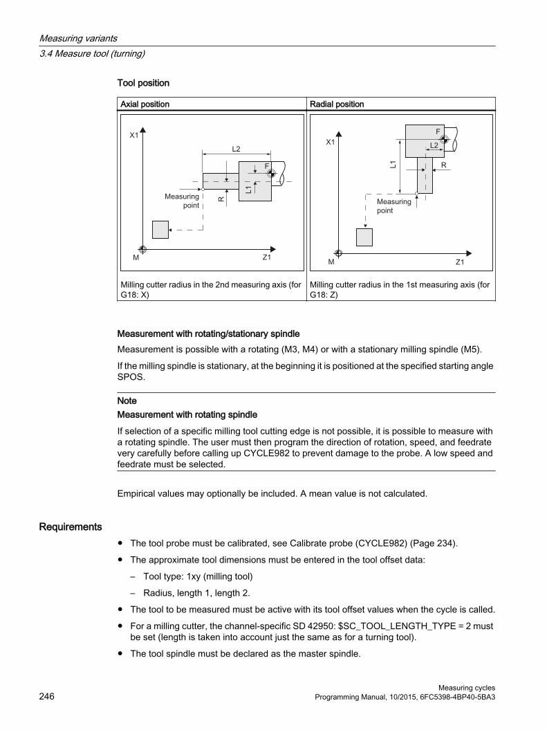
Tool position
Axial position Radial position
Milling cutter radius in the 2nd measuring axis (for G18: X)
Milling cutter radius in the 1st measuring axis (for G18: Z)
Measurement with rotating/stationary spindleMeasurement is possible with a rotating (M3, M4) or with a stationary milling spindle (M5).
If the milling spindle is stationary, at the beginning it is positioned at the specified starting angle SPOS.
NoteMeasurement with rotating spindle
If selection of a specific milling tool cutting edge is not possible, it is possible to measure with a rotating spindle. The user must then program the direction of rotation, speed, and feedrate very carefully before calling up CYCLE982 to prevent damage to the probe. A low speed and feedrate must be selected.
Empirical values may optionally be included. A mean value is not calculated.
Requirements● The tool probe must be calibrated, see Calibrate probe (CYCLE982) (Page 234).
● The approximate tool dimensions must be entered in the tool offset data:
– Tool type: 1xy (milling tool)
– Radius, length 1, length 2.
● The tool to be measured must be active with its tool offset values when the cycle is called.
● For a milling cutter, the channel-specific SD 42950: $SC_TOOL_LENGTH_TYPE = 2 must be set (length is taken into account just the same as for a turning tool).
● The tool spindle must be declared as the master spindle.
Measuring variants3.4 Measure tool (turning)
Measuring cycles246 Programming Manual, 10/2015, 6FC5398-4BP40-5BA3

Starting position before the measurementFrom the starting position, collision-free approach to the probe must be possible.
The initial positions are located outside the unauthorized area (see the diagram below).
① to ④ permissible area
Image 3-25 Measure milling cutter: Possible starting positions in the 2nd axis of the plane (for G18: X)
Position after the end of the measuring cycleFor an "axis-by-axis" measurement, the tool tip is positioned at the measurement path distance away from the last probed measuring surface of the probe.
For a "complete" measurement, after the measurement, the tool is positioned at the starting point before the cycle was called.
ProcedureThe part program or ShopTurn program to be processed has been created and you are in the editor.
1. Press the "Meas. tool" softkey.
2. Press the "Milling tool" softkey.The input window "Measure: Milling tool" opens.
Measuring variants3.4 Measure tool (turning)
Measuring cyclesProgramming Manual, 10/2015, 6FC5398-4BP40-5BA3 247

Parameter
G code program ShopTurn programParameter Description Unit Parameter Description UnitPL Measuring plane (G17 - G19) - T Name of the tool to be meas‐
ured-
Calibration data set (1 - 6) - D Cutting edge number (1 - 9) - Calibration data set (1 - 6) - β Tool alignment with swivel axis
● (0 degrees)● (90 degrees)● Value entry
Degrees
Z Start point Z of the measure‐ment
mm
X Start point X of the measure‐ment
mm
Y Start point Y of the measure‐ment
mm
Parameters Description UnitMeasurement type ● Axis-by-axis
● Complete (measure length and radius)-
Tool position ● Axial (←)● Radial (↓)
-
For measurement type "Complete": Measure Lengths X, Z and radius (in accordance with the tool position) -Cutting edge ● End face
● Rear face-
Approach Approach probe from the following direction (for measuring plane G18):● In the case of tool position "axial": +/- X● In the case of tool position "radial": +/- Z
-
For measurement type "Axis-by-axis": Measure For measuring plane G18:
● Length X/Z and radius (in accordance with the tool position)● Only length Z● Only length X● Only radius
-
Milling tool reversal ● Yes (measurement with reversal of the milling tool (180°))
● No (measurement without reversal)-
Position spindle Set position of the tool spindle (only for milling tool reversal "No")● No (any tool spindle position)● Yes (position tool spindle at starting angle)
-
Measuring variants3.4 Measure tool (turning)
Measuring cycles248 Programming Manual, 10/2015, 6FC5398-4BP40-5BA3

Parameters Description UnitSPOS Angle for positioning on a tool tip (only for milling cutter reversal "Yes" or position
spindle "Yes" or for "complete" measurement type)Degrees
SCOR Offset angle for reversal (only for milling tool reversal "Yes") DegreesDFA Measurement path mmTSA Safe area for the measurement result mmTZL Tolerance range for work offset mmTDIF Tolerance range for dimensional difference monitoring mm
List of the result parametersThe measuring variant "Milling tool" provides the following result parameters:
Table 3-40 "Milling tool" result parameters
Parameters Description Unit_OVR[8] Length actual value L1 mm_OVR[9] Length difference L1 mm_OVR[10] Length actual value L2 mm_OVR[11] Length difference L2 mm_OVR[12] Radius actual value mm_OVR[13] Radius difference mm_OVR[27] Work offset range mm_OVR[28] Safe area mm_OVR[29] Permissible dimensional difference mm_OVR[30] Empirical value mm_OVI[0] D number -_OVI[2] Measuring cycle number -_OVI[5] Probe number -_OVI[7] Empirical value memory -_OVI[8] Tool number -_OVI[9] Alarm number -
Measuring variants3.4 Measure tool (turning)
Measuring cyclesProgramming Manual, 10/2015, 6FC5398-4BP40-5BA3 249

3.4.5 Drill (CYCLE982)
Function With this measuring version, the tool length (L1 or L2) of a drill can be measured. The measuring version checks whether the difference to be corrected with respect to the old tool length lies within a defined tolerance range:
● Upper limits: Safe area TSA and dimensional difference control DIF
● Lower limit: Zero offset range TZL
If this range is not violated, the new tool length is accepted in the tool offset, otherwise an alarm is output. Violation of the lower limit is not corrected.
Measuring principleThe length (L1 or L2) of the drill is measured in the parameterized measuring axis.
Measuring length L2 Measuring length L1
Measuring variants3.4 Measure tool (turning)
Measuring cycles250 Programming Manual, 10/2015, 6FC5398-4BP40-5BA3

Tool position:
Axial position Radial position
Drill radius in the 2nd measuring axis (for G18: X) Drill radius in the 1st measuring axis (for G18: Z)
Image 3-26 Measure: drill (CYCLE982), example , tool position: ↓ radial position
Note
If the length of the drill is measured by approaching the probe from the side, then it must be ensured that the drill to be measured does not deflect the probe in the area of the twist groove or in the area of its drill tip.
The requirement is that the drill radius was entered in the tool offset, otherwise, an alarm will be output.
Measuring variants3.4 Measure tool (turning)
Measuring cyclesProgramming Manual, 10/2015, 6FC5398-4BP40-5BA3 251

Requirements● The tool probe must be calibrated.
● The approximate tool dimensions must be entered in the tool offset data:
– Tool type: 2xy (drill)
– Length 1, length 2
● The tool to be measured must be active with its tool offset values when the cycle is called.
● The channel-specific SD 42950: $SC_TOOL_LENGTH_TYPE should be assigned 2 as standard (length assignment the same as for turning tools). For special applications, a value 0 can be used, see Measure drills - special applications (Page 0 ).
Starting position before the measurementFrom the starting position, collision-free approach to the probe must be possible.
The initial positions are located outside the unauthorized area (see the diagram below).
① to ④ permissible area
Image 3-27 Measure drill: Possible starting positions in the 2nd axis of the plane (for G18: X)
Position after the end of the measuring cycleThe tool tip is positioned at the measurement path from the measuring surface.
Measure drill - special applicationsThe tool probe has been calibrated with G18 active as is usual for turning tools.
FunctionIf drills are used on lathes with a length compensation as for milling machines (SD 42950: $SC_TOOL_LENGTH_TYPE=0), then a drill can also be measured (gauged) in this application.
Length L1 is always calculated in the 3rd axis (tool offset axis) of the actual plane G17 to G19. This also characterizes the position of the tool.
G17: L1 in Z axis (corresponds to axial position)
Measuring variants3.4 Measure tool (turning)
Measuring cycles252 Programming Manual, 10/2015, 6FC5398-4BP40-5BA3

G18: L1 in Y axis (no turning machine application)
G19: L1 in X axis (corresponds to radial position)
ConditionsLength L1 is determined if the following conditions are satisfied:
● the active tool is of type 2xy (drill)
● Channel-specific SD 42950: $SC_TOOL_LENGTH_TYPE=0
● G17 or G19 are active and
Measure drill length L1 for G17 Measure drill length L1 for G19
ProcedureThe part program or ShopTurn program to be processed has been created and you are in the editor.
1. Press the "Meas. tool" softkey.
2. Press the "Drill" softkey.The input window "Measure: Drill" opens.
Measuring variants3.4 Measure tool (turning)
Measuring cyclesProgramming Manual, 10/2015, 6FC5398-4BP40-5BA3 253

Parameters
G code program ShopTurn programParameters Description Unit Parameters Description UnitPL Measuring plane (G17 - G19) - T Name of the tool to be meas‐
ured-
Calibration data set (1 - 6) - D Cutting edge number (1 - 9) -Tool posi‐tion
● Axial (←)● Radial (↓)
- Calibration data set (1 - 6) -β Tool alignment with swivel axis
● (0 degrees)● (90 degrees)● Value entry
Degrees
Z Start point Z of the measure‐ment
mm
X Start point X of the measure‐ment
mm
Y Start point Y of the measure‐ment
mm
Parameters Description UnitDFA Measurement path mmTSA Safe area for the measurement result mmTZL Tolerance range for work offset mmTDIF Tolerance range for dimensional difference monitoring mm
List of the result parametersThe measuring variant "Drill" provides the following result parameters:
Table 3-41 "Drill" result parameters
Parameters Description Unit_OVR[8] Length actual value L1 mm_OVR[9] Length difference L1 mm_OVR[10] Length actual value L2 mm_OVR[11] Length difference L2 mm_OVR[27] Work offset range mm_OVR[28] Safe area mm_OVR[29] Permissible dimensional difference mm_OVR[30] Empirical value mm_OVI[0] D number -_OVI[2] Measuring cycle number -_OVI[3] Measuring version -_OVI[5] Probe number -
Measuring variants3.4 Measure tool (turning)
Measuring cycles254 Programming Manual, 10/2015, 6FC5398-4BP40-5BA3

Parameters Description Unit_OVI[7] Empirical value memory -_OVI[8] Tool number -_OVI[9] Alarm number -
3.4.6 Measure tool with toolholder that can be orientated
OverviewThe functionality is designed for a specific configuration on turning machines (turning/milling machines). As well as the linear axes (Z and X) and main spindle, the turning machines must have swivel axis about Y with accompanying tool spindle. The swivel axis can be used to align the tool on the X/Z level.
Preconditions● The lateral surfaces of the tool probe should be aligned parallel to the relevant axes
(machine or workpiece coordinate system in the 1st and 2nd axis of the plane). The tool probe must be calibrated in the measuring axis and direction in which measuring will be performed.
● The tool to be measured must be active with its tool offset values when the cycle is called.
● When measuring turning tools, the cutting edge position of the tool must be entered in the tool offset in accordance with the basic position of the tool carrier.
● When measuring drilling and milling tools, the setting data must beSD 42950: TOOL_LENGTH_TYPE = 2i.e., lengths are assigned to the axes in the same way as for turning tools.
● The active level must be G18.
FunctionTo take into account the tool carrier that can be orientated in measuring cycle CYCLE982, the following machine data must be set:
MD 51740 $MNS_MEA_FUNCTION_MASK, bit 16 = 1
The tool components are corrected corresponding to the orientation of the tool carrier in the initial state.
When measuring turning tools, especially roughers, finishers and mushroom-shaped tools, the swivel axis can assume any position around Y. Multiples of 90° are permitted for milling and drilling tools. Multiples of 180° are possible when positioning the tool spindle.
This is monitored within the cycle.
If turning tools are measured around Y using any positions (not multiples of 90°) of the swivel axis, then it should be taken into consideration that the turning tool is measured with the same tool position in both axes X/Z, assuming that this is possible.
Measuring variants3.4 Measure tool (turning)
Measuring cyclesProgramming Manual, 10/2015, 6FC5398-4BP40-5BA3 255

SequenceBefore CYCLE 982 is called, the tool must be aligned in the same way as it will eventually be measured.
The tool should be preferably aligned with CYCLE800, refer to the Operating Manual Turning, Chapter "Swivel plane/align tool (CYCLE800)".
Please note that the measuring cycle assumes that the tool has been aligned in advance.
From the position adopted by the tool, it must be possible to approach the probe in X, Z via the measuring cycle.
The measuring procedure that follows is the same as for the measuring variants when the tool carrier is in its basic position.
NoteMeasuring milling tools
The following measuring version is not supported when using a tool carrier that can be orientated:
Measuring type: "complete" and cutting edge: measure "rear side".
When this measuring version is used, alarm 61037: "Incorrect measuring version" is output.
Measuring variants3.4 Measure tool (turning)
Measuring cycles256 Programming Manual, 10/2015, 6FC5398-4BP40-5BA3

3.5 Measure tool (milling)
3.5.1 General informationThe measuring cycles described in this chapter are intended for use on milling machines and machining centers.
NoteSpindle
Spindle commands in the measuring cycles always refer to the active master spindle of the control.
When using the measuring cycles at machines with several spindles, then the spindle involved must be defined as master spindle before the cycle call.
Reference:/PG/"Programming Guide Fundamentals"
Plane definitionFor milling machines and machining centers, the default setting is the actual machining plane G17.
Measuring variants3.5 Measure tool (milling)
Measuring cyclesProgramming Manual, 10/2015, 6FC5398-4BP40-5BA3 257

Machine/workpiece-related measuring/calibrating● Machine-related measuring/calibrating:
Measuring is performed in the basic coordinate system (machine coordinate system with kinematics transformation disabled).The switching positions of the tool probe refer to the machine zero. Data from the following general setting data are used:
3
4
2 1
① SD54625 $SNS_MEA_TP_TRIG_MINUS_DIR_AX1② SD54626 $SNS_MEA_TP_TRIG_PLUS_DIR_AX1③ SD54627 $SNS_MEA_TP_TRIG_MINUS_DIR_AX2④ SD54628 $SNS_MEA_TP_TRIG_PLUS_DIR_AX2⑤ SD54629 $SNS_MEA_TP_TRIG_MINUS_DIR_AX3⑥ SD54630 $SNS_MEA_TP_TRIG_PLUS_DIR_AX3
Image 3-28 Tool probe, machine-related (G17)
● Workpiece-related measuring/calibrating:The switching positions of the tool probe refer to the workpiece zero. Data from the following general setting data are used:
3
4
2 1
5
6
① SD54640 $SNS_MEA_TPW_TRIG_MINUS_DIR_AX1② SD54641 $SNS_MEA_TPW_TRIG_PLUS_DIR_AX1③ SD54642 $SNS_MEA_TPW_TRIG_MINUS_DIR_AX2④ SD54643 $SNS_MEA_TPW_TRIG_PLUS_DIR_AX2⑤ SD54644 $SNS_MEA_TPW_TRIG_MINUS_DIR_AX3⑥ SD54645 $SNS_MEA_TPW_TRIG_PLUS_DIR_AX3
Image 3-29 Tool probe, workpiece-related (G17)
Measuring variants3.5 Measure tool (milling)
Measuring cycles258 Programming Manual, 10/2015, 6FC5398-4BP40-5BA3

Note
Workpiece-related or machine-related measurement requires an appropriately calibrated tool probe, see Chapter Calibrate probe (CYCLE971) (Page 259).
Compensation strategyThe tool measuring cycle is intended for various applications:
● First measurement of a tool (general setting data SD54762 $SNS_MEA_FUNCTION_MASK_TOOL[Bit9]):The tool offset values in geometry and wear are replaced.The offset is applied in the geometry component of the length or the radius.The wear component is deleted.
● Post measuring a tool (general setting data SD 54762 $SNS_MEA_FUNCTION_MASK_TOOL[Bit9]):The resulting difference is calculated into the wear component (links or radius) of the tool.
Empirical values may optionally be included. A mean value is not calculated.
3.5.2 Calibrate probe (CYCLE971)
Function This measuring version calibrates a tool probe machine-related or workpiece-related.
Values are corrected without empirical and mean values.
Measuring variants3.5 Measure tool (milling)
Measuring cyclesProgramming Manual, 10/2015, 6FC5398-4BP40-5BA3 259

Measuring principleThe current clearances between machine zero (machine-related calibration) or workpiece zero (workpiece-related calibration) and the probe trigger point are determined with the aid of the calibration tool. The cycle positions the calibration tool to the probe.
Calibrate: Probe (CYCLE971), axis-by-axis Calibrate: Probe (CYCLE971), complete
Axis-by-axis calibrationFor "axis-by-axis" calibration, the probe is calibrated in the parameterized measuring axis and measuring direction. The probing point can be centered in the offset axis. The actual center of the tool probe is determined first in the offset axis before the calibration is performed in the measuring axis.
1
2 3
① General SD 54627 $SNS_MEA_TP_TRIG_MINUS_DIR_AX2② General SD 54626 $SNS_MEA_TP_TRIG_PLUS_DIR_AX1③ General SD 54625 $SNS_MEA_TP_TRIG_MINUS_DIR_AX1
Image 3-30 Calibrate probe (CYCLE971) with offset axis, example G17: Determine center in X, calibrate in Y
Measuring variants3.5 Measure tool (milling)
Measuring cycles260 Programming Manual, 10/2015, 6FC5398-4BP40-5BA3

Complete calibrationThe tool probes are automatically calibrated for the "complete" calibration. Using the calibration tool, the measuring cycle determines the tool probe trigger points in all axes or axis directions in which the probe can be approached. See, Commissioning Manual SINUMERIK Operate (IM9) / SINUMERIK 840D sl, Chapter "Tool measurement in milling": General setting data SD 54632 $SNS_MEA_TP_AX_DIR_AUTO_CAL or SD 54647 $SNS_MEA_TPW_AX_DIR_AUTO_CAL.
The tool axis (for G17: Z) must always be able to be approached in the minus direction. Otherwise no "complete" calibration is possible. Calibration is started in the 3rd axis, followed by the axes of the plane. "Complete" calibration is shown in the following screens (example: G17).
Image 3-31 Tool probe, disk and cube version
Before the first calibration operation in the plane, e.g. plus direction of the 1st axis, the precise center of the probe is determined in the other axis (2nd axis), as long as the probe can be approached in this axis. Additional movements are performed in the plane for this purpose.
3
4
2 1
① General SD 54625 $SNS_MEA_TP_TRIG_MINUS_DIR_AX1② General SD 54626 $SNS_MEA_TP_TRIG_PLUS_DIR_AX1③ General SD 54627 $SNS_MEA_TP_TRIG_MINUS_DIR_AX2④ General SD 54628 $SNS_MEA_TP_TRIG_PLUS_DIR_AX2⑤ General SD 54629 $SNS_MEA_TP_TRIG_MINUS_DIR_AX3⑥ General SD 54630 $SNS_MEA_TP_TRIG_PLUS_DIR_AX3
Image 3-32 Determining the probe center in the 2nd axis of the plane, calibration +X
Measuring variants3.5 Measure tool (milling)
Measuring cyclesProgramming Manual, 10/2015, 6FC5398-4BP40-5BA3 261

Requirements● The exact length and radius of the calibration tool must be stored in a tool offset data record.
This tool offset must be active when the measuring cycle is called.
● Tool type:
– Calibration tool (type 725)
– Milling tool (type 1xy)
● The machining plane G17 or G18 or G19 must be defined prior to the cycle call.
● The approximate coordinates of the tool probe must be entered in the general setting data before calibration starts (see Commissioning Manual SINUMERIK Operate (IM9) / SINUMERIK 840D sl, Chapter "Tool measurement in milling").These values are used for automatic approach to the probe with the calibration tool and their absolute value must not deviate from the actual value by more than the value in parameter TSA.
● The probe must be reached within the total path 2 x DFA.
Starting position before the measurementFor "axis-by-axis" calibration, from the starting position, the cycle calculates the approach distance to the probe and generates the appropriate traversing blocks. It must be ensured that a collision-free approach is possible.
1 2
① General SD 54626 $SNS_MEA_TP_TRIG_PLUS_DIR_AX1② General SD 54625 $SNS_MEA_TP_TRIG_MINUS_DIR_AX1
Image 3-33 Starting positions for calibration in the plane, example: G17
NoteCalibrating in the 3rd axis of the measuring plane
If the tool diameter is larger, the calibration tool is positioned, offset by the tool radius, to the center of the probe. The value of the offset is subtracted.
For "complete" calibration, the position before the cycle call should be selected so that a collision-free, centered approach is possible above the probe center by measuring path DFA.
Measuring variants3.5 Measure tool (milling)
Measuring cycles262 Programming Manual, 10/2015, 6FC5398-4BP40-5BA3

The axis sequence for the approach is first the tool axis (3rd axis) followed by the axes of the plane.
Position after the end of the measuring cycleFor "axis-by-axis" calibration, the calibration tool is positioned above the measuring surface by measuring path DFA.
For "complete" calibration, the calibration tool is positioned about the center of the probe by measuring path DFA.
ProcedureThe part program or ShopMill program to be processed has been created and you are in the editor.
1. Press the "Meas. tool" softkey.
2. Press the "Calibrate probe" softkey.The input window "Calibrate: Probe" opens.
Parameters
G code program ShopMill programParameter Description Unit Parameter Description UnitPL Measuring plane (G17 - G19) - T Name of the calibration tool -
Calibration data record (1 - 6) - D Cutting edge number (1 - 9) -F Calibration and measuring fee‐
drate Distance/min
Calibration data record (1 - 6) -
F Calibration and measuring fee‐drate
mm/min
Parameter Description UnitMeasurement type ● Axis-by-axis calibration
● Complete calibration-
Only for measuring mode "axis-by-axis" (for G17): Measuring axis X Y Z - Center probing point ● No
● In Y● No● In X
See tool offset -
Measuring variants3.5 Measure tool (milling)
Measuring cyclesProgramming Manual, 10/2015, 6FC5398-4BP40-5BA3 263
Parameter Description Unit Tool offset Direction of the tool offset axis for large tools
● No– Calibration in the 3rd axis: Calibration is performed, centered about the probe.– Calibration in the plane: The precise probe center is not defined in the other axis
to the measuring axis.● In X
– Calibration in the plane: Prior to the calibration in Y, the precise probe center in X is determined.
– Calibration in the 3rd axis: See offset● In Y
– Calibration in the plane: Prior to the calibration in X, the precise probe center in Y is determined.
– Calibration in the 3rd axis: See offset
-
Spindle reversal Compensation of eccentricity through spindle reversal 1)
● Yes● No
-
V Lateral offset (only for measuring axis "Z", for G17)The offset is active when calibrating the 3rd measuring axis, if the calibration tool diam‐eter is larger than the upper diameter of the probe. Here, the tool is offset from the center of the probe by the tool radius, minus the value of V. An offset axis must be specified.
mm
DFA Measurement path mmTSA Safe area for the measurement result mm
1) The "Spindle reversal" function is shown if bit 11 is set in the general SD 54762 $SNS_MEA_FUNCTION_MASK_TOOL .
List of the result parametersThe measuring variant "Calibrate probe" provides the following result parameters:
Table 3-42 "Calibrate probe" result parameters
Parameters Description Unit_OVR [8] Trigger point in minus direction, actual value of 1st geometry axis mm_OVR [10] Trigger point in plus direction, actual value of 1st geometry axis mm_OVR [12] Trigger point in minus direction, actual value of 2nd geometry axis mm_OVR [14] Trigger point in plus direction, actual value of 2nd geometry axis mm_OVR [16] Trigger point in minus direction, actual value of 3rd geometry axis mm_OVR [18] Trigger point in plus direction, actual value of 3rd geometry axis mm_OVR [9] Trigger point in minus direction, difference of 1st geometry axis mm_OVR [11] Trigger point in plus direction, difference of 1st geometry axis mm_OVR [13] Trigger point in minus direction, difference of 2nd geometry axis mm_OVR [15] Trigger point in plus direction, difference of 2nd geometry axis mm_OVR [17] Trigger point in minus direction, difference of 3rd geometry axis mm_OVR [19] Trigger point in plus direction, difference of 3rd geometry axis mm_OVR [27] Work offset range mm
Measuring variants3.5 Measure tool (milling)
Measuring cycles264 Programming Manual, 10/2015, 6FC5398-4BP40-5BA3

Parameters Description Unit_OVR [28] Safe area mm_OVI [2] Measuring cycle number -_OVI [3] Measuring version _OVI [5] Probe number -_OVI [9] Alarm number -
3.5.3 Milling tool (CYCLE971)
Function With this measuring version, the tool length or the tool radius of milling tools can be measured. With milling tools, optionally the cutting edge length or the cutting edge radius can be measured (e.g. to check whether individual cutting edges of the milling tool have been broken out), see Section, Cutting tooth breakage monitoring.
A check is made whether the difference to be corrected in the entered tool length or to the entered tool radius in the tool management lies within a defined tolerance range:
● Upper limit: Safe area TSA and dimensional difference control DIF
● Lower limit: Work offset range TZL
When this area is maintained, the measured tool length or the tool radius is entered in the tool management, otherwise a message is output. Violation of the lower limit is not corrected.
Measuring is possible either with:
● Stationary spindle (see Section Tool measurement with stationary spindle (Page 268))
● Rotating spindle (see Section Tool measurement with rotating spindle (Page 268))
Note
The cutting tooth breakage monitoring is only possible in conjunction with the "Tool measurement with rotating spindle" function!
Measuring variants3.5 Measure tool (milling)
Measuring cyclesProgramming Manual, 10/2015, 6FC5398-4BP40-5BA3 265

Measuring principle
Measure: Milling tool (CYCLE971),example, length
Measure: Milling tool (CYCLE971),example, radius
The milling tool must always be aligned perpendicular to the probe before the measuring cycle is called, i.e. the tool axis is parallel to the center line of the probe.
Image 3-34 Parallel alignment of tool axis, probe axis and axis of the coordinate system
Length measurementIf the tool diameter is less than the upper diameter of the probe, then the tool is always positioned at the center of the probe.
If the tool diameter is larger, the tool is positioned offset by the tool radius toward the center onto the probe. The value of the offset is subtracted.
If no offset axis is specified, if necessary an offset is realized in the 1st axis of the plane (with G17: X axis).
Measuring variants3.5 Measure tool (milling)
Measuring cycles266 Programming Manual, 10/2015, 6FC5398-4BP40-5BA3

Image 3-35 Length measurement with and without offset
Radius measurementThe tool radius is measured using lateral probing at the probe in the parameterized measuring axis and measuring direction (see the following diagram).
Image 3-36 Radius measurement with and without offset
Requirements
Note
The tool probe must be calibrated before the tool measurement (see Calibrate probe (CYCLE971) (Page 259)).
● The tool geometry data (approximate values) must be entered in a tool offset data record.
● The tool must be active.
● The machining plane must be programmed in which the probe was calibrated.
● The tool must be prepositioned in such a way that collision-free approach with the probe is possible in the measuring cycle.
Measuring variants3.5 Measure tool (milling)
Measuring cyclesProgramming Manual, 10/2015, 6FC5398-4BP40-5BA3 267

Starting position before the measurementBefore the cycle call, a starting position must be assumed from which the probe can be approached collision-free. The measuring cycle calculates the direction of approach and generates the appropriate traversing blocks.
1 2
① General SD 54626 $SNS_MEA_TP_TRIG_PLUS_DIR_AX1② General SD 54625 $SNS_MEA_TP_TRIG_MINUS_DIR_AX1
Image 3-37 Calibrate probe (CYCLE971), starting positions for calibration in the plane
Position after the end of the measuring cycleThe tool is positioned at the measurement path distance away from the measuring surface.
3.5.3.1 Measurement with stationary spindle
Tool measurement with stationary spindleWhen measuring milling tools, before the measuring cycle is called, the tool with the spindle must be rotated so that the selected cutting edge can be measured (length or radius).
3.5.3.2 Measurement with rotating spindle
Tool measurement with rotating spindleTypically, measurements of the radius of milling tools are executed with rotating spindle, which means that the largest cutting edge determines the measuring result.
Likewise, it can make sense to measure the length of milling tools with the spindle rotating.
The following must be taken into account:
● Is it permissible to use the tool probe to perform measurements with rotating spindle with length and/or radius calculation? (manufacturer data)
● Permissible peripheral (circumferential) speed for the tool to be measured
● Maximum permissible speed
Measuring variants3.5 Measure tool (milling)
Measuring cycles268 Programming Manual, 10/2015, 6FC5398-4BP40-5BA3

● Maximum permissible feedrate when probing
● Minimum feedrate when probing
● Selecting the direction of rotation depending on the cutting edge geometry to avoid a hard impact when probing at the probe
● Specified measuring accuracy
When performing a measurement with rotating tool, the ratio between the measuring feedrate and speed must be taken into account. In this case, a cutting edge is considered. For multiple cutting edges, the longest cutting edge is responsible for the measuring result.
The following interrelationships have to be taken into account:
n = S / (2π · r · 0.001)
F = n · Δ
Where: Basic system Metric Inchn Speed rev/min rev/minS Max. permissible peripheral speed m/min Feet/minr Tool radius mm InchF Measuring feedrate mm/min inch/minΔ Measuring accuracy mm Inch
Measuring variants3.5 Measure tool (milling)
Measuring cyclesProgramming Manual, 10/2015, 6FC5398-4BP40-5BA3 269

Special issues when performing measurements with rotating spindle● As standard, the feedrate and speed with the limit values defined in the general setting data
SD 54670 - SD 54677 for peripheral speed, speed, minimum feedrate maximum feedrate and measuring accuracy, as well as the intended direction of spindle rotation for measurement are calculated in a cycle (see Commissioning Manual SINUMERIK Operate (IM9) / SINUMERIK 840D sl, Chapter "Tool measurement in milling - monitoring for measuring with rotating spindle")Measuring is conducted by probing twice; the 1st probing action causes a higher feedrate. A maximum of three probing operations are possible for measuring. If probing is performed several times the speed is additionally reduced on the last probing operation.By setting the general SD 54740 $SNS_MEA_FUNCTION_MASK[Bit19], this speed reduction can be suppressed.
● Using the general SD 54762 $SNS_MEA_FUNCTION_MASK_TOOL[Bit5], the user can hide the cycle-internal calculation and enter the values for feedrate and speed via the input screen form of the cycle.To specify the values with bit 5 set in the general SD 54762 $SNS_MEA_FUNCTION_MASK_TOOL, the input fields in the screen form F1 (feedrate 1) and S1 (speed 1), F2 (feedrate 2) and S2 (speed 2) or F3 (feed 3) and S3 (Speed 3) are used. For the first probing, the values of F1 and S1 are effective, and for the second probing the values F2 and S2. If S2=0, only one probing action is performed. If S3>0 and S2>0, triple probing is performed, whereby for the 3rd probing, the values from F3 and S3 are effective.The monitoring functions for the general setting data SD 54670 - SD 54677 are not active!
● If, when calling the measuring cycle, the spindle is stationary, then the direction of rotation is determined from the general SD 54674 $SNS_MEA_CM_SPIND_ROT_DIR.
Note
If, when calling a measuring cycle, the spindle is already rotating, then this direction of rotation is kept independent of the general SD 54674 $SNS_MEA_CM_SPIND_ROT_DIR!
3.5.3.3 Cutting tooth breakage monitoring
Cutting tooth breakage monitoring The cutting tooth breakage monitoring can be used for remeasuring (offset in the wear) and initial measuring (offset in the geometry). Milling tools with up to 100 cutting edges can be measured.
A check is made as to whether the measured values of all cutting edges are within a defined tolerance range:
● Upper limit: Safe area TSA and dimensional difference control DIF
● Lower limit: Work offset range TZL
If the measured values are outside the tolerance range, an alarm is output.
Measuring variants3.5 Measure tool (milling)
Measuring cycles270 Programming Manual, 10/2015, 6FC5398-4BP40-5BA3

If the measured value of the longest cutting edge is within the tolerance range, this is entered in the tool management. Violation of the lower limit is not corrected.
Note
The cutting tooth breakage monitoring is only possible in conjunction with the Tool measurement with rotating spindle (Page 268) function.
Length measurementThe tool is positioned to the side of the probe and below the upper edge of the probe in the offset axis. To determine the spindle position of a cutting edge, the probe makes contact twice with the rotating tool.
This is followed by the length measurement with stationary spindle. For this purpose, the tool is positioned above the probe and offset by the tool radius to the center of the probe.
First, the cutting edge whose spindle position has been determined through lateral contact is measured. The other cutting edges are measured through spindle orientation.
After the measurements, the measured value of the longest cutting edge is entered in the tool offset, when this is within the tolerance range.
Radius measurementFor radius measurement, the distance between the cutting edges must be identical (example: A tool with three cutting edges has a cutting edge every 120 degrees).
The tool is positioned to the side of the probe and below the upper edge of the probe in the offset axis. To determine the spindle position of the longest cutting edge, the probe makes contact twice with the rotating tool.
The exact spindle position and the cutting edge radius at the highest point of the cutting edge are then measured through multiple contacts when the spindle is stationary.
The other cutting edges are measured by changing the spindle orientation. The measured radius of the longest cutting edge is entered in the tool offset, when the value is within the tolerance range.
Special issues relating to the cutting tooth breakage monitoringThe following additional requirements apply:
● The number of cutting edges of the milling tool must be entered in the tool offset.
● Tool spindle with position measuring system.
● The tool probe must be calibrated, see Calibrate probe (CYCLE971) (Page 259)
Before the cycle call, the tool must be positioned next to the probe and above the probe edge.
Measuring variants3.5 Measure tool (milling)
Measuring cyclesProgramming Manual, 10/2015, 6FC5398-4BP40-5BA3 271

Image 3-38 Measuring cutting tooth breakage monitoring (CYCLE971), starting position before measuring cycle call
3.5.3.4 Calling the measuring version
ProcedureThe part program or ShopMill program to be processed has been created and you are in the editor.
1. Press the "Measure tool" softkey in the vertical softkey bar.
2. Press the "Milling tool" softkey in the horizontal softkey bar.The input window "Measure: Tool" opens.
3.5.3.5 Parameters
Parameter
G code program ShopMill programParameter Description Unit Parameter Description UnitPL Measuring plane (G17 - G19) - T Name of the tool to be meas‐
ured-
Calibration data record (1 - 6) - D Cutting edge number (1 - 9) - Calibration data record (1 - 6) -
Parameter Description UnitMeasuring ● Length (measure tool length)
● Radius (measure tool radius)-
Spindle Behavior of spindle during measurement:● Spindle stationary● Spindle rotates
-
Measuring variants3.5 Measure tool (milling)
Measuring cycles272 Programming Manual, 10/2015, 6FC5398-4BP40-5BA3

Parameter Description UnitSingle cut. edge meas. Cutting tooth breakage monitoring (only with "rotating spindle") 1)
● Yes● No
-
Only for measure "Radius": - Measuring axis Corresponding to the set measuring plane:
● X (for G17)● Y (for G17)
-
DZ Length offset (for G17) mmOnly for measure "Length": - Tool offset Offset axis
● No: The tool is measured,centered.● In X● In Y
-
V Lateral offset (only for tool offset in X / Y) mmDFA Measurement path mmTSA Safe area for the measurement result mm
1) The "Cutting tooth breakage monitoring" function is shown if bit 10 is set in the general SD 54762 $SNS_MEA_FUNCTIONS_MASK_TOOL .
3.5.3.6 Result parameters
List of the result parametersThe measuring version "Milling tool" provides the following result parameters:
Table 3-43 "Measure tool" result parameters
Parameter Description Unit_OVR [8] Actual value of length L1 1) / length of the longest cutting edge 3) mm_OVR [9] Difference of length L1 1) / difference of length of the longest cutting
edge 3)mm
_OVR [10] Actual value of radius R 2), / actual value of radius of the longest cutting edge 4)
mm
_OVR [11] Difference of radius R 2) / difference of radius of the longest cutting edge 4)
mm
_OVR [12] Actual value of length of the shortest cutting edge 3) mm_OVR [13] Difference of length of the shortest cutting edge 3) mm_OVR [14] Actual value of radius of the shortest cutting edge 4) mm_OVR [15] Difference of radius of the shortest cutting edge 4) mm_OVR [27] Work offset range mm_OVR [28] Safe area mm_OVR [29] Permissible dimensional difference mm_OVR [30] Empirical value mm
Measuring variants3.5 Measure tool (milling)
Measuring cyclesProgramming Manual, 10/2015, 6FC5398-4BP40-5BA3 273

Parameter Description Unit_OVR [100] - _OVR [199]
Actual values of the individual radii 4), mm
_OVR [200] - _OVR [299]
Difference of the individual radii 4), mm
_OVR [300] - _OVR [399]
Actual value of the individual lengths 3) mm
_OVR [400] - _OVR [499]
Difference of the individual lengths 3) mm
_OVI [0] D number -_OVI [2] Measuring cycle number -_OVI [3] Measuring version -_OVI [5] Probe number -_OVI [7] Number of the empirical value memory -_OVI [8] T name -_OVI [9] Alarm number -
1) Only for measure "Length"2) Only for measure "Radius"3) Only for the "cutting tooth breakage monitoring" function, measure cutting edge length4) Only for the "cutting tooth breakage monitoring" function, measure cutting edge radius
3.5.3.7 Measuring the tool on machines with combined technologies
General informationThis chapter refers to measuring a tool on milling/turning machines. Turning is set up as the 1st technology and milling as the 2nd technology.
Preconditions:
1. Milling: MD 52200 $MCS_TECHNOLOGY = 2
2. Turning: MD 52201 $MCS_TECHNOLOGY_EXTENSION = 1
Further, the following setting data must be set:
● SD 42950 $SC_TOOL_LENGTH_TYPE = 3
● SD 42940 $SC_TOOL_LENGTH_CONST = 17
● SD 42942 $SC_TOOL_LENGTH_CONST_T = 19
Additional settings/notes relating to milling/turning technology should be taken from IM9, Chapter "Turning on milling machines".
Measuring variants3.5 Measure tool (milling)
Measuring cycles274 Programming Manual, 10/2015, 6FC5398-4BP40-5BA3

FunctionUsing measuring cycles, the probe can be calibrated on milling/turning machines and milling, drilling and turning tools can be measured.
● A probe is calibrated using the CYCLE971 cycle
● Cycle CYCLE971 is used to measure milling and drilling tools
● Cycle CYCLE982 is used to measure turning tools
The descriptions for the appropriate cycles in this manual should be used to parameterize the individual measuring versions.
3.5.4 Drill (CYCLE971)
Function With this measuring version, the tool length or the tool radius of drilling tools can be measured.
A check is made whether the difference to be corrected in the entered tool length or to the entered tool radius in the tool management lies within a defined tolerance range:
● Upper limit: Safe area TSA and dimensional difference control DIF
● Lower limit: Work offset range TZL
When this area is maintained, the measured tool length or the tool radius is entered in the tool management, otherwise a message is output. Violation of the lower limit is not corrected.
Measuring is possible either with:
● Stationary spindle (see Section Tool measurement with stationary spindle (Page 268))
● Rotating spindle (see Section Tool measurement with rotating spindle (Page 268))
Measuring variants3.5 Measure tool (milling)
Measuring cyclesProgramming Manual, 10/2015, 6FC5398-4BP40-5BA3 275
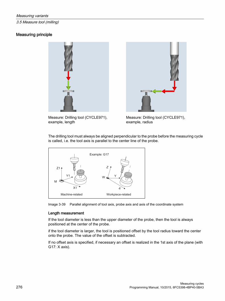
Measuring principle
Measure: Drilling tool (CYCLE971),example, length
Measure: Drilling tool (CYCLE971),example, radius
The drilling tool must always be aligned perpendicular to the probe before the measuring cycle is called, i.e. the tool axis is parallel to the center line of the probe.
Image 3-39 Parallel alignment of tool axis, probe axis and axis of the coordinate system
Length measurementIf the tool diameter is less than the upper diameter of the probe, then the tool is always positioned at the center of the probe.
if the tool diameter is larger, the tool is positioned offset by the tool radius toward the center onto the probe. The value of the offset is subtracted.
If no offset axis is specified, if necessary an offset is realized in the 1st axis of the plane (with G17: X axis).
Measuring variants3.5 Measure tool (milling)
Measuring cycles276 Programming Manual, 10/2015, 6FC5398-4BP40-5BA3

Image 3-40 Length measurement with and without offset
Radius measurementThe tool radius is measured using lateral probing at the probe in the parameterized measuring axis and measuring direction (see the following diagram).
Image 3-41 Radius measurement with and without offset
Preconditions
Note
The tool probe must be calibrated before the tool measurement (see Calibrate probe (CYCLE971) (Page 259)).
● The tool geometry data (approximate values) must be entered in a tool offset data record.
● The tool must be active.
● The machining plane must be programmed in which the probe was calibrated.
● The tool must be prepositioned in such as way that collision-free approach with the probe is possible in the measuring cycle.
Measuring variants3.5 Measure tool (milling)
Measuring cyclesProgramming Manual, 10/2015, 6FC5398-4BP40-5BA3 277

Starting position before the measurementBefore the cycle call, a starting position must be assumed from which the probe can be approached collision-free. The measuring cycle calculates the direction of approach and generates the appropriate traversing blocks.
1 2
① General SD 54626 $SNS_MEA_TP_TRIG_PLUS_DIR_AX1② General SD 54625 $SNS_MEA_TP_TRIG_MINUS_DIR_AX1
Image 3-42 Calibrate probe (CYCLE971), starting positions for calibration in the plane
Position after the end of the measuring cycleThe tool is positioned at the measurement path distance away from the measuring surface.
3.5.4.1 Calling the measuring version
ProcedureThe part program or ShopMill program to be processed has been created and you are in the editor.
1. Press the "Measure tool" softkey in the vertical softkey bar.
2. Press the "Drilling tool" softkey in the horizontal softkey bar.The input window "Measure: Tool" opens.
Measuring variants3.5 Measure tool (milling)
Measuring cycles278 Programming Manual, 10/2015, 6FC5398-4BP40-5BA3

3.5.4.2 Parameters
Parameter
G code program ShopMill programParameter Description Unit Parameter Description UnitPL Measuring plane (G17 - G19) - T Name of the tool to be meas‐
ured-
Calibration data record (1 - 6) - D Cutting edge number (1 - 9) - Calibration data record (1 - 6) -
Parameter Description UnitMeasuring ● Length (measure tool length)
● Radius (measure tool radius)-
Spindle Behavior of spindle during measurement:● Spindle stationary● Spindle rotates
-
Single cut. edge meas. Cutting tooth breakage monitoring (only with "rotating spindle") 1)
● Yes● No
-
Only for measure "Radius": - Measuring axis Corresponding to the set measuring plane:
● X (for G17)● Y (for G17)
-
DZ Length offset (for G17) mmOnly for measure "Length": - Tool offset Offset axis
● No: The tool is measured,centered.● In X● In Y
-
V Lateral offset (only for tool offset in X / Y) mmDFA Measurement path mmTSA Safe area for the measurement result mm
1) The "Cutting tooth breakage monitoring" function is shown if bit 10 is set in the general SD 54762 $SNS_MEA_FUNCTIONS_MASK_TOOL .
Measuring variants3.5 Measure tool (milling)
Measuring cyclesProgramming Manual, 10/2015, 6FC5398-4BP40-5BA3 279

3.5.4.3 Result parameters
List of the result parametersThe measuring version "Measure drill" provides the following result parameters:
Table 3-44 "Measure tool" result parameters
Parameter Description Unit_OVR [8] Actual value of length L1 1) / length of the longest cutting edge 3) mm_OVR [9] Difference of length L1 1) / difference of length of the longest cutting
edge 3)mm
_OVR [10] Actual value of radius R 2), / actual value of radius of the longest cutting edge 4)
mm
_OVR [11] Difference of radius R 2) / difference of radius of the longest cutting edge 4)
mm
_OVR [12] Actual value of length of the shortest cutting edge 3) mm_OVR [13] Difference of length of the shortest cutting edge 3) mm_OVR [14] Actual value of radius of the shortest cutting edge 4) mm_OVR [15] Difference of radius of the shortest cutting edge 4) mm_OVR [27] Work offset range mm_OVR [28] Safe area mm_OVR [29] Permissible dimensional difference mm_OVR [30] Empirical value mm_OVR [100] - _OVR [199]
Actual values of the individual radii 4), mm
_OVR [200] - _OVR [299]
Difference of the individual radii 4), mm
_OVR [300] - _OVR [399]
Actual value of the individual lengths 3) mm
_OVR [400] - _OVR [499]
Difference of the individual lengths 3) mm
_OVI [0] D number -_OVI [2] Measuring cycle number -_OVI [3] Measuring version -_OVI [5] Probe number -_OVI [7] Number of the empirical value memory -_OVI [8] T name -_OVI [9] Alarm number -
1) Only for measure "Length"2) Only for measure "Radius"3) Only for the "cutting tooth breakage monitoring" function, measure cutting edge length4) Only for the "cutting tooth breakage monitoring" function, measure cutting edge radius
Measuring variants3.5 Measure tool (milling)
Measuring cycles280 Programming Manual, 10/2015, 6FC5398-4BP40-5BA3
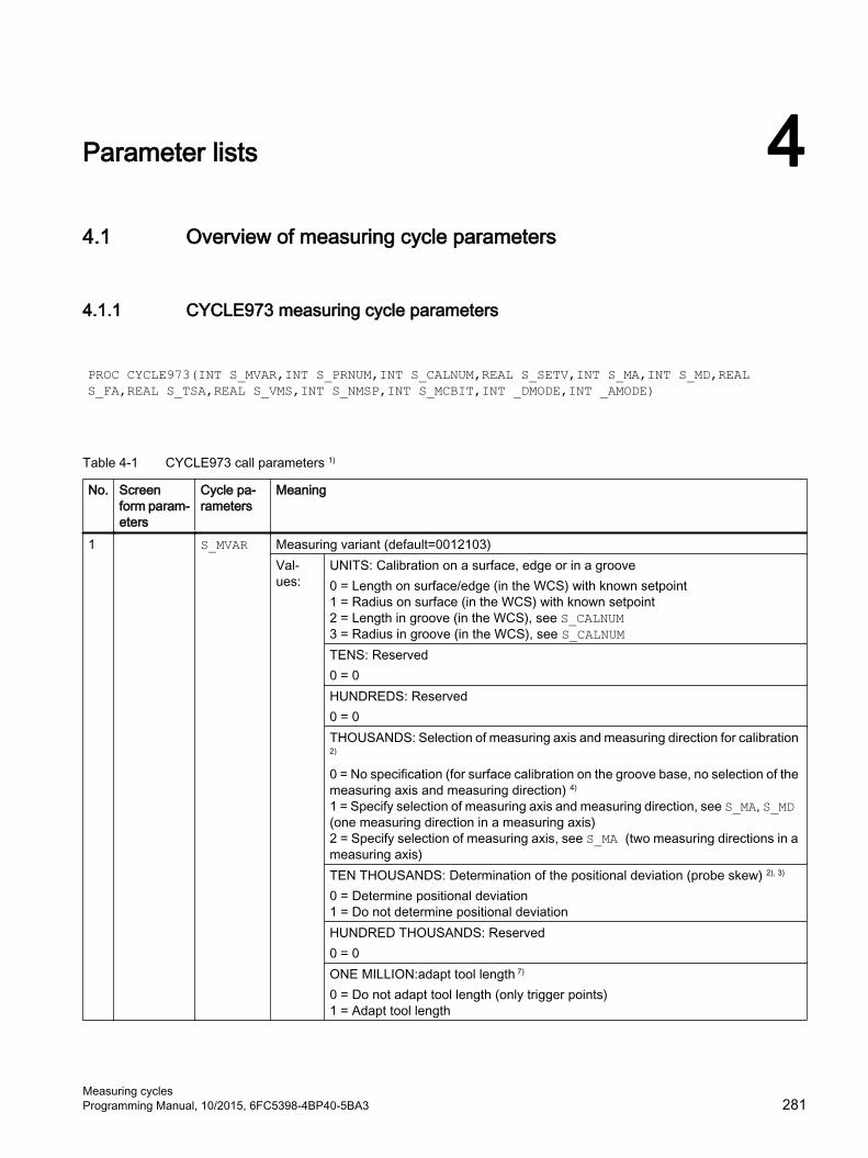
Parameter lists 44.1 Overview of measuring cycle parameters
4.1.1 CYCLE973 measuring cycle parameters
PROC CYCLE973(INT S_MVAR,INT S_PRNUM,INT S_CALNUM,REAL S_SETV,INT S_MA,INT S_MD,REAL S_FA,REAL S_TSA,REAL S_VMS,INT S_NMSP,INT S_MCBIT,INT _DMODE,INT _AMODE)
Table 4-1 CYCLE973 call parameters 1)
No. Screen form param‐eters
Cycle pa‐rameters
Meaning
1 S_MVAR Measuring variant (default=0012103)Val‐ues:
UNITS: Calibration on a surface, edge or in a groove0 = Length on surface/edge (in the WCS) with known setpoint1 = Radius on surface (in the WCS) with known setpoint2 = Length in groove (in the WCS), see S_CALNUM3 = Radius in groove (in the WCS), see S_CALNUMTENS: Reserved0 = 0HUNDREDS: Reserved0 = 0THOUSANDS: Selection of measuring axis and measuring direction for calibration 2)
0 = No specification (for surface calibration on the groove base, no selection of the measuring axis and measuring direction) 4)
1 = Specify selection of measuring axis and measuring direction, see S_MA, S_MD (one measuring direction in a measuring axis)2 = Specify selection of measuring axis, see S_MA (two measuring directions in a measuring axis)TEN THOUSANDS: Determination of the positional deviation (probe skew) 2), 3)
0 = Determine positional deviation1 = Do not determine positional deviationHUNDRED THOUSANDS: Reserved0 = 0ONE MILLION:adapt tool length 7)
0 = Do not adapt tool length (only trigger points)1 = Adapt tool length
Measuring cyclesProgramming Manual, 10/2015, 6FC5398-4BP40-5BA3 281

No. Screen form param‐eters
Cycle pa‐rameters
Meaning
2 Icon+number
S_PRNUM Number of the field of the probe parameters (not probe number)(default=1)
3 S_CALNUM Number of the calibration groove for calibration on a groove (default=1) 5)
4 S_SETV Setpoint for calibration on a surface5 X0 S_MA Measuring axis (number of the axis) 6) (default=1)
Val‐ues:
1 = 1st axis of the plane (for G18 Z)2 = 2nd axis of the plane (for G18 X)3 = 3rd axis of the plane (for G18 Y) 6)
6 +- S_MD Measuring direction (default=1)Val‐ues:
0 = Positive measuring direction1 = Negative measuring direction
7 DFA S_FA Measurement path8 TSA S_TSA Safe area9 VMS S_VMS Variable measuring velocity for calibration 2)
10 Measure‐ments
S_NMSP Number of measurements at the same location 2) (default=1)
11 S_MCBIT Reserved12 _DMODE Display mode
Val‐ues:
UNITS: Machining plane G17/G18/G190 = compatibility, the plane active before the cycle call remains active1 = G17 (only active in the cycle)2 = G18 (only active in the cycle)3 = G19 (only active in the cycle)
13 _AMODE Alternative mode1) All default values = 0 or marked as default=x2) Display depends on the general SD 54760 $SNS_MEA_FUNCTION_MASK_PIECE3) Only relevant for calibration in two axis directions4) Only measuring axis and measuring direction are determined automatically from the cutting edge position (SL) of the probe.
SL=8 → -X , SL=7 → -Z5) The number of the calibration groove (n) refers to the following general setting data (all positions in machine coordinate
system):For cutting edge SL=7:SD54615 $SNS_MEA_CAL_EDGE_BASE_AX1[n] Position of the base of the groove in the 1st axis of the plane (for G18 Z)SD54621 $SNS_MEA_CAL_EDGE_PLUS_DIR_AX2[n] Position of the groove wall in the positive direction of the 2nd axis of the plane (for G18 X)SD54622 $SNS_MEA_CAL_EDGE_MINUS_DIR_AX2[n] Position of the groove wall in the negative direction of the 2nd axis of the planeFor cutting edge SL=8:SD54619 $SNS_MEA_CAL_EDGE_BASE_AX2[n] Position of the base of the groove in the 2nd axis of the planeSD54620 $SNS_MEA_CAL_EDGE_UPPER_AX2[n] Position of the upper edge of the groove in the 2nd axis of the plane, (only to pre-position the probe)SD54617 $SNS_MEA_CAL_EDGE_PLUS_DIR_AX1[n] Position of the groove wall in the positive direction of the 1st axis of the planeSD54618 $SNS_MEA_CAL_EDGE_MINUS_DIR_AX1[n] Position of the groove wall in the negative direction of the 1st axis of the planeNote:The position values for the groove wall +- can be roughly determined.
Parameter lists4.1 Overview of measuring cycle parameters
Measuring cycles282 Programming Manual, 10/2015, 6FC5398-4BP40-5BA3

The groove width from the difference of the position values of the groove wall must be able to be precisely determined (precision dial gauge).When calibrating in the groove, it is assumed that the tool length of the probe of the calibrated axis = 0.The position values for the groove base must also be precisely determined at the machine (not just a dimension taken from a drawing).
6) Measuring axis S_MA=3 for calibration on a surface and on a turning machine with real 3rd axis of the plane (for G18 Y).7) Adapt tool length when calibrating length in the groove, or for lengths at the surface.
Workpiece probe in lathes can be defined using 2 lengths (X Z).Turning probe, type 580cutting-edge position 7: For length calibration, optionally, the Z length is corrected. Turning probe, type 580cutting edge position 8: For length calibration, optionally, the X length is correctedThe tool length is not adapted for the measurement version, radius at groove or radius at the surface.Only the corresponding trigger points are saved.
4.1.2 CYCLE974 measuring cycle parameters
PROC CYCLE974(INT S_MVAR,INT S_KNUM,INT S_KNUM1,INT S_PRNUM,REAL S_SETV,INT S_MA,REAL S_FA,REAL S_TSA,REAL S_STA1,INT S_NMSP,STRING[32] S_TNAME,INT S_DLNUM,REAL S_TZL,REAL S_TDIF,REAL S_TUL,REAL S_TLL,REAL S_TMV,INT S_K,INT S_EVNUM,INT S_MCBIT,INT _DMODE,INT _AMODE)
Table 4-2 CYCLE974 call parameters 1)
No. Screen form pa‐rameters
Cycle pa‐rameters
Meaning
1 S_MVAR Measuring version Val‐ues:
UNITS:0 = Measure front face1 = Inside measurement2 = Outside measurementTENS: ReservedHUNDREDS: Correction target0 = Only measurement (no correction of the WO or no tool offset)1 = Measurement, determination and correction of the WO (see S_KNUM) 3)
2 = Measurement and tool offset (see S_KNUM1)THOUSANDS: ReservedTEN THOUSANDS: Measurement with or without reversal of the main spindle (workspindle)0 = Measurement without reversal1 = Measurement with reversal
Parameter lists4.1 Overview of measuring cycle parameters
Measuring cyclesProgramming Manual, 10/2015, 6FC5398-4BP40-5BA3 283

No. Screen form pa‐rameters
Cycle pa‐rameters
Meaning
2 Selection S_KNUM Correction in the work offset (WO) or basic WO or basic reference 2)
Val‐ues:
UNITS:TENS: 0 = No correction1 to max. 99 numbers of the work offset or1 to max. 16 numbers of the basic offsetHUNDREDS: ReservedTHOUSANDS: Correction in WO or basic WO or basic reference0 = Correction of the adjustable WO1 = Correction of the channel-specific basic WO2 = Correction of the basic reference3 = Correction of the global basic WO 9 = Correction of the active WO or for G500, last active channel-specific basic WOTEN THOUSANDS: Coarse or fine correction in the WO, basic WO or basic ref‐erence0 = Fine correction 6)
1 = Coarse correction3 Selection S_KNUM1 Correction in tool offset 2), 4)
Val‐ues:
UNITS:TENS: HUNDREDS:0 = No correction1 to max. 999 D numbers (cutting edge numbers) for tool offset; for additive and setup offset, see also S_DLNUMTHOUSANDS: 0 or unique D numberTEN THOUSANDS: 0 or unique D number1 to max. 32000 if unique D numbers in MD have been set upHUNDRED THOUSANDS: Tool offset2)
0 = No specification (offset in tool geometry)1 = Offset of length L12 = Offset of length L23 = Offset of length L34 = Radius offsetONE MILLION: Tool offset2)
0 = No specification (offset of the tool length wear)1 = Tool offset, additive offset (AO) 5)
Tool offset value is added to the existing AO2 = Tool offset, setup offset (SO) 5)
SO (new) = SO (old) + AO (old) offset value, AO (new) = 03 = Tool offset, setup offset (SO) 5)
Tool offset value is added to the existing SO4 = Tool offset, geometry
TEN MILLION: Tool offset2)
0 = No specification (offset in tool geometry normal (not inverted))1 = Offset inverted
4 Icon+number
S_PRNUM Number of the field of the probe parameters (not probe number)(default=1)
Parameter lists4.1 Overview of measuring cycle parameters
Measuring cycles284 Programming Manual, 10/2015, 6FC5398-4BP40-5BA3

No. Screen form pa‐rameters
Cycle pa‐rameters
Meaning
5 X0 S_SETV Setpoint6 X S_MA Measuring axis (number of the axis) (default=1)
Val‐ues:
1 = 1. axis of the plane (for G18 Z)2 = 2nd axis of the plane (for G18 X)3 = 3rd axis of the plane (for G18 Y) 5)
7 DFA S_FA Measurement path8 TSA S_TSA Safe area9 α S_STA1 Starting angle for measurement with reversal10 Measure‐
mentsS_NMSP Number of measurements at the same location 2) (default=1)
11 T S_TNAME Tool name 2)
12 DL S_DLNUM Setup additive offset DL number 5)
13 TZL S_TZL Work offset 2), 4)
14 DIF S_TDIF Dimensional difference check 2), 4)
15 TUL S_TUL Upper tolerance limit (incremental to the setpoint) 4)
16 TLL S_TLL Lower tolerance limit (incremental to the setpoint) 4)
17 TMV S_TMV Offset range for averaging 2)
18 FW S_K Weighting factor for averaging 2)
19 EVN S_EVNUM Number of the empirical mean value memory 2), 7)
20 S_MCBIT Reserved21 _DMODE Display mode
Val‐ues:
UNITS: Machining plane G17/G18/G190 = Compatibility, the plane active before the cycle call remains active1 = G17 (only active in the cycle)2 = G18 (only active in the cycle)3 = G19 (only active in the cycle)
22 _AMODE Alternative modeVal‐ues:
UNITS: Dimensional tolerance yes/no0 = No1 = Yes
1) All default values = 0 or marked as default=x2) Display depends on the general SD 54760 $SNS_MEA_FUNCTION_MASK_PIECE3) Correction in WO only possible for measurement without reversal4) For tool offset in the channel-specific MD 20360 TOOL_PARAMETER_DEF_MASK , observe bit0 and bit15) Only if the "Setup additive offset" function has been set-up in the general MD 18108 $MN_MM_NUM_SUMCORR . In
addition, in the general MD 18080 $MN_MM_TOOL_MANAGEMENT_MASK , bit8 must be set to 1.6) If WO "fine" has not been set up in MDs, correction is according to WO "coarse"7) Empirical averaging only possible for tool offset
Value range for empirical mean value memory:1 to 20 numbers (n) of the empirical value memory, see channel-specific SD 55623 $SCS_MEA_EMPIRIC_VALUE[n-1]10000 to 200000 numbers (n) of the mean value memory, see channel-specific SD 55625 $SCS_MEA_AVERAGE_VALUE[n-1]
Parameter lists4.1 Overview of measuring cycle parameters
Measuring cyclesProgramming Manual, 10/2015, 6FC5398-4BP40-5BA3 285

4.1.3 CYCLE994 measuring cycle parameters
PROC CYCLE994(INT S_MVAR,INT S_KNUM,INT S_KNUM1,INT S_PRNUM,REAL S_SETV,INT S_MA,REAL S_SZA,REAL S_SZO,REAL S_FA,REAL S_TSA,INT S_NMSP,STRING[32] S_TNAME,INT S_DLNUM,REAL S_TZL,REAL S_TDIF,REAL S_TUL,REAL S_TLL,REAL S_TMV,INT S_K,INT S_EVNUM,INT S_MCBIT,INT _DMODE,INT _AMODE)
Table 4-3 CYCLE994 call parameters 1)
No. Screen form param‐eters
Cycle pa‐rameters
Meaning
1 S_MVAR Measuring version Val‐ues:
UNITS: Inside or outside measurement (default = 1)1 = Inside measurement2 = Outside measurementTENS: ReservedHUNDREDS: Correction target0 = Only measurement (no correction of the WO or no tool offset)1 = Measurement and determination and correction of the WO (see S_KNUM) 3)
2 = Measurement and tool offset (see S_KNUM1)THOUSANDS: Protection zone0 = No consideration of a protection zone1 = Consideration of a protection zone. Traverse axis, 1st axis of the plane (for G18 Z). Measuring axis, see S_MA.2 = Consideration of a protection zone. Traverse axis, 2nd axis of the plane (for G18 X). Measuring axis, see S_MA.3 = Consideration of a protection zone. Traverse axis, 3rd axis of the plane (for G18 Y). Measuring axis, see S_MA. 8)
2 Selection S_KNUM Correction of the work offset (WO) or basic WO or basic reference 2)
Val‐ues:
UNITS: TENS: 0 = No correction1 to max. 99 numbers of the work offset or1 to max. 16 numbers of the basic offsetHUNDREDS: ReservedTHOUSANDS: Correction of WO or basic or basic reference0 = Correction of the adjustable WO1 = Correction of the channel-specific basic WO2 = Correction of the basic reference3 = Correction of the global basic WO 9 = Correction of the active WO or for G500 in last active channel-specific basic WOTEN THOUSANDS: Coarse or fine correction in the WO, basic WO or basic reference0 = Fine correction 6)
1 = Coarse correction
Parameter lists4.1 Overview of measuring cycle parameters
Measuring cycles286 Programming Manual, 10/2015, 6FC5398-4BP40-5BA3

No. Screen form param‐eters
Cycle pa‐rameters
Meaning
3 Selection S_KNUM1 Correction in tool offset 2), 4)
Val‐ues:
UNITS: TENS: HUNDREDS: 0 = No correction1 to max. 999 D numbers (cutting edge numbers) for tool offset; for additive and setup offset, see also S_DLNUMTHOUSANDS: 0 or unique D numbersTEN THOUSANDS: 0 or unique D numbers1 to max. 32000, if unique D numbers in MD have been set upHUNDRED THOUSANDS: Tool offset2)
0 = No specification (offset tool geometry)1 = Offset of length L12 = Offset of length L23 = Offset of length L34 = Radius offsetONE MILLION: Tool offset2)
0 = No specification (offset of the tool length wear)1 = Tool offset, additive offset (AO) 5)
Tool offset value is added to the existing AO2 = Tool offset, setup offset (SO) 5)
SO (new) = SO (old) + AO (old) offset value, AO (new) = 03 = Tool offset, setup offset (SO) 5)
Tool offset value is added to the existing SO4 = Tool offset, geometry
TEN MILLION: Tool offset2)
0 = No specification (offset in tool geometry normal, not inverted)1 = Offset inverted
4 Icon+number
S_PRNUM Number of the field of the probe parameters (not probe number)(default=1)
5 X0 S_SETV Setpoint6 X S_MA Number of the measuring axis (default=1)
Val‐ues:
1 = 1st axis of the plane (for G18 Z)2 = 2nd axis of the plane (for G18 X)3 = 3rd axis of the plane (for G18 Y) 8)
7 X1 S_SZA Length of the protection zone in the measuring axis8 Y1 S_SZO Length of the protection zone in the traverse axis9 DFA S_FA Measurement path10 TSA S_TSA Safe area11 Measure‐
mentsS_NMSP Number of measurements at the same location 2) (default=1)
12 T S_TNAME Tool name 2)
13 DL S_DLNUM Setup additive offset DL number 5)
14 TZL S_TZL Work offset 2), 4)
15 DIF S_TDIF Dimensional difference check 2), 4)
Parameter lists4.1 Overview of measuring cycle parameters
Measuring cyclesProgramming Manual, 10/2015, 6FC5398-4BP40-5BA3 287

No. Screen form param‐eters
Cycle pa‐rameters
Meaning
16 TUL S_TUL Upper tolerance limit (incremental to the setpoint) 4)
17 TLL S_TLL Lower tolerance limit (incremental to the setpoint) 4)
18 TMV S_TMV Offset range for averaging 2)
19 FW S_K Weighting factor for averaging 2)
20 EVN S_EVNUM Number of the empirical value memory 2), 7)
21 S_MCBIT Reserved22 _DMODE Display mode
Val‐ues:
UNITS: Machining plane G17/G18/G190 = Compatibility, the plane active before the cycle call remains active1 = G17 (only active in the cycle)2 = G18 (only active in the cycle)3 = G19 (only active in the cycle)
23 _AMODE Alternative modeVal‐ues:
UNITS: Dimensional tolerance yes/no0 = No1 = Yes
1) All default values = 0 or marked as default=x2) Display depends on the general SD 54760 $SNS_MEA_FUNCTION_MASK_PIECE3) Correction in WO only possible for measurement without reversal4) For tool offset, observe the channel MD 20360 TOOL_PARAMETER_DEF_MASK 5) Only if the "Setup additive offset" function has been set-up in the general MD 18108 $MN_MM_NUM_SUMCORR . In
addition, the general MD 18080 $MN_MM_TOOL_MANAGEMENT_MASK , bit8 must be set to 1.6) If WO "fine" has not been set up in MDs, correction is according to WO "coarse"7) Empirical averaging only possible for tool offset
Value range for empirical mean value memory:1 to 20 numbers (n) of the empirical value memory, see channel-specific SD 55623 $SCS_MEA_EMPIRIC_VALUE[n-1]10000 to 200000 numbers (n) of the mean value memory, see channel-specific SD 55625 $SCS_MEA_AVERAGE_VALUE[n-1]
8) If Y axis is available on the machine
4.1.4 CYCLE976 measuring cycle parameters
PROC CYCLE976(INT S_MVAR,INT S_PRNUM,REAL S_SETV,REAL S_SETV0,INT S_MA,INT S_MD,REAL S_FA,REAL S_TSA,REAL S_VMS,REAL S_STA1,INT S_NMSP,INT S_SETV1,INT _DMODE,INT _AMODE)
Parameter lists4.1 Overview of measuring cycle parameters
Measuring cycles288 Programming Manual, 10/2015, 6FC5398-4BP40-5BA3
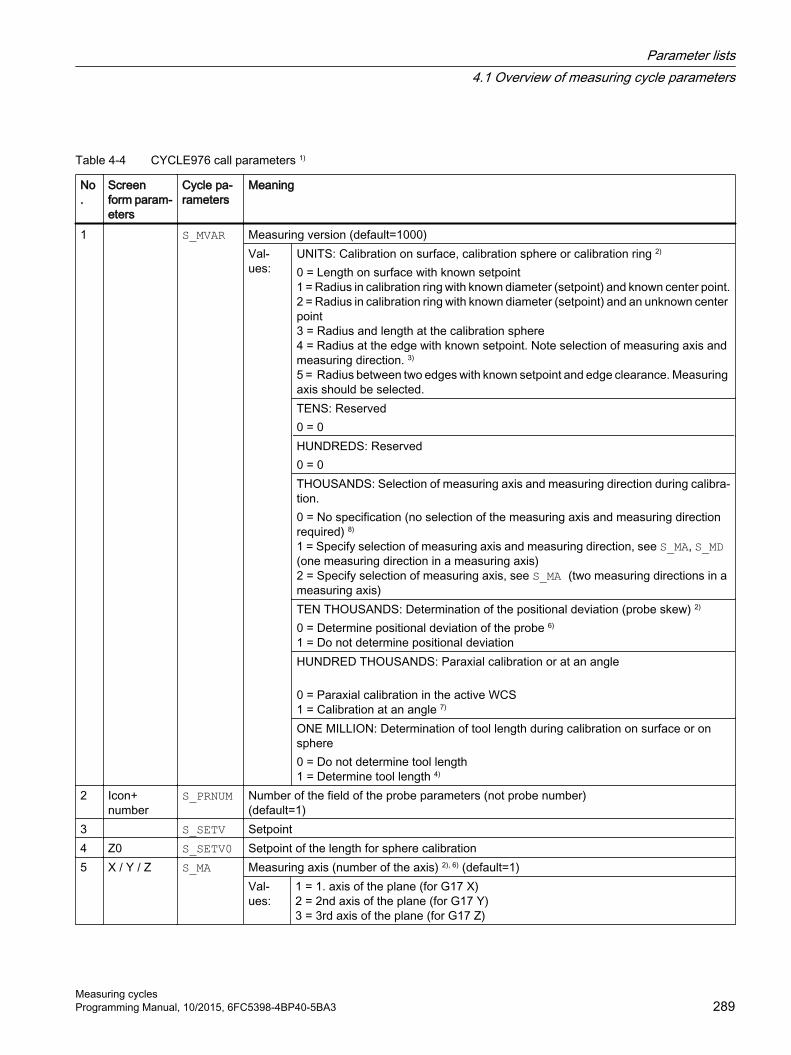
Table 4-4 CYCLE976 call parameters 1)
No.
Screen form param‐eters
Cycle pa‐rameters
Meaning
1 S_MVAR Measuring version (default=1000)Val‐ues:
UNITS: Calibration on surface, calibration sphere or calibration ring 2)
0 = Length on surface with known setpoint1 = Radius in calibration ring with known diameter (setpoint) and known center point.2 = Radius in calibration ring with known diameter (setpoint) and an unknown center point3 = Radius and length at the calibration sphere4 = Radius at the edge with known setpoint. Note selection of measuring axis and measuring direction. 3)
5 = Radius between two edges with known setpoint and edge clearance. Measuring axis should be selected.TENS: Reserved0 = 0HUNDREDS: Reserved0 = 0THOUSANDS: Selection of measuring axis and measuring direction during calibra‐tion.0 = No specification (no selection of the measuring axis and measuring direction required) 8)
1 = Specify selection of measuring axis and measuring direction, see S_MA, S_MD (one measuring direction in a measuring axis)2 = Specify selection of measuring axis, see S_MA (two measuring directions in a measuring axis)TEN THOUSANDS: Determination of the positional deviation (probe skew) 2)
0 = Determine positional deviation of the probe 6)
1 = Do not determine positional deviationHUNDRED THOUSANDS: Paraxial calibration or at an angle
0 = Paraxial calibration in the active WCS1 = Calibration at an angle 7)
ONE MILLION: Determination of tool length during calibration on surface or on sphere0 = Do not determine tool length1 = Determine tool length 4)
2 Icon+number
S_PRNUM Number of the field of the probe parameters (not probe number)(default=1)
3 S_SETV Setpoint4 Z0 S_SETV0 Setpoint of the length for sphere calibration5 X / Y / Z S_MA Measuring axis (number of the axis) 2), 6) (default=1)
Val‐ues:
1 = 1. axis of the plane (for G17 X)2 = 2nd axis of the plane (for G17 Y)3 = 3rd axis of the plane (for G17 Z)
Parameter lists4.1 Overview of measuring cycle parameters
Measuring cyclesProgramming Manual, 10/2015, 6FC5398-4BP40-5BA3 289

No.
Screen form param‐eters
Cycle pa‐rameters
Meaning
6 + - S_MD Measuring direction 2), 6)
Val‐ues:
0 = Positive1 = Negative
7 DFA S_FA Measurement path8 TSA S_TSA Safe area9 VMS S_VMS Variable measuring velocity for calibration 2)
10 α S_STA1 Starting angle 2), 5)
11 Measure‐ments
S_NMSP Number of measurements at the same location 2) (default=1)
12 X0 S_SETV1 Edge reference point when calibrating between 2 edges 3)
13 _DMODE Display modeVal‐ues:
UNITS: Machining plane G17/G18/G190 = Compatibility, the plane active before the cycle call remains active1 = G17 (only active in the cycle)2 = G18 (only active in the cycle)3 = G19 (only active in the cycle)
14 _AMODE Alternative mode1) All default values = 0 or marked as default=x2) Display depends on the general SD 54760 $SNS_MEA_FUNCTION_MASK_PIECE3) For "Radius in the calibration ring" calibration, the diameter and the center point of the ring must be known (four measuring
directions).For "Radius on two edges" calibration, the distance to the edges in the direction of the measuring axis must be known (two measuring directions).For "Radius on one edge" calibration, the setpoint of the surface must be known.
4) Measuring variant only calibration on a surface (length on surface), corrected tool length results from S_MD and S_MA.5) Only for measuring variant "Calibration ring, ... and known center point" (S_MVAR=1xxx02).6) Measuring axis only for measuring variant S_MVAR=0 or =xx1x01 or =xx2x01 or =20000
Measuring variant: "Calibration on a surface" → selection of measuring axis and measuring directionor on the "Calibration ring, ... and known center point" → selection of an axis direction and selection of measuring axis and measuring directionor on the "Calibration ring, ... and known center point" → selection of two axis directions and selection of measuring axisor "Determination of the probe length" → S_MA=3 → 3rd axis of the plane (for G17 Z)
7) Measuring version, only calibration in calibration ring or on calibration sphere For "Calibration on calibration sphere", for measuring at an angle, the axis circles around the sphere at the equator.
8) For "Radius in calibration ring" calibration with unknown center point, four measuring directions in the plane (for G17 +-X +-Y).For "Length on surface" calibration in minus direction of the tool axis (for G17 -Z).
Parameter lists4.1 Overview of measuring cycle parameters
Measuring cycles290 Programming Manual, 10/2015, 6FC5398-4BP40-5BA3

4.1.5 CYCLE978 measuring cycle parameters
PROC CYCLE978(INT S_MVAR,INT S_KNUM,INT S_KNUM1,INT S_PRNUM,REAL S_SETV,REAL S_FA,REAL S_TSA,INT S_MA,INT S_MD,INT S_NMSP,STRING[32] S_TNAME,INT S_DLNUM,REAL S_TZL,REAL S_TDIF,REAL S_TUL,REAL S_TLL,REAL S_TMV,INT S_K,INT S_EVNUM,INT S_MCBIT,INT _DMODE,INT _AMODE)
Table 4-5 CYCLE978 call parameters 1)
No. Screen form parameters
Cycle pa‐rameters
Meaning
1 S_MVAR Measuring version Val‐ues:
UNITS: Contour element0 = Measure surfaceTENS: ReservedHUNDREDS: Correction target0 = Only measurement (no correction of the WO or no tool offset)1 = Measurement, determination and correction of the WO (see S_KNUM)2 = Measurement and tool offset (see S_KNUM1)THOUSANDS: ReservedTEN THOUSANDS: Measurement with/without spindle reversal or align meas‐uring probe in the switching direction 9)
0 = Measurement without spindle reversal, without probe alignment1 = Measurement with spindle reversal2 = Align probe in switching direction
2 Selection S_KNUM Correction of the work offset (WO) or basic WO or basic reference 2)
Val‐ues:
UNITS: TENS: 0 = No correction1 to max. 99 numbers of the work offset or1 to max. 16 numbers of the basic offsetHUNDREDS: ReservedTHOUSANDS: Correction of WO or basic or basic reference0 = Correction of the adjustable WO1 = Correction of the channel-specific basic WO2 = Correction of the basic reference3 = Correction of the global basic WO 9 = Correction of the active WO or for G500 in last active channel-specific basic WOTEN THOUSANDS: Coarse or fine correction in the WO, basic WO or basic reference0 = Fine correction 6)
1 = Coarse correction
Parameter lists4.1 Overview of measuring cycle parameters
Measuring cyclesProgramming Manual, 10/2015, 6FC5398-4BP40-5BA3 291

No. Screen form parameters
Cycle pa‐rameters
Meaning
3 Selection S_KNUM1 Correction in tool offset 2)
Val‐ues:
UNITS:TENS:HUNDREDS: 0 = No correction1 to max. 999 D numbers (cutting edge numbers) for tool offset,for additive and setup offset, see also S_DLNUMTHOUSANDS: 0 or unique D numbersTEN THOUSANDS: 0 or unique D numbers1 to max. 32000 if unique D numbers in MDs have been set upHUNDRED THOUSANDS: Tool offset2)
0 = No specification (offset in tool geometry)1 = Offset of length L12 = Offset of length L23 = Offset of length L34 = Radius offsetONE MILLION: Tool offset2)
0 = No specification (offset of the tool radius wear)1 = Tool offset, additive offset (AO) 5)
Tool offset value is added to the existing AO2 = Tool offset, setup offset (SO) 5)
SO (new) = SO (old) + AO (old) offset value, AO (new) = 03 = Tool offset, setup offset (SO) 5)
Tool offset value is added to the existing SO4 = Tool offset, geometryTEN MILLION: Tool offset2)
0 = No specification (offset in tool geometry normal, not inverted)1 = Offset inverted
4 Icon+num‐ber
S_PRNUM Number of the field of the probe parameter (not probe number)(value range 1 to 12)
5 X0 S_SETV Setpoint6 DFA S_FA Measurement path7 TSA S_TSA Safe area8 X S_MA Number of the measuring axis 7) (value range 1 to 3)
Val‐ues:
1 = 1st axis of the plane (for G17 X)2 = 2nd axis of the plane (for G17 Y)3 = 3rd axis of the plane (for G17 Z) Measurement in tool direction
9 S_MD Measuring direction of the measuring axisVal‐ues:
1 = Positive measuring direction2 = Negative measuring direction
10 Measure‐ments
S_NMSP Number of measurements at the same location 2) (value range 1 to 9)
11 TR S_TNAME Tool name 3)
12 DL S_DLNUM Setup additive offset DL number 5)
13 TZL S_TZL Work offset 2), 3)
14 DIF S_TDIF Dimensional difference check 2), 3)
Parameter lists4.1 Overview of measuring cycle parameters
Measuring cycles292 Programming Manual, 10/2015, 6FC5398-4BP40-5BA3

No. Screen form parameters
Cycle pa‐rameters
Meaning
15 TUL S_TUL Upper tolerance limit (incremental to the setpoint) 3)
16 TLL S_TLL Lower tolerance limit (incremental to the setpoint) 3)
17 TMV S_TMV Offset range for averaging 2)
18 FW S_K Weighting factor for averaging 2)
19 EVN S_EVNUM Date set, empirical value memory 2), 8)
20 S_MCBIT Reserved21 _DMODE Display mode
Val‐ues:
UNITS: Machining plane G17/G18/G190 = Compatibility, the plane active before the cycle call remains active1 = G17 (only active in the cycle)2 = G18 (only active in the cycle)3 = G19 (only active in the cycle)
22 _AMODE Alternative modeVal‐ues:
UNITS: Dimensional tolerance yes/no0 = No1 = Yes
1) All default values = 0 or marked as the range of values a to b2) Display depends on the general SD 54760 $SNS_MEA_FUNCTION_MASK_PIECE3) Only for offset in tool, otherwise parameter = ""4) Only for offset in tool and dimensional tolerance "Yes", otherwise parameter = 05) Only if the "Setup additive offset" function has been set-up in the general MD 18108 $MN_MM_NUM_SUMCORR . In
addition, in the general MD 18080 $MN_MM_TOOL_MANAGEMENT_MASK , bit8 must be set to 1.6) If WO "fine" has not been set up in MDs, correction is according to WO "coarse"7) Offset in tool geometry:
For measurement in the plane (S_MA=1 or S_MA=2) Offset in tool radiusFor measurement in tool direction (S_MA=3) Offset in tool length L1
8) Empirical averaging for tool offset and correction in WO possibleValue range for empirical mean value memory:1 to 20 numbers (n) of the empirical value memory, see channel-specific SD 55623 $SCS_MEA_EMPIRIC_VALUE[n-1]10000 to 200000 numbers (n) of the mean value memory, see channel-specific SD 55625 $SCS_MEA_AVERAGE_VALUE[n-1]
9) When measuring with spindle reversal, the radius/diameter of the probe must be precisely determined. This should be realized with a calibration version of the CYCLE976 radius at the ring or at the edge or at the sphere. Otherwise, the measurement result will be falsified.
4.1.6 CYCLE998 measuring cycle parameters
PROC CYCLE998(INT S_MVAR,INT S_KNUM,INT S_RA,INT S_PRNUM,REAL S_SETV,REAL S_STA1,REAL S_INCA,REAL S_FA,REAL S_TSA,INT S_MA,INT S_MD,REAL S_ID,REAL S_SETV0,REAL S_SETV1,REAL S_SETV2,REAL S_SETV3,INT S_NMSP,INT S_EVNUM,INT _DMODE,INT _AMODE)
Parameter lists4.1 Overview of measuring cycle parameters
Measuring cyclesProgramming Manual, 10/2015, 6FC5398-4BP40-5BA3 293

Table 4-6 CYCLE998 call parameters 1)
No.
Screen form parameters
Cycle pa‐rameters
Meaning
1 S_MVAR Measuring variant (default=5)Val‐ues:
UNITS: Contour element5 = Measure edge (one angle)6 = Measure plane (two angles)TENS: ReservedHUNDREDS: Correction target0 = Only measurement and no correction of WO1 = Measurement, determination and correction of the WO (see S_KNUM)THOUSANDS: Protection zone0 = No consideration of a protection zone1 = Consideration of a protection zoneTEN THOUSANDS: Measurement with spindle reversal (difference measurement)0 = Measurement without spindle reversal1 = Measurement with spindle reversalHUNDRED THOUSANDS: Measurement at an angle or paraxial0 = Measurement at an angle1 = Measurement paraxial
2 Selection S_KNUM Correction of the work offset (WO) or basic WO or basic reference 2)
Val‐ues:
UNITS:TENS: 0 = No correction1 to max. 99 numbers of the work offset or1 to max. 16 numbers of the basic offsetHUNDREDS: ReservedTHOUSANDS: Correction of WO or basic or basic reference0 = Correction adjustable WO1 = correction, channel-specific basic WO2 = correction basic reference9 = Correction active WO and/or for G500 in last active channel-specific basic WOTEN THOUSANDS: Coarse or fine correction in the WO or basic WO or basic reference 3)
0 = Fine correction1 = Coarse correction
3
A, B, C
S_RA Correction target coordinate rotation or rotary axisVal‐ues:
0 = Correction target coordinate rotation around the axis that results from param‐eter S_MA 4)
>0 = Correction target rotary axis. Number of the channel axis number of the rotary axis (preferably rotary table). The angle offset is made in the translatory part of the WO of the rotary axis.
4 Icon+number
S_PRNUM Number of the field of the probe parameter(default=1)
5 DX / DY / DZ S_SETV Distance (incremental) from the starting position to measuring point P1 of the measuring axis (S_MA) 5)
Parameter lists4.1 Overview of measuring cycle parameters
Measuring cycles294 Programming Manual, 10/2015, 6FC5398-4BP40-5BA3

No.
Screen form parameters
Cycle pa‐rameters
Meaning
6 α S_STA1 Angle setpoint for "Align edge" or for "Align plane" around the 1st axis of the plane (for G17 X) 9)
7 β S_INCA Angle setpoint for "Align plane" around the 2nd axis of the plane (for G17 Y) 9)
8 DFA S_FA Measurement path9 TSA S_TSA Safe area
Monitoring of the angle difference to the angle setpoint [degrees] 6)
10 X / Y / Z S_MA Measuring axis, offset axis 7) (default=201)Val‐ues:
UNITS: Number of the measuring axis1 = 1st axis of the plane (for G17 X)2 = 2nd axis of the plane (for G17 Y)3 = 3rd axis of the plane (for G17 Z)TENS: ReservedHUNDREDS: Number of the offset axis1 = 1st axis of the plane (for G17 X)2 = 2nd axis of the plane (for G17 Y)3 = 3rd axis of the plane (for G17 Z)
11 +- S_MD Measuring direction of the measuring axis 8)
Val‐ues:
0 = Measuring direction is determined from the setpoint and the actual position of the measuring axis (compatibility)1 = Positive measuring direction2 = Negative measuring direction
12 L2 S_ID For measuring version "Align edge":Distance (incremental) between the measuring points P1 and P2 in the offset axis (value >0)For measuring version "Align plane", the parameters listed below apply.
13 L2 S_SETV0 Distance between the measuring points P1 and P2 in the 1st axis of the plane 10)
14 S_SETV1 Distance between the measuring points P1 and P2 in the 2nd axis of the plane 11), 12)
15 L3x S_SETV2 Distance between the measuring points P1 and P3 in the 1st axis of the plane 11)
16 L3y S_SETV3 Distance between the measuring points P1 and P3 in the 2nd axis of the plane 10)
17 Measure‐ments
S_NMSP Number of measurements at the same location 2) (default=1)
18 S_EVNUM Date set, empirical value memory 2), 13)
19 _DMODE Display modeVal‐ues:
UNITS: Machining plane G17/G18/G190 = compatibility, the plane active before the cycle call remains active1 = G17 (only active in the cycle)2 = G18 (only active in the cycle)3 = G19 (only active in the cycle)
20 _AMODE Reserved (alternative mode)1) All default values = 0 or marked as default=x2) Display depends on the general SD 54760 $SNS_MEA_FUNCTION_MASK_PIECE3) WO "fine"only if correction target is rotary axis and MD 52207 $MCS_AXIS_USAGE_ATTRIB[n] Bit6=1.
If WO has not been set up in MDs, correction is according to WO "coarse".4) Example for offset in coordinate rotation: S_MA=102 Measuring axis Y, offset axis X results in coordinate rotation around
Z (for G17)5) Value only relevant for protection zone "Yes" (S_MVARTHOUSANDS position = 1)
Parameter lists4.1 Overview of measuring cycle parameters
Measuring cyclesProgramming Manual, 10/2015, 6FC5398-4BP40-5BA3 295

6) When positioning from measuring point P1 to measuring point P2 in the offset axis, the angles in parameters S_STA1 and S_TSA are added.
7) Number of the measuring axis must not be the same as the number of the offset axis (e.g. 101 not permitted)8) Measuring direction only for "Align edge" and "Measurement paraxial" (S_MVAR=10x105)9) Angular range S_STA1 ±45 degrees for "Align edge"
Angular range S_STA1 0 to +60 degrees and S_INCA ±30 degrees for "Align plane"10) For measuring versions "Align plane" and "Align edge"11) For measuring variant "Measure plane" and "Measurement paraxial"12) Not for measuring cycle version SW04.04.13) Experience value generation for correction in WO; value range of empirical values mean value memory:
1 to 20 numbers(n) of the empirical value memory, see channel-specific SD 55623 $SCS_MEA_EMPIRIC_VALUE[n-1]
4.1.7 CYCLE977 measuring cycle parameters
PROC CYCLE977(INT S_MVAR,INT S_KNUM,INT S_KNUM1,INT S_PRNUM,REAL S_SETV,REAL S_SETV0,REAL S_SETV1,REAL S_FA,REAL S_TSA,REAL S_STA1,REAL S_ID,REAL S_SZA,REAL S_SZO,INT S_MA,INT S_NMSP,STRING[32] S_TNAME,INT S_DLNUM,REAL S_TZL,REAL S_TDIF,REAL S_TUL,REAL S_TLL,REAL S_TMV,INT S_K,INT S_EVNUM,INT S_MCBIT,INT _DMODE,INT _AMODE)
Table 4-7 CYCLE977 call parameters 1)
No. Screen form param‐eters
Cycle pa‐rameters
Meaning
1 S_MVAR Measuring version Val‐ues:
UNITS: Contour element (value range 1 to 6)1 = Measure hole2 = Measure spigot (shaft)3 = Measure groove4 = Measure rib5 = Measure rectangle, inside6 = Measure rectangle, outsideTENS: ReservedHUNDREDS: Correction target0 = Only measurement (no correction of the WO or no tool offset)1 = Measurement, determination and correction of the WO (see S_KNUM)2 = Measurement and tool offset (see S_KNUM1)THOUSANDS: Protection zone0 = No consideration of a protection zone1 = Consideration of a protection zoneTEN THOUSANDS: Measurement with/without spindle reversal (differential meas‐urement) or align measuring probe in the switching direction0 = Measurement without spindle reversal, do not align probe1 = Measurement with spindle reversal2 = Align probe in switching direction
Parameter lists4.1 Overview of measuring cycle parameters
Measuring cycles296 Programming Manual, 10/2015, 6FC5398-4BP40-5BA3

No. Screen form param‐eters
Cycle pa‐rameters
Meaning
2 Selection S_KNUM Correction of the work offset (WO) or basic WO or basic reference 2)
Val‐ues:
UNITS: TENS: 0 = No correction1 to max. 99 numbers of the work offset or1 to max. 16 numbers of the basic offsetHUNDREDS: ReservedTHOUSANDS: Correction of WO or basic or basic reference0 = Correction of the adjustable WO1 = Correction of the channel-specific basic WO2 = Correction of the basic reference3 = Correction of the global basic WO 9 = Correction of the active WO or for G500 in last active channel-specific basic WOTEN THOUSANDS: Coarse or fine correction in the WO, basic WO or basic refer‐ence0 = Fine correction 6)
1 = Coarse correction3 Selection S_KNUM1 Correction in tool offset 2)
Val‐ues:
UNITS:TENS:HUNDREDS:0 = No correction1 to max. 999 D numbers (cutting edge numbers) for tool offset; for additive and setup offset, see also S_DLNUMTHOUSANDS: 0 or unique D numbersTEN THOUSANDS: 0 or unique D numbers1 to max. 32000 if unique D numbers in MDs have been set upHUNDRED THOUSANDS: Tool offset2)
0 = No specification (offset tool radius)1 = Offset of length L12 = Offset of length L23 = Offset of length L34 = Radius offsetONE MILLION: Tool offset2)
0 = No specification (offset of the tool radius wear)1 = Tool offset, additive offset (AO) 5)
Tool offset value is added to the existing AO2 = Tool offset, setup offset (SO) 5)
SO (new) = SO (old) + AO (old) offset value, AO (new) = 03 = Tool offset, setup offset (SO) 5)
Tool offset value is added to the existing SO4 = Tool offset, geometryTEN MILLION: Tool offset2)
0 = No specification (offset in tool geometry normal, not inverted)1 = Offset inverted
Parameter lists4.1 Overview of measuring cycle parameters
Measuring cyclesProgramming Manual, 10/2015, 6FC5398-4BP40-5BA3 297

No. Screen form param‐eters
Cycle pa‐rameters
Meaning
4 Icon+number
S_PRNUM Number of the field of the probe parameter (not probe number)(value range 1 to 12)
5 X0 S_SETV Setpoint6 X0 S_SETV0 Setpoint for rectangle in 1st axis of the plane (X for G17)7 Y0 S_SETV1 Setpoint for rectangle in 2nd axis of the plane (Y for G17)8 DFA S_FA Measurement path9 TSA S_TSA Safe area10 α 0 S_STA1 Starting angle11 DZ S_ID Absolute incremental value
1. Incremental infeed of the 3rd axis of the plane (Z for G17)Infeed direction via sign of S_ID. For measurement of spigot, rib and rectangle outside, S_ID is used to define the lowering to measuring height.
2. Consideration of a protection zoneFor measurement of hole, groove and rectangle inside and a protection zone, S_ID is used to define the overtravel height.
12 X1 S_SZA Diameter or length (width) of the protection zone 7)
13 Y1 S_SZO For "Measure rectangle": Width of the protection zone of the 2nd axis of the plane14 X S_MA Number of the measuring axis 7) (only for measurement of groove or rib)
Val‐ues:
1 = 1st axis of the plane (for G17 X)2 = 2nd axis of the plane (for G17 Y)
15 Measure‐ments
S_NMSP Number of measurements at the same location 2) (value range 1 to 9)
16 TR S_TNAME Tool name 2)
17 DL S_DLNUM Setup additive offset DL number 5)
18 TZL S_TZL Work offset 2), 4)
19 DIF S_TDIF Dimensional difference check 2), 4)
20 TUL S_TUL Upper tolerance limit (incremental to the setpoint) 4)
21 TLL S_TLL Lower tolerance limit (incremental to the setpoint) 4)
22 TMV S_TMV Offset range for averaging 2)
23 FW S_K Weighting factor for averaging 2)
24 S_EVNUM Data set, empirical mean value memory 2), 8)
25 S_MCBIT Reserved26 _DMODE Display mode
Val‐ues:
UNITS: Machining plane G17/G18/G190 = Compatibility, the plane active before the cycle call remains active1 = G17 (only active in the cycle)2 = G18 (only active in the cycle)3 = G19 (only active in the cycle)
27 _AMODE Alternative modeVal‐ues:
UNITS: Dimensional tolerance yes/no0 = No1 = Yes
1) All default values = 0 or marked as the range of values a to b
Parameter lists4.1 Overview of measuring cycle parameters
Measuring cycles298 Programming Manual, 10/2015, 6FC5398-4BP40-5BA3

2) Display depends on the general SD 54760 $SNS_MEA_FUNCTION_MASK_PIECE3) Only for offset in tool, otherwise parameter = ""4) Only for offset in tool and dimensional tolerance "Yes", otherwise parameter = 05) Only if the "Setup additive offset" function has been set-up in the general MD 18108 $MN_MM_NUM_SUMCORR . In
addition, in the general MD 18080 $MN_MM_TOOL_MANAGEMENT_MASK , bit8 must be set to 1.6) If WO "fine" has not been set up in MDs, correction is according to WO "coarse"7) Diameter or width of the protection zone within a hole or groove
Diameter or width of the protection zone outside of a spigot or rib8) Empirical averaging possible for tool offset
Value range for empirical mean value memory:1 to 20 numbers (n) of the empirical value memory, see channel-specific SD 55623 $SCS_MEA_EMPIRIC_VALUE[n-1]10000 to 200000 numbers (n) of the mean value memory, see channel-specific SD 55625 $SCS_MEA_AVERAGE_VALUE[n-1]
4.1.8 CYCLE961 measuring cycle parameters
PROC CYCLE961(INT S_MVAR,INT S_KNUM,INT S_PRNUM,REAL S_SETV0,REAL S_SETV1,REAL S_SETV2,REAL S_SETV3,REAL S_SETV4,REAL S_SETV5,REAL S_SETV6,REAL S_SETV7,REAL S_SETV8,REAL S_SETV9,REAL S_STA1,REAL S_INCA,REAL S_ID,REAL S_FA,REAL S_TSA,INT S_NMSP,INT S_MCBIT,INT _DMODE,INT _AMODE)
Parameter lists4.1 Overview of measuring cycle parameters
Measuring cyclesProgramming Manual, 10/2015, 6FC5398-4BP40-5BA3 299

Table 4-8 CYCLE961 call parameters 1)
No.
Screen form pa‐rameters
Cycle pa‐rameters
Meaning
1 S_MVAR Measuring version (default ≥ 6)Val‐ues:
UNITS: Contour element5 = Setup of right-angled inside corner, setpoint specification of angle and distan‐ces A1 to A3 6 = Setup of right-angled outside corner, setpoint specification of angle and dis‐tances A1 to A3 7 = Setup of inside corner, specification of angle and distances A1 to A4 8 = Setup of outside corner, specification of angle and distances A1 to A4TENS: Setpoint specification as distance or via four points0 = Setpoint specification as distance (polar)1 = Setpoint specification using four points (measuring points P1 to P4)HUNDREDS: Correction target0 = Only measurement (no correction of WO or no tool offset)1 = Measurement, determination and correction of the WO, see S_KNUMTHOUSANDS: Protection zone0 = No consideration of a protection zone (obstacle)1 = Consideration of a protection zone (obstacle), see S_IDTEN THOUSANDS: Position of the corner in the WCS0 = Position of the corner is determined using parameter S_STA1 (compatibility)1 = Position 1 of the corner at the positioned starting point of the measurement 6)
2= Position 2 of the corner, distances in the 1st axis of the plane (for G17 X) are negative (see S_SETV0, S_SETV1)3 = Position 3 of the corner, distances in the 1st and 2nd axis of the plane (for G17 XY) are negative (seeS_SETV0to S_SETV3)4 = Position 4 of the corner, distances in the 2nd axis of the plane (for G17 Y) are negative (see S_SETV2, S_SETV3)
2 Selection S_KNUM Correction of the work offset (WO) or basic WO or basic reference 2)
Val‐ues:
UNITS: TENS: 0 = No correction1 to max. 99 numbers of the work offset or1 to max. 16 numbers of the basic offsetHUNDREDS: ReservedTHOUSANDS: Correction of WO or basic or basic reference0 = Correction adjustable WO1 = correction, channel-specific basic WO2 = correction basic reference9 = Correction active WO and/or for G500 last active channel-specific basic WOTEN THOUSANDS: Coarse or fine correction in the WO, basic WO or basic refer‐ence0 = Fine correction 5)
1 = Coarse correction
Parameter lists4.1 Overview of measuring cycle parameters
Measuring cycles300 Programming Manual, 10/2015, 6FC5398-4BP40-5BA3

No.
Screen form pa‐rameters
Cycle pa‐rameters
Meaning
3 Icon+number
S_PRNUM Number of the field of the probe parameter (not probe number)(value range 1 to 12)
4 L1/X1 S_SETV0 Distance L1 between the pole and measuring point P1 in the direction of the 1st axis of the plane (for G17 X) 3)
(if the actual distance L1=0, then L1 = M_SETV1 / 2 is automatically calculated) or starting point P1x of the 1st axis of the plane (for G17 X) 4)
5 L2/Y1 S_SETV1 Distance L2 between the pole and measuring point P2 in the direction of the 1st axis of the plane 3)
or starting point P1y of the 2nd axis of the plane (for G17 Y) 4)
6 L3/X2 S_SETV2 Distance L3 between the pole and measuring point P3 in the direction of the 2nd axis of the plane 3)
(if the distance L3=0, then for a corner that is not right angled, L3 = M_SETV3 / 2 is auto‐matically calculated)or starting point P2x of the 1st axis of the plane4)
7 L4/Y2 S_SETV3 Distance L4 between the pole and measuring point P3 in the direction of the 2nd axis of the plane with a corner that is not right angled 3)
or starting point P2y of the 2nd axis of the plane4)
8 XP/X3 S_SETV4 Position of the pole in the 1st axis of the plane 3)
or starting point P3x of the 1st axis of the plane4)
9 XP/Y3 S_SETV5 Position of the pole in the 2nd axis of the plane 3)
or starting point P3y of the 2nd axis of the plane4)
10 X4 S_SETV6 Starting point P4x of the 1st axis of the plane 4)
11 Y4 S_SETV7 Starting point P4y of the 2nd axis of the plane 4)
12 X0 S_SETV8 Setpoint of the measured corner in the 1st axis of the plane for correcting in WO13 Y0 S_SETV9 Setpoint of the measured corner in the 2nd axis of the plane for correcting in WO14 α0 S_STA1 Starting angle from the positive direction of the 1st axis of the plane to the reference edge
of the workpiece in the MCS (+-270 degrees)15 α1 S_INCA Angle between workpiece reference edges when measuring a non-right-angled corner 7)
16 DZ S_ID Infeed amount at the measuring height for each measuring point for active protection zone (see S_MVAR).
17 DFA S_FA Measurement path18 TSA S_TSA Safe area
Monitoring the angular difference to the angle setpoint [degrees] 19 Measure‐
mentsS_NMSP Number of measurements at the same location 2) (value range 1 to 9) 2)
20 S_MCBIT Reserved21 _DMODE Display mode
Val‐ues:
UNITS: Machining plane G17/G18/G190 = compatibility, the plane active before the cycle call remains active1 = G17 (only active in the cycle)2 = G18 (only active in the cycle)3 = G19 (only active in the cycle)
22 _AMODE Alternative mode1) All default values = 0 or marked as the range of values a to b2) Display depends on the general SD 54760 $SNS_MEA_FUNCTION_MASK_PIECE
Parameter lists4.1 Overview of measuring cycle parameters
Measuring cyclesProgramming Manual, 10/2015, 6FC5398-4BP40-5BA3 301

3) ) Input of the measuring points in polar coordinates, taking into account the starting angle S_STA1 for measuring point 3 or 4 of the incremental angle S_INCA .
4) Input of the measuring points in the right-angled coordinate system (input using 4 points),5) If WO "fine" has not been set up in MDs, correction is made according to WO "coarse"6) Value range of angle S_INCA: -180 to +180 degrees7) Starting angle S_STA1, value range: right-angled corner: +- 90 degrees, any corner: +- 45 degrees
4.1.9 CYCLE979 measuring cycle parameters
PROC CYCLE979(INT S_MVAR,INT S_KNUM,INT S_KNUM1,INT S_PRNUM,REAL S_SETV,REAL S_FA,REAL S_TSA,REAL S_CPA,REAL S_CPO,REAL S_STA1,REAL S_INCA,INT S_NMSP,STRING[32] S_TNAME,REAL S_DLNUM,REAL S_TZL,REAL S_TDIF,REAL S_TUL,REAL S_TLL,REAL S_TMV,INT S_K,INT S_EVNUM,INT S_MCBIT,INT _DMODE,INT _AMODE)
Table 4-9 CYCLE979 call parameters 0)
No.
Screen form param‐eters
Cycle pa‐rameters
Meaning
1 S_MVAR Measuring version Val‐ues:
UNITS: Contour element1 = Measure hole2 = Measure spigot (shaft)TENS: ReservedHUNDREDS: Correction target0 = Only measurement (no correction of the WO or no tool offset)1 = Measurement, determination and correction of the WO (see S_KNUM)2 = Measurement and tool offset (see S_KNUM1)THOUSANDS: Number of measurement points0 = 3 measuring points1 = 4 measuring pointsTEN THOUSANDS: Measurement with/without spindle reversal (differential meas‐urement) or align measuring probe in the switching direction0 = Measurement without spindle reversal, without probe alignment1 = Measurement with spindle reversal2 = Align probe in switching direction
Parameter lists4.1 Overview of measuring cycle parameters
Measuring cycles302 Programming Manual, 10/2015, 6FC5398-4BP40-5BA3

No.
Screen form param‐eters
Cycle pa‐rameters
Meaning
2 Selection S_KNUM Correction of the work offset (WO) or basic WO or basic reference 2)
Val‐ues:
UNITS: TENS: 0 = No correction1 to max. 99 numbers of the work offset or1 to max. 16 numbers of the basic offsetHUNDREDS: ReservedTHOUSANDS: Correction of WO or basic or basic reference0 = Correction of the adjustable WO1 = Correction of the channel-specific basic WO2 = Correction of the basic reference3 = Correction of the global basic WO 9 = Correction of the active WO or for G500 in last active channel-specific basic WOTEN THOUSANDS: Coarse or fine correction in the WO, basic WO or basic ref‐erence0 = Fine correction 6)
1 = Coarse correction3 Selection S_KNUM1 Correction in tool offset 2)
Val‐ues:
UNITS:TENS:HUNDREDS: 0 = No correction1 to max. 999 D numbers (cutting edge numbers) for tool offset; for additive and setup offset, see also S_DLNUMTHOUSANDS: 0 or unique D numbersTEN THOUSANDS: 0 or unique D numbers1 to max. 32000 if unique D numbers in MDs have been set upHUNDRED THOUSANDS: Tool offset2)
0 = No specification (offset in tool radius)1 = Offset of length L12 = Offset of length L23 = Offset of length L34 = Radius offsetONE MILLION: Tool offset2)
0 = No specification (offset of the tool radius wear)1 = Tool offset, additive offset (AO) 5)
Tool offset value is added to the existing AO2 = Tool offset, setup offset (SO) 5)
SO (new) = SO (old) + AO (old) offset value, AO (new) = 03 = Tool offset, setup offset (SO) 5)
Tool offset value is added to the existing SO4 = Tool offset, geometryTEN MILLION: Tool offset2)
0 = No specification (offset in tool geometry normal, not inverted)1 = Offset inverted
4 Icon+number
S_PRNUM Number of the field of the probe parameter (not probe number)(value range 1 to 12)
Parameter lists4.1 Overview of measuring cycle parameters
Measuring cyclesProgramming Manual, 10/2015, 6FC5398-4BP40-5BA3 303

No.
Screen form param‐eters
Cycle pa‐rameters
Meaning
5 X0 S_SETV Setpoint6 DFA S_FA Measurement path7 TSA S_TSA Safe area8 X0 S_CPA Center point of the 1st axis of the plane (for G17 X)9 Y0 S_CPO Center point of the 2nd axis of the plane (for G17 Y)10 alpha 0 S_STA1 Starting angle 7)
11 Alpha 1 S_INCA Incremental angle 8)
12 Measure‐ments
S_NMSP Number of measurements at the same location 1) (value range 1 to 9)
13 T S_TNAME Tool name 2)
14 DL S_DLNUM Setup additive offset DL number 1), 4)
15 TZL S_TZL Work offset 1), 2)
16 DIF S_TDIF Dimensional difference check 1), 2)
17 TUL S_TUL Upper tolerance limit (incremental to the setpoint) 2)
18 TLL S_TLL Lower tolerance limit (incremental to the setpoint) 2)
19 TMV S_TMV Offset range for averaging 1)
20 FW S_K Weighting factor for averaging 1)
21 S_EVNUM Date set, empirical value memory 1), 6)
22 S_MCBIT Reserved23 _DMODE Display mode
Val‐ues:
UNITS: Machining plane G17/G18/G190 = Compatibility, the plane active before the cycle call remains active1 = G17 (only active in the cycle)2 = G18 (only active in the cycle)3 = G19 (only active in the cycle)
24 _AMODE Alternative modeVal‐ues:
UNITS: Dimensional tolerance yes/no0 = No1 = Yes
0) All default values = 0 or marked as the range of values a to b1) Display depends on the general SD 54760 $SNS_MEA_FUNCTION_MASK_PIECE2) Only for offset in tool, otherwise parameter = ""3) Only for offset in tool and dimensional tolerance "Yes", otherwise parameter = 04) Only if the "Setup additive offset" function has been set-up in the general MD 18108 $MN_MM_NUM_SUMCORR .5) If WO "fine" has not been set up in MDs, correction is made according to WO "coarse"6) Empirical averaging only possible for tool offset
Value range for empirical mean value memory:1 to 20 numbers (n) of the empirical value memory, see channel-specific SD 55623 $SCS_MEA_EMPIRIC_VALUE[n-1]10000 to 200000 numbers (n) of the mean value memory, see channel-specific SD 55625 $SCS_MEA_AVERAGE_VALUE[n-1]
7) Value range of starting angle -360 to +360 degrees8) Value range of incremental angle >0 to ≤90 degrees for four measuring points or >0 to ≤120 degrees for three measuring
points.
Parameter lists4.1 Overview of measuring cycle parameters
Measuring cycles304 Programming Manual, 10/2015, 6FC5398-4BP40-5BA3

4.1.10 CYCLE997 measuring cycle parameters
PROC CYCLE997 (INT S_MVAR,INT S_KNUM,INT S_PRNUM,REAL S_SETV,REAL S_FA,REAL S_TSA,REAL S_STA1,REAL S_INCA,REAL S_SETV0,REAL S_SETV1,REAL S_SETV2,REAL S_SETV3,REAL S_SETV4,REAL S_SETV5,REAL S_SETV6,REAL S_SETV7,REAL S_SETV8,REAL S_TNVL,INT S_NMSP,INT S_MCBIT,INT _DMODE,INT _AMODE)
Table 4-10 CYCLE997 call parameters 1), 2)
No.
Screen form pa‐rameters
Cycle pa‐rameters
Meaning
1 S_MVAR Measuring variant (default =9)Val‐ues:
UNITS: Contour element9 = Measure sphereTENS: Repeat measurement0 = Without measurement repetition1 = With measurement repetitionHUNDREDS: Correction target0 = Only measurement (no correction of WO)1 = Measurement, determination and correction of the WO (see S_KNUM)THOUSANDS: Measuring strategy0 = Paraxial measurement, without starting angle, probe alignment corresponding to SD55740, bit 11 = Circling measurement, with starting angle, probe alignment corresponding to SD55740, Bit 12 = Circling measurement, with starting angle, align probe in the switching direction3 = Paraxial measurement, with starting angle, probe alignment corresponding to SD55740, bit 14 = Paraxial measurement, with starting angle, align probe in the switching directionTEN THOUSANDS: Number of spheres to be measured0 = Measure one sphere1 = Measure three spheresHUNDRED THOUSANDS: Number of measuring points, only for measurement at an angle (note measuring strategy: THOUSANDS position > 0)0 = Three measuring points for measurement at an angle (traversing around the sphere)1 = Four measuring points for measurement at an angle (traversing around the sphere)ONE MILLION: Determination of the diameter setpoint of the sphere0 = No determination of the diameter setpoint of the sphere1 = Determination of the diameter setpoint of the sphere
Parameter lists4.1 Overview of measuring cycle parameters
Measuring cyclesProgramming Manual, 10/2015, 6FC5398-4BP40-5BA3 305

No.
Screen form pa‐rameters
Cycle pa‐rameters
Meaning
2 Selection S_KNUM Correction in work offset (WO) or basic or basic reference 3)
Val‐ues:
UNITS:TENS:0 = No correction1 to max. 99 numbers of the work offset or1 to max. 16 numbers of the basic offsetHUNDREDS: ReservedTHOUSANDS: Correction in WO or basic WO or basic reference0 = Correction in the adjustable WO1 = Correction in the channel-specific basic WO2 = Correction in the basic reference3 = Correction in the global basic WO 7)
9 = Correction in the active WO or for G500 in the last active channel-specific basic WOTEN THOUSANDS: Coarse or fine correction in the WO or basic WO or basic reference0 = Fine correction 6)
1 = Coarse correction3 Icon+
numberS_PRNUM Number of the field of the probe parameter (not probe number)
(value range 1 to 12)4 S_SETV Diameter of the sphere(s) 4)
5 DFA S_FA Measurement path6 TSA S_TSA Safe area7 Alpha 0 S_STA1 Starting angle for measurement at an angle8 Alpha 1 S_INCA Incremental angle for measurement at an angle9 X1 S_SETV0 Position setpoint of the 1st sphere of the 1st axis of the plane (for G17 X) for 3 sphere
measurement10 Y1 S_SETV1 Position setpoint of the 1st sphere of the 2nd axis of the plane (for G17 Y) for 3 sphere
measurement11 Z1 S_SETV2 Position setpoint of the 1st sphere of the 3rd axis of the plane (for G17 Z) for 3 sphere
measurement12 X2 S_SETV3 Position setpoint of the 2nd sphere of the 1st axis of the plane for 3 sphere measurement13 Y2 S_SETV4 Position setpoint of the 2nd sphere of the 2nd axis of the plane for 3 sphere measurement14 Z2 S_SETV5 Position setpoint of the 2nd sphere of the 3rd axis of the plane for 3 sphere measurement15 X3 S_SETV6 Position setpoint of the 3rd sphere of the 1st axis of the plane for 3 sphere measurement16 Y3 S_SETV7 Position setpoint of the 3rd sphere of the 2nd axis of the plane for 3 sphere measurement17 Z3 S_SETV8 Position setpoint of the 3rd sphere of the 3rd axis of the plane for 3 sphere measurement18 TVL S_TNVL Limit value for distortion of the triangle (sum of the deviations) for 3 sphere measurement 5)
19 Measure‐ments
S_NMSP Number of measurements at the same location 2) (value range 1 to 9)
20 S_MCBIT Reserved
Parameter lists4.1 Overview of measuring cycle parameters
Measuring cycles306 Programming Manual, 10/2015, 6FC5398-4BP40-5BA3

No.
Screen form pa‐rameters
Cycle pa‐rameters
Meaning
21 _DMODE Display modeVal‐ues:
UNITS: Machining plane G17/G18/G190 = compatibility, the plane active before the cycle call remains active1 = G17 (only active in the cycle)2 = G18 (only active in the cycle)3 = G19 (only active in the cycle)
22 _AMODE Alternative mode1) All default values = 0 or marked as the range of values a to b2) Display depends on the general SD 54760 $SNS_MEA_FUNCTION_MASK_PIECE3) Intermediate positioning, circling around the ball at the equator4) 3 sphere measurement: The same diameter setpoint applies for all three spheres (_SETV)5) Default value for S_TNVL=1.2
Correction in WO: Correction is only performed in the WO when the determined distortion is below the S_TNVL limit value.6) If WO "fine" has not been set up in MDs, correction is according to WO "coarse"7) For measuring variant "Measure three spheres", correction in a global basic frame is not possible (S_KNUM = 3001 to
3016), as the frame does not have a rotation component.
4.1.11 CYCLE995 measuring cycle parameters
PROC CYCLE995 (INT S_MVAR,INT S_KNUM,INT S_PRNUM,REAL S_SETV,REAL S_FA,REAL S_TSA,REAL S_STA1,REAL S_INCA,REAL S_DZ,REAL S_SETV0,REAL S_SETV1,REAL S_SETV2,REAL S_TUL,REAL S_TZL,INT S_NMSP,INT S_MCBIT,INT _DMODE,INT _AMODE)
Parameter lists4.1 Overview of measuring cycle parameters
Measuring cyclesProgramming Manual, 10/2015, 6FC5398-4BP40-5BA3 307

Table 4-11 CYCLE995 call parameters 1)
No.
Screen form param‐eters
Cycle pa‐rameters
Meaning
1 S_MVAR Measuring variant (default=5)Val‐ues:
UNITS: Contour element5 = Spindle geometry (parallel to the tool axis)TENS: Repeat measurement1 = with repeat measurementHUNDREDS: No offset target0 = measurement onlyTHOUSANDS: Measuring strategy2 = measurement at an angle, align measuring probe in direction of switchingTEN THOUSANDS: Number of spheres to be measured0 = measure a sphereHUNDRED THOUSANDS: Number of measurement points1 = 4 measurement points when measuring at an angle (circle the sphere)ONE MILLION: Determination of the diameter setpoint of the sphere0 = No determination of the diameter setpoint of the sphere1 = Determination of the diameter setpoint of the sphere
2 Selection S_KNUM Correction target0 = 0
3 Icon+number
S_PRNUM Number of the field of the probe parameter (not probe number)(value range 1 to 12)
4 DM S_SETV Diameter of the calibration ball 4)
5 DFA S_FA Measurement path6 TSA S_TSA Safe area 5)
7 alpha 0 S_STA1 Starting angle for measurement at an angle 3)
8 S_INCA Incremental angle for measurement at an angle 2)
9 DZ S_DZ Distance 1st measurement P1 to the 2nd measurement P2 after the shaft of the probe10 S_SETV0 Setpoint position of the ball of the 1st axis of the plane (for G17 X) 2)
11 S_SETV1 Setpoint position of the ball of the 2nd axis of the plane (for G17 Y) 2)
12 S_SETV2 Setpoint position of the ball of the 3rd axis of the plane (for G17 Z) 2)
13 TUL S_TUL Upper tolerance value of the angle values14 TZL S_TZL Zero offset range 1), 4)
15 Number S_NMSP Number of measurements at the same location 2) (value range 1 to 9)16 S_MCBIT Reserved2)
17 _DMODE Display modeVal‐ues:
UNITS: Machining plane G17/G18/G190 = compatibility, the plane active before the cycle call remains active1 = G17 (only active in the cycle)2 = G18 (only active in the cycle)3 = G19 (only active in the cycle)
Parameter lists4.1 Overview of measuring cycle parameters
Measuring cycles308 Programming Manual, 10/2015, 6FC5398-4BP40-5BA3
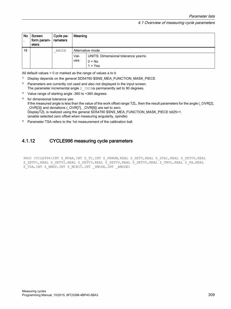
No.
Screen form param‐eters
Cycle pa‐rameters
Meaning
18 _AMODE Alternative modeVal‐ues:
UNITS: Dimensional tolerance yes/no0 = No1 = Yes
All default values = 0 or marked as the range of values a to b1) Display depends on the general SD54760 $SNS_MEA_FUNCTION_MASK_PIECE2) Parameters are currently not used and also not displayed in the input screen.
The parameter incremental angle S_INCAis permanently set to 90 degrees.3) Value range of starting angle -360 to +360 degrees4) for dimensional tolerance yes:
If the measured angle is less than the value of the work offset range TZL, then the result parameters for the angle (_OVR[2], _OVR[3]) and deviations (_OVR[7], _OVR[8]) are set to zero.DisplayTZL is realized using the general SD54760 $SNS_MEA_FUNCTION_MASK_PIECE bit25=1.(enable selected zero offset when measuring angularity, spindle)
5) Parameter TSA refers to the 1st measurement of the calibration ball.
4.1.12 CYCLE996 measuring cycle parameters
PROC CYCLE996(INT S_MVAR,INT S_TC,INT S_PRNUM,REAL S_SETV,REAL S_STA1,REAL S_SETV0,REAL S_SETV1,REAL S_SETV2,REAL S_SETV3,REAL S_SETV4,REAL S_SETV5,REAL S_TNVL,REAL S_FA,REAL S_TSA,INT S_NMSP,INT S_MCBIT,INT _DMODE,INT _AMODE)
Parameter lists4.1 Overview of measuring cycle parameters
Measuring cyclesProgramming Manual, 10/2015, 6FC5398-4BP40-5BA3 309

Table 4-12 CYCLE996 call parameters 1)
No.
Screen form param‐eters
Cycle pa‐rameters
Meaning
1 S_MVAR Measurement version (default=1)Val‐ues:
UNITS: Measuring sequence0 = Calculate kinematics (selection with: Result display, protocol, change of the swivel data sets, where relevant with operator acknowledgment), see _AMODE1 = 1st measurement2 = 2nd measurement3 = 3rd measurementTENS: Reserved0 = 0HUNDREDS: Measurement version for 1st to 3rd measurement0 = Measurement of the calibration ball paraxial1 = Measurement of the calibration sphere at an angle and no spindle correction 3)
2 = Measurement of the calibration sphere and correction of the spindle in the switching direction of the probe 3)
3 = Paraxial measurement, with starting angle 8)
4 = Paraxial measurement, with starting angle, tracking spindle in the switching direction of the probe 8)
THOUSANDS: Calculate correction target for kinematics 4)
0 = measuring only. Swivel data sets are calculated, but remain unchanged1 = calculate swivel data set. Swivel data sets are, if necessary, changed after acknowledgment by the operator 4)
TEN THOUSANDS: Measuring axis (rotary axis 1 or 2) or vector chain open or closed for calculate kinematics0 = Vector chain closed (only for calculate kinematics) 1 = Rotary axis 1 (only for 1st to 3rd measurement)2 = rotary axis 2 (only for the 1st to 3rd measurement) 5)
3 = vector chain open (only for calculate kinematics)HUNDRED THOUSANDS: Normalizing of rotary axis 1 for calculate kinematics0 = no scaling rotary axis 11 = scaling in the direction of the 1st axis of the plane (for G17 X)2 = scaling in the direction of the 2nd axis of the plane (for G17 Y)3 = scaling in the direction of the 3rd axis of the plane (for G17 Z)ONE MILLION: Normalizing of rotary axis 2 for calculate kinematics 5)
0 = no scaling rotary axis 21 = scaling in the direction of the 1st axis of the plane (for G17 X)2 = scaling in the direction of the 2nd axis of the plane (for G17 Y)3 = scaling in the direction of the 3rd axis of the plane (for G17 Z)TEN MILLION: Log file0 = no protocol file1 = protocol file with the calculated vectors (tool carrier) and the 1st dynamic 5-axis transformation (TRAORI(1)), if set-up in MDs.
2 S_TC Number of the swivel data record (tool carrier)3 Icon+
numberS_PRNUM Number of the field of the probe parameters (not probe number)
(default=1)
Parameter lists4.1 Overview of measuring cycle parameters
Measuring cycles310 Programming Manual, 10/2015, 6FC5398-4BP40-5BA3

No.
Screen form param‐eters
Cycle pa‐rameters
Meaning
4 S_SETV Diameter of the calibration ball5 alpha 0 S_STA1 Starting angle for measurement at an angle6 alpha 0 S_SETV0 Position value of rotary axis 1 (if rotary axis is manual or semi-automatic)7 alpha 1 S_SETV1 Position value of rotary axis 2 (if rotary axis is manual or semi-automatic) 6)
8 XN S_SETV2 Position value for normalizing rotary axis 19 XN S_SETV3 Position value for normalizing of rotary axis 2 6)
10 Delta S_SETV4 Tolerance value of the offset vectors I1 to I411 Delta S_SETV5 Tolerance value of rotary axis vectors V1 and V212 TVL S_TNVL Limit value of angular segment of the rotary axis (value range 1 to 60 degrees)
(default=20) 7)
13 DFA S_FA Measurement path14 TSA S_TSA Safe area15 Measure‐
mentsS_NMSP Number of measurements at the same location 2) (default=1)
16 S_MCBIT Reserved17 _DMODE Display mode
Val‐ues:
UNITS: Machining plane G17/G18/G190 = compatibility, the plane active before the cycle call remains active1 = G17 (only active in the cycle)2 = G18 (only active in the cycle)3 = G19 (only active in the cycle)
18 _AMODE Alternative modeVal‐ues:
UNITS: Tolerance check yes/no0 = No1 = Yes: Evaluation of the tolerance values of the vectors S_SETV4, S_SETV5TENS: Acknowledgment by the operator when entering the calculated vectors in the swivel data set 4)
0 = yes: Operator must acknowledge the change1 = no: calculated vectors are entered immediately (only effective if HUNDREDS and THOUSANDS position = 0)HUNDREDS: Measurement result display 5)
0 = no1 = yesTHOUSANDS: Measurement result display can be edited0 = no1 = yes, and can be edited (only effective, if the HUNDREDS position = 1)
1) All default values = 0 or marked as default=x2) Display depends on the general SD54760 $SNS_MEA_FUNCTION_MASK_PIECE3) Using this version, for example, for 90 degree positions, the kinematics can be measured at the calibration ball, without
colliding with the retaining shaft of the calibration ball. A starting angle S_STA1 (0 to 360 degrees) can be entered. The incremental angle when circling the sphere is equal to 90 degrees.As feedrate along the circular path, the channel-specific SD55634 $SCS_MEA_FEED_PLANE_VALUE is used
4) There is an operator prompt with M0 before entering. The vectors are only entered with NC start.If the measuring program is aborted with RESET no calculated vectors are entered.Vectors are only entered when the tolerance of the offset vectors has not been exceeded during the calculation.
Parameter lists4.1 Overview of measuring cycle parameters
Measuring cyclesProgramming Manual, 10/2015, 6FC5398-4BP40-5BA3 311

5) Measurement result display only for the calculated kinematics measuring version.If the measurement result should also be displayed after the 1st to the 3rd measurement, then this is realized by setting the channel-specific SD 55613 $SCS_MEA_RESULT_DISPLAY.
6) Rotary axis 2 only for kinematics with two rotary axes7) Limit value angular segment of the rotary axis. Value range of S_TNVL between 20 and 60 degrees. For values of S_TNVL
< 20 degrees, inaccuracies can be expected as a result of the measuring inaccuracies in the micrometer range of the probe. If the limit value is violated, then error message 61430 is output – with a display of the minimum limit value.
8) Spindle is tracked in the probe switching direction if SD54760 bit 17 = 1
4.1.13 CYCLE982 measuring cycle parameters
PROC CYCLE982(INT S_MVAR,INT S_KNUM,INT S_PRNUM,INT S_MA,INT S_MD,REAL S_ID,REAL S_FA,REAL S_TSA,REAL S_VMS,REAL S_STA1,REAL S_CORA,REAL S_TZL,REAL S_TDIF,INT S_NMSP,INT S_EVNUM,INT S_MCBIT,INT _DMODE,INT _AMODE)
Parameter lists4.1 Overview of measuring cycle parameters
Measuring cycles312 Programming Manual, 10/2015, 6FC5398-4BP40-5BA3

Table 4-13 CYCLE982 call parameters 1)
No. Screen form param‐eters
Cycle pa‐rameters
Meaning
1 S_MVAR Measuring version Val‐ues:
UNITS: Calibration/measurement0 = Calibrate tool probe1 = Single tool measurement 3)
2 = Multiple tool measurement, determine lengths and tool radius (for milling tools)TENS: Calibration or measurement in the MCS or WCS0 = Machine-related 4)
1 = Workpiece-relatedHUNDREDS: Measurement with or without reversal for milling tools0 = Measurement without reversal1 = Measurement with reversalTHOUSANDS: Correction target for milling tools0 = determine length or length and radius (see S_MVAR 1st position)1 = determine radius, if S_MVAR 1st position = 12 = determine length and radius (face side), if S_MVAR 1st position = 1 or 23 = side milling tool, upper cutting edge (rear side) and determine length and radius 5)
TEN THOUSANDS: Position of the milling tool or the drill0 = Axial position of the milling tool or the drill, radius in 2nd axis of the plane (for G18 X) 7)
1 = Radial position of the milling tool or the drill, radius in 1st axis of the plane (for G18 Z) 7)
HUNDRED THOUSANDS: Incremental calibration or measurement0 = No specification1 = Incremental calibration or measurementONE MILLION: Position spindle at starting angle S_STA1 (only for measurement of milling tools)0 = spindle is not positioned1 = spindle is positioned at the starting angle S_STA1
2 Selection S_KNUM Offset variant 2)
Val‐ues:
UNITS: Tool offset0 = No specification (tool offset in geometry)1 = Tool offset in wear
3 Icon+number
S_PRNUM Number of the field of the probe parameters (not probe number)(default=1)
4 X0 S_MA Measuring axisVal‐ues:
1 = 1. Axis of the plane (for G18 Z)2 = 2nd axis of the plane (for G18 X)
5 +- S_MD Measuring directionVal‐ues:
0 = No selection (measuring direction is determined from actual value)1 = Positive2 = Negative
Parameter lists4.1 Overview of measuring cycle parameters
Measuring cyclesProgramming Manual, 10/2015, 6FC5398-4BP40-5BA3 313

No. Screen form param‐eters
Cycle pa‐rameters
Meaning
6 Z2 S_ID Offset7 DFA S_FA Measurement path8 TSA S_TSA Safe area9 VMS S_VMS Variable measuring velocity for calibration 2)
10 Alpha1 S_STA1 Starting angle when measuring milling tools11 Alpha2 S_CORA Offset angle when measuring milling tools with reversal 8)
12 TZL S_TZL Work offset when measuring milling tools When calibrating S_TZL = 013 DIF S_TDIF Dimension difference check14 Measure‐
mentsS_NMSP Number of measurements at the same location 2) (default=1)
15 EVN S_EVNUM Number of the empirical mean value memory 2), 9)
16 S_MCBIT Reserved17 _DMODE Display mode
Val‐ues:
UNITS: Machining plane G17/G18/G190 = Compatibility, the plane active before the cycle call remains active1 = G17 (only active in the cycle)2 = G18 (only active in the cycle)3 = G19 (only active in the cycle)TENS: Cutting edge position for turning and milling tools (only for display in the input screens 1 to 9)HUNDREDS: Tool type0 = Turning tool1 = Milling tool2 = DrillTHOUSANDS: The approach strategy with reference to the tool probe0 = PLUS [X/Z]; X if tool position axial, Z if tool position radial1 = MINUS [X/Z]; X if tool position axial, Z if tool position radial
18 _AMODE Alternative mode Val‐
ues:UNITS: Reserved
TENS: Reserved HUNDREDS: Reserved THOUSANDS: approach starting position after measurement for calibration and
single measurement (see S_MVAR - UNITS)0 = tool is located, offset by DFA with respect to the probe edge1 = approach starting position
1) All default values = 0 or marked as default=x2) Display depends on the general SD 54762 _MEA_FUNCTION_MASK_TOOL3) Measure turning or milling tool or drill. Measuring axis in parameter S_MA
Specification for turning tools via cutting edge position 1...8, for milling tools via HUNDREDS to THOUSANDS position in parameter S_MVAR.
4) Measurement and calibration are performed in the basic coordinate system (MCS for kinematic transformation switched off).
5) Not for incremental measuring
Parameter lists4.1 Overview of measuring cycle parameters
Measuring cycles314 Programming Manual, 10/2015, 6FC5398-4BP40-5BA3

6) Only for multiple measurements S_MVAR=x2x02 or x3x02 (example, disk-type or groove milling tools)7) If the channel-specific SD 42950 $SC_TOOL_LENGTH_TYPE = 2, then the tool length components are assigned just the
same as for turning tools8) Only for measurement with reversal S_MVAR=xx1x19) Empirical value generation
Value range of the empirical value memory: 1 to 20 numbers(n) of the empirical value memory, see channel-specific SD 55623 $SCS_MEA_EMPIRIC_VALUE[n-1].
4.1.14 CYCLE971 measuring cycle parameters
PROC CYCLE971(INT S_MVAR,INT S_KNUM,INT S_PRNUM,INT S_MA,INT S_MD,REAL S_ID,REAL S_FA,REAL S_TSA,REAL S_VMS,REAL S_TZL,REAL S_TDIF,INT S_NMSP,REAL S_F1,REAL S_S1,REAL S_F2,REAL S_S2,REAL S_F3,REAL S_S3,INT S_EVNUM,INT S_MCBIT,INT _DMODE,INT _AMODE)
Table 4-14 CYCLE971 call parameters 1)
No. Screen form pa‐rameters
Cycle pa‐rameters
Meaning
1 S_MVAR Measuring version Val‐ues:
UNITS:0 = Calibrate tool probe1 = Measure tool with stationary spindle (length or radius)2 = Measure tool with rotating spindle (length or radius), see parameters S_F1 to S_S4TENS: Measurement in the machine coordinate system or workpiece coordinate system0 = Measurement in MCS (machine-related), measure tool or calibrate tool probe1 = Measurement in WCS (workpiece-related), measure tool or calibrate tool probeHUNDREDS: Tooth breakage monitoring for milling cutters0 = no1 = yesTHOUSANDS: 0 = 0TEN THOUSANDS: Incremental calibration or measurement0 = No specification1 = Incremental calibration or measurementHUNDRED THOUSANDS: Calibrate tool probe automatically0 = Do not calibrate tool probe automatically1 = Calibrate tool probe automaticallyONE MILLION: Calibrating in the plane with spindle reversal0 = Calibrating in the plane without spindle reversal1 = Calibrating in the plane with spindle reversal
Parameter lists4.1 Overview of measuring cycle parameters
Measuring cyclesProgramming Manual, 10/2015, 6FC5398-4BP40-5BA3 315

No. Screen form pa‐rameters
Cycle pa‐rameters
Meaning
2 Selection S_KNUM Offset variant 2)
Val‐ues:
UNITS: Tool offset0 = No specification (tool offset in geometry)1 = Tool offset in wear
3 Icon+number
S_PRNUM Number of the field of the probe parameters (not probe number)
4 X0 S_MA Measuring axis, offset axis 4)
Val‐ues:
UNITS: Number of the measuring axis1 = 1st axis of the plane (for G17 X)2 = 2nd axis of the plane (for G17 Y)3 = 3rd axis of the plane (for G17 Z)TENS:0 = 0HUNDREDS: Number of the offset axis0 = No offset axis1 = 1st axis of the plane (for G17 X)2 = 2nd axis of the plane (for G17 Y)
5 +- S_MD Measuring directionVal‐ues:
0 = No selection (measuring direction is determined from actual value)1 = Positive2 = Negative
6 V S_ID OffsetVal‐ues:
0 = For tools without offset>0 = ● Calibration: The offset is applied to the 3rd axis of the plane (for G17 Z) if the
diameter of the calibration tool is greater than the upper diameter of the probe. The tool is offset by the tool radius from the center of the probe, minus the value of S_ID. The offset axis is also specified in S_MA .
● Measure: With multiple cutting edges, the offset of tool length and the highest point of the cutting edge must be specified for radius measurement or the offset of tool radius to the highest point of the cutting edge must be specified when measuring the length.
7 DFA S_FA Measurement path8 TSA S_TSA Safe area9 VMS S_VMS Variable measuring velocity for calibration 2)
10 TZL S_TZL Work offset (only for tool measurement)11 DIF S_TDIF Dimensional difference check for tool measurement (S_MVAR=xx1or S_MVAR=xx2)12 Measure‐
mentsS_NMSP Number of measurements at the same location 2)
13 F1 S_F1 1st feedrate for contact with rotating spindle 2)
14 S1 S_S1 1st speed for contact with rotating spindle 2)
15 F2 S_F2 2nd feedrate for contact with rotating spindle 2)
16 S2 S_S2 2nd speed for contact with rotating spindle 2)
17 F3 S_F3 2nd feedrate for contact with rotating spindle 3)
Parameter lists4.1 Overview of measuring cycle parameters
Measuring cycles316 Programming Manual, 10/2015, 6FC5398-4BP40-5BA3

No. Screen form pa‐rameters
Cycle pa‐rameters
Meaning
18 S3 S_S3 2nd speed for contact with rotating spindle 3)
19 EVN S_EVNUM Number of the empirical value memory 2)
20 S_MCBIT Screen form of the _CBITs or _CHBITs21 _DMODE Display mode
Val‐ues:
UNITS: Machining plane G17/G18/G190 = Compatibility, the plane active before the cycle call remains active1 = G17 (only active in the cycle)2 = G18 (only active in the cycle)3 = G19 (only active in the cycle)
22 _AMODE Alternative modeVal‐ues:
UNITS: Measuring the tool offset for radius1 = no2 = yesTENS: Direction of the tool offset when measuring the radius in the 3rd axis of the plane (for G17 Z)1 = Positive2 = NegativeHUNDREDS: Tool offset when measuring the length or when calibrating the probe in the 3rd axis0 = Compatibility, auto1 = No2 = Yes
THOUSANDS: Direction of the tool offset when measuring the length in the offset axis (see S_MA HUNDREDS)1 = Positive2 = Negative
1) All default values = 0 or marked as default=x2) Display depends on the general SD 54762 MEA_FUNCTION_MASK_TOOL3) Only for offset in tool and dimensional tolerance "Yes", otherwise parameter = 04) For automatic measurement (S_MVAR=1x00xx), no display of measuring axis, offset axis ⇒ S_MA=0.
4.1.15 CYCLE150 measuring cycle parametersPROC CYCLE150(INT S_PICT,INT S_PROT,STRING[160] S_PATH) SAVE ACTBLOCNO DISPLOF
Parameter lists4.1 Overview of measuring cycle parameters
Measuring cyclesProgramming Manual, 10/2015, 6FC5398-4BP40-5BA3 317

Table 4-15 CYCLE150 call parameters
No. Screen pa‐rameters
Cycle pa‐rameters
Meaning
1 Measuring result screen
S_PICT Select result display (default = 0)
Values: UNITS:0 = Measuring result screen OFF1 = Measuring result screen ON
Tens: Select display mode (values as for SD 55613)1 = Display measuring result screen - automatically deselect after 8 s3 = Display measuring result screen - acknowledge using NC Start4 = Display measuring result screen - only for alarms (61303 ... 61306)
2 S_PROT Select logging (default = 0) Log Values: UNITS: Select protocol off / on / last measurement
0 = Log OFF1 = Log ON2 = Log last measurement
Log type TENS: Select log type0 = Standard log1 = User log (can be freely defined)
Log format HUNDREDS: Select log format0 = Text format1 = Table format (for import to Excel)
Log data THOUSANDS: Rewrite or attach selection0 = New1 = Attach
Logarchive
TEN THOUSANDS: Select log archive0 = As part program1 = Directory
3 S_PATH Path for the log file corresponding to the log archive selection(complete path name or only file name, e.g.:"//NC:/WKS.DIR/NAME.WPD or "MESSPROTOKOLL.TXT"
Parameter lists4.1 Overview of measuring cycle parameters
Measuring cycles318 Programming Manual, 10/2015, 6FC5398-4BP40-5BA3

4.2 Additional parametersThe following supplementary parameters can be hidden or unhidden using setting data in the input screen forms. For more information about setting data SD54760 to SD54764, see the List Manual SINUMERIK 840D sl, detailed description of the machine data.
Machine manufacturerPlease observe the machine manufacturer’s instructions.
The supplementary parameter are not available for all measuring cycles. See also the interface description.
Table 4-16 Supplementary parameters for workpiece measurement
Screen form pa‐rameters
Transfer pa‐rameters
Description Unit
Calibration data set S_PRNUM Number of the data set with the calibrated values of the probe -F S_VMS Measuring feedrate when calibrating the probe mm/minSelection S_MVAR Calibrate probe: selection at the known or unknown center point of the cali‐
bration ring-
Selection S_MVAR Calibrate probe: selection, calibration with or without position deviation (probe skew)
-
Number S_NMSP Number of measurements at the same location -TZL S_TZL Work offset for correction in a tool mmDIF S_TDIF Dimension difference monitoring for correction in a tool -Data set, mean val‐ue generation
S_EVNUM Generating mean values for correction in a tool -
Data set, empirical values
S_EVNUM Generating empirical values for correction in a tool -
FW S_K Weighting factor for averaging -TMV S_TMV Offset range for averaging Selection S_MVAR Measuring when turning, diameter inside outside:
● With reversal● Travel under center of rotation
-
Parameter lists4.2 Additional parameters
Measuring cyclesProgramming Manual, 10/2015, 6FC5398-4BP40-5BA3 319

Additional correction options when measuring workpiece:
1. Work offsets
– Offset in the basic reference
– Offset in the channel-specific basic WO
– Offset in the global basic WO
– Offset, coarse or fine
2. Tool offsets
– Tool offset in geometry or wear
– Tool offset, inverted or not inverted
– Tool offset in radius or length L1 or L2 or L3
Table 4-17 Supplementary parameter when measuring tool
Screen form pa‐rameters
Transfer pa‐rameters
Description Unit
Calibration data set S_PRNUM Number of the data set with the calibrated values of the probe -F S_VMS Measuring feedrate when calibrating the probe mm/minSelection, measur‐ing steps
S_MVAR Input of max. 3 feedrates and 3 spindle speeds when measuring with rotating spindle
-
Selection S_MVAR Tool offset in geometry or wear -Selection S_MVAR Measurement in the machine coordinate system or workpiece coordinate
system-
Number S_NMSP Number of measurements at the same location -Data set, empirical values
S_EVNUM Generating empirical values for correction in a tool -
Parameter lists4.2 Additional parameters
Measuring cycles320 Programming Manual, 10/2015, 6FC5398-4BP40-5BA3

4.3 Additional result parametersThe following table below contains the additional result parameters for the measuring variants of the tool offset.
Parameters Description Unit_OVR [8] 1) Upper tolerance limit for:
● Diameter of hole / circular spigot / circle segment● Measuring axis● Width of groove/rib● Rectangle length in the 1st axis of the plane
mm
_OVR [9] 1), 3) Upper tolerance limit for rectangle length in the 2nd axis of the plane
mm
_OVR [12] 1) Lower tolerance limit for: ● Diameter of hole / circular spigot / circle segment● Measuring axis● Width of groove/rib● Rectangle length in the 1st axis of the plane
mm
_OVR [13] 1), 3) Lower tolerance limit for rectangle length in the 2nd axis of the plane
mm
_OVR [20] 1) Offset value mm_OVR [27] 1) Work offset range mm_OVR [28] 1) Safe area mm_OVR [29] 1) Dimensional difference mm_OVR [30] 1) Empirical value mm_OVR [31] 1) Mean value mm_OVI [4] 1) Weighting factor -_OVI [5] Probe number -_OVI [6] 1) Mean value memory number -_OVI [7] 1) Empirical value memory number -_OVI [8] 1) Tool number -_OVI [9] 1) Alarm number -_OVI [11] 2) Status offset request -_OVI [13] 1) DL number -
1) Only for workpiece measurement with tool offset2) only for correction in the WO3) Only applies for the measuring versions "Rectangular pocket" and "Rectangular spigot"
Parameter lists4.3 Additional result parameters
Measuring cyclesProgramming Manual, 10/2015, 6FC5398-4BP40-5BA3 321

4.4 Parameter
Table 4-18 List of input/output variables for cycles
Screen form parameters
Cycle pa‐rameters
Meaning in English Meaning in German
S_CALNUM Calibration groove number Number of the gauging block S_MCBIT Central Bits Screen form of the _CBITs or _CHBITsα2 S_CORA Correction angle position Offset angleX0 S_CPA Center point abscissa Center point of the 1st axis of the planeY0 S_CPO Center point ordinate Center point of the 2nd axis of the planeDL S_DLNUM DL number for setup or additive offsetEVN S_EVNUM Number, mean empirical value memoryDFA S_FA Factor for multipl. of measurem.
pathMeasurement path
S_ID Infeed in applicate Incremental infeed absolute value / offsetα1 S_INCA Indexing angle Incremental angle / angle setpointFW S_K Weighting factor for averaging Weighting factor for averagingSelection S_KNUM Correction WO, basic WO or basic referenceSelection S_KNUM1 Correction in tool offsetX / Y / Z S_MA Number of measuring axis Measuring axis (number of the axis)+ / - S_MD Measuring direction Measuring direction S_MFS Feedrate and speed for measurement with rotating spin‐
dle S_MVAR Measuring variant Measuring versionNumber S_NMSP Number of measurements at same
spotNumber of measurements at the same location
_OVI [20]
Field: Output values INT
_OVR [32]
Field: Output values REAL
Icon + number S_PRNUM Probe type and probe number Number of the field of the probe parametersX0 / Y0 / Z0 S_SETV Setpoint value Setpointα1 S_STA1 Starting angle Starting angleX S_SZA Safety zone on workpiece abscissa Protection zone in the 1st axis of the planeY S_SZO Safety zone on workpiece ordinate Protection zone in the 2nd axis of the planeDIF S_TDIF Tolerance dimensional difference
checkDimension difference check
TLL S_TLL Tolerance lower limit Tolerance lower limitTMV S_TMV Mean value generation with compensationT S_TNAME Tool name Tool name when using tool manager S_TNVL Limit value for distortion of the triangleTSA S_TSA Tolerance safe area Safe areaTUL S_TUL Tolerance upper limit Tolerance upper limitTZL S_TZL Tolerance zero offset range Work offsetVMS S_VMS Variable measuring speed Variable measuring speed
Parameter lists4.4 Parameter
Measuring cycles322 Programming Manual, 10/2015, 6FC5398-4BP40-5BA3

Parameter lists4.4 Parameter
Measuring cyclesProgramming Manual, 10/2015, 6FC5398-4BP40-5BA3 323

Parameter lists4.4 Parameter
Measuring cycles324 Programming Manual, 10/2015, 6FC5398-4BP40-5BA3

Changes from cycle version SW4.4 and higher AA.1 Assignment of the measuring cycle parameters to
MEA_FUNCTION_MASK parametersAll setting data that were saved up to measuring cycle version 2.6 in GUD variables, from software release SW 4.4 are located in the configurable machine and setting data (e.g. data fields of the calibration values). The GUD modules GUD5, GUD6 and GUD7_MC are no longer required for measuring cycle data.
The following tables include the assignment of function-determining measuring cycle parameters to the MEA_FUNCTION_MASK parameters.
Bit 1)
Function MD identifierSW 2.6
GUD name up to SW 2.6
General cycle machine data: MD51740 $MNS_MEA_FUNCTION_MASK (32 bits)Workpiece measurement0 Calibration monitoring (default = 1) 51616 $MNS_MEA_CAL_MONITORING _CBIT[16]1 Length reference of the probe in the infeed axis
(default = 1)0 = Reference point is the center of the probe sphere1 = Reference point is the circumference of the probe sphere
51614 $MNS_MEA_PROBE_LENGTH_RE‐LATE
_CBIT[14]
2 Taking into account tool carriers that can be orientated for offset in a tool (default = 0)
51610 $MNS_MEA_TOOLCARR_ENABLE _CBIT[7]
3 Offset angle for mono-workpiece probe(default = 1)
51612 $MNS_MEA_MONO_COR_POS_AC‐TIVE
_CBIT[8]
Tool measurement16 Taking into account tool carriers that can be orientated
for offset in a tool (default = 0)MD 51610 $MNS_MEA_TOOLCARR_ENA‐BLE
_CBIT[7]
Channel-specific cycle machine data: MD52740 $MCS_MEA_FUNCTION_MASK (32 bits)Workpiece measurement0 Measuring input, workpiece probe (default = 0)
0 = CNC measuring input 11 = CNC measuring input 2
51606 $MNS_MEA_IN‐PUT_PIECE_PROBE[0]
_CHBIT[0]
1 Rotating measuring cycles use Y axis as measuring axis (default = 0)
52605 $MCS_MEA_TURN_CYC_SPE‐CIAL_MODE
_CHBIT[19]
Tool measurement16 Measuring input, tool probe (default = 1)
0 = CNC measuring input 11 = CNC measuring input 2
51607 $MNS_MEA_INPUT_TOOL_PROBE[0] _CHBIT[1]
General cycle setting data: SD 54740 $SNS_MEA_FUNCTION_MASK (32 bits)Workpiece measurement
Measuring cyclesProgramming Manual, 10/2015, 6FC5398-4BP40-5BA3 325

Bit 1)
Function MD identifierSW 2.6
GUD name up to SW 2.6
0 Repeat measurement in the event of violation of _TDIF and _TSA (default = 0)
54655 $SNS_MEA_REPEATE_ACTIVE _CBIT[0]
1 Repeat measurement with alarm output and cycle stop at M0 (default = 0)
54656 $SNS_MEA_REPEATE_WITH_M0 _CBIT[1]
2 Violation of _TUL, _TLL, _TDI,cycle stop at M0 (default = 0)
54657 $SNS_MEA_TOL_ALARM_SET_M0 _CBIT[2]
3 Accept calibrated probe sphere radius in tool data (de‐fault = 1)
54660 $SNS_MEA_PROBE_BALL_RAD_IN_TOA
_CBIT[15]
Tool measurement16 Repeat measurement in the event of violation of _TDIF
and _TSA (default = 0)54655 $SNS_MEA_REPEATE_ACTIVE _CBIT[0]
17 Repeat measurement with alarm output and cycle stop at M0 (default = 0)
54656 $SNS_MEA_REPEATE_WITH_M0 _CBIT[1]
18 Violation of _TDIF, cycle stop at M0 (default = 0)
54657 $SNS_MEA_TOL_ALARM_SET_M0 _CBIT[2]
19 Milling cutter, spindle speed reduction at the last con‐tact
_CHBIT[22]
Channel-specific setting data: SD 55740 $SCS_MEA_FUNCTION_MASK (32 bits)Workpiece measurement0 Collision monitoring (default = 1) 55600 $SCS_MEA_COLLISION_MONITOR‐
ING_CHBIT[2]
1 Coupling of the spindle position, with a coordinate ro‐tation around the infeed axis in AUTOMATIC (default = 0)
55602 $SCS_MEA_COUPL_SPIND_COORD _CHBIT[13]
2 Direction of rotation of the spindle positioning, with ac‐tive coupling of the spindle and coordinate rotation(default = 0)0 = In the GUZ1 = In the UZ
55604 $SCS_MEA_SPIND_MOVE_DIR _CHBIT[14]
3 Measurement attempts when the probe does not switch (default = 0)0 = 5 attempts 1 = 1 attempt
55606 $SCS_MEA_NUM_OF_MEASURE _CHBIT[15]
4 Approach velocity to the measuring position (default = 0)0 = With measuring feedrate _VMS1 = With $SCS_MEA_FEED_FAST_MEASURE
55610 $SCS_MEA_FEED_TYP _CHBIT[17]
5 Retraction velocity from the measuring point (default = 0)0 = With $SCS_MEA_FEED_PLANE_VALUE1 = With $SCS_MEA_FEED_RAPID_IN_PERCENT
55608 $SCS_MEA_RETRACTION_FEED _CHBIT[16]
Changes from cycle version SW4.4 and higherA.1 Assignment of the measuring cycle parameters to MEA_FUNCTION_MASK parameters
Measuring cycles326 Programming Manual, 10/2015, 6FC5398-4BP40-5BA3

Bit 1)
Function MD identifierSW 2.6
GUD name up to SW 2.6
6 Activate/deactivate workpiece probe before and after the NC command SPOS. See also CUST_MEA_CYC.SPF(default = 0)0 = No call CUST_MEA_CYC.SPF1 = Call CUST_MEA_CYC.SPF
- -
... 14 Coupling of the spindle position, with a coordinate ro‐
tation around the infeed axis when a measuring in AU‐TOMATIC (default = 1)
55770 $SCS_J_MEA_SET_COUPL_SP_CO‐ORD
E_MESS_SETT[0]
15 Calibration in the calibration ring when measuring in JOG(default = 0)0 = Calibrate with automatic reference center point1 = Calibrate with known reference center point
55771 $SCS_J_MEA_SET_CAL_MODE E_MESS_SETT[1]
Tool measurement16 Collision monitoring (default = 1) 55600 $SCS_MEA_COLLISION_MONITOR‐
ING_CHBIT[2]
17 Measurement attempts when the probe does not switch (default = 0)0 = 5 attempts 1 = 1 attempt
55606 $SCS_MEA_NUM_OF_MEASURE _CHBIT[15]
18 Approach velocity to the measuring position (default = 0)0 = With measuring feedrate _VMS1 = With $SCS_MEA_FEED_FAST_MEASURE
55610 $SCS_MEA_FEED_TYP _CHBIT[17]
19 Retraction velocity from the measuring point (default = 0)0 = With $SCS_MEA_FEED_PLANE_VALUE1 = With $SCS_MEA_FEED_RAPID_IN_PERCENT
55608 $SCS_MEA_RETRACTION_FEED _CHBIT[16]
1) Bit x=0 means that the function is disabledBit x=1 means that the function is enabledAll non-documented bits are not assigned.
Changes from cycle version SW4.4 and higherA.1 Assignment of the measuring cycle parameters to MEA_FUNCTION_MASK parameters
Measuring cyclesProgramming Manual, 10/2015, 6FC5398-4BP40-5BA3 327

A.2 Changes in the machine and setting data from SW 4.4
MD replaced with SDThe following cycle machine data (measuring in JOG) no longer apply from cycle release SW 04.04.01 (compared to SW 02.06.00 ) and are replaced by the following cycle setting data that mean the same .
MDs are no longer required Replaced by SD51609 $MNS_MEA_INPUT_TOOL_PROBE_SUB[0 .. 5] 54652 $SNS_MEA_INPUT_TOOL_PROBE_SUB[0 .. 5]51755 $MNS_J_MEA_MEASURING_FEED 55630 $SCS_MEA_FEED_MEASURE51774 $MNS_J_MEA_T_PROBE_TYPE[n] 54633 $SNS_MEA_TP_TYPE[n]51776 $MNS_J_MEA_T_PROBE_ALLOW_AX_DIR[n] 54632 $SNS_MEA_TP_AX_DIR_AUTO_CAL[n]51778 $MNS_J_MEA_T_PROBE_DIAM_LENGTH[n] 54631 $SNS_MEA_TP_EDGE_DISK_SIZE[n]51782 $MNS_J_MEA_T_PROBE_T_EDGE_DIST[n] 54634 $SNS_MEA_TP_CAL_MEASURE_DEPTH[n]51787 $MNS_J_MEA_T_PROBE_MEASURE_FEED 55628 $SCS_MEA_TP_FEED_MEASURE
Change, number of the setting dataFor the following cycle setting data, from SW 04.04.01, the number of the setting data changes (with respect to cycle release SW 02.06.00). Identifier and function have not changed.
Number SD IdentifierRelease SW 02.06.00 From SW 04.04.0154798 54780 $SNS_J_MEA_FUNCTION_MASK_PIECE54799 54782 $SNS_J_MEA_FUNCTION_MASK_TOOL55630 55632 $SCS_MEA_FEED_RAPID_IN_PERCENT55631 55634 $SCS_MEA_FEED_PLANE_VALUE55632 55636 $SCS_MEA_FEED_FEEDAX_VALUE55633 55638 $SCS_MEA_FEED_FAST_MEASURE
Changes from cycle version SW4.4 and higherA.2 Changes in the machine and setting data from SW 4.4
Measuring cycles328 Programming Manual, 10/2015, 6FC5398-4BP40-5BA3

A.3 Complete overview of the changed cycle machine and cycle setting data
Table A-1 Complete overview of the changed cycle machine data - from cycle SW 04.04.05.00
SW 02.06.01.03 HF3 CYCLE SW 02.06.56.00 CYCLE SW 04.04.05.00 N51071 $MNS_ACCESS_ACTIVATE_CTRL_E N51072 $MNS_ACCESS_EDIT_CTRL_E N51073 $MNS_ACCESS_SET_SOFTKEY_ACCESS N51199 $MNS_ACCESS_WRITE_TM_GRINDN51606 $MNS_MEA_INPUT_PIECE_PROBE[0] N52740 $MCS_MEA_FUNCTION_MASK Bit 0N51606 $MNS_MEA_INPUT_PIECE_PROBE[1] Not applicableN51607 $MNS_MEA_INPUT_TOOL_PROBE[0] N52740 $MCS_MEA_FUNCTION_MASK Bit 16N51607 $MNS_MEA_INPUT_TOOL_PROBE[1] Not applicableN51609 $MNS_MEA_INPUT_TOOL_PROBE_SUB[0 .. 5] Not applicableN51610 $MNS_MEA_TOOLCARR_ENABLE Not applicableN51612 $MNS_MEA_MONO_COR_POS_ACTIVE Not applicable, function always activeN51614 $MNS_MEA_PROBE_LENGTH_RELATE N51740 $MCS_MEA_FUNCTION_MASK Bit 1N51616 $MNS_MEA_CAL_MONITORING N51740 $MCS_MEA_FUNCTION_MASK Bit 0 N51755 $MNS_J_MEA_MEASURING_FEED Not applicableN51774 $MNS_J_MEA_T_PROBE_TYPE[0 .. 5] N54633 $SNS_MEA_TP_TYPE[n]N51776 $MNS_J_MEA_T_PROBE_ALLOW_AX_DIR[0 .. 5] N54632 $SNS_MEA_TP_AX_DIR_AUTO_CAL[n]N51778 $MNS_J_MEA_T_PROBE_DIAM_LENGTH[0 .. 5] N54631 $SNS_MEA_TP_EDGE_DISK_SIZE[n]N51782 $MNS_J_MEA_T_PROBE_T_EDGE_DIST[0 .. 5] N54634 $SNS_MEA_TP_CAL_MEASURE_DEPTH[n]N51787 $MNS_J_MEA_T_PROBE_MEASURE_FEED N54636 $SNS_MEA_TP_FEED[n] N52605 $MCS_MEA_TURN_CYC_SPECIAL_MODE N52740 $MCS_MEA_FUNCTION_MASK Bit 1 N52248 $MCS_REV_2_BORDER_TOOL_LENGTH N52290 $MCS_SIM_DISPLAY_CONFIG N52740 $MCS_MEA_FUNCTION_MASK N52751 $MCS_J_MEA_MAGN_GLAS_POS[0] N52751 $MCS_J_MEA_MAGN_GLAS_POS[1]
Table A-2 Complete overview of the changed cycle setting data - from cycle SW 04.04.05.00
SW 02.06.01.03 HF3 CYCLE SW 02.06.56.00 CYCLE SW 04.04.05.00 N54611 $SNS_MEA_WP_FEED[0 .. 11] N54636 $SNS_MEA_TP_FEED[0 .. 5] N54651 $SNS_MEA_TPW_FEED[0 .. 5] N54652 $SNS_MEA_INPUT_TOOL_PROBE_SUB[0 .. 5] N54740 $SNS_MEA_FUNCTION_MASK N54760 $SNS_MEA_FUNCTION_MASK_PIECE
Changes from cycle version SW4.4 and higherA.3 Complete overview of the changed cycle machine and cycle setting data
Measuring cyclesProgramming Manual, 10/2015, 6FC5398-4BP40-5BA3 329

SW 02.06.01.03 HF3 CYCLE SW 02.06.56.00 CYCLE SW 04.04.05.00 N54762 $SNS_MEA_FUNCTION_MASK_TOOL N54764 $SNS_MEA_FUNCTION_MASK_TURNN54798 $SNS_J_MEA_FUNCTION_MASK_PIECE N54780 $SNS_J_MEA_FUNCTION_MASK_PIECEN54799 $SNS_J_MEA_FUNCTION_MASK_TOOL N54782 $SNS_J_MEA_FUNCTION_MASK_TOOLN54655 $SNS_MEA_REPEAT_ACTIVE N54740 $SNS_MEA_FUNCTION_MASK Bit 0N54656 $SNS_MEA_REPEAT_WITH_M0 N54740 $SNS_MEA_FUNCTION_MASK Bit 1N54657 $SNS_MEA_TOL_ALARM_SET_M0 N54740 $SNS_MEA_FUNCTION_MASK Bit 2N54659 $SNS_MEA_TOOL_MEASURE_RELATE Not applicableN54660 $SNS_MEA_PROBE_BALL_RAD_IN_TOA N54740 $SNS_MEA_FUNCTION_MASK Bit 3 N55600 $SCS_MEA_COLLISION_MONITORING N55740 $SCS_MEA_FUNCTION_MASK Bit 0N55602 $SCS_MEA_COUPL_SPIND_COORD N55740 $SCS_MEA_FUNCTION_MASK Bit 1N55604 $SCS_MEA_SPIND_MOVE_DIR N55740 $SCS_MEA_FUNCTION_MASK Bit 2N55606 $SCS_MEA_NUM_OF_MEASURE N55740 $SCS_MEA_FUNCTION_MASK Bit 17N55608 $SCS_MEA_RETRACTION_FEED N55740 $SCS_MEA_FUNCTION_MASK Bit 5N55610 $SCS_MEA_FEED_TYP N55740 $SCS_MEA_FUNCTION_MASK Bit 4 N55628 $SCS_MEA_TP_FEED_MEASURE N55630 $SCS_MEA_FEED_MEASUREN55630 $SCS_MEA_FEED_RAPID_IN_PERCENT N55632 $SCS_MEA_FEED_RAPID_IN_PERCENTN55631 $SCS_MEA_FEED_PLANE_VALUE N55634 $SCS_MEA_FEED_PLANE_VALUEN55632 $SCS_MEA_FEED_FEEDAX_VALUE N55636 $SCS_MEA_FEED_FEEDAX_VALUEN55633 $SCS_MEA_FEED_FAST_MEASURE N55638 $SCS_MEA_FEED_FAST_MEASURE N55642 $SCS_MEA_EDGE_SAVE_ANG N55761 $SCS_J_MEA_SET_NUM_OF_ATTEMPTS N55740 $SCS_MEA_FUNCTION_MASK Bit 17N55762 $SCS_J_MEA_SET_RETRAC_MODE N55740 $SCS_MEA_FUNCTION_MASK Bit 5N55763 $SCS_J_MEA_SET_FEED_MODE N55740 $SCS_MEA_FUNCTION_MASK Bit 4N55770 $SCS_J_MEA_SET_COUPL_SP_COORD Not applicable, function always activeN55771 $SCS_J_MEA_SET_CAL_MODE N55740 $SCS_MEA_FUNCTION_MASK Bit 15N55772 $SCS_J_MEA_SET_PROBE_MONO Not applicable, function corresponds to tool type
Changes from cycle version SW4.4 and higherA.3 Complete overview of the changed cycle machine and cycle setting data
Measuring cycles330 Programming Manual, 10/2015, 6FC5398-4BP40-5BA3

A.4 Comparing GUD parameters (regarding measuring functions)You can make specific basic settings per cycle machine, setting data (MD, SD).
The following prefixes are defined:
● §SNS_... Generally applicable setting data
● §SCS_... Channel-specific setting data
● §MNS_... Generally applicable machine data
● $MCS_... Channel-specific machine data
The GUD parameters listed in the following table represent the contents of the GUD blocks GUD5, GUD6 and GUD7_MC up to version V7.5 where equivalent MD/SD is available as from version V2.7 / V4.4.
The GUD are backwards compatible with existing measuring programs regarding their use.
The GUD5, GUD6 and GUD7_MC modules are replaced by the PGUD (SGUD in the parameter display).
GUD up to Version 7.5 From MD/SD version V2.7/V4.4_WP[x,0] SD54600 $SNS_MEA_WP_BALL_DIAM[0...11]_WP[x,1] SD54601 $SNS_MEA_WP_TRIG_MINUS_DIR_AX1[0...11]_WP[x,2] SD54602 $SNS_MEA_WP_TRIG_PLUS_DIR_AX1[0...11]_WP[x,3] SD54603 $SNS_MEA_WP_TRIG_MINUS_DIR_AX2[0...11]_WP[x,4] SD54604 $SNS_MEA_WP_TRIG_PLUS_DIR_AX2[0...11]_WP[x,5] SD54605 $SNS_MEA_WP_TRIG_MINUS_DIR_AX3[0...11]_WP[x,6] SD54606 $SNS_MEA_WP_TRIG_PLUS_DIR_AX3[0...11]_WP[x,7] SD54607 $SNS_MEA_WP_POS_DEV_AX1[0...11]_WP[x,8] SD54608 $SNS_MEA_WP_POS_DEV_AX2[0...11]_WP[x,9] SD54609 $SNS_MEA_WP_STATUS_RT[0...11]_WP[x,10] SD54610 $SNS_MEA_WP_STATUS_GEN[0...11] _KB[x,0] SD54621 $SNS_MEA_CAL_EDGE_PLUS_DIR_AX2[0...2]_KB[x,1] SD54622 $SNS_MEA_CAL_EDGE_MINUS_DIR_AX2[0...2]_KB[x,2] SD54615 $SNS_MEA_CAL_EDGE_BASE_AX1[0...2]_KB[x,3] SD54617 $SNS_MEA_CAL_EDGE_PLUS_DIR_AX1[0...2]_KB[x,4] SD54618 $SNS_MEA_CAL_EDGE_MINUS_DIR_AX1[0...2]_KB[x,5] SD54620 $SNS_MEA_CAL_EDGE_UPPER_AX2[0...2]_KB[x,6] SD54619 $SNS_MEA_CAL_EDGE_BASE_AX2[0...2] _TP[x,0] SD54625 $SNS_MEA_TP_TRIG_MINUS_DIR_AX1[0...5]_TP[x,1] SD54626 $SNS_MEA_TP_TRIG_PLUS_DIR_AX1[0...5]_TP[x,2] SD54627 $SNS_MEA_TP_TRIG_MINUS_DIR_AX2[0...5]_TP[x,3] SD54628 $SNS_MEA_TP_TRIG_PLUS_DIR_AX2[0...5]_TP[x,4] SD54629 $SNS_MEA_TP_TRIG_MINUS_DIR_AX3[0...5]_TP[x,5] SD54630 $SNS_MEA_TP_TRIG_PLUS_DIR_AX3[0...5]
Changes from cycle version SW4.4 and higherA.4 Comparing GUD parameters (regarding measuring functions)
Measuring cyclesProgramming Manual, 10/2015, 6FC5398-4BP40-5BA3 331

GUD up to Version 7.5 From MD/SD version V2.7/V4.4_TP[x,6] and E_MESS_MT_DL[3]
SD54631 $SNS_MEA_TP_EDGE_DISK_SIZE[0...5]
_TP[x,7] and E_MESS_MT_AX[3]
SD54632 $SNS_MEA_TP_AX_DIR_AUTO_CAL[0...5]
_TP[x,8] and E_MESS_MT_TYP[3]
SD54633 $SNS_MEA_TP_TYPE[0...5]
_TP[x,9] and E_MESS_MT_DZ[3]
SD54634 $SNS_MEA_TP_CAL_MEASURE_DEPTH[0...5]
_TPW[x,1] SD54641 $SNS_MEA_TPW_TRIG_PLUS_DIR_AX1[0...5]_TPW[x,2] SD54642 $SNS_MEA_TPW_TRIG_MINUS_DIR_AX2[0...5]_TPW[x,3] SD54643 $SNS_MEA_TPW_TRIG_PLUS_DIR_AX2[0...5]_TPW[x,4] SD54644 $SNS_MEA_TPW_TRIG_MINUS_DIR_AX3[0...5]_TPW[x,5] SD54645 $SNS_MEA_TPW_TRIG_PLUS_DIR_AX3[0...5]_TPW[x,6] SD54646 $SNS_MEA_TPW_EDGE_DISK_SIZE[0...5]_TPW[x,7] SD54647 $SNS_MEA_TPW_AX_DIR_AUTO_CAL[0...5]_TPW[x,8] SD54648 $SNS_MEA_TPW_TYPE[0...5]_TWP[x,9] SD54649 $SNS_MEA_TPW_CAL_MEASURE_DEPTH[0...5] _CM[0] SD54670 $SNS_MEA_CM_MAX_PERI_SPEED[0] 1)
_CM[1] SD54671 $SNS_MEA_CM_MAX_REVOLUTIONS[0] 1)
_CM[4] SD54672 $SNS_MEA_CM_MAX_FEEDRATE[0] 1)
_CM[2] SD54673 $SNS_MEA_CM_MIN_FEEDRATE[0] 1)
_CM[5] SD54674 $SNS_MEA_CM_SPIND_ROT_DIR[0] 1)
_CM[6] SD54675 $SNS_MEA_CM_FEEDFACTOR_1[0] 1)
_CM[7] SD54676 $SNS_MEA_CM_FEEDFACTOR_2[0] 1)
_CM[3] SD54677 $SNS_MEA_CM_MEASURING_ACCURACY[0] 1)
_CM[8] MD51618 $MNS_MEA_CM_ROT_AX_POS_TOL _CBIT[0] SD54740 $SNS_MEA_FUNCTION_MASK, bit 0 (measure workpiece)
SD54740 $SNS_MEA_FUNCTION_MASK, bit 16 (measure tool)_CBIT[1] SD54740 $SNS_MEA_FUNCTION_MASK bit 1 (measure workpiece)
SD54740 $SNS_MEA_FUNCTION_MASK, bit 17 (measure tool)_CBIT[2] SD54740 $SNS_MEA_FUNCTION_MASK bit 2 (measure workpiece)
SD54740 $SNS_MEA_FUNCTION_MASK bit 18 (measure tool)_CBIT[7] MD51740 $MNS_MEA_FUNCTION_MASK bit 2 (measure workpiece)
MD51740 $MNS_MEA_FUNCTION_MASK, bit 16 (measure tool)_CBIT[8] MD51740 $MNS_MEA_FUNCTION_MASK, bit 3_CBIT[14] MD51740 $MNS_MEA_FUNCTION_MASK bit 1_CBIT[15] SD54740 $SNS_MEA_FUNCTION_MASK, bit 3_CBIT[16] MD51740 $MNS_MEA_FUNCTION_MASK bit 0 _CHBIT[0] MD52740 $MCS_MEA_FUNCTION_MASK bit 0_CHBIT[1] MD52740 $MCS_MEA_FUNCTION_MASK bit 16
Changes from cycle version SW4.4 and higherA.4 Comparing GUD parameters (regarding measuring functions)
Measuring cycles332 Programming Manual, 10/2015, 6FC5398-4BP40-5BA3

GUD up to Version 7.5 From MD/SD version V2.7/V4.4_CHBIT[2] SD55740 $SCS_MEA_FUNCTION_MASK bit 0 (measure workplace)
SD55740 $SCS_MEA_FUNCTION_MASK bit 16 (measure tool)_CHBIT[10] SD55613 $SCS_MEA_RESULT_DISPLAY_CHBIT[13] SD55740 $SCS_MEA_FUNCTION_MASK bit 1_CHBIT[14] SD55740 $SCS_MEA_FUNCTION_MASK bit 2_CHBIT[15] SD55740 $SCS_MEA_FUNCTION_MASK bit 3 (measure workplace)
SD55740 $SCS_MEA_FUNCTION_MASK bit 17 (measure tool)_CHBIT[16] SD55740 $SCS_MEA_FUNCTION_MASK bit 5 (measure workplace)
SD55740 $SCS_MEA_FUNCTION_MASK bit 19 (measure tool)_CHBIT[17] SD55740 $SCS_MEA_FUNCTION_MASK bit 4 (measure workplace)
SD55740 $SCS_MEA_FUNCTION_MASK bit 18 (measure tool)_CHBIT[19] MD52740 $MCS_MEA_FUNCTION_MASK bit 1_CHBIT[22] SD54740 $SNS_MEA_FUNCTION_MASK, bit 19 _EVMVNUM[0] SD55622 $SCS_MEA_EMPIRIC_VALUE_EVMVNUM[1] SD55624 $SCS_MEA_AVERAGE_VALUE_EV[20] SD55623 $SCS_MEA_EMPIRIC_VALUE[0...19]_MV[20] SD55625 $SCS_MEA_AVERAGE_VALUE[0...19] _SPEED[0] SD55632 $SCS_MEA_FEED_RAPID_IN_PERCENT_SPEED[1] SD55634 $SCS_MEA_FEED_PLANE_VALUE_SPEED[2] SD55636 $SCS_MEA_FEED_FEEDAX_VALUE_SPEED[3] SD55638 $SCS_MEA_FEED_FAST_MEASURE _TP_CF SD54690 $SNS_MEA_T_PROBE_MANUFACTURER_MT_COMP SD54691 $SNS_MEA_T_PROBE_OFFSET _MT_EC_R[1.5] SD54695 $SNS_MEA_RESULT_OFFSET_TAB_RAD1[0...4]_MT_EC_R[2.5] SD54696 $SNS_MEA_RESULT_OFFSET_TAB_RAD2[0...4]_MT_EC_R[3.5] SD54697 $SNS_MEA_RESULT_OFFSET_TAB_RAD3[0...4]_MT_EC_R[4.5] SD54698 $SNS_MEA_RESULT_OFFSET_TAB_RAD4[0...4]_MT_EC_R[5.5] SD54699 $SNS_MEA_RESULT_OFFSET_TAB_RAD5[0...4]_MT_EC_R[6.5] SD54700 $SNS_MEA_RESULT_OFFSET_TAB_RAD6[0...4] _MT_EC_L[1.5] SD54705 $SNS_MEA_RESULT_OFFSET_TAB_LEN1[0...4]_MT_EC_L[2.5] SD54706 $SNS_MEA_RESULT_OFFSET_TAB_LEN2[0...4]_MT_EC_L[3.5] SD54707 $SNS_MEA_RESULT_OFFSET_TAB_LEN3[0...4]_MT_EC_L[4.5] SD54708 $SNS_MEA_RESULT_OFFSET_TAB_LEN4[0...4]_MT_EC_L[5.5] SD54709 $SNS_MEA_RESULT_OFFSET_TAB_LEN5[0...4]_MT_EC_L[6.5] SD54710 $SNS_MEA_RESULT_OFFSET_TAB_LEN6[0...4] E_MESS_D MD51750 $MNS_J_MEA_M_DISTE_MESS_D_M MD51751 $MNS_J_MEA_M_DIST_MANUELLE_MESS_D_L MD51752 $MNS_J_MEA_M_DIST_TOOL_LENGTH
Changes from cycle version SW4.4 and higherA.4 Comparing GUD parameters (regarding measuring functions)
Measuring cyclesProgramming Manual, 10/2015, 6FC5398-4BP40-5BA3 333

GUD up to Version 7.5 From MD/SD version V2.7/V4.4E_MESS_D_R MD51753 $MNS_J_MEA_M_DIST_TOOL_RADIUSE_MESS_FM SD55630 $SCS_MEA_FEED_MEASUREE_MESS_F MD51757 $MNS_J_MEA_COLL_MONIT_FEEDE_MESS_FZ MD51758 $MNS_J_MEA_COLL_MONIT_POS_FEEDE_MESS_CAL_D[2] MD51770 $MNS_J_MEA_CAL_RING_DIAM[0...11]E_MESS_CAL_L[0] MD51772 $MNS_J_MEA_CAL_HEIGHT_FEEDAX[0...11]E_MESS_MT_DR[3] MD51780 $MNS_J_MEA_T_PROBE_DIAM_RAD[0...5]E_MESS_MT_DIR[3] MD51784 $MNS_J_MEA_T_PROBE_APPR_AX_DIR[0...5]E_MESS_SETT[0] SD55740 $SCS_MEA_FUNCTION_MASK bit 14E_MESS_SETT[1] SD55740 $SCS_MEA_FUNCTION_MASK bit 151) For parameters SD54670 to 54677, there are two data sets, indices 0 and 1. Note: Data set with index 1 should always be used for GIV 2.7/4.4. Data set with index 0 should always be used from GIV 4.5 and higher.
GUD up to cycle SW 04.04.00
From cycle SW 04.04.05.00
_RF N55640 $SCS_MEA_FEED_CIRCLE
Changes from cycle version SW4.4 and higherA.4 Comparing GUD parameters (regarding measuring functions)
Measuring cycles334 Programming Manual, 10/2015, 6FC5398-4BP40-5BA3

A.5 Changes to names of cycle programs and GUD modulesThe following measuring programs have been renamed or deleted from measuring cycle version 2.6:
Cycle Name of GUD up to Version 7.5 Cycle Name as of Version 2.6CYC_JMC Cycle131CYC_JMA Cycle132Cycle198 CUST_MEACYCCycle199 CUST_MEACYCCycle100 Program is no longer available.Cycle101 Program is no longer available.Cycle105 Program is no longer available.Cycle106 Program is no longer available.Cycle107 Program is no longer available.Cycle108 Program is no longer available.Cycle113 Program is no longer available.Cycle118 Program is no longer available.Cycle972 Program is no longer available.E_SP_NPV Program is no longer available.CYC_JM Program is no longer available.GUD5 Module no longer available.GUD6 Module no longer available.GUD7 Module no longer available.GUD7_MC Module no longer available.
Changes from cycle version SW4.4 and higherA.5 Changes to names of cycle programs and GUD modules
Measuring cyclesProgramming Manual, 10/2015, 6FC5398-4BP40-5BA3 335

Changes from cycle version SW4.4 and higherA.5 Changes to names of cycle programs and GUD modules
Measuring cycles336 Programming Manual, 10/2015, 6FC5398-4BP40-5BA3

Appendix BB.1 Abbreviations
Abbreviation MeaningCNC Computerized Numerical Control Computerized numerical controlDIN Deutsche Industrie Norm (German Industry Standard)I/O Input/OutputGUD Global User Data Global user dataJOG JOGging: Setup modeMD Machine dataMCS Machine coordinate systemNC Numerical Control: Numerical ControlNCK Numerical Control Kernel: NC kernel with block preparation, traversing range, etc.NCU Numerical Control Unit: NCK hardware unitWO Zero point offsetPLC Programmable Logic Control ControllerSL Cutting edge positionSoftware SoftwareWCS Workpiece coordinate system
Measuring cyclesProgramming Manual, 10/2015, 6FC5398-4BP40-5BA3 337

B.2 Documentation overview
AppendixB.2 Documentation overview
Measuring cycles338 Programming Manual, 10/2015, 6FC5398-4BP40-5BA3

Glossary
Actual/set differenceDifference between measured and expected value.
Asynchronous subroutinePart program that can be started asynchronously to (independently of) the current program status using an interrupt signal (e.g., "Rapid NC input" signal).
CalibrationWhen calibrating, the trigger points of the probe are identified and saved in the cycle setting data from SD 54600.
Calibration toolIs a special tool (usually a cylindrical stylus), whose dimensions are known and that is used for precisely determining the distances between the machine zero and the probe trigger point (of the workpiece probe).
Collision monitoringIn the context of measuring cycles, this is a function that monitors all intermediate positions generated within the measuring cycle for the switching signal of the probe. When the probe switches, motion is stopped immediately and an alarm message is output.
Delete distance-to-goIf a measuring point is to be approached, a traverse command is transmitted to the position control loop and the probe is moved towards the measuring point. A point behind the expected measuring point is defined as setpoint position. As soon as the probe makes contact, the actual axis value at the time the switching position is reached is measured and the drive is stopped. The remaining "distance-to-go" is deleted.
Differential measurementDifferential measurement means that the 1st measuring point is measured twice, once with a 180 degree spindle reversal (rotation of the probe), i.e. opposite the cycle start position and once with the spindle position that was available at the start of the cycle. This procedure allows uncalibrated probes to be used without imposing less stringent precision requirements!
Measuring cyclesProgramming Manual, 10/2015, 6FC5398-4BP40-5BA3 339

Dimension difference checkIs a tolerance parameter, and when a limit (S_DIF) is reached the tool is probably worn and must be replaced. The dimension difference check has no effect on generation of the compensation value.
Empirical valueThe empirical values are used to suppress constant dimensional deviations that are not subject to a trend.
Flying measurementThis method processes the probe signal directly in the NC.
Lower tolerance limitWhen measuring a dimensional deviation as the lower tolerance limit (S_TLL) ranging between "2/3 tolerance of workpiece" and "Dimensional difference control", this is regarded 100 % as tool offset. The previous average value is deleted.
Mean valueThe mean value calculation takes account of the trend of the dimensional deviations of a machining series. The → weighting factor k – used as basis for forming the mean value – is selectable.
Measure toolTo measure the tool, the new tool is moved up to the probe which is either permanently fixed or swiveled into the working range. The automatically derived tool geometry is entered in the relevant tool offset data record.
Measure workpieceFor workpiece measurement, a measuring probe is moved up to the clamped workpiece in the same way as a tool. The flexibility of measuring cycles makes it possible to perform nearly all measurements required on a milling or turning machine.
Measurement pathMeasurement path DFA defines the distance between the starting position and the expected switching position (setpoint) of the probe.
Measuring accuracyThe measurement accuracy that can be obtained is dependent on the following factors:
Glossary
Measuring cycles340 Programming Manual, 10/2015, 6FC5398-4BP40-5BA3

Measuring at an angleA measurement version used to measure a hole, spigot (shaft), groove, or a web at any angle. The measurement path is traveled at a certain set angle defined in the WCS.
Measuring blanksThe blank measurement determines the position, deviation, and work offset of the workpiece in the result of a → workpiece measurement.
Measuring in JOGIt contains the following functions:
Measuring versionThe measuring version of each measuring cycle is defined in parameter S_MVAR. The parameter can have certain integer values for each measuring cycle, which are checked for validity within the cycle.
Mono probeA mono(directional) probe is a probe that can only deflect in one direction. It can only be used for workpiece measurement on milling machines and machining centers with slight limitations.
Multi probeA multi(directional) probe is one that can deflect in three dimensions.
Multiple measurement at the same locationParameter S_NMSP can be used to determine the number of measurements at the same point. The actual/set difference is determined arithmetically.
Offset angle positionWhen using a → mono probe, for machine-specific reasons it may be necessary to correct the position of the probe using the tool data in mono probe type 712.
Offset axisWith some measuring versions, for example, measuring an angle in CYCLE998, positioning in another axis that must be defined, (also called offset axis) can be performed between measurements in the measuring axis. This must be defined in parameter S_MA with offset axis/measuring axis.
Glossary
Measuring cyclesProgramming Manual, 10/2015, 6FC5398-4BP40-5BA3 341

Paraxial measurementA measuring version used for paraxial measurement of a workpiece, such as a hole, spigot (shaft), rectangle, etc. The measuring path is traversed paraxially in the workpiece coordinate system.
Positional deviationThe positional deviation (skew) describes the difference between the spindle center and the probe tip center ascertained by calibration. It is compensated for by the measuring cycles.
Probe ball diameterThe active diameter of the probe ball. It is ascertained during calibration and stored in the measuring cycle data.
Probe typeTo measure tool and workpiece dimensions, an electronic touch-trigger probe is required that provides a signal change (edge) when deflected.
Reference grooveA groove located in the working area (permanent feature of the machine) whose precise position is known and that can be used to calibrate workpiece probes.
Safe areaThe safe area S_TSA does not affect the offset value; it is used for diagnostics. If this limit is reached, there is a defect in the probe or the set position is incorrect.
SetpointIn the "on-the-fly measurement" procedure, a position is specified as the setpoint value for the cycle at which the signal of the touch-trigger probe is expected.
Tool nameName of the tool in the tool list.
Trigger pointWhen calibrating, the trigger points of the probe are determined and saved in the channel-specific setting data from SD 54600 and higher for the corresponding axis direction.
Glossary
Measuring cycles342 Programming Manual, 10/2015, 6FC5398-4BP40-5BA3

Upper tolerance limitWhen measuring a dimensional deviation as the upper tolerance limit (S_TU) ranging between "2/3 tolerance of workpiece" and "Dimensional difference control", this is regarded 100% as tool offset. The previous average value is deleted.
Weighting factor for averagingThe weighting factor k can be applied to allow different weighting to be given to an individual measurement. A new measurement result thus has only a limited effect on the new tool offset as a function of k.
Work offset (WO)In the result of a measurement, the actual-setpoint value difference is stored in the data set of any settable work offset.
Work offset rangeThis tolerance range (lower limit S_TZL) corresponds to the absolute value of maximum random dimensional deviations. If the absolute value of the actual/set difference is less than the work offset range, the offset is not applied.
Glossary
Measuring cyclesProgramming Manual, 10/2015, 6FC5398-4BP40-5BA3 343

Glossary
Measuring cycles344 Programming Manual, 10/2015, 6FC5398-4BP40-5BA3

Index
User Program
before undertaking measurement,
CCalculating the deceleration distance, 37Calculation of center point and radius of a circle, 51Calibration tool, 34compensation value calculation, 41CYCLE116, 51
DDimension difference check, 45Dimensional deviations, 41
EEffect of empirical value, mean value, and tolerance parameters, 49
FFlying measurement, 35
LLower tolerance limit, 45
MMean value, 41Mean value calculation, 41Measure tool (milling)
Calibrate probe (CYCLE971), 259Measuring - drill (CYCLE971), 275Measuring - milling tool (CYCLE971), 265
Measure tool (turning)Calibrate probe (CYCLE982), 234Measuring - drill (CYCLE982), 250Measuring - milling tool (CYCLE982), 243Measuring - turning tool (CYCLE982), 239
Measure workpiece (milling)Calibrate on sphere (CYCLE976), 122Calibrate radius at edge (CYCLE976), 116Calibrate radius in ring (CYCLE976), 111Length alignment (CYCLE976), 108Measurement - angular deviation spindle (CYCLE995), 205Measuring - 1 circular spigot (CYCLE977), 179Measuring - 1 hole (CYCLE977), 163Measuring - 3 balls (CYCLE997), 199Measuring - align edge (CYCLE998), 131Measuring - align plane (CYCLE998), 189Measuring - any corner (CYCLE961), 153Measuring - groove (CYCLE977), 138Measuring - inner circle segment (CYCLE979), 168Measuring - kinematics (CYCLE996), 209Measuring - outer circle segment (CYCLE979), 184Measuring - rectangular pocket (CYCLE977), 158Measuring - rectangular spigot (CYCLE977), 173Measuring - rib (CYCLE977), 143Measuring - right-angled corner (CYCLE961), 148Measuring - set edge (CYCLE978), 125Measuring sphere (CYCLE997), 194
Measure workpiece (turning)Calibrate - probe in groove (CYCLE973), 85Calibration - length (CYCLE973), 80Calibration - radius on surface (CYCLE973), 82Extended measurement, 105Measuring - front edge (CYCLE974), 91Measuring - inside diameter (CYCLE974, CYCLE994), 94Measuring - outside diameter (CYCLE974, CYCLE994), 99
Measurement result display, 56Measuring cycle support in the program editor (from SW 6.2), Measuring accuracy, 38Measuring cycle parameters
CYCLE961, 300CYCLE971, 315CYCLE973, 281CYCLE974, 283CYCLE976, 289CYCLE977, 296CYCLE978, 291CYCLE979, 302
Measuring cyclesProgramming Manual, 10/2015, 6FC5398-4BP40-5BA3 345

CYCLE982, 313CYCLE994, 286CYCLE995, 308CYCLE996, 310CYCLE997, 305CYCLE998, 294
Measuring strategy, 41Measuring velocity, 37Menu tree
Milling technology, 76Turning technology, 74
PParameters for checking the measurement result and offset, 44Probe, 23
L probe, 26Mono probe, 25Multi probe, 25Star probe, 26Tool probe, 23Workpiece probe, 24
Probes that can be used, 23
RReference points at machine and workpiece, 18Result parameters, 78
SSafe area, 44Starting position/Setpoint position, 36
TTool measurement, 14
UUpper tolerance limit, 45
WWork offset (WO), 18Work offset range, 46Workpiece measurement, 13Workpiece probe, 27
Index
Measuring cycles346 Programming Manual, 10/2015, 6FC5398-4BP40-5BA3


![forums.autodesk.com · -----[ AIDA64 Extreme ]----- Versão](https://img.dokumen.tips/doc/110x75/5c6538bc09d3f2b26e8c5f1b/-aida64-extreme-versao-.jpg)


