Embed Size (px)
Citation preview

TECHNO-ECONOMIC SURVEY AND PREPARATION OF DPR FOR PANVEL-DIVA-VASAI-VIRAR CORRIDOR
Final TES & Detail Project Report Sept, 2014 3-1
33.. SSYYSSTTEEMM DDEESSIIGGNN
3.1 INTRODUCTION
MRVC vide their letter No. MRVC/W/184 (FC & VR-DW-PNVL) Dt. 28.02.2012 has appointed M/s RITES Ltd., as consultants for Consultancy services for carrying out Techno-Economic Survey and Preparation of Detailed Project Report for i) New Sub-urban corridor on Virar – Vasai Road – Diva – Panvel section &
ii) Fast corridor on CSTM - PNVL Harbour line on Central Railway, Mumbai.
This Report covers the System Selection & System Design Criteria for the proposed new suburban corridor on Virar – Panvel section of Central Railway, Mumbai.
3.2 OBJECTIVE The system Selection is a most important factor and the based on the certain parameters like: Operational philosophy
Traffic demand on the corridor
Designed headway and operating frequency
Safety of the System & passengers
Passenger amenities,
Availability of power supply
Ease of maintenance and
Cost of the system.
Considering all the above factors the System for Proposed Virar-PNVL suburban corridor is so designed to meet the all operational and technical requirements. The proposed system for the said corridor is presented in this report.
3.3 TRACTION SYSTEM Traditionally, electric traction is used in suburban systems as a prerequisite for requirement of high acceleration and pollution-free services in urban areas. There are three standard and proven systems of electric traction for use in suburban and metro lines, viz., 750V dc third rail, 1500V dc overhead catenary and 25kV ac overhead catenary system. Presently, all these three systems are in use in India (750 V dc third rail in Kolkata Metro, 1500V dc catenary in Mumbai suburban of Central & Western Railways and 25kV ac catenary in Delhi Metro & Indian Railways). 1500 V dc system presently operational in few suburban sections of Central Railways will be

TECHNO-ECONOMIC SURVEY AND PREPARATION OF DPR FOR PANVEL-DIVA-VASAI-VIRAR CORRIDOR
Final TES & Detail Project Report Sept, 2014 3-2
converted to 25kV ac soon to meet increased traffic demand. Western Railways have already switched to 25 KV AC traction systems. Proposed corridor is to run in parallel to the existing corridor used mainly for mail/express and freight train operations in addition to skeleton services of MEMO and DEMU to cater for the daily commuters of this area. As the proposed corridor will be integrated with existing corridor therefore; there is no choice for consideration of any alternate mode of traction. Proposed corridor will have 25 kV single-phase AC Traction similar to existing system. The overhead traction lines will be flexible copper overhead catenary system (OCS). Further details of the traction system are given in Power Supply Section of this report.
3.4 SIGNALLING AND TRAIN CONTROL SYSTEM The signalling system will provide the means for an efficient train control, ensuring safety in train movements. It assists in optimization of rail infrastructure investment and running of an efficient train services on the network. The adopted Train control & signalling system shall be for efficient, safe and quicker train movements. The proposed signalling system for Virar- Panvel suburban corridors shall be capable of supporting 12 car length trains and flexible enough to accommodate the up-gradation in phased manner to achieve optimum train operation. The communication system shall be provided for monitoring train operation, and provides relevant train running information to passengers and meeting the operational and administrative requirements of railway network.
3.4.1 DESIGN CRITERIA
The signalling system designs are based with following criteria:
I. Signalling and Train Control systems shall be designed with fail-safe
principles.
II. Safety critical systems shall be engineered for a Safety Integrity Level
4 (SIL 4)
III. The system shall be designed for the Train headway of 03 minutes in
the year 2021.
IV. The Signalling shall be automatic signalling.
V. No trackside equipment (e.g. loop cables, beacons, etc) should affect
passenger evacuation and maintenance activities. In addition, it shall
not impose the tripping hazard to both passengers and maintenance
staff.
TECHNO-ECONOMIC SURVEY AND PREPARATION OF DPR FOR PANVEL-DIVA-VASAI-VIRAR CORRIDOR
Final TES & Detail Project Report Sept, 2014 3-3
VI. All Vehicle Position Detection devices (e.g. AFTC / HFTC /Digital axle
counter) shall be AC-Immunized and shall not be interfered by other
railway systems.
VII. Train Protection shall be achieved by AWS/TPWS
VIII. All Signalling operations will be with a power backup of 4 hour and
diesel generator/ solar power for operations during long power cuts.
IX. The probability of a wrong side failure shall be equal to or less than
10-9 per train operating hour for the whole of the Signalling and Train
Control system supplied.
X. The design life of all the electronic equipment and associated wayside
equipment shall be 20 years and 30 years respectively.
XI. The Signalling systems shall be compatible with 25KV, 50 HZ AC
traction.
XII. Power supply for signalling systems will be available continuously with
back up of generators to ensure train running even during long power
cuts.
XIII. Remote operations of Signals/ points from control centre are possible
for any station and especially crossing stations.
3.4.2 SELECTION OF SIGNALLING & TRAIN CONTROL SYSTEM
The Signalling system shall be designed to meet passenger traffic requirement
and it can satisfactorily be managed by operating 12 cars EMU Train services at
an interval of 3 minutes (headway) to meet the increased traffic demand in the
course of time i.e. in year 2041.
I. The Signalling and Train Control system shall be of following types:
II. Interlocking: Electronic Interlocking
III. Point Operation: Electrical
IV. System of working – Automatic block Signalling
V. Signals: Multiple aspect colour light signals (MACLS)
VI. Signal lighting: LED
VII. Operation: Train Management System
VIII. Track vacancy detection: AFTC / HFTC/ Digital Axle counter
IX. Design Suitable for 25 KV AC traction systems
X. Isolation : Standard III isolation will be provided at all running yards,
XI. Train Protection : AWS/TPWS system shall be provided
XII. Safety Standard : Safety Integrity Level 4 CENELEC (SIL 4),

TECHNO-ECONOMIC SURVEY AND PREPARATION OF DPR FOR PANVEL-DIVA-VASAI-VIRAR CORRIDOR
Final TES & Detail Project Report Sept, 2014 3-4
Fig : 1 Signalling System Overview
Stations provided with points and crossings will have a Computer
based Electronic (Solid State) Interlocking arrangement for operation
of points / crossings & setting of routes.
Facilities for setting of the route and clearing of the signals will be
provided from SSI located at stations with points and crossings.
Presence of Train on the track will be detected with the help of track
Circuits (AFTC)/ Digital Axle Counters (DAC) with Double detection
system.
All Signals working in automatic mode will be equipped with Auxiliary
Warning System.
The Signalling and Train Control system and its Sub-
system/Components will conform to international standards like
CENELEC, IEC, BS, IS, ITU-T, IRS etc:
The new Suburban corridor in junction with existing lines shall form an
integrated system to provide smooth, uninterrupted traffic flow. It is
presumed that by the time the proposed corridor becomes functional,
this would have been equipped with Automatic Signalling.
This will enable running of optimum train services, meeting traffic
requirements in the most efficient and cost effective way.
3.4.3 SAFETY STANDARDS
Signalling and Train Control systems shall be designed with fail-safe principles. Safety critical systems shall be engineered for a Safety Integrity Level 4 CENELEC (SIL 4), as defined in IEC 61508 Standard. An alternative of other National or International Standard or equivalent standards will also be accepted but subject to the review and acceptance of Railway Board /MRVC.

TECHNO-ECONOMIC SURVEY AND PREPARATION OF DPR FOR PANVEL-DIVA-VASAI-VIRAR CORRIDOR
Final TES & Detail Project Report Sept, 2014 3-5
3.4.4 ELECTRONIC INTERLOCKING SYSTEM
At all stations with points and crossings, Electronic Interlocking (EI) will be
provided for operation of points and crossings and setting of routes.
The setting of the route and clearing of the signals will be done by
workstation, which can be either locally (at station) operated or
operated remotely .
This sub-system is used for controlling vehicle movements into or out of
stations automatically from a workstation. All stations having points and
crossings will be provided with workstations for local control. Track
occupancy, point position, etc. will be clearly indicated on the workstation. It
will be possible to operate the workstation locally, if the central control
hands over the operation to the local station. The interlocking system
design will be based on fail-safe principle.
The equipment will withstand tough environmental conditions encountered
in a Mass Transit System. Control functions in external circuits will be
provided both in the positive and negative wires. Suitable IS, IRS, BS
standards or equivalent international standards will be followed in case
wiring, installation, earthing, cabling, power supply and for material used
in track circuits, relays, point operating machines, power supply etc.
The electronic interlocking proposed will be processor based interlocking
with 2 out of 3 systems and with hot standby at all major yards, for other
stations and crossing stations 2 out of 3 systems with warm standby will
be provided.
SIL4 level of CENELEC standards will be provided.
EI shall have user-friendly graphic based design tool to generate
station specific application software to carry out future yard
modifications. For all vital inputs/ outputs, double cutting arrangement
shall be provided. Both hardware & software of EI must meet SIL-4 as
defined in CENELEC Standards.
The EI system software as well as warm/hot standby changeover software
should have been independently verified and validated including its
offered configuration by third party. Railway shall verify application
software pertaining to yard data.
The audio-visual alarm shall be available for Approach locking, Button
stacking etc. in EI.

TECHNO-ECONOMIC SURVEY AND PREPARATION OF DPR FOR PANVEL-DIVA-VASAI-VIRAR CORRIDOR
Final TES & Detail Project Report Sept, 2014 3-6
The equipment will withstand tough environmental conditions
encountered in railway system. Control functions in external circuits will
be provided both in the positive and negative wires. Suitable IS, IRS, BS
standards or equivalent international standards will be followed in
case wiring, installation, earthing, cabling, power supply and for
material used in track circuits, relays, point operating machines,
power supply etc.
Hardware and Software requirements
Both hardware & software of EI must meet SIL-4 as defined in CENELEC
Standards. The standards of interlocking are conforming to SIL4 level of
CENELEC standards EN 50126, EN 50128 and EN 50129.
The EI system software as well as warm/hot standby changeover software
should have been independently verified and validated including its
offered configuration by third party.
3.4.5 ELECTRIC POINT OPERATION
The method of operating of points in electronic interlocking territory will be
of electrical. For each & every point on the proposed Virar-Panvel suburban
corridor an electrical point machine will be provided. In the designed
signalling system, the point machines will be operated electrically either by
individual operation or when a route is set/ Signal is cleared.
Fig: 2 Point Machine
3.4.6 TRAIN VACANCY DETECTION SYSTEM Duel train vacancy Detection system will be provided on the proposed
corridor. Digital Axle counter / Track circuit will be provided for train
detection.
Joint Less Coded Audio Frequency Track Circuit will be provided as primary
train detection on main line on the proposed Virar-Panvel suburban corridor.
Digital Axle counter will be used as secondary detection on main line.

TECHNO-ECONOMIC SURVEY AND PREPARATION OF DPR FOR PANVEL-DIVA-VASAI-VIRAR CORRIDOR
Final TES & Detail Project Report Sept, 2014 3-7
Digital Axle counter will be used as primary Train Vacancy detection system in
Yards/ Depot.
3.4.7 TRAIN PROTECTION AND WARNING SYSTEM (TPWS)
It is proposed to adopt Train Protection and Warning System (TPWS), a
variant of Auxiliary Warning System (AWS), to enhance safety levels in train
operations by preventing cases of ‘Signal Passing at Danger’. Unlike ATP, it
does not aim to stop trains at or before a signal that is at "danger" - it aims to
stop the train before the point at which a collision with another train could
occur, excluding rear-ends collision with a train in front. TPWS automatically
activates brakes on any train that has passed a signal at danger or is over
speeding.
Unlike the conventional AWS, which uses track magnet, which are basically
made of Copper, as track device making it prone to thefts; TPWS use Euro
Balise as a track device, which is an electronic device with very less copper
inside and it uses radio transmission for sending information to cab
equipment. A standard installation consists of an on-track transmitter placed
adjacent to a signal, which gets activated when the signal is at 'danger'. On
train equipment includes an aerial that picks up the frequency from on-track
transmitter (loops) if they are energised, and applies the brakes if required.
On-Track Equipment
TPWS panel in driving cab
On Indian railways, TPWS has been provided on New Delhi to Agra (North) –
one of the busiest trunk routes and Chennai Beach to Gummidipundi (South)
– one of the busiest suburban routes. This system is being provided on
Dumdum – New Garia section by Metro Railway, Kolkata also.

TECHNO-ECONOMIC SURVEY AND PREPARATION OF DPR FOR PANVEL-DIVA-VASAI-VIRAR CORRIDOR
Final TES & Detail Project Report Sept, 2014 3-8
The TPWS system being provided on Metro Railway, is proposed to be
provided on Virar-Diva-Vasai-Panvel new sub-urban corridor to achive traion
safety.
3.4.8 DATA LOGGER A data logger is an electronic device that records data over time or in relation
to location either with a built in instrument or sensor or via external
instrument and sensors. There would be data logging equipment for each
piece of signal equipment, which will record information on the functioning
of the signal and send it to a computer at a central point (Operation Control
Centre) where reports can be generated and alarms raised for various kinds
of malfunctions (power failure, signal passed at danger, train entering
without line clear, signal lamp failure, loose packing of points, etc.). The
proposed data logger system will monitor all the signal equipments, track
circuits and signal power supplies.
Block Diagram of Data Logger System
3.4.9 TRAIN MANAGEMENT SYSTEM Train management system will be provided on the PNVL-VR corridor for
effective management of train operation and will interfaced with existing
TMS system of central Railway /Western Railway.
TMS Train Describer / Management System is broadly computer based
information storage cum retrieval system located in the control office,
collects signalling information such as signals, points, track circuits, route
setting etc. from various station/ interlocking cabins on real time basis. It
also collects train identification information from the train originating
stations. All this information is processed by the system and movement of
trains at various locations together with status of signals is displayed to
authorities.

TECHNO-ECONOMIC SURVEY AND PREPARATION OF DPR FOR PANVEL-DIVA-VASAI-VIRAR CORRIDOR
Final TES & Detail Project Report Sept, 2014 3-9
TMS will be designed as per the standard train management systems
available for Indian railways.
It is planned to be compatible with electronic Interlocking system.
Communication and safety requirement will meet CENELEC standards.
TMS Control Centre For train management system, control system is
proposed to be established at present Train Control Centre at Mumbai
CSTM. The existing building is proposed to be augmented for additional
space requirements. Large VDU display is proposed in control centre so as
to monitor the complete section.
Way side station: It is proposed to provide all the way side signalling
installation in PNVL-VR section with Field Input Unit for collection of
signalling information and train data. All way side signalling location shall
be connected with Optical Fibre Cable (OFC) based data network with
adequate redundancy.
Passenger Information system (PIS) interface: TMS system is proposed to
have interface for PIS system so as to extend real time train information
to PIS available at the stations. The same information is planned to be
provided to web based/ mobile based train information system for
commuters.
Central Control line: It is proposed to connect all stations with the Central
Control line with adequate redundancy.

TECHNO-ECONOMIC SURVEY AND PREPARATION OF DPR FOR PANVEL-DIVA-VASAI-VIRAR CORRIDOR
Final TES & Detail Project Report Sept, 2014 3-10
Interlocking
Relay Room
RUD card
Server
Work Station
VDU
Line
Unit at
TMS
Control
Centre
BCT
EBISAT
DDRGMN
Hex Code
Transmitted
Command
entered here as
specified in
command list
Command
received here
Two Predefined Relays pick up as per
the command.
( Three in case of some
commandslike ERRB, Calling ON
clearance etc)
Hex Code
Basic Pre Check
is carried out here
Communication
Network
EBISAT
IDF
32 Pair
0.4 sqmm
Cable
from
EBISAT
21.5.3
22.1.3
Euro
Connector
NO Relay in RUD Card
RUD Card
IDF for Cable (from RUD
Card ) termination
Contact for bypassing
the button contact in
parallel
Using RUD Relay potential free contacts directly
bypassing operating panel button contacts
Fig 3 & 4: Typical TMS arrangement
3.4.10 SIGNAL ASPECT
Multiple Aspect (3/4 Aspect) Colur Light LED Signals are proposed with
automatic signalling.The advantages of multiple aspect colour light signalling
over semaphore signals are well known. In multiple aspect colour light
signalling installations, each signal is pre-warned and its aspect is conveyed at
signal in rear. This enhances safety and boosts confidence of the driver.
Colour light signalling improves night visibility of signals and improves line
capacity of a section.
Signal lighting arrangement shall be LED type high visibility and high
performance lamps. The reliability of LED traffic lights is far superior to
conventional lamp. In addition, the power usage is far lower than a
conventional, thus resulting in reduction in electricity consumption. The
bright LED light also improves the visibility of the signals. This technology
virtually eliminates the dreaded phantom light (sunlight from a low sun
reflected by the signal head). LED signal shall be as per CENEL SIL 4 standards
and approved by RDSO or equivalent railway approving agency.
TECHNO-ECONOMIC SURVEY AND PREPARATION OF DPR FOR PANVEL-DIVA-VASAI-VIRAR CORRIDOR
Final TES & Detail Project Report Sept, 2014 3-11
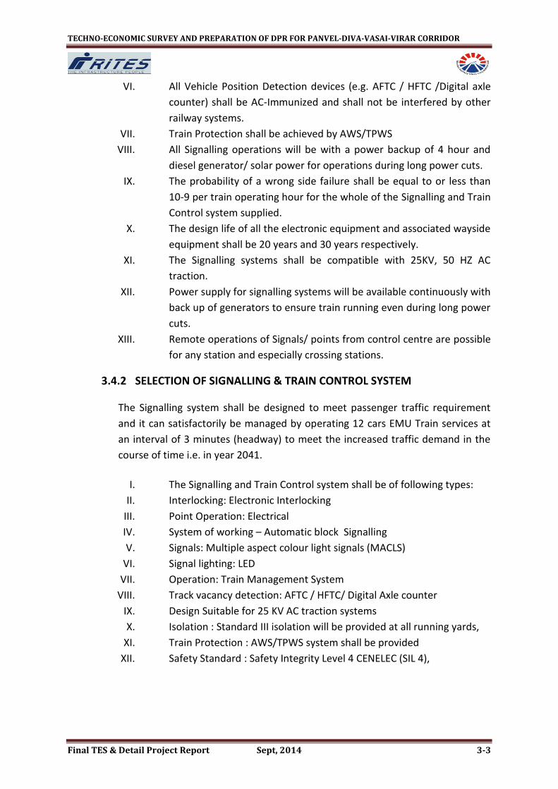
Fig : 5 Block Diagram of LED
3.4.11 EVENT LOGGER /DATA LOGGER An Event logger is an electronic device that records data over time or in
relation to location either with a built in instrument or sensor or via external
instrument and sensors. There would be data logging equipment for signal
equipment, which will record information on the functioning of the signal
and send it to a computer at a central point (Operation Control Centre)
where reports can be generated and alarms raised for various kinds of
malfunctions (power failure, signal passed at danger, train entering without
line clear, signal lamp failure, loose packing of points, etc.). The proposed
data logger system will monitor all the signal equipments, track circuits and
signal power supplies. Data Logger will have 128/256/512 digital and 16
analog inputs monitoring power supply
Fig : 6 Block Diagram of Event Logger System
3.4.12 POWER SUPPLY Signalling systems will get primary power from Traction substations supply as
that is the most reliable power supply available. There would be fallback
arrangement from local power supply that will be switched over to in case of
failure of Traction substation power supply. In the event both the power
supplies fails, power would be sourced from the diesel generator input where
diesel generator needs to be started. An uninterrupted power supply
arrangement with battery backup (for power storage) up to 4 hrs will be
provided at each station.
The uninterrupted power supply (UPS) of suitable KVA, 415 V ± 1%, 3 phases
with Battery bank of suitable AH capacity at each interlock station and
suitable KVA with Battery bank of suitable AH capacity at each non interlock

TECHNO-ECONOMIC SURVEY AND PREPARATION OF DPR FOR PANVEL-DIVA-VASAI-VIRAR CORRIDOR
Final TES & Detail Project Report Sept, 2014 3-12
station will be provided for hour back up. UPS systems of proven technology
shall be provided at all Stations, and the Depot to supply systems. This UPS
may be modular and redundant, online type (i.e. output power shall be taken
from the batteries at all times other than when a bypass is in operation.
3.4.13 STANDARDS
Subject Organization Standard
Electro-magnetic compatibility
EEC 89/336/EEC
Electro-magnetic compatibility
CENELEC EN 50081-2, EN50121-1, EN50121-2, EN50121-3 EN 50121-4, EN50123 IEC 61000-1, IEC 61000-2 IEC 61000-3, IEC 61000-4 IEC 61000-5
Conducted immunity level CENELEC EN 50082-2
Electrostatic discharge (ESD)
IEC IEC 61000-4-2
Fast transient burst IEC IEC 61000-4-4
Point machines IR IRS: S24
Electronic Interlocking IR IRS:S36
Electric Signalling & Interlocking Equipment
IR IRS:S23
Lightening and Surge Protection
IEC IEC 60364, 61643, 62305
Power surge
IEC IEC 61000-4-5
Safety and Reliability Requirement of Electronic Signalling Equipment
IR CENELEC
RDSO/SPN/144 EN 50126 EN50128,EN50129
Software CENELEC
EN 50128/EN50126 EN50129 EN50159-1 &2
Signalling / Train Control System
IEC IEC 60529 Ed. 2.0 b
Functional Requirement Specification for ETCS(European Train Control System)
ETCS A200 FRS
Environmental Requirement specification for ETCS(European Train Control System)
ETCS env A200/FRSenv
Environmental standard IEC IP code 67

TECHNO-ECONOMIC SURVEY AND PREPARATION OF DPR FOR PANVEL-DIVA-VASAI-VIRAR CORRIDOR
Final TES & Detail Project Report Sept, 2014 3-13
3.5 TELECOMMUNICATION SYSTEM The purpose of Telecommunication System is to serve the Operative and Administrative communication requirement of Railway Organization. Telecommunication System also acts as a backbone for Railway signalling System.
for trackside equipment and external train borne equipment
Environmental standard for equipment in the Signal equipment Room and internal train borne equipment
IEC IP code 52
Electronic equipment used on Railway Vehicles.
IEC CENELEC
IEC 571 EN50155
Prevention of inadvertent ignition of flammable atmospheres by radio frequency radiation
BS BS 6656
Train borne equipment IS IS 9000
Trackside equipment IS IS 9000
Installation work and line side assets Network Rail (formerly Rail track) GS/IH0001 or equivalent Standard CD ROM format
ISO
ISO 9660
Network time protocol
Network Working Group
RFC 1305
Cable standard and cable installation standard
BS IEC
BS 6360 IEC 287 IEC 364-5-523
Cable standard
IRS
S-35/93 S63/89 Amendment-5; or latest TC30/05
Installation of Communication Networks in Industrial Premises
IEC IEC-61918
Installation of Field Buses IEC IEC-61784-5-3
Terminal Blocks / Connectors and Testing of Terminal Blocks / Connectors
IEC IEC 60947 & other Applicable IEC standards

TECHNO-ECONOMIC SURVEY AND PREPARATION OF DPR FOR PANVEL-DIVA-VASAI-VIRAR CORRIDOR
Final TES & Detail Project Report Sept, 2014 3-14
3.5.1 INTRODUCTION The telecommunication facilities proposed are helpful in meeting the
requirements for:
I. Supplementing the Signalling system for efficient train operation.
II. Exchange of managerial information
III. Crisis management during emergencies
IV. Passenger Information System
3.5.2 SELECTION OF SYSTEM The proposed telecom system will cater to the following requirements:
Train Traffic Control
Assistance to Train Traffic Control
Maintenance Control
Emergency Control
Station to station dedicated communication
Passenger Announcement System within the station and from Central
Control to each station or station itself. .
Centralized synchronous Clock System
Passenger Display Information
Data Channels for Signalling, SCADA for Traction & non Traction supply
System etc
Telecommunication Requirements and the proposed solutions
Telecommunication Requirements
Telecommunication System
Traffic Control Communication
Train management system based on Optical Fiber Communication system / Quad copper cable System
Emergency Control Communication
Optical Fiber Communication system and Quad copper cable System
Administrative voice and data communication
Optical Fiber Communication system/Digital Microwave System
Operational voice and data communication
Optical Fiber Communication system / Quad copper cable System
Interactive Voice Response System- IVRS
Computer Network based System
Pre recorded Announcements
Computer Network based System
Coach Guidance system Local / Centralized Computer based System
Public Announcement and Clocks
Local / Centralized Computer based Master- Slave GPRS Clock System
Telephone Exchange System
TDMA, PBX Exchange System / Centralized IP based New Generation Exchange System
Passenger Reservation TDMA Circuit switched / IP based Packet
TECHNO-ECONOMIC SURVEY AND PREPARATION OF DPR FOR PANVEL-DIVA-VASAI-VIRAR CORRIDOR
Final TES & Detail Project Report Sept, 2014 3-15
System switching computer network
Surveillance of fixed and movable assets
Close circuit TV and SCADA
Yard communication in big Marshaling yards
Paging Talkback System / Voice Group call
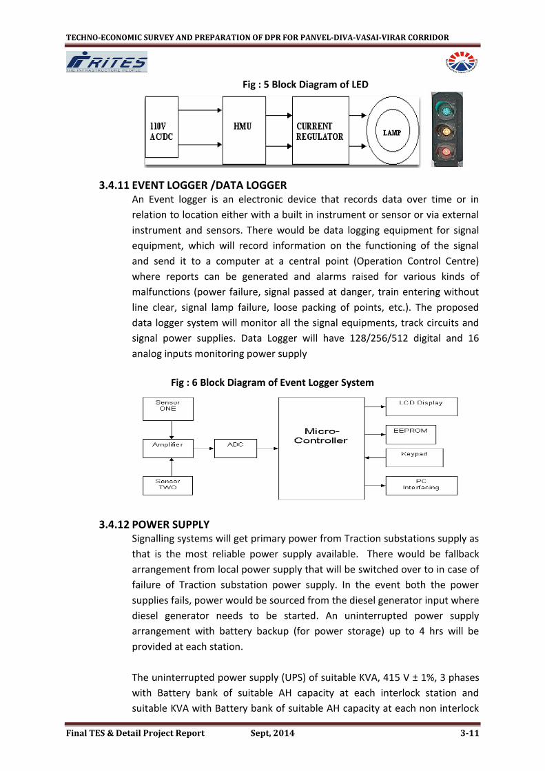
3.5.3 OPTICAL FIBER CABLE- MAIN TELECOMMUNICATION BEARER The main bearer of the bulk of the telecommunication network is proposed
with optical fiber cable system. Considering the channel requirement and
keeping in view the future expansion requirements 24 fibre, Optical Fiber
Cable is proposed to be laid in ring configuration with path diversity. This
medium shall be utilized to carry video/audio signals and SCADA related
information.
Apart from meeting required optical characteristics, it will be low smoke/ low
halogen type optical fibre cable for underground applications. OFC shall be
laid on either side of the tracks to ensure path diversity for improved
reliability.
SDH STM-4 based system will be adopted with SDH nodes at every station and depot. Access at 2MB multiplexing system will be adopted for the lower level at each node, equipped for channel cards depending on the requirement of channels in the network. Further small routers and switches will be provided for LAN network at station for system/subsystems.
Fig: 7 Optical Fibre System
3.5.4 TELEPHONE EXCHANGE SYSTEM A cost effective solution a small EPABX of at least 40 ports upgradeable up to
96 ports will be provided at each station and at the major stations including

TECHNO-ECONOMIC SURVEY AND PREPARATION OF DPR FOR PANVEL-DIVA-VASAI-VIRAR CORRIDOR
Final TES & Detail Project Report Sept, 2014 3-16
Virar, Vasai, Diva & panvel and depot 256 port exchanges upgrade able up to
512 will be provided. The Exchanges will serve the subscribers at all the
stations, and depot. The exchanges will be interconnected at multiple 2 MB
levels through redundant optical fiber cable paths. The Exchanges will be
software partitioned for EPABX and Direct Line Communication from which
the phones will be extended to the stations.
3.5.5 MOBILE RADIO COMMUNICATION Mobile Radio communication system having at least 8 channels is proposed
for on-line emergency communication between Motorman (Front end and
Rear end) of moving train and the Central Control. The system shall be based
on Digital Trunk Radio Technology to Tetra international standard. This
system is widely adopted for mobile radio communication in metro / rapid
transit services abroad. All the stations and the control centre will be
provided with handheld sets. These persons will be able to communicate
with each other as well as with central control.
The system provides full duplex communication between the Central Control
and the Motormen throughout the entire section even when the trains are in
running conditions. The system also helps in establishing communication
links between Central Control and the Maintenance staff during non
commercial hours at the time of maintenance. The existing system works on
159-164 MHz band and is based on the old Analog system with Leaky Coaxial
Technology.
Fig: 8 Typical view of tetra Sets

TECHNO-ECONOMIC SURVEY AND PREPARATION OF DPR FOR PANVEL-DIVA-VASAI-VIRAR CORRIDOR
Final TES & Detail Project Report Sept, 2014 3-17
Radio Architecture
10
Fig: 9 Schematic of Radio Architecture
The frequency band for operation of the system will be that for Tetra
in 400/800 MHz band, depending on frequency availability. The
different available bands are 380-400, 410-430, 450-470, 806-821 &
851-866 MHz.
The system shall provide mobile radio communication between the
motorman of the moving cars from any place and the central control.
The motorman can also contact any station in the network through
the central control, besides intimating the approaching trains about
any emergency like accident, fire, line blocked etc., thus improving
safety performance.
All the stations and Car Depot will be provided with fixed radio sets.
Mobile communication facility for maintenance parties and Security
Personnel will be provided with handheld sets. These persons will be
able to communicate with each other as well as with central control.
To provide adequate coverage, based on the RF site survey to be
carried out, base stations for the system will be located at a site
conveniently selected after detailed survey.
Advantages of TETRA over other Technologies:
The much lower frequency used gives longer range, which in turn
permits very high levels of geographic coverage with a smaller
number of transmitters, thus cutting infrastructure costs.

TECHNO-ECONOMIC SURVEY AND PREPARATION OF DPR FOR PANVEL-DIVA-VASAI-VIRAR CORRIDOR
Final TES & Detail Project Report Sept, 2014 3-18
High spectral efficiency - 4 channels in 25 kHz and no guard bands,
compared to GSM with 8 channels in 200 kHz and guard bands.
Very fast call set-up - a one to many group call is generally set-up
within 0.5 seconds (typical less than 250 msec for a single node call)
compared with the many seconds (typically 7 to 10s) that are required
for a GSM network.
Works at high relative speeds >400 km/h. TETRA was used during the
French TGV train speed record on 3 April 2007 at 574.8 km/h.
The system contains several mechanisms, designed into the protocols
and radio parameters, to ensure communication success even during
overload situations (e.g., during major public events or disaster
situations), thus calls will always get through unlike in cellular
systems. The system also supports a range of emergency calling
modes.
TETRA infrastructure is usually separate from (but connected to) that
of the public (mobile) phone networks, resulting in (normally) no call
charges for the system owners, substantially more diverse and
resilient communications and it is easy to customise and integrate
with data applications (vehicle location, GIS databases, dispatch
systems, etc.).
Unlike most cellular technologies, TETRA networks typically provide a
number of fall-back modes such as the ability for a base station to
process local calls. So called Mission Critical networks can be built
with TETRA where all aspects are fail-safe/multiple-redundant.
In the absence of a network mobiles/portables can use 'direct mode'
whereby they share channels directly (walkie-talkie mode).
Gateway mode - where a single mobile with connection to the
network can act as a relay for other nearby mobiles that are out of
range of the infrastructure.
TETRA also provides a point-to-point function that traditional
analogue emergency services radio systems did not provide. This
enables users to have a one-to-one trunked 'radio' link between sets
without the need for the direct involvement of a control room
operator/dispatcher.
Unlike the cellular technologies, which connect one subscriber to one
other subscriber (one-to-one) then TETRA is built to do one-to-one,
one-to-many and many-to-many. These operational modes are
directly relevant to the public safety and professional users.
TETRA supports both air-interface encryption and end-to-end
encryption

TECHNO-ECONOMIC SURVEY AND PREPARATION OF DPR FOR PANVEL-DIVA-VASAI-VIRAR CORRIDOR
Final TES & Detail Project Report Sept, 2014 3-19
Rapid deployment (transportable) network solutions are available for
disaster relief and temporary capacity provision.
Equipment is available from many suppliers around the world, thus
providing the benefits of interoperable competition.
Network solutions are available in both the older circuit-switched
(telephone like) architectures and flat, IP architectures with soft
(software) switches.
3.5.6 PUBLIC ADDRESS SYSTEM The public Address System shall be capable of digitized voice announcements
and will generally operate in automatic mode providing information of time
and destination of the next schedule train, special upcoming event, safety
and security announcement at pre determined intervals and general
information to enhance the travel experience for all users. There will be over
ridding facility for manual announcement in case of an emergency.
3.5.7 CLOCK SYSTEM
The Clock System shall provide synchronized time for the whole Rail system.
The time source shall be the Global Positioning System (GPS).
The synchronized time information shall be displayed on slave clock units and
provided to other interfacing systems via the Data Transmission System.
This will ensure an accurate display of time through a synchronization system
of slave clocks driven from a Master Clock at the operation control center.
The Master Clock signal will also be required for synchronization of SDH and
Exchanges. The System will ensure identical display of time at all locations.
Clocks are to be provided at platforms, concourse, Station Master's Room
and other service establishments etc.
Fig: 10 Clock Console

TECHNO-ECONOMIC SURVEY AND PREPARATION OF DPR FOR PANVEL-DIVA-VASAI-VIRAR CORRIDOR
Final TES & Detail Project Report Sept, 2014 3-20
The free run accuracy of the master clock units shall never be more than 30
milliseconds different from the GPS reference. Network time synchronization
over the data network shall be using NTP, with an accuracy of ±0.1s per 24
hours to the reference. The system shall have a minimum accuracy of 1
second a day when they do not receive signals from the master clock.
3.5.8 PASSANGER INFORMATION DISPLAY On board Passenger Information Display screens (Flat Panel Displays) shall be
fitted to provide passenger information on train movements and next train
indication. They shall be full colour display capable of showing graphics and
video. The display shall show information to match automated audio
announcements. A link to the fire safety system to provide evacuation
information shall be provided.
3.5.9 PASSANGER INFORMATION SYSTEM At all stations, suitable Electronic Passenger Information Display Boards (Flat
Panel) will be provided. The PIS will be of train actuated along with facility for
manual inputs from the local station.
Passenger Information display boards will be provided at convenient
locations at all stations to provide trilingual visual indication of the status of
the running trains and will typically indicate information such as destination,
platform numbers, arrival/departure time, and also special messages in
emergencies. The boards will be provided at all platforms and concourses of
terminal & junction stations.
Fig:11 Passenger Information Display System

TECHNO-ECONOMIC SURVEY AND PREPARATION OF DPR FOR PANVEL-DIVA-VASAI-VIRAR CORRIDOR
Final TES & Detail Project Report Sept, 2014 3-21
It is envisaged that Public Address and Passenger Information Display System
is provided in the car so that passengers are continuously advised of the next
stoppage station, final destination station, interchange station, emergency
situations if any, and other messages. The rolling stock is provided with Talk
Back Units inside the cars, which permit conversation between passengers
and the drivers in case of any emergency.
3.5.10 VIDEO SURVEILLANCE SYSTEM: CLOSED CIRCUIT TV For security purpose as well as an aid to train operation video surveillance
system based on CCTV system is proposed for selected locations of stations
including Platform, entry / exit gates, stairs , escalators , FOB etc. It will
provide Surveillance by Motormen about the entraining and detraining of
passengers, surveillance by station in charge about every important locations
of station and also surveillance by Central Control about proper running of
trains.
3.5.11 SPACE REQUIREMENT FOR S&T INSTALLATIONS Adequate space for proper installation of all Signalling and
Telecommunication equipment at each of the stations should be provided
keeping in view the maintenance and use of instrumentation set up for
regular testing. The areas without infringement by air conditioner required at
each of the stations for S & T equipment will be generally 60 sqm each for
Telecomm Room, 60 sqm for UPS Room and 55-60 sqm for Signalling
equipment room at interlock stations & 30 sqm at non interlock stations. This
area will also cater to local storage and space for maintenance personnel to
work.
At the Depot, the areas required will be as per the final configuration of the
equipments and network configuration keeping space for further expansion.
For laying the S&T cable along with track a viaduct size 500X250 mm to be
provided at opposite side of power cable and 200X250 mm each side along
the track for optic fiber cable and connectivity from viaduct to equipment
room to be provided.

TECHNO-ECONOMIC SURVEY AND PREPARATION OF DPR FOR PANVEL-DIVA-VASAI-VIRAR CORRIDOR
Final TES & Detail Project Report Sept, 2014 3-22
3.5.12 STANDARDS FOR TELECOMMUNICATION Description Standards
Transmission System SDH/GE (Giga Ethernet) based for the entire telecom network. OFC backbone network shall be formed by laying two outdoor single mode optical fiber cables (to be laid on either side of tracks). The normal and protected routes shall arrange in two different cables for path diversity.
Optical Fiber cable OFC for underground environment shall be steel armoured and manufactured from Fire Retardant/resistance, Low Smoke and zero halogen materials. For elevated portion of corridor, it shall be steel armoured and conforming to IRS specifications.
Telephone Exchange IP based Electronic Exchange
UPS 415 V ± 1%, 3- phase Conforming to international standards. Rated for continuous operation System availability > 99.9% Reliability shall be > 99.9%.
Passenger Display Information System
It shall be interfaced with signalling system for online update of train information. IEC as applicable or any equivalent international/National standard.
Synchronized Clock system GPS based, master – slave system IEC 61588 or equivalent standard
Public Address System Passenger Announcement System shall be interfaced with signalling system for online update of train information. IEC 60268 as applicable or any equivalent international/National standard. The characteristics to be specified and the methods of measurement for the equipment shall be in accordance with IEC 268 Part 1 to 17 – Sound System Equipment. Fire resistant Low Smoke Zero Halogen cables shall be used to maintain the circuit integrity in case of fire.
CCTV/ Camera ¼“ CCD Camera progressive Scan of International Standards like EN/FCC/UL/CE CCTV network shall be as per IEEE standards. Approval: EN/FCC/UL/CE
Compression techniques H.264, MPEG4 or similar
Minimum illumination For Colour 0.5 LUX For B/W 0.008 LUX

TECHNO-ECONOMIC SURVEY AND PREPARATION OF DPR FOR PANVEL-DIVA-VASAI-VIRAR CORRIDOR
Final TES & Detail Project Report Sept, 2014 3-23
Redundancy (Major System)
Redundancy on Radio base station equipment.
Environmental Conditions All equipment rooms to be air-conditioned
Maintenance Philosophy
System to have, as far as possible, automatic switching facility to alternate routes/circuits in the event of failure. Philosophy of preventive checks of maintenance to be followed. System networked with NMS for diagnosing faults and coordination. Card/module level replacement will be done in the field and repairs undertaken in the central laboratory/manufacture's premises.
3.6 ROLLING STOCK
Rolling Stock proposed for PANVEL-VIRAR suburban corridor shall be Broad Gauge, 100 Kmph maximum speed, Stainless steel body, Automatic Voice Announcement System, well ventilated etc. The broad features of Rolling Stock, which may be followed for this corridor, are presented in Table below; the basis of which is given in the following paragraphs.
Table 3.1: Broad Features of Rolling Stock
S. No.
Parameter Details
1
Basic Unit One Motor coach (MC) and one Trailer coach (TC) and one driving coach (DC).
12-Car Train Composition
DC-MC-TC-TC-MC-TC-TC-MC-TC-TC-MC-DC
2 Coach construction Light weight stainless steel body
3 Tare Weight DC (32.0 T), TC (32.0 T), MC (52.0 T)
4 Axle load 20.5 T
5 Propulsion system 3 phase drive system with VVVF control
6 Type of traction supply 25KV AC Overhead collection
7 Passenger Loading (SDCL)
DC (28.0 T), TC (34.0 T), MC (27.0 T) Loading Equivalent to 16 standing passenger /m2
3.6.1 OPTIMIZATION OF COACH SIZE
Considering the clearances and also the space required for service and cables
etc., the coach with following principal dimensions has been prescribed.

TECHNO-ECONOMIC SURVEY AND PREPARATION OF DPR FOR PANVEL-DIVA-VASAI-VIRAR CORRIDOR
Final TES & Detail Project Report Sept, 2014 3-24
Table 3.2: Size of the Coach
Car Length Width at Door Height
Driving Trailer Coach (DC) 21.0 m 3.66 m 4.2 m*
Trailer/Motor Coach (TC/MC) 21.0 m 3.66 m 4.0 m
* Height over pantograph in down condition
3.6.2 COACH DESIGN AND BASIC PARAMETERS The important criteria for selection of rolling stock are as under:
i. Proven equipment with high reliability
ii. Passenger safety feature
iii. Energy efficiency
iv. Light weight equipment and coach body
v. Optimized scheduled speed
vi. Aesthetically pleasing Interior and Exterior
vii. Low Life cycle cost
viii. Flexibility to meet increase in traffic demand
3.6.3 SPEED /ACCELERATION / DECELERATION The equipment shall be designed for following operational parameters at
maximum gross weight (SDCL).
i. Max. operating speed : 110 kmph
ii. Max Test Speed: 125 kmph
iii. Starting Acceleration (zero to 40 kmph) : 0.54 m/s2
iv. Deceleration Average from booked to 50 kmph : 0.76 m/s2
v. Average from 50 kmph to standstill : 0.86 m/s2
3.6.4 SELECTION OF TECHNOLOGY i) Low life cycle cost
The low life cycle cost is achieved by the way of reduced scheduled and
unscheduled maintenance and high reliability of the sub-systems. It is
possible to achieve these objectives by adopting suitable proven
technologies. The selection of following Technologies has been adopted to
ensure low life cycle cost.
ii) Car body

TECHNO-ECONOMIC SURVEY AND PREPARATION OF DPR FOR PANVEL-DIVA-VASAI-VIRAR CORRIDOR
Final TES & Detail Project Report Sept, 2014 3-25
In the past carbon high tensile steel was invariably used for car bodies. In-fact
almost all the coaches built by Indian Railways are of this type. These steel
bodied coaches need frequent painting and corrosion repairs, which may
have to be carried out up to 4-5 times during the service life of these
coaches. It is now standard practice to adopt stainless steel or aluminum. The
car body with aluminum requires long and complex extruded sections, which
are still not manufactured in India. Therefore aluminum car body has not
been considered for use. Stainless steel sections are available in India and
therefore Stainless steel car bodies have been specified. No corrosion repair
is necessary on stainless steel cars during the service life of the cars.
The stainless steel car body leads to energy saving due to light weight. It also
results in cost saving due to easy maintenance and reduction of repair cost
from excellent anti corrosive properties as well as an improvement of riding
comfort and safety in case of crash or fire. A design life of 30 years for coach
has been recommended.
iii) Bogies
Bolster less lightweight bogies with rubber springs are now universally
adopted in metro cars. These bogies require less maintenance and overhaul
interval is also of the order of 4,20,000 km. The use of air spring at secondary
stage is considered with a view to keeps the floor level of the cars constant
irrespective of passenger loading unlike those with coil spring. The
perturbations from the track are also dampened inside the car body on
account of the secondary air spring along with suitable Vertical Hydraulic
Damper. The primary suspension system improves the curve running
performance by reducing lateral forces through application of conical rubber
spring. A smooth curving performance with better ride index is being ensured
by provision of above type of bogies.
iv) Braking System
The brake system shall consist of –
An electro-pneumatic (EP) service friction brake
A fail safe, pneumatic friction emergency brake
A spring applied air-release parking brake
An electric regenerative service brake
Provision of smooth and continuous blending of EP and regenerative
braking
The regenerative braking will be the main brake power of the train and will
regain the maximum possible energy and pump it back to the system and
thus fully utilize the advantage of three phase technology. The regenerative
braking should have air supplement control to bear the load of trailer car. In

TECHNO-ECONOMIC SURVEY AND PREPARATION OF DPR FOR PANVEL-DIVA-VASAI-VIRAR CORRIDOR
Final TES & Detail Project Report Sept, 2014 3-26
addition, speed sensors mounted on each axle control the braking force of
the axles with anti skid valves, prompting re-adhesion in case of a skid. The
brake actuator shall operate either a tread brake or a wheel disc brake.
v) Propulsion System Technology
The brush less 3 phase induction motors has now replaced the d.c series
motors in traction applications. The induction motor, for the same power
output, is smaller and lighter in weight and ideally suited for rail based Mass
Rapid Transit applications. The motor tractive effort and speed is regulated
by ‘Variable Voltage and Variable frequency’ control and can be programmed
to suit the track profile and operating requirements. Another advantage of 3
phase a.c. drive and VVVF control is that regenerative braking can be
introduced by lowering the frequency and the voltage to reverse the power
flow and to allow braking to very low speed.
Converter and Inverter should be IGBT based. The advanced IGBT contains an
Insulated Gate Bipolar Transistor (IGBT) and gate drive circuit and protection.
The advanced IGBT incorporates its own over current protection, short circuit
protection; over temperature protection and low power supply detection.
The inverter unit uses optical fiber cable to connect the control unit to the
gate interface. The optical fiber cable provides electrical isolation between
the advanced IGBT and the control unit and is impervious to electrical
interference. These features are recommended for adoption in Trains of
Mumbai MRTS.
vi) Cab Layout
The modern stylish driver panel shall be FRP moulded which give maximum
comfort and easy accessibility of different monitoring equipments to the
driver along with clear visibility. The driver seat has been provided at the left
side of the cabin.
3.6.5 COMMUNICATION The driving cab of the cars are provided with continuous communication with
base Operational Control Centre and station control for easy monitoring of
the individual train in all sections at all the time. Public Address and
Passenger Information Display System is provided in the car so that
passengers are continuously advised of the next stoppage station, final
destination station, interchange station, emergency situations if any, and
other messages.

TECHNO-ECONOMIC SURVEY AND PREPARATION OF DPR FOR PANVEL-DIVA-VASAI-VIRAR CORRIDOR
Final TES & Detail Project Report Sept, 2014 3-27
3.6.6 NOISE AND VIBRATION The train passes through heavily populated urban area. The noise and
vibration for a metro railway become important criteria from public
acceptance view point. The sources of noise are:
i. Rail-wheel interaction
ii. Noise generated from equipment like Blower, Compressor, air conditioner, door, Inverter etc.
iii. Traction motor in running train. For elimination and reduction of noise following features are incorporated: -
Provision of anti drumming floor and noise absorption material
Low speed compressor, blower and air conditioner
Mounting of under frame equipments on anti-vibration pad
Smooth and gradual control of door
Provision of GRP baffle on the via-duct for elimination of noise transmission
Provision of sound absorbing material in the supply duct and return grill of air conditioner
Sealing design to reduce the aspiration of noise through the gap in the sliding doors and piping holes
Provision of bolster less type bogies having secondary air spring.
3.6.7 PASSANGER SAFETY FEATURES AWS The complete system shall be compatible with the Auxiliary
Warning System already working in Mumbai area.
Fire The rolling stock is provided with fire retarding materials having low fire load, low heat release rate, low smoke and toxicity inside the cars. The electric cables used are also normally low smoking zero halogen type which ensures passenger safety in case of fire.
Crash worthiness features
The rolling stock is provided with inter car couplers having crashworthiness feature which reduces the severity of injury to the passengers in case of accidents.