Embed Size (px)
Citation preview

1
CONTENTSSafety Information ..................................................................................................................................... 2Electrostatic Discharge Sensitive (ESDS) Device Handling.................................................................. 3Theory of Operation .............................................................................................................................4-26System Overview ...................................................................................................................................... 4Console Theory of Operation .............................................................................................................. 4-191.0 Power Supply ...................................................................................................................................... 4 1.1. Switching Power Supplies .............................................................................................................. 5 1.2. Linear Power Supplies ..................................................................................................................... 5 1.3. Supply Synchronization .................................................................................................................. 5 1.4. Power Failure Detection .................................................................................................................. 62.0 Processor and Its Peripherals ............................................................................................................ 63.0 Communications Busses and Interface Blocks ............................................................................... 8 3.1 Communications Busses ................................................................................................................. 8 3.2 Interface Blocks ................................................................................................................................ 9 3.3 Ethernet ............................................................................................................................................ 104.0 Audio Path.......................................................................................................................................... 11 4.1 Analog Audio Path ........................................................................................................................... 12 4.2 Digital Audio Path ............................................................................................................................ 12 4.3 Interaction Between the Digital and Analog Inputs ...................................................................... 135.0 Video Path .......................................................................................................................................... 136.0 Tuner Electronics .............................................................................................................................. 14 6.1 Main PCB Interface ......................................................................................................................... 14 6.2 Control ............................................................................................................................................. 15 6.3 FM Tuner .......................................................................................................................................... 16 6.5 Phase-locked Loop Tuning ............................................................................................................. 18 6.6 RDS................................................................................................................................................... 19PS3•2•1 Series II Speaker System (Bass Module) Theory of Operation ............................................. 191.0 Components ...................................................................................................................................... 192.0 Bass Module Interface ...................................................................................................................... 19 2.1 Interface connector and cable descriptions ................................................................................. 20 2.2 3•2•1 Series II Bass Module Details ............................................................................................... 21Test Procedures .................................................................................................................................27-36 Console Procedures ........................................................................................................................27-33 Bass Module Procedures ................................................................................................................34-35 Satellite Array Procedures .................................................................................................................... 36Appendix .............................................................................................................................................37-51 Figure 1. 3•2•1 Series II Console Test Setup Diagram ............................................................................ 37 Figure 2. 3•2•1 Series II Bass Module Test Setup Diagram .................................................................... 38 Obtaining System Information from the Media Center Display ........................................................ 39 Computer Setup Procedure ............................................................................................................ 40-41 TAP Cable Construction ....................................................................................................................... 42 Boselink ETAP Cable Wiring Diagram ................................................................................................. 42 B+B Electronics model 232LPTTL RS232 to TTL converter .............................................................. 42 Bass Module Test Cable Construction ................................................................................................ 43 Bass Module Test Cable Wiring Information ...................................................................................... 43 Console Test Cable Construction ........................................................................................................ 44 Console Test Cable Wiring Information .............................................................................................. 44 Putting the Console into TAP mode .................................................................................................... 45 Console TAP Commands .................................................................................................................45-48 Changing the Region Code .................................................................................................................. 49 Console Troubleshooting Tips ............................................................................................................. 50 Bass Module Troubleshooting Tips ..................................................................................................... 51IC Diagrams ........................................................................................................................................52-61Service Manual Revision History ........................................................................................................... 62
2
SAFETY INFORMATION1. Parts that have special safety characteristics are identified by the symbol on schematicsor by special notes on the parts list. Use only replacement parts that have critical characteristicsrecommended by the manufacturer.
2. Make leakage current or resistance measurements to determine that exposed parts areacceptably insulated from the supply circuit before returning the unit to the customer.Use the following checks to perform these measurements:
A. Leakage Current Hot Check-With the unit completely reassembled, plug the AC line corddirectly into a 120V AC outlet. (Do not use an isolation transformer during this test.) Use aleakage current tester or a metering system that complies with American National StandardsInstitute (ANSI) C101.1 "Leakage Current for Appliances" and Underwriters Laboratories (UL)6500 / IEC 60056 paragraph 9.1.1. With the unit AC switch first in the ON position and then inOFF position, measure from a known earth ground (metal waterpipe, conduit, etc.) to all ex-posed metal parts of the unit (antennas, handle bracket, metal cabinet, screwheads, metallicoverlays, control shafts, etc.), especially any exposed metal parts that offer an electrical returnpath to the chassis. Any current measured must not exceed 0.5 milliamp. Reverse the unitpower cord plug in the outlet and repeat test. ANY MEASUREMENTS NOT WITHIN THELIMITS SPECIFIED HEREIN INDICATE A POTENTIAL SHOCK HAZARD THAT MUST BEELIMINATED BEFORE RETURNING THE UNIT TO THE CUSTOMER.
B. Insulation Resistance Test Cold Check-(1) Unplug the power supply and connect a jumperwire between the two prongs of the plug. (2) Turn on the power switch of the unit. (3) Measurethe resistance with an ohmmeter between the jumpered AC plug and each exposed metalliccabinet part on the unit. When testing 3 wire products, the resistance measured to the productenclosure should be between 2 and infinite MOhms. Also, the resistance measured to exposedinput/output connectors should be between 4 and infinite MOhms. When testing 2 wire prod-ucts, the resistance measured to exposed input/output connectors should be between 4 andinfinite MOhms. If it is not within the limits specified, there is the possibility of a shock hazard,and the unit must be repaired and rechecked before it is returned to the customer.
CAUTION: The Bose® 3•2•1 Series II Home Entertainment Systemcontains no user-serviceable parts. To prevent warranty infractions,
refer servicing to warranty service stations or factory service.
PROPRIETARY INFORMATION
THIS DOCUMENT CONTAINS PROPRIETARY INFORMATION OFBOSE CORPORATION WHICH IS BEING FURNISHED ONLY FORTHE PURPOSE OF SERVICING THE IDENTIFIED BOSE PRODUCTBY AN AUTHORIZED BOSE SERVICE CENTER OR OWNER OFTHE BOSE PRODUCT, AND SHALL NOT BE REPRODUCED ORUSED FOR ANY OTHER PURPOSE.

3
ELECTROSTATIC DISCHARGE SENSITIVE (ESDS)DEVICE HANDLING
This unit contains ESDS devices. We recommend the following precautions when repairing,replacing or transporting ESDS devices:
• Perform work at an electrically grounded work station.• Wear wrist straps that connect to the station or heel straps that connect to conductive floor mats.• Avoid touching the leads or contacts of ESDS devices or PC boards even if properly grounded. Handle boards by the edges only.• Transport or store ESDS devices in ESD protective bags, bins, or totes. Do not insert unprotected devices into materials such as plastic, polystyrene foam, clear plastic bags, bubble wrap or plastic trays.

4
THEORY OF OPERATIONSystem Overview
The 3•2•1 Series II is a single-zone home entertainment system. It has two configurations:(1) basic/standard system with no Ethernet interface and no hard drive or uMusicTM function.This system will be available with either the standard 3•2•1 speaker arrays or the GemstoneTM
speaker arrays. (2) A premium system including the Ethernet interface and hard drive anduMusic. This system will also incorporate the array speakers developed in the Gemstoneproject.
The 3•2•1 Series II system consists of the following major components:1. Console with Display, Main board, Tuner board, button board and IR remote receiver,
CD/DVD driver, Hard disk driver (premium version only).2. Bass module Unit with Woofer, DSP board, I/O board and system power supply.3. Two two-element speaker arrays.4. IR remote control.
Console Theory of OperationThe basic elements of the console are:1. Main board.2. Tuner board.3. VFD display.4. DVD ROM driver.5. Button board.6. IR receiver.7. Hard disk driver (premium only)8. Ethernet interface (premium only)
1. Power SupplyNote: Refer to the 3•2•1 II console schematic sheets, 270593, for the following information.The bass module provides un-regulated power V_UNREG to console via connector J100 pins 1and 2 [sheet 10, B2]. The power supply electronics are comprised of 4 main sections; switchingpower supplies, linear power supplies, power supply synchronization, and power fail detection.The console’s input voltage, V_UNREG, comes from the bass module and is nominally 26VDC.This voltage varies with load and line levels, but is limited to 31.5V maximum (assuming linevoltage of 140V AC). This voltage is always present whenever the bass module is plugged intothe wall and so the console’s power supplies are likewise active. All the voltage level source arelisted in following table:
Note: The 1.8V and 3.3V linear regulators are derived from the +5V switching power supply.The 9V linear regulator is derived from the +12V switching power supply.
Node Name Output Voltage
Type Input from Outputs to
V_UNREG +26 Full wave rectifier
Bass module at line of 120VAC
+12V and +5V switching power supply
+12V +12 Switching V_UNREG DVD drive, Tuner board, VFD display, Video control relay.
+9V +9 Linear +12V Analog MUX, DAC output filter op-amps, Summing op-amps and Zone speaker differential input op-amps.
+5V +5 Switching V_UNREG +3.3V and +1.8V switching power supply; DVD drive, Hard disk driver, IR receiver, DAC, SPDIF receiver.
+3.3V +3.3 Linear +5V Processor CS98200’s I/O power, Flash, SDRAM IC’s, Ethernet controller, SPDIF receiver,
+1.8V +1.8 Linear +3.3V Processor CS98200’s core and PLL circuit power; power on/monitor reset chip.
5
1.1. Switching Power Supplies
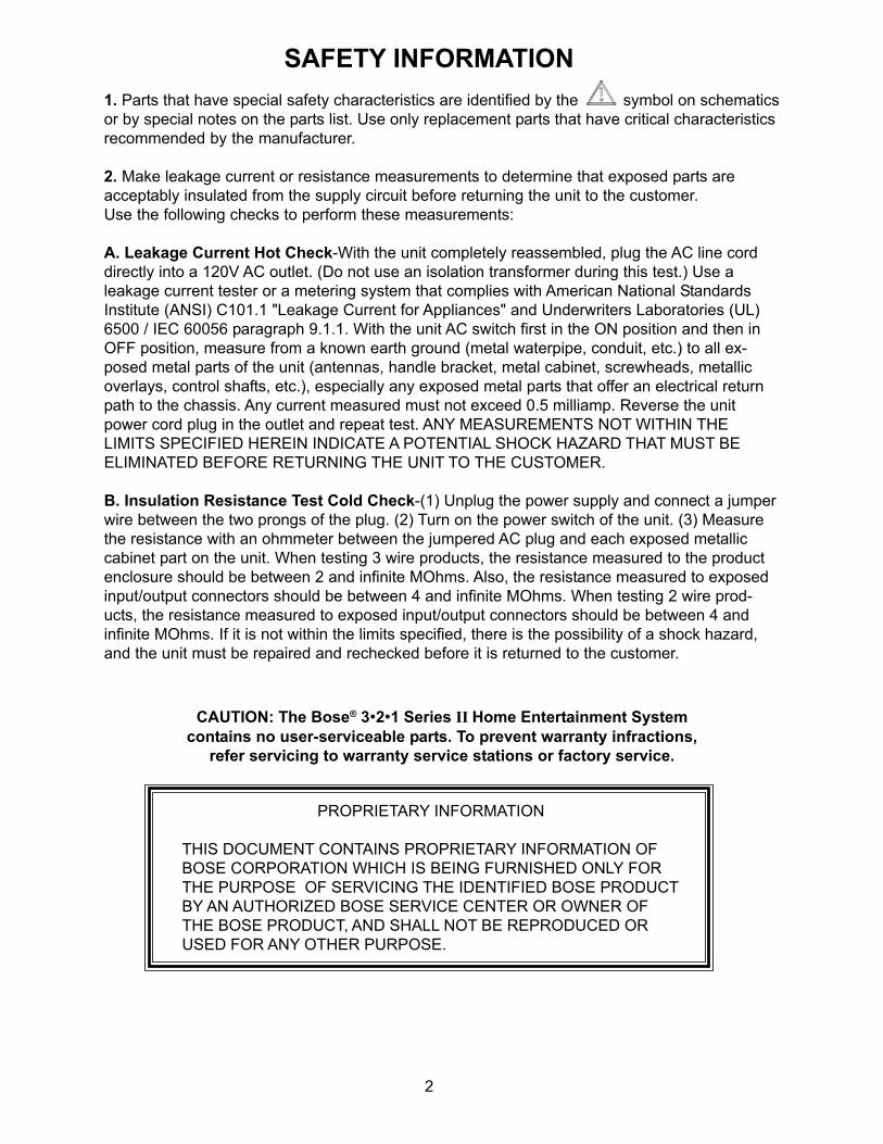
The +12V and +5V switching power supplies use ST L4973D3.3 regulator ICs (U17 [sheet 14,B5] and U2 [A6]). The power supplies are designed as step-down Buck converters. The voltagefed back to the chip on pin 13 determines the output voltage; the chip’s control circuitry will workto keep this voltage at +3.3V. The +5.1V and +12V supplies use resistor divide-down networksto obtain the +3.3V feedback voltage.
The reference designators listed below correspond to the +12V switching power supply; thedesigns of the +5V regulator is nearly identical.
A number of additional series inductors and parallel capacitors exist to provide filtering func-tions.
The compensation networks used for these switching power supplies have been chosen toprovide stability under all conditions and to provide minimal RF interference to the tuner.The supplies function in both continuous and discontinuous mode depending on the load.
1.2. Linear Power Supplies
U18 [C3] is the +9V linear regulator. VR1 [A3] and VR2 [A2] are the 3.3V and 1.8V linear regula-tor, respectively.
1.3. Supply Synchronization
In order to control the noise interference to the AM tuner, a variable frequency to alternateswitching synchronization scheme was implemented. When the console is in the Tuner mode,the SPDIF receiver (U8001 [sheet 12, B4]) delivers a 2.8224MHz clock signal (SPDIFIN_BCK)from the 11.2896MHz crystal oscillator. SPDIFIN_BCK drives the binary count (U3 [sheet 14,C4]) and generates a required synchronizing pulse (F_SYNCH) and feed to pin 20 of U17 [C5]and pin 20 of U2 [B6]. Q4 [D3] and Q5 [D3] are for buffering and level shifting of the synchroniz-ing pulse. The synchronization pulse alternation is controlled by tuner board based on the AMstation to be tuned.
THEORY OF OPERATION
IC Pin Components Connected Function 1 R17, C50 Sets free running switching frequency
(when not controlled externally) 10 C25 Bootstrap to drive internal D-MOS 11 R33 Inhibits supply 12 R36 C22 C24 Lead-lag filter for compensation loop 13 R30 R37 Voltage feedback for control 18 C51 +5.1V for external reference 19 C58 Sets supply soft-start time constant 20 Q5 Supply frequency switching synchronization
(see section 2.4 below)
6
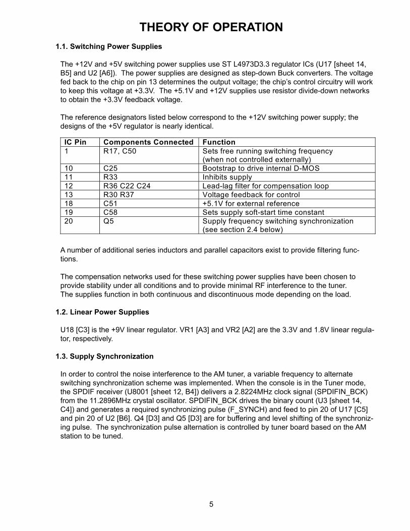
THEORY OF OPERATION1.4. Power Failure Detection
It is important to detect a power failure and alert the mircoprocessor to save any relevant infor-mation and mute the power amplifiers so that no audio “pops” will be heard. The power failuredetection circuit (Q2, Q3, R11, R35, R40 and R15 [sheet 14, C7]) that we employ controls anedge-triggered interrupt to the CS98200 microprocessor (U7003, pin 146 [sheet 5, C5]) to dojust that. If the voltage on V_UNREG falls below roughly 13.2V, the microprocessor will bealerted that there is a power failure occuring. The interrupt will be unasserted (go high) whenV_UNREG goes above roughly 16.1V. This large hytsterisis is set so that dips in V_UNREGcaused by loud volumes will not inadvertantly trip a power fail interrupt. In a brownout condition,the system will mute with the power dip and then recover gracefully when the normal line level isrestored (V_UNREG goes above 15.39V).
2. Processor and Its Peripherals
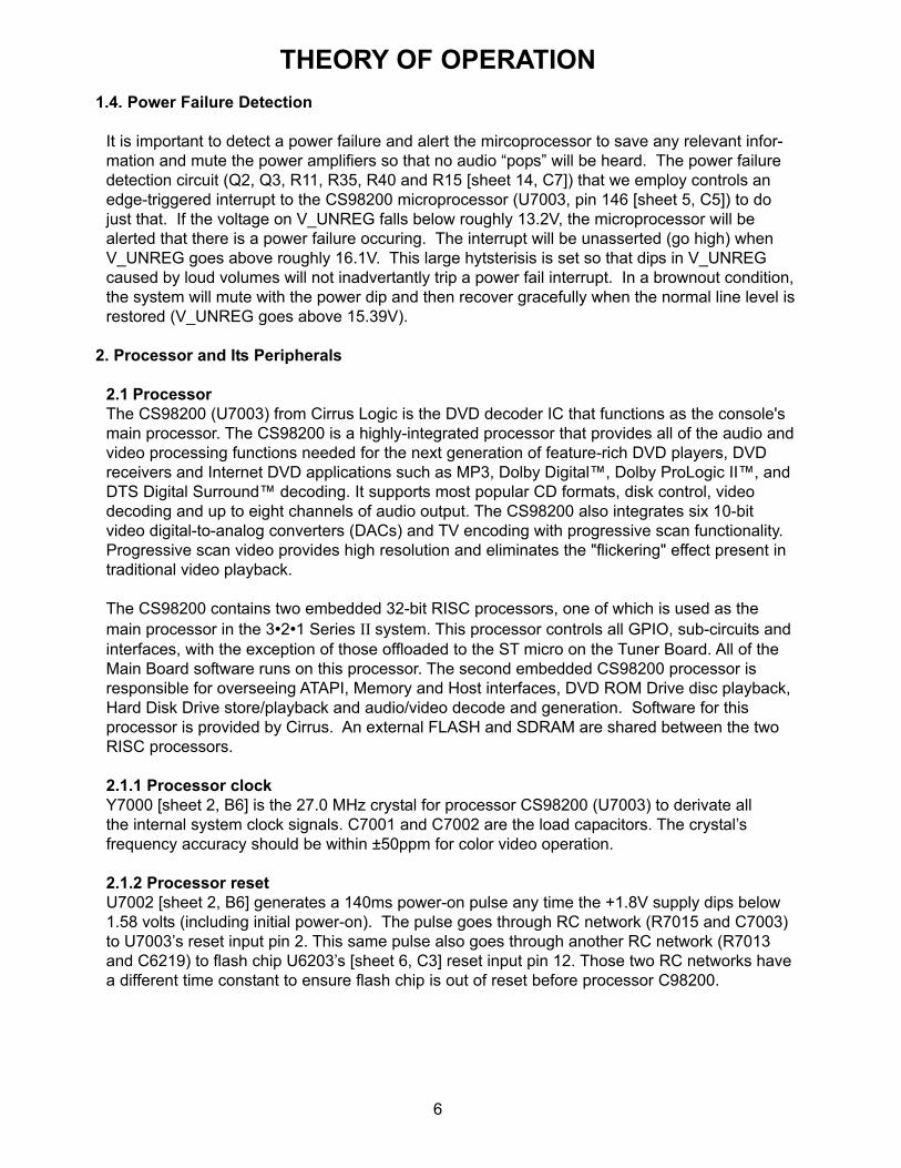
2.1 ProcessorThe CS98200 (U7003) from Cirrus Logic is the DVD decoder IC that functions as the console'smain processor. The CS98200 is a highly-integrated processor that provides all of the audio andvideo processing functions needed for the next generation of feature-rich DVD players, DVDreceivers and Internet DVD applications such as MP3, Dolby Digital™, Dolby ProLogic II™, andDTS Digital Surround™ decoding. It supports most popular CD formats, disk control, videodecoding and up to eight channels of audio output. The CS98200 also integrates six 10-bitvideo digital-to-analog converters (DACs) and TV encoding with progressive scan functionality.Progressive scan video provides high resolution and eliminates the "flickering" effect present intraditional video playback.
The CS98200 contains two embedded 32-bit RISC processors, one of which is used as themain processor in the 3•2•1 Series II system. This processor controls all GPIO, sub-circuits andinterfaces, with the exception of those offloaded to the ST micro on the Tuner Board. All of theMain Board software runs on this processor. The second embedded CS98200 processor isresponsible for overseeing ATAPI, Memory and Host interfaces, DVD ROM Drive disc playback,Hard Disk Drive store/playback and audio/video decode and generation. Software for thisprocessor is provided by Cirrus. An external FLASH and SDRAM are shared between the twoRISC processors.
2.1.1 Processor clockY7000 [sheet 2, B6] is the 27.0 MHz crystal for processor CS98200 (U7003) to derivate allthe internal system clock signals. C7001 and C7002 are the load capacitors. The crystal’sfrequency accuracy should be within ±50ppm for color video operation.
2.1.2 Processor resetU7002 [sheet 2, B6] generates a 140ms power-on pulse any time the +1.8V supply dips below1.58 volts (including initial power-on). The pulse goes through RC network (R7015 and C7003)to U7003’s reset input pin 2. This same pulse also goes through another RC network (R7013and C6219) to flash chip U6203’s [sheet 6, C3] reset input pin 12. Those two RC networks havea different time constant to ensure flash chip is out of reset before processor C98200.

7
2.2 SDRAMU6200 [sheet 6, B/C7] is a 128Mbit with 32-bit bus wide synchronous dynamic random accessmemory (SDRAM) IC. For SDRAM accesses, a memory clock of up to 166 MHz that synchro-nizes data access is sent to the chip at pin 68. Data commands for accesses are coded in theM_RAS_L and M_CAS_L signals (pins 18 and 19), and data read/write selection is done by theM_WE_L signal (pin 17). The address to be written or read is given on the address busMA[10:0]. The 32-bit data bus MD[31:0] contains the word to be written or read after the pipelinedelay of the memory chip.
2.3 FLASHU6203 [sheet 6, C3] is a 32Mbit with 16-bit bus wide Flash memory IC but only 8-bit wide databus is used in the system due to the limitation of CS98200. U6203 shares the memory addresswith SDRAM (U6200) but the data is a dedicated one from CS98200. Flash access is asynchro-nous and does not use a memory clock.
U6204 and U6205 [sheet 6, 4A-D] are buffers between the SDRAM and FLASH, and they havetheir Output Enable pins tied to common pull-down resistors, with test points, allowing themanufacturing plant to disable these buffers (thus releasing the FLASH address/data bus)during programming. Half of buffer U6204 (2A/B[1..8]) is used to condition the 8 memorycontrol signals, and is given its own enable and direction-control signals (with independent testpoints). This allows the manufacturing plant to maintain control of the SDRAM during both writeand read-back phases of In-circuit test.
2.4 ROMULATOR
J6200 [sheet 6, B/C2] is the ROMULATOR connector for the debug purposes of softwaredevelopment. The console Main board provides a footprint for the required 60-pin ROMULATORconnector but not populated in production. This connector will allow access to the FLASHaddress and data busses, as per the Cirrus reference design. Pin 59 shall be tied into theconsole reset circuitry, allowing it to access the CS98200 and keep the console FLASH in resetwhile running off the ROMULATOR.
U6203 can be programmed not only from the ROMULATOR connector during development butalso from CD/DVD driver in the field. During re-programming in the field via CD/DVD driver, theoperating and new program are held in SDRAM. Power failures during field Flash update couldresult in the console being made completely inoperable.
THEORY OF OPERATION

8
3. Communications Busses and Interface Blocks
3.1 Communications Busses
3.1.1 I2C BusThere are two I2C buses: (1) the I2C Debug bus for software development, the connectoris J7000-NV which is not populated in production; (2) the I2C configuration bus whichconfigures the devices in audio path. The devices connecting to the I2C configuration busand its protocol are listed in following table.
*Note: "w" bit can be either 1 or 0 depending on read/write.
3.1.2 SPI Bus
The CS98200's (U7003) built-in SPI interface is used to control two subsystems in theconsole, the VFD (interface connector is J6500 [sheet 13, B8]) and the Tuner Assembly(interface connector is J6000 [D8]). U6802 [A-C6] is the buffer between CS98200 and thetwo subsystems. These subsystems must timeshare the SPI resource.
For the outbound data (data stream from CS98200 to subsystems), both subsystems have asignal which uniquely identifies when the SPI data sent from the CS98200 is valid for them.For the VFD module, the VFD_STROBE indicates it is the target. For the Tuner Assembly,it is SPI_SEL (which becomes TNRBD_SEL once buffered). These signals are the key totimesharing the SPI bus. Note the differing polarities associated with the signals.
For the outbound data (data stream from subsystems to CS98200), each subsystem inter-acts with the CS98200 differently, as follows:• The VFD module allows for bi-directional communication, but timeshares a single wire inhalf-duplex mode to accomplish this. To receive SPI data from the VFD, the CS98200 musttherefore use the SPI configuration option which allows receiving on the same pin used fortransmission (pin 196). See the CS98200 register spec for details.• The Tuner Assembly will use SPI in true bi-directional, full duplex mode, although theCS9200 will be the master of all transfers. The TNRBD_DATAIN signal, which ties to theCS98200's SPI receiver, is used for receiving. Again, see the CS98200 register spec forSPI configuration details.
THEORY OF OPERATION
Reference Designator
Vendor Number
Protocol Address Byte
Description
U4000 TEA6422 I2C 10011010b 6-input stereo analog audio input MUX chip (ST). No CS pin is available on this part. ADDR pin has an internal 50K pull-up: logic high.
U8001 AK4112B AKM 00wxxxxxb
S/PDIF receiver. Uses the AKM_CS chip select signal to differentiate its messages from I2C. The AKM address separates its messages from those for the mix-down DAC. “w” is the write bit. The 8 data bits of the 16-bit protocol are driven by the AK4112B when w is 0.
U9200 AK4382A AKM 011xxxxxb
Stereo DAC for the CS98200 Mix-down path. Uses the AKM_CS chip select signal to differentiate its messages from I2C. The AKM address separates its messages from those for the S/PDIF receiver.

9
3.2 Interface Blocks
3.2.1 Vacuum Fluorescent Display (VFD)This vacuum fluorescent display is a custom, stand-alone VFD module manufactured byFutaba. It includes the VFD glass assembly, as well as all power supply and control/refreshelectronics, and a ribbon cable interconnect to the console main board.
The console VFD module interface with the Main board is by a flexible cable via connectorJ6500 [sheet 13, B8] which has 5-pin as listed in following table:
Note: (1) There is a buffer, U6802 with open collector between VFD and the CS98200. Thebuffer is required to level-shift the 3.3V logic levels associated with the SPI interface to the 5Vlogic levels required by the VFD module.(2) The VFD module has built-in 1.5K Ohm pull-up resistors on the Clock, Data and Strobesignals. There are no such pull-ups on the console Main Board; therefore, these signals will notbe measurable at connector J6500 unless the VFD is attached.
3.2.2 Button Board
The console has 6 buttons on the top leading edge. The buttons are physically located on asmall assembly which connects to the Main Board via ribbon cable into J6700 [sheet 8, D8].Software continually monitors these buttons to detect and de-bounce a key press. Pull-downresistors are provided to hold KEY inputs to logical 0 (ground) when no buttons are pressed.Interconnections to the buttons are in the form of a 2x3 row/column matrix of key closures.Each button is therefore identified by its unique row/column position.
The arrangement of buttons on the front of the console is as follows. Each circular buttonrepresents a key closure which shorts a given KEYOUT row signal to a given KEYIN columnsignal when a button is pressed. For example, ON/OFF shorts the KEYOUT0 signal to KEYIN0when pressed:
THEORY OF OPERATION
J6500 Pin
Signal Function
1 +12V +12V supply for the module. 2 Strobe/ Strobe for serial protocol (low when sending VFD data). 3 Ground Power supply/signal ground. 4 Clock Clock for serial protocol. Normally high here at the connector. 5 Data Data for serial protocol. Normally high here at the connector.
ON/OFF SOUR + ENTER EJECT
KEYOUT2KEYOUT1KEYOUT0
KEYIN1KEYIN0
VOLUME

10
3.2.3 IR ReceiverThe 321 Series II console includes a narrow-band IR receiver module. The IR receiver gets theIR signal from the remote control and passes it to the Main board via the Button board. The IRsignal information enters the Main board at J6700 pin7.
The console is capable of being controlled by the universal IR remote controls (basic andpremium) developed specifically for the 3•2•1 Series II, as well as 3rd party remote controlswhich either include the 3•2•1 II codes or can learn them (such as a Crestron universal re-mote). A narrow-band IR receiver module is provided on a printed circuit sub-assembly topermit mounting in the front of the console. This module amplifies the incoming IR data streamand removes its 37.9 kHz AM sub-carrier. The CS98200 handles the decoding of inboundcontrol commands from IR receiver module. Hardware assistance/noise filtering is provided inthe chip for this.
3.2.4 DVD DriverJ3200 [sheet 7, B/C5] is the connector for the DVD ROM driver which connects to the ATAPIbus on Main board. The DVD ROM provides video source and one of the internal audio sources.It can be configured either master or slave mode and share same ATAPI bus and reset signalwith HDD but with separate select signal.
3.2.5 Hard Disk DriverJ9341 [sheet 7, B/C4] is the connector for the hard disk driver (HDD) which connects to theATAPI bus on Main board. The DVD ROM provides one of the internal audio sources. It can beconfigured either master or slave mode and share same ATAPI bus and reset signal with DVDROM but with separate select signal. HDD is only populated on premium product.
3.3 EthernetThe 3•2•1 Series II premium console includes an Ethernet connector J9640 [sheet 9, B/C2] anda Cirrus CS8900A 10baseT Ethernet Controller IC U9641 [sheet 9, B/C6] which interfaces to theCS98200 via the parallel Host bus. Since this bus is timeshared with the ATAPI drives, RISC0 isexpected to handle all interactions with the chip, providing essentially a transmit and receiveFIFO for RISC1 to use for sending/receiving Ethernet packets, as well as a software API forhigh-level control of the chip (power up/down, etc.).
The LINK LED, LAN LED and isolation transformer are included inside the Ethernet connector,J9640, visible from the back of the console. The green LED (D9640) is connected directly tothe LINK LED output of the CS8900A Ethernet Controller IC (U9641) via R9656. The yellowLED is directly connected to the LAN LED output via R9657.
THEORY OF OPERATIONRow Signal Column Signal
KEYOUT2
KEYOUT1
KEYOUT0
KEYIN1
KEYIN0
Button Name Button Position
0 0 1 0 1 ON/OFF 1 (Left) 0 0 1 1 0 “+” (VOL_UP) 4 0 1 0 0 1 SOURCE 2 0 1 0 1 0 ENTER (labeled
STORE on premium console)
5
1 0 0 0 1 “-“ (VOL_DN) 3 1 0 0 1 0 EJECT 6 (Right)

11
4. Audio PathThe audio path block diagram is as follows:
THEORY OF OPERATION

12
4.1 Analog Audio Path
4.1.1 Analog Input
There are total of 7 analog input sources: 6 external analog inputs and one internal analoginput. Those 6 external analog inputs are: 1 tuner from Tuner board via J6000 [sheet 13, D8],3 external (AUX, CAB/SAT and TV) from connector J201 [sheet 10, B-D8], 2 network speaker(Zone1 and Zone2) from J202 [sheet 11, C3] via differential input buffer U8406 [B/C1]. Theinternal analog input is from the mix-down DAC U9200 [C8] which convert I2S audio streamfrom the CS98200 to an analog signal which is one of the two inputs to the summing circuitU9100 [C5].
The 6 external analog sources are selected by the TEA6422 (U4000 [sheet 10, B5]) analogaudio MUX. The MUX is controlled via the CS98200's I2C bus. The MUX has the ability todirect any one of the 6 input sources to any one of the 3 output.
4.1.2 Analog Output
Only the 3rd output of the TEA6422 (U4000) analog audio MUX is used (the 1st and 2nd outputchannels are unused) and the 3rd output of the TEA6422 is summed into the NJM4556 bufferamplifiers (U9100 [sheet 11, C5]). The mix-down DAC outputs are also summed into thesebuffer amplifiers. When one of the 6 external analog audio sources is selected as the consoleanalog output, the 3rd output of the TEA6422 is active and the output of the mix-down DAC isplaced into reset through the reset bit in the I2C registers in order to reduce the noise level tominimum. In a similar way, when the CS98200-generated down-mix is selected as the consoleanalog output, the 3rd output of the TEA6422 is muted and the output of the mix-down DACtakes active.
The analog output goes to the bass module via the connector J100 [sheet 10, B2]. TheTEA6422 analog input MUX supports 2Vrms signal levels. The maximum amplitude of thedifferential outputs of the AK4382 DAC is approximately 2Vrms. External analog input signalsmay be up to 2Vrms without experiencing distortion or clipping-- absolute maximum allowableinput levels are about 3dB higher.
4.2 Digital Audio Path
4.2.1 Digital Input
There are total of 6 digital input sources: 4 external digital inputs and 2 internal digital input.Those 4 external digital inputs are: AUX, CABSAT and TV from connector J201 [sheet 12, C8]and optical signal from J8000 [B8]. The 2 internal digital input sources are from the DVD ROMdriver via connector J3200 [sheet 7, B/C5] and hard disk driver (HDD installed on premiumproduct only) via connector J9341 [B/C4].
The 4 external digital sources are directed to the AK4112 U8001 [sheet 12, B/C5] SPDIF re-ceiver. The SPDIF receiver is controlled via the CS98200's I2C bus. The 2 internal digital inputsources (both DVD ROM driver and HDD) feed the audio data streams to CS98200 via theATAPI bus for decoding and processing.
THEORY OF OPERATION
13
4.2.2 Digital Output
The AK4112 (U8001) SPDIF receiver has two output options for all the 4 external digital inputsources: (1) bypass one of the 4 external SPDIF input steams to the digital MUX U8002, and(2) recover the SPDIF input stream, convert to I2S and feed to CS98200. Those two outputoptions can be selected independently. The audio streams from both DVD ROM driver and HDDare decoded and processed by CS98200 and then output to the digital MUX U8002 [sheet 12,C3]. The digital MUX U8002 selects one of its two inputs and feeds the output to the bassmodule via isolation pulse transformer T8600 [sheet 12, C1] and connector J100 [sheet 10, B2].
The 3•2•1 Series II console provides a digital output stream for the Smart Speaker compatiblespeaker system. This output is capable of sending up to 192 kHz S/PDIF streams when drivenby the CS98200. The outbound S/PDIF signal is roughly 2 Vpp, allowing diode-terminationtechniques in the Smart Speaker. When external analog sources (or the AM/FM tuner) areplayed, the required data is not available on the digital audio output. When CD/DVD discs areplayed, the frame rate will be generated by the CS98200 to be compatible with the disc. Whenexternal digital inputs are played, the AK4112B receiver will phase-lock to the inbound SPDIFstream, derive bit/frame clocks from it, and provide these clocks to the CS98200 for use inclocking the S/PDIF output stream.
4.3 Interaction Between the Digital and Analog Inputs
The CS98200 has some ways to decide which input type should be played for each source.When playing the external inputs, the external digital inputs have preference, and shall beplayed whenever an input stream is found to be present. If none is available, the associatedanalog inputs shall be selected, thought the digital inputs shall continue to be monitored forstreams that might appear later. Digital signals are routed through the CS98200, which exam-ines them for available data in any of the supported formats (PCM, MP3, AC3, MPEG2 or DTS).
As for the selection between optical and electrical digital input, the console external optical inputis assigned through the on-screen display (OSD) to a particular input source. To allow this, thehardware has provided the optical signal a unique input into the AK4112B S/PDIF MUX/receiver.When playing the source assigned to the optical input, the software should first check for thepresence of an optical input signal-if none is present, the coax digital input (S/PDIF) should beexamined. If, again, no signal is present, the external analog inputs should be played. Theexternal analog inputs may be played while detection of a valid digital stream is in process.
5. Video Path
The video DAC’s inside CS98200 may be configured for either S-video and CVBS outputs orComponent Video (YPrPb or RGB) output. The component output can be configured eitherinterlaced or progressive scan (the console's video low-pass filters have been designed tosupport both standard and progressive-scan video outputs). A separate set of Component Videooutput jacks is provided. The “Y” jack includes a switch normally closed to ground that isopened when a cable is inserted into the jack. The resulting signal “COMP_SENSE” is moni-tored by the CS98200.
THEORY OF OPERATION

14
A pair of signal relays, K5000 [sheet 13, C2] and K5001 [B2], permit selection of internallygenerated Composite and S-Video signals or pass-through of external Composite and S-Videosignal inputs to the output Composite and S-Video connector J201. When VIDEO_SEL is low,the console is configured as video pass-through mode which plays external video signals.When VIDEO_SEL is high, the console is configured as playing video signals from CS98200.
The Component Video (YPrPb) output should be selected whenever the COMP_SENSE signalis high. Also, when Component Video is selected, the VIDEO_SEL line shall remain low at alltimes. This prevents attenuation of the video signal if both sets of outputs (Composite, S-Videoand YPrPb) are connected to other equipment.
6. Tuner Electronics
The tuner function is implemented on a dedicated PCB which has no other essential functionsor hardware. This has the advantage of the console working without needing the tuner board incircuit. The topology of the tuner circuit itself is very similar to the 321 Series I tuner. There arethree variations of the final assembly. See SD270575 for details.
Note: Refer to the Tuner PCB schematic sheets, 270575, for the following information.
6.1 Main PCB Interface
Interfacing the Tuner PCB to the Main is accomplished through a 13 connection flat-flex cable toconnector J1 [sheet 2, C8]. Below is a table describing the pin functionality…
THEORY OF OPERATION
Pin Number
Name Direction Function/Notes
1 +12V Supply Sole supply voltage for the tuner board, in normal operation it draws <100mA. Local 10V(U18) and 5V(U19) is derived from this
2 Supply_Freq_Sel Output Logic Level output setting the main board switching power supply frequency determined by a lookup table in the ST micro (ST72324) for interference avoidance. AM only. Low, Fsync=97.324kHz High, Fsync=100.800kHz
3 Gnd Supply Return for all signals. No differentiation in grounding is implemented on the tuner board.
4 Tuner_L Output Left channel analog audio output. 5 Tuner_R Output Right channel analog audio output. 6 Gnd Supply As 3 7 Tnrbd_Sel Input Buffered SPI select line for communicating with the
ST72324 from the CS98200 on the main board. Note, this comm bus is shared with the display so this line allows for the differentiation of commands between systems.
8 Tnrbd_Clk Input Buffered SPI clock line for communicating with the ST72324 from the CS98200 on the main board.
9 Tnrbd_Datain Output SPI data from the ST72324 to the CS98200. +5V logic levels.
10 Gnd Supply As 3 11 Tnrbd_Dataout Input Buffered SPI data output from the CS98200 to the
ST72324. 12 Tnrbd_Reset Input Hard Resets the ST72324 13 Tnrbd_Flash Input Control Signal to apply programming voltage to ST72324 in
order to reprogram internal flash.

15
6.2 Control
Detailed control of the tuner is implemented by the ST72324 (U7001 [sheet 3, C6]) micropro-cessor upon instructions from the CS98200 SPI bus on the main board. U7001 is responsiblefor:• Handling all control commands from the main board.• Communicating with the PLL IC (U2074 [sheet 2, C/D3]) via the CCB bus to set it’s various• I/O pins as well as setting the desired local oscillator frequency.• Querying the RDS chip (U2200 [sheet 2, D6]), if present, for relevant messages.• Processing the seek algorithms based on S-Meter and audio levels, as well as IF-count.• Storing the seek/stop and stereo levels during tuner alignment for use in the field.
The general purpose input and output ports on the PLL IC (U2074) are set up as follows:
THEORY OF OPERATION
U2074 Pin Number
Name Direction Function/Notes
7 FM/AM Output Controls Q2000 which switches power to the FM front-end and the IF amplifier. In AM mode these are both switched off.
8 IF/MUTE O.C. Output Enables the audio output of the detector when low. See pin 13.
9 AM/FM Output Switches the mode of detector IC U2000 and sets which output (FM : pin 23, AM : pin 24) is active. Inactive => high impedance.
10 FORCE-MONO
Output Forces the detector IC to decode FM into mono-aural audio.
11 Supply_Freq_Sel
Output See above table
13 IF/MUTE Input When pin 8 is high impedance R2013 pulls the DC level of the IF/MUTE line high (>3.5v), audio is muted and the output of the FM IF buffer appears on this line. This is fed to the IF counter on pin 13. This is used during seek to determine if a valid broadcast signal is present. Note that this output is dependent on having TU-LED (Pin 6) low indicating a sufficient input IF level.
14 ST-LED Input Used to monitor the stereo indicator coming from pin 7 of U2000. The state of this pin is shown on the stereo icon display or in the OSD FM status window

16
6.3 FM Tuner
6.3.1 FM Tuner Front End Circuitry
The FM RF signal from the antenna is input via the F or PAL-type input connector J2001 [sheet1, B8] and goes to the FM front-end module. The antenna supplied with the console is thestandard quarter-wavelength dipole antenna.
The FM front-end [sheet 1, B/C8] contains a tuned RF amplifier, FM local oscillator and a mixer.The 10.7 MHz IF output signal (pin 7 of the module) passes through a 10.7 MHz ceramic filter,CF2000 [C7], an FM IF amplifier Q2001 [C6] and then through a second ceramic filter, CF2001[C6]. Transistor Q2001 and related circuitry form the FM IF amplifier produces about 15 dB ofvoltage gain and provides the proper impedance matching for the ceramic filters. These FM IFfilter stages reject unwanted FM stations and noise.
The software that controls the FM tuner has provisions for an IF offset to optimize tuner perfor-mance for a given range of IF filters. The possible values of IF offset are -25kHz, 0, and+25kHz, with the available offsets determined by twice the reference frequency (2 x 12.5kHz).The software measures (“counts”) the IF frequency, and this offset is added to the count. Intuner alignment, the value that minimizes THD at 98.1 MHz for an un-modulated signal ischosen and stored before other stop levels are set.
6.3.2 FM Tuner Output Circuitry
The output signal from CF2001 is fed to the LA1837 AM/FM detector IC, U2000 [C4] at pin1.This device contains the FM IF limiter, FM detector, FM stereo MPX decoder, and the S-metercircuitry used for seek processing. The FM IF input signal to the LA1837 goes through severalgain/limiter stages and then to a single-tuned, coil-based discriminator circuit. The discriminatorcoil, T2001 [C5], is adjusted for minimum second harmonic audio distortion. The recovered FMcomposite signal appears on pin 23 of U2000.
The composite audio signal is filtered by C2018 [C2] and fed back into pin 22 of U2000. Thevalue of C2018 is chosen to optimize FM stereo separation. The stereo MPX decoding is alsoperformed by U2000 and the decoded left and right signals are output on pins 20 and 21. Thepilot PLL VCO is completely internal to the LA1837 detector IC, not requiring an external 456kHz ceramic resonator as in older designs. The pilot PLL loop filter is formed by C2014, R2016,and C2016 on pin 14.
FM de-emphasis for the left audio channel is set by C2026, R2022 and the output impedance ofpin 21 of U2000 (3.3k). FM de-emphasis for the right audio channel is set by C2027, R2023 andthe output impedance of pin 20 of U2000 (3.3k). For a US unit the capacitor values are set toproduce 75µS de-emphasis, and for Europe/Japan they are set to produce 50µS de-emphasis.The resultant de-emphasized and amplified audio signal appears on pins 16 and 17. Signalsabove the audio band, including the 38 kHz sub-channel demodulation components are cut offat the bass module by the input filters in A/D converters and the audio DSP is used to create anotch filter at 19 kHz to reject the 19 kHz pilot tone, thus removing the need for external MPXfilters.
THEORY OF OPERATION

17
6.3.3 FM and AM S-Meter and Stop, and Stereo Levels
The FM and AM S-meter signals, pin 11 and 12 of the LA1837 respectively, are analog voltagelevels that indicate the FM IF and AM RF input signal levels. These signals are connected to theA/D inputs of the ST72324. During factory tuner alignment the appropriate test signal levels areinjected into the UUT and the resultant ADC values for FM stop level, FM mono/stereo level andAM stop level are stored in the EEPROM U7000 [sheet 3, D3].
The stop level is the voltage level above which the signal strength is deemed strong enough towarrant stopping on a channel during seek. This does not mean that the unit will always stop ona station if the S-meter level is high enough since an IF count is also performed during to en-sure that the correct IF frequency has been obtained.
The stereo level is the level above which a channel that has been automatically forced intomono will return to being decoded as stereo (if stereo material is present).
When first tuning to a station the unit defaults into mono for one half second to prevent a monostation from coming through as noisy stereo. If the initial S-meter read is greater than thestereo level the unit switches into stereo. After the initial S-meter read the unit switches be-tween stereo and mono in the following way. Every 500ms the S-meter is read and the unitswitches from stereo to mono if it reads one S-meter level below the force-mono level. The unitswitches from mono to stereo after ten consecutive readings of S-meter level above the stereolevel. The reasoning for using one sample to force-mono but ten consecutive samples forstereo is to ensure that a unit with S-meter reading levels close to the threshold do not switchbetween noisy stereo and clear mono too often. The set voltage between the force-mono andstereo thresholds also helps to prevent unnecessary switching between mono and stereo,mainly due to modulation noise on the S-meter capacitor.
Note: Switching stereo “on” via the On Screen Display will enable the above automatic force-mono function while switching it “off” disables this automatic function and ALWAYS forces theunit into monaural decoding. Also note that the stereo icon on the front display and the stereostatus flag on the OSD indicate the state of the ST-LED line, which indicates detection of the19 kHz pilot tone present in stereo broadcasts. In force-mono (automatic or otherwise) this willalways be low even if the actual broadcast is in stereo.
The nominal FM stop and stereo levels are:FM stop : 30 dBf @ 98.1 MHzFM stereo : 42 dBf @ 98.1 MHz (force-mono approx 2dB lower)
THEORY OF OPERATION

18
6.4 AM Tuner
The signal from the external AM loop antenna enters through the 2.5 mm AM jack, J2000 [sheet1, D8], and is fed to the AM front end module, T2000 [D6]. The antenna input is balanced byplacing C2000 [D7] between one side of the input and ground, reducing electric field interfer-ence. The front end module contains the varactor-tuned RF and Local Oscillator (LO) trackingcircuits. This part is pre-tuned by the manufacturer for proper alignment with AM antennaPT199824-002, and is further adjusted during factory alignment, if necessary. The RF tunedoutput is fed to the AM buffer FET transistor Q2002 [D6] and the buffered output is sent to pin27 of U2000 [C3] which contains the AM RF amplifier, mixer, IF amplifier, AM detector, and AMS-meter circuitry. The 450 kHz AM IF output signal that appears on pin 2 is filtered by the IFfilter, T2001 [C5], and fed back into the IC on pin 4. The AM IF signal is demodulated by U2000and the audio output is sent to pins 20 and 21, to pass through the low pass filter used in FM forde-emphasis.
In order to avoid having harmonics of the main board switching power supplies interfere with theAM tuner the switching frequency is controlled by F_SYNCH, a clock output from U3 [consoleschematic sheet 14, C4] on the main board. The signal Supply_Freq_Sel (via lookup tablebased on AM station) is used to vary the output of F_SYNCH between two frequencies that willavoid the selected channel frequency and its image the best.
The AM seek stop processing and factory alignment is performed in a similar fashion to FMmode processing. The nominal AM stop level is 56 dBµV/m @ 1080 kHz.
6.5 Phase-locked Loop Tuning
The AM and FM local oscillators are controlled by the PLL IC, U2074 [sheet 2, C3]. The micro-processor selects the AM or FM band and the particular frequency. The 7.2 MHz clock refer-ence is generated by the microprocessor which is the stable crystal oscillator frequency dividedby 2. The 7.2 MHz oscillator is divided down to produce a 12.5 kHz reference frequency in FMmode and a 10 kHz (9 kHz for European and Japan units) reference frequency in AM mode.U2074 [sheet 2, C/D3] divides down the AM or FM LO input, compares it to the appropriatereference frequency and generates an error signal that is output on pin 19.
This error signal is integrated and amplified by an active lead-lag filter formed using an internalFET inside U2074 and associated components connected to pins 19, 20 and 21. C2096, C2097,R2079, R2080 and R2081 control the gain and pole-zero locations of the filter. The values ofthese components are chosen to ensure stability of the PLL while providing sufficient speed,moderate overshoot, and symmetric up/down settling time. The resulting signal output at pin 21is used as a tuning voltage and is fed back to the AM and FM front-ends.
The AM tuning voltage is further filtered by R2078 and C2095 and is fed back to the commonnode of the varactors inside the AM front end, T2004. The tuning voltage varies the capaci-tance of the varactor diodes, which in turn simultaneously tunes both the AM antenna and theAM LO. In FM mode, the tuning voltage is filtered by R2077 [sheet 2, D1] and the input capaci-tance of pin 5 of the FM front-end (0.047uF) [sheet 1, B/C8]. As in the AM case, the tuningvoltage is fed to varactors which tune the LO frequency and RF filtering.
THEORY OF OPERATION

19
6.6 RDS
European tuners contain additional components for the decoding of Radio Data System (RDS)information. The LC72722 Radio Data System (RDS) decoder IC, U2200 [sheet 2, D6], is asingle-chip system IC that implements the signal processing required by both the EuropeanRDS standard and US RDBS system. RDS/RDBS systems can send digital information overthe airwaves along with the standard FM signal by adding a digitally modulated 57 kHz sub-carrier to the normal FM composite signal. The LC72722 includes a bandpass filter, demodula-tor, synchronization, and error correction circuits. The input (pin 2) to the RDS IC comes fromQ2003 [sheet 1, C1], which buffers the FM composite signal at pin 23 of the LA1837. The timebase for the decoder is a crystal oscillator formed by the 4.332 MHz crystal, Y2200, the inverterinternal to the IC across pins 12 and 13, and the two shunt capacitors, C2205 and C2206.Control of the RDS IC is achieved by using the same bus interface used for the PLL IC.
PS3•2•1 Series II Speaker System Theory of Operation
The following information describes the operation of the PS3•2•1 Series II bass module.
Note: Refer to the bass module amp and DSP schematic diagrams, 270921, for the followinginformation.
1. Components
The PS3•2•1 Series II Speaker System consists of:• The PS3•2•1 Series II Bass Module, 273031-*• Qty 2 Array Speakers, 255198-* or (Series II GS) 269990-*• Array Speaker Cable, 255123-* or (Series II GS) 269984-*• Line Cord 260082-*• Bass Module Interface Cable Assembly 269997-** Dash variants may vary.The components above permit connection to the AV3•2•1 Series II console.
2. Bass Module Interface
Control and audio input to the bass module is by means of a 13-pin interface connector andassociated bass module to console cable. This interface provides up to 15 watts (average) ofunregulated DC power for operation of the connected console. The bass module is controlledthrough a single-wire serial connection which utilizes the Smart Speaker protocol on a 4800Baud, half-duplex, bi-directional connection. Audio from the console is transported to the bassmodule via stereo analog and/or S/PDIF input. The analog and digital audio inputs may beused in conjunction to allow the transport of multi-channel audio information. A separate MUTEline is also provided to allow the console to immediately mute the audio output. Additionally,there is a control line which completely powers down the DSP section of the bass module toreduce power consumption, but it is not implemented in production.
THEORY OF OPERATION
20
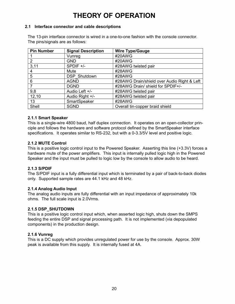
2.1 Interface connector and cable descriptions
The 13-pin interface connector is wired in a one-to-one fashion with the console connector.The pins/signals are as follows:
2.1.1 Smart SpeakerThis is a single-wire 4800 baud, half duplex connection. It operates on an open-collector prin-ciple and follows the hardware and software protocol defined by the SmartSpeaker interfacespecifications. It operates similar to RS-232, but with a 0-3.3/5V level and positive logic.
2.1.2 MUTE ControlThis is a positive logic control input to the Powered Speaker. Asserting this line (+3.3V) forces ahardware mute of the power amplifiers. This input is internally pulled logic high in the PoweredSpeaker and the input must be pulled to logic low by the console to allow audio to be heard.
2.1.3 S/PDIFThe S/PDIF input is a fully differential input which is terminated by a pair of back-to-back diodesonly. Supported sample rates are 44.1 kHz and 48 kHz.
2.1.4 Analog Audio InputThe analog audio inputs are fully differential with an input impedance of approximately 10kohms. The full scale input is 2.0Vrms.
2.1.5 DSP_SHUTDOWNThis is a positive logic control input which, when asserted logic high, shuts down the SMPSfeeding the entire DSP and signal processing path. It is not implemented (via depopulatedcomponents) in the production design.
2.1.6 VunregThis is a DC supply which provides unregulated power for use by the console. Approx. 30Wpeak is available from this supply. It is internally fused at 4A.
THEORY OF OPERATION
Pin Number Signal Description Wire Type/Gauge 1 Vunreg #20AWG 2 GND #20AWG 3,11 SPDIF +/- #28AWG twisted pair 4 Mute #28AWG 5 DSP_Shutdown #28AWG 6 AGND #28AWG Drain/shield over Audio Right & Left 7 DGND #28AWG Drain/ shield for SPDIF+/- 9,8 Audio Left +/- #28AWG twisted pair 12,10 Audio Right +/- #28AWG twisted pair 13 SmartSpeaker #28AWG Shell SGND Overall tin-copper braid shield

21
THEORY OF OPERATION2.2 3•2•1 Series II Bass Module Details
The bass module contains all the active audio processing and amplification electronics of the3•2•1 Series II System. The rear end cap of the bass module provides access to the followingcomponents:• Line cord socket• Power Switch (European only)• System Connector (13-pin)• Array Speaker Connector (DB9-S)
All the above components are mounted on the I/O Printed Circuit Assembly, part number270926-001, which is, in turn, secured to the end cap via a metal bracket. The dash suffix isused to denote the various AC voltage variants.
All other electronics reside on the DSP/Amplifier PCB Assembly. The DSP/Amp PCB is securedto the extruded aluminum heat sink (which is glued to the back baffle of the module enclosure)with a metal bracket. This bracket provides sufficient compression force to the PCB to maintaingood thermal contact to the heat sink of the audio power amplifiers, rectifier diodes, and pre-regulator FET.
The power transformer for the system is directly mounted to the end baffle of the module abovethe heat sink.
2.2.1 I/O Printed Circuit AssemblyNote: Refer to the Input/Output (I/O) PCB schematic diagram, 270926, for the following infor-mation.
The I/O printed circuit assembly contains the AC input connector J1 [C4], the line switch S1 [D3]and line fuse F1 [C3]. Connector J2/J5 [D2], depending on the dash (-xxx) variation, providesthe primary power connection to the power transformer. A location for a MOV (VR1 [C3]) isprovided, but is not populated in production.Connectors J6 [B7] and J7 [D8] connect the I/O PCB to the DSP PCB. J6 connects to a 16-position ribbon cable which carries the S/PDIF and audio inputs and control signals to/from theDSP board. J7 connects to a 10-position cable that brings the array speaker amplifier outputsand Vunreg/GND onto the I/O PCB. C7-9 provide RF ground coupling between the variousground pins and structures on the board. C1, C3, C4, C5, and C10 are DC blocking caps onthe differential audio inputs and associated GND. C6 is the bulk storage capacitor for theVunreg supply. All of the signals described in section 3.1 are connected to the 13-pin systemconnector J3 [B2] on this board.
2.2.2 DSP/Amplifier Printed Circuit AssemblyThis board provides the following major functions:
Note: Refer to the DSP/Amplifier PCB schematic diagrams, 270921, for the following informa-tion.

22
THEORY OF OPERATION2.2.2.1 Power rectification, pre-regulation and filteringJ5 [sheet 4, D6] connects the secondary winding of the power transformer to the circuit rectifiersD7-10 [C/D 5/6], which form a full-bridge rectifier. The DC output of the rectifier charges capaci-tor C22 [D2] to a controlled peak voltage, via FET Q4 [D4]. The controlled peak voltage is15.75V (± 0.75V). The pre-regulator circuit formed by ZR1 [D5], Q2-3 [C4/5], R7-13, and C21,24-5 cause Q1 to switch off once the limit voltage has been attained.The diodes D7-10 and Q1 are required to have good thermal contact to the heat sink. Thisrequires a deflection of 0.5 to 1mm of the thermal material applied in the interface. Q5 andassociated components provide a soft-switching function
2.2.2.2 Control Power generationBoth a 5 volt and a 3.3 volt power rails are generated for the DSP and audio source controlcircuits.
U100 [sheet 4, B5], L70 [B4], D11, and C30, C31 form a buck switching regulator for the 5 voltsupply. The nominal switching frequency is established by components R16 and C33 [B6]. Amodulating signal derived from the transformer secondary is coupled to the oscillator circuit viaC37. R18 and R19 establish the magnitude of the modulating signal. C38 filters unwantedharmonics and line noise from the signal. Q6 [A6] allows the Inhibit pin to be pulled low fromthe console, which disables the power supply, forming the DSP_SHUTDOWN function.U101 [A3] generates the 3.3 volt supply from the 5 volt supply. C42 prevents oscillation of theoutput of U502 as well as assisting to manage voltage ripple due to load fluctuations. U6000[sheet 1, D5] monitors the 3.3V and issues a reset of the DSP if this supply ever drops below aregulation threshold of 3.08V.
2.2.2.3 Audio Power amplificationDual Audio Amplifier IC’s, U150 [sheet 5, C/D3] and U250 [A/B3] provide the power amplificationfor the external speaker arrays. The array outputs are available on J150 [B/C1]. A similaramplifier, U350 [B/C6], provides power amplification to the bass module woofer via connectorJ350 [C4]. Both inputs of U350 are wired in parallel and both amp outputs are provided to thewoofer connector J350. Each output of the amplifiers have an RF de-coupling capacitor of.01uF, C152 and similar, shunting the high-frequency components of the signal through a seriesresistor of 3.32 Ohms, R162 and similar. The series resistor creates a lead in the pass charac-teristic at approximately 4.7MHz in order to maintain stability of the power amplifier.The differential inputs of the power amplifiers are coupled to the output of the Audio DAC via1uF aluminum electrolytic capacitors, C156, C157 and similar. A shunt resistor and capacitor,R151 and C156 and similar, form the termination of a second-order low-pass filter describedlater.
2.2.2.4 Power Amplifier control, monitoringThe MODE signal is a three-level signal generated by Q450 [sheet 5, A8], Q451 [B8], Q452[B8], D450, R450, and R451. IF the /STDBYout signal is asserted low, the internal bias of theMODE pins of the amplifiers will cause the signal to drive to ground. This causes the amplifiersto enter the “Stand-by” low-power state. The internal bias to the amplifier signal inputs is turnedoff causing the inputs to drift to ground. Stand-by should not be entered while the DAC drivingthe signal inputs is out of the reset state.

23
When the /STDBYout signal is high, the MODE pin will be either within the 3.3-6.4 volt range(mute), or near VRAW (active), as controlled by the MUTE signal and Q450, D450. WhenMUTE is high, Q450 saturates, causing the MODE voltage to be driven to approximately 5.4volts. R450 assures the MUTE signal is active any time the DSP (U7000) is not driving it.The open-collector diagnostic outputs of the three amplifier IC’s are summed into the /DIAGsignal to the DSP (U7000 [sheet 1, B/C 4/5]). R453 [sheet 5, C7] pulls the signal to logic false(high) when none of the amplifiers is asserting the signal. Currently /DIAG is unused by theDSP.
The Clip signals of the amplifier IC’s driving the array speakers (U150, U250) are summed intothe /ARRAYCLIP signal. R454 [sheet 5, D2] holds the signal false (high) if neither amplifier ICis asserting the clip signal. A similar arrangement is used for the bass amplifier with the /BASSCLIP signal.
2.2.2.5 Digital-to Analog Signal conversion and conditioningProcessed audio signals are converted to amplifier drive signals by the DAC portion of theCodec (CS4228), U4000 [sheet 2, C/D2]. The single-ended outputs of U4000 have a full-scaleoutput of nominally 1.31 Vrms. They also have significant out-of-band noise as well as theexpected sigma-delta conversion noise due the IC’s location in the digital portion of the circuit.Resistor arrays R4300, R4301, R4302 [B2] serve to terminate the negative signal of the poweramplifier differential inputs and provides the source impedance for the first stage of the second-order low-pass filter. The Capacitors C4300-11 provide both the switching noise suppression onthe individual signal and one of the two poles for the second-order lowpass filter.Resistor arrays R150 [sheet 5, C4], R250 [B4], R350 [B8] increase the source impedance of thesecond portion of the filter. The shunt resistance of R151 and similar and the shunt capacitanceof C158 and similar form the second pole.Analog output gain for a 0dbFS digital signal…• DAC output 1.3Vrms• Filter Gain -8dB• Amplifier Gain 26dB• Total Gain 18dB (8x)• Max amplitude 10.4 volts RMS or 14.7 volts peakNote that DSP gain managers limit the signals to avoid clipping, which is likely to occur beyond11 volts peak.
2.2.2.6 Analog-to Digital ConversionThe analog inputs (J7100, pins 2, 3, 5, 6 [sheet 3, C7]) are coupled to the ADC differential inputof U4000 [sheet 2, C/D2] through a RC t-network which utilizes the inherent element matchedvalues of quad resistor packs R1001 and R1005. This provides good common-mode rejectionon the inputs as well as providing a lowpass filter function.The A/D conversion sample rate is determined by the SHARC_CLK providing a 128Fs masterclock to the converter (33.333MHz/6 = 5.56MHz) rate which ultimately yields a sample rate of43.4kHz.
THEORY OF OPERATION

24
2.2.2.7 S/PDIF ReceiverU4400 [sheet 1, B7] provides the S/PDIF digital audio receiver function. The incoming differen-tial S/PDIF signal is fed to U4400’s differential inputs RXP0 and RXN0 through a filter andtermination network. T1 is a common-mode transformer which rejects unwanted common-mode noise, particularly important since U4400 has little or no common-mode rejection inherentto the IC design. D4502 [sheet 3, C6] clamps the signal to +/- one diode drop. This is the only“termination” of the input signal. The assumption is that while there is a termination mismatchon the end of the twisted pair, all reflections and standing waves are eliminated by the clampingaction of the diodes, i.e., the reflections never reach into the +/- one diode drop region. Thesubsequent resistors and capacitors form a low pass network that limits the bandwidth to justabove the fundamental bit rate of the S/PDIF signal (128Fs).U4400 provides the system MCLK at 128Fs when the S/PDIF input is active. When the ADCpath is selected, the MCLK is provided by the DSP (U7000) SHRAC_CLK output [sheet 1, C3],which is routed through U4400s MCLK output (pin 10) by setting the IC into “Stop” mode via anI2C command from the DSP.
2.2.2.8 Internal audio pathExternal analog and S/PDIF input signals are converted to serial digital samples that areclocked at the bit rate established by BITCLK. Each sample is 32-bits long alternate betweenleft and right channels as indicated by the LRCLK signal. The Codec, U4000, generatesBITCLK and LRCLK in all operating modes based on its MCLK input. MCLK is programmed tobe 128 times the LRCLK rate and, thus, 4 times the BITCLK rate.The S/PDIF decoder, U4400, either generates MCLK from the bit-rate detected on the selecteddigital audio input, or passes through the SHARC_CLK signal when no valid digital audio inputis detected or when the part is not running. The SHARC_CLK signal clocks the audio pathwhen analog audio inputs are selected.The analog data converted by U4000 is presented to the DSP controller U7000 on A/DOUT.The received digital data from either S/PDIF input is transmitted to U7000 on a separate signalusing the DR0A input of U7000. Both signals share the same LRCLK and BITCLK as do theaudio outputs D/ADATA1-3.
2.2.2.9 Communications
Smart Speaker InterfaceSmart Speaker commands from the console are received by the circuit comprised of Q6100 andQ6101 [sheet 1, C7]. The input is level shifted to a 3.3V signal by Q6100 and is then “gained-up” with hysteresis before being presented to the PWM0 input of the DSP. This is accomplishedwith 3 inverters of U6100 and C6105 and is necessary as the PWM0 input uses a fast counterto determine the commands and any noise/glitching of the input destroys the message.
TAP InterfaceThe components used to access TAP directly onto the bass module DSP/Amplifier PCB are notpopulated on the production versions of this board. Any testing or troubleshooting will be per-formed using the Smart Speaker commands as listed in the test procedures in this troubleshoot-ing guide. The following is for informational purposes only.
The TAP interface uses the serial ports (signals TAPIN and TAPOUT) on the Sharc micropro-cessor (U7000 [sheet 1, C4]). The connection is made through J6200 [sheet 3, A8]. Q6200,R6200 and similar convert RS-232 level input communication signals to logic level. Q6201drives the output line to 0 and 3.3V. These parts are not used, and are shown as NV (no value)on the schematic sheets.
THEORY OF OPERATION

25
DSP/Amplifier PCB LED’sThere are 2 LED’s in the system, located on the DSP/Amplifier board, a green LED (DS6500[sheet 3, D7]) and an amber LED (DS6501). The amber LED is not populated in production.When the main board is installed and rear cover is in place, the light produced is visible (withpractice) through the rear grille as it reflects off the heat sink as well as goes through drilledholes in the PC board. R6500 and R6501 limit the current through the LED’s (as well as theDSP controlling them). The table below explains the uses of these LED’s in production mode(CB = Counter Blink: when one LED is on, the other LED is off!):
THEORY OF OPERATION
Green LED
Amber LED
Description
Off Off This should never happen. If it does, it likely means 1) That there is no power –OR- 2) There is a problem with the hardware (or, perhaps, software!)
Off On When power is first supplied, BEFORE the DSP boots, the hardware will put the LED’s into this state. If the board stays in this state there is a problem with the DSP hardware (or software).
CB, 5 Hz CB, 5 Hz Immediately after powering up AND if the LED’s remain in this mode, there is a problem with the Power On Self Test (POST): either the FLASH did not checksum or the SDRAM memory test failed or there was a problem initializing one or more or the audio peripherals (U4000, U4400).
Once every 5
sec
Off Board is powered, initialized, and waiting for a Smart Speaker command to turn on the board. The LED will be on for only 0.010 seconds!
1 Hz Off Board is powered, initialized, has been turned on by the console (or in ASCII TAP mode) and S/PDIF is present. When on, the LED will be on for 0.5 seconds.
CB, 1 Hz CB, 1 Hz Board is powered, initialized, has been turned on by the console (or in ASCII TAP mode), S/PDIF NOT present. When on the LED will be on for 0.5 seconds.
Toggle Don’t care
The green LED will toggle whenever a byte is received from the RS-232 input. This toggling will modulate the current state of the green LED, i.e. the normal 1 Hz rate may be “chopped” by incoming RS-232 data.
CB, 5 Hz CB, 5 Hz If the board passed the POST and generally seemed to be OK, this state indicates that a catastrophic software error has occurred. The production code will stay in this mode for 1 second then do a software reset; development code will remain in this state, allowing the developer to isolate the source of the problem.
X ON When the system is operating normally, the orange LED may remain on when the amplifier mute is on.
1 Hz 1 Hz LED’s will blink together when reading FLASH update data. 5 Hz 5 Hz LED’s will blink together when FLASH is being written with update
information 10 Hz OFF The green LED will blink when in the quasi-standby state

26
2.2.2.10 DSPThe DSP system comprises of the SHARC microprocessor (21065L, U7000), the FLASHmemory (U7200 [sheet 2, B5]), and the SDRAM (U7300 [B/C3]). The software can essentiallybe broken up into two segments: The framework and the DSP functions. The frameworkcomprises all of the micro-controller type functions for the 3•2•1 Series II such as the communi-cations, controlling/monitoring the power amplifiers, and power-up/down. The DSP functionsare the digital audio signal processing functions that exist “inside” the framework, such as theequalization, array processing, volume control, etc. The following discussion relates only to theinteractive and hardware information about the DSP system.
Booting - On a cold start, the supplies come up with the 3.3V supply being the last to achieveregulation. This supply is monitored with the reset IC, MAX823 (U6000 [sheet 1, D5]) such thatwhen a threshold is reached, about 3.1V, the IC brings the DSP system out of RESET. Whenthis occurs, the DSP boots from the FLASH IC and enters the Standby mode.
Standby - After a cold start or an off signal, the DSP puts the system into a standby modewhere the system draws about 3-4 W off the primary AC. Mainly, the amplifiers are put intostandby mode (low quiescent draw), the CS8415A (U4400 [sheet 1, A7]) and CS4228 (U4000[C2]) are reset, and the DSP enters the “IDLE16” mode (NOT reset) as this is the lowest powerdrain mode for the DSP. In this mode, the TAP input works as described above and the PWMinput looks for any communication via Smart Speaker. On any edge on the COMM line, theDSP enters its quasi-power-down (quasi-standby) mode and sees if a valid command wasreceived, if not, then the unit enters the standby mode again. LED action shows what is goingon during this time. Also once a second, the system must “come alive” briefly to toggle thewatchdog timer to prevent a RESET to occur.Also, on entering standby, the volume parameter is set to the last value, but is bounded in therange of 20 to 80.
Oscillator - The system clock is derived from the oscillator formed by Y7000 [sheet 1, A6] andan inverter of U6100. There is an onboard inverter on the SHARC but it was determined to nothave enough gain to reliably start-up the oscillator. R7000 was empirically determined to keepthe power dissipation in the crystal to less than .5mW. C7008, 7009 make up the loadingcapacitance to set the correct frequency, 33.333MHz. The SHARC doubles this clock to66.666MHz which sets the maximums MIPS load of the software.Reprogramming - Software updating is accomplished via the S/PDIF input. The “file” is aconverted binary image into a stereo PCM format that comprises a header followed by theimage to be flashed (the length of this file is about 2 seconds). This allows the software to beupgraded from a CD-ROM inserted into the console. When the appropriate Smart Speakercommands are sent, the DSP reboots into ERC then looks again for an update header beforereading in the actual update image. When the image is read in, the code takes a few secondsto determine the validity with a checksum. If the checksum fails, then no update occurs. (Ifthere are still “updates” being presented, then the process will begin again.) If the checksumpasses, the unit then writes the image to the FLASH, a process which takes about 45 secondsand the LED’s blink very rapidly (10 Hz, see above). The update disc/file can then be stoppedduring this time safely. When this has completed, the system then reboots into the new code asif it were a cold start (into standby).
The ERC (Emergency Recovery Code) has been written to a protected area of the FLASH suchthat in case a software update crashed or anything else that causes the FLASH to be corrupted,the ERC will always be available, and therefore rewriting the FLASH is always possible usingthe same update procedure.
THEORY OF OPERATION

©2005 Bose CorporationReference Number 273029-TG Rev. 00
Troubleshooting Guide
Electronic Copy Only
Troubleshooting Guide3•2•1 and 3•2•1GS Series II
Home Entertainment System(US/Canada, European, UK, Australia, Japan
and Dual Voltage Standard Versions)
3•2•1 Series II System
3•2•1GS Series II System

SPECIFICATIONS AND FEATURES SUBJECT TO CHANGE WITHOUT NOTICE
Bose CorporationThe MountainFramingham Massachusetts USA 01701
P/N: 273029-TG Rev. 00 3/2005 (H)http://serviceops.bose.com