Embed Size (px)
Citation preview

INSTRUCTIONS
Matrix® 5 & Matrix® 15 Meter
313046A
- For dispensing oils and antifreeze over wireless communication with a Matrix system -
Maximum Working Pressure: 1500 psi (10 MPa, 103 bar) Maximum Flow Rate:14 gpm (53.0 lpm)
Matrix 5 and Matrix 15 contain an RF devise with the following approval:
Models:All meters are preset to Quarts in the Graco factory.
*Extensions and Nozzles must be purchases separately.
Important Safety InstructionsRead all warnings and instructions in this manual. Save these instructions.
NOTICE
This dispense valve is designed to dispense petroleum-based lubricants and antifreeze only. Do not dispense windshield washer solvent with this dispense valve.
FCC ID: TFB-FREESTARIC: 5969A-FREESTAR
Matrix Name Model No. Swivel Extension* Quick Close Nozzle* Fluid
Matrix 5 256282 1/2” npt(f) Rigid Standard, Automatic, Non-drip Oil
Matrix 5 256482 1/2” npt(f) Flexible Standard, Automatic, Non-drip Oil
Matrix 5 256483 1/2” npt(f) Gear Lube Standard Gear Lube
Matrix 5 256484 1/2” npt(f) Rigid Standard Antifreeze
Matrix 5 256485 1/2” npt(f) Flexible Standard Antifreeze
Matrix 15 256486 1/2” npt(f) Rigid High Flow Oil
Matrix 15 256487 1/2” npt(f) Flexible High Flow Oil
Matrix 15 256488 3/4” npt(f) Rigid High Flow Oil
Matrix 15 257120 3/4” npt(f) Flexible High Flow Oil
Warnings
2 313046A
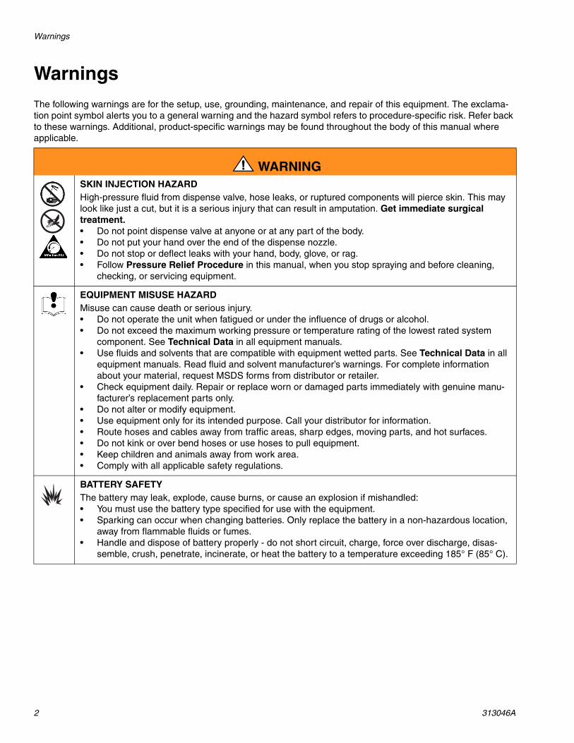
WarningsThe following warnings are for the setup, use, grounding, maintenance, and repair of this equipment. The exclama-tion point symbol alerts you to a general warning and the hazard symbol refers to procedure-specific risk. Refer back to these warnings. Additional, product-specific warnings may be found throughout the body of this manual where applicable.
WARNINGSKIN INJECTION HAZARD High-pressure fluid from dispense valve, hose leaks, or ruptured components will pierce skin. This may look like just a cut, but it is a serious injury that can result in amputation. Get immediate surgical treatment.• Do not point dispense valve at anyone or at any part of the body.• Do not put your hand over the end of the dispense nozzle.• Do not stop or deflect leaks with your hand, body, glove, or rag.• Follow Pressure Relief Procedure in this manual, when you stop spraying and before cleaning,
checking, or servicing equipment.
EQUIPMENT MISUSE HAZARD Misuse can cause death or serious injury.• Do not operate the unit when fatigued or under the influence of drugs or alcohol.• Do not exceed the maximum working pressure or temperature rating of the lowest rated system
component. See Technical Data in all equipment manuals.• Use fluids and solvents that are compatible with equipment wetted parts. See Technical Data in all
equipment manuals. Read fluid and solvent manufacturer’s warnings. For complete information about your material, request MSDS forms from distributor or retailer.
• Check equipment daily. Repair or replace worn or damaged parts immediately with genuine manu-facturer’s replacement parts only.
• Do not alter or modify equipment.• Use equipment only for its intended purpose. Call your distributor for information.• Route hoses and cables away from traffic areas, sharp edges, moving parts, and hot surfaces.• Do not kink or over bend hoses or use hoses to pull equipment.• Keep children and animals away from work area.• Comply with all applicable safety regulations.
BATTERY SAFETY The battery may leak, explode, cause burns, or cause an explosion if mishandled: • You must use the battery type specified for use with the equipment. • Sparking can occur when changing batteries. Only replace the battery in a non-hazardous location,
away from flammable fluids or fumes.• Handle and dispose of battery properly - do not short circuit, charge, force over discharge, disas-
semble, crush, penetrate, incinerate, or heat the battery to a temperature exceeding 185° F (85° C).

Warnings
313046A 3
FIRE AND EXPLOSION HAZARD When flammable fluids are present in the work area, such as gasoline and windshield wiper fluid, be aware that flammable fumes can ignite or explode. To help prevent fire and explosion:• Use equipment only in well ventilated area.• Eliminate all ignition sources, such as cigarettes and portable electric lamps. • Keep work area free of debris, including rags and spilled or open containers of solvent and gasoline.• Do not plug or unplug power cords or turn lights on or off when flammable fumes are present.• Ground all equipment in the work area.• Use only grounded hoses.• If there is static sparking or you feel a shock, stop operation immediately. Do not use equipment
until you identify and correct the problem.• Keep a working fire extinguisher in the work area.
WARNING
Meter Overview
4 313046A
Meter Overview
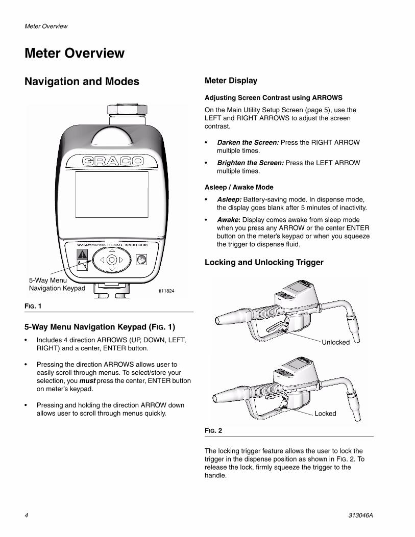
Navigation and Modes
5-Way Menu Navigation Keypad (FIG. 1)
• Includes 4 direction ARROWS (UP, DOWN, LEFT, RIGHT) and a center, ENTER button.
• Pressing the direction ARROWS allows user to easily scroll through menus. To select/store your selection, you must press the center, ENTER button on meter’s keypad.
• Pressing and holding the direction ARROW down allows user to scroll through menus quickly.
Meter Display
Adjusting Screen Contrast using ARROWS
On the Main Utility Setup Screen (page 5), use the LEFT and RIGHT ARROWS to adjust the screen contrast.
• Darken the Screen: Press the RIGHT ARROW multiple times.
• Brighten the Screen: Press the LEFT ARROW multiple times.
Asleep / Awake Mode
• Asleep: Battery-saving mode. In dispense mode, the display goes blank after 5 minutes of inactivity.
• Awake: Display comes awake from sleep mode when you press any ARROW or the center ENTER button on the meter’s keypad or when you squeeze the trigger to dispense fluid.
Locking and Unlocking Trigger
The locking trigger feature allows the user to lock the trigger in the dispense position as shown in FIG. 2. To release the lock, firmly squeeze the trigger to the handle.
FIG. 1
ti11824
5-Way MenuNavigation Keypad
FIG. 2
Unlocked
Locked

Registering the Meter
313046A 5
Registering the MeterGraco recommends registering the meter prior to installation.
NOTE: Before registering the meter, use the Matrix PC software to enter setup information pertaining to the:
• Transceiver, • Tank Level Monitor (TLM),• Tank Set Up,
and (optional)
• Pump Air Control (PAC).
If this has not been done first, the software will display an error when attempting to set up meter.
Main Utility Setup Screens (FIG. 4)
The Main Utility Screen displays a list of available Setup Screens. This list also includes a link (QUIT) back to the Operation Screens.
• REGISTER• RF TEST• UPGRADE• EMERGENCY• QUIT
Displaying Register Utility Screen
1. If you are on a Dispense Screen, to display the Main Utility Screen, first hold down the RIGHT ARROW (a) only, for a few seconds (FIG. 3).
2. Then at the same time, also hold down the center, ENTER button (b) (FIG. 3). Hold both buttons down until the Main Utility Screen shown in FIG. 4 dis-plays.
3. Use the UP or DOWN arrow to move the cursor up and down the list until it is over the REGISTER option on the list.
4. Press the center ENTER button on meter’s keypad to select the REGISTER option. The Register Screen shown in FIG. 5 displays.
FIG. 3
(a)(b)
ti11824a
FIG. 4
REGISTERRF TESTUPGRADEEMERGENCYQUIT
3.01.001
ti12259a

Registering the Meter
6 313046A
REGISTER Screen
A. NETWORK ID: The unique Radio Frequency (RF) assigned to components of the same operating system in a specific facility. The unique NETWORK ID assigned to the facility, prevents RF interference from other Matrix Systems operating in the vicinity, at other locations. There are 8 NETWORK ID’s available.
To setup a meter to receive the correct NETWORK ID RF signal, use the UP or DOWN ARROWS to scroll, one number at a time, through the NETWORK ID numbers (1-8). When the correct NETWORK ID number assigned to your facility is displayed in the field/box, press center ENTER button on meter’s keypad to lock in the choice.
B. TRANS ID: The unique RF frequency assigned to a specific transceiver in the operating system. Each transceiver in the system has its own TRANS(ciever) ID number assigned to it. An operating system can have more than one transceiver. There are 8 TRANS ID’s available.
To set up a meter to receive the correct TRANS ID RF Signal, use the UP or DOWN ARROWS to scroll, one number at a time, through the TRANS ID numbers (1-8). When the number assigned to the transceiver you are using displays in the field/box, press center ENTER button on meter’s keypad to lock in the choice.
C. REGISTER /field: Sends message to Matrix PC Software to register the meter with the operating system.
Use the LEFT or RIGHT ARROWS to move the cursor over the REGISTER field/box on the display. Then press center, ENTER button on meter’s keypad, to confirm the selection.
D. WRENCH Icon: Returns user to Main Utility Screen.
Use the LEFT or RIGHT ARROWS to move the cursor over the WRENCH Icon on the display. Then press center, ENTER button on meter’s keypad, to confirm the selection.
E. SERIAL Number: Unique meter ID.
Registering Meter with Matrix PC Software
1. The screen displays the NETWORK ID (A) and TRANS(ceiver) ID (B) (FIG. 5) currently assigned to the meter.
2. If the ID’s in both fields are correct and you do not need to make any changes, use LEFT or RIGHT ARROWS to move cursor over REGISTER (C). Press center ENTER button on meter’s keypad. The meter resets to it’s initial screen.
OR . . .
If the NETWORK ID or TRANS ID information shown on the display is NOT correct:
a. Use LEFT or RIGHT ARROWS to move cursor to NETWORK ID field and/or TRANS ID field.
b. When field you want to modify is selected, use UP or DOWN ARROWS to scroll forward or backward through the available NETWORK ID or TRANS ID numbers.
c. When correct ID number displays, press center ENTER button on meter’s keypad to confirm your choice. If necessary, use LEFT or RIGHT ARROWS to move cursor to the next field and repeat this procedure.
d. When both the NETWORK ID and TRANS ID fields display the correct information, use LEFT or RIGHT ARROWS to move cursor over REG-ISTER. Press center ENTER button on the meter’s keypad to complete meter registration.
FIG. 5
REGISTER
NETWORK ID 8 TRANS ID 6
REGISTERREGISTER
123F456A
ti12260a
D
A B
C
E

Registering the Meter
313046A 7
e. The meter resets and returns to it’s initial screen.
NOTE: If the meter is not able to communicate with the PC during registration, the message NO SIGNAL or NO PC SIGNAL appears on the meter display.
NO SIGNAL message means:
• There is no RF signal between the PC and Meter.
• The meter is out of the RF Signal range.• The Transceiver does not have power.• Either the NETWORK ID and/or TRANS-
CEIVER ID information is not correct in the meter and the correct information must be pro-vided.
NO PC SIGNAL message means:
• The Matrix Client isn’t running.• The cable is not connected between the PC and
Transceiver.
f. After the information is programmed into the electronic meter, the meter can be connected to the dispensing hose.
NOTE: If the programmed parameters need to be changed, the meter must be reprogrammed.

RF Test
8 313046A
RF Test An RF Test is performed before a Matrix System and meters are installed at a site to evaluate the strength of the RF signal and determine the number of Transceivers that will be needed and where they should be installed in the facility.
In order to perform this test, a test computer with the Matrix PC software installed and a Transceiver are located in the area of the shop that the installed Transceiver will be located. The tester then uses a meter to evaluate the strength of the RF Signal between the Transceiver and meter at each potential meter location throughout the shop.
1. On the Main Utility Screen, use the UP or DOWN ARROWS to select the RF TEST option on the list. Then press the center ENTER button on meter’s keypad to confirm the selection.
To perform the RF TEST:
2. Holding the meter, walk around the shop to a poten-tial meter installation work area.
3. Verify that the Network ID and Trans ID assigned to the meter are correct. If they are not correct, you must first register the meter. (See Registering the Meter, page 5).
4. Use RIGHT ARROW to move cursor over START (FIG. 7).
5. Use center ENTER button to confirm the selection.
The meter sends an RF signal to the Transceiver.
If the signal is good on the following message dis-plays on the meter screen (FIG. 8):
RETRIES: 0 (or 1-5) GOOD SIGNAL
FIG. 6
REGISTERRF TESTUPGRADEEMERGENCYQUIT
3.01.001
FIG. 7
FIG. 8
TEST RF
NETWORK ID 8 TRANS ID 6
START
123F456A
TEST RF
NETWORK ID 8 TRANS ID 6
START
123F456A
RETRIES = 0GOOD SIGNAL
ti12405a

Upgrade
313046A 9
If the signal is weak or there is not a signal at all. one of the following message appears on the meter screen (FIG. 9).
NOTE: The meter is programmed to try sending a signal to the Transceiver 5 times before displaying the BAD SIGNAL message.
6. After the final area has been tested, use the LEFT ARROW to move the cursor to the Wrench Icon. Press the center ENTER button on meter’s keypad to confirm the selection and return to the Main Utility Screen.
UpgradeThis feature is used to modify the firmware software used by the meter when a new and upgraded version of the software is released or a new feature is added. When this is required, your Graco distributor will contact you to arrange the upgrade.
EmergencyIf the communication link between the meter and PC is lost due to power loss or the computer crashing, the meter will continue to function if it is placed in Emergency Mode.
1. On the Main Utility Screen, use the UP or DOWN ARROWS to select the EMERGENCY option on the list. Then press the center ENTER button to confirm the selection.
FIG. 9
TEST RF
NETWORK ID 8 TRANS ID 6
START
123F456A
RETRIES = 5BAD SIGNAL
TEST RF
NETWORK ID 8 TRANS ID 6
START
123F456A
RETRIES = 0NO PC SIGNAL
FIG. 10
FIG. 11
REGISTERRF TESTUPGRADEEMERGENCYQUIT
3.01.001
REGISTERRF TESTUPGRADEEMERGENCYQUIT
3.01.001
ti12408a

Emergency
10 313046A
2. The Emergency Screen appears. The cursor is already in position for entering the first number of the Emergency Code. Use the UP or DOWN ARROWS to scroll through the numbers 0-9 until the first number of the unique Emergency Code assigned to that meter appears in the field.
3. Use the center ENTER to confirm the selection. The cursor moves to the next field.
4. Repeat steps 2-3 until all 4 numbers have been entered. After the 4th number of the Emergency Code is entered the cursor automatically moves to the ENTER on the display.
5. Press the center ENTER button to confirm the selection.
6. The Dispense Screen displays on the meter.
NOTE: When the meter is put in Emergency Mode:
• All pending work orders will be deleted from the work order queue in the meter. They will have to be entered again by the System Administrator on the PC.
• New work orders cannot be added at the meter.
FIG. 12
EMERGENCY MODE
ENTER QUIT
2 1 2 2

Installation
313046A 11
Installation
Typical Installations (FIG. 13)
The typical installation shown in FIG. 13 is only a guide. It is not a complete system design. Contact your Graco distributor for assistance in designing a system to suit your needs.
Mounting Bracket (FIG. 14)
Mounting Bracket Kit 249440 is available for resting the dispense valve on a console.
NOTICE
The dispense valve is not designed for in-line installation.
FIG. 13
B
D
E
C
A
ti11010a
ITEM DESCRIPTIONA Electronic metered dispense valve
B Fluid shut-off valve
C Hose
D Hose reel fluid inlet hose
E Hose reel
A Thermal Relief Kit (not shown) is required. The kit required will vary by pump selected.
FIG. 14ti11822

Installation
12 313046A
Drum Mount Bracket (FIG. 15)
Mounting Bracket 15B750 is available for resting the dispense valve on a drum.
Oil Bar (FIG. 16)
An Oil Bar Kit 255370 is available for mounting up to two meters.Oil bar kit 156719 allows for mounting three meters.
Pressure Relief Procedure
This equipment will stay pressurized until the pressure has been manually relieved. To reduce the risk of serious injury from pressurized fluid, accidental spray from the dispense valve or splashing fluid, follow this Pressure Relief Procedure when ever you:
• Are instructed to relieve pressure.• Check, clean or service any system equipment.• Install or clean fluid nozzles or filter.
1. Turn off power supply to the pump or close upstream ball valve.
2. Open nozzle. Trigger the dispense valve into a waste container to relieve pressure.
3. Open any bleed-type master air valves and fluid drain valves in the system.
4. Leave the drain valve open until you are ready to pressurize the system.
Grounding
The equipment must be grounded. Grounding reduces the risk of static and electric shock by providing an escape wire for the electrical current due to static build up or in the event of a short circuit.
Pump: Follow manufacturer’s recommendations.
Air and fluid hoses: Only use electrically conductive hoses. Check electrical resistance of hoses. If total resistance to ground exceeds 29 megohms, replace hose immediately.
FIG. 15
FIG. 16
ti11823
ti12303a
FIRE HAZARD: Conductive metal surfaces on the meter must not make contact with any positively charged metal surface, including (but not limited to), the starter solenoid terminal, alternator terminal or battery terminal. Such contact could cause electrical arcing and a fire.

Installation
313046A 13
Air compressor: Follow manufacturer’s recommendations.
Fluid supply container: Follow local code.
To maintain grounding continuity when flushing or relieving pressure: hold a metal part of the dispense valve firmly to the side of a grounded metal pail, then trigger the valve.
Pre-Installation Procedure
1. Relieve pressure, page 12.
2. Close the shut-off valve (B, FIG. 13).
3. Ground the hose and reel or console, page 12. Leave at least two threads bare when using PTFE tape. The bare threads ensure a ground is main-tained.
Installation Procedure
Flushing
If this is an existing installation, go to Installing Meter section, page 13. The following procedure, Steps 1-5 are the Flushing Procedure.
1. Close the fluid shut-off valve (B, FIG. 13, page 11) at each dispense position.
2. Make sure:• the main fluid outlet valve at the pump is closed,• the air pressure to the pump motor is adjusted,
and• the air valve is open.
3. Slowly open the main fluid valve.a. Place the hose end (with no dispense valve
connected) into a container for waste oil.b. Secure the hose in the container so it will not
come out during flushing. c. If you have multiple dispense positions, first
flush the dispense position farthest from the pump and work your way toward the pump.
4. Slowly open the shut-off valve (B) at the dispense position. Flush out a sufficient amount of oil to ensure that the entire system is clean; then close the valve.
5. Repeat Step 4 at all other positions.
Installing Meter (FIG. 17)
1. Relieve pressure, page 12.
2. Slide the swivel boot (32) back, over the hose, small end first to access the swivel fitting (a).
3. Apply thread sealant to the male threads of the hose fitting. Thread the hose fitting into the meter swivel (31). Use two wrenches to tighten securely (FIG. 17).
NOTE: Make sure you let the sealant cure to the manufacturer’s recommendations before circulating fluid through the system.
NOTICE
• If this is a new installation or if the fluid lines are contaminated, flush the lines before you install the metered valve. Contaminated lines could cause the valve to leak.
• Never dispense compressed air with meter. Doing so will damage meter.
FIG. 17
31
ti10983a
32a

Installation
14 313046A
Installing Tube Extension (FIG. 18)
1.a. Loosen nut (a). b. Thread extension (20) into housing (b) until it
bottoms out. c. Align extension (20) with meter housing and
handle (c). d. Firmly tighten nut (a).
Installing Nozzle (FIG. 19)
1.a. Thread new nozzle (33) onto extension (20). b. With an open-end adjustable wrench on flats of
nozzle bushing, tighten firmly.
NOTE: • Only tighten nozzle with wrench on flats of the
nozzle bushing. • Do not disassemble the bushing from noz-
zle. Disassembly will affect performance of the nozzle.
2. Open automatic twist lock nozzle and all fluid shut-off valves. Start pump to pressurize system.
3. To ensure dispensing accuracy, purge all air from the fluid lines and dispense valve before you use it.
4. Set the system flow to the desired flow rate.
FIG. 18
20
a
c
b
ti10615A2
FIG. 19
20
33
ti10615A

Setup
313046A 15
Setup
Battery IndicatorA battery icon appears on the upper right corner of most Setup and Dispense screens. When the batteries are fully charged, the battery will be completely filled in. As the battery discharges, the amount of battery that is filled in will decline. For example, the battery in FIG. 20 is at about 50%.
NOTE: The meter’s operating parameters are controlled by the Matrix PC Software and setup by the System Administrator. See the Matrix 3 Software instruction manual for these instructions.
Meter CalibrationMeter calibration is performed using the Matrix PC software. Refer to the Matrix 3 Software instruction manual for this procedure.
Security ModesWhen the meter was originally programmed by the system administrator, one of the following security choices was entered:
• PIN Code• Parts Room Authorization• System Monitoring
Prior to dispensing, it may be necessary to complete one of the following security procedures, depending on the security mode set by the system administrator.
PIN Code (FIG. 21)
PIN Code (Personal Identification Number) means that a four digit number must be entered at the meter before every new dispense to obtain dispense authorization. To use a meter with PIN Code security:
1. Use the UP or DOWN ARROWS to select the first PIN Code number field.
FIG. 20
MOBIL1 5W-20
ENTER
PIN CODE
2 1 2 2
FIG. 21
MOBIL1 5W-20
ENTER
PIN CODE
2 1 2 2
ti12255a

Setup
16 313046A
2. Press the UP or DOWN ARROWS to scroll through the numbers 0-9. When the correct numeral appears in the field, press center ENTER button on meter’s keypad to select the number. After a number is entered, the cursor automatically moves to the right, to the next number field.
3. Continue this process until the complete, 4-digit PIN Code has been entered.
4. After the last number is entered, the cursor moves over ENTER. Press center ENTER button on the meter’s keypad to send the PIN Code entry to the PC.
5. The PC recognizes the PIN Code entered, and authorizes the meter to begin the dispense.
Parts Room Authorization (FIG. 22)
This mode provides highest level of security and requires a Parts Room Administrator to authorize each dispense. Before each dispense the meter displays the message: AUTHORIZATION REQUIRED. To send an authorization request to the Parts Room Administrator:
1. Move cursor to select the REQUEST on the display and push the center ENTER button on meter’s key-pad to send the authorization request to the Parts Room.
2. After sending the request, the message PLEASE WAIT appears at the top of the screen as shown in FIG. 23.
3. You will not receive a message at the meter saying the Parts Room Administrator has authorized the meter to begin the dispense.
There are two ways to determine when the meter is ready:
• Press the center ENTER button to select REQUEST again. If the meter has received authorization from the Parts Room Administra-tor, the meter display will change to either the Dispense Screen or, if the meter was pro-grammed to process work orders, the Work Order Enter/Select screen will appear (see Work Orders and Job Numbers, page 17).
OR. . .
• Wait for the meter to fall asleep. When you press any button to wake it up, if the meter has been authorized for the dispense, the Dispense Screen will display.
NOTE: The Parts Room Administrator can choose to reject the dispense request. If a request is rejected, the PLEASE WAIT message on the display will be replaced with REJECTED and the meter will not be allowed to dispense.
System Monitoring
When system monitoring is selected, no security authorization is required prior to making a dispense. Any amount of fluid dispensed is automatically sent by the meter to the PC where it is recorded for future reference.
FIG. 22
MOBIL1 5W-20
REQUEST
AUTHORIZATIONREQUIRED
ti12256a
FIG. 23
MOBIL1 5W-20
REQUEST
PLEASE WAIT
AUTHORIZATIONREQUIRED
ti12257a

Setup
313046A 17
Work Orders and Job CodesRefer to the Matrix 3 Software manual for instructions on creating and sending Work Orders and Job Codes using the PC and/or Global Work Orders.
The System Administrator can program the meter to process work orders using one of the following methods:
• Work Order/Job Code at the PC only• Work Order/Job Code at the PC and Meter
Work Orders can have a maximum of (8) characters. The Job Code can have a maximum of (3) characters. The Work Order number is separated from the Job Code with a dash (-) (FIG. 24).
The numbers, 0 - 9; alphabet characters, A - Z; and period (.), forward slash (/) and dash (-) or space characters can be used when assigning a Work Order or Job Number. One Work Order can require more than one service.
NOTE: One naming convention that can be implemented for identifying different services on a Work Order is adding an extension to the end of the order number (i.e., 123456.oil, 123456.atf).
On meters configured to enter Work Orders and Job Codes at the PC only, the screen shown in FIG. 25 displays before the Dispense Screen.
The meter can receive any number of work orders. New work orders added at the PC will appear at the end of the work order list.
On the meter, use the UP or DOWN ARROWS to scroll through the list of entered work orders.
On meters configured to enter Work Orders and Job Codes at the PC and meter, the screen shown in FIG. 26 displays before the Dispense Screen.
Work orders entered at the meter appear at the beginning of the Work Order list on the meter and are placed ahead of Work Orders previously entered on the PC.
FIG. 24
ENTER W.O
CANCEL ENTER
1 2 3 4 5 6 7 8
W E B
ti12271a
FIG. 25
FIG. 26
MOBIL1 5W-20
SELECT
ti12404a
MOBIL1 5W-20
SELECT ENTER NEW
ti12270a

Setup
18 313046A
To Display PC Created Work Order on the Meter:
The screen shown in FIG. 27 (a) (meters set to receive Work Orders and Job Numbers from the PC only) or (b) (meter set to receive Work Orders and Job Numbers from the PC or created at the meter), displays before a dispense can be made by the meter.
To view the Work Orders in the Work Order Queue:
1. Use the UP or DOWN ARROWS to display the work orders.
2. When the work order that applies to the vehicle you are servicing appears on the display, press the ENTER button to start a dispense.
Creating Work Order at the Meter (FIG. 28)
Using the UP ARROW displays the numbers, 0 - 9 and then alphabet letters, A - Z. By using the DOWN ARROW when the blank field is displays will also provide the period (.) ; forward slash (/); dash (-) characters; or space can be used.
To enter a new work order at the meter:
1. Use the LEFT ARROW to position the cursor over ENTER NEW.
2. Press center ENTER button on the meter’s keypad to select the ENTER NEW option.
3. The cursor automatically is positioned on the first field of the Enter Work Order screen. Use the UP or DOWN ARROWS to scroll through the list of num-bers, letters and characters or a field can be left blank.
4. When the number, letter or character you want to use displays, press the center ENTER button on meter’s keypad to confirm the selection. The cursor automatically advances to the next field.
5. Repeat this procedure for all Work Order and Job Number fields on the display.
After the last field has been completed, the cursor will automatically move to the CANCEL.
6. To Cancel the new Work Order and Job Number you just created on the meter, press the center ENTER button on meter’s keypad to select the Can-cel option.
To Select the new Work Order and Job Number you just created on the meter, use the LEFT ARROW to move the cursor to ENTER on the display. Press the
FIG. 27
MOBIL1 5W-20
SELECT
ti12257a
MOBIL1 5W-20
SELECT ENTER NEW
(a)
(b)
ti12270
FIG. 28
ENTER W.O
CANCEL ENTER
1 2 3 4 5 6 7 8
W E B

Setup
313046A 19
center ENTER button on the meter’s keypad. This new work order now appears as the first item in the Work Order Queue.
7. The work order selection screen displays. You can either select the work order you just created or use the UP or DOWN ARROWS to scroll through the list of all work orders in the queue until you find the work order that applies to the vehicle you are servic-ing.
8. Use the LEFT or RIGHT ARROWS to move cursor to SELECT. Press the center ENTER button on the meter’s keypad to confirm the work order selection.
FIG. 29
MOBIL1 5W-20
SELECT
12345 - 12

Dispense
20 313046A
Dispense The meter dispense options are determined by the System Administrator at the time the meter is programmed. Meter dispense options include:
• Manual Dispense Mode• Preset Dispense Mode• Restricted Preset Dispense Mode
NOTE: To change the meter from one mode to another, you must edit the meter’s profile.
Manual Dispense ModeTo dispense fluid in this mode:
1. If necessary, enter the PIN Code or Parts Room Authorization request (15 and 17) and, if the meter is set to use Work Orders and Job Codes, select or add a Work Order (page 17).
2. The Manual Dispense Screen (FIG. 30) displays. Press the center ENTER button on the meter’s key-pad to select ACTIVATE. You will hear a loud click at the meter indicating it is now ready to begin dis-pensing fluid
3. Pull the trigger to begin the dispense. The meter counts up until you release the trigger.
4. When you have finished the dispense, press the center ENTER button on the meter’s keypad to select END (FIG. 31).
The meter sends the dispense report to the PC.
Preset DispenseTo dispense fluid in this mode:
1. If necessary enter the PIN Code or Parts Room Authorization request (pages 15 and 17) and, if the meter is set to use Work Orders and Job Codes, select or add a Work Order (page 17).
2. The Preset Dispense Screen displays. Press the center ENTER button on the meter’s keypad to select the ACTIVATE. You will hear a loud click at the meter indicating it is now ready to begin dis-pensing fluid.
FIG. 30
MOBIL1 5W-20
0.00 QTS
ACTIVATE
FIG. 31
FIG. 32
MOBIL1 5W-20
0.00 QTS
END
MOBIL1 5W-20
0.00 QTS
ACTIVATE

Dispense
313046A 21
3. The display changes to show the Preset Amount.
The UP or DOWN ARROWS can be used to increase or decrease this amount. If you change the amount you must press the center ENTER button on the meter’s keypad to confirm the new amount before you begin dispensing fluid.
4. Pull the trigger to begin the dispense. The meter counts up from 0. The progression bar also provides a visual display of the dispense.
NOTE: If at any time before reaching the preset dis-pense amount, you want to stop the dispense, STOP on the bottom of the screen can be selected.
The screen shown in FIG. 35 displays. Use the LEFT or RIGHT ARROW and center ENTER s to select one of three options:
a. TOP OFF - the dispense can be continued in TOP OFF mode (see description of TOP OFF, on this page.
b. PRESET - returns meter to PRESET mode and continues the current preset dispense where it was stopped.
c. END - ends the dispense and sends final report to PC.
5. When the preset amount has been dispensed the meter will click loudly and release the trigger, stop-ping the dispense.
6. You now have the option to choose either:
• TOP OFF if you need to add additional fluid. The amount of top off allowed can be limited during meter programming.
OR . . .
• END to finish the dispense and send the dis-pense report to the PC.
TOP OFF
FIG. 33
FIG. 34
MOBIL1 5W-20
0.00 QTS
20.0
20.0
MOBIL1 5W-20
2.25 QTS
STOP
4.5xxxxxxxxxxxxxxxxxxxxxxxx
FIG. 35
FIG. 36
STOPPED
4.50 QTS
TOP OFF
xxxxxxxxxxxxxxxxxxxxxxxxxxxxxxxxxxxxxxxxxxxxxxxxxx
PRESET END
DONE
4.50 QTS
TOP OFF
xxxxxxxxxxxxxxxxxxxxxxxxxxxxxxxxxxxxxxxxxxxxxxxxxx
END
Dispense
22 313046A
1. To TOP OFF, press the center ENTER button on the meter’s keypad to select TOP OFF on the display (the cursor will automatically be positioned over this option when the meter clicks off).
2. Squeeze trigger to dispense additional fluid.
The amount dispensed on the display will continue to count up. Unless there is a preset limit on the amount you are allowed to top off and you have reached the limit, you can squeeze the trigger again to dispense more fluid.
To end the TOP OFF release trigger. The cursor will be over the END option on the display.
3. Use the center ENTER button on the meter’s key-pad to select END on the display.
The meter sends the dispense report to the PC.
END
If you do not need to dispense additional fluid, use the LEFT ARROW to move the cursor to END on the display. Press center ENTER button on the meter’s keypad to confirm the selection.
The meter sends the dispense report to the PC.
Restricted Preset DispenseWhen meters are programmed in restricted preset mode, the specified dispense value cannot be increased, only decreased. The functionality of this feature is identical to Preset Dispense Mode except that the preset value can only be decreased with the DOWN ARROW.

Troubleshooting
313046A 23
Troubleshooting
• Relieve pressure, page 12, before you check or repair the meter. Be sure all other valves, controls and pump are operating properly.
• When calling for Technical Assistance you may be asked to provide the Software Version that is being used by your meter. Refer to FIG. 5, page 6, item E for help determining where this information is shown on your meter.
Problem Cause Solution
Battery dead icon is present. Batteries are low. Replace batteries, page 26.
Display does not activate.
Batteries are defective. Replace batteries, page 26.
Electronic control is malfunctioning. Replace the electronic bezel assem-bly. Order Kit 255886.
Transceiver not connected to PC Check USB connection between Transceiver and PC and reconnect if loose of disconnected.
Cannot read display Contrast is set too high or too low to be viewed in work area
Adjust contrast. See Adjusting Screen Contrast Using LEFT or RIGHT ARROWS, page 4.
Slow or no fluid flow.
Filter is clogged.
1. Relieve pressure, page 12.
2. Clean or replace filter. Order Fil-ter Kit 255885.
3. If the problem remains, contact your Graco distributor for repair or replacement.
Pump pressure is low. Increase pump pressure.
Twist lock nozzle not fully open. Aim nozzle into bucket or rag. Fully open nozzle.
Do not trigger meter when nozzle is closed! If you do accidentally trig-ger the meter with the nozzle closed, point nozzle into a waste bucket and open the nozzle to relieve pressure and expel built up fluid.
Shut-off valve is not fully open. Fully open shut-off valve.
Foreign material is jammed in the meter housing.
Contact your Graco distributor for repair or replacement.
Displayed dispensed amount is not accurate.
Unit needs to be calibrated for the fluid that is being dispensed.
Calibrate the meter for the fluid that is being dispensed.
Meter leaks from cover/control. Poor seal at metering cover chamber. Contact your Graco distributor for repair or replacement.

Troubleshooting
24 313046A
Meter leaks from twist lock nozzle.
• It is important to distinguish between the two causes of this problem. A new nozzle will NOT correct a fluid leak caused by a faulty valve.
Twist lock nozzle has a damaged seal.
Replace nozzle. See Step 1 in Instal-lation Procedure, page 14.
Valve has damaged or obstructed seals.
Clean valve stem o-rings.
Meter leaks from swivel.
Poor swivel/hose connection. Apply PTFE tape (leave a minimum 2 engaged threads uncovered for elec-trical continuity) or sealant to threads of hose and tighten the connection. See Step 3 in Installation Procedure, page 13.
Poor swivel/meter housing connec-tion.
Torque the fitting to 20-25 ft.-lbs.
Swivel seals have deteriorated and leak.
Replace swivel.
Unit does not stop dispensing when assumed preset amount is dis-pensed.
Valve is dirty or seals are defective. Clean valve or replace valve seal.
Low battery. Replace batteries, page 26.
Solenoid not functioning (Preset only).
Replace solenoid.
Problem Cause Solution

Troubleshooting
313046A 25
Error CodesError codes are listed below. Even in an error condition the unit keeps track of the amount dispensed. With any error code displayed you must end a dispense.
Error Code Cause Solution
Err 2
Switch Error: Error occurred with pick-up in internal gear.
or
Ensure that your flow rate is not higher than 14 gpm (37.8 lpm). For further assistance, contact your Graco distributor.
Unit was dropped or unit encountered excessive vibration during shipping.
End Dispense
Err 4
Flow has continued after it should have shut off.
or
End Dispense
Flow has occurred in lockout condi-tion.
Err7CAP ERROR: Error has occurred in control.
Replace electronic bezel assembly. Order Kit 255886.

Service
26 313046A
Service
Replacing the Battery
To change the battery:
1. Press firmly on battery compartment cover. Using a flat screwdriver turn latch screw counter-clockwise 1/2 turn.
2. Remove the battery compartment cover and batter-ies.
3. Install new batteries. See FIG. 37 for battery orienta-tion.
4. Replace cover. The cover is designed to only fit on battery compartment one way. The notch (a) on cover fits into slot (b) on compartment. (FIG. 38).
.
5. Press down firmly on cover. Using a flat screwdriver turn latch screw clockwise 1/4 turn.
• Only use the size and type of batteries specified in this manual.
Batteries required to meet life expectancy:
• Energizer E91
• Be sure to follow the correct polarity when installing batteries in the battery compartment (FIG. 37). Reversed batteries may damage this meter.
• Do not mix different types of batteries together or old batteries with fresh ones. Always replace all 4 batteries with 4, fresh, new batteries.
FIG. 37
FIG. 38
ti10984a
47
BatteryOrientation
(b)
(a)

Notes
313046A 27
Notes
Meter Parts
28 313046A
Meter Parts (
▲ Replacement Danger and Warning labels, tags and cards are available at no cost.
Ref Part Description Qty2 115477 SCREW, mach, torx pan hd 63 255889 KIt, repair, trip rod, includes 3a-3c
and instruction manual 3129441
3a BALL,5 MM, carbide 33b ROD 13c SPRING, compression 10.67 mm 15 120812 O-RING, seal 16 15K418 TRIGGER, meter 17 15K443 ARM, trip 18 15K446 PLATE, ratchet 19 15K464 GUARD, bumper 111 HOUSING, meter 112 15W093 SOLENOID 113 15K600 CARTRIDGE, valve 114 15W020 STEM, valve 115 15K602 SPRING, torsion 117 255197 MODULE, battery 118 255886 KIT, repair, electronic bezel,
includes 18a and instruction man-ual 312942
1
18a LABEL, control, overlay 119 120850 PIN, dowel M4 224 255888 KIT, repair, valve and seal,
includes 24a-24e and instruction manual 312939
24a PACKING, o-ring 124b PACKING, o-ring 124c PACKING, o-ring 124d O-RING, 2
24e SPRING, compression 6.1 x 76mm 131 247344 SWIVEL, straight, 1/2-14 NPT,
includes 31a (used with 256282, 256482, 256483, 256484, 256485, 256486, 256487)
1
247345 SWIVEL, straight, 3/4-14 NPT includes 31 (used with 256488 & 257120)
1
31a 105765 O-RING 132 15T366 BOOT, swivel, 3/4” hose, black
(standard with meter)1
15T367 BOOT, swivel, 3/4” hose, red 115T368 BOOT, swivel, 3/4” hose, blue 115T369 BOOT, swivel, 3/4” hose, green 115T370 BOOT, swivel, 3/4” hose, yellow 1
34 255885 KIT, filter, includes 34a-34c 134a KIT, filter, wire, 40 mesh 1034b PACKING, o-ring 1034c SPACER, strainer 1047 121413 BATTERY, pkg, 4 count, alkaline,
AA (page 26) 1
49▲ 15T259 LABEL, CE 151 15T603 GUARD, right 152 15T604 GUARD, left 153 117436 SCREW, thd forming 2
Ref Part Description Qty

Meter Parts
313046A 29
34a34b
34c
24a
24b
13 14
24d
7
24e
15 6
19
8
3
18
24c
52
51
53
2
34
3a
3b
3c
ti10617a
11
49
5
9
18a
12
17 / 47
32
3131a
Torque to 25-35 IN. LBS3
Torque to 20-30 FT. LBS5
5
3
5

Nozzle (33) and Extension (20) Kits
30 313046A
Nozzle (33) and Extension (20) Kits
Part No. Description Fluid Type
255852*Automatic, non-drip quick close nozzle with rigid extension.
Oil
255853*Automatic, non-drip quick close nozzle with flexible extension
Oil
255854Non-drip, quick close nozzle with rigid extension
Gear Lube
255855*Non-drip, quick close nozzle with rigid exten-sion
Anti-freeze
255856*Non-drip, quick close nozzle with flexible extension
Anti-freeze
*Used for dispensing 5gpm (22.7 lpm) or less.
continued on page 32
ti11826
ti11827
ti11825
ti11827
ti11831
ti11830
ti11826
ti11828
ti11825
ti11828
Nozzle (33) and Extension (20) Kits
313046A 31
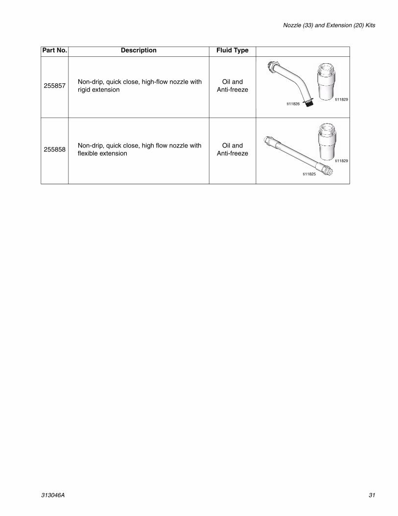
255857Non-drip, quick close, high-flow nozzle with rigid extension
Oil and Anti-freeze
255858Non-drip, quick close, high flow nozzle with flexible extension
Oil and Anti-freeze
Part No. Description Fluid Type
ti11826ti11829
ti11825
ti11829

Nozzle (33) and Extension (20) Kits
32 313046A
Nozzle (33) Kits
Thermal Relief Kits (page 4)
255459* Automatic, non-drip, quick-close nozzle Qty Oil
• BODY, nozzle 1
• O-RING, packing 1
• SPRING, compression 1
• O-RING, packing 1
• STEM, nozzle, valve 1
• SEAT, valve 1
255460* Automatic, non-drip, quick-close nozzle Anti-freeze
• BODY, nozzle 1
• SPRING, compression 1
• O-RING, packing 1
• STEM, nozzle, valve 1
• O-RING, packing 1
• SEAT, valve 1
255461 Automatic, non-drip, high-flow nozzle Oil and Antifreeze
• STEM, nozzle 1
• BODY, nozzle 1
• O-RING, packing 1
• O-RING, packing 1
• O-RING, packing 1
255470 Non-drip, quick-close nozzle Gear Lube
• Housing 1
• Body, nozzle 1
• O-RING, packing 1
• O-RING, packing 1
• Plug, Hollow, hex 1
*Used for dispensing 5gpm (22.7 lpm) or less.
Part No. Description PSI (bar) Rating112353 Diaphragm pump for fuel dispense, valve only 50 psi (3.4 bar)235998 Mini Fire-Ball™ 225, 3:1 600 psi (41 bar)237601 Fire-Ball 425, 3:1 600 psi (41 bar)237893 Mini Fire-Ball 300, 5:1 and Fire-Ball 425, 6:1 900 psi (62 bar)
248296Mini Fire-Ball 300, 5:1 and Fire-Ball 425, 6:1 (same as 237893 without bung adapter and swivel. Includes 6-foot hose)
900 psi (62 bar)
238899 Diaphragm pump 150 psi (10.4 bar)240429 Fire-Ball 425, 10:1 1600 psi (110 bar)
248324Fire-Ball 425, 10:1 (same as 240429 minus bung adapter and swivel. Includes 6-foot hose)
1600 psi (110 bar)

Technical Data
313046A 33
Technical Data
*Tested in 10W motor oil. Flow rates vary with fluid pressure, temperature and viscosity.
**Battery required to meet life expectancy: Energizer® Alkaline E91.
† At 2.5 gpm (9.5 lpm), at 70°F (21°C), with 10-weight oil and 1 gallon dispensed. May require calibration; out-of-box accuracy is +/- 1.25 percent.
Flow range* 0.1 to 14 gpm (0.4 to 53 lpm)Maximum Working Pressure 1500 psi (103.4 bar)Units of Measure pints, quarts, gallons, liters (factory set to quarts)Weight 5 pounds (2.26 kg)Dimensions (without extension)
Length 13 inches (33 cm)Width 3.75 inches (9.5 cm)Height 5.75 inches (14.6 cm)
Units of measure factory set in quartsmaximum totalizer amount = 999,999 gallons or litersmaximum recorded dispensed volume = 999.99 units
maximum preset volume = 999.9 unitsInlet 1/2-14 npt or 3/4-14 nptOutlet 3/4-16 straight thread o-ring bossOperating temperature range 4 °F to 158°F (-4°C to 70°C)Storage temperature range -40°F to 150°F (-40°C to 70°C)Battery** 4AA alkaline or lithium batteriesExpected battery life in typical shop environment 6 monthsWetted parts aluminum, stainless steel, PBT/PC, zinc,
nitrile rubber, CSFluid compatibility antifreeze, gear oil, crankcase oil, ATFMeter pressure loss 80 psi @ 10 gpm
Accuracy† +/- 0.5 percent

All written and visual data contained in this document reflects the latest product information available at the time of publication. Graco reserves the right to make changes at any time without notice.
This manual contains English. MM 313046
Graco Headquarters: MinneapolisInternational Offices: Belgium, China, Japan, Korea
GRACO INC. P.O. BOX 1441 MINNEAPOLIS, MN 55440-1441Copyright 2008, Graco Inc. is registered to I.S. EN ISO 9001
www.graco.com10/2008
Graco Extended Matrix 5 & Matrix 15 Meter WarrantyGraco warrants all equipment referenced in this document which is manufactured by Graco and bearing its name to be free from defects in material and workmanship on the date of sale to the original purchaser for use. Graco will, for a period of five (5) years from the date of sale, repair or replace any non-electronic part of the equipment determined by Graco to be defective. Graco will also for a period of three (3) years from the date of sale, repair, or replace any meter electronic components determined by Graco to be defective. This warranty applies only when the equipment is installed, operated and maintained in accordance with Graco’s written recommendations.
This warranty does not cover, and Graco shall not be liable for general wear and tear, or any malfunction, damage or wear caused by faulty installation, misapplication, abrasion, corrosion, inadequate or improper maintenance, negligence, accident, tampering, or substitution of non-Graco component parts. Nor shall Graco be liable for malfunction, damage or wear caused by the incompatibility of Graco equipment with structures, accessories, equipment or materials not supplied by Graco, or the improper design, manufacture, installation, operation or maintenance of structures, accessories, equipment or materials not supplied by Graco.
This warranty is conditioned upon the prepaid return of the equipment claimed to be defective to an authorized Graco distributor for verification of the claimed defect. If the claimed defect is verified, Graco will repair or replace free of charge any defective parts. The equipment will be returned to the original purchaser transportation prepaid. If inspection of the equipment does not disclose any defect in material or workmanship, repairs will be made at a reasonable charge, which charges may include the costs of parts, labor, and transportation.
THIS WARRANTY IS EXCLUSIVE, AND IS IN LIEU OF ANY OTHER WARRANTIES, EXPRESS OR IMPLIED, INCLUDING BUT NOT LIMITED TO WARRANTY OF MERCHANTABILITY OR WARRANTY OF FITNESS FOR A PARTICULAR PURPOSE.
Graco’s sole obligation and buyer’s sole remedy for any breach of warranty shall be as set forth above. The buyer agrees that no other remedy (including, but not limited to, incidental or consequential damages for lost profits, lost sales, injury to person or property, or any other incidental or consequential loss) shall be available. Any action for breach of warranty must be brought within two (2) years of the date of sale.
GRACO MAKES NO WARRANTY, AND DISCLAIMS ALL IMPLIED WARRANTIES OF MERCHANTABILITY AND FITNESS FOR A PARTICULAR PURPOSE, IN CONNECTION WITH ACCESSORIES, EQUIPMENT, MATERIALS OR COMPONENTS SOLD BUT NOT MANUFACTURED BY GRACO. These items sold, but not manufactured by Graco (such as electric motors, switches, hose, etc.), are subject to the warranty, if any, of their manufacturer. Graco will provide purchaser with reasonable assistance in making any claim for breach of these warranties.
In no event will Graco be liable for indirect, incidental, special or consequential damages resulting from Graco supplying equipment hereunder, or the furnishing, performance, or use of any products or other goods sold hereto, whether due to a breach of contract, breach of warranty, the negligence of Graco, or otherwise.
FOR GRACO CANADA CUSTOMERSThe Parties acknowledge that they have required that the present document, as well as all documents, notices and legal proceedings entered into, given or instituted pursuant hereto or relating directly or indirectly hereto, be drawn up in English. Les parties reconnaissent avoir convenu que la rédaction du présente document sera en Anglais, ainsi que tous documents, avis et procédures judiciaires exécutés, donnés ou intentés, à la suite de ou en rapport, directement ou indirectement, avec les procédures concernées.
Graco Information TO PLACE AN ORDER, contact your Graco distributor or call to identify the nearest distributor.Phone: 612-623-6928 or Toll Free: 1-800-533-9655, Fax: 612-378-3590.