Embed Size (px)
Citation preview
Physics 313 Spring 2005 Laboratory 5 : Light Wave Interference
Introduction: Light is often thought of in a poetic convention, e.g. "as rays of light stream from the sun." Although this
description lends itself to lyrical improvisation and is the foundation of geometric optics, light is better described as an
electromagnetic wave. In fact, most of what is now called modern optics resulted from the realization of the wave nature of light.
Current research in optics often involves the use of light as a wave. After completing the experiments, you should be able to
answer the following questions:
• Is light a wave ?
• Can you interfere light waves just as water waves ?
• How can one use the small wavelength of light to measure very small distances accurately?
Method/Experiments: Construct a “home-built” interferometer and use it to verify the wave nature of light, in particular its
constructive and destructive interference properties. The interferometer is very sensitive to the position of its optical components
and can thus be used to make small-distance scale measurements. Using the interferometer, measure the wavelength of the HeNe
light, quantify optical errors of magnitude 10-6 m in a transparent material, and determine the temperature profile of a flame.
Frame-grabber software will be used to process the signals from the CCD camera. The following equipment is required to collect
the data:
CCD cameraTransmission test targetLensesHeNe laser
Optical mounts, basesPiece of acetateTwo ¼-wave mirrors Cube beam-splitter
RulerCandle, lighterPost platformOptical table
Experiment 1: Construction of a Michelson interferometer
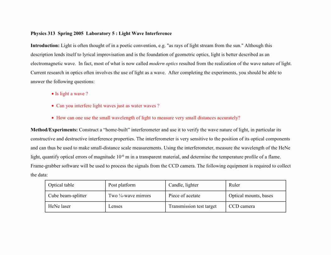
An interferometer (see Figure 1) is designed to divide a wave into two parts,
and then recombine the two waves at the output. If light is a wave, when two
crossing light beams cross they will interfere with each other according to their
relative phase differences. The phase difference in the paths, (k*r1 - ωt ) -
(k*r2 - ωt), comes from the difference in the paths, (r1-r2). Figure 1 is a
schematic of an interferometer showing the beam splitter, two different paths,
and the combined beams, recombined at the beam splitter.
Design your interferometer such that the optical paths in both arms are equal
within millimeters. Also, allow enough space to insert objects into one arm; 6”
to 8” is sufficient. Set all the optics at the same height and direct the HeNe
laser beam through the center of the optics for the maximum clear aperture.
Adjust the prism beam-splitter and the mirrors to keep the beams at the same
height and parallel to the holes in the breadboard (see Fig. 2).
Alignment is critical in this lab so take the time to measure the height of the
beam at each optical piece. The light beams should exactly overlap at the
output; do not be fooled by stray reflections off optics. Propagate the output
beam several meters to ensure that it is overlapped. The light should also be
visible traveling back to the HeNe laser. The beam splitter and mirrors should
be aligned so that some of the recombined light and back reflections go back
to the HeNe laser. Some additional tips are given at the end of the manual.
mirror
beam-splitter
mirror
Input light beam
Outputlight
beams
Figure 1: Schematic of a Michelson Interferometer. The red arrows indicate the direction of the light.r1 and r2 are the distances traveled by the two independent paths after the light is divided in the beam splitter.
r2
r1
Figure 2: The beam should be level and centered alongholes throughout the interferometer.

If the interferometer is properly aligned and light is a wave, interference
fringes will be visible at the output. These will be difficult to observe given
the small waist of the HeNe laser beam, and placing a positive lens in the path
of the input light beam to create two point sources and a subsequent
broadening of the beam will help to see circular fringes.
Record the alignment procedure and the final construction of the
interferometer in your write-up, and note your conclusion as to whether light is
a wave, or composed of particles traveling in waves.
Set-up for circular fringes Linear optics equivalent Geometry for circular fringes
Experiment 2: The WAVE WAVE WAVE WAVE nature of light
Two crossing water wave-trains will interfere, as you can observe at the beach.
Use your interferometer to determine whether crossing light beams will
behave in the same way. Adjust the angle of intersection between the light
waves by adjusting the mirrors and determine the properties of constructive
and destructive interference.
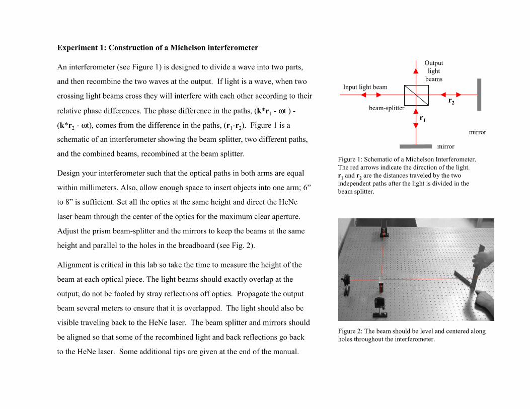
Interference is best observed between large plane waves. With this geometry,
you will observe fringes of equal thickness. Using the assortment of lenses in
the lab, pick a combination of two that allows you to expand the HeNe laser
beam to overfill the cube beam-splitter. Ensure that the output is collimated
over many meters and recheck the alignment (see Fig. 3).
If light is a wave, you should be able to observe interference at the output of
the interferometer where the waves cross. To quantitatively measure the
interference pattern, you can view the interferometer’s output with a CCD
camera interfaced to a video frame-grabber in the computer.
Figure 3: The expanded beam should be collimated, aligned and largeenough to fill the beamsplitter.
You’ll need to determine the pixel-distance scale on the
monitor by measuring the width of a group of lines on the
transmission test target and calibrating this distance with
what appears on the screen.
Generation of fringes of equalthickness. (a) Set-up for parallelbeam. (b) M2 parallel to M1’(c) M2 tilted

To reduce any blurring of the target’s lines, place it as closely as possible to
the CCD camera. Block one of the interferometer’s arms to eliminate any
competing fringe pattern. In Figure 4 one can see the test target near the CCD
(T) and the frame grabber image on the screen (M).
Calipers or a small handheld microscope can be used to measure the distance
between the lines on the test target. Use this value to obtain the physical
dimensions of the pixels by comparing this with the distance between lines in
the image as measured in pixels.
You can use your calibration of the CCD image pixels to determine the
wavelength of the laser light. Adjust one of the mirrors to produce a small
number of either vertical or horizontal fringes. Mount a small protractor to the
adjustment knob of the mirror mount to record the angular change when tilting
the mirror (or devise another way of doing this). Count the fringes on the
monitor, then tilt the mirror and count the final number of fringes (see Fig.5).
The number m of fringes introduced with an angular tilt is related to the light
wavelength by m λ = d sin[2 tan-1(ε /l)] where d is the distance over which the
fringes are measured at the output, l is the distance over which the tilt occurs
in the mirror mount and ε is the translation of the 1/4" diameter adjustment
screw with an 80 thread per inch pitch: ε = screw revolutions / screw pitch. Figure 4: What is the distance relationship between what is measured (T)and what appears on the monitor (M)?

Derive this relationship in your lab write-up. The following may be useful:
1. Given the geometry of the mirror mount in the interferometer, how is
the angular tilt of the two beams related to l (the distance over which
the tilt occurs in the mirror mount) and ε (the translation of the
adjustment screw)?
2. If a beam is reflected off a mirror and you rotate the mirror by , by
what angle is the beam then deflected?
3. m λ = d sin is the condition for constructive interference for two
slits separated by d. What is the equivalent condition for your case of
plane waves incident with an angular tilt?
Figure 5: Tilting one of the mirrors will shift the fringe pattern. Notice that three fringe patterns are shown on the screen alongwith a 2-D plot of one of the images.
Using m λ = d sin[2 tan-1(ε /l)], determine the wavelength of the laser.
Repeat your measurement several times with different screw revolutions
and find an average value for the wavelength of the laser. Analyze your
error compared with the value posted on the front of the laser.

Figure 6: The fringe distortion on the monitor is caused by inserting a flame into an arm. Note that a lens has been used to demagnify the light waves so that they fit onto the smaller CCD chip. This requires a new calibration.
Experiment 3: Measurements with light waves
The optical path for light equals the product of the distance and the index of
refraction. Inserting a transparent object of varying thickness or index of
refraction into an interferometer’s arm introduces a phase difference that will
alter the fringe pattern. Quantitative properties of these objects can be
deduced by observing the changes in the fringe pattern.
For the next experiments, place a positive lens between the CCD camera and
the beam-splitter so that the entire field of view is visible on the monitor (see
Fig. 6). You’ll need to recalibrate the pixel-distance scale; do this with the
transmission test target placed before the lens.
Adjust the mirrors to produce many fringes and insert a piece of acetate film
into one arm of the interferometer. You should see the distortion of the fringe
pattern caused by the thickness variations of the material. Quantify these
variations, i.e. the changes they introduce into the optical path, by counting the
fringe’s displacement. Measure the distortion in a peak to peak fashion from
an initially linear fringe pattern.
Knowing the acetate’s index of refraction to be n=1.5, give a quantitative
description of variations in the film’s thickness.

Index of Refraction for Air as a Function of Temperaturen-1 = 0.000291/(1+0.00368T)
0
0.0001
0.0002
0.0003
0 250 500 750 1000 1250
Temperature (C)
Inde
x of
refr
actio
n: (n
-1)
Figure 7: Index of refraction for air vs. temperature.
The index of refraction for a material is a function of its temperature (as
well as wavelength and composition). Using the induced variation in
the index of refraction due to the flame’s heat, determine the
temperature profile of the flame. Place a lit candle on a platform and
insert it in one arm of the interferometer. Record the changes the
flame’s heat introduces in the optical path (i.e. the fringe displacements)
of the interferometer. In figure 6, for example, you can see the
interference is displaced by the 4 fringes at the peak of the flame due to
the lower index of refraction for the hot air.
Measure the width of the flame using the observed heat-induced optical
path difference profile and your pixel-to-distance calibration. Using the
known temperature dependence for the index of refraction of air (see
Fig. 7), determine the temperature of the flame. This experiment can
reveal some very nice interference patterns as shown in Fig. 6.

Interferometer alignment tips
• Before starting the set up ensure that you have all the mirrors, the beam splitter, the lenses mounted to the working level on the optical table. A quick inspection by using the measurement tools available is advised.
• Take time to ensure that the laser source is firmly held at the base on the table.
• Ensure the laser is propagating along optical table holes and is level both at near field and far field. Use of level measurements at these points as you adjust the level is helpful and less time consuming. You can level the laser by using an additional postmount to tilt it.
• With source in place you need to ensure that the mirror surfaces and the beam splitter are perpendicular to the beam. Ensure that in all instances the beam propagates through the center of the optic in question. Back reflection from the surfaces should help in this process.
• The alignment should be such that the level and line of propagation is not changed when a lens is inserted in the beam. If this happens then you have to keep adjusting the lens to perfect alignment.
• As you have realized, beam collimation is very important here. Given the available lenses, calculate the lens separation well inadvance. (For a beam expanding telescope, recall that the lenses must be separated by the sum of their focal lengths.) This will enable you to set up your interferometer with enough space for collimation. Else you will be forced to dismantle your set up after the first stage and waste time setting up again.
• In ensuring that you have the interference fringes, the distance from the beam splitter to the M1 and M2 should be equal. A quick way in achieving this is by counting the holes on the optical table to each mirror or by actual measurement. But remember that the holes on the optical table are evenly spaced and that is for a reason. Take advantage of this and save time.


![[LAB05]Motor ECH Daihatsu](https://img.dokumen.tips/doc/110x75/577cd5c41a28ab9e789b9626/lab05motor-ech-daihatsu.jpg)