Embed Size (px)
Citation preview

MOTOR - 1.5 HPMOTOR - 1.5 HPMOTOR - 1.5 HPMOTOR - 1.5 HPMOTOR - 1.5 HPRatedRatedRatedRatedRated
ASSEMBLY AND OPERATING INSTRUCTIONS
3491 MISSION OAKS BLVD., CAMARILLO, CA 93011VISIT OUR WEB SITE AT HTTP://WWW.HARBORFREIGHT.COM
Copyright © 2004 by Harbor Freight Tools®. All rights reserved. No portion ofthis manual or any artwork contained herein may be reproduced in any shapeor form without the express written consent of Harbor Freight Tools.
For technical questions and replacement parts, please call 1-800-444-3353
MOTOR - 2 HPMOTOR - 2 HPMOTOR - 2 HPMOTOR - 2 HPMOTOR - 2 HPRatedRatedRatedRatedRated
30188 30189
REV 12/04
Due to continuing improvements, actual product may differ slightly from the product described herein.

Page 2SKU 30188, 30189 For technical questions, please call 1-800-444-3353
SPECIFICATIONS
30188 – 1.5 HP Rated Motor Item Description
Power Requirement 115 VAC @15 A, 60 Hz, single phase, or 230 VAC @ 7.5 A, 60 Hz, single phase
Output Power 1.5 HP Rated Shaft/Frame 5/8 (dia.) x 2 (L) inches; keyed: 0.18 (W) x 1-1/2
(L) x 0.113 (D) inches/S56 Frame Rotation Facing Shaft: Counterclockwise (non-
reversible); 3450 RPM Base Mounting Holes Spacing: 3 x 5 inches; Slot size: 3/8 x 1 inch;
Mount with1/4 inch bolts (not supplied) Features Thermal overload protection, reset button
Fan cooled Overall Dimensions 11 (L) x 6-5/8 (W) x 8-1/4 H) inches
30189 – 2 HP Rated Motor Item Description
Power Requirement 115 VAC @24 A, 60 Hz, split phase, or 230 VAC @ 12 A, 60 Hz, split phase
Output Power 2 HP Rated Shaft/Frame 5/8 (dia.) x 2 (L) inches; keyed: 0.18 (W) x 1-1/2
(L) x 0.113 (D) inches/56C Frame Rotation Facing Shaft: Counterclockwise (non-
reversible); 3450 RPM Base Mounting Holes Spacing: 3 x 4 inches; Slot size: 5/16 x 1 inch;
Mount with1/4 inch bolts (not supplied) Features Thermal overload protection, reset button
Fan cooled Overall Dimensions 12-1/4 (L) x 6-5/8 (W) x 8 (H) inches
SAVE THIS MANUAL
You will need the manual for the safety warnings and precautions, assembly instructions,operating and maintenance procedures, parts list and diagram. Keep your invoice with thismanual. Write the invoice number on the inside of the front cover. Keep the manual andinvoice in a safe and dry place for future reference.
GENERAL SAFETY RULES
WARNING!
READ AND UNDERSTAND ALL INSTRUCTIONS. Failure to follow all instructionslisted below may result in electric shock, fire, and/or serious injury.
SAVE THESE INSTRUCTIONS
REV 12/04

Page 3SKU 30188, 30189 For technical questions, please call 1-800-444-3353
Work Area
1. Keep your work area clean and well lit. Cluttered benches and dark areas inviteaccidents.
2. Do not operate power tools in explosive atmospheres, such as in the presence offlammable liquids, gases, or dust. Power tools create sparks which may ignite thedust or fumes.
3. Keep bystanders, children, and visitors away while operating a power tool.
Distractions can cause you to lose control. Protect others in the work area from debrissuch as chips and sparks. Provide barriers or shields as needed.
Electrical Safety
4. Avoid body contact with grounded surfaces such as pipes, radiators, ranges, andrefrigerators. There is an increased risk of electric shock if your body is grounded.
5. Do not expose power tools to rain or wet conditions. Water entering a power tool willincrease the risk of electric shock.
6. Grounded tools must be plugged into an outlet properly installed and grounded inaccordance with all codes and ordinances. Never remove the grounding prong ormodify the plug in any way. Do not use any adapter plugs. Check with a qualifiedelectrician if you are in doubt as to whether the outlet is properly grounded. If thetools should electrically malfunction or break down, grounding provides a low resistancepath to carry electricity away from the user.
7. Double insulated tools are equipped with a polarized plug (one blade is wider thanthe other). This plug will fit in a polarized outlet only one way. If the plug does notfit fully in the outlet, reverse the plug. If it still does not fit, contact a qualifiedelectrician to install a polarized outlet. Do not change the plug in any way. Doubleinsulation eliminates the need for the three wire grounded power cord and groundedpower supply system.
8. Do not abuse the Power Cord. Never use the Power Cord to carry the tools or pullthe Plug from an outlet. Keep the Power Cord away from heat, oil, sharp edges, ormoving parts. Replace damaged Power Cords immediately. Damaged Power Cordsincrease the risk of electric shock.
9. When operating a power tool outside, use an outdoor extension cord marked“W-A” or “W”. These extension cords are rated for outdoor use, and reduce the risk ofelectric shock.

Page 4SKU 30188, 30189 For technical questions, please call 1-800-444-3353
Personal Safety10. Stay alert. Watch what you are doing, and use common sense when operating a
power tool. Do not use a power tool while tired or under the influence of drugs,alcohol, or medication. A moment of inattention while operating power tools may resultin serious personal injury.
11. Dress properly. Do not wear loose clothing or jewelry. Contain long hair. Keepyour hair, clothing, and gloves away from moving parts. Loose clothes, jewelry, orlong hair can be caught in moving parts.
12. Avoid accidental starting. Be sure the Power Switch is off before plugging in.Carrying power tools with your finger on the Power Switch, or plugging in power toolswith the Power Switch on, invites accidents.
13. Remove adjusting keys or wrenches before turning the power tool on. A wrench ora key that is left attached to a rotating part of the power tool may result in personal injury.
14. Do not overreach. Keep proper footing and balance at all times. Proper footing andbalance enables better control of the power tool in unexpected situations.
15. Use safety equipment. Always wear eye protection. Dust mask, non-skid safetyshoes, hard hat, or hearing protection must be used for appropriate conditions.
Tool Use and Care16. Use clamps (not included) or other practical ways to secure and support the
workpiece to a stable platform. Holding the work by hand or against your body isunstable and may lead to loss of control.
17. Do not force the tool. Use the correct tool for your application. The correct tool willdo the job better and safer at the rate for which it is designed.
18. Do not use the power tool if the Power Switch does not turn it on or off. Any tool thatcannot be controlled with the Power Switch is dangerous and must be replaced.
19. Disconnect the Power Cord Plug from the power source before making anyadjustments, changing accessories, or storing the tool. Such preventive safetymeasures reduce the risk of starting the tool accidentally.
20. Store idle tools out of reach of children and other untrained persons. Tools aredangerous in the hands of untrained users.
21. Maintain tools with care. Keep cutting tools sharp and clean. Properly maintainedtools with a sharp cutting edge are less likely to bind and are easier to control. Do notuse a damaged tool. Tag damaged tools “Do not use” until repaired.
22. Check for misalignment or binding of moving parts, breakage of parts, and anyother condition that may affect the tool’s operation. If damaged, have the toolserviced before using. Many accidents are caused by poorly maintained tools.
23. Use only accessories that are recommended by the manufacturer for your model.Accessories that may be suitable for one tool may become hazardous when used onanother tool.

Page 5SKU 30188, 30189 For technical questions, please call 1-800-444-3353
Service
24. Motor service must be performed only by qualified repair personnel. Service ormaintenance performed by unqualified personnel could result in a risk of injury.
25. When servicing a tool, use only identical replacement parts. Follow instructions inthe “Inspection, Maintenance, And Cleaning” section of this manual. Use ofunauthorized parts or failure to follow maintenance instructions may create a risk ofelectric shock or injury.
SPECIFIC SAFETY RULES FOR THIS PRODUCT
1. Maintain labels and nameplates on the Motor. These carry important information. Ifunreadable or missing, contact Harbor Freight Tools for a replacement.
2. Always wear ANSI approved safety impact eye goggles and heavy work gloveswhen using or installing the Motor. Using personal safety devices reduce the risk forinjury. Safety impact eye goggles and heavy work gloves are available from Harbor FreightTools.
3. Maintain a safe working environment. Keep the work area well lit. Make sure there isadequate surrounding workspace. Always keep the work area free of obstructions, grease,oil, trash, and other debris. Do not use a power tool in areas near flammable chemicals,dusts, and vapors. Do not use this product in a damp or wet location.
4. Avoid unintentional starting. Make sure you are prepared to begin work before turningon the Motor.
5. Do not force the Motor. This tool will do the work better and safer at the speed andcapacity for which it was designed.
6. Always unplug the Motor from its electrical outlet (or turn off the circuit breakerand tag) before performing and inspection, maintenance, or cleaning procedures.
7. When installing motor, observe all national and local codes. Make sure to install,protect, and fuse according to the latest issue of the National Electric Code, NEMAStandard Publication No. MG2, and local codes. Ground frames in accordance withNEC Article 430. For general grounding information, refer to NEC Article 250.
8. Install guards when appropriate. Make sure all moving parts, including the shaft andany attached accessories, are permanently guarded to prevent clothing and body partsfrom being caught.
9. Disconnect power before working on motor driven equipment. Motors with automaticthermal protectors will automatically restart when the protector cools. Do not use motorswith automatic thermal protector in applications where automatic restart will be hazardousto personnel or equipment. Motors may start unexpectedly after protector trips.
10. Before each use, check all nuts, bolts, and screws for tightness. Vibration duringoperation may cause these to loosen.
(1)
Page 6SKU 30188, 30189 For technical questions, please call 1-800-444-3353
11. Keep extension cord off the ground and away from water.
12. Always connect the Line Cord to a Ground Fault Circuit Interrupter (GFCI) protectedelectrical outlet.
13. Industrial applications must follow OSHA guidelines.
WARNING! People with pacemakers should consult their physician(s) before usingthis product. Operation of electrical equipment in close proximity to a heart pacemakercould cause interference or failure of the pacemaker.
GROUNDING
WARNING!
Improperly connecting the grounding wire can result in the risk of electric shock.Check with a qualified electrician if you are in doubt as to whether the outlet isproperly grounded. Do not modify the power cord plug provided with the tool orproduct. Never remove the grounding prong from the plug. Do not use the tool ifthe power cord or plug is damaged. If damaged, have it repaired by a servicefacility before use. If the plug will not fit the outlet, have a proper outlet installedby a qualified electrician.
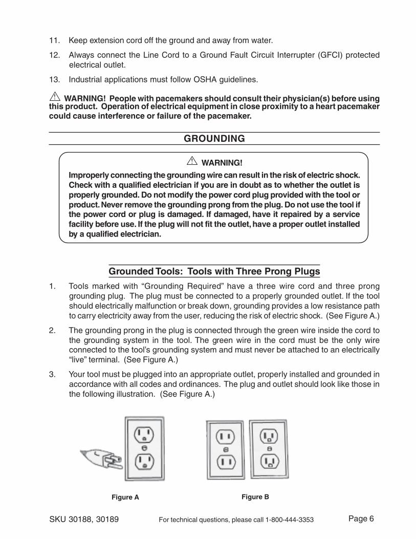
Grounded Tools: Tools with Three Prong Plugs
1. Tools marked with “Grounding Required” have a three wire cord and three pronggrounding plug. The plug must be connected to a properly grounded outlet. If the toolshould electrically malfunction or break down, grounding provides a low resistance pathto carry electricity away from the user, reducing the risk of electric shock. (See Figure A.)
2. The grounding prong in the plug is connected through the green wire inside the cord tothe grounding system in the tool. The green wire in the cord must be the only wireconnected to the tool’s grounding system and must never be attached to an electrically“live” terminal. (See Figure A.)
3. Your tool must be plugged into an appropriate outlet, properly installed and grounded inaccordance with all codes and ordinances. The plug and outlet should look like those inthe following illustration. (See Figure A.)
Figure A Figure B

Page 7SKU 30188, 30189 For technical questions, please call 1-800-444-3353
Double Insulated Tools: Tools with Two Prong Plugs
4. Tools marked “Double Insulated” do not require grounding. They have a special doubleinsulation system which satisfies OSHA requirements and complies with the applicablestandards of Underwriters Laboratories, Inc., the Canadian Standard Association, andthe National Electrical Code. (See Figure B.)
5. Double insulated tools may be used in either of the 120 volt outlets shown in the followingillustration. (See Figure B.)
EXTENSION CORDS
1. Grounded tools require a three wire extension cord. Double Insulated tools can useeither a two or three wire extension cord.
2. As the distance from the supply outlet increases, you must use a heavier gauge extensioncord. Using extension cords with inadequately sized wire causes a serious drop involtage, resulting in loss of power and possible tool damage. (See Table A.)
3. The smaller the gauge number of the wire, the greater the capacity of the cord. For example,a 14 gauge cord can carry a higher current than a 16 gauge cord. (See Table A.)
4. When using more than one extension cord to make up the total length, make sure eachcord contains at least the minimum wire size required. (See Table A.)
5. If you are using one extension cord for more than one tool, add the nameplate amperesand use the sum to determine the required minimum cord size. (See Table A.)
6. If you are using an extension cord outdoors, make sure it is marked with the suffix“W-A” (“W” in Canada) to indicate it is acceptable for outdoor use.
7. Make sure your extension cord is properly wired and in good electrical condition. Alwaysreplace a damaged extension cord or have it repaired by a qualified electrician beforeusing it.
8. Protect your extension cords from sharp objects, excessive heat, and damp or wet areas.
Table ARECOMMENDED MINIMUM WIRE GAUGE FOR EXTENSION CORDS*
(120 VOLT)NAMEPLATE
AMPERES(At Full Load)
EXTENSION CORD LENGTH
25Feet
50Feet
75Feet
100Feet
150Feet
0 – 2.0 18 18 18 18 162.1 – 3.4 18 18 18 16 143.5 – 5.0 18 18 16 14 125.1 – 7.0 18 16 14 12 127.1 – 12.0 16 14 12 10 -
12.1 – 16.0 14 12 10 - -16.1 – 20.0 12 10 - - -
* Based on limiting the line voltage drop to five volts at 150% of the rated amperes.
Page 8SKU 30188, 30189 For technical questions, please call 1-800-444-3353
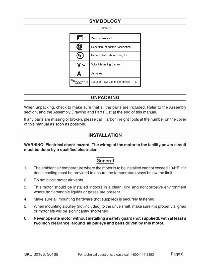
SYMBOLOGYTable B
UNPACKING
When unpacking, check to make sure that all the parts are included. Refer to the Assemblysection, and the Assembly Drawing and Parts List at the end of this manual.
If any parts are missing or broken, please call Harbor Freight Tools at the number on the coverof this manual as soon as possible.
INSTALLATION
WARNING: Electrical shock hazard. The wiring of the motor to the facility power circuitmust be done by a qualified electrician.
General
1. The ambient air temperature where the motor is to be installed cannot exceed 104°F. If itdoes, cooling must be provided to ensure the temperature stays below the limit.
2. Do not block motor air vents.
3. This motor should be installed indoors in a clean, dry, and noncorrosive environmentwhere no flammable liquids or gases are present.
4. Make sure all mounting hardware (not supplied) is securely fastened.
5. When mounting a pulley (not included) to the drive shaft, make sure it is properly alignedor motor life will be significantly shortened.
6. Never operate motor without installing a safety guard (not supplied), with at least atwo inch clearance, around all pulleys and belts driven by this motor.

Page 9SKU 30188, 30189 For technical questions, please call 1-800-444-3353
Motor Wire Connections
The table below, and the photo, indicate the proper wiring connections for the motor internalwires and the external power connections (neutral power wire is usually white; hot power wireis usually black, ground wire is for earth ground). At 230V, Single Phase, both conductors are“HOT”.
1. Remove rear Access Panel (21) to expose the Connection Board (22) (see photo below).
2. Verify that there is no power to the circuit to be connected. Check fuse box and turn offcircuit breaker.
3. Using approved National Electrical Code electrical standards, make the connections asdescribed in the table below for 115 VAC or 230 VAC operation.
The facility power circuit, and connecting wires, must be rated to at least 20 amps ofcurrent or 30 amps for sku 30198 at 115 VAC. Use properly-sized, insulated ring or quickdisconnect terminals to securely and safely connect the wires to the Connection Board(22).
4. Replace Access Panel (21).
Warning: Always connect the green grounding wire to the green motor chassis screw.Failure to connect this wire properly can create a severe safety hazard.
Note: Both SKU30188 and 30189Motors have thesame wiringconnections.
REV 06/05;09/05
Ground Wire (green)
Line In
Line In
Reset Button
Connection Board(22) to right wired for115 VAC operation.
To change to 230VAC operation:Move the brownwire from # 5 to # 3;Move the white wirefrom # 6 to # 5.

Page 10SKU 30188, 30189 For technical questions, please call 1-800-444-3353
OPERATING INSTRUCTIONS
Before initial operation, verify that:
1. The Motor is dry.
2. The voltage and frequency stamped on motor and control nameplates correspond withthat of the input power line.
3. All connections to the motor are correct.
4. The rotor turns freely when disconnected from the load.
5. The motor is detached from the load for the initial start. Operate the motor without a loadfor about one hour to test for any localized heating in bearings and windings.
6. The motor operates in counterclockwise rotation.
7. The voltage is correct and balanced at the motor terminals, and no-load current draw (inamps) is correct.
8. The motor comes up to its operational speed and is not being overloaded.
INSPECTION, MAINTENANCE, AND CLEANING
WARNING! Make sure the Power Switch of the Motor is in its “OFF” position and thatthe tool is unplugged or disconnected from its electrical outlet before performing anyinspection, maintenance, or cleaning procedures.
1. Before each use, inspect the general condition of the Motor. Check for loose screws,misalignment or binding of moving parts, cracked or broken parts, damaged electricalwiring, and any other condition that may affect its safe operation. If abnormal noise orvibration occurs, have the problem corrected before further use. Do not use damagedequipment.
2. Maintenance and repairs should only be done by a qualified technician.
3. Periodically recheck all nuts, bolts, and screws for tightness.
4. Store in a clean and dry location.
Lubrication
Note: If lubrication instructions are shown on motor, they will supersede this generalinstruction. Lubrication should be completed by a qualified technician.
1. The Motor is properly lubricated at the time of manufacture. It is not necessary to lubricateat time of installation unless the motor has been in storage for a period of 12 months orlonger.
2. Re-oil sleeve bearings with drops of 5W20 viscosity motor oil every 2000 hours of normalservice. Direct drive operation (no pulleys) requires lubrication every 3000 hours of normalservice.
3. Sealed ball bearings require no attention during the life of the bearing.

Page 11SKU 30188, 30189 For technical questions, please call 1-800-444-3353
tsiLstraP.roferastrapehtrebmunledomhcihwyficepsoteruseb,gniredronehW:TNATROPMI
traP noitpircseD yt'Q88103
)98103(
traP noitpircseD yt'Q88103
)98103(
traP noitpircseD yt'Q88103
)98103(
1 revoCdnEtfahS 1 11 tooFrotoM 1 22 draoBnoitcennoC 1
2 tloBxeHdaeHgnoL 4 21 eroCnorI 1 32 8x4MtloB 2
3 rehsaWrebbuR 8 31 gniraeB 2 42 5x4MtloB 2
4 revoCroticapaC )1(2 41 naF 1 52 revoCdnEkcaB 1
a5 roticapaCnuR )V054Fµ52( )0(1 51 rotoR 1 62 gulP 2
b5 roticapaCtratS )V521Fµ004( 1 61 hctiwSlagufirtneC 1 72 rehsaW 2
6 lwoCroticapaC )1(2 71 recapS 1 82 tuN 4
7 4x4ØniPrednilyC 1 81 rehsaW 4 92 nottuBteseRdaolrevO 1
8 4ØrehsaWrebbuR )8(01 91 tfahS 1 03 tloB 2
9 tloB )2(4 02 reppotSgniR 2 13 pilCeriW 1
01 gnisaCrotoM 1 12 lenaPsseccA 1
Assembly Diagram
REV 06/05
PLEASE READ THE FOLLOWING CAREFULLY
THE MANUFACTURER AND/OR DISTRIBUTOR HAS PROVIDED THE PARTS DIAGRAM IN THISMANUAL AS A REFERENCE TOOL ONLY. NEITHER THE MANUFACTURER NOR DISTRIBUTOR MAKESANY REPRESENTATION OR WARRANTY OF ANY KIND TO THE BUYER THAT HE OR SHE IS QUALIFIEDTO MAKE ANY REPAIRS TO THE PRODUCT OR THAT HE OR SHE IS QUALIFIED TO REPLACE ANYPARTS OF THE PRODUCT. IN FACT, THE MANUFACTURER AND/OR DISTRIBUTOR EXPRESSLY STATESTHAT ALL REPAIRS AND PARTS REPLACEMENTS SHOULD BE UNDERTAKEN BY CERTIFIED ANDLICENSED TECHNICIANS AND NOT BY THE BUYER. THE BUYER ASSUMES ALL RISK AND LIABILITYARISING OUT OF HIS OR HER REPAIRS TO THE ORIGINAL PRODUCT OR REPLACEMENT PARTSTHERETO, OR ARISING OUT OF HIS OR HER INSTALLATION OF REPLACEMENT PARTS THERETO.
NOTE: Some parts are listed and shown for illustration purposes onlyand are not available individually as replacement parts.