Embed Size (px)
Citation preview

TABLE OF CONTENTS PART IV – STANDARD DRAWINGS
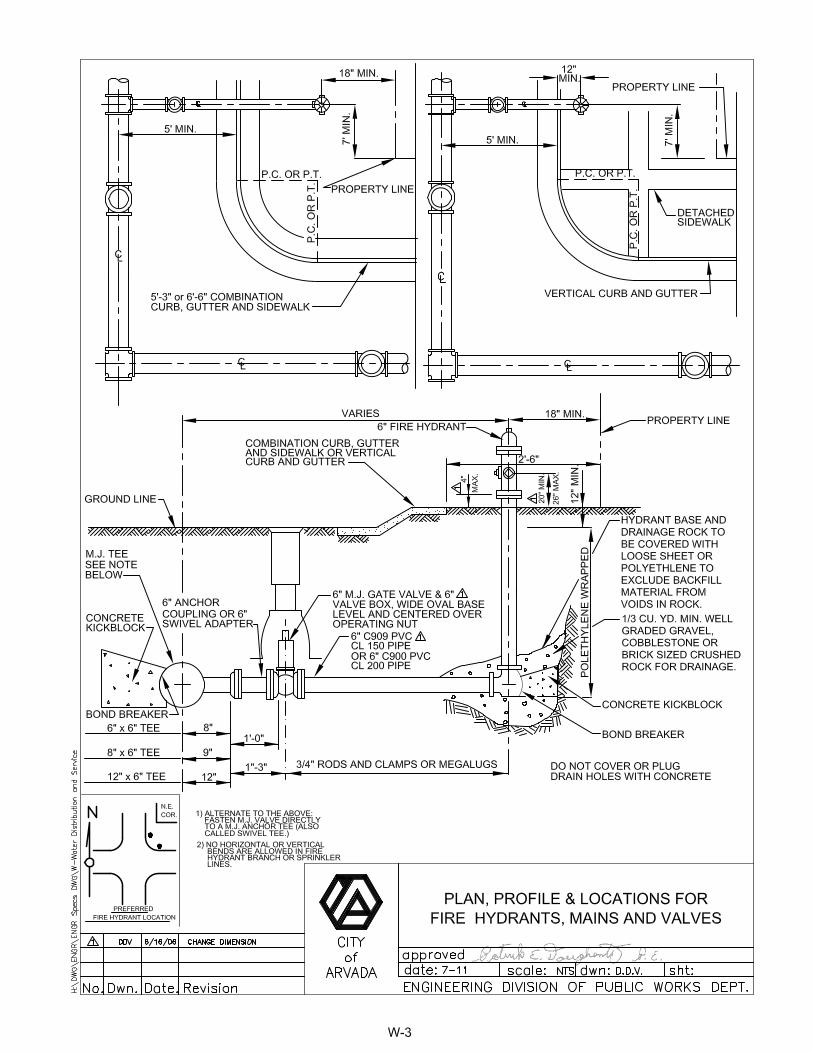
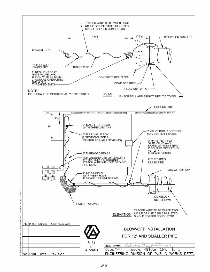
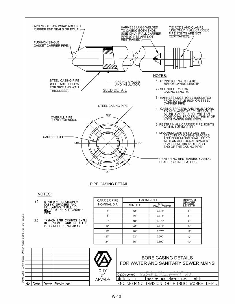
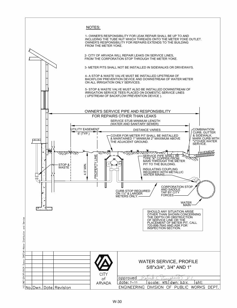
WATER DISTRIBUTION AND SERVICE Section No. Description Page No. W Typical Trench Section Pipe Protection Water Mains .................................W-1 W Typical Trench Section for Water Main Pipelines In Unstable Subgrade..............................................................................W-2 W Plan, Profile & Locations for Fire Hydrants, Mains and Valves ...................W-3 W Fire Hydrant Installation ..............................................................................W-4 W Water Distribution System Typical Plan for Cul-de-Sacs ............................W-5 W Piping at Street Intersections Future Connections ......................................W-6 W Stub-Out Configurations for Future Main Extensions ..................................W-7 W Stub-Out Configurations for Future Main Extensions ..................................W-8 W Blow-Off Installation for 12" and Smaller Pipe.............................................W-9 W Crossing Storm and Sanitary Sewers .......................................................W-10 W Open Cut Crossing Beneath Conduit ........................................................W-11 W Bored Crossings Beneath Conduits ..........................................................W-12 W Bore Casing Details ..................................................................................W-13 W Combination Flanged Harness Lug Details ...............................................W-14 W Typical Cutoff Wall for Ditch or Canal Crossing ........................................W-15 W Concrete Kickblocks Bearing Surfaces and Installation ............................W-16 W Concrete Kickblocks for Wet Taps ............................................................W-17 W Reaction Blocking All Thread Anchor........................................................W-18 W Length of Restrained Pipe.........................................................................W-19 W Tie Rod and Washer Details .....................................................................W-20 W Joint Restraint Detail Eye Bolts .................................................................W-21 W Mechanical Joint Restraint Details ............................................................W-22 W Clamp Details and Dimensions for Use with C.I. & D.I. Fittings Only ........W-23 W Flange Lug Detail ......................................................................................W-24 W Transmission Main Butterfly Valve Installation ..........................................W-25 W Insulated Joints, Rods and Bolted Sleeve Type Couplings .......................W-26 W Link-Seal Modular Wall and Casing Seal ..................................................W-27 W Utility Services Typical Layout...................................................................W-28 W General Meter Notes.................................................................................W-29 W Water Service, Profile 5/8" x 3/4", 3/4" and 1"...........................................W-30 W Outside Meter Setting 1" and Smaller .......................................................W-31 W Outside Setting for 1 ½" and 2" Water Meter with Check Valve and Bypass in Manhole .........................................................................W-32 W Outside Setting for 1 ½" and 2" Meter Brass Alternative ...........................W-33 W Outside Setting for 1 ½" and 2" Irrigation (only) Water Meter in Manhole ........................................................................W-34

TABLE OF CONTENTS PART IV – STANDARD DRAWINGS
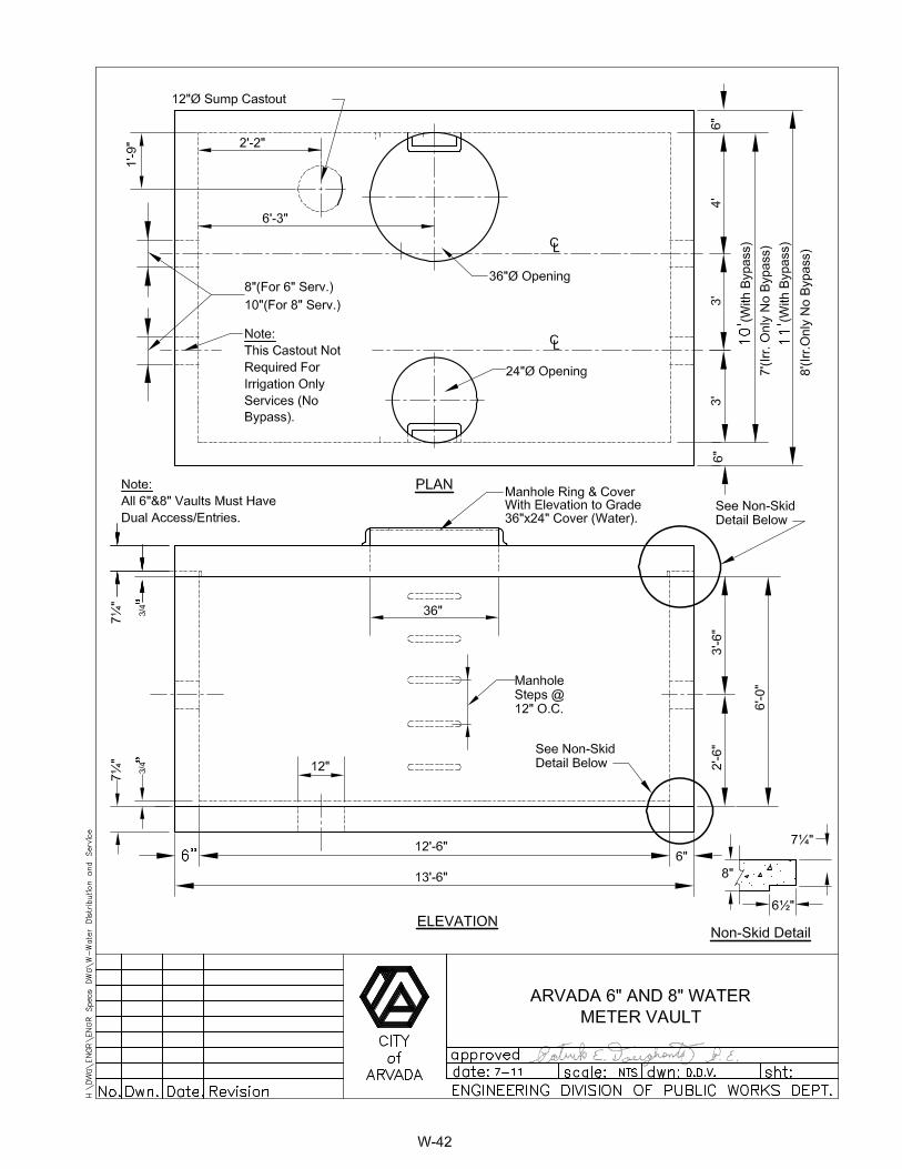
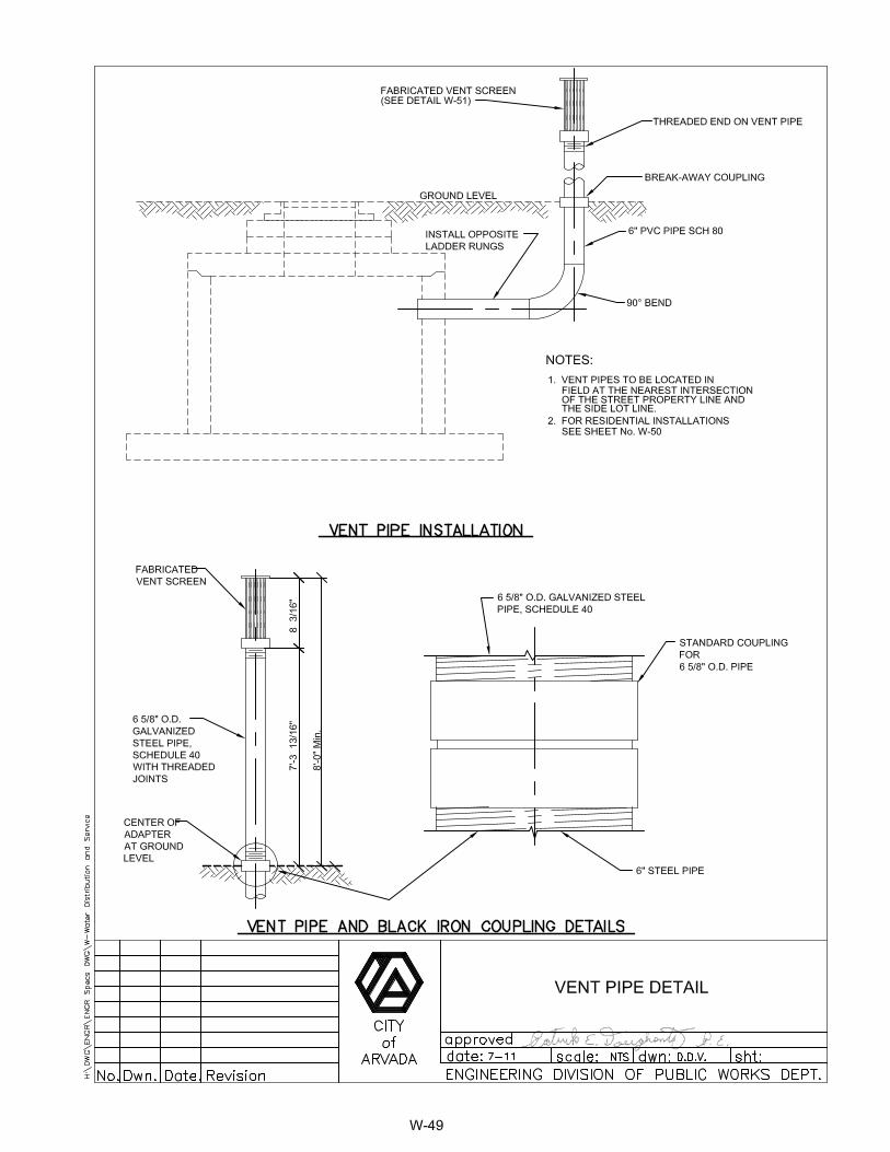
WATER DISTRIBUTION AND SERVICE (Cont.) Section No. Description ......................................................................................Page No. W Piping Layout for 3", 4", 6" & 8" Compound or Turbine Meter Settting with Bypass..............................................................................W-35 W Piping Layout for 3", 4", 6" & 8" Turbine Meter Setting "Irrigation Only" .....................................................................................W-36 W Piping Layout for F.M.C.T. Meter with Bypass 6" & 8" Services Only ............................................................................W-37 W Arvada 3" and 4" Water Services Meter Vault with Bypass.......................W-38 W Arvada 3" and 4" Water Services Meter Vault with Bypass Isometric View.......................................................................................W-39 W Arvada 3" and 4" Meter Vault Irrigation Only.............................................W-40 W Arvada 3" and 4" Meter Vault Irrigation Only Isometric View.....................W-41 W Arvada 6" and 8" Water Meter Vault .........................................................W-42 W Arvada 6" and 8" Water Meter Vault Isometric View .................................W-43 W Wall Plates and Body Clamps for 3" Meters..............................................W-44 W Wall Plates for 4", 6", 8" & 10" Meters.......................................................W-45 W Dual 2" Air Release and Vacuum Valve Installation for Mains Larger than 12" Diameter ......................................................W-46 W Single 2" Air Release and Vacuum Valve Installation for Mains 12" or Less in Diameter .........................................................W-47 W Dual Air and Vacuum Valve Assembly with Access Manhole ...................W-48 W Vent Pipe Installation and Details..............................................................W-49 W Residential Vent Assembly........................................................................W-50 W 6" Diameter Vent Pipe Screen...................................................................W-51 W Adjustable Steel Pipe Valve Support.........................................................W-52 W Valve Box Support Plate and Valve Operator Extension Guide ................W-53 W Pressure Regulating Valve Rectangular Vault Typical Plan......................W-54 W Pressure Regulating Valve Rectangular Vault Cross Section ...................W-55 W Pressure Regulating Valve System Piping & Appurtenances....................W-56 W Temporary Water Set-Up for Construction Use.........................................W-57 W Reference Post Typical Detail ...................................................................W-58 W Water Meter or Valve Vault Frame and Lid Detail .....................................W-59 W Fire Hydrant Blowoff Assembly Detail 24" Diameter and Larger Transmission Lines ...............................................................................W-60 W O-Ring Joint and Welded Joint Details Steel Pipe Lines...........................W-61 W Closure for Concrete and Steel Pipe.........................................................W-62 W Anode Test Site.........................................................................................W-63 W Sump Pit....................................................................................................W-64 W Tracer Wire Detail .....................................................................................W-65 W Fire Line for 3” and Larger Pipe ................................................................W-66 W Fire Line for Less Than 3” Pipe .................................................................W-67 W Single Family Fire Line……………………………………………………......W-68