Embed Size (px)
Citation preview

perator's
I:RnFrSMRN°30 in. Two Bin Rear Bagger
for the Craftsman RERIO00
Model No. 247.24035
\
\\
• Espanol, P. 14
\
/
Before using this equipment,read this manual and follow
all safety rules and operatinginstructions.
For answers to your questions aboutthis product, Call:
1-800-659-5917CraftsmanTractorHelp Line7 am = 7 pm CT, Mort. =Sun.
Sears Brands Management Corporation, Hoffman Estates, IL 60179, U.S.A.Visit our website: www.craftsman.com
FormNo.769-07689
(January2, 2012)

Craftsman One Year Full WarrantyFORONEYEARfromthe dateof purchase,this productis warrantedagainstanydefectsin materialor workmanship.A defectiveproductwill bereplacedfreeof charge.
Forwarrantycoveragedetailsto obtainfree replacement,visit theweb site:www.craftsman.com
Thiswarrantydoesnot coverbags,whichareexpendableparts thatcanwear outfromnormalusewithinthe warrantyperiod.
Thiswarrantyis void if thisproductis everusedwhile providingcommercialservicesor if rentedto anotherperson.
Thiswarrantygivesyou specificlegal rights,andyou mayalso haveotherrightswhichvaryfromstateto state.
Sears Brands Management Corporation, Idoffman Estates, IL 60179
© SearsBrands,LLC 2
Thissymbolpointsout importantsafetyinstructionswhich,if notfollowed,couldendangerthepersonalsafetyand/orpropertyofyourselfandothers. Readandfollowall instructionsin thismanualbeforeattemptingto operatethismachine.Failureto complywiththeseinstructionsmayresultin personalinjury.Whenyou seethissymbol,HEEDITSWARNING!
CALIFORNIA PROPOSITION 65
EngineExhaust,someof itsconstituents,andcertainvehiclecomponentscontainoremitchemicalsknownto Stateof Californiato causecancerandbirthdefectsorother reproductiveharm.Batteryposts,terminals,and relatedaccessoriescontainleadandleadcompounds,chemicalsknownto the Stateof Californiatocausecancerandreproductiveharm.Washhandsafterhandling.
Thisattachmentwas builtto be usedaccordingto the safeopera-tion practicesin this manual.Carelessnessor erroronthe part ofthe operatorcan resultin seriousinjury.Mowersarecapableofamputatinghandsandfeetandthrowingobjects.Failureto observethe followingsafetyinstructionsas wellas the instructionsprovidedwithyour mower,could resultin seriousinjuryordeath.
Your Responsibility--Restrict the useof thispowermachinetopersonswho read,understandandfollowthewarningsand instruc-tions in thismanualandon the machine.
SAVE THESE INSTRUCTIONS!
GENERAL OPERATION,, Read,understand,and followall instructionsonyour equipmentand
intheir manualsbeforeattemptingto assembleand operate.Keepthismanual ina safe placefor futureand regularreferenceandfor orderingreplacementparts.
,, Tohelpavoidbladecontact ora thrownobjectinjury,keepbystanders,helpers,childrenand petsat least75 feetfromthe mowerwhile it is inoperation.Stop machineif anyoneentersthe area.
,, Thoroughlyinspectthe areawherethe equipmentis to beused.Removeall stones,sticks,wire, bones, toys,and otherforeignobjectswhichcouldbepickedupand thrownby the blade(s).Thrownobjects cancauseseriouspersonalinjury.
,, Alwayswearsafetyglassesor safetygogglesduringoperationand whileperforminganadjustmentor repairto protectyoureyes.Thrownobjectswhichricochetcancauseseriousinjury to the eyes.
,, Do notoperatethe mowerwithoutthe dischargecoveror entiregrasscatcherinits properplace.A missingor damageddischargecoverorgrass bagattachmentcomponentmayresult inthrownobjectsor bladecontactinjuries.
,, Do notputhands or feet near rotatingparts or underthe cutting deck.Contactwiththe blade(s) canamputatehandsand feet.
,, Shut offmower'sengineand wait for bladesto come to a completestopbeforeuncloggingmower'sdischargeopeningor baggerparts.
,, Slow downbeforeturning. Operatethe machinesmoothly.Avoiderraticoperationandexcessivespeed.Be awarethat a grasscatcherattach-mentcanaffectthe handlingcharacteristicsof your mower.
,, Disengageblade(s),set parkingbrake,stopengineand waituntil theblade(s)cometo a completestop beforeopeningbaggerattachment'stop cover,removinggrass catcher,emptyinggrass,uncloggingchute,removinganygrass ordebris,or makinganyadjustments.
,, Neverleavea runningmachineunattended.Alwaysturn off blade(s),placetransmissionin neutral,set parkingbrake,stopengineandremovekeybeforedismounting.
,, Yourmachineis designedto cut normalresidentialgrassof a heightnomorethan 10".Do notattemptto mowthroughunusuallytall, dry grass(e.g.,pasture)or pilesof dry leaves.Drygrass or leavesmaycontactthe engineexhaustand/or buildupon the mowerdeckpresentingapotentialfirehazard.
,, If situationsoccur whichare notcoveredinthis manual,usecare andgood judgment.Contact 1-800-659-5917for assistance.
3
SLOPE OPERATIONSlopesare a majorfactor relatedto lossof controlandtip-overaccidentswhichcan resultinsevere injuryordeath.Attachmentscanalso affect thestabilityof the machine.All slopesrequireextra caution.
Foryoursafety,use the slopegaugeincludedas part of this manualtoestimatetheangle of slopesbeforeoperatingthis machineona slopedor hillyarea.If theslope is greaterthan 10degreesas shownon the slopeguide,donotoperatethe mowerwiththe grass bagattachmentinstalledon that areaor
seriousinjurycouldresult.
DO:1. Mowupanddownslopes,not across.Exerciseextremecautionwhen
changingdirectiononslopes.
2. Watchfor holes,ruts,bumps,rocks,or otherhiddenobjects. Uneventerraincouldoverturnthe machine.Tallgrasscan hideobstacles.
3. Useslowspeed.Choosea lowenoughspeedsetting sothat youwill nothaveto stopor shift whileon the slope.Tires maylosetractiononslopeseventhoughthe brakesarefunctioningproperly.Alwayskeepmachinein gearwhengoingdownslopesto takeadvantageof enginebrakingaction.
4. Followthe manufacturer'srecommendationsfor wheelweightsorcounterweightsto improvestability.
5. Keepall movementon theslopesslowand gradual.Do notmakesud-denchangesin speedor direction.Rapidengagementor brakingcouldcausethefrontof the machineto liftand rapidlyflip overbackwardswhichcouldcauseserious injury.
6. Avoidstartingor stoppingon a slope.If tires losetraction,disengagetheblade(s)andproceedslowly straightdownthe slope.
DO NOT:1. Do not turn on slopesunlessnecessary;then, turn slowlyand gradually
downhill, if possible.
2. Do notmowneardrop-offs,ditchesor embankments.The mowercouldsuddenlyturn over if a wheel is overthe edgeof a cliff,ditch,or if anedge caves in.
3. Do not try to stabilizethe machineby puttingyourfooton theground.
4. Do notusea grasscatcheronsteepslopes.
5. Do notmowonwet grass. Reducedtractioncouldcausesliding.
GENERAL SERVICE1. Beforecleaning, repairing,or inspecting,makecertainthe blade(s)
and all movingparts havestopped. Disconnectthe spark plugwireandgroundagainsttheengine to preventunintendedstarting.
2. Keep allnuts, bolts,and screwstight to besurethe equipmentis in safeworkingcondition.
3. Nevertamperwith yourmower'ssafetyinterlocksystemor othersafetydevices.Checktheir properoperationregularly.
4. Neverattemptto makeadjustmentsor repairswhilethemower'sengineis running.
5. Grasscatchercomponentsandthe dischargecoverare subjectto wearand damagewhichcouldexpose movingpartsor allowobjectsto bethrown.Forsafetyprotection,frequentlycheckcomponentsand replaceimmediatelywith originalequipmentmanufacturer's(O.E.M.)parts only,listed inthis manual.Useof parts whichdonot meetthe originalequip-ment specificationsmayleadto improperperformanceandcompromisesafety!
6. Maintainor replacesafetyand instructionlabels,as necessary.
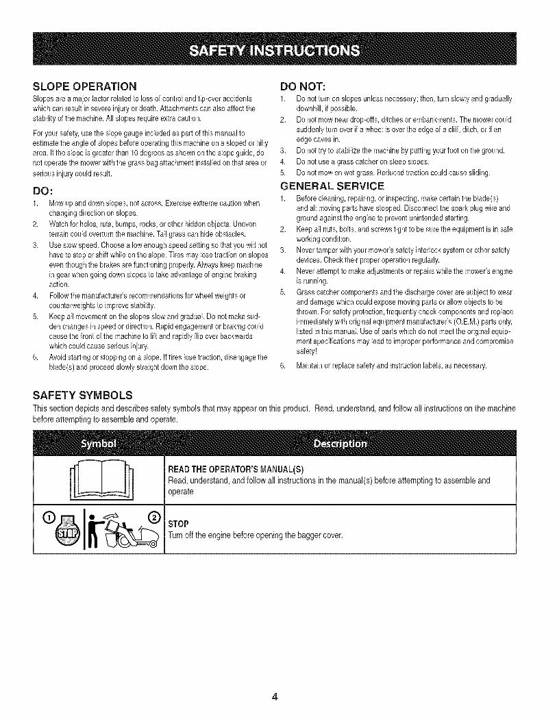
SAFETY SYMBOLS
This section depicts and describes safety symbols that may appear on this product. Read, understand, and follow all instructions on the machine
before attempting to assemble and operate.
II
READTHEOPERATOR'SMANUAL(S)Read,understand,andfollowall instructionsin the manual(s)beforeattemptingto assembleandoperate
STOPTurnoff the enginebeforeopeningthe baggercover.
4
(OK)
10° Slope
(TOO STEEP)
10° Slope
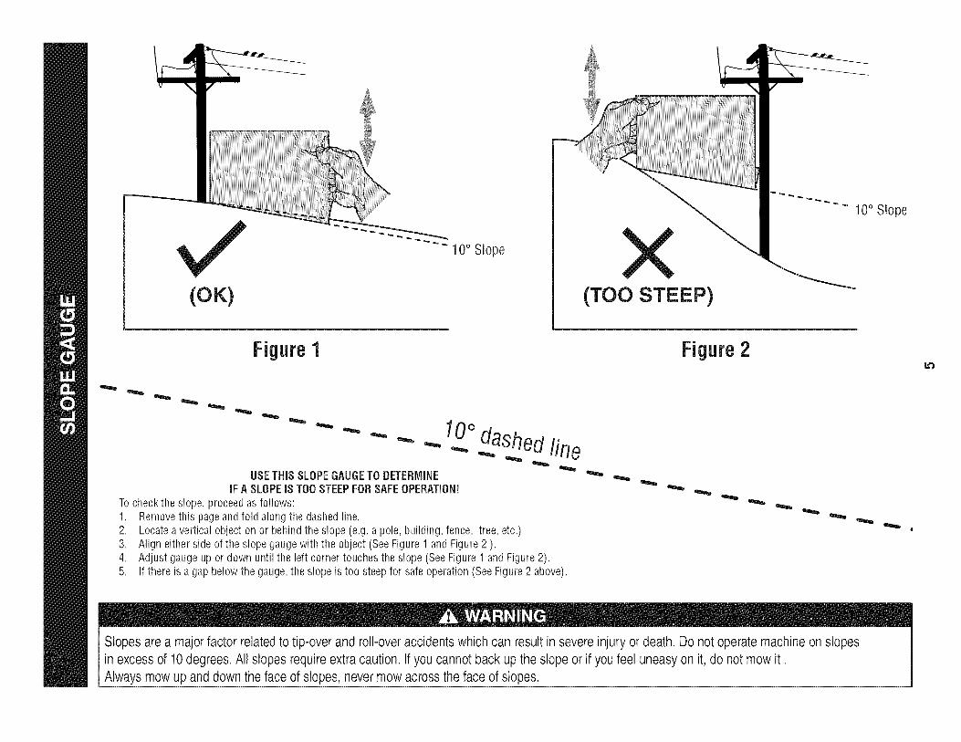
Figure 1
USETHiSSLOPEGAUGETO DETERMINEiFA SLOPEiS TOOSTEEPFORSAFEOPERATION!
Tocheckthe slope,proceedas follows:1. Removethis pageandfold alongthe dashedline.2. Locateavertical objectonor behindthe slope(e.g.a pole,building,fence, tree,etc.)3. Aligneither sideof the slopegaugewith the object (SeeFigure1 andFigure2 ).4. Adjustgaugeup or down until the left cornertouchesthe slope(SeeFigure1 andFigure2).5.
10odashedline
If there is a gapbelowthe gauge,the slope is too steepfor safeoperation(SeeFigure2 above).
Figure2
Slopes are a majorfactor related to tip-over and roll-over accidents which can result in severe injury or death. Do not operate machineon slopesin excess of 10degrees. All slopes requireextra caution, if you cannot back up the slope or if you feel uneasy on it, do not mow it.Always mow up and down the face of slopes, nevermow across the face of slopes.
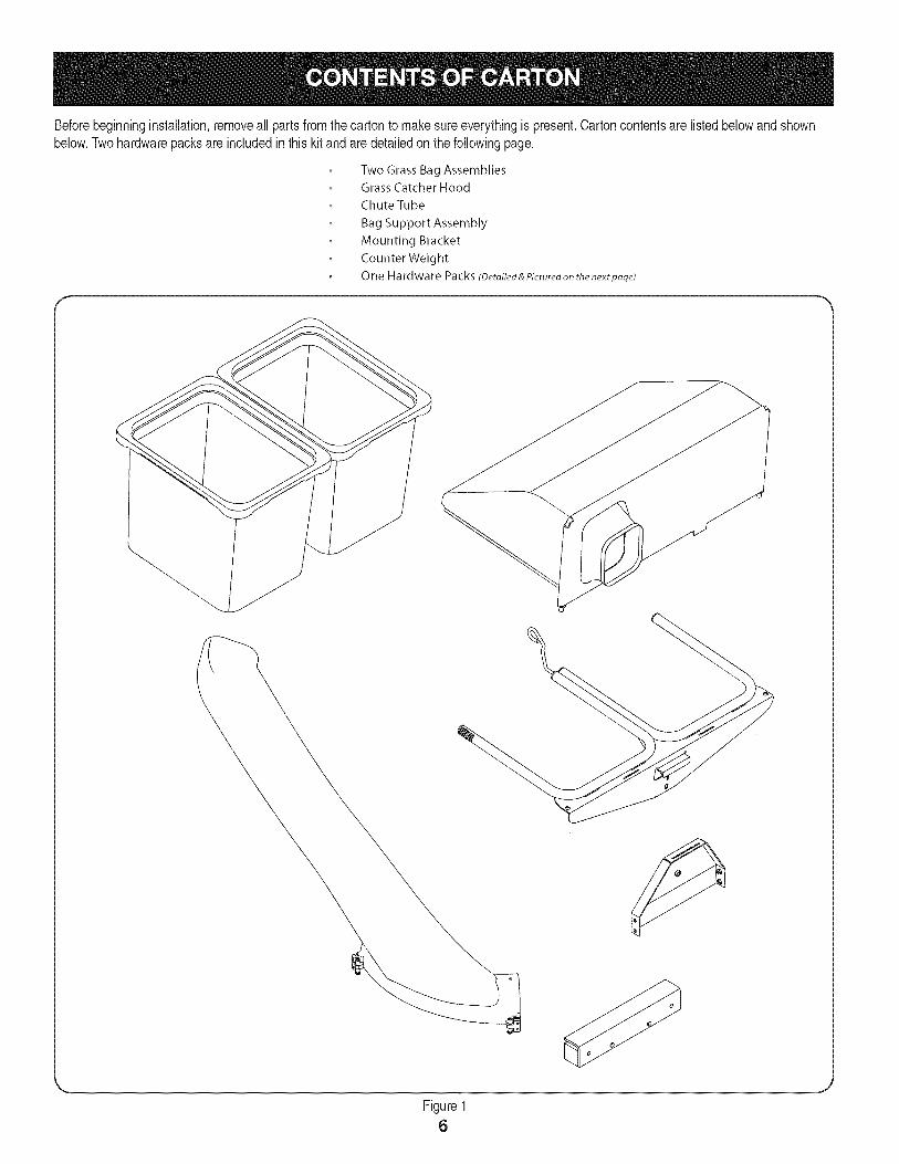
Beforebeginninginstallation,removeall parts fromthe cartonto makesureeverythingis present.Cartoncontentsare listedbelowand shownbelow.Twohardwarepacksare includedin thiskit andaredetailedonthe followingpage.
Two Grass Bag Assemblies
Grass Catcher Hood
Chute Tube
Bag Support Assembly
Mounting Bracket
CounterWeight
One Hardware Packs (Detoited&Picturedonthe nextpoge)
Figure16
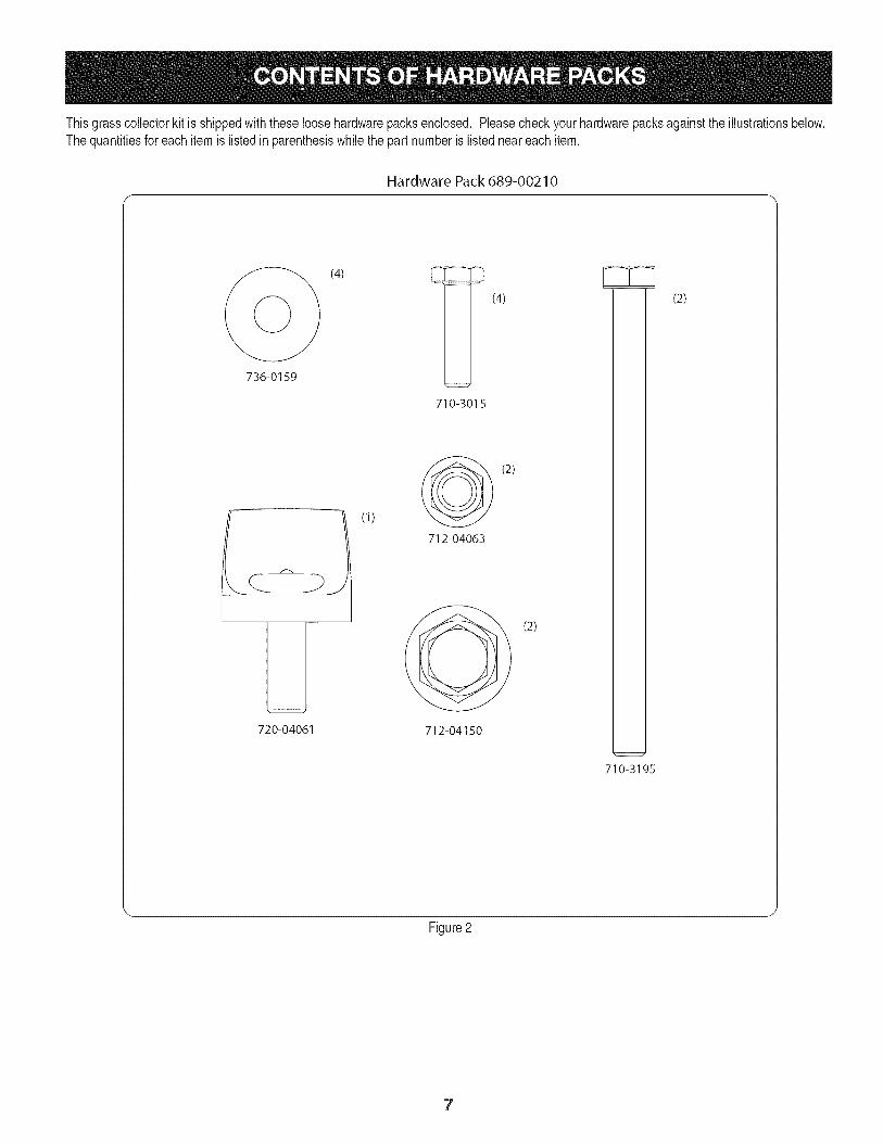
Thisgrasscollectorkit is shippedwith theseloosehardwarepacksenclosed, Pleasecheckyourhardwarepacksagainstthe illustrationsbelow,The quantitiesfor eachitemis listed inparenthesiswhilethe part numberis listedneareach item.
Hardware Pack 689-00210
(4) _ (4)
736-0159
LJ720-04061
(1)
710-3015
(2)
712-04063
(2)
712-04150
710-3195
(2)
Figure2
7
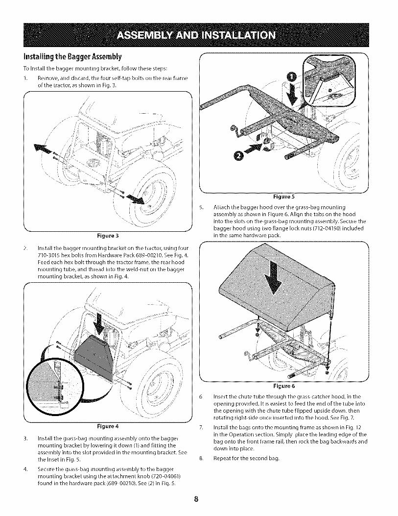
Installingthe BaggerAssemblyTo install the bagger mounting bracket, follow these steps:
1. Remove, and discard, the four self-tap bolts on the rear frame
of the tractor, as shown in Fig. 3.
//
/2'
/
/
//
Figure 3
5_
Figure 5
Attach the bagger hood over the grass-bag mounting
assembly as shown in Figure 6. Align the tabs on the hood
into the slots on the grass-bag mounting assembly. Secure the
bagger hood using two flange lock nuts (712-04150) included
in the same hardware pack.
2_ Install the bagger mounting bracket on the tractor, using four
710-3015 hex bolts from Hardware Pack 689-00210. See Fig. 4.
Feed each hex bolt through the tractor frame, the rear hood
mounting tube, and thread into the weld-nut on the baggermounting bracket, as shown in Fig. 4.
//
Figure 4
3. Install the grass-bag mounting assembly onto the baggermounting bracket by lowering it down (1) and fitting theassembly into the slot provided in the mounting bracket. Seethe Inset in Fig. 5.
4. Secure the grass-bag mounting assembly to the baggermounting bracket using the attachment knob (720-04061)found in the hardware pack (689-00210). See (2)in Fig. 5.
Figure 6
6. Insert the chute tube through the grass-catcher hood, in the
opening provided. It is easiest to feed the end of the tube into
the opening with the chute tube flipped upside down, thenrotating right-side once inserted into the hood. See Fig. 7.
7. Install the bags onto the mounting frame as shown in Fig. 12
in the Operation section. Simply place the leading edge of the
bag onto the front frame rail, then rock the bag backwards and
down into place.
8. Repeatforthesecond bag.
8
9.
10.
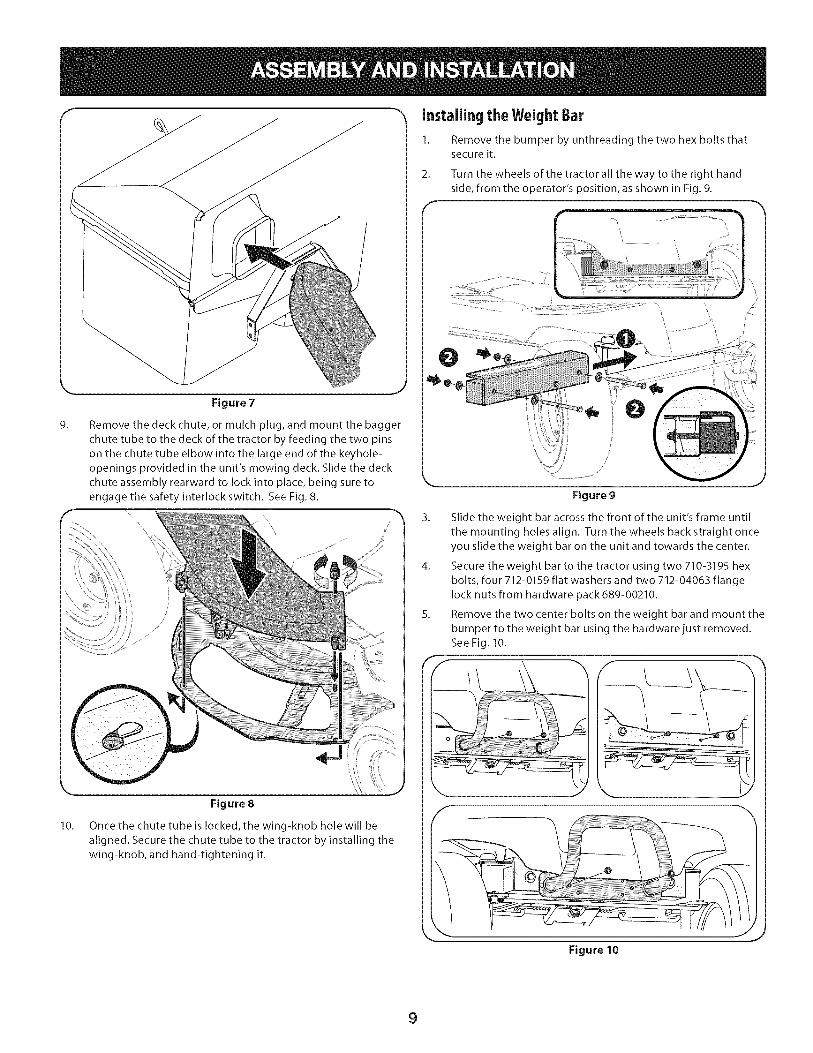
Figure 7
Remove the deck chute, or mulch plug, and mount the bagger
chute tube to the deck of the tractor by feeding the two pins
on the chute tube elbow into the large end of the keyhole-openings provided in the unit's mowing deck. Slide the deck
chute assembly rearward to lock into place, being sure to
engage the safety interlock switch. See Fig. 8.
\\
J
Figure 8
Once the chute tube is locked, the wing-knob hole will be
aligned. Secure the chute tube to the tractor by installing the
wing-knob, and hand-tightening it.
Installing the WeightBar
1. Remove the bumper by unthreading the two hex bolts thatsecure it.
2. Turn the wheels of the tractor all the way to the right hand
side, from the operator's position, as shown in Fig. 9.
Figure 9
3. Slide the weight bar across the front of the unit's frame until
the mounting holes align. Turn the wheels back straight once
you slide the weight bar on the unit and towards the center.
4. Secure the weight bar to the tractor using two 710-3195 hex
bolts, four 712-0159 flat washers and two 712-04063 flangelock nuts from hardware pack 689-00210.
5. Remove the two center bolts on the weight bar and mount the
bumper to the weight bar using the hardware just removed.
See Fig. 10.
\
Figure 10
9
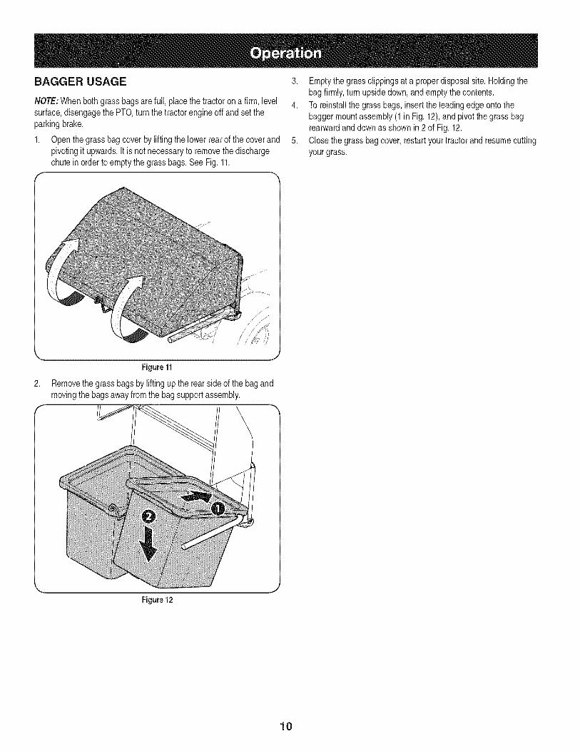
BAGGER USAGE
NOTE:Whenboth grassbagsarefull, placethe tractorona firm, levelsurface,disengagethe PTO,turnthe tractorengineoff andset theparkingbrake.
1. Openthe grassbagcoverby liftingthe lowerrearof the coverandpivotingit upwards.It is not necessaryto removethe dischargechute inorder toemptythe grassbags.See Fig.11.
3. Emptythe grassclippingsat a properdisposalsite. Holdingthebagfirmly,turn upsidedown,and emptythecontents.
4. To reinstallthe grassbags,insert the leadingedgeontothebaggermountassembly(1 in Fig.12),andpivot the grassbagrearwardanddownas shown in2 of Fig. 12.
5. Closethegrassbagcover,restartyourtractorandresumecuttingyourgrass.
Figure 11
2. Removethe grassbagsby liftingupthe rearsideof the bagandmovingthebagsawayfromthe bagsupportassembly.
Figure 12
10

This page intentionally left blank. Use this page to make any notes regarding your tractor.
11
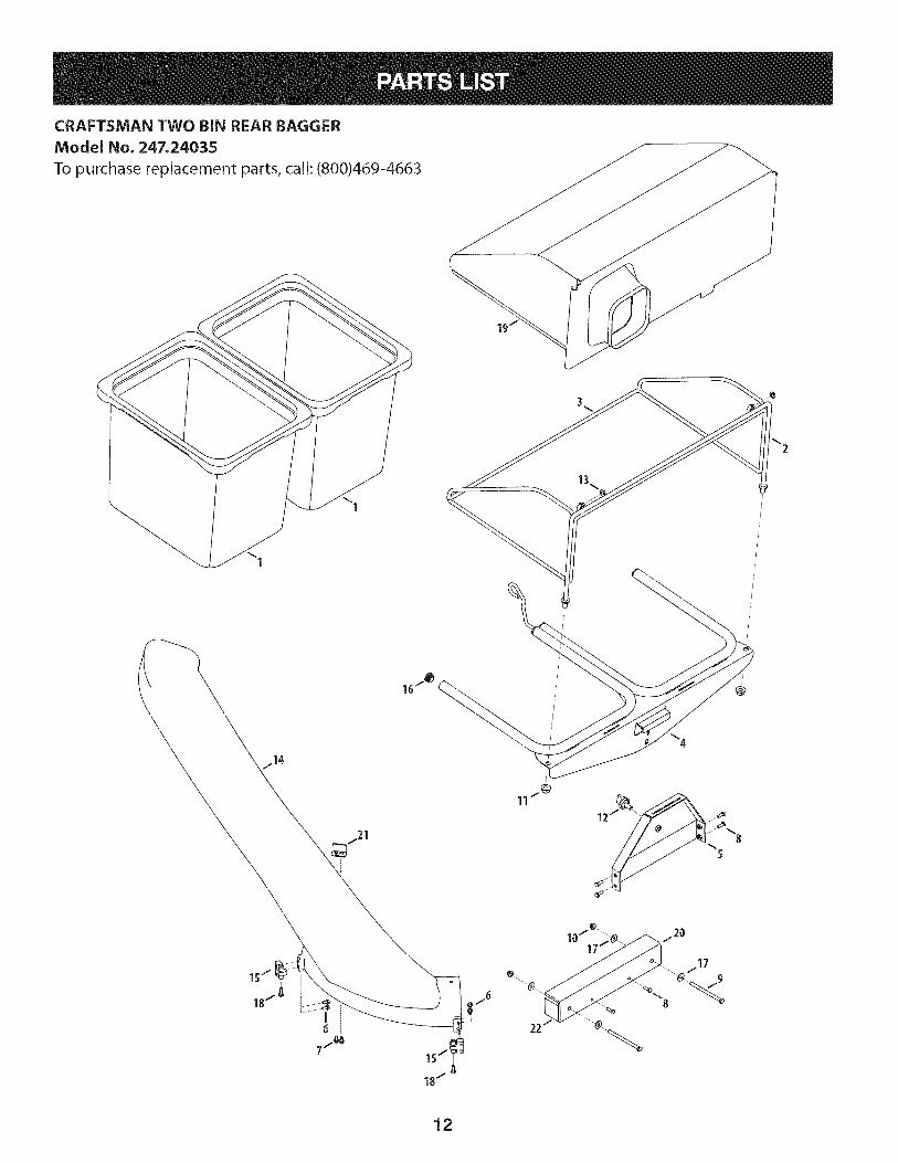
CRAFTSMAN TWO BIN REAR BAGGER
Model No. 247.24035
To purchase replacement parts, call: (800)469-4663
12

!
Ref, I Part Number
1. 664-04167
2. 683-04771
3. 683-04772
4. 683-04775
5. 683-04781
6. 710-0895
Z 710-0599
8. 710-3015
9. 710-3195
lO. 712-04063
II. 712-04150
12. 720-04061
13. 726-0100
14. 731-08548
15. 731-08834
16. 735-0246A
17. 736-0159
18. 738-04519
19. 764-04148
20. 783-07380
21. 783-07286
22. 783-07379
Description
Grass Bag
Front Hood Assembly Frame
Rear Hood Assembly Frame
Bagger Support Assembly
Mounting Bracket
Hex Lock Screw, 1/4-15, 0.75
Tap Screw, 1/4-20, 0.500
Hex Head Screw, 1/4-20, .75
Hex Head Screw, 5/16-18, 4.50
Flange Lock Nut, 5/16-18
Flange Lock Nut, 1/2-13
Knob, 3/8-16, .875
Push Cap, 3/8 ROD
Chute Tube
Chute Mount Bracket
Plug End
Flat Washer, .349 x .879 x .063
Shoulder Screw, 1/4-15, .750
Grass Catcher Hood
Weight Bar Mounting Bracket
Boot Switch Safety Bracket
Weight Bar
13
Garant[a ........................................................................ 14
Medidas importantes de seguridad ............................. 15Gu_a pendiente de ........................................................ 17Contenido de la caja y paquetes de hardware ..............18Montaje e Instalaci6n ................................................... 20operaci6n de ............................................................... 22Lista de piezas ............................................................ 12
Craftsman Un ASo De Garantia
Duranteun aSodesdelafechadecompra,esteproductoest&garantizadocontracualquierdefectode materialeso manode obra. Unproductodefectuososer&reemplazadodeformagratuita.
Forwarrantycoveragedetailsto obtainfree replacement,visit theweb site:www.craftsman.com
Thiswarrantydoesnot coverbags,whichareexpendableparts thatcanwear outfromnormalusewithinthe warrantyperiod.
Thiswarrantyis void if thisproductis everusedwhile providingcommercialservicesor if rentedto anotherperson.
Thiswarrantygivesyou specificlegal rights,andyou mayalso haveotherrightswhichvaryfromstateto state.
Sears Brands Management Corporation, Hoffman Estates, IL 60179
© SearsBrands,LLC 14

Lapresenciadeeste sirnboloindicaque setratade instruccionesirnportantesde seguridadquese debenrespetarparaevitarponerenpeligrosu seguridadpersonaly/o materialy lade otraspersonas.Leay siga todaslas instruccionesdeestemanualantesde poneren funcionarnientoestarnAquina.Si no respetaestasinstruccionespodriaprovocarlesionespersonales.Cuandoveaestesirnbolo,ipresteatenci6na la advertencia!
PROPOSICION 65 DE CALIFORNIA
Elescapedel motordeesteproducto,algunosde suscornponentesy algunoscornponentesdelvehiculocontieneno liberansustanciasquirnicasqueelestadodeCaliforniaconsideraque puedenproducircancer,defectosde nacirnientouotrosproblernasreproductivos.Losbornesdela bateriay los accesoriosalinescontienenplornoycornpuestosde plorno,sustanciasquirnicasque seg_nIo estableci-do porel Estadode Californiacausancancery daSosenel sisternareproductivo.Ldveselas manos despu_sde estaren contactocon estoscomponentes.
EstarnAquinarueconstruidaparaseroperadadeacuerdoconlas reglasde seguridadcontenidasenestemanual.AI igualqueconcualquiertipo deequipornotorizado,undescuidoo errorporpartedeloperadorpuedeproducirlesionesgraves.EstarnAquinaes capazde arnputarrnanosy piesy dearrojarobjetoscon granfuerza.Deno respetarlas instruccionesde seguridadsiguientessepuedenproducirlesionesgraveso larnuerte.
Su responsabilidad--Restrinja el usode estarnAquinarnotorizadaa las personasque lean,cornprendany respetenlasadvertenciase instruccionesqueaparecenen estemanualy en larnAquina.
iGUARDEESTASINSTRUCCIONES!
Fun¢ionamiento general
1. Lea, comprenda y respete todas las instrucciones que figuranen el equipo yen los manuales antes de intentar armarlo yhacerlo funcionar. Guarde este manual en un lugar seguropara consultas futuras y peri6dicas, asi como para solicitarrepuestos.
2. Para ayudar a evitar una lesi6n pot contacto con las cuchillaso con un objeto que sea arrojado, mantenga alas personasque observan, a los ayudantes, ni_os y mascotas alejados a nomenos de 25 metros de la m_quina mientras est& funcionando.Detenga la m&quina si alguien entra en la zona.
3. Revise minuciosamente el _irea donde se va a usar el equipo.Retire todas las piedras, palos, cables, huesos, juguetes y otrosobjetos extra6os que podrian set recogidos y arrojados por laacci6n de las cuchillas. Los objetos arrojados por la m&quinapueden causar lesiones graves.
4. Para protegerse los ojos, utilice siempre galas o lentes deseguridad mientras opera la m&quina o mientras la ajustao repara. Los objetos arrojados que rebotan pueden causarlesiones oculares graves.
5. Nunca opere la cortadora de c_sped sin tenet bien colocadala cubierta de descarga o el colector de c_sped. Si falta o
est_ da6ada la cubierta de descarga oun componente delaccesorio embolsador puede resultar en lesiones por contacto
con la cuchilla o con objetos arrojados.
6. No ponga las manos ni los pies cerca de las piezas rotatorias nidebajo de la plataforma de corte. El contacto con las cuchillaspuede resultar en la amputaci6n de una mano o pie.
7. Apague el motor de la cortadora de c_sped y espere quelas cuchillas se detengan totalmente antes de desbloquearla abertura de descarga de la cortadora o las piezas de laembolsadora.
8. Reduzca la velocidad antes de girar. Opere la m&quina de
forma pareja. Evite el funcionamiento err_itico y la velocidadexcesiva. Tenga en cuenta que el accesorio colector de c_sped
puede afectar las caracteristicas de manejo de su cortadora.
Fundonamiento en pendientes
Las pendientes son un factor importante en los accidentes
ocasionados pot p_rdida de control y vuelcos que pueden causarlesiones graves e incluso la muerte. Los accesorios tambien puedenafectar la estabilidad de la m&quina. La operaci6n en pendiente
requiere mayor precauci6n.
Para seguridad, use el medidor de pendientes que se incluye comoparte de este manual para estimar el _ingulo de la pendiente antesde hacer funcionar la m_iquina en una zona inclinada. Si la pendiente
es mayor a 10 grados en el medidor, no opere la cortadora con elaccesorio embolsador en ese sector, pues podria causar lesiones
graves.
HagaIo siguiente:
1. Corte hacia arriba y abajo de las pendientes, no en formatransversal. Tenga sumo cuidado al cambiar de direcci6n enuna pendiente.
2. Est_ atento a los hoyos, surcos, baches, rocas, u otros objetosocultos. El terreno desnivelado puede voltear la m&quina. Elpasto alto puede ocultar obst_iculos.
3. Conduzca a baja velocidad. Elija una velocidad Iosuficientemente baja como para no tener que detenerseo cambiar de marcha mientras est,1 en la pendiente. Losneum_ticos pueden perder tracci6n en las pendientes auncuando los frenos funcionen correctamente. Mantengala m&quina siempre en velocidad cuando desciende unapendiente, para poder frenar con el motor.
15
4. Siga las recomendaciones del fabricante sobre pesos ycontrapesos de las ruedas, para mejorar la estabilidad.
5. Haga que todos los movimientos en las pendientes seanlentos y graduales. No cambie repentinamente la velocidadni la direcci6n. Un frenado o cambio de velocidad repentinospueden causar que el frente de la m_quina se levante y d6 unavoltereta hacia atr_s, Io que podria causar lesiones graves.
6. Evite arrancar o detenerse en una pendiente. Si los neum_ticospierden tracci6n, desenganche las cuchillas y desciendalentamente la pendiente.
No haga I0siguiente:
I. No gire en una pendiente a menos que sea imprescindible. De
ser posible, gire lenta y gradualmente cuesta abajo.
2. No corte el c_sped cerca de barrancos, zanjas o terraplenes. Lacortadora de c_sped podria volcarse repentinamente si una de
las ruedas estuviera sobre el borde de un acantilado o zanja, osi un borde se desmoronara.
3. No intente estabilizar la m_quina poniendo el pie en el suelo.
4. No utilice un colector de c_sped en pendientes empinadas.
5. No corte el c_sped humedo. Una reducci6n en tracci6n puede
causar derrapes.
Servid0 general
I. Antes de limpiar, reparar o inspeccionar la m_quina,
compruebe que las cuchillas y todas las piezas m6viles se
hayan detenido. Desconecte el cable de la bujia y p6ngalohaciendo masa contra el motor para evitar que arranqueaccidentalmente.
2. Mantenga todas las tuercas, pernos y tornillos bien ajustados
para asegurarse de que el equipo est_ en condiciones seguras
de operaci6n.
3. Nunca intente violar el sistema de bloqueo de seguridad u
otros mecanismos de seguridad de la cortadora. Controle
peri6dicamente que funcionan correctamente.
4. No intente nunca hacer ajustes o reparaciones a la cortadoramientras el motor est_ en marcha.
5. Los componentes del colector de c6sped y la cubierta de
descarga est_n sujetos a desgaste y daffos que podrian dejarexpuestas piezas que se mueven o permitir que se arrojen
objetos. Para proteger su seguridad, verifique frecuentemente
todos los componentes y reempl_celos inmediatamente0nicamente con piezas de los fabricantes del equipo original
(O.E.M.) indicados en este manual. El uso de piezas que no
cumplen con las especificaciones del equipo original puede
resultar en rendimiento inadecuado y puede poner en peligro
la seguridad.
6. Mantenga o reemplace las etiquetas de seguridad y deinstrucciones seg0n sea necesario.
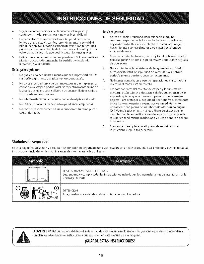
Simbolosde segufidad
En esta p_gina se presentan y describen los simbolos de seguridad que pueden aparecer en este producto. Lea, entienda y cumpla todas las
instrucciones incluidas en la m_quina antes de intentar armarla y utilizarla.
LEA LOS MANUALES DEL OPERADOR
Lea, entienda y cumpla todas las instrucciones incluidas en los manuales antes de intentar armar la
unidad y utilizarla.
DETENCION
Apague el motor antes de abrir la cubierta de la embolsadora.
iADVERTENCIA! Su responsabilidad--Limiteel usodeesta m_.quinamotorizadaalas personasque lean,comprendanycumplanlasadvertenciase instruccionesqueapareceneneste manualyen lam_.quina.
iGLIARDEESTASINSTRL!CCIONES!
16
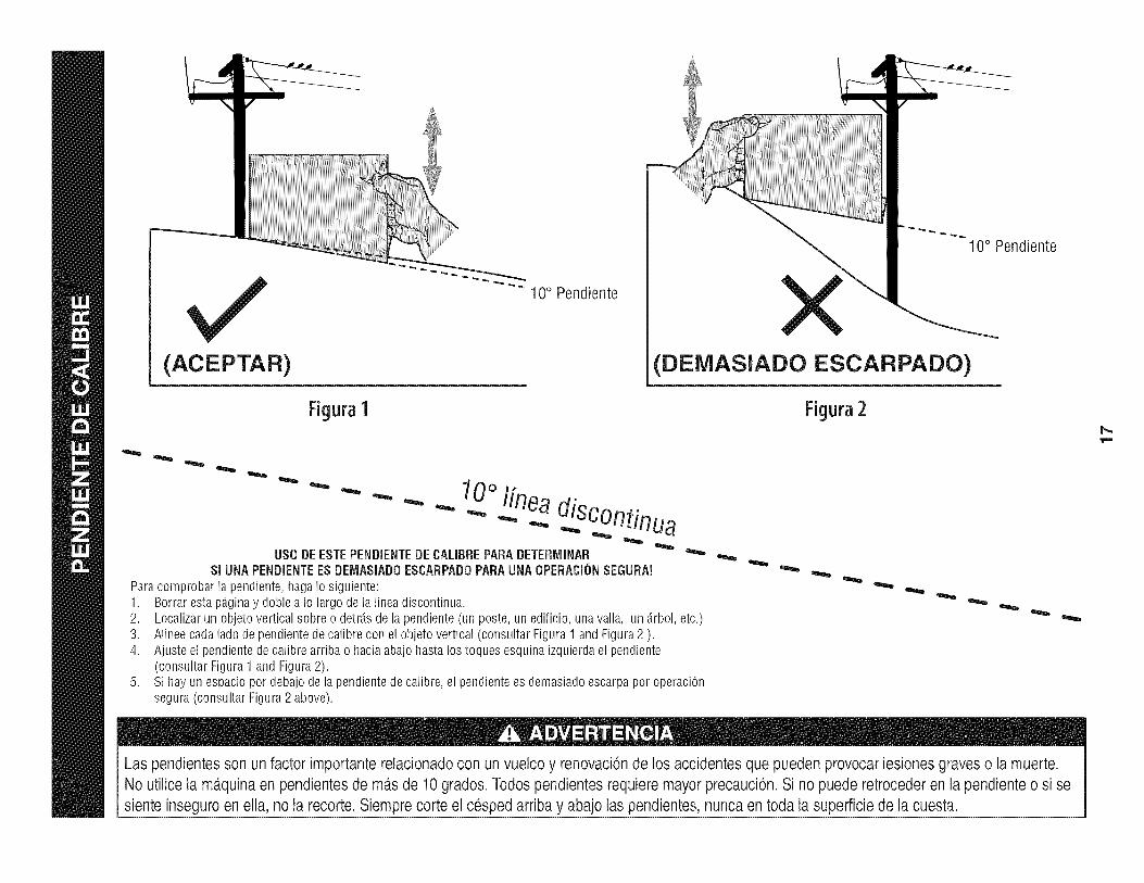
(ACEPTAR)
Figura1
"" 10° Pendiente
10° Pendiente
(DEiVIASlADO ESCARPADO)
Figura2
0oI[nea- - " "" - _ .-...diSC°ntinua
US0 DEESTEPENDIENTEDECALIBREPARADETERiVIINARSI UNAPENDiENTEESDEIV1ASiADOESCARPADOPARAUNAOPERACi(_NSEGURA!
Paracomprobarlapendiente,hagaIosiguiente:1. Borrarestap_.ginay dobleaIo largodela lineadiscontinua.2.3.4.
Localizarun objetoverticalsobreo detrJ.sdelapendiente(unposte,unedificio,unavalla, un _.rbol,etc.)Alineecadaladodependientedecalibrecon elobjetovertical(consultarFigura1 andFigura2 ).Ajusteel pendientedecalibrearribao haciaabajohastalos toquesesquinaizquierdael pendiente(consultarFigura1andFigura2).Sihayun espaciopordebajodela pendientedecalibre,el pendientees demasiadoescarpaporoperaciOnsegura(consultarFigura2 above).
Las pendientesson un factor importante relacionadocon un vuelco y renovaci6nde los accidentesque pueden provocar lesionesgraves o la muerte.No utilice la m_.quinaen pendientes de m_.sde 10grados. Todos pendientesrequiere mayorprecauci6n.Si no puede retroceder en la pendiente o si sesiente inseguro en ella, no la recorte. Siempre corte el cesped arriba y abajo laspendientes, nunca en toda la superficiede la cuesta.
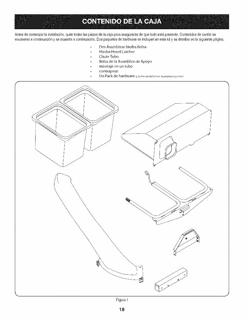
Antesdecomenzarla instalaci6n,quitetodaslas piezasde lacaja paraasegurarsedeque todoest,.presente.Contenidosde cart6nseenumerana continuaci6ny se muestraa continuaci6n.Dospaquetesde hardwarese incluyenenestekity se detallanen lasiguientep_.gina.
o
o
o
o
o
o
Dos Asambleas hierba Bolsa
Hierba Hood Catcher
Chute Tubo
Bolsa de la Asamblea de Apoyo
montaje en un tubo
contrapesoUn Pack de hardware (ylafotodetatladaenlapbginasiguiente)
Figura1
18
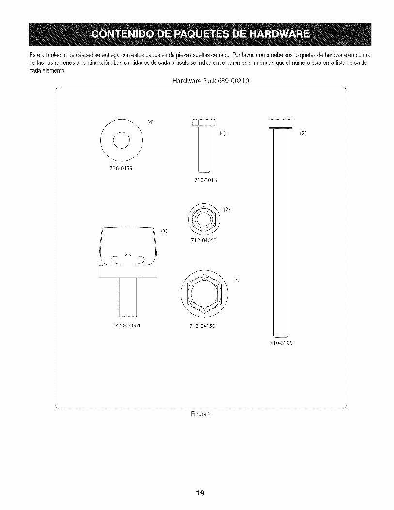
Estekit colectorde c_spedse entregacon estospaquetesdepiezassueltascerrado.Porfavor,compruebesuspaquetesde hardwareen contrade las ilustracionesa continuaci6n.Lascantidadesde cadaarticuloseindicaentre par_ntesis,mientrasqueel nQmeroest,.en la listacercadecada eiemento.
Hardware Pack 689-00210
(4) _ (4)
736-0159
720-04061
(1)
710-3015
(2)
712-04063
(2)
712-04150
710-3195
(2)
Figura2
19
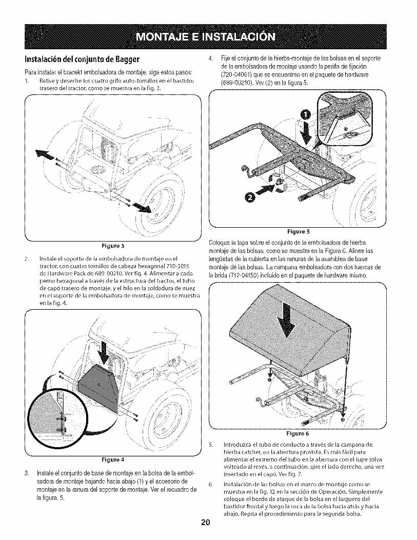
Instalaci6ndeiconjunto deBagger
Parainstalarel bracektembolsadorade montaje,siga estospasos:1. Retire y deseche los cuatro grifo auto-tornillos en el bastidor
trasero del tractor, como se muestra en la fig. 3.
, Fijeel conjuntode la hierba-montajede las bolsasenel soportede laembolsadorade montajeusandola perilladefijaci6n(720-04061)que seencuentranenel paquetede hardware(689-00210).Ver(2) enla figura5.
2_
\
Figure 3
Instale el soporte de la embolsadora de montaje en el
tractor, con cuatro tornillos de cabeza hexagonal 710-3015de Hardware Pack de 689-00210. Ver fig. 4. Alimentar a carla
perno hexagonal a trav6s de la estructura del tractor, el tubo
de cap6 trasero de montaje, y el hilo en la soldadura de nuez
en el soporte de la embolsadora de montaje, como se muestra
en la fig. 4.
Coloquela tapasobreel conjuntode laembolsadoradehierbamontajede las bolsas,comose muestraen la Figura6. Alineelasleng0etasde lacubiertaen las ranurasdela asambleade basemontajede las bolsas.Lacampanaembolsadoracon dos tuercasdela brida(712-04150)incluidoenel paquetedehardwaremismo.
,
Figure 4
Instaleel conjuntodebasede rnontajeen la bolsadela embol-sadorade montajebajandohaciaabajo(1)y el accesoriodemontajeen la ranuradelsoportede montaje.Verel recuadrodelafigura.5.
5. Introduzca el tubo de conducto a trav6s de la campana de
hierba catcher, en la abertura provista. Es m_is f_icil para
alimentar el extremo del tubo en la abertura con el tupe tolva
volteado al rev6s, a continuaci6n, gire el lado derecho, una vez
insertado en el cap6. Ver fig. 7.
6. Instalaci6n de las bolsas en el marco de montaje como semuestra en la fig. 12 en la secci6n de Operaci6n. Simplemente
coloque el borde deataque de la bolsa en el larguero del
bastidor frontal y luego la roca de la bolsa hacia atr_is y hacia
abajo. Repita el procedimiento para la segunda bolsa.
Figure 6
20
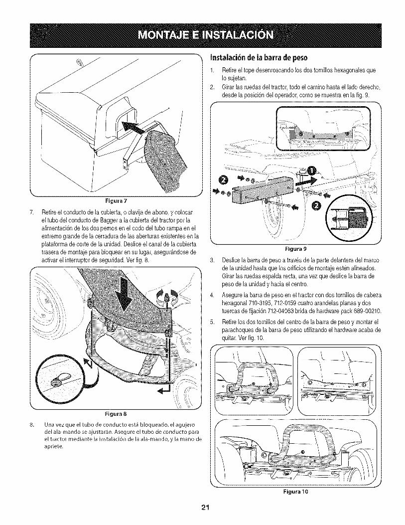
7.
.J
Figura 7
Retireel conductodela cubierta,o clavijade abono,y colocarel tubodelconductode Baggera lacubiertadel tractorpor laalimentaci6ndelos dos pernosen elcodo del tubo rampaenelextremograndede lacerraduradelas aberturasexistentesen laplataformadecortede la unidad.Desliceelcanalde lacubiertatraserademontajeparabloquearen su lugar,asegur_.ndosedeactivarel interruptorde seguridad.Vet fig.8.
\
Instalaci6n de ia barra de peso
1. Retireel topedesenroscandolos dos tornilloshexagonalesqueIo sujetan.
2. Girar las ruedasdel tractor,todoel caminohastael ladoderecho,desdela posici6ndeloperador,comose muestraen la fig.9.
\
Figura 9
3. Deslicelabarradepesoa travesde la partedelanteradelmarcode launidadhastaquelosorificiosde montajeest_nalineados.Girar las ruedasespaldarecta,unavezquedeslice labarradepesode launidady haciaelcentro.
4. Asegurela barrade pesoenel tractorcon dos tornillosdecabezahexagonal710-3195,712-0159cuatroarandelasplanasy dostuercasde fijaci6n712-04063bridade hardwarepack689-00210.
5. Retirelos dostornillosdel centrodela barrade pesoy montarelparachoquesde labarradepeso utilizandoelhardwareacabadequitar.Verfig. 10.
Una vez que el tubo de conducto est& bloqueado, el agujero
del ala-mando se ajustar,:in. Asegure el tubo de conducto para
el tractor mediante la instalaci6n de la ala-mando, y la mano deapriete.
Figura 10
21
BAGGER USO
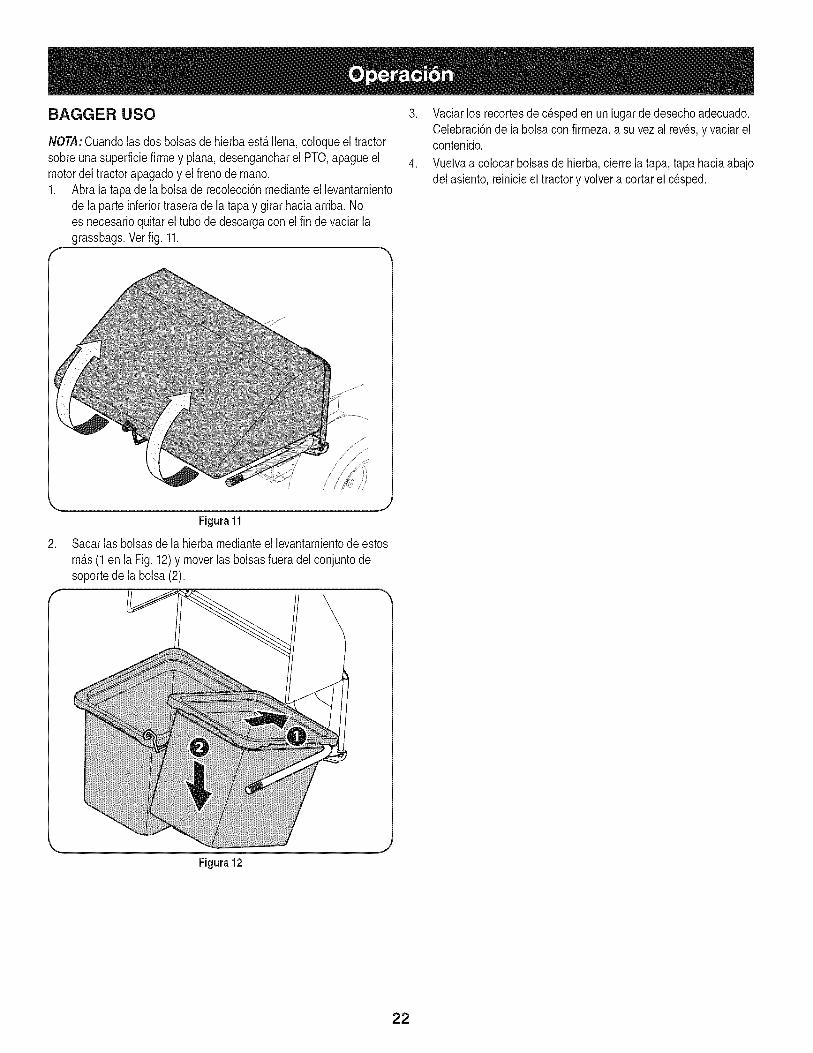
NOTA:Cuandolas dosbolsasdehierbaest,. llena,coloqueel tractorsobreunasuperfMefirmey plana,desengancharel PTO,@agueelmotordel tractorapagadoy el frenode mano.1. Abra la tapa dela bolsade recolecd6nmedianteel levantamiento
de laparte inferiortraserade la tapay girarhaciaarriba. Noes necesarioquitarel tubode descargacon el fin de vaciarlagrassbags.Ver fig. 11.
r
3. Vaciarlos recortesdec_speden unlugardedesechoadecuado.Celebraci6nde labolsacon firmeza,asu vezal reves,y vaciarelcontenido.
4. Vuelvaa colocarbolsasde hierba,cierrela tapa, tapa haciaabajodel asiento,reinicieel tractory volvera cortarel cesped.
2.
Figura 11
Sacarlas bolsasdela hierbamedianteel levantamientode estos
m_.s(1en la Fig.12)y moverlas bolsasfueradel conjuntodesoportede labolsa(2).
Figura 12
22

Esta pagina se dej6 intencionalmente en blanco. Utilice esta pagina para tomar notas acerca de su tractor.
23

Your HomeFor troubleshooting, product manuals and expert advice:
managernylifewww.managemylife.com
For repair - in your home - of all major brand appliances,lawn and garden equipment, or heating and cooling systems,
no matter who made it, no matter who sold it!
For the replacement parts, accessories andowner's manuals that you need to do-it-yourself.
For Sears professional installation of home appliancesand items like garage door openers and water heaters.
1-800-4-MY-HOME ® (1-800-469-4663)
Call anytime, day or night (U.S.A. and Canada)
www.sears.com www.sears.ca
Our Home
For repair of carry-in items like vacuums, lawn equipment,and electronics, call anytime for the location of your nearest
Sears Parts & Repair Service Center
1-800-488-1222 (U.S.A.) 1-800-469-4663 (Canada)www.sears.com www.sears.ca
To purchase a protection agreement on a product serviced by Sears:
1-800-827-6655 (U.S.A.) 1-800-361-6665 (Canada)
Para pedir servicio de reparaci6na domicilio, y para ordenar piezas:
1-888-SU-HOGAR ®
(1-888-784-6427)www.sears.com
Au Canada pour service en frangais:
1-800-LE-FOYER Mc
(1-800-533-6937)www.sears.ca
® Registered Trademark / TMTrademark of KCD IP, LLC in the United States, or Sears Brands, LLC in other countries® Marca Registrada ! TMMarca de Fabrica de KCD IP, LLC en Estados Unidos, o Sears Brands, LLC in otros paisesMCMarque de commerce ! MDMarque deposee de Sears Brands, LLC


![[Wess Bagger]Supersymmetry and Supergravity](https://img.dokumen.tips/doc/110x75/55cf8eb6550346703b94d652/wess-baggersupersymmetry-and-supergravity.jpg)