Embed Size (px)
Citation preview

-30°C Laboratory FreezersTSX Series
Installation and Operation
327932H01 Rev. H September 2021
Visit us online to register your warrantywww.thermofisher.com/labwarranty

IMPORTANT Read this instruction manual. Failure to follow the instructions in this manual can result in damage to the unit, injury to operating personnel, and poor equipment performance.
CAUTION All internal adjustments and maintenance must be performed by qualified service personnel.
Material in this manual is for informational purposes only. The contents and the product it describes are subject to change without notice. Thermo Fisher Scientific makes no representations or warranties with respect to this manual. In no event shall Thermo be held liable for any damages, direct or incidental, arising from or related to the use of this manual.
© 2021 Thermo Fisher Scientific Inc. All rights reserved.
For your future reference and when contacting the factory, please have the following information readily available. It can be found on the dataplate attached to your unit.
Model Number:
Serial Number:
The following information, if available, is helpful for contacting the factory.
Date Purchased:
Purchase order number:
Source of Purchase:
(manufacturer or specific agent/rep organization)
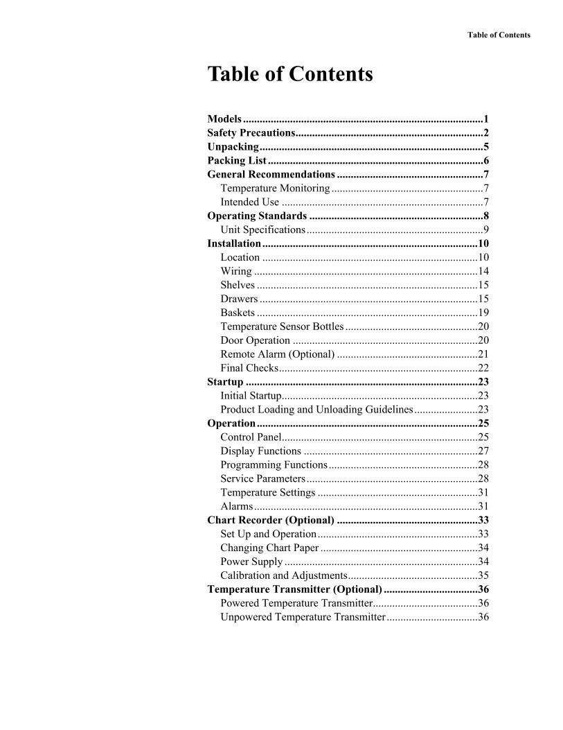
Table of Contents
Table of Contents
Models .......................................................................................1Safety Precautions....................................................................2Unpacking.................................................................................5Packing List ..............................................................................6General Recommendations .....................................................7
Temperature Monitoring .......................................................7Intended Use .........................................................................7
Operating Standards ...............................................................8Unit Specifications................................................................9
Installation..............................................................................10Location ..............................................................................10Wiring .................................................................................14Shelves ................................................................................15Drawers ...............................................................................15Baskets ................................................................................19Temperature Sensor Bottles ................................................20Door Operation ...................................................................20Remote Alarm (Optional) ...................................................21Final Checks........................................................................22
Startup ....................................................................................23Initial Startup.......................................................................23Product Loading and Unloading Guidelines.......................23
Operation................................................................................25Control Panel.......................................................................25Display Functions ...............................................................27Programming Functions......................................................28Service Parameters ..............................................................28Temperature Settings ..........................................................31Alarms.................................................................................31
Chart Recorder (Optional) ...................................................33Set Up and Operation..........................................................33Changing Chart Paper .........................................................34Power Supply ......................................................................34Calibration and Adjustments...............................................35
Temperature Transmitter (Optional) ..................................36Powered Temperature Transmitter......................................36Unpowered Temperature Transmitter .................................36

Table of Contents
Maintenance ...........................................................................37Cleaning the Cabinet Interior ..............................................37Cleaning the Condenser Filter.............................................37Cleaning the Condenser ......................................................37Automatic Defrost...............................................................38Gasket Maintenance............................................................38Alarm Battery Maintenance ................................................38Preparation for Storage .......................................................38Probe Recalibration Schedule .............................................38
Troubleshooting .....................................................................39End of Life Care.....................................................................41Warranty ................................................................................42

Models
Thermo Scientific TSX -30°C Laboratory Freezers 1
1 Models The table below shows the units covered in this operation and installationmanual by model number. Refer to Section 6.1 for details on the voltagespecifications for the various models.
Table 1. Applicable Models
Unit Model (*) Energy Star Model (*)
Thermo Scientific - TSX1230F* V/Y/Z A/D
Thermo Scientific - TSX2330F* V/Y/Z A/D
Thermo Scientific - TSX3030F* V/Y/Z A/D
Thermo Scientific - TSX5030F* V/Y/Z A/D

Safety Precautions
2 TSX -30°C Laboratory Freezers Thermo Scientific
2 Safety Precautions In this manual, the following symbols and conventions are used:
This symbol when used alone indicates important operating instructions whichreduce the risk of injury or poor performance of the unit.
WARNING: This symbol indicates potentially hazardous situations which,if not avoided, could result in serious injury or death.
WARNING: This symbol indicates situations where dangerous voltagesexist and potential for electrical shock is present.
WARNING: This symbol indicates potentially hazardous situations, whichif not avoided could result in fire.
CAUTION: This symbol, in the context of a CAUTION, indicates apotentially hazardous situation which if not avoided could result in minor tomoderate injury or damage to the equipment.
CAUTION: This indicates a situation which may result in propertydamage.
This symbol indicates surfaces which may become hot during use and may causea burn if touched with unprotected body parts.
Before installing, using or maintaining this product, please be sure to read themanual and product warning labels carefully. Failure to follow these instructionsmay cause the product to malfunction, which could result in injury or damage.
This symbol indicates possible pinch points which may cause personal injury.
The snowflake symbol indicates low temperatures and risk of frost bite. Do nottouch bare metal or samples with unprotected body parts.
This symbol indicates a need to use gloves during indicated procedures. Ifperforming decontamination procedures, use chemically resistant gloves.
This symbol indicates possible sharp points which may cause skin abrasion.

Safety Precautions
Thermo Scientific TSX -30°C Laboratory Freezers 3
Below are important safety precautions that apply to this product:
Use this product only in the way described in the product literature and in thismanual. Before using it, verify that this product is suitable for its intended use. Ifthe equipment is used in a manner not specified by the manufacturer, theprotection provided by the equipment may be impaired.
Do not modify system components, especially the controller. Use OEM exactreplacement equipment or parts. Before use, confirm that the product has notbeen altered in any way.
WARNING: Risk of Shock. Your unit must be properly grounded inconformity with national and local electrical codes. Do not connect the unitto overloaded power sources.
WARNING: Risk of Shock. Disconnect unit from all power sources beforecleaning, troubleshooting, or performing other maintenance on the productor its controls.
WARNING: Risk of Fire. This unit is not for storage of flammable materials.
WARNING: Risk of Fire. This unit is charged with hydrocarbon refrigerants.Only qualified service personnel should service this unit.
Unauthorized repair of your freezer will invalidate your warranty. Contact Technical Service at 1-800-438-4851 for additional information.
WARNING: Risk of Fire. No equipment that uses an open flame should beplaced inside the unit. This will harm the unit, hamper functionality andcompromise your safety.
WARNING: Risk of Fire. Do not use any battery powered orexternally-powered equipment in the device.
CAUTION: Risk of Abrasion. Hidden sharp edges may be present ondrawers. Use appropriate Personal Protective Equipment (such as gloves)while handling the drawers to avoid possible sharp points related injury.

Safety Precautions
4 TSX -30°C Laboratory Freezers Thermo Scientific
EMC
EMC Registration is done on this equipment for business use only. It may causeinterference when the product would be used in home.
사용자 안내문 이 기기는 업무용 환경에서 사용할 목적으로 적합성평가를받은 기기로서 가정용 환경에서 사용하는 경우 전파간섭의 우려가 있습니다 .
This equipment has been tested and found to comply with the limits for a ClassA digital device. Class A covers devices for usage in all establishments other thandomestic and that are not directly connected to a low voltage power supplynetwork, which supplies domestic environment.
This ISM device complies with Canadian ICES-001.
FCC
This equipment has been tested and found to comply with the limits for a ClassA digital device, pursuant to part 15 of the FCC Rules. These limits are designedto provide reasonable protection against harmful interference when theequipment is operated in a commercial environment. This equipment generates,uses, and can radiate radio frequency energy and, if not installed and used inaccordance with the instruction manual, may cause harmful interference to radiocommunications. Operation of this equipment in a residential area is likely tocause harmful interference in which case the user will be required to correct theinterference at his own expense.

Unpacking
Thermo Scientific TSX -30°C Laboratory Freezers 5
3 Unpacking At the time of delivery, be sure to inspect the unit packaging for damage beforesigning for the shipment. If packaging damage is present, request immediateproduct inspection and file a claim with the carrier.
Note Packaging damage does not denote that unit damage exists.
If concealed damage is found (damage that is not apparent until the item hasbeen unpacked), stop further unpacking and save all packing for carrier’sinspection. Make a written request for inspection to delivering carrier. This mustbe done within 15 days after delivery. Then file a claim with the carrier. Do not return goods to the manufacturer without written authorization.

Packing List
6 TSX -30°C Laboratory Freezers Thermo Scientific
4 Packing List Inside the freezer cabinet is a bag containing:
• Essential safety instructions, including translated versions
• Certificate of Conformance
• Warranty Card
• Safety Data Sheet for Glycerin
• Quick start guide
• Two control panel keys
• Two cabinet door keys
If the unit was ordered with shelves, the bag will also include:
• Small bag with shelving clips
If the unit was ordered with a chart recorder, the bag will also contain:
• Chart recorder pamphlet
• Extra chart recorder paper
If specified on the order, the bag may also include:
• QC temperature graph and test log
• Calibration information
Other items with your unit include:
• Power Cord
• Anti-Tip Bracket Kit (See Section 7.1.2, Table 3 for applicable models)
• Baskets, Shelves or Drawers
• Thermal Bottles
Manual Label provides link to Installation and Operation Manual for the unit.
Note To download the complete Installation and Operation Manual for theunit, please visit:https://www.thermofisher.com/usermanuals

General Recommendations
Thermo Scientific TSX -30°C Laboratory Freezers 7
5 GeneralRecommendations
This section includes some general recommendations for your unit.
5.1 TemperatureMonitoring
IMPORTANT NOTE We recommend the use of a redundant andindependent temperature monitoring system so that the device can bemonitored continuously for performance commensurate with the value ofthe product stored. Please use the probe in glycerin bottle (if present) as thetemperature reading reference point for all calibration / validationprocedures.
5.2 Intended Use The -30°C Laboratory Freezers described in this manual are highperformance units for professional use. These products are intended for useas cold storage in research use and as a general purpose laboratory freezer,storing samples or inventory at operating temperatures between -35°C and-15°C.
Expected users of this equipment include but are not limited to personnel fromthe following areas: Professional and clinical laboratories, Pharma and Biotechfacilities, Academic, Industrial, and Government facilities or those trained inlaboratory protocols put in place at your facility. The units are not for use by thegeneral public.
It is not considered a medical device and has therefore not been registered with amedical device regulatory body (e.g. FDA): that is, it has not been evaluated forthe storage of samples for diagnostic use or for samples to be re-introduced to thebody.
This unit is not intended for use in classified hazardous locations, nor to be usedfor the storage of flammable or corrosive inventory.
Storage of unsealed corrosive substances may cause the interior of the unit to corrode.

Operating Standards
8 TSX -30°C Laboratory Freezers Thermo Scientific
6 OperatingStandards
The freezers described in this manual are classified for use as stationaryequipment in a Pollution Degree 2 and Overvoltage Category II environment.
These units are designed to operate under the following environmentalconditions:
• Indoor use
• Altitude up to 2000 m (6512 feet)
• Maximum relative humidity 60% for temperatures from 15 to 32°C (59 to 90°F).
• Main supply voltage fluctuations not to exceed 10% of the nominalvoltage.
• The freezer must not be connected to a GFCI (Ground Fault CircuitInterrupter) protected outlet as it may be subject to nuisance tripping.
Operation outside of these conditions will affect the performance of the unit and the samples stored inside.

Operating Standards
Thermo Scientific TSX -30°C Laboratory Freezers 9
6.1 Unit Specifications The last character in the model number listed on the freezer identifies theelectrical specifications for your unit.
The dataplate is located on the upper left side of the unit.
Table 2. Unit Specifications
Model Rated Voltage
Rated Current
Frequency / Phase
Power Module Plug
Approximate Weight Kg (lbs)
Exterior Dimensions (D x W x H)
12A / 12Y 115 V 7.2 A 60 Hz/1
IEC C19
128 (281) 79.0 x 61.9 x 185.4 cm (31.1 x 24.0 x 73.0 in)12D / 12Z 208-230 V 3.6 A 60 Hz/1
12 V 208-230 V 3.6 A 50 Hz/1
23A / 23Y 115 V 10.0 A 60 Hz/1 162 (358)96.2 x 71.1 x 199.4 cm (37.9 x 28.0 x 78.5 in)23D / 23Z 208-230 V 7.4 A 50/60 Hz/1 153 (337)
23 V 208-230 V 7.4 A 50/60 Hz/1 153 (337)
30A / 30Y 115 V 10.0 A 60 Hz/1
168 (371) 96.2 x 86.4 x 199.4 cm (37.9 x 34.0 x 78.5 in)30D / 30Z 208-230 V 7.4 A 60 Hz/1
30 V 208-230 V 7.4 A 50 Hz/1
50A / 50Y 115 V 16 A 60 Hz/1
243 (535) 96.2 x 143.5 x 199.4 cm (37.9 x 56.5 x 78.5 in)50D / 50Z 208-230 V 9.6 A 60 Hz/1
50 V 208-230 V 9.6 A 50 Hz/1

Installation
10 TSX -30°C Laboratory Freezers Thermo Scientific
7 InstallationWARNING: Risk of Shock. Do not exceed the electrical rating printed onthe dataplate located on the upper left side of the unit.
Do not move the unit using the drain pan on the back. This could cause damage to the equipment.
7.1 Location Install the unit on a level area free from vibration with a minimum of 6 inches ofspace on the sides and rear and 12 inches at the top. Do not position theequipment in direct sunlight or near heating diffusers, radiators, or other sourcesof heat.
WARNING: Risk of Injury. Do not move the unit while loaded. Move bypushing slowly at handle level or lower. Use caution on uneven surfaces.
7.1.1 Installation Instructions(Models A/D from Table 1)
The unit must be level both front to back and side to side when installed. If theunit is out of level, you may need to shim the corners or casters with thin sheetsof metal. Be sure to set the brakes for units equipped with casters.
An unlevel unit may result in instability and performance issues for the doors and drawers.
7.1.2 Installation Instructions(Models V/Y/Z from Table 1)
The unit must be level both front to back and side to side when installed. If theunit is out of level, you may need to shim the corners or casters with thin sheetsof metal. Be sure to set the brakes for units equipped with casters.
An unlevel unit may result in instability and performance issues for the doors and drawers.
WARNING: The freezer must be secured by the anti-tip bracket supplied.
Unless properly installed, the freezer could tip when shelves/drawers/basketsare loaded. Injury and damage to the equipment and contents may result fromthe freezer tipping.
This freezer has been designed to meet all recognized industry tip standards forall normal conditions when anti-tip bracket is installed and properly engaged.

Installation
Thermo Scientific TSX -30°C Laboratory Freezers 11
*Check the product data plate to confirm model number.
Anti-tip Bracket Installation instructions are provided for wood and concretefloors. Any other type of construction may require special installation techniquesas deemed necessary to provide adequate fastening of the anti-tip bracket to thefloor. For installation on floors other than wood and concrete, please contacttechnical support.The use of this bracket does not prevent the tipping of the freezer when notproperly installed.
Figure 1. Materials Supplied
Table 4. Tools required
Table 3. TSX -30°C Freezer Model Numbers Requiring Anti-Tip Bracket Installation*
TSX1230FV TSX2330FV TSX3030FV TSX5030FV
TSX1230FY TSX2330FY TSX3030FY TSX5030FY
TSX1230FZ TSX2330FZ TSX3030FZ TSX5030FZ
Label Description1 Bracket
2 Bolts
3 Anchors
4 Instructions and Installation Template
Wood Floor Concrete FloorFlashlight
Tape Measure
1/2" (13 mm) Wrench
3/4" (19 mm) Wrench
Drill Hammer Drill
15/64" (6 mm) Drill Bit 1/2" (13 mm) Masonry Bit

Installation
12 TSX -30°C Laboratory Freezers Thermo Scientific
1. Locating the Bracket
a. Determine where you want the centerline of the freezer to be.b. Place the included template on the floor lined up with the centerline
of the freezer and keep 6"- 12" between the wall and the back of theunit.
c. On the floor, mark the location of Hole #1 & Hole #2 (and Hole #3 & Hole #4 for double door units).
2. Anti-Tip Bracket Installation
Wood Constructiona. Drill 15/64" (6 mm) pilot holes in locations marked in step 1.b. Place bracket on floor aligned with holes.c. Use supplied lag bolts to attach bracket to floor.
Concrete Constructiona. Drill 1/2" (13 mm) holes in locations marked in step 1 with
masonry bit.b. Slide lag screw anchors into holes to be flush with floor surface.
c. Place bracket on floor aligned with holes.
d. Use supplied lag bolts to attach bracket to floor.
3. Adjusting Bolt in Freezer
a. Locate 1/2" bolt attached to bottom of cabinet.b. Unscrew 1/2" bolt until there is 1/2" clearance between floor and
head of bolt as shown in Figure 2 below.c. Tighten lock nut against bottom of unit.

Installation
Thermo Scientific TSX -30°C Laboratory Freezers 13
Figure 2. Bolt Location
4. Freezer Positioning
a. Line up 1/2" bolt installed in step 3 with anti-tip bracket.b. Roll or slide freezer into position until bolt stops against bracket.c. Lock the casters.
5. Checking the Installation
Check to see if the anti-tip bracket is installed properly by shining lightunder cabinet and confirming bolt in cabinet is secured by bracket onfloor.
Label Description
1 Back of Unit
2 1/2" Bolt Location
3 Detailed View
4 Lock Nut
5 1/2" Bolt 6 Floor
7 1/2" Clearance

Installation
14 TSX -30°C Laboratory Freezers Thermo Scientific
7.2 Wiring The wiring diagrams are attached on the back of the cabinet.
CAUTION: Connect the equipment to the correct power source. Incorrectvoltage can result in severe damage to the equipment.
CAUTION: Risk of Shock. For personal safety and trouble-free operation,this unit must be properly grounded while in use. Failure to ground theequipment may cause personal injury or damage to the equipment. Alwaysconform to the National Electrical Code and local codes. Do not connectthe unit to overloaded power lines.
Do not position the unit in a way that impedes access to the disconnecting device or circuit breaker in the back of the unit.
Always connect the unit to a dedicated (separate) circuit. Each unit is equipped with a service cord and plug designed to connect it to a power outlet which delivers the correct voltage. Supply voltage must be within ±10% of the unit rated voltage. If cord becomes damaged, replace with a properly rated power supply cord.
CAUTION: Risk of Shock. Never cut the grounding prong from theservice cord plug. If the prong is removed, the warranty is invalidated.
In an emergency, the power cord is a disconnect device.
The freezer is equipped with a connectivity port on the back of the unit. For use,refer to the instructions provided with the applicable Thermo Fisher Scientificconnectivity device.
Table 5. Power Cord Specifications
Model Power Cord Specifications12/23/30 A/Y 3-G 12 AWG, NEMA 5-15P, 15A/125V
50 A/Y 3-G 12 AWG, NEMA 5-20P, 20A/125V
D / Z 3-G 14 AWG, NEMA 6-15P, 15A/250V
V 3-G 1.5 mm2, CEE 7/7, 16A/250V

Installation
Thermo Scientific TSX -30°C Laboratory Freezers 15
7.3 Shelves Single door laboratory freezers come standard with 4 shelves and double doorlaboratory freezers come standard with 8 shelves. Maximum shelf capacity is 45 kg (100 lbs). For safety in shipping, the shelves are packaged and secured inside thecabinet. Insert the shelf support hangers (included inside the unit) into thebuilt-in shelf supports (located on the inside walls of the cabinet interior) atthe desired locations. Position the shelves on the flat supports (refer toFigure 3). Do not position shelving to disrupt the thermal bottle(s).
Figure 3. Shelf Support Hanger
7.4 Drawers Single door laboratory freezers have the option to be ordered with 7 drawers anddouble door laboratory freezers have the option to be ordered with 14 drawers.
Drawers are shipped in a factory installed position that promotes uniformspacing between the drawers. The drawer slides are adjustable to higher andlower positions in the cabinet. You can position these slides in the vertical slotswhich are spaced at one-inch intervals. The drawers must be removed in order toadjust the position of the drawer slides.
For TSX1230, TSX2330, and TSX5030, the maximum drawer capacity is 27 kg (60 lbs). For TSX3030, the maximum drawer capacity is 36 kg (80 lbs).
CAUTION: Risk of Abrasion. Hidden sharp edges may be present ondrawers. Use appropriate Personal Protective Equipment (such as gloves)while handling the drawers to avoid possible sharp points related injury.

Installation
16 TSX -30°C Laboratory Freezers Thermo Scientific
7.4.1 Removing the Drawers To remove the drawers, complete the following steps (refer to Figure 4):
1. Pull the drawer towards you until the slides are fully extended.
2. Lift the back of the drawer to disengage the mounting tabs from theslots on the slides.
Note The drawers fit snugly between the slides. Push the back of the drawerfrom underneath to remove the drawer.
3. Raise the back of the drawer almost to a vertical position and disengagethe front mounting clips from the sides.
Figure 4. Drawer Removal and Installation
7.4.2 Reinstalling the Drawers To reinstall the drawers, complete the following steps (refer to Figure 4):1. Pull both the slides of the drawer towards you until the slides are fully
extended.2. Position the drawer between the slides and with the back facing end
raised at 45 degree angle, insert the mounting clips at the front into theslots on front of the slides.
3. Push the back of the drawer down between the slides and insert thebasket tabs into the slots at the back.
Label Description
1 Tabs
2 Drawer Slide
3 Slot

Installation
Thermo Scientific TSX -30°C Laboratory Freezers 17
Note The drawers fit snugly between the slides. Push on the back of thedrawer from the inside to insert the drawer tabs completely into the slots.Make sure both the drawer tabs are aligned with the slots on the slidesbefore pushing the drawer down between the slides.
CAUTION: Be careful when reinstalling the drawers to avoid possiblepinching.
7.4.3 Changing DrawerPosition
Drawer slides have a small wire safety clip at the front pilaster which prevent theslides from falling when the drawer is removed. To change the position of thedrawer slides, complete the following steps:1. Locate the safety clip.2. Slip a small screwdriver under the bottom of the wire clip and pry the
clip towards the inside of the freezer.
Figure 5. Clip Removal3. Lift up the slide at the front. The slide is free to move from the front
pilaster.
Figure 6. Front of Slide Removal

Installation
18 TSX -30°C Laboratory Freezers Thermo Scientific
4. The drawer slide must be removed from the rear pilaster atapproximately a 45 degree angle towards the center of the cabinet.
Figure 7. Slide Rotation
5. Pull the slide towards the front of the cabinet.
6. Determine desired location for the slide and insert the slide into the rearpilaster at a 45 degree angle towards the center of the cabinet.
7. Once the slide is seated in the rear pilaster, rotate the slide until it isparallel with the unit wall and insert slide into front pilaster.
Figure 8. Slide Installation
CAUTION: Ensure the slide is level. If the slide is not seated in a levelorientation, the drawers/baskets will not function as intended. This couldcause injury or product damage.
8. Replace the safety clip by hooking the clip under the front pilaster slidebracket. Then rotate the wire safety clip to position the other bend ofthe wire safety clip over the top of the same bracket.

Installation
Thermo Scientific TSX -30°C Laboratory Freezers 19
Figure 9. Clip Replacement
CAUTION: Drawer slides do not require lubrication. Additional lubricantcould impede movement of the drawers when lubricant is cold.
7.5 Baskets Baskets can be ordered as an accessory for this unit.
The basket slides are adjustable to higher and lower positions in the cabinet.You can position these slides in the vertical slots which are spaced at one-inchintervals. The baskets must be removed in order to adjust the position of theslides. The procedure for removing, reinstalling, and changing position of thebaskets can be found in Section 7.4.1, Section 7.4.2, and Section 7.4.3.The maximum basket capacity is 27 kg (60 lbs).

Installation
20 TSX -30°C Laboratory Freezers Thermo Scientific
7.6 Temperature SensorBottles
The temperature displayed on the control panel is measured by a probeinserted in sensor bottle inside the cabinet. The sensor probe must beinserted in the glycerin bottle prior to operation.
The sensor bottle is positioned on the left wall towards the top of the unit.
To install the sensor(s) into the bottles, complete the following steps:
1. Remove the bottle from the bracket and verify that each bottle is full ofliquid.
2. Remove the solid cap from the bottle and save for the next time the unitneeds to be moved.
3. Remove the taped lid and temperature sensor(s) from the wall.
4. Insert the temperature probe(s) into the bottle.
5. Secure the lid to the bottle and return the bottle to the bracket.
7.6.1 Independent Probe The rear wall of the cabinet comes standard with a port hole to facilitate theinstallation of an independent temperature monitoring device. Remove both theinner and outer caps in order to route the device into the cabinet. Be sure to sealthe hole with insulation tape to prevent undesired air exchange. The independentprobe should be installed within the cabinet usable space (i.e. shelf, basket, ordrawer).
7.7 Door Operation The doors on all units are designed to stay open if opened 90 degrees or more.The door spring tension cannot be adjusted.
If the self-closing door does not work properly, make sure the unit is level.
Door seal integrity is critical for unit’s performance. Never route anything through the door seal. A loose fitting gasket allows moist air to be drawn into the cabinet, resulting in quicker frost buildup on the evaporator coil, longer running time, poor temperature maintenance, and increased operation cost.
CAUTION: Keep hands and body parts clear of closing doors. The movingparts create a potential pinch point.
WARNING: Risk of Fire. There are port holes in the walls of the cabinet tohelp facilitate routing of tubing, independent temperature sensors, andother non-electrical items. The ports are not intended to supply power todevices inside the device. Be sure to seal the holes after routing items toprevent undesired air exchange.

Installation
Thermo Scientific TSX -30°C Laboratory Freezers 21
7.8 Remote Alarm(Optional)
All units have factory-installed local alarm contacts that can be used for remotealarm systems.
The maximum distance between a freezer and a remote alarm depends on thewire gauge used. Refer to Table 6 below:
Remote alarm terminals are located at the rear of the machine compartment. Thethree terminals are: COMMON, OPEN ON FAIL (Normally Closed), andCLOSE ON FAIL (Normally Open).
Figure 10. Remote Alarm Diagram
Table 6. Wire Gauges and Distance to Remote Alarm
Wire Gauge Total Wire Length (feet)
Distance to Alarm 1/2 Wire Length (feet)
20 530 265
18 840 420
16 1330 665
14 2120 1060
12 3370 1685

Installation
22 TSX -30°C Laboratory Freezers Thermo Scientific
To install the remote alarm, make the following connections:1. Connect the COMMON terminal on the cabinet switch to the
COMMON wire on the alarm.2a. To get an alarm when the switch contacts open, connect the OPEN ON
FAIL terminal on the cabinet to the OPEN ON FAIL wire on thealarm.
2b. To get an alarm when the switch contacts close, connect the CLOSEON FAIL terminal on the cabinet to the CLOSE ON FAIL wire on thealarm. The COMMON and CLOSE ON FAIL wires must be tiedtogether in this application.
3. Plug the alarm system service cord into an electrical outlet. The contacts will trip in the event of a power outage, high temperature alarm orlow temperature alarm.
7.9 Final Checks Before start up, be sure to complete the following steps:
1. Make sure that the unit is free of all wood or cardboard shippingmaterials, both inside and outside.
2. Check the positions of the shelves, drawers or baskets. If you want toadjust the positions, see instructions in Section 7.3, Section 7.4 andSection 7.5.
3. Verify that the unit is connected to a dedicated circuit.

Startup
Thermo Scientific TSX -30°C Laboratory Freezers 23
8 Startup8.1 Initial Startup To start up the freezer, complete the following steps:
1. Verify that the sensor probe(s) have been installed in the bottle(s) asdescribed in Section 7.6.
2. Ensure the double pole circuit breaker switch located next to the powerinlet is in “ON” position (i.e. “I” position).
3. Insert the key in the switch and turn to the Power On position. Thedisplay will show the actual cabinet temperature and the compressor andevaporator should start within approximately 10 minutes.
4. Allow the unit to reach operating temperature before loading it with anyproduct. To stabilize the temperature profile, a 24-hour waiting periodis recommended.
5. If you desire to enable the alarms, turn the three position key switch oneturn further clockwise to the Alarm On position. To avoid nuisancealarms, wait until the unit has cooled down to the desired operatingtemperature (-30°C default).
6. If you have a remote alarm, hook it up at this point (refer to Section 7.8).7. If desired, lock the cabinet door using the key. Place duplicate key copies
in a safe place.
All controls should now be fully operational, the alarm active (if enabled), and all visual indicators active.
CAUTION: Use gloves when handling samples to avoid potential frostbite.
8.2 Product Loading andUnloading Guidelines
When loading your freezer, take care to observe the following guidelines:• Distribute the load as evenly as possible. Temperature uniformity
depends on air circulation, which could be impeded if the internalstorage components are overfilled, particularly at the top of the cabinet.
• For critical applications, be sure that the alarm systems are working andactive before you load any product.
• Ensure clearance between the top of the cargo and the bottom of theshelf/drawer/basket. Lack of clearance may affect unit performance orimpede operation of drawer/basket. Keep cargo within the bounds ofthe shelf/drawer/basket.
• For initial product loading and after removing the drawers or baskets forcleaning, be sure to load the unit from the bottom drawer or basket upto ensure the components are seated properly.
• Only open one drawer or basket at a time.

Startup
24 TSX -30°C Laboratory Freezers Thermo Scientific
• Avoid disrupting the thermal bottle(s) when repositioning interiorcomponents.
• With the top shelf installed in the highest position, do not load theproduct higher than one inch. Do not load product above physicalbarriers created by internal components such as the temperature sensorbottle or evaporator drain tube.
• The floor of the cabinet shall not be loaded.
• Never load the unit above the load limit line. This is important toensure that air can circulate properly and evenly distribute thetemperature throughout the interior.
Figure 11. Load Limit Line

Operation
Thermo Scientific TSX -30°C Laboratory Freezers 25
9 Operation9.1 Control Panel
Figure 12. Freezer Control PanelThe control panel is located on the top right side of your freezer. You can use thethree pushbuttons (#5, #8, and #9 in Figure 12) to change the temperaturedisplay (#1) or to adjust temperature and alarm setpoints as given in Section 9.3.The thermometer display (#2) provides a quick visual indicator of currentcabinet temperature and alarm conditions.
1. Main temperature display - during normal operation, shows cabinettemperature in degrees Celsius, as measured by the primary sensor insidethe cabinet. You can use the buttons to display other values such assetpoints and highest and lowest recorded temperatures. The number inthe main display flashes when the value can be modified.
2. Thermometer - shows cabinet temperature and alarm conditions. Thereare 10 horizontal bars: 9 are displayed during normal operation, thetenth (top) bar indicates a warm alarm condition. The number of barsilluminated indicates approximate cabinet temperature. With thedefault settings, 4 to 6 bars illuminated indicate that the cabinet is atdesired setpoint. For example, suppose that the cabinet temperaturesetpoint is -30°C and that the cold and warm alarm setpoints are -35°Cand -20°C. Then the number of bars illuminated indicates cabinettemperature as follows:
13 413 5
1087611 12
14 2
9

Operation
26 TSX -30°C Laboratory Freezers Thermo Scientific
When cabinet temperature exceeds the warm alarm setpoint, the top bar of thethermometer flashes. When temperature is lower than the cold alarm setpoint,the bulb flashes. When you are in programming mode (described in Table 9) thethermometer shows the setpoint value you are changing.
3. Power failure - illuminates when the main power supply is interrupted.In this case the audible alarm also sounds.
4. Service mode - illuminates when the controller is in serviceprogramming mode.
5. Increase - pushbutton used to increase setpoint values in programmingmode and for various display functions.
6. Door ajar - illuminates when the freezer door is open longer than theduration specified in the service parameters table; default isapproximately 3 minutes (when the alarm is activated and the keyswitch is turned to the alarm position).
7. Battery low - illuminates when the backup battery is low (refer toSection 12.6).
8. Decrease - pushbutton used to decrease setpoint values in programmingmode and for various display functions.
9. Scan - pushbutton used to change the main display and for variousother functions.
10. Audible alarm - illuminates during warm and cold alarm conditions.
Table 7. Thermometer Display on Control Panel (Setpoint -30°C)
Bars Displayed
Temperature (°C)
Bars Displayed
Temperature (°C)
Bulb Only -35 (cold alarm) 6 Bars -26
1 Bar -33.5 7 Bars -24.5
2 Bars -32 8 Bars -23
3 Bars -30.5 9 Bars -21.5
4 Bars -29 10 Bars -20 (warm alarm)
5 Bars -27.5

Operation
Thermo Scientific TSX -30°C Laboratory Freezers 27
11. Key Switch - switch used to turn the power and alarms on and off forthe unit.
12. Alarm On - Setpoint Security - when the key switch is in the alarm onposition, the alarms are on and the setpoints cannot be modified.
13. Power On - when the key switch is in the on position, the unit power ison with no alarms active.
14. Off - when the key switch is in the off position, the unit is off.
For full descriptions of display, programming and service functions, refer toTable 8, Table 9, and Table 10.
9.2 Display FunctionsTable 8. Control Panel Display Functions
Function Meaning Sequence Display
Normal operation Default display while freezer is running.
Temperature display and control panel thermometer icon show cabinet temperature.
Coldest logged temperature
Show coldest cabinet temperature since last startup or reset.
Press Display shows coldest logged temperature while button is pressed.
Warmest logged temperature
Show warmest cabinet temperature since last startup or reset.
Press Display shows warmest logged temperature while button is pressed.
Mute Silence audible alarm for approximately 6 minutes. Press Display and thermometer show cabinet
temperature, alarm icon continues to flash.
ResetReturn to default display after alarm condition, clears temperature log.
Press and hold and simultaneously.
Excursion values are reset; temperature display shows cabinet temperature.
Alarm TestTest by simulating warm alarm. Key switch must be in alarm mode.
Press and simultaneously, hold for approximately 5 seconds.
First, the display will show “AtSt” to show entry of the test. Display and thermometer show simulated cabinet temperatures (warm), alarms flash and sound as appropriate. Alarms clear when test is completed.

Operation
28 TSX -30°C Laboratory Freezers Thermo Scientific
9.3 ProgrammingFunctions
You can enter the programming mode by pressing the Scan button ( ) andholding for approximately 5 seconds. The display will then flash “Prg” toindicate that you have entered the programming mode. Use ( ) and ( )buttons to modify the values and press the scan ( )button to save the valueand go to the next screen.
Note If the alarms are enabled, all parameters are read only and cannot beedited.
If the unit is left idle for a period of approximately 30 seconds during programmode, the program mode shall be exited.
If at any point the scan button is pressed and held for a period of approximately10 seconds, the unit shall enter the service mode.
9.4 Service Parameters You can enter the service mode by pressing the Scan button ( ) and holdingfor approximately 10 seconds while in Programming mode (refer to Section 9.3).The display will then flash “SEr” to indicate that you have entered the servicemode followed by the software checksum values flashing on the screen. Theservice icon ( )will also illuminate. Use up ( ) and down ( ) buttons tomodify the values and press the scan ( ) button to save the value and go to thenext screen.
Note If the alarms are enabled, the unit will not enter Service Mode.
Resetting any of the following parameter values could adversely affect the performance of your unit. Be sure to understand your product requirements before making any adjustment to the service parameter values. These settings very rarely need to be changed from normal operation. Call technical support if you have any questions prior to making any adjustments to service parameter values.
Table 9. Setpoint Programming Functions
Screen/Button Function Summary
1 Initial Screen Unit Setpoint The temperature that the unit is set to run
2 Press Scan ( ) Cold Alarm Temperature
The temperature that will actuate the cold alarm (if active)
3 Press Scan ( ) Warm Alarm Temperature
The temperature that will actuate the warm alarm (if active)
4 Press Scan ( ) Exit Program Mode Returns to normal operating screen

Operation
Thermo Scientific TSX -30°C Laboratory Freezers 29
Table 10: Service Parameters
Screen/Button Display Function Summary
1 Initial Screen
SEr -30 Temp of unit Allows the user to see what temperature the unit is designed to run.
Varies CPU Checksum Shows the current checksum of the CPU board for validation.
Varies Relay Board Checksum
Shows the current checksum of the Relay board for validation.
tyP Model Type Unit type 30 for -30 Freezer. This parameter should never be changed.
2 Press Scan ( ) CFg Type of unit This parameter should only be changed by trained service personnel.
3 Press Scan ( ) CuFt Size of the unit Setting for Size of the unit.
4 Press Scan ( ) Pd oFSt Control Probe Pulldown Offset
The difference in temperature between the control probe value and the average compartment temperature that determines when the control system changes from pull down mode to steady state operation. This can be useful to adjust if the average compartment temperature has an undershoot or overshoot relative to setpoint during pull down mode. This offset is also used on some freezer models as a response to door openings.
5 Press Scan ( ) Cnt oFSt Control Probe Offset
The difference in temperature between the control probe value and the average compartment temperature that is used to control the cooling system to the unit setpoint during steady state operation. This can be useful to adjust if there is a discrepancy between the unit setpoint and the average cabinet temperature.
6 Press Scan ( ) dIS oFSt Display Probe Offset
The difference in temperature between the display probe value seen on the User Interface display and the average compartment temperature at the unit setpoint during steady state operation. This can be useful to adjust the display during unit calibration procedures.
7 Press Scan ( ) Ctr CAl Display Control Probe with Offset
(If present)Normally OFF (00). If ON (01), the Upper Bottle Temperature output on main display is replaced by the control probe temperature value with offset when exiting the service menu.
8 Press Scan ( ) Cnt ucl Control Upper Hysteresis
The degree increase in temperature from the setpoint that will trigger the unit to begin cooling to prevent the unit from getting too warm.

Operation
30 TSX -30°C Laboratory Freezers Thermo Scientific
If the unit is left idle for a period of approximately 30 seconds during servicemode, the unit will exit service mode and return to normal operation.
9 Press Scan ( ) Cnt lclControl LowerHysteresis
The degree decrease in temperature from the setpoint that will trigger the unit to stop cooling to prevent the unit from getting too cold.
10 Press Scan ( ) door AJAr Door Alarm Time The approximate time the door can remain open before the door ajar alarm activates in minutes.
11 Press Scan ( ) AdP dEF Adaptive Defrost Setting for adaptive defrost ON (01) or OFF (00).
12 Press Scan ( ) dEF Int Defrost Interval The time interval between defrost cycles in hours.
13 Press Scan ( ) dEF dur Defrost DurationThe maximum amount of time the defrost cycle will run in minutes. Value will be “nA” for units with hot gas defrost.
14 Press Scan ( ) dEF Hi Defrost Temp Out The maximum temperature that the defrost probe can reach before stopping the defrost cycle.
15 Press Scan ( ) PAn Hi Drip Pan Temp Out
Maximum Temperature Drip Pan probe can reach before stopping the defrost drip time.
16 Press Scan ( ) qUA Quality Mode Normally OFF (00). Used for production line testing.
17 Press Scan ( ) bot BOT Mode
Normally OFF (00). If ON (01), the unit is forced to run at coldest possible temperature for approximately 24 hours. Defrosts will still occur as scheduled.
18 Press Scan ( ) PEr Perimeter Heater Duty Cycle Controls the perimeter heater ON time.
19 Press Scan ( ) Cnt Prb Control Probe Temperature Displays control probe temperature (Read only).
20 Press Scan ( ) Anb Prb Ambient Probe Temperature
Displays ambient probe temperature in deck (Read only).
21 Press Scan ( ) dEF Prb Defrost Probe Temperature Displays defrost probe temperature (Read only).
22 Press Scan ( ) PAn PrbDefrost Drip Pan Probe Temperature
Displays defrost drip pan probe temperature (Read only).
23 Press Scan ( ) --- Enter Defrost Cycle
Pressing the Scan button after displaying the defrost drip pan probe temperature while not in an alarm mode will force the unit into a defrost cycle. To avoid defrost cycle, leave unit screen idle for approximately 30 seconds.
Table 10: Service Parameters
Screen/Button Display Function Summary

Operation
Thermo Scientific TSX -30°C Laboratory Freezers 31
Note If an alarm occurs while in the service mode, it will not show untilexiting this mode.
To reset values back to factory settings, perform the following procedure:1. Turn keyswitch to “OFF” position.
2. Hold the up ( ) and down ( ) arrows while turning the keyswitch tothe “ON” position.
3. Continue to hold buttons for approximately 10 seconds.
4. Release buttons and turn keyswitch to “OFF” position.
5. Turn keyswitch to “ON” position.
Performing this reset will overwrite any changes made after receipt of this unit and may overwrite any changes that were made at the factory to optimize performance.
9.5 TemperatureSettings
The factory default temperature setting is -30°C for laboratory freezers. Tochange the factory temperature settings, refer to the instructions in Section 9.3.
The freezer described in this manual is designed for optimum performance at -30°C. It is advisable to call Technical Service before changing setpoints.
The recommended setpoint for NSF 456 vaccine refrigerators is -30°C. Changing this parameter or any other service parameters may affect the units ability to meet the NSF 456 standard.
9.6 Alarms The alarm system is designed to provide visual and audible warning signals for both power failure and rise in temperature. The alarm is equipped with a battery backup.
Default cold and warm alarm values are -35°C and -20°C. These values may be adjusted, following instructions in Section 9.3.
The alarm system is activated only when the key switch is turned to the Alarm On position. The audible warning signal sounds when there is a power failure, temperature alarm condition, or when the door is ajar for approximately 3 minutes with default door alarm setting.

Operation
32 TSX -30°C Laboratory Freezers Thermo Scientific
The Mute function (pressing the ( ) button) allows you to turn off the audio warning without turning off the visual indicators. The alarm will ring back after approximately 6 minutes if the alarm is still active.
During a warm alarm, a flashing of the uppermost bar of the thermometer, the temperature display, and the speaker icon will occur at the same time.
If there has been a warm alarm since the last alarm reset, but the temperature is not currently in an alarm state, the uppermost bar of the thermometer and the speaker icon will slowly alternate in flashing.
During a cold alarm, a flashing of the bulb of the thermometer, the temperature display, and the speaker icon will occur at the same time. If there has been a cold alarm since the last alarm reset, but the temperature is not currently in an alarm state, the bulb of the thermometer and the speaker icon will slowly alternate in flashing.
During a power failure, the power failure icon will illuminate, the thermometer will display without the bulb, and the temperature will flash approximately every 3 seconds. If there has been a power failure since the last alarm reset, the power failure icon and the speaker icon will slowly alternate in flashing.
During a low battery condition, the low battery icon will illuminate.
The alarms can be reset by pressing and holding the and simultaneously.

Chart Recorder (Optional)
Thermo Scientific TSX -30°C Laboratory Freezers 33
10 Chart Recorder(Optional)
Panel-mounted six inch recorders are available as a factory installed option.Recorder operation begins when the system is powered on.
10.1 Set Up andOperation
To prepare the recorder to function properly, complete the following steps:
1. Open the recorder door to access the recorder.
2. Connect the nine volt DC battery located at the recorder’s upper rightcorner. This battery provides back-up power.
3. Install clean chart paper (refer to Section 10.2 at the next page).
4. Close the recorder door.
Note The recorder may not respond until the system reaches temperatureswithin the recorder’s range.
Figure 13. Chart Recorder
Label Description
1 Pressure Sensitive Chart Buttons
2 Imprinting Stylus
3 Reference Mark
4 Hub-Nut and Retaining Wire
5 Chart

Chart Recorder (Optional)
34 TSX -30°C Laboratory Freezers Thermo Scientific
Figure 14. Chart Buttons
10.2 Changing ChartPaper
To change the chart paper, complete the following steps:
1. Locate the pressure sensitive buttons at the front, upper left of therecorder panel.
2. Press and hold the change chart button (#3 in Figure 14) forapproximately one second. The pen will move off the scale.
3. Unscrew the center nut, remove the old chart paper, and install newchart paper. Carefully align the day and time with the reference mark onthe recorder panel (a small groove on the left side of the panel, as shownin Figure 13).
4. Replace the center nut and hand tighten. Press the change chart buttonagain (#3) to resume temperature recording.
Note Be careful not to pull up on the chart recorder arm while changingpaper. Pulling on the arm may damage the recorder.
CAUTION: Do not use sharp or pointed objects to depress the chartbuttons. This may cause permanent damage to the recorder.
10.3 Power Supply The recorder normally uses AC power when the system is operating. If ACpower fails, the LED indicator on the recorder flashes to alert you to a powerfailure. The recorder continues sensing cabinet temperature and the chartcontinues turning for approximately 24 hours with back-up power providedby the nine-volt battery.The LED indicator glows continuously when main power is functioningand the battery is charged.When the battery is low, the LED flashes to indicate that the battery needsto be changed.

Chart Recorder (Optional)
Thermo Scientific TSX -30°C Laboratory Freezers 35
10.4 Calibration andAdjustments
This recorder has been accurately calibrated at the factory and retains calibrationeven during power interruptions. If required, however, adjustments can be madeas follows:
1. Run the unit continuously at the control setpoint temperature.Continue steady operation for at least two hours to provide adequatetime for recorder response.
2. Measure cabinet center temperature with a calibrated temperaturemonitor.
3. Compare the recorder temperature to the solution temperature. Ifnecessary, adjust the recorder by pressing the left and right chart buttons(#1 and #2 from Figure 14) for approximately 5 seconds.
Note The stylus does not begin to move until the button is held for approximately 5 seconds.

Temperature Transmitter (Optional)
36 TSX -30°C Laboratory Freezers Thermo Scientific
11 TemperatureTransmitter
(Optional)11.1 PoweredTemperatureTransmitter
A powered temperature transmitter is an option for this unit. This temperaturetransmitter allows for remote temperature monitoring of your system.
To connect your remote temperature monitoring system to the poweredtemperature transmitter, refer to Figure 15.
Figure 15. Powered Temperature Transmitter
Note The building management system load wiring must have a resistanceless than 340 ohms.
11.2 UnpoweredTemperatureTransmitter
An unpowered temperature transmitter is an option for this unit. Thistemperature transmitter allows for remote temperature monitoring of yoursystem.To connect your remote temperature monitoring system to the unpoweredtemperature transmitter, refer to the diagram attached on the back of the unit.
Label Description
1 Terminal Strip
2 Rear of Unit
3 Controller and/or Indicator
4 Customer Provided System

Maintenance
Thermo Scientific TSX -30°C Laboratory Freezers 37
12 Maintenance
WARNING: Risk of Shock. Disconnect equipment from main powerbefore attempting any maintenance to equipment or its controls unlessstated otherwise.
12.1 Cleaning theCabinet Interior
To clean the cabinet interior, remove the shelves, drawers, or baskets followingthe instructions in Section 7.3, Section 7.4 and Section 7.5. Use a solution ofwater and a mild detergent for cleaning. Rinse the interior storage componentsand wipe them dry with a soft cloth.
12.2 Cleaning theCondenser Filter
Clean the condenser filter every three months. There is one condenser filterlocated in the back cage of the unit that can be accessed without removing theback cage or disconnecting the power.
To clean the filter, complete the following steps:1. Remove the filter by pulling upwards through the slot in the back cage.
2. Shake the filter to remove loose dust.
3. Rinse the filter in clean water.4. Shake the excess water from the filter and let it dry.
5. Reinstall filter by pushing downwards through the slot in the back cage.
CAUTION: Risk of Abrasion. Do not pull the filter downwards from thebottom. The condenser has sharp surfaces.
12.3 Cleaning theCondenser
Condensers should be cleaned at least every six months; more often if the laboratory area is dusty. In heavy traffic areas, condensers load with dirt more quickly. Failure to keep the condenser clean can result in equipment warm-up or erratic temperatures.
CAUTION: Risk of Abrasion. Never clean around the condensers withyour fingers. Some surfaces are sharp.The condenser is located in the top rear of the machine compartment. Toclean the condenser, complete the following steps:
1. Disconnect the power.2. Remove the filter.3. Vacuum the condenser and clean up any loose dust.4. Replace the filter.5. Reconnect power.

Maintenance
38 TSX -30°C Laboratory Freezers Thermo Scientific
12.4 Automatic Defrost The defrosting process on all -30°C freezers initiates automatically in response toa built-in timer. The defrost interval timer adapts to user conditions and willeither be approximately every 6 hours or 15 hours. During this time, there maybe a slight increase in display temperature.
If a door or port has been open for an extended duration allowing room air toflow into the freezer, frost may build up inside of the freezer and negatively affectthe performance of the freezer. The unit defrost may not be able to overcome thisand the unit must be manually defrosted by turning the freezer off.
12.5 GasketMaintenance
Periodically check the gaskets around the door for punctures or tears. Leaks areindicated by condensation or frost which form at the point of gasket failure.Make sure that the cabinet is level (refer to Section 7.1.1 for levelinginformation).
Keep the door gaskets clean and frost free by wiping gently with a soft cloth.
To check the door seal, complete the following steps:
1. Open the door.
2. Insert a strip of paper (a couple of inches wide) between the door gasketand the cabinet flange and close the door.
3. Slowly pull the paper strip from the outside. You should feel someresistance.
4. Repeat this test at 4-inch intervals around the door. If the door does notseal properly, replace the gasket.
12.6 Alarm BatteryMaintenance
Have a certified technician replace the alarm battery every twelve months at mostor when the alarm is active. The part number for a replacement battery is322533H01.
12.7 Preparation forStorage
If the unit is going to be stored in an off condition, allow the unit to warm upand dry out with the door open before moving into storage.
12.8 Probe RecalibrationSchedule
The control and display probes should be calibrated every 3 years.
Troubleshooting
Thermo Scientific TSX -30°C Laboratory Freezers 39
13 Troubleshooting
WARNING: Risk of Shock. Troubleshooting procedures involve workingwith high voltages which can cause injury or death. Troubleshooting shouldonly be performed by trained personnel.
This section is a guide for troubleshooting equipment problems.
Table 11. Troubleshooting Procedures
Problem Cause Solution
Unit does notoperate orPower FailureIndicator is on
Power supply
Check that the cord is securely plugged in.
Plug another appliance into the outlet to see if it is live.
Check that the double pole circuit breaker located next to the power inlet is in “ON” position (i.e. “I” position). Try cycling to OFF position (i.e. “O” position) & then bring to ON (“I”) position.
Test the voltage and verify that it is correct for your unit (refer to Table 2).
If the outlet is dead, check the circuit breaker or fuses.
The unit should not be connected to a GFCI (Ground Fault Circuit Interrupter) protected outlet as it may be subject to nuisance tripping.
Temperature fluctuates
Temperature Control Make sure that the control is set correctly. Refer to Section 9.3.
Condenser clogged Make sure the condenser and filter are clean. Refer to Section 12.2 andSection 12.3.
Solution bottle Make sure the solution bottles for the temperature sensors are full. The solution is a 50/50 mixture of glycerine and distilled water.
Other causes If the temperature control is set correctly, the condenser is clean, buttemperature continues to fluctuate, call an authorized service representative.
Low battery icon is lit
12V backup battery needs to be replaced.
Replace the battery. It is located on the top right hand side of the cabinet. Call an authorized service representative.
Condensation around door frame
Incorrect Perimeter Heater Duty Cycle Increase the Perimeter Heater Duty Cycle, Refer to Section 9.4.
Gaps exist in unit port holes
Ensure all port holes in the cabinet top, sides, and back are sealed properly to prevent warm airflow into the cabinet. Seal any gaps.
Door seal is brokenVerify nothing is placed through the door seal such as a sensor. Check the door seal following instructions in Section 12.5.

Troubleshooting
40 TSX -30°C Laboratory Freezers Thermo Scientific
Unit is warm around door frame
Perimeter Heater is ON
This is a normal function of the unit and is a result of the perimeter heater to reduce condensation.
Unit warms up
Door is open Make sure the door is completely closed.
Door seal Check the door seal, following instructions in Section 12.5.
Warm product recently loaded in unit Allow ample time to recover from loading warm product.
Power supply Check for proper voltage to the unit. If there is no voltage to the unit, call an electrician.
Setpoints need to be adjusted To adjust the setpoint, refer to Section 9.3.
Extended air leak into freezer
Warm air entering the freezer from extended door openings, leaking gaskets, or unsealed port holes may create excess frost and ice buildup in the freezer that the automatic defrost may not be able to remove. This will inhibit freezer cooling. The freezer needs to be manually defrosted by turning off the unit to allow all frost and ice to melt.
“E01” on display Invalid Algorithm Check to ensure the model type is set correctly in service mode. Refer to Section 9.4
“E02” on display Control Probe Failure Check for loose probe connector. Replace control probe.
“E03” on display Defrost Probe Failure Check for loose probe connector. Replace defrost probe.
“E05” on display Ambient Probe Failure Check for loose probe connector. Replace ambient probe.
“E06” on display Drip Pan Probe Failure Check for loose probe connector. Replace Drip pan probe.
“Err” on display Upper Bottle Probe Failure Check for loose probe connector. Replace upper bottle probe.
“---” on display Lost Communication Call customer service.
Table 11. Troubleshooting Procedures
Problem Cause Solution

End of Life Care
Thermo Scientific TSX -30°C Laboratory Freezers 41
14 End of Life Care Be sure to follow local regulations when disposing of an old unit. Somesuggestions are listed in the following:
1. Remove items and defrost unit. Be sure to clean up any biological safetyhazards.
2. Remove the cabinet door to help prevent entrapment inside of a unit.
3. Have a certified technician remove the refrigerant and compressor, thendrain the compressor and oil from the system. Dispose of componentsfollowing local regulations.
Warranty
42 TSX -30°C Laboratory Freezers Thermo Scientific
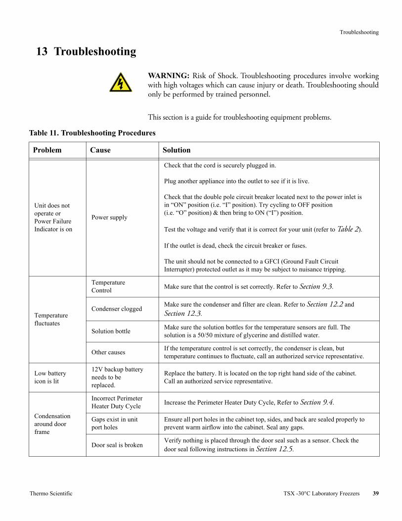
15 Warranty Domestic Warranty • 2 Years Parts and Labor Plus an Additional 8 Years onV-Drive.
International Warranty • 2 Years Parts Plus and Additional 8 Years on V-Drive.
During the first twenty four (24) months from shipment, Thermo FisherScientific Inc, through its authorized Dealer or service organizations, will at itsoption and expense repair or replace any part found to be non-conforming inmaterial or workmanship-with the exception of V-drive which is covered for anadditional 8 years (96 months) from the time of the shipment. Thermo FisherScientific Inc reserves the right to use replacement parts, which are used orreconditioned. Replacement or repaired parts will be warranted for only theunexpired portion of the original warranty.
This warranty does not apply to damage caused by (i) accident, misuse, fire, floodor acts of God; (ii) failure to properly install, operate or maintain the products inaccordance with the printed instructions provided, (iii) causes external to theproducts such as, but not limited to, power failure or electrical power surges, (iv)improper storage and handling of the products, (v) use of the products incombination with equipment or software not supplied by Thermo Fisher; or (vi)installation, maintenance, repair, service, relocation or alteration of the productsby any person other than Thermo Fisher or its authorized representative. Toobtain proper warranty service, you must contact the nearest authorized servicecenter or Dealer. Thermo Fisher Scientific, Inc’s own shipping records showingdate of shipment shall be conclusive in establishing the warranty period. AtThermo Fisher’s option, all non-conforming parts must be returned to ThermoFisher postage paid and replacement parts are shipped FOB Thermo Fisher’slocation.
Limitation of Liability
THIS WARRANTY IS EXCLUSIVE AND IN LIEU OF ALL OTHERWARRANTIES, WHETHER WRITTEN, ORAL, OR IMPLIED. NOWARRANTIES OF MERCHANTABILITY OR FITNESS FOR APARTICULAR PURPOSE SHALL APPLY. THERMO FISHER DOES NOTWARRANT THAT THE PRODUCTS ARE ERROR-FREE OR WILLACCOMPLISH ANY PARTICULAR RESULT.
THERMO FISHER SHALL NOT BE LIABLE FOR ANY INDIRECT ORCONSEQUENTIAL DAMAGES INCLUDING, WITHOUT LIMITATION,DAMAGES TO LOST PROFITS OR LOSS OF PRODUCTS.

WEEE Compliance
WEEE Compliance. This product is required to comply with the European Union’s WasteElectrical & Electronic Equipment (WEEE) Directive 2012/19/EU. It is marked with thefollowing symbol. Thermo Fisher Scientific has contracted with one or morerecycling/disposal companies in each EU Member State, and this product should bedisposed of or recycled through them. Further information on our compliance with theseDirectives, the recyclers in your country, and information on Thermo Scientific productswhich may assist the detection of substances subject to the RoHS Directive are available atwww.thermofisher.com/WEEERoHS.
WEEE Konformittät. Dieses Produkt muss die EU Waste Electrical & ElectronicEquipment (WEEE) Richtlinie 2012/19/EU erfüllen. Das Produkt ist durch folgendesSymbol gekennzeichnet. Thermo Fisher Scientific hat Vereinbarungen getroffen mitVerwertungs-/Entsorgungsanlagen in allen EU-Mitgliederstaaten und dieses Produkt mussdurch diese Firmen widerverwetet oder entsorgt werden. Mehr Informationen über dieEinhaltung dieser Anweisungen durch Thermo Scientific, dieVerwerter und Hinweise dieIhnen nützlich sein können, die Thermo Fisher Scientific Produkte zu identizfizieren, dieunter diese RoHS. Anweisungfallen, finden Sie unter www.thermofisher.com/WEEERoHS.
Conformità WEEE. Questo prodotto deve rispondere alla direttiva dell’ Unione Europea2012/19/EU in merito ai Rifiuti degli Apparecchi Elettrici ed Elettronici (WEEE). È marcato col seguente simbolo.Thermo Fischer Scientific ha stipulato contratti con una odiverse società di riciclaggio/smaltimento in ognuno degli Stati Membri Europei. Questoprodotto verrà smaltito o riciclato tramite queste medesime. Ulteriori informazioni sullaconformità di Thermo Fisher Scientific con queste Direttive, l’elenco delle ditte diriciclaggio nel Vostro paese e informazioni sui prodotti Thermo Scientific che possonoessere utili alla rilevazione di sostanze soggette alla Direttiva RoHS sono disponibili sul sitowww.thermofisher.com/WEEERoHS.
Conformité WEEE. Ce produit doit être conforme à la directive euro-péenne(2012/19/EU) des Déchets d’Equipements Electriques et Electroniques (DEEE). Il estmarqué par le symbole suivant. Thermo Fisher Scientific s’est associé avec une ou plusieurscompagnies de recyclage dans chaque état membre de l’union européenne et ce produitdevraitêtre collecté ou recyclé par celles-ci. Davantage d’informations sur laconformité deThermo Fisher Scientific à ces directives, les recycleurs dans votre pays et les informationssur les produits Thermo Fisher Scientific qui peuvent aider le détection des substancessujettes à la directive RoHS sont disponibles sur www.thermofisher.com/WEEERoHS.
Great Britain
Deutschland
Italia
France

Thermo Fisher Scientific Inc.
275 Aiken RoadAsheville, NC 28804United States
www.thermofisher.com
(V Models only)Authorized Representative:
Thermo Electron LED GmBHRobert-Bosch-Strasse 1Langenselbold - 63505Germany.
Contact UsNorth America: 866-984-3766 Europe: France +33 2 2803 2180 Germany +49 9184 90 9640 UK/Ireland + 44 870 609 9203Asia: China +86 21 6865 4588 India 1800 22 8374 Japan +81 45 453 9220
327932H01 Rev. H