Embed Size (px)
Citation preview

University of Basrah
College of Engineering
Mechanical Engineering Department
MANUFACTURING PROCESSES (ME337), 3rd Year (2019-2020)
Lecturer: Dr. Rafid Jabbar Mohammed
3. Wire and Bar Drawing Conventional and Non-Conventional
Processes
3.1. Wire and Bar Drawing – Conventional Process
Introduction:
- It is an operation in which the cross-section of a bar, rod or wire is reduced
by pulling it through a die opening.
- The difference between extrusion and drawing is: the w.p. is pulled in
drawing, whereas it is pushed in extrusion.
- Bar drawing is the term used for large diameter bar and rod stock (it usually
involves stock that is too large in cross-section to be coiled). Round bar
stock may be 1 to 10cm in diameter or even larger.
- Wire drawing applies to small diameter stock. Wire sizes down to 0.03mm
(0.001in) are possible in wire drawing.
- Bar drawing is accomplished as a single-draft operation: the stock is pulled
through one die opening (it is in the form of a straight cylindrical piece
rather than coiled due to large diameter of stock).
- Wire is drawn from coils consisting of several hundred (or even several
thousand) feet of wire and is passed through a series of draw dies
- In wire drawing, no. of dies varies typically between 4 and 12.
- The term continuous drawing is used to describe this type of operation.
- The drawing process is described in figure (3-30).
Figure (3-30) Drawing Process
Ao Af
Vf
Df
D

Chapter Three Metal Forming Processes
P a g e | 65
Analysis of Drawing:
1- Area Reduction:
- From figure (3-30), the reduction in area can be:
𝒓 =𝑨𝒐 − 𝑨𝒇
𝑨𝒐
r: area reduction (drawing reduction)
Ao: original area of w.p.
Af: final area of w.p.
2- Draft:
𝒅 = 𝑫𝒐 − 𝑫𝒇
d: draft
Do: original diameter of w.p.
Df: final diameter of w.p.
3- True Strain:
- For ideal deformation (no friction or redundant work occurred during
drawing process), the true strain will be:
𝜺 = 𝐥𝐧𝑨𝒐
𝑨𝒇= 𝐥𝐧
𝟏
𝟏 − 𝒓
4- True Stress:
- For ideal deformation (no friction or redundant work occurred during
drawing process), the true stress will be:
𝝈 = �̅�𝒇𝜺 = �̅�𝒇 𝐥𝐧𝑨𝒐
𝑨𝒇
�̅�𝒇 =𝑲𝜺𝒏
𝒏 + 𝟏
- For processes that including gradual deformation and strain hardening like
drawing and extrusion, the average flow stress is used instead of flow stress.
Chapter Three Metal Forming Processes
P a g e | 66
�̅�𝒇: average flow stress
5- Actual Draw Stress (𝝈𝒅):
- Due to friction between w.p. and die in drawing process and the w.p.
experiences inhomogeneous deformation (redundant work), then:
𝝈𝒅 > 𝝈
- Variables that influence draw stress are:
(a) Ao / Af ratio
(b) Die angle α
(c) Friction coefficient (µ) at the w.p.-die interface
Thus, the actual draw stress will be according to the following equation:
𝝈𝒅 = �̅�𝒇(𝟏 +𝝁
𝒕𝒂𝒏 𝜶)∅ 𝐥𝐧
𝑨𝒐
𝑨𝒇
𝝈𝒅: actual draw stress
𝝁: die-w.p. friction coefficient
α: die angle (half-angle)
∅: is a factor that accounts for inhomogeneous deformation (redundant work)
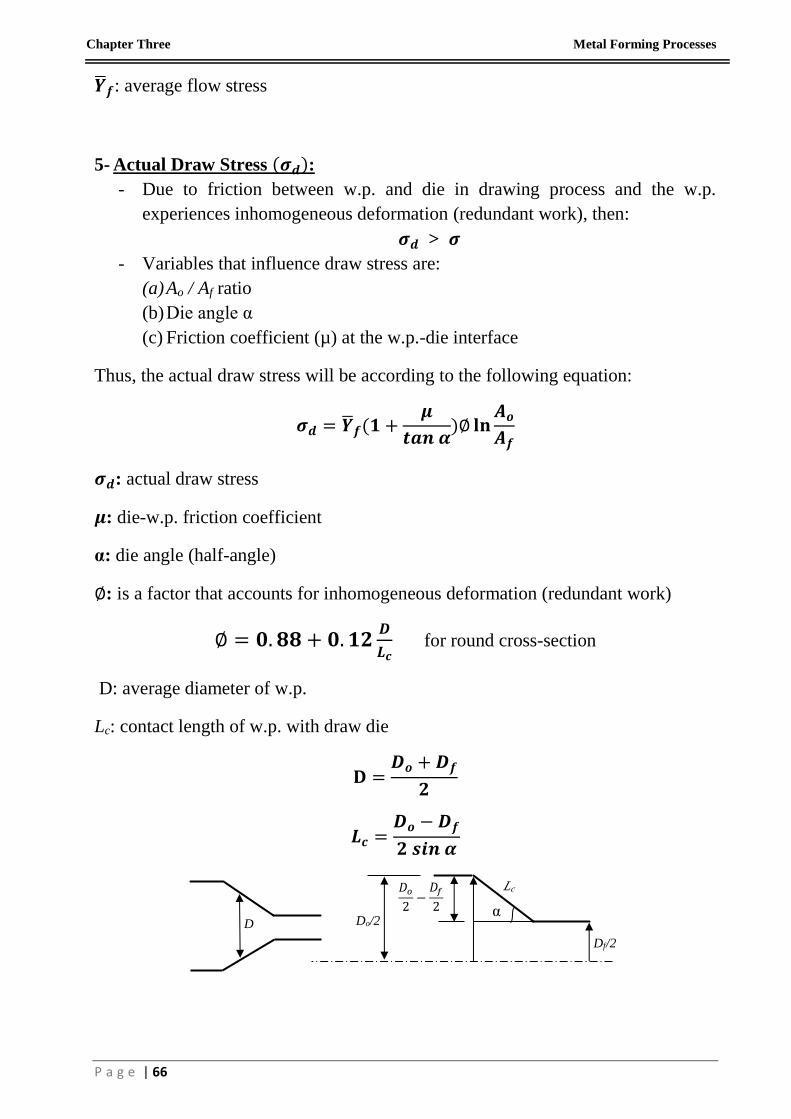
∅ = 𝟎. 𝟖𝟖 + 𝟎. 𝟏𝟐𝑫
𝑳𝒄 for round cross-section
D: average diameter of w.p.
Lc: contact length of w.p. with draw die
𝐃 =𝑫𝒐 + 𝑫𝒇
𝟐
𝑳𝒄 =𝑫𝒐 − 𝑫𝒇
𝟐 𝒔𝒊𝒏 𝜶
α Do/2
Df/2
Lc 𝐷𝑜
2−
𝐷𝑓
2
D

Chapter Three Metal Forming Processes
P a g e | 67
6- Draw Force:
𝑭𝒅 = 𝝈𝒅𝑨𝒇 = 𝑨𝒇�̅�𝒇(𝟏 +𝝁
𝒕𝒂𝒏 𝜶)∅ 𝐥𝐧
𝑨𝒐
𝑨𝒇
7- Draw Power:
𝑷𝒅 = 𝑭𝒅𝑽𝒇
Vf: final velocity of w.p. at exit (drawing velocity)
8- Die Pressure:
- The die pressure along the die contact length can be obtained from:
𝒑𝒅𝒊𝒆 = 𝒀𝒇 − 𝝈
pdie: die pressure
𝜎: tensile stress in the deformation zone at a particular diameter
𝑌𝑓: flow stress of the w.p. at a particular diameter
𝒀𝒇 = 𝑲𝜺𝒏
𝝈 = 𝟎. 𝟎 at the die entry
𝝈 = 𝝈𝒅 at the die exit
9- Drawing Analysis at Elevated Temperature:
- As we have seen, the flow stress of metals is a function of the strain rate.
- In drawing, the average true-strain rate in the deformation zone can be given
by (as in hot extrusion):
�̇̅� =𝟔 𝑽𝒐
𝑫𝒐𝐥𝐧
𝑨𝒐
𝑨𝒇
Vo: w.p. feeding velocity
�̇̅�: average true-strain rate
- Flow Stress:
�̅�𝒇 = 𝑪�̇̅�𝒎
- True Stress:

Chapter Three Metal Forming Processes
P a g e | 68
𝝈 = �̅�𝒇𝜺 = 𝑪�̇̅�𝒎 𝐥𝐧𝑨𝒐
𝑨𝒇
- Actual Draw Stress:
𝝈𝒅 = 𝑪�̇̅�𝒎(𝟏 +𝝁
𝒕𝒂𝒏 𝜶)∅ 𝐥𝐧
𝑨𝒐
𝑨𝒇
- Draw Force:
𝑭𝒅 = 𝝈𝒅𝑨𝒇
- Draw Power:
𝑷𝒅 = 𝑭𝒅𝑽𝒇
Example (10):
Wire is drawn through a draw die with entrance angle = 15º. Starting diameter is
2.5mm and final diameter = 2.0 mm. The coefficient of friction at the work–die
interface = 0.07. The metal has a strength coefficient K = 205 MPa and a strain-
hardening exponent n = 0.20. Determine the actual draw stress and corresponding
draw force in this operation.
Solution:
1- Draw stress:
𝜎𝑑 = �̅�𝑓(1 +𝜇
𝑡𝑎𝑛 𝛼)∅ ln
𝐴𝑜
𝐴𝑓
�̅�𝑓 =𝐾𝜀𝑛
𝑛 + 1
𝜀 = ln𝐴𝑜
𝐴𝑓= ln
𝐷𝑜2
𝐷𝑓2 = ln
2.52
22= 0.446
�̅�𝑓 =205 (0.446)0.2
1.2= 145.4𝑀𝑃𝑎
∅ = 0.88 + 0.12𝐷
𝐿𝑐
D =𝐷𝑜 + 𝐷𝑓
2=
2.5 + 2
2= 2.25𝑚𝑚
𝐿𝑐 =𝐷𝑜 − 𝐷𝑓
2 𝑠𝑖𝑛 𝛼=
2.5 − 2
2 𝑠𝑖𝑛 15= 1.0𝑚𝑚
∅ = 0.88 + 0.122.25
1.0= 1.15

Chapter Three Metal Forming Processes
P a g e | 69
∴ 𝜎𝑑 = 145.4 (1 +0.07
𝑡𝑎𝑛 15) (1.15)(0.446) = 94.1𝑀𝑃𝑎 Answer
2- Draw force:
𝐹𝑑 = 𝜎𝑑𝐴𝑓 = (94.1)𝜋
422 = 295.6𝑁 Answer
Example (11):
A round rod of annealed 302 stainless steel is being drawn from a diameter of
10mm to 8mm at a speed of 0.5m/s (drawing speed). Assume that the frictional and
redundant work together constitute 40% of the ideal work of deformation. (a)
Calculate the power required in this operation, and (b) Calculate the die pressure at
the exit of the die.
Take: K=1300MPa, n=0.3
Solution:
(a) 𝑃𝑑 = 𝐹𝑑𝑉𝑓
𝐹𝑑 = 𝜎𝑑𝐴𝑓
Multiplying draw stress with 1.4 to include the frictional and redundant work
effects. Thus:
𝜎𝑑 = 1.4(�̅�𝑓𝜀) = 1.4(�̅�𝑓 ln𝐴𝑜
𝐴𝑓)
𝜀 = ln102
82= 0.446
�̅�𝑓 =𝐾𝜀𝑛
𝑛 + 1=
1300(0.446)0.3
1.3= 784.875𝑀𝑃𝑎
∴ 𝜎𝑑 = 1.4(784.875)(0.446) = 490.1𝑀𝑃𝑎
𝐹𝑑 = 𝜎𝑑𝐴𝑓 = (490.1)𝜋
482 = 24635.1𝑁
∴ 𝑃𝑑 = 𝐹𝑑𝑉𝑓 = 24635.1(0.5) = 12.3𝑘𝑊 Answer
(b) 𝑝𝑑𝑖𝑒 = 𝑌𝑓 − 𝜎
𝜎 = 𝜎𝑑 = 490.1𝑀𝑃𝑎 at the die exit
𝑌𝑓 = 𝐾𝜀𝑛 = 1300(0.446)0.3 = 1020.3𝑀𝑃𝑎
Chapter Three Metal Forming Processes
P a g e | 70
𝑝𝑑𝑖𝑒 = 𝑌𝑓 − 𝜎 = 1020.3 − 490.1 = 530.2𝑀𝑃𝑎 Answer
Example (12):
Bar stock of initial diameter = 90 mm is drawn with a draft = 15 mm. The draw die
has an entrance angle = 18°, and the coefficient of friction at the work-die interface
= 0.08. The metal behaves as a perfectly plastic material with yield stress = 105
MPa. Determine (a) area reduction, (b) draw stress, (c) draw force required for the
operation, and (d) power to perform the operation if exit velocity = 1.0 m/min.
Solution:
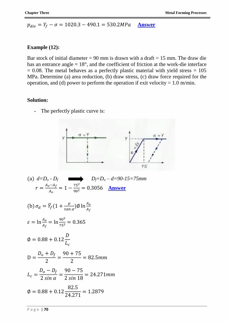
- The perfectly plastic curve is:
(a) d=Do - Df Df=Do – d=90-15=75mm
𝑟 =𝐴𝑜−𝐴𝑓
𝐴𝑜= 1 −
752
902= 0.3056 Answer
(b) 𝜎𝑑 = �̅�𝑓(1 +𝜇
𝑡𝑎𝑛 𝛼)∅ ln
𝐴𝑜
𝐴𝑓
𝜀 = ln𝐴𝑜
𝐴𝑓= ln
902
752= 0.365
∅ = 0.88 + 0.12𝐷
𝐿𝑐
D =𝐷𝑜 + 𝐷𝑓
2=
90 + 75
2= 82.5𝑚𝑚
𝐿𝑐 =𝐷𝑜 − 𝐷𝑓
2 𝑠𝑖𝑛 𝛼=
90 − 75
2 𝑠𝑖𝑛 18= 24.271𝑚𝑚
∅ = 0.88 + 0.1282.5
24.271= 1.2879

Chapter Three Metal Forming Processes
P a g e | 71
Since the material is perfectly plastic, then;
n=0.0, K=Y (yield strength) =105MPa
�̅�𝑓 =𝐾𝜀𝑛
𝑛 + 1=
105(0.365)0
1 + 0= 105𝑀𝑃𝑎
∴ 𝜎𝑑 = 105 (1 +0.08
𝑡𝑎𝑛 18) (1.2879)(0.365) = 61.5𝑀𝑃𝑎 Answer
(c) 𝐹𝑑 = 𝜎𝑑𝐴𝑓 = (61.5)𝜋
4752 = 271.7𝑘𝑁 Answer
(d) 𝑃𝑑 = 𝐹𝑑𝑉𝑓 = 271.7 (1
60) = 4.53𝑘𝑊 Answer
Maximum Reduction per Pass:
- As reduction increases 𝜎𝑑 increases.
- If reduction is large enough 𝜎𝑑 exceeds the w.p. strength
w.p. will elongate rather than new w.p. being squeezed.
- For successful drawing 𝜎𝑑 < yield strength of w.p.
- To determine maximum reduction in one pass under certain assumptions:
1- Perfectly plastic (n=0), ideal deformation (no friction and no redundant
work).
2- Maximum 𝜎𝑑 = Y (yield strength of w.p.)
𝜎𝑑 = �̅�𝑓 ln𝐴𝑜
𝐴𝑓
And setting �̅�𝑓 = 𝑌 (yield strength) because n=0
𝑌 = 𝑌 ln𝐴𝑜
𝐴𝑓 1 = ln
𝐴𝑜
𝐴𝑓 1 = 𝜀𝑚𝑎𝑥
𝐴𝑜
𝐴𝑓= 𝑒1 = 2.7183
∴ 𝑟𝑚𝑎𝑥 =𝐴𝑜−𝐴𝑓
𝐴𝑜= 1 −
𝐴𝑓
𝐴𝑜= 1 −
1
2.7183= 0.632 (theoretical max. reduction)
- In practice: maximum reduction is less than theoretical one due to:
1- Friction and redundant work reduce the max. reduction.
2- Strain hardening increases max. reduction because exiting w.p. be stronger
than starting w.p.
Chapter Three Metal Forming Processes
P a g e | 72
Drawing Practice:
- Drawing is usually performed as a cold-working operation.
- It is most used to produce round cross-sections but squares and other shapes
are also drawn.
- Wire drawing is an important industrial process which includes: electrical
wire and cables, wire stock for fences, coat hangers and shopping carts.
Rod stock to produce nails, screws, rivets, springs…
- Advantages of drawing in these application include:
1- Close dimensional control
2- Good surface finish
3- Improved mechanical properties such as strength and hardness
4- In case of bar drawing to provide stock for machining, the operation
improves the machinability of bar.
Drawing Equipment:
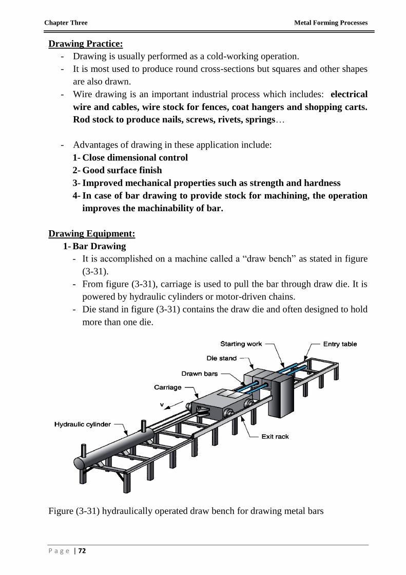
1- Bar Drawing
- It is accomplished on a machine called a “draw bench” as stated in figure
(3-31).
- From figure (3-31), carriage is used to pull the bar through draw die. It is
powered by hydraulic cylinders or motor-driven chains.
- Die stand in figure (3-31) contains the draw die and often designed to hold
more than one die.
Figure (3-31) hydraulically operated draw bench for drawing metal bars
Chapter Three Metal Forming Processes
P a g e | 73
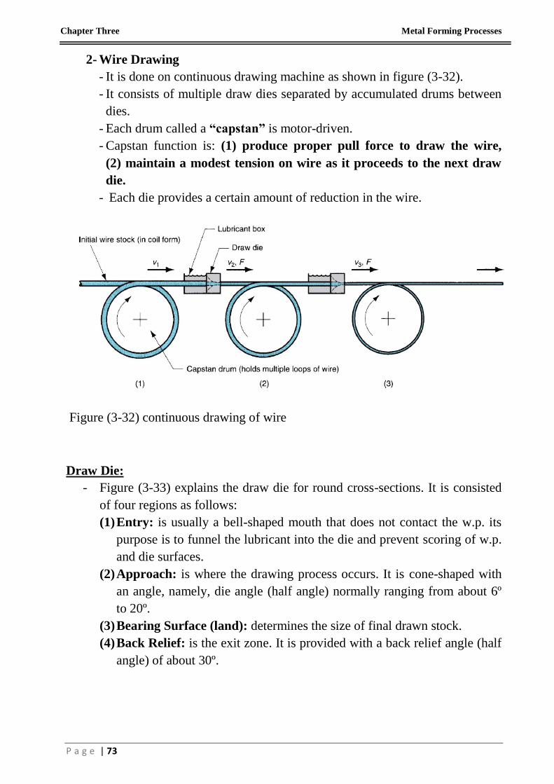
2- Wire Drawing
- It is done on continuous drawing machine as shown in figure (3-32).
- It consists of multiple draw dies separated by accumulated drums between
dies.
- Each drum called a “capstan” is motor-driven.
- Capstan function is: (1) produce proper pull force to draw the wire,
(2) maintain a modest tension on wire as it proceeds to the next draw
die.
- Each die provides a certain amount of reduction in the wire.
Figure (3-32) continuous drawing of wire
Draw Die:
- Figure (3-33) explains the draw die for round cross-sections. It is consisted
of four regions as follows:
(1) Entry: is usually a bell-shaped mouth that does not contact the w.p. its
purpose is to funnel the lubricant into the die and prevent scoring of w.p.
and die surfaces.
(2) Approach: is where the drawing process occurs. It is cone-shaped with
an angle, namely, die angle (half angle) normally ranging from about 6º
to 20º.
(3) Bearing Surface (land): determines the size of final drawn stock.
(4) Back Relief: is the exit zone. It is provided with a back relief angle (half
angle) of about 30º.

Chapter Three Metal Forming Processes
P a g e | 74
Figure (3-33) draw die for drawing of round rod or wire
Preparation of the W.P.:
1- Annealing: it is to increase the ductility of w.p. to accept deformation
during drawing.
2- Cleaning: is required to prevent damage of w.p. surface and draw die. It
involves removal of surface contaminants (e.g., scale and rust).
3- Pointing: involves the reduction in diameter of starting end of w.p. so that it
can be inserted through the draw die. This is usually accomplished by rolling
or turning. The pointed end of w.p. is then gripped by carriage jaws or other
device to initiate the drawing process.
Tube Drawing:
- Drawing can be used to reduce the diameter or wall thickness of seamless
tubes and pipes, after the initial tubing has been produced by some other
process such as extrusion.
- Tube drawing can be carried out either with or without a mandrel.
(1) No mandrel also called “tube sinking” is used as shown in figure (3-34).
The problem with it is that it lacks control over the inside diameter and
wall thickness of tube.

Chapter Three Metal Forming Processes
P a g e | 75
Figure (3-34) tube drawing with no mandrel.
(2) With mandrel: it is shown as in figure (3-35).
(a) Fixed Mandrel: it is attached to a long support bar to maintain inside
diameter and wall thickness. There is restriction of the length of tube
that can be drawn due to practical limitations on length of the support
bar.
(b) Floating Plug: whose shape is designed so that it finds a natural
position in the reduction zone of die. This method removes the
limitations on w.p. length.
Figure (3-35) tube drawing with mandrel: (a) fixed mandrel (b) floating plug
Chapter Three Metal Forming Processes
P a g e | 76
3.2. Dieless Drawing Processes – Non-Conventional Processes
Introduction:
- Dieless wire/tube drawing process is utilized in initiating continuous
deformation depending on local heating and intensive local cooling.
- The temperature range in this process should not be less than (0.4 - 0.5Tm).
- The strain rate ranges must be in low levels (10-5 – 10-1)s-1.
- To accomplish dieless drawing process (DLD), three major components must
be integrated; heating unit, cooling unit and drawing device.
- At elevated temperatures, yield strength, modulus of elasticity, ultimate
tensile strength and flow stress are decreased,
- Ductility and toughness (specific energy dispersed up to fracture) are
increased at high temperature.
- Consequently, a significant reduction in cross-section area of the wire/tube
will occur depending on feeding and drawing velocities of the wire/tube.
- The drawing force and suitable reduction ratio are depended on feeding and
drawing velocities of the wire/tube.
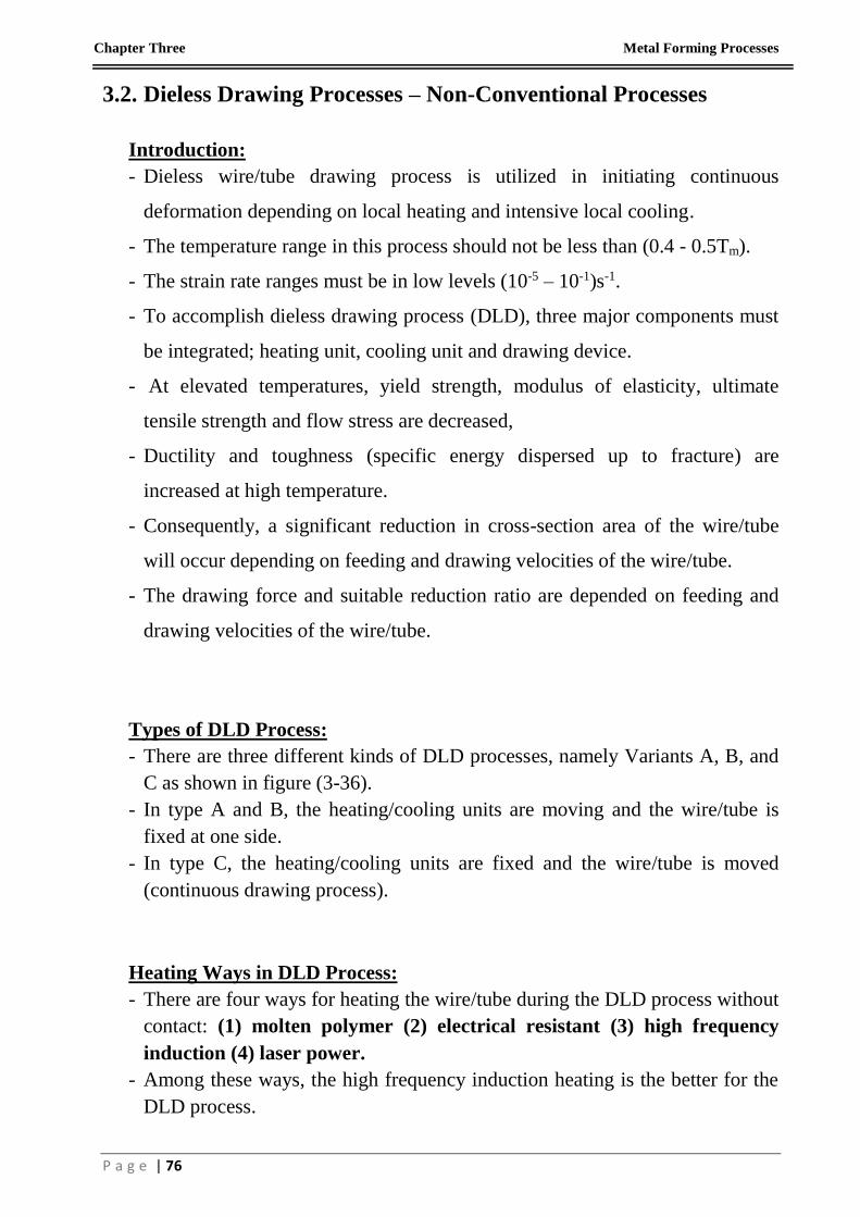
Types of DLD Process:
- There are three different kinds of DLD processes, namely Variants A, B, and
C as shown in figure (3-36).
- In type A and B, the heating/cooling units are moving and the wire/tube is
fixed at one side.
- In type C, the heating/cooling units are fixed and the wire/tube is moved
(continuous drawing process).
Heating Ways in DLD Process:
- There are four ways for heating the wire/tube during the DLD process without
contact: (1) molten polymer (2) electrical resistant (3) high frequency
induction (4) laser power.
- Among these ways, the high frequency induction heating is the better for the
DLD process.
Chapter Three Metal Forming Processes
P a g e | 77
Figure (3-36) DLD types ; (a) Continuous process, Vo: feeding velocity,
V1: drawing velocity, Ao: original cross-section area, A1: final cross-section area,
and (b), (c) Non Continuous process, Vo: velocity of heating/cooling unit,
V1: drawing velocity.
Cooling Ways in DLD Process:
- There are different fluids that are used in the cooling units (to gradient the
high temperature range and prevent further deformation) such as water,
compressed air, argon and liquid-CO2.
oA
1A
oV 1V
Heating
Unit
Cooling
Unit
1V
oV
1V
oV
(a)
(b)
(c)
Chapter Three Metal Forming Processes
P a g e | 78
Advantages of DLD Process:
- Eliminating of friction forces.
- Lowering of drawing force and energy consumption.
- Considerable area reduction in single drawing pass.
- Needless of pre-cleaning/lubricating.
- Allowing for variable sections to be manufactured.
- Refinement of grain size – possibly related to thermal cycling and reduction
in area - for steel or any microstructural transformation in materials, so
better mechanical properties can be imparted to the product after drawing
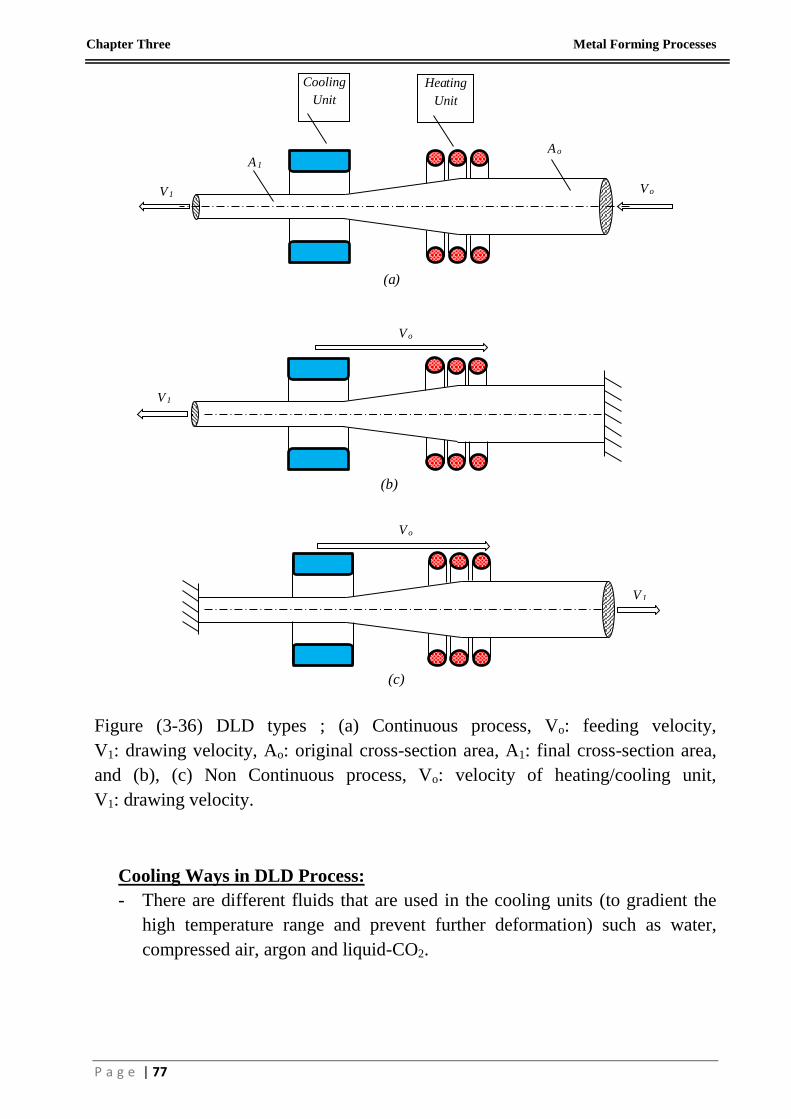
Disadvantages of DLD Process:
- Final sizes - particularly in massive reduction ratios - are unstable to some
degrees.
- Uneven shape (bamboo-like).
- Slow forming time due to low deforming speeds.
Uncontrolled Process Speed and Temperature
Inadequate Heating
Insufficient Cooling
RA=41%

Chapter Three Metal Forming Processes
P a g e | 79
Continuous Dieless Wire drawing Machine: General View; (1) DLD Machine,
(2) Computer, (3) Air Compressor, (4) Cooling Tower
RA=38%
3
4
2
1
Chapter Three Metal Forming Processes
P a g e | 80
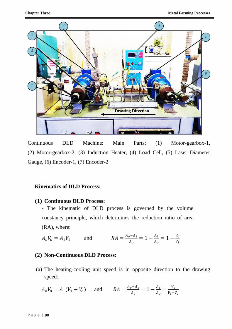
Continuous DLD Machine: Main Parts; (1) Motor-gearbox-1,
(2) Motor-gearbox-2, (3) Induction Heater, (4) Load Cell, (5) Laser Diameter
Gauge, (6) Encoder-1, (7) Encoder-2
Kinematics of DLD Process:
(1) Continuous DLD Process:
- The kinematic of DLD process is governed by the volume
constancy principle, which determines the reduction ratio of area
(RA), where:
𝐴𝑜𝑉𝑜 = 𝐴1𝑉1 and 𝑅𝐴 =𝐴𝑜−𝐴1
𝐴𝑜= 1 −
𝐴1
𝐴𝑜= 1 −
𝑉𝑜
𝑉1
(2) Non-Continuous DLD Process:
(a) The heating-cooling unit speed is in opposite direction to the drawing
speed:
𝐴𝑜𝑉𝑜 = 𝐴1(𝑉1 + 𝑉𝑜) and 𝑅𝐴 =𝐴𝑜−𝐴1
𝐴𝑜= 1 −
𝐴1
𝐴𝑜=
𝑉1
𝑉1+𝑉𝑜
1
3
2
4
5
6
7
Drawing Direction

Chapter Three Metal Forming Processes
P a g e | 81
(b) The heating-cooling unit speed is in the same direction with the drawing
speed:
𝐴𝑜(𝑉𝑜 − 𝑉1) = 𝐴1𝑉𝑜 and 𝑅𝐴 =𝐴𝑜−𝐴1
𝐴𝑜= 1 −
𝐴1
𝐴𝑜=
𝑉1
𝑉𝑜