Embed Size (px)
Citation preview

Key benefits
• Easeofintegration-valvesizematchespipesize,resultinginreducedinstallationtimeandinstallationcosts
• Flexibledesign-portscanbeconfiguredtosuitinstallation
• Lowpressuredrop-comparedtoothervalvetypes
• Smallphysicalsize
• Handwheelallowsmanualadjustmentofvalve(optionalonpneumaticvalve)-simplifiedsetupandmaintenance
Typical applications For engines, turbines, gearboxes and heat exchangers:
• Chargeaircooling
• Secondarycoolingsystems
• Fuelandlubeoilpreheating
• Co-generation
• Enginejacketwater
For refineries, chemical plants and oil reproduction:
• Wasteheatboilers
• Productcoolers
• Productheaters
• Productcondensers
ElectricGGvalve
PneumaticGGvalve
Now even more
compact
Gvalvecomparedwithatypicalequivalentcompetitor’sspecification.
ModelG,VersionGandAccessories
www.amot.com
3-WayTemperatureControlValve

page2DS-GG-Temp-Control-Valve-0912-rev8
3-Way Temperature Control Valve - Model G, Version G
Contents
Overview ..................................................... 3
Applications .............................................. 3
System Types .............................................. 4
Overview ofValve Body ............................ 6
Specification ............................................6
ModesofOperation ..................................7
ValveSizing..............................................9
Dimensions ................................................ 13 Overview of Electric Actuation ................... 15
Electronic Positioner ................................. 16
Overview of Pneumatic Actuation .............. 16
How to Order ............................................. 17
Accessories ............................................... 18
PIDController8071D,8072D,SSR47581....18
3-WirePT100TemperatureSensor8060.....18
SolidStateRelayModule8073C.................19
ElectroPneumaticConverter8064A............19
ElectroPneumaticConverter8064C............20
PneumaticIndicatorControllerSG80..........20

page3DS-GG-Temp-Control-Valve-0912-rev8
3-Way Temperature Control Valve - Model G, Version G
AMOTGvalvesare3-waycontrolvalvesconsistingofaheavydutyrotaryvalveandeitheraquarterturnelectricorpneumaticactuator.Thevalvesprovideahighdegreeofaccuracyandrepeatabilityforaccuratetemperaturecontrolandareequallyaccurateinmixingordivertingserviceoverawideflowrange.
Theheavydutyrotordesignprovidestighttemperaturecontrolwithouthighmaintenancerequirements.Thesystemisavailableinthreestandardcontrolconfigurations:electric;pneumatic;andelectro-pneumatic,offeringflexibilityformostrequirements.Designed
forhighvibrationservice,theAMOTGvalvesarequalifiedtoLloyd’sMarineRequirementsforshipboardservice.Valvescanbedirectlymountedtoreciprocatingmachinery,suchasdieselengines,withoutvibrationisolation.Theheavydutyactuatorsarespeciallyreinforcedtoprovidevibrationresistance.
Thestandardvalvesaresuitableforavarietyoffluidssuchaswater,water/glycol,seawater,lubricatingandhydraulicoils.Optionalbodymaterialsareavailableforservicesinvolvingsyntheticorfireresistantoils,deionizedwaterandammoniaorfreoninoil.
Applications
Overview
Charge Air Temperature ControlTheintercoolerisusedtocoolhightemperatureturbochargerair.
InthisapplicationtheGValveregulatestheflowofcoolingwaterthroughanintercooler,increasingefficiency,enhancingperformanceandhelpingtomeettoday’senvironmentalrequirements.
Diverting ApplicationsJacketwatercoolingindivertingapplicationsregulatestheoutletcoolantwatertemperaturefromadieselorgasengine.Thevalveeithersendswatertoacoolerorbypassloop,accuratelymaintainingthetemperature.
Thetemperatureisnormallymeasuredattheoutletfromtheheatsource.
Mixing ApplicationsLubricatingoiltemperaturecontrolisnormallyconfiguredinamixingapplicationcontrollingthereturntemperaturetotheheatload.Thetemperatureisnormallymeasuredascloseaspossibletothesumpreturn.

page4DS-GG-Temp-Control-Valve-0912-rev8
3-Way Temperature Control Valve - Model G, Version G
Electric System
Theelectricactuatorisarugged,compactandlightweightquarterturnactuatorhavingenclosureprotectiontoIP65.
Theactuatorispoweredbyanelectricmotordrivingaworm-typegearbox.Thewormgearboxpreventsreversedriveduetofluidforces.Itisfittedwithmanualoverrideasstandard,enablingvalveoperationwithoutpower.
Athermalcutoutisfittedpreventingoverheating.Limitswitchesateachendofstrokedisconnectmotorpowerwhenendstrokeisreached.Thesecanalsobeusedforremoteindication.
Seepage15formoreinformationontheelectricactuator.
GGValvePIDController8071/2D,IP67enclosure
Fortheelectricvalve,theactuatoroftheGvalveassemblyusesanelectricmotorwhichrotatesineitherdirectioninresponsetotheON-OFFsignalsreceived.Themotordrivesagearboxconnectedtotherotorshaftandturnsthevalverotorclockwiseorcounter-clockwise,amaximumof90degrees.Attheendoftravel,limitswitchesareincorporatedtoisolatetheelectricalsupplytothemotorwhenthevalverotorhasreachedeitherendoftherotation.Afeedbackpotentiometerisstandardandprovidespositionindicationtothecontrolsystem.
Electric Valve
Theelectricvalvesystemincorporatestheuseofanelectricallyactuatedthree-waycontrolvalvewithanelectroniccontroller.The8071DPIDControllercanbeeitherpanelorwallmounted(seepage18formoreinformation).Thesystemiscompletedwithatemperaturesensortype8060(seepage18fordetails).
TheelectricGValvesystemissimpletoinstallwithstandardfourcorecable,andprovidesmoreaccuratemeasurementandcontrolthantypicalpneumaticallyoperatedsystems.
TemperatureProbe8060
System Types
Electric GG Valve

page5DS-GG-Temp-Control-Valve-0912-rev8
3-Way Temperature Control Valve - Model G, Version G
Electro-Pneumatic System Theelectro-pneumaticvalvesystemcombinesbothelectricandpneumatictechnology,consistingofapneumaticallyactuatedthree-waycontrolvalvewithanelectro-pneumaticconverter,type8064A.Seepage19formoredetails.
Theprobesendsaresistancesignaltotheelectroniccontroller,whichinturnsendsa4to20mAsignaltoanI/Pconverterthatconvertsthistoapneumaticsignal.
Theelectro-pneumaticsystemcombinesthefeaturesandfunctionalityoftheAMOTelectroniccontrolsystemwiththefail-safeactionbenefitsofapneumaticallyactuatedvalve.
Pneumatic Valve Thepneumaticvalveusesaspringreturnpneumaticactuatorandpositionertocontroltherotationofthevalveinresponsetoaninputsignalfromapneumaticorelectro-pneumaticcontrolsystem.Thepneumaticcontrolsystemsendsapneumaticsignalrangingfrom0.21to1.03bar(3to15psi)totheactuatortocorrectlypositionthevalveatthedesiredtemperaturesetting.ThepneumaticcontrolsystemusuallyconsistsofaP+Ipneumaticcontroller,sensorandthenecessaryairsupplyconditioningequipment(regulators,filtersandwatertraps).
Pneumatic System Thepneumaticvalvesystemincorporatesapneumaticallyactuatedthree-waycontrolvalvewithcontrollerandintegraltemperaturesensor,theSG80,whichcanbepanelorwallmounted.FormoreinformationontheSG80,seepage20.ThepneumaticGvalvesystemisidealwhenthereisalackofelectricityorwhenafail-safesystemisneeded.
Thepneumaticactuatorisarugged,quarterturn,doublepistonactuatoroperatingonascotchyokeprinciple.
Theactuatorisfittedwithspringreturnasstandardallowingfail-safeconfigurationifnecessary.Itisalsofittedwithavalvepositionerenablingaccurateandrepeatablemovement.Seepage16formoreinformationonthepneumaticactuator.
SG80TemperatureControllerandSensor
System Types continued
Pneumatic GG Valve
GGValve
GGValveElectro-PneumaticConverter8064A
TemperatureController8071D
TemperatureProbe8060

page6DS-GG-Temp-Control-Valve-0912-rev8
3-Way Temperature Control Valve - Model G, Version G
Specification
Flow to: 720m3/hr 3,170USgpm ForvalveswithhigherflowratesseedatasheetGEF_GPD_Temp_Control_Valve
Sizes: Standard flow High flow
80mm-200mm(3”-8”) 50mm-200mm(2”-8”) For350mm(14”)andaboveseeDatasheetGEF_GPD_Temp_Control_Valvefordata
Body/rotor materials: Bronze Forseawater,shockresistance,or magneticpermeability
Ductileiron Highperformanceiron,forfresh water,lubricatingoils
Steel Forhighstrengthandhighpressure ratings
Stainlesssteel Corrosiveandspecialapplications
Seal material: Flourocarbon(Viton,FKM)
Flanges: EN1092,ASMEandJISstandards.
Maximum internal Ductileironorbronze 10bar (145psi)
valve pressure: Steelandstainlesssteel 16bar (232psi)
Maximum temperature 100°C (212°F) of fluid:
Vibration: ExceedstherequirementsofLloyd’sRegisterTypeApprovalSystem, TestSpecificationNumber1,2002,VibrationTest2. Forbothelectricandpneumatic:
Frequency range
Displacement Acceleration Lloyd’s
5-25Hz +/-1.6mm +/-1.6mm
25-100Hz +/-5.0g(49m/s2) +/-4.0g(39m/s2)
100-300Hz +/-1.0g(9.81m/s2)90minute
Norequirement
Overview of Valve Body
Key features and benefits• Lightweightandcompact
• Configurableports-allowingflexibilityoninstallation
• Lowpressuredrop-enablessavingsoneithervalveorpumpsize
• Highaccuracyprovidingbettertemperaturecontrol
ValveBody

page7DS-GG-Temp-Control-Valve-0912-rev8
3-Way Temperature Control Valve - Model G, Version G
TheuniqueconstructionoftheAMOTGvalveprovidestotalflexibilitybyallowingyoutoselectthevalveportpositionsmostideallysuitedtomeetyourapplicationrequirements.Therearetwomaintypesofmodeofoperation:90°rotorthatallowseitherports1or3tobeselectedasthecommonport;and180°rotorthatrequiresport2tobethecommonport.ArrowindicatesvalvemovementwithincreasingtemperatureormA,asviewedfromabove(seediagram).Forelectricallyactuatedvalves,onlossofsignaltheactuatorissetupbydefaulttostopinitscurrentposition.
Electric actuator (switched live input)
Electric actuator direct acting(4-20mA input)
Electric actuator reverse acting(20-4mA input)
Cold position Hot position 4mA (cold) 20mA (hot) 20mA (cold) 4mA (hot)
23
ed
oM
12
ed
oM
21 e
do
M3
2 e
do
M31
ed
oM
13
ed
oM
3
2
1
Modes of Operation - Electrically Actuated

page8DS-GG-Temp-Control-Valve-0912-rev8
3-Way Temperature Control Valve - Model G, Version G
TheuniqueconstructionoftheAMOTGvalveprovidestotalflexibilitybyallowingyoutoselectthevalveportpositionsmostideallysuitedtomeetyourapplicationrequirements.Therearetwomaintypesofmodeofoperation:90°rotorthatallowseitherports1or3tobeselectedasthecommonport;and180°rotorthatrequiresport2tobethecommonport.ArrowindicatesvalvemovementwithincreasingtemperatureormA,asviewedfromabove(seediagram).
Pneumatic actuator direct acting Pneumatic actuator reverse acting
3 PSI (cold) 15 PSI (hot) No signal 15 PSI (cold) 3 PSI (hot) No signal
23
ed
oM
12
ed
oM
21 e
do
M3
2 e
do
M31
ed
oM
13
ed
oM
3
2
1
Modes of Operation - Pneumatically Actuated

page9DS-GG-Temp-Control-Valve-0912-rev8
3-Way Temperature Control Valve - Model G, Version G
s s s s s sss s
80(3) 50(2) 7 14 20 26 33 39 46 52
100(4) 80(3) 19 35 51 67 83 99 115 131
125&150(5&6) 100(4) 29 54 79 104 129 154 179 204
200(8) 150(6) 66 122 178 235 291 347 403 459
200(8) 118 218 318 418 517 617 717 817
250(10)
300(12) 250(10)
350(14) 300(12)
400(16) 350(14)
450(18) 400(16)
Valve Sizing (Metric units)
Recommended maximum pressure drop
14 3 2
1 – Water
2 – ISO VG32
3 – ISO VG46
4 – ISO VG68
Valveselectioncurvesforvalveswith90orotor.Forvalveswith180orotormultiplypressuredropsby2.
AMOTtypeGvalvesaredesignedtoproduceminimalpressuredrop.Thenormalrecommendationinsizingthevalvesistoselectapressuredropbetween0.01to0.3bar(0.15and4.5psi).
Tousethegraphitisadvisedtousethefollowingmethod:1. Startwithapressuredropof0.05baron theverticalaxis,readacrosstothecurve.2. Followthislinedowntotheflowratesbelow untilyoufindthevalueclosesttoyourflowrate.3. Followthelineacrosstothelefttodetermine suitablevalvesize.Forstablecontrolthevalveshouldbeselectedsoastoprovideapressuredropwithfullflowofbetween0.01and0.3bar(0.15and4.5psi).
SizeDN(inches)
ValveFlowrateSelection(Flowratem3/hr)
CurrentlyonlyavailableinGEF/GPDversions.SeeDatasheetGEF_GPD_Temp_Control_Valvefordata
0
0.05
0.10
0.15
0.20
0.25
0.30
0.35
0.40
Pre
ssu
re d
rop
bar
Standard High flow flow
page10DS-GG-Temp-Control-Valve-0912-rev8
3-Way Temperature Control Valve - Model G, Version G
s s s s s s s ss
3(80) 2(50) 31 62 88 114 145 172 203229
4(100) 3(80) 84 154 225 295 365 436 506 577
5&6 (125&150) 4(100) 128 238 348 458 568 678 788 898
8(200) 6(150) 291 537 784 1035 1281 1528 1774 2021
8(200) 520 960 1400 1840 2276 2717 3157 3597
10(250)
12(300) 10(250)
14(350) 12(300)
16(400) 14(350)
18(450) 16(400)
Valve Sizing (English units)
ValveFlowrateSelection(FlowrateUSg/m)
Sizeinches(DN)
Pre
ssu
re d
rop
psi
Recommended maximum pressure drop
14 3 2
1 – Water
2 – ISO VG32
3 – ISO VG46
4 – ISO VG68
5.08
4.35
3.62
2.90
2.18
1.45
0.73
0
AMOTtypeGvalvesaredesignedtoproduceminimalpressuredrop.Thenormalrecommendationinsizingthevalvesistoselectapressuredropbetween0.15and4.5psi(0.01to0.3bar).
Tousethegraphitisadvisedtousethefollowingmethod:1. Startwithapressuredropof0.5psiontheverticalaxis, readacrosstothecurve.2. Followthislinedowntotheflowratesbelowuntilyoufindthevalueclosesttoyourflowrate.3. Followthelineacrosstothelefttodeterminesuitable valvesize.Forstablecontrolthevalveshouldbeselectedsoastoprovideapressuredropwithfullflowofbetween0.15and4.5psi(0.01and0.3bar).
CurrentlyonlyavailableinGEF/GPDversions.SeeDatasheetGEF_GPD_Temp_Control_Valvefordata
Valveselectioncurvesforvalveswith90orotor.Forvalveswith180orotormultiplypressuredropsby2.
Standard High flow flow

page11DS-GG-Temp-Control-Valve-0912-rev8
3-Way Temperature Control Valve - Model G, Version G
Fortheselectionofvalvesformoreviscousfluidsthanwater,thefollowingmustbecalculated:
Viscosity:Findtheviscosityofthefluidinwhichthevalveistooperate.Theviscosityisnormallyexpressedincentistokes.WhereISOoilisused,thegradenumberisalsotheviscosityegISOVG46is46centistokesat40°C(104°F).
Viscositycorrection:Byusingthecorrectiongraphbelow,theflowcoefficientcorrectionfactorcanbeestablished.Thecorrectionfigureobtainedfromthegraphshouldthenbemultipliedbytheoriginalflowcoefficientwhichcanthenbeusedinthestandardvalvesizingformulae.
Engine oils
Oil cSt
SAE5W 6.8
SAE10W 32
SAE20 46
SAE20W 68
SAE30 100
SAE40 150
SAE50 220
Gear oils
Oil cSt
SAE75W 22
SAE80W 46
SAE85W 100
SAE90 150
SAE140 460
SAE Oil Viscosities
Someapproximateviscosities(cSt)ofSAEoilsat40°C(104°F)areshownbelow,basedonleadingoilmanufacturers’publisheddata.
ViscosityCorrectionCurve(Fv)
Viscosity (Centistokes)
Valve Sizing
Example:
Fromthegraphbelow:100cSt=correctionfactorof0.68
0.68xflowcoefficient=correctedflowcoefficient(KvorCv)
Someapproximateviscosities(cSt)ofSAEoilsat40°C(110°F)areshownbelow,basedonleadingoilmanufacturerspublisheddata.
ViscosityCorrection
Cor
rect
ion
Fac
tor

page12DS-GG-Temp-Control-Valve-0912-rev8
3-Way Temperature Control Valve - Model G, Version G
TheGvalveisdesignedtoproduceminimalpressuredrop.ThenormalrecommendationwhendeterminingthesizeofanAMOTGvalveisapressuredropbetween0.01and0.3bar(1.5and4.5psi).Note:KvandCvvaluesareapplicableto90°rotorversionsonly.
Valve Flowrate
Size DN (in)
Standard flow
80 (3)
100 (4)
125 & 150 (5 & 6)
200 (8)
250 (10)
300 (12)
350 (14)
400 (16)
450 (18)
High flow
50 (2)
80 (3)
100 (4)
150 (6)
200 (8)
250 (10)
300 (12)
350 (14)
400 (16)
Kv 82 207 323 729 1296
Cv 96 242 378 851 1513
SeethetablebelowforexamplesofKvandCv:
Valve Sizing
ValveSizingCalculations
Pressure Drop
TheAMOTGValveisnotatightshutoffvalve.Whenusedinareasonablybalancedpressuresystemtherewillbesomesmallamountsofleakagebetweenports.Theactualamountofleakagewillvarywiththepressuredifference
Valve Bypass Flowrates betweentheseports.ConsultAMOTforfurtherinformationiftheapplicationissensitivetoleakageratesorifhighpressuredifferencesarelikelytooccur.
CurrentlyonlyavailableinGEF/GPDversions.SeeDatasheetGEF_GPD_Temp_Control_Valvefordata
TherearetwootherwaysthatthisformulacanbeusedtofindtheflowinUSgallons/minuteorpressuredropofavalveinPSI:
ThebasicformulatodeterminetheKvofavalveis:
DpSGKv=Q
Q=Flow(m3/h)
Dp=Pressuredrop(bar)
SG=Specificgravityoffluid
Kv=Valveflowcoefficient
ThebasicformulatodeterminetheCvofavalveis:
DpSGCv=Q
Q=Flow(USgallons/min)
Dp=Pressuredrop(psi)
SG=Specificgravityoffluid
Cv=Valveflowcoefficient
Therearetwootherwaysthatthisformulacanbeusedtofindtheflowinm3/horpressuredropofavalveinbar:
SGDpQ=Kv
KvQDp=SG
SGDpQ=Cv Cv
QDp= SG22
Kvistheflowcoefficientinmetricunits.Itisdefinedastheflowrateincubicmetersperhour(m3/h)ofwateratatemperatureof16ºcelsiuswithapressuredropacrossthevalveof1bar.Cvistheimperialcoefficient.ItisdefinedastheflowrateinUSGallonsperminute[gpm]ofwateratatemperatureof60ºfahrenheitwithapressuredropacrossthevalveof1psi.(Kv=0.865Cv/Cv=1.156Kv)

page13DS-GG-Temp-Control-Valve-0912-rev8
3-Way Temperature Control Valve - Model G, Version G
Dimensions
Seepage14fordimensions
ElectricallyActuatedwithManualOverride
PneumaticallyActuatedwithManualOverride
PneumaticallyActuated

page14DS-GG-Temp-Control-Valve-0912-rev8
3-Way Temperature Control Valve - Model G, Version G
Dimensions continued
*Relevantonlytopneumaticactuatorwithmanualoverrideversion
Boltholedimensionsareaspertherelevantspecificationchoseninthemodelcoding.Fulldimensionaldetailscanbeprovidedonrequest.
Dimensions in mm
Dimensions in inches
Valve Type
Valve Body Electrically Actuated Pneumatically ActuatedNB A B C D E R S T U V W X Y Z R* S* T* U* V* W X Y Z
02GGH 50 230 115 170 165 87
65
195
140 68
54 260 76 142 147
95 123 100 52 52 226 202 95 53
03GGS80 280 140
207200
107
03GGH 227 127
04GGS100 300 150
242 229 128
04GGH 281 224 169
05GGS 125 330 165 296 254 169
06GGS150 370 185
312 285 169
06GGH 346 285 191 100
155 200 45 79 276 358 115 5308GGS
200 450 225371 343 191
11308GGH 418 340 253
10GGS250 520 260
455 406 253
10GGH 521 405 292
221 70 290 82 160 157 236 298 400 156 132 363 477 149 5312GGS300 600 300
533483
292
12GGH 631 346
Valve Type
Valve Body Electrically Actuated Pneumatically ActuatedNB A B C D E R S T U V W X Y Z R* S* T* U* V* W X Y Z
02GGH 2 9.1 4.5 6.7 6.5 3.4
2.56
7.68
5.51 2.68
2.13 10.24 2.99 5.59 5.79
3.74 4.84 3.94 2.05 2.05 8.90 7.95 3.74 2.09
03GGS3 11.0 5.5
8.2 7.9 4.203GGH 8.9 7.9 5.004GGS
4 11.8 5.99.5 9.0 5.0
04GGH 11.1 8.8 6.705GGS 5 13.0 6.5 11.7 10.0 6.706GGS
6 14.6 7.312.3 11.2 6.7
06GGH 13.6 11.2 7.5 3.94
6.10 7.87 1.77 3.11 10.87 14.09 4.53 2.0908GGS
8 17.7 8.914.6 13.5 7.5
4.4508GGH 16.5 13.4 10.010GGS
10 20.4 10.217.9 16.0 10.0
10GGH 20.5 15.9 11.58.70 2.76 11.42 3.23 6.30 6.18 9.29 11.73 15.75 6.14 5.20 14.29 18.78 5.87 2.0912GGS
12 23.6 11.821.0 19.0 11.5
12GGH 24.8 19.0 13.6
page15DS-GG-Temp-Control-Valve-0912-rev8
3-Way Temperature Control Valve - Model G, Version G
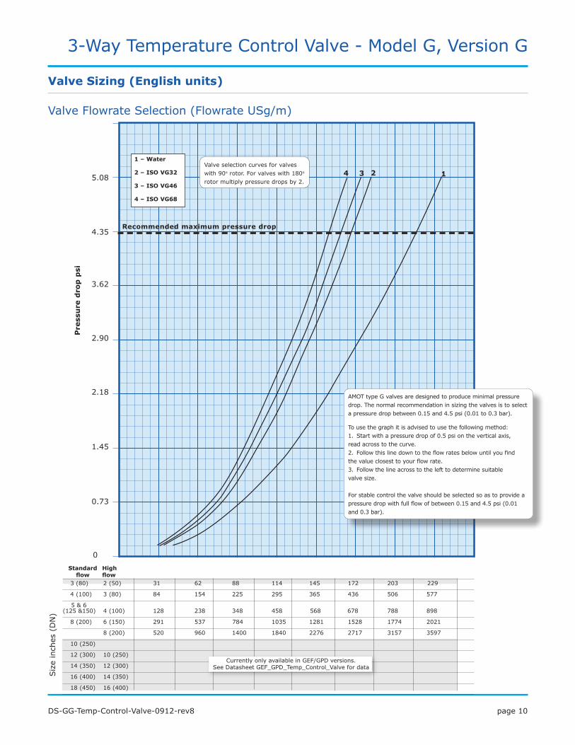
Keyfeaturesandbenefits
• Self-lockingwithminimumbacklashinthetransmission-preventsvalvemovementduetoflow
• Auxiliarylimitswitchesforuserconnection
• Manualoverridefittedasstandard-valvecanbeoperatedineventofpowerfailure
• Twotorqueswitches-provideprotectionineventofactuatoroverloading
Overview of Electric Actuation
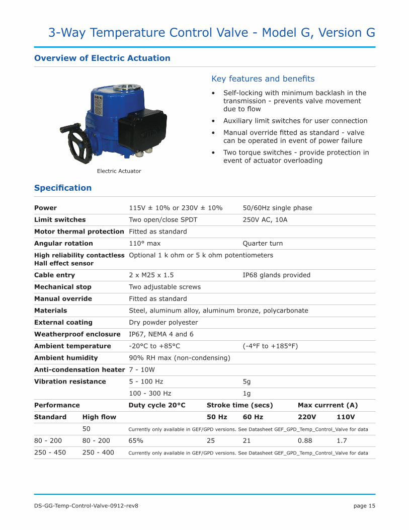
Specification
Power 115V ±10%or230V±10% 50/60Hzsinglephase
Limit switches Twoopen/closeSPDT 250VAC,10A
Motor thermal protection Fittedasstandard
Angular rotation 110°max Quarterturn
High reliability contactless Optional1kohmor5kohmpotentiometers Hall effect sensor
Cable entry 2xM25x1.5 IP68glandsprovided
Mechanical stop Twoadjustablescrews
Manual override Fittedasstandard
Materials Steel,aluminumalloy,aluminumbronze,polycarbonate
External coating Drypowderpolyester
Weatherproof enclosure IP67,NEMA4and6
Ambient temperature -20°Cto+85°C (-4°Fto+185°F)
Ambient humidity 90%RHmax(non-condensing)
Anti-condensation heater 7-10W
Vibration resistance 5-100Hz 5g
100-300Hz 1g
Performance Duty cycle 20°C Stroke time (secs) Max currrent (A)
Standard High flow 50 Hz 60 Hz 220V 110V
50 CurrentlyonlyavailableinGEF/GPDversions.SeeDatasheetGEF_GPD_Temp_Control_Valvefordata
80-200 80-200 65% 25 21 0.88 1.7
250-450 250-400 CurrentlyonlyavailableinGEF/GPDversions.SeeDatasheetGEF_GPD_Temp_Control_Valvefordata
ElectricActuator

page16DS-GG-Temp-Control-Valve-0912-rev8
3-Way Temperature Control Valve - Model G, Version G
TheAMOTactuator/valvepositionerisconfiguredtoacceptanindustrystandard4-20mApositiondemandinputsignal,andusesthistooperateinternalsolidstateswitchingtodrivethemotor.Themicroprocessorbasedunitusesthesignalfromthecontactlesspositionsensortoaccuratelypositiontheactuator,takingintoaccountmotorresponsetimeandactuatorovershoot.Thepositionerissplitintotwoparts,housedintheterminalbox.Thereisapowermodule,inwhichallhighvoltagecircuitsarefullyencapsulatedtowithstandhighvibration,andacontrolboard.Thisdesignallowsforeasymaintenance.
Userconfigurationallows:
• Theinputcanbeselectedfrom4-20mA,0-20mA,0-5V,0-10Vand2-10Vbyswitches.
• 4-20mAoutput,whichshowsactualvalveposition,canbeconfiguredtoretransmitthedemandinputsignal.
• Aswitchallowsforeasyconfigurationofwhichendofstrokecorrespondswitha4mAdemand.
• Theactiononsensorfailcanbeselectedfrommovingtoeitherthe4mAorthe20mApositions,butisfactorysettonotmoving.
• Thedeadbandcanbeincreasedtoaid performancewithnoisyinputsignals.
• Whennecessary,suchasaftermaintenance,theactuatorcanberecalibratedatthetouchofabutton.
Electronic Positioner
Overview of Pneumatic Actuation
Keyfeaturesandbenefits
• Aruggedquarterturn,doublepiston,rackandpinionpneumaticactuatorwithspringreturnandvalvepositionerasstandard.
• Canbeconfiguredfail-safe
Specification
Housing Castaluminumbase,steelcoverandtwopartPolyurethanepaintfinish.
Supply pressure 6to8bar (90to115psi)
Signal pressure 0.21to1.03bar (3to15psi)
Pressure connections G 1/4 (1/4NPT)
Manual override Optional
PneumaticActuator
TherearethreeLEDsontheterminalboxonthesideoftheactuator,providingclearvisualindicationofactuatorstatus.Twoalarmoutputsallowforremotefaultmonitoring.
ElectronicPositioner

page17DS-GG-Temp-Control-Valve-0912-rev8
3-Way Temperature Control Valve - Model G, Version G
HowtoOrder
A SizeNominal Bore Size
02GG 2 in (DN50), High flow only
03GG 3 in (DN80)
04GG 4 in (DN100)
05GG 5 in (DN125), Standard flow only
06GG 6 in (DN150)
08GG 8 in (DN200)
10GG 10 in (DN250)
12GG 12 in (DN300)
14GG 14 in (DN350)
16GG 16 in (DN400)
18GG 18 in (DN450), Standard flow only
B Flow Type*S Standard flow valve
H High flow valve
Example: A B C D E F G H J - K Model 08GG S D B S 32 EA B CA - AA
*Note:RefertoflowcoefficienttableforCv/Kvdata.
C Valve Body and Rotor MaterialBody and Rotor Material
B Bronze
D Ductile iron
R Stainless steel
S Carbon steel
D Flange Connection Standard
and ClassFlange class Flange standard
A PN6 EN 1092
B PN10 EN 1092
C PN16 EN 1092
F 125 lb (Flat Face)
ASME, Ductile iron valves only
J 150 lb ASME
L 10K JIS
M 5K JIS
N 150 lb MIL-PRF-200042E, Bronze valves only
E Rotor TypeS Standard rotor
F Mode of OperationCold Process Hot Process Rotation starting from Cold Position
12 Port 1 Port 2
Clockwise23 Port 2 Port 3
31 Port 3 Port 1
22 Port 2 Port 1Counter clockwise
32 Port 3 Port 2
13 Port 1 Port 3
G Actuation Type, Power Supply, Air Connections & Manual OverrideActuation Power Supply Air
ConnectionManualOverride
EAElectric
100-120 VAC 50/60 Hz -Fitted as standardEB 200-240 VAC 50/60 Hz -
P1
Pneumatic
- G1/4 (1/4” BSPP)Not fitted
P2 - 1/4” NPT
P3 - G1/4 (1/4” BSPP)Fitted
P4 - 1/4” NPT
H Actuator Control Input SignalActuation Input Signal Comments
A
Electric
Relays, Switched Live Supply
On Increasing TemperatureB 4-20 mA
C 20-4 mA
1Pneumatic
3-15 psi
2 15-3 psi
J Actuator Feedback SignalActuation Feedback Signal Comments
AA
Electric
NoneH ≠ B or C
BA 0 - 1000Ω (via Potentiometer)
CA 4-20 mA Position Retransmit
DA 4-20 mA Position Retransmit and 0 - 1000Ω (via Potentiometer)
EA 20-4 mA Position Retransmit
FA 20-4 mA Position Retransmit and 0 - 1000Ω (via Potentiometer)
00 Pneumatic None
UsethetablesbelowtoselecttheuniquespecificationofyourGvalve.
K Customer Special Options-AA Standard product
-*** Customer Special Code Assigned

page18DS-GG-Temp-Control-Valve-0912-rev8
3-Way Temperature Control Valve - Model G, Version G
PID Valve Controllers 8071/8072D and Solid State Relays 47581L001
Keyfeaturesandbenefits
• FullyprogrammablePID-basedcontrol-allowseasysystemconfiguration
• Universalinputs;RTD’s,thermocouple,orstandard4-20mAsignalgivesmaximumsystemdesignflexibility
• Canbeoperatedinmanualmode-easymaintenanceandsetup
Accessories
SolidStateRelay47581L001
PIDController8072D
PIDController8071D
ForfurtherinformationandhowtoordertheseproductsseeDatasheet_8071_2_D_47851.pdf
3-Wire PT100 Temperature Sensor - 8060
Keyfeaturesandbenefits
• 3wireRTDs-accuratetemperaturemeasurement
• Excellentlongtermstability
• Goodlinearity
• Canusestandard3-corecableTemperatureSensor
8060
ForfurtherinformationandhowtoorderthisproductseeDatasheet_8060_temp_sensor.pdf

page19DS-GG-Temp-Control-Valve-0912-rev8
3-Way Temperature Control Valve - Model G, Version G
Solid State Relay Module - 8073C
Accessories
Relay Module
8073C
The8073CrelaymoduleincorporatestwosolidstaterelayswithterminationsinanIP67enclosure.The8073Cisdesignedtobeusedwiththe8071DcontrollerlogicoutputstodrivevoltagesfortheelectricallyactuatedGvalve.Featuresinclude:zero-crossingswitching,relayandlogiclevelinputsandIP67enclosure.
Interfacewith8071Dcontroller InterfacewithACinputsignals
TypicalApplications
Logic outputs
110/240 Vac
AC inputs
110/240 Vac
Keyfeaturesandbenefits
• IP67enclosure
• AlternativetousingtwoSSRstype47581L001
• Goodlinearity
• Canusestandard3-corecable
ForfurtherinformationandhowtoorderthisproductseeDatasheet_8073C_SSR.pdf
Electro-Pneumatic Converter - 8064A
Electro-PneumaticConverter-8064A
Keyfeaturesandbenefits
• Highvibrationresistance-Lloyds4G
• Suitableforlongerpiperuns
• Fullyadjustableforoptimisedsystemoperation
• ATEXhazardousareacertification ForfurtherinformationandhowtoorderthisproductseeDatasheet_8064A_C_elect_pneu_converter.pdf
GValveElectro-PneumaticConverter8064A
TemperatureController8071D
TemperatureProbe8060
TypicalApplication

page20DS-GG-Temp-Control-Valve-0912-rev8
3-Way Temperature Control Valve - Model G, Version G
Pneumatic Indicator Controller - SG80
Accessories
PneumaticIndicatorControllerSG80
Keyfeaturesandbenefits
• Completestandalonecontroller,noothercontrolcomponentsrequired-reducedsystemcost
• Easilyremovablecomponents-lowmaintenance
• Gooddynamicresponse-givesoptimumengineperformance
• Compatiblewitheverytypeofpneumaticvalve-flexible
ForfurtherinformationandhowtoorderthisproductseeDatasheet_SG80_Pneu_Ind_Controller.pdf
TypicalApplication
SG80TemperatureControllerandSensor
GValve
Electro-Pneumatic Converter - 8064C
Electro-PneumaticConverter-8064C
ForfurtherinformationandhowtoorderthisproductseeDatasheet_8064A_C_elect_pneu_converter.pdf
TypicalApplication
Electro-pneumaticsystem
GvalveElectro-pneumaticconverter8064C
Temperaturecontroller8071D
Temperatureprobe8060
Keyfeaturesandbenefits
• Acceptshighsupplypressure-avoidsuseofadditionalregulator
• Factorysetforeaseofinstallation
• Lowcostalternativeto8064A
• ATEXhazardousareacertification

Europe and Africa
AMOTWesternWayBuryStEdmundsSuffolk,IP333SZEngland
Tel +44(0)1284762222Fax +44(0)[email protected]
AMOTControlsGmbHRondenbarg2522525HamburgGermany
Tel +49(0)4085371298Fax +49(0)[email protected]
Americas
AMOTUSA8824FallbrookDrHoustonTX77064USA
Tel: +1(281)9401800Fax +1(713)5599419Email [email protected]
Asia Pacific
AMOTShanghaiRm4102-4104UnitedPlaza1468NanjingRoadWestShanghai200040China
Tel +86(0)2162797700Fax +86(0)[email protected]
AMOTSingapore10EunosRoad8#12-06SingaporePostCentreSingapore408600
Tel +6564086265Fax [email protected]
www.amot.com