Embed Size (px)
Citation preview
3 Port Solenoid Valve
Series VP300/500/700 RoHS compliant
0.55 w1.55 w
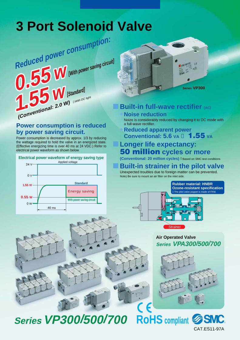
� Built-in full-wave rectifier (AC)
� Noise reductionNoize is considerably reduced by changing it to DC mode with a full-wave rectifier.
� Reduced apparent powerConventional: 5.6 VA → 1.55 VA
� Longer life expectancy:50 million cycles or more (Conventional: 20 million cycles) ∗ Based on SMC test conditions
� Built-in strainer in the pilot valve Unexpected troubles due to foreign matter can be prevented. Note) Be sure to mount an air filter on the inlet side.
Rubber material: HNBROzone-resistant specification ∗ The pilot valve poppet is made of FKM.
Strainer
Electrical power waveform of energy saving typeApplied voltage
Standard
With power saving circuit
40 ms
24 V
0 V
1.55 W
0.55 W
0 W
Energy savingEnergy saving
Reduced power consumption:
0.55 w [With power saving circuit]
1.55 w [Standard]
(Conventional: 2.0 W) ∗ With DC light
Power consumption is reduced by power saving circuit.Power consumption is decreased by approx. 1/3 by reducing the wattage required to hold the valve in an energized state. (Effective energizing time is over 40 ms at 24 VDC.) Refer to electrical power waveform as shown below.
Series VP300
Air Operated Valve
Series VPA300/500/700
CAT.ES11-97A
VP-A.qxd 08.12.8 10:44 AM Page C1
1(P)
3(R)
(A)2
1(P)
3(R)
(A)2
1(P)
3(R)
(A)2
X
1(P)
3(R)
(A)2
1(P)
3(R)
(A)2
1(P)
3(R)
(A)2
X
1(P)
3(R)
(A)2
X
Bas
e m
ou
nte
dB
od
y p
ort
ed
So
len
oid
val
ve
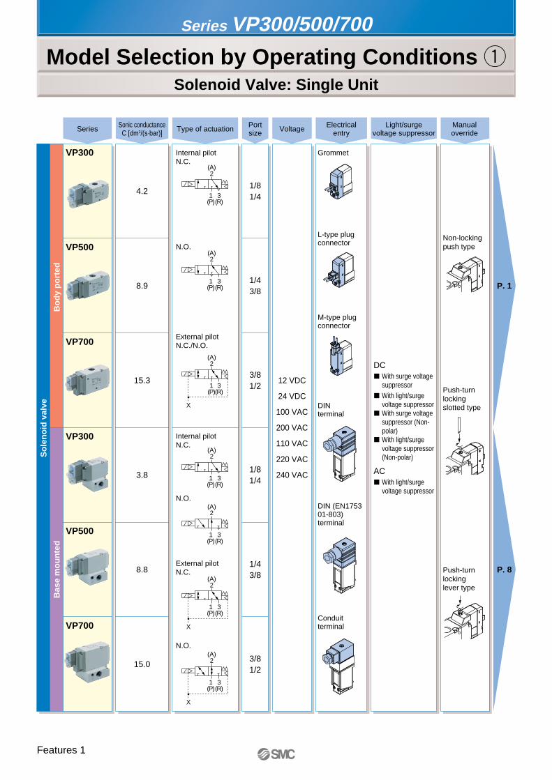
Series Sonic conductanceC [dm3/(s·bar)] Type of actuation
Internal pilotN.C.
Grommet
Non-locking push type
Push-turn locking slotted type
Push-turn locking lever type
L-type plug connector
M-type plug connector
DIN terminal
DIN (EN175301-803) terminal
Conduit terminal
Internal pilotN.C.
N.O.
External pilotN.C.
N.O.
N.O.
External pilotN.C./N.O.
Portsize Voltage Light/surge
voltage suppressorManualoverride
Electricalentry
VP300
VP500
VP700
VP300
VP500
VP700
12 VDC
24 VDC
100 VAC
200 VAC
110 VAC
220 VAC
240 VAC
P. 1
P. 8
1/81/4
1/43/8
3/81/2
1/81/4
1/43/8
3/81/2
4.2
8.9
15.3
3.8
8.8
15.0
Series VP300/500/700
Model Selection by Operating Conditions qSolenoid Valve: Single Unit
DC� With surge voltage
suppressor� With light/surge
voltage suppressor� With surge voltage
suppressor (Non-polar)
� With light/surge voltage suppressor (Non-polar)
AC� With light/surge
voltage suppressor
Features 1
VP-A.qxd 08.12.8 10:44 AM Page F1
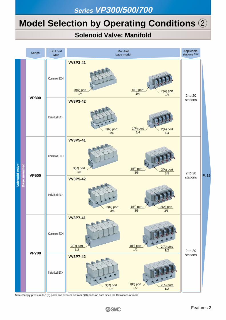
3(R) port1/4
3(R) port3/8
3(R) port1/2
3(R) port1/2
3(R) port1/4
2(A) port1/4
1(P) port1/4
2(A) port1/4
2(A) port3/8
2(A) port3/8
2(A) port1/2
2(A) port1/2
3(R) port3/8
1(P) port1/4
1(P) port3/8
1(P) port3/8
1(P) port1/2
1(P) port1/2
Bas
e m
ou
nte
d
So
len
oid
val
ve
Series EXH porttype
2 to 20stations
2 to 20stations
2 to 20stations
Common EXH
Individual EXH
Common EXH
Individual EXH
Common EXH
Individual EXH
VV3P3-41
VV3P3-42
VV3P5-41
VV3P5-42
VV3P7-41
VV3P7-42
Manifoldbase model
VP300
VP500
VP700
Applicable stations Note)
P. 15
Note) Supply pressure to 1(P) ports and exhaust air from 3(R) ports on both sides for 10 stations or more.
Series VP300/500/700
Model Selection by Operating Conditions wSolenoid Valve: Manifold
Features 2
VP-A.qxd 08.12.8 10:45 AM Page F2
1(P)
3(R)
(A)2
12
1(P)
3(R)
(A)2
12
1(P)
3(R)
(A)2
12
1(P)
3(R)
(A)2
12
12
(A)2
1(P)
3(R)
12
(A)2
1(P)
3(R)
12
(A)2
3(R)
1(P)
Air
op
erat
ed v
alve
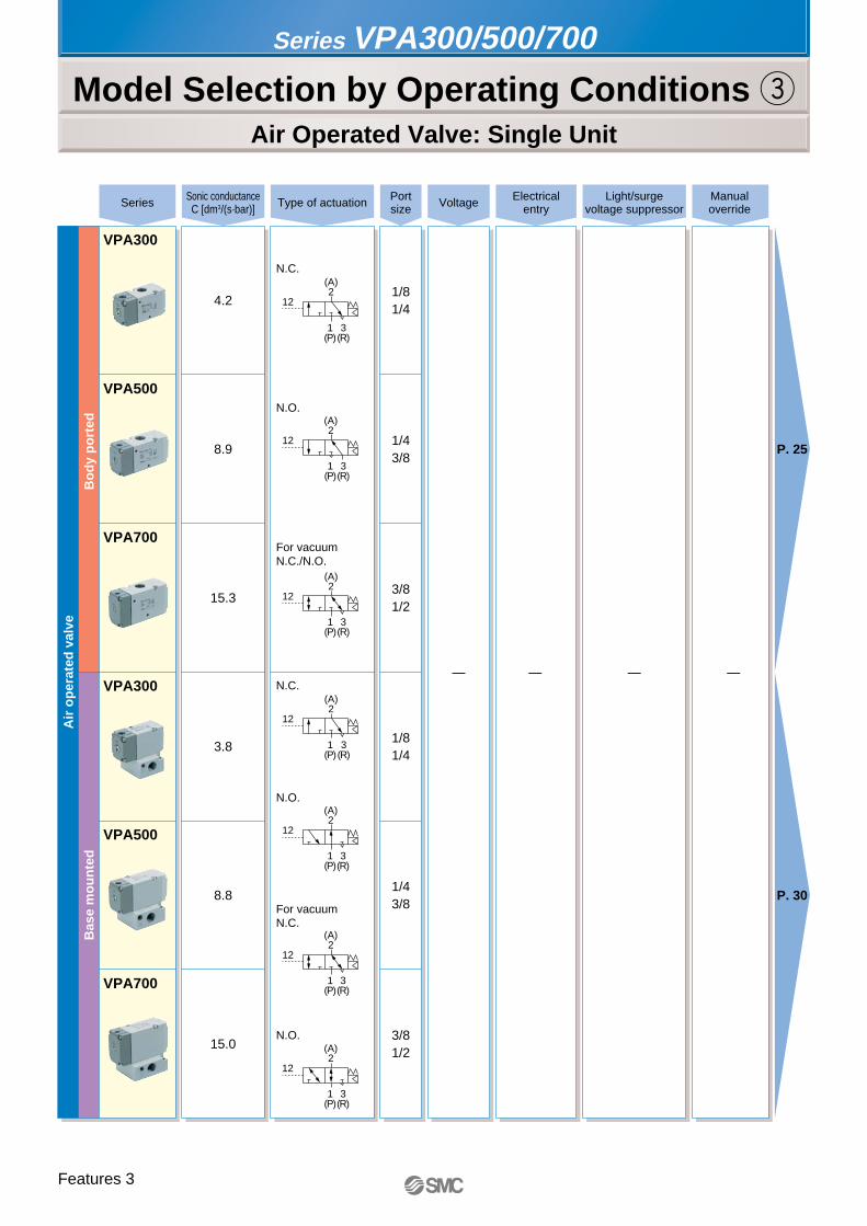
N.C.
N.O.
For vacuumN.C./N.O.
N.C.
N.O.
For vacuumN.C.
N.O.
VPA300
VPA500
VPA700
VPA300
VPA500
VPA700
— ———
P. 25
P. 30
1/81/4
1/43/8
3/81/2
1/81/4
1/43/8
3/81/2
4.2
8.9
15.3
3.8
8.8
15.0
Series VPA300/500/700
Model Selection by Operating Conditions eAir Operated Valve: Single Unit
Series Sonic conductanceC [dm3/(s·bar)] Type of actuation Port
size Voltage Light/surgevoltage suppressor
Manualoverride
Electricalentry
Bas
e m
ou
nte
dB
od
y p
ort
ed
Features 3
VP-A.qxd 08.12.8 10:45 AM Page F3

3(R) port1/4
3(R) port3/8
3(R) port1/2
3(R) port1/2
3(R) port1/4
2(A) port1/4
2(A) port1/4
2(A) port3/8
2(A) port3/8
2(A) port1/2
2(A) port1/2
3(R) port3/8
1(P) port1/4
1(P) port1/4
1(P) port3/8
1(P) port3/8
1(P) port1/2
1(P) port1/2
2 to 20stations
2 to 20stations
2 to 20stations
VV3PA3-41
VV3PA3-42
VV3PA5-41
VV3PA5-42
VV3PA7-41
VV3PA7-42
VPA300
VPA500
VPA700
P. 35
Note) Supply pressure to 1(P) ports and exhaust air from 3(R) ports on both sides for 10 stations or more.
Common EXH
Individual EXH
Common EXH
Individual EXH
Common EXH
Individual EXH
EXH porttype
Series VPA300/500/700
Model Selection by Operating Conditions rAir Operated Valve: Manifold
Series Manifoldbase model
Applicable stations Note)
Bas
e m
ou
nte
d
Air
op
erat
ed v
alve
Features 4
VP-A.qxd 08.12.8 10:45 AM Page F4
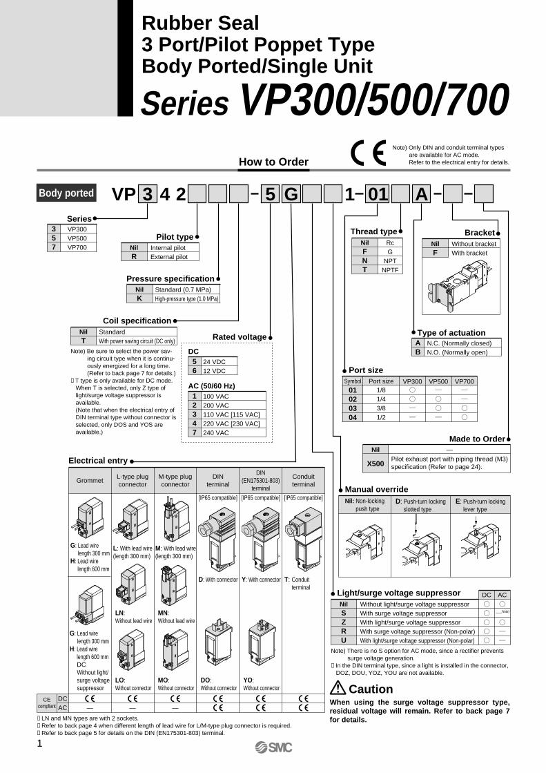
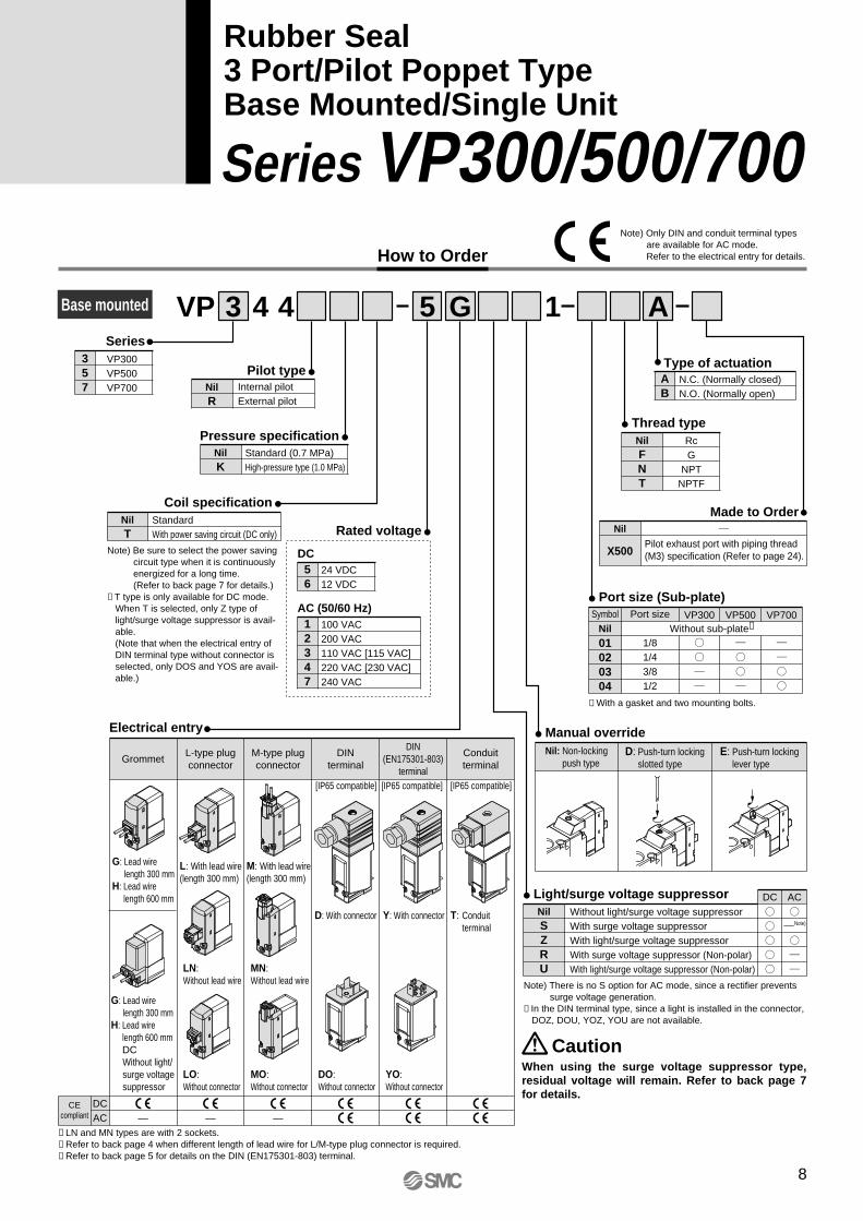
How to Order
Series VP300/500/700
Rubber Seal3 Port/Pilot Poppet TypeBody Ported/Single Unit
VP 3 4 2 5 G 1 01 ASeries
357
VP300VP500VP700
56
24 VDC12 VDC
Pilot typeNilR
Internal pilotExternal pilot
BracketNilF
Without bracketWith bracket
Thread typeNilFNT
RcG
NPTNPTF
Light/surge voltage suppressor DC ACNilSZRU
Without light/surge voltage suppressorWith surge voltage suppressorWith light/surge voltage suppressorWith surge voltage suppressor (Non-polar)With light/surge voltage suppressor (Non-polar)
Port size
01020304
Symbol Port size VP3001/81/43/81/2
VP500 VP700
Manual overrideNil: Non-locking
push typeD: Push-turn locking
slotted typeE: Push-turn locking
lever type
Pressure specificationNilK
Standard (0.7 MPa)High-pressure type (1.0 MPa)
Electrical entry
GrommetConduitterminal
L-type plugconnector
M-type plugconnector
DINterminal
DIN(EN175301-803)
terminal
G: Lead wirelength 300 mm
H: Lead wirelength 600 mm
L: With lead wire(length 300 mm)
LN:Without lead wire
LO:Without connector
M: With lead wire(length 300 mm)
D: With connector Y: With connector T: Conduit terminal
DO:Without connector
YO:Without connector
MN:Without lead wire
MO:Without connector
G: Lead wirelength 300 mm
H: Lead wirelength 600 mmDCWithout light/surge voltagesuppressor
Coil specificationNilT
StandardWith power saving circuit (DC only)
Body ported
Note) Be sure to select the power sav-ing circuit type when it is continu-ously energized for a long time.(Refer to back page 7 for details.)
∗ T type is only available for DC mode. When T is selected, only Z type of light/surge voltage suppressor is available.(Note that when the electrical entry of DIN terminal type without connector is selected, only DOS and YOS are available.)
Note) There is no S option for AC mode, since a rectifier prevents surge voltage generation.
∗ In the DIN terminal type, since a light is installed in the connector, DOZ, DOU, YOZ, YOU are not available.
Rated voltage
DC
12347
100 VAC200 VAC110 VAC [115 VAC]220 VAC [230 VAC]240 VAC
AC (50/60 Hz)
When using the surge voltage suppressor type, residual voltage will remain. Refer to back page 7 for details.
Caution
∗ LN and MN types are with 2 sockets.∗ Refer to back page 4 when different length of lead wire for L/M-type plug connector is required.∗ Refer to back page 5 for details on the DIN (EN175301-803) terminal.
[IP65 compatible] [IP65 compatible] [IP65 compatible]
Type of actuationAB
N.C. (Normally closed)N.O. (Normally open)
Made to OrderNil
X500
—Pilot exhaust port with piping thread (M3) specification (Refer to page 24).
CEcompliant
DCAC — — —
Note) Only DIN and conduit terminal types are available for AC mode.Refer to the electrical entry for details.
Note)
1
VP-A.qxd 08.12.8 10:45 AM Page 1
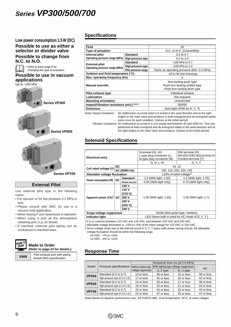
Low power consumption 1.5 W (DC)Possible to use as either a selector or divider valvePossible to change from N.C. to N.O.
Possible to use in vacuum applicationsUp to –100 kPa
Use external pilot type in the following cases:• For vacuum or for low pressure 0.2 MPa or
less• Please consult with SMC for use in a
vacuum hold application.• When having P port downsized in diameter• When using A port as the atmospheric
releasing port, e.g. air blower
External Pilot
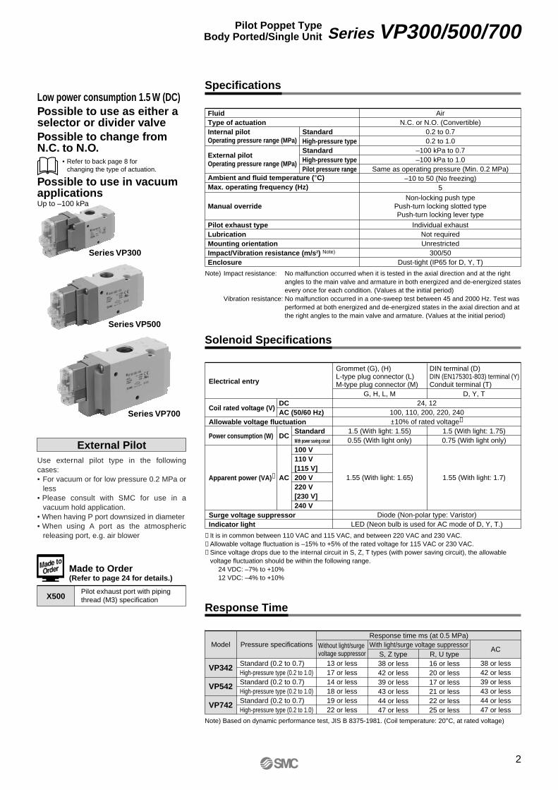
Specifications
Solenoid Specifications
Response Time
Electrical entry
Coil rated voltage (V)
Allowable voltage fluctuation
Power consumption (W)
Apparent power (VA)∗
Surge voltage suppressorIndicator light
24, 12100, 110, 200, 220, 240±10% of rated voltage∗
Diode (Non-polar type: Varistor)LED (Neon bulb is used for AC mode of D, Y, T.)
1.5 (With light: 1.75)0.75 (With light only)
1.55 (With light: 1.7)
1.5 (With light: 1.55)0.55 (With light only)
1.55 (With light: 1.65)
Grommet (G), (H)L-type plug connector (L)M-type plug connector (M)
DIN terminal (D)DIN (EN175301-803) terminal (Y)Conduit terminal (T)
DCAC (50/60 Hz)
StandardWith power saving circuit
100 V110 V[115 V]200 V220 V[230 V]240 V
G, H, L, M D, Y, T
∗ It is in common between 110 VAC and 115 VAC, and between 220 VAC and 230 VAC.∗ Allowable voltage fluctuation is –15% to +5% of the rated voltage for 115 VAC or 230 VAC.∗ Since voltage drops due to the internal circuit in S, Z, T types (with power saving circuit), the allowable
voltage fluctuation should be within the following range. 24 VDC: –7% to +10%12 VDC: –4% to +10%
FluidType of actuationInternal pilotOperating pressure range (MPa)
External pilotOperating pressure range (MPa)
Ambient and fluid temperature (°C)Max. operating frequency (Hz)
Manual override
Pilot exhaust typeLubricationMounting orientationImpact/Vibration resistance (m/s2) Note)
Enclosure
StandardHigh-pressure typeStandardHigh-pressure typePilot pressure range
Note) Impact resistance: No malfunction occurred when it is tested in the axial direction and at the right angles to the main valve and armature in both energized and de-energized states every once for each condition. (Values at the initial period)
Vibration resistance: No malfunction occurred in a one-sweep test between 45 and 2000 Hz. Test was performed at both energized and de-energized states in the axial direction and at the right angles to the main valve and armature. (Values at the initial period)
VP342
VP542
VP742
Standard (0.2 to 0.7)High-pressure type (0.2 to 1.0)Standard (0.2 to 0.7)High-pressure type (0.2 to 1.0)Standard (0.2 to 0.7)High-pressure type (0.2 to 1.0)
Response time ms (at 0.5 MPa)
13 or less17 or less14 or less18 or less19 or less22 or less
Without light/surge voltage suppressor
With light/surge voltage suppressorS, Z type38 or less42 or less39 or less43 or less44 or less47 or less
R, U type16 or less20 or less17 or less21 or less22 or less25 or less
AC
38 or less42 or less39 or less43 or less44 or less47 or less
Note) Based on dynamic performance test, JIS B 8375-1981. (Coil temperature: 20°C, at rated voltage)
Pressure specificationsModel
DC
AC
Series VP300
Series VP500
Series VP700
Made to Order(Refer to page 24 for details.)
Pilot exhaust port with piping thread (M3) specificationX500
AirN.C. or N.O. (Convertible)
0.2 to 0.70.2 to 1.0
–100 kPa to 0.7–100 kPa to 1.0
Same as operating pressure (Min. 0.2 MPa)–10 to 50 (No freezing)
5
Individual exhaustNot requiredUnrestricted
300/50Dust-tight (IP65 for D, Y, T)
Non-locking push typePush-turn locking slotted typePush-turn locking lever type
• Refer to back page 8 for changing the type of actuation.
2
Series VP300/500/700Pilot Poppet TypeBody Ported/Single Unit
VP-A.qxd 08.12.8 10:45 AM Page 2
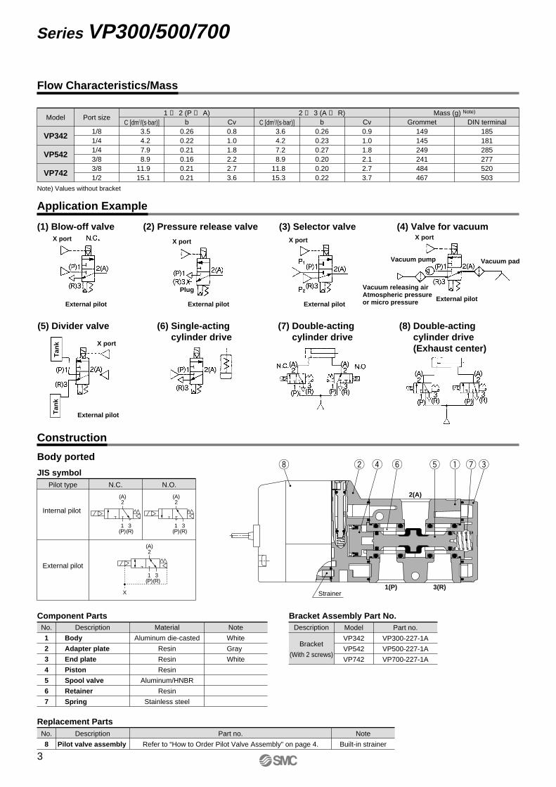
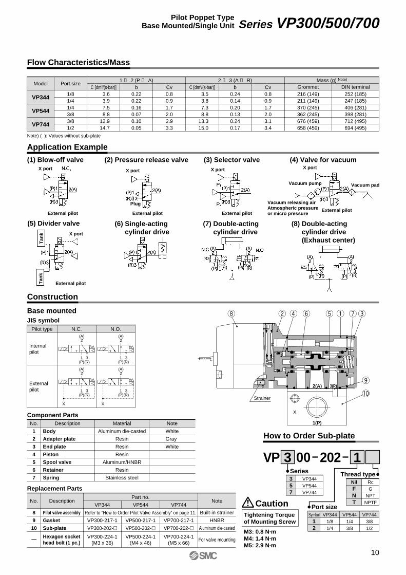
Construction
Application Example
Body
Adapter plate
End plate
Piston
Spool valve
Retainer
Spring
No.
1
2
3
4
5
6
7
Description Material
Aluminum die-casted
Resin
Resin
Resin
Aluminum/HNBR
Resin
Stainless steel
Note
White
Gray
White
Component Parts
Replacement PartsDescriptionNo. Part no.
Refer to “How to Order Pilot Valve Assembly” on page 4.Pilot valve assembly
Note
Built-in strainer8
C [dm3/(s·bar)] b CvMass (g) Note)
Port sizeModel
VP342
VP542
VP742
1/81/41/43/83/81/2
3.54.27.98.9
11.915.1
0.260.220.210.160.210.21
0.81.01.82.22.73.6
3.64.27.28.9
11.815.3
0.260.230.270.200.200.22
0.91.01.82.12.73.7
149145249241484467
185181285277520503
C [dm3/(s·bar)] b Cv Grommet DIN terminal1 ↔ 2 (P ↔ A) 2 ↔ 3 (A ↔ R)
Flow Characteristics/Mass
Body ported
Note) Values without bracket
1(P)
3(R)
(A)2
1(P)
3(R)
(A)2
X
1(P)
3(R)
(A)2
Description
Bracket
(With 2 screws)
Part no.Model
VP342
VP542
VP742
VP300-227-1A
VP500-227-1A
VP700-227-1A
Bracket Assembly Part No.
JIS symbolPilot type
External pilot
Internal pilot
N.C. N.O.
uy eqtrwi
2(A)
1(P) 3(R)Strainer
(1) Blow-off valve (2) Pressure release valve (3) Selector valve
(5) Divider valve (7) Double-acting cylinder drive
(6) Single-acting cylinder drive
(8) Double-acting cylinder drive(Exhaust center)
(4) Valve for vacuum
External pilotExternal pilot
Vacuum releasing airAtmospheric pressure or micro pressureExternal pilot
External pilot
External pilot
Vacuum pump Vacuum pad
X portX portX port
Tan
kT
ank
X port
X port
Plug
3
Series VP300/500/700
VP-A.qxd 08.12.8 10:45 AM Page 3
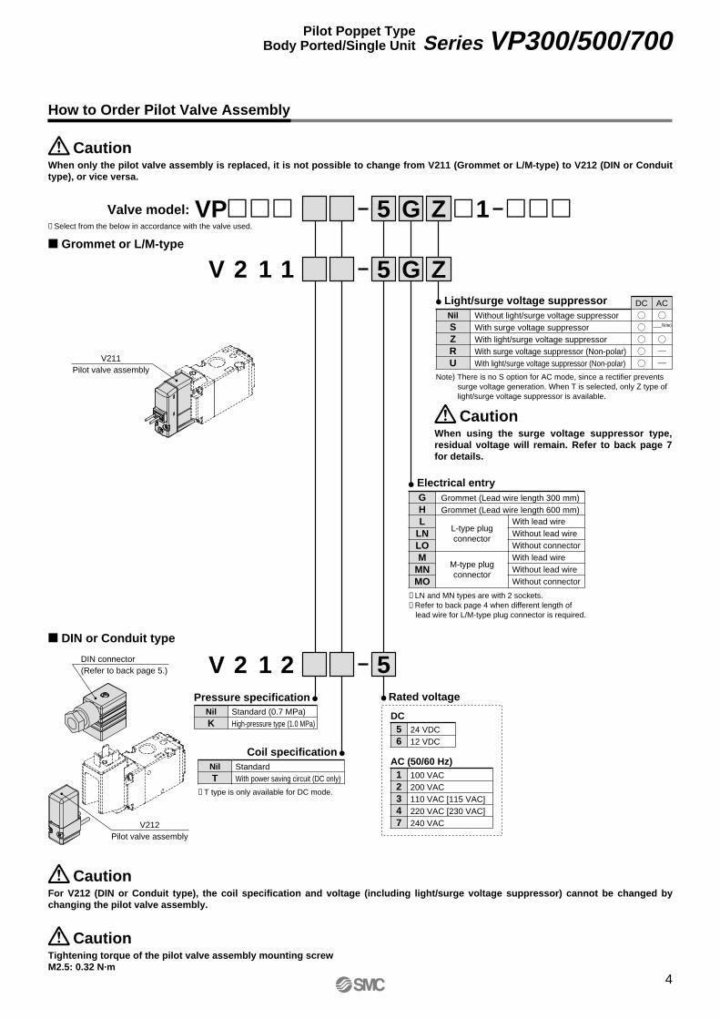
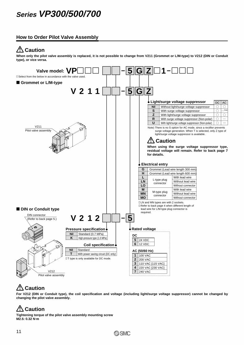
V211Pilot valve assembly
DIN connector(Refer to back page 5.)
V212Pilot valve assembly
How to Order Pilot Valve Assembly
When only the pilot valve assembly is replaced, it is not possible to change from V211 (Grommet or L/M-type) to V212 (DIN or Conduit type), or vice versa.
Caution
For V212 (DIN or Conduit type), the coil specification and voltage (including light/surge voltage suppressor) cannot be changed by changing the pilot valve assembly.
Caution
Tightening torque of the pilot valve assembly mounting screwM2.5: 0.32 N·m
Caution
VP��� �1 ���Valve model: 5 G Z
56
24 VDC12 VDC
Light/surge voltage suppressor DC ACNilSZRU
Without light/surge voltage suppressorWith surge voltage suppressorWith light/surge voltage suppressorWith surge voltage suppressor (Non-polar)With light/surge voltage suppressor (Non-polar)
Pressure specificationNilK
Standard (0.7 MPa)High-pressure type (1.0 MPa)
GHL
LNLOM
MNMO
Grommet (Lead wire length 300 mm)Grommet (Lead wire length 600 mm)
With lead wireWithout lead wireWithout connectorWith lead wireWithout lead wireWithout connector
Electrical entry
Coil specificationNilT
StandardWith power saving circuit (DC only)
∗ T type is only available for DC mode.
Note) There is no S option for AC mode, since a rectifier prevents surge voltage generation. When T is selected, only Z type of light/surge voltage suppressor is available.
∗ LN and MN types are with 2 sockets.∗ Refer to back page 4 when different length of
lead wire for L/M-type plug connector is required.
Rated voltage
DC
12347
100 VAC200 VAC110 VAC [115 VAC]220 VAC [230 VAC]240 VAC
AC (50/60 Hz)
When using the surge voltage suppressor type, residual voltage will remain. Refer to back page 7 for details.
Caution
L-type plugconnector
M-type plugconnector
� Grommet or L/M-type
� DIN or Conduit type
5 G Z
5
2V 1 1
2V 1 2
∗ Select from the below in accordance with the valve used.
Note)
4
Series VP300/500/700Pilot Poppet TypeBody Ported/Single Unit
VP-A.qxd 08.12.8 10:45 AM Page 4
App
rox.
300
(Lea
d w
ire le
ngth
)
14
97.3
42.7
56.4
20.4 16
1.1
26.5
4.5
ø3.8PE port∗
1/8, 1/41(P), 3(R) port
NO
3R
1P
96.1Approx. 300(Lead wire length)
3.4
(1.6)
1.3
21.5
0.8
(9)
20.4 16
57.6
26.2
11
M5 x 0.8External pilot port(External pilot specification: R)
1/8, 1/42(A) port
2 x ø3.2(For mounting)
Manual override
X
2A
NC
252.
815 26.2
42.7
3531
2 x ø3.2(For mounting)
(17.
5)
(45)
(54.5)
(5.4
)
(35)
19.7
(Indicator light)
+–
Max
. 1082.7
73.7
102.
9
Pg9
Applicable cable O.D.ø4.5 to ø7
Approx. 300(Lead wire length)
53.7
94
88.9
20
42.7
App
rox.
300
(Lea
d w
ire le
ngth
)10
2.4
(Mounting groove for M5 thread)
(20.9)(Distance between ports)
Max
. 10
115.
3
86.9 [76.9]
76.9 [66.9]
(Indicator light)
Pg9
Applicable cable O.D.ø4.5 to ø7
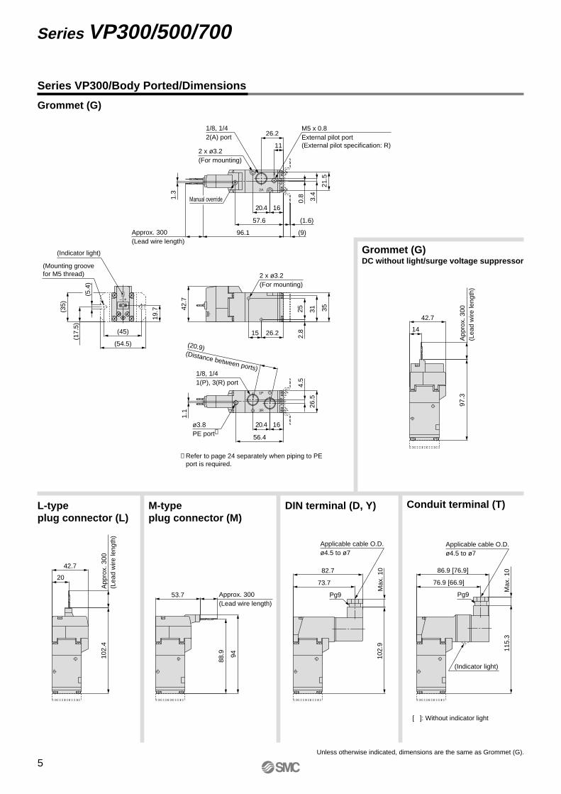
Series VP300/Body Ported/Dimensions
Grommet (G)
Grommet (G)DC without light/surge voltage suppressor
DIN terminal (D, Y)M-type plug connector (M)
L-type plug connector (L)
Conduit terminal (T)
Unless otherwise indicated, dimensions are the same as Grommet (G).
[ ]: Without indicator light
∗ Refer to page 24 separately when piping to PE port is required.
5
Series VP300/500/700
VP-A.qxd 08.12.8 10:45 AM Page 5
16.3
App
rox.
300
(Lea
d w
ire le
ngth
)12
3.5
45
Max
. 1085
76
129.
1
Applicable cable O.D.ø4.5 to ø7
Pg9
120.
2
115.
1
Approx. 300(Lead wire length)
56
App
rox.
300
(Lea
d w
ire le
ngth
)12
8.6
45
22.3
(22.
5)
(60)
(50)
(5.4
)
(45)
22
(Indicator light)
+–
122.3Approx. 300(Lead wire length)
26
4.5
3.5
(1.6)
(9)
83.8
31 25.6
41.1
19
1.3
1/8External pilot port(External pilot specification: R)
Manual override
2 x ø4.2(For mounting)
1/4, 3/82(A) port
NC
X2A
2.5
327
83.6
30.7 25.6
1/4, 3/81(P), 3(R) port
ø3.8PE port∗
NO
1P 3R
31.5
23.5 39.6 4
4045
2 x ø4.2(For mounting)
(31.5)(Distance between ports)
89.2 [79.2]
79.2 [69.2]
Max
. 10
131.
5
Pg9
(Indicator light)
Applicable cable O.D.ø4.5 to ø7
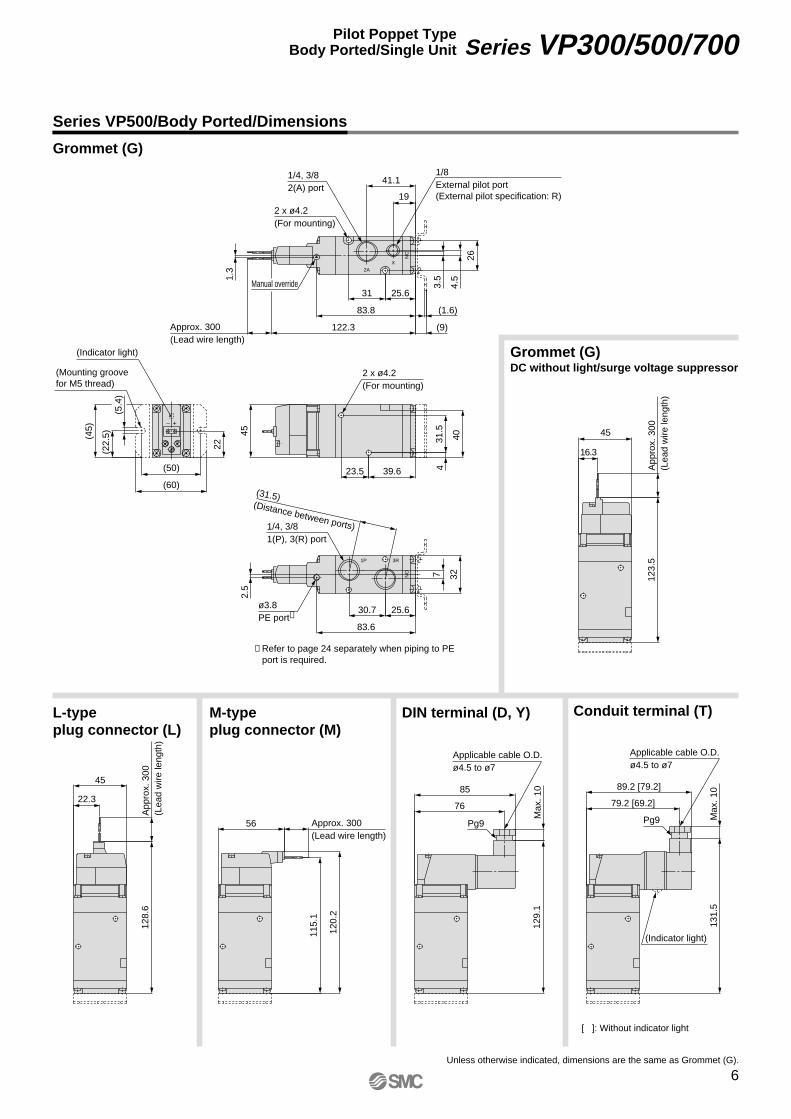
∗ Refer to page 24 separately when piping to PE port is required.
(Mounting groovefor M5 thread)
Series VP500/Body Ported/Dimensions
Grommet (G)DC without light/surge voltage suppressor
Unless otherwise indicated, dimensions are the same as Grommet (G).
[ ]: Without indicator light
Grommet (G)
DIN terminal (D, Y)M-type plug connector (M)
L-type plug connector (L)
Conduit terminal (T)
6
Series VP300/500/700Pilot Poppet TypeBody Ported/Single Unit
VP-A.qxd 08.12.8 10:45 AM Page 6
34.3
App
rox.
300
(Lea
d w
ire le
ngth
)14
6.5
63
Max
. 10
152.
1
94
103
Pg9
Applicable cable O.D.ø4.5 to ø7
138.
1
143.
2
Approx. 300(Lead wire length)
74
App
rox.
300
(Lea
d w
ire
leng
th)
151.
6
63
40.3
145.3Approx. 300(Lead wire length)
(2)106.8
(9)
51.5
27.5
41 31
33
7.5
4.5
1.3
1/8External pilot port(External pilot specification: R)
3/8, 1/22(A) port
2 x ø5.2(For mounting)
Manual override
NC
X
2A
40
(31.
5)
(60)
(74)
(6.4
)
(63)
(Indicator light)
+–
38.5
9.431 51.5
56.563
2 x ø5.2(For mounting)
107.5
42 30.5
409
2.5
ø4PE port∗
3/8, 1/21(P), 3(R) port
NO
3R1P
107.2 [97.2]
97.2 [87.2]
Max
. 10
154.
5
Pg9
(Indicator light)
Applicable cable O.D.ø4.5 to ø7
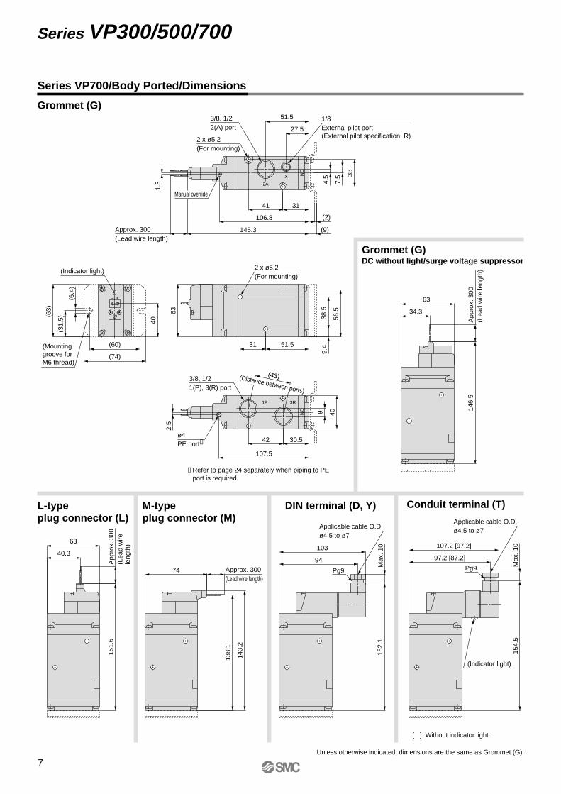
∗ Refer to page 24 separately when piping to PE port is required.
(Mounting groove for M6 thread)
(43)(Distance between ports)
Grommet (G)DC without light/surge voltage suppressor
Unless otherwise indicated, dimensions are the same as Grommet (G).
[ ]: Without indicator light
Series VP700/Body Ported/Dimensions
Grommet (G)
DIN terminal (D, Y)M-type plug connector (M)
L-type plug connector (L)
Conduit terminal (T)
7
Series VP300/500/700
VP-A.qxd 08.12.8 10:45 AM Page 7
VP 3 4 4 5 G 1 A
357
VP300VP500VP700
Type of actuationAB
N.C. (Normally closed)N.O. (Normally open)
56
24 VDC12 VDC
Pilot typeNilR
Thread typeNilFNT
RcG
NPTNPTF
Light/surge voltage suppressor DC ACNilSZRU
Without light/surge voltage suppressorWith surge voltage suppressorWith light/surge voltage suppressorWith surge voltage suppressor (Non-polar)With light/surge voltage suppressor (Non-polar)
Port size (Sub-plate)
01020304
SymbolNil
Port size VP300Without sub-plate∗
1/81/43/81/2
VP500 VP700
Manual override
Pressure specificationNilK
Standard (0.7 MPa)High-pressure type (1.0 MPa)
Electrical entry
Coil specificationNilT
StandardWith power saving circuit (DC only)
Note) Be sure to select the power saving circuit type when it is continuously energized for a long time.(Refer to back page 7 for details.)
∗ T type is only available for DC mode. When T is selected, only Z type of light/surge voltage suppressor is avail-able.(Note that when the electrical entry of DIN terminal type without connector is selected, only DOS and YOS are avail-able.)
Note) There is no S option for AC mode, since a rectifier prevents surge voltage generation.
∗ In the DIN terminal type, since a light is installed in the connector, DOZ, DOU, YOZ, YOU are not available.
∗ With a gasket and two mounting bolts.
Rated voltage
DC
12347
100 VAC200 VAC110 VAC [115 VAC]220 VAC [230 VAC]240 VAC
AC (50/60 Hz)
When using the surge voltage suppressor type, residual voltage will remain. Refer to back page 7 for details.
Caution
∗ LN and MN types are with 2 sockets.∗ Refer to back page 4 when different length of lead wire for L/M-type plug connector is required.∗ Refer to back page 5 for details on the DIN (EN175301-803) terminal.
Made to OrderNil
X500Pilot exhaust port with piping thread (M3) specification (Refer to page 24).
[IP65 compatible] [IP65 compatible] [IP65 compatible]
CEcompliant
DCAC — — —
Series VP300/500/700
Rubber Seal3 Port/Pilot Poppet TypeBase Mounted/Single Unit
How to Order
Base mounted
Series
Internal pilotExternal pilot
GrommetConduitterminal
L-type plugconnector
M-type plugconnector
DINterminal
DIN(EN175301-803)
terminal
G: Lead wirelength 300 mm
H: Lead wirelength 600 mm
L: With lead wire(length 300 mm)
LN:Without lead wire
LO:Without connector
M: With lead wire(length 300 mm)
D: With connector Y: With connector T: Conduit terminal
DO:Without connector
YO:Without connector
MN:Without lead wire
MO:Without connector
G: Lead wirelength 300 mm
H: Lead wirelength 600 mmDCWithout light/surge voltagesuppressor
Nil: Non-lockingpush type
D: Push-turn lockingslotted type
E: Push-turn lockinglever type
Note)
Note) Only DIN and conduit terminal types are available for AC mode.Refer to the electrical entry for details.
8
VP-A.qxd 08.12.8 10:45 AM Page 8
Use external pilot type in the following cases:• For vacuum or for low pressure 0.2 MPa or
less• Please consult with SMC for use in a
vacuum hold application.• When having P port downsized in diameter• When using A port as the atmospheric
releasing port, e.g. air blower• If manifold, external pilot piping can be
centralized in manifold base.
External Pilot
VP344
VP544
VP744
Note) Based on dynamic performance test, JIS B 8375-1981. (Coil temperature: 20°C, at rated voltage)
Pressure specifications
∗ It is in common between 110 VAC and 115 VAC, and between 220 VAC and 230 VAC.∗ Allowable voltage fluctuation is –15% to +5% of the rated voltage for 115 VAC or 230 VAC.∗ Since voltage drops due to the internal circuit in S, Z, T types (with power saving circuit), the allowable
voltage fluctuation should be within the following range. 24 VDC: –7% to +10%12 VDC: –4% to +10%
Series VP300
Series VP500
Series VP700
Made to Order(Refer to page 24 for details.)
Pilot exhaust port with piping thread (M3) specificationX500
Low power consumption 1.5 W (DC)Possible to use as either a selector or divider valvePossible to change from N.C. to N.O.
Possible to use in vacuum applicationsUp to –100 kPa
• Refer to back page 8 for changing the type of actuation.
Note) Impact resistance: No malfunction occurred when it is tested in the axial direction and at the right angles to the main valve and armature in both energized and de-energized states every once for each condition. (Values at the initial period)
Vibration resistance: No malfunction occurred in a one-sweep test between 45 and 2000 Hz. Test was performed at both energized and de-energized states in the axial direction and at the right angles to the main valve and armature. (Values at the initial period)
FluidType of actuationInternal pilotOperating pressure range (MPa)
External pilotOperating pressure range (MPa)
Ambient and fluid temperature (°C)Max. operating frequency (Hz)
Manual override
Pilot exhaust typeLubricationMounting orientationImpact/Vibration resistance (m/s2) Note)
Enclosure
StandardHigh-pressure typeStandardHigh-pressure typePilot pressure range
AirN.C. or N.O. (Convertible)
0.2 to 0.70.2 to 1.0
–100 kPa to 0.7–100 kPa to 1.0
Same as operating pressure (Min. 0.2 MPa)–10 to 50 (No freezing)
5
Individual exhaustNot requiredUnrestricted
300/50Dust-tight (IP65 for D, Y, T)
Non-locking push typePush-turn locking slotted typePush-turn locking lever type
Specifications
Electrical entry
Coil rated voltage (V)
Allowable voltage fluctuation
Power consumption (W)
Apparent power (VA)∗
Surge voltage suppressorIndicator light
24, 12100, 110, 200, 220, 240±10% of rated voltage∗
Diode (Non-polar type: Varistor)LED (Neon bulb is used for AC mode of D, Y, T.)
1.5 (With light: 1.75)0.75 (With light only)
1.55 (With light: 1.7)
1.5 (With light: 1.55)0.55 (With light only)
1.55 (With light: 1.65)
Grommet (G), (H)L-type plug connector (L)M-type plug connector (M)
DIN terminal (D)DIN (EN175301-803) terminal (Y)Conduit terminal (T)
DCAC (50/60 Hz)
StandardWith power saving circuit
100 V110 V[115 V]200 V220 V[230 V]240 V
G, H, L, M D, Y, T
DC
AC
Solenoid Specifications
Response Time
Standard (0.2 to 0.7)High-pressure type (0.2 to 1.0)Standard (0.2 to 0.7)High-pressure type (0.2 to 1.0)Standard (0.2 to 0.7)High-pressure type (0.2 to 1.0)
Response time ms (at 0.5 MPa)
13 or less17 or less14 or less18 or less19 or less22 or less
Without light/surge voltage suppressor
With light/surge voltage suppressorS, Z type38 or less42 or less39 or less43 or less44 or less47 or less
R, U type16 or less20 or less17 or less21 or less22 or less25 or less
AC
38 or less42 or less39 or less43 or less44 or less47 or less
Model
9
Series VP300/500/700
VP-A.qxd 08.12.8 10:45 AM Page 9
Construction
Application Example
Body
Adapter plate
End plate
Piston
Spool valve
Retainer
Spring
No.
1
2
3
4
5
6
7
Description Material
Aluminum die-casted
Resin
Resin
Resin
Aluminum/HNBR
Resin
Stainless steel
Note
White
Gray
White
Component Parts
Replacement Parts
DescriptionNo.Part no.
VP544
Refer to “How to Order Pilot Valve Assembly” on page 11.
VP500-217-1
VP500-202-�
VP500-224-1(M4 x 46)
VP744
VP700-217-1
VP700-202-�
VP700-224-1(M5 x 66)
VP344
VP300-217-1
VP300-202-�
VP300-224-1(M3 x 36)
Pilot valve assembly
Gasket
Sub-plate
Hexagon socket head bolt (1 pc.)
Note
Built-in strainer
HNBR
Aluminum die-casted
For valve mounting
8
9
10
—
CautionTightening Torqueof Mounting Screw
M3: 0.8 N·mM4: 1.4 N·mM5: 2.9 N·m
b Cv
VP344
VP544
VP744
1/81/41/43/83/81/2
b Cv
Base mounted
VP
Port size
Thread typeSeries
3 1
How to Order Sub-plate
357
VP344VP544VP744
NilFNT
RcG
NPTNPTF
Symbol12
VP3441/81/4
VP5441/43/8
VP7443/81/2
20200
3.63.97.58.8
12.914.7
0.220.220.160.070.100.05
0.80.91.72.02.93.3
3.53.87.38.8
13.315.0
0.240.140.200.130.240.17
0.80.91.72.03.13.4
216 (149)211 (149)370 (245)362 (245)676 (459)658 (459)
252 (185)247 (185)406 (281)398 (281)712 (495)694 (495)
Note) ( ): Values without sub-plate
JIS symbol
1(P)
3(R)
(A)2
1(P)
3(R)
(A)2
1(P)
3(R)
(A)2
X
1(P)
3(R)
(A)2
Pilot type
External pilot
Internal pilot
N.C. N.O.
XStrainer
X
uy eqtrwi
o
!02(A) 3(R)
1(P)
Flow Characteristics/Mass
C [dm3/(s·bar)]Mass (g) Note)
Port sizeModelC [dm3/(s·bar)] Grommet DIN terminal
1 ↔ 2 (P ↔ A) 2 ↔ 3 (A ↔ R)
(1) Blow-off valve (2) Pressure release valve (3) Selector valve
(5) Divider valve (7) Double-acting cylinder drive
(6) Single-acting cylinder drive
(8) Double-acting cylinder drive(Exhaust center)
(4) Valve for vacuum
External pilotExternal pilot
Vacuum releasing airAtmospheric pressure or micro pressureExternal pilot
External pilot
External pilot
Vacuum pump Vacuum pad
X portX portX port
Tan
kT
ank
X port
X port
Plug
10
Series VP300/500/700Pilot Poppet TypeBase Mounted/Single Unit
VP-A.qxd 08.12.8 10:45 AM Page 10
V211Pilot valve assembly
DIN connector(Refer to back page 5.)
V212Pilot valve assembly
How to Order Pilot Valve Assembly
When only the pilot valve assembly is replaced, it is not possible to change from V211 (Grommet or L/M-type) to V212 (DIN or Conduit type), or vice versa.
Caution
For V212 (DIN or Conduit type), the coil specification and voltage (including light/surge voltage suppressor) cannot be changed by changing the pilot valve assembly.
Caution
Tightening torque of the pilot valve assembly mounting screwM2.5: 0.32 N·m
Caution
VP��� �1 ���5 G Z
56
24 VDC12 VDC
Light/surge voltage suppressor DC ACNilSZRU
Without light/surge voltage suppressorWith surge voltage suppressorWith light/surge voltage suppressorWith surge voltage suppressor (Non-polar)With light/surge voltage suppressor (Non-polar)
Pressure specificationNilK
Standard (0.7 MPa)High-pressure type (1.0 MPa)
GHL
LNLOM
MNMO
Grommet (Lead wire length 300 mm)Grommet (Lead wire length 600 mm)
With lead wireWithout lead wireWithout connectorWith lead wireWithout lead wireWithout connector
Electrical entry
Coil specificationNilT
StandardWith power saving circuit (DC only)
∗ T type is only available for DC mode.
Note) There is no S option for AC mode, since a rectifier prevents surge voltage generation. When T is selected, only Z type of light/surge voltage suppressor is available.
Rated voltage
DC
12347
100 VAC200 VAC110 VAC [115 VAC]220 VAC [230 VAC]240 VAC
AC (50/60 Hz)
When using the surge voltage suppressor type, residual voltage will remain. Refer to back page 7 for details.
Caution
L-type plugconnector
M-type plugconnector
� DIN or Conduit type
5 G Z
5
2V 1 1
2V 1 2
∗ Select from the below in accordance with the valve used.
∗ LN and MN types are with 2 sockets.∗ Refer to back page 4 when different length of
lead wire for L/M-type plug connector is required.
Valve model:
� Grommet or L/M-type
Note)
11
Series VP300/500/700
VP-A.qxd 08.12.8 10:45 AM Page 11
App
rox.
300
(Lea
d w
ire le
ngth
)97
.3
66.7
38
X
Max
. 10
102.
9
106.7
97.7
Applicable cable O.D.ø4.5 to ø7
Pg9
X
Approx. 300(Lead wire length)
77.7
94
88.9
X102.
4A
ppro
x. 3
00(L
ead
wire
leng
th)
66.7
44
X
39
34
19.5
66.7
24
59
17.5
12
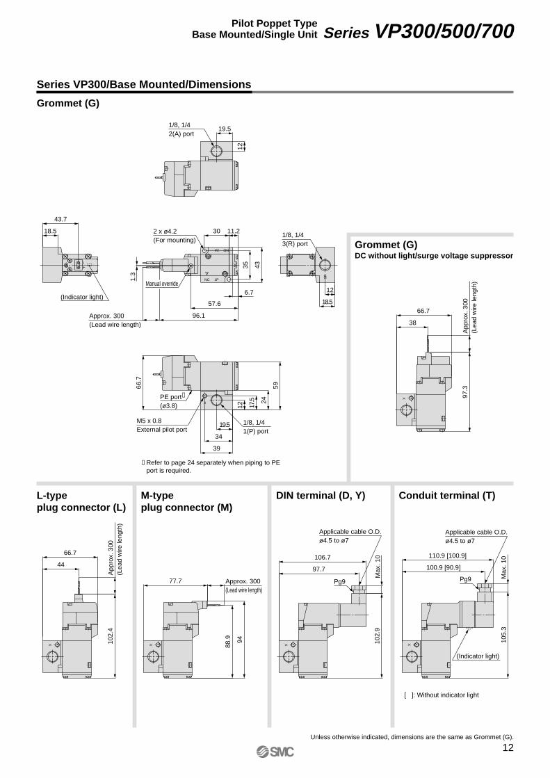
1/8, 1/41(P) port
M5 x 0.8External pilot port
PE port∗
(ø3.8)X
19.5
12
1/8, 1/42(A) port
1.3
96.1
35
Approx. 300(Lead wire length)
43
57.6
6.7
11.2302 x ø4.2(For mounting)
Manual override
2A NO
1PNC
NC
18.5
12
1/8, 1/43(R) port
3R
43.7
18.5
(Indicator light)
+–
110.9 [100.9]
100.9 [90.9]
Max
. 10
105.
3
Pg9
(Indicator light)
Applicable cable O.D.ø4.5 to ø7
X
∗ Refer to page 24 separately when piping to PE port is required.
Series VP300/Base Mounted/Dimensions
Grommet (G)
Grommet (G)DC without light/surge voltage suppressor
DIN terminal (D, Y)M-type plug connector (M)
L-type plug connector (L)
Conduit terminal (T)
Unless otherwise indicated, dimensions are the same as Grommet (G).
[ ]: Without indicator light
12
Series VP300/500/700Pilot Poppet TypeBase Mounted/Single Unit
VP-A.qxd 08.12.8 10:45 AM Page 12
X
44.8
App
rox.
300
(Lea
d w
ire le
ngth
)
73.5
123.
5
X
Approx. 300(Lead wire length)
84.5
120.
2
115.
1X
App
rox.
300
(Lea
d w
ire
leng
th)
128.
6
73.5
50.8
NO2A
1PNC
NC
1.3
122.3
4217.6
Approx. 300(Lead wire length)
83.812.6
47
52
2 x ø5.2(For mounting)
Manual override
X
Max
. 10
129.
1
113.5
104.5
Pg9
Applicable cable O.D.ø4.5 to ø7
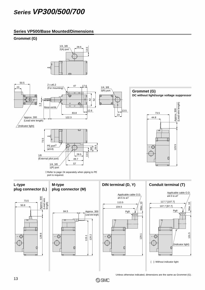
13.528.51/4, 3/8
2(A) port
X 28.5
19.5
13.5
73.5
57
49.7
28.5
1/4, 3/81(P) port
1/8(External pilot port)
PE port∗
(ø3.8)
+–
50.5
23
(Indicator light)
3R23
13.5
1/4, 3/83(R) port
Max
. 10
131.
5
117.7 [107.7]
107.7 [97.7]
Pg9
(Indicator light)
Applicable cable O.D.ø4.5 to ø7
X
∗ Refer to page 24 separately when piping to PE port is required.
Series VP500/Base Mounted/Dimensions
Grommet (G)
Grommet (G)DC without light/surge voltage suppressor
DIN terminal (D, Y)M-type plug connector (M)
L-type plug connector (L)
Conduit terminal (T)
Unless otherwise indicated, dimensions are the same as Grommet (G).
[ ]: Without indicator light
13
Series VP300/500/700
VP-A.qxd 08.12.8 10:45 AM Page 13
X
66.895.5
146.
5A
ppro
x. 3
00(L
ead
wire
leng
th)
X
138.
1
143.
2
Approx. 300(Lead wire length)
106.5
X
App
rox.
300
(Lea
d wi
re le
ngth
)15
1.6
95.5
72.8
X
Max
. 10
152.
1
135.5
126.5
Applicable cable O.D.ø4.5 to ø7
Pg9
NC 1P
NO2A
NC
1.3
145.3
18
53
Approx. 300(Lead wire length)
106.811.5
67
66
2 x ø6.2(For mounting)
Manual override
X
8064
40
32.5
2116
95.5
PE port∗
(ø4)
1/8(External pilot port)
3/8, 1/21(P) port
16
403/8, 1/22(A) port
3R
2416
3/8, 1/23(R) port
+–
72.524
(Indicator light)
Max
. 10
154.
5
139.7 [129.7]
129.7 [119.7]Pg9
(Indicator light)
Applicable cable O.D.ø4.5 to ø7
X
∗ Refer to page 24 separately when piping to PE port is required.
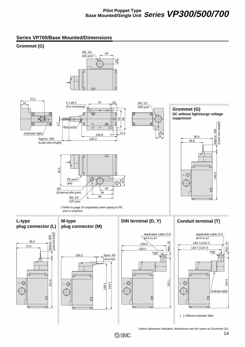
Series VP700/Base Mounted/Dimensions
Grommet (G)
Grommet (G)DC without light/surge voltage suppressor
DIN terminal (D, Y)M-type plug connector (M)
L-type plug connector (L)
Conduit terminal (T)
Unless otherwise indicated, dimensions are the same as Grommet (G).
[ ]: Without indicator light
14
Series VP300/500/700Pilot Poppet TypeBase Mounted/Single Unit
VP-A.qxd 08.12.8 10:45 AM Page 14
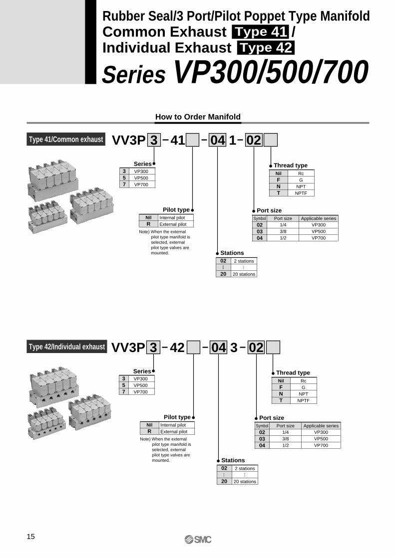
How to Order Manifold
Rubber Seal/3 Port/Pilot Poppet Type ManifoldCommon Exhaust Type 41 /Individual Exhaust Type 42
Series VP300/500/700
VV3P 3 141 04 02
Series357
VP300VP500VP700
Pilot typeNilR
Internal pilotExternal pilot
Thread typeNilFNT
RcG
NPTNPTF
Stations02
20
2 stations
20 stations
Port size
020304
Symbol Port size Applicable series1/43/81/2
VP300VP500VP700
··· ···
VV3P 3 342 04 02
Series357
VP300VP500VP700
Thread typeNilFNT
RcG
NPTNPTF
Stations02
20
2 stations
20 stations
Port size
020304
Symbol Port size Applicable series1/43/81/2
VP300VP500VP700
··· ···
Type 41/Common exhaust
Type 42/Individual exhaust
Note) When the external pilot type manifold is selected, external pilot type valves are mounted.
Pilot typeNilR
Internal pilotExternal pilot
Note) When the external pilot type manifold is selected, external pilot type valves are mounted.
15
VP-A.qxd 08.12.8 10:45 AM Page 15
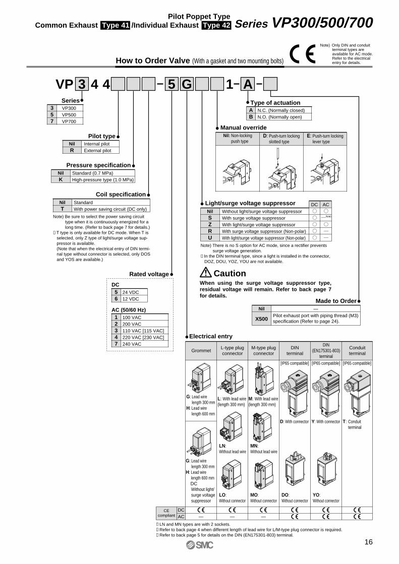
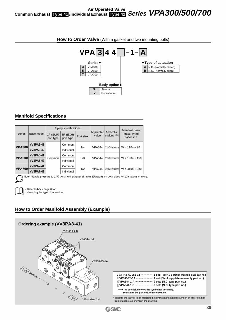
How to Order Valve (With a gasket and two mounting bolts)
VP 3 4 4 5 G 1 ASeries
357
VP300VP500VP700
Type of actuationAB
N.C. (Normally closed)N.O. (Normally open)
56
24 VDC12 VDC
Pilot typeNilR
Internal pilotExternal pilot
Light/surge voltage suppressor DC ACNilSZRU
Without light/surge voltage suppressorWith surge voltage suppressorWith light/surge voltage suppressorWith surge voltage suppressor (Non-polar)With light/surge voltage suppressor (Non-polar)
Manual override
Pressure specificationNilK
Standard (0.7 MPa)High-pressure type (1.0 MPa)
Electrical entry
Coil specificationNilT
StandardWith power saving circuit (DC only)
Note) Be sure to select the power saving circuit type when it is continuously energized for a long time. (Refer to back page 7 for details.)
∗ T type is only available for DC mode. When T is selected, only Z type of light/surge voltage sup-pressor is available.(Note that when the electrical entry of DIN termi-nal type without connector is selected, only DOS and YOS are available.)
Note) There is no S option for AC mode, since a rectifier prevents surge voltage generation.
∗ In the DIN terminal type, since a light is installed in the connector, DOZ, DOU, YOZ, YOU are not available.
Rated voltage
DC
12347
100 VAC200 VAC110 VAC [115 VAC]220 VAC [230 VAC]240 VAC
AC (50/60 Hz)
When using the surge voltage suppressor type, residual voltage will remain. Refer to back page 7 for details.
Caution
∗ LN and MN types are with 2 sockets.∗ Refer to back page 4 when different length of lead wire for L/M-type plug connector is required.∗ Refer to back page 5 for details on the DIN (EN175301-803) terminal.
CEcompliant
DCAC — — —
Made to OrderNil
X500
—Pilot exhaust port with piping thread (M3) specification (Refer to page 24).
GrommetConduitterminal
L-type plugconnector
M-type plugconnector
DINterminal
DIN(EN175301-803)
terminal
G: Lead wirelength 300 mm
H: Lead wirelength 600 mm
L: With lead wire(length 300 mm)
LN:Without lead wire
LO:Without connector
M: With lead wire(length 300 mm)
D: With connector Y: With connector T: Conduit terminal
DO:Without connector
YO:Without connector
MN:Without lead wire
MO:Without connector
G: Lead wirelength 300 mm
H: Lead wirelength 600 mm
DCWithout light/surge voltagesuppressor
Nil: Non-lockingpush type
D: Push-turn lockingslotted type
E: Push-turn lockinglever type
[IP65 compatible] [IP65 compatible] [IP65 compatible]
Note) Only DIN and conduit terminal types are available for AC mode.Refer to the electrical entry for details.
Note)
16
Series VP300/500/700Pilot Poppet TypeCommon Exhaust Type 41 /Individual Exhaust Type 42
VP-A.qxd 08.12.8 10:45 AM Page 16
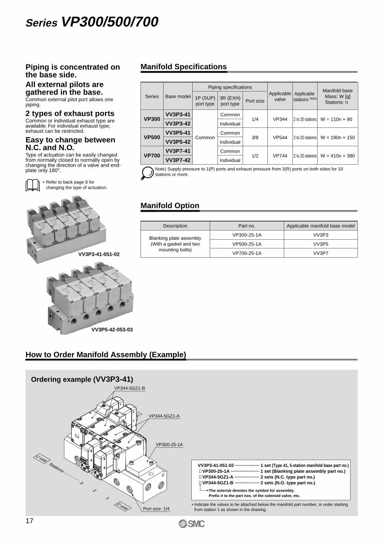
Note) Supply pressure to 1(P) ports and exhaust pressure from 3(R) ports on both sides for 10 stations or more.
Series
VP300
Base model 1P (SUP)port type
Piping specifications
Common
3R (EXH)port type
Common
Individual
Common
Individual
Common
Individual
Port size
1/4
3/8
1/2
Applicablevalve
VP344
VP544
VP744
Applicable stations Note)
2 to 20 stations
2 to 20 stations
2 to 20 stations
W = 110n + 90
W = 190n + 150
W = 410n + 380
Manifold baseMass: W [g]Stations: n
VP500
VP700
VV3P3-41
VV3P3-42
VV3P5-41
VV3P5-42
VV3P7-41
VV3P7-42
Description
Blanking plate assembly(With a gasket and two
mounting bolts)
Part no. Applicable manifold base model
VP300-25-1A VV3P3
VP700-25-1A VV3P7
VP500-25-1A VV3P5
Piping is concentrated on the base side.All external pilots are gathered in the base.Common external pilot port allows one piping.
2 types of exhaust portsCommon or individual exhaust type are available. For individual exhaust type, exhaust can be restricted.
Easy to change between N.C. and N.O.Type of actuation can be easily changed from normally closed to normally open by changing the direction of a valve and end-plate only 180°.
Manifold Specifications
Manifold Option
How to Order Manifold Assembly (Example)
Port size: 1/4
VP344-5GZ1-B
VP344-5GZ1-A
VP300-25-1A
Stations
3
2
1D side
U side
Ordering example (VV3P3-41)
• Indicate the valves to be attached below the manifold part number, in order starting from station 1 as shown in the drawing.
VV3P3-41-051-02 ···················· 1 set (Type 41, 5-station manifold base part no.) ∗ VP300-25-1A ······················· 1 set (Blanking plate assembly part no.) ∗ VP344-5GZ1-A ···················· 2 sets (N.C. type part no.) ∗ VP344-5GZ1-B ···················· 2 sets (N.O. type part no.)
The asterisk denotes the symbol for assembly. Prefix it to the part nos. of the solenoid valve, etc.
VV3P3-41-051-02
VV3P5-42-053-03
• Refer to back page 8 for changing the type of actuation.
17
Series VP300/500/700
VP-A.qxd 08.12.8 10:45 AM Page 17
NO
NC
+–
2A 2A
3R
1P
3R
1P
3R
1P
3R
1P
3R
1P
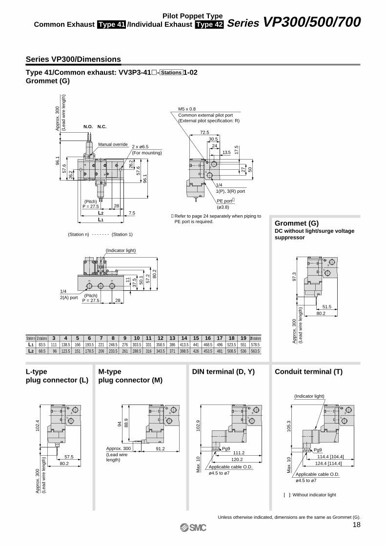
50.1 80
.2
96.1
57.626
.2
App
rox.
300
(Lea
d w
ire le
ngth
)96
.1
57.6
26.2
28
7.5L2
L1
28
57.2
37.511
72.5
5027
17.5
30.5
24
13.5
M5 x 0.8Common external pilot port(External pilot specification: R)
PE port∗
(ø3.8)
(Indicator light)
(Station n) (Station 1)
N.C.N.O.
2 x ø6.5(For mounting)
Manual override
(Pitch)P = 27.5
1/41(P), 3(R) port
1/42(A) port (Pitch)
P = 27.5
80.2
51.5
App
rox.
300
(Lea
d w
ire le
ngth
)97
.3
120.2
111.2
Max
. 10
102.
9
Applicable cable O.D.ø4.5 to ø7
Pg991.2Approx. 300(Lead wire length)
94 88.9
80.2
57.5
102.
4A
ppro
x. 3
00(L
ead
wire
leng
th)
124.4 [114.4]
114.4 [104.4]
Max
. 10
105.
3
Pg9
(Indicator light)
Applicable cable O.D.ø4.5 to ø7
3R
1P
∗ Refer to page 24 separately when piping to PE port is required.
Series VP300/Dimensions
Type 41/Common exhaust: VV3P3-41�- 1-02Grommet (G)
Station nL1
L2
2 stations83.568.5
111 96
138.5123.5
166151
193.5178.5
221206
248.5233.5
276261
303.5288.5
331316
358.5343.5
386371
413.5398.5
441426
468.5453.5
496481
523.5508.5
551536
578.5563.5
3 4 5 6 7 8 9 10 11 12 13 14 15 16 17 18 19 20 stations
Stations
Grommet (G)DC without light/surge voltage suppressor
DIN terminal (D, Y)M-type plug connector (M)
L-type plug connector (L)
Conduit terminal (T)
Unless otherwise indicated, dimensions are the same as Grommet (G).
[ ]: Without indicator light
18
Series VP300/500/700Pilot Poppet TypeCommon Exhaust Type 41 /Individual Exhaust Type 42
VP-A.qxd 08.12.8 10:45 AM Page 18
+ –
3R 3R
NO
NC
+–
2A2A
1P
1P
1P1P 1P
50.1
18.5
28
72.5
30.5
24
50
13.5
17.5
80.2
96.1
57.626
.2
App
rox.
300
(Lea
d w
ire le
ngth
)96
.1
57.6
26.2
28
7.5L2
L1
28
57.2
37.511
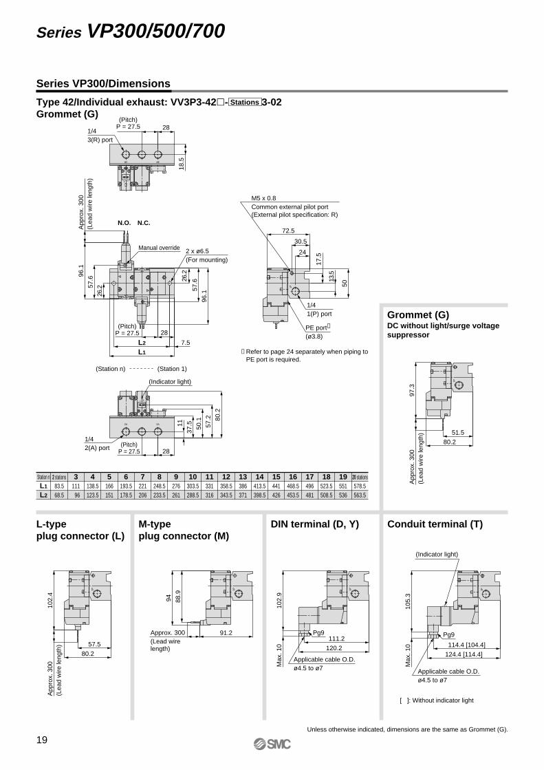
1/43(R) port
(Pitch)P = 27.5
M5 x 0.8Common external pilot port(External pilot specification: R)
PE port∗
(ø3.8)
(Indicator light)
(Station n) (Station 1)
N.C.N.O.
2 x ø6.5(For mounting)
Manual override
(Pitch)P = 27.5
1/41(P) port
1/42(A) port (Pitch)
P = 27.5
80.2
51.5
App
rox.
300
(Lea
d w
ire le
ngth
)97
.3
120.2
111.2
Max
. 10
102.
9
Applicable cable O.D.ø4.5 to ø7
Pg9
80.2
57.5
102.
4A
ppro
x. 3
00(L
ead
wire
leng
th)
91.2Approx. 300(Lead wire length)
94 88.9
Max
. 10
105.
3
124.4 [114.4]
114.4 [104.4]
Pg9
(Indicator light)
Applicable cable O.D.ø4.5 to ø7
1P
∗ Refer to page 24 separately when piping to PE port is required.
Station nL1
L2
2 stations83.568.5
111 96
138.5123.5
166151
193.5178.5
221206
248.5233.5
276261
303.5288.5
331316
358.5343.5
386371
413.5398.5
441426
468.5453.5
496481
523.5508.5
551536
578.5563.5
3 4 5 6 7 8 9 10 11 12 13 14 15 16 17 18 19 20 stations
Type 42/Individual exhaust: VV3P3-42�- 3-02Grommet (G)
Stations
Series VP300/Dimensions
Grommet (G)DC without light/surge voltage suppressor
DIN terminal (D, Y)M-type plug connector (M)
L-type plug connector (L)
Conduit terminal (T)
Unless otherwise indicated, dimensions are the same as Grommet (G).
[ ]: Without indicator light
19
Series VP300/500/700
VP-A.qxd 08.12.8 10:45 AM Page 19

NO
NC
+–
2A2A
3R
1P
3R
1P
3R
1P
3R
1P
3R
1P
92.5
63.8
App
rox.
300
(Lea
d w
ire le
ngth
)12
3.5
132.5
123.5
Max
. 10
129.
1
Pg9
Applicable cable O.D.ø4.5 to ø7
103.5Approx. 300(Lead wire length)
120.
211
5.1
92.5
69.8
App
rox.
300
(Lea
d w
ire le
ngth
)12
8.6
61.3
31
7.5L2
L1
App
rox.
300
(Lea
d w
ire le
ngth
)12
2.3
83.8
41.1
122.
383.8
41.1
31
92.5
69.5
47.5
13.5
23.5
6033
4230
20.5
(Pitch)P = 33
N.C.N.O.
PE port∗
(ø3.8)
M5 x 0.8Common external pilot port(External pilot specification: R)
(Pitch)P = 33
(Station 1)(Station n)
2 x ø7.2(For mounting)
Manual override
3/81(P), 3(R) port
(Indicator light)
3/82(A) port
136.7 [126.7]
126.7 [116.7]
Max
. 10
131.
5
Pg9
(Indicator light)
Applicable cable O.D.ø4.5 to ø7
3R
1P
∗ Refer to page 24 separately when piping to PE port is required.
Station nL1
L2
2 stations9580
128113
161146
194179
227212
260245
293278
326311
359344
392377
425410
458443
491476
524509
557542
590575
623608
656641
689674
3 4 5 6 7 8 9 10 11 12 13 14 15 16 17 18 19 20 stations
Grommet (G)DC without light/surge voltage suppressor
DIN terminal (D, Y)M-type plug connector (M)
L-type plug connector (L)
Conduit terminal (T)
Unless otherwise indicated, dimensions are the same as Grommet (G).
[ ]: Without indicator light
Series VP500/Dimensions
Type 41/Common exhaust: VV3P5-41�- 1-03Grommet (G)
Stations
20
Series VP300/500/700Pilot Poppet TypeCommon Exhaust Type 41 /Individual Exhaust Type 42
VP-A.qxd 08.12.8 10:45 AM Page 20

1P1P1P
1P
+ –
NO
NC
1P
3R3R
+–
2A2A
132.5123.5
Max
. 10
129.
1
Pg9
Applicable cable O.D.ø4.5 to ø7
103.5Approx. 300(Lead wire length)
120.
211
5.1
92.569.8
App
rox.
300
(Lea
d w
ire le
ngth
)12
8.6
61.3
16.5
28.5
31
317.5L2
L1
App
rox.
300
(Lea
d w
ire le
ngth
)12
2.3
83.8
41.1
122.
383.8
41.1
31
92.5
69.5
47.5
13.5
23.5
60
4230
(Pitch)P = 333/8
3(R) port
(Pitch)P = 33
N.C.N.O.
PE port∗
(ø3.8)
M5 x 0.8Common external pilot port(External pilot specification: R)
(Pitch)P = 33
(Station 1)(Station n)
2 x ø7.2(For mounting)
Manual override
3/81(P) port
(Indicator light)
3/82(A) port 92.5
63.8
App
rox.
300
(Lea
d w
ire le
ngth
)12
3.5
Max
. 10
131.
5
136.7 [126.7]
126.7 [116.7]
Pg9
(Indicator light)
Applicable cable O.D.ø4.5 to ø7
1P
∗ Refer to page 24 separately when piping to PE port is required.
L1
L2
9580
128113
161146
194179
227212
260245
293278
326311
359344
392377
425410
458443
491476
524509
557542
590575
623608
656641
689674
3 4 5 6 7 8 9 10 11 12 13 14 15 16 17 18 19
Grommet (G)DC without light/surge voltage suppressor
DIN terminal (D, Y)M-type plug connector (M)
L-type plug connector (L)
Conduit terminal (T)
Unless otherwise indicated, dimensions are the same as Grommet (G).
[ ]: Without indicator light
Type 42/Individual exhaust: VV3P5-42�- 3-03Grommet (G)
Stations
Series VP500/Dimensions
Station n 2 stations 20 stations
21
Series VP300/500/700
VP-A.qxd 08.12.8 10:45 AM Page 21
NO
NC
2A 2A
+–
1P
3R
1P
3R
1P
3R
1P
3R
1P
3R
12697.3
146.
5A
ppro
x. 3
00(L
ead
wire
leng
th)
166
157
Max
. 10
152.
1
Applicable cable O.D.ø4.5 to ø7
Pg9137
138.
1
143.
2
Approx. 300(Lead wire length)126
103.3
App
rox.
300
(Lea
d w
ire le
ngth
)15
1.6
78.2
378L2
L1
App
rox.
300
(Lea
d w
ire le
ngth
)14
5.3
106.
8
51.5
145.
3106.
851.5
5540
24
8648
32
126
103
63
19
37
N.C.N.O.
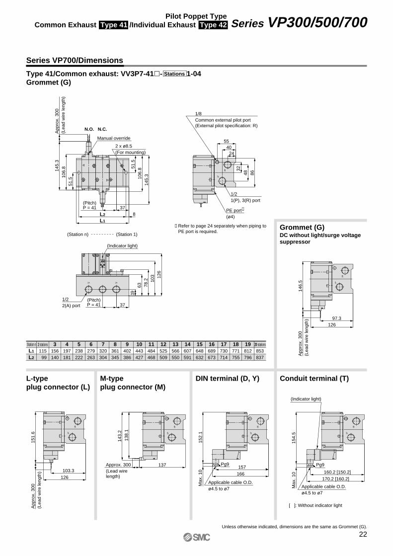
(Pitch)P = 41
1/8Common external pilot port(External pilot specification: R)
1/21(P), 3(R) port
(Indicator light)
1/22(A) port
(Pitch)P = 41
(Station 1)(Station n)
PE port∗
(ø4)
170.2 [160.2]
160.2 [150.2]
Max
. 10
154.
5
Pg9
(Indicator light)
Applicable cable O.D.ø4.5 to ø7
1P
3R
∗ Refer to page 24 separately when piping to PE port is required.
Manual override
2 x ø8.5(For mounting)
Station nL1
L2
2 stations115 99
3156140
4197181
5238222
6279263
7320304
8361345
9402386
10443427
11484468
12525509
13566550
14607591
15648632
16689673
17730714
18771755
19812796
20 stations853837
Grommet (G)DC without light/surge voltage suppressor
DIN terminal (D, Y)M-type plug connector (M)
L-type plug connector (L)
Conduit terminal (T)
Unless otherwise indicated, dimensions are the same as Grommet (G).
[ ]: Without indicator light
Series VP700/Dimensions
Type 41/Common exhaust: VV3P7-41�- 1-04Grommet (G)
Stations
22
Series VP300/500/700Pilot Poppet TypeCommon Exhaust Type 41 /Individual Exhaust Type 42
VP-A.qxd 08.12.8 10:45 AM Page 22
3R3R
2A 2A
NO
NC
+ –
1P
1P 1P
1P
1P
+–
12697.3
146.
5A
ppro
x. 3
00(L
ead
wire
leng
th)
166157
Max
. 10
152.
1
Pg9137
138.
1
143.
2
Approx. 300(Lead wire length)126
103.3
App
rox.
300
(Lea
d w
ire le
ngth
)15
1.6
78.2
24
37
34
378L2
L1
App
rox.
300
(Lea
d w
ire le
ngth
)14
5.3
106.
8
51.5
145.
3106.
851.5
55
40
86
32
126
103
63
19
37
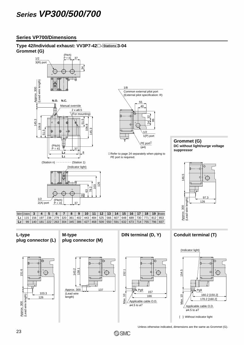
(Pitch)P = 411/2
3(R) port
2 x ø8.5(For mounting)
N.C.N.O.
(Pitch)P = 41
1/8Common external pilot port(External pilot specification: R)
1/21(P) port
(Indicator light)
1/22(A) port
(Pitch)P = 41
(Station 1)(Station n)
PE port∗
(ø4)
Max
. 10
154.
5
170.2 [160.2]
160.2 [150.2]
Pg9
(Indicator light)
1P
∗ Refer to page 24 separately when piping to PE port is required.
Manual override
Applicable cable O.D.ø4.5 to ø7
Applicable cable O.D.ø4.5 to ø7
Station nL1
L2
2 stations115 99
156140
197181
238222
279263
320304
361345
402386
443427
484468
525509
566550
607591
648632
689673
730714
771755
812796
853837
3 4 5 6 7 8 9 10 11 12 13 14 15 16 17 18 19 20 stations
Grommet (G)DC without light/surge voltage suppressor
DIN terminal (D, Y)M-type plug connector (M)
L-type plug connector (L)
Conduit terminal (T)
Unless otherwise indicated, dimensions are the same as Grommet (G).
[ ]: Without indicator light
Type 42/Individual exhaust: VV3P7-42�- 3-04Grommet (G)
Stations
Series VP700/Dimensions
23
Series VP300/500/700
VP-A.qxd 08.12.8 10:45 AM Page 23
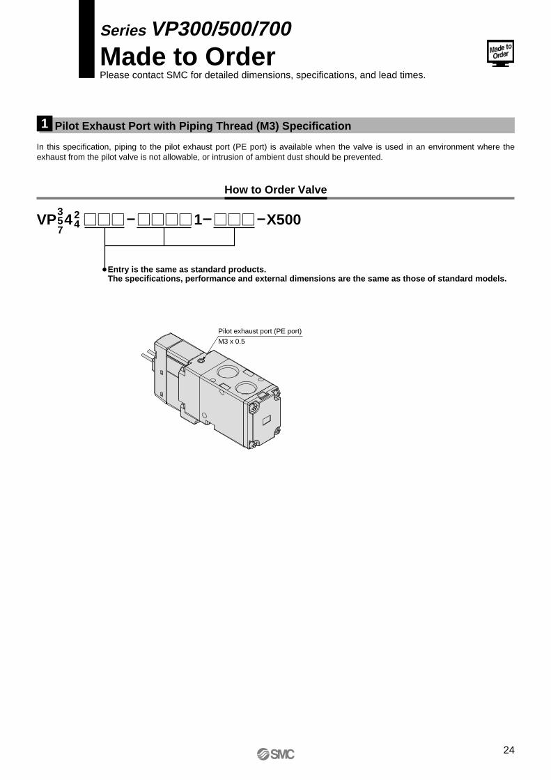
Pilot Exhaust Port with Piping Thread (M3) Specification1
Series VP300/500/700Made to OrderPlease contact SMC for detailed dimensions, specifications, and lead times.
In this specification, piping to the pilot exhaust port (PE port) is available when the valve is used in an environment where the exhaust from the pilot valve is not allowable, or intrusion of ambient dust should be prevented.
VP 4357
24 1 X500
Entry is the same as standard products.The specifications, performance and external dimensions are the same as those of standard models.
How to Order Valve
Pilot exhaust port (PE port)
M3 x 0.5
24
VP-A.qxd 08.12.8 10:45 AM Page 24
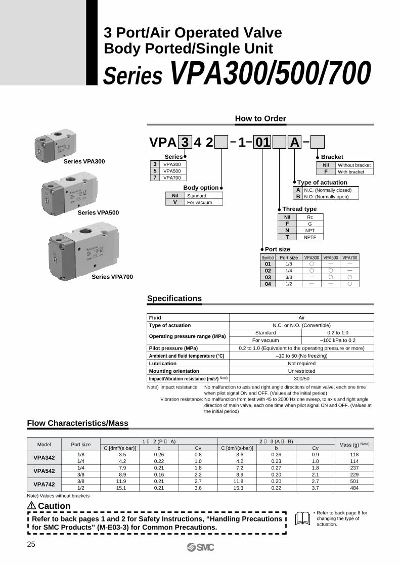
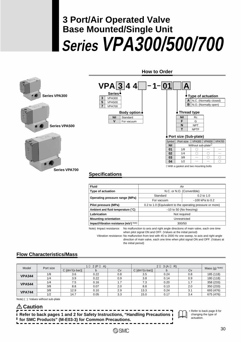
How to Order
Series VPA300/500/7003 Port/Air Operated ValveBody Ported/Single Unit
VPA 3 4 2 1 01 ASeries
357
VPA300VPA500VPA700
Type of actuationAB
N.C. (Normally closed)N.O. (Normally open)
Body optionNilV
StandardFor vacuum
BracketNilF
Without bracketWith bracket
Thread typeNilFNT
RcG
NPTNPTF
Port size
01020304
Symbol Port size VPA3001/81/43/81/2
VPA500 VPA700
Caution
Mass (g) Note)Port sizeModel
VPA342
VPA542
VPA742
1/81/41/43/83/81/2
Air
N.C. or N.O. (Convertible)
0.2 to 1.0 (Equivalent to the operating pressure or more)
–10 to 50 (No freezing)
Not required
Unrestricted
300/50
Standard
For vacuum
0.2 to 1.0
–100 kPa to 0.2
Refer to back pages 1 and 2 for Safety Instructions, “Handling Precautions for SMC Products” (M-E03-3) for Common Precautions.
Fluid
Type of actuation
Operating pressure range (MPa)
Pilot pressure (MPa)
Ambient and fluid temperature (°C)
Lubrication
Mounting orientation
Impact/Vibration resistance (m/s2) Note)
• Refer to back page 8 for changing the type of actuation.
Note) Impact resistance: No malfunction to axis and right angle directions of main valve, each one time when pilot signal ON and OFF. (Values at the initial period)
Vibration resistance: No malfunction from test with 45 to 2000 Hz one sweep, to axis and right angle direction of main valve, each one time when pilot signal ON and OFF. (Values at the initial period)
Specifications
Flow Characteristics/Mass
C [dm3/(s·bar)] b Cv3.54.27.98.9
11.915.1
0.260.220.210.160.210.21
0.81.01.82.22.73.6
3.64.27.28.9
11.815.3
0.260.230.270.200.200.22
0.91.01.82.12.73.7
118114237229501484
C [dm3/(s·bar)] b Cv1 ↔ 2 (P ↔ A) 2 ↔ 3 (A ↔ R)
Note) Values without brackets
Series VPA300
Series VPA500
Series VPA700
25
VP-A.qxd 08.12.8 10:45 AM Page 25
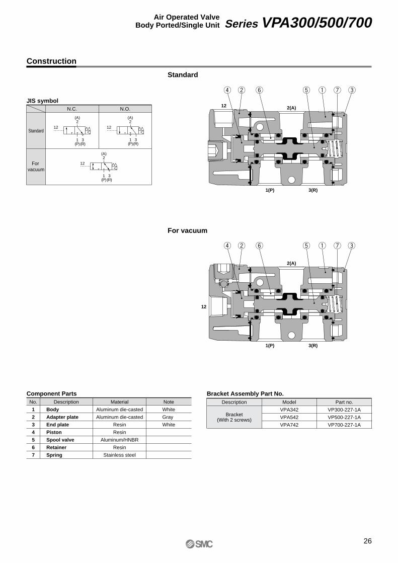
Construction
For vacuum
Standard
uy tr ew q
uy tr ew q
2(A)12
1(P) 3(R)
2(A)
12
1(P) 3(R)
JIS symbol
1(P)
3(R)
(A)2
1(P)
3(R)
(A)2
N.C.
Standard
For vacuum
N.O.
12 12
Bracket Assembly Part No.Description Part no.
VP300-227-1A
VP500-227-1A
VP700-227-1A
Bracket(With 2 screws)
Model
VPA342
VPA542
VPA742
12
(A)2
1(P)
3(R)
Body
Adapter plate
End plate
Piston
Spool valve
Retainer
Spring
No.
1
2
3
4
5
6
7
Description Material
Aluminum die-casted
Aluminum die-casted
Resin
Resin
Aluminum/HNBR
Resin
Stainless steel
Note
White
Gray
White
Component Parts
26
Series VPA300/500/700Air Operated ValveBody Ported/Single Unit
VP-A.qxd 08.12.8 10:45 AM Page 26
12
2A
NC
12
NO
3R
1P
(17.
5)
25
65.2
58.2
(9)
(1.6)
21.5
3.4
26.2
20.4 16
36 3531
2.826.21516
.5
(54.5)
(45)
(5.4
)
(35)
3
53.7
26.5
4.5
1620.4
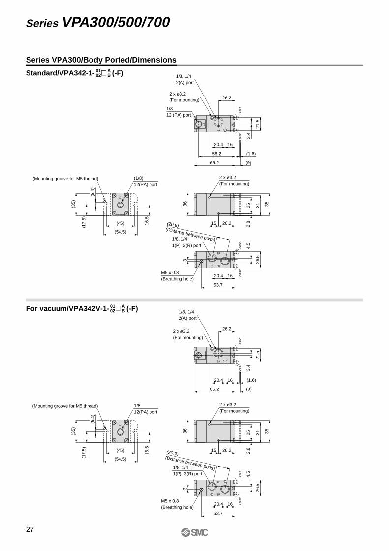
1/812 (PA) port
1/8, 1/42(A) port
2 x ø3.2(For mounting)
2 x ø3.2(For mounting)
(1/8)12(PA) port
M5 x 0.8(Breathing hole)
1/8, 1/41(P), 3(R) port
2A
NC
12
NO
3R
1P
(17.
5)
25
65.2 (9)
(1.6)
21.5
3.4
26.2
20.4 16
36 3531
2.826.215
16.5
(54.5)
(45)
(5.4
)
(35)
3
53.7
26.5
4.5
1620.4
1/8, 1/42(A) port
2 x ø3.2(For mounting)
2 x ø3.2(For mounting)
1/812(PA) port
M5 x 0.8(Breathing hole)
1/8, 1/41(P), 3(R) port
(Mounting groove for M5 thread)
(20.9)(Distance between ports)
(20.9)(Distance between ports)
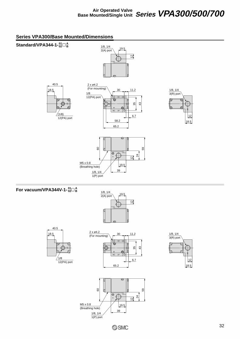
Series VPA300/Body Ported/Dimensions
Standard/VPA342-1- � (-F)
For vacuum/VPA342V-1- � (-F)
0102
AB
0102
AB
(Mounting groove for M5 thread)
27
Series VPA300/500/700
VP-A.qxd 08.12.8 10:45 AM Page 27
12 NC
2A
12
NO
1P 3R
91
83
(9)
(1.6)
31 25.6
26
3.5
41.1
46 454031.5
4
39.623.5
22.5
(60)
(50)
(45)
(5.4
)
3
76.8
327
25.630.7
1/812(PA) port
1/4, 3/82(A) port
2 x ø4.2(For mounting)
2 x ø4.2(For mounting)
(1/8)12(PA) port
M5 x 0.8(Breathing hole)
1/4, 3/81(P), 3(R) port
NC
2A
12
NO
1P 3R
91 (9)
(1.6)31 25.6
26
3.5
41.1
46 454031.5
4
39.623.5
22.5
(60)
(50)
(45)
(5.4
)
3
76.8
327
25.630.7
1/4, 3/82(A) port
2 x ø4.2(For mounting)
2 x ø4.2(For mounting)
1/812(PA) port
M5 x 0.8(Breathing hole)
1/4, 3/81(P), 3(R) port
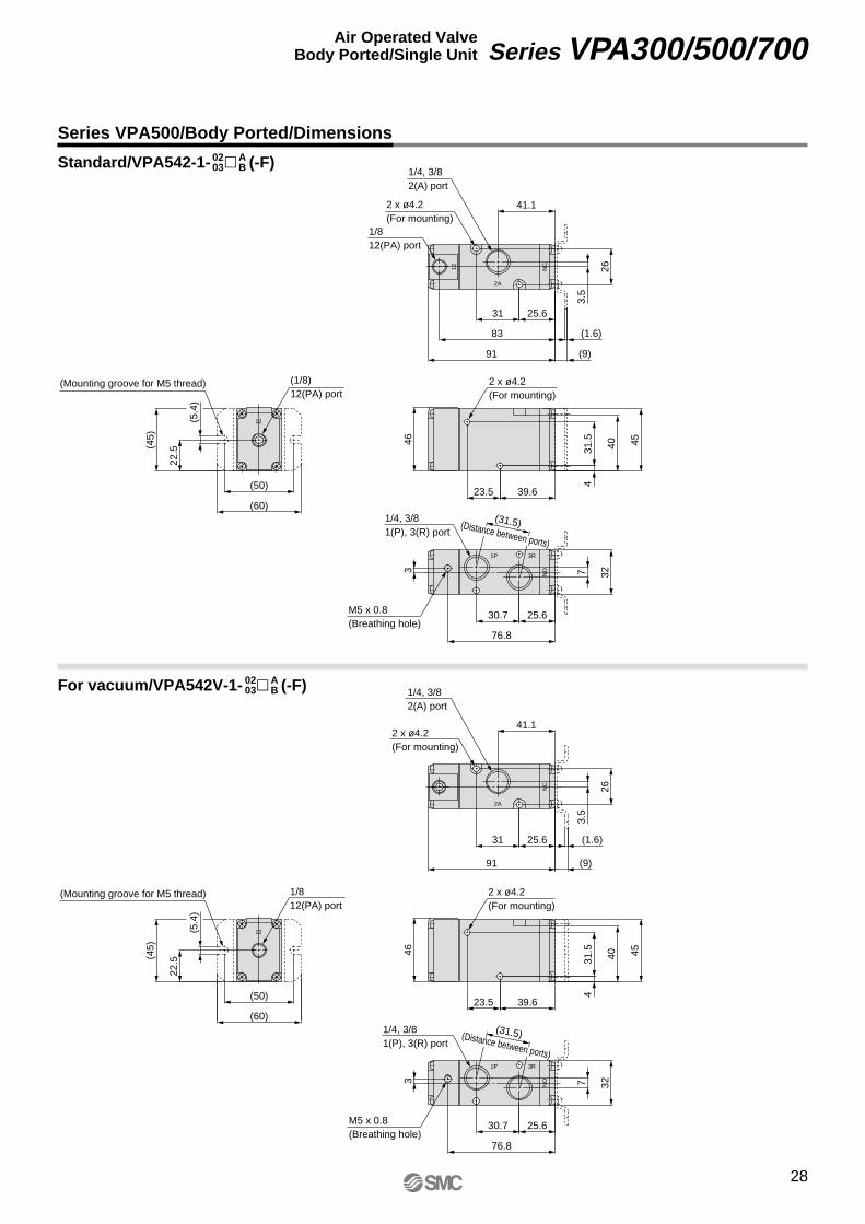
Series VPA500/Body Ported/Dimensions
Standard/VPA542-1- � (-F)0203
AB
For vacuum/VPA542V-1- � (-F)0203
AB
(Mounting groove for M5 thread)
(Mounting groove for M5 thread)
(31.5)(Distance between ports)
(31.5)(Distance between ports)
28
Series VPA300/500/700Air Operated ValveBody Ported/Single Unit
VP-A.qxd 08.12.8 10:45 AM Page 28
12 NC
2A
12
NO
3R1P
115.1
33
(2)
(9)
107.1
51.5
4.5
3141
64 63
56.5
9.4
38.5
51.531
31.5
(63)
(6.4
)
(74)
(60)
3
100.8
42 30.5
409
1/812(PA) port
3/8, 1/22(A) port
2 x ø5.2(For mounting)
2 x ø5.2(For mounting)
(1/8)12(PA) port
3/8, 1/21(P), 3(R) port
M5 x 0.8(Breathing hole)
NC
2A
12
NO
3R1P
115.1
33
(2)
(9)
51.5
4.5
3141
64 63
56.5
9.4
38.5
51.531
31.5
(63)
(6.4
)
(74)
(60)
3
100.8
42 30.5
409
3/8, 1/22(A) port
2 x ø5.2(For mounting)
2 x ø5.2(For mounting)
1/812(PA) port
3/8, 1/21(P), 3(R) port
M5 x 0.8(Breathing hole)
(43)(Distance between ports)
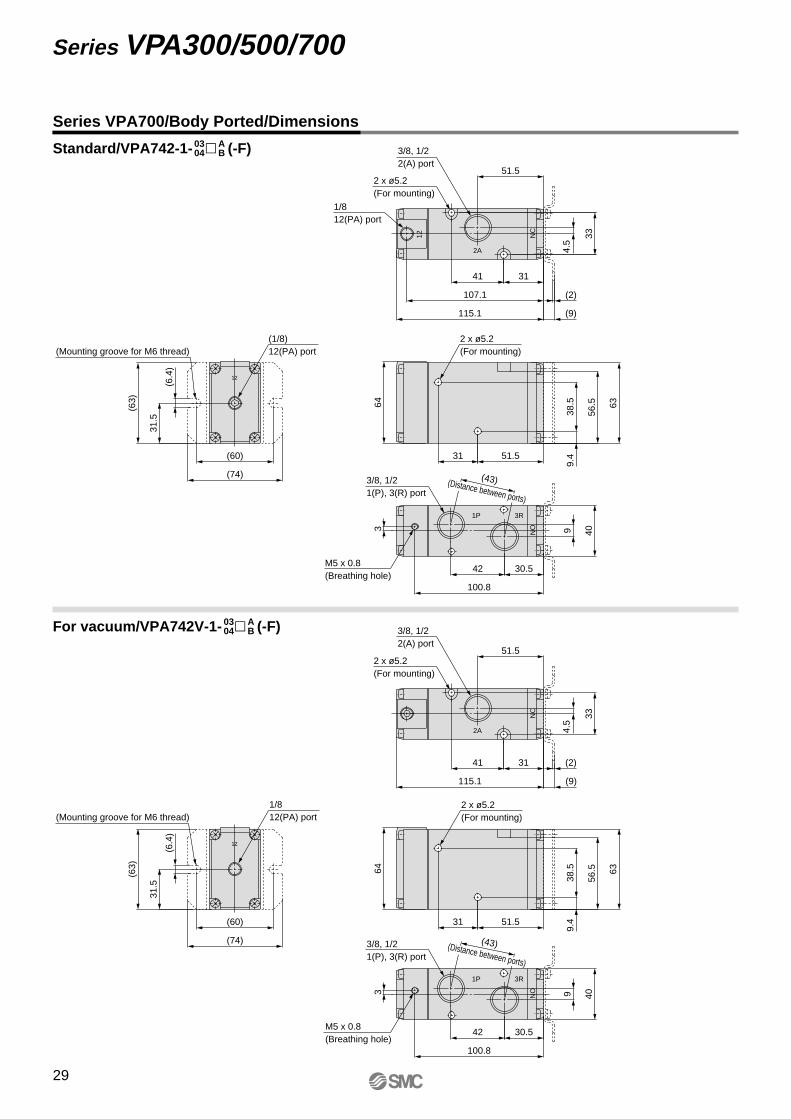
Series VPA700/Body Ported/Dimensions
Standard/VPA742-1- � (-F)0304
AB
For vacuum/VPA742V-1- � (-F)0304
AB
(Mounting groove for M6 thread)
(Mounting groove for M6 thread)
(43)(Distance between ports)
29
Series VPA300/500/700
VP-A.qxd 08.12.8 10:45 AM Page 29
Series VPA300/500/7003 Port/Air Operated ValveBase Mounted/Single Unit
How to Order
VPA 3 4 4 1 01 ASeries
357
VPA300VPA500VPA700
Type of actuationAB
N.C. (Normally closed)N.O. (Normally open)
Body optionNilV
StandardFor vacuum
Thread typeNilFNT
RcG
NPTNPTF
Port size (Sub-plate)
01020304
SymbolNil
Port sizeWithout sub-plate∗
VPA300
1/81/43/81/2
VPA500 VPA700
Air
N.C. or N.O. (Convertible)
0.2 to 1.0 (Equivalent to the operating pressure or more)
–10 to 50 (No freezing)
Not required
Unrestricted
300/50
Standard
For vacuum
0.2 to 1.0
–100 kPa to 0.2
Fluid
Type of actuation
Operating pressure range (MPa)
Pilot pressure (MPa)
Ambient and fluid temperature (°C)
Lubrication
Mounting orientation
Impact/Vibration resistance (m/s2) Note)
Note) Impact resistance: No malfunction to axis and right angle directions of main valve, each one time when pilot signal ON and OFF. (Values at the initial period)
Vibration resistance: No malfunction from test with 45 to 2000 Hz one sweep, to axis and right angle direction of main valve, each one time when pilot signal ON and OFF. (Values at the initial period)
Specifications
Flow Characteristics/Mass
Mass (g) Note)Port sizeModel
VPA344
VPA544
VPA744
1/81/41/43/83/81/2
C [dm3/(s·bar)] b Cv3.63.97.58.8
12.914.7
0.220.220.160.070.100.05
0.80.91.72.02.93.3
3.53.87.38.8
13.315.0
0.240.140.200.130.240.17
0.80.91.72.03.13.4
185 (118)180 (118)358 (233)350 (233)693 (476)675 (476)
C [dm3/(s·bar)] b Cv1 ↔ 2 (P ↔ A) 2 ↔ 3 (A ↔ R)
Note) ( ): Values without sub-plate
Series VPA300
Series VPA500
Series VPA700∗ With a gasket and two mounting bolts
CautionRefer to back pages 1 and 2 for Safety Instructions, “Handling Precautions for SMC Products” (M-E03-3) for Common Precautions.
• Refer to back page 8 for changing the type of actuation.
30
VP-A.qxd 08.12.8 10:45 AM Page 30
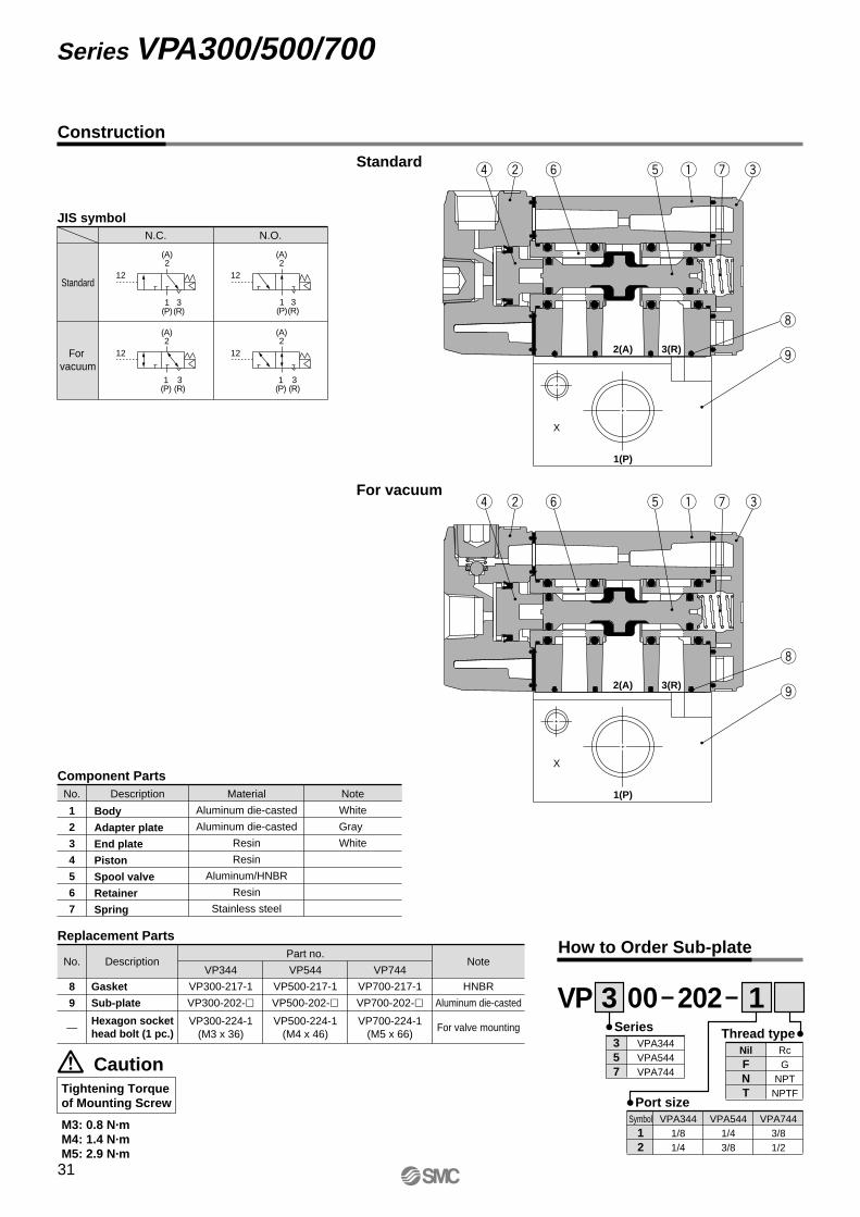
Construction
For vacuum
No. Description Material
Aluminum die-casted
Aluminum die-casted
Resin
Resin
Aluminum/HNBR
Resin
Stainless steel
Note
White
Gray
White
1
2
3
4
5
6
7
Component Parts
Body
Adapter plate
End plate
Piston
Spool valve
Retainer
Spring
Replacement Parts
DescriptionNo.Part no.
VP544
VP500-217-1
VP500-202-�
VP500-224-1(M4 x 46)
VP744
VP700-217-1
VP700-202-�
VP700-224-1(M5 x 66)
VP344
VP300-217-1
VP300-202-�
VP300-224-1(M3 x 36)
Gasket
Sub-plate
Note
HNBR
Aluminum die-casted
For valve mounting
8
9
—
Standard
Caution
M3: 0.8 N·mM4: 1.4 N·mM5: 2.9 N·m
Port size
How to Order Sub-plate
Symbol12
VPA3441/81/4
VPA5441/43/8
VPA7443/81/2
VPThread typeSeries
3 1357
VPA344VPA544VPA744
NilFNT
RcG
NPTNPTF
20200
JIS symbol
1(P)
3(R)
(A)2
1(P)
3(R)
(A)2
N.C. N.O.
12 12
Hexagon socket head bolt (1 pc.)
o
i
uy tr ew q
X
o
i
uy tr ew q
X
2(A)
1(P)
3(R)
2(A)
1(P)
3(R)
Standard
For vacuum
12
(A)2
1(P)
3(R)
12
(A)2
3(R)
1(P)
Tightening Torqueof Mounting Screw
31
Series VPA300/500/700
VP-A.qxd 08.12.8 10:45 AM Page 31
12
12
2A NO
1PNC
NC
3R
X
35
65.2
58.2
6.7
43
11.230
12
19.5
60 59
24
12
39
19.5
40.5
18.5
18.5
12
M5 x 0.8(Breathing hole)
1/812(PA) port
2 x ø4.2(For mounting)
1/8, 1/42(A) port
1/8, 1/41(P) port
(1/8)12(PA) port
1/8, 1/43(R) port
12
2A NO
1PNC
NC
3R
X
35
65.2
6.7
43
11.230
12
19.5
60 59
24
12
39
19.5
40.5
18.5
18.5
12
1/8, 1/41(P) port
M5 x 0.8(Breathing hole)
1/8, 1/42(A) port
1/812(PA) port
1/8, 1/43(R) port
Series VPA300/Base Mounted/Dimensions
For vacuum/VPA344V-1- �0102
AB
Standard/VPA344-1- �0102
AB
2 x ø4.2(For mounting)
32
Series VPA300/500/700Air Operated ValveBase Mounted/Single Unit
VP-A.qxd 08.12.8 10:45 AM Page 32
12
12
NO2A
1PNC
NC
3R
X
17.6
42
91
83
47
52
12.6
13.528.5
51
23
23
13.5
74.5
73.5
28.5
13.5
28.5
57
M5 x 0.8(Breathing hole)
1/812(PA) port
1/4, 3/82(A) port
(1/8)12(PA) port
1/4, 3/83(R) port
1/4, 3/81(P) port
12
NO2A
1PNC
NC
X
3R
17.6
42
91
47
52
12.6
13.528.5
51
23
23
13.5
74.5
73.5
28.5
13.5
28.5
571/4, 3/81(P) port
M5 x 0.8(Breathing hole)
2 x ø5.2(For mounting)
1/4, 3/82(A) port
1/812(PA) port
1/4, 3/83(R) port
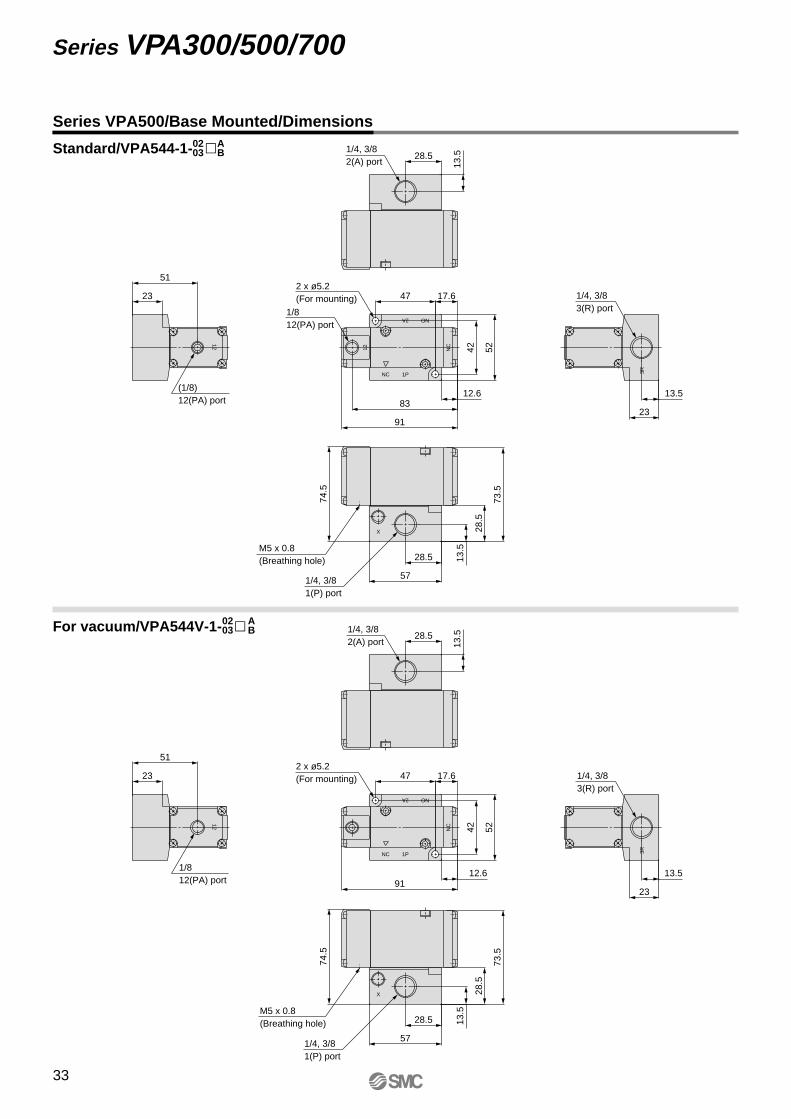
For vacuum/VPA544V-1- �0203
AB
Series VPA500/Base Mounted/Dimensions
Standard/VPA544-1- �0203
AB
2 x ø5.2(For mounting)
33
Series VPA300/500/700
VP-A.qxd 08.12.8 10:45 AM Page 33
12
12
NC 1P
NO2A
3R
NC
X
16
40
24
16
53
115.1
107.1
1867
66
11.5
64
2496
.5
95.5
32.5
16
40
80
M5 x 0.8 (Breathing hole)
3/8, 1/22(A) port
3/8, 1/23(R) port
1/812(PA) port
2 x ø6.2(For mounting)
2 x ø6.2(For mounting)
(1/8)12(PA) port
3/8, 1/21(P) port
12
3R
NC
NC 1P
NO2A
X
16
40
24
16
53
115.1
1867
66
11.5
64
24
96.5
95.5
32.5
16
40
803/8, 1/21(P) port
M5 x 0.8 (Breathing hole)
3/8, 1/22(A) port
3/8, 1/23(R) port
1/812(PA) port
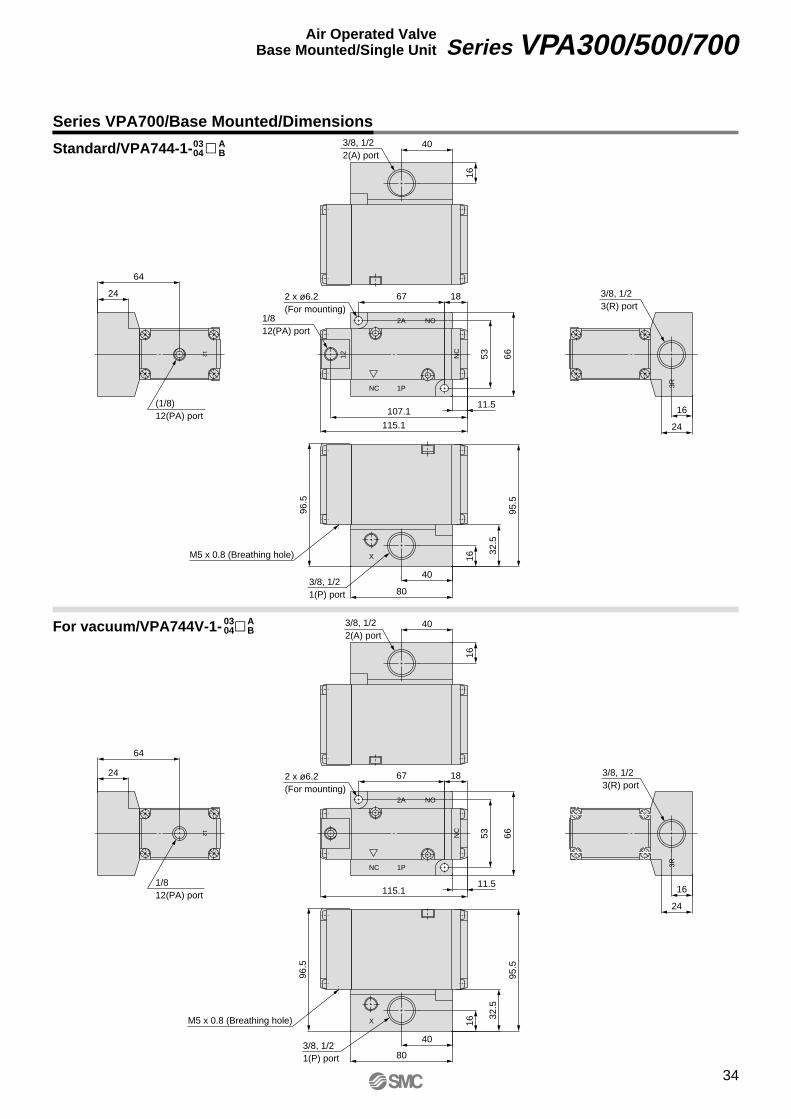
For vacuum/VPA744V-1- �
Series VPA700/Base Mounted/Dimensions
Standard/VPA744-1- �0304
AB
0304
AB
34
Series VPA300/500/700Air Operated ValveBase Mounted/Single Unit
VP-A.qxd 08.12.8 10:45 AM Page 34
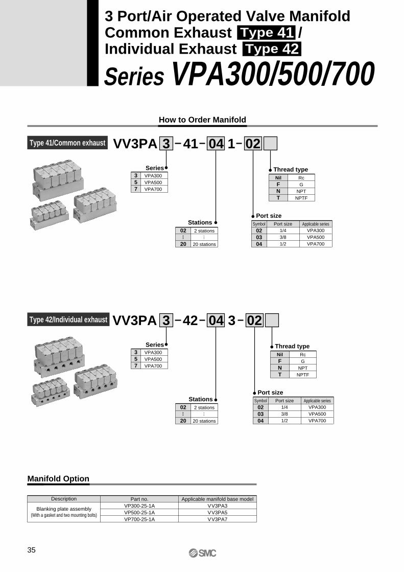
How to Order Manifold
VV3PA 3 141 04 02
Series357
VPA300VPA500VPA700
Thread typeNilFNT
RcG
NPTNPTF
Stations02
20
2 stations
20 stations
Port size
020304
Symbol Port size Applicable series1/43/81/2
VPA300VPA500VPA700
··· ···
VV3PA 3 342 04 02
Series357
VPA300VPA500VPA700
Thread typeNilFNT
RcG
NPTNPTF
Stations02
20
2 stations
20 stations
Port size
020304
Symbol Port size Applicable series1/43/81/2
VPA300VPA500VPA700
··· ···
Description
Blanking plate assembly(With a gasket and two mounting bolts)
Part no. Applicable manifold base modelVP300-25-1A VV3PA3
VP700-25-1A VV3PA7VP500-25-1A VV3PA5
Manifold Option
Series VPA300/500/700
3 Port/Air Operated Valve ManifoldCommon Exhaust Type 41 /Individual Exhaust Type 42
Type 41/Common exhaust
Type 42/Individual exhaust
35
VP-A.qxd 08.12.8 10:45 AM Page 35
Note) Supply pressure to 1(P) ports and exhaust air from 3(R) ports on both sides for 10 stations or more.
VPA300
Common
Common
Individual
Common
Individual
Common
Individual
1/4
3/8
1/2
Applicablevalve
VPA344
VPA544
VPA744
2 to 20 stations
2 to 20 stations
2 to 20 stations
W = 110n + 90
W = 190n + 150
W = 410n + 380
VPA500
VPA700
VV3PA3-41
VV3PA3-42
VV3PA5-41
VV3PA5-42
VV3PA7-41
VV3PA7-42
How to Order Valve (With a gasket and two mounting bolts)
How to Order Manifold Assembly (Example)
VPA 3 4 4 1 ASeries
357
VPA300VPA500VPA700
Type of actuationAB
N.C. (Normally closed)N.O. (Normally open)
Body optionNilV
StandardFor vacuum
• Indicate the valves to be attached below the manifold part number, in order starting from station 1 as shown in the drawing.
VV3PA3-41-051-02 ················· 1 set (Type 41, 5-station manifold base part no.) ∗ VP300-25-1A ······················· 1 set (Blanking plate assembly part no.) ∗ VPA344-1-A ························ 2 sets (N.C. type part no.) ∗ VPA344-1-B ························ 2 sets (N.O. type part no.)
The asterisk denotes the symbol for assembly. Prefix it to the part nos. of the valve, etc.
Ordering example (VV3PA3-41)
Manifold Specifications
3
2
1
Port size: 1/4
VPA344-1-B
VPA344-1-A
VP300-25-1A
Stations
D side
U side
• Refer to back page 8 for changing the type of actuation.
Series Base model 1P (SUP)port type
Piping specifications
3R (EXH)port type
Port size
Applicable stations Note)
Manifold baseMass: W [g]Stations: n
36
Series VPA300/500/700Air Operated ValveCommon Exhaust Type 41 /Individual Exhaust Type 42
VP-A.qxd 08.12.8 10:45 AM Page 36
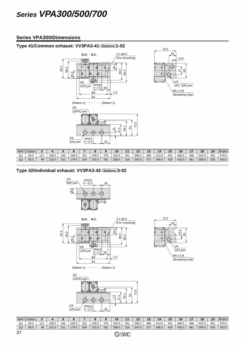
Series VPA300/Dimensions
Station nL1
L2
2 stations83.568.5
111 96
138.5123.5
166151
193.5178.5
221206
248.5233.5
276261
303.5288.5
331316
358.5343.5
386371
413.5398.5
441426
468.5453.5
496481
523.5508.5
551536
578.5563.5
3 4 5 6 7 8 9 10 11 12 13 14 15 16 17 18 19 20 stations
Station nL1
L2
2 stations83.568.5
111 96
138.5123.5
166151
193.5178.5
221206
248.5233.5
276261
303.5288.5
331316
358.5343.5
386371
413.5398.5
441426
468.5453.5
496481
523.5508.5
551536
578.5563.5
3 4 5 6 7 8 9 10 11 12 13 14 15 16 17 18 19 20 stations
Type 41/Common exhaust: VV3PA3-41- 1-02Stations
Type 42/Individual exhaust: VV3PA3-42- 3-02Stations
12
12
NC12
NO
3R
1P
2A 2A
50.1
65.2
58.265
.2
58.2
73.5
54
26.2
26.2
28
7.5L2
L1
28
37.511
72.5
5027
24
13.5
(Station n) (Station 1)
M5 x 0.8(Breathing hole)
N.C.N.O.
1/812(PA) port
1/812(PA) port
2 x ø6.5(For mounting)
(Pitch)P = 27.5
1/41(P), 3(R) port
1/42(A) port
(Pitch)P = 27.5
3R 3R
12
12
NC12
NO
2A 2A
1P
50.1
28
18.5
13.5
65.2
58.265
.2
58.2
73.5
54
26.2
26.2
28
7.5L2
L1
28
37.511
72.5
50
24
(Pitch)P = 27.5
1/43(R) port
(Station n) (Station 1)
1/812(PA) port
M5 x 0.8(Breathing hole)
N.C.N.O.
1/812(PA) port
2 x ø6.5(For mounting)
(Pitch)P = 27.5
1/41(P) port
1/42(A) port
(Pitch)P = 27.5
12
37
Series VPA300/500/700
VP-A.qxd 08.12.8 10:45 AM Page 37
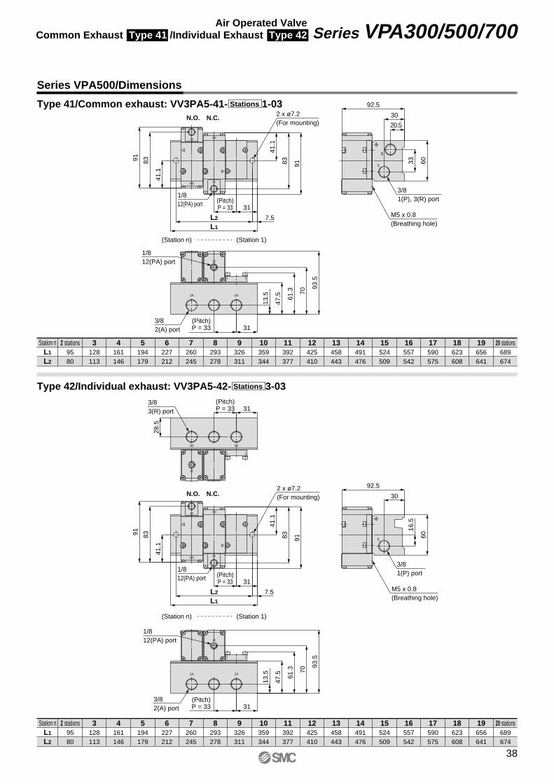
Series VPA500/Dimensions
Station nL1
L2
2 stations9580
128113
161146
194179
227212
260245
293278
326311
359344
392377
425410
458443
491476
524509
557542
590575
623608
656641
689674
3 4 5 6 7 8 9 10 11 12 13 14 15 16 17 18 19 20 stations
Station nL1
L2
2 stations9580
128113
161146
194179
227212
260245
293278
326311
359344
392377
425410
458443
491476
524509
557542
590575
623608
656641
689674
3 4 5 6 7 8 9 10 11 12 13 14 15 16 17 18 19 20 stations
Type 41/Common exhaust: VV3PA5-41- 1-03Stations
Type 42/Individual exhaust: VV3PA5-42- 3-03Stations
12
NC
12
NO
3R1P
2A2A 61.3
9183
41.1
91 83
41.1
92.5
93.5
70
47.5
13.5
30
31
7.5
31
20.5
6033
L1
L2
3/82(A) port
M5 x 0.8(Breathing hole)
(Station n) (Station 1)
N.C.N.O.
1/812(PA) port
1/812(PA) port
(Pitch)P = 33
(Pitch)P = 33
3/81(P), 3(R) port
2 x ø7.2(For mounting)
3R3R
12
NC
12
NO
1P
2A2A 61.3
28.5
3116
.5
9183
41.1
91 83
41.1
92.5
93.5
70
47.5
13.5
30
31
7.5
31
60
L1
L2
(Pitch)P = 33
3/83(R) port
(Station n) (Station 1)
N.C.N.O.
1/812(PA) port
M5 x 0.8(Breathing hole)
1/812(PA) port
(Pitch)P = 33
3/82(A) port
(Pitch)P = 33
3/81(P) port
2 x ø7.2(For mounting)
12
12
12
38
Series VPA300/500/700Air Operated ValveCommon Exhaust Type 41 /Individual Exhaust Type 42
VP-A.qxd 08.12.8 10:45 AM Page 38
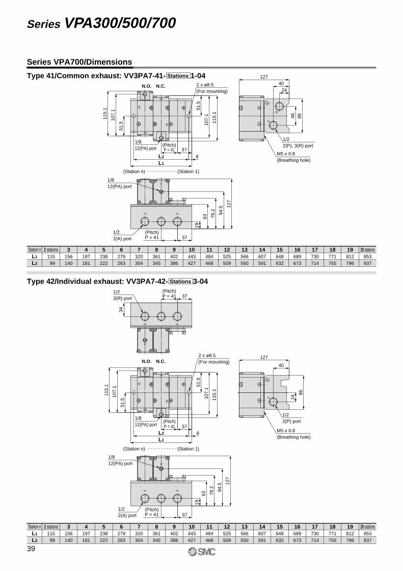
Station nL1
L2
2 stations115 99
156140
197181
238222
279263
320304
361345
402386
443427
484468
525509
566550
607591
648632
689673
730714
771755
812796
853837
3 4 5 6 7 8 9 10 11 12 13 14 15 16 17 18 19 20 stations
Station nL1
L2
2 stations115 99
156140
197181
238222
279263
320304
361345
402386
443427
484468
525509
566550
607591
648632
689673
730714
771755
812796
853837
3 4 5 6 7 8 9 10 11 12 13 14 15 16 17 18 19 20 stations
Series VPA700/Dimensions
Type 41/Common exhaust: VV3PA7-41- 1-04Stations
Type 42/Individual exhaust: VV3PA7-42- 3-04Stations
12
NC12
NO
12
2A
1P
3R
2A78
.211
5.1
107.
1
51.5
115.
1
107.
1
51.5
127
94.5
63
19
12740
24
37
8
37
8648
L1
L2
N.C.N.O.
1/812(PA) port
(Pitch)P = 41
(Station n) (Station 1)
1/812(PA) port
(Pitch)P = 41
M5 x 0.8(Breathing hole)
1/22(P), 3(R) port
2 x ø8.5(For mounting)
1/22(A) port
12
NC12
NO
3R3R
2A
1P
2A
78.2
37
34
24
40
86
115.
1
107.
1
51.5
115.
1
107.
1
51.5
127
94.5
6319
127
37
837
L1
L2
(Pitch)P = 41
1/23(R) port
1/22(P) port
N.C.N.O.
1/812(PA) port
(Pitch)P = 41
(Station n) (Station 1)
1/812(PA) port
(Pitch)P = 41
M5 x 0.8(Breathing hole)
2 x ø8.5(For mounting)
1/22(A) port
12
12
39
Series VPA300/500/700
VP-A.qxd 08.12.8 10:45 AM Page 39

VP-A.qxd 08.12.8 10:45 AM Page 40
Safety InstructionsThese safety instructions are intended to prevent hazardous situations and/or equipment damage. These instructions indicate the level of potential hazard with the labels of “Caution,” “Warning” or “Danger.” They are all important notes for safety and must be followed in addition to International Standards (ISO/IEC), Japan Industrial Standards (JIS)∗1) and other safety regulations∗2).∗ 1) ISO 4414: Pneumatic fluid power – General rules relating to systems.
ISO 4413: Hydraulic fluid power – General rules relating to systems.IEC 60204-1: Safety of machinery – Electrical equipment of machines. (Part 1: General requirements)ISO 10218-1992: Manipulating industrial robots -Safety.JIS B 8370: General rules for pneumatic equipment.JIS B 8361: General rules for hydraulic equipment. JIS B 9960-1: Safety of machinery – Electrical equipment of machines. (Part 1: General requirements)JIS B 8433-1993: Manipulating industrial robots - Safety. etc.
∗ 2) Labor Safety and Sanitation Law, etc.
1. The compatibility of the product is the responsibility of the person who designs the equipment or decides its specifications. Since the product specified here is used under various operating conditions, its compatibility with specific equipment must be decided by the person who designs the equipment or decides its specifications based on necessary analysis and test results. The expected performance and safety assurance of the equipment will be the responsibility of the person who has determined its compatibility with the product. This person should also continuously review all specifications of the product referring to its latest catalog information, with a view to giving due consideration to any possibility of equipment failure when configuring the equipment.
2. Only personnel with appropriate training should operate machinery and equipment.The product specified here may become unsafe if handled incorrectly. The assembly, operation and maintenance of machines or equipment including our products must be performed by an operator who is appropriately trained and experienced.
3. Do not service or attempt to remove product and machinery/equipment until safety is confirmed.1. The inspection and maintenance of machinery/equipment should only be performed after measures to prevent falling or
runaway of the driven objects have been confirmed.
2. When the product is to be removed, confirm that the safety measures as mentioned above are implemented and the power from any appropriate source is cut, and read and understand the specific product precautions of all relevant products carefully.
3. Before machinery/equipment is restarted, take measures to prevent unexpected operation and malfunction.
4. Contact SMC beforehand and take special consideration of safety measures if the product is to be used in any of the following conditions. 1. Conditions and environments outside of the given specifications, or use outdoors or in a place exposed to direct sunlight.
2. Installation on equipment in conjunction with atomic energy, railways, air navigation, space, shipping, vehicles, military, medical treatment, combustion and recreation, or equipment in contact with food and beverages, emergency stop circuits, clutch and brake circuits in press applications, safety equipment or other applications unsuitable for the standard specifications described in the product catalog.
3. An application which could have negative effects on people, property, or animals requiring special safety analysis.
4. Use in an interlock circuit, which requires the provision of double interlock for possible failure by using a mechanical protective function, and periodical checks to confirm proper operation.
Warning
Caution: Operator error could result in injury or equipment damage.
Danger : In extreme conditions, there is a possibility of serious injury or loss of life.
Warning: Operator error could result in serious injury or loss of life.
Back page 1
VP-A.qxd 08.12.8 10:45 AM Page U1
Safety Instructions
Limited Warranty and Disclaimer/Compliance Requirements The product used is subject to the following “Limited Warranty and Disclaimer” and “Compliance Requirements”. Read and accept them before using the product.
The product is provided for use in manufacturing industries.The product herein described is basically provided for peaceful use in manufacturing industries. If considering using the product in other industries, consult SMC beforehand and exchange specifications or a contract if necessary. If anything is unclear, contact your nearest sales branch.
Caution
Limited Warranty and Disclaimer
1. The warranty period of the product is 1 year in service or 1.5 years after the product is deliv-ered.∗3)
Also, the product may have specified durability, running distance or replacement parts. Please consult your nearest sales branch.
2. For any failure or damage reported within the warranty period which is clearly our responsibility, a replacement product or necessary parts will be provided. This limited warranty applies only to our product independently, and not to any other damage incurred due to the failure of the product.
3. Prior to using SMC products, please read and understand the warranty terms and disclaimers noted in the specified catalog for the particular products.∗ 3) Vacuum pads are excluded from this 1 year warranty.
A vacuum pad is a consumable part, so it is warranted for a year after it is delivered. Also, even within the warranty period, the wear of a product due to the use of the vacuum pad or failure due to the deterioration of rubber material are not covered by the limited warranty.
Compliance RequirementsWhen the product is exported, strictly follow the laws required by the Ministry of Economy, Trade and Industry (Foreign Exchange and Foreign Trade Control Law).
Back page 2
VP-A.qxd 08.12.8 10:45 AM Page U2
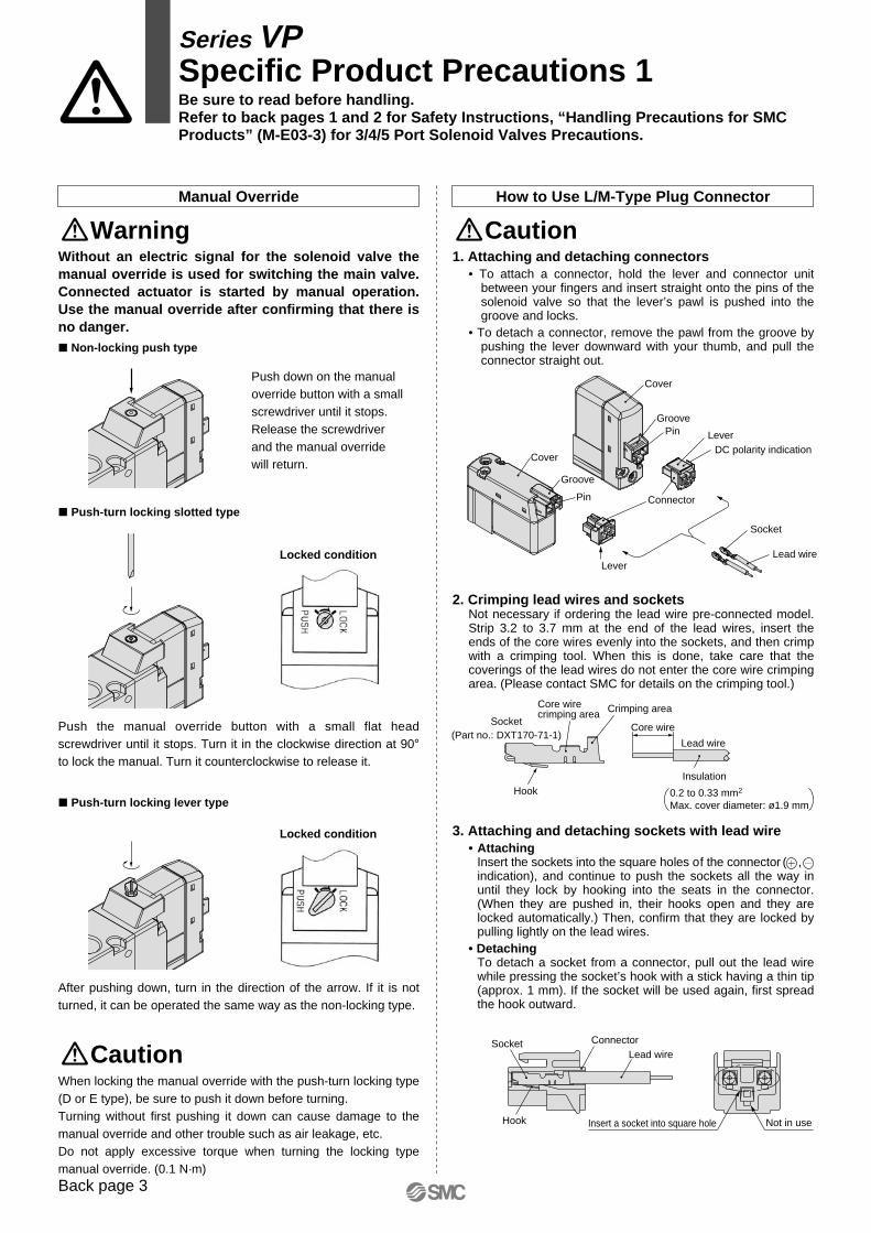
Lead wire
Socket
Lever
Connector
LeverDC polarity indication
Cover
GroovePin
Pin
Groove
Cover
0.2 to 0.33 mm2
Max. cover diameter: ø1.9 mmHook
Crimping areaCore wire crimping area
Socket(Part no.: DXT170-71-1)
Core wire
Insulation
Lead wire
Socket
Hook
ConnectorLead wire
Insert a socket into square hole Not in use
Manual Override How to Use L/M-Type Plug Connector
Warning Caution
Series VPSpecific Product Precautions 1Be sure to read before handling.Refer to back pages 1 and 2 for Safety Instructions, “Handling Precautions for SMC Products” (M-E03-3) for 3/4/5 Port Solenoid Valves Precautions.
Without an electric signal for the solenoid valve the manual override is used for switching the main valve. Connected actuator is started by manual operation. Use the manual override after confirming that there is no danger.
CautionWhen locking the manual override with the push-turn locking type (D or E type), be sure to push it down before turning.Turning without first pushing it down can cause damage to the manual override and other trouble such as air leakage, etc.Do not apply excessive torque when turning the locking type manual override. (0.1 N·m)
1. Attaching and detaching connectors• To attach a connector, hold the lever and connector unit
between your fingers and insert straight onto the pins of the solenoid valve so that the lever’s pawl is pushed into the groove and locks.
• To detach a connector, remove the pawl from the groove by pushing the lever downward with your thumb, and pull the connector straight out.
2. Crimping lead wires and socketsNot necessary if ordering the lead wire pre-connected model. Strip 3.2 to 3.7 mm at the end of the lead wires, insert the ends of the core wires evenly into the sockets, and then crimp with a crimping tool. When this is done, take care that the coverings of the lead wires do not enter the core wire crimping area. (Please contact SMC for details on the crimping tool.)
3. Attaching and detaching sockets with lead wire• Attaching
Insert the sockets into the square holes of the connector ( , indication), and continue to push the sockets all the way in until they lock by hooking into the seats in the connector. (When they are pushed in, their hooks open and they are locked automatically.) Then, confirm that they are locked by pulling lightly on the lead wires.
• DetachingTo detach a socket from a connector, pull out the lead wire while pressing the socket’s hook with a stick having a thin tip (approx. 1 mm). If the socket will be used again, first spread the hook outward.
� Non-locking push type
� Push-turn locking slotted type
Push down on the manual override button with a small screwdriver until it stops. Release the screwdriver and the manual override will return.
Push the manual override button with a small flat head screwdriver until it stops. Turn it in the clockwise direction at 90° to lock the manual. Turn it counterclockwise to release it.
After pushing down, turn in the direction of the arrow. If it is not turned, it can be operated the same way as the non-locking type.
Locked condition
� Push-turn locking lever type
Locked condition
Back page 3
VP-A.qxd 08.12.8 10:45 AM Page U3
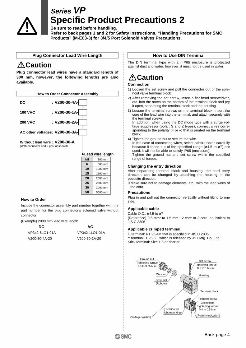
Housing
(Polarity indication)
+–
(Voltage symbol)
(Location forlight mounting)
Terminal block
3 locationsTightening torque
0.4 to 0.5 N·m
Terminal screw
Tightening torque0.5 to 0.6 N·m
Set screw
Grommet(Rubber)
Washer
Tightening torque2.5 to 3.75 N·m
Ground nut
How to Use DIN Terminal
The DIN terminal type with an IP65 enclosure is protected against dust and water, however, it must not be used in water.
Caution
Plug Connector Lead Wire Length
How to Order Connector Assembly
DC : V200-30-4A-
100 VAC : V200-30-1A-
200 VAC : V200-30-2A-
AC other voltages: V200-30-3A-
Without lead wire : V200-30-A(With connector and 2 pcs. of socket)
CautionPlug connector lead wires have a standard length of 300 mm, however, the following lengths are also available.
How to OrderInclude the connector assembly part number together with the part number for the plug connector’s solenoid valve without connector.
(Example) 2000 mm lead wire length
DC ACVP342-5LO1-01A VP342-1LO1-01A
V200-30-4A-20 V200-30-1A-20
Lead wire lengthNil
6101520253050
300 mm
600 mm
1000 mm
1500 mm
2000 mm
2500 mm
3000 mm
5000 mm
Connection1) Loosen the set screw and pull the connector out of the sole-
noid valve terminal block.2) After removing the set screw, insert a flat head screwdriver,
etc. into the notch on the bottom of the terminal block and pry it open, separating the terminal block and the housing.
3) Loosen the terminal screws on the terminal block, insert the core of the lead wire into the terminal, and attach securely with the terminal screws.In addition, when using the DC mode type with a surge vol-tage suppressor (polar: S and Z types), connect wires corre-sponding to the polarity (+ or –) that is printed on the terminal block.
4) Tighten the ground nut to secure the wire.In the case of connecting wires, select cabtire cords carefully because if those out of the specified range (ø4.5 to ø7) are used, it will not be able to satisfy IP65 (enclosure). Tighten the ground nut and set screw within the specified range of torque.
Changing the entry directionAfter separating terminal block and housing, the cord entry direction can be changed by attaching the housing in the opposite direction.∗ Make sure not to damage elements, etc., with the lead wires of
the cord.
PrecautionsPlug in and pull out the connector vertically without tilting to one side.
Applicable cableCable O.D.: ø4.5 to ø7(Reference) 0.5 mm2 to 1.5 mm2, 2-core or 3-core, equivalent to JIS C 3306
Applicable crimped terminalO terminal: R1.25-4M that is specified in JIS C 2805Y terminal: 1.25-3L, which is released by JST Mfg. Co., Ltd.Stick terminal: Size 1.5 or shorter
Series VPSpecific Product Precautions 2Be sure to read before handling.Refer to back pages 1 and 2 for Safety Instructions, “Handling Precautions for SMC Products” (M-E03-3) for 3/4/5 Port Solenoid Valves Precautions.
Back page 4
VP-A.qxd 08.12.8 10:45 AM Page U4
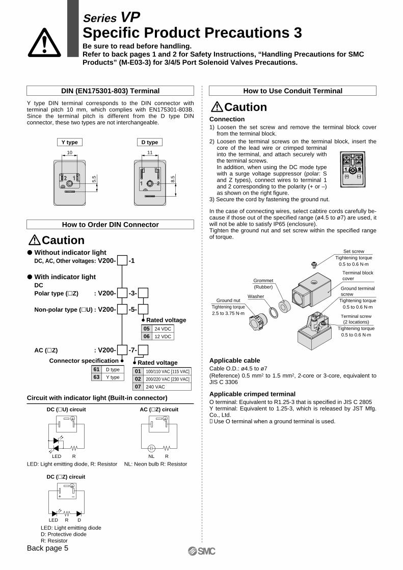
AC (�Z) circuitDC (�U) circuit
NL: Neon bulb R: ResistorLED: Light emitting diode, R: Resistor
LED R NL R
LED: Light emitting diodeD: Protective diodeR: Resistor
DC (�Z) circuit
DLED
–+
R
(–)(+)
Set screwTightening torque
0.5 to 0.6 N·m
Terminal block cover
Tightening torque0.5 to 0.6 N·m
Terminal screw(2 locations)
Tightening torque0.5 to 0.6 N·m
Grommet(Rubber)
WasherGround nut
Tightening torque2.5 to 3.75 N·m
Y type D type
1110
5.5
8.5
Ground terminalscrew
How to Order DIN Connector
Caution
Caution
� Without indicator lightDC, AC, Other voltages: V200- -1
� With indicator lightDCPolar type (�Z) : V200- -3-
Non-polar type (�U) : V200- -5-
AC (�Z) : V200- -7-
Rated voltage010207
100/110 VAC [115 VAC]
200/220 VAC [230 VAC]
240 VAC
Rated voltage0506
24 VDC
12 VDC
Circuit with indicator light (Built-in connector)
How to Use Conduit Terminal
Connection1) Loosen the set screw and remove the terminal block cover
from the terminal block.2) Loosen the terminal screws on the terminal block, insert the
core of the lead wire or crimped terminal into the terminal, and attach securely with the terminal screws.In addition, when using the DC mode type with a surge voltage suppressor (polar: S and Z types), connect wires to terminal 1 and 2 corresponding to the polarity (+ or –) as shown on the right figure.
3) Secure the cord by fastening the ground nut.
DIN (EN175301-803) Terminal
Y type DIN terminal corresponds to the DIN connector with terminal pitch 10 mm, which complies with EN175301-803B. Since the terminal pitch is different from the D type DIN connector, these two types are not interchangeable.
Connector specification6163
D type
Y type
In the case of connecting wires, select cabtire cords carefully be-cause if those out of the specified range (ø4.5 to ø7) are used, it will not be able to satisfy IP65 (enclosure). Tighten the ground nut and set screw within the specified range of torque.
Applicable cableCable O.D.: ø4.5 to ø7(Reference) 0.5 mm2 to 1.5 mm2, 2-core or 3-core, equivalent to JIS C 3306
Applicable crimped terminalO terminal: Equivalent to R1.25-3 that is specified in JIS C 2805Y terminal: Equivalent to 1.25-3, which is released by JST Mfg. Co., Ltd.∗ Use O terminal when a ground terminal is used.
Series VPSpecific Product Precautions 3Be sure to read before handling.Refer to back pages 1 and 2 for Safety Instructions, “Handling Precautions for SMC Products” (M-E03-3) for 3/4/5 Port Solenoid Valves Precautions.
Back page 5
VP-A.qxd 08.12.8 10:45 AM Page U5
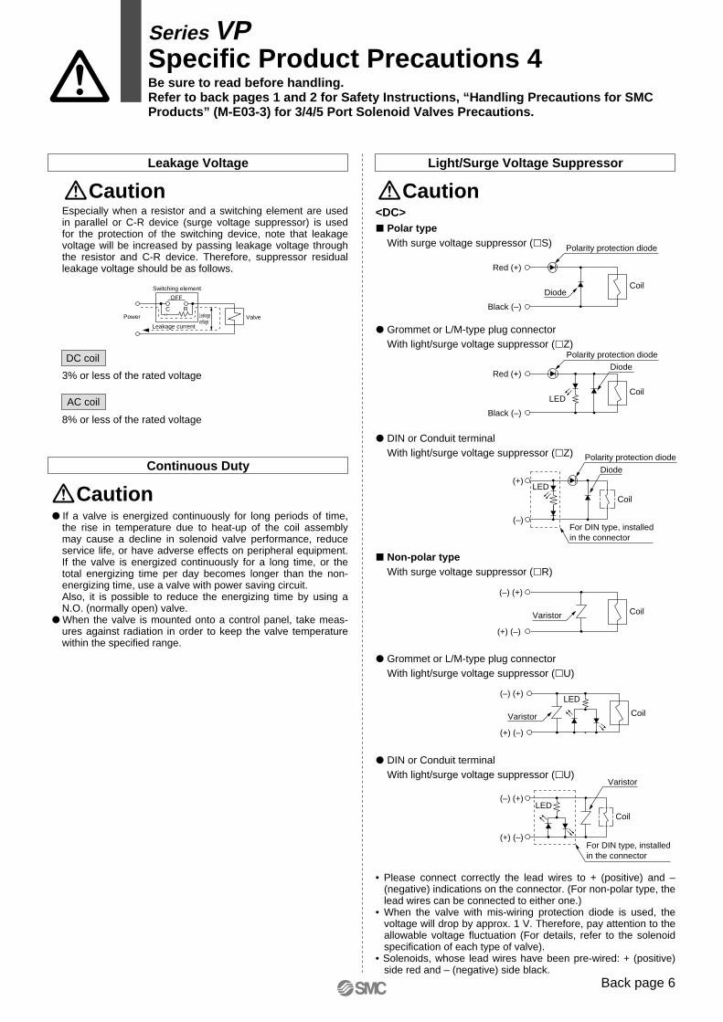
(–) (+)
(+) (–)
Varistor
(–) (+)
(+) (–)
Varistor
LED
Red (+)
Black (–)
Red (+)
Black (–)
Polarity protection diode
Coil
Coil
Coil
Coil
Coil
Coil
Diode
Polarity protection diode
LED
Diode
For DIN type, installedin the connector
Diode
Polarity protection diode
LED
(–)
(+)
For DIN type, installedin the connector
LED
Varistor
(+) (–)
(–) (+)
Caution
• Please connect correctly the lead wires to + (positive) and – (negative) indications on the connector. (For non-polar type, the lead wires can be connected to either one.)
• When the valve with mis-wiring protection diode is used, the voltage will drop by approx. 1 V. Therefore, pay attention to the allowable voltage fluctuation (For details, refer to the solenoid specification of each type of valve).
• Solenoids, whose lead wires have been pre-wired: + (positive) side red and – (negative) side black.
<DC>� Polar type With surge voltage suppressor (�S)
� DIN or Conduit terminal With light/surge voltage suppressor (�Z)
� DIN or Conduit terminal With light/surge voltage suppressor (�U)
� Non-polar type With surge voltage suppressor (�R)
� Grommet or L/M-type plug connector With light/surge voltage suppressor (�U)
� Grommet or L/M-type plug connector With light/surge voltage suppressor (�Z)
Light/Surge Voltage Suppressor
Switching element
C
OFF
Leakage current
Leakage voltage
ValveR
Power
DC coil
AC coil
Especially when a resistor and a switching element are used in parallel or C-R device (surge voltage suppressor) is used for the protection of the switching device, note that leakage voltage will be increased by passing leakage voltage through the resistor and C-R device. Therefore, suppressor residual leakage voltage should be as follows.
3% or less of the rated voltage
8% or less of the rated voltage
Leakage Voltage
Caution
� If a valve is energized continuously for long periods of time, the rise in temperature due to heat-up of the coil assembly may cause a decline in solenoid valve performance, reduce service life, or have adverse effects on peripheral equipment. If the valve is energized continuously for a long time, or the total energizing time per day becomes longer than the non-energizing time, use a valve with power saving circuit.Also, it is possible to reduce the energizing time by using a N.O. (normally open) valve.
� When the valve is mounted onto a control panel, take meas-ures against radiation in order to keep the valve temperature within the specified range.
Continuous Duty
Caution
Series VPSpecific Product Precautions 4Be sure to read before handling.Refer to back pages 1 and 2 for Safety Instructions, “Handling Precautions for SMC Products” (M-E03-3) for 3/4/5 Port Solenoid Valves Precautions.
Back page 6
VP-A.qxd 08.12.8 10:45 AM Page U6
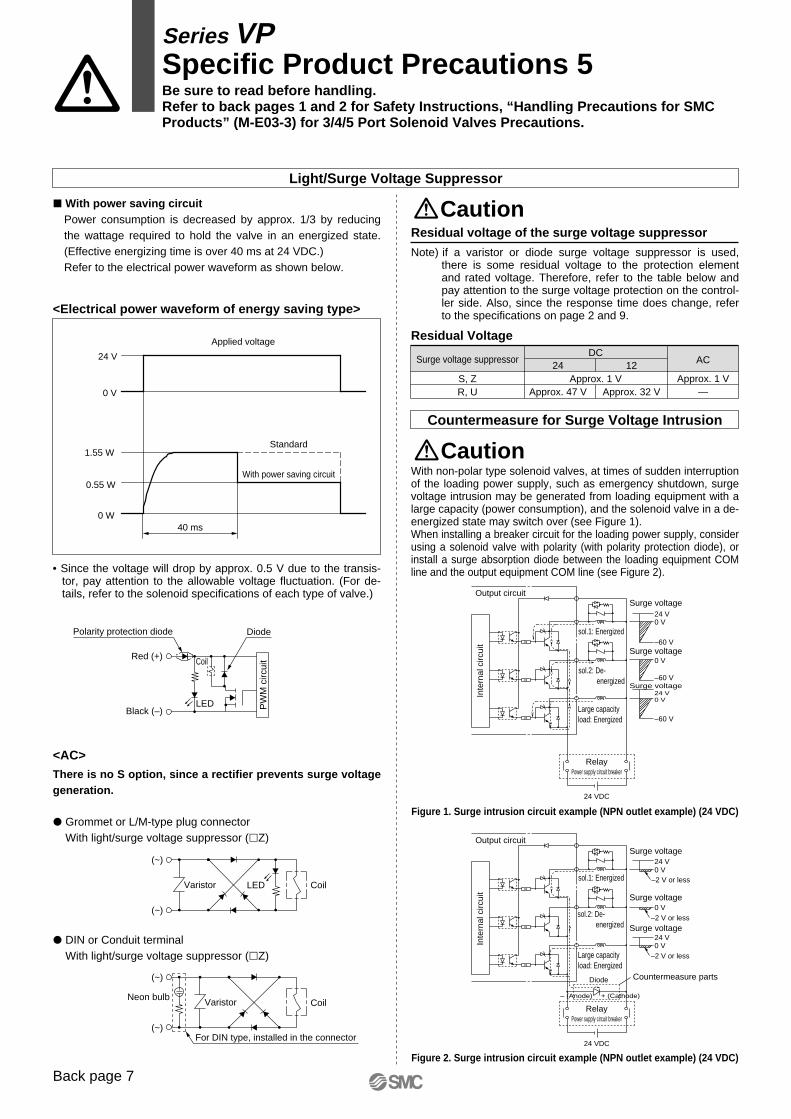
–60 V
–60 V
–60 V
Surge voltage
Surge voltage
24 V0 V
0 V
24 V0 V
Surge voltage
Power supply circuit breaker
Large capacityload: Energized
Relay
sol.2: De-energized
sol.1: Energized
Output circuit
Output circuit
Inte
rnal
circ
uit
Inte
rnal
circ
uit
24 VDC
R
R
R
Countermeasure parts
Surge voltage
Surge voltage
–2 V or less
–2 V or less
–2 V or less
– (Anode) + (Cathode)
Diode
24 V0 V
0 V
24 V0 V
Surge voltage
Power supply circuit breaker
Large capacityload: Energized
Relay
sol.2: De-energized
sol.1: Energized
24 VDC
R
R
R
Applied voltage
Standard
With power saving circuit
40 ms
24 V
0 V
1.55 W
0.55 W
0 W
For DIN type, installed in the connector
(~)
(~)
(~)
(~)
LEDVaristor
Neon bulbVaristor
Polarity protection diode Diode
Coil
LED PW
M c
ircui
t
Coil
Coil
Red (+)
Black (–)
CautionResidual voltage of the surge voltage suppressor
Note) if a varistor or diode surge voltage suppressor is used, there is some residual voltage to the protection element and rated voltage. Therefore, refer to the table below and pay attention to the surge voltage protection on the control-ler side. Also, since the response time does change, refer to the specifications on page 2 and 9.
Residual Voltage
Surge voltage suppressor
S, ZR, U
DC24
Approx. 47 VApprox. 1 V
AC
Approx. 1 V—
12
Approx. 32 V
Figure 1. Surge intrusion circuit example (NPN outlet example) (24 VDC)
Figure 2. Surge intrusion circuit example (NPN outlet example) (24 VDC)
CautionWith non-polar type solenoid valves, at times of sudden interruption of the loading power supply, such as emergency shutdown, surge voltage intrusion may be generated from loading equipment with a large capacity (power consumption), and the solenoid valve in a de-energized state may switch over (see Figure 1).When installing a breaker circuit for the loading power supply, consider using a solenoid valve with polarity (with polarity protection diode), or install a surge absorption diode between the loading equipment COM line and the output equipment COM line (see Figure 2).
Countermeasure for Surge Voltage Intrusion
Light/Surge Voltage Suppressor
• Since the voltage will drop by approx. 0.5 V due to the transis-tor, pay attention to the allowable voltage fluctuation. (For de-tails, refer to the solenoid specifications of each type of valve.)
� With power saving circuit
<AC>There is no S option, since a rectifier prevents surge voltage generation.
� Grommet or L/M-type plug connector With light/surge voltage suppressor (�Z)
� DIN or Conduit terminal With light/surge voltage suppressor (�Z)
<Electrical power waveform of energy saving type>
Power consumption is decreased by approx. 1/3 by reducing the wattage required to hold the valve in an energized state. (Effective energizing time is over 40 ms at 24 VDC.)Refer to the electrical power waveform as shown below.
Series VPSpecific Product Precautions 5Be sure to read before handling.Refer to back pages 1 and 2 for Safety Instructions, “Handling Precautions for SMC Products” (M-E03-3) for 3/4/5 Port Solenoid Valves Precautions.
Back page 7
VP-A.qxd 08.12.8 10:45 AM Page U7
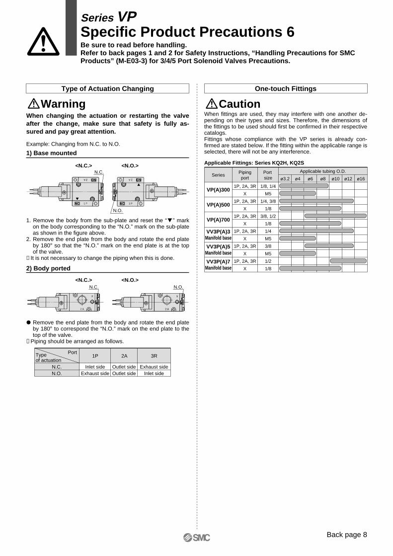
SeriesPipingport
Port size
Applicable tubing O.D.
ø3.2 ø4 ø6 ø8 ø10 ø12 ø16
VP(A)300
VP(A)500
VP(A)700
VV3P(A)3Manifold base
VV3P(A)5Manifold base
VV3P(A)7Manifold base
1P, 2A, 3R
X
1P, 2A, 3R
X
1P, 2A, 3R
X
1P, 2A, 3R
X
1P, 2A, 3R
X
1P, 2A, 3R
X
1/8, 1/4
M5
1/4, 3/8
1/8
3/8, 1/2
1/8
1/4
M5
3/8
M5
1/2
1/8
Applicable Fittings: Series KQ2H, KQ2S
N.C.
N.O.
N.C. N.O.
One-touch Fittings
When fittings are used, they may interfere with one another de-pending on their types and sizes. Therefore, the dimensions of the fittings to be used should first be confirmed in their respective catalogs.Fittings whose compliance with the VP series is already con-firmed are stated below. If the fitting within the applicable range is selected, there will not be any interference.
Caution
Type of Actuation Changing
Warning
Example: Changing from N.C. to N.O.
1) Base mounted
1. Remove the body from the sub-plate and reset the “� ” mark on the body corresponding to the “N.O.” mark on the sub-plate as shown in the figure above.
2. Remove the end plate from the body and rotate the end plate by 180° so that the “N.O.” mark on the end plate is at the top of the valve.
∗ It is not necessary to change the piping when this is done.
2) Body ported
� Remove the end plate from the body and rotate the end plate by 180° to correspond the “N.O.” mark on the end plate to the top of the valve.
∗ Piping should be arranged as follows.
PortType of actuation
N.C.N.O.
Inlet sideExhaust side
2A1P
Outlet sideOutlet side
Exhaust sideInlet side
3R
<N.C.> <N.O.>
<N.C.> <N.O.>
When changing the actuation or restarting the valve after the change, make sure that safety is fully as-sured and pay great attention.
Series VPSpecific Product Precautions 6Be sure to read before handling.Refer to back pages 1 and 2 for Safety Instructions, “Handling Precautions for SMC Products” (M-E03-3) for 3/4/5 Port Solenoid Valves Precautions.
Back page 8
VP-A.qxd 08.12.8 10:45 AM Page U8

VP-A.qxd 08.12.8 10:45 AM Page U9

VP-A.qxd 08.12.8 10:45 AM Page C3

Akihabara UDX 15F, 4-14-1, Sotokanda, Chiyoda-ku, Tokyo 101-0021, JAPANPhone: 03-5207-8249 Fax: 03-5298-5362URL http://www.smcworld.com© 2008 SMC Corporation All Rights Reserved
Specifications are subject to change without prior notice and any obligation on the part of the manufacturer.
1st printing MZ printing MZ 16400DN Printed in Japan.D-DN
This catalog is printed on recycled paper with concern for the global environment.
Safety Instructions Be sure to read “Handling Precautions for SMC Products” (M-E03-3) before using.
NETHERLANDSSMC Pneumatics B.V.
NORWAYSMC Pneumatics Norway AS
POLANDSMC Industrial Automation Polska Sp.z.o.o.
ROMANIA SMC Romania S.r.l.
RUSSIA SMC Pneumatik LLC
SLOVAKIASMC Priemyselná Automatizácia Spol s.r.o.
SLOVENIASMC Industrijska Avtomatika d.o.o.
SPAIN/PORTUGALSMC España S.A.
SWEDENSMC Pneumatics Sweden AB
SWITZERLANDSMC Pneumatik AG
U.K.SMC Pneumatics (U.K.) Ltd.
ASIACHINASMC (China) Co., Ltd.
HONG KONGSMC Pneumatics (Hong Kong) Ltd.
INDIASMC Pneumatics (India) Pvt. Ltd.
MALAYSIASMC Pneumatics (S.E.A.) Sdn. Bhd.
PHILIPPINESShoketsu SMC Corporation
SINGAPORESMC Pneumatics (S.E.A.) Pte. Ltd.
SOUTH KOREASMC Pneumatics Korea Co., Ltd.
TAIWANSMC Pneumatics (Taiwan) Co., Ltd.
THAILANDSMC (Thailand) Ltd.
NORTH AMERICACANADASMC Pneumatics (Canada) Ltd.
MEXICOSMC Corporation (Mexico), S.A. de C.V.U.S.A.SMC Corporation of America
SOUTH AMERICAARGENTINASMC Argentina S.A.
BOLIVIASMC Pneumatics Bolivia S.r.l.
BRAZILSMC Pneumáticos do Brasil Ltda
CHILESMC Pneumatics (Chile) S.A.
VENEZUELASMC Neumatica Venezuela S.A.
OCEANIAAUSTRALIASMC Pneumatics (Australia) Pty. Ltd.
NEW ZEALANDSMC Pneumatics (N.Z.) Ltd.
EUROPEAUSTRIASMC Pneumatik GmbH (Austria)
BELGIUMSMC Pneumatics N.V./S.A.
BULGARIASMC Industrial Automation Bulgaria Eood
CROATIASMC Industrijska Automatika d.o.o.
CZECH REPUBLICSMC Industrial Automation CZ s.r.o.
DENMARKSMC Pneumatik A/S
ESTONIASMC Pneumatics Estonia OÜ
FINLANDSMC Pneumatics Finland Oy
FRANCESMC Pneumatique SA
GERMANYSMC Pneumatik GmbH
GREECESMC Hellas E.P.E.
HUNGARYSMC Hungary Ipari Automatizálási Kft.
IRELANDSMC Pneumatics (Ireland) Ltd.
ITALYSMC Italia S.p.A.
LATVIASMC Pnuematics Latvia SIA
LITHUANIAUAB “SMC Pneumatics”
SMC'S GLOBAL MANUFACTURING, DISTRIBUTION AND SERVICE NETWORK
VP-A.qxd 08.12.8 10:45 AM Page C4