Embed Size (px)
Citation preview

Sonic conductanceC [dm3/(s·bar)]
Type ofactuation Voltage
Electricalentry
With light/surgevoltage suppressor
Manualoverride
VQZ100
VQZ200
VQZ300
—
1.3 1.7
2.4 3.0
N.C.
N.O.
3 p
ort
(Except VQZ100)
(A)2
1(P)
3(R)
(A)2
1(P)
3(R)
(Poppet)
0.56
RubberMetal
Bo
dy
Po
rted (Standard)
12 VDC24 VDC
(Option)100 VAC200 VAC110 VAC220 VAC
Grommet (G)
L plug connector (L)
DIN terminal (Y)
Except VQZ100 )(
With light/surgevoltage suppressor
L plug connector (L)
M plug connector (M)
DIN terminal (YZ)
Except VQZ100 )(
Non-lockingpush type
(Tool required)
Locking type(Tool required)
M plug connector (M)
Series Variations
3 Port Solenoid ValveMetal Seal/Rubber Seal, Body Ported
SeriesVQZ100/200/300
4-14-1
V100
SY
SYJ
VK
VZ
VT
VP
VG
VP
S070
VQ
VKF
VQZ
VZ
VS
VFN

Circuit with Light/Surge Voltage Suppressor
(Not necessary if ordering the lead wire pre-connected model.)
Crimping of lead wires and sockets
No polarity by adopting non-polar light.
DC circuit AC circuit
Push type (Tool required)
Locking type (Tool required)VQZ200VQZ300
Attaching and detaching connectors
Attaching
Crimping areaCore wirecrimping area
Terminal
Hook
Core wire
Insulation
Lead wire
0.2 to 0.33 mm2
Max. cover diameter: ø1.7 mm
Socket
Hook
Connector
Lead wire
A
C
SOL
IndicatorlightA(–)
C( + )
SOL
ZNRIndicatorlight
[+]
[–]
Red (DC)
Blue 100 VAC110 VAC
Red 200 VAC220 VAC
Black (DC)
Blue 100 VAC110 VAC200 VAC220 VACRed
Crimping tool: Part no. DXT170-75-1
Attaching and detaching lead wires with sockets
Locking type (Tool required) VQZ100
Connector part no. AXT661-12
Cover
Pin
Concave
Concave
Cover
Pin
L plug connector
Lead wire 0.2 to 0.33 mm2
(Max. O.D. ø1.7 mm)
Socket part no. DXT170-71-1
Lever
Hook
M plug connector
Indicator light
Precautions
Without an electric signal for the solenoid valve the manual override is used for switching the main valve.Locking type (Tool required) is available as an option.
Push down on the manual override button with a small screwdriver until it stops. Release the screwdriver and the manual override will return.
Push down completely on the manual override button with a small screwdriver. While down, turn clockwise 90° to lock it. Turn it counterclockwise to release it.
If the manual override is turned by 180° clockwise and the � mark is adjusted to 1, then pushed in the direction of an arrow (�), it will be locked in the ON state. If the manual override is turned by 180° counterclockwise and � mark is adjusted to 0, locking will be released and the manual override will return.
To attach a connector, hold the lever and connector unit between your fingers and insert straight onto the pins of the solenoid valve so that the lever’s pawl is pushed into the groove and locks.
To detach a connector, remove the pawl from the groove by pushing the lever downward with your thumb, and pull the connector straight out.
Refer to page 4-14-19 for part no. of plug connector assembly.
Peel 3.2 to 3.7 mm of the tip of lead wire, enter the core wires neatly into a socket and crimp it with a special crimp tool. Be careful so that the cover of lead wire does not enter into the crimping part.
Insert the sockets into the square holes of the connector (with �+ and �– indication) and continue to push the sockets all the way in until the lock by hooking into the seats in the connector. (When they are pushed in, their hooks open and they are locked automatically.)Then confirm that they are locked by lightly pulling on the lead wire.
DetachingTo remove the socket from the connector, pull out lead wire while depressing the hook of the socket with a fine screwdriver (or similar). If the socket is used again, spread the hook outward.
Be sure to read before handling. For Safety Instructions and Solenoid Valve Precautions, refer to page 4-18-2.
Warning
Caution
Manual OverrideConnect each lead wire to the power source side, because of no polarity for DC as well.
Connection and Electrical Circuit
CautionHow to Use L/M Plug Connector
Connection of Lead Wire
Do not apply excessive torque when turning the locking type manual override.
Series VQZ100/200/300
4-14-2
Body Ported
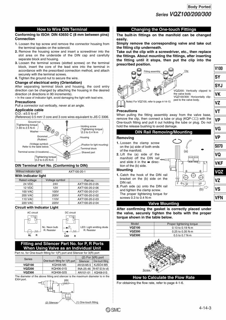
Conforming to ISO#: DIN 43650 C (8 mm between pins)Connection
DIN Terminal Part No. (Conforming to DIN)
Without indicator light
Rated voltage
With indicator lightAXT100-20-1
Voltage symbol Part no.
Circuit with Indicator Light
For obtaining the flow rate, refer to page 4-1-6.
ModelVQZ100VQZ200VQZ300
Proper tightening torque0.13 to 0.19 N·m0.25 to 0.35 N·m0.5 to 0.7 N·m
Ground nut
Washer
Grommet(Rubber)
(Voltage symbol)Refer to the table below.
Terminal screw (3 locations)
Holding screw
Housing
(Position for light mounting)
Terminal block
Shaved part
NL: Neon bulbR: Resister
LED: Light emitting diodeR: Resister
AC circuit DC circuit
1 2
NL R
1 2
RLED
Fitting assembly Clip
Part no. for One-touch fitting for 1(P) port and Silencer for 3(R) port
VQZ100VQZ200VQZ300
KQH06-M5KQH06-01SKQH08-02S
(1)One-touch fitting for 1(P) port Silencer
AN120-M5-SINA-25-46AN101-01
(2) For 3(R) portOne-touch fittingKJSO4-M5
IN-457-32 (for ø6)
Series
KQH08-01S
Clip
Tightening torque1.65 to 2.5 N·m Tightening torque
0.3 to 0.4 N·m
Tightening torque0.2 to 0.25 N·m
(1) One-touch fitting(2) Silencer
Screw
1. Loosen the top screw and remove the connector housing from the terminal spades on the solenoid.
2. Remove the housing screw and insert a screwdriver into the slot area on the underside of the DIN cap and carefully separate block and housing.
3. Loosen the terminal screws (slotted screws) on the terminal block, insert the core of the lead wire into the terminal in accordance with the prescribed connection method, and attach securely with the terminal screws.
4. Tighten the ground nut to secure the wire.Change of electrical entry (Orientation)After separating terminal block and housing, the cord entry direction can be changed by attaching the housing in the desired direction (4 directions in 90 increments).∗ In the case of indicator light, avoid damaging the light with lead wire.
PrecautionsPull a connector out vertically, never at an angle.Applicable cableO.D.: ø3.5 to ø7(Reference) 0.5 mm2 2 core and 3 core wires equivalent to JIS C 3306.
24 VDC12 VDC
100 VAC200 VAC110 VAC220 VAC
AXT100-20-2-05AXT100-20-2-06AXT100-20-2-01AXT100-20-2-02AXT100-20-2-03AXT100-20-2-04
The diameter of the above fitting and silencer is the maximum diameter to in the EXH port.
The built-in fittings on the manifold can be changed easily.Simply remove the corresponding valve and take out the fitting clip underneath. Take out the clip with a screwdriver, etc., then replace the fittings. About mounting the fittings, after inserting the fitting until it stops, then put the clip into the prescribed position.
Note) For VQZ100, refer to page 4-14-13.
VQZ200: Vertically clipped to the valve bodyVQZ100/300: Horizontally clip-ped to the valve body.
PrecautionsWhen pulling the fitting assembly away from the valve base, remove the clip, then connect a tube or plug (KQP-��) with the One-touch fitting and pull it out holding the tube or plug. Do not hold the release bushing to avoid damage.
Removing1. Loosen the clamp screw
on the (a) side of both ends of the manifold.
2. Lift the (a) side of the manifold off the DIN rail and slide it in the direc-tion of the (b) side.
Mounting1. Catch the hook of the DIN rail
bracket on the (b) side on the DIN rail.
2. Push side (a) onto the DIN rail and tighten the clamp screw.The proper tightening torque for screws 0.3 to 0.4 N·m
After confirming the gasket is correctly placed under the valve, securely tighten the bolts with the proper torque shown in the table below.
How to Wire DIN Terminal Changing the One-touch Fittings
DIN Rail Removing/Mounting
Valve Mounting
How to Calculate the Flow Rate
Fitting and Silencer Part No. for P, R PortsWhen Using Valve as an Individual Unit
(a)
(b)
24V12V100V200V110V220V
4-14-3
Series VQZ100/200/300Body Ported
V100
SY
SYJ
VK
VZ
VT
VP
VG
VP
S070
VQ
VKF
VQZ
VZ
VS
VFN
Type of actuation
Series
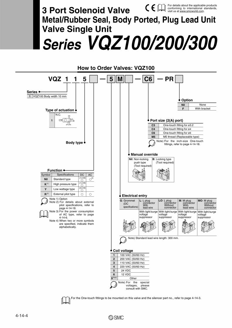
VQZ 1 1 5 5 M C6
How to Order Valves: VQZ100
1 VQZ100 Body width 10 mm
1
N.C.
Body type
Function
Port size {2(A) port}One-touch fitting for ø3.2One-touch fitting for ø4
One-touch fitting for ø6
M5 thread (Replaceable type)
Manual overrideNil: Non-locking
push type(Tool required)
B: Locking type(Tool required)
Electrical entryG: Grommet
(DCspecifications)
L: L plugconnectorWith lead wire
LO: L plugconnectorWithoutconnector
M: M plug connectorWithlead wire
MO: M plugconnectorWithoutconnector
With light/surgevoltage suppressor
With light/surgevoltage suppressor
With light/surgevoltage suppressor
With light/surgevoltage suppressor
Note) Standard lead wire length: 300 mm.
Coil voltage123456
9Note)
100 VAC (50/60 Hz)200 VAC (50/60 Hz)110 VAC (50/60 Hz)220 VAC (50/60 Hz)24 VDC12 VDC
Other
C3C4C6M5
PR
NilF
NoneWith bracket
Option
(A)2
1(P)
3(R)
Nil
K (1)
Y
R (2)
Symbol Specifications DC(1.0 W)
�(1.0 W)
�(0.5 W)
�
�
�
�
(3)
AC
For the One-touch fittings to be mounted on this valve and the silencer part no., refer to page 4-14-3.
Note 1) OptionNote 2) For details about external
pilot specifications, refer to page 4-14-18.
Note 3) For the power consumption of AC type, refer to page 4-14-6.
Note 4) When two or more symbols are specified, indicate them alphabetically.
B CA
BC
A
3 Port Solenoid ValveMetal/Rubber Seal, Body Ported, Plug Lead Unit Valve Single Unit
Series VQZ100/200/300
For details about the applicable products conforming to international standards, visit us at www.smcworld.com.
Note) For the inch-size One-touch fittings, refer to page 4-14-18.
Note) For the special voltages, please consult with SMC.
Standard type
High pressure type
Low wattage type
External pilot type
4-14-4

Type of actuation
Series
VQZ 2 1 2 5 M
How to Order Valves: VQZ200/300
23
VQZ200 Body width 15 mmVQZ300 Body width 18 mm
1
N.C.
Body type2 Body ported
Function
Manual override
Electrical entryG: Grommet
(DCspecifications)
L: L plugconnectorWith lead wire
LO: L plugconnectorWithoutconnector
M: M plug connectorWith lead wire
MO: M plugconnectorWithoutconnector
Note) Standard lead wire length: 300 mm.
Coil voltage1234569
100 VAC (50/60 Hz)200 VAC (50/60 Hz)110 VAC (50/60 Hz)220 VAC (50/60 Hz)24 VDC12 VDC
Other
2
N.O.
3
N.C.
4
N.O.
Y: DINterminal
YO: DINterminalWithoutconnector
YZ: DINterminal
YOS: DINterminal
Withoutconnector
YS: DINterminal
Met
al s
eal
Rub
ber
seal
(A)2
1(P)
3(R)
(A)2
1(P)
3(R)
(A)2
1(P)
3(R)
(A)2
1(P)
3(R)
Nil: Non-lockingpush type(Tool required)
B: Locking type(Tool required)
Nil Standard type
High pressure type(Metal seal only)
Low wattage type
External pilot type
K (1)
Y
R (2)
Symbol Specifications DC(1.0 W)
�
(1.0 W)�
(0.5 W)�
�
�
�
(3)
AC
For the One-touch fittings to be mounted on this valve and the silencer part no., refer to page 4-14-3.
Note 1) OptionNote 2) For details about external
pilot specifications, refer to page 4-14-18.
Note 3) For the power consumption of AC type, refer to page 4-14-6.
Note 4) When two or more symbols are specified, indicate them alphabetically.
BC
A
BC
A
C6
Port size {2(A) port}
�
�
——�
—
—�
�
�
—�
VQZ200One-touch fitting for ø4One-touch fitting for ø6One-touch fitting for ø8
One-touch fitting for ø10M5 thread
Rc 1/4
C4C6C8
C10M502
NilF
NoneWith bracket
Option
VQZ300Port sizeSymbol
Note) For the inch-size One-touch fittings, refer to page 4-14-18.
With light/surgevoltage suppressor
With light/surgevoltage suppressor
With light/surgevoltage suppressor
With light/surgevoltage suppressor
With light/surgevoltage suppressor
With surgevoltage suppressor
With surgevoltage suppressor
Note) For the special voltages, please consult with SMC.
4-14-5
Series VQZ100/200/300Body Ported
3 Port Solenoid Valve (Valve Single Unit)Metal/Rubber Seal, Body Ported, Plug Lead Unit
V100
SY
SYJ
VK
VZ
VT
VP
VG
VP
S070
VQ
VKF
VQZ
VZ
VS
VFN

Standard Specifications
Valve construction
Fluid
Maximum operating pressure
Minimum operating pressure
Ambient and fluid temperature
Maximum operating frequency
Pilot valve EXH
Lubrication
Pilot valve manual override
Shock/Vibration resistance (2)
Enclosure
Coil rated voltage
Allowable voltage fluctuation
Coil insulation type
24 VDC
12 VDC
100 VAC
110 VAC
200 VAC
220 VAC
Powerconsumption(Current)
Val
ve s
peci
ficat
ions
Ele
ctric
ity s
peci
ficat
ions
Metal seal
0.1 MPa
–10 to 50°C (1)
20 Hz
Rubber seal
0.7 MPa
0.15 MPa
–10 to 50°C (1)
5 Hz
Not required
Non-locking push type/Slotted locking type (tool required) as an option
150/30 m/s2
Dustproof
12, 24 VDC and 100, 110, 200, 220 VAC
±10% of rated voltage
Equivalent to class B
1 W DC (42 mA), 0.5 W DC (21 mA)
1 W DC (83 mA), 0.5 W DC (42 mA)
Inrush 0.5 VA (5 mA), Holding 0.5 VA (5 mA)
Inrush 0.55 VA (5 mA), Holding 0.55 VA (5 mA)
Inrush 1.0 VA (5 mA), Holding 1.0 VA (5 mA)
Inrush 1.1 VA (5 mA), Holding 1.1 VA (5 mA)
Flow Characteristics/Weight
Series Valveconstruction
Poppet
Metal seal
Rubber seal
Metal seal
Rubber seal
Metal seal
Rubber seal
Metal seal
Rubber seal
N.C. valve
N.C. valve
VQZ100
N.O. valve
N.C. valve
N.O.valve
VQZ200
VQZ300
Model
VQZ115
VQZ212
VQZ232
VQZ222
VQZ242
VQZ312
VQZ332
VQZ322
VQZ342
Weight (2)
(g)
Response time (ms)(1)
2 � 3 (A � R)1 � 2 (P � A)
Flow characteristics
C [dm3/(s·bar)] b
0.44
0.21
0.33
0.25
0.36
0.18
0.34
0.21
0.38
Cv
0.17
0.30
0.39
0.31
0.40
0.62
0.87
0.59
0.88
Standard type: 1 W
AC
VQZ100 (Poppet seal)
0.15 MPa
–10 to 50°C (1)
20 Hz
Common exhaust
25
58
92
C [dm3/(s·bar)] b
0.30
0.24
0.37
0.20
0.36
0.28
0.33
0.16
0.27
Cv
0.14
0.33
0.45
0.31
0.45
0.56
0.72
0.49
0.69
10 or less
14 or less
15 or less
14 or less
15 or less
17 or less
25 or less
17 or less
25 or less
13 or less
18 or less
20 or less
18 or less
20 or less
22 or less
33 or less
22 or less
33 or less
22 or less
34 or less
36 or less
34 or less
36 or less
34 or less
57 or less
34 or less
57 or less
Air/Inert gas
Note 1) Use dry air to prevent condensation when operating at low temperatures.Note 2) Impact resistance: No malfunction occurred when it is tested with a drop tester in the axial
direction and at the right angles to the main valve and armature in both energized and de-energized states every once for each condition. (Values at the initial period)
Vibration resistance: No malfunction occurred in a one-sweep test between 45 and 2000 Hz. Test was performed at both energized and de-energized states in the axial direction and at the right angles to the main valve and armature. (Values at the initial period)
High pressure type: 1.0 WLow wattage type: 0.5 W
0.59
1.2
1.6
1.2
1.6
2.7
3.5
2.6
3.5
0.56
1.3
1.7
1.3
1.7
2.4
3.0
2.2
2.9
Note 1) Based on JIS B 8375-1981 (Supply pressure: 0.5 MPa; with light/surge voltage suppressor; clean air) The response time is subject to the pressure and the air quality.Response time values will change depending on pressure and air quality.
Note 2) Weight without sub-plate
0.7 MPa (High pressure type: 1.0 MPa)
0.7 MPa (High pressure type: 1.0 MPa)
Individual EXH
4-14-6
Series VQZ100/200/300Body Ported

Rubber seal typeVQZ200/300Metal seal type
Construction
N.C.VQZ100Poppet type (A)
2
1(P)
3(R)
Description Material
Aluminum die-casted
Stainless steel
Aluminum/HNBR
Resin
—
Note
Metal seal
Rubber seal
No.
q
w
e
r
Component Parts
N.C. N.C.
N.O. N.O.
3(R)
1(P)
(A)2
3(R)
1(P)
(A)2
3(R)
1(P)
(A)2
3(R)
1(P)
(A)2
Description
Body
Spool valve
Pilot valve assembly
P/R plate
Material
Resin
Aluminum/HNBR
—
Resin/Aluminum
Note
VQZ100-12A (Standard)
VQZ100-12B (External pilot)
No.
q
w
e
r
Component Parts
For “How to Order Pilot Valve Assembly”, refer to page 4-14-19.
qwe
r
r e w q
r e w q r e w q
r e w q
Body
Spool/Sleeve
Spool valve
Piston
Pilot valve assembly
4-14-7
Series VQZ100/200/300Body Ported
3 Port Solenoid Valve (Valve Single Unit)Metal/Rubber Seal, Body Ported, Plug Lead Unit
V100
SY
SYJ
VK
VZ
VT
VP
VG
VP
S070
VQ
VKF
VQZ
VZ
VS
VFN

Dimensions: VQZ100
L plug connector (L): VQZ115-�L�-C3/C4/C6/M5-PR M plug connector (M): VQZ115-�M�-C3/C4/C6/M5-PR
C6: One-touch fitting for ø6
C4: One-touch fitting for ø4
C3: One-touch fitting for ø3.2
C3, C4, C6, M5
M5: M5 thread
Manual override
13.8
53
10
7
41
13.6
16.3 18 24
.5≅7
.8 (
For
C3,
C4,
C6)
(For
M5:
5.7
)
Cover dia. ø1.6Cross section 0.34 mm2
2- ø3.4 mounting hole
9
32
10.7
M5 x 0.83(R) port
M5 x 0.81(P) port
M5 X 0.8 external pilot port
(Only external pilot type (R))
≅ 30
0
(Lead
wire
leng
th)27
.5
Single unitGrommet (G): VQZ115-�G�-C3/C4/C6/M5-PR
A2
P1
R3
< >: AC
4.3
1010
(2)
6
16
(24.5)
(53)
1.2
(≅7.8)
2-ø3.2 mounting hole
13.8
Foot bracket
For the One-touch fittings for P/R port and silencer model no., refer to page 4-14-3.
41
54 <59>
≅300
Indicator light
Cover diameter ø1.5Cross section 0.23 mm2
(Lea
d w
ire le
ngth
)
35
60.5 <65.5>≅300
Indicator light
Cover diameter ø1.5
Cross section 0.23 mm2
(Lead wire length)
For the bracket assembly model, refer to page 4-14-19.
< >: AC
4-14-8
Series VQZ100/200/300Body Ported

Dimensions: VQZ200
L plug connector (L): VQZ2�2(R)-�L�-C4/C6/M5
M plug connector (M): VQZ2�2(R)-�M�-C4/C6/M5
DIN terminal (Y): VQZ2�2(R)-�Y�-C4/C6/M5
SMC
M5: M5 thread
C6: One-touch fitting for ø6
C4: One-touch fitting for ø4
C4, C6, M5
19.370≅ 300
(Lead wire length)
R2.7
11 15
3.5
20.5
34
8Cover dia.ø1.6Cross section 0.34 mm2 Manual
override
M3 x 0.5 External pilot port(Only external pilot type (R))
2-ø2.7 mounting hole
2.1 20 25
≅10
(For
C4,
C6)
(For
M5)
4.1282-ø3.2 mounting hole
30
14.511
2-ø2.2 die-cast holeFor manifold gasket positioning
Rc 1/81(P) port
G 1/163(R) port
PE port
5 5.2
99.
2
12.5
2-M2.5 x 0.45Thread length 4
2-ø3.5 mounting hole
22.5
29.5
4.529.5 ≅10
Foot bracket
2.5
Pg.7Indicator light
87Max. 10
Applicable cable O.D.ø3.5 to ø7
36
54
61.5
89
27
34
Single unitGrommet (G): VQZ2�2(R)-�G�-C4/C6/M5
A
2
P13
R
< >: AC
< >: AC
For the One-touch fittings for P/R port and silencer model no., refer to page 4-14-3.
37 <
42>
78≅300
Indicator light
Cover diameter ø1.5Cross section 0.23 mm2
(Lea
d w
ire le
ngth
)
30.5
<35
.5>
84≅300
Indicator light
Cover diameter ø1.5Cross section 0.23 mm2
(Lead wire length)
For the bracket assembly model, refer to page 4-14-19.
4-14-9
Series VQZ100/200/300Body Ported
3 Port Solenoid Valve (Valve Single Unit)Metal/Rubber Seal, Body Ported, Plug Lead Unit
V100
SY
SYJ
VK
VZ
VT
VP
VG
VP
S070
VQ
VKF
VQZ
VZ
VS
VFN

Dimensions: VQZ300
L plug connector (L): VQZ3�2(R)-�L�-C6/C8/C10/02
M plug connector (M): VQZ3�2(R)-�M�-C6/C8/C10/02
DIN terminal (Y): VQZ3�2(R)-�Y�-C6/C8/C10/02
SMC
C10: One-touch fitting for ø10
C8: One-touch fitting for ø8
C6: One-touch fitting for ø6
C6, C8, C10, 02
02: Rc 1/4
2- ø3.4 mounting hole
13 18
4
41.8
75.5≅ 300
(Lead wire length)
28.6 7.1R3
Cover dia.ø1.6Cross section 0.34 mm2
Manual override
M5 X 0.8 external pilot port
(Only external pilot style (R))
3 24.5 38
.5≅1
7.5
(For
C10
)(F
or 0
2)
≅10.
5(F
or C
6, C
8)
4362- ø3.4 mounting hole
31.5
6.5 6.5
139
16.5
2-M2.5 x 0.45Thread length 6
15.416.7PE port
Rc 1/41(P) port
Rc 1/83(R) port
2-ø3 die-cast holeFor manifold gasket positioning
2-ø4.5 mounting hole
20 28.5
38
46.5
947.5 ≅10.5
Foot bracket
2.5
Indicator light
Pg.7Applicable cable O.D.ø3.5 to ø7
92.5Max. 10
35.5
53.561
94.5
Single unitGrommet (G): VQZ3�2(R)-�G�-C6/C8/C10/02
60.5
22
A
2
3R
A
P1
1.5
< >: AC
< >: AC
30.5
<35
.5>
89≅300
Indicator light
Cover diameter ø1.5Cross section 0.23 mm2
(Lead wire length)
37 <
42>
83
≅300
Indicator light
Cover diameter ø1.5Cross section 0.23 mm2
(Lea
d w
ire le
ngth
)
For the bracket assembly model, refer to page 4-14-19.
4-14-10
Series VQZ100/200/300Body Ported

Series
VV3QZ 1 2 08
How to Order Manifold: VQZ100
1 VQZ100
C D
Stations02
20
2 stations
20 stations
······
Manifold2 Body ported
Kit type
OptionNone
DIN rail mounting style (With DIN rail in standard length)DIN rail mounting style (Without DIN rail)
External pilot specifications
Nil
C Connector
Series
VQZ 1 5
1 VQZ100 Body width 10 mm
Type of actuation1 N.C. (Normal Closed)
Manual override
BNon-locking push type (Tool required)
Locking type (Tool required)Nil
1 5 M
Body type
Function
Coil voltage1234569
100 VAC (50/60 Hz)200 VAC (50/60 Hz)110 VAC (50/60 Hz)220 VAC (50/60 Hz)24 VDC12 VDC
Other
Electrical entry
GL
LOM
MO
Grommet (DC specifications)L plug connector with lead wireL plug connector without connectorM plug connector with lead wireM plug connector without connector
How to Order Valves: VQZ100
Light/Surgevoltage
suppressor
No
Yes
Port size {2(A) port}C3C4C6M5
One-touch fitting for ø3.2One-touch fitting for ø4One-touch fitting for ø6
M5 thread (Replaceable type)
C3
Symbol Electrical entry
Nil
K (1)
Y
R (2)
Symbol Specifications DC(1.0 W)
�(1.0 W)
�(0.5 W)
�
�
�
�
(3)
—
—
AC
DDOR
3 Port Solenoid ValveMetal/Rubber Seal, Body Ported, Plug Lead UnitManifold (Connector Kit)
Series VQZ100/200/300
Note) Order DIN rail separately.For the DIN rail model number, refer to page 4-14-17.
Note 1) OptionNote 2) For details about external
pilot specifications, refer to page 4-14-18.
Note 3) For the power consumption of AC type, refer to page 4-14-6.
Note 4) When two or more symbols are specified, indicate them alphabetically.
Note) For the inch-size One-touch fittings, refer to page 4-14-18.
Note) Standard lead wire length: 300 mm.
Note) For the special voltages, please consult with SMC.
Note)
Note)
Standard type
High pressure type
Low wattage type
External pilot type
4-14-11
V100
SY
SYJ
VK
VZ
VT
VP
VG
VP
S070
VQ
VKF
VQZ
VZ
VS
VFN

Series
VV3QZ 2 2 08
How to Order Manifold: VQZ200/300
23
VQZ200 VQZ300
Port size {2(A) port}
C D
Stations02
20
2 stations
20 stations
······
Manifold2 Body ported
Kit type
Option
DDO
NoneDIN rail mounting style (With DIN rail in standard length)
DIN rail mounting style (Without DIN rail )
Nil
C Connector
C4C6C8
C10M502
One-touch fitting for ø4One-touch fitting for ø6One-touch fitting for ø8
One-touch fitting for ø10M5 thread
Rc 1/4
VQZ200 VQZ300�
�
——�
—
—�
�
�
—�
Series
VQZ 1 2
23
VQZ200 Body width 15 mmVQZ300 Body width 18 mm
Type of actuation1234
N.C., Metal sealN.O., Metal seal
N.C., Rubber sealN.O., Rubber seal
Manual override
BNon-locking push type (Tool required)
Locking type (Tool required)Nil
2 5 M
Body type2 Body ported
Coil voltage1234569
100 VAC (50/60 Hz)200 VAC (50/60 Hz)110 VAC (50/60 Hz)220 VAC (50/60 Hz)24 VDC12 VDC
Other
Electrical entry
GL
LOM
MOY
YOYZYS
YOSNote) Standard lead wire length: 300 mm.
Grommet (DC specifications)L plug connector with lead wireL plug connector without connectorM plug connector with lead wireM plug connector without connectorDIN terminalDIN terminal without connectorDIN terminalDIN terminalDIN terminal without connector
How to Order Valves: VQZ200/300
No
Light/Surgevoltage
suppressor
Yes
No
YesYes
(W/o indicator light)Yes
(W/o indicator light)
Electrical entrySymbol
Port sizeSymbol
Function
Nil Standard type
High pressure type(Metal seal only)
Low wattage type
External pilot type
K (1)
Y
R (2)
Symbol Specifications DC(1.0 W)
�
(1.0 W)�
(0.5 W)�
�
�
�
—
—
AC
Note) Order DIN rail separately.For the DIN rail model number, refer to page 4-14-17.
Note) For the inch-size One-touch fittings, refer to page 4-14-18.
Note) For the special voltages, please consult with SMC.
(3)
Note 1) OptionNote 2) For details about external
pilot specifications, refer to page 4-14-18.
Note 3) For the power consumption of AC type, refer to page 4-14-6.
Note 4) When two or more symbols are specified, indicate them alphabetically.
Note)
Note)
4-14-12
Series VQZ100/200/300Body Ported

Manifold Specifications
How to Order Valve Manifold Assembly (Example)
VV3QZ22-05C··········· 1 set (C kit 5 stations manifold base)∗VVQZ200-10A-2······ 1 set (Blanking plate assembly)∗VQZ212-5M-C6········ 4 sets (N.C. type part no.)
Port size
Porting specifications
2(A)
C3 (For ø3.2)C4 (For ø4)C6 (For ø6)
M5 (M5 thread)
C4 (For ø4)C6 (For ø6)
M5 (M5 thread)
C6 (For ø6)C8 (For ø8)
C10 (For ø10)Rc 1/4
1(P), 3(R)
Rc 1/8
Rc 1/8
Rc 1/4
Portlocation
Top
Top
Top
Applicablevalve model
VQZ115
VQZ2�2
VQZ3�2
Series
VQZ100
VQZ200
VQZ300
Applicablestations
2 to 20stations
2 to 20stations
2 to 20stations
Manifoldbase
weight (g)
2 stations: 83Additionper/station: 19
2 stations: 68Additionper/station: 20
2 stations: 114Additionper/station: 37
Enter in order starting from the first station on the D side.
Base model
VV3QZ12-���
VV3QZ22-���
VV3QZ32-���
The asterisk denotes the symbol for assembly. Prefix it to the part nos. of the solenoid valve, etc.
Specify the part numbers for valves and options together beneath the manifold base part number.When entry of part numbers becomes complicated, indicate on the manifold specification sheet.
U side
D side
Stations
1 2
3
4-14-13
Series VQZ100/200/300Body Ported
3 Port Solenoid Valve (Manifold: Connector Kit)Metal/Rubber Seal, Body Ported, Plug Lead Unit
V100
SY
SYJ
VK
VZ
VT
VP
VG
VP
S070
VQ
VKF
VQZ
VZ
VS
VFN

L1L2L3L4
L n 2 3 4 5 6 7 8 9 10 11 12 13 14 15 16 17 18 19 20
L plug connector (L) M plug connector (M)
Dimensions: VQZ100
n
5
4
3
2
1
Stations
n-C3, C4, C6, M5C3: One-touch fitting for ø3.2C4: One-touch fitting for ø4C6: One-touch fitting for ø6M5: M5 thread
2-ø4.5 mounting hole
DIN rail clamp screw
Manual override
2-M5 x 0.8 external pilot port
(Only external pilot type (R))
(4.5)
(5.5)(35)
P =
10.
5
L2(L3)
(L4)
16.5
5.5
2.3
21.6
35
53 5.5
20
27.5
(7.5)
(11)
16.3
41.2
46.5
13.4
8 15
39.5
≅7.8
(F
or C
3, C
4, C
6)
(For
M5:
5.7
)
2-M5 x 0.8PE port
2-Rc 1/81(P) port
2-Rc 1/8Port 3(R)
Cover dia. ø1.6Cross section 0.34 mm2
≅ 30
0
(Lea
d w
ire le
ngth
)42
.5(1
1)
VV3QZ12- Stations CGrommet (G)
A2
A2
A2
A2
P
1 3
R
Formula L1 = 10.5n + 9.5 L2 = 10.5n + 22.5 n: Stations (Maximum 20 stations)Dimensions
5.5
L1
< >: AC
59.5 <64.5>
≅300
56
Indicator light
P
3
R
1
Cover diameter ø1.5Cross section 0.23 mm2
(Lea
d w
ire le
ngth
)
≅300
50
66 <71>
Indicator light
P
3
R
1
Cover diameter ø1.5Cross section 0.23 mm2
(Lead wire length)
< >: AC
30.543.57585.5
41547585.5
51.564.587.598
6275
100110.5
72.585.5
112.5123
8396
125135.5
93.5106.5137.5148
104117137.5148
114.5127.5150160.5
125138162.5173
135.5148.5175185.5
146159187.5198
156.5169.5200210.5
167180200210.5
177.5190.5212.5223
188201225235.5
198.5211.5237.5248
209222250260.5
219.5232.5262.5273
U side
D side
4-14-14
Series VQZ100/200/300Body Ported

L plug connector (L) DIN terminal (Y)
Dimensions: VQZ200
M plug connector (M)
SM
CS
MC
SM
CS
MC
n-C4, C6, M5C4: One-touch fitting for ø4C6: One-touch fitting for ø6M5: M5 thread
2-ø4.5 mounting hole
DIN rail clamp screw
Manual override
P =
16
L1L2(L3)
(L4)
19
5.5
Cover dia. ø1.6Cross section 0.34 mm2
18.5
34
7.82-Rc 1/81(P) port
2-Rc 1/8Port 3(R)
(18)
48.5
(11)
7.5 43
.5≅1
0
(For
C4,
C6)
(For
M5)
18
26
(7.5)
(11)
Indicator lightPg.7
87Max. 10
Applicable cable O.D.ø3.5 to ø7
54.572
.580
89
0.717
703≅ 300
(Lead wire length)
PE port
A
2
A
2
A
2
A
2
R 3 1 P
0.5
(5.5)(35)
< >: AC
< >: AC
78
56 <
61>
≅300
Indicator light
P13R
P13R
Cover diameter ø1.5Cross section 0.23 mm2
(Lea
d w
ire le
ngth
)
49 <
54>
≅300 84
Indicator light
P13RCover diameter ø1.5Cross section 0.23 mm2
(Lead wire length)
L1L2L3L4
L n 2 3 4 5 6 7 8 9 10 11 12 13 14 15 16 17 18 19 20
Formula L1 = 16n + 11 L2 = 16n + 22 n: Stations (Maximum 20 stations)Dimensions
43547585.5
91102125135.5
7586
112.5123
5970
100110.5
107118137.5148
123134162.5173
139150175185.5
155166187.5198
171182212.5223
187198225235.5
203214237.5248
219230250260.5
235246275285.5
251262287.5298
267278300310.5
283294325335.5
299310337.5348
315326350360.5
331342362.5373
VV3QZ22- Stations CGrommet (G)
n
5
4
3
2
1
Stations
D side
U side
4-14-15
Series VQZ100/200/300Body Ported
3 Port Solenoid Valve (Manifold: Connector Kit)Metal/Rubber Seal, Body Ported, Plug Lead Unit
V100
SY
SYJ
VK
VZ
VT
VP
VG
VP
S070
VQ
VKF
VQZ
VZ
VS
VFN

Dimensions: VQZ300
L plug connector (L)
M plug connector (M)
DIN terminal (Y)
(35)(5.5)
(2.5)
2-ø4.5 mounting hole
DIN rail clamp screw(L
4)
(L3) L2 L1
P =
19
6
21
02: Rc 1/4
C8: One-touch fitting for ø8
C6: One-touch fitting for ø6
n-C6, C8, C10, 02
C10: One-touch fitting for ø10
75.5
3.5≅300
(Lead wire length)
20.5
1.8
Cover dia. ø1.6Cross section 0.34 mm2
56(1
1)
(24) PE port
2-Rc 1/4
2(R) port
2-Rc 1/4
1(P) port41
21 10
R 3 1 P
63
≅10.
5
(For
C6,
C8)
≅17.5
(For
C10
)
9
33.5
24
(11)
(7.5)
92.5Max. 10
Pg.7
Indicator light
R 3 1 P
Applicable cable O.D.
ø3.5 to ø7
85.5
7860
94.5
Manual override
AA
AA
22
22
(For
02)
< >: AC
< >: AC
≅300 89
54.5
<59
.5>
Indicator light
1 P3RCover diameter ø1.5Cross section 0.23 mm2
(Lead wire length)
83
≅300
61.5
<66
.5>
Indicator light
1 P3R
Cover diameter ø1.5Cross section 0.23 mm2
(Lea
d w
ire le
ngth
)
L1L2L3L4
L n 2 3 4 5 6 7 8 9 10 11 12 13 14 15 16 17 18 19 20
Formula L1 = 19n + 11 L2 = 19n + 23 n: Stations (Maximum 20 stations)Dimensions
496187.598
106118137.5148
8799
125135.5
6880
100110.5
125137162.5173
144156187.5198
163175200210.5
182194225235.5
201213237.5248
220232262.5273
239251275285.5
258270300310.5
277289312.5323
296308337.5348
315327350360.5
334346375385.5
353365387.5398
372384412.5423
391403425435.5
VV3QZ32- Stations CGrommet (G)
n
5
4
3
2
1
Stations
D side
U side
4-14-16
Series VQZ100/200/300Body Ported
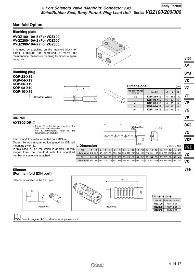
Manifold Option
KQP-23-X19KQP-04-X19KQP-06-X19KQP-08-X19KQP-10-X19
Dimensions
Blanking plateVVQZ100-10A-5 (For VQZ100)VVQZ200-10A-2 (For VQZ200)VVQZ300-10A-2 (For VQZ300)
Blanking plugKQP-23-X19KQP-04-X19KQP-06-X19KQP-08-X19KQP-10-X19
Color: White 3.2468
10
Applicable fittingsfitting ød Model
16161820.522
31.532353943
3.268
1012
A L D
LA
øD
DIN railAXT100-DR-�
40510.5
39498
38485.5
37473
36460.5
35448
34435.5
33423
32410.5
31398
30385.5
29373
28360.5
27348
26335.5
25323
24310.5
23298
22285.5
21273
No.L dimension
20260.5
19248
18235.5
17223
16210.5
15198
14185.5
13173
12160.5
11148
10135.5
9123
8110.5
798
685.5
573
460.5
348
235.5
123
No.L dimension
L Dimension
L12.5
(Pitch)5.25
1.255.
5
7.5
2535
VQZ100VQZ200VQZ300
Dimensions
Silencer(For manifold EXH port)
Silencer is installed in the EXH port.
AN110-01AN110-01AN200-02
Silencer part no.Model
L = 12.5n + 10.5
38
ø13
63
ø22
AN200-02AN110-01
It is used by attaching on the manifold block for being prepared for removing a valve for maintenance reasons or planning to mount a spare valve, etc.
Refer to page 4-14-3 for silencer for single valve unit.
∗ As for �, enter the number from the DIN rail dimensions table.For L dimension, refer to the dimensions of each kit.
Each manifold can be mounted on a DIN rail. Order it by indicating an option symbol for DIN rail mounting style, -D.In this case, a DIN rail which is approx. 30 mm longer than the manifold with the specified number of stations is attached.
(mm)
4-14-17
Series VQZ100/200/300Body Ported
3 Port Solenoid Valve (Manifold: Connector Kit)Metal/Rubber Seal, Body Ported, Plug Lead Unit
V100
SY
SYJ
VK
VZ
VT
VP
VG
VP
S070
VQ
VKF
VQZ
VZ
VS
VFN

Note 1) R port of VQZ200 is only PF 1/16.
Note 2) Except VQZ100
Pressure Specifications
–100 kPa to 0.7 MPa
Externalpilotpressurerange
Series
Operating pressure range
Metalseal
Rubberseal
VQZ100:Poppet
VQZ100 VQZ200/300
——
0.2 to 0.7 MPa
0.1 to 0.7 MPa
0.15 to 0.7 MPa
How to order valves
Series VQZOption
External Pilot Specifications
VQZ212RExternal pilot specifications
5M
Inch-size One-touch Fittings and Option Threads
C6
VQZ212
Cylinder port
How to order valves
5M N7
2(A)port
Symbol
Applicable tubing O.D. (Inch)
N1 N3 N7 N9 N111/8" 5/32" 1/4" 5/16"
� � � — —
— � � — —
— — � � �
3/8"
Thread type(Cylinder port and 1(P), 3(R) port)
Nil
N
T
F
Rc
NPT
NPTF
G
Dusttight/Low Jetproof Type (IP65)DIN terminal is available with dusttight/low jetproof (IP65) type.
VQZ332
IP65 compliant
5YZB 02
Nil
W
No (Standard)
Compliant
W
T
VV3QZ22
How to order manifold(Suffix each symbol to the end of part number.)
05C 00T
Thread type1(P), 3(R) port
Nil
00N
00T
00F
Rc
NPT
NPTF
G
M5 02
M5 thread
� —
� —
— �
thread
Body Ported
External pilot specifications are used when the operating pressure is below the minimum operating pressure 0.1 to 0.15 MPa or when valve is used for a vacuum application.Order a valve by adding the external pilot specifications [R] to the part number.
Inch-size One-touch fittings and NPT/NPTF/G threads are available.
How to order valves(Applicable to VQZ200/300 rubber seal with the exception of the external pilot type)
Note 1) For the high pressure type, the upper limit of max. operating pressure and external pressure range is 1 MPa.
Note 2) If VQZ100 is applied in vacuum, vacuum from 1(P) port. When finishing the vacuum application, supply pressure from 3(R) port. Ensure the burst pressure is set to be less than half of the external pilot pressure.
External pilot port
M3 x 0.5 (VQZ200)M5 x 0.8 (VQZ300)
( (
Note) The pilot exhaust of the IP65 valves is common with main valve exhaust.(The standard valve has an individual exhaust for the pilot valve.)
(2)
(1)
(1)
Ø Ø Ø Ø Ø
Note)
14
VQZ100
VQZ200
VQZ300
Note) Metric size of One-touch fittings (C�) are also available.
4-14-18

<Plug connector assembly>
VQ11
<Pilot valve assembly>
Function
Coil voltage100 VAC (50/60 Hz)200 VAC (50/60 Hz)110 VAC (50/60 Hz)220 VAC (50/60 Hz)24 VDC12 VDC
Other
1234569
Electrical entry
Grommet (DC specifications)L plug connector with lead wireL plug connector without connectorM plug connector with lead wireM plug connector without connectorDIN terminalDIN terminal without connectorDIN terminal with light/surge voltage suppressorDIN terminal with surge voltage suppressor
DIN terminal with surge voltage suppressorWithout connector
G L
LO M
MO Y
YOYZYS
YOS
Gasket and Screw Assembly Part No.Part no.
VQZ100-GS-2
VQZ200-GS-2
VQZ300-GS-2
VQZ100
VQZ200
VQZ300
VQZ100/200
VQZ300
VVQ1000-50A-C3 VVQ1000-50A-C4 VVQ1000-50A-C6
VVQ1000-51A-C6
C3 C4 C6 C8 C10Fitting size
Model
One-touch Fitting Assembly (For cylinder port)
Note) Purchasing order is available in units of 10 pieces.
Series
Light/Surgevoltage suppressor
No
Yes
No
YesYes (W/o indicator light)
Yes (W/o indicator light)
Valve model
VQZ115�-�L�
VQZ115�-�M�
Pilot valve model
VQ110�-�M�
VQ110�-�L�
Electrical entrySymbol
AXT661-14A- Lead wire lengthFor AC
AXT661-31A-For 100/110 VAC
AXT661-34A-For 200/220 VAC
Only connector and sockets (3 pcs.)AXT661-12A
VVQ1000-50A-M5
M5 (VQZ100 only)
Nil
K
Y
Standard type
High pressure type(Metal seal, VQZ100 only)
Low wattage type
Symbol Specifications DC(1.0 W)
�
(1.0 W)�
(0.5 W)�
�
AC
5 G1 Bracket Assembly Part No.Part no.
VQZ100-FB
VQZ200-FB
VQZ300-FB
Tightening torque (N·m)
0.45 to 0.55
0.25 to 0.35
0.25 to 0.35
VQZ100
VQZ200
VQZ300
Series VQZReplacement Parts
Body Ported
Standard wire length of valve with plug connector is 300 mm.When requiring valve with 600 mm length lead wire specify the model number of valve without plug connector and plug connector assembly.
Nil 300 mm600 mm
1000 mm2000 mm3000 mm5000 mm
610203050
Note) Above part number consists of 10 units. Each unit has one gasket and two screws. Purchasing order is available in units of 10 pieces.
Note) Tightening torque for mounting brackets on the valve.
Note 1) OptionNote 2) When two or more
symbols are specified, indicate them alphabetically.
Note) For the special voltages, please consult with SMC.
Note 1) DIN is applicable to VQZ200 and 300.Note 2) Electrical entry of pilot valve for VQZ100 (“L” and “M”) is the
opposite side of valve body part number.
VVQ1000-51A-C8 VVQ1000-51A-C10
Note)
(1)
Note)
(1)
(1)
(1)
(1)
(1)
—
—
0
1
VQZ100
VQZ200/300
4-14-19
V100
SY
SYJ
VK
VZ
VT
VP
VG
VP
S070
VQ
VKF
VQZ
VZ
VS
VFN

4-14-20

Series Variations
Sonic conductanceC [dm3/(s·bar)]
Type ofactuation Voltage
With light/surgevoltage suppressor
Manualoverride
VQZ100
—
2.0 3.0
3.2 4.1
N.C.
N.O.Bas
e M
ou
nte
d (Standard)12 VDC24 VDC
(Option)100 VAC200 VAC110 VAC220 VAC
Grommet (G)
L plug connector (L)
DIN terminal (Y)
L plugconnector (L)
M plug connector (M)
DIN terminal (YZ)
ExceptVQZ100 )(
Non-lockingpush type
(Tool required)
Locking type(Tool required)
(Poppet)
1.0
RubberMetal
(Except VQZ100)
(A)2
1(P)
3(R)
ExceptVQZ100 )(
(A)2
1(P)
3(R)
M plug connector (M)
VQZ300
VQZ200
3 p
ort
3 Port Solenoid ValveMetal Seal/Rubber Seal, Base Mounted
Series VQZ100/200/300
With light/surgevoltage suppressor
Electricalentry
4-14-21
V100
SY
SYJ
VK
VZ
VT
VP
VG
VP
S070
VQ
VKF
VQZ
VZ
VS
VFN

Push type (Tool required)
Locking type (Tool required)VQZ200VQZ300
Attaching and detaching connectors
Circuit with Light/Surge Voltage Suppressor
No polarity by adopting non-polar light.
Connect each lead wire to the power source side, because of no polarity for DC as well.
Locking type (Tool required)VQZ100
Do not apply excessive torque when turning the locking type manual override. (0.1 N·m or less)
Connector part no. AXT661-12
Cover
Pin
Concave
Concave
Cover
Pin
L plug connector
Lead wire 0.2 to 0.33 mm2
(Max. O.D. ø1.7 mm)
Socket part no. DXT170-71-1
Lever
Hook
M plug connector
Red (DC)
Blue 100 VAC110 VAC
Red 200 VAC220 VAC
Black (DC)
Blue 100 VAC110 VAC200 VAC220 VACRed
Indicator light
Precautions
Push down on the manual override button with a small screwdriver until it stops.Release the screwdriver and the manual override will return.
To attach a connector, hold the lever and connector unit between your fingers and insert straight onto the pins of the solenoid valve so that the lever’s pawl is pushed into the groove and locks.
To detach a connector, remove the pawl from the groove by pushing the lever downward with your thumb, and pull the connector straight
Push down completely on the manual override button with a small screwdriver. While down, turn clockwise 90° to lock it.Turn it counterclockwise to release it.
If the manual override is turned by 180° clockwise and the � mark is adjusted to 1, then pushed in the direction of an arrow (�), it will be locked in the ON state. If the manual override is turned by 180° counterclockwise and � mark is adjusted to 0, locking will be released and the manual override will return.
Refer to page 4-14-41 for part no. of plug connector assembly.
Be sure to read before handling. For Safety Instructions and Slenoid Valve Precautions, refer to page 4-18-2.
Manual Override
WarningHow to Use L/M Plug Connector
Connection and Electrical Circuit
Caution
Caution
Without an electric signal for the solenoid valve the manual override is used for switching the main valve.Non-locking push type (tool required) is standard.Locking type (tool required) is available as an option.
A
C
SOL
Indicator light
AC circuit
A(–)
C(+)
SOL
ZNRIndicatorlight
[+]
[–]
DC circuit
4-14-22
Series VQZ100/200/300Base Mounted

(Not necessary if ordering the lead wire pre-connected model.)Crimping of lead wires and sockets
Attaching and detaching lead wires with sockets
Crimping areaCore wire crimping area
Terminal
Hook
Core wire
Insulation
Lead wire
0.2 to 0.33 mm2
Max. cover diameter: ø1.7 mm
Socket
connector
Lead wire
Hook
DIN Terminal Part No. (Conforming to DIN)
Without indicator light
Rated voltageWith indicator light
AXT100-20-1
Voltage symbol Part no.AXT100-20-2-05AXT100-20-2-06AXT100-20-2-01AXT100-20-2-02AXT100-20-2-03AXT100-20-2-04
Circuit with Indicator Light
AC circuit
Ground nut
WasherGrommet(Rubber)
(Voltage symbol)Refer to the table below.
Terminal screw (3 locations)
Holding screw
Housing
(Position for light mounting)
Terminal block
Shaved part
Conforming to ISO#: DIN 43650 C (8 mm between pins)
Tool for crimping: Part no. DXT170-75-1
Tightening torque1.65 to 2.5 N·m
Tightening torque0.3 to 0.4 N·m
Tightening torque0.2 to 0.25 N·m
PR plate
Clip
Port plug(VVQZ100-CP)
One-touch fitting
16.8
13.8
Precautions
Peel 3.2 to 3.7 mm of the tip of lead wire, enter the core wires neatly into a socket and crimp it with a special crimp tool. Be careful so that the cover of lead wire does not enter into the crimping part.
AttachingInsert the sockets into the square holes of the connector (with + and – indication) and, continue to push the sockets all the way in until the lock by hooking into the seats in the connector. (When they are pushed in, their hooks open and they are locked automatically.) Then confirm that they are locked by lightly pulling on the lead wire.DetachingTo remove the socket from the connector, pull out lead wire while depressing the hook of the socket with a fine screwdriver (or similar). If the socket is used again, spread the hook outward.
1. It is able to change the cylinder port between side ported and top ported. Since the fittings and port plug are cassette style, first detach the clip with a flat head screwdriver, etc., and then remove the fittings and port plug. Changing between side ported and top ported is possible by replacing fittings with port plug. When mounting for replacement and installment, make sure to insert the fittings and port plug until they stop, and then put the clip into the prescribed position completely.
VQZ100-12A (Standard)VQZ100-12B (External pilot) ∗ 2 mounting screws are included
with each plate.2. Abase mount VQZ100 valve can
be converted to an individual in-line (body ported) valve by installing an adapter plate on the mounting surface of the valve.
Whole length of a clip is different from the one for valve and base. If mounting with wrong clips, fittings are likely to pull out. Use caution not to exchange from one to the other.
Connection1. Loosen the set screw and pull out the connector from the
terminal block of the solenoid.2. Remove the housing screw and insert a screwdriver into the
slot area on the underside of the DIN cap and carefully separate block and housing.
3. Loosen the terminal screws (slotted screws) on the terminal block, insert the core of the lead wire into the terminal in accordance with the prescribed connection method, and attach securely with the terminal screws.
4. Tighten the ground nut to secure the wire.
Change of electrical entry (Orientation)After separating terminal block and housing, the cord entry direction can be changed by attaching the housing in the desired direction (4 directions in 90 increments).∗ In the case of indicator light, avoid damaging the light with lead wire.
PrecautionsPull a connector out vertically, never at an angle.
Applicable cableO.D.: ø3.5 to ø7(Reference) 0.5 mm2 2 core and 3 core wires equivalent to JIS C 3306.
24 VDC12 VDC
100 VAC200 VAC110 VAC220 VAC
Be sure to read before handling. For Safety Instructions and Solenoid Valve Precautions, refer to page 4-18-2.
Connection of Lead Wire How to Wire DIN Terminal
How to Change Piping Direction for VQZ100
Caution
24V12V100V200V110V220V
LED: Light emitting diodeR: Resister
1 2
RLED
DC circuit
NL: Neon bulbR: Resister
1 2
NL R
4-14-23
Series VQZ100/200/300Base Mounted
V100
SY
SYJ
VK
VZ
VT
VP
VG
VP
S070
VQ
VKF
VQZ
VZ
VS
VFN

For obtaining the flow rate, refer to page 4-1-6.
Model
VQZ100
VQZ200
VQZ300
Proper tightening torque
0.13 to 0.19 N·m
0.25 to 0.35 N·m
0.5 to 0.7 N·m
Clamp screw
Clip
Fitting assembly
Screw
Precautions
PrecautionWhen pulling the fitting assembly away from the manifold base, remove the clip, then connect a tube or plug (KQP-��) with the One-touch fitting and pull it out holding the tube or plug. Do not hold the release bushing to avoid damage.
Mounting1. Catch the hook of the DIN rail
bracket on the (b) side of the DIN rail.
2. Push side (a) onto the DIN rail and tighten the clamp screw.The proper tightening torque for screws 0.3 to 0.4 N·m.
After confirming the gasket is correctly placed under the valve, securely tighten the bolts with the proper torque shown in the table below.
Be sure to read before handling. For Safety Instructions and Solenoid Valve Precautions, refer to page 4-18-2.
CautionChanging the One-touch Fittings Valve Mounting
How to Calculate the Flow Rate
DIN Rail Removing/Mounting
The built-in fittings on the manifold can be changed easily. Clip prevents the fittings to come off. After removing the corresponding valve and take out the clip with a screwdriver, etc., then replace the fittings. About mounting the fittings, after inserting the fitting until it stops, then put the clip into the prescribed position.
Removing1. Loosen the clamp screw on
the (a) side of both ends of the manifold.
2. Lift the (a) side of the mani-fold off the DIN rail and slide it in the direction of the (b) side.
(a)
(b)
4-14-24
Series VQZ100/200/300Base Mounted

4-14-25
V100
SY
SYJ
VK
VZ
VT
VP
VG
VP
S070
VQ
VKF
VQZ
VZ
VS
VFN

Type of actuation
Series
VQZ 1 1 5 5 M 01
How to Order Valves: VQZ100
1 VQZ100 Body width 10 mm
1
N.C.
Body type5 Base mounted
Port size {2(A) port}Without sub-plate
Rc 1/801
Manual overrideNil: Non-locking
push type(Tool required)
B: Locking type(Tool required)
Electrical entryG: Grommet
(DCspecifications)
Note) Standard lead wire length: 300 mm.
Coil voltage1234569
100 VAC (50/60 Hz)200 VAC (50/60 Hz)110 VAC (50/60 Hz)220 VAC (50/60 Hz)24 VDC12 VDC
Other
CP
(A)2
1(P)
3(R)
Function
Nil
K (1)
Y
R (2)
Symbol Specifications DC(1.0 W)
�(1.0 W)
�(0.5 W)
�
�
�
�
AC
Note 1) OptionNote 2) For details about external pilot
specifications, refer to page 4-14-40.
Note 3) For the power consumption of AC type, refer to page 4-14-28.
Note 4) When two or more symbols are specified, indicate them alphabetically.
B CA
BC
A
3 Port Solenoid ValveMetal/Rubber Seal, Base Mounted, Plug Lead UnitValve Single Unit
Series VQZ100/200/300
(3)
L: L plugconnectorWithlead wire
LO: L plugconnectorWithoutconnector
M: M plug connectorWithlead wire
MO: M plugconnectorWithoutconnector
With light/surgevoltage suppressor
With light/surgevoltage suppressor
With light/surgevoltage suppressor
With light/surgevoltage suppressor
Note) For the sub-plate part no, refer to page 4-14-41.
Note) For the special voltages, please consult with SMC.
Note)
—
—
Standard type
High pressure type
Low wattage type
External pilot type
For details about the applicable products conforming to international standards, visit us at www.smcworld.com.
4-14-26

Type of actuation
Series
VQZ 2 1 5 5 M
How to Order Valves: VQZ200/300
23
VQZ200 Body width 15 mmVQZ300 Body width 18 mm
1
N.C.
Body type5 Base mounted
Function
Manual overrideNil: Non-locking
push type(Tool required)
B: Locking type(Tool required)
Electrical entry
Note) Standard lead wire length: 300 mm.
Coil voltage1234569
100 VAC (50/60 Hz)200 VAC (50/60 Hz)110 VAC (50/60 Hz)220 VAC (50/60 Hz)24 VDC12 VDC
Other
2
N.O.
3
N.C.
4
N.O.
Y: DINterminal
YO: DINterminalWithoutconnector
YZ: DINterminal
YOS: DINterminalWithoutconnector
YS: DINterminal
With surgevoltage suppressor
With surgevoltage suppressor
Met
al s
eal
Rub
ber
seal
(A)2
1(P)
3(R)
(A)2
1(P)
3(R)
(A)2
1(P)
3(R)
(A)2
1(P)
3(R)
Port size {2(A) port}
Nil Without sub-plateRc 1/8Rc 1/4Rc 3/8
010203
�
�
�
—
�
—�
�
VQZ200 VQZ300Symbol Port size
Nil Standard type
High pressure type(Metal seal only)
Low wattage type
External pilot type
K (1)
Y
R (2)
Symbol Specifications DC(1.0 W)
�
(1.0 W)�
(0.5 W)�
�
�
�
(3)
AC
Note 1) OptionNote 2) For details about external pilot
specifications, refer to page 4-14-40.
Note 3) For the power consumption of AC type, refer to page 4-14-28.
Note 4) When two or more symbols are specified, indicate them alphabetically.
BC
A
BC
A
G: Grommet(DCspecifications)
L: L plugconnectorWithlead wire
LO: L plugconnectorWithoutconnector
M: M plug connectorWithlead wire
MO: M plugconnectorWithoutconnector
With light/surgevoltage suppressor
With light/surgevoltage suppressor
With light/surgevoltage suppressor
With light/surgevoltage suppressor
With light/surgevoltage suppressor
Note) For the sub-plate part no, refer to page 4-14-41.
Note) For the special voltages, please consult with SMC.
Note)
4-14-27
Series VQZ100/200/300Base Mounted
3 Port Solenoid Valve (Valve Single Unit)Metal/Rubber Seal, Base Mounted, Plug Lead Unit
V100
SY
SYJ
VK
VZ
VT
VP
VG
VP
S070
VQ
VKF
VQZ
VZ
VS
VFN

Standard Specifications
24 VDC
12 VDC
100 VAC
110 VAC
200 VAC
220 VAC
Powerconsumption(Current)
Val
ve s
peci
ficat
ions
Ele
ctric
ity s
peci
ficat
ions
Metal seal
0.1 MPa
–10 to 50°C(1)
20 Hz
VQZ100 (Poppet seal)
0.15 MPa
–10 to 50°C(1)
20 Hz
Not required
Non-locking push type/Slotted locking type (tool required) as an option
150/30 m/s2
Dustproof
12, 24 VDC and 100, 110, 200, 220 VAC
±10% of rated voltage
Equivalent to class B
1 W DC (42 mA), 0.5 W DC (21 mA)
1 W DC (83 mA), 0.5 W DC (42 mA)
Inrush 0.5 VA (5 mA), Holding 0.5 VA (5 mA)
Inrush 0.55 VA (5 mA), Holding 0.55 VA (5 mA)
Inrush 1.0 VA (5 mA), Holding 1.0 VA (5 mA)
Inrush 1.1 VA (5 mA), Holding 1.1 VA (5 mA)
Flow Characteristics/Weight
SeriesValve
construction
Poppet
Metal seal
Rubber seal
Metal seal
Rubber seal
Metal seal
Rubber seal
Metal seal
Rubber seal
N.C. valve
N.C. valve
VQZ100
N.O. valve
N.C. valve
N.O. valve
VQZ200
VQZ300
Model
VQZ115
VQZ215
VQZ235
VQZ225
VQZ245
VQZ315
VQZ335
VQZ325
VQZ345
Weight (2)
(g)
Response time (ms) (1)
2 � 3 (A � R) 1 � 2 (P � A)
Flow characteristics
C [dm3/(s·bar)] b
0.46
0.17
0.46
0.18
0.43
0.21
0.42
0.21
0.45
Cv
Standardtype:1 W
ACHigh pressure type: 1.0 WLow wattage type: 0.5 W
25
53
77
C [dm3/(s·bar)]
1.0
2.0
3.0
1.8
3.0
3.2
4.1
2.9
4.5
b
0.35
0.20
0.40
0.21
0.30
0.27
0.36
0.16
0.38
Cv
10 or less
14 or less
15 or less
14 or less
15 or less
17 or less
25 or less
17 or less
25 or less
22 or less
34 or less
36 or less
34 or less
36 or less
34 or less
57 or less
34 or less
57 or less
13 or less
18 or less
20 or less
18 or less
20 or less
22 or less
33 or less
22 or less
33 or less
Air/Inert gas
Note 1) Use dry air to prevent condensation when operating at low temperatures.Note 2) Impact resistance: No malfunction occurred when it is tested with a drop tester in the axial
direction and at the right angles to the main valve and armature in both energized and de-energized states every once for each condition. (Values at the initial period)
Vibration resistance: No malfunction occurred in a one-sweep test between 45 and 2000 Hz. Test was performed at both energized and de-energized states in the axial direction and at the right angles to the main valve and armature. (Values at the initial period)
0.87
1.7
2.3
1.7
2.5
3.0
4.5
2.9
4.4
0.23
0.38
0.65
0.38
0.67
0.70
1.3
0.72
1.2
0.25
0.45
0.80
0.39
0.74
0.80
1.0
0.69
1.2
Note 1) Based on JIS B 8375-1981 (Supply pressure: 0.5 MPa; with light/surge voltage suppressor; clean air) The response time is subject to the pressure and the air quality.Response time values will change depending on pressure and air quality.
Note 2) Weight without sub-plate.
Individual EXH Common exhaust
Valve construction
Fluid
Maximum operating pressure
Minimum operating pressure
Ambient and fluid temperature
Maximum operating frequency
Pilot valve EXH
Lubrication
Pilot valve manual override
Shock/Vibration resistance (2)
Enclosure
Coil rated voltage
Allowable voltage fluctuation
Coil insulation type
0.7 MPa (High pressure type: 1.0 MPa)
0.7 MPa (High pressure type: 1.0 MPa)
Rubber seal
0.7 MPa
0.15 MPa
–10 to 50°C (1)
5 Hz
4-14-28
Series VQZ100/200/300Base Mounted

Description Material
Aluminum die-casted
Stainless steel
Aluminum/HNBR
Resin
—
Note
Metal seal
Rubber seal
No.
q
w
e
r
Rubber seal type
N.C. N.C.
N.O. N.O.
Component Parts
VQZ200/300Metal seal type
Construction
N.C.VQZ100Poppet (A)
2
1(P)
3(R)
(A)2
1(P)
3(R)
(A)2
1(P)
3(R)
(A)2
1(P)
3(R)
(A)2
1(P)
3(R)
Description
Body
Spool valve
Pilot valve assembly
Port plug
Material
Resin
Aluminum/HNBR
—
Resin/NBR
NoteNo.
q
w
e
r
Component Parts
VVQZ100-CP
For “How to Order Pilot Valve Assembly”, refer to page 4-14-41.
re
w
q
r e w q r e w q
r e w q r e w q
Body
Spool/Sleeve
Spool valve
Piston
Pilot valve assembly
4-14-29
Series VQZ100/200/300Base Mounted
3 Port Solenoid Valve (Valve Single Unit)Metal/Rubber Seal, Base Mounted, Plug Lead Unit
V100
SY
SYJ
VK
VZ
VT
VP
VG
VP
S070
VQ
VKF
VQZ
VZ
VS
VFN

Dimensions: VQZ100
L plug connector (L): VQZ115(R)-�L�-01 M plug connector (M): VQZ115(R)-�M�-01
SMC
PE
127.
5
M5 x 0.8PE port
5314.5 14.5
Manual override3441
3.5
10 24
3.5
2- ø3.4 mounting holeM5 x 0.8 external pilot port
(Only external pilot port (R))R 3.5
1 P 3 R
12X A 2
38.5
≅300
(Lea
d w
ire le
ngth
)
Cover dia. ø1.6
3-Rc 1/81(P), 2(A), 3(R) port
14.5 7 7.5
16
35.5
7.5
2(A) port
Single unitGrommet (G): VQZ115(R)-�G�-01
< >: AC
54 <59>
≅300
52
Indicator light
Cover diameter ø1.5Cross section 0.23 mm2
(Lea
d w
ire le
ngth
)
46
60.5 <65.5>
Indicator light
Cover diameter ø1.5Cross section 0.23 mm2
< >: AC
Cross section 0.34 mm2
≅300(Lead wire length)
4-14-30
Series VQZ100/200/300Base Mounted

Dimensions: VQZ200
0102
L plug connector (L): VQZ2�5(R)-�L�-
M plug connector (M): VQZ2�5(R)-�M�-
DIN terminal (Y): VQZ2�5(R)-�Y�-0102
0102
0102
SMC
3 R
A 2
1 P
≅300
415 34
2-ø4.5 mounting hole
19.2432
Manual overrideCover dia. ø1.6Cross section 0.34 mm2
(Lead wire length)
40
R4
51
22
9
45
17
18
10.5
10
(For Rc 1/8)
(For Rc 1/4)
(For Rc 1/8)
(For Rc 1/4)
3-Rc 1/8, 1/41(P), 2(A), 3(R) port
PE port
913.516
2(A) port
M5 x 0.8 external pilot port(Only external pilot port (R))
56.5
7582.5
87Max. 10Applicable cable O.D.
Pg.7
Indicator lightø3.5 to ø7
89
Single unitGrommet (G): VQZ2�5(R)-�G�-
70
< >: AC
< >: AC
77.5
58 <
63>
≅300
Indicator light
Cross section 0.23 mm2Cover diameter ø1.5
(Lea
d w
ire le
ngth
)
≅300 83.5
51.5
<56
.5>
Indicator light
Cross section 0.23 mm2Cover diameter ø1.5
(Lead wire length)
SMC
4-14-31
Series VQZ100/200/300Base Mounted
3 Port Solenoid Valve (Valve Single Unit)Metal/Rubber Seal, Base Mounted, Plug Lead Unit
V100
SY
SYJ
VK
VZ
VT
VP
VG
VP
S070
VQ
VKF
VQZ
VZ
VS
VFN

Dimensions: VQZ300
L plug connector (L): VQZ3�5(R)-�L�-
M plug connector (M): VQZ3�5(R)-�M�-
DIN terminal (Y): VQZ3�5(R)-�Y�-
0203
0203
23.5
37 5
47
76≅300
(Lead wire length)
Cover dia. ø1.6 Manualoverride
2-ø4.5 mounting hole
5
18 45
54.5
19
21
14
13
(For Rc 1/4)
(For Rc 3/8)
(For Rc 1/4)
(For Rc 3/8)
3-Rc 1/4, 3/81(P), 2(A), 3(R) port
PE port
56.5
26.5
11.5
911.5
2(A) port
17.5
20.5
M5 x 0.8 external pilot port(Only external pilot port (R))
92.5Max. 10
78.5
86
Applicablecable O.D.ø3.5 to ø7
Pg.7
95
R5
Indicator light
Single unitGrommet (G): VQZ3�5(R)-�G�-
3 R 1 P
2A
83.5
62 <
67>
≅300
Indicator light
Cross section 0.23 mm2Cover diameter ø1.5
(Lea
d w
ire le
ngth
)
55 <
60>
≅300 89.5
Indicator light
Cross section 0.23 mm2
Cover diameter ø1.5
(Lead wire length)
< >: AC
< >: AC
0203
0203
Cross section 0.34 mm2
4-14-32
Series VQZ100/200/300Base Mounted

Series
VV3QZ 1 5 08 C6
How to Order Manifold: VQZ100
1 VQZ100
Port size {2(A) port}
C D
Stations02
20
2 stations
20 stations
······
Manifold5 Base mounted
Kit type
Option
DDOR
NoneDIN rail mounting style (With DIN rail in standard length)
DIN rail mounting style (Without DIN rail)External pilot specifications
Nil
C Connector
C3C4C6M5CPCM
One-touch fitting for ø3.2One-touch fitting for ø4One-touch fitting for ø6
M5 thread (Changeable type)With port plug
Mixture of port sizes
Series
VQZ 1 5
1 VQZ100 Body width 10 mm
Type of actuation1 N.C. (Normally closed)
Manual override
BNon-locking push type (Tool required)
Locking type (Tool required)Nil
1 5 M
Body type5 Base mounted
Coil voltage1234569
100 VAC (50/60 Hz)200 VAC (50/60 Hz)110 VAC (50/60 Hz)220 VAC (50/60 Hz)24 VDC12 VDC
Other
Electrical entry
GL
LOM
MO
Note) Standard lead wire length: 300 mm.
Grommet (DC specifications)L plug connector with lead wireL plug connector without connectorM plug connector with lead wireM plug connector without connector
How to Order Valves: VQZ100
Side ported
Top ported—
Light/Surgevoltage suppressor
No
Yes
Port sizeCPC3C4C6M5
With port plugOne-touch fitting for ø3.2One-touch fitting for ø4One-touch fitting for ø6
M5 thread
Side ported
Top ported
Symbol Electrical entry
Function
Nil Standard type
High pressure type(Metal seal only)
Low wattage type
External pilot type
K
Y
R
Symbol Specifications DC(1.0 W)
�(1.0 W)
�
(0.5 W)�
�
�
�
(3)
—
—
AC
Note 1) When CP port plug is attached on all 2(A) port. Valve on manifold is top ported.
Note 2) Specify the mixture port (including top and side piping) on the manifold specification sheet.
Note 3) For the inch-size One-touch fittings, refer to page 4-14-40.
Note 1) OptionNote 2) For details about external
pilot specifications, refer to page 4-14-40.
Note 3) For the power consumption of AC type, refer to page 4-14-28.
Note 4) When two or more symbols are specified, indicate them alphabetically.
Note) Order DIN rail separately.For the DIN rail model number, refer to page 4-14-39.
Note) For the special voltages, please consult with SMC.
3 Port Solenoid ValveMetal/Rubber Seal, Base Mounted, Plug Lead UnitManifold (Connector Kit)
Series VQZ100/200/300
(1)
(2)
Note)
(1)
(2)
Note)
4-14-33
V100
SY
SYJ
VK
VZ
VT
VP
VG
VP
S070
VQ
VKF
VQZ
VZ
VS
VFN

Series
VV3QZ 2 5 08 C6
How to Order Manifold: VQZ200/300
23
VQZ200 VQZ300
Port size {2(A) port}
C D
Stations02
20
2 stations
20 stations
······
Manifold5 Base mounted
Kit type
Option
DDOR
DIN rail mounting style (With DIN rail in standard length)DIN rail mounting style (Without DIN rail )
External pilot specifications
Nil
C Connector
C4C6C8C100102CM
One-touch fitting for ø4One-touch fitting for ø6One-touch fitting for ø8One-touch fitting for ø10
Rc 1/8Rc 1/4
Mixture of port sizes
VQZ200 VQZ300�
�
�
—�
—�
—�
�
�
—�
�
Series
VQZ 1 5
23
VQZ200 Body width 15 mmVQZ300 Body width 18 mm
Type of actuation1234
N.C., Metal sealN.O., Metal seal
N.C., Rubber sealN.O., Rubber seal
Manual override
B
Non-locking push type (Tool required)Locking type (Tool required)
Nil
2 5 M
Body type5 Base mounted
Coil voltage1234569
100 VAC (50/60 Hz)200 VAC (50/60 Hz)110 VAC (50/60 Hz)220 VAC (50/60 Hz)24 VDC12 VDC
Other
Electrical entry
GL
LOM
MOY
YOYZYS
YOSNote) Standard lead wire length: 300 mm.
Grommet (DC specifications)L plug connector with lead wireL plug connector without connectorM plug connector with lead wireM plug connector without connectorDIN terminalDIN terminal without connectorDIN terminalDIN terminalDIN terminal without connector
How to Order Valves: VQZ200/300
No
Light/Surgevoltage suppressor
Yes
No
YesYes (W/o indicator light)Yes (W/o indicator light)
Port sizeSymbol
Electrical entrySymbol
Function
Nil Standard type
High pressure type(Metal seal only)
Low wattage type
External pilot type
K
Y
R
Symbol Specifications DC(1.0 W)
�
(1.0 W)�
(0.5 W)�
�
�
�
—
—
AC
Note 1) Specify port mixture/with port plug by means of the manifold specification sheet. Port mixture and port plug are available only for One-touch fitting type.
Note 2) For the inch-size One-touch fittings, refer to page 4-14-40.
Note 1) OptionNote 2) For details about external pilot
specifications, refer to page 4-14-40.Note 3) For the power consumption of AC type,
refer to page 4-14-28. Note 4) When two or more symbols are
specified, indicate them alphabetically.
Note) Order DIN rail separately.For the DIN rail model number, refer to page 4-14-39.
Note) For the special voltages, please consult with SMC.
(1)
Note)
(1)
(2)
(3)
Note)
None
4-14-34
Series VQZ100/200/300Base Mounted

Manifold Specifications
How to Order Valve Manifold Assembly (Example)
VV3QZ25-05C6C······ 1 set (C kit 5 stations manifold base)∗VVQZ200-10A-5······1 set (Blanking plate assembly)∗VQZ215-5L··············4 sets (N.C. type part no.)
Port size
Porting specifications
Series
VQZ100
VQZ200
2(A)
C3 (For ø3.2)C4 (For ø4)C6 (For ø6)
M5 (M5 thread)
C4 (For ø4)C6 (For ø6)C8 (For ø8)
Rc 1/8
C6 (For ø6)C8 (For ø8)
C10 (For ø10)Rc 1/4
1(P), 3(R)
Rc 1/8
Rc 1/4
1(P) portRc 3/8
3(R) portRc 1/4
Portlocation
Side
Top
Side
Side
Base model
VV3QZ15-���
VV3QZ25-���
VV3QZ35-���
Applicablevalve model
VQZ115
VQZ2�5
VQZ3�5VQZ300
Applicablestations
2 to 20stations
2 to 20stations
2 to 20stations
2 stations: 83Additionper/station: 192 stations: 126Additionper/station: 382 stations: 209Additionper/station: 60
Manifoldbase
weight (g)
Enter in order starting from the first station on the D side.
Note) Threaded port.
VQZ215-5L 4 sets
C6: One-touch fitting for ø6
VVQZ200-10A-5
1
3
Stations
2
The asterisk denotes the symbol for assembly. Prefix it to the part nos. of the solenoid valve, etc.
Specify the part numbers for valves and options together beneath the manifold base part number.When entry of part numbers becomes complicated, indicate on the manifold specification sheet.
U side
D side
4-14-35
Series VQZ100/200/300Base Mounted
3 Port Solenoid Valve (Manifold: Connector Kit)Metal/Rubber Seal, Base Mounted, Plug Lead Unit
V100
SY
SYJ
VK
VZ
VT
VP
VG
VP
S070
VQ
VKF
VQZ
VZ
VS
VFN

R
31
P
59.5<64.5>
≅300
56
Indicator light
Cover diameter ø1.5Cross section 0.23 mm2
(Lea
d w
ire le
ngth
)
L plug connector (L) M plug connector (M)
Dimensions: VQZ100
Cover dia. ø1.6Cross section 0.34 mm2
≅ 30
0(L
ead
wire
leng
th)
42.5
2-Rc 1/81(P) port
2-M5 x 0.8PE port
13.4
46.5
16.3
158
41.2
39.5
≅7.8
(For
top
port
ed)
2-Rc 1/8Port 3(R)
2-ø4.5 mounting hole
(35)
(4.5)
L2(L3)
(L4)
P =
10.
5
5.5
Manual override
2.3
21.6
(5.5)
≅7.8 (For C3, C4, C6)
35
53
(For M5: 5.7)
5.5
DIN rail clamp screw16
.5
5.5
6 .5
L1
2-M5 x 0.8 external pilot port(Only external pilot port (R))
11.720 (7.5)
27.5 (11)
C6: One-touch fitting for ø6C4: One-touch fitting for ø4C3: One-touch fitting for ø3.2n-C3, C4, C6, M5
P =
10.
513
.5
M5: M5 thread
A 2A 2
A 2
A 2
A 2
A 2
P R1 3
VV3QZ15- Stations Port size CGrommet (G)
< >: AC
R
31
P
50
≅300 66<71>
Indicator light
Cover diameter ø1.5Cross section 0.23 mm2
(Lead wire length)
< >: AC
The broken lines indicate the DIN rail mounting style [-D].
L1L2L3L4
L n 2 3 4 5 6 7 8 9 10 11 12 13 14 15 16 17 18 19 20
Formula L1 = 10.5n + 9.5 L2 = 10.5n + 22.5 n: Stations (Maximum 20 stations)Dimensions
30.543.57585.5
41547585.5
51.564.587.598
6275
100110.5
72.585.5
112.5123
8396
125135.5
93.5106.5137.5148
104117137.5148
114.5127.5150160.5
125138162.5173
135.5148.5175185.5
146159187.5198
156.5169.5200210.5
167180200210.5
177.5190.5212.5223
188201225235.5
198.5211.5237.5248
209222250260.5
219.5232.5262.5273
D side
U side
n
5
4
3
2
1
Stations
4-14-36
Series VQZ100/200/300Base Mounted

L plug connector (L) DIN terminal (Y)
Dimensions: VQZ200
M plug connector (M)
SM
C
(3.5)
(35)
(5.5)
P =
16
L1L2(L3)
(L4)
18
5
50.5
70
22.5
≅ 300
(Lead wire length)3
2-ø4.5 mounting hole
DIN rail clamp screw
20
38.5
43.5 ≅11
12.5
25.5
11Cover dia. ø1.6
Cross section 0.34 mm2
2-Rc 1/4
1(P) port
PE port
M5 x 0.8 external pilot port
(Only external pilot port (R))
2-Rc 1/43(R) port
21.5
30 (7.5)
38 (11)
P =
16
15.5
C8: One-touch fitting for ø8
C6: One-touch fitting for ø6
C4: One-touch fitting for ø4
n-C4, C6, C8, 01
01: Rc 1/8
87
90Max. 10
8390.5
Pg.7
Applicable cable O.D.
ø3.5 to ø7
92
Indicator light
A 2A 2
R 3 1 P
59
(30) R 3 1 P
Manual override
The broken lines indicate the DIN rail mounting style [-D].
8178
≅300
66 <
71>
Indicator light
P13R
Cover diameter ø1.5Cross section 0.23 mm2(L
ead
wire
leng
th)
87
84
≅300
59.5
<64
.5>
Indicator light
P13R
(Lead wire length)
Cover diameter ø1.5Cross section 0.23 mm2
< >: AC
< >: AC
L1L2L3L4
L n 2 3 4 5 6 7 8 9 10 11 12 13 14 15 16 17 18 19 20
Formula L1 = 16n + 10 L2 = 16n + 20 n: Stations (Maximum 20 stations)Dimensions
42527585.5
90100125135.5
7484
112.5123
586887.598
106116137.5148
122132162.5173
138148175185.5
154164187.5198
170180200210.5
186196225235.5
202212237.5248
218228250260.5
234244275285.5
250260287.5298
266276300310.5
282292312.5323
298308337.5348
314324350360.5
330340362.5373
VV3QZ25- Stations Port size CGrommet (G)
D side
U side
n
5
4
3
2
1
Stations
4-14-37
Series VQZ100/200/300Base Mounted
3 Port Solenoid Valve (Manifold: Connector Kit)Metal/Rubber Seal, Base Mounted, Plug Lead Unit
V100
SY
SYJ
VK
VZ
VT
VP
VG
VP
S070
VQ
VKF
VQZ
VZ
VS
VFN

Dimensions: VQZ300
L plug connector (L)
M plug connector (M)
DIN terminal (Y)
(3)
(35)(5.5)2-ø4.5 mounting hole
DIN rail clamp screw
23
L1L2(L3)(L4)
P =
20
9
75.5≅300
(Lead wire length)
50 29.53.8
Cover dia. ø1.6Cross section 0.34 mm2
34
64
21
50
18
≅1144.5
2-Rc 1/4
3(R) port
PE port2-Rc 3/8
1(P) portM5 x 0.8 external pilot port
(Only external pilot style (R))
C6: One-touch fitting for ø6n-C6, C8, C10, 02
C8: One-touch fitting for ø8
C10: One-touch fitting for ø10
02: Rc1/4
23.5
34 (7.5)43.5 (11)
A 2A 2
P =
20
19.5
92.5
96Max. 10
Applicable cable O.D.
ø3.5 to ø7
8693.5
98.5
R P
3 1
Manual override
6229
.511.5
3 1
R P
Pg.7
The broken lines indicate the DIN rail mounting style [-D].
< >: AC
< >: AC
63 <
68>
93
89.5
≅300
3
R
1
P
Indicator light
Cross section 0.23 mm2Cover diameter ø1.5
(Lead wire length)
69.5
<74
.5>
8783.5≅3
00
3
R
1
P
Indicator lightCross section 0.23 mm2Cover diameter ø1.5
(Lea
d wi
re le
ngth
)
L1L2L3L4
L n 2 3 4 5 6 7 8 9 10 11 12 13 14 15 16 17 18 19 20
Formula L1 = 20n + 8 L2 = 20n + 26 n: Stations (Maximum 20 stations)Dimensions
486687.598
108126150160.5
88106137.5148
6886
112.5123
128146175185.5
148166187.5198
168186212.5223
188206237.5248
208226250260.5
228246275285.5
248266287.5298
268286312.5323
288306337.5348
308326350360.5
328346375385.5
348366387.5398
368386412.5423
388406437.5448
408426450460.5
VV3QZ35- Stations Port size CGrommet (G)
n
5
4
3
2
1
Stations
D side
U side
4-14-38
Series VQZ100/200/300Base Mounted

Manifold Option
KQP-23-X19KQP-04-X19KQP-06-X19KQP-08-X19KQP-10-X19
Dimensions
VQZ100VQZ200VQZ300
Dimensions
Blanking plate
Blanking plug
KQP-23-X19KQP-04-X19KQP-06-X19KQP-08-X19KQP-10-X19
Color: White
Silencer(For manifold EXH port)Silencer is installed in the EXH port.
DIN rail
3.2468
10
Applicable fittingsfitting ød
Model A L D
AN110-01AN200-02AN200-02
Silencer part no.Model
LA
øD
L12.5(Pitch)
5.25
12.5
5.5
7.5
2535
AXT100-DR-�
40510.5
39498
38485.5
37473
36460.5
35448
34435.5
33423
32410.5
31398
30385.5
29373
28360.5
27348
26335.5
25323
24310.5
23298
22285.5
21273
No.L dimension
20260.5
19248
18235.5
17223
16210.5
15198
14185.5
13173
12160.5
11148
10135.5
9123
8110.5
798
685.5
573
460.5
348
235.5
123
No.L dimension
L Dimension L = 12.5n + 10.5
38
ø13
63
ø22
AN200-02AN110-01
(mm)
Port plugVVQZ100-CP (For VQZ100)This is used when changing piping location. (Side or Top)
It is used by attaching on the manifold block for being prepared for removing a valve for maintenance reasons or planning to mount a spare valve, etc.
VVQZ100-10A-5 (For VQZ100)VVQZ200-10A-5 (For VQZ200)VVQZ300-10A-5 (For VQZ300)
∗ As for �, enter the number from the DIN rail dimensions table.
Each manifold can be mounted on a DIN rail. Order it by indicating an option symbol for DIN rail mounting style, -D.In this case, a DIN rail which is approx. 30 mm longer than the manifold with the specified number of stations is attached.
16 16 18 20.522
31.532 35 39 43
3.268
1012
4-14-39
Series VQZ100/200/300Base Mounted
3 Port Solenoid Valve (Manifold: Connector Kit)Metal/Rubber Seal, Base Mounted, Plug Lead Unit
V100
SY
SYJ
VK
VZ
VT
VP
VG
VP
S070
VQ
VKF
VQZ
VZ
VS
VFN

How to order valves
External Pilot Specifications
VQZ215R
VV3QZ25
External pilot specifications
5M
How to order manifold
External pilotspecifications
06C6C R
Pressure Specifications
–100 kPa to 0.7 MPa
Externalpilotpressurerange
VV3QZ15
Cylinder port
How to order manifold
Inch-size One-touch Fittings and Option Threads
08 N7
VQZ100
02
Cylinderport
Symbol
Applicable tubing O.D.
VQZ200
VQZ300
N1 N3 N7 N9 N11
ø1/8" ø5/32" ø1/4" ø5/16"
� � � — —
— � � � —
— — � � �
NM
Mixed
�
�
�
ø3/8"
International Thread Standards Other than Rc
VQZ215
Thread type(Cylinder port and1(P), 3(R) port)
How to order valves
5M 02
Nil
N
T
F
Rc
NPT
NPTF
G
T
Dusttight/Low Jetproof Type (IP65)DIN terminal is available with dusttight/low jetproof (IP65) type.
VQZ335IP65 compliant
5YZB 03
Nil
W
No (Standard)
Compliant
W
Note)
Thread type(Cylinder port and 1(P), 3(R) port)
Nil
N
T
F
Rc
NPT
NPTF
G
T C
M5 01 02
M5 threads 1/8 thread
� — —
— � —
— — �
1/4 thread
Series
Operating pressure range
Metalseal
Rubberseal
VQZ100: Poppet
VQZ100 VQZ200/300
——
0.2 to 0.7 MPa
0.1 to 0.7 MPa
0.15 to 0.7 MPa
External pilot specifications are used when the operating pressure is below the minimum operating pressure 0.1 to 0.15 MPa or when valve is used for a vacuum application.Order a valve by adding the external pilot specifications [R] to the part number.
Inch-size One-touch fittings and NPT/NPTF/G threads are available.
Note 1) For the high pressure type, the upper limit of max. operating pressure and external pressure range is 1 MPa.
Note 2) If VQZ100 is applied in vacuum, vacuum from 1(P) port. When finishing the vacuum application, supply pressure from 3(R) port. Ensure the burst pressure is set to be less than half of the external pilot pressure.
External pilot port
Series VQZOption
Base Mounted
( (
Note 1) Mixing One-touch fittings and thread types is impossible except for VQZ100.
Note 2) Metric sizes of One-touch fittings (C�) are also available.
Rc specifications are standard for all ports, however, NPT, NPTF and G are available for international markets. Add the appropriate symbol following the port size in the standard part number.
Note) The pilot exhaust of the IP65 valves is common with main valve exhaust.(The standard valve has an individual exhaust for the pilot valve.)
(1)
(1)
(2)
(1)
How to order valves(Applicable to VQZ200/300 rubber seal with the exception of the external pilot type)
4-14-40
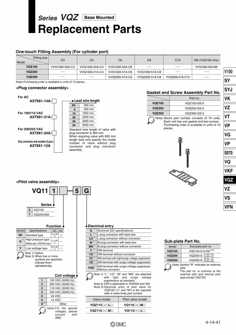
AXT661-14A- Lead wire lengthNil 300 mm
600 mm1000 mm2000 mm3000 mm5000 mm
610203050
<Plug connector assembly>
VQ11
<Pilot valve assembly>
Coil voltage100 VAC (50/60 Hz)200 VAC (50/60 Hz)110 VAC (50/60 Hz)220 VAC (50/60 Hz)24 VDC12 VDC
Other
1234569
Electrical entryGrommet (DC specifications)L plug connector with lead wireL plug connector without connectorM plug connector with lead wireM plug connector without connectorDIN terminalDIN terminal without connectorDIN terminal with light/surge voltage suppressor DIN terminal with surge voltage suppressor
DIN terminal with surge voltage suppressor Without connector
GL
LOM
MOY
YOYZYS
YOS
Gasket and Screw Assembly Part No.Part no.
VQZ100-GS-5
VQZ200-GS-5
VQZ300-GS-5
VQZ100
VQZ200
VQZ300
VQZ100
VQZ200
VQZ300
VVQ1000-50A-C3 VVQ1000-50A-C4
VVQ1000-51A-C4
VVQ1000-50A-C6
VVQ1000-51A-C6
VVQ2000-51A-C6
VVQ1000-51A-C8
VVQ2000-51A-C8 VVQ2000-51A-C10
C3 C4 C6 C8 C10Fitting size
Model
One-touch Fitting Assembly (For cylinder port)
Note) Purchasing order is available in units of 10 pieces.
SeriesVQZ100
1
0
VQZ200/300
(1)
(1)
(1)
(1)
(2)
(2)
(2)
(2)
(2)
Valve model
VQZ115�-�L�
VQZ115�-�M�
Pilot valve model
VQ110�-�M�
VQ110�-�L�
VVQ1000-50A-M5
M5 (VQZ100 only)
For AC
AXT661-31A-For 100/110 VAC
AXT661-34A-For 200/220 VAC
Only connector and sockets (3 pcs.)AXT661-12A
Sub-plate Part No.Model Sub-plate part no.
VQZ100
VQZ200
VQZ300
VQZ100-S-01(R)
VQZ200-S-
VQZ300-S-
01 [Rc 1/8]02 [Rc 1/4]02 [Rc 1/4]03 [Rc 3/8]
Note)
Function
Nil Standard type
High pressure type(Metal seal, VQZ100 only)
Low wattage type
K
Y
Symbol Specifications DC(1.0 W)
�
(1.0 W)�
(0.5 W)�
�
—
—
AC
51 G
Series VQZReplacement Parts
Base Mounted
Standard wire length of valve with plug connector is 300 mm.When requiring valve with 600 mm length lead wire specify the model number of valve without plug connector and plug connector assembly.
Note) Above part number consists of 10 units. Each unit has one gasket and two screws.Purchasing order is available in units of 10 pieces.
Note 1) OptionNote 2) When two or more
symbols are specified, indicate them alphabetically.
Note) For the special voltages, please consult with SMC.
Note 1) “L”, “LO”, “M” and “MO” are attached with light and surge voltage suppressors as standard.
Note 2) DIN is applicable to VQZ200 and 300.Note 3) Electrical entry of pilot valve for
VQZ100 (“L” and “M”) is the opposite side of valve body part number.
Note) Symbol “R” indicates an external pilot.The part no. is common to the external pilot and internal pilot type except VQZ100.
(1)
Note)
4-14-41
V100
SY
SYJ
VK
VZ
VT
VP
VG
VP
S070
VQ
VKF
VQZ
VZ
VS
VFN

4-14-42

Compact design with largeflow capacity
DIN rail mounting is available.
All solenoids on one side
High speed and long service lifeVQZ1000 10 ms
VQZ2000 12 ms
VQZ3000 15 ms
Response time Life
Dispersion accuracy ±2 ms
200 million cycles
Built-in One-touch fittings for easier piping.
VQZ3000VQZ1000/2000
Clip
5 Port Solenoid ValveMetal Seal/Rubber SealBody Ported
VQZ1000/2000/3000
∗ Flow characteristics: 4/2 � 5/3 (A/B � R1/R2)
ModelFlow characteristics
Cylindersize
Manifoldpitch(mm)
Metal sealC [dm3/(s·bar)]
Rubber sealC [dm3/(s·bar)]
Up to ø50Up to ø80Up to ø100
Fitting assemblyClip
3 port valve5 port valve
Port plugLatching
Manual override
VQZ1000VQZ2000VQZ3000
101518
0.541.42.4
0.711.63.2
DIN terminal is available with dust tight/low jetproof (IP65) type.
Integral One-touch fittings save on installation time and labor and can be easily removed if necessary.
∗ Metal seal, single solenoid with light/surge voltage suppressor, according to SMC life test conditions.
Choice of metal or rubber seal main valve construction
Both 3 and 5 port valves can be mounted on the same manifold. Optional latching coil valve operates the same
as a 2 position/double solenoid valve but uses only one solenoid. This saves space and wiring costs.
2-7-1
VQC
SQ
VQ0
VQ4
VQ5
VQZ
VQD
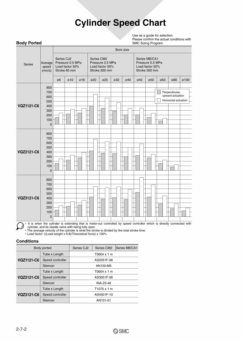
∗ It is when the cylinder is extending that is meter-out controlled by speed controller which is directly connected with cylinder, and its needle valve with being fully open.
∗ The average velocity of the cylinder is what the stroke is divided by the total stroke time.∗ Load factor: ((Load weight x 9.8)/Theoretical force) x 100%
Use as a guide for selection.Please confirm the actual conditions with SMC Sizing Program.
Cylinder Speed Chart
Body Ported
Conditions
Bore size
ø6 ø10 ø16 ø20 ø25 ø32 ø40 ø40 ø50 ø63 ø80 ø100
Series
VQZ1121-C6
800700600500400300200100
0
VQZ2121-C6
800700600500400300200100
0
VQZ3121-C6
VQZ1121-C6
VQZ2121-C6
VQZ3121-C6
800700600500400300200100
0
Averagespeed(mm/s)
Series CJ2Pressure 0.5 MPaLoad factor 50%Stroke 60 mm
Series CM2Pressure 0.5 MPaLoad factor 50%Stroke 300 mm
Series MB/CA1Pressure 0.5 MPaLoad factor 50%Stroke 500 mm
Perpendicular, upward actuation
Horizontal actuation
Tube x Length
Speed controller
Silencer
Tube x Length
Speed controller
Silencer
Tube x Length
Speed controller
Silencer
Body ported Series CJ2 Series CM2
T0604 x 1 m
AS2051F-06
AN120-M5
T0604 x 1 m
AS3001F-06
INA-25-46
T1075 x 1 m
AS4001F-10
AN101-01
Series MB/CA1
2-7-2

Type of actuation Voltage Electrical entry Light/Surgevoltage suppressor
Manual override
VQZ1000
VQZ2000
VQZ3000
VQZ1000
VQZ2000
VQZ3000
1.4 1.6
0.54 0.71
2.4 3.2
0.54 0.71
1.4 1.6
2.4 3.2
2 position single
2 position double
3 position closed center
3 position exhaust center
3 position pressure center
N.C.
N.O.
5 p
ort
3 p
ort
fo
r m
ixtu
re m
ou
nti
ng
Bo
dy
Po
rted
(Standard)12 VDC24 VDC
(Option)100 VAC200 VAC110 VAC220 VAC
Grommet (G)
DIN terminal (Y)
Except VQZ1000)(
With light/surgevoltage
suppressor
L plug connector (L)
M plug connector (M)
DIN terminal (YZ)
Except VQZ1000 )(
(A)4
1(P)
3 (R2)
(B)2
(A)4
(B)2
(A)4(B)2
(A)4
(B)2
(A)4
(B)2
5(R1)
1(P)
3 (R2)
5(R1)
1(P)
3 (R2)
5(R1)
1(P)
3 (R2)
5(R1)
1(P)
3 (R2)
5(R1)
(A)4
1(P)
5(R)
(B)2
1(P)
3(R)
M plug connector (M)
L plug connector (L)
Series VQZModel Selection
Body Ported
Sonic conductanceC [dm3/(s·bar)]
∗ Flow characteristics: 4/2 � 5/3 (A/B � R1/R2)
Non-lockingpush type
(Tool required)
Locking type(Tool required)
2-7-3
VQC
SQ
VQ0
VQ4
VQ5
VQZ
VQD

Be sure to read before handling. For Safety Instructions and Solenoid Valve Precautions, refer to page 2-9-2.
Due to the use of non-polar light, the VQZ series has no polarity.Refer to page 2-7-26 for latching style.
Caution
WarningConnection and Electrical Circuit
For with Light/Surge Voltage Suppressor
Crimping of lead wires and sockets
Circuit for DC Circuit for AC
Push type (Tool required)
Locking type (Tool required)
How to Use L/M Plug Connector
Attaching and detaching connectors
Attaching
Connector
Lead wire 0.2 to 0.33 mm2
(Max. O.D. ø1.7 mm)
SocketPart no. DXT170-71-1
Cover
Pin
Concave
Cover
Pin
Lever
Hook
Crimping area
Core wire crimping area
Terminal
Hook
Core wire
Insulation
Lead wire
0.2 to 0.33 mm2
Max. cover diameter: ø1.7 mm)
Socket
Hook
Connector
Lead wire
M plug connector
L plug connector
A (–)
C (+)
SOL
ZNRIndicatorlight
A
C
SOL
Concave
Indicatorlight
[+]
[–]
Indicator light
Red (DC)
Blue 100 VAC110 VAC
Red 200 VAC220 VAC
Black (DC)
Blue 100 VAC110 VAC200 VAC220 VACRed
Crimping tool: Model no. DXT170-75-1
Precautions
Caution
Without an electric signal for the solenoid valve the manual override is used for switching the main valve.Locking type (Tool required) is available as an option.
Push down on the manual override button with a small screwdriver until it stops. Release the screwdriver and the manual override will return.
Push down completely on the manual override button with a small screwdriver. While down, turn clockwise 90° to lock it. Turn it counterclockwise to release it.
To attach a connector, hold the lever and connector unit between your fingers and insert straight onto the pins of the solenoid valve so that the lever’s pawl is pushed into the groove and locks.
To detach a connector, remove the pawl from the groove by pushing the lever downward with your thumb, and pull the connector straight out.
Insert the sockets into the square holes of the connector (with + and – indication) and, continue to push the sockets all the way in until the lock by hooking into the seats in the connector. (When they are pushed in, their hooks open and they are locked automatically.) Then confirm that they are locked by pulling lightly on the lead wires.
To detach a socket from a connector, pull out the lead wire while pressing the socket’s hook with a stick having a thin tip (approx. 1 mm). If the socket will be used again, first spread the hook outward.
Peel 3.2 to 3.7 mm of the tip of lead wire, enter the core wires neatly into a socket and crimp it with a special crimp tool. Be careful so that the cover of lead wire does not enter into the crimping part.
Refer to page 2-7-28 for part no. of plug connector assembly.
Do not apply excessive torque when turning the locking type manual override. (0.1 N·m or less)
Detaching
(Not necessary if ordering the lead wire pre-connected model.)
Manual Override
Connection of Lead Wire
Both DCs have no polarity, and then connect each lead wire with the power source side.
2-7-4
Series VQZ1000/2000/3000Body Ported

VQC
SQ
VQ0
VQ4
VQ5
VQZ
VQDFitting assembly
Removing1. Loosen the clamp screw on the (A) side
of both ends of the manifold.2. Lift the (A) side of the manifold off the
DIN rail and slide it in the direction of the (B) side.
Mounting1. Catch the hook of the DIN rail bracket on
the (B) side on the DIN rail.2. Push side (A) onto the DIN rail and
tighten the clamp screw.The proper tightening torque for screws is 0.3 to 0.4 N·m.
(VQZ 82 , N.C./VQZ 92 , N.O.)
Mounting 3 Port Valves on 5 Port ManifoldsHow to Wire DIN Terminal
DIN Terminal Part No.Without light
Rated voltage24 VDC12 VDC
100 VAC200 VAC110 VAC220 VAC
With Indicator Light
AXT100-20-1
Voltage symbol24V12V100V200V110V220V
Part no.AXT100-20-2-05AXT100-20-2-06AXT100-20-2-01AXT100-20-2-02AXT100-20-2-03AXT100-20-2-04
Circuit with indicator light
123
123
01
DIN Rail Removal/Mounting
Valve Mounting
How to Calculate the Flow RateFor obtaining the flow rate, refer to pages 2-1-8 to 2-1-11.
ModelVQZ1000VQZ2000VQZ3000
Proper tightening torque0.18 to 0.25 N·m0.25 to 0.35 N·m0.5 to 0.7 N·m
Changing the One-touch Fittings
01
Ground nut
Washer
Grommet(Rubber)
(Voltage symbol)Refer to the table below.
Terminal screw(3 locations)
Holding screw
Housing
(Position for light mounting)
Terminal block
Shaved part
NL: Neon lightR: Resister
LED: Emitting diodeR: Resister
AC circuit DC circuit
1 2
NL R
1 2
RLED
Fitting and Silencer Part No. for P, R PortsWhen Using Valve as an Individual Unit
Screw
Clip
5 port valve
Port plug
3 port valve
Part no. for One-touch fitting for 1(P) port and Silencer for 3(R2, R), 5(R1) port
VQZ1000VQZ2000VQZ3000
KQH06-M5KQH06-01SKQH08-02S
(1) One-touch fitting for 1(P) port Silencer
AN120-M5INA-25-46AN101-01
(2) Silencer for 3(R2, R), 5(R1)One-touch fitting
KJSO4-M5IN-457-32L (for ø6)
KQH06-01S
Series
VQZ3000
Clip
VQZ1000/2000
Tightening torque1.65 to 2.5 N·m Tightening torque
0.3 to 0.4 N·m
Tightening torque0.2 to 0.25 N·m
Conforming to ISO#: DIN 43650 C (8 mm between pins)Connection1. Loosen the top screw and remove the connector housing from the
terminal spades on the solenoid.2. Remove the housing screw and insert a screwdriver into the slot
area on the underside of the DIN cap and carefully separate block and housing.
3. Loosen the terminal screws (slotted screws) on the terminal block, insert the core of the lead wire into the terminal in accordance with the prescribed connection method, and attach securely with the terminal screws.
4. Tighten the ground nut to secure the wire.
Change of electrical entry (Orientation)After separating terminal block and housing, the cord entry direction can be changed by attaching the housing in the desired direction (4 directions in 90° increments).∗ In the case of indicator light, avoid damaging the light with lead wire.
PrecautionsPull a connector out vertically, never at an angle.
Applicable cableO.D.: ø3.5 to ø7(Reference) 0.5 mm2 2 core and 3 core wires equivalent to JIS C 3306.
The diameter of the above fitting and silencer is the maximum diameter to in the EXH port.
After confirming the gasket is correctly placed under the valve, securely tighten the bolts with the proper torque shown in the table below.
PrecautionsWhen pulling the fitting assembly away from the valve base, remove the clip, then connect a tube or plug (KQP-��) with the One-touch fitting and pull it out holding the tube or plug. Do not hold the release bushing to avoid damage.
(B)
(A)
VQZ1000/2000: Horizontally clipped to the valve bodyVQZ3000: Vertically clipped to the valve body
The built-in fittings on the manifold can be changed easily. Simply remove the corresponding valve and take out the fitting clip underneath. Take out the clip with a screwdriver, etc., then replace the fittings. About mounting the fittings, after inserting the fitting until it stops, then put the clip into the prescribed position.
Even though 3 port valves have the same construction as the 5 port single solenoid valves, the port plug is installed in the 2(B) port for N.C. type, and 4(A) port or N.O. type. By changing the port plug into a fitting, it can be used as the 5 port single solenoid valves, too.
(2) Silencer(1) One-touch fitting
2-7-5
Series VQZ1000/2000/3000Body Ported

5 Port Solenoid ValveBody PortedPlug Lead Unit: Single Unit
VQZ1000/2000/3000
Type of actuation
Series
VQZ 1 1 2 5 M C6
How to Order Valves
123
VQZ1000 body width 10 mmVQZ2000 body width 15 mmVQZ3000 body width 18 mm
1
2 position single
Body2 Body ported
Function
Nil Standard
High pressure(Metal seal only)
Low wattage type
External pilot
K
Y
R
(1)
(2)
Port size {4(A), 2(B) port}
One-touch fitting for ø3.2One-touch fitting for ø4One-touch fitting for ø6One-touch fitting for ø8One-touch fitting for ø10
M5 threadRc 1/4
C3C4C6C8
C10M502
Manual overrideNil:Non-lockingpush type(Tool required)
B:Locking type(Tool required)
Electrical entryG: Grommet(DC specification)
L:L plug connectorwith lead wire
LO:L plug connectorwithout connector
M:M plug connectorwith lead wire
MO:M plug connectorwithout connector
With light/surge voltagesuppressor
With light/surge voltagesuppressor
With light/surge voltagesuppressor
With light/surge voltagesuppressor
Coil voltage123456
9
100 VAC (50/60 Hz)200 VAC (50/60 Hz)110 VAC (50/60 Hz)220 VAC (50/60 Hz) 24 VDC 12 VDC
Note)
1
2
2 position double
3
3 position closed center
4
3 position exhaust center
5
3 position pressure center
Seal01
Metal sealRubber seal
Y: DIN terminal
YO: DIN terminalwithout connector
YZ:DIN terminal (1)
YOS: DIN terminal (1)
without connector
With surgevoltagesuppressor
With light/surge voltagesuppressor
�
�
�
——�
—
—�
�
——�
—
——�
�
�
—�
VQZ3000
Note)
Note)Except VQZ1000 andmetal seal type.
NilF
NoneWith bracket (Applicable to single)
Bracket
(A)4
1(P)
3 (R2)
(B)2
5(R1)
Metal seal Rubber seal
VQZ2000VQZ1000Symbol Port size
Symbol Specifications DC(1.0 W)
�
(1.0 W)�
(0.5 W)�
�
�
�
(3)
—
—
AC
YS: DIN terminal (1)
With surgevoltagesuppressor
OptionFor details about external pilot specifications except VQZ1000, refer to page 2-7-27.For power consumption of AC type, refer to page 2-7-7. When two or more symbols are specified, indicate them alphabetically.
For One-touch fittings to be mounted on this valve and the silencer part no., refer to page 2-7-5.
Note) For the special voltages,please consult with SMC.
Note 1) Applicable to VQZ2000 and 3000.Note 2) Standard lead wire length: 300 mm
(A)4
1(P)
3 (R2)
(B)2
5(R1)
(A)4
1(P)
3 (R2)
(B)2
(A)4
(B)2
5(R1)
1(P)
3 (R2)
5(R1)
1(P)
3 (R2)
5(R1)
(A)4
1(P)
3 (R2)
(B)2
5(R1)
Note) For inch size and One-touch fittings, referto page 2-7-27.
Other
Note 1)Note 2)
Note 3)
Note 4)
For details about certified products conforming to international standards, visit us at www.smcworld.com.
2-7-6

Standard Specifications
Valve construction
Fluid
Maximum operating pressure
Ambient and fluid temperaure
Pilot valve EXH
Lubrication
Pilot valve manual override
Shock/Vibration resistance(2)
Enclosure
Coil rated voltage
Allowable voltage fluctuation
Coil insulation type
3 position
Min. operatingpressure
3 position
SingleDouble2 positionMax. operating
frequency
24 VDC
12 VDC
100 VAC
110 VAC
200 VAC
220 VAC
Powerconsumption(Current)
Val
ve s
peci
ficat
ions
Ele
ctric
ity s
peci
ficat
ions
Metal seal
Air/Inert gas
–10 to 50°C(1)
20 Hz
10 Hz
Rubber seal
Air/Inert gas
–10 to 50°C(1)
5 Hz
3 Hz
0.7 MPa (High pressure type: 1.0 MPa)
Individual EXH
Not required
Push type/Locking type (Tool required) Option
150/30 m/s2
Dustproof
12, 24 VDC and 100, 110, 200, 220 VAC
±10% of rated voltage
Equivalent to class B
1 W DC (42 mA), 0.5 W DC (21 mA)
1 W DC (83 mA), 0.5 W DC (42 mA)
Inrush 0.5 VA (5 mA), Holding 0.5 VA (5 mA)
Inrush 0.55 VA (5 mA), Holding 0.55 VA (5 mA)
Inrush 1.0 VA (5 mA), Holding 1.0 VA (5 mA)
Inrush 1.1 VA (5 mA), Holding 1.1 VA (5 mA)
0.1 MPaOnly for VQZ3000, 3 position
0.15 MPa
SingleDouble
2 position
Note 1) Use dry air to prevent condensation when operating at low temperatures.
Note 2) Impact resistance:No malfunction occurred when it is tested with a drop tester in the axial direction and at the right angles to the main valve and armature in both energized and de-energized states every once for each condition. (Values at the initial period)Vibration resistance: No malfunction occurred in a one-sweep test between 45 and 2000 Hz. Test was performed at both energized and de-energized states in the axial direction and at the right angles to the main valve and armature. (Values at the initial period)
Model
Series Configuration
Metal seal
Rubber seal
Metal seal
Rubber seal
Metal seal
Rubber seal
Metal seal
Rubber seal
Rubber seal
Metal seal
Rubber seal
Metal seal
Rubber seal
Metal seal
Rubber seal
Metal seal
Rubber seal
Metal seal
Rubber seal
Metal seal
Rubber seal
Metal seal
Rubber seal
Metal seal
Rubber seal
Metal seal
Rubber seal
Metal seal
Rubber seal
Single
Double
ClosedcenterVQZ1000
Exhaust center
Pressure center
Single
Double
Closedcenter
Exhaust center
Pressure center
Single
Double
Closedcenter
Exhaust center
Pressure center
2 position
3 position
2 position
3 position
VQZ2000
2 position
3 position
VQZ3000
Model
VQZ1120
VQZ1121
VQZ1220
VQZ1221
VQZ1320
VQZ1321
VQZ1420
VQZ1421
VQZ1521
VQZ2120
VQZ2121
VQZ2220
VQZ2221
VQZ2320
VQZ2321
VQZ2420
VQZ2421
VQZ2520
VQZ2521
VQZ3120
VQZ3121
VQZ3220
VQZ3221
VQZ3320
VQZ3321
VQZ3420
VQZ3421
VQZ3520
VQZ3521
Weight (g)Flow characteristics
1 � 4/2 (P � A/B)C [dm3/(s.bar)] b Cv C [dm3/(s.bar)] b Cv
4/2 � 5/3 (A/B � EA/EB) Response time (ms) (1)
Standard:1W
ACHigh pressure: 1WLow wattage:
0.5 W
42
61
64
88
109
134
(2)
0.54
0.90
0.54
0.90
0.55
0.87
0.55
0.87
0.91
1.2
1.7
1.2
1.7
1.1
1.4
1.1
1.4
1.3
1.7
2.4
3.1
2.4
3.1
2.3
2.7
2.3
2.7
2.5
3.2
0.20
0.40
0.20
0.40
0.29
0.38
0.28
0.38
0.41
0.21
0.39
0.21
0.39
0.21
0.33
0.23
0.33
0.28
0.34
0.23
0.34
0.23
0.34
0.19
0.30
0.19
0.30
0.25
0.38
0.13
0.26
0.13
0.26
0.13
0.23
0.13
0.23
0.26
0.30
0.45
0.30
0.45
0.26
0.35
0.28
0.35
0.34
0.44
0.56
0.79
0.56
0.79
0.54
0.66
0.54
0.66
0.60
0.82
0.54
0.71
0.54
0.71
0.50
0.68
0.54
0.71
0.68
1.4
1.6
1.4
1.6
1.1
1.4
1.4
1.6
1.2
1.4
2.4
3.2
2.4
3.2
2.1
2.4
2.4
3.2
2.1
2.4
0.26
0.40
0.26
0.40
0.25
0.39
0.26
0.40
0.39
0.20
0.35
0.20
0.35
0.24
0.37
0.20
0.35
0.27
0.37
0.19
0.38
0.19
0.38
0.21
0.33
0.19
0.38
0.18
0.33
0.13
0.19
0.13
0.19
0.08
0.18
0.13
0.19
0.18
0.32
0.44
0.32
0.44
0.26
0.36
0.32
0.44
0.30
0.36
0.54
0.81
0.54
0.81
0.54
0.62
0.54
0.81
0.47
0.62
12 or less
12 or less
10 or less
10 or less
20 or less
25 or less
20 or less
25 or less
25 or less
14 or less
15 or less
10 or less
12 or less
23 or less
25 or less
23 or less
25 or less
23 or less
25 or less
17 or less
25 or less
10 or less
15 or less
25 or less
30 or less
25 or less
30 or less
25 or less
30 or less
15 or less
15 or less
13 or less
13 or less
26 or less
33 or less
26 or less
33 or less
33 or less
18 or less
20 or less
13 or less
15 or less
30 or less
33 or less
30 or less
33 or less
30 or less
33 or less
22 or less
33 or less
13 or less
20 or less
33 or less
39 or less
33 or less
39 or less
33 or less
39 or less
29 or less
34 or less
13 or less
13 or less
40 or less
47 or less
40 or less
47 or less
47 or less
34 or less
36 or less
13 or less
15 or less
44 or less
47 or less
44 or less
47 or less
44 or less
47 or less
34 or less
57 or less
13 or less
20 or less
53 or less
59 or less
53 or less
59 or less
53 or less
59 or less
Note 1) Based on JIS B 8375-1981 (Supply pressure; 0.5 MPa; with light/surge voltage suppressor; clean air) Response time values will change depending on pressure and air quality. The values at the time of ON are given for double types.
Note 2) Weight without sub-plate
0.7 MPa
0.15 MPa
0.1 MPa
0.2 MPa
2-7-7
Series VQZ1000/2000/3000Plug Lead Unit: Single Unit
Body Ported
VQC
SQ
VQ0
VQ4
VQ5
VQZ
VQD

Refer to page 2-7-28 for Pilot Valve Assembly.
Construction: VQZ1000/2000/3000
Description
Body
Spool/Sleeve
Spool valve
Piston
Pilot valve assembly
Material
Aluminum die-casted
Stainless steel
Aluminum/HNBR
Resin
Note
Metal seal
Rubber seal
No.
q
w
e
r
Metal seal type Rubber seal type
2 position single 2 position single
3 position pressure center3 position exhaust center3 position closed center3 position pressure center3 position exhaust center3 position closed center
Component Parts
e w q
e w q
e w q e w q
e w q
e w q
—
2 position double 2 position double
r
r
r r
r
r
(A)4
(B)2
3(R2)
1(P)
5(R1)
(A)4
(B)2
3(R2)
1(P)
5(R1)
(A)4
(B)2
3(R2)
1(P)
5(R1)
(A)4
(B)2
3(R2)
1(P)
5(R1)
(A)4
(B)2
3(R2)
1(P)
5(R1)
(A)4
(B)2
3(R2)
1(P)
5(R1)
(A)4
(B)2
3(R2)
1(P)
5(R1)
(A)4
(B)2
3(R2)
1(P)
5(R1)
(A)4
(B)2
3(R2)
1(P)
5(R1)
(A)4
(B)2
3(R2)
1(P)
5(R1)
Note)
Note) Except VQZ1000 and metal seal type.
2-7-8
Series VQZ1000/2000/3000Body Ported

2-C3, C4, C6, M5
C3: One-touch fitting for ø3.2
C4: One-touch fitting for ø4
C6: One-touch fitting for ø6
M5 : M5 thread
For bracket assembly modes,refer to page 2-7-28.
Dimensions: VQZ1000
L plug connector (L): VQZ11201-�L�-C3/C4/C6/M5 M plug connector (M): VQZ1120
1-�M�-C3/C4/C6/M5
SM
CS
MC
Cover diameter ø1.6Cross section 0.34 mm2
Manual override
2- ø2.2 mounting hole
2- ø3.2 mounting hole
PE port
3-M5 x 0.81(P), 3(R2), 5(R1) port
2-ø2.2 die-cast hole
(For manifold gasket positioning)
2- ø3.5 mounting hole
≅ 300
(Lead wirelength)
69.5 (Metal seal)67 (Rubber seal)
47.55.5
(M5: 6)5.5
(M5: 6)
25.8
60.3
8.6
10
R2
(47.5)
5
10
5.4
18.5 25
.5(F
or M
5)
≅ 9.
5(F
or C
3, C
4, C
6)
(47.5)
9.99.9
16.623.6
17 24
25.5 ≅ 9.5
2
≅ 3
00(L
ead
wire
leng
th)
26.5
4
2
5
1 3
Foot bracket
Grommet (G): VQZ11201-�G�-C3/C4/C6/M5
2 position single
0.8
< >: AC
(Lead wire length)
Cover diameter ø1.5Cross section 0.23 mm2
Indicator light
27.5
<32
.5>
61
81 (Single rubber)
83 (Single metal)
Cross section 0.23 mm2Cover diameter ø1.5
Indicator light
55
75 (Single rubber)
77 (Single metal)
34 <
39>
≅ 300
< >: AC
2-7-9
Series VQZ1000/2000/3000Plug Lead Unit: Single Unit
Body Ported
VQC
SQ
VQ0
VQ4
VQ5
VQZ
VQD

Dimensions: VQZ1000
Grommet (G): VQZ12201-�G�-C3/C4/C6/M5
L plug connector (L): VQZ12201-�L�-C3/C4/C6/M5 M plug connector (M): VQZ1220
1-�M�-C3/C4/C6/M5
SMC SM
C
5.5(M5: 6)
47.5
95
5.5(M5: 6)
≅ 300
(Lead wire length)
25.8
60.3
Manual override
Cover diameter ø1.6
Cross section 0.34 mm2
C6: One-touch fitting for ø6
C4: One-touch fitting for ø4
C3: One-touch fitting for ø3.2
2-C3, C4, C6, M5
M5: M5 thread
2- ø2.2 mounting hole
47.5
5
10
2-ø3.2 mounting hole
5.4
18.526
.5
25.5
(For
M5)
≅ 9.
5
(For
C3,
C4,
C6)
9.9
(47.5)
9.9
2-PE port2-ø2.2 die-cast hole
(For manifold gasket positioning)
≅ 300
(Lead wire length)
Cover diameter ø1.5
Cross section0.23 mm2
≅ 30
0
(Lea
d w
ire le
ngth
)
Cover diameter ø1.5
Cross section 0.23 mm2
8.6
10
R2
2 position double
2
4
5
1 3
0.8
3-M5 x 0.81(P), 3(R2), 5(R1) port
Indicator light61
122
27.5
<32
.5>
Indicator light
34 <
39>
55
110
< >: AC < >: AC
2-7-10
Series VQZ1000/2000/3000Body Ported

L plug connector (L): VQZ1 201-�L�-C3/C4/C6/M5 M plug connector (M): VQZ1 20
1-�M�-C3/C4/C6/M5
345
345
345
VQZ1000
SMC SM
C
C6: One-touch fitting for ø6
C4: One-touch fitting for ø4
C3: One-touch fitting for ø3.2
2-C3, C4, C6, M5
M5: M5 threadR
2
5.5(M5: 6)
47.5
103.5
5.5(M5: 6)
≅ 300
(Lead wire length)2- ø2.2 mounting hole
25.8
60.3
Manual override
Cover diameter ø1.6
Cross section 0.34 mm2
(47.5)
25.5
(For
M5)
≅ 9.
5
(For
C3,
C4,
C6)
5
10
2- ø3.2 mounting hole
5.4
18.526
.5
9.9
(47.5)
9.9
2- ø2.2 die-cast hole
(For manifold gasket positioning)
2-PE port
≅ 300
(Lead wire length)
Cover diameter ø1.5
Cross section0.23 mm2
Cover diameter ø1.5
Cross section 0.23 mm2
≅ 30
0
(Lea
d w
ire le
ngth
)
3 position closed center/exhaust center/pressure center (Except metal seal type)Grommet (G): VQZ1 20
1-�G�-C3/C4/C6/M5
2
4
8.6
1031
50.
8
3-M5 x 0.81(P), 3(R2), 5(R1) port
Indicator lightIndicator light
61
131 55
119
27.5
<32
.5>
34 <
39>
< >: AC < >: AC
2-7-11
Series VQZ1000/2000/3000Plug Lead Unit: Single Unit
Body Ported
VQC
SQ
VQ0
VQ4
VQ5
VQZ
VQD

M5: M5 thread
C6: One-touch fitting for ø6
C4: One-touch fitting for ø4
2-C4, C6, M5
For bracket assembly modes, refer to page 2-7-28.For model no. for One-touch fittings for P, R port and silencer, refer to page 2-7-5.
< >: AC
L plug connector (L): VQZ21201(R)-�L�-C4/C6/M5
M plug connector (M): VQZ212 (R)-�M�-C4/C6/M5
DIN terminal (Y): VQZ21201(R)-�Y�-C4/C6/M5
Dimensions: VQZ2000
Grommet (G): VQZ21201(R)-�G�-C4/C6/M5
01
SMC
6
17.3
54.5
84.5
6
≅ 300
(Lead wire length)
2466.5
2- ø2.7 mounting holeManual override
Cover diameter ø1.6
Cross section 0.34 mm2
M3 x 0.5 external pilot port
(Only external pilot type (R))
11 15
R2.5
(54.5) 16.6
25
(For
M5)
≅ 10
(For
C4,
C6)
202.5
2- ø3.2 mounting hole33.2
30
10.8 10.8PE port
2- ø2.2 die-cast hole
(For manifold gasket positioning)
2-G 1/16
3(R2), 5(R1) port
Rc 1/8
1(P) port
22
27
34
22.5
29.5
2- ø3.5 mounting hole
4.529.5 ≅10
Foot bracket
≅ 300
(Lead wire length)
Cover diameter ø1.5
Cross section 0.23 mm2
Cover diameter ø1.5
Cross section 0.23 mm2
≅ 30
0
(Lea
d w
ire le
ngth
)
73.5
103.5
101.5MAX. 10
Pg.7
36
54
61.5
Applicable cable O.D.
ø3.5 to ø7Indicator light
(54.5)
2.5
2 position single
2
4
A
B
3
15
P
3.4
Indicator light
Indicator light
31 <
36>
37.5
<42
.5>
68
98
62
92
< >: AC
2-7-12
Series VQZ1000/2000/3000Body Ported

C6: One-touch fitting for ø6
C4: One-touch fitting for ø4
2-C4, C6, M5
M5: M5 thread
< >: AC
< >: AC
Grommet (G): VQZ22201(R)-�G�-C4/C6/M5
L plug connector (L): VQZ22201(R)-�L�-C4/C6/M5
M plug connector (M): VQZ22201(R)-�M�-C4/C6/M5
DIN terminal (Y): VQZ22201(R)-�Y�-C4/C6/M5
VQZ2000
SMC SM
C
2- ø2.7 mounting hole
617.3
54.5109.2
6
≅ 300(Lead wire length)
(54.5) 16.6
24
66.5
Manual override
M3 x 0.5 external pilot port(Only external pilot type (R))
3.4
Cover diameter ø1.6
Cross section 0.34 mm2
33.22- ø3.2 mounting hole
25≅
10202.
5
(For
C4,
C6)
30
10.8 10.82-PE port 2- ø2.2 die-cast hole(For manifold gasket positioning)
22
(54.5) 2-G 1/163(R2), 5(R1) port
Rc 1/81(P) port
≅ 300
(Lead wire length)
Cover diameter ø1.5
Cross section 0.23 mm2
Cover diameter ø1.5
Cross section 0.23 mm2
≅ 30
0
(Lea
d w
ire le
ngth
)
71.5142.5MAX.10
Pg.7
73.5
147
365461
.5
Applicable cableO.D.
R2.5
11 15
Indicator light
2 position double
(For
M5)
2
4
A
B
3
5
P
1
Indicator light
Indicator light
68136.5
62124.5
31 <
36>
37.5
<42
.5>
For model no. for One-touch fittings for P, R port and silencer, refer to page 2-7-5.
ø3.5 to ø7
2-7-13
Series VQZ1000/2000/3000Plug Lead Unit: Single Unit
Body Ported
VQC
SQ
VQ0
VQ4
VQ5
VQZ
VQD

M5: M5 thread
C6: One-touch fitting for ø6
C4: One-touch fitting for ø4
2-C4, C6, M5
L plug connector (L): VQZ2 201(R)-�L�-C4/C6/M5
M plug connector (M): VQZ2 2 (R)-�M�-C4/C6/M5
DIN terminal(Y): VQZ2 201(R)-�Y�-C4/C6/M5
Dimensions: VQZ2000
345
345
01
345
345
SMC SM
C
2- ø2.7 mounting hole
617.3
54.5122
6
≅ 300(Lead wire length)
11 15
24
66.5
Manual override
M3 x 0.5 external pilot port(Only external pilot type (R))
3.4
Cover diameter ø1.6
Cross section 0.34 mm2
(54.5) 16.6
25≅
10202.
5
(For
C4,
C6)
33.2
30
10.8 10.8
(54.5)
2-PE port2- ø2.2 die-cast hole
(For manifold gasket positioning)
2-G 1/163(R2), 5(R1) port
Rc 1/81(P) port
2- ø3.2 mounting hole
≅ 300
(Lead wire length)
Cover diameter ø1.5
Cross section 0.23 mm2
≅ 30
0(L
ead
wire
leng
th)
Cover diameter ø1.5
Cross section 0.23 mm2
365461
.5
71.5
155.5MAX. 10
Indicator light
Pg.7
Applicable cable O.D.
ø3.5 to ø7
73.5
160
R2.5
3 position closed center/exhaust center/pressure centerGrommet (G): VQZ2 20
1(R)-�G�-C4/C6/M5
(For
M5)
B
A 2
4
5
3P
1 22
Indicator light
Indicator light
31 <
36>
37.5
<42
.5>
68149.5
62
137.5
< >: AC
< >: AC
For model no. for One-touch fittings for P, R port and silencer, refer to page 2-7-5.
2-7-14
Series VQZ1000/2000/3000Body Ported

C10: One-touch fitting for ø10
C8: One-touch fitting for ø8
C6: One-touch fitting for ø6
2-C6, C8, C10, 02
02: Rc 1/4
For bracket assembly modes, refer to page 2-7-28.
Grommet (G): VQZ31201(R)-�G�-C6/C/C10/02
L plug connector (L): VQZ31201(R)-�L�-C6/C8/C10/02
M plug connector (M): VQZ31201(R)-�M�-C6/C8/C10/02
DIN terminal (Y): VQZ31201(R)-�Y�-C6/C8/C10/02
VQZ3000
SM
C
2- ø4.5 mounting hole
20 28.5
3846.5
2.5
745.5 ≅ 10.5
Foot bracket
413 18
924.4
5895
9
≅ 300(Lead wire length) 19
38
2- ø3.4 mounting holeManual override
M5 x 0.8 external pilot port
(Only external pilot type (R))
Cover diameter ø1.6Cross section 0.34 mm2
48
24(58) ≅ 10
.5
38.5
(For
C6,
C8)
≅ 17
.5
(For
C10
)(F
or 0
2)
2- ø3.4 mounting hole
324.531
.5
15
(58)
15
1.5
1.5
2-Rc 1/83(R2), 5(R1) port
Rc 1/4
1(P) port
2- ø2.2 die-cast hole
(For manifold gasket positioning)
PE port
≅ 300
(Lead wire length)
Cover diameter ø1.5Cross section 0.23 mm2
Cover diameter ø1.5Cross section 0.23 mm2
≅ 30
0(L
ead
wire
leng
th)
111.5MAX. 10
Pg.7Indicator light
35.5
53.561
77
114
Applicable cable O.D.
ø3.5 to ø7
R3
2 position single
B
2
A
4
3
P
15
Indicator light
Indicator light
72108.5
66102.5
30.5
<35
.5>
37 <
42>
< >: AC
< >: AC
2-7-15
Series VQZ1000/2000/3000Plug Lead Unit: Single Unit
Body Ported
VQC
SQ
VQ0
VQ4
VQ5
VQZ
VQD

C10: One-touch fitting for ø10
C8: One-touch fitting for ø8
C6: One-touch fitting for ø6
2-C6, C8, C10, 02
02: Rc 1/4
Grommet (G): VQZ32201(R)-�G�-C6/C8/C10/02
L plug connector (L): VQZ32201(R)-�L�-C6/C8/C10/02
M plug connector (M): VQZ32201(R)-�M�-C6/C8/C10/02
DIN terminal (Y): VQZ32201(R)-�Y�-C6/C8/C10/02
Dimensions: VQZ3000
SM
C SM
C
R3
38
2- ø3.4 mounting holeManual override
M5 x 0.8 external pilot port(Only external pilot type (R))
924.4
58116.5
9
≅ 300(Lead wire length) 19
Cover diameter ø1.6
Cross section 0.34 mm2
4
13 18
≅ 10
.5
38.5
(For
C6,
C8)
≅ 17
.5
(For
C10
)(F
or 0
2)
24(58)
324.531
.5
482- ø3.4 mounting hole
15(58)
15
1.5
1.5
2-Rc 1/83(R2), 5(R1) port
Rc 1/41(P) port
2-PE port
2- ø2.2 die-cast hole(For manifold gasket positioning)
≅ 300
(Lead wire length)
Cover diameter ø1.5
Cross section 0.23 mm2
≅ 30
0
(Lea
d w
ire le
ngth
)
Cover diameter ø1.5
Cross section 0.23 mm2
150MAX.10
Pg.7Indicator light
75
35.5
53.561
Applicable cableO.D.ø3.5 to ø7
77
154.5
2 position double
2
B
A
4
3
P
5 1
Indicator light
Indicator light
30.5
<35
.5>
37 <
42>
72144
66132
< >: AC
< >: AC
2-7-16
Series VQZ1000/2000/3000Body Ported

C10: One-touch fitting for ø10
C8: One-touch fitting for ø8
C6: One-touch fitting for ø6
2-C6, C8, C10, 02
02: Rc 1/4
L plug connector (L): VQZ3 201(R)-�L�-C6/C8/C10/02
M plug connector (M): VQZ3 201(R)-�M�-C6/C8/C10/02
DIN terminal (Y): VQZ3 201(R)-�Y�-C6/C8/C10/02
VQZ3000
345
345
345
345
SMC
SMC
R3
38
2- ø3.4 mounting holeManual override
M5 x 0.8 external pilot port(Only external pilot type (R))
Cover diameter ø1.6
Cross section 0.34 mm2
924.4
58130
9
≅ 300(Lead wire length) 19
4
13 18
≅ 10
.5
38.5
(For
C6,
C8)
≅ 17
.5
(For
C10
)(F
or 0
2)
2- ø3.4 mounting hole48
324.531
.5
24(58)
15
(58)
15
1.5
1.5
2-Rc 1/83(R2), 5(R1) port
Rc 1/41(P) port
2-PE port
2- ø2.2 die-cast hole(For manifold gasket positioning)
≅ 300
(Lead wire length)
Indicator light
Cover diameter ø1.5Cross section0.23 mm2
37 <
42>
≅ 30
0
(Lea
d w
ire le
ngth
)
Indicator light
163.5MAX.10
75
Pg.7Indicator light
35.5
53.561
Applicable cableO.D.ø3.5 to ø7
3 position closed center/exhaust center/pressure centerGrommet (G): VQZ3 20
1(R)-�G�-C6/C8/C10/02
77
168
B
A
2
4
3
P
5 1
Cross section 0.23 mm2Cover diameter ø1.5
30.5
<35
.5>
72
157
66
145
< >: AC
< >: AC
2-7-17
Series VQZ1000/2000/3000Plug Lead Unit: Single Unit
Body Ported
VQC
SQ
VQ0
VQ4
VQ5
VQZ
VQD

5 Port Solenoid ValveBody PortedPlug Lead Unit: Manifold (Connector Kit)
VQZ1000/2000/3000
Series
VV5QZ 1 2 08
How to Order Manifold
123
VQZ1000VQZ2000 VQZ3000
C
C6
Stations02
20
2 stations
20 stations
······
Manifold2 Body ported
Kit type
Option
D
DO
NoneDIN rail mounting style (With DIN rail in standard length)
DIN rail mounting style (Without DIN rail )
Nil
C Connector
Series
VQZ 1 2
123
VQZ1000 body width 10 mmVQZ2000 body width 15 mmVQZ3000 body width 18 mm
Seal01
Metal sealRubber seal
Type of actuation2 position single2 position double
3 position closed center3 position exhaust center3 position pressure center
3 port for mixture mounting N.C.3 port for mixture mounting N.O.
Manual override
BNon-locking push type (Tool required)
Locking type (Tool required)Nil
1 1 5 M
Body2 Body ported
Coil voltage123456
9
100 VAC (50/60 Hz)200 VAC (50/60 Hz)110 VAC (50/60 Hz)220 VAC (50/60 Hz) 24 VDC 12 VDC
Note) For the special voltages,please consult with SMC.Note)
Electrical entry
GL
LOM
MOY
YOYZYS
YOS
Note 1) Applicable to VQZ2000 and 3000.Note 2) Standard lead wire length: 300 mm
Grommet (DC specifications)L plug connector with lead wireL plug terminal without connectorM plug connector with lead wireM plug terminal without connector
DIN terminal DIN terminal without connector
DIN terminal DIN terminal
DIN terminal without connector
How to Order Valves
Note)
Note) Order DIN rail separately.For DIN rail model number, refer to page 2-7-23.
Note)
Note) Except VQZ1000 andmetal seal type.
(1)
None
Yes
Light/Surgevoltage suppressor
None
Yes
Yes (W/o indicator light)Yes (W/o indicator light)
(1)
(1)
(1)
(1)
Port size {4(A), 2(B) port}
One-touch fitting for ø3.2One-touch fitting for ø4One-touch fitting for ø6One-touch fitting for ø8One-touch fitting for ø10
M5 threadRc 1/4
C3C4C6C8
C10M502
�
�
�
——�
—
—�
�
——�
—
——�
�
�
—�
VQZ3000
Note) For inch size and One-touch fittings,refer to page 2-7-27.
VQZ2000VQZ1000Symbol Port size
Electrical entrySymbol
Function
Nil Standard
High pressure(Metal seal only)
Low wattage type
External pilot
(1)
(2)
Symbol Specifications DC(1.0 W)
�
(1.0 W)�
(0.5 W)�
�
�
�
(3)
—
—
AC
1234589
K
Y
R
Note 1) OptionNote 2) For details about external pilot
specifications, refer to page 2-7-27.
Note 3) For power consumption of AC type, refer to page 2-7-7.
Note 4) When two or more symbols are specified, indicate them alphabetically.
Other
2-7-18

VQC
SQ
VQ0
VQ4
VQ5
VQZ
VQD
Manifold Specifications
Base modelManifold
baseweight (g)
How to Order Valve Manifold Assembly (Example)
VV5QZ22-05C·············· 1 set (C kit 5 stations manifold base)∗VVQZ2000-10A-2········ 1 set (Blanking plate assembly)∗VQZ2120-5M-C6········· 1 set (Single solenoid part no.)∗VQZ2220-5M-C6········· 2 sets (Double solenoid part no.)∗VQZ2320-5M-C6········· 1 set (3 position part no.)
Applicablestations
Applicablesolenoid
valvePort size
1(P), 3/5(R) 4(A), 2(B)
Porting specifications
Portlocation
Series
VQZ10002 to 20stations
2 stations: 64Additionper/station: 18
VQZ20002 to 20stations
2 stations: 86Additionper/station: 26
VQZ3000 2 to 20stations
2 stations: 181Additionper/station: 53
The asterisk denotes the symbol for assembly.Prefix it to the part nos. of the solenoid valve, etc.
Rc1/8
Rc1/8
Rc1/4
Top
Top
Top
C3 (For ø3.2)C4 (For ø4)C6 (For ø6)
M5 (M5 thread)
C4 (For ø4)C6 (For ø6)
M5 (M5 thread)
C6 (For ø6)C8 (For ø8)
C10(For ø10)Rc 1/4
Enter in order starting from the first station on the D side.
VQZ2120-5M-C6
VQZ2220-5M-C6
VQZ2320-5M-C6
C6: One-touch fitting for ø6VVQZ2000-10A-2
U side
23
45
D side1
VV5QZ22-05C
VV5QZ32-���
VV5QZ22-���
VV5QZ12-��� VQZ1�20VQZ1�21
VQZ2�20VQZ2�21
VQZ3�20VQZ3�21
Specify the part numbers for valves and options together beneath the manifold base part number.When entry of part numbers becomes complicated, indicate on the manifold specification sheet.
2-7-19
Series VQZ1000/2000/3000Plug Lead Unit: Manifold
Body Ported

M5: M5 thread
L1L2L3L4
L n 230.538.562.573
341 49 75 85.5
451.559.587.598
5 62 70 100 110.5
6 72.5 80.5100 110.5
7 83 91112.5123
8 93.5101.5125 135.5
9104 112 137.5148
10114.5122.5150 160.5
11125 133 162.5173
12135.5143.5175 185.5
13146 154 175 185.5
14156.5164.5187.5198
15167 175 200 210.5
16177.5185.5212.5223
17188 196 225 235.5
18198.5206.5237.5248
19209 217 237.5248
20219.5227.5250 260.5
L plug connector (L) M plug connector (M)
Grommet (G)
Dimensions: VQZ1000
L1
27.5 (11)
20 (7.5)
Cover diameter ø1.6Cross section 0.34 mm2
PE port
4-Rc 1/83(R2), 5(R1) port
8.5
13
46(F
or M
5)≅
10.5
(For
C3,
C4,
C6)
≅ 30
0
(Lea
d w
ire le
ngth
)
Cover diameter ø1.5
Cross section 0.23 mm2
n
5
4
3
2
1
Stations
VV5QZ12- Stations C
Formula L1 = 10.5n + 9.5, L2 = 10.5n + 17.5 n: Stations (Maximum 20 stations)Dimensions
(L4)
(L3)
L2
P =
10.
547
(20)
16.5 16.5
(23.5)
47
5.5 5.58.38.3
23.547.5
67 (Single rubber seal)
69.5 (Single metal seal)
95 (Double)
103.5 (3 position)≅ 300
(Lead wire length)
131 (3 position)122 (Double)
83 (Single metal seal)81 (Single rubber seal)
≅ 300
(Lead wire length)
Cover diameter ø1.5Cross section 0.23 mm2
48 <
53>
61
n-C3, C4, C6, M5
C4: One-touch fittings for ø4C6: One-touch fittings for ø6
2-Rc 1/81(P) port
4- ø4.5 mounting hole
Manual override
SM
C
2
4
SM
C
2
4
SM
C
SM
C
2
4
SM
C
SM
C
2
4
SM
C
SM
C
1 P
R15 R2 3
DIN rail clamp screw C3: One-touch fittings for ø3.2(5.5)
(35)
14
4
< >: AC < >: AC
1 P
R15 R2 3
1 P
R15 R2 3
Indicator light Indicator light
54.5
<59
.5>
55
75 (Single, rubber)77 (Single, metal)
110 (Double)
119 (3 position)
2-7-20
Series VQZ1000/2000/3000Body Ported

VQC
SQ
VQ0
VQ4
VQ5
VQZ
VQD
< >: AC
VQZ2000
Grommet (G)
L plug connector (L)
M plug connector (M)
L1L2L3L4
L n 358 68 87.598
4 74 84 112.5123
5 90 100 125 135.5
6106 116 137.5148
7122 132 162.5173
8138 148 175 185.5
9154 164 187.5198
10170 180 200 210.5
11186 196 225 235.5
12202 212 237.5248
13218 228 250 260.5
14234 244 275 285.5
15250 260 287.5298
16266 276 300 310.5
17282 292 312.5323
18298 308 337.5348
19314 324 350 360.5
20330 340 362.5373
DIN terminal (Y)
R1 R2
28 (11)
20 (7.5)
≅ 300
(Lead wire length)
Cover diameter ø1.5Cross section 0.23 mm2
Cover diameter ø1.5Cross section 0.23 mm2
≅ 30
0(L
ead
wire
leng
th)
155.5 (3 position)
142.5 (Double)
101.5 (Single)
71.5
Indicator light
MAX.10
Pg.7
Applicable cable O.D.ø3.5 to ø7
73.5
82
74.5
56.5
47
(23.5)
16.516.5 2-Rc 1/81(P) port
PE port
4-Rc 1/83(R2), 5(R1) port
Cover diameter ø1.6Cross section 0.34 mm2
(L4)
(L3) L2 L1
518
P =
16
n
5
4
3
2
1
Stations
1 P
5 3
VV5QZ22- Stations C (35)(5.5)
4- ø4.5 mounting hole
DIN rail clamp screwn-C4, C6, M5
C4: One-touch fitting for ø4C6: One-touch fitting for ø6
M5: M5 thread
66
8.38.3
23.554.584.5 (Single)
109 (Double)
122 (3 position)≅ 300
(Lead wire length)
(For
M5)
(11)
(20)
50.5
45.5
≅ 10
(For
C4,
C6)
13
8.5
Formula L1 = 16n + 10, L2 = 16n + 20 n: Stations (Maximum 20 stations)Dimensions 242 52 75 85.5
1 P
5 R1 R2 3
1 P
5 R1 R2 3
Indicator light
Indicator light
68
98 (Single)136.5 (Double)149.5 (3 position)
51.5
<56
.5>
58 <
63>
62
92 (Single)124.5 (Double)137.5 (3 position)
Manual override
SM
C
B
A
4
2
SM
C
SM
C
B
A
4
2
SM
C
SM
C
B
A
4
2
SM
C
SM
C
B
A
4
2
SM
C
1 P
5 R1 R2 3
< >: AC
2-7-21
Series VQZ1000/2000/3000Plug Lead Unit: Manifold
Body Ported

02: Rc 1/4
C8: One-touch fitting for ø8
C6: One-touch fitting ø6
2n-C6, C8, C10, 02
C10: One-touch fitting for ø10
L1L2L3L4
L n 249 61 87.598
3 68 80 100 110.5
4 87 99 125 135.5
5106 118 137.5148
6125 137 162.5173
7144 156 187.5198
8163 175 200 210.5
9182 194 225 235.5
10201 213 237.5248
11220 232 262.5273
12239 251 275 285.5
13258 270 300 310.5
14277 289 312.5323
15296 308 337.5348
16315 327 350 360.5
17334 346 375 385.5
18353 365 387.5398
19372 384 412.5423
20391 403 425 435.5
L plug connector (L) DIN terminal (Y)
M plug connector (M)
R1 R25 3
1 P
35.5
26
(12)
(7.5)
Cover diameter ø1.5
Cross section 0.23 mm2
≅ 300
(Lead wire length)
≅ 30
0(L
ead
wire
leng
th)
Cover diameter ø1.5
Cross section 0.23 mm2
Indicator light
163.5 (3 Position)MAX.10
150 (Double)
111.5 (Single)
75Pg.7
Applicable cable O.D.
ø3.5 to ø7
87.5
80
61.5
77
130 (3 position)
116.5 (Double)≅ 300
95 (Single)58 30
(Lead wire length)
10.5 10.599
n
5
4
3
2
1
Stations
(35)(5.5)
(4)4- ø4.5 mounting hole
DIN rail clamp screw
60(30)2121
Cover diameter ø1.6
Cross section 0.34 mm2
PE port
4-Rc 1/43(R2), 5(R1) port
58(1
2)
(26)
2-Rc 1/41(P) port
65
56
≅ 10
.5
(For
C6,
C8)
≅ 17
.5
(For
C10
)
16.5
11.5
(For
02)
Formula L1 = 19n + 11, L2 = 19n + 23 n: Stations (Maximum 20 stations)Dimensions
Dimensions: VQZ3000
VV5QZ32- Stations CGrommet (G)
5R1P1
R23
5R1P1
R23
Indicator light
Indicator light
72108.5 (Single)
144 (Double)157 (3 position)
57 <
62>
63.5
<68
.5>
66102.5 (Single)
132 (Double)145 (3 position)
Manual override
SM
C
2
B4
A
SM
C
2
B4
A
SM
C
SM
C
2
B4
A
SM
C
2
B4
A
SM
C
5R1P1
R23
SM
CS
MC
(L4)
(L3) L2 L1
P =
19
6
21
< >: AC
< >: AC
2-7-22
Series VQZ1000/2000/3000Body Ported

VQC
SQ
VQ0
VQ4
VQ5
VQZ
VQD
Manifold Option
Blanking plate assembly
VVQZ1000-10A-2 (For VQZ1000)VVQZ2000-10A-2 (For VQZ2000)VVQZ3000-10A-2 (For VQZ3000)
DIN railAXT100-DR-�
∗ As for �, enter the number from the DIN rail dimensions table.For L dimension, refer to the dimensions of each kit.
40510.5
39498
38485.5
37473
36460.5
35448
34435.5
33423
32410.5
31398
30385.5
29373
28360.5
27348
26335.5
25323
24310.5
23298
22285.5
21273
No.L dimension
20260.5
19248
18235.5
17223
16210.5
15198
14185.5
13173
12160.5
11148
10135.5
9123
8110.5
798
685.5
573
460.5
348
235.5
123
No.L dimension
L Dimension
L12.5
(Pitch)5.25
1.25
5.5
7.5
2535
Silencer (For EXH port)
Blanking plugKQP-23-X19KQP-04-X19KQP-06-X19KQP-08-X19KQP-10-X19
Color: WhiteKQP-23-X19KQP-04-X19KQP-06-X19KQP-08-X19KQP-10-X19
Dimensions
3.2468
10
Applicable fittingssize ød
Model
16161820.522
31.532353943
3.268
1012
A L D
Silencer is installed in the EXH port.
VQZ1000VQZ2000VQZ3000
Dimensions
AN110-01AN110-01AN200-02
Silencer P/NModel
LA
øD
L = 12.5n + 10.5
Port plug
VVQZ100-CP (For VQZ1000/VQZ2000)VVQZ2000-CP (For VQZ3000)
38
ø13
63
ø22
AN200-02AN110-01
For a silencer to be mounted in a single valve unit, refer to page 2-7-5.
It is used by attaching on the manifold block for being prepared for removing a valve for maintenance reasons or planning to mount a spare valve, etc.
Each manifold can be mounted on a DIN rail.Insert “D” at the end of the manifold part number. The DIN rail is approximately 30 mm longer than the length of manifold.
Used to block a cylinder port when changing 5 port valves into 3 port valves, etc.
2-7-23
Series VQZ1000/2000/3000Plug Lead Unit: Manifold
Body Ported

IN
IN
OUT
O
UT
Manifold Option
Double check block (Externally placed downstream): For VQZ1000 onlyVQ1000-FPG-��
Note) Based on JIS B 8375-1981(Supply pressure: 0.5 MPa)
SpecificationsMaximum operating pressureMinimum operating pressureAmbient and fluid temp.Flow characteristics: CMax. operating frequency
0.8 MPa0.15 MPa–5 to 50°C
0.60 dm3/(s·bar)180 c.p.m
<Check valve operation principle>
Dimensions
Single unit Manifold
L1L2L3
131 50 60.5
242 62.573
353 75 85.5
464 87.598
5 75 100 110.5
6 86 112.5123
7 97 125 135.5
8108 125 135.5
9119 137.5148
10130 150 160.5
11141 162.5173
12152 175 185.5
Ln
nL
L1L2L3
13163 187.5198
14174 187.5198
15185 200 210.5
16196 212.5223
17207 225 235.5
18218 237.5248
19229 250 260.5
20240 250 260.5
21251 262.5273
22262 275 285.5
23273 287.5298
24284 300 310.5
Dimensions Formula L1 = 11n + 20n: Station (Maximum 24 stations)
How to Order
Double check block
IN side port size OUT side port size
Option
C4C6
One-touch fitting for ø4One-touch fitting for ø6
M5C3C4C6
M5 threadOne-touch fitting for ø3.2One-touch fitting for ø4One-touch fitting for ø6
None
DIN rail mount style(For manifold)
With bracketName plate
Nil
<Example>
VVQ1000-FPG- 06
Stations01
16
1 station
16 stations<Ordering Example>VVQ1000-FPG-06···· 6 stations of manifold∗VQ1000-FPG-C4M5-D: 3 sets∗VQ1000-FPG-C6M5-D: 3 sets
Double checkblock
F
D
N
To CYL port
Manifold
Cylinder side pressure(P2)
SUP side pressure (P1)
C6: One-touch fitting assembly for ø6
2n-C4, C6C4: One-touch fitting assembly for ø4
21.5
(5)
10.5
4.5
671.
7
33
Residual pressure releaseManual override
Mounting hole for 2-M2.5
Mounting hole for 2-M3
(22.5) 0.5
(17.5)
11
46.5
8
(43) 2.538
29.5
C6: One-touch fitting assembly for ø6
2n-C3, C4, C6, M5C3: One-touch fitting assembly for ø3.2
C4: One-touch fitting assembly for ø4
M5: M5 thread
21.5 10
.5(5
)
38(1
4)
(30)
3.5
29
C6: One-touch fitting assembly for ø6
2n-C4, C6C4: One-touch fitting assembly for ø4
18
P = 1115.5L1L2L3
32.2
5.5
671.
7≅
4.5
U sideD side Stations 1 2 3 n
Residual pressure releaseManual override
C6: One-touch fitting assembly for ø6
2n-C3, C4, C6, M5C3: One-touch fitting assembly for ø3.2C4: One-touch fitting assembly for ø4
M5: M5 thread
7.5
18
29
45.5
2.5
DIN rail clamp screw
Dropprevention
Stoppagein the middle
3
2 (B) 4 (A) 4 (A) 2 (B) Caution
2 position 3 position/exhaust center
Bracket AssemblyTightening torque Note)
0.22 to 0.25 N·m
Part no.
VQ1000-FPG-FB
5 (R1) 1 (P) 3 (R2)
5 (R1) 1 (P) 3 (R2)
5 (R1) 1 (P) 3 (R2)
5 (R1) 1 (P) 3 (R2)
It is used on the outlet side piping to keep the cylinder in the intermediate position for a long time. Combining the double check block with a built-in pilot type double check valve and a 3 position exhaust center solenoid valve will enable the cylinder to stop in the middle or maintain its position for a long time.The combination of a 2 position single or double solenoid with a double check block will prevent the cylinder from “dropping” at stroke end when residual supply pressure is released.
Note)When two or more symbols are specified, indicate them alphabetically.Example) -DN
� Since air leakage from the pipe between the valve and cylinder or the fittings will prevent the cylinder from stopping for a long time. Check for air leakage using neutral household detergent, such as dish washing soap. Also check the cylinder’s tube gasket, piston packing and rod packing for air leakage.
� Since One-touch fittings allow slight air leakage, screw piping (with M5 thread) is recommended when stopping the cylinder in the middle for a long time.
� Combining double check block with 3 position closed center or pressure center solenoid valve will not work.
� A M5 fitting assembly is attached, without being incorporated in the double After screwing in the fittings, mount the assembly on the double check block. (Tightening torque: 0.8 to 1.2 N·m)
� If exhaust side of double check block is narrowed down too much intermediate stopping accuracy will be decreased.
Note) It is the tightening torque for mounting a bracket for the perfect block.
······
VQ1000-FPG- C4 M5 F
2-7-24
Series VQZ1000/2000/3000Body Ported

VQC
SQ
VQ0
VQ4
VQ5
VQZ
VQD
Note) Based on JIS B 8375-1981(Supply pressure: 0.5 MPa)
Manifold Option
Double check block (Externally placed downstream): For VQZ2000, 3000 onlyVQ2000-FPG-��-�
SpecificationsMaximum operating pressureMinimum operating pressureAmbient and fluid temperatnreFlow characteristics: CMax. operating frequency
0.8 MPa0.15 MPa–5 to 50°C
3.0 dm3/(s·bar)180 c.p.m
<Check valve operation principle>
Dimensions
Single unit Manifold
L1L2L3
146 75 85.5
268 87.598
3 90 112.5123
4112 137.5148
5134 162.5173
6156 175 185.5
7178 200 210.5
8200 225 235.5
10244 262.5273
11266 287.5298
12288 312.5323
Ln 13
310 337.5348
14332 362.5373
15354 375 385.5
16376 400 410.5
Dimensions Formula L1 = 22n + 24 n: Station
How to Order
It is used on the outlet side piping to keep the cylinder in the intermediate position for a long time.Combining the double check block with a built-in pilot type double check valve and a 3 position exhaust center solenoid valve will enable the cylinder to stop in the middle or maintain its position for a long time.The combination of a 2 position single or double solenoid with a double check block will prevent the cylinder from “dropping” at stroke end when residual supply pressure is released.
Cylinder side(P2)
SUP sidepressure (P1)
Residual pressure releaseManual override
2-M4 mounting hole
2-Rc 1/8, 1/4, C6, C8C6: One-touch fitting assembly for ø6C8: One-touch fitting assembly for ø8
17.5
37.5
(1.5
)
17.537
.5(1
.5)
(59.5)58
20.5
39.5
22
(41.5)(33)
(5)
10.5
1.5
(≅ 9
.5)
6.5
(40)
69.558
4.5
IN
80(≅
9.5
)
C8: One-touch fitting assembly for ø8
2-Rc 1/8, 1/4, C6, C8C6: One-touch fitting assembly for ø6
7
2-M6 mounting hole
9222 250 260.5
U sideD side Stations 1 2 3 n
Residual pressure releaseManual override
DIN rail clamp screw (≅
9.5
)
23 P = 22L1L2L3
25
45
IN IN IN
257.
5
(≅ 9
.5)
4565
.5
37.5
5.5
80
C8: One-touch fitting assembly for ø8
2-Rc 1/8, 1/4, C6, C8C6: One-touch fitting assembly for ø6
(For
C6,
C8)
C8: One-touch fitting assembly for ø8
2-Rc 1/8, 1/4, C6, C8C6: One-touch fitting assembly for ø6
(For
C6,
C8)
(For
C6,
C8)
(For
C6,
C8)
4 4 4
2 2 2A A A
B B B
444
222AAA
BBB
4
2A
B
4
2A
B
To CYL port
IN
IN
<Ordering Example>VVQ2000-FPG-06····6 stations manifold∗ VQ2000-FPG-C6C6-D: 3 sets∗ VQ2000-FPG-C8C8-D: 3 sets
Double checkblock
······
Caution
Note) It is the tightening torquefor mounting a bracketfor the perfect block.
Double check block
IN side port size OUT side port size
Option
0102C6C8
One-touch fitting for ø6One-touch fitting for ø8
0102C6C8
Rc 1/8Rc 1/4
One-touch fitting for ø6One-touch fitting for ø8
Nil
<Example>
Stations01
16
1 station
16 stations
N
Manifold Dropprevention
Stoppagein the middle
Rc 1/8Rc 1/4
Connection threadsRc 1/8Rc 1/4
Proper tightening torque (N·m)7 to 9
12 to 14
D
F With bracket
DIN rail mounting style(For manifold)
Name plate
None
2 position 3 position/exhaust center
Bracket AssemblyTightening torque Note)
0.8 to 1.0 N·m
Part no.
VQ2000-FPG-FB
2 (B) 4 (A) 2 (B) 4 (A)
5 (R1) 1 (P) 3 (R2)
5 (R1) 1 (P) 3 (R2)
5 (R1) 1 (P) 3 (R2)
5 (R1) 1 (P) 3 (R2)
Note) When two or more symbolsare specified, indicate themalphabetically. Ex.) -DN
� Since air leakage from the pipe between the valve and cylinder or the fittings will prevent the cylinder from stopping for a long time. Check for air leakage using neutral household detergent, such as dish washing soap. Also check the cylinder’s tube gasket, piston packing and rod packing for air leakage.
� Since One-touch fittings allow slight air leakage, screw piping is recommended when stopping the cylinder in the middle for a long time.
� Combining perfect block with 3 position closed center or pressure center solenoid valve will not work.
� When screwing the fittings in the double check block, proper tightening torque for screws is as shown at the right.
� Set the cylinder load so that the cylinder pressure will be within two times that of the supply pressure.
� If exhaust side of double check block is narrowed down too much, intermediate stopping accuracy will be decreased.
VQ2000-FPG 01 01 F
···
VVQ2000-FPG 06
2-7-25
Series VQZ1000/2000/3000Plug Lead Unit: Manifold
Body Ported
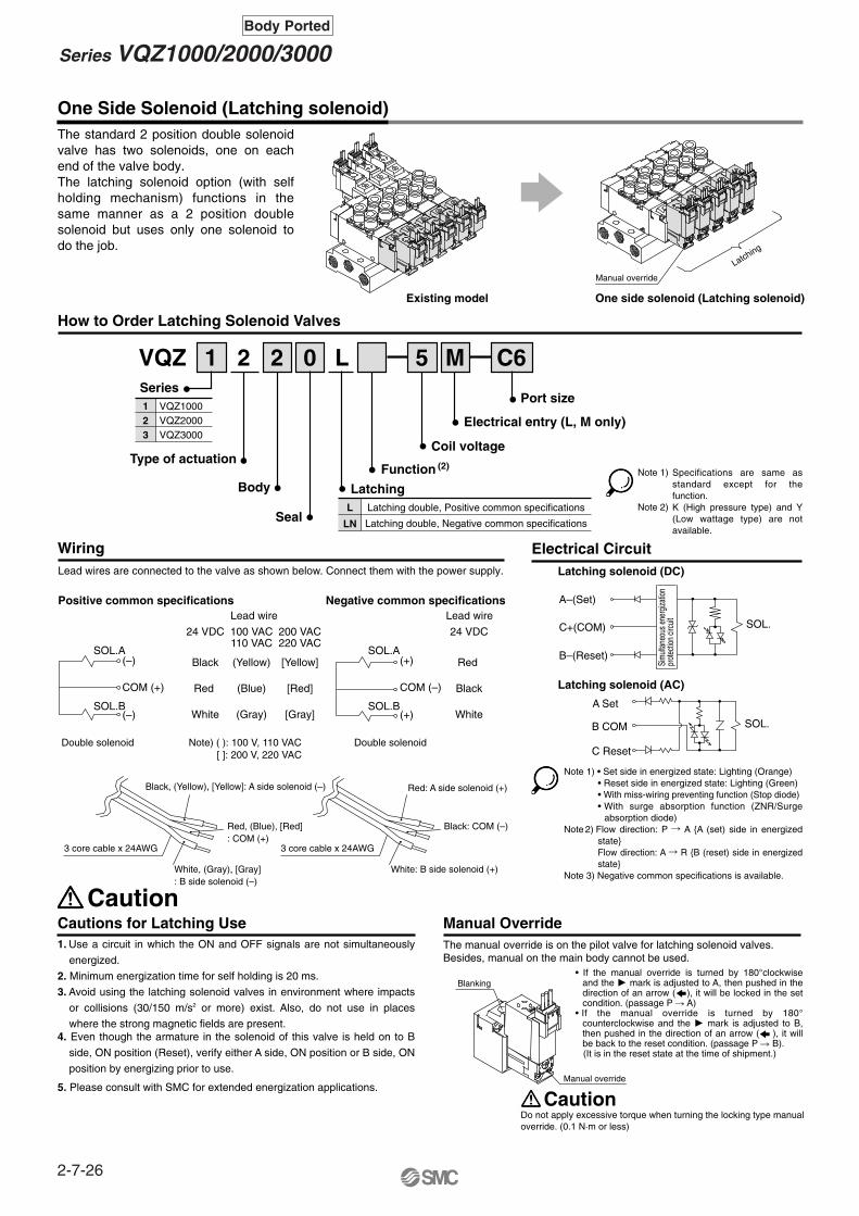
One Side Solenoid (Latching solenoid)
Series
VQZ 5
Type of actuation
1 2 2 0 L M
Body
Seal
Port size
Electrical entry (L, M only)
Coil voltage
123
VQZ1000VQZ2000VQZ3000
Manual OverrideThe manual override is on the pilot valve for latching solenoid valves.Besides, manual on the main body cannot be used.
Existing model One side solenoid (Latching solenoid)
Caution
C6
Electrical CircuitLatching solenoid (DC)
Latching solenoid (AC)
Sim
ultan
eous
ene
rgiza
tion
prot
ectio
n cir
cuit SOL.
SOL.
A–(Set)
C+(COM)
B–(Reset)
A Set
B COM
C Reset
Positive common specifications Negative common specifications
SOL.A
SOL.B
(–)
(–)
COM (+)
SOL.A
SOL.B
(+)
(+)
COM (–)
Lead wire
24 VDC
Black
Red
White
100 VAC110 VAC
(Yellow)
(Blue)
(Gray)
200 VAC220 VAC
[Yellow]
[Red]
[Gray]
Lead wire
24 VDC
Red
Black
White
Double solenoid Double solenoidNote) ( ): 100 V, 110 VAC [ ]: 200 V, 220 VAC
Black, (Yellow), [Yellow]: A side solenoid (–)
Red, (Blue), [Red]: COM (+)
White, (Gray), [Gray]: B side solenoid (–)
3 core cable x 24AWG
Red: A side solenoid (+)
Black: COM (–)
White: B side solenoid (+)
3 core cable x 24AWG
Lead wires are connected to the valve as shown below. Connect them with the power supply.
Manual override
Blanking
Latching
Manual override
Do not apply excessive torque when turning the locking type manualoverride. (0.1 N·m or less)
Caution
L
LN
Latching double, Positive common specifications
Latching double, Negative common specifications
Latching
Function (2)
The standard 2 position double solenoid valve has two solenoids, one on each end of the valve body.The latching solenoid option (with self holding mechanism) functions in the same manner as a 2 position double solenoid but uses only one solenoid to do the job.
How to Order Latching Solenoid Valves
Cautions for Latching Use
Wiring
Specifications are same as standard except for the function.K (High pressure type) and Y (Low wattage type) are not available.
Note 1) • Set side in energized state: Lighting (Orange)• Reset side in energized state: Lighting (Green)• With miss-wiring preventing function (Stop diode)• With surge absorption function (ZNR/Surge
absorption diode)Note 2) Flow direction: P � A {A (set) side in energized
state}Flow direction: A � R {B (reset) side in energized state}
Note 3) Negative common specifications is available.
1. Use a circuit in which the ON and OFF signals are not simultaneously
energized.
2. Minimum energization time for self holding is 20 ms.
3. Avoid using the latching solenoid valves in environment where impacts
or collisions (30/150 m/s2 or more) exist. Also, do not use in places
where the strong magnetic fields are present.4. Even though the armature in the solenoid of this valve is held on to B
side, ON position (Reset), verify either A side, ON position or B side, ON
position by energizing prior to use.
5. Please consult with SMC for extended energization applications.
• If the manual override is turned by 180°clockwise and the � mark is adjusted to A, then pushed in the direction of an arrow ( ), it will be locked in the set condition. (passage P � A)
• If the manual override is turned by 180° counterclockwise and the � mark is adjusted to B, then pushed in the direction of an arrow ( ), it will be back to the reset condition. (passage P � B).
(It is in the reset state at the time of shipment.)
Note 1)
Note 2)
2-7-26
Series VQZ1000/2000/3000Body Ported

Inch-size One-touch Fittings and Option Thread
Pressure Specifications
–100 KPa to 0.7 MPa
Externalpilot pressurerange
Series
Operatingpressure range
Metalseal
Rubberseal
VQZ2000/30002 position single 2 position double 3 position
0.1 to 0.7 MPa
0.15 to 0.7 MPa
Only VQZ3000, 3 position0.15 to 0.7 MPa
0.1 to 0.7 MPa 0.2 to 0.7 MPa
VQZ2120RExternal pilot specifications
How to Order Manifold
Series VQZOption
External Pilot Specifications(Except VQZ1000)
5M C6
External pilot port
M3 x 0.5 (VQZ2000)M5 x 0.8 (VQZ3000)
VQZ2120
Cylinder port
How to Order Manifold
5M N7
VQZ1000
A, Bport
Symbol
Applicable tubing O.D. (Inch)
VQZ2000
VQZ3000
N1 N3 N7 N9 N111/8" 5/32" 1/4" 5/16"
� � � — —
— � � — —
— — � � �
3/8"
Thread type(Cylinder port and 1(P), 3(R2), 5(R1) port)
Nil
N
T
F
Rc
NPT
NPTF
G
Dusttight/Low Jetproof Type (IP65)DIN terminal is available with Dusttight/Low jetproof (IP65) type.
VQZ3121IP65 compliant
How to Order Valves(Applicable to VQZ2000/3000 rubber sealwith the exception of the external pilot type)
5YZB 02
Nil
W
No (Standard)
CompliantNote)
T
VV5QZ22
How to Order Manifold(Suffix each symbol to the end of part number.)
05C 00T
Thread type(1(P), 3(R2), 5(R1)) ports)Nil
00N
00T
00F
Rc
NPT
NPTF
G
M5 02
M5 thread
� —
� —
— �
1/4 thread
Note) Metric sizes of One-touch fittings (C�) are also available.
Body Ported
ø ø ø ø ø
The external pilot specifications are used when the operating pressure is below the minimum operating pressure 0.1 to 0.2 MPa or when valve is used for a vacuum application.Order a valve by adding the external pilot specifications [R] to the part number.
Inch sizes of One-touch fittings and NPT, NPTF and G thread are available.
Note) The pilot exhaust IP65 valves is common with main valve exhaust.(The standard valve has an individual exhaust for the pilot valve.)
W
Note) In the case of the high pressure type, upper limit of max. operating pressure and external pilot pressure range is 1 MPa.
Note 1) 3(R2), 5(R1) port of VQZ2000 is only G 1/16.
Note 2) Except VQZ1000
Note)
Note)
2-7-27
VQC
SQ
VQ0
VQ4
VQ5
VQZ
VQD

<Plug connector assembly>
VQ11<Pilot valve assembly>
Electrical entry
Grommet (DC specifications)L plug connector with lead wire
L plug terminal without connectorM plug connector with lead wire
M plug terminal without connectorDIN terminal
DIN terminal without connectorDIN terminal with light/surge voltage suppressor
DIN terminal with surge voltage suppressorDIN terminal with surge voltage suppressor, without connector
G L
LO M
MO Y
YOYZYS
YOSNote) DIN is applicable to VQZ2000/3000.
Gasket and Screw Assembly Part no.
VQZ1000-GS-2
VQZ2000-GS-2
VQZ3000-GS-2
VQZ1000
VQZ2000
VQZ3000
VQZ1000/2000
VQZ3000
VVQ1000-50A-C3 VVQ1000-50A-C4 VVQ1000-50A-C6
VVQ1000-51A-C6 VVQ1000-51A-C8 VVQ1000-51A-C10
C3 C4 C6 C8 C10Fitting size
Model
One-touch Fitting Assembly (For cylinder port)
Note) Purchasing order is available in units of 10 pieces.
Series10
VQZ1000/2000/3000Latching
Series VQZReplacement Parts
Light/Surge voltagesuppressor
None
Yes
None
YesYes (W/o indicator light)Yes (W/o indicator light)
Note)
Note)
Note)
Note)
Note)
Applicable model (Length of screwsattached is different from each other.)
4
5
Nil VQZ2000/3000
A and B side of VQZ1000 single double solenoid typeA side of VQZ1000 3 position
B side of VQZ1000 3 position
Electrical entrySymbol
AXT661-14A- Lead wire lengthNil 300 mm
600 mm1000 mm2000 mm3000 mm5000 mm
610203050
• Single
AXT661-13A-• Latching
AXT661-13AN-• Latching
DC positive common
DC (–COM)
AXT661-31A-• SingleFor 100 V, 110 VAC
AXT661-32A-• Latching
AXT661-34A-• SingleFor 200 V, 220 VAC
AXT661-35A-• Latching
Only connector andsockets (3 pcs.)
AXT661-12A
Body Ported
51 G
Coil voltage100 VAC (50/60 Hz)200 VAC (50/60 Hz)110 VAC (50/60 Hz)220 VAC (50/60 Hz) 24 VDC 12 VDC
1234569
Note) For the special voltages,please consult with SMC.
Note)
Function
Nil Standard
High pressure(Metal seal only)
Low wattage type
Latching type
Negative common type
K
Y
L
N
(1)
(3)
(4)
Symbol Specifications DC(1.0 W)
�
(1.0 W)�
(0.5 W)�
�
�
�
�
—
—
—
AC
(1.0 W)
Bracket Assembly Part no.
VQZ1000-FB-MVQZ1000-FB-RVQZ2000-FBVQZ3000-FB
Tightening torque (N·m)
0.2 to 0.26
0.25 to 0.350.25 to 0.35
VQZ1000
Note) Tightening torque when mounting a bracket on the valve.
VQZ2000VQZ3000
Metal seal
Rubber seal
Note)
Note) Above part number consists of 10 units.Each unit has one gasket and two screws. Purchasing order is available in units of 10 pieces. Standard wire length of valve with plug
connector is 300 mm.When requiring valve with 600 mm length lead wire specify the model number of valve without plug connector and plug connector assembly.
Note 1) OptionNote 2) When two or more symbols
are specified, indicate them alphabetically.
Note 3) K (High pressure) and Y (Low wattage) are not available.Electrical entry: L/M plug connector only.
Note 4) Applicable to latching type.
Other
2-7-28

Compact design withlarge flow capacity
Choice of metal or rubber seal main valve construction
DIN terminal is available withdust tight / low jetproof (IP65) type.
DIN rail mounting is available.
All solenoids on one side
Manual override
One side solenoid
latching type
High speed andlong service life
VQZ1000 10 ms
VQZ2000 12 ms
VQZ3000 15 ms
Response time Life
Dispersion accuracy ±2 ms
2 million cycles
Built-in One-touch fittings for easier piping.
Both 3 and 5 port valvescan be mountedon the same manifold.
5 port valve3 port valve
Port plug
Clip
Fitting assembly
∗ Flow characteristics: 4/2 � 5/3 (A/B � R1/R2)
ModelManifold
pitch(mm)
Cylindersize
Flow characteristicsMetal seal
C [dm3/(s·bar)]Rubber seal
C [dm3/(s·bar)]
VQZ1000VQZ2000VQZ3000
101518
0.701.93.0
1.32.34.6
Up to ø63Up to ø100Up to ø100
Integral One-touch fittings save on installation time and labor and can be easily removed if necessary.
Optional latching coil valve operates the same as a 2 position/double solenoid valve but uses only one solenoid. This saves space and wiring costs.
3/5 Port Solenoid ValveMetal Seal/Rubber SealBase Mounted
VQZ1000/2000/3000
∗ Metal seal, single solenoid with light/surge voltage suppressor, according to SMC life test conditions.
2-7-29
VQC
SQ
VQ0
VQ4
VQ5
VQZ
VQD

Cylinder Speed Chart
Base Mounted
Conditions
Use as a guide for selection. Please confirm the actual conditions withSMC Sizing Program.
Bore size
ø6 ø10 ø16 ø20 ø25 ø32 ø40 ø40 ø50 ø63 ø80 ø100
Series
VQZ1151-01
800700600500400300200100
0
VQZ2151-02
800700600500400300200100
0
VQZ3151-03
VQZ1151-01
VQZ2151-02
VQZ3151-03
900800700600500400300200100
0
Averagespeed(mm/s)
Series CJ2Pressure 0.5 MPaLoad factor 50%Stroke 60 mm
Series CM2Pressure 0.5 MPaLoad factor 50%Stroke 300 mm
Series MB/CA1Pressure 0.5 MPaLoad factor 50%Stroke 500 mm
Tube x Length
Speed controller
Silencer
Tube x Length
Speed controller
Silencer
Tube x Length
Speed controller
Silencer
Body ported Series CJ2 Series CM2
T0604 x 1 m
AS3001F-06
AN110-01
T0604 x 1 m
AS3001F-06
T0604 x 1 m
AS3001F-06
AN200-02
T1075 x 1 m
AS4001F-10
AN300-03
T1209 x 1 m
AS4001F-12
T0806 x 1 m
AS3001F-08
Series MB/CA1
∗ It is when the cylinder is extending that is meter-out controlled by speed controller which is directly connected with cylinder, and its needle valve with being fully open.
∗ The average velocity of the cylinder is what the stroke is divided by the total stroke time.∗ Load factor: ((Load weight x 9.8)/Theoretical force) x 100%
Perpendicular, upward actuation
Horizontal actuation
2-7-30

Sonic conductanceC [dm3/(s·bar)] Type of actuation Voltage Electrical entry
Light/Surgevoltage suppressor Manual override
VQZ1000
VQZ2000
VQZ3000
VQZ1000
VQZ2000
VQZ3000
0.70 1.3
Metal Rubber
1.9 2.3
3.0 4.6
0.90 1.3
1.9 2.3
3.0 4.6
2 position single
2 position double
3 position closed center
3 position exhaust center
3 position pressure center
N.C.
N.O.
5 p
ort
3 p
ort
fo
r m
ixtu
re m
ou
nti
ng
Bas
e M
ou
nte
d (Standard)12 VDC24 VDC
(Option)100 VAC200 VAC110 VAC220 VAC
Grommet (G)
L plug connector (L)
DIN terminal (Y)
With light/surgevoltage
suppressor
L plug connector (L)
M plug connector (M)
DIN terminal (YZ)
Except VQZ1000 )(
Non-lockingpush type
(Tool required)
Locking type(Tool required)
(A)4
1(P)
3 (R2)
(B)2
5(R1)
(A)4
1(P)
5(R)
(A)4
1(P)
5(R) Except
VQZ1000 )(
(A)4
1(P)
3 (R2)
(B)2
5(R1)
(A)4
1(P)
3(R2)
(B)2
5(R1)
(A)4
1(P)
3(R2)
(B)2
5(R1)
(A)4
1(P)
3(R2)
(B)2
5(R1)
M plug connector (M)
Series VQZModel Selection
Base Mounted
∗ Flow Characteristics: 4/2 � 5/3 (A/B � R1/R2)
AC
B
BC
A
2-7-31
VQC
SQ
VQ0
VQ4
VQ5
VQZ
VQD

CautionWarningManual Override
Push type (Tool required)
Locking type (Tool required)
Push down on the manual override button with a small screwdriver until it stops.Release the screwdriver and the manual override will return.
Push down completely on the manual override button with a small screwdriver.While down, turn clockwise 90° to lock it.Turn it counterclockwise to release it.
How to Use L/M Plug Connector
Attaching and detaching connectors
Refer to page 2-7-61 for part no. of plug connector assembly.
ConnectorPart no. AXT661-12
Lead wire 0.2 to 0.33 mm2
(Max. O.D. ø1.7 mm)
SocketPart no. DXT170-71-1
Cover
Pin
Cover
Pin
Lever
Hook
M plug connector
L plug connector
Concave
Concave
Connection and Electrical Circuit
For with Light/Surge Voltage Suppressor
Due to the use of non-polar light, the series VQZ has no polarity.For latching type, refer to page 2-7-59.
Circuit for DC Circuit for AC
A (–)
C (+)
SOL
ZNRIndicatorlight
A
C
SOL
Indicator light
[+]
[–]
Red (DC)
Blue 100 VAC110 VAC
Red 200 VAC220 VAC
Black (DC)
Blue 100 VAC110 VAC200 VAC220 VACRed
Precautions 1Be sure to read before handling. For Safety Instructions and Solenoid Valve Precautions, refer to page 2-9-2.
Caution
Indicator light
Do not apply excessive torque when turning the locking type manual override. (0.1 N·m or less)
To attach a connector, hold the lever and connector unit between your fingers and insert straight onto the pins of the solenoid valve so that the lever’s pawl is pushed into the groove and locks.
To detach a connector, remove the pawl from the groove by pushing the lever downward with your thumb, and pull the connector straight out.
Both DCs have no polarity, and then connect each lead wire with the power source side.
Without an electric signal for the solenoid valve the manual override is used for switching the main valve.Locking type (Tool required) is available as an option.
2-7-32
Series VQZ1000/2000/3000Base Mounted

(Not necessary if ordering the lead wire pre-connected model.)
Crimping of lead wires and sockets
Attaching and detaching lead wires with sockets
Crimping area
Core wire crimping area
Terminal
Hook
Core wire
Insulation
Lead wire
0.2 to 0.33 mm2
Max. cover diameter ø1.7 mm
Socket
connector
Lead wire
Hook DIN Terminal Part No. (Conforming to DIN)
Without light
Rated voltage24 VDC 12 VDC
100 VAC 200 VAC 110 VAC 220 VAC
With indicator light
AXT100-20-1
Voltage symbol24V12V100V200V110V220V
Part no.AXT100-20-2-05AXT100-20-2-06AXT100-20-2-01AXT100-20-2-02AXT100-20-2-03AXT100-20-2-04
Circuit with Indicator Light
NL: Neon lightR: Resister
LED: Emitting diodeR: Resister
AC circuit DC circuit
Ground nut
Washer
Grommet(Rubber)
(Voltage symbol)Refer to the table below.
Terminal screw (3 locations)
Holding screw
Housing
(Position for light mounting)
Terminal block
Shaved part
Conforming to ISO#: DIN 43650 C (8 mm between pins)
1 2
NL R
1 2
RLED
Tool for crimping: Model No. DXT170-75-1
Be sure to read before handling. For Safety Instructions and Solenoid Valve Precautions, refer to pages 2-9-2.
Precautions 2
Tightening torque1.65 to 2.5 N·m
Tightening torque0.3 to 0.4 N·m
Tightening torque0.2 to 0.25 N·m
Peel 3.2 to 3.7 mm of the tip of lead wire, enter the core wires neatly into a socket and crimp it with a special crimp tool. Be careful so that the cover of lead wire does not enter into the crimping part.
AttachingInsert the sockets into the square holes of the connector (with + and – indication) and, continue to push the sockets all the way in until the lock by hooking into the seats in the connector. (When they are pushed in, their hooks open and they are locked automatically.) Then confirm that they are locked by pulling lightly on the lead wires.DetachingTo detach a socket from a connector, pull out the lead wire while pressing the socket’s hook with a stick having a thin tip (approx. 1 mm). If the socket will be used again, first spread the hook outward.
Connection1. Loosen the set screw and pull out the connector from the
terminal block of the solenoid.2. Remove the housing screw and insert a screwdriver into the
slot area on the underside of the DIN cap and carefully separate block and housing.
3. Loosen the terminal screws (slotted screws) on the terminal block, insert the core of the lead wire into the terminal in accordance with the prescribed connection method, and attach securely with the terminal screws.
4. Tighten the ground nut to secure the wire.
Change of electrical entry (Orientation)After separating terminal block and housing, the cord entry direction can be changed by attaching the housing in the desired direction (4 directions in 90° increments).∗ In the case of indicator light, avoid damaging the light with lead
wire.
PrecautionsPull a connector out vertically, never at an angle.
Applicable cableO.D.: ø3.5 to ø7(Reference) 0.5 mm2 2 core and 3 core wires equivalent to JIS C 3306.
Connection of Lead Wire How to Wire DIN Terminal
2-7-33
Series VQZ1000/2000/3000Base Mounted
VQC
SQ
VQ0
VQ4
VQ5
VQZ
VQD
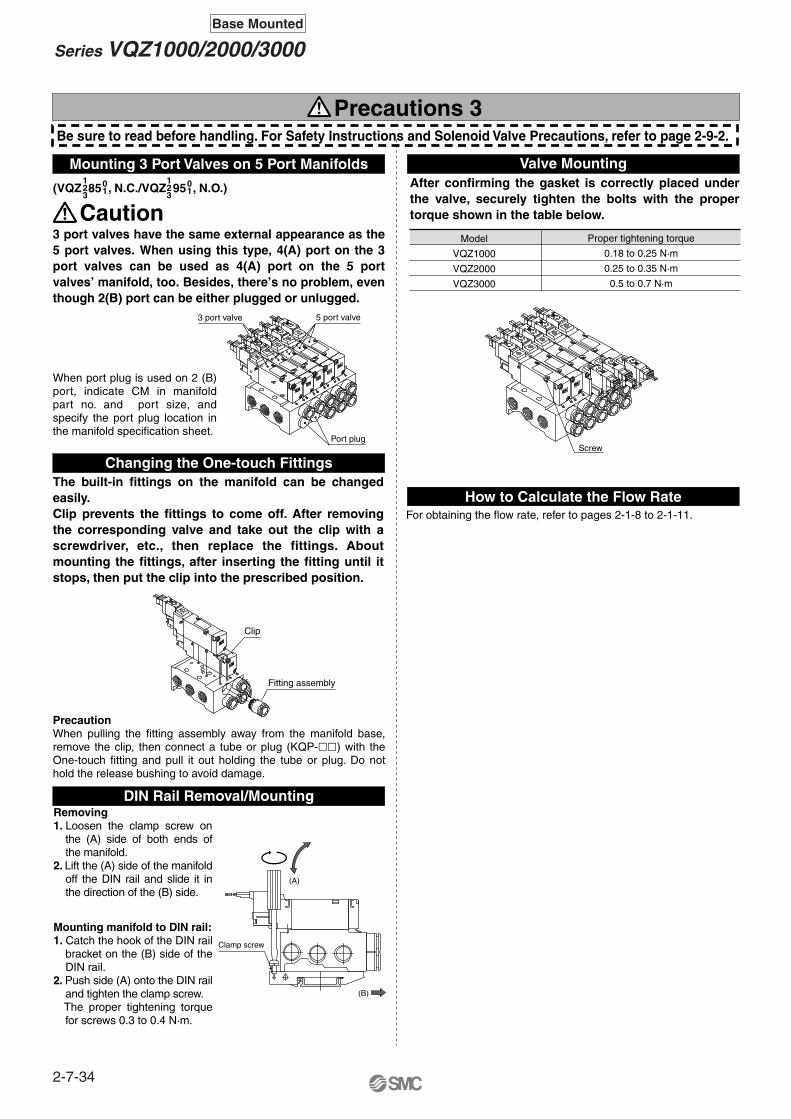
(VQZ 85 , N.C./VQZ 95 , N.O.)123
123
01
5 port valve
DIN Rail Removal/Mounting
How to Calculate the Flow RateFor obtaining the flow rate, refer to pages 2-1-8 to 2-1-11.
Model
VQZ1000
VQZ2000
VQZ3000
Proper tightening torque
0.18 to 0.25 N·m
0.25 to 0.35 N·m
0.5 to 0.7 N·m
Changing the One-touch Fittings
01
3 port valve
Port plug
(B)
Clamp screw
(A)
Caution
Screw
Be sure to read before handling. For Safety Instructions and Solenoid Valve Precautions, refer to page 2-9-2.
Precautions 3
Clip
Fitting assembly
3 port valves have the same external appearance as the 5 port valves. When using this type, 4(A) port on the 3 port valves can be used as 4(A) port on the 5 port valves’ manifold, too. Besides, there’s no problem, even though 2(B) port can be either plugged or unlugged.
The built-in fittings on the manifold can be changed easily. Clip prevents the fittings to come off. After removing the corresponding valve and take out the clip with a screwdriver, etc., then replace the fittings. About mounting the fittings, after inserting the fitting until it stops, then put the clip into the prescribed position.
When port plug is used on 2 (B) port, indicate CM in manifold part no. and port size, and specify the port plug location in the manifold specification sheet.
PrecautionWhen pulling the fitting assembly away from the manifold base, remove the clip, then connect a tube or plug (KQP-��) with the One-touch fitting and pull it out holding the tube or plug. Do not hold the release bushing to avoid damage.
Removing1. Loosen the clamp screw on
the (A) side of both ends of the manifold.
2. Lift the (A) side of the manifold off the DIN rail and slide it in the direction of the (B) side.
Mounting manifold to DIN rail: 1. Catch the hook of the DIN rail
bracket on the (B) side of the DIN rail.
2. Push side (A) onto the DIN rail and tighten the clamp screw.
The proper tightening torque for screws 0.3 to 0.4 N·m.
After confirming the gasket is correctly placed under the valve, securely tighten the bolts with the proper torque shown in the table below.
Mounting 3 Port Valves on 5 Port Manifolds Valve Mounting
2-7-34
Series VQZ1000/2000/3000Base Mounted

2-7-35
VQC
SQ
VQ0
VQ4
VQ5
VQZ
VQD

5 Port Solenoid ValveBase MountedPlug Lead Unit: Single Unit
VQZ1000/2000/3000
Note) Except VQZ1000and metal seal type.
Type of actuation
Series
VQZ 1 1 5 5 M 01
How to Order Valves
123
VQZ1000 body width 10 mmVQZ2000 body width 15 mmVQZ3000 body width 18 mm
1
2 position single
Body5 Base mounted
Port size {4(A), 2(B) port}
NilPort size
Without sub-plateRc 1/8Rc 1/4Rc 3/8
010203
Manual overrideNil:Non-lockingpush type(Tool required)
B: Locking type(Tool required)
Electrical entryG:Grommet(DC specifications)
L:L plugconnectorwith lead wire
LO:L plugconnectorwithout connector
M:M plug connectorwith lead wire
MO:M plugconnectorwithout connectorWith light/surge voltagesuppressor
With light/surge voltagesuppressor
With light/surge voltagesuppressor
With light/surge voltagesuppressor
Note 1) Applicable to VQZ2000 and 3000.Note 2) Standard lead wire length: 300 mm
Coil voltage123456
9
100 VAC (50/60 Hz)200 VAC (50/60 Hz)110 VAC (50/60 Hz)220 VAC (50/60 Hz) 24 VDC 12 VDC
Note) For the special voltages, please consult with SMC.
Note)
1
2
2 position double
3
3 position closed center
4
3 position exhaust center
5
3 position pressure center
Seal01
Metal sealRubber seal
Y: DIN terminal (1)
YO:DIN terminal (1)
without connector
YZ: DIN terminal (1)
YOS:DIN terminal (1)
without connector
YS: DIN terminal (1)
With surge voltagesuppressor
With surge voltagesuppressor
With light/surge voltagesuppressor
�
�
——
�
�
�
—
�
—�
�
VQZ1000 VQZ2000 VQZ3000
Note)
(A)4
1(P)
3 (R2)
(B)2
5(R1)
1(P)
3 (R2)
5(R1)
(A)4
1(P)
3 (R2)
(B)2
5(R1)
(A)4
1(P)
3 (R2)
(B)2
5(R1)
(A)4
1(P)
3 (R2)
(B)2
5(R1)
(A)4
1(P)
3 (R2)
(B)2
(A)4
(B)2
5(R1)
Metal seal Rubber seal
Symbol
Note) For sub-plate part no,refer to page 2-7-61.
Function
Nil Standard
High pressure(Metal seal only)
Low wattage type
External pilot
K
Y
R
(1)
(2)
Symbol Specifications DC(1.0 W)
�
(1.0 W)�
(0.5 W)�
�
�
�
(3)
—
—
AC
BC
A
AC
B
Note 1) OptionNote 2) For details about external pilot
specifications, refer to page 2-7-60.
Note 3) For power consumption of AC type, refer to page 2-7-37.
Note 4) When two or more symbols are specified, indicate themalphabetically.
Other
For details about certified products conforming to international standards, visit us at www.smcworld.com.
2-7-36

VQC
SQ
VQ0
VQ4
VQ5
VQZ
VQD
Standard Specifications
Valve construction
Fluid
Maximum operating pressure
Ambient and fluid temperature
Pilot valve EXH
Lubrication
Manual override
Shock/ Vibration resistance
Enclosure
Coil rated voltage
Allowable voltage fluctuation
Coil insulation type
2 position singleDoubleMin. operating
pressure
3 position
Single, Double2 positionMax. operatingfrequency
24 VDC
12 VDC
100 VAC
110 VAC
200 VAC
220 VAC
Powerconsumption(Current)
Val
ve s
peci
ficat
ions
Ele
ctric
ity s
peci
ficat
ions
Metal seal
Air/Inert gas
–10 to 50°C
20 Hz
10 Hz
(1)
Rubber seal
Air/Inert gas
–10 to 50°C
5 Hz
3 Hz
0.7 MPa (High pressure type: 1.0 MPa)
Individual EXH
Not required
Push type/Locking type (Tool required) Option
150/30 m/s2
Dust-protected
12, 24 VDC and 100,110, 200, 220 VAC
±10% of rated voltage
Equivalent to class B
1 W DC (42 mA), 0.5 W DC (21 mA)
1 W DC (83 mA), 0.5 W DC (42 mA)
Inrush 0.5 VA (5 mA), Holding 0.5 VA (5 mA)
Inrush 0.55 VA (5 mA), Holding 0.55 VA (5 mA)
Inrush 1.0 VA (5 mA), Holding 1.0 VA (5 mA)
Inrush 1.1 VA (5 mA), Holding 1.1 VA (5 mA)
Model
Series Configuration
Metal seal
Rubber seal
Metal seal
Rubber seal
Metal seal
Rubber seal
Metal seal
Rubber seal
Rubber seal
Metal seal
Rubber seal
Metal seal
Rubber seal
Metal seal
Rubber seal
Metal seal
Rubber seal
Metal seal
Rubber seal
Metal seal
Rubber seal
Metal seal
Rubber seal
Metal seal
Rubber seal
Metal seal
Rubber seal
Metal seal
Rubber seal
0.70
1.2
0.70
1.2
0.56
1.1
0.56
1.1
1.4
1.6
2.0
1.6
2.0
1.5
1.7
1.5
1.7
1.8
2.0
2.6
3.9
2.6
3.9
2.4
3.1
2.4
3.9
3.0
4.4
0.21
0.35
0.21
0.35
0.20
0.33
0.20
0.33
0.20
0.13
0.35
0.13
0.35
0.16
0.27
0.16
0.27
0.13
0.35
0.12
0.29
0.12
0.29
0.12
0.33
0.12
0.33
0.12
0.27
0.17
0.30
0.17
0.30
0.13
0.27
0.13
0.27
0.34
0.36
0.51
0.36
0.51
0.35
0.39
0.35
0.39
0.39
0.50
0.60
1.0
0.60
1.0
0.58
0.82
0.58
0.82
0.69
1.1
0.70
1.3
0.70
1.3
0.57
1.0
0.70
1.3
1.0
1.9
2.3
1.9
2.3
1.3
1.7
1.9
2.3
1.5
1.7
3.0
4.6
3.0
4.6
2.8
3.6
3.0
4.6
2.9
3.6
0.21
0.24
0.21
0.24
0.22
0.38
0.21
0.24
0.38
0.16
0.29
0.16
0.29
0.26
0.28
0.16
0.29
0.26
0.28
0.15
0.26
0.15
0.26
0.16
0.35
0.15
0.26
0.16
0.35
0.17
0.32
0.17
0.32
0.14
0.27
0.17
0.32
0.27
0.40
0.53
0.40
0.53
0.32
0.39
0.40
0.53
0.36
0.39
0.74
1.2
0.74
1.2
0.65
0.97
0.74
1.2
0.65
0.97
12 or less
12 or less
10 or less
10 or less
20 or less
25 or less
20 or less
25 or less
25 or less
14 or less
15 or less
10 or less
12 or less
23 or less
25 or less
23 or less
25 or less
23 or less
25 or less
17 or less
25 or less
10 or less
15 or less
25 or less
30 or less
25 or less
30 or less
25 or less
30 or less
15 or less
15 or less
13 or less
13 or less
26 or less
33 or less
26 or less
33 or less
33 or less
18 or less
20 or less
13 or less
15 or less
30 or less
33 or less
30 or less
33 or less
30 or less
33 or less
22 or less
33 or less
13 or less
20 or less
33 or less
39 or less
33 or less
39 or less
33 or less
39 or less
29 or less
34 or less
13 or less
13 or less
40 or less
47 or less
40 or less
47 or less
47 or less
34 or less
36 or less
13 or less
15 or less
44 or less
47 or less
44 or less
47 or less
44 or less
47 or less
34 or less
57 or less
13 or less
20 or less
53 or less
59 or less
53 or less
59 or less
53 or less
59 or less
Single
Double
ClosedcenterVQZ1000
Exhaust center
Pressure center
Single
Double
Closedcenter
Exhaust center
Pressure center
Single
Double
Closedcenter
Exhaust center
Pressure center
2 position
3 position
2 position
3 position
VQZ2000
2 position
3 position
VQZ3000
Model
VQZ1150
VQZ1151
VQZ1250
VQZ1251
VQZ1350
VQZ1351
VQZ1450
VQZ1451
VQZ1551
VQZ2150
VQZ2151
VQZ2250
VQZ2251
VQZ2350
VQZ2351
VQZ2450
VQZ2451
VQZ2550
VQZ2551
VQZ3150
VQZ3151
VQZ3250
VQZ3251
VQZ3350
VQZ3351
VQZ3450
VQZ3451
VQZ3550
VQZ3551
Weight (g)Flow characteristics
1 � 4/2 (P � A/B)C[dm3/(s.bar)] b Cv C[dm3/(s.bar)] b Cv
4/2 � 5/3 (A/B � EA/EB) Response time (ms) (1)
Standard:1 W
ACHigh pressure: 1 WLow wattage:
0.5 W
(2)
0.1 MPaonly for VQZ3000, 3 position
0.15 MPa
(1)
3 position
37
56
60
84
94
119
Note 1) Based on JIS B 8375-1981 (Supply pressure; 0.5 MPa; with indicator light/surge voltage suppressor; clean air),Response time values will change depending on pressure and air quality. The values at the time of ON are given for double types.
Note 2) Weight without sub-plate
(2)
Note 1) Use dry air to prevent condensation when operating at low temperatures.
Note 2) Impact resistance:No malfunction occurred when it is tested with a drop tester in the axial direction and at the right angles to the main valve and armature in both energized and de-energized states every once for each condition. (Values at the initial period)Vibration resistance:No malfunction occurred in a one-sweep test between 45 and 2000 Hz. Test was performed at both energized and de-energized states in the axial direction and at the right angles to the main valve and armature. (Values at the initial period)
0.7 MPa
0.15 MPa
0.1 MPa
0.2 MPa
2-7-37
Series VQZ1000/2000/3000Plug Lead Unit: Single Unit
Base Mounted

Refer to page 2-7-61 for Pilot Valve Assembly.
Construction: VQZ1000/2000/3000
Description
Body
Spool/Sleeve
Spool valve
Piston
Pilot valve assembly
Material
Aluminum die-casted
Stainless steel
Aluminum/HNBR
Resin
—
Note
Metal seal
Rubber seal
No.
q
w
e
r
Metal seal type Rubber seal type
2 position single 2 position single
2 position double 2 position double
3 position pressure center3 position exhaust center3 position closed center3 position pressure center3 position exhaust center3 position closed center
Component Parts
r e w q
r e w q
r e w q r e w q
r e w q
r e w q
(A)4
(B)2
3(R2)
1(P)
5(R1)
Note) Except VQZ1000and metal sealtype.
(A)4
1(P)
3 (R2)
(B)2
5(R1)
(A)4
1(P)
3 (R2)
(B)2
5(R1)
(A)4
(B)2
3(R2)
1(P)
5(R1)
(A)4
(B)2
3(R2)
1(P)
5(R1)
(A)4
(B)2
3(R2)
1(P)
5(R1)
(A)4
(B)2
3(R2)
1(P)
5(R1)
(A)4
(B)2
3(R2)
1(P)
5(R1)
(A)4
(B)2
3(R2)
1(P)
5(R1)
(A)4
(B)2
3(R2)
1(P)
5(R1)
Note)
2-7-38
Series VQZ1000/2000/3000Base Mounted

VQC
SQ
VQ0
VQ4
VQ5
VQZ
VQD
Dimensions: VQZ1000
Grommet (G): VQZ11501(R)-�G�-01
L plug connector (L): VQZ11501(R)-�L�-01 M plug connector (M): VQZ1150
1(R)-�M�-01
R1 R2
SMC
24
5 1 3
A
B
≅ 300(Lead wire
length)
68.5
47.5 18
7.27.2
Manual override
Cover diameter ø1.6
Cross section 0.34 mm2
3
10 22
2- ø3.4 mounting hole
4236 3
M5 x 0.8 external pilot port(Only external pilot type (R))
1.1
14.6
10
SMC
69.5 (Metal seal)
67 (Rubber seal)
(47.5)
40.5
5-Rc 1/81(P), 2(B), 3(R2),
4(A), 5(R1) port
PE port13.413.4
P
46.5
20
12
7.2
M5 x 0.8(Not applicable to standard.)
10
2(B), 2(A) port
2 position single
R3
Cover diameter ø1.5
Cross section 0.23 mm2
P
R1 R2
(Lead wire length)
Indicator light
83 (Metal seal)≅ 300
47.5
<52
.5>
82
61
81 (Rubber seal)
Cross section 0.23 mm2
Cover diameter ø1.5
P
R1 R2
(Lea
d w
ire le
ngth
)
Indicator light
54 <
59>
≅ 30
0
76
55
75 (Rubber seal)
77 (Metal seal)
< >: AC < >: AC
2-7-39
Series VQZ1000/2000/3000Plug Lead Unit: Single Unit
Base Mounted

Dimensions: VQZ1000
Grommet (G): VQZ12501(R)-�G�-01
L plug connector (L): VQZ12501(R)-�L�-01 M plug connector (M): VQZ1250
1(R)-�M�-01
R1 R2
SM
C
SM
C
315
4 2
A
B
2- ø3.4 mounting hole ≅ 300
(Lead wirelength)
95
47.5 187.27.2 3
10 22
Manual override4236 3
Cover diameter ø1.6
Cross section 0.34 mm2
M5 x 0.8 external pilot port(Only external pilot type (R))
14.6
10
1.1
2-PE port
13.413.4
P
46.5
20
12
7.2
(47.5)
40.5
M5 x 0.8(Not applicable to standard.)
10
R3
2 position double
5-Rc 1/81(P), 2(B), 3(R2),
4(A), 5(R1) port
2(B), 2(A) port
Cross section 0.23 mm2
Cover diameter ø1.5
P
R1 R2
(Lea
d w
ire le
ngth
)
Indicator light
54 <
59>
≅ 30
0
55
110
Cover diameter ø1.5Cross section 0.23 mm2
P
R1 R2
(Lead wire length)
Indicator light
61
122≅ 300
47.5
<52
.5>
< >: AC < >: AC
2-7-40
Series VQZ1000/2000/3000Base Mounted

VQC
SQ
VQ0
VQ4
VQ5
VQZ
VQD
3 position closed center/exhaust center/pressure center (Except metal seal type)Grommet (G): VQZ1 50
1(R)-�G�-01
L plug connector (L): VQZ1 501(R)-�L�-01 M plug connector (M): VQZ1 50
1(R)-�M�-01
345
345
345
VQZ1000
R1 R2
SM
C
SM
C
≅ 300
(Lead wirelength)
103.5
47.5 18
7.27.2
2- ø3.4 mounting hole
3
10 22
4236 3
Manual overrideCover diameter ø1.6Cross section 0.34 mm2
M5 x 0.8 external pilot port
(Only external pilot type (R))
14.6
10
1.1
46.5
20
12
7.2
P
2-PE port13.413.4
40.5
(47.5)
M5 x 0.8
(Not applicable to standard.)
10
5 1 3
24R3
5-Rc 1/81(P), 2(B), 3(R2),
4(A), 5(R1) port
2(B), 2(A) port
Cover diameter ø1.5Cross section 0.23 mm2
P
R1 R2
(Lead wire length)
Indicator light
47.5
<52
.5>
≅ 300
61
131
Cross section 0.23 mm2
Cover diameter ø1.5
P
R1 R2
(Lea
d w
ire le
ngth
)
Indicator light
54 <
59>
≅ 30
0
55
119
< >: AC < >: AC
2-7-41
Series VQZ1000/2000/3000Plug Lead Unit: Single Unit
Base Mounted

L plug connector (L): VQZ21501(R)-�L�-01
02
M plug connector (M): VQZ21501(R)-�M�-01
02
DIN terminal (Y): VQZ21501(R)-�Y�-01
02
Dimensions: VQZ2000
Grommet (G): VQZ21501(R)-�G�-01
02
SM
C
R2R15 1 P 3
A 4 B 2
SMC
≅ 300
(Lead wirelength)
84.5
54.5 24
99
2- ø4.5 mounting hole
R4
Manual override
Cover diameter ø1.6Cross section 0.34 mm2
5648 4
4
15 34M5 x 0.8 external pilot port
(Only external pilot type (R))
2.1
169
(54.5)
45PE port 1818
51
22
9
28
M5 x 0.8(Not applicable to standard.)
9
101.5Max. 10
Indicator light
57
7582.5
103.5
73.5
Pg.7
Applicable cableO.D.ø3.5 to ø7
2 position single
5-Rc 1/8, 1/41(P), 2(B), 3(R2),
4(A), 5(R1) port
2(B), 2(A) port
Cover diameter ø1.5Cross section 0.23 mm2
(Lead wire length)
Indicator light≅ 300
51.5
<56
.5>
68
98
Cross section 0.23 mm2
Cover diameter ø1.5
(Lea
d w
ire le
ngth
)
Indicator light
≅ 30
058
.5 <
63.5
>
92
62
< >: AC
< >: AC
2-7-42
Series VQZ1000/2000/3000Base Mounted

VQC
SQ
VQ0
VQ4
VQ5
VQZ
VQD
Grommet (G): VQZ22501(R)-�G�-01
02
L plug connector (L): VQZ22501(R)-�L�-01
02
M plug connector (M): VQZ22501(R)-�M�-01
02
DIN terminal (Y): VQZ22501(R)-�Y�-01
02
VQZ2000
SM
C
R2R1
SM
C
15 P 3
A 4 B 2
SMC
≅ 300(Lead wire
length)
109
54.5 2499
2- ø4.5 mounting hole R4
Manual override
Cover diameter ø1.6Cross section 0.34 mm2
5648 4
4
15 34
M5 x 0.8 external pilot port(Only external pilot type (R))
2.1
16 9
(54.5)
45
2-PE port 1818
51
22
9
28
5-Rc 1/8, 1/41(P), 2(B), 3(R2),
4(A), 5(R1) port
M5 x 0.8(Not applicable to standard.)
9
142.5Max. 10
Indicator light
57
7582.5
147
73.5
Pg.7 Applicable cable O.D.
ø3.5 to ø7
71.5
2 position double
2(B), 4(A) port
Cover diameter ø1.5Cross section 0.23 mm2
(Lead wire length)
Indicator light
≅ 300
51.5
<56
.5>
68
136.5
Cross section 0.23 mm2
Cover diameter ø1.5
(Lea
d w
ire le
ngth
)
Indicator light
≅ 30
058
.5 <
63.5
>
62
124.5
< >: AC
< >: AC
2-7-43
Series VQZ1000/2000/3000Plug Lead Unit: Single Unit
Base Mounted

L plug connector (L): VQZ2 501(R)-�L�-01
02
M plug connector (M): VQZ2 5 (R)-�M�-
DIN terminal (Y): VQZ2 501(R)-�Y�-01
02
Dimensions: VQZ2000
345
345
01
345
0102
345
SMC
SM
C
SM
CR2R15 1 P 3
A 4 B 2
≅ 300
(Lead wirelength)
122
54.599
2- ø4.5 mounting hole
R4
Manual override
Cover diameter ø1.6Cross section 0.34 mm2
5648 4
4
15 34
(54.5)
45
2-PE port 1818
51
22
9
28
5-Rc 1/8, 1/41(P), 2(B), 3(R2),
4(A), 5(R1) portM5 x 0.8 external pilot port(Only external pilot type (R))
2.1
16 9
M5 x 0.8(Not applicable to standard.)
9
155.5Max. 10
Indicator light
57
7582.5
160
73.5
Pg.7Applicable cable O.D.
ø3.5 to ø7
71.5
3 position closed center/exhaust center/pressure centerGrommet (G): VQZ2 50
1(R)-�G�-0102
2(B), 4(A) port
Cross section 0.23 mm2
Cover diameter ø1.5
(Lea
d w
ire le
ngth
)
Indicator light
≅ 30
058
.5 <
63.5
>
62137.5
Cover diameter ø1.5Cross section 0.23 mm2
(Lead wire length)
Indicator light
51.5
<56
.5>
≅ 30068
149.5
< >: AC
< >: AC
2-7-44
Series VQZ1000/2000/3000Base Mounted

VQC
SQ
VQ0
VQ4
VQ5
VQZ
VQD
2 position singleGrommet (G): VQZ3150
1(R)-�G�-0203
L plug connector (L): VQZ31501(R)-�L�-02
03
M plug connector (M): VQZ31501(R)-�M�-02
03
DIN terminal (Y): VQZ31501(R)-�Y�-02
03
VQZ3000
SMC
SMC
SM
C
R1 R25 1 P 3
A 4 B 2
B
A
≅ 300(Lead wire
length)
9558
992- ø4.5 mounting hole
R5
Manual overrideCover diameter ø1.6Cross section 0.34 mm2
6656 5
5
18 45
10.510.528
(For Rc 1/4) (For Rc 1/4)
(For Rc 3/8) (For Rc 3/8)
M5 x 0.8(Not applicable to standard.)
13.5
9
20.5
M5 x 0.8 external pilot port(Only external pilot type (R))
9
(58)
54.5
PE port 1818
56.5
26.5
11.5
21
13.5
21
33
2-Rc 1/4, 3/83(R2), 5(R1) port
Rc 1/4, 3/81(P) port (For Rc 1/4) (For Rc 1/4)
(For Rc 3/8) (For Rc 3/8)
111.5Max. 10
Indicator light
60.5
78.586
114
77
Pg.7
Applicable cableO.D.ø3.5 to ø7
2(B), 4(A) port
(Lead wire length)
(Lea
d w
ire le
ngth
)
Cover diameter ø1.5
Cross section0.23 mm2
Cover diameter ø1.5Cross section 0.23 mm2
Indicator light
Indicator light
≅ 30
062
<67
>
55 <
60>
≅ 300
72
108.5
66
102.5
< >: AC
< >: AC
2-7-45
Series VQZ1000/2000/3000Plug Lead Unit: Single Unit
Base Mounted

2 position doubleGrommet (G): VQZ3250
1(R)-�G�-0203
SM
C
R1 R2
SM
C
5 1 P 3
A 4 B 2
AB
L plug connector (L): VQZ32501(R)-�L�-02
03
M plug connector (M): VQZ32501(R)-�M�-02
03
DIN terminal (Y): VQZ32501(R)-�Y�-02
03
Dimensions: VQZ3000
≅ 300
(Lead wire length)
116.5
58
9 (for Rc 1/4)
2- ø4.5 mounting hole
R5
ManualoverrideCover diameter ø1.6
Cross section 0.34 mm2
6656 5
5
18 45
10.5 (for Rc 3/8)
28
9 (for Rc 1/4)
10.5 (for Rc 3/8)
(58)
54.5
2-PE port1818
56.5
26.5
11.5
21
13.5
21
33
2-Rc 1/4, 3/83(R2), 5(R1) portRc 1/4, 3/8
1(P) port
(For Rc 1/4) (For Rc 1/4)
(For Rc 3/8) (For Rc 3/8)
M5 x 0.8(Not applicable to standard.)
13.5
9 20.5
M5 x 0.8 external pilot port(Only external pilot type (R))
9
150Max. 10
Indicator light
60.5
78.586
154.5
77
Pg.7
Applicable cable O.D.
ø3.5 to ø7
75
SMC
2(B), 4(A) port
(Lead wire length)
(Lea
d w
ire le
ngth
)
Cover diameter ø1.5Cross section 0.23 mm2
Cover diameter ø1.5Cross section 0.23 mm2
Indicator light
Indicator light
≅ 30
062
<67
>55
<60
>
≅ 30072
144
66132
< >: AC
< >: AC
2-7-46
Series VQZ1000/2000/3000Base Mounted

VQC
SQ
VQ0
VQ4
VQ5
VQZ
VQD
SMC
SM
C
R1 R2
SM
C
5 1 P 3
A 4 B 2
BA
≅ 300
(Lead wire length)
130
58
9 (For Rc 1/4)
2- ø4.5 mounting hole
R5
ManualoverrideCover diameter ø1.6
Cross section 0.34 mm2
6656 5
5
18 45
10.5 (For Rc 3/8)
28
9 (For Rc 1/4)
10.5 (For Rc 3/8)
(58)
54.5
2-PE port 1818
56.5
26.5
11.5
21
13.5
21
33
2-Rc 1/4, 3/83(R2), 5(R1) port
Rc 1/4, 3/81(P) port
(For Rc 1/4) (For Rc 1/4)
(For Rc 3/8) (For Rc 3/8)
M5 x 0.8(Not applicable to standard.)
13.5
9 20.5
M5 x 0.8 External pilot port(Only external pilot type (R))
9
163.5MAX.10
Indicator light
60.5
78.586
168
77
Pg.7
Applicable cable O.D.
ø3.5 to ø7
75
L plug connector (L): VQZ3 501(R)-�L�-02
03
M plug connector (M): VQZ3 501(R)-�M�-02
03
DIN terminal (Y): VQZ3 501(R)-�Y�-02
03
VQZ3000
345
345
345
345
3 position closed center/exhaust center/pressure centerGrommet (G): VQZ3 50
1(R)-�G�-0203
2(B), 4(A) port
(Lead wire length)
(Lea
d w
ire le
ngth
)
Cover diameter ø1.5Cross section0.23 mm2
Cover diameter ø1.5Cross section 0.23 mm2
Indicator light
Indicator light
≅ 30
062
<67
>55
<60
>
≅ 30072
157
66145
< >: AC
< >: AC
2-7-47
Series VQZ1000/2000/3000Plug Lead Unit: Single Unit
Base Mounted

5 Port Solenoid ValveBase MountedPlug Lead Unit: Manifold (Connector Kit)
VQZ1000/2000/3000How to Order Manifold
Series
VV5QZ 1 5 08 C6
123
VQZ1000VQZ2000 VQZ3000
Port size {4 (A), 2 (B) port}
C N
Stations02
20
2 stations
20 stations
······
Manifold5 Base mounted
Kit type
Option
DDONR
NoneDIN rail mounting style (With DIN rail in standard length)
DIN rail mounting style (Without DIN rail )Name plate
External pilot specifications
Nil
C Connector
SymbolC3C4C6C8C10M50102CM
Port sizeOne-touch fitting for ø3.2One-touch fitting for ø4One-touch fitting for ø6One-touch fitting for ø8One-touch fitting for ø10
M5 threadRc 1/8Rc 1/4
Mixture of port sizes
VQZ1000 VQZ2000 VQZ3000�
�
�
——�
——�
—�
�
�
——�
—�
——�
�
�
——�
�
Series
VQZ 5
123
VQZ1000 body width 10 mmVQZ2000 body width 15 mmVQZ3000 body width 18 mm
Seal01
Metal sealRubber seal
Type of actuation1234
589
2 position single2 position double
3 position closed center3 position exhaust center3 position pressure center
3 port for mixture mounting N.C.3 port for mixture mounting N.O.
Manual override
B
Non-locking push type (Tool required)Locking type (Tool required)
Nil
1 5
Body5 Base mounted
Function
Coil voltage123456
9
100 VAC (50/60 Hz)200 VAC (50/60 Hz)110 VAC (50/60 Hz)220 VAC (50/60 Hz) 24 VDC 12 VDC
Note) For the special voltages,please consult with SMC.
Electrical entry
GLLOMMOYYOYZYSYOS
Note 1) Applicable to VQZ2000 and 3000.Note 2) Standard lead wire length: 300 mm
Grommet (DC specifications)L plug connector with lead wireL plug terminal without connectorM plug connector with lead wireM plug terminal without connector
DIN terminal DIN terminal without connector
DIN terminal DIN terminal
DIN terminal without connector
How to Order Valves
(1)
Note 1) Order DIN rail separately.For DIN rail model number, refer to page 2-7-54.
Note 2) Applicable to VQZ2000 and 3000.
Note)
Note)
Note) Except VQZ1000 and metal sealtype.
(1)
(1)
(1)
(1)
(1)
None
Yes
Light/Surgevoltage suppressor
None
Yes
Yes (W/o indicator light)
Yes (W/o indicator light)
(1)
Electrical entrySymbol
(2)
Nil Standard
High pressure(Metal seal only)
Low wattage type
External pilot
K
Y
R
(1)
(2)
Symbol Specifications DC(1.0 W)
�
(1.0 W)�
(0.5 W)�
�
�
�
(3)
—
—
AC
Note 1) Specify port mixture/with port plug by means of the manifold specification sheet.Port mixture and port plug are available only for One-touch fitting type.
Note 2) For inch size and One-touch fittings, refer to page 2-7-60.
M
Note 1) OptionNote 2) For details about external pilot
specifications, refer to page 2-7-60.Note 3) For power consumption of AC type,
refer to page 2-7-37. Note 4) When two or more symbols are
specified, indicate them alphabetically.
11
Other
2-7-48
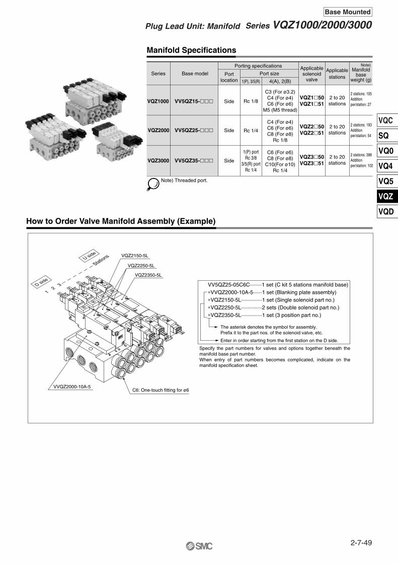
VQC
SQ
VQ0
VQ4
VQ5
VQZ
VQD
Manifold Specifications
Base modelManifold
baseweight (g)
How to Order Valve Manifold Assembly (Example)
VV5QZ25-05C6C········1 set (C kit 5 stations manifold base)∗VVQZ2000-10A-5······1 set (Blanking plate assembly)∗VQZ2150-5L··············1 set (Single solenoid part no.)∗VQZ2250-5L··············2 sets (Double solenoid part no.)∗VQZ2350-5L··············1 set (3 position part no.)
Applicablestations
Applicablesolenoid
valvePort size
1(P), 3/5(R) 4(A), 2(B)
Porting specifications
Portlocation
Series
SideVV5QZ15-���VQZ1�50VQZ1�51VQZ1000
2 to 20stations
2 stations: 105Additionper/station: 27
SideVV5QZ25-���VQZ2�50VQZ2�51VQZ2000
2 to 20stations
2 stations: 193Additionper/station: 54
SideVV5QZ35-���VQZ3�50VQZ3�51VQZ3000
2 to 20stations
2 stations: 398Additionper/station: 102
The asterisk denotes the symbol for assembly. Prefix it to the part nos. of the solenoid valve, etc.
Rc 1/8
Rc 1/4
1(P) portRc 3/8
3/5(R) portRc 1/4
C3 (For ø3.2)C4 (For ø4)C6 (For ø6)
M5 (M5 thread)
C4 (For ø4)C6 (For ø6)C8 (For ø8)
Rc 1/8
C6 (For ø6)C8 (For ø8)
C10(For ø10)Rc 1/4
Enter in order starting from the first station on the D side.
U side
23
VQZ2150-5L
VQZ2250-5L
VQZ2350-5L
VVQZ2000-10A-5C6: One-touch fitting for ø6
D side
1
Note)
Note) Threaded port.
Specify the part numbers for valves and options together beneath the manifold base part number.When entry of part numbers becomes complicated, indicate on the manifold specification sheet.
Stations
2-7-49
Series VQZ1000/2000/3000Plug Lead Unit: Manifold
Base Mounted

L1L2L3L4
L n 230.538.562.573
341 49 75 85.5
451.559.587.598
5 62 70 100 110.5
6 72.5 80.5100 110.5
7 83 91 112.5123
8 93.5101.5125 135.5
9104 112 137.5148
10114.5122.5150 160.5
11125 133 162.5173
12135.5143.5175 185.5
13146 154 175 185.5
14156.5164.5187.5198
15167 175 200 210.5
16177.5185.5212.5223
17188 196 225 235.5
18198.5206.5237.5248
19209 217 237.5248
20219.5227.5250 260.5
L plug connector (L) M plug connector (M)
Dimensions: VQZ1000
8
30.567 (Single, rubber)69.5 (Single, metal)
95 (Double)
103.5 (3 position)
8
44
14
L1L2(L3)(L4)
P =
10.
5
44- ø4.5 mounting hole
DIN rail clamp screw(4.5)
(35)
(5.5)
Manual override
14 6.5
29 (7.5)
36.5 (11)
P =
10.
516
.1
C6: One-touch fitting for ø6
C4: One-touch fitting for ø4
C3: One-touch fitting for ø3.2
2n-C3, C4, C6
U side
n
5
4
3
2
1
D side
Stations
P =
10.
517
.7
14.5
14 6.5
M5
2n-M513
.6
8.5
15.5
(30.5)
54 ≅ 6.5
15.5
Cover diameter ø1.6
Cross section 0.34 mm2
(29)
55
2-Rc 1/8
1(P) port
PE port4-Rc 1/8
3(R2), 5(R1) port
≅ 300
(Lead wire length)
A 4 B 2
A 4 B 2
A 4 B 2
VV5QZ15- Stations Port size CGrommet (G)
Formula L1 = 10.5n + 9.5, L2 = 10.5n + 17.5 n: Stations (Maximum 20 stations)
External pilot specifications
The broken lines indicate the DIN railmounting style [-D].
Dimensions
57.5
31 2613
3357 ≅ 7
15 16.516.5
2-M5 x 0.8 external pilot port
R1 R25 31 P
X
206
R1 R25 31 P
(Lead wire length)
Cross section 0.23 mm2
Cover diameterø1.5
Indicator light
R1 5
1 P
3 R2
≅ 300
56 <
61>
5881 (Single, rubber)83 (Single, metal)
122 (Double)131 (3 position)
(Lea
d w
ire le
ngth
)
Cross section 0.23 mm2
Cover diameter ø1.5Indicator light
R1 5
1 P
3 R262.5
<67
.5>
≅ 30
0
5275 (Single, rubber)77 (Single, metal)
110 (Double)119 (3 position)
< >: AC < >: AC
2-7-50
Series VQZ1000/2000/3000Base Mounted
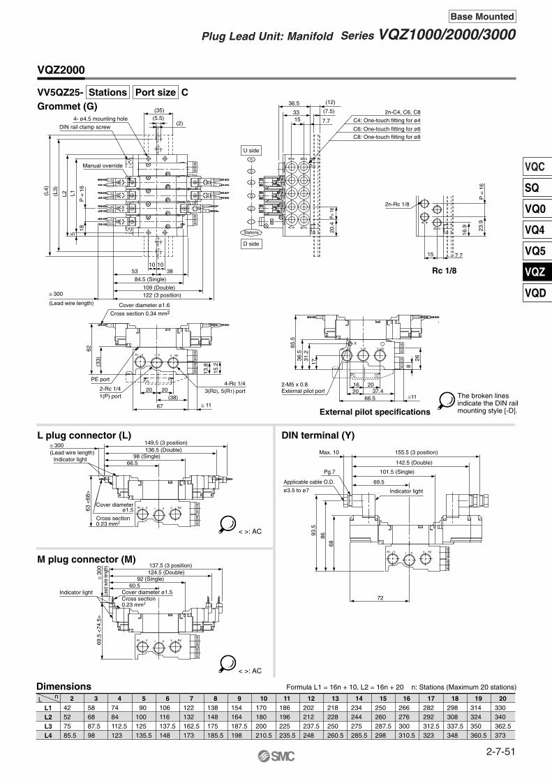
VQC
SQ
VQ0
VQ4
VQ5
VQZ
VQD
2n-C4, C6, C8
VQZ2000
L plug connector (L)
M plug connector (M)
L1L2L3L4
L n 242 52 75 85.5
358 68 87.598
47484112.5123
5 90100 125 135.5
6106 116 137.5148
7122 132 162.5173
8138 148 175 185.5
9154 164 187.5198
10170 180 200 210.5
11186 196 225 235.5
12202 212 237.5248
13218 228 250 260.5
14234 244 275 285.5
15250 260 287.5298
16266 276 300 310.5
17282 292 312.5323
18298 308 337.5348
19314 324 350 360.5
20330 340 362.5373
DIN terminal (Y)
R1 R2
R1 R2
C8: One-touch fitting for ø8C6: One-touch fitting for ø6
C4: One-touch fitting for ø415 7.7
33 (7.5)36.5 (12)
U side
n
5
4
3
2
1
D side
Stations
P= 1
620
.4
2n-Rc 1/8
P =
16
23.9
16.9
15 7.7
SMC
Cover diameter ø1.6
Cross section 0.34 mm2
(33)
62
2-Rc 1/41(P) port
PE port4-Rc 1/4
3(R2), 5(R1) port
(2)
(35)(5.5)4- ø4.5 mounting hole
DIN rail clamp screw
18
L1L2(L3)
(L4)
5
Manual override
P =
16
84.5 (Single)
109 (Double)122 (3 position)≅ 300
(Lead wire length)
53 3810 10
Indicator light
Applicable cable O.D.
ø3.5 to ø7
Pg.7
69.5
101.5 (Single)
142.5 (Double)
155.5 (3 position)Max. 10
93.5
86
68
20 20(38)
67 ≅ 11
72
5 31 P
Dimensions Formula L1 = 16n + 10, L2 = 16n + 20 n: Stations (Maximum 20 stations)
VV5QZ25- Stations Port size CGrommet (G)
A 4 B 2
A 4 B 2
5 1 P 3
Rc 1/8
15.2
13.8
External pilot specifications
37.466.5 ≅11
2016 20
65.5
36.5
31.2
17
2-M5 x 0.8External pilot port
A 4
B 2
26
8
X
R1 R25 1 P 3
(Lead wire length)
(Lea
d wi
re le
ngth
)
Cross section 0.23 mm2
Cover diameterø1.5
Cross section 0.23 mm2
Cover diameter ø1.5
R1 5 1 P 3 R2
R1 5 1 P 3 R2
Indicator light
Indicator light
69.5
<74
.5>
≅ 30
0
≅ 300
66.5
60.5
98 (Single)136.5 (Double)149.5 (3 position)
63 <
68>
92 (Single)124.5 (Double)137.5 (3 position)
< >: AC
< >: AC
The broken linesindicate the DIN railmounting style [-D].
2-7-51
Series VQZ1000/2000/3000Plug Lead Unit: Manifold
Base Mounted

2n-C6, C8, C10
L1L2L3L4
L n 2 50 72 100 110.5
3 70 92 112.5123
4 90 112 137.5148
5110 132 162.5173
6130 152 175 185.5
7150 172 200 210.5
8170 192 212.5223
9190 212 237.5248
10210 232 262.5273
11230 252 275 285.5
12250 272 300 310.5
13270 292 312.5323
14290 312 337.5348
15310 332 362.5373
16330 352 375 385.5
17350 372 400 410.5
18370 392 412.5423
19390 412 437.5448
20410 432 462.5473
L plug connector (L) DIN terminal (Y)
Dimensions: VQZ3000
M plug connector (M)
SM
C
SM
CS
MC
SM
C
SM
C
SM
C
SM
C
SM
C
R2R1
R2R1
4- ø4.5 mounting holeDIN rail clamp screw
(35)
(5.5)
L1L2(L3)
(L4)
11.511.557.5 42
95 (Single)
116.5 (Double)
130 (3 position)≅300(Lead wire length)
Manual override
Cover diameter ø1.6Cross section 0.34 mm2
2-Rc 3/81(P) port
PE port
4-Rc 1/43(R2), 5(R1) port
2-M5 x 0.8 external pilot port(Only external pilot port (R))
21 2126
(42)
73 ≅11
49
41
19.5
(12)(7.5)
26P
= 2
0(1
2)71
(41) 37
19.1
20.5
69
163.5 (3 position)
150 (Double)
111.5 (Single)
74.5
Max. 10
Pg.7
Applicable cable O.D.ø3.5 to ø7
76.5
100.
593
75
Indicator light
C10: One-touch fitting for ø10C8: One-touch fitting for ø8C6: One-touch fitting for ø6U side
n
5
4
3
2
1
D side
Stations
P= 2
022
.9P=
20
19.2
26.6
19.5 9.4
2n-Rc 1/4
11
1 P5 3
1 P5 3
A 4
B 2
9.4
VV5QZ35- Stations Port size CGrommet (G)
Dimensions Formula L1 = 20n + 10, L2 = 20n + 32 n: Stations (Maximum 20 stations)
A 4 B 2
Rc 1/4A 4 B 2
(Lead wire length)
(Lea
d w
ire le
ngth
)
Cross section 0.23 mm2Cover diameter ø1.5
Cross section 0.23 mm2
Cover diameter ø1.5
R235R1P1
R235R1P1
Indicator light
Indicator light
76.5
<81
.5>
≅ 300
69.5
<74
.5>
≅ 30
0
71108.5 (Single)
144 (Double)157 (3 position)
65
102.5 (Single)132 (Double)
145 (3 position)
< >: AC
< >: AC
The broken lines indicate the DIN railmounting style [-D].
2-7-52
Series VQZ1000/2000/3000Base Mounted

VQC
SQ
VQ0
VQ4
VQ5
VQZ
VQD
Manifold Option
Blanking plate assemblyVVQZ1000-10A-5 (VQZ1000)VVQZ2000-10A-5 (VQZ2000)VVQZ3000-10A-5 (VQZ3000)
Individual SUP spacerVVQZ1000-P-5-M5 (VQZ1000)VVQZ2000-P-5-01 (VQZ2000)VVQZ3000-P-5-02 (VQZ3000)
Individual EXH spacerVVQZ1000-R-5-M5 (VQZ1000)VVQZ2000-R-5-01 (VQZ2000)VVQZ3000-R-5-02 (VQZ3000)
Port plugVVQZ1000-CP (VQZ1000)VVQZ2000-CP (VQZ2000)VVQZ3000-CP (VQZ3000)
Throttle valve spacer (For VQZ2000 only)VVQZ2000-20A-5
74.5
39.5
B
C
D
A
M5: VQZ1000Rc 1/8: VQZ2000Rc 1/4: VQZ3000
M5: VQZ1000Rc 1/8: VQZ2000Rc 1/4: VQZ3000
Dimensions
VQZ1000VQZ2000VQZ3000
A B293341
354352
C405263
D678193
Note) For grommet
Note)
Dimensions
VQZ1000VQZ2000VQZ3000
A B293341
354352
C405263
D678193
Note) For grommet
Note)
B
C
D
A
It is used by attaching on the manifold block for being prepared for removing a valve for maintenance reasons or planning to mount a spare valve, etc.
Mount a throttle valve spacer between manifold base and valve, and thus making it possible to control cylinder speed by meter-out.
Supply port can be installed individually by mounting an individual supply spacer onto the manifold block. It’s used for such cases that the different pressure should be supplied into each valve, etc.
Exhaust port can be installed individually by mounting an individual exhaust spacer on to the manifold block. It’s used for such cases that the valve exhaust is likely to affect other stations due to circuit, etc.
Used to block a cylinder port when changing 5 port valves into 3 port valves, etc.
SM
C
SM
CS
MC
SM
C
SM
C
SM
C
SM
C
SM
C
2-7-53
Series VQZ1000/2000/3000Plug Lead Unit: Manifold
Base Mounted

Manifold Option
Silencer(For Manifold EXH port)
Name plate [-N] (For VQZ2000 and 3000 only)VVQZ2000-N5- Stations (VQZ2000)VVQZ3000-N5- Stations (VQZ3000)
DIN railAXT100-DR-�
∗ As for �, enter the number from the DIN rail dimensions table. For L dimension, refer to the dimensions of each manifold.
Blanking plugKQP-23-X19KQP-04-X19KQP-06-X19KQP-08-X19KQP-10-X19
Color: WhiteKQP-23-X19KQP-04-X19KQP-06-X19KQP-08-X19KQP-10-X19
Dimensions
3.2468
10
Applicable fittingssize ød Model
16 16 18 20.522
31.532 35 39 43
3.2 6 8 10 12
A L D
Silencer is installed in the EXH port.
VQZ1000VQZ2000VQZ3000
AN110-01AN200-02AN200-02
Silencer P/NModel
40510.5
39498
38485.5
37473
36460.5
35448
34435.5
33423
32410.5
31398
30385.5
29373
28360.5
27348
26335.5
25323
24310.5
23298
22285.5
21273
No.L dimension
20260.5
19248
18235.5
17223
16210.5
15198
14185.5
13173
12160.5
11148
10135.5
9123
8110.5
798
685.5
573
460.5
348
235.5
123
No.L dimension
L Dimension
L12.5
(Pitch)5.25
1.25
5.5
7.5
2535
LA
øD
38
ø13
63
ø22
L = 12.5n + 10.5
AN200-02AN110-01
It is a transparent resin plate for placing a label that indicates solenoid valve function, etc. Insert it into the groove on the side of the end plate and bend it as shown in the figure.• To order a manifold with nameplate already attached, insert “N” at
the end of the manifold number.
∗ 4 clips are attached for name plate mounting.
Each manifold can be mounted on a DIN rail.Order it by indicating an option symbol for DIN rail mounting style, -D.The DIN rail is approximately 30 mm longer than the length of manifold.
2-7-54
Series VQZ1000/2000/3000Base Mounted
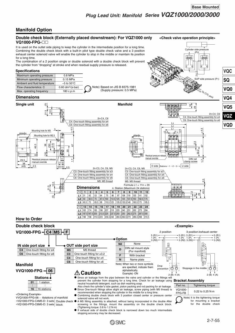
VQC
SQ
VQ0
VQ4
VQ5
VQZ
VQD
Manifold Option
Double check block (Externally placed downstream): For VQZ1000 onlyVQ1000-FPG-��
SpecificationsMaximum operating pressureMinimum operating pressureAmbient and fluid temperatureFlow characteristics: CMax. operating frequency
0.8 MPa0.15 MPa–5 to 50°C
0.60 dm3/(s·bar)180 c.p.m
<Check valve operation principle>
Dimensions
Single unit Manifold
L1L2L3
131 50 60.5
242 62.573
353 75 85.5
464 87.598
5 75 100 110.5
6 86 112.5123
7 97 125 135.5
8108 125 135.5
9119 137.5148
10130 150 160.5
11141 162.5173
12152 175 185.5
Ln
nL
L1L2L3
13163 187.5198
14174187.5198
15185 200 210.5
16196 212.5223
17207 225 235.5
18218 237.5248
19229 250 260.5
20240 250 260.5
21251 262.5273
22262 275 285.5
23273 287.5298
24284 300 310.5
DimensionsFormula L1 = 11n + 20
n: Station (Maximum 24 stations)
How to Order
Double check block
IN side port size OUT side port size
Option
C4C6
One-touch fitting for ø4One-touch fitting for ø6
M5C3C4C6
M5 threadOne-touch fitting for ø3.2One-touch fitting for ø4One-touch fitting for ø6
None
DIN rail mount style(For manifold)
With bracket
Name plate
Nil
<Example>
Bracket Assembly
VVQ1000-FPG 06
Stations01
16
1 station
16 stations
F
D
N
Tightening torque
0.22 to 0.25 N·m
Part no.
VQ1000-FPG-FB
C6: One-touch fitting assembly for ø6
2n-C4, C6C4: One-touch fitting assembly for ø4
21.5
(5)
10.5
≅ 4.
567
1.7
33
Residual pressure releasemanual override
Mounting hole for M2.5
Mounting hole for M3
(22.5) 0.5
(17.5)
11
46.5
8
(43) 2.538
29.5
C6: One-touch fitting assembly for ø6
2n-C3, C4, C6, M5C3: One-touch fitting assembly for ø3C4: One-touch fitting assembly for ø4
M5: M5 thread
21.5 10
.5(5
)
29
C6: One-touch fitting assembly for ø6
2n-C4, C6C4: One-touch fitting assembly for ø4
18
P = 1115.5L1L2L3
32.2
5.5
671.
7≅
4.5
U sideD side Stations 1 2 3 n
Residual pressure releasemanual override
C6: One-touch fitting assembly for ø6
2n-C3, C4, C6, M5C3: One-touch fitting assembly for ø3C4: One-touch fitting assembly for ø4
M5: M5 thread
7.5
18
29
45.5
2.5
38(1
4)
(30)
(3.5
)
DIN rail clamp screw
Manifold
5 (R1) 1 (P) 3 (R2)
5 (R1) 1 (P) 3 (R2)
5 (R1) 1 (P) 3 (R2)
5 (R1) 1 (P) 3 (R2)
4 (A) 2 (B) 4 (A) 2 (B)
Dropprevention
2 position 3 position/exhaust center
Stoppage in the middle
Cylinder side pressure(P2)
SUP side pressure (P1)
3
VQ1000-FPG C4 M5 F
It is used on the outlet side piping to keep the cylinder in the intermediate position for a long time. Combining the double check block with a built-in pilot type double check valve and a 3 position exhaust center solenoid valve will enable the cylinder to stop in the middle or maintain its position for a long time.The combination of a 2 position single or double solenoid with a double check block will prevent the cylinder from “dropping” at stroke end when residual supply pressure is released.
Note) When two or more symbols are specified, indicate them alphabetically.
Example) -DNCaution� Since air leakage from the pipe between the valve and cylinder or the fittings will
prevent the cylinder from stopping for a long time. Check for air leakage using neutral household detergent, such as dish washing soap. Also check the cylinder’s tube gasket, piston packing and rod packing for air leakage.
� Since One-touch fittings allow slight air leakage, screw piping (with M5 thread) is recommended when stopping the cylinder in the middle for a long time.
� Combining double check block with 3 position closed center or pressure center solenoid valve will not work.
� A M5 fitting assembly is attached, without being incorporated in the double After screwing in the fittings, mount the assembly on the double check block. (Tightening torque: 0.8 to 1.2 N·m)
� If exhaust side of double check block is narrowed down too much intermediate stopping accuracy may be decreased.
<Ordering Example>VVQ1000-FPG-06···· 6stations of manifold∗VQ1000-FPG-C4M5-D: 3 sets∗VQ1000-FPG-C6M5-D: 3 sets
Double checkblock
······
Note) It is the tightening torque for mounting a bracket for the double check
To CYL port
ININ
T UO T UO
MSC
MSC
Note) Based on JIS B 8375-1981(Supply pressure: 0.5 MPa)
2-7-55
Series VQZ1000/2000/3000Plug Lead Unit: Manifold
Base Mounted

4 4 4
2 2 2A A A
B B B
444
222AAA
BBB
4
2A
B
4
2A
B
Manifold Option
Double check block (Externally placed downstream): For VQZ2000/3000 onlyVQ2000-FPG-��-�
SpecificationsMaximum operating pressureMinimum operating pressureAmbient and fluid temperatureFlow characteristics: CMax. operating frequency
0.8 MPa0.15 MPa–5 to 50°C
3.0 dm3/(s·bar)180 c.p.m
<Check valve operation principle>
Dimensions
Single unit Manifold
L1L2L3
146 75 85.5
268 87.598
3 90 112.5123
4112 137.5148
5134 162.5173
6156 175 185.5
7178 200 210.5
8200 225 235.5
10244 262.5273
11266 287.5298
12288 312.5323
Ln 13
310 337.5348
14332 362.5373
15354 375 385.5
16376 400 410.5
Dimensions Formula L1 = 22n + 24 n: Station
How to Order
Double check block
IN side port size OUT side port size
Option
0102C6C8
One-touch fitting for ø6One-touch fitting for ø8
0102C6C8
Rc 1/8Rc 1/4
One-touch fitting for ø6One-touch fitting for ø8
NoneWith bracket
DIN rail mount type(for manifold)Name plate
Nil
<Example>
VVQ2000-FPG 06
Stations01
16
1 station
16 stations
F
D
N
Manifold Dropprevention Stoppage
in the middle
Residual pressurerelease manual override
2-M4 mounting hole
2-Rc 1/8, 1/4, C6, C8C6: One-touch fitting assembly for ø6C8: One-touch fitting assembly for ø8
17.5
37.5
(1.5
)17
.537.5
(1.5
)
(59.5)58
20.5
39.5
22
(41.5)(33)
(5)
10.5
1.5
(≅ 9
.5)
6.5
(40)
69.558
4.5
IN
80(≅
9.5
)
C8: One-touch fitting assembly for ø8
2-Rc 1/8, 1/4, C6, C8C6: One-touch fitting assembly for ø6
7
2-M6 mounting hole
9222 250 260.5
Residual pressure releasemanual override
DIN rail clamp screw (≅
9.5
)
23 P = 22L1L2L3
25
45
IN IN IN
257.
5
(≅ 9
.5)
4565
.5
37.5
5.5
80
C8: One-touch fitting assembly for ø8
2-Rc1/8, 1/4, C6, C8C6: One-touch fitting assembly for ø6
(For
C6,
C8)
C8: One-touch fitting assembly for ø8
2-Rc 1/8, 1/4, C6, C8C6: One-touch fitting assembly for ø6
(For
C6,
C8)
(For
C6,
C8)
(For
C6,
C8)
Rc 1/8Rc 1/4
Connection threadsRc 1/8Rc 1/4
Proper tightening torque (N·m)7 to 9
12 to 14
Cylinder sidepressure (P2)
SUP side pressure (P1)
2 position 3 position/exhaust center
Bracket AssemblyTightening torque
0.8 to 1.0 N·m
Part no.
Note) It is the tightening torquefor mounting a bracketfor the perfect block.
VQ2000-FPG-FB
5 (R1) 1 (P) 3 (R2)
5 (R1) 1 (P) 3 (R2)
5 (R1) 1 (P) 3 (R2)
5 (R1) 1 (P) 3 (R2)
2 (B) 4 (A) 2 (B) 4 (A)
It is used on the outlet side piping to keep the cylinder in the intermediate position for a long time.Combining the double check block with a built-in pilot type double check valve and a 3 position exhaust center solenoid valve will enable the cylinder to stop in the middle or maintain its position for a long time.The combination of a 2 position single or double solenoid with a double check block will prevent the cylinder from “dropping” at stroke end when residual supply pressure is released.
U sideD side Stations 1 2 3 n
Note) When two or more symbols are specified, indicate them alphabetically. Example) -DN
� Since air leakage from the pipe between the valve and cylinder or the fittings will prevent the cylinder from stopping for a long time. Check for air leakage using neutral household detergent, such as dish washing soap. Also check the cylinder’s tube gasket, piston packing and rod packing for air leakage.
� Since One-touch fittings allow slight air leakage, screw piping is recommended when stopping the cylinder in the middle for a long time.
� Combining perfect block with 3 position closed center or pressure center solenoid valve will not work.
� When screwing the fittings in the double check block, proper tightening torque for screws is as shown at the right.
� Set the cylinder load so that the cylinder pressure will be within two times that of the supply pressure.
� If exhaust side of double check block is narrowed down too much, intermediate stopping accuracy will be decreased.
<Ordering Example>VVQ2000-FPG-06····6 stations manifold∗VQ2000-FPG-C6C6-D: 3 sets∗VQ2000-FPG-C8C8-D: 3 sets
Double checkblock
······
Caution
To CYL port
IN
IN
Note) Based on JIS B 8375-1981(Supply pressure: 0.5 MPa)
2-7-56
Series VQZ1000/2000/3000Base Mounted

VQC
SQ
VQ0
VQ4
VQ5
VQZ
VQD
Note) Order DIN rail separately.For DIN rail model number, refer to page 2-7-54.
Note) For the special voltages,please consult with SMC.
With light/surge voltage suppressorfor L, LO, M, MO
Compact Body Type with Speed Controller: For VQZ2000 Only
Flow Characteristics
Valve model
JIS Symbol
Series
VV5QZ25C CC4
2 VQZ2000
Manifold
Stations02
20
2 stations
20 stations
... ...
Manifold5 Base mounted
Compact body
Port size {4(A), 2(B) port}C3C4C601
One-touch fitting for ø3.2One-touch fitting for ø4One-touch fitting for ø6
Rc 1/8
Option
VQZ2 1 5 1 MSymbol
1234
2 position single2 position double3 position closed center3 position exhaust center
Body5 Base mounted
Seal01
Metal sealRubber seal
Throttle valve
SNoneWith
Nil
Coil voltage1234569
100 VAC (50/60 Hz)200 VAC (50/60 Hz)110 VAC (50/60 Hz)220 VAC (50/60 Hz) 24 VDC 12 VDC
Note)
Manual override
BNon-locking push type (Tool required)
Locking type (Tool required)Nil
Electrical entryGLLOMMO
Grommet (DC specifications)L plug connector with lead wire
L plug terminal without connectorM plug connector with lead wire
M plug terminal without connectorNote)
Note)
Note)
Note)
10
100
200
987654321 Fullyopen
Number of needle rotations (turns)
Flo
w r
ate
(l/m
in (
AN
R))
Note)
05
Specifications
Port sizeWithout sub-plate
Rc 1/8
SymbolNil01
C
Compact body
Port size {4(A), 2(B) port}
0.7 MPa
0.5 MPa
0.3 MPa
0.15 MPa
Nil Standard
High pressure(Metal seal only)
Low wattage type
K
Y
(1)
Symbol Specifications DC(1.0 W)
�
(1.0 W)�
(0.5 W)�
�(2)
—
—
AC
Function
Number ofsolenoids
Metal(Without speed controller)Rubber seal(Without speed controller)Rubber seal (With speed controller) Metal(Without speed controller)Rubber seal(Without speed controller)Rubber seal (With speed controller)Metal(Without speed controller)Rubber seal(Without speed controller)Rubber seal (With speed controller)
Single
Double
Closedcenter
Exhaust center
2 po
sitio
n3
posi
tion
Model
VQZ2150-�-C
VQZ2151-�-C
VQZ2151S-�-C
VQZ2250-�-C
VQZ2251-�-C
VQZ2251S-�-C
VQZ2350-�-C
VQZ2351-�-C
VQZ2351S-�-C
VQZ2450-�-C
VQZ2451-�l-C
VQZ2451S-�-C
0.74
1.2
1.2
0.74
1.2
1.2
0.47
0.53
0.59
0.50
0.53
0.53
0.19
0.17
0.13
0.19
0.17
0.13
0.23
0.42
0.33
0.29
0.42
0.34
0.17
0.26
0.27
0.17
0.26
0.27
0.11
0.15
0.15
0.12
0.15
0.13
0.63
1.0
0.40
0.63
1.0
0.40
0.41
0.62
0.35
0.65
1.1
0.42
0.19
0.20
0.25
0.19
0.20
0.25
0.28
0.31
0.28
0.13
0.16
0.35
0.16
0.24
0.10
0.16
0.24
0.10
0.10
0.16
0.09
0.15
0.24
0.10
12 or less
15 or less
15 or less
10 or less
15 or less
15 or less
20 or less
25 or less
25 or less
20 or less
25 or less
25 or less
15 or less
20 or less
20 or less
13 or less
20 or less
20 or less
26 or less
33 or less
33 or less
26 or less
33 or less
33 or less
29 or less
36 or less
36 or less
13 or less
20 or less
20 or less
40 or less
47 or less
47 or less
40 or less
47 or less
47 or less
Weight(g)
Flow characteristics
1 � 4/2 (P � A/B)
C [dm3/(s·bar)] b Cv C [dm3/(s·bar)] b Cv
4/2 � 5/3 (A/B � EA/EB)
Response time (ms) (1)
Standard:1W
ACHigh pressure:
1WLow wattage:
0.5 W
40
44
54
58
54
58
54
58
(2)
Sub-plate Part No.VQZ2000C-S-01
Blanking Plate AssemblyVVQZ2000C-10A-5
Note)
D
• Speed controllers are built into the valve body, making it easier to adjust cylinder speed.
• Needle valve is equipped with a retainer to prevent accidental needle loss.
(Single)
Note) The One-touch fittings on the compact manifold are pressed in and therefore cannot be changed out.
Nil
D
DO
None
DIN rail mounting style(With DIN rail in standard length)
DIN rail mounting style(Without DIN rail)
5
Note 1) Based on JIS B 8375-1981 (Value for supply pressure of 0.5 MPa, with light/surge voltage suppressor, when using clean air). Response time values will change depending on pressure and air quality. The values at the time of ON are given for double styles.
Note 2) Weight without sub-plate
Note 1) Valve with built-in speed controls is available on rubber seal models only.
Note 2) Since the body (of this type) is made compact, there is no interchangeability with the standard VQZ2000.
Note 3) Tightening torque of needle valve lock nut should not exceed 0.3 N·m.
Metal(Without speed controller)Rubber seal(Without speed controller)Rubber seal(With speed controller)
Note) Available with rubber seal valve only.
Other
Note 1) OptionNote 2) For power consumption of AC type, refer to page
2-7-37. Note 3) When two or more symbols are specified, indicate
them alphabetically.
IN
IN
2-7-57
Series VQZ1000/2000/3000Plug Lead Unit: Manifold
Base Mounted

Blanking plate assembly
Dimensions: VQZ2000
L plug connector (L) M plug connector (M)
L1L2L3L4
L n 243 52 75 85.5
359 68 87.598
4 75 84112.5123
5 91 100 125 135.5
6107 116 137.5148
7123 132 162.5173
8139 148 175 185.5
9155 164 187.5198
10171 180 200 210.5
11187 196 225 235.5
12203 212 237.5248
13219 228 250 260.5
14235 244 275 285.5
15251 260 287.5298
16267 276 300 310.5
17283 292 312.5323
18299 308 337.5348
19315 324 350 360.5
20331 340 362.5373
3 R
1 P
2- ø5.5 mounting hole11
(35)
(5.5)
VVQZ2000C-10A-5
18
L1L2(L3)
(L4)
P =
16
4.5
Manualoverride
1372 (Single)
107 (Double)116 (3 position)
0.5
Cover diameter ø1.6Cross section 0.34 mm2
(25)
≅ 30
0(L
ead
wire
leng
th)
48.5
2-Rc 1/81(P) port
2-Rc 1/83(R) port 23.4
45.5 ≅ 4
14.6
16
8.5
U side
n
D side
5
4
3
2
1
Stations
11.8 7.4
25 (7.5)33 (11)
C6: One-touch fitting for ø6C4: One-touch fitting for ø4
01: Rc1/82n-01, C4, C6
P=
1621
.7
14.3
P=
1621
.7
14.3
Rc 1/8
10.3 7.4
VV5QZ25C- Stations Port size CGrommet (G)
Dimensions Formula L1 = 16n + 11, L2 = 16n + 20 n: Stations (Maximum 20 stations)
A 4
B 2
A 4
B 2
A 4
B 2
≅ 30
045
.7
7.47.4
3112
3.53831
11.5 11.5M
AX
55
42.5
2214
.47.
215
7234.5 19
(Lea
d w
ire le
ngth
)
Throttle valve
EB
P
EB
4
35
2
1
5-Rc 1/8
2- ø3.4 mounting holeManual override
B
A
(Lea
d w
ire le
ngth
)
Cross section 0.2 mm2
3 R
1 P
Indicator light
73 (Single) <78>
62.5
≅ 30
0
108 (Double) <118>117.5 (3 position) <127.5>
Cover diameter ø1.4
(Lead wire length)
Cover diameterø1.4
Cross section 0.2 mm2
3 R
1 P
Indicator light 79.5 (Single) <84.5>121.5 (Double) <131.5 >131 (3 position) <141>≅ 300
56.5
< >: AC < >: AC
The broken lines indicate the DIN railmounting style [-D].
2-7-58
Series VQZ1000/2000/3000Base Mounted

VQC
SQ
VQ0
VQ4
VQ5
VQZ
VQD
One Side Solenoid (Latching solenoid)
Series
VQZ 5
L
LN
Latching double, Positive common specifications
Latching double, Negative common specifications
How to Order Latching Solenoid Valves
Type of actuation
1 2 5 0 L M
BodySeal
Port sizeElectrical entry (L, M only)
Coil voltage
Latching
Function (2)
123
VQZ1000VQZ2000VQZ3000
Cautions for Latching Use Manual OverrideThe manual override is on the pilot valve for latching solenoid valves.Besides, manual on the main body cannot be used.
Existing model One side solenoid (Latching solenoid)
Caution
Wiring
Latching solenoid (DC)
Latching solenoid (AC)
Sim
ultan
eous
ene
rgiza
tion
prot
ectio
n cir
cuit
SOL.
SOL.
A–(Set)
C+(COM)
B–(Reset)
A Set
B COM
C Reset
Positive common specifications Negative common specifications
SOL.A
SOL.B
(–)
(–)
COM (+)
SOL.A
SOL.B
(+)
(+)
COM (–)
Lead wire color
24 VDC
Black
Red
White
100 VAC110 VAC
(Yellow)
(Blue)
(Gray)
200 VAC220 VAC
[Yellow]
[Red]
[Gray]
Lead wire color
24 VDC
Red
Black
White
Double solenoid Double solenoid
Black, (Yellow), [Yellow]:A side solenoid (–)
Red, (Blue), [Red]: COM (+)
White (Gray) [Gray]: B side solenoid (–)
3 core cable x 24AWG
Red: A side solenoid (+)
Black: COM (–)
White: B side solenoid (+)
3 core cable x 24AWG
Manual override
Latching
Blanking
Manualoverride
Electrical CircuitLead wires are connected to the valve as shown below. Connect them with the power supply.
Caution
The standard 2 position double solenoid valve has two solenoids, one on each end of the valve body.The latching solenoid option (with self holding mechanism) functions in the same manner as a 2 position double solenoid but uses only one solenoid to do the job.
Specifications are same as standard except for the function.K (High pressure type) and Y (Low wattage type) are not available.
Note 1) • Set side in energized state: Lighting (Orange)• Reset side in energized state: Lighting (Green)• With miss-wiring preventing function (Stop diode)• With surge absorption function (ZNR/Surge absorption diode)
Note 2) Flow direction: P � A {A (set) side in energized state}Flow direction: A � R {B (reset) side in energized state}
Note 3) Negative common specifications is available.
• If the manual override is turned by 180° clockwise and the � mark is adjusted to A, then pushed in the direction of an arrow ( ), it will be locked in the set condition. (passage P � A)
• If the manual override is turned by 180° counterclockwise and the � mark is adjusted to B, then pushed in the direction of an arrow ( ), it will be back to the reset condition. (passage P � B).(It is in the reset state at the time of shipment.)
Do not apply excessive torque when turning the locking type manual override. (0.1 N·m or less)
1. Use a circuit in which the ON and OFF signals are not simultaneously energized.
2. Minimum energization time for self holding is 20 ms.3. Avoid using the latching solenoid valves in environment where
impacts or collisions (30/150 m/s2 or more) exist. Also, do not use in places where the strong magnetic fields are present.
4. Even though the armature in the solenoid of this valve is held on to B side, ON position (Reset), verify either A side, ON position or B side, ON position by energizing prior to use.
5. Please consult with SMC for extended energization applications.
Note) ( ): 100 V, 110 VAC[ ]: 200 V, 220 VAC
Note 1)
Note 2)
2-7-59
Series VQZ1000/2000/3000Plug Lead Unit: Manifold
Base Mounted

VQZ2150RExternal pilot specifications
How to Order Manifold
Series VQZOption
External Pilot Specifications
5M
VV5QZ25External pilotspecifications
How to Order Manifold
06C6C R
Pressure Specifications
–100 kPa to 0.7 MPa
Externalpilotpressurerange
VV5QZ15
Cylinder port
How to Order Manifold
Inch-size One-touch Fittings and Option Thread
08 N7 N
VQZ1000
02
Cylinderport
Symbol
Applicable tubing O.D.
VQZ2000
VQZ3000
N1 N3 N7 N9 N11
ø1/8" ø5/32" ø1/4" ø5/16"
� � � — —
— � � � —
— — � � �
NM
Mixed
�
�
�External pilot port
ø3/8"
M5 x 0.8
International Thread Standards Other than Rc
VQZ2151
Thread type(Cylinder port and1 (P), 3 (R2), 5 (R1) ports)
How to Order Valves
5M 02
Nil
N
T
F
Rc
NPT
NPTF
G
T
Dusttight/Low Jetproof Type (IP65)DIN terminal is available with Dusttight/Low jetproof (IP65) type.
VQZ3151IP65 compliant
How to Order Valves(Applicable to VQZ2000/3000 rubber sealwith the exception of the external pilot type)
5YZB 03
Nil
W
No (Standard)
Compliant
W
Note)
(1)
Note 1) Mixing One-touch fittings and thread types is impossible.Note 2) Matric sizes of One-touch fittings (C�) are also available.
Thread type(Cylinder port and 1(P), 3(R2), 5(R1) port)Nil
N
T
F
Rc
NPT
NPTF
G
T C
M5 01 02
M5 threads 1/8 thread
� — —
— � —
— — �
1/4 thread
Series
Operatingpressure range
Metalseal
Rubberseal
VQZ1000/2000/30002 position single 2 position double 3 position
0.1 to 0.7 MPa
0.15 to 0.7 MPa
Only VQZ3000, 3 position0.15 to 0.7 MPa
0.1 to 0.7 MPa 0.2 to 0.7 MPa
The external pilot specifications are used when the operating pressure is below the minimum operating pressure 0.1 to 0.2 MPa or when valve is used for a vacuum application.Order a valve by adding the external pilot specifications [R] to the part number.
Rc specifications are standard for all ports, however, NPT, NPTF and G are available for international markets. Add the appropriate symbol following the port size in the standard part number.
Note) The pilot exhaust of the IP65 valves is common with main valve exhaust.(The standard valve has an individual exhaust for the pilot valve.)
Base Mounted
Note)
Note) In the case of the high pressure type, upper limit of max. operating pressure and external pilot pressure range is 1 MPa.
Inch sizes of One-touch fittings and NPT, NPTF and G thread are available.
Note)
2-7-60

AXT661-14A- Lead wire lengthNil 300 mm
600 mm1000 mm2000 mm3000 mm5000 mm
610203050
<Plug connector assembly>
• Single
AXT661-13A-• Latching
VQ11<Pilot valve assembly>
Coil voltage100 VAC (50/60 Hz)200 VAC (50/60 Hz)110 VAC (50/60 Hz)220 VAC (50/60 Hz) 24 VDC 12 VDC
1234569
Note) For the special voltages,please consult with SMC.
Gasket and Screw Assembly Part no.
VQZ1000-GS-5
VQZ2000-GS-5
VQZ3000-GS-5
VQZ1000
VQZ2000
VQZ3000
VQZ1000
VQZ2000
VQZ3000
VVQ1000-50A-C3 VVQ1000-50A-C4
VVQ1000-51A-C4
VVQ1000-50A-C6
VVQ1000-51A-C6
VVQ2000-51A-C6
VVQ1000-51A-C8
VVQ2000-51A-C8 VVQ2000-51A-C10
C3 C4 C6 C8 C10Fitting size
Model
AXT661-13AN-• Latching
One-touch Fitting Assemnly (For cylinder port)
Note) Purchasing order is available in units of 10 pieces.
Note)
Series1 VQZ1000/2000/3000
0 Latching type
Series VQZReplacement Parts
Applicable model (length of screwsattached is different from each other.)
4
5
Nil VQZ2000/3000
A and B side of VQZ1000 single double solenoid typeA side of VQZ1000 3 position
B side of VQZ1000 3 position
DC positive common
DC (–COM)
AXT661-31A-• SingleFor 100 V, 110 VAC
AXT661-32A-• Latching
AXT661-34A-• SingleFor 200 V, 220 VAC
AXT661-35A-• Latching
Only connector andsockets (3 pcs.)
AXT661-12A
Sub-plateModel Sub-plate part no.
VQZ1000
VQZ2000
VQZ3000
VQZ1000-S-01
VQZ2000-S-
VQZ3000-S-
01 [Rc 1/8]02 [Rc 1/4]02 [Rc 1/4]03 [Rc 3/8]
Function
Nil Standard
High pressure(Metal seal only)
Low wattage type
Latching type
Negative common type
K
Y
L
N
(1)
(3)
(4)
Symbol Specifications DC(1.0 W)
�
(1.0 W)�
(0.5 W)�
�
�
�
�
—
—
—
AC
(1.0 W)
1 5 G
Electrical entry
Grommet (DC specifications)L plug connector with lead wire
L plug terminal without connectorM plug connector with lead wire
M plug terminal without connectorDIN terminal
DIN terminal without connectorDIN terminal with light/surge voltage suppressor
DIN terminal with surge voltage suppressorDIN terminal with surge voltage suppressor, without connector
G L LOM MOY
YOYZYS
YOS
Note) DIN is applicable to VQZ2000/3000.
Light/Surgevoltage suppressor
None
Yes
None
YesYes (W/o indicator light)Yes (W/o indicator light)
Note)
Note)
Note)
Note)
Note)
Electrical entrySymbol
Standard wire length of valve with plug connector is 300 mm.When requiring valve with 600 mm length lead wire specify the model number of valve without plug connector and plug connector assembly.
Note ) Above part number consists of 10 units. Each unit has one gasket and two screws.Purchasing order is available in units of 10 pieces.
OptionWhen two or more symbols are specified, indicate them alphabetically.K (High pressure) and Y (Low wattage) are not available.Electrical entry: L/M plug connector only.Applicable to latching type.
Note 1)Note 2)
Note 3)
Note 4)
Other
Base Mounted
2-7-61
VQC
SQ
VQ0
VQ4
VQ5
VQZ
VQD

2-7-62


![Metal Seal Rubber Seal 0.9 W [Option] SV SYJ (Standard ... · PDF fileSMC life test conditions. 3 port valve 5 port valve Port plug Body ported Base mounted Fitting assembly Clip Clip](https://img.dokumen.tips/doc/110x75/5ab440e87f8b9a2f438b5bda/metal-seal-rubber-seal-09-w-option-sv-syj-standard-life-test-conditions.jpg)