Embed Size (px)
Citation preview
International Journal of Civil Engineering and Technology (IJCIET), ISSN 0976 – 6308(Print),
ISSN 0976 – 6316(Online) Volume 1, Number 1, May - June (2010), © IAEME
27
DYNAMIC RESPONSE OF ELEVATED LIQUID STORAGE
ELASTIC TANKS WITH BAFFLE
Damodar Maity
Associate Professor
Department of Civil Engineering
IIT Kharagpur, India
E-Mail: [email protected]
C. Naveen Raj
Department of Civil Engineering
IIT Guwahati, India
Indrani Gogoi
Associate Professor
Department of Civil Engineering
NITK Surathkal, India
ABSTRACT
The dynamic response of elevated baffled liquid storage tanks, including the
hydrodynamic interaction, is presented in this paper. Both the tank and fluid are
discretized by finite elements. The tank wall and baffle are made of elastic, isotropic
material. The liquid in the tank is considered as water. The equation of the liquid motion
is expressed in terms of pressure by neglecting the viscosity and nonlinear term of the
Navier-Strokes equation. The fluid is modeled with twenty seven node solid (3-D)
elements whereas the elastic tank wall and its baffle are modeled with nine node (2-D)
shell elements using ADINA–FSI, a multi-physics simulation program. The response of
the coupled system is obtained considering fluid structure interaction effects.
Hydrodynamic pressure generated in the fluid-structure interface and the displacement of
the tank wall is evaluated. A parametric study has been carried out to study the
effectiveness of a baffle for damping liquid oscillations in order to evaluate efficient
baffle configuration in an elevated tank.
International Journal of Civil Engineering
and Technology (IJCIET), ISSN 0976 – 6308(Print)
ISSN 0976 – 6316(Online) Volume 1
Number 1, May - June (2010), pp. 27-45
© IAEME, http://www.iaeme.com/ijciet.html
IJCIET
© I A E M E

International Journal of Civil Engineering and Technology (IJCIET), ISSN 0976 – 6308(Print),
ISSN 0976 – 6316(Online) Volume 1, Number 1, May - June (2010), © IAEME
28
Key words: Elevated tank; baffle; fluid-structure interaction; hydrodynamic pressure;
seismic response
1. INTRODUCTION
In the recent years there has been an upsurge of unrest in the safety of all
structures, components and facilities that can produce both primary and secondary health
hazards in the event of an earthquake. The structural integrity of liquid operational and
liquid retaining structures is one of the prime concerns. Liquid storage tanks are very
important components of industrial and agricultural facilities used for storing toxic or
inflammable liquids and water respectively. Observations from available field reports on
the structural performance of tanks during recent earthquakes indicate that the steel tanks,
rather than concrete tanks, are more susceptible to damage and eventual collapse
(Hamdan 2000). Failure of tanks and their accessories is not only limited to the
immediate danger to nearby human lives, but also to a large extent leads to serious
consequences and long-term environmental damages.
Unlike buildings, predicting seismic behavior of liquid containing tanks are (i)
affected by hydrodynamic force on tank walls and base exerted by liquid during seismic
excitation and (ii) liquid containing tanks are less ductile and have less redundancy. In
big cities, sometimes swimming pools are constructed on the terrace of the buildings,
which may disturb the structural integrity as a whole during the earthquake, if
hydrodynamic pressure is not taken into account properly while designing the structural
system. Heavy damages were caused to liquid storage tanks especially elevated tanks by
strong earthquakes such as Niigata in 1964, Alaska in 1964 and Parkfield in 1966. A
review of seismic codes on liquid containing tanks carried out by Jaiswal et al. (2007)
concludes that all the codes design for higher seismic force for liquid containing tank as
they possess low ductility and redundancy. A lower value of response modification factor
is prescribed as compared to a building system. However, there is a large variation in
assigning of response modification factor for different types of tanks.
When a tank like container, partly filled with liquid is excited by external forces,
sloshing takes place. Sloshing is the term used to describe the motion of a liquid in a
partially filled tank. The hydrodynamic pressure is developed due to the liquid movement
International Journal of Civil Engineering and Technology (IJCIET), ISSN 0976 – 6308(Print),
ISSN 0976 – 6316(Online) Volume 1, Number 1, May - June (2010), © IAEME
29
and the pressure is exerted on the tank wall. The tank wall should therefore be strong
enough to withstand these hydrodynamic forces in addition to hydrostatic pressure. An
additional structural member called baffle can be provided to control sloshing. For ease
of installation, a disk-type baffle with inner hole is being widely used for liquid storage
tanks.
Both experimental and theoretical studies related to the vibration of liquid in a
stored container have been reported in the literature. A numerical investigation was
carried out by Haroun and Tayel (1985) on partly filled axi-symmetric tanks in which the
shell was modeled by finite elements and liquid region treated analytically. Natural
frequencies and mode shapes were evaluated. Hwang (1989) studied the dynamic
response of liquid storage tank during to earthquake by combining boundary element
method and finite element method. The tank wall 3 and the fluid domain were treated as
two substructures of the total system. The boundary element method was used to find the
hydrodynamic forces associated with small amplitude excitations.
A baffle is a supplementary structural member, which supplies a sort of passive
control during earthquake motion. Baffle has been introduced recently with the objective
of improving the seismic safety and reducing the risk of damage or failure of thin walled
cylindrical liquid storage tanks. The effects of a rigid baffle on the seismic response of
liquid in a rigid cylindrical tank was studied by Gedikli and Erguven (1999). The
parametric eigen characteristics of baffled cylindrical liquid storage tank was investigated
by Cho et. al. (2002) with the coupled structural acoustic finite element method. Biswal
et al. (2004) demonstrated coupled formulation for the free vibration analysis of liquid-
filled cylindrical tank - baffle system that can be used to compute the low frequencies
associated with liquid sloshing modes and high frequencies associated with the coupled
vibration modes. Maity et al. (2009) showed the effective location of baffle and its
dimension to obtain minimum response of the tank-water coupled system under seismic
excitations. Eswaran et al. (2009) investigated the effect of ring baffles on liquid sloshing
for partially filled cubic tank. The effect of various factors like depth of liquid, tank
geometry, the amplitude and nature of the tank motions on sloshing severity were
studied. The results obtained were further used to verify the effectiveness of numerical
simulation technique.

International Journal of Civil Engineering and Technology (IJCIET), ISSN 0976 – 6308(Print),
ISSN 0976 – 6316(Online) Volume 1, Number 1, May - June (2010), © IAEME
30
Following the development of FEA tools used for structural analysis, significant
advances in the fluid analysis have empowered the fluid analysts with a number of
commercial CFD codes that are robust and efficient for general fluid flow analysis
(Freitas 1995, Bathe et al. 1995, Zhang et al 2003, Bathe and Zhang 2004). The
Lagrangian-Eulerian formulation in the fluid system can efficiently be solved by using
ADINA–FSI, a multi-physics simulation program (Andersson and Andersson 1997,
Bathe et al 1999, Wang 1999, Panigrahy et al 2009). Moreover, recent efforts have
resulted in a very smart design of the user-interface such as providing effective ways to
generate meshes, set modeling assumptions, and state boundary conditions.
The present study focuses on the study on the response of elevated liquid storage
tank with the presence of baffle. The steel tank and the water domain are discretized by
finite elements. The tank material is considered as isotropic and elastic. The tank wall and
baffle are discretized by nine node shell elements. The liquid in the present analysis is
water and is assumed to be inviscid, linearly compressible and is under small amplitude
of excitation. Pressure degree of freedom is taken for fluid element. The fluid domain is
modeled using twenty seven noded elements. The fluid and the tank domain are treated as
two sub-structures coupled through their interface by an iterative scheme. The dynamic
response of elevated baffled liquid storage tank has been studied extensively to study the
influence of baffle on the response control of the coupled system.
2. MATHEMATICAL MODELING
The results of any dynamic analysis depend on the approximation involved in the
development of the mathematical models for the systems. It is not possible always to obtain a
closed form analytical solution for many engineering problems. With the advent of faster
generation computers, one of the most powerful numerical techniques that have been
developed in the realm of engineering analysis is the finite element method. The method,
being general, can be used for the analysis of liquids and solids of complex shapes and
complicated boundary conditions. In the present study, nine noded shell elements for the tank
wall and twenty seven noded 3D solid elements for the liquid are chosen (Fig. 1 and Fig. 2)
for the analysis. Three noded 3-d frame elements (Fig. 1) have been considered to model the
steel column and bracing of the elevated tank.

International Journal of Civil Engineering and Technology (IJCIET), ISSN 0976 – 6308(Print),
ISSN 0976 – 6316(Online) Volume 1, Number 1, May - June (2010), © IAEME
31
2.1 Mathematical Modeling of Liquid:
Using the principles of classical mechanics, the motion of continuous fluid
medium in a fixed Cartesian coordinate frame of reference can be expressed using the
Eulerian approach in terms of mass, momentum and energy as
The characteristic properties of the medium are considered as functions of time
and space in the frame of reference. In the above equations, t is the time, ρ is the density,
v is the velocity vector, fB is the body force vector of the fluid medium, τ is the stress
tensor and given by
τ = (− p +λ�.v)I + 2µe (4)
Here, p is hydrodynamic pressure distribution in excess of the hydrostatic
pressure; µ and λ are the two coefficients of fluid viscosity. The heat flux q and the
specific rate of heat generation qB are neglected in the present problem. E is the specific
total energy and is defined as
Here b is the specific kinetic energy and e is the velocity strain tensor, which may
be expressed as:
The body forces included in fB (Eq. 2-3) is the gravitational force which may be
written as
where g is the gravitational acceleration vector. Since the flows are basically
incompressible, a constant density (ρ) throughout the governing equations has been

International Journal of Civil Engineering and Technology (IJCIET), ISSN 0976 – 6308(Print),
ISSN 0976 – 6316(Online) Volume 1, Number 1, May - June (2010), © IAEME
32
assumed except in the continuity equation. The non-conservative form of the continuity
equation in slightly compressible flows becomes
where, ρm is the fluid density with the compressibility and ρ is the density at p = 0 and
thus can be relating as:
Here, k is the bulk modulus of elasticity of the fluid. Thus for the small amplitude
of motion and with the absence of body force, the continuity and momentum equations of
the fluid can be simplified to:
2.2 Mathematical Modeling of Solid:
Material for solid parts is assumed to be isotropic elastic with small displacements
and strains. The tank wall and its baffle (Figure 1) are modeled using the standard
Lagrangian formulation for displacement and strain, which is as follows:
where, is the ijth components of the Cauchy stress tensor for (i, j = 1, 2, 3), is
the displacement component in the co-ordinate i direction and is the mass density.
2.3 Modeling of FSI Problems:
In case of fluid-structure interaction (FSI) problems, fluid forces are applied on
the structure and the structural deformation changes the fluid domain. Difficulties arise in
the FSI analysis not only because of the non-linear governing equations for fluid; but also
because of description of the governing equations for fluid and structure in different
coordinates. The computational domain is divided into fluid and structural domain, where
International Journal of Civil Engineering and Technology (IJCIET), ISSN 0976 – 6308(Print),
ISSN 0976 – 6316(Online) Volume 1, Number 1, May - June (2010), © IAEME
33
a fluid model and a structural modelare defined respectively, through their material data,
boundary conditions etc. The interaction occurs along the interface of the two domains.
One can perform simulations and predict many physical phenomena when these two
models are coupled together. The coupling conditions at the fluid-structure interfaces are:
Here, f is the traction vector acting on the structure surface, and n is the unit vector normal to
the
interface. Using an Arbitrary-Lagrangian-Eulerian coordinate system (ALE) i.e., eqs. (10)-
(11)
for fluid; eq. (12) for solid and application of the boundary conditions eq. (13) to the discrete
finite element equations of the fluid and the structure, the finite element equations of the
coupled fluid-structure system can be expressed as
where, are the solution vectors of the coupled system. Xf and Xs are the fluid
and solid vectors defined at the fluid and solid nodes respectively. Ff and Fs are the finite
element equations corresponding to the fluid and structure model. The decoupled fluid
and solid equations can be represented by respectively.
3. RESULTS AND DISCUSSIONS
The types of problems addressed through this formulation are that of a rectangular
thin walled elevated water filled tank and is subjected to external excitations. The tank
wall is considered in this case to be elastic in nature.
3.1 Validation for empty tank without baffle
To validate the correctness of the developed models a benchmark problem has
been considered and results are compared with the results available in the literature. A
cylindrical ground supported circular steel tank of modulus of elasticity,

International Journal of Civil Engineering and Technology (IJCIET), ISSN 0976 – 6308(Print),
ISSN 0976 – 6316(Online) Volume 1, Number 1, May - June (2010), © IAEME
34
Poisson’s ratio, υ = 0.3 and mass density, has
been considered for analysis and compared with the results obtained by Haroun and
Tayel (1985). The thickness of tank wall and its radius is considered as 25.4 mm and
18.29 m respectively.
Figure 1 Finite element discretization of Elevated tank
Figure 2 Finite element discretization of fluid domain
Free vibration analysis of the above tank has been carried out to validate the
developed finite element model. The variations of natural frequencies with various
heights to radius ratio of the tank have been studied and the results are tabulated in Table
1 along with the results obtained from literature by Haroun and Tayel (1985). In Table 1,

International Journal of Civil Engineering and Technology (IJCIET), ISSN 0976 – 6308(Print),
ISSN 0976 – 6316(Online) Volume 1, Number 1, May - June (2010), © IAEME
35
H/R represents the ratio of height to radius of the tank. A convergence study has been
done to find the results with a desired level of accuracy. For example, in case of H/R =
0.67, the discretization has been taken as 5×40 in which the results are converging
sufficiently. The comparison of results at R = 18.29 m, show that the frequencies
obtained by the proposed model agree quite well with those obtained in literature.
Table 1 Variation of fundamental frequency of empty tank
3.2 Response of elevated tank
The dynamic analysis of elevated tank has been carried out to study the stability
of the developed modeling. The geometry and material properties of the tank are
considered as follows: Tank: length = 6 m, width = 6 m, height = 4 m, Thickness = 20
mm, column spacing = 4 m, column height = 15 m. The tank wall is made of steel having
the material properties of modulus of elasticity, Poisson’s ratio, υ
=0.3 and density . The mass density and velocity of sound in water
are assumed as and 1438.7 m/s respectively. The above dimensions and
material properties has been considered throughout the study unless it is mentioned.
The horizontal displacements of the elevated tank under different sinusoidal
excitation frequencies with unit amplitude of acceleration are plotted in Figures 3 to 5.
The frequencies under consideration are the fundamental natural frequency along with
some different frequencies. It is observed that the displacement is increasing continuously
(Figure 4) when the tank is excited at its natural frequency as expected. The first three
mode shapes of the elevated empty tank have been plotted in Figure 6.

International Journal of Civil Engineering and Technology (IJCIET), ISSN 0976 – 6308(Print),
ISSN 0976 – 6316(Online) Volume 1, Number 1, May - June (2010), © IAEME
36
Figure 3 Displacement at top of tank due to sinusoidal ground acceleration for f = 0.8 cps
Figure 4 Displacement at top of tank due to sinusoidal ground acceleration for f=2.134cps
Figure 5 Displacement at top of tank due to sinusoidal ground acceleration for f = 4 cps

International Journal of Civil Engineering and Technology (IJCIET), ISSN 0976 – 6308(Print),
ISSN 0976 – 6316(Online) Volume 1, Number 1, May - June (2010), © IAEME
37
(a) 1
st Mode (b) 2
nd Mode (c) 3
rd Mode
Figure 6 Mode shapes of elevated tank
3.3 Effect of baffle on elevated tank under sinusoidal acceleration
To study the effect of baffle on elevated tank, the baffle is located at mid height of
water level. The baffle location is arrived on the basis of previous work carried by Maity
et al (2009) at which substantial amount of response reduction is expected. The material
properties of the baffle are same as in case of tank wall. A sinusoidal ground acceleration
of frequency 6cps, is applied at the ground. The dynamic responses due to both horizontal
and vertical sinusoidal loadings are shown in Figures 7 to 10. It is observed that the
developed hydrodynamic pressures as well as the tank displacements are reducing due to
the presence of an elastic baffle.
The deformation pattern of the water filled baffled tank under horizontal
sinusoidal ground excitation at different time instant has been plotted in Figure 11. The
time period (T) of the excitation is taken as 0.1676 cps in this analysis. The deformation
patterns are plotted at time, t = 0, T/16, 2T/16, 3T/16 and 4T/16 secs respectively shows
the behaviour of the elevated tank. Figure 12 shows deformation of the same tank at
different time instant due to sinusoidal excitation in vertical direction.

International Journal of Civil Engineering and Technology (IJCIET), ISSN 0976 – 6308(Print),
ISSN 0976 – 6316(Online) Volume 1, Number 1, May - June (2010), © IAEME
38
Figure 7 Top displacement of the tank wall due to horizontal sinusoidal acceleration
Figure 8 Hydrodynamic pressure at the bottom of tank due to horizontal sinusoidal
acceleration
Figure 9 Top displacement of the tank wall due to vertical sinusoidal acceleration

International Journal of Civil Engineering and Technology (IJCIET), ISSN 0976 – 6308(Print),
ISSN 0976 – 6316(Online) Volume 1, Number 1, May - June (2010), © IAEME
39
Figure 10 Hydrodynamic pressures at the bottom of tank due to vertical sinusoidal
acceleration
(a) t = 0 sec. (b) t = T/16 sec. (c) t = 2T/16 sec. (d) t = 3T/16 sec. (e) t = 4T/16 sec
Figure 11 Deformation pattern at different time instant due to horizontal sinusoidal
excitation
(a) t = 0 sec. (b) t = T/16 sec. (c) t = 2T/16 sec. (d) t = 3T/16 sec. (e) t = 4T/16 sec.
Figure 12 Deformation pattern at different time instant due to vertical sinusoidal
excitation

International Journal of Civil Engineering and Technology (IJCIET), ISSN 0976 – 6308(Print),
ISSN 0976 – 6316(Online) Volume 1, Number 1, May - June (2010), © IAEME
40
3.3 Effect of baffle on elevated tank under seismic excitation
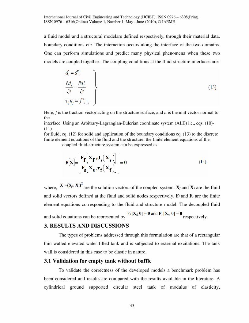
The seismic response of the same tank has been plotted in Figures 13 to Figure 16
to study the effectiveness of the baffle. Results presented are used to depict the
distinction between the response obtained with and without the presence of baffle under
horizontal and vertical El Centro (N-E) horizontal earthquake excitation. It is observed
that both the displacement and hydrodynamic pressure are well controlled if the baffle is
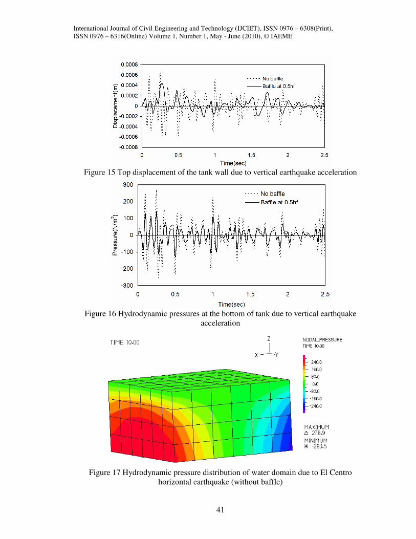
present in the water filled tank. Figures 17and 18 show the hydrodynamic pressure
distribution of fluid domain at a particular time instant (in this case 10 sec.) due to El
Centro horizontal earthquake excitation without and with the presence of baffle
respectively. It is observed by comparing above two figures that the magnitude of the
hydrodynamic pressure becomes considerably less if the baffle is present inside the water
tank. Same observations have been noticed in Figures 19 and 20 while the tank is
subjected to El Centro earthquake excitation in the vertical direction.
Figure 13 Top displacement of the tank wall due to horizontal earthquake acceleration
Figure 14 Hydrodynamic pressures at the bottom of tank due to horizontal earthquake
acceleration
International Journal of Civil Engineering and Technology (IJCIET), ISSN 0976 – 6308(Print),
ISSN 0976 – 6316(Online) Volume 1, Number 1, May - June (2010), © IAEME
41
Figure 15 Top displacement of the tank wall due to vertical earthquake acceleration
Figure 16 Hydrodynamic pressures at the bottom of tank due to vertical earthquake
acceleration
Figure 17 Hydrodynamic pressure distribution of water domain due to El Centro
horizontal earthquake (without baffle)

International Journal of Civil Engineering and Technology (IJCIET), ISSN 0976 – 6308(Print),
ISSN 0976 – 6316(Online) Volume 1, Number 1, May - June (2010), © IAEME
42
Figure 18 Hydrodynamic pressure distribution of water domain due to El Centro
horizontal earthquake (with baffle)
Figure 19 Hydrodynamic pressure distribution of water domain due to El Centro vertical
earthquake (without baffle)

International Journal of Civil Engineering and Technology (IJCIET), ISSN 0976 – 6308(Print),
ISSN 0976 – 6316(Online) Volume 1, Number 1, May - June (2010), © IAEME
43
Figure 20 Hydrodynamic pressure distribution of water domain due to El Centro vertical
earthquake (with baffle)
4. CONCLUSIONS
The objective of the present investigation is to gain an understanding of the
behavior of the coupled elevated baffled tank-water system. The FE model using ADINA
program is developed, in which a general time domain analysis of the coupled system is
carried out considering fluid-structure interaction effects. The displacements in the tank
and the pressure developed in the water domain are computed using the developed model
under external excitations. Study has been carried out under horizontal as well as vertical
seismic excitation to have a comparative response of the baffled tank-water system. The
fluid-structure interaction effects are achieved by indirect coupling of the two systems
viz., the elevated baffled tank and water domain. The elevated water tanks are, in general,
very susceptible to earthquakes. The parametric study reveals that the presence of baffle
in the elevated water tank reduces the dynamic response of the coupled system to a large
extent. The response results depict that baffles may be used effectively as controlling
devices for the control of tank displacements and hydrodynamic forces during earthquake
excitations.

International Journal of Civil Engineering and Technology (IJCIET), ISSN 0976 – 6308(Print),
ISSN 0976 – 6316(Online) Volume 1, Number 1, May - June (2010), © IAEME
44
REFERENCES
1. ADINA R & D, Inc., (2003), ADINA-F Theory and Modeling Guide, Report No.
ARD-03-9, June 2003
2. Andersson L, and Andersson P, (1997), "Some experiences in the use of ADINA
in the Swedish nuclear industry," Computers & Structures, Vol. 64, pp. 893-907
3. Bathe, K. J., (1996), “Simulation of Structural and Fluid Flow Response in
Engineering Practice,” Computer Modeling and Simulation in Engineering, Vol.
1, pp. 47-77
4. Bathe, K. J., Zhang, H., and Ji, S., (1999), “Finite Element Analysis of Fluid
Flows Fully Coupled with Structural Interactions,” Computers and Structures,
Vol. 72, pp. 1-16
5. Bathe, K. J., Zhang, H., and Wang, M.H., (1995), “Finite Element Analysis of
Incompressible and Compressible Fluid Flows with Free Surfaces and Structural
Interactions,” Computers & Structures, Vol. 56, No. 2/3, pp. 193-213
6. Bathe K. J., and Zhang H, (2004), "Finite element developments for general fluid
flows with structural interactions," International Journal for Numerical Methods
in Engineering, Vol. 60, pp. 213-232
7. Biswal, K. C., Bhattacharyya, S. K. and Sinha, P. K. (2004), “Dynamic response
analysis of a liquid-filled cylindrical tank with annular baffle”. Journal of Sound
and Vibration, Vol. 274, pp. 13-37
8. Cho, J. R., Lee, H. W. and Kim K. W. (2002), “Free vibration analysis of baffled
liquid storage tank by the structural-acoustic finite element formulation. Journal
of Sound and Vibration Vol. 258, pp. 847–866
9. Eswaran, M., Saha, U. K., and Maity, D. (2009), “Effect of baffles on a partially
filled cubic tank: Numerical simulation and experimental validation”, Computers
and Structures Vol. 87, pp.198–205
10. Hamdan, F. H., (2000), “Seismic behaviour of cylindrical steel liquid storage
tanks”, Journal of Constructional Steel Research, Vol. 53, pp. 307-333
11. Haroun, M. A., and Tayel, M. A. (1985), “Axisymmetrical vibrations of tanks-
Numerical”, Journal of Engineering Mechanics Vol. 111, pp. 346-358

International Journal of Civil Engineering and Technology (IJCIET), ISSN 0976 – 6308(Print),
ISSN 0976 – 6316(Online) Volume 1, Number 1, May - June (2010), © IAEME
45
12. Hwang, I. T., and Ting, K. (1989), “Boundary element method for fluid-structure
interaction problems in liquid storage tanks”, Journal of Pressure Vessel
Technology, Vol. 3, pp. 435- 440
13. Gedikli, A., and Erguven, M. E. (1999), “Seismic analysis of a liquid storage tank
with a baffle”, Journal of Sound and Vibration Vol. 223, pp. 141-155
14. Freitas, C. (1995), “Perspective: Selected Benchmarks from Commercial CFD
Codes,” ASME Journal of Fluids Engineering, Vol. 117, pp. 208-218
15. Jaiswal, O.R., Rai, D.C. and Jain, S.K. (2007), “Review of seismic Codes on
Liquid-Containing Tanks”, Earthquake Spectra, Vol.23 (1), pp.239-260.
16. Maity, D., Satya Narayana, T. and Saha, U. K. (2009), “Dynamic Response of
Liquid Storage Elastic Tanks with Baffle’, Journal of Structural Engineering,
Vol. 36, No. 3, pp. 172-181.
17. Panigrahy, P. K., Saha, U. K. and Maity, D. (2009), “Experimental Studies on
Sloshing Behaviour due to Horizontal Movement of Liquids in Baffled Tanks”
Journal of Ocean Engineering, Vol. 36, No. 3-4, pp. 213-222.
18. Wang, X. D. (1999), "Analytical and computational approaches for some fluid-
structure interaction analyses," Computers & Structures, Vol. 72, pp. 423-433.
19. Zhang H, Zhang XL, Ji SH, Guo YH, Ledezma G, Elabbasi N, and deCougny H
(2003), "Recent development of fluid-structure interaction capabilities in the
ADINA system" Computers & Structures, Vol. 81, pp. 1071-1085.