Embed Size (px)
Citation preview

8/12/2019 3 Design-for-Information-Processing-in-Living-Neuronal-Networks.pdf
http://slidepdf.com/reader/full/3-design-for-information-processing-in-living-neuronal-networkspdf 1/16
25
Copyright © 2013, IGI Global. Copying or distributing in print or electronic forms without written permission of IGI Global is prohibited.
Chapter 3
DOI: 10.4018/978-1-4666-4225-6.ch003
Design for InformationProcessing in LivingNeuronal Networks
ABSTRACT
A neurorobot is a model system for biological information processing with vital components and the
artificial peripheral system. As a central processing unit of the neurorobot, a dissociated culture system
possesses a simple and functional network comparing to a whole brain; thus, it is suitable for exploration
of spatiotemporal dynamics of electrical activity of a neuronal circuit. The behavior of the neurorobot is
determined by the response pattern of neuronal electrical activity evoked by a current stimulation from
outer world. “Certain premise rules” should be embedded in the relationship between spatiotemporal
activity of neurons and intended behavior. As a strategy for embedding premise rules, two ideas are pro-
posed. The first is “shaping,” by which a neuronal circuit is trained to deliver a desired output. Shaping
strategy presumes that meaningful behavior requires manipulation of the living neuronal network. The
second strategy is “coordinating.” A living neuronal circuit is regarded as the central processing unit
of the neurorobot. Instinctive behavior is provided as premise control rules, which are embedded into
the relationship between the living neuronal network and robot. The direction of self-tuning process of
neurons is not always suitable for desired behavior of the neurorobot, so the interface between neurons
and robot should be designed so as to make the direction of self-tuning process of the neuronal network
correspond with desired behavior of the robot. Details of these strategies and concrete designs of the
interface between neurons and robot are be introduced and discussed in this chapter.
1. INTRODUCTION
A neurorobot is a model system in which a liv-
ing neuronal circuit is electrically connected
to a robot body (Bakkum, 2004; Kudoh, 2007,
2011; Novellino, 2007). The neurorobot serves
as a simple model for reconnection of brain andperipherals and reconstruction of biological intel-
ligence. The neurorobot concept was pioneered
by Potter and colleagues in 2003, who developed
“Hybrot,” a contraction of hybrid robot (Bakkum,
2004). Hybrot is so to speak a kind of extension
Suguru N. Kudoh
Kwansei Gakuin University, Japan

8/12/2019 3 Design-for-Information-Processing-in-Living-Neuronal-Networks.pdf
http://slidepdf.com/reader/full/3-design-for-information-processing-in-living-neuronal-networkspdf 2/16
26
Design for Information Processing in Living Neuronal Networks
of “Animat” reported by the same group in 2001
(DeMarse, 2001), in which a living neuronal circuit
interacts with a computer-simulated environment.
Although Hybrot replaced the simulated envi-
ronment of Animat with a real robot body, both
designs shared a common purpose: to elucidate
mechanisms of biological intelligence, especially
self-organization process of the intelligence during
interactions between a neuronal network and the
environment. Because the robot body is a mediator
between neurons and environment, Hybrot exem-
plifies the field of “Embodied Cognitive Science,”
which emphasizes the critical roles of a body on
biological intelligence (Brooks, 1986; Pfeifer,
1999). Although the concept was foresighted,
Animat, which simply connects neurons and
the environment, could not deliver its intended
behavior. It appears that “certain premise rules”
should be embedded in the relationship between
spatiotemporal activity of neurons and intended
behavior—premise rules do not autonomously
emerge from random interactions.
As a strategy for embedding premise rules, two
ideas are proposed. The first is “shaping” (Chao,
2008), by which a neuronal circuit is trained to
deliver a desired output. This strategy requires a
supervisor to examine the output. The biological
analog of the supervisor is the reward system.
The second strategy is “coordinating” (Kudoh,
2007, 2011). A living neuronal circuit is regarded
as the central processing unit of the neurorobot.
No supervisor is assigned, and the neuronal circuit
is not manipulated by other components of the
neurorobot. The desired behavior is generated
by simple rules embedded in the connections
between the neurons and robot body. The differ-
ences between the two strategies will be discussed
later in this chapter.
To date, the characteristic features of biologi-
cal intelligence have been scarcely replicated by
artificial intelligence. The gap between artificial
intelligence and real life has been often attributed
to the frame problem and symbol grounding
problem. However, embodied cognitive science
offers appropriate solutions to these opt-expressed
problems. In the context of embodied cognitive
science, the premise rules for desired behavior are
embedded in the relationships between sensors and
actuators. The simple subsumption architecture of
this approach can be remarkably adaptable and
reliable in complex environments (Brooks, 1986).
A neurorobot is realization of embodiment cog-
nitive science by incorporating a living neuronal
circuit into robot system. Originally, a neurorobot
and its “small brain” constituted an effective
model of biological intelligence, with the robot
itself performing no useful work. Currently, it is
recognized as a model of biological intelligence,
especially in terms of embodied cognitive science.
In addition, the system can be used for testing
tube for such as regenerative neuromedicine and
Brain-Machine Interface (BMI). The neurorobot
system is simple and versatile enough to probe
related neuroengineering technologies such as
neuroelectrodes and BMI decoding algorithms.
This chapter introduces the concept of the
neurorobot system and its use in various technolo-
gies. Predicted future works are also discussed.
2. OUTLINE OF A NEUROROBOT
A neurorobot consists of three principal compo-
nents: a Living Neuronal Circuit (LNC), neuro-
device interface, and robot body.
A LNC uses a reconstructed semi-artificial
neuronal network in a dissociated culture system,
or a slice preparation of a brain (Bakkum, 2007). In
a broad sense, a local circuit in a whole living brain
can constitute the LNC of a neurorobot (Kawato,
2008); however, such configuration is generally
regarded as a BMI rather than a neurorobot model.
The interface includes hardware such as
electrodes, an amplifier, A/D converters, and a
computer to implement software such as programs
for decoding neuronal activity and stimulating

8/12/2019 3 Design-for-Information-Processing-in-Living-Neuronal-Networks.pdf
http://slidepdf.com/reader/full/3-design-for-information-processing-in-living-neuronal-networkspdf 3/16
27
Design for Information Processing in Living Neuronal Networks
the LNC. Interface software that connects the
neurons to the outer world may be divided into
several components, for example, an interfacing
unit for the I/O of LNC and a manipulating unit
for the robot. Most importantly, the robot body
requires sensors that receive environmental input
and actuators for manipulating the environment.
3. COMPONENTS OFA NEUROROBOT
3.1. Living Neuronal Network
As mentioned before, several LNC options are
available. In this section, I focus on dissociated
neuron cultures (Banker, 1977), which were
adopted in our own neurorobot system (Kudoh,
2001; Kiyohara, 2010) and in the first neurorobot
(DeMarse, 2001) proposed by the Potter group.
Brain tissues that are frequently used are those
of rat cortex and hippocampus. Large quantities of
cortical neurons are easily prepared because the
cortex covers a wide area of the brain, whereas
hippocampal culture is amongst the most widely
used and understood techniques. In living brain
tissue, neurons are connected in complex ways.
Prior to culturing, a rat brain is dissected and sliced,
and the neurons and surrounding supportable
glial cells are mildly dissociated by a digestive
enzyme such as papain or trypsin. Dissociated
neuronal cells are then seeded on a culture dish
precoated with adhesive materials such as electri-
cally charged polymers or adhesive proteins. We
adopted a modified conventional Banker’s method,
which is well known and extensively researched
(Banker, 1977).
When a Multielectrodes Array (MEA) is used
as an interface electrode, neuronal cells are directly
cultured on the MEA dish, enabling neurons to
contact to the electrodes (Gross, 1977; Pine, 1980;
Robinson, 1993; Oka, 1999).
Figure 1 shows rat hippocampal neurons and
glial cells cultured on an MEA dish. The number
of neurons is stable after several weeks of cultur-
ing (Wolters, 2004; Kiyohara, 2010).
3.2. Stimulation and RecordingSignals
In the neurorobot system, LNC electrical activ-
ity and stimulation are preferably achieved in a
noninvasive manner. Typical methods for detect-
ing neurorobot signals are extracellular potential
recordings or bioimaging (Jimbo, 1993).
These methods guarantee noninvasive multisite
measurements of network activity over long peri-
ods. MEA recording allows us to stimulate a LNC
as well as record its activity. This feature is critical
for completing closed-loop interactions. An actual
neuronal circuit cultured on MEA dish with an
extracellular potential multi-site recording system
is popular in the area of neurorobotics (DeMarse,
2001; Bakkum, 2008; Kudoh, 2007; Novellino,
2007). Major recording and stimulating systems
are available in the market, such as MEA-system
and MED64 system (Oka, 1999; Kudoh, 2003). In
Figure 1. An example of a LNC on an MEA dish
(E18DIV20). The black squares indicated by an
arrowhead in the microphotograph are planer
microelectrodes. An arrow indicates a represen-
tative neuron.

8/12/2019 3 Design-for-Information-Processing-in-Living-Neuronal-Networks.pdf
http://slidepdf.com/reader/full/3-design-for-information-processing-in-living-neuronal-networkspdf 4/16
28
Design for Information Processing in Living Neuronal Networks
the MED64 system, the electrical signals of LNC
action potentials are measured by an electrode
array on an MED probe, amplified 1000-fold,
converted to digital signals, and stored on the
hard disk of a PC/AT compatible computer. The
A/D conversion is performed at 20-kHz sampling
frequency and 16 quantum bits.
3.3. Robot Body
Numerous robot body choices are available. Pre-
viously, small moving robots such as Khepera or
e-puck have been adopted as the neurorobot body.
An originally constructed robot, for example, a
robot arm with camera vision, can also be used,
provided that it is equipped with sensors and
actuators. Because the neurorobot functions via
closed-loop interactions between the neurons and
environment, it should be able to detect environ-
mental changes. Other commercially available
robot constructs include Mindstorm NXT kit, a
programmable robotics kit equipped with a 32-bit
ARM7 microcontroller. Using Mindstorm NXT
kit, robots of various types can be constructed,
thereby allowing researchers to assess the inf lu-
ence of embodiment on neuron/environment
interactions.
4. PRINCIPLES OF A NEUROROBOT
In this section, I focus on a neurorobot system
whose LNC comprises a dissociated neuronal
culture on an MEA dish. An almost reproducible
pattern of neuronal activity is evoked by a par-
ticular input to this network. In addition, living
neurons in the network retain synaptic plasticity
(Jimbo, 1999; Van Pelt, 2005; Murata, 2011).
4.1. Autonomous Activity
The LNC is electrically stimulated and its elec-
trical activity is recorded by the MEA-system
(our group employed the MED64; Alpha MED
Scientific, Japan). The LNC responses are im-
perfectly reproduced, i.e., the same input does
not evoke precisely the same response (Figure 2
(a)). Depending on culture conditions, autono-
mous (spontaneous) electrical activity is often
observed in the LNC, which influences the evoked
response. Consequently, the response comprises
both evoked and autonomous activity. Figure 2
(a) and (b) indicate some responses evoked by
the stimulation of electrode #51 and electrode
#8, respectively. The spatiotemporal response
patterns evoked by the same input (a single shot
of electrical stimulation to the same electrode) are
very similar, unlike the responses evoked by dif-
ferent inputs (indicated in Figures 2 (a) and (b)).
These results suggest that the LNC can express
several patterns independently (Kudoh, 2003,
2011; Wagenaar, 2006; Rolston, 2007).
Although the responses evoked by the same
inputs are more similar than those evoked by
distinct inputs, they are nonetheless subject to
fluctuations. Moreover, the responses of the cul-
tured LNC to the same stimulation protocol are
nonidentical. These fluctuations should be con-
sidered in the neurorobot decoder design.
Figure 2. Almost reproducible responses evoked
by the same inputs. Left and right panels indicate
the spatiotemporal patterns of responses evoked
by #52 and #8 electrode, respectively. Arrows
indicates electrodes for stimulation.

8/12/2019 3 Design-for-Information-Processing-in-Living-Neuronal-Networks.pdf
http://slidepdf.com/reader/full/3-design-for-information-processing-in-living-neuronal-networkspdf 5/16
29
Design for Information Processing in Living Neuronal Networks
4.2. Shaping of Living Neurons
I previously mentioned “shaping” as a strategy
for embedding premise rules. Essentially, shaping
trains the LNC to generate a meaningful behavior
of the neurorobot. Potter and colleagues, who
pioneered the concept, applied appropriate train-
ing stimuli to modify the functional connections
in a neuronal circuit until desired outputs were
obtained. Their neurorobot was controlled by a
novel statistic, the Center of neural activity of re-
sponses (CA) within 100 ms after each “proving”
electrical stimulus (Bakkum, 2008; Chao, 2007,
2008) (where a “proving stimulus” is a mimicked
sensory input to the brain). These stimuli were ap-
plied to the neural network every 5 s. LNC training
was applied whenever the supervisor detected an
unsuitable or undesired response. Training was
achieved by applying Patterned Training Stimula-
tion (PTS) to induce synaptic strength changes.
If the behavior was corrected, training was ter-
minated. Thus, Potter and colleagues succeeded
in performing goal-directed behavior. They used
well-designed stimulation protocols to tame the
LNC (Chao, 2008). Another group elicited desired
neurorobot behavior by constructing physical
LNC structures (Cozzi, 2005; Novellino, 2007).
Both strategies presume that meaningful behav-
ior requires manipulation of the LNC. Our group
has proposed a different concept, in which the
LNC is the sole decision maker of the neurorobot
system and behavior is generated in the absence
of an additional supervisor.
4.3. Living Neurons as
Central Processor
We propose that the LNC is the highest information
processing unit of the system (Kudoh, 2007, 2011),
and should not be influenced by a supervisor. In
other words, LNC is never explicitly manipulated.
Instead of employing a supervisor, we adapt the
relationships between neuronal activity and LNC
sensor inputs. The strategy coordinates the sur-
rounding components of LNC. Instinctive behavior
is provided as premise control rules, which are em-
bedded into the relationship between the LNC and
robot. The direction of self-tuning process (such
as synaptic modification) of LNC is not always
suitable for desired behavior of the neurorobot, so
we have to design the interface between neurons
and robot so as to make the direction of self-tuning
process of LNC correspond with desired behavior
of the robot. Because the machine and biological
component lacks a supervisor and reward system,
respectively, nonteacher learning of the LNC is
necessarily selected for this scheme.
In addition, the LNC network activity is detect-
ed in the absence of proving stimuli. Autonomous
activity (with or without stimulation), rather than
evoked responses, is evaluated continuously. The
LNC is stimulated only when sensors are activated
above a certain threshold. Thus, our neurorobot
performs stimulation and measures activity inde-
pendently and simultaneously. Consequently, the
system does not discriminate autonomous activity
from evoked activity. In fact, brain neurons cannot
distinguish between signals originating from a
sensor input and autonomous signals from other
neurons in brain. Because autonomous activity can
influence responses to external inputs, it can be
regarded as an internal state of the LNC, whereas
response fluctuations result from certain informa-
tion processing. The internal states themselves
can be regarded as representations of behavior
or internal representations of an external object.
In conclusion, a neuronal network response is
not tightly coupled to environmental input, and
each input recalls one of the several LNC states.
Autonomous activity has been generally treated
as noise (Potter, 2008). In contrast, we consider
such fluctuations not as noise but as a certain type
of LNC information processing (Kiyohara, 2011).
Defining the LNC as the master of the neu-
rorobot is equivalent to creating a semi-artificial
intelligence equipped with a body. The neuroro-
bot is expected to develop cognitive functions
in response to the real environment, analogous
8/12/2019 3 Design-for-Information-Processing-in-Living-Neuronal-Networks.pdf
http://slidepdf.com/reader/full/3-design-for-information-processing-in-living-neuronal-networkspdf 6/16
30
Design for Information Processing in Living Neuronal Networks
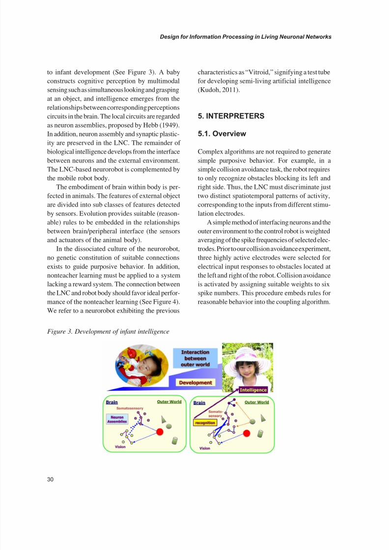
to infant development (See Figure 3). A baby
constructs cognitive perception by multimodal
sensing such as simultaneous looking and grasping
at an object, and intelligence emerges from the
relationships between corresponding perceptions
circuits in the brain. The local circuits are regarded
as neuron assemblies, proposed by Hebb (1949).
In addition, neuron assembly and synaptic plastic-
ity are preserved in the LNC. The remainder of
biological intelligence develops from the interface
between neurons and the external environment.
The LNC-based neurorobot is complemented by
the mobile robot body.
The embodiment of brain within body is per-
fected in animals. The features of external object
are divided into sub classes of features detected
by sensors. Evolution provides suitable (reason-
able) rules to be embedded in the relationships
between brain/peripheral interface (the sensors
and actuators of the animal body).
In the dissociated culture of the neurorobot,
no genetic constitution of suitable connections
exists to guide purposive behavior. In addition,
nonteacher learning must be applied to a system
lacking a reward system. The connection between
the LNC and robot body should favor ideal perfor-
mance of the nonteacher learning (See Figure 4).
We refer to a neurorobot exhibiting the previous
characteristics as “Vitroid,” signifying a test tube
for developing semi-living artificial intelligence
(Kudoh, 2011).
5. INTERPRETERS
5.1. Overview
Complex algorithms are not required to generate
simple purposive behavior. For example, in a
simple collision avoidance task, the robot requires
to only recognize obstacles blocking its left and
right side. Thus, the LNC must discriminate just
two distinct spatiotemporal patterns of activity,
corresponding to the inputs from different stimu-
lation electrodes.
A simple method of interfacing neurons and the
outer environment to the control robot is weighted
averaging of the spike frequencies of selected elec-
trodes. Prior to our collision avoidance experiment,
three highly active electrodes were selected for
electrical input responses to obstacles located at
the left and right of the robot. Collision avoidance
is activated by assigning suitable weights to six
spike numbers. This procedure embeds rules for
reasonable behavior into the coupling algorithm.
Figure 3. Development of infant intelligence

8/12/2019 3 Design-for-Information-Processing-in-Living-Neuronal-Networks.pdf
http://slidepdf.com/reader/full/3-design-for-information-processing-in-living-neuronal-networkspdf 7/16
31
Design for Information Processing in Living Neuronal Networks
When response patterns are very discrete,
simple weighted averaging of responses is suffi-
cient. In such cases, neuronal activity is expected
to settle into a stable pattern. In fact, the standard
deviation in the number of evoked responses de-
creases during robot running. However, this result
is ambiguous because the coupling rule for the
neurorobot also decreases the standard deviationin the number of spontaneous activities. Because
closed-loop interaction develops self-organized
changes in LNC activity for stabilizing robot be-
havior, a more suitable linking algorithm should
be sought. Such research is essential to understand-
ing how robot behavior is linked to the neuronal
network and to establishing suitable interaction
schemes between the neurons and environment.
5.2. Strategy for PatternRecognition of LNC Activity
As already mentioned, evoked LNC activity is
influenced by the internal state of the network,
which generates response fluctuations. In addi-
tion, the LNC activity gradually changes as the
network develops. Accounting for this fluctuationand gradual change of network activity is es-
sential. To evaluate the performance of different
interfacing algorithms, the neurorobot should con-
tain modular structures for exchanging multiple
algorithms. Our Vitroid neurorobot is equipped
with two interfacing programs, Brain Interface
and Client. Brain Interface detects spike activity
from noisy electrical signals and controls electrical
Figure 4. Embodiment schematics of an animal and a neurorobot

8/12/2019 3 Design-for-Information-Processing-in-Living-Neuronal-Networks.pdf
http://slidepdf.com/reader/full/3-design-for-information-processing-in-living-neuronal-networkspdf 8/16
32
Design for Information Processing in Living Neuronal Networks
stimulation. Two decoders, “output interpreter”
and “input interpreter,” are implemented in Client
(See Figure 5). The output interpreter translates
neuronal electrical activity patterns into robot
behavior, whereas the input interpreter determines
the stimulation pattern input to the LNN on the
basis of the sensory inputs (sensors on the robot
body).
Roughly two strategies are considered for pat-
tern recognition of imperfectly reproducible LNC
activity. The first is a pattern-matching approach
with “fixed” pattern templates and flexible output
modification (Figure 6 (a)). In this method, the
templates of the output interpreter are priorly
generated from the (almost) reproducible response
patterns, and are thereafter fixed. The templates
of the interpreter correspond to several situations;
for example, the robot is located near the right
wall (situation A) or midway between the left and
right walls (situation B). If the input from the real
world evokes a specific pattern that is 86% simi-
lar to situation A and 66% similar to situation B,
the output interpreter selects a value intermediate
between the ideal control values of each situation.
This strategy can be implemented using soft
computing technology. In particular, fuzzy reason-
ing (Mamdani, 1974) is useful for such ambiguous
changes. An output interpreter is realized with a
Fuzzy Pattern Template (FPT) matching method
(Kudoh, 2007, 2011). The pattern templates are
implemented as patterns of fuzzy “high” and “low”
labels in antecedent clauses. The input patterns
are compared to these templates, and the compat-
ibility degrees are calculated on the basis of the
similarities between the input pattern and each
template. The actuator speed is the weighted
average of the consequent-clause (then-part)
values of each fuzzy rule. In this method, templates
are totally fixed, whereas the actuator speed is
flexibly calculated by simplified fuzzy reasoning.
The second approach uses dynamic pattern
templates (Figure 6 (b)), which are the pattern
templates are not fixed but updated according to
the input response pattern of the neuronal net-
work. In this strategy, the output interpreter has
several classes, which are linked to particular robot
behaviors. These classes include several similar
patterns and are generated by a clustering process.
The response pattern of the LNN is compared to
class prototypes by nearest neighbor method and
is allocated to a certain class. The classes are
continuously updated during robot movement.
If the uniformity within each class changes to
meet certain criteria imposed by incoming new
Figure 5. Schematic of the proposed “vitroid” system

8/12/2019 3 Design-for-Information-Processing-in-Living-Neuronal-Networks.pdf
http://slidepdf.com/reader/full/3-design-for-information-processing-in-living-neuronal-networkspdf 9/16
33
Design for Information Processing in Living Neuronal Networks
data, the output interpreter generates a new class
for the new situation. In other words, the output
interpreter only updates the range of classes (or
the mapping between the input data and its repre-
sentative position in the clustering space). Thus,
the output interpreter generates a new candidate
class for the real-world situation from its existing
templates.This type of output interpreter is implemented
using a Self-Organizing Map (SOM; Kohonen,
2001). In our method, instead of performing clus-
tering, a SOM gathers similar data onto an output
layer map. If the distance between the center of the
class and a dividing line is defined, classes are also
defined. By simultaneous pattern recognition and
learning, the SOM updates the mapping between
the input data and their representative positions
in the clustering space.
5.3. Fuzzy Template Matching
We previously the Vitroid implemented by Fuzzy
Pattern Template (FPT) matching method. A set of256 fuzzy rules are applied to eight inputs of the
output interpreter. The fuzzy rules share a com-
mon set of 256 antecedent clauses (if-part) and
two independent sets of 256 consequent clauses.
The consequent clause of the same antecedent
clause maintains the premise relationship such as
symmetrical values.
Figure 6. Strategies for pattern recognition of imperfectly reproducible LNC activity

8/12/2019 3 Design-for-Information-Processing-in-Living-Neuronal-Networks.pdf
http://slidepdf.com/reader/full/3-design-for-information-processing-in-living-neuronal-networkspdf 10/16
34
Design for Information Processing in Living Neuronal Networks
This large number (256) of fuzzy rules de-
scribes all possible patterns invoked by combina-
tions of eight inputs (2^8). The eight inputs from
eight electrodes in the LNC represent the number
of detected action potentials within a 50-ms time
window. Each input of the fuzzy reasoning unit
has two fuzzy labels, high-frequency and low-
frequency. The maximum number of input spike
activity of all electrodes defines the maximum of
the horizontal axis in a membership function. The
maximum of the membership function assigned
to the high- and low-frequency labels corresponds
to three-quarters and one-quarter of the points of
maximum frequency, respectively. These anteced-
ent clauses are used as pattern templates for the
eight LNC inputs. The input patterns are compared
to these templates, and the compatibility degrees
are calculated on the basis of the similarities be-
tween the input pattern and each template. The
speed of an actuator is the weighted average of
consequent clause (then-part) values of each fuzzy
rule. To determine the quantitative relationships
between the input patterns and actuator speeds,
we adjust the consequent clauses of each fuzzy
rule by teacher learning.
Teacher signal is a set of speed values of both
sides of the actuators, derived from the values of
the IR sensors on the robot body. If the sum of the
IR sensor values on the left side of the robot body
exceeds that of the right side, the teacher signal
is set to the desired values of actuator speeds;
10 and 0 for the left actuator and right actuator,
respectively. This process links the spatiotemporal
pattern of electrical neuron activity (evoked by an
electrical input determined by IR sensor signals)
to the desired behavior (generated by balancing
the speeds of actuators on both sides of the robot
body) (See Figure 7).
5.4. Self-Organization Map
Electrical activity patterns within a certain time
window (in our case, 50 ms) constitute a feature
vector of 64 spike numbers detected at each elec-
trode. Basic SOM algorithms are employed for
the output interpreter. The input layer containing
64 nodes receives the feature vector. The SOM
features a two-dimensional output layer containing
10 × 10 nodes for dimensional reduction of the
feature vector. The SOM determines a winner node
in the output layer encoded in an input vector, as
shown in Figure 8. Because the winner node is
located in a 2D map, a 64-dimensional vector is
mapped to 2D winner node. The node with theshortest Euclidean distance between an input fea-
ture vector and a corresponding reference vector
is designated the winner for the input vector. The
reference vector of the winner is then updated to
more closely match the input vector. At the same
time, the reference vectors of the neighboring
Figure 7. Fuzzy reasoning used for pattern rec-
ognition
Figure 8. Schematic diagram of a SOM for the
neurorobot

8/12/2019 3 Design-for-Information-Processing-in-Living-Neuronal-Networks.pdf
http://slidepdf.com/reader/full/3-design-for-information-processing-in-living-neuronal-networkspdf 11/16
35
Design for Information Processing in Living Neuronal Networks
nodes of the winner node are updated toward the
input vector. This procedure places nodes with
similar reference vectors within neighborhoods.
Consequently, spatial relationships between
the nodes in the output layer correspond to the
relationships between the input vectors coupled
to those nodes. These steps are implemented in
an orthodox SOM algorithm. We aim to define a
reproducible pattern that represents information
in the living neuronal network. The coupling of
gathered nodes to similar feature vectors ensures
that similar spatiotemporal patterns of network
activity are gathered together.
The spatial location of the winner depends on
the initial state of the reference vectors. If a certain
electrode (say E1) is stimulated by an input from
the robot sensor, a winner node should be located
at a certain position in the output layer of the
SOM. If a winner activated by E2 stimulation is
located near that activated by E1, the outputs of
the living neuronal network responding to the E1
and E2 inputs will be similar. In generating the
robot behavior, instinctive behaviors such as col-
lision avoidance should be incorporated as prem-
ise behaviors. In this case, ideal winner distribu-
tion will be predetermined. If the map location of
a representative winner for the E1 input is speci-
fied, a suitable behavioral response to the E1
input can be defined. For example, if the E1 input
signals an obstacle at the left side of the robot,
the robot should turn to the right; thus, the left
motor speed should be set higher than that of the
right motor. To constrain the winner correspond-
ing response to a particular input, the winner for
that input should be fixed at a seed node and the
E1 input should be repeatedly applied during the
initial learning process (Figure 9). Thereafter,
winners responding to the E1 input are expected
to be gathered near the seed node. The robot is
controlled by the position of the winner for a
specified input activity. For example, the left and
right motor speeds are calculated by the weighted
average of the total network activity, where the
weights are the Euclidian distances between the
winner and E1 or E2 seed node.
6. EXPERIMENTS USING VITROID
6.1. Vitroid with FPTMatching Algorithm
Vitroid operating with the FPT matching algorithm
navigated a course between two parallel walls
without collision (Figure 10). The length of the
course was 1200 mm, and the distance between the
Figure 9. Generation of robot behavior with SOM

8/12/2019 3 Design-for-Information-Processing-in-Living-Neuronal-Networks.pdf
http://slidepdf.com/reader/full/3-design-for-information-processing-in-living-neuronal-networkspdf 12/16
36
Design for Information Processing in Living Neuronal Networks
walls was 90 mm. The robot was initially placed
midway between the walls at one end of the course,
and connected to a set of control programs, Brain
Interface and Client.
At each of the eight recording sites, the num-
ber of spikes evoked within a 50-ms time window
and the fuzzy grades of the 256 rules were analyzed
during robot running. In the latter part of the run-
ning, collision avoidance became gradually de-
layed (Figure 11(a)). While the variance in the
number of electrical spikes evoked by the inputs
tends to decrease during robot movement, the
standard deviation in the number of electrical
spikes evoked by spontaneous activity clearly
increases. This suggests that the network dynam-
ics are modified by the robot behavior, espe-
cially in response to the inputs (Figure 11 (b)).
Figure 10. Test course for robot running and robot
body (Khepera II)
Figure 11. (a) An example of the trajectory, classified inputs (L, R, SPT), and number of inputs cor-
responding to the activities in eight electrodes, and the fuzzy grade (compatibility degrees) of the top
five rules during an experiment with 1 mM Mg2+ recording solution. (b) An example of the variance in
the number of electrical spikes evoked by the inputs at the middle and latter stages of the experiment.

8/12/2019 3 Design-for-Information-Processing-in-Living-Neuronal-Networks.pdf
http://slidepdf.com/reader/full/3-design-for-information-processing-in-living-neuronal-networkspdf 13/16
37
Design for Information Processing in Living Neuronal Networks
6.2. SOM Identifier forSpatiotemporal Pattern of the SpikeActivity
The recognition resolution of electrical spike pat-
terns in a neuronal network depends on the num-
ber of nodes in the SOM output layer. Adequate
node number and nodal arrangement can only be
determined empirically. To this end, the number
of nodes was initially set as 10 × 10. At this grid
setting, spike patterns evoked by the inputs from
two distinct electrodes were separated. After 40
seedings, the winner nodes corresponding to the
input spike patterns had been almost separated,
with most winners correctly assigned to the left
or right section of the output layer. Only a small
minority of nodes was assigned the wrong loca-
tion (Figure 12).
Figure 12. (a) An example of the spatial distribution of winner nodes for 20 input feature vectors. The
grey squares indicate the winner nodes for the input feature vector of spike pattern evoked by the stimula-
tion labeled “L.” The black squares indicate the winner nodes for the stimulation labeled “R.” (b) Plot
of the number of occurrences of a selected number, as a function of the number of selection as winnernodes for L stimulation (solid line) and R stimulation (dotted line).
Figure 13. An example of the trajectory of an e-puck robot controlled by the proposed method with a
SOM. This image was synthesized by merging frames extracted every 1-s from a 40-s movie. Electrical
stimuli were applied to a living neuronal circuit via two electrodes linked to the left and right turns of
the e-puck robot. One of these electrodes was randomly selected and electrical stimulation was applied
every 1-s. The e-puck robot successfully behaved according to the spike pattern of a living neuronal
circuit. The solid circle and arrow indicate starting position and initial moving direction of the robot.

8/12/2019 3 Design-for-Information-Processing-in-Living-Neuronal-Networks.pdf
http://slidepdf.com/reader/full/3-design-for-information-processing-in-living-neuronal-networkspdf 14/16
38
Design for Information Processing in Living Neuronal Networks
The number of selection as winner node was
rarely more than one or two out of 40 selections.
The spike pattern is expected to be periodic and
such patterns should appear repeatedly. The clas-
sification of spike patterns was possibly too
sensitive for a small number of representative
patterns of electrical spikes evoked by just two
types of stimulation. At this stage, we have con-
firmed that electrical spike patterns from 64 sites
in a living neuronal network can be recognized
by our method. In addition, the robot body (e-puck,
implemented using EPFL) can be controlled by
SOM-generated behaviors (Figure 13). Currently,
we are examining the optimal number and ar-
rangement of nodes in the output layer of the
SOM.
7. DISCUSSION
Neurorobots have been proposed by several groups
as a model system for investigating brain and pe-
ripheral connections and reconstructing biological
intelligence. In a neurorobot system, a LNC is
connected to a moving sensor-equipped robot via
interface hardware and decoding software. Two
main strategies exist for the connecting scheme;
shaping and coordinating of the LNC. In addition,
it is critical that whether autonomous activity and
response fluctuations are regarded as mere noise
or results of information processing. Handling
such fluctuations is especially critical in the co-
ordinating strategy, in which the LNC is regarded
as the highest central processor of a neurorobot.
Decoding algorithms have been proposed, such
as CA, simple weighted averaging, FTP matching,
and SOM. These methods incorporate embedded
rules and specific summations of input signals.
Placing excessive faith in fluctuated activity
defeats the purposive behavior of the neurorobot.
Furthermore, LNC activity is developing during
culturing. Therefore, to maintain the desired robot
behavior, buffering or coordinating is required.
On the other hand, over-buffering the fluctuations
may destroy the effective closed-loop interaction
between the LNC and its external environment.
The LNC neurons receive input from the envi-
ronment in response to their prior activity. If the
interpreter absorbs the fluctuations too effectively,
the neurons cannot correctly interpret their external
environment. Besides the behavioral performance
of the neurorobot, linking algorithms should also
be evaluated from this perspective.
One fundamental problem is the innate be-
havior of the LNC. The reproducibility of spike
pattern evoked by a certain input and the number
of separable patterns depend on the network struc-
ture and functional connectivity between living
neurons. This issue is pertinent to the stimulation
method. Biological conditions and LNC treatment
methods are critical in realizing a stable control
of the neurorobot.
These discussions and investigations of the
neurorobot will contribute to the development of
new methods for regenerative neuromedicine and
the creation of novel algorithms for information
processing.
REFERENCES
Bakkum, D. J., Gamblen, P. M., Ben-Ary, G.,
Chao, Z. C., & Potter, S. M. (2007). MEART:
The semi-living artist.Frontiers in Neurorobotics,
1(5), 1–10. doi: doi:10.3389/neuro.12.005.2007
PMID:18958272.
Bakkum, D. J., Shkolnik, A. C., Ben-Ary, G.,
Gamblen, P., DeMarse, T. B., & Potter, S. M.
(2004). Removing some ‘A’ from AI: Embodied
cultured networks. In Iida, F., Pfeifer, R., Steels,L., & Kuniyoshi, Y. (Eds.), Embodied Artificial
Intelligence (pp. 130–145). New York: Springer.
doi:10.1007/978-3-540-27833-7_10.
Banker, G. A., & Cowan, W. M. (1977). Rat
hippocampal neurons in dispersed cell culture.
Brain Research,126 , 397–342. doi:10.1016/0006-
8993(77)90594-7 PMID:861729.

8/12/2019 3 Design-for-Information-Processing-in-Living-Neuronal-Networks.pdf
http://slidepdf.com/reader/full/3-design-for-information-processing-in-living-neuronal-networkspdf 15/16
39
Design for Information Processing in Living Neuronal Networks
Brooks, R. (1986). A robust layered control
system for a mobile robot. IEEE Journal on Ro-
botics and Automation, 2, 14–23. doi:10.1109/
JRA.1986.1087032.
Chao, Z. C., Bakkum, D. J., & Potter, S. M.
(2007). Region-specific network plasticity in
simulated and living cortical networks: Com-
parison of the center of activity trajectory (CAT)
with other statistics. Journal of Neural Engineer-
ing, 4, 1–15. doi:10.1088/1741-2560/4/3/015
PMID:17409475.
Chao, Z. C., Bakkum, D. J., & Potter, S. M. (2008).
Shaping embodied neural networks for adaptive
goal-directed behavior. PLoS Computational
Biology, 4(3). doi:10.1371/journal.pcbi.1000042
PMID:18369432.
Cozzi, L., D’Angelo, P., Chiappalone, M., Ide, A.
N., Novellino, A., Martinoia, S., & Sanguineti, V.
(2005). Coding and decoding of information in a
bi-directional neural interface. Neurocomputing,
65, 783–792. doi:10.1016/j.neucom.2004.10.075.
DeMarse, T. B., Wagenaar, D. A., Blau, W. P. A.,
& Potter, S. M. (2001). The neurally controlled
animat: Biological brains acting with simu-
lated bodies. Autonomous Robots, 11, 305–310.
doi:10.1023/A:1012407611130 PMID:18584059.
Gross, G. W., Rieske, E., Kreutzberg, G. W.,
& Meyer, A. (1977). A new fixed-array multi-
microelectrode system designed for long term
monitoring of extracellular single unit neuro-
nal activity in vitro. Neuroscience Letters, 6 ,
101–105. doi:10.1016/0304-3940(77)90003-9
PMID:19605037.
Gross, G. W., Williams, A. N., & Lucas, J. H.
(1982). Recording of spontaneous activity with
photo etched microelectrode surfaces from mouse
spinal neurons in culture. Journal of Neurosci-
ence Methods, 5(1–2), 13–22. doi:10.1016/0165-
0270(82)90046-2 PMID:7057675.
Hebb, D. O. (1949). The organization of behav-
iour: A neuropsychological theory. New York:
John Wiley & Sons.
Jimbo, Y., Robinson, H. P., & Kawana, A. (1993).
Simultaneous measurement of intracellular
calcium and electrical activity from patterned
neural networks in culture. IEEE Transactions
on Bio-Medical Engineering, 40, 804–810.
doi:10.1109/10.238465 PMID:8258447.
Jimbo, Y., Tateno, T., & Robinson, H. P. C.
(1999). Simultaneous induction of pathway-
specific potentiation and depression in networks
of cortical neurons. Biophysical Journal, 76 ,
670–678. doi:10.1016/S0006-3495(99)77234-6
PMID:9929472.
Kawato, M. (2008). Brain controlled robots. HFSP
Journal, 2(3), 136–142. doi:10.2976/1.2931144
PMID:19404467.
Kiyohara, A., Taguchi, T., & Kudoh, S. N. (2011).
Effects of electrical stimulation on autonomous
electrical activity in a cultured rat hippocampal
neuronal network. IEEJ Transactions on Electri-
cal and Electronic Engineering, 6 (2), 163–167.
doi:10.1002/tee.20639.
Kohonen, T. (2001). Self-organizing maps (3rd
ed.). New York: Springer. doi:10.1007/978-3-
642-56927-2.
Kudoh, S. N., Hosokawa, C., Kiyohara, A.,
Taguchi, T., & Hayashi, I. (2007). Biomodeling
system—Interaction between living neuronal
networks and the outer world. Journal of Robotics
and Mechatronics, 19(5), 592–600.
Kudoh, S. N., Nagai, R., Kiyosue, K., & Taguchi,T. (2001). PKC and CaMKII dependent synaptic
potentiation in cultured cerebral neurons. Brain
Research, 915(1), 79–87. doi:10.1016/S0006-
8993(01)02835-9 PMID:11578622.

8/12/2019 3 Design-for-Information-Processing-in-Living-Neuronal-Networks.pdf
http://slidepdf.com/reader/full/3-design-for-information-processing-in-living-neuronal-networkspdf 16/16
Design for Information Processing in Living Neuronal Networks
Kudoh, S. N., & Taguchi, T. (2003). Operation
of spatiotemporal patterns in living neuronal
networks cultured on a microelectrode array.
Journal of Advanced Computational Intelligence
and Intelligent Informatics, 8 , 100–107.
Kudoh, S. N., & Taguchi, T. (2003). Operation
of spatiotemporal patterns in living neuronal
networks cultured on a microelectrode array.
Journal of Advanced Computational Intelligence
and Intelligent Informatics, 8 , 100–107.
Kudoh, S. N., Tokuda, M., Kiyohara, A., Ho-
sokawa, C., Taguchi, T., & Hayashi, I. (2011).
Vitroid—The robot system with an interface
between a living neuronal network and outer
world. International Journal of Mechatronics
and Manufacturing Systems, 4(2), 135–149.
doi:10.1504/IJMMS.2011.039264.
Mamdani, E. H. (1974). Application of fuzzy al-
gorithms for the control of a simple dynamic plant.
Proceedings of the IEEE , 121(12), 1585–1588.
Murata, M., Ito, H., Taenaka, T., & Kudoh, S. N.
(2011). Modification of activity pattern induced by
synaptic enhancements in a semi-artificial network
of living neurons. In Proceedings of the Interna-
tional Symposium on Micro-NanoMechatronics
and Human Science (MHS), (pp. 250–254). MHS.
Novellino, A., D’Angelo, P., Cozzi, L., Chiap-
palone, M., Sanguineti, V., & Martinoia, S.
(2007). Connecting neurons to a mobile robot:
An in vitro bidirectional neural interface. Journal
of Computational Intelligence and Neuroscience.
doi: 10.1155/2007/12725
Oka, H., Shimono, K., Ogawa, R., Sugihara, H., &Taketani, M. (1999). A new planar multielectrode
array for extracellular recording: Application to
hippocampal acute slice. Journal of Neurosci-
ence Methods, 93, 61–67. doi:10.1016/S0165-
0270(99)00113-2 PMID:10598865.
Pfeifer, R., & Scheier, C. (1999). Understanding
intelligence. Cambridge, MA: The MIT Press.
Pine, J. (1980). Recording action potentials fromcultured neurons with extracellular microcircuit
electrodes. Journal of Neuroscience Methods,
2, 19–31. doi:10.1016/0165-0270(80)90042-4
PMID:7329089.
Potter, S. M. (2008). How should we think about
bursts? In Proceedings of the 6th International
Meeting on Substrate-Integrated Microelectrodes.
ISBN 3-938345-05-5
Robinson, H. P., Kawahara, M., Jimbo, Y., Torim-
itsu, K., Kuroda, Y., & Kawana, A. (1993). Periodicsynchronized bursting and intracellular calcium
transients elicited by low magnesium in cultured
cortical neurons. Journal of Neurophysiology,
70(4), 1606–1616. PMID:8283217.
Rolston, J. D., Wagenaar, D. A., & Potter, S. M.
(2007). Precisely-timed spatiotemporal patterns
of neural activity in dissociated cortical cultures.
Neuroscience, 148 , 294–303. doi:10.1016/j.neu-
roscience.2007.05.025 PMID:17614210.
Van Pelt, J., Vajda, I., Wolters, P. S., Corner, M. A.,& Ramakers, G. J. (2005). Dynamics and plasticity
in developing neuronal networks in vitro. Progress
in Brain Research, 147 , 173–188. doi:10.1016/
S0079-6123(04)47013-7 PMID:15581705.
Wagenaar, D. A., Pine, J., & Potter, S. M. (2006).
An extremely rich repertoire of bursting patterns
during the development of cortical cultures. BMC
Neuroscience,7 (11). doi: doi:10.1186/1471-2202-
7-11 PMID:16464257.
Wolters, P. S., Rutten, W. L., Ramakers, G. J., VanPelt, J., & Corner, M. A. (2004). Long term sta-
bility and developmental changes in spontaneous
network burst firing patterns in dissociated rat ce-
rebral cortex cell cultures on multielectrode arrays.
Neuroscience Letters, 361, 86–89. doi:10.1016/j.
neulet.2003.12.062 PMID:15135900.