Embed Size (px)
Citation preview
California Department of Water Resources
Chapter 3 Description of the Proposed Project
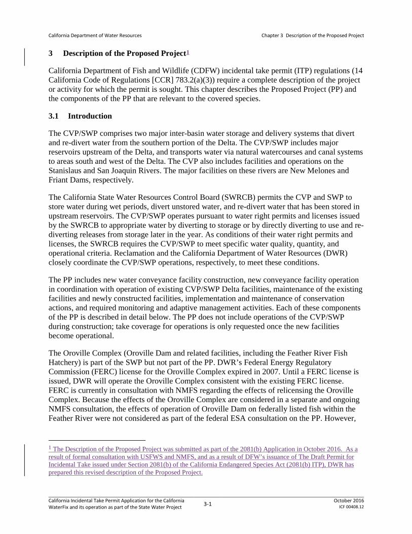
3 Description of the Proposed Project1
California Department of Fish and Wildlife (CDFW) incidental take permit (ITP) regulations (14 California Code of Regulations [CCR] 783.2(a)(3)) require a complete description of the project or activity for which the permit is sought. This chapter describes the Proposed Project (PP) and the components of the PP that are relevant to the covered species.
3.1 Introduction
The CVP/SWP comprises two major inter-basin water storage and delivery systems that divert and re-divert water from the southern portion of the Delta. The CVP/SWP includes major reservoirs upstream of the Delta, and transports water via natural watercourses and canal systems to areas south and west of the Delta. The CVP also includes facilities and operations on the Stanislaus and San Joaquin Rivers. The major facilities on these rivers are New Melones and Friant Dams, respectively.
The California State Water Resources Control Board (SWRCB) permits the CVP and SWP to store water during wet periods, divert unstored water, and re-divert water that has been stored in upstream reservoirs. The CVP/SWP operates pursuant to water right permits and licenses issued by the SWRCB to appropriate water by diverting to storage or by directly diverting to use and re-diverting releases from storage later in the year. As conditions of their water right permits and licenses, the SWRCB requires the CVP/SWP to meet specific water quality, quantity, and operational criteria. Reclamation and the California Department of Water Resources (DWR) closely coordinate the CVP/SWP operations, respectively, to meet these conditions.
The PP includes new water conveyance facility construction, new conveyance facility operation in coordination with operation of existing CVP/SWP Delta facilities, maintenance of the existing facilities and newly constructed facilities, implementation and maintenance of conservation actions, and required monitoring and adaptive management activities. Each of these components of the PP is described in detail below. The PP does not include operations of the CVP/SWP during construction; take coverage for operations is only requested once the new facilities become operational.
The Oroville Complex (Oroville Dam and related facilities, including the Feather River Fish Hatchery) is part of the SWP but not part of the PP. DWR’s Federal Energy Regulatory Commission (FERC) license for the Oroville Complex expired in 2007. Until a FERC license is issued, DWR will operate the Oroville Complex consistent with the existing FERC license. FERC is currently in consultation with NMFS regarding the effects of relicensing the Oroville Complex. Because the effects of the Oroville Complex are considered in a separate and ongoing NMFS consultation, the effects of operation of Oroville Dam on federally listed fish within the Feather River were not considered as part of the federal ESA consultation on the PP. However,
1 The Description of the Proposed Project was submitted as part of the 2081(b) Application in October 2016. As a result of formal consultation with USFWS and NMFS, and as a result of DFW’s issuance of The Draft Permit for Incidental Take issued under Section 2081(b) of the California Endangered Species Act (2081(b) ITP), DWR has prepared this revised description of the Proposed Project.
California Incidental Take Permit Application for the California WaterFix and its operation as part of the State Water Project 3-1 October 2016
ICF 00408.12
California Department of Water Resources
Chapter 3 Description of the Proposed Project
the effects of the flows from the Oroville Complex on all state-listed species are considered in the analysis presented in this application.
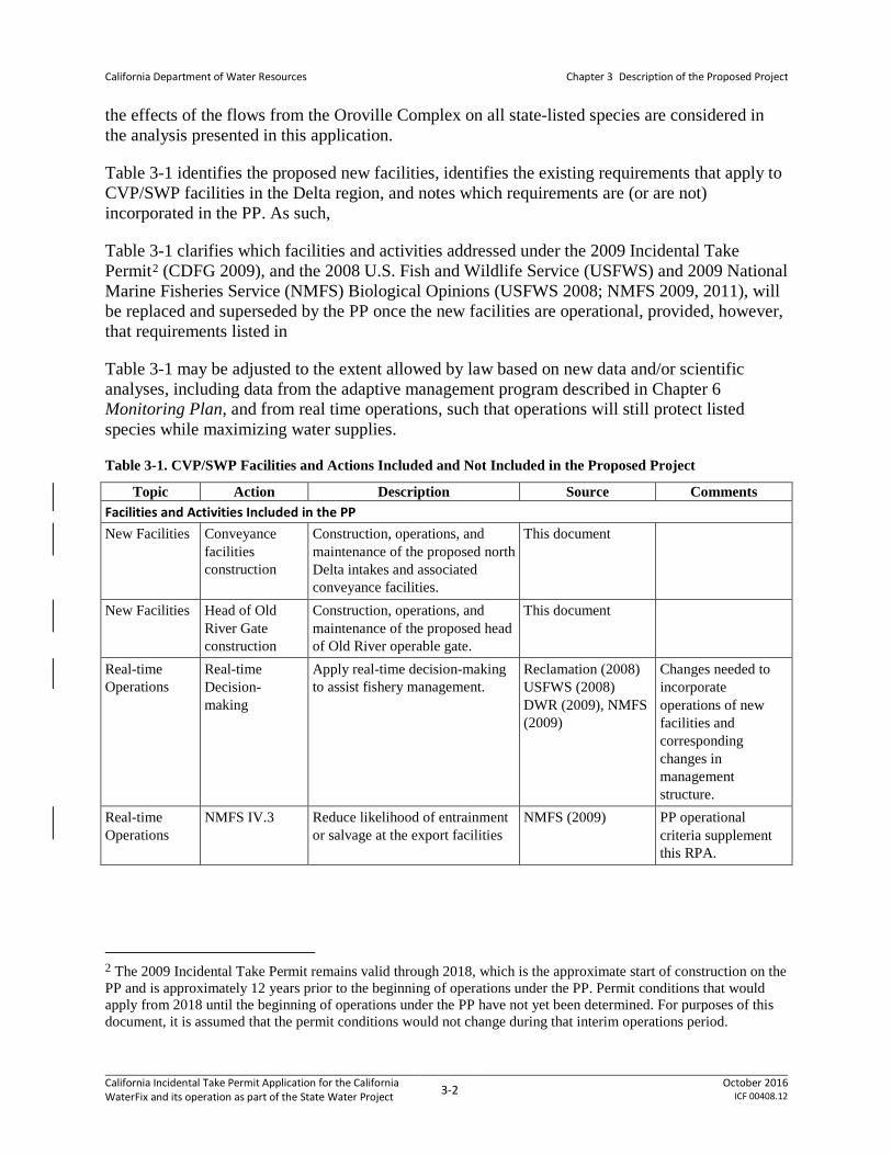
Table 3-1 identifies the proposed new facilities, identifies the existing requirements that apply to CVP/SWP facilities in the Delta region, and notes which requirements are (or are not) incorporated in the PP. As such,
Table 3-1 clarifies which facilities and activities addressed under the 2009 Incidental Take Permit2 (CDFG 2009), and the 2008 U.S. Fish and Wildlife Service (USFWS) and 2009 National Marine Fisheries Service (NMFS) Biological Opinions (USFWS 2008; NMFS 2009, 2011), will be replaced and superseded by the PP once the new facilities are operational, provided, however, that requirements listed in
Table 3-1 may be adjusted to the extent allowed by law based on new data and/or scientific analyses, including data from the adaptive management program described in Chapter 6 Monitoring Plan, and from real time operations, such that operations will still protect listed species while maximizing water supplies.
Table 3-1. CVP/SWP Facilities and Actions Included and Not Included in the Proposed Project
Topic Action Description Source Comments Facilities and Activities Included in the PP New Facilities Conveyance
facilities construction
Construction, operations, and maintenance of the proposed north Delta intakes and associated conveyance facilities.
This document
New Facilities Head of Old River Gate construction
Construction, operations, and maintenance of the proposed head of Old River operable gate.
This document
Real-time Operations
Real-time Decision-making
Apply real-time decision-making to assist fishery management.
Reclamation (2008) USFWS (2008) DWR (2009), NMFS (2009)
Changes needed to incorporate operations of new facilities and corresponding changes in management structure.
Real-time Operations
NMFS IV.3 Reduce likelihood of entrainment or salvage at the export facilities
NMFS (2009) PP operational criteria supplement this RPA.
2 The 2009 Incidental Take Permit remains valid through 2018, which is the approximate start of construction on the PP and is approximately 12 years prior to the beginning of operations under the PP. Permit conditions that would apply from 2018 until the beginning of operations under the PP have not yet been determined. For purposes of this document, it is assumed that the permit conditions would not change during that interim operations period.
California Incidental Take Permit Application for the California WaterFix and its operation as part of the State Water Project 3-2 October 2016
ICF 00408.12

California Department of Water Resources
Chapter 3 Description of the Proposed Project
Topic Action Description Source Comments Real-time Operations
USFWS RPA General
Smelt Working Group and Water and Operations Management Team
USFWS (2008) WOMT coordinates with and provides recommendations to the RTO Team for the Delta operations.
Real-time Operations
NMFS 11.2.1.1 Technical Team NMFS (2009) Existing real-time decision making process is incorporated into the PP as described in Section 3.1.5 Real-Time Operations Upstream of the Delta. In addition to this process a separate real-time operations coordination team will be convened in an advisory capacity, as described in Section 3.3.3 Real-Time Operational Decision-Making Process.
Real-time Operations
NMFS IV.5 Formation of Delta Operations for Salmon and Sturgeon Technical Working Group
NMFS (2009) These technical groups are incorporated in the PP unchanged.
Barriers Temporary Barriers
Operation of the temporary barriers project in the south Delta
Reclamation (2008) Temporary barriers are included with regard to operational effects, but year-to-year placement and removal are subject to separate authorizations. HORB replaced by operable HOR gate.
Barriers Do not implement Permanent Barriers
South Delta Improvement Program—Phase I (Permanent Operable Gates)
USFWS (2008), NMFS (2009)
SDIP is not being implemented. The HOR gate is included in the PP.
Barriers DO in Stockton Deep-Water Ship Channel
Operate HORB to improve DO in the Stockton Deep-Water Ship Channel
Reclamation (2008) Existing aeration facility in the Stockton Deep-Water Ship Channel is not included in the PP.
California Incidental Take Permit Application for the California WaterFix and its operation as part of the State Water Project 3-3 October 2016
ICF 00408.12

California Department of Water Resources
Chapter 3 Description of the Proposed Project
Topic Action Description Source Comments Flow CDFW
Condition 5 Flow criteria, also including real-time operational considerations
CDFG (2009) Changes needed to incorporate operations of new facilities and corresponding changes in management structure.
Flow Jones Pumping Plant
Permitted diversion capacity of 4,600 cfs
Reclamation (2008) USFWS (2008) NMFS (2009)
CVP facility to be operated per flow criteria. Permitted diversion capacity does not allow for more water to be exported in conjunction with the operation of NDD than is permitted by the SWRCB.
Flow Banks Pumping Plant
Diversion rates at Clifton Court intake are normally restricted to 6,680 cfs, with exceptions
Reclamation (2008) USFWS (2008) DWR (2009) NMFS (2009)
To be operated per flow criteria.
Flow NMFS IV.2.1 San Joaquin River inflow to export ratio (and 61-day pulse flows)
NMFS (2009) Modeling criteria of PP uses this as mechanism to meet spring outflow criteria in April and May. PP operational criteria for south Delta operations supersede this RPA action; PP operational criteria include this I:E ratio for April and May only. See Table 3-21.
Flow NMFS IV.2.3 OMR flow management NMFS (2009) PP operational criteria incorporate and replace this RPA action. See Table 3-21.
California Incidental Take Permit Application for the California WaterFix and its operation as part of the State Water Project 3-4 October 2016
ICF 00408.12

California Department of Water Resources
Chapter 3 Description of the Proposed Project
Topic Action Description Source Comments Flow USFWS 1 Adult migration and entrainment;
first flush: limit exports so average daily OMR flow is no more negative than -2,000 cfs for 14 days, with a 5-day running average no more negative than -2,500 cfs
USFWS (2008) PP operational criteria incorporate all aspects of this action including salvage based triggers, and replace this RPA action. See Table 3-21 and Section 3.3.2 Operational Criteria.
Flow USFWS 2 Adult migration and entrainment USFWS (2008) PP operational criteria incorporate and replace this RPA action.
Flow USFWS 3 Entrainment protection of larval smelt
USFWS (2008) PP operational criteria incorporate and replace this RPA action.
Flow USFWS 4 Estuarine habitat during fall (provide Delta outflow to maintain average X2 for September, October, and November)
USFWS (2008)
North Bay Aqueduct
North Bay Aqueduct Monitoring
Conduct monitoring at NBA Reclamation (2008) Monitoring would continue.
North Bay Aqueduct
North Bay Aqueduct Operations
Operate NBA USFWS (2008) CDFG (2009)
No change from 2008/2009 operational constraints.
Delta Cross Channel
Delta Cross Channel Operations
Operate Delta Cross Channel Reclamation (2008) NMFS (2009)
NMFS IV.1.2 operational criteria without any change. NMFS IV.1.1 is addressed by real-time operations. As described in Chapter 6, Monitoring Plan, the monitoring associated with current operations would continue.
Interior Delta Entry
Engineering solutions to reduce interior Delta entry
Reduce interior Delta entry Reclamation (2008) NMFS (2009)
NMFS IV.1.3 is addressed in PP by Georgiana Slough non-physical barrier and HOR gate.
California Incidental Take Permit Application for the California WaterFix and its operation as part of the State Water Project 3-5 October 2016
ICF 00408.12

California Department of Water Resources
Chapter 3 Description of the Proposed Project
Topic Action Description Source Comments Tracy and Skinner Facilities3
CDFW Condition 6.2
Skinner facility operations CDFG (2009) No change from 2009 operational constraints.
Tracy and Skinner Facilities
CDFW Condition 6.3
Skinner facility salvage operations CDFG (2009) No change from 2009 operational constraints.
Suisun Marsh Facilities
Suisun Marsh Salinity Control Gates
Operate Suisun Marsh salinity control gates, as described
Reclamation (2008) DWR (2009)
No change from 2009 operational constraints.
Suisun Marsh Facilities
Roaring River Distribution System
Operations Reclamation (2008) NMFS (2009) DWR (2009)
No change from constraints imposed by 2009 BiOps and ITP.
Suisun Marsh Facilities
Morrow Island Distribution System
Operations Reclamation (2008) CDFG (2009) NMFS (2009) DWR (2009)
No change from 2009 constraints imposed by 2009 BiOps and ITP.
Suisun Marsh Facilities
Goodyear Slough Outfall
Operations Reclamation (2008) CDFG (2009) NMFS (2009) DWR (2009)
No change from 2009 constraints imposed by 2009 BiOps and ITP.
Studies NMFS 11.2.1.2 Research and adaptive management
NMFS (2009) California WaterFix proposes new program.
Studies NMFS 11.2.1.3 Monitoring programs and reporting regarding effects of CVP/SWP operations
NMFS (2009) This work is performed by IEP with take authorization via scientific collection permits. This would continue and include any additional monitoring and reporting as required by CWF.
Studies CDFW Condition 8
Monitoring and reporting CDFG (2009) No change from 2009 activities.
Other Facilities CCWD Facilities
Operation and maintenance of CCWD facilities owned by Reclamation: the Rock Slough Intake and Contra Costa Canal
Reclamation (2008) Rock Slough diversion is included in modeling/baseline.
Other Facilities Clifton Court Forebay Aquatic Weed Control Program
Application of herbicide to control aquatic weeds and algal blooms in CFF
Reclamation (2008) DWR (2009)
3 See Permit Resolution Log item # 4 CHECK
California Incidental Take Permit Application for the California WaterFix and its operation as part of the State Water Project 3-6 October 2016
ICF 00408.12

California Department of Water Resources
Chapter 3 Description of the Proposed Project
Topic Action Description Source Comments Facilities and Activities Not Included in the PP Existing Requirements
D-1641 Implement D-1641, as described SWRCB D-1641
Incorporated into the environmental baseline. PP may include discretionary operations as allowed under the existing regulatory criteria and proposed operations criteria.
Existing Requirements
COA Implement existing COA P.L. 99-546 Incorporated into the environmental baseline. PP may include discretionary operations as allowed under the existing regulatory criteria and proposed operations criteria.
Existing Requirements
CVPIA Implement CVPIA, as authorized P.L. 102-575 Incorporated into the environmental baseline. PP may include discretionary operations as allowed under the existing regulatory criteria and proposed operations criteria.
Existing Requirements
SWRCB WRO 90-05
Implement WRO 90-05 SWRCB WRO 90-05 Incorporated into the environmental baseline.
Flow VAMP Vernalis Adaptive Management Plan (VAMP)
D-1641 Reclamation (2008)
VAMP has expired, per agreement.
North Bay Aqueduct
CDFW Condition 6.4
NBA, RRDS, and Sherman Island diversions and fish screens
CDFG (2009) Will be complete prior to start of PP.
Delta Cross Channel
Delta Cross Channel Operations
Operate Delta Cross Channel Reclamation (2008) NMFS (2009)
NMFS IV.1.2 operational criteria without any change. NMFS IV.1.1 is addressed by real-time operations. As described in Chapter 6, Monitoring Plan, the monitoring associated with current operations would continue.
California Incidental Take Permit Application for the California WaterFix and its operation as part of the State Water Project 3-7 October 2016
ICF 00408.12

California Department of Water Resources
Chapter 3 Description of the Proposed Project
Topic Action Description Source Comments Tracy and Skinner Facilities
NMFS IV.4.1 Tracy fish collection facility improvements to reduce pre-screen loss and improve screening efficiency
NMFS (2009) Will be completed before north Delta diversion operations begin; subject to a separate take authorization.
Tracy and Skinner Facilities
NMFS IV.4.2 Skinner fish collection facility improvements to reduce pre-screen loss and improve screening efficiency
NMFS (2009) Will be completed before north Delta diversion operations begin; subject to a separate take authorization.
Tracy and Skinner Facilities
NMFS IV.4.3 Tracy fish collection facility and the Skinner fish collection facility actions to improve salvage monitoring, reporting, and release survival rates
NMFS (2009) Will be completed before north Delta diversion operations begin; subject to a separate take authorization.
Other Facilities CCWD Facilities
Operation and maintenance of CCWD facilities owned by Reclamation: the Rock Slough Intake and Contra Costa Canal
Reclamation (2008) Rock Slough diversion is included in modeling/baseline.
Studies NMFS IV.2.2 Six-year acoustic tag experiment NMFS (2009) In progress. Habitat Restoration
NMFS I.5 Funding for CVPIA Anadromous Fish Screen Program
NMFS (2009)
Habitat Restoration
NMFS I.6.1 Restoration of floodplain rearing habitat
NMFS (2009) Occurs in Yolo Bypass; subject to separate take authorization.
Habitat Restoration
NMFS I.6.2 Near-term actions at Liberty Island/Lower Cache Slough and Lower Yolo Bypass
NMFS (2009) Actions already under way and will have separate take authorization.
Habitat Restoration
NMFS I.6.3 Lower Putah Creek enhancements NMFS (2009) Actions already under way and will have separate take authorization.
Habitat Restoration
NMFS I.6.4 Lisbon Weir improvements NMFS (2009) Actions already under way and will have separate take authorization.
Habitat Restoration
NMFS I.7 Reduce migratory delays and loss of salmon, steelhead, and sturgeon at Fremont Weir and other structures in the Yolo Bypass
NMFS (2009) Occurs in Yolo Bypass; subject to separate take authorization.
California Incidental Take Permit Application for the California WaterFix and its operation as part of the State Water Project 3-8 October 2016
ICF 00408.12

California Department of Water Resources
Chapter 3 Description of the Proposed Project
Topic Action Description Source Comments Habitat Restoration
USFWS 6 Habitat restoration (create or restore a minimum of 8,000 acres of intertidal and associated subtidal habitat in the Delta and Suisun Marsh)
USFWS (2008) Action is being implemented and is expected to be completed before north Delta diversion operations begin.
Habitat Restoration
CDFW Condition 7
LFS habitat restoration CDFG (2009) Action is being implemented and may be included in the USFWS 6 requirement above. Action is expected to be completed before north Delta diversion operations begin.
Studies CDFW Condition 6.1
MIDS study of entrainment effects
CDFG (2009) Study is underway and will complete prior to initiation of PP.
Other Facilities CCWD Alternative Intake
Construction of alternative intake at Rock Slough
Reclamation (2008) Operates under existing BiOps, incorporated into the environmental baseline.
BiOp = biological opinion CAMT = Collaborative Adaptive Management Team CCWD = Contra Costa Water District CDFW = California Department of Fish and Wildlife CESA = California Endangered Species Act cfs = cubic feet per second COA = Coordinated Operations Agreement CVPIA = Central Valley Project Improvement Act DO = Dissolved oxygen ESA = Endangered Species Act of 1972, as amended HOR = head of Old River HORB = head of Old River barrier IEP = Interagency Ecological Program ITP = Incidental take permit LFS = Longfin smelt MIDS = Morrow Island Distribution System NBA = North Bay Aqueduct OMR = Old and Middle Rivers RPA = Reasonable and Prudent Alternative RRDS = Roaring River Distribution System RTO = Real-Time Operations SWG = Smelt Working Group SWRCB = State Water Resources Control Board WOMT = Water and Operations Management Team
The purpose of this Application is to evaluate the effects of the proposed project on species listed under the California Endangered Species Act (CFGC Sections 2050-2116). The PP entails
California Incidental Take Permit Application for the California WaterFix and its operation as part of the State Water Project 3-9 October 2016
ICF 00408.12
California Department of Water Resources
Chapter 3 Description of the Proposed Project
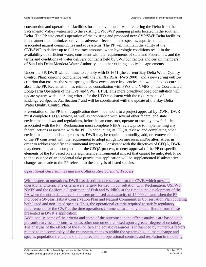
construction and operation of facilities for the movement of water entering the Delta from the Sacramento Valley watershed to the existing CVP/SWP pumping plants located in the southern Delta. The PP also entails operation of the existing and proposed new CVP/SWP Delta facilities in a manner that minimizes or avoids adverse effects on listed species, aquatic habitat, and associated natural communities and ecosystems. The PP will maintain the ability of the CVP/SWP to deliver up to full contract amounts, when hydrologic conditions result in the availability of sufficient water, consistent with the requirements of state and Federal law and the terms and conditions of water delivery contracts held by SWP contractors and certain members of San Luis Delta Mendota Water Authority, and other existing applicable agreements.
Under the PP, DWR will continue to comply with D-1641 (the current Bay-Delta Water Quality Control Plan), ongoing compliance with the Fall X2 RPA (FWS 2008), and a new spring outflow criterion that ensures the same spring outflow exceedance frequencies that would have occurred absent the PP. Reclamation has reinitiated consultation with FWS and NMFS on the Coordinated Long-Term Operation of the CVP and SWP (LTO). This more broadly-scoped consultation will update system-wide operating criteria for the LTO consistent with the requirements of Endangered Species Act Section 7 and will be coordinated with the update of the Bay-Delta Water Quality Control Plan. Presentation of the PP in this application does not amount to a project approval by DWR. DWR must complete CEQA review, as well as compliance with several other federal and state environmental laws and regulations, before it can construct, operate or use any new facilities associated with the PP. Reclamation must complete NEPA review prior to implementing any federal actions associated with the PP. In conducting its CEQA review, and completing other environmental compliance processes, DWR may be required to modify, add, or remove elements of the PP consistent with the requirement to adopt mitigation measures and/or alternatives in order to address specific environmental impacts. Consistent with the directives of CEQA, DWR may determine, at the completion of the CEQA process, to deny approval of the PP or specific elements of the PP based on any significant environmental impact that cannot be mitigated. Prior to the issuance of an incidental take permit, this application will be supplemented if substantive changes are made to the PP relevant to the analysis of listed species.
Operational Uncertainties and the Collaborative Scientific Process With respect to operations, DWR has described one scenario for the CWF, which presents operational criteria. The criteria were largely formed, in consultation with Reclamation, USFWS, NMFS and the California Department of Fish and Wildlife, at the time in the development of the PA when the north delta diversions were proposed at a capacity of 15,000 cfs and when the PP included a 50-year Habitat Conservation Plan and Natural Communities Conservation Plan covering both listed and non-listed species. Thus, the operational criteria required to satisfy regulatory requirements for the CWF at the time operations commence are likely to be different from those presented in DWR’s application. Additionally, some of the criteria and some of the outcomes in the effects analysis are based upon precautionary assumptions, whereas other outcomes are based upon a greater degree of certainty. The analysis of the effects of the PPon fish and aquatic resources is influenced by numerous factors related to the complexity of the ecosystem, changes within the system (e.g., climate change and species population trends), and the imprecision of operational controls and resolution in modeling
California Incidental Take Permit Application for the California WaterFix and its operation as part of the State Water Project 3-10 October 2016
ICF 00408.12
California Department of Water Resources
Chapter 3 Description of the Proposed Project
tools. These factors are further complicated by the scientific uncertainty about some fundamental aspects of the life histories of the listed fish species and how these species respond to changes in the system, as well as sometimes competing points of view on the interpretation of biological and physical data within the scientific community. Some of the criteria of the PP have been conservatively estimated based on professional judgment. In this context, uncertainty in some of the criteria was resolved in a manner to provide greater protection of species and these criteria may be in excess of what may be required to avoid jeopardy and to minimize and fully mitigate the impacts of authorized take. As noted above, the operational criteria described in DWR’s application are likely to change not only for the reasons described above but also based on other processes. Future CVP/SWP operations with CWF and species needs will be informed by these other processes, including the State Water Board process to update the Bay Delta WQCP, reinitiation of consultation on the 2008 USFWS BiOp, reinitiation of consultation on the 2009 NMFS BiOp, replacement of the existing incidental take permit for Longfin Smelt, the Collaborative Science and Adaptive Management Program (CSAMP), implementation of the Adaptive Management Program for the California Water Fix and Current Biological Opinions on the Coordinated Operations of the Central Valley and State Water Projects (AMP, California EcoRestore, implementation of the Delta Smelt Resiliency Strategy, implementation of the Salmonid Resiliency Strategy, the Delta Smelt Recovery Plan update, and other actions that are likely to cause physical, chemical and biological changes within the watershed. The outcomes of the processes described above, as well as consideration of Delta conditions and relevant regulatory obligations existing at the time, will be considered in determining how CWF will be operated. Some of the criteria identified in the PP may have substantial water supply effects while providing limited ability to minimize effects to species. As a result, operational criteria identified in the CWF PP may be modified, relaxed or removed and may no longer apply to an operation with CWF, while other operational criteria, not currently identified in this CWF consultation or those already identified may be included or modified. Therefore, the operational criteria that are described in DWR’s application are likely to change between now and when CWF becomes operational. DWR is committed to working with CDFW and other agencies and stakeholders through the AMP, CSAMP and other processes to undertake additional focused research and analyses to improve scientific understanding concerning the tools used to analyze species effects and the impact of the facilities’ operations on listed species and their habitat, as well as the scientific understanding concerning the benefits of other actions (e.g. habitat restoration) on listed species and their habitats. The CWF includes a robust AMP that incorporates a collaborative science process to further refine, during the subsequent regulatory processes (which may result in issuance of a new or amended 2081 permit), what ultimately will be defined as the initial operating criteria for the CWF project. The AMP will continue to refine CWF operations over time. The AMP described in Section 6.1, will collect and analyze data for the purpose of evaluating the propriety of the anticipated operations in light of the evolving science and changing circumstances in the Delta. Based on the results for the AMP DWR recognizes that a request for a permit amendment may be necessary to implement modified operational criteria.[A1]
California Incidental Take Permit Application for the California WaterFix and its operation as part of the State Water Project 3-11 October 2016
ICF 00408.12

California Department of Water Resources
Chapter 3 Description of the Proposed Project
3.1.1 Central Valley Project
The CVP is the largest Federal Reclamation project and was originally authorized by the Rivers and Harbors Act of 1935. The CVP was reauthorized by the Rivers and Harbors Act of 1937 for the purposes of “improving navigation, regulating the flow of the San Joaquin River and the Sacramento River, controlling floods, providing for storage and for the delivery of the stored waters thereof, for construction under the provisions of the Federal Reclamation Laws of such distribution systems as the Secretary of the Interior (Secretary) deems necessary in connection with lands for which said stored waters are to be delivered, for the reclamation of arid and semiarid lands and lands of Indian reservations, and other beneficial uses, and for the generation and sale of electric energy as a means of financially aiding and assisting such undertakings and in order to permit the full utilization of the works constructed.” This Act provided that the dams and reservoirs of the CVP “shall be used, first, for river regulation, improvement of navigation and flood control; second, for irrigation and domestic uses; and, third, for power.” The CVP was reauthorized in 1992 through the Central Valley Project Improvement Act (CVPIA). The CVPIA modified that authorization under Rivers and Harbors Act of 1937 adding mitigation, protection, and restoration of fish and wildlife as a project purpose. Further, the CVPIA specified that the dams and reservoirs of the CVP should now be used “first, for river regulation, improvement of navigation, and flood control; second, for irrigation and domestic uses and fish and wildlife mitigation, protection and restoration purposes; and, third, for power and fish and wildlife enhancement.”
CVPIA (Public Law 102-575, Title 34) includes authorization for actions to benefit fish and wildlife intended to implement the purposes of that Title. Specifically, Section 3406(b)(1) is implemented through the Anadromous Fish Restoration Program (AFRP). The AFRP objectives, as they relate to operations, are further explained below. CVPIA Section 3406(b)(1) provides for modification of the CVP Operations to meet the fishery restoration goals of the CVPIA, so long as the operations are not in conflict with the fulfillment of the Secretary’s contractual obligations to provide CVP water for other authorized purposes. The U.S. Department of the Interior’s (Interior) decision on Implementation of Section 3406(b)(2) of the CVPIA, dated May 9, 2003, provides for the dedication and management of 800,000 acre-feet (af) of CVP-water yield annually by implementing upstream and Delta actions. Interior manages and accounts for (b)(2) water pursuant to its May 9, 2003, decision and the Ninth Circuit’s decision in Bay Institute of San Francisco v. United States, 66 Fed. Appx. 734 (9th Cir. 2003), as amended, 87 Fed. Appx. 637 (2004). Additionally, Interior is authorized to acquire water to supplement (b)(2) water, pursuant to Section 3406(b)(3).
A portion of the water stored in upstream reservoirs on the Sacramento and San Joaquin Rivers and their tributaries is pumped at the C.W. “Bill” Jones Pumping Plant in the Delta and delivered to the south of the Delta, the CVP service area.
Under the PP, the Jones Pumping Plant will continue to fulfill its role, in conjunction with the Banks Pumping Plant. Both pumping plants will also use water diverted from the Sacramento River at three new intakes located in the north Delta and conveyed to the south Delta export facilities via new tunneled and connecting conveyance, as described in Section 3.2, Conveyance Facility Construction. Flow criteria affecting CVP/SWP water withdrawals under the PP are described in Section 3.3, Operations and Maintenance of New and Existing Facilities, as are
California Incidental Take Permit Application for the California WaterFix and its operation as part of the State Water Project 3-12 October 2016
ICF 00408.12

California Department of Water Resources
Chapter 3 Description of the Proposed Project
operational criteria for other CVP/SWP facilities and activities in the Delta, as well as facilities maintenance.
3.1.2 State Water Project
DWR was established in 1956 as the successor to the Department of Public Works for authority over water resources and dams within California. DWR also succeeded to the Department of Finance’s powers with respect to state application for the appropriation of water (Stats. 1956, First Ex. Sess., Ch. 52; see also Wat. Code Sec. 123) and has permits for appropriation from the SWRCB for use by the SWP. DWR’s authority to construct state water facilities or projects is derived from the Central Valley Project Act (CVPA) (Wat. Code Sec. 11100 et seq.), the Burns-Porter Act (California Water Resources Development Bond Act) (Wat. Code Sec. 12930-12944), the State Contract Act (Pub. Contract Code Sec. 10100 et seq.), the Davis-Dolwig Act (Wat. Code Sec. 11900-11925), and special acts of the State Legislature. Although the Federal government built certain facilities described in the CVPA, the Act authorizes DWR to build facilities described in the Act and to issue bonds. See Warne v. Harkness, 60 Cal. 2d 579 (1963). The CVPA describes specific facilities that have been built by DWR, including the Feather River Project and California Aqueduct (Wat. Code Sec. 11260), Silverwood Lake (Wat. Code Sec. 11261), and the North Bay Aqueduct (Wat. Code Sec. 11270). The Act allows DWR to administratively add other units (Wat. Code Sec. 11290) and develop power facilities (Wat. Code Sec. 11295).
The Burns-Porter Act, approved by the California voters in November 1960 (Wat. Code Sec. 12930-12944), authorized issuance of bonds for construction of the SWP. The principal facilities of the SWP are Oroville Reservoir and related facilities, and San Luis Dam and related facilities, Delta facilities, the California Aqueduct including its terminal reservoirs, and the North and South Bay Aqueducts. The Burns-Porter Act incorporates the provisions of the CVPA. DWR is required to plan for recreational and fish and wildlife uses of water in connection with state-constructed water projects and can acquire land for such uses (Wat. Code Sec. 233, 345, 346, 12582). The Davis-Dolwig Act (Wat. Code Sec. 11900-11925) establishes the policy that preservation of fish and wildlife is part of state costs to be paid by water supply contractors, and recreation and enhancement of fish and wildlife are to be provided by appropriations from the General Fund.
DWR holds contracts with 29 public agencies in northern, central, and southern California for water supplies from the SWP. Water stored in the Oroville facilities, along with water available in the Delta (consistent with applicable regulations) is captured in the Delta and conveyed through several facilities to SWP contractors.
The SWP is operated to provide flood control and water for agricultural, municipal, industrial, recreational, and environmental purposes. A large portion of the water conserved in Oroville Reservoir is released to serve three Feather River area contractors, two contractors served from the North Bay Aqueduct, and pumped at the Banks Pumping Plant in the Delta serving the remaining 24 contractors in the SWP service areas south of the Delta. In addition to pumping water released from Oroville Reservoir, the Banks Pumping Plant pumps water from other sources entering the Delta.
California Incidental Take Permit Application for the California WaterFix and its operation as part of the State Water Project 3-13 October 2016
ICF 00408.12

California Department of Water Resources
Chapter 3 Description of the Proposed Project
Under the PP, the Banks Pumping Plant will continue to fulfill this role, but will also use water diverted from the Sacramento River at three new intakes located in the north Delta and conveyed to the Banks Pumping Plant via new tunneled and connecting conveyance, as described in Section 3.2, Conveyance Facility Construction. Flow criteria affecting CVP/SWP water withdrawals under the PP are described in Section 3.3, Operations and Maintenance of New and Existing Facilities, as are operational criteria for other CVP/SWP facilities and activities in the Delta, and facilities maintenance.
3.1.2.1 Feather River Operations Consultation
As part of the SWP, DWR operates the Oroville Facilities on the Feather River under a license from the Federal Energy Regulatory Commission (FERC). As part of the FERC process for relicensing the Oroville Facilities, NMFS is consulting with FERC under ESA Section 7 regarding effects on listed species under NMFS’ jurisdiction from FERC’s proposed relicensing the Oroville Facilities. NMFS released a draft BiOp for FERC relicensing of the Oroville Facilities in July 2009. A final BiOp is scheduled for release in 2016.
The original FERC license to operate the Oroville Facilities expired in January 2007. Since then, an annual license that renews automatically each year has been issued, authorizing DWR to continue operating to the terms of the original FERC license until the new license is issued. To prepare for the expiration of the original FERC license, DWR began working on the relicensing process in 2001. As part of the process, DWR entered into a Settlement Agreement (SA), signed in 2006, with state, federal, and local agencies; state water contractors; non-governmental organizations; a tribal government; and others to implement improvements within the FERC boundary. The FERC boundary includes all of the Oroville Facilities, including Lake Oroville, and extends downstream of Oroville Dam to include portions of the Low Flow Channel (LFC) on the lower Feather River and portions of the High Flow Channel (HFC) of the Lower Feather River downstream of the Thermalito Afterbay Outlet. In addition to the SA, a Habitat Expansion Agreement was negotiated with NMFS and others to address the effects of the Oroville Facilities on anadromous fish in the Feather River, and to provide an alternative to NMFS and USFWS exercising their authority to prescribe fish passage under Federal Power Act Section 18.
In 2010, the State Water Resources Control Board issued the Clean Water Act Section 401 Certification for FERC relicensing of the Oroville Facilities, analyzing the SA-proposed conditions. Although the new FERC license has not been issued, it is anticipated to include the SA license terms and conditions from Appendix A of the SA and the terms and conditions of the Clean Water Act Section 401 Certification. However, Oroville operations have not received CESA coverage for their impacts on spring-run Chinook salmon. DWR will comply with the requirements in the NMFS BiOp after it is issued to FERC and FERC relicenses the Oroville Facilities. It is anticipated that the new FERC license will be issued for a period of up to 50 years. The FERC license and its associated agreements and permits will be the primary regulatory drivers for operations at the Oroville Facilities. Operational requirements in the forthcoming license and associated permits are expected to include minimum channel flows, water temperature, and ramping rates. These requirements will need to be met, along with any other requirements imposed on the SWP through this consultation. The analysis below describes the similarities in the proposed operations in the FERC SA and the PP, and why no conflicts between these operations is expected.
California Incidental Take Permit Application for the California WaterFix and its operation as part of the State Water Project 3-14 October 2016
ICF 00408.12

California Department of Water Resources
Chapter 3 Description of the Proposed Project
The operations modeled for the PP in this Application are similar to the operations modeled in DWR’s BA for FERC relicensing of the Oroville Facilities. The modeling assumptions for this Application incorporated flow requirements specified in the SA (Table 3-2). Because the NMFS BiOp for FERC relicensing of the Oroville Facilities is not yet final, the draft BiOp terms and conditions were not included in the modeling assumptions. However, for purposes of understanding potential differences between what was assumed for the modeling in this Application and what is expected to be included in the NMFS BiOp for FERC relicensing of the Oroville Facilities on the Feather River, various flow requirements were compared (Table 3-2). As shown, the majority of assumed criteria for Feather River minimum instream flow in the modeling in this Application are the same as those included in the NMFS Draft BiOp for FERC Oroville Facilities relicensing. One exception is the pulse flow target flows in March, April, and May in the NMFS Draft BiOp, which were not part of the SA and were not assumed in the modeling in this Application.
As shown, the pulse flow targets at the southern end of the FERC boundary range from 2-day pulses to 12-day pulses of 7,000 cubic feet per second (cfs) in wet and above normal water years. Based on the input from the Green Sturgeon Technical Subcommittee of the Feather River Technical Team, two additional 2-day (48-hour) pulse flows of sufficient magnitude and duration to improve passage impediments and facilitate upstream movement of adult sturgeon may be provided. There is uncertainty as to what future pulse flow specifications NMFS might include in the Final BiOp for FERC relicensing of the Oroville Facilities because of changing river bathymetric conditions. The 12-day pulse under the NMFS Draft BiOp in March requires approximately 165 TAF of flow released from Oroville Facilities. The two pulses in April and May require approximately 56 TAF and 28 TAF, respectively. Given that these short-duration pulse flows are limited to wetter conditions and relatively small in volume, their effect on the available coldwater pool in Lake Oroville for the months following the pulse is expected to be small. Should these pulse flow operations remain in the final NMFS BiOp for FERC relicensing of the Oroville Facilities, DWR will implement them in coordination with other SWP operations, including the PP described in this Application. Given the similarities between assumed Feather River operations criteria in the modeling for this Application, and the conditions in the NMFS Draft BiOp (Table 3-2), the PP is not expected to affect the ability to meet the conditions analyzed in the final NMFS BiOp for FERC relicensing of the Oroville Facilities.
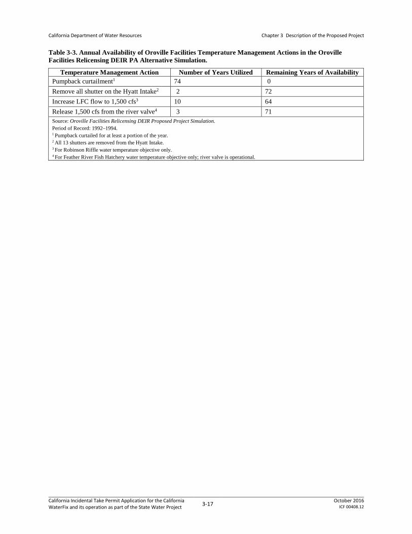
Table 3-3 shows the availability of Temperature Control Actions (TCAs) from the FERC DEIR modeling. Because the Feather River flow requirements and all the water temperature objectives for the NAA4 in this Application are the same as those analyzed in the FERC Oroville Facilities relicensing BA and the Oroville Facilities Relicensing Draft Environmental Impact Report Proposed Project Alternative (FERC DEIR) modeling, conditions in the absence of the PP would be similar to those detailed in the FERC DEIR. Given that modeling for the PA would result in storage conditions in Oroville (Table 3-4) that would be similar to those of the NAA, as well as similar temperature conditions in the LFC (Table 3-5 and Table 3-6), conditions under the PA at the two common water temperature compliance locations, the Feather River Fish Hatchery (FRFH) and Robinson Riffle, would be expected to be similar to the FERC DEIR PA (Note: The
4 “NAA” signifies the “no action alternative” as defined in the NEPA and CEQA documentation supporting the PP. It was used as the standard of comparison in modeling used to evaluate the operational effects of the PP.
California Incidental Take Permit Application for the California WaterFix and its operation as part of the State Water Project 3-15 October 2016
ICF 00408.12

California Department of Water Resources
Chapter 3 Description of the Proposed Project
use of “PA” as a column header in these tables is intended to refer to the PP. These tables were taken from ICF International (2016), which used the term “PA” to describe the PP.)
Even if the Oroville storage conditions under the PP were lower than the conditions that were modeled in the FERC DEIR PA, the PP would utilize the TCAs described in the SA. As noted in Table 3-3, not all the TCAs were required to meet the temperature requirements at FRFH and Robinson Riffle under FERC DEIR PA modeling; if needed, the PP can utilize the remaining TCAs. With ability to exercise various TCAs outlined in the SA, DWR is expected to have enough flexibility to meet the minimum instream flow and temperature requirements outlined in the NMFS Draft BiOp without significantly affecting the operations resulting from the PP.
In conclusion, modeling of the Oroville Facilities conducted as part of the Oroville Facilities Relicensing EIR, BA, and draft BiOp is consistent with modeling conducted for the PP in this application. Although the TCAs taken to achieve the water temperatures could be different under the PP modeling, flows and temperatures in the Feather River LFC and FRFH are expected to be generally similar under the PP and the NMFS BiOp for relicensing of the Oroville Facilities. Therefore, no additional analysis of those operations and associated effects is included in this application. However, the effects of the Oroville Facilities operations are considered as part of the status of the species.
Table 3-2. Feather River Minimum Instream Flow Requirements Included in the Oroville Facilities Settlement Agreement and California WaterFix 2081 Application Modeling Compared to the NMFS Draft BiOp.
Oroville Facilities Settlement Agreement, and PP Modeling NMFS Draft BiOp
Minimum Flow in Feather River LFC
700 cfs, except from September 9 to March 31 of each year to accommodate spawning of anadromous fish release (800 cfs).
Same
Minimum Flow in Feather River HFC
Consistent with existing license and 1983 DWR-CDFW agreement (750–1,700 cfs)
Same
Additional Pulse Flows
None In wet and above normal water years, target flows: Mar 1–12: 7,000 cfs Apr 1–30: two 48-hour, 7,000 cfs pulse flows May 1–31: one 48-hour, 7,000 cfs pulse flow In below normal and dry water years, convene Green Sturgeon Technical Team and Feather River Technical Team to determine if pulse flows are warranted. In Mar–Apr, if directed, provide two 48-hour, 2,500 cfs pulse flows
California Incidental Take Permit Application for the California WaterFix and its operation as part of the State Water Project 3-16 October 2016
ICF 00408.12
California Department of Water Resources
Chapter 3 Description of the Proposed Project
Table 3-3. Annual Availability of Oroville Facilities Temperature Management Actions in the Oroville Facilities Relicensing DEIR PA Alternative Simulation.
Temperature Management Action Number of Years Utilized Remaining Years of Availability Pumpback curtailment1 74 0 Remove all shutter on the Hyatt Intake2 2 72 Increase LFC flow to 1,500 cfs3 10 64 Release 1,500 cfs from the river valve4 3 71 Source: Oroville Facilities Relicensing DEIR Proposed Project Simulation. Period of Record: 1992–1994. 1 Pumpback curtailed for at least a portion of the year. 2 All 13 shutters are removed from the Hyatt Intake. 3 For Robinson Riffle water temperature objective only. 4 For Feather River Fish Hatchery water temperature objective only; river valve is operational.
California Incidental Take Permit Application for the California WaterFix and its operation as part of the State Water Project 3-17 October 2016
ICF 00408.12

Chapter 3 Description of the Proposed Project
Table 3-4. End-of-Month Oroville Storage Modeling Results for the NAA and the PP
Note: The use of “PA” as a column header in this table is intended to refer to the PP. These tables were taken from ICF International (2016), which used the term “PA” to describe the PP.
NAA PA Diff. Perc. Diff. NAA PA Diff. Perc. Diff. NAA PA Diff. Perc. Diff. NAA PA Diff. Perc. Diff. NAA PA Diff. Perc. Diff. NAA PA Diff. Perc. Diff.Probability of Exceedancea
10% 2,051 2,070 19 1% 2,112 2,173 61 3% 2,712 2,706 -6 0% 2,788 2,788 0 0% 2,917 2,919 2 0% 3,035 3,049 14 0%
20% 1,779 1,915 136 8% 1,799 1,951 152 8% 2,031 2,175 144 7% 2,610 2,788 178 7% 2,788 2,788 0 0% 2,964 2,964 0 0%
30% 1,612 1,756 145 9% 1,656 1,760 104 6% 1,793 1,984 190 11% 2,287 2,356 69 3% 2,788 2,788 0 0% 2,897 2,933 37 1%
40% 1,364 1,526 161 12% 1,374 1,495 120 9% 1,583 1,720 137 9% 1,941 2,191 250 13% 2,553 2,658 105 4% 2,788 2,809 21 1%
50% 1,257 1,378 121 10% 1,249 1,355 107 9% 1,391 1,524 133 10% 1,703 1,875 172 10% 2,176 2,449 272 13% 2,646 2,777 132 5%
60% 1,165 1,248 83 7% 1,138 1,238 100 9% 1,252 1,259 7 1% 1,595 1,607 12 1% 1,892 1,976 84 4% 2,261 2,341 80 4%
70% 1,098 1,163 65 6% 1,022 1,118 96 9% 1,093 1,211 118 11% 1,298 1,342 44 3% 1,677 1,728 51 3% 2,041 2,133 92 5%
80% 999 1,059 60 6% 958 1,004 46 5% 983 1,083 100 10% 1,147 1,233 86 7% 1,432 1,473 41 3% 1,706 1,737 31 2%
90% 906 929 22 2% 890 921 31 3% 903 957 54 6% 1,007 1,076 69 7% 1,244 1,254 10 1% 1,491 1,518 27 2%
Long TermFull Simulation Periodb 1,399 1,480 81 6% 1,390 1,470 80 6% 1,565 1,644 79 5% 1,830 1,912 81 4% 2,146 2,209 64 3% 2,387 2,435 47 2%
Water Year Typesc
Wet (32%) 1,919 1,978 58 3% 1,877 1,943 66 4% 1,996 2,079 83 4% 2,185 2,297 112 5% 2,830 2,858 28 1% 2,942 2,942 0 0%
Above Normal (16%) 1,507 1,602 95 6% 1,488 1,579 91 6% 1,583 1,675 91 6% 1,773 1,858 85 5% 2,516 2,612 96 4% 2,892 2,927 36 1%
Below Normal (13%) 1,239 1,412 173 14% 1,174 1,348 174 15% 1,301 1,459 158 12% 1,712 1,851 138 8% 2,125 2,228 103 5% 2,400 2,526 126 5%
Dry (24%) 1,079 1,155 76 7% 1,145 1,210 65 6% 1,501 1,553 52 3% 1,753 1,793 40 2% 1,583 1,659 76 5% 1,939 2,012 73 4%
Critical (15%) 836 873 37 4% 835 874 38 5% 961 991 30 3% 1,362 1,389 27 2% 1,218 1,269 51 4% 1,376 1,423 46 3%
NAA PA Diff. Perc. Diff. NAA PA Diff. Perc. Diff. NAA PA Diff. Perc. Diff. NAA PA Diff. Perc. Diff. NAA PA Diff. Perc. Diff. NAA PA Diff. Perc. Diff.Probability of Exceedancea
10% 3,352 3,352 0 0% 3,538 3,538 0 0% 3,538 3,538 0 0% 3,037 2,944 -92 -3% 2,758 2,639 -119 -4% 2,217 2,242 24 1%
20% 3,298 3,298 0 0% 3,538 3,538 0 0% 3,535 3,528 -8 0% 2,952 2,889 -63 -2% 2,516 2,429 -87 -3% 1,960 2,094 133 7%
30% 3,268 3,274 6 0% 3,475 3,475 0 0% 3,357 3,202 -154 -5% 2,746 2,635 -111 -4% 2,313 2,201 -112 -5% 1,824 1,848 24 1%
40% 3,208 3,215 7 0% 3,312 3,375 63 2% 3,103 2,993 -110 -4% 2,468 2,384 -84 -3% 1,979 2,048 69 3% 1,522 1,734 212 14%
50% 2,925 3,044 120 4% 3,018 3,078 60 2% 2,831 2,798 -32 -1% 2,201 2,166 -35 -2% 1,718 1,802 84 5% 1,331 1,545 213 16%
60% 2,600 2,657 57 2% 2,690 2,779 89 3% 2,448 2,430 -18 -1% 1,821 1,866 45 2% 1,508 1,514 6 0% 1,256 1,394 139 11%
70% 2,218 2,283 66 3% 2,300 2,332 32 1% 2,015 2,101 86 4% 1,448 1,610 162 11% 1,247 1,279 32 3% 1,203 1,244 41 3%
80% 1,900 1,857 -43 -2% 1,860 1,933 72 4% 1,682 1,763 81 5% 1,241 1,294 53 4% 1,130 1,225 95 8% 1,075 1,136 61 6%
90% 1,661 1,654 -6 0% 1,512 1,578 65 4% 1,306 1,359 54 4% 1,138 1,218 80 7% 986 1,102 116 12% 897 977 80 9%
Long TermFull Simulation Periodb 2,654 2,695 41 2% 2,749 2,793 43 2% 2,602 2,593 -9 0% 2,118 2,108 -10 0% 1,817 1,815 -2 0% 1,512 1,601 89 6%
Water Year Typesc
Wet (32%) 3,300 3,300 0 0% 3,486 3,488 1 0% 3,439 3,383 -56 -2% 2,958 2,876 -82 -3% 2,619 2,548 -71 -3% 2,102 2,163 61 3%
Above Normal (16%) 3,246 3,262 16 1% 3,392 3,410 18 1% 3,231 3,122 -109 -3% 2,598 2,497 -101 -4% 2,115 2,061 -54 -3% 1,657 1,738 81 5%
Below Normal (13%) 2,656 2,776 119 4% 2,716 2,832 116 4% 2,530 2,584 54 2% 1,922 1,960 38 2% 1,512 1,586 75 5% 1,307 1,503 196 15%
Dry (24%) 2,178 2,251 73 3% 2,209 2,288 78 4% 1,957 2,011 54 3% 1,476 1,544 68 5% 1,284 1,326 41 3% 1,146 1,247 102 9%
Critical (15%) 1,401 1,436 35 2% 1,388 1,423 35 3% 1,248 1,289 42 3% 1,028 1,097 68 7% 925 984 59 6% 874 912 38 4%a Exceedance probability is defined as the probability a given value will be exceeded in any one year.
b Based on the 82-year simulation period.
d There are 26 wet years, 13 above normal years, 11 below normal years, 20 dry years, and 12 critical years projected for 2030 under Q5 climate scenario.
c As defined by the Sacramento Valley 40-30-30 Index Water Year Hydrologic Classification (SWRCB D-1641, 1999); projected to Year 2030. WYT for a given water year is applied from Feb through Jan consistent with CALSIM II.
Statistic
End of Month Storage (TAF)
April May June July August September
Statistic
End of Month Storage (TAF)
October November December January February March
California Incidental Take Permit Application for the California WaterFix and its operation as part of the State Water Project 3-18 October 2016
ICF 00408.12

Chapter 3 Description of the Proposed Project
Table 3-5. Modeled Feather River Low Flow Channel near Fish Dam Monthly Temperature for the NAA and the PP
Note: The use of “PA” as a column header in this table is intended to refer to the PP. These tables were taken from ICF International (2016), which used the term “PA” to describe the PP.
NAA PA Diff. Perc. Diff. NAA PA Diff. Perc. Diff. NAA PA Diff. Perc. Diff. NAA PA Diff. Perc. Diff. NAA PA Diff. Perc. Diff. NAA PA Diff. Perc. Diff.Probability of Exceedancea
10% 57.9 58.2 0.3 1% 58.9 58.9 0.0 0% 54.8 54.3 -0.5 -1% 51.4 51.5 0.1 0% 51.5 51.5 0.0 0% 53.4 53.4 0.0 0%
20% 56.0 55.6 -0.4 -1% 57.8 57.4 -0.4 -1% 54.0 53.4 -0.6 -1% 50.4 50.5 0.1 0% 50.9 51.1 0.2 0% 52.7 52.8 0.1 0%
30% 54.8 54.6 -0.2 0% 56.6 56.0 -0.6 -1% 53.1 53.0 -0.1 0% 49.8 49.9 0.1 0% 50.5 50.8 0.3 1% 51.7 51.9 0.2 0%
40% 54.1 54.0 -0.1 0% 56.0 55.2 -0.8 -1% 52.6 52.3 -0.3 -1% 49.4 49.4 0.0 0% 50.0 50.0 0.0 0% 51.4 51.3 -0.1 0%
50% 54.0 53.6 -0.4 -1% 55.4 54.8 -0.6 -1% 52.2 51.9 -0.3 -1% 49.2 49.3 0.1 0% 49.6 49.8 0.2 0% 50.8 50.8 0.0 0%
60% 53.7 53.4 -0.3 -1% 55.0 53.6 -1.4 -3% 51.6 51.5 -0.1 0% 48.8 48.8 0.0 0% 49.3 49.4 0.1 0% 50.1 50.2 0.1 0%
70% 53.3 53.2 -0.1 0% 54.2 52.8 -1.4 -3% 51.3 51.0 -0.3 -1% 48.1 48.2 0.1 0% 48.9 49.0 0.1 0% 49.6 49.7 0.1 0%
80% 53.2 53.1 -0.1 0% 52.8 52.5 -0.3 -1% 50.8 50.5 -0.3 -1% 47.5 47.7 0.2 0% 48.5 48.4 -0.1 0% 49.3 49.0 -0.3 -1%
90% 53.0 52.9 -0.1 0% 52.3 52.2 -0.1 0% 49.6 49.5 -0.1 0% 47.0 47.0 0.0 0% 47.6 47.7 0.1 0% 48.4 48.5 0.1 0%
Long TermFull Simulation Periodb 55.0 54.8 -0.2 0% 55.6 55.0 -0.6 -1% 52.2 52.0 -0.2 0% 49.1 49.2 0.1 0% 49.6 49.7 0.1 0% 50.9 50.9 0.0 0%
Water Year Typesc
Wet (32%) 53.5 53.4 0.0 0% 54.7 54.3 -0.5 -1% 52.9 52.6 -0.4 -1% 50.1 50.1 0.0 0% 48.7 48.8 0.1 0% 49.4 49.4 0.0 0%
Above Normal (16%) 53.5 53.3 -0.1 0% 54.5 54.1 -0.5 -1% 51.9 51.8 -0.2 0% 48.8 49.0 0.1 0% 45.9 45.9 0.0 0% 46.1 46.0 0.0 0%
Below Normal (13%) 54.5 54.3 -0.2 0% 55.6 54.5 -1.1 -2% 52.2 51.5 -0.7 -1% 48.2 48.3 0.1 0% 50.2 50.3 0.1 0% 51.6 51.8 0.2 0%
Dry (24%) 55.5 54.9 -0.6 -1% 55.9 55.2 -0.7 -1% 52.1 52.0 -0.1 0% 46.5 46.6 0.1 0% 49.9 50.1 0.2 0% 52.3 52.2 -0.1 0%
Critical (15%) 59.5 59.3 -0.3 0% 57.8 57.4 -0.4 -1% 51.2 51.3 0.1 0% 48.1 48.2 0.1 0% 50.3 50.4 0.1 0% 52.1 52.0 -0.1 0%
NAA PA Diff. Perc. Diff. NAA PA Diff. Perc. Diff. NAA PA Diff. Perc. Diff. NAA PA Diff. Perc. Diff. NAA PA Diff. Perc. Diff. NAA PA Diff. Perc. Diff.Probability of Exceedancea
10% 53.8 53.6 -0.2 0% 56.9 56.9 0.0 0% 58.8 58.7 -0.1 0% 62.7 62.4 -0.3 0% 62.7 62.9 0.2 0% 59.8 58.3 -1.5 -3%
20% 53.1 52.8 -0.3 -1% 56.5 56.6 0.1 0% 58.5 58.4 -0.1 0% 61.9 62.0 0.1 0% 62.0 62.2 0.2 0% 57.1 57.3 0.2 0%
30% 52.4 52.4 0.0 0% 56.2 56.3 0.1 0% 58.3 58.2 -0.1 0% 61.4 61.5 0.1 0% 61.5 61.5 0.0 0% 56.8 56.7 -0.1 0%
40% 52.2 52.2 0.0 0% 56.0 56.0 0.0 0% 58.2 57.9 -0.3 -1% 61.2 61.3 0.1 0% 60.8 61.0 0.2 0% 55.5 56.4 0.9 2%
50% 51.9 51.9 0.0 0% 55.9 55.9 0.0 0% 58.0 57.8 -0.2 0% 61.1 61.1 0.0 0% 60.4 60.7 0.3 0% 54.9 56.1 1.2 2%
60% 51.7 51.7 0.0 0% 55.7 55.8 0.1 0% 57.8 57.5 -0.3 -1% 61.1 61.0 -0.1 0% 60.3 60.4 0.1 0% 54.7 55.3 0.6 1%
70% 51.3 51.3 0.0 0% 55.3 55.3 0.0 0% 57.6 57.4 -0.2 0% 60.9 61.0 0.1 0% 60.1 60.2 0.1 0% 54.6 55.0 0.4 1%
80% 50.6 50.7 0.1 0% 54.9 54.9 0.0 0% 57.5 57.3 -0.2 0% 60.9 60.9 0.0 0% 59.9 60.0 0.1 0% 54.5 54.8 0.3 1%
90% 50.2 50.2 0.0 0% 54.5 54.5 0.0 0% 57.2 57.0 -0.2 0% 60.8 60.7 -0.1 0% 59.7 59.7 0.0 0% 54.3 54.6 0.3 1%
Long TermFull Simulation Periodb 52.0 51.9 0.0 0% 55.8 55.8 0.0 0% 58.0 57.8 -0.2 0% 61.4 61.4 0.0 0% 61.0 61.0 0.0 0% 56.1 56.3 0.2 0%
Water Year Typesc
Wet (32%) 50.9 51.0 0.0 0% 55.1 55.1 0.0 0% 57.8 57.5 -0.2 0% 61.3 61.2 -0.1 0% 60.5 60.6 0.2 0% 54.5 54.8 0.3 0%
Above Normal (16%) 48.0 47.9 -0.1 0% 51.9 51.9 0.0 0% 53.6 53.3 -0.4 -1% 56.2 56.2 0.0 0% 55.3 55.5 0.2 0% 50.3 50.7 0.4 1%
Below Normal (13%) 52.6 52.5 -0.1 0% 55.9 55.9 0.0 0% 58.1 57.8 -0.3 0% 61.0 61.0 0.0 0% 60.4 60.6 0.2 0% 56.0 57.0 1.0 2%
Dry (24%) 52.6 52.7 0.0 0% 56.0 56.0 0.0 0% 57.9 57.9 -0.1 0% 61.3 61.4 0.1 0% 61.5 61.3 -0.2 0% 56.8 57.0 0.2 0%
Critical (15%) 52.4 52.4 -0.1 0% 56.4 56.4 0.0 0% 58.6 58.6 0.1 0% 62.8 62.7 -0.1 0% 62.8 62.5 -0.2 0% 60.2 59.3 -0.9 -2%a Exceedance probability is defined as the probability a given value will be exceeded in any one year.
b Based on the 82-year simulation period.
d There are 26 wet years, 13 above normal years, 11 below normal years, 20 dry years, and 12 critical years projected for 2030 under Q5 climate scenario.
c As defined by the Sacramento Valley 40-30-30 Index Water Year Hydrologic Classification (SWRCB D-1641, 1999); projected to Year 2030. WYT for a given water year is applied from Feb through Jan consistent with CALSIM II.
Statistic
Monthly Temperature (Deg-F)
April May June July August September
Statistic
Monthly Temperature (Deg-F)
October November December January February March
California Incidental Take Permit Application for the California WaterFix and its operation as part of the State Water Project 3-19 October 2016
ICF 00408.12

Chapter 3 Description of the Proposed Project
Table 3-6. Modeled Feather River Low Flow Channel at Robinson Riffle Monthly Temperature for the NAA and the PP
Note: The use of “PA” as a column header in this table is intended to refer to the PP. These tables were taken from ICF International (2016), which used the term “PA” to describe the PP.
NAA PA Diff. Perc. Diff. NAA PA Diff. Perc. Diff. NAA PA Diff. Perc. Diff. NAA PA Diff. Perc. Diff. NAA PA Diff. Perc. Diff. NAA PA Diff. Perc. Diff.Probability of Exceedancea
10% 59.7 59.6 -0.1 0% 58.3 58.2 -0.1 0% 53.3 53.1 -0.2 0% 50.7 50.7 0.0 0% 52.4 52.3 -0.1 0% 54.9 54.8 -0.1 0%
20% 58.1 58.2 0.1 0% 57.1 56.8 -0.3 -1% 52.9 52.4 -0.5 -1% 50.0 49.9 -0.1 0% 51.5 51.5 0.0 0% 54.1 54.2 0.1 0%
30% 56.9 56.8 -0.1 0% 56.3 55.8 -0.5 -1% 52.1 51.9 -0.2 0% 49.5 49.7 0.2 0% 51.0 51.2 0.2 0% 53.5 53.5 0.0 0%
40% 56.6 56.6 0.0 0% 55.8 54.8 -1.0 -2% 51.7 51.3 -0.4 -1% 49.0 49.1 0.1 0% 50.7 50.7 0.0 0% 52.8 52.8 0.0 0%
50% 56.3 56.1 -0.2 0% 55.2 54.6 -0.6 -1% 51.1 51.1 0.0 0% 48.7 48.8 0.1 0% 50.3 50.5 0.2 0% 52.1 52.2 0.1 0%
60% 56.0 55.9 -0.1 0% 54.8 53.8 -1.0 -2% 50.6 50.5 -0.1 0% 48.2 48.3 0.1 0% 50.0 50.1 0.1 0% 51.9 51.8 -0.1 0%
70% 55.7 55.5 -0.2 0% 54.4 53.5 -0.9 -2% 50.4 50.2 -0.2 0% 47.8 47.8 0.0 0% 49.7 49.8 0.1 0% 51.4 51.3 -0.1 0%
80% 55.2 55.1 -0.1 0% 53.5 52.9 -0.6 -1% 50.1 49.8 -0.3 -1% 47.4 47.5 0.1 0% 49.0 49.0 0.0 0% 50.9 50.9 0.0 0%
90% 54.8 54.8 0.0 0% 52.6 52.3 -0.3 -1% 49.1 48.9 -0.2 0% 46.3 46.6 0.3 1% 48.2 48.2 0.0 0% 50.1 50.1 0.0 0%
Long TermFull Simulation Periodb 57.0 56.8 -0.2 0% 55.4 54.9 -0.5 -1% 51.3 51.1 -0.2 0% 48.6 48.7 0.1 0% 50.3 50.3 0.1 0% 52.5 52.5 0.0 0%
Water Year Typesc
Wet (32%) 55.6 55.6 0.0 0% 54.7 54.3 -0.4 -1% 51.9 51.6 -0.3 -1% 49.6 49.6 0.0 0% 49.6 49.6 0.1 0% 51.2 51.2 0.0 0%
Above Normal (16%) 55.7 55.5 -0.1 0% 54.3 53.9 -0.4 -1% 50.9 50.8 -0.1 0% 48.3 48.4 0.1 0% 46.5 46.5 0.0 0% 47.8 47.8 0.0 0%
Below Normal (13%) 56.6 56.5 -0.2 0% 55.5 54.6 -0.9 -2% 51.1 50.5 -0.6 -1% 47.7 47.8 0.1 0% 50.6 50.7 0.1 0% 53.0 53.1 0.1 0%
Dry (24%) 57.5 57.0 -0.5 -1% 55.8 55.2 -0.6 -1% 51.3 51.3 -0.1 0% 46.1 46.2 0.1 0% 50.5 50.6 0.1 0% 53.6 53.5 0.0 0%
Critical (15%) 60.7 60.5 -0.2 0% 57.3 56.9 -0.3 -1% 50.2 50.3 0.1 0% 47.8 47.8 0.1 0% 50.9 51.1 0.1 0% 53.6 53.5 0.0 0%
NAA PA Diff. Perc. Diff. NAA PA Diff. Perc. Diff. NAA PA Diff. Perc. Diff. NAA PA Diff. Perc. Diff. NAA PA Diff. Perc. Diff. NAA PA Diff. Perc. Diff.Probability of Exceedancea
10% 57.6 57.4 -0.2 0% 62.1 62.1 0.0 0% 66.1 65.9 -0.2 0% 69.6 69.5 -0.1 0% 68.8 68.7 -0.1 0% 63.0 62.5 -0.5 -1%
20% 56.5 56.3 -0.2 0% 61.6 61.6 0.0 0% 65.8 65.6 -0.2 0% 69.1 69.0 -0.1 0% 68.0 68.1 0.1 0% 61.6 62.0 0.4 1%
30% 56.0 56.0 0.0 0% 61.2 61.2 0.0 0% 65.4 65.2 -0.2 0% 68.7 68.8 0.1 0% 67.6 67.7 0.1 0% 61.1 61.5 0.4 1%
40% 55.5 55.6 0.1 0% 60.8 60.8 0.0 0% 65.1 64.9 -0.2 0% 68.6 68.5 -0.1 0% 67.1 67.2 0.1 0% 60.7 61.0 0.3 0%
50% 55.0 55.0 0.0 0% 60.6 60.6 0.0 0% 64.6 64.3 -0.3 0% 68.2 68.3 0.1 0% 66.6 66.9 0.3 0% 60.4 60.7 0.3 0%
60% 54.6 54.7 0.1 0% 60.3 60.4 0.1 0% 64.2 64.0 -0.2 0% 68.0 68.1 0.1 0% 66.3 66.4 0.1 0% 60.1 60.4 0.3 0%
70% 54.4 54.4 0.0 0% 60.0 60.0 0.0 0% 63.8 63.8 0.0 0% 67.8 67.7 -0.1 0% 66.1 66.1 0.0 0% 59.6 60.0 0.4 1%
80% 54.0 53.9 -0.1 0% 59.8 59.8 0.0 0% 63.4 63.3 -0.1 0% 67.3 67.4 0.1 0% 65.8 65.7 -0.1 0% 59.4 59.6 0.2 0%
90% 53.4 53.3 -0.1 0% 59.1 59.1 0.0 0% 62.8 62.9 0.1 0% 67.0 66.9 -0.1 0% 65.3 65.3 0.0 0% 58.8 59.1 0.3 1%
Long TermFull Simulation Periodb 55.3 55.3 0.0 0% 60.7 60.7 0.0 0% 64.5 64.4 -0.1 0% 68.4 68.4 0.0 0% 66.9 66.9 0.0 0% 60.7 60.9 0.1 0%
Water Year Typesc
Wet (32%) 54.0 54.0 0.0 0% 60.2 60.2 0.0 0% 64.0 63.8 -0.2 0% 68.4 68.4 0.0 0% 66.7 66.9 0.1 0% 59.8 59.9 0.2 0%
Above Normal (16%) 51.2 51.2 0.0 0% 56.4 56.5 0.0 0% 59.9 59.6 -0.2 0% 62.6 62.6 0.0 0% 60.9 61.1 0.1 0% 54.8 55.1 0.3 1%
Below Normal (13%) 56.2 56.2 0.0 0% 60.5 60.5 0.0 0% 64.9 64.7 -0.2 0% 68.3 68.3 0.0 0% 66.7 66.8 0.1 0% 60.8 61.5 0.7 1%
Dry (24%) 55.9 55.9 0.0 0% 60.9 61.0 0.0 0% 64.9 64.8 0.0 0% 68.1 68.1 0.1 0% 67.1 67.0 -0.1 0% 61.1 61.3 0.2 0%
Critical (15%) 55.9 55.8 0.0 0% 60.9 60.9 0.0 0% 64.6 64.7 0.1 0% 69.4 69.3 -0.1 0% 68.1 68.0 -0.1 0% 63.5 62.9 -0.7 -1%a Exceedance probability is defined as the probability a given value will be exceeded in any one year.
b Based on the 82-year simulation period.
d There are 26 wet years, 13 above normal years, 11 below normal years, 20 dry years, and 12 critical years projected for 2030 under Q5 climate scenario.
c As defined by the Sacramento Valley 40-30-30 Index Water Year Hydrologic Classification (SWRCB D-1641, 1999); projected to Year 2030. WYT for a given water year is applied from Feb through Jan consistent with CALSIM II.
Statistic
Monthly Temperature (Deg-F)
April May June July August September
Statistic
Monthly Temperature (Deg-F)
October November December January February March
California Incidental Take Permit Application for the California WaterFix and its operation as part of the State Water Project 3-20 October 2016
ICF 00408.12

California Department of Water Resources
Chapter 3. Description of the Proposed Project
3.1.3 Coordinated Operations Agreement
The Coordinated Operations Agreement (COA) between the United States of America and DWR to operate the CVP/SWP was signed in November 1986. Congress, through Public Law 99-546, authorized and directed the Secretary of the Interior to execute and implement the COA. The COA defines the rights and responsibilities of the CVP/SWP with respect to in-basin water needs and project exports and provides a mechanism to account for those rights and responsibilities.
Under the COA, Reclamation and DWR agree to operate the CVP/SWP under balanced conditions in a manner that meets Sacramento Valley and Delta needs while maintaining their respective annual water supplies as identified in the COA. Balanced conditions are defined as periods when the two projects agree that releases from upstream reservoirs, plus unregulated flow, approximately equal water supply needed to meet Sacramento Valley in-basin uses and project exports. Coordination between the CVP and the SWP is facilitated by implementing an accounting procedure based on the sharing principles outlined in the COA. During balanced conditions in the Delta when water must be withdrawn from storage to meet Sacramento Valley and Delta requirements, 75 percent of the responsibility to withdraw from storage is borne by the CVP and 25 percent by the SWP. The COA also provides that during balanced conditions when unstored water is available for export, 55 percent of the sum of stored water and the unstored water for export is allocated to the CVP, and 45 percent is allocated to the SWP. Although the principles were intended to cover a broad range of conditions, changes implanted in subsequent the 2000 Trinity ROD, recent biological opinions, a SWRCB Decision 1641 (Revised D-1641) (see Section 3.1.4.2 Decision 1641 and Revised D1641), and changes to the CVPIA were not specifically addressed by the COA. However, these variances have been addressed by Reclamation and DWR through mutual, informal agreements. The operational criteria (Section 3.3.2) specified under the PP will be implemented consistent with the COA.
3.1.4 Delta Operations Regulatory Setting
3.1.4.1 1995 Water Quality Control Plan
The SWRCB adopted the 1995 Bay-Delta Water Quality Control Plan (WQCP) on May 22, 1995, which became the basis of SWRCB Decision-1641. The SWRCB continues to hold workshops and receive information regarding processes on specific areas of the 1995 WQCP. The SWRCB amended the WQCP in 2006 (as discussed below), but, to date, the SWRCB has made no significant changes to the 1995 WQCP framework.
3.1.4.2 Decision 1641 and Revised D1641
The SWRCB has issued numerous orders and decisions regarding water quality and water right requirements for the Bay-Delta Estuary that impose multiple operations responsibilities on CVP/SWP in the Delta to meet the flow objectives in the 1995 WQCP. With D-1641 (issued December 29, 1999) and its subsequent revision (Revised D-1641, dated March 15, 2000), the SWRCB implements the objectives set forth in the 1995 WQCP, resulting in flow and water quality requirements for CVP/SWP operations to assure protection of beneficial uses in the Delta. The SWRCB also conditionally allows for changes to points of diversion (e.g., for the PP) with Revised D-1641.
California Incidental Take Permit Application for the California WaterFix and its operation as part of the State Water Project 3-21 October 2016
ICF 00408.12

California Department of Water Resources
Chapter 3. Description of the Proposed Project
The various flow objectives and export restraints are designed to protect fisheries. These objectives include specific outflow requirements throughout the year, specific export restraints in the spring, and export limits based on a percentage of estuary inflow throughout the year. The water quality objectives are designed to protect agricultural, municipal and industrial (M&I), and fishery uses, and they vary throughout the year and according to the wetness of the year (five water-year types: W, AN, BN, D, CD) classification scheme (e.g., the five water-year types using Sacramento Valley 40-30-30 Water Year Index). These flow and water quality objectives remain in effect and are subject to revision per petition process or every 3–5 year revision process set by the SWRCB.
On December 29, 1999, SWRCB adopted and subsequently revised (on March 15, 2000) D-1641, amending certain terms and conditions of the water rights of the CVP/SWP under D1485. D-1641 substituted certain objectives adopted in the 1995 Bay-Delta Plan for water quality objectives that had to be met under the water rights of the CVP/SWP. The requirements in D-1641 address the standards for fish and wildlife protection, M&I water quality, agricultural water quality, and Suisun Marsh salinity. SWRCB D-1641 also authorizes the CVP/SWP to jointly use each other’s points of diversion in the southern Delta, with conditional limitations and required response coordination plans. SWRCB D-1641 modified the Vernalis salinity standard under SWRCB Decision 1422 to the corresponding Vernalis salinity objective in the 1995 Bay-Delta Plan.
3.1.4.3 2006 Revised WQCP
The SWRCB undertook a proceeding under its water quality authority to amend the 1995 WQCP. Prior to commencing this proceeding, the SWRCB conducted a series of workshops in 2004 and 2005 to receive information on specific topics addressed in the 1995 WQCP.
The SWRCB adopted a revised WQCP on December 13, 2006. There were no changes to the Beneficial Uses from the 1995 WQCP to the 2006 WQCP, nor were any new water quality objectives adopted in the 2006 WQCP. A number of changes were made simply for readability. Consistency changes were also made to assure that sections of the 2006 plan reflected the current physical condition or current regulation. The SWRCB continues to hold workshops and receive information regarding Pelagic Organism Decline (POD), Climate Change, and San Joaquin salinity and flows, and will coordinate updates of the Bay-Delta Plan with on-going development of the comprehensive Salinity Management Plan.
3.1.4.4 Current Water Quality Control Plan Revision Process
The State Water Board is in the process of developing and implementing updates to 2006 WQCP that protect beneficial uses in the Bay-Delta watershed. This update is broken into four phases, some of which are proceeding concurrently. Phase 1 of this work, currently in progress, involves updating San Joaquin River flow and southern Delta water quality requirements for inclusion in the WQCP. Phase 2 will involve comprehensive changes to the WQCP to protect beneficial uses not addressed in Phase 1, focusing on Sacramento River driven standards. Phase 3 will involve implementation of Phases 1 and 2 through changes to water rights and other measures; this phase requires a hearing to determine the appropriate allocation of responsibility between water rights
California Incidental Take Permit Application for the California WaterFix and its operation as part of the State Water Project 3-22 October 2016
ICF 00408.12

California Department of Water Resources
Chapter 3. Description of the Proposed Project
holders within the scope of the Phase 1 and Phase 2 plans. Phase 4 will involve developing and implementing flow objectives for priority Delta tributaries upstream of the Delta.
3.1.4.5 Annual/Seasonal Temperature Management Upstream of the Delta
Reclamation is required to control water temperature in the Sacramento River pursuant to State Water Board Order WR 90-5. Furthermore, per the Reasonable and Prudent Alternative (RPA) (Action Suite I.2) in the NMFS 2009 BiOp, Reclamation is required to develop and implement an annual Temperature Management Plan by May 15 each year to manage the cold water supply within Shasta Reservoir and make cold water releases from Shasta Reservoir, and Trinity Reservoir through the Spring Creek Tunnel, to provide suitable temperatures for listed species, and, when feasible, fall-run Chinook salmon. Reclamation shall manage operations to achieve certain daily average water temperatures in the Sacramento River between Keswick Dam and Bend Bridge. In addition, Reclamation is required to provide the draft February forecast and initial allocations, as well as a projection of temperature management operations for the summer months to NMFS for review and evaluation under RPA Action I.2.3.
Since December 2013, state and Federal agencies that supply water, regulate water quality, and protect fish and wildlife have worked closely to manage these resources despite persistent drought conditions. As an example, in 2015 and 2016, Reclamation and NMFS adjusted the February operations forecast modeling, temperature compliance criteria, and Keswick release schedule in efforts to minimize further temperature effects. However, recent drought operations under the 2009 NMFS BiOp RPA have resulted in approximately 5.6 percent and 4.2 percent egg-to-fry survival to Red Bluff in 2014 and 2015, respectively5. In consideration of recent concerns with the level of protection provided by the NMFS 2009 BiOp RPA based on the very low egg-to-fry survival to Red Bluff, and new information regarding temperature tolerance during early life stages over the past few years, NMFS will work with Reclamation and other state and Federal agencies to adjust the RPA Action Suite 1.2. The adjustment will be made pursuant to the 2009 NMFS BiOp Section 11.2.1.2. Research and Adaptive Management, which states “After completion of the annual review, NMFS may initiate a process to amend specific measures in this RPA to reflect new information, provided that the amendment is consistent with the Opinion’s underlying analysis and conclusions and does not limit the effectiveness of the RPA in avoiding jeopardy to listed species or adverse modification of critical habitat.” This process is anticipated to conclude in late 2016 and may include refinements and additions to the existing annual/seasonal temperature management processes, including spring storage targets, revised temperature compliance criteria and a range in summertime Keswick release rates. The adjusted RPA Action Suite I.2 will apply to Reclamation’s Shasta operations when the adjustment process is completed as described above.
3.1.5 Current Real-Time Operations Upstream of the Delta
The goal for real-time decision making is to assist fishery management by minimizing potential adverse effects for listed species while meeting permit requirements and contractual obligations for water deliveries. Real-time data assessment promotes flexible operational decision making
5 NMFS' March 18, 2016, response to the Bureau of Reclamation's February forecast.
California Incidental Take Permit Application for the California WaterFix and its operation as part of the State Water Project 3-23 October 2016
ICF 00408.12

California Department of Water Resources
Chapter 3. Description of the Proposed Project
that can be adjusted in the face of uncertainties as outcomes from management actions and other events become better understood. High uncertainty exists regarding real-time conditions that can change management decisions to balance operations to meet beneficial uses through 2030.
The PP does not propose changing any of the existing real-time operational processes currently in place. However, as described in Section 3.3.3 Real-Time Operational Decision-Making Process, an additional real-time operations process would be implemented under the PP.
Sources of uncertainty that are considered and responded to during real-time operations include the following.
• Hydrologic conditions
• Meteorological conditions
• Tidal variability
• Listed species (abundance, presence, distribution, habitat, and other factors such as ocean conditions)
• Ecological conditions
3.1.5.1 Ongoing Processes to support Real-Time Decision Making
Real-time changes to CVP/SWP operations that help avoid and minimize adverse effects to listed species must also consider public health, safety, and water supply reliability. While Reclamation and DWR maintain their respective authorities to operate the CVP and SWP, various operating criteria are influenced by a number of real-time factors. To facilitate real-time operational decisions and fish and wildlife agency (consisting of USFWS, NMFS, and the California Department of Fish and Wildlife [CDFW]) determinations, Reclamation, DWR, and the fish and wildlife agencies have developed and refined (U.S. Bureau of Reclamation 2008; National Marine Fisheries Service 2009; U.S. Fish and Wildlife Service 2008) a set of processes to collect data, disseminate information, develop recommendations, make decisions, and provide transparency. This process consists of three types of groups that meet on a recurring basis. All of these teams review the most up-to-date data and information on fish status and Delta conditions, and develop recommendations that can be used to modify operations or criteria to improve the protection of listed species.
The process to identify actions to protect listed species varies to some degree among species and geographic area, but abides by the following general outline. A fisheries or operations technical team compiles and assesses current information that may include operational or hydrologic conditions, or species specific factors such as stages of reproductive development, geographic distribution, relative abundance, and physical habitat conditions. That team then provides a recommendation to the fish and wildlife agency with statutory obligation to enforce protection of the species in question, within guidelines established within the respective biological opinion or incidental take authorization. The fish and wildlife agency’s staff and management review the recommendation and use it as a basis for developing, in cooperation with Reclamation and
California Incidental Take Permit Application for the California WaterFix and its operation as part of the State Water Project 3-24 October 2016
ICF 00408.12

California Department of Water Resources
Chapter 3. Description of the Proposed Project
DWR, an operational response that minimizes adverse effects on listed species. In addition, certain actions may require input from the SWRCB to assess consistency with WQCP requirements or other water rights permit terms. The outcomes of protective actions that are implemented are monitored and documented, and this information informs future actions by the real-time decision-making teams. The management team is comprised of management staff from Reclamation, DWR, and the fish and wildlife agencies. The SWRCB also participates in management team meetings.
• Information teams are teams that disseminate and coordinate information among agencies and stakeholders.
• Fisheries and operations technical teams are comprised of technical staff from state and Federal agencies.
All of these teams review the most up-to-date data and information on fish status and Delta conditions, and develop recommendations that can be used to modify operations or criteria to improve the protection of listed species.
Table 3-7. Ongoing Real-Time Decision-Making Groups
CURRENT REAL TIME OPERATIONS DECISION-MAKING6
Working Group Description Agency Lead Meeting
Water Operations Management Team (WOMT)
Existing technical work teams report weekly updates and recommendations to the WOMT, which is then used to advise USFWS, NMFS and CDFW in order to make final determinations for listed aquatic species conservation needs and water operations.
DWR Weekly (Tuesday at 1:00PM) October–June
WATER OPERATIONS TECHNICAL WORK TEAMS Smelt Working Group (SWG)
A technical advisory team that provides recommendations on SWP and CVP operations to USFWS, CDFW, and WOMT pursuant to the USFWS RPA on Delta Smelt and CDFW ITP on Longfin Smelt.
FWS Weekly (Monday at 10:00AM) December–June
Delta Operations for Salmonids and Sturgeon (DOSS)
A technical advisory team that provides recommendations on SWP and CVP operations to NMFS and WOMT pursuant to the NMFS RPA on anadromous salmonids and green sturgeon.
NMFS Weekly (Tuesday at 9:00AM) October–June
CALFED Operations Group
Representatives from fish agencies and stakeholder groups make recommendations to SWP and CVP operations with the requirements of the SWRCB's Decision 95-6, the NMFS & USFWS biological opinions and CVPIA.
DWR Monthly
6National Marine Fisheries Service 2009; U.S. Fish and Wildlife Service 2008
California Incidental Take Permit Application for the California WaterFix and its operation as part of the State Water Project 3-25 October 2016
ICF 00408.12

California Department of Water Resources
Chapter 3. Description of the Proposed Project
CURRENT REAL TIME OPERATIONS DECISION-MAKING6
Working Group Description Agency Lead Meeting
Central Valley Project Improvement Act B2 Interagency Team (B2IT)
Discusses implementation of section 3406 (b)(2) of the CVPIA, which defines the dedication of CVP water supply for environmental purposes. It communicates with WOMT to ensure coordination with the other operational programs or resource-related aspects of project operations, including flow and temperature issues.
FWS Weekly (Thursdays at 9:30AM)
Data Assessment Team (DAT)
Coordinates and disseminates information and data among Project and Fisheries agencies and stakeholders that are related to water project operations, hydrology, and fish surveys in the Delta.
DWR Weekly
Delta Conditions Team (DCT)
Coordinates with scientists and engineers from the state and federal agencies, water contractors, and environmental groups to review the real-time operations and Delta conditions, including data from new turbidity monitoring stations and new analytical tools. The members of the DCT provide their individual information to the SWG and/or DOSS, which can then be used to provide recommendations to WOMT.
FWS Weekly (Friday at 9:30AM)
Sacramento River Temperature Task Group (SRTTG)
Meets initially in the spring to discuss biological, hydrologic, and operational information, objectives, and alternative operations plans to recommend a temperature control point. Once the SRTTG has recommended an operation plan for temperature control, Reclamation submits to the SWRCB an operations plan for temperature control, generally on or before June 1st each year.
USBR Monthly (April–October)
American River Group (ARG)
Although open to the public, the ARG meetings generally include representatives from several agencies and organizations with on-going concerns and interests regarding management of the Lower American River. The ARG convenes monthly or more frequently if needed, with the purpose of providing fishery updates and reports for Reclamation to help manage Folsom Reservoir for fish resources in the Lower American River.
USBR Monthly
Clear Creek Technical Working Group (CCTWG)
Group that identifies, prioritizes, and guides restoration opportunities on lower Clear Creek with an emphasis on anadromous fish.
USBR Quarterly
Stanislaus Operation Group (SOG)
Action III.1.1 calls for Reclamation to create a Stanislaus Operations Group to provide a forum for real-time operational flexibility and implementation of the alternative actions defined in the RPA. This group provides direction and oversight to ensure that the East Side Division RPA actions are implemented, monitored for effectiveness and evaluated. Reclamation, in coordination with SOG, shall submit an annual summary of the status of these actions.
USBR Monthly
California Incidental Take Permit Application for the California WaterFix and its operation as part of the State Water Project 3-26 October 2016
ICF 00408.12

California Department of Water Resources
Chapter 3. Description of the Proposed Project
CURRENT REAL TIME OPERATIONS DECISION-MAKING6
Working Group Description Agency Lead Meeting
Stanislaus River Forum (SRF)
New group formed to allow for stakeholder input immediately prior to the SOG discussions. Not part of the existing NMFS BiOp.
USBR Monthly (Right before SOG)
NMFS BiOp Annual Review Group
Reclamation and NMFS will host a workshop to review the prior water years’ operations and to determine whether any measures prescribed in the 2009 NMFS Biological Opinion RPA should be altered in light of information learned from prior years’ operations or research.
NMFS Annually (No later than 11/30)
5 Agency Meeting (BO RPA Implementation)
To assure close coordination and oversee the efforts of IMT on the implementation of the biological opinions governing SWP and CVP.
DWR Monthly
Implementation Management Team (IMT)
Responsible for ensuring the regulatory compliance and implementation of the biological opinions (i.e. RPA actions).
NMFS Monthly
Interagency Fish Passage Steering Committee (IFPSC)
To charter, and support through funding agreements, an interagency steering committee to provide oversight and technical, management, and policy direction for the Fish Passage Program.
USBR Periodically
Sources: National Marine Fisheries Service (2009), U.S. Fish and Wildlife Service (2008).
3.1.5.2 Groups Involved in Real-Time Decision Making and Information Sharing
3.1.5.2.1 Water Operations Management Team
The Water Operations Management Team (WOMT) is composed of representatives from Reclamation, DWR, USFWS, NMFS, and CDFW. SWRCB participates in discussions. This management-level team was established to facilitate timely decision-support and decision making at the appropriate level. The WOMT first met in 1999, and continues to meet to make management decisions. Although the goal of WOMT is to achieve consensus on decisions, the participating agencies retain their authorized roles and responsibilities. Existing working groups/technical work teams report weekly updates and recommendations to the WOMT, which are then used to advise USFWS, NMFS and CDFW in order to make final determinations for listed aquatic species conservation needs and water operations.
3.1.5.2.2 Operations and Fisheries Technical Teams
Several fisheries-specific teams have been established to provide guidance and recommendations on current operations (flow and temperature regimes), as well as resource management issues. These teams include the Sacramento River Temperature Task Group, Smelt Working Group, Delta Conditions Team, Delta Operations for Salmonids and Sturgeon Workgroup, Stanislaus Operations Group, and American River Group. Each of these teams is described in more detail below. A more detailed list is provided in Table 3-7 above.
California Incidental Take Permit Application for the California WaterFix and its operation as part of the State Water Project 3-27 October 2016
ICF 00408.12

California Department of Water Resources
Chapter 3. Description of the Proposed Project
3.1.5.2.2.1 The Sacramento River Temperature Task Group The Sacramento River Temperature Task Group (SRTTG) is a multiagency group formed by Reclamation pursuant to SWRCB Water Rights Orders 90-5 and 91-1, to assist with improving and stabilizing the Chinook salmon population in the Sacramento River. Annually, Reclamation develops temperature operation plans for the Shasta and Trinity divisions of the CVP. These plans consider impacts on winter-run and other races of Chinook salmon and associated Project operations. The SRTTG meets initially in the spring to discuss biological, hydrologic, and operational information, objectives, and alternative operations plans for temperature control. Once the SRTTG has recommended an operations plan for temperature control, Reclamation then submits a temperature management plan to SWRCB and NMFS, generally on or before June 1 each year.
After implementation of the operations plan, the SRTTG may report out on the results of studies and monitoring, or temperature model runs. The group holds meetings as needed, typically monthly through the summer and into fall, to recommend plan revisions based on updated biological data, reservoir temperature profiles, and operations data. Updated plans may be needed for summer operations to protect winter-run, or in fall for the fall-run spawning season. If there are any changes in the plan, Reclamation submits a supplemental report to SWRCB.
3.1.5.2.2.2 Smelt Working Group The Smelt Working Group (SWG) consists of representatives from USFWS, CDFW, DWR, U.S. Environmental Protection Agency (USEPA), Reclamation, and NMFS. USFWS chairs the group, and a member is assigned by each agency. The SWG evaluates biological and technical issues regarding Delta Smelt and develops recommendations for consideration by USFWS. Since longfin smelt became a state candidate species in 2008, SWG has also developed recommendations for CDFW to minimize adverse effects on longfin smelt.
The SWG compiles and interpret the latest real-time information regarding state- and federally listed smelt, such as stages of development, distribution, and salvage. After evaluating available information, if the SWG members agree that a protective action is warranted, the SWG submits its recommendations in writing to WOMT, USFWS and CDFW.
The SWG may meet at any time at the request of USFWS, but generally meets weekly during the months of January through June, when smelt salvage at the CVP and SWP export facilities has historically occurred.
3.1.5.2.2.3 Stanislaus Operations Group Reclamation created a Stanislaus Operations Group (SOG) to provide a forum for real-time operational flexibility and implementation of the alternative actions defined in the RPA. This group provides direction and oversight to ensure that the East Side Division actions are implemented, monitored for effectiveness and evaluated. Reclamation, in coordination with SOG, submits an annual summary of the status of these actions. Stakeholders interested in providing information to Reclamation and NMFS regarding Stanislaus River operations are invited to do so via the Stanislaus River Forum (SRF).
California Incidental Take Permit Application for the California WaterFix and its operation as part of the State Water Project 3-28 October 2016
ICF 00408.12

California Department of Water Resources
Chapter 3. Description of the Proposed Project
3.1.5.2.2.4 Delta Condition Team The existing SWG and WOMT advise USFWS on smelt conservation needs and water operations. In addition, a Delta Condition Team (DCT), consisting of scientists and engineers from the state and federal agencies, water contractors, and environmental groups, meet weekly to review the real time operations and Delta conditions, including data from new turbidity monitoring stations and new analytical tools such as the Delta Smelt behavior model. The members of the DCT provide their individual information to the SWG and the DOSS workgroup. Individual members of the DCT may provide, in accordance with a process provided by the WOMT, their information to the SWG or DOSS for their consideration in developing recommendations to the Project Agencies for actions to protect listed fish species.
3.1.5.2.2.5 Delta Operations Salmonid and Sturgeon Workgroup The DOSS workgroup is a technical team with relevant expertise from Reclamation, DWR, CDFW, USFWS, SWRCB, U.S. Geological Survey (USGS), USEPA, and NMFS that provides advice to WOMT and to NMFS on issues related to fisheries and water resources in the Delta and recommendations on measures to reduce adverse effects of Delta operations of the CVP and SWP to salmonids and green sturgeon. The purpose of DOSS is to provide recommendations for real-time management of operations to WOMT and NMFS; annually review CVP and SWP operations in the Delta and the collected data from the different ongoing monitoring programs; and coordinate with the SWG to maximize benefits to all listed species.
3.1.5.2.2.6 American River Group In 1996, Reclamation established a working group for the Lower American River, known as the American River Group (ARG). Although open to the public, the ARG meetings generally include representatives from several agencies and organizations with ongoing concerns and interests regarding management of the Lower American River. The formal members of the group are Reclamation, USFWS, NMFS, CDFW, and the Water Forum.
The ARG convenes monthly or more frequently if needed, with the purpose of providing fishery updates and recommendations for Reclamation to help manage operations at Folsom Dam and Reservoir for the protection of fishery resources in the Lower American River, and with consideration of its other intended purposes (e.g., water and power supply).
3.1.6 Take Authorization Requested
The PP includes several activities that are expected to result in incidental take of state-listed species. This application requests take authorization for activities in which take is anticipated. However, some activities that may result in incidental take are not able to be authorized at this time because of lack of specific detail for effects to state-listed species. In these cases, separate incidental take authorization may be required via separate Section 2081(b) applications or scientific collecting permits.
The following timeline of actions indicates which of the actions under the PP include a request for take authorization. For clarity on the relationship of these actions to the existing biological opinions and incidental take statement, the timeline also includes some components of operations pursuant to the USFWS (2008) and NMFS (2009) biological opinions for the operations of the CVP and SWP, as well as the existing CDFG (2009) incidental take permit for longfin smelt.
California Incidental Take Permit Application for the California WaterFix and its operation as part of the State Water Project 3-29 October 2016
ICF 00408.12

California Department of Water Resources
Chapter 3. Description of the Proposed Project
3.1.6.1 Construction Phase
The construction phase begins when after the NEPA record of decision is issued, compliance with the Delta Reform Act is achieved, and all other necessary authorizations are obtained consistent with state and federal law; and ends when operations of the NDDs commence. During the construction phase, take authorization is requested for the following activities.
• All activities described in Section 3.2.1 Geotechnical Exploration.
• All activities described in Section 3.2.2 North Delta Diversions.
• All activities described in Section 3.2.3 Tunneled Conveyance.
• All activities described in Section 3.2.4 Intermediate Forebay.
• All activities described in Section 3.2.5 Clifton Court Forebay.
• All activities described in Section 3.2.6 Connections to Banks and Jones Pumping Plants.
• All activities described in Section 3.2.7 Power Supply and Grid Connections, and maintenance of transmission line facilities as described in Section 3.3.6.6 Power Supply and Grid Connections.
• All activities described in Section 3.2.8 Head of Old River Gate.
• All activities described in Section 3.2.9 Temporary Access and Work Areas.
During the construction phase, take authorization is not requested for the following activities.
• CVP/SWP operations, which will continue pursuant to the CDFG (2009) incidental take permit, the CDFG (2011) Consistency Determination for Delta Smelt, and the CDFG (2012) Consistency Determination for Winter and Spring Run Chinook Salmon.
• Construction of the Georgiana Slough non-physical barrier described in Section 5.3.3.2.2 Nonphysical Fish Barrier at Georgiana Slough.
• Construction undertaken pursuant to the Contra Costa Water District settlement agreement (described in the introduction of Section 3.2 Conveyance Facility Construction). Take authorization for such construction, if needed, will be requested once any needed facilities have been identified.
• Construction of mitigation for impacts to state-listed species, described in Section 5.4 Mitigation Measures. Once these mitigation sites have been selected, following procedures described in the cited sections, separate 2081(b) applications are expected to be submitted for construction at each mitigation site.
• Mitigation site compliance monitoring effects on listed species. Such monitoring, if it entails a risk of take, will need separate authorization under CESA.
California Incidental Take Permit Application for the California WaterFix and its operation as part of the State Water Project 3-30 October 2016
ICF 00408.12

California Department of Water Resources
Chapter 3. Description of the Proposed Project
3.1.6.2 Operations Phase
The operations phase begins when operations of the NDDs commence. During the operations phase, take authorization is requested for the following activities.
• Operations of the NDDs as described in Section 3.3.2.1 Operational Criteria for North Delta CVP/SWP Export Facilities.
• Continued operations of south Delta SWP export facilities (i.e., to the extent that those operations are currently covered under the USFWS (2008) and NMFS (2009) biological opinions, the CDFG (2009) incidental take permit, the CDFG (2011) Consistency Determination for Delta Smelt, and the CDFG (2012) Consistency Determination for Winter and Spring Run Chinook Salmon for the operations of the SWP) as described in Section 3.3.2.2 Operational Criteria for South Delta CVP/SWP Export Facilities.
• Operations of the HOR gate as described in Section 3.3.2.3 Operational Criteria for the Head of Old River Gate.
• Operations of the Delta Cross Channel gates as described in Section 3.3.2.4 Operational Criteria for the Delta Cross Channel Gates.
• Operations of the Suisun Marsh facilities as described in Section 3.3.2.5 Operational Criteria for the Suisun Marsh Facilities.
• Operations of the North Bay Aqueduct intake as described in Section 3.3.2.6 Operational Criteria for the North Bay Aqueduct Intake.
• Operations of the Georgiana Slough non-physical barrier as described in Section 5.3.3.2.1 Nonphysical Fish Barrier at Georgiana Slough.
• Maintenance of transmission line facilities as described in Section 3.3.6.6 Power Supply and Grid Connections.
• Giant garter snake habitat maintenance as described in Section 3.3.6.4 Clifton Court Forebay and Pumping Plant and Section 3.3.6.6 Power Supply and Grid Connections.
During the operations phase, take authorization is not requested for the following activities.
• All activities described in Section 5.3.3.2.1 Nonphysical Fish Barrier at Georgiana Slough. Installation of this barrier is expected to be covered under a separate 2081(b) application.
• In-water maintenance activities described in Section 3.3.6.1 North Delta Diversions. It is not possible, prior to final design of the facilities, to define how these activities would be performed or how often they would be needed. These activities will be addressed via a separate 2081(b) application.
California Incidental Take Permit Application for the California WaterFix and its operation as part of the State Water Project 3-31 October 2016
ICF 00408.12

California Department of Water Resources
Chapter 3. Description of the Proposed Project
• In-water maintenance activities described in Section 3.3.6.4 Clifton Court Forebay and Pumping Plant. It is not possible, prior to final design of the facilities, to define how these activities would be performed or how often they would be needed. These activities will be addressed via a separate 2081(b) application.
• In-water maintenance activities described in Section 3.3.6.5 Connections to Banks and Jones Pumping Plants. It is not possible, prior to final design of the facilities, to define how these activities would be performed or how often they would be needed. These activities will be addressed via a separate 2081(b) application.
• In-water maintenance activities described in Section 3.3.6.7 Head of Old River Gate. It is not possible, prior to final design of the facilities, to define how these activities would be performed or how often they would be needed. These activities will be addressed via a separate 2081(b) application.
• Terrestrial (i.e., not in-water) maintenance activities described in Section 3.3.6 Maintenance of the Facilities.
• Fish monitoring and studies described in Chapter 6 Monitoring Plan. These studies are subject to design through a collaborative process engaging the fish and wildlife agencies. The need for take authorization and any necessary incidental take authorization will occur through that process.
• Mitigation site compliance monitoring effects, in cases where there is a risk of take, will need separate authorization under CESA.
3.2 Conveyance Facility Construction
Conveyance facility construction includes the following component parts, with each discussed in a subsection to this chapter as follows:
• Geotechnical exploration, Section 3.2.1.
• North delta diversions construction, Section 3.2.2.
• Tunneled conveyance, which will connect the intakes to the forebays, Section 3.2.3.
• Intermediate Forebay (IF), Section 3.2.4.
• Clifton Court Forebay, an existing structure that will be reconfigured in accordance with the new dual-conveyance system design, Section 3.2.5.
• Connections to the Banks and Jones Pumping Plants, which are existing CVP/SWP export facilities, Section 3.2.6.
• Power supply and grid connections, Section 3.2.7.
• Head of Old River (HOR) gate, Section 3.2.8.
California Incidental Take Permit Application for the California WaterFix and its operation as part of the State Water Project 3-32 October 2016
ICF 00408.12

California Department of Water Resources
Chapter 3. Description of the Proposed Project
• Temporary access and work areas, Section 3.2.9.
As part of the water right change in point of diversion process with the California State Water Resources Control Board, DWR and Reclamation are working to address the concerns of protesting legal users of water throughout the watersheds involved in either the CVP or SWP. To date, only one settlement, with Contra Costa Water District (CCWD), is complete. The CCWD settlement requires the inclusion of mitigation measures for water quality effects associated with the PP. The mitigation measures include sequenced implementation mechanisms, related to the construction, operation, and maintenance of additional facilities to transfer water to existing CCWD facilities7. Because the detail and related effects of those facilities are currently being defined, the adverse effects to listed species and to critical habitat are not evaluated in this BA. When actions associated with implementation of the agreement are sufficiently defined to provide for analysis of potential adverse effects to listed species, a supplement to this application will be provided to the CDFW.
A detailed description of the construction activities associated with each of these component parts is provided below. Figure 3-1 provides a map overview of these facilities, and Figure 3-2 provides a schematic diagram showing how these facilities will work with existing water-export facilities to create a modified water-export infrastructure facility for the Delta. Further design detail is provided in these following appendices: Appendices 3.A Map Book for the Proposed Project; 3.B Conceptual Engineering Report, Volume 18; 3.C Conceptual Engineering Report, Volume 2; and 3.D Construction Schedule for the Proposed Project. Many of the construction techniques that will be employed during construction phase, such as cofferdams, sheet pile walls, slurry and diaphragm walls, are detailed in Appendix 3.B Appendix B Conceptual Level Construction Sequencing of DHCCP Intakes (despite the title, Appendix 3.B addresses engineering techniques common to intake, shaft, and forebay construction).
Components of conveyance facility construction share common construction-related activities; for example, some of the component parts require dewatering.
Table 3-8 identifies 11 common construction-related activities, each of which is described in greater detail in Section 3.2.10 Common Construction-Related Activities. In addition, all construction-related activities described in the PP will be performed in accordance with the general avoidance and minimization measures detailed in Appendix 3.F General Avoidance and Minimization Measures (AMMs, equivalent to take minimization measures [TMMs])9. Where it
7 See Attachment BO#146 for information adding the Settlement Agreement facilities to the Proposed Action and evaluating the effects of this change on listed species. 8 Note that Appendix 3.B Conceptual Engineering Report, Volume 1 and Appendix 3.C Conceptual Engineering Report, Volume 2 were prepared to support engineering conceptual design as of July 1, 2015. During the preparation of this application, certain design changes were made in order to further minimize potential effects on listed species. Thus the PP described in this application differs in some particulars from the description in the appendices. Where such inconsistencies occur, this application constitutes an accurate description and represents DWR’s intent to perform the PP as here described. 9 The AMMs presented in this section are also the subject of concurrent environmental review processes required for approval of the PP and, therefore, may be subject to further revision. Prior to the conclusion of formal consultation, this application will be supplemented if substantive changes are made to the AMMs relevant to the analysis of listed species.
California Incidental Take Permit Application for the California WaterFix and its operation as part of the State Water Project 3-33 October 2016
ICF 00408.12

California Department of Water Resources
Chapter 3. Description of the Proposed Project
is not possible, prior to final design of the facilities, to provide full detail on how AMM’s would be implemented or how often they would be needed, DWR or its contractors will develop specific plans associated with those AMM’s for review and approval by the agencies. Specific avoidance and minimization measures ( Table 3-9) are referred to in the following descriptions as applicable, except that AMM1 Worker Awareness Training is a general AMM and is applicable to all personnel and all aspects of conveyance facility construction, and therefore will not be repeated in this description. Except where stipulated by an applicable species-specific AMM, proposed work may occur at the following times of day (see Table 3-8 for definitions of each term).
• Clearing: Between dawn and sunset.
• Site work: At any time of the day or night.
• Ground improvement: At any time of the day or night.
• Borrow fill: At any time of the day or night.
• Fill to flood height: At any time of the day or night.
• Dispose spoils: At any time of the day or night.
• Dewatering: At any time of the day or night.
• Dredging and Riprap Placement: Between dawn and sunset when performed adjacent to or in water bodies. At any time of the day or night when performed in dry areas or in a previously-cleared area.
• Barge operations: At any time of the day or night.
• Landscaping: Between dawn and sunset.
• Pile Driving: Between dawn and sunset.
Proposed construction-related work entails the use of equipment that may produce in-air sound at levels in excess of the local acoustic background; see the effects analysis (Chapter 6) for detailed analysis of the effects of exposure to in-air sound associated with various activities on listed species.
Several activities required for conveyance construction (e.g., dredging, pile driving, barge operations, geotechnical exploration, etc.) will result in disturbance and redistribution of sediments at and below the surface. There is a potential for some of these sediments to contain existing contaminants, and the disturbance associated with these activities could increase the risk of exposure to contaminants for listed species. Detailed sediment and contaminant characterizations of the specific areas expected to be subject to sediment disturbance are limited and do not provide enough information to support a thorough analysis of effects at this time. Examples of such studies include the maintenance dredging of Discovery Bay and the
California Incidental Take Permit Application for the California WaterFix and its operation as part of the State Water Project 3-34 October 2016
ICF 00408.12

California Department of Water Resources
Chapter 3. Description of the Proposed Project
maintenance dredging of federal navigational channels in San Francisco Bay (see Appendix 3.F General Avoidance and Minimization Measures, Section 3.F.2.6.3.1 Risks Associated with Excavation of Contaminated Material for discussion of these studies). Based on these previous studies, the preliminary contaminant risk to listed species is low due to low contaminant levels in both clay/silt and sand samples, with particularly low concentrations likely in the predominately sand-sized sediments at the NDDs where exposure risk is greatest. Therefore, analysis of all actions in this PP that result in potential turbidity effects and sediment disturbance assumes a level of risk to the species from exposure to contaminants that is equivalent to the findings of the first-level sediment assessment for an initial evaluation of effects to listed fish species and their aquatic habitat. The PP also includes AMM6 Disposal and Reuse of Spoils, Reusable Tunnel Material, and Dredged Material (Appendix 3.F General Avoidance and Minimization Measures), which is intended to specifically address the identified preliminary contaminant risk(s). This approach incorporates the potential for take authorization to be revised at the time that effects of the action are determined to be “reasonably certain to occur” and the description of activities, existing conditions, and risk to species can be more specifically described with updated, site-specific information.
In Appendix 3.A, Map Book for the Proposed Project, a detailed set of aerial photographs showing the proposed facilities and areas of both temporary and permanent impact are presented.
Temporary impacts include impacts associated with new facility construction, but not ongoing or future facility operations. The following criteria determine whether a construction impact is temporary or permanent for the purposes of assessing effects on listed species.
• For all wildlife species, Delta Smelt, and longfin smelt, impacts lasting more than 1 year (365 days) are considered permanent.
• For all salmonid species, impacts lasting more than 2 years are considered permanent.
Temporary impacts are not compensated for by habitat restoration; however, affected sites are restored to preconstruction conditions.
Note that Appendix 3.A does not include facilities for which the location is unknown. These unknown locations fall into three types: geotechnical exploration sites, safe haven work areas, and barge landings. Section 3.2.1 Geotechnical Exploration describes geotechnical exploration sites; Section 3.2.3 Tunneled Conveyance describes safe haven work areas; and Section 3.2.10.9 Barge Landing Construction and Operations, describes barge landings. See Chapter 4 Take Analysis for a discussion of how effects of these activities on listed species were analyzed.
Appendix 3.B8 Conceptual Engineering Report, Volume 1 provides detailed descriptions and related information pertaining to conveyance facility construction. Sections of Appendix 3.B are referenced in the following subsections where appropriate. Similarly, Appendix 3.C8 Conceptual Engineering Report, Volume 2, provides detailed drawings of conveyance facilities.
Appendix 3.D Construction Schedule for the Proposed Project contains conveyance facility construction-related scheduling and forms the basis for statements regarding scheduling in this chapter.
California Incidental Take Permit Application for the California WaterFix and its operation as part of the State Water Project 3-35 October 2016
ICF 00408.12

California Department of Water Resources
Chapter 3. Description of the Proposed Project
Pile driving assumptions are detailed in Appendix 3.E Pile Driving Assumptions for the Proposed Project.
Table 3-8. Components of Conveyance Construction and the Common Construction Activities Used in Each
Common Construction Activity
Conveyance System Component
Geotechnical
Exploration
Delta Intakes
Tunnels
Intermediate
Forebay
Clifton Court
Forebay
Connections to Banks
and Jones
Power Supply
and Grid Connectio
ns
Head of Old
River Gate
Clearinga At upland sites Yes Yes Yes Yes Yes Yes Yes
Site workb No Yes Yes Yes Yes Yes Yes Yes Ground improvementc No Yes Shafts Yes Yes Yes Yes No Borrow filld No Yes Yes Yes Yes Yes No No Fill to flood heighte No Yes Yes Yes Yes Yes Yes No Dispose spoilsf No Yes Yes Yes Yes Yes Yes Yes Dewateringg Yes Yes Yes Yes Yes Yes No Yes Dredging and Riprap Placementh No Yes Yes No Yes Yes No Yes
Barge operationsi No Yes Yes Yes Yes Yes No Yes Landscapingj No Yes Yes Yes Yes Yes Yes Yes Pile Drivingk Yes Yes No No Yes Yes No Yes a Includes grubbing, clearing, and grading. Assumed to affect entire construction footprint; any areas not actually cleared are nonetheless
subject to sufficiently invasive activity that their value as habitat for listed species is reduced to near zero. b Includes all initial site work: Construct access, establish stockpiles and storage areas, construction electric, fencing, stormwater treatment
per a SWPPP (Stormwater Pollution Prevention Plan). Occurs only on cleared sites. c Includes drilling, injection of materials, installation of dewatering wells, etc. Occurs only on cleared sites. d Includes excavation, dewatering (separate activity), and transport of borrow material. Occurs only on cleared sites. e Includes placement of engineered fill to design flood height. Occurs only on cleared sites that previously or concurrently experience ground
treatment and dewatering. Fill work meets U.S. Army Corps of Engineers (USACE) levee specifications where relevant. f Includes placement of excavated, dredged, sedimentation basin, or reusable tunnel material (RTM) material on cleared sites where site work
has been done. g Includes dewatering via groundwater wells or by direct removal of water from excavation, as well as dewatering of excavated material;
water may be contaminated by contact with wet cement or other chemicals (e.g., binders for RTM); includes dewatering of completed construction, e.g. of shafts during tunneling.
h Includes any work that occurs in fish-bearing waters, except that barge operations and pile driving are separately described. i Includes barge landing construction; barge operations in river (e.g., to place sheetpiles); tug operations; barge landing removal. j Includes placement of topsoil, installation of plant material, and irrigation and other activities as necessary until performance criteria are
met. Occurs only on cleared sites. k Includes work that involves vibratory and/or impact driving of piles in fish-bearing waters.
California Incidental Take Permit Application for the California WaterFix and its operation as part of the State Water Project 3-36 October 2016
ICF 00408.12

California Department of Water Resources
Chapter 3. Description of the Proposed Project
Table 3-9. Summary of the Avoidance and Minimization Measures Detailed in Appendix 3.F
Number Title Summary AMM1 Worker Awareness
Training Includes procedures and training requirements to educate construction personnel on the types of sensitive resources in the work area, the applicable environmental rules and regulations, and the measures required to avoid and minimize effects on these resources.
AMM2 Construction Best Management Practices (BMPs) and Monitoring
Standard practices and measures that will be implemented prior, during, and after construction to avoid or minimize effects of construction activities on sensitive resources (e.g., species, habitat), and monitoring protocols for verifying the protection provided by the implemented measures.
AMM3 Stormwater Pollution Prevention Plan
Includes measures that will be implemented to minimize pollutants in stormwater discharges during and after construction related to the PP, and that will be incorporated into a stormwater pollution prevention plan to prevent water quality degradation related to pollutant delivery from project area runoff to receiving waters.
AMM4 Erosion and Sediment Control Plan
Includes measures that will be implemented for ground-disturbing activities to control short-term and long-term erosion and sedimentation effects and to restore soils and vegetation in areas affected by construction activities, and that will be incorporated into plans developed and implemented as part of the National Pollutant Discharge Elimination System (NPDES) permitting process for the PP.
AMM5 Spill Prevention, Containment, and Countermeasure Plan
Includes measures to prevent and respond to spills of hazardous material that could affect navigable waters, including actions used to prevent spills, as well as specifying actions that will be taken should any spills occur, and emergency notification procedures.
AMM6 Disposal and Reuse of Spoils, Reusable Tunnel Material, and Dredged Material
Includes measures for handling, storage, beneficial reuse, and disposal of excavation or dredge spoils and reusable tunnel material, including procedures for the chemical characterization of this material or the decant water to comply with permit requirements, and reducing potential effects on aquatic habitat, as well as specific measures to avoid and minimize effects on species in the areas where RTM will be used or disposed.
AMM7 Barge Operations Plan Includes measures to avoid or minimize effects on aquatic species and habitat related to barge operations, by establishing specific protocols for the operation of all PP-related vessels at the construction and/or barge landing sites. Also includes monitoring protocols to verify compliance with the plan and procedures for contingency plans.
AMM8 Fish Rescue and Salvage Plan
Includes measures that detail procedures for fish rescue and salvage to avoid and minimize the number of Chinook salmon and other listed species of fish stranded during construction activities, especially during the placement and removal of cofferdams at the intake construction sites.
AMM9 Underwater Sound Control and Abatement Plan
Includes measures to minimize the effects of underwater construction noise on fish, particularly from impact pile–driving activities. Potential effects of pile driving will be minimized by restricting work to the proposed in-water work windows10 and by controlling or abating underwater noise generated during pile driving.
10 Proposed in-water work windows vary within the Delta:June 1 to October 31 at the NDDs, July 1 to November 30 at the CCF, and August 1 to November 30 at the HOR Gate and October 31 at the barge landings.
California Incidental Take Permit Application for the California WaterFix and its operation as part of the State Water Project 3-37 October 2016
ICF 00408.12

California Department of Water Resources
Chapter 3. Description of the Proposed Project
Number Title Summary AMM10 Methylmercury
Management Design and construct wetland mitigation sites to minimize ecological risks of methylmercury production.
AMM11 Design Standards and Building Codes
Ensure that the standards, guidelines, and codes, which establish minimum design criteria and construction requirements for project facilities, will be followed. Follow any other standards, guidelines, and code requirements that are promulgated during the detailed design and construction phases and during operation of the conveyance facilities.
AMM12 Transmission Line Design and Alignment Guidelines
Design the alignment of proposed transmission lines to minimize impacts on sensitive terrestrial and aquatic habitats when siting poles and towers. Restore disturbed areas to preconstruction conditions. In agricultural areas, implement additional BMPs. Site transmission lines to avoid greater sandhill crane roost sites or, for temporary roost sites, by relocating roost sites prior to construction if needed. Site transmission lines to minimize bird strike risk.
AMM13 Noise Abatement Develop and implement a plan to avoid or reduce the potential in-air noise impacts related to construction, maintenance, and operations.
AMM14 Hazardous Material Management
Develop and implement site-specific plans that will provide detailed information on the types of hazardous materials used or stored at all sites associated with the water conveyance facilities and required emergency-response procedures in case of a spill. Before construction activities begin, establish a specific protocol for the proper handling and disposal of hazardous materials.
AMM15 Construction Site Security Provide all security personnel with environmental training similar to that of onsite construction workers, so that they understand the environmental conditions and issues associated with the various areas for which they are responsible at a given time.
AMM16 Fugitive Dust Control Implement basic and enhanced control measures at all construction and staging areas to reduce construction-related fugitive dust and ensure the Action commitments are appropriately implemented before and during construction, and that proper documentation procedures are followed.
AMM17 Notification of Activities in Waterways
Before in-water construction or maintenance activities begin, notify appropriate agency representatives when these activities could affect water quality or aquatic species.
A great deal of refinement has occurred during the PP development process, enabling substantial reductions in potential impacts. These refinements are summarized in Table 3-10.
Geotechnical exploration: August 1 to October 31; Barge landings: July 1 to August 31;. NDDs: June 1 to October 31, except that in-water impact pile driving is limited to June 15 to September 15; CCF and Banks/Jones Connections: July 1 to October 31;and HOR gate: August 1 to October 31. With regard to impact pile driving, work windows for the NDD may be lengthened subject to NMFS and USFWS approval based on success of bubble curtain and real-time monitoring for fish presence (any extension would not go past October 31st). In-water activities associated with mobilization and demobilization are not subject to the work windows. In-water impact pile installation may occur outside of the work windows if performed within a dewatered cofferdam and with in-channel acoustic monitoring to verify that generated sound thresholds do not exceed the 150 dB behavioral criterion. Apart from impact pile driving, any other work may occur within a dewatered cofferdam regardless of the timing of in-water work windows. Any extension/reduction of work windows would focus on half-month increments.
California Incidental Take Permit Application for the California WaterFix and its operation as part of the State Water Project 3-38 October 2016
ICF 00408.12

California Department of Water Resources
Chapter 3. Description of the Proposed Project
Table 3-10. California WaterFix Design Refinements
PP Refinement1 Administrative Draft EIR/EIS
(December 2012)
2013 Design Refinements
2014 Design Refinements2
Water facility footprint 3,654 acres 1,851 acres 1,810 acres Intermediate forebay size (water surface) 750 acres 40 acres 28 acres Private property impacts 5,965 acres 5,557 acres 4,288 acres Public lands used 240 acres 657 acres 733 acres Number of intakes 5 3 3 Number of tunnel reaches 6 5 5 Number of launch and retrieval shaft locations 7 5 5 Agricultural impacts 6,105 acres 6,033 acres 4,890 acres Notes
1 Named revisions are described in Section 3.2 Conveyance Facility Construction. 2 Current design.
3.2.1 Geotechnical Exploration
3.2.1.1 Overview of Geotechnical Exploration
Geotechnical exploration will be used to obtain data to support the development of an appropriate geologic model, characterize ground conditions, and reduce the geologic risks associated with the construction of proposed facilities.
DWR will perform a series of geotechnical investigations along the selected water conveyance alignment, at locations proposed for facilities, and at material borrow areas. The proposed exploration is designed as a two-part program (Phases 2a and 2b) to collect geotechnical data. The two-part program will allow refinement of the second part of the program to respond to findings from the first part. The Draft Geotechnical Exploration Plan (Phase 2) provides additional details for both phases regarding the rationale, methodology, locations, and criteria for obtaining subsurface soil information and laboratory test data (Appendix 3.G, Geotechnical Exploration Plan—Phase 2).
Sampling will occur at locations along the water conveyance alignment and at proposed facility sites. The exploration will include field and laboratory testing of soil samples. The field tests will consist of auger and mud-rotary drilling with soil sampling using a standard penetration test (SPT) barrel (split spoon sampler) and Shelby tubes; cone penetrometer testing (CPT); geophysical testing; pressure meter testing; installation of piezometers and groundwater extraction wells; dissolved gas sampling; aquifer testing; and excavation of test pits. All of these techniques, except test pit excavation and CPT, entail drilling. The field exploration program will evaluate soil characteristics and collect samples for laboratory testing. Laboratory tests will include soil index properties, strength, compressibility, permeability, and specialty testing to support tunnel boring machine (TBM) selection and performance specification.
California Incidental Take Permit Application for the California WaterFix and its operation as part of the State Water Project 3-39 October 2016
ICF 00408.12
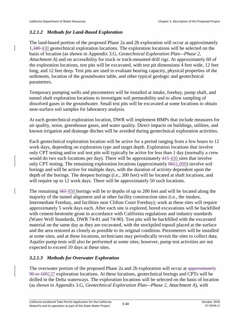
California Department of Water Resources
Chapter 3. Description of the Proposed Project
3.2.1.2 Methods for Land-Based Exploration
The land-based portion of the proposed Phase 2a and 2b exploration will occur at approximately 1,380 430 geotechnical exploration locations. The exploration locations will be selected on the basis of location (as shown in Appendix 3.G, Geotechnical Exploration Plan—Phase 2, Attachment A) and on accessibility for truck or track-mounted drill rigs. At approximately 60 of the exploration locations, test pits will be excavated, with test pit dimensions 4 feet wide, 12 feet long, and 12 feet deep. Test pits are used to evaluate bearing capacity, physical properties of the sediments, location of the groundwater table, and other typical geologic and geotechnical parameters.
Temporary pumping wells and piezometers will be installed at intake, forebay, pump shaft, and tunnel shaft exploration locations to investigate soil permeability and to allow sampling of dissolved gases in the groundwater. Small test pits will be excavated at some locations to obtain near-surface soil samples for laboratory analysis.
At each geotechnical exploration location, DWR will implement BMPs that include measures for air quality, noise, greenhouse gases, and water quality. Direct impacts on buildings, utilities, and known irrigation and drainage ditches will be avoided during geotechnical exploration activities.
Each geotechnical exploration location will be active for a period ranging from a few hours to 12 work days, depending on exploration type and target depth. Exploration locations that involve only CPT testing and/or soil test pits will typically be active for less than 1 day (normally a crew would do two such locations per day). There will be approximately 415 430 sites that involve only CPT testing. The remaining exploration locations (approximately 9651,000) involve soil borings and will be active for multiple days, with the duration of activity dependent upon the depth of the borings. The deepest borings (i.e., 300 feet) will be located at shaft locations, and will require up to 12 work days. There will be approximately 50 such locations.
The remaining 365 950 borings will be to depths of up to 200 feet and will be located along the majority of the tunnel alignment and at other facility construction sites (i.e., the intakes, Intermediate Forebay, and facilities near Clifton Court Forebay); work at these sites will require approximately 5 work days each. After each site is explored, bored excavations will be backfilled with cement-bentonite grout in accordance with California regulations and industry standards (Water Well Standards, DWR 74-81 and 74-90). Test pits will be backfilled with the excavated material on the same day as they are excavated, with the stockpiled topsoil placed at the surface and the area restored as closely as possible to its original condition. Piezometers will be installed at some sites, and at these locations, technicians may periodically revisit the sites to collect data. Aquifer pump tests will also be performed at some sites; however, pump test activities are not expected to exceed 10 days at these sites.
3.2.1.3 Methods for Overwater Exploration
The overwater portion of the proposed Phase 2a and 2b exploration will occur at approximately 90 to 100137 exploration locations. At these locations, geotechnical borings and CPTs will be drilled in the Delta waterways. The exploration locations will be selected on the basis of location (as shown in Appendix 3.G, Geotechnical Exploration Plan—Phase 2, Attachment A), with
California Incidental Take Permit Application for the California WaterFix and its operation as part of the State Water Project 3-40 October 2016
ICF 00408.12

California Department of Water Resources
Chapter 3. Description of the Proposed Project
precise site selection based upon practicability considerations such as avoidance of navigation markers and underwater cables. Approximately 30 of these locations will be in the Sacramento RiverThe locations, shown in Table 3-11, have been selected to obtain geotechnical data for the proposed intake structures, to assess. An additional 25 to 35 of these locations will be at the major water undercrossings along the tunnel alignment, to assess and 30 to 35 of these locations will be at the proposed barge unloading facilities, and the Clifton Court Forebay (CCF) modifications. The borings and CPTs are planned to explore depths between 100 and 200 feet below the mud line (i.e., river bottom).
DWR will conduct overwater drilling only during the in-water work window10 between the hours of sunrise and sunset. Duration of drilling at each location will vary depending on the number and depth of the holes, drill rate, and weather conditions, but activities are not expected to exceed 60 days at any one location. Overwater borings for the intake structures and river crossings for tunnels will be carried out by a drill ship and barge-mounted drill rigs.
3.2.1.4 Extent of Phase 2a Land-based and Overwater Work
Phase 2a exploration will focus on collecting data to support preliminary engineering through soil borings and CPTs at approximately 550 land-based and 43 overwater locations. Land-based explorations will be conducted for the intake perimeter berms, State Route (SR) 160, sedimentation basins, pumping plants, forebay embankments, tunnel construction shafts, and other appurtenant facilities (subsequent subsections herein describe these facilities in detail). Overwater explorations will support the design of intake structures and the major water crossings along the conveyance alignment.
Phase 2a exploration for tunnel construction will entail land-based drilling approximately every 1,000 feet along the tunnel alignment. One-third of the sites will receive only soil borings, half will receive only CPTs, and one-sixth will receive both soil borings and CPTs. All of the land-based boreholes along the tunnel alignments will be fitted with piezometers. Overwater drilling is planned in Potato Slough (three sites), San Joaquin River (three sites), Connection Slough (two sites), and CCF (35 sites).
In addition, six soil borings and four CPTs will occur at each tunnel shaft or CCF pumping plant shaft site. Once drilling is completed at each shaft site, two of the boreholes will be converted into groundwater extraction wells and the other four boreholes will be converted into piezometers. Boreholes and CPTs are also proposed for the intake and pumping plant sites and SR 160. Approximately six boreholes at each of the proposed intakes will be converted into piezometers.
3.2.1.5 Extent of Phase 2b Land-based and Overwater Work
Phase 2b exploration will support final design, permitting requirements, and planning for procurement and construction-related activities. Phase 2b explorations will include soil borings, CPTs, and test pits at approximately 830 880 land-based and 94 overwater locations.
Phase 2b exploration for tunnel construction will entail land-based drilling for soil borings near the Phase 2a CPT locations such that a borehole (soil boring or CPT) will have been located at
California Incidental Take Permit Application for the California WaterFix and its operation as part of the State Water Project 3-41 October 2016
ICF 00408.12

California Department of Water Resources
Chapter 3. Description of the Proposed Project
approximately 500-foot intervals along the entire tunnel alignment, a spacing that generally conforms to typical design efforts for tunnels like those proposed.
Similarly, Phase 2b boring will occur at the construction and ventilation shaft sites, and will also occur at the safe haven intervention sites (these types of facilities are described in Section 3.2.3 Tunneled Conveyance). Overwater boreholes and CPTs are planned in the Sacramento River, Snodgrass Slough, South Fork Mokelumne River, San Joaquin River, Potato Slough, Middle River, Connection Slough, Old River, North Victoria Canal, and CCF. Phase 2a and Phase 2b geotechnical exploration are summarized in Table 3-11.
Table 3-11. Planned Geotechnical Exploration
Siting Location Maximum Number of Exploration Sites Phase 2a Phase 2b
On land All locations 550 880 Over-water Sacramento River 0 30 Over-water Snodgrass Slough 0 3 Over-water South Fork Mokelumne River 0 3 Over-water San Joaquin River 3 12 Over-water Potato Slough 3 18 Over-water Middle River 0 2 Over-water Connection Slough 2 7 Over-water Old River 0 6 Over-water West Canal 0 8 Over-water Clifton Court Forebay 35 5
3.2.1.6 Schedule
Phase 2a and Phase 2b land-based explorations will require approximately 24 months, using six land-based drill rigs operating concurrently for six days per week. It is not known when each rig will work at each site. Land-based explorations will typically occur from April through November, and when performed in suitable habitat will conform to timing constraints for terrestrial species as specified in Section 5.3 Take Minimization Measures. Phase 2a and Phase 2b overwater explorations will require approximately 14 months, using two drill rigs operating concurrently for 6 days per week. Work will be performed within proposed in-water work windows10. This schedule will be expedited if possible, depending on the availability of site access, drilling contractors and equipment, permit conditions, and weather. Most of the proposed geotechnical explorations will be performed during the first 3 years of implementation. See Appendix 3.D Construction Schedule for the Proposed Project for further information on the conveyance facility construction schedule.
3.2.2 North Delta Diversions
The siting process featured evaluations of a wide variety of locations for north Delta diversion intakes and various configurations. Possible intake locations and configurations were considered and analyzed in terms of the availability of quantity and quality of water for the diversion, the ability to divert at each intake location, potential impacts on other nearby diverters and
California Incidental Take Permit Application for the California WaterFix and its operation as part of the State Water Project 3-42 October 2016
ICF 00408.12

California Department of Water Resources
Chapter 3. Description of the Proposed Project
dischargers, fish exposure-risk to intakes, presence of fish migration corridors, potential water quality considerations, and reasonable costs estimates involved in construction and operation, among other considerations. This preliminary analysis provided information sufficient to focus on potential intake locations and assumed a diversion facility consisting of five (5) intakes with a total capacity of 15,000 cubic feet per second (cfs). Potential siting of intake locations ranged in distance as far upstream on the Sacramento River to north of the American River confluence in Sacramento County, to as far downstream as south of Steamboat Slough in Solano County. Detailed analyses of these potential intake configurations were conducted in 2010. These analyses showed that actual intake locations are primarily influenced by exposure risk for fish, and to a lesser extent, migration pathways (California Department of Water Resources et al. 2013 [Appendix 3.A]).
After extensive analysis and consultation with stakeholders, in July 2012 the project proponents proposed to evaluate the construction and use of three intakes (Intakes 2, 3, and 5) located between Courtland and Clarksburg for a total maximum pumping diversion capacity of 9,000 cfs. This configuration and capacity was chosen because the water facilities would meet projected water supply needs. The use of three intakes was found to be sufficient to meet forecast diversion volume needs and would have lower environmental impacts compared to construction of five intakes. The intakes are designed as on-bank screens. Design and operational criteria supporting this concept included design constraints developed in collaboration with the fish and wildlife agencies (Fish Facilities Technical Team 2008, 2011), as well as minimum performance standards for bypass flows, sufficient to minimize the risk of covered fishes becoming entrained or impinged on the screens.
The intake design process also reflects a long duration of collaborative discussions between the project proponents and the fish and wildlife agencies. In 2008, the Fish Facilities Technical Team’s (FFTT) preliminary draft, Conceptual Proposal for Screening Water Diversion Facilities along the Sacramento River, reviewed and evaluated various approaches to the screening of diversion facilities, using screen design principles offered by the National Marine Fisheries Service (NMFS), California Department of Fish and Wildlife (CDFW), and U.S. Fish and Wildlife Service (USFWS) (Fish Facilities Technical Team 2008). These principles included using designs that would comply with the following criteria:
• Be biologically protective.
• Provide a positive, physical barrier between fish and water intakes.
• Avoid the need to collect, concentrate, and handle fish passing the intake.
• Avoid bypasses that would concentrate fish numbers, increasing the risk of predation.
• Avoid off-channel systems, in order to avoid handling fish.
• Select locations that have desirable hydraulic characteristics (e.g., uniform sweeping velocities, reduced turbulence).
• Use the best available existing technology in use in the Sacramento Valley.
California Incidental Take Permit Application for the California WaterFix and its operation as part of the State Water Project 3-43 October 2016
ICF 00408.12

California Department of Water Resources
Chapter 3. Description of the Proposed Project
• Use smaller multiple intakes (as opposed to a single large intake) to enhance fish protection with operational flexibility under varying flow conditions.
• Minimize the length of intake(s) to reduce the duration of exposure to the screen surface for fish.
• Select locations on the Sacramento River as far north as practicable to reduce the exposure of delta smelt, longfin smelt, and other estuarine species.
• Avoid areas where predators may congregate or where potential prey would have increased vulnerability to predation.
• Avoid areas of existing riparian habitat.
To the extent possible, these principles have been used to guide the preliminary design of the NDD and will continue to be used as the design process continues, although it is acknowledged that site-specific constraints may not allow all of the criteria suggested in these principles to be met.
3.2.2.1 Intake Design
The PP will include construction of three intakes (Intake 2, Intake 3, and Intake 5) on the east bank of the Sacramento River between Clarksburg and Courtland, in Sacramento County, California. Intake locations and plans are shown in Figure 3-1; in Appendix 3.A Map Book for the Proposed Project, Sheets 1 and 2; and Appendix 3.C8 Conceptual Engineering Report, Volume 2, Sheets 10 to 32, 44, and 45. The materials in Appendix 3.C include a rendering of a completed intake, as well as both overview and detail drawings for each intake site. The intakes are described in Appendix 3.B8 Conceptual Engineering Report, Volume 1, Section 6.1 Description and Site Plans; see particularly Tables 6-1 and 6-2, which describe intake design criteria relevant to analysis of effects, such as approach and sweeping velocities and fish screen specifications, and Section 6.1.1.1 Intake Structures, which describes fish screen design. Other intake components are behind the fish screens and have no potential to affect listed species. Information relevant to intakes construction details is provided in Appendix 3.B, Section 6.2 Construction Methodology. General intake dimensions are shown in Table 3-12.
Table 3-12. Intake Dimensions
Intake Location (river mile)
Overall Length of Structure
along Sacramento
River Bank (feet)
Area of Intake Construction Site
(acres)
Area of Tidal Perennial Habitat (acres)
Temporary In-Water Work
Permanent (Intake + Wing
Wall Transitions)
Intake 2 41.1 1,969 190 4.9 2.6 Intake 3 39.4 1,497 152 3.3 1.8 Intake 5 36.8 1,901 144 5.0 2.3 Total -- 5,367 486 13.2 6.6
California Incidental Take Permit Application for the California WaterFix and its operation as part of the State Water Project 3-44 October 2016
ICF 00408.12
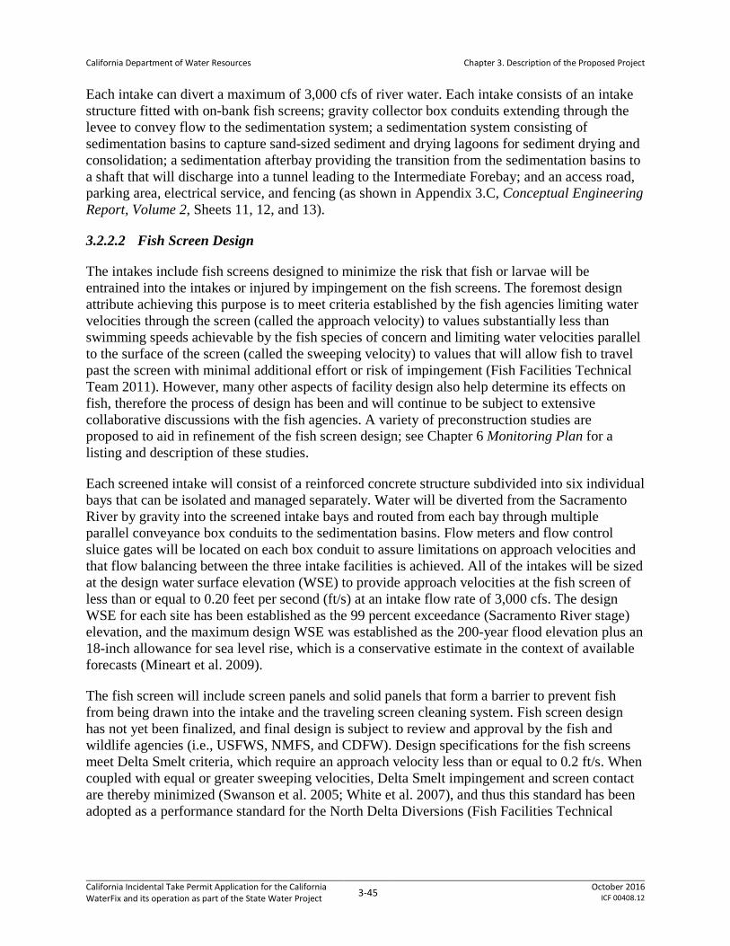
California Department of Water Resources
Chapter 3. Description of the Proposed Project
Each intake can divert a maximum of 3,000 cfs of river water. Each intake consists of an intake structure fitted with on-bank fish screens; gravity collector box conduits extending through the levee to convey flow to the sedimentation system; a sedimentation system consisting of sedimentation basins to capture sand-sized sediment and drying lagoons for sediment drying and consolidation; a sedimentation afterbay providing the transition from the sedimentation basins to a shaft that will discharge into a tunnel leading to the Intermediate Forebay; and an access road, parking area, electrical service, and fencing (as shown in Appendix 3.C, Conceptual Engineering Report, Volume 2, Sheets 11, 12, and 13).
3.2.2.2 Fish Screen Design
The intakes include fish screens designed to minimize the risk that fish or larvae will be entrained into the intakes or injured by impingement on the fish screens. The foremost design attribute achieving this purpose is to meet criteria established by the fish agencies limiting water velocities through the screen (called the approach velocity) to values substantially less than swimming speeds achievable by the fish species of concern and limiting water velocities parallel to the surface of the screen (called the sweeping velocity) to values that will allow fish to travel past the screen with minimal additional effort or risk of impingement (Fish Facilities Technical Team 2011). However, many other aspects of facility design also help determine its effects on fish, therefore the process of design has been and will continue to be subject to extensive collaborative discussions with the fish agencies. A variety of preconstruction studies are proposed to aid in refinement of the fish screen design; see Chapter 6 Monitoring Plan for a listing and description of these studies.
Each screened intake will consist of a reinforced concrete structure subdivided into six individual bays that can be isolated and managed separately. Water will be diverted from the Sacramento River by gravity into the screened intake bays and routed from each bay through multiple parallel conveyance box conduits to the sedimentation basins. Flow meters and flow control sluice gates will be located on each box conduit to assure limitations on approach velocities and that flow balancing between the three intake facilities is achieved. All of the intakes will be sized at the design water surface elevation (WSE) to provide approach velocities at the fish screen of less than or equal to 0.20 feet per second (ft/s) at an intake flow rate of 3,000 cfs. The design WSE for each site has been established as the 99 percent exceedance (Sacramento River stage) elevation, and the maximum design WSE was established as the 200-year flood elevation plus an 18-inch allowance for sea level rise, which is a conservative estimate in the context of available forecasts (Mineart et al. 2009).
The fish screen will include screen panels and solid panels that form a barrier to prevent fish from being drawn into the intake and the traveling screen cleaning system. Fish screen design has not yet been finalized, and final design is subject to review and approval by the fish and wildlife agencies (i.e., USFWS, NMFS, and CDFW). Design specifications for the fish screens meet Delta Smelt criteria, which require an approach velocity less than or equal to 0.2 ft/s. When coupled with equal or greater sweeping velocities, Delta Smelt impingement and screen contact are thereby minimized (Swanson et al. 2005; White et al. 2007), and thus this standard has been adopted as a performance standard for the North Delta Diversions (Fish Facilities Technical
California Incidental Take Permit Application for the California WaterFix and its operation as part of the State Water Project 3-45 October 2016
ICF 00408.12
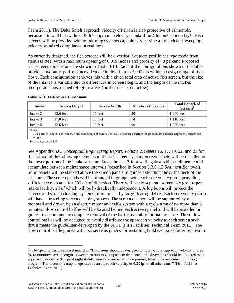
California Department of Water Resources
Chapter 3. Description of the Proposed Project
Team 2011). The Delta Smelt approach velocity criterion is also protective of salmonids, because it is well below the 0.33 ft/s approach velocity standard for Chinook salmon fry11. Fish screens will be provided with monitoring systems capable of verifying approach and sweeping velocity standard compliance in real time.
As currently designed, the fish screens will be a vertical flat plate profile bar type made from stainless steel with a maximum opening of 0.069 inches and porosity of 43 percent. Proposed fish screens dimensions are shown in Table 3-13. Each of the configurations shown in the table provides hydraulic performance adequate to divert up to 3,000 cfs within a design range of river flows. Each configuration achieves this with a given total area of active fish screen, but the size of the intakes is variable due to differences in screen height, and the length of the intakes incorporates unscreened refugium areas (further discussed below).
Table 3-13. Fish Screen Dimensions
Intake Screen Height Screen Width Number of Screens Total Length of Screens1
Intake 2 12.6 feet 15 feet 90 1,350 feet Intake 3 17.0 feet 15 feet 74 1,110 feet Intake 5 12.6 feet 15 feet 90 1,350 feet Notes
1 Fish screen length is shorter than structure length shown in Table 3-12 because structure length includes concrete approach sections and refugia.
Source: Appendix 3.C See Appendix 3.C, Conceptual Engineering Report, Volume 2, Sheets 16, 17, 19, 22, and 23 for illustration of the following elements of the fish screen system. Screen panels will be installed in the lower portion of the intake structure face, above a 2-foot wall against which sediment could accumulate between maintenance intervals (described in Section 3.3.6.1.2 Sediment Removal). Solid panels will be stacked above the screen panels in guides extending above the deck of the structure. The screen panels will be arranged in groups, with each screen bay group providing sufficient screen area for 500 cfs of diversion. There will be six separate screen bay groups per intake facility, all of which will be hydraulically independent. A log boom will protect the screens and screen cleaning systems from impact by large floating debris. Each screen bay group will have a traveling screen cleaning system. The screen cleaners will be supported by a monorail and driven by an electric motor and cable system with a cycle time of no more than 5 minutes. Flow control baffles will be located behind each screen panel and will be installed in guides to accommodate complete removal of the baffle assembly for maintenance. These flow control baffles will be designed to evenly distribute the approach velocity to each screen such that it meets the guidelines developed by the FFTT (Fish Facilities Technical Team 2011). The flow control baffle guides will also serve as guides for installing bulkhead gates (after removal of
11 The specific performance standard is: “Diversions should be designed to operate at an approach velocity of 0.33 fps to minimize screen length, however, to minimize impacts to delta smelt, the diversions should be operated to an approach velocity of 0.2 fps at night if delta smelt are suspected to be present, based on a real-time monitoring program. The diversions may be operated to an approach velocity of 0.33 fps at all other times” (Fish Facilities Technical Team 2011).
California Incidental Take Permit Application for the California WaterFix and its operation as part of the State Water Project 3-46 October 2016
ICF 00408.12

California Department of Water Resources
Chapter 3. Description of the Proposed Project
the flow control baffles) for maintenance of each screen bay group. The bulkhead gates will be designed to permit dewatering of a screen bay group under normal river conditions.
Because of the length of the screens and extended fish exposure to their influence (screens and cleaners), incorporation of fish refugia areas will be evaluated as part of next engineering design phase of the intakes, as recommended by the FFTT (Fish Facilities Technical Team 2011). Current conceptual design for the refugia would provide areas within the columns between the fish screen bay groups that would provide fish resting areas and protected cover from predators. The current design calls for a 22-foot-wide refugium between each of the six screen bay groups at each intake. Design concepts for fish refugia and studies to evaluate their effectiveness are still in development, and final refugia design is subject to review by the fish agencies (i.e., USFWS, NMFS, and CDFW). The review and final design process will incorporate lessons from the Fish Facilities Technical Team (2011) work, the current NMFS (2011) guidance for fish screens, and recent relevant projects, as applicable.
Two recent examples of fish refugia design and installation include the Red Bluff Diversion fish screen and that of Reclamation District 2035, on the Sacramento River just north of Sacramento (Svoboda 2013). The Red Bluff Diversion fish screen design used a physical model study to assess hydraulic parameters such as velocity and turbulence in relation to behavior of juvenile Chinook salmon, white sturgeon, and rainbow trout. The refugia consist of flat recessed panels protected by vertical bars. Bar spacing at the entrance to each refugium was selected based on fish size, to allow entry of protected species while excluding predators. A final design was chosen to reduce velocity in the refuge while minimizing turbulence; under this design, a total of four fish refugia were constructed along 1,100 feet of screen.
At the Reclamation District 2035 fish screen, an initial design included a single refuge pocket midway along the intake, which was subsequently modified to include 2-ft-long refugia between each screen panel along the intake. This fish screen also included juvenile fish habitat elements into the upstream and downstream sheet pile training walls and the sloped soil areas above the training walls, with grating materials attached to the sheet pile walls to prevent predatory fish from holding in the corrugated areas by the walls and to provide another form of refuge for small fish (Svoboda 2013). These two examples serve to illustrate the site-specific design considerations that are necessary for construction of large intakes. The effectiveness of refugia requires study (Svoboda 2013).
All fish screen bay groups will be separated by piers with appropriate guides to allow for easy installation and removal of screen and solid panels as well as the flow control baffle system and bulkheads; these features will be removable by gantry crane (Appendix 3.C, Conceptual Engineering Report, Volume 2, Sheet 17). Piers will support the operating deck set with a freeboard of 18 inches above the 200-year flood level with sea level rise12. The levee in the immediate area will be raised to provide a freeboard of 3 feet above the 200-year flood level with sea level rise. Sheet pile training walls will have a radius of 200 feet and will be upstream and downstream of the intake structures providing improved river hydraulics and vehicular access to
12 Height of the deck from sill invert varies depending on the location: For Intakes 2, 3, and 5, the deck heights from sill invert would be 44.4 ft, 48.4 ft, 43.2 ft, respectively. See drawing sheet # 17 of 96, in Appendix 3.C.
California Incidental Take Permit Application for the California WaterFix and its operation as part of the State Water Project 3-47 October 2016
ICF 00408.12
California Department of Water Resources
Chapter 3. Description of the Proposed Project
the operating deck as well as transitioning the intake structure to the levee. These walls will be made of sheet piles, which are used to enclose the areas between fish screens and levees located upstream and downstream of the screens (Appendix 3.C, Sheets 33 and 34 show the extent of levee modifications).
3.2.2.3 Construction Overview and Schedule
The timeline for NDD construction is presented in Appendix 3.D Construction Schedule for the Proposed Project. The schedule is complex, with work simultaneously occurring at all major facilities for a period of years, and tunnel boring likewise occurring simultaneously at multiple sites for a period of years. During construction, the sequence of activities and duration of each schedule element will depend on the contractor’s available means and methods, definition and variation of the design, departure from expected conditions, and perhaps other variable factors. All construction will be performed within the permanent footprint identified in Appendix 3.A Map Book for the Proposed Project.
Each intake has its own construction duration with Intakes 2, 3, and 5 each projected to take approximately 4 to 5 years. Early phase tasks to facilitate construction will include mobilization, site work, and establishing concrete batch plants, pug mills, and cement storage areas. During mobilization the contractors will bring materials and equipment to construction sites, set up work areas, locate offices, staging and laydown areas, and secure temporary electrical power. Staging, storage, and construction zone prep areas for each intake site will cover approximately 5 to 10 acres. Barges, which will be used as construction platforms for drilling rigs, cranes, etc., will be present throughout the construction period at each intake facility.
Site work consists of clearing and grubbing (discussed in Section 3.2.10.1 Clearing), constructing site work pads, and defining and building construction access roads (discussed in Section 3.2.9 Temporary Access and Work Areas) and barge access (discussed in Section 3.2.10.9 Barge Landing Construction and Operations). Before site work commences, the contractor will implement erosion and sediment controls in accordance with the Storm Water Pollution Prevention Plan (SWPPP) (See Appendix 3.F General Avoidance and Minimization Measures, AMM3 Stormwater Pollution Prevention Plan, for a detailed description). Site clearing and grubbing and site access to stockpile locations have not yet been developed, but will be subject to erosion and dust control measures as specified in the SWPPP and other permit authorizations.
Although DWR plans to use existing roads to the greatest extent possible, some new roads and bridges will be constructed to expedite construction activities and to minimize impact to existing commuters and the environment. Access roads and environmental controls will be maintained consistent with BMPs and other requirements of the SWPPP and permit documents.
Substantial amounts of engineered fill will be placed landward of the levee, amounting to approximately 2 million cubic yards at each intake site. This fill material will be used primarily in levee work, pad construction for the fills, and other placements needed to ensure that the permanent facilities are at an elevation above the design flood (i.e., a 200-year flood with additional allowance for sea level rise). The required engineered fill material will preferably be sourced onsite from locations within the permanent impact footprint, for instance from
California Incidental Take Permit Application for the California WaterFix and its operation as part of the State Water Project 3-48 October 2016
ICF 00408.12

California Department of Water Resources
Chapter 3. Description of the Proposed Project
excavations to construct the sedimentation basins. Material sourced from offsite will be obtained as described in Section 3.2.10.4, Borrow Fill.
3.2.2.4 Levee Work
Levee modifications will be required to facilitate intake construction and to provide continued flood management. The levee modifications are described in Appendix 3.B, Conceptual Engineering Report, Volume 1, Section 15, Levees, and in Appendix 3.C, Conceptual Engineering Report, Volume 2, Drawings 6, 10 to 17, 19, 44, and 45. Additional information on cofferdam construction (one element of the levee work) appears in Appendix 3.B, Section 6.2.1, General Constructability Considerations. The Sacramento River levees are Federal Flood Control Project levees under the jurisdiction of USACE and Central Valley Flood Protection Board, and specific requirements are applicable to penetrations of these levees. Authorizations for this work have not yet been issued. All construction on these levees will be performed in accordance with conditions and requirements set forth in the USACE permit authorizing the work.
Principal levee modifications necessary for conveyance construction are here summarized. See the referenced text in Appendices 3.B and 3.C, Conceptual Engineering Report, Volumes 1 and 2, respectively, for detailed descriptions of the work. Appendix 3.B, Section 15.2, Sequence of Construction at the Levee, includes a table detailing the sequence of construction activities in levee work.
New facilities interfacing with the levee at each intake site will include the following elements.
3.2.2.4.1 Levee Widening
Levees near the intakes will be widened on the land-side to increase the crest width, facilitate intake construction, provide a pad for sediment handling, and accommodate the Highway 160 realignment. Levee widening is done by placing low permeability levee fill material on the land-side of the levee. The material is compacted in lifts and keyed into the existing levee and ground. The levee will be widened by about 250 feet at each intake site. The widened levee sections will allow for construction of the intake cofferdams, associated diaphragm walls, and levee cutoff walls within the existing levee prism while preserving a robust levee section to remain in place during construction.
SR 160 will be impacted by construction activities at each of the three intake sites. During the levee widening, the highway will be permanently relocated from its current alignment along the top of the river levee to a new alignment established on top of the widened levee aligned approximately 220 feet farther inland from the river. The location of the new permanent SR 160 alignment is shown in Appendix 3.C Conceptual Engineering Report, Volume 2, Drawings 13, 14, 15 and 16.
3.2.2.4.2 On-Bank Intake Structure, Cofferdam, and Cutoff Walls
The intake structure and a portion of the box conduits will be constructed inside a dual sheet pile cofferdam installed within the levee prism on the river-side (Appendix 3.C Conceptual Engineering Report, Volume 2, Drawings 15, 16, 17 and 19; construction techniques are
California Incidental Take Permit Application for the California WaterFix and its operation as part of the State Water Project 3-49 October 2016
ICF 00408.12

California Department of Water Resources
Chapter 3. Description of the Proposed Project
described in Appendix 3.B Conceptual Engineering Report, Volume 1, Sections 6.2.1, General Constructability Considerations; 15.1, Configuration of Facilities in the Levee; and 15.2, Sequence of Construction at the Levee. See Section 3.2.2.5 Pile Installation for Intake Construction, for detail on the pile placement required for cofferdam construction). The intake structure foundation will use a combination of ground improvement (as described in Section 3.2.10.3 Ground Improvement) and steel-cased driven piles or drilled piers. The cofferdams will project from 10 to 35 feet into the river, relative to the final location of the intake screens13, dewatering up to 5 acres of channel at each intake site. The river width varies from 475 feet at Intake 3 to 615 feet at Intake 5, so this represents 1.6 percent to 7.4 percent of the channel width.
The back wall of the cofferdam along the levee crest will be a deep slurry diaphragm cutoff wall designed for dual duty as a structural component of the cofferdam and to minimize seepage through and under the levee at the facility site; thus the cofferdam sheet piles will become permanent structural components of the intake facility. The diaphragm wall will extend along the levee crest upstream and downstream of the cofferdam and the fill pad for the sedimentation on the land-side, which will allow for a future tie-in with levee seepage cutoffs that are not part of the PP. The other three sides of the cofferdam, including a center divider wall, will be sheet pile walls. The cofferdam will include a permanent, 5-foot-thick tremie concrete seal in the bottom to aid dewatering and constructability within the enclosed work area.
Once each cofferdam is completed and the tremie seal has been poured and has cured, the enclosed area will be dewatered as described in Section 3.2.10.7 Dewatering, with fish rescue occurring at that time, in accordance with a fish rescue plan that has been previously approved by CDFW, NMFS, and USFWS. Preparation and requirements for fish rescue plans are described in Appendix 3.F General Avoidance and Minimization Measures, AMM8 Fish Rescue and Salvage Plan. Following dewatering, areas within the cofferdam will be excavated to the level of design subgrade using clam shell or long-reach backhoe before ground improvements (jet grouting and deep soil mixing) and installation of foundation piles as described below in Section 3.2.2.5 Pile Installation for Intake Construction.
In conjunction with the diaphragm wall, a slurry cutoff wall (soil, bentonite, and cement slurry) will be constructed around the perimeter of the construction area for the land-side facilities (facilities described above in the paragraphs on initial site work and levee widening). This slurry wall will be tied into the diaphragm wall at the levee by short sections of diaphragm wall perpendicular to the levee. The slurry cutoff wall will overlap for approximately 150 feet along the diaphragm wall at the points of tie-in. The slurry wall is intended to help prevent river water from seeping through or under the levee during periods when deep excavations and associated dewatering are required on the land-side. By using the slurry wall in conjunction with the diaphragm wall, the open cut excavation portion of the work on the landside will be completely surrounded by cutoff walls. These walls will minimize induced seepage from the river through the levee, both at the site and immediately adjacent to the site, and serve as long-term seepage control behind the levee.
13 Fish screens would be located on the bank of existing levees. See drawing sheets 11, 12, and 13 of 96, in Appendix 3.C.
California Incidental Take Permit Application for the California WaterFix and its operation as part of the State Water Project 3-50 October 2016
ICF 00408.12

California Department of Water Resources
Chapter 3. Description of the Proposed Project
At the upstream and downstream ends of the intake structure, a sheet pile training wall will transition from the concrete intake structure into the river-side of the levee. Riprap will be placed on the levee-side slope upstream and downstream of the structure to prevent erosion from anomalies in the river created by the structure. Riprap will also be placed along the face of the structure at the river bottom to resist scour.
The cofferdam structure and the berm surrounding the entire intake construction site landward of the levee will provide temporary flood protection during construction; see Appendix 3.B, Conceptual Engineering Report, Volume 1, Section 15.3.1, Temporary Flood Protection Features, for a detailed explanation of how this will be accomplished.
After intake construction is complete the cofferdammed area will be flooded and underwater divers using torches or plasma cutters will trim the sheet piles at the finished grade/top of structural slab. A portion of the cofferdam will remain in place after intake construction is complete to facilitate dewatering as necessary for maintenance and repairs, as shown in Appendix 3.C Conceptual Engineering Report, Volume 2, Drawing 16.
3.2.2.4.3 Box Conduits
Large gravity collector box conduits (12 conduits at each intake) will lead from the intake structure through the levee prism to the landside facilities. The box conduits will be constructed by open-cut methods after the intake portion of the cofferdam is backfilled. Backfill above the box conduits and reconstruction of the disturbed portion of the levee prism will be accomplished using low-permeability levee material in accordance with USACE specifications.
3.2.2.5 Pile Installation for Intake Construction
Structural properties of the sediment at the construction site are a principal consideration in determining the effort required for pile installation. See Appendix 3.B, Section 6.2.2, Intake Structure and Sediment Facilities Geotechnical, for a description of geotechnical findings at each intake site. Generally, sediments at the intake sites consist of a surficial layer of soft to medium stiff, fine-grained soils to a depth of approximately 20 to 30 feet below ground surface; underlain by stratified stiff clay, clayey silt, and dense silty sand to the depth of the soil borings.
See Section 3.2.10.11 Pile Driving, for a general description of how pile driving will be performed. Table 3-14 summarizes proposed pile driving at the intake sites, including the type, size, and number of piles required, as well as the number of piles driven per day, the number of impact strikes per pile, and whether piles will be driven in-water or on land. Table 3-14 specifies 42-inch steel piles for the intake foundations; however, depending on the findings of the geotechnical exploration, it may be feasible to replace some or all of those steel piles with cast-in-drilled-hole (CIDH) foundation piles. The CIDH piles are installed by drilling a shaft, installing rebar, and filling the shaft with concrete; no pile driving is necessary with CIDH methods. Use of concrete filled steel piles will involve vibratory or impact-driving hollow steel piles, and then filling them with concrete. Table 3-14 assumes that all piles will be driven using impact pile driving, but the design intent is to use impact pile driving only for placement of the intake structure foundation piles. All other piles will be started using vibratory pile driving and driving will be completed using impact pile driving. Based on experience during construction of
California Incidental Take Permit Application for the California WaterFix and its operation as part of the State Water Project 3-51 October 2016
ICF 00408.12
California Department of Water Resources
Chapter 3. Description of the Proposed Project
the Freeport diversion facility, it is expected that approximately 70 percent of the length of each pile can be placed using vibratory pile driving, with impact driving used to finalize pile placement. In-water pile driving will be subject to abatement, hydroacoustic monitoring14, and compliance with timing limitations as described in Appendix 3.F General Avoidance and Minimization Measures, AMM9 Underwater Sound Control and Abatement Plan.
14 For more on corrective measures, thresholds, and responses to underwater noise see Permit Resolution Log, item #33.
California Incidental Take Permit Application for the California WaterFix and its operation as part of the State Water Project 3-52 October 2016
ICF 00408.12

California Department of Water Resources
Chapter 3. Description of the Proposed Project
Table 3-14. Pile Driving for Intake Construction
Feature On-land or In-water
Pile Type/ Sizes
Total Piles
Number of Pile Drivers
in Concurrent
Use
Piles/ Day
Strikes/ Pile
Strikes/ Day
Intake 2 Cofferdam – Intakes 2, 3, and 5 In-water Sheet pile 2,500 4 60 210 12,600
Intake 3 Cofferdam In-water Sheet pile 2,500 4 60 210 12,600 Intake 5 Cofferdam In-water Sheet pile 2,500 4 60 210 12,600 Intake 2 Structure Foundation – Intake 2 In-water 42-inch
diameter steel 1,120 4 60 1,500 90,000
Intake 3 Structure Foundation – Intake 3 In-water 42-inch
diameter steel 850 4 60 1,500 90,000
Intake 5 Structure Foundation – Intake 5 In-water 42-inch
diameter steel 1,120 4 60 1,500 90,000
SR-160 Bridge (Realignment) at Intake On-land 42-inch
diameter steel 150 2 30 1,200 36,000
Control Structure at Intake On-land 42-inch diameter steel 650 4 60 1,200 72,000
Pumping Plant and Concrete Sedimentation Basins at Intake
On-land 42-inch diameter steel 1,650 4 60 1,200 72,000
Sheet piles will be installed in two phases starting with a vibratory hammer and then switching to impact hammer if refusal is encountered before target depths. Sheet pile placement for cofferdam installation will be performed by a barge-mounted crane equipped with vibratory and impact pile-driving rigs. Foundation pile placement within the cofferdammed area may be done before or after the cofferdammed area is dewatered. If it is done after the cofferdammed area is dewatered and the site is dry, a crane equipped with pile driving rig will be used within the cofferdam. If done before the cofferdam is dewatered, pile driving will be performed by a barge-mounted crane positioned outside of the cofferdam or a crane mounted on a deck on top of the cofferdam. In-water pile driving will be subject to abatement (e.g., use of a bubble curtain), hydroacoustic monitoring, and compliance with timing limitations as described in Appendix 3.F General Avoidance and Minimization Measures, AMM9 Underwater Sound Control and Abatement Plan.
At the conclusion of construction, the intake facilities will be landscaped, fenced, and provided with security lighting as described in Section 3.2.10.10 Landscaping and Associated Activities.
California Incidental Take Permit Application for the California WaterFix and its operation as part of the State Water Project 3-53 October 2016
ICF 00408.12
California Department of Water Resources
Chapter 3. Description of the Proposed Project
3.2.3 Tunneled Conveyance
Although conceptual proposals for north Delta diversions of water for the CVP/SWP have been discussed since at least the early 1960s15, the earlier proposals all relied upon canal designs that would have resulted in extensive and unacceptable adverse impacts on both the human and natural environment in the Delta.
In 2009, however, the project proponents selected a pipeline and tunnel-based system as the preferred basis of design for conveyance of water from the North Delta Diversions to the CVP/SWP export facilities. The initial tunneled conveyance design, analyzed in the draft EIR/EIS for the PP (U.S. Bureau of Reclamation, U.S. Fish and Wildlife Service, National Marine Fisheries Service, and California Department of Water Resources 2013), had pump stations sited at each of the intakes, and somewhat smaller tunnels, north of the IF, compared to the PP.
Subsequent value engineering studies revealed that if the tunnels were made larger, then a gravity-feed system would work, allowing elimination of the pump stations at the intakes and their replacement with a consolidated pump station at the CCF. This design change reduced overall electricity consumption associated with operations of the PP, with a concomitant reduction in greenhouse gas generation (for electric power production). It also eliminated the need for new, permanent high-voltage electrical transmission lines serving the new intakes, and thereby eliminated the potential bird strike and other adverse effects associated with those transmission lines (although temporary transmission lines are still needed, to power TBMs and provide other construction electricity).
3.2.3.1 Design
The conveyance tunnels will extend from the proposed intake facilities (Section 3.2.2 North Delta Diversions) to the North Clifton Court Forebay (NCCF). The tunneled conveyance includes the North Tunnels, which consist of three reaches that connect the intakes to the IF; and two parallel Main Tunnels, connecting the IF to the NCCF. Final surface conveyance connecting the NCCF to the existing export facilities is described in Section 3.2.6 Connections to the Banks and Jones Pumping Plants. The water conveyance tunnels will be operated with a gravity feed system, delivering to a pumping station located at the NCCF.
Each tunnel segment will be excavated by a TBM. This technique largely limits surface impacts to those associated with initial geotechnical investigations on the TBM route (Section 3.2.1 Geotechnical Exploration), surface facilities located at the TBM launch and reception shafts (this section), the disposition of material excavated by the TBMs (Section 3.2.10.6 Dispose Spoils), the provision of electric power to the TBM (Section 3.2.7 Power Supply and Grid Connections), and points where the TBM cutterhead may need to be accessed for repair or maintenance (Section 3.2.3.3.5 Intermediate Tunnel Access). Water quality impact potential is associated with dewatering procedures and construction stormwater disposition at the TBM launch and reception
15 See Draft EIR/EIS Appendix 3.A, (California Department of Water Resources et al. 2013), for a detailed description of the historical development of the tunneled conveyance concept.
California Incidental Take Permit Application for the California WaterFix and its operation as part of the State Water Project 3-54 October 2016
ICF 00408.12

California Department of Water Resources
Chapter 3. Description of the Proposed Project
surface facilities, and would be addressed via relevant minimization measures described in Section 3.2.10.7 Dewatering, and relevant AMMs (Appendix 3.F General Avoidance and Minimization Measures, AMM3 Stormwater Pollution Prevention Plan, AMM4 Erosion and Sediment Control Plan, and AMM5 Spill Prevention, Containment, and Countermeasure Plan). TBMs also have the potential to generate subsurface effects due to the sound produced by TBM excavation.
The TBM launch facilities will be relatively large and active construction sites because they are continuously active during a TBM tunnel drive, when they will provide the only surface access to the tunnel. Thus they will require stockpiles of materials used by the TBM, will provide access to the TBM for its operation and maintenance, and will receive all materials excavated by the TBM. Conversely, TBM reception facilities will be used to recover the TBM at the end of its drive, and thus have a smaller footprint and a more limited operating scope. Table 3-15 summarizes all of the proposed tunnel drives, identifying launch and reception shafts, tunnel lengths, and tunnel diameters. Appendix 3.B, Conceptual Engineering Report, Volume 1, Figure 11-1, shows this information on a map. Note that Bouldin Island and the IF will be the primary launch shaft sites; the IF will be the launch point for 25.1 miles of two 40-foot tunnels and 4.8 miles of a 28-foot tunnel, while Bouldin Island will be the launch point for four, 40-foot tunnels with a total length of 25.4 miles. The north end of Clifton Court Forebay will be the launch point for two, 40-foot tunnels with a total length of 16.6 miles, while Intake 2 will be a relatively small site, acting as launch point for one 28-foot tunnel that will be 2.0 miles long.
For a detailed explanation of the tunneling work, see Appendix 3.B Conceptual Engineering Report, Volume 1, Sections 3.1 Proposed Alignment and Key Components, 3.2 Reach Descriptions, and 11.0 Tunnels; Sections 11.2.5 Tunnel Excavation Methods, and 11.2.6 Tunnel Support, in particular, detail the process of tunneling. Briefly16, tunneling will be performed by a TBM, which is a very large and heavy electrically-powered machine that will be launched from the bottom of a launch shaft, and will tunnel continuously underground to a reception shaft. The cutterhead of the TBM will be hydrostatically isolated from the remainder of the machine, so that the inside of the tunnel will be dry and at atmospheric pressure. As the TBM proceeds, precast concrete tunnel lining sections will be assembled within the TBM to produce a rigid, water-tight tunnel lining. Typically very little dewatering will be needed to keep the interior of the tunnel dry. A electrically-powered conveyor will carry excavated material from the TBM back to the launch shaft, where a vertical conveyor will carry the material to the surface for disposal (Section 3.2.10.6 Dispose Spoils). A narrow-gauge railway may be installed in the tunnel with a diesel locomotive, or rubber wheeled diesel engine trucks may be used to carry workers, tunnel lining segments, and other materials from the launch shaft to the TBM.
A map book showing all of the tunnel drives is presented in Appendix 3.A Map Book for the Proposed Project. Design drawings showing tunnel routing, design of the shaft structures, and layout of the surface facilities at launch and reception sites appear in Appendix 3.C Conceptual
16 An excellent video summarizing how a TBM tunnels through soft sediment is available at https://www.youtube.com/watch?v=qx_EjMlLgqY. Neither the contractor nor the project depicted in the video has any relationship to the PP, but the type of machine used and the procedures depicted are very similar to those that would occur under the PP.
California Incidental Take Permit Application for the California WaterFix and its operation as part of the State Water Project 3-55 October 2016
ICF 00408.12

California Department of Water Resources
Chapter 3. Description of the Proposed Project
Engineering Report, Volume 2; see Drawings 44 to 54, showing the tunnel routing and all associated areas of surface activity. A detailed project schedule, showing periods of tunneling and associated activities, is given in Appendix 3.D Construction Schedule for the Proposed Project. Each TBM launch or retrieval shaft will require barge access for equipment and materials; see Section 3.2.10.9 Barge Landing Construction and Operations, for further information. Avoidance and minimization measures (AMMs) to be implemented during construction work at all surface facilities supporting the tunneling work appear in Appendix 3.F General Avoidance and Minimization Measures, and are referenced below as appropriate.
Table 3-15. Tunnel Drive Summary
Reach Launch Shaft Reception Shaft Inside Diameter (ft) Length (miles) 1 Intake 2 Intake 3 junction structure 28 1.99 2 IF inlet Intake 3 junction structure 40 6.74 3 IF inlet Intake 5 28 4.77 4 (west tunnel) IF Staten Island 40 9.17 4 (east tunnel) IF Staten Island 40 9.17 5 (west tunnel) Bouldin Island Staten Island 40 3.83 5 (east tunnel) Bouldin Island Staten Island 40 3.83 6 (west tunnel) Bouldin Island Bacon Island 40 8.86 6 (east tunnel) Bouldin Island Bacon Island 40 8.86 7 (west tunnel) NCCF Bacon Island 40 8.29 7 (east tunnel) NCCF Bacon Island 40 8.29 IF = Intermediate Forebay NCCF = North Clifton Court Forebay
3.2.3.2 Schedule
Appendix 3.D Construction Schedule for the Proposed Project provides scheduling information for tunneling activities. The TBM launch shafts will be most active, producing RTM on a nearly continuous basis, for the following time periods:
• CCF: May 2020 to February 2025
• Bouldin Island: October 2020 to May 2025
• IF: May 2021 to October 2026
• Intake 2: October 2021 to July 2025
Overall, the peak period of activity will be from October 2020 to April 2025. Considering time required to prepare each site, as well as time required to stabilize and restore RTM storage areas, each site will remain active throughout essentially the whole period of construction (2018 to 2030). Since the CCF, IF, and Intake 2 are essential components of the conveyance system, these sites will remain permanently active. The Bouldin Island site, however, will close following attainment of revegetation and restoration objectives for the associated RTM storage areas, although a small permanent tunnel access shaft will remain.
California Incidental Take Permit Application for the California WaterFix and its operation as part of the State Water Project 3-56 October 2016
ICF 00408.12

California Department of Water Resources
Chapter 3. Description of the Proposed Project
3.2.3.3 Construction
Launch shaft sites (IF, Bouldin, NCCF, and Intake 2) are shown in Appendix 3.C Conceptual Engineering Report, Volume 2, Drawings 56, 50, 76, and 11, respectively. Reception shaft sites (Intake 3, Intake 5, Staten Island, and Bacon Island) are similar in design. Appendix 3.C, Drawings 69 to 73 show typical work area and finished construction plans for paired tunnel shafts. All construction will be performed within the permanent footprint identified in Appendix 3.A Map Book for the Proposed Project.
3.2.3.3.1 Shaft Site Facilities
Facilities at launch shaft sites will include a concrete batch plant and construction work areas including offices, parking, shop, short-term segment storage, fan line storage, crane, dry houses, settling ponds, daily spoils piles, temporary RTM storage, electrical power supplies, air, water treatment, and other requirements. There will also be space for slurry ponds at sites where slurry wall construction is required. Work areas for RTM handling and permanent disposal will also be necessary, as discussed in Section 3.2.10.6 Dispose Spoils. Facilities at reception shafts will be similar but more limited, as there will be no need for a concrete batch plant or for RTM storage.
3.2.3.3.2 Shaft Site Preparation
Shaft site preparation is detailed in Appendix 3.B Conceptual Engineering Report, Volume 1, Section 11.2.1 Advance Works Contracts. During shaft site preparation, vehicular access will be established and electrical service will be provided via temporary transmission line (see Section 3.2.7 Power Supply and Grid Connections). The shafts will be located on pads elevated to above the 200-year flood elevation; fill will be placed to construct these pads and to preload the ground to facilitate settling. The site will be fenced for security and made ready for full construction mobilization. Due to the pervasive nature of these activities, all surface disturbance associated with construction at each shaft site will occur very early during the period of activity at each site; the entire site footprint will be disturbed and will remain so for the duration of construction activity.
3.2.3.3.2.1 Access Routes Access routes for each shaft site are shown in Appendix 3.A Map Book for the Proposed Project, and in Appendix 3.C Conceptual Engineering Report, Volume 2, Drawings 44 to 54. These sources also depict the footprint for new permanent access roads, which will be a feature of every shaft site. SR 160 provides access to the intakes and their associated shafts, but for all other shafts (including atmospheric safe haven access shafts, discussed in Section 3.2.3.3.5 Intermediate Tunnel Access), access roads will be constructed. Those roads will be permanent features except at atmospheric safe haven access shafts, where they will be temporary, but are treated as permanent due to the duration of their operations (which may typically last for more than 1 year). Safe haven access roads will typically be short, located at or adjoining existing roads; the impact analysis conservatively assumes a road 0.25 mile long and 20 ft wide, representing an area of 0.6 acre, for each safe haven location.
California Incidental Take Permit Application for the California WaterFix and its operation as part of the State Water Project 3-57 October 2016
ICF 00408.12

California Department of Water Resources
Chapter 3. Description of the Proposed Project
3.2.3.3.2.2 Fill Pads Permanent conveyance facilities (intakes, permanent launch and reception shaft sites, IF, and CCF facilities) must be sited at elevations that are at minimal risk of flooding; see Appendix 3.B Conceptual Engineering Report, Volume 1, Section 3.5 Flood Protection Considerations, for a detailed discussion of this issue. This means that the facilities will require fill pads with a top surface elevation of approximately 25 feet to 35 feet, depending upon location (Appendix 3.B, Table 3-4). These sites are currently near or below sea level, so substantial fill volumes will be needed, the placement of which will cause consolidation settlement of underlying delta soils at the construction sites. The shafts at the IF are an exception; these will initially be constructed at near existing site grades, and final site grades will be established in conjunction with final IF inlet and outlet facilities. The permanent elevated pad perimeters are assumed to extend to 75 feet from the outside of the shafts to facilitate heavy equipment access for maintenance and inspection. As the existing ground elevations are significantly lower than the final planned elevations, the pad fills will slope down to the adjacent existing site grades at an inclination of between 3 horizontal to 1 vertical (3H to 1V) to 5H to 1V.
Due to the soft ground conditions expected at the construction sites, it will also be necessary to improve existing sites to support heavy construction equipment, switchyards, transformers, concrete and grout plants, cranes and hoists, TBMs, and water treatment plants. See Section 3.2.10.3 Ground Improvement, for discussion of how this will be achieved.
Preliminary estimates suggest 8 to 10 feet of consolidation settlement can be expected from the placement of shaft pad area fills. Pre-loading of the existing pad and placement of vertical wick drains, spaced at 5 feet on center to a depth of 60 feet, will be used to achieve soil consolidation through vertical relief of excess pore water pressure in the compressible soils. It is expected that all but approximately 12 inches of the total settlement will occur within 1 year following pad placement. Thus pad construction will significantly precede other work at the shaft site; at the IF, for instance, earthwork will begin 2.5 years prior to ground improvement, and will then be followed by a 9-month period of ground improvement, before the site will be ready for mobilization.
Construction of the pad fills will require substantial amounts of material, which will be sourced from borrow sites; see Section 3.2.10.4 Borrow Fill for further discussion.
3.2.3.3.3 Shaft Construction
During mobilization, construction manpower, stockpiles of materials, and needed equipment will be stationed at the construction site.
Shaft construction procedures are described in Appendix B Conceptual Engineering Report, Volume 1, Section 11.2.3 Shaft Construction, and here summarized. Shafts are circular in plan with a 100-foot diameter for 28 foot tunnels and a 113-foot diameter for 40-foot tunnels. These minimum sizes are constrained by the equipment needs to launch and retrieve the TBM from the bottom of the shaft.
Final design of shafts is not complete, but the basic objective is to use concrete construction methods to create a watertight shaft sufficiently strong to resist hydrostatic pressure within the
California Incidental Take Permit Application for the California WaterFix and its operation as part of the State Water Project 3-58 October 2016
ICF 00408.12

California Department of Water Resources
Chapter 3. Description of the Proposed Project
delta sediments. This will be done by constructing a concrete cylinder prior to removing the sediment from the structure. Potential construction methods include overlapping concrete caisson walls, panel walls, jet-grout column walls, secant piles walls, slurry walls, precast sunken caissons, and potentially other technologies. In the areas where TBMs enter and exit, a special break-in/break-out section (where the TBM enters or exits the shaft) will be constructed as an integral part of the shaft.
Shaft bottoms will be stabilized to resist uplift associated with external hydrostatic pressures, during both excavation and operation. It may be necessary to pretreat ground at the shaft area from the surface to the bottom of the shaft to control blowouts during excavation of the shaft. Concrete working slabs capable of withstanding uplift will be required at all shaft locations to provide a stable bottom and a suitable working environment. To place the bottom slab, the shaft will be excavated to approximately 30 to 50 feet below the invert level of the tunnel, and a concrete base will be placed underwater using tremie techniques. It is expected that this will be an unreinforced mass concrete plug to withstand ground water pressure, with optional relief wells to relieve uplift pressure during tunnel construction. The launch and reception of the TBMs will require that large openings be created in the shaft walls. To maintain structural stability, it will be necessary to provide additional structural support. This will be provided by a reinforced concrete buttress or frame structure within the shaft.
Dewatering will be required during shaft construction and operation, and will be performed as described in Section 3.2.10.7 Dewatering. Dewatering of sediments surrounding the shaft may be needed during construction, depending upon the construction method selected. Dewatering will also be needed during excavation within the shaft, following placement of the tremie seal, and continuously thereafter until completion of construction work within the shaft.
3.2.3.3.4 Tunnel Excavation
The tunnel excavation procedure is described in Appendix 3.B Conceptual Engineering Report, Volume 1, Sections 11.2.5 Tunnel Excavation Methods, to 11.2.8 Logistics. Tunnel excavation will occur entirely underground and thus will entail no surface impacts, apart from those associated with the TBM launch and reception shafts (discussed above) and the construction access shafts (discussed below). Tunnel dewatering needs will be minor, compared to those associated with shaft construction, and are discussed above. Disposition of material excavated during tunnel construction is addressed in Section 3.2.10.6 Dispose Spoils.
3.2.3.3.5 Intermediate Tunnel Access
In the event that maintenance, inspection, or repair of the TBM cutterhead will be needed, contractors will be able to access their equipment either from inside the TBM or from the surface using construction access shafts. Such access points are termed “safe havens” because they constitute points where humans can work on the outside of the TBM in conditions of comparative safety.
Access to the cutterhead from inside the TBM will occur at a “pressurized safe haven intervention.” It will be a “pressurized” safe haven because compressed air will be used to create a safe work area; the air pressure will exclude sediment and water from the excavation.
California Incidental Take Permit Application for the California WaterFix and its operation as part of the State Water Project 3-59 October 2016
ICF 00408.12

California Department of Water Resources
Chapter 3. Description of the Proposed Project
Consequently humans in the work area will be subject to risks similar to those experienced by SCUBA divers: they will have a limited time during which they can safely work in the excavation, and must undergo a long and potentially dangerous decompression process when they leave the work area. In order to minimize that risk, surface-based equipment is commonly used to inject grout into the sediments surrounding the work area, minimizing the risk that the excavation will collapse and allowing workers to work in a less highly pressurized environment. Pressurized safe haven interventions will be constructed by injecting grout from the surface to a point in front of the TBM, or by using other ground improvement techniques such as ground freezing. Once the ground has been stabilized by one of these techniques, the TBM will then bore into the treated area. Surface equipment required to construct the safe haven intervention site will include a small drill rig and grout mixing and injection equipment, and facilities to control runoff from dewatering (dewatering, if required, will be performed as described in Section 3.2.10.7 Dewatering). Disturbance at the site will be limited to an area of no more than 1 acre. The surface drilling and treatment operation will typically take about 8 weeks to complete. Once complete, all equipment will be removed and the surface features reestablished. Thus, pressurized safe havens represent a temporary impact. To the greatest extent possible, established roadways will be used to access the intervention sites. If access is not readily available, temporary access roads will be established.
Access to the cutterhead from the surface, referred to as an “atmospheric safe haven interventions,” will require construction of a shaft. These construction access shafts will not require pad construction to elevate the top of the shaft to above the 200-year flood level. At these sites, a shaft roughly equal to the diameter of the TBM cutterhead will be excavated to tunnel depth. Up to 3 acres will be required at each of these locations to set up equipment, construct flood protection facilities, excavate/construct the shaft, and set up and maintain the equipment necessary for the TBM maintenance work. It is anticipated that all work associated with developing and maintaining these shafts will occur over approximately 9 to 12 months; conservatively, these shafts are treated as a permanent impact (i.e., an impact with a duration longer than 1 year). At the completion of the TBM maintenance at these sites, the TBM will mine forward, and the shaft location will be backfilled. Dewatering at construction access shafts, if required, will be performed as described in Section 3.2.10.7 Dewatering. Drilling muds or other materials required for drilling and grouting will be confined on the work site and such materials will be disposed of offsite at a permitted facility. Disturbed areas will be returned to preconstruction conditions by grading and appropriate revegetation (in most cases, returning the site to use as cropland).
Final determination of the number and siting of shaft locations will depend upon determinations by the tunnel construction contractor(s). Moreover, it is likely that final siting of both pressurized and atmospheric safe haven intervention sites will not occur until after geotechnical explorations are completed, as information from those explorations is needed to determine the appropriate spacing for safe haven intervention sites (TBM cutterhead wear rates depend partly upon the types of material being tunneled). Table 3-16 shows the number of safe haven interventions expected to be associated with each tunnel, based upon current understanding of site conditions.
California Incidental Take Permit Application for the California WaterFix and its operation as part of the State Water Project 3-60 October 2016
ICF 00408.12

California Department of Water Resources
Chapter 3. Description of the Proposed Project
Table 3-16. Expected Safe Haven Interventions
Reach Length (miles) Number of Safe Haven Interventions Pressurized Atmospheric
1 1.99 4 0 2 6.74 13 1 3 4.77 9 1 4 (twin tunnel) 9.17 34 6 5 (twin tunnel) 3.83 12 2 6 (twin tunnel) 8.86 30 6 7 (twin tunnel) 8.29 32 6
Both pressurized and atmospheric safe haven intervention sites will be located to minimize impacts on sensitive terrestrial and aquatic habitats. Because intervention sites are not determinable at this time, potential effects on species are estimated using a conservative analysis, as detailed in in Appendix 6.B Terrestrial Effects Analysis Methods.
3.2.3.4 Landscaping
As at the Delta intakes, the construction phase at both permanent and temporaryall shaft sites will conclude with landscaping and the installation of safety lighting and security fencing, which will be performed as described in Section 3.2.10.10 Landscaping and Associated Activities.
3.2.4 Intermediate Forebay
The IF will receive water from the three North Delta Diversions and discharge it to the twin tunneled conveyance to CCF. When first proposed, the IF was a much larger facility (750 acres) and was located in an environmentally sensitive location, on private land adjacent to the Stone Lakes National Wildlife Refuge. Subsequent hydraulic design of the conveyance system that locates the pumping plants at CCF allows the IF to be located on a DWR-owned parcel of land. The IF footprint is a water surface area of 54 acres at maximum water elevation.
3.2.4.1 Design
Appendix 3.A Map Book for the Proposed Project, Sheet 5, shows the IF, access routes, and related facilities in the area. Appendix 3.C Conceptual Engineering Report, Volume 2, Drawings 55 to 68, show an artist’s concept of the completed forebay, as well as drawings showing the complete forebay and various design details. Appendix 3.B Conceptual Engineering Report, Volume 1, Section 14 Forebays, provides detail on the design, construction and operations of the IF; see particularly Sections 14.1 (description and site plan), 14.2 (construction methodology), 14.2.4 (embankment completion), 14.2.6 (spillway), and 14.2.8 (inlet and outlet structures). Section 5.3.1 Intermediate Forebay Size Evaluation, describes the basis for design sizing of the IF. Proposed construction will comply with avoidance and minimization measures identified in Appendix 3.F General Avoidance and Minimization Measures.
The IF, located on Glannvale Tract, will store water between the proposed intake and conveyance facilities and the main tunnel conveyance segment. The IF provides an atmospheric
California Incidental Take Permit Application for the California WaterFix and its operation as part of the State Water Project 3-61 October 2016
ICF 00408.12
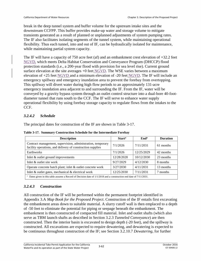
California Department of Water Resources
Chapter 3. Description of the Proposed Project
break in the deep tunnel system and buffer volume for the upstream intake sites and the downstream CCFPP. This buffer provides make-up water and storage volume to mitigate transients generated as a result of planned or unplanned adjustments of system pumping rates. The IF also facilitates isolating segments of the tunnel system, while maintaining operational flexibility. Thus each tunnel, into and out of IF, can be hydraulically isolated for maintenance, while maintaining partial system capacity.
The IF will have a capacity of 750 acre feet (af) and an embankment crest elevation of +32.2 feet NGVD, which meets Delta Habitat Conservation and Conveyance Program (DHCCP) flood protection standards (i.e., a 200-year flood with provision for sea level rise). Current ground surface elevation at the site averages +0 feet NGVD. The WSE varies between a maximum elevation of +25 feet NGVD and a minimum elevation of -20 feet NGVD. The IF will include an emergency spillway and emergency inundation area to prevent the forebay from overtopping. This spillway will divert water during high flow periods to an approximately 131-acre emergency inundation area adjacent to and surrounding the IF. From the IF, water will be conveyed by a gravity bypass system through an outlet control structure into a dual-bore 40-foot-diameter tunnel that runs south to the CCF. The IF will serve to enhance water supply operational flexibility by using forebay storage capacity to regulate flows from the intakes to the CCF.
3.2.4.2 Schedule
The principal dates for construction of the IF are shown in Table 3-17.
Table 3-17. Summary Construction Schedule for the Intermediate Forebay
Description Starta Enda Duration Contract management, supervision, administration, temporary facility operations, and delivery of construction supplies 7/1/2026 7/11/2031 61 months
Earthworks 7/1/2026 12/25/2029 42 months Inlet & outlet ground improvements 12/28/2028 10/12/2030 23 months Inlet & outlet site work 9/27/2029 4/12/2030 8 months Operate concrete batch plant; inlet & outlet concrete work 3/27/2030 4/11/2031 13 months Inlet & outlet gates, mechanical & electrical work 12/25/2030 7/11/2031 7 months a Dates given in this table assume a Record of Decision date of 1/1/2018 and a construction end date of 7/11/2031.
3.2.4.3 Construction
All construction of the IF will be performed within the permanent footprint identified in Appendix 3.A Map Book for the Proposed Project. Construction of the IF entails first excavating the embankment areas down to suitable material. A slurry cutoff wall is then emplaced to a depth of -50 feet to eliminate the potential for piping or seepage beneath the embankment. The embankment is then constructed of compacted fill material. Inlet and outlet shafts (which also serve as TBM launch shafts as described in Section 3.2.3 Tunneled Conveyance) are then constructed. Then the interior basin is excavated to design depth (-20 feet), and the spillway is constructed. All excavations are expected to require dewatering, and dewatering is expected to be continuous throughout construction of the IF; see Section 3.2.10.7 Dewatering, for further
California Incidental Take Permit Application for the California WaterFix and its operation as part of the State Water Project 3-62 October 2016
ICF 00408.12

California Department of Water Resources
Chapter 3. Description of the Proposed Project
discussion of how this will be achieved. Ground improvement (described in Section 3.2.10.3 Ground Improvement) may be needed beneath structures, depending upon the outcomes of the geotechnical explorations described in Section 3.2.1 Geotechnical Exploration.
The IF will have a surface footprint of 243 acres, all of which is permanent impact (under current conditions, the area is a vineyard). Approximately 1 million cubic yards (cy) of excavation and 2.3 million cy of fill material are required for completing the IF embankments. Much of the excavated material is expected to be high in organics and unsuitable for use in embankment construction and requires disposal (see Section 3.2.10.6 Dispose Spoils).
Construction of the IF embankments and tunnel shaft pans will require substantial volumes of engineered fill. The required fill material will preferably be sourced onsite from locations within the permanent impactconstruction footprint. Material sourced from offsite will be obtained as described in Section 3.2.10.4 Borrow Fill.
As at the Delta intakes, the construction phase at the IF will conclude with landscaping and the installation of safety lighting and security fencing, which will be performed as described in Section 3.2.10.10 Landscaping and Associated Activities.
3.2.5 Clifton Court Forebay
3.2.5.1 Design
Functionally, the facilities at CCF are proposed to receive water from north Delta and south Delta sources, and to deliver that water into the CVP/SWP. In order to accomplish this dual function, the existing forebay will be divided into two halves, North CCF (NCCF) and South CCF (SCCF). The NCCF will receive screened water from the new river intakes, while the SCCF will continue to receive flows from the existing Old River intake gate on CCF. The NCCF will be designed to accommodate hydraulic surges and transitions related to short-term (typically less than 24 hours) differences in the rate of water delivery to NCCF and the rate of export by the CVP/SWP pumps. The NCCF will also be the site for a pump station, the operations of which form the primary control and constraints on the rate of water diversion through the river intakes (although that rate is also subject to control at the river intakes). Collective operations of these facilities will be coordinated through an operations center sited at the NCCF pump station. The SCCF will continue to operate as under current conditions. To minimize environmental impacts, the proposed size of the CCF and its appurtenant facilities have been optimized consistent with the overall design goal of the PP to achieve diversion rates at the North Delta Diversions not exceeding 9,000 cfs, and to achieve overall CVP/SWP water export rates consistent with existing authorizations for those facilities, subject to operational and regulatory constraints detailed in Section 3.3 Operations and Maintenance of the New and Existing Facilities.
Maps and drawings depicting the CCF and its spatial relationship to other elements of the PP are shown in the Appendices. Appendix 3.A Map Book for the Proposed Project, Sheet 13, shows the CCF, access routes, and related facilities in the area. Appendix 3.C Conceptual Engineering Report, Volume 2, Drawing 2, provides an overview of the CCF facilities in relation to the rest of the conveyance facilities, and Drawing 54 provides a site-scale view of the proposed facilities at
California Incidental Take Permit Application for the California WaterFix and its operation as part of the State Water Project 3-63 October 2016
ICF 00408.12

California Department of Water Resources
Chapter 3. Description of the Proposed Project
CCF. Drawing 74 shows an artist’s concept of the completed CCF pumping plant, and Drawings 75 to 78 show details of the proposed pumping plant. Drawing 82 is a detailed overall CCF site plan, and Drawings 85 to 87 provide sectional views of the proposed embankments that contain the CCF. Drawings 90 and 91 provide plan and section views of the proposed spillway from the NCCF into Old River.
Detailed information on design of the proposed facilities at CCF is given in Appendix 3.B8 Conceptual Engineering Report, Volume 1. Sections 4.4.6 Clifton Court Forebay Pump Plant (CCFPP) Operations; 4.4.7 North Clifton Court Forebay Operations; and 4.6 Implications of Modified Pipeline/Tunnel Clifton Court Option on Current SWP and CVP Operations, describe how the CCF pump plant and the NCCF will be operated to support overall conveyance system functions. Section 7 CCF Pumping Plant, describes the design and construction of the CCF pumping plant, while the north and south CCF and their construction methodology are described in Sections 14.1.2 North Clifton Court Forebay, 14.1.3 South Clifton Court Forebay, 14.2.2 General Excavation for the NCCF and SCCF, 14.2.3 General Excavation for the Existing South Embankment of Clifton Court Forebay, 14.2.5 New Clifton Court Forebay Embankment, 14.2.6 New Spillway and Stilling Basin, and 14.2.8 New Forebay Structures. Construction will comply with avoidance and minimization measures identified in Appendix 3.F, General Avoidance and Minimization Measures.
Construction at the CCF will also include connections to the existing Banks and Jones pumping plants. Design and construction of those connections are described in Section 3.2.6, Connections to Banks and Jones Pumping Plants.
The overall schedule17 for activities at CCF is shown in Appendix 3.D Construction Schedule for the Proposed Project; see drawings in Appendix 3.C Conceptual Engineering Report, Volume 2, for locations of the referenced structures. Four major elements of the proposed construction will occur in the CCF area: tunneling, the CCPP, the modifications to the current CCF to create a North and South CCF, and connections to the Banks and Jones pumping plants.
• Tunneling (Reach 7) will start from the CCPP construction site and will excavate north to Bacon Island, as described in Section 3.2.3 Tunneled Conveyance; RTM from the tunnels will be disposed near CCF as described in Section 3.2.10.6 Dispose Spoils. Tunneling activity will begin 47 months after project start (scheduled to occur in January; the start year depends upon the date of project authorization and the time needed to prepare contract specifications and issue contracts) and will proceed continuously for 61 months.
• The CCPP will be constructed at the northeast corner of the CCF complex and includes the shafts used to launch the TBMs. Construction will start at the CCPP will begin 36 months after project start and will proceed continuously for 100 months.
• CCF work will occur throughout the site, and will be continuously active from 84 months after project start until 147 months after project start. Apart from startup activities (access improvement, mobilization, etc.), embankment and canal work will continue from 90
17 For more information on timing of activities at CCF, see Attachment BO#9.
California Incidental Take Permit Application for the California WaterFix and its operation as part of the State Water Project 3-64 October 2016
ICF 00408.12

California Department of Water Resources
Chapter 3. Description of the Proposed Project
months to 130 months after project start. Work on control structures and spillways will occur from 108 months to 144 months after project start.
• Connections to the Banks and Jones pumping plants are described in Section 3.2.6 Connections to Banks and Jones Pumping Plants.
3.2.5.1.1 Clifton Court Pumping Plant
Each of the two units at CCPP will have a design pumping capacity of 4,500 cfs and will include 4 large pumps (1,125 cfs capacity) and 2 smaller pumps (563 cfs capacity). One large pump at each plant will be a spare. Each pumping plant will be housed within a building and will have an associated electrical building. The pumping plant buildings will be circular structures with a diameter of 182 feet and each will be equipped with a bridge crane that will rotate around the building and allow for access to the main floor for pump removal and installation. The total site for the pumping plants, electrical buildings, substation, spillway, access roads, and construction staging areas is approximately 95 acres. The main floor of the pumping plants and appurtenant permanent facilities will be constructed at a minimum elevation of 25 feet to provide flood protection. The bottom of the pump shafts will be at an elevation of approximately -163 feet, though a concrete base slab, shaft lining, and diaphragm wall will be constructed to deeper levels (to an elevation of -275 feet). A control room within an electrical building at the pumping facility site will be responsible for controlling and monitoring the communication between the intakes, pumping plants, and the Delta Field Division Operations and Maintenance Center, DWR Headquarters, and the Joint Operations Center.
A 230 kV transmission line and associated 230Kv–115kV substation used during construction will be repurposed and used to power the pumping plants at the CCF location during operations. The repurposed substation will provide power to a new substation that will convert power from 115kV to 13.8kV. This substation will then include 13.8 kV feeder lines to a proposed electrical building to distribute the power to the major loads including the main pumps, dewatering pumps, and 13.8kV to 480V transformers.
3.2.5.1.2 Clifton Court Forebay
SWP pumps operate primarily during off-peak electrical usage hours, which minimizes electricity costs and makes optimal use of available generating capacity. Thus the current CCF is sized to accommodate the hydraulic differential generated by the difference between a fairly constant rate of flow into the Forebay, but a highly variable rate of discharge into the export canal. Under the PP, the CCF will be divided into two separate but contiguous forebays: North Clifton Court Forebay (NCCF) and South Clifton Court Forebay (SCCF). The NCCF will be sized to meet the hydraulic needs of balancing water entry from the North Delta Diversions with discharge via the CVP/SWP export pumps. Since NCCF will receive the flow from the Delta Intakes, this will be water that has passed through the Delta Intake fish screens and is therefore expected to contain no fish. The SCCF will continue to meet the needs of SWP export pumps taking in south Delta water; as such it will function as a replacement for the current CCF, and thus must be enlarged south in order to maintain its current size while still accommodating the creation of the NCCF. SCCF will consist of the southern portion of the existing CCF, with expansion to the south into Byron Tract 2.
California Incidental Take Permit Application for the California WaterFix and its operation as part of the State Water Project 3-65 October 2016
ICF 00408.12

California Department of Water Resources
Chapter 3. Description of the Proposed Project
The CCF will be expanded by approximately 590 acres to the southeast of the existing forebay. The existing CCF will be dredged, and the expansion area excavated, to design depths of -8 feet for the north cell (the NCCF) and -10 feet for the south cell (the SCCF). A new embankment will be constructed around the perimeter of the forebay, as well as an embankment dividing the forebay into the NCCF and the SCCF. The tunnels from the Sacramento River intakes will enter the CCPP at the northeastern end of the NCCF, immediately south of Victoria Island, and flows will typically enter the NCCF via pumping (unpumped gravity flow will be feasible when the Sacramento River is at exceptionally high stages; see Appendix 3.B Conceptual Engineering Report, Volume 1, Section 7.1.3.2 Pumping Hydraulics, for detailed discussion of hydraulic constraints on gravity-driven vs. pumped operations).
3.2.5.1.3 Clifton Court Forebay Technical Team
Modifications to CCF constitute one of the most complex aspects of the PP. Recognizing that design of these modifications is still in an early stage, DWR, Reclamation, NMFS, CDFW, and USFWS have determined that ongoing collaborative efforts will be needed to ensure that the final design and construction procedures for CCF minimize effects on listed species. Accordingly, representatives from each of these agencies will participate in a Clifton Court Forebay Technical Team (CCFTT). The CCFTT will convene prior to issuance of the ITP for the PP and will meet periodically until DWR completes final design for the proposed CCF modifications (a time period expected to be at least two years). The CCFTT will be charged with the following duties:
• Based on construction information presented by DWR, review and make recommendations regarding phasing of CCF construction for the benefit of listed and unlisted fish or for water quality. In considering any options for phasing, the CCFTT will consider preliminary costs and constructability.
• Based on construction information presented by DWR, review and make recommendations regarding appropriate techniques for dewatering, fish rescue, and fish exclusion during in-water work. Dewatering and fish rescue will be needed for all cofferdam work at CCF, and fish exclusion will be needed for dredging. In considering these techniques, the CCFTT will consider preliminary costs and constructability.
• Develop performance criteria and study programs to evaluate critical issues in CCF operations. One such issue is changes to predation patterns in the SCCF, which may have significantly deeper water depths, different residence times, and more exposure of mineral substrates, compared to the current CCF. Other operational issues may also be identified by the CCFTT.
• Identify and describe near-term research/monitoring needs, if any, to reduce key uncertainties prior to construction.
• Prepare draft and final reports summarizing CCFTT recommendations. The final report must be provided no less than 8 months prior to DWR’s completion of final design, so that recommendations can be incorporated into those construction contract documents.
California Incidental Take Permit Application for the California WaterFix and its operation as part of the State Water Project 3-66 October 2016
ICF 00408.12

California Department of Water Resources
Chapter 3. Description of the Proposed Project
CCFTT recommendations will be reviewed by the five agencies for consideration. Adopted recommendations will be incorporated to CCF final design. DWR will abide by monitoring provisions and other measures sufficient to demonstrate implementation of these recommendations.
3.2.5.2 Construction
All construction in the Clifton Court vicinity will be performed within the permanent footprint identified in Appendix 3.A Map Book for the Proposed Project.
3.2.5.2.1 Clifton Court Pumping Plant
3.2.5.2.1.1 Overview A detailed account of CCPP construction appears in Appendix 3.B8 Conceptual Engineering Report, Volume 1, Section 7.2 Construction Methodology. In general, construction of the CCPP will follow the procedures described for tunnel shaft construction in Sections 3.2.3.3.1 Shaft Site Facilities; 3.2.3.3.2 Shaft Site Preparation; and 3.2.3.3.3 Shaft Construction. The CCPP shafts will be larger in inside diameter (150 feet instead of 113 feet) than most shafts serving 40-foot tunnel bores due to the design needs of the pumping plant. As shown in Appendix 3.C Conceptual Engineering Report, Volume 2, Drawings 75 and 76, the appurtenant facilities will be more extensive than at most tunnel shaft sites, including a permanent electrical substation, two electrical buildings, and an office/storage building, as well as temporary facilities for storage, staging, construction electrical, and water treatment (for stormwater). All of these facilities will be sited on the CCF embankment, at the design flood elevation (i.e., a 200-year flood with provision for sea level rise) of 25 feet.
3.2.5.2.1.2 Site Access Vehicular site access during construction will use existing roads: from the east, from Byron Highway via Clifton Court Road and the Italian Slough levee crest road or the NCCF embankment crest road. Access from the south will be from the Byron Highway via NCCF embankment crest road and West Canal levee crest road. These are existing roads. The Clifton Court Road is not proposed for paving or widening. Barge access will also be needed, for transport of heavy TBM sections and other very large equipment and materials, and possibly for transport of bulk materials (fill material or excavated material). Barge access will be from the West Canal using a proposed barge unloading facility. See Section 3.2.10.9 Barge Landing Construction and Operations for further discussion of the use, design, and construction of barge landings. Proposed barge traffic and landing facilities are also generally described in Appendix 3.B8 Conceptual Engineering Report, Volume 1, Section 23.3.
3.2.5.2.1.3 Cofferdam and Fill Work A sheet pile cofferdam will be placed to enclose the portion of the CCPP fill pad adjoined by water (Appendix 3.C8 Conceptual Engineering Report, Volume 2, Drawings 75 and 83; however note that, as detailed below, the design has been modified to dewater NCCF prior to CCPP construction; thus no sheet pile cofferdam will be placed in the portions of the CCPP fill pad adjoining the NCCF). Sheet pile placement for cofferdam installation will be performed by a barge-mounted crane and/or a crane mounted on the existing levee, equipped with vibratory and impact pile-driving rigs.
California Incidental Take Permit Application for the California WaterFix and its operation as part of the State Water Project 3-67 October 2016
ICF 00408.12

California Department of Water Resources
Chapter 3. Description of the Proposed Project
The general approach to pile driving, including minimization measures to be used, is described in Section 3.2.10.11 Pile Driving. Assumptions for pile driving are given in Appendix 3.E Pile Driving Assumptions for the Proposed Project, which addresses the number, type and size of piles required, as well as the number of piles driven per day, the number of impact strikes per pile, and whether piles will be driven in-water or on land (piles driven to construct the cofferdam will all be “in-water”). Sheet piles will be driven starting with a vibratory hammer, then switching to an impact hammer if refusal is encountered before target depths. In-water pile driving will be subject to abatement, hydroacoustic monitoring, and compliance with timing limitations as described in Appendix 3.F General Avoidance and Minimization Measures, AMM9 Underwater Sound Control and Abatement Plan.
Fill pad construction will then proceed within the dewatered area, as described in Section 3.2.3.3.2.2, Fill Pads, including fill placement, compaction, and ground improvement.
3.2.5.2.1.4 Dewatering Dewatering and water treatment associated with cofferdam installation will be as described in Section 3.2.10.7 Dewatering. This procedure includes fish removal as prescribed in Appendix 3.F General Avoidance and Minimization Measures, AMM8 Fish Rescue and Salvage Plan.
Extensive dewatering will be required during construction of the CCPP shafts. Dewatering will be performed as described in Section 3.2.3.3.3 Shaft Construction. Other construction activities with the potential to affect listed species are described below, in the discussion of how CCF embankments and related facilities will be constructed.
3.2.5.2.2 Clifton Court Forebay
Please refer to Attachment BO#9 for a description of proposed construction at CCF18Plan for removal of Clifton Court south embankment and filling of new Clifton Court enlargement at Byron tract location (Permit Resolution Log item #9).
Due to the duration and complexity of the proposed work at CCF, a phased work schedule is planned. The phases include the following:
• Phase 1 – SCCF expansion (eastern and western parts of expansion area shown in Appendix 3.C Conceptual Engineering Report, Volume 2, Drawings 54 and 82)
• Phase 2 – Dredge to design depth within the portion of CCF located south of the proposed embankment separating NCCF and SCCF
• Phase 3 – Remove embankment separating the existing CCF from the expansion area
• Phase 4 – Construct embankment separating NCCF and SCCF, with subsequent dewatering, fish rescue, and excavation to design depth within NCCF
18 For more information on construction activities, see Permit Resolution Log items #127, #128, #129, #130 and #131
California Incidental Take Permit Application for the California WaterFix and its operation as part of the State Water Project 3-68 October 2016
ICF 00408.12
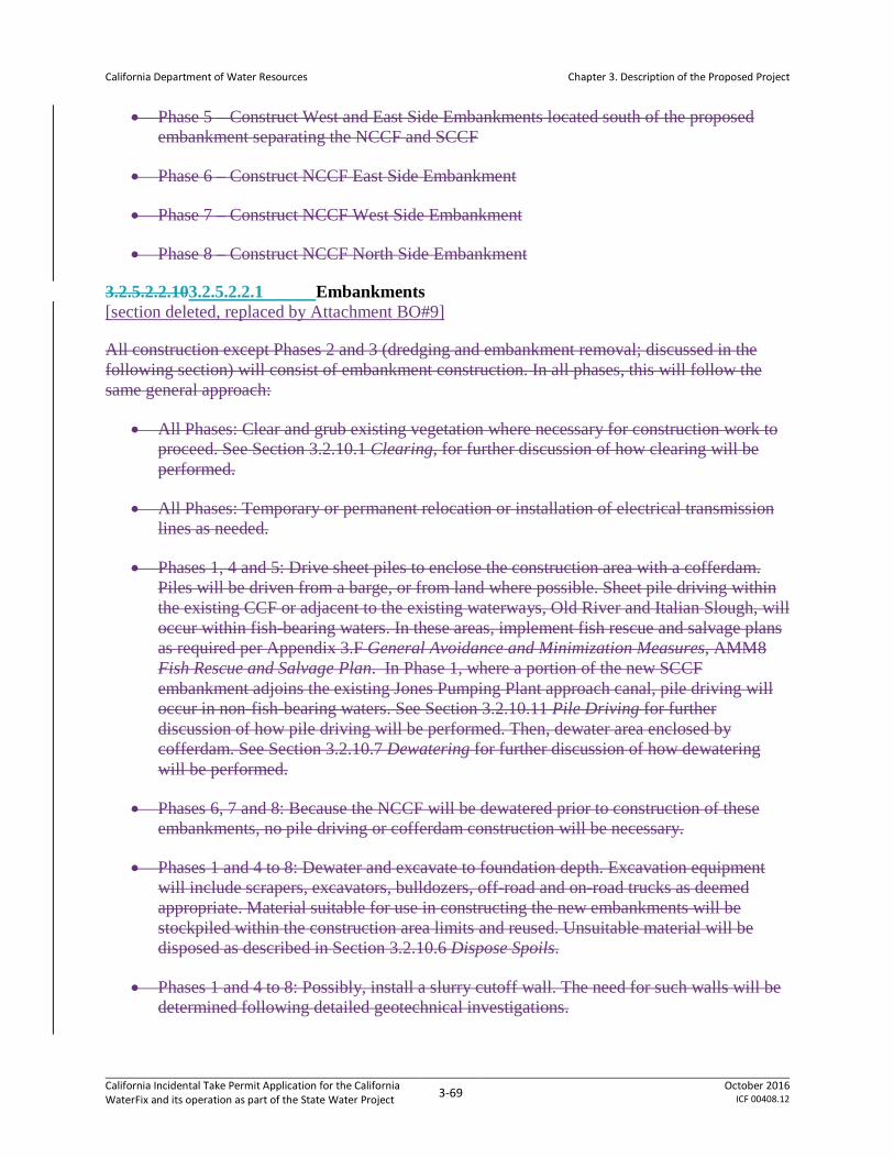
California Department of Water Resources
Chapter 3. Description of the Proposed Project
• Phase 5 – Construct West and East Side Embankments located south of the proposed embankment separating the NCCF and SCCF
• Phase 6 – Construct NCCF East Side Embankment
• Phase 7 – Construct NCCF West Side Embankment
• Phase 8 – Construct NCCF North Side Embankment
3.2.5.2.2.103.2.5.2.2.1 Embankments [section deleted, replaced by Attachment BO#9]
All construction except Phases 2 and 3 (dredging and embankment removal; discussed in the following section) will consist of embankment construction. In all phases, this will follow the same general approach:
• All Phases: Clear and grub existing vegetation where necessary for construction work to proceed. See Section 3.2.10.1 Clearing, for further discussion of how clearing will be performed.
• All Phases: Temporary or permanent relocation or installation of electrical transmission lines as needed.
• Phases 1, 4 and 5: Drive sheet piles to enclose the construction area with a cofferdam. Piles will be driven from a barge, or from land where possible. Sheet pile driving within the existing CCF or adjacent to the existing waterways, Old River and Italian Slough, will occur within fish-bearing waters. In these areas, implement fish rescue and salvage plans as required per Appendix 3.F General Avoidance and Minimization Measures, AMM8 Fish Rescue and Salvage Plan. In Phase 1, where a portion of the new SCCF embankment adjoins the existing Jones Pumping Plant approach canal, pile driving will occur in non-fish-bearing waters. See Section 3.2.10.11 Pile Driving for further discussion of how pile driving will be performed. Then, dewater area enclosed by cofferdam. See Section 3.2.10.7 Dewatering for further discussion of how dewatering will be performed.
• Phases 6, 7 and 8: Because the NCCF will be dewatered prior to construction of these embankments, no pile driving or cofferdam construction will be necessary.
• Phases 1 and 4 to 8: Dewater and excavate to foundation depth. Excavation equipment will include scrapers, excavators, bulldozers, off-road and on-road trucks as deemed appropriate. Material suitable for use in constructing the new embankments will be stockpiled within the construction area limits and reused. Unsuitable material will be disposed as described in Section 3.2.10.6 Dispose Spoils.
• Phases 1 and 4 to 8: Possibly, install a slurry cutoff wall. The need for such walls will be determined following detailed geotechnical investigations.
California Incidental Take Permit Application for the California WaterFix and its operation as part of the State Water Project 3-69 October 2016
ICF 00408.12

California Department of Water Resources
Chapter 3. Description of the Proposed Project
• Phases 1 and 4 to 8: Construct new embankment using similar equipment as excavation operations, but also including compaction equipment, rollers, motor graders, and water trucks or water pulls to place material in lifts until finish heights are reached. The required embankment material will be borrowed from within the limits of the forebays to the extent feasible, or from borrow sites, as described in Section 3.2.10.4 Borrow Fill. A total of 9.3 million cy of fill will be used in the new and modified CCF embankments
• Phases 1, 2 and 5 to 8: Trim or remove sheet piles if needed (Phases 6 to 8 will not have sheet piles) and place riprap or other appropriate slope protection materials on water-side of slopes using excavators, loaders and trucks as required.
3.2.5.2.2.203.2.5.2.2.2 Phased Construction at Clifton Court Forebay [section deleted, replaced by Attachment BO#9]
The phases of work in embankment construction will include the following:
• Phase 1 – Drive sheet piles on southwest side of CCF by outflow channel and southeast side of forebay by inflow gates to facilitate new channel and new embankment work. Clear, grub, and perform exploration of SCCF expansion property to find suitable soils for embankment fills and potential spoil areas. Construct embankment fills as described above. Relocate or raise electrical transmission towers within the construction area concurrently with embankment construction.
• Phase 2 – Dredge the portion of CCF located south of the proposed embankment dividing NCCF from SCCF to an elevation of approximately -10.0 ft, which will be the bottom elevation of SCCF. Dredging will be performed with a cutter head dredge, a dragline type dredge, or other suitable dredging technique. Silt curtains will be used as required by applicable permits, and other measures to minimize potential effects will be implemented as described in Section 3.2.10.8 Dredging and Riprap Placement, and in Appendix 3.F General Avoidance and Minimization Measures, AMM6 Disposal and Reuse of Spoils, Reusable Tunnel Material, and Dredged Material. Silt curtains will be placed in a west-east orientation so as to not impede water flow from inlet to outlet in the portions of the forebay not being dredged at any given time, and will enclose an area of approximately 200 acres. Portions of the forebay deeper than -10.0 feet (principally, the scour holes near the CCF inlet and outlet) will not be dredged and silt curtains will be placed so as to avoid exposing these areas to dredging-related water quality effects. Four or five such 200-acre cells will be dredged sequentially to complete dredging in the affected area. Dredging will be performed only during the in-water work window10; three successive work windows will be needed to complete the dredging. Unsuitable material will be disposed as described in Section 3.2.10.6 Dispose Spoils. As described there, up to 7,000,000 cubic yards of dredged material will be produced. It is assumed for the purposes of this analysis that all of that material will be classified as unsuitable and require disposal, but the material will be evaluated, stockpiled within the construction area limits, and re-used in embankment construction to the extent feasible.
• Phase 3 - Drive sheet piles to connect the two sets of sheet piles installed on the south side of CCF during Phase 1. Excavate existing embankment down to invert elevation.
California Incidental Take Permit Application for the California WaterFix and its operation as part of the State Water Project 3-70 October 2016
ICF 00408.12

California Department of Water Resources
Chapter 3. Description of the Proposed Project
Excavated material suitable for use in constructing the new embankments will be stockpiled within the construction area limits and reused. Unsuitable material will be disposed as described in Section 3.2.10.6 Dispose Spoils. Allow water to be introduced into the new forebay section on the south of CCF until water height of the two locations is even, then remove the sheet piles placed during Phase 2.
• Phase 4 – Drive sheet piles for partitioning forebay. Dewater NCCF, which is now blocked off by partition sheet piles. In the dewatered area, excavate to a bottom elevation of -8.0 ft. Construct partition embankment fill as described above.
• Phase 5 – Construct embankment on east side of NCCF, following procedure described above. Construct spillway (described below) concurrently with embankment construction.
• Phase 6 – Construct embankment on west side of NCCF, following procedure described above.
• Phase 7 – Construct embankment on north side of NCCF, following procedure described above; note that much of the north side work will have already been completed during pad construction for the CCPP. Construct spillway (described below) concurrently with embankment construction.
3.2.5.2.2.293.2.5.2.2.3 CCF Spillway An emergency spillway will be constructed in the NCCF east side embankment, south of the CCPP fill pad. The spillway will be sized to carry emergency overflow (9,000 cfs, the maximum inflow from the North Delta Diversions) to the Old River, so a containment area will not be necessary.
The shallow foundation beneath this structure must be improved to prevent strength loss and seismic settlement. The ground improvement (Section 3.2.10.3 Ground Improvement) will be to elevation -50.0 feet within the footprint of the structure and beyond the structure by a distance of approximately 25 feet. The work will be performed within the sheet pile installed for embankment filling under construction Phase 6.
3.2.6 Connections to Banks and Jones Pumping Plants
3.2.6.1 Design
Under existing conditions, the Jones Pumping Plant draws water from the Old River and West Canal via an approach canal that originates at the Tracy Fish Collection Facility, near the southeast corner of the CCF. The Banks Pumping Plant draws water from the CCF via an approach canal that originates at the southwest corner of the CCF, at the Skinner Delta Fish Protective Facility. The PP entails no changes to the Tracy or Skinner fish facilities.
The new system configuration allows both the Banks Pumping Plant and the Jones Pumping Plant to draw water from existing sources and/or from the NCCF. See Appendix 3.C Conceptual Engineering Report, Volume 2, Sheet 82, for a drawing showing the following:
California Incidental Take Permit Application for the California WaterFix and its operation as part of the State Water Project 3-71 October 2016
ICF 00408.12
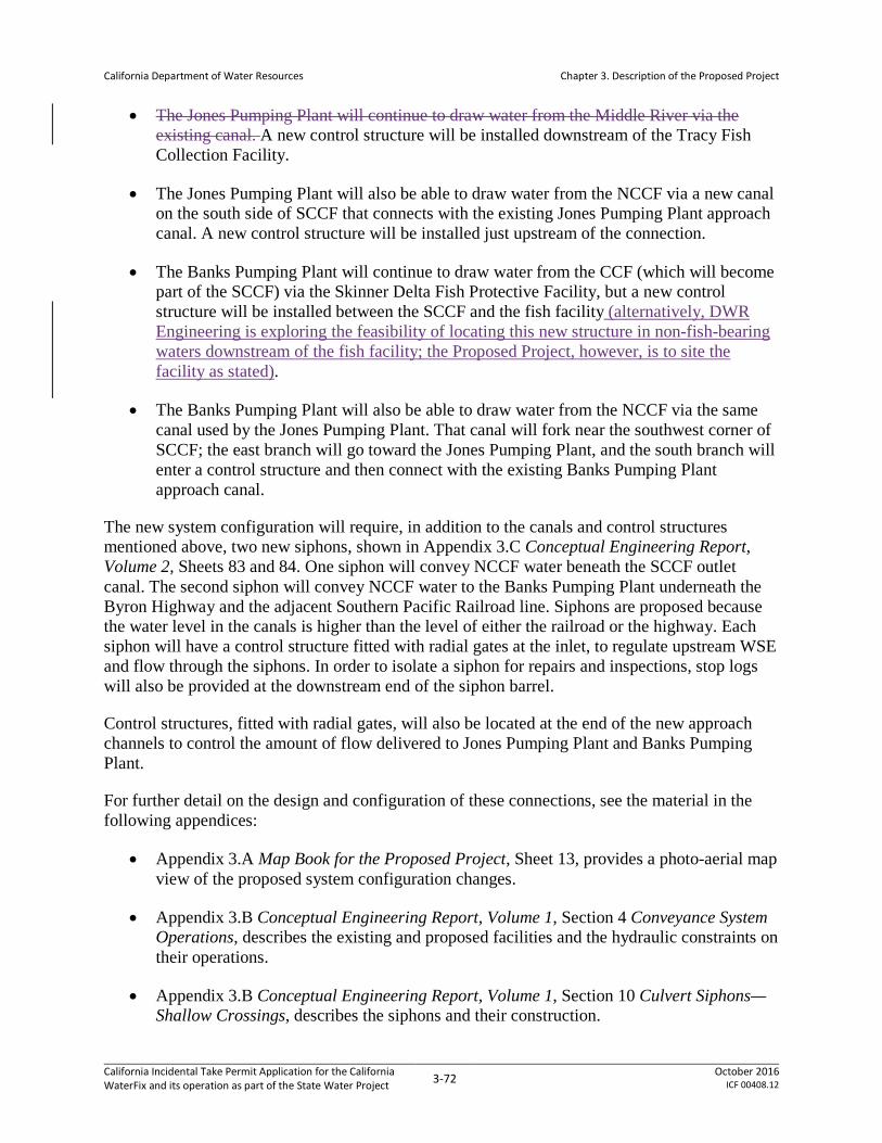
California Department of Water Resources
Chapter 3. Description of the Proposed Project
• The Jones Pumping Plant will continue to draw water from the Middle River via the existing canal. A new control structure will be installed downstream of the Tracy Fish Collection Facility.
• The Jones Pumping Plant will also be able to draw water from the NCCF via a new canal on the south side of SCCF that connects with the existing Jones Pumping Plant approach canal. A new control structure will be installed just upstream of the connection.
• The Banks Pumping Plant will continue to draw water from the CCF (which will become part of the SCCF) via the Skinner Delta Fish Protective Facility, but a new control structure will be installed between the SCCF and the fish facility (alternatively, DWR Engineering is exploring the feasibility of locating this new structure in non-fish-bearing waters downstream of the fish facility; the Proposed Project, however, is to site the facility as stated).
• The Banks Pumping Plant will also be able to draw water from the NCCF via the same canal used by the Jones Pumping Plant. That canal will fork near the southwest corner of SCCF; the east branch will go toward the Jones Pumping Plant, and the south branch will enter a control structure and then connect with the existing Banks Pumping Plant approach canal.
The new system configuration will require, in addition to the canals and control structures mentioned above, two new siphons, shown in Appendix 3.C Conceptual Engineering Report, Volume 2, Sheets 83 and 84. One siphon will convey NCCF water beneath the SCCF outlet canal. The second siphon will convey NCCF water to the Banks Pumping Plant underneath the Byron Highway and the adjacent Southern Pacific Railroad line. Siphons are proposed because the water level in the canals is higher than the level of either the railroad or the highway. Each siphon will have a control structure fitted with radial gates at the inlet, to regulate upstream WSE and flow through the siphons. In order to isolate a siphon for repairs and inspections, stop logs will also be provided at the downstream end of the siphon barrel.
Control structures, fitted with radial gates, will also be located at the end of the new approach channels to control the amount of flow delivered to Jones Pumping Plant and Banks Pumping Plant.
For further detail on the design and configuration of these connections, see the material in the following appendices:
• Appendix 3.A Map Book for the Proposed Project, Sheet 13, provides a photo-aerial map view of the proposed system configuration changes.
• Appendix 3.B Conceptual Engineering Report, Volume 1, Section 4 Conveyance System Operations, describes the existing and proposed facilities and the hydraulic constraints on their operations.
• Appendix 3.B Conceptual Engineering Report, Volume 1, Section 10 Culvert Siphons—Shallow Crossings, describes the siphons and their construction.
California Incidental Take Permit Application for the California WaterFix and its operation as part of the State Water Project 3-72 October 2016
ICF 00408.12

California Department of Water Resources
Chapter 3. Description of the Proposed Project
• Appendix 3.B Conceptual Engineering Report, Volume 1, Sections 14.1.2 North Clifton Court Forebay; 14.1.3 South Clifton Court Forebay; 14.2.7 New Approach Canals to Banks and Jones Pumping Plants; and 14.2.9 Banks and Jones Channel Control Structures describe design and construction of various elements of the Banks and Jones connections. Further details appear in Sections 24.4.3.4 Canals (Approach Canals to Jones and Banks Pumping Plants) and 24.4.3.5 Culvert Siphons.
• Appendix 3.C Conceptual Engineering Report, Volume 2, Sheets 82 to 84, are drawings showing the proposed canals, siphons, and control structures.
3.2.6.2 Construction
All construction of the Banks and Jones connections will be performed within the permanent footprint identified in Appendix 3.A Map Book for the Proposed Project.
NCCF Canal
The new canal delivering water from the NCCF to the Banks Pumping Plant and Jones Pumping Plant will originate at NCCF Siphon 1, which will convey water from the NCCF under the existing CCF outlet. The canal will run due south for 2,700 feet, where it will fork; the south fork will pass through Siphon 2 and then join the existing Banks Pumping Plant approach canal at a location downstream of the existing Skinner Delta Fish Protective Facility. The east fork will parallel the Byron Highway on its north side for 4,900 feet, where it will join the existing Jones Pumping Plant approach canal at a location downstream of the existing Tracy Fish Collection Facility (Appendix 3.C Conceptual Engineering Report, Volume 2, Sheet 82).
As with SCCF, the embankment crest elevation for the NCCF canal is +24.5 feet, which includes considerations for flood levels and sea-level rise. The canal invert is -5 feet at Siphon 1, dropping gradually to meet the existing invert depths at the points where it connects to the existing Banks and Jones approach canals. The ground beneath the canal will be subject to ground improvement (Section 3.2.10.3 Ground Improvement) to depth -50 feet. The canal will be excavated and its embankments constructed using the same procedure described in Section 3.2.5.2.2.1 Embankments. That procedure will entail cofferdam installation to provide a dry work area, in places where construction will be contiguous with waters of the state. The canal adjoins fish-bearing waters (Italian Slough), and entails pile driving in or near those waters, for approximately 800 feet along the Banks Pumping Plant approach canal upstream of the Skinner Delta Fish Protective Facility. The same portion of the California Aqueduct will be affected by construction of the control structure upstream of the fish facility, and this work will also necessitate cofferdam pile placement in fish-bearing waters. The construction methodology will be to isolate one side of the channel by a cofferdam, construct the portion of the control structure on that side of the channel, remove the cofferdam, isolate the other side of the channel with a cofferdam, construct the remainder of the control structure, and then remove the cofferdam. This procedure is necessary to continue use of the channel during the construction processApart from this section, construction pile driving associated with the Banks and Jones connections will not occur in or near fish-bearing waters.
California Incidental Take Permit Application for the California WaterFix and its operation as part of the State Water Project 3-73 October 2016
ICF 00408.12

California Department of Water Resources
Chapter 3. Description of the Proposed Project
3.2.6.2.1 NCCF Siphon 1 (Beneath SCCF Outlet)
NCCF Siphon 1 will convey water from the NCCF beneath the existing CCF outlet (which will become the SCCF outlet) and into the NCCF canal, leading to the Banks Pumping Plant and Jones Pumping Plant approach canals (Appendix 3.C, Conceptual Engineering Report, Volume 2, Sheet 82 and Sheet 84). The siphon will be 1,500 feet long and will consist of 3 concrete box culverts, each 23 feet wide and 23 feet tall, with a total conveyance capacity of 15,000 cfs, matching the combined pumping capacity of the Banks Pumping Plant plus the Jones Pumping Plant and providing maximum operational flexibility for drawdown of the forebayNCCF. It will be provided with radial gates at the inlet, and it will have provision for stop logs at the outlet, enabling dewatering of each culvert if necessary for maintenance.
The siphon will be supported on a pile foundation, and will be constructed within a cofferdam erected in the CCF outlet channel. Concrete structures will be cast-in-place. The CCF outlet channel is a fish-bearing water, so cofferdam installation is subject to timing, noise abatement, and other constraints as identified in Section 3.2.10.11 Pile Driving, and in Appendix 3.F General Avoidance and Minimization Measures, AMM9 Underwater Sound Control and Abatement Plan. Foundation pile driving, if required, will occur within a dewatered cofferdam and thus will not be an in-water activity. Dewatering of the cofferdam will occur as described in Section 3.2.10.7 Dewatering, and will require compliance with Appendix 3.F General Avoidance and Minimization Measures, AMM8 Fish Rescue and Salvage Plan.
The siphon will be constructed in two phases, each phase lasting approximately one year. In the first phase, a temporary cofferdam will be constructed approximately halfway along the length of the siphon and then the area will be dewatered and excavated to the desired lines and grade. Half of the total length of the culvert siphon will be constructed inside the cofferdam, temporarily plugged, and backfilled to the desired waterway bottom configuration. During the second phase, the cofferdam will be re-installed across the other half of the siphon, the area will be dewatered, and the remainder of the siphon will be constructed and backfilled.
The siphon structure footprint will be as shown in the map book (Appendix 3.A Map Book for the Proposed Project, Sheet 12). The area of impact will be up to 250 feet wide. A 15-acre area will be required for construction staging, also as shown in the map book.
3.2.6.2.2 NCCF Siphon 2 (Beneath Byron Highway)
NCCF Siphon 2, which will pass beneath Byron Highway and the adjacent Southern Pacific Railroad line, will be of the same basic design as NCCF Siphon 1, but will be smaller, consisting of 2, 23-foot-square box culverts with a total flow capacity of 10,300 cfs; the siphon will be 1,000 feet long (Appendix 3.C Conceptual Engineering Report, Volume 2, Sheet 82 and Sheet 84).
Construction of NCCF Siphon 2 will be as described above for NCCF Siphon 1, except that no cofferdam will be needed, no fish-bearing waters will be affected, construction will occur within one year, and reroutes during construction, traffic onof the Byron Highway and the SPRR will be rerouted as needed during construction. These reroutes will occur within the temporary impact areas shown in the map book (Appendix 3.A Map Book for the Proposed Project, Sheet 13use
California Incidental Take Permit Application for the California WaterFix and its operation as part of the State Water Project 3-74 October 2016
ICF 00408.12

California Department of Water Resources
Chapter 3. Description of the Proposed Project
alternative, existing roads and rail lines). The excavation will require dewatering as described in Section 3.2.10.7 Dewatering, and the footprint of the construction work and staging areas will be as shown in the map book (Appendix 3.A, Sheet 13).
3.2.6.2.3 Canal Control Structures
Four canal control structures will be constructed (shown in Appendix 3.C8 Conceptual Engineering Report, Volume 2, Sheet 82):
• Old River/Jones PP canal control structure.
• NCCF/Jones Pumping Plant canal control structure.
• NCCF/Banks Pumping Plant canal control structure.
• SCCF/Banks Pumping Plant canal control structure.
Two of these will be constructed in the existing Banks Pumping Plant and Jones Pumping Plant approach canals, and the others will be constructed in the forks of the new NCCF canal that lead to the Banks Pumping Plant and Jones Pumping Plant approach canals. Use of these control structures will enable operational decisions about how much water to divert to each pumping plant from each water source (i.e., north or south Delta waters). Control structure designs are shown in Appendix 3.C Conceptual Engineering Report, Volume 2, Sheets 88 and 89. Note that the design in Appendix 3.C has been revised to site the control structure shown just upstream of the Skinner Fish Facility. The control structure will instead be sited downstream of the facility. As such, all control structures will be sited in non-fish-bearing waters, except for the the control structure where water conveyed from the NCCF is delivered into the California Aqueduct north of the Skinner Fish Facility and will be located downstream of fish-bearing waters. Structures will be cast-in-place concrete structures with ground improvement (Section 3.2.10.3 Ground Improvement) used for foundation work. Footprints for construction will range from 476 by 200 feet (Old River/Jones Pumping Plant canal structure) to 656 by 422 feet (NCCF/Banks Pumping Plant canal structure); in each case, the footprint will lie within the area otherwise occupied by the canal itself.
3.2.7 Power Supply and Grid Connections
The PP as originally envisioned entailed new pumping plants at each of the new North Delta Diversions, which would have required long runs of high-voltage (250 kV) electrical transmission lines powerlines to establish grid connections. Those powerlines transmission lines resulted in substantial adverse effects on covered listed species due to construction, maintenance, and bird strike potential of the operational lines. Redesign to eliminate the intake pumping plants has greatly reduced the electrical demand of the operating project. During construction, the PP will rely primarily upon electrical power sourced from the grid via temporary transmission lines to serve the TBMs and other project components. Use of diesel generators or other portable electrical power sources will be minimized due to the adverse air quality impacts of onsite power generation. Once operational, the largest power consumption will be for the pumping plant at CCF, where a grid connection will be available nearby. The intakes and IF will have relatively
California Incidental Take Permit Application for the California WaterFix and its operation as part of the State Water Project 3-75 October 2016
ICF 00408.12

California Department of Water Resources
Chapter 3. Description of the Proposed Project
low operational power demands, which will be met via relatively short and lower-voltage connections to nearby grid sources.
3.2.7.1 Design
Electric power will be required for intakes, pumping plants, operable barriers, boat locks, and gate control structures throughout the proposed conveyance alignment. Temporary power will also be required during construction of water conveyance facilities.
New temporary electrical transmission lines to power construction activities will be built prior to construction of permanent transmission lines to power conveyance facilities. These lines will extend existing power infrastructure (lines and substations) to construction areas, generally providing electrical capacity of 12 kV at work sites. Excepting Staten Island, which will tap an existing electrical transmission line, main shafts for the construction of deep tunnel segments will require the construction of 69 kVhigher-voltage temporary electrical transmission lines. Shafts at Intake 2, Intake 3 and the Intermediate Forebay will use 69 kV lines, and shafts at Intake 5, Bouldin Island, Bacon Island, and the Clifton Court Pumping Plant will use 230 kV lines. The Bouldin Island and Bacon Island lines will be temporary, serving only to support facility construction. The other lines will be permanent. Both temporary and permanent electrical transmission lines serving the PP are shown in Appendix 3.C Conceptual Engineering Report, Volume 2, Sheet 94. Temporary and permanent transmission lines are also shown in the map book, Appendix 3.A Map Book for the Proposed Project, Sheets 1 to 15.
Transmission lines to construct and operate the water conveyance facilities will connect to the existing grid in two different locations. The northern point of interconnection will be located north of Lambert Road and west of Highway 99 (Appendix 3.A Map Book for the Proposed Project, Sheet 4). From here, a new permanent 230 kV transmission line will run west, along Lambert Road, where one segment will run south to the IF on Glannvale Tract, and one segment will run north to connect to a substation where 69 kV lines will connect to the intakes. At the southern end of the conveyance alignment, the point of interconnection will be in one of two possible locations: southeast of Brentwood near Brentwood Boulevard (Appendix 3.A, sheet 15) or adjacent to the Jones Pumping Plant (Appendix 3.A, sheet 13). While only one of these points of interconnection will be used, both are depicted in figures, and the effects of constructing transmission lines leading from both sites are combined and accounted for in the effects analysis. A temporary 230 kV line will extend from one of these locations to a tunnel shaft northwest of CCF, and will then continue north, following tunnel shaft locations, to Bouldin Island. Lower voltage lines (Appendix 3.C Conceptual Engineering Report, Volume 2, Sheet 94) will be used to power intermediate and reception shaft sites between the main drive shafts. Because the power required during operation of the water conveyance facilities will be much less than that required during construction, and because it will largely be limited to the pumping plants, all of the new electrical transmission lines between the IF and the CCF will be temporary.
An existing 500kV line, which crosses the area proposed for expansion of the CCF, will be relocated to the southern end of the expanded forebay in order to avoid disruption of existing power facilities. No interconnection to this existing line is proposed.
California Incidental Take Permit Application for the California WaterFix and its operation as part of the State Water Project 3-76 October 2016
ICF 00408.12

California Department of Water Resources
Chapter 3. Description of the Proposed Project
Temporary substations will be constructed at each intake, at the IF, at each of the launch shaft locations. To serve permanent pumping loads, a permanent substation will be constructed adjacent to the pumping plants at CCFCCPP, where electrical power will be transformed from 230 kV to appropriate voltages for the pumps and other facilities at the pumping plant site. For operation of the three intake facilities and IF, existing distribution lines will be used to power gate operations, lighting, and auxiliary equipment at these facilities.
Utility interconnections are planned for completion in time to support most construction activities, but for some activities that need to occur early in the construction sequence (e.g., constructing raised pads at shaft locations and excavating the shafts), onsite generation may be required on an interim basis. As soon as the connection to associated utility grid power is completed, electricity from the interim onsite generators will no longer be used.
3.2.7.2 Construction
Construction of the power supply and grid connections will be performed within the permanent footprint identified in Appendix 3.A Map Book for the Proposed Project. Selection of transmission line alignments is subject to Appendix 3.F General Avoidance and Minimization Measures, AMM12 Transmission Line Design and Alignment, which identifies mandatory habitat avoidance measures and defines other aspects of transmission line design and routing. Temporary lines will be constructed from existing facilities to each worksite where power will be necessary for construction, following the alignments shown in Appendix 3.A Map Book for the Proposed Project. Construction of new transmission lines will require three phases: site preparation, tower or pole construction, and line stringing. For 12 kV and 69 kV lines, cranes will be used during the line stringing phase. For stringing transmission lines between 230 kV towers, cranes and helicopters will be used. Helicopters may fly as low as the top of the transmission towers, which may be as low as 60 feet. They will take-off and land in the right of ways obtained for transmission line construction, within the corridor identified on the construction footprint, or on other property obtained for the project, and identified on the project construction footprint, or designated existing helicopter pads (airstrips). They will not be allowed to land in sensitive habitat.
Construction of 230 kV and 69 kV transmission lines will require a corridor width of 50 feet and, at each tower or pole, a 100- by 50-foot area will be required for construction laydown, trailers, and trucks. Towers or poles will be located at average intervals of 450 feet for 69kV lines, and 750 feet for 230kV lines, although some variability is feasible to minimize impacts to sensitive resources. Construction will also require about 350 feet along the corridor (measured from the base of the tower or pole) at conductor pulling locations, which includes any turns greater than 15 degrees and/or every 2 miles of line. Construction will also require vehicular access to each tower or pole location. Vehicular access routes have not yet been determined, but will use existing routes to the greatest extent practicable, and are likewise subject to the siting constraints of AMM12.
For construction of 12 kV lines (when not sharing a 69 kV line), a corridor width of 25–40 feet will be necessary, with 25 feet in each direction along the corridor at each pole. Construction will also require 200 feet along the corridor (measured from the base of the pole) and a 50-foot-wide area at conductor pulling locations, which will include any turns greater than 15° and/or every 2
California Incidental Take Permit Application for the California WaterFix and its operation as part of the State Water Project 3-77 October 2016
ICF 00408.12

California Department of Water Resources
Chapter 3. Description of the Proposed Project
miles of line. For a pole-mounted 12 kV/480 volt transformer, the work area will only be that normally used by a utility to service the pole (typically about 20 by 30 feet adjacent to pole). For pad-mounted transformers, the work area will be approximately 20 by 30 feet adjacent to the pad (for construction vehicle access). Construction of 12kV lines will also require vehicular access to each tower or pole location. Vehicular access routes have not yet been determined, but will use existing routes to the greatest extent practicable, and are likewise subject to the siting constraints of AMM12.
3.2.8 Head of Old River Gate
3.2.8.1 Design
An operable gate will be constructed at the head of Old River, replacing the current practice of seasonally installing and removing a rock barrier at this location. The practice of seasonal installation and removal of a rock barrier at this location is planned to continue until the new operable gate begins operations. One purpose of the HOR gate is to keep outmigrating salmonids in the mainstem of the San Joaquin River and to prevent them from moving into the south Delta via Old River; another purpose is to improve water quality in the San Joaquin River (particularly the Stockton Deep Water Ship Channel) in the fall by keeping more water in the mainstem San Joaquin River. The barrier will be located at the divergence of the head of Old River and the San Joaquin River, as shown in Appendix 3.A Map Book for the Proposed Project, Sheet 16; this location is approximately 300 feet west of the temporary rock barrier that is annually installed and removed under current conditions. Preliminary design of the HOR gate specifies that it will be 210 feet long and 30 feet wide overall, with top elevation of +15 feet (Appendix 3.C8 Conceptual Engineering Report, Volume 2, Sheets 95 and 96). Design and construction of the structure are further detailed in Appendix 3.B8 Conceptual Engineering Report, Volume 1, Section 17 Operable Barrier19.
This structure will include seven bottom-hinged gates, totaling approximately 125 feet in length. Other components associated with this barrier are a fish passage structure20, a boat lock, a control building, a boat lock operator’s building, and a communications antenna. Appurtenant components include floating and pile-supported warning signs, water level recorders, and navigation lights. The barrier will also have a permanent storage area (180 by 60 feet) for equipment and operator parking. Fencing and gates will control access to the structure. A propane tank will supply emergency power backup.
The boat lock will be 20 feet wide and 70 feet long. The associated fish passage structure will be designed according to guidelines established by CDFW, NMFS, and USFWS, and will be 40 feet long and 10 feet wide, constructed with reinforced concrete. Stop logs will be used to close the fish passage structure when not in use to protect it from damage. When the gate is partially closed, flow will pass through the fish passage structure traversing a series of baffles. The fish passage structure is designed to maintain a 1-foot-maximum head differential across each set of
19 Design calls for an Obermeyer weir; see Permit Resolution Log, item #140. 20 The fish passage structure is designed for salmonids; it is assumed that the HOR Gate would not be able to pass sturgeon, either via the fish passage structure or the boat lock.See Permit Resolution Log, item 10
California Incidental Take Permit Application for the California WaterFix and its operation as part of the State Water Project 3-78 October 2016
ICF 00408.12

California Department of Water Resources
Chapter 3. Description of the Proposed Project
baffles. The historical maximum head differential across the gate is 4 feet; therefore, four sets of baffles will be required. The vertical slot fish passage structure will be entirely self-regulating and will operate without mechanical adjustments to maintain an equal head drop through each set of baffles regardless of varying upstream and downstream water surface elevations.
3.2.8.1.1 HOR Gate Technical Team
Recognizing that design of the HOR gate is still in an early stage, DWR, Reclamation, NMFS, CDFW, and USFWS have determined that ongoing collaborative efforts will be needed to ensure that the final design and construction procedures for the HOR gate minimize effects on listed species. Accordingly, representatives from each of these agencies will participate in an HOR Gate Technical Team (HGTT). The HGTT will convene prior to NEPA/CEQA approval of the PP and will meet periodically until DWR completes final design for the HOR gate (a time period expected to be at least two years). The HGTT will be charged with the following duties:
• Based on construction information presented by DWR, review and make recommendations regarding provisions for fish passage at the HOR gate. In considering such provisions, the HGTT will consider preliminary costs and constructability.
• Based on construction information presented by DWR, review and make recommendations regarding appropriate techniques for dewatering, fish rescue, and fish exclusion during in-water work. These measures will likely be needed for all cofferdam work at the HOR gate. In considering these techniques, the HGTT will consider preliminary costs and constructability.
• Identify and describe near-term research/monitoring needs, if any, to reduce key uncertainties prior to construction.
• Prepare draft and final reports summarizing HGTT recommendations. The final report must be provided no less than 8 months prior to DWR’s completion of final design, so that recommendations can be incorporated into construction contract documents.
HGTT recommendations will be reviewed by the five agencies for consideration. Adopted recommendations will be incorporated to HOR gate final design specifications prior to construction contract issuance. DWR will abide by monitoring provisions and other measures sufficient to demonstrate implementation of these recommendations.
3.2.8.2 Construction
Appendix 3.D Construction Schedule for the Proposed Project presents the schedule for HOR gate construction. The operable barrier will be sited within the confines of the existing channel and will be tied in to the adjoining levees, however, with no levee relocation is proposed. To ensure the stability of the levee, a sheet pile retaining wall will be installed in the levee where the HOR gate connects to it. All construction at the HOR Gate site will be performed within the permanent footprint identified in Appendix 3.A Map Book for the Proposed Project. Construction will comply with relevant avoidance and minimization measures detailed in Appendix 3.F General Avoidance and Minimization Measures, including the following.
California Incidental Take Permit Application for the California WaterFix and its operation as part of the State Water Project 3-79 October 2016
ICF 00408.12

California Department of Water Resources
Chapter 3. Description of the Proposed Project
• AMM2 Construction Best Management Practices and Monitoring
• AMM3 Stormwater Pollution Prevention Plan
• AMM4 Erosion and Sediment Control Plan
• AMM5 Spill Prevention, Containment, and Countermeasure Plan
• AMM6 Disposal and Reuse of Spoils, Reusable Tunnel Material, and Dredged Material
• AMM7 Barge Operations Plan
• AMM8 Fish Rescue and Salvage Plan
• AMM9 Underwater Sound Control and Abatement Plan
• AMM11 Design Standards and Building Codes
• AMM14 Hazardous Materials Management
• AMM15 Construction Site Security
• AMM16 Fugitive Dust Control
• AMM17 Notification of Activities in Waterways
3.2.8.2.1 Dredging
Dredging to prepare the channel for gate construction will occur along 500 feet of channel, from 150 feet upstream to 350 feet downstream from the proposed barrier. A total of up to 1,500 cubic yards of material will be dredged. Dredging will last approximately 15 days, will be performed during the in-water work window10, and will otherwise occur as described in Section 3.2.10.8 Dredging and Riprap Placement, and subject to the constraints described in Appendix 3.F General Avoidance and Minimization Measures, AMM6 Disposal and Reuse of Spoils, Reusable Tunnel Material, and Dredged Material. Dredging may use either a hydraulic or a sealed clamshell dredge, in either case operated from a barge in the channel.
Dredging is proposed to deviate from the procedure described in AMM6 in one respect. Assuming that on-land disposal of dredged material is determined by the appropriate review authorities to be suitable, the material will be spread on adjacent agricultural fields in a layer approximately 1-foot thick, subject to landowner approval. If required to use an existing dredged material disposal site, theThe site currently used for dredged material disposal in association with temporary rock barrier placement and removal will be used. This site, at the junction of Old and Middle rivers, is shown in Appendix 3.A Map Book for the Proposed Project, Sheet 16.
California Incidental Take Permit Application for the California WaterFix and its operation as part of the State Water Project 3-80 October 2016
ICF 00408.12

California Department of Water Resources
Chapter 3. Description of the Proposed Project
3.2.8.2.2 Gate Construction
The HOR gate will be constructed using cofferdam construction, which will create a dewatered construction area for ease of access and egress. Construction will occur in two phases. The first phase will include construction of half of the operable barrier, masonry control building, operator’s building, and boat lock. The second phase will include construction of the second half of the operable barrier, the equipment storage area, and the remaining fixtures, including the communications antenna and fish passage structure. The total construction period is estimated to be up to 32 months, with a maximum construction crew of 80 people. A temporary work area of up to 15 10 acres will be sited in the vicinity of the barrier for such uses as storage of materials, fabrication of concrete forms or gate panels, placing of stockpiles, office trailers, shops, and construction equipment maintenance. The operable barrier construction site, including the temporary work area, has for many years been used for seasonal construction and removal of a temporary rock barrier, and all proposed work will occur within the area that is currently seasonally disturbed for temporary rock barrier construction. Site access roads and staging areas used in the past for rock barrier installation and removal will be used for construction, staging, and other construction support facilities for the proposed barrier.
All in-water work, including the construction of cofferdams, sheetpile walls and pile foundations, and placing rock bedding and stone slope protection, will occur during the proposed in-water work windows10 to minimize effects on fish. All other construction will take place from a barge or from the levee crown and will occur throughout the year.
The construction of the cofferdam and the foundation for the HOR gate will require in-water pile driving, performed as described in Section 3.2.10.11 Pile Driving. The installation of the cofferdams will require approximately 550 sheet piles (275 per season). Approximately 15 piles, a maximum of 50 feet long and to a depth of 13.5 to 15 feet, will be set per day with an estimated 210 strikes per pile over a period of approximately 18 days per season. Sheet piles will be installed starting with a vibratory hammer, then switching to impact hammer if refusal is encountered before target depths. The installment of the foundation for the operable barrier will require 100 14-inch steel pipe or H-piles (50 per season) to be set with 1 pile driver on site. Approximately 15 piles, a maximum of 50 feet long and to a depth of 13.5 to 15 feet, will be set per day with an estimated 1,050 strikes per pile over a period of approximately 3 days per season. Foundation pile driving may be done in the dry or in the wet. It is possible that cast-in-drilled-hole concrete foundation piles will be used, in which case pile driving of foundation piles will not be required, but that determination awaits results of geotechnical analysis and further design work; the effects analysis assumes that impact driving will occur.
The first construction phase involves installing a cofferdam in half of the channel and then dewatering the area (see Section 3.2.10.7 Dewatering). The cofferdam will remain in the water until the completion of half of the gate. The cofferdam will then be flooded, and removed or cut off at the required invert depth, and another cofferdam installed in the other half of the channel. In the second phase, the gate will be constructed using the same methods, with the cofferdam either removed or cut off. Cofferdam construction will in both phases begin in August and last approximately 18 days. Construction has been designed so that the south Delta temporary barriers at this site can continue to be installed and removed as they are currently until the
California Incidental Take Permit Application for the California WaterFix and its operation as part of the State Water Project 3-81 October 2016
ICF 00408.12

California Department of Water Resources
Chapter 3. Description of the Proposed Project
permanent gates are fully operable, however, the installation and removal of the temporary barriers is not part of the PP.
3.2.9 Temporary Access and Work Areas
Construction work areas for the conveyance facilities will include areas for construction equipment and worker parking, field offices, a warehouse, maintenance shops, equipment and materials laydown and storage, and stockpiled topsoil strippings saved for reuse in landscaping, as discussed in Section 3.2.10.10 Landscaping and Associated Activities. All of these facilities will be located within the permanent footprint identified in Appendix 3.A Map Book for the Proposed Project.
Surface vehicular access will be needed for construction of all water conveyance facilities. Geotechnical exploration sites on water or on agricultural lands can be accessed by suitable vehicles, but all other construction sites will require road access. All-weather roads (asphalt paved) will be needed for year-round construction at all facilities, while dry-weather roads (minimum 12 inch thick gravel or asphalt paved) can be used for construction activities restricted to the dry season (May 1 to October 31). Comparable lengths of temporary and permanent access roads would be constructed. Dust abatement will be addressed in all construction areas as provided by Appendix 3.F General Avoidance and Minimization Measures, AMM16 Fugitive Dust Control. Heavy construction equipment, such as diesel-powered dozers, excavators, rollers, dump trucks, fuel trucks, and water trucks will be used during excavation, grading, and construction of access/haul roads. Detour roads will be needed for all intakes and for traffic circulation around the work areas.
Temporary barge unloading facilities will be constructed, used, and decommissioned as detailed in Section 3.2.10.9 Barge Landing Construction and Operations.
As described in Appendix 3.B Conceptual Engineering Report, Volume 1, Section 24.3.4 Concrete Batch Plants, Pug Mills, and Cement Storage, temporary concrete batch plants will be needed due to the large amount of concrete required for construction and the schedule demands of the PP. A batch plant is proposed for siting at each TBM launch shaft or TBM retrieval shaft location (listed in Table 3-15). Since there is no TBM launch shaft or TBM retrieval shaft at the site of the HOR Gate, no concrete batch plant will be sited at the HOR Gate. The area required for these plants will be within the construction footprint for these facilities as shown in Appendix 3.A Map Book for the Proposed Project, but precise facility siting within the construction site has not yet been determined. Other facilities to be co-located with concrete batch plants within the construction site footprint will include fuel stations, pug mills, soil mixing facilities, cement storage, and fine and coarse aggregate storage. Fuel stations will be needed for construction equipment fueling. Pug mills will be needed for generating processed soil materials used at the various sites. Soil mixing facilities will be needed for some of the muck disposal and for ground improvement activities. Cement and required admixtures will be stored at each site to support concrete, slurry walls, ground improvement, soil mixing, and other similar needs. TBM launch sites may also contain facilities for production of precast tunnel segments. If constructed, these will be located adjacent to concrete plants, and will also be within the construction site footprint as shown in Appendix 3.A. It is likely that each precast segment plant
California Incidental Take Permit Application for the California WaterFix and its operation as part of the State Water Project 3-82 October 2016
ICF 00408.12

California Department of Water Resources
Chapter 3. Description of the Proposed Project
would require approximately 10 acres for offices, concrete plant, materials storage, and casting facilities.
All storage and processing areas will be properly contained as required for environmental and regulatory compliance. In addition, work at all sites will be required to comply with terms of all applicable avoidance and minimization measures listed in Appendix 3.F General Avoidance and Minimization Measures.
3.2.10 Common Construction-Related Activities
3.2.10.1 Clearing
Essentially all lands within the temporary and permanent impact footprint are assumed to be cleared; the only exceptions are lands that are underlain by a structure (TBM-excavated tunnels), or that are beneath a structure (electrical transmission line wires, between the towers), or that are underwater (in association with the Delta intakes, the CCF, the Banks and Jones connections, and the HOR gate). Grading will be performed where required by the project design. Clearing and grading will be performed using standard equipment such as bulldozers. Topsoil from cleared areas will be stockpiled and reused at the close of construction (see Section 3.2.10.10 Landscaping and Associated Activities).
Clearing will be the principal conveyance construction impact on listed species of plants and wildlife, resulting in habitat removal as well as potential effects on individuals. Impacts due to clearing and grading will be treated as permanent when they persist for more than one year, which will be the case for all conveyance construction components except geotechnical exploration (see Section 3.2.1 Geotechnical Exploration, for explanation). Clearing work will be subject to relevant avoidance and minimization measures including AMM2 Construction Best Management Practices and Monitoring, AMM3 Stormwater Pollution Prevention plan, AMM4 Erosion and Sediment Control Plan, AMM5 Spill Prevention, Containment, and Countermeasure Plan, AMM14 Hazardous Material Management, AMM16 Fugitive Dust Control, and the appropriate species-specific measures applicable to modeled habitat at the construction site (see Appendix 3.F General Avoidance and Minimization Measures for full detail on these measures).
3.2.10.2 Site Work
Site work will occur within previously cleared areas. It will include construction of site access, establishment of stockpiles and staging and storage areas, site fencing, onsite electric (such as a substation), and erection of temporary construction buildings (primarily offices and storage). Equipment used during site work mainly will include large vehicles and vehicle-mounted equipment such as cranes, which have the potential to create noise and light comparable to other construction equipment. Performance of site work will entail the risk of spills associated with vehicles and with materials transport, and the potential for erosion or stormwater effects associated with cleared areas. These risks will be minimized by implementing all of the same avoidance and minimization measures named above for clearing and grading work.
California Incidental Take Permit Application for the California WaterFix and its operation as part of the State Water Project 3-83 October 2016
ICF 00408.12

California Department of Water Resources
Chapter 3. Description of the Proposed Project
3.2.10.3 Ground Improvement
Ground improvement will occur within previously cleared areas. Ground improvement serves to improve existing substrates at a site so that they can bear heavy loads and otherwise support the design of the proposed construction. Activities performed in ground improvement will include drilling and injection of materials. Ground improvement commonly will occur in association with grading (Section 3.2.10.1 Clearing) and dewatering (Section 3.2.10.7 Dewatering). Ground improvement constitutes a permanent impact; improved ground will remain in place for the duration of the PP and thereafter. Equipment used in ground improvement will include large vehicle-mounted drilling and injection equipment with potential to create noise and light comparable to other construction equipment. Performance of ground improvement will entail the risk of spills associated with vehicles and with materials transport. These risks will be minimized by implementing avoidance and minimization measures AMM2 Construction Best Management Practices and Monitoring, AMM5 Spill Prevention, Containment, and Countermeasure Plan, and AMM14 Hazardous Material Management.
3.2.10.4 Borrow Fill
The total amount of borrow material for engineered fill used in all aspects of the PP will be approximately 21 million cy (as bank cubic yards). This total amount will include approximately 3 million cy for tunnel shaft pads, 6.5 million cy for the CCF embankments, 2 million cy for the IF embankments, 6.7 million cy at the three intake sites (approximately 2 million cy each), and 2.6 million cy at the CCPP site. Source locations for this borrow material will be within the work area footprint shown in Appendix 3.A Map Book for the Proposed Project. Appendix 3.B Conceptual Engineering Report, Volume 1, Section 21 Borrow Sites, describes the criteria for selection of borrow sites and identifies suitable geological materials that could be used as sources of borrow material. Apart from engineering specifications, the criteria for selection of borrow sites will include the following:
• Borrow material should not require post-excavation processing (other than moisture conditioning).
• Borrow material should be exposed at surface and require no, or very limited, overburden removal.
• Borrow areas should be selected to minimize the impact or encroachment on existing surface and subsurface development and environmentally sensitive areas as much as possible.
3.2.10.5 Fill to Flood Height
Permanent levees, embankments, and fills on which structures are sited at the intakes, the IF, the CCPP, and the Banks and Jones connections, will be filled to the design flood height, which is the level of the 0.5 percent annual exceedance flood (i.e., the 200-year flood), plus an 18-inch allowance for sea level rise. Since current ground elevations at most of the construction sites are at or slightly below sea level, substantial volumes of material will be needed to construct these fills, and the weight of this material will cause substantial compaction and settling in the
California Incidental Take Permit Application for the California WaterFix and its operation as part of the State Water Project 3-84 October 2016
ICF 00408.12

California Department of Water Resources
Chapter 3. Description of the Proposed Project
underlying ground. Compaction and settling issues will be addressed by ground improvement (Section 3.2.10.3 Ground Improvement) and dewatering wells (Section 3.2.10.7 Dewatering), which are used to reduce hydraulic pressure within the sediments and accelerate the rate of compaction.
Fills to flood height will occur at sites that have previously been cleared. The fill material will be sourced from borrow sites (Section 3.2.10.4 Borrow Fill) and transported using conventional earthmoving equipment, or possibly conveyors if the distances involved are short and are entirely within the area cleared for facility construction. Performance of this work will entail the risk of spills associated with vehicles and with materials transport, and the potential for erosion or stormwater effects associated with cleared areas. These risks will be minimized by implementing all of the same avoidance and minimization measures named above for clearing and grading work (Section 3.2.10.1 Clearing).
3.2.10.6 Dispose Spoils
Spoils will include materials removed from the construction area and placed for nonstructural purposes. The principal sources of spoils will be materials removed during excavation of tunnels (RTM) and dredging of the CCF. Secondary sources will include structural excavations during facilities construction.
Dredged material composition is not currently determined. Composition, potential contamination, and resulting considerations in disposition of this material are described in AMM6 Disposal and Reuse of Spoils, Reusable Tunnel Material, and Dredged Material (Appendix 3.F, General Avoidance and Minimization Measures). Properties and disposition of RTM are detailed below.
RTM is the by-product of tunnel excavation using a TBM. The RTM will be a plasticized mix consisting of soil cuttings, air, water, and may also include soil conditioning agents. Soil conditioning agents such as foams, polymers, and bentonite may be used to make soils more suitable for excavation by a TBM. Soil conditioners are non-toxic and biodegradable. During tunnel construction the daily volume of RTM withdrawn at any one shaft location will vary, with an average volume of approximately 6,000 cubic yards per day. It is expected that the transport of the RTM out of the tunnels and to the RTM storage areas will be nearly continuous during mining or advancement of the TBM. The RTM will be carried on a conveyor belt from the TBM to the base of the launch shaft. The RTM will be withdrawn from the tunnel shaft with a vertical conveyor and placed directly into the RTM work area using another conveyor belt system. From the RTM work area, the RTM will be roughly segregated for transport to RTM storage and water treatment (if required) areas as appropriate. Appendix 3.A Map Book for the Proposed Project, Sheets 1–5 and 7–15 show conveyor belt and RTM storage area locations.
RTM must be dewatered in order to stabilize it for long-term placement in a storage area. Atmospheric drying by tilling and rotating the material, combined with subsurface collection of excess liquids will typically be sufficient to render the material dry and suitable for long-term storage or reuse. Leachate will drain from ponds to a leachate collection system, then be pumped to leachate ponds for possible additional treatment. Disposal of the RTM decant liquids will require permitting in accordance with NPDES and Regional Water Quality Control Board
California Incidental Take Permit Application for the California WaterFix and its operation as part of the State Water Project 3-85 October 2016
ICF 00408.12

California Department of Water Resources
Chapter 3. Description of the Proposed Project
regulations. A retaining dike and underdrain liquid collection system (composed of a berm of compacted soil, gravel and collection piping, as described below), will be built at each RTM storage area. The purpose of this berm and collection system will be to contain any liquid runoff from the drying material. The dewatering process will consist of surface evaporation and draining through a drainage blanket consisting of rock, gravel, or other porous drain material. The drainage system will be designed per applicable permit requirements. Treatment of liquids (primarily water) extracted from the material could be done in several ways, including conditioning, flocculation, settlement/sedimentation, and/or processing at a package treatment plant to ensure compliance with discharge requirements.
Disposition and reuse of all spoils will be subject to Appendix 3.F General Avoidance and Minimization Measures, AMM6 Disposal and Reuse of Spoils, Reusable Tunnel Material, and Dredged Material. That AMM prescribes criteria for the selection of spoils storage areas; preparation of storage areas; and the procedures for draining, chemical characterization, and treatment of spoils, including how any existing contamination of the spoils will be addressed.
Table 3-18 provides a summary of how spoils would be stored, and Table 3-19 summarizes the disposition of spoils material. Designated spoils storage areas are shown in Appendix 3.A Map Book for the Proposed Project. RTM will be the largest source of this material, and disposition of that material will be, on an acreage basis, one of the largest impacts of the PP. Dredged material from the CCF will be the second largest source of spoils.
California Incidental Take Permit Application for the California WaterFix and its operation as part of the State Water Project 3-86 October 2016
ICF 00408.12

California Department of Water Resources
Chapter 3. Description of the Proposed Project
Table 3-18. Spoils and Reusable Tunnel Material Storage: Key Construction Information
• Final locations for storage of spoils, RTM, and dredged material will be selected based on the guidelines presented in Appendix 3.F General Avoidance and Minimization Measures, AMM6 Disposal and Reuse of Spoils, Reusable Tunnel Material, and Dredged Material.
• Conventional earthmoving equipment, such as bulldozers and graders, would be used to place the spoil. Some spoil, with the exception of RTM, may be placed on the landside toes of canal embankments and/or setback levees.
• Spoils may temporarily be placed in borrow pits or temporary spoil laydown areas pending completion of embankment or levee construction. Borrow pits created for this project will be the preferred spoil location.
• RTM that may be have potential for re-use in the PP (such as levee reinforcement, embankment or fill construction) will be stockpiled. The process for testing and reuse of this material is described further in Appendix 3.F, General Avoidance and Minimization Measures, AMM6 Disposal and Reuse of Spoils, Reusable Tunnel Material, and Dredged Material.
• A berm of compacted imported soil will be built around the perimeter of the RTM storage area to ensure containment. The berm will conform to USACE guidelines for levee design and construction.
• RTM will be stacked to an average depth of 10 ft; precise stacking depth will vary across disposal sites. • Maximum capacity of RTM storage ponds will be less than 50 af. • RTM areas may be subdivided by a grid of interior earthen berms in RTM ponds for dewatering. • Dewatering will involve evaporation and a drainage blanket of 2 ft-thick pea gravel or similar material placed
over an impervious liner. • Leachate will drain from ponds to a leachate collection system, then be pumped to leachate ponds for possible
additional treatment. • Transfer of RTM solids to disposal areas may be handled by conveyor, wheeled haul equipment, or barges, at the
contractor’s discretion. • Where feasible, the invert of RTM ponds will be a minimum of 5 ft above seasonal high groundwater table. • An impervious liner will be placed on the invert and along interior slopes of berms, to prevent groundwater
contamination. • RTM will not be compacted. • Spoil placed in disposal areas will be placed in 12-inch lifts, with nominal compaction. • The maximum height for placement of spoil is expected to be 6 ft above preconstruction grade (10 ft above
preconstruction grade for sites adjacent to CCF), and have side slopes of 5H:1V or flatter. • After final grading of spoil is complete, the area will be restored based on site-specific conditions following
project restoration guidelines. Table 3-19. Spoils Disposition, Volumes and Acreages
Disposal Site Volume (cy) Disposal Area (acres) RTM and dredged material disposal site near Intake 2 1,020,000 45.6 RTM disposal sites near IF 9,060,000 404.7 RTM disposal site on Bouldin Island 8,340,000 1,208.8
RTM and dredged material disposal sites near CCF 5,370,000 (RTM) 7,000,000 (dredged)
899.6
TOTAL 30,790,000 2,558.7 RTM is expected to be reusable, suitable as engineered fill for varied applications, and also suitable for restoration work such as tidal habitat restoration. However, end uses for that material have not yet been identified. It is likely that the material will remain in designated storage areas for a period of years before a suitable end use is identified, and any such use will be subject to environmental evaluation and permitting independent of the PP. Therefore disposition of RTM is assumed to be permanent, and future reuse of this material is not part of the PP.
California Incidental Take Permit Application for the California WaterFix and its operation as part of the State Water Project 3-87 October 2016
ICF 00408.12

California Department of Water Resources
Chapter 3. Description of the Proposed Project
Materials removed during surface excavation and dredging, or from clearing of the sedimentation basins, may also be reusable. Much of this material is expected to have a high content of fines and/or organic matter and thus may not be suitable for use as engineered fill, but may be suitable for use in habitat restoration projects. As with RTM, no end uses for this material have yet been identified, such use is not part of the PP, and the material will be permanently disposed in the designated RTM and dredged material storage areas. The exception to this statement is topsoil removed during clearing for construction. Topsoil is not classified as spoils; it will be stockpiled and reused for landscaping and restoration, as described in Section 3.2.10.10 Landscaping and Associated Activities.
Sacramento River sediment removed from the water column by the NDDs will be reused as described above. However, to the maximum extent practicable, the first and preferred disposition of this material will be to reintroduce it to the water column in order to maintain Delta water quality (specifically, turbidity, as a component of Delta Smelt habitat; as described in Section 4.1.3.5.3 Sediment Removal (Water Clarity)). Such an action is promoted in the Delta Smelt Resiliency Strategy (California Natural Resources Agency 2016, Sediment Supplementation in the Low Salinity Zone). The sources and disposition of this material have not yet been determined. Some of the material may be sourced from the settling basins at the NDDs; material may also settle out farther downstream, e.g. at NCCF. Practicability of recovering sediment from locations downstream of the NDDs has not yet been determined. DWR will collaborate with USFWS and CDFW to develop and implement a sediment reintroduction plan that provides the desired beneficial habitat effects of maintained turbidity while addressing related permitting concerns (the proposed sediment reintroduction is expected to require permits from the Central Valley Regional Water Quality Control Board and USACE). CDFW, USFWS, and NMFS will have approval authority for this plan and for monitoring measures, to be specified in the plan, to assess its effectiveness. Current conceptual design for the plan suggests that it will incorporate placement of sediment during low flow periods at a seasonally inundated location along the mainstem river, such as a bench constructed for the purpose. The sediment would then be remobilized and carried downstream following inundation during seasonal high flows (generally, the winter and spring months). The sediment reintroduction would be designed for consistency with Basin Plan objectives for turbidity, viz., “For Delta waters, the general objectives for turbidity apply subject to the following: except for periods of storm runoff, the turbidity of Delta waters shall not exceed 50 NTUs in the waters of the Central Delta and 150 NTUs in other Delta waters. Exceptions to the Delta specific objectives will be considered when a dredging operation can cause an increase in turbidity. In this case, an allowable zone of dilution within which turbidity in excess of limits can be tolerated will be defined for the operation and prescribed in a discharge permit” (Central Valley Water Board 1998, p. III-9.00).
3.2.10.7 Dewatering
Due to the generally high groundwater table in the Delta, the location of much of the construction alignment at below-sea-level elevations, and the extensive construction of below-grade structures, dewatering will be needed for nearly all components of conveyance construction. “Dewatering” as used in this document refers to the removal of water from a work area or from excavated materials, and discharge of the removed water to surface waters in accordance with the terms and conditions of a valid NPDES permit and any other applicable Central Valley Regional Water Quality Control Board requirements.
California Incidental Take Permit Application for the California WaterFix and its operation as part of the State Water Project 3-88 October 2016
ICF 00408.12

California Department of Water Resources
Chapter 3. Description of the Proposed Project
Dewatering will generally be accomplished by electrically powered pumps, which will either dewater via groundwater wells (thereby drawing down the water table to minimize the amount of water entering a work area) or by direct removal of water from an excavation or other work area (such as a cofferdam or the bottom of a completed tunnel access shaft). Dewatering of excavated materials would be accomplished in a similar manner, by stockpiling the material and allowing the water to infiltrate to an impervious layer such as a liner or the bottom of a storage tank, and then pumping or draining it prior to treatment or discharge. At most conveyance facilities, dewatering will be an ongoing activity throughout most of the period of construction activity.
Dewatering water is subject to contamination. Groundwater at a site may be contaminated due to a preexisting condition, such as elevated salinity; or contaminants may be introduced by construction activity. The most frequent contaminants are expected to be alkalinity caused by water contact with curing concrete or ground improvement materials, or viscous binders used in drilling mud or to treat sediments being excavated by a TBM. There is also the potential for accidental contamination due to spillage of construction materials such as diesel fuel. Dewatering waters will be stored in sedimentation tanks; tested for contaminants and treated in accordance with permit requirements; and discharged to surface waters. Treatment of the removed groundwater has not yet been determined and could include conditioning, flocculation, settlement/sedimentation, and/or processing at a package treatment plant. Velocity dissipation structures, such as rock or grouted riprap, will be used to prevent scour where dewatering discharges enter the river. Location of dewatering discharge points will be determined at time of filing for coverage under the NPDES general permit or before start-up of discharge as appropriate. Additional information will be developed during design and the contractor will be required to comply with permit requirements.
3.2.10.8 Dredging and Riprap Placement
For the purposes of this analysis, dredging and riprap placement are defined to be activities that occur in fish-bearing waters. This definition thus excludes, for instance, dredging that occurs in the sedimentation basins at the intakes, or riprap placement that occurs in a dewatered area.
Dredging is subject to constraints imposed by the Federal permit for the activity, and further would be conducted as specified in Appendix 3.F General Avoidance and Minimization Measures, AMM6 Disposal and Reuse of Spoils, Reusable Tunnel Material, and Dredged Material. AMM6 requires preparation of a sampling and analysis plan; compliance with relevant NPDES and SWRCB requirements; compliance with the proposed in-water work windows2110; and other measures intended to minimize risk to listed species. Riprap placement would also comply with relevant NPDES and SWRCB requirements; and with the proposed in-water work windows510.
21 Dredging operations at south CCF and the barge landings will be limited to the impact pile driving work windows specified for these facilities. Dredging of the North CCF will take place after fish recovery.
California Incidental Take Permit Application for the California WaterFix and its operation as part of the State Water Project 3-89 October 2016
ICF 00408.12

California Department of Water Resources
Chapter 3. Description of the Proposed Project
3.2.10.9 Barge Landing Construction and Operations22
Contractors will use barges to deliver TBM components to TBM launch sites, and may also use barges to deliver other heavy or bulky equipment or materials to those sites, or to haul such materials from those sites.
This activity will include barge landing construction, barge operations in the river, tug operations, and barge landing removal.
Seven barge landings are proposed, as follows, described from north to south:
1. Zacharias Island, on Snodgrass Slough: A barge landing and access road will be needed to deploy the TBM launched from the Intermediate Forebay, and well as to convey construction equipment and materials for work at the Intermediate Forebay site.
2. Bouldin Island, on Little Potato Slough: A barge landing and access road will be needed to deploy the TBMs launched from Bouldin Island, and well as to convey construction equipment and materials for work at the Bouldin Island shaft site.
3. Venice Island, on the San Joaquin River: An atmospheric safe haven shaft will be needed on Venice Island, and there is no road access to the island. A barge landing and access road will be needed to convey construction equipment and materials for work at the Venice Island atmospheric safe haven shaft site.
4. Mandeville Island, near conjunction of San Joaquin River and Middle River: An atmospheric safe haven shaft will be needed on Mandeville Island. A barge landing and access road will be needed to convey construction equipment and materials for work at the Mandeville Island atmospheric safe haven shaft site.
5. Bacon Island, on Middle River: A barge landing and access road will be needed to recover the TBMs that terminate their drives at Bacon Island, and well as to convey construction equipment and materials for work at the Bacon Island shaft site.
6. Victoria Island, on Middle River: An atmospheric safe haven shaft will be needed on Victoria Island. A barge landing and access road will be needed to convey construction equipment and materials for work at the Victoria Island atmospheric safe haven shaft site.
7. Clifton Court Forebay, at junction of West Canal and Old River: A barge landing will be needed to deploy the TBMs launched from the Clifton Court Forebay site, and well as to convey construction equipment and materials for work at the Clifton Court Forebay site
Barge docks will be needed at each TBM launch shaft site, i.e., Intake 2, the IF, Bouldin Island, and the CCF. Appendix 3.D Construction Schedule for the Proposed Project presents the schedule for barge landing construction. Locations of the barge landings are shown in Appendix
22 For more information on barge landings, barge operations, and barge traffic, see Permit Resolution Log items #13, #14, #37, #40, #41 and #161.
California Incidental Take Permit Application for the California WaterFix and its operation as part of the State Water Project 3-90 October 2016
ICF 00408.12
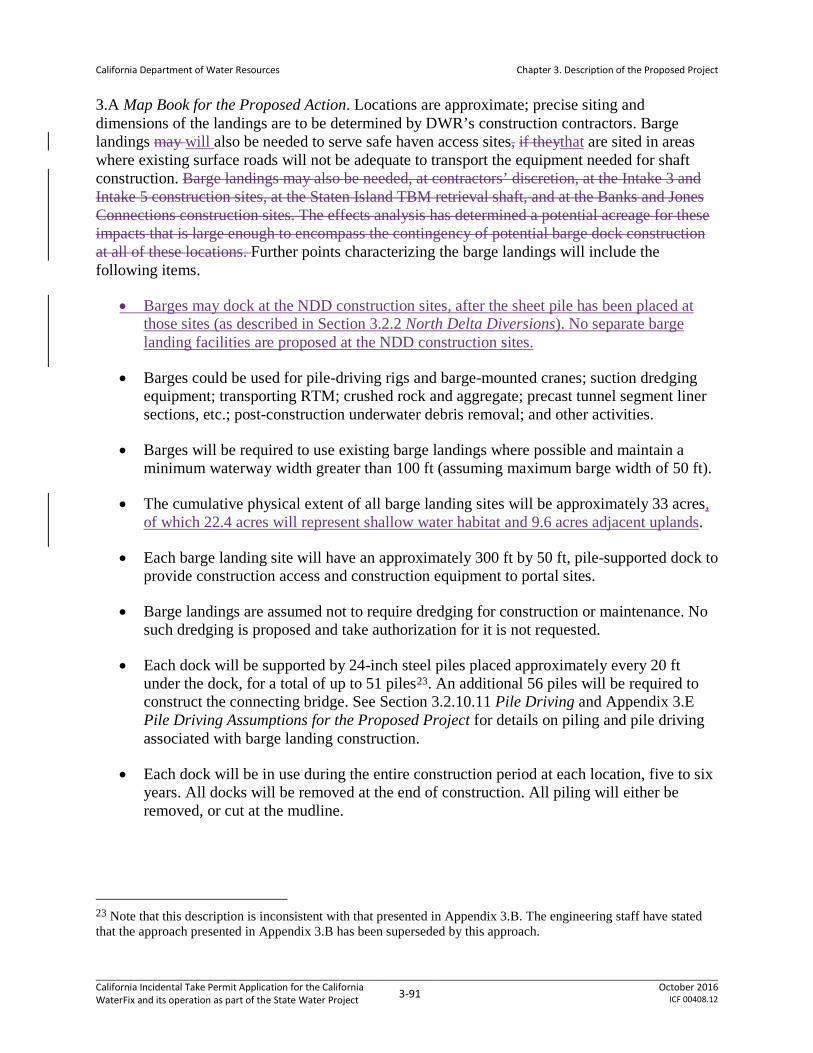
California Department of Water Resources
Chapter 3. Description of the Proposed Project
3.A Map Book for the Proposed Action. Locations are approximate; precise siting and dimensions of the landings are to be determined by DWR’s construction contractors. Barge landings may will also be needed to serve safe haven access sites, if theythat are sited in areas where existing surface roads will not be adequate to transport the equipment needed for shaft construction. Barge landings may also be needed, at contractors’ discretion, at the Intake 3 and Intake 5 construction sites, at the Staten Island TBM retrieval shaft, and at the Banks and Jones Connections construction sites. The effects analysis has determined a potential acreage for these impacts that is large enough to encompass the contingency of potential barge dock construction at all of these locations. Further points characterizing the barge landings will include the following items.
• Barges may dock at the NDD construction sites, after the sheet pile has been placed at those sites (as described in Section 3.2.2 North Delta Diversions). No separate barge landing facilities are proposed at the NDD construction sites.
• Barges could be used for pile-driving rigs and barge-mounted cranes; suction dredging equipment; transporting RTM; crushed rock and aggregate; precast tunnel segment liner sections, etc.; post-construction underwater debris removal; and other activities.
• Barges will be required to use existing barge landings where possible and maintain a minimum waterway width greater than 100 ft (assuming maximum barge width of 50 ft).
• The cumulative physical extent of all barge landing sites will be approximately 33 acres, of which 22.4 acres will represent shallow water habitat and 9.6 acres adjacent uplands.
• Each barge landing site will have an approximately 300 ft by 50 ft, pile-supported dock to provide construction access and construction equipment to portal sites.
• Barge landings are assumed not to require dredging for construction or maintenance. No such dredging is proposed and take authorization for it is not requested.
• Each dock will be supported by 24-inch steel piles placed approximately every 20 ft under the dock, for a total of up to 51 piles23. An additional 56 piles will be required to construct the connecting bridge. See Section 3.2.10.11 Pile Driving and Appendix 3.E Pile Driving Assumptions for the Proposed Project for details on piling and pile driving associated with barge landing construction.
• Each dock will be in use during the entire construction period at each location, five to six years. All docks will be removed at the end of construction. All piling will either be removed, or cut at the mudline.
23 Note that this description is inconsistent with that presented in Appendix 3.B. The engineering staff have stated that the approach presented in Appendix 3.B has been superseded by this approach.
California Incidental Take Permit Application for the California WaterFix and its operation as part of the State Water Project 3-91 October 2016
ICF 00408.12

California Department of Water Resources
Chapter 3. Description of the Proposed Project
• Approximately 5,911,800 barge trips24 11,800 barge trips are projected to carry tunnel segment liners from ports (locations not yet determined, but likely in the Sacramento area) to barge landings via the Sacramento River, averaging approximately 4 round-trips per day for up to 5.5 years. Because barges may also be used for other purposes, such as transportation of bulk materials, a total of 9,415,000 barge of 15,000 barge trips are projected as a conservative assumption (i.e., a greater number of trips is not expected to occur). This is a small increase relative to existing marine traffic in the area. Barges used will be commercial vessels propelled by tugboats. Barge sizes have not been determined. Commercial barge operators on the Sacramento River are required to operate in compliance with navigational guidelines.
From June 1 through October 31, barge traffic may travel from all three locations (Stockton, San Francisco and Antioch). From November 1 through February 28, barge traffic is limited to travel from Port of Stockton to Bouldin Island. From March 1 through May 31, barge traffic should be restricted to move critical heavy construction equipment in the San Joaquin River due to emigrating listed steelhead and spring-run CS from the San Joaquin River basin. To further minimize potential effects to fish species, plans will be developed for materials that can be transported by truck or rail to launch and retrieval points along the proposed tunnel alignment. This includes investigating the potential of using rail to deliver materials and components to Stockton and the CCF location.
See Appendix 3.B Conceptual Engineering Report, Volume 1, Section 23.3 Barge Traffic and Landing Facilities, for further discussion of barge traffic and barge docks.
• All barge operations will be required to comply with the provisions of a barge operations plan, as specified in Appendix 3.F General Avoidance and Minimization Measures, AMM7 Barge Operations Plan. As there stated, the barge operations plan will be subject to review and approval by DWR and the other resource agencies (CDFW, NMFS, and USFWS included), and will address the following.
o Bottom scour from propeller wash.
o Bank erosion or loss of submerged or emergent vegetation from propeller wash and/or excessive wake.
o Sediment and benthic community disturbance from accidental or intentional barge grounding or deployment of barge spuds (extendable shafts for temporarily maintaining barge position) or anchors.
o Accidental material spillage.
o Hazardous materials spills (e.g., fuel, oil, hydraulic fluids).
o Potential for suspension of contaminated sediments.
24 See BO #13 Barge Unloading Facility Pile Quantities and Barge Trip Estimates
California Incidental Take Permit Application for the California WaterFix and its operation as part of the State Water Project 3-92 October 2016
ICF 00408.12

California Department of Water Resources
Chapter 3. Description of the Proposed Project
3.2.10.10 Landscaping and Associated Activities
The construction phase at most conveyance facilities will conclude with landscaping. Revegetation of disturbed areas will be determined in accordance with guidance given by DWR’s WREM No. 30a, Architectural Motif, State Water Project and through coordination with local agencies through an architectural review process. This guidance from DWR WREM No 30a is set forth as follows.
If possible, the natural environment will be preserved. If not possible, a re-vegetation plan will be developed. Landscaping plans may be required if deemed appropriate to enhance facility attractiveness, for the control of dust/mud/wind/unauthorized access, for reducing equipment noise/glare, for screening of unsightly areas from visually sensitive areas. Planting will use low water-use plants native to the Delta or the local environment, with an organic/natural landscape theme without formal arrangements. For longevity and minimal visual impact, low maintenance plants and irrigation designs will be chosen. Planting plans will use native trees, shrubs or grasses and steps will be taken to avoid inducing growth of non-native invasive plant species/CA Plant Society weedy species25. Planting of vegetation will be compatible with density and patterns of existing natural vegetation areas and will be placed in a manner that does not compromise facility safety and access. Planting will be done within the first year following the completion of the project and a plant establishment plan will be implemented.
Landscaping in cleared areas will reuse topsoil stockpiled at the time of site clearing. Site revegetation plans will be developed for restoration of areas disturbed by PP activities.
Other activities occurring at the conclusion of construction will include site cleanup, installation of operational lighting, and installation of security fencing.
Site cleanup will consist of removal of all construction equipment, materials, and debris from the site. Construction debris will be disposed at a regional facility authorized to receive such materials.
Operational lighting will be needed at the intakes, the IF, the consolidated pumping plant at CFF, at the HOR gate, and at the control structures associated with the Banks and Jones connections; operational lighting will also be provided at the existing CVP/SWP facilities. Lighting for the proposed facilities would be designed in accordance with guidance given by DWR’s WREM No. 30a, Architectural Motif, State Water Project and through coordination with local agencies through an architectural review process. This guidance is set forth as follows.
All artificial outdoor lighting is to be limited to safety and security requirements. All lighting is to provide minimum impact on the surrounding environment and is to be shielded to direct the light only towards objects requiring illumination.
25 This text refers to plant species identified as invasive by the California Invasive Plant Council. For further information see http://www.cal-ipc.org/ .
California Incidental Take Permit Application for the California WaterFix and its operation as part of the State Water Project 3-93 October 2016
ICF 00408.12

California Department of Water Resources
Chapter 3. Description of the Proposed Project
Lights shall be downcast, cut-off type fixtures with non-glare finishes set at a height that casts low-angle illumination to minimize incidental spillover of light onto adjacent properties, open spaces or backscatter into the nighttime sky. Lights shall provide good color rendering with natural light qualities with the minimum intensity feasible for security, safety and personnel access. All outdoor lighting will be high pressure sodium vapor with individual photocells. Lighting will be designed per the guidelines of the Illuminating Engineering Society (IES). Additionally, all lights shall be consistent with energy conservation and are to be aesthetically pleasing. Lights will have a timed on/off program or will have daylight sensors. Lights will be programmed to be on whether personnel is present or not.
The intakes, the IF, the consolidated pumping plant at CFF, and the HOR gate will be provided with security fencing to prevent unauthorized public access. Security camera systems and intrusion alarm systems will be located at these sites. Admission to the sites and buildings will require credentialed entry through access control gates and secure doors, respectively. At each site, the fence line will be coincident with or within the area of permanent impact shown in Appendix 3.A Mapbook for the Proposed Project.
3.2.10.11 Pile Driving
Sheet pile and tubular steel pile driving will be required for intake construction, barge dock construction, embankment work at CCF, the Banks and Jones connections, and construction of the HOR gate. Multiple pile driving rigs may be operated simultaneously; the minimum spacing between rigs will be 200 feet. In practice, the spacing is expected to depend on contractor means and methods. Both vibratory and impact pile driving are expected to occur at each of these locations, as structural requirements call for impact pile driving to refusal.
In-water pile driving will be subject to abatement, hydroacoustic monitoring, and compliance with timing limitations as described in Appendix 3.F General Avoidance and Minimization Measures, AMM9 Underwater Sound Control and Abatement Plan. Pile driving will be limited to the in-water work windows, specific to each construction area, detailed in the introductory paragraphs of Section 3.2 Conveyance Facility Construction. For all sheetpile cofferdams proposed at the Delta intakes, CCF, and HOR gate, it is assumed that approximately 70 percent of the length of each pile can be placed using vibratory pile driving, with impact driving used to finalize pile placement. The degree to which vibratory driving can be performed effectively is unknown at this time due to as yet undetermined geologic conditions at the construction sites. Once constructed, if the foundation design for either the Delta intakes or HOR gate requires pile driving, such work will be conducted from within the cofferdam; it is still undetermined if the foundation will use piles or concrete-in-drilled-hole methods, which does not require pile driving. If driven foundation piles are included in the design, DWR will require contractors to isolate pile driving activities within dewatered cofferdams as a means of minimizing noise levels and potential adverse effects on fish.
Barge landing construction will entail pile driving 24-inch tubular steel piles in the water. DWR will work with contractors to minimize pile driving, particularly impact pile driving, by using floating docks instead of pile-supported docks, wherever feasible considering the load
California Incidental Take Permit Application for the California WaterFix and its operation as part of the State Water Project 3-94 October 2016
ICF 00408.12

California Department of Water Resources
Chapter 3. Description of the Proposed Project
requirements of the landings and the site conditions; floating docks would need fewer piles. If dock piles for barge landings cannot be installed using vibratory methods, the construction contractor will use a bubble curtain or other attenuation device to minimize underwater noise.
Table 3-20 shows the approximate channel widths, timing, and duration of pile driving for each facility or structure where pile driving is proposed to occur in open water or on land within 200 ft of open water.
Table 3-20. Pile Driving Sites, Schedule, and Durations
Facility or Structure
Average Width of Water Body (feet)
Year of Construction
Number of Pile Drivers
Duration of Pile Driving (days)1
Intake 2 Cofferdam
700 Year 8 4 42
Intake 2 Foundation
700 Year 9 4 19
Intake 3 Cofferdam
500 Year 7 4 42
Intake 3 Foundation
500 Year 8 4 14
Intake 5 Cofferdam 600 Year 5 4 42
Intake 5 Foundation 600 Year 6 4 19
Barge Landings 265–1,030 Years 1 to 32 4 2 CCF Cofferdams 10,500 Year 9 and 10 4 85 NCCF Siphon 10,500 Year 6 and 7 2 36 HOR Gate Cofferdams 150 Year 3 and 4 1 19
HOR Gate Foundation 150 Year 3 and 4 1 4
Notes
1 Indicates number of days required for one pile driver. Work may be completed more quickly if multiple pile driving rigs operate concurrently. 2 Two years of pile driving per site; three years to complete pile driving at all facilities.
3.3 Operations and Maintenance of New and Existing Facilities
This section of Chapter 3 discusses proposed operations and maintenance of the PP, which includes new and existing CVP/SWP facilities in the Delta. It includes the following subsections.
• Section 3.3.1 Implementation
• Section 3.3.2 Operational Criteria describes the approach to flow management and identify specific operational criteria applying to both existing and proposed CVP/SWP facilities in the Delta.
• Section 3.3.3 Real-Time Operational (RTO) Decision-Making Process describes how those criteria will be implemented in real time using available system status information.
California Incidental Take Permit Application for the California WaterFix and its operation as part of the State Water Project 3-95 October 2016
ICF 00408.12

California Department of Water Resources
Chapter 3. Description of the Proposed Project
• Section 3.3.4 Operation of South Delta Facilities describes how the south Delta facilities are operated to minimize harm to listed species of fish, and to control invasive aquatic vegetation.
• Section 3.3.5 Water Transfers describes what water transfers are and defines the extent to which they are covered activities under the PP.
• Section 3.3.6 Maintenance of the Facilities describes how the new and existing facilities will be maintained under the PP.
As previously stated, DWR has entered into a settlement agreement with CCWD, the effects of which are not evaluated in this application. When operational and maintenance actions associated with implementation of the agreement are sufficiently defined to provide for analysis of potential adverse effects to listed species, a supplement to this application will be provided to CDFW.
3.3.1 Implementation
Implementation of the PP will include operations of both new and existing water conveyance facilities once the new north Delta diversion facilities are completed and become operational, Most existing facilities will continue to be operated consistent with existing regulatory authorizations, including the USFWS (2008) and NMFS (2009)26 BiOps, the CDFW (2009) incidental take permit, and the associate
CWF operating criteria are not intended to change Shasta operating criteria and consistency determinations. However, operational limits included in this PP for south Delta export facilities will replace the south Delta operational limits currently implemented in compliance with the USFWS (2008) and NMFS (2009) BiOps, the CDFW (2009) incidental take permit, and the associated consistency determinations when the proposed north Delta diversion becomes operational. See
Table 3-1 for a complete summary of facilities and actions included in the PP. The PP also includes criteria for spring outflow and new minimum flow criteria at Rio Vista during the months of January through August that will apply when the proposed north Delta diversion becomes operational. The north Delta diversions and the head of Old River gate are ‘new’ facilities for the SWP and will be operated consistent with the PP criteria presented in this Application for these facilities.
The incidental take permit requested in this application will replace the existing 2009 incidental take authorization for CVP/SWP operations when the PP conveyance becomes operational. However, the USFWS (2008) and NMFS (2009) BiOps for CVP/SWP operations will continue to apply for CVP/SWP activities not included in the PP. For Shasta operations, the NMFS (2009) RPA adjustment (Action Suite 1.2) for seasonal temperature management that will likely be completed in late 2016 will apply. The proposed a; thus, the NMFS (2009) RPA adjustment
26 Note: Any reference to the NMFS (2009) BO in this Chapter is to include the amendments to that BO, as issued by NMFS on April 7, 2011.
California Incidental Take Permit Application for the California WaterFix and its operation as part of the State Water Project 3-96 October 2016
ICF 00408.12

California Department of Water Resources
Chapter 3. Description of the Proposed Project
(Action suite 1.2) for seasonal temperature management will control if there are any unforeseen conflicts in Shasta operations between the proposed CWF operating criteria and the adjusted RPA for CVP operations; in that case, proposed CWF operating criteria will be met through SWP operations. To summarize, the proposed project includes modified or new operational criteria for the following facilities:
• north Delta Intakes
• south Delta export facilities
• HOR gate operations
Additionally, the operation of the following facilities is included in the PP once the north Delta diversions are operational, but no changes to their operations are proposed.
• Delta Cross Channel (DCC) gate operations
• Suisun Marsh facilities
• North Bay Aqueduct (NBA) Intake
The proposed operational criteria are described in the following sections and in Table 3-21. The Delta smelt, longfin smelt, winter-run Chinook salmon, and spring-run Chinook salmon are species listed under the California Endangered Species Act (CESA). Therefore, it will be necessary for DWR to meet CESA permit issuance criteria for these species. To avoid a reduction in overall abundance for longfin smelt, the PP includes spring outflow criteria, which are intended to be provided by appropriate beneficiaries through the acquisition of water from willing sellers. If sufficient water cannot be acquired for this purpose, the spring outflow criteria will be accomplished through operations of the CVP/SWP to the extent an obligation is imposed on either the SWP or CVP under federal or applicable state law. This recognizes that DWR will manage the State Water Project to meet regulatory requirements through Real-Time Operations with full consideration of end of September Oroville storage levels. (This is consistent with the modeling results indicated by Alternative 4A operational scenarios H3 and H4 as set forth in the Final EIR/EIS.) Best available science, including that developed through a collaborative science program, will be used to analyze and make recommendations on the role of such flow in supporting longfin smelt abundance to CDFW, through the adaptive management process for the PP.
Operations under the PP may result in substantial change in Delta flows compared to the expected flows under the existing Delta configuration, and in some instances real-time operations will be applied for water supply, water quality, flood control, and/or fish protection purposes. Two key drivers of CVP/SWP operations, Fall X2 and spring outflow, as well as many of the individual operational components described below, are designed to adapt to developing scientific information as a consequence of the level of uncertainty associated with those criteria. A Collaborative Science and Adaptive Management Program will be used to evaluate and consider changes in the operational criteria based on information gained before and after the new facilities become operational. Described in more detail in Section 6.1 Collaborative Science and
California Incidental Take Permit Application for the California WaterFix and its operation as part of the State Water Project 3-97 October 2016
ICF 00408.12

California Department of Water Resources
Chapter 3. Description of the Proposed Project
Adaptive Management Program this program will be used to consider and address scientific uncertainty regarding the Delta ecosystem and to inform implementation of the operational criteria in the near term for existing BiOps for the coordinated operations of the CVP/SWP (U.S. Fish and Wildlife Service 2008, National Marine Fisheries Service 2009), the incidental take permit for the SWP facilities and operations (California Department of Fish and Game 2009) and the associated consistency determinations , as well as in the future for the new BiOp arising from the ESA Section 7 consultation for the PP, and the 2081(b) ITP for the PP.
3.3.2 Operational Criteria
Table 3-21 provides an overview of the proposed new criteria and other key criteria assumed for Delta operations when the proposed north Delta diversion intakes are operational. The proposed operational criteria were developed in coordination with NMFS, USFWS, and CDFW to minimize project effects on listed species. Further descriptions, including the intent of the specific criteria for each facility are described below, except Two new criteria, not associated with any facility, include a minimum flow at Rio Vista and is athe spring outflow criteriaon which is not associated with any facility. The purpose of the spring outflow criterion is to maintain spring outflows consistent with the current Biological Opinions (FWS 2008; NMFS 2009), as described above.
A brief description of the modeling assumptions for each criterion is also included. Additional detail regarding modeling assumptions is included in Table 3-22. Actual operations will also rely on real-time operations as described in Section 3.3.3 Real-Time Operational Decision-Making Process. Criteria presented in Table 3-21 for south Delta operations represent the maximum restrictions on exports. Even though this application attempts to describe the temporal scale at which some of the operational criteria will be implemented (e.g. north Delta bypass flow requirements and OMR requirements), a detailed operations plan will be developed by Reclamation and DWR in coordination with CDFW, NMFS and USFWS prior to the new facilities becoming operational, which will detail implementation of the criteria presented in Table 3-21.
California Incidental Take Permit Application for the California WaterFix and its operation as part of the State Water Project 3-98 October 2016
ICF 00408.12
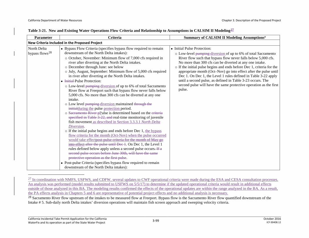
California Department of Water Resources
Chapter 3. Description of the Proposed Project
Table 3-21. New and Existing Water Operations Flow Criteria and Relationship to Assumptions in CALSIM II Modeling27
Parameter Criteria Summary of CALSIM II Modeling Assumptionsa New Criteria Included in the Proposed Project North Delta bypass flows28
Bypass Flow Criteria (specifies bypass flow required to remain downstream of the North Delta intakes): October, November: Minimum flow of 7,000 cfs required in
river after diverting at the North Delta intakes. December through June: see below July, August, September: Minimum flow of 5,000 cfs required
in river after diverting at the North Delta intakes. Initial Pulse Protection: Low-level pumping diversion of up to 6% of total Sacramento
River flow at Freeport such that bypass flow never falls below 5,000 cfs. No more than 300 cfs can be diverted at any one intake.
Low level pumping diversion maintained through the initialduring the pulse protection period.
Sacramento River pPulse is determined based on the criteria specified in Table 3-22, and real-time monitoring of juvenile fish movement as described in Section 3.3.3.1 North Delta Diversion.
If the initial pulse begins and ends before Dec 1, the bypass flow criteria for the month (Oct-Nov) when the pulse occurred would take effectpost-pulse criteria for the month of May go into effect after the pulse until Dec 1. On Dec 1, the Level 1 rules defined below apply unless a second pulse occurs. If a second pulse occurs before June 30th, will have the same protective operation as the first pulse.
Post-pulse Criteria (specifies bypass flow required to remain downstream of the North Delta intakes):
Initial Pulse Protection: Low-level pumping diversion of up to 6% of total Sacramento
River flow such that bypass flow never falls below 5,000 cfs. No more than 300 cfs can be diverted at any one intake.
If the initial pulse begins and ends before Dec 1, criteria for the appropriate month (Oct–Nov) go into effect after the pulse until Dec 1. On Dec 1, the Level 1 rules defined in Table 3-22 apply until a second pulse, as defined in Table 3-23 occurs. The second pulse will have the same protective operation as the first pulse.
27 In coordination with NMFS, USFWS, and CDFW, several updates to CWF operational criteria were made during the ESA and CESA consultation processes. An analysis was performed (model results submitted to USFWS on 5/5/17) to determine if the updated operational criteria would result in additional effects outside of those analyzed in this BA. The modeling results confirmed the effects of the operational updates are within the range analyzed in the BA. As a result, the PA effects analysis in Chapters 5 and 6 are representative of potential project effects and no additional analysis is necessary. 28 Sacramento River flow upstream of the intakes to be measured flow at Freeport. Bypass flow is the Sacramento River flow quantified downstream of the Intake # 5. Sub-daily north Delta intakes’ diversion operations will maintain fish screen approach and sweeping velocity criteria.
California Incidental Take Permit Application for the California WaterFix and its operation as part of the State Water Project 3-99 October 2016
ICF 00408.12

California Department of Water Resources
Chapter 3. Description of the Proposed Project
Parameter Criteria Summary of CALSIM II Modeling Assumptionsa December through June: once the initial pulse protection ends,
post-pulse bypass flow operations will not exceed Level 1 pumping unless specific criteria have been met to increase to Level 2 or Level 3. If those criteria are met, operations can proceed as defined in Table 3-22. Allowable diversion will be greater of the low-level pumpingdiversion or the diversion allowed by the post-pulse bypass flow rules in Table 3.3-2. The specific criteria for transitioning between and among pulse protection, Level 1, Level 2, and/or Level 3 operations, will be developed and based on real-time fish monitoring and hydrologic/behavioral cues upstream of and in the Delta as discussed in Section 3.3.3.1, North Delta Diversion. During operations, adjustments to the default allowable diversion level specified in Table 3-22 are expected to be made to improve water supply and/or migratory conditions for fish by making real-time adjustments to the diversion levels at the north Delta intakes. These adjustments are expected to fall within the operational bounds analyzed for this application and will be managed under real time operations (RTOs).
South Delta operations29, 30
October, November: To be determined based on real time operations and protection of the D-1641 San Joaquin River 2-week pulseNo south Delta exports during the D-1641 San Joaquin River 2-week pulse31, no OMR flow32 restriction during 2 weeks prior to pulse, and a 3-day average of −5,000 cfs in November
October, November39: Assumed no south Delta exports during the D-1641 San Joaquin River 2-week pulse, no OMR restriction during 2 weeks prior to pulse, and −5,000 cfs in November after pulse.
December: −5,000 cfs only when the Sacramento River pulse
29 The criteria do not fully reflect the complexities of CVP/SWP operations, dynamic hydrology, or spatial and temporal variation in the distribution of aquatic species. As a result, the criteria will be achieved by operating within an initial range of real time operational criteria from January through March and in June. This initial range, including operational triggers, will be determined through future discussion, including a starting point of -1250 to -5000 cfs based on a 14-day running average, and will be informed by the Adaptive Management Program, including real time monitoring. Further, the 3-day averaging period may be modified through future discussion. Modifications to the 3-day average period and the range of operating criteria may be needed, in part, because: 1) the water year type is forecasted in February but not finalized until May and 2) 0 cfs, or positive, OMR in wet and above normal years may be attained coincident with unimpaired flows. 30 OMR measured through the currently proposed index-method (Hutton 2008) with a 14-day averaging period consistent with the current operations (USBR 2014). 31 San Joaquin River based OMR action triggered when the leading edge of the pulse releases are measured at Vernalis. 32 OMR measured through the currently proposed index-method (Hutton 2008) with a 14-day averaging period consistent with the current operations (USBR 2014).
California Incidental Take Permit Application for the California WaterFix and its operation as part of the State Water Project 3-100 October 2016
ICF 00408.12

California Department of Water Resources
Chapter 3. Description of the Proposed Project
Parameter Criteria Summary of CALSIM II Modeling Assumptionsa after pulse.
December: OMR flows will not be more negative than an average of −5,000 cfs when the Sacramento River at Wilkins Slough pulse (same as north Delta diversion bypass flow pulse defined in Table 3-22) triggers33, and no more negative than an average of −2,000 cfs when the Delta smelt USFWS (2008) BiOp Action 1 triggers. No OMR flow restriction prior to the Sacramento River pulse or Delta smelt Action 1 triggers.
January, February34: OMR flows will not be more negative than a 3-day average of 0 cfs during wet years, −3,500 cfs during above-normal years, or −4,000 cfs during below-normal to critical years, except −5,000 in January of dry and critical years.
March35: OMR flows will not be more negative than a 3-day average of 0 cfs during wet or above- normal years or −3,500 cfs during below-normal and dry year and -3,000 cfs during critical years.
April, May36: Allowable OMR flows depend on gaged flow measured at Vernalis, and will be determined by a linear relationship. If Vernalis flow is below 5,000 cfs, OMR flows will
based on the Wilkins Slough flow (same as the pulse for the north Delta diversion) occurs. If the USFWS (2008) BiOp Action 1 is triggered,−2,000 cfs requirement for 14 days is assumed. Remaining December days were assumed to have an allowable OMR of -8000 cfs to compute a composite monthly allowable OMR level.
April, May: OMR requirement for the Vernalis flows between 5000 cfs and 30000 cfs were determined by linear interpolation. For example, when Vernalis flow is between 5,000 cfs and 6,000 cfs, OMR requirement is determined by linearly interpolating between −2,000 cfs and +1,000 cfs.
January–March and June– September: Same as the criteria New OMR criteria modeled as monthly average values.
39 As a result of formal consultation with USFWS and NMFS, and as a result of DFW’s issuance of the Draft 2081(b) ITP, DWR and Reclamation have included clarifications to the CWF operations flow criteria contained in Table 3-21. Although the October/November south Delta operational criteria were updated for the PP (see criteria described in the left column), for CALSIM modeling purposes in the effects analysis, the operational criteria listed here were used in the PP scenario to compare against the NAA, which has no OMR flow restrictions in October or November. As described in footnote 25, an analysis (model results submitted to USFWS on 5/5/17) was performed which indicated that the effects of the updated operational criteria are consistent with the effects analyzed in the BA; therefore, it was determined no changes to the CALSIM II modeling assumptions or performance of additional analysis was necessary. 33 December Sacramento River pulse determined by flow increases at Wilkins Slough of greater than 45% within 5-day period and exceeding 12,000 cfs at the end of 5-day period, and real-time monitoring of juvenile fish movement. Preliminary discussions with engineers indicates ramping down can begin within an hour of the trigger and full ramp down could be complete within approximately 12 hours. The Wilkins Slough trigger will be reviewed through future discussion, which will be informed by the Adaptive Management Program, including real time monitoringReclamation and DWR will require lead time of no less than 3 days to change operations in response to the pulse. 34 Water year type based on the Sacramento 40-30-30 index to be based on 50% forecast per current approaches; the first update of the water year type to occur in February. CALSIM II modeling uses previous water year type for October through January, and the current water year type from February onwards. 35 Water year type as described in the above footnote. 36 When OMR target is based on Vernalis flow, will be a function of 5-day average measured flow.
California Incidental Take Permit Application for the California WaterFix and its operation as part of the State Water Project 3-101 October 2016
ICF 00408.12

California Department of Water Resources
Chapter 3. Description of the Proposed Project
Parameter Criteria Summary of CALSIM II Modeling Assumptionsa not be more negative than -2000 cfs. If Vernalis is 6,000 cfs, OMR flows will not be less than +1000 cfs. If Vernalis is 10,000 cfs, OMR flows will not be less than +2,000 cfs. If Vernalis is 15,000 cfs, OMR flows will not be less than +3,000 cfs. If Vernalis is at or exceeds 30,000 cfs, OMR flows will not be less than 6,000 cfs.
June: Similar to April and May, allowable flows depend on gaged flow measured at Vernalis (except without interpolation). If Vernalis is less than 3,500 cfs, OMR flows will not be more negative than −3,500 cfs. If Vernalis exceeds 3,500 cfs up to 10,000 cfs, OMR flows will not be less than 0 cfs. If Vernalis exceeds 10,000 cfs up to 15,000 cfs, OMR flows will not be less than +1,000 cfs. If Vernalis exceeds 15,000 cfs, OMR flows will not be less than +2,000 cfs.
July, August, September: No OMR flow constraints37. OMR criteria under 2008 USFWS and 2009 NMFS BiOps or the
above, whichever results in more positive, or less negative OMR flows, will be applicable38.
37 PP operations include a preference for south Delta pumping in July through September months to provide limited flushing flows to manage water quality in the south Delta. 38 Change in CVP/SWP pumping from the south Delta will occur to comply with OMR targets will be achieved to the extent exports can control the flow. The OMR targets would not be achieved through releases from CVP/SWP reservoirs. The combined CVP/SWP export rates from the proposed north Delta intakes and the existing south Delta intakes will not be required to drop below 1,500 cfs to provide water supply for health and safety needs, critical refuge supplies, and obligation to senior water rights holders.
California Incidental Take Permit Application for the California WaterFix and its operation as part of the State Water Project 3-102 October 2016
ICF 00408.12

California Department of Water Resources
Chapter 3. Description of the Proposed Project
Parameter Criteria Summary of CALSIM II Modeling Assumptionsa HOR gate operations
October 1–November 30: RTO management – with the current expectation being that the HOR gate will be closed in orderoperated to protect the D-1641 pulse flow designed to attract upstream migrating San Joaquin origin adult Fall-Run Chinook Salmon (Section 3.3.3 Real-Time Operational Decision-Making Process). HOR gate will be closed approximately 50% during the time immediately before and after the SJR pulse and it will be fully closed during the pulse unless new information suggests alternative operations are better for fish.
January 1-March 31, and June 1-15: RTO will determine exact operations to protect salmon fry when migrating, During this migration, operation When salmon fry are migrating (determined based on real time monitoring), initial operating criterion will be to close the gate subject to RTO for purposes of water quality, stage, and flood control considerations.
February–June 15thApril-May: Initial operating criterion will be to close the gate 100% of the time subject to RTO for purposes of water quality, stage, and flood control considerations (Section 3.3.3, Real-Time Operational Decision-Making Process). Reclamation, DWR, NMFS, USFWS, and DFW will actively explore the implementation of reliable juvenile salmonid tracking technology that may enable shifting to a more flexible real time operating criterion based on the presence/absence of listed fishes.
June 16 to September 30, December: Operable gates will be open.
Assumed 50% open from January 1 to June 15, and during days in October prior to the D-1641 San Joaquin River pulse. Closed during the pulse. 100% open in the remaining months.
Spring Outflow40 March, April, May: Initial operations will maintain the March–May average delta outflow that would occur with existing facilities under the operational criteria described in the 2008 USFWS BiOp and
2011 NMFS RPA for San Joaquin River i-e ratio constraint is the primary driver for the Apr-May Delta outflow under the No Action Alternative, this criterion was used to constrain Apr-May total Delta exports under the PP to meet Mar-May Delta outflow targets.
40 For modeling purposes, the criteria described in the CALSIM modeling assumptions column were used for the PP scenario. However, the 2081(b) ITP is expected to include final operations related to spring outflow. Although the expected spring outflow requirements from DFW are not components for the proposed project, DFW’s expected operational criteria related to spring outflow was modeled and included in the draft 2081(b) ITP and presented in the table below: Spring Outflow Criteria Upon initiation of the Test Period and throughout the CDFW permit term, average Delta outflow for LFS based on the 50% exceedance forecast for the current month’s ELT 8 River Index (8RI).) (From DFW ITP)
California Incidental Take Permit Application for the California WaterFix and its operation as part of the State Water Project 3-103 October 2016
ICF 00408.12

California Department of Water Resources
Chapter 3. Description of the Proposed Project
Parameter Criteria Summary of CALSIM II Modeling Assumptionsa 2009 NMFS BiOp (U.S. Fish and Wildlife Service 2008; National Marine Fisheries Service 2009).41 The 2011 NMFS BiOp action IV.2.1 (San Joaquin River i-e ratio) will be used to constrain Apr–May total Delta exports under the PA to meet March–May Delta outflow targets per current operational practices (National Marine Fisheries Service 2009).21
March–May average delta outflow targets representative of the modeled outflows under the current BiOps with existing facilities at the time the North Delta Diversion will be operational are tabulated below for 10% exceedance intervals
(U.S. Fish and Wildlife Service 2008; National Marine Fisheries Service 2009). The 2011 NMFS BiOp action IV.2.1 (San Joaquin River i-e ratio) will be used to constrain April–May total Delta exports under the PP to meet March–May Delta outflow targets per current operational practices (National Marine Fisheries Service 2009).42 March–May average delta outflow targets representative of the modeled outflows under the current BiOps with existing facilities at the time the North Delta Diversion will be operational are tabulated below for 10% exceedance intervals (U.S. Fish and Wildlife Service 2008; National Marine Fisheries Service 2009).
Rio Vista minimum flow standard43
January through August: flows will exceed 3,000 cfs September through December: flows per D-1641
Same as PP criteria
41 If best available science resulting from collaborative scientific research program shows that Longfin Smelt abundance can be maintained in the absence of spring outflow, and DFW concurs, an alternative operation for spring outflow could be developed to follow flow constraints established under D-1641. Any changes in the PA will be implemented consistent with the CWF AMP, including coordination with USFWS and NMFS 42 For example, if best available science resulting from collaborative scientific research program shows that longfin smelt abundance can be maintained in the absence of spring outflow, and DFW concurs, an alternative operation for spring outflow could be to follow flow constraints established under D-1641. Any changes in the PA will be implemented consistent with the Collaborative Science and Adaptive Management Program, including coordination with CDFW, USFWS and NMFS. 43 Rio Vista minimum monthly average flow in cfs (7-day average flow not be less than 1,000 below monthly minimum), consistent with the SWRCB D-1641
California Incidental Take Permit Application for the California WaterFix and its operation as part of the State Water Project 3-104 October 2016
ICF 00408.12

California Department of Water Resources
Chapter 3. Description of the Proposed Project
Parameter Criteria Summary of CALSIM II Modeling Assumptionsa Key Existing Delta Criteria Included in Modeling44
Fall Outflow No change. September, October, November: implement the USFWS 2008 BO Fall X2 requirements in wet (W) and above normal (AN) year types.
September, October, November: implement the 2008 USFWS BiOp “Action 4: Estuarine Habitat During Fall” (Fall X2) requirements (U.S. Fish and Wildlife Service 2008).
Winter and summer outflow
No change. Flow constraints established under D-1641 will be followed if not superseded by criteria listed above.
SWRCB D-1641 Delta outflow and February – June X2 criteria.
Rio Vista minimum flow standard45
January through August: flows will exceed 3,000 cfs September through December: flows per D-1641
Same as PP criteria
Delta Cross Channel Gates
No change in operational criteria. Operating criteria as required by NMFS (2009) BiOp Action IV.1
and D-1641
Delta Cross Channel gates are closed for a certain number of days during October 1 through December 14 based on the Wilkins Slough flow, and the gates may be opened if the D-1641 Rock Slough salinity standard is violated because of the gate closure. Delta Cross Channel gates are assumed to be closed during December 15 through January 31. February 1 through June 15, Delta Cross Channel gates are operated based on D-1641 requirements.
Suisun Marsh Salinity Control Gates
No change. Gates will continue to be closed up to 20 days per year from October through May.
For the DSM2 modeling, used generalized seasonal and tidal operations for the gates. Seasonal operation: The radial gates are operational from October
to February if Martinez EC is higher than 20000, and for remaining months they remain open.
Tidal operations when gates are operational: gates close when downstream channel flow is < 0.1 (onset of flood tide); gates open when upstream to downstream stage difference is greater than 0.3 ft (onset of ebb tide)
44 CALSIM II modeling assumptions are described in Appendix 5.A CALSIM Methods and Results. 45 Rio Vista minimum monthly average flow in cfs (7-day average flow not be less than 1,000 below monthly minimum), consistent with the SWRCB D-1641
California Incidental Take Permit Application for the California WaterFix and its operation as part of the State Water Project 3-105 October 2016
ICF 00408.12

California Department of Water Resources
Chapter 3. Description of the Proposed Project
Parameter Criteria Summary of CALSIM II Modeling Assumptionsa Export to inflow ratio
Operational criteria are the same as defined under D-1641, and applied as a maximum 3-day running average.
The D-1641 export/inflow (E/I) ratio calculation was largely designed to protect fish from south Delta entrainment. For the PP, Reclamation and DWR propose that the NDD be excluded from the E/I ratio calculation. In other words, Sacramento River inflow is defined as flows downstream of the NDD and only south Delta exports are included for the export component of the criteria.
Combined export rate is defined as the diversion rate of the Banks Pumping Plant and Jones Pumping Plant from the south Delta channels.
Delta inflow is defined as the sum of the Sacramento River flow downstream of the proposed north Delta diversion intakes, Yolo Bypass flow, Mokelumne River flow, Cosumnes River flow, Calaveras River flow, San Joaquin River flow at Vernalis, and other miscellaneous in-Delta flows.
a See Table 3-22 for Proposed Project CALSIM II Modeling Assumptions
California Incidental Take Permit Application for the California WaterFix and its operation as part of the State Water Project 3-106 October 2016
ICF 00408.12
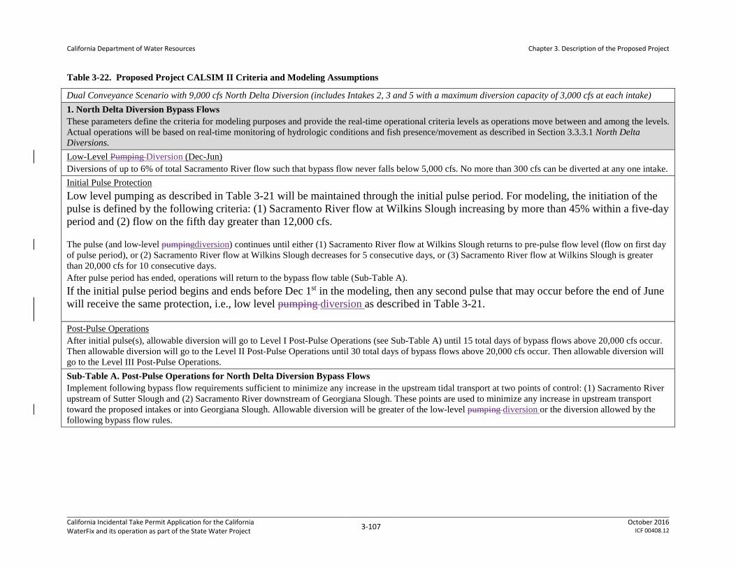
California Department of Water Resources
Chapter 3. Description of the Proposed Project
Table 3-22. Proposed Project CALSIM II Criteria and Modeling Assumptions
Dual Conveyance Scenario with 9,000 cfs North Delta Diversion (includes Intakes 2, 3 and 5 with a maximum diversion capacity of 3,000 cfs at each intake) 1. North Delta Diversion Bypass Flows These parameters define the criteria for modeling purposes and provide the real-time operational criteria levels as operations move between and among the levels. Actual operations will be based on real-time monitoring of hydrologic conditions and fish presence/movement as described in Section 3.3.3.1 North Delta Diversions. Low-Level Pumping Diversion (Dec-Jun) Diversions of up to 6% of total Sacramento River flow such that bypass flow never falls below 5,000 cfs. No more than 300 cfs can be diverted at any one intake. Initial Pulse Protection Low level pumping as described in Table 3-21 will be maintained through the initial pulse period. For modeling, the initiation of the pulse is defined by the following criteria: (1) Sacramento River flow at Wilkins Slough increasing by more than 45% within a five-day period and (2) flow on the fifth day greater than 12,000 cfs.
The pulse (and low-level pumpingdiversion) continues until either (1) Sacramento River flow at Wilkins Slough returns to pre-pulse flow level (flow on first day of pulse period), or (2) Sacramento River flow at Wilkins Slough decreases for 5 consecutive days, or (3) Sacramento River flow at Wilkins Slough is greater than 20,000 cfs for 10 consecutive days. After pulse period has ended, operations will return to the bypass flow table (Sub-Table A). If the initial pulse period begins and ends before Dec 1st in the modeling, then any second pulse that may occur before the end of June will receive the same protection, i.e., low level pumping diversion as described in Table 3-21.
Post-Pulse Operations After initial pulse(s), allowable diversion will go to Level I Post-Pulse Operations (see Sub-Table A) until 15 total days of bypass flows above 20,000 cfs occur. Then allowable diversion will go to the Level II Post-Pulse Operations until 30 total days of bypass flows above 20,000 cfs occur. Then allowable diversion will go to the Level III Post-Pulse Operations. Sub-Table A. Post-Pulse Operations for North Delta Diversion Bypass Flows Implement following bypass flow requirements sufficient to minimize any increase in the upstream tidal transport at two points of control: (1) Sacramento River upstream of Sutter Slough and (2) Sacramento River downstream of Georgiana Slough. These points are used to minimize any increase in upstream transport toward the proposed intakes or into Georgiana Slough. Allowable diversion will be greater of the low-level pumping diversion or the diversion allowed by the following bypass flow rules.
California Incidental Take Permit Application for the California WaterFix and its operation as part of the State Water Project 3-107 October 2016
ICF 00408.12

California Department of Water Resources
Chapter 3. Description of the Proposed Project
Level I Post-Pulse Operations Level II Post-Pulse Operations Level III Post Pulse Operations If
Sacramento River flow is
over... But not over... The bypass is...
If Sacramento River flow is
over... But not over... The bypass is...
If Sacramento River flow is
over... But not over... The bypass is...
Dec–Apr 0 cfs 5,000 cfs 100% of the
amount over 0 cfs 0 cfs 5,000 cfs 100% of the
amount over 0 cfs 0 cfs 5,000 cfs 100% of the amount over
0 cfs 5,000 cfs 15,000 cfs Flows remaining
after constant low level pumpingdiversion
5,000 cfs 11,000 cfs Flows remaining after constant low level diversionpumping
5,000 cfs 9,000 cfs Flows remaining after constant low level diversionpumping
15,000 cfs 17,000 cfs 15,000 cfs plus 80% of the amount over 15,000 cfs
11,000 cfs 15,000 cfs 11,000 cfs plus 60% of the amount over 11,000 cfs
9,000 cfs 15,000 cfs 9,000 cfs plus 50% of the amount over 9,000 cfs
17,000 cfs 20,000 cfs 16,600 cfs plus 60% of the amount over 17,000 cfs
15,000 cfs 20,000 cfs 13,400 cfs plus 50% of the amount over 15,000 cfs
15,000 cfs 20,000 cfs 12,000 cfs plus 20% of the amount over 15,000 cfs
20,000 cfs no limit 18,400 cfs plus 30% of the amount over 20,000 cfs
20,000 cfs no limit 15,900 cfs plus 20% of the amount over 20,000 cfs
20,000 cfs no limit 13,000 cfs plus 0% of the amount over 20,000 cfs
May 0 cfs 5,000 cfs 100% of the
amount over 0 cfs 0 cfs 5,000 cfs 100% of the
amount over 0 cfs 0 cfs 5,000 cfs 100% of the amount over
0 cfs 5,000 cfs 15,000 cfs Flows remaining
after constant low level diversionpumping
5,000 cfs 11,000 cfs Flows remaining after constant low level diversionpumping
5,000 cfs 9,000 cfs Flows remaining after constant low level diversionpumping
15,000 cfs 17,000 cfs 15,000 cfs plus 70% of the amount over 15,000 cfs
11,000 cfs 15,000 cfs 11,000 cfs plus 50% of the amount over 11,000 cfs
9,000 cfs 15,000 cfs 9,000 cfs plus 40% of the amount over 9,000 cfs
17,000 cfs 20,000 cfs 16,400 cfs plus 50% of the amount over 17,000 cfs
15,000 cfs 20,000 cfs 13,000 cfs plus 35% of the amount over 15,000 cfs
15,000 cfs 20,000 cfs 11,400 cfs plus 20% of the amount over 15,000 cfs
California Incidental Take Permit Application for the California WaterFix and its operation as part of the State Water Project 3-108 October 2016
ICF 00408.12
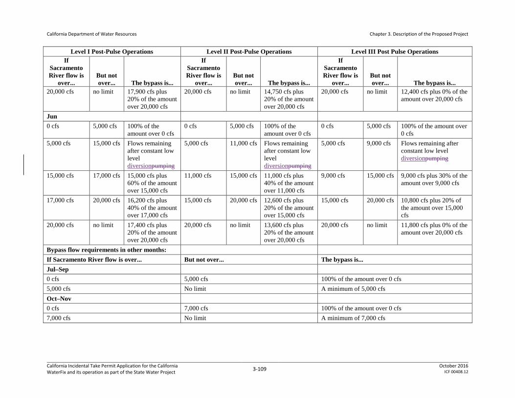
California Department of Water Resources
Chapter 3. Description of the Proposed Project
Level I Post-Pulse Operations Level II Post-Pulse Operations Level III Post Pulse Operations If
Sacramento River flow is
over... But not over... The bypass is...
If Sacramento River flow is
over... But not over... The bypass is...
If Sacramento River flow is
over... But not over... The bypass is...
20,000 cfs no limit 17,900 cfs plus 20% of the amount over 20,000 cfs
20,000 cfs no limit 14,750 cfs plus 20% of the amount over 20,000 cfs
20,000 cfs no limit 12,400 cfs plus 0% of the amount over 20,000 cfs
Jun 0 cfs 5,000 cfs 100% of the
amount over 0 cfs 0 cfs 5,000 cfs 100% of the
amount over 0 cfs 0 cfs 5,000 cfs 100% of the amount over
0 cfs 5,000 cfs 15,000 cfs Flows remaining
after constant low level diversionpumping
5,000 cfs 11,000 cfs Flows remaining after constant low level diversionpumping
5,000 cfs 9,000 cfs Flows remaining after constant low level diversionpumping
15,000 cfs 17,000 cfs 15,000 cfs plus 60% of the amount over 15,000 cfs
11,000 cfs 15,000 cfs 11,000 cfs plus 40% of the amount over 11,000 cfs
9,000 cfs 15,000 cfs 9,000 cfs plus 30% of the amount over 9,000 cfs
17,000 cfs 20,000 cfs 16,200 cfs plus 40% of the amount over 17,000 cfs
15,000 cfs 20,000 cfs 12,600 cfs plus 20% of the amount over 15,000 cfs
15,000 cfs 20,000 cfs 10,800 cfs plus 20% of the amount over 15,000 cfs
20,000 cfs no limit 17,400 cfs plus 20% of the amount over 20,000 cfs
20,000 cfs no limit 13,600 cfs plus 20% of the amount over 20,000 cfs
20,000 cfs no limit 11,800 cfs plus 0% of the amount over 20,000 cfs
Bypass flow requirements in other months: If Sacramento River flow is over... But not over... The bypass is... Jul–Sep 0 cfs 5,000 cfs 100% of the amount over 0 cfs 5,000 cfs No limit A minimum of 5,000 cfs Oct–Nov 0 cfs 7,000 cfs 100% of the amount over 0 cfs 7,000 cfs No limit A minimum of 7,000 cfs
California Incidental Take Permit Application for the California WaterFix and its operation as part of the State Water Project 3-109 October 2016
ICF 00408.12
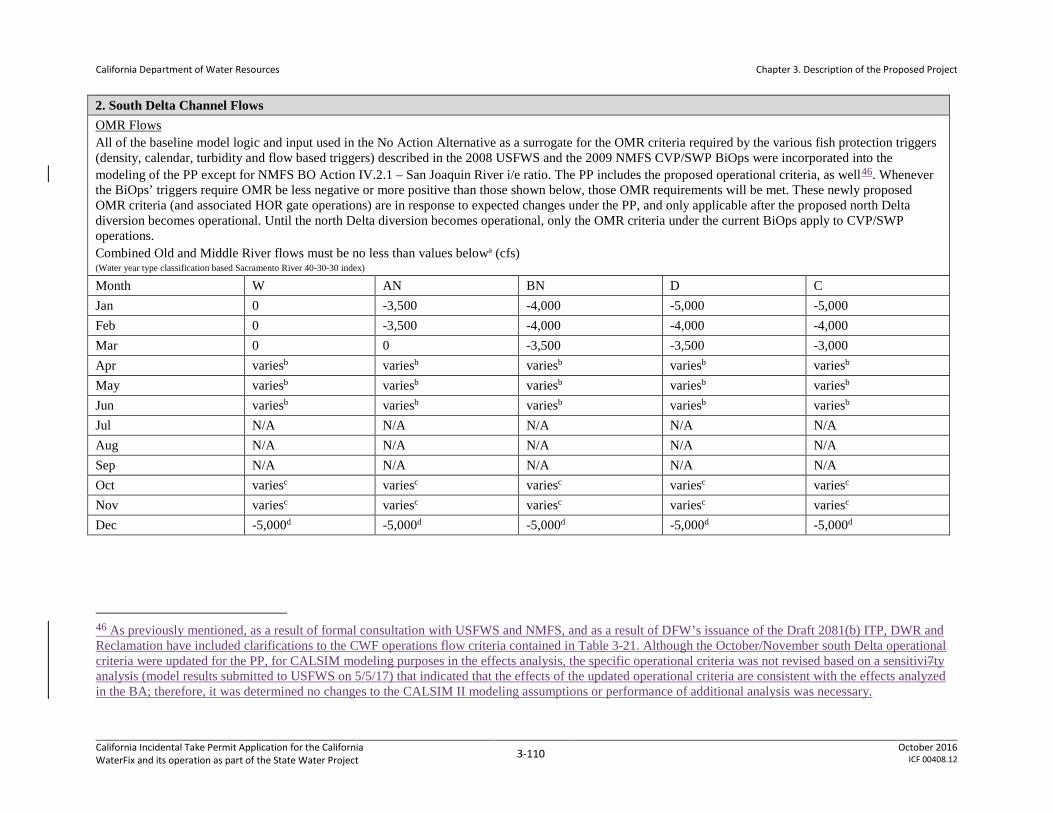
California Department of Water Resources
Chapter 3. Description of the Proposed Project
2. South Delta Channel Flows OMR Flows All of the baseline model logic and input used in the No Action Alternative as a surrogate for the OMR criteria required by the various fish protection triggers (density, calendar, turbidity and flow based triggers) described in the 2008 USFWS and the 2009 NMFS CVP/SWP BiOps were incorporated into the modeling of the PP except for NMFS BO Action IV.2.1 – San Joaquin River i/e ratio. The PP includes the proposed operational criteria, as well46. Whenever the BiOps’ triggers require OMR be less negative or more positive than those shown below, those OMR requirements will be met. These newly proposed OMR criteria (and associated HOR gate operations) are in response to expected changes under the PP, and only applicable after the proposed north Delta diversion becomes operational. Until the north Delta diversion becomes operational, only the OMR criteria under the current BiOps apply to CVP/SWP operations. Combined Old and Middle River flows must be no less than values belowa (cfs) (Water year type classification based Sacramento River 40-30-30 index) Month W AN BN D C Jan 0 -3,500 -4,000 -5,000 -5,000 Feb 0 -3,500 -4,000 -4,000 -4,000 Mar 0 0 -3,500 -3,500 -3,000 Apr variesb variesb variesb variesb variesb May variesb variesb variesb variesb variesb Jun variesb variesb variesb variesb variesb Jul N/A N/A N/A N/A N/A Aug N/A N/A N/A N/A N/A Sep N/A N/A N/A N/A N/A Oct variesc variesc variesc variesc variesc Nov variesc variesc variesc variesc variesc Dec -5,000d -5,000d -5,000d -5,000d -5,000d
46 As previously mentioned, as a result of formal consultation with USFWS and NMFS, and as a result of DFW’s issuance of the Draft 2081(b) ITP, DWR and Reclamation have included clarifications to the CWF operations flow criteria contained in Table 3-21. Although the October/November south Delta operational criteria were updated for the PP, for CALSIM modeling purposes in the effects analysis, the specific operational criteria was not revised based on a sensitivi7ty analysis (model results submitted to USFWS on 5/5/17) that indicated that the effects of the updated operational criteria are consistent with the effects analyzed in the BA; therefore, it was determined no changes to the CALSIM II modeling assumptions or performance of additional analysis was necessary.
California Incidental Take Permit Application for the California WaterFix and its operation as part of the State Water Project 3-110 October 2016
ICF 00408.12

California Department of Water Resources
Chapter 3. Description of the Proposed Project
a Values are monthly averages for use in modeling. The model compares these minimum allowable OMR values to 2008 USFWS BiOp RPA OMR requirements and uses the less negative flow requirement.
b Based on San Joaquin inflow relationship to OMR provided below in Sub-Table B. c Two weeks before the D-1641 pulse (assumed to occur October 16-31 in the modeling), No OMR restrictions (for modeling purposes an OMR requirement of -5,000 cfs was assumed during this 2
week period) Two weeks during the D-1641 pulse, no south Delta exports Two weeks after the D-1641 pulse, -5,000 cfs OMR requirement (through November)
d OMR restriction of -5,000 cfs for Sacramento River winter-run Chinook salmon when North Delta initial pulse flows are triggered or OMR restriction of -2,000 cfs for Delta smelt when triggered. For modeling purposes (to compute a composite Dec allowable OMR), remaining days were assumed to have an allowable OMR of -8000 cfs.
Head of Old River Operable (HOR) Gate Operations/Modeling assumptions (% OPEN)47 MONTH HOR Gatea MONTH HOR Gatea Oct 50% (except during the pulse)b May 50% Nov 100% (except during the post-pulse period)b Jun 1–15 50% Dec 100% Jun 16–30 100% Jan 50%c Jul 100% Feb 50% Aug 100% Mar 50% Sep 100% April 50% a Percent of time the HOR gate is open. Agricultural barriers are in and operated consistent with current practices. HOR gate will be open 100% whenever flows are greater than 10,000 cfs at
Vernalis. HOR gate operation is triggered based upon State Water Board D-1641 pulse trigger. For modeling assumptions only, two weeks before the D-1641 pulse, it is assumed that the HOR gate will be open 50%.
b During the D-1641 pulse (assumed to occur October 16-31 in the modeling), it is assumed the HOR gate will be closed. For two weeks following the D-1641 pulse, it was assumed that the HOR gate will be open 50%. Exact timing of the action will be based on hydrologic conditions.
c The HOR gate becomes operational at 50% when salmon fry are migrating (based on real time monitoring). This generally occurs when flood flow releases are being made. For the purposes of modeling, it was assumed that salmon fry are migrating starting on January 1.
In the CALSIM II modeling, the “HOR gate open percentage” specified above is modeled as the percent of time within a month that HOR gate is open. In the DSM2 modeling, HOR gate is assumed to operate such that the above-specified percent of “the flow that would have entered the Old River if the HOR gate were fully open”, would enter the Old River.
47 The following HOR gate operating criteria represent assumptions used in the CALSIM modeling for the PP scenario. Refer to Table 3-21 and Section 3.3.4 for a description of HOR gate operations under the PP.
California Incidental Take Permit Application for the California WaterFix and its operation as part of the State Water Project 3-111 October 2016
ICF 00408.12

California Department of Water Resources
Chapter 3. Description of the Proposed Project
Sub-Table B. San Joaquin Inflow Relationship to OMR April and May June
If San Joaquin flow at Vernalis is the following
Average OMR flows would be at least the following (interpolated linearly between values)
If San Joaquin flow at Vernalis is the following
Average OMR flows would be at least the following (no interpolation)
≤ 5,000 cfs -2,000 cfs ≤ 3,500 cfs -3,500 cfs 6,000 cfs +1,000 cfs
3,501 to 10,000 cfs 0 cfs 10,000 cfs +2,000 cfs 15,000 cfs +3,000 cfs 10,001 to 15,000 cfs +1,000 cfs ≥30,000 cfs +6,000 cfs >15,000 cfs +2,000 cfs 3. Delta Cross Channel Gate Operations Assumptions Per SRWCB D-1641 with additional days closed from Oct 1 – Jan 31 based on NMFS BiOp (Jun 2009) Action IV.1.2 (closed during flushing flows from Oct 1 – Dec 14 unless adverse water quality conditions). This criterion is consistent with the No Action Alternative. 4. Rio Vista Minimum Instream Flows Assumptions Sep–Dec: Per D-1641; Jan-Aug: Minimum of 3,000 cfs 5. Delta Outflow Delta Outflow SWRCB D-1641 requirements, or outflow per requirements noted below, whichever is greater Months Delta Outflow Requirement Spring (Mar–May): Additional spring outflow requirementa
Fall (Sep–Nov): Implement USFWS (2008) Fall X2 requirement
California Incidental Take Permit Application for the California WaterFix and its operation as part of the State Water Project 3-112 October 2016
ICF 00408.12

California Department of Water Resources
Chapter 3. Description of the Proposed Project
Notes: a For modeling purposes, the spring outflow criteria described in Table 3-3.1 (see footnote 38) were used to model the PA scenario. However, the 2081 ITP will include final operations related to
spring outflow. These operations include the following: Protective outflows from March through May every year shall be determined by the use of a lookup table derived from a linear relationship between the 50% exceedance forecast for the current month’s 8RI and recent historic Delta outflow (1980 – 2016). Operators shall utilize Net Delta Outflow Index (NDOI) data to confirm that the average Delta outflow target was met during each 30 day period from March – May. Operators shall provide daily NDOI data quantifying daily Delta outflow in each 30 day period to CDFW on or before April 20, May 21, and June 20 every year. Reduction in exports down to minimum health and safety requirements established in D-1641 (currently 1500 cfs) may be necessary. These targets are intended to be provided through the acquisition of water from willing sellers and through operations of the CVP/SWP. This recognizes that DWR will manage the SWP to meet regulatory requirements through Real-Time Operations with full consideration of end of September Oroville storage levels. (This is consistent with the modeling results indicated by Alternative 4A operational scenarios H3 and H4 as set forth in the Final EIR/EIS.) Operators shall achieve Delta outflow targets through shared export allocations between the NDD and South Delta, consistent with required Operating Criteria described in the CDFW ITP. If the target average Delta outflow is greater than 44,500 cfs operators shall consult with CDFW to determine how to allocate exports between the NDD and the South DeltaAdditional Delta Outflow required during the Mar-May period to maintain Delta outflows that would occur under the No Action Alternative at the time North Delta Diversions would become operational (for modeling purposes this is represented by the No Action Alternative model with projected climate (Q5) and sea level conditions at Early Long-Term). March–May average Delta outflow targets for the PP are tabulated below for 10% exceedance intervals based on the modeled No Action Alternative March-May Delta outflow. Since NMFS (2009) San Joaquin River i-e ratio constraint is the primary driver for the April-May Delta outflow under the No Action Alternative, this criterion was used to constrain April-May TOTAL Delta exports under the PP to meet March-May Delta outflow targets.
Spring Outflow Criteria (presents the operational requirements expected to be included in the 2081(b) ITP, as represented in DFW’s draft 2081(b)ITP. Upon initiation of the Test Period and throughout the CDFW permit term, average Delta outflow for LFS based on the 50% exceedance forecast for the current month’s ELT 8 River Index (8RI).). March ELT 8RI
(TAF)
March – April Average Delta
Outflow Target (cfs)
April ELT 8RI
(TAF)
April – May Average Delta
Outflow Target (cfs)
May ELT 8RI
(TAF) May – June Average Delta Outflow Target (cfs)
0 0
0 0
0 0 450 7100
425 7100
250 4000
1000 7100
1000 7100
1000 4000 1650 7100
1750 7100
1600 4000
1700 8100
1930 7500
1700 4900 1800 10300
2000 8700
1800 6200
1900 12500
2100 10900
1900 7500 2000 14700
2200 13100
2000 8700
2100 16800
2300 15300
2100 10000 2200 19000
2400 17600
2200 11300
2300 21200
2500 19800
2300 12500 2400 23400
2600 22000
2400 13800
2500 25500
2700 24300
2500 15000 2600 27700
2800 26500
2600 16300
2700 29900
2900 28700
2700 17600
California Incidental Take Permit Application for the California WaterFix and its operation as part of the State Water Project 3-113 October 2016
ICF 00408.12

California Department of Water Resources
Chapter 3. Description of the Proposed Project
2800 32100
3000 31000
2800 18800 2900 34300
3100 33200
2900 20100
3000 36400
3200 35400
3000 21400 3100 38600
3300 37600
3100 22600
3200 40800
3400 39900
3200 23900 3300 43000
3500 42100
3300 25200
3370 44500
3600 44300
3400 26400 ≥ 3370 44500
≥ 3600 44500
3500 27700
3600 29000
3700 30200
3800 31500
3900 32800
4000 34000
4100 35300
4200 36500
4300 37800
4400 39100
4500 40300
4600 41600
4700 42900
4830 44500
≥ 4830 44500
Percent Exceedance: 10% 20% 30% 40% 50% 60% 70% 80% 90% Proposed Mar-May Delta Outflow Target (cfs)*:
44,500 44,500 35,000 27,900 20,700 16,800 13,500 11,500 9,100
* values based on the flow frequency of March–May average Delta Outflow modeled under No Action Alternative under Early Long-Term Q5 climate projections, without San Joaquin River Restoration Flows.
California Incidental Take Permit Application for the California WaterFix and its operation as part of the State Water Project 3-114 October 2016
ICF 00408.12

California Department of Water Resources
Chapter 3. Description of the Proposed Project
6. Operations for Delta Water Quality and Residence Time Assumptions Jul–Sep: Prefer south delta intake up to total pumping of 3,000 cfs; No specific intake preference beyond 3,000 cfs. Oct–Jun: Prefer north delta intake; (real-time operational flexibility) 7. In-Delta Agricultural and Municipal & Industrial Water Quality Requirements Assumptions Existing D-1641 AG and MI standards 8. D-1641 E-I Ratio Computation Assumptions In computing the E-I Ratio in the CALSIM II model, the North Delta Diversion is not included in the export term, and the Sacramento River inflow is as modeled downstream of the North Delta Intakes.
California Incidental Take Permit Application for the California WaterFix and its operation as part of the State Water Project 3-115 October 2016
ICF 00408.12

California Department of Water Resources
Chapter 3. Description of the Proposed Project
Flow criteria are applied seasonally (month by month) and according to the following five water-year types. Under the observed hydrologic conditions over the 82-year period (1922–2003), the number of years of each water-year type is listed below. The water-year type classification, unless otherwise noted, is based on the Sacramento Valley 40-30-30 Water Year Index defined under Revised D-1641.
• Wet (W) water-year: the wettest 26 years of the 82-year hydrologic data record, or 32 percent of years.
• Above-normal (AN) water-year: 12 years of 82, or 15 percent.
• Below-normal (BN) water-year: 14 years of 82, or 17 percent.
• Dry (D) water-year: 18 years of 82, or 22 percent.
• Critical (C) water-year: 12 years of 82, or 15 percent.
The above noted frequencies are expected to change slightly under projected climate conditions at year 2030. The number of years of each water-year type per D-1641 Sacramento Valley 40-30-30 Water Year Index under the projected climate condition assumed for this application, over the 82-year period (1922–2003) is provided below. See Section 5.A.3, Climate Change and Sea Level Rise in CalSim II Modeling and Results [U.S. Bureau of Reclamation 2016, Appendix 5.A]) for more information on the assumed climate change projection at year 2030 for this BA. Also, see attachment 3-1 for more information on how the PP will maintain desired operational criteria under future climate change conditions, and how this issue will continue to be addressed in future consultation on long-term operations of the CVP and SWP.
• Wet water-year: the wettest 26 years of the 82-year hydrologic data record, or 32 percent of years.
• Above-normal water-year: 13 years of 82, or 16 percent.
• Below-normal water-year: 11 years of 82, or 13 percent.
• Dry water-year: 20 years of 82, or 24 percent.
• Critical water-year: 12 years of 82, or 15 percent.
3.3.2.1 Operational Criteria for North Delta CVP/SWP Export Facilities
The proposed operational criteria were developed based on the scientific information available at the time of document preparation and are intended to minimize project effects on listed species while providing water supply reliability. The proposed north Delta diversions will allow the PP to export water, consistent with applicable criteria, during periods of high flow. Thus, north Delta diversions will be greatest in wetter years and lowest in drier years, when south Delta diversions will provide the majority of the CVP/SWP exports. North Delta bypass flow criteria were developed primarily to avoid impacts on listed species, with the considerations enumerated below. Real time operations will also be used to adjust operations to further limit effects on listed
California Incidental Take Permit Application for the California WaterFix and its operation as part of the State Water Project 3-116 October 2016
ICF 00408.12

California Department of Water Resources
Chapter 3. Description of the Proposed Project
species and maximize water supply benefits (Section 3.3.3, Real-Time Operational Decision-Making Process). Additionally, the PP operations include a preference for south Delta facility pumping in July through September to limit any potential water quality degradation in the south Delta. Delta channel flows and diversions may be modified in response to real-time operational needs such as those related to Old and Middle Rivers (OMR), Delta Cross Channel operations (DCC), or North Delta bypass flows.
In addition to the bypass flow criteria described below and in Table 3-21 and Table 3-22, constraints incorporated in the design and operation of the north Delta intakes include the following.
• The new north Delta diversion intakes will consist of three separate intake units with a total, combined intake capacity not exceeding 9,000 cfs (maximum of 3,000 cfs per unit); details in Section 3.2.2, North Delta Diversions.
• Project conveyance will be provided by a tunnel capacity sized to provide for gravity-assisted flow from an IF to the south Delta pumping facilities when supported by sufficient flow conditions.
• The facility will, during operational testing and as needed thereafter, demonstrate compliance with the then-current NOAA, USFWS, and CDFW fish screening design and operating criteria, which govern such things as approach and sweeping velocities and rates of impingement. In addition, the screens will be operated to achieve the following performance standard: Maintain listed juvenile salmonid survival rates through the reach containing new north Delta diversion intakes (0.25 mile upstream of the upstream-most intake to 0.25 mile downstream of the downstream-most intake) of 95 percent or more of the existing survival rate in this reach. The reduction in survival of up to 5 percent below the existing survival rate will be cumulative across all screens and will be measured on an average monthly basis.
• The facility will precede full operations with a phased test period during which DWR, as project applicant, in close collaboration with NMFS and CDFW, will develop detailed plans for appropriate tests and use those tests to evaluate facility performance across a range of pumping rates and flow conditions. This phased testing period will include biological studies and monitoring efforts to enable the measurement of survival rates (both within the screening reach and downstream to Chipps Island), and other relevant biological parameters which may be affected by the operation of the new intakes.
• Operations will be managed at all times to avoid increasing the magnitude, frequency, or duration of flow reversals in the Sacramento River at the Georgiana Slough junction above pre-north Delta diversion intakes operations levels.
• The fish and wildlife agencies (i.e., USFWS, NMFS, and CDFW) retain responsibility for determination of the operational criteria and constraints (i.e., which pumping stations are operated and at what pumping rate) during testing. The fish and wildlife agencies are also responsible for evaluating and determining whether the diversion structures are achieving performance standards for listed species of fish over the course of operations. Consistent
California Incidental Take Permit Application for the California WaterFix and its operation as part of the State Water Project 3-117 October 2016
ICF 00408.12
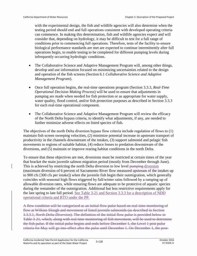
California Department of Water Resources
Chapter 3. Description of the Proposed Project
with the experimental design, the fish and wildlife agencies will also determine when the testing period should end and full operations consistent with developed operating criteria can commence. In making this determination, fish and wildlife agencies expect and will consider that, depending on hydrology, it may be difficult to test for a full range of conditions prior to commencing full operations. Therefore, tests of the facility to ensure biological performance standards are met are expected to continue intermittently after full operations begin, to enable testing to be completed for different pumping levels during infrequently occurring hydrologic conditions.
• The Collaborative Science and Adaptive Management Program will, among other things, develop and use information focused on minimizing uncertainties related to the design and operation of the fish screens (Section 6.1 Collaborative Science and Adaptive Management Program).
• Once full operation begins, the real-time operations program (Section 3.3.3, Real-Time Operational Decision Making Process) will be used to ensure that adjustments in pumping are made when needed for fish protection or as appropriate for water supply, water quality, flood control, and/or fish protection purposes as described in Section 3.3.3 for each real-time operational component.
• The Collaborative Science and Adaptive Management Program will review the efficacy of the North Delta bypass criteria, to identify what adjustments, if any, are needed to further minimize adverse effects on listed species of fish.
The objectives of the north Delta diversion bypass flow criteria include regulation of flows to (1) maintain fish screen sweeping velocities, (2) minimize potential increase in upstream transport of productivity in the channels downstream of the intakes, (3) support salmonid and pelagic fish movements to regions of suitable habitat, (4) reduce losses to predation downstream of the diversions, and (5) maintain or improve rearing habitat conditions in the north Delta.
To ensure that these objectives are met, diversions must be restricted at certain times of the year that bracket the main juvenile salmon migration period (mostly from December through June). This is achieved by restricting the north Delta diversion to low level pumping diversion (maximum diversion of 6 percent of Sacramento River flow measured upstream of the intakes up to 900 cfs [300 cfs per intake]) when the juvenile fish begin their outmigration, which generally coincides with seasonal high flows triggered by fall/winter rains followed by a ramping up of allowable diversion rates, while ensuring flows are adequate to be protective of aquatic species during the remainder of the outmigration. Additional but less restrictive requirements apply for the late spring to late fall period. See Table 3-21 and Section 3.3.3 for a description of NDD operational criteria and RTO under the PP.
A flow condition will be categorized as an initial flow pulse based on real-time monitoring of flow at Wilkins Slough and movement of listed juvenile salmonids (as described in Section 3.3.3.1, North Delta Diversion). The definition of the initial flow pulse is provided below in Table 3-21, which, along with real time monitoring of fish movement, will be used to determine the fish pulse. If the initial pulse begins and ends before December 1, the Level 1 post pulse criteria for May will go into effect after the pulse until December 1. On December 1, the post-
California Incidental Take Permit Application for the California WaterFix and its operation as part of the State Water Project 3-118 October 2016
ICF 00408.12

California Department of Water Resources
Chapter 3. Description of the Proposed Project
pulse rules defined below for December through April, starting with Level 1, apply. If a second pulse, as defined above, occurs, the second pulse will have the same protective operations as the first pulse.
At the end of the pulse phase, post-pulse operations described in Table 3-23 will apply, with potential adjustments made based on real-time operations. The conditions that trigger the transition from the pulse protection to post-pulse operations are described in Table 3-22, along with bypass operating rules for the post-pulse phase, which provide maximum allowable levels of diversion for a given Sacramento River inflow measured upstream of the intakes. Additionally, as described in Table 3-23, there will be biologically based triggers to allow for transitioning between and among the different diversion levels shown in Table 3-22 (Section 3.3.3.1, North Delta Diversion).
In July through September, the bypass rules are less restrictive, allowing for a greater proportion of the Sacramento River flow to be diverted, as described in Table 3-21. In October through November, the bypass amount is increased from 5,000 cfs to 7,000 cfs, allowing a smaller proportion of the Sacramento River flow to be diverted during the fall months.
In addition, north Delta diversion at the three intakes are subjected to approach velocity and sweeping velocity restrictions at the proposed fish screens. Appendices 5A and 5B describes the assumptions used in modeling the sweeping velocity restrictions on the north Delta diversion.
3.3.2.2 Operational Criteria for South Delta CVP/SWP Export Facilities
The objective of the new south Delta flow criteria is to further minimize take at south Delta pumps by reducing the hydrodynamic effects of south Delta operations that may affect fish movement and migration routing during critical periods for listed fish species. The south Delta channel flow criteria are based on the parameters for Old and Middle River (OMR) flows and the San Joaquin River inflow, as summarized below and in Table 3-21 and Table 3-22, and HOR gate operations (summarized in Section 3.3.2.3 Operational Criteria for the Head of Old River Gate).
Additionally, the PP operations include a preference for south Delta pumping in July through September to provide limited flushing flows to manage water quality in the south Delta.
The OMR flow criteria chiefly serve to constrain the magnitude of reverse flows in the Old and Middle Rivers to limit fish entrainment into the south Delta and increase the likelihood that Delta smelt can successfully reproduce in the San Joaquin River. The rational for using OMR flow criteria is based on the USFWS (2008) and NMFS (2009) BiOp RPA Actions, and are described in Table 3-21 and Table 3-22. These newly proposed additional OMR criteria (and associated HOR gate operations) described in Table 3-21 in Section 3.3.2.3 Operational Criteria for the Head of Old River Gate) are designed primarily to provide additional protections related to fish habitat to secure operations that are expected to provide beneficial changes in south Delta flows under the PP, (i.e., they would lessen reverse flows in Old and Middle Rivers); and they are only applicable only after the proposed north Delta diversion becomes operational.
California Incidental Take Permit Application for the California WaterFix and its operation as part of the State Water Project 3-119 October 2016
ICF 00408.12
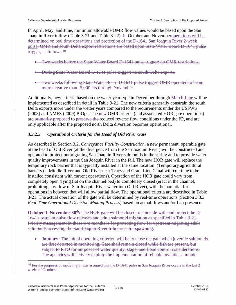
California Department of Water Resources
Chapter 3. Description of the Proposed Project
In April, May, and June, minimum allowable OMR flow values would be based upon the San Joaquin River inflow (Table 3-21 and Table 3-22). In October and Novemberoperations will be determined on real time operations and protection of the D-1641 San Joaquin River 2-week pulse, OMR and south Delta export restrictions are based upon State Water Board D-1641 pulse trigger, as follows.48
• Two weeks before the State Water Board D-1641 pulse trigger: no OMR restrictions.
• During State Water Board D-1641 pulse trigger: no south Delta exports.
• Two weeks following State Water Board D-1641 pulse trigger: OMR operated to be no more negative than -5,000 cfs through November.
Additionally, new criteria based on the water year type in December through March June will be implemented as described in detail in Table 3-21. The new criteria generally constrain the south Delta exports more under the wetter years compared to the requirements under the USFWS (2008) and NMFS (2009) BiOps. The new OMR criteria (and associated HOR gate operations) are primarily proposed to preserve the reduced reverse flow conditions under the PP, and are only applicable after the proposed north Delta diversion becomes operational.
3.3.2.3 Operational Criteria for the Head of Old River Gate
As described in Section 3.2, Conveyance Facility Construction, a new permanent, operable gate at the head of Old River (at the divergence from the San Joaquin River) will be constructed and operated to protect outmigrating San Joaquin River salmonids in the spring and to provide water quality improvements in the San Joaquin River in the fall. The new HOR gate will replace the temporary rock barrier that is typically installed at the same location. (Temporary agricultural barriers on Middle River and Old River near Tracy and Grant Line Canal will continue to be installed consistent with current operations). Operation of the HOR gate could vary from completely open (lying flat on the channel bed) to completely closed (erect in the channel, prohibiting any flow of San Joaquin River water into Old River), with the potential for operations in between that will allow partial flow. The operational criteria are described in Table 3-21. The actual operation of the gate will be determined by real-time operations (Section 3.3.3 Real-Time Operational Decision-Making Process) based on actual flows and/or fish presence.
October 1–November 30th: The HOR gate will be closed to coincide with and protect the D-1641 upstream pulse flow releases and adult salmonid migration as specified in Table 3-21. Priority management in these two months is for protecting flow for upstream migrating adult salmonids accessing the San Joaquin River tributaries for spawning.
• January: The initial operating criterion will be to close the gate when juvenile salmonids are first detected in monitoring. Gate shall remain closed while fish are present, but subject to RTO for purposes of water quality, stage, and flood control considerations. The agencies will actively explore the implementation of reliable juvenile salmonid
48 For the purposes of modeling, it was assumed that the D-1641 pulse in San Joaquin River occurs in the last 2 weeks of October.
California Incidental Take Permit Application for the California WaterFix and its operation as part of the State Water Project 3-120 October 2016
ICF 00408.12

California Department of Water Resources
Chapter 3. Description of the Proposed Project
tracking technology that may enable shifting to a more flexible real time operating criterion based on the presence/absence of listed fishes.
• February–June 15: The gate will be closed, but subject to RTO for purposes of water quality, stage, and flood control considerations (Section 3.3.3 Real-Time Operational Decision-Making Process). The agencies will actively explore the implementation of reliable juvenile salmonid tracking technology that may enable shifting to a more flexible real time operating criterion based on the presence/absence of listed fishes.
• June 16 to September 30, December: Operable gates will be open.
• To reduce downstream flood risks based on current conditions, HOR gate will remain open if San Joaquin River flow at Vernalis is greater than 10,000 cfs (threshold may be revised to align with any future flood protection actions).
3.3.2.93.3.2.4 Operational Criteria for the Delta Cross Channel Gates
The Delta Cross Channel (DCC) is a gated diversion channel in the Sacramento River near Walnut Grove and Snodgrass Slough (Appendix 3.A Map Book for the Proposed Project, Sheet 5) that is owned and operated by Reclamation. No changes to DCC operational criteria from the operations described in D-1641 and the USFWS (2008) and NMFS (2009) BiOps are proposed. Flows into the DCC from the Sacramento River are controlled by two 60-foot by 30-foot radial gates. When the gates are open, water flows from the Sacramento River through the cross channel to channels of the lower Mokelumne and San Joaquin Rivers toward the interior Delta. The DCC operation improves water quality in the interior Delta by improving circulation patterns of higher-quality water from the Sacramento River towards Delta diversion facilities.
Reclamation operates the DCC in the open position to (1) improve water quality in the interior Delta, and (2) reduce saltwater intrusion rates in the western Delta. During the late fall, winter, and spring, the gates are often periodically closed to protect out-migrating salmonids from entering the interior Delta. In addition, whenever flows in the Sacramento River at Sacramento reach 20,000 to 25,000 cfs (on a sustained basis), the gates are closed to reduce potential scouring and flooding that might occur in the channels on the downstream side of the gates.
Flow rates through the gates are determined by Sacramento River stage and are not affected by export rates in the south Delta. The DCC also serves as a link between the Mokelumne River and the Sacramento River for small craft. It is used extensively by recreational boaters and anglers whenever it is open. Because alternative routes around the DCC are quite long, Reclamation tries to provide adequate notice of DCC closures so boaters may plan for the longer excursion.
Under the PP, the DCC will continue to be operated as it is now operated under the terms of the NMFS (2009) BiOp IV.1 and D-1641. The gates will be closed if fish are present in October and November, with closure decisions at that time reached through the existing real-time operations process described in Section 3.3.3 Real-Time Operational Decision Making Process. The CALSIM II modeling assumed DCC operations as required by NMFS (2009) BiOp RPA Action IV.1.2 by using a regression of Sacramento River monthly flow at Wilkins Slough and the number of days in the month when the daily flow would be greater than 7500 cfs. The latter was
California Incidental Take Permit Application for the California WaterFix and its operation as part of the State Water Project 3-121 October 2016
ICF 00408.12

California Department of Water Resources
Chapter 3. Description of the Proposed Project
assumed to be an indicator that salmonids would be migrating to the delta. In the modeling, DCC gates are closed for the same number of days as Wilkins Slough is estimated to exceed 7500 cfs during October 1 through December 14, and the gates may be opened if the D-1641 Rock Slough salinity standard is violated because of the gate closure. DCC gates are assumed to be closed during December 15 through January 31. February 1 through June 15, DCC gates are operated based on D-1641 requirements. DCC closure for downstream flood control will be based on Sacramento River flow at Freeport upstream of the NDD facilities.
3.3.2.103.3.2.5 Operational Criteria for the Suisun Marsh Facilities
The Suisun Marsh facilities are jointly operated by CVP/SWP and include the Suisun Marsh Salinity Control Gates (SMSCG), Roaring River Distribution System (RRDS), Morrow Island Distribution System (MIDS), and Goodyear Slough Outfall. No changes to the operations of the Suisun Marsh facilities from those described in the USFWS (2008) and NMFS (2009) BiOps are proposed.
3.3.2.10.13.3.2.5.1 Suisun Marsh Salinity Control Gates
The SMSCG are located on Montezuma Slough about two miles downstream from the confluence of the Sacramento and San Joaquin Rivers, near Collinsville (Appendix 3.A Map Book for the Proposed Project, Sheet 17). Operation of the SMSCG began in October 1988 as Phase II of the Plan of Protection for the Suisun Marsh. The objective of SMSCG operation is to decrease the salinity of the water in Montezuma Slough. The facility, spanning the 465-foot width of Montezuma Slough, consists of a boat lock, a series of three radial gates, and removable flashboards. The gates control salinity by restricting the flow of higher salinity water from Grizzly Bay into Montezuma Slough during incoming tides and retaining lower salinity Sacramento River water from the previous ebb tide. Operation of the gates in this fashion lowers salinity in Suisun Marsh channels and results in a net movement of water from east to west.
When Delta outflow is low to moderate and the gates are not operating, tidal flow past the gate is approximately 5,000 to 6,000 cfs while the net flow is near zero. When operated, flood tide flows are arrested while ebb tide flows remain in the range of 5,000 to 6,000 cfs. The net flow in Montezuma Slough becomes approximately 2,500 to 2,800 cfs. The Corps of Engineers permit for operating the SMSCG requires that it be operated between October and May only when needed to meet Suisun Marsh salinity standards. Historically, the gate has been operated as early as October 1, while in some years (e.g., 1996) the gate was not operated at all. When the channel water salinity decreases sufficiently below the salinity standards or at the end of the control season, the flashboards are removed and the gates raised to allow unrestricted movement through Montezuma Slough. Details of annual gate operations can be found in “Summary of Salinity Conditions in Suisun Marsh During WYs 1984–1992”, or the “Suisun Marsh Monitoring Program Data Summary” produced annually by DWR, Division of Environmental Services.
The approximately 2,800 cfs net flow induced by SMSCG operation is effective at moving the salinity downstream in Montezuma Slough. Salinity is reduced by roughly one-hundred percent at Beldons Landing, and lesser amounts further west along Montezuma Slough. At the same time, the salinity field in Suisun Bay moves upstream as net Delta outflow (measured nominally
California Incidental Take Permit Application for the California WaterFix and its operation as part of the State Water Project 3-122 October 2016
ICF 00408.12

California Department of Water Resources
Chapter 3. Description of the Proposed Project
at Chipps Island) is reduced by gate operation. Net outflow through Carquinez Strait is not affected.
The boat lock portion of the gate is held open at all times during SMSCG operation to allow for continuous salmon passage opportunity. With increased understanding of the effectiveness of the gates in lowering salinity in Montezuma Slough, salinity standards have been met with less frequent gate operation, compared to the early years of operations (prior to 2006). For example, despite very low outflow in fall 2007 and fall 2008, gate operation was not required at all in 2007, and was limited to 17 days during winter 2008. Assuming no significant, long-term changes in the drivers mentioned above, this level of operational frequency (10 to 20 days per year) can generally be expected to continue to meet standards in the future except perhaps during the most critical hydrologic conditions and/or other conditions that affect Delta outflow.
3.3.2.10.23.3.2.5.2 Roaring River Distribution System
The RRDS (Appendix 3.A Map Book for the Proposed Project, Sheet 17) was constructed during 1979 and 1980 as part of the Initial Facilities in the Plan of Protection for the Suisun Marsh. The system was constructed to provide lower salinity water to 5,000 acres of private and 3,000 acres of DFG-managed wetlands on Simmons, Hammond, Van Sickle, Wheeler, and Grizzly islands.
The RRDS includes a 40-acre intake pond that supplies water to Roaring River Slough. Motorized slide gates in Montezuma Slough and flap gates in the pond control flows through the culverts into the pond. A manually operated flap gate and flashboard riser are located at the confluence of Roaring River and Montezuma Slough to allow drainage back into Montezuma Slough for controlling water levels in the distribution system and for flood protection. DWR owns and operates this drain gate to ensure the Roaring River levees are not compromised during extremely high tides.
Water is diverted through a bank of eight 60-inch-diameter culverts equipped with fish screens into the Roaring River intake pond on high tides to raise the water surface elevation in RRDS above the adjacent managed wetlands. Managed wetlands north and south of the RRDS receive water, as needed, through publicly and privately owned turnouts on the system.
The intake to the RRDS is screened to prevent entrainment of fish larger than approximately 25 mm. DWR designed and installed the screens based on CDFW criteria. The screen is a stationary vertical screen constructed of continuous-slot stainless steel wedge wire. All screens have 3/32-inch slot openings. To minimize the risk of delta smelt entrainment, RRDS diversion rates are controlled to maintain an average approach velocity below 0.2 ft/s at the intake fish screen. Initially, the intake culverts were held at about 20 percent capacity to meet the velocity criterion at high tide. Since 1996, the motorized slide gates have been operated remotely to allow hourly adjustment of gate openings to maximize diversion throughout the tide.
3.3.2.10.33.3.2.5.3 Morrow Island Distribution System
The MIDS (Appendix 3.A Map Book for the Proposed Project, Sheet 17) was constructed in 1979 and 1980 in the south-western Suisun Marsh as part of the Initial Facilities in the Plan of Protection for the Suisun Marsh. The contractual requirement for Reclamation and DWR is to
California Incidental Take Permit Application for the California WaterFix and its operation as part of the State Water Project 3-123 October 2016
ICF 00408.12

California Department of Water Resources
Chapter 3. Description of the Proposed Project
provide water to the ownerships so that lands may be managed according to approved local management plans. The system was constructed primarily to channel drainage water from the adjacent managed wetlands for discharge into Suisun Slough and Grizzly Bay. This approach increases circulation and reduces salinity in Goodyear Slough.
The MIDS is used year-round, but most intensively from September through June. When managed wetlands are filling and circulating, water is tidally diverted from Goodyear Slough just south of Pierce Harbor through three 48-inch culverts. Drainage water from Morrow Island is discharged into Grizzly Bay by way of the C-Line Outfall (two 36-inch culverts) and into the mouth of Suisun Slough by way of the M-Line Outfall (three 48- inch culverts), rather than back into Goodyear Slough. This helps prevent increases in salinity due to drainage water discharges into Goodyear Slough. The M-Line ditch is approximately 1.6 miles in length and the C-Line ditch is approximately 0.8 miles in length.
3.3.2.10.43.3.2.5.4 Goodyear Slough Outfall
The Goodyear Slough Outfall (Appendix 3.A Map Book for the Proposed Project, Sheet 17) was constructed in 1979 and 1980 as part of the Initial Facilities in the Plan of Protection for the Suisun Marsh. A channel approximately 69 feet wide was dredged from the south end of Goodyear Slough to Suisun Bay (about 2,800 feet). The excavated material was used for levee construction. The control structure consists of four 48-inch culverts with flap gates on the bay side. On ebb tides, Goodyear Slough receives watershed runoff from Green Valley Creek and, to a lesser extent, Suisun Creek. The system was designed to draw creek flow south into Goodyear Slough, and thereby reduce salinity, by draining water one-way from the lower end of Goodyear Slough into Suisun Bay on the ebb tide. The one-way flap gates at the Outfall close on flood tide keeping saltier bay water from mixing into the slough. The system creates a small net flow in the southerly direction overlaid on a larger, bidirectional tidal flow. The system provides lower salinity water to the wetland managers who flood their ponds with Goodyear Slough water. Another initial facility, the MIDS, diverts from Goodyear Slough and receives lower salinity water. Since the gates are passively operated (in response to water surface elevation differentials) there are no operations schedules or records. The system is open for free fish movement except very near the Outfall when flap gates are closed during flood tides.
3.3.2.113.3.2.6 Operational Criteria for the North Bay Aqueduct Intake
The Barker Slough Pumping Plant diverts water from Barker Slough into the North Bay Aqueduct (NBA) for delivery in Napa and Solano Counties. Maximum pumping capacity is 175 cubic feet per second (cfs) (pipeline capacity). During the past few years, daily pumping rates have ranged between 0 and 140 cfs. The current maximum pumping rate is 140 cfs due to the physical limitations of the existing pumps. Growth of biofilm in a portion of the pipeline also limits the NBA ability to reach its full pumping capacity.
The NBA intake is located approximately 10 miles from the mainstem Sacramento River at the end of Barker Slough (Appendix 3.A Map Book for the Proposed Project, Sheet 17). Per salmon screening criteria, each of the ten NBA pump bays is individually screened with a positive barrier fish screen consisting of a series of flat, stainless steel, wedge-wire panels with a slot width of 3/32 inch. This configuration is designed to exclude fish approximately one inch or
California Incidental Take Permit Application for the California WaterFix and its operation as part of the State Water Project 3-124 October 2016
ICF 00408.12

California Department of Water Resources
Chapter 3. Description of the Proposed Project
larger from being entrained. The bays tied to the two smaller units have an approach velocity of about 0.2 feet per second (ft/s). The larger units were designed for a 0.5 ft/s approach velocity, but actual approach velocity is about 0.44 ft/s. The screens are routinely cleaned to prevent excessive head loss, thereby minimizing increased localized approach velocities.
The NBA fish screens are also designed to comply with USFWS criteria for Delta smelt protection (Reclamation 2008), which are likewise protective of longfin smelt. The fish screens are assessed annually for effectiveness, per the terms of the USFWS (2008) BiOp and the CDFG (2009) incidental take permit. The Smelt Larval Survey occurs each winter/early spring (January–March) in Suisun Bay, Suisun Marsh, and the Delta, including sloughs near NBA. This monitoring program is used to trigger NBA export reductions in drier years when longfin smelt larvae are detected nearby (specifically at station 716 in Cache Slough), per the terms of the CDFG (2009) incidental take permit.
Delta smelt monitoring was required at Barker Slough under the March 6, 1995 OCAP BiOp. Starting in 1995, monitoring was required every other day at three sites from mid- February through mid-July, when Delta smelt may be present. As part of the Interagency Ecological Program, DWR has contracted with DFW to conduct the required monitoring each year since the BO was issued. Details about the survey and data are available on DFG’s website (http://www.delta.dfg.ca.gov/data/NBA). Beginning in 2008, the NBA larval sampling was replaced by an expanded 20-mm survey (described at http://www.delta.dfg.ca.gov/data/20mm) that has proven to be fairly effective at tracking delta smelt distribution and reducing entrainment. The expanded survey covers all existing 20-mm stations, in addition to a new suite of stations near the NBA. The expanded survey also has an earlier seasonal start and stop date to focus on the presence of larvae in the Delta. These surveys also collect information on longfin smelt.
3.3.3 Real-Time Operational Decision-Making Process
The real-time operational decision-making process (real-time operations [RTO]) allows short-term (i.e., daily and weekly) adjustments to be made to water operations, within the range of criteria described in Section 3.3.1 Implementation and Section 3.3.2 Operational Criteria. RTO will be implemented to maximize water supply for CVP/SWP, subject to providing the necessary protections for listed species, through the existing decision-making process and related technical work teams identified in Section 3.1.5.2 Groups Involved in Real-Time Decision Making and Information Sharing49.
To complement the RTO process, DWR and Reclamation can convene a separate Operational Opportunities subcommitteereal time operations coordination team (RTOCT), as part of the Interagency Implementation Coordination Group (IICG) described in the Agreement For Implementation Of An Adaptive Management Program For Project Operations, will be convened on a case-by-case basis to consider and make recommendations regarding specific short term (within one year) ecological or water supply opportunities that may be available
49 The decision-making process and technical work teams identified here are provisional and may be subject to further revision, either through future coordination or as developed through the Collaborative Science and Adaptive Management Program described in Section 6.1.
California Incidental Take Permit Application for the California WaterFix and its operation as part of the State Water Project 3-125 October 2016
ICF 00408.12

California Department of Water Resources
Chapter 3. Description of the Proposed Project
without reducing the ability of the SWP or CVP to deliver water, imposing additional funding obligations on the SWP/CVP Contractors, or adversely impacting Protected Species. that includes representatives of USFWS, NMFS, CDFW, DWR and Reclamation. DWR and Reclamation also will designate one representative of the SWP contractors and one representative of the CVP contractors as participants on the coordination team in an advisory capacity. This RTOCT effort will assist DWR and Reclamation in fulfilling their responsibility to inform the SWP and CVP participants regarding available information and real-time decisions. This coordination effort may also periodically review how to enhance or strengthen the scientific and technical information used to inform decision-making, and how to communicate with the public and other interested parties.
real time operations coordination team (RTOCT) that includes representatives of USFWS, NMFS, CDFW, DWR and Reclamation. DWR and Reclamation also will designate one representative of the SWP contractors and one representative of the CVP contractors as participants on the RTOCT in an advisory capacity. This RTOCT effort will assist DWR and Reclamation in fulfilling their responsibility to inform the SWP and CVP participants regarding available information and real-time decisions. This coordination effort may also periodically review how to enhance or strengthen the scientific and technical information used to inform decision-making, and how to communicate with the public and other interested parties.
DWR, Reclamation, and fish and wildlife agency representatives will confer with the SWP and CVP contractor representatives regarding ideas, options and additional funding to enhance the information available for decisions on RTO. The SWP and CVP contractor representatives will confer with other SWP and CVP contractors regarding RTOCT coordination and decisions. This RTOCT is intended to supplement the existing process and teams. This may result in recommendations being made through the DCT. Decision-making will follow a process similar to whatstill happen as it currently occurs does under the USFWS (2008) and NMFS (2009) BiOps, CDFG (2009) incidental take permit, and consistency determinations.
The process to identify actions for protection of covered species varies to some degree among species but follows this general outline: A Fisheries or Operations Technical Team, generally including representatives of CDFW as well as the federal fish and wildlife agencies, compiles and assesses current information regarding species, such as stages of reproductive development, geographic distribution, relative abundance, and physical habitat conditions. Based on its review, the team will provide a recommendation to CDFW. CDFW staff and management will review the recommendation and use it as a basis for developing, in cooperation with DWR through the Water Operations Management Team, a modification of water operations that will minimize the adverse effects of the PP to covered species. Because the SWP is operated in coordination with the CVP and is also subject to the federal ESA, the Fisheries or Operations Technical Teams and WOMT will consider and develop recommendations for the real-time operations under the biological opinions applicable to the CVP and SWP. In developing its water operations modifications, the WOMT will consider the terms and conditions of the CESA and federal ESA authorizations. If DWR does not agree with the modification, then CDFW will make a final decision on an action that it deems necessary and appropriate to protect the species and maintain compliance with the ITP.
California Incidental Take Permit Application for the California WaterFix and its operation as part of the State Water Project 3-126 October 2016
ICF 00408.12
California Department of Water Resources
Chapter 3. Description of the Proposed Project
The outcomes of protective actions that are implemented will be monitored and documented, and this information will inform future recommended actions.”
The operational adjustments made through the RTO processes apply only to the facilities and activities identified in the PP. RTOs are expected to be needed during at least some part of the year at the north and south Delta diversions and the HOR gate. The PP establishes criteria, ranges, and considerations for real time operational adjustments in subsections 3.3.3.1 North Delta Diversion; 3.3.3.2 South Delta Diversion; and 3.3.3.3 Head of Old River Gate. The PP includes operations within the criteria and/or ranges set out in the operating criteria.
The CVP-SWP operators conduct seasonal planning of the CVP-SWP operations, taking into account many factors such as the existing regulatory requirements, forecasted hydrology, contractual demands, etc. The operators also consider any recommendations resulting from the RTO decision making to minimize adverse effects for listed species while meeting permit requirements and contractual obligations for water deliveries.
California Incidental Take Permit Application for the California WaterFix and its operation as part of the State Water Project 3-127 October 2016
ICF 00408.12

California Department of Water Resources
Chapter 3. Description of the Proposed Project
3.3.3.1 North Delta Diversion
Operations for North Delta bypass flows will be managed according to the following criteria:
• October, November: Minimum bypass flows of 7,000 cfs required after diverting at the North Delta intakes.
• December through June: As described below, Ppost-pulse bypass flow operations will be operated within the range of pulse protection, and Levels 1, 2, and 3, depending on risk to fish and with consideration for other factors such as water supply and other Delta conditions, and by implementing pulse protection periods when primary juvenile winter-run and spring-run Chinook salmon migration is occurring. Post-pulse bypass flow operations may remain at Level 1 pumpingdiversion depending on fish presence, abundance, and movement in the north Delta; however, the exact levels will be determined through initial operating studies evaluating the level of protection provided at various levels of pumpingdiversion.not exceed Level 1 pumping unless specific criteria have been met to increase to Level 2 or Level 3. If those criteria are met, operations can proceed as defined in Table 3.3-2. The specific criteria for transitioning between and among pulse protection, Level 1, Level 2, and/or Level 3 operations, will be developed and based on real-time fish monitoring and hydrologic/ behavioral cues upstream of and in the Delta. During operations, adjustments are expected to be made to improve water supply and/or migratory conditions for fish by making real-time adjustments to the pumpingdiversion levels at the north Delta diversions. These adjustments will be managed under RTOs as described belowPost-pulse bypass flow operations will not exceed Level 1 pumping unless specific criteria have been met to increase to Level 2 or Level 3. If those criteria are met, operations can proceed as defined in Table 3-21 and Table 3-22. The specific criteria for transitioning between and among pulse protection, Level 1, Level 2, and/or Level 3 operations, will be developed and based on real-time fish monitoring and hydrologic/ behavioral cues upstream of and in the Delta. During operations, adjustments are expected to be made to improve water supply and/or migratory conditions for fish by making real-time adjustments to the pumping levels at the north Delta diversions. These adjustments will be managed under RTOs as described below.
• July, August, September: Minimum bypass flows of 5,000 cfs required after diverting at the north Delta diversion intakes.
Real-time operations of the north Delta intakes are intended to allow for the project objective of water diversion while also providing for the protection needed toof migrating and rearing salmonids. RTOs will be a key component of NDD operations, and will likely govern operations for the majority of the December through June salmonid migration period. Under RTOs, the NDD would be operated within the range of pulse protection, and Levels 1, 2, and -3, depending on risk to fish and with consideration for other factors such as water supply and other Delta conditions, and by implementing pulse protection periods when primary juvenile winter-run and spring-run Chinook salmon migration is occurring. Post-pulse bypass flow operations will may remain at Level 1 pumping diversion depending on fish presence, abundance, and movement in the north Delta; however, the exact levels will be while juvenile salmonids are migrating through
California Incidental Take Permit Application for the California WaterFix and its operation as part of the State Water Project 3-128 October 2016
ICF 00408.12

California Department of Water Resources
Chapter 3. Description of the Proposed Project
and rearing in the north Delta, unless it is determined through initial operating studies evaluating the level of protection provided at various levels of that an equivalent level of protection can still be provided at Level 2 or 3 pumpingdiversion. The specific criteria for transitioning between and among pulse protection, Level 1, Level 2, and/or Level 3 and post-pulse bypass flow operations, will be based on real-time fish monitoring and hydrologic/ behavioral cues upstream of and in the Delta that will be studied as part of the PP’s Collaborative Science and Adaptive Management Program (Section 6.1). Based on the outcome of the studies pursued under that program, information about appropriate triggers, off-ramps, and other RTO management of NDD operations will be integrated into the operations of the PP. The RTOs will be used to support the successful migration of salmonids past the NDD and through the Delta, in combination with other operational components of the PP50.
The following operational framework serves as an example that is based on the recommended NDD RTO process (Marcinkevage and Kundargi 2016). A 5-agency technical team co-chaired by NMFS and CDFW will incorporate results from ongoing monitoring and studies to revise specific fish triggers and may further refine the RTO process based on the amount of time it takes to make the RTO change in pumpingdiversion rates and develop the RTO process based on a science plan developed through the collaborative science process and finalized through the adaptive management process prior to commencement of actual operations of the north Delta facilities.
3.3.3.1.1 Pulse-Protection
• A fish pulse is defined as combined catch of Xp winter-run and spring-run -sized Chinook salmon in a single day at a specified locations51.
• Upon initiation of fish pulse, operations must reduce to low-level pumpingdiversion.
• Pumping Diversion may not exceed low-level pumping diversion for the duration of fish pulse. However, additional pumpingdiversion above low-level may be allowed as long as a minimum of 35,000 cfs52 bypass flow is maintained during the period of pulse protection. A fish pulse is considered over after X53 consecutive days with daily combined catch of winter- and spring run-sized Chinook salmon less than Xp
4668 at or just downstream of the new intakesA fish pulse is considered over after X2 consecutive days
50 Operations necessary to support Delta rearing of juvenile salmonids will be addressed through the adaptive management program, due to limited information on rearing flow needs at this time. 51 Triggers will be developed from data provided by monitoring stations. 52 Preliminary evaluation of the effects of the proposed operations will use a minimum off-ramp bypass flow developed from existing data. The off-ramp bypass flow required will be determined based on pre-construction studies identified in Chapter 6. 53 Preliminary evaluation of the effects of the proposed operations will use triggers developed from data provided by existing monitoring stations. The values and monitoring location would depend upon operation of a new/additional station, the method used to identify winter- and spring-run Chinook salmon, collection of sufficient data, and the time of year. DFW’s draft 2081 permit includes a condition related to pulse protection which considers a pulse to be over when Knights Landing catch index (Xp) is less than 5 for a duration (X) of 5 days.
California Incidental Take Permit Application for the California WaterFix and its operation as part of the State Water Project 3-129 October 2016
ICF 00408.12

California Department of Water Resources
Chapter 3. Description of the Proposed Project
with daily winter-run-sized Chinook salmon catch less than Xp at or just downstream of the new intakes42.
• Post-pulse bypass flow operations will be determined through initial operating studies evaluating the level of protection provided at various levels of pumpingdiversion.
• All subsequent pulses of winter- and spring-run Chinook salmon will be afforded the same level of protection as the first pulse2946, 48, 31
• Unlimited fish pulses are protected in any given year.
• Operations may increase to Level 1 when the fish pulse is over as described in the above criteria are met.
• A second fish pulse, if detected using the same definition (catch of Xp winter-run-sized Chinook salmon in a single day at a specified location), is given the same low-level pumping protection as the first pulse if the first pulse occurred before December [1]54. Otherwise, operations remain at Level 1 during the second fish pulse.
• A maximum of two fish pulses are protected in a year.
• After protection of pulse(s), post-pulse migration protection criteria are imposed.
3.3.3.6.0 Post-Pulse Migration Protection
• Post-pulse operations must remain at Level 1 until combined catch at all Sacramento stations is below Xa55 for five consecutive days and bypass flows are greater than 20,000 cfs for 15 non-consecutive days (as stated in Table 3-22). If both conditions are met, operations may transition to Level 2.
• Operations at Level 2 can remain at Level 2 as long as there is no subsequent fish migration event detected, in which case operations would revert back to level 1 (see following two bullets). Provided there are no fish migration events detected, operations must remain at Level 2 until bypass flows are greater than 20,000 cfs for 15 (additional) non-consecutive days (as stated in Table 3-22). If both conditions are met, operations may transition to Level 3.
• A fish migration event is defined as catch of Xm Chinook salmon of any size or run in a single day at a specific location56.
• Upon initiation of a migration event, operations must revert back to Level 1 (if not already there) for migration protection.
54 Triggers and the exact date in December will be developed from data provided by monitoring stations. Effects analysis based on pulse protection period ending December 1st. 55 Xa – Specific durations and triggers will be developed from data provided by monitoring stations. 56 Xm – Specific durations and triggers will be developed from data provided by monitoring stations.
California Incidental Take Permit Application for the California WaterFix and its operation as part of the State Water Project 3-130 October 2016
ICF 00408.12
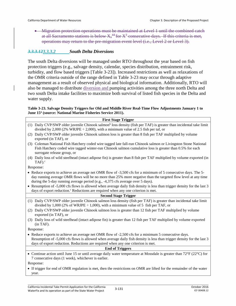
California Department of Water Resources
Chapter 3. Description of the Proposed Project
• Migration protection operations must be maintained at Level 1 until the combined catch at all Sacramento stations is below Xa
44 for X3 consecutive days. If this criteria is met, operations may return to the pre-migration event level (i.e., Level 2 or Level 3).
3.3.3.123.3.3.2 South Delta Diversions
The south Delta diversions will be managed under RTO throughout the year based on fish protection triggers (e.g., salvage density, calendar, species distribution, entrainment risk, turbidity, and flow based triggers [Table 3-23]). Increased restrictions as well as relaxations of the OMR criteria outside of the range defined in Table 3-23 may occur through adaptive management as a result of observed physical and biological information. Additionally, RTO will also be managed to distribute diversion and pumping activities among the three north Delta and two south Delta intake facilities to maximize both survival of listed fish species in the Delta and water supply.
Table 3-23. Salvage Density Triggers for Old and Middle River Real-Time Flow Adjustments January 1 to June 15a (source: National Marine Fisheries Service 2011).
First Stage Trigger (1) Daily CVP/SWP older juvenile Chinook salmonb loss density (fish per TAF) is greater than incidental take limit
divided by 2,000 (2% WRJPE ÷ 2,000), with a minimum value of 2.5 fish per taf, or (2) Daily CVP/SWP older juvenile Chinook salmon loss is greater than 8 fish per TAF multiplied by volume
exported (in TAF), or (3) Coleman National Fish Hatchery coded wire tagged late fall-run Chinook salmon or Livingston Stone National
Fish Hatchery coded wire tagged winter-run Chinook salmon cumulative loss is greater than 0.5% for each surrogate release group, or
(4) Daily loss of wild steelhead (intact adipose fin) is greater than 8 fish per TAF multiplied by volume exported (in TAF).c
Response: • Reduce exports to achieve an average net OMR flow of -3,500 cfs for a minimum of 5 consecutive days. The 5-
day running average OMR flows will be no more than 25% more negative than the targeted flow level at any time during the 5-day running average period (e.g., -4,375 cfs average over 5 days).
• Resumption of -5,000 cfs flows is allowed when average daily fish density is less than trigger density for the last 3 days of export reduction.c Reductions are required when any one criterion is met.
Second Stage Trigger (1) Daily CVP/SWP older juvenile Chinook salmon loss density (fish per TAF) is greater than incidental take limit
divided by 1,000 (2% of WRJPE ÷ 1,000), with a minimum value of 5 fish per TAF, or (2) Daily CVP/SWP older juvenile Chinook salmon loss is greater than 12 fish per TAF multiplied by volume
exported (in TAF), or (3) Daily loss of wild steelhead (intact adipose fin) is greater than 12 fish per TAF multiplied by volume exported
(in TAF). Response: • Reduce exports to achieve an average net OMR flow of -2,500 cfs for a minimum 5 consecutive days.
Resumption of -5,000 cfs flows is allowed when average daily fish density is less than trigger density for the last 3 days of export reduction. Reductions are required when any one criterion is met.
End of Triggers • Continue action until June 15 or until average daily water temperature at Mossdale is greater than 72°F (22°C) for
7 consecutive days (1 week), whichever is earlier. Response: • If trigger for end of OMR regulation is met, then the restrictions on OMR are lifted for the remainder of the water
year.
California Incidental Take Permit Application for the California WaterFix and its operation as part of the State Water Project 3-131 October 2016
ICF 00408.12
California Department of Water Resources
Chapter 3. Description of the Proposed Project
a Salvage density triggers modify PP operations only within the ranges proposed in Table 3-21. Triggers will not be implemented in a manner that reduces water supplies in amounts greater than modeled outcomes.
b Older juvenile Chinook salmon is defined as any Chinook salmon that is above the minimum length for winter-run Chinook salmon, according to the Delta Model length-at-date table used to assign individuals to race.
c Three consecutive days in which the combined loss numbers are below the action triggers are required before the OMR flow reductions can be relaxed to no more negative than -5,000 cfs. A minimum of 5 consecutive days of export reduction are required for the protection of listed salmonids under the action. Starting on day 3 of the export curtailment, the level of fish loss must be below the action triggers for the remainder of the 5-day export reduction to relax the OMR requirements on day 6. Any exceedance of a more conservative trigger restarts the 5-day OMR action response with the 3 consecutive days of loss monitoring criteria.
TAF = thousand acre-feet. WRJPE = the current year’s winter-run Chinook salmon juvenile production estimate.
California Incidental Take Permit Application for the California WaterFix and its operation as part of the State Water Project 3-132 October 2016
ICF 00408.12

California Department of Water Resources
Chapter 3. Description of the Proposed Project
3.3.3.133.3.3.3 Head of Old River Gate
Operations for the HOR gate will be managed under RTOs as follows.
• October 1–November 30th: RTO management – with the current expectation being that the HOR gate will be operated to protect the D-1641 pulse flow.The HOR gate will be closed to coincide with and protect the D-1641 upstream pulse flow releases and adult salmonid migration as specified in Table 3.3-1. Priority management in these two months is for protecting flow for upstream migrating adult salmonids accessing the San Joaquin River tributaries for spawning.
• January-March 31st , and June 1-15: RTO will determine exact operations to protect salmonid fryjuveniles when migrating, During this migration, operation will be to close the gate subject to RTO for purposes of water quality, stage, and flood control considerations.The initial operating criterion will be to close the gate when juvenile salmonids are first detected in monitoring. Gate shall remain closed while fish are present, but subject to RTO for purposes of water quality, stage, and flood control considerations. The agencies will actively explore the implementation of reliable juvenile salmonid tracking technology that may enable shifting to a more flexible real time operating criterion based on the presence/absence of listed fishes.
• February–June 15thApril-May: Initial operating criterion will be to close the gate 100% of time subject to RTO for purposes of water quality, stage, and flood control considerationsThe gate will be closed, but subject to RTO for purposes of water quality, stage, and flood control considerations. The agencies will actively explore the implementation of reliable juvenile salmonid tracking technology that may enable shifting to a more flexible real time operating criterion based on the presence/absence of listed fishes. Reclamation, DWR, NMFS, USFWS, and DFW will actively explore the implementation of reliable juvenile salmonid tracking technology that may enable shifting to a more flexible real time operating criterion based on the presence/absence of listed fishes.
October 1–November 30th: The HOR gate will be closed to coincide with and protect the D-1641 upstream pulse flow releases and adult salmonid migration as specified in Table 3-21. Priority management in these two months is for protecting flow for upstream migrating adult salmonids accessing the San Joaquin River tributaries for spawning.
• January: The initial operating criterion will be to close the gate when juvenile salmonids are first detected in monitoring. Gate shall remain closed while fish are present, but subject to RTO for purposes of water quality, stage, and flood control considerations. The agencies will actively explore the implementation of reliable juvenile salmonid tracking technology that may enable shifting to a more flexible real time operating criterion based on the presence/absence of listed fishes.
• February–June 15th: The gate will be closed, but subject to RTO for purposes of water quality, stage, and flood control considerations. The agencies will actively explore the implementation of reliable juvenile salmonid tracking technology that may enable
California Incidental Take Permit Application for the California WaterFix and its operation as part of the State Water Project 3-133 October 2016
ICF 00408.12
California Department of Water Resources
Chapter 3. Description of the Proposed Project
shifting to a more flexible real time operating criterion based on the presence/absence of listed fishes.
• June 16 to September 30, December: Operable gates will be open.
• To reduce downstream flood risks based on current conditions, HOR gate will remain open if San Joaquin River flow at Vernalis is greater than 10,000 cfs (threshold may be revised to align with any future flood protection actions).
3.3.4 Operation of South Delta Facilities
This section describes how the existing South Delta facilities, including the CVP’s C.W. “Bill” Jones Pumping Plant and Tracy Fish Collection Facility and the SWP’s Harvey O. Banks Pumping Plant and Skinner Delta Fish Protective Facility, are operated to minimize the risks of predation and entrainment of listed species of fish57,, and how the Clifton Court Forebay is managed for control of invasive aquatic vegetation. These operations are unchanged from those described in and regulated by the USFWS (2008) and NMFS (2009) BiOps.
3.3.4.1 C.W. “Bill” Jones Pumping Plant and Tracy Fish Collection Facility
The CVP and SWP use the Sacramento River, San Joaquin River, and Delta channels to transport water to export pumping plants located in the south Delta. The CVP’s Jones Pumping Plant, about five miles north of Tracy, consists of six available pumps. The Jones Pumping Plant is located at the end of an earth-lined intake channel about 2.5 miles in length. At the entrance to the intake channel, louver screens (that are part of the Tracy Fish Collection Facility) intercept fish, which are then collected, held, and transported by tanker truck to release sites more than 20 km away from the pumping plants, in the west Delta near the Sacramento/San Joaquin confluence. Currently those sites include the Emmaton and Delta Base release sites for the CVP, and the Curtis Landing and Horseshoe Bend release sites for the SWP.
Jones Pumping Plant has a permitted diversion capacity of 4,600 cfs with maximum pumping rates capable of achieving that capacity.
The Tracy Fish Collection Facility (TFCF) is located in the south-west portion of the Sacramento-San Joaquin Delta and uses behavioral barriers consisting of primary louvers and secondary screens to guide entrained fish into holding tanks before transport by truck to release sites within the Delta. The primary louvers are located in the primary channel just downstream of a trashrack structure. The secondary screens consist of a travelling positive barrier fish screen. The louvers and screens allow water to pass through into the pumping plant but the openings
57 Note that there would be no salvage operations performed when diversion flows originated solely from NCCF, and Skinner louver flows would be stopped at those times. Otherwise, salvage operations would be the same as current practice. Future south Delta operations will be managed to maintain, or reduce, the loss of covered fish by a variety of mechanisms including preservation of existing louver salvage efficiencies when possible. Dual operations, which are intended to reduce dependence on south Delta facilities that present fish hazards, may affect the frequency that the south Delta louvers are able to operate at ideal salvage efficiencies, but would neither preclude such efficiencies from being attained nor would be expected to result in greater overall loss of covered species at the south Delta facilities.
California Incidental Take Permit Application for the California WaterFix and its operation as part of the State Water Project 3-134 October 2016
ICF 00408.12

California Department of Water Resources
Chapter 3. Description of the Proposed Project
between the slats prevent fish with a body width greater than 2 inches from passing between them and redirect them toward one of four bypass entrances along the louver arrays. Smaller fish, that can pass through the louvers, may be behaviorally redirected by the louver structure. The louvers perform best at flows low enough to allow fish to behaviorally redirect before they contact the structure.
There are approximately 52 different species of fish entrained into the TFCF per year; however, the total numbers are significantly different for the various species salvaged. Also, it is difficult if not impossible to determine exactly how many safely make it all the way to the collection tanks awaiting transport back to the Delta. Hauling trucks used to transport salvaged fish to release sites inject oxygen and contain an eight parts per thousand salt solution to reduce stress. The CVP uses two release sites, one on the Sacramento River near Horseshoe Bend and the other on the San Joaquin River immediately upstream of the Antioch Bridge. The transition boxes and conduits between the louvers and fish screens were rehabilitated during the San Joaquin pulse period of 2004.
When south Delta hydraulic conditions allow, and within the original design criteria for the TFCF, the louvers are operated with the D-1485 and NMFS (2009) BiOp objectives of achieving water approach velocities: for striped bass of approximately 1 foot per second (ft/s) from May 15 through October 31, and for salmon of approximately 3 ft/s from November 1 through May 14. Channel velocity criteria are a function of bypass ratios through the facility. Due to changes in south Delta hydrology and seasonal fish protection regulations over the past twenty years, the present-day TFCF is able to meet these conditions approximately 55 percent of the time.
Fish passing through the facility are sampled at intervals of no less than 30 minutes every 2 hours when listed fish are present, generally December through June. When listed fish are not present, sampling intervals are 10 minutes every 2 hours. Fish observed during sampling intervals are identified by species, measured to fork length, examined for marks or tags, and placed in the collection facilities for transport by tanker truck to the release sites in the North Delta away from the pumps. In addition, TFCF personnel are currently required, per the court order, to monitor for the presence of spent female delta smelt in anticipation of expanding the salvage operations to include sub-20 mm larval delta smelt detection.
CDFW is leading studies of fish survival during the collection, handling, transportation, and release process, examining delta smelt injury, stress, survival, and predation. Thus far it has presented initial findings at various interagency meetings (Interagency Ecological Program, Central Valley Fish Facilities Review Team, and American Fisheries Society) showing relatively high survival and low injury. DWR has concurrently been conducting focused studies examining the release phase of the salvage process including a study examining predation at the point of release and a study examining injury and survival of delta smelt and Chinook salmon through the release pipe. Based on these studies, improvements to release operations and/or facilities, including improving fishing opportunities in Clifton Court Forebay (CCF) to reduce populations of predator fish, are being implemented.
CDFW and USFWS evaluated pre-screen loss and facility/louver efficiency for juvenile and adult delta smelt at the Skinner Delta Fish Protective Facility. DWR has also conducted pre-screen loss and facility efficiency studies for steelhead.
California Incidental Take Permit Application for the California WaterFix and its operation as part of the State Water Project 3-135 October 2016
ICF 00408.12

California Department of Water Resources
Chapter 3. Description of the Proposed Project
3.3.4.2 Harvey O. Banks Pumping Plant and Skinner Delta Fish Protective Facility
SWP facilities in the southern Delta include Clifton Court Forebay, John E. Skinner Delta Fish Protective Facility (Skinner), and the Banks Pumping Plant.
• Clifton Court Forebay will be extensively modified and repurposed under the PP, as described in Section 3.2.5 Clifton Court Forebay, however, the modifications will not impact or change operations of the existing Banks and Skinner facilities.
• Skinner is located west of the CCF, two miles upstream of the Banks Pumping Plant. Skinner screens fish away from the pumps that lift water into the California Aqueduct. Large fish and debris are directed away from the facility by a 388-foot long trash boom. Smaller fish are diverted from the intake channel into bypasses by a series of metal louvers, while the main flow of water continues through the louvers and towards the pumps. The diverted fish pass through a secondary system of screens and pipes into seven holding tanks, where a sub-sample is counted and recorded. The salvaged fish are then returned to the Delta in oxygenated tank trucks.
• The Banks Pumping Plant is in the South Delta, about eight miles northwest of Tracy, and marks the beginning of the California Aqueduct. By means of 11 pumps, including two rated at 375 cfs capacity, five at 1,130 cfs capacity, and four at 1,067 cfs capacity, the plant provides the initial lift of water 244 feet into the California Aqueduct. The nominal capacity of the Banks Pumping Plant is 10,300 cfs, although Corps permits restrict 3- and 7-day averages to 6,680 cfs.
3.3.4.3 Clifton Court Forebay Aquatic Weed Control Program
DWR will apply herbicides or will use mechanical harvesters on an as-needed basis to control aquatic weeds and algal blooms in CCF. Herbicides may include Komeen®, a chelated copper herbicide (copper-ethylenediamine complex and copper sulfate pentahydrate) and Nautique®, a copper carbonate compound. These products are used to control algal blooms that can degrade drinking water quality through tastes and odors and production of algal toxins. Dense growth of submerged aquatic weeds, predominantly Egeria densa, can cause severe head loss and pump cavitation at Banks Pumping Plant when the stems of the rooted plant break free and drift into the trashracks. This mass of uprooted and broken vegetation essentially forms a watertight plug at the trashracks and vertical louver array. The resulting blockage necessitates a reduction in the pumping rate of water to prevent potential equipment damage through cavitation at the pumps. Cavitation creates excessive wear and deterioration of the pump impeller blades. Excessive floating weed mats also reduce the efficiency of fish salvage at the Skinner Fish Facility. Ultimately, this all results in a reduction in the volume of water diverted by the SWP. Herbicide treatments will occur only in July and August on an as needed basis in the CCF, dependent upon the level of vegetation biomass in the enclosure.
California Incidental Take Permit Application for the California WaterFix and its operation as part of the State Water Project 3-136 October 2016
ICF 00408.12

California Department of Water Resources
Chapter 3. Description of the Proposed Project
3.3.4.4 Contra Costa Canal Rock Slough Intake58
The CCWD diverts water from the Delta for irrigation and M&I uses under its CVP contract and under its own water right permits and license, issued by SWRCB for users. CCWD’s water system includes the Mallard Slough, Rock Slough, Old River, and Middle River (on Victoria Canal) intakes; the Contra Costa Canal and shortcut pipeline; and the Los Vaqueros Reservoir. The Rock Slough Intake facilities, the Contra Costa Canal, and the shortcut pipeline are owned by Reclamation, and operated and maintained by CCWD under contract with Reclamation. Reclamation completed construction of the fish screen at the Rock Slough intake in 2011, and testing and the transfer of operation and maintenance to CCWD is ongoing. Mallard Slough Intake, Old River Intake, Middle River Intake, and Los Vaqueros Reservoir are owned and operated by CCWD. The operation of the Rock Slough intake is included in the PP; the operation of the other intakes, and Los Vaqueros Reservoir, are not included in the PP.
The Rock Slough Intake is located about four miles southeast of Oakley, where water flows through a positive barrier fish screen into the earth-lined portion of the Contra Costa Canal. The fish screen at this intake was constructed by Reclamation in accordance with the CVPIA and the 1993 USFWS BiOp for the Los Vaqueros Project to reduce take of fish through entrainment at the Rock Slough Intake. The Canal connects the fish screen at Rock Slough to Pumping Plant 1, approximately four miles to the west. The Canal is earth-lined and open to tidal influence for approximately 3.7 miles from the Rock Slough fish screen. Approximately 0.3 miles of the Canal immediately east (upstream) of Pumping Plant 1 have been encased in concrete pipe, the first portion of the Contra Costa Canal Encasement Project to be completed. When fully completed, the Canal Encasement Project will eliminate tidal flows into the Canal because the encased pipeline will be located below the tidal range elevation. Pumping Plant 1 has capacity to pump up to 350 cfs into the concrete-lined portion of the Canal. Diversions at Rock Slough Intake are typically taken under CVP contract. With completion of the Rock Slough fish screen, CCWD can divert approximately 30 percent to 50 percent of its total annual supply (approximately 127 TAF) through the Rock Slough Intake depending upon water quality there.
The Rock Slough fish screen has experienced problems; the current rake cleaning system on the screens is unable to handle the large amounts of aquatic vegetation that end up on the fish screen (National Marine Fisheries Service 2015: 2). Reclamation is testing alternative technology to improve vegetation removal, an action that NMFS (2015: 4) has concluded will improve screen efficiency by minimizing the risk of fish entrainment or impingement at the fish screen. Reclamation’s testing program is expected to continue at least until 2018. The PP presumes continued operation and maintenance of the fish screen design that is operational when north Delta diversion operations commence, subject to any constraints imposed pursuant to the ongoing ESA Section 7 consultation on Rock Slough fish screen operations.
58 Note that this Reclamation-operated facility is not subject to CESA and thus is not part of the PP; however, its operation was included in the hydraulic modeling and the facility is here described for informational purposes.
California Incidental Take Permit Application for the California WaterFix and its operation as part of the State Water Project 3-137 October 2016
ICF 00408.12

California Department of Water Resources
Chapter 3. Description of the Proposed Project
3.3.5 Water Transfers
California Water Law and the CVPIA promote water transfers as important water resource management measures to address water shortages provided certain protections to source areas and users are incorporated into the water transfer. Parties seeking water transfers generally acquire water from sellers who have available contract water and available stored water; sellers who can pump groundwater instead of using surface water; or sellers who will fallow crops or substitute a crop that uses less water in order to reduce normal consumptive use of surface diversions.
Water transfers occur when a water right holder within the Sacramento-San Joaquin River watershed undertakes actions to make water available for transfer. The PP does not address the upstream operations and authorizations (e.g., consultations under ESA Section 7) that may be necessary to make water available for transfer.
Transfers requiring export from the Delta are done at times when pumping and conveyance capacity at the CVP or SWP export facilities is available to move the water. Additionally, operations to accomplish these transfers must be carried out in coordination with CVP/SWP operations, such that the capabilities of the projects to exercise their own water rights or to meet their legal and regulatory requirements are not diminished or limited in any way. In particular, parties to the transfer are responsible for providing for any incremental changes in flows required to protect Delta water quality standards. All transfers will be in accordance with all existing regulations and requirements.
Purchasers of water for transfers may include Reclamation, CVP contractors, DWR, SWP entitlement holders, other State and Federal agencies, and other parties. DWR and Reclamation have operated water acquisition programs in the past to provide water for environmental programs and additional supplies to SWP entitlement holders, CVP contractors, and other parties. Past transfer programs include the following.
• DWR administered the 1991, 1992, 1994, and 2009 Drought Water Banks and Dry Year Programs in 2001 and 2002.
• Water transfers in the Delta watershed.
• Reclamation operated a forbearance program in 2001 by purchasing CVP contractors’ water in the Sacramento Valley to support CVPIA instream flows and to augment water supplies for CVP contractors south of the Delta and wildlife refuges. Reclamation administers the CVPIA Water Acquisition Program for Refuge Level 4 supplies and fishery instream flows.
• DWR is a signatory to the Yuba River Accord Water Transfer Agreement through 2025 that provides fish flows on the Yuba River and water supply that is exported at DWR and Reclamation Delta Facilities. Reclamation may also become a signatory to that agreement in the future.
California Incidental Take Permit Application for the California WaterFix and its operation as part of the State Water Project 3-138 October 2016
ICF 00408.12
California Department of Water Resources
Chapter 3. Description of the Proposed Project
• Reclamation and the San Luis Delta-Mendota Water Authority issued a ROD and NOD for the Long-term Transfers Program, which addressed water transfers from water agencies in northern California to water agencies south of the Sacramento-San Joaquin Delta (Delta) and in the San Francisco Bay Area. Water transfers will occur through various methods, including, but not limited to, groundwater substitution and cropland idling, and will include individual and multiyear transfers from 2015 through 2024.
• In the past, CVP contractors and SWP entitlement holders have independently acquired water and arranged for pumping and conveyance through CVP/SWP facilities.
3.3.6 Maintenance of the Facilities
The PP includes the maintenance of the new north Delta facilities (intakes, conveyance facilities, and appurtenance structures), the HOR gate, and the south Delta facilities, as described below. This discussion is provided for informational purposes only; the PP does not seek incidental take authorization for facilities maintenance (see Section 3.1.6 Take Authorization Requested), with the exception of transmission line corridor maintenance (Section 3.3.6.6 Power Supply and Grid Connections). DWR will prepare a separate 2081(b) application addressing non-covered facilities maintenance, if and when such an application is necessary. In-water facilities maintenance would comply with the in-water work windows10 unless specified otherwise in subsequent 2081(b) permits. See Attachment BO#164 for further information on the frequency of maintenance activities.
3.3.6.1 North Delta Diversions
Appendix 3.B Conceptual Engineering Report, Volume 1, Section 6.3 Maintenance Considerations, discusses maintenance needs at the intakes. These include intake dewatering, sediment removal, debris removal, biofouling, corrosion, and equipment needs.
3.3.6.1.1 Intake Dewatering
The intake structure on the land side of each screen bay group (i.e., a group of 6 fish screens) will be dewatered by closing the slide gates on the back wall of the intake structure, installing bulkheads in guides at the front of the structure, and pumping out the water with a submersible pump; see Appendix 3.C Conceptual Engineering Report, Volume 2, drawings 15, 16, 17, 19, and 22, for illustrations of this structure. The intake collector box conduits can be dewatered by closing the gates on both sides of the flow control sluice gates and flowmeter and pumping out the water between the gates. Dewatering could be done to remove accumulated sediment (described below) or to repair the fish screens.
Intake dewater would likely be disposed by discharge to conveyance, an activity which would have to potential to affect listed species. Any discharge of dewatering waters to surface water (the Sacramento River) would occur only in accordance with the terms and conditions of a valid NPDES permit and any other applicable Central Valley Regional Water Quality Control Board requirements.
California Incidental Take Permit Application for the California WaterFix and its operation as part of the State Water Project 3-139 October 2016
ICF 00408.12

California Department of Water Resources
Chapter 3. Description of the Proposed Project
3.3.6.1.2 Sediment Removal
Sediment can bury intakes, reduce intake capability, and force shutdowns for restoration of the intake. Maintenance sediment removal activities include activities that will occur on the river side of the fish screens, as well as activities that will occur on the land side of the fish screens. The former have the potential to affect listed species. They include suction dredging around the intake structure, and mechanical excavation around intake structures using track-mounted equipment and a clamshell dragline. Mechanical excavation will occur behind a floating turbidity control curtain. These maintenance activities will occur on an approximately annual basis, depending upon the rates of sediment accumulation.
Sediment will also be annually dredged from within the sedimentation basins using a barge mounted suction dredge, will periodically be removed from other piping and conduits within the facility by dewatering, and will be annually removed from the sediment drying lagoons using equipment such as a front-end loader. Since these activities will occur entirely within the facility, they have no potential to affect listed species. The accumulated sediment will be tested and disposed in accordance with the materials reuse provisions of AMM6 Disposal and Reuse of Spoils, Reusable Tunnel Material, and Dredged Material.
Maintenance dredging will occur only during NMFS- and USFWS-approved in-water work windows10. Potential effects to listed species from maintenance dredging will be further minimized by compliance with terms and conditions issued pursuant to regulatory authorizations for the dredging work. These authorizations typically include a permit for in-water work from the USACE and a water quality certification from the Central Valley Regional Water Quality Control Board. Such certifications include provisions minimizing the risk of turbidity, mobilization of contaminated sediment, or spill of hazardous material (such as diesel fuel).
3.3.6.1.3 Debris Removal
After heavy-to-extreme hydrologic events, the intake structures will be visually inspected for debris. If a large amount of debris has accumulated, the debris must be removed. Intake screens, which remove debris from the surface of the water, are maintained by continuous traveling cleaning mechanisms, or other screen cleaning technology. Cleaning frequency depends on the debris load.
A log boom system will be aligned within the river alongside the intake structure to protect the fish screens and fish screen cleaning systems from being damaged by large floating debris. Spare parts for vulnerable portions of the intake structure will be kept available to minimize downtime, should repairs be needed.
3.3.6.1.4 Biofouling
Biofouling, the accumulation of algae and other biological organisms, could occlude the fish screens and impair function. A key design provision for intake facilities is that all mechanical elements can be moved to the top surface for inspection, cleaning, and repairs. The intake facilities will have top-side gantry crane systems for removal and insertion of screen panels, tuning baffle assemblies, and bulkheads. All panels will require periodic removal for pressure washing. Additionally, screen bay groups will require periodic dewatering (as described above)
California Incidental Take Permit Application for the California WaterFix and its operation as part of the State Water Project 3-140 October 2016
ICF 00408.12

California Department of Water Resources
Chapter 3. Description of the Proposed Project
for inspection and assessment of biofouling rates. With the prospective invasion of quagga and zebra mussels into inland waters, screen and bay washing will become more frequent. Coatings and other deterrents to reduce the need for such maintenance will be investigated during further facility design. In-water work is not expected to be necessary to address biofouling, as the potentially affected equipment is designed for ready removal. However, if needed, in-water work would be performed consistent with NMFS- and USFWS-approved in-water work windows10.
3.3.6.1.5 Corrosion
Materials for the intake screens and baffles will consist of plastics and austenitic stainless steels. Other systems will be constructed of mild steel, provided with protective coatings to preserve the condition of those buried and submerged metals and thereby extend their service lives. Passive (galvanic) anode systems can also be used for submerged steel elements. Maintenance consists of repainting coated surfaces and replacing sacrificial (zinc) anodes at multi-year intervals.
3.3.6.1.6 Equipment Needs
Operation and maintenance equipment for the intake facilities include the following.
• A self-contained portable high-pressure washer unit to clean fish screen and solid panels, concrete surfaces, and other surfaces.
• Submersible pumps for dewatering.
• A floating work platform for accessing, inspecting, and maintaining the river side of the facility.
• A hydraulic suction dredge.
• A man basket or bridge inspection rig to safely access the front of the intake structure from the upper deck.
3.3.6.1.7 Sedimentation Basins and Drying Lagoons
The sedimentation system at each intake will consist of a jetting system in the intake structure that will resuspend accumulated river sediment through the box conduits to two unlined earthen sedimentation basins where it will settle out, and then on to four drying lagoons (Appendix 3.C Conceptual Engineering Report, Volume 2, Sheets 10-13, 18-21, and 28-30; see also Appendix 3.B Conceptual Engineering Report, Volume 1, Section 6.1.2 Sedimentation System General Arrangement, for detailed description of the sedimentation system). Sediment particles larger than 0.002 mm are expected to be retained (settle out) in the sedimentation basins, while particles smaller than 0.002 mm (i.e., colloidal particles) will flow through to the tunnel system to the IF.
At each intake, a barge-mounted suction dredge will hydraulically dredge the sedimentation basins through a dedicated dredge discharge pipeline to 4 drying lagoons. Dredging will occur annually. Dredged material will be disposed at an approved upland site.
California Incidental Take Permit Application for the California WaterFix and its operation as part of the State Water Project 3-141 October 2016
ICF 00408.12

California Department of Water Resources
Chapter 3. Description of the Proposed Project
3.3.6.2 Tunnels
Maintenance requirements for the tunnels have not yet been finalized. Some of the critical considerations include evaluating whether the tunnels need to be taken out of service for inspection and, if so, how frequently. Typically, new water conveyance tunnels are inspected at least every 10 years for the first 50 years and more frequently thereafter. In addition, the equipment that the facility owner must put into the tunnel for maintenance needs to be assessed so that the size of the tunnel access structures can be finalized. Equipment such as trolleys, boats, harnesses, camera equipment, and communication equipment will be described prior to finalizing shaft design, as will ventilation requirements. As described above, it is anticipated that, following construction, large-diameter construction shafts will be modified to approximately 20-foot diameter access shafts.
At the time of preparation of this application, the use of remotely operated vehicles or autonomous underwater vehicles is being considered for routine inspection, reducing the number of dewatering events and reserving such efforts for necessary repairs.
3.3.6.43.3.6.3 Intermediate Forebay
The IF embankments will be maintained to control vegetation and rodents (large rodents, such as muskrat and beaver, have been known to undermine similarly constructed embankments, causing embankment failure.) Embankments will be repaired in the event of island flooding and wind/wave action. Maintenance of control structures could include roller gates, radial gates, and stop logs. Maintenance requirements for the spillway will include the removal and disposal of any debris blocking the outlet culverts.
The majority of easily settled sediments are removed at the sedimentation basins at each intake facility (see Section 3.3.6.1.2 Sediment Removal). The IF provides additional opportunity to settle sediment. It is anticipated that over a 50-year period, sediments will accumulate to a depth of approximately 4.1 feet, which is less than one-half the height of the overflow weir at the outlet of the IF. Thus maintenance dredging of the IF is not expected to be necessary during the term of the PP.
3.3.6.53.3.6.4 Clifton Court Forebay and Pumping Plant
The CCF embankments and grounds, including the vicinity of the consolidated pumping plant as well as the NCCF and SCCF, will all be maintained to control of vegetation and rodents (large rodents, such as muskrat and beaver, have been known to undermine similarly constructed embankments, causing embankment failure). They will also be subject to embankment repairs in the event of island flooding and wind/wave action. Maintenance of forebay control structures could include roller gates, radial gates, and stop logs. Maintenance requirements for the spillway will include the removal and disposal of any debris blocking the structure. Riprap slope protection on the water-side of the embankments will require periodic maintenance to monitor and repair any sloughing. In-water work, if needed (e.g. to maintain riprap below the ordinary high-water mark), would be performed during in-water work windows10.
The small fraction of sediment passing through the IF is transported through the tunnels to NCCF. Given the upstream sediment removal and the large storage available at the forebay,
California Incidental Take Permit Application for the California WaterFix and its operation as part of the State Water Project 3-142 October 2016
ICF 00408.12

California Department of Water Resources
Chapter 3. Description of the Proposed Project
sediment accumulation at NCCF is expected to be minimal over a even 50-year period, and no maintenance dredging is expected to be needed during the life of the facility.
3.3.6.63.3.6.5 Connections to Banks and Jones Pumping Plants
Maintenance requirements for the canal will include erosion control, control of vegetation and rodents, embankment repairs in the event of island flooding and wind wave action, and monitoring of seepage flows. Sediment traps may be constructed by over-excavating portions of the channel upstream of the structures where the flow rate will be reduced to allow suspended sediment to settle at a controlled location. The sediment traps will be periodically dredged to remove the trapped sediment.
3.3.6.73.3.6.6 Power Supply and Grid Connections
Three utility grids could supply power to the PP conveyance facilities: Pacific Gas and Electric Company (PG&E) (under the control of the California Independent System Operator), the Western Area Power Administration (Western), and/or the Sacramento Municipal Utility District (SMUD). The electrical power needed for the conveyance facilities will be procured in time to support construction and operation of the facilities. Purchased energy may be supplied by existing generation, or by new generation constructed to support the overall energy portfolio requirements of the western electric grid. It is unlikely that any new generation will be constructed solely to provide power to the PP conveyance facilities. It is anticipated the providers of the three utility grids that supply power to the PP will continue to maintain their facilities.
3.3.6.83.3.6.7 Head of Old River Gate
For the operable barrier proposed under the PP, maintenance of the gates will occur every 5 to 10 years. Maintenance of the motors, compressors, and control systems will occur annually and require a service truck.
Each miter or radial gate bay will include stop log guides and pockets for stop log posts to facilitate the dewatering of individual bays for inspection and maintenance. Each gate bay will be inspected annually at the end of the wet season (April) for sediment accumulation. Maintenance dredging around the gate will be necessary to clear out sediment deposits. Dredging around the gates will be conducted using a sealed clamshell dredge. Depending on the rate of sedimentation, maintenance dredging is likely to occur at intervals of 3 to 5 years, removing no more than 25 percent of the original dredged amount. The timing and duration of maintenance dredging will comply with the proposed in-water work windows10. Spoils will be dried in the areas adjacent to the gate site. A formal dredging plan with further details on specific maintenance dredging activities will be developed prior to dredging. Guidelines related to dredging are given in Appendix 3.F General Avoidance and Minimization Measures, AMM6 Disposal and Reuse of Spoils, Reusable Tunnel Material, and Dredged Material. AMM6 requires preparation of a sampling and analysis plan; compliance with relevant NPDES and SWRCB requirements; compliance with proposed in-water work windows; and other measures intended to minimize risk to listed species.
California Incidental Take Permit Application for the California WaterFix and its operation as part of the State Water Project 3-143 October 2016
ICF 00408.12
California Department of Water Resources
Chapter 3. Description of the Proposed Project
3.3.6.93.3.6.8 Existing South Delta Export Facilities
The PP will include maintenance of CVP/SWP facilities in the south Delta after the proposed intakes become operational.
Maintenance means those activities that maintain the capacity and operational features of the CVP/SWP water diversion and conveyance facilities described above. Maintenance activities include maintenance of electrical power supply facilities; maintenance as needed to ensure continued operations; replacement of facility or system components when necessary to maintain system capacity and operational capabilities; and upgrades and technological improvements of facilities to maintain system capacity and operational capabilities, improve system efficiencies, and reduce operations and maintenance costs.
3.4 Drought Procedures
Drought is a gradual phenomenon and can best be thought of as a condition of water shortage for a particular user in a particular location. Although persistent drought may be characterized as an emergency, it differs from typical emergency events. Most natural disasters, such as floods or forest fires, occur relatively rapidly and afford little time for preparing for disaster response. Droughts occur slowly, over a period of time. There is no universal definition of when a drought begins or ends. Impacts of drought are typically felt first by those most reliant on annual rainfall —ranchers engaged in dryland grazing, rural residents relying on wells in low-yield rock formations, or small water systems lacking a reliable water source. Drought impacts increase with the length of a drought, as carry-over supplies in reservoirs are depleted and water levels in groundwater basins decline.
Measurements of California water conditions cover only a small slice of the past. Widespread collection of rainfall and streamflow information began around the turn of the 20th century. During our period of recorded hydrology, the most significant statewide droughts occurred during 1928-34, 1976-77, 1987-92, 2007-10, and 2013-2016. Historical data combined with estimates created from indirect indicators such as tree rings suggest that the 1928-34 event may have been the driest period in the Sacramento River watershed since about the mid-1550s.
3.4.1 Water Management in Drought Conditions
3.4.1.1 Historic Drought Management Actions
Previous droughts that have occurred throughout California’s history continue to shape and spur innovation in the ways in which DWR and Reclamation meet the needs of both public health standards and urban and agricultural water demand, as well as protecting the ecosystem and its inhabitants. The most notable droughts in recent history are the droughts that occurred in 1976–77, 1987–92, and 2013–2016. These periods of drought have helped shape legislation and stressed the importance of maintaining water supplies for all water users.
The impacts of a dry hydrology in 1976 were mitigated by reservoir storage and groundwater availability. The immediate succession of an even drier 1977, however, set the stage for widespread impacts. In 1977 CVP agricultural water contractors received 25 percent of their allocations, municipal contractors received 25 to 50 percent, and the water rights or exchange
California Incidental Take Permit Application for the California WaterFix and its operation as part of the State Water Project 3-144 October 2016
ICF 00408.12

California Department of Water Resources
Chapter 3. Description of the Proposed Project
contractors received 75 percent. SWP agricultural contractors received 40 percent of their allocations and urban contractors received 90 percent.
Managing Delta salinity was a major challenge, given the competing needs to preserve critical carry-over storage and to release water from storage to meet Bay-Delta water quality standards. In 1977, the present-day Coordinated Operation Agreement between DWR and USBR was not in effect. In February 1977, the SWRCB adopted an interim water quality control plan to modify Delta standards to allow the SWP to conserve storage in Lake Oroville. As extremely dry conditions continued that spring, the SWRCB subsequently adopted an emergency regulation superseding its interim water quality control plan, temporarily eliminating most water quality standards and forbidding the SWP to export stored water. As a further measure to conserve reservoir storage, DWR constructed temporary facilities (i.e., rock barriers, new diversions for Sherman Island agricultural water users, and facilities to provide better water quality for duck clubs in Suisun Marsh) in the Delta to help manage salinity with physical, rather than hydraulic, approaches.
In 1977, SWP and CVP contractors used water exchanges to respond to drought; one of the largest exchanges involved 435 TAF of SWP entitlement made available by MWD and three other SWP Southern California water contractors for use by San Joaquin Valley irrigators and urban agencies in the San Francisco Bay area. The MWD entitlement supplied water to Marin Municipal Water District via an emergency pipeline laid across the San Rafael Bridge and a complicated series of exchanges under which DWR delivered the water to the Bay Area via the South Bay Aqueduct. Public Law 95-18, the Emergency Drought Act of 1977, authorized Reclamation to purchase water from willing sellers on behalf of its contractors; Reclamation purchased about 46 TAF of water from sources including groundwater substitution and the SWP. Reclamation’s ability to operate the program was facilitated by CVP water rights that broadly identified the project’s service area as the place of use, allowing transfers within the place of use. Institutional constraints and water rights laws limited the transfer/exchange market at this time, and transfer activity outside of those exchanges arranged by DWR and Reclamation’s drought water bank was relatively small-scale.
The Western Governors’ Conference named a western regional drought action task force in 1977 and used that forum to coordinate state requests for federal assistance. Multi-state drought impacts led to increased appropriations for traditional federal financial assistance programs (e.g., USDA assistance programs for agricultural producers), and two drought-specific pieces of federal legislation. The Emergency Drought Act of 1977 authorized the Department of the Interior to take temporary emergency drought mitigation actions and appropriated $100 million for activities to assist irrigated agriculture, including Reclamation’s water transfers programs. The Community Emergency Drought Relief Act of 1977 authorized $225 million for the Economic Development Agency’s drought program, of which $175 million was appropriated ($109 million for loans and $66 million for grants) to assist communities with populations of 10,000 or more, tribes, and special districts with urban water supply actions. Projects in California received 41 percent of the funding appropriated pursuant to this act.
Within California, the Governor signed an executive order naming a drought emergency task force in 1977. Numerous legislative proposals regarding drought were introduced, about one-third of which became law. These measures included: authorization of a loan program for
California Incidental Take Permit Application for the California WaterFix and its operation as part of the State Water Project 3-145 October 2016
ICF 00408.12

California Department of Water Resources
Chapter 3. Description of the Proposed Project
emergency water supply facilities; authorization of funds for temporary emergency barriers in the Delta (the barriers were ultimately funded by the federal Emergency Drought Act instead); prohibition of public agencies’ use of potable water to irrigate greenbelt areas if the SWRCB found that recycled water was available; authorization for water retailers to adopt conservation plans; addition of drought to the definition of emergency in the California Emergency Services Act.
During the 1987–92 drought, the state’s 1990 population was close to 80 percent of present amounts and irrigated acreage was roughly the same as that of the present, but the institutional setting for water management differed significantly. Delta regulatory constraints affecting CVP and SWP operations were based on SWRCB water right decision D-1485, which had taken effect in 1978 immediately following the 1976–77 drought. In addition to D-1485 requirements on SWP and CVP operations in the Delta, other operational constraints included temperature standards imposed by the SWRCB through Orders WR 90-5 and 91-01 for portions of the Sacramento and Trinity Rivers. On the Sacramento River below Keswick Dam, these orders included a daily average water temperature objective of 56°F during periods of salmon egg and pre-emergent fry incubation. As part of managing salinity during the drought, DWR installed temporary barriers at two South Delta locations – Middle River and Old River near the Delta-Mendota Canal intake — to improve water levels and water quality/water circulation for agricultural diverters.
In response to Executive Order W-3-91 in 1991, DWR developed a drought water bank that operated in 1991 and 1992. The bank bought water from willing sellers and made it available for purchase to agencies with critical water needs. Critical water needs were understood to be basic domestic use, health and safety, fire protection, and irrigation of permanent plantings.
In 1992, NMFS issued its first biological opinion for the Sacramento River winter-run Chinook salmon, which had been listed as threatened pursuant to the ESA in 1989. The Central Valley Project Improvement Act of 1992 (CVPIA) was enacted just at the end of the drought, so provisions reallocating project yield for environmental purposes were not in effect for 1992 water operations. The CVPIA dedicated 800,000 acre-feet of project yield for environmental purposes. The regulatory framework for the SWP and CVP has changed significantly in terms of new ESA requirements to protect certain fish species, and SWRCB water rights decisions governing the water projects’ operations in the Delta.
When executed in 1994 the Monterey amendments provided that an equal annual allocation would be made to urban and agricultural contractors. The prior provisions in effect during the 1987–92 drought called for agricultural contractors to take a greater reduction in their allocations during shortages than urban contractors, which had resulted in the zero allocation to the agricultural contractors in 1991.
The institutional setting for water management has changed greatly since the 1987–92 drought. Some of the most obvious changes have affected management of the state’s largest water projects, such as the CVP, SWP, Los Angeles Aqueduct, or Colorado River system. New listings and management of fish populations pursuant to the ESA have impacted operations of many of the state’s water projects, including the large projects affected by listing of Central Valley fish
California Incidental Take Permit Application for the California WaterFix and its operation as part of the State Water Project 3-146 October 2016
ICF 00408.12

California Department of Water Resources
Chapter 3. Description of the Proposed Project
species as well as smaller projects on coastal rivers where coho salmon populations have been listed.
The current regulatory framework for CVP and SWP operations is distinctly different from that of 1987–92. The first biological opinion for the then-threatened winter-run Chinook salmon was issued in 1992, just at the end of the drought; in 1994 winter-run were reclassified as endangered. A significant provision of the initial 1992 biological opinion for winter-run salmon, and also of subsequent opinions, was a requirement to provide additional cold water in Sacramento River spawning areas downstream of Keswick Dam, resulting in increased late-season reservoir storage. Delta smelt were listed as threatened in 1993. Subsequently, other fish species listed pursuant to the federal ESA or the California ESA included the longfin smelt, Central Valley spring-run Chinook salmon, California Central Valley steelhead, and Southern distinct population segment of North American green sturgeon.
The biological opinions for operation of the CVP and SWP, together with changes in SWRCB Bay-Delta requirements, represent a major difference between 1987–92, when SWRCB’s Water Rights Decision D-1485 governed the projects’ Delta operations, and the present. SWRCB’s Water Rights Decision D-1641 reduced water project exports in order to provide more water for Delta outflow. Requirements of the most recent biological opinions for operation of the CVP and SWP afforded additional protections to listed fish species than D-1641 requirements, further reducing the water projects’ delivery capabilities by imposing greater pumping curtailments and Delta outflow requirements. Additionally, the CVPIA mandate to reallocate 800 TAF of CVP yield for environmental purposes and to provide a base water supply for wildlife refuges was not in effect for 1987–92 water operations.
3.4.1.2 Recent Drought Management Processes and Tools
On January 17, 2014, Governor Brown proclaimed a State of Emergency due to severe drought conditions and directed the State Water Board, among other things, to consider modifying requirements for reservoir releases or diversion limitations that were established to implement a water quality control plan. The Proclamation stated that such modifications may be necessary to conserve cold water stored in upstream reservoirs that may be needed later in the year to protect salmon and steelhead, to maintain water supply, and to improve water quality. The Proclamation was followed by several executive orders continuing the State of Emergency and identifying and expediting actions necessary for state and local agencies and Californians to take to reduce the harmful effects of the drought, including streamlined processing of permits and increased enforcement, conservation, and coordination.
Reclamation and DWR reviewed the ability of the CVP and SWP to meet existing regulatory standards and objectives contained in their water rights permits and licenses, as well as environmental laws and regulations, based on the current and projected hydrology, exceedance forecasts, reservoir levels, etc. This included consideration of the requirements of D-1641, and the 2008 USFWS and 2009 NMFS Biological Opinions on the Coordinated Long-term Operation of the CVP and SWP (BiOps). Reclamation and DWR then jointly developed proposed modifications to D-1641 and operations consistent with the BiOps and prepared appropriate documentation to support the permitting and consultation processes. This included preparation of a Temporary Urgency Change Petition (TUCP) for submittal to the SWRCB, and Endangered Species Act (ESA) and California Endangered Species Act (CESA) consultation letters/memorandums for exchange with USFWS, NMFS, and CDFW. These documents
California Incidental Take Permit Application for the California WaterFix and its operation as part of the State Water Project 3-147 October 2016
ICF 00408.12

California Department of Water Resources
Chapter 3. Description of the Proposed Project
typically included the following elements: 1) proposed action description, 2) hydrologic forecasts, 3) modeling output, and 4) biological review. The process relied heavily on on-going communication and coordination among six agencies (Reclamation, DWR, USFWS, NMFS, CDFW, and SWRCB) through the Real Time Drought Operations Management Team (RTDOMT) and frequent meetings of the executive leadership of these agencies. State agencies also provided enhanced monitoring in the Delta. The effectiveness of the actions under the TUCP and BiOps and results of the monitoring activities were reviewed and utilized, in light of the species responses, to inform the continued response to drought.
A variety of tools were used to plan, implement, and monitor WY 2014 and 2015 drought response actions. These included participation by technical staff, managers, and directors in various ongoing and new multi-agency teams, hydrologic and biological modeling efforts, and monitoring activities including:
a. Multi-agency communication and coordination teams, including but not limited to RTDOMT, Delta Operations for Salmon and Sturgeon (DOSS), Smelt Working Group (SWG), and the Water Operations Management Team (WOMT)
b. Modeling
i. Hydrologic forecasts and exceedances (50 percent 90 percent, 99 percent)
ii. Operations plans
1. Reservoir releases
2. Salinity levels
3. Storage levels
4. Projected inflows and depletions
iii. Fish survival models
c. Monitoring, including but not limited to:
i. Fish
1. Aerial redd and carcass surveys
2. Redd dewatering surveys
3. Fall mid water trawl
4. Spring Kodiak trawl
5. Rotary screw trap
6. Delta smelt early warning survey
ii. Water quality
1. Sediment
2. Turbidity plume
3. Algae
4. Temperature
California Incidental Take Permit Application for the California WaterFix and its operation as part of the State Water Project 3-148 October 2016
ICF 00408.12
California Department of Water Resources
Chapter 3. Description of the Proposed Project
iii. First flush events and runoff associated with precipitation events
California Incidental Take Permit Application for the California WaterFix and its operation as part of the State Water Project 3-149 October 2016
ICF 00408.12

California Department of Water Resources
Chapter 3. Description of the Proposed Project
3.4.2 Proposed Future Drought Procedures
In order to evaluate the challenges related to the 2013–2016 drought, federal and state agencies (Reclamation, DWR, USFWS, NMFS, CDFW, and SWRCB) relied heavily on on-going communication and coordination through the RTDOMT and frequent meetings of the executive leadership of these agencies. In order to better prepare for future droughts, this type of coordination and communication will need to begin as early as possible.
Therefore, on October 1st, if the prior water year was dry or critical59, Reclamation and DWR will convene a multi-agency drought management team to include representatives from Reclamation, DWR, USFWS, NMFS, SWRCB, and CDFW and be charged with evaluating current hydrologic conditions and the potential for continued dry conditions that may necessitate the need for development of a drought contingency plan for the water year.
The drought management team will commit to convening at least every month to assess hydrologic conditions and forecast predictions and identify the potential need for development of a drought contingency plan until it is clear that drought conditions for that year will not persist. Information and recommendations from the drought management team will be reported back to the executive leadership of the agencies. These assessments would also inform what actions should be included in a drought contingency plan, depending on the updated hydrology assessment and the magnitude and duration of the preceding dry conditions. While a drought contingency plan may recommend adhering to the operations as identified in existing regulatory authorizations, in longer periods of dry conditions, the plan could also propose other drought response actions. Such a contingency plan should, at a minimum, include information pertaining to: an evaluation of current and forecasted hydrologic conditions and water supplies; recommended actions or changes needed to respond to drought (including changes to project operations, contract deliveries, and regulatory requirements) and any associated water supply or fish and wildlife impacts; identified timeframes; potential benefits; monitoring needs and measures to avoid and minimize fish and wildlife impacts; and proposed mitigation (if necessary).
3.5 References
Allen, C. R., J. J. Fontaine, K. L. Pope, and A. S. Garmestani. 2011. Adaptive management for a turbulent future. Journal of Environmental Management. 92:1339–1345.
Brown, L. R. and D. Michniuk. 2007. Littoral Fish Assemblages of the Alien-Dominated Sacramento—San Joaquin Delta, California 1980—1983 and 2001—2003. Estuaries and Coasts 30: 186—200.
CALFED Bay-Delta Program. 2000. Ecosystem Restoration Program Plan. Volume II: Ecological Management Zone Visions. Final programmatic EIS/EIR technical appendix. Available: <http://www.delta.dfg.ca.gov/erp/docs/reports_docs/ERPP_Vol_2.pdf>.
59 For either Sacramento Valley or San Joaquin Water Year classifications
California Incidental Take Permit Application for the California WaterFix and its operation as part of the State Water Project 3-150 October 2016
ICF 00408.12

California Department of Water Resources
Chapter 3. Description of the Proposed Project
California Department of Fish and Game. 2009. California Endangered Species Act Incidental Take Permit No. 2081-2009-001-03.
California Department of Water Resources. 2009. California Incidental Take Permit Application for the California State Water Project Delta Facilities and Operations. Submitted to California Department of Fish and Game, February 2009.
California Department of Water Resources, U.S. Bureau of Reclamation, U.S. Fish and Wildlife Service, and National Marine Fisheries Service. 2013. Draft Environmental Impact Report/Environmental Impact Statement for the Bay Delta Conservation Plan. November. (ICF 00674.12.) Prepared by ICF International, Sacramento, CA.
California Natural Resources Agency. 2016. Delta Smelt Resiliency Strategy. Available http://resources.ca.gov/docs/Delta-Smelt-Resiliency-Strategy-FINAL070816.pdf, accessed September 30, 2016.
Central Valley Water Board. 1998. Amendments to the 1994 Water Quality Control Plan for the Sacramento River and San Joaquin River Basins. Available: http://www.waterboards.ca.gov/centralvalley/water_issues/basin_plans/new_pages_201604.pdf. Accessed July 6, 2016.
Dahm, C., T. Dunne, W. Kimmerer, D. Reed, E. Soderstrom, W. Spencer, S. Ustin, J. Wiens, and I. Werner. 2009. Bay Delta Conservation Plan Independent Science Advisors’ Report on Adaptive Management. Prepared for: BDCP Steering Committee.
Fish Facilities Technical Team. 2008. Conceptual Proposal for Screening Water Diversion Facilities along the Sacramento River. Preliminary draft.
Fish Facilities Technical Team. 2011. Technical Memorandum. Bay Delta Conservation Plan.
Fresh, K. L. 2006. Juvenile Pacific Salmon in Puget Sound. Puget Sound Nearshore Partnership Report No. 2006-06. Seattle, WA: U.S. Army Corps of Engineers. Available: <www.pugetsoundnearshore.org.www.pugetsoundnearshore.org>.
Healey, M. 2008. Science in policy development for the Bay-Delta. Page 174 in M. C. Healey, M. D. Dettinger, and R. B. Norgaard, editors. The State of Bay-Delta Science, 2008. The CALFED Science Program, Sacramento.
Holling, C. S. 1978. Adaptive Environmental Assessment and Management. Chichester: Wiley.
Hutton, P. 2008. A model to estimate combined Old and Middle River Flows. Final Report. Metropolitan Water District.
Ingebritsen, S. E., M. E. Ikehara, D. L. Galloway, and D. R. Jones. 2000. Delta Subsidence in California—The Sinking Heart of the State: U.S. Geological Survey Fact Sheet. Available: <http://pubs.usgs.gov/fs/2000/fs00500>.
California Incidental Take Permit Application for the California WaterFix and its operation as part of the State Water Project 3-151 October 2016
ICF 00408.12

California Department of Water Resources
Chapter 3. Description of the Proposed Project
Marcinkevage, C. and K. Kundargi. 2016. Interagency North Delta Diversion Real-Time Operations Transitional Criteria Workgroup Summary Document: Memorandum to Maria Rea and Carl Wilcox. CDFW and NMFS.
Mineart, P., T. MacDonald, and W. Huang, 2009. Flood Elevations and Protection. Technical Memorandum. Prepared for DWR DHCCP project. January.
National Marine Fisheries Service. 2009. Biological Opinion and Conference Opinion on the Long-term 28 Operations of the Central Valley Project and State Water Project. June. Southwest Region, Long Beach, CA.
National Marine Fisheries Service. 2011. 2011 Amendments to the NMFS OCAP RPA. April 7. 31 Available: <http://swr.nmfs.noaa.gov/ocap.htm>. Southwest Region, Long Beach, CA.
National Marine Fisheries Service. 2015. Endangered Species Act Section 7(a)(2) Concurrence Letter, and Magnuson-Stevens Fishery Conservation and Management Act Essential Fish Habitat Response for Testing and Modifications of the Rock Slough Fish Screen. NMFS No. WCR-2015-2095. February 20, 2015.
National Research Council. 2004. Adaptive Management for Water Resources Project Planning. National Academies Press, Washington, DC.
National Research Council. 2011. A Review of the Use of Science and Adaptive Management in California’s Draft Bay Delta Conservation Plan. Washington, DC: National Academies Press.
Nobriga, M. L., F. Feyrer, R. Baxter, and M. Chotkowski. 2005. Fish Community Ecology in an Altered River Delta: Spatial Patterns in Species Composition, Life History Strategies, and Biomass. Estuaries and Coasts 28:776–785.
Parker, A., C. Simenstad, T. L. George, N. Monsen, T. Parker, G. Ruggerone, and J. Skalski. 2011. Bay Delta Conservation Plan (BDCP) Effects Analysis Conceptual Foundation and Analytical Framework and Entrainment Appendix: Review Panel Summary Report. Delta Science Program. Independent Scientific Review Panel. November. Available: <http://deltacouncil.ca.gov/sites/default/files/documents/files/BDCP_Effects_Analysis_Review_Panel_Report_FINAL.pdf>.
Parker, A., C. Simenstad, T. L. George, N. Monsen, T. Parker, G. Ruggerone, and J. Skalski. 2012. Bay Delta Conservation Plan (BDCP) Effects Analysis Phase 2 Partial Review. Review Panel Summary Report. Delta Science Program. Available: <http://deltacouncil.ca.gov/sites/default/files/documents/files/BDCP_Effects_Analysis_Review_Panel_Final_Report_061112.pdf>
Quinn, T. P. 2005. The Behavior and Ecology of Pacific Salmon and Trout. Seattle, WA: University of Washington Press.
California Incidental Take Permit Application for the California WaterFix and its operation as part of the State Water Project 3-152 October 2016
ICF 00408.12

California Department of Water Resources
Chapter 3. Description of the Proposed Project
Reed, D., J. Anderson, E. Fleishman, D. Freyberg, W. Kimmerer, K. Rose, M. Stacey, S. Ustin, I. Werner, B. DiGennaro, and W. Spencer. 2007. Bay Delta Conservation Plan Independent Science Advisors Report. November 16.
Sommer, T., and F. Mejia. 2013. A Place to Call Home: A Synthesis of Delta Smelt Habitat in the Upper San Francisco Estuary. San Francisco Estuary and Watershed Science 11(2).
Svoboda, C. 2013. Scoping Paper: investigation of Fish Refugia Concepts at Hydraulic Structures. Bureau of Reclamation, Denver, CO.
Swanson, C., P. S.Young, and J. J. Cech Jr. 2005. Close encounters with a fish screen: integrating physiological and behavioral results to protect endangered species in exploited ecosystems. Transactions of the American Fisheries Society. 134(5):1111–1123.
U.S. Bureau of Reclamation. 2008. Biological Assessment on the Continued Long-term Operations of the Central Valley Project and the State Water Project. Sacramento, CA: Mid-Pacific Region.
U.S. Bureau of Reclamation. 2016. Biological Assessment for the California WaterFix. July, 2016.
U.S. Bureau of Reclamation, U.S. Fish and Wildlife Service, National Marine Fisheries Service, and California Department of Water Resources. 2013. Draft Environmental Impact Statement, Bay-Delta Conservation Plan.
U.S. Fish and Wildlife Service. 2008. Formal Endangered Species Act Consultation on the Proposed Coordinated Operations of the Central Valley Project (CVP) and State Water Project (SWP). Biological opinion. December. Sacramento, CA. Available: <http://www.fws.gov/sfbaydelta/cvp-swp/cvp-swp.cfm>.
Walters, C. J. 1986. Adaptive Management of Renewable Resources. New York, NY: Mc Graw Hill.
White, D. K., C. Swanson, P. S. Young, J. J. Cech, Z. Q. Chen, and M. L. Kavvas. 2007. Close Encounters with a Fish Screen II: Delta Smelt Behavior Before and During Screen Contact. Transactions of the American Fisheries Society 136(2):528-538.
Williams, B. K. 2011. Adaptive management of natural resources—framework and issues. U.S. Geological Survey Cooperative Research Units. Journal of Environmental Management. 92:1345-1353.
Williams, A. E., S. O’Neil, E. Speith, and J. Rodgers. 2009. Early Detection of Invasive Plant Species in the San Francisco Bay Area Network: A Volunteer-Based Approach. Natural Resource Report NPS/SFAN/NRR—2009/136. National Park Service, Fort Collins, Colorado.
California Incidental Take Permit Application for the California WaterFix and its operation as part of the State Water Project 3-153 October 2016
ICF 00408.12