Embed Size (px)
Citation preview

SDC35/36Single Loop Controller
User's Manual"Installation & Configurations"
No. CP-SP-1150E
Thank you for purchasing the SingleLoop Controller SDC35/36.This manual contains information forensuring correct use of the SDC35/36. Italso provides necessary information forinstallation, maintenance, and trou-bleshooting.This manual should be read by thosewho design and maintain devices thatuse the SDC35/36. Be sure to keep this manual nearby forhandy reference.

This product has been designed, developed and manufactured for general-purposeapplication in machinery and equipment.Accordingly, when used in applications outlined below, special care should be taken toimplement a fail-safe and/or redundant design concept as well as a periodicmaintenance program.
• Safety devices for plant worker protection• Start/stop control devices for transportation and material handling machines• Aeronautical machines• Aerospace machines• Control devices for nuclear reactors
Never use this product in applications where human safety may be put at risk.
RESTRICTIONS ON USE
REQUEST
©2004 Yamatake Corporation ALL RIGHTS RESERVED
Ensure that this User's Manual is handed over to the user before theproduct is used.
Copying or duplicating this User's Manual in part or in whole is forbid-den. The information and specifications in this User's Manual are sub-ject to change without notice.
Considerable effort has been made to ensure that this User's Manual isfree from inaccuracies and omissions. If you should find any inaccuracies or omissions, please contactYamatake Corporation.
In no event is Yamatake Corporation liable to anyone for any indirect,special or consequential damages as a result of using this product.

i
To reduce risk of electric shock which could cause personal injury, follow all safetynotices in this documentation.
This symbol warns the user of a potential shock hazard where hazardous live voltagesmay be accessible.
• If the equipment is used in a manner not specified by the manufacturer, the protectionprovided by the equipment must be impaired.
• Do not replace any component (or part) not explicitly specified as replaceable by yoursupplier.
• All wiring must be in accordance with local norms and carried out by authorized andexperienced personnel.
• A switch in the main supply is required near the equipment.
• Main power supply wiring requires a (T) 500mA, 250V fuse(s) (IEC 127).
EQUIPMENT RATINGSSupply voltages: 100 to 240Vac (operating power supply voltage 85 to 264Vac)Frequency: 50/60HzPower consumption: 12VA maximum
EQUIPMENT CONDITIONSDo not operate the instrument in the presence of flammable liquids or vapors.Operation of any electrical instrument in such an environment constitutes a safety hazard.Temperature: 0 to 50˚CHumidity: 10 to 90%RH (non-condensing)Vibration: 2m/s2 (10 to 60Hz)Over-voltage category: Category II (IEC60364-4-443, EN60664-1)Pollution degree: 2
EQUIPMENT INSTALLATIONThe controller must be mounted into a panel to limit operator access to the rear terminal.Specifications of common mode voltage: The common mode voltages of all I/O except for mainsupply and relay outputs are less than 33Vrms, 46.7V peak and 70Vdc.
APPLICABLE STANDARDSEN61010-1, EN61326
SAFETY REQUIREMENTS

About IconsSafety precautions are for ensuring safe and correct use of this product, and forpreventing injury to the operator and other people or damage to property. Youmust observe these safety precautions. The safety precautions described in thismanual are indicated by various icons.As the following describes the icons and their meanings, be sure to read andunderstand the descriptions before reading this manual:
Examples
ii
Triangles warn the user of a possible danger that may be caused bywrongful operation or misuse of this product.These icons graphically represent the actual danger. (The example onthe left warns the user of the danger of electric shock.)
White circles with a diagonal bar notify the user that specific actions areprohibited to prevent possible danger.These icons graphically represent the actual prohibited action. (Theexample on the left notifies the user that disassembly is prohibited.)
Black filled-in circles instruct the user to carry out a specific obligatoryaction to prevent possible danger.These icons graphically represent the actual action to be carried out.(The example on the left instructs the user to remove the plug from theoutlet.)
SAFETY PRECAUTIONS
WARNING Warnings are indicated when mishandling this product might
result in death or serious injury to the user.
CAUTION Cautions are indicated when mishandling this product might
result in minor injury to the user, or only physical damage to
this product.

iii
WARNING
CAUTIONUse the SDC35/36 within the operating ranges recommended in thespecifications (temperature, humidity, voltage, vibration, shock,mounting direction, atmosphere, etc.).
Do not block ventilation holes.Doing so might cause fire or faulty operation.
Wire the SDC35/36 properly according to predetermined standards.Also wire the SDC35/36 using specified power leads according torecognized installation methods.Failure to do so might cause electric shock, fire or faulty operation.
Do not allow lead clippings, chips or water to enter the controller case.Doing so might cause fire or faulty operation.
Firmly tighten the terminal screws with the specified torque as listed inthe specifications.Insufficient tightening of terminal screws might cause electric shock orfire.
Do not use unused/spare terminals on the SDC35/36 as transitterminals.Doing so might cause electric shock, fire, or faulty operation.
We recommend attaching the terminal cover (sold separately) afterwiring the SDC35/36.Failure to do so might cause electric shock, fire, or faulty operation.
Use the relays within the recommended life.Failure to do so might cause fire or faulty operation.
Use Yamatake Corporation's "SURGENON" if there is the risk of powersurges caused by lightning.Lightning power surges might cause fire or faulty operation.
Do not make incorrect connections. If the cables are connectedincorrectly, this might cause the unit to malfunction.
The controller requires 6 seconds to stabilize after power ON. Greatcare should be taken when the relay output from the controller is usedas interlock signals.
Do not disassemble the SDC35/36.Doing so might cause electric shock or faulty operation.
Before wiring, or removing/mounting the SDC35/36, be sure to turn thepower OFF.Failure to do so might cause electric shock.
Do not touch electrically charged parts such as the power terminals.Doing so might cause electric shock.

iv
CAUTIONThe part between the control output 1 and control output 2 is notisolated. When necessary, use an appropriate isolator.
Do not connect multiple loader cables to multiple units from onepersonal computer. The current coming from other circuits mightcause the PV value indication error to occur.
Do not connect any terminating resistor to both ends of thecommunication path when performing the RS-485 wiring.Doing so might cause the communication to fail.
Always mount a switch for shut-down of the main power of this unit inan easily accessible area of the operator when performing electricwiring of this unit. Additionally, connect a slow-action type (T) fusehaving a rated current of 0.5A and rated voltage of 250V to the wiringfor the instrument power supply of the AC power supply model.(IEC127)
Do not operate the key with a pencil or sharp-tipped object.Doing so might cause faulty operation.
The Role of This Manual
v
Three manuals are available for the Single Loop Controller SDC35/36 (hereafter referred to as "this unit").Read appropriate manuals according to your requirements. If you do not have your required manual, contactYamatake Corporation or its dealer.Additionally, you can download necessary manuals from "http://www.yamatake.com".
User’s Manual
WARNING
WARNING
CAUTION
CAUTION
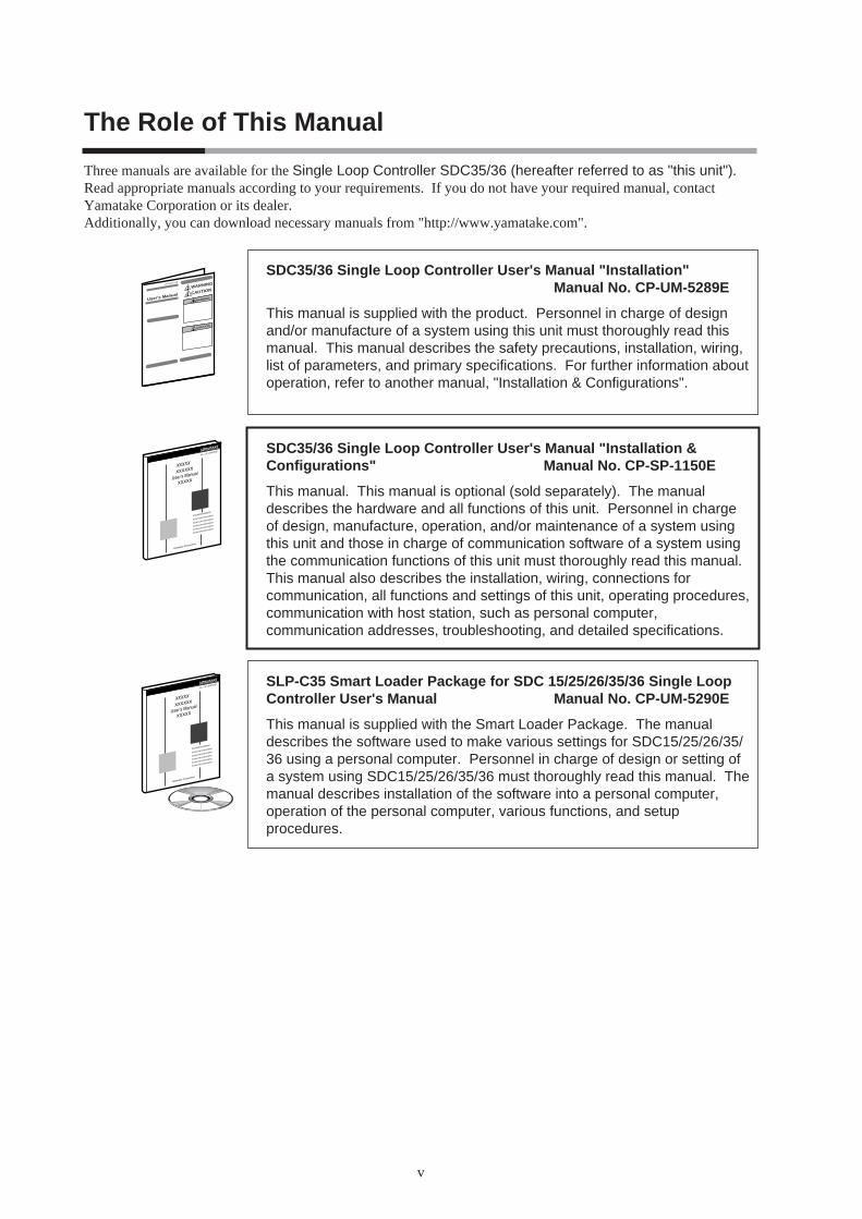
SDC35/36 Single Loop Controller User's Manual "Installation"Manual No. CP-UM-5289E
This manual is supplied with the product. Personnel in charge of designand/or manufacture of a system using this unit must thoroughly read thismanual. This manual describes the safety precautions, installation, wiring,list of parameters, and primary specifications. For further information aboutoperation, refer to another manual, "Installation & Configurations".
SDC35/36 Single Loop Controller User's Manual "Installation &Configurations" Manual No. CP-SP-1150E
This manual. This manual is optional (sold separately). The manualdescribes the hardware and all functions of this unit. Personnel in chargeof design, manufacture, operation, and/or maintenance of a system usingthis unit and those in charge of communication software of a system usingthe communication functions of this unit must thoroughly read this manual.This manual also describes the installation, wiring, connections forcommunication, all functions and settings of this unit, operating procedures,communication with host station, such as personal computer,communication addresses, troubleshooting, and detailed specifications.
SLP-C35 Smart Loader Package for SDC 15/25/26/35/36 Single LoopController User's Manual Manual No. CP-UM-5290E
This manual is supplied with the Smart Loader Package. The manualdescribes the software used to make various settings for SDC15/25/26/35/36 using a personal computer. Personnel in charge of design or setting ofa system using SDC15/25/26/35/36 must thoroughly read this manual. Themanual describes installation of the software into a personal computer,operation of the personal computer, various functions, and setupprocedures.
Organization of This User's Manual
vi
This manual is organized as follows:
Chapter 1. OVERVIEWThis chapter describes the applications, features, model selection guide, and partnames and functions of this unit. Since the part names described in this chapterare used in the subsequent descriptions, the part names and functions of this unitmust be understood correctly in this chapter.
Chapter 2. OUTLINE OF FUNCTIONSThis chapter describes the outline and operation flow of the functions of this unit.
Chapter 3. INSTALLATIONThis chapter describes the environmental conditions, installation dimensions,installation procedures, and necessary tools when installing this unit.
Chapter 4. WIRINGThis chapter describes the wiring procedures, wiring precautions, and connectionexamples.
Chapter 5. DETAILED DESCRIPTION OF EACH FUNCTIONThis chapter describes each function of this unit in detail.
Chapter 6. LIST OF DISPLAYS AND SETTING DATAThis chapter lists up the display items of this unit and their contents.
Chapter 7. CPL COMMUNICATION FUNCTIONThis chapter describes how to communicate this unit with a host unit, such as apersonal computer or PLC through Yamatake's standard CPL communicationusing RS-485.
Chapter 8. MODBUS COMMUNICATION FUNCTIONThis chapter describes how to communicate this unit with a host unit, such as apersonal computer or PLC through MODBUS communication.
Chapter 9. LIST OF COMMUNICATION DATAThis chapter shows the list of communication data inside the memory of this unit.
Chapter 10. MAINTENANCE AND TROUBLESHOOTINGThis chapter describes the maintenance and inspection of this unit, as well astroubleshooting.
Chapter 11. CALIBRATIONThis chapter describes how to calibrate this unit in order to keep the accuracy andto safely operate this unit for an extended period of time.
Chapter 12. DISPOSALThis chapter describes safety precautions and how to dispose of this unit when theunit is no longer used.
Chapter 13. SPECIFICATIONSThis chapter describes the general specifications, performance specifications, andoptional parts of this unit.

Contents
vii
SAFETY REQUIREMENTSSAFETY PRECAUTIONSThe Role of This ManualOrganization of This User's ManualConventions Used in This Manual
Chapter 1. OVERVIEW
1-1 Overview• • • • • • • • • • • • • • • • • • • • • • • • • • • • • • • • • • • • • • • • • • • • • • • • • • • • • • • • • • • • • • • • • • • 1-1 Model selection table • • • • • • • • • • • • • • • • • • • • • • • • • • • • • • • • • • • • • • • • • • • • • • • • • • 1-2 Accessories and optional parts • • • • • • • • • • • • • • • • • • • • • • • • • • • • • • • • • • • • • • • • 1-3
1-2 Part Names and Functions• • • • • • • • • • • • • • • • • • • • • • • • • • • • • • • • • • • • • • • • • • • • • • • • • 1-4 Main body and console • • • • • • • • • • • • • • • • • • • • • • • • • • • • • • • • • • • • • • • • • • • • • • • • 1-4 Rear panel • • • • • • • • • • • • • • • • • • • • • • • • • • • • • • • • • • • • • • • • • • • • • • • • • • • • • • • • • • • • • 1-7
Chapter 2. OUTLINE OF FUNCTIONS
2-1 Input/Output Configuration • • • • • • • • • • • • • • • • • • • • • • • • • • • • • • • • • • • • • • • • • • • • • • • • 2-12-2 Key Operation • • • • • • • • • • • • • • • • • • • • • • • • • • • • • • • • • • • • • • • • • • • • • • • • • • • • • • • • • • • • • 2-2
Data setting procedures • • • • • • • • • • • • • • • • • • • • • • • • • • • • • • • • • • • • • • • • • • • • • • • 2-4 [mode] key operating procedures • • • • • • • • • • • • • • • • • • • • • • • • • • • • • • • • • • • • • • 2-7 User level • • • • • • • • • • • • • • • • • • • • • • • • • • • • • • • • • • • • • • • • • • • • • • • • • • • • • • • • • • • • • • 2-7
2-3 Operation Modes • • • • • • • • • • • • • • • • • • • • • • • • • • • • • • • • • • • • • • • • • • • • • • • • • • • • • • • • • • 2-8
Chapter 3. INSTALLATION
Installation locations • • • • • • • • • • • • • • • • • • • • • • • • • • • • • • • • • • • • • • • • • • • • • • • • • • • 3-1 External Dimensions • • • • • • • • • • • • • • • • • • • • • • • • • • • • • • • • • • • • • • • • • • • • • • • • • • 3-2 Panel Cutout Dimensions • • • • • • • • • • • • • • • • • • • • • • • • • • • • • • • • • • • • • • • • • • • • • • 3-3 Mounting procedures • • • • • • • • • • • • • • • • • • • • • • • • • • • • • • • • • • • • • • • • • • • • • • • • • • 3-4
Chapter 4. WIRING
Terminal assignment label symbols • • • • • • • • • • • • • • • • • • • • • • • • • • • • • • • • • • • 4-2 Wiring Precautions• • • • • • • • • • • • • • • • • • • • • • • • • • • • • • • • • • • • • • • • • • • • • • • • • • • • • 4-2 Connection of open collector output to digital input • • • • • • • • • • • • • • • • • • • 4-5 Connection of communication (RS-485) cable • • • • • • • • • • • • • • • • • • • • • • • • • 4-5 Connection with solid state relay (SSR)• • • • • • • • • • • • • • • • • • • • • • • • • • • • • • • • 4-7 Connection method for the motor drive relay output (R1) • • • • • • • • • • • • 4-10 Noise Preventive Measures • • • • • • • • • • • • • • • • • • • • • • • • • • • • • • • • • • • • • • • • • • • 4-10
viii
Chapter 5. DETAILED DESCRIPTION OF EACH FUNCTION
5-1 PV Input • • • • • • • • • • • • • • • • • • • • • • • • • • • • • • • • • • • • • • • • • • • • • • • • • • • • • • • • • • • • • • • • • • • 5-1 PV input range type • • • • • • • • • • • • • • • • • • • • • • • • • • • • • • • • • • • • • • • • • • • • • • • • • • • • 5-2 Temperature unit • • • • • • • • • • • • • • • • • • • • • • • • • • • • • • • • • • • • • • • • • • • • • • • • • • • • • • • 5-3 Cold junction compensation (T/C) • • • • • • • • • • • • • • • • • • • • • • • • • • • • • • • • • • • • • 5-3 PV square root extraction dropout • • • • • • • • • • • • • • • • • • • • • • • • • • • • • • • • • • • • • 5-4 Decimal point position • • • • • • • • • • • • • • • • • • • • • • • • • • • • • • • • • • • • • • • • • • • • • • • • • 5-5 PV input range low limit/high limit • • • • • • • • • • • • • • • • • • • • • • • • • • • • • • • • • • • • • 5-6 PV ratio and PV bias • • • • • • • • • • • • • • • • • • • • • • • • • • • • • • • • • • • • • • • • • • • • • • • • • • • 5-6 PV filter • • • • • • • • • • • • • • • • • • • • • • • • • • • • • • • • • • • • • • • • • • • • • • • • • • • • • • • • • • • • • • • • 5-7 PV hold • • • • • • • • • • • • • • • • • • • • • • • • • • • • • • • • • • • • • • • • • • • • • • • • • • • • • • • • • • • • • • • • 5-7 PV low limit/high limit and PV low limit/high limit alarms • • • • • • • • • • • • • • 5-7 Zener barrier adjustment • • • • • • • • • • • • • • • • • • • • • • • • • • • • • • • • • • • • • • • • • • • • • • • 5-8
5-2 Mode • • • • • • • • • • • • • • • • • • • • • • • • • • • • • • • • • • • • • • • • • • • • • • • • • • • • • • • • • • • • • • • • • • • • • 5-10 AUTO/MANUAL mode• • • • • • • • • • • • • • • • • • • • • • • • • • • • • • • • • • • • • • • • • • • • • • • • • 5-10 RUN/READY mode • • • • • • • • • • • • • • • • • • • • • • • • • • • • • • • • • • • • • • • • • • • • • • • • • • • 5-10 LSP/RSP mode • • • • • • • • • • • • • • • • • • • • • • • • • • • • • • • • • • • • • • • • • • • • • • • • • • • • • • • 5-10 Auto tuning (AT) stop/start • • • • • • • • • • • • • • • • • • • • • • • • • • • • • • • • • • • • • • • • • • • 5-11 Release all digital output (DO) latches • • • • • • • • • • • • • • • • • • • • • • • • • • • • • • • • 5-11 Communication digital input 1 (communication DI 1) • • • • • • • • • • • • • • • • • 5-11
5-3 Control • • • • • • • • • • • • • • • • • • • • • • • • • • • • • • • • • • • • • • • • • • • • • • • • • • • • • • • • • • • • • • • • • • • 5-12 Control method • • • • • • • • • • • • • • • • • • • • • • • • • • • • • • • • • • • • • • • • • • • • • • • • • • • • • • • 5-14 Control action and Heat/Cool control • • • • • • • • • • • • • • • • • • • • • • • • • • • • • • • • • 5-15 Special control outputs • • • • • • • • • • • • • • • • • • • • • • • • • • • • • • • • • • • • • • • • • • • • • • • 5-15 MANUAL mode change • • • • • • • • • • • • • • • • • • • • • • • • • • • • • • • • • • • • • • • • • • • • • • • 5-16 PID control initialization • • • • • • • • • • • • • • • • • • • • • • • • • • • • • • • • • • • • • • • • • • • • • • 5-16 Initial output of PID control • • • • • • • • • • • • • • • • • • • • • • • • • • • • • • • • • • • • • • • • • • • 5-17 PID decimal point position • • • • • • • • • • • • • • • • • • • • • • • • • • • • • • • • • • • • • • • • • • • • 5-17 ON/OFF control • • • • • • • • • • • • • • • • • • • • • • • • • • • • • • • • • • • • • • • • • • • • • • • • • • • • • • • 5-18 Output variation limit • • • • • • • • • • • • • • • • • • • • • • • • • • • • • • • • • • • • • • • • • • • • • • • • • 5-18 PID control • • • • • • • • • • • • • • • • • • • • • • • • • • • • • • • • • • • • • • • • • • • • • • • • • • • • • • • • • • • • 5-19 Zone PID • • • • • • • • • • • • • • • • • • • • • • • • • • • • • • • • • • • • • • • • • • • • • • • • • • • • • • • • • • • • • • 5-23 Heat/Cool control • • • • • • • • • • • • • • • • • • • • • • • • • • • • • • • • • • • • • • • • • • • • • • • • • • • • • 5-24 Auto tuning (AT) • • • • • • • • • • • • • • • • • • • • • • • • • • • • • • • • • • • • • • • • • • • • • • • • • • • • • • 5-26 Just-FiTTER • • • • • • • • • • • • • • • • • • • • • • • • • • • • • • • • • • • • • • • • • • • • • • • • • • • • • • • • • • 5-28 RationaLOOP • • • • • • • • • • • • • • • • • • • • • • • • • • • • • • • • • • • • • • • • • • • • • • • • • • • • • • • • • 5-28 SP lag • • • • • • • • • • • • • • • • • • • • • • • • • • • • • • • • • • • • • • • • • • • • • • • • • • • • • • • • • • • • • • • • • 5-28
5-4 Auto Tuning (AT) Function • • • • • • • • • • • • • • • • • • • • • • • • • • • • • • • • • • • • • • • • • • • • • • • 5-29 Starting procedures • • • • • • • • • • • • • • • • • • • • • • • • • • • • • • • • • • • • • • • • • • • • • • • • • • 5-29 Stopping procedures • • • • • • • • • • • • • • • • • • • • • • • • • • • • • • • • • • • • • • • • • • • • • • • • • 5-29
5-5 Set Point (SP)• • • • • • • • • • • • • • • • • • • • • • • • • • • • • • • • • • • • • • • • • • • • • • • • • • • • • • • • • • • • • 5-32 SP setup in operation display mode • • • • • • • • • • • • • • • • • • • • • • • • • • • • • • • • • • 5-33 LSP system group • • • • • • • • • • • • • • • • • • • • • • • • • • • • • • • • • • • • • • • • • • • • • • • • • • • • 5-33 SP ramp type • • • • • • • • • • • • • • • • • • • • • • • • • • • • • • • • • • • • • • • • • • • • • • • • • • • • • • • • • 5-33 RSP input type • • • • • • • • • • • • • • • • • • • • • • • • • • • • • • • • • • • • • • • • • • • • • • • • • • • • • • • • 5-33 RSP input range low limit/high limit • • • • • • • • • • • • • • • • • • • • • • • • • • • • • • • • • • 5-34 RSP ratio and RSP bias • • • • • • • • • • • • • • • • • • • • • • • • • • • • • • • • • • • • • • • • • • • • • • • 5-34 RSP filter• • • • • • • • • • • • • • • • • • • • • • • • • • • • • • • • • • • • • • • • • • • • • • • • • • • • • • • • • • • • • • 5-35
ix
RSP low limit/high limit and RSP low limit/high limit alarms • • • • • • • • • • 5-35 RSP and LSP1 to 8 • • • • • • • • • • • • • • • • • • • • • • • • • • • • • • • • • • • • • • • • • • • • • • • • • • • • 5-35 PID group number • • • • • • • • • • • • • • • • • • • • • • • • • • • • • • • • • • • • • • • • • • • • • • • • • • • • 5-36 LSP group number• • • • • • • • • • • • • • • • • • • • • • • • • • • • • • • • • • • • • • • • • • • • • • • • • • • • 5-36 DI Assignment of LSP group selection • • • • • • • • • • • • • • • • • • • • • • • • • • • • • • • 5-37 SP ramp unit • • • • • • • • • • • • • • • • • • • • • • • • • • • • • • • • • • • • • • • • • • • • • • • • • • • • • • • • • • 5-37 SP ramp-up/ramp-down• • • • • • • • • • • • • • • • • • • • • • • • • • • • • • • • • • • • • • • • • • • • • • • 5-38 SP multi-ramp • • • • • • • • • • • • • • • • • • • • • • • • • • • • • • • • • • • • • • • • • • • • • • • • • • • • • • • • 5-39 SP low limit/high limit • • • • • • • • • • • • • • • • • • • • • • • • • • • • • • • • • • • • • • • • • • • • • • • • • 5-40 DI Assignment of SP ramp enabled/disabled • • • • • • • • • • • • • • • • • • • • • • • • • 5-40
5-6 Step Operation • • • • • • • • • • • • • • • • • • • • • • • • • • • • • • • • • • • • • • • • • • • • • • • • • • • • • • • • • • • 5-41 LSP system group • • • • • • • • • • • • • • • • • • • • • • • • • • • • • • • • • • • • • • • • • • • • • • • • • • • • 5-41 SP ramp type • • • • • • • • • • • • • • • • • • • • • • • • • • • • • • • • • • • • • • • • • • • • • • • • • • • • • • • • • 5-42 SP ramp unit • • • • • • • • • • • • • • • • • • • • • • • • • • • • • • • • • • • • • • • • • • • • • • • • • • • • • • • • • • 5-43 STEP time unit • • • • • • • • • • • • • • • • • • • • • • • • • • • • • • • • • • • • • • • • • • • • • • • • • • • • • • • • 5-43 STEP PV start • • • • • • • • • • • • • • • • • • • • • • • • • • • • • • • • • • • • • • • • • • • • • • • • • • • • • • • • • 5-44 STEP loop • • • • • • • • • • • • • • • • • • • • • • • • • • • • • • • • • • • • • • • • • • • • • • • • • • • • • • • • • • • • 5-45 STEP operation LSP, PID group No., ramp, time • • • • • • • • • • • • • • • • • • • • • • 5-46 Operation type of internal contact • • • • • • • • • • • • • • • • • • • • • • • • • • • • • • • • • • • • 5-48
5-7 Digital Input (DI) and Internal Contact • • • • • • • • • • • • • • • • • • • • • • • • • • • • • • • • • • • • 5-49 Operation type • • • • • • • • • • • • • • • • • • • • • • • • • • • • • • • • • • • • • • • • • • • • • • • • • • • • • • • • 5-50 Event channel definitions • • • • • • • • • • • • • • • • • • • • • • • • • • • • • • • • • • • • • • • • • • • • • 5-51 Input bit function • • • • • • • • • • • • • • • • • • • • • • • • • • • • • • • • • • • • • • • • • • • • • • • • • • • • • 5-52 Input assignment • • • • • • • • • • • • • • • • • • • • • • • • • • • • • • • • • • • • • • • • • • • • • • • • • • • • • 5-53 Polarity of input assignment • • • • • • • • • • • • • • • • • • • • • • • • • • • • • • • • • • • • • • • • • • 5-54 Polarity of input bit function • • • • • • • • • • • • • • • • • • • • • • • • • • • • • • • • • • • • • • • • • • 5-55 DI Assignment setting with Smart Loader Package SLP-C35 • • • • • • • • • 5-55
5-8 Internal Event• • • • • • • • • • • • • • • • • • • • • • • • • • • • • • • • • • • • • • • • • • • • • • • • • • • • • • • • • • • • • 5-56 Operation • • • • • • • • • • • • • • • • • • • • • • • • • • • • • • • • • • • • • • • • • • • • • • • • • • • • • • • • • • • • • 5-57 Operation type • • • • • • • • • • • • • • • • • • • • • • • • • • • • • • • • • • • • • • • • • • • • • • • • • • • • • • • • 5-63 Direct/reverse, standby, and EVENT state at READY • • • • • • • • • • • • • • • • • 5-64 Alarm OR, special OFF setup, and delay time unit • • • • • • • • • • • • • • • • • • • • 5-65 Main setting, sub setting, and hysteresis • • • • • • • • • • • • • • • • • • • • • • • • • • • • • 5-66 ON delay and OFF delay • • • • • • • • • • • • • • • • • • • • • • • • • • • • • • • • • • • • • • • • • • • • • • 5-67
5-9 Digital Output (DO) • • • • • • • • • • • • • • • • • • • • • • • • • • • • • • • • • • • • • • • • • • • • • • • • • • • • • • • 5-69 MV1/MV2 process • • • • • • • • • • • • • • • • • • • • • • • • • • • • • • • • • • • • • • • • • • • • • • • • • • • • • 5-70 Operation type • • • • • • • • • • • • • • • • • • • • • • • • • • • • • • • • • • • • • • • • • • • • • • • • • • • • • • • • 5-72 Output assignment • • • • • • • • • • • • • • • • • • • • • • • • • • • • • • • • • • • • • • • • • • • • • • • • • • • 5-73 Polarity of output assignment • • • • • • • • • • • • • • • • • • • • • • • • • • • • • • • • • • • • • • • • 5-75 Polarity of output bit function• • • • • • • • • • • • • • • • • • • • • • • • • • • • • • • • • • • • • • • • • 5-76 Latch• • • • • • • • • • • • • • • • • • • • • • • • • • • • • • • • • • • • • • • • • • • • • • • • • • • • • • • • • • • • • • • • • • 5-76 DO Assignment setting with Smart Loader Package SLP-C35 • • • • • • • • 5-77
5-10 Application Examples • • • • • • • • • • • • • • • • • • • • • • • • • • • • • • • • • • • • • • • • • • • • • • • • • • • • 5-78 Examples of applications using assignment functions • • • • • • • • • • • • • • • 5-78
5-11 Continuous Output • • • • • • • • • • • • • • • • • • • • • • • • • • • • • • • • • • • • • • • • • • • • • • • • • • • • • • • 5-85 Output range• • • • • • • • • • • • • • • • • • • • • • • • • • • • • • • • • • • • • • • • • • • • • • • • • • • • • • • • • • 5-85 Output type • • • • • • • • • • • • • • • • • • • • • • • • • • • • • • • • • • • • • • • • • • • • • • • • • • • • • • • • • • • 5-85 Output scaling low limit/high limit • • • • • • • • • • • • • • • • • • • • • • • • • • • • • • • • • • • • 5-86 MV scaling range • • • • • • • • • • • • • • • • • • • • • • • • • • • • • • • • • • • • • • • • • • • • • • • • • • • • • 5-87
5-12 Current Transformer (CT) Input• • • • • • • • • • • • • • • • • • • • • • • • • • • • • • • • • • • • • • • • • • • 5-88 CT type • • • • • • • • • • • • • • • • • • • • • • • • • • • • • • • • • • • • • • • • • • • • • • • • • • • • • • • • • • • • • • • 5-89 CT output • • • • • • • • • • • • • • • • • • • • • • • • • • • • • • • • • • • • • • • • • • • • • • • • • • • • • • • • • • • • • 5-89 CT measurement wait time • • • • • • • • • • • • • • • • • • • • • • • • • • • • • • • • • • • • • • • • • • • 5-89 Number of CT turns and number of CT power wire loops• • • • • • • • • • • • • 5-90
5-13 Console Display and Key Operation • • • • • • • • • • • • • • • • • • • • • • • • • • • • • • • • • • • • • • 5-92 Key operation type• • • • • • • • • • • • • • • • • • • • • • • • • • • • • • • • • • • • • • • • • • • • • • • • • • • • 5-92 [mode] key function • • • • • • • • • • • • • • • • • • • • • • • • • • • • • • • • • • • • • • • • • • • • • • • • • • 5-92 MODE display setup • • • • • • • • • • • • • • • • • • • • • • • • • • • • • • • • • • • • • • • • • • • • • • • • • • 5-93 PV/SP display setup • • • • • • • • • • • • • • • • • • • • • • • • • • • • • • • • • • • • • • • • • • • • • • • • • • 5-94 MV display setup • • • • • • • • • • • • • • • • • • • • • • • • • • • • • • • • • • • • • • • • • • • • • • • • • • • • • 5-95 EV display setup • • • • • • • • • • • • • • • • • • • • • • • • • • • • • • • • • • • • • • • • • • • • • • • • • • • • • • 5-96 Timer remaining time display setup • • • • • • • • • • • • • • • • • • • • • • • • • • • • • • • • • • 5-96 CT display setup • • • • • • • • • • • • • • • • • • • • • • • • • • • • • • • • • • • • • • • • • • • • • • • • • • • • • • 5-97 User level • • • • • • • • • • • • • • • • • • • • • • • • • • • • • • • • • • • • • • • • • • • • • • • • • • • • • • • • • • • • • 5-97 Communication monitoring display • • • • • • • • • • • • • • • • • • • • • • • • • • • • • • • • • • 5-97 Multi Status (MS) display • • • • • • • • • • • • • • • • • • • • • • • • • • • • • • • • • • • • • • • • • • • • • 5-98 User Function • • • • • • • • • • • • • • • • • • • • • • • • • • • • • • • • • • • • • • • • • • • • • • • • • • • • • • • 5-101 Key lock, communication lock, and loader lock • • • • • • • • • • • • • • • • • • • • • 5-105 Password • • • • • • • • • • • • • • • • • • • • • • • • • • • • • • • • • • • • • • • • • • • • • • • • • • • • • • • • • • • • 5-106
5-14 Position Proportional Control • • • • • • • • • • • • • • • • • • • • • • • • • • • • • • • • • • • • • • • • • • • 5-107 Position proportional type • • • • • • • • • • • • • • • • • • • • • • • • • • • • • • • • • • • • • • • • • • • 5-107 Position proportional dead zone • • • • • • • • • • • • • • • • • • • • • • • • • • • • • • • • • • • • 5-109 Motor long life mode• • • • • • • • • • • • • • • • • • • • • • • • • • • • • • • • • • • • • • • • • • • • • • • • • 5-109 Motor auto adjust • • • • • • • • • • • • • • • • • • • • • • • • • • • • • • • • • • • • • • • • • • • • • • • • • • • • 5-109 Motor wiring and motor auto adjust operation• • • • • • • • • • • • • • • • • • • • • • • 5-111 Input with motor fully closed and input with motor fully open • • • • • • • 5-113 Motor full close–full open time • • • • • • • • • • • • • • • • • • • • • • • • • • • • • • • • • • • • • • 5-113
Chapter 6. LIST OF DISPLAYS AND SETTING DATA
6-1 List of Operation Displays • • • • • • • • • • • • • • • • • • • • • • • • • • • • • • • • • • • • • • • • • • • • • • • • • 6-1 Operation displays • • • • • • • • • • • • • • • • • • • • • • • • • • • • • • • • • • • • • • • • • • • • • • • • • • • • • 6-1
6-2 List of Parameter Setting Displays• • • • • • • • • • • • • • • • • • • • • • • • • • • • • • • • • • • • • • • • • 6-3 Mode bank • • • • • • • • • • • • • • • • • • • • • • • • • • • • • • • • • • • • • • • • • • • • • • • • • • • • • • • • • • • • • 6-3 SP bank • • • • • • • • • • • • • • • • • • • • • • • • • • • • • • • • • • • • • • • • • • • • • • • • • • • • • • • • • • • • • • • • 6-4 Event bank • • • • • • • • • • • • • • • • • • • • • • • • • • • • • • • • • • • • • • • • • • • • • • • • • • • • • • • • • • • • • 6-5 PID bank • • • • • • • • • • • • • • • • • • • • • • • • • • • • • • • • • • • • • • • • • • • • • • • • • • • • • • • • • • • • • • • 6-7 Parameter bank • • • • • • • • • • • • • • • • • • • • • • • • • • • • • • • • • • • • • • • • • • • • • • • • • • • • • • • 6-10 Extended tuning bank • • • • • • • • • • • • • • • • • • • • • • • • • • • • • • • • • • • • • • • • • • • • • • • • 6-11 Zone bank • • • • • • • • • • • • • • • • • • • • • • • • • • • • • • • • • • • • • • • • • • • • • • • • • • • • • • • • • • • • 6-11
6-3 List of Setup Setting Displays • • • • • • • • • • • • • • • • • • • • • • • • • • • • • • • • • • • • • • • • • • • • 6-12 Setup bank• • • • • • • • • • • • • • • • • • • • • • • • • • • • • • • • • • • • • • • • • • • • • • • • • • • • • • • • • • • • 6-12 Event configuration bank • • • • • • • • • • • • • • • • • • • • • • • • • • • • • • • • • • • • • • • • • • • • • 6-19 DI Assignment bank • • • • • • • • • • • • • • • • • • • • • • • • • • • • • • • • • • • • • • • • • • • • • • • • • • 6-22 DO Assignment bank • • • • • • • • • • • • • • • • • • • • • • • • • • • • • • • • • • • • • • • • • • • • • • • • • 6-26 User Function bank • • • • • • • • • • • • • • • • • • • • • • • • • • • • • • • • • • • • • • • • • • • • • • • • • • • 6-29
x

xi
Lock bank• • • • • • • • • • • • • • • • • • • • • • • • • • • • • • • • • • • • • • • • • • • • • • • • • • • • • • • • • • • • • 6-30 Instrument information bank• • • • • • • • • • • • • • • • • • • • • • • • • • • • • • • • • • • • • • • • • • 6-30
Chapter 7. CPL COMMUNICATION FUNCTION
7-1 Outline of Communication • • • • • • • • • • • • • • • • • • • • • • • • • • • • • • • • • • • • • • • • • • • • • • • • • 7-1 Features • • • • • • • • • • • • • • • • • • • • • • • • • • • • • • • • • • • • • • • • • • • • • • • • • • • • • • • • • • • • • • • 7-1 Setup• • • • • • • • • • • • • • • • • • • • • • • • • • • • • • • • • • • • • • • • • • • • • • • • • • • • • • • • • • • • • • • • • • • 7-1 Communication procedures • • • • • • • • • • • • • • • • • • • • • • • • • • • • • • • • • • • • • • • • • • • 7-2
7-2 Message Structure • • • • • • • • • • • • • • • • • • • • • • • • • • • • • • • • • • • • • • • • • • • • • • • • • • • • • • • • • 7-3 Message structure • • • • • • • • • • • • • • • • • • • • • • • • • • • • • • • • • • • • • • • • • • • • • • • • • • • • • 7-3 Data link layer • • • • • • • • • • • • • • • • • • • • • • • • • • • • • • • • • • • • • • • • • • • • • • • • • • • • • • • • • • 7-3 Application layer • • • • • • • • • • • • • • • • • • • • • • • • • • • • • • • • • • • • • • • • • • • • • • • • • • • • • • • 7-5
7-3 Description of Commands • • • • • • • • • • • • • • • • • • • • • • • • • • • • • • • • • • • • • • • • • • • • • • • • • 7-6 Continuous data read command (RS command) • • • • • • • • • • • • • • • • • • • • • • • 7-6 Continuous data write command (WS command) • • • • • • • • • • • • • • • • • • • • • • 7-7 Fixed length continuous data read command (RD command) • • • • • • • • • 7-8 Fixed length continuous data write command (WD command) • • • • • • • • 7-9 Fixed length random data read command (RU command) • • • • • • • • • • • • 7-10 Fixed length random data write command (WU command) • • • • • • • • • • • 7-11
7-4 Definition of Data Addresses • • • • • • • • • • • • • • • • • • • • • • • • • • • • • • • • • • • • • • • • • • • • • 7-127-5 Numeric Representation in the Application Layer • • • • • • • • • • • • • • • • • • • • • • • • 7-137-6 List of Termination Codes • • • • • • • • • • • • • • • • • • • • • • • • • • • • • • • • • • • • • • • • • • • • • • • • 7-147-7 Reception and Transmission Timing • • • • • • • • • • • • • • • • • • • • • • • • • • • • • • • • • • • • • 7-15
Timing specifications for instruction and response message • • • • • • • • 7-15 RS-485 driver control timing specifications• • • • • • • • • • • • • • • • • • • • • • • • • • • 7-15
7-8 Cautions when Executing Communication Programs for the Master Station• • • • • • • • • • • • • • • • • • • • • • • • • • • • • • • • • • • • • • • • • • • • • • • • • • • • • 7-16 Example of communication program • • • • • • • • • • • • • • • • • • • • • • • • • • • • • • • • • 7-16
Chapter 8. MODBUS COMMUNICATION FUNCTION
8-1 Outline of Communication • • • • • • • • • • • • • • • • • • • • • • • • • • • • • • • • • • • • • • • • • • • • • • • • • 8-1 Features • • • • • • • • • • • • • • • • • • • • • • • • • • • • • • • • • • • • • • • • • • • • • • • • • • • • • • • • • • • • • • • 8-1 Setup• • • • • • • • • • • • • • • • • • • • • • • • • • • • • • • • • • • • • • • • • • • • • • • • • • • • • • • • • • • • • • • • • • • 8-1 Communication procedures • • • • • • • • • • • • • • • • • • • • • • • • • • • • • • • • • • • • • • • • • • • 8-2
8-2 Message Structure • • • • • • • • • • • • • • • • • • • • • • • • • • • • • • • • • • • • • • • • • • • • • • • • • • • • • • • • • 8-3 Message structure • • • • • • • • • • • • • • • • • • • • • • • • • • • • • • • • • • • • • • • • • • • • • • • • • • • • • 8-3 Command type • • • • • • • • • • • • • • • • • • • • • • • • • • • • • • • • • • • • • • • • • • • • • • • • • • • • • • • • • 8-6 Other specifications • • • • • • • • • • • • • • • • • • • • • • • • • • • • • • • • • • • • • • • • • • • • • • • • • • • 8-6
8-3 Description of Commands • • • • • • • • • • • • • • • • • • • • • • • • • • • • • • • • • • • • • • • • • • • • • • • • • 8-7 Read command (03H) • • • • • • • • • • • • • • • • • • • • • • • • • • • • • • • • • • • • • • • • • • • • • • • • • • 8-7 Write command (10H) • • • • • • • • • • • • • • • • • • • • • • • • • • • • • • • • • • • • • • • • • • • • • • • • • • 8-9
8-4 Specifications Common with CPL Communication Function • • • • • • • • • • • • • 8-11 Definition of data addresses • • • • • • • • • • • • • • • • • • • • • • • • • • • • • • • • • • • • • • • • • • 8-11 Numeric representation • • • • • • • • • • • • • • • • • • • • • • • • • • • • • • • • • • • • • • • • • • • • • • • 8-11 RS-485 driver control timing specifications• • • • • • • • • • • • • • • • • • • • • • • • • • • 8-11

xii
Chapter 9. LIST OF COMMUNICATION DATA
List of communication data • • • • • • • • • • • • • • • • • • • • • • • • • • • • • • • • • • • • • • • • • • • • 9-1
Chapter 10. MAINTENANCE AND TROUBLESHOOTING
Maintenance • • • • • • • • • • • • • • • • • • • • • • • • • • • • • • • • • • • • • • • • • • • • • • • • • • • • • • • • • • 10-1 Alarm displays and corrective action • • • • • • • • • • • • • • • • • • • • • • • • • • • • • • • • • 10-2 Behavior in case of PV input failure • • • • • • • • • • • • • • • • • • • • • • • • • • • • • • • • • • 10-3 Behavior in case of RSP input failure • • • • • • • • • • • • • • • • • • • • • • • • • • • • • • • • • 10-4
Chapter 11. CALIBRATION
Starting the calibration • • • • • • • • • • • • • • • • • • • • • • • • • • • • • • • • • • • • • • • • • • • • • • • 11-1 Exiting the calibration • • • • • • • • • • • • • • • • • • • • • • • • • • • • • • • • • • • • • • • • • • • • • • • • 11-1 Cautions before starting the calibration • • • • • • • • • • • • • • • • • • • • • • • • • • • • • • 11-2 Measuring instruments required for calibration • • • • • • • • • • • • • • • • • • • • • • 11-2 Calibration procedures • • • • • • • • • • • • • • • • • • • • • • • • • • • • • • • • • • • • • • • • • • • • • • • 11-2
Chapter 12. DISPOSAL
Chapter 13. SPECIFICATIONS
Specifications • • • • • • • • • • • • • • • • • • • • • • • • • • • • • • • • • • • • • • • • • • • • • • • • • • • • • • • • 13-1 Accessories and optional parts • • • • • • • • • • • • • • • • • • • • • • • • • • • • • • • • • • • • • • • 13-7
Appendix
Glossary • • • • • • • • • • • • • • • • • • • • • • • • • • • • • • • • • • • • • • • • • • • • • • • • • • • • • • • • • • Appendix-1
Index
Conventions Used in This Manual
xiii
The following conventions are used in this manual:
Handling Precautions: Handling Precautions indicate items that the user should pay attention to
when handling the SDC35/36.
: This indicates the item or page that the user is requested to refer to.
Note : Notes indicate useful user tips and information.
(1), (2), (3) : The numbers with the parenthesis indicate steps in a sequence orindicate corresponding parts in an explanation.
[para], [mode] etc. : These indicate keys on the keyboard of this unit, and messages andmenus that appear on the personal computer screen.
>> : This indicates the operation results and the status after operation.
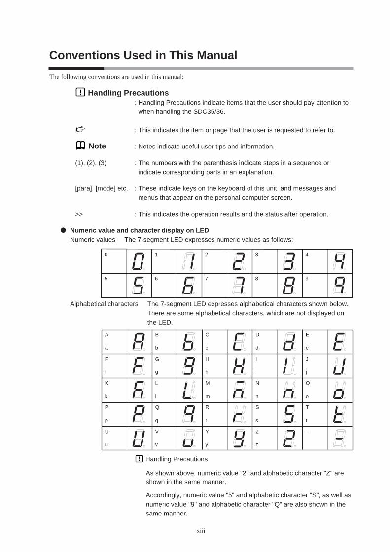
Numeric value and character display on LEDNumeric values The 7-segment LED expresses numeric values as follows:
Alphabetical characters The 7-segment LED expresses alphabetical characters shown below.There are some alphabetical characters, which are not displayed onthe LED.
Handling Precautions
As shown above, numeric value "2" and alphabetic character "Z" areshown in the same manner.
Accordingly, numeric value "5" and alphabetic character "S", as well asnumeric value "9" and alphabetic character "Q" are also shown in thesame manner.
0 1 2 3 4
5 6 7 8 9
A B C D E
a b c d e
F G H I J
f g h i j
K L M N O
k l m n o
P Q R S T
p q r s t
U V Y Z –
u v y z


Chapter 1. OVERVIEW1 - 1 Overview
1-1
This unit is a compact controller having a mask of 48 X 96 mm or 96 X 96 mm and provides the following
features:
• The depth is only 65 mm, providing excellent space-saving.
• The front panel is only 5 mm thick. This ensures excellent thin design.
• The display panel is large. This provides excellent visibility.
• [mode] key, [para] key, digit-shift keys, [display] key, and [enter] key are
provided on the front panel. This ensures easy setup operation.
• Various input types are available, thermocouples (K, J, E, T, R, S, B, N, PLII,
WRe5-26, Ni-NiMo, PR40-20, DIN U, DIN L, gold iron chromel), RTDs
(Pt100, JPt100), current signals (4 to 20mAdc, 0 to 20mAdc), and voltage
signals (0 to 10mVdc, -10 to +10mVdc, 0 to 1Vdc, 1 to 5Vdc, 0 to 5Vdc, and 0
to 10Vdc).
• The accuracy is ±0.1%FS and the sampling cycle time is 0.1 sec. This ensures
high accuracy.
• For control output types, relay, voltage pulse for driving SSR, current output,
and continuous voltage outputs are provided. Additionally, these control output
types can be combined for control outputs 1 and 2.
• Three event output points or two event output points (independent contacts) are
provided as standard functions.
• 2-point CT input, 4-point digital input, RSP input, and RS-485 can be combined
as optional functions.
• Current output or continuous voltage output is provided as auxiliary output.
• The unit can be configured for the heat/cool control using the 2nd control
output and/or event relay.
• The unit can be controlled by means of the ON/OFF control or fixed PID
control method.
• In addition to the PID control, two algorithms, RationaLOOP and Just-FiTTER,
are built-in, which ensures excellent controllability.
• The personal computer loader port is provided as standard function. The setup
can be configured easily with use of the personal computer loader.
• Use of optional Smart Loader Package (SLP-C35) makes it possible to easily
perform the read/write operation of the parameters.
In addition to the table format setup, the operation and control status can be
monitored using the trend display. This unit can be operated without use of
program on the host unit.
• The unit conforms to the IEC directive and the CE marking is affixed on the
unit.
(Applicable standards: EN61010-1 and EN61326-1)
1-2
Chapter 1. OVERVIEW
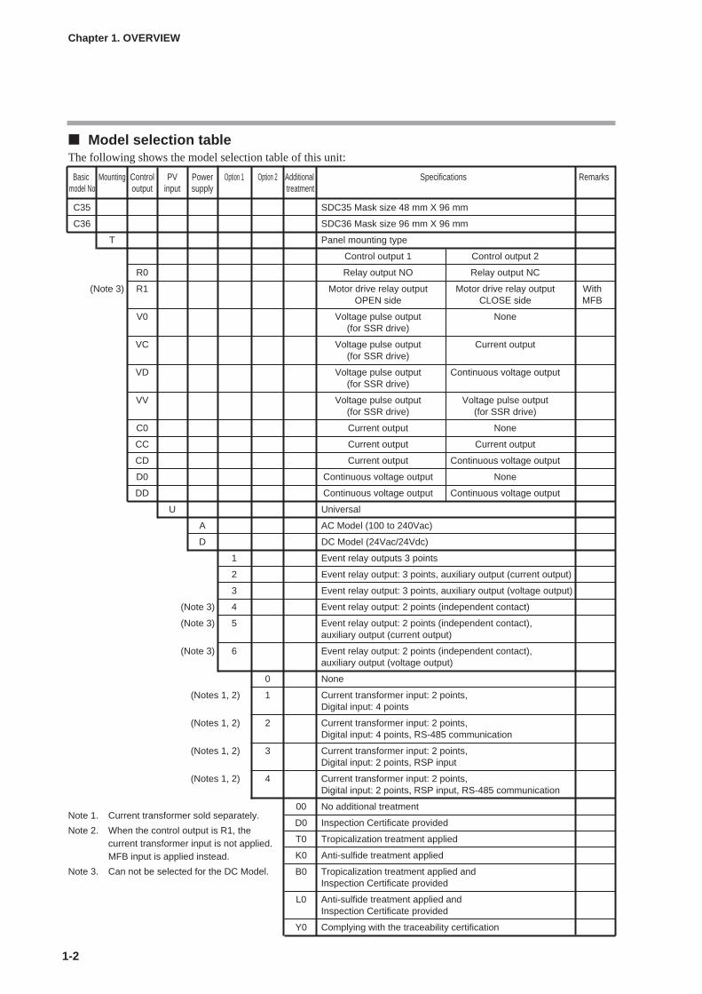
Model selection tableThe following shows the model selection table of this unit:
Basic Mounting Control PV Power Option 1 Option 2 Additional Specifications Remarksmodel No. output input supply treatment
C35 SDC35 Mask size 48 mm X 96 mm
C36 SDC36 Mask size 96 mm X 96 mm
T Panel mounting type
Control output 1 Control output 2
R0 Relay output NO Relay output NC
(Note 3) R1 Motor drive relay output Motor drive relay output WithOPEN side CLOSE side MFB
V0 Voltage pulse output None(for SSR drive)
VC Voltage pulse output Current output(for SSR drive)
VD Voltage pulse output Continuous voltage output(for SSR drive)
VV Voltage pulse output Voltage pulse output(for SSR drive) (for SSR drive)
C0 Current output None
CC Current output Current output
CD Current output Continuous voltage output
D0 Continuous voltage output None
DD Continuous voltage output Continuous voltage output
U Universal
A AC Model (100 to 240Vac)
D DC Model (24Vac/24Vdc)
1 Event relay outputs 3 points
2 Event relay output: 3 points, auxiliary output (current output)
3 Event relay output: 3 points, auxiliary output (voltage output)
(Note 3) 4 Event relay output: 2 points (independent contact)
(Note 3) 5 Event relay output: 2 points (independent contact), auxiliary output (current output)
(Note 3) 6 Event relay output: 2 points (independent contact), auxiliary output (voltage output)
0 None
(Notes 1, 2) 1 Current transformer input: 2 points,Digital input: 4 points
(Notes 1, 2) 2 Current transformer input: 2 points,Digital input: 4 points, RS-485 communication
(Notes 1, 2) 3 Current transformer input: 2 points,Digital input: 2 points, RSP input
(Notes 1, 2) 4 Current transformer input: 2 points,Digital input: 2 points, RSP input, RS-485 communication
00 No additional treatment
D0 Inspection Certificate provided
T0 Tropicalization treatment applied
K0 Anti-sulfide treatment applied
B0 Tropicalization treatment applied andInspection Certificate provided
L0 Anti-sulfide treatment applied andInspection Certificate provided
Y0 Complying with the traceability certification
Note 1. Current transformer sold separately.
Note 2. When the control output is R1, thecurrent transformer input is not applied.MFB input is applied instead.
Note 3. Can not be selected for the DC Model.

1-3
Accessories and optional parts
Chapter 1. OVERVIEW
Name Model No.
Mounting bracket 81409654-001 (Accessory)
Current transformer QN206A (5.8mm hole dia.)
QN212A (12mm hole dia.)
Hard cover 81446915-001 (for C35)81446916-001 (for C36)
Terminal cover 81446912-001 (for C35)81446913-001 (for C36)
1 - 2 Part Names and Functions
1-4
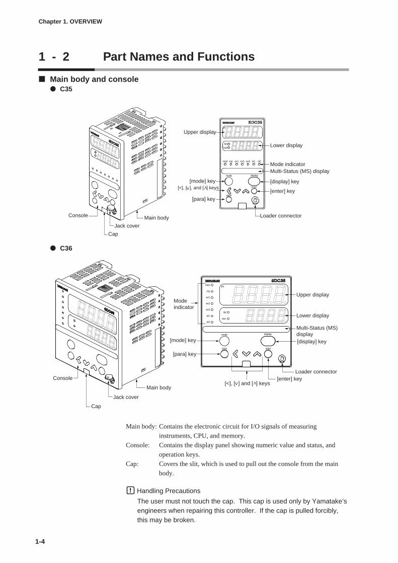
Main body and console C35
C36
Main body: Contains the electronic circuit for I/O signals of measuring
instruments, CPU, and memory.
Console: Contains the display panel showing numeric value and status, and
operation keys.
Cap: Covers the slit, which is used to pull out the console from the main
body.
Handling Precautions
The user must not touch the cap. This cap is used only by Yamatake’sengineers when repairing this controller. If the cap is pulled forcibly,this may be broken.
Chapter 1. OVERVIEW
sp
out
pv
man rsp ev1 ev2 ev3 ot1 ot2
mode display
enter
para
Console
Cap
Jack cover
Main body
[mode] key
Loader connector
Lower display
Multi-Status (MS) display
[enter] key
Mode indicator
[display] key
Upper display
[<], [ ], and [ ] keys
[para] key
<<
para enter
displaymode
pv
out
sp
ot2
ot1
ev3
ev2
ev1
rsp
man
Console
Cap
Main body
Jack cover
[mode] key
Loader connector
Lower display
Multi-Status (MS)display
Upper display
[enter] key
Mode indicator
[display] key
[<], [ ] and [ ] keys
[para] key
<
<

1-5
Detailed description of console[mode] key
When this key is kept pressed for 1 sec. or longer in the operation display
mode, any of the following operations, which have been set previously, can be
performed:
• AUTO/MANUAL mode selection
• RUN/READY mode selection
• Auto Tuning (AT) start/stop selection
• Local SP (LSP) group selection
• Release all Digital Output (DO) latches
• LSP/RSP mode selection
• ON/OFF selection of communication Digital Input (DI) 1
When pressing the [mode] key in the setup display mode, the display is
changed to the operation display.
[display] key
This key is used to change the display item in the operation display mode.
When pressing this key in the bank selection, bank setup, or user function setup
display mode, the display is changed to the operation display.
[para] key
When this key is kept pressed for 2s or longer in the operation display mode,
the display is then changed to the bank selection display.
[<], [ ], [ ] keys
These keys are used to increase or decrease the numeric value, or to shift the
digit.
The [ ] and [ ] keys are used to change the bank in the bank selection
display mode. In the bank setup display mode, these keys are used to change
the display item.
[enter] key
This key is used to start changing setup values. Additionally, the key is also
used to set setup values currently being changed.
When pressing this key in the bank selection display mode, the bank is set and
the display is changed to the bank setup display.
Upper display
This display shows the PV value or the name of each display item (display
value or set value). If an alarm occurs in the operation display mode, the
normal display and alarm code are displayed alternately.
The decimal point at the right end digit shows auto tuning (AT) status. The
decimal point flashes twice repeatedly during execution of AT.
Lower display
This display shows the SP value, or the display value or set value of each
display item. The decimal point at the right end digit shows the RUN/READY
mode or communication status.
Chapter 1. OVERVIEW

1-6
Mode indicators
[man]: AUTO/MANUAL mode indicator. Lights in MANUAL
mode.
[rsp]: LSP/RSP mode indicator. Lights in RSP mode.
[ev1], [ev2], [ev3]: Event output 1 to 3 indicator. Lights when event relays are
ON.
[ot1], [ot2]: Control output 1 and 2 indicator. Lights when the control
output is ON. The indicators are always lit when the
current output or continuous voltage output is used.
Multi-Status (MS) display
By combining the lighting conditions with the lighting status, three groups can
be set for priority display.
For lighting conditions, the internal event ON status, DI ON status, and
READY mode are provided.
For lighting status, flashing, reciprocating between left and right, and MV graph
are provided.
Jack cover: This jack cover protects the loader connector. When
connecting the loader, pull this cover upward by finger.
Loader connector: This connector is used for connecting to a personal computer
using the dedicated cable supplied with the Smart Loader
Package.
Handling Precautions
• To select the LSP group using the [mode] key, it is necessary to set avalue of “2” or more in [LSP system group].
• To show the RUN/READY mode and communication status using thedecimal point at the right end digit on the lower display, select “Highfunction configuration” and make the [LED monitor] settings.
• Do not operate the key with a sharp object (such as tip of mechanicalpencil or needle). Doing so might cause the unit to malfunction.
• If the jack cover is pulled forcibly, it may be broken. Never attempt topull this cover forcibly.
Chapter 1. OVERVIEW

1-7
Rear panel C35
C36
Terminal part: The power supply, input, and output are connected to the terminals.
The M3 screw is used. When connecting to the terminal, always
use a correct crimp type terminal lug suitable for the M3 screw.
The tightening torque of the terminal screw is 0.4 to 0.6N·m or less.
Chapter 1. OVERVIEW
Terminal part
Terminal part

Chapter 2. OUTLINE OF FUNCTIONS2 - 1 Input/Output Configuration
2-1
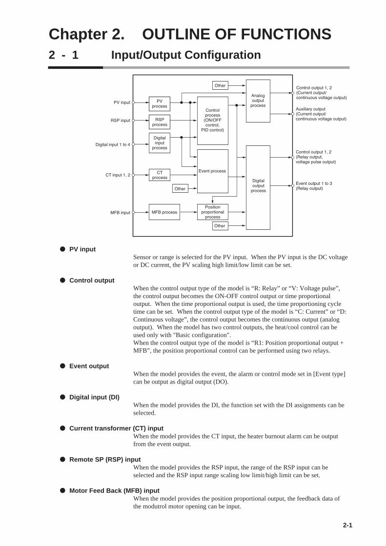
PV inputSensor or range is selected for the PV input. When the PV input is the DC voltageor DC current, the PV scaling high limit/low limit can be set.
Control outputWhen the control output type of the model is “R: Relay” or “V: Voltage pulse”,the control output becomes the ON-OFF control output or time proportionaloutput. When the time proportional output is used, the time proportioning cycletime can be set. When the control output type of the model is “C: Current” or “D:Continuous voltage”, the control output becomes the continuous output (analogoutput). When the model has two control outputs, the heat/cool control can beused only with "Basic configuration".When the control output type of the model is “R1: Position proportional output +MFB”, the position proportional control can be performed using two relays.
Event outputWhen the model provides the event, the alarm or control mode set in [Event type]can be output as digital output (DO).
Digital input (DI)When the model provides the DI, the function set with the DI assignments can beselected.
Current transformer (CT) inputWhen the model provides the CT input, the heater burnout alarm can be outputfrom the event output.
Remote SP (RSP) inputWhen the model provides the RSP input, the range of the RSP input can beselected and the RSP input range scaling low limit/high limit can be set.
Motor Feed Back (MFB) inputWhen the model provides the position proportional output, the feedback data ofthe modutrol motor opening can be input.
!
"#$
%& %&
'% '%
(##
%)
%
"#$
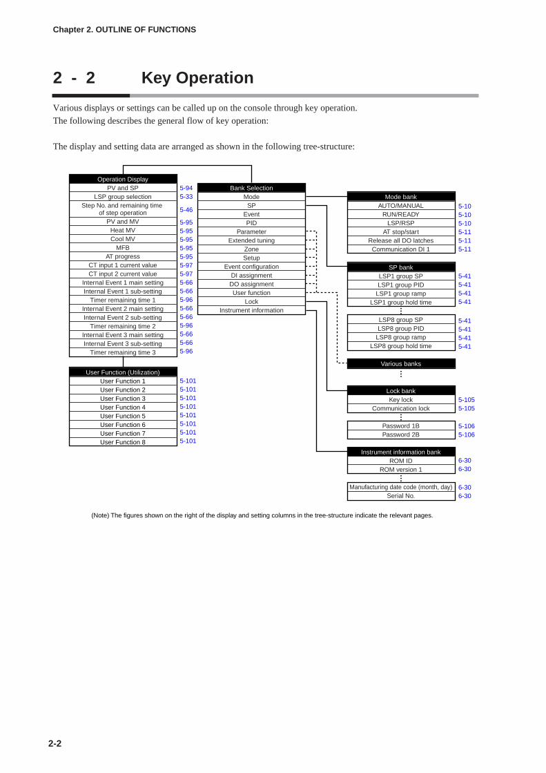
Various displays or settings can be called up on the console through key operation.
The following describes the general flow of key operation:
The display and setting data are arranged as shown in the following tree-structure:
Operation DisplayPV and SP
LSP group selectionStep No. and remaining time
of step operationPV and MV
Heat MVCool MV
MFBAT progress
CT input 1 current valueCT input 2 current value
Internal Event 1 main settingInternal Event 1 sub-setting
Timer remaining time 1Internal Event 2 main settingInternal Event 2 sub-setting
Timer remaining time 2Internal Event 3 main settingInternal Event 3 sub-setting
Timer remaining time 3
User Function (Utilization)User Function 1User Function 2User Function 3User Function 4User Function 5User Function 6User Function 7User Function 8
Bank SelectionMode
SPEventPID
ParameterExtended tuning
ZoneSetup
Event configurationDI assignmentDO assignmentUser function
LockInstrument information
Mode bankAUTO/MANUAL
RUN/READYLSP/RSP
AT stop/startRelease all DO latches
Communication DI 1
SP bankLSP1 group SPLSP1 group PID
LSP1 group rampLSP1 group hold time
LSP8 group SPLSP8 group PID
LSP8 group rampLSP8 group hold time
Various banks
Lock bankKey lock
Communication lock
Password 1BPassword 2B
Instrument information bankROM ID
ROM version 1
Manufacturing date code (month, day)Serial No.
(Note) The figures shown on the right of the display and setting columns in the tree-structure indicate the relevant pages.
••••••
••••••
5-105-105-105-115-115-11
5-415-415-415-41
5-415-415-415-41
5-1055-105
5-1065-106
6-306-30
6-306-30
5-945-33
5-46
5-955-955-955-955-955-975-975-665-665-965-665-665-965-665-665-96
5-1015-1015-1015-1015-1015-1015-1015-101
2 - 2 Key Operation
2-2
Chapter 2. OUTLINE OF FUNCTIONS

Handling Precautions
• For details about display and setup contents of the operation display,parameter setting display, and setup setting display, refer to;
6-1 List of Operation Displays (on page 6-1), 6-2 List of Parameter Setting Displays (on page 6-3) and6-3 List of Setup Setting Displays (on page 6-12).
In the lists shown above, the banks to which each setting item isbelonged are described.
2-3
Chapter 2. OUTLINE OF FUNCTIONS
Operation display
Display when the poweris turned ON.
PV/SP display
Press the [display] key.
No key operation for 3min or more.
MV display
Press the [display] key.
Press the [display] key.
Bank selection display
Mode bank selection
SP bank selection
Bank setup display
PV range type setup
Temperature unit setup
pv
sp
pv
sp
pv
sp
pv
sp
pv
sp
pv
sp
The display and setup status shown above are examples forexplanation. Therefore, some displays or settings are not shownactually according to the model and/or setup contents.
Off.
Off.The modeindicators are sequentially lit.
para enter
displaymode
pv
out
sp
ot2
ot1
ev3
ev2
ev1
rsp
man
The mode indicators are sequentially lit for up to 5s after the power has been turned ON while both the upper display and lower display are off.When all mode indicators have been lit, the display is changed to the operation display.
Keep the [para] key pressed for 2s or longer. Press the [display]
or [mode] key.
Press the [enter] or [<] key.
No key operation for 3min or more.
Press the [display] or [mode] key.
Other display and setup(Operate the [display] key repeatedly.)
Other setup(Operate the [para] key repeatedly.)
Keep the [para] key pressed for 2s or longer.
Press the [para] key.Press the [ ] or [ ] key.
<
<
<
<
Other bank(Operate the [para], [ ] and [ ] keys repeatedly.)
<
<
Press the [para] key.Press the [ ] or [ ] key.
<
<
Press the [para] key.Press the [ ] or [ ] key.
<
<
Press the [para] key.Press the [ ] or [ ] key.
Press the [para] key.Press the [ ] or [ ] key.
<
<
Press the [para] key.Press the [ ] or [ ] key.
<
<
• When pressing the [<] key with the [para] key kept pressed instead ofpressing of the [para] key on the setting display, various displays andsettings can be operated in the reverse order. However, theoperation that both the [para] key and [<] key are kept pressed for 2sor longer, is invalid.
• When pressing the [<] key with the [display] key kept pressed insteadof pressing the [display] key in the operation display mode, variousdisplays and setting displays can be operated in the reverse order.
Data setting proceduresTwo types of data setting procedures are provided, standard type and special type.A desired type can be selected using the setup bank [C71: Key operationmode/type].
Standard type: The [enter] key is used to start changing the setup value and toset the value currently being changed.
Special type: The [<], [ ], or [ ] key is used to start changing the setupvalue. To set the value currently being changed, wait for 2swithout pressing of any key. (However, only the standard typeoperation can be performed in the bank setup display mode.)
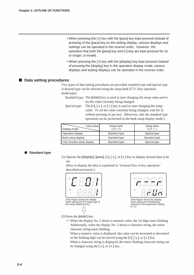
Standard type(1) Operate the [display], [para], [<], [ ], or [ ] key to display desired data to be
set.(How to display the data is explained in "General flow of key operation"described previously.)
(2) Press the [enter] key.>> When the display No. 2 shows a numeric value, the 1st digit starts flashing.
Additionally, when the display No. 2 shows a character string, the entirecharacter string starts flashing.When a numeric value is displayed, the value can be increased or decreasedor the flashing digit can be moved using the [<], [ ], or [ ] key.When a character string is displayed, the entire flashing character string canbe changed using the [ ], or [ ] key.
2-4
Chapter 2. OUTLINE OF FUNCTIONS
Type setup Setup bank Setup bankDisplay mode C71 = 0 C71 = 1
Operation display Standard type Special type
Bank setup display Standard type Standard type
User function setup display Standard type Special type
pv
sp
pv
sp
(This Figure shows the display when setting the PV range type of the setup setting [C01].)
(This Figure shows the display when setting the RUN/Ready selection in the parameter setting [r--r].)
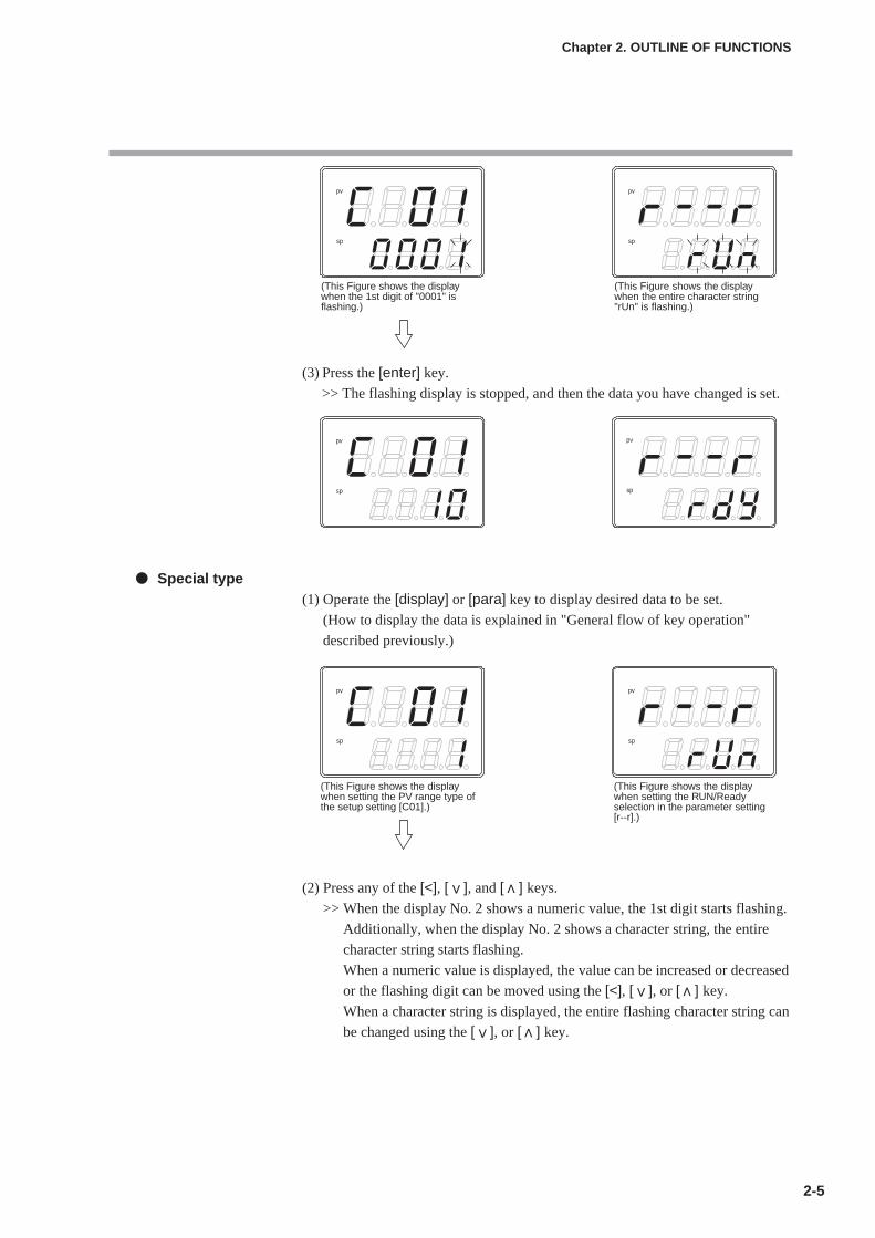
(3) Press the [enter] key.
>> The flashing display is stopped, and then the data you have changed is set.
Special type(1) Operate the [display] or [para] key to display desired data to be set.
(How to display the data is explained in "General flow of key operation"
described previously.)
(2) Press any of the [<], [ ], and [ ] keys.
>> When the display No. 2 shows a numeric value, the 1st digit starts flashing.
Additionally, when the display No. 2 shows a character string, the entire
character string starts flashing.
When a numeric value is displayed, the value can be increased or decreased
or the flashing digit can be moved using the [<], [ ], or [ ] key.
When a character string is displayed, the entire flashing character string can
be changed using the [ ], or [ ] key.
2-5
Chapter 2. OUTLINE OF FUNCTIONS
pv
sp
pv
sp
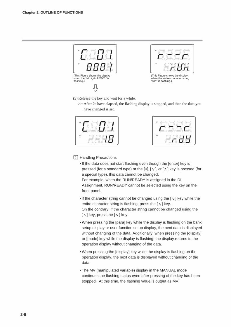
(This Figure shows the display when the 1st digit of "0001" is flashing.)
(This Figure shows the display when the entire character string "rUn" is flashing.)
pv
sp
pv
sp
pv
sp
pv
sp
(This Figure shows the display when setting the PV range type of the setup setting [C01].)
(This Figure shows the display when setting the RUN/Ready selection in the parameter setting [r--r].)
2-6
Chapter 2. OUTLINE OF FUNCTIONS
(3) Release the key and wait for a while.
>> After 2s have elapsed, the flashing display is stopped, and then the data you
have changed is set.
Handling Precautions
• If the data does not start flashing even though the [enter] key ispressed (for a standard type) or the [<], [ ], or [ ] key is pressed (fora special type), this data cannot be changed.For example, when the RUN/READY is assigned in the DIAssignment, RUN/READY cannot be selected using the key on thefront panel.
• If the character string cannot be changed using the [ ] key while theentire character string is flashing, press the [ ] key.On the contrary, if the character string cannot be changed using the[ ] key, press the [ ] key.
• When pressing the [para] key while the display is flashing on the banksetup display or user function setup display, the next data is displayedwithout changing of the data. Additionally, when pressing the [display]or [mode] key while the display is flashing, the display returns to theoperation display without changing of the data.
• When pressing the [display] key while the display is flashing on theoperation display, the next data is displayed without changing of thedata.
• The MV (manipulated variable) display in the MANUAL modecontinues the flashing status even after pressing of the key has beenstopped. At this time, the flashing value is output as MV.
pv
sp
pv
sp
(This Figure shows the display when the 1st digit of "0001" is flashing.)
(This Figure shows the display when the entire character string "rUn" is flashing.)
pv
sp
pv
sp

2-7
Chapter 2. OUTLINE OF FUNCTIONS
[mode] key operating proceduresWhen the [mode] key is kept pressed for 1 sec. or longer on the operation display,the selection operation, which has been set using the [mode] key function (C72) ofthe setup setting, can be performed.
The Figure on the right shows an example that the[mode] key is pressed in the RUN/READY selection(C72 = 2) setting.(1) If the current mode is the READY mode when the
PV/SP is shown on the operation display, thecharacter string "rUn" on the display No. 2 startsflashing.
(2) When the [mode] key is kept pressed for 1 sec. orlonger, the READY mode is changed to the RUNmode and the flashing of the character string "rUn"is stopped.
(3) When pressing of the [mode] key is stopped, thedisplay is returned to the original display.
Handling Precautions• If the MODE key function of the setup setting is set disabled (C72 = 0)
or if the set selection operation is invalid, the selection operationcannot be performed using the [mode] key.
• When pressing the [mode] key on the parameter setting display orsetup setting display instead of the operation display, the display isreturned to the operation display. However, even though the [mode]key is kept pressed continually, the selection operation cannot beperformed. In this case, stop pressing the key once, and then pressthe [mode] key.
User levelThe user level of this unit can be selected from three levels, "Basic configuration","Standard configuration", and "High function configuration" using [C79: Userlevel] of the setup setting.For details, refer to;
Chapter 6, LIST OF DISPLAYS AND SETTING DATA.
Handling PrecautionsEven though the user level is changed, the functions other than settingdisplay cannot be changed. The user level is set to "Standardconfiguration" or "High function configuration" and more advancedfunctions are set. After that, when the setup is returned to "Basicconfiguration", this function setup cannot be displayed, but the functionitself is operated.
pv
pv
pv
2 - 3 Operation Modes
2-8
Chapter 2. OUTLINE OF FUNCTIONS
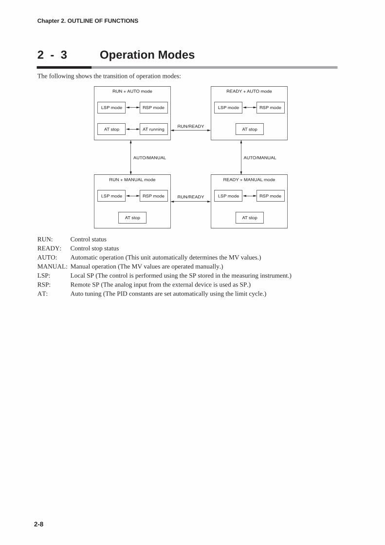
The following shows the transition of operation modes:
RUN: Control status
READY: Control stop status
AUTO: Automatic operation (This unit automatically determines the MV values.)
MANUAL: Manual operation (The MV values are operated manually.)
LSP: Local SP (The control is performed using the SP stored in the measuring instrument.)
RSP: Remote SP (The analog input from the external device is used as SP.)
AT: Auto tuning (The PID constants are set automatically using the limit cycle.)
Chapter 3. INSTALLATION
3-1
Installation locationsInstall the controller in the following locations:
• Common mode voltage for I/O excluding the power supply and relay contact
output:
The voltage to the grounding line must be as follows:
AC: 33V r.m.s. or less and 46.7V peak or less
DC: 70Vdc or less
• Not at high or low temperature/humidity.
• Free from sulfide gas or corrosive gas.
• Less dust or soot.
• Appropriately processed locations to prevent direct sunlight, wind or rain.
• Less mechanical vibration and shock.
• Not close to the high voltage line, welding machine or electrical noise generating
source.
• Minimum 15m away from the high voltage ignition device for a boiler.
• Less effect by the magnetic.
• No inflammable liquid or gas.
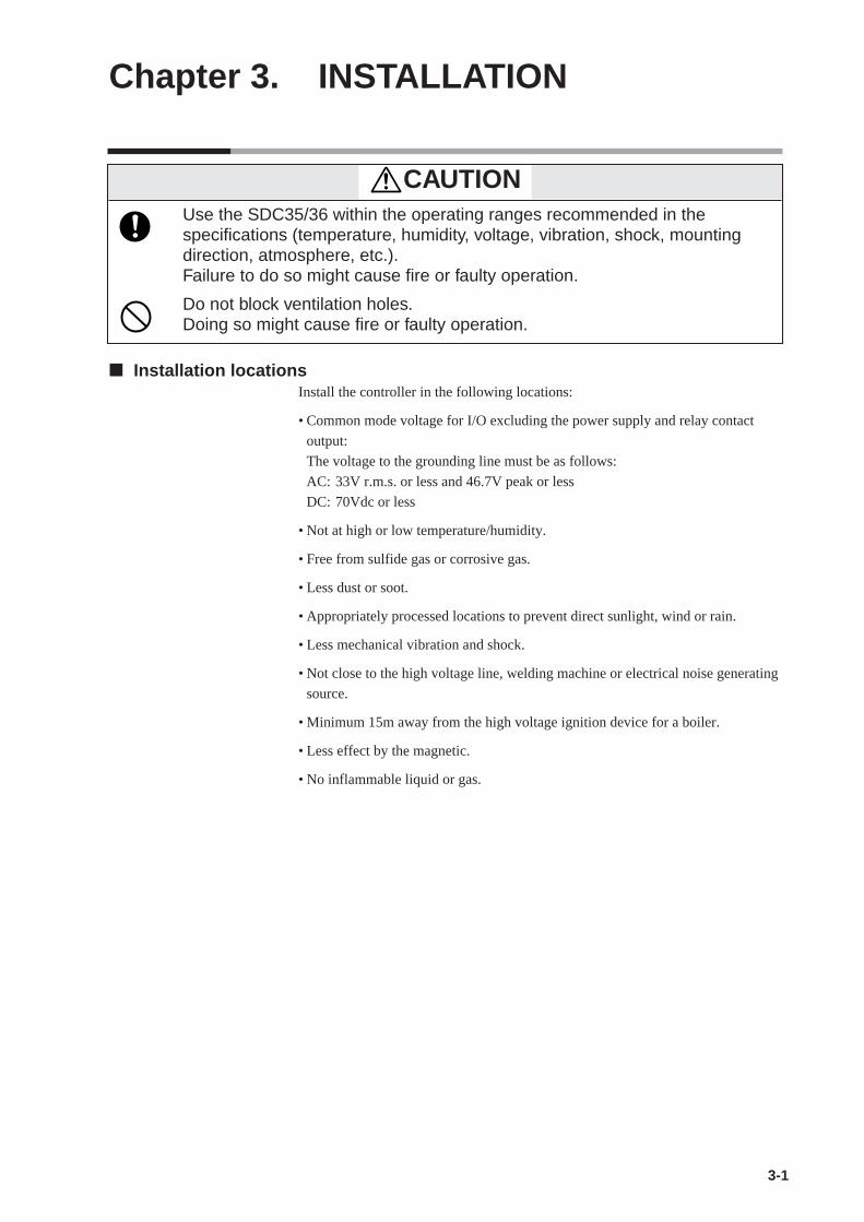
CAUTIONUse the SDC35/36 within the operating ranges recommended in thespecifications (temperature, humidity, voltage, vibration, shock, mountingdirection, atmosphere, etc.).Failure to do so might cause fire or faulty operation.
Do not block ventilation holes.Doing so might cause fire or faulty operation.
3-2
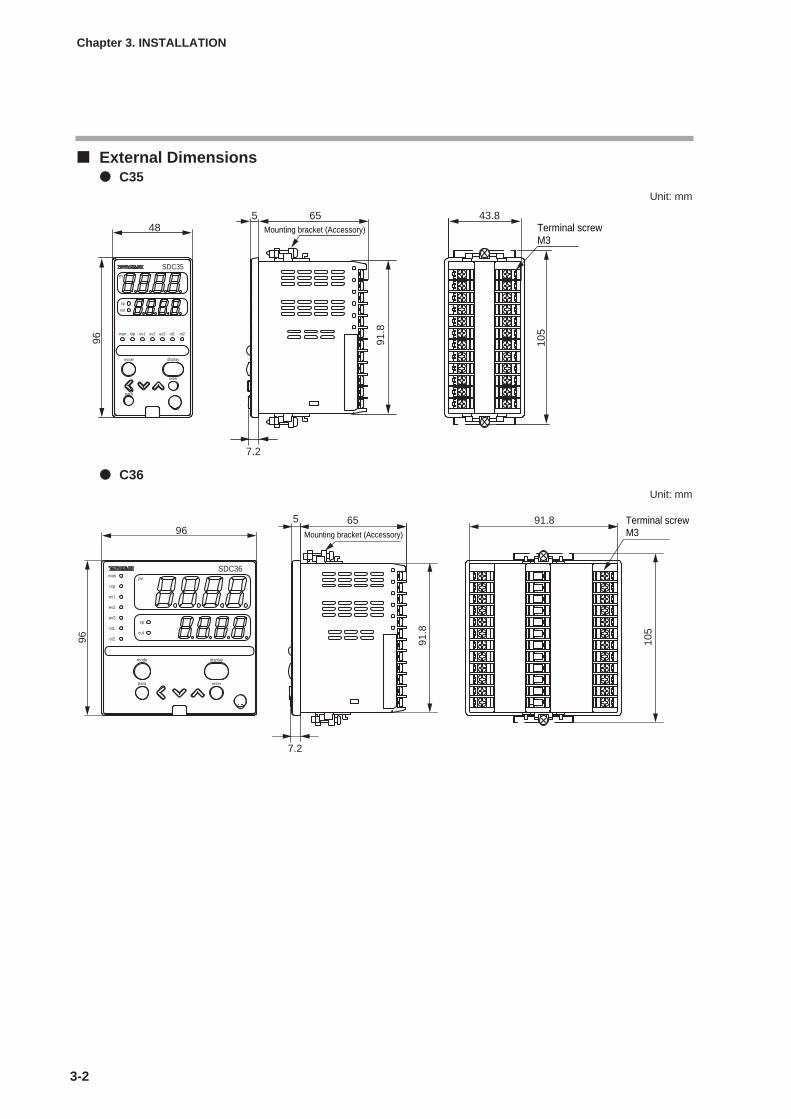
External Dimensions C35
Unit: mm
C36Unit: mm
Chapter 3. INSTALLATION
para
enter
displaymode
pv
out
sp
105
5
7.2
65 43.8
96
48
ot2ot1ev3ev2ev1rspman
SDC35
91.8
Mounting bracket (Accessory)M3Terminal screw
mode display
enterpara
man
rsp
ev1
ev2
ev3
ot1
ot2
sp
out
pv
SDC36
655
105
96
96
91.8
91.8
7.2
Mounting bracket (Accessory) M3Terminal screw
3-3
Chapter 3. INSTALLATION
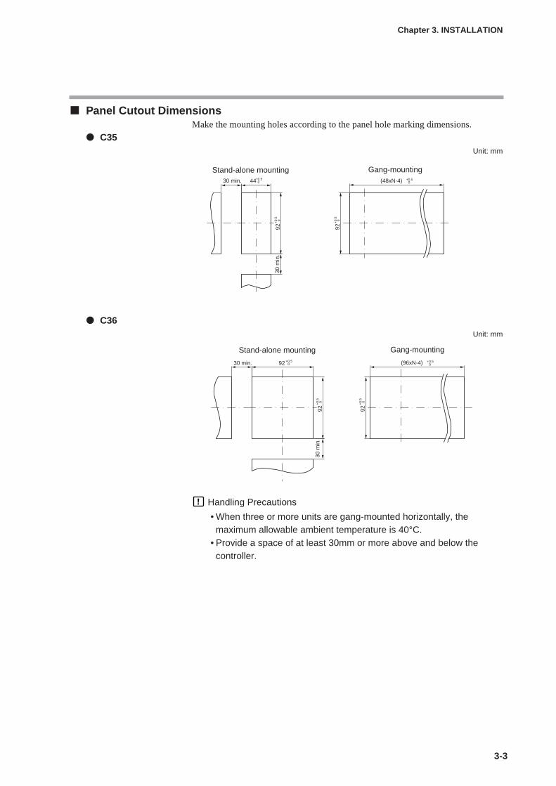
Panel Cutout DimensionsMake the mounting holes according to the panel hole marking dimensions.
C35Unit: mm
C36Unit: mm
Handling Precautions
• When three or more units are gang-mounted horizontally, themaximum allowable ambient temperature is 40°C.
• Provide a space of at least 30mm or more above and below thecontroller.
30 m
in.
92
44 (48xN-4)30 min. +0.50
+0.50
+0.
50
92+
0.5
0
Gang-mountingStand-alone mounting
Gang-mountingStand-alone mounting
30 m
in.
30 min.
92+
0.5
0
+0.
50
(96xN-4)92
92 +0.50
+0.50

3-4
Chapter 3. INSTALLATION
Mounting procedures• The mounting must be horizontal within 10 degrees tilted on the back side
lowering or within 10 degrees tilted on the back side rising.
• The mounting panel should be used with a thickness of less than 9 mm of firm
board.
Ordinal mountingTools:
Phillips-head screwdriver
(1) Insert this unit from the front of the panel.
(2) Fit the mounting bracket from the back of the panel.
(3) Push the mounting bracket against the panel until the hook of the mounting
bracket is firmly engaged with the groove of the main body.
(4) Tighten the upper and lower screws of the mounting bracket.
Handling Precautions
• To fasten this controller onto the panel, tighten a mounting bracketscrews, and turn one more turn when there is no play between thebracket and panel. Excessive tightening of the screws may deformthe controller case.
Plate thickness is 9 mm or less.
Screws for mounting bracket
Mounting bracket
Panel
Panel hole
Grooves for mounting brackets (top and bottom)
Main body

3-5
Chapter 3. INSTALLATION
Using a hard coverFor panel mounting type, it is possible to attach the hard cover to the front console.
Use of hard cover makes it possible to prevent the settings from being changed
due to accidental operation or to operate the unit in poor installation environment.
The display can be seen with the cover kept closed. Raise the cover to operate the
key.
Items to be prepared:Hard cover (for SDC35) Part No. 81446915-001 (Optional unit)Hard cover (for SDC36) Part No. 81446916-001 (Optional unit)
(1) As shown in the Figure, mount the hard cover.
(2) Insert this unit from the front of the panel.
(3) Fit the mounting bracket from the back of the panel.
(4) Push the mounting bracket against the panel until the hook of the mounting
bracket is firmly engaged with the groove of the main body.
(5) Tighten the upper and lower screws of the mounting bracket.
Handling Precautions
• To fasten this controller onto the panel, tighten a mounting bracketscrews, and turn one more turn when there is no play between thebracket and panel. Excessively tightening the screws may deform thecontroller case.
Hard cover
Main body
Panel

3-6
How to use the hard coverWhen operating the unit with the hard cover, flip the lower end of the cover
upward. At this time, the cover is so designed that it can be kept open without
holding the cover by hand.
After the cover has been flipped upward, slide it to the right as shown in the
Figure.
The hard cover is then locked/latched at an angle of approximately 30 ˚to the panel
surface. In this status, the key operation and loader connection can be made.
To return the cover to the previous position, slide the cover to the left and when
released it flips downward and covers the unit.
Chapter 3. INSTALLATION
Chapter 4. WIRING
4-1
WARNINGBefore wiring, or removing/mounting the SDC35/36, be sure to turn the powerOFF.Failure to do so might cause electric shock.
Do not touch electrically charged parts such as the power terminals.Doing so might cause electric shock.
CAUTIONWire the SDC35/36 properly according to predetermined standards.Also wire the SDC35/36 using specified power leads according to recognizedinstallation methods.Failure to do so might cause electric shock, fire or faulty operation.
Do not allow lead clippings, chips or water to enter the controller case.Doing so might cause fire or faulty operation.
Firmly tighten the terminal screws with the specified torque as listed in thespecifications.Insufficient tightening of terminal screws might cause electric shock or fire.
Do not use unused/spare terminals on the SDC35/36 as relay terminals.Doing so might cause electric shock, fire, or faulty operation.
We recommend attaching the terminal cover (sold separately) after wiring theSDC35/36.Failure to do so might cause electric shock, fire, or faulty operation.
Use the relays within the recommended life.Failure to do so might cause fire or faulty operation.
Use Yamatake Corporation's "SURGENON" if there is the risk of powersurges caused by lightning.Lightning power surges might cause fire or faulty operation.Do not make incorrect connections. If the cables are connected incorrectly,this might cause the unit to malfunction.
The controller requires 6 seconds to stabilize after power ON. Great careshould be taken when the relay output from the controller is used as interlocksignals.
The part between the control output 1 and control output 2 is not isolated.When necessary, use an appropriate isolator.
Do not connect multiple loader cables to multiple units from one personalcomputer. The current coming from other circuits might cause the PV valueindication error to occur.
Do not connect any terminating resistor to both ends of the communicationpath when performing the RS-485 wiring. Doing so might cause thecommunication to fail.
Always mount a switch for shut-down of the main power of this unit in aneasily accessible area of the operator when performing electric wiring of thisunit. Additionally, connect a slow-action type (T) fuse having a rated currentof 0.5A and rated voltage of 250V to the wiring for the instrument powersupply of the AC power supply model. (IEC127)

4-2
Terminal assignment label symbolsThe following table shows the meanings of the symbols used for the terminal
assignment label attached to the side panel of this unit:
Wiring Precautions• Before starting the wiring work, carefully check the label on the side panel of this
unit to understand the model No. and terminal No. to carry out the wiringproperly.
• Use an appropriate crimp type terminal lug suitable for the M3 screw to connectthe terminals. The tightening torque of the terminal screw must be 0.4 to 0.6N·mor less.
• Pay special attention so that no crimp type terminal lugs are in touch withadjacent terminals.
• Keep the input/output signal cables 50cm or more away from the drive powercable and/or power cable. Additionally, do not lay the input/output signal cablesand the drive power cable and/or power cable together in the same conduit orduct.
• When connecting this unit and other measuring instrument in parallel, carefullycheck the conditions necessary for other instrument before starting theinstrumentation.
• The digital input is so designed that it is potential free input. A contact for microcurrent must be used.
• The heater current carrying conductor must be routed through the currenttransformer. Additionally, carefully check that the heater current does notexceed the allowable current limit stated in the specification. If the heatercurrent exceeds the allowable current limit, this might cause damage to this unit.
• The input of the current transformer cannot be used for the phase angle control.
• An optional terminal cover is available to prevent electric shock. (Model No.:81446912-001 for C35 or 81446913-001 for C36)
• The part between the control output 1 and control output 2 is not isolated. Whennecessary, use an appropriate isolator.
Terminating resistor
• Do not connect any terminating resistor to both ends of the RS-485communication path. Doing so might cause the communication failure.
IMPORTANT
Chapter 4. WIRING
Symbol Contents
~ AC
DC power supply
Caution, Electric shock hazard
Caution
Terminal cover

4-3
• When the motor power to be connected to the motor drive relay output is 100Vacor 200Vac, use an external auxiliary relay.
• Do not run the motor drive terminals (13), (14), and (15), and MFB inputterminals (7), (8), and (9) in the same duct. Additionally, do not use 6-corecables for the wiring work.Doing so might cause the unit to malfunction due to noise at start-up of themotor.
• Devices or systems to be connected to this controller must have the basicinsulation suitable for the maximum operating voltage levels of the power supplyand input/output part.
• This unit has been designed to start functioning after an initial stabilizationperiod of 5 seconds after power ON, in order to ensure stable operation. Afterthat, the unit then enters the operation mode. However, to satisfy the specifiedaccuracy, it is necessary to warm up the unit for at least 30 min.
Wiring of C35/36
Chapter 4. WIRING
1
2
3
4
5
6
7
8
9
10
11
12
13
14
15
13
14
16
17
18
19
20
21
22
23
24
3Load
4
5
6
Load
Load
Load
7
8
9
7
8
9
Load
10
11
12
10
11
12
3
2
1
COM
2
1
CT1
CT2
YOpen
Close
T
G
CT input
Relay independent contact
Relay
AC power supply100 to 240 Vac
DC power supply24Vac/24Vdc(non polar)
MFB
Thermocouple
RTD
DC current
DC voltage
C
B
A
10
11
12
–
–
+
+
+
mA
V
1
2
Power supplyControl output
Auxiliary output
Event output
Input
PV input
Load
Load
Load
15 NC
NO
CLOSE
OPEN13
14
15
13
14
15
Load16
17
13
14
Load
Load 15 2
1
18
19
20
21
18
19
20
21
22
23
24
DA
DB
SG
4
3
2
1
2
1
mA/V
Relay
Current or continuous voltage
Digital input
RSP
Digital input
Communication
Motor drive relay
Voltage pulse/current/continuous voltage
Voltage pulse/current/continuous voltage
Voltage pulse/current/continuous voltage
–
+
–
–
–
+
+
+
+
3
4
5
6
1
2

4-4
Recommended crimp type terminal lugsFor wiring of C35/36, use an appropriate crimp type terminal lug suitable for the
M3 screw.
Handling Precautions
• When installing this unit in a place where the vibration or impact islarge, always use an appropriate round crimp type terminal lug toavoid loose terminal connections.
• Pay special attention so that no crimp type terminal lugs are in touchwith adjacent terminals.
Chapter 4. WIRING
A B o
rle
ss
C o
rle
ss
Applicable Terminal dimensions (mm) Recommended crimp terminal Applicable electrical JST Mfg. Co.
screw size A B C JIS indication wire size Model No. (Reference)
M3 6.1 5.8 5.8 RAV1.25 - 3 0.3 to 1.3mm2
V1.25 - 3AWG22 to 16 V1.25 B3A
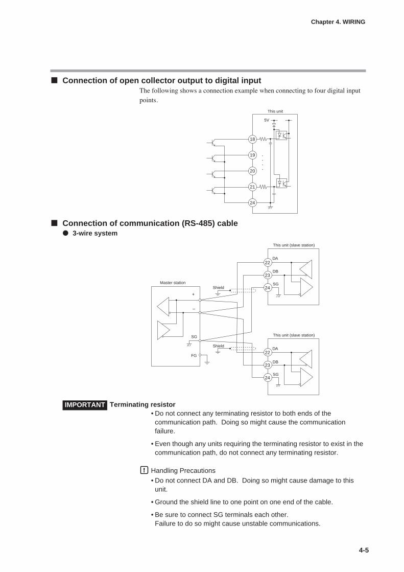
4-5
Connection of open collector output to digital inputThe following shows a connection example when connecting to four digital input
points.
Connection of communication (RS-485) cable 3-wire system
Terminating resistor• Do not connect any terminating resistor to both ends of the
communication path. Doing so might cause the communicationfailure.
• Even though any units requiring the terminating resistor to exist in thecommunication path, do not connect any terminating resistor.
Handling Precautions
• Do not connect DA and DB. Doing so might cause damage to thisunit.
• Ground the shield line to one point on one end of the cable.
• Be sure to connect SG terminals each other.Failure to do so might cause unstable communications.
Chapter 4. WIRING
18
19
20
21
24
5V
This unit
22
23
24
22
Master station
DA
DA
DB
DB
SG
SG
SG
FG
+
–
This unit (slave station)
This unit (slave station)
Shield
Shield
23
24
IMPORTANT
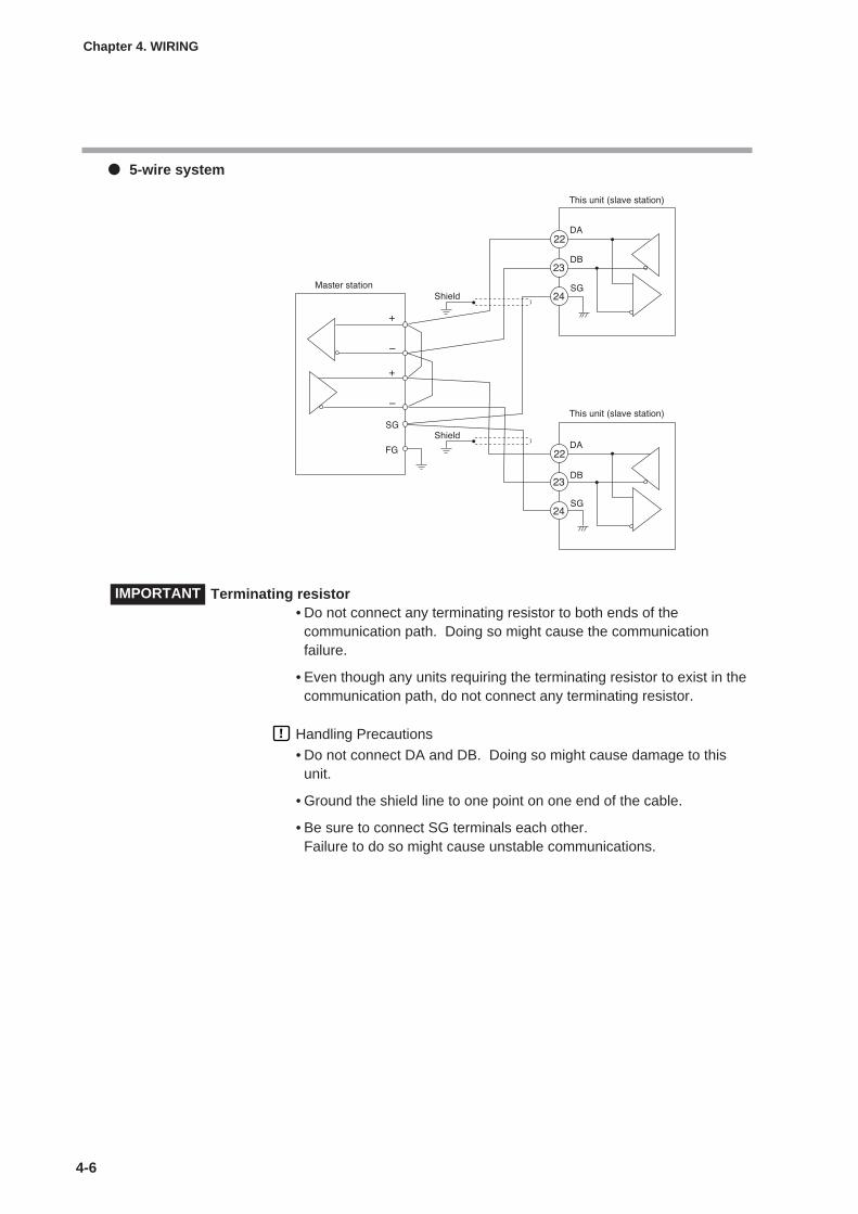
4-6
5-wire system
Terminating resistor• Do not connect any terminating resistor to both ends of the
communication path. Doing so might cause the communicationfailure.
• Even though any units requiring the terminating resistor to exist in thecommunication path, do not connect any terminating resistor.
Handling Precautions
• Do not connect DA and DB. Doing so might cause damage to thisunit.
• Ground the shield line to one point on one end of the cable.
• Be sure to connect SG terminals each other.Failure to do so might cause unstable communications.
Chapter 4. WIRING
IMPORTANT
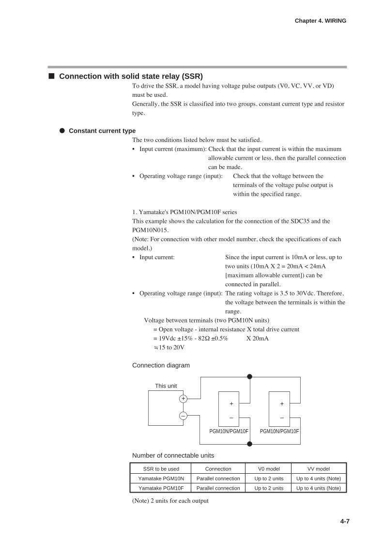
4-7
Connection with solid state relay (SSR)To drive the SSR, a model having voltage pulse outputs (V0, VC, VV, or VD)
must be used.
Generally, the SSR is classified into two groups, constant current type and resistor
type.
Constant current typeThe two conditions listed below must be satisfied.
• Input current (maximum): Check that the input current is within the maximum
allowable current or less, then the parallel connection
can be made.
• Operating voltage range (input): Check that the voltage between the
terminals of the voltage pulse output is
within the specified range.
1. Yamatake's PGM10N/PGM10F series
This example shows the calculation for the connection of the SDC35 and the
PGM10N015.
(Note: For connection with other model number, check the specifications of each
model.)
• Input current: Since the input current is 10mA or less, up to
two units (10mA X 2 = 20mA < 24mA
[maximum allowable current]) can be
connected in parallel.
• Operating voltage range (input): The rating voltage is 3.5 to 30Vdc. Therefore,
the voltage between the terminals is within the
range.
Voltage between terminals (two PGM10N units)
= Open voltage - internal resistance X total drive current
= 19Vdc ±15% - 82Ω ±0.5% X 20mA
15 to 20V
Connection diagram
Number of connectable units
(Note) 2 units for each output
Chapter 4. WIRING
This unit
+
–
+
–
PGM10N/PGM10F
+
–
PGM10N/PGM10F
SSR to be used Connection V0 model VV model
Yamatake PGM10N Parallel connection Up to 2 units Up to 4 units (Note)
Yamatake PGM10F Parallel connection Up to 2 units Up to 4 units (Note)
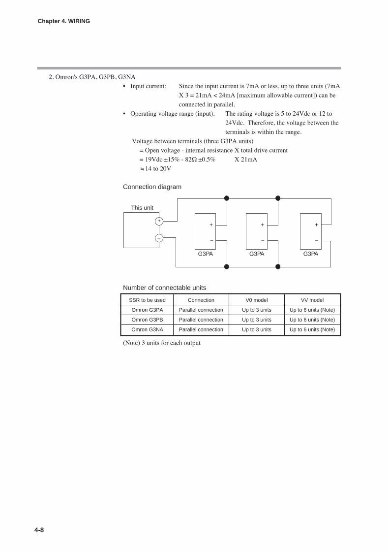
4-8
Chapter 4. WIRING
2. Omron's G3PA, G3PB, G3NA
• Input current: Since the input current is 7mA or less, up to three units (7mA
X 3 = 21mA < 24mA [maximum allowable current]) can be
connected in parallel.
• Operating voltage range (input): The rating voltage is 5 to 24Vdc or 12 to
24Vdc. Therefore, the voltage between the
terminals is within the range.
Voltage between terminals (three G3PA units)
= Open voltage - internal resistance X total drive current
= 19Vdc ±15% - 82Ω ±0.5% X 21mA
14 to 20V
Connection diagram
Number of connectable units
(Note) 3 units for each output
This unit
++
–
G3PA
+
G3PA
+
G3PA
– – –
SSR to be used Connection V0 model VV model
Omron G3PA Parallel connection Up to 3 units Up to 6 units (Note)
Omron G3PB Parallel connection Up to 3 units Up to 6 units (Note)
Omron G3NA Parallel connection Up to 3 units Up to 6 units (Note)

4-9
Chapter 4. WIRING
Resistor type (Yamatake's PGM 2A1, etc.)When necessary, an appropriate external resistor is connected in series so that the
voltage between the input terminals of the SSR you are using is within the
specified range.
(Example) Connection of two Yamatake PGM units
Connection diagram
V: 19V ± 15%
R0: 82Ω ± 0.5%
R1: 680 Ω
R2: 260 Ω
Vf: 1.1V
Voltage between terminals of PGM = (V - 2 X Vf) / (R0 + R1+ R2 + R2) X R2 + Vf
4.5 V
Input voltage range of PGM: Since the input voltage range is 3 to 6V, the
operation is possible.
External resistors
Number of connectable units
(Note) 4 units for each output
SSR to be used Connection V0 model VV model
PGM 2A1 Series connection Up to 4 units Up to 8 units (Note)
SSR to be Number of units Connection External Remarksused to be connected resistor
PGM 2A1 1 – 1kΩ (series connection) Rating is 1/2W or more.
2 Series connection 680Ω (series connection) Rating is 1/2W or more.
3 Series connection 330Ω (series connection) Rating is 1/2W or more.
4 Series connection None

4-10
Connection method for the motor drive relay output (R1)
Handling Precautions
• When a relatively high voltage (e.g., 100Vac) motor power supply isto be connected to the motor drive relay output, use a separateexternal relay in conjuction with the built-in relay.
• Do not run the cables of motor drive relay terminals 13, 14 and 15together with the cables of MFB input terminals 7, 8 and 9 in thesame conduit. Do not use one 6-core cable for all these connections.Doing so might cause a malfunction due to motor start-up noise.
• Avoid setting the PID control such that the output excessively repeatsON-OFF operations.Doing so might shorten the life of the built-in relay.If [C59: Motor long life mode] is set at “1,” the number of relayoperations can be reduced with almost no influence on the controlresults.
• When [C57: Position proportional type] is set at “2” or “3,” connectionsto MFB terminals 7, 8 and 9 are not necessary. (This is the case ofcontrol without a feedback function.)
• When [C57: Position proportional type] is set at “0” or “1” with motorfeedback function (MFB enabled), be sure to execute [C60: Motorauto adjust].
• When [C57: Position proportional type] is set at “2” or “3” withoutmotor feedback function (MFB disabled), be sure to input the value of[C63: Motor full close – full open time] exactly.
Noise Preventive MeasuresThe power is taken from the single-phase instrument power supply to consider
noise preventive measures.
If the noise from the power supply is large, an appropriate insulation transformer
is added to the power supply and an appropriate line filter must be used.
(Yamatake's line filter model No.: 81446364-001)
If the noise has a fast rising edge, an appropriate CR filter must be used.
(Yamatake's CR filter model No.: 81446365-001)
Handling Precautions
After the noise preventive measures have been taken, do not bundlethe primary and secondary sides of the insulation transformer togetheror lay/route them in the same conduit or duct.
Chapter 4. WIRING
7
8
9
YOpen
Close
T
G
MFB Feedback resistance:100 to 250Ω
CLOSE
OPEN13
14
15
Motor drive relay
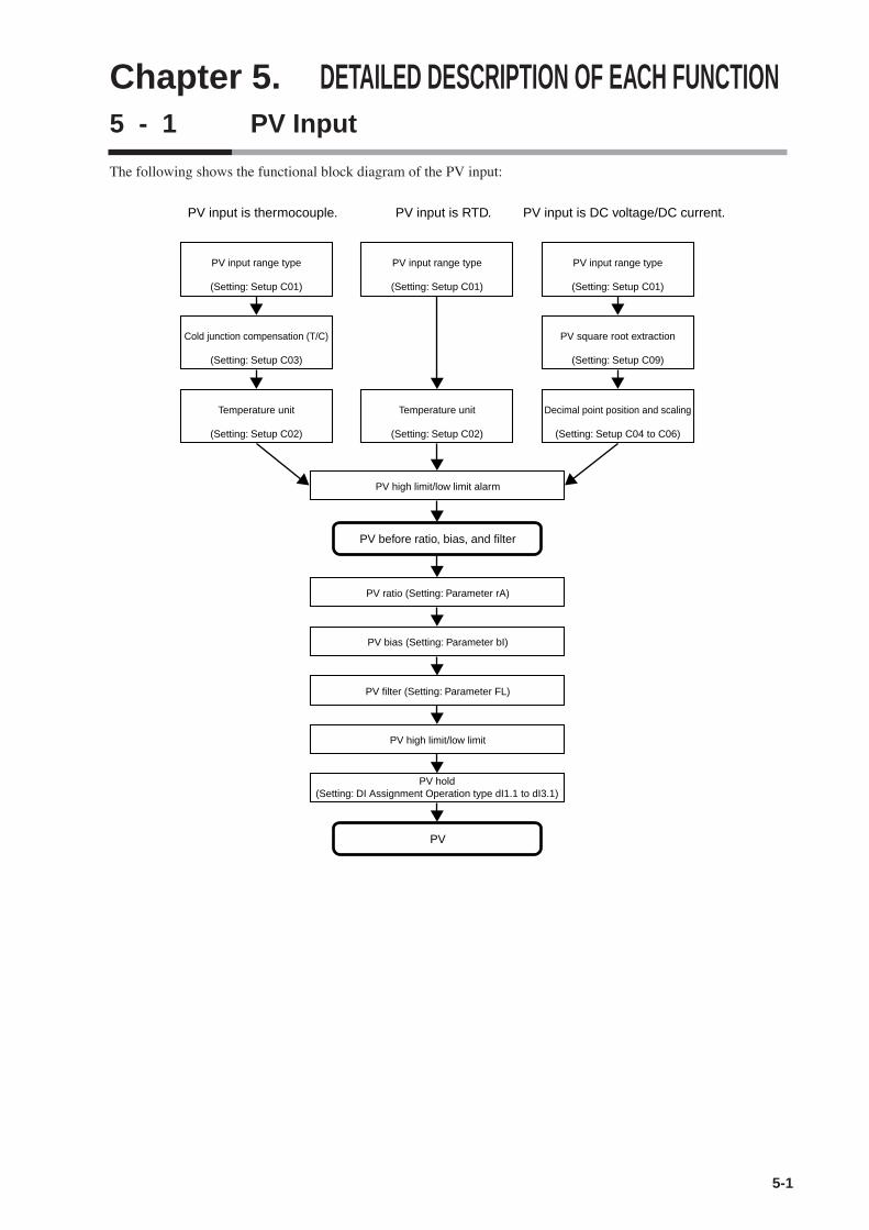
Chapter 5. DETAILED DESCRIPTION OF EACH FUNCTION5 - 1 PV Input
5-1
The following shows the functional block diagram of the PV input:
PV input is thermocouple.
PV input range type
(Setting: Setup C01)
Cold junction compensation (T/C)
(Setting: Setup C03)
Temperature unit
(Setting: Setup C02)
PV input is RTD.
PV input range type
(Setting: Setup C01)
Temperature unit
(Setting: Setup C02)
PV high limit/low limit alarm
PV ratio (Setting: Parameter rA)
PV bias (Setting: Parameter bI)
PV filter (Setting: Parameter FL)
PV high limit/low limit
PV hold(Setting: DI Assignment Operation type dI1.1 to dI3.1)
PV before ratio, bias, and filter
PV
PV input is DC voltage/DC current.
PV input range type
(Setting: Setup C01)
PV square root extraction
(Setting: Setup C09)
Decimal point position and scaling
(Setting: Setup C04 to C06)

PV input range typeWhen the PV input range type is thermocouple or RTD, the sensor type andtemperature range can be selected. When the PV input range type is DC voltage orDC current, the signal type can be selected.
PV input range table (Thermocouple) PV input range table (RTD)
PV input range table (DC voltage/DC current)
Handling Precautions• When an input range has the decimal point display,
the PV and/or SP can be displayed on the consoleof this unit so that they are displayed to the 1stdigit after the decimal point or without the decimalpoint.
• For details about the accuracy of each PV rangetype, refer to;
Chapter 13, SPECIFICATIONS (on page 13-1).• The accuracy of the PLII thermocouple(CO1
No.19) in the range of 0 to 32˚F does not meet theindication accuracy specified in the chapter 13SPECIFICATIONS.
5-2
Chapter 5. DETAILED DESCRIPTION OF EACH FUNCTION
Item (Bank) Display Contents Initial value User level
PV input range type(Setup bank)
Refer to the PV input range table. 88 Basic,Standard,High function
C01 set value Sensor type Range (Celsius) Range (Fahrenheit)
1 K –200 to +1200˚C –330 to +2200˚F2 K 0 to 1200˚C 0 to 2200˚F3 K 0.0 to 800.0˚C(*1) 0 to 1500˚F4 K 0.0 to 600.0˚C 0 to 1100˚F5 K 0.0 to 400.0˚C 0 to 700˚F6 K –200.0 to +400.0˚C –300 to +700˚F7 K –200.0 to +200.0˚C -300 to +400˚F8 J 0 to 1200˚C 0 to +2200˚F9 J 0.0 to 800.0˚C 0 to 1500˚F10 J 0.0 to 600.0˚C 0 to 1100˚F11 J –200.0 to +400.0˚C –300 to +700˚F12 E 0.0 to 800.0˚C 0 to +1500˚F13 E 0.0 to 600.0˚C 0 to 1100˚F14 T –200.0 to +400.0˚C –300 to +700˚F15 R 0 to 1600˚C 0 to 3000˚F16 S 0 to 1600˚C 0 to 3000˚F17 B 0 to 1800˚C(*2) 0 to 3300˚F18 N 0 to 1300˚C 0 to 2300˚F19 PL II 0 to 1300˚C 0 to 2300˚F20 WRe5-26 0 to 1400˚C 0 to 2400˚F21 WRe5-26 0 to 2300˚C 0 to 4200˚F22 Ni-NiMo 0 to 1300˚C 0 to +2300˚F23 PR40-20 0 to 1900˚C 0 to +3400˚F24 DIN U –200.0 to +400.0˚C –300 to +700˚F25 DIN L –100.0 to +800.0˚C –150 to +1500˚F26 Gold iron 0.0 to 360.0K 0 to 360.0K
chromel
C01 set value Sensor type Range (Celsius) Range (Fahrenheit)
41 Pt100 –200.0 to +500.0˚C –300 to +900˚F42 JPt100 –200.0 to +500.0˚C –300 to +900˚F43 Pt100 –200.0 to +200.0˚C –300 to +400˚F44 JPt100 –200.0 to +200.0˚C –300 to +400˚F45 Pt100 –100.0 to +300.0˚C –150 to +500˚F46 JPt100 –100.0 to +300.0˚C –150 to +500˚F47 Pt100 –100.0 to +200.0˚C –150 to +400˚F48 JPt100 –100.0 to +200.0˚C –150 to +400˚F49 Pt100 –100.0 to +150.0˚C –150 to +300˚F50 JPt100 –100.0 to +150.0˚C –150 to +300˚F51 Pt100 –50.0 to +200.0˚C –50 to +400˚F52 JPt100 –50.0 to +200.0˚C –50 to +400˚F53 Pt100 –50.0 to +100.0˚C –50 to +200˚F54 JPt100 –50.0 to +100.0˚C –50 to +200˚F55 Pt100 –60.0 to +40.0˚C –60 to +100˚F56 JPt100 –60.0 to +40.0˚C –60 to +100˚F57 Pt100 –40.0 to +60.0˚C –40 to +140˚F58 JPt100 –40.0 to +60.0˚C –40 to +140˚F59 Pt100 –10.00 to +60.00˚C –10 to +140˚F60 JPt100 –10.00 to +60.00˚C –10 to +140˚F61 Pt100 0.0 to 100.0˚C 0 to 200˚F62 JPt100 0.0 to 100.0˚C 0 to 200˚F63 Pt100 0.0 to 200.0˚C 0 to 400˚F64 JPt100 0.0 to 200.0˚C 0 to 400˚F65 Pt100 0.0 to 300.0˚C 0 to 500˚F66 JPt100 0.0 to 300.0˚C 0 to 500˚F67 Pt100 0.0 to 500.0˚C 0 to 900˚F68 JPt100 0.0 to 500.0˚C 0 to 900˚F
C01 set value Sensor type Range
81 0 to10mV
82 –10 to +10mV
83 0 to 100mV
84 0 to 1V
86 1 to 5V
87 0 to 5V
88 0 to 10V
89 0 to 20mA
90 4 to 20mA
The scaling and
the decimal point
position can be
changed variably
in a range of
–1999 to +9999.
*1: If ROM version 1 of the instrument information bank(Id02) is prior to 2.04, a setting of “3” for the PVinput range type (C01) will result in display of the Kthermocouple 0–800˚C range with no decimal point.
*2: The indicated low limit for a B thermocouple is 20˚C.However, if ROM version 1 of the instrumentinformation bank(Id02) is prior to 2.04, the value is -180˚C.

Temperature unitWhen the PV input range type is thermocouple or RTD, the temperature unit can
be selected.
• When the PV input range type is thermocouple or RTD, the display and setting
can be configured.
Cold junction compensation (T/C)When the PV input range type is thermocouple, either of the following can be
selected:
• The cold junction compensation (T/C) is performed inside this unit.
• The cold junction compensation (T/C) is not performed inside this unit since
an external cold junction compensation unit, such as ice bath is used.
• When the PV input range type is thermocouple, the display and setting can
be configured.
Item (Bank) Display Contents Initial value User level
5-3
Chapter 5. DETAILED DESCRIPTION OF EACH FUNCTION
Temperature unit(Setup bank)
0: Celsius (˚C)1: Fahrenheit (˚F).
0 Basic,Standard,High function
Item (Bank) Display Contents Initial value User level
Cold junctioncompensation (T/C)(Setup bank)
0: Cold junction compensation (T/C) isperformed (internal).
1: Cold junction compensation (T/C) is notperformed (external).
0 High function

5-4
Chapter 5. DETAILED DESCRIPTION OF EACH FUNCTION
PV square root extraction dropoutWhen the PV input range type is DC voltage or DC current, a dropout value can be
set so that the result of the PV square root extraction used to convert the pressure
(differential pressure) into the flow becomes "0".
• When the PV input range type is DC voltage or DC current, the display and
setting can be made.
• Details of PV square root extraction
The calculation input in % and the calculation result in % are expressed as PVin
and PVout, respectively.
When the PV input is the PV square root extraction dropout set value or more
and less than 100.0%, the control formula becomes as shown below.
PVout = √PVin/100 X 100
When the PV input is larger than 0.0% and smaller than the PV square root
extraction dropout set value, PVout = 0.0%.
When the PV input is 0.0% or less or 100.0% or more, the square root extraction
is not performed. Therefore, PVout = PVin.
Item (Bank) Display Contents Initial value User level
PV square root extractiondropout(Setup bank)
0.0%: Square root extraction is not performed.0.1 to 100.0%
0.0% High function
Output after PV square root extraction (PVout)
100%FSPVin
Dropout value (variable change from 0.1 to 100.0%)
0
100%FS
0
Y = Xin/100 X100

5-5
Chapter 5. DETAILED DESCRIPTION OF EACH FUNCTION
Decimal point positionWhen the PV input range type is DC voltage or DC current or when the PV input
range type is a part of the PV input range type of thermocouple or RTD, the
decimal point position of the PV input can be set.
• When the PV input range type is DC voltage or DC current, the display and
setting can be made.
• When the PV input range type is thermocouple or RTD and it is a range having
the decimal point stated in PV range table (on page 5-2) of 5-1 PV Input, "0: No
decimal point" or "1: 1 digit after decimal point" can be displayed and set.
Handling Precautions
As this setting is changed, the decimal point position of the parametersrelated to the decimal point position of the PV input is also changed.Actually, the decimal point position of the following settings arechanged:
SP settingSP low limit/high limit settingRSP range low limit/high limit settingSP ramp-up/ramp-down settingEvent setting and continuous output setting related to PVEvent setting and continuous output setting related to SPEvent setting and continuous output setting related to deviation(absolute deviation)
When the PV input range type is set to thermocouple or RTD, thedecimal point position is generally 0 if the range has no decimal point,and is 1 if the range has a decimal point. However, when the PV inputrange is set to 3 (K thermocouple 0.0 to 800.0˚C), the decimal pointposition is 0. This exception ensures compatibility if PV range type 3 isK thermocouple 0–800˚C without a decimal point, which is the casewhen ROM version 1 of the instrument information bank(Id02) is priorto 2.04.
Item (Bank) Display Contents Initial value User level
Decimal point position(Setup bank)
0: No decimal point1: 1 digit after decimal point2: 2 digits after decimal point3: 3 digits after decimal point
0 Basic,Standard,High function

5-6
Chapter 5. DETAILED DESCRIPTION OF EACH FUNCTION
PV input range low limit/high limitWhen the PV input range type is DC voltage or DC current, the scaling of the PV
input can be set.
• When the PV input range type is thermocouple or RTD, the setting item can be
displayed, but the setting cannot be made.
• When the PV input range type is DC voltage or DC current, the display and
setting can be made.
The following describes the relationship between the PV input and PV when
setting up the range low limit and high limit:
PV ratio and PV biasThe PV ratio and PV bias can be set to compensate the PV.
• Details of PV ratio and PV bias controls
Assuming that the control input is PVin, control result is PVout, PV ratio is RA,
and PV bias is BI, the following control formula is obtained:
PVout = (PVin X RA) + BI
Item (Bank) Display Contents Initial value User level
PV input range low limit(Setup bank)
When the PV input range type is DC voltageor DC current, the following contents apply:-1999 to +9999 (no decimal point)-199.9 to +999.9 (1 digit after decimal point)-19.99 to +99.99 (2 digits after decimal point)-1.999 to +9.999 (3 digits after decimal point)When the PV input type is thermocouple orRTD, the range low limit and high limit valuesselected using the PV input range type areused.
0 Basic,Standard,High function
PV input range high limit(Setup bank)
1000
PV
-10 0 100110Input (%)
Low limit
Low limit < High limit Low limit > High limit
High limit
PV
-10 0 100110Input (%)
Low limit
High limit
Item (Bank) Display Contents Initial value User level
PV ratio(Parameter bank)
0.001 to 9.999 1.000 Standard,High function
PV bias(Parameter bank)
0U Basic,Standard,High function
-1999 to +9999 U

5-7
Chapter 5. DETAILED DESCRIPTION OF EACH FUNCTION
PV filterThis PV filter is a primary delay filter to be used if the PV repeatedly fluctuates
rapidly and the control cannot be performed or if the PV fluctuates finely due to
influence of noise, etc.
As a larger value is set, it becomes difficult to change the PV used for the control
of this unit.
Normally, the PV filter is used with an initial value of "0.0".
OUT = OUT-1 + (IN – OUT-1)/(T/Ts + 1)
IN: Input to filter
OUT: Control output of current filter
OUT-1: Control output of previous filter
T: Filter set value (s)
Ts: Sampling cycle time (0.1s)
PV holdIt is possible to set the PV to a fixed value using the PV hold, PV Max. hold, and
PV Min. hold of the digital input (DI) functions.
PV hold: PV is set to a fixed value and it is not updated.
PV Max. hold: PV maximum value is held.
The PV value is updated only when the new PV value is larger
than the currently held value.
PV Min. hold: PV minimum value is held.
The PV value is updated only when the new PV value is smaller
than the currently held value.
When using the PV hold, PV Max. hold, or PV Min. hold, the PV indication on the
upper display is flashing.
PV low limit/high limit and PV low limit/high limit alarmsPV low limit and PV high limit are provided for each PV input range type.
In principle, -10%FS of each range becomes the PV low limit while +110%FS
becomes the PV high limit.
For details,
refer to Behavior in case of PV input failure (on page 10-3).The PV is limited so that it is within a range between the PV low limit and PV
high limit.
If the PV before activation of the PV ratio, PV bias, and PV filter is larger than the
PV high limit, PV high limit alarm (AL01) occurs. On the contrary, if this PV is
smaller than the PV low limit, the PV low limit alarm (AL02) occurs.
Item (Bank) Display Contents Initial value User level
PV filter(Parameter bank)
0.0: No filter0.1 to 120.0s
0.0s Basic,Standard,High function
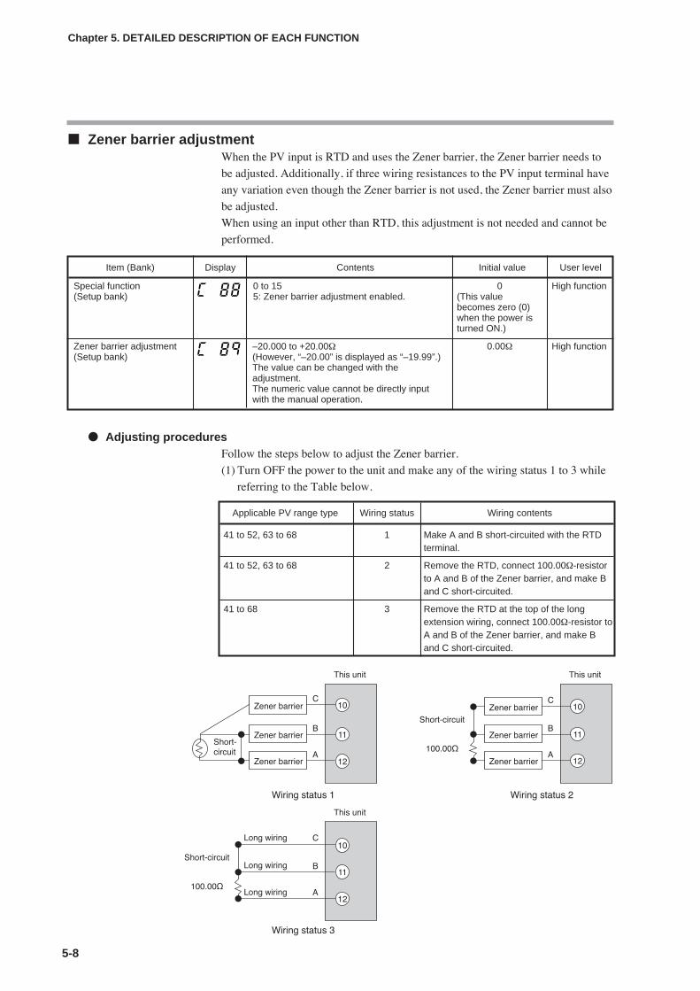
Zener barrier adjustmentWhen the PV input is RTD and uses the Zener barrier, the Zener barrier needs to
be adjusted. Additionally, if three wiring resistances to the PV input terminal have
any variation even though the Zener barrier is not used, the Zener barrier must also
be adjusted.
When using an input other than RTD, this adjustment is not needed and cannot be
performed.
Adjusting proceduresFollow the steps below to adjust the Zener barrier.
(1) Turn OFF the power to the unit and make any of the wiring status 1 to 3 while
referring to the Table below.
5-8
Chapter 5. DETAILED DESCRIPTION OF EACH FUNCTION
Item (Bank) Display Contents Initial value User level
Special function(Setup bank)
0 to 155: Zener barrier adjustment enabled.
0(This valuebecomes zero (0)when the power isturned ON.)
High function
Zener barrier adjustment(Setup bank)
0.00Ω–20.000 to +20.00Ω(However, “–20.00” is displayed as “–19.99”.)The value can be changed with theadjustment.The numeric value cannot be directly inputwith the manual operation.
Applicable PV range type Wiring status Wiring contents
41 to 52, 63 to 68 1 Make A and B short-circuited with the RTDterminal.
41 to 52, 63 to 68 2 Remove the RTD, connect 100.00Ω-resistorto A and B of the Zener barrier, and make Band C short-circuited.
41 to 68 3 Remove the RTD at the top of the longextension wiring, connect 100.00Ω-resistor toA and B of the Zener barrier, and make Band C short-circuited.
High function
5-9
(2) Turn ON the power to the unit and set “5” to [C88: Special function].
(3) Display [C89: Zener barrier adjustment].
Handling Precautions
(If [C01: PV range type] is not RTD or if [C88: Special function] is otherthan “5”, [C89: Zener barrier adjustment] is not displayed.)
(4) Press the [enter] key to display a difference in wiring resistance between the A
and B lines on the lower display.
(5) Press the [enter] key to store the difference in wiring resistance between the A
and B lines into this unit as an adjustment value.
(6) Turn OFF the power to the unit and connect the RTD correctly.
Handling Precautions
• The Zener barrier can be used only when the PV range type is 41 to52 or 63 to 68.
• Use a Zener barrier having a DC resistance value of 70Ω or less.
• Adjust the Zener barrier with a resistance difference between theZener barrier and long extension wiring of 20Ω or less. If thisresistance difference is 20Ω or more, the Zener barrier cannot beadjusted and the adjustment value becomes 0.00Ω.
• Once the Zener barrier has been adjusted, the correction isperformed with the same adjustment value even though the PV rangetype is changed to other RTD.
• To return the adjustment value to 0.00Ω, perform above steps (2) to(5) with nothing connected to the PV input terminal.
Chapter 5. DETAILED DESCRIPTION OF EACH FUNCTION

5-10
Chapter 5. DETAILED DESCRIPTION OF EACH FUNCTION
5 - 2 Mode
It is possible to set the AUTO/MANUAL mode selection, RUN/READY mode selection, LSP/RSP mode
selection, Auto Tuning (AT) stop/start selection, release all digital output (DO) latches, and OFF/ON selection of
communication digital input 1 (communication DI 1).
AUTO/MANUAL modeThe AUTO/MANUAL mode selection can be set.
• When the AUTO/MANUAL mode is changed, the display is automatically
returned to the operation display.
• If the operation type of internal contacts 1 to 5 is set at “AUTO/MANUAL”, [A--
M: AUTO/MANUAL] can be displayed, but the setting cannot be configured.
• When [CtrL: Control method] is set at "0" (ON/OFF control), [A--M:
AUTO/MANUAL] cannot be displayed and set.
• When [bit 0: AUTO/MANUAL display] of [C73: MODE display setup] is set at
"0" (no display), [A--M: AUTO/MANUAL] cannot be displayed and set.
RUN/READY modeThe RUN/READY mode selection can be set.
• If the operation type of internal contacts 1 to 5 is set at “RUN/READY”, [r--r:
RUN/READY] can be displayed, but the setting cannot be configured.
• When [bit 1: RUN/READY display] of [C73: MODE display setup] is set at "0"
(no display), [r--r: RUN/READY] cannot be displayed and set.
LSP/RSP modeThe LSP/RSP mode selection can be set.
• If the operation type of internal contacts 1 to 5 is set at “LSP/RSP”, [L--r:
LSP/RSP] can be displayed, but the setting cannot be configured.
• When [bit 2: LSP/RSP display] of [C73: MODE display setup] is set at "0" (no
display), [L--r: LSP/RSP] cannot be displayed and set.
• If the model does not have the RSP mode, [L--r: LSP/RSP] cannot be displayed
and set.
Item (Bank) Display Contents Initial value User level
AUTO/MANUAL(Mode bank)
AUto: AUTO mode [Communication value is"0".]
MAn: MANUAL mode [Communication valueis "1".]
AUto Basic,Standard,High function
Item (Bank) Display Contents Initial value User level
RUN/READY(Mode bank)
rUn: RUN mode [Communication value is "0".]rdy: READY mode [Communication value is
"1".]
rUn Basic,Standard,High function
Item (Bank) Display Contents Initial value User level
LSP/RSP(Mode bank)
LSP: LSP mode [Communication value is "0".]RSP: RSP mode [Communication value is
"1".]
LSP Basic,Standard,High function
5-11
Chapter 5. DETAILED DESCRIPTION OF EACH FUNCTION
Auto tuning (AT) stop/startThe AT stop/start selection can be set.
• The AT is stopped in the MANUAL or READY mode.
• If the PV high limit alarm (AL01) or PV low limit alarm (AL02) occurs, the AT
is stopped.
• If the operation type of internal contacts 1 to 5 is set at "AT stop/start", [At: AT
stop/start] can be displayed, but the setting cannot be made.
• When [CtrL: Control method] is set at "0" (ON/OFF control), [At: AT stop/start]
cannot be displayed and set.
• When [bit 3: AT stop/start display] of [C73: MODE display setup] is set at "0"
(no display), [At: AT stop/start] cannot be displayed and set.
For details about AT, refer to;
AT (on page 5-26) and AT function (on page 5-29).
Release all digital output (DO) latchesRelease all digital output (DO) latches can be set.
• If the operation type of internal contacts 1 to 5 is set at "Release all DO latches",
[do.Lt: Release all DO latches] can be displayed, but the setting cannot be
configured.
• When [bit 4: Release all DO latches display] of [C73: MODE display setup] is
set at "0" (no display), [do.Lt: Release all DO latches] cannot be displayed and
set.
Communication digital input 1 (communication DI 1)Communication digital input 1 (communication DI 1) can be set.
• Four communication DIs, DI1 to DI4, are provided. However, only
communication DI 1 can be set using the key operation.
• The function (operation) with communication DI 1 can be set using the DI
Assignment.
• When [bit 5: Communication DI 1 display] of [C73: MODE display setup] is set
at "0" (no display), [C.DI1: Communication DI 1] cannot be displayed and set.
Item (Bank) Display Contents Initial value User level
Auto Tuning (AT) stop/start(Mode bank)
At.oF: AT stop [Communication value is "0".]At.on: AT start [Communication value is "1".]
At.oF Basic,Standard,High function
Item (Bank) Display Contents Initial value User level
Release all digital output(DO) latches(Mode bank)
Lt.on: Latch is continued. [Communicationvalue is "0".]
Lt.oF: Latch is released. [Communicationvalue is "1".])
Lt.on Basic,Standard,High function
Item (Bank) Display Contents Initial value User level
Communication digitalinput 1 (communication DI1)(Mode bank)
DI.oF: Communication DI1. OFF[Communication value is "0".]
DI.on: Communication DI1. ON[Communication value is "1".]
DI.oF Basic,Standard,High function
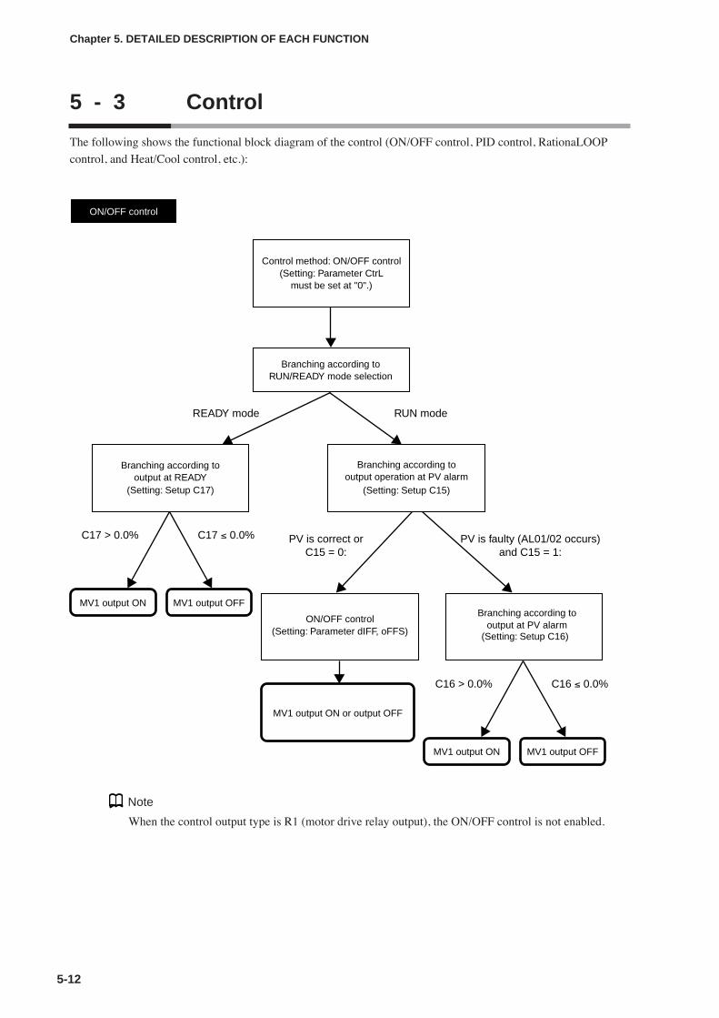
5-12
Chapter 5. DETAILED DESCRIPTION OF EACH FUNCTION
5 - 3 Control
The following shows the functional block diagram of the control (ON/OFF control, PID control, RationaLOOP
control, and Heat/Cool control, etc.):
MV1 output ON MV1 output OFF
MV1 output ON or output OFF
ON/OFF control
Control method: ON/OFF control(Setting: Parameter CtrL
must be set at "0".)
ON/OFF control(Setting: Parameter dIFF, oFFS)
Branching according tooutput at READY
(Setting: Setup C17)
Branching according tooutput operation at PV alarm
(Setting: Setup C15)
Branching according toRUN/READY mode selection
READY mode
C17 > 0.0% C17 ≤ 0.0%
MV1 output ON MV1 output OFF
Branching according tooutput at PV alarm
(Setting: Setup C16)
C16 > 0.0% C16 ≤ 0.0%
PV is correct orC15 = 0:
PV is faulty (AL01/02 occurs)and C15 = 1:
RUN mode
Note
When the control output type is R1 (motor drive relay output), the ON/OFF control is not enabled.

5-13
Chapter 5. DETAILED DESCRIPTION OF EACH FUNCTION
MV1 = MV
Fixed PID
Control method: Fixed PID(Setting: Parameter CtrL
must be set at "1".)
READY mode
AUTO mode
MANUAL mode
RUN mode
SP lag overshoot suppression(Setting: Extended tuning SP.Lg)
RationaLOOP high precision control logic
(Setting: Extended tuning Ctr.A)
Just-FiTTER overshoot suppression(Setting: Extended tuning
JF.ov, JF.bd)
Bumpless transfer/Preset selection(Setting: Setup C19, C20)
Branching according toAUTO/MANUAL mode
Branching according toRUN/READY mode
MV
MV1 = MV
Branching according tooutput operation at PV alarm
MV rate-of-change limit(Setting: Parameter oUtL)
(Setting: Setup C15, C16)
Output at PV alarm(Setting: Setup C16)
Branching according toHeat/Cool control
(Setting: Setup C26)
C26 = 0 C26 = 1
Branching according toHeat/Cool control
(Setting: Setup C26)
MV1 = Heat MV MV2 = Cool MV MV1 = Heat MV MV2 = Cool MV
Output at READY(Setting: Setup C17, C18)
Heat/Cool control(Setting: Setup C28, C29)
Output at READY(Setting: Setup C17)
PV is correct orC15 = 0:
C26 = 0
C26 = 1
PV is faulty and C15 = 1:
PID control(Setting: P-1 to P-8, I-1 to I-8, d-1 to d-8, rE-1 to rE-8, oL-1 to oL-8, oH-1
to oH-8, P-1.C to P-8.C, I-1.C to I-8.C, d-1.C to d-8.C, oL-1.C to
oL-8.C, oH-1.C to oH-8.C)
Note
When the control output type is R1 (motor drive relay output), the Heat/Cool control is not enabled.

5-14
Chapter 5. DETAILED DESCRIPTION OF EACH FUNCTION
Control methodA desired control method can be selected from two kinds of control methods.
• When the control output type is the position proportional output, only [1: FixedPID] can be selected.
• When the control output type is relay (R0), the initial value becomes "0". Theinitial value is "1" in other cases.
• "Fixed" of [1: Fixed PID] means that the PID constant is not changedautomatically since the self-tuning (ST) provided for SDC15 is not run.However, the AT can be run even in the fixed PID control.
• The following table shows valid and invalid functions related to [1: Fixed PID],as well as other related parameters:
Item (Bank) Display Contents Initial value User level
Control method(Parameter bank)
0: ON/OFF control1: Fixed PID
0 or 1 Basic,Standard,High function
Classification of Classification Classification of RationaLOOP AT Just-FiTTERHeat/Cool control of RationaLOOP control action function
Normal control Normal PID P control X X
PI control X
PD control X X
PID control X
RationaLOOP P control X X
PI control X
PD control X X
PID control
Heat/Cool control Normal PID P control X X
PI control X
PD control X X
PID control X
RationaLOOP P control X X
PI control X
PD control X X
PID control
Remarks Adjustment result be-comes the PID control.
Related settings Control algorithm AT type Just-FiTTER overshoot limit/restraint/control coefficient
MV low limit at AT Just-FiTTERsettling band
MV high limit at AT
AT Proportionalband adjust
AT Integral timeadjust
AT Derivative timeadjust

5-15
Chapter 5. DETAILED DESCRIPTION OF EACH FUNCTION
Control action and Heat/Cool controlThe control action (direct/reverse) and Heat/Cool control (enabled/disabled) can
be selected.
However, when the control output type is R1 (motor drive relay output), the
Heat/Cool control is not enabled.
• When the control output type is other than R1 (motor drive relay output), and
when the control method is other than the ON/OFF control (CtrL ≠ 0), [C26:
Heat/Cool control] can be displayed and set.
However, in case of the position proportional control model, the Heat/Cool
control is not enabled.
• When the Heat/Cool control is set disabled (C26 = 0), [C14: Control action] can
be displayed and set.
• When the Heat/Cool control is set disabled (C26 = 0), both [C20: Preset
MANUAL value] and [C22: Initial output of PID control] are changed to "0.0".
• When the Heat/Cool control is set enabled (C26 = 1), both [C20: Preset
MANUAL value] and [C22: Initial output of PID control] are changed to "50.0".
• The reverse action (heat control) is a control that decreases (or turns OFF) the
manipulated variable (MV) as the PV increases.
The direct action (cool control) is a control that increases (or turns ON) the
manipulated variable (MV) as the PV increases.
Special control outputsThe control output at PV alarm and control output at READY can be set.
• When the control method is other than the ON/OFF control (CtrL ≠ 0) and the
Heat/Cool control is set enabled (C26 = 1), [C18: Output at READY (cool)] can
be displayed and set.
• The PV alarm status means that AL01, 02, or 03 occurs.
Item (Bank) Display Contents Initial value User level
Control action(direct/reverse)(Setup bank)
0: Heat control (Reverse)1: Cool control (Direct)
0 Basic,Standard,High function
Heat/Cool control(Setup bank)
0 Basic,Standard,High function
0: Disabled.1: Enabled.
Item (Bank) Display Contents Initial value User level
Output operation at PValarm(Setup bank)
0: Control calculation is continued.1: Output at PV alarm is output.
0 High function
Output at PV alarm(Setup bank)
0.0% High function-10.0 to +110.0%
Output at READY (Heat)(Setup bank)
0.0% Standard,High function
-10.0 to +110.0%
Output at READY (Cool)(Setup bank)
0.0% Standard,High function
-10.0 to +110.0%

5-16
Chapter 5. DETAILED DESCRIPTION OF EACH FUNCTION
MANUAL mode changeThe control output when the AUTO mode is changed to the MANUAL mode can
be set.
• When [C19: Output operation at changing Auto/Manual] is set at [0: Bumplesstransfer], the manipulated variable (MV) when the AUTO mode is changed tothe MANUAL mode is retained. When set at [1: Preset], the manipulatedvariable (MV) is set to [C20: Preset MANUAL value] when the AUTO mode ischanged to the MANUAL mode.
• When the control method is other than ON/OFF control (CtrL ≠ 0), [C19: Outputoperation at changing Auto/Manual] and [C20: Preset MANUAL value] can bedisplayed and set.
• When the Heat/Cool control is not used (C26 = 0), the initial value of [C20:Preset MANUAL value] is [0.0]. On the contrary, when the Heat/Cool control isused (C26 =1), this initial value becomes [50.0].
Handling Precautions
When the unit is in the MANUAL mode if the power is turned ON, theset value of C20 becomes the initial manipulated variable (MV).
PID control initialization
• When the control method is other than the ON/OFF control (CtrL≠0), the displayand setting can be performed.
• If the PID group is changed as the SP value or SP group is changed, themanipulated variable (MV) is stopped at its low limit or high limit, and then thePV may not change or may overshoot. To prevent such trouble, it is effective toinitialize the PID control.
• The setting is “0” (Auto).It is judged automatically whether or not the PID control needs to be initializedas the SP value or SP group is changed. As a result, the PID control is initializedonly when it is required.
• The setting is “1” (Not initialized).Even though the SP value or SP group is changed, the PID control is notinitialized. This setting is effective when the continuation of the manipulatedvariable (MV) is important if the SP value or SP group is changed.
• The setting is “2” (Initialized).Every time the SP value or SP group is changed, the PID control is alwaysinitialized. This setting is effective when it is important that an increase or adecrease in manipulated variable (MV) immediately affects the relationshipbetween the PV and SP when the SP value or SP group is changed.
Item (Bank) Display Contents Initial value User level
Output operation atchanging Auto/Manual(Setup bank)
0: Bumpless transfer1: Preset
0 Standard,High function
Preset MANUAL value(Setup bank)
0.0 or 50.0% Standard,High function
-10.0 to +110.0%
Item (Bank) Display Contents Initial value User level
Initial output type (mode)of PID control(Setup bank)
0: Auto1: Not initialized.2: Initialized. (If SP value different from the
current value is input.)
0 High function

5-17
Initial output of PID control
• When the control method is other than the ON/OFF control (CtrL≠0), the display
and setting can be performed.
• This value is used for the PID control immediately after the operation mode is
changed from READY to RUN or the operation mode becomes RUN as the
power is turned ON. This value greatly affects the manipulated variable (MV)
when the operation mode is changed.
• When the setting of the Heat/Cool control (C26) is changed, the value is
automatically set again. When [C26: Heat/Cool control] is changed to “Enabled”
(C26=1), the value becomes “50.0%”. On the contrary, when the setting is
changed to “Disabled” (C26=0), the value becomes “0.0%”.
PID decimal point position
• When the control method is other than the ON/OFF control (CtrL≠0), the display
and setting can be performed.
• When this setting is set at “0”, the integral time and derivative time settings
become 0 to 9999s.
• When this setting is set at “1”, the integral time and derivative time settings
become 0.0 to 999.9s.
Handling Precautions
When the setting of the PID decimal point position is changed, theintegral time and derivative time values are divided by 10 (1/10) ormultiplied by 10, and the control characteristics may be changedgreatly.After the setting has been changed, always set the integral time andderivative time to an appropriate value again.For example, if the setting of the PID decimal point position is changedfrom “0” to “1” with integral time of 120s, the integral time becomes12.0s.
Chapter 5. DETAILED DESCRIPTION OF EACH FUNCTION
Item (Bank) Display Contents Initial value User level
Initial output of PID control(Setup bank)
–10.0 to +110.0% 0.0% or 50.0% High function
Item (Bank) Display Contents Initial value User level
PID decimal point position(Setup bank)
0: No decimal point1: 1 digit after decimal point
(Decimal point of integral time andderivative time)
0 High function

5-18
Chapter 5. DETAILED DESCRIPTION OF EACH FUNCTION
ON/OFF controlThe ON/OFF control related items can be set.
• [Differential (for ON/OFF control): dIFF] and [ON/OFF control action point
offset: oFFS] can be displayed and set when the control method is the ON/OFF
control (CtrL = 0).
• The following Figure shows the operation of the ON/OFF control:
shows that the ON/OFF is changed at this value.
shows that the ON/OFF is changed at a point that "1U" is added to this
value.
• The following describes examples showing how to use the ON/OFF control
action point offset:
To turn OFF the output at 205˚C or more and turn ON the output at less than
190˚C with the heat control and SP = 200˚C, the differential is set to 15˚C and
the offset is set to 5˚C.
To turn OFF the output at 5˚C or less and turn ON the output at more than 10˚C
with the cool control and SP = 10˚C, the differential is set to 5˚C and the offset is
set to -5˚C.
Output variation limitVariation in the manipulated variable (MV) can be limited.
• The upper limit (%) for the absolute value of MV variation can be set in 1s
intervals. However, because the sampling cycle is 0.1s, the actual MV variation
is limited to 1/10 of the value set. For example, when 5.0(%/s) is set, the
variation per 0.1s is limited to ±0.5%. In addition, when 0.1(%/s) is set, the
variation per 0.1s is limited to ±0.01%.
• When 0.0 is set, there is no limit on MV variation.
• When the model is a motor drive relay output type with a motor long life mode
(C59 = 1), display and setting are not possible because the MV variation limit
function operates automatically.
Item (Bank) Display Contents Initial value User level
Differential (for ON/OFFcontrol) (Parameter bank)
0 to 9999U 5U Basic,Standard,High function
ON/OFF control actionpoint offset (Parameterbank)
0U High function-1999 to +9999U
SP + oFFS
Heat control (Reverse action) Cool control (Direct action)
PV
ON dIFF
SP + oFFSPV
ONdIFF
Item (Bank) Display Contents Initial value User level
Output variation limit(Parameter bank)
0.0: No limit0.1 to 999.9%
0.0 High

5-19
Chapter 5. DETAILED DESCRIPTION OF EACH FUNCTION
PID controlIn the fixed PID control, the PID control related items can be set.
(Note) For presence of the decimal point, when [C23: PID decimal point position] is set at “0”, thedecimal point does not exist. When this setting is set at “1”, the decimal point exists.
Item (Bank) Display Contents Initial value User level
Proportional band (PID1)(PID bank)
0.1 to 999.9% 5.0% Basic,Standard,High function
Integral time (PID1)(PID bank)
120s0 to 9999s(No integration control action when set at "0".)
Derivative time (PID1)(PID bank)
30s0 to 9999s(No derivative control action when set at "0".)
Manual reset (PID1)(PID bank)
50.0%-10.0 to +110.0%
MV low limit (PID1)(PID bank)
-10.0 to +110.0% 0.0% Standard,High function
MV high limit (PID1)(PID bank)
-10.0 to +110.0% 100.0%
Proportional band for coolside (PID1) (PID bank)
0.1 to 999.9% 5.0% Basic,Standard,High function
Integral time for cool side(PID1) (PID bank)
0 to 9999s(No integration control action when set at "0".)
120s
Derivative time for cool side(PID1) (PID bank)
0 to 9999s(No derivative control action when set at "0".)
30s
Output low limit for coolside (PID1) (PID bank)
-10.0 to +110.0% 0.0% Standard,High function
Output high limit for coolside (PID1) (PID bank)
-10.0 to +110.0% 100.0%
Proportional band (PID 2) Same as PID 1 5.0% Basic,Standard,High function
Integral time (PID 2) 120s
Derivative time (PID 2) 30s
Manual reset (PID 2) 50.0%
MV low limit (PID 2) Same as PID 1 0.0% Standard,High function
MV high limit (PID 2) 100.0%
Proportional band for coolside (PID 2)
Same as PID 1 5.0% Basic,Standard,High functionIntegral time for cool side
(PID 2)120s
Derivative time for cool side(PID 2)
30s
Output low limit for coolside (PID 2)
Same as PID 1 0.0% Standard,High function
Output high limit for coolside (PID 2)
100.0%
(To be continued to the next page.)
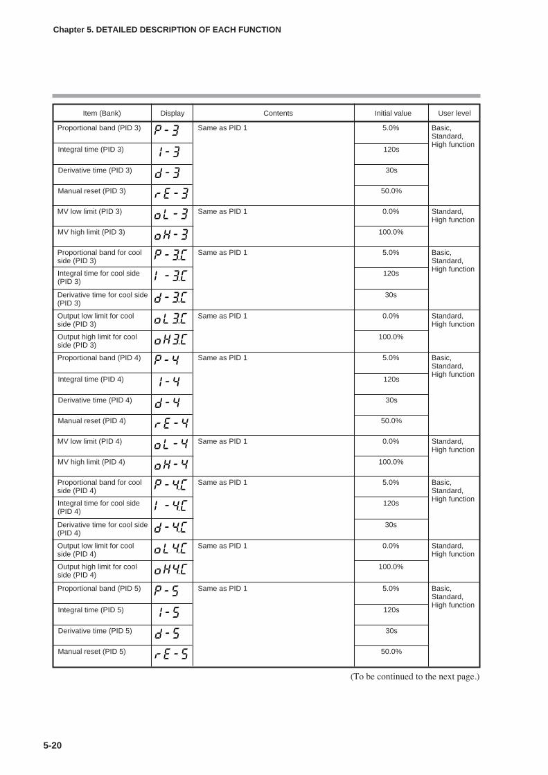
5-20
Chapter 5. DETAILED DESCRIPTION OF EACH FUNCTION
Item (Bank) Display Contents Initial value User level
Proportional band (PID 3) Same as PID 1 5.0% Basic,Standard,High function
Integral time (PID 3) 120s
Derivative time (PID 3) 30s
Manual reset (PID 3) 50.0%
MV low limit (PID 3) Same as PID 1 0.0% Standard,High function
MV high limit (PID 3) 100.0%
Proportional band for coolside (PID 3)
Same as PID 1 5.0% Basic,Standard,High functionIntegral time for cool side
(PID 3)120s
Derivative time for cool side(PID 3)
30s
Output low limit for coolside (PID 3)
Same as PID 1 0.0% Standard,High function
Output high limit for coolside (PID 3)
100.0%
Proportional band (PID 4) Same as PID 1 5.0% Basic,Standard,High function
Integral time (PID 4) 120s
Derivative time (PID 4) 30s
Manual reset (PID 4) 50.0%
MV low limit (PID 4) Same as PID 1 0.0% Standard,High function
MV high limit (PID 4) 100.0%
Proportional band for coolside (PID 4)
Same as PID 1 5.0% Basic,Standard,High functionIntegral time for cool side
(PID 4)120s
Derivative time for cool side(PID 4)
30s
Output low limit for coolside (PID 4)
Same as PID 1 0.0% Standard,High function
Output high limit for coolside (PID 4)
100.0%
Proportional band (PID 5) Same as PID 1 5.0% Basic,Standard,High function
Integral time (PID 5) 120s
Derivative time (PID 5) 30s
Manual reset (PID 5) 50.0%
(To be continued to the next page.)

5-21
Chapter 5. DETAILED DESCRIPTION OF EACH FUNCTION
Item (Bank) Display Contents Initial value User level
Proportional band (PID 6) Same as PID 1 5.0% Basic,Standard,High function
Integral time (PID 6) 120s
Derivative time (PID 6) 30s
Manual reset (PID 6) 50.0%
MV low limit (PID 6) Same as PID 1 0.0% Standard,High function
MV high limit (PID 6) 100.0%
Proportional band for coolside (PID 6)
Same as PID 1 5.0% Basic,Standard,High functionIntegral time for cool side
(PID 6)120s
Derivative time for cool side(PID 6)
30s
Output low limit for coolside (PID 6)
Same as PID 1 0.0% Standard,High function
Output high limit for coolside (PID 6)
100.0%
MV low limit (PID 5) Same as PID 1 0.0% Standard,High function
MV high limit (PID 5) 100.0%
Proportional band for coolside (PID 5)
Same as PID 1 5.0% Basic,Standard,High functionIntegral time for cool side
(PID 5)120s
Derivative time for cool side(PID 5)
30s
Output low limit for coolside (PID 5)
Same as PID 1 0.0% Standard,High function
Output high limit for coolside (PID 5)
100.0%
Proportional band (PID 7) Same as PID 1 5.0% Basic,Standard,High function
Integral time (PID 7) 120s
Derivative time (PID 7) 30s
Manual reset (PID 7) 50.0%
MV low limit (PID 7) Same as PID 1 0.0% Standard,High function
MV high limit (PID 7) 100.0%
(To be continued to the next page.)
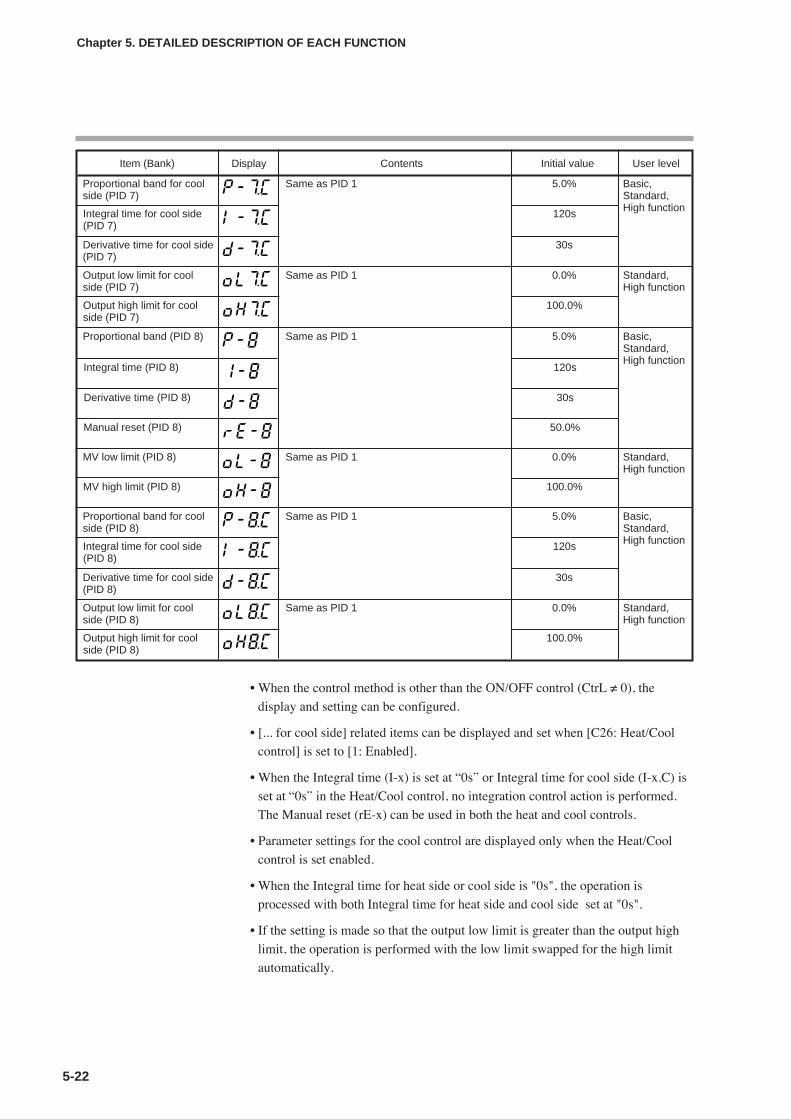
• When the control method is other than the ON/OFF control (CtrL ≠ 0), the
display and setting can be configured.
• [... for cool side] related items can be displayed and set when [C26: Heat/Cool
control] is set to [1: Enabled].
• When the Integral time (I-x) is set at “0s” or Integral time for cool side (I-x.C) is
set at “0s” in the Heat/Cool control, no integration control action is performed.
The Manual reset (rE-x) can be used in both the heat and cool controls.
• Parameter settings for the cool control are displayed only when the Heat/Cool
control is set enabled.
• When the Integral time for heat side or cool side is "0s", the operation is
processed with both Integral time for heat side and cool side set at "0s".
• If the setting is made so that the output low limit is greater than the output high
limit, the operation is performed with the low limit swapped for the high limit
automatically.
5-22
Chapter 5. DETAILED DESCRIPTION OF EACH FUNCTION
Item (Bank) Display Contents Initial value User level
Proportional band (PID 8) Same as PID 1 5.0% Basic,Standard,High function
Integral time (PID 8) 120s
Derivative time (PID 8) 30s
Manual reset (PID 8) 50.0%
MV low limit (PID 8) Same as PID 1 0.0% Standard,High function
MV high limit (PID 8) 100.0%
Proportional band for coolside (PID 8)
Same as PID 1 5.0% Basic,Standard,High functionIntegral time for cool side
(PID 8)120s
Derivative time for cool side(PID 8)
30s
Output low limit for coolside (PID 8)
Same as PID 1 0.0% Standard,High function
Output high limit for coolside (PID 8)
100.0%
Proportional band for coolside (PID 7)
Same as PID 1 5.0% Basic,Standard,High functionIntegral time for cool side
(PID 7)120s
Derivative time for cool side(PID 7)
30s
Output low limit for coolside (PID 7)
Same as PID 1 0.0% Standard,High function
Output high limit for coolside (PID 7)
100.0%

5-23
• Priorities for PID group change
Priorities for PID group change are shown below.
Handling Precautions
• If PID group change is used for an internal contact (DI), zone PIDdoes not function. When zone PID is used, do not use PID groupchange by selecting PID group selection as the function of an internalcontact (DI).
• The SDC25/26 does not have an RSP (remote SP) function or zonefunction.
Zone PIDIn the PID fixed control, the PID group auto change function by the SP or PV can
be selected.
• When the PID fixed control (CtrL=1) is used, the display and setting can be
performed.
• When [C24: Zone PID operation] is set at “0: Disabled.”, the PID group setting
of the SP bank becomes valid.
• When the zone PID operation is set at “Enabled.” (C24=1 or 2), the PID group
setting of the SP bank becomes invalid and the PID group is automatically
changed as described in the following. Additionally, a hysteresis can be set so
that the PID group is not changed frequently by a small change of the PV or SP
at a position close to the zone set value.
Chapter 5. DETAILED DESCRIPTION OF EACH FUNCTION
DI function
When PID groupchange isselected.
Zone function
During use
PriorityHigh Low
During RSP
[SP group linked][RSP dedicated
group selectable]
SP groupassignment of
PID group> > >
Item (Bank) Display Contents Initial value User level
Zone 4 (Zone bank) 9999U
Zone 5 (Zone bank) 9999U
Zone 6 (Zone bank) 9999U
Zone 7 (Zone bank) 9999U
Zone hysteresis (Zone bank)
0 to 9999U 5U
zone PID operation(Setup bank)
0: Disabled.1: Changed by SP.2: Changed by PV.
0 High function
Zone 1 (Zone bank) –1999 to +9999U 9999U
Zone 2 (Zone bank)
High function
Zone 3 (Zone bank) 9999U
9999U
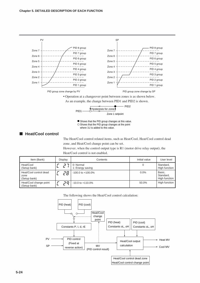
• Operation at a changeover point between zones is as shown below.
As an example, the change between PID1 and PID2 is shown.
Heat/Cool controlThe Heat/Cool control related items, such as Heat/Cool, Heat/Cool control dead
zone, and Heat/Cool change point can be set.
However, when the control output type is R1 (motor drive relay output), the
Heat/Cool control is not enabled.
The following shows the Heat/Cool control calculation:
5-24
Chapter 5. DETAILED DESCRIPTION OF EACH FUNCTION
Shows that the PID group changes at this value.Shows that the PID group changes at the point where 1U is added to this value.
Zone 1 setpoint
PID2
PID1Hysteresis for zone
Item (Bank) Display Contents Initial value User level
Heat/Cool(Setup bank)
0: Normal1: Energy saving
0 Standard,High function
Heat/Cool control deadzone(Setup bank)
0.0% Basic,Standard,High function
-100.0 to +100.0%
Heat/Cool change point(Setup bank)
50.0% High function-10.0 to +110.0%
PID (heat) PID (cool)
Heat/Coolchangepoint
PID control
(Fixed at
reverse action)
PID (heat)
Constants oL, oH
PID (cool)
Constants oL, oH
Heat/Cool output
calculation
Heat/Cool control dead zone
Heat/Cool control change point
Constants P, I, d, rE
Heat MV
Cool MV
PV
SP MV(PID control result)

5-25
Chapter 5. DETAILED DESCRIPTION OF EACH FUNCTION
• When [C26: Heat/Cool control] is set to [1: Enabled], the display and setting can
be made.
• When MV ≥ 50%, the control is changed to the PID (heat).
• When MV < 50%, the control is changed to the PID (cool).
• When [C27: Heat/Cool] is set to [1: Energy saving], the heat/cool change is
suppressed to indirectly obtain the energy saving effect. However, when [C28:
Heat/Cool control dead zone] is less than 0.0%, the energy saving effect cannot
be obtained.
• How the relationship between the output (heat) and output (cool) is made for the
PID control result (MV) is set.
Constants oL and oH function as shown in the Figure below.
100.0%
0.0%
Heat MV
100.0%
Cool MV
0.0%
0.0% 50.0% 100.0% MV
100.0%
0.0%
Heat MV
100.0%
Cool MV
0.0%
0.0% 50.0%
Dead zone
Dead zone > 0.0%Dead zone = 0.0%
100.0% MV
100.0%
0.0%
Heat MV
100.0%
Cool MV
0.0%
0.0% 50.0%
Absolute value ofdead zone
Dead zone < 0.0%
100.0% MV
100%
100%
0%
CoolMV
HeatMV
MV
oH(cool)
oL(cool)oL
(heat)
oH(heat)
Note: A bold line indicates Heat MV and a dotted line indicates Cool MV.
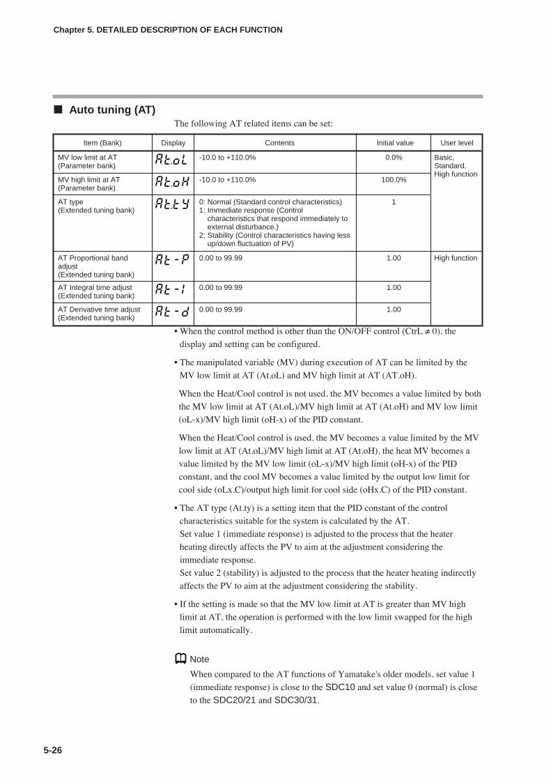
Auto tuning (AT)The following AT related items can be set:
• When the control method is other than the ON/OFF control (CtrL ≠ 0), the
display and setting can be configured.
• The manipulated variable (MV) during execution of AT can be limited by the
MV low limit at AT (At.oL) and MV high limit at AT (AT.oH).
When the Heat/Cool control is not used, the MV becomes a value limited by both
the MV low limit at AT (At.oL)/MV high limit at AT (At.oH) and MV low limit
(oL-x)/MV high limit (oH-x) of the PID constant.
When the Heat/Cool control is used, the MV becomes a value limited by the MV
low limit at AT (At.oL)/MV high limit at AT (At.oH), the heat MV becomes a
value limited by the MV low limit (oL-x)/MV high limit (oH-x) of the PID
constant, and the cool MV becomes a value limited by the output low limit for
cool side (oLx.C)/output high limit for cool side (oHx.C) of the PID constant.
• The AT type (At.ty) is a setting item that the PID constant of the control
characteristics suitable for the system is calculated by the AT.
Set value 1 (immediate response) is adjusted to the process that the heater
heating directly affects the PV to aim at the adjustment considering the
immediate response.
Set value 2 (stability) is adjusted to the process that the heater heating indirectly
affects the PV to aim at the adjustment considering the stability.
• If the setting is made so that the MV low limit at AT is greater than MV high
limit at AT, the operation is performed with the low limit swapped for the high
limit automatically.
Note
When compared to the AT functions of Yamatake's older models, set value 1
(immediate response) is close to the SDC10 and set value 0 (normal) is close
to the SDC20/21 and SDC30/31.
5-26
Chapter 5. DETAILED DESCRIPTION OF EACH FUNCTION
Item (Bank) Display Contents Initial value User level
MV low limit at AT(Parameter bank)
-10.0 to +110.0% 0.0% Basic,Standard,High function
MV high limit at AT(Parameter bank)
-10.0 to +110.0% 100.0%
AT type(Extended tuning bank)
0: Normal (Standard control characteristics)1: Immediate response (Control
characteristics that respond immediately toexternal disturbance.)
2: Stability (Control characteristics having lessup/down fluctuation of PV)
1
AT Proportional bandadjust(Extended tuning bank)
0.00 to 99.99 1.00 High function
AT Integral time adjust(Extended tuning bank)
0.00 to 99.99 1.00
AT Derivative time adjust(Extended tuning bank)
0.00 to 99.99 1.00

5-27
The following figure shows the conceptual diagram expressing differences in
control result using the PID constant calculated by each AT type:
• For the AT Proportional band adjustment (At-P), AT Integral time adjustment
(At-I), and AT Derivative time adjustment (At-d), the value that the PID constant
calculated by the AT is multiplied by each coefficient is written into the set value
of the PID constant. However, the coefficient must be a value in the PID
constant setting range.
Note
• In the Heat/Cool control, it is possible to execute the AT only on the heat or
cool side.
• Setting that the AT is activated for only the heat PID constant in the
Heat/Cool control:
50.0% <MV low limit at AT (At.oL) < MV high limit at AT (At.oH)
• Setting that the AT is activated for only the cool PID constant in the
Heat/Cool control:
MV low limit at AT (At.oL) < MV high limit at AT (At.oH) < 50.0%
For details about AT, refer to;
AT stop/start (on page 5-11) and AT function (on page 5-29).
Chapter 5. DETAILED DESCRIPTION OF EACH FUNCTION
PV
Time
Difference in PV change when SP is changed.
SP
AT type = 1(Immediate response)
AT type = 0 (Normal)
AT type = 2 (Stability)

Just-FiTTERThis Just-FiTTER function provides the effect of the overshoot suppression andthe following items can be set:
• When the control method is other than the ON/OFF control (CtrL ≠ 0), thedisplay and setting can be configured.
• Function of Just-FiTTER overshoot limit/restraint/control coefficient (JF.ov)When the Just-FiTTER overshoot limit/restraint/control coefficient (JF.ov) is setto “0”, the Just-FiTTER function becomes invalid.When this coefficient is “1” or more, the effect of the overshootlimit/restraint/control becomes larger as the coefficient becomes larger.
• Function of Just-FiTTER settling band (JF.bd)When the % value of the width of the absolute value deviation to the PV range islarger than the set value, the Just-FiTTER function is started. When this value issmaller than the set value, this is judged as that the PV is settled by the Just-FiTTER function.
RationaLOOPThis RationaLOOP function suppresses the unstable trend if the immediateresponse to external disturbance is increased by the high precision control logic.The following items can be set:
• When the control method is other than the ON/OFF control (CtrL ≠ 0), thedisplay and setting can be made.
SP lagThis SP lag function suppresses changes in MV when the SP is changed. Thefollowing items can be set:
• When the control method is other than the ON/OFF control (CtrL ≠ 0), thedisplay and setting can be made.
• Function of SP lag constant (SP.Lg)When the SP lag constant is set at "0.0", the SP lag function becomes invalid.When this value is "0.1" or more, changes in MV when the SP is changedbecome smaller and the effect of the overshoot suppression becomes larger as thevalue becomes larger.
5-28
Chapter 5. DETAILED DESCRIPTION OF EACH FUNCTION
Item (Bank) Display Contents Initial value User level
Just-FiTTER overshootlimit/restraint/controlcoefficient(Extended tuning bank)
0 to 100(“0”: JF function disabled)
0 Standard,High function
Just-FiTTER settling band(Extended tuning bank)
0.00 to 10.00% 0.30% High function
Item (Bank) Display Contents Initial value User level
Control algorithm(Extended tuning bank)
0: PID (Conventional PID)1: RationaLOOP (High-performance PID)
0 Standard,High function
Item (Bank) Display Contents Initial value User level
SP lag constant(Extended tuning bank)
0.0 to 999.9(No effect when set at “0.0”.)
0.0 High function

5 - 4 Auto Tuning (AT) Function
5-29
Chapter 5. DETAILED DESCRIPTION OF EACH FUNCTION
The auto tuning (AT) function is used when the PID constants are set automatically with the control method set at
“Fixed PID” ([CtrL = 1]).
The AT function can be used when the control method is set to “Fixed PID”.
Starting procedures(1) Make sure that the PV input or operation end (heater power, etc.) is
controllable.
(2) Using the [r- -r] setup of the mode bank, multi-status display, and LED
monitor, make sure that the operation is in the RUN mode. If the indicator
[rdy] is lit and the operation is in the READY mode, change the mode to the
RUN mode.
(3) Make sure that the mode indicator [man] is off and the operation is in the
AUTO mode. If the indicator [man] is lit and the operation is in the MANUAL
mode, change the mode to the AUTO mode.
(4) Set the parameter setting [AT Stop/Start] to “AT start ([At] = [At.on])”.
Stopping proceduresThe AT function is completed automatically. To stop the AT function, which is
running, change the parameter setting [AT Stop/Start] to AT stop ([At] = [At.oF]).
Additionally, the AT function is stopped when changing the READY mode to the
MANUAL mode.
Display during execution of AT The decimal point at the 1st digit of the upper display (right end digit) flashes
twice repeatedly while the AT function is running. When the AT function is
completed and the PID constants are changed, this LED goes off.
Operation during execution of ATThe AT function calculates the PID constants using the limit cycle.
(1) When the AT function is started, a point, where the SP and PV deviations are
split to “2:1”, is determined as ON/OFF change point of the manipulated
variable (MV).
(2) When the limit cycle is judged as stable, the PID constants are changed and the
AT function is completed.
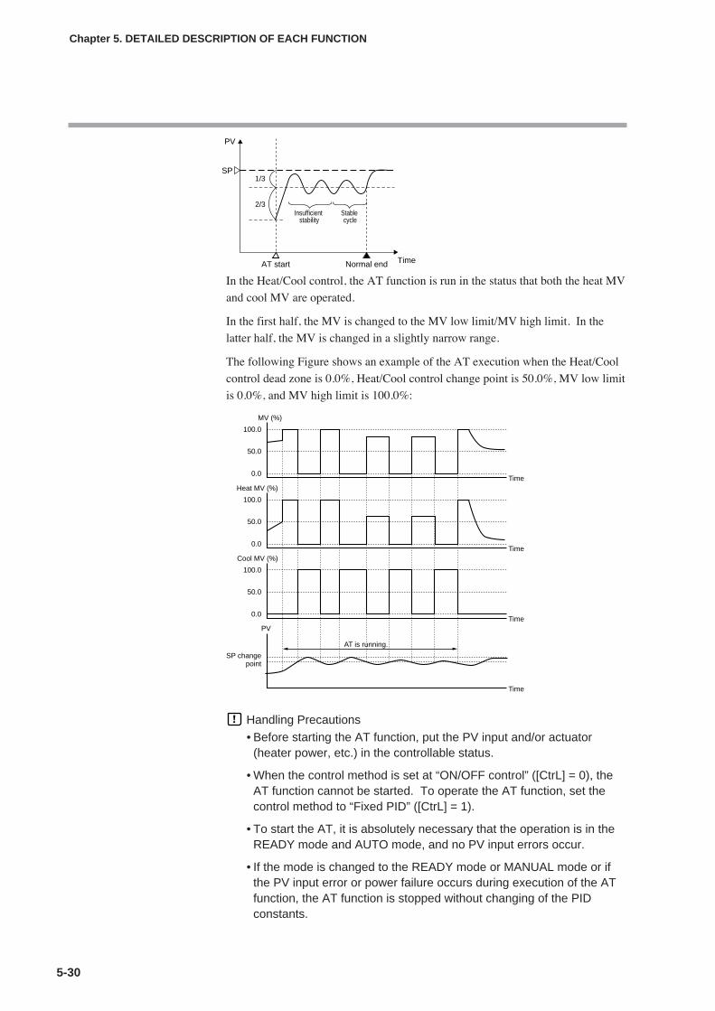
In the Heat/Cool control, the AT function is run in the status that both the heat MV
and cool MV are operated.
In the first half, the MV is changed to the MV low limit/MV high limit. In the
latter half, the MV is changed in a slightly narrow range.
The following Figure shows an example of the AT execution when the Heat/Cool
control dead zone is 0.0%, Heat/Cool control change point is 50.0%, MV low limit
is 0.0%, and MV high limit is 100.0%:
Handling Precautions
• Before starting the AT function, put the PV input and/or actuator(heater power, etc.) in the controllable status.
• When the control method is set at “ON/OFF control” ([CtrL] = 0), theAT function cannot be started. To operate the AT function, set thecontrol method to “Fixed PID” ([CtrL] = 1).
• To start the AT, it is absolutely necessary that the operation is in theREADY mode and AUTO mode, and no PV input errors occur.
• If the mode is changed to the READY mode or MANUAL mode or ifthe PV input error or power failure occurs during execution of the ATfunction, the AT function is stopped without changing of the PIDconstants.
5-30
Chapter 5. DETAILED DESCRIPTION OF EACH FUNCTION
PV
SP
2/3
1/3
Insufficient stability
AT start TimeNormal end
Stable cycle
MV (%)
100.0
Time
50.0
0.0
Heat MV (%)
100.0
Time
50.0
0.0
Cool MV (%)
100.0
Time
50.0
0.0
PV
Time
SP changepoint
AT is running.

5-31
• When the Heat/Cool control is not used, the MV becomes a valuelimited by both ranges, one range is between the MV low limit at AT(AT.oL) and MV high limit at AT (AT.oH), and the other is between theMV low limit (oL-x) and MV high limit (oH-x) of the PID constant.When there are no common portions in two ranges, the AT function isstopped automatically.
• When the Heat/Cool control is used, the MV becomes a value limitedby the MV low limit at AT (At.oL)/MV high limit at AT (At.oH), the heatMV becomes a value limited by the MV low limit (oL-x)/MV high limit(oH-x) of the PID constant, and the cool MV becomes a value limitedby the output low limit for cool side (oLx.C)/output high limit for coolside (oHx.C) of the PID constant.
• When the MV low limit at AT (AT.oL)/high limit (AT.oH), MV low limit(oL-x)/high limit (oH-x), output low limit for cool side (oLx.C)/high limitfor cool side (oHx.C) of the PID constant are set unevenly, the PVmay not be changed up or down even though the MV is changed bythe AT. In this case, the AT is kept continued. Then, stop the ATmanually, set the high limit and low limit of the manipulated variableagain, and restart the AT.
• The number of limit cycles and period of time from the AT start to ATend may vary depending on the control subject.
• The MV ON and OFF are repeated several times during execution ofthe AT function to perform the limit cycle. (The OFF operationdescribed here means MV limited by the MV low limit at AT ([At.oL])or MV high limit at AT ([oL]). The default setting before shipment is“0%”. Additionally, the ON operation described here means MVlimited by the MV high limit at AT ([At.oH]) or MV high limit at AT([oH]). The default setting before shipment is “100%”. If this AToperation does not function correctly, take either of the followingmeasures:(1) Change the MV low limit at AT ([At.oL]) or MV high limit at AT
([At.oH]) to an appropriate value, and then start the AT function.(2) Set the PID constants manually without use of AT.
• The AT progress value can be seen in the operation display mode.For details, refer to;
Operation displays in section 6-1, List of Operation Displays(on page 6-1).When the Heat/Cool control is not used, the AT progress valuedecrements from [4] during execution of the AT function and becomes[0] at completion of the AT function.When the Heat/Cool control is used, the AT progress valuedecrements from [8] during execution of the AT function and becomes[0] at completion of the AT function.In both cases, the AT progress value may be “1” or “0” when the ATprocess is in the transient status.
• Appropriate PID constants cannot be obtained depending on thecontrol subject. If this happens, set the PID constants manually.
• The MV ON/OFF change point determined when the AT function isstarted does not change even though the SP is changed while the ATis running.For details about AT function, refer to;
AT Stop/Start (on page 5-11) and AT (on page 5-26).
Chapter 5. DETAILED DESCRIPTION OF EACH FUNCTION

5-32
Chapter 5. DETAILED DESCRIPTION OF EACH FUNCTION
5 - 5 Set Point (SP)
The following shows the functional block diagram of the SP. For details about step operation,
refer to 5-6, Step operation.
NoteLSP is a local SP and shows that the data is retained inside this unit.
On the contrary, SP by the analog input from the outside is called RSP or remote
SP.
One LSP group exists. Two or more LSP groups exist.
LSP system group(Setting: Setup C30)
LSP1(Setting: SP SP1)
DI Assignment isnot provided.
DI Assignment isprovided.
LSP value in use
SP
RSP
DI Assignment of LSP group selection provided/not provided.(Setting: DI Assignment di1.1 to
di3.1)
LSP group number(Setting: LSP group number in operation
display mode)
Logical operation of DI(Setting: General DI
Assignment)
RSP input type(Setting: Setup C10)
RSP high limit/low limit alarm
(RSP mode only)
RSP scaling(Setting: Setup C11 to
C12)
RSP ratio(Setting: Parameter rA2)
RSP bias(Setting: Parameter bI2)
RSP high limit/low limit(-10 to +110% of scaling)
LSP/RSP mode selection
SP high limit/low limit(Setting: Setup C07, C08)
SP ramp unit (Setting: Setup C32)SP ramp-up/ramp-down (Setting: Parameter
SPU, SPd)
DI Assignment of SP ramp enabled/disabled.(Setting: DI Assignment di1.1 to di3.1)
LSP 1 to 8(Setting: SP SP1 to
SP8)

5-33
Chapter 5. DETAILED DESCRIPTION OF EACH FUNCTION
SP setup in operation display modeThe set value for LSP in use of LSP1 to 8 can be set.
The LSP set value is different from the SP display value during SP ramp.
However, the set value is displayed while the key is being operated to change the
setting.
• When [bit 1: SP display] of [C74: PV/SP display setup] is set at "1" (display is
provided), the display and setting can be made.
• The SP cannot be set in the RSP mode.
LSP system groupThe LSP system group can be selected.
SP ramp typeEither the standard ramp or multi-ramp can be selected.
Additionally, for details about step operation, refer to;
5-6, Step operation (on page 5-41).
• When this setting is set at “0”, the ramp-up and ramp-down use only one setting
group (SP ramp-up and SP ramp-down of parameter bank) even though one LSP
group or multiple LSP groups are used.
• When this setting is set at “1”, the ramp setting (ramp 1 to 8 of SP bank)
common to the up/down to be set by LSP group is used.
RSP input typeThe RSP input signal type can be selected.
• When the model provides the RSP input, the display and setting can be
performed.
Item (Bank) Display Contents Initial value User level
SP (Operation display) SP low limit to SP high limit U 0 U Basic,Standard,High function
Item (Bank) Display Contents Initial value User level
LSP system group(Setup bank)
1 to 8 1 Basic,Standard,High function
PV isshown onthe upperdisplay.
Item (Bank) Display Contents Initial value User level
SP ramp type(Setup bank)
1: Multi-ramp2: Step operation The step operation is
stopped when the power is turned ONagain (READY).
3: Step operation The step operation isrecovered when the power is turned ONagain.
0 High function
Item (Bank) Display Contents Initial value User level
RSP input type(Setup bank)
0: 4 to 20mA1: 0 to 20mA2: 0 to 5V3: 1 to 5V4: 0 to 10V
0 Basic,Standard,High function
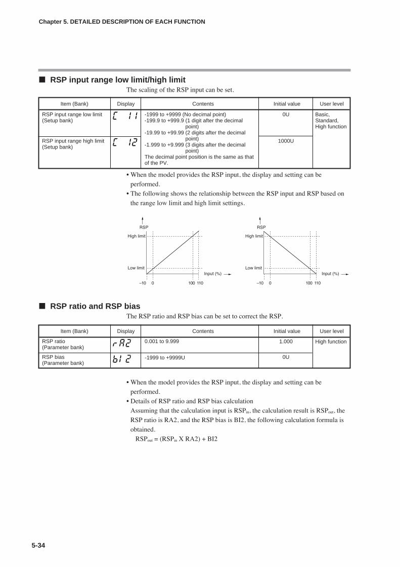
RSP input range low limit/high limitThe scaling of the RSP input can be set.
• When the model provides the RSP input, the display and setting can be
performed.
• The following shows the relationship between the RSP input and RSP based on
the range low limit and high limit settings.
RSP ratio and RSP biasThe RSP ratio and RSP bias can be set to correct the RSP.
• When the model provides the RSP input, the display and setting can be
performed.
• Details of RSP ratio and RSP bias calculation
Assuming that the calculation input is RSPin, the calculation result is RSPout, the
RSP ratio is RA2, and the RSP bias is BI2, the following calculation formula is
obtained.
RSPout = (RSPin X RA2) + BI2
5-34
Chapter 5. DETAILED DESCRIPTION OF EACH FUNCTION
Item (Bank) Display Contents Initial value User level
RSP input range low limit(Setup bank)
-1999 to +9999 (No decimal point)-199.9 to +999.9 (1 digit after the decimal
point)-19.99 to +99.99 (2 digits after the decimal
point)-1.999 to +9.999 (3 digits after the decimal
point)The decimal point position is the same as thatof the PV.
0U Basic,Standard,High function
RSP input range high limit(Setup bank)
1000U
Item (Bank) Display Contents Initial value User level
RSP ratio(Parameter bank)
0.001 to 9.999 1.000 High function
RSP bias(Parameter bank)
0U-1999 to +9999U

5-35
RSP filterThis RSP filter is a primary delay filter to be used if the RSP deflects finely due to
effect of the noise. As this set value is made larger, the RSP to be used for control
of this unit becomes difficult to change. Normally, the RSP filter is used with the
initial value (0.0).
• When the model provides the RSP input, the display and setting can beperformed.
OUT = OUT-1 + (IN – OUT-1)/(T/ Ts +1)IN: Input to the filterOUT: Current filter calculation outputOUT-1: Previous filter calculation outputT: Filter set value (second)Ts: Sampling cycle time (0.1s)
RSP low limit/high limit and RSP low limit/high limit alarmsThe RSP low limit and RSP high limit are provided for each RSP input type.Basically, -10%FS of each range is the RSP low limit and +110%FS of each rangeis the RSP high limit.For details, refer to;
Behavior in case of RSP failure (on page 10-4).
The RSP is limited so that it is in a range from the RSP low limit to the RSP highlimit. If the RSP before the RSP ratio, RSP bias, and RSP filter are activated islarger than the RSP high limit in the RSP mode, the RSP high limit alarm (AL05)occurs. If this RSP is smaller than the RSP low limit, the RSP low limit alarm(AL06) occurs. (Both the RSP high limit alarm and RSP low limit alarm do notoccur in the LSP mode.) When the RSP is used as SP in the RSP mode, thelimiting with the SP low limit and SP high limit also becomes valid.
RSP and LSP1 to 8The RSP display and eight groups of LSP setup values can be set.
• When the model provides the RSP input, the RSP can be displayed and set.• The display and setting can be made for the LSP system group selected in [C30:
LSP system group].
Chapter 5. DETAILED DESCRIPTION OF EACH FUNCTION
Item (Bank) Display Contents Initial value User level
RSP filter(Parameter bank)
0.0 to 120.0 0.0 High function
Item (Bank) Display Contents Initial value User level
RSP(SP bank)
RSP (Remote SP)Setting disabled.
— Basic,Standard,High functionLSP
(SP bank)SP low limit to SP high limit 0U
0U
0U
0U
0U
0U
0U
0U

PID group numberThe PID group numbers to the RSP and eight groups of LSPs can be set.
• When the model provides the RSP input, the PID group number (RSP) can be
displayed and set.
• The PID group numbers (LSP) for the LSP system groups selected in [C30: LSP
system group] can be displayed and set.
LSP group numberThe LSP group number can be set.
• When [C30: LSP system group] is set at “2” or more and [bit 2: LSP group
number display] of the PV/SP display setup (setup C74) is set at “1” (display is
provided), the display can be made.
• When the display is possible and the DI Assignment of the LSP group selection
is not performed, the setting can be made.
5-36
Chapter 5. DETAILED DESCRIPTION OF EACH FUNCTION
Item (Bank) Display Contents Initial value User level
PID group number (RSP)(SP bank)
1 to 8 1 Standard,High function
PID group number (LSP)(SP bank)
1
1
1
1
1
1
1
1
Item (Bank) Display Contents Initial value User level
LSP group number(Operation display)
Numeric value at the rightmost digit of thedisplay.1 to LSP system group
1 Basic,Standard,High function
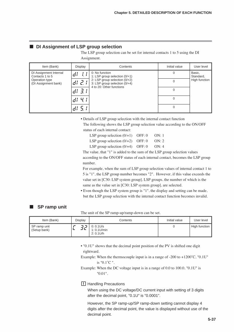
5-37
DI Assignment of LSP group selectionThe LSP group selection can be set for internal contacts 1 to 5 using the DI
Assignment.
• Details of LSP group selection with the internal contact function
The following shows the LSP group selection value according to the ON/OFF
status of each internal contact:
LSP group selection (0/+1) OFF: 0 ON: 1
LSP group selection (0/+2) OFF: 0 ON: 2
LSP group selection (0/+4) OFF: 0 ON: 4
The value, that "1" is added to the sum of the LSP group selection values
according to the ON/OFF status of each internal contact, becomes the LSP group
number.
For example, when the sum of LSP group selection values of internal contact 1 to
5 is "1", the LSP group number becomes "2". However, if this value exceeds the
value set in [C30: LSP system group], LSP groups, the number of which is the
same as the value set in [C30: LSP system group], are selected.
• Even though the LSP system group is "1", the display and setting can be made,
but the LSP group selection with the internal contact function becomes invalid.
SP ramp unitThe unit of the SP ramp-up/ramp-down can be set.
• "0.1U" shows that the decimal point position of the PV is shifted one digit
rightward.
Example: When the thermocouple input is in a range of -200 to +1200˚C, "0.1U"
is "0.1˚C ".
Example: When the DC voltage input is in a range of 0.0 to 100.0, "0.1U" is
"0.01".
Handling Precautions
When using the DC voltage/DC current input with setting of 3 digitsafter the decimal point, "0.1U" is "0.0001".
However, the SP ramp-up/SP ramp-down setting cannot display 4digits after the decimal point, the value is displayed without use of thedecimal point.
Chapter 5. DETAILED DESCRIPTION OF EACH FUNCTION
Item (Bank) Display Contents Initial value User level
DI Assignment InternalContacts 1 to 5Operation type(DI Assignment bank)
0: No function1: LSP group selection (0/+1)2: LSP group selection (0/+2)3: LSP group selection (0/+4)4 to 20: Other functions
0 Basic,Standard,High function0
0
Item (Bank) Display Contents Initial value User level
SP ramp unit(Setup bank)
0: 0.1U/s1: 0.1U/min2: 0.1U/h
0 High function
0
0

SP ramp-up/ramp-downThe SP ramp-up and ramp-down can be set.
• The SP ramp-up/ramp-down setting is valid when [C31: SP ramp type] is set at
“0: Standard”.
• When an initial value of “0.0U” is set, the SP ramp function does not function.
Therefore, when the ramp-up setting is set to “0.1U” or more and the ramp-down
is set to “0.0U”, the SP ramp function is enabled only during the ramp-up and
disabled during the ramp-down. Additionally, the reverse operation can also be
set so that the SP ramp function is enabled only during the ramp-down and
disabled during the ramp-up.
• "0.1U" shows that the decimal point position of the PV is shifted one digit
rightward.
Example: When the thermocouple input is in a range of -200 to +1200˚C, "0.1U"
is "0.1˚C ".
Example: When the DC voltage input is in a range of 0.0 to 100.0, "0.1U" is
"0.01".
• The ramp is started assuming that the current PV value is used as start point
when the SP ramp-up or ramp-down is possible under the following conditions.
The power is turned ON.
READY+AUTO status is changed to RUN+AUTO status.
RUN+MANUAL status is changed to RUN+AUTO status.
The AT function is completed (both normal end and forced stop).
Example: (1) When READY is changed to RUN with SP=100˚C, PV =25˚C,
SPU=0.0, and SPd=1.0, the PV is not started.
(2) When READY is changed to RUN with SP=50˚C, PV=100˚C,
SPU=0.0, and SPd=1.0, the PV is started.
• The SP ramp does not function for remote SP.
5-38
Chapter 5. DETAILED DESCRIPTION OF EACH FUNCTION
Item (Bank) Display Contents Initial value User level
SP ramp-up(Parameter bank)
0.0U: No ramp 0.1 to 999.9U(The unit of the ramp time is selected usingthe SP ramp unit.)
0.0U High function
0.0USP ramp-down(Parameter bank)

5-39
SP multi-rampThe SP multi-ramp set values can be set for eight groups of LSPs.
• When [C31: SP ramp type] is set at “1: Multi-ramp”, the display and setting canbe performed.
• In the standard ramp, the ramp-up and ramp-down are set individually.However, in the multi-ramp, the ramp common to the up and down is set.
• When this setting is set at “0.0U”, the SP ramp does not function.
• “rmp.1” corresponds to LSP1 while “rmp.8” corresponds to LSP8.
• “0.1U” shows that the decimal point position is shifted one digit right from thedecimal point position of the PV.For example, refer to;
SP ramp-up/ramp-down (on page 5-38).
• For details about conditions to start the ramp assuming that the current PV valueis used as start point, refer to;
SP ramp-up/ramp-down (on page 5-38).
NoteThe multi-ramp function is applicable to an application that changes the SP change
timing using the external switch or communication when performing the pattern
operation as shown above.
To set the SP value hold time, refer to;
5-6 Step operation (on page 5-41).
Chapter 5. DETAILED DESCRIPTION OF EACH FUNCTION
Item (Bank) Display Contents Initial value User level
Ramp(SP bank)
0.0U: No ramp.0.1 to 999.9U(The time unit of the ramp is selected usingthe SP ramp unit.)
0.0U High function
0.0U
0.0U
0.0U
0.0U
0.0U
0.0U
0.0U

5-40
Chapter 5. DETAILED DESCRIPTION OF EACH FUNCTION
SP low limit/high limitThe SP low limit and high limit can be set to limit the SP range.
• If the setting is made so that the SP low limit is greater than the SP high limit, the
operation is performed with the low limit swapped for the high limit
automatically.
Handling Precautions
When [C01: PV input range type] is set, the SP low limit and high limitare initialized.
DI Assignment of SP ramp enabled/disabledThe SP ramp enabled/disabled can be set for the internal contact function using the
DI assignment.
• Details of SP ramp enabled/disabled with internal contact function
The following shows the SP ramp enabled/disabled setting with the internal
contact ON/OFF:
OFF: SP ramp enabled. ON: SP ramp disabled.
The SP ramp enabled/disabled is set for only one internal contact.
• When the SP ramp is set disabled, the SP ramp operation is stopped and the SP
value becomes the final SP.
Item (Bank) Display Contents Initial value User level
DI Assignment InternalContacts 1 to 5 Operationtype(DI Assignment bank)
0: No function13: SP ramp enabled/disabled.1 to 12, 14 to 20: Other functions
0 Basic,Standard,High function0
0
Item (Bank) Display Contents Initial value User level
SP low limit(Setup bank)
PV input range low limit to PV input rangehigh limit
PV input range lowlimit
Standard,High function
SP high limit(Setup bank)
PV input range low limit to PV input rangehigh limit
PV input range highlimit
Standard,High function
0
0
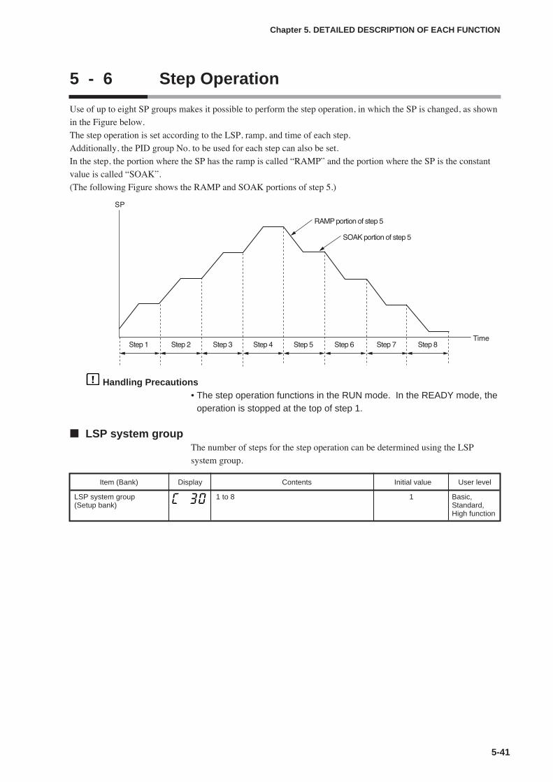
5 - 6 Step Operation
Use of up to eight SP groups makes it possible to perform the step operation, in which the SP is changed, as shown
in the Figure below.
The step operation is set according to the LSP, ramp, and time of each step.
Additionally, the PID group No. to be used for each step can also be set.
In the step, the portion where the SP has the ramp is called “RAMP” and the portion where the SP is the constant
value is called “SOAK”.
(The following Figure shows the RAMP and SOAK portions of step 5.)
Handling Precautions• The step operation functions in the RUN mode. In the READY mode, the
operation is stopped at the top of step 1.
LSP system groupThe number of steps for the step operation can be determined using the LSP
system group.
5-41
Chapter 5. DETAILED DESCRIPTION OF EACH FUNCTION
Item (Bank) Display Contents Initial value User level
LSP system group(Setup bank)
1 to 8 1 Basic,Standard,High function
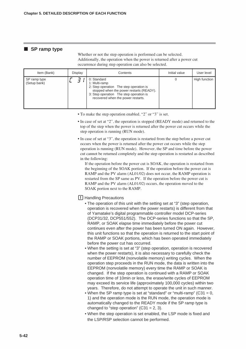
SP ramp typeWhether or not the step operation is performed can be selected.Additionally, the operation when the power is returned after a power cutoccurrence during step operation can also be selected.
• To make the step operation enabled, “2” or “3” is set.
• In case of set at “2”, the operation is stopped (READY mode) and returned to thetop of the step when the power is returned after the power cut occurs while thestep operation is running (RUN mode).
• In case of set at “3”, the operation is restarted from the step before a power cutoccurs when the power is returned after the power cut occurs while the stepoperation is running (RUN mode). However, the SP and time before the powercut cannot be returned completely and the step operation is restarted as describedin the following:
If the operation before the power cut is SOAK, the operation is restarted fromthe beginning of the SOAK portion. If the operation before the power cut isRAMP and the PV alarm (AL01/02) does not occur, the RAMP operation isrestarted from the SP same as PV. If the operation before the power cut isRAMP and the PV alarm (AL01/02) occurs, the operation moved to theSOAK portion next to the RAMP.
Handling Precautions• The operation of this unit with the setting set at “3” (step operation,
operation is recovered when the power restarts) is different from thatof Yamatake’s digital programmable controller model DCP-series(DCP31/32, DCP551/552). The DCP-series functions so that the SP,RAMP, or SOAK elapse time immediately before the power cutcontinues even after the power has been turned ON again. However,this unit functions so that the operation is returned to the start point ofthe RAMP or SOAK portions, which has been operated immediatelybefore the power cut has occurred.
• When the setting is set at “3” (step operation, operation is recoveredwhen the power restarts), it is also necessary to carefully check thenumber of EEPROM (nonvolatile memory) writing cycles. When theoperation step proceeds in the RUN mode, the data is written into theEEPROM (nonvolatile memory) every time the RAMP or SOAK ischanged. If the step operation is continued with a RAMP or SOAKoperation time of 10min or less, the erase/write cycles of EEPROMmay exceed its service life (approximately 100,000 cycles) within twoyears. Therefore, do not attempt to operate the unit in such manner.
• When the SP ramp type is set at “standard” or “multi-ramp” (C31 = 0,1) and the operation mode is the RUN mode, the operation mode isautomatically changed to the READY mode if the SP ramp type ischanged to “step operation” (C31 = 2, 3).
• When the step operation is set enabled, the LSP mode is fixed andthe LSP/RSP selection cannot be performed.
5-42
Chapter 5. DETAILED DESCRIPTION OF EACH FUNCTION
Item (Bank) Display Contents Initial value User level
SP ramp type(Setup bank)
0: Standard1: Multi-ramp2: Step operation The step operation is
stopped when the power restarts (READY).3: Step operation The step operation is
recovered when the power restarts.
0 High function

5-43
SP ramp unitThe ramp unit for the RAMP portion of the step operation can be set.
• ”0.1U” shows that the decimal point position is shifted one digit right from the
decimal point position of the PV.
Example: When the thermocouple input is in a range of –200 to +1200˚C,
“0.1U” is equal to 0.1˚C.
Example: When the DC voltage input is in a range of 0.0 to 100.0, “0.1U” is
equal to “0.01V”.
Handling Precautions
When the DC voltage or DC current input is used with the setting, threedigits after the decimal point, “0.1U” is equal to “0.0001”.
However, since the SP ramp-up or SP ramp-down setting cannot showfour digits after the decimal point, the setting is shown without thedecimal point.
STEP time unitThe time unit for the SOAK portion of the step operation can be set.
• When this setting is set at “0”, the time setting unit of the SP bank becomes
“0.1s”.
• When this setting is set at “1”, the time setting unit of the SP bank becomes “s”.
The decimal point is shown between “min” (2 digits) and “s” (2 digits) of the
step remain time on the operation display.
• When this setting is set at “2”, the time setting unit of the SP bank becomes
“min”. The decimal point is shown between “h” (2 digits) and “min” (2 digits)
of the step remain time on the operation display.
Handling Precautions
In the operation display mode, the step remaining time display followsthe step operation time unit setting regardless of the RAMP and SOAKportions.
Chapter 5. DETAILED DESCRIPTION OF EACH FUNCTION
Item (Bank) Display Contents Initial value User level
SP ramp unit(Setup bank)
0: 0.1U/s1: 0.1U/min2: 0.1U/h
1 High function
Item (Bank) Display Contents Initial value User level
STEP time unit(Setup bank)
0: 0.1s1: 1s (“min. s” on the operation display)2: 1min (“h. min” on the operation display)
0 High function

STEP PV startWhether or not the PV start exists and its type at start of the step operation can be
set.
• When this setting is set at “0”, the step operation is started from the SOAK
portion of step 1.
• When this setting is set at “1”, the step operation is started from the same SP as
PV in the up RAMP portion of step 1 if PV<SP-1. If PV≥SP-1, the step
operation is started from the SOAK portion of step 1.
• When this setting is set at “2”, the step operation is started from the same SP as
PV in the down RAMP portion of step 1 if PV>SP-1. If PV≤SP-1, the step
operation is started from the SOAK portion of step 1.
5-44
Chapter 5. DETAILED DESCRIPTION OF EACH FUNCTION
Item (Bank) Display Contents Initial value User level
STEP PV start (Setup bank)
0: None1: Up start2: Down start
0 High function
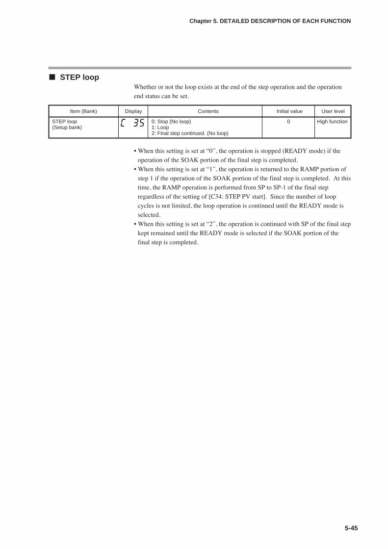
5-45
STEP loopWhether or not the loop exists at the end of the step operation and the operation
end status can be set.
• When this setting is set at “0”, the operation is stopped (READY mode) if the
operation of the SOAK portion of the final step is completed.
• When this setting is set at “1”, the operation is returned to the RAMP portion of
step 1 if the operation of the SOAK portion of the final step is completed. At this
time, the RAMP operation is performed from SP to SP-1 of the final step
regardless of the setting of [C34: STEP PV start]. Since the number of loop
cycles is not limited, the loop operation is continued until the READY mode is
selected.
• When this setting is set at “2”, the operation is continued with SP of the final step
kept remained until the READY mode is selected if the SOAK portion of the
final step is completed.
Chapter 5. DETAILED DESCRIPTION OF EACH FUNCTION
Item (Bank) Display Contents Initial value User level
STEP loop(Setup bank)
0: Stop (No loop)1: Loop2: Final step continued. (No loop)
0 High function

STEP operation LSP, PID group No., ramp, timeThe SP change and PID group No. by step of the step operation can be set.
(To be continued to the next page.)
5-46
Chapter 5. DETAILED DESCRIPTION OF EACH FUNCTION
Item (Bank) Display Contents Initial value User level
LSP1 (Step 1)(SP bank)
SP low limit (C07) to SP high limit (C08) 0 Basic,Standard,High function
PID group No. (Step 1)(SP bank)
1 to 8 1 Standard,High function
Ramp (Step 1)(SP bank)
0.0U: No ramp.0.1 to 999.9U (The time unit of the ramp is selected in theSP ramp unit.)
0.0
Time (Step 1)(SP bank)
0.0 to 999.9s (The time unit of the step operation is set at“0.1s”.)
0 to 9999s (The time unit of the step operation is set at“1s”.)
0 to 9999 min (The time unit of the step operation is set at“1min”.)
0.0
LSP (Step 2)(SP bank)
Same as step 1. 0 Basic,Standard,High function
PID group No. (Step 2)(SP bank)
1 Standard,High function
Ramp (Step 2)(SP bank)
0.0
Time (Step 2)(SP bank)
0.0
LSP (Step 3)(SP bank)
Same as step 1. 0 Basic,Standard,High function
PID group No. (Step 3)(SP bank)
1 Standard,High function
Ramp (Step 3)(SP bank)
0.0
Time (Step 3)(SP bank)
0.0
LSP (Step 4)(SP bank)
Same as step 1. 0 Basic,Standard,High function
PID group No. (Step 4)(SP bank)
1 Standard,High function
Ramp (Step 4)(SP bank)
0.0
Time (Step 4)(SP bank)
0.0

5-47
• The display and setting for the number of steps set in [C30: LSP system group]
can be performed.
• The PID group No. cannot be displayed and set if the ON/OFF control is used, if
the PID group selection is set for the operation type of internal contact 1 to 5, or
if the zone PID function is used.
• “0.1U” of the ramp shows that the decimal point position is shifted one digit
right from the decimal point position of the PV.
• When the ramp is set at “0.0U”, the operation skips the RAMP and moves to the
next SOAK. Additionally, when the LSPs of two continuous steps are the same,
the operation skips the RAMP and moves to the next SOAK.
• When the time setting is set at “0.0” or “0”, the operation skips the SOAK and
moves to the next RAMP.
Chapter 5. DETAILED DESCRIPTION OF EACH FUNCTION
Item (Bank) Display Contents Initial value User level
LSP (Step 5)(SP bank)
Same as step 1. 0 Basic,Standard,High function
PID group No. (Step 5)(SP bank)
1 Standard,High function
Ramp (Step 5)(SP bank)
0.0
Time (Step 5)(SP bank)
0.0
LSP (Step 6)(SP bank)
Same as step 1. 0 Basic,Standard,High function
PID group No. (Step 6)(SP bank)
1 Standard,High function
Ramp (Step 6)(SP bank)
0.0
Time (Step 6)(SP bank)
0.0
LSP (Step 7)(SP bank)
Same as step 1. 0 Basic,Standard,High function
PID group No. (Step 7)(SP bank)
1 Standard,High function
Ramp (Step 7)(SP bank)
0.0
Time (Step 7)(SP bank)
0.0
LSP (Step 8)(SP bank)
Same as step 1. 0 Basic,Standard,High function
PID group No. (Step 8)(SP bank)
1 Standard,High function
Ramp (Step 8)(SP bank)
0.0
Time (Step 8)(SP bank)
0.0
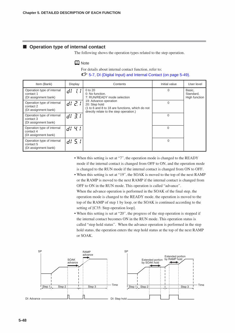
Operation type of internal contact The following shows the operation types related to the step operation.
Note
For details about internal contact function, refer to;
5-7, DI (Digital Input) and Internal Contact (on page 5-49).
• When this setting is set at “7”, the operation mode is changed to the READY
mode if the internal contact is changed from OFF to ON, and the operation mode
is changed to the RUN mode if the internal contact is changed from ON to OFF.
• When this setting is set at “19”, the SOAK is moved to the top of the next RAMP
or the RAMP is moved to the next RAMP if the internal contact is changed from
OFF to ON in the RUN mode. This operation is called “advance”.
When the advance operation is performed in the SOAK of the final step, the
operation mode is changed to the READY mode, the operation is moved to the
top of the RAMP of step 1 by loop, or the SOAK is continued according to the
setting of [C35: Step operation loop].
• When this setting is set at “20”, the progress of the step operation is stopped if
the internal contact becomes ON in the RUN mode. This operation status is
called “step hold status”. When the advance operation is performed in the step
hold status, the operation enters the step hold status at the top of the next RAMP
or SOAK.
5-48
Chapter 5. DETAILED DESCRIPTION OF EACH FUNCTION
Item (Bank) Display Contents Initial value User level
Operation type of internalcontact 1(DI assignment bank)
0 to 200: No function.7: RUN/READY mode selection19: Advance operation20: Step hold(1 to 6 and 8 to 18 are functions, which do notdirectly relate to the step operation.)
0 Basic,Standard,High function
Operation type of internalcontact 2(DI assignment bank)
0
Operation type of internalcontact 3(DI assignment bank)
0
Operation type of internalcontact 4(DI assignment bank)
0
Operation type of internalcontact 5(DI assignment bank)
0
!
!
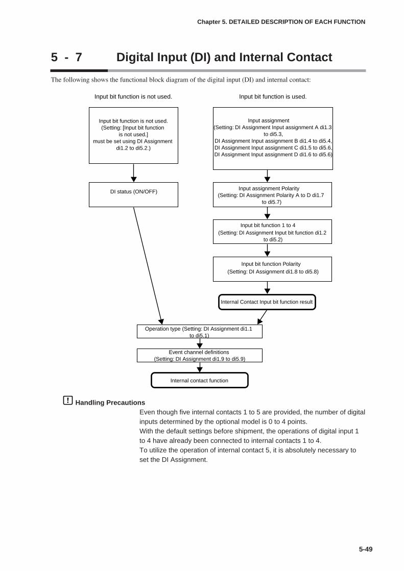
5-49
Chapter 5. DETAILED DESCRIPTION OF EACH FUNCTION
5 - 7 Digital Input (DI) and Internal Contact
The following shows the functional block diagram of the digital input (DI) and internal contact:
Handling PrecautionsEven though five internal contacts 1 to 5 are provided, the number of digitalinputs determined by the optional model is 0 to 4 points.With the default settings before shipment, the operations of digital input 1to 4 have already been connected to internal contacts 1 to 4.To utilize the operation of internal contact 5, it is absolutely necessary toset the DI Assignment.
Input bit function is not used.(Setting: [Input bit function
is not used.]must be set using DI Assignment
di1.2 to di5.2.)
DI status (ON/OFF)Input assignment Polarity
(Setting: DI Assignment Polarity A to D di1.7 to di5.7)
Internal Contact Input bit function result
Input bit function is not used.
Input assignment(Setting: DI Assignment Input assignment A di1.3
to di5.3,DI Assignment Input assignment B di1.4 to di5.4,DI Assignment Input assignment C di1.5 to di5.6,DI Assignment Input assignment D di1.6 to di5.6)
Input bit function 1 to 4(Setting: DI Assignment Input bit function di1.2
to di5.2)
Input bit function Polarity(Setting: DI Assignment di1.8 to di5.8)
Input bit function is used.
Event channel definitions (Setting: DI Assignment di1.9 to di5.9)
Operation type (Setting: DI Assignment di1.1 to di5.1)
Internal contact function
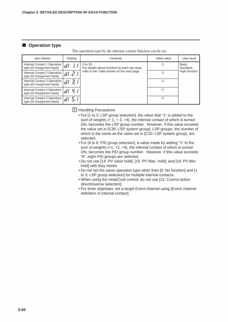
5-50
Chapter 5. DETAILED DESCRIPTION OF EACH FUNCTION
Operation typeThe operation type by the internal contact function can be set.
Handling Precautions• For [1 to 3: LSP group selection], the value that “1” is added to the
sum of weights (+ 1, + 2, +4), the internal contact of which is turnedON, becomes the LSP group number. However, if this value exceedsthe value set in [C30: LSP system group], LSP groups, the number ofwhich is the same as the value set in [C30: LSP system group], areselected.
• For [4 to 6: PID group selection], a value made by adding “1” to thesum of weights (+1, +2, +4), the internal contact of which is turnedON, becomes the PID group number. However, if this value exceeds“8”, eight PID groups are selected.
• Do not use [14: PV value hold], [15: PV Max. hold], and [16: PV Min.hold] with they mixed.
• Do not set the same operation type other than [0: No function] and [1to 3: LSP group selection] for multiple internal contacts.
• When using the Heat/Cool control, do not use [12: Control actiondirect/reverse selection].
• For timer stop/start, set a target Event channel using [Event channeldefinition of internal contact].
Item (Bank) Display Contents Initial value User level
Internal Contact 1 Operationtype (DI Assignment bank)
0 to 20For details about function by each set value,refer to the Table shown on the next page.
0 Basic,Standard,High function0Internal Contact 2 Operation
type (DI Assignment bank)
0Internal Contact 3 Operationtype (DI Assignment bank)
Internal Contact 4 Operationtype (DI Assignment bank)
0
0Internal Contact 5 Operationtype (DI Assignment bank)
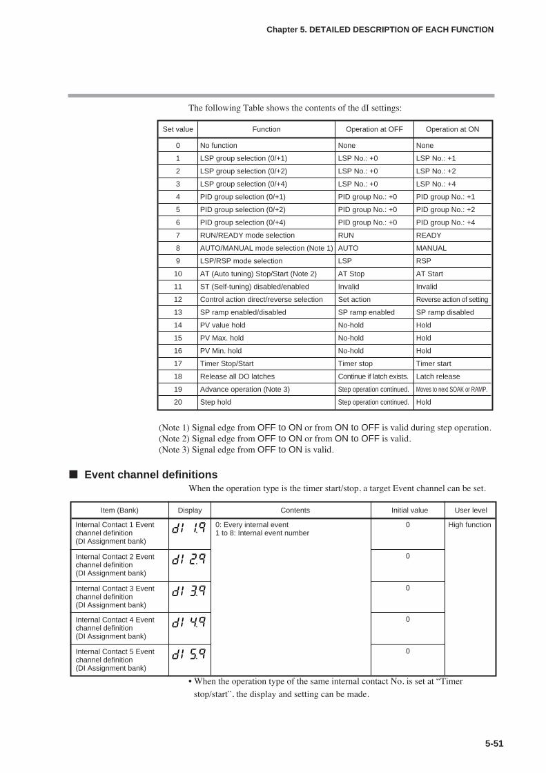
5-51
Chapter 5. DETAILED DESCRIPTION OF EACH FUNCTION
The following Table shows the contents of the dI settings:
(Note 1) Signal edge from OFF to ON or from ON to OFF is valid during step operation.(Note 2) Signal edge from OFF to ON or from ON to OFF is valid.(Note 3) Signal edge from OFF to ON is valid.
Event channel definitionsWhen the operation type is the timer start/stop, a target Event channel can be set.
• When the operation type of the same internal contact No. is set at “Timer
stop/start”, the display and setting can be made.
Item (Bank) Display Contents Initial value User level
Internal Contact 1 Eventchannel definition(DI Assignment bank)
0: Every internal event1 to 8: Internal event number
0 High function
0Internal Contact 2 Eventchannel definition(DI Assignment bank)
0Internal Contact 3 Eventchannel definition(DI Assignment bank)
Set value Function Operation at OFF Operation at ON
0 No function None None
1 LSP group selection (0/+1) LSP No.: +0 LSP No.: +1
2 LSP group selection (0/+2) LSP No.: +0 LSP No.: +2
3 LSP group selection (0/+4) LSP No.: +0 LSP No.: +4
4 PID group selection (0/+1) PID group No.: +0 PID group No.: +1
5 PID group selection (0/+2) PID group No.: +0 PID group No.: +2
6 PID group selection (0/+4) PID group No.: +0 PID group No.: +4
7 RUN/READY mode selection RUN READY
8 AUTO/MANUAL mode selection (Note 1) AUTO MANUAL
9 LSP/RSP mode selection LSP RSP
10 AT (Auto tuning) Stop/Start (Note 2) AT Stop AT Start
11 ST (Self-tuning) disabled/enabled Invalid Invalid
12 Control action direct/reverse selection Set action Reverse action of setting
13 SP ramp enabled/disabled SP ramp enabled SP ramp disabled
14 PV value hold No-hold Hold
15 PV Max. hold No-hold Hold
16 PV Min. hold No-hold Hold
17 Timer Stop/Start Timer stop Timer start
18 Release all DO latches Continue if latch exists. Latch release
19 Advance operation (Note 3) Step operation continued. Moves to next SOAK or RAMP.
20 Step hold Step operation continued. Hold
0Internal Contact 4 Eventchannel definition(DI Assignment bank)
0Internal Contact 5 Eventchannel definition(DI Assignment bank)

Input bit functionFour kinds of input bit functions are provided. The required functions can be
configured by the user.
• When the set value is “0”, the input bit function is not used and the default input
is used. The following shows the default input of each internal contact:
Internal Contact 1: digital input (DI) 1
Internal Contact 2: digital input (DI) 2
Internal Contact 3: digital input (DI) 3
Internal Contact 4: digital input (DI) 4
Internal Contact 5: OFF status
• In the input bit function, the logical operations (AND, OR) of each of internal
contacts 1 to 5 are combined. In input bit functions 1 to 4, the combination of the
logical operations may vary. The following shows one logical operation:
Logical AND Logical OR
OFF and OFF = OFF OFF or OFF = OFF
ON and OFF = OFF ON or OFF = ON
ON and ON = ON ON or ON = ON
• “OFF” is “contact open (OPEN)” or “0” when expressed using the numerical
value.
• “ON” is “contact close (CLOSE)” or “1” when expressed using the numerical
value.
5-52
Chapter 5. DETAILED DESCRIPTION OF EACH FUNCTION
Item (Bank) Display Contents Initial value User level
Internal Contact 1 Input bitfunction(DI Assignment bank)
0: Not used (Default input)1: Function 1 ((A and B) or (C and D))2: Function 2 ((A or B) and (C or D))3: Function 3 (A or B or C or D)4: Function 4 (A and B and C and D)
0 High function
0Internal Contact 2 Input bitfunction(DI Assignment bank)
0Internal Contact 3 Input bitfunction(DI Assignment bank)
0Internal Contact 4 Input bitfunction(DI Assignment bank)
0Internal Contact 5 Input bitfunction(DI Assignment bank)
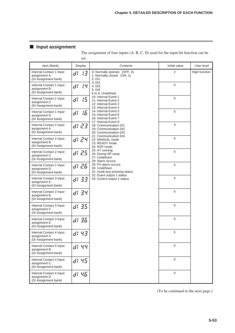
5-53
Input assignmentThe assignment of four inputs (A, B, C, D) used for the input bit function can be
set.
(To be continued to the next page.)
Chapter 5. DETAILED DESCRIPTION OF EACH FUNCTION
Item (Bank) Display Contents Initial value User level
Internal Contact 1 Inputassignment A(DI Assignment bank)
0: Normally opened. (OFF, 0)1: Normally closed. (ON, 1)2: DI13: DI24: DI35: DI46 to 9: Undefined.10: Internal Event 111: Internal Event 212: Internal Event 313: Internal Event 414: Internal Event 515: Internal Event 616: Internal Event 717: Internal Event 818: Communication DI119: Communication DI220: Communication DI321: Communication DI422: MANUAL mode23: READY mode24: RSP mode25: AT running26: During SP ramp27: Undefined.28: Alarm occurs.29: PV alarm occurs.30: Undefined.31: mode key pressing status32: Event output 1 status33: Control output 1 status
2 High function
0Internal Contact 1 Inputassignment B(DI Assignment bank)
0Internal Contact 1 Inputassignment C(DI Assignment bank)
0Internal Contact 1 Inputassignment D(DI Assignment bank)
3Internal Contact 2 Inputassignment A(DI Assignment bank)
0Internal Contact 2 Inputassignment B(DI Assignment bank)
0Internal Contact 2 Inputassignment C(DI Assignment bank)
0Internal Contact 2 Inputassignment D(DI Assignment bank)
4Internal Contact 3 Inputassignment A(DI Assignment bank)
0Internal Contact 3 Inputassignment B(DI Assignment bank)
0Internal Contact 3 Inputassignment C(DI Assignment bank)
0Internal Contact 3 Inputassignment D(DI Assignment bank)
5Internal Contact 4 Inputassignment A(DI Assignment bank)
0Internal Contact 4 Inputassignment B(DI Assignment bank)
0Internal Contact 4 Inputassignment C(DI Assignment bank)
0Internal Contact 4 Inputassignment D(DI Assignment bank)

• When the internal contact No. and its input bit functions 1 to 4 are set, the
display and setting can be configured.
Polarity of input assignmentThe polarity of four input assignments (A, B, C, D) used for the input bit function
can be set.
• When the internal contact No. and its input bit functions 1 to 4 are set, the
display and setting can be configured.
5-54
Chapter 5. DETAILED DESCRIPTION OF EACH FUNCTION
Item (Bank) Display Contents Initial value User level
Internal Contact 1, PolarityA to D (DI Assignment bank)
The digits are called 1st digit, 2nd digit, 3rddigit, and 4th digit from the right end.
1st digit: Input assignment A Polarity setting2nd digit: Input assignment B Polarity setting3rd digit: Input assignment C Polarity setting4th digit: Input assignment D Polarity setting
0: Direct1: Reverse
0000 High function
0000Internal Contact 2, Polarity A to D (DI Assignment bank)
0000Internal Contact 3, Polarity A to D (DI Assignment bank)
Item (Bank) Display Contents Initial value User level
Internal Contact 5 Inputassignment A(DI Assignment bank)
0: Normally opened. (OFF, 0)1: Normally closed. (ON, 1)2: DI13: DI24: DI35: DI46 to 9: Undefined.10: Internal Event 111: Internal Event 212: Internal Event 313: Internal Event 414: Internal Event 515: Internal Event 616: Internal Event 717: Internal Event 818: Communication DI119: Communication DI220: Communication DI321: Communication DI422: MANUAL mode23: READY mode24: RSP mode25: AT running26: During SP ramp27: Undefined.28: Alarm occurs.29: PV alarm occurs.30: Undefined.31: mode key pressing status32: Event output 1 status33: Control output 1 status
0 High function
0Internal Contact 5 Inputassignment B(DI Assignment bank)
0Internal Contact 5 Inputassignment C(DI Assignment bank)
0Internal Contact 5 Inputassignment D(DI Assignment bank)
0000Internal Contact 4, Polarity A to D (DI Assignment bank)
0000Internal Contact 5, Polarity A to D (DI Assignment bank)
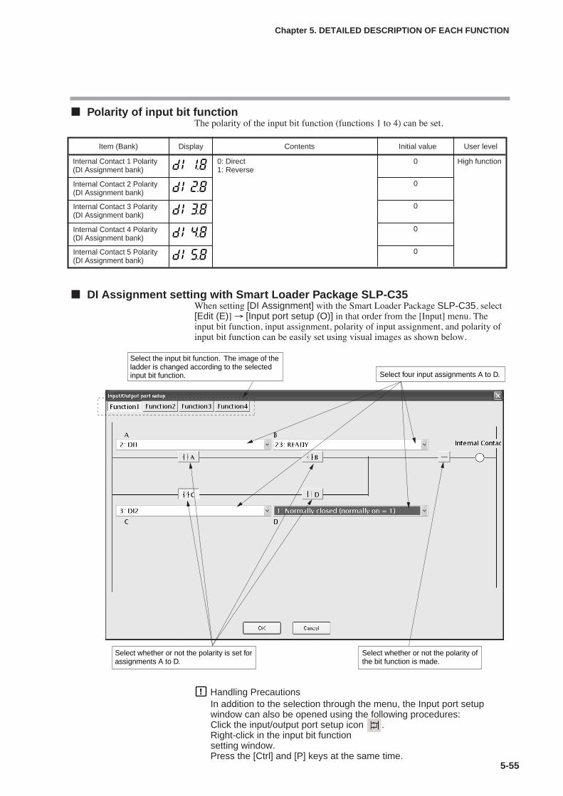
5-55
Polarity of input bit functionThe polarity of the input bit function (functions 1 to 4) can be set.
DI Assignment setting with Smart Loader Package SLP-C35When setting [DI Assignment] with the Smart Loader Package SLP-C35, select[Edit (E)] → [Input port setup (O)] in that order from the [Input] menu. Theinput bit function, input assignment, polarity of input assignment, and polarity ofinput bit function can be easily set using visual images as shown below.
Handling PrecautionsIn addition to the selection through the menu, the Input port setupwindow can also be opened using the following procedures:Click the input/output port setup icon .Right-click in the input bit functionsetting window.Press the [Ctrl] and [P] keys at the same time.
Chapter 5. DETAILED DESCRIPTION OF EACH FUNCTION
Select the input bit function. The image of the ladder is changed according to the selected input bit function. Select four input assignments A to D.
Select whether or not the polarity is set for assignments A to D.
Select whether or not the polarity of the bit function is made.
Item (Bank) Display Contents Initial value User level
Internal Contact 1 Polarity(DI Assignment bank)
0: Direct1: Reverse
0 High function
0Internal Contact 2 Polarity(DI Assignment bank)
0Internal Contact 3 Polarity(DI Assignment bank)
0Internal Contact 4 Polarity(DI Assignment bank)
0Internal Contact 5 Polarity(DI Assignment bank)
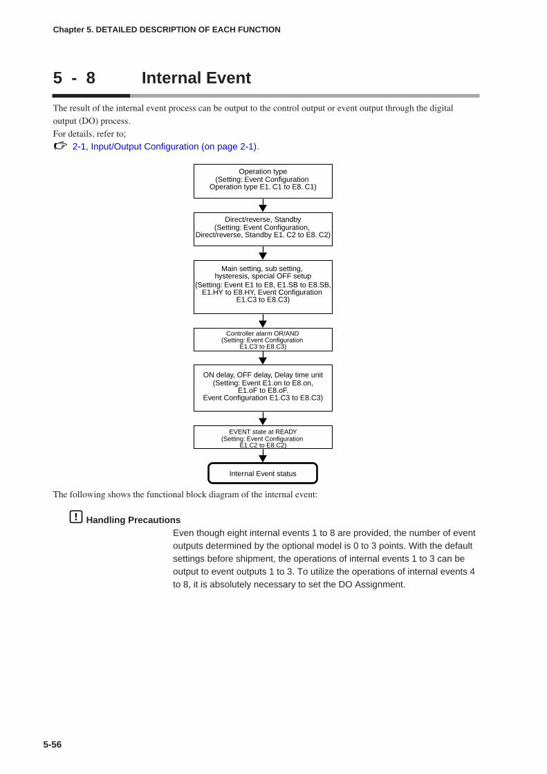
5 - 8 Internal Event
5-56
The result of the internal event process can be output to the control output or event output through the digital
output (DO) process.
For details, refer to;2-1, Input/Output Configuration (on page 2-1).
The following shows the functional block diagram of the internal event:
Handling PrecautionsEven though eight internal events 1 to 8 are provided, the number of eventoutputs determined by the optional model is 0 to 3 points. With the defaultsettings before shipment, the operations of internal events 1 to 3 can beoutput to event outputs 1 to 3. To utilize the operations of internal events 4to 8, it is absolutely necessary to set the DO Assignment.
Chapter 5. DETAILED DESCRIPTION OF EACH FUNCTION
Operation type(Setting: Event Configuration
Operation type E1. C1 to E8. C1)
Direct/reverse, Standby(Setting: Event Configuration,
Direct/reverse, Standby E1. C2 to E8. C2)
Controller alarm OR/AND(Setting: Event Configuration
E1.C3 to E8.C3)
EVENT state at READY(Setting: Event Configuration
E1.C2 to E8.C2)
Main setting, sub setting, hysteresis, special OFF setup
(Setting: Event E1 to E8, E1.SB to E8.SB,E1.HY to E8.HY, Event Configuration
E1.C3 to E8.C3)
ON delay, OFF delay, Delay time unit(Setting: Event E1.on to E8.on,
E1.oF to E8.oF.Event Configuration E1.C3 to E8.C3)
Internal Event status

5-57
OperationAccording to the operation type, direct/reverse, main setting, sub setting,hysteresis, and other settings, the operation of the internal event becomes asfollows:
[List of internal event operations]
NoteFor details about unit (U), refer to the attached glossary.
* If the setting is made so that the main setting is greater than the sub setting, the operation is performed with themain setting swapped for the sub setting automatically.
(To be continued to the next page.)
Chapter 5. DETAILED DESCRIPTION OF EACH FUNCTION
Operation type Set value Direct action Reverse actionof operation
type
No event 0 Always OFF Always OFF
PV high limit 1
PV low limit 2
PV high/low limit 3
Deviation high 4limit
Deviation low limit 5
Deviation high/ 6low limit
Deviation high limit 7(Final SP reference)
Deviation low limit 8(Final SP reference)
Deviation high/ 9low limit
(Final SP reference)
ONHYS ON HYS
Main settingMain settingPV PV
Main setting
PV
Main setting
PV
ONHYSON HYS
Main setting Sub-settingPVSP
ON HYS ONHYS ONHYS HYS
Main setting Sub-setting PVSP
Main setting (*) Sub-setting (*) Main setting (*) Sub-setting (*)
PV PV
ON HYS ONHYS ONHYS HYS
ONHYS ON HYS
SP + Main setting SP + Main setting
PV PV
SP + Main setting
PV
SP + Main setting
PV
ONHYSON HYS
Same as the direct action of the deviation highlimit when the SP ramp is not used. Thedifference is that the SP ramp does not use thecurrent SP, but it uses the final SP.
Same as the reverse action of the deviationhigh limit when the SP ramp is not used. Thedifference is that the SP ramp does not use thecurrent SP, but it uses the final SP.
Same as the direct action of the deviation lowlimit when the SP ramp is not used. Thedifference is that the SP ramp does not use thecurrent SP, but it uses the final SP.
Same as the reverse action of the deviationlow limit when the SP ramp is not used. Thedifference is that the SP ramp does not use thecurrent SP, but it uses the final SP.
Same as the direct action of the deviationhigh/low limit when the SP ramp is not used.The difference is that the SP ramp does notuse the current SP, but it uses the final SP.
Same as the reverse action of the deviationhigh/low limit when the SP ramp is not used.The difference is that the SP ramp does notuse the current SP, but it uses the final SP.
shows that the ON/OFF is changed at this value. shows that the ON/OFF is changed at a point that
"1U" is added to this value.
shows that the ON/OFF is changed at this value. shows that the ON/OFF is changed at a point that
"1U" is added to this value.
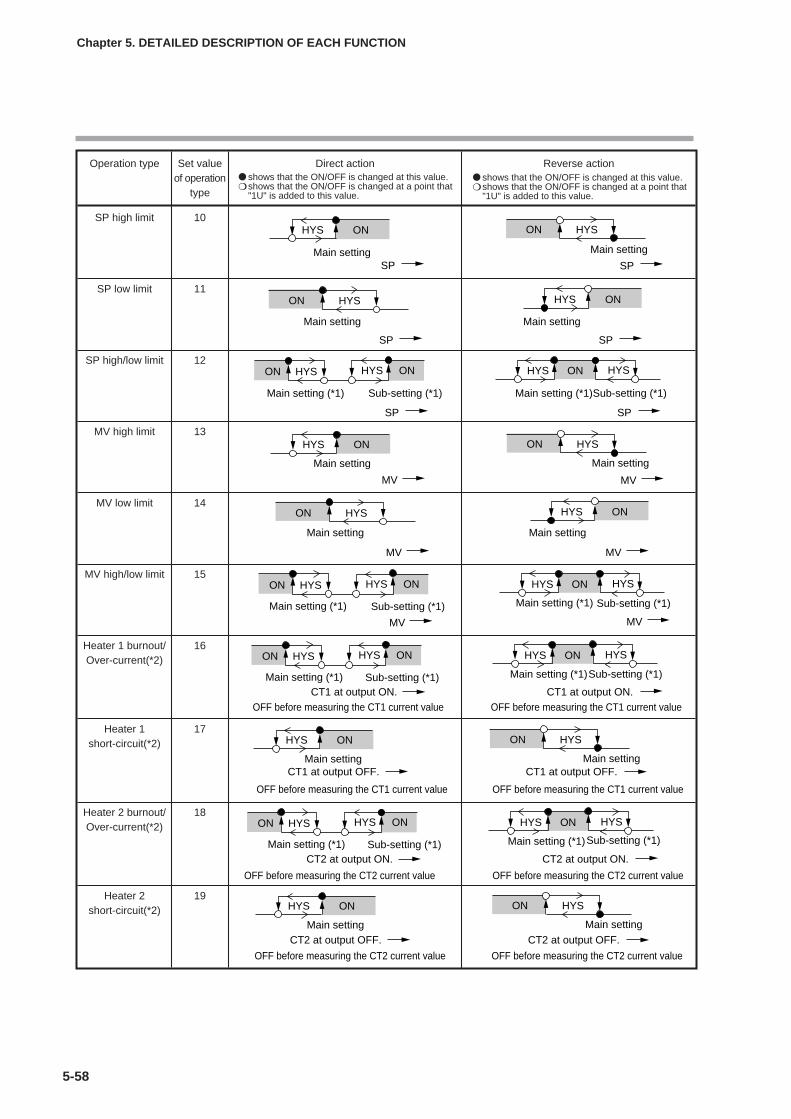
5-58
Chapter 5. DETAILED DESCRIPTION OF EACH FUNCTION
Operation type Set value Direct action Reverse actionof operation
type
SP high limit 10
SP low limit 11
SP high/low limit 12
MV high limit 13
MV low limit 14
MV high/low limit 15
Heater 1 burnout/ 16Over-current(*2)
Heater 1 17short-circuit(*2)
Heater 2 burnout/ 18Over-current(*2)
Heater 2 19short-circuit(*2)
Main setting
SP
Main setting
SP
ONHYSON HYS
Main setting (*1) Sub-setting (*1) Main setting (*1)Sub-setting (*1)
SP SP
ON HYS ONHYS ONHYS HYS
ONHYS ON HYS
Main setting Main setting
MV MV
Main setting
MV
Main setting
MV
ONHYSON HYS
Main setting (*1) Sub-setting (*1)
MV
ON HYS ONHYS ONHYS HYS
Main setting (*1) Sub-setting (*1)
MV
Main setting (*1) Sub-setting (*1)CT1 at output ON. CT1 at output ON.
ON HYS ONHYS ONHYS HYS
Main setting (*1)Sub-setting (*1)
OFF before measuring the CT1 current value OFF before measuring the CT1 current value
ONHYS ON HYS
Main setting Main settingCT1 at output OFF. CT1 at output OFF.
OFF before measuring the CT1 current value OFF before measuring the CT1 current value
Main setting (*1) Sub-setting (*1)CT2 at output ON. CT2 at output ON.
ON HYS ONHYS ONHYS HYS
Main setting (*1)Sub-setting (*1)
OFF before measuring the CT2 current value OFF before measuring the CT2 current value
ONHYS ON HYS
Main setting Main setting
CT2 at output OFF. CT2 at output OFF.
OFF before measuring the CT2 current value OFF before measuring the CT2 current value
shows that the ON/OFF is changed at this value. shows that the ON/OFF is changed at a point that
"1U" is added to this value.
shows that the ON/OFF is changed at this value. shows that the ON/OFF is changed at a point that
"1U" is added to this value.
ONHYS ON HYS
Main settingMain settingSP SP
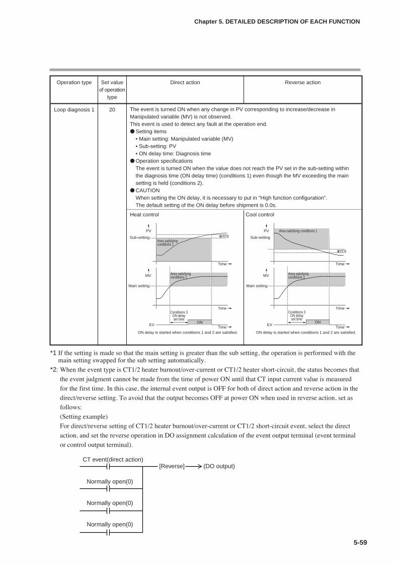
5-59
Chapter 5. DETAILED DESCRIPTION OF EACH FUNCTION
Operation type Set value Direct action Reverse actionof operation
type
Loop diagnosis 1 20
Sub-setting
Main setting
Time
Conditions 3ON delayset time
ON delay is started when conditions 1 and 2 are satisfied.
Area satisfying conditions 1
Area satisfying conditions 2
Time
Time
PV
MV
EV ON
HYS Sub-setting
Main setting
Time
Conditions 3ON delayset time
ON delay is started when conditions 1 and 2 are satisfied.
Area satisfying conditions 1
Area satisfying conditions 2
Time
Time
PV
MV
EV ON
HYS
The event is turned ON when any change in PV corresponding to increase/decrease inManipulated variable (MV) is not observed.This event is used to detect any fault at the operation end. Setting items
• Main setting: Manipulated variable (MV)• Sub-setting: PV• ON delay time: Diagnosis time
Operation specificationsThe event is turned ON when the value does not reach the PV set in the sub-setting withinthe diagnosis time (ON delay time) (conditions 1) even though the MV exceeding the mainsetting is held (conditions 2).
CAUTIONWhen setting the ON delay, it is necessary to put in "High function configuration".The default setting of the ON delay before shipment is 0.0s.
Heat control Cool control
*1 If the setting is made so that the main setting is greater than the sub setting, the operation is performed with themain setting swapped for the sub setting automatically.
*2: When the event type is CT1/2 heater burnout/over-current or CT1/2 heater short-circuit, the status becomes that
the event judgment cannot be made from the time of power ON until that CT input current value is measured
for the first time. In this case, the internal event output is OFF for both of direct action and reverse action in the
direct/reverse setting. To avoid that the output becomes OFF at power ON when used in reverse action, set as
follows:
(Setting example)
For direct/reverse setting of CT1/2 heater burnout/over-current or CT1/2 short-circuit event, select the direct
action, and set the reverse operation in DO assignment calculation of the event output terminal (event terminal
or control output terminal).
CT event(direct action)[Reverse] (DO output)
Normally open(0)
Normally open(0)
Normally open(0)

(To be continued to the next page.)
5-60
Chapter 5. DETAILED DESCRIPTION OF EACH FUNCTION
Operation type Set value Direct action Reverse actionof operation
type
Loop diagnosis 2 21
PV to be usedas reference
Main setting
Time
Conditions 3ON delayset time
ON delay is started when conditions 1 and 2 are satisfied.
Area satisfyingconditions 1
Sub-setting(0 or more)
Area satisfying conditions 2
Time
Time
PV
MV
EV ON
HYS
Main setting
Time
Conditions 3ON delayset time
ON delay is started when conditions 1 and 2 are satisfied.
Area satisfyingconditions 1
Area satisfyingconditions 2
Time
Time
PV
MV
EV ON
HYS
Sub-setting (0 or more)
PV to be usedas reference
The event is turned ON when any change in PV corresponding to increase/decrease inManipulated variable (MV) is not observed.This event is used to detect any fault at the operation end. Setting items
• Main setting: Manipulated variable (MV)• Sub-setting: Change in PV from the point that the MV exceeds the main setting.• ON delay time: Diagnosis time
Operation specificationsThe event is turned ON when the MV exceeding the main setting is held (conditions 2) andthe PV does not reach the value that the sub-setting is added to (subtracted from) the PV atthe point that the MV exceeds the main setting within the diagnosis time (ON delay time)(conditions 1).
CAUTIONWhen setting the ON delay, it is necessary to put in "High function configuration".The default setting of the ON delay before shipment is 0.0s.
Heat control Cool control

(To be continued to the next page.)
5-61
Chapter 5. DETAILED DESCRIPTION OF EACH FUNCTION
Operation type Set value Direct action Reverse actionof operation
type
Loop diagnosis 3 22
High limit
Low limit
Time
Conditions 3ON delayset time
Conditions 3ON delayset time
ON delay is started when conditions 1 and 2 are satisfied.
Area satisfyingconditions 2
Area satisfyingconditions 2
Time
Time
PV
MV
EV ON ON
HYS
HYSPV to be used
as reference
PV to be used as reference
(0 or more)Main setting
Main setting (0 or more)
Area satisfyingconditions 1
Area satisfyingconditions 1
High limit
Low limit
Time
Conditions 3ON delayset time
Conditions 3ON delayset time
ON delay is started when conditions 1 and 2 are satisfied.
Area satisfyingconditions 2
Area satisfyingconditions 2
Time
Time
PV
MV
EV ON ON
HYS
HYS
(0 or more)Main setting
Main setting (0 or more)
Area satisfyingconditions 1
Area satisfyingconditions 1
PV to be usedas reference
PV to be usedas reference
The event is turned ON when any change in PV corresponding to increase/decrease inManipulated variable (MV) is not observed. This event is used to detect any fault at theoperation end. Setting items
• Main setting: Change in PV from the point that the MV reaches the high limit (100%) or lowlimit (0%).
• Sub-setting: Range of absolute value of deviation (PV-SP) allowing the event to hold OFFstate.
• ON delay time: Diagnosis time• OFF delay time: A period of time from power ON allowing the event to hold OFF state.
Operation specificationsThe direct action is used for the heat control and is turned ON in the following cases:• The increase in PV becomes smaller than the main setting after the diagnosis time (ON
delay time) has elapsed after the MV had reached the high limit.• The decrease in PV becomes smaller than the main setting after the diagnosis time (ON
delay time) has elapsed after the MV had reached the low limit.The reverse action is used for the cool control and is turned ON in the following cases:• The decrease in PV becomes smaller than the main setting after the diagnosis time (ON
delay time) has elapsed after the MV had reached the high limit.• The increase in PV becomes smaller than the main setting after the diagnosis time (ON
delay time) has elapsed after the MV had reached the low limit.In the following cases, the event is turned OFF with the priority over the above conditions:• The absolute value of the deviation (PV-SP) becomes less than the sub-setting.
However, the event is turned OFF when the absolute value of the deviation is less than the(sub setting – hysteresis) value after the absolute value of the deviation has become the subsetting or more.
• A period of time after the operation has been started by power ON is less than the OFFdelay time.
CAUTIONWhen setting the ON delay and OFF delay, it is necessary to put in " High functionconfiguration".The default settings of the ON delay and OFF delay before shipment are 0.0s.
Heat control Cool control

5-62
Chapter 5. DETAILED DESCRIPTION OF EACH FUNCTION
Operation type Set value Direct action Reverse actionof operation
type
Alarm 23 ON if alarm occurs (alarm code AL01 to 99). OFF if alarm occurs (alarm code AL01 to 99).(status) OFF in other cases. ON in other cases.
READY 24 ON in the READY mode. OFF in the READY mode.(status) OFF in the RUN mode. ON in the RUN mode.
MANUAL 25 ON in the MANUAL mode. OFF in the MANUAL mode.(status) OFF in the AUTO mode. ON in the AUTO mode.
RSP 26 ON in the RSP mode. OFF in the RSP mode.(status) OFF in the LSP mode. ON in the LSP mode.
During AT 27 ON when AT is executed. OFF when AT is executed.(Status) OFF when AT is stopped. ON when AT is stopped.
During SP ramp 28 ON during SP ramp. OFF during SP ramp.OFF when SP ramp is not performed or is completed. ON when SP ramp is not performed or is completed.
Control action 29 ON during direct action (cooling). OFF during direct action (cooling).(status) OFF during reverse action (heating). ON during reverse action (heating).
ST setting standby 30 Invalid in this unit. Always OFF. Invalid in this unit. Always ON.(status)
During estimated 31 ON during estimated position control. OFF during estimated position control.position control OFF when not estimated. ON when not estimated.
(status)
Timer 32(status)
High and low limits 33of MFB value
The direct and reverse action settings are disabled for the timer event.When using the timer event, it is necessary to set the operation type of the DI assignment to"Timer Start/Stop". Additionally, when setting the event channel designation of the DIassignment, multiple timer events are controlled from individual internal contacts (DI). Setting items
• ON delay time: A period of time necessary for the event change from OFF to ON after DI hasbeen changed from OFF to ON.
• OFF delay time: A period of time necessary for the event change from ON to OFF after DIhas been changed from ON to OFF.
Operation specifications• The event is turned ON when DI ON continues for ON delay time or longer.• The event is turned OFF when DI OFF continues for OFF delay time.• In other cases, the current status is continued.
CAUTIONWhen setting the ON delay and OFF delay, it is necessary to put in "High functionconfiguration".The default settings of the ON delay and OFF delay before shipment are 0.0s.The default setting of the event channel designation of the DI assignment before shipment is"0". In this case, the timer event start/stop can be set for all internal events from one internalcontact (DI).Additionally, as one or more event channel designation is set, the timer event start/stop canbe set for one internal event specified by one internal contact (DI).However, when setting the event channel of the DI assignment, it is necessary to put in "Highfunction configuration".
Time
ONInternal event
ONDI
OFF delayON delay
Main setting(*1) Sub setting(*1) Main setting(*1) Sub setting(*1)
MFB MFB
ON HYS ONHYS ONHYS HYS
*1 If the setting is made so that the main setting is greater than the sub setting, the operation is performed with themain setting swapped for the sub setting automatically.

5-63
Operation typeThe operation type of the internal event can be set.
Chapter 5. DETAILED DESCRIPTION OF EACH FUNCTION
Item (Bank) Display Contents Initial value User level
Internal Event 1Configuration 1 Operationtype(Event Configuration bank)
0: No event1: PV high limit2: PV low limit3: PV high/low limit4: Deviation high limit5: Deviation low limit6: Deviation high/low limit7: Deviation high limit
(Final SP reference)8: Deviation low limit
(Final SP reference)9: Deviation high/low limit
(Final SP reference)10: SP high limit11: SP low limit12: SP high/low limit13: MV high limit14: MV low limit15: MV high/low limit16: CT1 heater burnout/over-current17: CT1 heater short-circuit18: CT2 heater burnout/over-current19: CT2 heater short-circuit20: Loop diagnosis 121: Loop diagnosis 222: Loop diagnosis 323: Alarm (status)24: READY (status)25: MANUAL (status)26: RSP (status)27: During AT execution (status)28: During SP ramp (status)29: Control direct action (status)30: ST setting standby (status)
(Invalid in this unit.)31: During estimated position control (status)32: Timer (status)33: High and Low limits of MFB value
(Invalid in this unit)
0 Basic,Standard,High function
0Internal Event 2Configuration 1 Operationtype(Event Configuration bank)
0Internal Event 3Configuration 1 Operationtype(Event Configuration bank)
0Internal Event 4Configuration 1 Operationtype(Event Configuration bank)
0Internal Event 5Configuration 1 Operationtype(Event Configuration bank)
0Internal Event 6Configuration 1 Operationtype(Event Configuration bank)
0Internal Event 7Configuration 1 Operationtype(Event Configuration bank)
0Internal Event 8Configuration 1 Operationtype(Event Configuration bank)
Handling Precautions
• If ROM version 1 of the instrument information bank (Id02) is prior to2.04, “33” cannot be set as [Internal Event configuration 1 operationtype].

Direct/reverse, standby, and EVENT state at READYDirect/reverse, standby, and EVENT state at READY accompanying with the
operation type can be set.
• When the internal event configuration 1 operation type is set at [0: No event], the
internal event configuration 2 (direct/reverse, standby, and EVENT state at
READY) is not displayed.
• For details about internal event operation with the direct/reverse setting, refer to;
List of internal event operations (on pages 5-57 to 5-62).
Handling Precautions
• “Standby” is a function that does not turn ON the event even thoughthe event currently used satisfies the ON conditions (before polarity)when the instrument power is turned ON or when the READY mode ischanged to the RUN mode. The event is turned ON when the ONconditions are satisfied again once the OFF conditions have beensatisfied.
• “Standby + Standby at SP change” means that the standby is setagain when the SP is changed (SP value and LSP group number) inaddition to the standby functions. However, when the same SP valueis written or when the SP value is not changed even though the LSPgroup number is changed, the unit does not enter the standby mode.
5-64
Chapter 5. DETAILED DESCRIPTION OF EACH FUNCTION
Item (Bank) Display Contents Initial value User level
Internal Event 1Configuration 2(Event Configuration bank)
The digits are called 1st digit, 2nd digit, 3rddigit, and 4th digit from the right end.1st digit: Direct/reverse setup
0: Direct1: Reverse
2nd digit: Standby setup0: None1: Standby2: Standby + Standby at SP change
3rd digit: EVENT state at READY setup0: Continued.1: Forced OFF
4th digit: Undefined.0: Undefined.
0000 Basic,Standard,High function
0000Internal Event 2Configuration 2(Event Configuration bank)
0000Internal Event 3Configuration 2(Event Configuration bank)
0000Internal Event 4Configuration 2(Event Configuration bank)
0000Internal Event 5Configuration 2(Event Configuration bank)
0000Internal Event 6Configuration 2(Event Configuration bank)
0000Internal Event 7Configuration 2(Event Configuration bank)
0000Internal Event 8Configuration 2(Event Configuration bank)
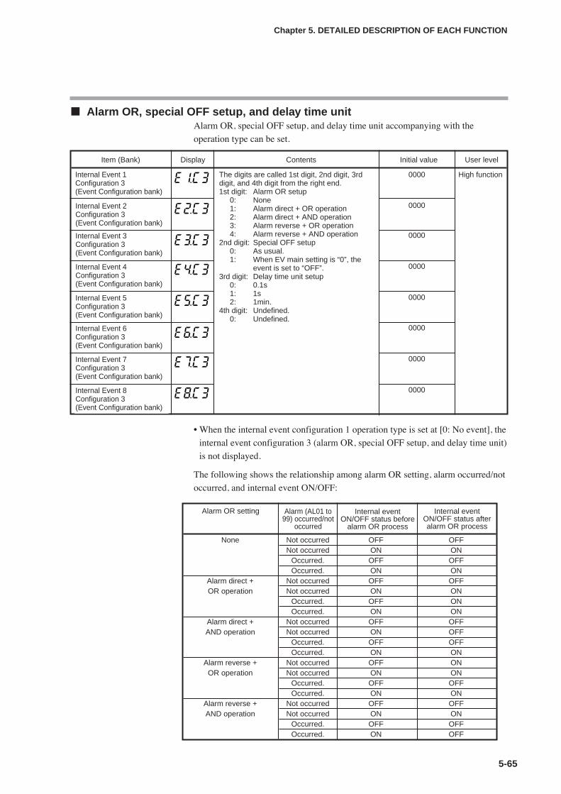
5-65
Alarm OR, special OFF setup, and delay time unitAlarm OR, special OFF setup, and delay time unit accompanying with the
operation type can be set.
• When the internal event configuration 1 operation type is set at [0: No event], the
internal event configuration 3 (alarm OR, special OFF setup, and delay time unit)
is not displayed.
The following shows the relationship among alarm OR setting, alarm occurred/not
occurred, and internal event ON/OFF:
Chapter 5. DETAILED DESCRIPTION OF EACH FUNCTION
Item (Bank) Display Contents Initial value User level
Internal Event 1Configuration 3(Event Configuration bank)
The digits are called 1st digit, 2nd digit, 3rddigit, and 4th digit from the right end.1st digit: Alarm OR setup
0: None1: Alarm direct + OR operation2: Alarm direct + AND operation3: Alarm reverse + OR operation4: Alarm reverse + AND operation
2nd digit: Special OFF setup0: As usual.1: When EV main setting is “0”, the
event is set to “OFF”.3rd digit: Delay time unit setup
0: 0.1s1: 1s2: 1min.
4th digit: Undefined.0: Undefined.
0000 High function
0000Internal Event 2Configuration 3(Event Configuration bank)
0000Internal Event 3Configuration 3(Event Configuration bank)
0000Internal Event 4Configuration 3(Event Configuration bank)
0000Internal Event 5Configuration 3(Event Configuration bank)
None Not occurred OFF OFFNot occurred ON ON
Occurred. OFF OFFOccurred. ON ON
Alarm direct + Not occurred OFF OFFOR operation Not occurred ON ON
Occurred. OFF ONOccurred. ON ON
Alarm direct + Not occurred OFF OFFAND operation Not occurred ON OFF
Occurred. OFF OFFOccurred. ON ON
Alarm reverse + Not occurred OFF ONOR operation Not occurred ON ON
Occurred. OFF OFFOccurred. ON ON
Alarm reverse + Not occurred OFF OFFAND operation Not occurred ON ON
Occurred. OFF OFFOccurred. ON OFF
Alarm OR setting Alarm (AL01 to99) occurred/not
occurred
Internal eventON/OFF status before
alarm OR process
Internal eventON/OFF status afteralarm OR process
0000Internal Event 6Configuration 3(Event Configuration bank)
0000Internal Event 7Configuration 3(Event Configuration bank)
0000Internal Event 8Configuration 3(Event Configuration bank)

Main setting, sub setting, and hysteresisMain setting, sub setting, and hysteresis accompanying with the operation type can
be set.
(To be continued to the next page.)
5-66
Chapter 5. DETAILED DESCRIPTION OF EACH FUNCTION
Item (Bank) Display Contents Initial value User level
Internal Event 1 Main setting(Event bank)
-1999 to +9999The decimal point position may vary so that itmeets the operation type. The above valuebecomes 0 to 9999 in some operation types.
0 Basic,Standard,High function
Internal Event 1 Sub-setting(Event bank)
-1999 to +9999The decimal point position may vary so that itmeets the operation type. The above valuebecomes 0 to 9999 in some operation types.
0
Internal Event 1 Hysteresis(Event bank)
0 to 9999The decimal point position may vary so that itmeets the operation type.
5
Internal Event 2 Main setting(Event bank)
Same as Internal Event 1 Main setting. 0
Internal Event 2 Sub-setting(Event bank)
Same as Internal Event 1 Sub setting. 0
Internal Event 2 Hysteresis(Event bank)
Same as Internal Event 1 Hysteresis. 5
Internal Event 3 Main setting(Event bank)
Same as Internal Event 1 Main setting. 0
Internal Event 3 Sub-setting(Event bank)
Same as Internal Event 1 Sub setting. 0
Internal Event 3 Hysteresis(Event bank)
Same as Internal Event 1 Hysteresis. 5
Internal Event 4 Main setting(Event bank)
Same as Internal Event 1 Main setting. 0
Internal Event 4 Sub-setting(Event bank)
Same as Internal Event 1 Sub setting. 0
Internal Event 4 Hysteresis(Event bank)
Same as Internal Event 1 Hysteresis. 5
Internal Event 5 Main setting(Event bank)
Same as Internal Event 1 Main setting. 0
Internal Event 5 Sub-setting(Event bank)
Same as Internal Event 1 Sub setting. 0
Internal Event 5 Hysteresis(Event bank)
Same as Internal Event 1 Hysteresis. 5
Internal Event 6 Main setting(Event bank)
Same as Internal Event 1 Main setting. 0
Internal Event 6 Sub-setting(Event bank)
Same as Internal Event 1 Sub setting. 0
Internal Event 6 Hysteresis(Event bank)
Same as Internal Event 1 Hysteresis. 5
Internal Event 7 Main setting(Event bank)
Same as Internal Event 1 Main setting. 0
Internal Event 7 Sub-setting(Event bank)
Same as Internal Event 1 Sub setting. 0
Internal Event 7 Hysteresis(Event bank)
Same as Internal Event 1 Hysteresis. 5

5-67
• When the internal event configuration 1 operation type is set at [0: No event], the
internal event main setting, sub-setting, and hysteresis are not displayed.
• For details about internal event operation with main setting, sub-setting, and
hysteresis, refer to;
List of internal event operations (on pages 5-57 to 5-62).
ON delay and OFF delayON delay is a function that delays the timing, at which the internal event status is
changed from OFF to ON.
OFF delay is a function that delays the timing, at which the internal event status is
changed from ON to OFF.
However, when the operation type is set at [20: Loop diagnosis 1], [21: Loop
diagnosis 2], [22: Loop diagnosis 3], or [32: Timer], the ON delay and OFF delay
are operated as another function.
For details, refer to;
List of internal event operations (on pages 5-57 to 5-62).
ON delay and OFF delay can be set.
(To be continued to the next page.)
Chapter 5. DETAILED DESCRIPTION OF EACH FUNCTION
Item (Bank) Display Contents Initial value User level
Internal Event 1 ON delay(Event bank)
0.0 to 999.9s (Delay time unit is “0.1s”.)0 to 9999s (Delay time unit is “1s”.)0 to 9999min (Delay time unit is “1min”.)
0.0s or 0s
or 0min
High function
Internal Event 1 OFF delay(Event bank)
Same as internal event 1 ON delay. 0.0s or 0s or 0min
Internal Event 2 ON delay(Event bank)
Same as internal event 1 ON delay. 0.0s or 0s or 0min
Internal Event 2 OFF delay(Event bank)
Same as internal event 1 ON delay. 0.0s or 0s or 0min
Internal Event 3 ON delay(Event bank)
Same as internal event 1 ON delay. 0.0s or 0s or 0min
Internal Event 3 OFF delay(Event bank)
Same as internal event 1 ON delay. 0.0s or 0s or 0min
Internal Event 4 ON delay(Event bank)
Same as internal event 1 ON delay. 0.0s or 0s or 0min
Internal Event 4 OFF delay(Event bank)
Same as internal event 1 ON delay. 0.0s or 0s or 0min
Item (Bank) Display Contents Initial value User level
Basic,Standard,High function
Internal Event 8 Main setting(Event bank)
Same as Internal Event 1 Main setting. 0
Internal Event 8 Sub-setting(Event bank)
Same as Internal Event 1 Sub setting. 0
Internal Event 8 Hysteresis(Event bank)
Same as Internal Event 1 Hysteresis. 5
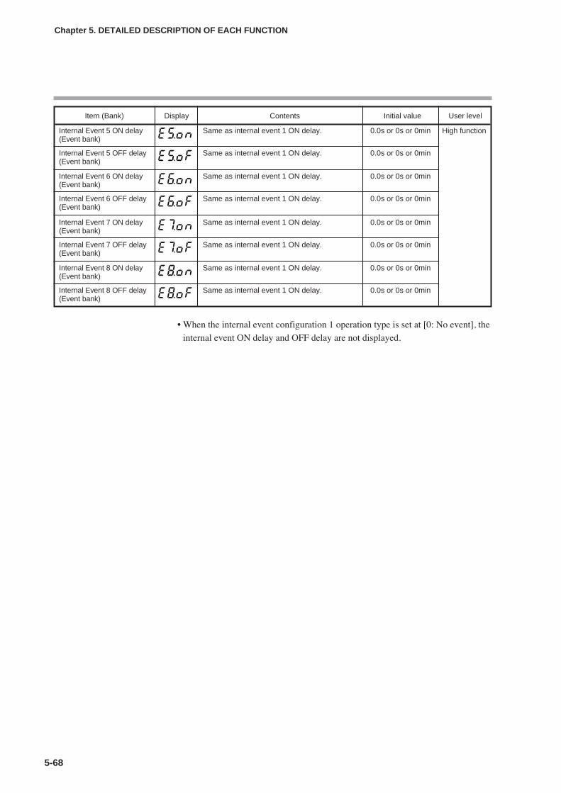
• When the internal event configuration 1 operation type is set at [0: No event], the
internal event ON delay and OFF delay are not displayed.
5-68
Chapter 5. DETAILED DESCRIPTION OF EACH FUNCTION
Item (Bank) Display Contents Initial value User level
Internal Event 5 ON delay(Event bank)
Same as internal event 1 ON delay. 0.0s or 0s or 0min High function
Internal Event 5 OFF delay(Event bank)
Same as internal event 1 ON delay. 0.0s or 0s or 0min
Internal Event 6 ON delay(Event bank)
Same as internal event 1 ON delay. 0.0s or 0s or 0min
Internal Event 6 OFF delay(Event bank)
Same as internal event 1 ON delay. 0.0s or 0s or 0min
Internal Event 7 ON delay(Event bank)
Same as internal event 1 ON delay. 0.0s or 0s or 0min
Internal Event 7 OFF delay(Event bank)
Same as internal event 1 ON delay. 0.0s or 0s or 0min
Internal Event 8 ON delay(Event bank)
Same as internal event 1 ON delay. 0.0s or 0s or 0min
Internal Event 8 OFF delay(Event bank)
Same as internal event 1 ON delay. 0.0s or 0s or 0min
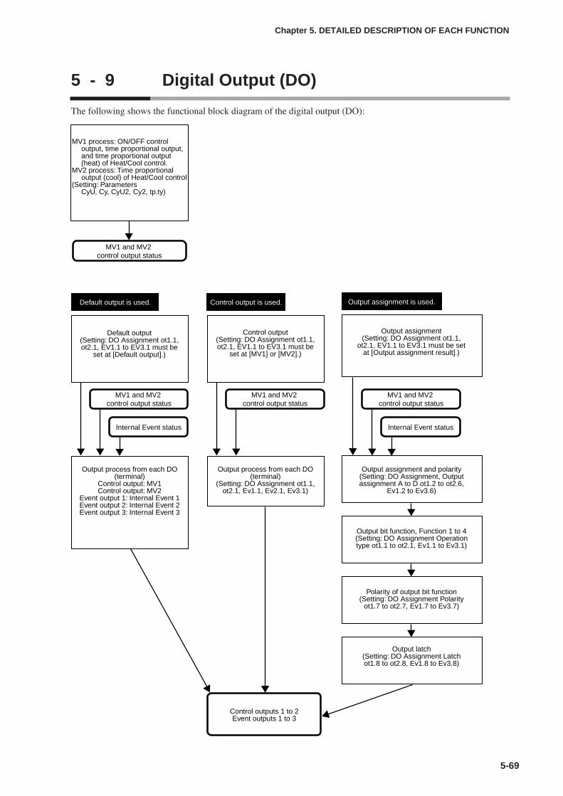
5 - 9 Digital Output (DO)
The following shows the functional block diagram of the digital output (DO):
5-69
Chapter 5. DETAILED DESCRIPTION OF EACH FUNCTION
MV1 and MV2 control output status
Control outputs 1 to 2Event outputs 1 to 3
Output assignment is used.
MV1 and MV2 control output status
Default output is used.
MV1 and MV2 control output status
Internal Event status
MV1 and MV2 control output status
Internal Event status
Control output is used.
MV1 process: ON/OFF control output, time proportional output, and time proportional output (heat) of Heat/Cool control.
MV2 process: Time proportional output (cool) of Heat/Cool control
(Setting: Parameters CyU, Cy, CyU2, Cy2, tp.ty)
Default output(Setting: DO Assignment ot1.1, ot2.1, EV1.1 to EV3.1 must be
set at [Default output].)
Control output(Setting: DO Assignment ot1.1, ot2.1, EV1.1 to EV3.1 must be
set at [MV1] or [MV2].)
Output assignment(Setting: DO Assignment ot1.1,
ot2.1, EV1.1 to EV3.1 must be set at [Output assignment result].)
Output process from each DO (terminal)
Control output: MV1Control output: MV2
Event output 1: Internal Event 1Event output 2: Internal Event 2Event output 3: Internal Event 3
Output process from each DO (terminal)
(Setting: DO Assignment ot1.1, ot2.1, Ev1.1, Ev2.1, Ev3.1)
Output assignment and polarity(Setting: DO Assignment, Output assignment A to D ot1.2 to ot2.6,
Ev1.2 to Ev3.6)
Output bit function, Function 1 to 4(Setting: DO Assignment Operation type ot1.1 to ot2.1, Ev1.1 to Ev3.1)
Polarity of output bit function(Setting: DO Assignment Polarity
ot1.7 to ot2.7, Ev1.7 to Ev3.7)
Output latch(Setting: DO Assignment Latch ot1.8 to ot2.8, Ev1.8 to Ev3.8)

MV1/MV2 processThe time proportional cycle and time proportional cycle mode of MV1/MV2 can
be set.
• MV1 is the general term for the ON/OFF control output, time proportionaloutput, and time proportional output for heat side of the Heat/Cool control.MV2 is the time proportional output for cool side of the Heat/Cool control.
• When MV1 is connected only to the voltage pulse output in the DO Assignment,the display and setting of the time proportional unit 1 (CyU) can be performed.
• When MV1 is connected to any of the relay control output, voltage pulse controloutput, and event output in the DO Assignment, the display and setting of thetime proportional cycle 1 (Cy) can be made. However, when the timeproportional unit 1 (CyU) is other than “0”, the display and setting of the timeproportional cycle 1 (Cy) cannot be performed.
• When the Heat/Cool control is used and MV2 is connected only to the voltagepulse output in the DO Assignment, the display and setting of the timeproportional unit 2 (CyU2) can be performed.
• When the Heat/Cool control is used and MV2 is connected to any of the relaycontrol output, voltage pulse control output, and event output in the DOAssignment, the display and setting of the time proportional cycle 2 (Cy2) can bemade. However, when the time proportional unit 2 (CyU2) is other than “0”, thedisplay and setting of the time proportional cycle 2 (Cy2) cannot be performed.
• The initial value of the time proportional cycle 1 (Cy) is “10” when the controloutput 1 is the relay output and it is “2” in other cases.
• The initial value of the time proportional cycle 2 (Cy2) is “10” when a modelwith one control output point is used and it is “2” when other models are used.
5-70
Chapter 5. DETAILED DESCRIPTION OF EACH FUNCTION
Item (Bank) Display Contents Initial value User level
Time proportional unit 1 (forMV1)(Parameter bank)
0: 1s unit1: Cycle fixed at 0.5s.2: Cycle fixed at 0.25s.3: Cycle fixed at 0.1sIf the set value is other than “0”, the timeproportional cycle 1 (Cy) cannot be set.
0
Basic,Standard,High function
Time proportional cycle 1(for MV1)(Parameter bank)
10 or 2s
Time proportional cyclemode(Parameter bank)
0: Controllability aiming type1: Operation service life aiming type (ON/OFF
operation is performed only once within thetime proportional cycle.
0 or 1
High function
5 to 120s (Output destination of MV1 includesthe relay output.)1 to 120s (Output destination of MV1 does notinclude the relay output.)If the time proportional unit 1 (CyU) ≠ 0, thissetting becomes invalid and the settingbecomes impossible.
Time proportional unit 2 (forMV2)(Parameter bank)
0: 1s unit1: Cycle fixed at 0.5s.2: Cycle fixed at 0.25s.3: Cycle fixed at 0.1sIf the set value is other than “0”, the timeproportional cycle 2 (Cy2) cannot be set.
0
Basic,Standard,High function
Time proportional cycle 2(for MV2)(Parameter bank)
10 or 2s
High function
5 to 120s (Output destination of MV2 includesthe relay output.)1 to 120s (Output destination of MV2 does notinclude the relay output.)If the time proportional unit 2 (CyU2) ≠ 0, thissetting becomes invalid and the settingbecomes impossible.
High function

5-71
• The setting of the time proportional cycle mode (tP.ty) is valid to the time
proportional outputs of both MV1 and MV2.
• When MV1 is connected to the relay control output or event output in the DO
Assignment and the time proportional cycle 1 (Cy) is set at less than “5s”, the
operation is performed at intervals of 5s.
• When MV2 is connected to the relay control output or event output in the DO
Assignment and the time proportional cycle 2 (Cy2) is set at less than “5s”, the
operation is performed at intervals of 5s.
Handling Precautions
• The following shows the resolution of the time proportional output bythe setting of the time proportional unit 1 and 2 (CyU/CyU2):
When this setting is set at “0” (1s unit), the resolution becomes“1/1000” (seconds of the time proportional cycle X 1/1000).When this setting is set at “1” (Cycle fixed at “0.5s”), the resolutionbecomes “1/500 (1ms)”.When this setting is set at “2” (Cycle fixed at “0.25s”), the resolutionbecomes “1/250 (1ms)”.When this setting is set at “3” (Cycle fixed at “0.1s”), the resolutionbecomes “1/100 (1ms)”.
• The time proportional cycle is operated for a period of timeapproximately 2.4% longer than the setting. Care should be takenwhen using the timer function with the time proportional output. Usethe ON delay/ OFF delay and DI timer stop/start functions with thetimer function of the internal event, if the ON/OFF output having moreprecise time is needed.
Chapter 5. DETAILED DESCRIPTION OF EACH FUNCTION
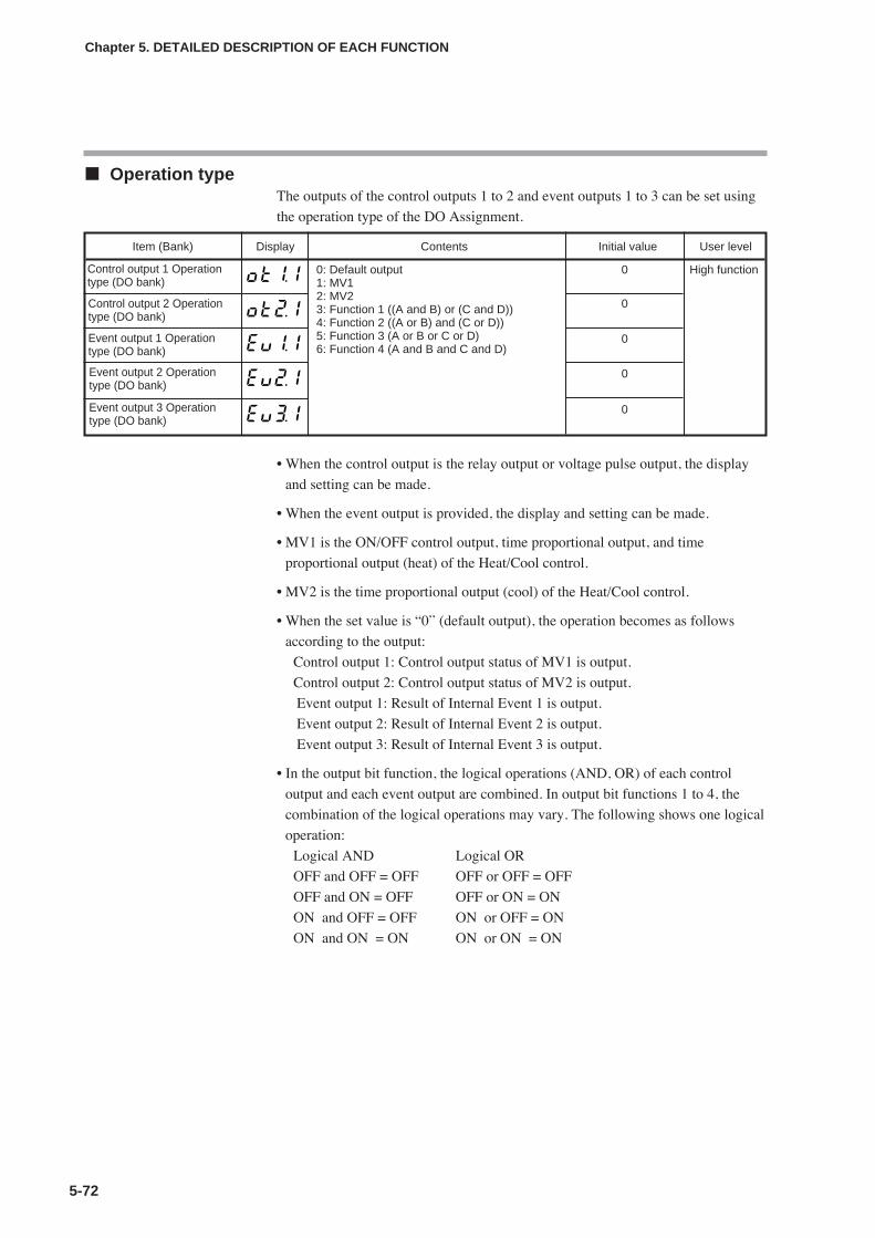
5-72
Chapter 5. DETAILED DESCRIPTION OF EACH FUNCTION
Operation typeThe outputs of the control outputs 1 to 2 and event outputs 1 to 3 can be set using
the operation type of the DO Assignment.
• When the control output is the relay output or voltage pulse output, the display
and setting can be made.
• When the event output is provided, the display and setting can be made.
• MV1 is the ON/OFF control output, time proportional output, and time
proportional output (heat) of the Heat/Cool control.
• MV2 is the time proportional output (cool) of the Heat/Cool control.
• When the set value is “0” (default output), the operation becomes as follows
according to the output:
Control output 1: Control output status of MV1 is output.
Control output 2: Control output status of MV2 is output.
Event output 1: Result of Internal Event 1 is output.
Event output 2: Result of Internal Event 2 is output.
Event output 3: Result of Internal Event 3 is output.
• In the output bit function, the logical operations (AND, OR) of each control
output and each event output are combined. In output bit functions 1 to 4, the
combination of the logical operations may vary. The following shows one logical
operation:
Logical AND Logical OR
OFF and OFF = OFF OFF or OFF = OFF
OFF and ON = OFF OFF or ON = ON
ON and OFF = OFF ON or OFF = ON
ON and ON = ON ON or ON = ON
Item (Bank) Display Contents Initial value User level
0: Default output1: MV12: MV23: Function 1 ((A and B) or (C and D))4: Function 2 ((A or B) and (C or D))5: Function 3 (A or B or C or D)6: Function 4 (A and B and C and D)
0 High function
Control output 2 Operationtype (DO bank)
0
Event output 1 Operationtype (DO bank)
0
Event output 2 Operationtype (DO bank)
0
Event output 3 Operationtype (DO bank)
0
Control output 1 Operationtype (DO bank)
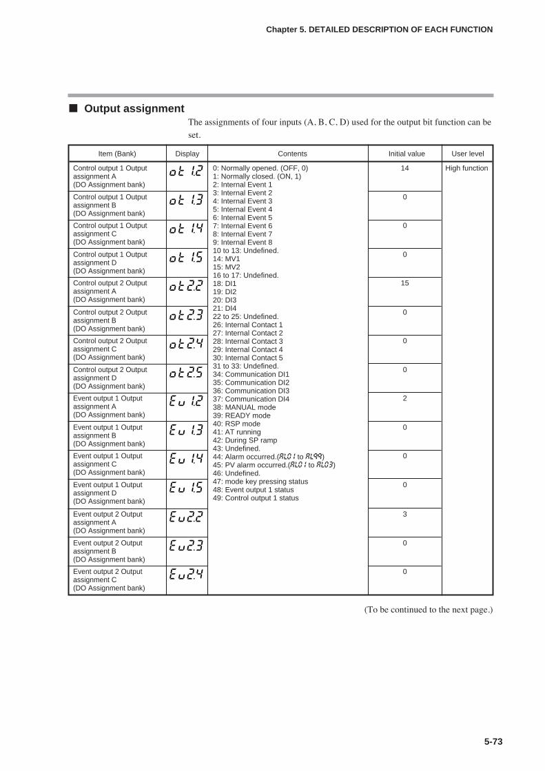
5-73
Chapter 5. DETAILED DESCRIPTION OF EACH FUNCTION
Output assignmentThe assignments of four inputs (A, B, C, D) used for the output bit function can be
set.
(To be continued to the next page.)
Item (Bank) Display Contents Initial value User level
Control output 1 Outputassignment A (DO Assignment bank)
0: Normally opened. (OFF, 0)1: Normally closed. (ON, 1)2: Internal Event 13: Internal Event 24: Internal Event 35: Internal Event 46: Internal Event 57: Internal Event 68: Internal Event 79: Internal Event 810 to 13: Undefined.14: MV115: MV216 to 17: Undefined.18: DI119: DI220: DI321: DI422 to 25: Undefined.26: Internal Contact 127: Internal Contact 228: Internal Contact 329: Internal Contact 430: Internal Contact 531 to 33: Undefined.34: Communication DI135: Communication DI236: Communication DI337: Communication DI438: MANUAL mode39: READY mode40: RSP mode41: AT running42: During SP ramp43: Undefined.44: Alarm occurred.(AL0 1 to AL99)45: PV alarm occurred.(AL0 1 to AL03)46: Undefined.47: mode key pressing status48: Event output 1 status49: Control output 1 status
14 High function
Control output 1 Outputassignment B (DO Assignment bank)
0
Control output 1 Outputassignment C (DO Assignment bank)
0
Control output 1 Outputassignment D (DO Assignment bank)
0
Control output 2 Outputassignment A (DO Assignment bank)
15
Control output 2 Outputassignment B(DO Assignment bank)
0
Control output 2 Outputassignment C (DO Assignment bank)
0
Control output 2 Outputassignment D (DO Assignment bank)
0
Event output 1 Outputassignment A(DO Assignment bank)
2
Event output 1 Outputassignment B (DO Assignment bank)
0
Event output 1 Outputassignment C (DO Assignment bank)
0
Event output 1 Outputassignment D (DO Assignment bank)
0
Event output 2 Outputassignment A (DO Assignment bank)
3
Event output 2 Outputassignment B (DO Assignment bank)
0
Event output 2 Outputassignment C (DO Assignment bank)
0
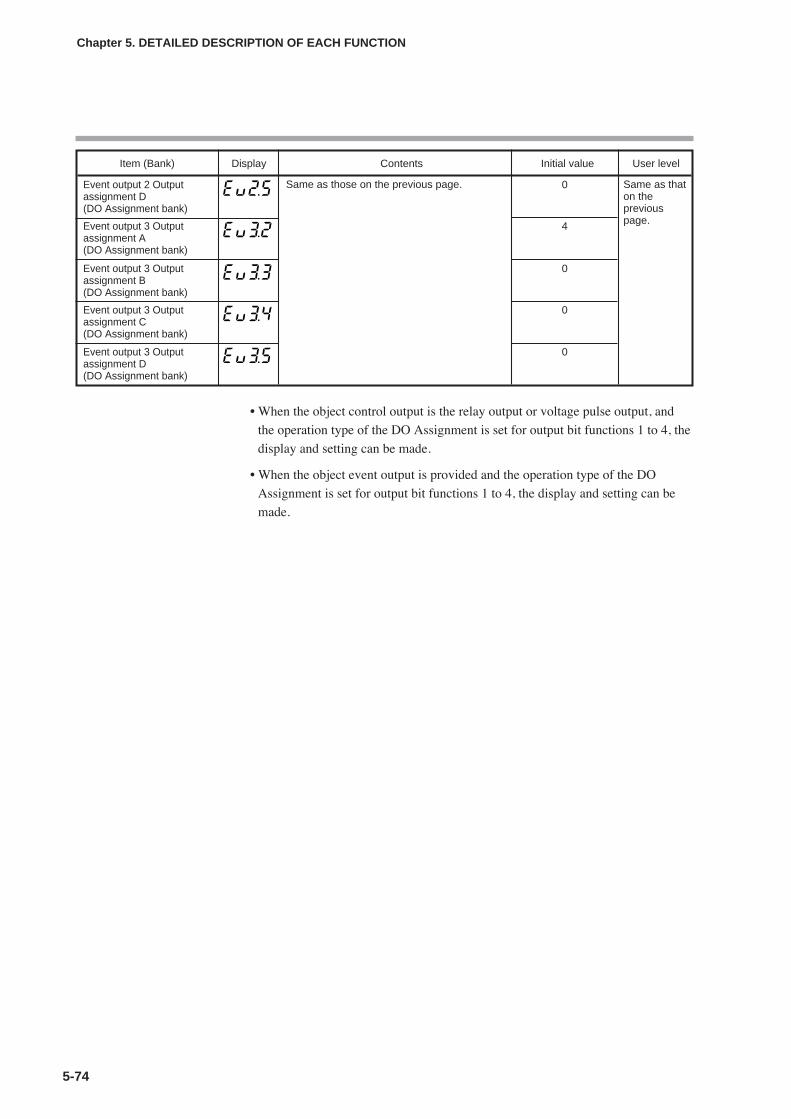
5-74
Chapter 5. DETAILED DESCRIPTION OF EACH FUNCTION
• When the object control output is the relay output or voltage pulse output, and
the operation type of the DO Assignment is set for output bit functions 1 to 4, the
display and setting can be made.
• When the object event output is provided and the operation type of the DO
Assignment is set for output bit functions 1 to 4, the display and setting can be
made.
Item (Bank) Display Contents Initial value User level
Same as those on the previous page. Same as thaton thepreviouspage.
Event output 2 Outputassignment D (DO Assignment bank)
0
Event output 3 Outputassignment A (DO Assignment bank)
4
Event output 3 Outputassignment B (DO Assignment bank)
0
Event output 3 Outputassignment C (DO Assignment bank)
0
Event output 3 Outputassignment D (DO Assignment bank)
0
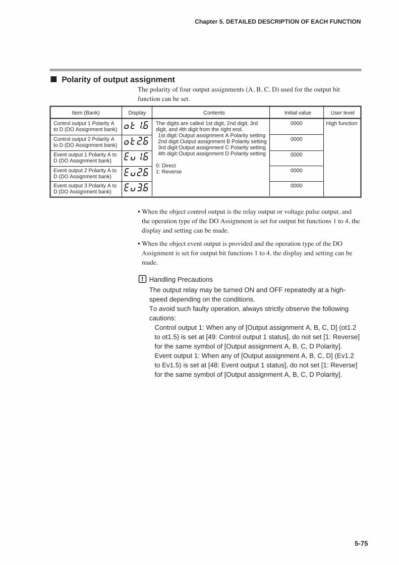
5-75
Chapter 5. DETAILED DESCRIPTION OF EACH FUNCTION
Polarity of output assignmentThe polarity of four output assignments (A, B, C, D) used for the output bit
function can be set.
• When the object control output is the relay output or voltage pulse output, and
the operation type of the DO Assignment is set for output bit functions 1 to 4, the
display and setting can be made.
• When the object event output is provided and the operation type of the DO
Assignment is set for output bit functions 1 to 4, the display and setting can be
made.
Handling Precautions
The output relay may be turned ON and OFF repeatedly at a high-speed depending on the conditions.To avoid such faulty operation, always strictly observe the followingcautions:
Control output 1: When any of [Output assignment A, B, C, D] (ot1.2to ot1.5) is set at [49: Control output 1 status], do not set [1: Reverse]for the same symbol of [Output assignment A, B, C, D Polarity].Event output 1: When any of [Output assignment A, B, C, D] (Ev1.2to Ev1.5) is set at [48: Event output 1 status], do not set [1: Reverse]for the same symbol of [Output assignment A, B, C, D Polarity].
Item (Bank) Display Contents Initial value User level
Control output 1 Polarity Ato D (DO Assignment bank)
The digits are called 1st digit, 2nd digit, 3rddigit, and 4th digit from the right end.1st digit:Output assignment A Polarity setting2nd digit:Output assignment B Polarity setting3rd digit:Output assignment C Polarity setting4th digit:Output assignment D Polarity setting
0: Direct1: Reverse
0000 High function
Control output 2 Polarity Ato D (DO Assignment bank)
0000
Event output 1 Polarity A toD (DO Assignment bank)
0000
Event output 2 Polarity A toD (DO Assignment bank)
0000
Event output 3 Polarity A toD (DO Assignment bank)
0000
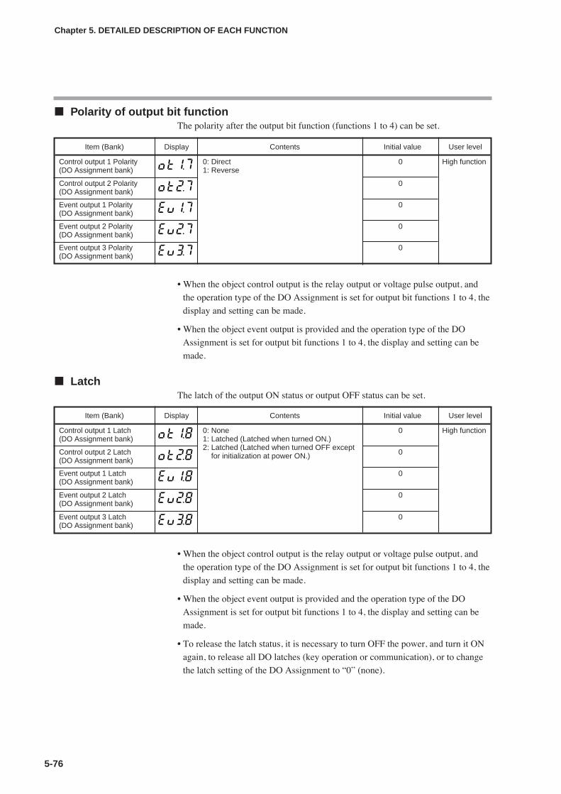
5-76
Chapter 5. DETAILED DESCRIPTION OF EACH FUNCTION
Polarity of output bit functionThe polarity after the output bit function (functions 1 to 4) can be set.
• When the object control output is the relay output or voltage pulse output, and
the operation type of the DO Assignment is set for output bit functions 1 to 4, the
display and setting can be made.
• When the object event output is provided and the operation type of the DO
Assignment is set for output bit functions 1 to 4, the display and setting can be
made.
LatchThe latch of the output ON status or output OFF status can be set.
• When the object control output is the relay output or voltage pulse output, and
the operation type of the DO Assignment is set for output bit functions 1 to 4, the
display and setting can be made.
• When the object event output is provided and the operation type of the DO
Assignment is set for output bit functions 1 to 4, the display and setting can be
made.
• To release the latch status, it is necessary to turn OFF the power, and turn it ON
again, to release all DO latches (key operation or communication), or to change
the latch setting of the DO Assignment to “0” (none).
Item (Bank) Display Contents Initial value User level
Control output 1 Polarity(DO Assignment bank)
0: Direct1: Reverse
0 High function
Control output 2 Polarity(DO Assignment bank)
0
Event output 1 Polarity(DO Assignment bank)
0
Event output 2 Polarity(DO Assignment bank)
0
Event output 3 Polarity(DO Assignment bank)
0
Item (Bank) Display Contents Initial value User level
Control output 1 Latch(DO Assignment bank)
0: None1: Latched (Latched when turned ON.)2: Latched (Latched when turned OFF except
for initialization at power ON.)
0 High function
Control output 2 Latch(DO Assignment bank)
0
Event output 1 Latch(DO Assignment bank)
0
Event output 2 Latch(DO Assignment bank)
0
Event output 3 Latch(DO Assignment bank)
0
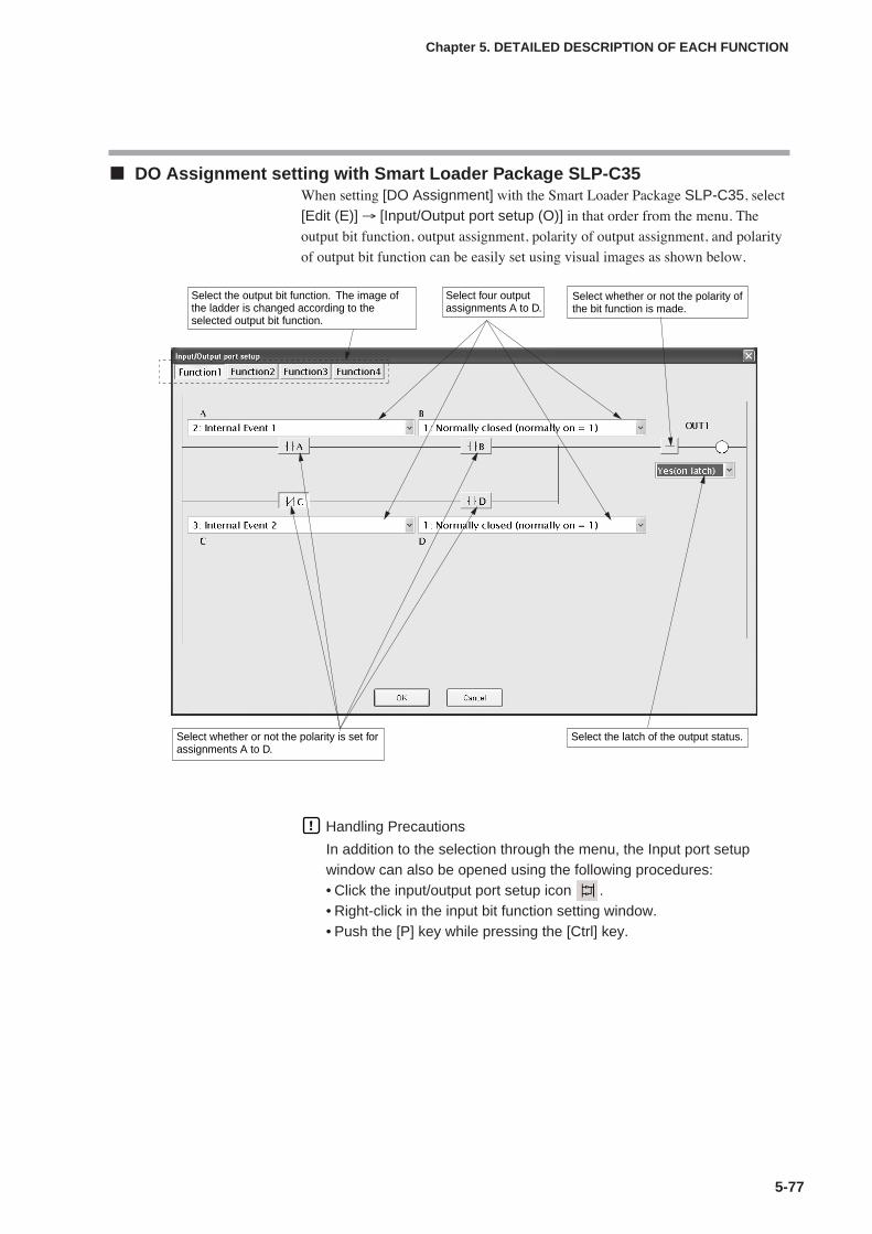
5-77
Chapter 5. DETAILED DESCRIPTION OF EACH FUNCTION
DO Assignment setting with Smart Loader Package SLP-C35When setting [DO Assignment] with the Smart Loader Package SLP-C35, select
[Edit (E)] → [Input/Output port setup (O)] in that order from the menu. The
output bit function, output assignment, polarity of output assignment, and polarity
of output bit function can be easily set using visual images as shown below.
Handling Precautions
In addition to the selection through the menu, the Input port setupwindow can also be opened using the following procedures:• Click the input/output port setup icon .• Right-click in the input bit function setting window.• Push the [P] key while pressing the [Ctrl] key.
Select the output bit function. The image of the ladder is changed according to the selected output bit function.
Select whether or not the polarity is set for assignments A to D.
Select the latch of the output status.
Select four output assignments A to D.
Select whether or not the polarity of the bit function is made.

5-78
Chapter 5. DETAILED DESCRIPTION OF EACH FUNCTION
5 - 10 Application Examples
This section describes examples of applications using the assignment functions of this unit.
Examples of applications using assignment functionsThe following shows setting examples with the Smart Loader Package SLP-C35.
To use assignment functions, it is absolutely necessary to set the user level to
“High function configuration”.
Example 1 Logical OR of the heater burnout and PV high limit alarm is output.Conditions: PV high limit is set to Internal Event 1.
Heater burnout is set to Internal Event 2.
Logical OR of the above events is output to the EV1 relay.
(1) Select [Standard] → [Event] and set [Internal Event 1] to [1: PV high limit].(2) Similarly, set [Internal Event 2] to [16: Heater 1 break/Heater over
current].(3) Select [Option] → [DO Assignment] and right-click on the operation type of
[Event output 1] to select [Input/Output port setup].
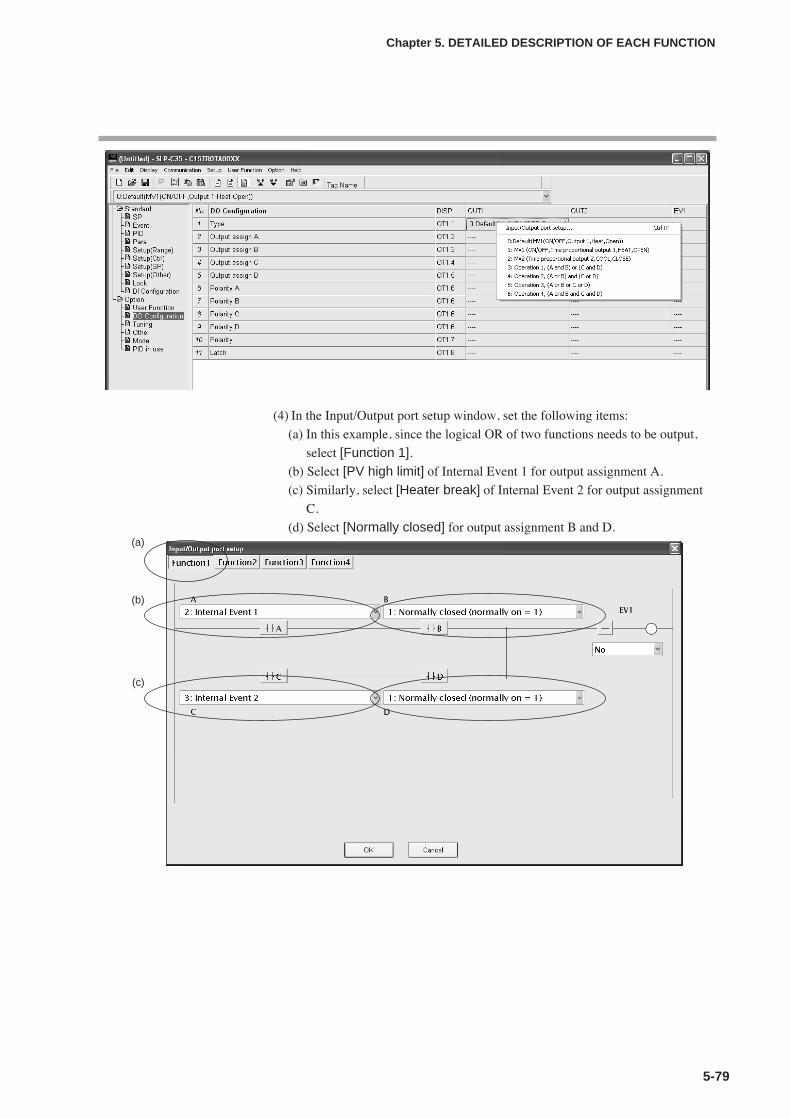
5-79
Chapter 5. DETAILED DESCRIPTION OF EACH FUNCTION
(4) In the Input/Output port setup window, set the following items:
(a) In this example, since the logical OR of two functions needs to be output,
select [Function 1].(b) Select [PV high limit] of Internal Event 1 for output assignment A.
(c) Similarly, select [Heater break] of Internal Event 2 for output assignment
C.
(d) Select [Normally closed] for output assignment B and D.(a)
(b)
(c)
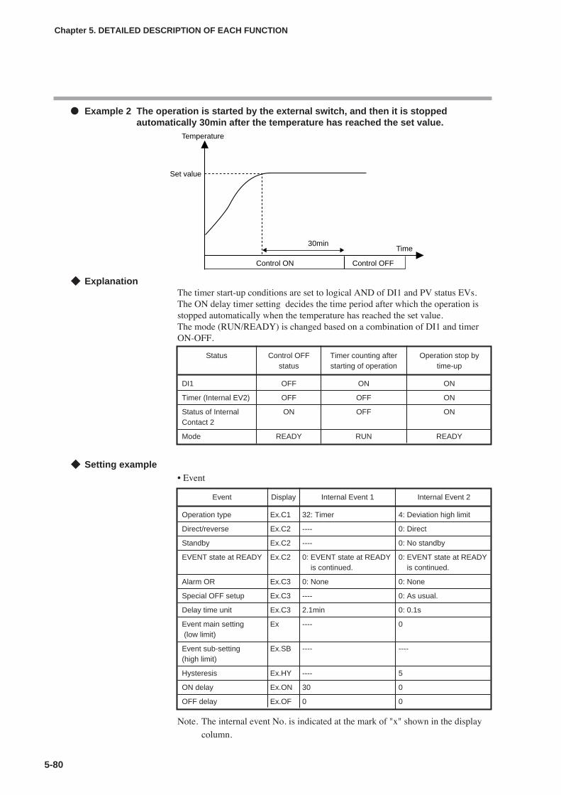
5-80
Chapter 5. DETAILED DESCRIPTION OF EACH FUNCTION
Example 2 The operation is started by the external switch, and then it is stoppedautomatically 30min after the temperature has reached the set value.
ExplanationThe timer start-up conditions are set to logical AND of DI1 and PV status EVs.The ON delay timer setting decides the time period after which the operation isstopped automatically when the temperature has reached the set value.The mode (RUN/READY) is changed based on a combination of DI1 and timerON-OFF.
Setting example• Event
Note. The internal event No. is indicated at the mark of "x" shown in the display
column.
Set value
Time30min
Control ON Control OFF
Temperature
Status Control OFF Timer counting after Operation stop bystatus starting of operation time-up
DI1 OFF ON ON
Timer (Internal EV2) OFF OFF ON
Status of Internal ON OFF ONContact 2
Mode READY RUN READY
Event Display Internal Event 1 Internal Event 2
Operation type Ex.C1 32: Timer 4: Deviation high limit
Direct/reverse Ex.C2 ---- 0: Direct
Standby Ex.C2 ---- 0: No standby
EVENT state at READY Ex.C2 0: EVENT state at READY 0: EVENT state at READYis continued. is continued.
Alarm OR Ex.C3 0: None 0: None
Special OFF setup Ex.C3 ---- 0: As usual.
Delay time unit Ex.C3 2.1min 0: 0.1s
Event main setting Ex ---- 0(low limit)
Event sub-setting Ex.SB ---- ----(high limit)
Hysteresis Ex.HY ---- 5
ON delay Ex.ON 30 0
OFF delay Ex.OF 0 0
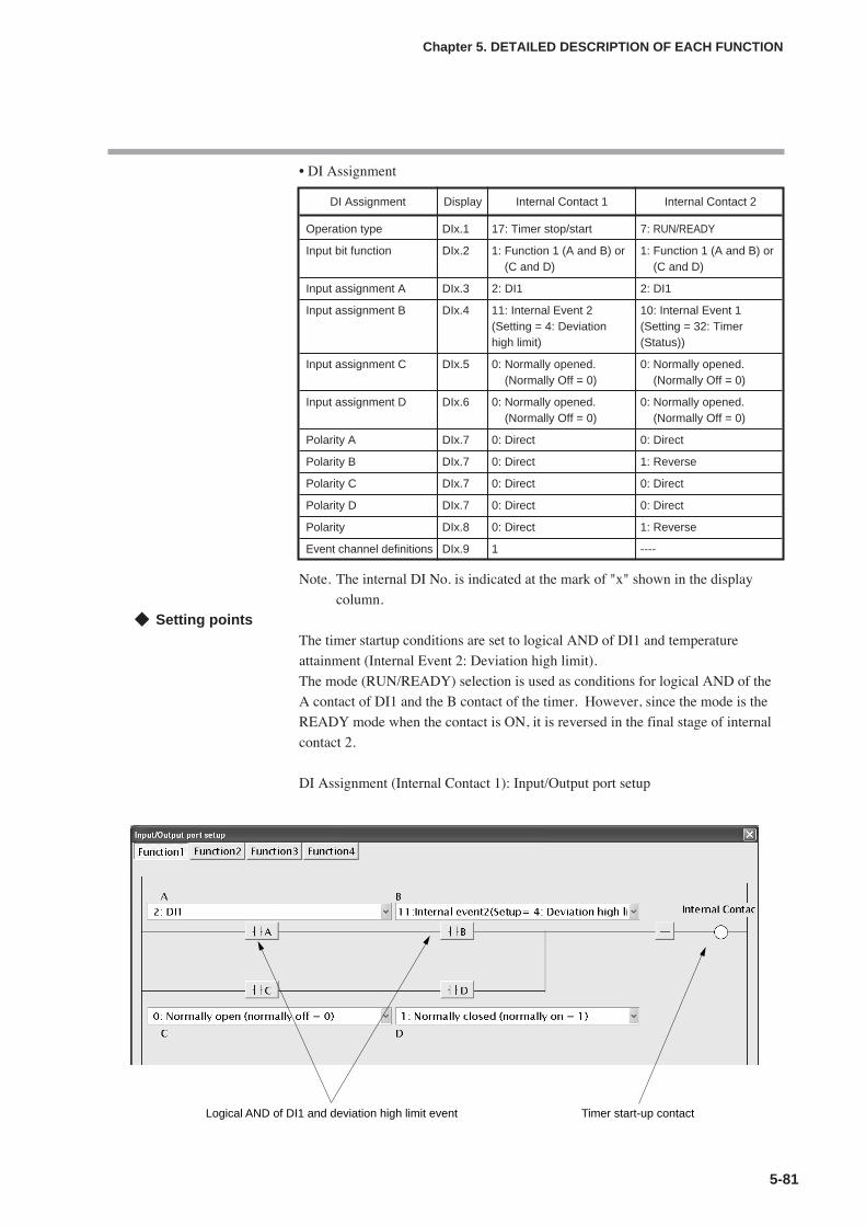
5-81
Chapter 5. DETAILED DESCRIPTION OF EACH FUNCTION
• DI Assignment
Note. The internal DI No. is indicated at the mark of "x" shown in the display
column.
Setting pointsThe timer startup conditions are set to logical AND of DI1 and temperature
attainment (Internal Event 2: Deviation high limit).
The mode (RUN/READY) selection is used as conditions for logical AND of the
A contact of DI1 and the B contact of the timer. However, since the mode is the
READY mode when the contact is ON, it is reversed in the final stage of internal
contact 2.
DI Assignment (Internal Contact 1): Input/Output port setup
DI Assignment Display Internal Contact 1 Internal Contact 2
Operation type DIx.1 17: Timer stop/start 7: RUN/READY
Input bit function DIx.2 1: Function 1 (A and B) or 1: Function 1 (A and B) or(C and D) (C and D)
Input assignment A DIx.3 2: DI1 2: DI1
Input assignment B DIx.4 11: Internal Event 2 10: Internal Event 1(Setting = 4: Deviation (Setting = 32: Timerhigh limit) (Status))
Input assignment C DIx.5 0: Normally opened. 0: Normally opened.(Normally Off = 0) (Normally Off = 0)
Input assignment D DIx.6 0: Normally opened. 0: Normally opened.(Normally Off = 0) (Normally Off = 0)
Polarity A DIx.7 0: Direct 0: Direct
Polarity B DIx.7 0: Direct 1: Reverse
Polarity C DIx.7 0: Direct 0: Direct
Polarity D DIx.7 0: Direct 0: Direct
Polarity DIx.8 0: Direct 1: Reverse
Event channel definitions DIx.9 1 ----
Logical AND of DI1 and deviation high limit event Timer start-up contact
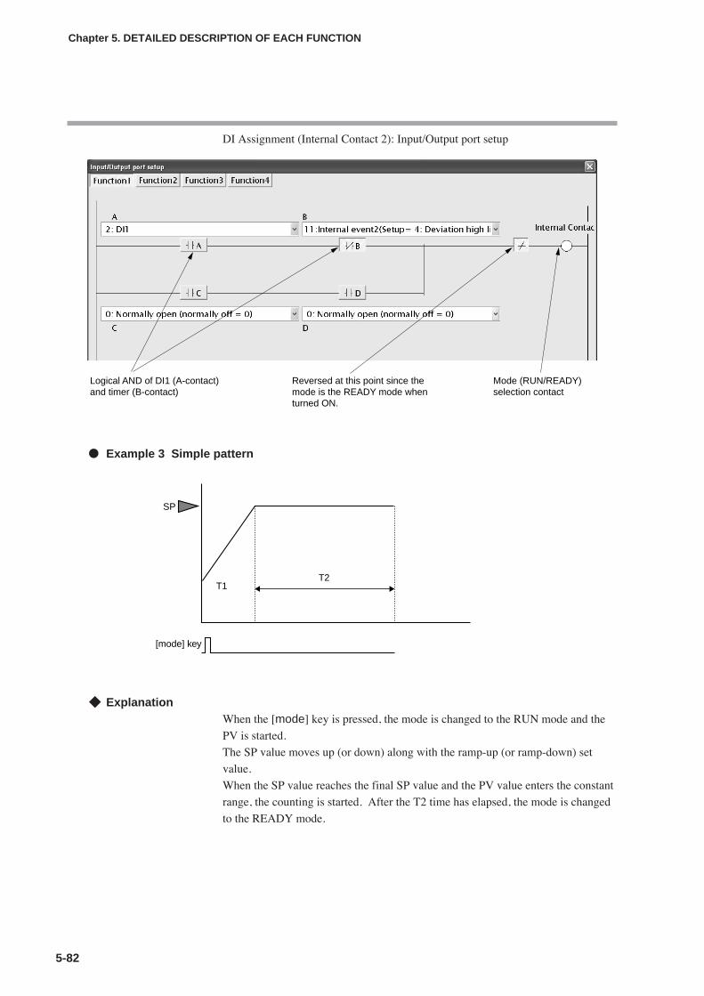
5-82
Chapter 5. DETAILED DESCRIPTION OF EACH FUNCTION
DI Assignment (Internal Contact 2): Input/Output port setup
Example 3 Simple pattern
ExplanationWhen the [mode] key is pressed, the mode is changed to the RUN mode and the
PV is started.
The SP value moves up (or down) along with the ramp-up (or ramp-down) set
value.
When the SP value reaches the final SP value and the PV value enters the constant
range, the counting is started. After the T2 time has elapsed, the mode is changed
to the READY mode.
Logical AND of DI1 (A-contact)and timer (B-contact)
Reversed at this point since the mode is the READY mode when turned ON.
Mode (RUN/READY) selection contact
SP
[mode] key
T1T2
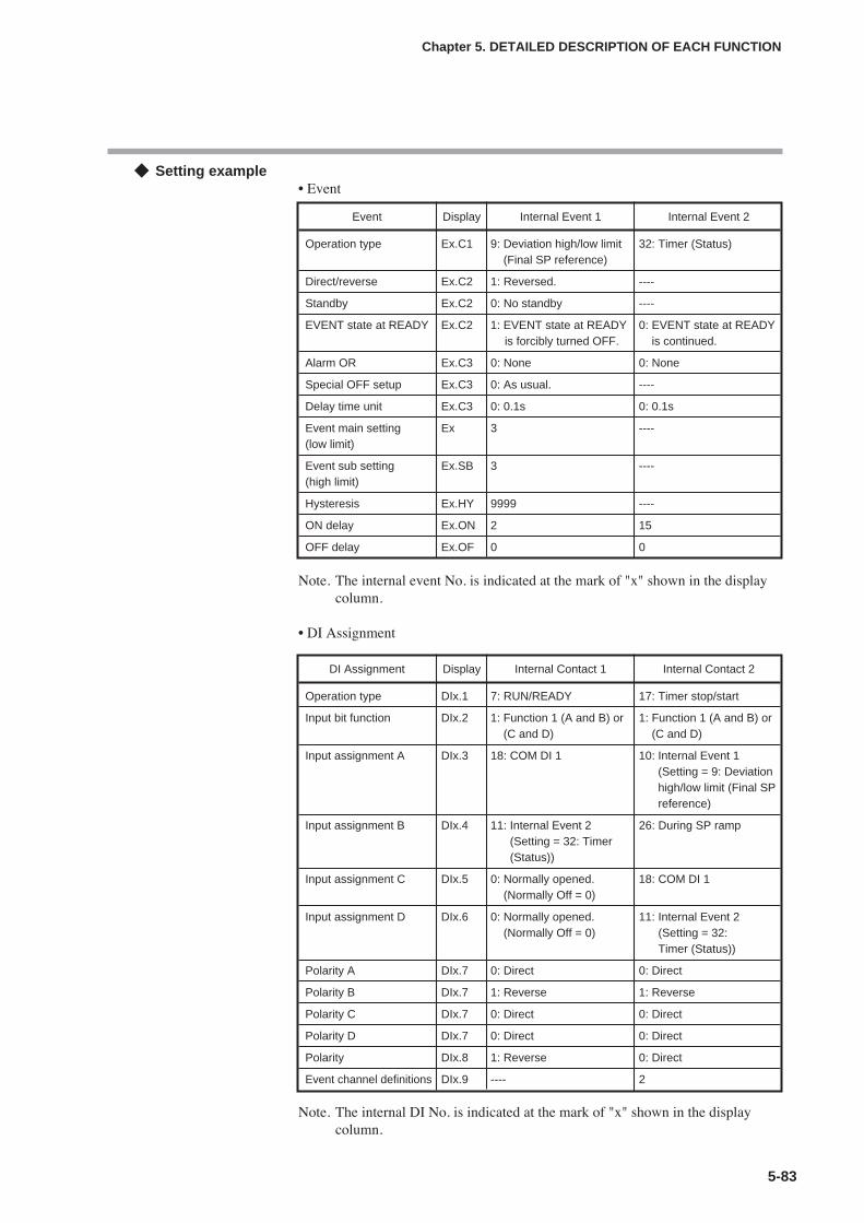
5-83
Chapter 5. DETAILED DESCRIPTION OF EACH FUNCTION
Setting example• Event
Note. The internal event No. is indicated at the mark of "x" shown in the displaycolumn.
• DI Assignment
Note. The internal DI No. is indicated at the mark of "x" shown in the displaycolumn.
Event Display Internal Event 1 Internal Event 2
Operation type Ex.C1 9: Deviation high/low limit 32: Timer (Status)(Final SP reference)
Direct/reverse Ex.C2 1: Reversed. ----
Standby Ex.C2 0: No standby ----
EVENT state at READY Ex.C2 1: EVENT state at READY 0: EVENT state at READYis forcibly turned OFF. is continued.
Alarm OR Ex.C3 0: None 0: None
Special OFF setup Ex.C3 0: As usual. ----
Delay time unit Ex.C3 0: 0.1s 0: 0.1s
Event main setting Ex 3 ----(low limit)
Event sub setting Ex.SB 3 ----(high limit)
Hysteresis Ex.HY 9999 ----
ON delay Ex.ON 2 15
OFF delay Ex.OF 0 0
DI Assignment Display Internal Contact 1 Internal Contact 2
Operation type DIx.1 7: RUN/READY 17: Timer stop/start
Input bit function DIx.2 1: Function 1 (A and B) or 1: Function 1 (A and B) or(C and D) (C and D)
Input assignment A DIx.3 18: COM DI 1 10: Internal Event 1(Setting = 9: Deviationhigh/low limit (Final SPreference)
Input assignment B DIx.4 11: Internal Event 2 26: During SP ramp(Setting = 32: Timer(Status))
Input assignment C DIx.5 0: Normally opened. 18: COM DI 1(Normally Off = 0)
Input assignment D DIx.6 0: Normally opened. 11: Internal Event 2(Normally Off = 0) (Setting = 32:
Timer (Status))
Polarity A DIx.7 0: Direct 0: Direct
Polarity B DIx.7 1: Reverse 1: Reverse
Polarity C DIx.7 0: Direct 0: Direct
Polarity D DIx.7 0: Direct 0: Direct
Polarity DIx.8 1: Reverse 0: Direct
Event channel definitions DIx.9 ---- 2

5-84
Chapter 5. DETAILED DESCRIPTION OF EACH FUNCTION
OthersC72 [mode key function]: 7 (COM DI1 selection)
SP ramp-up/ramp-down: Desired value
Setting pointsThe internal EV1 is substituted for the guarantee soak.
Therefore, “9999” is set to the hysteresis of Event 1 so that Event 1 is not turned
OFF after it has been turned ON even though the PV fluctuates.
DI Assignment (Internal Contact 1): Input/Output port setup
DI Assignment (Internal Contact 2): Input/Output port setup
Logical AND of COM DI1 (A-contact) and timer (B-contact)
Mode (RUN/READY) selection contact
Reversed at this point since the mode is the READY mode when turned ON.
The timer start is self-retained at time-up so that the timer is not restarted due to change in PV.
Timer start-up contact
Conditions for guarantee soak (ramp is completed and operation enters within the deviation of the final SP.)
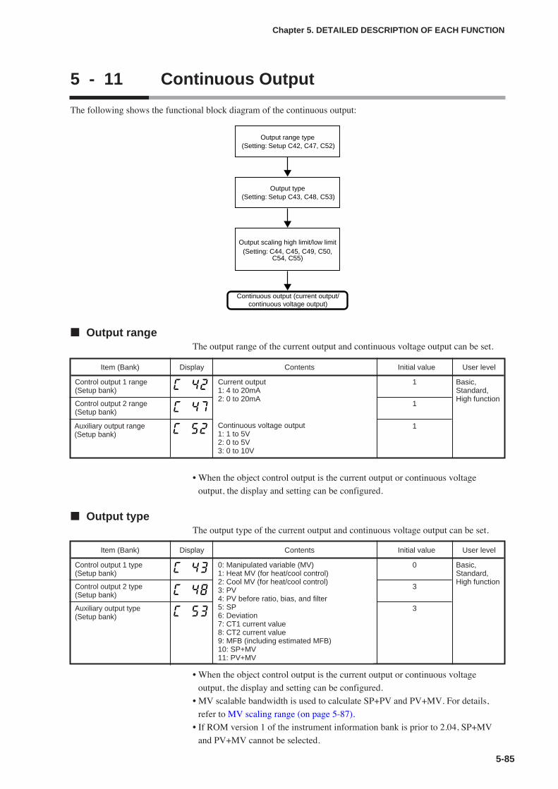
5-85
Chapter 5. DETAILED DESCRIPTION OF EACH FUNCTION
5 - 11 Continuous Output
The following shows the functional block diagram of the continuous output:
Output rangeThe output range of the current output and continuous voltage output can be set.
• When the object control output is the current output or continuous voltage
output, the display and setting can be configured.
Output typeThe output type of the current output and continuous voltage output can be set.
• When the object control output is the current output or continuous voltage
output, the display and setting can be configured.
• MV scalable bandwidth is used to calculate SP+PV and PV+MV. For details,
refer to MV scaling range (on page 5-87).
• If ROM version 1 of the instrument information bank is prior to 2.04, SP+MV
and PV+MV cannot be selected.
(Setting: Setup C42, C47, C52)
Continuous output (current output/continuous voltage output)
Output range type
(Setting: Setup C43, C48, C53)Output type
(Setting: C44, C45, C49, C50,C54, C55)
Output scaling high limit/low limit
Item (Bank) Display Contents Initial value User level
Control output 1 range(Setup bank)
Current output1: 4 to 20mA2: 0 to 20mA
1 Basic,Standard,High function
Control output 2 range(Setup bank)
1
Item (Bank) Display Contents Initial value User level
Control output 1 type(Setup bank)
0: Manipulated variable (MV)1: Heat MV (for heat/cool control)2: Cool MV (for heat/cool control)3: PV4: PV before ratio, bias, and filter5: SP6: Deviation7: CT1 current value8: CT2 current value9: MFB (including estimated MFB)10: SP+MV11: PV+MV
0 Basic,Standard,High function
Control output 2 type(Setup bank)
3
Auxiliary output range(Setup bank)
1Continuous voltage output1: 1 to 5V2: 0 to 5V3: 0 to 10V
Auxiliary output type(Setup bank)
3

5-86
Chapter 5. DETAILED DESCRIPTION OF EACH FUNCTION
Output scaling low limit/high limitThe output scaling low limit and high limit of the current output and continuous
voltage output can be set.
• When the object control output is the current output or continuous voltage
output, the display and setting can be configured.
• The following figures show the relationship between the numeric value and
output of the output type using the output scaling low limit/high limit settings:
However, the output is 0 to 110% in a range of 0 to 20mA.
Item (Bank) Display Contents Initial value User level
Control output 1 scaling lowlimit (Setup bank)
-1999 to +9999The decimal point position may vary so that itmeets the output type.The unit depend on the output type are asfollows:
•When the output type is 0 to 2, % ofmanipulated variable
•When the output type is 3 to 6, same asPV(˚C etc.)
•When the output type is 7 and 8,ampere(current value)
•When the output type is 9, % of MFB
0.0 Basic,Standard,High functionControl output 1 scaling high
limit (Setup bank)100.0
Control output 2 scaling lowlimit (Setup bank)
0
Control output 2 scaling highlimit (Setup bank)
1000
Output (%) Output (%)
-100
100110
-100
100110
Input (%)
Low limit Low limitLow limit < High limit Low limit > High limit
High limit High limit
Input (%)
Auxiliary output scaling lowlimit (Setup bank)
0
Auxiliary output scaling highlimit (Setup bank)
1000
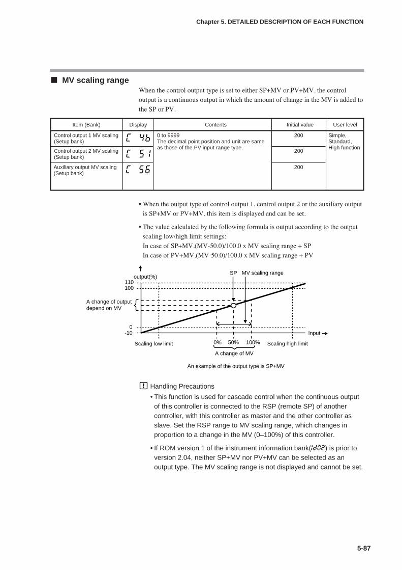
5-87
Chapter 5. DETAILED DESCRIPTION OF EACH FUNCTION
MV scaling rangeWhen the control output type is set to either SP+MV or PV+MV, the control
output is a continuous output in which the amount of change in the MV is added to
the SP or PV.
• When the output type of control output 1, control output 2 or the auxiliary output
is SP+MV or PV+MV, this item is displayed and can be set.
• The value calculated by the following formula is output according to the output
scaling low/high limit settings:
In case of SP+MV,(MV-50.0)/100.0 x MV scaling range + SP
In case of PV+MV,(MV-50.0)/100.0 x MV scaling range + PV
Handling Precautions
• This function is used for cascade control when the continuous outputof this controller is connected to the RSP (remote SP) of anothercontroller, with this controller as master and the other controller asslave. Set the RSP range to MV scaling range, which changes inproportion to a change in the MV (0–100%) of this controller.
• If ROM version 1 of the instrument information bank(Id02) is prior toversion 2.04, neither SP+MV nor PV+MV can be selected as anoutput type. The MV scaling range is not displayed and cannot be set.
Item (Bank) Display Contents Initial value User level
Control output 1 MV scaling(Setup bank)
0 to 9999The decimal point position and unit are sameas those of the PV input range type.
200 Simple,Standard,High function
Control output 2 MV scaling(Setup bank)
200
Auxiliary output MV scaling(Setup bank)
200
output(%)
Scaling low limit Scaling high limit
A change of MV
MV scaling range
An example of the output type is SP+MV
SP
0% 50% 100%
110100
0-10
A change of outputdepend on MV
Input
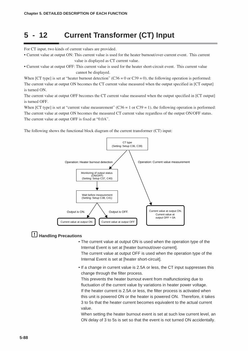
5-88
Chapter 5. DETAILED DESCRIPTION OF EACH FUNCTION
5 - 12 Current Transformer (CT) Input
For CT input, two kinds of current values are provided.
• Current value at output ON: This current value is used for the heater burnout/over-current event. This current
value is displayed as CT current value.
• Current value at output OFF: This current value is used for the heater short-circuit event. This current value
cannot be displayed.
When [CT type] is set at “heater burnout detection” (C36 = 0 or C39 = 0), the following operation is performed:
The current value at output ON becomes the CT current value measured when the output specified in [CT output]
is turned ON.
The current value at output OFF becomes the CT current value measured when the output specified in [CT output]
is turned OFF.
When [CT type] is set at “current value measurement” (C36 = 1 or C39 = 1), the following operation is performed:
The current value at output ON becomes the measured CT current value regardless of the output ON/OFF status.
The current value at output OFF is fixed at “0.0A”.
The following shows the functional block diagram of the current transformer (CT) input:
Handling Precautions• The current value at output ON is used when the operation type of the
Internal Event is set at [heater burnout/over-current].The current value at output OFF is used when the operation type of theInternal Event is set at [heater short-circuit].
• If a change in current value is 2.5A or less, the CT input suppresses thischange through the filter process.This prevents the heater burnout event from malfunctioning due tofluctuation of the current value by variations in heater power voltage.If the heater current is 2.5A or less, the filter process is activated whenthis unit is powered ON or the heater is powered ON. Therefore, it takes3 to 5s that the heater current becomes equivalent to the actual currentvalue.When setting the heater burnout event is set at such low current level, anON delay of 3 to 5s is set so that the event is not turned ON accidentally.
(Setting: Setup C36, C39)
Current value at output ON Current value at output OFF
Current value at output ON.Current value at output OFF = 0A
CT type
(Setting: Setup C37, C40)
Monitoring of output status (ON/OFF)
(Setting: Setup C38, C41)Wait before measurement
Operation: Heater burnout detection
Output is ON. Output is OFF.
Operation: Current value measurement
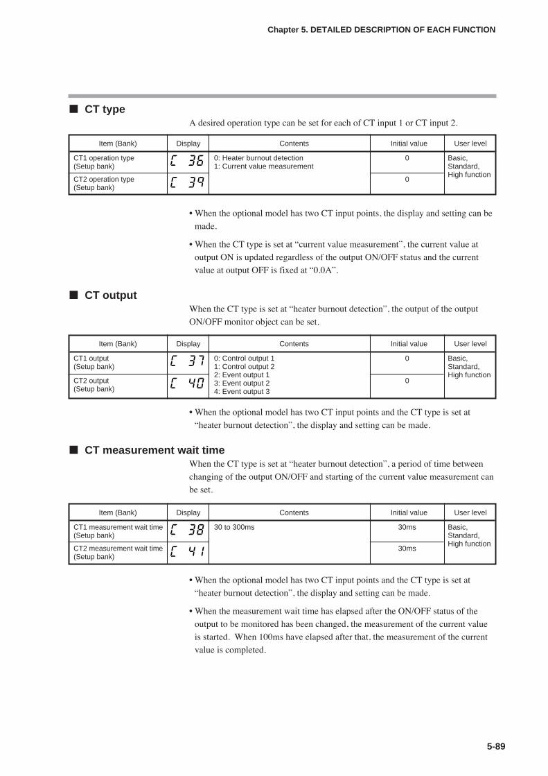
5-89
Chapter 5. DETAILED DESCRIPTION OF EACH FUNCTION
CT typeA desired operation type can be set for each of CT input 1 or CT input 2.
• When the optional model has two CT input points, the display and setting can be
made.
• When the CT type is set at “current value measurement”, the current value at
output ON is updated regardless of the output ON/OFF status and the current
value at output OFF is fixed at “0.0A”.
CT outputWhen the CT type is set at “heater burnout detection”, the output of the output
ON/OFF monitor object can be set.
• When the optional model has two CT input points and the CT type is set at
“heater burnout detection”, the display and setting can be made.
CT measurement wait timeWhen the CT type is set at “heater burnout detection”, a period of time between
changing of the output ON/OFF and starting of the current value measurement can
be set.
• When the optional model has two CT input points and the CT type is set at
“heater burnout detection”, the display and setting can be made.
• When the measurement wait time has elapsed after the ON/OFF status of the
output to be monitored has been changed, the measurement of the current value
is started. When 100ms have elapsed after that, the measurement of the current
value is completed.
Item (Bank) Display Contents Initial value User level
CT1 operation type(Setup bank)
0: Heater burnout detection1: Current value measurement
0 Basic,Standard,High function
CT2 operation type(Setup bank)
0
Item (Bank) Display Contents Initial value User level
CT1 output(Setup bank)
0: Control output 11: Control output 22: Event output 13: Event output 24: Event output 3
0 Basic,Standard,High function
CT2 output(Setup bank)
0
Item (Bank) Display Contents Initial value User level
CT1 measurement wait time(Setup bank)
30 to 300ms 30ms Basic,Standard,High function
CT2 measurement wait time(Setup bank)
30ms

5-90
Chapter 5. DETAILED DESCRIPTION OF EACH FUNCTION
Number of CT turns and number of CT power wire loopsEach CT of CT inputs 1 and 2 can be set.
• If the controller has two CT inputs, this item is displayed and can be set.
• For the number of turns, use the number of CT turns divided by 100. For
example, if the number of CT turns is 400, set at 4. (However, a setting of 0 has
the same meaning as 8, namely 800 CT turns.) If using the optional QN206A or
QN212A, which have 800 turns, set at 8.
• For the number of power wire loops, use the number of times the power wire
passes through the CT hole. For example, if the power wire passes through the
CT hole 2 times, set at 2. (However, a setting of 0 has the same meaning as 1,
namely that there is 1 power wire loop).
Item (Bank) Display Contents Initial value User level
Number of CT1 turns(Setup bank)
0: 800 turns1 to 40: CT turns devided by 100
8 High function
Number of CT1 power wireloops(Setup bank)
1
Number of CT2 turns(Setup bank)
0: 800 turns1 to 40: CT turns devided by 100
8
Number of CT2 power wireloops(Setup bank)
1
0: 1 times1 to 6: Number of times
0: 1 time1 to 6: Number of times
Heater etc.
Power wire
CT
CT input
This device
Relay and power supply etc.

5-91
Chapter 5. DETAILED DESCRIPTION OF EACH FUNCTION
Handling Precautions• Do not allow the current to exceed the upper limit of the CT input display
range. Doing so might cause a malfunction.
• If a current exceeding the upper limit of the CT input display range isdetected, the CT input failure alarm (AL11) is displayed. However, if theexcessive current is very large, the CT input failure alarm is notdisplayed.
• The CT input display range and measurement current range changeaccording to the number of CT turns and the number of CT power wireloops. Set for the number of CT turns and the number of CT power wireloops suitable for the conditions of the CT connected. The display rangeand the measurement current range are calculated by the formulasshown below. (The internal calculations of this device have an error ofless than 0.1A.)
Display range lower limit (A) = 0.0Display range upper limit (A) = Number of turns ÷ (16 x number ofpower wire loops) x 1.4Measurement current range lower limit (A) = Number of turns ÷ (2000 xnumber of power wire loops) Measurement current range upper limit (A) = Number of turns ÷ (16 xnumber of power wire loops)
The table below shows examples of how display range and measurementcurrent range change according to the number of CT turns and the numberof CT power wire loops. Measurement current range is shown inparentheses.
• If ROM version 1 of the instrument information bank (Id02) is prior toversion 2.04, the operation is always performed on the basis of 800 CTturns and one CT power wire loop. The number of CT1/CT2 turns andpower wire loops is not displayed and cannot be set.
• If ROM version 1 of the instrument information bank (Id02) is prior toversion 2.04, the CT input failure alarm (AL11) is not displayed.
100 turns 400 turns 800 turns 1600 turns 4000 turns
1 time 0.0 to 8.7A 0.0 to 35.0A 0.0 to 70.0A 0.0 to 140.0A 0.0 to 350.0A(0.1 to 6.2A) (0.2 to 25.0A) (0.4 to 50.0A) (0.8 to 100.0A) (2.0 to 250.0A)
2 times 0.0 to 4.3A 0.0 to 17.5A 0.0 to 35.0A 0.0 to 70.0A 0.0 to 175.0A(0.1 to 3.1A) (0.1 to 12.5A) (0.2 to 25.0A) (0.4 to 50.0A) (1.0 to 125.0A)
6 times 0.0 to 1.4A 0.0 to 5.8A 0.0 to 11.6A 0.0 to 23.3A 0.0 to 58.3A(0.1 to 1.0A) (0.1 to 4.1A) (0.1 to 8.3A) (0.2 to 16.6A) (0.4 to 41.6A)
Number ofturns
Number ofpower wire
loops
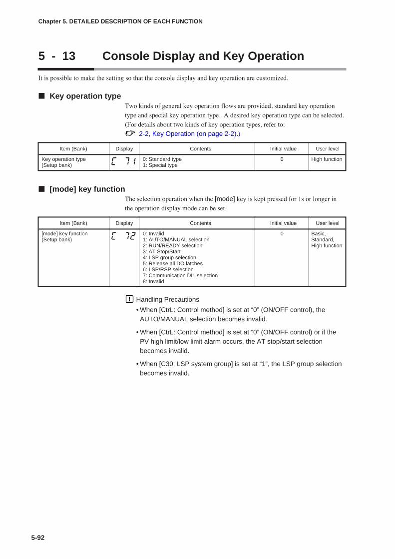
5-92
Chapter 5. DETAILED DESCRIPTION OF EACH FUNCTION
5 - 13 Console Display and Key Operation
It is possible to make the setting so that the console display and key operation are customized.
Key operation typeTwo kinds of general key operation flows are provided, standard key operation
type and special key operation type. A desired key operation type can be selected.
(For details about two kinds of key operation types, refer to;
2-2, Key Operation (on page 2-2).)
[mode] key functionThe selection operation when the [mode] key is kept pressed for 1s or longer in
the operation display mode can be set.
Handling Precautions
• When [CtrL: Control method] is set at “0” (ON/OFF control), theAUTO/MANUAL selection becomes invalid.
• When [CtrL: Control method] is set at “0” (ON/OFF control) or if thePV high limit/low limit alarm occurs, the AT stop/start selectionbecomes invalid.
• When [C30: LSP system group] is set at “1”, the LSP group selectionbecomes invalid.
Item (Bank) Display Contents Initial value User level
Key operation type(Setup bank)
0: Standard type1: Special type
0 High function
Item (Bank) Display Contents Initial value User level
[mode] key function(Setup bank)
0: Invalid1: AUTO/MANUAL selection2: RUN/READY selection3: AT Stop/Start4: LSP group selection5: Release all DO latches6: LSP/RSP selection7: Communication DI1 selection8: Invalid
0 Basic,Standard,High function

5-93
Chapter 5. DETAILED DESCRIPTION OF EACH FUNCTION
MODE display setupThe mode related setup items of the parameter setting and mode bank to be
displayed can be set.
• When using the Smart Loader Package SLP-C35, not only the numeric value,
but also the bit input can be used to set [C73: MODE display setup].
Handling Precautions
• Even though the AUTO/MANUAL display is set at [Displayed], theAUTO/MANUAL is not displayed when [CtrL: Control method] is set at“0” (ON/OFF control).
• Even though the AT stop/start display is set at [Displayed], the ATstop/start is not displayed when [CtrL: Control method] is set at “0”(ON/OFF control).
• Even though the LSP/RSP display is set at [Enabled], the LSP/RSP isnot displayed if the model does not provide the RSP input.
Item (Bank) Display Contents Initial value User level
MODE display setup(Setup bank)
Whether or not the mode bank setup isdisplayed is determined by the sum of thefollowing weights:Bit 0: AUTO/MANUAL display
Disabled: 0, Enabled: +1Bit 1: RUN/READY display
Disabled: 0, Enabled: +2Bit 2: LSP/RSP display
Disabled: 0, Enabled: +4Bit 3: AT stop/start display
Disabled: 0, Enabled: +8Bit 4: Release all DO latches display
Disabled: 0, Enabled: +16Bit 5: Communication DI1 ON/OFF display
Disabled: 0, Enabled: +32Other invalid settings, 0, +64, +128
255 Standard,High function
27 26 25 24 23 22 21 20
Undefined.
Undefined.
Communication DI1 ON/OFF display
Release all DO latches display
AT stop/start display
LSP/RSP display
RUN/READY display
AUTO/MANUAL display
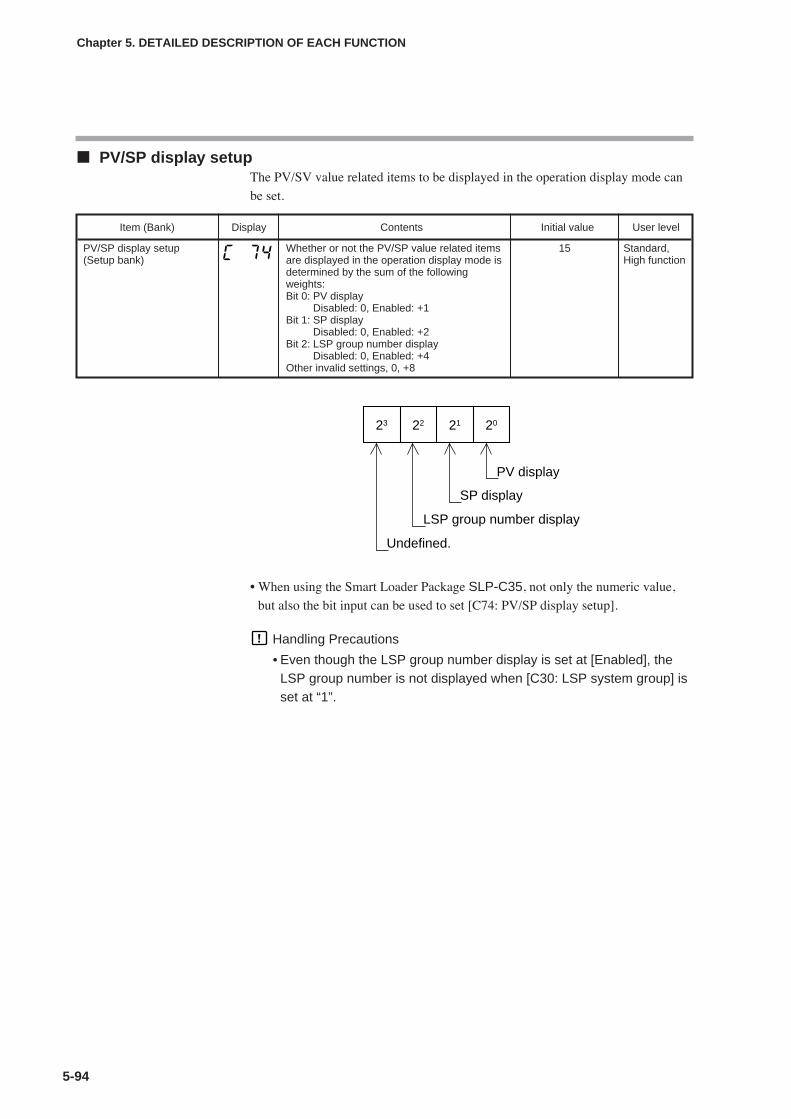
5-94
Chapter 5. DETAILED DESCRIPTION OF EACH FUNCTION
PV/SP display setupThe PV/SV value related items to be displayed in the operation display mode can
be set.
• When using the Smart Loader Package SLP-C35, not only the numeric value,
but also the bit input can be used to set [C74: PV/SP display setup].
Handling Precautions
• Even though the LSP group number display is set at [Enabled], theLSP group number is not displayed when [C30: LSP system group] isset at “1”.
Item (Bank) Display Contents Initial value User level
PV/SP display setup(Setup bank)
Whether or not the PV/SP value related itemsare displayed in the operation display mode isdetermined by the sum of the followingweights:Bit 0: PV display
Disabled: 0, Enabled: +1Bit 1: SP display
Disabled: 0, Enabled: +2Bit 2: LSP group number display
Disabled: 0, Enabled: +4Other invalid settings, 0, +8
15 Standard,High function
23 22 21 20
Undefined.
LSP group number display
SP display
PV display
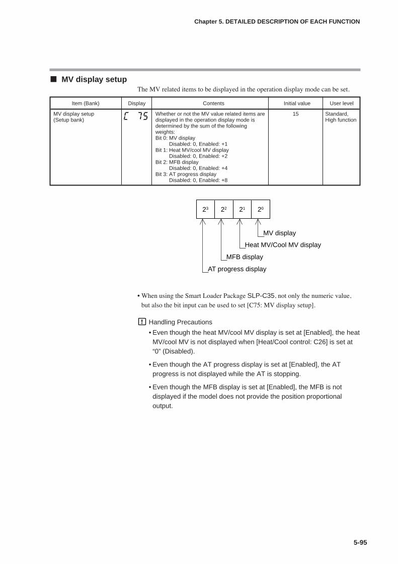
5-95
Chapter 5. DETAILED DESCRIPTION OF EACH FUNCTION
MV display setupThe MV related items to be displayed in the operation display mode can be set.
• When using the Smart Loader Package SLP-C35, not only the numeric value,
but also the bit input can be used to set [C75: MV display setup].
Handling Precautions
• Even though the heat MV/cool MV display is set at [Enabled], the heatMV/cool MV is not displayed when [Heat/Cool control: C26] is set at“0” (Disabled).
• Even though the AT progress display is set at [Enabled], the ATprogress is not displayed while the AT is stopping.
• Even though the MFB display is set at [Enabled], the MFB is notdisplayed if the model does not provide the position proportionaloutput.
Item (Bank) Display Contents Initial value User level
MV display setup(Setup bank)
Whether or not the MV value related items aredisplayed in the operation display mode isdetermined by the sum of the followingweights:Bit 0: MV display
Disabled: 0, Enabled: +1Bit 1: Heat MV/cool MV display
Disabled: 0, Enabled: +2Bit 2: MFB display
Disabled: 0, Enabled: +4Bit 3: AT progress display
Disabled: 0, Enabled: +8
15 Standard,High function
23 22 21 20
AT progress display
MFB display
Heat MV/Cool MV display
MV display
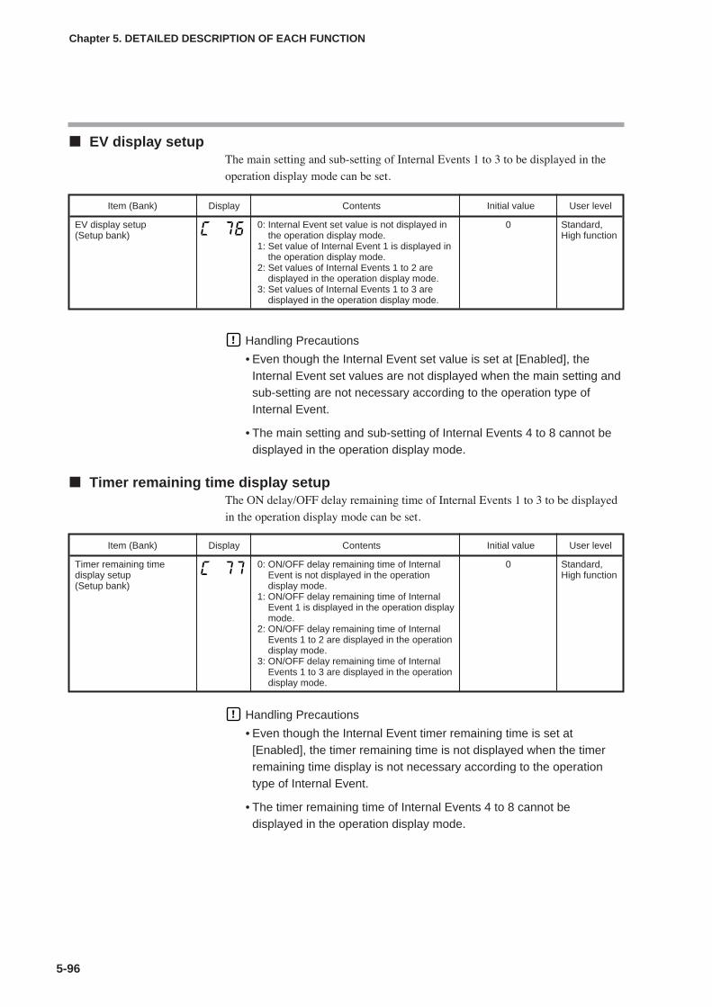
5-96
Chapter 5. DETAILED DESCRIPTION OF EACH FUNCTION
EV display setupThe main setting and sub-setting of Internal Events 1 to 3 to be displayed in the
operation display mode can be set.
Handling Precautions
• Even though the Internal Event set value is set at [Enabled], theInternal Event set values are not displayed when the main setting andsub-setting are not necessary according to the operation type ofInternal Event.
• The main setting and sub-setting of Internal Events 4 to 8 cannot bedisplayed in the operation display mode.
Timer remaining time display setupThe ON delay/OFF delay remaining time of Internal Events 1 to 3 to be displayed
in the operation display mode can be set.
Handling Precautions
• Even though the Internal Event timer remaining time is set at[Enabled], the timer remaining time is not displayed when the timerremaining time display is not necessary according to the operationtype of Internal Event.
• The timer remaining time of Internal Events 4 to 8 cannot bedisplayed in the operation display mode.
Item (Bank) Display Contents Initial value User level
EV display setup(Setup bank)
0: Internal Event set value is not displayed inthe operation display mode.
1: Set value of Internal Event 1 is displayed inthe operation display mode.
2: Set values of Internal Events 1 to 2 aredisplayed in the operation display mode.
3: Set values of Internal Events 1 to 3 aredisplayed in the operation display mode.
0 Standard,High function
Item (Bank) Display Contents Initial value User level
Timer remaining timedisplay setup(Setup bank)
0: ON/OFF delay remaining time of InternalEvent is not displayed in the operationdisplay mode.
1: ON/OFF delay remaining time of InternalEvent 1 is displayed in the operation displaymode.
2: ON/OFF delay remaining time of InternalEvents 1 to 2 are displayed in the operationdisplay mode.
3: ON/OFF delay remaining time of InternalEvents 1 to 3 are displayed in the operationdisplay mode.
0 Standard,High function
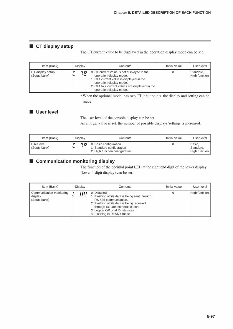
5-97
Chapter 5. DETAILED DESCRIPTION OF EACH FUNCTION
CT display setupThe CT current value to be displayed in the operation display mode can be set.
• When the optional model has two CT input points, the display and setting can be
made.
User levelThe user level of the console display can be set.
As a larger value is set, the number of possible displays/settings is increased.
Communication monitoring displayThe function of the decimal point LED at the right end digit of the lower display
(lower 4-digit display) can be set.
Item (Bank) Display Contents Initial value User level
CT display setup(Setup bank)
0: CT current value is not displayed in theoperation display mode.
1: CT1 current value is displayed in theoperation display mode.
2: CT1 to 2 current values are displayed in theoperation display mode.
0 Standard,High function
Item (Bank) Display Contents Initial value User level
User level (Setup bank)
0: Basic configuration1: Standard configuration2: High function configuration
0 Basic,Standard,High function
Item (Bank) Display Contents Initial value User level
Communication monitoringdisplay(Setup bank)
0: Disabled1: Flashing while data is being sent through
RS-485 communication.2: Flashing while data is being received
through RS-485 communication.3: Logical OR of all DI statuses4: Flashing in READY mode
0 High function

5-98
Chapter 5. DETAILED DESCRIPTION OF EACH FUNCTION
Multi Status (MS) displayThe lighting conditions for the Multi Status (MS) display located at the center of
the console and three groups of the lighting statuses can be set with the priority
put.
Item (Bank) Display Contents Initial value User level
Multi Status (MS) display,Condition (top priority)(Setup bank)
0: Normally open (Normally OFF=0)1: Normally close (Normally ON=1)2 to 9: Internal event 1 to 810 to 13: Undefined.14: MV1 (ON/OFF, Time proportional 1, Heat-
side, OPEN-side output)15: MV2 (Time proportional 2, Cool-side,
CLOSE-side output)16 to 17: Undefined.18 to 21: DI1 to DI422 to 25: Undefined.26 to 30: Internal contact 1 to 531 to 33: Undefined.34 to 37: Communication DI1 to DI438: MANUAL39: READY40: RSP41: AT42: During ramp43: Undefined.44: Alarm45: PV alarm46: Undefined.47: [mode] key pressing status48: Event output 1 terminal status49: Control output 1 terminal status
39 High function
Multi Status (MS) display,Status (top priority)(Setup bank)
0: Lit.1: Slow flashing2: Flashing twice3: Fast flashing4: Left to right5: Right to left6: Reciprocating between left and right7: Deviation OK8: Deviation graph9: MV graph10: Heat-side MV graph (For heat/cool control)11: Cool-side MV graph (For heat/cool control)12: MFB graph (including MFB being
estimated)13: DI monitor14: Internal contact monitor15: Internal event monitor
1 High function
Multi Status (MS) display,Condition (second priority)(Setup bank)
Same as Multi Status (MS) display, Condition(top priority).
44 High function
Multi Status (MS) display,Status (second priority)(Setup bank)
Same as Multi Status (MS) display, Status (top priority).
6
Multi Status (MS) display,Condition (third priority)(Setup bank)
Same as Multi Status (MS) display, Condition(top priority).
1 High function
Multi Status (MS) display,Status (third priority)(Setup bank)
Same as Multi Status (MS) display, Status (top priority).
9
Multi Status (MS) display,Deviation range(Setup bank)
0 to 9999U 5U High function

5-99
Chapter 5. DETAILED DESCRIPTION OF EACH FUNCTION
• The lighting conditions are satisfied when the status set as conditions is ON
(example: Internal event 1) or the status set as conditions is met (example:
MANUAL). Therefore, if the lighting conditions are set at “0”, the conditions
are always not satisfied. If the lighting conditions are set at “1”, the conditions
are always satisfied.
• When the lighting conditions having the top priority are satisfied, the operation
enters the lighting status having the top priority.
• When the lighting conditions having the top priority are not satisfied and the
lighting conditions having the second priority are satisfied, the operation enters
the lighting status having the second priority.
• When the lighting conditions having the top and second priorities are not
satisfied and the lighting conditions having the third priority are satisfied, the
operation enters the lighting status having the third priority.
• When the lighting conditions having the top to third priorities are not satisfied,
the Multi Status (MS) display becomes off.
• When the lighting status is set at “7” (deviation OK), the Multi Status (MS)
display is lit or off as shown in the following Figure:
If the deviation range of the Multi Status (MS) display is set at “0U”, the Multi
Status (MS) display is lit only when the PV display value equals SP (PV=SP).
• When the lighting status is set at “8” (deviation graph), the Multi Status (MS)
display is lit as shown in the following Figure:
The deviation range of the Multi Status (MS) display is set to “1U” or more. If
this range is set at “0U”, the Multi Status (MS) display becomes off.
Lit
Deviation OK lit/off
Off Off
PV
SP
Deviation range of Multi Status (MS) display
Deviation range of Multi Status (MS) display
Lighting range of deviation graph (Ratio of deviation (PV-SP) to Multi Status (MS) display deviation range)
+100.1% or more
+80.1 to +100.0%
+60.1 to +80.0%
+40.1 to +60.0%
+20.1 to +40.0%
+0.1 to +20.0%
-100.1% or less
-99.9 to -80.0%
-79.9 to -60.0%
-59.9 to -40.0%
-39.9 to -20.0%
-19.9 to 0.0%
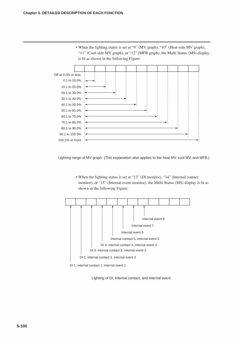
5-100
Chapter 5. DETAILED DESCRIPTION OF EACH FUNCTION
• When the lighting status is set at “9” (MV graph), “10” (Heat-side MV graph),
“11” (Cool-side MV graph), or “12” (MFB graph), the Multi Status (MS) display
is lit as shown in the following Figure:
• When the lighting status is set at “13” (DI monitor), “14” (Internal contact
monitor), or “15” (Internal event monitor), the Multi Status (MS) display is lit as
shown in the following Figure:
Lighting range of MV graph (This explanation also applies to the heat MV, cool MV, and MFB.)
Off at 0.0% or less
0.1 to 10.0%
10.1 to 20.0%
20.1 to 30.0%
30.1 to 40.0%
40.1 to 50.0%
50.1 to 60.0%
60.1 to 70.0%
70.1 to 80.0%
80.1 to 90.0%
90.1 to 100.0%
100.1% or more
Lighting of DI, internal contact, and internal event
Internal event 8
Internal event 7
Internal event 6
Internal contact 5, internal event 5
DI 4, internal contact 4, internal event 4
DI 3, internal contact 3, internal event 3
DI 2, internal contact 2, internal event 2
DI 1, internal contact 1, internal event 1
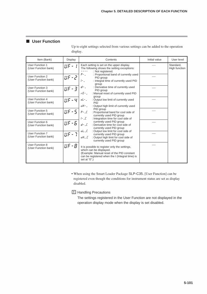
5-101
Chapter 5. DETAILED DESCRIPTION OF EACH FUNCTION
User FunctionUp to eight settings selected from various settings can be added to the operation
display.
• When using the Smart Loader Package SLP-C35, [User Function] can be
registered even though the conditions for instrument status are set as display
disabled.
Handling Precautions
The settings registered in the User Function are not displayed in theoperation display mode when the display is set disabled.
Item (Bank) Display Contents Initial value User level
User Function 1(User Function bank)
Each setting is set on the upper display.The following shows the setting exceptions:---- : Not registered.P-_ : Proportional band of currently used
PID groupI-_ : Integral time of currently used PID
groupd-_ : Derivative time of currently used
PID grouprE-_ : Manual reset of currently used PID
groupOL-_ : Output low limit of currently used
PIDOH-_ : Output high limit of currently used
PID groupP-_C : Proportional band for cool side of
currently used PID groupI-_C : Integration time for cool side of
currently used PID groupd-_C : Derivative time for cool side of
currently used PID groupOl._C : Output low limit for cool side of
currently used PID groupOH._C : Output high limit for cool side of
currently used PID group
It is possible to register only the settings,which can be displayed.(Example: Manual reset of the PID constantcan be registered when the I (Integral time) isset at “0”.)
---- Standard,High function
User Function 2(User Function bank)
----
User Function 3(User Function bank)
----
User Function 4(User Function bank)
----
User Function 5(User Function bank)
----
User Function 6(User Function bank)
----
User Function 7(User Function bank)
----
User Function 8(User Function bank)
----
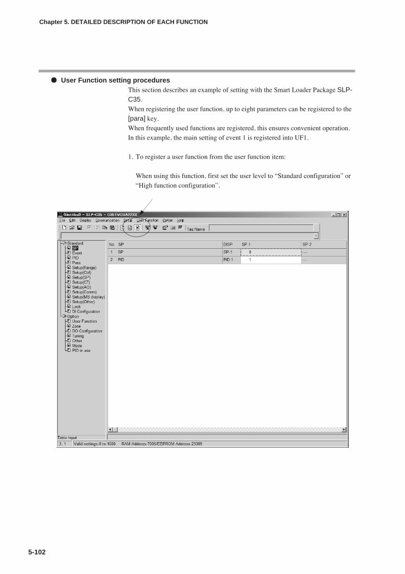
5-102
Chapter 5. DETAILED DESCRIPTION OF EACH FUNCTION
User Function setting proceduresThis section describes an example of setting with the Smart Loader Package SLP-C35.
When registering the user function, up to eight parameters can be registered to the
[para] key.
When frequently used functions are registered, this ensures convenient operation.
In this example, the main setting of event 1 is registered into UF1.
1. To register a user function from the user function item:
When using this function, first set the user level to “Standard configuration” or
“High function configuration”.
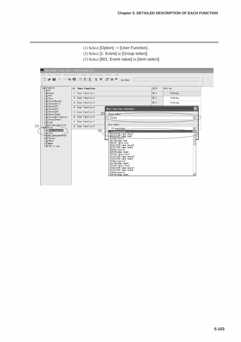
5-103
Chapter 5. DETAILED DESCRIPTION OF EACH FUNCTION
(1) Select [Option] → [User Function].(2) Select [1: Event] in [Group select].(3) Select [801: Event value] in [Item select].
(1)
(2)
(3)
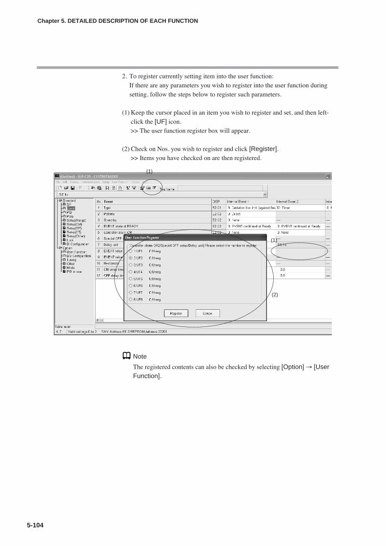
5-104
Chapter 5. DETAILED DESCRIPTION OF EACH FUNCTION
2. To register currently setting item into the user function:
If there are any parameters you wish to register into the user function during
setting, follow the steps below to register such parameters.
(1) Keep the cursor placed in an item you wish to register and set, and then left-
click the [UF] icon.
>> The user function register box will appear.
(2) Check on Nos. you wish to register and click [Register].>> Items you have checked on are then registered.
Note
The registered contents can also be checked by selecting [Option] → [UserFunction].
(1)
(1)
(2)

5-105
Chapter 5. DETAILED DESCRIPTION OF EACH FUNCTION
Key lock, communication lock, and loader lockThe setting (changing) or display can be set disabled using the key lock.
The communication can be set disabled using the communication lock and loader
lock.
• When using only the key lock setting, key lock objects can be displayed, but the
setting (changing) cannot be configured.
• When locked with the password, the display and setting of key lock objects
cannot be configured.
Item (Bank) Display Contents Initial value User level
Key lock(Lock bank)
0: All settings are possible.1: Mode, event, operation display, SP, UF,
lock, manual MV, and mode key can be set.2: Operation display, SP, UF, lock, manual
MV, and mode key can be set.3: UF, lock, manual MV, and mode key can be
set.
0 Basic,Standard,High function
Communication lock(Lock bank)
0: RS-485 communication read/write enabled.1: RS-485 communication read/write disabled.
0 High function
Loader lock(Lock bank)
0: Loader communication read/write enabled.1: Loader communication read/write disabled.
0 High function
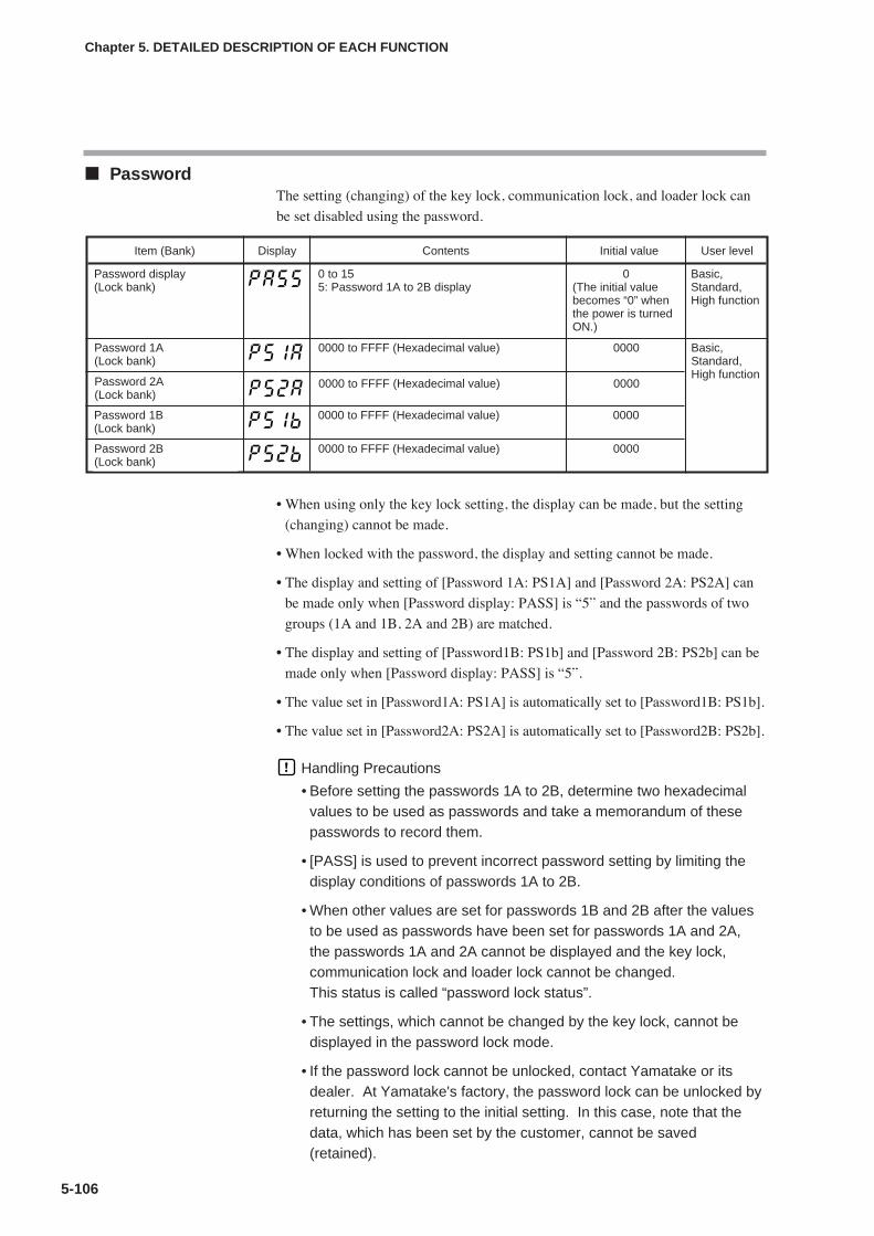
5-106
Chapter 5. DETAILED DESCRIPTION OF EACH FUNCTION
PasswordThe setting (changing) of the key lock, communication lock, and loader lock can
be set disabled using the password.
• When using only the key lock setting, the display can be made, but the setting
(changing) cannot be made.
• When locked with the password, the display and setting cannot be made.
• The display and setting of [Password 1A: PS1A] and [Password 2A: PS2A] can
be made only when [Password display: PASS] is “5” and the passwords of two
groups (1A and 1B, 2A and 2B) are matched.
• The display and setting of [Password1B: PS1b] and [Password 2B: PS2b] can be
made only when [Password display: PASS] is “5”.
• The value set in [Password1A: PS1A] is automatically set to [Password1B: PS1b].
• The value set in [Password2A: PS2A] is automatically set to [Password2B: PS2b].
Handling Precautions
• Before setting the passwords 1A to 2B, determine two hexadecimalvalues to be used as passwords and take a memorandum of thesepasswords to record them.
• [PASS] is used to prevent incorrect password setting by limiting thedisplay conditions of passwords 1A to 2B.
• When other values are set for passwords 1B and 2B after the valuesto be used as passwords have been set for passwords 1A and 2A,the passwords 1A and 2A cannot be displayed and the key lock,communication lock and loader lock cannot be changed.This status is called “password lock status”.
• The settings, which cannot be changed by the key lock, cannot bedisplayed in the password lock mode.
• If the password lock cannot be unlocked, contact Yamatake or itsdealer. At Yamatake's factory, the password lock can be unlocked byreturning the setting to the initial setting. In this case, note that thedata, which has been set by the customer, cannot be saved(retained).
Item (Bank) Display Contents Initial value User level
Password display(Lock bank)
0 to 155: Password 1A to 2B display
0(The initial valuebecomes “0” whenthe power is turnedON.)
Basic,Standard,High function
Password 1A(Lock bank)
0000 to FFFF (Hexadecimal value) 0000 Basic,Standard,High function
Password 2A(Lock bank)
0000 to FFFF (Hexadecimal value) 0000
Password 1B(Lock bank)
0000 to FFFF (Hexadecimal value) 0000
Password 2B(Lock bank)
0000 to FFFF (Hexadecimal value) 0000
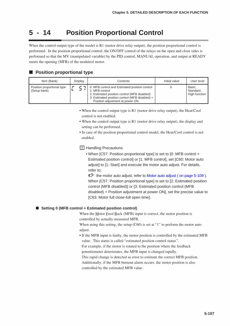
5-107
Chapter 5. DETAILED DESCRIPTION OF EACH FUNCTION
5 - 14 Position Proportional Control
When the control output type of the model is R1 (motor drive relay output), the position proportional control is
performed. In the position proportional control, the ON/OFF control of the relays on the open and close sides is
performed so that the MV (manipulated variable) by the PID control, MANUAL operation, and output at READY
meets the opening (MFB) of the modutrol motor.
Position proportional type
• When the control output type is R1 (motor drive relay output), the Heat/Cool
control is not enabled.
• When the control output type is R1 (motor drive relay output), the display and
setting can be performed.
• In case of the position proportional control model, the Heat/Cool control is not
enabled.
Handling Precautions
• When [C57: Position proportional type] is set to [0: MFB control +Estimated position control] or [1: MFB control], set [C60: Motor autoadjust] to [1: Start] and execute the motor auto adjust. For details,refer to;
the motor auto adjust, refer to Motor auto adjust ( on page 5-109 ).When [C57: Position proportional type] is set to [2: Estimated positioncontrol (MFB disabled)] or [3: Estimated position control (MFBdisabled) + Position adjustment at power ON], set the precise value to[C63: Motor full close-full open time].
Setting 0 (MFB control + Estimated position control)When the Motor Feed Back (MFB) input is correct, the motor position is
controlled by actually measured MFB.
When using this setting, the setup (C60) is set at “1” to perform the motor auto
adjust.
• If the MFB input is faulty, the motor position is controlled by the estimated MFB
value. This status is called “estimated position control status”.
For example, if the motor is rotated to the position where the feedback
potentiometer deteriorates, the MFB input is changed rapidly.
This rapid change is detected as error to estimate the correct MFB position.
Additionally, if the MFB burnout alarm occurs, the motor position is also
controlled by the estimated MFB value.
Item (Bank) Display Contents Initial value User level
Position proportional type(Setup bank)
0: MFB control and Estimated position control1: MFB control2: Estimated position control (MFB disabled)3: Estimated position control (MFB disabled) +
Position adjustment at power ON.
0 Basic,Standard,High function
5-108
Chapter 5. DETAILED DESCRIPTION OF EACH FUNCTION
• In the estimated position control status, an error occurs between the actual motor
opening and estimated MFB value.
Therefore, if the output (MV) ≤ 0.0%, the relay on the close side is always turned
ON. If the output (MV) ≥ 100.0%, the relay on the open side is always turned
ON.
According to the above control, the motor is put in the fully closed status or fully
opened status to correct the error.
However, the error is not corrected if the MV value is limited to a range of 0.1 to
99.9% by the output limiter or if the MV value does not become 0.0% or less or
100% or more according to the control status.
• The following may be the cause if the estimated position control is activated
easily.
• The motor opening is adjusted incorrectly.
• The feedback potentiometer deteriorates or the resolution is insufficient.
• The MFB wiring is faulty.
Setting 1 (MFB control)The motor is controlled by actually measured MFB. If the MFB burnout alarm
(AL07) occurs, the MFB is changed to “150%” so that the relay on the close side
is always turned ON. When using this setting, the setup (C60) is set at “1” to
perform the motor auto adjust.
Setting 2 (Estimated position control)• The motor is always controlled in the estimated position control status.
Regardless of the presence of the MFB wiring, the motor position is controlled
by the estimated MFB value.
• When using this setting, [C63: Motor full close-full open time] must be input
correctly.
• The MFB burnout alarm does not occur.
• The error between the actual motor opening and estimated MFB value is
corrected by forcibly moving the motor continuously in the close or open
direction when the MV is 0.0% or 100%.
Setting 3 (Estimated position control + Position adjustment at power ON)When the power is turned ON, the relay on the close side is kept turned ON for a
period of time set in [C63: Motor full close-full open time] to make “0%” of the
estimated MFB matched with the motor opening. Subsequent operation is the
same as that described for setting 2 (Estimated position control).
When using Setting 3, set the precise value to [C63: Motor full close–full open
time].
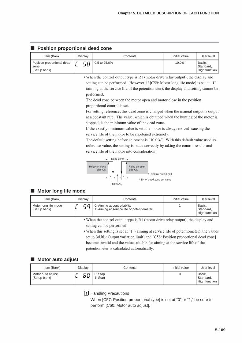
5-109
Chapter 5. DETAILED DESCRIPTION OF EACH FUNCTION
Position proportional dead zone
• When the control output type is R1 (motor drive relay output), the display and
setting can be performed. However, if [C59: Motor long life mode] is set at “1”
(aiming at the service life of the potentiometer), the display and setting cannot be
performed.
The dead zone between the motor open and motor close in the position
proportional control is set.
For setting reference, this dead zone is changed when the manual output is output
at a constant rate. The value, which is obtained when the hunting of the motor is
stopped, is the minimum value of the dead zone.
If the exactly minimum value is set, the motor is always moved, causing the
service life of the motor to be shortened extremely.
The default setting before shipment is “10.0%”. With this default value used as
reference value, the setting is made correctly by taking the control results and
service life of the motor into consideration.
Motor long life mode
• When the control output type is R1 (motor drive relay output), the display and
setting can be performed.
• When this setting is set at “1” (aiming at service life of potentiometer), the values
set in [oUtL: Output variation limit] and [C58: Position proportional dead zone]
become invalid and the value suitable for aiming at the service life of the
potentiometer is calculated automatically.
Motor auto adjust
Handling Precautions
When [C57: Position proportional type] is set at “0” or “1,” be sure toperform [C60: Motor auto adjust].
Item (Bank) Display Contents Initial value User level
Motor long life mode(Setup bank)
0: Aiming at controllability1: Aiming at service life of potentiometer
1 Basic,Standard,High function
Item (Bank) Display Contents Initial value User level
Motor auto adjust(Setup bank)
0: Stop1: Start
0 Basic,Standard,High function
Item (Bank) Display Contents Initial value User level
Position proportional deadzone(Setup bank)
0.5 to 25.0% 10.0% Basic,Standard,High function
Dead zone
* 1/4 of dead zone set value* *
Relay on openside ON
Relay on closeside ON
Control output (%)
MFB (%)

5-110
Chapter 5. DETAILED DESCRIPTION OF EACH FUNCTION
• When the control output type is R1 (motor drive relay output), the display andsetting can be performed. However, when [C57: Position proportional type] isset at “2” (Estimated position control) or “3” (Estimated position control +Position adjustment at power ON), the display and setting cannot be performed.
• When using the motor auto adjust function of the position proportional control,[C61: Input with motor fully closed], [C62: Input with motor fully open], and[C63: Motor full close-full open time] are set automatically.
• Motor auto adjusting procedures1. Set “0” or “1” to [C57: Position proportional type].2. Set “1” to [C60: Motor auto adjust] and press the [enter] key.
When this setup (C60) is already set at “1”, press the [enter] key twice.3. The motor auto adjust is then started.
• The upper display shows and the relay on the close side is turned ON.• The motor is moved toward the close side and the MFB count value is
shown on the lower display. When the counting becomes stable, the fullyclosed adjustment is completed. This count value is then written into [C61:Input with motor fully closed].
• The upper display shows and the relay on the open side is turned ON.• The motor is moved toward the open side and the MFB count value is shown
on the lower display. When the counting becomes stable, the fully openadjustment is completed. This count value is then written into [C62: Inputwith motor fully open]. Additionally, a period of time, which has elapsedfrom the fully closed position to the fully open position, is written into [C63:Motor full close-full open time]. However, if this time is 240.0s or longer,“240.0s” is set to this parameter.
• When the motor auto adjust has been completed, the basic display screenwill appear.
4. To cancel the adjustment, press the [display] key.When the motor auto adjust is started, keys other than the [display] key usedto cancel the adjustment cannot be operated.If any of the following arises, each value is returned to its default settingbefore shipment and “AL10” is shown as the troubleshooting process.“AL10” is cleared only when the motor auto adjust is restarted and completedcorrectly or when the power is reset.• The count value between the fully closed position and fully open position is
less than “260”.• The fully closed count is greater than the fully open count.• The period of time from the fully closed position to the fully open position is
less than 5s.• The MFB burnout alarm (AL07) is continued or occurs frequently.• The period of time that the MFB count value becomes stable exceeds 5min.• The MFB or open/close relay has faulty wiring.
(However, all of faulty wiring cannot be detected as error.)
• As the data is written into the motor auto adjust (decimal address: 5260) throughthe CPL or MODBUS communication, the starting of the motor auto adjust canbe cancelled. To start the motor auto adjust, “1” is written. On the contrary, tocancel the motor auto adjust, “0” is written.
Handling Precautions
• If the power to the measuring instrument is turned OFF during motorauto adjust of the position proportional control, the motor auto adjustis cancelled when the power is turned ON again.
• Even though the AUTO/MANUAL mode, RUN/READY mode, orLSP/RSP is changed during motor auto adjust, the motor auto adjustis continued.
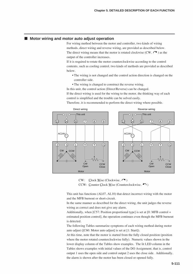
5-111
Chapter 5. DETAILED DESCRIPTION OF EACH FUNCTION
Motor wiring and motor auto adjust operationFor wiring method between the motor and controller, two kinds of wiring
methods, direct wiring and reverse wiring, are provided as described below.
The direct wiring means that the motor is rotated clockwise (CW, ) as the
output of the controller increases.
If it is required to rotate the motor counterclockwise according to the control
contents, such as cooling control, two kinds of methods are provided as described
below.
• The wiring is not changed and the control action direction is changed on the
controller side.
• The wiring is changed to construct the reverse wiring.
In this unit, the control action (Direct/Reverse) can be changed.
If the direct wiring is used for the wiring to the motor, the thinking way of each
control is simplified and the trouble can be solved easily.
Therefore, it is recommended to perform the direct wiring where possible.
CW: Clock Wise (Clockwise, )
CCW: Counter Clock Wise (Counterclockwise, )
This unit has functions (AL07, AL10) that detect incorrect wiring with the motor
and the MFB burnout or short-circuit.
In the same manner as described for the direct wiring, the unit judges the reverse
wiring as correct and does not give any alarm.
Additionally, when [C57: Position proportional type] is set at [0: MFB control +
estimated position control], the operation continues even though the MFB burnout
is detected.
The following Tables summarize symptoms of each wiring method during motor
auto adjust ([C60: Motor auto adjust] is set at [1: Start]).
At this time, note that the motor is started from the fully closed position (position
where the motor rotated counterclockwise fully). Numeric values shown in the
lower display column of the Tables show examples. The lit LED column in the
Tables shows examples with initial values of the DO Assignment, that is, control
output 1 uses the open side and control output 2 uses the close side. Additionally,
the alarm is shown after the motor has been closed or opened fully.
8714 9
This unit
3
AC24V
2 1 Y
CW CCW
T G
CWOpen
CCWClose
Motor
This unit
3
AC24V
T
CWOpen
CCWClose
Motor
2 1 GY
Direct wiring Reverse wiring
7 8 913 14 1513 15
CW CCW
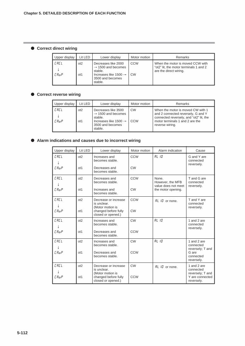
5-112
Chapter 5. DETAILED DESCRIPTION OF EACH FUNCTION
Correct direct wiring
Correct reverse wiring
Alarm indications and causes due to incorrect wiring
Upper display Lit LED Lower display Motor motion Remarks
Decreases like 2000→ 1500 and becomesstable.Increases like 1500 →3500 and becomesstable.
When the motor is moved CCW with“ot2” lit, the motor terminals 1 and 2are the direct wiring.
CCW
CW
ot2
ot1
↓
Upper display Lit LED Lower display Motor motion Remarks
Decreases like 3500→ 1500 and becomesstable.Increases like 1500 →3500 and becomesstable.
When the motor is moved CW with 1and 2 connected reversely, G and Yconnected reversely, and “ot2” lit, themotor terminals 1 and 2 are thereverse wiring.
CW
CCW
ot2
ot1
↓
Upper display Lit LED Lower display Motor motion Alarm indication Cause
Increases andbecomes stable.
Decreases andbecomes stable.
CCW
CW
ot2
ot1
↓
G and Y areconnectedreversely.
Decreases andbecomes stable.
Increases andbecomes stable.
None.However, the MFBvalue does not meetthe motor opening.
CCW
CW
ot2
ot1
↓
T and G areconnectedreversely.
Decrease or increaseis unclear.(Motor motion ischanged before fullyclosed or opened.)
or none.CCW
CW
ot2
ot1
↓
T and Y areconnectedreversely.
Increases andbecomes stable.
Decreases andbecomes stable.
CW
CCW
ot2
ot1
↓
1 and 2 areconnectedreversely.
Increases andbecomes stable.
Decreases andbecomes stable.
CW
CCW
ot2
ot1
↓
1 and 2 areconnectedreversely; T andG areconnectedreversely.
Decrease or increaseis unclear.(Motor motion ischanged before fullyclosed or opened.)
or none.CW
CCW
ot2
ot1
↓
1 and 2 areconnectedreversely; T andY are connectedreversely.

5-113
Chapter 5. DETAILED DESCRIPTION OF EACH FUNCTION
Input with motor fully closed and input with motor fully open
• When the control output type is R1 (motor drive relay output), the display and
setting can be performed. However, if [C57: Position proportional type] is set at
“2” (Estimated position control) or “3” (Estimated position control + Position
adjustment at power ON), the display and setting cannot be performed.
• If you use the motor auto adjust function of the position proportional control,
these parameters can be set automatically. Additionally, they can also be set
manually in the same manner as described for normal set values.
Note
For details about motor auto adjust, refer to;
Motor auto adjust (on page 5-109).
Motor full close–full open time
• When the control output type is R1 (motor drive relay output), the display and
setting can be performed.
• When using the motor auto adjust function of the position proportional control
with [C57: Position proportional type] set at “0” (MFB control + Estimated
position control) or “1” (MFB control), the motor full close–full open time can
be set automatically. Additionally, this time can also be set manually in the same
manner as described for normal set values.
Note
For details about motor auto adjust, refer to;
Motor auto adjust (on page 5-109).
• When [C57: Position proportional type] is set at “2” (Estimated position control)
or “3” (Estimated position control + Position adjustment at power ON), the
actually measured motor full open time is set.
Item (Bank) Display Contents Initial value User level
Input with motor fullyclosed(Setup bank)
0 to 9999 1000 Basic,Standard,High function
Input with motor fullyclosed(Setup bank)
0 to 9999 3000
Item (Bank) Display Contents Initial value User level
Motor full close–full opentime(Setup bank)
5.0 to 240.0s 30.0s Basic,Standard,High function


Chapter 6. LIST OF DISPLAYS AND SETTING DATA6 - 1 List of Operation Displays
6-1
The following shows the meanings of the values stated in the “User Level” column:
0: Basic, Standard, and High function configuration
1: Standard and High function configuration
2: High function configuration
Operation displays
Display Item Contents Initialvalue
Userlevel
Remarks
Upper display: PVLower display: SP
SP (Target value) SP low limit (C07) to SP high limit(C08)
0 0 Whether or not this item isdisplayed is selected by thePV/SP display setup (C74).
(Displayexample)Lower display:LSP
LSP group number(1st digit: Value at theright end digit)
1 to LSP system group (C30, Max. 8) 1 0 Displayed when LSP systemgroup (C30) is “2” or more.The lower display shows theLSP set value correspondingto the LSP group number.Whether or not this item isdisplayed is selected by thePV/SP display setup (C74).
MV (ManipulatedVariable)
-10.0 to +110.0%Setting is disabled in AUTO mode.(Numeric value does not flash.)Setting is enabled in MANUAL mode.(Numeric value flashes.)
— 0 In the ON/OFF control (CtrL= 0), "100.0" is displayed atON and "0.0" is displayed atOFF. Whether or not thisitem is displayed is selectedby the MV display setup (C75).
Heat MV (ManipulatedVariable)
Setting is disabled.-10.0 to +110.0%
— 0 This item is displayed whenusing the Heat/Cool control(C26 = 1).Whether or not this item isdisplayed is selected by theMV display setup (C75).
Cool MV (ManipulatedVariable)
— 0
Upper display:PV
AT progress display(1st digit = Numericvalue at right enddigit)
Setting is disabled.Lower display shows the AT progressvalue on the right of “At”.1 - : During execution of AT (Value is
decreased.)0: Completion of AT
— 0 Displayed during execution ofAT. (The display is continuedeven after completion of AT.)Whether or not this item isdisplayed is selected by theMV display setup (C75).
CT (Current trans-former) current value 1
Setting is disabled. — 0 Displayed when the optionalmodel has two currenttransformer points.Whether or not this item isdisplayed is selected by theCT display setup (C78).
CT (Current trans-former) current value 2
Setting is disabled. — 0
Internal Event 1 main setting
The allowable setting range may varydepending on the operation type ofthe internal event.-1999 to +9999U: Set value is otherthan the following values:0 to 9999U: Set value is an absolutevalue.-199.9 to +999.9%: Set value is MV.
0 0 Setting required by theoperation type of the internalevent is displayed.Whether or not this item isdisplayed is selected by theEV display setup (C76).
Internal Event 1 sub setting
0 0
(Displayexample)
(Displayexample)Lower display:Step remain time
Step No. and stepremain time
Setting is disabled.Upper display shows the step No. (1to 8), and distinction among the soak,up ramp, and down ramp on the rightof “St.”. Lower display shows thesoak remain time or ramp remaintime.
1 0 Regardless of the soak orramp operation, the remaintime is displayed in step timeunit (setup C33). When theunit is 1s, “min.s” isdisplayed. When the unit is1min, “h.min” is displayed.
Upper display:PVLower display:MV
MFB (Motor openingfeedback value)
Setting is disabled.-10.0 to +110.0%Flashing when the value is 0.0 to100.0% during estimate.
— 0 Displayed when the outputtype is the positionproportional output.Whether or not the MFB isdisplayed is selected usingthe MV display setup (C75).
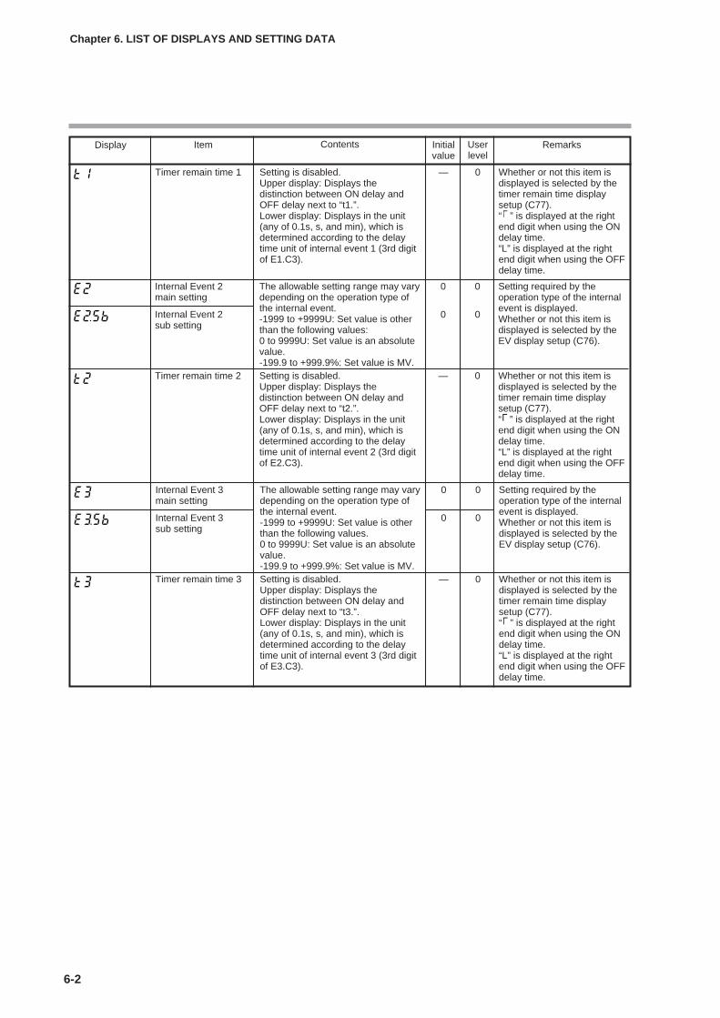
6-2
Chapter 6. LIST OF DISPLAYS AND SETTING DATA
Display Item Contents Initialvalue
Userlevel
Remarks
Internal Event 3 main setting
The allowable setting range may varydepending on the operation type ofthe internal event.-1999 to +9999U: Set value is otherthan the following values.0 to 9999U: Set value is an absolutevalue.-199.9 to +999.9%: Set value is MV.
0 0 Setting required by theoperation type of the internalevent is displayed.Whether or not this item isdisplayed is selected by theEV display setup (C76).
Internal Event 3 sub setting
0 0
Timer remain time 3 Setting is disabled.Upper display: Displays thedistinction between ON delay andOFF delay next to “t3.”.Lower display: Displays in the unit(any of 0.1s, s, and min), which isdetermined according to the delaytime unit of internal event 3 (3rd digitof E3.C3).
— 0 Whether or not this item isdisplayed is selected by thetimer remain time displaysetup (C77).“ ” is displayed at the rightend digit when using the ONdelay time.“L” is displayed at the rightend digit when using the OFFdelay time.
Timer remain time 1 Setting is disabled.Upper display: Displays thedistinction between ON delay andOFF delay next to “t1.”.Lower display: Displays in the unit(any of 0.1s, s, and min), which isdetermined according to the delaytime unit of internal event 1 (3rd digitof E1.C3).
— 0 Whether or not this item isdisplayed is selected by thetimer remain time displaysetup (C77).“ ” is displayed at the rightend digit when using the ONdelay time.“L” is displayed at the rightend digit when using the OFFdelay time.
Internal Event 2 main setting
The allowable setting range may varydepending on the operation type ofthe internal event.-1999 to +9999U: Set value is otherthan the following values:0 to 9999U: Set value is an absolutevalue.-199.9 to +999.9%: Set value is MV.
0 0 Setting required by theoperation type of the internalevent is displayed.Whether or not this item isdisplayed is selected by theEV display setup (C76).
Internal Event 2 sub setting
0 0
Timer remain time 2 Setting is disabled.Upper display: Displays thedistinction between ON delay andOFF delay next to “t2.”.Lower display: Displays in the unit(any of 0.1s, s, and min), which isdetermined according to the delaytime unit of internal event 2 (3rd digitof E2.C3).
— 0 Whether or not this item isdisplayed is selected by thetimer remain time displaysetup (C77).“ ” is displayed at the rightend digit when using the ONdelay time.“L” is displayed at the rightend digit when using the OFFdelay time.
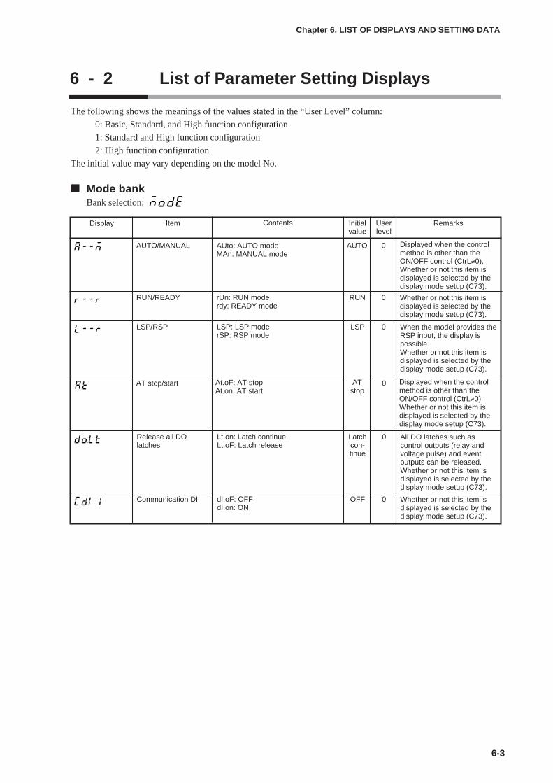
6-3
Chapter 6. LIST OF DISPLAYS AND SETTING DATA
6 - 2 List of Parameter Setting Displays
The following shows the meanings of the values stated in the “User Level” column:
0: Basic, Standard, and High function configuration
1: Standard and High function configuration
2: High function configuration
The initial value may vary depending on the model No.
Mode bankBank selection:
Display Item Contents Initialvalue
Userlevel
Remarks
AUTO/MANUAL AUto: AUTO modeMAn: MANUAL mode
AUTO 0
RUN/READY RUN 0
Displayed when the controlmethod is other than theON/OFF control (CtrL≠0).Whether or not this item isdisplayed is selected by thedisplay mode setup (C73).
rUn: RUN moderdy: READY mode
Whether or not this item isdisplayed is selected by thedisplay mode setup (C73).
AT stop/start ATstop
0At.oF: AT stopAt.on: AT start
Displayed when the controlmethod is other than theON/OFF control (CtrL≠0).Whether or not this item isdisplayed is selected by thedisplay mode setup (C73).
Release all DOlatches
Latchcon-tinue
0Lt.on: Latch continueLt.oF: Latch release
All DO latches such ascontrol outputs (relay andvoltage pulse) and eventoutputs can be released.Whether or not this item isdisplayed is selected by thedisplay mode setup (C73).
Communication DI OFF 0dI.oF: OFFdI.on: ON
Whether or not this item isdisplayed is selected by thedisplay mode setup (C73).
LSP/RSP LSP 0LSP: LSP moderSP: RSP mode
When the model provides theRSP input, the display ispossible.Whether or not this item isdisplayed is selected by thedisplay mode setup (C73).
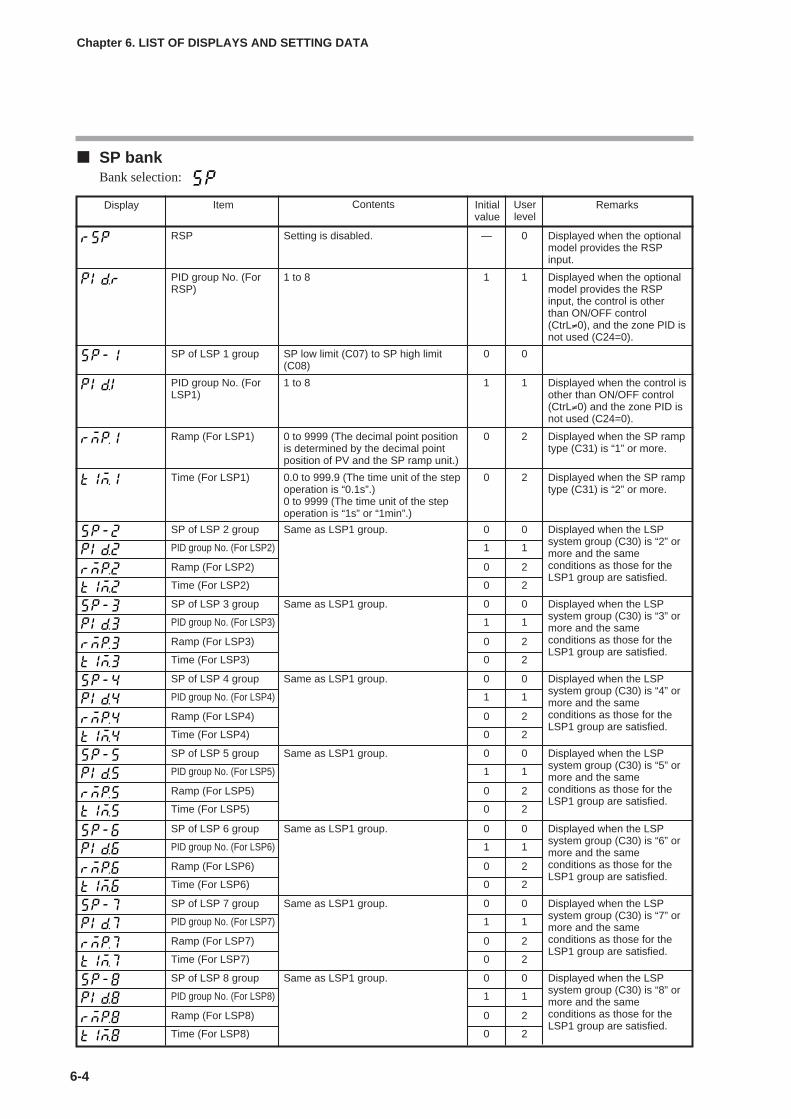
SP bankBank selection:
6-4
Chapter 6. LIST OF DISPLAYS AND SETTING DATA
Display Item Contents Initialvalue
Userlevel
Remarks
RSP — 0Setting is disabled. Displayed when the optionalmodel provides the RSPinput.
PID group No. (ForRSP)
1 11 to 8 Displayed when the optionalmodel provides the RSPinput, the control is otherthan ON/OFF control(CtrL≠0), and the zone PID isnot used (C24=0).
SP of LSP 1 group 0 0SP low limit (C07) to SP high limit(C08)
PID group No. (ForLSP1)
1 11 to 8 Displayed when the control isother than ON/OFF control(CtrL≠0) and the zone PID isnot used (C24=0).
Ramp (For LSP1) 0 20 to 9999 (The decimal point positionis determined by the decimal pointposition of PV and the SP ramp unit.)
Displayed when the SP ramptype (C31) is “1” or more.
Time (For LSP1) 0 20.0 to 999.9 (The time unit of the stepoperation is “0.1s”.)0 to 9999 (The time unit of the stepoperation is “1s” or “1min”.)
Displayed when the SP ramptype (C31) is “2” or more.
SP of LSP 2 group 0 0Same as LSP1 group. Displayed when the LSPsystem group (C30) is “2” ormore and the sameconditions as those for theLSP1 group are satisfied.
PID group No. (For LSP2) 1 1
Ramp (For LSP2) 0 2
Time (For LSP2) 0 2
SP of LSP 3 group 0 0Same as LSP1 group. Displayed when the LSPsystem group (C30) is “3” ormore and the sameconditions as those for theLSP1 group are satisfied.
PID group No. (For LSP3) 1 1
Ramp (For LSP3) 0 2
Time (For LSP3) 0 2
SP of LSP 4 group 0 0Same as LSP1 group. Displayed when the LSPsystem group (C30) is “4” ormore and the sameconditions as those for theLSP1 group are satisfied.
PID group No. (For LSP4) 1 1
Ramp (For LSP4) 0 2
Time (For LSP4) 0 2
SP of LSP 5 group 0 0Same as LSP1 group. Displayed when the LSPsystem group (C30) is “5” ormore and the sameconditions as those for theLSP1 group are satisfied.
PID group No. (For LSP5) 1 1
Ramp (For LSP5) 0 2
Time (For LSP5) 0 2
SP of LSP 6 group 0 0Same as LSP1 group. Displayed when the LSPsystem group (C30) is “6” ormore and the sameconditions as those for theLSP1 group are satisfied.
PID group No. (For LSP6) 1 1
Ramp (For LSP6) 0 2
Time (For LSP6) 0 2
SP of LSP 7 group 0 0Same as LSP1 group. Displayed when the LSPsystem group (C30) is “7” ormore and the sameconditions as those for theLSP1 group are satisfied.
PID group No. (For LSP7) 1 1
Ramp (For LSP7) 0 2
Time (For LSP7) 0 2
SP of LSP 8 group 0 0Same as LSP1 group. Displayed when the LSPsystem group (C30) is “8” ormore and the sameconditions as those for theLSP1 group are satisfied.
PID group No. (For LSP8) 1 1
Ramp (For LSP8) 0 2
Time (For LSP8) 0 2

6-5
Chapter 6. LIST OF DISPLAYS AND SETTING DATA
Event bankBank selection:
(To be continued to the next page.)
Display Item Contents Initialvalue
Userlevel
Remarks
Internal Event 1 main setting
0 0 Necessary settings aredisplayed according toInternal Event 1 operationtype (E1.C1).
-1999 to +9999The decimal point position may varyso that it meets the operation type ofthe internal event.The above value becomes 0 to 9999in some operation types.
Internal Event 1 sub-setting
0 0
Internal Event 1Hysteresis
5 00 to 9999The decimal point position may varyso that it meets the operation type ofthe internal event.
Internal Event 1 ON delay time
0 20.0 to 999.9(Delay unit is 0.1s.)0 to 9999(Delay unit is other than 0.1s.)
Internal Event 1 OFF delay time
0 2
Internal Event 2 main setting
0 0 Necessary settings aredisplayed according toInternal Event 2 operationtype (E2.C1).
Same as Internal Event 1.
Internal Event 2 sub-setting
0 0
Internal Event 2Hysteresis
5 0
Internal Event 2 ON delay time
0 2
Internal Event 2 OFF delay time
0 2
Internal Event 3 main setting
0 0 Necessary settings aredisplayed according toInternal Event 3 operationtype (E3.C1).
Same as Internal Event 1.
Internal Event 3 sub-setting
0 0
Internal Event 3Hysteresis
5 0
Internal Event 3 ON delay time
0 2
Internal Event 3 OFF delay time
0 2
Internal Event 4 main setting
0 0 Necessary settings aredisplayed according toInternal Event 4 operationtype (E4.C1).
Same as Internal Event 1.
Internal Event 4 sub-setting
0 0
Internal Event 4Hysteresis
5 0
Internal Event 4 ON delay time
0 2
Internal Event 4 OFF delay time
0 2
Internal Event 5 main setting
0 0 Necessary settings aredisplayed according toInternal Event 5 operationtype (E5.C1).
Same as Internal Event 1.
Internal Event 5 sub-setting
0 0
Internal Event 5Hysteresis
5 0
Internal Event 5 ON delay time
0 2
Internal Event 5 OFF delay time
0 2

6-6
Chapter 6. LIST OF DISPLAYS AND SETTING DATA
Display Item Contents Initialvalue
Userlevel
Remarks
Internal Event 6 main setting
0 0 Necessary settings aredisplayed according toInternal Event 6 operationtype (E6.C1).
Same as Internal Event 1.
Internal Event 6 sub-setting
0 0
Internal Event 6Hysteresis
5 0
Internal Event 6 ON delay time
0 2
Internal Event 6 OFF delay time
0 2
Internal Event 7 main setting
0 0 Necessary settings aredisplayed according toInternal Event 7 operationtype (E7.C1).
Same as Internal Event 1.
Internal Event 7 sub-setting
0 0
Internal Event 7Hysteresis
5 0
Internal Event 7 ON delay time
0 2
Internal Event 7 OFF delay time
0 2
Internal Event 8 main setting
0 0 Necessary settings aredisplayed according toInternal Event 8 operationtype (E8.C1).
Same as Internal Event 1.
Internal Event 8 sub-setting
0 0
Internal Event 8Hysteresis
5 0
Internal Event 8 ON delay time
0 2
Internal Event 8 OFF delay time
0 2

6-7
Chapter 6. LIST OF DISPLAYS AND SETTING DATA
PID bankBank selection:
(Note) For presence of the decimal point, when [C23: PID Decimal point position] is set at “0”, thedecimal point does not exist. When this setting is set at “1”, the decimal point exists.
Display Item Contents Initialvalue
Userlevel
Remarks
Proportional band(PID 1)
0.1 to 999.9% 5.0 0 Displayed when the controlmethod is other than theON/OFF control (CtrL≠0).Integral time (PID 1) 0 to 9999s or 0.0 to 999.9s (Note)
(No integration control action whenset at "0".)
120 0
Derivative time (PID 1)
0 to 9999s or 0.0 to 999.9s (Note)(No derivative control action when setat "0".)
30 0
Manual reset (PID 1) -10.0 to +110.0% 50.0 0 Displayed when the controlmethod is other than theON/OFF control (CtrL≠0) andthe I (Integral time) in thesame PID group is “0”.
MV low limit (PID 1) -10.0 to +110.0% 0.0 1 Displayed when the controlmethod is other than theON/OFF control (CtrL≠0) or Displayed when the controlmethod is other than theON/OFF control (CtrL≠0) andthe Heat/Cool control is used(C26 = 1).
MV high limit (PID 1) -10.0 to +110.0% 100.0 1
Proportional band forcool side (PID 1)
0.1 to 999.9% 5.0 0
Integral time for coolside (PID 1)
0 to 9999s or 0.0 to 999.9s (Note)(No integration control action whenset at "0".)
120 0
Derivative time forcool side (PID 1)
0 to 9999s or 0.0 to 999.9s (Note)(No derivative control action when setat "0".)
30 0
Output low limit forcool side (PID 1)
-10.0 to +110.0% 0.0 1
Output high limit forcool side (PID 1)
-10.0 to +110.0% 100.0 1
Proportional band(PID 2)
Same as PID 1 5.0 0 Same as PID 1
Integral time (PID 2) 120 0
Derivative time (PID 2)
30 0
Manual reset (PID 2) 50.0 0
MV low limit (PID 2) 0.0 1
MV high limit (PID 2) 100.0 1
Proportional band forcool side (PID 2)
5.0 0
Integral time for coolside (PID 2)
120 0
Derivative time forcool side (PID 2)
30 0
Output low limit forcool side (PID 2)
0.0 1
Output high limit forcool side (PID 2)
100.0 1
(To be continued to the next page.)
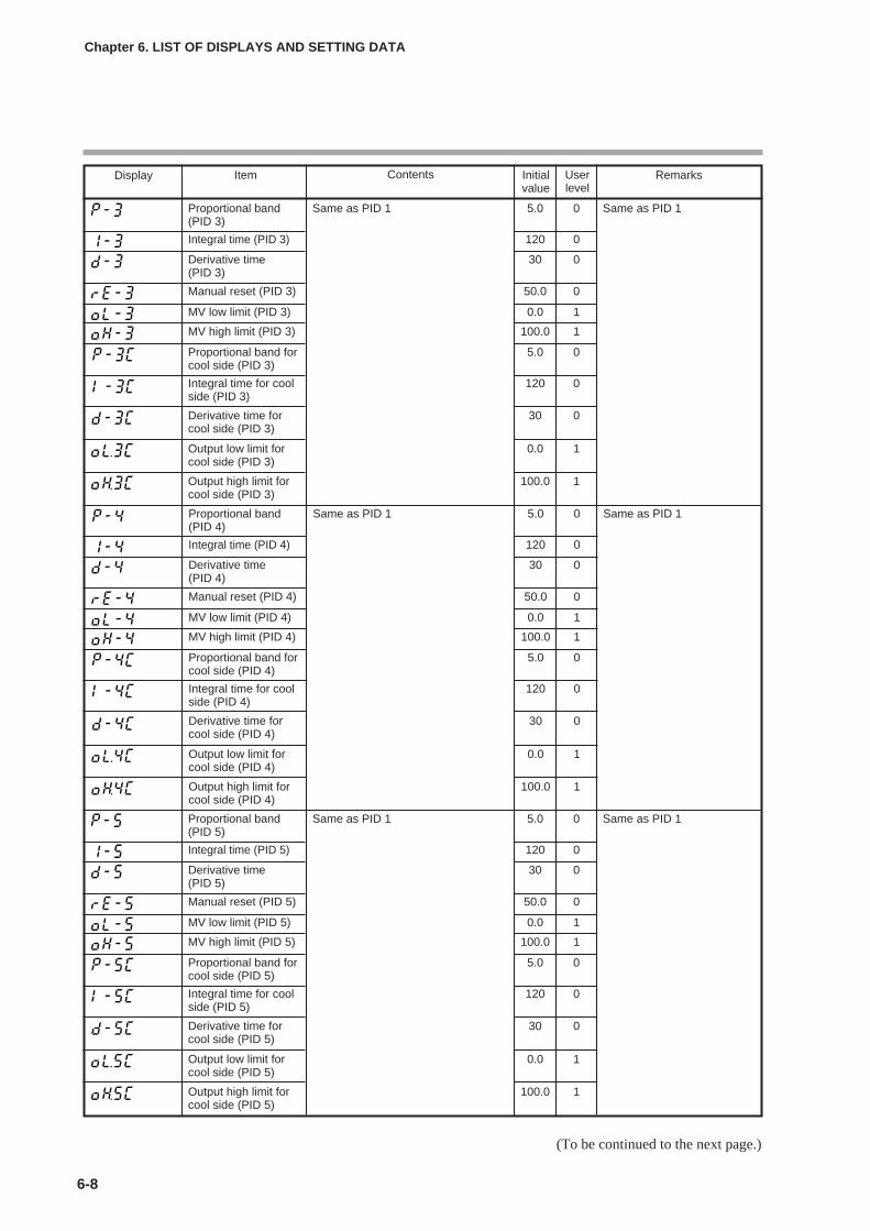
(To be continued to the next page.)
6-8
Chapter 6. LIST OF DISPLAYS AND SETTING DATA
Display Item Contents Initialvalue
Userlevel
Remarks
Proportional band(PID 3)
Same as PID 1 5.0 0 Same as PID 1
Integral time (PID 3) 120 0
Derivative time (PID 3)
30 0
Manual reset (PID 3) 50.0 0
MV low limit (PID 3) 0.0 1
MV high limit (PID 3) 100.0 1
Proportional band forcool side (PID 3)
5.0 0
Integral time for coolside (PID 3)
120 0
Derivative time forcool side (PID 3)
30 0
Output low limit forcool side (PID 3)
0.0 1
Output high limit forcool side (PID 3)
100.0 1
Proportional band(PID 4)
Same as PID 1 5.0 0 Same as PID 1
Integral time (PID 4) 120 0
Derivative time (PID 4)
30 0
Manual reset (PID 4) 50.0 0
MV low limit (PID 4) 0.0 1
MV high limit (PID 4) 100.0 1
Proportional band forcool side (PID 4)
5.0 0
Integral time for coolside (PID 4)
120 0
Derivative time forcool side (PID 4)
30 0
Output low limit forcool side (PID 4)
0.0 1
Output high limit forcool side (PID 4)
100.0 1
Proportional band(PID 5)
Same as PID 1 5.0 0 Same as PID 1
Integral time (PID 5) 120 0
Derivative time (PID 5)
30 0
Manual reset (PID 5) 50.0 0
MV low limit (PID 5) 0.0 1
MV high limit (PID 5) 100.0 1
Proportional band forcool side (PID 5)
5.0 0
Integral time for coolside (PID 5)
120 0
Derivative time forcool side (PID 5)
30 0
Output low limit forcool side (PID 5)
0.0 1
Output high limit forcool side (PID 5)
100.0 1

6-9
Chapter 6. LIST OF DISPLAYS AND SETTING DATA
Display Item Contents Initialvalue
Userlevel
Remarks
Proportional band(PID 6)
Same as PID 1 5.0 0 Same as PID 1
Integral time (PID 6) 120 0
Derivative time (PID 6)
30 0
Manual reset (PID 6) 50.0 0
MV low limit (PID 6) 0.0 1
MV high limit (PID 6) 100.0 1
Proportional band forcool side (PID 6)
5.0 0
Integral time for coolside (PID 6)
120 0
Derivative time forcool side (PID 6)
30 0
Output low limit forcool side (PID 6)
0.0 1
Output high limit forcool side (PID 6)
100.0 1
Proportional band(PID 7)
Same as PID 1 5.0 0 Same as PID 1
Integral time (PID 7) 120 0
Derivative time (PID 7)
30 0
Manual reset (PID 7) 50.0 0
MV low limit (PID 7) 0.0 1
MV high limit (PID 7) 100.0 1
Proportional band forcool side (PID 7)
5.0 0
Integral time for coolside (PID 7)
120 0
Derivative time forcool side (PID 7)
30 0
Output low limit forcool side (PID 7)
0.0 1
Output high limit forcool side (PID 7)
100.0 1
Proportional band(PID 8)
Same as PID 1 5.0 0 Same as PID 1
Integral time (PID 8) 120 0
Derivative time (PID 8)
30 0
Manual reset (PID 8) 50.0 0
MV low limit (PID 8) 0.0 1
MV high limit (PID 8) 100.0 1
Proportional band forcool side (PID 8)
5.0 0
Integral time for coolside (PID 8)
120 0
Derivative time forcool side (PID 8)
30 0
Output low limit forcool side (PID 8)
0.0 1
Output high limit forcool side (PID 8)
100.0 1
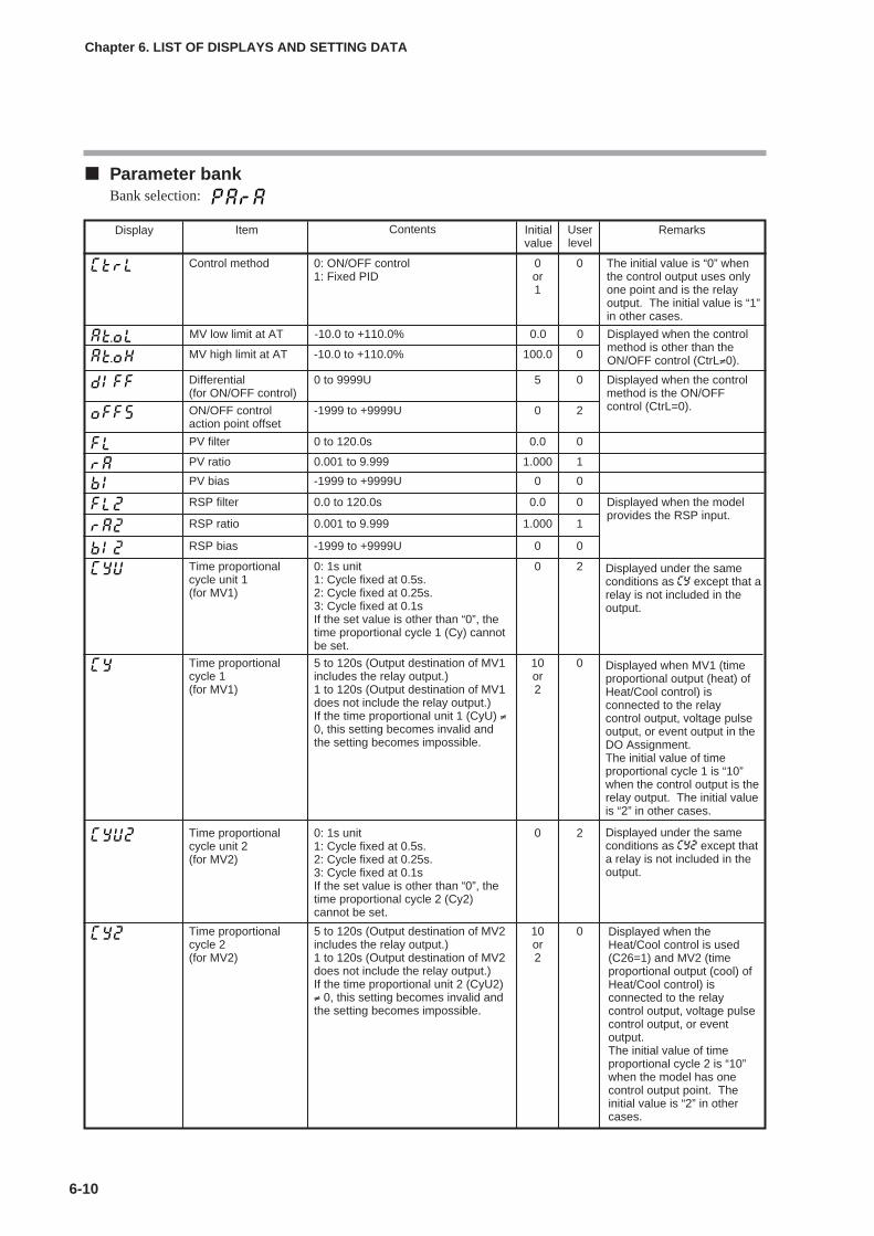
6-10
Chapter 6. LIST OF DISPLAYS AND SETTING DATA
Parameter bankBank selection:
Display Item Contents Initialvalue
Userlevel
Remarks
Control method 0: ON/OFF control1: Fixed PID
0or1
0 The initial value is “0” whenthe control output uses onlyone point and is the relayoutput. The initial value is “1”in other cases.
MV low limit at AT -10.0 to +110.0% 0.0 0 Displayed when the controlmethod is other than theON/OFF control (CtrL≠0).MV high limit at AT -10.0 to +110.0% 100.0 0
Differential (for ON/OFF control)
0 to 9999U 5 0 Displayed when the controlmethod is the ON/OFFcontrol (CtrL=0).ON/OFF control
action point offset-1999 to +9999U 0 2
PV filter 0 to 120.0s 0.0 0
PV ratio 0.001 to 9.999 1.000 1
PV bias -1999 to +9999U 0 0
Time proportionalcycle unit 1(for MV1)
0: 1s unit1: Cycle fixed at 0.5s.2: Cycle fixed at 0.25s.3: Cycle fixed at 0.1sIf the set value is other than “0”, thetime proportional cycle 1 (Cy) cannotbe set.
0 2
Time proportionalcycle 1(for MV1)
5 to 120s (Output destination of MV1includes the relay output.)1 to 120s (Output destination of MV1does not include the relay output.)If the time proportional unit 1 (CyU) ≠0, this setting becomes invalid andthe setting becomes impossible.
10or2
0
Time proportionalcycle unit 2(for MV2)
0: 1s unit1: Cycle fixed at 0.5s.2: Cycle fixed at 0.25s.3: Cycle fixed at 0.1sIf the set value is other than “0”, thetime proportional cycle 2 (Cy2)cannot be set.
0 2
Time proportionalcycle 2(for MV2)
5 to 120s (Output destination of MV2includes the relay output.)1 to 120s (Output destination of MV2does not include the relay output.)If the time proportional unit 2 (CyU2)≠ 0, this setting becomes invalid andthe setting becomes impossible.
10or2
0
RSP filter 0.0 to 120.0s 0.0 0 Displayed when the modelprovides the RSP input.
RSP ratio 0.001 to 9.999 1.000 1
RSP bias -1999 to +9999U 0 0
Displayed under the sameconditions as CY except that arelay is not included in theoutput.
Displayed under the sameconditions as CY2 except thata relay is not included in theoutput.
Displayed when MV1 (timeproportional output (heat) ofHeat/Cool control) isconnected to the relaycontrol output, voltage pulseoutput, or event output in theDO Assignment.The initial value of timeproportional cycle 1 is “10”when the control output is therelay output. The initial valueis “2” in other cases.
Displayed when theHeat/Cool control is used(C26=1) and MV2 (timeproportional output (cool) ofHeat/Cool control) isconnected to the relaycontrol output, voltage pulsecontrol output, or eventoutput.The initial value of timeproportional cycle 2 is “10”when the model has onecontrol output point. Theinitial value is “2” in othercases.
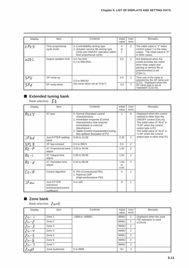
6-11
Chapter 6. LIST OF DISPLAYS AND SETTING DATA
Extended tuning bankBank selection:
Zone bankBank selection:
Display Item Contents Initialvalue
Userlevel
Remarks
AT type 0: Normal (Standard controlcharacteristics)
1: Immediate response (Controlcharacteristics that respondimmediately to externaldisturbance.)
2: Stable (Control characteristics havingless up/down fluctuation of PV)
1 0 Displayed when the controlmethod is other than theON/OFF control (CtrL≠0).The initial value of “At-d” is“0.00” when the controloutput type is R1.The initial value of “At-d” is“1.00” when the controloutput type is other than R1.Just-FiTTER settling
band0.00 to 10.00 0.30 2
SP lag constant 0.0 to 999.9 0.0 2
AT Proportional bandadjust
0.00 to 99.99 1.00 2
AT Integral timeadjust
0.00 to 99.99 1.00 2
AT Derivative timeadjust
0.00 to 99.99 1.00or
0.00
2
Control algorithm 0: PID (Conventional PID)1: RationaLOOP
(High-performance PID)
0 1
Just-FiTTERovershootlimit/restraint/controlcoefficient
0 to 100 0 1
Display Item Contents Initialvalue
Userlevel
Remarks
Zone 1 -1999 to +9999U 9999U 2 Displayed when the zonePID operation is used(C24≠0).Zone 2 9999U 2
Zone 3 9999U 2
Zone 4 9999U 2
Zone 5 9999U 2
Zone 6 9999U 2
Zone 7 9999U 2
Zone hysteresis 5U 20 to 9999
Display Item Contents Initialvalue
Userlevel
Remarks
Time proportionalcycle mode
0: Controllability aiming type1: Actuator service life aiming type
(Only one ON/OFF operation withintime proportional cycle)
0or1
2 The initial value is “1” whencontrol output 1 is the relayoutput. The initial value is “0”in other cases.
SP ramp-up0.0 to 999.9U(No ramp when set at “0.0U”)
0.0 2 Time unit of the ramp isselected by the SP ramp unit(C32). Displayed when theSP ramp type is set at“standard” (C31=0).
SP ramp-down 0.0 2
Output variation limit 0.0: No limit.0.1 to 999.9%/s
0.0 2 Not displayed when themodel provides the motordrive relay output and[aiming at service life ofpotentiometer] is set(C59=1).
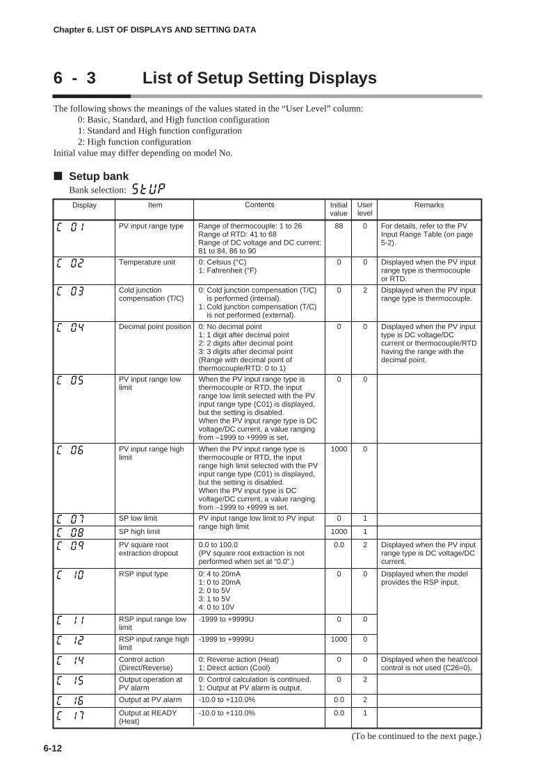
6-12
Chapter 6. LIST OF DISPLAYS AND SETTING DATA
6 - 3 List of Setup Setting Displays
The following shows the meanings of the values stated in the “User Level” column:0: Basic, Standard, and High function configuration1: Standard and High function configuration2: High function configuration
Initial value may differ depending on model No.
Setup bankBank selection:
Display Item Contents Initialvalue
Userlevel
Remarks
PV input range type Range of thermocouple: 1 to 26Range of RTD: 41 to 68Range of DC voltage and DC current:81 to 84, 86 to 90
88 0 For details, refer to the PVInput Range Table (on page5-2).
Temperature unit 0: Celsius (°C)1: Fahrenheit (°F)
0 0 Displayed when the PV inputrange type is thermocoupleor RTD.
Cold junctioncompensation (T/C)
0: Cold junction compensation (T/C)is performed (internal).
1: Cold junction compensation (T/C)is not performed (external).
0 2 Displayed when the PV inputrange type is thermocouple.
Decimal point position 0: No decimal point1: 1 digit after decimal point2: 2 digits after decimal point3: 3 digits after decimal point(Range with decimal point ofthermocouple/RTD: 0 to 1)
0 0 Displayed when the PV inputtype is DC voltage/DCcurrent or thermocouple/RTDhaving the range with thedecimal point.
PV input range lowlimit
When the PV input range type isthermocouple or RTD, the inputrange low limit selected with the PVinput range type (C01) is displayed,but the setting is disabled.When the PV input range type is DCvoltage/DC current, a value rangingfrom –1999 to +9999 is set.
0 0
PV input range highlimit
When the PV input range type isthermocouple or RTD, the inputrange high limit selected with the PVinput range type (C01) is displayed,but the setting is disabled.When the PV input type is DCvoltage/DC current, a value rangingfrom –1999 to +9999 is set.
1000 0
SP low limit PV input range low limit to PV inputrange high limit
0 1
SP high limit 1000 1
PV square rootextraction dropout
0.0 to 100.0(PV square root extraction is notperformed when set at “0.0”.)
0.0 2 Displayed when the PV inputrange type is DC voltage/DCcurrent.
Control action(Direct/Reverse)
0: Reverse action (Heat)1: Direct action (Cool)
0 0
Output operation atPV alarm
0: Control calculation is continued.1: Output at PV alarm is output.
0 2
Output at PV alarm -10.0 to +110.0% 0.0 2
Output at READY(Heat)
-10.0 to +110.0% 0.0 1
RSP input type 0: 4 to 20mA1: 0 to 20mA2: 0 to 5V3: 1 to 5V4: 0 to 10V
0 0 Displayed when the modelprovides the RSP input.
RSP input range lowlimit
-1999 to +9999U 0 0
RSP input range highlimit
-1999 to +9999U 1000 0
Displayed when the heat/coolcontrol is not used (C26=0).
(To be continued to the next page.)
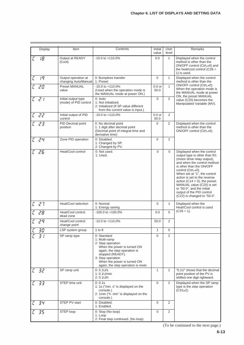
6-13
Chapter 6. LIST OF DISPLAYS AND SETTING DATA
Display Item Contents Initialvalue
Userlevel
Remarks
Output operation atchanging Auto/Manual
0: Bumpless transfer1: Preset
0 1 Displayed when the controlmethod is other than theON/OFF control (CtrL≠0).When the operation mode isthe MANUAL mode at powerON, the preset MANUALvalue (C20) becomes theManipulated Variable (MV).
Preset MANUALvalue
-10.0 to +110.0%(Used when the operation mode isthe MANUAL mode at power ON.)
0.0 or50.0
1
Initial output type(mode) of PID control
0: Auto1: Not initialized.2: Initialized (If SP value different
from the current value is input.)
0 2
Initial output of PIDcontrol
-10.0 to +110.0% 0.0 or50.0
2
Heat/Cool control 0: Not used.1: Used.
0 0 Displayed when the controloutput type is other than R1(motor drive relay output),and when the control methodis other than the ON/OFFcontrol (CtrL≠0).When set at “1”, the controlaction is set to the reverseaction (C14 = 0), the presetMANUAL value (C20) is setto “50.0”, and the initialoutput of the PID control(C22) is changed to “50.0”.
Heat/Cool selection 0: Normal1: Energy saving
0 1
Heat/Cool controldead zone
-100.0 to +100.0% 0.0 0
Heat/Cool controlchange point
-10.0 to +110.0% 50.0 2
LSP system group 1 to 8 1 0
SP ramp unit 0: 0.1U/s1: 0.1U/min2: 0.1U/h
1 2 "0.1U" shows that the decimalpoint position of the PV isshifted one digit rightward.
Displayed when theHeat/Cool control is used(C26 = 1).
Output at READY(Cool)
-10.0 to +110.0% 0.0 1 Displayed when the controlmethod is other than theON/OFF control (CtrL≠0) andthe heat/cool control (C26 =1) is used.
PID Decimal pointposition
0: No decimal point1: 1 digit after decimal point(Decimal point of integral time andderivative time)
0 2 Displayed when the controlmethod is other than theON/OFF control (CtrL≠0).
Zone PID operation 0: Disabled.1: Changed by SP.2: Changed by PV.
0 2
SP ramp type 0: Standard1: Multi-ramp2: Step operation
When the power is turned ONagain, the step operation isstopped (READY).
3: Step operationWhen the power is turned ONagain, the step operation is reset.
0 2
STEP time unit 0: 0.1s1: 1s (“min. s” is displayed on the
console.)2: 1min (“h. min” is displayed on the
console.)
0 2 Displayed when the SP ramptype is the step operation(C31≥2).
STEP PV start 0: Disabled.1: Enabled.
0 2
STEP loop 0: Stop (No loop)1: Loop2: Final step continued. (No loop)
0 2
(To be continued to the next page.)

6-14
Chapter 6. LIST OF DISPLAYS AND SETTING DATA
Display Item Contents Initialvalue
Userlevel
Remarks
Control output 1range
Current output1: 4 to 20mA2: 0 to 20mAContinuous voltage output1: 1 to 5V2: 0 to 5V3: 0 to 10V
1 0 Displayed when controloutput 1 of the model is thecurrent output or continuousvoltage output.The decimal point position ofthe scaling low limit/high limitbecomes 1 digit after thedecimal point when thecontrol output 1 type isrelated to the MV and CT.When the control output 1type is related to the PV andSP, the decimal pointposition becomes the sameas that of the PV.The unit of scaling lowlimit/high limit depends onthe output type of controloutput 1.
When the output typerelative to MV and MFB; %.When the ouput typerelative to PV and SP;same as PV.When the output typerelative CT;ampere(current value).
Control output 1 type 0: MV1: Heat MV (for heat/cool control)2: Cool MV (for heat/cool control)3: PV4: PV before ratio, bias, and filter5: SP6: Deviation7: CT1 current value8: CT2 current value9: MFB (including estimated MFB)10: SP+MV11: PV+MV
0 0
Control output 1scaling low limit
-1999 to +9999The decimal point position and unitmay vary depending on controloutput 1 type.
0 0
Control output 1scaling high limit
100.0 0
CT1 operation type 0: Heater burnout detection1: Current value measurement
0 0 Displayed when the optionalmodel has two currenttransformer input points.
CT1 output 0: Control output 11: Control output 22: Event output 13: Event output 24: Event output 3
0 0 Displayed when the optionalmodel has two currenttransformer input points andthe CT1 operation type is setto "heater burnout detection"(C36 = 0).CT1 measurement
wait time30 to 300ms 30 0
CT2 operation type Same as CT1 operation type 0 0 Displayed when the optionalmodel has two currenttransformer input points.
CT2 output Same as CT1 output 0 0 Displayed when the optionalmodel has two currenttransformer input points andthe CT2 operation type is setto "heater burnout detection"(C39 = 0).
CT2 measurementwait time
Same as CT1 measurement waittime
30 0
(To be continued to the next page.)
Control output 1 MVscaling
200.0 00 to 9999The decimal point position and unitare same as for PV.
If the controller model usescurrent output for controloutput 1 and if the controloutput 1 type is SP+MV orPV+MV, this setting isdisplayed.
Handling Precautions
• If ROM version 1 of the instrument information bank(Id02) is prior to2.04, SP+MV and PV+MV cannot be set in [Control output 1 type],[Control output 2 type], and [Auxiliary output type ].
• If ROM version 1 of the instrument information bank(Id02) is prior to2.04, SP+MV and PV+MV cannot be set in [Control output 1 MVscaling], [Control output 2 MV scaling], and [Auxiliary output MVscaling ].
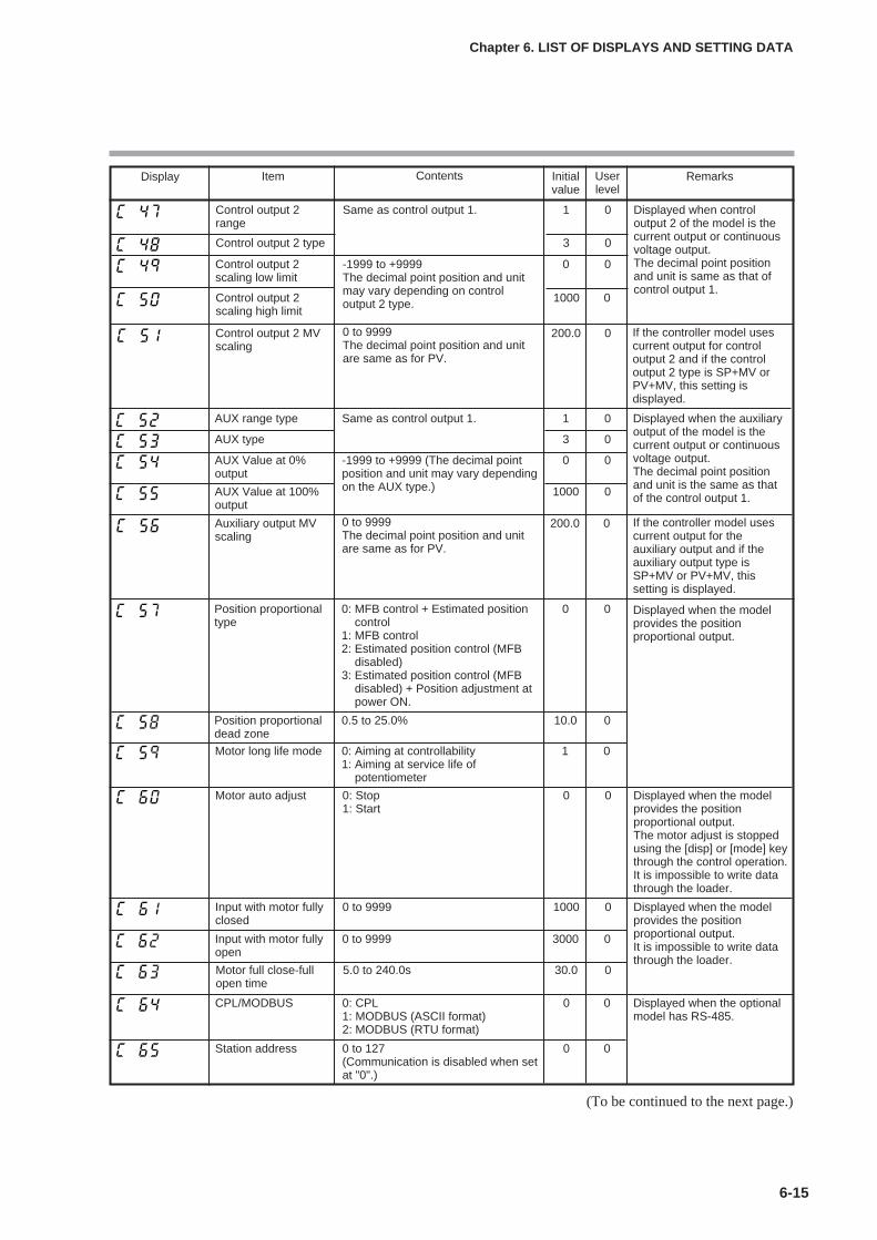
6-15
Chapter 6. LIST OF DISPLAYS AND SETTING DATA
Display Item Contents Initialvalue
Userlevel
Remarks
Motor long life mode 0: Aiming at controllability1: Aiming at service life of
potentiometer
1 0
Input with motor fullyopen
0 to 9999 3000 0
Motor full close-fullopen time
5.0 to 240.0s 30.0 0
AUX range type Same as control output 1. 1 0 Displayed when the auxiliaryoutput of the model is thecurrent output or continuousvoltage output.The decimal point positionand unit is the same as thatof the control output 1.
AUX type 3 0
AUX Value at 0%output
-1999 to +9999 (The decimal pointposition and unit may vary dependingon the AUX type.)
0 0
AUX Value at 100%output
1000 0
Position proportionaltype
0: MFB control + Estimated positioncontrol
1: MFB control2: Estimated position control (MFB
disabled)3: Estimated position control (MFB
disabled) + Position adjustment atpower ON.
0 0
Position proportionaldead zone
0.5 to 25.0% 10.0 0
Motor auto adjust 0: Stop1: Start
0 0 Displayed when the modelprovides the positionproportional output.The motor adjust is stoppedusing the [disp] or [mode] keythrough the control operation.It is impossible to write datathrough the loader.
Input with motor fullyclosed
0 to 9999 1000 0 Displayed when the modelprovides the positionproportional output.It is impossible to write datathrough the loader.
Station address 0 to 127(Communication is disabled when setat "0".)
0 0
CPL/MODBUS 0: CPL1: MODBUS (ASCII format)2: MODBUS (RTU format)
0 0 Displayed when the optionalmodel has RS-485.
(To be continued to the next page.)
Displayed when the modelprovides the positionproportional output.
Control output 2range
Same as control output 1. 1 0
Control output 2 type 3 0
Control output 2scaling low limit
-1999 to +9999The decimal point position and unitmay vary depending on controloutput 2 type.
0 0
Displayed when controloutput 2 of the model is thecurrent output or continuousvoltage output.The decimal point positionand unit is same as that ofcontrol output 1.
Control output 2scaling high limit
1000 0
Control output 2 MVscaling
200.0 00 to 9999The decimal point position and unitare same as for PV.
If the controller model usescurrent output for controloutput 2 and if the controloutput 2 type is SP+MV orPV+MV, this setting isdisplayed.
Auxiliary output MVscaling
200.0 00 to 9999The decimal point position and unitare same as for PV.
If the controller model usescurrent output for theauxiliary output and if theauxiliary output type isSP+MV or PV+MV, thissetting is displayed.
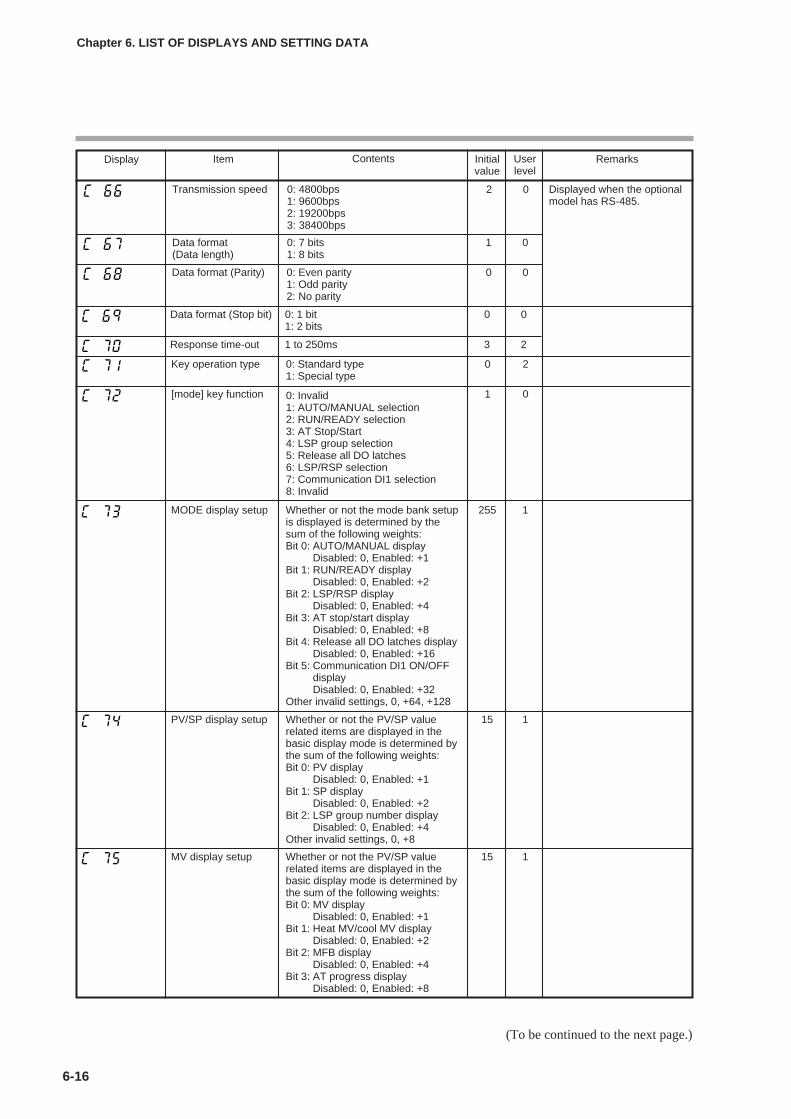
6-16
Chapter 6. LIST OF DISPLAYS AND SETTING DATA
Display Item Contents Initialvalue
Userlevel
Remarks
MODE display setup Whether or not the mode bank setupis displayed is determined by thesum of the following weights:Bit 0: AUTO/MANUAL display
Disabled: 0, Enabled: +1Bit 1: RUN/READY display
Disabled: 0, Enabled: +2Bit 2: LSP/RSP display
Disabled: 0, Enabled: +4Bit 3: AT stop/start display
Disabled: 0, Enabled: +8Bit 4: Release all DO latches display
Disabled: 0, Enabled: +16Bit 5: Communication DI1 ON/OFF
displayDisabled: 0, Enabled: +32
Other invalid settings, 0, +64, +128
255 1
PV/SP display setup Whether or not the PV/SP valuerelated items are displayed in thebasic display mode is determined bythe sum of the following weights:Bit 0: PV display
Disabled: 0, Enabled: +1Bit 1: SP display
Disabled: 0, Enabled: +2Bit 2: LSP group number display
Disabled: 0, Enabled: +4Other invalid settings, 0, +8
15 1
MV display setup Whether or not the PV/SP valuerelated items are displayed in thebasic display mode is determined bythe sum of the following weights:Bit 0: MV display
Disabled: 0, Enabled: +1Bit 1: Heat MV/cool MV display
Disabled: 0, Enabled: +2Bit 2: MFB display
Disabled: 0, Enabled: +4Bit 3: AT progress display
Disabled: 0, Enabled: +8
15 1
(To be continued to the next page.)
Data format (Stop bit) 0: 1 bit1: 2 bits
0 0
Response time-out 1 to 250ms 3 2
Key operation type 0: Standard type1: Special type
0 2
[mode] key function 0: Invalid1: AUTO/MANUAL selection2: RUN/READY selection3: AT Stop/Start4: LSP group selection5: Release all DO latches6: LSP/RSP selection7: Communication DI1 selection8: Invalid
1 0
Data format (Data length)
0: 7 bits1: 8 bits
1 0
Data format (Parity) 0: Even parity1: Odd parity2: No parity
0 0
Transmission speed 0: 4800bps1: 9600bps2: 19200bps3: 38400bps
2 0 Displayed when the optionalmodel has RS-485.

6-17
Chapter 6. LIST OF DISPLAYS AND SETTING DATA
Display Item Contents Initialvalue
Userlevel
Remarks
CT display setup 0: CT current value is not displayedin the operation display mode.
1: CT1 current value is displayed inthe operation display mode.
2: CT1 to 2 current values are displayedin the operation display mode.
0 1
User level 0: Basic configuration1: Standard configuration2: High function configuration
0 0
Communicationmonitoring display
0: Not used.1: Flashing while data is being sent
through RS-485 communication.2: Flashing while data is being
received through RS-485communication.
3: Logical OR of all DI statuses4: Flashing in READY mode
0 2
Multi Status (MS)display, Condition (toppriority)
0: Normally open (Normally OFF=0)1: Normally close (Normally ON=1)2 to 9: Internal event 1 to 810 to 13: Undefined.14: MV1 (ON/OFF, Time proportional
1, Heat-side, OPEN-side output)15: MV2 (Time proportional 2, Cool-
side, CLOSE-side output)16 to 17: Undefined.18 to 21: DI1 to DI422 to 25: Undefined.26 to 30: Internal contact 1 to 531 to 33: Undefined.34 to 37: Communication DI1 to DI438: MANUAL39: READY40: RSP41: AT42: During ramp43: Undefined.44: Alarm45: PV alarm46: Undefined.47: [mode] key pressing status48: Event output 1 terminal status49: Control output 1 terminal status
39 2
(To be continued to the next page.)
Timer remaining timedisplay setup
0: ON/OFF delay remaining time ofInternal Event is not displayed inthe operation display mode.
1: ON/OFF delay remaining time ofInternal Event 1 is displayed in theoperation display mode.
2: ON/OFF delay remaining time ofInternal Events 1 to 2 are displayedin the operation display mode.
3: ON/OFF delay remaining time ofInternal Events 1 to 3 are displayedin the operation display mode.
0 1
EV display setup 0: Internal Event set value is notdisplayed in the operation displaymode.
1: Set value of Internal Event 1 isdisplayed in the operation displaymode.
2: Set values of Internal Events 1 to 2are displayed in the operationdisplay mode.
3: Set values of Internal Events 1 to 3are displayed in the operationdisplay mode.
0 1
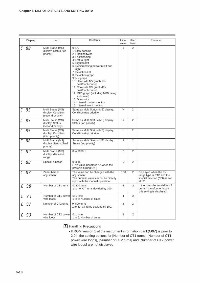
6-18
Chapter 6. LIST OF DISPLAYS AND SETTING DATA
Display Item Contents Initialvalue
Userlevel
Remarks
Multi Status (MS)display, Condition(second priority)
Same as Multi Status (MS) display,Condition (top priority)
44 2
Multi Status (MS)display, Status(second priority)
Same as Multi Status (MS) display,Status (top priority)
6 2
Multi Status (MS)display, Condition(third priority)
Same as Multi Status (MS) display,Condition (top priority)
1 2
Multi Status (MS)display, Status (thirdpriority)
Same as Multi Status (MS) display,Status (top priority)
9 2
Multi Status (MS)display, deviationrange
0 to 9999U 5 2
Special function 0 to 15(This value becomes “0” when thepower is turned ON.)
0 2
Zener barrieradjustment
The value can be changed with theadjustment.The numeric value cannot be directlyinput with the manual operation.
0.00 2 Displayed when the PVrange type is RTD and thespecial function (C88) is setat “5”.
Multi Status (MS)display, Status (toppriority)
0: Lit.1: Slow flashing2: Flashing twice3: Fast flashing4: Left to right5: Right to left6: Reciprocating between left and
right7: Deviation OK8: Deviation graph9: MV graph10: Heat-side MV graph (For
heat/cool control)11: Cool-side MV graph (For
heat/cool control)12: MFB graph (including MFB being
estimated)13: DI monitor14: Internal contact monitor15: Internal event monitor
1 2
Number of CT2 powerwire loops
0: 1 time1 to 6: Number of times
1 2
Number of CT2 turns 0: 800 turns1 to 40: CT turns devided by 100.
8 2
Number of CT1 turns 0: 800 turns1 to 40: CT turns devided by 100.
8 2
Number of CT1 powerwire loops
0: 1 time1 to 6: Number of times
1 2
Handling Precautions
• If ROM version 1 of the instrument information bank(Id02) is prior to2.04, the setting options for [Number of CT1 turns], [Number of CT1power wire loops], [Number of CT2 turns] and [Number of CT2 powerwire loops] are not displayed.
If the controller model has 2current transformer inputs,this setting is displayed.
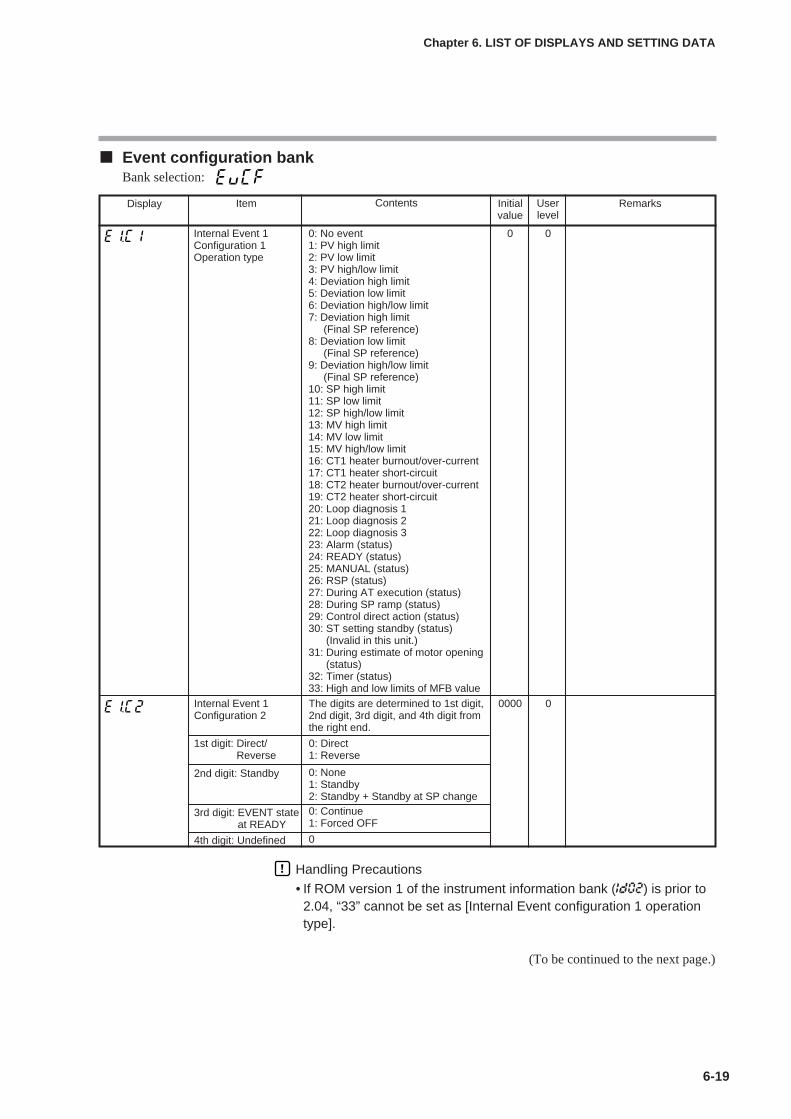
6-19
Chapter 6. LIST OF DISPLAYS AND SETTING DATA
Event configuration bankBank selection:
(To be continued to the next page.)
Display Item Contents Initialvalue
Userlevel
Remarks
Internal Event 1Configuration 1Operation type
0: No event1: PV high limit2: PV low limit3: PV high/low limit4: Deviation high limit5: Deviation low limit6: Deviation high/low limit7: Deviation high limit
(Final SP reference)8: Deviation low limit
(Final SP reference)9: Deviation high/low limit
(Final SP reference)10: SP high limit11: SP low limit12: SP high/low limit13: MV high limit14: MV low limit15: MV high/low limit16: CT1 heater burnout/over-current17: CT1 heater short-circuit18: CT2 heater burnout/over-current19: CT2 heater short-circuit20: Loop diagnosis 121: Loop diagnosis 222: Loop diagnosis 323: Alarm (status)24: READY (status)25: MANUAL (status)26: RSP (status)27: During AT execution (status)28: During SP ramp (status)29: Control direct action (status)30: ST setting standby (status)
(Invalid in this unit.)31: During estimate of motor opening
(status)32: Timer (status)33: High and low limits of MFB value
0 0
Internal Event 1Configuration 2
The digits are determined to 1st digit,2nd digit, 3rd digit, and 4th digit fromthe right end.
0000 0
1st digit: Direct/Reverse
0: Direct1: Reverse
2nd digit: Standby 0: None1: Standby2: Standby + Standby at SP change
3rd digit: EVENT stateat READY
0: Continue1: Forced OFF
4th digit: Undefined 0
Handling Precautions
• If ROM version 1 of the instrument information bank (Id02) is prior to2.04, “33” cannot be set as [Internal Event configuration 1 operationtype].

6-20
Chapter 6. LIST OF DISPLAYS AND SETTING DATA
Display Item Contents Initialvalue
Userlevel
Remarks
Internal EventConfiguration 3
The digits are determined to 1st digit,2nd digit, 3rd digit, and 4th digit fromthe right end.
0000 2
4th digit: Undefined. 0
1st digit: Controlleralarm OR
0: None1: Alarm direct + OR operation2: Alarm direct + AND operation3: Alarm reverse + OR operation4: Alarm reverse + AND operation
2nd digit: Special OFFsetup
0: As usual.1: When the event set value (main
setting) is “0”, the event is “OFF”.
3rd digit: Delay unit 0: 0.1s1: 1s2: 1min
Internal Event 2Configuration 1Operation type
Same as Internal Event 1Configuration 1.
0 0
Internal Event 2Configuration 21st digit: Direct/
Reverse2nd digit: Standby3rd digit: EVENT state
at READY4th digit: Undefined.
Same as Internal Event 1Configuration 2.
0000 0
Internal Event 2Configuration 31st digit: Controller
alarm OR2nd digit: Special OFF
setup3rd digit: Delay unit4th digit: Undefined.
Same as Internal Event 1Configuration 3.
0000 2
Internal Event 3Configuration 1Operation type
Same as Internal Event 1Configuration 1.
0 0
Internal Event 3Configuration 21st digit: Direct/
Reverse2nd digit: Standby3rd digit: EVENT state
at READY4th digit: Undefined.
Same as Internal Event 1Configuration 2.
0000 0
Internal Event 3Configuration 31st digit: Controller
alarm OR2nd digit: Special OFF
setup3rd digit: Delay unit4th digit: Undefined.
Same as Internal Event 1Configuration 3.
0000 2
Internal Event 4Configuration 1Operation type
Same as Internal Event 1Configuration 1.
0 0
Internal Event 4Configuration 21st digit: Direct/
Reverse2nd digit: Standby3rd digit: EVENT state
at READY4th digit: Undefined.
Same as Internal Event 1Configuration 2.
0000 2
Internal Event 4Configuration 31st digit: Controller
alarm OR2nd digit: Special OFF
setup3rd digit: Delay unit4th digit: Undefined.
Same as Internal Event 1Configuration 3.
0000 2
Internal Event 5Configuration 1Operation type
Same as Internal Event 1Configuration 1.
0 0
(To be continued to the next page.)

6-21
Chapter 6. LIST OF DISPLAYS AND SETTING DATA
Display Item Contents Initialvalue
Userlevel
Remarks
Internal Event 5Configuration 21st digit: Direct/
Reverse2nd digit: Standby3rd digit: EVENT state
at READY4th digit: Undefined.
Same as Internal Event 1Configuration 2.
0000 0
Internal Event 5Configuration 31st digit: Controller
alarm OR2nd digit: Special OFF
setup3rd digit: Delay unit4th digit: Undefined.
Same as Internal Event 1Configuration 3.
0000 2
Internal Event 6Configuration 1Operation type
Same as Internal Event 1Configuration 1.
0 0
Internal Event 6Configuration 21st digit: Direct/
Reverse2nd digit: Standby3rd digit: EVENT state
at READY4th digit: Undefined.
Same as Internal Event 1Configuration 2.
0000 0
Internal Event 6Configuration 31st digit: Controller
alarm OR2nd digit: Special OFF
setup3rd digit: Delay unit4th digit: Undefined.
Same as Internal Event 1Configuration 3.
0000 2
Internal Event 7Configuration 1Operation type
Same as Internal Event 1Configuration 1.
0 0
Internal Event 7Configuration 21st digit: Direct/
Reverse2nd digit: Standby3rd digit: EVENT state
at READY4th digit: Undefined.
Same as Internal Event 1Configuration 2.
0000 0
Internal Event 7Configuration 31st digit: Controller
alarm OR2nd digit: Special OFF
setup3rd digit: Delay unit4th digit: Undefined.
Same as Internal Event 1Configuration 3.
0000 2
Internal Event 8Configuration 1Operation type
Same as Internal Event 1Configuration 1.
0 0
Internal Event 8Configuration 21st digit: Direct/
Reverse2nd digit: Standby3rd digit: EVENT state
at READY4th digit: Undefined.
Same as Internal Event 1Configuration 2.
0000 0
Internal Event 8Configuration 31st digit: Controller
alarm OR2nd digit: Special OFF
setup3rd digit: Delay unit4th digit: Undefined.
Same as Internal Event 1Configuration 3.
0000 2
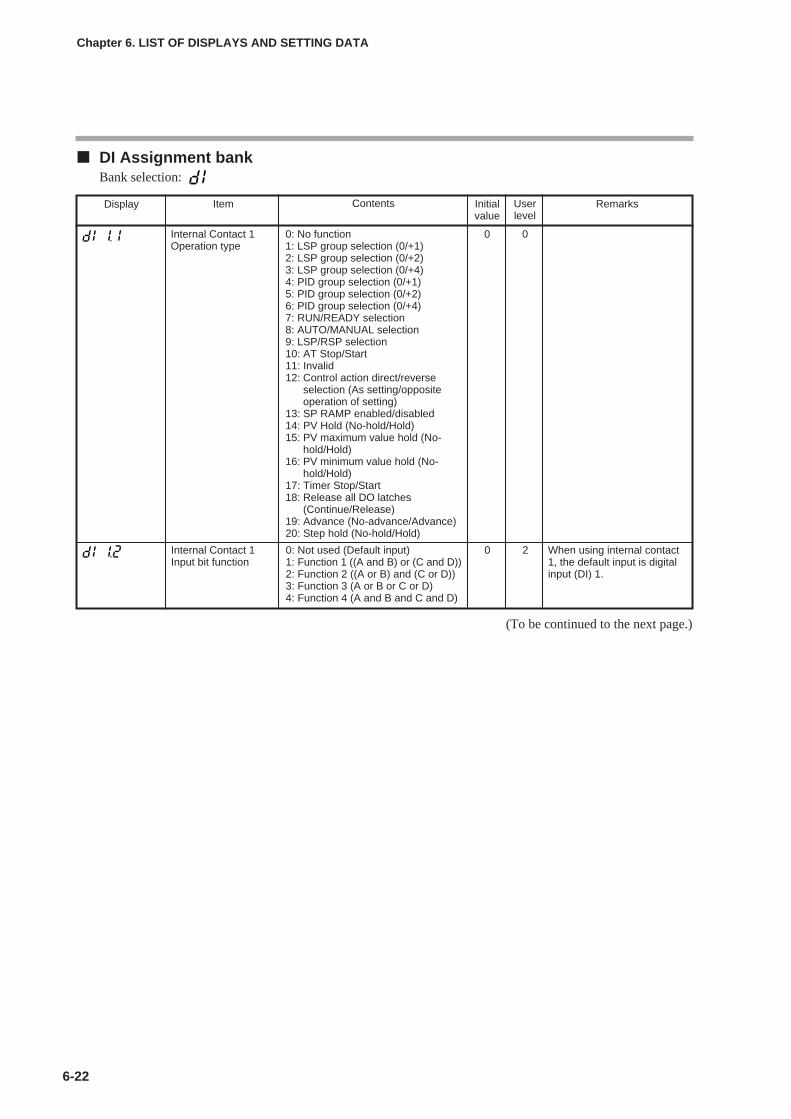
6-22
Chapter 6. LIST OF DISPLAYS AND SETTING DATA
DI Assignment bankBank selection:
(To be continued to the next page.)
Display Item Contents Initialvalue
Userlevel
Remarks
Internal Contact 1Operation type
0: No function1: LSP group selection (0/+1)2: LSP group selection (0/+2)3: LSP group selection (0/+4)4: PID group selection (0/+1)5: PID group selection (0/+2)6: PID group selection (0/+4)7: RUN/READY selection8: AUTO/MANUAL selection9: LSP/RSP selection10: AT Stop/Start11: Invalid12: Control action direct/reverse
selection (As setting/oppositeoperation of setting)
13: SP RAMP enabled/disabled14: PV Hold (No-hold/Hold)15: PV maximum value hold (No-
hold/Hold)16: PV minimum value hold (No-
hold/Hold)17: Timer Stop/Start18: Release all DO latches
(Continue/Release)19: Advance (No-advance/Advance)20: Step hold (No-hold/Hold)
0 0
Internal Contact 1Input bit function
0: Not used (Default input)1: Function 1 ((A and B) or (C and D))2: Function 2 ((A or B) and (C or D))3: Function 3 (A or B or C or D)4: Function 4 (A and B and C and D)
0 2 When using internal contact1, the default input is digitalinput (DI) 1.

6-23
Chapter 6. LIST OF DISPLAYS AND SETTING DATA
Display Item Contents Initialvalue
Userlevel
Remarks
Internal Contact 1Polarity A to D1st digit: Polarity A(Polarity of Inputassignment A)2nd digit: Polarity B(Polarity of Inputassignment B)3rd digit: Polarity C(Polarity of Inputassignment C)4th digit: Polarity D(Polarity of Inputassignment D)
The digits are determined to 1st digit,2nd digit, 3rd digit, and 4th digit fromthe right end.0: Direct1: Reverse
0000 2
Internal Contact 1Polarity
0: Direct1: Reverse
0 2
Internal Contact 1Event channel def.
0: Every Internal Event1 to 8: Internal Event No.
0 2 Displayed when theoperation type of internalcontact 1 is timer stop/start(DI1.1 = 17).
Internal Contact 2Operation type
Same as Internal Contact 1Operation type.
0 0
Internal Contact 2Input bit function
Same as Internal Contact 1 Input bitfunction.0: Not used. (Default input)1 to 4: Function 1 to 4
0 2 When using internal contact2, the default input is digitalinput (DI) 2.
Internal Contact 1Input assignment A
0: Normally opened. (OFF, 0)1: Normally closed. (ON, 1)2: DI13: DI24: DI35: DI46 to 9: Undefined.10: Internal Event 111: Internal Event 212: Internal Event 313: Internal Event 414: Internal Event 515: Internal Event 616: Internal Event 717: Internal Event 818: Communication DI119: Communication DI220: Communication DI321: Communication DI422: MANUAL mode23: READY mode24: RSP mode25: AT running26: During SP ramp27: Undefined.28: Alarm occurs.29: PV alarm occurs.30: Undefined.31: mode key pressing status32: Event output 1 status33: Control output 1 status
2 2 Displayed when internalcontact 1 Input bit function isset 1 to 4 (DI1.2≠0).
Internal Contact 1Input assignment B
0 2
Internal Contact 1Input assignment C
0 2
Internal Contact 1Input assignment D
0 2
(To be continued to the next page.)

6-24
Chapter 6. LIST OF DISPLAYS AND SETTING DATA
Display Item Contents Initialvalue
Userlevel
Remarks
Internal Contact 3Input assignment A
Same as Internal Contact 1 Inputassignment A to D.
4 2 Displayed when internalcontact 3 Input bit function isset 1 to 4 (DI3.2≠0).Internal Contact 3
Input assignment B0 2
Internal Contact 3Input assignment C
0 2
Internal Contact 3Input assignment D
0 2
Internal Contact 3Polarity A to D1st digit: Polarity A2nd digit: Polarity B3rd digit: Polarity C4th digit: Polarity D
Same as Internal Contact 1 PolarityA to DThe following setting applies to eachdigit:0: Direct1: Reverse
0000 2
Internal Contact 3Polarity
0: Direct1: Reverse
0 2
Internal Contact 3Event channel def.
0: Every Internal Event1 to 8: Internal Event No.
0 2 Displayed when theoperation type of internalcontact 3 is timer stop/start(DI3.1 = 17).
Internal Contact 2Input assignment A
Same as Internal Contact 1 Inputassignment A to D.
3 2 Displayed when internalcontact 2 Input bit function isset 1 to 4 (DIl2.2≠0).Internal Contact 2
Input assignment B0 2
Internal Contact 2Input assignment C
0 2
Internal Contact 2Input assignment D
0 2
Internal Contact 2Polarity A to D1st digit: Polarity A2nd digit: Polarity B3rd digit: Polarity C4th digit: Polarity D
Same as Internal Contact 1 PolarityA to DThe following setting applies to eachdigit:0: Direct1: Reverse
0000 2
Internal Contact 2Polarity
0: Direct1: Reverse
0 2
Internal Contact 2Event channel def.
0: Every Internal Event1 to 8: Internal Event No.
0 2 Displayed when theoperation type of internalcontact 2 is timer stop/start(DI2.1 = 17).
Internal Contact 3Operation type
Same as Internal Contact 1Operation type.
0 0
Internal Contact 3Input bit function
Same as Internal Contact 1 Input bitfunction.0: Not used. (Default input)1 to 4: Function 1 to 4
0 2 When using internal contact3, the default input is digitalinput (DI) 3.
Internal Contact 4Operation type
Same as Internal Contact 1Operation type.
0 0
Internal Contact 4Input bit function
Same as Internal Contact 1 Input bitfunction.0: Not used. (Default input)1 to 4: Function 1 to 4
0 2 When using internal contact4, the default input is digitalinput (DI) 4.
(To be continued to the next page.)
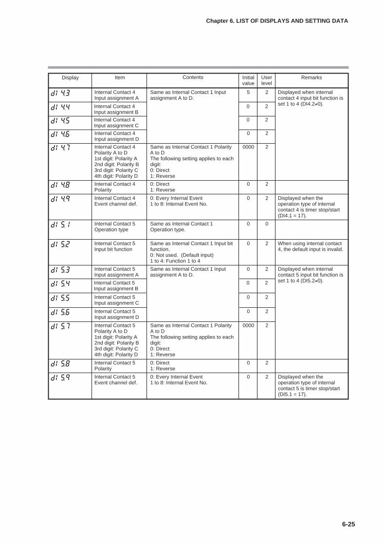
6-25
Chapter 6. LIST OF DISPLAYS AND SETTING DATA
Display Item Contents Initialvalue
Userlevel
Remarks
Internal Contact 5Input assignment A
Same as Internal Contact 1 Inputassignment A to D.
0 2 Displayed when internalcontact 5 input bit function isset 1 to 4 (DI5.2≠0).Internal Contact 5
Input assignment B0 2
Internal Contact 5Input assignment C
0 2
Internal Contact 5Input assignment D
0 2
Internal Contact 5Polarity A to D1st digit: Polarity A2nd digit: Polarity B3rd digit: Polarity C4th digit: Polarity D
Same as Internal Contact 1 PolarityA to DThe following setting applies to eachdigit:0: Direct1: Reverse
0000 2
Internal Contact 5Polarity
0: Direct1: Reverse
0 2
Internal Contact 5Event channel def.
0: Every Internal Event1 to 8: Internal Event No.
0 2 Displayed when theoperation type of internalcontact 5 is timer stop/start(DI5.1 = 17).
Internal Contact 4Input assignment A
Same as Internal Contact 1 Inputassignment A to D.
5 2 Displayed when internalcontact 4 input bit function isset 1 to 4 (DI4.2≠0).Internal Contact 4
Input assignment B0 2
Internal Contact 4Input assignment C
0 2
Internal Contact 4Input assignment D
0 2
Internal Contact 4Polarity A to D1st digit: Polarity A2nd digit: Polarity B3rd digit: Polarity C4th digit: Polarity D
Same as Internal Contact 1 PolarityA to DThe following setting applies to eachdigit:0: Direct1: Reverse
0000 2
Internal Contact 4Polarity
0: Direct1: Reverse
0 2
Internal Contact 4Event channel def.
0: Every Internal Event1 to 8: Internal Event No.
0 2 Displayed when theoperation type of internalcontact 4 is timer stop/start(DI4.1 = 17).
Internal Contact 5Operation type
Same as Internal Contact 1Operation type.
0 0
Internal Contact 5Input bit function
Same as Internal Contact 1 Input bitfunction.0: Not used. (Default input)1 to 4: Function 1 to 4
0 2 When using internal contact4, the default input is invalid.
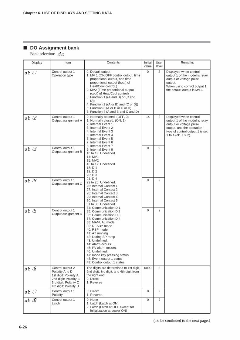
6-26
Chapter 6. LIST OF DISPLAYS AND SETTING DATA
DO Assignment bankBank selection:
(To be continued to the next page.)
Display Item Contents Initialvalue
Userlevel
Remarks
Control output 1 Operation type
0: Default output1: MV 1 (ON/OFF control output, time
proportional output, and timeproportional output (heat) ofHeat/Cool control.)
2: MV2 (Time proportional output(cool) of Heat/Cool control)
3: Function 1 ((A and B) or (C andD))
4: Function 2 ((A or B) and (C or D))5: Function 3 (A or B or C or D)6: Function 4 (A and B and C and D)
0 2 Displayed when controloutput 1 of the model is relayoutput or voltage pulseoutput.When using control output 1,the default output is MV1.
Control output 1 Output assignment A
0: Normally opened. (OFF, 0)1: Normally closed. (ON, 1)2: Internal Event 13: Internal Event 24: Internal Event 35: Internal Event 46: Internal Event 57: Internal Event 68: Internal Event 79: Internal Event 810 to 13: Undefined.14: MV115: MV216 to 17: Undefined.18: DI119: DI220: DI321: DI422 to 25: Undefined.26: Internal Contact 127: Internal Contact 228: Internal Contact 329: Internal Contact 430: Internal Contact 531 to 33: Undefined.34: Communication DI135: Communication DI236: Communication DI337: Communication DI438: MANUAL mode39: READY mode40: RSP mode41: AT running42: During SP ramp43: Undefined.44: Alarm occurs.45: PV alarm occurs.46: Undefined.47: mode key pressing status48: Event output 1 status49: Control output 1 status
14 2 Displayed when controloutput 1 of the model is relayoutput or voltage pulseoutput, and the operationtype of control output 1 is set1 to 4 (ot1.1 > 2).
Control output 1 Output assignment B
0 2
Control output 1 Output assignment C
0 2
Control output 1 Output assignment D
0 2
The digits are determined to 1st digit,2nd digit, 3rd digit, and 4th digit fromthe right end.0: Direct1: Reverse
0000 2
Control output 1 Polarity
0: Direct1: Reverse
0 2
Control output 1 Latch
0: None1: Latch (Latch at ON)2: Latch (Latch at OFF except for
initialization at power ON)
0 2
Control output 2Polarity A to D1st digit: Polarity A2nd digit: Polarity B3rd digit: Polarity C4th digit: Polarity D

6-27
Chapter 6. LIST OF DISPLAYS AND SETTING DATA
Display Item Contents Initialvalue
Userlevel
Remarks
Control output 2 Operation type
Same as Control output 1 Operationtype.0: Default output1: MV12: MV23 to 6: Function 1 to 4
0 2 Displayed when the controloutput of the model is set tothe position proportionaloutput or the control output 2of the model is voltage pulseoutput.When using control output 2,the default output is MV2.
Control output 2 Output assignment A
Same as Control output 1 Outputassignment A to D.
15 2 Displayed when controloutput 2 of the model is setto the voltage pulse outputand the operation type ofcontrol output 2 is set 1 to 4(ot2.1 > 2).
Control output 2 Output assignment B
0 2
Control output 2 Output assignment C
0 2
Control output 2 Output assignment D
0 2
Control output 2Polarity A to D1st digit: Polarity A2nd digit: Polarity B3rd digit: Polarity C4th digit: Polarity D
Same as Control output 1 Polarity Ato D.The following setting applies to eachdigit:0: Direct1: Reverse
0000 2
Control output 2Polarity
0: Direct1: Reverse
0 2
Control output 2 Latch
0: None1: Latch (Latch at ON)2: Latch (Latch at OFF except for
initialization at power ON)
0 2
Event output 1 Operation type
Same as Control output 1 Operationtype.0: Default output1: MV12: MV23 to 6: Function 1 to 4
0 2
Event output 1 Output assignment A
Same as Control output 1 Outputassignment A to D.
2 2
Event output 1 Output assignment B
0 2
Event output 1 Output assignment C
0 2
Event output 1 Output assignment D
0 2
Event output 1 Polarity A to D1st digit: Polarity A2nd digit: Polarity B3rd digit: Polarity C4th digit: Polarity D
0000 2
Event output 1 Polarity
0: Direct1: Reverse
0 2
Event output 1 Latch
0: None1: Latch (Latch at ON)2: Latch (Latch at OFF except for
initialization at power ON)
0 2
Displayed when the optionalmodel has Event output 1.When using Event output 1,the default output is InternalEvent 1.
Displayed when the optionalmodel has Event output 1and the operation type ofEvent output 1 is set 1 to 4(Ev1.1 > 2).
Same as Control output 1 Polarity Ato D.The following setting applies to eachdigit:0: Direct1: Reverse
(To be continued to the next page.)

6-28
Chapter 6. LIST OF DISPLAYS AND SETTING DATA
Display Item Contents Initialvalue
Userlevel
Remarks
Event output 2 Operation type
Same as Control output 1 Operationtype.0: Default output1: MV12: MV23 to 6: Function 1 to 4
0 2 Displayed when the optionalmodel has Event output 2.When using Event output 2,the default output is InternalEvent 2.
Event output 2 Output assignment A
Same as Control output 1 Outputassignment A to D.
3 2 Displayed when the optionalmodel has Event output 2and the operation type ofEvent output 2 is set 1 to 4(Ev2.1 > 2).
Event output 2 Output assignment B
0 2
Event output 2 Output assignment C
0 2
Event output 2 Output assignment D
0 2
Event output 2 Polarity A to D1st digit: Polarity A2nd digit: Polarity B3rd digit: Polarity C4th digit: Polarity D
Same as Control output 1 Polarity Ato D.The following setting applies to eachdigit:0: Direct1: Reverse
0000 2
Event output 2 Polarity
0: Direct1: Reverse
0
2Event output 2 Latch
0: None1: Latch (Latch at ON)2: Latch (Latch at OFF except for
initialization at power ON)
0
2
Event output 3 Operation type
Same as Control output 1 Operationtype.0: Default output1: MV12: MV23 to 6: Function 1 to 4
0 2
Event output 3 Output assignment A
Same as Control output 1 Outputassignment A to D.
4 2
Event output 3 Output assignment B
0 2
Event output 3 Output assignment C
0 2
Event output 3 Output assignment D
0 2
Event output 3 Polarity A to D1st digit: Polarity A2nd digit: Polarity B3rd digit: Polarity C4th digit: Polarity D
0000 2
Event output 3 Polarity
0: Direct1: Reverse
0 2
Event output 3 Latch
0: None1: Latch (Latch at ON)2: Latch (Latch at OFF except for
initialization at power ON)
0 2
Displayed when the optionalmodel has Event output 3.When using Event output 3,the default output is InternalEvent 3.
Displayed when the optionalmodel has Event output 3and the operation type ofEvent output 3 is set 1 to 4(Ev3.1 > 2).
Same as Control output 1 Polarity Ato D.The following setting applies to eachdigit:0: Direct1: Reverse

6-29
Chapter 6. LIST OF DISPLAYS AND SETTING DATA
User Function bankBank selection:
Display Item Contents Initialvalue
Userlevel
Remarks
User Function 1 Each setting is set on the upperdisplay.The following shows the settingexceptions:---- : Not registered.P-_ : Proportional band of
currently used PID groupI-_ : Integral time of currently
used PID groupd-_ : Derivative time of
currently used PID grouprE-_ : Manual reset of currently
used PID groupOL-_ : Output low limit of currently
used PIDOH-_ : Output high limit of
currently used PID groupP-_C : Proportional band for cool
side of currently used PIDgroup
I-_C : Integration time for coolside of currently used PIDgroup
d-_C : Derivative time for coolside of currently used PIDgroup
Ol._C : Output low limit for coolside of currently used PIDgroup
OH._C : Output high limit for coolside of currently used PIDgroup
---- 1
User Function 7 ---- 1
User Function 2 ---- 1
User Function 3 ---- 1
User Function 4 ---- 1
User Function 5 ---- 1
User Function 6 ---- 1
It is possible to register onlythe settings, which can bedisplayed.(Example: Manual reset ofthe PID constant can beregistered when the I(Integral time) is set at “0”.)The registered setting isadded to the end of thedisplay order of the basicdisplay.
User Function 8 ---- 1
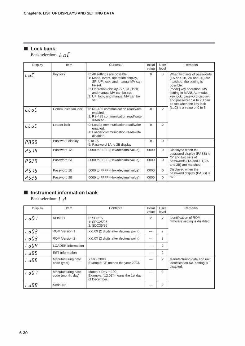
6-30
Chapter 6. LIST OF DISPLAYS AND SETTING DATA
Lock bankBank selection:
Instrument information bankBank selection:
Display Item Contents Initialvalue
Userlevel
Remarks
ROM ID 0: SDC151: SDC25/262: SDC35/36
2 2
ROM Version 1 — 2
ROM Version 2 — 2
LOADER Information — 2
EST Information — 2
Manufacturing datecode (year)
— 2
Identification of ROMfirmware setting is disabled.
Serial No. — 2
XX.XX (2 digits after decimal point)
XX.XX (2 digits after decimal point)
Year - 2000Example: "3" means the year 2003.
Manufacturing date and unitidentification No. setting isdisabled.
Manufacturing datecode (month, day)
— 2Month + Day ÷ 100.Example: "12.01" means the 1st dayof December.
Display Item Contents Initialvalue
Userlevel
Remarks
Key lock 0: All settings are possible.1: Mode, event, operation display,
SP, UF, lock, and manual MV canbe set.
2: Operation display, SP, UF, lock,and manual MV can be set.
3: UF, lock, and manual MV can beset.
0 0
Password 1A 0000 to FFFF (Hexadecimal value) 0000 0
Communication lock 0 2
Loader lock 0: Loader communication read/writeenabled.
1: Loader communication read/writedisabled.
0 2
Password display 0 to 155: Password 1A to 2B display
0 0
When two sets of passwords(1A and 1B, 2A and 2B) arematched, the setting ispossible.[mode] key operation, MVsetting in MANUAL mode,key lock, password display,and password 1A to 2B canbe set when the key lock(LoC) is a value of 0 to 3.
Displayed when thepassword display (PASS) is“5” and two sets ofpasswords (1A and 1B, 2Aand 2B) are matched.
0: RS-485 communication read/writeenabled.
1: RS-485 communication read/writedisabled.
Password 2A 0000 to FFFF (Hexadecimal value) 0000 0
Password 1B 0000 to FFFF (Hexadecimal value) 0000 0 Displayed when thepassword display (PASS) is“5”.Password 2B 0000 to FFFF (Hexadecimal value) 0000 0
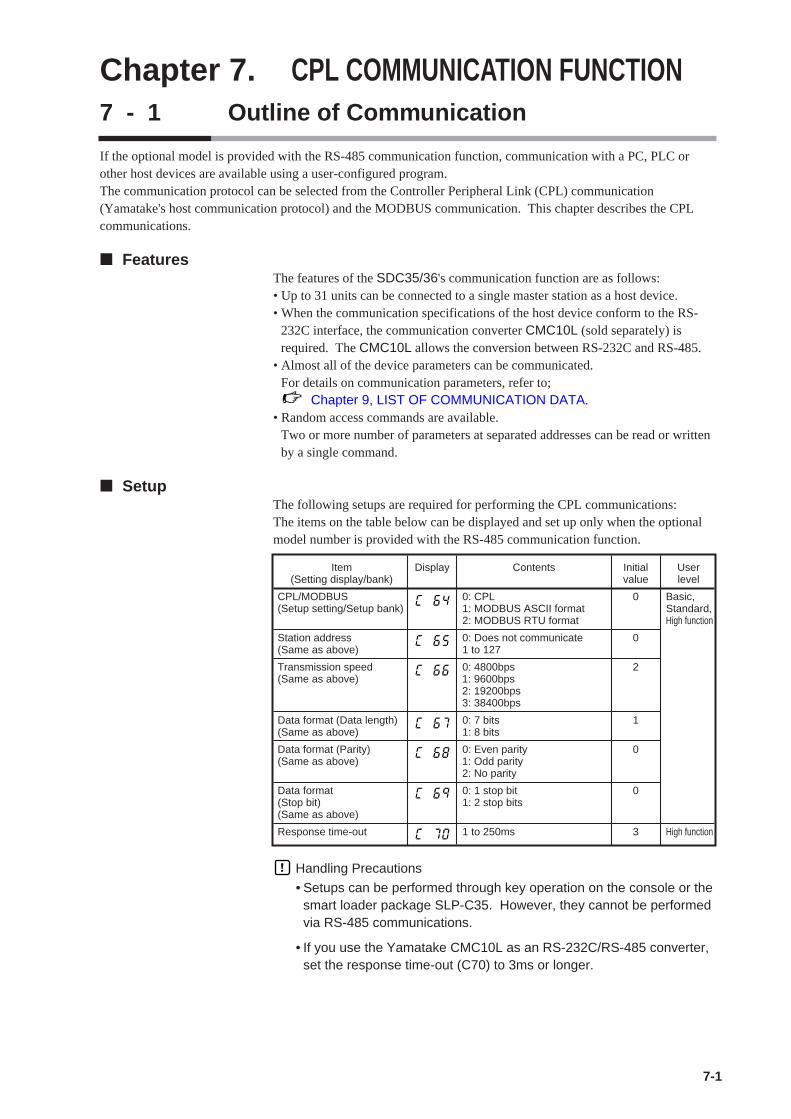
Chapter 7. CPL COMMUNICATION FUNCTION7 - 1 Outline of Communication
7-1
If the optional model is provided with the RS-485 communication function, communication with a PC, PLC orother host devices are available using a user-configured program.The communication protocol can be selected from the Controller Peripheral Link (CPL) communication(Yamatake's host communication protocol) and the MODBUS communication. This chapter describes the CPLcommunications.
FeaturesThe features of the SDC35/36's communication function are as follows:• Up to 31 units can be connected to a single master station as a host device.• When the communication specifications of the host device conform to the RS-
232C interface, the communication converter CMC10L (sold separately) isrequired. The CMC10L allows the conversion between RS-232C and RS-485.
• Almost all of the device parameters can be communicated.For details on communication parameters, refer to;
Chapter 9, LIST OF COMMUNICATION DATA.• Random access commands are available.
Two or more number of parameters at separated addresses can be read or writtenby a single command.
SetupThe following setups are required for performing the CPL communications:The items on the table below can be displayed and set up only when the optionalmodel number is provided with the RS-485 communication function.
Handling Precautions
• Setups can be performed through key operation on the console or thesmart loader package SLP-C35. However, they cannot be performedvia RS-485 communications.
• If you use the Yamatake CMC10L as an RS-232C/RS-485 converter,set the response time-out (C70) to 3ms or longer.
Item Display Contents Initial User(Setting display/bank) value level
CPL/MODBUS 0: CPL 0 Basic,(Setup setting/Setup bank) 1: MODBUS ASCII format Standard,
2: MODBUS RTU format High function
Station address 0: Does not communicate 0(Same as above) 1 to 127
Transmission speed 0: 4800bps 2(Same as above) 1: 9600bps
2: 19200bps3: 38400bps
Data format (Data length) 0: 7 bits 1(Same as above) 1: 8 bits
Data format (Parity) 0: Even parity 0(Same as above) 1: Odd parity
2: No parity
Data format 0: 1 stop bit 0(Stop bit) 1: 2 stop bits(Same as above)
Response time-out 1 to 250ms 3 High function
Communication proceduresThe communication procedure is as follows:
(1) The instruction message is sent from the host device (master station) to one
unit (slave station) to communicate with.
(2) The slave station receives the instruction message, and performs read or write
processing according to the content of the message.
(3) The slave station sends a message corresponding to the processing content as a
response message.
(4) The master station receives the response message.
Handling Precautions
It is not allowed to use two or more number of protocols together on asingle RS-485 transmission line such as CPL, MODBUS ASCII format,and MODBUS RTU format.
7-2
Chapter 7. CPL COMMUNICATION FUNCTION

7 - 2 Message Structure
Message structureThe following shows the message structure:Messages are broadly classified into two layers; the data link layer and theapplication layer.
• Data link layerThis layer contains the basic information required for the communication suchas the destination of the communication message and the check information ofthe message.
• Application layerData is read and written in this layer. The content of the layer variesaccording to the purpose of the message.
Messages comprise parts (1) to (9) as shown in the figure below.The command (details sent from the master station) and the response (detailsreturned from the slave station) are stored in the application layer.
Data link layer Outline
The data link layer is of a fixed length. The position of each data item and thenumber of its characters are already decided. Note, however, that the datapositions of the data link layer from ETX onwards shift according to the numberof characters in the application layer. The character length, however, remainsunchanged.
Response start conditions • The device sends the response message only when (1) message structure, station
address, sub-address, checksum and message length of a single frame in the datalink layer are all correct. If even one of these is incorrect, no response messagesare sent, and the device waits for new message.
• Number of word addresses accessible by a single frame
7-3
Chapter 7. CPL COMMUNICATION FUNCTION
02H 58H 0DH03H
STX X ETX
0AH
CR LF
(2)(1) (3) (4) (5) (6) (7) (8) (9)
Data link layer Application layer Data link layer
1 frame
(1) STX (start of message)(2) Station address(3) Sub-address(4) Device code(5) Send message = command,
response message = response
(6) ETX (end of command/response)(7) Checksum(8) CR (delimiter)(9) LF (delimiter)
Type Description of command RAM area EEPROM area
RS Decimal format read command 16 16
WS Decimal format write command 16 16
RD Hexadecimal format read command 28 28
WD Hexadecimal format write command 27 16
RU Hexadecimal format random read command 28 28
WU Hexadecimal format random write command 14 14

List of data link layer data definitionsThe following list shows the definitions for data in the data link layer:
Description of data items• STX (02H)
When STX is received, the device judges this to be the start of the send message.For this reason, the device returns to the initial state whatever reception state itwas in, and processing is started on the assumption that the STX, the firstcharacter, has been received. The purpose of this is to enable recovery of thedevice's response at the next correct message (e.g. RETRY message) from themaster station in the event that noise, for example, causes an error in the sentmessage.
• Station addressOf the messages sent by the master station, the device creates response messagesonly when station addresses are the same. Station addresses in the messages areexpressed as two-digit hexadecimal characters.The station address is set up by the station address setup (setup setting C65).However, when the station address is set to 0 (30H 30H), the device creates noresponse even if station addresses match.The device returns the same station address as that of the received message.
• Sub-addressThe C35/36 does not use the sub-address. For this reason, set "00" (30H 30H).The device returns the same sub-address as that of the received message.
• Device codeThe device sets X (58H) or x (78H) as the device code. This code is determinedfor each device series, and other codes cannot be selected. The device returns thesame device code as that of the received message. X (58H) is used as the default,and x (78H) is used for judging the message as the resend message.
• ETXETX indicates the end of the application layer.
• ChecksumThis value is for checking whether or not some abnormality (e.g. noise) causesthe message content to change during communications.The checksum is expressed as two hexadecimal characters.
7-4
Chapter 7. CPL COMMUNICATION FUNCTION
Data name Character code Number of Meaning of datacharacters
STX 02H 1 Start of message
Station address 0 to 7FH are expressed as 2 Identification of devicehexadecimal character codes. to communicate with
Sub-address "00" (30H, 30H) 2 No function
Device code "X" (58H) or "x" (78H) 1 Device type
ETX ETX (03H) 1 End position of theapplication layer
Checksum 00H to FFH are expressed as two- 2 Checksum of messagedigit hexadecimal character codes.
CR 0DH 1 End of message (1)
LF 0AH 1 End of message (2)
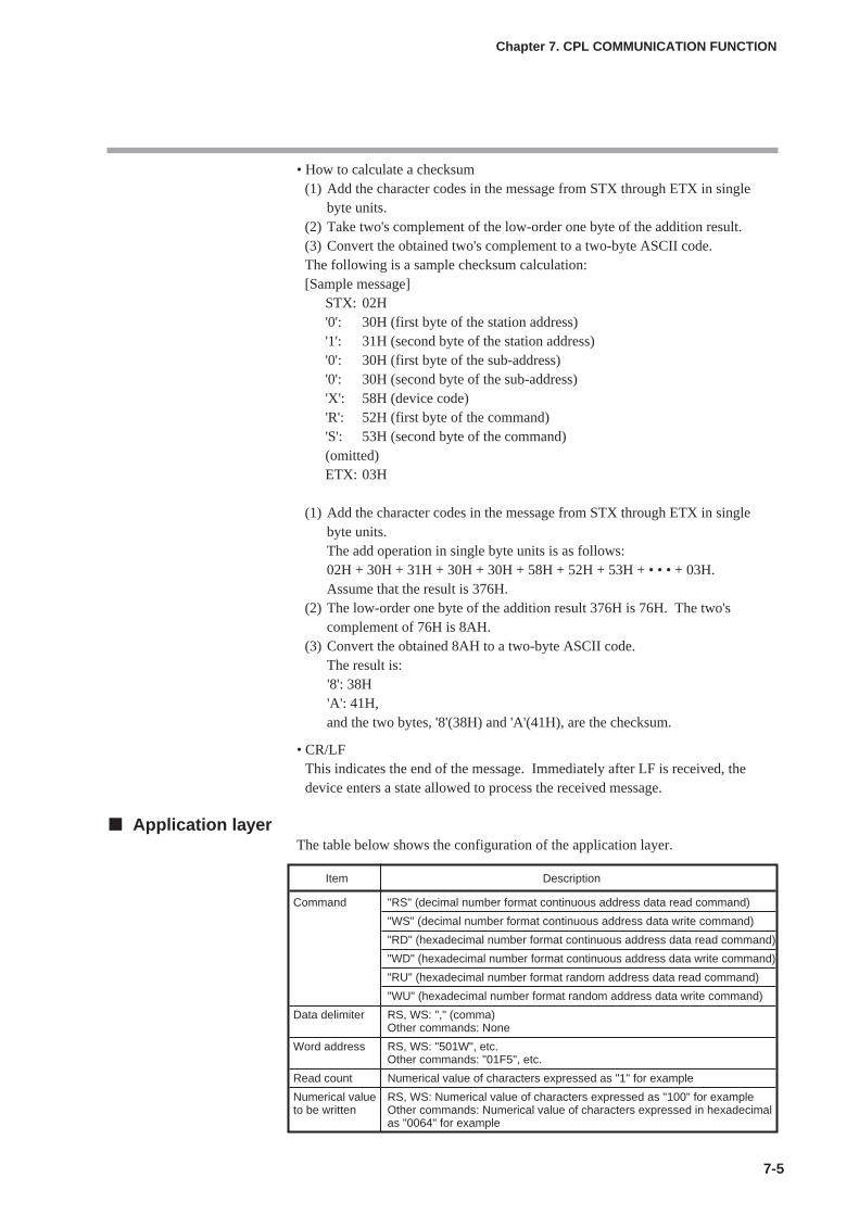
7-5
• How to calculate a checksum(1) Add the character codes in the message from STX through ETX in single
byte units.(2) Take two's complement of the low-order one byte of the addition result.(3) Convert the obtained two's complement to a two-byte ASCII code.The following is a sample checksum calculation:[Sample message]
STX: 02H'0': 30H (first byte of the station address)'1': 31H (second byte of the station address)'0': 30H (first byte of the sub-address)'0': 30H (second byte of the sub-address)'X': 58H (device code)'R': 52H (first byte of the command)'S': 53H (second byte of the command)(omitted)ETX: 03H
(1) Add the character codes in the message from STX through ETX in singlebyte units.The add operation in single byte units is as follows:02H + 30H + 31H + 30H + 30H + 58H + 52H + 53H + • • • + 03H.Assume that the result is 376H.
(2) The low-order one byte of the addition result 376H is 76H. The two'scomplement of 76H is 8AH.
(3) Convert the obtained 8AH to a two-byte ASCII code.The result is:'8': 38H'A': 41H,and the two bytes, '8'(38H) and 'A'(41H), are the checksum.
• CR/LFThis indicates the end of the message. Immediately after LF is received, thedevice enters a state allowed to process the received message.
Application layerThe table below shows the configuration of the application layer.
Chapter 7. CPL COMMUNICATION FUNCTION
Item Description
Command "RS" (decimal number format continuous address data read command)
"WS" (decimal number format continuous address data write command)
"RD" (hexadecimal number format continuous address data read command)
"WD" (hexadecimal number format continuous address data write command)
"RU" (hexadecimal number format random address data read command)
"WU" (hexadecimal number format random address data write command)
Data delimiter RS, WS: "," (comma)Other commands: None
Word address RS, WS: "501W", etc.Other commands: "01F5", etc.
Read count Numerical value of characters expressed as "1" for example
Numerical value RS, WS: Numerical value of characters expressed as "100" for exampleto be written Other commands: Numerical value of characters expressed in hexadecimal
as "0064" for example

7 - 3 Description of Commands
7-6
Continuous data read command (RS command)This command reads data of continuous addresses by a single command.
Send messageThis command enables the content of continuous data addresses starting with the
specified read start address to be read as a single message. The figure below
shows the structure of the application layer of the send message when the data is
read.
Response messageIf the message is correctly received, a response message corresponding to the
command content is returned.
The figure below shows the structure of the application layer of the response
message when the data is read.
Maximum number of read data per messageUp to 16 words for both RAM and EEPROM areas
Chapter 7. CPL COMMUNICATION FUNCTION
(2)(1) (3) (4)
Application layer
(1) Continuous read command(2) Data delimiter(3) Data address(4) Number of read data
R 0S , 1 5 1 W , 1(2)
0
• Normal termination (reading of single data item)
0
• Normal termination (reading of multiple data items)
0 0
• Abnormal termination
X X The abnormal termination code is entered at XX. For details of codes, refer to; 7-6, List of Termination Codes (on page 7-14).
(2)(1) (3)
(1) Termination code(2) Data delimiter(3) Data(4) Data 2 to (n-1)(5) Data n
,
(1) (2) (3) (4) (5)
, , ,
(2) (2)
(1)
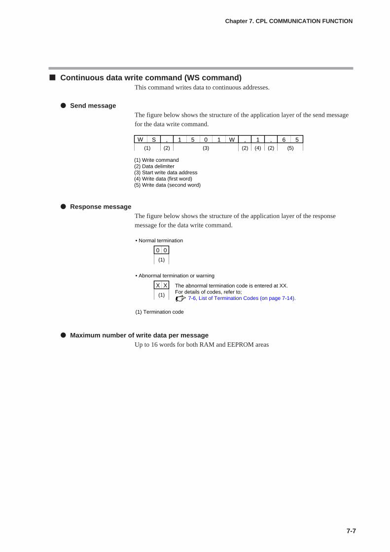
7-7
Continuous data write command (WS command)This command writes data to continuous addresses.
Send messageThe figure below shows the structure of the application layer of the send message
for the data write command.
Response messageThe figure below shows the structure of the application layer of the response
message for the data write command.
Maximum number of write data per messageUp to 16 words for both RAM and EEPROM areas
Chapter 7. CPL COMMUNICATION FUNCTION
(2)(1) (3) (4)
(1) Write command(2) Data delimiter(3) Start write data address(4) Write data (first word)(5) Write data (second word)
W 0S , 1 5 1 W , 1(2)
, 6 5(2) (5)
0
• Normal termination
0
• Abnormal termination or warning
X X The abnormal termination code is entered at XX.For details of codes, refer to; 7-6, List of Termination Codes (on page 7-14).
(1)
(1)
(1) Termination code
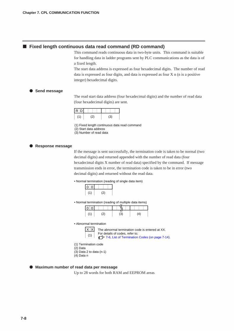
Fixed length continuous data read command (RD command)This command reads continuous data in two-byte units. This command is suitable
for handling data in ladder programs sent by PLC communications as the data is of
a fixed length.
The start data address is expressed as four hexadecimal digits. The number of read
data is expressed as four digits, and data is expressed as four X n (n is a positive
integer) hexadecimal digits.
Send messageThe read start data address (four hexadecimal digits) and the number of read data
(four hexadecimal digits) are sent.
Response messageIf the message is sent successfully, the termination code is taken to be normal (two
decimal digits) and returned appended with the number of read data (four
hexadecimal digits X number of read data) specified by the command. If message
transmission ends in error, the termination code is taken to be in error (two
decimal digits) and returned without the read data.
Maximum number of read data per messageUp to 28 words for both RAM and EEPROM areas
7-8
Chapter 7. CPL COMMUNICATION FUNCTION
(1) Fixed length continuous data read command(2) Start data address(3) Number of read data
R
(1)
D
(2) (3)
0
• Normal termination (reading of single data item)
(1)
0
• Normal termination (reading of multiple data items)
0
(1)
0
(2) (3) (4)
• Abnormal termination
X
(1)
X The abnormal termination code is entered at XX.For details of codes, refer to; 7-6, List of Termination Codes (on page 7-14).
(2)
(1) Termination code(2) Data(3) Data 2 to data (n-1)(4) Data n
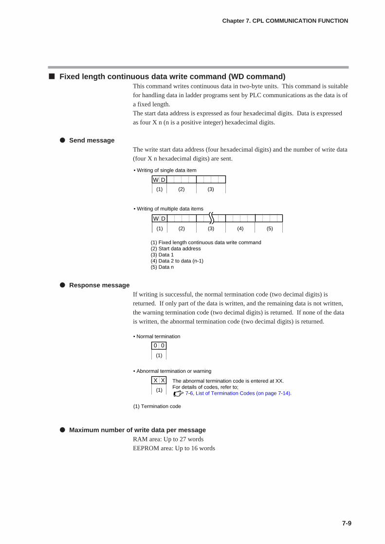
7-9
Fixed length continuous data write command (WD command)This command writes continuous data in two-byte units. This command is suitable
for handling data in ladder programs sent by PLC communications as the data is of
a fixed length.
The start data address is expressed as four hexadecimal digits. Data is expressed
as four X n (n is a positive integer) hexadecimal digits.
Send messageThe write start data address (four hexadecimal digits) and the number of write data
(four X n hexadecimal digits) are sent.
Response messageIf writing is successful, the normal termination code (two decimal digits) is
returned. If only part of the data is written, and the remaining data is not written,
the warning termination code (two decimal digits) is returned. If none of the data
is written, the abnormal termination code (two decimal digits) is returned.
Maximum number of write data per messageRAM area: Up to 27 words
EEPROM area: Up to 16 words
Chapter 7. CPL COMMUNICATION FUNCTION
W
• Writing of single data item
D
• Writing of multiple data items
(1) Fixed length continuous data write command(2) Start data address(3) Data 1(4) Data 2 to data (n-1)(5) Data n
(1) (2) (3)
(5)
W
(1)
D
(2) (3) (4)
0
• Normal termination
(1)
0
• Abnormal termination or warning
X
(1)
X The abnormal termination code is entered at XX.For details of codes, refer to; 7-6, List of Termination Codes (on page 7-14).
(1) Termination code
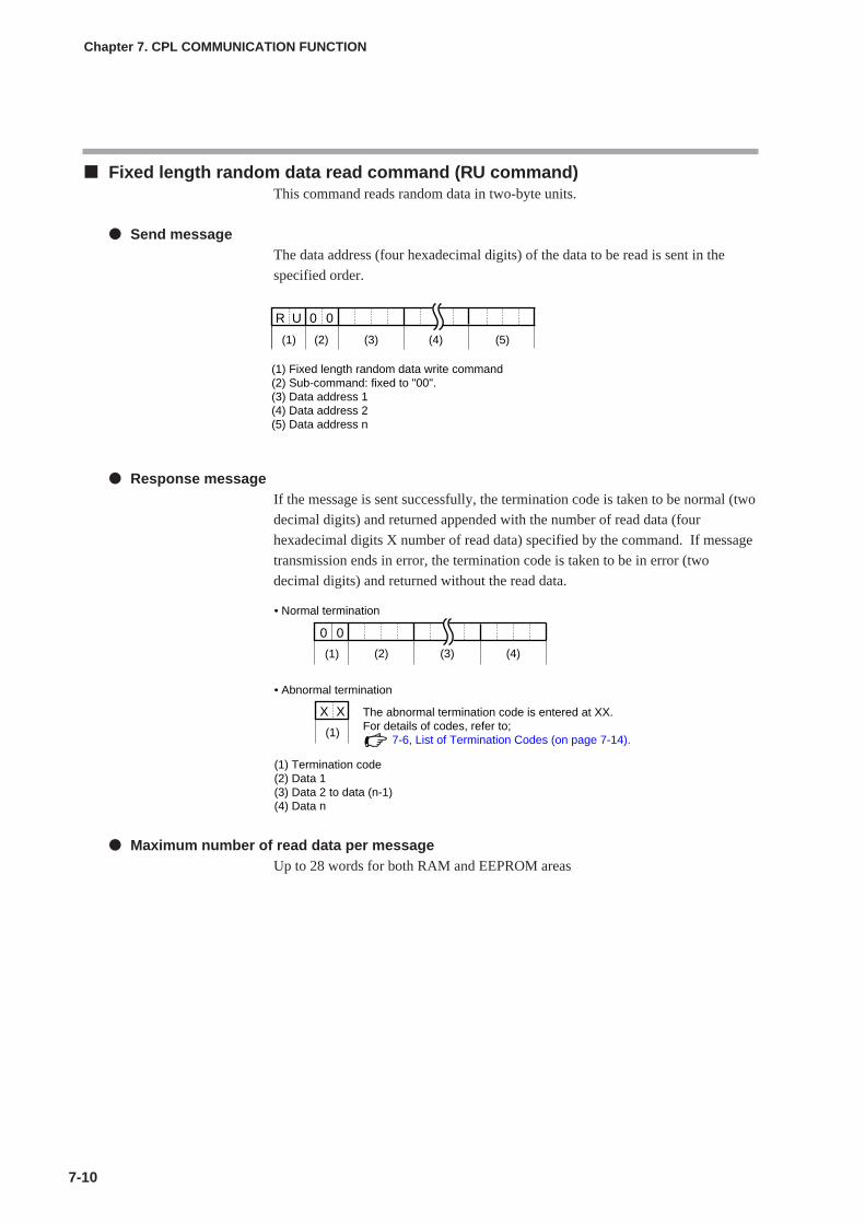
Fixed length random data read command (RU command)This command reads random data in two-byte units.
Send messageThe data address (four hexadecimal digits) of the data to be read is sent in the
specified order.
Response messageIf the message is sent successfully, the termination code is taken to be normal (two
decimal digits) and returned appended with the number of read data (four
hexadecimal digits X number of read data) specified by the command. If message
transmission ends in error, the termination code is taken to be in error (two
decimal digits) and returned without the read data.
Maximum number of read data per messageUp to 28 words for both RAM and EEPROM areas
7-10
Chapter 7. CPL COMMUNICATION FUNCTION
0 0R U
(1) Fixed length random data write command(2) Sub-command: fixed to "00".(3) Data address 1(4) Data address 2(5) Data address n
(5)(1) (2) (3) (4)
• Normal termination
• Abnormal termination
X
(1)
X The abnormal termination code is entered at XX.For details of codes, refer to; 7-6, List of Termination Codes (on page 7-14).
(1) Termination code(2) Data 1(3) Data 2 to data (n-1)(4) Data n
0
(1)
0
(2) (3) (4)
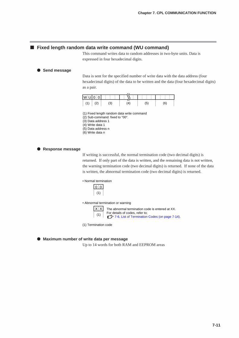
7-11
Fixed length random data write command (WU command)This command writes data to random addresses in two-byte units. Data is
expressed in four hexadecimal digits.
Send messageData is sent for the specified number of write data with the data address (four
hexadecimal digits) of the data to be written and the data (four hexadecimal digits)
as a pair.
Response messageIf writing is successful, the normal termination code (two decimal digits) is
returned. If only part of the data is written, and the remaining data is not written,
the warning termination code (two decimal digits) is returned. If none of the data
is written, the abnormal termination code (two decimal digits) is returned.
Maximum number of write data per messageUp to 14 words for both RAM and EEPROM areas
Chapter 7. CPL COMMUNICATION FUNCTION
0 0W
(1)
U
(3) (5) (6)(2) (4)
(1) Fixed length random data write command(2) Sub-command: fixed to "00".(3) Data address 1(4) Write data 1(5) Data address n(6) Write data n
• Normal termination
0
(1)
0
• Abnormal termination or warning
X
(1)
X The abnormal termination code is entered at XX.For details of codes, refer to; 7-6, List of Termination Codes (on page 7-14).
(1) Termination code

7 - 4 Definition of Data Addresses
7-12
RAM and EEPROM areas of data addressesData addresses are categorized as follows:
Handling PrecautionsErase/write cycle of EEPROM is limited (100,000 cycles). Accordingly, werecommend writing parameters that are written extremely frequently toRAM that can be written without limitation.However, that when writing to RAM is performed, the data in EEPROM is
transferred to RAM when the power is turned ON again.
Write data rangeIf the write value exceeds the range determined by parameters, writing is not
performed and an abnormal termination code is returned.
Write conditionsAn abnormal termination code is also returned when the writing is not possible
due to the conditions.
Chapter 7. CPL COMMUNICATION FUNCTION
Data address Name Remarks(hexadecimal notation)
273W to 14859W RAM access data address Reading and writing of these addresses are (0111 to 3A0B) both performed on RAM.
Since writing is not performed to EEPROM,the value returns to that stored in EEPROMafter restarted.
16657W to 31243W EEPROM access data address Writing is performed to both RAM and (4111 to 7A0B) EEPROM; reading is performed only on RAM.
Since writing is also performed to EEPROM,the value does not change even afterrestarted.
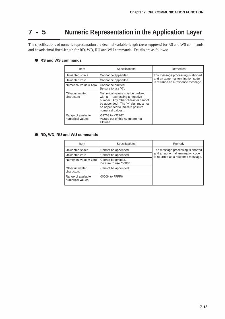
7 - 5 Numeric Representation in the Application Layer
The specifications of numeric representation are decimal variable-length (zero suppress) for RS and WS commands
and hexadecimal fixed-length for RD, WD, RU and WU commands. Details are as follows:
RS and WS commands
RD, WD, RU and WU commands
7-13
Chapter 7. CPL COMMUNICATION FUNCTION
Item Specifications Remedies
Unwanted space Cannot be appended.
Unwanted zero Cannot be appended.
Numerical value = zero Cannot be omitted.Be sure to use "0".
Other unwanted Numerical values may be prefixedcharacters with a "-" expressing a negative
number. Any other character cannot be appended. The "+" sign must not be appended to indicate positive numerical values.
Range of available -32768 to +32767numerical values Values out of this range are not
allowed.
The message processing is abortedand an abnormal termination codeis returned as a response message.
Item Specifications Remedy
Unwanted space Cannot be appended.
Unwanted zero Cannot be appended.
Numerical value = zero Cannot be omitted.Be sure to use "0000".
Other unwanted Cannot be appended.characters
Range of available 0000H to FFFFHnumerical values
The message processing is abortedand an abnormal termination codeis returned as a response message.
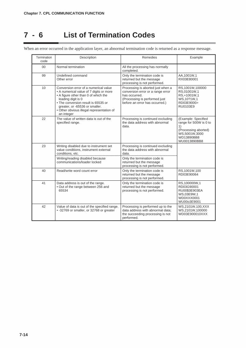
7 - 6 List of Termination Codes
7-14
When an error occurred in the application layer, an abnormal termination code is returned as a response message.
Chapter 7. CPL COMMUNICATION FUNCTION
Termination Description Remedies Examplecode
00
99
10
22
23
40
41
42
Normal termination
Undefined commandOther error
Conversion error of a numerical value• A numerical value of 7 digits or more• A figure other than 0 of which the
leading digit is 0• The conversion result is 65535 or
greater, or -65536 or smaller.• Other obvious illegal representation of
an integer
The value of written data is out of thespecified range.
Writing disabled due to instrument setvalue conditions, instrument externalconditions, etc.
Writing/reading disabled becausecommunications/loader locked
Read/write word count error
Data address is out of the range.• Out of the range between 256 and
65534
Value of data is out of the specified range.• -32769 or smaller, or 32768 or greater
All the processing has normallycompleted.
Only the termination code isreturned but the messageprocessing is not performed.
Processing is aborted just when aconversion error or a range errorhas occurred.(Processing is performed justbefore an error has occurred.)
Processing is continued excludingthe data address with abnormaldata.
Processing is continued excludingthe data address with abnormaldata.
Only the termination code isreturned but the messageprocessing is not performed.
Only the termination code isreturned but the messageprocessing is not performed.
Only the termination code isreturned but the messageprocessing is not performed.
Processing is performed up to thedata address with abnormal data;the succeeding processing is notperformed.
AA,1001W,1RX03E80001
RS,1001W,100000RS,01001W,1RS,+1001W,1WS,10?1W,1RD03E9000>RU0103E9
(Example: Specifiedrange for 500W is 0 to1)(Processing aborted)WS,5001W,3000WD13890BB8WU0013890BB8
RS,1001W,100RD03E90064
RS,100000W,1RD03G90001RU00$3E903EAWS,03E9W,1WD0XXX0001WU00o3E9001
WS,2101W,100,XXXWS,2101W,100000WD03E900010XXX

7 - 7 Reception and Transmission Timing
Timing specifications for instruction and response messageThe cautions below are required with regard to the timing to transmit a instruction
message from the master station and a response message from the slave station.
Response monitor timeThe maximum response time from the end of the instruction message transmission
by the master station until when the master station receives a response message
from the slave station is two seconds ((1) in the figure below). So, the response
monitor time should be set to two seconds.
Generally, when a response time-out occurs, the instruction message is resent.
Transmission start timeA wait time of 10ms is required before the master station starts to transmit the next
instruction message (to the same slave station or a different slave station) after the
end of receiving response message ((2) in the figure below).
RS-485 driver control timing specificationsWhen the transmission/reception on the RS-485 3-wire system is directly
controlled by the master station, care should be paid to the following timing:
7-15
Chapter 7. CPL COMMUNICATION FUNCTION
Instructionmessage
Responsemessage
Instructionmessage
Responsemessage
Transmis-sion line
• RS-485 3-wire system
(1) End of master station transmission - Transmission start time of slave station = Max. 2000ms
(2) End of slave station transmission - Transmission start time of master station = Min. 10ms
(1) (2)
(enable)
(enable)
(disable)
(disable)
Master stationdriver control
Slave stationdriver control
Transmissionline
(instruction message)
Effective data
Effective data
(1) End of master station transmission - Driver disable time = Max. 500µs(2) End of slave station reception - Driver enable time = Response time-out setup setting (C70) or greater(3) End of slave station transmission - Driver disable time = Max. 10ms(4) End of master station reception - Driver enable time = Min. 10ms
End of master station transmission
End of slave station transmission
(response message)
(1) (4)
(2) (3)
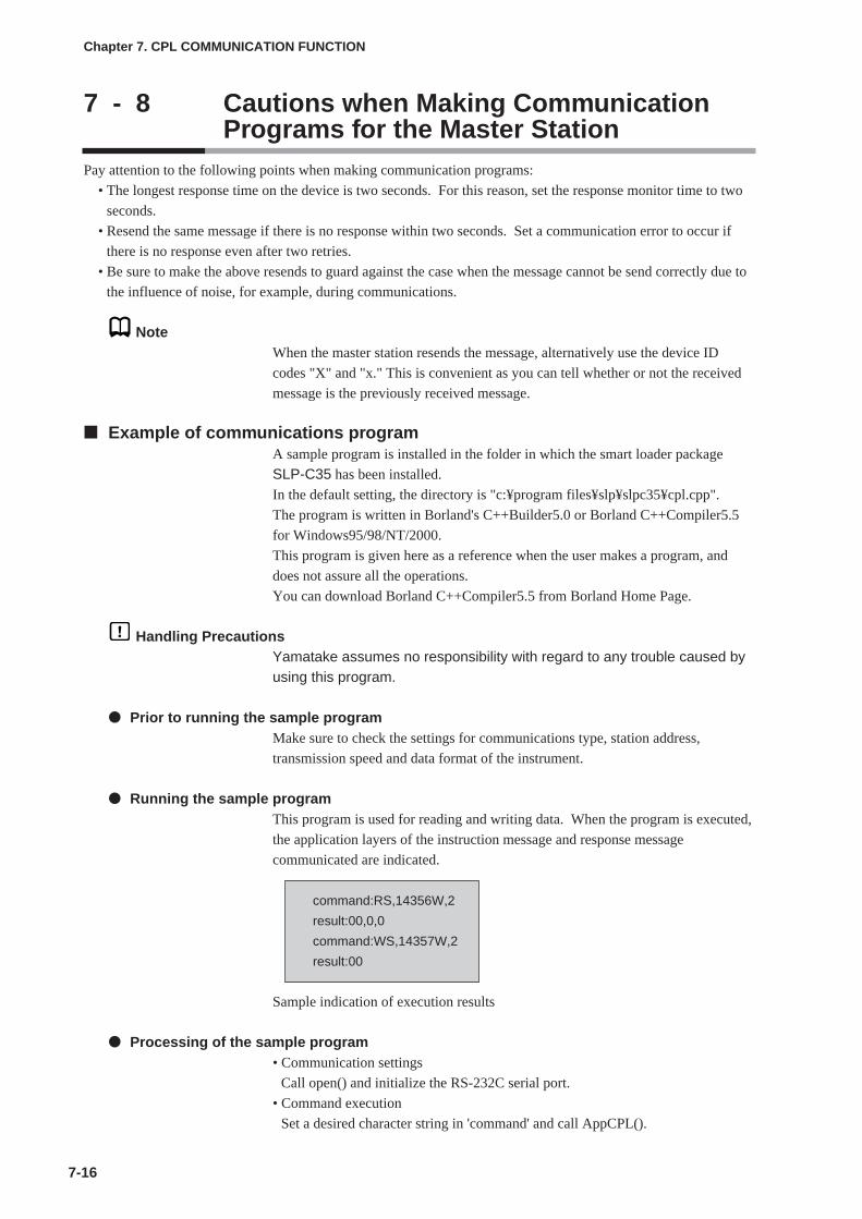
7 - 8 Cautions when Making CommunicationPrograms for the Master Station
7-16
Pay attention to the following points when making communication programs:
• The longest response time on the device is two seconds. For this reason, set the response monitor time to two
seconds.
• Resend the same message if there is no response within two seconds. Set a communication error to occur if
there is no response even after two retries.
• Be sure to make the above resends to guard against the case when the message cannot be send correctly due to
the influence of noise, for example, during communications.
NoteWhen the master station resends the message, alternatively use the device ID
codes "X" and "x." This is convenient as you can tell whether or not the received
message is the previously received message.
Example of communications programA sample program is installed in the folder in which the smart loader package
SLP-C35 has been installed.
In the default setting, the directory is "c:¥program files¥slp¥slpc35¥cpl.cpp".
The program is written in Borland's C++Builder5.0 or Borland C++Compiler5.5
for Windows95/98/NT/2000.
This program is given here as a reference when the user makes a program, and
does not assure all the operations.
You can download Borland C++Compiler5.5 from Borland Home Page.
Handling PrecautionsYamatake assumes no responsibility with regard to any trouble caused byusing this program.
Prior to running the sample programMake sure to check the settings for communications type, station address,
transmission speed and data format of the instrument.
Running the sample programThis program is used for reading and writing data. When the program is executed,
the application layers of the instruction message and response message
communicated are indicated.
command:RS,14356W,2
result:00,0,0
command:WS,14357W,2
result:00
Sample indication of execution results
Processing of the sample program• Communication settings
Call open() and initialize the RS-232C serial port.
• Command execution
Set a desired character string in 'command' and call AppCPL().
Chapter 7. CPL COMMUNICATION FUNCTION

Chapter 8. MODBUS COMMUNICATION FUNCTION8 - 1 Outline of Communication
8-1
If the optional model is provided with the RS-485 communications function, communication with a PC, PLC or
other host devices are available using a user-configured program.
The communication protocol can be selected from the Controller Peripheral Link (CPL) communication
(Yamatake's host communication protocol) and the MODBUS communication. This chapter describes the
MODBUS communications.
FeaturesThe features of the C35/36's communication function are as follows:
• Up to 31 units can be connected to a single master station as a host device.
• When the communication specifications of the host device conform to the RS-
232C interface, the communication converter CMC10L (sold separately) is
required. The CMC10L allows the conversion between RS-232C and RS-485.
• Almost all of the device parameters can be communicated.
For details on communication parameters, refer to;
Chapter 9, LIST OF COMMUNICATION DATA.
SetupThe following setups are required for performing the MODBUS communication:
• If the optional model number is provided with the RS-485 communications
function, display and setup are available.
• If the communications type is set to MODBUS RTU format, data format (data
length) cannot be displayed nor set up, and the action is fixed to 8-bit data.
Handling Precautions
• Setups can be performed through key operation on the console or thesmart loader package SLP-C35. However, they cannot be performedvia RS-485 communications.
• If you use the Yamatake CMC10L as an RS-232C/RS-485 converter,set the response time-out (C70) to 3ms or longer.
Item Display Contents Initial User(Setting display/bank) value level
CPL/MODBUS 0: CPL 0 Basic,(Setup setting/Setup bank) 1: MODBUS ASCII format Standard,
2: MODBUS RTU format High
Station address 0: Does not communicate 0 function
(Same as above) 1 to 127
Transmission speed 0: 4800bps 2(Same as above) 1: 9600bps
2: 19200bps3: 38400bps
Data format (Data length) 0: 7 bits 1(Same as above) 1: 8 bits
Data format (Parity) 0: Even parity 0(Same as above) 1: Odd parity
2: No parity
Data format (Stop bit) 0: 1 stop bit 0(Same as above) 1: 2 stop bits
Response time-out 1 to 250ms 3 Highfunction
Communication proceduresThe communication procedure is as follows:
(1) The instruction message is sent from the host device (master station) to one
unit (slave station) to communicate with.
(2) The slave station receives the instruction message, and performs read or write
processing according to the content of the message.
(3) The slave station sends a message corresponding to the processing content as a
response message.
(4) The master station receives the response message.
Handling Precautions
It is not allowed to use two or more number of protocols together on asingle RS-485 transmission line such as CPL, MODBUS ASCII format,and MODBUS RTU format.
8-2
Chapter 8. MODBUS COMMUNICATION FUNCTION
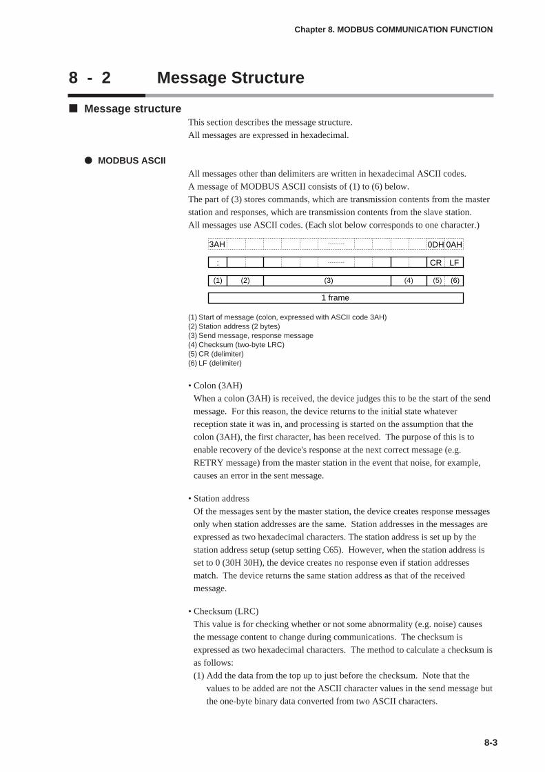
8 - 2 Message Structure
Message structureThis section describes the message structure.
All messages are expressed in hexadecimal.
MODBUS ASCIIAll messages other than delimiters are written in hexadecimal ASCII codes.
A message of MODBUS ASCII consists of (1) to (6) below.
The part of (3) stores commands, which are transmission contents from the master
station and responses, which are transmission contents from the slave station.
All messages use ASCII codes. (Each slot below corresponds to one character.)
(1) Start of message (colon, expressed with ASCII code 3AH)(2) Station address (2 bytes)(3) Send message, response message(4) Checksum (two-byte LRC)(5) CR (delimiter)(6) LF (delimiter)
• Colon (3AH)
When a colon (3AH) is received, the device judges this to be the start of the send
message. For this reason, the device returns to the initial state whatever
reception state it was in, and processing is started on the assumption that the
colon (3AH), the first character, has been received. The purpose of this is to
enable recovery of the device's response at the next correct message (e.g.
RETRY message) from the master station in the event that noise, for example,
causes an error in the sent message.
• Station address
Of the messages sent by the master station, the device creates response messages
only when station addresses are the same. Station addresses in the messages are
expressed as two hexadecimal characters. The station address is set up by the
station address setup (setup setting C65). However, when the station address is
set to 0 (30H 30H), the device creates no response even if station addresses
match. The device returns the same station address as that of the received
message.
• Checksum (LRC)
This value is for checking whether or not some abnormality (e.g. noise) causes
the message content to change during communications. The checksum is
expressed as two hexadecimal characters. The method to calculate a checksum is
as follows:
(1) Add the data from the top up to just before the checksum. Note that the
values to be added are not the ASCII character values in the send message but
the one-byte binary data converted from two ASCII characters.
8-3
Chapter 8. MODBUS COMMUNICATION FUNCTION
(4) (5)
3AH 0DH
:
0AH
CR LF
(2)(1) (3) (6)
1 frame

(2) Take two's complement of the addition result.
(3) Convert the low-order one byte of the addition result to a character code.
The following is a sample checksum calculation:
[Sample message]
: : 3AH (start of the message)
'0' : 30H (first byte of the station address)
'A' : 41H (second byte of the station address)
'0' : 30H (first byte of the read command)
'3' : 33H (second byte of the read command)
'0' : 30H (first byte of the start data address)
'3' : 33H (second byte of the start data address)
'E' : 45H (third byte of the start data address)
'9' : 39H (fourth byte of the start data address)
'0' : 30H (first byte of the number of read data)
'0' : 30H (second byte of the number of read data)
'0' : 30H (third byte of the number of read data)
'2' : 32H (fourth byte of the number of read data)
(1) Add the data from the top up to just before the checksum.
The add operation is as follows:
0AH + 03H + 03H + E9H + 00H + 02H
The result is FBH.
(2) The low-order byte of the addition result FBH is FBH as is. The two's
complement of FBH is 05H.
(3) Convert the obtained 05H to a two-byte ASCII code.
The result is:
'0' : 30H
'5' : 35H,
and the two bytes, '0' (30H) and '5' (35H), are the checksum.
• CR/LF
This indicates the end of the message. After LF is received, the device
immediately stands by for permission to process the received message.
8-4
Chapter 8. MODBUS COMMUNICATION FUNCTION
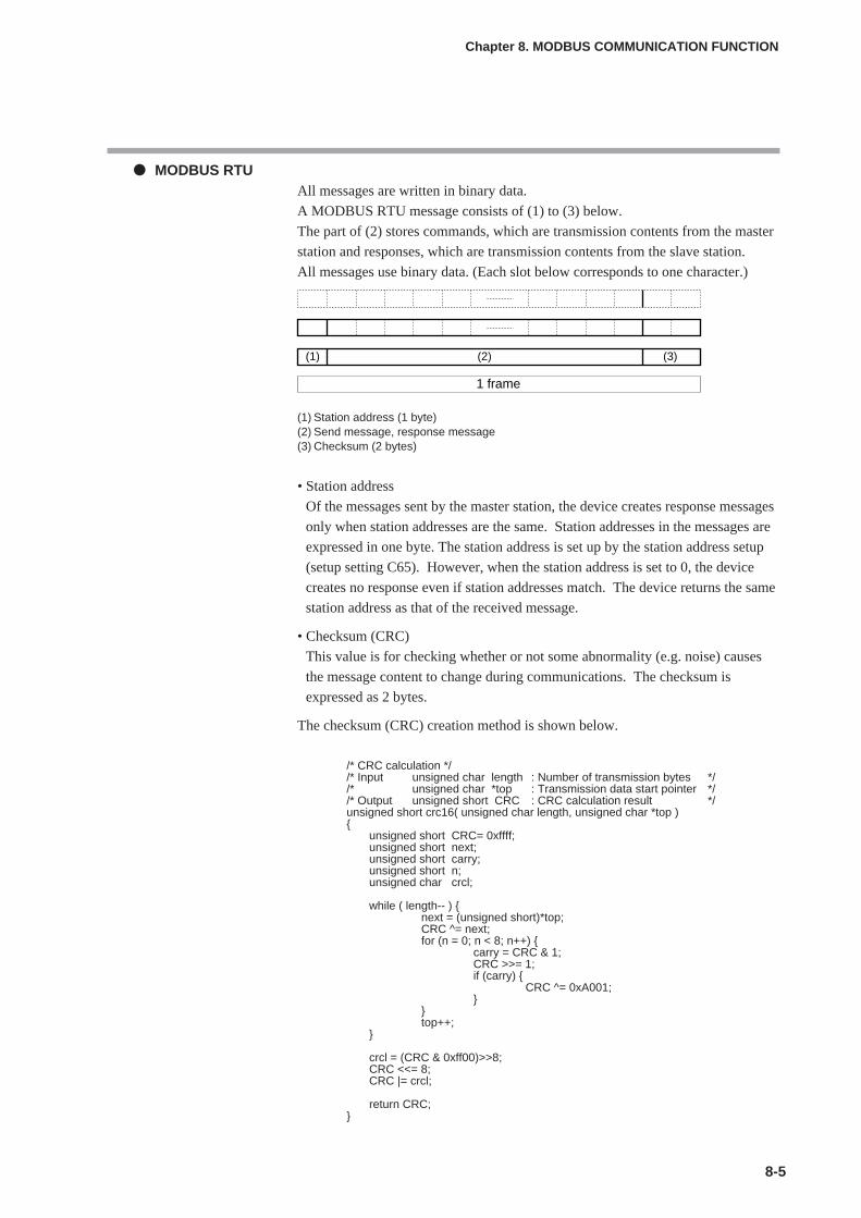
8-5
MODBUS RTUAll messages are written in binary data.
A MODBUS RTU message consists of (1) to (3) below.
The part of (2) stores commands, which are transmission contents from the master
station and responses, which are transmission contents from the slave station.
All messages use binary data. (Each slot below corresponds to one character.)
(1) Station address (1 byte) (2) Send message, response message(3) Checksum (2 bytes)
• Station address
Of the messages sent by the master station, the device creates response messages
only when station addresses are the same. Station addresses in the messages are
expressed in one byte. The station address is set up by the station address setup
(setup setting C65). However, when the station address is set to 0, the device
creates no response even if station addresses match. The device returns the same
station address as that of the received message.
• Checksum (CRC)
This value is for checking whether or not some abnormality (e.g. noise) causes
the message content to change during communications. The checksum is
expressed as 2 bytes.
The checksum (CRC) creation method is shown below.
/* CRC calculation *//* Input unsigned char length : Number of transmission bytes *//* unsigned char *top : Transmission data start pointer *//* Output unsigned short CRC : CRC calculation result */unsigned short crc16( unsigned char length, unsigned char *top )
unsigned short CRC= 0xffff;unsigned short next;unsigned short carry;unsigned short n;unsigned char crcl;
while ( length-- ) next = (unsigned short)*top;CRC ^= next;for (n = 0; n < 8; n++)
carry = CRC & 1;CRC >>= 1;if (carry)
CRC ^= 0xA001;
top++;
crcl = (CRC & 0xff00)>>8;CRC <<= 8;CRC |= crcl;
return CRC;
Chapter 8. MODBUS COMMUNICATION FUNCTION
(2)(1) (3)
1 frame

• 1-frame end judgment
A message end (1-frame end) is determined when a time period specified for
each transmission speed has passed during which no character is received. It is
considered that 1 frame has ended when the next character is not received before
the time-out time shown below passes.
However, the time-out time has a fluctuation of ±1ms from the values in the table
below.
Command typeThere are two command (send message) types as shown below.
Other specifications• Supporting the MODBUS Class 0
• Abnormal termination codes
• Maximum number of communication data words
• The others
For the details of MODBUS specifications, refer to;
OPEN MODBUS/TCP SPECIFICATION (Release 1.0) by ModiconInc.
8-6
Chapter 8. MODBUS COMMUNICATION FUNCTION
Set transmission speed Time-out time(bps)
4800 16ms or more
9600 8ms or more
19200 4ms or more
38400 2ms or more
Command Description
ASCII RTU (binary)
Read command "03" (sample) 03H (sample)
Write command "10" (sample) 10H (sample)
Code Description
01 Command error
02 Address error
03 Data error
Command Number of data
ASCII RTU
03 (READ) 16 16
10 (WRITE) 16 16

8 - 3 Description of Commands
Read command (03H)
Send MessageThis is a command capable of reading the contents of continuous data addresses
from a specified read start data address with a single message. The following is an
example of send message while reading data:
MODBUS ASCII
(1) Start of message(2) Station address(3) Read command(4) Start data address(5) Number of read data(6) Checksum (LRC)(7) Delimiter
MODBUS RTU
(1) Station address(2) Read command(3) Start data address(4) Number of read data(5) Checksum (CRC)
Response MessageA response message corresponding to the command content is returned when the
message is correctly received.
The figure below shows the structure of the response message while reading data.
MODBUS ASCII• Example in case of normal reception
(1) Start of message(2) Station address(3) Read command(4) Number of read data X 2(5) Read data 1(6) Read data 2(7) Checksum (LRC)(8) Delimiter
8-7
Chapter 8. MODBUS COMMUNICATION FUNCTION
(2)(1) (3) (4)
3AH:
30H0
41HA
30H0
33H3
30H0
33H3
45HE
39H9
30H0
30H0
30H0
32H2
30H0
35H5
0DHCR
0AHLF
(5) (6) (7)
(2)(1) (3) (4)
0AH 03H 03H E9H 00H 02H 14H(5)
C0H
(2)(1) (3) (4)
3AH:
30H0
41HA
30H0
33H3
30H0
34H4
30H0
33H3
30H0
31H1
30H0
30H0
30H0
33H3
45HE
38H8
D0HCR
0AHLF
(5) (6) (7) (8)

• Example in case of error
(1) Start of message(2) Station address(3) Error flag (since undefined "04" is sent as a command with a send message, the most
significant bit is turned ON and sent back as "84".)(4) Abnormal termination code ( refer to page 8-6)(5) Checksum (LRC) (6) Delimiter
MODBUS RTU• Example in case of normal reception
(1) Station address (2) Read command(3) Number of read data X 2 (bytes)(4) Read data 1(5) Read data 2(6) Checksum (CRC)
• Example in case of error
(1) Station address (2) Error flag (since undefined "04H" is sent as a command with a send message, the most
significant bit is turned ON and sent back as "84H".)(3) Abnormal termination code ( refer to page 8-6)(4) Checksum (CRC)
8-8
Chapter 8. MODBUS COMMUNICATION FUNCTION
(2)(1) (3) (4)
3AH:
30H0
41HA
38H8
34H4
30H0
31H1
(5) (6)
37H7
31H1
0DHCR
0AHLF
(2)(1) (3) (4)
0AH 03H 04H 03H 01H 00H 03H(5) (6)
51H 76H
(2)(1) (3)
0AH 84H 01H F3H 02H(4)
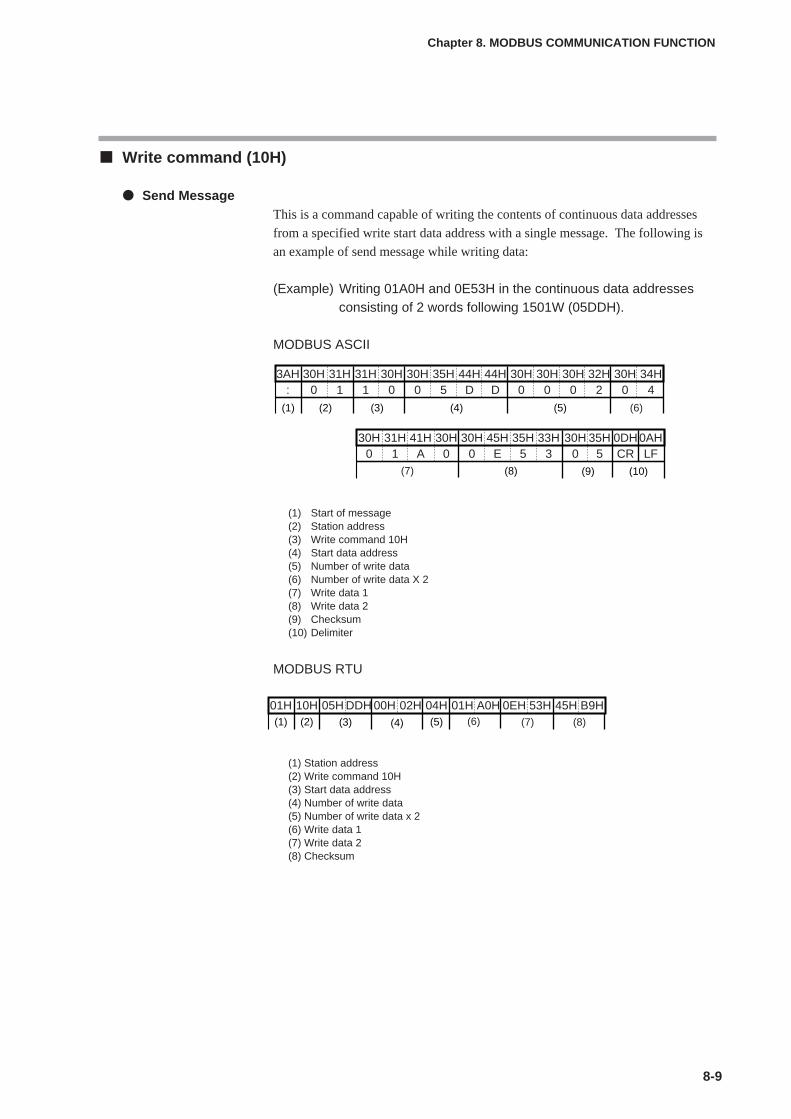
8-9
Write command (10H)
Send MessageThis is a command capable of writing the contents of continuous data addresses
from a specified write start data address with a single message. The following is
an example of send message while writing data:
(Example) Writing 01A0H and 0E53H in the continuous data addressesconsisting of 2 words following 1501W (05DDH).
MODBUS ASCII
(1) Start of message(2) Station address(3) Write command 10H(4) Start data address(5) Number of write data(6) Number of write data X 2(7) Write data 1(8) Write data 2(9) Checksum(10) Delimiter
MODBUS RTU
(1) Station address(2) Write command 10H(3) Start data address(4) Number of write data(5) Number of write data x 2(6) Write data 1(7) Write data 2(8) Checksum
Chapter 8. MODBUS COMMUNICATION FUNCTION
(2)(1) (3) (4) (5) (6)
(7) (8) (9) (10)
3AH:
30H0
31H1
31H1
30H0
30H0
35H5
44HD
44HD
30H0
30H0
30H0
32H2
30H0
34H4
30H0
31H1
30H0
30H0
45HE
35H5
33H3
30H0
35H5
0DHCR
41HA
0AHLF
(3) (4)
01H(1)
10H(2)
05H DDH 00H 02H 04H(5)
01H A0H 0EH 53H 45H B9H(6) (7) (8)

Response MessageA response message corresponding to the command content is returned when the
message is correctly received.
The figure below shows the structure of the response message when the data is
written.
MODBUS ASCII
(1) Start of message(2) Station address(3) Write command 10H(4) Start data address(5) Number of write data(6) Checksum(7) Delimiter
MODBUS RTU
(1) Station address(2) Write command 10H(3) Start data address(4) Number of write data(5) Checksum
NoteThe response message at the time of abnormal termination is the same as that for
the read command.
8-10
Chapter 8. MODBUS COMMUNICATION FUNCTION
(2)(1) (3) (4) (5) (6) (7)
3AH:
30H0
31H1
31H1
30H0
30H0
35H5
44HD
44HD
30H0
30H0
30H0
32H2
30H0
42HB
0DHCR
0AHLF
(2)(1) (3) (4)
01H 10H 05H DDH 00H 02H D1H(5)
3EH
8 - 4 Specifications Common with CPLCommunication Function
Definition of data addressesRefer to;
7-4 Definition of Data Addresses (on page 7-12)
Numeric representationThe specifications of numeric representation is the same as the following:
RD, WD, RU and WU commands in 7-5 Numeric Representation inthe Application Layer (on page 7-13).
RS-485 driver control timing specificationsRefer to;
7-7 Reception and Transmission Timing (on page 7-15).
8-11
Chapter 8. MODBUS COMMUNICATION FUNCTION


Chapter 9. LIST OF COMMUNICATION DATA
9-1
List of communication data
The following shows the meanings of the symbols stated in the “RAM/EEPROM Read/Write”columns:
No symbol: Possible. : Possible according to the conditions.∆: Possible, but data is invalid.X: Impossible.
Note: When reading the EEPROM address, data in the RAM is read in the same manner asreading of the RAM address.
Decimal point information: No decimal point1 to 3: Decimal point position (The communication data becomes that the
original value is multiplied by 10, 100, or 1000.)P: Follows the PV input range.S: Follows various conditions.
RS/WS commands of CPL communication Decimal data address with “W” attached nextto it is used.
RD/WD/RU/WU commands of CPL communication: Hexadecimal data address is used.Commands of MODBUS communication: Hexadecimal data address is used.
Bank Item name RAM address EEPROM address RAM EEPROM Decimal point RemarksDecimal Hexadecimal Decimal Hexadecimal Read Write Read Write information
Instrument ROM ID 273 0111 16657 4111 X X — "2" when using SDC35/36.
information ROM Version 1 274 0112 16658 4112 X X 2
ROM Version 2 275 0113 16659 4113 X X 2
LOADER Information 276 0114 16660 4114 X X —
EST Information 277 0115 16661 4115 X X —
Manufacturing date code (year) 278 0116 16662 4116 X X — Year - 2000 Example: Year of 2003 is expressed as "3"
Manufacturing date code (month, day) 279 0117 16663 4117 X X 2 Month + (Day ÷ 100) Example:Dec. 1st is expressed as "12.01".
Serial No. 280 0118 16664 4118 X X —
Lock Key lock 5001 1389 21385 5389 —
Communication lock 5002 138A 21386 538A X X — When the communication lockexists, the error response is sent.
Loader lock 5003 138B 21387 538B X X —
Password display 5004 138C 21388 538C X —
Password 1A — — — — X X X X — Communication and loader cannotread and write the password.
Password 2A — — — — X X X X — Same as above.
Password 1B — — — — X X X X — Same as above.
Password 2B — — — — X X X X — Same as above.
User User Function 1 5101 13ED 21485 53ED —
Function User Function 2 5102 13EE 21486 53EE —
User Function 3 5103 13EF 21487 53EF —
User Function 4 5104 13F0 21488 53F0 —
User Function 5 5105 13F1 21489 53F1 —
User Function 6 5106 13F2 21490 53F2 —
User Function 7 5107 13F3 21491 53F3 —
User Function 8 5108 13F4 21492 53F4 —
Setup PV input range type 5201 1451 21585 5451 —
Temperature unit 5202 1452 21586 5452 —
Cold junction compensation (T/C) 5203 1453 21587 5453 —
Decimal point position 5204 1454 21588 5454 —
(To be continued to the next page.)
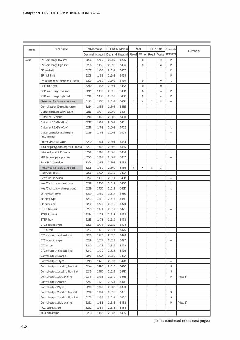
9-2
Chapter 9. LIST OF COMMUNICATION DATA
(To be continued to the next page.)
Bank Item name RAM address EEPROM address RAM EEPROM Decimal point RemarksDecimal Hexadecimal Decimal Hexadecimal Read Write Read Write information
Setup PV input range low limit 5205 1455 21589 5455 P
PV input range high limit 5206 1456 21590 5456 P
SP low limit 5207 1457 21591 5457 P
SP high limit 5208 1458 21592 5458 P
PV square root extraction dropout 5209 1459 21593 5459 1
RSP input type 5210 145A 21594 545A —
RSP input range low limit 5211 145B 21595 545B P
RSP input range high limit 5212 145C 21596 545C P
(Reserved for future extension.) 5213 145D 21597 545D ∆ X ∆ X —
Control action (Direct/Reverse) 5214 145E 21598 545E —
Output operation at PV alarm 5215 145F 21599 545F —
Output at PV alarm 5216 1460 21600 5460 1
Output at READY (Heat) 5217 1461 21601 5461 1
Output at READY (Cool) 5218 1462 21602 5462 1
Output operation at changing 5219 1463 21603 5463 —Auto/Manual
Preset MANUAL value 5220 1464 21604 5464 1
Initial output type (mode) of PID control 5221 1465 21605 5465 —
Initial output of PID control 5222 1466 21606 5466 1
PID decimal point position 5223 1467 21607 5467 —
Zone PID operation 5224 1468 21608 5468 —
(Reserved for future extension.) 5225 1469 21609 5469 ∆ X ∆ X —
Heat/Cool control 5226 146A 21610 546A —
Heat/Cool selection 5227 146B 21611 546B —
Heat/Cool control dead zone 5228 146C 21612 546C 1
Heat/Cool control change point 5229 146D 21613 546D 1
LSP system group 5230 146E 21614 546E —
SP ramp type 5231 146F 21615 546F —
SP ramp unit 5232 1470 21616 5470 —
STEP time unit 5233 1471 21617 5471 —
STEP PV start 5234 1472 21618 5472 —
STEP loop 5235 1473 21619 5473 —
CT1 operation type 5236 1474 21620 5474 —
CT1 output 5237 1475 21621 5475 —
CT1 measurement wait time 5238 1476 21622 5476 —
CT2 operation type 5239 1477 21623 5477 —
CT2 output 5240 1478 21624 5478 —
CT2 measurement wait time 5241 1479 21625 5479 —
Control output 1 range 5242 147A 21626 547A —
Control output 1 type 5243 147B 21627 547B —
Control output 1 scaling low limit 5244 147C 21628 547C S
Control output 1 scaling high limit 5245 147D 21629 547D S
Control output 1 MV scaling 5246 147E 21630 547E P (Note 1)
Control output 2 range 5247 147F 21631 547F —
Control output 2 type 5248 1480 21632 5480 —
Control output 2 scaling low limit 5249 1481 21633 5481 S
Control output 2 scaling high limit 5250 1482 21634 5482 S
Control output 2 MV scaling 5251 1483 21635 5483 P (Note 1)
AUX output range 5252 1484 21636 5484 —
AUX output type 5253 1485 21637 5485 —
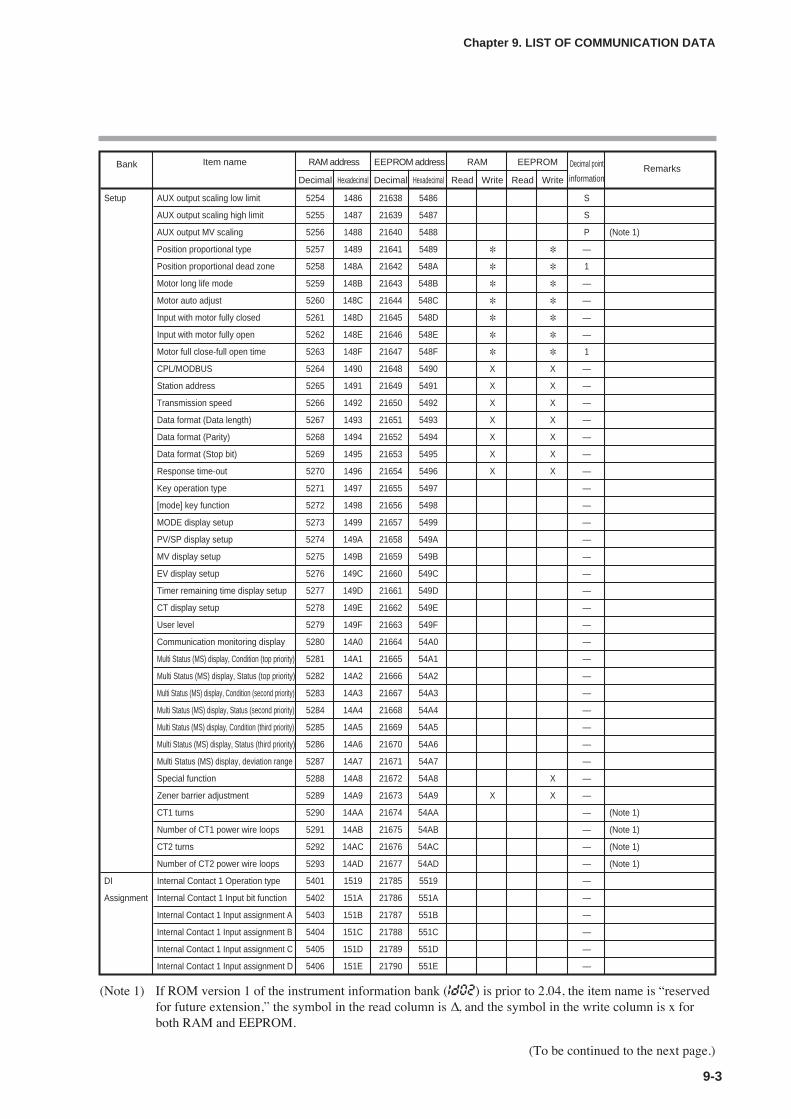
9-3
Chapter 9. LIST OF COMMUNICATION DATA
(To be continued to the next page.)
Bank Item name RAM address EEPROM address RAM EEPROM Decimal point RemarksDecimal Hexadecimal Decimal Hexadecimal Read Write Read Write information
Setup AUX output scaling low limit 5254 1486 21638 5486 S
AUX output scaling high limit 5255 1487 21639 5487 S
AUX output MV scaling 5256 1488 21640 5488 P (Note 1)
Position proportional type 5257 1489 21641 5489 —
Position proportional dead zone 5258 148A 21642 548A 1
Motor long life mode 5259 148B 21643 548B —
Motor auto adjust 5260 148C 21644 548C —
Input with motor fully closed 5261 148D 21645 548D —
Input with motor fully open 5262 148E 21646 548E —
Motor full close-full open time 5263 148F 21647 548F 1
CPL/MODBUS 5264 1490 21648 5490 X X —
Station address 5265 1491 21649 5491 X X —
Transmission speed 5266 1492 21650 5492 X X —
Data format (Data length) 5267 1493 21651 5493 X X —
Data format (Parity) 5268 1494 21652 5494 X X —
Data format (Stop bit) 5269 1495 21653 5495 X X —
Response time-out 5270 1496 21654 5496 X X —
Key operation type 5271 1497 21655 5497 —
[mode] key function 5272 1498 21656 5498 —
MODE display setup 5273 1499 21657 5499 —
PV/SP display setup 5274 149A 21658 549A —
MV display setup 5275 149B 21659 549B —
EV display setup 5276 149C 21660 549C —
Timer remaining time display setup 5277 149D 21661 549D —
CT display setup 5278 149E 21662 549E —
User level 5279 149F 21663 549F —
Communication monitoring display 5280 14A0 21664 54A0 —
Multi Status (MS) display, Condition (top priority) 5281 14A1 21665 54A1 —
Multi Status (MS) display, Status (top priority) 5282 14A2 21666 54A2 —
Multi Status (MS) display, Condition (second priority) 5283 14A3 21667 54A3 —
Multi Status (MS) display, Status (second priority) 5284 14A4 21668 54A4 —
Multi Status (MS) display, Condition (third priority) 5285 14A5 21669 54A5 —
Multi Status (MS) display, Status (third priority) 5286 14A6 21670 54A6 —
Multi Status (MS) display, deviation range 5287 14A7 21671 54A7 —
Special function 5288 14A8 21672 54A8 X —
Zener barrier adjustment 5289 14A9 21673 54A9 X X —
CT1 turns 5290 14AA 21674 54AA — (Note 1)
Number of CT1 power wire loops 5291 14AB 21675 54AB — (Note 1)
CT2 turns 5292 14AC 21676 54AC — (Note 1)
Number of CT2 power wire loops 5293 14AD 21677 54AD — (Note 1)
DI Internal Contact 1 Operation type 5401 1519 21785 5519 —
Assignment Internal Contact 1 Input bit function 5402 151A 21786 551A —
Internal Contact 1 Input assignment A 5403 151B 21787 551B —
Internal Contact 1 Input assignment B 5404 151C 21788 551C —
Internal Contact 1 Input assignment C 5405 151D 21789 551D —
Internal Contact 1 Input assignment D 5406 151E 21790 551E —
(Note 1) If ROM version 1 of the instrument information bank (Id02) is prior to 2.04, the item name is “reservedfor future extension,” the symbol in the read column is ∆, and the symbol in the write column is x forboth RAM and EEPROM.
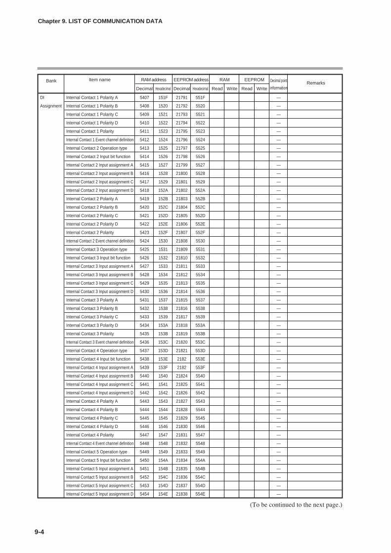
9-4
Chapter 9. LIST OF COMMUNICATION DATA
Bank Item name RAM address EEPROM address RAM EEPROM Decimal point RemarksDecimal Hexadecimal Decimal Hexadecimal Read Write Read Write information
DI Internal Contact 1 Polarity A 5407 151F 21791 551F —
Assignment Internal Contact 1 Polarity B 5408 1520 21792 5520 —
Internal Contact 1 Polarity C 5409 1521 21793 5521 —
Internal Contact 1 Polarity D 5410 1522 21794 5522 —
Internal Contact 1 Polarity 5411 1523 21795 5523 —
Internal Contact 1 Event channel definition 5412 1524 21796 5524 —
Internal Contact 2 Operation type 5413 1525 21797 5525 —
Internal Contact 2 Input bit function 5414 1526 21798 5526 —
Internal Contact 2 Input assignment A 5415 1527 21799 5527 —
Internal Contact 2 Input assignment B 5416 1528 21800 5528 —
Internal Contact 2 Input assignment C 5417 1529 21801 5529 —
Internal Contact 2 Input assignment D 5418 152A 21802 552A —
Internal Contact 2 Polarity A 5419 152B 21803 552B —
Internal Contact 2 Polarity B 5420 152C 21804 552C —
Internal Contact 2 Polarity C 5421 152D 21805 552D —
Internal Contact 2 Polarity D 5422 152E 21806 552E —
Internal Contact 2 Polarity 5423 152F 21807 552F —
Internal Contact 2 Event channel definition 5424 1530 21808 5530 —
Internal Contact 3 Operation type 5425 1531 21809 5531 —
Internal Contact 3 Input bit function 5426 1532 21810 5532 —
Internal Contact 3 Input assignment A 5427 1533 21811 5533 —
Internal Contact 3 Input assignment B 5428 1534 21812 5534 —
Internal Contact 3 Input assignment C 5429 1535 21813 5535 —
Internal Contact 3 Input assignment D 5430 1536 21814 5536 —
Internal Contact 3 Polarity A 5431 1537 21815 5537 —
Internal Contact 3 Polarity B 5432 1538 21816 5538 —
Internal Contact 3 Polarity C 5433 1539 21817 5539 —
Internal Contact 3 Polarity D 5434 153A 21818 553A —
Internal Contact 3 Polarity 5435 153B 21819 553B —
Internal Contact 3 Event channel definition 5436 153C 21820 553C —
Internal Contact 4 Operation type 5437 153D 21821 553D —
Internal Contact 4 Input bit function 5438 153E 2182 553E —
Internal Contact 4 Input assignment A 5439 153F 2182 553F —
Internal Contact 4 Input assignment B 5440 1540 21824 5540 —
Internal Contact 4 Input assignment C 5441 1541 21825 5541 —
Internal Contact 4 Input assignment D 5442 1542 21826 5542 —
Internal Contact 4 Polarity A 5443 1543 21827 5543 —
Internal Contact 4 Polarity B 5444 1544 21828 5544 —
Internal Contact 4 Polarity C 5445 1545 21829 5545 —
Internal Contact 4 Polarity D 5446 1546 21830 5546 —
Internal Contact 4 Polarity 5447 1547 21831 5547 —
Internal Contact 4 Event channel definition 5448 1548 21832 5548 —
Internal Contact 5 Operation type 5449 1549 21833 5549 —
Internal Contact 5 Input bit function 5450 154A 21834 554A —
Internal Contact 5 Input assignment A 5451 154B 21835 554B —
Internal Contact 5 Input assignment B 5452 154C 21836 554C —
Internal Contact 5 Input assignment C 5453 154D 21837 554D —
Internal Contact 5 Input assignment D 5454 154E 21838 554E —
(To be continued to the next page.)
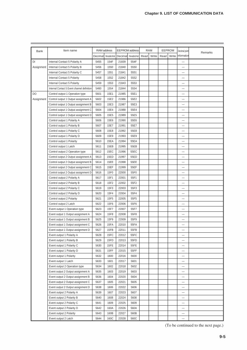
Bank Item name RAM address EEPROM address RAM EEPROM Decimal point RemarksDecimal Hexadecimal Decimal Hexadecimal Read Write Read Write information
DI Internal Contact 5 Polarity A 5455 154F 21839 554F —
Assignment Internal Contact 5 Polarity B 5456 1550 21840 5550 —
Internal Contact 5 Polarity C 5457 1551 21841 5551 —
Internal Contact 5 Polarity 5458 1552 21842 5552 —
Internal Contact 5 Polarity 5459 1553 21843 5553 —
Internal Contact 5 Event channel definition 5460 1554 21844 5554 —
DO Control output 1 Operation type 5601 15E1 21985 55E1 —
Assignment Control output 1 Output assignment A 5602 15E2 21986 55E2 —
Control output 1 Output assignment B 5603 15E3 21987 55E3 —
Control output 1 Output assignment C 5604 15E4 21988 55E4 —
Control output 1 Output assignment D 5605 15E5 21989 55E5 —
Control output 1 Polarity A 5606 15E6 21990 55E6 —
Control output 1 Polarity B 5607 15E7 21991 55E7 —
Control output 1 Polarity C 5608 15E8 21992 55E8 —
Control output 1 Polarity D 5609 15E9 21993 55E9 —
Control output 1 Polarity 5610 15EA 21994 55EA —
Control output 1 Latch 5611 15EB 21995 55EB —
Control output 2 Operation type 5612 15EC 21996 55EC —
Control output 2 Output assignment A 5613 15ED 21997 55ED —
Control output 2 Output assignment B 5614 15EE 21998 55EE —
Control output 2 Output assignment C 5615 15EF 21999 55EF —
Control output 2 Output assignment D 5616 15F0 22000 55F0 —
Control output 2 Polarity A 5617 15F1 22001 55F1 —
Control output 2 Polarity B 5618 15F2 22002 55F2 —
Control output 2 Polarity C 5619 15F3 22003 55F3 —
Control output 2 Polarity D 5620 15F4 22004 55F4 —
Control output 2 Polarity 5621 15F5 22005 55F5 —
Control output 2 Latch 5622 15F6 22006 55F6 —
Event output 1 Operation type 5623 15F7 22007 55F7 —
Event output 1 Output assignment A 5624 15F8 22008 55F8 —
Event output 1 Output assignment B 5625 15F9 22009 55F9 —
Event output 1 Output assignment C 5626 15FA 22010 55FA —
Event output 1 Output assignment D 5627 15FB 22011 55FB —
Event output 1 Polarity A 5628 15FC 22012 55FC —
Event output 1 Polarity B 5629 15FD 22013 55FD —
Event output 1 Polarity C 5630 15FE 22014 55FE —
Event output 1 Polarity D 5631 15FF 22015 55FF —
Event output 1 Polarity 5632 1600 22016 5600 —
Event output 1 Latch 5633 1601 22017 5601 —
Event output 2 Operation type 5634 1602 22018 5602 —
Event output 2 Output assignment A 5635 1603 22019 5603 —
Event output 2 Output assignment B 5636 1604 22020 5604 —
Event output 2 Output assignment C 5637 1605 22021 5605 —
Event output 2 Output assignment D 5638 1606 22022 5606 —
Event output 2 Polarity A 5639 1607 22023 5607 —
Event output 2 Polarity B 5640 1608 22024 5608 —
Event output 2 Polarity C 5641 1609 22025 5609 —
Event output 2 Polarity D 5642 160A 22026 560A —
Event output 2 Polarity 5643 160B 22027 560B —
Event output 2 Latch 5644 160C 22028 560C —
9-5
Chapter 9. LIST OF COMMUNICATION DATA
(To be continued to the next page.)
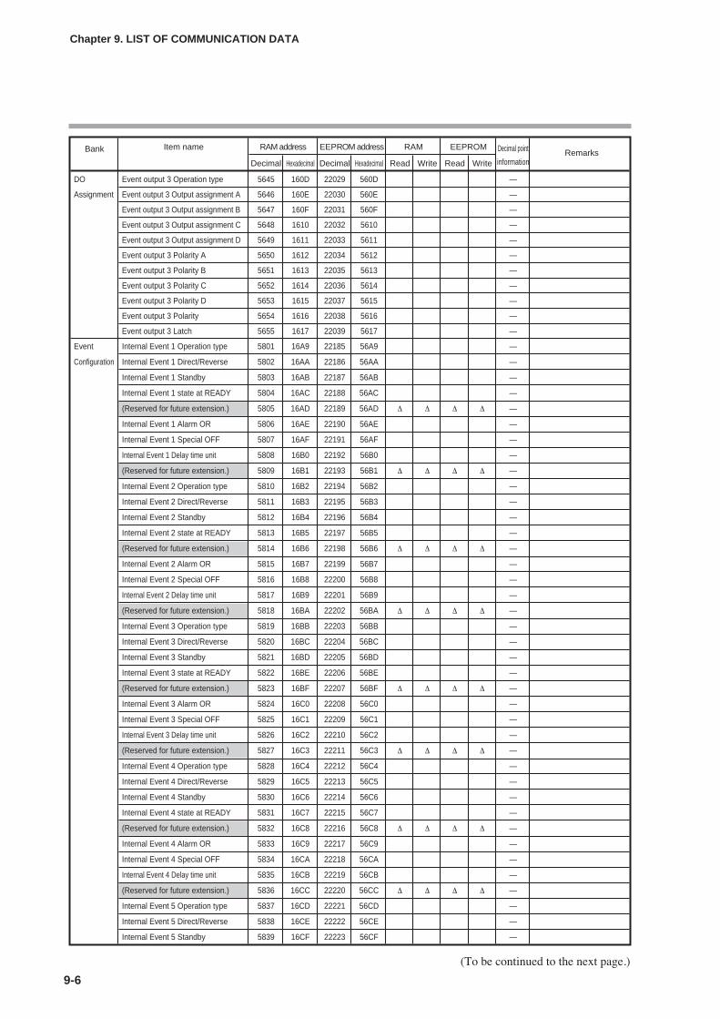
9-6
Chapter 9. LIST OF COMMUNICATION DATA
(To be continued to the next page.)
Bank Item name RAM address EEPROM address RAM EEPROM Decimal point RemarksDecimal Hexadecimal Decimal Hexadecimal Read Write Read Write information
DO Event output 3 Operation type 5645 160D 22029 560D —
Assignment Event output 3 Output assignment A 5646 160E 22030 560E —
Event output 3 Output assignment B 5647 160F 22031 560F —
Event output 3 Output assignment C 5648 1610 22032 5610 —
Event output 3 Output assignment D 5649 1611 22033 5611 —
Event output 3 Polarity A 5650 1612 22034 5612 —
Event output 3 Polarity B 5651 1613 22035 5613 —
Event output 3 Polarity C 5652 1614 22036 5614 —
Event output 3 Polarity D 5653 1615 22037 5615 —
Event output 3 Polarity 5654 1616 22038 5616 —
Event output 3 Latch 5655 1617 22039 5617 —
Event Internal Event 1 Operation type 5801 16A9 22185 56A9 —
Configuration Internal Event 1 Direct/Reverse 5802 16AA 22186 56AA —
Internal Event 1 Standby 5803 16AB 22187 56AB —
Internal Event 1 state at READY 5804 16AC 22188 56AC —
(Reserved for future extension.) 5805 16AD 22189 56AD ∆ ∆ ∆ ∆ —
Internal Event 1 Alarm OR 5806 16AE 22190 56AE —
Internal Event 1 Special OFF 5807 16AF 22191 56AF —
Internal Event 1 Delay time unit 5808 16B0 22192 56B0 —
(Reserved for future extension.) 5809 16B1 22193 56B1 ∆ ∆ ∆ ∆ —
Internal Event 2 Operation type 5810 16B2 22194 56B2 —
Internal Event 2 Direct/Reverse 5811 16B3 22195 56B3 —
Internal Event 2 Standby 5812 16B4 22196 56B4 —
Internal Event 2 state at READY 5813 16B5 22197 56B5 —
(Reserved for future extension.) 5814 16B6 22198 56B6 ∆ ∆ ∆ ∆ —
Internal Event 2 Alarm OR 5815 16B7 22199 56B7 —
Internal Event 2 Special OFF 5816 16B8 22200 56B8 —
Internal Event 2 Delay time unit 5817 16B9 22201 56B9 —
(Reserved for future extension.) 5818 16BA 22202 56BA ∆ ∆ ∆ ∆ —
Internal Event 3 Operation type 5819 16BB 22203 56BB —
Internal Event 3 Direct/Reverse 5820 16BC 22204 56BC —
Internal Event 3 Standby 5821 16BD 22205 56BD —
Internal Event 3 state at READY 5822 16BE 22206 56BE —
(Reserved for future extension.) 5823 16BF 22207 56BF ∆ ∆ ∆ ∆ —
Internal Event 3 Alarm OR 5824 16C0 22208 56C0 —
Internal Event 3 Special OFF 5825 16C1 22209 56C1 —
Internal Event 3 Delay time unit 5826 16C2 22210 56C2 —
(Reserved for future extension.) 5827 16C3 22211 56C3 ∆ ∆ ∆ ∆ —
Internal Event 4 Operation type 5828 16C4 22212 56C4 —
Internal Event 4 Direct/Reverse 5829 16C5 22213 56C5 —
Internal Event 4 Standby 5830 16C6 22214 56C6 —
Internal Event 4 state at READY 5831 16C7 22215 56C7 —
(Reserved for future extension.) 5832 16C8 22216 56C8 ∆ ∆ ∆ ∆ —
Internal Event 4 Alarm OR 5833 16C9 22217 56C9 —
Internal Event 4 Special OFF 5834 16CA 22218 56CA —
Internal Event 4 Delay time unit 5835 16CB 22219 56CB —
(Reserved for future extension.) 5836 16CC 22220 56CC ∆ ∆ ∆ ∆ —
Internal Event 5 Operation type 5837 16CD 22221 56CD —
Internal Event 5 Direct/Reverse 5838 16CE 22222 56CE —
Internal Event 5 Standby 5839 16CF 22223 56CF —
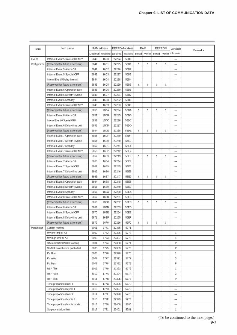
9-7
Chapter 9. LIST OF COMMUNICATION DATA
(To be continued to the next page.)
Bank Item name RAM address EEPROM address RAM EEPROM Decimal point RemarksDecimal Hexadecimal Decimal Hexadecimal Read Write Read Write information
Event Internal Event 5 state at READY 5840 16D0 22224 56D0 —
Configuration (Reserved for future extension.) 5841 16D1 22225 56D1 ∆ ∆ ∆ ∆ —
Internal Event 5 Alarm OR 5842 16D2 22226 56D2 —
Internal Event 5 Special OFF 5843 16D3 22227 56D3 —
Internal Event 5 Delay time unit 5844 16D4 22228 56D4 —
(Reserved for future extension.) 5845 16D5 22229 56D5 ∆ ∆ ∆ ∆ —
Internal Event 6 Operation type 5846 16D6 22230 56D6 —
Internal Event 6 Direct/Reverse 5847 16D7 22231 56D7 —
Internal Event 6 Standby 5848 16D8 22232 56D8 —
Internal Event 6 state at READY 5849 16D9 22233 56D9 —
(Reserved for future extension.) 5850 16DA 22234 56DA ∆ ∆ ∆ ∆ —
Internal Event 6 Alarm OR 5851 16DB 22235 56DB —
Internal Event 6 Special OFF 5852 16DC 22236 56DC —
Internal Event 6 Delay time unit 5853 16DD 22237 56DD —
(Reserved for future extension.) 5854 16DE 22238 56DE ∆ ∆ ∆ ∆ —
Internal Event 7 Operation type 5855 16DF 22239 56DF —
Internal Event 7 Direct/Reverse 5856 16E0 22240 56E0 —
Internal Event 7 Standby 5857 16E1 22241 56E1 —
Internal Event 7 state at READY 5858 16E2 22242 56E2 —
(Reserved for future extension.) 5859 16E3 22243 56E3 ∆ ∆ ∆ ∆ —
Internal Event 7 Alarm OR 5860 16E4 22244 56E4 —
Internal Event 7 Special OFF 5861 16E5 22245 56E5 —
Internal Event 7 Delay time unit 5862 16E6 22246 56E6 —
(Reserved for future extension.) 5863 16E7 22247 56E7 ∆ ∆ ∆ ∆ —
Internal Event 8 Operation type 5864 16E8 22248 56E8 —
Internal Event 8 Direct/Reverse 5865 16E9 22249 56E9 —
Internal Event 8 Standby 5866 16EA 22250 56EA —
Internal Event 8 state at READY 5867 16EB 22251 56EB —
(Reserved for future extension.) 5868 16EC 22252 56EC ∆ ∆ ∆ ∆ —
Internal Event 8 Alarm OR 5869 16ED 22253 56ED —
Internal Event 8 Special OFF 5870 16EE 22254 56EE —
Internal Event 8 Delay time unit 5871 16EF 22255 56EF —
(Reserved for future extension.) 5872 16F0 22256 56F0 ∆ ∆ ∆ ∆ —
Parameter Control method 6001 1771 22385 5771 —
MV low limit at AT 6002 1772 22386 5772 1
MV high limit at AT 6003 1773 22387 5773 1
Differential (for ON/OFF control) 6004 1774 22388 5774 P
ON/OFF control action point offset 6005 1775 22389 5775 P
PV filter 6006 1776 22390 5776 1
PV ratio 6007 1777 22391 5777 3
PV bias 6008 1778 22392 5778 P
RSP filter 6009 1779 22393 5779 1
RSP ratio 6010 177A 22394 577A 3
RSP bias 6011 177B 22395 577B P
Time proportional unit 1 6012 177C 22396 577C —
Time proportional cycle 1 6013 177D 22397 577D —
Time proportional unit 2 6014 177E 22398 577E —
Time proportional cycle 2 6015 177F 22399 577F —
Time proportional cycle mode 6016 1780 22400 5780 —
Output variation limit 6017 1781 22401 5781 1
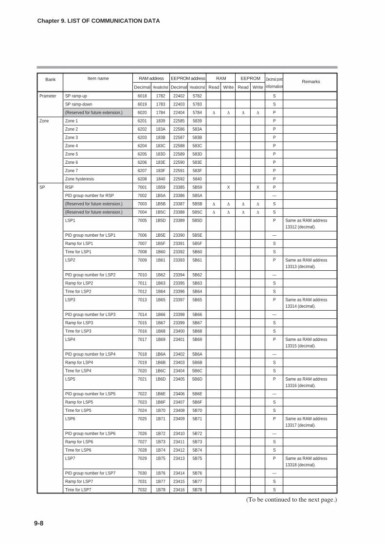
9-8
Chapter 9. LIST OF COMMUNICATION DATA
(To be continued to the next page.)
Bank Item name RAM address EEPROM address RAM EEPROM Decimal point RemarksDecimal Hexadecimal Decimal Hexadecimal Read Write Read Write information
Prameter SP ramp-up 6018 1782 22402 5782 S
SP ramp-down 6019 1783 22403 5783 S
(Reserved for future extension.) 6020 1784 22404 5784 ∆ ∆ ∆ ∆ P
Zone Zone 1 6201 1839 22585 5839 P
Zone 2 6202 183A 22586 583A P
Zone 3 6203 183B 22587 583B P
Zone 4 6204 183C 22588 583C P
Zone 5 6205 183D 22589 583D P
Zone 6 6206 183E 22590 583E P
Zone 7 6207 183F 22591 583F P
Zone hysteresis 6208 1840 22592 5840 P
SP RSP 7001 1B59 23385 5B59 X X P
PID group number for RSP 7002 1B5A 23386 5B5A —
(Reserved for future extension.) 7003 1B5B 23387 5B5B ∆ ∆ ∆ ∆ S
(Reserved for future extension.) 7004 1B5C 23388 5B5C ∆ ∆ ∆ ∆ S
LSP1 7005 1B5D 23389 5B5D P Same as RAM address13312 (decimal).
PID group number for LSP1 7006 1B5E 23390 5B5E —
Ramp for LSP1 7007 1B5F 23391 5B5F S
Time for LSP1 7008 1B60 23392 5B60 S
LSP2 7009 1B61 23393 5B61 P Same as RAM address13313 (decimal).
PID group number for LSP2 7010 1B62 23394 5B62 —
Ramp for LSP2 7011 1B63 23395 5B63 S
Time for LSP2 7012 1B64 23396 5B64 S
LSP3 7013 1B65 23397 5B65 P Same as RAM address13314 (decimal).
PID group number for LSP3 7014 1B66 23398 5B66 —
Ramp for LSP3 7015 1B67 23399 5B67 S
Time for LSP3 7016 1B68 23400 5B68 S
LSP4 7017 1B69 23401 5B69 P Same as RAM address13315 (decimal).
PID group number for LSP4 7018 1B6A 23402 5B6A —
Ramp for LSP4 7019 1B6B 23403 5B6B S
Time for LSP4 7020 1B6C 23404 5B6C S
LSP5 7021 1B6D 23405 5B6D P Same as RAM address13316 (decimal).
PID group number for LSP5 7022 1B6E 23406 5B6E —
Ramp for LSP5 7023 1B6F 23407 5B6F S
Time for LSP5 7024 1B70 23408 5B70 S
LSP6 7025 1B71 23409 5B71 P Same as RAM address13317 (decimal).
PID group number for LSP6 7026 1B72 23410 5B72 —
Ramp for LSP6 7027 1B73 23411 5B73 S
Time for LSP6 7028 1B74 23412 5B74 S
LSP7 7029 1B75 23413 5B75 P Same as RAM address13318 (decimal).
PID group number for LSP7 7030 1B76 23414 5B76 —
Ramp for LSP7 7031 1B77 23415 5B77 S
Time for LSP7 7032 1B78 23416 5B78 S
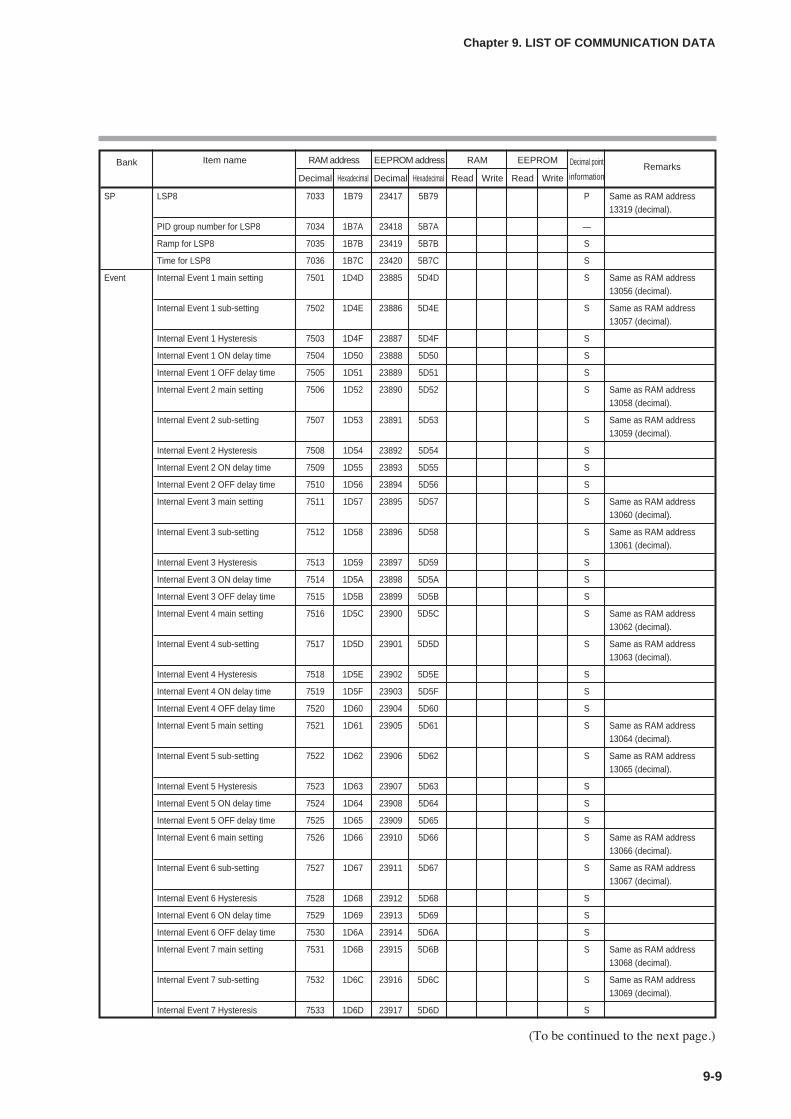
9-9
Chapter 9. LIST OF COMMUNICATION DATA
Bank Item name RAM address EEPROM address RAM EEPROM Decimal point RemarksDecimal Hexadecimal Decimal Hexadecimal Read Write Read Write information
SP LSP8 7033 1B79 23417 5B79 P Same as RAM address13319 (decimal).
PID group number for LSP8 7034 1B7A 23418 5B7A —
Ramp for LSP8 7035 1B7B 23419 5B7B S
Time for LSP8 7036 1B7C 23420 5B7C S
Event Internal Event 1 main setting 7501 1D4D 23885 5D4D S Same as RAM address13056 (decimal).
Internal Event 1 sub-setting 7502 1D4E 23886 5D4E S Same as RAM address13057 (decimal).
Internal Event 1 Hysteresis 7503 1D4F 23887 5D4F S
Internal Event 1 ON delay time 7504 1D50 23888 5D50 S
Internal Event 1 OFF delay time 7505 1D51 23889 5D51 S
Internal Event 2 main setting 7506 1D52 23890 5D52 S Same as RAM address13058 (decimal).
Internal Event 2 sub-setting 7507 1D53 23891 5D53 S Same as RAM address13059 (decimal).
Internal Event 2 Hysteresis 7508 1D54 23892 5D54 S
Internal Event 2 ON delay time 7509 1D55 23893 5D55 S
Internal Event 2 OFF delay time 7510 1D56 23894 5D56 S
Internal Event 3 main setting 7511 1D57 23895 5D57 S Same as RAM address13060 (decimal).
Internal Event 3 sub-setting 7512 1D58 23896 5D58 S Same as RAM address13061 (decimal).
Internal Event 3 Hysteresis 7513 1D59 23897 5D59 S
Internal Event 3 ON delay time 7514 1D5A 23898 5D5A S
Internal Event 3 OFF delay time 7515 1D5B 23899 5D5B S
Internal Event 4 main setting 7516 1D5C 23900 5D5C S Same as RAM address13062 (decimal).
Internal Event 4 sub-setting 7517 1D5D 23901 5D5D S Same as RAM address13063 (decimal).
Internal Event 4 Hysteresis 7518 1D5E 23902 5D5E S
Internal Event 4 ON delay time 7519 1D5F 23903 5D5F S
Internal Event 4 OFF delay time 7520 1D60 23904 5D60 S
Internal Event 5 main setting 7521 1D61 23905 5D61 S Same as RAM address13064 (decimal).
Internal Event 5 sub-setting 7522 1D62 23906 5D62 S Same as RAM address13065 (decimal).
Internal Event 5 Hysteresis 7523 1D63 23907 5D63 S
Internal Event 5 ON delay time 7524 1D64 23908 5D64 S
Internal Event 5 OFF delay time 7525 1D65 23909 5D65 S
Internal Event 6 main setting 7526 1D66 23910 5D66 S Same as RAM address13066 (decimal).
Internal Event 6 sub-setting 7527 1D67 23911 5D67 S Same as RAM address13067 (decimal).
Internal Event 6 Hysteresis 7528 1D68 23912 5D68 S
Internal Event 6 ON delay time 7529 1D69 23913 5D69 S
Internal Event 6 OFF delay time 7530 1D6A 23914 5D6A S
Internal Event 7 main setting 7531 1D6B 23915 5D6B S Same as RAM address13068 (decimal).
Internal Event 7 sub-setting 7532 1D6C 23916 5D6C S Same as RAM address13069 (decimal).
Internal Event 7 Hysteresis 7533 1D6D 23917 5D6D S
(To be continued to the next page.)

9-10
Chapter 9. LIST OF COMMUNICATION DATA
(To be continued to the next page.)
Bank Item name RAM address EEPROM address RAM EEPROM Decimal point RemarksDecimal Hexadecimal Decimal Hexadecimal Read Write Read Write information
Event Internal Event 7 ON delay time 7534 1D6E 23918 5D6E S
Internal Event 7 OFF delay time 7535 1D6F 23919 5D6F S
Internal Event 8 main setting 7536 1D70 23920 5D70 S Same as RAM address13070 (decimal).
Internal Event 8 sub-setting 7537 1D71 23921 5D71 S Same as RAM address13071 (decimal).
Internal Event 8 Hysteresis 7538 1D72 23922 5D72 S
Internal Event 8 ON delay time 7539 1D73 23923 5D73 S
Internal Event 8 OFF delay time 7540 1D74 23924 5D74 S
Extended AT type 8501 2135 24885 6135 —
tuning (Reserved for future extension.) 8502 2136 24886 6136 ∆ X ∆ X —
Just-FiTTER settling band 8503 2137 24887 6137 —
SP lag constant 8504 2138 24888 6138 1
(Reserved for future extension.) 8505 2139 24889 6139 ∆ X ∆ X —
AT Proportional band adjust 8506 213A 24890 613A 2
AT Integral time adjust 8507 213B 24891 613B 2
AT Derivative time adjust 8508 213C 24892 613C 2
Control algorithm 8509 213D 24893 613D —
Just-FiTTER overshoot limit/restraint/ 8510 213E 24894 613E —control coefficient
(Reserved for future extension.) 8511 213F 24895 613F ∆ X ∆ X —
(Reserved for future extension.) 8512 2140 24896 6140 ∆ X ∆ X —
(Reserved for future extension.) 8513 2141 24897 6141 ∆ X ∆ X —
(Reserved for future extension.) 8514 2142 24898 6142 ∆ X ∆ X —
(Reserved for future extension.) 8515 2143 24899 6143 ∆ ∆ ∆ ∆ 2
(Reserved for future extension.) 8516 2144 24900 6144 ∆ ∆ ∆ ∆ 2
(Reserved for future extension.) 8517 2145 24901 6145 ∆ ∆ ∆ ∆ 2
(Reserved for future extension.) 8518 2146 24902 6146 ∆ ∆ ∆ ∆ —
Mode AUTO/MANUAL 9001 2329 25385 6329 — Same as RAM address 14596 (decimal). Writing isenabled under no DIAssignment and otherconditions.
RUN/READY 9002 232A 25386 632A — Same as RAM address14595 (decimal). Writing isenabled under no DIAssignment conditions.
LSP/RSP 9003 232B 25387 632B — Same as RAM address14598 (decimal). Writing isenabled under no DIAssignment conditions.
AT stop/start 9004 232C 25388 632C — Same as RAM address 14597 (decimal). Writing isenabled under no DIAssignment and otherconditions.
Release all DO latches 9005 232D 25389 632D — Writing is enabled under noDI Assignment conditions.
Operation PV 9101 238D 25485 638D X X P Same as RAM address display 14356 (decimal).
SP (Target value) 9102 238E 25486 638E P (Note 1)
LSP group selection 9103 238F 25487 638F — Same as RAM address14592 (decimal). Writing isenabled under no DIAssignment conditions.(Note 2)
PID group being selected. 9104 2390 25488 6390 X X —
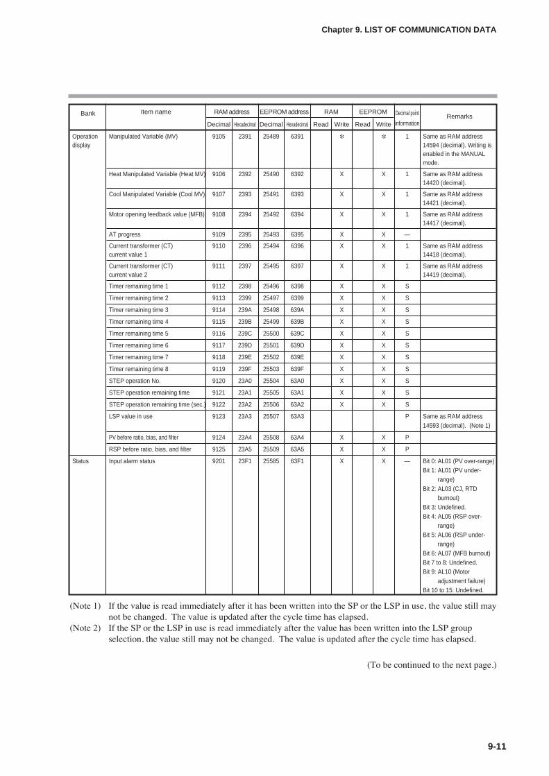
9-11
Chapter 9. LIST OF COMMUNICATION DATA
(Note 1) If the value is read immediately after it has been written into the SP or the LSP in use, the value still maynot be changed. The value is updated after the cycle time has elapsed.
(Note 2) If the SP or the LSP in use is read immediately after the value has been written into the LSP groupselection, the value still may not be changed. The value is updated after the cycle time has elapsed.
(To be continued to the next page.)
Bank Item name RAM address EEPROM address RAM EEPROM Decimal point RemarksDecimal Hexadecimal Decimal Hexadecimal Read Write Read Write information
Operation Manipulated Variable (MV) 9105 2391 25489 6391 1 Same as RAM address display 14594 (decimal). Writing is
enabled in the MANUALmode.
Heat Manipulated Variable (Heat MV) 9106 2392 25490 6392 X X 1 Same as RAM address14420 (decimal).
Cool Manipulated Variable (Cool MV) 9107 2393 25491 6393 X X 1 Same as RAM address14421 (decimal).
Motor opening feedback value (MFB) 9108 2394 25492 6394 X X 1 Same as RAM address 14417 (decimal).
AT progress 9109 2395 25493 6395 X X —
Current transformer (CT) 9110 2396 25494 6396 X X 1 Same as RAM addresscurrent value 1 14418 (decimal).
Current transformer (CT) 9111 2397 25495 6397 X X 1 Same as RAM addresscurrent value 2 14419 (decimal).
Timer remaining time 1 9112 2398 25496 6398 X X S
Timer remaining time 2 9113 2399 25497 6399 X X S
Timer remaining time 3 9114 239A 25498 639A X X S
Timer remaining time 4 9115 239B 25499 639B X X S
Timer remaining time 5 9116 239C 25500 639C X X S
Timer remaining time 6 9117 239D 25501 639D X X S
Timer remaining time 7 9118 239E 25502 639E X X S
Timer remaining time 8 9119 239F 25503 639F X X S
STEP operation No. 9120 23A0 25504 63A0 X X S
STEP operation remaining time 9121 23A1 25505 63A1 X X S
STEP operation remaining time (sec.) 9122 23A2 25506 63A2 X X S
LSP value in use 9123 23A3 25507 63A3 P Same as RAM address14593 (decimal). (Note 1)
PV before ratio, bias, and filter 9124 23A4 25508 63A4 X X P
RSP before ratio, bias, and filter 9125 23A5 25509 63A5 X X P
Status Input alarm status 9201 23F1 25585 63F1 X X — Bit 0: AL01 (PV over-range)Bit 1: AL01 (PV under-
range)Bit 2: AL03 (CJ, RTD
burnout)Bit 3: Undefined.Bit 4: AL05 (RSP over-
range)Bit 5: AL06 (RSP under-
range)Bit 6: AL07 (MFB burnout)Bit 7 to 8: Undefined.Bit 9: AL10 (Motor
adjustment failure)Bit 10 to 15: Undefined.
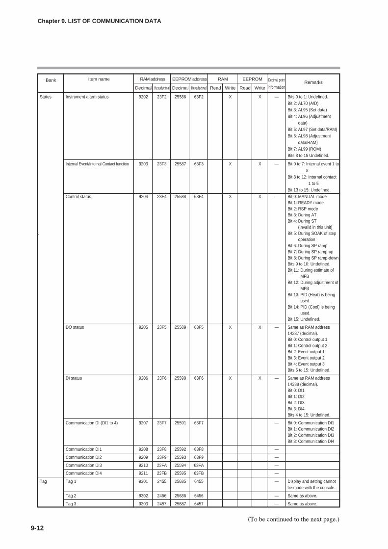
9-12
Chapter 9. LIST OF COMMUNICATION DATA
Bank Item name RAM address EEPROM address RAM EEPROM Decimal point RemarksDecimal Hexadecimal Decimal Hexadecimal Read Write Read Write information
Status Instrument alarm status 9202 23F2 25586 63F2 X X — Bits 0 to 1: Undefined.Bit 2: AL70 (A/D)Bit 3: AL95 (Set data)Bit 4: AL96 (Adjustment
data)Bit 5: AL97 (Set data/RAM)Bit 6: AL98 (Adjustment
data/RAM)Bit 7: AL99 (ROM)Bits 8 to 15 Undefined.
Internal Event/Internal Contact function 9203 23F3 25587 63F3 X X — Bit 0 to 7: Internal event 1 to8
Bit 8 to 12: Internal contact1 to 5
Bit 13 to 15: Undefined.Control status 9204 23F4 25588 63F4 X X — Bit 0: MANUAL mode
Bit 1: READY modeBit 2: RSP modeBit 3: During ATBit 4: During ST
(Invalid in this unit). Bit 5: During SOAK of step
operationBit 6: During SP rampBit 7: During SP ramp-upBit 8: During SP ramp-downBits 9 to 10: Undefined.Bit 11: During estimate of
MFBBit 12: During adjustment of
MFBBit 13: PID (Heat) is being
used.Bit 14: PID (Cool) is being
used.Bit 15: Undefined.
DO status 9205 23F5 25589 63F5 X X — Same as RAM address14337 (decimal).Bit 0: Control output 1Bit 1: Control output 2Bit 2: Event output 1Bit 3: Event output 2Bit 4: Event output 3Bits 5 to 15: Undefined.
DI status 9206 23F6 25590 63F6 X X — Same as RAM address14338 (decimal).Bit 0: DI1Bit 1: DI2Bit 2: DI3Bit 3: DI4Bits 4 to 15: Undefined.
Communication DI (DI1 to 4) 9207 23F7 25591 63F7 — Bit 0: Communication DI1Bit 1: Communication DI2Bit 2: Communication DI3Bit 3: Communication DI4
Communication DI1 9208 23F8 25592 63F8 —
Communication DI2 9209 23F9 25593 63F9 —
Communication DI3 9210 23FA 25594 63FA —
Communication DI4 9211 23FB 25595 63FB —
Tag Tag 1 9301 2455 25685 6455 — Display and setting cannotbe made with the console.
Tag 2 9302 2456 25686 6456 — Same as above.
Tag 3 9303 2457 25687 6457 — Same as above.
(To be continued to the next page.)
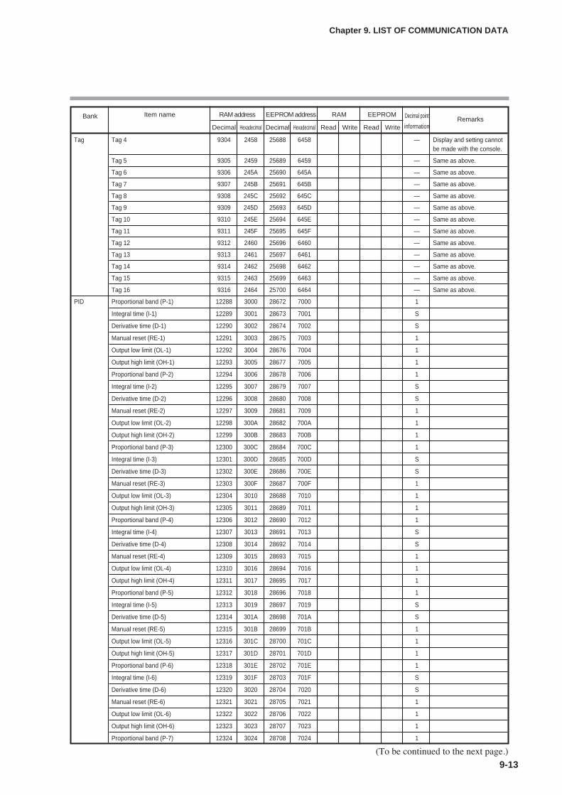
9-13
Chapter 9. LIST OF COMMUNICATION DATA
Bank Item name RAM address EEPROM address RAM EEPROM Decimal point RemarksDecimal Hexadecimal Decimal Hexadecimal Read Write Read Write information
Tag Tag 4 9304 2458 25688 6458 — Display and setting cannotbe made with the console.
Tag 5 9305 2459 25689 6459 — Same as above.
Tag 6 9306 245A 25690 645A — Same as above.
Tag 7 9307 245B 25691 645B — Same as above.
Tag 8 9308 245C 25692 645C — Same as above.
Tag 9 9309 245D 25693 645D — Same as above.
Tag 10 9310 245E 25694 645E — Same as above.
Tag 11 9311 245F 25695 645F — Same as above.
Tag 12 9312 2460 25696 6460 — Same as above.
Tag 13 9313 2461 25697 6461 — Same as above.
Tag 14 9314 2462 25698 6462 — Same as above.
Tag 15 9315 2463 25699 6463 — Same as above.
Tag 16 9316 2464 25700 6464 — Same as above.
PID Proportional band (P-1) 12288 3000 28672 7000 1
Integral time (I-1) 12289 3001 28673 7001 S
Derivative time (D-1) 12290 3002 28674 7002 S
Manual reset (RE-1) 12291 3003 28675 7003 1
Output low limit (OL-1) 12292 3004 28676 7004 1
Output high limit (OH-1) 12293 3005 28677 7005 1
Proportional band (P-2) 12294 3006 28678 7006 1
Integral time (I-2) 12295 3007 28679 7007 S
Derivative time (D-2) 12296 3008 28680 7008 S
Manual reset (RE-2) 12297 3009 28681 7009 1
Output low limit (OL-2) 12298 300A 28682 700A 1
Output high limit (OH-2) 12299 300B 28683 700B 1
Proportional band (P-3) 12300 300C 28684 700C 1
Integral time (I-3) 12301 300D 28685 700D S
Derivative time (D-3) 12302 300E 28686 700E S
Manual reset (RE-3) 12303 300F 28687 700F 1
Output low limit (OL-3) 12304 3010 28688 7010 1
Output high limit (OH-3) 12305 3011 28689 7011 1
Proportional band (P-4) 12306 3012 28690 7012 1
Integral time (I-4) 12307 3013 28691 7013 S
Derivative time (D-4) 12308 3014 28692 7014 S
Manual reset (RE-4) 12309 3015 28693 7015 1
Output low limit (OL-4) 12310 3016 28694 7016 1
Output high limit (OH-4) 12311 3017 28695 7017 1
Proportional band (P-5) 12312 3018 28696 7018 1
Integral time (I-5) 12313 3019 28697 7019 S
Derivative time (D-5) 12314 301A 28698 701A S
Manual reset (RE-5) 12315 301B 28699 701B 1
Output low limit (OL-5) 12316 301C 28700 701C 1
Output high limit (OH-5) 12317 301D 28701 701D 1
Proportional band (P-6) 12318 301E 28702 701E 1
Integral time (I-6) 12319 301F 28703 701F S
Derivative time (D-6) 12320 3020 28704 7020 S
Manual reset (RE-6) 12321 3021 28705 7021 1
Output low limit (OL-6) 12322 3022 28706 7022 1
Output high limit (OH-6) 12323 3023 28707 7023 1
Proportional band (P-7) 12324 3024 28708 7024 1
(To be continued to the next page.)
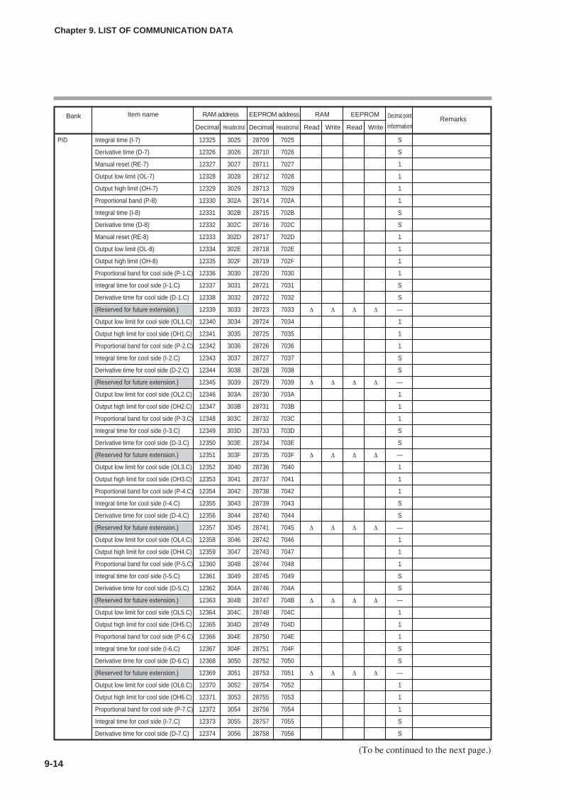
9-14
Chapter 9. LIST OF COMMUNICATION DATA
(To be continued to the next page.)
Bank Item name RAM address EEPROM address RAM EEPROM Decimal point RemarksDecimal Hexadecimal Decimal Hexadecimal Read Write Read Write information
PID Integral time (I-7) 12325 3025 28709 7025 S
Derivative time (D-7) 12326 3026 28710 7026 S
Manual reset (RE-7) 12327 3027 28711 7027 1
Output low limit (OL-7) 12328 3028 28712 7028 1
Output high limit (OH-7) 12329 3029 28713 7029 1
Proportional band (P-8) 12330 302A 28714 702A 1
Integral time (I-8) 12331 302B 28715 702B S
Derivative time (D-8) 12332 302C 28716 702C S
Manual reset (RE-8) 12333 302D 28717 702D 1
Output low limit (OL-8) 12334 302E 28718 702E 1
Output high limit (OH-8) 12335 302F 28719 702F 1
Proportional band for cool side (P-1.C) 12336 3030 28720 7030 1
Integral time for cool side (I-1.C) 12337 3031 28721 7031 S
Derivative time for cool side (D-1.C) 12338 3032 28722 7032 S
(Reserved for future extension.) 12339 3033 28723 7033 ∆ ∆ ∆ ∆ —
Output low limit for cool side (OL1.C) 12340 3034 28724 7034 1
Output high limit for cool side (OH1.C) 12341 3035 28725 7035 1
Proportional band for cool side (P-2.C) 12342 3036 28726 7036 1
Integral time for cool side (I-2.C) 12343 3037 28727 7037 S
Derivative time for cool side (D-2.C) 12344 3038 28728 7038 S
(Reserved for future extension.) 12345 3039 28729 7039 ∆ ∆ ∆ ∆ —
Output low limit for cool side (OL2.C) 12346 303A 28730 703A 1
Output high limit for cool side (OH2.C) 12347 303B 28731 703B 1
Proportional band for cool side (P-3.C) 12348 303C 28732 703C 1
Integral time for cool side (I-3.C) 12349 303D 28733 703D S
Derivative time for cool side (D-3.C) 12350 303E 28734 703E S
(Reserved for future extension.) 12351 303F 28735 703F ∆ ∆ ∆ ∆ —
Output low limit for cool side (OL3.C) 12352 3040 28736 7040 1
Output high limit for cool side (OH3.C) 12353 3041 28737 7041 1
Proportional band for cool side (P-4.C) 12354 3042 28738 7042 1
Integral time for cool side (I-4.C) 12355 3043 28739 7043 S
Derivative time for cool side (D-4.C) 12356 3044 28740 7044 S
(Reserved for future extension.) 12357 3045 28741 7045 ∆ ∆ ∆ ∆ —
Output low limit for cool side (OL4.C) 12358 3046 28742 7046 1
Output high limit for cool side (OH4.C) 12359 3047 28743 7047 1
Proportional band for cool side (P-5.C) 12360 3048 28744 7048 1
Integral time for cool side (I-5.C) 12361 3049 28745 7049 S
Derivative time for cool side (D-5.C) 12362 304A 28746 704A S
(Reserved for future extension.) 12363 304B 28747 704B ∆ ∆ ∆ ∆ —
Output low limit for cool side (OL5.C) 12364 304C 28748 704C 1
Output high limit for cool side (OH5.C) 12365 304D 28749 704D 1
Proportional band for cool side (P-6.C) 12366 304E 28750 704E 1
Integral time for cool side (I-6.C) 12367 304F 28751 704F S
Derivative time for cool side (D-6.C) 12368 3050 28752 7050 S
(Reserved for future extension.) 12369 3051 28753 7051 ∆ ∆ ∆ ∆ —
Output low limit for cool side (OL6.C) 12370 3052 28754 7052 1
Output high limit for cool side (OH6.C) 12371 3053 28755 7053 1
Proportional band for cool side (P-7.C) 12372 3054 28756 7054 1
Integral time for cool side (I-7.C) 12373 3055 28757 7055 S
Derivative time for cool side (D-7.C) 12374 3056 28758 7056 S

Bank Item name RAM address EEPROM address RAM EEPROM Decimal point RemarksDecimal Hexadecimal Decimal Hexadecimal Read Write Read Write information
PID (Reserved for future extension.) 12375 3057 28759 7057 ∆ ∆ ∆ ∆ —
Output low limit for cool side (OL7.C) 12376 3058 28760 7058 1
Output high limit for cool side (OH7.C) 12377 3059 28761 7059 1
Proportional band for cool side (P-8.C) 12378 305A 28762 705A 1
Integral time for cool side (I-8.C) 12379 305B 28763 705B S
Derivative time for cool side (D-8.C) 12380 305C 28764 705C S
(Reserved for future extension.) 12381 305D 28765 705D ∆ ∆ ∆ ∆ —
Output low limit for cool side (OL8.C) 12382 305E 28766 705E 1
Output high limit for cool side (OH8.C) 12383 305F 28767 705F 1
Event Internal Event 1 main setting 13056 3300 29440 7300 S
Internal Event 1 sub-setting 13057 3301 29441 7301 S
Internal Event 2 main setting 13058 3302 29442 7302 S
Internal Event 2 sub-setting 13059 3303 29443 7303 S
Internal Event 3 main setting 13060 3304 29444 7304 S
Internal Event 3 sub-setting 13061 3305 29445 7305 S
Internal Event 4 main setting 13062 3306 29446 7306 S
Internal Event 4 sub-setting 13063 3307 29447 7307 S
Internal Event 5 main setting 13064 3308 29448 7308 S
Internal Event 5 sub-setting 13065 3309 29449 7309 S
Internal Event 6 main setting 13066 330A 29450 730A S
Internal Event 6 sub-setting 13067 330B 29451 730B S
Internal Event 7 main setting 13068 330C 29452 730C S
Internal Event 7 sub-setting 13069 330D 29453 730D S
Internal Event 8 main setting 13070 330E 29454 730E S
Internal Event 8 sub-setting 13071 330F 29455 730F S
LSP LSP1 13312 3400 29696 7400 P
LSP2 13313 3401 29697 7401 P
LSP3 13314 3402 29698 7402 P
LSP4 13315 3403 29699 7403 P
LSP5 13316 3404 29700 7404 P
LSP6 13317 3405 29701 7405 P
LSP7 13318 3406 29702 7406 P
LSP8 13319 3407 29703 7407 P
Instrument Typical alarm 14336 3800 30720 7800 X X — Bit 0: PV failure (AL01 to status 1 03)
Bits 1 to 11: Undefined.Bit 12: Hardware failure
(AL70)Bit 13: Parameter failure
(AL95/97)Bit 14: Adjustment data
failure (AL96/98)Bit 15: ROM failure (AL99)
DO status 14337 3801 30721 7801 X X — Same as RAM address9205 (decimal).
DI status 14338 3802 30722 7802 X X — Same as RAM address9206 (decimal).
9-15
Chapter 9. LIST OF COMMUNICATION DATA
(To be continued to the next page.)
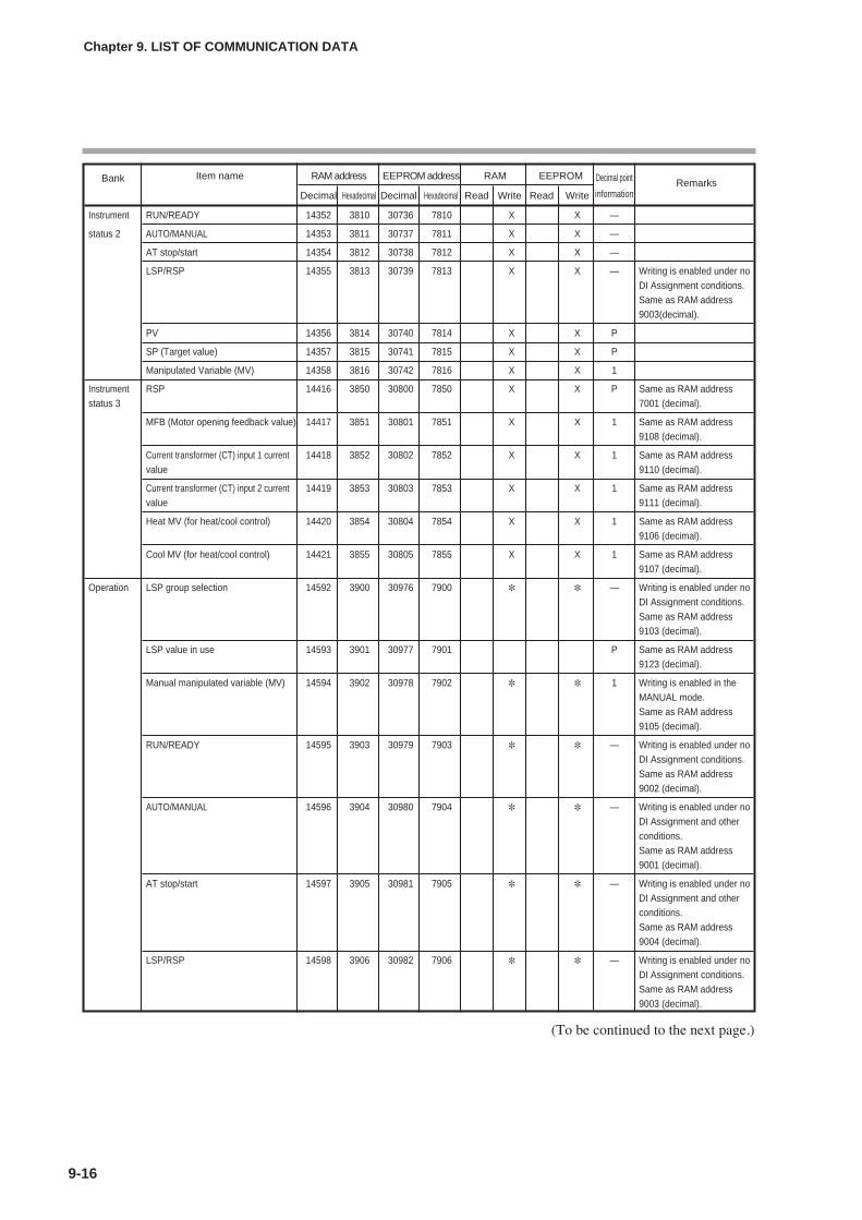
9-16
Chapter 9. LIST OF COMMUNICATION DATA
Bank Item name RAM address EEPROM address RAM EEPROM Decimal point RemarksDecimal Hexadecimal Decimal Hexadecimal Read Write Read Write information
Instrument RUN/READY 14352 3810 30736 7810 X X —
status 2 AUTO/MANUAL 14353 3811 30737 7811 X X —
AT stop/start 14354 3812 30738 7812 X X —
LSP/RSP 14355 3813 30739 7813 X X — Writing is enabled under noDI Assignment conditions.Same as RAM address9003(decimal).
PV 14356 3814 30740 7814 X X P
SP (Target value) 14357 3815 30741 7815 X X P
Manipulated Variable (MV) 14358 3816 30742 7816 X X 1
Instrument RSP 14416 3850 30800 7850 X X P Same as RAM address status 3 7001 (decimal).
MFB (Motor opening feedback value) 14417 3851 30801 7851 X X 1 Same as RAM address9108 (decimal).
Current transformer (CT) input 1 current 14418 3852 30802 7852 X X 1 Same as RAM address value 9110 (decimal).
Current transformer (CT) input 2 current 14419 3853 30803 7853 X X 1 Same as RAM address value 9111 (decimal).
Heat MV (for heat/cool control) 14420 3854 30804 7854 X X 1 Same as RAM address9106 (decimal).
Cool MV (for heat/cool control) 14421 3855 30805 7855 X X 1 Same as RAM address9107 (decimal).
Operation LSP group selection 14592 3900 30976 7900 — Writing is enabled under noDI Assignment conditions.Same as RAM address9103 (decimal).
LSP value in use 14593 3901 30977 7901 P Same as RAM address9123 (decimal).
Manual manipulated variable (MV) 14594 3902 30978 7902 1 Writing is enabled in theMANUAL mode.Same as RAM address9105 (decimal).
RUN/READY 14595 3903 30979 7903 — Writing is enabled under noDI Assignment conditions.Same as RAM address9002 (decimal).
AUTO/MANUAL 14596 3904 30980 7904 — Writing is enabled under noDI Assignment and otherconditions.Same as RAM address9001 (decimal).
AT stop/start 14597 3905 30981 7905 — Writing is enabled under noDI Assignment and otherconditions.Same as RAM address9004 (decimal).
LSP/RSP 14598 3906 30982 7906 — Writing is enabled under no DI Assignment conditions.Same as RAM address9003 (decimal).
(To be continued to the next page.)
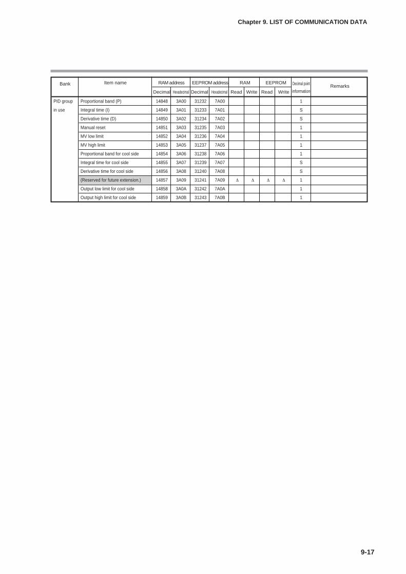
9-17
Chapter 9. LIST OF COMMUNICATION DATA
Bank Item name RAM address EEPROM address RAM EEPROM Decimal point RemarksDecimal Hexadecimal Decimal Hexadecimal Read Write Read Write information
PID group Proportional band (P) 14848 3A00 31232 7A00 1
in use Integral time (I) 14849 3A01 31233 7A01 S
Derivative time (D) 14850 3A02 31234 7A02 S
Manual reset 14851 3A03 31235 7A03 1
MV low limit 14852 3A04 31236 7A04 1
MV high limit 14853 3A05 31237 7A05 1
Proportional band for cool side 14854 3A06 31238 7A06 1
Integral time for cool side 14855 3A07 31239 7A07 S
Derivative time for cool side 14856 3A08 31240 7A08 S
(Reserved for future extension.) 14857 3A09 31241 7A09 ∆ ∆ ∆ ∆ 1
Output low limit for cool side 14858 3A0A 31242 7A0A 1
Output high limit for cool side 14859 3A0B 31243 7A0B 1

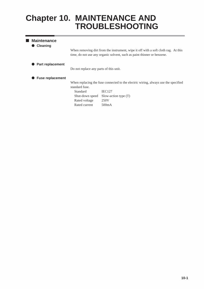
Chapter 10. MAINTENANCE ANDTROUBLESHOOTING
10-1
Maintenance Cleaning
When removing dirt from the instrument, wipe it off with a soft cloth rag. At thistime, do not use any organic solvent, such as paint thinner or benzene.
Part replacementDo not replace any parts of this unit.
Fuse replacementWhen replacing the fuse connected to the electric wiring, always use the specifiedstandard fuse.
Standard IEC127Shut-down speed Slow-action type (T)Rated voltage 250VRated current 500mA

10-2
Chapter 10. MAINTENANCE AND TROUBLESHOOTING
Alarm displays and corrective actionThe following table shows the alarm displays and corrective actions if any failureoccurs in this unit:
Alarm code Failure name Cause Corrective action
PV input failure Sensor burnout, incorrect wiring,(Over-range) incorrect PV input type setting
PV input failure Sensor burnout, incorrect wiring,(Under-range) incorrect PV input type setting
CJ failure Terminal temperature is faulty(thermocouple).
PV input failure Sensor burnout, incorrect wiring Check the wiring.(RTD)
RSP input failure Sensor burnout, incorrect wiring, (Over-range) incorrect RSP input type setting(Displayed only in the RSP mode.)
RSP input failure Sensor burnout, incorrect wiring, (Under-range) incorrect RSP input type setting(Displayed only in the RSP mode.)
MFB input failure Burnout, incorrect wiring
Motor adjustment Check for burnout or incorrect failure wiring.
Motor power shutdown.
CT input failure A current exceeding the upper (over-range) limit of the display range was (CT input 1 or 2, measured. The number of CT or both) turns or the number of CT
power wire loops is incorrectly set, or wiring is incorrect.
A/D conversion A/D converter is faulty.failure
Parameter failure Data is corrupted by noise, orpower is shut-down while thedata is being set.
Adjustment data Data is corrupted by noise, or failure power is shut-down while the
data is being set.
Parameter failure Data is corrupted by noise.(RAM area)
Adjustment data Data is corrupted by noise.failure (RAM area)
ROM failure ROM (memory) is faulty.
Check the wiring.Set the PV input typeagain.
Check the ambienttemperature.
Replace the unit.
• Restart the unit.• Set the data again (set
data for AL95/97 andadjustment data forAL96/98).
• Replace the unit.
• Restart the unit.• Replace the unit.
Check the wiring.Set the RSP input typeagain.
Check the wiring.Set the RSP input typeagain.
Check the wiring.Check the MFB inputvalue.
Readjust the motor afterchecking the wiring andmotor power.
Handling Precautions
• If ROM version 1 of the instrument information bank (Id02) is prior to2.04, CT input failure (AL11) is not displayed.
Use a CT with the correctnumber of turns for thedisplay range, reset thenumber of CT turns, resetthe number of CT powerwire loops, and/or checkthe wiring.
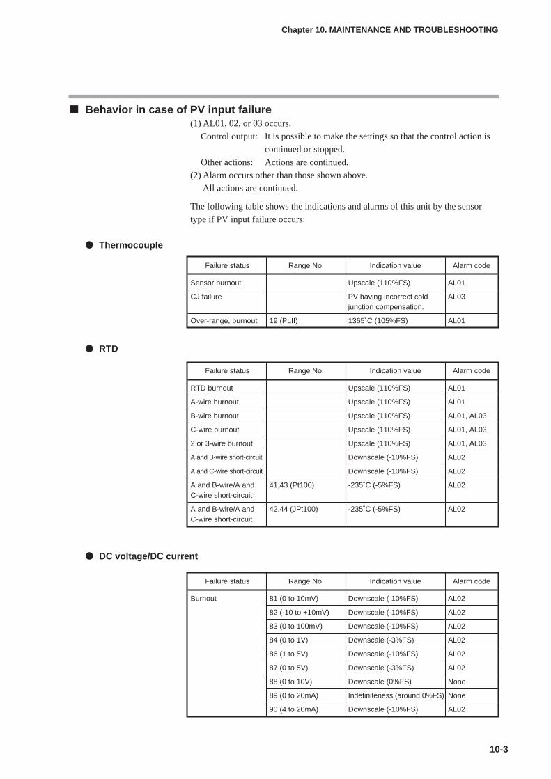
10-3
Chapter 10. MAINTENANCE AND TROUBLESHOOTING
Behavior in case of PV input failure(1) AL01, 02, or 03 occurs.
Control output: It is possible to make the settings so that the control action is
continued or stopped.
Other actions: Actions are continued.
(2) Alarm occurs other than those shown above.
All actions are continued.
The following table shows the indications and alarms of this unit by the sensor
type if PV input failure occurs:
Thermocouple
RTD
DC voltage/DC current
Failure status Range No. Indication value Alarm code
Burnout 81 (0 to 10mV) Downscale (-10%FS) AL02
82 (-10 to +10mV) Downscale (-10%FS) AL02
83 (0 to 100mV) Downscale (-10%FS) AL02
84 (0 to 1V) Downscale (-3%FS) AL02
86 (1 to 5V) Downscale (-10%FS) AL02
87 (0 to 5V) Downscale (-3%FS) AL02
88 (0 to 10V) Downscale (0%FS) None
89 (0 to 20mA) Indefiniteness (around 0%FS) None
90 (4 to 20mA) Downscale (-10%FS) AL02
Failure status Range No. Indication value Alarm code
Sensor burnout Upscale (110%FS) AL01
CJ failure PV having incorrect cold AL03junction compensation.
Over-range, burnout 19 (PLII) 1365˚C (105%FS) AL01
Failure status Range No. Indication value Alarm code
RTD burnout Upscale (110%FS) AL01
A-wire burnout Upscale (110%FS) AL01
B-wire burnout Upscale (110%FS) AL01, AL03
C-wire burnout Upscale (110%FS) AL01, AL03
2 or 3-wire burnout Upscale (110%FS) AL01, AL03
A and B-wire short-circuit Downscale (-10%FS) AL02
A and C-wire short-circuit Downscale (-10%FS) AL02
A and B-wire/A and 41,43 (Pt100) -235˚C (-5%FS) AL02C-wire short-circuit
A and B-wire/A and 42,44 (JPt100) -235˚C (-5%FS) AL02C-wire short-circuit
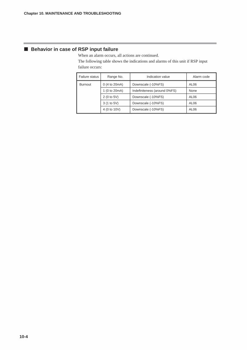
10-4
Chapter 10. MAINTENANCE AND TROUBLESHOOTING
Behavior in case of RSP input failureWhen an alarm occurs, all actions are continued.
The following table shows the indications and alarms of this unit if RSP input
failure occurs:
Failure status Range No. Indication value Alarm code
Burnout 0 (4 to 20mA) Downscale (-10%FS) AL06
1 (0 to 20mA) Indefiniteness (around 0%FS) None
2 (0 to 5V) Downscale (-10%FS) AL06
3 (1 to 5V) Downscale (-10%FS) AL06
4 (0 to 10V) Downscale (-10%FS) AL06
Chapter 11. CALIBRATION
11-1
Handling PrecautionsIt may be required to disconnect and reconnect the wiring for calibration.At this time, strictly observe the warnings and cautions about wiring statedin Chapter 4, WIRING.
This chapter describes how to calibrate this unit.To calibrate this unit, Smart Loader Package SLP-C35 is required.
Starting the calibrationStart up the Smart Loader Package SLP-C35. On the menu screen, select[Calibration (J)] from the [Menu (M)] pull-down menu. The [Calibrate]confirmation screen will appear.On this screen, select [OK]. The Calibration screen will appear and this unit entersthe calibration mode.When this unit is in the calibration mode, “tESt” will appear on the lower display.However, note that another message appears when inspecting the LED.
Handling Precautions
• Yamatake shall not be held responsible for any defects arising fromimproper calibration made by the customer.
• To return the unit to the calibration status of the default settingsbefore shipment during calibration, follow the steps below. From thepull-down menu, select [Command] → [Data retrieval]. The data,which has been calibrated, is disposed of and the data is thenreturned to the default settings before shipment. If this operation isperformed accidentally during calibration, all contents, which havebeen calibrated by the customer, will be lost.
Exiting the calibrationTo exit the calibration, perform either of the following operations:
(1) On the Calibration screen of the Smart Loader Package, select [Quit (Q)] fromthe [File (F)] pull-down menu.
(2) Click [X] at the upper right corner of the Calibration screen to close the screen.The screen will be returned to the menu screen and the unit also returns to thenormal mode.
Handling Precautions
If the loader cable is disconnected before starting the calibration exitoperation with the Smart Loader Package, this unit is continuously keptin the calibration mode. At this condition, turn OFF the power, and turnit ON again. The unit will return to the normal mode.
CAUTIONDo not change the mode to the calibration mode while the control object isbeing operated.When this unit is put in the calibration mode, the control output and eventoutput enter the fixed status and they do not function. Always start thecalibration by considering this point carefully.

Cautions before starting the calibrationWhen calibrating the unit, strictly observe the following cautions. Failure to do somay cause inaccuracy:
• Before starting the calibration, supply the power to this unit for at least 1 hr.
• The ambient temperature of the calibration place must conform to the standardconditions specified in the unit specifications.
• Do not calibrate the unit in a place where it is in contact with the wind or duringambient temperature fluctuation.
• Do not calibrate the unit with the measuring instruments having lowerspecifications stated in the next section, Measuring instruments required forcalibration.
Measuring instruments required for calibration
Calibration procedures
I/O check
(1) Select the [I/O Check] tab.
(2) Select a desired item from the check contents.
(3) Click [Execute].
The input system (key and digital input) is shown on the personal computer screenwhile the input status (ON/OFF) of this unit is being read continuously.
For the output system (control output and event output), the status (ON/OFF) youhave checked on desired check boxes is output from the output terminal of thisunit.
PV input calibration
(1) Select the [PV Calibration] tab.
(2) Select the model, [4: C25/26/35/36 T/C], [5: C25/26/35/36 RTD], or [6:C25/26/35/36 LIN].
(3) Select the gain No. in the ascending order and perform the operation from step(4).
(4) Click [Read].
(5) Apply the voltage, current, and resistance values written next to the gain No. tothe PV input terminal.
11-2
Chapter 11. CALIBRATION
Measuring instrument Specifications
Reference current/ Accuracy: ±0.1% or less, voltage generator Minimum resolution: 100 µV or less (voltage),
Minimum resolution: 100 µA or less (current)
Resistor Accuracy: ±0.1% or less, Minimum resolution: 0.1Ω or less
Ammeter Accuracy: ±0.1% or less, Minimum resolution: 1µA or less
Voltmeter Accuracy: ±0.1% or less, Minimum resolution: 1mV or less
Thermometer Accuracy: ±0.1˚C or less, Minimum resolution: 0.1˚C or less
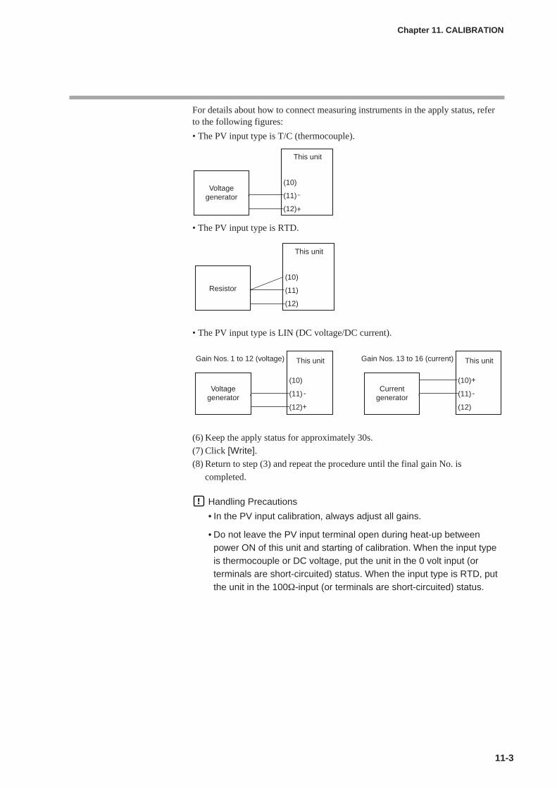
11-3
For details about how to connect measuring instruments in the apply status, referto the following figures:
• The PV input type is T/C (thermocouple).
• The PV input type is RTD.
• The PV input type is LIN (DC voltage/DC current).
(6) Keep the apply status for approximately 30s.
(7) Click [Write].(8) Return to step (3) and repeat the procedure until the final gain No. is
completed.
Handling Precautions
• In the PV input calibration, always adjust all gains.
• Do not leave the PV input terminal open during heat-up betweenpower ON of this unit and starting of calibration. When the input typeis thermocouple or DC voltage, put the unit in the 0 volt input (orterminals are short-circuited) status. When the input type is RTD, putthe unit in the 100Ω-input (or terminals are short-circuited) status.
Chapter 11. CALIBRATION
Voltagegenerator
This unit
-
+
(10)
(11)
(12)
Resistor
This unit
(10)
(11)
(12)
Voltagegenerator
Gain Nos. 1 to 12 (voltage) This unit
-
+
(10)
(11)
(12)
Currentgenerator
Gain Nos. 13 to 16 (current) This unit
-
+(10)
(11)
(12)

RSP input calibration
(1) Select the [PV Calibration] tab.
(2) Select the model [7: C35/36 RSP].
(3) Select the gain No. in the ascending order and perform the operation from
step (4).
(4) Click [Read].
(5) Apply the voltage and current values written next to the gain No. to the PV
input terminal.
For details about how to connect measuring instruments in the apply status, refer
to the following Figures:
(6) Keep the apply status for approximately 30s.
(7) Click [Write].
(8) Return to step (3) and repeat the procedure until the final gain No. is
completed.
Handling Precautions
• In the RSP input calibration, it is always necessary to adjust all gains.• Do not leave the RSP input terminal open during heat-up between
power ON of this unit and starting of calibration. When the input typeis DC voltage, put the unit in the 0 volt input (or terminals are short-circuited) status.
11-4
Chapter 11. CALIBRATION
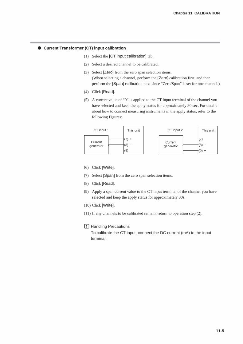
11-5
Chapter 11. CALIBRATION
Current Transformer (CT) input calibration
(1) Select the [CT input calibration] tab.
(2) Select a desired channel to be calibrated.
(3) Select [Zero] from the zero span selection items.
(When selecting a channel, perform the [Zero] calibration first, and then
perform the [Span] calibration next since “Zero/Span” is set for one channel.)
(4) Click [Read].
(5) A current value of “0” is applied to the CT input terminal of the channel you
have selected and keep the apply status for approximately 30 sec. For details
about how to connect measuring instruments in the apply status, refer to the
following Figures:
(6) Click [Write].
(7) Select [Span] from the zero span selection items.
(8) Click [Read].
(9) Apply a span current value to the CT input terminal of the channel you have
selected and keep the apply status for approximately 30s.
(10) Click [Write].
(11) If any channels to be calibrated remain, return to operation step (2).
Handling Precautions
To calibrate the CT input, connect the DC current (mA) to the inputterminal.
Currentgenerator
CT input 1 This unit
-
+(7)
(8)
(9)
Currentgenerator
CT input 2 This unit
-
+
(7)
(8)
(9)

11-6
Chapter 11. CALIBRATION
Current output/continuous voltage output calibration(1) Select the [Analog Output Calibration] tab.
(2) Select a desired channel to be calibrated.
Select [ch1] for control output 1, [ch2] for control output 2, and [ch3] for
auxiliary output.
(3) Select [Zero] from the zero span selection items.
(When selecting a channel, perform the [Zero] calibration first, and then
perform the [Span] calibration next since “Zero/Span” is set for one channel.)
(4) When clicking [Read], the zero calibration current/continuous voltage is
output to the output terminal of the channel you have selected.
(5) Keep this status for approximately 30s.
(6) Read the current value in units of 0.001 mA from the ammeter or the voltage
value in units of 0.001V from the voltmeter, input them in [Current(mA)/Voltage (V)], and click [Write].
(7) Select [Span] from the zero span selection items.
(8) When clicking [Read], the span calibration current/continuous voltage is
output to the output terminal of the channel you have selected.
(9) Keep this status for approximately 30s.
(10) Read the current value in units of 0.001 mA from the ammeter or the voltage
value in units of 0.001V from the voltmeter, input them in [Current(mA)/Voltage (V)], and click [Write].
(11) If any channels to be calibrated remain, return to operation step (2).
For details about how to connect measuring instruments, refer to the
following Figures:
!
"
# $
"
# $
"
! # $

Chapter 12. DISPOSAL
12-1
When disposing of this unit, dispose of it appropriately as an industrial waste in accordance with local laws and
regulations.

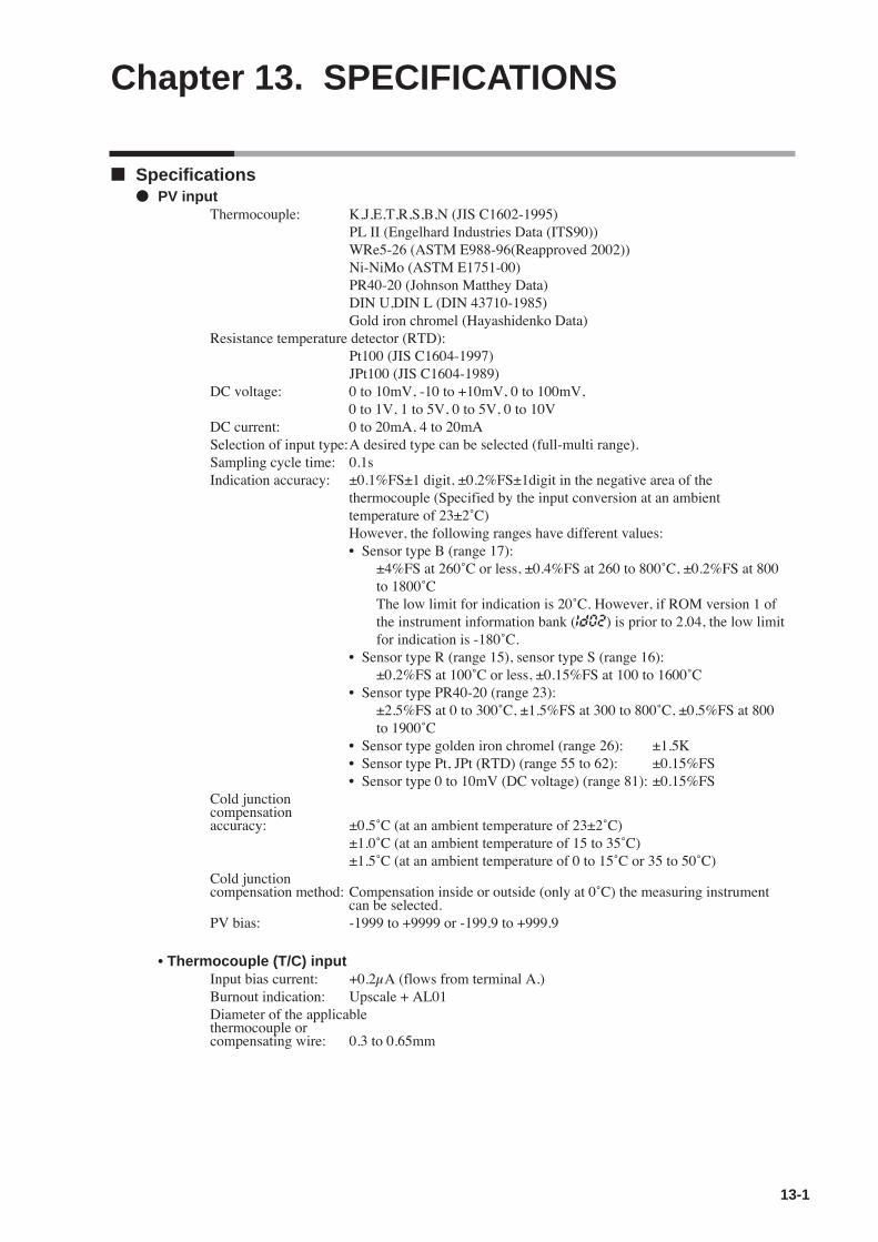
Chapter 13. SPECIFICATIONS
13-1
Specifications PV input
Thermocouple: K,J,E,T,R,S,B,N (JIS C1602-1995)PL II (Engelhard Industries Data (ITS90))WRe5-26 (ASTM E988-96(Reapproved 2002))Ni-NiMo (ASTM E1751-00)PR40-20 (Johnson Matthey Data)DIN U,DIN L (DIN 43710-1985)Gold iron chromel (Hayashidenko Data)
Resistance temperature detector (RTD):Pt100 (JIS C1604-1997)JPt100 (JIS C1604-1989)
DC voltage: 0 to 10mV, -10 to +10mV, 0 to 100mV, 0 to 1V, 1 to 5V, 0 to 5V, 0 to 10V
DC current: 0 to 20mA, 4 to 20mASelection of input type:A desired type can be selected (full-multi range).Sampling cycle time: 0.1sIndication accuracy: ±0.1%FS±1 digit, ±0.2%FS±1digit in the negative area of the
thermocouple (Specified by the input conversion at an ambienttemperature of 23±2˚C)However, the following ranges have different values:• Sensor type B (range 17):
±4%FS at 260˚C or less, ±0.4%FS at 260 to 800˚C, ±0.2%FS at 800 to 1800˚CThe low limit for indication is 20˚C. However, if ROM version 1 of the instrument information bank (Id02) is prior to 2.04, the low limit for indication is -180˚C.
• Sensor type R (range 15), sensor type S (range 16):±0.2%FS at 100˚C or less, ±0.15%FS at 100 to 1600˚C
• Sensor type PR40-20 (range 23):±2.5%FS at 0 to 300˚C, ±1.5%FS at 300 to 800˚C, ±0.5%FS at 800 to 1900˚C
• Sensor type golden iron chromel (range 26): ±1.5K• Sensor type Pt, JPt (RTD) (range 55 to 62): ±0.15%FS• Sensor type 0 to 10mV (DC voltage) (range 81): ±0.15%FS
Cold junction compensation accuracy: ±0.5˚C (at an ambient temperature of 23±2˚C)
±1.0˚C (at an ambient temperature of 15 to 35˚C)±1.5˚C (at an ambient temperature of 0 to 15˚C or 35 to 50˚C)
Cold junction compensation method: Compensation inside or outside (only at 0˚C) the measuring instrument
can be selected.PV bias: -1999 to +9999 or -199.9 to +999.9
• Thermocouple (T/C) inputInput bias current: +0.2µA (flows from terminal A.)Burnout indication: Upscale + AL01Diameter of the applicable thermocouple or compensating wire: 0.3 to 0.65mm

13-2
• Resistance temperature detector (RTD) inputInput bias current: Approx. +1mA (flows from terminal A.)Burnout indication: RTD burnout or A-wire burnout . . . . Upscale + AL01
B-wire burnout or C-wire burnout. . . Upscale + AL01, AL032 or more wires burnout . . . . . . . . . . Upscale + AL01, AL03
Effect of wiring resistance: Max. ±0.05%FS/ΩAllowable wiring resistance: 10Ω or less for range No. 53 to 62 (Zener barrier cannot be used.)
85Ω or less for ranges other than above range (including the resistance of the Zener barrier)
• DC voltage inputInput impedancce: 1MΩInput bias current: 1V range or less . . . . . . . . . . . . . .Max. 1µA (flows to the (+) terminal)
0 to 5V, 1 to 5V range . . . . . . . . .Max. 3.5µA (flows to the (+) terminal)0 to 10V range . . . . . . . . . . . . . . .Max. 7µA (flows to the (+) terminal)
Burnout indication: Downscale + AL02However, the burnout cannot be detected in a range of 0 to 10V.
• DC current inputInput impedance: Max. 100ΩBurnout indication: Downscale + AL02
However, the burnout cannot be detected in a range of 0 to 20mA.
Motor feedback potentiometer input (R1 model)Allowable resistance: 100 to 2500ΩBurnout detection: AL07 indication
RSP inputInput type: Linear 0 to 20mA/4 to 20mA or linear 0 to 5V/1 to 5V/0 to 10VScaling: Possible in a range of -1999 to +9999. It is also possible to set the decimal
point position.Sampling cycle: 100msIndication accuracy: ±0.1%FS±1digit (at an ambient temperature of 23±2˚C)
• Voltage input specificationsInput impedance: Max. 1MΩInput bias current: 0 to 5V, 1 to 5V range . . . . . . . . . . Max. 3µA (flows to the (+) terminal)
0 to 10V range . . . . . . . . . . . . . . . . Max. 5µA (flows to the (+) terminal)Burnout indication: Downscale + AL06
• Current input specificationsInput impedance: Max. 100ΩBurnout indication: Downscale + AL06
However, the burnout cannot be detected in a range of 0 to 20mA.
Chapter 13. SPECIFICATIONS
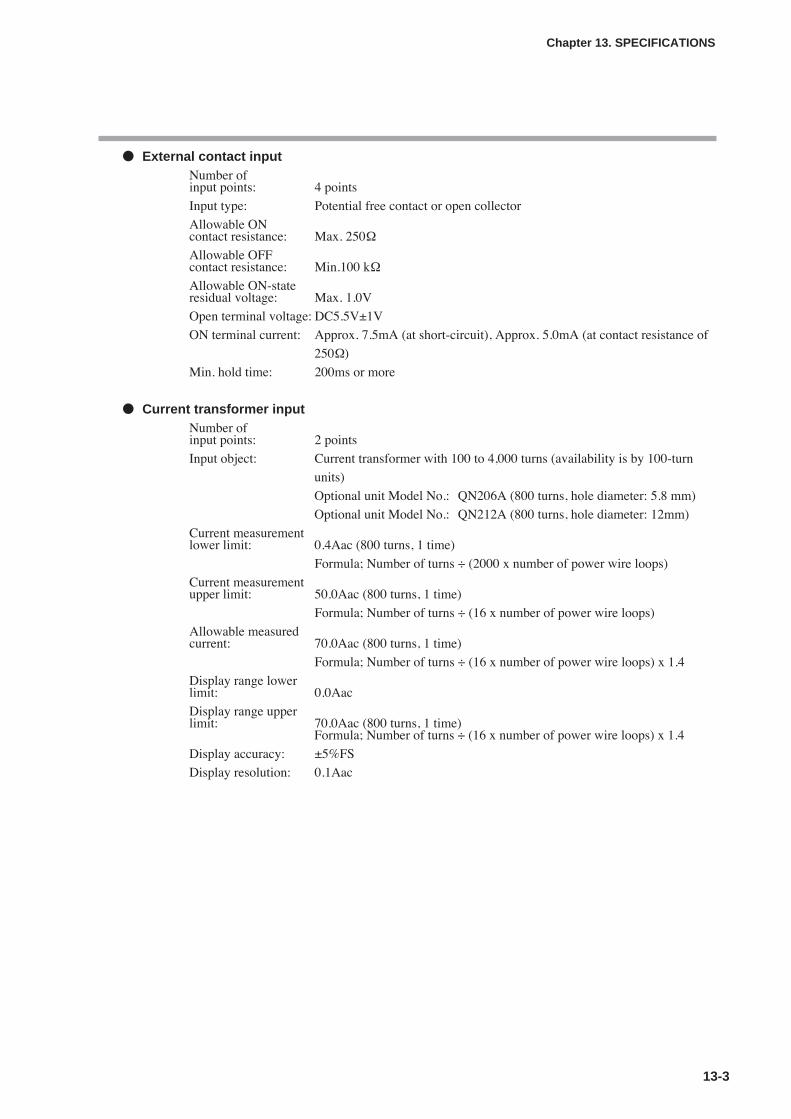
13-3
Chapter 13. SPECIFICATIONS
External contact inputNumber of input points: 4 points
Input type: Potential free contact or open collector
Allowable ON contact resistance: Max. 250Ω
Allowable OFF contact resistance: Min.100 kΩ
Allowable ON-state residual voltage: Max. 1.0V
Open terminal voltage: DC5.5V±1V
ON terminal current: Approx. 7.5mA (at short-circuit), Approx. 5.0mA (at contact resistance of
250Ω)
Min. hold time: 200ms or more
Current transformer inputNumber of input points: 2 points
Input object: Current transformer with 100 to 4,000 turns (availability is by 100-turn
units)
Optional unit Model No.: QN206A (800 turns, hole diameter: 5.8 mm)
Optional unit Model No.: QN212A (800 turns, hole diameter: 12mm)
Current measurementlower limit: 0.4Aac (800 turns, 1 time)
Formula; Number of turns ÷ (2000 x number of power wire loops)
Current measurementupper limit: 50.0Aac (800 turns, 1 time)
Formula; Number of turns ÷ (16 x number of power wire loops)
Allowable measuredcurrent: 70.0Aac (800 turns, 1 time)
Formula; Number of turns ÷ (16 x number of power wire loops) x 1.4
Display range lower limit: 0.0Aac
Display range upperlimit: 70.0Aac (800 turns, 1 time)
Formula; Number of turns ÷ (16 x number of power wire loops) x 1.4
Display accuracy: ±5%FS
Display resolution: 0.1Aac

13-4
Chapter 13. SPECIFICATIONS
Control output• Relay output
Contact rating: NO side 250Vac/30Vdc, 3A (resistance load)NC side 250Vac/30Vdc, 1A (resistance load)
Life: 50,000 cycles or more on NO side100,000 cycles or more on NC side
Min. open/close specifications: 5V, 100mAMin. open time/close times 250ms
• Motor drive relay output (R1 model)Contact type: 1c, 2 circuitsContact rating: 250Vac, 8A (resistive load)Life: 120,000 cycles or moreMin. open/closespecifications: 24Vdc, 40mA
• Voltage pulse output (For SSR drive)Voltage between terminals at open: 19Vdc±15%Internal resistance: 82Ω±0.5%Allowable current: Max. 24mAdcOFF leak current: Max. 100µAMin. OFF time/ON time: 1ms when the time proportional cycle time is less than 10s.
250ms when the time proportional cycle time is more than 10s.
• Current outputOutput type: 0 to 20mAdc or 4 to 20mAdcAllowance load resistance: Max. 600ΩOutput accuracy: ±0.1%FS (at an ambient temperature of 23±2˚C)
However, ±1.0%FS in a range of 0 to 1mA.Output resolution: 1/10000
• Continuous voltage outputOutput type: 0 to 5Vdc, 1 to 5Vdc or 0 to 10Vdc
Allowable load resistance: Min. 1000ΩOutput accuracy: ±0.1%FS (at an ambient temperature of 23±2˚C)
However, ±1%FS at 0 to 0.05V.Output resolution: 1/10000
Auxiliary output• Current output
Output type: 0 to 20mAdc or 4 to 20mAdc
Allowable load resistance: Max. 600ΩOutput accuracy: ±0.1%FS (at an ambient temperature of 23±2˚C)
However, ±1%FS at 0 to 1mA.Output resolution: 1/10000

13-5
Chapter 13. SPECIFICATIONS
• Continuous voltage outputOutput type: 0 to 5Vdc, 1 to 5Vdc or 0 to 10Vdc voltage output
Allowable load resistance: Min. 1000ΩOutput accuracy: ±0.1%FS (at an ambient temperature of 23±2˚C)
However, ±1%FS at 0 to 0.05V.Output resolution: 1/10000
Event relay outputNumber of output points: 2 to 3 points (This may vary depending on the model.)
Output type: SPST contact
3 points, 3 points/common; 2 points, Each individual contact
Output rating: 250Vac/30Vdc, 2A (resistive load)Life: 100,000 cycles or more
Min. open/close specifications: 5V, 10mA (Reference value)
RS-485 communication Transmission line: 3-wire methodTransmission speed: 4800, 9600, 19200, 38400 bpsCommunication distance: Max. 500mCommunicationmethod: Half duplex, start/stop synchronization methodCommunication protocol: In conformity with CPL and MODBUSNumber of connection units: Max. 31 unitsTerminating resistor: Connection prohibited.
Loader communicationTransmission line: 3-wire methodTransmission speed: Fixed at 19200 bps.Recommended cable: Specially designed cable, 2m Model No.: 81440793-001
Isolation between input and outputPortions enclosed by solid lines are insulated from other signals.
Portions enclosed by dotted lines are not insulated.
The inputs and outputs provided may vary depending upon the model. In case of the independent contacts, the output 1 and the output 2 are isolated.
Power supply Control output 1
PV input Control output 2
CT input 1 Auxiliary output
CT input 2
MFB input
Loader communicationInternal
Digital input 1 circuit Event output 1
Digital input 2 Event output 2
Digital input 3 Event output 3
Digital input 4
RS-485 communication
RSP input
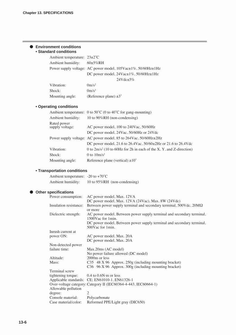
13-6
Chapter 13. SPECIFICATIONS
Environment conditions• Standard conditions
Ambient temperature: 23±2˚C
Ambient humidity: 60±5%RH
Power supply voltage: AC power model, 105Vac±1%, 50/60Hz±1Hz
DC power model, 24Vac±1%, 50/60Hz±1Hz
24Vdc±5%
Vibration: 0m/s2
Shock: 0m/s2
Mounting angle: (Reference plane) ±3˚
• Operating conditionsAmbient temperature: 0 to 50˚C (0 to 40˚C for gang-mounting)
Ambient humidity: 10 to 90%RH (non-condensing)
Rated power supply voltage: AC power model, 100 to 240Vac, 50/60Hz
DC power model, 24Vac, 50/60Hz or 24Vdc
Power supply voltage: AC power model, 85 to 264Vac, 50/60Hz±2Hz
DC power model, 21.6 to 26.4Vac, 50/60±2Hz or 21.6 to 26.4Vdc
Vibration: 0 to 2m/s2 (10 to 60Hz for 2h in each of the X, Y, and Z-direction)
Shock: 0 to 10m/s2
Mounting angle: Reference plane (vertical) ±10˚
• Transportation conditionsAmbient temperature: -20 to +70˚C
Ambient humidity: 10 to 95%RH (non-condensing)
Other specificationsPower consumption: AC power model, Max. 12VA
DC power model, Max. 12VA (24Vac), Max. 8W (24Vdc)Insulation resistance: Between power supply terminal and secondary terminal, 500Vdc, 20MΩ
or moreDielectric strength: AC power model, Between power supply terminal and secondary terminal,
1500Vac for 1min.DC power model, Between power supply terminal and secondary terminal,500Vac for 1min.
Inrush current at power ON: AC power model, Max. 20A
DC power model, Max. 20ANon-detected powerfailure time: Max.20ms (AC model)
No power failure allowed (DC model)Altitude: 2000m or lessMass: C35 48 X 96 Approx. 250g (including mounting bracket)
C36 96 X 96 Approx. 300g (including mounting bracket)Terminal screw tightening torque: 0.4 to 0.6N·m or lessApplicable standards: CE; EN61010-1, EN61326-1Over-voltage category: Category II (IEC60364-4-443, IEC60664-1)Allowable pollution degree: 2Console material: PolycarbonateCase material/color: Reformed PPE/Light gray (DIC650)
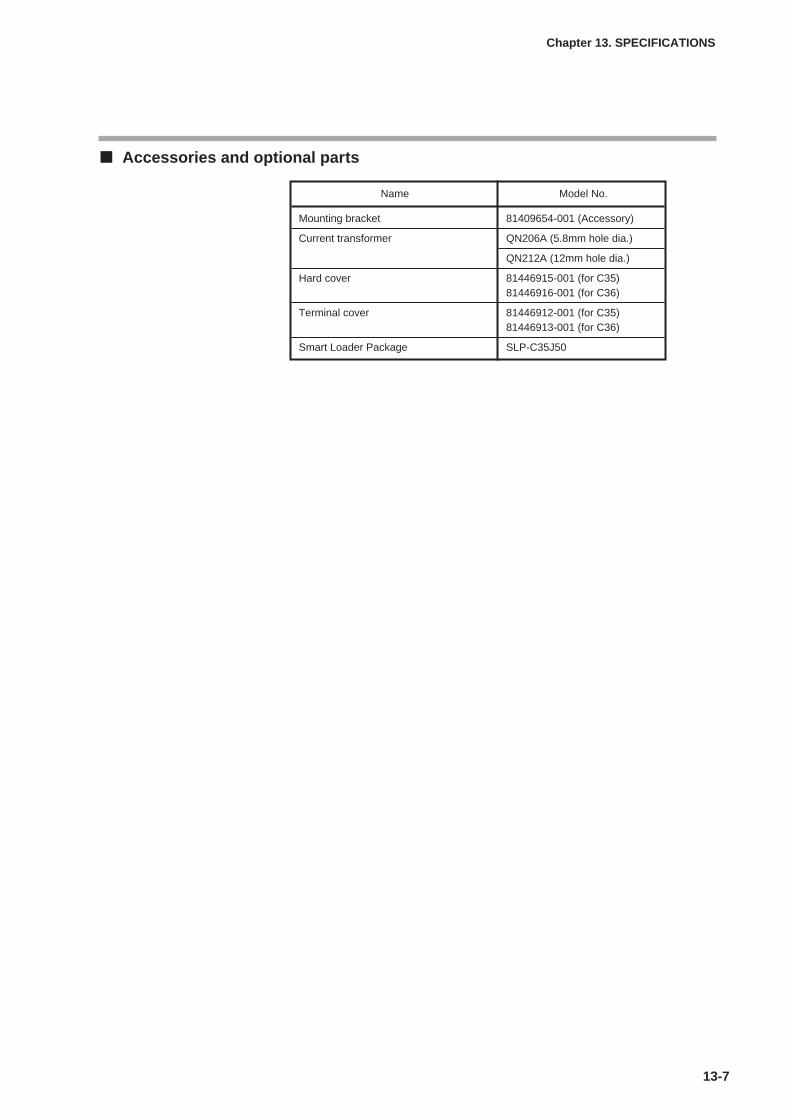
13-7
Chapter 13. SPECIFICATIONS
Accessories and optional parts
Name Model No.
Mounting bracket 81409654-001 (Accessory)
Current transformer QN206A (5.8mm hole dia.)
QN212A (12mm hole dia.)
Hard cover 81446915-001 (for C35)81446916-001 (for C36)
Terminal cover 81446912-001 (for C35)81446913-001 (for C36)
Smart Loader Package SLP-C35J50

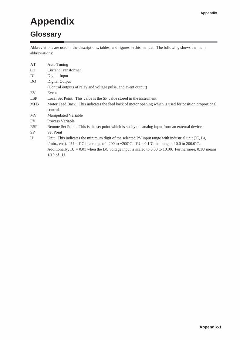
AppendixGlossary
Appendix-1
Appendix
Abbreviations are used in the descriptions, tables, and figures in this manual. The following shows the main
abbreviations:
AT Auto Tuning
CT Current Transformer
DI Digital Input
DO Digital Output
(Control outputs of relay and voltage pulse, and event output)
EV Event
LSP Local Set Point. This value is the SP value stored in the instrument.
MFB Motor Feed Back. This indicates the feed back of motor opening which is used for position proportional
control.
MV Manipulated Variable
PV Process Variable
RSP Remote Set Point. This is the set point which is set by the analog input from an external device.
SP Set Point
U Unit. This indicates the minimum digit of the selected PV input range with industrial unit (˚C, Pa,
l/min., etc.). 1U = 1˚C in a range of –200 to +200˚C. 1U = 0.1˚C in a range of 0.0 to 200.0˚C.
Additionally, 1U = 0.01 when the DC voltage input is scaled to 0.00 to 10.00. Furthermore, 0.1U means
1/10 of 1U.


Index
Index-1
-Number-3-wire system • • • • • • • • • • • • • • • • • • 4-5
5-wire system • • • • • • • • • • • • • • • • • • 4-6
-A-Accessories • • • • • • • • • • • • • • • • • • • 1-3
Alarm code • • • • • • • • • • • • • • • • • • 10-2
Application example • • • • • • • • • • • • • • 5-78
Application layer • • • • • • • • • • • • • • 7-5, 7-3
AT Derivative time adjust • • • • • • • • • • • 5-26
AT Integral time adjust • • • • • • • • • • • • • 5-26
AT Proportional Band adjust • • • • • • • • • 5-26
AT start • • • • • • • • • • • • • • • • • • • • 5-29
AT Stop/Start • • • • • • • • • • • • • • • • • 5-11
AT type • • • • • • • • • • • • • • • • • • • • 5-26
Auto tuning (AT) • • • • • • • • • • • • 5-26, 5-29
AUTO/MANUAL mode • • • • • • • • • • • • 5-10
Auxiliary relay • • • • • • • • • • • • • • • • • 4-3
-B-Bank selection display • • • • • • • • • • • • • • 2-3
Bank setup display • • • • • • • • • • • • • • • 2-3
Basic configuration • • • • • • • • • • • • • 2-1, 2-7
-C-C01 PV input range type • • • • • • • • • • • • 5-2
C02 Temperature unit • • • • • • • • • • • • • • 5-3
C03 Cold junction compensation (T/C) • • • • • 5-3
C04 Decimal point position • • • • • • • • • • • 5-5
C05 PV input range low limit • • • • • • • • • • 5-6
C06 PV input range high limit • • • • • • • • • • 5-6
C07 SP low limit • • • • • • • • • • • • • • • 5-40
C08 SP high limit • • • • • • • • • • • • • • • 5-40
C09 PV square root extraction dropout • • • • • 5-4
C10 RSP input type • • • • • • • • • • • • • • 5-33
C11 RSP input range low limit • • • • • • • • • 5-34
C12 RSP input range high limit • • • • • • • • 5-34
C14 Control action (Direct/Reverse) • • • • • 5-15
C15 Output operation at PV alarm • • • • • • • 5-15
C16 Output at PV alarm • • • • • • • • • • • • 5-15
C17 Output at READY • • • • • • • • • • • • 5-15
C18 Output at READY (Cool) • • • • • • • • • 5-15
C19 Output operation at changing Auto/Manual 5-16
C20 Preset manual value • • • • • • • • • • • • 5-16
C21 Initial output type (mode) of PID control • 5-16
C22 Initial output of PID control • • • • • • • • 5-17
C23 PID Decimal point position • • • • • • • • 5-17
C24 Zone PID operation • • • • • • • • • • • • 5-23
C26 Heat/Cool control • • • • • • • • • • • • • 5-15
C27 Heat/Cool • • • • • • • • • • • • • • • • • 5-24
C28 Heat/Cool control dead zone • • • • • • • 5-24
C29 Heat/Cool change point • • • • • • • • • • 5-24
C30 LSP system group • • • • • • • • • • 5-33, 5-41
C31 SP ramp type • • • • • • • • • • • • 5-33, 5-42
C32 SP ramp unit • • • • • • • • • • • • 5-37, 5-43
C33 STEP time unit • • • • • • • • • • • • • • 5-43
C34 STEP PV start • • • • • • • • • • • • • • 5-44
C35 STEP loop • • • • • • • • • • • • • • • • 5-45
C36 CT1 operation type • • • • • • • • • • • • 5-89
C37 CT1 output • • • • • • • • • • • • • • • • 5-89
C38 CT1 measurement wait time • • • • • • • • 5-89
C39 CT2 operation type • • • • • • • • • • • • 5-89
C40 CT2 output • • • • • • • • • • • • • • • • 5-89
C41 CT2 measurement wait time • • • • • • • • 5-89
C42 Output 1 range • • • • • • • • • • • • • • 5-85
C43 Output1 type • • • • • • • • • • • • • • • 5-85
C44 Output 1 scaling low limit • • • • • • • • • 5-86
C45 Output 1 scaling high limit • • • • • • • • 5-86
C46 Output 1 MV scaling • • • • • • • • • • • 5-87
C47 Output 2 range • • • • • • • • • • • • • • 5-85
C48 Output 2 type • • • • • • • • • • • • • • • 5-85
C49 Output 2 scaling low limit • • • • • • • • • 5-86
C50 Output 2 scaling high limit • • • • • • • • 5-86
C51 Output 2 MV scaling • • • • • • • • • • • 5-87
C52 AUX range type • • • • • • • • • • • • • 5-85
C53 AUX type • • • • • • • • • • • • • • • • • 5-85
C54 AUX Value at 0% output • • • • • • • • • 5-86
C55 AUX Value at 100% output • • • • • • • • 5-86
C56 AUX MV scaling • • • • • • • • • • • • • 5-87
C57 Position proportional type • • • • • • • • 5-107
C58 Position proportional dead zone • • • • • 5-108
C59 Motor long life mode • • • • • • • • • • 5-109
C60 Motor auto adjust • • • • • • • • • • • • 5-109
C61 Input with motor fully closed • • • • • • 5-113
C62 Input with motor fully open • • • • • • • 5-113
C63 Motor full close-full open time • • • • • • 5-113
C64 CPL/MODBUS • • • • • • • • • • • • • • 7-1
C65 Station address • • • • • • • • • • • • • • • 7-1
C66 Transmission speed • • • • • • • • • • • • 7-1
C67 Data format (Data length) • • • • • • • • • 7-1
C68 Data format (Parity) • • • • • • • • • • • • 7-1
C69 Data format (Stop bit) • • • • • • • • • • • 7-1
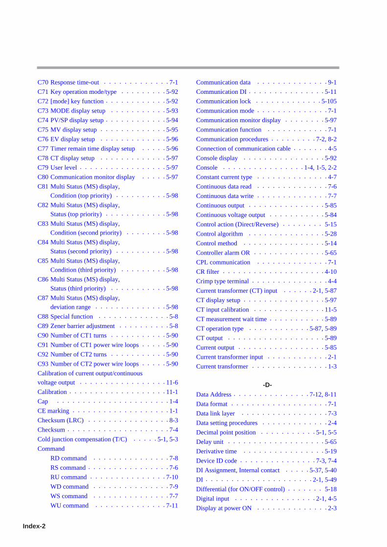
Index-2
C70 Response time-out • • • • • • • • • • • • • 7-1
C71 Key operation mode/type • • • • • • • • • 5-92
C72 [mode] key function • • • • • • • • • • • • 5-92
C73 MODE display setup • • • • • • • • • • • 5-93
C74 PV/SP display setup • • • • • • • • • • • • 5-94
C75 MV display setup • • • • • • • • • • • • • 5-95
C76 EV display setup • • • • • • • • • • • • • 5-96
C77 Timer remain time display setup • • • • • 5-96
C78 CT display setup • • • • • • • • • • • • • 5-97
C79 User level • • • • • • • • • • • • • • • • • 5-97
C80 Communication monitor display • • • • • 5-97
C81 Multi Status (MS) display,
Condition (top priority) • • • • • • • • • • 5-98
C82 Multi Status (MS) display,
Status (top priority) • • • • • • • • • • • • 5-98
C83 Multi Status (MS) display,
Condition (second priority) • • • • • • • • 5-98
C84 Multi Status (MS) display,
Status (second priority) • • • • • • • • • • 5-98
C85 Multi Status (MS) display,
Condition (third priority) • • • • • • • • • 5-98
C86 Multi Status (MS) display,
Status (third priority) • • • • • • • • • • • 5-98
C87 Multi Status (MS) display,
deviation range • • • • • • • • • • • • • • 5-98
C88 Special function • • • • • • • • • • • • • • 5-8
C89 Zener barrier adjustment • • • • • • • • • • 5-8
C90 Number of CT1 turns • • • • • • • • • • • 5-90
C91 Number of CT1 power wire loops • • • • • 5-90
C92 Number of CT2 turns • • • • • • • • • • • 5-90
C93 Number of CT2 power wire loops • • • • • 5-90
Calibration of current output/continuous
voltage output • • • • • • • • • • • • • • • • • 11-6
Calibration • • • • • • • • • • • • • • • • • • • 11-1
Cap • • • • • • • • • • • • • • • • • • • • • • 1-4
CE marking • • • • • • • • • • • • • • • • • • • 1-1
Checksum (LRC) • • • • • • • • • • • • • • • • 8-3
Checksum • • • • • • • • • • • • • • • • • • • • 7-4
Cold junction compensation (T/C) • • • • • 5-1, 5-3
Command
RD command • • • • • • • • • • • • • • • 7-8
RS command • • • • • • • • • • • • • • • • 7-6
RU command • • • • • • • • • • • • • • • 7-10
WD command • • • • • • • • • • • • • • • 7-9
WS command • • • • • • • • • • • • • • • 7-7
WU command • • • • • • • • • • • • • • 7-11
Communication data • • • • • • • • • • • • • • 9-1
Communication DI • • • • • • • • • • • • • • • 5-11
Communication lock • • • • • • • • • • • • • 5-105
Communication mode • • • • • • • • • • • • • • 7-1
Communication monitor display • • • • • • • • 5-97
Communication function • • • • • • • • • • • • 7-1
Communication procedures • • • • • • • • • 7-2, 8-2
Connection of communication cable • • • • • • • 4-5
Console display • • • • • • • • • • • • • • • • 5-92
Console • • • • • • • • • • • • • • • • 1-4, 1-5, 2-2
Constant current type • • • • • • • • • • • • • • 4-7
Continuous data read • • • • • • • • • • • • • • 7-6
Continuous data write • • • • • • • • • • • • • • 7-7
Continuous output • • • • • • • • • • • • • • • 5-85
Continuous voltage output • • • • • • • • • • • 5-84
Control action (Direct/Reverse) • • • • • • • • 5-15
Control algorithm • • • • • • • • • • • • • • • 5-28
Control method • • • • • • • • • • • • • • • • 5-14
Controller alarm OR • • • • • • • • • • • • • • 5-65
CPL communication • • • • • • • • • • • • • • 7-1
CR filter • • • • • • • • • • • • • • • • • • • • 4-10
Crimp type terminal • • • • • • • • • • • • • • • 4-4
Current transformer (CT) input • • • • • • 2-1, 5-87
CT display setup • • • • • • • • • • • • • • • • 5-97
CT input calibration • • • • • • • • • • • • • • 11-5
CT measurement wait time • • • • • • • • • • • 5-89
CT operation type • • • • • • • • • • • • 5-87, 5-89
CT output • • • • • • • • • • • • • • • • • • • 5-89
Current output • • • • • • • • • • • • • • • • • 5-85
Current transformer input • • • • • • • • • • • • 2-1
Current transformer • • • • • • • • • • • • • • • 1-3
-D-Data Address • • • • • • • • • • • • • • • 7-12, 8-11
Data format • • • • • • • • • • • • • • • • • • • 7-1
Data link layer • • • • • • • • • • • • • • • • • 7-3
Data setting procedures • • • • • • • • • • • • • 2-4
Decimal point position • • • • • • • • • • • 5-1, 5-5
Delay unit • • • • • • • • • • • • • • • • • • • 5-65
Derivative time • • • • • • • • • • • • • • • • 5-19
Device ID code • • • • • • • • • • • • • • • 7-3, 7-4
DI Assignment, Internal contact • • • • • 5-37, 5-40
DI • • • • • • • • • • • • • • • • • • • • • 2-1, 5-49
Differential (for ON/OFF control) • • • • • • • 5-18
Digital input • • • • • • • • • • • • • • • • 2-1, 4-5
Display at power ON • • • • • • • • • • • • • • 2-3
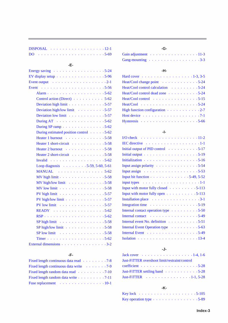
Index-3
DISPOSAL • • • • • • • • • • • • • • • • • • 12-1
DO • • • • • • • • • • • • • • • • • • • • • • 5-69
-E-Energy saving • • • • • • • • • • • • • • • • • 5-24
EV display setup • • • • • • • • • • • • • • • • 5-96
Event output • • • • • • • • • • • • • • • • • • 2-1
Event • • • • • • • • • • • • • • • • • • • • • 5-56
Alarm • • • • • • • • • • • • • • • • • • • 5-62
Control action (Direct) • • • • • • • • • • 5-62
Deviation high limit • • • • • • • • • • • • 5-57
Deviation high/low limit • • • • • • • • • 5-57
Deviation low limit • • • • • • • • • • • • 5-57
During AT • • • • • • • • • • • • • • • • 5-62
During SP ramp • • • • • • • • • • • • • • 5-62
During estimated position control • • • • • 5-62
Heater 1 burnout • • • • • • • • • • • • • 5-58
Heater 1 short-circuit • • • • • • • • • • • 5-58
Heater 2 burnout • • • • • • • • • • • • • 5-58
Heater 2 short-circuit • • • • • • • • • • • 5-58
Invalid • • • • • • • • • • • • • • • • • • 5-62
Loop diagnosis • • • • • • • • 5-59, 5-60, 5-61
MANUAL • • • • • • • • • • • • • • • 5-62
MV high limit • • • • • • • • • • • • • • • 5-58
MV high/low limit • • • • • • • • • • • • 5-58
MV low limit • • • • • • • • • • • • • • • 5-58
PV high limit • • • • • • • • • • • • • • • 5-57
PV high/low limit • • • • • • • • • • • • • 5-57
PV low limit • • • • • • • • • • • • • • • 5-57
READY • • • • • • • • • • • • • • • • • 5-62
RSP • • • • • • • • • • • • • • • • • • • • 5-62
SP high limit • • • • • • • • • • • • • • • 5-58
SP high/low limit • • • • • • • • • • • • • 5-58
SP low limit • • • • • • • • • • • • • • • 5-58
Timer • • • • • • • • • • • • • • • • • • • 5-62
External dimensions • • • • • • • • • • • • • • • 3-2
-F-Fixed length continuous data read • • • • • • • • 7-8
Fixed length continuous data write • • • • • • • 7-9
Fixed length random data read • • • • • • • • • 7-10
Fixed length random data write • • • • • • • • • 7-11
Fuse replacement • • • • • • • • • • • • • • • 10-1
-G-Gain adjustment • • • • • • • • • • • • • • • • 11-3
Gang-mounting • • • • • • • • • • • • • • • • • 3-3
-H-Hard cover • • • • • • • • • • • • • • • • • 1-3, 3-5
Heat/Cool change point • • • • • • • • • • • • 5-24
Heat/Cool control calculation • • • • • • • • • 5-24
Heat/Cool control dead zone • • • • • • • • • • 5-24
Heat/Cool control • • • • • • • • • • • • • • • 5-15
Heat/Cool • • • • • • • • • • • • • • • • • • • 5-24
High function configuration • • • • • • • • • • • 2-7
Host device • • • • • • • • • • • • • • • • • • • 7-1
Hysteresis • • • • • • • • • • • • • • • • • • • 5-66
-I-I/O check • • • • • • • • • • • • • • • • • • • 11-2
IEC directive • • • • • • • • • • • • • • • • • • 1-1
Initial output of PID control • • • • • • • • • • 5-17
Initial output • • • • • • • • • • • • • • • • • • 5-19
Initialization • • • • • • • • • • • • • • • • • • 5-16
Input assign polarity • • • • • • • • • • • • • • 5-54
Input assign • • • • • • • • • • • • • • • • • • 5-53
Input bit function • • • • • • • • • • • • • 5-49, 5-52
input types • • • • • • • • • • • • • • • • • • • 1-1
Input with motor fully closed • • • • • • • • • 5-113
Input with motor fully open • • • • • • • • • • 5-113
Installation place • • • • • • • • • • • • • • • • 3-1
Integration time • • • • • • • • • • • • • • • • 5-19
Internal contact operation type • • • • • • • • • 5-50
Internal contact • • • • • • • • • • • • • • • • 5-49
Internal event No. definition • • • • • • • • • • 5-51
Internal Event Operation type • • • • • • • • • 5-63
Internal Event • • • • • • • • • • • • • • • • • 5-49
Isolation • • • • • • • • • • • • • • • • • • • • 13-4
-J-Jack cover • • • • • • • • • • • • • • • • • 1-4, 1-6
Just-FiTTER overshoot limit/restraint/control
coefficient • • • • • • • • • • • • • • • • • • • 5-28
Just-FiTTER settling band • • • • • • • • • • • 5-28
Just-FiTTER • • • • • • • • • • • • • • • 1-1, 5-28
-K-Key lock • • • • • • • • • • • • • • • • • • • 5-105
Key operation type • • • • • • • • • • • • • • • 5-89

Index-4
-L-Latch • • • • • • • • • • • • • • • • • • • • • 5-76
Line filter • • • • • • • • • • • • • • • • • • • 4-10
Loader • • • • • • • • • • • • • • • • • • • 1-4, 1-6
Loader lock • • • • • • • • • • • • • • • • • • 5-105
Loop • • • • • • • • • • • • • • • • • • • • • • 5-45
Lower display • • • • • • • • • • • • • • • 1-4, 1-5
LSP group No. • • • • • • • • • • • • • • • • 5-36
LSP system group • • • • • • • • • • • • 5-33, 5-41
LSP • • • • • • • • • • • • • • • • • • • 5-32, 5-33
LSP/RSP mode • • • • • • • • • • • • • • • • 5-10
-M-Main setting • • • • • • • • • • • • • • • • • • 5-66
Maintenance • • • • • • • • • • • • • • • • • • 10-1
Manual reset • • • • • • • • • • • • • • • • • • 5-19
Master station • • • • • • • • • • • • • • • • • • 7-1
Message Structure • • • • • • • • • • • • • 7-3, 8-3
MFB input • • • • • • • • • • • • • • • • • • • 2-1
MFB • • • • • • • • • • • • • • • • • • • • • 5-107
MODBUS ASCII • • • • • • • • • • • • • • • • 8-3
MODBUS communications • • • • • • • • • • • 8-1
MODBUS RTU • • • • • • • • • • • • • • • • • 8-5
MODE display setup • • • • • • • • • • • • • • 5-93
Mode indicators • • • • • • • • • • • • • • 1-4, 1-6
[mode] key function • • • • • • • • • • • • • • 5-94
[mode] key operating procedures • • • • • • • • 2-7
Model selection table • • • • • • • • • • • • • • 1-2
Motor auto adjust • • • • • • • • • • • • • • • 5-109
Motor drive relay output • • • • • • • • • • • • • 4-3
Motor full close-full open time • • • • • • • • 5-113
Motor long life mode • • • • • • • • • • • • • 5-109
Motor wiring • • • • • • • • • • • • • • • • • 5-113
Mounting bracket • • • • • • • • • • • • • • • • 3-4
Mounting procedures • • • • • • • • • • • • • • 3-4
Multi Status (MS) display • • • • • • • 1-4, 1-6, 5-98
Multi Status (MS) display, Condition • • • • • • 5-98
Multi Status (MS) display, Deviation graph • • 5-99
Multi Status (MS) display, Deviation OK • • • • 5-99
Multi Status (MS) display, Monitor • • • • • • 5-100
Multi Status (MS) display, MV graph • • • • • 5-100
Multi Status (MS) display, Status • • • • • • • • 5-98
Multi-ramp • • • • • • • • • • • • • • • • 5-33, 5-39
MV display setup • • • • • • • • • • • • • • • 5-95
MV high limit at AT • • • • • • • • • • • • • • 5-26
MV low limit at AT • • • • • • • • • • • • • • 5-26
MV process • • • • • • • • • • • • • • • • • • 5-70
MV scaling range • • • • • • • • • • • • • • • 5-87
MV • • • • • • • • • • • • • • • • • • • • • • 5-19
-N-Noise Preventive Measures • • • • • • • • • • • 4-10
Number of connectable units • • • • • • 4-7, 4-8, 4-9
Number of CT turns and number of CT power wire loops • 5-90
Number of steps • • • • • • • • • • • • • • • • 5-41
Numeric representation • • • • • • • • • • • • 7-13
-O-OFF delay • • • • • • • • • • • • • • • • • • • 5-67
ON delay • • • • • • • • • • • • • • • • • • • 5-67
ON/OFF control point • • • • • • • • • • • • • 5-18
ON/OFF control • • • • • • • • • • • • • 5-14, 5-18
Operation display • • • • • • • • • • • • • • • • 2-3
Operation Modes • • • • • • • • • • • • • • • • 2-8
Operation type of internal contact • • • • • • • 5-48
Optional parts • • • • • • • • • • • • • • • • • • 1-3
Output assign • • • • • • • • • • • • • • • • • 5-73
Output at PV alarm • • • • • • • • • • • • • • 5-15
Output at READY • • • • • • • • • • • • • • • 5-15
Output operation at changing Auto/Manual • • • 5-16
Output operation at PV alarm • • • • • • • • • 5-15
Output range • • • • • • • • • • • • • • • • • • 5-85
Output scaling • • • • • • • • • • • • • • • • • 5-86
Output type • • • • • • • • • • • • • • • • 1-1, 5-85
Output • • • • • • • • • • • • • • • • • • • • • 2-1
Over-voltage category • • • • • • • • • • • • • 13-5
-P-Password • • • • • • • • • • • • • • • • • • • 5-106
Phase angle control • • • • • • • • • • • • • • • 4-2
PID control initialization • • • • • • • • • • • • 5-16
PID control • • • • • • • • • • • • • • • • • • 5-19
PID decimal point position • • • • • • • • • • • 5-19
PID fixed control • • • • • • • • • • • • • • • 5-19
PID group No. for LSP • • • • • • • • • • • • • 5-35
PID group No. for RSP • • • • • • • • • • • • • 5-35
PID group No. • • • • • • • • • • • • • • • • 5-36
Polarity of function • • • • • • • • • • • • 5-54, 5-76
Polarity of output assign • • • • • • • • • • • • 5-74
Position proportional control • • • • • • • • • 5-107
Position proportional dead zone • • • • • • • • 5-108
Position proportional type • • • • • • • • • • • 5-107
Index-5
Preset MANUAL value • • • • • • • • • • • • 5-16
Proportional band • • • • • • • • • • • • • • • 5-19
PV bias • • • • • • • • • • • • • • • • • • • • • 5-6
PV filter • • • • • • • • • • • • • • • • • • • • 5-7
PV high limit alarm • • • • • • • • • • • • • • • 5-7
PV high limit • • • • • • • • • • • • • • • • • • 5-7
PV hold • • • • • • • • • • • • • • • • • • • • • 5-7
PV input calibration
DC voltage/DC current input • • • • • • • • • • 11-3
PV input calibration (RTD input) • • • • • • • • 11-3
PV input calibration (thermocouple input) • • • 11-3
PV input calibration • • • • • • • • • • • • • • 11-2
PV input failure • • • • • • • • • • • • • • • • 10-3
PV input range high limit • • • • • • • • • • • • 5-6
PV input range low limit • • • • • • • • • • • • 5-6
PV input range type • • • • • • • • • • • • • 5-1, 5-2
PV input • • • • • • • • • • • • • • • • • • 2-1, 5-1
PV low limit alarm • • • • • • • • • • • • • • • 5-7
PV low limit • • • • • • • • • • • • • • • • • • 5-7
PV range table • • • • • • • • • • • • • • • • • 5-2
PV ratio • • • • • • • • • • • • • • • • • • • • • 5-6
PV square root extraction • • • • • • • • • • • • 5-1
PV square root extraction dropout • • • • • • • • 5-4
PV start • • • • • • • • • • • • • • • • • • • • 5-44
PV/SP display setup • • • • • • • • • • • • • • 5-94
-R-RAMP • • • • • • • • • • • • • • • • • • • • • 5-41
Ramp-down • • • • • • • • • • • • • • • • • • 5-38
Ramp-up • • • • • • • • • • • • • • • • • • • • 5-38
RationaLOOP • • • • • • • • • • • • • • • 1-1, 5-28
RD command • • • • • • • • • • • • • • • • • • 7-8
Read command (03H) • • • • • • • • • • • 8-6, 8-7
Reception and transmission timing • • • • • • • 7-15
Release all DO latches • • • • • • • • • • • • • 5-11
Resistor type • • • • • • • • • • • • • • • • • • 4-7
Response monitor time • • • • • • • • • • • • • 7-15
Response start conditions • • • • • • • • • • • • 7-3
RS command • • • • • • • • • • • • • • • • • • 7-6
RS-485 driver control timing • • • • • • • • • • 7-15
RSP bias • • • • • • • • • • • • • • • • • • • • 5-34
RSP filter • • • • • • • • • • • • • • • • • • • 5-35
RSP high limit alarm • • • • • • • • • • • • • • 5-35
RSP high limit • • • • • • • • • • • • • • • • • 5-35
RSP input calibration • • • • • • • • • • • • • 11-4
RSP input • • • • • • • • • • • • • • • • • • • • 2-1
RSP low limit alarm • • • • • • • • • • • • • • 5-35
RSP low limit • • • • • • • • • • • • • • • • • 5-35
RSP range high limit • • • • • • • • • • • • • • 5-34
RSP range low limit • • • • • • • • • • • • • • 5-34
RSP range • • • • • • • • • • • • • • • • • • • 5-34
RSP ratio • • • • • • • • • • • • • • • • • • • 5-34
RSP • • • • • • • • • • • • • • • • • • • 5-32, 5-35
RTD • • • • • • • • • • • • • • • • • • • • 5-1, 5-2
RU command • • • • • • • • • • • • • • • • • 7-10
RUN/READY mode • • • • • • • • • • • • • • 5-10
-S-Sample program • • • • • • • • • • • • • • • • 7-16
Sampling cycle • • • • • • • • • • • • • • • • 13-1
Scaling • • • • • • • • • • • • • • • • • • • • • 5-1
Sensor type • • • • • • • • • • • • • • • • • • • 5-2
SOAK • • • • • • • • • • • • • • • • • • • • • 5-41
SP high limit • • • • • • • • • • • • • • • • • • 5-40
SP lag • • • • • • • • • • • • • • • • • • • • • 5-28
SP low limit • • • • • • • • • • • • • • • • • • 5-40
SP multi-ramp • • • • • • • • • • • • • • • • • 5-39
SP ramp disabled • • • • • • • • • • • • • • • 5-40
SP ramp enabled • • • • • • • • • • • • • • • • 5-40
SP ramp type • • • • • • • • • • • • • • • 5-33, 5-42
SP ramp unit • • • • • • • • • • • • • • • 5-37, 5-43
SP ramp-down • • • • • • • • • • • • • • • • • 5-38
SP ramp-up • • • • • • • • • • • • • • • • • • 5-38
SP • • • • • • • • • • • • • • • • • • • • • • • 5-32
Special function • • • • • • • • • • • • • • • • • 5-8
Special OFF setup • • • • • • • • • • • • • • • 5-65
Special type • • • • • • • • • • • • • • • • • • • 2-5
SSR • • • • • • • • • • • • • • • • • • • • • • • 4-7
Stand-alone mounting • • • • • • • • • • • • • • 3-3
Standard ramp • • • • • • • • • • • • • • • • • 5-33
Standard setup • • • • • • • • • • • • • • • • • 2-7
Standard type • • • • • • • • • • • • • • • • • • 2-4
Standby • • • • • • • • • • • • • • • • • • • • 5-64
Station address • • • • • • • • • • • • • • • 7-1, 7-4
Step hold status • • • • • • • • • • • • • • • • 5-48
STEP loop • • • • • • • • • • • • • • • • • • • 5-45
STEP operation • • • • • • • • • • • • • • • • 5-41
STEP PV start • • • • • • • • • • • • • • • • • 5-44
STEP time unit • • • • • • • • • • • • • • • • • 5-43
Sub setting • • • • • • • • • • • • • • • • • • • 5-66
Sub-address • • • • • • • • • • • • • • • • 7-3, 7-4

Index-6
-T-Temperature unit • • • • • • • • • • • • • • 5-1, 5-3
Terminal assignment label • • • • • • • • • • • • 4-2
Terminal cover • • • • • • • • • • • • • • • 1-3, 4-2
Terminal part • • • • • • • • • • • • • • • • • • 1-7
Terminating resistor • • • • • • • • • • 4-2, 4-5, 4-6
Termination code • • • • • • • • • • • • • • • 7-14
Thermocouple • • • • • • • • • • • • • • • • • • 5-1
Tightening torque • • • • • • • • • • • • • 4-2, 13-5
Time proportional cycle mode • • • • • • • • • 5-70
Time proportional cycle • • • • • • • • • • • • 5-70
Timer remaining time display setup • • • • • • 5-96
Transition • • • • • • • • • • • • • • • • • • • • 2-8
Transmission speed • • • • • • • • • • • • • • • 7-1
Transmission start time • • • • • • • • • • • • 7-15
Tree structure • • • • • • • • • • • • • • • • • • 2-2
-U-Upper display • • • • • • • • • • • • • • • 1-4, 1-5
User function • • • • • • • • • • • • • • • • • 5-101
User level • • • • • • • • • • • • • • • • • 2-7, 5-97
-V-Voltage between terminals • • • • • • • 4-7, 4-8, 4-9
-W-WD command • • • • • • • • • • • • • • • • • • 7-9
Wiring resistance • • • • • • • • • • • • • • • • 5-9
Write command (10H) • • • • • • • • • • • 8-9, 8-6
Writing conditions • • • • • • • • • • • • • • • 7-12
Writing data range • • • • • • • • • • • • • • • 7-12
WS command • • • • • • • • • • • • • • • • • • 7-7
WU command • • • • • • • • • • • • • • • • • 7-11
-Z-Zener barrier adjustment • • • • • • • • • • • • 5-8
Zone PID • • • • • • • • • • • • • • • • • • • 5-23

Revision History
Printed Manual Number Edition Revised pages DescriptionDate
Feb. 2004 CP-UM-1150E 1st Edition
Oct. 2004 2nd Edition 1-2, 4-3, 13-5 DC power model added.1-7, 13-5 The tightening torque of the terminal screw
changed. 0.4N•m or less→0.4 to 0.6 N•m or less.4-9 Resistor type SSR added.4-10 Connection method for the motor drive relay
output(R1) added.5-59 Note about CT1/2 heater burnout/over-current and
short-circuit added.5-86 Contents about unit added in the table.5-104 Setting 0 and an explanation added in the table.
Handling Precautions added.5-106 Handling Precautions added.6-14 Remarks about C42 to C45 added.13-1 A standard of temperature sensor about input type
added.
May 2005 3rd Edition 3-4 Mounting procedures 2nd contents changed.5-2 PV input range table *1,*2 added.5-5 Handling Precautions explanation added.5-13 MV rate-change limit (Setting: Parameter oUtL)
added.5-18 Output viriation limit added.5-23 Priorities for PID group change added.5-24 Hysteresis for zone added.5-25 Change point→50.0% changed.5-38 SP ramp-up/ramp-down,explanation item added.5-51 Event channel definitions Contents changed.5-62 High and Low limits of MFB value added.
Note *1 added.5-63 Handling Precautions added.5-85 Output type Contents No. 10,11 added.
explanation 2 item.5-87 MV scaling range added.5-88, 5-89 Old 5-87 to 5-89 pages.5-90, 5-91 Number of CT turns and number of CT power
wire loops added.5-92 to 5-113 Old 5-89 to 5-110 pages.6-14, 6-15 C46, 51, 56 added. Handling Precautions added.6-18 C90 to 93 added. Handling Precautions added.6-19 Display E1.C1 Contents 33 added. Handling
Precautions added.7-3 to 7-5 Device ID code changed to Device code.9-2, 9-3 Control output 1, 2 and Auxiliary output 3 MV
scaling added.10-2 Alarm displays and corrective action AL11
added. Handling Precautions added.10-3 to 10-4 Old 10-2 to 10-3 pages.13-1 A standard of temperature sensor about input
type added. DC voltage input Input impedance added.
13-3 Current transformer input changed.13-5 to 13-7 Old 13-4 to 13-6 pages.13-6 Non-detected power failure time added.
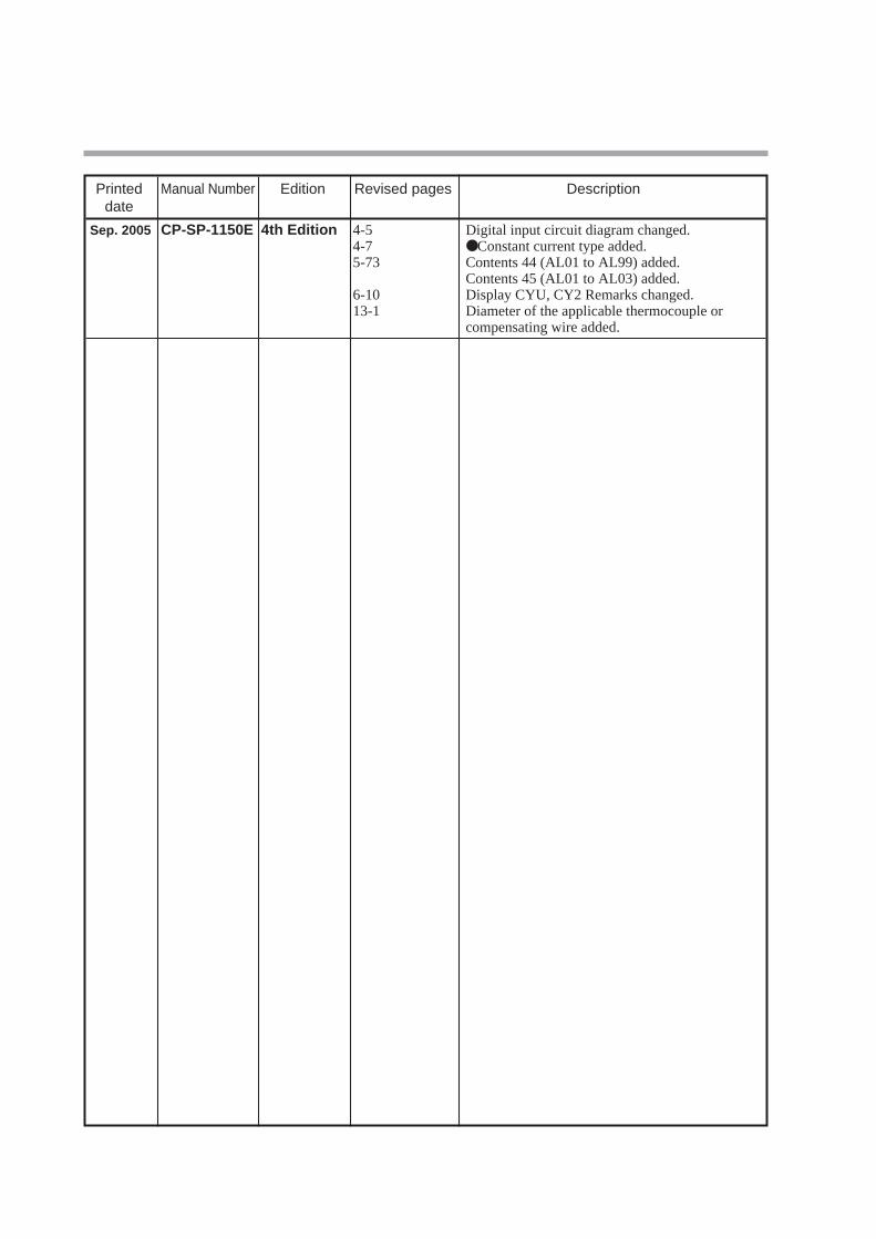
Printed Manual Number Edition Revised pages Descriptiondate
Sep. 2005 CP-SP-1150E 4th Edition 4-5 Digital input circuit diagram changed.4-7 Constant current type added.5-73 Contents 44 (AL01 to AL99) added.
Contents 45 (AL01 to AL03) added.6-10 Display CYU, CY2 Remarks changed.13-1 Diameter of the applicable thermocouple or
compensating wire added.


Specifications are subject to change without notice.
Advanced Automation Company
Totate International Building2-12-19 Shibuya Shibuya-kuTokyo 150-8316 JapanURL: http://www.yamatake.com
Printed in Japan.1st Edition: Issued in Feb. 2004
4th Edition: Issued in Sep. 2005(E)Printed on recycled paper. (04)


![Motor Controller SFC−LACI · 2016. 3. 5. · Manual Motor Controller Type SFC−LACI−...−DN (DeviceNet) Manual 567 387 en 0812NH [742 429] Motor Controller SFC−LACI](https://img.dokumen.tips/doc/110x75/610bcfd3e723f43589286efd/motor-controller-sfcalaci-2016-3-5-manual-motor-controller-type-sfcalaciaadn.jpg)