Embed Size (px)
Citation preview

2C09
Design for seismic
and climate change
Raffaele Landolfo
Mario D’Aniello European Erasmus Mundus Master Course
Sustainable Constructions
under Natural Hazards and Catastrophic Events 520121-1-2011-1-CZ-ERA MUNDUS-EMMC
European Erasmus Mundus
Master Course
Sustainable Constructions
under Natural Hazards
and Catastrophic Events
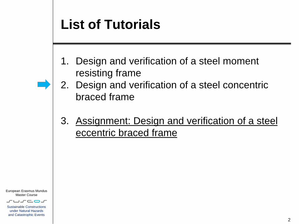
List of Tutorials
1. Design and verification of a steel moment
resisting frame
2. Design and verification of a steel concentric
braced frame
3. Assignment: Design and verification of a steel
eccentric braced frame
2

European Erasmus Mundus
Master Course
Sustainable Constructions
under Natural Hazards
and Catastrophic Events
Design and verification of a steel Concentric
Braced Frames
1. Introduction
2. General requirements for Concentric Braced
Frames
3. Damage limitation
4. Structural analysis and calculation models
5. Verification
3
European Erasmus Mundus
Master Course
Sustainable Constructions
under Natural Hazards
and Catastrophic Events
Introduction
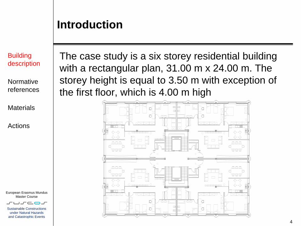
The case study is a six storey residential building
with a rectangular plan, 31.00 m x 24.00 m. The
storey height is equal to 3.50 m with exception of
the first floor, which is 4.00 m high
4
Building
description
Normative
references
Materials
Actions

European Erasmus Mundus
Master Course
Sustainable Constructions
under Natural Hazards
and Catastrophic Events
Introduction
Structural plan and configuration of the CBFs
5
Building
description
Normative
references
Materials
Actions
66
22 2
731
6 5
66 2.34 2.332.33 2.52.5
1 2 3
4 5 6
7 8 9
76
24
X Bracings V Bracings
Direction X Direction Y
European Erasmus Mundus
Master Course
Sustainable Constructions
under Natural Hazards
and Catastrophic Events
Introduction
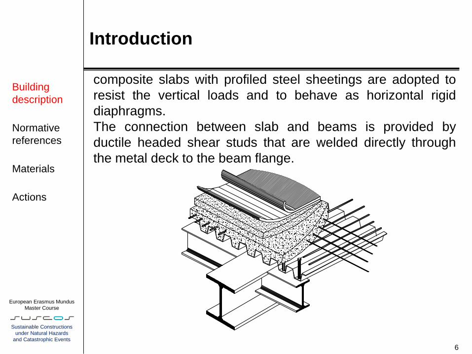
composite slabs with profiled steel sheetings are adopted to
resist the vertical loads and to behave as horizontal rigid
diaphragms.
The connection between slab and beams is provided by
ductile headed shear studs that are welded directly through
the metal deck to the beam flange.
6
Building
description
Normative
references
Materials
Actions
European Erasmus Mundus
Master Course
Sustainable Constructions
under Natural Hazards
and Catastrophic Events
Introduction
Apart from the seismic recommendations, the structural safety
verifications are carried out according to the following
European codes:
- EN 1990 (2001) Eurocode 0: Basis of structural design;
- EN 1991-1-1 (2002) Eurocode 1: Actions on structures - Part
1-1: General actions -Densities, self-weight, imposed loads for
buildings;
- EN 1993-1-1 (2003) Eurocode 3: Design of steel structures -
Part 1-1: General rules and rules for buildings;
- EN 1994-1-1 (2004) Eurocode 4: Design of composite steel
and concrete structures - Part 1.1: General rules and rules for
buildings.
In EU specific National annex should be accounted for design.
For generality sake, the calculation examples are carried out
using the recommended values of the safety factors 7
Building
description
Normative
references
Materials
Actions

European Erasmus Mundus
Master Course
Sustainable Constructions
under Natural Hazards
and Catastrophic Events
Introduction
It is well known that the standard nominal yield stress fy is the
minimum guaranteed value, which is generally larger than the actual
steel strength.
Owing to capacity design criteria, it is important to know the maximum
yield stress of the dissipative parts.
This implies practical problems because steel products are not usually
provided for an upper bound yield stress.
Eurocode 8 faces this problem considering 3 different options:
a) the actual maximum yield strength fy,max of the steel of dissipative
zones satisfies the following expression
fy,max ≤ 1.1gov fy
where fy is the nominal yield strength specified for the steel grade and
gov is a coefficient based on a statistic characterization of steel
products.
The Recommended value is 1.25 (EN1998-1 6.2.3(a)), but the
designer may use the value provided by the relevant National Annex.
8
Building
description
Normative
references
Materials
Actions

European Erasmus Mundus
Master Course
Sustainable Constructions
under Natural Hazards
and Catastrophic Events
Introduction
b) this clause refers to a situation in which steel producers provide a
“seismic-qualified” steel grade with both lower and upper bound value
of yield stress defined.
So if all dissipative parts are made considering one “seismic” steel
grade and the non-dissipative are made of a higher grade of steel
there is no need for gov which can be set equal to 1.
c) the actual yield strength fy,act of the steel of each dissipative zone is
determined from measurements and the overstrength factor is
computed for each dissipative zone as gov,act = fy,act / fy , fy being the
nominal yield strength of the steel of dissipative zones.
9
Building
description
Normative
references
Materials
Actions
European Erasmus Mundus
Master Course
Sustainable Constructions
under Natural Hazards
and Catastrophic Events
Introduction
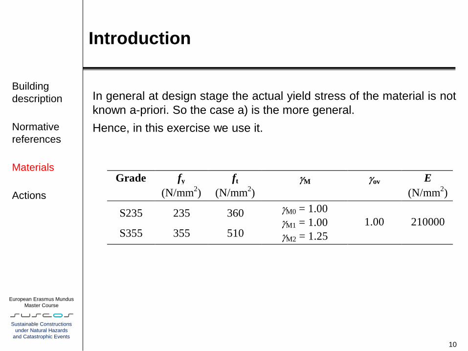
In general at design stage the actual yield stress of the material is not
known a-priori. So the case a) is the more general.
Hence, in this exercise we use it.
10
Building
description
Normative
references
Materials
Actions
Grade fy ft gM gov E
(N/mm2) (N/mm
2) (N/mm
2)
S235 235 360 gM0 = 1.00
gM1 = 1.00
gM2 = 1.25
1.00 210000 S355 355 510
European Erasmus Mundus
Master Course
Sustainable Constructions
under Natural Hazards
and Catastrophic Events
Introduction
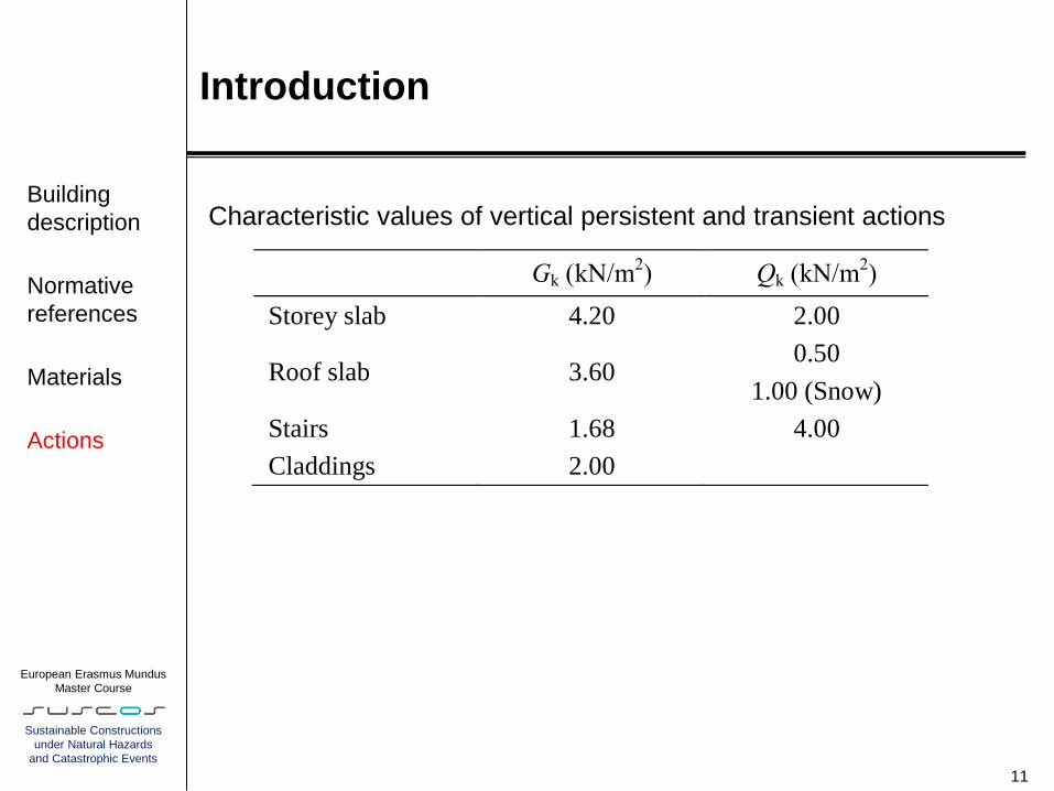
Characteristic values of vertical persistent and transient actions
11
Building
description
Normative
references
Materials
Actions
Gk (kN/m2) Qk (kN/m
2)
Storey slab 4.20 2.00
Roof slab 3.60 0.50
1.00 (Snow)
Stairs 1.68 4.00
Claddings 2.00

European Erasmus Mundus
Master Course
Sustainable Constructions
under Natural Hazards
and Catastrophic Events
Introduction
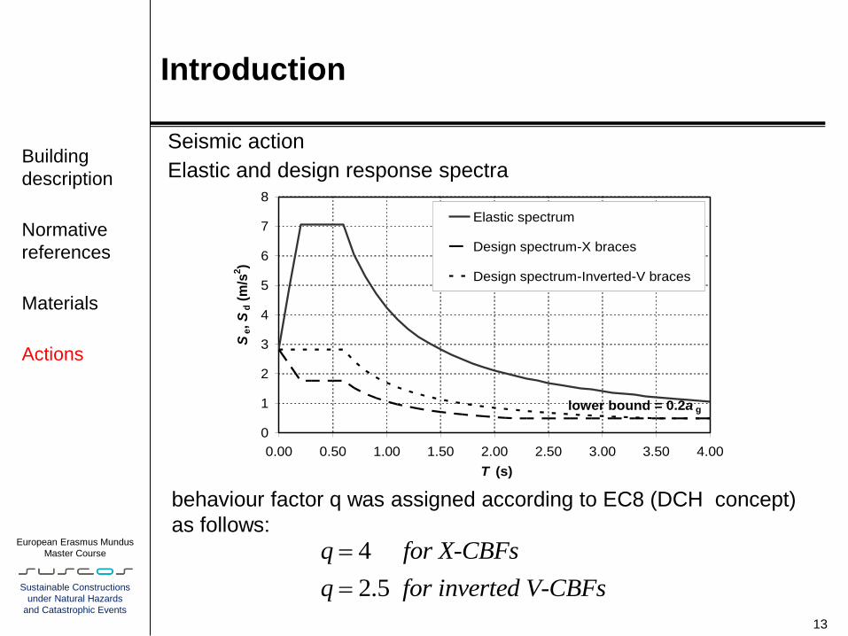
Seismic action
A reference peak ground acceleration equal to agR = 0.25g (being g
the gravity acceleration), a type C soil and a type 1 spectral shape
have been assumed.
The design response spectrum is then obtained starting from the
elastic spectrum using the following equations
12
Building
description
Normative
references
Materials
Actions
0 BT T 2.5
1 1d g
B
TS T a S
T q
B CT T T 2.5
d gS T a Sq
C DT T T
2.5 Cg
d
g
Ta S
q TS T
a
DT T 2
2.5 C Dg
d
g
T Ta S
q TS T
a
(3.2)
S = 1.15, TB = 0.20 s , TC = 0.60 s and TD = 2.00 s.
The parameter β is the lower bound factor for the horizontal design
spectrum, whose value should be found in National Annex.
β = 0.2 is recommended by the code (EN1998-1.2.2.5)
European Erasmus Mundus
Master Course
Sustainable Constructions
under Natural Hazards
and Catastrophic Events
Introduction
Seismic action
Elastic and design response spectra
13
Building
description
Normative
references
Materials
Actions
behaviour factor q was assigned according to EC8 (DCH concept)
as follows:
4
2.5
q for X-CBFs
q for inverted V-CBFs
0
1
2
3
4
5
6
7
8
0.00 0.50 1.00 1.50 2.00 2.50 3.00 3.50 4.00
T (s)
Se, S
d (
m/s
2)
Elastic spectrum
Design spectrum-X braces
Design spectrum-Inverted-V braces
lower bound = 0.2a g

European Erasmus Mundus
Master Course
Sustainable Constructions
under Natural Hazards
and Catastrophic Events
Introduction
Combination of actions
In case of buildings the seismic action should be combined with
permanent and variable loads as follows:
where Gk,i is the characteristic value of permanent action “I” (the self
weight and all other dead loads), AEd is the design seismic action
(corresponding to the reference return period multiplied by the
importance factor), Qk,i is the characteristic value of variable action “I”
and ψ2,i is the combination coefficient for the quasi-permanent value
of the variable action “I”, which is a function of the destination of use
of the building
14
Building
description
Normative
references
Materials
Actions
k,i k,i Ed2,i" " " "G Q A
Type of variable actions 2i
Category A – Domestic, residential areas 0.30
Roof 0.30
Snow loads on buildings 0.20
Stairs 0.80

European Erasmus Mundus
Master Course
Sustainable Constructions
under Natural Hazards
and Catastrophic Events
Introduction
Masses
In accordance with EN 1998-1 3.2.4 (2)P, the inertial effects in the
seismic design situation have to be evaluated by taking into account
the presence of the masses corresponding to the following
combination of permanent and variable gravity loads:
where is the combination coefficient for variable action i,
which takes into account the likelihood of the loads Qk,i to be not
present over the entire structure during the earthquake, as well as a
reduced participation in the motion of the structure due to a non-rigid
connection with the structure.
15
Building
description
Normative
references
Materials
Actions
k,i k,iE,i" "G Q
E,i 2i
Type of variable actions 2i Ei
Category A – Domestic, residential areas 0.30 0.50 0.15
Roof 0.30 1.00 0.30
Snow loads on buildings 0.20 1.00 0.20
Stairs 0.80 0.50 0.40
European Erasmus Mundus
Master Course
Sustainable Constructions
under Natural Hazards
and Catastrophic Events
Introduction
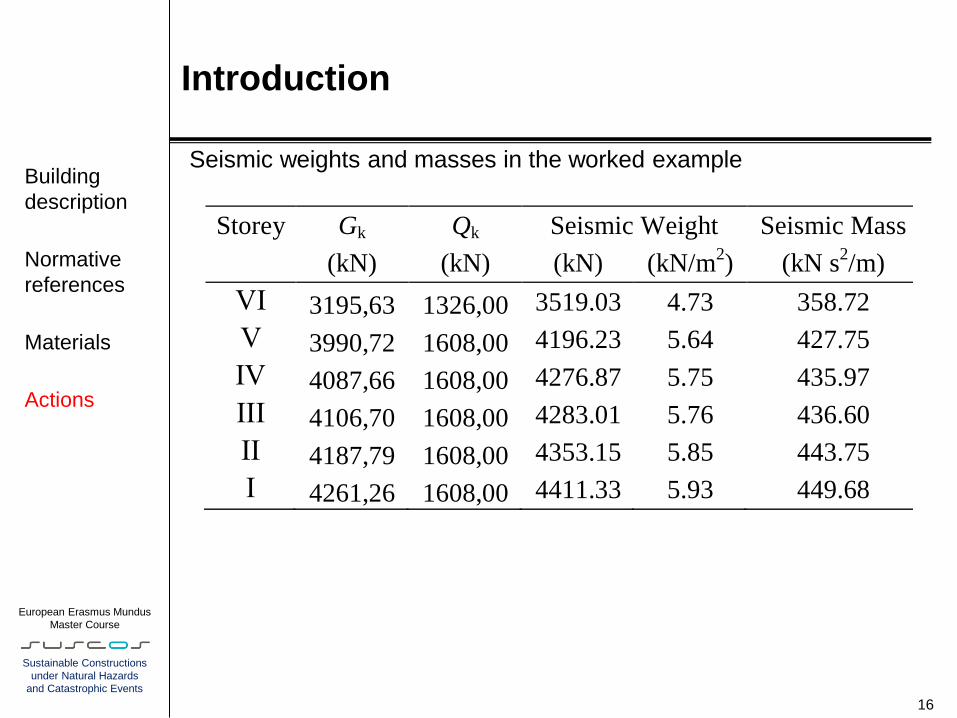
Seismic weights and masses in the worked example
16
Building
description
Normative
references
Materials
Actions
Storey Gk Qk Seismic Weight Seismic Mass
(kN) (kN) (kN) (kN/m2) (kN s
2/m)
VI 3195,63 1326,00 3519.03 4.73 358.72
V 3990,72 1608,00 4196.23 5.64 427.75
IV 4087,66 1608,00 4276.87 5.75 435.97
III 4106,70 1608,00 4283.01 5.76 436.60
II 4187,79 1608,00 4353.15 5.85 443.75
I 4261,26 1608,00 4411.33 5.93 449.68
European Erasmus Mundus
Master Course
Sustainable Constructions
under Natural Hazards
and Catastrophic Events
General requirements for CBFs
Basic principles of conceptual design
- structural simplicity: it consists in realizing clear and direct paths for
the transmission of the seismic forces
- uniformity: uniformity is characterized by an even distribution of the
structural elements both in-plan and along the height of the building.
- symmetry : a symmetrical layout of structural elements is envisaged
- redundancy: redundancy allow redistributing action effects and
widespread energy dissipation across the entire structure
- bi-directional resistance and stiffness: the building structure must be
able to resist horizontal actions in any direction
- torsional resistance and stiffness: building structures should possess
adequate torsional resistance and stiffness to limit torsional motions
- diaphragmatic behaviour at storey level: the floors (including the roof)
should act as horizontal diaphragms, thus transmitting the inertia forces
to the vertical structural systems
- adequate foundation: the foundations have a key role, because they
have to ensure a uniform seismic excitation on the whole building.
17
Basic
principles of
conceptual
design
Plan location
of CBFs and
structural
regularity
Damage
limitation
European Erasmus Mundus
Master Course
Sustainable Constructions
under Natural Hazards
and Catastrophic Events
General requirements for CBFs
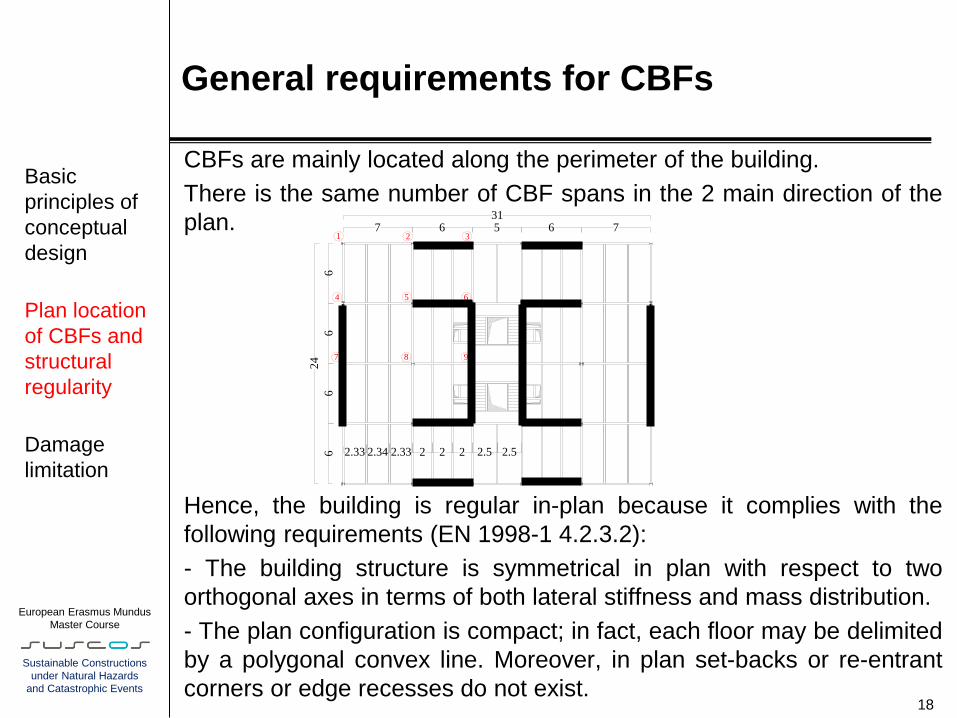
CBFs are mainly located along the perimeter of the building.
There is the same number of CBF spans in the 2 main direction of the
plan.
Hence, the building is regular in-plan because it complies with the
following requirements (EN 1998-1 4.2.3.2):
- The building structure is symmetrical in plan with respect to two
orthogonal axes in terms of both lateral stiffness and mass distribution.
- The plan configuration is compact; in fact, each floor may be delimited
by a polygonal convex line. Moreover, in plan set-backs or re-entrant
corners or edge recesses do not exist. 18
Basic
principles of
conceptual
design
Plan location
of CBFs and
structural
regularity
Damage
limitation
66
22 2
731
6 5
66 2.34 2.332.33 2.52.5
1 2 3
4 5 6
7 8 9
76
24
X Bracings V Bracings

European Erasmus Mundus
Master Course
Sustainable Constructions
under Natural Hazards
and Catastrophic Events
General requirements for CBFs
- The structure has rigid in plan diaphragms.
- The in-plan slenderness ratio Lmax/Lmin of the building is lower
than 4 (31000 mm / 24000 mm = 1.29), where Lmax and Lmin are
the larger and smaller in plan dimensions of the building,
measured in two orthogonal directions.
- At each level and for both X and Y directions, the structural
eccentricity eo (which is the nominal distance between the
centre of stiffness and the centre of mass) is practically
negligible and the torsional radius r is larger than the radius of
gyration of the floor mass in plan
19
Basic
principles of
conceptual
design
Plan location
of CBFs and
structural
regularity
Damage
limitation

European Erasmus Mundus
Master Course
Sustainable Constructions
under Natural Hazards
and Catastrophic Events
General requirements for CBFs
Regularity in elevation
- All seismic resisting systems are distributed along the building
height without interruption from the base to the top of the
building.
- Both lateral stiffness and mass at every storey practically
remain constant and/or reduce gradually, without abrupt
changes, from the base to the top of the building.
- The ratio of the actual storey resistance to the resistance
required by the analysis does not vary disproportionately
between adjacent storeys.
- There are no setbacks 20
Basic
principles of
conceptual
design
Plan location
of CBFs and
structural
regularity
Damage
limitation

European Erasmus Mundus
Master Course
Sustainable Constructions
under Natural Hazards
and Catastrophic Events
General requirements for CBFs
damage limitation requirement is expressed by the following
Equation:
drn ≤ h
where:
is the limit related to the typology of non-structural elements;
dr is the design interstorey drift;
h is the storey height;
n is a displacement reduction factor depending on the
importance class of the building, whose values are specified in
the National Annex. In this Tutorial n = 0.5 is assumed, which is
the recommended value for importance classes I and II
(the structure calculated in the numerical example belonging to
class II).
21
Basic
principles of
conceptual
design
Plan location
of CBFs and
structural
regularity
Damage
limitation

European Erasmus Mundus
Master Course
Sustainable Constructions
under Natural Hazards
and Catastrophic Events
General requirements for CBFs
According to EN 1998-1 4.3.4, If the analysis for the design seismic
action is linear-elastic based on the design response spectrum (i.e.
the elastic spectrum with 5% damping divided by the behaviour
factor q), then the values of the displacements ds are those from
that analysis multiplied by the behaviour factor q, as expressed by
means of the following simplified expression:
ds = qd ×de
where:
ds is the displacement of the structural system induced by the
design seismic action;
qd is the displacement behaviour factor, assumed equal to q;
de is the displacement of the structural system, as determined by a
linear elastic analysis under the design seismic forces.
22
Basic
principles of
conceptual
design
Plan location
of CBFs and
structural
regularity
Damage
limitation

European Erasmus Mundus
Master Course
Sustainable Constructions
under Natural Hazards
and Catastrophic Events
Structural analysis and calculation models
In this Tutorial two separate calculation 2D planar models in the
two main plan directions have been used, one in X direction and
the other in Y direction. This approach is allowed by the EC8 (at
clause 4.3.1(5)), since the examined building satisfies the
conditions given by EN 1998-1 4.2.3.2 and 4.3.3.1(8)
Modelling assumptions:
for the gravity load designed parts of the frame (beam–to-
columns connections, column bases) have been assumed as
perfectly pinned, but columns are considered continuous
through each floor beam.
Masses are considered as lumped into a selected master-joint
at each floor, because the floor diaphragms may be taken as
rigid in their planes
The models of X-CBFs and inverted V-CBFs need different
assumption for the braced part. 23
General
features
Calculation
models and
code
requirements
for X-CBFs
Calculation
models and
code
requirements
for inverted
V-CBFs
European Erasmus Mundus
Master Course
Sustainable Constructions
under Natural Hazards
and Catastrophic Events
Structural analysis and calculation models
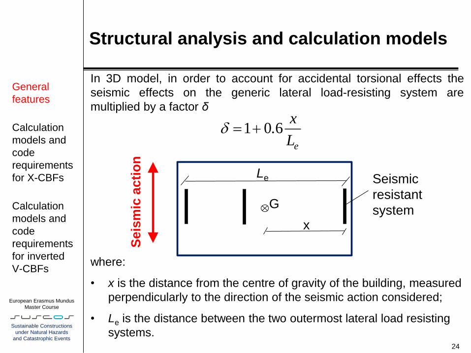
In 3D model, in order to account for accidental torsional effects the
seismic effects on the generic lateral load-resisting system are
multiplied by a factor δ
where:
• x is the distance from the centre of gravity of the building, measured
perpendicularly to the direction of the seismic action considered;
• Le is the distance between the two outermost lateral load resisting
systems.
24
x
Le
G
1 0 6e
x.
L
Se
ism
ic a
cti
on
Seismic
resistant
system
General
features
Calculation
models and
code
requirements
for X-CBFs
Calculation
models and
code
requirements
for inverted
V-CBFs
European Erasmus Mundus
Master Course
Sustainable Constructions
under Natural Hazards
and Catastrophic Events
Structural analysis and calculation models
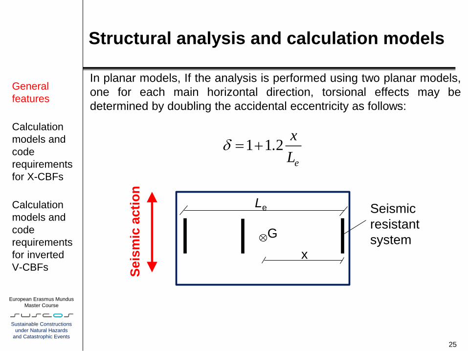
In planar models, If the analysis is performed using two planar models,
one for each main horizontal direction, torsional effects may be
determined by doubling the accidental eccentricity as follows:
25
x
Le
G
1 1 2e
x.
L
Se
ism
ic a
cti
on
Seismic
resistant
system
General
features
Calculation
models and
code
requirements
for X-CBFs
Calculation
models and
code
requirements
for inverted
V-CBFs
European Erasmus Mundus
Master Course
Sustainable Constructions
under Natural Hazards
and Catastrophic Events
Structural analysis and calculation models
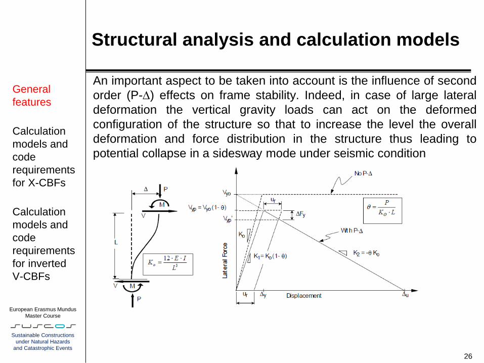
An important aspect to be taken into account is the influence of second
order (P-) effects on frame stability. Indeed, in case of large lateral
deformation the vertical gravity loads can act on the deformed
configuration of the structure so that to increase the level the overall
deformation and force distribution in the structure thus leading to
potential collapse in a sidesway mode under seismic condition
26
General
features
Calculation
models and
code
requirements
for X-CBFs
Calculation
models and
code
requirements
for inverted
V-CBFs
European Erasmus Mundus
Master Course
Sustainable Constructions
under Natural Hazards
and Catastrophic Events
Structural analysis and calculation models
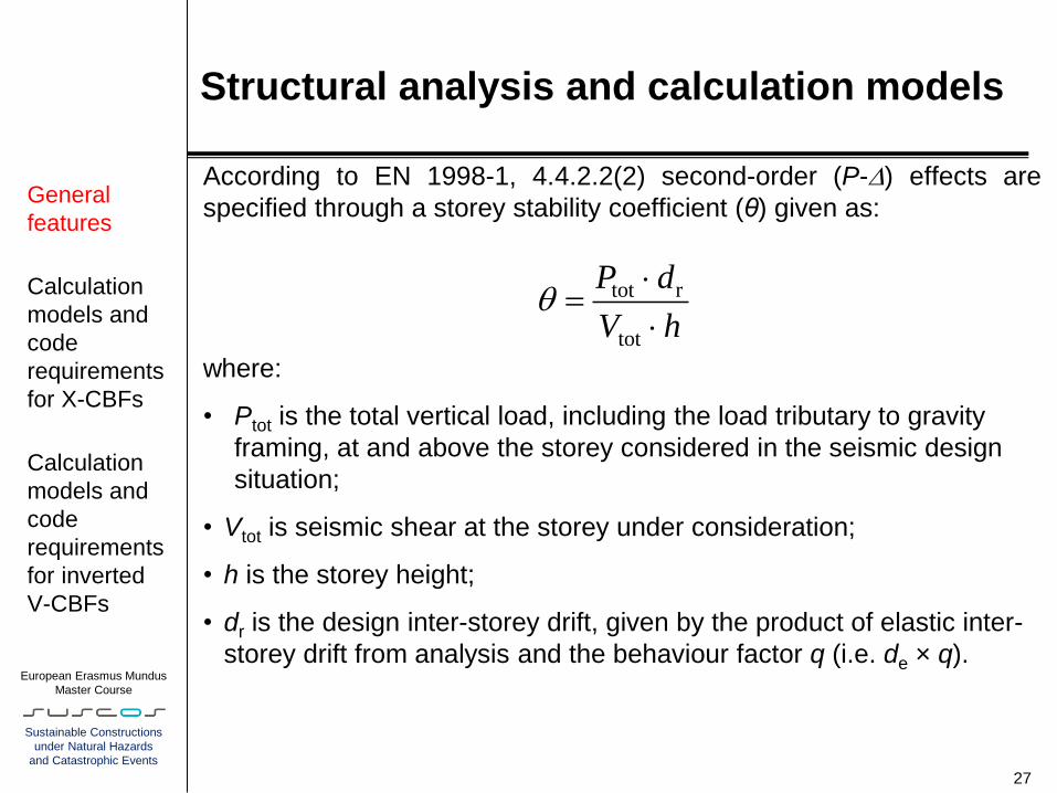
According to EN 1998-1, 4.4.2.2(2) second-order (P-) effects are
specified through a storey stability coefficient (θ) given as:
where:
• Ptot is the total vertical load, including the load tributary to gravity
framing, at and above the storey considered in the seismic design
situation;
• Vtot is seismic shear at the storey under consideration;
• h is the storey height;
• dr is the design inter-storey drift, given by the product of elastic inter-
storey drift from analysis and the behaviour factor q (i.e. de × q).
27
tot r
tot
P d
V h
General
features
Calculation
models and
code
requirements
for X-CBFs
Calculation
models and
code
requirements
for inverted
V-CBFs

European Erasmus Mundus
Master Course
Sustainable Constructions
under Natural Hazards
and Catastrophic Events
Structural analysis and calculation models
Frame instability is assumed for θ ≥ 0.3. If θ ≤ 0.1, second-order effects
could be neglected, whilst for 0.1 < θ ≤ 0.2, P- effects may be
approximately taken into account in seismic action effects through the
following multiplier:
Differently from MRFs, for CBFs it is common that the storey stability
coefficient is < 0.1, owing to the large lateral stiffness of this type of
structural scheme.
Hence, CBFs are generally insensitive to P-Delta effects
28
1
1
General
features
Calculation
models and
code
requirements
for X-CBFs
Calculation
models and
code
requirements
for inverted
V-CBFs

European Erasmus Mundus
Master Course
Sustainable Constructions
under Natural Hazards
and Catastrophic Events
Structural analysis and calculation models
X-CBFs According to EN 1998-1 6.7.2(2)P, in case of X-CBFs the structural
model shall include the tension braces only, unless a non-linear
analysis is carried out. Then, the generic braced bay is ideally
composed by a single brace (i.e. the diagonal in tension).
Generally speaking, in order to make tension alternatively developing in
all the braces at any storey, two models must be developed, one with
the braces tilted in one direction and another with the braces tilted in
the opposite direction
29 a)
k 2i kiiG Q
,Ed iF
b)
k 2i kiiG Q
,Ed iF
General
features
Calculation
models and
code
requirements
for X-CBFs
Calculation
models and
code
requirements
for inverted
V-CBFs
European Erasmus Mundus
Master Course
Sustainable Constructions
under Natural Hazards
and Catastrophic Events
Structural analysis and calculation models
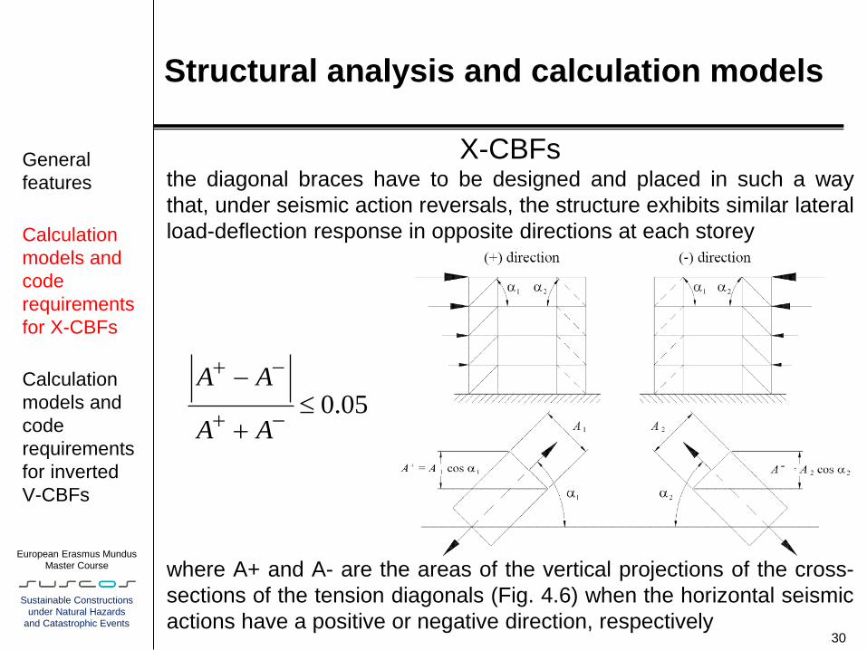
X-CBFs the diagonal braces have to be designed and placed in such a way
that, under seismic action reversals, the structure exhibits similar lateral
load-deflection response in opposite directions at each storey
where A+ and A- are the areas of the vertical projections of the cross-
sections of the tension diagonals (Fig. 4.6) when the horizontal seismic
actions have a positive or negative direction, respectively 30
General
features
Calculation
models and
code
requirements
for X-CBFs
Calculation
models and
code
requirements
for inverted
V-CBFs
0.05A A
A A
-

European Erasmus Mundus
Master Course
Sustainable Constructions
under Natural Hazards
and Catastrophic Events
Structural analysis and calculation models
X-CBFs
The diagonal braces have also to be designed in such a way
that the yield resistance Npl,Rd of their gross cross-section is
such that Npl,Rd ≥ NEd, where NEd is calculated from the elastic
model illustrated in Fig. 4.5 (Section 4.4.2).
In addition, the brace slenderness must fall in the range
31
General
features
Calculation
models and
code
requirements
for X-CBFs
Calculation
models and
code
requirements
for inverted
V-CBFs
1.3 2.0
being y

European Erasmus Mundus
Master Course
Sustainable Constructions
under Natural Hazards
and Catastrophic Events
Structural analysis and calculation models
X-CBFs
the restraint effect of the diagonal in tension has been taken into
account in the calculation of the geometrical slenderness of X-
diagonal braces. This effect halves the brace in-plane buckling
length, while it is taken as inefficient for out-of-plane buckling
Hence, the geometrical in-plane slenderness is calculated
considering the half brace length, while the out-of-plane ones
considering the entire brace length
32
General
features
Calculation
models and
code
requirements
for X-CBFs
Calculation
models and
code
requirements
for inverted
V-CBFs
Out-of-plane buckling
In-plane buckling
LbLb
LbLb

European Erasmus Mundus
Master Course
Sustainable Constructions
under Natural Hazards
and Catastrophic Events
Structural analysis and calculation models
X-CBFs
In order to force the formation of a global mechanism, which
means maximizing the number of yielding diagonals, clause
6.7.4(1) of the EC8 imposes that the ratios Ωi = Npl,Rd,i/NEd,i ,
which define the design overstrength of diagonals, may not vary
too much over the height of the structure.
In practical, being Ω the minimum over-strength ratio, the values
of all other Ωi should be in the range Ω to 1.25Ω
33
General
features
Calculation
models and
code
requirements
for X-CBFs
Calculation
models and
code
requirements
for inverted
V-CBFs
European Erasmus Mundus
Master Course
Sustainable Constructions
under Natural Hazards
and Catastrophic Events
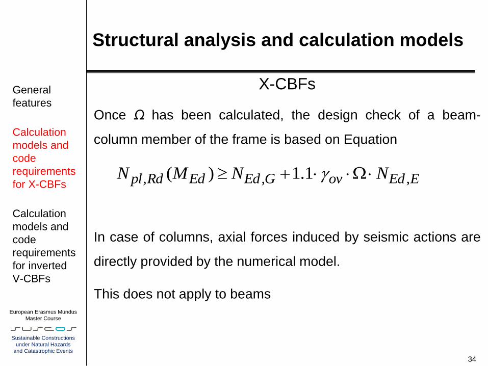
Structural analysis and calculation models
X-CBFs
Once Ω has been calculated, the design check of a beam-
column member of the frame is based on Equation
In case of columns, axial forces induced by seismic actions are
directly provided by the numerical model.
This does not apply to beams
34
General
features
Calculation
models and
code
requirements
for X-CBFs
Calculation
models and
code
requirements
for inverted
V-CBFs
, , ,( ) 1.1pl Rd Ed Ed G ov Ed EN M N Ng

European Erasmus Mundus
Master Course
Sustainable Constructions
under Natural Hazards
and Catastrophic Events
Structural analysis and calculation models
X-CBFs In the numerical model, floors are usually simulated by means of
rigid diaphragms. In such a way the relative in-plane
deformations are eliminated and the numerical model gives null
beam axial forces.
it is possible to calculate the beam axial forces by simple hand
calculations:
35
General
features
Calculation
models and
code
requirements
for X-CBFs
Calculation
models and
code
requirements
for inverted
V-CBFs
European Erasmus Mundus
Master Course
Sustainable Constructions
under Natural Hazards
and Catastrophic Events
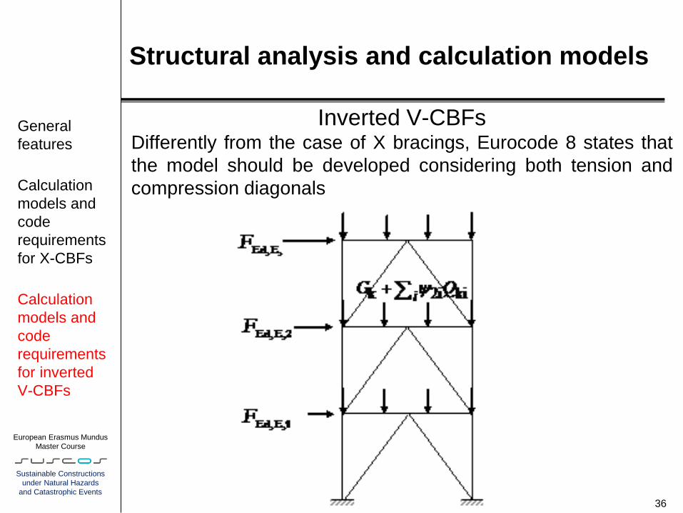
Structural analysis and calculation models
Inverted V-CBFs Differently from the case of X bracings, Eurocode 8 states that
the model should be developed considering both tension and
compression diagonals
36
General
features
Calculation
models and
code
requirements
for X-CBFs
Calculation
models and
code
requirements
for inverted
V-CBFs

European Erasmus Mundus
Master Course
Sustainable Constructions
under Natural Hazards
and Catastrophic Events
Structural analysis and calculation models
Inverted V-CBFs
Differently from X-CBFs, in frame with inverted-V bracing
compression diagonals should be designed for the compression
resistance in accordance to EN 1993:1-1 (EN 1998-1 6.7.3(6)).
This implies that the following condition shall be satisfied the
following condition:
where is the buckling reduction factor (EN 1993:1-1 6.3.1.2
(1)) and NEd,i is the required strength
37
General
features
Calculation
models and
code
requirements
for X-CBFs
Calculation
models and
code
requirements
for inverted
V-CBFs
,pl Rd EdN N

European Erasmus Mundus
Master Course
Sustainable Constructions
under Natural Hazards
and Catastrophic Events
Structural analysis and calculation models
Inverted V-CBFs
Differently from the case of X-CBFs, the code does not impose
a lower bound limit for the non-dimensional slenderness , while
the upper bound limit ( ) is retained.
Also in this case it is compulsory to control the variability of the
over-strength ratios Ωi = Npl,Rd,i/NEd,i in all diagonal braces.
However, it should be noted that, differently from the case of X-
CBFs, the design forces NEd,i are calculated with the model
where both the diagonal braces are taken into account
38
General
features
Calculation
models and
code
requirements
for X-CBFs
Calculation
models and
code
requirements
for inverted
V-CBFs
2

European Erasmus Mundus
Master Course
Sustainable Constructions
under Natural Hazards
and Catastrophic Events
Structural analysis and calculation models
Inverted V-CBFs
39
General
features
Calculation
models and
code
requirements
for X-CBFs
Calculation
models and
code
requirements
for inverted
V-CBFs
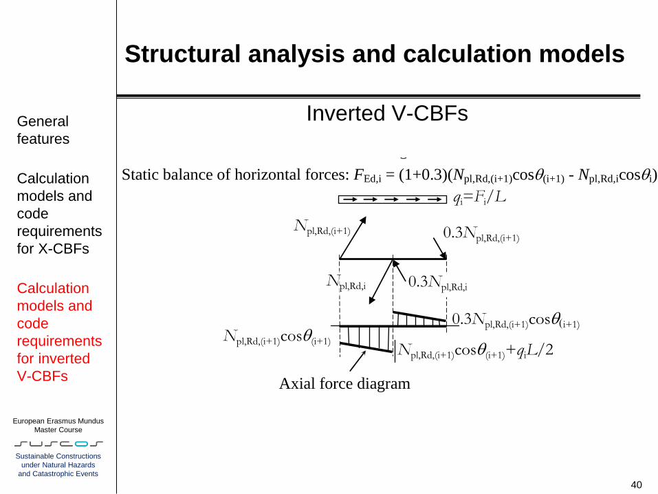
Vertical component of the force transmitted by the tension and compression braces:
(1-0.3)Npl,Rd,iseni
qi=Fi/L
FEd,i
Npl,Rd,(i+1)cos(i+1)
Axial force diagram L
Npl,Rd,(i+1) 0.3Npl,Rd,(i+1)
FEd,i+1
0.3Npl,Rd,(i+1)cosi+1)
Npl,Rd,i 0.3Npl,Rd,i
Static balance of horizontal forces: Fi = (1+0.3)(Npl,Rd,(i+1)cos(i+1) - Npl,Rd,icosi)
Npl,Rd,(i+1)cos(i+1)+qiL/2 i
Npl,Rd,i
MEd,E=(Npl,Rd,i-0.3Npl,Rd,i)(seni)(L/4)
Bending moment diagram
0.3Npl,Rd,i
+
k 2i kiiG Q
VEd,E=(Npl,Rd,i-0.3Npl,Rd,i)(seni)/2 VEd,E=(Npl,Rd,i-0.3Npl,Rd,i)(seni)/2
Shear force diagram
Npl,Rd,i
(Npl,Rd,i - 0.3Npl,Rd,i)(seni)(L/4)
Bending moment diagram
0.3Npl,Rd,i
+
k 2i kiiG Q
VEd,E=(Npl,Rd,i-0.3Npl,Rd,i)(seni)/2 VEd,E=(Npl,Rd,i-0.3Npl,Rd,i)(seni)/2
Shear force diagram
Static balance of horizontal forces: FEd,i = (1+0.3)(Npl,Rd,(i+1)cos(i+1) - Npl,Rd,icosi)
1
qi=Fi/L
FEd,i
Npl,Rd,(i+1)cos(i+1)
Axial force diagram L
Npl,Rd,(i+1) 0.3Npl,Rd,(i+1)
FEd,i+1
0.3Npl,Rd,(i+1)cosi+1)
Npl,Rd,i 0.3Npl,Rd,i
Static balance of horizontal forces: Fi = (1+0.3)(Npl,Rd,(i+1)cos(i+1) - Npl,Rd,icosi)
Npl,Rd,(i+1)cos(i+1)+qiL/2 i
European Erasmus Mundus
Master Course
Sustainable Constructions
under Natural Hazards
and Catastrophic Events
Structural analysis and calculation models
Inverted V-CBFs
40
General
features
Calculation
models and
code
requirements
for X-CBFs
Calculation
models and
code
requirements
for inverted
V-CBFs
Vertical component of the force transmitted by the tension and compression braces:
(1-0.3)Npl,Rd,iseni
qi=Fi/L
FEd,i
Npl,Rd,(i+1)cos(i+1)
Axial force diagram L
Npl,Rd,(i+1) 0.3Npl,Rd,(i+1)
FEd,i+1
0.3Npl,Rd,(i+1)cosi+1)
Npl,Rd,i 0.3Npl,Rd,i
Static balance of horizontal forces: Fi = (1+0.3)(Npl,Rd,(i+1)cos(i+1) - Npl,Rd,icosi)
Npl,Rd,(i+1)cos(i+1)+qiL/2 i
Npl,Rd,i
MEd,E=(Npl,Rd,i-0.3Npl,Rd,i)(seni)(L/4)
Bending moment diagram
0.3Npl,Rd,i
+
k 2i kiiG Q
VEd,E=(Npl,Rd,i-0.3Npl,Rd,i)(seni)/2 VEd,E=(Npl,Rd,i-0.3Npl,Rd,i)(seni)/2
Shear force diagram
Npl,Rd,i
(Npl,Rd,i - 0.3Npl,Rd,i)(seni)(L/4)
Bending moment diagram
0.3Npl,Rd,i
+
k 2i kiiG Q
VEd,E=(Npl,Rd,i-0.3Npl,Rd,i)(seni)/2 VEd,E=(Npl,Rd,i-0.3Npl,Rd,i)(seni)/2
Shear force diagram
Static balance of horizontal forces: FEd,i = (1+0.3)(Npl,Rd,(i+1)cos(i+1) - Npl,Rd,icosi)
1
qi=Fi/L
FEd,i
Npl,Rd,(i+1)cos(i+1)
Axial force diagram L
Npl,Rd,(i+1) 0.3Npl,Rd,(i+1)
FEd,i+1
0.3Npl,Rd,(i+1)cosi+1)
Npl,Rd,i 0.3Npl,Rd,i
Static balance of horizontal forces: Fi = (1+0.3)(Npl,Rd,(i+1)cos(i+1) - Npl,Rd,icosi)
Npl,Rd,(i+1)cos(i+1)+qiL/2 i

European Erasmus Mundus
Master Course
Sustainable Constructions
under Natural Hazards
and Catastrophic Events
Verifications
Numerical models for X-CBFs
numerical models of the calculation example with single
diagonals tilted in +X direction (a) and in –X direction (b).
41
Numerical
models and
dynamic
properties
P- effects
X-CBFs
Inverted V-
CBFs
Connections
Damage
limitation
a) b)
European Erasmus Mundus
Master Course
Sustainable Constructions
under Natural Hazards
and Catastrophic Events
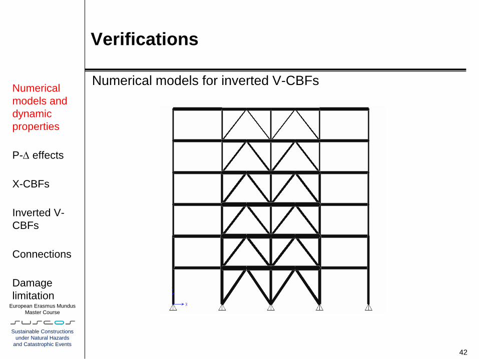
Verifications
Numerical models for inverted V-CBFs
42
Numerical
models and
dynamic
properties
P- effects
X-CBFs
Inverted V-
CBFs
Connections
Damage
limitation
European Erasmus Mundus
Master Course
Sustainable Constructions
under Natural Hazards
and Catastrophic Events
Verifications
43
Numerical
models and
dynamic
properties
P- effects
X-CBFs
Inverted V-
CBFs
Connections
Damage
limitation
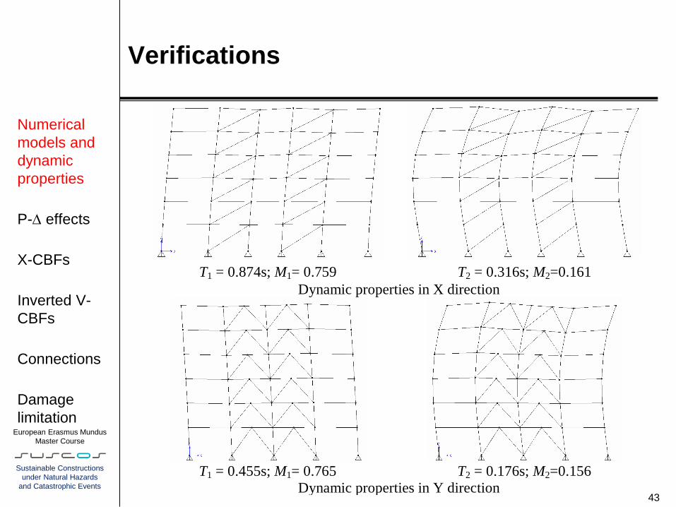
T1 = 0.874s; M1= 0.759
T2 = 0.316s; M2=0.161
Dynamic properties in X direction
T1 = 0.455s; M1= 0.765
T2 = 0.176s; M2=0.156
Dynamic properties in Y direction
European Erasmus Mundus
Master Course
Sustainable Constructions
under Natural Hazards
and Catastrophic Events
Verifications
The effects of actions included in the seismic design situation
have been determined by means of a linear-elastic modal
response spectrum analysis.
The first two modes have been considered because they satisfy
the following criterion:
“the sum of the effective modal masses for the modes taken into
account amounts to at least 90% of the total mass of the
structure”.
Since the first two vibration modes in both X and Y direction
may be considered as independent (being T2 ≤ 0.9T1, EN 1998-
1, 4.3.3.3.2) the SRSS (Square Root of the Sum of the Squares)
method is used to combine the modal maxima
44
Numerical
models and
dynamic
properties
P- effects
X-CBFs
Inverted V-
CBFs
Connections
Damage
limitation

European Erasmus Mundus
Master Course
Sustainable Constructions
under Natural Hazards
and Catastrophic Events
Verifications
the coefficient θ are lesser than 0.1 for both X-CBFs
and inverted V-CBFs.
Hence, the structure is not sensitive to second order
effects that can be neglected in the calculations.
This result is generally common for CBFs
45
Numerical
models and
dynamic
properties
P- effects
X-CBFs
Inverted V-
CBFs
Connections
Damage
limitation
European Erasmus Mundus
Master Course
Sustainable Constructions
under Natural Hazards
and Catastrophic Events
Verifications
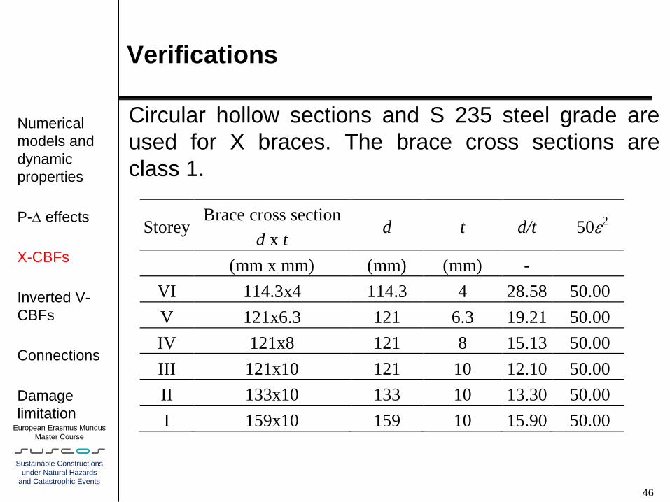
Circular hollow sections and S 235 steel grade are
used for X braces. The brace cross sections are
class 1.
46
Numerical
models and
dynamic
properties
P- effects
X-CBFs
Inverted V-
CBFs
Connections
Damage
limitation
Storey Brace cross section
d x t d t d/t .502
(mm x mm) (mm) (mm) -
VI 114.3x4 114.3 4 28.58 50.00
V 121x6.3 121 6.3 19.21 50.00
IV 121x8 121 8 15.13 50.00
III 121x10 121 10 12.10 50.00
II 133x10 133 10 13.30 50.00
I 159x10 159 10 15.90 50.00

European Erasmus Mundus
Master Course
Sustainable Constructions
under Natural Hazards
and Catastrophic Events
Verifications
The circular hollow sections are suitable to satisfy both the slenderness
limits (1.3 < ≤ 2.0) and the requirement of minimizing the variation
among the diagonals of the overstrength ratio Ωi, whose maximum
value (Ωmax) must not differ from the minimum one (Ωmin) by more than
25%. .
47
Numerical
models and
dynamic
properties
P- effects
X-CBFs
Inverted V-
CBFs
Connections
Damage
limitation
Storey
Brace cross
section
(d x t) Npl,Rd NEd i = Npl,Rd i min
(x 100)
(mm x
mm) (kN) (kN)
NEd
min
VI 114.3x4 178.10 1.90 326.65 180.65 1.81 16.70
V 121x6.3 171.08 1.82 533.45 325.70 1.64 5.71
IV 121x8 173.22 1.85 667.40 430.74 1.55 0.00
III 121x10 176.29 1.88 820.15 517.46 1.58 2.29
II 133x10 159.31 1.70 907.10 576.19 1.57 1.61
I 159x10 136.57 1.45 1099.80 650.07 1.69 9.19
European Erasmus Mundus
Master Course
Sustainable Constructions
under Natural Hazards
and Catastrophic Events
Verifications
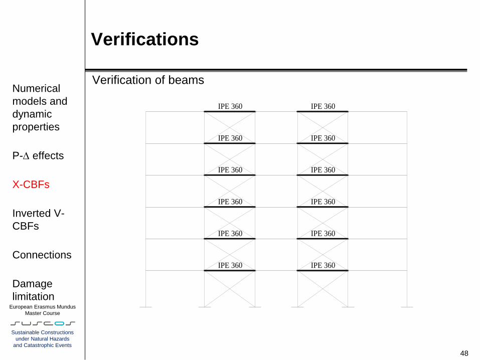
Verification of beams
48
Numerical
models and
dynamic
properties
P- effects
X-CBFs
Inverted V-
CBFs
Connections
Damage
limitation
IPE 360
IPE 360
IPE 360
IPE 360
IPE 360
IPE 360
IPE 360
IPE 360
IPE 360
IPE 360
IPE 360
IPE 360
European Erasmus Mundus
Master Course
Sustainable Constructions
under Natural Hazards
and Catastrophic Events
Verifications
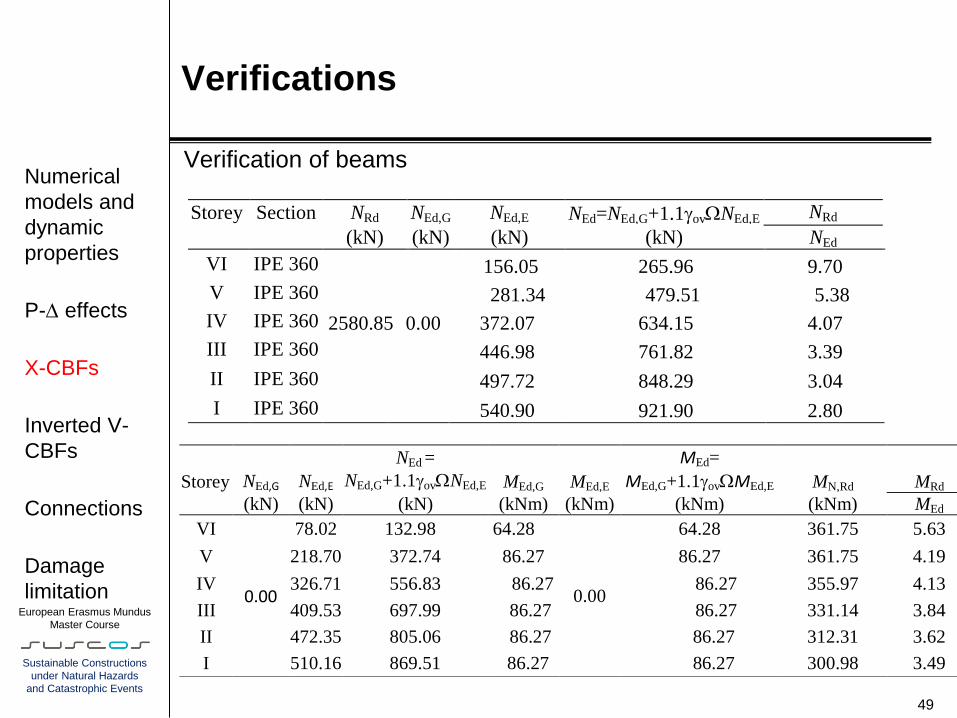
Verification of beams
49
Numerical
models and
dynamic
properties
P- effects
X-CBFs
Inverted V-
CBFs
Connections
Damage
limitation
Storey Section NRd NEd,G NEd,E NEd=NEd,G+1.1govNEd,E NRd
(kN) (kN) (kN) (kN) NEd
VI IPE 360 156.05 265.96 9.70
V IPE 360 281.34 479.51 5.38
IV IPE 360 2580.85 0.00 372.07 634.15 4.07
III IPE 360
446.98 761.82 3.39
II IPE 360 497.72 848.29 3.04
I IPE 360 540.90 921.90 2.80
Storey NEd,G NEd,E
NEd = NEd,G+1.1govNEd,E MEd,G MEd,E
MEd=
MEd,G+1.1govMEd,E MN,Rd MRd
(kN) (kN) (kN) (kNm) (kNm) (kNm) (kNm) MEd
VI
0.00
78.02 132.98 64.28
0.00
64.28 361.75 5.63
V 218.70 372.74 86.27 86.27 361.75 4.19
IV 326.71 556.83 86.27 86.27 355.97 4.13
III 409.53 697.99 86.27 86.27 331.14 3.84
II 472.35 805.06 86.27 86.27 312.31 3.62
I 510.16 869.51 86.27 86.27 300.98 3.49

European Erasmus Mundus
Master Course
Sustainable Constructions
under Natural Hazards
and Catastrophic Events
Verifications
Verification of columns
50
Numerical
models and
dynamic
properties
P- effects
X-CBFs
Inverted V-
CBFs
Connections
Damage
limitation
HE 180 A
HE 240 B
HE 240 M
HE 240 B
HE 240 M
HE 180 A
HE 180 A
HE 240 B
HE 240 M
HE 240 B
HE 240 M
HE 180 A
HE 180 A
HE 240 B
HE 240 M
HE 240 B
HE 240 M
HE 180 A
(a) (a) (b) (b) X
Z
European Erasmus Mundus
Master Course
Sustainable Constructions
under Natural Hazards
and Catastrophic Events
Verifications
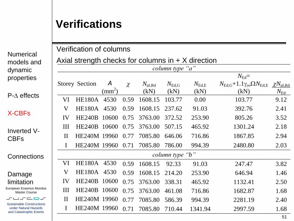
Verification of columns
Axial strength checks for columns in + X direction
51
Numerical
models and
dynamic
properties
P- effects
X-CBFs
Inverted V-
CBFs
Connections
Damage
limitation
column type “a”
Storey Section A Npl,Rd NEd,G NEd,E
NEd=
NEd,G+1.1govNEd,E Npl,Rd
(mm2) (kN) (kN) (kN) (kN) NEd
VI HE180A 4530 0.59 1608.15 103.77 0.00 103.77 9.12
V HE180A 4530 0.59 1608.15 237.62 91.03 392.76 2.41
IV HE240B 10600 0.75 3763.00 372.52 253.90 805.26 3.52
III HE240B 10600 0.75 3763.00 507.15 465.92 1301.24 2.18
II HE240M 19960 0.77 7085.80 646.06 716.86 1867.85 2.94
I HE240M 19960 0.71 7085.80 786.00 994.39 2480.80 2.03
column type “b”
VI HE180A 4530 0.59 1608.15 92.33 91.03 247.47 3.82
V HE180A 4530 0.59 1608.15 214.20 253.90 646.94 1.46
IV HE240B 10600 0.75 3763.00 338.31 465.92 1132.41 2.50
III HE240B 10600 0.75 3763.00 461.08 716.86 1682.87 1.68
II HE240M 19960 0.77 7085.80 586.39 994.39 2281.19 2.40
I HE240M 19960 0.71 7085.80 710.44 1341.94 2997.59 1.68

European Erasmus Mundus
Master Course
Sustainable Constructions
under Natural Hazards
and Catastrophic Events
Verifications
Inverted V-CBFs
Similarly to the X-bracing, for the inverted-V braces circular hollow
sections and S235 steel grade are used. The adopted brace cross
sections belong to class 1
52
Numerical
models and
dynamic
properties
P- effects
X-CBFs
Inverted V-
CBFs
Connections
Damage
limitation
Storey Brace cross section
d x t d t d/t .502
(mm x mm) (mm) (mm) -
VI 127x6.3 127 6.3 20.16 50.00
V 193.7x8 193.7 8 24.21 50.00
IV 244.5x8 244.5 8 30.56 50.00
III 244.5x10 244.5 10 24.45 50.00
II 273x10 273 10 27.30 50.00
I 323.9x10 323.9 10 32.39 50.00
European Erasmus Mundus
Master Course
Sustainable Constructions
under Natural Hazards
and Catastrophic Events
Verifications
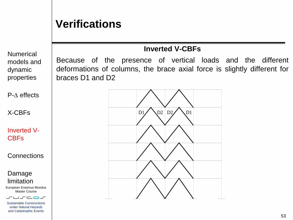
Inverted V-CBFs
Because of the presence of vertical loads and the different
deformations of columns, the brace axial force is slightly different for
braces D1 and D2
53
Numerical
models and
dynamic
properties
P- effects
X-CBFs
Inverted V-
CBFs
Connections
Damage
limitation
D1 D1D2D2
European Erasmus Mundus
Master Course
Sustainable Constructions
under Natural Hazards
and Catastrophic Events
Verifications
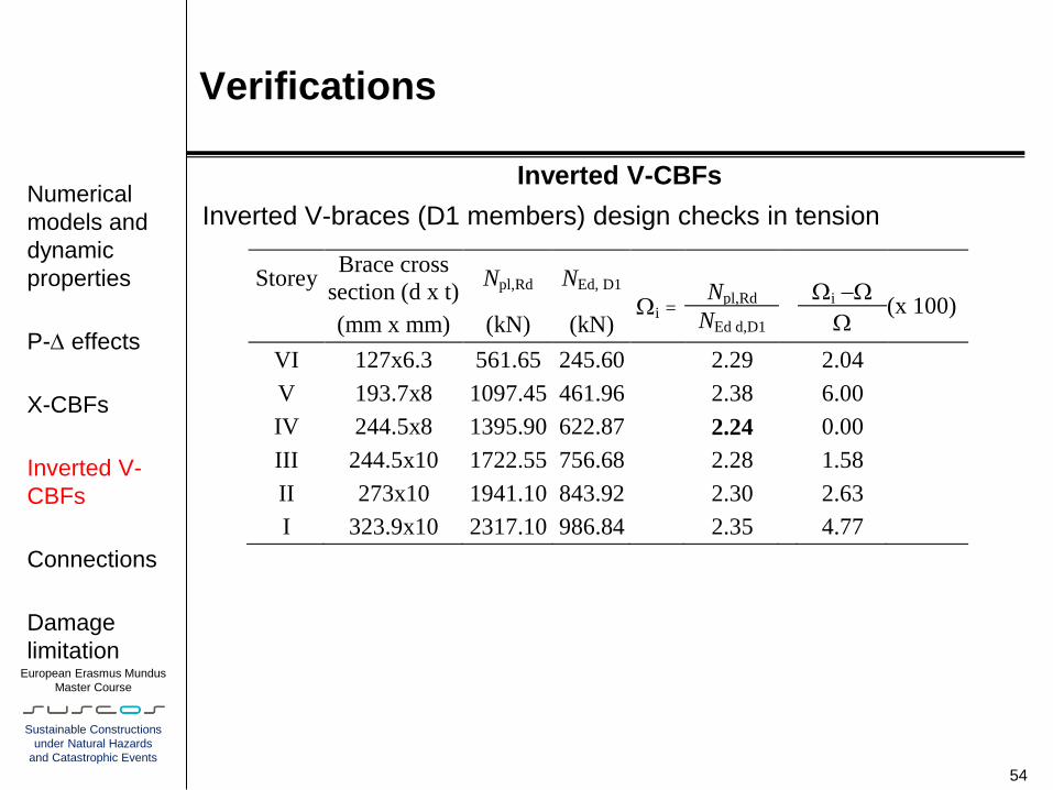
Inverted V-CBFs
Inverted V-braces (D1 members) design checks in tension
54
Numerical
models and
dynamic
properties
P- effects
X-CBFs
Inverted V-
CBFs
Connections
Damage
limitation
Storey Brace cross
section (d x t) Npl,Rd NEd, D1
i = Npl,Rd
i
(x 100) (mm x mm) (kN) (kN) NEd d,D1
VI 127x6.3 561.65 245.60 2.29 2.04
V 193.7x8 1097.45 461.96 2.38 6.00
IV 244.5x8 1395.90 622.87 2.24 0.00
III 244.5x10 1722.55 756.68 2.28 1.58
II 273x10 1941.10 843.92 2.30 2.63
I 323.9x10 2317.10 986.84 2.35 4.77
European Erasmus Mundus
Master Course
Sustainable Constructions
under Natural Hazards
and Catastrophic Events
Verifications
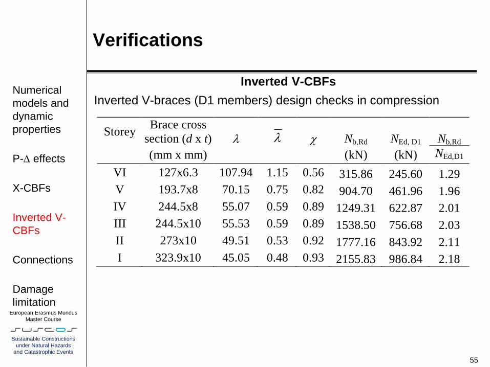
Inverted V-CBFs
Inverted V-braces (D1 members) design checks in compression
55
Numerical
models and
dynamic
properties
P- effects
X-CBFs
Inverted V-
CBFs
Connections
Damage
limitation
Storey Brace cross
section (d x t) Nb,Rd NEd, D1 Nb,Rd
(mm x mm) (kN) (kN) NEd,D1
VI 127x6.3 107.94 1.15 0.56 315.86 245.60 1.29
V 193.7x8 70.15 0.75 0.82 904.70 461.96 1.96
IV 244.5x8 55.07 0.59 0.89 1249.31 622.87 2.01
III 244.5x10 55.53 0.59 0.89 1538.50 756.68 2.03
II 273x10 49.51 0.53 0.92 1777.16 843.92 2.11
I 323.9x10 45.05 0.48 0.93 2155.83 986.84 2.18
European Erasmus Mundus
Master Course
Sustainable Constructions
under Natural Hazards
and Catastrophic Events
Verifications
Inverted V-CBFs
Verification of beams
56
Numerical
models and
dynamic
properties
P- effects
X-CBFs
Inverted V-
CBFs
Connections
Damage
limitation
HE 320 B
HE 320 M
HE 360 M
HE 450 M
HE 500 M
HPE 550 M
HE 320 B
HE 320 M
HE 360 M
HE 450 M
HE 500 M
HPE 550 M
European Erasmus Mundus
Master Course
Sustainable Constructions
under Natural Hazards
and Catastrophic Events
Verifications
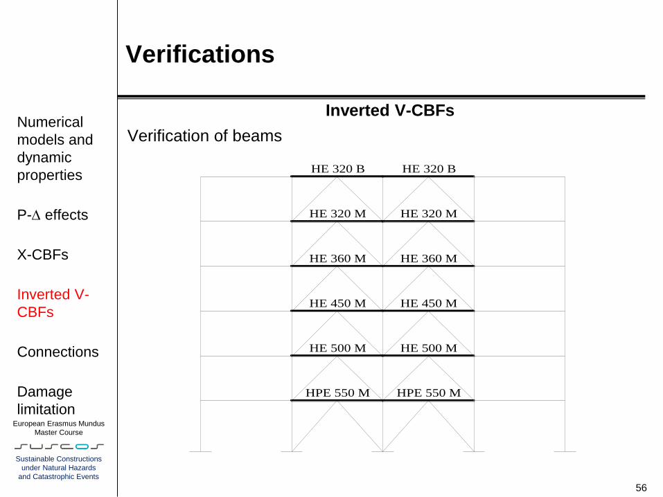
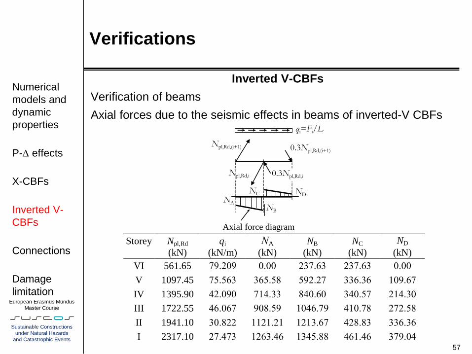
Inverted V-CBFs
Verification of beams
Axial forces due to the seismic effects in beams of inverted-V CBFs
57
Numerical
models and
dynamic
properties
P- effects
X-CBFs
Inverted V-
CBFs
Connections
Damage
limitation
qi=Fi/L
FEd,i
NA
Axial force diagram L
Npl,Rd,(i+1) 0.3Npl,Rd,(i+1)
FEd,i+1
ND
Npl,Rd,i 0.3Npl,Rd,i
Static balance of horizontal forces: Fi = (1+0.3)(Npl,Rd,(i+1)cos(i+1) - Npl,Rd,icosi)
NB i
NC
Storey Npl,Rd qi NA NB NC ND
(kN) (kN/m) (kN) (kN) (kN) (kN)
VI 561.65 79.209 0.00 237.63 237.63 0.00
V 1097.45 75.563 365.58 592.27 336.36 109.67
IV 1395.90 42.090 714.33 840.60 340.57 214.30
III 1722.55 46.067 908.59 1046.79 410.78 272.58
II 1941.10 30.822 1121.21 1213.67 428.83 336.36
I 2317.10 27.473 1263.46 1345.88 461.46 379.04

European Erasmus Mundus
Master Course
Sustainable Constructions
under Natural Hazards
and Catastrophic Events
Verifications
Inverted V-CBFs
Verification of beams
Axial strength checks in beams of inverted-V CBFs
58
Numerical
models and
dynamic
properties
P- effects
X-CBFs
Inverted V-
CBFs
Connections
Damage
limitation
Storey Section A Npl,Rd NEd,G NEd,E = NA
NEd =
NEd,G +NEd,E Npl,Rd
(mm2) (kN) (kN) (kN) (kN) NEd
VI HE320 B 16130 5726.15
0.00
475.25 475.25 12.05
V HE320 M 31200 11076.00 928.63 928.63 11.93
IV HE360 M 31880 11317.40 1181.17 1181.17 9.58
III HE450 M 33540 11906.70 1457.57 1457.57 8.17
II HE500 M 34430 12222.65 1642.50 1642.50 7.44
I HE550 M 35440 12581.20 1807.34 1807.34 6.96

European Erasmus Mundus
Master Course
Sustainable Constructions
under Natural Hazards
and Catastrophic Events
Verifications
Inverted V-CBFs
Verification of beams
Combined bending-axial force checks in beams of inverted-V CBFs
59
Numerical
models and
dynamic
properties
P- effects
X-CBFs
Inverted V-
CBFs
Connections
Damage
limitation
Storey Section NEd MEd,G MEd,E MEd MRd MRd
(kN) (kNm) (kNm) (kNm) (kNm) MEd
VI HE320 B 475.25 41.90 447.83 489.73 762.90 1.56
V HE320 M 928.63 58.13 875.05 933.19 1574.43 1.69
IV HE360 M 1181.17 58.35 1113.02 1171.38 1771.10 1.51
III HE450 M 1457.57 58.62 1373.48 1432.10 2247.51 1.57
II HE500 M 1642.50 59.24 1547.74 1606.98 2518.37 1.57
I HE550 M 1807.34 61.28 1946.36 2007.64 2816.22 1.40

European Erasmus Mundus
Master Course
Sustainable Constructions
under Natural Hazards
and Catastrophic Events
Verifications
Inverted V-CBFs
Verification of beams
Shear force checks in beams of inverted-V CBFs
60
Numerical
models and
dynamic
properties
P- effects
X-CBFs
Inverted V-
CBFs
Connections
Damage
limitation
Storey Section A Av Vpl,Rd VEd,G VEd,E VEd Vpl,Rd
(mm2) (mm
2) (kN) (kN) (kN) (kN) VEd
VI HE320B 16130 5172.75 1060.20 27.93 149.28 177.21 5.98
V HE320M 31200 9450.00 1943.01 38.75 291.69 330.44 5.88
IV HE360M 31880 10240.00 2098.78 38.90 371.01 409.91 5.12
III HE450M 33540 11980.00 2455.41 38.08 457.83 496.90 4.94
II HE500M 34430 12950.00 2654.22 39.49 515.91 555.41 4.78
I HE550M 35440 13960.00 2861.23 40.62 648.79 689.41 4.15
European Erasmus Mundus
Master Course
Sustainable Constructions
under Natural Hazards
and Catastrophic Events
Verifications
Inverted V-CBFs
Verification of columns
61
Numerical
models and
dynamic
properties
P- effects
X-CBFs
Inverted V-
CBFs
Connections
Damage
limitation
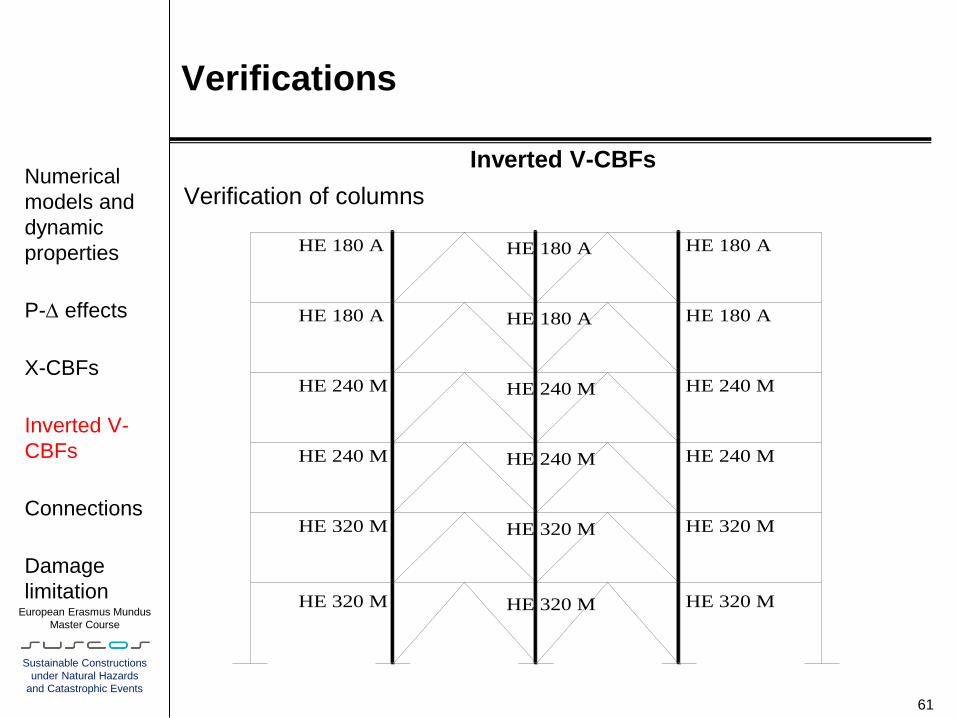
HE 180 A
HE 180 A
HE 240 M
HE 240 M
HE 320 M
HE 320 M
HE 180 A
HE 180 A
HE 240 M
HE 240 M
HE 320 M
HE 320 M
HE 180 A
HE 180 A
HE 240 M
HE 240 M
HE 320 M
HE 320 M

European Erasmus Mundus
Master Course
Sustainable Constructions
under Natural Hazards
and Catastrophic Events
Verifications
Inverted V-CBFs
Verification of columns
62
Numerical
models and
dynamic
properties
P- effects
X-CBFs
Inverted V-
CBFs
Connections
Damage
limitation
Storey Section A Npl,Rd NEd,G NEd,E NEd= NEd,G+1.1govNEd,E Npl,Rd
(mm2) (kN) (kN) (kN) (kN) NEd
VI HE180A 4530 0.59 1608.15 94.72 0.00 94.72 9.99
V HE180A 4530 0.59 1608.15 225.44 182.06 674.27 1.40
IV HE240M 19960 0.77 7085.80 384.77 527.24 1684.50 3.26
III HE240M 19960 0.77 7085.80 534.95 984.00 2960.71 1.85
II HE320M 31200 0.85 11076.00 694.41 1535.70 4480.22 2.10
I HE320M 31200 0.81 11076.00 847.88 2139.46 6122.07 1.46

European Erasmus Mundus
Master Course
Sustainable Constructions
under Natural Hazards
and Catastrophic Events
Verifications
Connections
Connections have to satisfy the requirements given in EN 1998-1 6.5.5.
In particular, the following connection overstrength criterion must be
applied:
Rd ≥ 1.1 γov Rfy
where Rd is the resistance of the connection, Rfy is the plastic
resistance of the connected dissipative member based on the design
yield stress of the material, γov is the material overstrength factor.
In addition, Eurocode 8 introduces an additional capacity design
criterion for bolted shear connections. Indeed, the design shear
resistance of the bolts should be at least 1.2 times higher than the
design bearing resistance.
63
Numerical
models and
dynamic
properties
P- effects
X-CBFs
Inverted V-
CBFs
Connections
Damage
limitation
European Erasmus Mundus
Master Course
Sustainable Constructions
under Natural Hazards
and Catastrophic Events
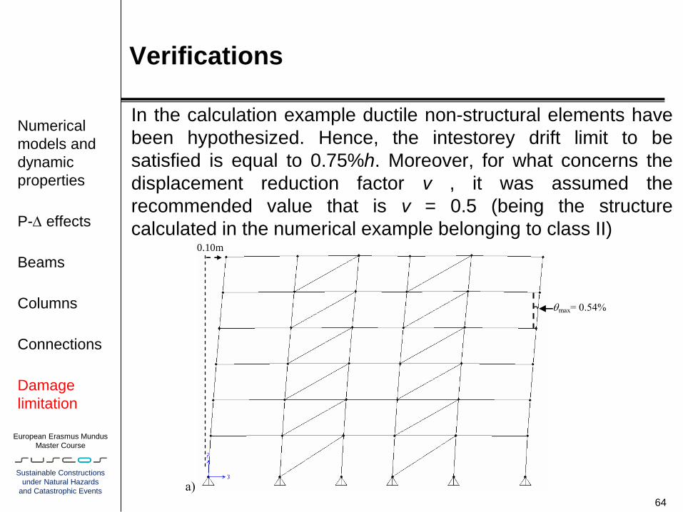
Verifications
In the calculation example ductile non-structural elements have
been hypothesized. Hence, the intestorey drift limit to be
satisfied is equal to 0.75%h. Moreover, for what concerns the
displacement reduction factor ν , it was assumed the
recommended value that is ν = 0.5 (being the structure
calculated in the numerical example belonging to class II)
64
Numerical
models and
dynamic
properties
P- effects
Beams
Columns
Connections
Damage
limitation
a)
0.10m
0.04m
max= 0.54%
European Erasmus Mundus
Master Course
Sustainable Constructions
under Natural Hazards
and Catastrophic Events
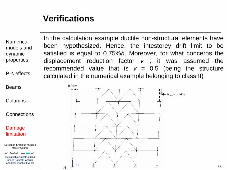
Verifications
In the calculation example ductile non-structural elements have
been hypothesized. Hence, the intestorey drift limit to be
satisfied is equal to 0.75%h. Moreover, for what concerns the
displacement reduction factor ν , it was assumed the
recommended value that is ν = 0.5 (being the structure
calculated in the numerical example belonging to class II)
65
Numerical
models and
dynamic
properties
P- effects
Beams
Columns
Connections
Damage
limitation
a)
b)
0.10m
0.04m
max= 0.54%
max= 0.54%

Thank you
for your attention
http://steel.fsv.cvut.cz/suscos