Embed Size (px)
Citation preview
RAV4 – NEW FEATURES
10SEG01Y
10SEG02Y
14
2AR-FE ENGINE
1. General
The 2AR-FE engine is an in-line, 4-cylinder, 2.5-liter, 16-valve DOHC engine. This engine uses the Dual
VVT-i (Variable Valve Timing-intelligent) system, DIS (Direct Ignition System), ACIS (Acoustic Control
Induction System) and ETCS-i (Electronic Throttle Control System-intelligent). It has been developed to
achieve high performance, quietness, fuel economy and clean emission.

RAV4 – NEW FEATURES 15
Engine Specifications
Model ’09 RAV 4 ’08 RAV4
Engine 2AR-FE 2AZ-FE
No. of Cyls. & Arrangement 4-cylinder, In-line
Valve Mechanism16-valve DOHC, Chain Drive
(with Dual VVT-i)
16-valve DOHC, Chain Drive
(with VVT-i)
Combustion Chamber Pentroof Type
Manifolds Cross-flow
Fuel System SFI
Ignition System DIS
Displacement2494 cm3
(152.2 cu.in.)
2362 cm3
(144.1 cu. in.)
Bore × Stroke90.0 × 98.0 mm
(3.54 × 3.86 in.)
88.5 × 96.0 mm
(3.48 × 3.78 in.)
Compression Ratio 10.4 : 1 9.8 : 1
Max. Output*1 (SAE-NET)134 kW @ 6000 rpm
(180 HP @ 6000 rpm)
124 kW @ 6000 rpm
(166 HP @ 6000 rpm)
Max. Torque*1 (SAE-NET)235 N⋅m @ 4100 rpm
(173 ft⋅lbf @ 4100 rpm)
224 N⋅m @ 4000 rpm
(165 ft⋅lbf @ 4000 rpm)
Valve
Timing
IntakeOpen 3 – 53 BTDC 3 – 43 BTDC
Closed 61 – 11 ABDC 65 – 25 ABDC
ExhaustOpen 60 – 20 BBDC 45 BBDC
Closed 4 – 44 ATDC 3 ATDC
Firing Order 1 – 3 – 4 – 2
Research Octane Number 91 or higher
Octane Rating 87 or higher
Tailpipe Emission Regulation ULEV-II, SFTP
Evaporative Emission Regulation LEV-II, ORVR
Engine Service Mass (Reference) *2 147 kg (324.0 lb) 138 kg (304.2 lb)
*1: Maximum output and torque rating is determined by revised SAE J1349 standard.
*2: Weight shows the figure with oil and engine coolant fully filled.

RAV4 – NEW FEATURES
10SEG03Y
Torque
(N.m)
240220
200
180160
(ft.lbf)
180
160
140
120
(HP)
200
180
160
140
120
100
80
60
40
20
0
(kW)
140
120
100
80
60
40
20
0
Output
0 1000 2000 3000 4000 5000 6000 7000
Engine Speed (rpm)
10SEG04Y
: Intake Valve Opening Angle
: Exhaust Valve Opening Angle
VVT-i Operation Range (Intake)
53
61
VVT-i Operation Range (Intake) 11
TDC3 4
VVT-i Operation Range (Exhaust)
44
60
VVT-i Operation Range (Exhaust)20
BDC
16
Performance Curve
Valve Timing

RAV4 – NEW FEATURES 17
2. Features of 2AR-FE Engine
The 2AR-FE engine has achieved the following performance features through the use of the items listed
below:
(1) High performance and reliability
(2) Low noise and vibration
(3) Lightweight and compact design
(4) Good serviceability
(5) Clean emission and fuel economy
Section Item (1) (2) (3) (4) (5)
Engine Proper
A cylinder head cover made of magnesium alloy is used.
A taper squish shape is used for the combustion chamber.
Spiny-type liners are used in the cylinder bores.
A water jacket spacer is used.
The piston skirt is coated with resin.
Low tension piston rings are used.
A resin gear balance shaft is used.
Valve
Mechanism
A timing chain and chain tensioner are used.
Hydraulic lash adjusters are used.
Roller rocker arms are used.
Lubrication
SystemAn oil filter with a replaceable element is used.
Cooling SystemTOYOTA Genuine SLLC (Super Long Life Coolant) is
used.
Intake and
Exhaust
System
A charcoal filter is used in the air cleaner cap.
An intake manifold made of plastic is used.
A linkless-type throttle body is used.
A thin-wall ceramic TWC (Three-Way Catalytic
converter) is used.
Fuel System
A fuel returnless system is used.
Quick connectors are used to connect the fuel hose with
the fuel pipe.
12-hole type fuel injectors with high atomizing
performance are used.
Ignition System Long-reach type iridium-tipped spark plugs are used.
Charging
SystemA segment conductor type generator is used.
Starting SystemA PS (Planetary reduction-Segment conductor motor)
type starter is used.
Serpentine Belt
Drive SystemA serpentine belt drive system is used.
(Continued)

RAV4 – NEW FEATURES18
Section Item (1) (2) (3) (4) (5)
Engine Control
System
The DIS (Direct Ignition System) makes ignition timing
adjustment unnecessary.
An ETCS-i (Electronic Throttle Control
System-intelligent) is used.
A Dual VVT-i (Variable Valve Timing-intelligent)
system is used.
An ACIS (Acoustic Control Induction System) is used.
A tumble control system is used.
A starter control (cranking hold function) is used.*
*: Models with smart key system

RAV4 – NEW FEATURES
10SEG08Y
Cylinder Head Cover
A
Cylinder Head Cover Gasket
Oil Delivery Pipe
View from A
10SEG09Y
19
3. Engine Proper
Cylinder Head Cover
A lightweight magnesium alloy die-cast cylinder head cover is used.
An oil delivery pipe is installed inside the cylinder head cover. This ensures lubrication to the sliding parts
of the roller rocker arm, improving reliability.
Cylinder Head Gasket
A triple-layer metal type cylinder head gasket is used.
The surface of the cylinder head gasket is coated with fluoro rubber to ensure a high level of reliability.

RAV4 – NEW FEATURES
10SEG10Y
10SEG11Y
Camshaft Housing
Cylinder Head
Camshaft Bearing Cap
A
A
Exhaust Side
Intake Side
IntakeSide
Taper Squish
ExhaustSide
A – A Cross Section
20
Cylinder Head
The cylinder head structure has been simplified by separating the camshaft housing (cam journal portion)
from the cylinder head.
The cylinder head, which is made of aluminum, contains a pentroof-type combustion chamber. The spark
plug is located in the center of the combustion chamber in order to improve the engine’s anti-knocking
performance.
A taper squish combustion chamber is used to improve anti-knocking performance. In addition, engine
performance and fuel economy have been improved.
Long nozzle type fuel injectors are installed in the cylinder head to reduce the distance from injector to
intake valve, thus preventing the fuel from adhering to the intake port walls, and reducing HC exhaust
emissions.

RAV4 – NEW FEATURES
10SEG29Y
CrankshaftBearingCap
PlasticRegionTightening Bolt
Oil Drain Passage
A
A
Blowby Gas Passage
Oil Filter Bracket
Crankcase
Water Passage
CylinderBlock
Spiny-type Liner(Irregularly shaped outer casting surface of liner)
A – A Cross Section
21
Cylinder Block
Water passages have been provided between the cylinder bores. By allowing the engine coolant to flow
between the cylinder bores, this construction enables the temperature of the cylinder walls to be kept
uniform.
The liners are the spiny-type, which have been manufactured so that their casting exteriors form large
irregular surfaces in order to enhance the adhesion between the liners and the aluminum cylinder block.
The enhanced adhesion helps heat dissipation, resulting in a lower overall temperature and heat
deformation of the cylinder bores.
Blowby gas passages are provided in the crankcase.
Oil drain passages are provided in the crankcase. This prevents the crankshaft from mixing the engine
oil, which reduces rotational resistance.
The oil filter bracket is integrated into the crankcase.

RAV4 – NEW FEATURES
10SEG30Y
Oil Separator
Separator Case
Oil Separator Cover
10SEG31Y
Bore Center
Crankshaft Center
MaximumPressure
CrankshaftCenter
Offset Crankshaft
MaximumPressure
Center Crankshaft
IntakeSide
ExhaustSide
22
An oil separator is provided in the blowby gas passage inside the cylinder block. This separates the engine
oil from the blowby gas in order to reduce the degradation and consumption of volume of the engine oil.
Through the use of the offset crankshaft, the bore center is shifted 10 mm (0.39 in.) towards the exhaust,
in relation to the crankshaft center. Thus, the side force to the cylinder wall is reduced when the maximum
pressure is applied, which contributes to fuel economy.

RAV4 – NEW FEATURES
10SEG32Y
A
A
Water Jacket Spacer
Water Jacket
Water Jacket Spacer
A – A Cross Section
23
A shallow bottom water jacket is used. The resulting reduction in the volume of the engine coolant
improves warm-up performance, which contributes to improved fuel economy.
The water jacket spacer is provided in the water jacket of the cylinder block.
The water jacket spacer suppresses the water flow in the bottom of the water jackets, guides the coolant
in the upper area of the water jacket, and ensures uniform temperature distribution. As a result, the
viscosity of the engine oil that acts as a lubricant between the bore walls and the pistons can be lowered,
thus reducing friction.

RAV4 – NEW FEATURES
10SEG12Y
Anodic Oxide Coating
ResinCoating
Taper Squish ShapePiston Ring PVD Coating
No. 1 Compression Ring
No. 2 Compression Ring
Oil Ring
10SEG13Y
Plastic Region Tightening Bolt
Micro-grooved
24
Piston
The piston is made of aluminum alloy and the skirt area is made compact and lightweight.
The piston head portion uses a taper squish shape to improve the fuel combustion efficiency.
The piston skirt has been coated with resin to reduce the friction loss.
The groove of the top ring is coated with anodic oxide to improve wear resistance and corrosion
resistance.
Low-tension piston rings are used to reduce friction and achieve excellent fuel economy.
Narrow-width piston rings are used to reduce weight and friction.
A No. 1 compression ring with an inside bevel shape is used.
A PVD (Physical Vapor Deposition) coating has been applied to the surface of the No. 1 compression
ring, in order to improve its wear resistance.
Connecting Rod
The connecting rods and caps are made of microalloyed steel.
Plastic region tightening bolts are used on the connecting rod.
The connecting rod bearings are reduced in width to reduce friction.
The lining surface of the connecting rod bearing has been micro-grooved to achieve an optimal amount
of oil clearance. As a result, cold-engine cranking performance has been improved and engine vibrations
have been reduced.

RAV4 – NEW FEATURES
10SEG14Y
10SEG15Y
No. 1 Journal
Balance Weight
Balance Shaft Drive Gear
Crank PinOil Hole
Oil GrooveUpper Main Bearing
Micro-grooved
Lower Main Bearing
25
Crankshaft
The crankshaft is made of microalloyed steel. It has 5 journals and 8 balance weights.
A balance shaft drive gear is provided for the crankshaft.
The crankshaft bearings are reduced in width to reduce friction.
The lining surface of the crankshaft bearing has been micro-grooved to achieve an optimal amount of
oil clearance. As a result, cold-engine cranking performance has been improved and engine vibrations
have been reduced.
The oil groove on the crankshaft bearing is made eccentric to reduce the amount of oil leakage from the
bearing. This enables the capacity of the oil pump to be reduced in order to achieve a low friction
operation.

RAV4 – NEW FEATURES
10SEG33Y
Balance Shaft Drive Gear
No. 2 Balance Shaft
Crankshaft
: Resin Gear
No. 2 Balance Shaft Housing
No. 1 Balance Shaft
No. 1 Balance Shaft Housing
26
Balance Shaft
1) General
A balance shaft is used to reduce vibrations.
The crankshaft directly drives the No. 1 balance shaft.
In addition, a resin gear is used on the driven side to suppress noise and offer lightweight design.

RAV4 – NEW FEATURES
286EG71
Top Dead Center
Point of Max. Speed
Bottom Dead Center90
Point of Max. Speed
Point of Max. Speed
286EG72
Inertial Force of Cylinders No. 2 and No. 3
Combined Inertial Force of All Cylinders(Unbalanced Secondary Inertial Force)
Inertial Force of Cylinder No. 1 and No. 4
–180
–90
Force
0
90
180
270
Inertial force that cannot be canceled
Crankshaft Angle
Inertial Force Generated by the In-line 4 Cylinders
10SEG71Y
0
A
90
CDB
180
E
270
Inertial Force of Balancer
Crankshaft Angle
Secondary Inertial Force
Mass Direction of Balance Shaft
Inertial Force of Balancer
Mass Direction of Balance Shaft at Crankshaft Angle
27
2) Operation
In the in-line 4-cylinder engine, the crankshaft
angle for cylinders No. 1 and No. 4 are at exactly
the opposite (180) position of cylinders No. 2 and
No. 3. Therefore, the inertial force of the pistons
and the connecting rods of the former 2 cylinders
and of the latter 2 cylinders almost cancel each
other out. However, because the position at which
the piston reaches its maximum speed is located
toward the top dead center from the center of the
stroke, the upward inertial force is greater than the
downward inertial force. This unbalanced
secondary inertial force is generated twice for each
rotation of the crankshaft.
To cancel the unbalanced secondary inertial force, 2 balance shafts are rotated twice for each rotation
of the crankshaft and generate inertial force in the opposite direction. Also, in order to cancel the inertial
force generated by the balance shaft itself, the balance shaft actually consists of 2 shafts rotating in
opposite directions.

RAV4 – NEW FEATURES
10SEG16Y
Intake VVT-i Controller
ChainSlipper
ChainTensioner
No. 2 Chain Damper
Exhaust VVT-i Controller
IntakeValve
Chain Damper
Exhaust Camshaft
Intake Camshaft
ExhaustValve
Roller Rocker Arm
Hydraulic Lash Adjuster
Valve
28
4. Valve Mechanism
General
The Dual VVT-i system is used to improve fuel economy and engine performance and reduce exhaust
emissions. For details of Dual VVT-i system, see page 72.
The intake and exhaust camshafts are driven by a timing chain.
The roller rocker arms with built-in needle bearings are used. This reduces the friction that occurs
between the cams and the areas (roller rocker arms) that push the valves down, thus improving fuel
economy.
The hydraulic lash adjusters, which maintain a constant zero valve clearance through the use of oil
pressure and spring force, are used.

RAV4 – NEW FEATURES
10SEG17Y
Intake VVT-i Controller
Exhaust VVT-i Controller
Timing Rotor
Timing Rotor
Indented R Portion of Cam (Profile)
Cam with Indented R
10SEG18Y
Chain Slipper
Chain Tensioner
No. 2 Chain Damper
Chain Damper
29
Camshaft
An oil passage is provided in the intake and exhaust camshafts in order to supply engine oil to the DualVVT-i system.
A VVT-i controller has been installed on each front of the intake and exhaust camshafts to vary the timingof the intake and exhaust valves.
Together with the use of the roller rocker arm, the cam profile has been designed with an indented R(radius). This results in increased valve lift when the valve begins to open and finishes closing, helpingto achieve enhanced output performance.
A timing rotor for the camshaft position sensor is provided at each back end of the intake and exhaustcamshafts.
Timing Chain
A roller chain with a 9.525 mm (0.375 in.) pitch is used.
The timing chain is lubricated by a timing chain oil jet. See page 30 for the location of the timing chainoil jet.
The chain tensioner uses a spring and oil pressure to maintain proper chain tension at all times. The chaintensioner suppresses noise generated by the timing chain.
The chain tensioner is ratchet type with a non-return mechanism.
To achieve excellent serviceability, the chain tensioner is constructed so that it can be removed andinstalled from the outside of the timing chain cover.

RAV4 – NEW FEATURES
10SEG19Y
Roller Rocker Arm Cam
HydraulicLash Adjuster
OilPassage
Check Ball Spring
Check Ball
Plunger
OilPassage
Plunger Spring
Service Tip
Valve clearance adjustment is not necessary because a hydraulic lash adjuster is used.
10SEG34Y
Service Hole (for Intake VVT)
Service Hole (for Chain Tensioner)
Timing Chain Cover
A
Timing Chain Oil Jet
Oil Pump
View from A
30
Hydraulic Lash Adjuster
The hydraulic lash adjuster, which is located at the fulcrum of the roller rocker arm, consists primarily
of a plunger, plunger spring, check ball, and check ball spring.
The engine oil supplied by the cylinder head and the built-in spring actuates the hydraulic lash adjuster.
The oil pressure and the spring force that act on the plunger push the roller rocker arm against the cam,
in order to adjust the valve clearance that is created during the opening and closing of the valve. As a
result, engine noise has been reduced.
Timing Chain Cover
An aluminum die-cast timing chain cover is used.
The timing chain cover has an integrated construction consisting of the oil pump and timing chain oil
jet. Thus, the number of parts has been reduced, resulting in a weight reduction.
To achieve excellent serviceability, service holes for the chain tensioner and intake VVT are provided
on the timing chain cover.

RAV4 – NEW FEATURES
10SEG65Y
Intake Camshaft Timing Oil Control Valve
Intake VVT-i Controller
Exhaust VVT-i Controller
Chain Tensioner
Oil Pump
Oil Strainer
Exhaust Camshaft Timing Oil Control Valve
Piston Oil Jet
Balance Shaft
Oil Filter
Hydraulic LashAdjuster
31
5. Lubrication System
General
The lubrication circuit is fully pressurized and oil passes through an oil filter.
This engine has an oil return system in which the oil is force-fed to the upper cylinder head and returns
to the oil pan through the oil return hole in the cylinder head.
A cycloid rotor type oil pump is used. The oil pump is directly driven by the crankshaft.
The Dual VVT-i system is used. This system is operated by the engine oil.

RAV4 – NEW FEATURES
10SEG64I
Main Oil Hole
BypassValve
ReliefValve
Oil Filter
Oil Pump
OilStrainer
TimingChain Oil Jet
TimingChain
Cylinder Head
Exhaust CamshaftJournalsNo. 2, 3, 4 and 5, andHydraulicLashAdjusters
IntakeOCV*
Intake VVT-i Controller
OilDeliveryPipe
ExhaustOCV*
ExhaustVVT-iController
PistonOil Jet
BalanceShaft
CrankshaftJournal No. 1
CrankshaftJournals No. 2 and 4
CrankshaftJournalsNo. 3 and 5
ChainTensioner
CrankshaftPin
Oil Pan
*: OCV (Oil Control Valve)
Intake CamshaftJournalsNo. 1
ExhaustCamshaftJournalsNo. 1
Intake CamshaftJournalsNo. 2, 3, 4 and 5, andHydraulicLashAdjusters
10SEG20Y
Oil Jet
Bottom Side View
CheckValve Oil
Oil Jet Cross Section
32
Oil Circuit
Oil Jet
Piston oil jets for cooling and lubricating the pistons and bores are used in the cylinder block.
These oil jets contain a check valve to prevent oil from being fed when the oil pressure is low. This
prevents the overall oil pressure in the engine from dropping.

RAV4 – NEW FEATURES
10SEG63Y
Oil Filter Bracket
Element
Filter Cap
Drain Plug
Element
Filter Cap
Drain Plug
Drain Pipe
Hose(Inside Diameter: 15 mm (0.59 in.))
When draining engine oil
Service Tip
The engine oil in the oil filter can be drained by removing the drain plug and inserting the drain
pipe supplied with the element into the oil filter. For details, refer to the 2009 RAV4 Repair
Manual (Pub. No. RM10S0U).
The engine oil maintenance interval for a model that has an oil filter with a replaceable element
is the same as that for the conventional model.
33
Oil Filter
An oil filter with a replaceable element is used. The element uses a high-performance filter paper to
improve filtration performance. It is also combustible for environmental protection.
A plastic filter cap is used for weight reduction.
This oil filter has a structure which can drain the engine oil remaining in the oil filter. This prevents engine
oil from spattering when replacing the element and allows the technician to work without touching hot
engine oil.

RAV4 – NEW FEATURES
10SEG68Y
Reservoir Tank
Water Pump
Radiator
Thermostat
From Heater Core
To Heater Core
Throttle Body
ATF Warmer
10SEG35I
Bypass Passage
Water Pump
Thermostat
Cylinder Head
Cylinder Block
ReservoirTank
Radiator
Heater Core
ATFWarmer
ThrottleBody
34
6. Cooling System
The cooling system uses a pressurized forced-circulation system with a pressurized reservoir tank.
A thermostat with a bypass valve is located on the water inlet housing to maintain suitable temperature
distribution in the cooling system.
An aluminum radiator core is used for weight reduction.
The flow of the engine coolant makes a U-turn in the cylinder block to ensure a smooth flow of the engine
coolant. In addition, a bypass passage is enclosed in the cylinder head and the cylinder block.
Warm engine coolant from the engine is sent to the throttle body to prevent freeze-up.
TOYOTA Genuine SLLC (Super Long Life Coolant) is used.
System Diagram

RAV4 – NEW FEATURES 35
Specifications
Engine
Coolant
Type
TOYOTA genuine SLLC or similar high
quality ethylene glycol based non-silicate,
non-amine, non-nitrite and non-borate coolant
with long-life hybrid organic acid technology
(coolant with long-life hybrid organic acid
technology is a combination of low
phosphates and organic acids). Do not use
plain water alone.
Color Pink
Maintenance IntervalsFirst Time 100000 mile (160000 km)
Subsequent Every 50000 mile (80000 km)
Thermostat Opening Temperature 80 – 84C (176 – 183F)
SLLC is pre-mixed (models for U.S.A.: 50% coolant and 50% deionized water, models for Canada: 55%
coolant and 45% deionized water). Therefore, no dilution is needed when SLLC in the vehicle is added
or replaced.
If LLC (red-colored) is mixed with SLLC (pink-colored), the interval for LLC (every 25000 miles (models
for U.S.A.), 32000 km (models for Canada) or 24 months whichever comes first) should be used.

RAV4 – NEW FEATURES
10SEG36Y
Exhaust Manifold
Intake Manifold
Air Cleaner
Exhaust Pipe
36
7. Intake and Exhaust System
General
The linkless-type throttle body is used to achieve excellent throttle control.
ETCS-i (Electronic Throttle Control System-intelligent) is used to provide excellent throttle control. For
details, see page 67.
A plastic intake manifold is used for weight reduction.
A stainless steel exhaust manifold is used for weight reduction.
The ACIS (Acoustic Control Induction System) is used to improve the engine performance. For details,
see page 78.
The tumble control system is used to improve the engine performance and reduce exhaust emissions. For
details, see page 81.

RAV4 – NEW FEATURES
01MEG10Y
Air Cleaner Cap
Charcoal Filter
Air Cleaner Element (Nonwoven Fabric)
Service Tip
The charcoal filter, which is maintenance-free, cannot be removed from the air cleaner cap.
10SEG37Y
Throttle Position Sensor
Throttle Control Motor
37
Air Cleaner
A nonwoven, full-fabric type air cleaner element is used.
A charcoal filter, which absorbs the HC that accumulates in the intake system when the engine is stopped,
is used in the air cleaner cap in order to reduce evaporative emissions.
Throttle Body
The linkless-type throttle body is used and it achieves excellent throttle control.
A DC motor with excellent response and minimal power consumption is used for the throttle control
motor. The ECM performs the duty cycle control of the direction and the amperage of the current that
flows to the throttle control motor in order to regulate the opening angle of the throttle valve.

RAV4 – NEW FEATURES
10SEG40Y
10SEG39Y
10SEG38Y
Actuator(for Tumble Control System)
Tumble Control Valve
Mesh Type Gasket
VSV (for ACIS)
Intake Air Control Valve
Actuator (for ACIS)
Tumble Control Valve
Vacuum Tank
Intake Air Control Valve
Intake Manifold Cross Section
38
Intake Manifold
The intake manifold is made of lightweight plastic.
A rotary type intake air control valve, which has less intake air resistance, is provided in the intakemanifold. The intake air control valve is activated by the ACIS (Acoustic Control Induction System).For details, see page 78.
The tumble control valve is provided in the intake manifold. The tumble control valve is activated bythe tumble control system. For details, see page 81.
A DC motor type actuator for the tumble control system, the vacuum type actuator for the ACIS and VSVfor ACIS are provided to the intake manifold. The ACIS actuator is laser-welded onto the intake airchamber.
A mesh type gasket is used between the throttle body and the intake manifold to improve the flow of airwithin the intake manifold.
To achieve a compact configuration, the vacuum tank for the ACIS is located in the dead space of theintake manifold.
— REFERENCE —
Laser-welding:In laser-welding, a laser-absorbing material (for the intake manifold) is joined to a laser-transmittingmaterial (for the ACIS actuator). Laser beams are then irradiated from the laser-transmitting side. Thebeams penetrate the laser-transmitting material to heat and melt the surface of the laser-absorbingmaterial. Then, the heat of the laser-absorbing material melts the laser-transmitting material and causesboth materials to become welded.

RAV4 – NEW FEATURES
10SEG21Y
TWC
10SEG41Y
Ball Joint
Spring
Bolt
Gasket
Ball Joint
TWC
Main Muffler
Ball Joint
Sub Muffler
39
Exhaust Manifold
A stainless steel exhaust manifold is used for improving the warm-up of the TWC (Three-Way Catalytic
converter) and for weight reduction.
Exhaust Pipe
The exhaust pipe uses two ball joints in order to achieve a simple construction and ensured reliability.
The TWC is used to reduce exhaust emissions.

RAV4 – NEW FEATURES
10SEG42Y
Injector
Bottom Side View
Pulsation Damper
Quick Connector
Fuel Delivery Pipe
InjectorCanister
Fuel Tank
Fuel Pump Assembly Fuel Filter Pressure Regulator
40
8. Fuel System
General
The fuel returnless system is used to reduce evaporative emissions.
A fuel cut control is used to stop the fuel pump when the SRS airbag is deployed in a front or side collision.
For details, see page 84.
A quick connector is used in the fuel main pipe to improve serviceability.
The long nozzle type fuel injector is used. This injector has 12 injection holes.
The ORVR (On-board Refueling Vapor Recovery) system is used. For details, see page 87.

RAV4 – NEW FEATURES
185EG16
PulsationDamper
Fuel Filter
Fuel Pump
Pressure Regulator
Fuel Tank
Fuel Pump Assembly
41
Fuel Returnless System
The fuel returnless system is used to reduce the evaporative emission. As shown below, by integrating the
fuel filter and pressure regulator with the fuel pump assembly, the fuel return system in which the fuel
returns from the engine area has been discontinued and temperature rise inside the fuel tank is prevented.

RAV4 – NEW FEATURES
165EG25
CamshaftPositionSensor
CrankshaftPositionSensor
VariousSensors
G2
NEECM
IGT1
IGT2
IGT3
IGT4
IGF
+B
Ignition Coil (with Igniter)
No. 1 Cylinder
No. 2 Cylinder
No. 3 Cylinder
No. 4 Cylinder
42
9. Ignition System
General
A DIS (Direct Ignition System) is used. The DIS improves the ignition timing accuracy, reduces
high-voltage loss, and enhances the overall reliability of the ignition system by eliminating the
distributor.
The DIS in this engine is an independent ignition system which has one ignition coil (with igniter) for
each cylinder.
Long-reach type iridium-tipped spark plugs are used.
RAV4 – NEW FEATURES
208EG70
04FEG60Y
Long-reach Type Conventional Type
Iridium Tip
Platinum Tip
43
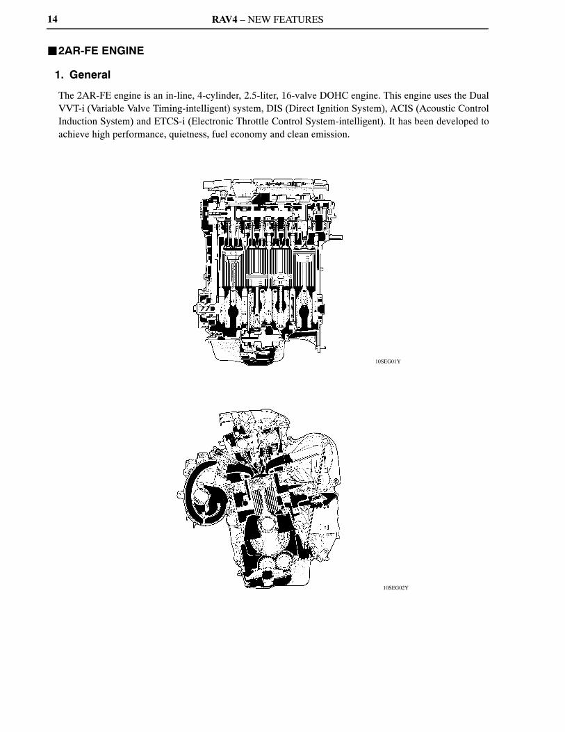
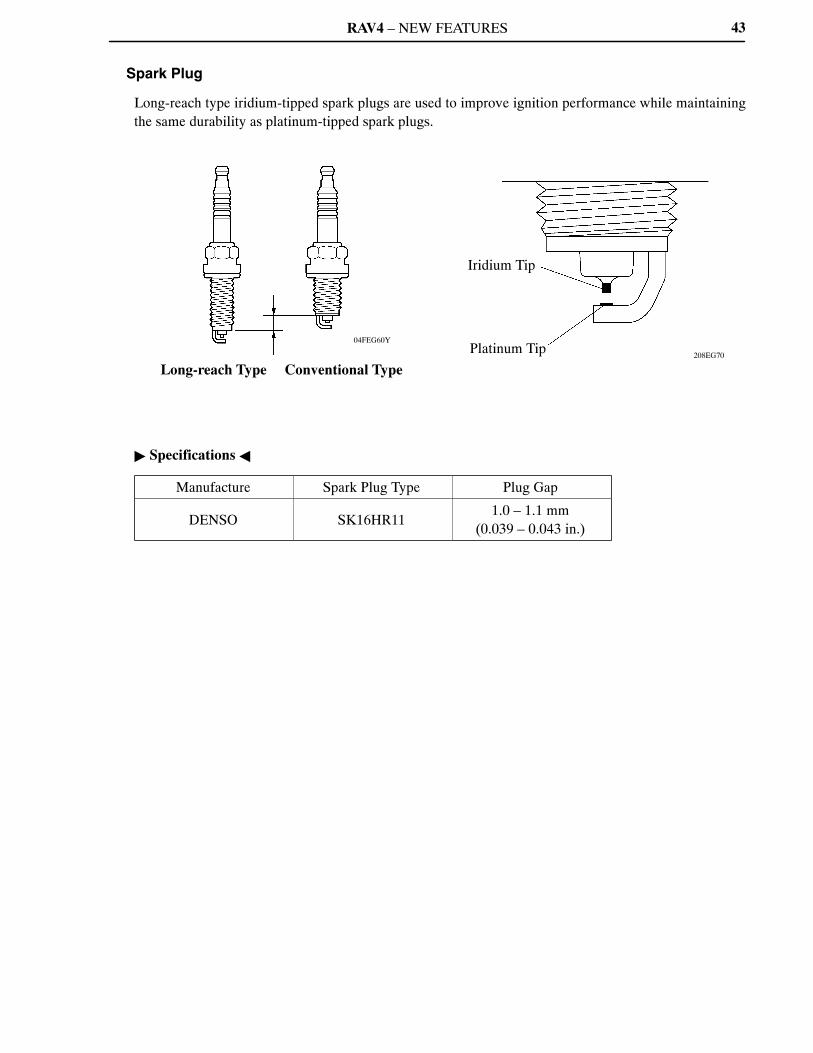
Spark Plug
Long-reach type iridium-tipped spark plugs are used to improve ignition performance while maintaining
the same durability as platinum-tipped spark plugs.
Specifications
Manufacture Spark Plug Type Plug Gap
DENSO SK16HR111.0 – 1.1 mm
(0.039 – 0.043 in.)

RAV4 – NEW FEATURES
206EG41206EG40
206EG42
Stator
A
A
SegmentConductor Stator
Joined Segment Conductor System
SegmentConductor
Joined A – A Cross
Section
Stator
B
B
Stator ConductorWire
Wiring System
Conductor Wire
B – B Cross
Section
Segment Conductor Type Generator
Stator
Conventional Type Generator
Segment Conductor
Cross Section
Stator of Segment Conductor Type Generator
44
10. Charging System
General
A compact and lightweight segment conductor type generator is used.
Specifications
Type SE0
Rated Voltage 12 V
Rated Output 100 A
Segment Conductor Type Generator
The segment conductor type generator generates a high amperage output in a highly efficient manner.
This generator uses a joined segment conductor system, in which multiple segment conductors are
welded together to the stator. Compared to the conventional winding system, the electrical resistance has
been reduced due to the shape of the segment conductors, and their arrangement helps to make the
generator more compact.

RAV4 – NEW FEATURES
008EG08Y
Generator
E
Regulator
B
M
IG
S
L
Ignition Switch
Discharge Warning Light
45
Wiring Diagram

RAV4 – NEW FEATURES
01NEG46Y
Surface Commutator
Armature
Length
Brush
Permanent Magnet
46
11. Starting System
General
A compact and lightweight PS (Planetary reduction-Segment conductor motor) type starter is used.
Because the PS type starter contains an armature that uses square-shaped conductors, and its surface
functions as a commutator, its output torque has been improved and its overall length has been reduced.
In place of the field coil used in the conventional type starter, the PS type starter uses two types of
permanent magnets: main magnets and interpolar magnets. The main magnets and interpolar magnets
have been efficiently arranged to increase the magnetic flux and to shorten the length of the yoke.
Specifications
Starter Type PS Type
Rating Output 1.7 kW
Rating Voltage 12 V
Length*1 128.1 mm (5.04 in.)
Weight 2930 g (6.46 lb)
Rotational Direction*2 Counterclockwise
*1: Length from the mounted area to the rear end of the starter
*2: Viewed from pinion side

RAV4 – NEW FEATURES
206EG20
Conventional Type
Armature
PS Type
Brush
Commutator
Brush
Surface Commutator
Square-shapedConductor
A – A
Cross Section
(PS Type)
Round-shapedConductor
B – B
Cross Section
(Conventional Type)
Armature
B
A
B
A
222EG15
Main Magnet
Yoke
Interpolar Magnet
Main Magnet
Armature
Cross Section of Yoke
Magnetic Flux Generated by Relationship between Main Magnets
Magnetic Flux Generated by Interpolar Magnets
NS
N
NS
S
47
Construction
Instead of constructing the armature coil with conventional type round-shaped conductor wires, the PS
type starter uses square-shaped conductors. With this type of construction, the same conditions achieved
by winding numerous round-shaped conductor wires can be achieved without increasing the mass. As
a result, the output torque has been increased, and the armature coil has been made more compact.
Because the surface of the square-shaped conductors used in the armature coil functions as a commutator,
the overall length of the PS type starter has been shortened.
Instead of the field coils used in the conventional type starter, the PS type starter uses two types of
permanent magnets: the main magnets and the interpolar magnets. The main and interpolar magnets are
arranged alternately inside the yoke, allowing the magnetic flux generated between the main and
interpolar magnets to be added to the magnetic flux generated by the main magnets. In addition to
increasing the amount of magnetic flux, this construction shortens the overall length of the yoke.

RAV4 – NEW FEATURES
10SEG22Y
Idler Pulley for Automatic Tensioner
Crankshaft Pulley
Air Conditioning Compressor Pulley
Water Pump Pulley
Generator Pulley
10SEG23Y
Spring
Arm
Idler Pulley
Cross Section
Fulcrum
Arm
Belt Loosen Direction
Belt Tension Direction
Idler Pulley
48
12. Serpentine Belt Drive System
General
Accessory components are driven by a serpentine belt consisting of a single V-ribbed belt. It reduces the
overall engine length, weight and the number of engine parts.
An automatic tensioner eliminates the need for tension adjustment.
Automatic Tensioner
The tension of the V-ribbed belt is properly maintained by the tension spring enclosed in the automatic
tensioner.

RAV4 – NEW FEATURES 49
13. Engine Control System
General
The engine control system for the 2AR-FE engine has the following systems:
System Outline
SFI
(Sequential Multiport
Fuel Injection)
An L-type SFI system directly detects the intake air mass with a
hot-wire type mass air flow meter.
The fuel injection system is a sequential multiport fuel injection
system.
ESA
(Electronic Spark
Advance)
Ignition timing is determined by the ECM based on signals from various
sensors. The ECM corrects ignition timing in response to engine
knocking.
ETCS-i
(Electronic Throttle
Control System-intelligent)
[See page 67]
Optimally controls the throttle valve opening in accordance with the
amount of accelerator pedal effort and the condition of the engine and
the vehicle.
A linkless-type is used, without an accelerator cable.
An accelerator pedal position sensor is provided on the accelerator
pedal.
A non-contact type throttle position sensor and the accelerator pedal
position sensor are used.
Dual VVT-i
(Variable Valve
Timing-intelligent)
System
[See page 72]
Controls the intake and exhaust camshafts to an optimal valve timing in
accordance with the engine condition.
ACIS
(Acoustic Control
Induction System)
[See page 78]
The intake air passages are switched according to the engine speed and
throttle valve opening angle to provide high performance in all speed
ranges.
Tumble Control System
[See page 81]
Controls fully closes the tumble control valve during cold start and cold
running conditions to improve exhaust emissions while the engine is
running cold.
Air-fuel Ratio Sensor and
Oxygen Sensor Heater
Control
Maintains the temperature of the air-fuel ratio sensor or oxygen sensor
at an appropriate level to achieve accuracy of detection of the oxygen
concentration in the exhaust gas.
Air Conditioning Cut-off
Control
Maintains drivability by turning the air conditioning compressor ON or
OFF in accordance with the engine condition.
Cooling Fan Control
[See page 83]
Radiator cooling fan operation is controlled by signals from the ECM
based on the engine coolant temperature sensor signal and the operating
condition of the air conditioning.
Fuel Pump Control
[See page 84]
Fuel pump operation is controlled by a signal from the ECM.
The fuel pump is stopped when the SRS airbags are deployed.
(Continued)

RAV4 – NEW FEATURES50
System Outline
Starter Control (Cranking
Hold Function)*
[See page 85]
Once the engine switch is pushed, this control continues to operate the
starter until the engine is started.
Evaporative Emission
Control
[See page 87]
The ECM controls the purge flow of evaporative emissions (HC) in the
canister in accordance with engine conditions.
Approximately five hours after the ignition switch has been turned OFF,
the ECM operates the canister pump module to detect any evaporative
emission leakage occurring in the EVAP (evaporative emission) control
system through changes in the 0.02 in. leak pressure.
Engine ImmobilizerProhibits fuel delivery and ignition if an attempt is made to start the
engine with an invalid ignition key.
Diagnosis
[See page 100]
When the ECM detects a malfunction, it diagnoses and memorizes the
failed section.
Fail-safe
[See page 100]
When the ECM detects a malfunction, it stops or controls the engine
according to the data already stored in memory.
*: Models with smart key system

RAV4 – NEW FEATURES
10SEG05Y
MASS AIR FLOW METER
INTAKE AIR TEMPERATURE SENSOR
ENGINE COOLANT TEMPERATURE SENSOR
THROTTLE POSITION SENSOR
CRANKSHAFT POSITION SENSOR
INTAKE CAMSHAFT POSITION SENSOR
EXHAUST CAMSHAFT POSITION SENSOR
ACCELERATOR PEDAL POSITION SENSOR
AIR-FUEL RATIO SENSOR(Bank 1, Sensor 1)
HEATED OXYGEN SENSOR(Bank 1, Sensor 2)
KNOCK SENSOR
TUMBLE CONTROLVALVE POSITION SENSOR
CANISTER PUMP MODULE
CANISTER PRESSURESENSOR
IGNITION SWITCH*
ECM
VG
THA
THW
VTA1
VTA2
NE
G2
EV1
VPA
VPA2
A1A
OX1B
KNK1
IAC1
PPMP
IGSW
STA
#10
#20
#30
#40
IGT1 –IGT4
IGF1
M
OC1
OE1
ACIS
FC
SFI
No. 1 INJECTOR
No. 2 INJECTOR
No. 3 INJECTOR
No. 4 INJECTOR
ESA
IGNITION COIL with IGNITER
SPARK PLUG
ETCS-i
THROTTLE CONTROL MOTOR
DUAL VVT-i
INTAKE CAMSHAFT TIMING OIL CONTROL VALVE
EXHAUST CAMSHAFT TIMING OIL CONTROL VALVE
ACIS
VSV
FUEL PUMP CONTROL
CIRCUIT OPENING RELAY
FUEL PUMP
51
Construction
The configuration of the engine control system in the 2AR-FE engine is shown in the following chart:
(Continued)
*: Except models with smart key system

RAV4 – NEW FEATURES
10SEG06Y
IG2 RELAY*
MAIN BODY ECU*
ENGINE SWITCH*
PARK/NEUTRAL POSITION SWITCH
TRANSMISSION CONTROL SWITCH
CRUISE CONTROL SWITCH
GENERATOR
DEFOGGER SWITCH
TAILLIGHT SWITCH
STOP LIGHT SWITCH
TRANSPONDER KEY ECU
BATTERY
IGSW
NSW
R, P, N
D, 2, L
3
CCS
ALT
ELS1
ELS3
STP
ST1–
IMI
IMO
BATT
ECM
HA1A
HT1B
IA1
FANH
FANL
STSW
ACCR
STAR
STA
AIR-FUEL RATIO AND HEATED OXYGEN SENSORHEATER CONTROL
AIR-FUEL RATIO SENSORHEATER (Bank 1, Sensor 1)
HEATED OXYGEN SENSORHEATER (Bank 1, Sensor 2)
TUMBLE CONTROL SYSTEM
ACTUATOR (DC MOTOR)
COOLING FAN CONTROL
No. 1 COOLING FAN RELAY
No. 2 COOLING FAN RELAY
No. 3 COOLING FAN RELAY
STARTER CONTROL*
MAIN BODY ECU
IG2 RELAY
STARTER CUT RELAY
STARTER RELAY
52
(Continued)
*: Models with smart key system

RAV4 – NEW FEATURES
10SEG07Y
DLC3
AIR CONDITIONING AMPLIFIER
SKID CONTROL ECU
AIRBAG SENSOR ASSEMBLY
EPS ECU
CAN (V Bus)
TC
TACH
MPMP
VPMP
PRG
MREL
+B
W
TACH
SPD
EVAPORATIVE EMISSIONCONTROL
CANISTER PUMP MODULE
LEAK DETECTION PUMP
VENT VALVE
PURGE VSV
EFI MAIN RELAY
COMBINATION METER
MIL
TACHOMETER
Vehicle Speed Signal
53

RAV4 – NEW FEATURES
10SEG55Y
Cruise Control Switch
No. 1 Cooling Fan RelayNo. 2 Cooling Fan RelayNo. 3 Cooling Fan Relay
Accelerator Pedal Position Sensor
EFI Main Relay
DLC3
Various ECUs
Starter Cut Relay*1
Engine Switch*1
StarterRelay*1
Main BodyECU*1
IG2 Relay*1
MIL
Ignition Switch*2
Park/NeutralPosition Switch
Battery
ECM
Exhaust CamshaftPositionSensor
IgnitionCoilwithIgniter
IntakeCamshaftPositionSensor
VSV(for ACIS)
Transponder Key ECU
PurgeVSV
Mass Air Flow Meter*5
*3 *4
Injector
Tumble Control Valve Position Sensor
Actuator (for Tumble Control System)
Knock Sensor
Engine Coolant TemperatureSensor
Crankshaft Position Sensor
Throttle ControlMotor
Throttle Position Sensor
Circuit Opening Relay
CanisterFilter
Fuel PumpTWC TWC
Air-fuel Ratio Sensor(Bank 1, Sensor 1)
Heated Oxygen Sensor(Bank 1, Sensor 2)
Canister Pump Module Vent Valve Leak Detection Pump Canister Pressure Sensor
54
Engine Control System Diagram
*1: Models with smart key system*2: Except models with smart key system*3: Exhaust Camshaft Timing Oil Control Valve*4: Intake Camshaft Timing Oil Control Valve*5: Built-in intake air temperature sensor

RAV4 – NEW FEATURES
10SEG56Y
Accelerator Pedal Position Sensor
Mass Air Flow Meter(Built-in Intake Air Temperature Sensor)
Purge VSV
Heated Oxygen Sensor(Bank 1, Sensor 2) ECM
Canister Pump Module Vent Valve Leak Detection Pump Canister Pressure Sensor
Fuel Pump
DLC3
Intake Camshaft Timing Oil Control ValveExhaust Camshaft Timing Oil Control Valve
Exhaust CamshaftPositionSensor
Air-fuel Ratio Sensor(Bank 1, Sensor 1)
Engine Coolant Temperature Sensor Actuator (for Tumble Control System)
Built-in Tumble Control valve Position Sensor
Throttle Position Sensor
Intake Camshaft Position Sensor
Ignition Coil with Igniter
Injector
Crankshaft Position Sensor
KnockSensor
VSV (for ACIS)
55
Layout of Main Components

RAV4 – NEW FEATURES56
Main Components of Engine Control System
1) General
The main components of the 2AR-FE engine control system are as follows:
Components Outline Quantity Function
ECM 32-bit CPU 1
The ECM optimally controls the SFI,
ESA, and ISC to suit the operating
conditions of the engine in
accordance with the signals provided
by the sensors.
Air-fuel Ratio Sensor
(Bank 1, Sensor 1)
[See page 58]
Type with Heater
(Planar Type)1 This sensor detects the oxygen
concentration in the exhaust emission
by measuring the electromotive force
generated in the sensor itself.Heated Oxygen Sensor
(Bank 1, Sensor 2)
[See page 58]
Type with Heater
(Cup Type)1
Mass Air Flow Meter
[See page 59]Hot-wire Type 1
This sensor has a built-in hot-wire to
directly detect the intake air mass.
Intake Air Temperature
Sensor
[See page 59]
Thermistor Type 1
This sensor detects the intake air
temperature by means of an
internal thermistor.
This sensor is integrated in the
mass air flow meter.
Crankshaft Position
Sensor
[See page 60]
Pick-up Coil Type
(Rotor Teeth/36 - 2)1
This sensor detects the engine speed
and performs the cylinder
identification.
Camshaft Position
Sensor
[See page 60]
MRE (Magnetic
Resistance Element)
Type (Rotor Teeth/3)
2This sensor performs the cylinder
identification.
Throttle Position Sensor
[See page 62]Non-contact Type 1
This sensor detects the throttle valve
opening angle.
Accelerator Pedal
Position Sensor
[See page 63]
Non-contact Type 1
This sensor detects the amount of
pedal effort applied to the accelerator
pedal.
Tumble Control Valve
Position Sensor
[See page 64]
Non-contact Type 1This sensor detects the tumble
control valve opening angle.
Knock Sensor
[See page 65]
Built-in Piezoelectric
Element Type
(Flat Type)
1
This sensor detects an occurrence of
the engine knocking indirectly from
the vibration of the cylinder block
caused by the occurrence of engine
knocking.
(Continued)

RAV4 – NEW FEATURES 57
Components Outline Quantity Function
Engine Coolant
Temperature SensorThermistor Type 1
This sensor detects the engine coolant
temperature by means of an internal
thermistor.
Injector 12-hole Type 4
The injector is an
electromagnetically-operated nozzle
which injects fuel in accordance with
the signals from the ECM.
RAV4 – NEW FEATURES
00REG21Y
D13N11
Air-fuel Ratio Sensor
A1A+
(3.3 V)
A1A–
(2.9 V)
ECM
Air-fuel Ratio Sensor Circuit
HeatedOxygenSensor
OX1B
EX1B
ECM
Heated Oxygen Sensor
: Air-fuel Ratio Sensor
: Heated Oxygen Sensor
4.2
Air-fuel Ratio Sensor Data Displayed on Techstream
2.2
11 (Rich) 14.7 19 (Lean)
Air-fuel Ratio
1
Heated Oxygen Sensor Output (V)
0.1
58
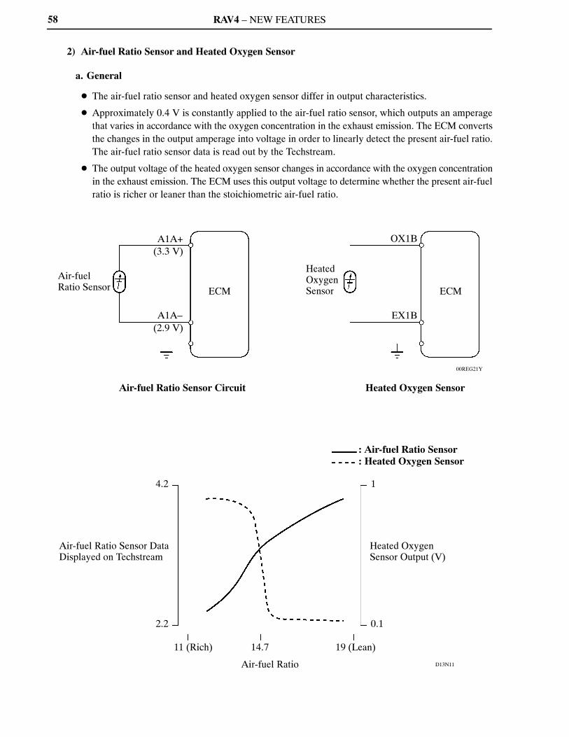
2) Air-fuel Ratio Sensor and Heated Oxygen Sensor
a. General
The air-fuel ratio sensor and heated oxygen sensor differ in output characteristics.
Approximately 0.4 V is constantly applied to the air-fuel ratio sensor, which outputs an amperage
that varies in accordance with the oxygen concentration in the exhaust emission. The ECM converts
the changes in the output amperage into voltage in order to linearly detect the present air-fuel ratio.
The air-fuel ratio sensor data is read out by the Techstream.
The output voltage of the heated oxygen sensor changes in accordance with the oxygen concentration
in the exhaust emission. The ECM uses this output voltage to determine whether the present air-fuel
ratio is richer or leaner than the stoichiometric air-fuel ratio.

RAV4 – NEW FEATURES
10SEG50Y
Alumina
Dilation Layer
Alumina
PlatinumElectrode
Sensor Element (Zirconia)
Heater
Atmosphere
Planar Type Air-fuel Ratio Sensor
Heater
PlatinumElectrode
Sensor Element (Zirconia)
Atmosphere
Cup Type Heated Oxygen Sensor
01YEG10Y
Hot-wire Element
Temperature Sensing Element
Air FlowIntake Air Temperature Sensor
59
b. Construction
The basic construction of the air-fuel ratio sensor and heated oxygen sensor is the same. However,
they are divided into the cup type and the planar type, according to the different types of heater
construction that are used.
The cup type heated oxygen sensor contains a sensor element that surrounds the heater.
The planar type air-fuel ratio sensor uses alumina, which excels in heat conductivity and insulation,
to integrate a sensor element with the heater, thus achieving the excellent warm-up performance of
the sensor.
Warm-up Specification
Sensor Type Planar Type Cup Type
Warm-up Time Approx. 10 sec. Approx. 30 sec.
3) Mass Air Flow Meter
The compact and lightweight mass air flow meter, which is a plug-in type, allows a portion of the
intake air to flow through the detection area. By directly measuring the mass and the flow rate of the
intake air, detection precision is ensured and intake air resistance is reduced.
This mass air flow meter has a built-in intake air temperature sensor.

RAV4 – NEW FEATURES
10SEG60Y10SEG59Y
CrankshaftPositionSensor
Exhaust Camshaft Position Sensor
Timing Rotor Timing Rotor
Intake Camshaft Position Sensor
Timing Rotor
10SEG57I
10SEG58I
720 CA
180 CA 180 CA 180 CA 180 CA
5 V
0 V
Camshaft Position Sensor Output Waveform
720 CA
360 CA 360 CA
0 V
2 Teeth Missing
Crankshaft Position Sensor Output Waveform
60
4) Crankshaft and Camshaft Position Sensors
a. General
The pick-up coil type crankshaft position sensor is used. The timing rotor of the crankshaft consists
of 34 teeth, with 2 teeth missing. The crankshaft position sensor outputs the crankshaft rotation
signals every 10, and the missing teeth are used to determine the top dead center.
The MRE (Magnetic Resistance Element) type intake and exhaust camshaft position sensors are
used. To detect the camshaft position, each timing rotor on the intake and exhaust camshafts is used
to generate 3 (3 high output, 3 low output) pulses for every 2 revolutions of the crankshaft.
Sensor Output Waveforms

RAV4 – NEW FEATURES
04FEG96Y
232CH41
Timing Rotor
Intake CamshaftPosition Sensor VCV1
G2
G2–
ECM
EngineSpeed
SensorOutput
MRE Type
Digital Output
EngineSpeed
SensorOutput
No Detecting
Analog Output
Pick-up Coil Type
61
b. MRE Type Camshaft Position Sensor
The MRE type camshaft position sensor consists of an MRE, a magnet and a sensor. The direction
of the magnetic field changes due to the different shapes (protruded and non-protruded portions) of
the timing rotor, which passes by the sensor. As a result, the resistance of the MRE changes, and the
output voltage to the ECM changes to high or low. The ECM detects the camshaft position based on
this output voltage.
The differences between the MRE type camshaft position sensor and the pick-up coil camshaft
position sensor used on the conventional model are as follows:
ItemSensor Type
MRE Pick-up Coil
Signal OutputConstant digital output starts from
low engine speeds.
Analog output changes with the
engine speed.
Camshaft Position
Detection
Detection is made by comparing the
NE signals with the Hi/Lo output
switch timing due to the
protruded/non-protruded portions
of the timing rotor, or made based on
the number of the input NE signals
during Hi/Lo outputs.
Detection is made by comparing the
NE signals with the change of
waveform that is output when the
protruded portion of the timing rotor
passes.
Wiring Diagram
MRE Type and Pick-up Coil Type Output Waveform Image Comparison

RAV4 – NEW FEATURES
10SEG43Y
230LX12 238EG79
Throttle Body
Throttle Control Motor
Throttle Position Sensor Portion
MagneticYoke
Hall IC
Cross Section
Throttle Position Sensor
Magnetic Yoke
HallIC
HallIC
VTA1
ETA
VCTA
VTA2
ECM OutputVoltage
(V)
5VTA2
VTA1
0 10 90 ()
Fully Closed
Throttle Valve Opening Angle
Fully Open
Service Tip
The inspection method differs from the conventional contact type throttle position sensor because
this non-contact type sensor uses a Hall IC.
For details, refer to the 2009 RAV4 Repair Manual (Pub. No. RM10S0U).
62
5) Throttle Position Sensor
The throttle position sensor is mounted on the throttle body to detect the opening angle of the throttle
valve. The throttle position sensor converts the magnetic flux density that changes when the magnetic
yoke (located on the same axis as the throttle shaft) rotates around the Hall IC into electric signals to
operate the throttle control motor.

RAV4 – NEW FEATURES
00SEG39Y
228TU24 228TU25
A
A
Internal Construction
AcceleratorPedal Arm
Magnetic YokeHall IC
A – A Cross Section
Accelerator Pedal Position Sensor
Magnetic Yoke
HallIC
HallIC
VPA
EPA
VCPA
VPA2
EPA2
VCP2
ECM
(V)
5
OutputVoltage
0
FullyClosed
VPA2
VPA90
FullyOpen
Accelerator Pedal Depressed Angle
Service Tip
The inspection method differs from the conventional contact type accelerator pedal position
sensor because this non-contact type sensor uses a Hall IC.
For details, refer to the 2009 RAV4 Repair Manual (Pub. No. RM10S0U).
63
6) Accelerator Pedal Position Sensor
The non-contact type accelerator pedal position sensor uses a Hall IC.
The magnetic yoke that is mounted at the accelerator pedal arm rotates around the Hall IC in
accordance with the amount of effort that is applied to the accelerator pedal. The Hall IC converts the
changes in the magnetic flux at that time into electrical signals, and outputs them as accelerator pedal
effort to the ECM.
The Hall IC contains circuits for the main and sub signals. It converts the accelerator pedal depressed
angles into electric signals with two differing characteristics and outputs them to the ECM.

RAV4 – NEW FEATURES
10SEG52Y10SEG51Y
10SEG53Y
Actuator
Hall IC
Magnetic Yoke
(V)
OutputVoltage
FullyClosed Tumble Control Valve
Opening Angle
FullyOpen
Magnetic Yoke
Magnet
Hall IC
VCIA
IAC1
EIA1
ECM
64
7) Tumble Control Valve Position Sensor
The non-contact type tumble control valve position sensor uses a Hall IC.
It detects the tumble control valve opening angle.
The sensor converts the magnetic flux density that changes when the magnetic yoke (located on the same
axis as the tumble control valve shaft) rotates around the Hall IC into electric signals and sends them to
ECM.
System Diagram

RAV4 – NEW FEATURES
214CE04
: Conventional Type
: Flat Type
(V)
Voltage
A
B
A: Detection Band ofConventional Type
B: Detection Band ofFlat Type
Frequency (Hz)
Characteristic of Knock Sensor
214CE01
Steel Weight
Insulator
PiezoelectricElement
Open/Short Circuit Detection Resistor
Flat Type Knock Sensor
(Non-resonant Type)
214CE02
PiezoelectricElement
Vibration Plate
Conventional Type Knock Sensor
(Resonant Type)
65
8) Knock Sensor (Flat Type)
a. General
In the conventional type knock sensor (resonant type), a vibration plate which has the same resonance
point as the knocking frequency of the engine is built in and can detect the vibration in this frequency
band. On the other hand, a flat type knock sensor (non-resonant type) has the ability to detect vibration
in a wider frequency band from about 6 kHz to 15 kHz, and has the following features:
The engine knocking frequency will change a bit depending on the engine speed. The flat type knock
sensor can detect the vibration even when the engine knocking frequency is changed. Thus the
vibration detection ability is increased compared to the conventional type knock sensor, and a more
precise ignition timing control is possible.
b. Construction
The flat type knock sensor is installed on the engine through the stud bolt installed on the cylinder
block. For this reason, a hole for the stud bolt runs through the center of the sensor.
Inside the sensor, a steel weight is located on the upper portion and a piezoelectric element is located
under the weight through the insulator.
The open/short circuit detection resistor is integrated.

RAV4 – NEW FEATURES
214CE08
Steel Weight
Inertia
PiezoelectricElement
214CE06
Knock Sensor
PiezoelectricElement
Open/Short Circuit Detection Resistor
200 kΩ
KNK1
EKNK
ECM
5 V
200 kΩ
IC
Service Tip
In accordance with the use of an open/short circuit detection resistor, the inspection method
for the sensor has been changed. For details, refer to the 2009 RAV4 Repair Manual (Pub.
No. RM10S0U).
To prevent water accumulation in the connecter, make sure to install the flat type knock
sensor in the position shown in the following illustration:
10SEG66Y
7
10
Knock Sensor
66
c. Operation
The knocking vibration is transmitted to the
steel weight and its inertia applies pressure
to the piezoelectric element. The action
generates electromotive force.
d. Open/Short Circuit Detection Resistor
While the ignition is ON, the open/short circuit detection resistor in the knock sensor and the resistor
in the ECM keep constant the voltage at the terminal KNK1 of engine.
An IC (Integrated Circuit) in the ECM is always monitoring the voltage of the terminal KNK1. If the
open/short circuit occurs between the knock sensor and the ECM, the voltage of the terminal KNK1
will change and the ECM detects the open/short circuit and stores DTC (Diagnostic Trouble Code).

RAV4 – NEW FEATURES
10SEG44I
Accelerator Pedal Position Sensor
Mass Air Flow Meter
Cruise Control Switch
Throttle Valve
Throttle Position Sensor
Throttle ControlMotor
CAN (V Bus)
ECMSkid Control ECU
IgnitionCoil
FuelInjector
67
ETCS-i (Electronic Throttle Control System-intelligent)
1) General
The ETCS-i is used, providing excellent throttle control in all the operating ranges. In the 2AR-FE
engine, the accelerator cable has been discontinued, and an accelerator pedal position sensor has been
provided on the accelerator pedal.
In the conventional throttle body, the throttle valve opening is determined by the amount of the
accelerator pedal effort. In contrast, the ETCS-i uses the ECM to calculate the optimal throttle valve
opening that is appropriate for the respective driving condition and uses a throttle control motor to
control the opening.
The ETCS-i controls the IAC (Idle Air Control) system, TRAC (Traction Control), VSC (Vehicle
Stability Control) system and cruise control system.
In case of an abnormal condition, this system switches to the limp mode.
System Diagram

RAV4 – NEW FEATURES
10SEG45Y
Throttle Body
Throttle Position Sensor Portion
ReductionGears
A
View from A
Throttle Valve
Cross Section
Magnetic Yoke
Hall IC
Throttle Control Motor
68
2) Construction
a. Throttle Position Sensor
The throttle position sensor is mounted on the throttle body, to detect the opening angle of the throttlevalve.
b. Throttle Control Motor
A DC motor with excellent response and minimal power consumption is used for the throttle controlmotor. The ECM performs the duty cycle control of the direction and the amperage of the current thatflows to the throttle control motor in order to regulate the opening of the throttle valve.
3) Operation
a. General
The ECM drives the throttle control motor by determining the target throttle valve opening inaccordance with the respective operating condition.
Non-linear Control
Idle Air Control
TRAC Throttle Control
VSC Coordination Control
Cruise Control

RAV4 – NEW FEATURES
005EG13Y
Vehicle’s Longitudinal G
0
Throttle Valve Opening Angle
0
Accelerator Pedal Depressed Angle
0
: With Control
: Without Control
Time
69
b. Normal Throttle Control (Non-linear Control)
This controls the throttle to an optimal throttle valve opening that is appropriate for the driving
condition such as the amount of the accelerator pedal effort and the engine speed in order to achieve
excellent throttle control and comfort in all operating ranges.
Control Examples During Acceleration and Deceleration
c. Idle Air Control
The ECM controls the throttle valve in order to constantly maintain an ideal idle speed.
d. TRAC Throttle Control
As part of the TRAC system, the throttle valve is closed by a demand signal from the skid control ECU
if an excessive amount of slippage is created at a driving wheel, thus facilitating the vehicle in providing
excellent stability and driving force.
e. VSC Coordination Control
In order to bring the effectiveness of the VSC system control into full play, the throttle valve opening
angle is controlled by effecting a coordination control with the skid control ECU.
f. Cruise Control
An ECM with an integrated cruise control ECU directly actuates the throttle valve for operation of the
cruise control.

RAV4 – NEW FEATURES
199EG45
Accelerator Pedal Position Sensor
Main
Sub Main
SubThrottlePositionSensor
Open
Throttle Valve ReturnSpring
ThrottleControlMotor
Accelerator Pedal Throttle Body
ECM
199EG46
ECM
Accelerator Pedal Position Sensor
Main
Sub Main
Sub
Throttle PositionSensor
Close byReturn Spring
Throttle ValveReturnSpring
ThrottleControlMotor
Accelerator Pedal Throttle Body
70
4) Fail-safe of Accelerator Pedal Position Sensor
The accelerator pedal position sensor is comprised of two (main, sub) sensor circuits. If a malfunction
occurs in either one of the sensor circuits, the ECM detects the abnormal signal voltage difference
between these two sensor circuits and switches to the limp mode. In the limp mode, the remaining
circuit is used to calculate the accelerator pedal depressed angle, in order to operate the vehicle under
the limp mode control.
If both circuits have malfunctions, the ECM detects the abnormal signal voltage from these two sensor
circuits and stops the throttle control. At this time, the vehicle can be driven within its idling range.

RAV4 – NEW FEATURES
199EG47
Injectors
Accelerator Pedal Position Sensor
Main
Sub
Accelerator Pedal
ECM
Main
Sub
Return to Prescribed Angle
Throttle Valve
Throttle Body
Ignition Coils
ReturnSpring
ThrottleControlMotor
71
5) Fail-safe of Throttle Position Sensor
The throttle position sensor is comprised of two (main, sub) sensor circuits. If a malfunction occurs
in either one or both of the sensor circuits, the ECM detects the abnormal signal voltage difference
between these two sensor circuits, cuts off the current to the throttle control motor, and switches to
the limp mode. Then, the force of the return spring causes the throttle valve to return and stay at the
prescribed opening angle. At this time, the vehicle can be driven in the limp mode while the engine
output is regulated through the control of the fuel injection (intermittent fuel-cut) and ignition timing
in accordance with the accelerator opening.
The same control as above is effected if the ECM detects a malfunction in the throttle control motor
system.

RAV4 – NEW FEATURES
10SEG67Y
Intake Camshaft Timing Oil Control Valve
Exhaust Camshaft Timing Oil Control Valve
Intake Camshaft Position Sensor
Exhaust Camshaft Position Sensor
CrankshaftPositionSensor
Engine Coolant Temperature Sensor
ECM
Mass Air Flow Meter Throttle Position
Sensor
221EG16
Crankshaft PositionSensor
Mass Air Flow Meter
Throttle Position Sensor
Engine Coolant Temp. Sensor
Camshaft Position Sensors
Vehicle Speed Signal
ECM
Target Valve Timing
Feedback
Correction
Actual Valve Timing
Duty Cycle Control
Camshaft Timing Oil Control Valves
72
Dual VVT-i (Variable Valve Timing-intelligent) System
1) General
The Dual VVT-i system is designed to control the intake and exhaust camshafts within a range of 50
and 40 respectively (of Crankshaft Angle) to provide valve timing optimally suited to the engine
condition. This improves torque in all the speed ranges as well as increasing fuel economy, and
reducing exhaust emissions.
Using the engine speed, intake air mass, throttle position and engine coolant temperature, the ECM
can calculate optimal valve timing for each driving condition and controls the camshaft timing oil
control valve. In addition, the ECM uses signals from the camshaft position sensor and the crankshaft
position sensor to detect the actual valve timing, thus providing feedback control to achieve the target
valve timing.

RAV4 – NEW FEATURES
285EG61
285EG62
285EG59
285EG59
285EG63
285EG60
285EG59
Earliest Timing (EX)
TDC LatestTiming (IN)
EX IN
BDC
To Advance Side (EX)
To Retard Side (IN)
EX IN
To Advance Side (IN)
To Retard Side (EX)
EX IN
EX IN
To Retard Side (EX)
To AdvanceSide (IN)
EX
IN
To Advance Side (EX)
EarliestTiming(EX)
LatestTiming (IN)
EX
IN
EarliestTiming(EX)
EX
LatestTiming (IN)
IN
To RetardSide (IN)
73
2) Effectiveness of the Dual VVT-i System
Operation State Objective Effect
During Idling
Eliminating overlap to
reduce blow back to the
intake side
Stabilized idling
speed
Better fuel economy
At Light Load
Eliminating overlap to
reduce blow back to the
intake side
Ensured engine stability
At Medium Load
Increasing overlap to
increase internal EGR
to reduce pumping loss
Better fuel economy
Improved emission
control
In Low to Medium
Speed Range with
Heavy Load
Advancing the intake
valve close timing for
volumetric efficiency
improvement
Improved torque in low
to medium speed range
In High Speed
Range with Heavy
Load
Retarding the intake
valve close timing for
volumetric efficiency
improvement
Improved output
At Low
Temperatures
Eliminating overlap to
reduce blow back to the
intake side leads to the
lean burning condition,
and stabilizes the idling
speed at fast idle
Stabilized fast idle
speed
Better fuel economy
Upon Starting
Stopping the
Engine
Eliminating overlap to
minimize blow back to
the intake side
Improved startability
RAV4 – NEW FEATURES
10SEG61Y
10SEG62Y
HousingVane (Fixed on Intake Camshaft)
Lock Pin
Sprocket
Intake Camshaft
At a Stop
Lock Pin
In Operation
Oil Pressure
Housing
Lock Pin
Sprocket
Advance Assist Spring
Vane (Fixed on Exhaust Camshaft)
Exhaust Camshaft
74
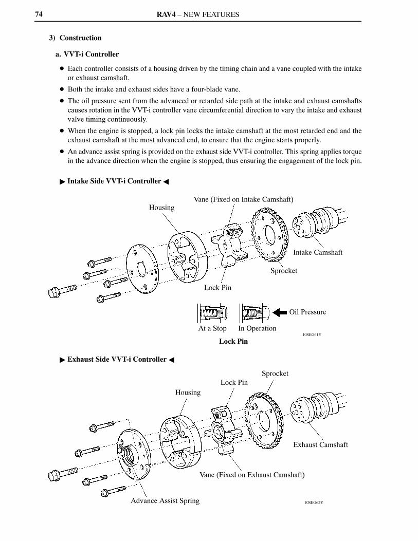
3) Construction
a. VVT-i Controller
Each controller consists of a housing driven by the timing chain and a vane coupled with the intake
or exhaust camshaft.
Both the intake and exhaust sides have a four-blade vane.
The oil pressure sent from the advanced or retarded side path at the intake and exhaust camshafts
causes rotation in the VVT-i controller vane circumferential direction to vary the intake and exhaust
valve timing continuously.
When the engine is stopped, a lock pin locks the intake camshaft at the most retarded end and the
exhaust camshaft at the most advanced end, to ensure that the engine starts properly.
An advance assist spring is provided on the exhaust side VVT-i controller. This spring applies torque
in the advance direction when the engine is stopped, thus ensuring the engagement of the lock pin.
Intake Side VVT-i Controller
Exhaust Side VVT-i Controller

RAV4 – NEW FEATURES
04FEG180Y
To VVT-i Controller(Advanced Side)*
Spring
Sleeve
Drain
Oil Pressure
Drain
Spool Valve
To VVT-i Controller(Retarded Side)*
75
b. Camshaft Timing Oil Control Valve
This camshaft timing oil control valve controls the spool valve using duty cycle control from the ECM.
This allows hydraulic pressure to be applied to the VVT-i controller advanced or retarded side. When
the engine is stopped, the camshaft timing oil control valve is in the most retarded position.
*: On the exhaust side oil control valve, the advance and retard sides are reversed.

RAV4 – NEW FEATURES
10SEG25Y
10SEG27Y
Rotation Direction
Vane
Oil Pressure
IN Drain
ECM
Rotation Direction
VaneOil Pressure
Drain IN
ECM
76
4) Operation
a. Advance
When the camshaft timing oil control valve is positioned as illustrated below by the advance signals
from the ECM, the resultant oil pressure is applied to the timing advance side vane chamber to rotate
the camshaft in the timing advance direction.
Intake Side
Exhaust Side

RAV4 – NEW FEATURES
10SEG26Y
10SEG28Y
Rotation Direction
VaneOil Pressure
Drain IN
ECM
Rotation Direction
Vane
Oil Pressure
IN Drain
ECM
77
b. Retard
When the camshaft timing oil control valve is positioned as illustrated below by the retard signals from
the ECM, the resultant oil pressure is applied to the timing retard side vane chamber to rotate the
camshaft in the timing retard direction.
Intake Side
Exhaust Side
c. Hold
After reaching the target timing, the valve timing is held by keeping the camshaft timing oil control
valve in the neutral position unless the traveling state changes.
This adjusts the valve timing at the desired target position and prevents the engine oil from running out
when it is unnecessary.

RAV4 – NEW FEATURES
10SEG46Y
CrankshaftPositionSensor
ECM
VSV
Actuator
Check Valve
Vacuum Tank
Intake Air Control Valve
Throttle Position Sensor
78
ACIS (Acoustic Control Induction System)
1) General
The ACIS is implemented by using a bulkhead to divide the intake manifold into 2 stages, with an intake
air control valve in the bulkhead being opened and closed to vary the effective length of the intake
manifold in accordance with the engine speed and throttle valve opening angle. This increases the power
output in all ranges from low to high speed.
System Diagram
RAV4 – NEW FEATURES
10SEG70Y
10SEG40Y
VSV
Intake Air Control Valve
Actuator
Vacuum Tank
Intake Manifold Cross Section
79
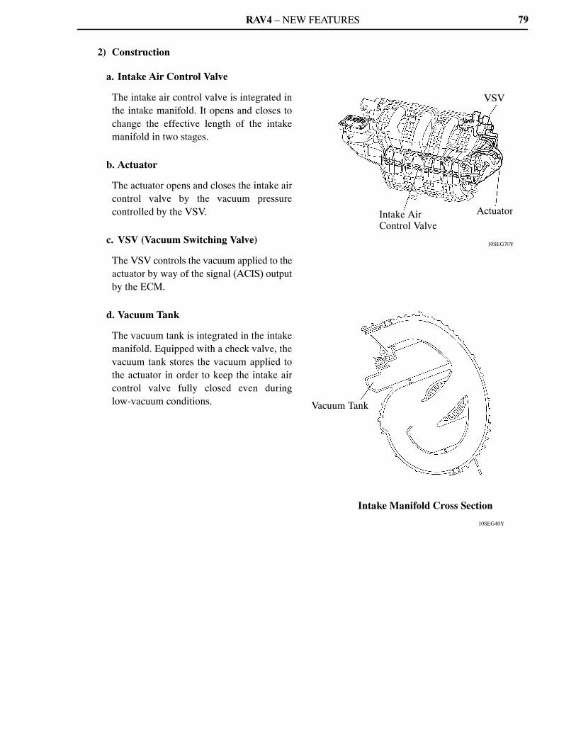
2) Construction
a. Intake Air Control Valve
The intake air control valve is integrated in
the intake manifold. It opens and closes to
change the effective length of the intake
manifold in two stages.
b. Actuator
The actuator opens and closes the intake air
control valve by the vacuum pressure
controlled by the VSV.
c. VSV (Vacuum Switching Valve)
The VSV controls the vacuum applied to the
actuator by way of the signal (ACIS) output
by the ECM.
d. Vacuum Tank
The vacuum tank is integrated in the intake
manifold. Equipped with a check valve, the
vacuum tank stores the vacuum applied to
the actuator in order to keep the intake air
control valve fully closed even during
low-vacuum conditions.

RAV4 – NEW FEATURES
10SEG47Y
Open
ThrottleValve
ClosedLow
VSV ON
Engine SpeedHigh
: Effective intake manifold length
10SEG48Y
: Effective intake manifold length
Open
ThrottleValve
Closed
Low
VSV OFF
Engine Speed
High
80
3) Operation
a. When the Intake Control Valve Closes (VSV ON)
The ECM activates the VSV to match the longer pulsation cycle so that the negative pressure acts on
the diaphragm chamber of the actuator. This closes the control valve. As a result, the effective length
of the intake manifold is lengthened and the intake efficiency in the medium speed range is improved
due to the dynamic effect of the intake air, thereby increasing the power output.
b. When the Intake Control Valve Opens (VSV OFF)
The ECM deactivates the VSV to match the shorter pulsation cycle so that atmospheric air is led into
the diaphragm chamber of the actuator and opens the control valve. When the control valve is open,
the effective length of the intake air chamber is shortened and peak intake efficiency is shifted to the
low-to-high engine speed range, thus providing greater output at low-to-high engine speeds.

RAV4 – NEW FEATURES
10SEG49Y
Tumble Control Valve
Actuator (DC motor)
Tumble Control ValvePosition Sensor
ECMEngine CoolantTemperature Sensor
InjectorIgnition Coilwith Igniter
10SEG69Y
Actuator Built-in Tumble Control valve
Position Sensor
Tumble Control Valve
81
Tumble Control System
1) General
In the tumble control system, the tumble control valve remains fully closed during cold start and cold
running conditions, in order to create a strong tumble current in the combustion chamber. In addition,
this system optimally controls the ignition timing and the fuel injection volume in accordance with the
opening and closing of the valve. As a result, it improves combustion while the engine is running cold.
System Diagram
2) Construction
a. Tumble Control Valve
The tumble control valve is provided in the
intake manifold. This valve closes in order to
create a tumble current in the combustion
chamber.
b. Actuator
A DC motor type actuator is provided in the
intake manifold. Based on the signals
provided by the ECM, the actuator opens
and closes the tumble control valve.
c. Tumble Control Valve Position Sensor
For details of the tumble control valve
position sensor, see page 64.

RAV4 – NEW FEATURES82
3) Operation
a. Engine Running Cold
To improve combustion, the ECM operates the actuator to fully close the tumble control valve, in order
to create a strong tumble current in the combustion chamber. This enables the engine to operate at a lean
air-fuel ratio immediately after a cold start.
Based on the signals from the various sensors, the ECM retards the ignition timing in order to reduce
the amount of unburned gas and promote the warming up of the TWC. In addition, the ECM optimizes
the fuel injection volume.
The vacuum pressure created downstream of the valve promotes the atomization of the fuel and
prevents the fuel from adhering to the ports.
These measures help reduce exhaust gas emissions while the engine is running cold.
b. Engine Warmed Up
The ECM operates the actuator to fully open the tumble control valve. When the valve is fully open,
the passage has minimal intake resistance in order to improve engine performance.