Embed Size (px)
Citation preview
Architectural Support for Uniprocessor andMultiprocessor Active Memory Systems
Daehyun Kim, Mainak Chaudhuri, Student Member, IEEE,
Mark Heinrich, Member, IEEE, and Evan Speight, Member, IEEE
Abstract—We introduce an architectural approach to improve memory system performance in both uniprocessor and multiprocessor
systems. The architectural innovation is a flexible active memory controller backed by specialized cache coherence protocols that
permit the transparent use of address remapping techniques. The resulting system shows significant performance improvement across
a spectrum of machine configurations, from uniprocessors through single-node multiprocessors (SMPs) to distributed shared memory
clusters (DSMs). Address remapping techniques exploit the data access patterns of applications to enhance their cache performance.
However, they create coherence problems since the processor is allowed to refer to the same data via more than one address. While
most active memory implementations require cache flushes, we present a new approach to solve the coherence problem. We leverage
and extend the cache coherence protocol so that our techniques work transparently to efficiently support uniprocessor, SMP and DSM
active memory systems. We detail the coherence protocol extensions to support our active memory techniques and present simulation
results that show uniprocessor speedup from 1.3 to 7.6 on a range of applications and microbenchmarks. We also show remarkable
performance improvement on small to medium-scale SMP and DSM multiprocessors, allowing some parallel applications to continue
to scale long after their performance levels off on normal systems.
Index Terms—Active memory systems, address remapping, cache coherence protocol, distributed shared memory, flexible memory
controller architecture.
�
1 INTRODUCTION
ACTIVE memory systems provide a promising approachto overcoming the memory wall [32] for applications
with irregular access patterns not amenable to techniqueslike prefetching or improvements in the cache hierarchy.The central idea in this approach is to perform data-parallelcomputations or address remapping operations in thememory system to either offload computation directly orto reduce the number of processor cache misses. However,both approaches introduce data coherence problems eitherby allowing more than one processor in memory to accessthe same data or by accessing the same data via more thanone address.
Most active memory system approaches [5], [13], [33]
require the programmer to insert cache flushes before
invoking active memory operations to avoid correctness
problems. Cache flush overhead on modern processors can
be large—typically requiring a trap to the operating system
to execute a privileged instruction or set of instructions, and
grows more costly as the number of cache levels increases.
Though user-level cache flushes may reduce this overhead,
either compilers must conservatively insert flushes to
maintain correctness or inserting flushes requires human
intervention. Further, this software cache-coherent pro-gramming model via flushes does not scale well tomultiprocessor systems since it must flush all the cachesin the system to guarantee correctness.
We propose an active memory system that leverages andextends the hardware cache coherence protocol. The key tothe approach is that the memory controller not onlyperforms the active memory operations required, but alsoruns the cache coherence protocol and, hence, solves theresulting data coherence problems. Our system does notrequire cache flushes, providing transparent active memorysupport without changing the programming model.Further, our unique approach naturally extends to multi-processor active memory systems. We present a flexibleactive memory controller architecture that merges addressremapping techniques and the directory-based cachecoherence protocol. Although our focus is to supportaddress remapping techniques, our approach does notpreclude the future use of active memory elements as well.While many machines employ snoopy-based coherencemechanisms, recent architectures [8], [18] have abandonedbus-based snooping in favor of directories because of thedecrease in local memory access time and the electricaladvantages of point-to-point links between the processorand the memory controller. Finally, our techniques workwith commodity microprocessors and memory technologiesbecause we modify only the memory controller.
With the aid of our programmable active memorycontroller, augmented with specialized cache line assemblyand disassembly hardware, we extend a conventionalhardware cache coherence protocol to transparently sup-port a number of address remapping techniques. We
288 IEEE TRANSACTIONS ON COMPUTERS, VOL. 53, NO. 3, MARCH 2004
. D. Kim, M. Chaudhuri, and E. Speight are with the Computer SystemsLaboratory, Cornell University, Ithaca, NY 14853.E-mail: {daehyun, mainak, espeight}@csl.cornell.edu.
. M. Heinrich is with the School of Electrical Engineering and ComputerScience, University of Central Florida, Orlando, FL 32816.E-mail: [email protected].
Manuscript received 20 Nov. 2002; revised 24 Apr. 2003; accepted 28 May2003.For information on obtaining reprints of this article, please send e-mail to:[email protected], and reference IEEECS Log Number 117800.
0018-9340/04/$20.00 � 2004 IEEE Published by the IEEE Computer Society
achieve significant performance improvement on a spec-trum of machine configurations, from uniprocessorsthrough SMP multiprocessors to DSM multinode systems.Detailed simulations of our active memory system showuniprocessor speedup from 1.3 to 7.6 for three addressremapping techniques. In addition to uniprocessor speed-up, our system also improves the performance of parallelapplications on both single-node SMP and multinode DSMsystems. Our system is from 1.2 to 1.8 times faster than anormal system on a 4-processor SMP and from 1.2 to2.8 times faster on a 32-processor DSM configuration.
The rest of this paper is organized as follows: Wediscuss related work in Section 2. In Section 3, we presentfour address remapping techniques that our systemsupports and explain the coherence problem that ariseswith each. The flexibility of our active memory controllerenables us to extend this set of techniques at any timewithout additional hardware cost. Section 4 describes theimplementation of our active memory controller as wellas the details of the coherence protocol extensionsrequired. We present our simulation environment inSection 5 and analyze simulation results for a large classof important applications on uniprocessors, single-nodemultiprocessors, and multinode clusters in Section 6.Finally, we draw conclusions in Section 7.
2 RELATED WORK
Previous work in active memory systems can be dividedinto projects with active memory elements and those withactive memory controllers. While our active memorysystems approach can support active memory elements,the focus of this paper is solely on our active memorycontroller.
The DIVA [5], Active Pages [26], and FlexRAM [13]projects all involve active memory elements—addingprocessing capability to memory chips, creating so-calledPIMs. Both DIVA and FlexRAM have programming modelsthat require cache flushes when communicating betweenthe main processor and the active memory elements. ActivePages initially required cache flushes as well, but realizedthe critical role of coherence in active memory systems [14]at the same time we did [20], noting that coherence was abetter mechanism than flushing for Active Pages. However,the Active Pages project examined coherence only as amechanism for ensuring the active pages acted on the latestcopy of the data and not in support of the addressremapping techniques discussed here.
More closely related to this work is the Impulse memorycontroller [33], which is a hard-wired memory controllerthat supports a set of address remapping techniques toimprove processor cache behavior. Impulse proposed twouniprocessor techniques, namely, matrix transpose andsparse matrix, and designed specialized hardware toaccelerate cache line assembly and disassembly. However,unlike our active memory approach that leverages cachecoherence, the Impulse programming model requires cacheflushes. The necessity of using cache flushes also compli-cates the use of these techniques on multiprocessors.Though we use two of the same address remappingtechniques in this work, we extend those techniques to
SMP and DSM multiprocessors as well as uniprocessors.Further, we present a linked-list linearization technique andaparallel reduction technique that cannot be implementedonImpulse because they require coherence support and multi-processor support, respectively. Our active memory con-troller shares similar cache line assembly/disassemblyfunctionality with the Impulse memory controller, but ourmemory controller implements not only the address remap-ping techniques, but also the cache coherence mechanism,which imposes different requirements on our memorycontroller design. In addition, our memory controller takesadvantage of its programmability, allowing us to supportmultiple active memory techniques and various machineconfigurations without hardware modification.
Our linked-list linearization technique performs re-peated linked-list traversals that are similar to those usedin memory forwarding [19], complete with the “safety net.”However, while memory forwarding requires both mainprocessor and memory controller modifications, our activememory controller can extend the cache coherence protocoland perform the linked-list linearization as well as imple-ment the safety-net without modifying the main processor.
Our parallel reduction technique, initially proposed in anonactive memory context in [7], triggers reduction opera-tions on writebacks. The initial proposal used softwareflushes to guarantee data coherence between mappedaddress spaces. The parallel reduction technique also hassimilarity to techniques used in the ReVive [27] andMemory Sharing Predictor [17] proposals in the sense thatthese two also trigger checkpointing/logging-related opera-tions and sharing predictions, respectively, when the homenode receives certain types of coherence messages.
The main contribution of our active memory approach isthat we leverage, integrate with, and extend the existinghardware cache coherence protocol. With this approach,our active memory controller supports address remappingtechniques on uniprocessor as well as multiprocessorsystems transparently and efficiently.
3 ACTIVE MEMORY TECHNIQUES
In this section, we explain four classes of active memorytechniques discussed in this paper: Matrix Transpose, SparseMatrix, Linked-list Linearization, and Parallel Reduction. Weshow how active memory techniques can improve perfor-mance by reducing cache misses, TLB misses, and, in somecases, processor busy time. We also discuss why a datacoherence problem arises with each technique and explainhow we solve the problem.
3.1 Matrix Transpose
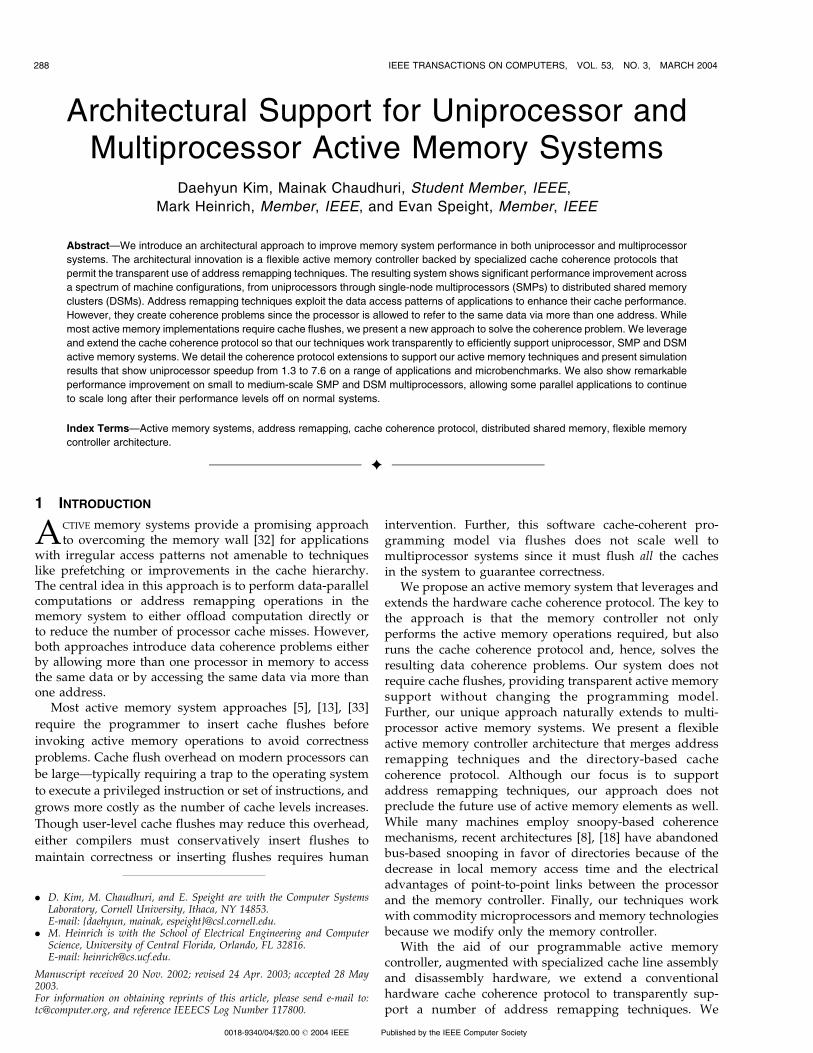
Consider a matrix A stored in memory in row-major order(see Fig. 1). An application accesses the matrix A first inrow-wise fashion and then in column-wise fashion. The sizeof the matrix A is N �N and the application is parallelizedon P processors.
If a processor Pid wants to access the matrix A column-wise, it results in poor cache behavior because the matrix Ais stored in row-major order. To improve cache perfor-mance, programmers typically use a Tiled Transposetechnique, which the above example uses to implement
KIM ET AL.: ARCHITECTURAL SUPPORT FOR UNIPROCESSOR AND MULTIPROCESSOR ACTIVE MEMORY SYSTEMS 289
the Transpose routine. Before accessing the matrix Acolumn-wise, we transpose the matrix A into a matrix A0.Then, instead of accessing the matrix A, we can access thematrix A0 row-wise. Though tiling the transpose phasereduces the number of cache misses, this software transposetechnique still has some overhead. Whenever we change theaccess pattern from row-wise to column-wise or vice versa,we need to perform the transpose phase, which costsprocessor busy time, memory access time, and synchroniza-tion time. The remote and local memory accesses during thetranspose phase especially become a bottleneck. Our activememory technique eliminates the transpose phase and,hence, reduces this overhead.
Instead, our active memory controller provides a remap-ping transpose operation, In-memory Transpose. An addressremapping technique [33] is used to map AT to anadditional physical address space A0, called the ShadowSpace. The shadow matrix A0 is not backed by any realphysical memory. Instead, it is composed by the memorycontroller on the fly, based on information such as thestarting address and the dimension and element size of thematrix A provided via the one-time AMInitTranspose
library call. In other words, the matrix transpose is carriedout by the memory controller, not by the main processor,removing the software transpose overhead. Note that theinitialization phase does not perform matrix transpose—itonly communicates the information used to compose theshadow matrix A0 to the memory controller via a shortsequence of uncached writes.
This matrix transpose technique gives rise to a coherenceproblem between the normal matrix A and the shadowmatrix A0. Any two corresponding elements of the matrix Aand the matrix A0 should be identical, yet the processor maybe caching them at two separate locations. One way toensure coherence is to guarantee that only one of the twospaces is cached at any time. We extend the coherence
protocol and treat the access to the two spaces by the sameprocessor in precisely the same way a coherence protocoltreats accesses to the same cache line by different processorsin a multiprocessor. When returning shadow space cachelines, we invalidate the corresponding normal space cachelines from the processor caches. When a processor nextreferences these lines in the normal space, we haveguaranteed that this access will cause a cache miss andour active memory controller can undo the previousremapping operation, returning the latest copy of the datato the processor and invalidating the correspondingshadow space cache lines cached by the processors. Thedetails of the protocol are discussed in Section 4.2.
3.2 Sparse Matrix
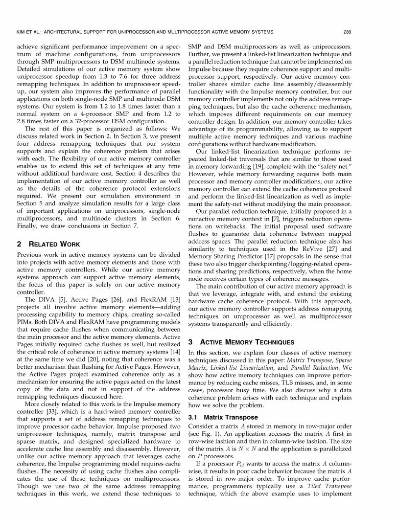
In this technique, the central idea is to gather scattered datathat the main processor wishes to access closely spaced intime and assemble them into cache lines. As an example, inFig. 2, we show the basic loop of Sparse Matrix VectorMultiply, using the Compressed Row Storage representa-tion for a sparse matrix A.
The scattered accesses to the dense vector v willexperience cache misses if the vector v is large. To improvecache behavior, we remap the vector v to a shadow vector v0
and, in the loop, replace v½Acol½j��with v0½j�. When the activememory controller sees accesses to the vector v0, it calculatesthe index j, accesses the cache line containing Acol½j�,assembles the corresponding elements of v½Acol½j�� into acache line, and returns the cache line to the main processor.As a result, the main processor sees contiguous accesses tothe vector v0 and improved cache behavior. This techniquealso makes it possible to prefetch accesses to the vector v0,which now exhibit good spatial locality.
The library call AMInitSparse communicates to thememory controller the necessary information to constructthe vector v0 such as the starting addresses of v and Acol, the
290 IEEE TRANSACTIONS ON COMPUTERS, VOL. 53, NO. 3, MARCH 2004
Fig. 1. Example code: matrix transpose.
Fig. 2. Example code: sparse matrix.
total number of nonzero elements (NZ) in the sparse matrixA and the element size of the vector v. A careful comparisonof the active memory optimized code with the original codewill reveal that this technique saves not only the cachemisses of accessing the vector v, but also processor busycycles by removing the address calculation for Acol[j].
The coherence problem arises between the normal vectorv and the shadow vector v0. The solution is similar to that formatrix transpose, though this particular technique prohibitswrites to the shadow vector v0 because a single cache line ofthe vector v0 may contain the same element as the vector vmore than once. Therefore, if the processor writes to oneelement, the other element (at a different position in thesame cache line) would have a stale value. This restrictionapplies to any active memory implementation of thisoperation, whether using cache flushes or leveraging thecoherence protocol. However, none of the sparse matrixapplications that we have seen need writes to the shadowvector v0. Again, the details of the protocol are discussed inSection 4.2.
3.3 Linked-List Linearization
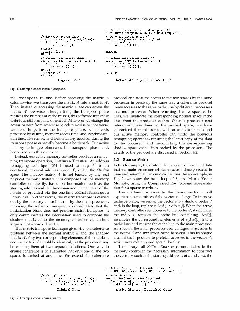
Searching, inserting, or deleting items in a linked-list mayrequire walking through the list and these linked-listtraversals can exhibit poor cache behavior. Consider thefollowing example in Fig. 3 where an application traverses alinked-list A: If the nodes of the list A are scattered inmemory, the traversal of the list can result in a largenumber of cache misses. Our active memory techniquesolves this problem by packing consecutive nodes of alinked-list into a contiguously allocated memory region in adynamic fashion.
The AMInitLinearize library call sends the memorycontroller the information needed to linearize the linked-listA such as the byte offset of the next pointer within a node(NP ), the number of nodes to linearize (LS), and the size ofeach node in the list A. The AMLinearize call to the activememory controller packs a certain number (LS in thisexample) of nodes in the list into a contiguous region,updating the “next” pointers (based on NP ) in the list as itgoes. The next time the processor traverses the list, it seescontiguous memory accesses and, hence, improved cachebehavior. Note that, after linearizing the list, it is possible toeasily prefetch consecutive nodes of the list, which is difficultin the random linked-list structure of the original list.
Linearizing linked-lists can be done in software withoutthe use of active memory systems. However, a correctnessproblem arises if, after linearization, the processor derefer-ences a dangling pointer that points into the “old” linked-list. Such a reference may now return stale data. Our
solution to this problem is much like that of memoryforwarding [19], except we can perform this optimizationwithout processor modifications. Here, the coherenceprotocol implements a safety net by invalidating the originalcache lines during the copying phase. If the processoraccesses a dangling pointer, it is guaranteed to be a cachemiss and can therefore be handled correctly by the activememory controller. There are some limitations of thistechnique such as safety net overhead and potential pointercomparison problems [19], but it is still a powerfultechnique that shows large benefits in many applications.The detailed discussion of the protocol is in Section 4.2.
3.4 Parallel Reduction
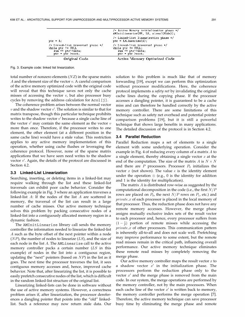
Parallel Reduction maps a set of elements to a singleelement with some underlying operation. Consider theexample in Fig. 4 of reducing every column of a matrix A toa single element, thereby obtaining a single vector x at theend of the computation. The size of the matrix A is N �N
and there are P processors. Processor P0 initializes thevector x (not shown). The value e is the identity elementunder the operation � (e.g., 0 is the identity for additionand 1 is the identity for multiplication).
The matrix A is distributed row-wise as suggested by thecomputational decomposition in the code (i.e., the first N=P
rows are placed on P0, the next N=P rows on P1, etc.) andprivate x of each processor is placed in the local memory ofthat processor. Thus, the reduction phase does not have anyremote memory accesses. However, the merge phaseassigns mutually exclusive index sets of the result vectorto each processor and, hence, every processor suffers fromð1� 1
PÞ portion of remote misses while accessing theprivate x of other processors. This communication patternis inherently all-to-all and does not scale well. Prefetchingmay improve performance to some extent, but the remoteread misses remain in the critical path, influencing overallperformance. Our active memory technique eliminatesthese remote read misses by completely removing themerge phase.
Our active memory controller maps the result vector x toa shadow vector x0 in the initialization phase. Theprocessors perform the reduction phase only to thevector x0 and the merge phase is removed from the maincode. In our system, the merge operations are performed bythe memory controller, not by the main processors. Wheneach cache line of the vector x0 is written back to memory,the memory controller performs the merge operation [7].Therefore, the active memory technique can save processorbusy time by eliminating the merge phase and remote
KIM ET AL.: ARCHITECTURAL SUPPORT FOR UNIPROCESSOR AND MULTIPROCESSOR ACTIVE MEMORY SYSTEMS 291
Fig. 3. Example code: linked list linearization.
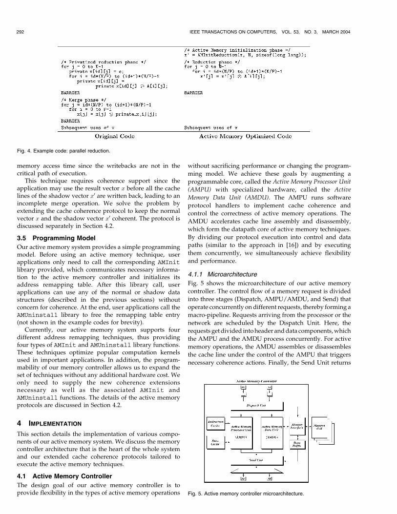
memory access time since the writebacks are not in thecritical path of execution.
This technique requires coherence support since theapplication may use the result vector x before all the cachelines of the shadow vector x0 are written back, leading to anincomplete merge operation. We solve the problem byextending the cache coherence protocol to keep the normalvector x and the shadow vector x0 coherent. The protocol isdiscussed separately in Section 4.2.
3.5 Programming Model
Our active memory system provides a simple programmingmodel. Before using an active memory technique, userapplications only need to call the corresponding AMInit
library provided, which communicates necessary informa-tion to the active memory controller and initializes itsaddress remapping table. After this library call, userapplications can use any of the normal or shadow datastructures (described in the previous sections) withoutconcern for coherence. At the end, user applications call theAMUninstall library to free the remapping table entry(not shown in the example codes for brevity).
Currently, our active memory system supports fourdifferent address remapping techniques, thus providingfour types of AMInit and AMUninstall library functions.These techniques optimize popular computation kernelsused in important applications. In addition, the program-mability of our memory controller allows us to expand theset of techniques without any additional hardware cost. Weonly need to supply the new coherence extensionsnecessary as well as the associated AMInit andAMUninstall functions. The details of the active memoryprotocols are discussed in Section 4.2.
4 IMPLEMENTATION
This section details the implementation of various compo-nents of our active memory system. We discuss the memorycontroller architecture that is the heart of the whole systemand our extended cache coherence protocols tailored toexecute the active memory techniques.
4.1 Active Memory Controller
The design goal of our active memory controller is toprovide flexibility in the types of active memory operations
without sacrificing performance or changing the program-
ming model. We achieve these goals by augmenting a
programmable core, called the Active Memory Processor Unit
(AMPU) with specialized hardware, called the Active
Memory Data Unit (AMDU). The AMPU runs software
protocol handlers to implement cache coherence and
control the correctness of active memory operations. The
AMDU accelerates cache line assembly and disassembly,
which form the datapath core of active memory techniques.
By dividing our protocol execution into control and data
paths (similar to the approach in [16]) and by executing
them concurrently, we simultaneously achieve flexibility
and performance.
4.1.1 Microarchitecture
Fig. 5 shows the microarchitecture of our active memory
controller. The control flow of a memory request is divided
into three stages (Dispatch, AMPU/AMDU, and Send) that
operate concurrently on different requests, thereby forming a
macro-pipeline. Requests arriving from the processor or the
network are scheduled by the Dispatch Unit. Here, the
requestsgetdivided intoheader anddata components,which
the AMPU and the AMDU process concurrently. For active
memory operations, the AMDU assembles or disassembles
the cache line under the control of the AMPU that triggers
necessary coherence actions. Finally, the Send Unit returns
292 IEEE TRANSACTIONS ON COMPUTERS, VOL. 53, NO. 3, MARCH 2004
Fig. 4. Example code: parallel reduction.
Fig. 5. Active memory controller microarchitecture.
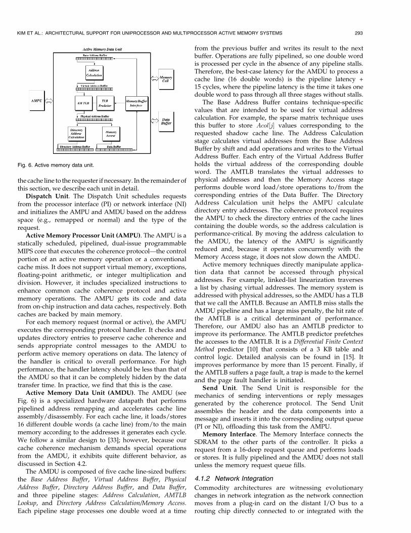
the cache line to the requester if necessary. In the remainder ofthis section, we describe each unit in detail.
Dispatch Unit. The Dispatch Unit schedules requestsfrom the processor interface (PI) or network interface (NI)and initializes the AMPU and AMDU based on the addressspace (e.g., remapped or normal) and the type of therequest.
Active Memory Processor Unit (AMPU). The AMPU is astatically scheduled, pipelined, dual-issue programmableMIPS core that executes the coherence protocol—the controlportion of an active memory operation or a conventionalcache miss. It does not support virtual memory, exceptions,floating-point arithmetic, or integer multiplication anddivision. However, it includes specialized instructions toenhance common cache coherence protocol and activememory operations. The AMPU gets its code and datafrom on-chip instruction and data caches, respectively. Bothcaches are backed by main memory.
For each memory request (normal or active), the AMPUexecutes the corresponding protocol handler. It checks andupdates directory entries to preserve cache coherence andsends appropriate control messages to the AMDU toperform active memory operations on data. The latency ofthe handler is critical to overall performance. For highperformance, the handler latency should be less than that ofthe AMDU so that it can be completely hidden by the datatransfer time. In practice, we find that this is the case.
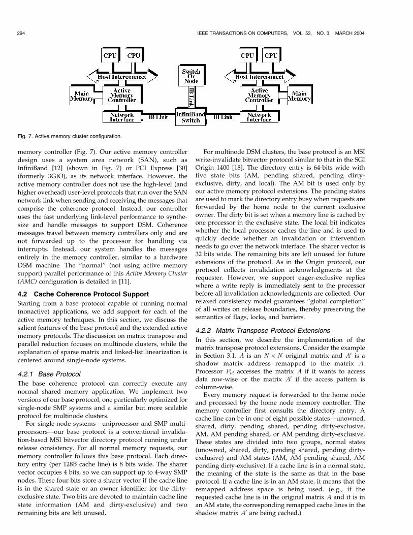
Active Memory Data Unit (AMDU). The AMDU (seeFig. 6) is a specialized hardware datapath that performspipelined address remapping and accelerates cache lineassembly/disassembly. For each cache line, it loads/stores16 different double words (a cache line) from/to the mainmemory according to the addresses it generates each cycle.We follow a similar design to [33]; however, because ourcache coherence mechanism demands special operationsfrom the AMDU, it exhibits quite different behavior, asdiscussed in Section 4.2.
The AMDU is composed of five cache line-sized buffers:the Base Address Buffer, Virtual Address Buffer, PhysicalAddress Buffer, Directory Address Buffer, and Data Buffer,and three pipeline stages: Address Calculation, AMTLBLookup, and Directory Address Calculation/Memory Access.Each pipeline stage processes one double word at a time
from the previous buffer and writes its result to the nextbuffer. Operations are fully pipelined, so one double wordis processed per cycle in the absence of any pipeline stalls.Therefore, the best-case latency for the AMDU to process acache line (16 double words) is the pipeline latency +15 cycles, where the pipeline latency is the time it takes onedouble word to pass through all three stages without stalls.
The Base Address Buffer contains technique-specificvalues that are intended to be used for virtual addresscalculation. For example, the sparse matrix technique usesthis buffer to store Acol½j� values corresponding to therequested shadow cache line. The Address Calculationstage calculates virtual addresses from the Base AddressBuffer by shift and add operations and writes to the VirtualAddress Buffer. Each entry of the Virtual Address Bufferholds the virtual address of the corresponding doubleword. The AMTLB translates the virtual addresses tophysical addresses and then the Memory Access stageperforms double word load/store operations to/from thecorresponding entries of the Data Buffer. The DirectoryAddress Calculation unit helps the AMPU calculatedirectory entry addresses. The coherence protocol requiresthe AMPU to check the directory entries of the cache linescontaining the double words, so the address calculation isperformance-critical. By moving the address calculation tothe AMDU, the latency of the AMPU is significantlyreduced and, because it operates concurrently with theMemory Access stage, it does not slow down the AMDU.
Active memory techniques directly manipulate applica-tion data that cannot be accessed through physicaladdresses. For example, linked-list linearization traversesa list by chasing virtual addresses. The memory system isaddressed with physical addresses, so the AMDU has a TLBthat we call the AMTLB. Because an AMTLB miss stalls theAMDU pipeline and has a large miss penalty, the hit rate ofthe AMTLB is a critical determinant of performance.Therefore, our AMDU also has an AMTLB predictor toimprove its performance. The AMTLB predictor prefetchesthe accesses to the AMTLB. It is a Differential Finite ContextMethod predictor [10] that consists of a 3 KB table andcontrol logic. Detailed analysis can be found in [15]. Itimproves performance by more than 15 percent. Finally, ifthe AMTLB suffers a page fault, a trap is made to the kerneland the page fault handler is initiated.
Send Unit. The Send Unit is responsible for themechanics of sending interventions or reply messagesgenerated by the coherence protocol. The Send Unitassembles the header and the data components into amessage and inserts it into the corresponding output queue(PI or NI), offloading this task from the AMPU.
Memory Interface. The Memory Interface connects theSDRAM to the other parts of the controller. It picks arequest from a 16-deep request queue and performs loadsor stores. It is fully pipelined and the AMDU does not stallunless the memory request queue fills.
4.1.2 Network Integration
Commodity architectures are witnessing evolutionarychanges in network integration as the network connectionmoves from a plug-in card on the distant I/O bus to arouting chip directly connected to or integrated with the
KIM ET AL.: ARCHITECTURAL SUPPORT FOR UNIPROCESSOR AND MULTIPROCESSOR ACTIVE MEMORY SYSTEMS 293
Fig. 6. Active memory data unit.
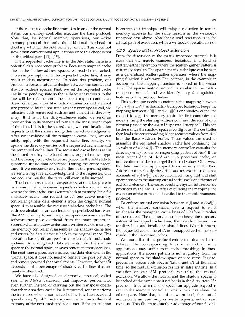
memory controller (Fig. 7). Our active memory controller
design uses a system area network (SAN), such as
InfiniBand [12] (shown in Fig. 7) or PCI Express [30]
(formerly 3GIO), as its network interface. However, the
active memory controller does not use the high-level (and
higher overhead) user-level protocols that run over the SAN
network link when sending and receiving the messages that
comprise the coherence protocol. Instead, our controller
uses the fast underlying link-level performance to synthe-
size and handle messages to support DSM. Coherence
messages travel between memory controllers only and are
not forwarded up to the processor for handling via
interrupts. Instead, our system handles the messages
entirely in the memory controller, similar to a hardware
DSM machine. The “normal” (not using active memory
support) parallel performance of this Active Memory Cluster
(AMC) configuration is detailed in [11].
4.2 Cache Coherence Protocol Support
Starting from a base protocol capable of running normal
(nonactive) applications, we add support for each of the
active memory techniques. In this section, we discuss the
salient features of the base protocol and the extended active
memory protocols. The discussion on matrix transpose and
parallel reduction focuses on multinode clusters, while the
explanation of sparse matrix and linked-list linearization is
centered around single-node systems.
4.2.1 Base Protocol
The base coherence protocol can correctly execute any
normal shared memory application. We implement two
versions of our base protocol, one particularly optimized for
single-node SMP systems and a similar but more scalable
protocol for multinode clusters.For single-node systems—uniprocessor and SMP multi-
processors—our base protocol is a conventional invalida-
tion-based MSI bitvector directory protocol running under
release consistency. For all normal memory requests, our
memory controller follows this base protocol. Each direc-
tory entry (per 128B cache line) is 8 bits wide. The sharer
vector occupies 4 bits, so we can support up to 4-way SMP
nodes. These four bits store a sharer vector if the cache line
is in the shared state or an owner identifier for the dirty-
exclusive state. Two bits are devoted to maintain cache line
state information (AM and dirty-exclusive) and two
remaining bits are left unused.
For multinode DSM clusters, the base protocol is an MSIwrite-invalidate bitvector protocol similar to that in the SGIOrigin 1400 [18]. The directory entry is 64-bits wide withfive state bits (AM, pending shared, pending dirty-exclusive, dirty, and local). The AM bit is used only byour active memory protocol extensions. The pending statesare used to mark the directory entry busy when requests areforwarded by the home node to the current exclusiveowner. The dirty bit is set when a memory line is cached byone processor in the exclusive state. The local bit indicateswhether the local processor caches the line and is used toquickly decide whether an invalidation or interventionneeds to go over the network interface. The sharer vector is32 bits wide. The remaining bits are left unused for futureextensions of the protocol. As in the Origin protocol, ourprotocol collects invalidation acknowledgments at therequester. However, we support eager-exclusive replieswhere a write reply is immediately sent to the processorbefore all invalidation acknowledgments are collected. Ourrelaxed consistency model guarantees “global completion”of all writes on release boundaries, thereby preserving thesemantics of flags, locks, and barriers.
4.2.2 Matrix Transpose Protocol Extensions
In this section, we describe the implementation of thematrix transpose protocol extensions. Consider the examplein Section 3.1. A is an N �N original matrix and A0 is ashadow matrix address remapped to the matrix A.Processor Pid accesses the matrix A if it wants to accessdata row-wise or the matrix A0 if the access pattern iscolumn-wise.
Every memory request is forwarded to the home nodeand processed by the home node memory controller. Thememory controller first consults the directory entry. Acache line can be in one of eight possible states—unowned,shared, dirty, pending shared, pending dirty-exclusive,AM, AM pending shared, or AM pending dirty-exclusive.These states are divided into two groups, normal states(unowned, shared, dirty, pending shared, pending dirty-exclusive) and AM states (AM, AM pending shared, AMpending dirty-exclusive). If a cache line is in a normal state,the meaning of the state is the same as that in the baseprotocol. If a cache line is in an AM state, it means that theremapped address space is being used. (e.g., if therequested cache line is in the original matrix A and it is inan AM state, the corresponding remapped cache lines in theshadow matrix A0 are being cached.)
294 IEEE TRANSACTIONS ON COMPUTERS, VOL. 53, NO. 3, MARCH 2004
Fig. 7. Active memory cluster configuration.
If the requested cache line from A is in any of the normalstates, our memory controller executes the base protocol.Note that, for normal memory operations, our activememory protocol has only the additional overhead ofchecking whether the AM bit is set or not. This does notslow down conventional applications since this check is noton the critical path [11], [15].
If the requested cache line is in the AM state, there is apotential data coherence problem. Because remapped cachelines in the shadow address space are already being cached,if we simply reply with the requested cache line, it mayresult in data inconsistency. To solve this problem, ourprotocol enforces mutual exclusion between the normal andshadow address spaces. First, we set the requested cacheline in the pending state so that subsequent requests to theline will be refused until the current request completes.Based on information like matrix dimension and elementsize provided by the one-time AMInitTranspose call, wecalculate each remapped address and consult its directoryentry. If it is in the dirty-exclusive state, we send anintervention to its owner and retrieve the most recent copyof the data. If it is in the shared state, we send invalidationrequests to all the sharers and gather the acknowledgments.After we invalidate all the remapped cache lines, we cansafely reply with the requested cache line. Finally, weupdate the directory entries of the requested cache line andthe remapped cache lines. The requested cache line is set inthe shared or dirty state based on the original request typeand the remapped cache lines are placed in the AM state toguarantee future data coherence. During the entire proce-dure, if we encounter any cache line in the pending state,we send a negative acknowledgment to the requester. Ourprotocol ensures that the retry will eventually succeed.
The in-memory matrix transpose operation takes place intwo cases: when a processor requests a shadow cache line orwhena shadowcache line iswrittenback tomemory. First, fora shadow cache line request to A0, our active memorycontroller gathers data elements from the original normalspace A to assemble the requested shadow cache line. Theaddress calculations are accelerated by specialized hardware(the AMDU in Fig. 6) and the gather operation eliminates thesoftware transpose overhead from the main processor.Second,when a shadowcache line iswritten back tomemory,the memory controller disassembles the shadow cache lineand writes the data elements back to the original space. Thisoperation has significant performance benefit in multinodesystems. By writing back data elements from the shadowspace to the normal space, it saves remote memory accesses.The next time a processor accesses the data elements in thenormal space, it does not need to retrieve the possibly dirtyand remotely cached shadow elements. However, the benefitdepends on the percentage of shadow cache lines that aretimely written back.
We have also designed an alternative protocol, calledSpeculative Matrix Transpose, that improves performanceeven further. Instead of carrying out the transpose opera-tion when a shadow cache line is requested, we can performthe transpose when a normal cache line is written back andspeculatively “push” the transposed cache line to the localmemory of the next predicted consumer. If the speculation
is correct, our technique will enjoy a reduction in remotememory accesses for the same reasons as the writebacktranspose case above. Note that a read operation is in thecritical path of execution, while a writeback operation is not.
4.2.3 Sparse Matrix Protocol Extensions
From the discussion of the matrix transpose protocol, it isclear that the matrix transpose technique is a kind ofscatter/gather operation where the scatter/gather pattern isextremely regular. The sparse matrix technique can be seenas a generalized scatter/gather operation where the map-ping function is arbitrary. For instance, in the example inSection 3.2, the mapping function is stored in the vectorAcol. The sparse matrix protocol is similar to the matrixtranspose protocol and we identify only distinguishingfeatures of this protocol below.
This technique needs to maintain the mapping betweenv½Acol½j�� and v0½j� as thematrix transpose technique keeps themapping betweenA½i�½j� andA0½j�½i�. For a shadow cache linerequest to v0½j�, the memory controller first computes theindex j using the starting address of v0 and the size of dataelement passed by the AMInitSparse library call. This canbe done since the shadow space is contiguous. The controllerthen loads the corresponding 16 consecutivevalues fromAcolinto the Base Address buffer. These values are used toassemble the requested shadow cache line containing the16 values of v½Acol½j��. The memory controller consults thedirectory entry for the corresponding portion of Acol. If themost recent data of Acol are in a processor cache, aninterventionmust be sent to get the correct values.Otherwise,the data may be simply copied from memory to the BaseAddress buffer. Finally, thevirtual addresses of the requestedelements of v½Acol½j�� can be calculated using add and shiftoperationswith the startingvirtual address of vand the sizeofeach data element. The corresponding physical addresses areproduced by the AMTLB. After calculating the mapping, theexecution of the protocol is identical to the matrix transposeprotocol.
To enforce mutual exclusion between v0½j� and v½Acol½j��,when the memory controller gets a request to v0, itinvalidates the remapped cache lines of v before it repliesto the request. The memory controller checks the directoryentries of remapped cache lines, then sends interventionsfor dirty lines and invalidates shared lines. When it returnsthe requested cache line of v0, no remapped cache lines of vreside in the processor caches.
We found that if the protocol enforces mutual exclusionbetween the corresponding lines in v and v0, someapplications may suffer from cache thrashing. In thoseapplications, the access pattern is not migratory from thenormal space to the shadow space or vice versa. Instead,processors access both spaces (i.e., v and v0) at the sametime, so the mutual exclusion results in false sharing. In avariation on our AM protocol, we relax the mutualexclusion. We allow the normal and the shadow spaces tobe cached at the same time if neither is in the dirty state. If aprocessor tries to write one space, an upgrade request issent to the memory controller, which then invalidates theother space. Note that, in this new protocol, the mutualexclusion is imposed only on write requests, not on readrequests. This illustrates another advantage of our flexible
KIM ET AL.: ARCHITECTURAL SUPPORT FOR UNIPROCESSOR AND MULTIPROCESSOR ACTIVE MEMORY SYSTEMS 295
memory controller in that it can adapt the coherenceprotocol to the needs of applications.
As mentioned in Section 3.2, this protocol has onelimitation: It does not allow writes to the shadow vector v0.If two elements in a shadow cache line (at different positions,but in the same line) are mapped to a single element in anormal cache line and a processor writes to one of theelements, the other elementwill become stale. This restrictionapplies to anyactivememory system that doesnotmodify theprocessor cache architecture. However, writes to v0 may beintroduced only if the application writes to v in a sparsemanner and, in our experienc,e sparsematrix applications donot need sparse writes to the vector v.
4.2.4 Linked-List Linearization Protocol Extensions
The linked-list linearization protocol is composed of twooperations—Linearization and Safety-Net. Linearizationcopies a linked-list into a contiguous memory space andsafety-net guarantees correctness. Consider the examplegiven in Section 3.3, where we traverse a linked-list A.
This technique provides a library call AMLinearize touser applications. On a linearize call to the linked-list A, thememory controller linearizes the list—it copies a certainnumber of nodes of the list into a contiguous physicaladdress space. First, the linearize call communicates to thememory controller the starting virtual address of the list A,which the AMTLB translates into a physical address. Then,the memory controller checks the directory entry of thecorresponding cache line. It retrieves a dirty cache line fromthe processor cache and invalidates any sharers, then copiesdata into a contiguous memory space provided by theoperating system. It also updates the “next” pointer of thenode to point to the new space. Now that the first node ofthe list is copied, the memory controller chases the nextpointer to get the virtual address of the next element andrepeats the same procedure above. The memory controllerfinishes when it reaches the end of the list or it haslinearized a predefined number of nodes. It returns thestarting address of the newly linearized list and theapplication traverses the new list instead of the list A. Thislinearize call can be implemented in software without anyactive memory support. However, our technique canachieve higher performance since our memory controlleris closer to main memory and can manipulate data withword granularity. The main processor pays longer latencyto access memory and must transfer entire cache lines.
More seriously, without active memory support, acorrectness problem arises if a processor accesses adangling pointer that points into the “old” linked-list. Sucha reference may return stale data. Our solution is the safety-net operation that keeps data coherent between the originallist and the linearized lists. We establish a mappingbetween the original and linearized lists and enforce mutualexclusion so that only one of the remapped elements can becached at a time. First, we make a mapping by the “memoryforwarding” chain. When the memory controller performs alinearize call, it stores pointers to the newly linearized list inthe memory space of the old list. So, each node of the old listnow contains a pointer to the corresponding node of thenew list, instead of a data value. It also sets the AM bits ofthe cache lines that contain any nodes of the old list. Second,
if a processor accesses a dangling pointer, the AM bit in thedirectory entry of the requested cache line must be set,indicating that some of the nodes in the cache line arelinearized and therefore invalid. The memory controllerfinds these old nodes, reads the pointers to the new nodes,and follows the memory forwarding chain to the end. Notethat multiple linearize calls may be performed on a singlelinked-list and we keep the valid data nodes (not thepointer nodes) at the end of the chain. For those validnodes, the memory controller retrieves the most recent datathrough the same procedures as before—it consults thedirectory entries and sends interventions for dirty cachelines and invalidations for shared lines. Finally, the memorycontroller gathers all the valid data and returns therequested cache line. The memory controller also needs toupdate the memory forwarding chain and the directoryentries to guarantee future correctness. It puts the requestedcache line at the end of the forwarding chain and clears theAM bit. The AM bits of other cache lines in the sameforward chain are also updated accordingly.
4.2.5 Parallel Reduction Protocol Extensions
As in the parallel reduction example in Section 3.4, in thefirst phase of execution, every processor reads and writesthe shadow cache lines of x0. When a processor reads ashadow cache line in the shared state, the local memorycontroller immediately replies with a cache line filled withidentity values e. It does not notify the home node becausethe algorithm guarantees that every shadow cache line willbe written eventually. If the processor wishes to write ashadow cache line, the local memory controller still repliesimmediately with a cache line filled with values e. The mainprocessor receives the cache line, but the write does notcomplete globally until all address remapped memory linesare invalidated from other caches and all the necessaryacknowledgments are gathered. To do this, the localmemory controller also forwards the write request to thehome node. The home node memory controller consults thedirectory entries of the requested x0 cache line as well as thecorresponding x cache line. The protocol execution observesone of the following four cases.
The first case occurs when the corresponding x cache lineis in the dirty state. The home node notifies the requesterthat the number of acknowledgments is one, sends anintervention to the owner, and sets the shadow directoryentry in the pending exclusive state to indicate that the firstshadow request for this cache line has been received andthe intervention has been sent. Later, after the dirty line isretrieved and written back to memory, the home nodesends an acknowledgment to every requester marked in theshadow directory entry and clears the pending bit. Onlyafter the requesters receive the acknowledgments does thecorresponding write complete.
The second possibility is that the x cache line is in theshared state. The home node replies with the number ofsharers to the requester and sends out invalidation requests.The sharers send their acknowledgments directly with therequester.
The third case arises when the requested x0 cache line isin the pending exclusive state—the first case abovedescribes why and when the directory entry transitions to
296 IEEE TRANSACTIONS ON COMPUTERS, VOL. 53, NO. 3, MARCH 2004
this state. In this case, the home node notifies the requesterthat the number of acknowledgments is one.
In the last case, the directory entries of both the x andx0 cache lines are clean. The home node notifies therequester that the expected number of acknowledgmentsis zero. In all the cases, the home node marks therequester in the shadow directory entry and sets theAM bit in the normal directory entry.
The merge phase takes place at the home node when itreceives a writeback for a shadow cache line. The homenode clears the source node of the writeback from theshadow directory entry, performs the reduction operation,and writes the result back to memory. The last writebackclears the AM bit in the normal directory entry. At thispoint, the corresponding x cache line in memory holds themost recent value.
Finally, we discuss the case when a memory requestarrives for a normal cache line of x. If the AM bit in thecorresponding directory entry is clear, the behavior of ouractive memory controller is identical to the base protocol.However, if the AM bit is set, it means that the correspond-ing shadow cache line is cached in the dirty-exclusive stateby one or more processors. Note that, in this protocol, thereare only two stable states for a shadow cache line, namely,invalid and dirty-exclusive. Note also that, from theprotocol execution discussed above, it is clear that the sameshadow cache line can have simultaneous multiple writers.To satisfy the request for the x cache line, the home nodesends out interventions by reading the owners from theshadow directory entry and keeping the normal directoryentry in the appropriate pending state (e.g., shared or dirty-exclusive) until the last intervention reply arrives. Everyintervention reply arrives at the home node and clears thesource node from the shadow directory. At this time, thehome node also carries out the reduction between theintervention reply and the resident memory line. The finalintervention reply triggers the data reply carrying therequested x cache line to the requester.
4.2.6 Protocol Design Issues
In the following, we summarize a few implementation-specific issues in active memory protocol design. Ourdiscussion touches on four topics, handler latency, shadowpage placement, cache line invalidation, and deadlockavoidance. The latter three issues are particular to multi-node active memory systems.
The most important performance issue in our protocoldesign is the path length of the protocol handlers. Handlerlatency (the execution time of the software protocolhandler) directly affects memory system performance. Inour active memory controller, the AMPU and the AMDUwork concurrently. The AMPU executes the protocolhandlers, while the AMDU accesses main memory. In theideal case, the handler latency is completely hidden by thememory access time, which is the case for all normal(nonactive) memory accesses. However, the active memoryprotocol handlers are longer since they do more work (notethat this is justified because we are saving future cachemisses). To optimize our active memory handlers, weimplement some common functionality in hardware. Forexample, the AMDU calculates the directory entry
addresses for the AMPU, which it uses in every activememory protocol. We also adopt software optimizationtechniques like loop unrolling in our protocol handlers,which results in better code scheduling and fewer branchesin the dual-issue AMPU.
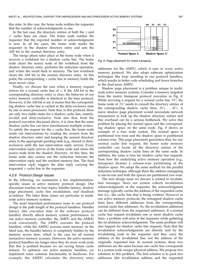
Shadow page placement is a problem unique to multi-node active memory systems. Consider a memory snapshotfrom the matrix transpose protocol execution in Fig. 8.While servicing a request for a normal cache line NC, thehome node of NC needs to consult the directory entries ofthe corresponding shadow cache lines, SC0; . . . ; SC7. Anaive shadow page placement would necessitate networktransactions to look up the shadow directory entries andthis overhead can be a serious bottleneck. We solve thisproblem by placing the normal space and the correspond-ing shadow space on the same node. Fig. 8 shows anexample of a four node system. The normal space ispartitioned row-wise and the shadow space is partitionedcolumn-wise. This page placement guarantees that, for anynormal cache line request, the home node memorycontroller can locate all the directory entries of thecorresponding shadow cache lines on the same node. Inaddition, the same is true for shadow cache line requests.Note how the underlying active memory operation (e.g.,transpose) dictates a column-wise partitioning of theshadow space. We adopt the same method for the parallelreduction technique, although there the address remappingis one-to-one and both the spaces are partitioned row-wise.
The next design issue we discuss is related to invalida-tion messages. Since our system collects invalidationacknowledgments at the requester, the acknowledgmentmessage typically carries the address of the requested cacheline (i.e., the cache line that is being written). However inour active memory protocols, the remapped shadow cachelines have different addresses from the correspondingnormal cache line addresses. So, the invalidation addressescan be different from the requested addresses. If a normalcache line request invalidates one or more shadow cachelines, a problem will arise at the requester while gatheringthe invalidation acknowledgments. The same problem willalso happen for shadow cache line requests. Note that theinvalidation acknowledgments are directly sent by theinvalidating node to the requester and they carry theaddress of the invalidated line, not the address of theoriginally requested line. In normal systems, these twoaddresses are the same because one cache line correspondsto a system-wide unique physical address. We propose twosolutions to this problem. The first solution is to pack twoaddresses (the invalidation address and the requested
KIM ET AL.: ARCHITECTURAL SUPPORT FOR UNIPROCESSOR AND MULTIPROCESSOR ACTIVE MEMORY SYSTEMS 297
Fig. 8. Page placement for matrix transpose.
address) in the header of the invalidation request messagefrom the home node to the invalidating node so that theinvalidating node can set the requested address in theacknowledgment header. The second solution is to carryout an address remapping operation again at the invalidat-ing node to compute the corresponding requested address.The flexibility of our design allows us to employ the secondsolution and therefore does not require changes to thenetwork message header structure.
Finally, the possibility of generating multiple interven-tions from a single request in active memory protocols hasramifications on the deadlock avoidance strategy. Also,unlike the baseline protocol, many of the active memoryprotocol handlers require more than one data buffer fortransferring cache-line-sized data to and from the memorysystem, requiring careful data buffer management. How-ever, we solve both problems similarly to conventionalDSM systems—a handler running out of any necessaryresource suspends execution and reschedules itself at a laterpoint in time instead of waiting for that resource. Weenqueue the incomplete request to a reserved portion ofmain memory at the home node and dispatch it whenappropriate resources are available. This ensures forwardprogress by allowing the memory controller to handle otheroutstanding requests and break deadlock cycles. Note thatour protocols use three or four virtual lanes, obviating theneed for complicated back-off mechanisms like thoseimplemented in the SGI Origin 1400 protocol.
5 SIMULATION METHODOLOGY
In this section, we discuss the applications we use toevaluate the performance of our active memory system andthe simulation environment we use to collect the results.
5.1 Applications
To evaluate our active memory system we use a range ofapplications—some are well-known benchmarks while
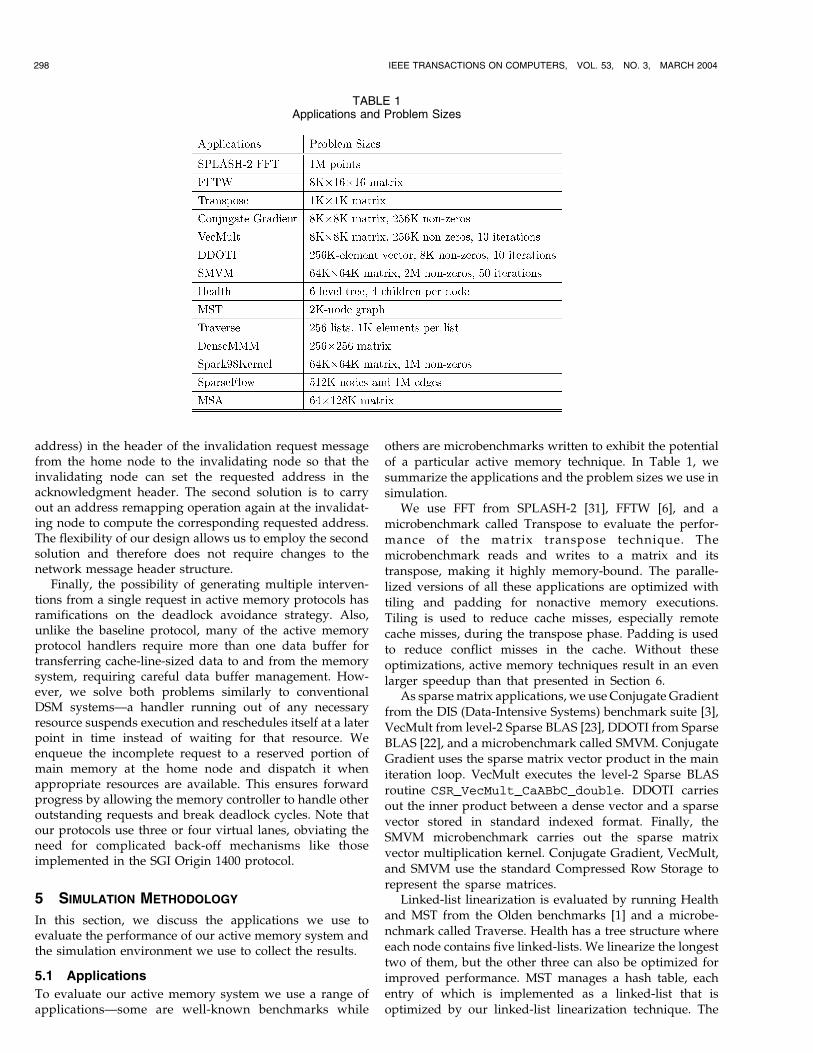
others are microbenchmarks written to exhibit the potentialof a particular active memory technique. In Table 1, wesummarize the applications and the problem sizes we use insimulation.
We use FFT from SPLASH-2 [31], FFTW [6], and amicrobenchmark called Transpose to evaluate the perfor-mance of the matrix transpose technique. Themicrobenchmark reads and writes to a matrix and itstranspose, making it highly memory-bound. The paralle-lized versions of all these applications are optimized withtiling and padding for nonactive memory executions.Tiling is used to reduce cache misses, especially remotecache misses, during the transpose phase. Padding is usedto reduce conflict misses in the cache. Without theseoptimizations, active memory techniques result in an evenlarger speedup than that presented in Section 6.
As sparsematrix applications, we use Conjugate Gradientfrom the DIS (Data-Intensive Systems) benchmark suite [3],VecMult from level-2 Sparse BLAS [23], DDOTI from SparseBLAS [22], and a microbenchmark called SMVM. ConjugateGradient uses the sparse matrix vector product in the mainiteration loop. VecMult executes the level-2 Sparse BLASroutine CSR_VecMult_CaABbC_double. DDOTI carriesout the inner product between a dense vector and a sparsevector stored in standard indexed format. Finally, theSMVM microbenchmark carries out the sparse matrixvector multiplication kernel. Conjugate Gradient, VecMult,and SMVM use the standard Compressed Row Storage torepresent the sparse matrices.
Linked-list linearization is evaluated by running Healthand MST from the Olden benchmarks [1] and a microbe-nchmark called Traverse. Health has a tree structure whereeach node contains five linked-lists. We linearize the longesttwo of them, but the other three can also be optimized forimproved performance. MST manages a hash table, eachentry of which is implemented as a linked-list that isoptimized by our linked-list linearization technique. The
298 IEEE TRANSACTIONS ON COMPUTERS, VOL. 53, NO. 3, MARCH 2004
TABLE 1Applications and Problem Sizes
Traverse microbenchmark walks through an array of lists asnew elements are inserted. The length of each list increasesto a maximum of 1,024 nodes. We linearize the listsperiodically as every 32 nodes are inserted.
To evaluate parallel reduction we use the dense matrixmultiplication (Dense MMM) kernel, a modified Spark98kernel [24], [25], a microbenchmark called SparseFlow, anda microbenchmark called Mean Square Average (MSA).Dense MMM carries out the computation C ¼ ATB onsquare matrices A and B, which is a special case of thelevel-3 BLAS [4] matrix-matrix multiplication subroutine.The modified Spark98 kernel parallelizes one call toLocalSMVP. SparseFlow computes a function on the in-flow of every edge incident on a node and sums up thefunction outputs as the net in-flux at each node in a sparsemultisource flow graph. MSA calculates the arithmeticmean of squares of the elements in every column of amatrix. All four applications use addition as the underlyingreduction operation.
5.2 Simulation Environment
The main processor runs at 2 GHz and is equipped withseparate 32 KB primary instruction and data caches that aretwo-way set associative and have a line size of 64 bytes. Thesecondary cache is unified, 512 KB, two-way set associative,and has a line size of 128 bytes. For sparse matrixapplications, we scale down the cache size so that we cansimulate the effect of running problems with large sparsematrices by running smaller problem sizes that we cansimulate within a reasonable amount of time. This isjustified since these applications have a working set sizeproportional to the problem size. For this class of applica-tions, we use a 16 KB primary data cache and a 64 KBsecondary cache, keeping the same line sizes and associa-tivities. We also assume that the processor ISA includesprefetch and prefetch-exclusive instructions. In our proces-sor model, a load miss stalls the processor until the firstdouble-word of data is returned, while store misses will notstall the processor unless there are already referencesoutstanding to four different cache lines. The processormodel also contains fully-associative 64-entry instructionand data TLBs. For a TLB miss, we charge 65 processorcycles (miss handler latency) plus any associated cache andmemory access time. The simulated page size is 4 KB.
The embedded active memory processor is a dual-issuecore running at the 400 MHz system clock frequency. Theinstruction and data cache behavior of the active memoryprocessor is modeled precisely via a cycle-accurate simu-lator similar to that for the protocol processor in [9]. Ourexecution-driven simulator models contention in detailwithin the active memory controller, between the controllerand its external interfaces, at main memory, and for thesystem bus. The system bus is 64-bits wide, and itsbandwidth is 3.2 GB/s, which matches the DRAMbandwidth. The memory request queue is 16 entries deep.The access time to the first 8 bytes in DRAM cells is fixed at125 ns (50 system cycles), similar to that in recentcommercial high-end servers [28], [29]. The following 8-byterequests can be pipelined, in a way similar to [21]. The inputand output queue sizes in the memory controller interfaceare set at 16 and 2 entries, respectively. The corresponding
queues in the network interface are 2 and 16 entries deep.The network interface is equipped with four virtual lanes toaid deadlock-free routing. We assume processor interfacedelays of one system cycle inbound and four system cyclesoutbound and network interface delays of 16 system cyclesinbound and eight system cycles outbound. We simulate16-port crossbar switches organized as a fat tree and presentresults for a slow (150 ns hop time) as well as a fast (50 nshop time) SAN router. The node-to-network link band-width is 1 GB/s, typical of current system area networks.
When comparing against flush schemes, we simulateuser-level complete cache flushes to minimize the flushoverhead. This does not involve any kernel trap overhead,but it does model the latency incurred in the cachehierarchy to flush the whole cache. Note that systems thatonly support selective page flushes will see a larger flushoverhead because realistic problem sizes are far bigger thanthe cache size and the entire data structure is flushed onepage at a time.
6 SIMULATION RESULTS
Our simulation results are divided into three areas:uniprocessor active memory systems, single-node multi-processor active memory systems, and multinode activememory clusters.
6.1 Uniprocessor Active Memory Systems
We report uniprocessor results for three active memorytechniques: matrix transpose, sparse matrix, and linked-listlinearization. We present speedup of the active memoryversion over the normal application. We also show thespeedup of active memory applications with softwareprefetches only for the shadow space accesses. Prefetchingthe same accesses in the normal case is extremely difficultor highly inefficient, while our active memory techniquesresult in easily prefetched sequential data from the shadowspace. For the first two techniques, we also give thespeedup of active memory applications using user-levelcache flushes (to emulate the Impulse memory controller[33]) rather than our hardware coherence, while, forapplications involving linked-list linearization, cacheflushes have no relevance since this technique requiresleveraging the coherence mechanism.
6.1.1 Matrix Transpose
Fig. 9 shows the uniprocessor speedup of three matrixtranspose benchmark applications with active memoryoptimization (AM), with active memory and softwareprefetching of the shadow address space only (AM+Pre-fetch), and with active memory using cache flushes ratherthan cache coherence (Flush), measured relative to theexecution time of the normal application. Table 2 sum-marizes the speedup of the nonprefetched AM case versusnormal execution, as well as how much our active memorysystem reduces CPU busy time, L2 cache read miss count,L2 cache write miss count, and data TLB stall time.
All the applications show the clear success of the matrixtranspose technique. Our active memory system achievesspeedup from 1.28 to 2.30 over a normal memory system.The matrix transpose technique improves performance by
KIM ET AL.: ARCHITECTURAL SUPPORT FOR UNIPROCESSOR AND MULTIPROCESSOR ACTIVE MEMORY SYSTEMS 299
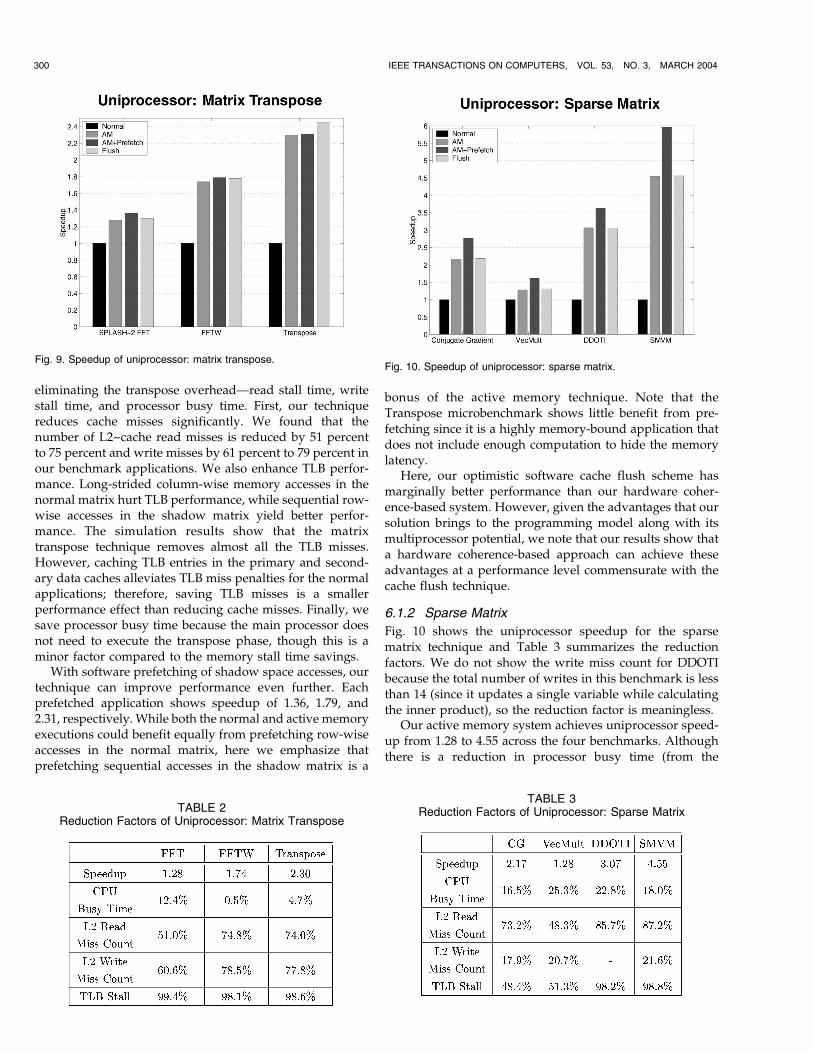
eliminating the transpose overhead—read stall time, writestall time, and processor busy time. First, our techniquereduces cache misses significantly. We found that thenumber of L2~cache read misses is reduced by 51 percentto 75 percent and write misses by 61 percent to 79 percent inour benchmark applications. We also enhance TLB perfor-mance. Long-strided column-wise memory accesses in thenormal matrix hurt TLB performance, while sequential row-wise accesses in the shadow matrix yield better perfor-mance. The simulation results show that the matrixtranspose technique removes almost all the TLB misses.However, caching TLB entries in the primary and second-ary data caches alleviates TLB miss penalties for the normalapplications; therefore, saving TLB misses is a smallerperformance effect than reducing cache misses. Finally, wesave processor busy time because the main processor doesnot need to execute the transpose phase, though this is aminor factor compared to the memory stall time savings.
With software prefetching of shadow space accesses, ourtechnique can improve performance even further. Eachprefetched application shows speedup of 1.36, 1.79, and2.31, respectively. While both the normal and active memoryexecutions could benefit equally from prefetching row-wiseaccesses in the normal matrix, here we emphasize thatprefetching sequential accesses in the shadow matrix is a
bonus of the active memory technique. Note that theTranspose microbenchmark shows little benefit from pre-fetching since it is a highly memory-bound application thatdoes not include enough computation to hide the memorylatency.
Here, our optimistic software cache flush scheme hasmarginally better performance than our hardware coher-ence-based system. However, given the advantages that oursolution brings to the programming model along with itsmultiprocessor potential, we note that our results show thata hardware coherence-based approach can achieve theseadvantages at a performance level commensurate with thecache flush technique.
6.1.2 Sparse Matrix
Fig. 10 shows the uniprocessor speedup for the sparsematrix technique and Table 3 summarizes the reductionfactors. We do not show the write miss count for DDOTIbecause the total number of writes in this benchmark is lessthan 14 (since it updates a single variable while calculatingthe inner product), so the reduction factor is meaningless.
Our active memory system achieves uniprocessor speed-up from 1.28 to 4.55 across the four benchmarks. Althoughthere is a reduction in processor busy time (from the
300 IEEE TRANSACTIONS ON COMPUTERS, VOL. 53, NO. 3, MARCH 2004
Fig. 9. Speedup of uniprocessor: matrix transpose.
TABLE 2Reduction Factors of Uniprocessor: Matrix Transpose
Fig. 10. Speedup of uniprocessor: sparse matrix.
TABLE 3Reduction Factors of Uniprocessor: Sparse Matrix
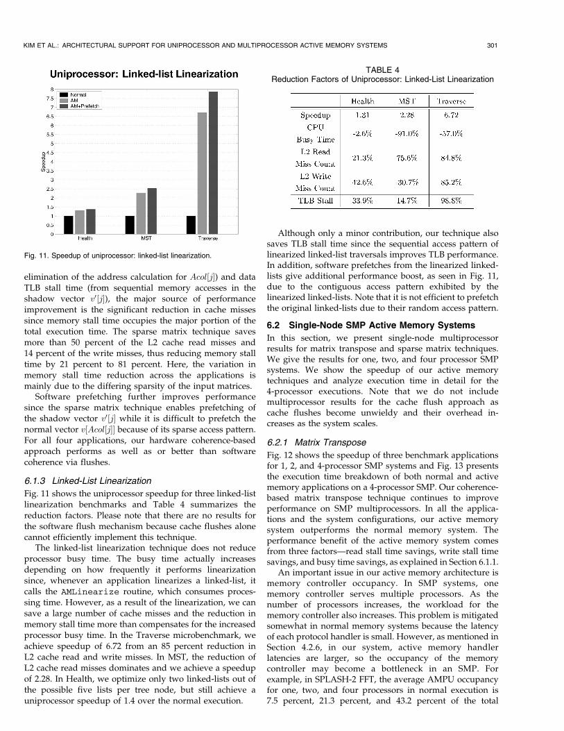
elimination of the address calculation for Acol½j�) and dataTLB stall time (from sequential memory accesses in theshadow vector v0½j�), the major source of performanceimprovement is the significant reduction in cache missessince memory stall time occupies the major portion of thetotal execution time. The sparse matrix technique savesmore than 50 percent of the L2 cache read misses and14 percent of the write misses, thus reducing memory stalltime by 21 percent to 81 percent. Here, the variation inmemory stall time reduction across the applications ismainly due to the differing sparsity of the input matrices.
Software prefetching further improves performancesince the sparse matrix technique enables prefetching ofthe shadow vector v0½j� while it is difficult to prefetch thenormal vector v½Acol½j�� because of its sparse access pattern.For all four applications, our hardware coherence-basedapproach performs as well as or better than softwarecoherence via flushes.
6.1.3 Linked-List Linearization
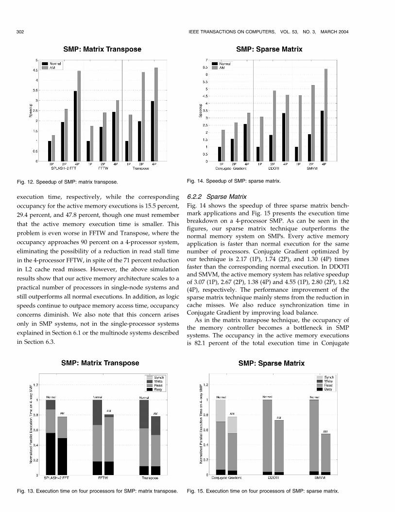
Fig. 11 shows the uniprocessor speedup for three linked-listlinearization benchmarks and Table 4 summarizes thereduction factors. Please note that there are no results forthe software flush mechanism because cache flushes alonecannot efficiently implement this technique.
The linked-list linearization technique does not reduceprocessor busy time. The busy time actually increasesdepending on how frequently it performs linearizationsince, whenever an application linearizes a linked-list, itcalls the AMLinearize routine, which consumes proces-sing time. However, as a result of the linearization, we cansave a large number of cache misses and the reduction inmemory stall time more than compensates for the increasedprocessor busy time. In the Traverse microbenchmark, weachieve speedup of 6.72 from an 85 percent reduction inL2 cache read and write misses. In MST, the reduction ofL2 cache read misses dominates and we achieve a speedupof 2.28. In Health, we optimize only two linked-lists out ofthe possible five lists per tree node, but still achieve auniprocessor speedup of 1.4 over the normal execution.
Although only a minor contribution, our technique alsosaves TLB stall time since the sequential access pattern oflinearized linked-list traversals improves TLB performance.In addition, software prefetches from the linearized linked-lists give additional performance boost, as seen in Fig. 11,due to the contiguous access pattern exhibited by thelinearized linked-lists. Note that it is not efficient to prefetchthe original linked-lists due to their random access pattern.
6.2 Single-Node SMP Active Memory Systems
In this section, we present single-node multiprocessorresults for matrix transpose and sparse matrix techniques.We give the results for one, two, and four processor SMPsystems. We show the speedup of our active memorytechniques and analyze execution time in detail for the4-processor executions. Note that we do not includemultiprocessor results for the cache flush approach ascache flushes become unwieldy and their overhead in-creases as the system scales.
6.2.1 Matrix Transpose
Fig. 12 shows the speedup of three benchmark applicationsfor 1, 2, and 4-processor SMP systems and Fig. 13 presentsthe execution time breakdown of both normal and activememory applications on a 4-processor SMP. Our coherence-based matrix transpose technique continues to improveperformance on SMP multiprocessors. In all the applica-tions and the system configurations, our active memorysystem outperforms the normal memory system. Theperformance benefit of the active memory system comesfrom three factors—read stall time savings, write stall timesavings, and busy time savings, as explained in Section 6.1.1.
An important issue in our active memory architecture ismemory controller occupancy. In SMP systems, onememory controller serves multiple processors. As thenumber of processors increases, the workload for thememory controller also increases. This problem is mitigatedsomewhat in normal memory systems because the latencyof each protocol handler is small. However, as mentioned inSection 4.2.6, in our system, active memory handlerlatencies are larger, so the occupancy of the memorycontroller may become a bottleneck in an SMP. Forexample, in SPLASH-2 FFT, the average AMPU occupancyfor one, two, and four processors in normal execution is7.5 percent, 21.3 percent, and 43.2 percent of the total
KIM ET AL.: ARCHITECTURAL SUPPORT FOR UNIPROCESSOR AND MULTIPROCESSOR ACTIVE MEMORY SYSTEMS 301
Fig. 11. Speedup of uniprocessor: linked-list linearization.
TABLE 4Reduction Factors of Uniprocessor: Linked-List Linearization
execution time, respectively, while the corresponding
occupancy for the active memory executions is 15.5 percent,
29.4 percent, and 47.8 percent, though one must remember
that the active memory execution time is smaller. This
problem is even worse in FFTW and Transpose, where the
occupancy approaches 90 percent on a 4-processor system,
eliminating the possibility of a reduction in read stall time
in the 4-processor FFTW, in spite of the 71 percent reduction
in L2 cache read misses. However, the above simulation
results show that our active memory architecture scales to a
practical number of processors in single-node systems and
still outperforms all normal executions. In addition, as logic
speeds continue to outpace memory access time, occupancy
concerns diminish. We also note that this concern arises
only in SMP systems, not in the single-processor systems
explained in Section 6.1 or the multinode systems described
in Section 6.3.
6.2.2 Sparse Matrix
Fig. 14 shows the speedup of three sparse matrix bench-mark applications and Fig. 15 presents the execution timebreakdown on a 4-processor SMP. As can be seen in thefigures, our sparse matrix technique outperforms thenormal memory system on SMPs. Every active memoryapplication is faster than normal execution for the samenumber of processors. Conjugate Gradient optimized byour technique is 2.17 (1P), 1.74 (2P), and 1.30 (4P) timesfaster than the corresponding normal execution. In DDOTIand SMVM, the active memory system has relative speedupof 3.07 (1P), 2.67 (2P), 1.38 (4P) and 4.55 (1P), 2.80 (2P), 1.82(4P), respectively. The performance improvement of thesparse matrix technique mainly stems from the reduction incache misses. We also reduce synchronization time inConjugate Gradient by improving load balance.
As in the matrix transpose technique, the occupancy ofthe memory controller becomes a bottleneck in SMPsystems. The occupancy in the active memory executionsis 82.1 percent of the total execution time in Conjugate
302 IEEE TRANSACTIONS ON COMPUTERS, VOL. 53, NO. 3, MARCH 2004
Fig. 13. Execution time on four processors for SMP: matrix transpose.
Fig. 12. Speedup of SMP: matrix transpose. Fig. 14. Speedup of SMP: sparse matrix.
Fig. 15. Execution time on four processors of SMP: sparse matrix.
Gradient, 92.6 percent in DDOTI, and 98.7 percent in SMVMon a 4-processor system, which is 30.6 percent (ConjugateGradient), 5 percent (DDOTI), and 17.1 percent (SMVM)higher than in the normal executions. The higher occupancyin our system explains why the relative speedup of theactive memory applications over the normal executions getssmaller as the number of processors increases. It is also thereason that 4-processor active memory speedup in DDOTIis smaller than the 2-processor one (though still higher thanthe 4-processor normal speedup).
6.3 Multinode Active Memory Systems
This section presents simulation results for our matrixtranspose and parallel reduction techniques on multinodeactive memory systems. We analyze parallel execution timeand scalability for both normal and active memory systems.We also explore the effects of network latency on theachieved speedup.
6.3.1 Matrix Transpose
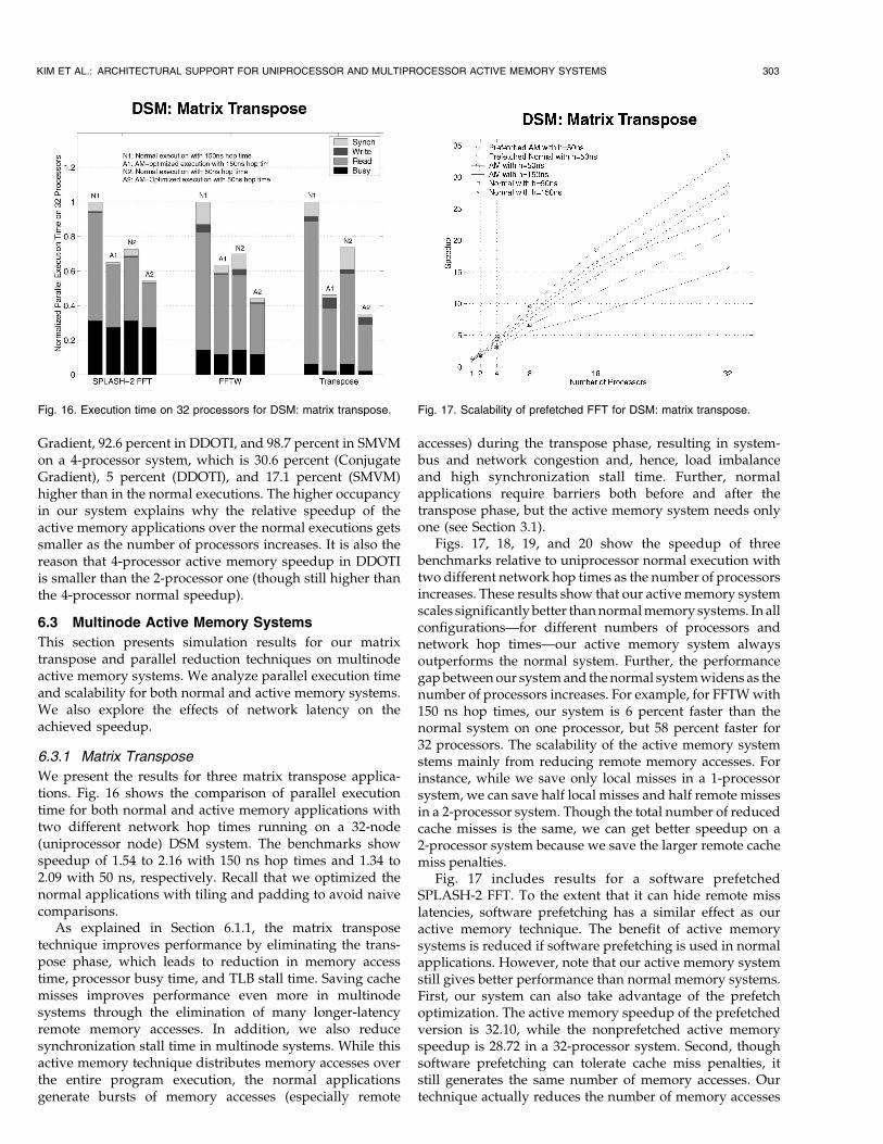
We present the results for three matrix transpose applica-tions. Fig. 16 shows the comparison of parallel executiontime for both normal and active memory applications withtwo different network hop times running on a 32-node(uniprocessor node) DSM system. The benchmarks showspeedup of 1.54 to 2.16 with 150 ns hop times and 1.34 to2.09 with 50 ns, respectively. Recall that we optimized thenormal applications with tiling and padding to avoid naivecomparisons.
As explained in Section 6.1.1, the matrix transposetechnique improves performance by eliminating the trans-pose phase, which leads to reduction in memory accesstime, processor busy time, and TLB stall time. Saving cachemisses improves performance even more in multinodesystems through the elimination of many longer-latencyremote memory accesses. In addition, we also reducesynchronization stall time in multinode systems. While thisactive memory technique distributes memory accesses overthe entire program execution, the normal applicationsgenerate bursts of memory accesses (especially remote
accesses) during the transpose phase, resulting in system-bus and network congestion and, hence, load imbalanceand high synchronization stall time. Further, normalapplications require barriers both before and after thetranspose phase, but the active memory system needs onlyone (see Section 3.1).
Figs. 17, 18, 19, and 20 show the speedup of threebenchmarks relative to uniprocessor normal execution withtwo different network hop times as the number of processorsincreases. These results show that our active memory systemscales significantly better thannormalmemory systems. In allconfigurations—for different numbers of processors andnetwork hop times—our active memory system alwaysoutperforms the normal system. Further, the performancegapbetweenour systemand thenormal systemwidens as thenumber of processors increases. For example, for FFTWwith150 ns hop times, our system is 6 percent faster than thenormal system on one processor, but 58 percent faster for32 processors. The scalability of the active memory systemstems mainly from reducing remote memory accesses. Forinstance, while we save only local misses in a 1-processorsystem, we can save half local misses and half remote missesin a 2-processor system. Though the total number of reducedcache misses is the same, we can get better speedup on a2-processor system because we save the larger remote cachemiss penalties.
Fig. 17 includes results for a software prefetchedSPLASH-2 FFT. To the extent that it can hide remote misslatencies, software prefetching has a similar effect as ouractive memory technique. The benefit of active memorysystems is reduced if software prefetching is used in normalapplications. However, note that our active memory systemstill gives better performance than normal memory systems.First, our system can also take advantage of the prefetchoptimization. The active memory speedup of the prefetchedversion is 32.10, while the nonprefetched active memoryspeedup is 28.72 in a 32-processor system. Second, thoughsoftware prefetching can tolerate cache miss penalties, itstill generates the same number of memory accesses. Ourtechnique actually reduces the number of memory accesses
KIM ET AL.: ARCHITECTURAL SUPPORT FOR UNIPROCESSOR AND MULTIPROCESSOR ACTIVE MEMORY SYSTEMS 303
Fig. 16. Execution time on 32 processors for DSM: matrix transpose. Fig. 17. Scalability of prefetched FFT for DSM: matrix transpose.
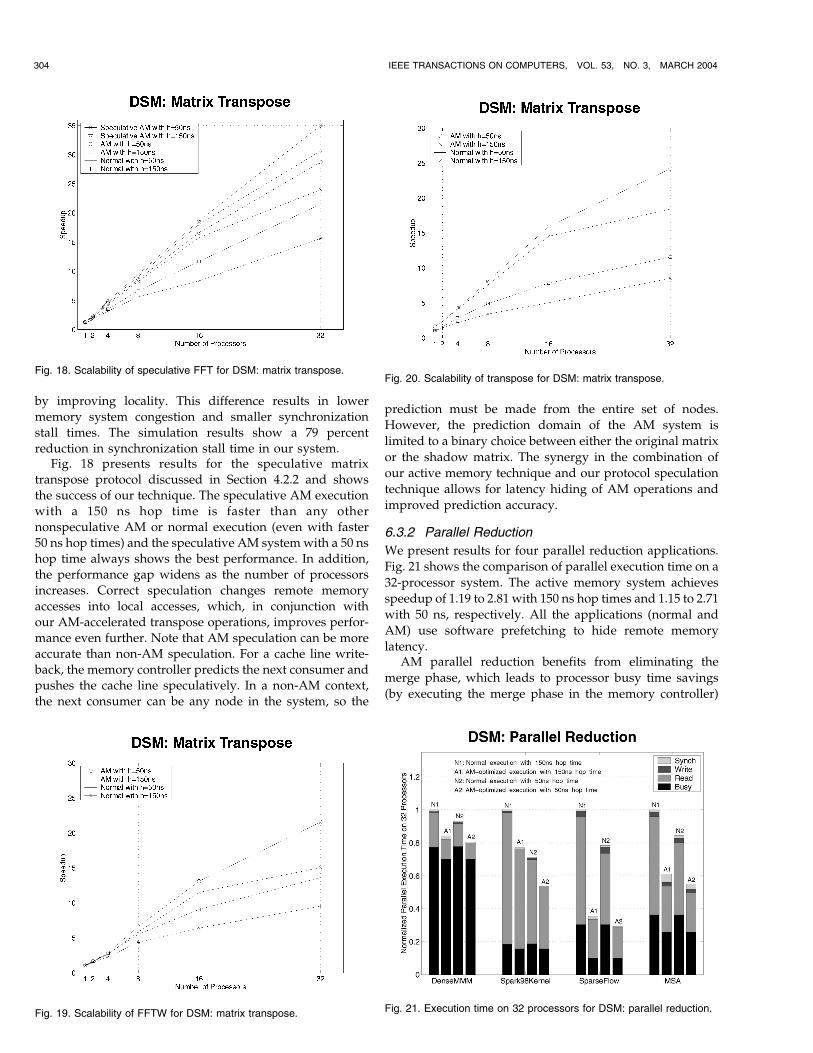
by improving locality. This difference results in lowermemory system congestion and smaller synchronizationstall times. The simulation results show a 79 percentreduction in synchronization stall time in our system.
Fig. 18 presents results for the speculative matrixtranspose protocol discussed in Section 4.2.2 and showsthe success of our technique. The speculative AM executionwith a 150 ns hop time is faster than any othernonspeculative AM or normal execution (even with faster50 ns hop times) and the speculative AM systemwith a 50 nshop time always shows the best performance. In addition,the performance gap widens as the number of processorsincreases. Correct speculation changes remote memory
accesses into local accesses, which, in conjunction withour AM-accelerated transpose operations, improves perfor-mance even further. Note that AM speculation can be moreaccurate than non-AM speculation. For a cache line write-back, the memory controller predicts the next consumer andpushes the cache line speculatively. In a non-AM context,the next consumer can be any node in the system, so the
prediction must be made from the entire set of nodes.
However, the prediction domain of the AM system is
limited to a binary choice between either the original matrix
or the shadow matrix. The synergy in the combination of
our active memory technique and our protocol speculation
technique allows for latency hiding of AM operations and
improved prediction accuracy.
6.3.2 Parallel Reduction
We present results for four parallel reduction applications.
Fig. 21 shows the comparison of parallel execution time on a
32-processor system. The active memory system achieves
speedup of 1.19 to 2.81 with 150 ns hop times and 1.15 to 2.71
with 50 ns, respectively. All the applications (normal and
AM) use software prefetching to hide remote memory
latency.AM parallel reduction benefits from eliminating the
merge phase, which leads to processor busy time savings
(by executing the merge phase in the memory controller)
304 IEEE TRANSACTIONS ON COMPUTERS, VOL. 53, NO. 3, MARCH 2004
Fig. 20. Scalability of transpose for DSM: matrix transpose.
Fig. 21. Execution time on 32 processors for DSM: parallel reduction.Fig. 19. Scalability of FFTW for DSM: matrix transpose.
Fig. 18. Scalability of speculative FFT for DSM: matrix transpose.
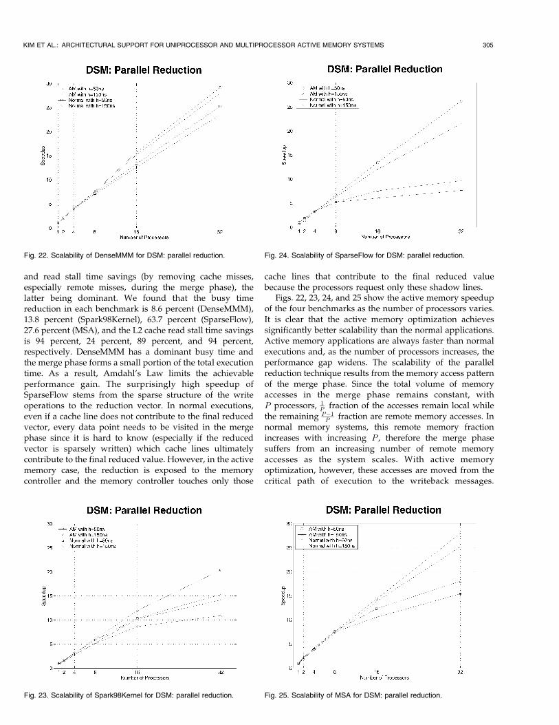
and read stall time savings (by removing cache misses,especially remote misses, during the merge phase), thelatter being dominant. We found that the busy timereduction in each benchmark is 8.6 percent (DenseMMM),13.8 percent (Spark98Kernel), 63.7 percent (SparseFlow),27.6 percent (MSA), and the L2 cache read stall time savingsis 94 percent, 24 percent, 89 percent, and 94 percent,respectively. DenseMMM has a dominant busy time andthe merge phase forms a small portion of the total executiontime. As a result, Amdahl’s Law limits the achievableperformance gain. The surprisingly high speedup ofSparseFlow stems from the sparse structure of the writeoperations to the reduction vector. In normal executions,even if a cache line does not contribute to the final reducedvector, every data point needs to be visited in the mergephase since it is hard to know (especially if the reducedvector is sparsely written) which cache lines ultimatelycontribute to the final reduced value. However, in the activememory case, the reduction is exposed to the memorycontroller and the memory controller touches only those
cache lines that contribute to the final reduced valuebecause the processors request only these shadow lines.
Figs. 22, 23, 24, and 25 show the active memory speedupof the four benchmarks as the number of processors varies.It is clear that the active memory optimization achievessignificantly better scalability than the normal applications.Active memory applications are always faster than normalexecutions and, as the number of processors increases, theperformance gap widens. The scalability of the parallelreduction technique results from the memory access patternof the merge phase. Since the total volume of memoryaccesses in the merge phase remains constant, withP processors, 1
P fraction of the accesses remain local whilethe remaining P�1
P fraction are remote memory accesses. Innormal memory systems, this remote memory fractionincreases with increasing P , therefore the merge phasesuffers from an increasing number of remote memoryaccesses as the system scales. With active memoryoptimization, however, these accesses are moved from thecritical path of execution to the writeback messages.
KIM ET AL.: ARCHITECTURAL SUPPORT FOR UNIPROCESSOR AND MULTIPROCESSOR ACTIVE MEMORY SYSTEMS 305
Fig. 23. Scalability of Spark98Kernel for DSM: parallel reduction.
Fig. 24. Scalability of SparseFlow for DSM: parallel reduction.
Fig. 25. Scalability of MSA for DSM: parallel reduction.
Fig. 22. Scalability of DenseMMM for DSM: parallel reduction.
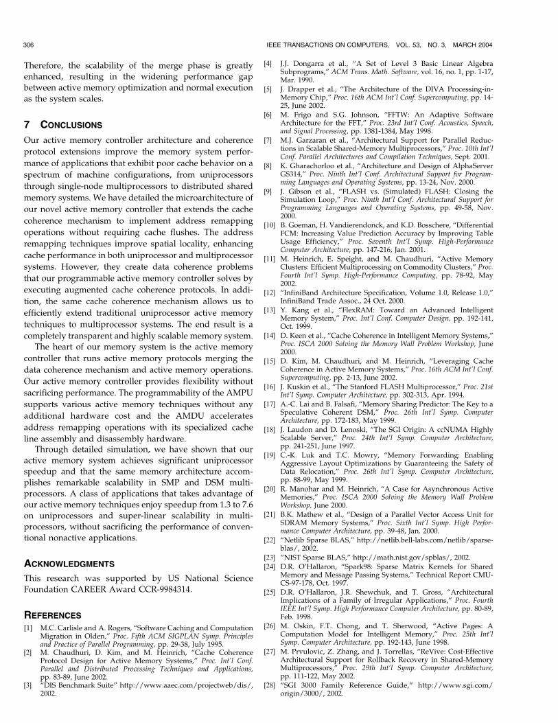
Therefore, the scalability of the merge phase is greatly
enhanced, resulting in the widening performance gap
between active memory optimization and normal execution
as the system scales.
7 CONCLUSIONS
Our active memory controller architecture and coherence
protocol extensions improve the memory system perfor-
mance of applications that exhibit poor cache behavior on a
spectrum of machine configurations, from uniprocessors
through single-node multiprocessors to distributed shared
memory systems. We have detailed the microarchitecture of
our novel active memory controller that extends the cache
coherence mechanism to implement address remapping
operations without requiring cache flushes. The address
remapping techniques improve spatial locality, enhancing
cache performance in both uniprocessor and multiprocessor
systems. However, they create data coherence problems
that our programmable active memory controller solves by
executing augmented cache coherence protocols. In addi-
tion, the same cache coherence mechanism allows us to
efficiently extend traditional uniprocessor active memory
techniques to multiprocessor systems. The end result is a
completely transparent and highly scalable memory system.
The heart of our memory system is the active memory
controller that runs active memory protocols merging the
data coherence mechanism and active memory operations.
Our active memory controller provides flexibility without
sacrificing performance. The programmability of the AMPU
supports various active memory techniques without any
additional hardware cost and the AMDU accelerates
address remapping operations with its specialized cache
line assembly and disassembly hardware.Through detailed simulation, we have shown that our
active memory system achieves significant uniprocessor
speedup and that the same memory architecture accom-
plishes remarkable scalability in SMP and DSM multi-
processors. A class of applications that takes advantage of
our active memory techniques enjoy speedup from 1.3 to 7.6
on uniprocessors and super-linear scalability in multi-
processors, without sacrificing the performance of conven-
tional nonactive applications.
ACKNOWLEDGMENTS
This research was supported by US National Science
Foundation CAREER Award CCR-9984314.
REFERENCES
[1] M.C. Carlisle and A. Rogers, “Software Caching and ComputationMigration in Olden,” Proc. Fifth ACM SIGPLAN Symp. Principlesand Practice of Parallel Programming, pp. 29-38, July 1995.
[2] M. Chaudhuri, D. Kim, and M. Heinrich, “Cache CoherenceProtocol Design for Active Memory Systems,” Proc. Int’l Conf.Parallel and Distributed Processing Techniques and Applications,pp. 83-89, June 2002.
[3] “DIS Benchmark Suite” http://www.aaec.com/projectweb/dis/,2002.
[4] J.J. Dongarra et al., “A Set of Level 3 Basic Linear AlgebraSubprograms,” ACM Trans. Math. Software, vol. 16, no. 1, pp. 1-17,Mar. 1990.
[5] J. Drapper et al., “The Architecture of the DIVA Processing-in-Memory Chip,” Proc. 16th ACM Int’l Conf. Supercomputing, pp. 14-25, June 2002.
[6] M. Frigo and S.G. Johnson, “FFTW: An Adaptive SoftwareArchitecture for the FFT,” Proc. 23rd Int’l Conf. Acoustics, Speech,and Signal Processing, pp. 1381-1384, May 1998.
[7] M.J. Garzaran et al., “Architectural Support for Parallel Reduc-tions in Scalable Shared-Memory Multiprocessors,” Proc. 10th Int’lConf. Parallel Architectures and Compilation Techniques, Sept. 2001.
[8] K. Gharachorloo et al., “Architecture and Design of AlphaServerGS314,” Proc. Ninth Int’l Conf. Architectural Support for Program-ming Languages and Operating Systems, pp. 13-24, Nov. 2000.
[9] J. Gibson et al., “FLASH vs. (Simulated) FLASH: Closing theSimulation Loop,” Proc. Ninth Int’l Conf. Architectural Support forProgramming Languages and Operating Systems, pp. 49-58, Nov.2000.
[10] B. Goeman, H. Vandierendonck, and K.D. Bosschere, “DifferentialFCM: Increasing Value Prediction Accuracy by Improving TableUsage Efficiency,” Proc. Seventh Int’l Symp. High-PerformanceComputer Architecture, pp. 147-216, Jan. 2001.
[11] M. Heinrich, E. Speight, and M. Chaudhuri, “Active MemoryClusters: Efficient Multiprocessing on Commodity Clusters,” Proc.Fourth Int’l Symp. High-Performance Computing, pp. 78-92, May2002.
[12] “InfiniBand Architecture Specification, Volume 1.0, Release 1.0,”InfiniBand Trade Assoc., 24 Oct. 2000.
[13] Y. Kang et al., “FlexRAM: Toward an Advanced IntelligentMemory System,” Proc. Int’l Conf. Computer Design, pp. 192-141,Oct. 1999.
[14] D. Keen et al., “Cache Coherence in Intelligent Memory Systems,”Proc. ISCA 2000 Solving the Memory Wall Problem Workshop, June2000.
[15] D. Kim, M. Chaudhuri, and M. Heinrich, “Leveraging CacheCoherence in Active Memory Systems,” Proc. 16th ACM Int’l Conf.Supercomputing, pp. 2-13, June 2002.
[16] J. Kuskin et al., “The Stanford FLASH Multiprocessor,” Proc. 21stInt’l Symp. Computer Architecture, pp. 302-313, Apr. 1994.
[17] A.-C. Lai and B. Falsafi, “Memory Sharing Predictor: The Key to aSpeculative Coherent DSM,” Proc. 26th Int’l Symp. ComputerArchitecture, pp. 172-183, May 1999.
[18] J. Laudon and D. Lenoski, “The SGI Origin: A ccNUMA HighlyScalable Server,” Proc. 24th Int’l Symp. Computer Architecture,pp. 241-251, June 1997.
[19] C.-K. Luk and T.C. Mowry, “Memory Forwarding: EnablingAggressive Layout Optimizations by Guaranteeing the Safety ofData Relocation,” Proc. 26th Int’l Symp. Computer Architecture,pp. 88-99, May 1999.
[20] R. Manohar and M. Heinrich, “A Case for Asynchronous ActiveMemories,” Proc. ISCA 2000 Solving the Memory Wall ProblemWorkshop, June 2000.
[21] B.K. Mathew et al., “Design of a Parallel Vector Access Unit forSDRAM Memory Systems,” Proc. Sixth Int’l Symp. High Perfor-mance Computer Architecture, pp. 39-48, Jan. 2000.
[22] “Netlib Sparse BLAS,” http://netlib.bell-labs.com/netlib/sparse-blas/, 2002.
[23] “NIST Sparse BLAS,” http://math.nist.gov/spblas/, 2002.[24] D.R. O’Hallaron, “Spark98: Sparse Matrix Kernels for Shared
Memory and Message Passing Systems,” Technical Report CMU-CS-97-178, Oct. 1997.
[25] D.R. O’Hallaron, J.R. Shewchuk, and T. Gross, “ArchitecturalImplications of a Family of Irregular Applications,” Proc. FourthIEEE Int’l Symp. High Performance Computer Architecture, pp. 80-89,Feb. 1998.
[26] M. Oskin, F.T. Chong, and T. Sherwood, “Active Pages: AComputation Model for Intelligent Memory,” Proc. 25th Int’lSymp. Computer Architecture, pp. 192-143, June 1998.
[27] M. Prvulovic, Z. Zhang, and J. Torrellas, “ReVive: Cost-EffectiveArchitectural Support for Rollback Recovery in Shared-MemoryMultiprocessors,” Proc. 29th Int’l Symp. Computer Architecture,pp. 111-122, May 2002.
[28] “SGI 3000 Family Reference Guide,” http://www.sgi.com/origin/3000/, 2002.
306 IEEE TRANSACTIONS ON COMPUTERS, VOL. 53, NO. 3, MARCH 2004
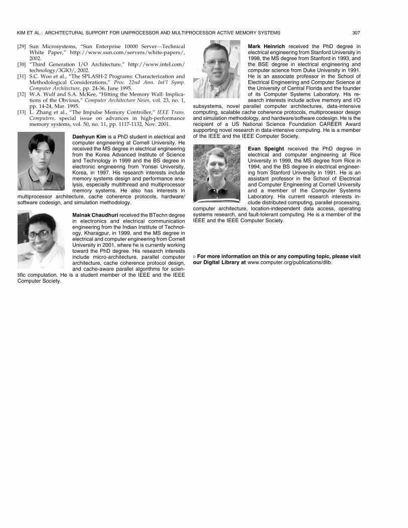
[29] Sun Microsystems, “Sun Enterprise 10000 Server—TechnicalWhite Paper,” http://www.sun.com/servers/white-papers/,2002.
[30] “Third Generation I/O Architecture,” http://www.intel.com/technology/3GIO/, 2002.
[31] S.C. Woo et al., “The SPLASH-2 Programs: Characterization andMethodological Considerations,” Proc. 22nd Ann. Int’l Symp.Computer Architecture, pp. 24-36, June 1995.
[32] W.A. Wulf and S.A. McKee, “Hitting the Memory Wall: Implica-tions of the Obvious,” Computer Architecture News, vol. 23, no. 1,pp. 14-24, Mar. 1995.
[33] L. Zhang et al., “The Impulse Memory Controller,” IEEE Trans.Computers, special issue on advances in high-performancememory systems, vol. 50, no. 11, pp. 1117-1132, Nov. 2001.
Daehyun Kim is a PhD student in electrical andcomputer engineering at Cornell University. Hereceived the MS degree in electrical engineeringfrom the Korea Advanced Institute of Scienceand Technology in 1999 and the BS degree inelectronic engineering from Yonsei University,Korea, in 1997. His research interests includememory systems design and performance ana-lysis, especially multithread and multiprocessormemory systems. He also has interests in
multiprocessor architecture, cache coherence protocols, hardware/software codesign, and simulation methodology.
Mainak Chaudhuri received the BTechn degreein electronics and electrical communicationengineering from the Indian Institute of Technol-ogy, Kharagpur, in 1999, and the MS degree inelectrical and computer engineering from CornellUniversity in 2001, where he is currently workingtoward the PhD degree. His research interestsinclude micro-architecture, parallel computerarchitecture, cache coherence protocol design,and cache-aware parallel algorithms for scien-
tific computation. He is a student member of the IEEE and the IEEEComputer Society.
Mark Heinrich received the PhD degree inelectrical engineering from Stanford University in1998, the MS degree from Stanford in 1993, andthe BSE degree in electrical engineering andcomputer science from Duke University in 1991.He is an associate professor in the School ofElectrical Engineering and Computer Science atthe University of Central Florida and the founderof its Computer Systems Laboratory. His re-search interests include active memory and I/O
subsystems, novel parallel computer architectures, data-intensivecomputing, scalable cache coherence protocols, multiprocessor designand simulation methodology, and hardware/software codesign. He is therecipient of a US National Science Foundation CAREER Awardsupporting novel research in data-intensive computing. He is a memberof the IEEE and the IEEE Computer Society.
Evan Speight received the PhD degree inelectrical and computer engineering at RiceUniversity in 1999, the MS degree from Rice in1994, and the BS degree in electrical engineer-ing from Stanford University in 1991. He is anassistant professor in the School of Electricaland Computer Engineering at Cornell Universityand a member of the Computer SystemsLaboratory. His current research interests in-clude distributed computing, parallel processing,
computer architecture, location-independent data access, operatingsystems research, and fault-tolerant computing. He is a member of theIEEE and the IEEE Computer Society.
. For more information on this or any computing topic, please visitour Digital Library at www.computer.org/publications/dlib.
KIM ET AL.: ARCHITECTURAL SUPPORT FOR UNIPROCESSOR AND MULTIPROCESSOR ACTIVE MEMORY SYSTEMS 307