Embed Size (px)
Citation preview

C h a p t e r 2 | 28
Inductors, Capacitors and AC Circuits
2.0 INTRODUCTION
This chapter is explaining about the indictors, capasitors and AC circuits. The learning outcome for this chapter are the students should be able to apply correctly the basic principles of inductors, capasitors and AC circuits that contains R, L and C to slove problems.
2.1 INDUCTOR
Inductor, choke or coil is the electric component that has the characteristics against the change of the current. Inductor made by winding the wire/conductor around the ferromagnetic material. There are two types of inductor which is often used in electronic circuits: fixed type and variable type. The symbol for inductor is as show in Figure 2.1.
(a) (b)
Figure 2.1: (a) Fixed type inductor (b) variable type inductor Unit for inductor is Henry and the symbol is L. 1 Henry is equal to the total inductance of winding when the current is in the rate of 1 ampere per second and producing the induced voltage for 1 volt. Table 2.1 show the equivalent value and unit for inductor.
2 CHAPTER
INDUCTORS,
CAPASITORS AND
ALTERNATING CURRENT
CIRCUITS
L

C h a p t e r 2 | 29
Inductors, Capacitors and AC Circuits
Table 2.1: Equivalent value and unit for inductor
Value Units
1 1 1 Henry 1 H
1000 1 x 10³ 1 kiloHenry 1 kH
0.001 1 x 10⁻³ 1 miliHenry 1 mH
0.000001 1 x 10⁻⁶
1 mikroHenry 1 µH
Inductor is a spiral structure coil of wire which creates a magnetic field when current passes through it. The magnetic field through the middle of the coil is directed from left to right, and is highly intensified.
Figure 2.2: EMF Induced
This magnetic field gives the coil some interesting and useful properties known as inductance. Increase the current in a coil will create a changing in magnetic field that will generate an electromotive force (emf) in the coil. Generated emf is opposes the applied voltage. The current through an inductance can only change gradually, it cannot change instantaneously as it could with only resistors in the circuit. The coil will store or release energy in its magnetic field as rapidly as necessary to oppose any such change.
The effects of inductor as the electrical device in the circuit are to: a) Smooth wave ripples in the DC circuit. b) Improve the transmission characteristics of waves in the telephone line
Magnetic Field
Current
flow Current
flow
EMF
induced

C h a p t e r 2 | 30
Inductors, Capacitors and AC Circuits
2.2 INDUCTANCE
Inductance is a characterstic of the inductor that have oppose any change in current through itself. There are two types of inductance: a) Self Inductance (L) b) Mutual Inductance (M)
2.2.1 Self Inductance (L)
Self inductance occur when a current flow in the coil causing the changing of flux in the winding. The electromotive force (emf) produced is opposite direction with the direction of the applied voltage.
e.m.f I
V
Figure 2.3: Self Inductance
The emf produce is opposite direction with the current flow. EMF generates due to changes of magnetic flux,
dt
dNe
φ−=1 (2.1)
EMF generates due to changes of current,
dt
diLe −=2 (2.2)

C h a p t e r 2 | 31
Inductors, Capacitors and AC Circuits
Faraday’s Law;
21 ee = (2.3)
dt
diL
dt
dN −=−
φ
di
dt
dt
dNL •=
φ
Where : L = Self Inductance N = Number of turns
=dt
dφ flux change against time
=dt
di current change against time
2.2.2 Mutual Inductance (M)
Mutual inductance is the ability of a first coil to produce 1 emf in the nearest coil through induction or when the current in the first coil is changing.
fluks, φ
I
A N1 N2 B e.m.f load
Figure 2.4: Mutual Inductance
Self Inductance, di
dNL
φ=

C h a p t e r 2 | 32
Inductors, Capacitors and AC Circuits
When current flow in the first loop, flux will be produce in the first coil. The continuos current causes flux flow to the next coil and then generate emf in the second coil. Emf produced in second coil will cut the conductor and produce the voltage in second loop.
2.3 INDUCTOR CIRCUIT ANALYSIS
Inductors can be connected in two different ways. The two simplest of these are called series and parallel and occur very frequently.
2.3.1 Series Inductors
Inductors connected in series are connected along a single path, so the same current flows through all of the components. Figure 2.5 is the connection for series inductors. Total inductance (LT) for a series circuit is the sum of all values of inductance in the circuit.
L1 L2 L3 L4
A B
Figure 2.5: Series Inductors
(2.4)
2.2.2 Parallel Inductors
Inductors connected in parallel are opposite to each other as in Figure 2.6. The same voltage is applied to each component but the total current will split into each branches. The total inductance of inductors in parallel is equal to the reciprocal of the sum of the reciprocals of their individual inductances. Total inductance for parallel circuit can calculate using equation (2.5).
4321 LLLLLT +++=

C h a p t e r 2 | 33
Inductors, Capacitors and AC Circuits
A
L1 L2 L3
B
Figure 2.6: Parallel Inductors
(2.5)
Example 2.1
Calculate the total inductance (LT) for the three coil when the value of each inductor
is 0.02H, 44mH, 400 µ H if the connection is in: a) Series b) Parallel
Solution 2.1 L1 = 0.02H
L2 = 44mH = 44 x 10-3 = 0.044H
L3 = 400µH = 400 x 10-6 = 0.0004H
a) series
321 LLLLT ++=
= 0.02 + 0.044 + 0.0004 = 0.0644H
b) parallel
321
1111
LLLLT
++=
321
1111
LLLLT
++=

C h a p t e r 2 | 34
Inductors, Capacitors and AC Circuits
= 0004.0
1
044.0
1
02.0
1++
= 2572.73
∴73.2572
1=TL = 389 X 10
-6 = 389µµµµH
2.4 INDUCTIANCE REACTANCE, LX
The alternating current (AC) is changing continuously which in turn produced continuous opposed induces emf as well. The opposition to the current flow is called inductance reactance. The symbol for inductance reactance is XL and the unit is Ohm (Ω). The value of Inductance reactance in a circuit depends on the inductance of the circuit due to the current change in the circuit. The rate of current change depends on the frequency of the supply voltage. Mathematically, equation (2.7) is use to calculate inductance reactance. (2.6) where : XL = Inductance Reactance (Ω)
f = Frequency (Hz)
L = Inductor (Henry)
Example 2.2 A coil with 0.2H connected with AC 200V, 50Hz. Calculate the inductance reactance in the circuit.
Solution 2.2
fLX L π2=
)2.0)(50(2π=
= 62.8 ΩΩΩΩ.
fLX L π2=

C h a p t e r 2 | 35
Inductors, Capacitors and AC Circuits
2.5 ENERGY IN INDUCTOR
Energy in the inductor can be calculate using the equation 2.4 below. The unit for energy is Joule (J)
(2.7)
2.6 CAPASITOR
Capacitor is an electrical device which is capable of storing electrical energy. Unit is Farad (F) and symbol is C. The quantity and duration of energy can be saved depends on the capacitance of the capacitor. Electrical energy stored in the capacitor is in a form of charge. A plate will has a negative charge (-ve) and the other plate is positive charge (+ve).
Direction of Current Flow + + + + + + + + _ _ _ _ V C
_ _ _ _
Figure 2.7 : Charges on the plate
Capacitor or condenser built with two-conductor or plate arranged opposite each other. It separated by insulating material called the dielectric as shown in Figure 6.2(a), Figure 6.2(b) show the symbol and unit for the capasitor.
Isolator
Conductor
(a) (b)
Figure 2.8 :Capasitor (a) Design Structure (b) Symbol Schematic
2
2
1LIE =

C h a p t e r 2 | 36
Inductors, Capacitors and AC Circuits
There are many types of capacitor which is Dielectric Air Convertible Capacitor, Paper Capacitor, Polyester Capacitor, Mica Capacitor, Ceramic Capacitor, Electrolytic Capacitor and Tantalum Capacitor
The effects of capacitor as the electrical device in the circuit are to: 1. Increasing the circuit power factor. 2. Reducing the fireworks during the switch is on inside the circuit. 3. Reduce radio interference test in the starter circuit pendaflour light. 4. Strengthen the electric current. 5. Store electrical charges.
2.7 CAPACITANCE
Capacitance is a characteristic of a capacitor to store electrical energy. It is define as the quantity or amount of electric charge needed to make a difference between the two plates. Capacitance of 1 Farad means a capacitor can store 1 coulomb of electrical charge when voltage is applied to the capacitor is 1 volt.
Capacitance, (Farad) = )(
)(
VoltVoltage
CoulombCas
(2.8)
Typically the unit use for capacitor are microFarad (µF) or pikoFarad (pF). Table 2.2 show the equivalent value and unit for capacitor.
Table 2.2: Equivalent value and unit for capacitor
Value Units
1 1 1 Farad 1 F
0.000001 1 x 10⁻⁶ 1 mikroFarad 1 µH
0.000000000001 1 x 10-12 1 pikoFarad 1 pH
V
QC =

C h a p t e r 2 | 37
Inductors, Capacitors and AC Circuits
Three (3) factors affecting the value of the capacitance of a capacitor:
1. Area of the Plate, A
Capacitance is directly proportional to the cross sectional area of the plates.
Capacitance of a capacitor varies with the capacitor plate area.
Area of large plates to accommodate many electrons, and can save a lot of
charge.
AC ∝ .
2. The Distance Between Two Plates, d
Capacitance is inversely proportional to the distance between the plates.
Capacitance of a capacitor change when the distance between the plates
changes. Capacitance will increase when the plates when the plate is brought
closer and less-plates removed.
dC
1∝
3. Permeability, ε
Capacitance is proportional to the permeability of the conductor.
ε∝C
2.8 CAPACITOR CIRCUIT ANALYSIS
The method of the capacitor circuit analysis is different with the method of circuit analysis for inductance. There are 3 types of circuit analysis in capacitor: 1. Series 2. Parallel 3. Combination of series and parallel

C h a p t e r 2 | 38
Inductors, Capacitors and AC Circuits
2.8.1 Series Capacitors
When capacitors are connected in series, the total capacitance (CT)is less than any one of the series capacitors' individual capacitances. If two or more capacitors are connected in series, the overall effect is that of a single (equivalent) capacitor having the sum total of the plate spacings of the individual capacitors.
C1 C2 C3
Q1 Q2 Q3
V1 V2 V3
VT
Figure 2.9 : Series Capacitors
The total capacitance is less than any one of the individual capacitors' capacitances. The formula for calculating the series total capacitance is as Equation 2.9. It is the same form as for calculating parallel resistances.
(2.9)
Equation 2.9 can be written as Equation 2.10 below.
323121
321
CCCCCC
CCCCT
++= (2.10)
Charges for each capacitor connected in series are the same.
TQQQQ === 321 , di mana TTT VCQ = (2.11)
321
1111
CCCCT
++=

C h a p t e r 2 | 39
Inductors, Capacitors and AC Circuits
Voltage drop for each capacitors can be calculate using Equation 2.12).
1
1C
QV T
C = , 2
2C
QV T
C = dan 3
3C
QV T
C = (2.12)
Untuk dua(2) buah pemuat seperti litar Rajah 6.4 di bawah, kemuatan jumlah juga boleh dikira dengan menggunakan persamaan (6.9).
Q
C1
V VC1 (2.13)
VC2
C2
Figure 2.10: Series with Two Capacitors
Voltage drop for each capacitors can be calculate using Equation 2.14.
TC VCC
CV )(
21
21
+=
TC VCC
CV )(
21
12
+=
Charges are equal for each capacitors which connected in series.
TQQQ == 21
21
21
CC
CCC T
+=
(2.14)

C h a p t e r 2 | 40
Inductors, Capacitors and AC Circuits
2.8.2 Parallel Capacitors
The total capacitance of capacitors in parallel is equal to the sum of their individual capacitances.
Q1 Q2 Q3
C1 C2 C3
V
Figure 2.11: Parallel Capacitors
(2.15)
Voltage drop at each capacitors are equal.
TCCC VVVV === 321 (2.16)
Value of charges through each parallel capacitor are different and can be calculated using Equation 2.17.
TC VCQ 11 = , TC VCQ 22 = and TC VCQ 33 = (2.17)
321 CCCCT ++=

C h a p t e r 2 | 41
Inductors, Capacitors and AC Circuits
Example 2.3
Calculate the total capacitance of the three (3) capacitor where the value of each capacitance is 120µF when it is connected in: a. Parallel b. Series
Solution 2.3
a. 321 CCCCT ++= = (120+120+120) x 10-6
= 360 x 10-6
= 360 µF
b. 40
1
120
3
120
1
120
1
120
11111
321
==++=++=CCCCT
FCT µ40=∴ .
Example 2.4
Two capacitors each value is 6µF and 10µF is connected in series with a 200V power supply. Calculate; a. Total capacitance b. Charge in each capacitor c. Voltage across each capacitor.
Solution 2.4
a. Total capacitance, TC
21
21
CC
CCCT
+=
= Fµ75.3
106
)10)(6(=
+
b. The value of charges for each capacitors in series are the same,
CxxVCQ TTT µ75010750)200)(1075.3( 66 ==== −−
Therefore,
CQQQ T µ75021 ===
C h a p t e r 2 | 42
Inductors, Capacitors and AC Circuits
c. Voltage drop for each capacitors are different
Vx
x
C
QV T 125
106
107506
6
1
1 ===−
−
Vx
x
C
QV T 75
1010
107506
6
2
2 ===−
−
2.9 CAPACITANCE REACTANCE, CX
Capacitance reactance is the opposition to the flow of the current by the capacitor. Capacitance reactance value is inversely proportional to the frequency of the
alternating current voltage. Symbol for capacitance reactance isCX and the unit is
ohm ( Ω ). Equation 2.18 is formula to calculate capacitance reactance.
C
X Cω
1= , where fπω 2= .
(2.18) Where , C = Capacitance (F)
f = Frequency (Hz)
ω = angular velocity (rads-1
)
π2 = constant
Example 2.5
8µF capacitor connected to the supply of 240V, 50Hz. Calculate the value of capacitance reactance.
fCX C
π2
1=

C h a p t e r 2 | 43
Inductors, Capacitors and AC Circuits
Solution 2.5
Ω===−
9.397)108(2
1
2
16xfC
XCππ
2.10 ENERGY IN CAPASITOR
Energy can be calculate using Equation 2.19 below. The unit for energy is Joule.
(2.19)
Equation 2.19 can be transform to another form in calculating energy by inserting Equation 2.8 in 2.19.
2
2
1CVE = and (2.20)
)(2
1 2
C
QE = (2.21)
Example 2.6
Capacitor with 8pF connected to the 600V power supply. Calculate the charge and energy that can be stored by the capacitor.
Solution 2.6
Charge, CVQ = = )600)(108( 12−x = 4.8 x 10
-7 C
Energy, === − )600)(108.4(2
1 12xQVE 2.88 x 10⁻⁹ Joule
QVE2
1=

C h a p t e r 2 | 44
Inductors, Capacitors and AC Circuits
2.11 ALTERNATING CURRENT (AC)
Alternating Current is a current flowing in two conditions whether at negative or positive values. The current flows from zero to positive maximum, to zero again and further to negative maximum and back to zero. Alternating voltage can be generated in 2 ways: 1. Conductors cut the magnetic flux which is the conductor is moving and the
magnetic flux is stationary. 2. Magnetic flux cut the conductor where the flux is moving and conductor is
stationary.
AC waveform is same as the form of sinus wave as shown in Figure 2.12
Figure 2.12: AC Waveform
where =)(tv Instantaneous voltage (volt)
=mv Maximum/peak voltage (volt)
=tω Phase angle against time (rad/degree)
ω
π2=T (second)
tvtv m ωsin)( =
(2.22)
emf
3600
1800 0
0
-Vm
Vm
Period (T)
tω

C h a p t e r 2 | 45
Inductors, Capacitors and AC Circuits
Figure 2.13: Terms in AC Waveform A complete cycle/period of sine wave is 3600 degree where 360º = 2Π radian. The terms related to the AC waveform:
a) VP (peak voltage) is the maximum voltage (Vm) from the waveform.
b) VPP (peak to peak voltage) is the value that start from +ve maximum to –ve maximum.
c) Va (average voltage) is the average value for sinus wave where the value is calculated for the area under ac wave line. The value is 63.7% of maximum voltage value.
Va = 0.637 Vm (2.25)
VPP = 2Vm (2.24)
VP = Vm (2.23)
emf
0.637
0.707
00
-Vm
Vm
1 cycle
tω Vp-p
Vrms Va
C h a p t e r 2 | 46
Inductors, Capacitors and AC Circuits
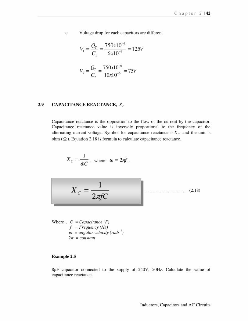
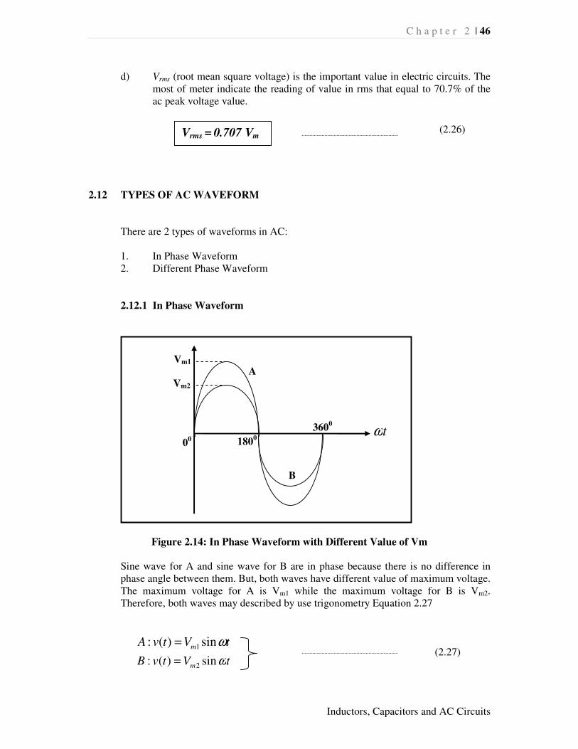
d) Vrms (root mean square voltage) is the important value in electric circuits. The most of meter indicate the reading of value in rms that equal to 70.7% of the ac peak voltage value.
2.12 TYPES OF AC WAVEFORM There are 2 types of waveforms in AC: 1. In Phase Waveform 2. Different Phase Waveform
2.12.1 In Phase Waveform
Figure 2.14: In Phase Waveform with Different Value of Vm
Sine wave for A and sine wave for B are in phase because there is no difference in phase angle between them. But, both waves have different value of maximum voltage. The maximum voltage for A is Vm1 while the maximum voltage for B is Vm2. Therefore, both waves may described by use trigonometry Equation 2.27
tVtvA m ωsin)(: 1=
tVtvB m ωsin)(: 2= (2.27)
3600
1800 0
0
Vm1
tω
Vm2
A
B
Vrms = 0.707 Vm (2.26)

C h a p t e r 2 | 47
Inductors, Capacitors and AC Circuits
2.12.2 Different Phase Waveform
Figure 2.15: Different Phase with Same Value of Vm
In this case, all waves have the same maximum voltage (Vm), but reach at different period/time. Thus, there are phase differences between all waves. The phase difference is depend on the phase angle value (α and β). The wave through the 00 will be the reference point.
Therefore the trigonometry equations for three waves above are as below:
a) Wave B is the reference point for the three waves.
tVtv m ωsin)( =
b) Wave A leads the wave B by a phase angle α
( )αω += tVtv m sin)(
(2.28)
c) Wave C lags behind the wave B by a phase angle β
( )βω −= tVtv m sin)( (2.29)
0
Vm
tω
B A C
β
α

C h a p t e r 2 | 48
Inductors, Capacitors and AC Circuits
Figure 2.16: Different Phase with Different Value of Vm
2.13 VECTOR/PHASOR DIAGRAM
Vector diagram is a graft provides the information of the magnitude (amplitude) and direction (phase) of a sinusoidal wave. The vector diagram is drawn corresponding to a fix zero point or known as point of origin. A vectors magnitude is the peak value of the sinusoid while a phase magnitude is the rms value of the sinusoid.
Figure 2.17: Vector Diagram
2700
900
1800 00
V2
V1
V3
θ2
θ1
00
( )122 sin θω += tVv m
tω
B A C
2θ
1θ
( )233 sin θω −= tVv m
tVv m ωsin11 =

C h a p t e r 2 | 49
Inductors, Capacitors and AC Circuits
Figure 2.17 is a vector diagram for the AC wave in Figure 2.16. The length of the arrow is refers to the magnitude which depend on the peak value of each wave. Meanwhile the direction the vectors are located based on the phase different of each waves started at zero (00) or origin point.
2.14 BASIC TYPES OF AC CIRCUIT
There are 3 basic types of AC circuit: 1. Purely Resistance 2. Purely Inductance 3. Purely Capacitance
2.14.1 Purely Resistance
Figure 2.18: Purely Resistance Circuit
By applying an alternating voltage to a circuit that contain the resistor, the alternating current value in the circuit can be determined by Ohm’s Law as equation 2.30
In a purely resistance circuit, the current and the voltage are in phase because there is no difference angle. Hence, the wave diagram and the vector diagram are shown in Figure 2.19
R
VI =
(2.30)
V
R
I
VR + _
C h a p t e r 2 | 50
Inductors, Capacitors and AC Circuits
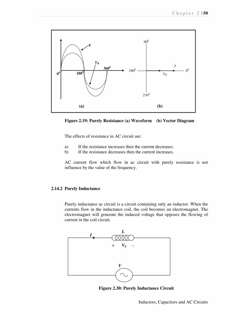
Figure 2.19: Purely Resistance (a) Waveform (b) Vector Diagram
The effects of resistance in AC circuit are:
a) If the resistance increases then the current decreases. b) If the resistance decreases then the current increases. AC current flow which flow in ac circuit with purely resistance is not influence by the value of the frequency.
2.14.2 Purely Inductance
Purely inductance ac circuit is a circuit containing only an inductor. When the currents flow in the inductance coil, the coil becomes an electromagnet. The electromagnet will generate the induced voltage that opposes the flowing of current in the coil circuit.
Figure 2.30: Purely Inductance Circuit
V
L I
VL + _
3600
1800 0
0
I
VR
2700
900
1800 00
VR
I
(a) (b)

C h a p t e r 2 | 51
Inductors, Capacitors and AC Circuits
The current in purely inductance circuit lags behind the voltage by a phase angle of 90
0. Therefore, Figure 2.31 shows the waveform and vector diagram
for purely inductance circuit.
Figure 2.31: Purely inductance (a) Waveform (b) Vector Diagram
The effects of inductance in AC circuit are: a) The value of inductance reactance is equal to resistance of resistor. b) The inductance reactance is directly proportional to the frequency.
When the frequency is increases, the voltage also increases and the reactance is increases too.
2.14.3 Purely Capacitance
Purely capacitance is an ac circuit containing only a capacitor.
Figure 2.32: Purely Capacitance Circuit
V
C I
VC + _
00
VL
900
I
2700
VL
1800
I
(a) (b)

C h a p t e r 2 | 52
Inductors, Capacitors and AC Circuits
In purely capacitance circuit, the current leads the voltage by a phase angle of 90
0.
Figure 2.33: Purely capacitance (a) Waveform (b) Vector Diagram
The effects of capacitance in AC circuit are: a) Capacitance reactance value is equal to the resistance value of resistor. b) The capacitance reactance is directly proportional to the frequency.
When frequency is increases, hence capacitance reactance is also increases.
NOTE:
Resistance (R) and reactance ( LX or )LX are different althougt same in unit ( )Ω .
Resistance is oppose to the current flow in both DC and AC circuits.
Reactance is oppose to the current flow only in AC circuit
Impedance (Z) also oppose to the current flow in only AC circuit.
00
I
900
VC
VC
900
1800
I
(a) (b)
C I V I L
C (CAPACITANCE) – I V (The current leads the voltage by a phase angle of 900)
L (INDUCTANCE) – V I (The voltage leads the current by a phase angle of 900)

C h a p t e r 2 | 53
Inductors, Capacitors and AC Circuits
2.15 AC CIRCUIT ANALYSIS
2.15.1 Series Resistance and Inductance (RL)
The RL circuit is the combination between resistor and inductor in series. In a series circuit, the current value is the same for each load. Thus, the current (I) become the reference factor in the vector diagram.
Figure 2.34: Series RL Circuit
The value of the current is limited by resistance and inductance reactance. The current flows through the resistance, R is in phase with the voltage but lags behind the voltage by a phase angle of 900 when flows through the inductance reactance, XL.
Figure 2.35: Vector Diagram for Series RL Circuit
Based on Figure 2.34, the magnitude of the supply voltage (V) can determine using Pythagoras theorem.
V
I
VL
VR
θ
V
L I
VL + _ _
+
R
VR

C h a p t e r 2 | 54
Inductors, Capacitors and AC Circuits
The voltage drop at each components can be calculate using equations below;
VR = IRL and VL = IXL (2.32) The impedance is the amount of impediment/resistance that exist in the ac circuit. The symbol for impedance is Z and unit is Ohm (Ω). An impedance
triangle in Figure 2.36 show the relationship between the resistance (R), inductance reactance (XL) and impedance (Z) can be generated based on the Figure 2.35.
Figure 2.36: Impedance Triangle for RL
Impedance can be calculates using Equation 2.33.
Or
Z = R + jXL
Z = r < θ
Where XL = 2ΠfL
Z XL
R
θ
22
LR VVV += (2.31)
(2.33) 22LXRZ +=
ω=

C h a p t e r 2 | 55
Inductors, Capacitors and AC Circuits
Phase angle and power factor for RL circuit can be calculates using equations below:
Phase angle,
= −
R
X L1tanθ (2.34)
Power factor, pf = Z
R=θcos
(2.35)
Example 2.7 The RL series circuit have 10Ω resistor, 0.2H inductor and supplied with 250v 50Hz AC supply. Calculates; i. lmpedance, Z ii. Current, I iii. Phase angle, θ
Solution 2.7
i. lmpedance , Z
XL = 2ΠfL = 2Π(50)(0.2) = 62.83 Ω Z = R + jXL = 10 + j62.83 = 63.62 < 80.95º Ω
ii. Current, I I = V/Z = 250 < 0º 63.62 < 80.95º = 3.929 < -80.95º A
iii. Phase angle, θ
θ = tan -1 ( XL/R) = tan -1 ( 62.83/10)
= 80.95º

C h a p t e r 2 | 56
Inductors, Capacitors and AC Circuits
2.15.2 Series Resistance and Capacitance (RC)
The RC circuit is the combination between resistor and capacitors in series. The current value is the same for each load. Thus, the current (I) become the reference factor in the vector diagram.
R C
I
+ RV - V + CV -
Figure 2.37: Series RC Circuit
The value of the current is limited by resistance, R and capacitance reactance, XC. The current flows through R is in phase with the voltage but leading by a phase angle of 900 when flows through inductance reactance. Figure 2.38 is a vector diagram for series RC circuit.
RV I
θ
CV V
Figure 2.38: Vector Diagram for Series RC Circuit
Based on Figure 2.38, the magnitude of the supply voltage (V) can determine using Pythagoras theorem.
22
LR VVV += (2.36)

C h a p t e r 2 | 57
Inductors, Capacitors and AC Circuits
The voltage drop at each components can be calculate using equations below;
VR = IRL and VC = IXC (2.37) An impedance triangle in Figure 2.39 show the relationship between the resistance (R), capacitance reactance (XC) and impedance (Z) which generated based on the Figure 2.38.
LX Z
θ
Figure 2.39: Impedance Triangle for RC
Impedance can be calculates using Equation 2.38.
Or Z = R – jXC
Z = r < -θ
Where XC = 1 / (2ΠfC)
Phase angle and power factor for RC circuit can be calculates using equations below:
Phase angle,
= −
R
XC1tanθ (2.39)
Power factor, pf = Z
R=θcos
(2.40)
22CXRZ +=
ω=
(2.38)
C h a p t e r 2 | 58
Inductors, Capacitors and AC Circuits
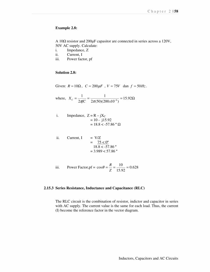
Example 2.8:
A 10Ω resistor and 200µF capasitor are connected in series across a 120V, 50V AC supply. Calculate: i. Impedance, Z ii. Current, I iii. Power factor, pf
Solution 2.8:
Given: Ω= 10R , FC µ200= , VV 75= dan Hzf 50= .
where, Ω===−
92.15)10200)(50(2
1
2
16xfC
XCππ
i. Impedance, Z = R – jXC
= 10 - j15.92 = 18.8 < -57.86 º Ω
ii. Current, I = V/Z = 75 < 0º 18.8 < -57.86 º = 3.989 < 57.86 º
iii. Power Factor,pf = 628.092.15
10cos ===
Z
Rθ
2.15.3 Series Resistance, Inductance and Capacitance (RLC)
The RLC circuit is the combination of resistor, indictor and capacitor in series with AC supply. The current value is the same for each load. Thus, the current (I) become the reference factor in the vector diagram.

C h a p t e r 2 | 59
Inductors, Capacitors and AC Circuits
R L C
I
+ RV - + LV - + CV -
V
Figure 2.40: Series RLC Circuit
In RLC there are (2) conditions should to be consider;
a) inductance reactance is greather than capacitance reactance, LX > > > > CX
LX
Z Z
)( CL XX −
θ θ
I R
CX
(a) (b)
Figure 2.41: (a) Vector Diagram (b) Impedance Triangle for LX > > > > CX
The impedance for RLC can be calculate using Equation 2.41 below:
22 )( CL XXRZ −+= (2.41)
C h a p t e r 2 | 60
Inductors, Capacitors and AC Circuits
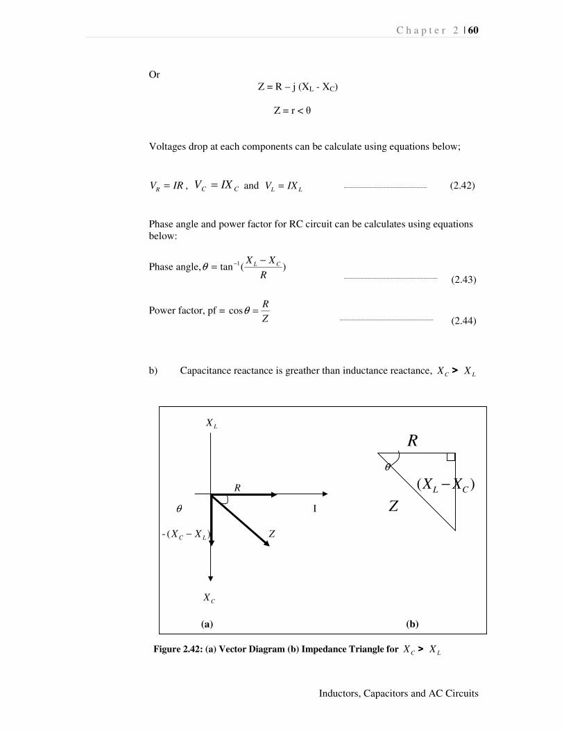
Or Z = R – j (XL - XC)
Z = r < θ
Voltages drop at each components can be calculate using equations below;
IRVR = , CC IXV = and LL IXV = (2.42)
Phase angle and power factor for RC circuit can be calculates using equations below:
Phase angle, )(tan 1
R
XX CL −= −θ
(2.43)
Power factor, pf = Z
R=θcos
(2.44)
b) Capacitance reactance is greather than inductance reactance, CX > > > > LX
LX
R
θ
R )( CL XX −
θ I Z
- )( LC XX − Z
CX
(a) (b)
Figure 2.42: (a) Vector Diagram (b) Impedance Triangle for CX > > > > LX

C h a p t e r 2 | 61
Inductors, Capacitors and AC Circuits
The analysis for calculating impedance, current, voltage drop at each
components, phase angle and power factor are same as LX > > > > CX . The
different only at the value of phase which is –ve that show the direction of the angle.
Z = r < -θ
2.16 POWER FACTOR
Power factor can be express in the form of percentage (%) or fractional numbers. It is known as cos θ and referred to as leading (lead) or lagging (lag) in which the phase angle between voltage and current. a. Power factor is a ratio between real power and apparent power.
S
PCos =θ (2.45)
b. Power factor is a ratio between resistance and impedance.
Z
RCos =θ (2.46)
c. Leading power factor is voltage leading the current when voltage as refference
factor and value of the voltage is positive. d. Lagging power factor is voltage lagging the current the when voltage as
refference factor and value of the voltage is negative.
e. Best value of power factor is where 1=θCos or nearly 1.
2.17 POWER IN AC CIRCUIT
There are 3 types of power in the ac circuit; a) Apparent power, S b) Real Power, P c) Reactive Power, Q

C h a p t e r 2 | 62
Inductors, Capacitors and AC Circuits
2.17.1 Apparent power , S
Power is reduced due to the existence of the reactance that cause current and voltage is not in phase. The separation of current and voltage caused the power in the circuit will be reduced. The simbol is S and unit is Volt –Ampere (VA)
Apparent Power = Voltage x Current
2.17.2 Real Power, P Real power or active power is the power consumed or absorbed by the resistor components in ac circuits. The symbol is P and the unit is watt (w).
Real Power = Voltage x Current x Power Factor
2.17.3 Reactive Power, Q
Reactive Power or Reactance Power is the power consumed or absorbed by the capacitor or inductor components in ac circuits . The simbol is Q and unit is Volt Ampere Reactive (VAR)
Reactive Power = Voltage x Current x Sinθ
θsinVIQ = (2.49)
θcosVIP = (2.48)
VIS = (2.47)

C h a p t e r 2 | 63
Inductors, Capacitors and AC Circuits
2.18 POWER TRIANGLE
Power triangle shows the relationship between the apparent power, real power and the reactive power.
S = VI
Q
θ
P
Figure 2.43: Power Triangle
Example 2.9:
A RLC circuit was connected in series with 100 ohms resistor, 200mikroF capacitor and 100mH inductor then supplied with AC power supply 240V, 50Hz. Calculate; i. lmpedance, Z ii. Current, I iii. Power factor and phase angle iv. Power in kVA, kW and kVAR .
Solution 2.9:
Ω=== − 42.31)10100)(50(22 3xfLX L ππ
Ω===−
91.15)10200)(50(2
1
2
16
xfCXC
ππ
i. Impedance, Z = R + j (XL – XC)
Z = 100 + j (31.42– 15.91)

C h a p t e r 2 | 64
Inductors, Capacitors and AC Circuits
Z = 100 + j 15.51
Z = 101.19 < 8.9º Ω
ii. Z
VI =
= 240 < 0º
101.19< 8.9º
= 2.37 < -8.9º
iii. Power factor,pf = 988.02.101
100===
Z
RCosθ
Phase Angle, o
Z
R9.8)988.0(cos)(cos 11 === −−θ
iv. Apparent Power, S in kVA,
kVAVIS 57.08.568)37.2)(240( ====
Real Power in kW,
kWVIP 562.0562)988.0)(8.568(cos ==== θ
Reactive Power in kVAR,
kVARVIQo 09.088)9.8)(sin8.568(sin ==== θ
REFERENCES
Hughes, E., 1960, “Electrical Technology 3rd Edition”, University of Michigan, Longmans Erickson, W.H., 1952, “Electrical engineering, theory and practice”, University of Wisconsin – Madison, Wiley
C h a p t e r 2 | 65
Inductors, Capacitors and AC Circuits
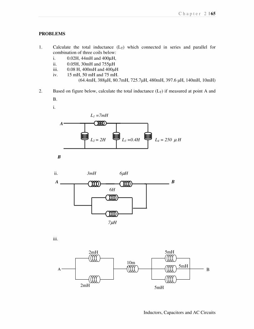
PROBLEMS
1. Calculate the total inductance (LT) which connected in series and parallel for
combination of three coils below:
i. 0.02H, 44mH and 400µH,
ii. 0.05H, 30mH and 755µH iii. 0.08 H, 400mH and 400µH iv. 15 mH, 50 mH and 75 mH.
(64.4mH, 388µH, 80.7mH, 725.7µH, 480mH, 397.6 µH, 140mH, 10mH) 2. Based on figure below, calculate the total inductance (LT) if measured at point A and
B.
i.
L1 =7mH
A
L2 = 2H L3 =0.4H L4 = 250 µ H
B
ii. 3mH 6µH
A B
6H
7µH
iii.
A B
2mH
10mH
5mH
5mH
2mH 5mH

C h a p t e r 2 | 66
Inductors, Capacitors and AC Circuits
iv.
v. A
B
vi. A
B
(10mH, 6.98µH, 12.6mH, 4.65mH, 6mH, 3.88mH)
3. Coil with 0.2H connected with AC circuit 200V, 50Hz. Calculate the Inductave
reactance. (62.8Ω)
4. A coil with 6H connected to AC 12 V 50 Hz. Calculate the current flow.
(0.19A)
5. A capacitor with 50µF connected to AC 115 V 60 Hz. Calculate capacitance reactance and current flow.
(53.1Ω, 2.167A)
6. A capacitor with 120µF connected with 500 V 50 Hz. Calculate capacitance reactance and current flow.
(26.52Ω, 18.8A)
1 mH
4 mH
3 mH 4 mH
12 mH
2 mH
2 mH
2mH
3 mH
5mH
20 µH

C h a p t e r 2 | 67
Inductors, Capacitors and AC Circuits
7. A capacitor 1000µF connected to AC 20 V 50 Hz.
i. Calculate current flow
ii. What is the effect of the current if the frequency change to 1000Hz.
(6.28A, increasing)
8. Capacitor with 50µF connected with 240V power supply. Calculate the charge and energy stored in the capacitor.
(0.012 C, 1.44 J) 9. Capacitor with 8µF connected with 240V, 50Hz power supply. Calculate the
Capacitance Reactance. (397.88Ω)
10. Calculate the total capacitance (CT) which connected in series and parallel for
combination of three capacitors below:
i. 120µF, 240 Fµ dan 360 Fµ
(65.45µF, 720µF)
11. Calculate the value of capacitor which is connected in series with other 60µF capasitor, where the total capacitance is 15µF.
(20µF)
12. 2 capacitors with values 6µF and 10µF respectively, connected in series with 200V power supply. Calculate ; i. Total Capacitance ii. Charge at each capacitors iii. Voltage drop at each capacitors
(3.75µF, 750x10-6C, 125V and 75V)
13. Based on figure below, calculate the total capacitance (CT)
i. 120 Fµ
A 40 Fµ 60 Fµ 80 Fµ B
20 Fµ
850pF
ii.
A 350 Fµ
200 Fµ
400 Fµ
B 500pF

C h a p t e r 2 | 68
Inductors, Capacitors and AC Circuits
iii.
iv.
(23.53 µF, 499.99pF, 3.33µF, 1.94µF)
14. 3 capacitors C1 = 6 µF, C2 = 12 µF dan C3 = 16 µF connected with 60 v power supply as shown in figure below. Calculate:
i. Total Capacitance ii. Charge at each capacitors iii. Voltage drops at each components iv. Energy used.
(12.85 µF, 3.6x10⁻⁴
C, 4.12x10⁻⁴
C, 60v, 34.28v, 25.72v, 0.023J ) 15. Based on figure below, calculate total capacitance,CT and total charge,QT.
(120pF, 18x10-9
C)
350 pF
500 pF
400 pF
200 pF
150 v
C1 C2
C3
Vs
10µF
5µF 10µF
10µF
15µF
3µF
4µF
2 µF
2µF 4µF

C h a p t e r 2 | 69
Inductors, Capacitors and AC Circuits
16. A circuit wit 3 capacitors C1, C2 and C3 connected in series wit values 3µF, 4pF and 1µF respectively. If the voltage supply is 100v, calculate: i. Total capacitance, CT
ii. Total Charge, QT
iii. Voltage drop at C1
(3.99pF, 3.99x10⁻¹⁰
C, 0.133mV)
17. Series RL with 25Ω and 25mH connected to AC 60 V, 100Hz. Calculate the current
and phase angle reffer to supplied voltege. (2.03<0°v, 32.12°)
18. Series RLC with R=33Ω, L=50mH and C=10µF. Voltage supply 75 V, 200Hz.
Calculate I, VR , VC ,VL and phase angle reffer to supplied voltege. (2.02<26.89°A, 66.7<26.89°V, 126.9<116.89°V, 150.7 <60.11°V )
19. A circuit with 25Ω resistance, 0.2 H inductance and 1µF capacitance connected in
series to AC 100 V, 50 Hz. Calculate : i. Impedance, Z.
ii. Current,I
(67.62<68.3°Ω, 1.47<-68.3°A)
20. Series RLC circuit with 20Ω, 0.1 H and 40µF respectively was connected to AC 230V, 50 Hz. Calculate:
i. Impedance, Z.
ii. Current, I
iii. Voltage drop at each components VR , VC andVL
iv. Power factor
v. Draw the vector diagram
(52.14<-67.44°Ω, 4.41<67.44°A, 88.2<67.44°V, 138.5<157.44°V, 350.9< -22.56°V, 0.384 )
21. A circuit with resistance 50Ω, inductance 0.15 H and capacitance 100µF connected in series with AC 100 V, 50 Hz. Calculate: i. Inductice reactance, capacitice reactance and impedance
ii. Current
iii. Voltage drop at each components VR , VC andVL
(94.24Ω, 15.9Ω, 92.9<57.43°Ω, 1.1<-57.43°A, 55<-57.43°V, 103.6<32.57°V, 17.49<-147.43°V )
22. AC circuit 200V, 50 Hz connected in series with resistance 40Ω, inductance reactance 20Ω and capacitance reactance 12Ω. Calculate: i. Impedance, Z.
ii. Current, I

C h a p t e r 2 | 70
Inductors, Capacitors and AC Circuits
iii. Voltage drop at each components VR , VC andVL
iv. Phase angle
v. Power factor
vi. Faktor kuasa
vii. Draw the Vector diagram
(40.79<11.3°Ω, 4.9<-11.3°A, 196<11.3°V, 98<101.3°V, 58.8<-78.7°V )
23. The RLC series circuit connected to AC 250V, 50 Hz with reactance 40Ω, inductance 0.4H and capacitance 150µF. Calculate: i. Impedance, Z.
ii. Current, I
iii. Voltage drop at each components VR , VL andVC
iv. Phase angle
v. Power factor
vi. Apparent power
(111.83<69°Ω, 2.23<-69°A, 89.2<69V, 280.22<159°V, 47.32<-21°V, 69°, 0.358, 557.5VA )
24. Series RLC circuit with 50Ω, 10mH and 100µF. Supplied with AC 240 <30˚ V 50 Hz. Calculate: i. Impedance, Z.
ii. Current, I
iii. Voltage drop at each components VR , VL and VC
iv. Power factor
(57.64<-29.84°Ω, 4.16<59.84°A, 208.18<59.84°V, 13.06<149.84°V, 132.41< -30.16°V, 0.867 )