Embed Size (px)
Citation preview

VeriFone Part Number 27584, Revision A
CTLS
Interface Developers Guide

All rights reserved. No part of the contents of this document may be reproduced or transmitted in any form without the writtenpermission of VeriFone, Inc.
The information contained in this document is subject to change without notice. Although VeriFone has attempted to ensure theaccuracy of the contents of this document, this document may include errors or omissions. The examples and sample programsare for illustration only and may not be suited for your purpose. You should verify the applicability of any example or sampleprogram before placing the software into productive use. This document, including without limitation the examples and softwareprograms, is supplied “As-Is.”
VeriFone, Inc.2099 Gateway Place, Suite 600
San Jose, CA, 95110 USA1-800-VERIFONEwww.verifone.com
VeriFone Part Number 27584, Revision A
CTLS Interface Developers Guide© 2009 VeriFone, Inc.
VeriFone, the VeriFone logo, Omni, VeriCentre, Verix, and ZonTalk are registered trademarks of VeriFone. Other brand namesor trademarks associated with VeriFone’s products and services are trademarks of VeriFone, Inc.
All other brand names and trademarks appearing in this manual are the property of their respective holders.
Comments? Please e-mail all comments on this document to your local VeriFone Support Team.

CONTENTS
CHAPTER 1Introduction Command Table . . . . . . . . . . . . . . . . . . . . . . . . . . . . . . . . . . . . . . . . . . . . . . . . . . 8
EMV Key Manager Table . . . . . . . . . . . . . . . . . . . . . . . . . . . . . . . . . . . . . . . . . . 15
CHAPTER 2Serial Link Protocol Port Settings . . . . . . . . . . . . . . . . . . . . . . . . . . . . . . . . . . . . . . . . . . . . . . . . . . . . 17
Basic Communication. . . . . . . . . . . . . . . . . . . . . . . . . . . . . . . . . . . . . . . . . . . . . 17Timeouts. . . . . . . . . . . . . . . . . . . . . . . . . . . . . . . . . . . . . . . . . . . . . . . . . . . . . . . 17
CHAPTER 3Packet Format Version 1 Formats . . . . . . . . . . . . . . . . . . . . . . . . . . . . . . . . . . . . . . . . . . . . . . . 19
Command Frames . . . . . . . . . . . . . . . . . . . . . . . . . . . . . . . . . . . . . . . . . . . . 19Data Frames . . . . . . . . . . . . . . . . . . . . . . . . . . . . . . . . . . . . . . . . . . . . . . . . . 20ACK Frames . . . . . . . . . . . . . . . . . . . . . . . . . . . . . . . . . . . . . . . . . . . . . . . . . 20NACK Frames. . . . . . . . . . . . . . . . . . . . . . . . . . . . . . . . . . . . . . . . . . . . . . . . 20Special Frames . . . . . . . . . . . . . . . . . . . . . . . . . . . . . . . . . . . . . . . . . . . . . . . 21
Version 2 Formats . . . . . . . . . . . . . . . . . . . . . . . . . . . . . . . . . . . . . . . . . . . . . . . 21Pass-Through Command Packets . . . . . . . . . . . . . . . . . . . . . . . . . . . . . . . . . . . 22
Pass-Through Command Packet . . . . . . . . . . . . . . . . . . . . . . . . . . . . . . . . . 22Pass-Through Response Packets . . . . . . . . . . . . . . . . . . . . . . . . . . . . . . . . 23
USB HID Command Encapsulation . . . . . . . . . . . . . . . . . . . . . . . . . . . . . . . . . . 23HID Report Format . . . . . . . . . . . . . . . . . . . . . . . . . . . . . . . . . . . . . . . . . . . . 23Sample Single Report Command and Responses . . . . . . . . . . . . . . . . . . . . 24Sample Single Report Command with Multiple Report Response . . . . . . . . 25Error Handling at Report Level . . . . . . . . . . . . . . . . . . . . . . . . . . . . . . . . . . . 27Error Handling at Command Level . . . . . . . . . . . . . . . . . . . . . . . . . . . . . . . . 28
Status Codes . . . . . . . . . . . . . . . . . . . . . . . . . . . . . . . . . . . . . . . . . . . . . . . . . . . 28Error Codes . . . . . . . . . . . . . . . . . . . . . . . . . . . . . . . . . . . . . . . . . . . . . . . . . . . . 29RF State Codes . . . . . . . . . . . . . . . . . . . . . . . . . . . . . . . . . . . . . . . . . . . . . . . . . 35CRC Calculation . . . . . . . . . . . . . . . . . . . . . . . . . . . . . . . . . . . . . . . . . . . . . . . . . 36
CHAPTER 4General Commands
for TransactionsPing . . . . . . . . . . . . . . . . . . . . . . . . . . . . . . . . . . . . . . . . . . . . . . . . . . . . . . . . . . 37Set Poll Mode . . . . . . . . . . . . . . . . . . . . . . . . . . . . . . . . . . . . . . . . . . . . . . . . . . . 38Set LCD Message . . . . . . . . . . . . . . . . . . . . . . . . . . . . . . . . . . . . . . . . . . . . . . . 39Store LCD Message . . . . . . . . . . . . . . . . . . . . . . . . . . . . . . . . . . . . . . . . . . . . . . 42Get LCD Message . . . . . . . . . . . . . . . . . . . . . . . . . . . . . . . . . . . . . . . . . . . . . . . 44Set/Get Source for RTC/LCD/Buzzer/LED. . . . . . . . . . . . . . . . . . . . . . . . . . . . . 47Set EMV Configuration . . . . . . . . . . . . . . . . . . . . . . . . . . . . . . . . . . . . . . . . . . . . 50
Interaction with Configurable AIDs . . . . . . . . . . . . . . . . . . . . . . . . . . . . . . . . 55Get EMV Configuration. . . . . . . . . . . . . . . . . . . . . . . . . . . . . . . . . . . . . . . . . . . . 55
Interaction with Configurable AIDs . . . . . . . . . . . . . . . . . . . . . . . . . . . . . . . . 59Cancel Transaction Command. . . . . . . . . . . . . . . . . . . . . . . . . . . . . . . . . . . . . . 60
CTLS INTERFACE DEVELOPERS GUIDE 3

CONTENTS
4
CHAPTER 5Configurable
ApplicationIdentifiers (AIDs)
Configurable AID Commands. . . . . . . . . . . . . . . . . . . . . . . . . . . . . . . . . . . . . . . 63Detailed Explanation of AID and Groups . . . . . . . . . . . . . . . . . . . . . . . . . . . . . . 63
System AID . . . . . . . . . . . . . . . . . . . . . . . . . . . . . . . . . . . . . . . . . . . . . . . . . . 63User AID . . . . . . . . . . . . . . . . . . . . . . . . . . . . . . . . . . . . . . . . . . . . . . . . . . . . 64Default Group . . . . . . . . . . . . . . . . . . . . . . . . . . . . . . . . . . . . . . . . . . . . . . . . 64Other Groups . . . . . . . . . . . . . . . . . . . . . . . . . . . . . . . . . . . . . . . . . . . . . . . . 65
Set Configurable AID (SCA) . . . . . . . . . . . . . . . . . . . . . . . . . . . . . . . . . . . . . . . . 66Set Configurable Group (SCG). . . . . . . . . . . . . . . . . . . . . . . . . . . . . . . . . . . . . . 70Get Configurable AID (GCA) . . . . . . . . . . . . . . . . . . . . . . . . . . . . . . . . . . . . . . . 74Get Configurable Group (GCG) . . . . . . . . . . . . . . . . . . . . . . . . . . . . . . . . . . . . . 75Delete Configurable AID (DCA) . . . . . . . . . . . . . . . . . . . . . . . . . . . . . . . . . . . . . 76Delete Configurable Group (DCG) . . . . . . . . . . . . . . . . . . . . . . . . . . . . . . . . . . . 78Get All AIDs (GAA) . . . . . . . . . . . . . . . . . . . . . . . . . . . . . . . . . . . . . . . . . . . . . . . 79Get All Groups (GAG). . . . . . . . . . . . . . . . . . . . . . . . . . . . . . . . . . . . . . . . . . . . . 80
CHAPTER 6Commands for
MagStripe & EMVTransactions
Activate Transaction Command . . . . . . . . . . . . . . . . . . . . . . . . . . . . . . . . . . . . . 81Get Transaction Result. . . . . . . . . . . . . . . . . . . . . . . . . . . . . . . . . . . . . . . . . . . . 93Update Balance Command . . . . . . . . . . . . . . . . . . . . . . . . . . . . . . . . . . . . . . . . 99
CHAPTER 7Commands for MXI(Ticketing/ePurse)
Transactions
Activate Transaction Command (MXI) . . . . . . . . . . . . . . . . . . . . . . . . . . . . . . . 103Debit Write Command . . . . . . . . . . . . . . . . . . . . . . . . . . . . . . . . . . . . . . . . . . . 107Write Data Command . . . . . . . . . . . . . . . . . . . . . . . . . . . . . . . . . . . . . . . . . . . . 111
CHAPTER 8Other Commands Reader Download (ISP) Mode . . . . . . . . . . . . . . . . . . . . . . . . . . . . . . . . . . . . . 115
Reader Download (USB Loader) Mode . . . . . . . . . . . . . . . . . . . . . . . . . . . . . . 116Get Firmware Version . . . . . . . . . . . . . . . . . . . . . . . . . . . . . . . . . . . . . . . . . 117
USB Flash Boot Loader Commands . . . . . . . . . . . . . . . . . . . . . . . . . . . . . . . . 118Description . . . . . . . . . . . . . . . . . . . . . . . . . . . . . . . . . . . . . . . . . . . . . . . . . 118Memory Map after any Reset . . . . . . . . . . . . . . . . . . . . . . . . . . . . . . . . . . . 119Criterion for Valid User Code . . . . . . . . . . . . . . . . . . . . . . . . . . . . . . . . . . . 119Communication Protocol. . . . . . . . . . . . . . . . . . . . . . . . . . . . . . . . . . . . . . . 119USB Firmware Dowloader Command Format . . . . . . . . . . . . . . . . . . . . . . 119USB Firmware Downloader Response Format. . . . . . . . . . . . . . . . . . . . . . 119USB Firmware Downloader Data Format . . . . . . . . . . . . . . . . . . . . . . . . . . 119USB Firmware Downloader Free Control . . . . . . . . . . . . . . . . . . . . . . . . . . 120RAM Used by USB Firmware Downloader . . . . . . . . . . . . . . . . . . . . . . . . . 120Sector Numbers . . . . . . . . . . . . . . . . . . . . . . . . . . . . . . . . . . . . . . . . . . . . . 120Flash Content Protection Mechanism . . . . . . . . . . . . . . . . . . . . . . . . . . . . . 121Code Read Protection (CRP) . . . . . . . . . . . . . . . . . . . . . . . . . . . . . . . . . . . 121USB Firmware Downloader Commands . . . . . . . . . . . . . . . . . . . . . . . . . . . 121Return Codes . . . . . . . . . . . . . . . . . . . . . . . . . . . . . . . . . . . . . . . . . . . . . . . 127
Set Baudrate. . . . . . . . . . . . . . . . . . . . . . . . . . . . . . . . . . . . . . . . . . . . . . . . . . . 128Get Serial Number . . . . . . . . . . . . . . . . . . . . . . . . . . . . . . . . . . . . . . . . . . . . . . 129Set Serial Number . . . . . . . . . . . . . . . . . . . . . . . . . . . . . . . . . . . . . . . . . . . . . . 130Flush Track Data . . . . . . . . . . . . . . . . . . . . . . . . . . . . . . . . . . . . . . . . . . . . . . . 131Get Full Track Data . . . . . . . . . . . . . . . . . . . . . . . . . . . . . . . . . . . . . . . . . . . . . 132
CTLS INTERFACE DEVELOPERS GUIDE

CONTENTS
Set RF Error Reporting. . . . . . . . . . . . . . . . . . . . . . . . . . . . . . . . . . . . . . . . . . . 135Get Firmware Version . . . . . . . . . . . . . . . . . . . . . . . . . . . . . . . . . . . . . . . . . . . 136Get Version - Protocol 2 . . . . . . . . . . . . . . . . . . . . . . . . . . . . . . . . . . . . . . . . . . 137
TLV Description . . . . . . . . . . . . . . . . . . . . . . . . . . . . . . . . . . . . . . . . . . . . . 138TLV Examples . . . . . . . . . . . . . . . . . . . . . . . . . . . . . . . . . . . . . . . . . . . . . . 142
CHAPTER 9QX110D Commands Configure Buttons Command . . . . . . . . . . . . . . . . . . . . . . . . . . . . . . . . . . . . . . 143
Get Button Configuration Command . . . . . . . . . . . . . . . . . . . . . . . . . . . . . . . . 144Disable Blue LED Sequence Command . . . . . . . . . . . . . . . . . . . . . . . . . . . . . 145Enable Blue LED Sequence Command . . . . . . . . . . . . . . . . . . . . . . . . . . . . . . 146LCD Display Clear Command . . . . . . . . . . . . . . . . . . . . . . . . . . . . . . . . . . . . . 147Turn Off Yellow LED Command . . . . . . . . . . . . . . . . . . . . . . . . . . . . . . . . . . . . 147Turn On Yellow LED Command . . . . . . . . . . . . . . . . . . . . . . . . . . . . . . . . . . . . 148Buzzer On/Off Command . . . . . . . . . . . . . . . . . . . . . . . . . . . . . . . . . . . . . . . . . 149LCD Display Line 1 Message Command . . . . . . . . . . . . . . . . . . . . . . . . . . . . . 150LCD Display Line 2 Message Command . . . . . . . . . . . . . . . . . . . . . . . . . . . . . 150
CHAPTER 10Sample Scenarios
and Packet FlowContactless MagStripe Transactions in Auto Poll Mode . . . . . . . . . . . . . . . . . 153Contactless MagStripe Transactions in Poll on Demand Mode . . . . . . . . . . . . 156EMV (MChip) Transaction in Poll on Demand Mode . . . . . . . . . . . . . . . . . . . . 159Ticketing/ePurse (MXI) Transaction (Payment at Entry) . . . . . . . . . . . . . . . . . 162Ticketing/ePurse (MXI) Transaction (Get Balance Only, NoDebit). . . . . . . . . . 166
CHAPTER 11Pass-Through Mode Basic Pass-Through Operation . . . . . . . . . . . . . . . . . . . . . . . . . . . . . . . . . . . . 171
Pass-Through Commands . . . . . . . . . . . . . . . . . . . . . . . . . . . . . . . . . . . . . . . . 172Pass Through Mode Start/Stop . . . . . . . . . . . . . . . . . . . . . . . . . . . . . . . . . 172Poll for Token . . . . . . . . . . . . . . . . . . . . . . . . . . . . . . . . . . . . . . . . . . . . . . . 173Antenna Control . . . . . . . . . . . . . . . . . . . . . . . . . . . . . . . . . . . . . . . . . . . . . 175LED Control . . . . . . . . . . . . . . . . . . . . . . . . . . . . . . . . . . . . . . . . . . . . . . . . 176Buzzer Control . . . . . . . . . . . . . . . . . . . . . . . . . . . . . . . . . . . . . . . . . . . . . . 177ISO APDU Exchange . . . . . . . . . . . . . . . . . . . . . . . . . . . . . . . . . . . . . . . . . 178PCD Single Command Exchange. . . . . . . . . . . . . . . . . . . . . . . . . . . . . . . . 180Get PCD and PICC Parameters . . . . . . . . . . . . . . . . . . . . . . . . . . . . . . . . . 185High Level Pass-Through Commands for Mifare Cards . . . . . . . . . . . . . . . 186High Level Halt Command . . . . . . . . . . . . . . . . . . . . . . . . . . . . . . . . . . . . . 199
Suggested Sequence for Pass-Through Commands. . . . . . . . . . . . . . . . . . . . 200Use of “PCD Single Command Exchange” Command. . . . . . . . . . . . . . . . . . . 201
Sending a HALTA Command to a Type A PICC. . . . . . . . . . . . . . . . . . . . . 201RF On/Off States in Different Commands . . . . . . . . . . . . . . . . . . . . . . . . . . . . 202
CHAPTER 12Key ManagerIntroduction
Key Manager Basic Operation . . . . . . . . . . . . . . . . . . . . . . . . . . . . . . . . . . . . . 203Key Manager Commands. . . . . . . . . . . . . . . . . . . . . . . . . . . . . . . . . . . . . . . . . 203
EMV Key Management Commands . . . . . . . . . . . . . . . . . . . . . . . . . . . . . . 203
CTLS INTERFACE DEVELOPERS GUIDE 5

CONTENTS
6
CHAPTER 13Burst Mode Burst Mode Packets . . . . . . . . . . . . . . . . . . . . . . . . . . . . . . . . . . . . . . . . . . . . . 222
Payload Packet (On Successful Read). . . . . . . . . . . . . . . . . . . . . . . . . . . . 222NACK Packet . . . . . . . . . . . . . . . . . . . . . . . . . . . . . . . . . . . . . . . . . . . . . . . 222Data Definitions. . . . . . . . . . . . . . . . . . . . . . . . . . . . . . . . . . . . . . . . . . . . . . 224
APPENDIXSample Codes PC-Side Code for CRC Calculation . . . . . . . . . . . . . . . . . . . . . . . . . . . . . . . . . 227
Examples Using Configurable Aids . . . . . . . . . . . . . . . . . . . . . . . . . . . . . . . . . 228Demo Utilities and Sample Code . . . . . . . . . . . . . . . . . . . . . . . . . . . . . . . . . . . 232Global Reader Version 1.0.0 Firmware FAQ . . . . . . . . . . . . . . . . . . . . . . . . . . 232Transaction Results for MSD2.0.2 AC3.0 Cryptogram17. . . . . . . . . . . . . . . . . 238
CTLS INTERFACE DEVELOPERS GUIDE

CHAPTER 1
Introduction
This document specifies a general serial interface that any terminal can use to communicate with a contactless reader for carrying out contactless EMV transactions. The commands and parameters related to the LCD display only works on readers that have the LCD display module.
Before the introduction of the contactless EMV, card readers usually worked in standalone mode in which it did not require a terminal to initiate a transaction. In this mode, the reader could carry out a transaction with a card at any time and then send the data to a terminal.
To provide fast processing of contactless EMV cards, readers such as the Qx120 device function in an intelligent mode and provide EMV functionality. This approach minimizes the time a cardholder needs to hold a contactless EMV card in front of a reader. However, support for contactless EMV cards has introduced some dependence on terminals to set certain parameters and also to perform some intelligent processing in order to complete a transaction.
While contactless EMV requires a terminal to carry out a meaningful transaction, it is still desirable for the card reader to be able to function in standalone mode. This is especially useful for test environments where a terminal may not be available. In addition, in environments where all transactions are going to be with contactless MagStripe cards, standalone functionality may be desirable.
The EMV serial interface specified in this document attempts to meet the requirements for contactless EMV support, while at the same time being backward compatible to the standalone mode of operation.
This document gives the details of how to communicate with card readers, including the physical connections, the Serial Link Protocol, and the Command API.
CTLS INTERFACE DEVELOPERS GUIDE 7

INTRODUCTIONCommand Table
8
Command Table
Table 1 Command Table
NOTE All commands in the following table use version 2 formats (see Version 2 Formats) except for Get Full Track Data, Set RF Error Reporting, and Get Firmware Version.
Command
CL or CL+ MSR
LCD Line US EMV Protocol CMD SUB CMD Notes
Activate Transaction Command
2 02 01
Activate Transaction Command (MXI)
2 02 02
Antenna Control
2 28 01
Buzzer Control Long
2 0B 02
Buzzer Control Short
2 0B 01
Buzzer
On/Off Command
n/a 2 F0 FE a
Cancel Transaction Command
2 05 01
Configure Buttons Command
2 F0 F4 a
Debit Write Command
2 03 01
Delete All CA Public Keys
1 24 03 b
Delete CA Public Key
1 24 02 b
Delete Configurable AID (DCA)
2 04 04 c
CTLS INTERFACE DEVELOPERS GUIDE

INTRODUCTIONCommand Table
Delete Configurable Group (DCG)
2 04 05 c
Disable Blue LED Sequence Command
n/a 2 F0 F6 a
Enable Blue LED Sequence Command
n/a 2 F0 F7 a
Flush Track Data
1 17 02
Get all AIDs (GAA)
2 03 05 c
Get all Groups (GAG)
2 03 07 c
Get All Reader Variables
2 09 00
Get Button Configuration Command
2 F0 F5 c
Get CA Public Key
1 0D 00 b
Get Configurable AID (GCA)
2 03 04 c
Get Configurable Group (GCG)
2 03 06 c
Get EMV Configuration
2 03 02
Get Firmware Full Version
2 2H 00
Get Firmware Subsystem Suite
2 09 04
Get Full Track Data
1 17 CD
Command
CL or CL+ MSR
LCD Line US EMV Protocol CMD SUB CMD Notes
CTLS INTERFACE DEVELOPERS GUIDE 9

INTRODUCTIONCommand Table
10
Get Layer 1 Anti-Collission Resolution (ACR) Version
2 09 08
Get Layer 1 PayPass Version
2 09 07
Get Layer 2 Card Application Suite
2 09 0A
Get LCD Message
2 01 04
Get Main Firmware Version
2 09 03
Get PCD and PICC Parameters
2 2C 05
Get Processor Type
2 09 02
Get Product Type
2 09 01
Get Serial Number
2 12 01
Get Serial Protocol Suite
2 09 06
Get System Information Suite
2 09 0E
Get Transaction Result
2 03 00
Get USB Boot Loader Version
2 2H 04 e
Get User Experience Suite
2 09 0C
Command
CL or CL+ MSR
LCD Line US EMV Protocol CMD SUB CMD Notes
CTLS INTERFACE DEVELOPERS GUIDE

INTRODUCTIONCommand Table
Get Version Protocol 1
1 29 00
Get Version Protocol 2
2 09 Mode
ISO APDU Exchange
2 2C 03
LCD Display Clear Command
n/a 2 F0 F9 a
LCD Display Line 1 Message Command
n/a 2 F0 FC a
LCD Display Line 2 Message Command
n/a 2 F0 FD a
LED Control 2 0A 02
Mifare Authenticate Block
2 2C 06
Mifare Read Blocks
2 2C 07
Mifare Write Blocks
2 2C 08
Pass-Through Mode Start/Stop
2 2C 01
PDC Single Command Exchange
2 2C 04
Ping 2 18 01Poll for Token 2 2C 02
Reader Download (ISP) Mode
2 07 01
RTC Get Date
1 25 04 d
Command
CL or CL+ MSR
LCD Line US EMV Protocol CMD SUB CMD Notes
CTLS INTERFACE DEVELOPERS GUIDE 11

INTRODUCTIONCommand Table
12
RTC Get Time
1 25 02 d
RTC Set Date
1 25 03 d
RTC Set Time
1 25 01 d
Set Baudrate 2 30 01
Set CA Public Key
1 24 01 b
Set Configurable AID (SCA)
2 04 03 c
Set Configurable Group (SCG)
2 04 03 c
Set EMV Configuration
2 04 00
Set LCD Message
2 01 02
Set Poll Mode
2 01 01
Set RF Error Reporting
1 17 03
Set Serial Number
2 12 02
Set/Get Source for RTC/LCD/Buzzer/LED
2 01 05
Store LCD Message
2 01 05
Turn Off Yellow LED Command
n/a 2 F0 FA a
Turn On Yellow LED Command
n/a 2 F0 FB a
Command
CL or CL+ MSR
LCD Line US EMV Protocol CMD SUB CMD Notes
CTLS INTERFACE DEVELOPERS GUIDE

INTRODUCTIONCommand Table
a Certain devices with LEDs onlyb If SAM is installed, US and EMV; If SAM is not installed, US Only.c Not in Global Reader Lite (GRL)d Real Time Clock onlye Only applies to devices with USB
Update Balance Command
2 03 03
Write Data Command
2 04 01
Command
CL or CL+ MSR
LCD Line US EMV Protocol CMD SUB CMD Notes
CTLS INTERFACE DEVELOPERS GUIDE 13

INTRODUCTIONCommand Table
14
Table 2 Pass-Through Command Table
NOTE All commands in the following table use version 2 formats (see Version 2 Formats).
CommandCL or CL +MSR
LCD Line US EMV Protocol CMD SUB CMD
LED Control 2 0A 02Buzzer Control Long
2 0B 01
Buzzer Control Short
2 0B 02
Antenna Control
2 28 01
Pass-Through Mode Start/Stop
2 2C 01
Poll for Token 2 2C 02ISO APDU Exchange
2 2C 03
PDC Single Command Exchange
2 2C 04
Get PCD & PICC Parameters
2 2C 05
Mifare Authenticate Block
2 2C 06
Mifare Read Blocks
2 2C 07
Mifare Write Blocks
2 2C 08
High Level Halt Command
2 2C 09
Mifare ePurse Command
2 2C 0A
CTLS INTERFACE DEVELOPERS GUIDE

INTRODUCTIONEMV Key Manager Table
EMV KeyManager Table
Table 3 EMV Key Manager Table
a If SAM is installed, US and EMV; If SAM is not installed, US only.b Real Time Clock only
NOTE All commands in the following table use version 1formats (see Version 1 Formats).
Command
CL or CL+ MSR
CL+ MSR + LCD
CL+MSR +Line
US EMV Protocol CMD SUB
CMD Notes
Set CA Public Key
1 24 01 a
Delete CA Public Key
1 24 02 a
Delete All CA Public Keys
1 24 03 a
RTC Set Time
1 25 01 b
RTC Get Time
1 25 02 b
RTC Set Date
1 25 03 b
RTC Get Date
1 25 04 b
CTLS INTERFACE DEVELOPERS GUIDE 15

INTRODUCTIONEMV Key Manager Table
16
CTLS INTERFACE DEVELOPERS GUIDE
CHAPTER 2
Serial Link Protocol
Port Settings To communicate with the card reader, the serial port parameters must be set to specific values. The parameters and the required settings are as follows:
Table 4 Serial Port Settings
BasicCommunication
All communication between the card reader and the POS terminal is in the form of command-response packets. The terminal always initiates communication by sending a command packet and the card reader sends a response. Details on packets are given in a later section.
Timeouts The timeouts on the card reader side are given below. Timeouts for a sample PC-side application are also given.
The card reader periodically checks for command packets. Once it starts receiving a command packet, it will expect each successive byte to arrive within 200ms. If at least one byte has been received by the card reader for the command packet and the next byte is not received within 200ms, the card reader will time out.
Once the card reader has received a command, the time in which it starts sending a response back to the terminal will vary from command to command, depending on what kind of processing is required before a response can be sent back.
Parameter Value
Baud Rate 19,200 bps (or 9,600 bps)Data Bits 8Stop Bits 1Parity NoneOut CTS Flow DisabledOut DSR Flow DisabledDTR Control DisabledRTS Control DisabledXON/XOFF Disabled
CTLS INTERFACE DEVELOPERS GUIDE 17

SERIAL LINK PROTOCOLTimeouts
18
CTLS INTERFACE DEVELOPERS GUIDE
CHAPTER 3
Packet Format
There are 2 types of protocols: Version 1 and Version 2.
Version 1Formats
High-level communication between the card reader and the terminal is in the form command-response pairs. This command/response mechanism involves the terminal sending information to the card reader in the form of one or more frames and the card reader sending one or more frames back to the terminal in a pre-defined order. A simple command will involve a command frame going from the terminal to the card reader and the card reader responding with a single frame. A more complex command may involve a number of frames being exchanged. This sub-section defines the different types of frames and their format.
Details of specific commands and the order in which different frames are exchanged are documented in a later sub-section.
There are three types of Frames – Command Frames, Data Frames and Acknowledgement Frames. The format of each type of frame is given below.
Command Frames Table 5 Command Frame Format
Direction: Terminal to card reader
Byte 0-8 Byte 9 Byte 10 Byte 11
Frame Tag Frame Type Command Sub-CommandViVOtech\0 ‘C’ See individual
commandsSee individual
commands
Byte 12 Byte 13 Byte 14 Byte 15
Data 1 Data 2 CRC (LSB) CRC (MSB)See individual
commandsSee individual
commands
CTLS INTERFACE DEVELOPERS GUIDE 19

PACKET FORMATVersion 1 Formats
20
Data Frames Table 6 Data Frame Format
Direction: Both ways (depending on Command). Variable length (n = 1... 244).
ACK Frames Table 7 ACK Frame Format
Direction: Card reader to terminal
NACK Frames Table 8 NACK Frame Format
Direction: Card reader to terminal
Byte 0-8 Byte 9 Byte 10 Byte 11
Frame Tag Frame Type Data 0 Data 1ViVOtech\0 ‘D’
– Byte n+10 Byte n+11 Byte n+12
– Data n CRC(MSB if from card
reader; LSB if from terminal)
CRC(LSB if from card
reader; MSB if from terminal)
Byte 0-8 Byte 9 Byte 10 Byte 11
Frame Tag Frame Type Command StatusViVOtech\0 ‘A’ See individual
commandsSee Status Codes for Version 1 Protocol
Byte 12 Byte 13 Byte 14 Byte 15
Data 1 Data 2 CRC (MSB) CRC (LSB)See individual
commandsSee individual
commands
Byte 0-8 Byte 9 Byte 10 Byte 11
Frame Tag Frame Type Command StatusViVOtech\0 ‘N’ See individual
commandsSee Status Codes for Version 1 Protocol
Byte 12 Byte 13 Byte 14 Byte 15
Data 1 Data 2 CRC (MSB) CRC (LSB)See individual
commandsSee individual
commands
CTLS INTERFACE DEVELOPERS GUIDE

PACKET FORMATVersion 2 Formats
A NACK frame will have the same fields as an ACK Frame, unless specified differently for a specific command. The only difference between a NACK and ACK frame is that the NACK Frame will always contain an Error Status and will never contain an OK status. When the card reader returns a NACK frame, the terminal must consider the command terminated. The Data1 and Data2 fields are not used with a NACK, unless specified differently by a command.
Special Frames Table 9 Special Frames Format
Direction: Both ways (depending on Command).
Version 2Formats
There are two types of Packets for Version 2 formats: Command Packets and Response Packets. The formats of these Packets are given below.
Table 10 Command Packet
Byte 0-8 Byte 9 Byte 10 Byte 11
Frame Tag Frame Type Data 1 Data 2ViVOtech\0 ‘S’ See individual
commandsSee individual
commands
Byte 12 Byte 13 Byte 14 Byte 15
Data 3 Data 4 CRC(MSB if from card
reader; LSB if from terminal)
CRC(LSB if from card
reader; MSB if from terminal)
See individual commands
See individual commands
Byte 0-9 Byte 10 Byte 11 Byte 12
Header Tag and Protocol Version
Command Sub-Command Data Length (MSB)
ViVOtech2\0
Byte 13 Byte 14... Byte 14+n-1 Byte 14+n Byte 15+n
Data Length (LSB) Data CRC (LSB) CRC (MSB)
CTLS INTERFACE DEVELOPERS GUIDE 21

PACKET FORMATPass-Through Command Packets
22
Table 11 Response Packet
Pass-ThroughCommand
Packets
There are two types of Packets - Command Packets and Response Packets. This sub-section defines the packet types and their format.
Details of specific commands and the order in which different frames are exchanged are documented in a later sub-section.
Pass-ThroughCommand Packet
Table 12 Pass-Through Command Packet
Direction: Terminal to card reader
Byte 0-9 Byte 10 Byte 11 Byte 12
Header Tag and Protocol Version
Command Status Code Data Length (MSB)
ViVOtech2\0
Byte 13 Byte 14... Byte 14+n-1 Byte 14+n Byte 15+n
Data Length (LSB) Data CRC (MSB) CRC (LSB)
NOTE The Byte 14+n and Byte 15+n CRCs are the reverse of standard Version 1 Format and Version 2 Format Command packets in that the CRC (MSB) is Byte 14 and the CRC (LSB) is Byte 15 for Pass-Through command packets.
Within each Pass-through Packet Type, the CRC will be stored as big-endian number i.e. higher byte first.
Byte 0-9 Byte 10 Byte 11 Byte 12
Header Tag and Protocol Version
Command Sub-Command Data Length (MSB)
ViVOtech2\0 See individual commands
See individual commands
See individual commands
Byte 13 Byte 14... Byte 14+n-1 Byte 14+n Byte 15+n
Data Length (LSB) Data CRC (MSB) CRC (LSB)See individual
commandsSee individual
commands
CTLS INTERFACE DEVELOPERS GUIDE

PACKET FORMATUSB HID Command Encapsulation
Pass-ThroughResponse Packets
Table 13 Pass-Through Response Packets
Direction: Card reader to terminal
USB HIDCommand
Encapsulation
All card reader Kiosk 2 commands sent over the USB HID interface will be encapsulated in the following protocol.
HID Report Format All HID reports sent to or received from the card reader Kiosk will be 64 bytes long. The first byte of the packet will be a single-byte Report ID number. The remaining 63 bytes will carry the report payload. Any reports with less than 63 bytes of command or response data will be padded with NULL bytes (0x00) to make them 63 bytes long.
Card reader commands and responses will be broken up into 63 byte packets for sending over the USB bus. Byte ordering in the USB packet will be the same as if the command were sent over the serial port , e.g. the “ViVOtech2” command tag will always start in the second byte of the first report containing the command, just after the Report ID.
There are 4 defined report IDs used in this protocol: 1, 2, 3, and 4. All undefined report IDs will be silently ignored.
• Report ID 1 packets are used when a complete command or response is less than 63 bytes long so that it fits within a single report. As soon as the host or device receives a Report ID 1 packet, it should parse the report data to extract the command or response.
• Report ID 2 packets are used when a complete command or response is more than 63 bytes long so that it will not fit in a single report. The Report ID 2 packet contains the first 63 bytes of the command. So the “ViVOtech2” command tag will only be found in report with an Id of 1 or 2.
Byte 0-9 Byte 10 Byte 11 Byte 12
Header Tag & Protocol Version
Command Status Code Data Length (MSB)
ViVOtech2\0 See individual commands
See individual commands
See individual commands
Byte 13 Byte 14... Byte 14+n-1 Byte 14+n Byte 15+n
Data Length (LSB) Data CRC (MSB) CRC (LSB)See individual
commandsSee individual
commands
NOTE These commands only work for Kiosk 2.
The maximum length for any command or response is 1,024 bytes since this is the size of the command FIFO.
CTLS INTERFACE DEVELOPERS GUIDE 23

PACKET FORMATUSB HID Command Encapsulation
24
The Report ID 2 packets should always contain 63 byte of valid data with no pad bytes since the command is more than 63 bytes long.
• Report ID 3 packets are continuation packets. For any command or response that is more than 126 bytes long, the middle packets of the response will be sent with a report ID of 3. Any packet received with a report ID 3 will be ignored unless it is preceded by a report with an ID of 1 or 2. The Report ID 3 packets should always contain 63 byte of valid data with no pad bytes.
• Report ID 4 packets mark the end of multi-report commands. Any padding needed to make the command a multiple of 63 bytes should be placed in this report. Any packet received with a report ID 4 will be ignored unless it is preceded by a report with an ID of 2 or 3. As soon as the host or device receives a valid Report ID 4 packet, it should parse the report data to extract the command or response.
The exception to the rule of only adding pad bytes to reports with ID of 1 or 4 is debug test packets. Surrounding a command with pad bytes to make the command span multiple reports is valid for testing the multi-report handling of the host and device software. This must be avoided in deployed code since it will slow command processing times.
Sample SingleReport Command
and Responses
The pad bytes are marked with bold text in this example.
Table 14 Ping Command Report
01 “V” “i” “V” “O” “t” “e” “c”CD 00 00 00 00 00 00 0000 00 00 00 00 00 00 0000 00 00 00 00 00 00 00
“h” “2” 00 18 01 00 00 B300 00 00 00 00 00 00 0000 00 00 00 00 00 00 0000 00 00 00 00 00 00 00
CTLS INTERFACE DEVELOPERS GUIDE

PACKET FORMATUSB HID Command Encapsulation
The pad bytes are marked with bold text in this example.
The serial port version of this command and response would be: (Data bytes in Hex format) Command : 56 69 56 4F 74 65 63 68 32 00 18 01 00 00 B3 CD
Response: 56 69 56 4F 74 65 63 68 32 00 18 00 00 00 FA 83
Sample SingleReport Command
with Multiple ReportResponse
The pad bytes are marked with bold text in this example.
Table 15 Ping Response Report
01 “V” “i” “V” “O” “t” “e” “c”83 00 00 00 00 00 00 0000 00 00 00 00 00 00 0000 00 00 00 00 00 00 00
“h” “2” 00 18 00 00 00 FA00 00 00 00 00 00 00 0000 00 00 00 00 00 00 0000 00 00 00 00 00 00 00
Table 16 Get EMV Cnfiguration Command Report
01 “V” “i” “V” “O” “t” “e” “c”91 00 00 00 00 00 00 0000 00 00 00 00 00 00 0000 00 00 00 00 00 00 00
“h” “2” 00 03 02 00 00 5B00 00 00 00 00 00 00 0000 00 00 00 00 00 00 0000 00 00 00 00 00 00 00
CTLS INTERFACE DEVELOPERS GUIDE 25

PACKET FORMATUSB HID Command Encapsulation
26
Get EMV Configuration Response Report
Table 17 First Response Report
02 “V” “i” “V” “O” “t” “e” “c”E4 01 00 9F 02 06 00 0000 00 00 00 00 DF 63 0100 DF 66 01 00 FF F0 03
“h” “2” 00 03 00 00 C2 FF00 00 00 01 9F 03 06 0000 DF 64 01 01 DF 65 0100 00 00 FF F2 08 30 30
Table 18 Second Response Report
03 30 30 30 30 30 30 FFFF F9 01 03 FF FA 02 0303 05 13 54 9C 01 00 5F02 9F 1A 02 08 40 9F 1B
F3 02 03 FF FF F7 01 02E8 9A 03 00 01 04 9F 212A 02 08 40 9F 09 02 0004 00 00 17 70 9F 33 03
Table 19 Third Response Report
03 00 08 E8 9F 35 01 229F 66 04 A0 00 00 00 FFFF F4 03 01 00 01 FF F5F8 01 00 FF FB 01 00 FF
9F 40 05 60 00 00 30 00F1 06 00 00 00 01 00 0006 00 00 00 00 80 00 FFFC 01 00 FF FD 05 F8 50
Table 20 Fourth and Final Response Report
04 AC F8 00 FF FE 05 F800 00 00 00 72 56 00 0000 00 00 00 00 00 00 0000 00 00 00 00 00 00 00
CTLS INTERFACE DEVELOPERS GUIDE

PACKET FORMATUSB HID Command Encapsulation
The pad bytes are marked with bold text in this example.
The serial port version of this command and response would be:
(Data bytes in Hex format)
Command: 56 69 56 4F 74 65 63 68 32 00 03 02 00 00 5B 91Response:__ 56 69 56 4F 74 65 63 68 32 00 03 00 00 C2 FF
E4 01 00 9F 02 06 00 00 00 00 00 01 9F 03 06 00
00 00 00 00 00 DF 63 01 00 DF 64 01 01 DF 65 01
00 DF 66 01 00 FF F0 03 00 00 00 FF F2 08 30 30
__ 30 30 30 30 30 30 FF F3 02 03 FF FF F7 01 02
FF F9 01 03 FF FA 02 03 E8 9A 03 00 01 04 9F 21
03 05 13 54 9C 01 00 5F 2A 02 08 40 9F 09 02 00
02 9F 1A 02 08 40 9F 1B 04 00 00 17 70 9F 33 03
__ 00 08 E8 9F 35 01 22 9F 40 05 60 00 00 30 00
9F 66 04 A0 00 00 00 FF F1 06 00 00 00 01 00 00
FF F4 03 01 00 01 FF F5 06 00 00 00 00 80 00 FF
F8 01 00 FF FB 01 00 FF FC 01 00 FF FD 05 F8 50
__ AC F8 00 FF FE 05 F8 50 AC A0 00 FF FF 05 00
00 00 00 00 72 56
Error Handling atReport Level
1 Any report with ID of 1 will be processed as soon as it is received. All other unprocessed reports will be discarded.
2 Any report with an ID of 2 will cause all other unprocessed reports to be discarded.
3 Any report with an ID of 3 will be discarded unless the previous report had an ID of 2 or 3. If the previous report ID 3 was discarded, then this report will also be discarded.
4 Any report with an ID of 4 will be discarded unless the previous report had an ID of 2 or 3. If the previous report had an ID of 3 and was discarded, then this report will also be discarded. If the report ID 4 packet is retained, then all retained reports will be processed when it is received.
50 AC A0 00 FF FF 05 0000 00 00 00 00 00 00 0000 00 00 00 00 00 00 0000 00 00 00 00 00 00 00
NOTEThe response to this command will change each time the command is sent since it includes the current time and date, which are not constant.
CTLS INTERFACE DEVELOPERS GUIDE 27

PACKET FORMATStatus Codes
28
Processing of reports means passing the concatenated data packets contained in the reports to the command handler. The report ID bytes must be discarded when concatenating the report data packets.
An alternate way to handle the rules for report IDs 3 and 4 is to set a flag when a report with an ID of 2 is received and reset the flag when a report with an ID of 1 is received or an ID of 4 has been processed. Reports with IDs of 3 or 4 are only kept when the flag is set.
Error Handling atCommand Level
The error handling at the command level will remain the same as it is currently implemented for serial port commands.
• Incomplete commands will be silently ignored when the reception times out. This will not occur for commands received over the USB HID interface unless a complete report is dropped, resulting in missing data for the command. The normal USB handshaking is expected to prevent this.
• A bad CRC value for the encapsulated command will result in a bad CRC response to the command.
• An unknown command or subcommand code will result in an unknown command or unknown subcommand response packet.
• If the host does not receive any response to a command it should retry the command.
If the host receives a bad CRC response to a command it should retry the command. This is not expected to occur when using USB since it includes a layer of error handling.
StatusCodes
The Serial Interface supports both Version 1 Protocol and Version 2 Protocol status codes.
Table 21 Status Codes for Version 1 ProtocolStatus Code Status
00h OK01h Incorrect Frame Tag02h Incorrect Frame Type03h Unknown Frame Type04h Unknown Command05h Unknown Sub-Command06h CRC Error07h Failed08h Timeout0Ah Incorrect Parameter0Bh Command Not Supported0Ch Sub-Command Not Supported0Dh Parameter Not Supported
CTLS INTERFACE DEVELOPERS GUIDE

PACKET FORMATError Codes
Table 22 Status Codes for Version 2 Protocol
Error Codes Table 23 Error Codes
Status Code Status
00h OK01h Incorrect Header Tag02h Unknown Command03h Unknown Sub-Command04h CRC Error in Packet05h Incorrect Parameter06h Parameter Not Supported07h Mal-formatted Data08h Timeout0Ah Failed / Nak0Bh Command Not Allowed0Ch Sub-Command Not Allowed0Dh Buffer Overflow (data length too large for Reader buffer)0Eh User Interface Event23h Request Online Authorization
Status Code Description Status
00h No Error None.01h Out of
Sequence Command
Terminal application is sending serial commands in the wrong sequence. Terminal should send commands in the correct sequence in terminal application code.
02h Go to Contact Interface
If the reader supports contact interface and transaction failed in the contactless interface, then it can use the contact interface to perform the transaction.
03h Transaction Amount is Zero
If the transaction amount is zero and the terminal is “an offline only terminal”, then reader needs to terminate the transaction.
CTLS INTERFACE DEVELOPERS GUIDE 29

PACKET FORMATError Codes
30
20h Card Returned Error Status
Card returned SW1SW2 not equal to 9000 hex. Value of the SW1SW2 bytes returned by Card will be returned in the Data portion of the response packet. Details of what the SW1SW2 codes mean for each RF State are Card dependent and out of the scope of this document.How the terminal handles this error would depend on when in the transaction flow the error occurred. The specific transaction state during which the error occurred is indicated by the RF State Code (see section on RF State Codes) that will be reported in the data section of the response packet. Suggested error handling for individual RF State Codes is given below:
If RF State Code = PPSE:If RF State Code = SELECT:If RF State Code = GPO:If RF State Code = READ RECORD:If RF State Code = GET DATA (Ticket):If RF State Code = GET DATA (Ticketing Profile):If RF State Code = GET DATA (Balance):If RF State Code = PUT DATA (Ticket):The terminal could retry the transaction or abandon it.
For MXI (Cash) transactions, the Card amount is not deducted at this point.
If RF State Code = GEN AC:For Credit transactions, the terminal could retry the transaction or abandon it.
For MXI (Cash) transactions, at this point the amount may or may not have been deducted from the Card Balance. In this case, the terminal MUST ask the customer to represent the card and retry the complete transaction again (from the Activate command). This will allow the Reader to carry out exception processing. If amount was already deducted, it will not be deducted again. If the amount had not been deducted, it will be deducted. If all goes well, a Clearing Record will be sent back. If the Reader is not allowed to do exception handling, then the balance on the card may not reflect the balance expected by the customer.
21h Collision Error
If more than one card in the field will generate this kind of error.
22h Amount Over Maximum Limit
If the Transaction Amount is greater than Maximum Offline Spending Amount.
23h Request Online Authorization
If the Transaction Amount is greater than the Balance on the card but is less than the Maximum Offline Spending Amount, then the reader sends this error code back to the terminal along with other information needed by the acquirer to format an online authorization request.
Status Code Description Status
CTLS INTERFACE DEVELOPERS GUIDE

PACKET FORMATError Codes
25h Card Blocked If the card is not supported by the reader according to the value of parameter Application Capability (FFF3), this error code will be sent to the terminal.
26h Card Expired This error code is sent to the terminal if the current date of the reader is greater than the expiration date of the card. This status code is only valid for qVSDC cards.
27h Unsupported Card
Card presented to the reader is of a type that is not supported by the reader. This could be due to presenting a card with an AID that is not recognized by the reader.
30h Card Did Not Respond
Card was removed from the field or there was a Comm Error as a result of which the card response did not reach the Reader. How the terminal handles this error would depend on when in the transaction the error occurred. The specific transaction state during which the error occurred is given by the RF State Code. Suggested error handling for each RF State Code is given below:RF State Code = PPSE:The terminal could retry the transaction or abandon it.
For MXI (Cash) transactions, the Card amount is not deducted at this point.
If RF State Code = SELECT:The terminal could retry the transaction or abandon it.
For MXI (Cash) transactions, the Card amount is not deducted at this point.
If RF State Code = GPO:The terminal could retry the transaction or abandon it.
For MXI (Cash) transactions, the Card amount is not deducted at this point.
If RF State Code = READ RECORD:The terminal could retry the transaction or abandon it.
For MXI (Cash) transactions, the Card amount is not deducted at this point.
Status Code Description Status
CTLS INTERFACE DEVELOPERS GUIDE 31

PACKET FORMATError Codes
32
If RF State Code = GEN AC:For Credit transactions, the terminal could retry the transaction or abandon it.For MXI (Cash) transactions, at this point the amount may or may not have been deducted from the Card Balance. The terminal MUST ask the customer to represent the card and retry the transaction again (from the Activate command). This will allow the Reader to carry out exception processing. If amount was already deducted, it will not be deducted again. If the amount had not been deducted, it will be deducted. On success a Clearing Record will be sent back. If the Reader is not allowed to do exception handling, then the balance on the card may not reflect the balance expected by the customer.If RF State Code = GET DATA (Ticket):For MXI (Cash) transactions, the terminal could retry the transaction or abandon it.
The Card amount is not deducted at this point.
If RF State Code = GET DATA (Ticketing Profile):For MXI (Cash) transactions, the terminal could retry the transaction or abandon it.
The Card amount is not deducted at this point.
If RF State Code = GET DATA (Balance):For MXI (Cash) transactions, the terminal could retry the transaction or abandon it.
The Card amount is not deducted at this point.
If RF State Code = PUT DATA (Ticket):For MXI (Cash-Ticketing) Payment at Exit-Exit transactions Only.
In this case the terminal MUST ask the customer to represent the card and retry the complete transaction again (from the Activate command). This will allow the Reader to carry out exception processing.
40h Unknown Data Element
This error code is reserved for future use.
41h Required Data Element(s) Missing
This error code is reserved for future use.
Status Code Description Status
CTLS INTERFACE DEVELOPERS GUIDE

PACKET FORMATError Codes
42h Card Generated AAC
The card declined the transaction by sending an AAC instead of a TC. The reason why the card declines the transaction is not known to the Reader.For MXI (Cash) transactions, at this point the amount may not have been deducted from the Card Balance. However, the terminal MUST ask the customer to represent the card and retry the complete transaction again (from the Activate command). This will allow the Reader to carry out exception processing. This is especially important for ticketing applications. If all goes well, a Clearing Record will be sent back. If the Reader is not allowed to do exception handling, then the balance on the card may not reflect the balance expected by the customer.
43h Card Generated ARQC
The card declined the transaction by sending an ARQC instead of a TC. The reason why the card declines the transaction is not known to the Reader.For MXI (Cash) transactions, at this point the amount may not have been deducted from the Card Balance. However, in this case too the terminal MUST ask the customer to represent the card and retry the complete transaction again (from the Activate command). This will allow the Reader to carry out exception processing. This is especially important for ticketing applications. If all goes well a Clearing Record will be sent back. If the Reader is not allowed to do exception handling, then the balance on the card may not reflect the balance expected by the customer.
44h SDA/DDA Failed (Not Supported by Card)
Data Authentication failed due to the card not indicating support for the Data Authentication method required. For Visa, when DDA is required, the card must indicate support for DDA in AIP. If this support is not indicated then the transaction will fail and this error code will be returned.
50h SDA/DDA/CDDA Failed (CA PublicKey)
Data Authentication failed due to missing CA Public Key. Retrying the transaction will not help since the transaction will fail at this point each time, unless the missing CA Public Key problem is corrected via Key Management commands. The terminal would have to know the correct key that is to be used before it can set it in the Reader.For MXI (Cash) transactions, at this point the amount has been deducted from the Card Balance.
51h SDA/DDA/CDDA Failed (Issuer PublicKey)
Data Authentication failed due to a problem in recovering the Issuer Public Key from the card data. This could be due to incorrect data from the card or due to incorrect CA Public Key data set in the Reader. Retrying the transaction will not help since the transaction will fail at this point each time, unless the problematic data is corrected.For MXI (Cash) transactions, at this point the amount has been deducted from the Card Balance.
Status Code Description Status
CTLS INTERFACE DEVELOPERS GUIDE 33

PACKET FORMATError Codes
34
52h SDA Failed (SSAD)
Data Authentication failed during SSAD. Retrying the transaction will not help since the transaction will fail at this point each time.For MXI (Cash) transactions, at this point the amount has been deducted from the Card Balance.
53h DDA/CDDA Failed (ICC Public Key)
Data Authentication failed during attempted recovery of ICC Public Key. Retrying the transaction will not help since the transaction will fail at this point each time.For MXI (Cash) transactions, at this point the amount has been deducted from the Card Balance.
54h DDA/CDDA Failed (Dynamic Signature Verification)
Data Authentication failed during Dynamic Signature Verification. Retrying the transaction will not help since the transaction will fail at this point each time.For MXI (Cash) transactions, at this point the amount has been deducted from the Card Balance.
55h Processing Restrictions Failed
The Processing Restrictions step as defined in EMV Specifications failed. This could be due to incorrectly set EMV configuration. Retrying the transaction with the same EMV configuration will not help since the transaction will fail at this point each time.For MXI (Cash) transactions, at this point the amount has been deducted from the Card Balance.
56h Terminal Risk Management (TRM) Failed
The Terminal Risk Management step as defined in EMV Specifications failed. This could be due to incorrectly set EMV configuration. Retrying the transaction with the same EMV configuration will not help since the ransaction will fail at this point each time.For MXI (Cash) transactions, at this point the amount has been deducted from the Card Balance.
57h Cardholder Verification Failed
The Cardholder Verification step as defined in EMV Specifications failed. This could be due to incorrectly set EMV configuration. Retrying the transaction with the same EMV configuration will not help since the transaction will fail at this point each time.For MXI (Cash) transactions, at this point the amount has been deducted from the Card Balance.
58h Terminal Action Analysis (TAA) Failed
The Terminal Action Analysis step as defined in EMV Specifications failed. This could be due to incorrectly set EMV configuration. Retrying the transaction with the same EMV configuration will not help since the transaction will fail at this point each time.For MXI (Cash) transactions, at this point the amount has been deducted from the Card Balance.
61h SD Memory Error
This error will be reported only when trying to retrieve Transaction Logs. This error will never be reported during a transaction.
Status Code Description Status
CTLS INTERFACE DEVELOPERS GUIDE

PACKET FORMATRF State Codes
If an error occurs during a transaction and the terminal determines that exception processing needs to be done by the Reader, then the terminal must keep on retrying the transaction until the transaction has been completed successfully or the terminal decides to abort it. The retries must be continued even if successive transactions fail with conditions that do not require exception processing. This must be done to allow the Reader to complete exception processing (even if there are failures during exception processing).
Under certain conditions the terminal may want to abort the retries even if the Reader has not been able to complete exception processing, for example, the customer walks away or there is a problem with the card, etc. How and when the terminal stops retrying is out of the scope of this document.
RF State Codes For some Error Codes, the RF State Code will indicate the exact Reader-Card command that failed. This will help determine the exact place where the failure occurred.
For MXI (Cash) transaction, the RF State Codes together with the Error Codes will allow the terminal to determine when exception processing needs to be done by the Reader.
Table 24 RF State CodesRF State Code RF State Description
00h None RF State Code not available01h PPSE Error occurred during PPSE command02h SELECT Error occurred during SELECT command03h GPO Error occurred during GET PROCESSING
OPTIONS command04h READ
RECORDError occurred during READ RECORD command
05h GEN AC Error occurred during GEN AC command06h CCC Error occurred during CCC command07h IA Error occurred during IA command08h SDA Error occurred during SDA command09h DDA Error occurred during DDA command0ah CDA Error occurred during CDA command0bh TAA Error occurred during TAA processing0ch UPDATE
RECORDError occurred during UPDATE RECORD command
10h GET DATA (Ticket)
Error occurred during GET DATA command to retrieve the Ticket
11h GET DATA (Ticketing Prof)
Error occurred during GET DATA command to retrieve the Ticketing Profile
CTLS INTERFACE DEVELOPERS GUIDE 35

PACKET FORMATCRC Calculation
36
CRC Calculation The 16-bit CRC value will be based on CRC-16/CCITT and will be calculated based on the following parameter set.
Width: 16-bitsPolynomial: x16 + x12 + x5 + 1Truncated Polynomial: 1021 hexInitial Value: FFFF hexInput Data: Not ReflectedOutput CRC: Not ReflectedXOR of Output CRC: Not Done
The CRC-16 will be calculated for the entire packet inclusive of Frame Tags, unused bytes, etc. The CRC of the Command Packets will be little-endian, i.e. Lower byte first. The CRC of the Response Packets will be big-endian, i.e. higher byte first.
Within each Pass-through Packet Type, the CRC will be stored as big-endian number, i.e. higher byte first.
Some test values that can be used to test an implementation of this algorithm are given below.
Data String (ASCII Text): 123456789CRC: 29B1h
Data (Hex): [01h] [02h] [03h] [04h] [05h]CRC: 9304h
Data (Hex): [56] [69] [56] [4F] [74] [65] [63] [68] [00] [43] [18] [00] [00] [00]CRC: A1F5h
See the Appendix for sample source code.
12h GET DATA (Balance)
Error occurred during GET DATA command to retrieve the Balance
13h GET DATA (All) Error occurred during GET DATA command to retrieve all data
20h PUT DATA (Ticket)
Error occurred during PUT DATA command to retrieve the Ticket
RF State Code RF State Description
CTLS INTERFACE DEVELOPERS GUIDE

CHAPTER 4
General Commands for Transactions
Ping Ping command can be used to check if the card reader is connected to the terminal or not. If the card reader is connected, it will respond back with a valid response packet, otherwise there will be no response.
Table 25 Command Packet
Table 26 Response Packet
Byte 0-9 Byte 10 Byte 11 Byte 12
Header Tag and Protocol Version
Command Sub-Command Data Length (MSB)
ViVOtech2\0 18h 01h 00h
Byte 13 Byte 14 Byte 14+n Byte 15+n
Data Length (LSB) Data CRC (LSB) CRC (MSB)00h None
Byte 0-9 Byte 10 Byte 11 Byte 12
Header Tag and Protocol Version
Command Sub-Command Data Length (MSB)
ViVOtech2\0 18h 00 00h
Byte 13 Byte 14... Byte 14+n-1 Byte 14+n Byte 15+n
Data Length (LSB) Data CRC (LSB) CRC (MSB)00h None
CTLS INTERFACE DEVELOPERS GUIDE 37

GENERAL COMMANDS FOR TRANSACTIONSSet Poll Mode
38
Set Poll Mode The card reader can function in two polling modes, “Auto Poll” and “Poll on Demand.”
When the card reader is powered up, it functions in “Auto Poll” mode by default. In this mode it is not dependent on an external terminal to initiate a transaction. It keeps polling for a card and if a card is found, it carries out a transaction. If a supported contactless MagStripe card is detected, then the transaction can be carried out without the intervention of a terminal and the Track data can be sent out on the MagStripe Interface (if the card reader unit supports it) and also retained until the terminal retrieves it through the Get Transaction Result command. The Auto Poll mode is required for environments where the card reader will be connected to a POS terminal via the MagStripe Interface and is required to read only contactless MagStripe Cards.
In Auto Poll mode, RF is always on.
In some environments it may be desirable that the reader starts to poll for a card only when the terminal requests it to. For such an environment, the terminal may opt for the “Poll on Demand” mode. In this mode, the card reader remains in the idle state and does not poll for cards. It only starts polling if the Activate Transaction Command is received. It continues to poll until a card is found, or it times out. Once the transaction has completed (or the reader times out while polling) the Reader returns to the idle state. This approach is more convenient for situations where the terminal may need to send some data to the reader such as for contactless EMV transactions.
In Poll on Demand mode, the RF is on only after receiving Activate Transaction.
The Set Poll Mode command allows the terminal to set the card reader polling mode. And the value will save to the nonvolatile memory so that it will not change after power cycling.
Table 27 Command Packet
Table 28 Poll Modes
Byte 0-9 Byte 10 Byte 11 Byte 12
Header Tag and Protocol Version
Command Sub-Command Data Length (MSB)
ViVOtech2\0 01h 01h 00h
Byte 13 Byte 14 Byte 14+n Byte 15+n
Data Length (LSB) Data CRC (LSB) CRC (MSB)01h Poll Mode
Poll Mode Description
00h Auto Poll01h Poll on Demand
CTLS INTERFACE DEVELOPERS GUIDE

GENERAL COMMANDS FOR TRANSACTIONSSet LCD Message
Table 29 Response Packet
The Poll Mode has been set to the requested mode only if the response packet contains an OK Status Code. No data will be returned in the response.
Set LCDMessage
This command is a way for the POS terminal to tell the reader to display message number # from the reader message storage. When this command is used to set the LCD message it can only work on certain card readers. But if this command is used to set the Buzzer/LED only then it can work on all the modules.
If the language is English the message can be configured by the Store LCD Message command. For all other languages the messages are not configurable.
There are three cases depending on the LCD Message index number:
1 Index 0x00 to 0x07 is the messages which directly display by the reader. Normally these messages not set through this command. But the terminal still can use “Store LCD Message” command to disable (set length to zero) or modify it if the language option is English. If using the Store LCD Message command to modify message “Amount” and “Balance”, the string 1 and string 2 will always refer to the currency sign and value.
2 Index 0x08 to 0x0B is the messages which can set by the terminal. If the language is English the terminal also can use the Store LCD Message command to configure it.
3 Index 0xFF indicates to the reader not to set the LCD message which will allow terminal to set LED/Buzzer only.
It also allows the POS terminal to request the beep or flash the LED from the reader when the terminal tells the reader to displays a message.
Byte 0-9 Byte 10 Byte 11 Byte 12
Header Tag and Protocol Version
Command Status Code Data Length (MSB)
ViVOtech2\0 01h See Status Codes for Version 2
Protocol.
00h
Byte 13 Byte 14... Byte 14+n-1 Byte 14+n Byte 15+n
Data Length (LSB) Data CRC (MSB) CRC (LSB)00h None
NOTE The reader must be in Poll On Demand mode to see the message displayed by the Set LCD Message command.
CTLS INTERFACE DEVELOPERS GUIDE 39

GENERAL COMMANDS FOR TRANSACTIONSSet LCD Message
40
Table 30 Command Packet
The format and contents of the data field in the command packet are given in the following table.
Table 31 Set LCD Message Data
Byte 0-9 Byte 10 Byte 11 Byte 12
Header Tag and Protocol Version
Command Sub-Command Data Length (MSB)
ViVOtech2\0 01h 02h 00
Byte 13 Byte 14... Byte 14+n-1 Byte 14+n Byte 15+n
Data Length (LSB) Data CRC (LSB) CRC (MSB)04 See Set LCD
Message Data.
Data Item Length in Bytes Description
LCD Message Index
1 00-07 is controlled by the reader and normally not set by the following commands:• 00: Idle Message (Welcome)• 01: Present card (Please Present Card)• 02: Time Out or Transaction cancel (No Card)• 03: Transaction between reader and card is in the
middle (Processing…)• 04: Transaction Pass (Thank You)• 05: Transaction Fail (Fail)• 06: Amount (Amount $ 0.00 Tap Card)• 07: Balance or Offline Available funds (Balance $
0.00)08-0B is controlled by the terminal through this command.
• 08: Insert or Swipe card (Use Chip & PIN)• 09: Try Again (Tap Again)• 0A: Indicate the custom to present only one card
(Present 1 card only)• 0B: Indicate the custom to wait for authentication/
authorization (Wait)FF indicates not to set the LCD message which will allow terminal to set LED/Buzzer only.
CTLS INTERFACE DEVELOPERS GUIDE

GENERAL COMMANDS FOR TRANSACTIONSSet LCD Message
Table 32 Response Packet
The LCD message has been set to the requested message only if the response packet contains an OK Status Code. No data will be returned in the response. It is the same for the beep indicator.
Data Item Length in Bytes Description
Beep Indicator 1 • 00h: No audible.• 01h: Single audible beep.• 02h: Double audible beep.• 03h: Three Short Beeps.• 04h: Four Short Beeps.• 05h One long beep of 200 ms.• 06h One long beep of 400 ms.• 07h One long beep of 600 ms.• 08h One long beep of 800 ms.
LED Number 1 • 00: LED 0 (Left most LED)• 01: LED 1• 02: LED 2• 03: LED 3• FF: All LEDs
LED Status 1 • 00: LED Off• 01: LED On• 02: LED Flash at 500ms blink rate.
Byte 0-9 Byte 10 Byte 11 Byte 12
Header Tag and Protocol Version
Command Status Code Data Length (MSB)
ViVOtech2\0 01h See Status Codes for Version 2
Protocol.
00h
Byte 13 Byte 14... Byte 14+n-1 Byte 14+n Byte 15+n
Data Length (LSB) Data CRC (MSB) CRC (LSB)00h None
CTLS INTERFACE DEVELOPERS GUIDE 41

GENERAL COMMANDS FOR TRANSACTIONSStore LCD Message
42
Store LCDMessage
This command is a way for the POS terminal to configure the LCD display message in ASCII format and store the configuration data into the EEPROM of the reader. This command only can configure the LCD message in English and only works on certain card readers.
Table 33 Command Packet
If the data field in the command packet is:
• FF: The reader will restore all LCD messages to default set for the basic UI scheme.
• FE: The reader will restore all LCD messages to default set for Visa Wave UI scheme.
• FD: The reader will restore all LCD messages to default set for EMEA UI scheme.
Byte 0-9 Byte 10 Byte 11 Byte 12
Header Tag and Protocol Version
Command Sub-Command Data Length (MSB)
ViVOtech2\0 01h 03h 00
Byte 13 Byte 14... Byte 14+n-1 Byte 14+n Byte 15+n
Data Length (LSB) Data CRC (LSB) CRC (MSB)Variable See Store LCD
Message Data.
CTLS INTERFACE DEVELOPERS GUIDE

GENERAL COMMANDS FOR TRANSACTIONSStore LCD Message
Otherwise the format and contents of the data field in the command packet are given in the following table:
Table 34 Store LCD Message Data
Data ItemLength in Bytes
Description
LCD Message
Variable • Message Index ID: one byte.• Message Index ID Data length(len1): one byte which is
not including the length of string 1,2 and 3.• Message Index ID String 1 length(len2): one byte.• Message Index ID String 2 length(len3): one byte.• Message Index ID String 3 length(len4): one byte.• Message Index ID Data: length is variable and the format
of data as follows:– ‘%%': '%'– \n: Indicates the start of a new line. If the \n is not
followed by a %Pccrr, the previous %Pccrr is used and the text will overlay previous text. For example, if you enter “Bill/nBlack/n, the word Black will overlay the word Bill.
– %Pccrr: Set the position (column = cc; row = rr) in pixels. If ccrr equals "cccc" the message is centered on the screen. If cc equals "cc" and rr is a valid row number the message is centered to the row. Default value is %P0023. The %Pccrr command is for the entire line, not where it is entered in the command. If multiple %Pccrr values are specified the last %Pccrr value is used.
– %Ff: Set font to the font number.f = 0: small ; f = 1: medium ; f = 2: large ; f = 3: extra large
– %Sn: Insert parameter string n; n is up to 3. The following is optional string data:String 1: Length is variable.String 2: Length is variable.String 3: Length is variable.
– %Iii - display image number ii at the current position sent by %P command. This is for displaying Chinese and English together.
Example 1: To display message “Welcome” in the center of LCD:
"%Pcccc%F3Welcome".
Example 2: To display message “Transaction Complete” in two lines:
"%Pcc15%F3Transaction\n%Pcc35Complete"
CTLS INTERFACE DEVELOPERS GUIDE 43

GENERAL COMMANDS FOR TRANSACTIONSGet LCD Message
44
Table 35 Response Packet
The LCD message has been stored to the EEPROM only if the response packet contains an OK Status Code.
Get LCDMessage
This command is used to get the messages stored inside EEPROM of the reader. These messages display in English. This command only works on certain card readers.
Table 36 Command Packet
Data ItemLength in Bytes
Description
Example 3: To display message “Amount Tap Card” and insert parameter string 1 ”$” and parameter string “100.00”. So the length is: len1=44, len2 =1, len3=6, len4=0. And the data which including strings is:
"%F3%Pcc04Amount\n%Pcc23%S1%S2\n%F2%Pcc45TapCard$100.00"
Byte 0-9 Byte 10 Byte 11 Byte 12
Header Tag and Protocol Version
Command Status Code Data Length (MSB)
ViVOtech2\0 01h See Status Codes for Version 2
Protocol.
00h
Byte 13 Byte 14... Byte 14+n-1 Byte 14+n Byte 15+n
Data Length (LSB) Data CRC (MSB) CRC (LSB)00h None
Byte 0-9 Byte 10 Byte 11 Byte 12
Header Tag and Protocol Version
Command Sub-Command Data Length (MSB)
ViVOtech2\0 01h 04h 00
Byte 13 Byte 14... Byte 14+n-1 Byte 14+n Byte 15+n
Data Length (LSB) Data CRC (LSB) CRC (MSB)1 Message ID or FF
(Request all messages save in
the EEPROM)
CTLS INTERFACE DEVELOPERS GUIDE

GENERAL COMMANDS FOR TRANSACTIONSGet LCD Message
Table 37 Response Packet
The format and contents of the data field in the response packet are given in the following table:
Byte 0-9 Byte 10 Byte 11 Byte 12
Header Tag and Protocol Version
Command Status Code Data Length (MSB)
ViVOtech2\0 01h See Status Codes for Version 2
Protocol.
00h
Byte 13 Byte 14... Byte 14+n-1 Byte 14+n Byte 15+n
Data Length (LSB) Data CRC (LSB) CRC (MSB)Variable See Get LCD
Message Data.
CTLS INTERFACE DEVELOPERS GUIDE 45

GENERAL COMMANDS FOR TRANSACTIONSGet LCD Message
46
Table 38 Get LCD Message Data
Data ItemLength in Bytes
Description
No. of LCD Messages
1 Number of LCD messages including in the response packet.
LCD Message Data
Variable • Message Index ID: one byte.• Message Index ID Data length(len1): one byte which is
not including the length of string 1,2 and 3.• Message Index ID String 1 length(len2): one byte.• Message Index ID String 2 length(len3): one byte.• Message Index ID String 3 length(len4): one byte.• Message Index ID Data: length is variable and the format
of data as follows:– ‘%%': '%'– \\n: Indicates the start of a new line. If the \n is not
followed by a %Pccrr, the previous %Pccrr is used and the text will overlay previous text. For example, if you enter “Bill/nBlack/n, the word Black will overlay the word Bill.
– %Pccrr: Set the position (column = cc; row = rr) in pixels.
If ccrr equals "cccc" the message is centered on the screen.
If cc equals "cc" and rr is a valid row number the message is centered to the row. Default value is %P0023.
The %Pccrr command is for the entire line, not where it is entered in the command.
If multiple %Pccrr values are specified the last %Pccrr value is used.
– %Ff: Set font to the font number.f = 0: small ; f = 1: medium ; f = 2: large ; f = 3: extra large
CTLS INTERFACE DEVELOPERS GUIDE

GENERAL COMMANDS FOR TRANSACTIONSSet/Get Source for RTC/LCD/Buzzer/LED
The LCD message data has been taken from the EEPROM correctly only if the response packet contains an OK Status Code.
Set/Get Sourcefor RTC/LCD/
Buzzer/LED
This command is used to set up or get the source for RTC/LCD/Buzzer/LED on the card reader. The reader can be configured to use internal source or external source for RTC/Buzzer/LED. If necessary, the reader can be configured to use both internal and external source except for RTC.
When the data length is 0x02, the command is used to set up the source configuration for RTC/LCD/Buzzer/LED; when the data length is 0, the current source configuration shall be returned in the response packet.
Table 39 Command Packet (Set Source)
– %Sn: Insert parameter string n; n is up to 3. The following is optional string data:String 1: Length is variable.String 2: Length is variable.String 3: Length is variable.
– %Iii - display image number ii at the current position sent by %P command. This is for displaying Chinese and English together.
Example 1: To display message “Welcome” in the center of LCD:
"%Pcccc%F3Welcome".
Example 2: To display message “Transaction Complete” in two lines:
"%Pcc15%F3Transaction\n%Pcc35Complete"
Example 3: To display message “Amount Tap Card” and insert parameter string 1 ”$” and parameter string “100.00”. So the length is: len1=44, len2 =1, len3=6, len4=0. And the data which including strings is:
"%F3%Pcc04Amount\n%Pcc23%S1%S2\n%F2%Pcc45TapCard$100.00"
Data ItemLength in Bytes
Description
Byte 0-9 Byte 10 Byte 11 Byte 12
Header Tag and Protocol Version
Command Sub-Command Data Length (MSB)
ViVOtech2\0 01h 05h 00h
CTLS INTERFACE DEVELOPERS GUIDE 47

GENERAL COMMANDS FOR TRANSACTIONSSet/Get Source for RTC/LCD/Buzzer/LED
48
Table 40 Response Packet (Set Source)
Table 41 Command Packet (Get Source)
Table 42 Response Packet (Get Source)
Byte 13 Byte 14 Byte 15 Byte 16 Byte 17
Data Length (LSB)
Data Byte1 Data Byte2 CRC (LSB) CRC (MSB)
02h Bitmap for RTC/LCD/Buzzer/LED.
Byte 0-9 Byte 10 Byte 11 Byte 12
Header Tag and Protocol Version
Command Status Code Data Length (MSB)
ViVOtech2\0 01h See Status Codes for Version 2
Protocol.
00h
Byte 13 Byte 16 Byte 17
Data Length (LSB) CRC (MSB) CRC (LSB)00h
Byte 0-9 Byte 10 Byte 11 Byte 12
Header Tag and Protocol Version
Command Sub-Command Data Length (MSB)
ViVOtech2\0 01h 05h 00h
Byte 13 Byte 16 Byte 17
Data Length (LSB) CRC (LSB) CRC (MSB)00h
Byte 0-9 Byte 10 Byte 11 Byte 12
Header Tag and Protocol Version
Command Status Code Data Length (MSB)
ViVOtech2\0 01h See Status Codes for Version 2
Protocol.
00h
Byte 13 Byte 14 Byte 15 Byte 16 Byte 17
Data Length (LSB)
Data Byte1 Data Byte2 CRC (MSB) CRC(LSB)
02h Bitmap for RTC/LCD/Buzzer/LED.
CTLS INTERFACE DEVELOPERS GUIDE

GENERAL COMMANDS FOR TRANSACTIONSSet/Get Source for RTC/LCD/Buzzer/LED
Table 43 Data Byte 1 Definition
Table 44 Data Byte 2 Definition
Bit7 Bit6 Bit5 Bit4 Bit3 Bit2 Bit1 Bit0
Reserved RTC LCD Buzzer
Bit1 Bit0 Description
00 Do not use buzzer.01 Use buzzer from card reader.10 Use buzzer from external source.11 Use buzzer from both reader and external source.
Bit3 Bit2 Description
00 Do not use LCD.01 Use LCD from card reader.10 Use LCD from external source.11 Use LCD from both reader and external source.
Bit5 Bit4 Description
00 Do not use RTC.01 Use RTC from card reader.10 Use RTC from external source.11 Not Allowed.
Bit7 Bit6 Bit5 Bit4 Bit3 Bit2 Bit1 Bit0
Reserved Reserved Power LED Transaction LED
Bit1 Bit0 Description
00 Do not use transaction LED.01 Use transaction LED from card reader.10 Use transaction LED from external source.11 Use transaction LED from both reader and external
source.
Bit3 Bit2 Description
00 Do not use power LED.01 Use power LED from card reader.10 Use power LED from external source.11 Use power LED from both reader and external source.
CTLS INTERFACE DEVELOPERS GUIDE 49

GENERAL COMMANDS FOR TRANSACTIONSSet EMV Configuration
50
The Date/Time can be configured to use internal or external Date/Time, depending on the reader configuration. When the reader is configured to use internal time, RTC (Real Time Clock) chip is needed on the card reader and the date and time from the RTC chip shall be used; when the reader is configured to use external time, the terminal needs to set up the RTC inside the ARM processor of the card reader (using the Set EMV Configuration command).
If configured to use internal buzzer, the buzzer inside the card reader shall be used to indicate the transaction progress (same as the standalone VP4500 firmware); if configured to use external buzzer, an external buzzer shall be used, and the buzzer inside the card reader shall not be used.
If configured to use internal LED, the LEDs inside the card reader shall be used to indicate the transaction progress (same as the standalone firmware); if configured to use external LED, the LEDs on the terminal shall be used, and the internal LEDs shall not be used. The source of three transaction LEDs and one power LED can be configured separately.
Set EMVConfiguration
This command can be used to set or change the values of the specified EMV data objects in the reader. It can be used to set parameters for Auto Poll as well as Poll on Demand Mode.
When the reader receives this command, it scans the data portion of the command, extracts the Tag Length Variable (TLV) encoded EMV parameters from it and saves them to the nonvolatile memory for future use. If the TLV object is mal-formatted, it stops processing the object. A single command may contain more than one data object.
NOTE It is strongly recommended that if you are just making a few changes to the default reader EMV SETTINGS, it is safer to use the Set EMV Configuration command listed below, rather than the Set Configurable Group (SCG) command.
Conversely, if you wish to set many default tag values, it is better to use the Set Configurable Group (SCG) command to modify the default group.
Finally, SET EMV configuration will never affect any configurable group except the default group variables. So, if you need to modify a tag value in a group other than the default, you must use the Get Configurable Group (GCG) command instead.
This information only applies if your reader uses configurable Application Identifier (AIDs).
CTLS INTERFACE DEVELOPERS GUIDE

GENERAL COMMANDS FOR TRANSACTIONSSet EMV Configuration
Table 45 Command Packet
The EMV Data Objects encoded as TLV that can be set using this command are given in the following table:
Table 46 AID TLV Objects
Byte 0-9 Byte 10 Byte 11 Byte 12
Header Tag and Protocol Version
Command Sub-Command Data Length (MSB)
ViVOtech2\0 04h 00h
Byte 13 Byte 14... Byte 14+n-1 Byte 14+n Byte 15+n
Data Length (LSB) Data CRC (LSB) CRC (MSB)TLV Data Objects
Tag Data Element Name FormatLength
in Bytes
9F02 Amount, Authorized (Numeric) n12 69F03 Amount, Other (Numeric) n12 69F33 Terminal Capabilities b 39F40 Additional Terminal Capabilities b 59F1A Terminal Country Code
Indicates the country code of the terminal, represented according to ISO 3166.
n3 2
9F1B Terminal Floor Limit
Changes the Floor Limit for ALL AIDs.
If the Terminal Floor Limit of a specific AID is to be set then this tag should be preceded by a TLV Field for the specific Terminal AID (Tag: 9F06, Format: b5-16).
Example 1: To set the Floor Limit for all AIDs to 100:
9F 1B 04 00 00 27 10
Example 2: To set the Floor Limit for PayPass MChip (MasterCard Credit) to 100:
9F 06 07 A0 00 00 00 04 10 10 ( or 9F 06 07 A0 00 00 00 04 88 26)
9F 1B 04 00 00 27 10
Example 3: To set the Floor Limit for PayPass MXI (MasterCard Cash) to 100:
9F 06 0A A0 00 00 00 02 30 60 D1 58 00
9F 1B 04 00 00 27 10
b 4
9F35 Terminal Type n2 1
CTLS INTERFACE DEVELOPERS GUIDE 51

GENERAL COMMANDS FOR TRANSACTIONSSet EMV Configuration
52
5F2A Transaction Currency Code
Indicates the Currency Code of the Transaction according to ISO 4217.
n3 2
9C Transaction Type (Value=00)
Indicates the type of financial transaction, represented by the first two digits of ISO 8583, Processing Code.
n2 1
9A Transaction Date (YYMMDD)
Indicates local date that the transaction was authorized.
n6 3
9F21 Transaction Time (HHMMSS)
Indicates local time that the transaction was authorized.
n6 3
9F66 Visa Terminal Transaction Qualifier (TTQ) b 4
FFFC[1] Force MagStripe Transactions on MChip Cards:
• Value = 00: Normal Transaction• Value = 01: Force MagStripe Transaction if MChip
Card presented.
b 1
FFFD[1] Terminal Action Code (Other) b 5
FFFE[1] Terminal Action Code (Default) b 5
FFFF[1] Terminal Action Code (Denial) b 5
FFFB[1]
[2]
Language Option for LCD display:
• Value = 00: English only display.• Value = 01: Chinese only display.• Value = 02: English & Chinese display.• Value = 03: French only display.
b 1
FFFA[1]
[2]
LCD Delay Time (ms) b 2
FFF9[1]
[2]
LCD Font Size:
• Value = 02: Large• Value = 03: Extra Large
b 1
FFF8[1] UI Scheme:
• Value = 00: Basic User Interface• Value = 02: Visa Wave User Interface• Value = 03: EMEA User Interface
Note: LCD Messages need to be configured separately.
b 1
FFF7[1] Enable/Disable Burst Mode:
• Value = 00: Disable Burst Mode• Value = 01: Enable Burst Mode• Value = 02: Burst Mode Auto shutoff. Burst mode will
be turned off as soon as a transaction command is received.
b 1
FFF5[1] CVM Required Limit n12 6
Tag Data Element Name FormatLength
in Bytes
CTLS INTERFACE DEVELOPERS GUIDE

GENERAL COMMANDS FOR TRANSACTIONSSet EMV Configuration
FFF4[1] Status Check & fDDAV00 & Zero Amount Handling (Online Capable)** for qVSDC
• Byte0 = 00:Enable Status Check• Byte0 > 00:Disable Status Check• Byte1 Note: fDDA version 1 is always enabled• Byte1 = 00:Disable fDDA version 00• Byte1 > 00:Enable fDDA version 00• Byte2 = 00:Disable Option1** (Option 2)• Byte2 > 00:Enable Option1**See Requirement 5.2.2.3 of the Visa Contactless Payment Specifications – Version 2.0.2.
b 3
FFF3[1] Application Capability (1:Supported, 0:Not Supported):
• Value = 0001: Support MasterCard Credit• Value = 0002: Support American Express• Value = 0004: Support Visa• Value = 0008: Support Mobile J/Speedy• Value = 0010: Support ViVOWallet1• Value = 0020: Support RBS• Value = 0040: Support MasterCard Cash• Value = 0080: Support Discover• Value = 0100: Support Normal J/Speedy• Value = 0200: Support Mifare for NFCExample: 0009 means reader support both MasterCard
and Mobile J/Speedy applications.
b 2
FFF2[1] Terminal IFD Serial Number an 8
FFF1[1] Terminal Contactless Transaction Limit n12 6
FFF0[1] Specific Feature Switch
• Byte 1, Bit 1:Value = 0(b): M/Chip Normal FlowValue = 1(b): M/Chip Optimized Flow
• Byte 1, Bits 2-8: RFU• Byte 2: RFU• Byte 3: RFU
b 3
DF63[1] Anti-Collision or Collision Detection
• 00: Anti-collision Detection• 01: Anti-collision Resolution (Visa Wave)
b 1
DF64[1] Enable/Disable Visa Wave cards
• 00: Reject Visa Wave cards• 01: Accept Visa Wave cards
b 1
Tag Data Element Name FormatLength
in Bytes
CTLS INTERFACE DEVELOPERS GUIDE 53

GENERAL COMMANDS FOR TRANSACTIONSSet EMV Configuration
54
[1] These objects do not have any Tags associated with them. In order to allow setting of these parameters, unused tags have been used. The use of these tags should only be restricted to this serial interface. Once the reader has received these values and saved them in memory, it should dispose of the tags (and not keep them associated with these two values). This note does not apply to those tags that are not marked as [1].
[2] These objects only work on certain card readers.[3] Only applies to non-index messages. The default size for the LCD font is 3. The Lookup
table for all the messages are hard coded with the Font Size 3. The Font Size = 2 is treated only when the three messages are displayed on the screen.
Example: LCD Font Size (2) ---> CopyrightName Inc.,2008When the user wants to use the LCD Font Size = 2, A store LCD message command can be
used to configure the string by prefixing the %F2.
Table 47 Response Packet
DF65[1] Require Heartbeat packet to stay in Idle mode (EMEA User Experience only).
If this feature is enabled then to stay in the Idle mode, a valid frame must be received by the reader every 15 seconds or it will go back to Not Working state.
• 00: Heartbeat packet not required.• 01: Heartbeat packet required.
b 1
DF66[1] Unsupported cards display option (EMEA User Experience only). If an unsupported card is detected, then display a message based on this setting.
• 00: Display a “Fail” message• 01: Display an “Insert/ Swipe” message if the reader
is configured to indicate support for Contact cards, otherwise, display a “Fail” message.
b 1
Byte 0-9 Byte 10 Byte 11 Byte 12
Header Tag and Protocol Version
Command Status Code Data Length (MSB)
ViVOtech2\0 04h See Status Codes for Version 2
Protocol.
Byte 13 Byte 14... Byte 14+n-1 Byte 14+n Byte 15+n
Data Length (LSB) Data CRC (MSB) CRC (LSB)None
Tag Data Element Name FormatLength
in Bytes
CTLS INTERFACE DEVELOPERS GUIDE

GENERAL COMMANDS FOR TRANSACTIONSGet EMV Configuration
Interaction withConfigurable AIDs
The Set EMV command is compatible with existing systems, whether they are Configurable AIDcapable or not. This is determined by the amount of EEPROM on the system; those with 64K can use the Configurable AID software, others cannot.
Systems based on the 2124 (those without 64K EEPROM) have the same Set EMV Configuration command capability covered in this document.
Systems with 64K of EEPROM use databases of TLVs, where they have the ability to choose which “Group” of TLV are used in the given transaction. In these systems, there is ALWAYS a Default Group 0, which is used to access most transactions.
In these systems, the Set EMV command actually modifies the TLV found in the Default Group.
In effect, the user can modify the Default Group 0 by either calling Set EMV Configuration or by calling Set Configurable Group (SCG). Both commands have access to the variables of the Default Group.
Get EMVConfiguration
It is usually more useful to use GET EMV Configuration rather than the GET GROUP command if you want access to the default group variable settings.
In essence, the Get EMV Configuration command ~ GET GROUP ZERO (default) command. Get EMV configuration cannot obtain any variables from other groups, you must use the GET GROUP command for those.
This command can be used to retrieve the values of the specified EMV data objects in the reader from nonvolatile memory.
When the reader receives this command, it returns the current values for all the EMV parameters that can be set using the Set EMV Configuration command. Each parameter is returned as a TLV Object. Floor Limits for different AID are preceded by the TLV Object of the specific AID associated with that object.
Table 48 Command Packet
NOTE
The
This information only applies if the reader uses configurable AIDs.
Byte 0-9 Byte 10 Byte 11 Byte 12
Header Tag and Protocol Version
Command Sub-Command Data Length (MSB)
ViVOtech2\0 03h 02h 00h
Byte 13 Byte 14... Byte 14+n-1 Byte 14+n Byte 15+n
Data Length (LSB) Data CRC (LSB) CRC (MSB)00h None
CTLS INTERFACE DEVELOPERS GUIDE 55

GENERAL COMMANDS FOR TRANSACTIONSGet EMV Configuration
56
Table 49 Response Packet
The EMV Data Objects encoded as TLV that will be returned in the data section of the response packet are given in the following table:
Table 50 AID TLV Objects
Byte 0-9 Byte 10 Byte 11 Byte 12
Header Tag and Protocol Version
Command Status Code Data Length (MSB)
ViVOtech2\0 03h See Status Codes for Version 2
Protocol.
Byte 13 Byte 14... Byte 14+n-1 Byte 14+n Byte 15+n
Data Length (LSB) Data CRC (MSB) CRC (LSB)TLV Data Objects
Tag Data Element Name FormatLength
in Bytes
9F02 Amount, Authorized (Numeric) n12 69F03 Amount, Other (Numeric) n12 69F33 Terminal Capabilities b 39F40 Additional Terminal Capabilities b 59F1A Terminal Country Code
Indicates the country code of the terminal, represented according to ISO 3166.
n3 2
9F1B Terminal Floor Limit
The response may have multiple occurrences of this Tag, one for the Floor Limit of each AID. The Floor Limit for each AID supported will be preceded by a TLV object representing the Terminal AID. (Tag: 9F06, Format: b5-16).
Example: If the terminal supports PayPass MChip (MasterCard Credit) and also PayPass MXI (MasterCard Cash) then the Floor Limits for these two AIDs will be returned as:
9F 06 07 A0 00 00 00 04 10 109F 1B 04 00 00 27 109F 06 0A A0 00 00 00 02 30 60 D1 58 009F 1B 04 00 00 27 10
b 4
9F35 Terminal Type n2 15F2A Transaction Currency Code
• Indicates the Currency Code of the Transaction according to ISO 4217.
n3 2
CTLS INTERFACE DEVELOPERS GUIDE

GENERAL COMMANDS FOR TRANSACTIONSGet EMV Configuration
9C Transaction Type
Indicates the type of financial transaction, represented by the first two digits of ISO 8583, Processing Code.
n2 1
9A Transaction Date (YYMMDD)
Indicates local date that the transaction was authorized.
n6 3
9F21 Transaction Time (HHMMSS)
Indicates local time that the transaction was authorized.
n6 3
9F66 Visa Terminal Transaction Qualifier (TTQ) b 4
FFFC[1] Force MagStripe Transactions on MChip Cards:
• Value = 00: Normal Transaction• Value = 01: Force MagStripe Transaction if MChip
Card presented.
b 1
FFFD[1] Terminal Action Code (Other) b 5
FFFE[1] Terminal Action Code (Default) b 5
FFFF[1] Terminal Action Code (Denial) b 5
FFFB[1]
[2]
Language Option for LCD display:
• Value = 00: English only display.• Value = 01: Chinese only display.• Value = 02: English & Chinese display.• Value = 03: French only display.
b 1
FFFA[1]
[2]
LCD Delay Time (ms) b 2
FFF9[1]
[2]
LCD Font Size:
• Value = 02: Large• Value = 03: Extra Large
b 1
FFF8[1] UI Scheme:
• Value = 00: Basic User Interface• Value = 02: Visa Wave User Interface• Value = 03: EMEA User Interface
Note: LCD Messages need to be configured separately.
b 1
FFF7[1] Enable/Disable Burst Mode:
• Value = 00: Disable Burst Mode• Value = 01: Enable Burst Mode• Value = 02: Burst Mode Auto shutoff. Burst mode will
be turned off as soon as a transaction command is received.
b 1
FFF5[1] CVM Required Limit n12 6
Tag Data Element Name FormatLength
in Bytes
CTLS INTERFACE DEVELOPERS GUIDE 57

GENERAL COMMANDS FOR TRANSACTIONSGet EMV Configuration
58
FFF4[1] Status Check & fDDAV00 & Zero Amount Handling (Online Capable)** for qVSDC
• Byte0 = 00 : Enable Status Check• Byte0 > 00 : Disable Status Check• Byte1
Note: fDDA version 1 is always enabled
• Byte1 = 00: Disable fDDA version 00• Byte1 > 00: Enable fDDA version 00• Byte2 = 00: Disable Option1** (Option 2)• Byte2 > 00: Enable Option1**See Requirement 5.2.2.3 of the Visa Contactless Payment Specifications – Version 2.0.2.
b 3
FFF3[1] Application Capability (1:Supported, 0:Not Supported)
• Value = 0001: Support MasterCard Credit• Value = 0002: Support American Express• Value = 0004: Support Visa• Value = 0008: Support Mobile J/Speedy• Value = 0010: Support ViVOWallet1• Value = 0020: Support RBS• Value = 0040: Support MasterCard Cash• Value = 0080: Support Discover• Value = 0100: Support Normal J/Speedy• Value = 0200: Support Mifare for NFCExample: 0009 means reader support both MasterCard
and Mobile J/Speedy applications
b 2
FFF2[1] Terminal IFD Serial Number an 8
FFF1[1] Terminal Contactless Transaction Limit n12 6
FFF0[1] Specific Feature Switch
• Byte 1, Bit 1:Value = 0(b): M/Chip Normal FlowValue = 1(b): M/Chip Optimized Flow
• Byte 1, Bits 2-8: RFU• Byte 2: RFU• Byte 3: RFU
b 3
DF63[1] Anti-Collision or Collision Detection
• 00: Anticollision Detection• 01: Anticollision Resolution (Visa Wave)
b 1
DF64[1] Enable/Disable Visa Wave cards
• 00: Reject Visa Wave cards• 01: Accept Visa Wave cards
b 1
Tag Data Element Name FormatLength
in Bytes
CTLS INTERFACE DEVELOPERS GUIDE

GENERAL COMMANDS FOR TRANSACTIONSGet EMV Configuration
[1] These objects do not have any Tags associated with them. In order to allow setting/retrieval of these parameters, unused tags have been used. The use of these tags should only be restricted to this serial interface. Once the Terminal has received these values and saved them in memory, it should dispose of the tags (and not keep them associated with these two values). This note does not apply to those tags that are not marked as [1]
[2] These objects only work on certain card readers.[3] Only applies to non-index messages.
Interaction withConfigurable AIDs
The Get EMV command is compatible with existing systems, whether they are Configurable AIDcapable or not. This is determined by the amount of EEPROM on the system; those with 64K can use the Configurable AID software, others cannot.
Systems based on the LPC2124 (those without 64K EEPROM) have the same Get EMV Configuration command capability covered in this document.
Systems with 64K of EEPROM use databases of TLVs, where they have the ability to choose which “Group” of TLV are used in the given transaction. In these systems, there is ALWAYS a Default Group 0, which is used to access most transactions.
In these systems, the Get EMV Configuration command actually transmits the TLV found in the Default Group.
In effect, the user can read the Default Group 0 by either calling Get EMV Configuration or by calling Get Group (covered in Get Configurable Group (GCG)). Both commands have access to the variables of the Default Group.
DF65[1] Require Heartbeat packet to stay in Idle mode (EMEA User Experience only).
If this feature is enabled then to stay in the Idle mode, a valid frame must be received by the reader every 15 seconds or it will go back to Not Working state.
• 00: Heartbeat packet not required.• 01: Heartbeat packet required.
b 1
DF66[1] Unsupported cards display option (EMEA User Experience only). If an unsupported card is detected, then display a message based on this setting.
• 00: Display a “Fail” message• 01: Display an “Insert/ Swipe” message if the reader
is configured to indicate support for Contact cards, otherwise, display a “Fail” message.
b 1
Tag Data Element Name FormatLength
in Bytes
CTLS INTERFACE DEVELOPERS GUIDE 59

GENERAL COMMANDS FOR TRANSACTIONSCancel Transaction Command
60
CancelTransaction
Command
This command is to ask the Reader to cancel the polling of any approaching card after the Activate Transaction Command command or Update Balance Command command has been sent to the reader.
After the terminal has issued the cancel command, the terminal will wait for the response from the reader. There should be no other command issued after the cancel command and before the response from the reader.
If the reader receives the cancel command before it sends the response of Activate command it will only send the response for cancel command. After that the reader will go to “idle” state and wait for the next command from the terminal.
Table 51 Command Packet
Table 52 Response Packet
Byte 0-9 Byte 10 Byte 11 Byte 12
Header Tag and Protocol Version
Command Sub-Command Data Length (MSB)
ViVOtech2\0 05h 01h 00h
Byte 13 Byte 14... Byte 14+n-1 Byte 14+n Byte 15+n
Data Length (LSB) Data CRC (LSB) CRC (MSB)00h None
Byte 0-9 Byte 10 Byte 11 Byte 12
Header Tag and Protocol Version
Command Status Code Data Length (MSB)
ViVOtech2\0 05h See Status Codes for Version 2
Protocol.
Byte 13 Byte 14... Byte 14+n-1 Byte 14+n Byte 15+n
Data Length (LSB) Data CRC (MSB) CRC (LSB)None
CTLS INTERFACE DEVELOPERS GUIDE

CHAPTER 5
Configurable Application Identifiers (AIDs)
Configurable Application Identifiers allow the creation and customization of AIDs. Each AID may have characteristics that are unique and different from the reader’s system configuration (see Set EMV Configuration ). The default configuration includes preloaded AIDs with predefined characteristics. These existing AIDs may also be modified or deleted as is required.
To create a new configurable AID you need to declare to the reader the AID you wish to use and you need to specify which function group that AID will use. The function group holds all of the characteristics (features and capabilities) for any AID that refers to it. You may create multiple AIDs and multiple groups. Multiple AIDs may refer to the same group or they may refer to different unique groups.
To modify an existing AID you need only communicate to the reader which AID and refer to the function group that has the characteristics you desire. You may delete an AID by communicating to the reader the AID number with no parameters.
Figure 1 Basic Reader System Showing Multiple System AIDs
NOTE As mentioned in Get EMV Configuration and Set EMV Configuration, a system with configurable AIDs now has multiple methods for accessing its default variables in Group 0.
In general, use the Get EMV Configuration and Set EMV Configuration when changing a few default values in Group 0. Use configurable AID commands when changing a majority of default values in Group 0, any Group 1-7 default values, or setting up new groups for non-default behavior.
CTLS INTERFACE DEVELOPERS GUIDE 61

CONFIGURABLE APPLICATION IDENTIFIERS (AIDS)
62
The basic reader system is configured to support multiple AIDs in the reader default mode. The default configuration can be configured using the Get EMV Configuration and Set EMV Configuration commands described above. Each AID specific transaction is defined by the parameters in the Reader Default Configuration.
Figure 2 Basic Reader System with Configurable AIDs and Configuration Groups
With configurable AIDs you can create new AIDs and new configuration Groups that define the functionality desired for a specific AID. You may also redefine the functionality for an existing AID by linking them to a new configuration Group or you may disable that AID if you do not desire that application to work.
Notice that 4 new AIDs and 3 new Groups have been created in the example above. The new AID “User AID – 5” has been linked to the Reader Default Configuration so that it will function as the other system AIDs will function. “User AID – 6” is will function as defined in the new “User Group – 2”. Both “User AID – 7” and “User AID – 8” both point to the new “User Group – 3” and will function accordingly. “System AID – 3” has been linked to the new Group “User Group – 3” so that an existing AID may function in a new manner. Also notice that “System AID – 4” has been disabled by removing it link to a configuration.
These are the communication tools available to perform these tasks. You will also find example communications sequences in the Appendix to help.
CTLS INTERFACE DEVELOPERS GUIDE

CONFIGURABLE APPLICATION IDENTIFIERS (AIDS)Configurable AID Commands
ConfigurableAID Commands
• Set Configurable AID (SCA) Cmd and Sub Cmd 04 02
• Set Configurable Group (SCG) Cmd and Sub Cmd 04 03
• Get Configurable AID (GCA) Cmd and Sub Cmd 03 04
• Get Configurable Group (GCG) Cmd and Sub Cmd 03 06
• Delete Configurable AID (DCA) Cmd and Sub Cmd 04 04
• Delete Configurable Group (DCG) Cmd and Sub Cmd 04 05
• Get All AIDs (GAA) Cmd and Sub Cmd 03 05
• Get All Groups (GAG) Cmd and Sub Cmd 03 07
DetailedExplanation of
AID and Groups
The reader at present contains ELEVEN System AIDs, NINE User AIDs and EIGHT Groups.
Each AID entry is unique. Only one such AID may be present in the reader at any given time (no duplicate AID values are allowed). No User AID can share the same AID as a System AID.
When a reader is booted up the very first time, it loads its default configuration. In this, the 11 System AIDs are defined along with ONE default group. All of the System AIDs refer to this default Group. There are no other AIDs or Groups present in the reader at this point.
From then on (unless reinitialized), the reader will remember all changes that the user makes. That is, on subsequent bootups, the reader will load the settings saved by the user previously INSTEAD of its default configuration. So for example, if the user has added a User AID to the system, the reader will remember this AID whenever it is power cycled.
System AID A System AID is an AID preloaded for a specific application, using a known AID value. Examples include MasterCard, American Express, Discover and Visa. These AIDs are the default choice for these applications.
Table 53 System AIDsApplication Name Application Identifier
Amex A0 00 00 00 25 01Mastercard A0 00 00 00 04 10 10QuicPay A0 00 00 00 65 90 01Maestro A0 00 00 00 04 30 60Visa A0 00 00 00 03 10 10Visa Electron A0 00 00 00 03 20 10Visa Interlink A0 00 00 00 03 30 10Visa Plus A0 00 00 00 03 80 10J/Speedy A0 00 00 00 65 10 10Discover A0 00 00 00 03 24 10 10MXI A0 00 00 00 02 30 60 D1 58 00
CTLS INTERFACE DEVELOPERS GUIDE 63

CONFIGURABLE APPLICATION IDENTIFIERS (AIDS)Detailed Explanation of AID and Groups
64
The user:
• May disable a System AID.• May ONLY modify some of the System AID properties.• May NOT delete a System AID.
While a user may not delete a System AID, they can disable it so that the reader does not use it for any transaction processing.
User AID A User AID is an optional AID that is added and/or configured by the user. These AIDs are used for servicing transactions that are not defined by one of the System AID (or need to be treated as a special case). This determination needs to be made by the user.
The user:
• May modify ANY User AID property.• May delete a User AID.
There is no equivalent to the System AID disable; the User AID either exists (and is used for its associated transactions) or the User AID is not present.
Default Group The reader is provided with a default Group. This Group (also known as Group Zero) lists all the properties (contained in EMV Tags) that should be loaded when doing a basic transaction. By default, all of the System AIDs use Group 0 to define their transaction processing. In general, it should suffice for User AIDs as well.
The user:
• MUST ALWAYS include the Group Number TLV as the FIRST TLV in the message.
• MUST define AT LEAST ONE TLV in addition to the Group Number TLV (in a Set Configurable Group (SCG) command).
• May modify ANY TLVs in Group 0.
• May NEVER delete Group 0.
Unlike all other groups, the TLVs in the Default Group (Group 0) are constant. The system will ALWAYS use the latest copy of the TLV; if you issue a Set Configurable Group (SCG) command and only update some TLV, the reader will continue to use older versions of the TLV that were not updated.
After each transaction, the reader will reload the default values from Group 0, prior to the next transaction. For this reason, Group 0 maintains a copy of ALL TLV that can be entered into a Group structure.
The lone exception to this is the TDOL TLV. This is an optional field and may be ignored. If the user wishes to set this TLV in Group 0, they simply add a TDOL TLV to the Set Configurable Group (SCG) command.
CTLS INTERFACE DEVELOPERS GUIDE

CONFIGURABLE APPLICATION IDENTIFIERS (AIDS)Detailed Explanation of AID and Groups
If the user has a TDOL TLV present in Group 0 and they wish to delete it, they must include a special TDOL TLV in the Set Configurable Group (SCG) command. They:
• MUST define a TDOL Tag Length of zero.
• MUST NOT include a TDOL Tag Value field.
This tag instructs Group 0 to delete the TDOL it may have present in its TLVs. This is the ONLY TLV in Group 0 that can be deleted; all others remain no matter what.
Other Groups The other 7 Groups on the reader are undefined at startup. These groups can be used for any purpose.
The user:
• MUST ALWAYS include the Group Number TLV as the FIRST TLV in the message.
• MUST include AT LEAST ONE TLV other than the Group Number TLV (in a Get Configurable Group (GCG) command).
• May modify ANY Group TLV in the Group.
• May ALWAYS delete a Group (as long as its not Group 0, the Default Group).
• SHOULD NEVER include the TDOL TLV if its length = zero (, i.e., only include the TDOL if it has a value).
User Groups differ from the Default Group 0 in a few aspects: first, these groups only need to contain the TLV which differ from the Default Group, so they may not represent a full set of Group TLV, unlike the Default Group which has a copy of all the tags.
Secondly, their tags are not permanent. If you Set a Group and then issue a second Set Configurable Group (SCG) command on that Group, the 2nd Set Configurable Group command will overwrite EVERY change to the Group made by the first command. THE ORIGINAL SETTINGS WILL BE LOST ENTIRELY.
When one of these Groups is specified during a transaction, the TLV included in it is loaded into the system. If a TLV was not included, then the reader will use the value for this TLV (if necessary) provided by the Default Group 0.
Once the reader has finished transaction processing, it will reload the Group 0 default values for all TLVs. It is now ready to commence the next transaction.
There are some guidelines for setting and deleting Groups listed below, most are intuitive (i.e., you MAY NOT delete a Group IF an AID exists that currently uses it).
The next step is to describe the subcommands themselves in detail.
NOTE Changing values in Group 0 should be done with EXTREME CAUTION, since this affects the default configuration that most transactions use.
CTLS INTERFACE DEVELOPERS GUIDE 65

CONFIGURABLE APPLICATION IDENTIFIERS (AIDS)Set Configurable AID (SCA)
66
Set ConfigurableAID (SCA)
This sub command allows the user to create or select an AID for configuration or deletion. There are SEVEN TLVs that can be included in this command. Some of them are MANDATORY.
• Group Number – This number refers to the group that has been created containing all of the characteristics desired for this AID. Setting and configuring the Group Number is explained below. The Group number must be configured first. If an AID is communicated referring to a non-existing group, that AID will be rejected.
• Registered Application Provider Identifier (RID) – The parameter is optional. If it is provided, this number will be used to reference the CA Public Key payment system. If it is not provided the first five bytes of the AID are used.
FOR SYSTEM AID:
• MUST ALWAYS include the Group Number TLV as the FIRST TLV in the message.
• MUST ALWAYS include the AID TLV as the SECOND TLV in the message.
• MUST NEVER include the Application Flow TLV in the message.
• MUST NEVER include the RID TLV in the message.
• The FOUR remaining TLVs are all optional.
There are 11 SYSTEM AIDs in the system. These can be disabled but may NEVER be deleted.
FOR USER AIDs:
• MUST ALWAYS include the Group Number TLV as the FIRST TLV in the message.
• MUST ALWAYS include the AID TLV as the SECOND TLV in the message.
• MUST ALWAYS include the Application Flow TLV in the message
• The FIVE remaining TLVs are all optional.
• The DISABLE AID tag will be ignored if included in a USER AID.
There are 9 USER AIDs in the system. These can be added (set) or deleted at the user’s discretion.
NO USER AID can have the same exact AID as a SYSTEM AID.
In addition to the above requirements:
• ANY AID MUST reference a Group (in the Group Number TLV) that already exists.
• ANY AID with a Partial Select TLV MUST also include the Max AID Length TLV.
CTLS INTERFACE DEVELOPERS GUIDE

CONFIGURABLE APPLICATION IDENTIFIERS (AIDS)Set Configurable AID (SCA)
Table 54 Command Packet
The EMV Data Objects encoded as TLV that can be set using this command are given in the following table. Some are mandatory, some are optional.
Byte 0-9 Byte 10 Byte 11 Byte 12
Header Tag and Protocol Version
Command Sub-Command Data Length (MSB)
ViVOtech2\0 04h 02h
Byte 13 Byte 14... Byte 14+n-1 Byte 14+n Byte 15+n
Data Length (LSB) Data CRC (LSB) CRC (MSB)TLV Data Objects
CTLS INTERFACE DEVELOPERS GUIDE 67

CONFIGURABLE APPLICATION IDENTIFIERS (AIDS)Set Configurable AID (SCA)
68
Table 55 AID TLV Objects
MAND = Mandatory, OPT = Optional, NEVER = Never Include
TagData Element Name
Status Description FormatLength
in Bytes
FFE4[1] Group Number
MAND The group number that contains the characteristics for this AID.
Note: This must be the 1st TLV in the Data field.
n2 1
9F06 Application Identifier (AID)– Card
MAND Identifies the application as described in ISO/IEC 7816-5.
Note: This must be the 2nd TLV in the Data field.
b 5-16
FFE2 Application Flow
Sys = NEVER
User =MAND
• 1 - MasterCard Application
• 2 - American Express Application
• 3 - MasterCard M/Stripe Application
• 4 - RFU• 5 - RFU• 6 - Visa application.• 7 - RFU• 8 - RFU• 9 - RFU• 10 - RFU• 11 - RFU• 12 - RFU• 13 - Discover application• 14 - JCB QuicPay
Application
n2 1
FFE0[1] Registered Application Provider Identifier (RID)
Sys =NEVER
User =
OPT
Identifies the payment system to which the Certification Authority Public Key is associated. If this Tag is not provided the first five bytes from the AID are used.
b 5
FFE1[1] Partial Selection Allowed
OPT Tells the reader to allow partial selection during the initial selection process.
b 1
FFE3 PPSE Disabled
OPT 01: Disable PPSE b 1
CTLS INTERFACE DEVELOPERS GUIDE

CONFIGURABLE APPLICATION IDENTIFIERS (AIDS)Set Configurable AID (SCA)
[1] These objects do not have any Tags associated with them. In order to allow setting of these parameters, unused tags have been used. The use of these tags should only be restricted to this serial interface. Once the reader has received these values and saved them in memory, it should dispose of the tags (and not keep them associated with these two values). This note does not apply to those tags that are not marked as [1].
If a Set AID command is sent without an FFE6 TLV, the reader will enable the AID if it is not already enabled.
Finally, a Set AID command that is used for a USER AID can include a FFE6 Disable AID Tag, but it will be ignored. This tag is only used to set SYSTEM AID.
Table 56 Response Packet
FFE5 Maximum AID Length
OPT • 8 bytes for MasterCard, Discover and QuicPay.
• 16 bytes for other applications (Visa).
Note: This is MANDATORY TLV if the FFE1 Partial Select TLV is included.
b 1
FFE6 AID Disabled OPT Used to disable a System AID (has no effect on a User AID).
b 1
TagData Element Name
Status Description FormatLength
in Bytes
NOTE At present, the preferred means of disabling a System AID is NOT to include the FFE6 TLV noted above. Instead, just issue a Delete AID command to this particular AID. This will delete a User AID OR disable a System AID.
Byte 0-9 Byte 10 Byte 11 Byte 12
Header Tag and Protocol Version
Command Status Code Data Length (MSB)
ViVOtech2\0 04h See Status Codes for Version 2
Protocol.
Byte 13 Byte 14... Byte 14+n-1 Byte 14+n Byte 15+n
Data Length (LSB) Data CRC (MSB) CRC (LSB)None
CTLS INTERFACE DEVELOPERS GUIDE 69

CONFIGURABLE APPLICATION IDENTIFIERS (AIDS)Set Configurable Group (SCG)
70
Set ConfigurableGroup (SCG)
This sub command allows creating or selecting a group for configuration. You may configure a specific group by communicating the Tags that provide the desired functionality associated with that group to the reader. The possible Tags are listed below. Nearly all of these Tags are optional. The functionality for a Tag not provided will be defaulted to the system configuration (see Set EMV Configuration section).
Table 57 Command Packet
The EMV Data Objects encoded as TLV that can be set using this command are given in the following Group TLV Objects.
In a future release, there may be additional tags defined as mandatory, but for now all tags are optional except for the Group Number tag.
Byte 0-9 Byte 10 Byte 11 Byte 12
Header Tag and Protocol Version
Command Sub-Command Data Length (MSB)
ViVOtech2\0 04h 03h
Byte 13 Byte 14... Byte 14+n-1 Byte 14+n Byte 15+n
Data Length (LSB) Data CRC (LSB) CRC (MSB)TLV Data Objects
NOTE • When setting a Group, ANY or ALL listed TLV may be included. The requirements are that: the Group Number MUST be included as the FIRST TLV; and, at least ONE OTHER TLV must also be included.
• Remember that when setting Group 0 (the Default Group), if a TLV is not being set in the Set Configurable Group command, then the reader will retain and use the old value for this TLV. If setting ANY other Group, the reader will discard all old values for TLV not mentioned in the current Set Configurable Group command.
• To set the TDOL TLV, simply pass on the desired values in the TLV. To reset the TDOL list (i.e., to disable it), the user can send a TDOL TLV with Length set to zero and no Value field included. This TLV instructs the reader to delete any existing TDOL list for this group.
CTLS INTERFACE DEVELOPERS GUIDE

CONFIGURABLE APPLICATION IDENTIFIERS (AIDS)Set Configurable Group (SCG)
Table 58 Group TLV Objects
MAND = Mandatory, OPT = Optional, NEVER = Never Include
TagData Element Name
Status Description FormatLength
in Bytes
FFE4[1] Group Number
MAND The group number that contains the characteristics for this AID.
Note: This must be the 1st TLV in the Data field.
n2 1
5F2A Transaction Currency Code
OPT Indicates the currency code of the transaction according to ISO 4217.
n3 2
9C Transaction Type
OPT Indicates the type of financial transaction, represented by the first two digits of ISO 8583:1987 Processing Code.
n2 1
9F1A Terminal Country Code
OPT Indicates the country of the terminal, represented according to ISO 3166
n3 2
9F1B Terminal Floor Limit
OPT Indicates the floor limit in the terminal in conjunction with the AID.
b 4
9F33 Terminal Capabilities
OPT Indicates the card data input, CVM, and security capabilities of the terminal.
b 3
9F35 Terminal Type
OPT Indicates the environment of the terminal, its communications capability, and its operational control.
n2 1
9F40 Additional Terminal Capabilities
OPT Indicates the data input and output capabilities of the terminal.
b 5
9F66 Terminal Transaction Qualifier (TTQ)
OPT Determine the type of transaction (MSD, Qvsdc, and Contactless VSDC) and whether online processing is supported.
b 4
FFF1[1] Terminal Contactless Transaction Limit
OPT Indicates the floor limit in the terminal in conjunction with the AID for Contactless transactions.
n12 6
CTLS INTERFACE DEVELOPERS GUIDE 71

CONFIGURABLE APPLICATION IDENTIFIERS (AIDS)Set Configurable Group (SCG)
72
FFF4[1] Status Check & fDDAV00 for qVSDC
OPT Status Check & fDDAV00 & Zero Amount Handling (Online Capable)** for qVSDC
• Byte0 = 00: Enable Status Check
• Byte0 > 00: Disable Status Check
• Byte1 = 00: Disable fDDA version 00
• Byte1 > 00: Enable fDDA version 01
• Byte2 = 00: Disable Option1**(Option 2)
• Byte2 > 00: Enable Option1**
See Requirement 5.2.2.3 of the Visa Contactless Payment Specifications – Version 2.0.2.
b 3
FFF5[1] CVM Required Limit
OPT Indicates the CVM required floor limit in the terminal in conjunction with the AID.
n12 6
FFFB[1] Language Option for LCD Display
OPT • Language Option for LCD display:
• Value = 00: English only display.
• Value = 01: Chinese only display.
• Value = 02: English & Chinese display.
• Value = 03: French only display.
b 1
FFFC[1] Force MagStripe Transactions on MChip Cards
OPT Force MagStripe Transactions on MChip Cards:
• Value = 00: Normal Transaction.
• Value = 01: Force MagStripe Transaction if MChip Card presented.
b 1
FFFD[1] Terminal Action Code (Other)
OPT Reflect the acquirer-selected action to be taken upon analysis of the TVR.
b 5
TagData Element Name
Status Description FormatLength
in Bytes
CTLS INTERFACE DEVELOPERS GUIDE

CONFIGURABLE APPLICATION IDENTIFIERS (AIDS)Set Configurable Group (SCG)
[1] These objects do not have any Tags associated with them. In order to allow setting of these parameters, unused tags have been used. The use of these tags should only be restricted to this serial interface. Once the reader has received these values and saved them in memory, it should dispose of the tags (and not keep them associated with these two values). This note does not apply to those tags that are not marked as [1].
Table 59 Response Packet
FFFE[1] Terminal Action Code (Default)
OPT Reflect the acquirer-selected action to be taken upon analysis of the TVR.
b 5
FFFF[1] Terminal Action Code (Denial)
OPT Reflect the acquirer-selected action to be taken upon analysis of the TVR
b 5
97 Default Transaction Certificate Data Object List (TDOL)
OPT List of data objects (tag and length) to be used by the terminal in generating the TC Hash Value in case TDOL is not returned by the card.
b ≤ 64
Byte 0-9 Byte 10 Byte 11 Byte 12
Header Tag and Protocol Version
Command Status Code Data Length (MSB)
ViVOtech2\0 04h See Status Codes for Version 2
Protocol.
Byte 13 Byte 14... Byte 14+n-1 Byte 14+n Byte 15+n
Data Length (LSB) Data CRC (MSB) CRC (LSB)None
TagData Element Name
Status Description FormatLength
in Bytes
CTLS INTERFACE DEVELOPERS GUIDE 73

CONFIGURABLE APPLICATION IDENTIFIERS (AIDS)Get Configurable AID (GCA)
74
GetConfigurable
AID (GCA)
This sub command allows reading the configurable AID EMV parameters. The user MUST send an AID TLV in the command, as the first TLV in the command. The reader will then return all tags associated with that configurable AID in the response.
Table 60 Command Packet
The command MUST encode the EMV TLV below. The command should NOT encode any other TLV.
Table 61 Group TLV Objects
Table 62 Response Packet
The optional EMV Data Objects encoded as TLV that will be returned in the data section of the response packet are the same as those listed in the AID TLV Objects. The reader will return ALL TLV associated with this AID in its response.
Byte 0-9 Byte 10 Byte 11 Byte 12
Header Tag and Protocol Version
Command Sub-Command Data Length (MSB)
ViVOtech2\0 03h 04h
Byte 13 Byte 14... Byte 14+n-1 Byte 14+n Byte 15+n
Data Length (LSB) Data CRC (LSB) CRC (MSB)TLV Data Objects
TagData Element Name
Status Description FormatLength
in Bytes
9F06 Application Identifier (AID) – Terminal
MAND Identifies the application as described in ISO/IEC 7816-5.
Note: This is the ONLY TLV in this command.
b 5-16
Byte 0-9 Byte 10 Byte 11 Byte 12
Header Tag and Protocol Version
Command Status Code Data Length (MSB)
ViVOtech2\0 03h See Status Codes for Version 2
Protocol.
Byte 13 Byte 14... Byte 14+n-1 Byte 14+n Byte 15+n
Data Length (LSB) Data CRC (MSB) CRC (LSB)TLV Data Objects
CTLS INTERFACE DEVELOPERS GUIDE

CONFIGURABLE APPLICATION IDENTIFIERS (AIDS)Get Configurable Group (GCG)
If an AID is requested and the reader fails to find it in its database, the reader will return the AID TLV itself and NO additional arguments. This indicates that the command was correct with the proper argument, but there was no match in the reader’s database. The reader will NOT indicate an error situation.
If the user requests a System AID that is currently disabled, the reader will return the AID TLVs, but will append the FFE6 TLV, showing that the AID is currently disabled.
GetConfigurableGroup (GCG)
This sub command allows reading the configurable Group EMV Parameters. A configurable Group Tag MUST be included as the ONLY TLV in this command. The response should contain all of the Tags associated with this configurable Group.
Table 63 Command Packet
The following EMV TLV MUST be encoded in the command, it is the ONLY tag included in the command.
Table 64 Group TLV Objects
[1] These objects do not have any Tags associated with them. In order to allow setting of these parameters, unused tags have been used. The use of these tags should only be restricted to this serial interface. Once the reader has received these values and saved them in memory, it should dispose of the tags (and not keep them associated with these two values). This note does not apply to those tags that are not marked as [1].
Byte 0-9 Byte 10 Byte 11 Byte 12
Header Tag and Protocol Version
Command Sub-Command Data Length (MSB)
ViVOtech2\0 03h 06h
Byte 13 Byte 14... Byte 14+n-1 Byte 14+n Byte 15+n
Data Length (LSB) Data CRC (LSB) CRC (MSB)TLV Data Objects
TagData Element Name
Status Description FormatLength
in Bytes
FFE4[1] Group Number
MAND The group number that contains the characteristics for this AID.
Note: This must be the 1st TLV in the Data field.
n2 1
CTLS INTERFACE DEVELOPERS GUIDE 75

CONFIGURABLE APPLICATION IDENTIFIERS (AIDS)Delete Configurable AID (DCA)
76
Table 65 Response Packet
The EMV Data Objects encoded as TLV that will be returned in the data section of the response packet are given in the Group TLV Objects.
If the user requests a Group that is illegal, an error response will be sent back.
If the user requests a valid Group number but the Group does NOT exist, then the reader will return the regular response but will only include the Group Number TLV (no other TLV will be included). This signifies that the user has requested a valid number but no Group has been assigned to it.
DeleteConfigurable
AID (DCA)
This sub command allows the deletion (or disabling) of a configurable AID. It is MANDATORY to include the AID TLV of the AID to be removed. No other TLVs should be included.
Table 66 Command Packet
Byte 0-9 Byte 10 Byte 11 Byte 12
Header Tag and Protocol Version
Command Status Code Data Length (MSB)
ViVOtech2\0 03h See Status Codes for Version 2
Protocol.
Byte 13 Byte 14... Byte 14+n-1 Byte 14+n Byte 15+n
Data Length (LSB) Data CRC (MSB) CRC (LSB)TLV Data Objects
Byte 0-9 Byte 10 Byte 11 Byte 12
Header Tag & Protocol Version
Command Sub-Command Data Length (MSB)
ViVOtech2\0 04h 04h
Byte 13 Byte 14... Byte 14+n-1 Byte 14+n Byte 15+n
Data Length (LSB) Data CRC (LSB) CRC (MSB)TLV Data Objects
CTLS INTERFACE DEVELOPERS GUIDE

CONFIGURABLE APPLICATION IDENTIFIERS (AIDS)Delete Configurable AID (DCA)
The EMV Data Object encoded as TLV that can be set using this command is below.
Table 67 Group TLV Objects
Table 68 Response Packet
The user may NOT delete a System AID. If this command is used on a System AID, the reader will disable that System AID but will not delete it. That System AID can be restored at any point by using the Set AID command on it. Until that point it will not function (but it will continue to reside in the reader’s database).
When deleting an AID, the reader will return an OK response if the operation was successful. If it failed to find a matching AID, it will return an invalid parameter error response. If there was a problem with the command, the error response will instead indicate malformed data.
TagData Element Name
Status Description FormatLength
in Bytes
9F06 Application Identifier (AID) – Terminal
MAND Identifies the application as described in ISO/IEC 7816-5.
Note: This is the ONLY TLV in this command.
b 5-16
Byte 0-9 Byte 10 Byte 11 Byte 12
Header Tag and Protocol Version
Command Status Code Data Length (MSB)
ViVOtech2\0 03h See Status Codes for Version 2
Protocol.
Byte 13 Byte 14... Byte 14+n-1 Byte 14+n Byte 15+n
Data Length (LSB) Data CRC (MSB) CRC (LSB)None
CTLS INTERFACE DEVELOPERS GUIDE 77

CONFIGURABLE APPLICATION IDENTIFIERS (AIDS)Delete Configurable Group (DCG)
78
DeleteConfigurableGroup (DCG)
This sub command allows the deletion of a configurable Group. This means that this Group can no longer be used to load the parameters for a transaction.
Table 69 Command Packet
It is MANDATORY to include the Group Number TLV of the Group the user wishes to delete. No other TLVs should be included.
Table 70 Group TLV Objects
[1] These objects do not have any Tags associated with them. In order to allow setting of these parameters, unused tags have been used. The use of these tags should only be restricted to this serial interface. Once the reader has received these values and saved them in memory, it should dispose of the tags (and not keep them associated with these two values). This note does not apply to those tags that are not marked as [1].
Table 71 Response Packet
Byte 0-9 Byte 10 Byte 11 Byte 12
Header Tag and Protocol Version
Command Sub-Command Data Length (MSB)
ViVOtech2\0 04h 05h
Byte 13 Byte 14... Byte 14+n-1 Byte 14+n Byte 15+n
Data Length (LSB) Data CRC (LSB) CRC (MSB)TLV Data Objects
TagData Element Name
Status Description FormatLength
in Bytes
FFE4[1] Group Number
MAND The group number that contains the characteristics for this AID.
Note: This must be the 1st TLV in the Data field.
n2 1
Byte 0-9 Byte 10 Byte 11 Byte 12
Header Tag and Protocol Version
Command Status Code Data Length (MSB)
ViVOtech2\0 03h See Status Codes for Version 2
Protocol.
Byte 13 Byte 14... Byte 14+n-1 Byte 14+n Byte 15+n
Data Length (LSB) Data CRC (MSB) CRC (LSB)None
CTLS INTERFACE DEVELOPERS GUIDE

CONFIGURABLE APPLICATION IDENTIFIERS (AIDS)Get All AIDs (GAA)
The user may NOT delete the Default Group 0. The reader will not allow this command, and it will NOT disable Group 0; instead it will return with an error.
If the Group is not a valid Group Number this will likewise return an error.
Finally, if the reader has ANY AID that references this Group, it will NOT delete the Group. It will return an error. That is, ONLY Groups that are NOT referenced by existing AID can be deleted. In this situation, the user must first delete or modify these AID, and then delete the Group.
Get All AIDs(GAA)
This sub command allows reading all AIDs in the reader. This sub command may be used to verify configured AIDs or to determine what system AIDs are in the reader.
Table 72 Command Packet
Table 73 Response Packet
The only EMV Data Objects that should be returned from the GAA command are AID Tags. The reader will send out ALL TLV associated with each AID.
The reader will send one or more packets with all the AID TLVs in it. Each AID grouping will begin with the Group Number TLV that this AID uses. The user can use this fact to parse between the AID grouping passed back to the POS.
Byte 0-9 Byte 10 Byte 11 Byte 12
Header Tag and Protocol Version
Command Sub-Command Data Length (MSB)
ViVOtech2\0 03h 05h
Byte 13 Byte 14... Byte 14+n-1 Byte 14+n Byte 15+n
Data Length (LSB) Data CRC (LSB) CRC (MSB)None
Byte 0-9 Byte 10 Byte 11 Byte 12
Header Tag and Protocol Version
Command Status Code Data Length (MSB)
ViVOtech2\0 03h See Status Codes for Version 2
Protocol.
Byte 13 Byte 14... Byte 14+n-1 Byte 14+n Byte 15+n
Data Length (LSB) Data CRC (MSB) CRC (LSB)TLV Data Objects
CTLS INTERFACE DEVELOPERS GUIDE 79

CONFIGURABLE APPLICATION IDENTIFIERS (AIDS)Get All Groups (GAG)
80
Get All Groups(GAG)
This sub command allows reading all Groups in the reader. This sub command may be used to verify all configured Groups in the reader.
Table 74 Command Packet
Table 75 Response Packet
The only EMV Data Objects that should be returned from the GAG command are Group Tags. These are the same as those itemized in the Group TLV Objects.
The reader will send one or more packets with all the Group TLVs in it. Each Group will begin with the Group Number TLV for the Group in question. The user can use this fact to parse between the Groups passed back to the POS.
Byte 0-9 Byte 10 Byte 11 Byte 12
Header Tag and Protocol Version
Command Sub-Command Data Length (MSB)
ViVOtech2\0 03h 07h
Byte 13 Byte 14... Byte 14+n-1 Byte 14+n Byte 15+n
Data Length (LSB) Data CRC (LSB) CRC (MSB)None
Byte 0-9 Byte 10 Byte 11 Byte 12
Header Tag and Protocol Version
Command Status Code Data Length (MSB)
ViVOtech2\0 03h See Status Codes for Version 2
Protocol.
Byte 13 Byte 14... Byte 14+n-1 Byte 14+n Byte 15+n
Data Length (LSB) Data CRC (MSB) CRC (LSB)TLV Data Objects
CTLS INTERFACE DEVELOPERS GUIDE

CHAPTER 6
Commands for MagStripe & EMV Transactions
ActivateTransaction
Command
This command is meant to be used when the card reader has been put in “Poll on Demand” mode, and a transaction needs to be carried out with any supported contactless EMV or contactless MagStripe Card. When a valid Activate Transaction command is sent to the card reader, it will start polling for cards. If it does not find a supported card for the specified time duration, it will time out and end the transaction. If it does find a card within the specified time interval, it will attempt to carry out the transaction. The transaction flow between the Reader and the card depends on the type of card detected. If the transaction is successful, the Reader will return the Clearing Record or Track Data in the response data. If the transaction is not successful yet proceeded into the transaction state machine the Reader will return a Failed Transaction Record in the response data. The format of the Clearing Record, Track Data and Failed Transaction record depends on the type of card that was detected.
When the reader is in Poll on Demand mode, the RF is turned on only after receiving Activate Transaction.Table 76 The Command PacketByte 0-9 Byte 10 Byte 11 Byte 12Header Tag and Protocol Version
Command Sub- Command Data Length (MSB)
ViVOtech2\0 02h 01h
Byte 13 Byte 14 …Byte 14+n-1 Byte 14+n Byte 15+n
Data Length (LSB) Data CRC (LSB) CRC (MSB)See Data Items in the Command Packet.
CTLS INTERFACE DEVELOPERS GUIDE 81

COMMANDS FOR MAGSTRIPE & EMV TRANSACTIONSActivate Transaction Command
82
The format and contents of the data field in the command packet are given in the following table:Table 77 Data Items in the Command Packet
Data Item Lengthin Bytes Description
Timeout 1 Byte Time in Seconds for which the Reader will wait for a card to be presented before timing out and returning an Error response.
Mandatory Format: BinaryTLV Amount Authorized[
9 Bytes
(including Tag and Length)
EMV data element “Amount Authorized (Numeric)” as a TLV data object.
Tag: 9F02 Format: n12, BCD encoded.
Not required for MagStripe transactions. Optional for EMV.
TLV Transaction Currency Code[2]
5
(including Tag and Length)
EMV data element “Transaction Currency Code” as a TLV data object. Indicates the Currency Code of the Transaction according to ISO 4217.
Tag: 5F2A Format: n3.
Not required for MagStripe transactions. Optional for EMV.
TLV Transaction Date
5
(including Tag and Length)
EMV data element “Transaction Date” as a TLV data object. Local date that the transaction was authorized.
Tag: 9A Format: n6 (YYMMDD)
Not required for MagStripe transactions. Mandatory for EMV.
TLV Transaction Time
6
(including Tag and Length)
EMV data element “Transaction Time” as a TLV data object. Local time that the transaction was authorized.
Tag: 9F21 Format: n6 (HHMMSS)
Not required for MagStripe transactions. Optional for EMV.
CTLS INTERFACE DEVELOPERS GUIDE

COMMANDS FOR MAGSTRIPE & EMV TRANSACTIONSActivate Transaction Command
For EMV transactions, if the terminal has already set up one or more of these data items using the Set EMV Configuration command, then the terminal need not include those data items in the command packet. If the terminal includes one or more values in the command packet, the Reader will use the included values. If it does not, the Reader will just use the default or previously set values.
On receiving this command, the card reader will start polling for cards. If it finds a card, it will try to carry out a transaction with the card. If the card is a supported contactless EMV Card the reader will use the TLV fields in the command packet for the transactions. If the card is a contactless MagStripe Card, the reader will not use the TLV objects for the transaction.
If the transaction is completed successfully, and the card supported contactless EMV, then the reader will send back the Clearing Record in the response data, otherwise, if the card does not support contactless EMV i.e. it is a contactless MagStripe Card, the reader will send back Track information in the response data.
If the transaction cannot be completed successfully, the response will contain an appropriate status code. The response packet will contain more error information in the data field, for certain status codes..
TLV Terminal Country Code[2]
5
(including Tag and Length)
EMV data element “Terminal Country Code” as a TLV data object. Indicates the country code of the terminal, represented according to ISO 3166.
Tag: 9F1A Format: n3
Not required for MagStripe transactions. Optional for EMV.
TLV Transaction Type
3
(including Tag and Length)
EMV data element “Transaction Type” as a TLV data object. Indicates the type of financial transaction, represented by the first two digits of ISO 8583, Processing Code.
Tag: 9C Format: n2
Not required for MagStripe transactions. Optional for EMV.
Table 78 The Response PacketByte 0-9 Byte 10 Byte 11 Byte 12Header Tag and Protocol Version
Command Status Code Data Length (MSB)
ViVOtech2\0 02h See Status Codes for Version 1 Protocol.
Table 77 Data Items in the Command Packet
Data Item Lengthin Bytes Description
CTLS INTERFACE DEVELOPERS GUIDE 83

COMMANDS FOR MAGSTRIPE & EMV TRANSACTIONSActivate Transaction Command
84
.
If the Status Code is OK or “Request Online Authorization” then the format and contents of the data field in the response packet are given in the following table.
Byte 13 Byte 14 …Byte 14+n-1 Byte 14+n Byte 15+n
Data Length (LSB) Data CRC (MSB) CRC (LSB)See Data Items in the Response Packet.
NOTE Specific Tag data may or may not be returned based on what was recovered from the card. Also, the table does not imply any sequence for returning the Tag data; the Tag data may or may not be returned in the order listed in the table based on what was recovered from the card.
Table 79 Data Items in the Response Packet
Data Item Length inBytes Description
Track 1 Length 1 If Track 1 is available, then this field will give the length of the Track 1 data that will follow. If Track 1 is not available, then a Length of 00h will be returned.
Format: BinaryTrack 1 Data (MagStripe Card)
Variable Track 1 Data (if available).
Format: ASCII (no null terminator).
DE055 (Clearing Record) Present
1 If a Clearing Record (DE 055) field is available, then this field will be 01h. If there is no Clearing Record (DE 055) field, then this field will be 00h.
TLV DE 055 (Clearing Record)
Variable up to 128 (including Tag and Length)
DE 055 data (if available) as a TLV data object encoded with Tag ‘E1’. The DE 055 data is the same data as is included in the Clearing Record. Details given in next Table.
Tag: E1 Format: b1..126 variable.TLV App PAN Variable, up to
12 (including Tag and Length)
Application Primary Account Number (PAN) as a TLV object. This field will be present only if the DE 055 object is present.
Tag: 5A Format: cn variable length up to 19 (10 bytes)
TLV PAN Seq Number
4 (including Tag and Length)
PAN Sequence Number as a TLV object. This field will be present only if the DE 055 object is present.
Tag: 5F34 Format: n2, BCD encoded on 1 bytes
CTLS INTERFACE DEVELOPERS GUIDE

COMMANDS FOR MAGSTRIPE & EMV TRANSACTIONSActivate Transaction Command
TLV Application Expiration Date
6
(including Tag and Length)
Application Expiration Date as a TLV object. This field will be present only if the DE 055 object is present.
Tag: 5F24 Format: n6, BCD encoded on 3 bytes (YYMMDD)
TLV Application
Label
Variable, up to 18 (including Tag and Length)
Application Label as a TLV object.This field will be present only if the DE 055 object is present.
Tag: 50 Format: a variable length up to 16 bytesTLV CVM Results
6
(including Tag and Length)
Cardholder Verification Method (CVM) Results as a TLV object.
This field will be present only if the DE 055 object is present.
Tag: 9F34 Format: b3TLV Data AuthenticationCode
5
(including Tag and Length)
Data Authentication Code as a TLV object.
This field will be present only if the DE 055 object is present.
Tag: 9F45 Format: b2TLV ICC Dynamic Number
11
(including Tag and Length)
ICC Dynamic Number as a TLV object.
This field will be present only if the DE 055 object is present.
Tag: 9F4C Format: b8TLV Track 1 Equivalent Data (MChip card)
81
(including Tag and Length)
Track 1 Equivalent Data as a TLV object.
This field will be present only if the DE 055 object is present.
Tag: 56 Format: b79TLV Transaction Status Information
4
(including Tag and Length)
Transaction Status Information as a TLV object.
This field will be present only if the DE 055 object is present.
Tag: 9B Format: b2Cardholder Name
29
(including Tag and Length)
Cardholder Name as a TLV object.
This field will be present only if the DE 055 object is present.
Tag: 5F20 Format: b26Application Usage Control
5
(including Tag and Length)
Application Usage Control as a TLV object.
This field will be present only if the DE 055 object is present.
Tag: 9F07 Format: b2
Table 79 Data Items in the Response Packet
Data Item Length inBytes Description
CTLS INTERFACE DEVELOPERS GUIDE 85

COMMANDS FOR MAGSTRIPE & EMV TRANSACTIONSActivate Transaction Command
86
Track 2 Length 1 If Track 2 is available, then this field will give the length of the Track 2 data that will follow. If Track 2 is not available, then a Length of 00h will be returned.
Format: BinaryTrack 2 Data (MagStripe Card)
Variable Track 2 Data (if available).
Format: ASCII (no null terminator)
Issuer Action
Code (Default)
8
(including Tag and Length)
Issuer Action Code (Default) as a TLV object.
This field will be present only if the DE 055 object is present.
Tag: 9F0D Format: b5Issuer Action Code (Denial)
8
(including Tag and Length)
Issuer Action Code (Denial) as a TLV object.
This field will be present only if the DE 055 object is present.
Tag: 9F0E Format: b5Issuer Action
Code (Online)
8
(including Tag and Length)
Issuer Action Code (Online) as a TLV object.
This field will be present only if the DE 055 object is present.
Tag: 9F0F Format: b5TLV Auth_Code
9
(including Tag and Length)
Authorization Code as a TLV object
Tag: E300 Format: b6
TLV Track 2 Equivalent Data
21
(including Tag and Length)
Track 2 Equivalent Data as a TLV object.
This field will be present only if the DE 055 object is present or
Authorization Code is present.
Tag: 57 Format: b19VLP Issuer Auth Code
9
(including Tag and Length)
VLP Issuer Authorization Code as a TLV object
Tag: 9F74 Format: b6
Application Identifier
Variable up to 19
(including Tag and Length)
AID as a TLV object
Tag: 9F06 Format: variable b5..16
Available Offline Spending Amount (Balance)
9
(including Tag and Length)
Available Offline Spending Amount as a TLV object
Tag: 9F5D Format: variable b6
Table 79 Data Items in the Response Packet
Data Item Length inBytes Description
CTLS INTERFACE DEVELOPERS GUIDE

COMMANDS FOR MAGSTRIPE & EMV TRANSACTIONSActivate Transaction Command
Format of the Clearing Record is given in the following table:
TLV Application
Effective Date
6
(including Tag and Length)
Application Effective Date as a TLV object.
Tag: 5F25 Format: n6, BCD encoded on 3 bytes (YYMMDD)
Card Transaction Qualifiers
5
(including Tag and Length)
Card Transaction Qualifiers (Visa transactions only) as a TLV object. If card does not return this tag then a length of zero will be returned.
Tag: 9F6C Format: b16
Table 80 Clearing Record TagsTag Data Element Name Format Origin ValueE1 DE 055 b1..126 var5F2A Terminal Currency Code n3 Terminal82 Application Interchange
Profileb2 Card
95 Terminal Verification Results
b5 Reader Normally all zeroes; can carry related transaction for some applications (i.e. PayPass M/Chip).
9A Transaction Date n69C Transaction Type n2 Reader ‘00’9F02 Amount, Authorized
(Numeric)n12 Terminal
9F03 Amount, Other (Numeric, Visa only)
n12 Terminal
9F10 Issuer Application Data b1..32 var Card9F1A Terminal Country Code n3 Terminal9F26 Application Cryptogram b8 Card9F27 Cryptogram Information
Datab1 Card
9F36 Application Transaction Counter
b2 Card
9F37 Unpredictable Number b4 Reader9F66 Visa TTQ (Visa only) b4 Reader9F6E Form Factor Indicator b4 Reader9F7E Customer Exclusive Data b1,,32 var Reader
Table 79 Data Items in the Response Packet
Data Item Length inBytes Description
CTLS INTERFACE DEVELOPERS GUIDE 87

COMMANDS FOR MAGSTRIPE & EMV TRANSACTIONSActivate Transaction Command
88
If the Status Code is OK the response is different depending on the card application:
• PayPass MagStripe application the reader returns Track1/Track2.
• PayPass Mchip application the reader returns chip data E1 and plus some other tags.
• JCB QuickPay application the reader only returns TLV Auth code and Track2 Equivalent data.
• VSDC online application the returns Track1/Track2 and VLP Issuer Auth code.
• VSDC offline and qVSDC application the reader returns chip data E1 and some other tags.
If the Status Code being returned in the Response Packet is “Failed” and the Error Code is not Request Online Authorization, then the contents of the Data field will contain further information on the cause of the failure and will not contain the Track or Clearing Record information. In this case the Data field in the Response Packet will have the following format:
If the Status Code being returned in the Response Packet is “Failed” and the Error Code is Request Online Authorization, then the contents of the Data field will contain further information on the cause of the failure and will not contain the Track or Clearing Record information. In this case the Data field in the Response Packet will have the following format:
Table 81 Data Items in the Clearing Record
Data Field Length in Bytes Description
Error Code 1 Byte Error Code giving the reason for the failure.
See sub-section on Error Codes.SW1 1 Byte Value of SW1 returned by the Card (SW1SW2
will be 0000 if SW1 SW2 not available).SW2 1 Byte Value of SW2 returned by the Card (SW1SW2
will be 0000 if SW1 SW2 not available).RF State Code 1 Byte RF State Code indicating exactly where the error
occurred in the Reader-Card transaction.
flow. See sub-section on RF State Codes.
CTLS INTERFACE DEVELOPERS GUIDE

COMMANDS FOR MAGSTRIPE & EMV TRANSACTIONSActivate Transaction Command
.
If the Status Code is “User Interface Event” then the format and contents of the data field in the response packet are given in the following table:
For any other Status Code the data field will be empty.
If the transaction failed, the Response Packet may have the following format. Invalid or inappropriate cards may result in no Response Packet.
Table 82 Data Field in the Response Packet
Data Field Length in Bytes Description
Error Code 1 Byte Error Code giving the reason for the failure.
See sub-section on Error Codes.SW1 1 Byte Value of SW1 returned by the Card (SW1SW2
will be 0000 if SW1 SW2 not available).SW2 1 Byte Value of SW2 returned by the Card (SW1SW2
will be 0000 if SW1 SW2 not available).RF State Code 1 Byte RF State Code indicating exactly where the error
occurred in the Reader-Card transaction.
flow. See sub-section on RF State Codes.TLV Track 2
Equivalent Data
21
(including Tag and Length)
Track 2 Equivalent Data as a TLV object.
Tag: 57 Format: b19
Amount Requested
6 Difference between the Maximum Offline.
Spending Amount and Balance. Format: n12
Table 83 Data Item for the Response Packet
Data Item Length in Bytes Description
Transaction status 1 01: The reader detects the card and initiates the transaction.
Table 84 Data Item
Data Item Lengthin Bytes Description
Error Code 1 Byte Error Code giving the reason for the failure. See sub-section on Error Codes.
SW1 1 Byte Value of SW1 returned by the Card (SW1SW2 will be 0000 if SW1 SW2 not available).
SW2 1 Byte Value of SW2 returned by the Card (SW1SW2 will be 0000 if SW1 SW2 not available).
CTLS INTERFACE DEVELOPERS GUIDE 89

COMMANDS FOR MAGSTRIPE & EMV TRANSACTIONSActivate Transaction Command
90
RF State Code 1 Byte RF State Code indicating exactly where the error occurred in the Reader-Card transaction. flow. See sub-section on RF State Codes.
TLV Application Label
Variable, up to 18 (including Tag and Length)
Application Label as a TLV object.
Tag: 50 Format: an variable length up to 16 bytes
TLV Track 2 Equivalent Data
21
(including Tag and Length)
Track 2 Equivalent Data as a TLV object.
Tag: 57 Format: b19
TLV App PAN Variable, up to 12 (including Tag and Length)
Application Primary Account Number (PAN) as a TLV object.
Tag: 5A Format: cn variable length up to 19 (10 bytes)
Cardholder Name 29
(including Tag and Length)
Cardholder Name as a TLV object.
Tag: 5F20 Format: b26
TLV Application Expiration Date
6
(including Tag and Length)
Application Expiration Date as a TLV object.
Tag: 5F24 Format: n6, BCD encoded on 3 bytes
(YYMMDD)TLV Application Effective Date
6
(including Tag and Length)
Application Effective Date as a TLV object.
Tag: 5F25 Format: n6, BCD encoded on 3 bytes
(YYMMDD)TLV Transaction Currency Code [2]
5
(including Tag and Length)
EMV data element “Transaction Currency Code” as a TLV data object. Indicates the Currency Code of the Transaction according to ISO 4217.
Tag: 5F2A Format: n3.TLV PAN Seq Number
4
(including Tag and Length)
PAN Sequence Number as a TLV object.
Tag: 5F34 Format: n2, BCD encoded on 1 bytes
Application Interchange Profile
4
(including Tag and Length)
Indicates the capabilities of the card to support specific functions in the application.
Tag: 82 Format b2Cardholder Verification Method (CVM) List
Variable, up to 252
(including Tag and Length)
Identifies a method of verification of the cardholder supported by the application.
Tag: 8E Format: b
Table 84 Data Item
Data Item Lengthin Bytes Description
CTLS INTERFACE DEVELOPERS GUIDE

COMMANDS FOR MAGSTRIPE & EMV TRANSACTIONSActivate Transaction Command
Terminal Verification Results
7
(including Tag and Length)
Status of the different functions as seen from the terminal.
Tag: 95 Format: bTLV Transaction Date
5
(including Tag and Length)
EMV data element “Transaction Date” as a TLV data object.
Local date that the transaction was authorized.
Tag: 9A Format: n6 (YYMMDD)TLV Transaction Status Information
4
(including Tag and Length)
Transaction Status Information as a TLV object.
Tag: 9B Format: b2
TLV Transaction Type [2]
3
(including Tag and Length)
EMV data element “Transaction Type” as a TLV data object. Indicates the type of financial transaction, represented by the first two digits of ISO 8583, Processing Code.
Tag: 9C Format: n2TLV Amount Authorized [2]
9 Bytes
(including Tag and Length)
EMV data element “Amount Authorized (Numeric)” as a TLV data object.
Tag: 9F02 Format: n12, BCD encoded.
Application
Identifier
Variable up to 19
(including Tag and Length)
AID as a TLV object.
Tag: 9F06 Format: variable b5..16
Application Usage Control
5
(including Tag and Length)
Application Usage Control as a TLV object.
Tag: 9F07 Format: b2
Application Version Number
5
(including Tag and Length)
Version number assigned by the payment system for the application.
Tag: 9F09 Format: b2Issuer Action Code (Default)
8
(including Tag and Length)
Issuer Action Code (Default) as a TLV object.
Tag: 9F0D Format: b5
Issuer Action
Code(Denial)
8
(including Tag and Length)
Issuer Action Code (Denial) as a TLV object.
Tag: 9F0E Format: b5
Table 84 Data Item
Data Item Lengthin Bytes Description
CTLS INTERFACE DEVELOPERS GUIDE 91

COMMANDS FOR MAGSTRIPE & EMV TRANSACTIONSActivate Transaction Command
92
Issuer Action
Code(Online)
8
(including Tag and Length)
Issuer Action Code (Online) as a TLV object.
Tag: 9F0F Format: b5
Issuer
Application Data
Variable
up to 35
(including Tag and Length)
Contains proprietary application data for transmission to the issuer in an online transaction.
Tag: 9F10 Format: b
TLV Terminal Country Code [2]
5
(including Tag and Length)
EMV data element “Terminal Country Code” as a TLV data object. Indicates the country code of the terminal, represented according to ISO 3166.
Tag: 9F1A Format: n3TLV Transaction Time
6
(including Tag and Length)
EMV data element “Transaction Time” as a TLV data object.
Local time that the transaction was authorized.
Tag: 9F21 Format: n6 (HHMMSS)Application Cryptogram
11
(including Tag and Length)
Cryptogram returned by the ICC in response of the GENERATE AC command.
Tag: 9F26 Format: bCryptogram Information Data
4
(including Tag and Length)
Indicates the type of cryptogram and the actions to be performed by the terminal.
Tag: 9F27 Format: bTLV CVM Results 6
(including Tag and Length)
Cardholder Verification Method (CVM) Results as a TLV object.
Tag: 9F34 Format: b3Application Transaction Counter (ATC)
5
(including Tag and Length)
Counter maintained by the application in the ICC (incrementing the ATC is managed by the ICC).
Tag: 9F36 Format: b
Unpredictable Number
7
(including Tag and Length)
Value to provide variability and uniqueness to the generation of a cryptogram.
Tag: 9F37 Format:TLV Data Authentication Code
5
(including Tag and Length)
Data Authentication Code as a TLV object.
Tag: 9F45 Format: b2
Table 84 Data Item
Data Item Lengthin Bytes Description
CTLS INTERFACE DEVELOPERS GUIDE

COMMANDS FOR MAGSTRIPE & EMV TRANSACTIONSGet Transaction Result
Get TransactionResult
This command is meant to be used when the card reader is functioning in “Auto Poll” mode. In this mode the reader will not wait for an Activate Transaction Command (MXI) command to start polling for a card. It will always be in poll mode. When it detects a card, it will carry out a transaction with the card. If the card is a supported contactless MagStripe card, the reader will not need any parameters from the terminal. If the card is a supported contactless EMV Card, then the reader will use the default Terminal parameters in the Reader.
If some Terminal parameters had been set by using the Set EMV Configuration command, then the reader will use the new values for these parameters. In either case, the reader will carry out the transaction. If the transaction is successful, the reader will keep the transaction data (Track or Clearing Record) in its memory.
When it receives the Get Transaction Result command, it will return this data to the terminal immediately and reset its data buffer. If the reader has not detected any card since power up or since the last Get Transaction Result command, and this command is received, the reader will respond back immediately indicating that it has no data for the terminal.
In “Auto Poll” mode the reader can carry out only contactless MagStripe and contactless EMV transactions. It cannot carry out any ticketing or ePurse transactions since these transactions require interaction with the terminal during the transaction itself.
TLV ICC Dynamic Number
11
(including Tag and Length)
ICC Dynamic Number as a TLV object.
Tag: 9F4C Format: b8
Available Offline Spending Amount (Balance)
9
(including Tag and Length)
Available Offline Spending Amount as a TLV object.
Tag: 9F5D Format: variable b6
Table 84 Data Item
Data Item Lengthin Bytes Description
CTLS INTERFACE DEVELOPERS GUIDE 93

COMMANDS FOR MAGSTRIPE & EMV TRANSACTIONSGet Transaction Result
94
Table 85 The Command Packet
On receiving this command, the card reader will return one of the following:
• A response containing Track Data (Contactless MagStripe Transaction).
• A response containing a Clearing Record (Contactless EMV Transaction).
• A response containing no Data (No transaction).
If the transaction cannot be completed successfully, the response will indicate an OK status and indicate “No Data”.
If there was an error in the command packet received then the response will contain an appropriate status code.
Table 86 The Response Packet
If Status Code is OK then the format and contents of the data field in the response packet are given in the following table:
Byte 0-9 Byte 10 Byte 11 Byte 12Header Tag and Protocol Version
Command Sub- Command Data Length (MSB)
ViVOtech2\0 03h 00h 00h
Byte 13 Byte 14 …Byte 14+n-1 Byte 14+n Byte 15+n
Data Length (LSB) Data CRC (LSB) CRC (MSB)00h
Byte 0-9 Byte 10 Byte 11 Byte 12Header Tag and Protocol Version
Command Status Code Data Length (MSB)
ViVOtech2\0 03h See Data Items in the Command Packet.
Byte 13 Byte 14 …Byte 14+n-1 Byte 14+n Byte 15+n
Data Length (LSB) Data CRC (LSB) CRC (MSB)See Tags for the Clearing Record.
CTLS INTERFACE DEVELOPERS GUIDE

COMMANDS FOR MAGSTRIPE & EMV TRANSACTIONSGet Transaction Result
.Table 87 Data Items in the Command Packet
Data Item Lengthin Bytes Description
Track 1 Length
1 If Track 1 is available, then this field will give the length of the Track 1 data that will follow. If Track 1 is not available, then a Length of 00h will be returned.
Format: BinaryTrack 1 Data (MagStripe card)
Variable Track 1 Data (if available).
Format: ASCII (no null terminator)
Track 2 Length
1 If Track 2 is available, then this field will give the length of the Track 2 data that will follow. If Track 2 is not available, then a Length of 00h will be returned.
Format: BinaryTrack 2 Data (MagStripe card)
Variable Track 2 Data (if available).
Format: ASCII (no null terminator)
DE055 (Clearing Record) Present
1 If a Clearing Record (DE 055) field is available, then this field will be 01h.
If there is no Clearing Record (DE 055) field, then this field will be 00h.
TLV DE 055 (Clearing Record)
Variable up to 128 (includingTag and Length)
DE 055 data (if available) as a TLV data object encoded with Tag ‘E1’. The DE 055 data is the same data as is included in the Clearing Record. Details given in next Table.
Tag: E1 Format: b1..126 variable.TLV App PAN Variable,
up to 12 (includingTag and Length)
Application Primary Account Number (PAN) as a TLV object.
This field will be present only if the DE 055 object is present.
Tag: 5A Format: cn variable length up to 19 (10 bytes)TLV PAN Seq Number
4
(includingTag and Length)
PAN Sequence Number as a TLV object.
This field will be present only if the DE 055 object is present.
Tag: 5F34 Format: n2, BCD encoded on 1 bytesTLV Application Expiration Date
6
(including Tag and Length)
Application Expiration Date as a TLV object.
This field will be present only if the DE 055 object is present.
Tag: 5F24 Format: n6, BCD encoded on 3 bytes (YYMMDD)
TLV Application Label
Variable, up to 18 (includingTag and Length)
Application Label as a TLV object.
This field will be present only if the DE 055 object is present.
Tag: 50 Format: an variable length up to 16 bytes
CTLS INTERFACE DEVELOPERS GUIDE 95

COMMANDS FOR MAGSTRIPE & EMV TRANSACTIONSGet Transaction Result
96
TLV CVM Results
6
(includingTag and Length)
Cardholder Verification Method (CVM) Results as a TLV object.
This field will be present only if the DE 055 object is present.
Tag: 9F34 Format: b3TLV Data AuthenticationCode
5
(including Tag and Length)
Data Authentication Code as a TLV object.
This field will be present only if the DE 055 object is present.
Tag: 9F45 Format: b2TLV ICC Dynamic Number
11
(includingTag and Length)
ICC Dynamic Number as a TLV object.
This field will be present only if the DE 055 object is present.
Tag: 9F4C Format: b8TLV Track 1 Equivalent Data (MChip card)
81
(including Tag and Length)
Track 1 Equivalent Data as a TLV object.
This field will be present only if the DE 055 object is present.
Tag: 56 Format: b79TLV Transaction Status Information
4
(including Tag and Length)
Transaction Status Information as a TLV object.
This field will be present only if the DE 055 object is present.
Tag: 9B Format: b2Cardholder Name
29
(including Tag and Length)
Cardholder Name as a TLV object.
This field will be present only if the DE 055 object is present.
Tag: 5F20 Format: b26Application Usage Control
5
(including Tag and Length)
Application Usage Control as a TLV object.
This field will be present only if the DE 055 object is present.
Tag: 9F07 Format: b2Issuer Action Code (Default)
8
(including Tag and Length)
Issuer Action Code (Online) as a TLV object.
This field will be present only if the DE 055 object is present.
Tag: 9F0D Format: b5Issuer Action Code (Denial)
8
(including Tag and Length)
Issuer Action Code (Denial) as a TLV object.
This field will be present only if the DE 055 object is present.
Tag: 9F0E Format: b5
Table 87 Data Items in the Command Packet
Data Item Lengthin Bytes Description
CTLS INTERFACE DEVELOPERS GUIDE

COMMANDS FOR MAGSTRIPE & EMV TRANSACTIONSGet Transaction Result
Format of the Clearing Record is given in the following table:
Table 88 Tags for the Clearing Record
Issuer Action Code(Online)
8
(including Tag and Length)
Issuer Action Code (Default) as a TLV object.
This field will be present only if the DE 055 object is present.
Tag: 9F0F Format: b5TLV Auth_Code
9
(including Tag and Length)
Authorization Code as a TLV object
Tag: E300 Format: b6
TLV Track 2 Equivalent Data
21
(including Tag and Length)
Track 2 Equivalent Data as a TLV object.
This field will be present only if the DE 055 object is present or
Authorization Code is present.
Tag: 57 Format: b19VLP Issuer Auth Code
9
(including Tag and Length)
VLP Issuer Authorization Code as a TLV object
Tag: 9F74 Format: b6
Application Identifier
Variable
up to 19
(including Tag and Length)
AID as a TLV object
Tag: 9F06 Format: variable b5..16
Available Offline
Spending Amount (Balance)
9
(including Tag and Length)
Available Offline Spending Amount as a TLV object
Tag: 9F5D Format: variable b6
TLV Application Effective Date
6
(including Tag and Length)
Application Effective Date as a TLV object.
Tag: 5F25 Format: n6, BCD encoded on 3 bytes (YYMMDD)
Tag Data Element Name Format Origin Value
E1 DE 055 b1..126 var5F2A Transaction
Currency Coden3 Terminal
Table 87 Data Items in the Command Packet
Data Item Lengthin Bytes Description
CTLS INTERFACE DEVELOPERS GUIDE 97

COMMANDS FOR MAGSTRIPE & EMV TRANSACTIONSGet Transaction Result
98
82 Application Interchange Profile
b2 Card
95 Terminal Verification Results
b5 Reader Normally all zeroes; can carry related transaction for some applications (i.e. PayPass M/Chip).
9A Transaction Date
n6 Terminal
9C Transaction Type
n2 Reader ‘00’
9F02 Amount, Authorized (Numeric)
n12 Terminal
9F03 Amount, Other (Numeric, Visa only)
n12 Terminal
9F10 Issuer Application Data
b1..32 var Card
9F1A Terminal Country Code
n3 Terminal
9F26 Application Cryptogram
b8 Card
9F27 Cryptogram Information Data
b1 Card
9F36 Application Transaction Counter
b2 Card
9F37 Unpredictable Number
b4 Reader
9F66 Visa TTQ (Visa only)
b4 Reader
9F6E Form Factor Indicator
b4 Reader
9F7E Customer Exclusive Data
b1..32 var Reader
Tag Data Element Name Format Origin Value
CTLS INTERFACE DEVELOPERS GUIDE

COMMANDS FOR MAGSTRIPE & EMV TRANSACTIONSUpdate Balance Command
If the Status Code is OK, the response is different depending on the card application:
• For PayPass MagStripe application, the reader returns Track1/Track2.
• For PayPass Mchip application, the reader returns chip data E1 and plus some other tags.
• For JCB QuicPay application, the reader only returns TLV Auth code and Track2 Equivalent data.
• For VSDC online application, the reader returns Track1/Track2 and VLP Issuer Auth code.
• For VSDC offline and qVSDC application, the reader returns chip data E1 and some other tags.
This command will never return a status code of “Failed.” If any status code other than OK is returned, the data field will be empty.
Update BalanceCommand
This command is meant to be used when the card reader has been put in “Poll on Demand” mode, and after the reader sends an online request to the issuer. This command is the authorization response sent by the issuer to the terminal, including the Authorization Status ( OK or not OK).
This command is also being used in some implementations (i.e. EMEA) to communicate the results of Issuer Authentication to the reader in order to display the correct LCD messages.
If the Status Code is OK, the issuer will also send Authorization Code (Auth_Code)/Date/Time to the terminal. After that, the reader will send a corresponding command to update the balance in the card/phone.
Table 89 The Command PacketByte 0-9 Byte 10 Byte 11 Byte 12Header Tag and Protocol Version
Command Sub-Command Data Length (MSB)
ViVOtech2\0 03h 03h
Byte 13 Byte 14 …Byte 14+n-1 Byte 14+n Byte 15+n
Data Length (LSB) Data CRC (LSB) CRC (MSB)See Data Items in the Command Packet.
CTLS INTERFACE DEVELOPERS GUIDE 99

COMMANDS FOR MAGSTRIPE & EMV TRANSACTIONSUpdate Balance Command
10
The format and contents of the data field in the command packet are given in the following table:
Table 90 Data Items in the Command Packet
Table 91 The Response Packet
Data Item Lengthin Bytes Description
Status Code 1 00: OK
01: NOT OKTLV Auth_Code
9
(including Tag and Length)
Authorization Code as a TLV object.
Tag: E300 Format: b6
TLV Transaction Date
5
(including Tag and Length)
EMV data element “Transaction Date” as a TLV data object.
Local date that the transaction was authorized.
Tag: 9A Format: n6 (YYMMDD)TLV Transaction Time
6
(including Tag and Length)
EMV data element “Transaction Time” as a TLV data object.
Local time that the transaction was authorized.
Tag: 9F21 Format: n6 (HHMMSS)
Byte 0-9 Byte 10 Byte 11 Byte 12Header Tag and Protocol Version
Command Status Code Data Length (MSB)
ViVOtech2\0 03h See Data Items in the Response Packet.
Byte 13 Byte 14 …Byte 14+n-1 Byte 14+n Byte 15+n
Data Length (LSB) Data CRC (LSB) CRC (MSB)See Data Fields in the Command Packet.
0 CTLS INTERFACE DEVELOPERS GUIDE

COMMANDS FOR MAGSTRIPE & EMV TRANSACTIONSUpdate Balance Command
If the Status Code is OK, a response packet is sent from the reader. The format and contents of the data field in the response packet are given in the following table:
If the Status Code being returned in the Response Packet is “Failed”, then the contents of the Data field will contain further information on the cause of the failure and will not contain the Authorization Code, etc. In this case, the Data field in the Response Packet will have the following format:
For any other Status Code, the data field will be empty.
Table 92 Data Items in the Response Packet
Data Item Lengthin Bytes Description
TLV Track 2
Equivalent Data
21
(including Tag and Length)
Track 2 Equivalent Data as a TLV object.
Tag: 57 Format: b19
TLV Auth_Code 9
(including Tag and Length)
Authorization Code as a TLV object
Tag: E300 Format: b6
Table 93 Data Fields in the Command Packet
Data Field Length in Bytes Description
Error Code 1 Byte Error Code giving the reason for the failure.
See sub-section on Error Codes.SW1 1 Byte Value of SW1 returned by the Card (SW1SW2 will be
0000 if SW1 SW2 not available).SW2 1 Byte Value of SW2 returned by the Card (SW1SW2 will be
0000 if SW1 SW2 not available).RF State Code
1 Byte RF State Code indicating exactly where the error occurred in the Reader-Card transaction flow. See sub-section on RF State Codes.
CTLS INTERFACE DEVELOPERS GUIDE 101

COMMANDS FOR MAGSTRIPE & EMV TRANSACTIONSUpdate Balance Command
10
2 CTLS INTERFACE DEVELOPERS GUIDE
CHAPTER 7
Commands for MXI (Ticketing/ePurse) Transactions
This command is meant to be used when the card reader has been put in “Poll on Demand” mode, and an ePurse or Ticketing transaction needs to be carried out with a contactless PayPass MXI Card. When a valid Activate Transaction command is sent to the contactless reader, it will start polling for cards. If it does not find a supported card during the specified time duration, it will time out and end the transaction. If it does find a card within the specified time interval, it will attempt to carry out the transaction. The transaction flow between the Reader and the card for this command will be as specified in the MasterCard PayPass M/Chip for MXI specs.
ActivateTransaction
Command (MXI)
This Activate Transaction command for MXI may be given for carrying out the following kinds of transactions:
• Transaction on a PayPass MXI Card - Payment at Entry.
• Transaction on a PayPass MXI Card - Payment at Exit-Entry.
• Transaction on a PayPass MXI Card - Payment at Exit-Exit.
The nature of the transaction flow (payment at entry, exit-entry or exit-exit) will depend on the tags that are requested by the terminal. If this leg of the transaction is successful, the Reader will return the requested data objects in the response data.Table 94 The Command Packet
Byte 0-9 Byte 10 Byte 11 Byte 12Header Tag and Protocol Version
Command Sub-Command Data Length (MSB)
ViVOtech2\0 02h 02h
Byte 13 Byte 14 …Byte 14+n-1 Byte 14+n Byte 15+n
Data Length (LSB) Data CRC (LSB) CRC (MSB)See Data Items in the Command Packet.
CTLS INTERFACE DEVELOPERS GUIDE 103

COMMANDS FOR MXI (TICKETING/EPURSE) TRANSACTIONSActivate Transaction Command (MXI)
10
The data field will contain the time for which the Reader is supposed to wait for a card to be presented and also a list of Tags indicating to the reader the data items that are to be returned in the response packet. The terminal should request those tags that are required for the specific transaction (payment at entry or exit-exit). The format and contents of the data field in the command packet are given in the following table. All possible tags are listed. The terminal must decide which tags are required.
On receiving this command, the card reader will start polling for cards. If it finds a PayPass M/Chip MXI card, it will try to carry out the first leg of the transaction with the card.
If the transaction is completed successfully, then the reader will send back the requested TLV Objects in the response. At this point the reader will not terminate the session.
Table 95 Data Items in the Command Packet
Data Item Lengthin Bytes Description
Timeout 1 Byte Time in Seconds , the Reader will wait for a card to be presented before timing out and returning an Error response.
Format: BinaryTicketing Profile Tag
2 TLV Tag for Ticketing Profile. This can be any valid tag for a ticketing profile.
Tag: 9F70 – 9F74Balance Tag 2 TLV Tag for Balance. The Balance Tag need only be
present if the COTR Tag is not.
Tag: 9F50COTR Tag 2 TLV Tag for COTR. The COTR Tag need only be present
if the Balance Tag is not present.
Tag: 9F7AApplication PAN Tag
1 TLV Tag for Application Primary Account Number (PAN).
Tag: 5APAN Seq Number Tag
2 TLV Tag for PAN Sequence Number.
Tag: 5F34Application Expiration Date Tag
2 TLV Tag for Application Expiration Date.
Tag: 5F24
Ticket Tag 2 TLV Tag for Ticket.
Tag: 9F75 – 9F79Application Label Tag
1 TLV Tag for Application Label.
Tag: 50
4 CTLS INTERFACE DEVELOPERS GUIDE

COMMANDS FOR MXI (TICKETING/EPURSE) TRANSACTIONSActivate Transaction Command (MXI)
If the transaction cannot be completed successfully, the response will contain an appropriate status code. The response packet will contain more error information in the data field, for certain status codes. At this point the reader will terminate the session.
If the Status Code is OK, then the data section of the response packet will contain the TLV data objects requested in the command packet. The format and contents of these data objects (if present) in the response packet are given in the following table:
Table 96 The Response Packet
Byte 0-9 Byte 10 Byte 11 Byte 12Header Tag and Protocol Version
Command Status Code Data Length (MSB)
ViVOtech2\0 02h See Status Codes for Version 1 Protocol.
Byte 13 Byte 14 …Byte 14+n-1 Byte 14+n Byte 15+n
Data Length (LSB) Data CRC (LSB) CRC (MSB)See Data Table.
Table 97 Data Items in the Response Packet
Data Item Length inBytes Description
TLV Ticketing Profile
(if requested)
Variable, up to 35 (including Tag and Length)
Ticketing Profile as a TLV object.
Tag: 9F70 – 9F74 Format: b variable length up to 32 bytes.
TLV Balance
(if requested)
9
(including Tag and Length)
Balance as a TLV object.
Tag: 9F50 Format: n12, BCD encoded on 6 bytes
TLV COTR
(if requested)
4
(including Tag and Length)
COTR as a TLV object.
Tag: 9F7A Format: b1
CTLS INTERFACE DEVELOPERS GUIDE 105

COMMANDS FOR MXI (TICKETING/EPURSE) TRANSACTIONSActivate Transaction Command (MXI)
10
If any of the optional items is not available, then the reader may send back a corresponding TLV object with zero length.
If the Status Code being returned in the Response Packet is “Failed”, then the contents of the Data field will contain further information on the cause of the failure and will not contain the TLV data objects. In this case the Data field in the Response Packet will have the following format:
Table 98 Data Field in the Response Packet
TLV App PAN
(if requested)
Variable, up to 12
(including Tag and Length)
Application Primary Account Number (PAN) as a TLV object.
Tag: 5A Format: cn variable length up to 19 (10 bytes)
TLV PAN Seq Number
(if requested)
4
(including Tag and Length)
PAN Sequence Number as a TLV object.
Tag: 5F34 Format: n2, BCD encoded on 1 bytes
TLV Application Expiration Date
(if requested)
6
(including Tag and Length)
Application Expiration Date as a TLV object.
Tag: 5F24 Format: n6, BCD encoded on 3 bytes (YYMMDD)
TLV Ticket
(if requested)
Variable, up to 35
(including Tag and Length)
Ticket as a TLV object.
Tag: 9F75 – 9F79 Format: b variable length up to 32 bytes
TLV Application Label
(if requested)
Variable, up to 18
(including Tag and Length)
Application Label as a TLV object.
Tag: 50 Format: an variable length up to 16 bytes
Data Field Length in Bytes Description
Error Code 1 Byte Error Code giving the reason for the failure.
See sub-section on Error Codes.SW1 1 Byte Value of SW1 returned by the Card (SW1SW2 will be
0000 if SW1 SW2 not available).
Table 97 Data Items in the Response Packet
Data Item Length inBytes Description
6 CTLS INTERFACE DEVELOPERS GUIDE

COMMANDS FOR MXI (TICKETING/EPURSE) TRANSACTIONSDebit Write Command
For any other Status Code, the data field will be empty.
For Terminal Application Developers:
The data items that the terminal must request in the Activate command for specific MXI transaction flows are given in the following table:
Debit WriteCommand
This command is used to continue to the second leg of an MXI payment transaction in order to complete the transaction. When a valid Debit Write command is sent to the card reader, it will attempt to carry out the remaining transaction. The transaction flow between the Reader and the card for this command will be as specified in the MasterCard PayPass M/Chip for MXI specs.
The type of transaction flow used by Reader (Entry, Exit-Exit) will depend on the data passed by the terminal in the command packet. If this leg of the transaction is successful, the Reader will return the Clearing Record in the response data. Once the transaction has been completed, the reader will terminate the session.
SW2 1 Byte Value of SW2 returned by the Card (SW1SW2 will be 0000 if SW1 SW2 not available).
RF State Code
1 Byte RF State Code indicating exactly where the error occurred in the Reader-Card transaction flow. See sub-section on RF State Codes.
Table 99 MXI Transaction Tags
MXI Transaction Type Tags to include in Activate Command
Payment at Entry Ticketing Profile
Balance or COTRPayment at Exit-Entry
PAN
PAN Sequence Number
Application Expiry DatePayment at Exit-Exit
Ticketing Profile
Ticket
Balance or COTR
Data Field Length in Bytes Description
Table 100 The Command Packet
Byte 0-9 Byte 10 Byte 11 Byte 12Header Tag and Protocol Version
Command Sub-Command Data Length (MSB)
ViVOtech2\0 03h 01h
CTLS INTERFACE DEVELOPERS GUIDE 107

COMMANDS FOR MXI (TICKETING/EPURSE) TRANSACTIONSDebit Write Command
10
.
The data field will contain a list of TLV Data items for the Reader. The terminal should include only those tags that are required for the specific transaction (Payment at Entry, Exit-Exit) as per the PayPass M/Chip for MXI specifications. The format and contents of the TLV data objects in the command packet are given in the following table. All possible data objects are listed. The terminal must decide which TLV objects to include.
On receiving this command, the card reader will try to carry out the second leg of the payment transaction.
If the transaction is completed successfully, the reader will send back the Clearing Record in the response data.
If the transaction cannot be completed successfully, the response will contain an appropriate status code. The response packet will contain more error information in the data field, for certain status codes.
Byte 13 Byte 14 …Byte 14+n-1 Byte 14+n Byte 15+n
Data Length (LSB) Data CRC (LSB) CRC(MSB)See Data Items in the Command Packet.
Table 101 Data Items in the Command Packet
Data Item Length inBytes Description
TLV Amount Authorized
9 Bytes
(including Tag and Length)
EMV data element “Amount Authorized (Numeric)” as a TLV data object. This is the amount that will be deducted.
Tag: 9F02 Format: n12, BCD encoded.TLV Transaction Date
5
(including Tag and Length)
EMV data element “Transaction Date” as a TLV data object.
Local date that the transaction was authorized.
Tag: 9A Format: n6 (YYMMDD)TLV Ticket Variable, up
to 35
(including Tag and Length)
TLV data object “Ticket”.
Tag: 9F75 – 9F79 Format: b1..32 (variable)
TLV Ticketing Info
Variable, up to 35
(including Tag and Length)
TLV data object for Ticketing information.
Tag: DF10 Format: b1..32 (variable)
8 CTLS INTERFACE DEVELOPERS GUIDE

COMMANDS FOR MXI (TICKETING/EPURSE) TRANSACTIONSDebit Write Command
In either case, the reader will terminate the session.
If the Status Code is OK, the reader sends a response packet. The format and contents of the data field in the response packet are given in the following table:
Table 102 The Response Packet
Byte 0-9 Byte 10 Byte 11 Byte 12Header Tag and Protocol Version
Command Status Code Data Length (MSB)
ViVOtech2\0 03h See Status Codes for Version 1 Protocol.
Byte 13 Byte 14 …Byte 14+n-1 Byte 14+n Byte 15+n
Data Length (LSB)
Data CRC (LSB) CRC (MSB)
See Data Items in the Response Packet.
Table 103 Data Items in the Response Packet
Data ItemLength inBytes
Description
Track 1 Length 1 Always 00h for this command.
Format: BinaryTrack 2 Length 1 Always 00h for this command.
Format: BinaryDE055 (Clearing Record) Present
1 If a Clearing Record (DE 055) field is available, then this field will be 01h.
If there is no Clearing Record (DE 055) field, then this field will be 00h.
TLV DE 055 (Clearing Record)
Variable up to 128
(including Tag and Length)
DE 055 data (if available) as a TLV data object encoded with Tag ‘E1’. The DE 055 data is the same data included in the Clearing Record. Details given in next Table.
Tag: E1 Format: b1..126 variable.TLV CVM Results
6
(including Tag and Length)
Cardholder Verification Method (CVM) Results as a TLV object.
This field will be present only if the DE 055 object is present.
Tag: 9F34 Format: b3
CTLS INTERFACE DEVELOPERS GUIDE 109

COMMANDS FOR MXI (TICKETING/EPURSE) TRANSACTIONSDebit Write Command
11
Format of the Clearing Record is given in the following table:
If the Status Code being returned in the Response Packet is “Failed”, then the contents of the Data field will contain further information on the cause of the failure and will not contain the Clearing Record information. In this case, the Data field in the Response Packet will have the following format:
TLV Data Authentication Code
5
(including Tag and Length)
Data Authentication Code as a TLV object.
This field will be present only if the DE 055 object is present.
Tag: 9F45 Format: b2TLV ICC Dynamic Number
11
(including Tag and Length)
ICC Dynamic Number as a TLV object.
This field will be present only if the DE 055 object is present.
Tag: 9F4C Format: b8
Table 104 Clearing Record TagsTag Data Element Name Format Origin ValueE1 DE 055 b1..126 var9F1A Terminal Country Code n3 Terminal9F02 Amount, Authorized
(Numeric)n12 Terminal
5F2A Transaction Currency Code
n3 Terminal
9A Transaction Date n6 Terminal9C Transaction Type n2 Reader ‘00’95 Terminal Verification
Resultsb5 Reader All zeroes.
9F37 Unpredictable Number b4 Reader82 Application Interchange
Profileb2 Card
9F26 Application Cryptogram b8 Card9F27 Cryptogram Information
Datab1 Card
9F10 Issuer Application Data b1..32 var Card9F36 Application Transaction
Counterb2 Card
Table 103 Data Items in the Response Packet
Data ItemLength inBytes
Description
0 CTLS INTERFACE DEVELOPERS GUIDE

COMMANDS FOR MXI (TICKETING/EPURSE) TRANSACTIONSWrite Data Command
Table 105 Data Fields in the Response Packet
For any other Status Code, the data field will be empty.
For Terminal Application Developers:
The data objects that the terminal must send in the Debit Write command for specific MXI transaction flows are given in the next table.
Write DataCommand
This command is used to store a ticket on the card. When a valid Write Data command is sent to the card reader, it will attempt to carry out the second leg of the payment at the exit transaction. The transaction flow between the Reader and the card for this command will be as specified in the MasterCard PayPass M/Chip for MXI specs. If this leg of the transaction is successful, the Reader will terminate the session. The response will not contain anything in the data field.
Data FieldLength in Bytes
Description
Error Code 1 Byte Error Code giving the reason for the failure.
See sub-section on Error Codes.SW1 1 Byte Value of SW1 returned by the Card (SW1SW2 will be
0000 if SW1 SW2 not available).SW2 1 Byte Value of SW2 returned by the Card (SW1SW2 will be
0000 if SW1 SW2 not available).RF State Code
1 Byte RF State Code indicating exactly where the error occurred in the Reader-Card transaction flow. See sub-section on RF State Codes.
Table 106 MXI Transaction TagsMXI Transaction Type Tags to include in Activate Command
Payment at Entry Amount
Transaction Date
Ticketing InfoPayment at Exit-Entry
Command Not Applicable
Payment at Exit-Exit Amount
Transaction Date
Ticket
Ticketing Info (optional)
CTLS INTERFACE DEVELOPERS GUIDE 111

COMMANDS FOR MXI (TICKETING/EPURSE) TRANSACTIONSWrite Data Command
11
.
On receiving this command, the card reader will try to carry out the second leg of the payment at the exit transaction.
If the transaction is completed successfullythe reader will send back a response without any data in the data field.
If the transaction cannot be completed successfully, the response will contain an appropriate status code. The response packet will contain more error information in the data field, for certain status codes.
In either case, the reader will terminate the session.
.
Table 107 The Command Packet
Byte 0-9 Byte 10 Byte 11 Byte 12Header Tag and Protocol Version
Command Sub-Command Data Length (MSB)
ViVOtech2\0 04h 01h
Byte 13 Byte 14 …Byte 14+n-1 Byte 14+n Byte 15+n
Data Length (LSB)
Data CRC (LSB) CRC (MSB)
See Data Items in the Command Packet.
Table 108 Data Items in the Command Packet
Data Item Length inBytes Description
TLV Ticket Variable, up to 35
(including Tag and Length)
Ticket as a TLV object (including tag and length)
Tag: 9F75 – 9F79 Format: b variable length up to 32 bytes
Table 109 The Response PacketByte 0-9 Byte 10 Byte 11 Byte 12Header Tag and Protocol Version
Command Status Code Data Length (MSB)
ViVOtech2\0 04h See Status Codes for Version 1 Protocol.
Byte 13 Byte 14 …Byte 14+n-1 Byte 14+n Byte 15+n
Data Length (LSB) Data CRC (LSB) CRC (MSB)None
2 CTLS INTERFACE DEVELOPERS GUIDE

COMMANDS FOR MXI (TICKETING/EPURSE) TRANSACTIONSWrite Data Command
If the Status Code being returned in the Response Packet is “Failed”, then the contents of the Data field will contain further information on the cause of the failure and will not contain the Clearing Record information. In this case, the Data field in the Response Packet will have the following format:
Table 110 Data Fields in the Response Packet
For any other Status Code (including OK), the data field will be empty.
Data Field Length in Bytes Description
Error Code 1 Byte Error Code giving the reason for the failure.
See sub-section on Error Codes.SW1 1 Byte Value of SW1 returned by the Card (SW1SW2 will be
0000 if SW1 SW2 not available).SW2 1 Byte Value of SW2 returned by the Card (SW1SW2 will be
0000 if SW1 SW2 not available).RF State Code
1 Byte RF State Code indicating exactly where the error occurred in the Reader-Card transaction flow. See sub-section on RF State Codes.
CTLS INTERFACE DEVELOPERS GUIDE 113

COMMANDS FOR MXI (TICKETING/EPURSE) TRANSACTIONSWrite Data Command
11
4 CTLS INTERFACE DEVELOPERS GUIDE
CHAPTER 8
Other Commands
ReaderDownload (ISP)
Mode
This command will instruct the Reader to switch to In System Programming (ISP) mode, also known as Download Mode. When this command is received by the reader, it will respond with an ACK and then put itself in the ISP Mode. Once the Reader is in ISP Mode, the terminal can download firmware (.hex file) to the Reader. There are two ways in which firmware can be downloaded to the Reader.
1 By using LPC 2000, a free PC utility available from Philips that will perform the function of downloading the firmware.
2 By programming the Flash Memory by sending specific ISP commands to the Reader. The ISP command would depend on the processor being used by the Reader. These card readers use the Philips LPC 2124. Refer to the Philips LPC 2124 for information on flash memory programming. This document can be downloaded from the following link:
• http://www.standardics.nxp.com/support/documents/microcontrollers/pdf/user.manual.lpc2114.lpc2124.lpc2212.lpc2214.pdf.
Details of ISP commands are out of the scope of this document.
Table 111 The Command Packet
Byte 0-9 Byte 10 Byte 11 Byte 12Header Tag and Protocol Version
Command Sub-Command Data Length (MSB)
ViVOtech\0 07h 01h 00h
Byte 13 Byte 14 Byte 14+n Byte 15+nData Length (LSB)
Data CRC (LSB) CRC (MSB)
01h Max Download Time Code
CTLS INTERFACE DEVELOPERS GUIDE 115

OTHER COMMANDSReader Download (USB Loader) Mode
11
The Max Download Time Code specifies the maximum time in multiples of 10 seconds that would be required to download the firmware. This defines the time interval from the time that the Reader switches to ISP mode to the time that the Reader automatically resets to start executing the downloaded firmware. The time interval specified must be large enough to complete the firmware download. If the time interval is shorter than the download time, then the reader will reset itself in the middle of the download.
If the Reader Download (ISP) Mode command is successful, a response packet is not returned. If the Reader Download (ISP) Mode command is unsuccessful, a NACK packet is returned.
ReaderDownload (USB
Loader) Mode
This command will instruct the Reader to switch to USB boot loader mode. When this command is received by the reader, it will jump to the USB boot loader and reset the stack pointer. Once the Reader is in ISP Mode, the terminal can download firmware (.hex file) to the Reader using the USB HID interface.
Program the Flash Memory by sending specific USB flash boot loader commands to the Reader.
The Kiosk 2 Reader uses the Philips LPC 2148. For information on flash memory programming refer to the following sections.
Table 112 Data Fields for the Command Packet
Max Download Time Code Actual Timeout Interval1 10 seconds2 20 seconds
: :6 60 seconds: :10 100 seconds: :255 2550 seconds
NOTEThese command only works for Kiosk 2 device.
Table 113 The Command Packet
Byte 0-9 Byte 10 Byte 11 Byte 12Header Tag and Protocol Version
Command Sub-Command Data Length (MSB)
ViVOtech2\0 07h 02h 00h
6 CTLS INTERFACE DEVELOPERS GUIDE

OTHER COMMANDSReader Download (USB Loader) Mode
.
If the Reader Download (USB Boot Loader) Mode command is successful, a response packet is not returned. If the Reader Download (USB Boot Loader) Mode command is unsuccessful, a NACK packet is returned.
Get FirmwareVersion
Get the Firmware Version Number from the card reader. The card reader will send back a Response Packet containing the firmware version information.
Get Firmware Full Version
Byte 13 Byte 14 Byte 14+n Byte 15+nData Length (LSB)
Data CRC (LSB) CRC (MSB)
00h None
Table 114 The Command Packet
Byte 0-9 Byte 10 Byte 11 Byte 12Header Tag and Protocol Version
Command Sub-Command Data Length (MSB)
ViVOtech2\0 29h 00h 00h
Byte 13 Byte 14 Byte 14+n Byte 15+nData Length (LSB)
Data CRC (LSB) CRC (MSB)
00h None
Table 115 The Response Packet
Byte 0-9 Byte 10 Byte 11 Byte 12Header Tag and Protocol Version
Command Sub-Command Data Length (MSB)
ViVOtech2\0 29h See Status Codes for Version 1 Protocol.
00h
Byte 13 Byte 14 Byte 14+n Byte 15+nData Length (LSB)
Data CRC (LSB) CRC (MSB)
String Length Version String
CTLS INTERFACE DEVELOPERS GUIDE 117

OTHER COMMANDSUSB Flash Boot Loader Commands
11
Get USB Boot Loader Version
USB Flash BootLoader
Commands
The Boot Loader controls initial operation after reset and also provides the means to program the Flash memory.
Description The USB flash boot loader code is executed every time the part is powered on or reset. If a valid user program is found, then the execution control is transferred to it. If a valid user program is not found the USB firmware downloader is invoked.
Table 116 The Command Packet
Byte 0-9 Byte 10 Byte 11 Byte 12Header Tag and Protocol Version
Command Sub-Command Data Length (MSB)
ViVOtech2\0 29h 04h 00h
Byte 13 Byte 14 Byte 14+n Byte 15+nData Length (LSB)
Data CRC (LSB) CRC (MSB)
00h None
Table 117 The Response Packet
Byte 0-9 Byte 10 Byte 11 Byte 12Header Tag and Protocol Version
Command Sub-Command Data Length (MSB)
ViVOtech2\0 29h See Status Codes for Version 1 Protocol.
00h
Byte 13 Byte 14 Byte 14+n Byte 15+nData Length (LSB)
Data CRC (LSB) CRC (MSB)
String Length Version String
NOTEThese commands only work for Kiosk 2 devices.
8 CTLS INTERFACE DEVELOPERS GUIDE

OTHER COMMANDSUSB Flash Boot Loader Commands
Memory Map afterany Reset
The USB Firmware downloader resides in the first 5 blocks of Flash memory. (0X00000000 to 0X00004FFF) After any reset, the NXP boot loader is the first code executed. Once the NXP boot loader determines that the USB Boot loader is present, it will jump to the start of the USB boot loader. The USB Boot loader will then test the checksum of the main application’s interrupt vectors. If the checksum is valid, the USB Boot loader will pass control to the main application. If the checksum is not valid, then the USB Boot loader will enter the Firmware downloader and wait for a firmware image to be downloaded.
Criterion for ValidUser Code
Criterion for valid user code: The reserved ARM interrupt vector location (<main application start address> + 0x0000 0014) should contain the 2’s complement of the check-sum of the remaining interrupt vectors. This causes the checksum of all of the vectors together to be 0. If the signatures match, then the execution control is transferred to the user code by loading the program counter with <main application start address>. For safety reasons, an "Unlock" command is required before executing the commands resulting in flash erase/write operations and the "Go" command. The rest of the commands can be executed without the unlock command. The Unlock command is required to be executed once per USB firmware downloader session.
CommunicationProtocol
All Firmware down loader commands should be sent as single ASCII strings. Strings should be terminated with Carriage Return (CR) and/or Line Feed (LF) control characters. All Firmware down loader responses are sent as <CR><LF> terminated ASCII strings. Data is sent and received in UU-encoded format.
USB FirmwareDowloader
Command Format
1st HID report: "Command Parameter_0 Parameter_1 ... Parameter_n<CR><LF>"
2nd HID report: "Data"<CR><LF>" (Data only for Write commands)
USB FirmwareDownloader
Response Format
1st HID report: "Return_Code<CR><LF>Response_0<CR><LF>Response_1<CR><LF> ...
Response_n<CR><LF>" "Data" (Data only for Read commands)
USB FirmwareDownloader Data
Format
The data stream is in UU-encode format. The UU-encode algorithm converts 3 bytes of binary data in to 4 bytes of printable ASCII character set. It is more efficient than Hex format, which converts 1 byte of binary data in to 2 bytes of ASCII hex. The length of any UU-encoded line should not exceed 61 characters (bytes) i.e. it can hold a 1-byte length followed by 45 data bytes. The sender should send the checksum after transmitting 20 UU-encoded lines. The receiver should compare it with the checksum of the received bytes. If the checksum matches then the receiver should respond with "OK<CR><LF>" to continue further transmission. If the check-sum does not match, the receiver should respond with "RESEND<CR><LF>". In response, the sender should retransmit the bytes. A description of UU-encode is available at the webpage wotsit.org.
CTLS INTERFACE DEVELOPERS GUIDE 119

OTHER COMMANDSUSB Flash Boot Loader Commands
12
USB FirmwareDownloader Free
Control
The USB transport layer takes care of the flow control.
RAM Used by USBFirmware
Downloader
USB Firmware Downloader commands use on-chip RAM. The maximum stack usage in bytes grows downwards.
Sector Numbers Some USB Firmware Downloader commands operate on "sectors" and specify sector numbers. The following table indicate the correspondence between sector numbers and memory addresses for LPC2148 devices containing 512K bytes of Flash. The USB Boot loader is located in the first 5 Flash blocks. The USB Firmware Downloader commands will not allow a write or erase operation on these Flash blocks.
.
Table 118 Flash Sectors in LPC 2148
Sector Number Sector Size [kB] Address Range
1 4 0X0000 0000 - 0X0000 0FFF2 4 1 4 0X0000 1000 - 0X0000 1FFF3 4 0X0000 3000 - 0X0000 3FFF4 4 0X0000 4000 - 0X0000 4FFF5 4 0X0000 5000 - 0X0000 5FFF6 4 0X0000 6000 - 0X0000 6FFF7 4 0X0000 7000 - 0X0000 7FFF8 32 0x0000 8000 - 0X0000 FFFF9 32 0x0001 0000 - 0X0001 7FFF10 ( 0x0A ) 32 0x0001 8000 - 0X0001 FFFF11 ( 0x0B ) 32 0x0002 0000 - 0X0002 7FFF12 ( 0x0C ) 32 0x0002 8000 - 0X0002 FFFF13 ( 0x0D ) 32 0x0003 0000 - 0X0003 7FFF14 ( 0x0E ) 32 0x0003 8000 - 0X0003 FFFF15 ( 0x0F ) 32 0x0004 0000 - 0X0004 7FFF16 ( 0x10 ) 32 0x0004 8000 - 0X0004 FFFF17 ( 0x11 ) 32 0x0005 0000 - 0X0005 7FFF18 ( 0x12) 32 0x0005 8000 - 0X0005 FFFF19 ( 0x13 ) 32 0x0006 0000 - 0X0006 7FFF20 ( 0x14 ) 32 0x0006 8000 - 0X0006 FFFF21 ( 0x15 ) 32 0x0007 0000 - 0X0007 7FFF22 ( 0x16 ) 4 0x0007 8000 - 0X0007 8FFF23 ( 0x17 ) 4 0x0007 9000 - 0X0007 9FFF24 ( 0x18 ) 4 0x0007 A000 - 0X0007 AFFF25 ( 0x19 ) 4 0x0007 B000 - 0X0007 BFFF26 ( 0x1A ) 4 0x0007 C000 - 0X0007 CFFF
0 CTLS INTERFACE DEVELOPERS GUIDE

OTHER COMMANDSUSB Flash Boot Loader Commands
Flash ContentProtection
Mechanism
The LPC2148 is equipped with Error Correction Code (ECC) capable Flash memory. A byte of ECC corresponds to every consecutive 128 bits of the user accessible Flash. Consequently, Flash bytes from 0x0000 0000 to 0x0000 000F are protected by the first ECC byte, Flash bytes from 0x0000 0010 to 0x0000 001F are protected by the second ECC byte, etc. When a write request into the user’s Flash is made, write of user specified content is accompanied by a matching ECC value calculated and stored in the ECC memory. Once an ECC byte is written, it can not be updated unless it is erased first.
Therefore, for the implemented ECC mechanism to perform properly, data must be written into the Flash memory in groups of 16 bytes (or multiples of 16), aligned as described above.
Code ReadProtection (CRP)
The USB Boot loader enables code read protection feature in the processor. When code read protection is enabled, the JTAG debug port and the following NXP boot loader ISP commands are disabled:
• Read Memory
• Write to RAM
• Go
• Copy RAM to Flash
The ISP commands mentioned above terminate with return code
CODE_READ_PROTECTION_ENABLED. The ISP erase command only allows erasure of all user sectors when the code read protection is enabled.
The USB Firmware Downloader implements a similar philosophy in how it handles commands and which commands are supported.
USB FirmwareDownloaderCommands
The following commands are accepted by the USB Firmware Downloader. Detailed status codes are supported for each command. The USB Firmware Downloader sends the return code INVALID_COMMAND when an undefined command is received. Commands and return codes are in ASCII format. CMD_SUCCESS is sent by ISP command handler only when received ISP command has been completely executed and the new ISP command can be given by the host. Exceptions to this rule are the "Set Baud Rate", "Write to RAM", "Read Memory", and "Go" commands.
Table 119 ISP Command Summary
ISP Command Usage DescribedUnlock U <Unlock Code>Echo A <setting>Write to RAM W <start address> <number of bytes>Prepare sectors for Write operation
P <start sector number> <end sector number>
CTLS INTERFACE DEVELOPERS GUIDE 121

OTHER COMMANDSUSB Flash Boot Loader Commands
12
Unlock <unlock code>
This command must be set once after entering the Firmware downloader before using the Copy, Erase, or Go commands.
Echo <setting>
Copy RAM to Flash C <flash address> <RAM address> <number of bytes>
Go G <address> <Mode>Erase Sector(s) E <start sector number> <end sector number>Blank Check Sector(s) I <start sector number> <end sector number>Read Part ID JRead Boot Code Version K
Table 120 ISP Unlock Command
Command UInput Unlock Code “23130”Return Code CMD_SUCCESS| INVALID_CODE | PARAM_ERRORDescription This command is used to unlock flash Write, Erase, and Go
commands.Example “U 23130<CR><LF>” unlocks the flash Write/Erase & Go
commands.
Table 121 ISP Echo Command
Command AInput Setting: ON = 1 | OFF = 0Return Code CMD_SUCCESS | PARAM_ERRORDescription This command is used to unlock flash Write, Erase, and Go
commands.Example “A 0<CR><LF>” turns echo off
Table 119 ISP Command Summary
ISP Command Usage Described
NOTEAlthough this command will return CMSD_SUCCESS, it will not turn echo mode off.
2 CTLS INTERFACE DEVELOPERS GUIDE

OTHER COMMANDSUSB Flash Boot Loader Commands
Write to RAM
The host should send the data only after receiving the CMD_SUCCESS return code. The host should send a checksum line after transmitting 20 UU-encoded lines. The checksum is generated by adding raw data bytes (before UU-encoding), and is reset after transmitting 20 UU-encoded lines and the checksum. The length of any UU-encoded line should not exceed 61 characters (bytes), i.e. it can hold a 1-byte length followed by 45 data bytes. When the data fits in less then 20 UU-encoded lines, then the checksum should be for the actual number of bytes sent. The USB Firmware downloader compares it with the check-sum of the received bytes. If the check-sum matches, the USB Firmware downloader responds with "OK<CR><LF>" to continue further transmission. If the check-sum does not match, the USB Firmware downloader responds with "RESEND<CR><LF>". In response, the host should retransmit the bytes.
Prepare Sector(s) for Write Operation
This command makes flash write and erase operation a two-step process. This command will prepare all main application sectors for erase or write operations.
Table 122 ISP Write to RAM Command
Command WInput Start Address: RAM address where data bytes are to be written.
This address must be on a word boundary.
Number of Bytes: Number of bytes to be written. Count should be a multiple of 4.
Return Code CMD_SUCCESS |
ADDR_ERROR (Address not on word boundary) |
ADDR_NOT_MAPPED |
COUNT_ERROR (Byte count is not multiple of 4) | PARAM_ERROR |
CODE_READ_PROTECTION_ENABLEDDescription This command is used to download data to RAM. Data should
be in UU-encoded format.
This command is blocked when code read protection is enabled.Example "W 1073742336 4<CR><LF>" writes 4 bytes of data to address
0x4000 0200.
Table 123 ISP Prepare sector(s) for Write Operation Command
Command PInput IgnoredReturn Code CMD_SUCCESS |
BUSY |
PARAM_ERROR (more than 3 parameters found)
CTLS INTERFACE DEVELOPERS GUIDE 123

OTHER COMMANDSUSB Flash Boot Loader Commands
12
Copy RAM to Flash
This command writes the selected contents of RAM into the Flash memory. Writing data to sectors 0 through 4 is not allowed and will be skipped.
Description This command must be executed before executing the "Copy RAM to Flash" or "Erase Sectors" commands. Successful execution of the "Copy RAM to Flash" or "Erase Sectors" commands causes relevant sectors to be protected again.
Example "P <CR><LF>" prepares flash sector S 5 through 26.
Table 124 ISP Copy Command
Command CInput Flash address (DST): Destination Flash address where data
bytes are to be written. The destination should be a 256 byte boundary.
RAM Address (SRC): Source RAM address from where data bytes are to be read.
Number of Bytes: Number of bytes to be written. Should be 256 | 512| 1024 | 4096.
Return Code CMD_SUCCESS |
SRC_ADDR_ERROR (Address not on word boundary) |
DST_ADDR_ERROR (Address not on correct boundary) |
SRC_ADDR_NOT_MAPPED |
DST_ADDR_NOT_MAPPED |
COUNT_ERROR (Byte count is not 256 | 512 | 1024 | 4096) |
SECTOR_NOT_PREPARED_FOR WRITE_OPERATION |
BUSY |
CMD_LOCKED |
PARAM_ERROR |Description This command is used to program the flash memory. The
"Prepare Sector(s) for Write Operation" command should precede this command. The affected sectors are automatically protected again once the copy command is successfully executed. The boot block cannot be written by this command. This command is blocked when code read protection is enabled.
Example "C 0x5000 1073774592 512<CR><LF>" copies 512 bytes from the RAM address 0x4000 8000 to the flash address 0x5000.
Table 123 ISP Prepare sector(s) for Write Operation Command
Command P
4 CTLS INTERFACE DEVELOPERS GUIDE

OTHER COMMANDSUSB Flash Boot Loader Commands
Go
Erase Sector(s)
This command erases sectors 5 through 26.
Table 125 ISP Go Command
Command GInput Address: Flash address from which the code execution is to be
started. If this address is 0 the USB Boot loader will be restarted and a re-enumeration will occur. For all other addresses the code execution will be started at the beginning of the main application.
Return Code CMD_SUCCESS | CMD_LOCKED | PARAM_ERRORDescription This command is used to execute a program residing in RAM or
Flash memory. It may not be possible to return to the ISP command handler once this command is successfully executed. This command is blocked when code read protection is enabled.
Example "G 0<CR><LF>" branches to start of USB Boot loader.
Table 126 ISP Erase Sector Command
Command EInput NoneReturn Code CMD_SUCCESS | BUSY |
SECTOR_NOT_PREPARED_FOR_WRITE_OPERATION |
CMD_LOCKED | PARAM_ERRORDescription This command is used to erase one or more sector(s) of on-chip
Flash memory. The boot block can not be erased using this command. This command only allows erasure of all user sectors when the code read protection is enabled.
Example "E 2 3<CR><LF>" erases the flash sectors 2 and 3.
CTLS INTERFACE DEVELOPERS GUIDE 125

OTHER COMMANDSUSB Flash Boot Loader Commands
12
Blank Check Sector(s)
Read Part Identification Number
Table 127 ISP Blank Check Sector Command
Command IInput Start Sector Number:
End Sector Number: Must be greater than or equal to start sector number.
Return Code CMD_SUCCESS | SECTOR_NOT_BLANK | INVALID_SECTOR | PARAM_ERROR |
Description This command is used to blank check one or more sectors of on-chip Flash memory. Blank check on sectors 0 through 4 will fail because this is where the USB Boot loader resides.
Example "I 5 6<CR><LF>" blank checks the flash sectors 5 and 6.
Table 128 ISP Read Part Identification Number Command
Command JInput None.Return Code CMD_SUCCESS followed by part identification number in
ASCII.Description This command is used to read the part identification number.
Table 129 LPC214x Part Identification Numbers
Device ASCII/dec coding Hex codingLPC2141 196353 0x0402 FF01LPC2142 196369 0x0402 FF11LPC2144 196370 0x0402 FF12LPC2146 196387 0x0402 FF23LPC2148 196389 0x0402 FF25
6 CTLS INTERFACE DEVELOPERS GUIDE

OTHER COMMANDSUSB Flash Boot Loader Commands
Read Boot Code Version Number
Return Codes
Table 130 ISP Read Boot Code Version Number Command
Command KInput NoneReturn Code CMD_SUCCESS followed by 2 sections of boot code version
number in ASCII format, and USB Boot loader version string. It is to be interpreted as <number 1(Major)>.< number 0(Minor)> <USB Boot loader string>.
Description This command is used to read the NXP boot code and USB Boot loader versions.
Example “K<CR><LF>” responds with
“K<CR><LF>0<CR><LF>12<CR><LF>2<CR><LF>EC9_USB_BL 1.0.0<CR><LF>”
Table 131 ISP Return Codes Summary
Return Code Mnemonic Description
0 CMD_SUCCESS Command is executed successfully. Sent by ISP handler only when command given by the host has been completely and successfully executed.
1 INVALID_COMMAND Invalid command.2 SRC_ADDR_ERROR Source address is not on word boundary.3 DST_ADDR_ERROR Destination address is not on a correct
boundary.4 SRC_ADDR_NOT_MAPPED Source address is not mapped in the
memory map. Count value is taken in to consideration where applicable.
5 DST_ADDR_NOT_MAPPED Destination address is not mapped in the memory map. Count value is taken into consideration where applicable.
6 COUNT_ERROR Byte count is not a multiple of 4 or is not a permitted value.
7 INVALID_SECTOR Sector number is invalid or end sector number is greater than start sector number.
8 SECTOR_NOT_BLANK Sector is not blank9 SECTOR_NOT_PREPARED_F
OR _WRITE_OPERATIONCommand to prepare sector for write operation was not executed.
10 COMPARE_ERROR Source and destination data not equal.11 BUSY Flash programming hardware interface is
busy.12 PARAM_ERROR Insufficient number of parameters or
invalid parameter.13 ADDR_ERROR Address is not on word boundary.
CTLS INTERFACE DEVELOPERS GUIDE 127

OTHER COMMANDSSet Baudrate
12
Set Baudrate This command instructs the card reader to change its baud rate to the specified value. If the command frame is valid and the card reader supports the specified baud rate, it will return an OK response and then switch to the specified baud rate. If the command frame is not valid, or an invalid baud rate parameter is specified then the card reader will return an error response packet. The new baud rate will be retained over power cycles.
14 ADDR_NOT_MAPPED Address is not mapped in the memory map. Count value is taken into consideration where applicable.
15 CMD_LOCKED Command is locked.16 INVALID_CODE Unlock code is invalid.17 INVALID_BAUD_RATE Invalid baud rate setting.18 INVALID_STOP_BIT Invalid stop bit setting.19 CODE_READ_PROTECTION_
ENABLED
Table 131 ISP Return Codes Summary
Return Code Mnemonic Description
Table 132 The Command Packet
Byte 0-9 Byte 10 Byte 11 Byte 12Header Tag and Protocol Version
Command Sub-Command Data Length (MSB)
ViVOtech2\0 30h 01h 00h
Byte 13 Byte 14 Byte 14+n Byte 15+nData Length (LSB)
Data CRC (LSB) CRC (MSB)
01h See Baudrate Codes for the Command Packet.
8 CTLS INTERFACE DEVELOPERS GUIDE

OTHER COMMANDSGet Serial Number
.
The Reader will switch baud rate only if the response packet contains an OK Status Code. No data will be returned in the response.
Get SerialNumber
This command instructs the card reader to return the 14-digit serial number stored in its non-volatile memory. If a serial number has not been set in the reader then this command will fail with a Command not Allowed error status. If the command frame is not valid then the card reader will return an error response packet.
Table 133 Baudrate Codes for the Command Packet
Baudrate Code Baudrate01h 9600 baud02h 19200 baud03h 38400 baud04h 57600 baud05h 115200 baud
WARNING All other values for Baudrate Code are invalid and should not be accepted by Reader.
Table 134 The Response Packet
Byte 0-9 Byte 10 Byte 11 Byte 12Header Tag and Protocol Version
Command Sub- Command Data Length (MSB)
ViVOtech2\0 30h See Status Codes.
00h
Byte 13 Byte 14 …Byte 14+n-1 Byte 14+n Byte 15+n
Data Length (LSB)
Data CRC (LSB) CRC (MSB)
01h None
NOTEThe command can only be used after the reader has received a Set Serial Number command.
Table 135 The Command Packet
Byte 0-9 Byte 10 Byte 11 Byte 12Header Tag and Protocol Version
Command Sub-Command Data Length (MSB)
ViVOtech2\0 12h 01h 00h
CTLS INTERFACE DEVELOPERS GUIDE 129

OTHER COMMANDSSet Serial Number
13
.
Set SerialNumber
This command instructs the the card reader to store the 14-digit serial number in its non-volatile memory. If a serial number has already been set in the reader then this command will fail with a Command not Allowed error status. If the command frame is not valid, or the length is not 14 bytes then the card reader will return an error response packet.
Byte 13 Byte 14 Byte 14+n Byte 15+nData Length (LSB) Data CRC (LSB) CRC (MSB)00h None
Table 136 The Response Packet
Byte 0-9 Byte 10 Byte 11 Byte 12Header Tag and Protocol Version
Command Status Code Data
Length
(MSB)ViVOtech2\0 12h See Status Codes. 00h
Byte 13 Byte 14 …Byte 14+n-1 Byte 14+n Byte 15+n
Data Length (LSB) Data CRC (LSB) CRC (MSB)0Eh 14 digit Serial
Number
NOTEThe reader serial number can only be set once.
Table 137 The Command Packet
Byte 0-9 Byte 10 Byte 11 Byte 12Header Tag and Protocol Version
Command Sub-Command Data Length (MSB)
ViVOtech2\0 12h 02h 00h
Byte 13 Byte 14 Byte 14+n Byte 15+nData Length (LSB) Data CRC (LSB) CRC (MSB)0Eh 14 digit Serial Number
0 CTLS INTERFACE DEVELOPERS GUIDE

OTHER COMMANDSFlush Track Data
.
Flush Track Data This command allows the PC-side application to instruct the card reader to flush any Track Data that was read from a card previously but has not been transferred to the PC yet. On receiving this command, the card reader will clear any pending card data.
Table 138 The Response Packet
Byte 0-9 Byte 10 Byte 11 Byte 12Header Tag and Protocol Version
Command Status Code Data Length (MSB)
ViVOtech2\0 12h See Status Codes. 00h
Byte 13 Byte 14 …Byte 14+n-1 Byte 14+n Byte 15+n
Data
Length
(LSB)
Data CRC
(LSB)
CRC
(MSB)
00h None
Table 139 Command Frame from PC to the Card Reader
Byte 0-8 Byte 9 Byte 10 Byte 11Frame Tag Frame Type Command Sub-CommandViVOtech\0 ‘C’ 17h 02h
Byte 12 Byte 13 Byte 14 Byte 15Data 1 Data 2 CRC (LSB) CRC (MSB)00 00
Table 140 Acknowledgement Frame
Byte 0-8 Byte 9 Byte 10 Byte 11Frame Tag Frame Type Command StatusViVOtech\0 ‘A’ 17h Status=OK
Byte 12 Byte 13 Byte 14 Byte 15Data 1 Data 2 CRC (LSB) CRC (MSB)Unused XX
CTLS INTERFACE DEVELOPERS GUIDE 131

OTHER COMMANDSGet Full Track Data
13
Get Full TrackData
Get full Track Data from the card reader. If a card has been swiped, the card reader sends back an ACK Frame followed by a Data Frame containing track data. If no card has been swiped, the card reader just returns an ACK Frame and no Data Frame. If both Track 1 and Track 2 data is being returned, then the Data frame will contain the Track 1 Data, followed by a NULL character (0x00) marking the end of Track 1 Data, followed by Track 2 data.
If a card has been swiped, but an error occurred, then the card reader will just send an ACK frame with Status Failed.
Byte 12 is used for Tracks or Error Code, depending on the value of the Status in Byte 11 (see Status Codes). When Status is OK, Byte 12 is used to store Tracks. When Status is Failed, Byte 12 is used to store the Error Codes.
Table 141 Command Frame from PC to the Card Reader
Byte 0-8 Byte 9 Byte 10 Byte 11Frame Tag Frame
Type
Command Sub-
CommandViVOtech\0 ‘C’ 17h CDh
Byte 12 Byte 13 Byte 14 Byte 15Unused Unused CRC CRC
00 00 CRC CRC
Table 142 Acknowledgement Frame from the Card Reader(or NACK)
Byte 0-8 Byte 9 Byte 10 Byte 11Frame Tag Frame Type Command StatusViVOtech\0 ‘A’ 17h Status
Byte 12 Byte 13 Byte 14 Byte 15Data1 Data2 CRC (MSB) CRC (LSB)Tracks/Error Code DataLen
NOTE These Error Codes are valid only when the RF Error Code Reporting is enabled through Set RF Error Reporting command, see Set RF Error Reporting.
2 CTLS INTERFACE DEVELOPERS GUIDE

OTHER COMMANDSGet Full Track Data
Datalen
Number of Data Bytes in the Data Frame to Follow. This does not include the Frame Tag, Frame Type and Checksum bytes.
Table 143 Status CodesStatus Tracks/Error CodeOK Examples:
Bit 0 = Track 1 Track = 00h => No Track Data
Bit 1 = Track 2 Track = 01h => Track 1 Data Only
Bit 3 = Track 3 Track = 02h => Track 2 Data Only
Track = 03h => Track 1 & Track 2 Data etc.
Bit 7 = Card Type Card Type = 0 => Contactless Card
Card Type = 1 => Swiped Magnetic StripeFailed Error Code = 0x01 Card Removed
Error Code = 0x02 Communication Error
Error Code = 0x03 Protocol Error
Error Code = 0x04 Multiple Cards Detected
Error Code = 0x05 Card Not Accepted
Error Code = 0x06 Bad Data
Error Code = 0xFF Unknown ErrorOther
(See Status Codes for Version 1 Protocol)
N/A
Table 144 Data Frame from the Card Reader to PC (If the Card Reader sent an ACK and Track Data is available)
Byte 0-8 Byte 9 Byte 10 Byte 11Frame Tag Frame Type Data 0 Data 1ViVOtech\0 ‘D’ Data Data
.... Byte n+10 Byte n+11 Byte n+12
... Data n CRC (MSB) CRC (LSB)
... Data
CTLS INTERFACE DEVELOPERS GUIDE 133

OTHER COMMANDSGet Full Track Data
13
If PC fails to receive the track data, it can send a NACK Frame to request the card reader to resend the track data. To ensure that the the card reader resends the track data, the NACK frame must be received by the card reader within 500ms after it sends the original track data. If the card reader receives the NACK frame within that time period, it will first resend the ACK frame followed by the data frame to PC. If the card reader receives the NACK frame after 500ms of sending out the original track data, or if a new card has been detected, the card reader will just send an ACK/NACK frame to PC and will not resend the track data to PC. Each payload data will only be resent once.
Status
OK (See Status Codes for Version 1 Protocol).
Table 145 NACK Frame from PC to the Card Reader
Byte 0-8 Byte 9 Byte 10 Byte 11Frame Tag Frame Type Command StatusViVOtech\0 ‘N’ 17h 00
Byte 12 Byte 13 Byte 14 Byte 15Data 1 Data 2 CRC (MSB) CRC (LSB)00 00
Table 146 Acknowledgement Frame from the Card Reader (or NACK)
Byte 0-8 Byte 9 Byte 10 Byte 11Frame Tag Frame Type Command StatusViVOtech\0 ‘A’ 17h Status
Byte 12 Byte 13 Byte 14 Byte 15Data 1 Data 2 CRC (MSB) CRC (LSB)Tracks DataLen
Tracks Example
Bit 0 = Track 1 Track = 00h => No Track Data
Bit 1 = Track 2 Track = 01h => Track 2 Data Only
Bit 3 = Track 3 Track = 02h => Track 2 Data Only
Track = 03h => Track 1 and Track 2 Data etc.
4 CTLS INTERFACE DEVELOPERS GUIDE

OTHER COMMANDSSet RF Error Reporting
DataLen
Number of Data Bytes in the Data Frame to Follow. This does not include the Frame Tag, Frame Type and Checksum bytes.
Set RF ErrorReporting
This command allows the PC-side application to Enable/Disable RF Error Code Reporting for the Get Full Track Data command. When RF Error Code Reporting is enabled, if there is any RF error code, it will be reported to the PC-side application through the ACK frame for Get Full Track Data command (see Get Full Track Data).
Operation Code:
• 0x00: Disable RF Error Code Reporting
• 0x01: Enable RF Error Code Reporting
• 0x02 or others: No change
Byte 0-8 Byte 9 Byte 10 Byte 11Frame Tag Frame Type Data 0 Data 1ViVOtech\0 ‘D’ Data Data
.... Byte n+10 Byte n+11 Byte n+12
... Data n CRC (MSB) CRC (LSB)
... Data
Table 147 Command Frame from PC to the Card Reader
Byte 0-8 Byte 9 Byte 10 Byte 11Frame Tag Frame
Type
Command Sub-Command
ViVOtech\0 ‘C’ 17h 03h
Byte 12 Byte 13 Byte 14 Byte 15Data1 Data2 CRC CRC
Operation Code XX CRC CRC
CTLS INTERFACE DEVELOPERS GUIDE 135

OTHER COMMANDSGet Firmware Version
13
.
RF Error Code Reporting Status (only for ACK frame):
• 0x00: RF Error Code Reporting disabled
• 0x01: RF Error Code Reporting enabled
Get FirmwareVersion
Get the card reader Firmware Version Number from the card reader. The card reader will send back an ACK Frame containing the length of the Version Data. This will be followed by a Data Frame containing the card reader firmware version information.
.
Table 148 Acknowledgement Frame from the Card Reader (or NACK)
Byte 0-8 Byte 9 Byte 10 Byte 11Frame Tag Frame
Type
Command Status
ViVOtech\0 ‘C’ 17h Status=OK
Byte 12 Byte 13 Byte 14 Byte 15Data1 Data2 CRC CRC
RF Error Code
Reporting
Status
XX CRC CRC
Table 149 Command Frame from PC to the Card Reader
Byte 0-8 Byte 9 Byte 10 Byte 11Frame Tag Frame
Type
Command Sub-Command
ViVOtech\0 ‘C’ 29h 00
Byte 12 Byte 13 Byte 14 Byte 15Data1 Data2 CRC CRC
00 00
Table 150 Acknowledgement Frame from the Card Reader (or NACK)
Byte 0-8 Byte 9 Byte 10 Byte 11Frame Tag Frame
Type
Command Status
ViVOtech\0 ‘A’ 29h Status=OK
6 CTLS INTERFACE DEVELOPERS GUIDE

OTHER COMMANDSGet Version - Protocol 2
.
Status
OK (see Status Codes for Version 1 Protocol)
DataLen
Number of Data Bytes in the Data Frame to Follow. This does not include the Frame Tag, Frame Type and Checksum bytes.
Get Version -Protocol 2
This feature provides for communicating the firmware versions and, in some instances, the specification versions for specific modules in the reader to the POS or the POS Simulator via the serial interface. This also allows the tracking of changes for Certification purposes.
Command Packet
The Command and Sub Command allows the selection of the module or modules desired..
Byte 12 Byte 13 Byte 14 Byte 15Data1 Data2 CRC CRC
Unused DataLen
Table 151 Data Frame from the Card Reader to PC (If the Card Reader sent an ACK)
Byte 0-8 Byte 9 Byte 10 … Byte n+10Frame Tag Frame
Type
Data 0 … Data n
ViVOtech\0 ‘D’ Card Reader Version (Null Terminated ASCII String)
Byten+11
Byten+12
CRC CRC
Table 152 GET_RDR_INFO
Byte 0-9 Byte 10 Byte 11 Byte 12
Byte 13
Byte 14
Byte 15
Byte 16
Header Tag and Protocol
Command Sub-Command
Data Length (MSB)
Data Length (LSB)
Data CRC (LSB)
CRC (MSB)
ViVOtech2\0 09h Mode 00h 00h None
CTLS INTERFACE DEVELOPERS GUIDE 137

OTHER COMMANDSGet Version - Protocol 2
13
.
Response Packet
If there is an error, the appropriate Status Code will be returned with an empty Data field (Data Length = 0000h).
If the operation is successful, then the Data field will either contain at least one TLV.
TLV Description All TLVs below are proprietary.
Mode Description00h Get ALL Reader Variables01h Get Product Type02h Get Processor Type03h Get Main Firmware Version04h Get Firmware Subsystem Suite06h Get Serial Protocol Suite07h Get Layer 1 PayPass Version08h Get Layer 1 Anti-Collision Resolution (ACR) Version0Ah Get Layer 2 Card Application Suite0Ch Get User Experience Suite0Eh Get System Information Suite
Table 153 RSP_RDR_INFO
Byte 0-9 Byte 10 Byte 11 Byte 12
Byte 13
Byte 14
Byte 15
Byte 16
Header Tag and Protocol
Command Status Code
Data Length (MSB)
Data Length (LSB)
Data CRC (MSB)
CRC (LSB)
ViVOtech2\0 09h See Table TLV Data Objects
NOTESome TLV will be encapsulated TLV, meaning that they contain additional TLV inside.
Table 154 RSP_RDR_INFO TLVs
TLV Type Data Element Name Format Length (Bytes)
GENERIC VARIABLE FAMILY - All are basic variables used as primitives
DF7X
Generic Name String
Primitive A variable length (N) string of ASCII characters, NULL terminated. It is used for general names inside TLV constructs.
DF70 N
8 CTLS INTERFACE DEVELOPERS GUIDE

OTHER COMMANDSGet Version - Protocol 2
Generic Numeric ID Primitive An unsigned integer value that can be used for general identification when using TLV constructs
DF70 2
Generic Specification String
Primitve A variable length (N) string of ASCII characters, NULL terminated. It references which version of a specification is being followed.
DF71 N
Generic Implementation String
Primitive A variable length (N) string of ASCII characters, NULL terminated. It references which version of an implementation of a specification is being followed.
DF73 N
VIVOTECH SPECIFIC PRIMITIVES - Primitive variables unique to ViVOtech
DF6X
ViVOtech Product ID
Primitive An hex value that defines the Product ID
DF60 1
ViVOtech Processor Type ID
Primitive An character value that defines the Processor Type
DF61 1
ViVOtech Main Firmware ID
Primitive Character values that defines which version of FW is being used
DF62 Varies
VIVOTECH SPECIFIC CONSTRUCTS - Construct variables unique to ViVOtech
FF7X
Serial FSM Version Construct An encapsulated TLV that references the FW Subsystem Serial FSM. It contains:
•Specification TLV•Implementation TLV
FF70 Varies
Table 154 RSP_RDR_INFO TLVs
TLV Type Data Element Name Format Length (Bytes)
CTLS INTERFACE DEVELOPERS GUIDE 139

OTHER COMMANDSGet Version - Protocol 2
14
Transaction FSM Version
Construct An encapsulated TLV that references the FW Subsystem Transaction FSM. It
contains:
•Specification TLV•Implementation TLV
FF71 Varies
System Information Suite
Construct An encapsulated TLV that lists ALL System Information. It contains:
•Vivotech Product Type ID TLV
•Vivotech Processor ID TLV
•Vivotech Main Firmware ID TLV
•Serial FSM Version TLV
•Transaction FSM Version TLV
FF72
Serial Protocol Version
Construct An encapsulated TLV that references the Serial Protocol Version. It contains:
•Name TLV•Specification TLV•Implementation TLV
FF73 Varies
Serial Protocol Suite
Construct An encapsulated TLV that lists ALL Serial Protocols supported by the reader. It contains:
•N x Serial Protocol Version TLV, where N >= 1
FF74 Varies
L1 PayPass Version Construct An encapsulated TLV that references the PayPass Version. It contains:
•Specification TLV•Implementation TLV
(ANALOG)•Implementation TLV
(DIGITAL)
FF75 Varies
Table 154 RSP_RDR_INFO TLVs
TLV Type Data Element Name Format Length (Bytes)
0 CTLS INTERFACE DEVELOPERS GUIDE

OTHER COMMANDSGet Version - Protocol 2
L1 ACR Version Construct An encapsulated TLV that references the Anti-Collision Resolution Version. It contains:
•Specification TLV•Implementation TLV
FF76 Varies
L2 Card Application Version
Construct An encapsulated TLV that references the L2 Card Version. It contains:
•Numeric ID TLV•Name TLV•Specification TLV•Implementation TLV
FF77 Varies
L2 Card Application Suite
Construct An encapsulated TLV that lists ALL Card Applications supported by the reader. It contains:
•N x L2 Card Application Version TLV, where N>=1
FF78 Varies
User Experience Version
Construct An encapsulated TLV that references the User Experience. It contains:
•Name TLV•Specification TLV•Implementation TLV
FF79 Varies
User Experience Suite
Construct An encapsulated TLV that lists ALL User Experiences supported. It contains:
•N x User Experience Version TLV, where N>=1.
FF7A
Table 154 RSP_RDR_INFO TLVs
TLV Type Data Element Name Format Length (Bytes)
CTLS INTERFACE DEVELOPERS GUIDE 141

OTHER COMMANDSGet Version - Protocol 2
14
TLV Examples Here are some examples of some of the commands, and how they work.
Command: Request Product ID
56 69 56 4F 74 65 63 68 32 00 09 01 00 00 xx xx
Response: The product ID is B7 (VP5000)
56 69 56 4F 74 65 63 68 32 00 09 00 00 04 DF 60 01 B7 xx xx
Command: Request System Information
56 69 56 4F 74 65 63 68 32 00 09 0E 00 00 xx xx
Response:
56 69 56 4F 74 65 63 68 32 00 09 00 00 04
FF 72 37 DF 60 01 B7 DF 61 02 45 00 DF 62 09 47 52 20 31 2E 31 2E 30 00 FF
70 0E DF 72 04 31 2E 30 00 DF 73 04 31 2E 31 00 FF 71 0E DF 72 04 31 2E 30 00
DF
73 04 31 2E 30 00 xx xx
Explanation:
FF 72 37 - System Information - construct (a collection of tags)
DF 60 01 B7 – Product ID B7 (VP 5000)
DF 61 02 45 00- Processor ID - 45h is an ASCII ‘E’ = ARM7
DF 62 09 47 52 20 31 2E 31 2E 30 00 – Main FW ID ASCII string “GR 1.1.0”
FF 70 0E – Serial FSM Version – construct
DF 72 04 31 2E 30 00 – Spec version ASCII string “1.0”
DF 73 04 31 2E 31 00 – Implementation version ASCI string “1.1”
FF 71 0E – Transaction FSM Version - construct
DF 72 04 31 2E 30 00 – Spec version ASCII string “1.0”
DF 73 04 31 2E 30 00 – Implementation version ASCI string “1.0”
xx xx - CRC
2 CTLS INTERFACE DEVELOPERS GUIDE

CHAPTER 9
QX110D Commands
ConfigureButtons
Command
This command configures the buttons on the QX110D reader. Both the SWIPE and DONE buttons can be independently disabled with this command. This command will also set the TAP disable time for when the SWIPE button is pressed. When the SWIPE button is enabled, the contactless reader will be turned off for the programmed delay time so that a false read will not occur when the user wishes to swipe a dual contactless / magstripe card.
If Done is set to 0, the DONE switch is disabled. When the DONE button is pressed, the byte string "02 02 5B 2F" is sent to the serial port (5B 2F are the 2 CRC bytes). Pressing the DONE button will also display "DONE" on the LCD display.
If Swipe is set to 0, the SWIPE CARD switch is disabled. (Byte 15) The Swipe Card button sends the 4 bytes "02 03 4B 0E" to the serial port (4B 0E are the 2 CRC bytes). The QX110D can be configured to disable the contactless reader for a specified number of seconds. The only visual indication is that the LCD flashes when it writes "Please swipe card" on the LCD and then immediately rewrites the default message.
Table 155 The Command Packet
Byte 0-9 Byte 10 Byte 11 Byte 12Header Tag and Protocol Version
Command Sub-Command Data Length (MSB)
ViVOtech2\0 F0h F4h 00h
Byte 13 Byte 14 to 16 Byte 17 Byte 18Data Length (LSB) Data CRC (LSB) CRC (MSB)03h Done/Swipe/Delay
CTLS INTERFACE DEVELOPERS GUIDE 143

QX110D COMMANDSGet Button Configuration Command
14
The Delay is an unsigned delay value in seconds. This should probably not be set to values larger than 30 seconds.
The Reader will switch configuration only if the response packet contains an OK Status Code. No data will be returned in the response.
Get ButtonConfiguration
Command
This command reads the button configuration from the QX110D reader.
Table 156 The Response Packet
Byte 0-9 Byte 10 Byte 11 Byte 12Header Tag and Protocol Version
Command Status Code Data Length (MSB)
ViVOtech2\0 F0h See Status Codes for Version 1 Protocol.
00h
Byte 13 Byte 14 …Byte 14+n-1 Byte 14+n Byte 15+n
Data Length (LSB) Data CRC (LSB) CRC (MSB)00h None
Table 157 The Command Packet
Byte 0-9 Byte 10 Byte 11 Byte 12Header Tag and Protocol Version
Command Sub-Command Data Length (MSB)
ViVOtech2\0 F0h F5h 00h
Byte 13 Byte 14 Byte 15Data Length (LSB) CRC (LSB) CRC (MSB)00h
Table 158 The Response PacketByte 0-9 Byte 10 Byte 11 Byte 12Header Tag and Protocol Version
Command Status Code Data Length (MSB)
ViVOtech2\0 F0h See Status Codes for Version 1 Protocol.
00h
4 CTLS INTERFACE DEVELOPERS GUIDE

QX110D COMMANDSDisable Blue LED Sequence Command
.
Done is a Boolean value: if it is set to 0, the DONE switch is disabled.
Swipe is a Boolean value: if it is set to 0, the SWIPE CARD switch is disabled.
Delay is an unsigned 8-bit delay value in seconds.
Disable BlueLED Sequence
Command
This command stops the Blue LEDs on the QX110D from flashing in left to right sequence and turns the LEDs off.
Byte 13 Byte 14 to 16 Byte 17 Byte 18Data Length (LSB) Data CRC (LSB) CRC (MSB)03h Done/Swipe/Delay Swipe Delay
Table 159 The Command Packet
Byte 0-9 Byte 10 Byte 11 Byte 12Header Tag and Protocol Version
Command Sub-Command Data Length (MSB)
ViVOtech2\0 F0h F6h 00h
Byte 13 Byte 14 Byte 15Data Length (LSB) CRC (LSB) CRC (MSB)00h
Table 160 The Response Packet
Byte 0-9 Byte 10 Byte 11 Byte 12Header Tag and Protocol Version
Command Status Code Data Length (MSB)
ViVOtech2\0 F0h See Status Codes for Version 1 Protocol.
00h
Byte 13 Byte 14 …Byte 14+n-1 Byte 14+n Byte 15+n
Data Length (LSB) Data CRC (LSB) CRC (MSB)00h None
CTLS INTERFACE DEVELOPERS GUIDE 145

QX110D COMMANDSEnable Blue LED Sequence Command
14
Enable Blue LEDSequenceCommand
This command starts the Blue LEDs on the QX110D flashing in left to right sequence to indicate that the reader is active. When the Blue LEDs are enabled, the QX110D reader will output card data in the vending machine burst mode format.
Swiped card read:
• @<ESC>A<STX>CARD-[37 MAX bytes of card data]<ETX><LRC><CR>RFID Card read:
• @<ESC>A<STX>RFID-[37 MAX bytes of Card Data]<ETX><LRC><CR>
Table 161 The Command Packet
Byte 0-9 Byte 10 Byte 11 Byte 12Header Tag and Protocol Version
Command Sub-Command Data Length (MSB)
ViVOtech2\0 F0h F7h 00h
Byte 13 Byte 14 Byte 15Data Length (LSB) CRC (LSB) CRC (MSB)00h
Table 162 The Response Packet
Byte 0-9 Byte 10 Byte 11 Byte 12Header Tag and Protocol Version
Command Status Code Data Length (MSB)
ViVOtech2\0 F0h See Status Codes for Version 1 Protocol.
00h
Byte 13 Byte 14 …Byte 14+n-1 Byte 14+n Byte 15+n
Data Length (LSB) Data CRC (LSB) CRC (MSB)00h None
6 CTLS INTERFACE DEVELOPERS GUIDE

QX110D COMMANDSLCD Display Clear Command
LCD DisplayClear Command
This command clears the LCD display.
Turn Off YellowLED Command
This command turns off the QX110D’s yellow LED. This LED is located below the 3 blue LEDs.
Table 163 The Command Packet
Byte 0-9 Byte 10 Byte 11 Byte 12Header Tag and Protocol Version
Command Sub- Command Data Length (MSB)
ViVOtech2\0 F0h F9h 00h
Byte 13 Byte 14 Byte 15Data Length (LSB) CRC (LSB) CRC (MSB)00h
Table 164 The Response Packet
Byte 0-9 Byte 10 Byte 11 Byte 12Header Tag and Protocol Version
Command Status Code Data Length (MSB)
ViVOtech2\0 F0h See Status Codes. 00h
Byte 13 Byte 14 …Byte 14+n-1 Byte 14+n Byte 15+n
Data Length (LSB) Data CRC (LSB) CRC (MSB)00h None
Table 165 The Command Packet
Byte 0-9 Byte 10 Byte 11 Byte 12Header Tag and Protocol Version
Command Sub-Command Data Length (MSB)
ViVOtech2\0 F0h FAh 00h
Byte 13 Byte 14 Byte 15Data Length (LSB) CRC (LSB) CRC (MSB)00h
CTLS INTERFACE DEVELOPERS GUIDE 147

QX110D COMMANDSTurn On Yellow LED Command
14
.
Turn On YellowLED Command
This command turns on the QX110D’s yellow LED. This LED is located below the 3 blue LEDs.
Table 166 The Response Packet
Byte 0-9 Byte 10 Byte 11 Byte 12Header Tag and Protocol Version
Command Status Code Data Length (MSB)
ViVOtech2\0 F0h See Status Codes for Version 1 Protocol.
00h
Byte 13 Byte 14 …Byte 14+n-1 Byte 14+n Byte 15+n
Data Length (LSB) Data CRC (LSB) CRC (MSB)00h None
Table 167 The Command Packet
Byte 0-9 Byte 10 Byte 11 Byte 12Header Tag and Protocol Version
Command Sub-Command Data Length (MSB)
ViVOtech2\0 F0h FBh 00h
Byte 13 Byte 14 Byte 15Data Length (LSB) CRC (LSB) CRC (MSB)00h
Table 168 The Response Packet
Byte 0-9 Byte 10 Byte 11 Byte 12Header Tag and Protocol Version
Command Status Code Data Length (MSB)
ViVOtech2\0 F0h See Status Codes for Version 1 Protocol.
00h
Byte 13 Byte 14 …Byte 14+n-1 Byte 14+n Byte 15+n
Data Length (LSB) Data CRC (LSB) CRC (MSB)00h None
8 CTLS INTERFACE DEVELOPERS GUIDE

QX110D COMMANDSBuzzer On/Off Command
Buzzer On/OffCommand
This command causes the buzzer to beep once.Table 169 The Command Packet
Byte 0-9 Byte 10 Byte 11 Byte 12Header Tag and Protocol Version
Command Sub-
Command
Data Length (MSB)
ViVOtech2\0 F0h FEh 00h
Byte 13 Byte 14 Byte 15Data Length (LSB) CRC (LSB) CRC (MSB)00h
Table 170 The Response Packet
Byte 0-9 Byte 10 Byte 11 Byte 12Header Tag and Protocol Version
Command Status Code Data Length (MSB)
ViVOtech2\0 F0h See Status Codes for Version 1 Protocol.
00h
Byte 13 Byte 14 …Byte 14+n-1 Byte 14+n Byte 15+n
Data Length (LSB) Data CRC (LSB) CRC (MSB)00h None
CTLS INTERFACE DEVELOPERS GUIDE 149

QX110D COMMANDSLCD Display Line 1 Message Command
15
LCD DisplayLine 1 Message
Command
This command displays the command’s message on line 1 of the LCD display. On the QX110D, the LCD is a 2-line character display. Valid messages are between 1 and 16 printable characters long. Any message that is longer than 16 bytes will be rejected with an unknown subcommand status code. All messages are left justified on the LCD display.
LCD DisplayLine 2 Message
Command
This command displays the command’s message on line 2 of the LCD display. On the QX110D, the LCD is a 2-line character display. Valid messages are between 1 and 16 printable characters long. Any message that is longer than 16 bytes will be rejected with an unknown subcommand status code. All messages are left justified on the LCD display.
Table 171 The Command Packet
Byte 0-9 Byte 10 Byte 11 Byte 12Header Tag and Protocol Version
Command Sub-Command Data Length (MSB)
ViVOtech2\0 F0h FCh 00h
Byte 13 Byte 14 Byte 15Data Length (LSB) CRC (LSB) CRC (MSB)00h
Table 172 The Response Packet
Byte 0-9 Byte 10 Byte 11 Byte 12Header Tag and Protocol Version
Command Status Code Data Length (MSB)
ViVOtech2\0 F0h 00h
Byte 13 Byte 14 …Byte 14+n-1 Byte 14+n Byte 15+n
Data Length (LSB) Data CRC (LSB) CRC (MSB)00h None
Table 173 The Command Packet
Byte 0-9 Byte 10 Byte 11 Byte 12Header Tag and Protocol Version
Command Sub-Command Data Length (MSB)
ViVOtech2\0 F0h FDh 00h
0 CTLS INTERFACE DEVELOPERS GUIDE

QX110D COMMANDSLCD Display Line 2 Message Command
.
Byte 13 Byte 14 Byte 15Data Length (LSB) CRC (LSB) CRC (MSB)Msg len LCD Message
Table 174 The Response Packet
Byte 0-9 Byte 10 Byte 11 Byte 12Header Tag and Protocol Version
Command Status Code Data Length (MSB)
F0h See Status Codes for Version 1 Protocol.
00h
Byte 13 Byte 14 …Byte 14+n-1 Byte 14+n Byte 15+n
Data Length (LSB)
Data CRC (LSB) CRC (MSB)
00h None
CTLS INTERFACE DEVELOPERS GUIDE 151

QX110D COMMANDSLCD Display Line 2 Message Command
15
2 CTLS INTERFACE DEVELOPERS GUIDE
CHAPTER 10
Sample Scenarios and Packet Flow
ContactlessMagStripe
Transactions inAuto Poll Mode
For a contactless MagStripe transaction, the Reader does not require any setup data from the terminal.
Reader starts polling for cards. Terminal should keep checking for data from Reader. If a card has been read data will be available, otherwise there will be no data. The Get Transaction Result command is for retrieving the data. This command is not required for the Reader to poll for cards or to carry out a transaction..
Table 175 Command: Set Poll Mode (Auto Poll)
Header Cmd Sub-Cmd
DLen(MSB)
DLen(LSB) Data CRC
(LSB)CRC(MSB)
56 69 56 4F 74 65 63 68 32 00
01 01 00 01 00 F6 24
“ViVOtech2\0”
DLen = 1 decimal Auto Poll Mode
Table 176 Response: OK
Header Cmd Sub-Cmd
DLen(MSB)
DLen(LSB) Data CRC
(LSB)CRC(MSB)
56 69 56 4F 74 65 63 68 32 00
01 00 00 01 12 53
“ViVOtech2\0”
DLen = 0 decimal None
Table 177 Command: Get Transaction Result
Header Cmd Sub-Cmd
DLen(MSB)
DLen(LSB) Data CRC
(LSB)CRC(MSB)
56 69 56 4F 74 65 63 68 32 00
03 00 00 00 00 3B FF
“ViVOtech2\0”
DLen = 0 decimal None
CTLS INTERFACE DEVELOPERS GUIDE 153

SAMPLE SCENARIOS AND PACKET FLOWContactless MagStripe Transactions in Auto Poll Mode
15
.
Reader continues to poll for cards. No Card has been presented so far.
Reader continues to poll for cards. No Card has been presented so far.
Reader continues to poll for cards. Card presented and accepted by Reader.
Table 178 Response: OK, No Track Data, No Clearing Record i.e. No Transaction
Header Cmd Sub-Cmd
DLen(MSB)
DLen(LSB) Data CRC
(LSB)CRC(MSB)
56 69 56 4F 74 65 63 68 32 00
03 00 00 03 00 00 00 8D D0
“ViVOtech2\0”
DLen = 3 decimal T1 Len = 0, T2 Len = 0,
Clearing Record Not Present
Table 179 Command: Get Transaction Result
Header Cmd Sub-Cmd
DLen(MSB)
DLen(LSB) Data CRC
(LSB)CRC(MSB)
56 69 56 4F 74 65 63 68 32 00
03 00 00 00 00 3B FF
“ViVOtech2\0”
DLen = 0 decimal None
Table 180 Response: OK, No Track Data, No Clearing Record i.e. No Transaction
Header Cmd Sub-Cmd
DLen(MSB)
DLen(LSB) Data CRC
(LSB)CRC(MSB)
56 69 56 4F 74 65 63 68 32 00
03 00 00 03 00 00 00 8D D0
“ViVOtech2\0”
DLen = 3 decimal T1 Len = 0, T2 Len = 0,
Clearing Record Not Present
4 CTLS INTERFACE DEVELOPERS GUIDE

SAMPLE SCENARIOS AND PACKET FLOWContactless MagStripe Transactions in Auto Poll Mode
.Table 181 Command: Get Transaction Result
Header Cmd Sub-Cmd
DLen(MSB)
DLen(LSB) Data CRC
(LSB)CRC(MSB)
56 69 56 4F 74 65 63 68 32 00
03 00 00 00 00 3B FF
“ViVOtech2\0”
DLen = 0 decimal None
Table 182 Response: OK, Track1, Track2 Data available
Header Cmd Sub-Cmd
DLen(MSB)
DLen(LSB) Data CRC
(LSB)CRC(MSB)
56 69 56 4F 74 65 63 68 32 00
03 00 00 03 42 35 34 31 33 31 32 33 34 35 36 37
8D D0
“ViVOtech2\0”
OK DLen = 100 decimal
T1 Len = 60 (dec)
Data38 34 38 30 38 5E 53 4D 49 54 48 2F 4A 4F 48 4E 5E 30 35 30 38 31 30 31 33 33 35 33 37 33 33 33 36 30 37 32 32 32Track 1 Data
“84808^SMITH/JOHN^050810133537333607222”
Data32 32 37 32 34 31 31 31 31 33 25 35 34 31 33 31 32 33 34 35 36
37 38 34 38 30 38 3D 30 35 30 38 31 30 31
Track1 Data
“2272411113”
T2Len=
37 (dec)
Track 2 Data
“5413123456784808=0508101”
CTLS INTERFACE DEVELOPERS GUIDE 155

SAMPLE SCENARIOS AND PACKET FLOWContactless MagStripe Transactions in Poll on Demand Mode
15
.
Contactless MagStripe card was presented and accepted by Reader before the Get Transaction Result command. Track 1 and Track 2 data returned in response.
ContactlessMagStripe
Transactions inPoll on Demand
Mode
For a contactless MagStripe transaction, the Reader does not require any setup data from the terminal.
Reader stops polling for cards. Terminal will have to issue Activate command to allow Reader to poll for a card and carry out a transaction.
Data CRC(MSB)
CRC(LSB)
39 36 30 37 39 39 37 32 34 32 31 38 33
00 F1 FB
Track 2 Data
“9607997242183”
Clearing Record
Not Present
Table 183 Command: Set Poll Mode (Poll on Demand)
Header Cmd Sub-Cmd
DLen(MSB)
DLen(LSB) Data CRC
(LSB)CRC(MSB)
56 69 56 4F 74 65 63 68 32 00
01 01 00 01 00 D7 34
“ViVOtech2\0”
DLen = 1 decimal Auto Poll Mode
Table 184 Response: OK
Header Cmd Sub-Cmd
DLen(MSB)
DLen(LSB) Data CRC
(LSB)CRC(MSB)
56 69 56 4F 74 65 63 68 32 00
01 00 00 01 12 53
“ViVOtech2\0”
DLen = 0 decimal None
6 CTLS INTERFACE DEVELOPERS GUIDE
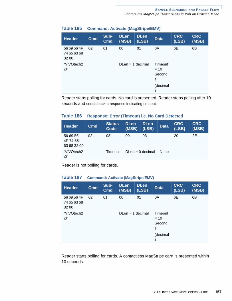
SAMPLE SCENARIOS AND PACKET FLOWContactless MagStripe Transactions in Poll on Demand Mode
.
Reader starts polling for cards. No card is presented. Reader stops polling after 10 seconds and sends back a response indicating timeout.
Reader is not polling for cards.
Reader starts polling for cards. A contactless MagStripe card is presented within 10 seconds.
Table 185 Command: Activate (MagStripe/EMV)
Header Cmd Sub-Cmd
DLen(MSB)
DLen(LSB) Data CRC
(LSB)CRC(MSB)
56 69 56 4F 74 65 63 68 32 00
02 01 00 01 0A 6E 6B
“ViVOtech2\0”
DLen = 1 decimal Timeout = 10 Seconds
(decimal)
Table 186 Response: Error (Timeout) i.e. No Card Detected
Header Cmd Status Code
DLen(MSB)
DLen(LSB) Data CRC
(LSB)CRC(MSB)
56 69 56 4F 74 65 63 68 32 00
02 08 00 03 20 2E
“ViVOtech2\0”
Timeout DLen = 0 decimal None
Table 187 Command: Activate (MagStripe/EMV)
Header Cmd Sub-Cmd
DLen(MSB)
DLen(LSB) Data CRC
(LSB)CRC(MSB)
56 69 56 4F 74 65 63 68 32 00
02 01 00 01 0A 6E 6B
“ViVOtech2\0”
DLen = 1 decimal Timeout = 10 Seconds
(decimal)
CTLS INTERFACE DEVELOPERS GUIDE 157

SAMPLE SCENARIOS AND PACKET FLOWContactless MagStripe Transactions in Poll on Demand Mode
15
Reader completes transaction, even if more than ten seconds pass since Activate command was received. After completing transaction Reader does not restart polling and just sends back the response containing the Track1 & Track2 data.Table 188 Response: OK, Track1, Track2 Data available
Header Cmd Status Code
DLen(MSB)
DLen(LSB) Data
56 69 56 4F 74 65 63 68 32 00
03 00 00 64 3C 42 35 34 31 33 31 32 33 34 35 36 37
“ViVOtech2\0”
OK DLen = 100 decimal T1Len=
60 (dec)
T1 Len = 60 (dec)
Data38 34 38 30 38 5E 53 4D 49 54 48 2F 4A 4F 48 4E 5E 30 35 30 38 31 30 31 33 33 35 33 37 33 33 33 36 30 37 32 32 32Track 1 Data
“84808^SMITH/JOHN^050810133537333607222”
Data32 32 37 32 34 31 31 31 31 33 25 35 34 31 33 31 32 33 34 35 36
37 38 34 38 30 38 3D 30 35 30 38 31 30 31
Track1 Data
“2272411113”
T2Len=
37 (dec)
Track 2 Data
“5413123456784808=0508101”
Data CRC(MSB)
CRC(LSB)
39 36 30 37 39 39 37 32 34 32 31 38 33
00 F6 7F
Track 2 Data
“9607997242183”
Clearing Record
Not Present
8 CTLS INTERFACE DEVELOPERS GUIDE

SAMPLE SCENARIOS AND PACKET FLOWEMV (MChip) Transaction in Poll on Demand Mode
EMV (MChip)Transaction in
Poll on DemandMode
The correct CA Public Keys required by the Cards that will be read have already been set up using the Key Management Commands (refer to Key Manager Basic Operation). This operation needs to be done only once for each key. Keys are retained over power cycles by Reader.
Reader stops polling for cards. Terminal will have to issue Activate command to allow Reader to poll for a card and carry out a transaction.
Assuming the current terminal values will be used for all other parameters (unless specified otherwise in Activate command).
Table 189 Command: Set Poll Mode (Poll on Demand)
Header Cmd Sub-Cmd
DLen(MSB)
DLen(LSB) Data CRC
(LSB)CRC(MSB)
56 69 56 4F 74 65 63 68 32 00
01 01 00 01 01 D7 34
“ViVOtech2\0”
DLen = 1 decimal Poll on Demand Mode
Table 190 Response: OK
Header Cmd Status Code
DLen(MSB)
DLen(LSB) Data CRC
(LSB)CRC(MSB)
56 69 56 4F 74 65 63 68 32 00
01 00 00 01 12 53
“ViVOtech2\0”
OK DLen = 0 decimal None
Table 191 Command: Set EMV Configuration (Terminal Country Code, Transaction Currency Code)
Header Cmd Sub-Cmd
DLen(MSB)
DLen(LSB)
56 69 56 4F 74 65 63 68 32 00
04 00 00 0A
“ViVOtech2\0” DLen = 10 decimal
Data CRC(LSB)
CRC(MSB)
9F 1A 02 00 56 5F 2A 02 09 78 6E 6BTLV Terminal
Country
Code
TLV Trans
Currency
Code
CTLS INTERFACE DEVELOPERS GUIDE 159

SAMPLE SCENARIOS AND PACKET FLOWEMV (MChip) Transaction in Poll on Demand Mode
16
.
Reader is still not polling for cards.
Reader starts polling for cards. A contactless EMV (MChip) card is presented within 10 seconds.
Reader completes transaction, even if more than ten seconds pass since Activate command was received. After completing transaction Reader does not restart polling and just sends back the response containing the Clearing Record data.
Table 192 Response: OK
Header Cmd Status Code
DLen(MSB)
DLen(LSB) Data CRC
(LSB)CRC(MSB)
56 69 56 4F 74 65 63 68 32 00
04 00 00 0A AE 16
“ViVOtech2\0”
OK DLen = 10 decimal
None
NOTE These parameter values may not apply to all cards. The terminal will have to make sure that correct values have been defined for the parameters based on card requirements otherwise a transaction will fail.
Table 193 Command: Activate (MagStripe/EMV)
Header Cmd Sub-Cmd
DLen(MSB)
DLen(LSB)
56 69 56 4F 74 65 63 68 32 00
02 01 00 06
“ViVOtech2\0” DLen = 1 decimal
Data CRC(LSB)
CRC(MSB)
0A 9A 03 05 08 18 77 1DTimeout =
10 Seconds
(decimal)
TLV
Transaction
Date
0 CTLS INTERFACE DEVELOPERS GUIDE

SAMPLE SCENARIOS AND PACKET FLOWEMV (MChip) Transaction in Poll on Demand Mode
.Table 194 Response: OK, Clearing Record and additional Data available
Header Cmd Status Code
DLen(MSB)
DLen(LSB) Data
56 69 56 4F 74 65 63 68 32 00
02 00 00 AB 00 00 01
“ViVOtech2\0”
OK DLen = 100 decimal
T1Len=
0 (dec)
T2Len =
0 (dec)
Clearing Record
Present
DataE1 56 9F 1A 02 01 58 9F 02 06 00 00 00 00 00 01 5F 2A 02 09 01 9A 03 05 08 02 9C 01 00 95 05 00 00 00 00 00 9F 37Clearing Record (DE 055)
Data04 84 77 98 32 82 02 58 80 9F 26 08 02 BB 21 5D D9 06 94 01 9F 27 01 40 9F 10 12 02 10 90 08 01 22 30 00 00 00 00Clearing Record (DE 055)
Data00 00 00 00 15 00 FF 9F 36 02 00 D0 5A
5A 08 54 12 34 00 00 00 00 19
5F 34 01 00 5F 24 03 10 07 31
Clearing Record (DE 055)
TLV App PAN
TLV PAN Seq Num
TLV App Expiration
Date
Data50 0A 4D 61 73 74 65 72 43 61 72 64
9F 34 03 00 1F 03
9F 45 02 DA C0
9F 4C 08 00 00 00 00 00 00 00 00
TLV Application Label CVM Results Data Auth Code
ICC Dynamic Number
CTLS INTERFACE DEVELOPERS GUIDE 161

SAMPLE SCENARIOS AND PACKET FLOWTicketing/ePurse (MXI) Transaction (Payment at Entry)
16
.
Ticketing/ePurse(MXI)
Transaction(Payment at
Entry)
It is assumed that the required CA Public Keys, Date and Time have been set in the Reader at least once in its lifetime.
It is also assumed that the Reader has been put in Poll on Demand mode and the EMV parameters have been set correctly by the terminal (see earlier examples).
Data57 13 54 12 34 00 00 00 00 19 D1 00 72 01 14 43 14 31 00 00
0F
56 00 9B 02 C8 00
TLV Track 2 Equivalent Data TLV Track 1
Equivalent Data
Transaction Status
Information
Data CRC(MSB)
CRC(LSB)
5F 20 1A 53 20 20 20 20 20 20 20 20 20 20 20 20 20 20 20 20 20 20 20 20 20 20 20 20 20
27 60
Cardholder Name
Table 195 Command: Set Poll Mode (Poll on Demand)
Header Cmd Sub-Cmd
DLen(MSB)
DLen(LSB) Data CRC
(LSB)CRC(MSB)
56 69 56 4F 74 65 63 68 32 00
01 01 00 01 01 D7 34
“ViVOtech2\0”
DLen = 1 decimal Poll on Demand Mode
Table 196 Response: OK
Header Cmd Status Code
DLen(MSB)
DLen(LSB) Data CRC
(LSB)CRC(MSB)
56 69 56 4F 74 65 63 68 32 00
01 00 00 01 12 53
“ViVOtech2\0”
OK DLen = 0 decimal None
2 CTLS INTERFACE DEVELOPERS GUIDE

SAMPLE SCENARIOS AND PACKET FLOWTicketing/ePurse (MXI) Transaction (Payment at Entry)
Reader stops polling for cards. Terminal will have to issue Activate command to allow Reader to poll for a card and carry out a transaction.
Reader is still not polling for cards.
Table 197 Command: Set EMV Configuration (Terminal Country Code, Transaction Currency Code)
Header Cmd Sub-Cmd
DLen(MSB)
DLen(LSB) Data
56 69 56 4F 74 65 63 68 32 00
04 00 00 1E 9F 1A 02 00 56
9F 1A 02 01 58
“ViVOtech2\0”
DLen = 10 decimal
TLV Terminal
Capabilities
TLV Terminal Country
Code
Data CRC(MSB)
CRC(LSB)
9F 1B 04 00 00 27 10
9F 35 01 26
5F 2A 02 08 40
9C 01 00 3C F8
TLV
Terminal Floor Limit
TLV
Terminal Type
TLV
Trans Currency Code
TLV
Transaction Type
Table 198 Response: OK
Header Cmd Status Code
DLen(MSB)
DLen(LSB) Data CRC
(MSB)CRC(LSB)
56 69 56 4F 74 65 63 68 32 00
04 00 00 01 AE 16
“ViVOtech2\0”
OK DLen = 0 decimal None
NOTE These parameter values may not apply to all cards. The terminal will have to make sure that correct values have been defined dor the parameters based on card requirements otherwise, a transaction will fail.
CTLS INTERFACE DEVELOPERS GUIDE 163

SAMPLE SCENARIOS AND PACKET FLOWTicketing/ePurse (MXI) Transaction (Payment at Entry)
16
Reader starts polling for cards. A contactless EMV cash card (MXI) card is presented within 10 seconds. Reader completes first leg of transaction, even if more than ten seconds pass since Activate command was received. After completing this leg of transaction Reader does not close session with card. It sends back the response containing the data items requested and waits for the next command.
Reader is not polling for cards. Card is still active.
Table 199 Command: Activate (MXI Payment at Entry)
Header Cmd Sub-Cmd
DLen(MSB)
DLen(LSB)
56 69 56 4F 74 65 63 68 32 00
02 02 00 05
“ViVOtech2\0” DLen = 5 decimal
Data CRC(LSB)
CRC(MSB)
0A 9F 50 9F 70 8E 33Timeout =
10 Seconds
(decimal)
Balance Tag Ticketing
Profile
Tag
Table 200 Response: OK, Clearing Record and additional Data available
Header Cmd Status Code
DLen(MSB)
DLen(LSB) Data
56 69 56 4F 74 65 63 68 32 00
02 00 00 AB 9F 50 06 00 00 00 00 19 98
“ViVOtech2\0” OK DLen = 44 decimal TLV Balance
Data9F 70 20 00 00 00 00 00 00 00 00 00 00 00 00 00 00 00 00 00 00 00 00 00 00 00 00 00 00 00 00 00 00 00 00TLV Ticketing Profile
CRC(MSB)
CRC(LSB)
38 3C
4 CTLS INTERFACE DEVELOPERS GUIDE

SAMPLE SCENARIOS AND PACKET FLOWTicketing/ePurse (MXI) Transaction (Payment at Entry)
.
Table 203
Table 201 Command: Debit Write
Header Cmd Sub-Cmd
DLen(MSB)
DLen(LSB) Data
56 69 56 4F 74 65 63 68 32 00
03 01 00 31 9F 02 06 00 00 00 00 00 01
9A 03 05 08 10
“ViVOtech2\0”
DLen = 49 decimal
TLV Amount Authorized
TLV
Transaction
Date
Table 202DataDF 10 20 31 32 33 34 35 36 37 38 39 30 31 32 33 34 35 36 37 38 39 30 31 32 33 34 35 36 37 38 39 30 31 32TLV Ticketing Info
CRC(MSB)
CRC(LSB)
BE 57
Table 204 Response: OK, Clearing Record being returned
Header Cmd Status Code
DLen(MSB)
DLen(LSB) Data
56 69 56 4F 74 65 63 68 32 00
03 00 00 71 00 00 01
“ViVOtech2\0”
OK DLen = 113 decimal
T1Len=
0 (dec)
T2Len =
0 (dec)
Clearing Record
Present
DataE1 56 9F 1A 02 01 58 9F 02 06 00 00 00 00 00 01 5F 2A 02 08 40 9A 03 05 08 10 9C 01 00 95 05 00 00 00 00 00Clearing Record
CTLS INTERFACE DEVELOPERS GUIDE 165

SAMPLE SCENARIOS AND PACKET FLOWTicketing/ePurse (MXI) Transaction (Get Balance Only, NoDebit)
16
.
Reader is not polling for cards. Session with card terminated.
Ticketing/ePurse(MXI)
Transaction (GetBalance Only,
NoDebit)
It is assumed that the required CA Public Keys, Date and Time have been set in the Reader at least once in its lifetime.
The balance will be retrieved by using only the first leg of MXI Payment at Entry and then aborting the transaction without doing a Debit Write.
.
Data9F 37 04 00 00 00 00 82 02 49 80 9F 26 08 EE 57 5B FB D8 33 7D E3 9F 27 01 40 9F 10 12 02 11 90 00 03 22 A0 00Clearing Record
Data00 00 00 00 00 27 96 00 3A FF 9F 36 02 01 FB
9F 34 03 1F 00 02 9F 45 02 12 34
Clearing Record CVM Results Data Auth Code
Data CRC(LSB)
CRC(MSB)
9F 4C 08 01 23 45 67 89 AB CD EF AA 79ICC Dynamic Number
Table 205 Command: Set Poll Mode (Poll on Demand)
Header Cmd Sub-Cmd
DLen(MSB)
DLen(LSB) Data CRC
(LSB)CRC(MSB)
56 69 56 4F 74 65 63 68 32 00
01 01 00 01 01 D7 34
“ViVOtech2\0”
DLen = 1 decimal Poll on Demand Mode
Table 206 Response: OK
Header Cmd Status Code
DLen(MSB)
DLen(LSB) Data CRC
(LSB)CRC(MSB)
56 69 56 4F 74 65 63 68 32 00
01 00 00 01 12 53
“ViVOtech2\0”
OK DLen = 0 decimal None
6 CTLS INTERFACE DEVELOPERS GUIDE

SAMPLE SCENARIOS AND PACKET FLOWTicketing/ePurse (MXI) Transaction (Get Balance Only, NoDebit)
Reader stops polling for cards. Terminal will have to issue Activate command to allow Reader to poll for a card and carry out a transaction.
Reader is still not polling for cards.
Table 207 Command: Set EMV Configuration (Terminal Country Code, Transaction Currency Code)
Header Cmd Sub-Cmd
DLen(MSB)
DLen(LSB) Data
56 69 56 4F 74 65 63 68 32 00
04 00 00 1E 9F 33 03 40 08 A0
9F 1A 02 01 58
“ViVOtech2\0”
DLen = 10 decimal
TLV Terminal
Capabilities
TLV Terminal Country
Code
Data CRC(LSB)
CRC(MSB)
9F 1B 04 00 00 27 10
9F 35 01 26 5F 2A 02 08 40
9C 01 00 3C F8
TLV
Terminal Floor Limit
TLV
Terminal Type
TLV
Trans Currency Code
TLV
Transaction Type
Table 208 Response: OK
Header Cmd Status Code
DLen(MSB)
DLen(LSB) Data CRC
(MSB)CRC(LSB)
56 69 56 4F 74 65 63 68 32 00
04 00 00 00 AE 16
“ViVOtech2\0”
OK DLen = 0 decimal None
NOTE These parameter values may not apply to all cards. The terminal will have to make sure that correct values have been defined for the parameters based on card requirements, otherwise, a transaction will fail.
CTLS INTERFACE DEVELOPERS GUIDE 167

SAMPLE SCENARIOS AND PACKET FLOWTicketing/ePurse (MXI) Transaction (Get Balance Only, NoDebit)
16
.
Reader starts polling for cards. A contactless EMV cash card (MXI) card is presented within 10 seconds. Reader completes first leg of transaction, even if more than ten seconds pass since Activate command was received. After completing this leg of transaction Reader does not close session with card. It sends back the response containing the data items requested and waits for the next command.
Reader is not polling for cards. Card is still active.
Table 209 Command: Activate (MXI Payment at Entry)
Header Cmd Sub-Cmd
DLen(MSB)
DLen(LSB)
56 69 56 4F 74 65 63 68 32 00
02 02 00 05
“ViVOtech2\0” DLen = 5 decimal
Data CRC(LSB)
CRC(MSB)
0A 9F 50 9F 70 8E 33Timeout =
10 Seconds
(decimal)
Balance Tag Ticketing
Profile
Tag
Table 210 Response: OK, Card Detected, Card Data being returned
Header Cmd Status Code
DLen(MSB)
DLen(LSB) Data
56 69 56 4F 74 65 63 68 32 00
02 00 00 AB 9F 50 06 00 00 00 00 19 98
“ViVOtech2\0” OK DLen = 44 decimal TLV Balance
Data9F 70 20 00 00 00 00 00 00 00 00 00 00 00 00 00 00 00 00 00 00 00 00 00 00 00 00 00 00 00 00 00 00 00 00TLV Ticketing Profile
CRC(MSB)
CRC(LSB)
BC D2
8 CTLS INTERFACE DEVELOPERS GUIDE
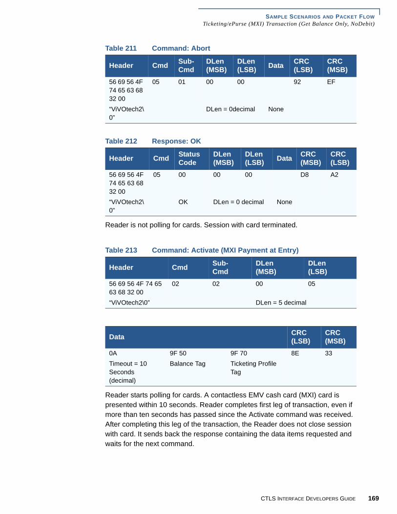
SAMPLE SCENARIOS AND PACKET FLOWTicketing/ePurse (MXI) Transaction (Get Balance Only, NoDebit)
.
Reader is not polling for cards. Session with card terminated.
Reader starts polling for cards. A contactless EMV cash card (MXI) card is presented within 10 seconds. Reader completes first leg of transaction, even if more than ten seconds has passed since the Activate command was received. After completing this leg of the transaction, the Reader does not close session with card. It sends back the response containing the data items requested and waits for the next command.
Table 211 Command: Abort
Header Cmd Sub-Cmd
DLen(MSB)
DLen(LSB) Data CRC
(LSB)CRC(MSB)
56 69 56 4F 74 65 63 68 32 00
05 01 00 00 92 EF
“ViVOtech2\0”
DLen = 0decimal None
Table 212 Response: OK
Header Cmd Status Code
DLen(MSB)
DLen(LSB) Data CRC
(MSB)CRC(LSB)
56 69 56 4F 74 65 63 68 32 00
05 00 00 00 D8 A2
“ViVOtech2\0”
OK DLen = 0 decimal None
Table 213 Command: Activate (MXI Payment at Entry)
Header Cmd Sub-Cmd
DLen(MSB)
DLen(LSB)
56 69 56 4F 74 65 63 68 32 00
02 02 00 05
“ViVOtech2\0” DLen = 5 decimal
Data CRC(LSB)
CRC(MSB)
0A 9F 50 9F 70 8E 33Timeout = 10 Seconds (decimal)
Balance Tag Ticketing Profile Tag
CTLS INTERFACE DEVELOPERS GUIDE 169

SAMPLE SCENARIOS AND PACKET FLOWTicketing/ePurse (MXI) Transaction (Get Balance Only, NoDebit)
17
.
Reader is not polling for cards. Card is still active.
Reader is not polling for cards. Session with card terminated.
Table 214 Response: OK, Card Detected, Card Data being returned
Header Cmd Status Code
DLen(MSB)
DLen(LSB) Data
56 69 56 4F 74 65 63 68 32 00
02 00 00 2C 9F 50 06 00 00 00 00 19 97
“ViVOtech2\0” OK DLen = 44 decimal TLV Balance
Data9F 70 20 00 00 00 00 00 00 00 00 00 00 00 00 00 00 00 00 00 00 00 00 00 00 00 00 00 00 00 00 00 00 00 00TLV Ticketing Profile
CRC(MSB)
CRC(LSB)
BC D2
Table 215 Command: Abort
Header Cmd Sub-Cmd
DLen(MSB)
DLen(LSB) Data CRC
(LSB)CRC(MSB)
56 69 56 4F 74 65 63 68 32 00
05 01 00 00 92 EF
“ViVOtech2\0”
DLen = 0decimal None
Table 216 Response: OK
Header Cmd Sub-Cmd
DLen(MSB)
DLen(LSB) Data CRC
(LSB)CRC(MSB)
56 69 56 4F 74 65 63 68 32 00
05 00 00 00 D8 A2
“ViVOtech2\0”
DLen = 0decimal None
0 CTLS INTERFACE DEVELOPERS GUIDE

CHAPTER 11
Pass-Through Mode
Some versions of the card reader firmware provide a Pass-through mode which can be used by a terminal to communicate directly with an RF card. This feature allows a terminal to add support for RF cards that are not supported by the card reader.
This section describes the Pass-through commands, the communication parameters, the card reader serial interface protocol, and the command-specific details.
Basic Pass-Through
Operation
Communication between the card reader and the terminal will be through the card reader standard serial interface protocol.
Pass-through mode allows a terminal to communicate directly with an ISO 14443 Type A or Type B Proximity Card (PICC), without the card reader knowing the specifics of the application or data present on the PICC. The pass-through mode allows a set of basic commands that allow polling and selection of a PICC, and sending/receiving low level information to/from the PICC. This allows a terminal to communicate with (and support) cards with applications and data that are not supported by the card reader. Individual pass-through sub-commands are described in the sections that follow.
Before enabling the pass-through mode, the terminal must make sure that it has not disabled the RF Field by sending the Antenna Off command. If it has, then it must turn the Antenna On before starting the pass-through mode. Once the pass-through mode has been started, the Antenna should be turned off only after the pass-through mode has been stopped. It should not be turned off during the pass-through mode, unless it is for handling the card removal sequence.
The Pass-through Mode subcommands are grouped into three categories:
• General Pass - through Set Up Sub-Commands: These sub-commands will have to be used whether we are using high level communication with the PICC or low level communication. These sub-commands include:
• Pass-through Mode Start/Stop• Poll for Token
• High Level PICC Communication Sub-Commands: If a PICC supports ISO 14443-4 Protocol, then these high-level sub-commands can be used to send application-level APDUs to the PICC and receive the PICC responses. The Send /Receive commands must always be used in pairs, unless the send command returns an error. The high level sub-commands include ISO APDU Exchange.
CTLS INTERFACE DEVELOPERS GUIDE 171

PASS-THROUGH MODEPass-Through Commands
17
• Low Level PICC Communication Sub-Commands:These low level sub-commands can be used to send raw ISO 14443-3 data to the PICC and receive the PICC responses. The Send/Receive commands must always be used in pairs,unless the send command returns an error. In addition to this, these sub-commands can also be used to get and set some PCD and PICC parameters. The low level sub-commands include.
• PCD Single Command Exchange
• Get PCD and PICC Parameters
Then the terminal must periodically instruct the card reader unit to poll for RF Cards. Whenever the card reader detects a card in the RF Field, it will try to carry out ISO 14443 Layer 3 and Layer 4 negotiations and report the card type found. In the pass-through mode, the card reader will not attempt to check whether the card is one of the cards that it supports.
Once a card is detected, the terminal may use one of the pass-through commands to communicate with the card at the application level and read the data.
These commands allow a terminal to use a number of features provided by the card reader, such as controlling the RF antenna (field).
Pass-ThroughCommands
Pass Through ModeStart/Stop
Whenever the terminal application wants to use the Pass-through Mode, this sub-command must be issued once at the beginning to instruct the card reader to go into Pass-through Mode. It must be issued once at the end to instruct the card reader to exit the Pass-through Mode and return to normal operations.
Once Pass-through Mode is started, the card reader will stop polling for cards that it recognizes and will only handle Pass-through commands to allow the terminal to communicate directly with a PICC, until it is brought out of Pass-through mode.
The card reader will not accept any Pass-through sub-command until it has been put in the Pass-through Mode by issuing this sub-command.
NOTE The Byte 14+n and Byte 15+n CRCs are the reverse of standard Version 1 Format and Version 2 Format Command packets in that the CRC (MSB) is Byte 14 and the CRC (LSB) is Byte 15 for Pass-Through Command packets.
Table 217 The Command Packet
Byte 0-9 Byte 10 Byte 11 Byte 12Header Tag and Protocol Version
Command Sub Command Data Length (MSB)
ViVOtech2\0 2Ch 01h 00h
2 CTLS INTERFACE DEVELOPERS GUIDE

PASS-THROUGH MODEPass-Through Commands
.
Mode = 0 Stop Pass-through
Mode = 1 Start Pass-through
Poll for Token Once Pass-through Mode is started, the card reader will stop polling for supported cards and sit dormant until the “Poll for Token” command is given. This command tells the card reader to start polling for a Type A or Type B PICC until a PICC is detected or a timeout occurs.
If a PICC is detected within the specified time limit, the card reader will activate it and respond back to the terminal with card-related data such as Serial Number.
If no PICC is detected within the specified time limit, the card reader will stop polling and respond back indicating that no card was found. No card-related data will be returned in this case.
Byte 13 Byte 14 Byte 15 Byte 16Data Length (LSB) Data CRC (MSB) CRC (LSB)01h Mode
Table 218 The Response Packet
Byte 0-9 Byte 10 Byte 11 Byte 12Header Tag and ProtocolVersion
Command Sub Command Data Length (MSB)
ViVOtech2\0 2Ch See Status Codes for Version 2 Protocol.
00h
Byte 13 Byte -- Byte 14 Byte 15Data Length (LSB) Data CRC (MSB) CRC (LSB)00h None
NOTE The Pass-through Mode Start command must be used to enter Pass-through Mode.
The Pass-through Mode Stop command can only be used in Pass-through Mode.
Table 219 The Command Packet
Byte 0-9 Byte 10 Byte 11 Byte 12Header Tag and Protocol Version
Command Sub Command Data Length (MSB)
ViVOtech2\0 2Ch 02h 00h
CTLS INTERFACE DEVELOPERS GUIDE 173

PASS-THROUGH MODEPass-Through Commands
17
.
Together, Timeout1 and Timeout2 are used by the card reader to calculate the Timeout, i.e. the time to wait for a PICC. For example:
.
Byte 13 Byte 14,15 Byte 16 Byte 17Data Length (LSB) Data CRC (MSB) CRC (LSB)02h See Data Fields for
the Command Packet
Table 220 Data Fields for the Command Packet
Data Field Length in Bytes DescriptionTimeout1 1 Byte Time in Seconds Timeout1 cannot be
zero seconds if Timeout2 is Zero.Timeout2 1 Byte Multiplier for Time in multiples of 10
milliseconds.
Timeout1 Timeout2 Timeout0 0 Not Allowed0 20 0 Seconds, 200 ms0 50 0 Seconds, 500 ms0 100 1 Second1 0 1 Second1 20 1 Second, 200 ms
Table 221 The Response Packet
Byte 0-9 Byte 10 Byte 11 Byte 12Header Tag and Protocol Version
Command Sub Command Data Length (MSB)
ViVOtech2\0 2Ch See Status Codes for Version 2 Protocol.
00h
Byte 13 Byte 14 ... Byte 14+n-1 Byte 14+n Byte 15+n
Data Length (LSB) Data CRC (MSB) CRC (LSB)Variable See Data Fields
for the Response Packet (if Status = OK).
Timeout2 Time in ms0 01 102 20: :255 2550
4 CTLS INTERFACE DEVELOPERS GUIDE

PASS-THROUGH MODEPass-Through Commands
The Data field will contain data only if Status Code is OK.
Antenna Control This command will allow the terminal to instruct the card reader to turn the RF Antenna ON or OFF.
Mode = 0 Disable RF Antenna
Mode = 1 Enable RF Antenna
Table 222 Data Fields for the Response Packet (if Status = OK)
Data Field Length in Bytes Description
Card 1 Byte Type of Card Found (or No Card Found).
Serial Number
0 or variable Serial Number (or the UID) of the PICC. Length will depend on the Card Detected. If no card was detected, then a Serial Number will not be sent back.
00h None (Card Not Detected or Could Not Activate)
01h ISO 14443 Type A (Supports ISO 14443-4 Protocol)
02h ISO 14443 Type B (Supports ISO 14443-4 Protocol)
03h Mifare Type A (Standard)
04h Mifare Type A (Ultralight)
05h ISO 14443 Type A (Does not support ISO 14443-4 Protocol)
06h ISO 14443 Type B (Does not support ISO 14443-4 Protocol)
07h ISO 14443 Type A and Mifare (NFC phone)
Table 223 The Command Packet
Byte 0-9 Byte 10 Byte 11 Byte 12Header Tag and Protocol Version
Command Sub Command Data Length (MSB)
ViVOtech2\0 28h 01h 00h
Byte 13 Byte 14 Byte 15 Byte 16Data Length (LSB) Data CRC (MSB) CRC (LSB)01h Mode
CTLS INTERFACE DEVELOPERS GUIDE 175

PASS-THROUGH MODEPass-Through Commands
17
.
LED Control This command can be used to switch the specified card reader LEDs off or on.
This command will result in the expected behavior only when the card reader is in Pass-through Mode.If this command is used to switch on an LED when the card reader is in normal operation mode and not in Pass-through Mode, the LED will not remain on.
Table 224 The Response Packet
Byte 0-9 Byte 10 Byte 11 Byte 12Header Tag and Protocol Version
Command Status Code Data Length (MSB)
ViVOtech2\0 28h See Status Codes for Version 2 Protocol
00h
Byte 13 Byte -- Byte 14 Byte 15Data Length (LSB) Data CRC (MSB) CRC (LSB)01h None
NOTE Antenna should not be disabled while polling for a card or while communicating with a card. If Antenna is disabled, no card will be detected.
This command should only be used in Pass-through Mode for termination handling once a card transaction is completed (successfully or with an error).
Table 225 The Command Packet
Byte 0-9 Byte 10 Byte 11 Byte 12Header Tag and Protocol Version
Command Sub Command Data Length (MSB)
ViVOtech2\0 0Ah 02h 00h
Byte 13 Byte 14,15 Byte 16 Byte 17Data Length (LSB)
Data CRC (MSB) CRC (LSB)
02h See .Data Fields for the Command Packet
6 CTLS INTERFACE DEVELOPERS GUIDE

PASS-THROUGH MODEPass-Through Commands
.
Buzzer Control This command can be used to sound the card reader Buzzer.
Table 226 Data Fields for the Command Packet
Data Field Length in Bytes DescriptionLED # 1 Byte 00h: LED 0 (First LED to the
Right of Power LED)
01h: LED 1
02h: LED 2
FFh: All three LEDsLED Status 1 Byte 00h: LEF Off
01h: LED On
Table 227 The Response Packet
Byte 0-9 Byte 10 Byte 11 Byte 12Header Tag and Protocol Version
Command Sub Command Data Length (MSB)
ViVOtech2\0 0Ah See Status Codes for Version 2 Protocol.
00h
Byte 13 Byte -- Byte 14 Byte 15
Data Length (LSB) Data CRC (MSB) CRC (LSB)00h None
Table 228 The Command Packet
Byte 0-9 Byte 10 Byte 11 Byte 12Header Tag and Protocol Version
Command Sub Command Data Length (MSB)
ViVOtech2\0 0Bh See Data Fields for the Command Packet.
00h
Byte 13 Byte 14 Byte 15 Byte 16Data Length (LSB)
Data CRC (MSB) CRC (LSB)
01h Buzzer Parameter
CTLS INTERFACE DEVELOPERS GUIDE 177

PASS-THROUGH MODEPass-Through Commands
17
Sub Command = 01h N Short Beeps
Sub Command = 02h Single Long Beep of Specified Duration
ISO APDU Exchange This sub-command will allow the terminal to send, via the card reader, application-level APDUs to a PICC that supports ISO 14443-4 Protocol. The PICC response is sent back by the card reader to the Terminal.
Table 229 Data Fields for the Command Packet
Data Field Length in Bytes DescriptionBuzzer Parameter 1 Byte If Sub-Command is Short Beeps …
Num Beeps = 01h One Short Beep
Num Beeps = 02h Two Short Beeps
Num Beeps = 03h Three Short Beeps
Num Beeps = 04h Four Short Beeps
If Sub-Command is Long Beep …
Duration = 00h 200 ms
Duration = 01h 400 ms
Duration = 02h 600 ms
Duration = 03h 800 ms
Table 230 The Response Packet
Byte 0-9 Byte 10 Byte 11 Byte 12Header Tag and Protocol Version
Command Sub Command Data Length (MSB)
ViVOtech2\0 0Bh See Status Codes for Version 2 Protocol.
00h
Byte 13 Byte -- Byte 14 Byte 15Data Length (LSB) Data CRC (MSB) CRC (LSB)00h None
Table 231 The Command Packet
Byte 0-9 Byte 10 Byte 11 Byte 12Header Tag and ProtocolVersion
Command Sub Command Data Length (MSB)
ViVOtech2\0 2Ch 03h Variable
8 CTLS INTERFACE DEVELOPERS GUIDE

PASS-THROUGH MODEPass-Through Commands
.
APDU Out is the complete APDU that is to be sent to the PICC. The contents of the APDU will depend on the application residing on the PICC and are out of the scope of this document.
If a valid Command Packet is received from the terminal, the card reader will send the APDU data to the PICC and receive its response. The card reader will treat the PICC response as unknown data and will not try to interpret it. If all goes well, the card reader will send back a response packet with an OK status and the Data received from the PICC (APDU In).
If the Command Packet contains any errors, or an error occurred during communication with the PICC, then the card reader will send a Response Packet with an appropriate Status. No Data will be returned in this case.
The Data field will contain data only if the Status Code is OK. In this case, the data will consist of “APDU In” i.e. the response data that was received from the PICC. The contents of the response will depend on the application residing on the PICC and are out of the scope of this document.
Byte 13 Byte 14 ... Byte 14+n-1 Byte 14+n Byte 15+n
Data Length (LSB) Data CRC (MSB) CRC (LSB)Variable APDU Out
Table 232 The Response Packet
Byte 0-9 Byte 10 Byte 11 Byte 12Header Tag and ProtocolVersion
Command Sub Command Data Length (MSB)
ViVOtech2\0 2Ch See Status Codes for Version 2 Protocol.
Variable
Byte 13 Byte 14 ... Byte 14+n-1 Byte 14+n Byte 15+n
Data Length (LSB) Data CRC (MSB) CRC (LSB)Variable APDU In or None
CTLS INTERFACE DEVELOPERS GUIDE 179

PASS-THROUGH MODEPass-Through Commands
18
PCD SingleCommandExchange
This sub-command will allow the terminal to send, via the card reader, raw data to an ISO 14443 PICC that does not support ISO 14443-4 Protocol (such as Mifare Standard or Mifare Ultralight). The PICC response is sent back by the card reader to the Terminal.
.
Table 233 The Command Packet
Byte 0-9 Byte 10 Byte 11 Byte 12
Header Tag and Protocol Version
Command Sub Command Data Length (MSB)
ViVOtech2\0 2Ch 04h Variable
Byte 13 Byte 14 ... Byte 14+n-1 Byte 14+n Byte 15+n
Data Length (LSB) Data CRC (MSB) CRC (LSB)Variable See Data Fields for
the Command Packet.
Table 234 Data Fields for the Command Packet
Data Field Length in Bytes Description
PCD Command 1 Byte This is the command that will be sent to the PCD Reader IC on the card reader board. It will tell the PCD what to do with the data sent with the command. The PCD commands supported and their values are given in the “PCD Cmd” Table below.
PCD Timeout 4 Bytes This is the RF communication timeout in ETUs stored as a 4-byte big-endian number, where 1 ETU is 9.44 microseconds. The RF communication timeout guards the communication between the PCD reader IC and the PICC Card. The timeout is measured between the last bit sent to the PICC and the first bit received from the PICC.
PCD Command Flags
1 Byte These flags allow greater control over the way the card reader processes the command via the PCD Reader IC. Format of the PCD Command Flags byte is given in the “PCD Command Flags” Table below.
0 CTLS INTERFACE DEVELOPERS GUIDE

PASS-THROUGH MODEPass-Through Commands
The Command Packet contains some PCD parameters and raw data. The PCD Command Parameter is used by the card reader to determine what PCD function is to be carried out. The raw data is sent to the PICC for the Transceive command, or is used for LoadKey / Authentication. The contents of the data will depend on the PICC and PCD and are out of the scope of this document.
Channel Redundancy Register
1 Byte This value tells the PCD what data integrity checks to perform during communication with the PICC Card. The checks to perform at each stage are defined by the protocol (14443 Type A or B). The format of the PCD Command Flags byte is given in the “Channel Redundancy Register” Table below.
Raw Data Out Variable Raw data that will be sent to the PICC or to the PCD.
Table 234 Data Fields for the Command Packet
Data Field Length in Bytes Description
NOTEThe Load key, Auth1 and Auth2 functions may also be performed by the terminal directly by using the PCD Transceive Command
Table 235 PCD Command Table
Data Field Length in Bytes Description
PCD LOADKEY 19h Used for Loading Mifare Key into PCD for Authentication
PCD AUTHENTICATE1
0Ch Used for PCD-based Mifare Authentication.This command will result in both Level 1 and Level 2 authentication being performed automatically.
PCD TRANSCEIVE
1Eh Used to Send/Receive raw data to/from the PICC
Table 236 PCD Command Flags Table
Bit# Flag Value Meaning0 Disable DF
(DF=Disturbance Filter)
1 When response from PICC Card has been received, end of response is signaled regardless of errors.
0 When response from PICC Card has been received, if there are errors, then the data received is flushed and the device continues to receive. If there are no errors, then end of response is signaled.
CTLS INTERFACE DEVELOPERS GUIDE 181

PASS-THROUGH MODEPass-Through Commands
18
If a valid Command Packet is received from the terminal, the card reader will send the data to the PICC (or carry out the appropriate action) and receive its response. The card reader will treat the response as unknown data and will not try to interpret it. If all goes well, the card reader will send back a Response Packet with OK Status and the Data received from the PICC (if any). The Response Packet will also contain the result of the PCD Command (PCD Status). The PCD Status may indicate success or an Error Code.
1 Flush FIFO 1 PCD FIFO is flushed before starting this PCD Command.
0 PCD FIFO is not flushed before starting this command
2-7 RFU X Reserved for future use.
Table 237 Channel Redundancy Register Table
Bit# Flag Value Meaning0 Parity Enable 1 Parity bit inserted in transmitted data and
expected in received data.0 No parity bit inserted or expected.
1 Parity Odd 1 Odd Parity0 Even Parity
2 Tx CRC Enable 1 CRC Bytes appended to transmitted data.0 CRC Bytes not appended to transmitted
data.3 RX CRC Enable 1 Last bytes of received data are interpreted
as CRC bytes
Note: The CRC is not sent back to the terminal by the card reader.
0 No CRC expected.4 CRC-8 1 8-Bit CRC calculated
0 16-Bit CRC calculated5 CRC 3309 1 CRC-Calculation is done according to ISO/
IEC3309 (ISO 14443B)0 CRC-Calculation is done according to ISO/
14443A.6 RFU 0 Must always be zero.7 RFU 0 Must always be zero.
Table 236 PCD Command Flags Table
Bit# Flag Value Meaning
2 CTLS INTERFACE DEVELOPERS GUIDE

PASS-THROUGH MODEPass-Through Commands
If the Command Packet contains any errors, or an error occurred during communication with the PICC (such as PICC removed from the field), then the card reader will send a Response Packet with an appropriate Status. No Data will be returned in this case..Table 238 The Response Packet
Byte 0-9 Byte 10 Byte 11 Byte 12Header Tag and Protocol Version
Command Sub Command Data Length (MSB)
ViVOtech2\0 2Ch See Status Codes for Version 2 Protocol.
Variable
Byte 13 Byte 14 ...Byte 14+n-1 Byte 14+n Byte 15+n
Data Length (LSB) Data CRC (MSB) CRC (LSB)Variable See Data Fields for
the Command Packet OR None.
CTLS INTERFACE DEVELOPERS GUIDE 183

PASS-THROUGH MODEPass-Through Commands
18
Table 239 Data Fields for the Command Packet
Data Field Length in Bytes Description
PCD Status 1 Byte This field contains the result of the PCD Command. Possible values are given in the following table.
RcvdBits 4 Bytes Number of bits received (sotred as a big-endian number)
Raw Data In 0 or Variable
The response data that is received from the PICC. The contents of the response will depend on the application residing on the PICC and are out of the scope of this document.
PCD Status Description0 OK-1 No Tag Error-2 CRC Error-3 Empty-4 Authentication Error-5 Parity Error-6 Code Error-7 Card Type Error-8 Serial Number Error-9 Key Error-10 Authentication not carried
out for this Sector-11 Bit Count Error-12 Byte Count Error-13 Idle-15 Write Error-18 Read Error-19 FIFO Overflow Error-21 Framing Error-22 Access Error-23 Unknown Command-24 Collision Error-25 Reset Error-27 Access Timeout-31 Coding Error-54 Baud Rate not supported by
PCD-112 Receive Buffer Overflow
4 CTLS INTERFACE DEVELOPERS GUIDE

PASS-THROUGH MODEPass-Through Commands
Get PCD and PICCParameters
This command will allow the terminal to retrieve PCD and PICC related parameters from the card reader.
If a valid Command Packet is received from the terminal, the card reader will retrieve the parameters from the PCD and PICC. If the parameters are retrieved successfully, the card reader will send back a Response Packet with OK Status and Data containing the parameters given below. For details on the parameters, refer to ISO 14443
Table 240 The Command Packet
Byte 0-9 Byte 10 Byte 11 Byte 12Header Tag and Protocol Version
Command Sub Command Data Length (MSB)
ViVOtech2\0 2Ch 05h 00h
Byte 13 Byte -- Byte 14 Byte 15Data Length (LSB) Data CRC (MSB) CRC (LSB)00h None
Table 241 The Response Packet
Byte 0-9 Byte 10 Byte 11 Byte 12Header Tag and Protocol Version
Command Sub Command Data Length (MSB)
ViVOtech2\0 2Ch See Status Codes for Version 2 Protocol.
00h
Byte 13 Byte 14... Byte 14+n-1 Byte 14+n Byte 15+n
Data Length (LSB) Data CRC (MSB) CRC (LSB)00h or 0Fh See Data Fields for
the Response Packet (if Status = OK).
CTLS INTERFACE DEVELOPERS GUIDE 185

PASS-THROUGH MODEPass-Through Commands
18
If the Command Packet contains any errors, or an error occurred while retrieving the parameters,then the card reader will send a Response Packet with an appropriate Status. No Data will be returned in this case.
High Level Pass-Through Commands
for Mifare Cards
This sub section contains serial commands that implement higher level functionality for the Mifare Cards. These commands can only be used once the Reader has been put in pass-through mode and the “Poll for Token” command has indicated that a Mifare Card is present. These commands will not work for non-Mifare cards.
Mifare Authenticate Block
This command will allow the terminal to instruct the card reader to authenticate the Mifare Card sector containing the specified block of data. The Key to be used will also be specified by the terminal. This command is applicable only for Mifare Standard / Classic Cards. It is not applicable for Mifare Ultralight Cards.
Table 242 Data Fields for the Response Packet (if Status = OK)
Data Byte Name Length
(Bytes) Format Notes
0-1 Reader Buffer Size
2 Bytes Binary Reader RF Buffer Size stored as a big-endian number.
2-3 Max Picc Frame Size
2 Bytes Binary Maximum PICC Frame Size stored as a big-endian number.
4 CID 1 Byte Binary CID5 Block 1 Byte Binary Block Number6 CID Supported 1 Byte Binary CID Supported7-10 FWT 4 Bytes Binary Frame Waiting Time in ETUs. It
is stored as a big-endian number.
11-14 D-FWT 4 Bytes Binary Delta FWT in ETUs. It is stored as a big-endian number.
Table 243 The Command Packet
Byte 0-9 Byte 10 Byte 11 Byte 12Header Tag and Protocol Version
Command Sub Command Data Length (MSB)
ViVOtech2\0 2Ch 06h 00h
Byte 13 Byte 14 -- Byte 21 Byte 22 Byte 23Data Length (LSB) Data CRC (MSB) CRC (LSB)08h See Data Fields for
the Command Packet
6 CTLS INTERFACE DEVELOPERS GUIDE

PASS-THROUGH MODEPass-Through Commands
For details on these fields, refer to the relevant Mifare Specifications.
After receiving the Command Packet, the card reader will verify the data and if the data is valid, then interact with the Mifare card to authenticate the sector containing the specified block. If this operation is successful, the card reader will send a Response Packet with an OK Status.If the operation fails or the data was invalid, then the reader will return a Response Packet with an appropriate Status.
Mifare Read Blocks
This command will allow the terminal to instruct the card reader to read data from one or more blocks on the Mifare Card and return the data to the terminal. The terminal can instruct the card reader to read up to 15 blocks using this command. If more than one block is defined, then the reader will automatically read the starting block and the blocks that follow.
The block size will depend on the type of Mifare card being accessed. For Mifare Standard Cards the block size is 16 bytes. For Mifare Ultralight Cards the block (page) size is 4 bytes; however each read operation will read 16 bytes of data. When reading Mifare Ultralight cards, BlockCount will be taken to mean 16 byte blocks (consisting of 4 4-byte pages each).
Table 244 Data Fields for the Command Packet
Data Field Length in Bytes Description
Block 1 Byte Block Number in the Mifare Card for which the relevant sector must be authenticated.
Key Type 1 Byte Specifies which type of key to use for authentication. It can have the following entries:
01h: Key A
02h: Key BKey 6 Bytes Value of the Key
Table 245 The Response Packet
Byte 0-9 Byte 10 Byte 11 Byte 12Header Tag and Protocol Version
Command Sub Command Data Length (MSB)
ViVOtech2\0 2Ch See Status Codes for Version 2 Protocol.
00h
Byte 13 Byte -- Byte 14 Byte 15Data Length (LSB) Data CRC (MSB) CRC (LSB)00h None
CTLS INTERFACE DEVELOPERS GUIDE 187

PASS-THROUGH MODEPass-Through Commands
18
For example, if the card is a Mifare Ultralight card, and a read is requested starting at Block 3 and BlockCount is 1 then 16 bytes of data will be returned consisting of Page # 3, 4, 5 and 6. And if a read is requested starting at Block 3 and BlockCount is 2, then 16*2=32 bytes of data will be returned consisting of Page # 3, 4, 5, 6, 7, 8, 9, 10.
If the card specified is a Mifare Standard card, then the terminal must have successfully sent at least one “Mifare Authenticate Block” command to the Reader for the first block to read.
If the card specified is a Mifare Standard card and the read command specifies a single block read, then the reader will try to read the data regardless of whether the block is a sector trailer block or not.
If the card specified is a Mifare Standard card, and the read is a multi block read, then the reader will skip reading the sector trailer blocks that contain the Keys (since the Keys cannot be read). Skipped blocks will not be included in the block count. While reading blocks in a Mifare Standard Card, if the read requires access to the next sector, then the card reader will carry out authentication for this block/sector automatically by using the Key Type and Key Value that were used by the terminal to authenticate the sector for the Starting Block via the “Mifare Authenticate Block” command.
Table 246 The Command Packet
Byte 0-9 Byte 10 Byte 11 Byte 12Header Tag and Protocol Version
Command Sub Command Data Length (MSB)
ViVOtech2\0 2Ch 07h 00h
Byte 13 Byte 14,15 Byte 16 Byte 17Data Length (LSB) Data CRC (MSB) CRC (LSB)02h See Data Fields for
the Command Packet
8 CTLS INTERFACE DEVELOPERS GUIDE

PASS-THROUGH MODEPass-Through Commands
After receiving the Command Packet the card reader will verify the parameters. If the parameters are valid, then it will read the data from the card. If this operation is successful, the card reader will send a Response Packet containing a Status of OK and the data read. If the operation fails or one or more parameters were invalid, then the reader will send a Response Packet containing an appropriate Status, but no data.
Table 247 Data Fields for the Command Packet
Data Field Length in Bytes Description
Card and Block Count
1 Byte Card Type: [Bit 7..4]
This can only indicate the following cards
•Mifare Type A (Standard)•Mifare Type A (Ultralight)
The values for these card types are defined in the “Poll for Token” command (consider only the lower 4 bits).
Block Count: [Bit 3..0]
This is the number of blocks that will be read. The Block Count cannot be greater than 15. This count does not include the skipped blocks if the card is a Mifare Standard card.
Start Block 1 Byte This is the card block number from which the reader will start reading.
Table 248 The Response Packet
Byte 0-9 Byte 10 Byte 11 Byte 12Header Tag and ProtocolVersion
Command Sub Command Data Length (MSB)
ViVOtech2\0 2Ch See Status Codes for Version 2 Protocol.
Variable
Byte 13 Byte 14... Byte 14+n-1 Byte 14+n Byte 15+n
Data Length (LSB) Data CRC (MSB) CRC (LSB)Variable Data Read from Card
OR None
CTLS INTERFACE DEVELOPERS GUIDE 189

PASS-THROUGH MODEPass-Through Commands
19
If the Status is OK, then the Data Length will depend on the number of blocks read and the card type.
DataLen = Blocks Read * (Bytes per Block for Card).
If there was an error or no data was read, then the Data Length will be zero.
Mifare Write Blocks
This command will allow the terminal to instruct the card reader to write data to one or more blocks on the Mifare Card. The terminal can instruct the card reader to write up to 15 blocks of data using this command. If more than one block is defined, then the reader will automatically write to the starting block and the blocks that follow.
The block size will depend on the type of Mifare card being accessed. For Mifare Standard Cards the block size is 16 bytes. For Mifare Ultralight Cards the block size is 4 bytes.
If the card specified is a Mifare Standard card, then the terminal must have successfully sent at least one “Mifare Authenticate Block” command to the Reader for the first block to write.
If the card specified is a Mifare Standard card and the write command specifies a single block write, then the reader will try to write the data regardless of whether the block is a sector trailer block or not.
If the card specified is a Mifare Standard card, and the write is a multi block write, then the reader will skip writing to the sector trailer blocks that contain the Keys. Skipped blocks will not be included in the block count. While writing blocks to a Mifare Standard Card, if the write requires access to the next sector, then the card reader will carry out authentication for this block/sector automatically by using the Key Type and Key Value that were used by the terminal to authenticate the sector for the Starting Block via the “Mifare Authenticate Block” command.
Table 249 The Command Packet
Byte 0-9 Byte 10 Byte 11 Byte 12Header Tag and Protocol Version
Command Sub Command Data Length (MSB)
ViVOtech2\0 2Ch 08h Variable
Byte 13 Byte 14... Byte 14+n-1 Byte 14+n Byte 15+n
Data Length (LSB) Data CRC (MSB) CRC (LSB)Variable See Data Fields for the
Command Packet.
0 CTLS INTERFACE DEVELOPERS GUIDE

PASS-THROUGH MODEPass-Through Commands
After receiving the Command Packet the card reader will verify the parameters. If the parameters are valid, it will write the data to the card. If this operation is successful, the card reader will send a Response Packet with a Status of OK.
If the Command Packet is invalid or the write operation fails then the reader will send a Response Packet with an appropriate Status.
Table 250 Data Fields for the Command Packet
Data Field Length in Bytes Description
Card and Block Count
1 Byte Card Type: [Bit 7..4]
This can only indicate the following cards
Mifare Type A (Standard)
Mifare Type A (Ultralight)
The values for these card types are defined in the “Poll for Token” command (consider only the lower 4 bits).
Block Count: [Bit 3..0]
This is the number of blocks that will be written. The Block Count cannot be greater than 15. This count does not include the skipped blocks if the card is a Mifare Standard card.
Start Block 1 Byte This is the card block number from which the reader will start writing.
Data to Write Variable Data to write to the Card.
The length of the data to be written to the card will depend on the number of blocks to be written and the card type.
Length = Blocks to be Written *
(Bytes per Block for Card).
Table 251 The Response Packet
Byte 0-9 Byte 10 Byte 11 Byte 12Header Tag and ProtocolVersion
Command Sub Command Data Length (MSB)
ViVOtech2\0 2Ch See Status Codes for Version 2 Protocol.
00h
Byte 13 Byte-- Byte 14 Byte 15
Data Length (LSB) Data CRC (MSB) CRC (LSB)00h None
CTLS INTERFACE DEVELOPERS GUIDE 191

PASS-THROUGH MODEPass-Through Commands
19
Mifare ePurse Command
This command allows the terminal to instruct the card reader to carry out Debit, Credit and Backup operations on value blocks in a Mifare card. These functions require that the related data blocks be formatted as a value block and that operations and keys used match the defined Access Conditions for that sector.
A Debit function subtracts a given amount from a Mifare value block and stores the result in the same block. A Credit function adds a given amount to a Mifare value block and stores the result in the same block. A Backup function reads a value block and stores a copy of it in another value block in the same authenticated sector.
This command is flexible in that it allows any number of Debit, Credit or Backup function blocks to be embedded within one command packet in any order, with or without keys specified, as long as the total number of bytes is within the size capability of one Pass-through command. Operations will be performed in the order they are specified.
For instance, a Purse Command could simply contain one Debit function to debit a value block by a specified amount. If a key and key type are included they will be used to authenticate the block and the debit function will be performed. If no key information is included the key and key type used in the previous Mifare Authentication command will be used.
In another case, the Purse Command could contain a Credit function to credit a value block by a specific amount and a Backup function to backup the resulting balance to another value block somewhere on the card. Each command could include a specific key for the block being addressed, or omit the key information and let the reader use the last known key.
NOTE The default key and key type are overwritten each time key information is encountered while processing a Purse Command. The initial default values are those installed when the Mifare Authentication command is received. Those will be used until another key is encountered at which point that key will become the default key for subsequent transactions. If purse commands are used without key information then the terminal must have successfully sent at least one “Mifare Authenticate Block” command to the Reader for the first block to access.
2 CTLS INTERFACE DEVELOPERS GUIDE

PASS-THROUGH MODEPass-Through Commands
WARNING Multiple ePurse command blocks can be included in one command; each command contains a count of the number of command blocks included in the command.
If the count of command blocks specified is not equal to the actual number of command blocks included in the command, an error may or may not be returned to the user.
• If the count of command blocks is greater than the actual number of command blocks specified, all command blocks available will be acted upon and an error will be returned to the user.
• If the count of command blocks is less than the actual number of command blocks in the command, only the number of commands specified in the count will be acted upon but no error will be returned.
Table 252 The Command Packet
Byte 0-9 Byte 10 Byte 11 Byte 12Header Tag and ProtocolVersion
Command Sub Command Data Length (MSB)
ViVOtech2\0 2Ch 0Ah Variable
Byte 13 Byte 14... Byte 14+n-1 Byte 14+n Byte 15+n
Data Length (LSB) Data CRC (MSB) CRC (LSB)Variable See Data Fields for
the Command Packet.
CTLS INTERFACE DEVELOPERS GUIDE 193

PASS-THROUGH MODEPass-Through Commands
19
Debit / Credit Function Block (with Key specified)
.
Table 253 Data Fields for the Command Packet
Data FieldLength in Bytes
Description
Mode, Card Type and Operation Count
1 Byte
Increment / Decrement Flag: [Bit 7]
Set to 1 instructs reader to Add to (Credit) amount.
Set to 0 instructs reader to Subtract from (Debit) amount.
Card Type: [Bit 6..4]
This can only indicate Mifare Type A (Standard) card (3, as defined in the “Poll for Token” command).
Operation Count: [Bit 3..0]
This is the number of operation command blocks contained within the rest of the Purse Command data area.
Purse Command Blocks
Variable Series of any combination of supported Purse Command blocks (Debit, Credit, Backup, Write). Refer to the description of each individual command packet below.
Table 254 Debit/Credit Function Block (with Key specified)
Byte 0 Byte 1 Byte 2 Byte 3 Byte 4 Byte 5Value Block Number
Command Length
Amount
0Bh See Table
Byte 6 Byte 7 Byte 8 Byte 9 Byte 10 Byte 11 Byte 12A/B Key KeySee Table See Table
Table 255 Debit/Credit Function Block (Using Default Key)
Byte 0 Byte 1 Byte 2 Byte 3 Byte 4 Byte 5Value Block Number
Command Length
Amount
04h See Table
7 6 5 4 3 2 1 01 = Inc
0 = Dec
Card Type Operation Count
4 CTLS INTERFACE DEVELOPERS GUIDE

PASS-THROUGH MODEPass-Through Commands
.
For details on these fields, refer to the relevant Mifare Specifications.
Table 256 Data Fields for the Debit/Credit Function Block
Data Field Length in Bytes Description
Amount 4 Bytes Amount to be added (Debit) or subtracted (Credit) in Little Endian format. Mode of operation (+ or - ) is specified by most significant bit of first data byte in Purse Command (Mode, Card Type and Operation Count).
Key Type 1 Byte Specifies which type of key to use for authentication. It can have the following values.
01h: Key A 02h: Key BKey 6 Bytes Value of the Key.
Table 257 Backup Function Block (with Key specified)
Byte 0 Byte 1 Byte 2 Byte 3Value Block Number Command Length Primary Block
NumberA/B Key
See Table 08h See Table See Table
Byte 4 Byte 5 Byte 6 Byte 7 Byte 8 Byte 9Key
See Table
Table 258 Backup Function Block (using Default key)
Byte 0 Byte 1 Byte 2Backup Block Number
Command Length Primary Block Number
See Table 01h See TableTable 259 Data Fields for the Backup Function Block
Data Field Length in Bytes Description
Backup Block Number
1 Byte Number of destination value block to be used for backup.
Primary Block Number
1 Byte Number of source value block to be copied.
Key type 1 Byte Specifies which type of key to use for authentication. It can have the following values.
01h: Key A 02h: Key BKey 6 Bytes Value of the Key
CTLS INTERFACE DEVELOPERS GUIDE 195

PASS-THROUGH MODEPass-Through Commands
19
For details on these fields, refer to the relevant Mifare Specifications.
After receiving the Command Packet the card reader will verify the parameters. If the parameters are valid, it will perform the operations specified in the order in which they appear within the Purse Command data packet.
If all operations are successful, the card reader will send a Response Packet with a Status of OK. If the Command Packet is invalid or any of the operations fail then the reader will send a Response Packet with an appropriate Status.
Example:
Application: Perform a Debit operation. Subtract 2000 from value block number 0H using last key specified. Blue shaded area shows the Debit function block within the Purse Command packet.
NOTE Although it is possible to include multiple value operations (Debit or Credit) in one command, because there is only a single one-bit flag to specify the Debit or Credit mode all value commands within one Purse Command must be either Debit or Credit functions.
Table 260 The Response Packet
Byte 0-9 Byte 10 Byte 11 Byte 12Header Tag and Protocol Version
Command Sub Command Data Length (MSB)
ViVOtech2\0 2Ch See Status Codes for Version 2 Protocol.
00h
Byte 13 Byte -- Byte 14 Byte 15Data Length (LSB) Data CRC (MSB) CRC (LSB)00h None
Table 261 The Command Packet
Byte 0-9 Byte 10 Byte 11 Byte 12 Byte 13 Byte 14Header and Tag Protocol Version
Command Sub-Command
Data Length (MSB)
Data Length (LSB)
Mode, Card Type, Operation Count
ViVOtech2\0 2Ch 0Ah 00 07 31H
6 CTLS INTERFACE DEVELOPERS GUIDE

PASS-THROUGH MODEPass-Through Commands
.
Application: Perform a Credit operation. Add 100 to value block number 20H specifying Key A. Blue shaded area shows the Credit function block within the Purse Command packet.
Byte 15 Byte 16 Byte 17 Byte 18 Byte 19 Byte 20Value Block Debit
Cmd Length
Debit Amount
20H DCH 07 00 00
Byte 21 Byte 22CRC
MSB
CRC
LSB
Table 262 The Command Packet
Byte 0-9 Byte 10 Byte 11 Byte 12 Byte 13 Byte 14Header and Tag Protocol Version
Command Sub-Command
Data Length (MSB)
Data Length (LSB)
Mode, Card Type, Operation Count
ViVOtech2\0 2Ch 0Ah 00 0EH B1H
Byte 15 Byte 16 Byte 17 Byte 18 Byte 19 Byte 20Value Block
Debit Cmd Length
Credit Amount
20H 0BH 64 00 00 00
Byte 21 Byte 22 Byte 23 Byte 25 Byte 26 Byte 27A/B Key Key01 Ka Kb Kd Ke Kf
Byte 28 Byte 29CRC
MSB
CRC
LSB
CTLS INTERFACE DEVELOPERS GUIDE 197

PASS-THROUGH MODEPass-Through Commands
19
Application: Perform a Debit operation with Backup. Subtract 300 from value block number 20H specifying Key A and back up the result to value block number 21H using the same key. Blue shaded area shows the Debit function block and Yellow shaded area shows the Backup function block within the Purse Command packet.
Application: Perform a Backup (value copy) operation only. Copy the value amount from block 1CH to block 1DH specifying Key B. Yellow shaded area shows the Backup function block within the Purse Command packet..
Table 263 The Command Packet
Byte 0-9 Byte 10 Byte 11 Byte 12 Byte 13 Byte 14Header and Tag Protocol Version
Command Sub-Command
Data Length (MSB)
Data Length (LSB)
Mode, Card Type, Operation Count
ViVOtech2\0 2Ch 0Ah 00 11H 32H
Byte 15 Byte 16 Byte 17 Byte 18 Byte 19 Byte 20Value Block Debit
Cmd Length
Debit Amount
20H 0BH 2CH 01 00 00
Byte 21 Byte 22 Byte 23 Byte 24 Byte 25 Byte 26 Byte 27A/B Key Key
01 Ka Kb Kc Kd Ke
Byte 28 Byte 29 Byte 30 Byte 31 Byte 32Backup Block
Backup Cmd Length
Primary Block CRC MSB CRC LSB
21H 01 20H
Table 264 The Command Packet
Byte 0-9 Byte 10 Byte 11 Byte 12 Byte 13 Byte 14Header and Tag Protocol Version
Command Sub-Command
Data Length (MSB)
Data Length (LSB)
Mode, Card Type, Operation Count
ViVOtech2\0 2Ch 0Ah 00 0BH 31H
8 CTLS INTERFACE DEVELOPERS GUIDE

PASS-THROUGH MODEPass-Through Commands
.
High Level HaltCommand
This Command instructs the card reader to send a HALT command to the card and can be used for any Type A or Type B card. This command can only be used once the Reader has been put in pass-through mode and the “Poll for Token” command has indicated that a Card is present.
Halt Type = 01h Send HALT A Command (For Type A Cards)
Halt Type = 02h Send HALT B Command (For Type B Cards)
Byte 15 Byte 16 Byte 15 Byte 15 Byte 18Backup Block Backup Cmd
LengthBackup Block Backup Block A/B Key
1DH 08 1DH 1DH 02
Byte 19 Byte 20 Byte 21 Byte 22 Byte 23 Byte 24Key
Byte 25 Byte 26CRC MSB CRC LSB
Table 265 The Command Packet
Byte 0-9 Byte 10 Byte 11 Byte 12Header Tag and Protocol Version
Command Sub Command Data Length (MSB)
ViVOtech2\0 2Ch 09h 00h
Byte 13 Byte 14 Byte 15 Byte 16Data Length (LSB) Data CRC (MSB) CRC (LSB)01h Halt Type
Table 266 The Response Packet
Byte 0-9 Byte 10 Byte 11 Byte 12Header Tag and Protocol Version
Command Sub Command Data Length (MSB)
ViVOtech2\0 2Ch See Status Codes for Version 2 Protocol.
00h
CTLS INTERFACE DEVELOPERS GUIDE 199

PASS-THROUGH MODESuggested Sequence for Pass-Through Commands
20
.
SuggestedSequence for
Pass-ThroughCommands
• Put the card reader in Pass-through Mode by sending a “Start Pass-through Mode” command to the card reader.
• Periodically request the card reader to poll for cards by sending the “Poll For Token” command. If no card is found within the time specified, the card reader will indicate this. If a card is found, it will return the card type and serial number.
• At this point the card reader will already have gone through the anti-collision, selection and activation (if required) sequence as per ISO 14443 A/B, and the card will be ready for communication. Depending on the Card Type, use the appropriate pass-through commands to communicate with the card. Card Types and the applicable commands are given below.
For ISO 14443-4 Compliant Type A or Type B Cards
Use the “ISO APDU Exchange” Command to communicate with the Card at the application level.
For ISO I4443 Type A or Type B Cards that are not ISO 14443-4 Compliant (i.e. ISO 14443-3 Compliant Cards), Mifare Type A, and Mifare UltralightType A.
Low Level Commands: Use the “PCD Single Command Exchange” command to communicate with the Card. If required, use the “Get PCD and PICC Parameters” command for greater control.
High Level Commands (For Mifare Cards Only): Or use the “Mifare Authenticate Block”, “Mifare Read Blocks”, “Mifare Write Blocks” commands to communicate with a Mifare Standard (1K) or Mifare Ultralight Card.
Byte 13 Byte -- Byte 14 Byte 15Data Length (LSB) Data CRC (MSB) CRC (LSB)00h None
0 CTLS INTERFACE DEVELOPERS GUIDE

PASS-THROUGH MODEUse of “PCD Single Command Exchange” Command
For Card Type None
The Card has either been removed from the Field, or there was an error in trying to connect to the card, or the card is not ISO 14443-3 or 14443-4 compliant. No need to communicatewith the card.
• When done communicating with the card, the terminal is responsible for handling the termination sequence. The terminal may use the Antenna Disable/Antenna Enable commands to turn the RF field off and then on again.
• The terminal can Instruct the card reader to terminate the Pass-through Mode and start normal polling for cards that the card reader supports by sending a “Stop Pass-through Mode” command
Use of “PCDSingle
CommandExchange”Command
Sending a HALTACommand to a Type
A PICC
Assuming that the card reader has been put into Pass-through Mode, a Type A PICC has been detected using the Poll for Token command, and the terminal application has completed the transaction with the card, an ISO 14443 HALTA command can be sent to the PICC by using the "PCD Single Command Exchange" command. Given below is a log of the command and data that the terminal would send to the card reader and also the responses that may be received from the card reader.
NOTE If the terminal communicates with the card in the pass-through mode and finds that it does not support the card, then the terminal is responsible for handling the termination sequence with the card. The terminal may keep sending “Poll for Token” commands to the card reader until the card has been removed from the field, replaced by another card (different serial number), or a timeout has occurred before it terminates the pass-through mode. Or the terminal may opt to not wait and terminate the pass-through mode as soon as it is done reading. However, in this case, if the card is not removed from the field fast enough, the terminal may end up doing multiple reads of the same card.
CTLS INTERFACE DEVELOPERS GUIDE 201

PASS-THROUGH MODERF On/Off States in Different Commands
20
The following serial data may be exchanged between a terminal/PC and the card reader:
RF On/Off Statesin DifferentCommands
Terminal Card ReaderCommand Packet (“PCD Single Command Exchange”, PcdTransceive, 106 ETUs, [FlushFiFO=0, DisableDF=0], ChanRedReg=07) ---->
"ViVOtech2\0" 2Ch 04h 00h 09h 1Eh 00h 00h 00h 6Ah 00h 07h 50h 00h <CRC><CRC>
<---- Response Packet (OK, NoTagError, RcvdBits=0)
"ViVOtech2\0" 2Ch 00h 00h 05h FFh 00h 00h 00h 00h <CRC><CRC>
Table 267 On/Off Stats in Different Commands
Command RF StatePing Reader OffTurn On Antenna OnStart Pass-through Mode OnPoll for Token OnHalt Card OnFlash LED OnBeep Buzzer OnTurn Off LED OnStop Pass-through Mode Off
WARNING When the Antenna Off command is issued, the RF fields are turned off (De-energized) in Pass-through mode.
This command should not be issued in the middle of Pass-through Mode; this command should be used only to turn OFF of the RF field indefinitely.
After issuing Antenna Off command, no transactions can be done. Even when switching from Poll on Demand to Auto Poll, the RF field remains OFF.
2 CTLS INTERFACE DEVELOPERS GUIDE

CHAPTER 12
Key Manager Introduction
Some card reader firmware versions that support EMV security features provide an EMV Key Management Interface that can be used by a terminal to Add/Delete CA Public Keys and related data. These firmware versions also provide a Real Time Clock set up interface and an EMV Terminal set up interface.
This document describes the card reader Serial Interface, specifically the EMV Key Management commands, the Real Time Clock set up commands and the EMV Terminal set up commands. It describes the communication parameters, the card reader serial interface protocol and the command-specific details.
Key ManagerBasic Operation
Communication between the card reader and the terminal will be through the standard serial interface protocol described in the following sections.
To be able to carry out key management, terminal parameter set up or real time clock set up, the terminal must use the relevant commands.
Key ManagerCommands
EMV KeyManagement
Commands
These functions allow EMV Key Management.
The card reader provides a secure storage environment on its Crypto Chip for storing the Certification Authority Public Keys. It allows for storage of up a maximum of 30 keys which are uniquely identified as a key index in each payment scheme (RID). The basic Key management functions provided are setting of a new Public Key based on a Unique <RID,Key Index> Pair, and deletion of a key. Once a key has been stored in the Crypto Chip, it does not allow retrieval of the key. All authentication / decryption functions that require the key take place inside the Crypto Chip.
NOTEThe Key Manager uses version 1 formats. Refer to Version 1 Formats for more information.
CTLS INTERFACE DEVELOPERS GUIDE 203

KEY MANAGER INTRODUCTIONKey Manager Commands
20
.Table 268 Error Codes for EMV Key Management Commands
Error Description00h No Error01h Unknown Error02h Invalid Data03h Incomplete Data04h Invalid Key Index05h Invalid CA Hash Algorithm Indicator06h Invalid CA Public Key Algorithm Indicator07h Invalid CA Public Key Modulus Length08h Invalid CA Public Key Exponent09h Key Already Exists
(Try to Set Key after deleting Existing Key)0Ah No space for new RID0Bh Key not Found0Ch Crypto Chip not Responding0Dh Crypto Chip Communication Error0Eh RID Key Slots Full0Fh No Free Key Slots Available
4 CTLS INTERFACE DEVELOPERS GUIDE

KEY MANAGER INTRODUCTIONKey Manager Commands
Set CA Public Key
This command will allow the terminal to send the data related to a CA Public Key to the card reader for storing in a secure environment (Crypto Chip Memory). The Public Key will be uniquely identified by the <RID,Key Index> pair. If the total length of the key related data being sent is more than 244 bytes, then it can be broken down into two data packets.
Figure 3 Flow of Frames Between the Card Reader and an External Device
CTLS INTERFACE DEVELOPERS GUIDE 205

KEY MANAGER INTRODUCTIONKey Manager Commands
20
.
DataLen, DataLen2
If the key data is being sent in a single data frame, then DataLen will contain the length of the one and only data frame to follow and DataLen2 will be 0. If the key data is being sent in two data frames, then DataLen will contain the length of the data frame to follow (first data frame) and DataLen2 contain the length of the second data frame.
DataLen > 0, DataLen2 >= 0
Acknowledgement Frame for the card reader (or NACK)
Status: OK ( or see Status Codes for Version 1 Protocol)
ErrorCode: See Error Codes for EMV Key Management Commands
Table 269 Command Frame from Terminal to the Card Reader
Byte 0-8 Byte 9 Byte 10 Byte 11Frame Tag Frame Type Command Sub-CommandViVOtech\0 ‘C’ 24h 01h
Byte 12 Byte 13 Byte 14 Byte 15Data 1 Data 2 CRC (LSB) CRC (MSB)DataLen2 DataLen
Table 270 ACK Frame
Byte 0-8 Byte 9 Byte 10 Byte 11Frame Tag Frame Type Command Sub-
CommandViVOtech\0 ‘A’ 24h Status
Byte 12 Byte 13 Byte 14 Byte 15Data 1 Data 2 CRC (MSB) CRC (LSB)Unused Unused
Table 271 NACK Frame
Byte 0-8 Byte 9 Byte 10 Byte 11Frame Tag Frame Type Command Sub-
CommandViVOtech\0 ‘N’ 24h FAILED
Byte 12 Byte 13 Byte 14 Byte 15Data 1 Data 2 CRC (MSB) CRC (LSB)ErrorCode Unused
6 CTLS INTERFACE DEVELOPERS GUIDE

KEY MANAGER INTRODUCTIONKey Manager Commands
If at any time the card reader sends back a NACK frame with Status set to Failed, then the Error code field will indicate the reason for failure.
The data field in the first data frame will contain the complete or partial CA Public Key related Data. The complete contents and format of the Key Data are given in the following Table. The data portion of Data Frame 1 and Data Frame 2 (if present) when stripped of the Frame overhead and concatenated, will provide the data as given in the following table.
Table 272 First Data Frame from terminal to the card reader (If the card reader sent an ACK)
Byte 0-8 Byte 9 Byte 10-13 Byte 14Frame Tag Frame Type Data 0 Data 1ViVOtech\0 ‘D’ Data Data
... Byte 10 + (n-1) Byte 10+n Byte 10+ (n+1)
... Data
(n-1)
CRC (LSB) CRC (MSB)
... Data
Data Type Name Length (Bytes) Format Notes
0-4 RID 5 Bytes Binary Registered Identifier.
Necessary for Unique Identification
5 CaPublicKey Index1 1 Byte Binary Index of the CA Public Key for this RID.
Necessary for Unique Identification
6 CaHashAlgoIndicator1 1 Byte Binary CA Hash Algo to produce Hash-Result in digital signature scheme. Valid Values: 01h: SHA-1
7 CaPublicKeyAlgoIndicator1
1 Byte Binary Digital Signature Algo to be used with CA Public Key. Valid Values: 01h: RSA
8-27 CaPublicKeyChecksum1
20 Bytes
Binary CA Public Key Checksum
CTLS INTERFACE DEVELOPERS GUIDE 207

KEY MANAGER INTRODUCTIONKey Manager Commands
20
[1]: Fields specified by EMV that need to be stored in Terminal Memory (See EMV2000, Book 2, Section 11.2.2 Table 3)
Acknowledgement Frame from the card reader (or NACK)
Status: OK (or see Status Codes for Version 1 Protocol)
28-31 CaPublicKeyExponent1
4 (Picc-based Length may be 1 or 3)
Binary CA Public Key Exponent.
Value can be 3 (Len=1 Byte) or 216+1=65537=010001h (Len=3 Bytes). We consider it as a 32-bit (4-Byte) Big-Endian number for the Serial Interface and Crypto Storage. The Picc may consider it as a 1-Byte or 3-byte number.
32,33 CaPublicKeyModulusLen
2 Bytes Binary CA Public Key (Modulus) Length stored as a Big-Endian number. Aka NCA
34 CaPublicKeyModulus1 Var. (max 256)
Binary CA Public Key (Modulus) with Length=NCA
Table 273 ACK Frame
Byte 0-8 Byte 9 Byte 10 Byte 11Frame Tag Frame Type Command StatusViVOtech\0 ‘A’ 24h Status=OK
Byte 12 Byte 13 Byte 14 Byte 15Data1 Data2 CRC (MSB) CRC (LSB)Unused Unused
Data Type Name Length (Bytes) Format Notes
8 CTLS INTERFACE DEVELOPERS GUIDE

KEY MANAGER INTRODUCTIONKey Manager Commands
.
ErrorCode: See Error Codes for EMV Key Management Commands
.
Where p = DataLen2 > 0
If the second data frame is sent, then the data field in this frame will contain the remaining CA Public Key related Data.
On receiving valid data, the card reader will send it to the Crypto Chip for secure storage. The Crypto Chip will check the data and store it in its memory. If the CA Public Key is stored successfully in the Crypto Chip memory, the card reader will send back an ACK frame. If for any reason the CA Public Key is not stored, the card reader will send back a NACK frame.
Final Acknowledgement Frame from the card reader (or NACK)
Status: OK (or see Status Codes for Version 1 Protocol)
Table 274 NACK Frame
Byte 0-8 Byte 9 Byte 10 Byte 11Frame Tag Frame Type Command StatusViVOtech\0 ‘N’ 24h FAILED
Byte 12 Byte 13 Byte 14 Byte 15Data1 Data2 CRC (MSB) CRC (LSB)ErrorCode Unused
Table 275 Second Data Frame from Terminal to the Card Reader (if the Card Reader sent an ACK, and Data remains to be sent)
Byte 0-8 Byte 9 Byte 10-13 Byte 14Frame Tag Frame Type Data 0 Data 1ViVOtech\0 ‘D’ Data Data
... Byte 10 + (p-1) Byte 10+p Byte 10+ (p+1)
... Data
(p-1)
CRC (LSB) CRC (MSB)
... Data
Table 276 ACK Frame
Byte 0-8 Byte 9 Byte 10 Byte 11Frame Tag Frame Type Command StatusViVOtech\0 ‘A’ 24h Status=OK
Byte 12 Byte 13 Byte 14 Byte 15Data1 Data2 CRC (MSB) CRC (LSB)Unused Unused
CTLS INTERFACE DEVELOPERS GUIDE 209

KEY MANAGER INTRODUCTIONKey Manager Commands
21
.
ErrorCode: See Error Codes for EMV Key Management Commands
Delete CA Public Key
This command will allow the terminal to instruct the card reader to delete a previously set CA Public Key from within secure storage in the Crypto Chip. The Key will be uniquely identified by the <RID, Key Index> pair.
When this command is received, the card reader will wait for a data frame containing the RID and Key Index. It will then instruct the Crypto Chip to delete the specified CA Public Key. Depending on the result of this operation, the card reader will send back an ACK or NACK Frame.
Acknowledgement Frame from the card reader (or NACK)
Status: OK (or see Status Codes for Version 1 Protocol)
Table 277 NACK Frame
Byte 0-8 Byte 9 Byte 10 Byte 11Frame Tag Frame Type Command StatusViVOtech\0 ‘N’ 24h FAILED
Byte 12 Byte 13 Byte 14 Byte 15Data1 Data2 CRC (MSB) CRC (LSB)ErrorCode Unused
Table 278 Command Frame from terminal to the Card Reader
Byte 0-8 Byte 9 Byte 10 Byte 11Frame Tag Frame Type Command Sub-CommandViVOtech\0 ‘C’ 24h 02h
Byte 12 Byte 13 Byte 14 Byte 15Data1 Data2 CRC (LSB) CRC (MSB)00 DataLen=6
Table 279 ACK Frame
Byte 0-8 Byte 9 Byte 10 Byte 11Frame Tag Frame Type Command StatusViVOtech\0 ‘A’ 24h Status=OK
Byte 12 Byte 13 Byte 14 Byte 15Data1 Data2 CRC (MSB) CRC (LSB)00 00
0 CTLS INTERFACE DEVELOPERS GUIDE

KEY MANAGER INTRODUCTIONKey Manager Commands
.
ErrorCode: See Error Codes for EMV Key Management Commands
RID: Registered Identifier (5 Bytes)
Key Index: Key Index (1 Byte)
The RID, together with the Key Index specifies a unique Key stored in the Card Reader Secure Memory. Final Acknowledgement Frame from the card reader (or NACK)
Status: OK (or see Status Codes for Version 1 Protocol)
Table 280 NACK Frame
Byte 0-8 Byte 9 Byte 10 Byte 11Frame Tag Frame Type Command StatusViVOtech\0 ‘N’ 24h FAILED
Byte 12 Byte 13 Byte 14 Byte 15Data1 Data2 CRC (MSB) CRC (LSB)ErrorCode Unused
Table 281 Data Frame from terminal to the Card Reader (if the card reader sent an ACK)
Byte 0-8 Byte 9 Byte 10 ...Frame Tag Frame Type Data 0 ...ViVOtech\0 ‘D RID [0] ...
Byte 14 Byte 15 Byte 16 Byte 17Data 4 Data 5 CRC (LSB) CRC (MSB)RID [4] Key Index
Table 282 ACK Frame
Byte 0-8 Byte 9 Byte 10 Byte 11Frame Tag Frame Type Command StatusViVOtech\0 ‘A’ 24h Status=OK
Byte 12 Byte 13 Byte 14 Byte 15Data1 Data2 CRC (MSB) CRC (LSB)00 00
CTLS INTERFACE DEVELOPERS GUIDE 211

KEY MANAGER INTRODUCTIONKey Manager Commands
21
.
ErrorCode: See Error Codes for EMV Key Management Commands
Delete All CA Public Keys
This command will allow the terminal to instruct the card reader to delete all previously set CA Public Keys from within secure storage in the Crypto Chip. The Keys will be deleted regardless of the <RID, Key Index> pair.
When this command is received, the card reader will instruct the Crypto Chip to delete all CA Public Keys. Depending on the result of this operation, the card reader will send back an ACK or NACK Frame.
Acknowledgement Frame from the card reader (or NACK)
Status: OK (or see Status Codes for Version 1 Protocol)
Table 283 NACK Frame
Byte 0-8 Byte 9 Byte 10 Byte 11Frame Tag Frame Type Command StatusViVOtech\0 ‘N’ 24h FAILED
Byte 12 Byte 13 Byte 14 Byte 15Data1 Data2 CRC (MSB) CRC (LSB)ErrorCode Unused
Table 284 Command Frame from terminal to the card reader
Byte 0-8 Byte 9 Byte 10 Byte 11Frame Tag Frame Type Command Sub-CommandViVOtech\0 ‘C’ 24h 03h
Byte 12 Byte 13 Byte 14 Byte 15Data1 Data2 CRC (LSB) CRC (MSB)00 00
Table 285 ACK Frame
Byte 0-8 Byte 9 Byte 10 Byte 11Frame Tag Frame Type Command StatusViVOtech\0 ‘A’ 24h Status=OK
Byte 12 Byte 13 Byte 14 Byte 15Data1 Data2 CRC (MSB) CRC (LSB)00 00
2 CTLS INTERFACE DEVELOPERS GUIDE

KEY MANAGER INTRODUCTIONKey Manager Commands
.
ErrorCode: See Error Codes for EMV Key Management Commands
RTC (Real Time Clock) Set Up Commands
On the card reader units that support EMV, the Real Time Clock must be configured with the correct local date and time for the region in which it will be used. The RTC commands allow a terminal to check the date and time on a the card reader unit and also change it if required.
Table 287 Error Codes for RTC Management
RTC Set Time
This command will allow the terminal to instruct the card reader to set a specific time in the Real Time Clock.
HH: Hour (2-digit, BCD, Range 00-23)
MM: Minutes (2-digit, BCD, Range 00-59)
Table 286 NACK Frame
Byte 0-8 Byte 9 Byte 10 Byte 11Frame Tag Frame Type Command StatusViVOtech\0 ‘N’ 24h FAILED
Byte 12 Byte 13 Byte 14 Byte 15Data1 Data2 CRC (MSB) CRC (LSB)ErrorCode Unused
Error Code Description00h No Error01h Unknown Error02h Invalid Data03h RTC not found or not responding
Table 288 Command Frame from terminal to the card reader
Byte 0-8 Byte 9 Byte 10 Byte 11Frame Tag Frame Type Command Sub-CommandViVOtech\0 ‘C’ 25h 01h
Byte 12 Byte 13 Byte 14 Byte 15Data1 Data2 CRC (LSB) CRC (MSB)HH MM
CTLS INTERFACE DEVELOPERS GUIDE 213

KEY MANAGER INTRODUCTIONKey Manager Commands
21
Acknowledgement Frame from the card reader (or NACK)
Status: OK (or see Status Codes for Version 1 Protocol)
ErrorCode: See Error Codes for RTC Management
RTC Get Time
This command will allow the terminal to instruct the card reader to return the current time from the Real Time Clock.
Table 289 ACK Frame
Byte 0-8 Byte 9 Byte 10 Byte 11Frame Tag Frame Type Command StatusViVOtech\0 ‘A’ 25h Status=OK
Byte 12 Byte 13 Byte 14 Byte 15Data1 Data2 CRC (MSB) CRC (LSB)00 00
Table 290 NACK Frame
Byte 0-8 Byte 9 Byte 10 Byte 11Frame Tag Frame Type Command StatusViVOtech\0 ‘N’ 25h FAILED
Byte 12 Byte 13 Byte 14 Byte 15Data1 Data2 CRC (MSB) CRC (LSB)ErrorCode Unused
Table 291 Command Frame from terminal to the card reader
Byte 0-8 Byte 9 Byte 10 Byte 11Frame Tag Frame Type Command Sub-CommandViVOtech\0 ‘C’ 25h 02h
Byte 12 Byte 13 Byte 14 Byte 15Data1 Data2 CRC (LSB) CRC (MSB)00 00
4 CTLS INTERFACE DEVELOPERS GUIDE

KEY MANAGER INTRODUCTIONKey Manager Commands
Acknowledgement Frame from the card reader (or NACK)
Status: OK (or see Status Codes for Version 1 Protocol)
HH: Hour (2-digit, BCD, Range 00-23)
MM: Minutes (2-digit, BCD, Range 00-59)
ErrorCode: See Error Codes for RTC Management
RTC Set Date
This command will allow the terminal to instruct the card reader to set a specific Date in the Real Time Clock.
Table 292 ACK Frame
Byte 0-8 Byte 9 Byte 10 Byte 11Frame Tag Frame Type Command StatusViVOtech\0 ‘A’ 25h Status=OK
Byte 12 Byte 13 Byte 14 Byte 15Data1 Data2 CRC (MSB) CRC (LSB)HH MM
Table 293 NACK Frame
Byte 0-8 Byte 9 Byte 10 Byte 11Frame Tag Frame Type Command StatusViVOtech\0 ‘N’ 25h FAILED
Byte 12 Byte 13 Byte 14 Byte 15Data1 Data2 CRC (MSB) CRC (LSB)ErrorCode Unused
Table 294 Command Frame from terminal to the card reader
Byte 0-8 Byte 9 Byte 10 Byte 11Frame Tag Frame Type Command Sub-CommandViVOtech\0 ‘C’ 25h 03h
Byte 12 Byte 13 Byte 14 Byte 15Data1 Data2 CRC (LSB) CRC (MSB)00 DataLen=4
CTLS INTERFACE DEVELOPERS GUIDE 215

KEY MANAGER INTRODUCTIONKey Manager Commands
21
DataLen
Number of Data Bytes in the Data Frame to Follow. This does not include the Frame Tag, Frame Type and Checksum bytes. This will always be 4.
Acknowledgement Frame from the card reader (or NACK)
Status: OK (or see Status Codes for Version 1 Protocol)
ErrorCode: See Error Codes for RTC Management
YY1: Year (Higher Century Byte) (2-Digit, BCD, Range 00-99)
YY2: Year (Lower Byte) (2-Digit, BCD, Range 00-99)
Table 295 ACK Frame
Byte 0-8 Byte 9 Byte 10 Byte 11Frame Tag Frame Type Command StatusViVOtech\0 ‘A’ 25h Status=OK
Byte 12 Byte 13 Byte 14 Byte 15Data1 Data2 CRC (MSB) CRC (LSB)00 00
Table 296 NACK Frame
Byte 0-8 Byte 9 Byte 10 Byte 11Frame Tag Frame Type Command StatusViVOtech\0 ‘N’ 25h FAILED
Byte 12 Byte 13 Byte 14 Byte 15Data1 Data2 CRC (MSB) CRC (LSB)ErrorCode Unused
Table 297 Data Frame from terminal to the card reader (if the card reader sent an ACK)
Byte 0-8 Byte 9 Byte 10 Byte 11Frame Tag Frame Type Data 0 Data 1ViVOtech\0 ‘D’ YY1 YY2
Byte 12 Byte 13 Byte 14 Byte 15Data2 Data 3 CRC (LSB) CRC (MSB)MM DD
6 CTLS INTERFACE DEVELOPERS GUIDE

KEY MANAGER INTRODUCTIONKey Manager Commands
MM: Month (2-Digit, BCD, Range 01-12)
DD: Date (2-Digit, BCD, Range 01-31)
Final Acknowledgement Frame from the card reader (or NACK)
Status: OK (or see Status Codes for Version 1 Protocol)
ErrorCode: See Error Codes for RTC Management
RTC Get Date
This command will allow the terminal to instruct the card reader to return the current Date from the Real Time Clock.
Table 298 ACK Frame
Byte 0-8 Byte 9 Byte 10 Byte 11Frame Tag Frame Type Command StatusViVOtech\0 ‘A’ 25h Status=OK
Byte 12 Byte 13 Byte 14 Byte 15Data1 Data2 CRC (MSB) CRC (LSB)00 00
Table 299 NACK Frame
Byte 0-8 Byte 9 Byte 10 Byte 11Frame Tag Frame Type Command StatusViVOtech\0 ‘N’ 25h FAILED
Byte 12 Byte 13 Byte 14 Byte 15Data1 Data2 CRC (MSB) CRC (LSB)ErrorCode Unused
Table 300 Command Frame from terminal to the card reader
Byte 0-8 Byte 9 Byte 10 Byte 11Frame Tag Frame Type Command Sub-CommandViVOtech\0 ‘C’ 25h 04h
Byte 12 Byte 13 Byte 14 Byte 15Data1 Data2 CRC (LSB) CRC (MSB)00 00
CTLS INTERFACE DEVELOPERS GUIDE 217

KEY MANAGER INTRODUCTIONKey Manager Commands
21
Acknowledgement Frame from the card reader (or NACK)
Status: OK (or see Status Codes for Version 1 Protocol)
DataLen
Number of Data Bytes in the Data Frame to Follow. This does Frame Type and Checksum bytes. This will either be 0 (if Date is not being returned) or 4.
ErrorCode: See Error Codes for RTC Management
.
YY1: Year (Higher Century Byte) (2-Digit, BCD, Range 00-99)
YY2: Year (Lower Byte) (2-Digit, BCD, Range 00-99)
MM: Month (2-Digit, BCD, Range 01-12)
DD: Date (2-Digit, BCD, Range 01-31)
Table 301 ACK Frame
Byte 0-8 Byte 9 Byte 10 Byte 11Frame Tag Frame Type Command StatusViVOtech\0 ‘A’ 25h Status=OK
Byte 12 Byte 13 Byte 14 Byte 15Data1 Data2 CRC (MSB) CRC (LSB)Unused DataLen
Table 302 NACK Frame
Byte 0-8 Byte 9 Byte 10 Byte 11Frame Tag Frame Type Command StatusViVOtech\0 ‘N’ 25h FAILED
Byte 12 Byte 13 Byte 14 Byte 15Data1 Data2 CRC (MSB) CRC (LSB)ErrorCode Unused
Table 303 Data Frame from terminal to the card reader (if the card reader sent an ACK)
Byte 0-8 Byte 9 Byte 10 Byte 11Frame Tag Frame Type Data 0 Data 1ViVOtech\0 ‘D’ YY1 YY2
Byte 12 Byte 13 Byte 14 Byte 15Data2 Data 3 CRC (MSB) CRC (LSB)MM DD
8 CTLS INTERFACE DEVELOPERS GUIDE

KEY MANAGER INTRODUCTIONKey Manager Commands
CTLS INTERFACE DEVELOPERS GUIDE 219

KEY MANAGER INTRODUCTIONKey Manager Commands
22
0 CTLS INTERFACE DEVELOPERS GUIDE
CHAPTER 13
Burst Mode
If the card reader Burst Mode Serial Interface is supported on the card reader unit, then the communication between the card reader and the terminal will normally be in Burst Mode. In this mode a data packet will be sent from the card reader to the terminal, each time a card is read successfully. The terminal does not have to send any command or data to the card reader.
The card reader will keep polling for the supported RF Cards. Whenever the card reader detects a card in the RF Field, it will try to read the card data. If the read operation is successful, the card reader will send a “Card Payload” packet that will contain the Status, Card Type, Card Data and CRC to the VeriFone terminal through its serial port. Detailed information on the packet format is given in the sections ahead.
One thing to note over here is that when the Burst Mode Serial Interface is enabled, the standard card reader Serial Interface is not disabled entirely. Commands such as Ping, etc. can still be sent to the card reader unit by following the protocol specified in the card reader Serial Interface. In the Command-Response Mode, the terminal sends a command to the card reader and the card reader will respond in pre-defined manner. The two devices may exchange a number of packets, depending on the command, in order to complete an operation. Details of this protocol are out of the scope of this document.Developers Guide
These commands will not affect the Burst Mode. However, if at any time the “Get Full Track Data” command is sent to the card reader unit, the card reader Burst Mode Serial Interface will automatically be disabled. It can be re-enabled by sending a specific command to enable it, or by resetting the card reader.
These commands allow a terminal to use a number of features provided by the card reader, such as checking for the presence of the card reader by pinging it, retrieving the firmware version number, etc.
NOTEThe reader must be set in Auto Poll mode for Burst mode to be used successfully.
CTLS INTERFACE DEVELOPERS GUIDE 221

BURST MODEBurst Mode Packets
22
Burst ModePackets
Payload Packet (OnSuccessful Read)
On successful read, the card reader will send a Card Payload packet to the terminal that will always contain Packet Type, Status and Card Type. The Status will always show Success (=00). The Card Type can have any of the values defined in the “Data Definitions” section. This will be followed by the track data. Only those tracks will be sent which the card reader was able to read from the Card. If a track is not present on the card, then it will not be sent to the terminal. Each Track will begin and end with its Start and End Sentinel. After the Track Data, the card reader will send two bytes of CRC. The details of the CRC algorithm used are given in the “CRC Calculation” section.
Example 1: Payload, Card Read Successfully, Card Type Visa, Both Track 1 and Track 2 Present
[01] [00] [02] %B123456789^ABCDEF^12345678?;123456=12345?<CRC1><CRC2>
Example 2: Payload, Card Read Successfully, Card Type MasterCard, Only Track 2 Present
[01] [00] [02] ;123456=12345?<CRC1><CRC2>
Example 3: Payload, Card Read Successfully, Card Type AmEx, Only Track 1 Present
[01] [00] [02] %B1234567^ABCDEF^12345678? <CRC1><CRC2>
Example 4: Payload, Card Read Successfully, Card Type Unknown, Both Track 1 and Track 2 Present
[01] [00] [00] %B123456789^ABCDEF^12345678?;123456=12345? <CRC1><CRC2>
NACK Packet If the terminal fails to receive the card payload data, it can send a NACK packet and request the card reader to resend the card payload data. To ensure that the card reader resends the card payload data, the NACK packet must be received by the card reader within 500ms after it sends the original card payload. If the card reader receives the NACK packet within this time period, it will resend the card payload data to the terminal. If the card reader receives the NACK Packet after 500ms of sending the original card payload, or if a new card has been detected, the card reader will ignore the NACK packet and will not resend the payload data. Each payload data will only be resent once.
Byte 0 Byte 1 Byte 2 Byte n-1 Byte nPacket Type = 01h
Status = 00h
Card Type
Track 1 Field (if found)
Track 2 Field (if found)
CRC (MSB)
CRC (LSB)
2 CTLS INTERFACE DEVELOPERS GUIDE

BURST MODEBurst Mode Packets
The NACK packet will be a 1-Byte code with value of ox55.
Example 1: The card reader receives NACK packet from terminal within 500ms after sending the original payload data, the card reader resends the card payload data.
Original Payload:
Payload, Card Read Successfully, Card Type Master Card, Both Track 1 and Track 2 Present
[01][00][01]%B5325350000623567^840SMITH/JOHN^05085011492563892473?;532535000062 3567=05081019492993892483? <CRC1><CRC2>
Resent payload:
Payload, Card Read Successfully, Card Type Master Card, Both Track 1 and Track 2 Present
[01][00][01]%B5325350000623567^840SMITH/JOHN^05085011492563892473?;532535000062 3567=05081019492993892483? <CRC1><CRC2>
Byte 0Packet Type = 0x55h
CTLS INTERFACE DEVELOPERS GUIDE 223

BURST MODEBurst Mode Packets
22
Example 2: The card reader receives NACK packet from terminal after 500ms of sending the original payload data, the card reader does not resend the card payload data.
Original card payload data (no resent payload data):
Payload, Card Read Successfully, Card Type American Express, Both Track 1 and Track 2 Present
[01][00][03]%B379013539021002^TEST/CARD001^0604718000877840?;379013539021002=06 0471800087784000102? <CRC1><CRC2>
Data Definitions Status
The Status will be a 1-Byte code that will indicate the Success or contain an Error Code. This can have any value from 0 – 255. A list of valid Status codes is given below.
The Status will never have a value that matches the Track 1 and Track 2 Start/End Sentinels.
Card Type
The Card Type will be a 1 byte code that will indicate the Card Type detected. This can have any value from 0 – 255. A list of Card Types is given below.
Status Value DescriptionSuccess / No Error 00h Card Read completed successfully.
Card Type ValueUnknown 00hMasterCard 01hVisa 02h
4 CTLS INTERFACE DEVELOPERS GUIDE

BURST MODEBurst Mode Packets
The Card Type will never have a value that matches the Track 1 and Track 2 Start/End Sentinels.
Track 1 Field
This will be a variable length field consisting of Track 1 data as ASCII characters. This field will start with the Track 1 Start Sentinel ‘%’ and end with the Track 1 End Sentinel ‘?’. If any Track 1 data is available, it will be present between the Start and End Sentinel. For example %B123456789^ABCDEF^12345678?
Track 2 Field
This will be a variable length field consisting of Track 2 data as ASCII characters. This field will start with the Track 2 Start Sentinel ‘;’ and end with the Track 2 End Sentinel ‘?’. If any Track 2 data is available, it will be present between the Start and End Sentinel. For example ;12345678=12345?
American Express 03hDiscover 04hSpeedPass 05hGift Card 06hDiners Club 07hEnroute 08hJCB 09hViVOwallet Diagnostic 0AhHID Card 0BhMSR - Physical MSR, Card type unknown
0Ah
Not used 25hNot used 3FhNot used 3BhNot used 3BhOthers TBD
Card Type Value
CTLS INTERFACE DEVELOPERS GUIDE 225

BURST MODEBurst Mode Packets
22
6 CTLS INTERFACE DEVELOPERS GUIDE
APPENDIX
Sample Codes
PC-Side Codefor CRC
Calculation
Sample PC-side code for CRC Calculation. This code has been written in Microsoft Visual C++ 6.0.
----------------------------------------------------
static const unsigned short CrcTable[ 256 ] = {
0x0000, 0x1021, 0x2042, 0x3063, 0x4084, 0x50A5, 0x60C6, 0x70E7, 0x8108, 0x9129, 0xA14A, 0xB16B, 0xC18C, 0xD1AD, 0xE1CE, 0xF1EF, 0x1231, 0x0210, 0x3273, 0x2252, 0x52B5, 0x4294, 0x72F7, 0x62D6, 0x9339, 0x8318, 0xB37B, 0xA35A, 0xD3BD, 0xC39C, 0xF3FF, 0xE3DE, 0x2462, 0x3443, 0x0420, 0x1401, 0x64E6, 0x74C7, 0x44A4, 0x5485, 0xA56A, 0xB54B, 0x8528, 0x9509, 0xE5EE, 0xF5CF, 0xC5AC, 0xD58D, 0x3653, 0x2672, 0x1611, 0x0630, 0x76D7, 0x66F6, 0x5695, 0x46B4, 0xB75B, 0xA77A, 0x9719, 0x8738, 0xF7DF, 0xE7FE, 0xD79D, 0xC7BC, 0x48C4, 0x58E5, 0x6886, 0x78A7, 0x0840, 0x1861, 0x2802, 0x3823, 0xC9CC, 0xD9ED, 0xE98E, 0xF9AF, 0x8948, 0x9969, 0xA90A, 0xB92B, 0x5AF5, 0x4AD4, 0x7AB7, 0x6A96, 0x1A71, 0x0A50, 0x3A33, 0x2A12, 0xDBFD, 0xCBDC, 0xFBBF, 0xEB9E, 0x9B79, 0x8B58, 0xBB3B, 0xAB1A, 0x6CA6, 0x7C87, 0x4CE4, 0x5CC5, 0x2C22, 0x3C03, 0x0C60, 0x1C41, 0xEDAE, 0xFD8F, 0xCDEC, 0xDDCD, 0xAD2A, 0xBD0B, 0x8D68, 0x9D49, 0x7E97, 0x6EB6, 0x5ED5, 0x4EF4, 0x3E13, 0x2E32, 0x1E51, 0x0E70, 0xFF9F, 0xEFBE, 0xDFDD, 0xCFFC, 0xBF1B, 0xAF3A, 0x9F59, 0x8F78, 0x9188, 0x81A9, 0xB1CA, 0xA1EB, 0xD10C, 0xC12D, 0xF14E, 0xE16F, 0x1080, 0x00A1, 0x30C2, 0x20E3, 0x5004, 0x4025, 0x7046, 0x6067, 0x83B9, 0x9398, 0xA3FB, 0xB3DA, 0xC33D, 0xD31C, 0xE37F, 0xF35E, 0x02B1, 0x1290, 0x22F3, 0x32D2, 0x4235, 0x5214, 0x6277, 0x7256, 0xB5EA, 0xA5CB, 0x95A8, 0x8589, 0xF56E, 0xE54F, 0xD52C, 0xC50D, 0x34E2, 0x24C3, 0x14A0, 0x0481, 0x7466, 0x6447, 0x5424, 0x4405, 0xA7DB, 0xB7FA, 0x8799, 0x97B8, 0xE75F, 0xF77E, 0xC71D, 0xD73C, 0x26D3, 0x36F2, 0x0691, 0x16B0, 0x6657, 0x7676, 0x4615, 0x5634, 0xD94C, 0xC96D, 0xF90E, 0xE92F, 0x99C8, 0x89E9, 0xB98A, 0xA9AB, 0x5844, 0x4865, 0x7806, 0x6827, 0x18C0, 0x08E1, 0x3882, 0x28A3, 0xCB7D, 0xDB5C, 0xEB3F, 0xFB1E, 0x8BF9, 0x9BD8, 0xABBB, 0xBB9A, 0x4A75, 0x5A54, 0x6A37, 0x7A16, 0x0AF1, 0x1AD0, 0x2AB3, 0x3A92, 0xFD2E, 0xED0F, 0xDD6C, 0xCD4D, 0xBDAA, 0xAD8B, 0x9DE8, 0x8DC9, 0x7C26, 0x6C07, 0x5C64, 0x4C45, 0x3CA2, 0x2C83, 0x1CE0, 0x0CC1, 0xEF1F, 0xFF3E, 0xCF5D, 0xDF7C, 0xAF9B, 0xBFBA, 0x8FD9, 0x9FF8, 0x6E17, 0x7E36, 0x4E55, 0x5E74, 0x2E93, 0x3EB2, 0x0ED1, 0x1EF0
};
CTLS INTERFACE DEVELOPERS GUIDE 227

SAMPLE CODESExamples Using Configurable Aids
22
unsigned short CalculateCRC ( unsigned char *Buffer, unsigned int Len )
{
unsigned short Crc = 0xffff;
while (Len--)
{ Crc = CrcTable[ ((Crc >> 8) ^ *Buffer++) ] ^ (Crc << 8);
}
return(Crc);
}
Examples UsingConfigurable
Aids
This is the communications between a Configurable AID capable Reader and an attached PC simulating POS.
Disable System AID
From POS ---->
56 69 56 4F 74 65 63 68 32 00 04 04 00 0A 9F 06 07 A0 00 00 00 04 10 10 25 59
From Reader <----
56 69 56 4F 74 65 63 68 32 00 04 00 00 00 AE 16
Uses the DCA Command (Delete Configurable AID - Cmd 4, Sub Cmd 4)
9F06 07 A0 00 00 00 04 10 10 – Selects the AID Number
Enable System AID
From POS ---->
56 69 56 4F 74 65 63 68 32 00 04 02 00 0E FF E4 01 00 9F 06 07 A0 00 00 00 04 10 10 D2 A8
From Reader <----
56 69 56 4F 74 65 63 68 32 00 04 07 00 00 2B 86
Uses the SCA Command (Set Configurable AID - Cmd 4, Sub Cmd 2)
FFE4 01 00 - Selects Group 0
9F06 07 A0 00 00 00 04 10 10 – Selects the AID Number
8 CTLS INTERFACE DEVELOPERS GUIDE

SAMPLE CODESExamples Using Configurable Aids
Add a New Configurable AID
From POS ---->
56 69 56 4F 74 65 63 68 32 00 04 02 00 18 FF E4 01 00 9F 06 05 B0 12 34 56 78 FF E2 01 03
FF E1 01 01 FF E5 01 0A 09 AB
From Reader <----
56 69 56 4F 74 65 63 68 32 00 04 00 00 00 AE 16
Uses the SCA Command (Set Configurable AID - Cmd 4, Sub Cmd 2)
FFE4 01 00 - Selects Group 0
9F06 05 B0 12 34 56 78 – Selects the AID Number
FFE2 01 03 – Selects Application Flow
FFE1 01 01 – Enables Partial Selection
FFE5 01 0A – Specify Maximum Partial Selection Length
Delete a Configurable AID
From POS ---->
56 69 56 4F 74 65 63 68 32 00 04 04 00 08 9F 06 05 B0 12 34 56 78 DF 97
From Reader <----
56 69 56 4F 74 65 63 68 32 00 04 00 00 00 AE 16
Uses the DCA Command (Delete Configurable AID - Cmd 4, Sub Cmd 4)
9F06 05 B0 12 34 56 78 - Specifies the AID to delete.
CTLS INTERFACE DEVELOPERS GUIDE 229

SAMPLE CODESExamples Using Configurable Aids
23
Create a New Group
From POS ---->
56 69 56 4F 74 65 63 68 32 00 04 03 00 0D FF E4 01 01 FF F1 06 00 00 00 01 00 00 64 03
From Reader <----
56 69 56 4F 74 65 63 68 32 00 04 00 00 00 AE 16
Uses the SCG Command (Set Configurable Group - Cmd 4, Sub Cmd 3)
FFE4 01 01 – Specify the NEW group number 1.
FFF1 06 00 00 00 01 00 00 - Terminal Transaction Limit.
Connect Existing AID to a Different Group
From POS ---->
56 69 56 4F 74 65 63 68 32 00 04 02 00 18 FF E4 01 01 9F 06 05 B0 12 34 56 78 FF E2 01 03
FF E1 01 01 FF E5 01 0A FF 7E
From Reader <----
56 69 56 4F 74 65 63 68 32 00 04 00 00 00 AE 16
Uses the SCA Command (Set Configurable AID - Cmd 4, Sub Cmd 2)
FFE4 01 01 – Specify the NEW group number 1.
9F06 05 B0 12 34 56 78 - Specifies the AID.
FFE2 01 03 – Selects Application Flow
FFE1 01 01 – Enables Partial Selection
FFE5 01 0A – Specify Maximum Partial Selection Length
0 CTLS INTERFACE DEVELOPERS GUIDE

SAMPLE CODESExamples Using Configurable Aids
Return Existing AID to Group 0
From POS ---->
56 69 56 4F 74 65 63 68 32 00 04 02 00 18 FF E4 01 00 9F 06 05 B0 12 34 56 78 FF E2 01 03
FF E1 01 01 FF E5 01 0A 09 AB
From Reader <----
56 69 56 4F 74 65 63 68 32 00 04 00 00 00 AE 16
Uses the SCA Command (Set Configurable AID - Cmd 4, Sub Cmd 2)
FFE4 01 00 – Specify Group number 0.
9F06 05 B0 12 34 56 78 - Specifies the AID.
FFE2 01 03 – Selects Application Flow
FFE1 01 01 – Enables Partial Selection
FFE5 01 0A – Specify Maximum Partial Selection Length
Delete a Group
From POS ---->
56 69 56 4F 74 65 63 68 32 00 04 05 00 04 FF E4 01 01 0C 5D
From Reader <----
56 69 56 4F 74 65 63 68 32 00 04 00 00 00 AE 16
Uses the DCG Command (Delete Configurable Group - Cmd 4, Sub Cmd 5)
FF E4 01 01 - Specify Group number to delete.
CTLS INTERFACE DEVELOPERS GUIDE 231

SAMPLE CODESDemo Utilities and Sample Code
23
Demo Utilitiesand Sample
Code
The following PC-based demo utilities and sample code are available on request.
Global ReaderVersion 1.0.0
Firmware FAQ
The following FAQs attempt to answer common issues with the Global Reader 1.0.0:
• Can you tell me which Terminal Types the reader supports?
The reader supports two terminal types 22 - online capable and 26 - offline only.
• How many keys can I load onto the reader?
It allows for storage of up to a maximum of 30 keys which are uniquely identified as a key index in each payment scheme (RID).
• How can I guarantee that all settings are erased in my reader when I load a new release of Global Reader firmware?
The best way to ensure this is to load a pre global reader version of the firmware prior to loading global reader. When the reader is first powered up after loading the Global Reader firmware you will also see the “initializing” prompt, this guarantees that the reader has been initialized correctly.
• How do I get the user interface to behave as described in the EMEA Common Contactless User Interface document?
This behavior can be achieved by selecting the EMEA User Interface option in the SET EMV Parameters message. The heartbeat feature must also be enabled once the EMEA User Interface option has been set. The messages also need to be set to EMEA set, this can be done using the “Store LCD Message” packet with a special value of FD for the message index.
• Why do I get an error after I have loaded new firmware onto my the card reader device?
Some early devices, which can be identified by the numbers 1163 in the part number (i.e. xxx_] 1163_]xx) have a smaller EEPROM and smaller FLASH in the microcontroller and aren’t capable of holding some of the latest firmware.
Item DescriptionRFIDRead.exe Demo Utility that polls the card reader for
Track Data.Sample_RFIDRead.zip Source Code for the RFIDRead Utility
(demonstrates use of Ping as well as Get Track Data Commands).
2 CTLS INTERFACE DEVELOPERS GUIDE

SAMPLE CODESGlobal Reader Version 1.0.0 Firmware FAQ
• Why does my MasterCard application ignore the Terminal Contactless Transaction Limit (FFF1) and the CVM Required Limit (FFF5) Tags?
The Terminal Contactless Transaction Limit (FFF1) and the CVM Required Limit (FFF5) Tags are used by Visa and not by MasterCard. MasterCard uses the Floor Limit and the CVM List structure described in the MasterCard specifications.
• How do I enable Maestro cards in Global Reader?
To enable Maestro cards, apply the following script.
---------CUT---------
AID SET
FFE4 01 00 ; Group 0
9F06 07 A0 00 00 00 04 30 60 ; AID Number
;FFE6 01 00 ; AID Disabled OFF
END
---------CUT---------
• I’m having issues with the AVN on some MasterCard cards, the reader appears to be returning the incorrect AVN. How can I ensure the correct AVN is used?
This is a known issue in GR 1.0.0. It will be fixed in the next release, but in the meantime apply the script below to override the reader’s default settings. Once done the new AVN setting may not get used until after the next transaction or a cold boot.
---------CUT---------
GROUP SET
FFE4 01 00 ; First Data element is always the group number
9F09 02 00 02 ; AVN set correctly
END
---------CUT--------
CTLS INTERFACE DEVELOPERS GUIDE 233

SAMPLE CODESGlobal Reader Version 1.0.0 Firmware FAQ
23
• How can I have my host application manage firmware downloads to the card reader?
There is a command in the EMV Serial Interface which puts the device into download mode; this mode is called Reader Download (ISP) Mode. Once this command has been issued, then the host application must send the firmware file in the Philips download format.
• What applications are supported in Global Reader 1.0.0?
The following applications are supported and certified.
PayPass Magstripe 3.2
PayPass MChip 1.3
PayPass MXI 1.4
RBS Application (M/Flex)
Visa MSD 2.0.2
Visa VSDC 2.0.2
Visa qVSDC (VW3) 2.0.2
JCB J/Speedy 2.8.1
JCB Mobile/QuicPay
American Express
Discover 1.0
ViVOwallet I
ViVONFC I
WARNING Care must be taken to make sure that the download occurs rapidly. Configure the Philips FLASH programmer baud-rate to as high as possible prior to initiating the download. If the download is interrupted you will not be able to recover or to reprogram. Recovery from this mode will require a special “Download Dongle” that forces the reader into the programming mode in a special fashion. The format can be found in the Phillips manual, a copy of which can be found here at the following URL: http://www.standardics.nxp.com/support/documents/microcontrollers/?search=2138&type=user
NOTE Visa Wave (for APAC) is not certified on GR1.0.0, and should be disabled by the host application. This application is not required in EMEA, as Visa qVSDC is used in EMEA; Visa qVSDC is fully supported and certified in Global Reader 1.0.0.
4 CTLS INTERFACE DEVELOPERS GUIDE

SAMPLE CODESGlobal Reader Version 1.0.0 Firmware FAQ
• Whenever I try to load a key into the device it fails, with the error EMV_KM_EC_NO_FREE_KEY_SLOTS. Why is that?
You must first delete a key from a slot before you can load a new one.
• Some values that I am sending in the Activate Transaction Command seem to be being ignored. How can I solve this?
There is a know issue in the Activate Transaction Command. Until the next firmware version is released and certified, use a SET EMV Parameters command to set the date and transaction amount values before the Activate Transaction command is used to start the transaction.
• How do I manage the FAIL message on the reader?
The way that we expect it to work is when a transaction error occurs; the reader sends error codes back to the host. The host can use the error code to determine the appropriate message to display on the reader using SET LCD message command. You may wish to replace the message FAIL (05) with a more user friendly message or a blank message and manage it yourself.
• Is there a limit to the number of times I can write data into flash?
The flash memory in our devices, which is used for firmware and for non volatile memory has a guaranteed minimum of 1,000,000 (one million) re-write cycles.
• Why does the ICS statement for Global Reader 1.0.0 state that the reader is an embedded reader, shouldn’t it be an intelligent reader?
This was a mistake on the ICS statement, the reader is an intelligent reader. MasterCard are aware of the error, and it shouldn’t cause you any issues as long as you submit for testing as an intelligent reader.
NOTEThis may show itself as a transactions not following the floor limit correctly.
CTLS INTERFACE DEVELOPERS GUIDE 235

SAMPLE CODESGlobal Reader Version 1.0.0 Firmware FAQ
23
• Why am I receiving timeouts when I try to load CAP keys into my reader using the key loading API?
The reason for time out is because the ‘Data Length’ in the command frame is greater than the actual data length, therefore the card reader waits for more data and times out. See the details below.
From the Key Management Spec the command info for setting the CA Public Key is:
And the Data Frame is:
First Data Frame from terminal to the card reader (If the card reader sent an ACK).
Where DataLen is n and not the total Frame Length (including the header and CRC)
• I'm performing a MasterCard test which requires that the reader send the Transaction Category Code (Tag 9F53) to the Card when requested. However, Tag 9F53 does not appear to be present in the reader's EMV settings. Is there any way to configure this value in the reader?
The Transaction Category Code is an optional element that is not supported in GR1.0.0.
Byte 9 Byte 10 Byte 11Frame Tag Frame Type Command Sub-CommandViVOtech\0 ‘C’ 24h 01h
Byte 12 Byte 13 Byte 14 Byte 15Data1 Data2 CRC (LSB) CRC (MSB)DataLen2 DataLen
Byte 0-8 Byte 9 Byte 10-13 Byte 14Frame Tag Frame Type Data 0 Data 1ViVOtech\0 ‘D’ Data Data
... Byte 10 + (n-1) Byte 10+n Byte 10 + (n+1)
... Data (n-1) CRC (LSB) CRC (MSB)
... Data
6 CTLS INTERFACE DEVELOPERS GUIDE

SAMPLE CODESGlobal Reader Version 1.0.0 Firmware FAQ
• On certain Visa cards the PAN (tag 5A) and Application Expiration Date (tag 5F24) are returned as zero length. Shouldn’t the reader provide both PAN and expiry date because the Visa Contactless Payment Specification, version 2.0.2 says: "Note that the PAN and the Expiration Date are obtained by the reader from the Track 2 Equivalent Data."
The reader will only return those tags if they are present in the card, they will then be provided in the transaction results.
• There appears to be an issue when setting the TDOL using the Set Configurable Groups command (CONAIDS).
There is a issue in the TDOL implementation of CONAIDS. The TDOL tags may appear correct after first loading but will not be loaded correctly after that. It will be fixed in the next release.
• I am using the Configurable AID features and my application is not able to correctly identify all Visa Cards.
Visa requires partial selection of the AID’s to be set in all PayWave applications. Please ensure that partial selection is enabled as shown below.
---------CUT---------
AID SET
FFE4 01 02 ; Group
9F06 07 A0 00 00 00 03 10 10 ; Visa
FFE5 01 10 ; include both of these tags Max AID length and
FFE1 01 01 ; allow partial selection
END
---------CUT---------
NOTEThe reader will not provide the tags if the card does not send then in the response packet.
NOTEPartial selection is enabled by default for specific system AID’s (including VISA) but when you reprogram the AID you have to specifically enable partial selection.
CTLS INTERFACE DEVELOPERS GUIDE 237

SAMPLE CODESTransaction Results for MSD2.0.2 AC3.0 Cryptogram17
23
TransactionResults for
MSD2.0.2 AC3.0Cryptogram17
The following provides information on the transaction results returned by GR1.1.0 for MSD2.0.2 AC3.0 Cryptogram17 transaction.
[Header] 56 69 56 4F 74 65 63 68 32 00
[Command byte] 02
[Status Code] 23
[Length] 01 66
[T1] 4C
42 34 30 30 35 35 37 38 30 30 30 30 33 38 36 36 33 5E 43 41 52 44
48 4F 4C 44 45 52 2F 56 49 53 41 5E 31 30 31 32 32 30 31 30 31 32
33 34 30 31 32 33 34 30 30 30 30 30 30 30 30 30 30 35 35 36 31 30
31 31 32 33 36 35 30 30 30 30
[T2] 25
34 30 30 35 35 37 38 30 30 30 30 33 38 36 36 33 3D 31 30 31 32 32
30 31 30 31 32 33 34 31 32 33 30 31 36 35 31
[Clearing Record present] 01
[Clearing Record] E1 7C
9F 66 04 80 80 00 00
9F 02 06 00 00 00 00 01 00
9F 37 04 02 45 70 24
5F 2A 02 08 40
9F 26 08 74 13 75 A7 11 47 47 93
9F 10 07 06 01 11 03 A0 00 00
9F 36 02 00 A5
9A 03 01 10 29
9C 01 22
95 05 00 00 00 00 00
82 02 00 80
9F 1A 02 08 40
9F 03 06 00 00 00 00 00 00
9F 6E 04 00 00 00 01
9F 7C 1B 00 06 49 53 53 55 45 52 00 0B 50 52 4F 50 52 49 45 54 41
52 59 00 04 44 41 54 41
8 CTLS INTERFACE DEVELOPERS GUIDE

SAMPLE CODESTransaction Results for MSD2.0.2 AC3.0 Cryptogram17
[End of clearing record]
9F 6C 00
5A 00
5F 34 01 01
5F 24 00
50 0B 56 49 53 41 20 43 52 45 44 49 54
57 13 40 05 57 80 00 03 86 63 D1 01 22 01 01 23 41 23 01 65 1F
56 00
9B 02 00 00
5F 20 0F 43 41 52 44 48 4F 4C 44 45 52 2F 56 49 53 41
9F 07 00
9F 0D 05 FF FF FF FF FF
9F 0E 05 00 00 00 00 00
9F 0F 05 FF FF FF FF FF
9F 06 07 A0 00 00 00 03 10 10
9F 5D 00
9F 74 00
5F 25 00
[CRC] 4D 0D
CTLS INTERFACE DEVELOPERS GUIDE 239

SAMPLE CODESTransaction Results for MSD2.0.2 AC3.0 Cryptogram17
24
Table 304 AC3.0 Additional Tag DefinitionCustomer Exclusive Data
9F7C TLV formatFixed length32 bytes
This field is available for the issuer’s discretionary use. If the issuer wishes to put data in this field and have Visa act on it, they will need to contact Visa to have identifiers provided for that purpose. As is the current practice with other fields, Visa will transfer the issuer-selected data without viewing the information contained in the field. Issuer is responsible for ensuring its use of the field complies with all applicable laws and its own privacy policy.
Note: The length of this field may be expanded to 255 in the future.
Form Factor Indicator
9F6E TLV formatFixed length4 bytes
This field contains indicators about the attributes of cardholder’s device and the technology used for communication between the cardholder’s device and the acquiring POS device.
For a list of valid values, refer to the Visa Contactless Payment Specification, Version 2.0.2, Including Additions and Clarification 3.0, Personalization Profile—U.S. Region Implementation.
0 CTLS INTERFACE DEVELOPERS GUIDE

SAMPLE CODESTransaction Results for MSD2.0.2 AC3.0 Cryptogram17
CTLS INTERFACE DEVELOPERS GUIDE 241

CTLS
Interface Developers Guide
VeriFone Part Number 27584, Revision A
VeriFone, Inc.2099 Gateway Place, Suite 600San Jose, CA, 95110 USA1-800-VERIFONEwww.verifone.com