Embed Size (px)
Citation preview

Module-3 Transmission Marc MoonenLecture-3 Transmitter Design K.U.Leuven/ESAT-SISTA
27/4/00p. 1
Postacademic Course on Telecommunications
Module-3 : Transmission
Lecture-3 (27/4/00)
Marc Moonen
Dept. E.E./ESAT, K.U.Leuven
www.esat.kuleuven.ac.be/sista/~moonen/

Postacademic Course on Telecommunications
Module-3 Transmission Marc MoonenLecture-3 Transmitter Design K.U.Leuven-ESAT/SISTA
27/4/00p. 2
Lecture-3: Transmitter Design
Overview• Transmitter : Constellation + Transmit filter • Preliminaries : Passband vs. baseband transmission
• Constellations for linear modulation ->M-PAM / M-PSK / M-QAM
->BER performance in AWGN channel for transmission of
1 symbol (Gray coding, Matched filter reception)
• Transmission pulses : ->Zero-ISI-forcing design procedure for transmit pulse
(and receiver front-end filter), Nyquist pulses, RRC pulses
Postacademic Course on Telecommunications
Module-3 Transmission Marc MoonenLecture-3 Transmitter Design K.U.Leuven-ESAT/SISTA
27/4/00p. 3
Lecture-3: Transmitter Design
Lecture partly adopted from
Module T2
`Digital Communication Principles’
M.Engels, M. Moeneclaey, G. Van Der Plas
1998 Postgraduate Course on Telecommunications
Special thanks to Prof. Marc Moeneclaey
Postacademic Course on Telecommunications
Module-3 Transmission Marc MoonenLecture-3 Transmitter Design K.U.Leuven-ESAT/SISTA
27/4/00p. 4
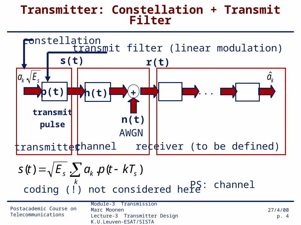
Transmitter: Constellation + Transmit Filter
PS: channel coding (!) not considered here
sk Ea .
r(t)
ka
transmit
pulse
s(t)
n(t)
p(t) +
AWGN
transmitter receiver (to be defined)
h(t)
channel
...
constellationtransmit filter (linear modulation)
k
sks kTtpaEts )(..)(
Postacademic Course on Telecommunications
Module-3 Transmission Marc MoonenLecture-3 Transmitter Design K.U.Leuven-ESAT/SISTA
27/4/00p. 5
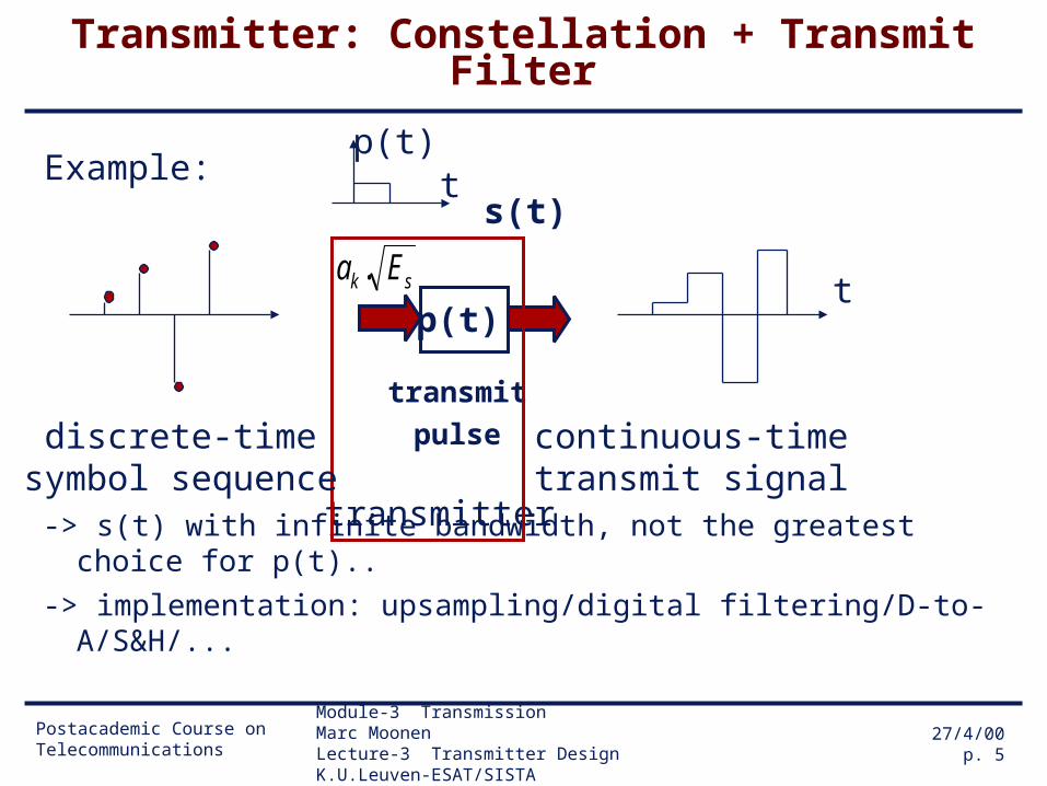
Transmitter: Constellation + Transmit Filter
-> s(t) with infinite bandwidth, not the greatest choice for p(t)..
-> implementation: upsampling/digital filtering/D-to-A/S&H/...
sk Ea .
transmit
pulse
s(t)
p(t)
transmitter
discrete-timesymbol sequence
continuous-timetransmit signal
tp(t)
Example:
t
Postacademic Course on Telecommunications
Module-3 Transmission Marc MoonenLecture-3 Transmitter Design K.U.Leuven-ESAT/SISTA
27/4/00p. 6
Preliminaries: Passband vs. baseband transmission (I)
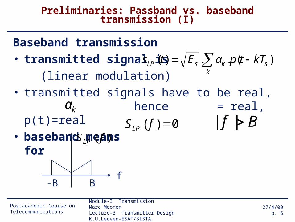
Baseband transmission• transmitted signal is
(linear modulation)• transmitted signals have to be real,
hence = real, p(t)=real• baseband means for
fB-B
0)( fSLPBf ||
)( fSLP
k
sksLP kTtpaEts )(..)(
ka
Postacademic Course on Telecommunications
Module-3 Transmission Marc MoonenLecture-3 Transmitter Design K.U.Leuven-ESAT/SISTA
27/4/00p. 7
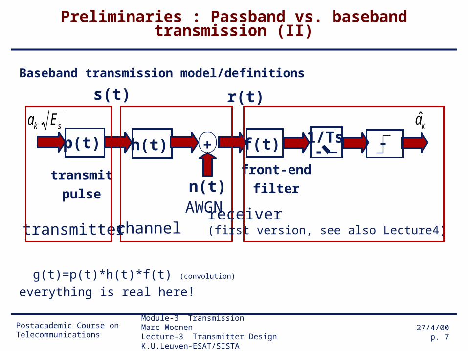
Preliminaries : Passband vs. baseband transmission (II)
Baseband transmission model/definitions
g(t)=p(t)*h(t)*f(t) (convolution)
everything is real here!
sk Ea .
r(t)
ka
transmit
pulse
s(t)
n(t)
p(t) + f(t)
front-end
filter
AWGN
1/Ts
transmitterreceiver (first version, see also Lecture4)
h(t)
channel

Postacademic Course on Telecommunications
Module-3 Transmission Marc MoonenLecture-3 Transmitter Design K.U.Leuven-ESAT/SISTA
27/4/00p. 8
Preliminaries : Passband vs. baseband transmission (III)
Bandpass transmission
transmitted signal is modulated baseband signal
)(tsLP
).2cos( 0tf
fB-B
)( fSLP
)(tsBP
-fof
)( fSBP
fo fo+B
`envelope’
Postacademic Course on Telecommunications
Module-3 Transmission Marc MoonenLecture-3 Transmitter Design K.U.Leuven-ESAT/SISTA
27/4/00p. 9
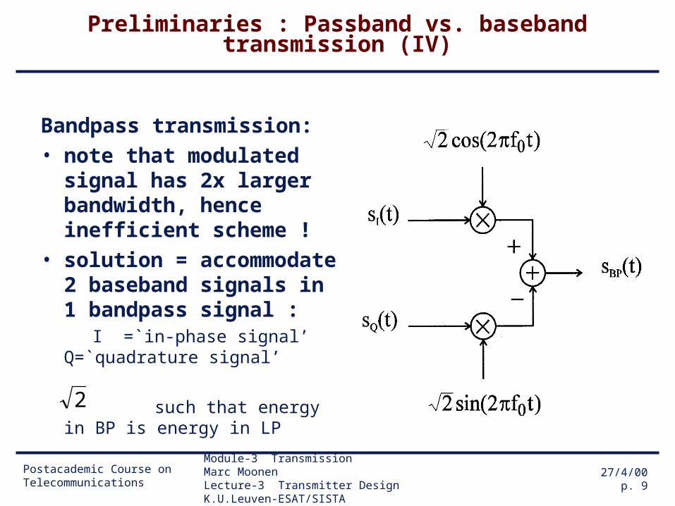
Preliminaries : Passband vs. baseband transmission (IV)
Bandpass transmission:• note that modulated
signal has 2x larger bandwidth, hence inefficient scheme !
• solution = accommodate 2 baseband signals in 1 bandpass signal :
I =`in-phase signal’ Q=`quadrature signal’
such that energy in BP is energy in LP
2
Postacademic Course on Telecommunications
Module-3 Transmission Marc MoonenLecture-3 Transmitter Design K.U.Leuven-ESAT/SISTA
27/4/00p. 10
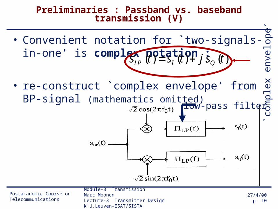
Preliminaries : Passband vs. baseband transmission (V)
• Convenient notation for `two-signals-in-one’ is complex notation :
• re-construct `complex envelope’ from BP-signal (mathematics omitted)
`com
p le x
env
e lo p
e’
)(.)()( tsjtsts QILP
low-pass filter
Postacademic Course on Telecommunications
Module-3 Transmission Marc MoonenLecture-3 Transmitter Design K.U.Leuven-ESAT/SISTA
27/4/00p. 11
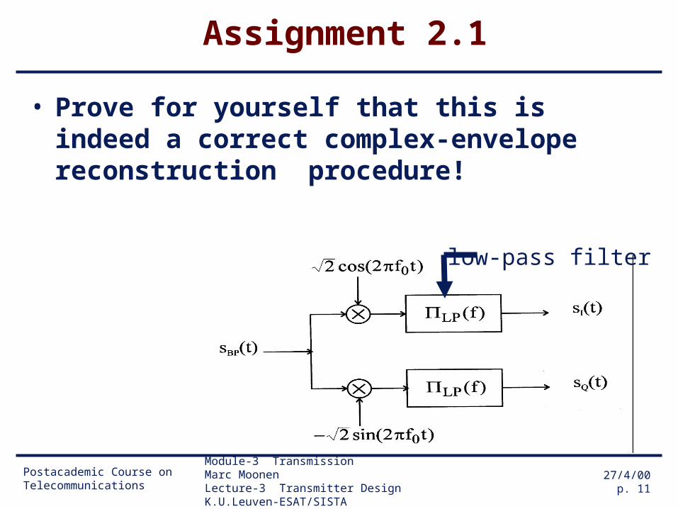
Assignment 2.1
• Prove for yourself that this is indeed a correct complex-envelope reconstruction procedure!
low-pass filter

Postacademic Course on Telecommunications
Module-3 Transmission Marc MoonenLecture-3 Transmitter Design K.U.Leuven-ESAT/SISTA
27/4/00p. 12
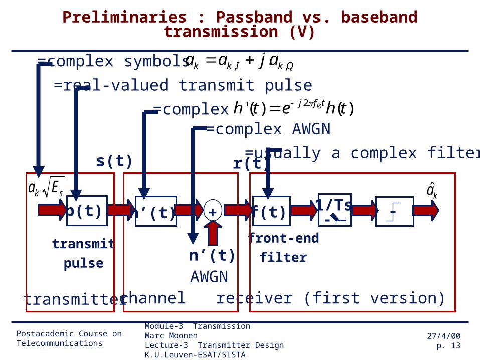
Preliminaries : Passband vs. baseband transmission (VI)
Passband transmission model/definitions
(mathematics omitted):
a convenient and consistent (baseband) model can be obtained, based on complex envelope signals, that does not have the modulation/demodulation steps:
ka
f(t)front-end
filter
1/Ts
receiver (first version)
r(t)
n’(t)
+
AWGN
sk Ea .
transmit
pulse
s(t)
p(t)
transmitter
h’(t)
channel
Postacademic Course on Telecommunications
Module-3 Transmission Marc MoonenLecture-3 Transmitter Design K.U.Leuven-ESAT/SISTA
27/4/00p. 13
Preliminaries : Passband vs. baseband transmission (V)
kaf(t)
front-end
filter
1/Ts
receiver (first version)
r(t)
n’(t)
+
AWGN
sk Ea .
transmit
pulse
s(t)
p(t)
transmitter
h’(t)
channel
=complex symbols
=usually a complex filter
)()(' 02 theth tfj =complex AWGN
=complex
=real-valued transmit pulseQkIkk ajaa ,, .

Postacademic Course on Telecommunications
Module-3 Transmission Marc MoonenLecture-3 Transmitter Design K.U.Leuven-ESAT/SISTA
27/4/00p. 14
Preliminaries : Passband vs. baseband transmission (VI)
• In the sequel, we will always use this baseband-equivalent model, with minor notational changes (h(t) and n(t), i.o. h’(t) and n’(t)). Hence no major difference between baseband and passband transmission/models (except that many things (e.g. symbols) can become complex-valued).
• PS: modulation/demodulation steps are transparent (hence may be omitted in baseband model) only if receiver achieves perfect carrier synchronization (frequency fo & phase). Synchronization not addressed here (see e.g. Lee & Messerschmitt, Chapter 16).
Postacademic Course on Telecommunications
Module-3 Transmission Marc MoonenLecture-3 Transmitter Design K.U.Leuven-ESAT/SISTA
27/4/00p. 15
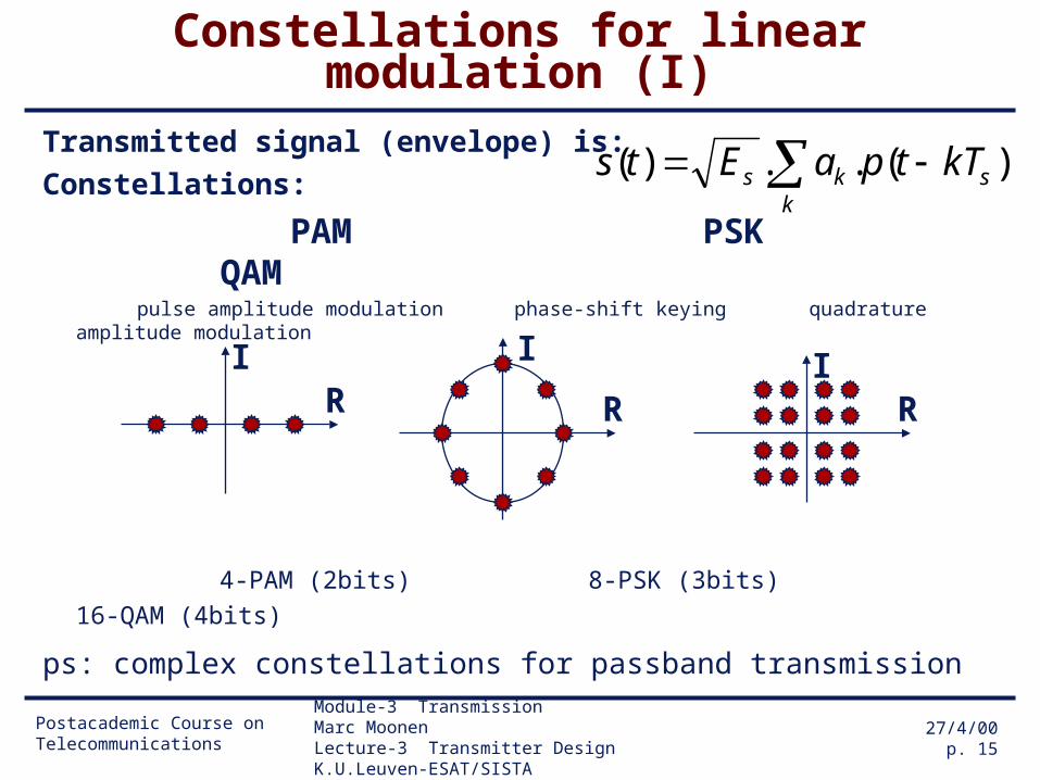
Constellations for linear modulation (I)
Transmitted signal (envelope) is:
Constellations:
PAM PSK QAM pulse amplitude modulation phase-shift keying quadrature amplitude modulation
4-PAM (2bits) 8-PSK (3bits) 16-QAM (4bits)
ps: complex constellations for passband transmission
IR
IR
I
R
k
sks kTtpaEts )(..)(
Postacademic Course on Telecommunications
Module-3 Transmission Marc MoonenLecture-3 Transmitter Design K.U.Leuven-ESAT/SISTA
27/4/00p. 16
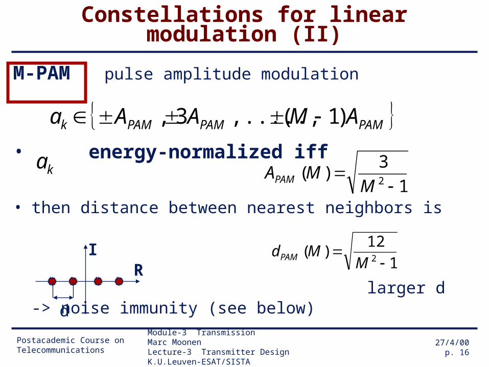
Constellations for linear modulation (II)
M-PAM pulse amplitude modulation
• energy-normalized iff
• then distance between nearest neighbors is
larger d -> noise immunity (see below)
IR
PAMPAMPAMk AMAAa )1(,.....,3,
ka1
3)(
2
MMAPAM
1
12)(
2
MMdPAM
d
Postacademic Course on Telecommunications
Module-3 Transmission Marc MoonenLecture-3 Transmitter Design K.U.Leuven-ESAT/SISTA
27/4/00p. 17
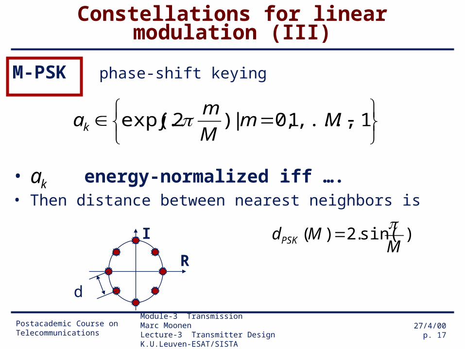
Constellations for linear modulation (III)
M-PSK phase-shift keying
• energy-normalized iff ….• Then distance between nearest neighbors is
1,...,1,0|)2.exp( Mm
M
mjak
ka
)sin(.2)(M
MdPSK
d
I
R

Postacademic Course on Telecommunications
Module-3 Transmission Marc MoonenLecture-3 Transmitter Design K.U.Leuven-ESAT/SISTA
27/4/00p. 18
Constellations for linear modulation (IV)
M-QAM quadrature amplitude modulation
• distance between nearest neighbors is 1
6)(
MMdQAM
d
IR
QAMQAMQAMkQkI AMAAaa )1(,.....,3,, ,, kQkIk ajaa ,, .
)()()( MdMdMd QAMPSKPAM
Postacademic Course on Telecommunications
Module-3 Transmission Marc MoonenLecture-3 Transmitter Design K.U.Leuven-ESAT/SISTA
27/4/00p. 19
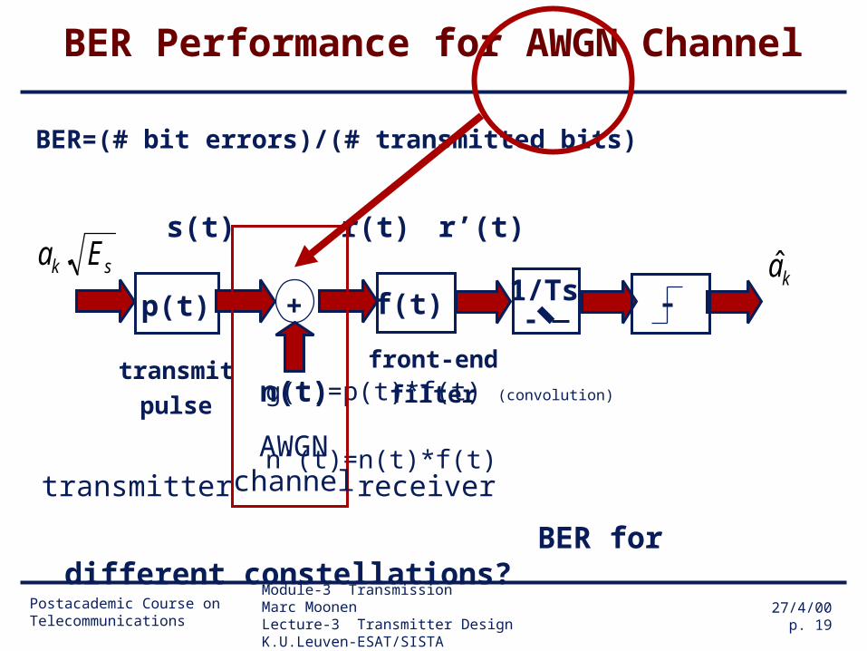
BER Performance for AWGN Channel
BER=(# bit errors)/(# transmitted bits)
g(t)=p(t)*f(t) (convolution)
n’(t)=n(t)*f(t)
BER for different constellations?
r(t)
ka
transmit
pulse
s(t)
n(t)
p(t) +
sk Ea .
f(t)
front-end
filter
AWGNchannel
1/Ts
transmitter receiver
r’(t)

Postacademic Course on Telecommunications
Module-3 Transmission Marc MoonenLecture-3 Transmitter Design K.U.Leuven-ESAT/SISTA
27/4/00p. 20
BER Performance for AWGN Channel
definitions: - transmitted signal
- received signal (at front-end filter)
- received signal (at sampler)
g(t) =p(t)*f(t) = transmitted pulse p(t) filtered by front-end filter
n’(t) =n(t)*f(t) = AWGN filtered by front-end filter
)(')(..)(' tnkTtgaEtrk
sks
k
sks kTtpaEts )(..)(
)()(..)( tnkTtpaEtrk
sks
Postacademic Course on Telecommunications
Module-3 Transmission Marc MoonenLecture-3 Transmitter Design K.U.Leuven-ESAT/SISTA
27/4/00p. 21
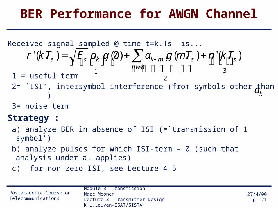
BER Performance for AWGN Channel
Received signal sampled @ time t=k.Ts is...
1 = useful term
2= `ISI’, intersymbol interference (from symbols other than )
3= noise term
Strategy : a) analyze BER in absence of ISI (=`transmission of 1 symbol’)
b) analyze pulses for which ISI-term = 0 (such that analysis under a. applies)
c) for non-zero ISI, see Lecture 4-5
3
2
01
).(').(.)0(..).(' sm
smkkss TknTmgagaETkr
ka

Postacademic Course on Telecommunications
Module-3 Transmission Marc MoonenLecture-3 Transmitter Design K.U.Leuven-ESAT/SISTA
27/4/00p. 22
Transmission of 1 symbol over AWGN channel (I)
BER for different constellations?
ka
transmit
pulse n(t)
p(t) +
sEa .0
f(t)
front-end
filter
AWGNchannel
1/Ts
...take 1 sample at time 0.Tstransmit 1 symbol at time 0.Ts ...

Postacademic Course on Telecommunications
Module-3 Transmission Marc MoonenLecture-3 Transmitter Design K.U.Leuven-ESAT/SISTA
27/4/00p. 23
Transmission of 1 symbol over AWGN channel (II)
Received signal sampled @ time t=0.Ts is..
• `Minimum distance’ decision rule/device :
3
21
0 ).0('0)0(..).0(' sss TngaETr
n
s
s
Mni
s
si
gE
Tr
gE
Tra
)0(.
).0('min
)0(.
).0('ˆ
100

Postacademic Course on Telecommunications
Module-3 Transmission Marc MoonenLecture-3 Transmitter Design K.U.Leuven-ESAT/SISTA
27/4/00p. 24
Transmission of 1 symbol over AWGN channel (III)
`Minimum distance’ decision rule :
Example : decision regions for 16-QAMI
R

Postacademic Course on Telecommunications
Module-3 Transmission Marc MoonenLecture-3 Transmitter Design K.U.Leuven-ESAT/SISTA
27/4/00p. 25
Transmission of 1 symbol over AWGN channel (IV)
Preliminaries :BER versus SER (symbol-error-rate)
• aim: each symbol error (1 symbol = n bits)
introduces only 1 bit error• how? : GRAY CODING
make nearest neighbor symbols correspond to groups of n bits that differ only in 1 bit position…
• …hence `nearest neighbor symbol errors’ (=most symbol errors) correspond to 1 bit error

Postacademic Course on Telecommunications
Module-3 Transmission Marc MoonenLecture-3 Transmitter Design K.U.Leuven-ESAT/SISTA
27/4/00p. 26
Transmission of 1 symbol over AWGN channel (V)
Gray Coding for 8-PSK

Postacademic Course on Telecommunications
Module-3 Transmission Marc MoonenLecture-3 Transmitter Design K.U.Leuven-ESAT/SISTA
27/4/00p. 27
Transmission of 1 symbol over AWGN channel (VI)
Gray Coding for 16-QAM
Postacademic Course on Telecommunications
Module-3 Transmission Marc MoonenLecture-3 Transmitter Design K.U.Leuven-ESAT/SISTA
27/4/00p. 28
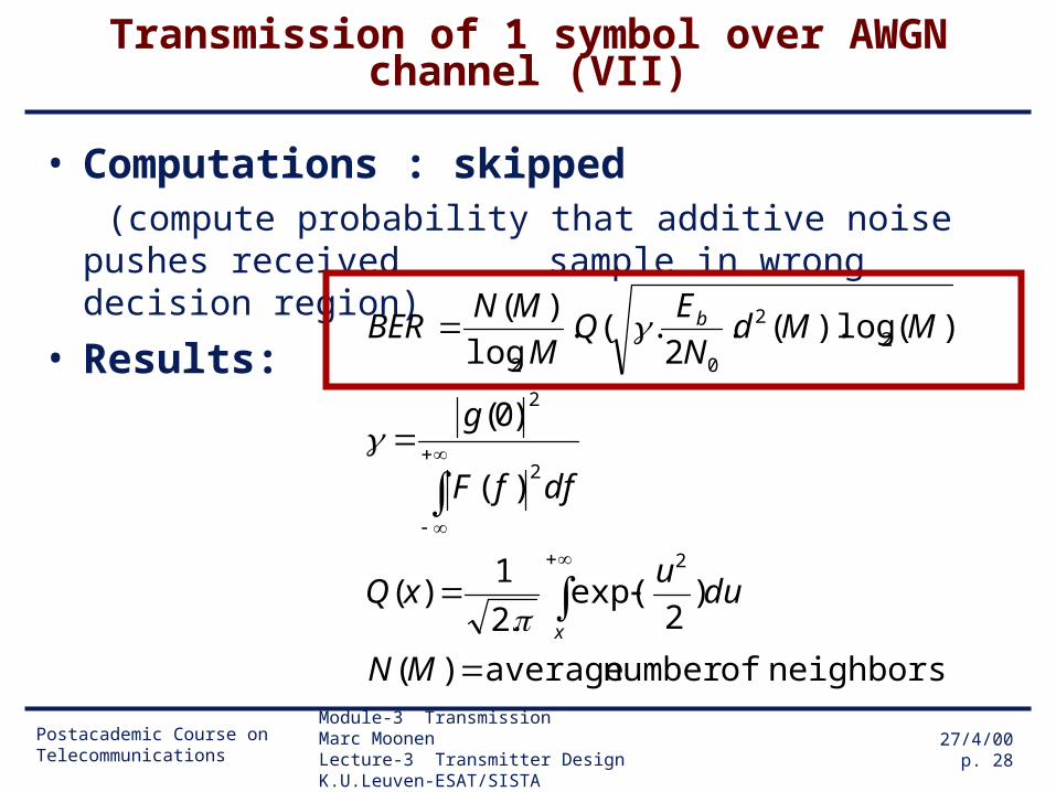
Transmission of 1 symbol over AWGN channel (VII)
• Computations : skipped (compute probability that additive noise pushes received
sample in wrong decision region)
• Results:
neighbors ofnumber average)(
)2
exp(.2
1)(
)(
)0(
)(log).(.2
.(.log
)(
2
2
2
22
02
MN
duu
xQ
dffF
g
MMdN
EQ
M
MNBER
x
b
Postacademic Course on Telecommunications
Module-3 Transmission Marc MoonenLecture-3 Transmitter Design K.U.Leuven-ESAT/SISTA
27/4/00p. 29
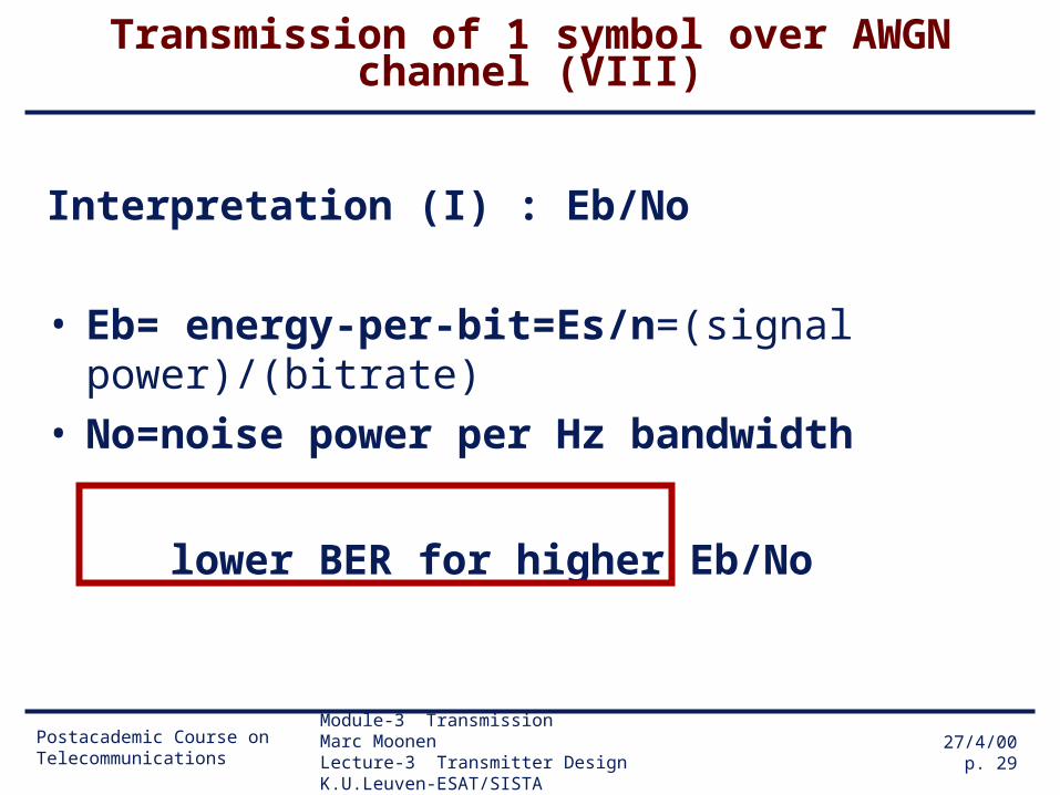
Transmission of 1 symbol over AWGN channel (VIII)
Interpretation (I) : Eb/No
• Eb= energy-per-bit=Es/n=(signal power)/(bitrate)• No=noise power per Hz bandwidth
lower BER for higher Eb/No
Postacademic Course on Telecommunications
Module-3 Transmission Marc MoonenLecture-3 Transmitter Design K.U.Leuven-ESAT/SISTA
27/4/00p. 30
Transmission of 1 symbol over AWGN channel (IX)
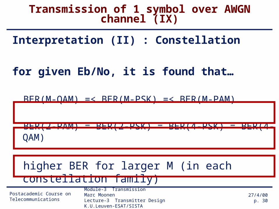
Interpretation (II) : Constellation
for given Eb/No, it is found that…
BER(M-QAM) =< BER(M-PSK) =< BER(M-PAM)
BER(2-PAM) = BER(2-PSK) = BER(4-PSK) = BER(4-QAM)
higher BER for larger M (in each constellation family)
Postacademic Course on Telecommunications
Module-3 Transmission Marc MoonenLecture-3 Transmitter Design K.U.Leuven-ESAT/SISTA
27/4/00p. 31
Transmission of 1 symbol over AWGN channel (X)
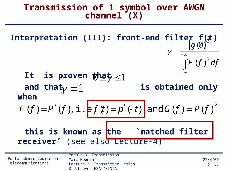
Interpretation (III): front-end filter f(t)
It is proven that
and that is obtained only when
this is known as the `matched filter receiver’ (see also Lecture-4)
dffF
g
2
2
)(
)0(
10 1
)()( and )()( i.e. ,)()(2** fPfGtptffPfF

Postacademic Course on Telecommunications
Module-3 Transmission Marc MoonenLecture-3 Transmitter Design K.U.Leuven-ESAT/SISTA
27/4/00p. 32
Transmission of 1 symbol over AWGN channel (XI)
Interpretation (IV)
with a matched filter receiver, obtained BER is independent of pulse p(t)
Postacademic Course on Telecommunications
Module-3 Transmission Marc MoonenLecture-3 Transmitter Design K.U.Leuven-ESAT/SISTA
27/4/00p. 33
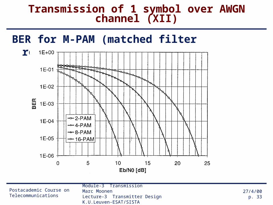
Transmission of 1 symbol over AWGN channel (XII)
BER for M-PAM (matched filter reception)
Postacademic Course on Telecommunications
Module-3 Transmission Marc MoonenLecture-3 Transmitter Design K.U.Leuven-ESAT/SISTA
27/4/00p. 34
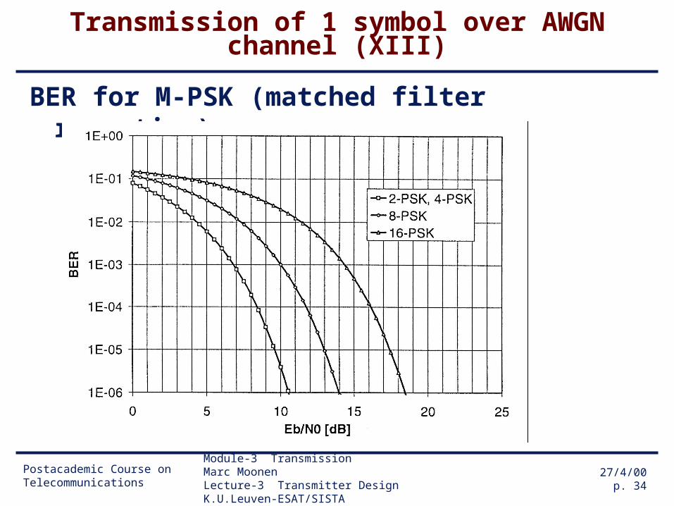
Transmission of 1 symbol over AWGN channel (XIII)
BER for M-PSK (matched filter reception)

Postacademic Course on Telecommunications
Module-3 Transmission Marc MoonenLecture-3 Transmitter Design K.U.Leuven-ESAT/SISTA
27/4/00p. 35
Transmission of 1 symbol over AWGN channel (XIV)
BER for M-QAM (matched filter reception)
Postacademic Course on Telecommunications
Module-3 Transmission Marc MoonenLecture-3 Transmitter Design K.U.Leuven-ESAT/SISTA
27/4/00p. 36
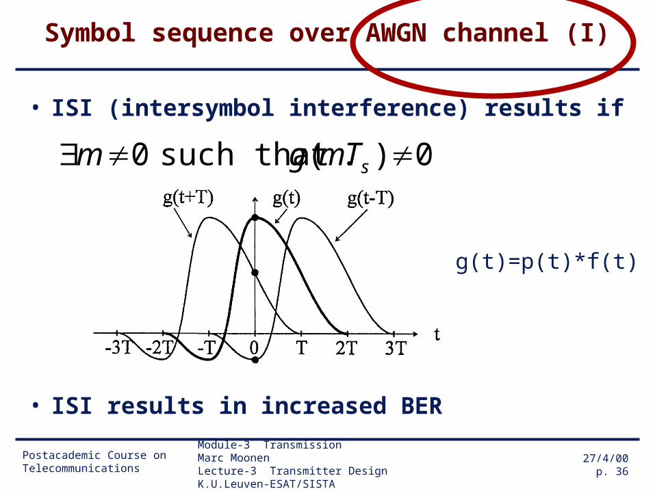
Symbol sequence over AWGN channel (I)
• ISI (intersymbol interference) results if
• ISI results in increased BER
0).( such that 0 sTmgm
g(t)=p(t)*f(t)
Postacademic Course on Telecommunications
Module-3 Transmission Marc MoonenLecture-3 Transmitter Design K.U.Leuven-ESAT/SISTA
27/4/00p. 37
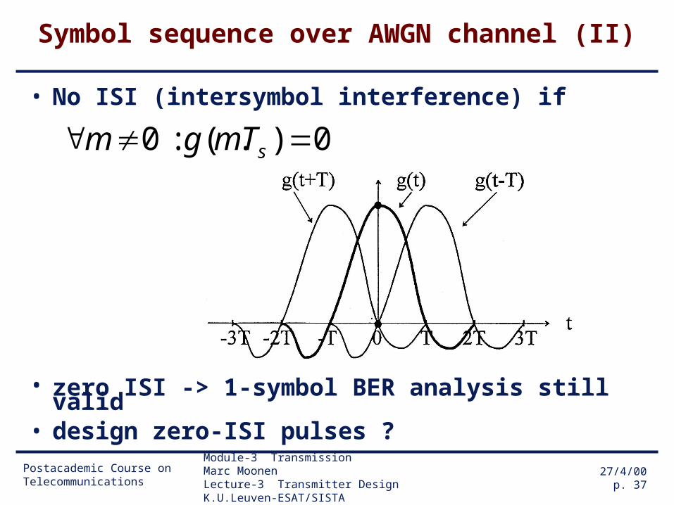
Symbol sequence over AWGN channel (II)
• No ISI (intersymbol interference) if
• zero ISI -> 1-symbol BER analysis still valid• design zero-ISI pulses ?
0).( : 0 sTmgm
Postacademic Course on Telecommunications
Module-3 Transmission Marc MoonenLecture-3 Transmitter Design K.U.Leuven-ESAT/SISTA
27/4/00p. 38
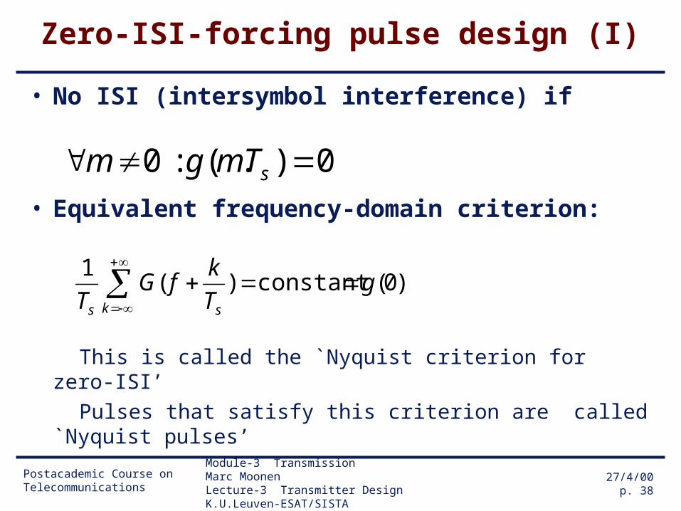
Zero-ISI-forcing pulse design (I)
• No ISI (intersymbol interference) if
• Equivalent frequency-domain criterion:
This is called the `Nyquist criterion for zero-ISI’
Pulses that satisfy this criterion are called `Nyquist pulses’
0).( : 0 sTmgm
)0(constant)(1
gT
kfG
T k ss
Postacademic Course on Telecommunications
Module-3 Transmission Marc MoonenLecture-3 Transmitter Design K.U.Leuven-ESAT/SISTA
27/4/00p. 39
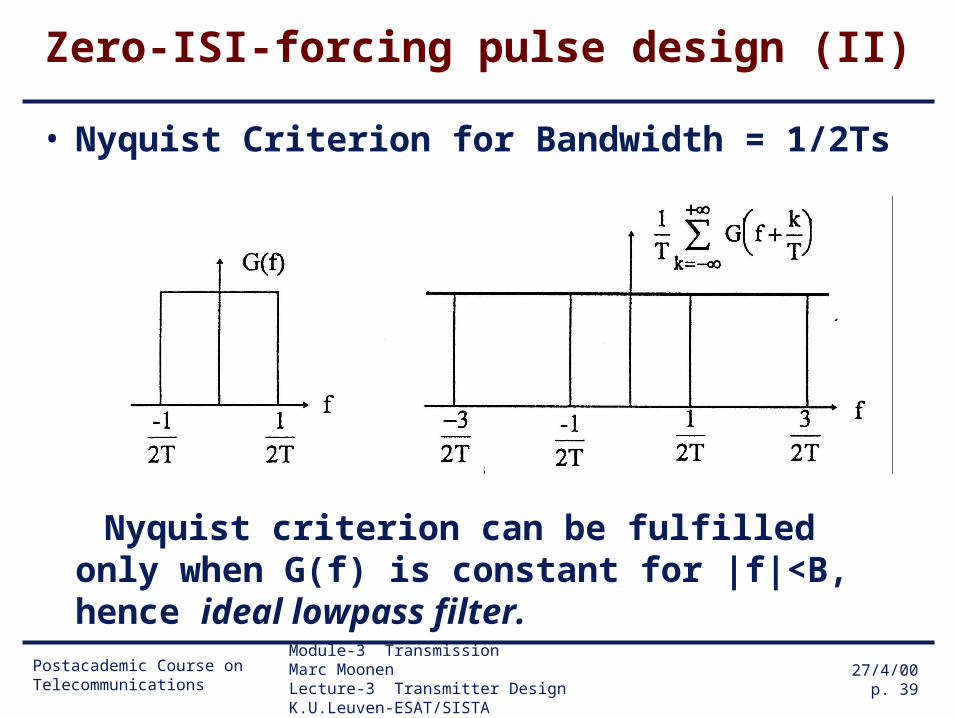
Zero-ISI-forcing pulse design (II)
• Nyquist Criterion for Bandwidth = 1/2Ts
Nyquist criterion can be fulfilled only when G(f) is constant for |f|<B, hence ideal lowpass filter.
Postacademic Course on Telecommunications
Module-3 Transmission Marc MoonenLecture-3 Transmitter Design K.U.Leuven-ESAT/SISTA
27/4/00p. 40
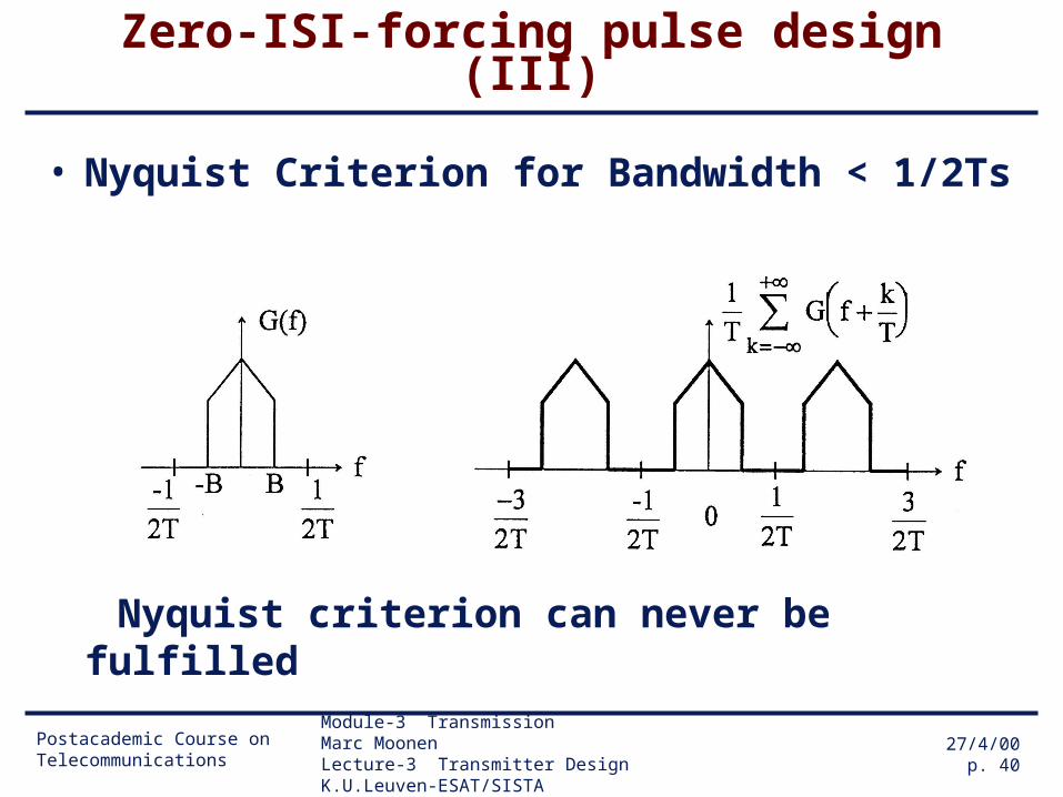
Zero-ISI-forcing pulse design (III)
• Nyquist Criterion for Bandwidth < 1/2Ts
Nyquist criterion can never be fulfilled
Postacademic Course on Telecommunications
Module-3 Transmission Marc MoonenLecture-3 Transmitter Design K.U.Leuven-ESAT/SISTA
27/4/00p. 41
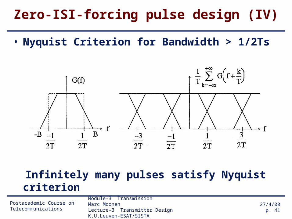
Zero-ISI-forcing pulse design (IV)
• Nyquist Criterion for Bandwidth > 1/2Ts
Infinitely many pulses satisfy Nyquist criterion
Postacademic Course on Telecommunications
Module-3 Transmission Marc MoonenLecture-3 Transmitter Design K.U.Leuven-ESAT/SISTA
27/4/00p. 42
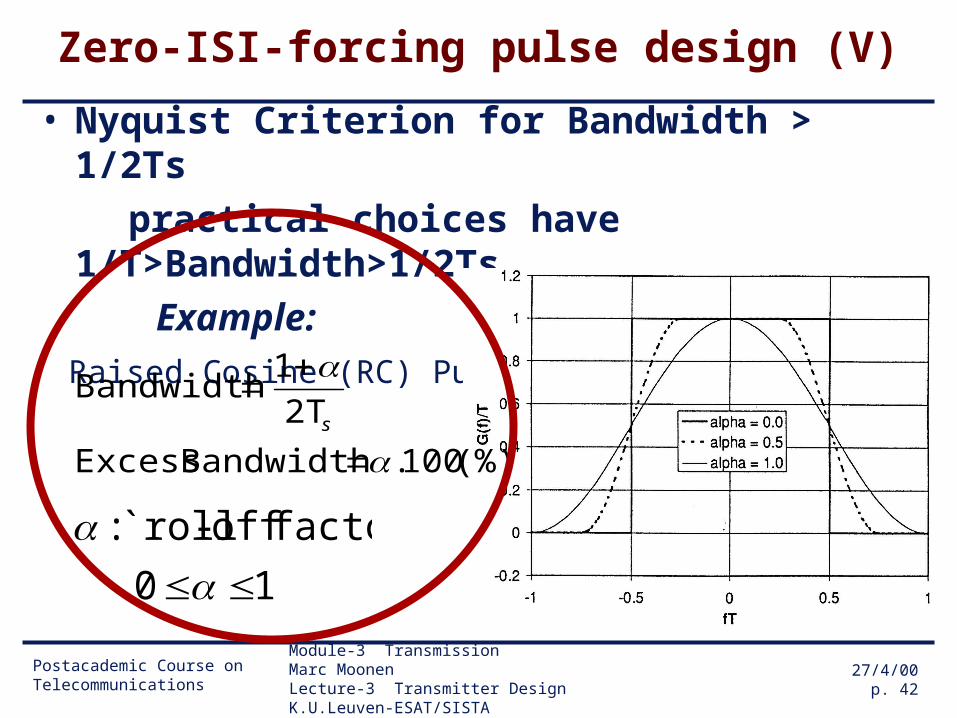
Zero-ISI-forcing pulse design (V)
• Nyquist Criterion for Bandwidth > 1/2Ts
practical choices have 1/T>Bandwidth>1/2Ts
Example:
Raised Cosine (RC) Pulses
10
factor' off-`roll :
(%)100. Bandwidth Excess
2T
1 Bandwidth
s
Postacademic Course on Telecommunications
Module-3 Transmission Marc MoonenLecture-3 Transmitter Design K.U.Leuven-ESAT/SISTA
27/4/00p. 43
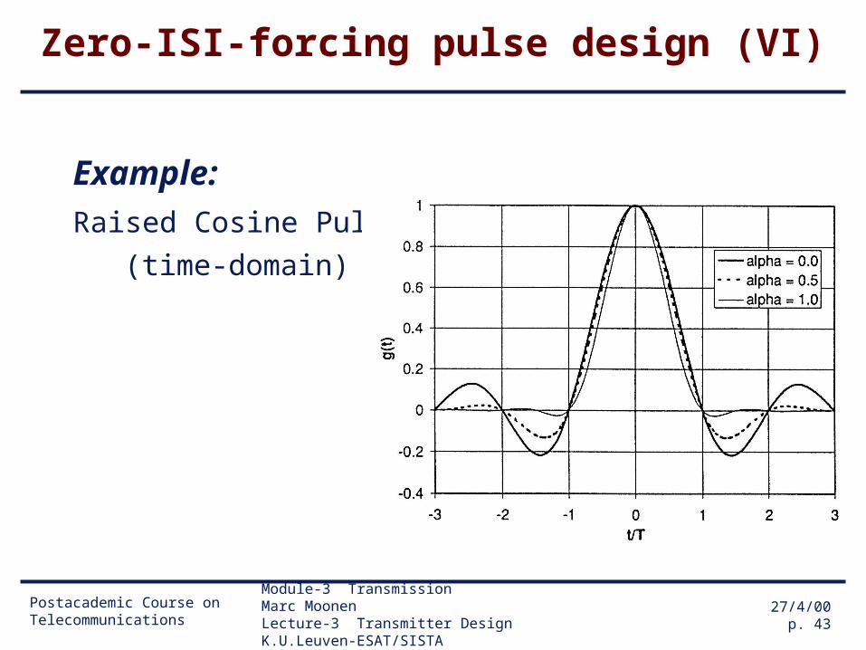
Zero-ISI-forcing pulse design (VI)
Example:
Raised Cosine Pulses
(time-domain)

Postacademic Course on Telecommunications
Module-3 Transmission Marc MoonenLecture-3 Transmitter Design K.U.Leuven-ESAT/SISTA
27/4/00p. 44
Zero-ISI-forcing pulse design (VII)
Procedure:
1. Construct Nyquist pulse G(f) (*)
e.g. G(f) = raised cosine pulse
(formulas, see Lee & Messerschmitt p.190)
2. Construct F(f) and P(f), such that (**)
F(f)=P*(f) and P(f).F(f)=G(f) -> P(f).P*(f)=G(f)
e.g. square-root raised cosine (RRC) pulse
(formulas, see Lee & Messerschmitt p.228)
(*) zero-ISI, hence 1-symbol BER performance
(**) matched filter reception = optimal performance
Postacademic Course on Telecommunications
Module-3 Transmission Marc MoonenLecture-3 Transmitter Design K.U.Leuven-ESAT/SISTA
27/4/00p. 45
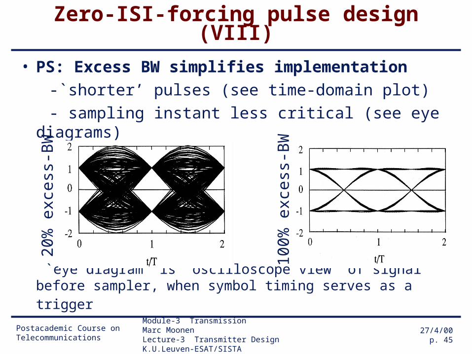
Zero-ISI-forcing pulse design (VIII)
• PS: Excess BW simplifies implementation
-`shorter’ pulses (see time-domain plot)
- sampling instant less critical (see eye diagrams)
`eye diagram’ is `oscilloscope view’ of signal before sampler, when symbol timing serves as a trigger
20%
exc
ess-
BW
100%
exc
ess-
BW
Postacademic Course on Telecommunications
Module-3 Transmission Marc MoonenLecture-3 Transmitter Design K.U.Leuven-ESAT/SISTA
27/4/00p. 46
Zero-ISI-forcing pulse design (IX)
• PPS: From the eye diagrams, it is seen that selecting a proper sampling instant is crucial
(for having zero-ISI)
->requires accurate clock synchronization,
a.k.a. `timing recovery’, at the receiver
(clock rate & phase)
->`timing recovery’ not addressed here
see e.g. Lee & Messerschmitt, Chapter 17
Postacademic Course on Telecommunications
Module-3 Transmission Marc MoonenLecture-3 Transmitter Design K.U.Leuven-ESAT/SISTA
27/4/00p. 47
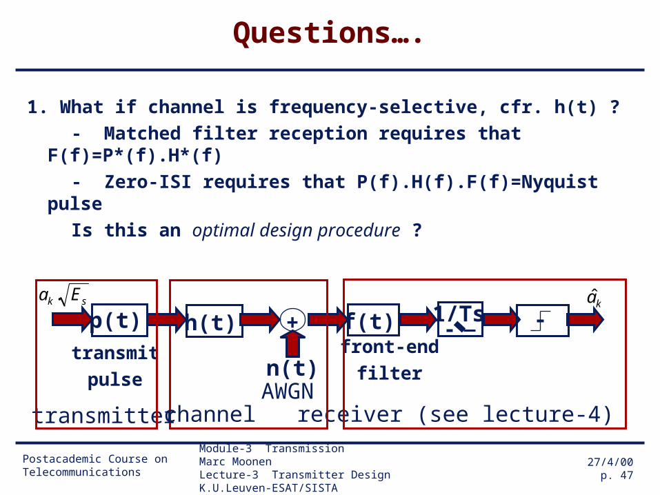
Questions….
1. What if channel is frequency-selective, cfr. h(t) ?
- Matched filter reception requires that F(f)=P*(f).H*(f)
- Zero-ISI requires that P(f).H(f).F(f)=Nyquist pulse
Is this an optimal design procedure ?
ka
f(t)front-end
filter
1/Ts
receiver (see lecture-4)
n(t)
+
AWGN
sk Ea .
transmit
pulse
p(t)
transmitter
h(t)
channel

Postacademic Course on Telecommunications
Module-3 Transmission Marc MoonenLecture-3 Transmitter Design K.U.Leuven-ESAT/SISTA
27/4/00p. 48
Assignment 2.2
Analyze this design procedure for the case where the channel is given as
H(f) = Ho for |f|<B/2
H(f) = 0.1 Ho for B/2<|f|<B
discover a phenomenon known as `noise enhancement’ (=zero-ISI-forcing approach ignores the additive noise, hence may lead to
an excessively noise-amplifying receiver)
ka
f(t)front-end
filter
1/Ts
receiver (see lecture-4)
n(t)
+
AWGN
sk Ea .
transmit
pulse
p(t)
transmitter
h(t)
channel

Postacademic Course on Telecommunications
Module-3 Transmission Marc MoonenLecture-3 Transmitter Design K.U.Leuven-ESAT/SISTA
27/4/00p. 49
Questions….
2. Is the receiver structure (matched filter front-end + symbol-rate sampler + slicer) optimal at all ?
Sampler works at symbol rate. With non-zero excess
bandwidth this is below the Nyquist rate.
Didn’t your signal processing teacher tell you never to do
sample below the Nyquist rate? Could this be o.k. ????
ka
f(t)front-end
filter
1/Ts
receiver (see lecture-4)
n(t)
+
AWGN
sk Ea .
transmit
pulse
p(t)
transmitter
h(t)
channel
Postacademic Course on Telecommunications
Module-3 Transmission Marc MoonenLecture-3 Transmitter Design K.U.Leuven-ESAT/SISTA
27/4/00p. 50
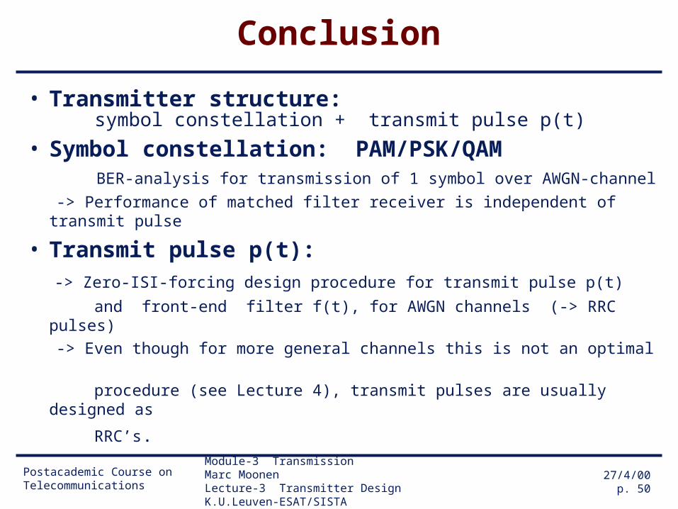
Conclusion
• Transmitter structure: symbol constellation + transmit pulse p(t)
• Symbol constellation: PAM/PSK/QAM BER-analysis for transmission of 1 symbol over AWGN-channel
-> Performance of matched filter receiver is independent of transmit pulse
• Transmit pulse p(t): -> Zero-ISI-forcing design procedure for transmit pulse p(t)
and front-end filter f(t), for AWGN channels (-> RRC pulses)
-> Even though for more general channels this is not an optimal
procedure (see Lecture 4), transmit pulses are usually designed as
RRC’s.


![[Marc Moonen] SVD and Signal Processing III Algor(BookFi.org)](https://img.dokumen.tips/doc/110x75/5529ff984a79590e778b4640/marc-moonen-svd-and-signal-processing-iii-algorbookfiorg.jpg)


