Embed Size (px)
Citation preview
1
27th Dec’13
(REVISED) TECHNICAL SPECIFICATION FOR
THREE PHASE L.T C.T OPERATED ELECTRONIC TRIVECTOR ENERGY METERS (125/5A) OF CLASS 0.5S ACCURACY WITH P.P BOX
1.0 SCOPE :
This specification covers design, engineering, manufacture, assemble, stage testing, inspection and testing before supply and delivery at destination stores of 3 element 4wire C.T Operated L.T Electronic Trivector (DLMS ) Meters of accuracy class 0.5S for the purpose of Tariff Metering.
1.1 It is not the intent to specify completely herein all the details of the
design and construction of material. However the material shall conform in all respects to high standards of engineering, design and workmanship and shall be capable of performing in continuous commercial operation in a manner acceptable to the purchaser, who will interpret the meanings of drawings and specification and shall have the power to reject any work or material which, in his judgment is not in accordance therewith. The offered material shall be complete with all components necessary for their effective and trouble free operation. Such, components shall be deemed to be within the scope of Bidder’s supply irrespective of whether those are specifically brought out in this specification and/or the commercial order or not.
1.2 It is mandatory that in case of all manufacturers, the offered meter shall be ISI marked and bidder shall have to furnish valid BIS certificate along with the offer.
2.0 APPLICATION Consumer meter – DLMS ICS Category “C”. 2.1 STANDARDS: 2.2 IS-14697:1999(2004) Specification for AC Static Transformer operated
Watt Hour & VAR-Hour meters (class 0.5S); IS-15959:2011 Data Exchange for Electricity Meter Reading Tariff & Load Control – Companion Specification CBIP - 304 Manual on Standardization of AC Static Electrical Energy Meter IEC 62052-11 Electricity metering equipment (AC) –General requirements, tests and test conditions -Part 11: Metering equipment; IEC 62053-22 Electricity metering equipment (AC) –Particular requirements - Part-22: Static Meters for Active Energy (Class 0.5S); IEC 62053-23 Electricity metering equipment (AC) –Particular requirements - Part-23: Static Meters for Reactive Energy; IS 15707 Specification for Testing, evaluation, installation & maintenance of AC Electricity Meters-Code of Practice. Guidelines on “Data Exchange for Electricity Meter Reading, Tariff and Load Control – Companion Specification” IEC 62056-21 Electricity metering: Data exchange for meter reading, tariff and load control- Part 21: Direct local data exchange

1
IEC 62056-31 Electricity metering: Data exchange for meter reading, tariff and load control -Part 31: Local Area Network data exchange IEC 62056-61 Electricity metering: Data exchange for meter reading, tariff and load control- Part 61: Object identification system (OBIS) IS: 2705/Part I, II & III: Specification for Current Transformers IS:5133 : Specification for boxes for enclosures to electrical accessories CEA installation and operation of meters regulations with all amendments. Equipment conforming to other internationally accepted standards which ensure equal or higher quality than the standards mentioned above would also be acceptable. in case of conflict the Guidelines on “Data Exchange for Electricity Meter Reading, Tariff and Load Control – Companion Specification” enclosed with this document as annexure shall prevail upon.
3.0 SERVICE CONDITIONS: The equipment to be supplied against this Specification shall be suitable for satisfactory continuous operation under the following tropical conditions.
Sl. No. Location
At various Sub-stations in the state of Andhra
Pradesh i) Max. ambient air temperature (deg.C) 50 ii) Max. ambient air temperature in a closed (deg.C) 60 iii) Min. Ambient air temperature (deg.C) 7.5 iv) Average daily ambient air temperature (deg.C) 3.5 v) Max. Relative Humidity (%) 100 vi) Max. altitude above mean sea level (m) 1000 vii) Average Annual rainfall (mm) 925 viii) Max. wind pressure (kg/sq.m) 200 ix) Isoceraunic level (days per year) 50 x) Seismic level (Horizontal accn.) 0.10g xi) Noise Level 45 Db
Moderately hot and humid tropical climate, conducive to rust and fungus growth. The climatic conditions are prone to wide variations in the ambient conditions. Smoke is also present in the atmosphere. Heavy lightning also occurs during June to October

3
4.0 GENERAL TECHNICAL REQUIREMENTS 4.1 The CT operated meter shall conform to the following specific parameters:
1 Type AMR Compatible Static, 3Ph,4Wire 3X 240V (LTCT)
2 frequency 50 Hz ± 5% 3 accuracy class 0.5S
4 voltage rating Suitable for operation from 240 V Ph-N, 240 V LT CT (3P, 4W)
5 voltage variation (-) 40% to (+) 20%
6 basic current (Ib) & current rating Ib- 5A, Ratio : 125/5 A for LT CT(3P, 4W)
7 maximum continuous current As per IS 14697:1999(2004) 8 starting current 0.1% of Ib
9 power consumption
The active and apparent power consumption, in each voltage circuit, at reference voltage, reference temperature and reference frequency shall not exceed 1. 0 W and 4 VA. The apparent power taken by each current circuit, at basic current, reference frequency and reference temperature shall not exceed 1.0 VA.
10 power factor 0 Lag – Unity – 0 Lead
11 Design
Meter shall be designed with application specific integrated circuit (ASIC) or micro controller; shall have no moving part; electronic components shall be assembled on printed circuit board using surface mounting technology; factory calibration using high accuracy (0.05 class) software based test bench. Assembly of electronic components shall be as per ANSI /IPC-A-610 standard.
12 DLMS test certificate Manufacturer must have test certificate for conformance to DLMS from CPRI of Category - C.
However manufacturer can offer meters which can withstand higher variations.
4.2 ACCURACY: Class of accuracy of meters shall be 0.5S. The accuracy should not drift with time.
4.3 STARTING CURRENT: The meter should start registering the energy at 0.1% Ib and unity power
factor.

4
4.4 MAXIMUM CURRENT:
The rated maximum current of the meter shall be 120% Ib at which the meter purports to meet the accuracy requirements.
4.5 MEASUREMENT OF ENERGY:
The meter should be capable of measuring Fundamental Energy as well Total Energy i.e. Fundamental plus Harmonics energy. Total Energy shall be made available on meter-display and the same only shall be used for billing purpose. Fundamental Energy should be provided in display.
4.6 The meter shall be suitable for lag only tariff. In case of lagging loads, KVAH2 = KWH2 + RKVAH2 and with leading load, KVAH = KWH .Thus RKVAH lead contribution shall be blocked.
5.0 CONSTRUCTIONAL REQUIREMENT/ METER COVER & SEALING
ARRANGEMENT
5.1 Wherever poly carbonate cover is specified, it shall conform to IS 11731 (FH-1category) besides meeting the test requirement of heat deflection test as per ISO 75, glow wire test as per the IS:11000 (part 2/SEC-1) 1984 OR IEC PUB,60695-2-12, Ball pressure test as per IEC--60695-10-2 and Flammability Test As per UL 94 or As per IS 11731(Part-2) 1986.
5.2 CONSTRUCTION
The case, winding, voltage circuit, sealing arrangements, registers, terminal block, terminal cover & name plate etc. shall be in accordance with the relevant standards. The meter should be compact & reliable in design, easy to transport & immune to vibration & shock involved in the transportation & handling. The construction of the meter should ensure consistence performance under all conditions especially during heavy rains / very hot weathers. The insulating materials used in the meter should be non-hygroscopic, non-ageing & have tested quality. The meter should comply latest technology such as Microcontroller or Application Specific Integrated Circuit (ASIC) to ensure reliable performance. The mounting of the components on the PCB should compulsorily be Surface Mounted Technology (SMT) type. Power supply component may be of PTH type. The electronic components used in the meter should be of high quality and there should be no drift in the accuracy of the meter for at least ten years. The circuitry of the meter should be compatible with 16 Bit (or better) ASIC with compatible processor and meter should be based on Digital measuring and sampling technique.
The meter should be housed in a safe, high grade, unbreakable, fire resistant, UV stabilized virgin Polycarbonate/ High Grade Engineering Plastic/Thermosetting Plastic casing of projection mounting type. The meter cover should be transparent, for easy reading of displayed parameters, and observation of operation indicators. The meter base may or may not be transparent, but it should not be black in colour. The meter casing should not change shape, size, and dimensions when subjected to 200 hrs on UV test as per ASTMD 53. It should withstand 650 deg. C. glow wire test and heat deflection test as per ISO 75.
5
5.3 METER CASE AND COVER
The meter should be sealed in such a way that the internal parts of the meter becomes inaccessible and attempts to open the meter shall result in viable damage to the meter cover. This is to be achieved by using continuous Ultrasonic welding on the Meter body, fully flushed between case and cover. In case, ultrasonic welding using plate/strip is used the material of plate/strip should be same as that of cover and base and the strip should flush with meter body. The manufacturers logo should be embossed on the strip / plate. The meter cover should be fixed to the meter base (case) with Unidirectional Screws, so that the same cannot be opened by use of screwdrivers. The meter shall withstand external magnetic influence as per latest amendments of CBIP 304.
5.4 GENERAL :
i) Meters shall be designed and constructed providing reinforced insulation in such a way so as to avoid causing any danger during use and under normal conditions. However, the following should be ensured :
a) Personnel safety against electric shock.
b) Personnel safety against effects of excessive temperature.
c) Protection against spread of fire.
d) Protection against penetration of solid objects, dust and water.
ii) All insulating materials used in the construction of meters shall be non-hygroscopic, non-ageing and of tested quality. All parts that are likely to develop corrosion shall be effectively protected against corrosion by providing suitable protective coating.
iii) The meter shall have an operation indication device such as a
blinking LED/LCD. The operation indicator shall be visible from the front window.
v) The meter shall be supplied with a transparent extended terminal-
block cover (ETBC).
vi) The meter terminal block, the ETBC and the meter case shall ensure reasonable safety against the spread of fire and should not be ignited by thermic overload of live parts in contact with them.
vii) The terminal block shall be of high grade non-hygroscopic, fire-
retardant, low-tracking, fire-resistant, high grade engineering plastic (not Bakelite) which should form an extension of the meter case, meeting the requirement of clause No.6.4 of IS:14697 / Clause No. 4.2.4 of IEC 1036-1996.
viii) A separate test terminal block is not required.
5.5 TERMINAL ARRANGEMENTS:
The terminals in the terminal block shall be of adequate length in order to have proper grip of conductor with the help of screw adjustable metal plates to increase the surface of contact and reduce the contact

6
resistance. The screws shall have thread size not less than M 4 and head having 4-6mm. diameters. The screws shall not have pointed ends at the end of threads. All terminals and connecting screws should be of tinned/nickel plated brass material. The terminals shall be marked properly on terminal block for giving external connections. The internal diameter of terminal hole should be minimum 5.5 mm. The holes in the insulating material shall be of sufficient size to accommodate the insulation of conductor also. The terminal cover shall be transparent High grade Engineering Plastic/Polycarbonate/ Thermosetting Plastic with minimum thickness 2.0 mm and the terminal cover shall be of extended type completely covering the terminal block and fixing holes. The space inside the terminal cover should be sufficient to accommodate adequate length of external cables. A diagram of connections should be provided inside the cover of terminal block. The terminal cover shall be extended such that when it is placed in position it is not possible to approach the connections or connecting wires. The terminals and the screws shall be suitable to carry up to 150% of Imax safely. The terminals shall have suitable construction with barriers and covers to provide secure and safe connections of Current Transformers and Voltage Transformers leads of stranded copper conductors.
5.6 SEALING OF METER:
Proper sealing arrangement should be provided on meter to make it tamper proof and avoid mishandling by unauthorized persons. Meters must be supplied with 2 (two) nos. manufacturer seals between meter base and meter cover at both the sides. The meter terminal block with minimum 1 number sealing screw and one number separate sealing arrangement to the MD reset push button. The RS232 port & optical port should have proper sealing arrangement. The meter should be designed and constructed in such manner to make it pilfer proof once it is sealed. Bidder shall provide patented seals as per CEA Regulation (2006).
5.7 MANUFACTURING PROCESS, ASSEMBLY AND TESTING:
Meters shall be manufactured using latest and „state of the art technology and methods prevalent in electronics industry. The meter shall be made from high accuracy and reliable surface mount technology (SMT) components. All inward flow of major components and sub assembly parts (CT, PT, RTCs / Crystal, LCDs, LEDs, power circuit electronic components etc.) shall have batch and source identification. Multilayer PCB assembly with PTH using surface mounted component shall have adequate track clearance for power circuits. SMT component shall be assembled using automatic „pick-and-place‟ machines, Reflow Soldering oven, for stabilized setting of the components on PCB. For soldered PCBs, cleaning and washing of cards, after wave soldering process is to be carried out as a standard practice. Assembly line of the manufacturing system shall have provision for testing of sub-assembled cards. Manual placing of components and soldering, to be minimized to items, which cannot be handled by automatic machine. Handling of PCB with ICs / C-MOS components, to be restricted to bare minimum and precautions to prevent ESD failure. Complete assembled and soldered PCB should undergo functional testing using Computerized Automatic Test Equipment. Fully assembled and finished meter shall undergo

7
“burn-in” test process for 24 Hours at 55 degree Celsius (Max. temperature to not exceed 60 degree Celsius) under base current (Ib) load condition. Test points should be provided to check the performance of each block/stage of the meter circuitry. RTC shall be synchronized with NPL time at the time of manufacture. Meters testing at intermediate and final stage shall be carried out with testing instruments, duly calibrated with reference standard, with traceability of source and date.
5.8 ENVIRONMENTAL ASPECTS:
Meter shall be designed and constructed to be capable of withstanding all severe stresses and vibration and dust environments likely to be encountered in actual practice as the meter will be installed outdoor in boxes.
If any special precautions etc. are required as the meters are supposed to be installed in outdoor you may please specify them.
5.9 IMMUNITY TO ELECTRO MAGNETIC DISTURBANCE:
The meter shall be designed in such a way that conducted or radiated electromagnetic disturbance as well as electrostatic discharge do not damage or substantially influence the meter. The test report from any standard lab conducting the test as prescribed in the CBIP -304 and IS 14697 and test result to be submitted.
5.10 MEASURING PARAMETERS:
The meter should be capable of measuring the following electric parameters of poly phase supplies in all power factors lagging or leading. The meter should measure 'kWh' and ‘kVArh’ continuously. It should compute kVAh in such a fashion that the leading power factor should be ignored i.e. kVAh calculation is based on Lag only.
1) The parameters kWH, kVARH, kVAH and max. demand shall be
displayed continuously in cyclic order on the meter to enable the Board/consumer to know the above parameters at any instant.
2) At the start of each sequence of display LED/LCD healthiness anomaly shall be displayed.
5.11 Display Parameter (Auto display):
The meter should be capable of displaying the following parameters automatically: (i) Cummulative Active Energy (Import) (ii) Cummulative Reactive Energy (Import) (iii) Cummulative Apparent Energy(Import) (iv) Maximum Demand (Occurrence, Date &Time) (v) Rising Demand with elapsed time (vi) M.D Reset Count (vii) Cumulative M.D (viii) Instantaneous Power Factor (ix) Line Frequency (x) Self Diagnostic (LCD segment check & battery check) (xi) Real time & date (xii) Phase Sequence & phase correspondences

8
(xiii) Connection Check
5.12 Display Parameter (Push Button):
The meter should be capable of displaying the following parameters using push button:
Cummulative Active Energy (Import) (with high resolution) Cummulative Reactive Energy (Import) (with high resolution) Cummulative Apparent Energy(Import) (with high resolution) Maximum Demand (Occurrence, Date &Time) Elapsed Time & Rise in Demand M.D Reset Count Cumulative M.D Previous 11 Nos. M.D Values with Date & Time Instantaneous Power Factor Line Frequency Real Time & Date Phase Voltages (Instantaneous) Phase Current (Instantaneous) Number of Tamper events. Present Tamper Status (PT/CT/Other) First Occurrence with Date & Time Last Occurrence with Date & Time Last Restoration with Date & Time Self Diagnostics (LCD segment check & battery check) Signed Inst. Power Factor – Phase Wise Signed Inst. Active Power Inst. Apparent Power TOD Wise Total Active Energies TOD Wise Apparent Energies TOD Wise Apparent Max. Demand (MD)
5.13 Read out Parameters with CMRI/ RMR :
The Read out parameters with CMRI/ RMR should be present in the meter as per ICS 15959 Cat C.
5.14 MAXIMUM CURRENT:
The maximum current of the meter is 120% Ib at which the meter purports to meet the accuracy requirements.
6.0 DISPLAY:
The meter display shall have 7 digits(complete) for energy counter with alphanumeric digits for parameter identifier and tamper indication with backlit Liquid Crystal Display (LCD) of minimum 10 mm height, wide viewing angle suitable for temperature withstand of 70° C. LCD to be of STN (super twisted numetic) type construction. No decimal is required for main KWh, KVAh, KVarh (lag & lead) display. The data stored in the meters shall not be lost in the event of power failure. The meter shall have Non Volatile Memory (NVM), which does not need any battery backup. The NVM shall have a minimum retention period of 10 years. Meter shall have Scroll Lock facility to display any one desired parameter continuously from display parameters. Auto display cycling of each parameter should be minimum 10-12 Seconds. The auto display cycles shall be continuous. OBIS code in display is optional. It should be possible to easily identify the single or multiple displayed parameters

9
through symbols/legend on the meter display itself or through display annunciation. Push button mechanism should be of high quality and should provide trouble free service for a long span of time. Up and Down scrolling facility should be there for Push Button Mode.
6.1 DISPLAY RESOLUTION :
1. Voltage = 0.1V 2. Current = 0.01A 3. P.F. = 0.001 4. Energy = 0.001 KWH/KVARH/KVAH 5. Demand = 0.1 KVA / KW
6.2 MAXIMUM DEMAND REGISTRATION:
The maximum demand is to be monitored during each demand interval set (30 minutes) and the maximum of these in a month shall be stored. Whenever MD is reset the maximum MD value so registered shall be stored along with date and time. Under the current integration period, the rising demand should be displayed continuously along with the elapsed time. The registered demand and the number of times the MD is reset shall also be displayed and the information stored.
6.3 MD RESET:
The meter should have provision of auto / manual maximum demand resetting.
a) Manually by operation of a button which is to be covered and sealing provision available for such cover.
b) Provision for automatic resetting at the end of certain period may be made available.
c) Manual MD reset facility shall be allowed only once in a day.
6.4 OUTPUT DEVICE:
Energy Meter shall have test output, accessible from the front, and be capable of being monitored with suitable testing equipment while in operation at site. The operation indicator must be visible from the front and test output device shall be provided in the form of LED. Resolution of the test output device shall be sufficient to enable the starting current test in less than 10 minutes. Minimum gap should be maintained between Active & Reactive Test LED.
Note: In the absence of power supply, facility for display of meter reading should be available.
6.5 REAL TIME INTERNAL CLOCK (RTC)
RTC shall be pre-programmed for 15 Years Day/date without any necessity for correction. The maximum drift shall not exceed ± 300 Seconds per year. The clock day/date setting and synchronization shall only be possible through password/Key code command from one of the following:

10
a) Hand Held Unit (HHU) or directly through BCS and this shall authentication from BCS for individual meter.
b) From remote server through suitable communication network with authentication from BCS.
7.0 SELF DIAGNOSTIC FEATURES:
The meter shall be capable of performing complete self-diagnostic check to monitor the circuits for any malfunctioning to ensure integrity of data memory location all the time. If possible, the details of malfunctioning should be recorded in the meter memory. The bidder should furnish the details of self-diagnostic capability feature, viz (i) Memory status, (ii)Battery status (iii) NVM & (iv) and it should be in display.
8.0 LOAD SURVEY CAPABILITY:
The meter should be capable of recording load survey data of Phase wise Voltage, Phase wise current, Active Energy and Apparent Energy Power Factor, kVArh Lag, kVArh Lead, Max. demand KW& kVA.for a period of minimum 90 days for 30-minute integration period. Real time & date should be shown in all the load survey graphs and table.
8.1 TIME OF DAY TARIFF / DEMAND:
The meter offered shall contain provisions for multiple tariff metering ( time of day metering / demand ) . The meter offered should have a real time clock based on a quartz crystal with a battery totally independent of power supply. The meter shall be capable of being set in to minimum of 8 time zones ( optionally more time zones can be offered) in 24 hours cycle to cover morning and evening on and off peak periods separately bb register shall be provided for active energy and demand data. Initially TOD registers for 6 time zones by default shall be programmed as detailed below to capture KWh, KVAh & KVA.
T1: 00.00 hrs. to 06.00 hrs. T2: 06.00 hrs. to 10.00 hrs. T3: 10.00 hrs. to 14.00 hrs. T4: 14.00 hrs. to 18.00 hrs. T5: 18.00 hrs. to 22.00 hrs. T6: 22.00 hrs. to 24.00 hrs. and T0: cumulative month end
and it should be possible for AP-PDCL to invoke / change them through the use of CMRI with 2 level password protection and necessary software should be loaded by the meter supplier into the base computer station. The above time zones should be non-operative and make them operative with CMRI by the meter manufacturer at free of cost as and when required by AP-PDCL.
8.2 COMMUNICATION CAPABILITY:
The meter shall be provided with two ports for communication of the measured/collected data. The hardware port (with sealing facility) compatible with RS 232 specifications which shall be used for remote access through suitable Modem and Optical port. RS232 shall be used

11
for local data downloading through a DLMS protocol with HHU or direct through BCS. Both ports shall support the default and minimum baud rate of 9600 bps. Data downloading time from meter to HHU/PC should be within 2 min for meter data (without load survey) and within 10 min for meter data with load survey. 2 Nos. cables (Flexible shielded universal cable of length 1500 mm ± 10 mm having (i) 9 pin D-type connector with electrical circuit and (ii) USB connector to facilitate downloading of meter data, either on to CMRI/HHU /Laptop for each 50 Nos. meters is required.
8.3 HAND HELD UNIT (HHU): Optional
To enable local reading of meters data a DLMS compliant HHU shall be used. The HHU shall be compatible to the DLMS compliant energy meters that to be procured/supplied on the basis of the specification having at least one USB communication port. Note: No. of HHU’s to be supplied as per the utility requirement from time to time.
8.4 BASE COMPUTER SOFTWARE (BCS):
The BCS should be user friendly. Latest version of Windows based BCS shall be supplied. The data transfer should be reliable and fraud proof. BCS should give all details pertaining to billing and load survey data. The meter condition details should also be transferred into the BCS including abnormalities/anomalies of voltage current conditions or tamper conditions which can occur due to mistake in connections or intentionally done for the purpose of tamper. The software should show electrical conditions existing at the time of reading the meter in tabular forms as well as in graphical format (Phase diagram) i.e. Phase diagram is required for voltage, current & PF only. All the information about energy, maximum demand and their respective TOD register readings, billing register readings and billing history readings should be shown in a manner which user can understand quickly, preferably in tabular format. All the load survey data should be available in numerical as well as graphical format. It should also be possible to view this data in daily, weekly and monthly formats. The load survey graph should show values. All the information about tamper events should be accompanied with date and time stamping along with the SNAPSHOT (details) of the respective electrical conditions. This information should be displayed in the sequence in which it happened, in cumulative format as well as in summary format. The cumulative format should segregate a particular tamper information and summary report should show count of tamper occurrence, restoration and the duration for which meter has remained under tamper condition. In BCS, tamper events must be followed as per Table 32-38 as per Annexure-G. In display, first tamper occurrence & last tamper occurrence & restoration with date & time and total tamper count must be available. The software should be capable of preparing CMRI to read the meter information or to reconfigure the meter for change the setting of the

12
meter as per IS 15959:2011. The BCS should have the facility for ASCII conversion of all recorded meter data. There should be user friendly approach for viewing meter data for the reading collected now or for the reading collected in the past. All information about a particular consumer should be segregated and available at one place so that locating any consumer's past data is easy. It should be possible to locate/retrieve data on the basis of one of the following particulars: a) Consumer ID/Number. b) Meter Sr. No. c) Date of meter reading. d) Location.
The BCS shall have multi level password for data protection and security. The first level should allow the user to enter the system. The different software features shall be protected by different passwords. The configuration of passwords should be user definable. The software installed on one PC should not be copy-able on to another PC.
It is very important that the BCS has the feature to export available data to ASCII format for integrating with the AP-DCL billing system. Here again a wizard should be available whereby user can select file format (for ASCII), what data to export, the field width selection (whether 8 characters or 10 characters, to include decimal point or not, number of digits after decimal point etc). Help should be available with the software so that user can use all the features of the software by just reading the Help contents.
8.5 Data Security: The meter manufacturers are responsible for maintaining the security software up to down loading to the base computer station. 9.0 ENVIRONMENTAL ASPECTS:
Meter shall be designed and constructed to be capable of withstanding all severe stresses and vibration and dust environments likely to be encountered in actual practice as the meter will be installed outdoor in boxes.
If any special precautions etc. are required as the meters are supposed to be installed in outdoor you may please specify them.
10.0 NAME PLATE MARKING:
Every meter shall have a nameplate clearly visible and indelible and distinctly marked in accordance with the relevant Standard mentioning “Category – C”. The following information should appear on an external plate attached to the meter cover. i) Manufacturers Name or trademark and place of manufacture. ii) Designation of type. iii) Number of phases and wires. iv) Serial number of meter. v) Month and year of manufacture. vi) Principal unit of measurement. vii) P.T. Ratio. viii) Basic Current and rated maximum current. ix) C.T. Ratio. x) Reference frequency in Hz. xi) Meter constant (impulse/unit). xii) Class index of meter. xiii) Reference temperature. xiv) “Property of AP-PDCL” xv) Purchaser‟s Order No. & Date. xvi) Guarantee for 5 years from the date of receipt at destination stores xvii) Sign. of insulation. xviii) Bar coding of Serial Number, month

13
& year of manufacture. The name plate shall be provided in such a manner that it is not exposed to the open and is secured against removal.
11.0 IMMUNITY TO ELECTRO MAGNETIC DISTURBANCE:
The meter shall be designed in such a way that conducted or radiated electro- magnetic disturbance as well as electrostatic discharge do not damage or substantially influence the meter. The test report from any standard lab conducting the test as per CBIP304 and test results submitted.
12.0 PERFORMANCE UNDER INFLUENCE QUANTITIES
The meters performance under influence quantities shall be governed by IS 14697:1999 (2004). The accuracy of meter shall not exceed the permissible limits of accuracy as per standard IS 14697:1999(2004)
13.0 GUARANTEED TECHNICAL PARTICULARS:
The technical particulars as detailed in the specification shall be guaranteed and a statement of guaranteed technical particulars shall be furnished in format along with the tender.
14.0 TAMPER & FRAUD MONITORING FEATURES:
The meter shall work satisfactorily under presence of various influencing conditions like External Magnetic Field, Electromagnetic Field, Radio Frequency Interference, Vibrations, Harmonic Distortion, Voltage/Frequency Fluctuations, and Electromagnetic High Frequency Fields etc. The meter shall be immune to abnormal voltage/frequency generating devices and shall record the occurrence and restoration of all tampers and related snapshots as per Annexure – G of IS 15959:2011 The accuracy of meter should not be affected with the application of abnormal voltage/ frequency generating device such as spark discharge of approximately 35 kV. The meters should work even in the presence of any two Potential wires. Meter should work correctly irrespective of phase sequence. Tamper details shall be stored in internal memory for retrieval by authorized personnel through either of the following: a) DLMS compliant HHU. b) Remote access through suitable communication network. c) Direct by PC. Meter should have a continuous and clear indication / annunciation in its display if top cover is removed/open and even refixed (non roll over) and only cover open must be logged in BCS without any restoration. Auto scroll display may be sacrificed for that COVER OPEN . The meter should have features to detect the occurrence and restoration of, at least, the following common abnormal events:
a) Missing Potential: The meter shall be capable of detecting and recording occurrence and
restoration with date and time the cases of Potential failure (one phase or two phases). The meter shall be capable of recording occurrences of missing potential phase wise, When I>2% of Ib and Vref< 80% , which can happen either owing to a PT fuse blowing or due to internal disconnection of a potential lead and its restoration with date and time along with total number of such occurrences during the above period. Further if the

14
voltage falls below 80% of the rated voltage the same shall be recorded. Whenever the potential / current is missed / restored, at that instant the meter should be capable of providing snapshot of Energies, Voltages and Currents at that instant with time & date. All potential missing cases shall be considered as power failure.
b) Current imbalance: The meter shall be capable of detecting and recording occurrence and restoration with date and time of Current unbalance (for more than a defined persistence time).
c) Current Reversal: The meter shall be capable of detecting and recording occurrence and restoration with date and time if the current is flowing in reverse direction in one or more phases. The meter shall continue to record in forwarded direction even in case of CT reversal.
d) Power on/off: The meter shall be capable to record power on /off events in the meter memory. All potential failure should record as power off event. As per DLMS spec, tamper is to be recorded by the meter.
e) Magnetic Influence - The meters shall be immune to tampering
through application of external magnetic fields as per CBIP-304 with latest amendments.
In the event of logging of presence of abnormal magnetic
induction with date & time the positive variation of error may be beyond the limit of 4% but not exceeding a value(e) as given in Note 3.2 under Table 17 (CBIP 304), corresponding to nominal registration of the meter at reference voltage, 150% maximum current and cosØ/sinØ =1, for active/reactive energy meters respectively.
f) Voltage unbalance – Meter shall detect voltage unbalance if there is unbalance in voltages.
g) Over Current – When load condition at any phase i.e. Line current at any phase goes more than defined limit , this will be detected as Over current condition.
h) CT Open – The meter should detect phase wise current circuit open when the circuit is opened from meter side.
i) CT Bypass – The condition should be detected whenever the current terminal is bypassed in the meter
j) Neutral Disturbance – The meter should detect neutral disturbance if
any spurious signal is applied at the meter’s neutral. k) High and Low Voltage: The meter should detect under and over
voltage events respectively if voltage falls / rise from defined limits. l) Cover Open: The meter shall be able to detect cover open occurrence
event if cover is opened in mains on or off condition. Separate legend for cover open event shall be made available on LCD. This legend shall remain in on state till meter reading so that it will come in to notice of meter reader
15
The above shall be selectable and will be in line with IS 15959 : Data Exchange for Electricity Meter Reading, Tariff and Load Control – Companion Specification A Minimum 200 numbers of events preferable (compartment wise) i.e. 100 no. events for occurrences & 100 no. events for restoration with date & time and snapshot should be available in the meter memory. Default occurrence and restoration time shall be 5 minutes. All the tamper information logged by the meter should be available in BCS with snapshot, Date & Time as per Table 39 of IS 15959:2011 with occurrence and restoration. Properly designed meter tamper logic with threshold value, should be provided and clearly explained in the bid. The tamper logic should be capable of discriminating the system abnormalities from source side and load side and it should not log / record tamper due to source side abnormalities.
15.0 TESTS:
15.1 TYPE TESTS FOR METERS:
Meters shall be fully type tested as per relevant Standard (latest version). The type test certificates should be submitted along with the offer. Offer without Type Test Report shall be liable for rejection. The equipment offered (i.e., meters and CTs where applicable) shall be fully type tested at any of the Govt. accredited NABL laboratories by the Bidder as per the relevant standards. The Bidder shall furnish one set of type test reports along with the bid. The date of type tests shall be not older than 3 years as on the date of Bid submission. Bids without type test reports will be treated as non responsive. The DLMS conformance latest certificate should also be enclosed (Confirms to DLMS-ICS-Cat-C specification). Type tests for trivector meters: As per IS 14697and magnetic tests as per CBIP 304 / IEC-687 and IS:15959:2011 (with latest amendments)
15.2 TESTS FOR CURRENT TRANSFORMERS:
As per IS-2705/1992(part-I, II & III) 15.3 TESTS FOR BOXES:
As per IS 14722 and in addition the box material will be tested for withstanding temperatures of boiling water for 5 minutes continuously for non distortion or softening of the material. The successful bidder shall submit the test reports for box within two weeks of clear purchase order.
15.4 ACCEPTANCE AND ROUTINE TESTS:
All acceptance tests as stipulated in the relevant standards shall be carried out by the supplier in presence of purchaser’s representative. All routine tests as in the relevant standards shall be carried out and routine test certificates shall be submitted to each consignee while dispatching the material.

16
The purchaser reserves the right to insist for witnessing the acceptance/routine testing.
The following shall constitute acceptance test for box:
i). Physical verification of dimensions of the box.
ii). Compatibility of the box for housing the meter, and CTs where applicable and ensuring ease of connecting and reading the meter.
15.5 Tests during manufacture: The Bidder shall furnish details of tests
carried out during the process of manufacture and end inspection by the bidder to ensure the desired quality of the equipment to be supplied.
15.6 ADDITIONAL TESTS:
The purchaser reserves the right of having at his own expenses any other tests(s) of reasonable nature carried out at Bidders premises, at site, or in any other place in addition to the aforesaid type, acceptance and routine tests, to satisfy himself that the material comply with the specifications.
In case of failure in any type test, the supplier is required to modify the
design of the material and the material shall be type tested again for the modified design, without any extra cost to the purchaser. No delivery extension shall be given for this additional testing.
The entire cost of testing for the acceptance and routine tests and tests
during manufacture shall be treated as included in the quoted unit price. 15.7 TEST REPORTS / TEST CERTIFICATES:
Record of routine test reports shall be maintained by the Bidder at his works for periodic inspection by the purchaser’s representative.
Test certificates of tests conducted during manufacture shall be
maintained by the Bidder. These shall be produced for verification as and when desired by the purchaser.
15.8 TEST FACILITIES:
The tests shall be carried out as per relevant Standards and test certificates shall be furnished for approval. The Bidder shall indicate the details of the equipment available with him for carrying out the various tests as per relevant Standards. The bidder shall indicate the sources of all materials.
Note: The Meters used for conducting tests shall be calibrated periodically at reputed Government Accredited Test Laboratories and test certificates shall be available at works for verification by purchasers representative.
15.9 SUBMISSION OF SAMPLE & DOCUMENTS
4 nos. sample meters (without CTs and box) having all the mentioned features, BCS with allied software and sample of seal etc. along with the Type Test Certificates, DLMS Certificate and with the test results and ISI
17
Certificate, Tamper Logic, Display Parameters List is to be submitted to CGM/P&MM/AP-DCL.
Offer will not be accepted without submission of sample and the Tender will not be opened. Any other accessories required for observing the performance & capabilities of the Meter are to be submitted along with offer.
16.0 INSPECTION: 16.1 The purchaser’s representative shall, at all times, be entitled to have
access to the works and at all places of manufacture where equipment is offered, and manufactured and the representative shall have full facilities for unrestricted inspection of the bidder’s works, raw materials and process of manufacture and conducting necessary tests as detailed herein.
16.2 The Bidder shall keep the purchaser informed in advance of the time of
starting and of the progress of manufacture of the offered equipment in its various stages so that arrangements can be made for inspection.
16.3 The supplier shall give 15 days advance intimation to enable the
purchaser to depute his representative for witnessing acceptance and routine tests.
16.4 No material shall be dispatched from its point of manufacture before it
has been satisfactorily inspected and tested, unless the inspection is waived off, by the purchaser in writing.
16.5 The acceptance of any quantity of material shall in no way relieve the
Bidder of any of his responsibilities for meeting all requirements of the specification, and shall not prevent subsequent rejection if such material is later found to be defective.
16.6 NOTE FOR FOREIGN BIDDERS:
The bidder shall indicate the name(s) of reputed inspection agencies and the inspection charges clearly for each lot. The inspection charges will be borne by the supplier. However the purchaser reserves the right to appoint at its cost any inspection agency to carry out the inspection.
17.0 QUALITY ASSURANCE PLAN:
The bidder shall invariably furnish the following information along with his bid, failing which his bid shall be liable for rejection. Information shall be separately given for individual type of material offered.
i) The structure of organization.
ii) The duties and responsibilities assigned to staff ensuring quality of work.
iii) The system of purchasing, taking delivery and verification of materials.
iv) The system for ensuring quality of workmanship.
v) The quality assurance arrangements shall conform to be relevant requirements of ISO 9001 or ISO 9002 as appropriate.
18
vi) Statement giving list of important raw materials names of sub-suppliers for the raw materials, list of standards according to which the raw materials are tested. List of test normally carried out on raw materials in presence of Bidder’s representative, copies of test certificates.
vii) Information and copies of test certificates as in (vi) above in respect of bought out accessories.
viii) List of manufacturing facilities available.
ix) Level of automation achieved and list of areas where manual procession exists.
x) List of areas in manufacturing process, where stage inspections are normally carried out for quality control and details of such tests and inspections.
xi) Lists of testing equipment available with the bidder for final testing of equipment specified and test plant limitation. If any, vis-a-vis the type, special acceptance and routine tests specified in the relevant standards. These limitations shall be very clearly brought out in schedule of deviations from specified test requirements.
The successful Contractor shall within 30 days of placement of order, submit following information to the purchaser.
i. List of raw materials as well as bought out accessories and the names of sub suppliers selected from those furnished along with offers.
ii. Type test certificates of the raw materials and bought out accessories if required by the purchaser.
iii. Quality assurance plan (QAP) with hold points for purchaser’s inspection. The quality assurance plan and purchasers hold points shall be discussed between the purchaser and Contractor before the QAP is finalized.
The Contractor shall submit the routine test certificates of bought out accessories and central excise asses for raw material at the time of routine testing if required by the purchaser and ensure that the quality assurance requirements of specification are followed by the sub-contractor.
The quality assurance programme shall give a description of the quality system and quality plans with the following details.
A) Quality System:
The structure of the organisation. The duties and responsibilities assigned to staff ensuring quality of
work. The system for purchasing, taking delivery and verification of
materials. The system for ensuring quality workmanship. The system for control of documentation. The system for the retention of records. The arrangement for the contractor’s internal auditing.

19
A list of administration and work procedures required to achieve and verify contract’s quality requirements. These procedures shall be made readily available to the purchaser for inspection on request.
B) Quality Plans:
An outline of the proposed work and programme sequence. The structure of the contractors organisation for the contract. The duties and responsibilities assigned to staff ensuring quality of
work. Hold and Notification points. Submission of Engineering documents required by the Specification. The inspection of materials and components on receipt. Reference to the contractors work procedures appropriate to each
activity. Inspection during fabrication/Construction. Final inspection and test.
18.0 DOCUMENTATION: 18.1 All drawings shall conform to International Standards Organisation (ISO)
‘A’ series of drawings sheet/India Standards Specifications IS :656. All drawings shall be in ink and suitable for micro filming. All dimensions and data shall be in S.I. Units.
18.2 LIST OF DRAWINGS AND DOCUMENTS:
The bidder shall furnish the followings along with bid:
i) Two sets of drawings showing clearly the general arrangements, fitting details, electrical connections etc.
ii) Technical leaflets (users manual giving operating instructions.) iii) Dimensional drawings of the box for each quoted item. iv) Dimensional drawings of the LT CTs where applicable for the quoted
item. 18.3 The manufacturing of the equipment shall be strictly in accordance with
the approved drawings and no deviation shall be permitted without the written approval of the purchaser. All manufacturing and fabrication work in connection with the equipment prior to the approval of the drawing shall be at the supplier’s risk.
18.4 Approval of drawings/work by purchaser shall not relieve the supplier of
his responsibility and liability for ensuring correctness and correct interpretation of the drawings for meeting the requirements of the latest revision of application standards, rules and codes of practices. The equipment shall conform in all respects to high standards of engineering, design, workmanship and latest revisions of relevant standards at the time of ordering and purchaser shall have the power to reject any work or materials which, in his judgment is not in full accordance therewith.
18.5 The successful Bidder shall, within 2 weeks of placement of order,
submit three sets of final versions of all the drawings as stipulated in the purchase order for purchaser’s approval. The purchaser shall communicate his comments/ approval on the drawings to the supplier

20
within two weeks. The supplier shall, if necessary, modify the drawings and resubmit three copies of the modified drawings for their approval. The supplier shall submit 3 prints with good quality of the approved drawings for purchaser’s use within one week.
18.6 The successful bidder shall furnish a sample of box duly mounting the
meter and CTs where applicable within two weeks of clear purchase order along with type tests certificates as per Clause 6.1.3. Supplies shall commence only after approval of these.
18.7 Eight sets of operating manuals/technical leaflets shall be supplied to
each consignee for the first instance of supply (The total no. of consignee is 5).
18.8 One set of routine test certificates shall accompany each dispatch
consignment. 18.9 The acceptance test certificates in case pre-dispatch inspection is
routine, test certificates in cases where inspection is waived shall be got approved by the purchaser.
19.0 PACKING & FORWARDING: 19.1 The equipment shall be packed in crates suitable for vertical/horizontal
transport as the case may be and suitable to withstand handling during transport and outdoor storage during transit. The supplier shall be responsible for any damage to the equipment during transit, due to improper and inadequate packing. The easily damageable material shall be carefully packed and marked with the appropriate caution symbol. Wherever necessary, proper arrangement for lifting, such as lifting hooks etc., shall be provided. Any material found short inside the packing cases shall be supplied immediately by supplier without any extra cost.
19.2 Each consignment shall be accompanied with a detailed packing list
containing the following information.
a) Name of the consignee. b) Details of consignment. c) Destination. d) Total weight of consignment. e) Handling and packing instructions. f) Bill of Material indicating contents of each package.
19.3 The supplier shall ensure that the packing list and bill of materials are
approved by the purchaser before dispatch. 19.4 The packing shall be done as per the manufacturer’s standard practice.
However, he should ensure the packing is such that, the material should not get damaged during transit by Rail/Road.
19.5 The marking on each package shall be as per the relevant Standards and
shall also contain PO reference, Name of the supplier, make, meter type and meter serial No.

21
20.0 QUANTITY AND DELIVERY REQUIREMENTS:
The quantity and delivery requirements indicated schedule.
21.0 SUPERVISION SERVICES: NIL
The purchaser will arrange for unloading of the consignments. 22.0 MANDATORY SPARES & TOOLS:
The bidder shall give the list of spares required for the equipment along with price list for them & shall keep a reasonable stock of the same during the warranty period. The bidder shall indicate the sources of spares like battery packs, interfacing cables in India and also mention the service agencies.
23.0 TECHNICAL DEVIATIONS:
Any deviation in Technical Specification shall be specifically and clearly indicated in the enclosed Technical deviation format.
24.0 GUARANTEE: 24.1 The material should be guaranteed for satisfactory operation for a period
of 5 years from the date of receipt of material at destination stores by the consignee in good condition. During the guarantee period if the meter while in its normal operation is found defective, it shall be replaced by the supplier with a new meter free of cost with in 15 days. If the meter is not replaced within 30 days of intimation the supplier should note that the guarantee period will be extended to that extent by the number of days delayed beyond 30 days. If the tenderer does not replace within 180 days the cost of the meter(s) will be recovered from the existing bills/ future bills/ Bank Guarantees available AP-PDCL. It is in suppression of Clause 1.22.1 © of section – I General and Financial Terms and conditions for supply of material in the booklet enclosed.
24.2 If the failure after erection and commissioning at site is more than 5%
the AP-PDCL reserves the right to cancel the balance quantity of the order or take such suitable action as deemed fit. Minor defects during transit may be permitted to attend to in stores/ MRT Lab.
25.0 GUARANTEED TECHNICAL PARTICULARS
The Bidder shall furnish the guaranteed Technical Particulars as per enclosed Annexure for L.T Electronic Trivector Meters, Annexure for LT CTs used in meters, & Annexure for Box used for meter and submit the same with the Tender.
26.0 PERFORMANCE SECURITY: i) Within Fifteen (15) days of receipt of the notification of Contract award.
The successful Bidder will furnish to the Purchaser the performance security for an amount 10% of the contract value for proper fulfillment of the contract, which will include the warranty period, and completion of performance obligations including Warranty obligations. The Performance Security will cover 6 months beyond the date of completion of performance obligations including Warranty obligations.

22
ii) In the event of any correction of defects or replacement of defective material during the warranty period, the warranty for the corrected / replaced material will be extended to a further period of 12 months and the Performance Bank Guarantee for proportionate value will be extended 6 months over and above the extended warranty period. iii) The proceeds of the performance security will be payable to the purchaser as compensation for any loss resulting from the supplier’s failure to complete its obligations under the contract.
iv) The performance security will be ….
a) A bank guarantee issued by a nationalized bank acceptable to the purchaser, in the form provided in the bidding documents.
b) A banker’s cheque or crossed DD or Pay order payable at the head quarter of the purchaser in favour of the Purchaser i.e., Pay officer, AP-PDCL, drawn on any Nationalised bank.
v) The performance security will be discharged by the purchaser and returned to the supplier not later than sixty (60) days after the expiry date.
vi) Failure of the successful Bidder to comply with the above requirement will entail cancellation of the award and forfeiture of the Bid Security.
27.0 GENERAL:
a) Principle of operation of the meter, outlining the methods and stages of computation of various parameters starting from input voltage and current signals including the sampling rate if applicable shall be furnished by the bidder.
b) The bidder shall indicate the method adopted to transform the voltage and current to the desired low values with explanation on devices used such as CT, VT or Potential divider as to how they can be considered superior in maintaining ratio and phase angle for variation of influence quantities during its service period.
c) The bidder shall furnish details of memory used in the meter.
d) Details of testing facilities:
The manufacturer laboratory must be well equipped for testing of the meters. They must have computerized standard power source and standard equipment calibrated not later than a year (or as per standard practice). The details of testing facilities available for conducting (a) The routine tests and (b) Acceptance tests shall be furnished in a statement. Bids without these details will be treated as Non responsive.
23
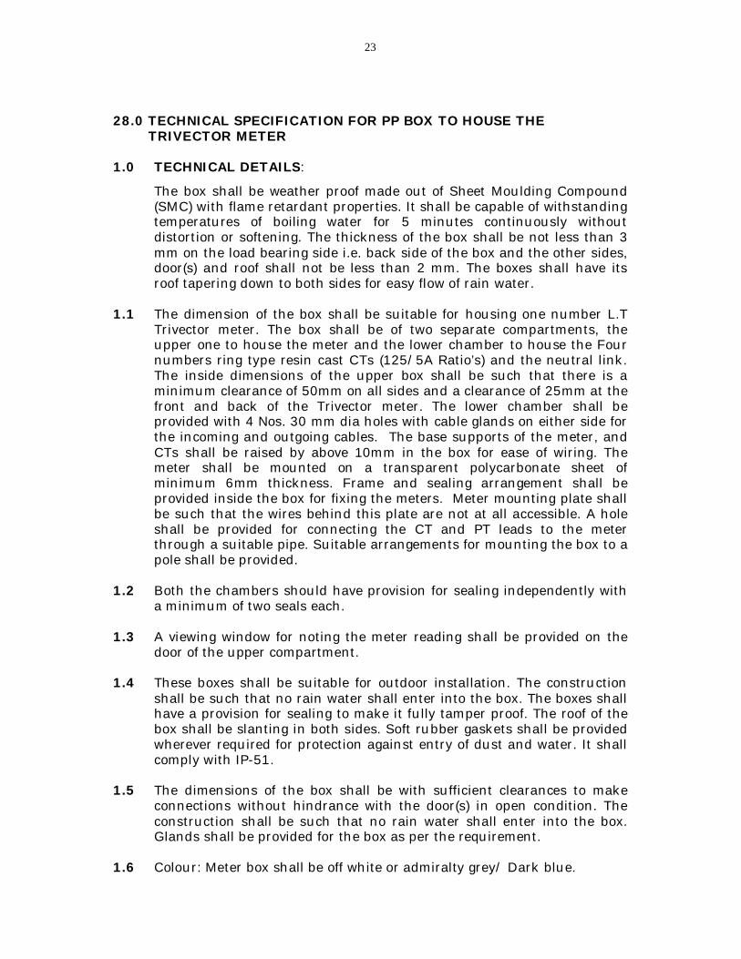
28.0 TECHNICAL SPECIFICATION FOR PP BOX TO HOUSE THE TRIVECTOR METER 1.0 TECHNICAL DETAILS:
The box shall be weather proof made out of Sheet Moulding Compound (SMC) with flame retardant properties. It shall be capable of withstanding temperatures of boiling water for 5 minutes continuously without distortion or softening. The thickness of the box shall be not less than 3 mm on the load bearing side i.e. back side of the box and the other sides, door(s) and roof shall not be less than 2 mm. The boxes shall have its roof tapering down to both sides for easy flow of rain water.
1.1 The dimension of the box shall be suitable for housing one number L.T
Trivector meter. The box shall be of two separate compartments, the upper one to house the meter and the lower chamber to house the Four numbers ring type resin cast CTs (125/5A Ratio’s) and the neutral link. The inside dimensions of the upper box shall be such that there is a minimum clearance of 50mm on all sides and a clearance of 25mm at the front and back of the Trivector meter. The lower chamber shall be provided with 4 Nos. 30 mm dia holes with cable glands on either side for the incoming and outgoing cables. The base supports of the meter, and CTs shall be raised by above 10mm in the box for ease of wiring. The meter shall be mounted on a transparent polycarbonate sheet of minimum 6mm thickness. Frame and sealing arrangement shall be provided inside the box for fixing the meters. Meter mounting plate shall be such that the wires behind this plate are not at all accessible. A hole shall be provided for connecting the CT and PT leads to the meter through a suitable pipe. Suitable arrangements for mounting the box to a pole shall be provided.
1.2 Both the chambers should have provision for sealing independently with
a minimum of two seals each. 1.3 A viewing window for noting the meter reading shall be provided on the
door of the upper compartment. 1.4 These boxes shall be suitable for outdoor installation. The construction
shall be such that no rain water shall enter into the box. The boxes shall have a provision for sealing to make it fully tamper proof. The roof of the box shall be slanting in both sides. Soft rubber gaskets shall be provided wherever required for protection against entry of dust and water. It shall comply with IP-51.
1.5 The dimensions of the box shall be with sufficient clearances to make
connections without hindrance with the door(s) in open condition. The construction shall be such that no rain water shall enter into the box. Glands shall be provided for the box as per the requirement.
1.6 Colour: Meter box shall be off white or admiralty grey/ Dark blue.

24
2.0 THE CONTENTS OF THE BOX ARE AS FOLLOWS: 2.1 Viewing Window: Viewing Window made of a scratch and break resistant
transparent polycarbonate/engineering plastic/toughened glass shall be provided on the door for meter reading without inconvenience. The minimum thickness of viewing window shall be 3mm. The viewing window should have a shade to protect the meter display from the direct sunlight.
There should not be any ingress of moisture through this window into the
box. 2.2 Internal hinges: A minimum of 2 Nos. internal hinges well protected
against corrosion shall be provided for each door. The hinges of the door should be concealed and they shall be fixed to the flanges provided to the base and cover of the box in such a manner that the door opens by a minimum of 90 degrees.
2.3 Handle: Suitable handle(s) or knob shall be provided for opening the box
door(s). 2.4 Earthing Bolt: 8mm dia GI bolt with 2nos washers for earthing all metal
parts used for fixing the meter shall be provided. 2.5 Fixing arrangement: While fixing the meter in the box, screws should
not protrude outside. Suitable arrangements for mounting the box to a pole or wall shall be provided.
2.6 Latch : Each door shall be provided with latch or a ‘U’ clamp to secure it
with the base of the box. 2.7 Sealing arrangement: The box shall have provision for minimum 2 nos.
seals to each door to make it fully tamper proof. 2.8 Printing: The Purchase Order No. & Month/Year of manufacturing shall
be engraved with letters “AP-PDCL” on the top cover of the box. The name of the manufacture shall be engraved/metallic sheet duly riveted on the bottom half of the box. The words of guarantee period of ‘5’ Years’ must also be etched on the name plate in Red Colour. A blank sticker shall also be fixed on the meter for the use of field staff to indicate the service No., meter constant, CT ratio etc.
2.9 The fixing arrangements shall not be complex and it shall be easily
approachable for connections when the door(s) in open condition and is completely tamper proof once it is sealed.
2.10. Wiring: The internal wiring inside the box shall be done neatly with 90
degrees bends with flexible PVC multi stranded copper wire of 2.5sq.mm (4 core or 10 core) maintaining the color code R-Y-B and with necessary looping (Grey/Black may be used for neutral).All potential wires shall pass through one duct and all currents wire shall pass through another duct from CT chamber to meter chamber.
2.11 Dimensional drawing giving details of meter box shall be submitted.

25
29.0 SPECIFICATION FOR RESIN CAST RING TYPE CURRENT TRANSFORMER
1.1 The resin cast ring type LT Current Transformers conforming to IS-
2705/1992 (Part I,II & III) or the latest version thereof, are of class 0.5S accuracy, 1VA burden for use in conjunction with -/1A Energy meters being supplied and are to be installed in a moulded box.
1.2 Ratings: The Current Transformers shall be of the following details. Type Resin cast ring type LT CTs
(without bar) Capacity 125/5A a) Number of C.T’s b) Rated Voltage c) No. of Cores d) Rated Burden e) Rated continuous Thermal Current temperature rise over ambient
f) One minute withstand Power Frequency Voltage
4 No’s. 440V One 1VA As per IS 2705/1992 or latest version thereof 3Kv
Class of Accuracy 0.5S Material i) Core
ii) Conductor
iii) Insulation
iv) Base
High grade non-ageing electrical low loss core of superior CRGO
silicon sheet steel Super enameled copper wire
2/1.22 mm
MS Hot dip galvanized
Secondary Termination Terminals S1 & S2 shall be clearly marked

26
ACRONYMS
Reference
Abbreviations Name and Address
IEC International Electro Technical Commission Bureau Central de la Commission Electro Technique International, Rue de verembe Geneva, Switzerland.
ISO International Organization for Standardization, Danish Board of Standardization Aurehoegyej – 12, DK – 2900, Heel prup, DENMARK.
ISS Indian Standard Bureau of Indian Standards Nanak Bhavan, 9, Bhadur Shah Zafar Marg, NEW DELHI – 110002, INDIA.
CBIP Central Board of Irrigation and Power, Malcha Marg, Chankyapuri, New Delhi – 110021, INDIA.
CT Current Transformer PT Potential Transformer
Deg. C Degrees centigrade Max Maximum Accn. Acceleration
db Decibels MD Maximum Demand TOD Time off day Min. Minimum CMRI Common Meter Reading Instrument
For the purpose of ensuring 5 years guarantee meter may be sealed at manufacturer’s premises and dispatch in sealed condition after inspection by the AP-PDCL representative.

27
GUARANTEED TECHNICAL PARTICULARS Three Phase L.T C.T Operated Electronic Trivector Meters
Sl. No. Characteristics
1. Marker’s name and country 2. Type of meter/model 3. Standards to which the meter conform 4. Accuracy class 5. Parameters measured 6. P.F. Range 7. Overload capacity 8. Variation of voltage at which meter functions normally 9. Minimum starting current 10. Dynamic range 11. MD reset provisions 12. Display of cumulative MD 13. Display of MD resets along with date and time 14. No. of digits of display; and height of character 15 15. Particulars of readout
a) Continuous display b) Manually on display c) Auto display i) Parameters ii) Scrolling period iii)Display of period between two Cycles d) With MRI
16 a) Meter terminal block having sealable extended transparent terminal cover b) Connection diagram inside the terminal cover Maximum safe current the terminals and screws shall Carry
17. Non volatile memory retention time in absence of power 18. Details of memory capacity (MB)
19. Details of ratings/capacities a) Current ratings b) Integration period
20.
c) Remote readout facility provision d) Communication protocol used e) Sealing provision for RS 232 and optical port f) Baud rate of data transmission g) Required software to be resident in CMRI and BCS h) Data security
28
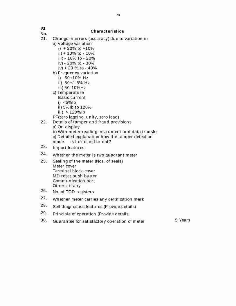
Sl. No. Characteristics
21. Change in errors (accuracy) due to variation in a) Voltage variation
i) + 20% to +10% ii) + 10% to - 10% iii) - 10% to - 20% iv) - 20% to - 30% iv) + 20 % to - 40%
b) Frequency variation i) 50+10% Hz ii) 50+/-5% Hz iii) 50-10%Hz
c) Temperature Basic current i) <5%Ib ii) 5%Ib to 120% iii) > 120%Ib PF(zero lagging, unity, zero lead)
22. Details of tamper and fraud provisions a) On display b) With meter reading instrument and data transfer c) Detailed explanation how the tamper detection made is furnished or not?
23. Import features
24. Whether the meter is two quadrant meter
25. Sealing of the meter (Nos. of seals) Meter cover Terminal block cover MD reset push button Communication port Others, if any
26. No. of TOD registers
27. Whether meter carries any certification mark
28. Self diagnostics features (Provide details)
29. Principle of operation (Provide details
30. Guarantee for satisfactory operation of meter 5 Years
29
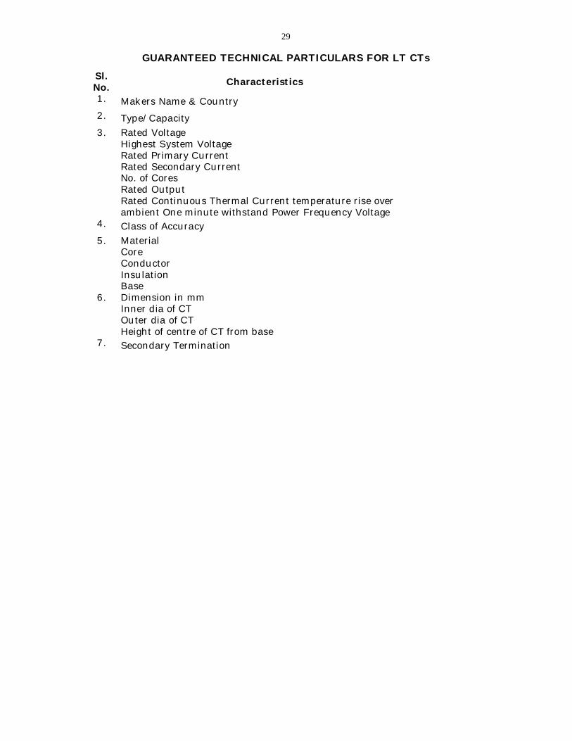
GUARANTEED TECHNICAL PARTICULARS FOR LT CTs
Sl. No. Characteristics
1. Makers Name & Country
2. Type/Capacity
3. Rated Voltage Highest System Voltage Rated Primary Current Rated Secondary Current No. of Cores Rated Output Rated Continuous Thermal Current temperature rise over ambient One minute withstand Power Frequency Voltage
4. Class of Accuracy
5. Material Core Conductor Insulation Base
6. Dimension in mm Inner dia of CT Outer dia of CT Height of centre of CT from base
7. Secondary Termination

30
GUARANTEED TECHNICAL PARTICULARS OF BOX
Sl. No Characteristics 1. Manufacturer’ name 2. Material used for box body 3. Material withstanding temperature 4. Dimensions of box (L x W x H) 5. Thickness (mm) 6. Color 7. Viewing window
Material Dimensions Whether shade arrangement to window provided or not
8. No. of Hinges 9. Handle provisions 10. Earthing provision 11. Sealing Arrangements 12. Inlet & Outlets 13. Gasket
Whether gasket is provided for (each) door and window Material of the gasket
14. Suitable for outdoor installation
31
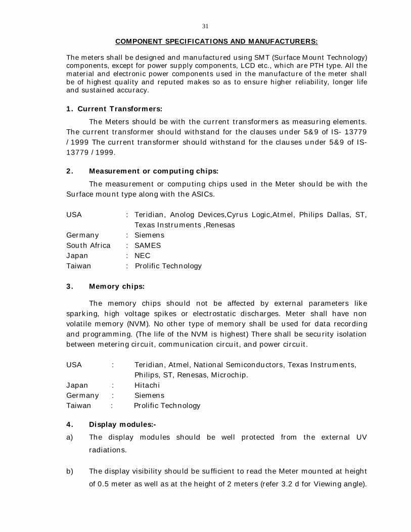
COMPONENT SPECIFICATIONS AND MANUFACTURERS:
The meters shall be designed and manufactured using SMT (Surface Mount Technology) components, except for power supply components, LCD etc., which are PTH type. All the material and electronic power components used in the manufacture of the meter shall be of highest quality and reputed makes so as to ensure higher reliability, longer life and sustained accuracy. 1. Current Transformers:
The Meters should be with the current transformers as measuring elements. The current transformer should withstand for the clauses under 5&9 of IS- 13779 /1999 The current transformer should withstand for the clauses under 5&9 of IS-13779 /1999. 2. Measurement or computing chips:
The measurement or computing chips used in the Meter should be with the Surface mount type along with the ASICs. USA : Teridian, Anolog Devices,Cyrus Logic,Atmel, Philips Dallas, ST,
Texas Instruments ,Renesas Germany : Siemens South Africa : SAMES Japan : NEC Taiwan : Prolific Technology 3. Memory chips: The memory chips should not be affected by external parameters like sparking, high voltage spikes or electrostatic discharges. Meter shall have non volatile memory (NVM). No other type of memory shall be used for data recording and programming. (The life of the NVM is highest) There shall be security isolation between metering circuit, communication circuit, and power circuit. USA : Teridian, Atmel, National Semiconductors, Texas Instruments,
Philips, ST, Renesas, Microchip. Japan : Hitachi Germany : Siemens Taiwan : Prolific Technology 4. Display modules:- a) The display modules should be well protected from the external UV
radiations.
b) The display visibility should be sufficient to read the Meter mounted at height
of 0.5 meter as well as at the height of 2 meters (refer 3.2 d for Viewing angle).

32
c)The construction of the modules should be such that the displayed quantity
should not disturbed with the life of display .d) It should be trans reflective
HTN or STN type industrial grade with extended temperature range.
Hongkong : Genda
Singapore : Bonafied Technologies,Holtek,Haijing.
Korea : Advantek
Japan : Hitachi,Sony.
Taiwan : Prolific Technology
5. Communication Modules: Communication modules should be compatible for the two ports (one for
Optical port for communication with meter reading instruments & the other for the
hardwired RS-232 port to communicate with various modems for AMR).
USA : National Semiconductors HP, Optonica, Agillant,Texas Instruments, Maxim.
Holland / Korea : Phillips
Japan : Hitachi Taiwan : Ligitek, Everlight, Prolific Technology
6. Power supply: The power supply should be with the Capabilities as per the relevant standards. The power supply unit of the meter should not be affected in case the maximum voltage of the system appears to the terminals due to faults or due to wrong connections. It should not also be affected by magnet - SMPS Type. 7. Electronic Components:
The active & passive components should be of the surface mount type are to be handled & soldered by the state of art assembly processes.
USA : National Semiconductors,Atmel, Philips, Texas Instruments, BC Component,Fairchild.
Japan : Hitachi, Taiyo Yuden, Oki, Toshiba,AVZ or Ricon Korea : Samsung Japan : Panasonic, Toshiba,Fairchild,PEC,CTR Germany : Vishay, Epcos & NSC,Yageo
Taiwan : Prolific Technology

33
8. Mechanical parts:
a) The internal electrical components should be of electrolytic copper & should be protected from corrosion, rust etc.
b) The other mechanical components should be protected from rust, corrosion etc. by suitable plating/painting methods.
9. Battery:
Maintenance free Lithium battery of long life of 10 years. Only non rechargeable battery should be used for RTC and rechargeable battery for display in absence of Power. Makes
USA : Maxell,Varta,Tedirun, Sanyo or National Japan : Panasonic,Sony , Mitsubishi,Sanyo France : Saft Korea : Tekcell.
10. RTC & Micro-controller-The accuracy of RTC shall be as per relevant IEC
/ IS standards.
USA : ST, Teridian, Philips, Dallas, Atmel, Motorola, Microchip, Texas Instruments, Holtek, IDT, Renesas. Japan : NEC or Oki,Epson. Malaysia : Intersil.
Taiwan : Prolific Technology 11. P.C.B.:
Glass Epoxy, fire resistance grade FR4, with minimum thickness 1.6 mm if 2 layer and 1.2 mm if 4 layer or more from any reputed Indian/Global manufacturers.