Embed Size (px)
Citation preview

IOT BASED REAL-TIME FIRE PROHIBITING SYSTEM USING GOOGLE MAP ‘FIREMAP’
BY
Nayem Musaddik ID: 142-15-3740
Md. Afratul Kaoser Taohid
ID: 142-15-3581
Md. Imran Khan ID: 142-15-3809
This Report Presented in Partial Fulfillment of the Requirements for the
Degree of Bachelor of Science in Computer Science and Engineering
Supervised By
Md. Rayhan Amin Lecturer
Department of CSE Daffodil International University
Co-Supervised By
Hasna Hena
Senior Lecturer Department of CSE
Daffodil International University
DAFFODIL INTERNATIONAL UNIVERSITY DHAKA, BANGLADESH
MAY 2018 © Daffodil International University
© Daffodil International University
ii
APPROVAL
This Project/Internship titled “IoT Based Real-Time Fire Prohibiting System Using
Google Map—Firemap”, submitted by Nayem Musaddik, Md. Afratul Kaoser Taohid
and Md. Imran Khan to the Department of Computer Science and Engineering, Daffodil
International University, has been accepted as satisfactory for the partial fulfillment of the
requirements for the degree of Bachelor of Science in Computer Science and Engineering
and approved as to its style and contents. The presentation has been held on 5 May, 2018.
BOARD OF EXAMINERS
Dr. Syed Akhter Hossain Chairman Professor and Head Department of Computer Science and Engineering Faculty of Science & Information Technology Daffodil International University Dr. Sheak Rashed Haider Noori Internal Examiner Associate Professor Department of Computer Science and Engineering Faculty of Science & Information Technology Daffodil International University Md. Zahid Hasan Internal Examiner Assistant Professor Department of Computer Science and Engineering Faculty of Science & Information Technology Daffodil International University Dr. Mohammad Shorif Uddin External Examiner Professor and Chairman Department of Computer Science and Engineering Jahangirnagar University

© Daffodil International University
iii
DECLARATION
We hereby declare that, this project has been done by us under the supervision of Md.
Rayhan Amin, Lecturer, Daffodil International University. I also declare that neither this
project nor any part of this project has been submitted elsewhere for award of any degree
or diploma.
Supervised by:
Md. Rayhan Amin Lecturer Department of CSE Daffodil International University
Submitted by:
Nayem Musaddik ID: 131-15-3740 Department of CSE Daffodil International University
Md. Afratul Kaoser Taohid ID: 131-15-3581 Department of CSE Daffodil International University
Md. Imran Khan ID: 131-15-3809 Department of CSE Daffodil International University

© Daffodil International University
iv
ACKNOWLEDGEMENT
First we express our heartiest thanks and gratefulness to almighty God for His divine
blessing makes us possible to complete the final year project/internship successfully.
We really grateful and wish our profound our indebtedness to Rayhan Amin, Lecturer,
Department of CSE Daffodil International University, Dhaka. Deep Knowledge & keen
interest of our supervisor in the field of “IoT based Real-time Fire Prohibiting System
Using Google Map ‘Firemap’” to carry out this project. His endless patience ,scholarly
guidance ,continual encouragement , constant and energetic supervision, constructive
criticism , valuable advice ,reading many inferior draft and correcting them at all stage
have made it possible to complete this project.
We would like to express our heartiest gratitude to Prof. Dr. Syed Akhter Hossain,
professor and head, Department of CSE, for his kind help to finish our project and also to
other faculty member and staff of CSE department of Daffodil International University.
We would like to thank our entire course mate in Daffodil International University, who
took part in this discuss while completing the course work.
Finally, we must acknowledge with due respect the constant support and patience of our
parents.

© Daffodil International University
v
ABSTRACT
The purpose of the system is to build an improved fire alarm mechanism that will alert the
Firefighter authority automatically with the real time location of the incident and show
them the shortest path on the map to reach there. There will also be a home user’s end to
confirm the fatality of the risks via a smartphone application. The main feature of the
project is to automatically alert and guide the firefighter to the fire incident location as it
detects fire. Mainly two categories of users will be notified if any occurrence happens, one
is the firefighter authority and another is the home users. With the help of Smoke Sensor,
Flame sensor and Temperature Sensor smoke, fire and temperature data will be collected
and using Arduino Uno R3 and ESP-8266 Wi-Fi Module the collected data will be sent
to a smart phone application via real time firebase database. Thus the both of the users will
be alerted. To avoid any false alarm there will also be options for Fire Service authority to
contact the users of the incident’s location to know the intensity of the fire and the damage
percentage. Home users can also take photo of the incident and manually notify the
firefighter authority via the smart phone application. The advantage of the system is that it
will help the firefighter authority to locate and act quickly for any fire occurrence by
knowing the real-time location and shortest path of the place and by the final confirmation
from the home users they can avoid false alerts.
© Daffodil International University
vi
TABLE OF CONTENTS
CHAPTER
CHAPTER 1: INTRODUCTION 1-3
1.1 Introduction 1
1.2 Motivation 2
1.3 Objectives 2
1.4 Expected Outcome 3
1.5 Report Layout 3
CHAPTER 2: BACKGROUND 4-6
2.1 Introduction 4
2.2 Related Works
2.3 Comparative Studies
2.4 Scope of the Problem
2.5 Challenges
4
5
5
6
CONTENTS PAGE
Approval ii
Board of examiners ii
Declaration iii
Acknowledgements iv
Abstract v
Table of Contents
vi

© Daffodil International University
vii
CHAPTER 3: REQUIREMENT SPECIFICATION 7-31
3.1 Business Process Modeling
3.1.1 Feasibility Study
3.1.2 Data Flow Diagram
3.1.3 Process Diagram
7
7
8
13
3.2 Requirement Collection And Analysis
3.2.1 Arduino Uno R3
3.2.2 ESP8266
3.2.3 Smoke Sensor
3.2.4 Flame Sensor
3.2.5 Temperature Sensor
3.3 Use Case Modeling and Description
3.3.1 Use Case
3.3.2 Use Case Narrative
3.4 Logical Data Model
3.4.1 E-R Diagram
16
16
18
19
20
21
22
22
25
31
31
CHAPTER 4: DESIGN SPECIFICATION 32-44
4.1 Front-end Design
4.1.1 XML
4.1.2 Anatomy of Android XML Layouts
32
32
33
4.2 Back-end Design
4.2.1 Java
4.2.2 Combination of C and C++
4.2.3 Firebase Database
36
36
37
38
4.3 Interaction Design and UX
4.3.1 System Architecture
4.3.2 Circuit Diagram and Connection
4.3.3 Activity Cycle
4.4 Implementation Requirements
40
40
41
42
43

© Daffodil International University
viii
CHAPTER 5: IMPLEMENTATION AND TESTING
45-67
5.1 Implementation of Database
5.1.1 User JSON Tree
5.1.2 Firefighter JSON Tree
5.1.3 Feed JSON Tree
5.1.4 Device JSON Tree
5.2 Implementation of Front-end Design
5.2.1 Home User
5.2.2 Firefighter Admin
5.3 Testing Implementation
5.3.1 Content Testing
5.3.2 Testing Strategy
5.3.3 Test Cases
5.4 Test Results and Reports
45
45
46
47
48
48
49
54
57
57
58
59
67
CHAPTER 6: CONCLUSION AND FUTURE SCOPE 68-69
6.1 Discussion and Conclusion 68
6.2 Scope for Further Developments 68
REFERENCES
70

© Daffodil International University
ix
LIST OF FIGURES
FIGURES PAGE
Figure: 3.1.1 DFD Device Module 8
Figure: 3.1.2 DFD Firefighter Registration Module 9
Figure: 3.1.3 DFD Firefighter Module 10
Figure: 3.1.4 DFD User Registration Module 11
Figure: 3.1.5 DFD User Module 12
Figure: 3.1.6 Process Diagram (Device) 13
Figure: 3.1.7 Process Diagram (User) 14
Figure: 3.1.8 Process Diagram (Firefighter) 15
Figure: 3.2.1 Arduino Uno R3 16
Figure: 3.2.2 ESP8266 Al Cloud Inside 18
Figure: 3.2.3 MQ-2 Smoke/LPG/CO Gas Sensor 19
Figure: 3.2.4 Flame Sensor Module 20
Figure: 3.2.5 LM35 Precision Temperature Sensor 21
Figure: 3.3.1 Use Case (Firefighter) 22
Figure: 3.3.2 Use Case (Registered Home User) 23
Figure: 3.3.3 Device Module 24
Figure: 3.4.1 E-R Diagram 31
Figure: 4.1.1 Anatomy of Android XML Layouts 33
Figure: 4.3.1 System Architecture
Figure: 4.3.2 Circuit Diagram
Figure: 4.3.1 User Activity Cycle
Figure: 4.3.2 Firefighter Activity Cycle
Figure: 5.1.1 User Node
Figure: 5.1.2 Firefighter Node
Figure: 5.1.3 Feed Node
40
41
42
43
45
46
47

© Daffodil International University
x
FIGURES
Figure: Device Node
Figure: 5.2.1 User Login
Figure: 5.2.2 User Register
Figure: 5.2.3 User Dashboard and Menu
Figure: 5.2.4 User Profile and Fire Station
Figure: 5.2.5 Posting a Threat
Figure: 5.2.6 Firefighter Log in and Registration
Figure: 5.2.7 Firefighter Dashboard
Figure: 5.2.8 Communicating with Users
Figure: 5.2.9 Viewing User feeds
PAGE
48
49
50
51
52
53
54
55
56
57

© Daffodil International University
1
CHAPTER 1
INTRODUCTION
1.1 Introduction
Fire is a revolutionary invention of mankind. It is one of the core elements of our survival
and without it our survival will be unimaginable. Many times fire breaks out accidently
and spreads over a large area and destroys everything in its way. It can break out anywhere
anytime in houses, factories, malls etc. it can be very dangerous and can cause a great
damage to human life and property. Fire is one of the major causes of accidental death in
the world. If proper action is not taken at a proper time, casualties can be unbearable and
unrecoverable. As technology advances, various types of alarm system have been
developed by using smoke detectors, temperature sensors, GPS modules and cameras etc.
Many automatic alarm systems are now available due availabilities of microcontroller and
these instruments. The advancement of internet based technologies are increasing the
efficiency of these systems. Wireless technologies and higher data transmission rate has
created a concept called IoT (Internet of Things). This project may take us one step closer
to reach completely Iot based world where everything is connected to internet and
automated. Development boards like Arduino and ESP-8266 are helping these automated
systems to come to life. These devices are cheap, low power consuming and very small in
size. The project proposed in this paper combines these devices with smart phone
application and creates an IoT based automated fire alarm system that ensures efficiency
and reliability.

© Daffodil International University
2
1.2 Motivation
This is the era of modern technology. Nowadays technology is helping us to overcome
many obstacles in our lives. Technology has made our life more easy and secure. Day by
day our technology is getting smart and proper use of smart technology has brought a lot
of blessing to us. From the different incidents of the past it has been observed that fire has
taken many lives and caused a heavy damage to our valuable properties due to poor
response time of firefighter authorities. On the other hand firefighter authorities could not
reach the place in time or responds late because they don't get the alert at the correct time.
The situation gets worse at night because people remain sleeping at households and the
industries, company offices remain closed during the night time. So if the fire breaks out it
becomes too late. And because of this delay the damage percentages becomes very high
and lives are lost. Sometimes firefighter units also faces difficulties to reach the proper
location because they could not determine the exact incident’s location. The main idea of
our project is to alert the firefighter authority in real time if the fire breaks out and help
them to reach the exact location as fast as possible by help of technology. The purpose of
our research project is to use the technology to reduce the damage caused by the fire and
make our lives and properties secure.
1.3 Objectives.
The first section will be a threshold based auto detection system that will be triggered by
using the intensity of smoke sensor, flame sensor and temperature sensor. There will be
another section which will be based on an android application. The application will be
mainly used for final confirmation and guiding the firefighter unit towards the exact
location. The android application will be also used to manually notify the firefighter, to
determine the damage percentage, to take photos of the casualty and send it to the
authority that will help understand the fire intensity. So the main objectives of this project
are as follows:
● Auto detect fire by using the sensors and Alarm the fire service and home users.
● Show the shortest way to the incident’s place via Android application.

© Daffodil International University
3
● If needed firefighter can get confirmation of the occurrence by contacting the home
users. So that they could avoid the false alarm.
● On the other hand if the auto detection system fails home users can manually notify
the firefighter via Android Application.
● Home users can take photograph of the fire incident and send it to firefighter
authority. There will also be an option for home users to to set the damage
percentage.
1.4 Expected Outcome
The aim is to complete all the task stated above. The completion of this project will help
us to reduce the casualties caused by the fire. People will be safe from any kind of fire
incidents.
The cooperation of the firefighter is mostly needed for this project. The project will help
the firefighter to act as quickly as possible .It will also help them to reach the place of
incident. Another great thing is the project will help detect false alarm. Firefighter authority
will able make sure that fire has really gone out of control by interacting with home users.
The damage percentage reporting system of the project will also help the firefighter to be
sure of the severances and these are some important data for future research.
1.5 Report Layout
The project paper is divided into six chapters where the first chapter has segmented with
the introduction, objectives, motivation, expected outcome and report layout. In Second
Chapter, Background of this project, introduction, related works, comparative studies,
scope of the problem and challenges of this project has assembled. Third Chapter focuses
on Requirement Specification where Business process modeling, Requirement collection
and analysis, use case modeling and description and logical data model and design
requirements. In Chapter 4, Design Specification is based on Front-end Design, Back-end
Design, Interaction Design and UX and Implementation Requirements. In Chapter 5, we
discussed about how we implement this system and it’s testing. Chapter 6 is about
conclusion and our future Scope what we will do in next.

© Daffodil International University
4
CHAPTER 2
BACKGROUND
2.1 Introduction
Since the evolution of microcontrollers and integrated circuits a lot of automatic security
and surveillance systems has been built. As we move towards to IoT world more and more
AutoDetect and alarm system are being developed. The up gradation and availability of
high speed internet helped these inventions to spread through different platforms. To build
our proposed system firstly a background study needed to be done on related projects.
2.2 Related Works
Md Saifudaullah Bin Bahrudin and Rosni Abu Kassim [1] proposed a real time fire
monitoring system using Raspberry Pi and Arduino Uno. Attaching a camera they capture
an image and remotely send an alert only if the smoke is detected. The image will be
displayed in a webpage. There is a user confirmation system to avoid the false alarm and
report to the firefighter via Short Message Service (SMS).
Sarita Gupta, Ajay Mudgil, Prashant Bhardwaj and Mahendra Gupta [2] built a wireless,
real time, automatic fire alert system consist of microcontroller, RF module, GSM and two
types of sensors. This system can detect degree of fire or spread of fire and location of
accidental site. They used GSM module to transmit the collected data to the firefighter
authority. Google Map is also used here to display and point the fire affected location.
Zhang Kun, Hu Shunbin and Li Jinfang[3] developed an automatic warehouse fire alarm
system based on MCU. Their system consists of ATmega16, temperature sensors, smoke
sensors, and EX-1 auto dialed alarm module.The system collects data by using temperature
and smoke sensors and processes the data using MCU. If the fire is detected by the system
then the alarm signal is turned on and transmits messages through EX-1.

© Daffodil International University
5
Suresh S., Yuthika S. and G.Adithya Vardhini[4] built an affordable Home based Fire
monitoring and Warning System using Arduino Uno R3. If the system detects a certain
level of smoke or flame it alerts the property owner using GSM. They mainly focused on
building an economical automatic fire alarm system so that users at any level of income
can afford it.
2.3 Comparative Studies
All these projects above are very well developed and effective. But our project is focused
on both IoT and smartphone application. None of these projects have any part for
smartphone application. We think nowadays smartphone applications have become very
important, useful and popular in our everyday life.it can also be useful to avoid any
dangerous situations. By the help of the smartphone application we can show the
firefighters the shortest path of the incident. In our project there is options for firefighter
authority to avoid any false alarm by contacting the home user on other hand there is an
option for home users to alert the firefighters manually via the smartphone application. Our
system also has options for users to take photo by the smartphone application and submit
the damage percentage of the incident. These extra effective features made our system
more unique and ensures more safety for any unwanted fire situations.
2.4 Scope of the Problem
To make an effective fire alarm system we needed to ensure that it is automated and there
are measures to avoid false alarm. By the help of the microcontrollers and sensors we have
made the system automatic and by the help of smartphone application we added the extra
features and ensured the reliability. We have also option for home users to submit the
damage percentage so that firefighter can determine the risks and the submitted data can
be used for future studies.

© Daffodil International University
6
2.5 Challenges
Finding the threshold value for the sensors was very challenging task. We had to fix a
certain amount of smoke and flame intensity to trigger the alarm. This threshold value
indicates if the smoke/fire has crossed the danger level or not.
There are different options for firefighter authority and home users. For that we have to
build two separate android application for two types users.
Determining the exact location of our home device was very difficult as GPS module Neo-
6M does not pick the correct location under the roof. It only works if the device is situated
outside. So cope up with this problem we have let the home user to provide the location
while signing up and we have used the ESP-8266 module and embedded with Google maps
to pick up the location of the device.

© Daffodil International University
7
CHAPTER 3
REQUIREMENTS SPECIFICATION
3.1 Business Process Modeling
3.1.1 Feasibility Study:
In this phase the feasibility of the system needs to be analyzed and proper business proposal
plan needs to be determined and cost estimates also should be considered. For feasibility
analysis, some understanding of the major requirements for the system is essential.
Three key considerations involved in the feasibility analysis are
Economic Feasibility
Technical Feasibility
Social Feasibility
Economic Feasibility
To determine how the system will impact on the organization economically, this study is
conducted. Only limited amount of fund will be invested by the company into the research
and development of the system. So the system is made as cheap as possible so that the
expenditures is properly justified. Using cheap small and portable devices like ESP-8266
and Arduino UNO R3 rather than using Raspberry pi has made this system less costly and
economical.
Technical Feasibility
To make the system more technically efficient this study is carried out. The system must
be made as error proof as possible to cope up with this challenging world. Without technical
efficiency this system will not be useful at all. This will dissatisfy the system’s purpose.
The developed system must have a decent requirement, as only exquisite or null changes
are needed for implementing this system.

© Daffodil International University
8
Social Feasibility
The purpose of study is to verify the level of acceptance of the system by the user. This
includes the method train and motivate the user to use the system efficiently. The user must
not feel threatened by the system, instead must accept it as an importance. The level of
acceptance by the users mostly depends on the processes that are used to educate the user
about the system and to make him recognize it. His level of confidence must be raised so
that he is also able to make some constructive criticism, which is welcomed.
3.1.2 Data Flow Diagram
Figure: 3.1.1 DFD Device Module
Figure: 3.1.1 shows the data flow diagram of the device. Here all the components are
connected with each other via Arduino Uno. Data is collected and sent to the server.
© Daffodil International University
9
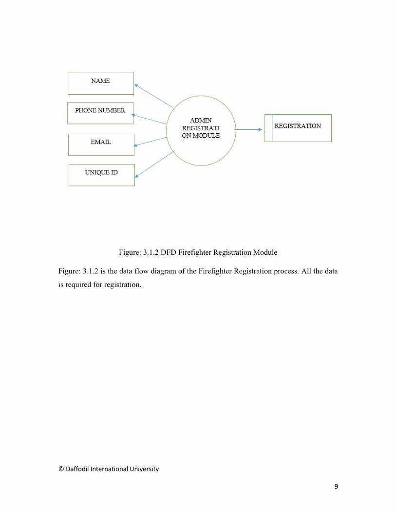
Figure: 3.1.2 DFD Firefighter Registration Module
Figure: 3.1.2 is the data flow diagram of the Firefighter Registration process. All the data
is required for registration.

© Daffodil International University
10
Figure: 3.1.3 DFD Firefighter Module
Figure: 3.1.3 is the diagram of takas of fire fighter app. To access these option firefighter
must login first

© Daffodil International University
11
Figure 3.1.4 DFD User Registration Module
Figure: 3.1.4 is the data flow diagram of the Home User Registration process. Home user
bust own the device before registering.

© Daffodil International University
12
Figure 3.1.5 DFD User Module
Figure 3.1.5 is the data flow diagram for the tasks of Home User app. All the data is
maintained by a firebase database.

© Daffodil International University
13
3.1.3 Process Diagram
Figure 3.1.6 Process Diagram (Device)
Figure 3.1.6 shows the process diagram of the device. The device collets the data using the
sensors and if the values crosses the threshold then its sets alarm and send the danger status
to server.

© Daffodil International University
14
Figure 3.1.7 Process Diagram (User)
Figure 3.1.7 is Process Diagram of the user. User must get registered or log in to access
these features like viewing sensor data, manage profile, manage post e.t.c

© Daffodil International University
15
Figure 3.1.8 Process Diagram (Firefighter)
Figure 3.1.8 is the process diagram of the firefighter app. Firefighters can take immediate
action using these features.

© Daffodil International University
16
3.2 Requirement Collection and Analysis
For building this project we have analyzed different hardware components and collected
the proper, efficient, portable and cost friendly equipment. Here we have described the
details about our required product and theirs benefits.
3.2.1 Arduino Uno R3
We have used Arduino Uno R3 Development board for this project.
Figure: 3.2.1 Arduino Uno R3
Arduino Uno is a microcontroller board based on the ATmega328P (datasheet). It has 14
digital input/output pins (of which 6 can be used as PWM outputs), 6 analog inputs, a 16
MHz quartz crystal, a USB connection, a power jack, an ICSP header and a reset button. It
contains everything needed to support the microcontroller; simply connect it to a computer
with a USB cable or power it with an AC-to-DC adapter or battery to get started. You can
tinker with your UNO without worrying too much about doing something wrong, worst
case scenario you can replace the chip for a few dollars and start over again.

© Daffodil International University
17
"Uno" means one in Italian and was chosen to mark the release of Arduino Software (IDE)
1.0. The Uno board and version 1.0 of Arduino Software (IDE) were the reference versions
of Arduino, now evolved to newer releases. The Uno board is the first in a series of USB
Arduino boards, and the reference model for the Arduino platform; for an extensive list of
current, past or outdated boards see the Arduino index of boards.
Table: 3.1 Specifications
Microcontroller ATmega328P
Operating Voltage 5V Input Voltage (recommended) 7-12V
Input Voltage (limit) 6-20V
Digital I/O Pins 14 (of which 6 provide PWM output)
PWM Digital I/O Pins 6
Analog Input Pins 6
DC Current per I/O Pin 20 mA
DC Current for 3.3V Pin 50 mA
Flash Memory 32 KB (ATmega328P) of which 0.5 KB used by bootloader
SRAM 2 KB (ATmega328P)
EEPROM 1 KB (ATmega328P)
Clock Speed 16 MHz
LED_BUILTIN 13

© Daffodil International University
18
3.2.2 ESP8266
For connecting our system to the internet we have user ESP-8266.
Figure: 3.2.2 ESP8266 Al Cloud Inside
The ESP8266 Wi-Fi Module is a self-contained SOC with integrated TCP/IP protocol stack
that can give any microcontroller access to your Wi-Fi network. The ESP8266 is capable
of either hosting an application or offloading all Wi-Fi networking functions from another
application processor. Each ESP8266 module comes pre-programmed with an AT
command set firmware, meaning, you can simply hook this up to your Arduino device and
get about as much Wi-Fi-ability as a Wi-Fi Shield offers. The ESP8266 module is an
extremely cost effective board with a huge, and ever growing, community.
Features
802.11 b/g/n
Wi-Fi Direct (P2P), soft-AP
Integrated TCP/IP protocol stack
Integrated TR switch, balun, LNA, power amplifier and matching network
Integrated PLLs, regulators, DCXO and power management units
+19.5dBm output power in 802.11b mode

© Daffodil International University
19
Power down leakage current of <10uA
1MB Flash Memory
Integrated low power 32-bit CPU could be used as application processor
SDIO 1.1 / 2.0, SPI, UART
STBC, 1×1 MIMO, 2×1 MIMO
A-MPDU & A-MSDU aggregation & 0.4ms guard interval
Wake up and transmit packets in < 2ms
Standby power consumption of < 1.0mW (DTIM3)
3.2.3 Smoke Sensor
For this project we have used MQ-2 Smoke/LPG/CO Gas Sensor to detect smoke.
Figure: 3.2.3 MQ-2 Smoke/LPG/CO Gas Sensor
The Analog Smoke/LPG/CO Gas Sensor (MQ2) module utilizes an MQ-2 as the sensitive
component and has a protection resistor and an adjustable resistor on board.
Features
Power supply needs 5V
Fast response and High sensitivity
Wide detecting scope
Simple drive circuit
Stable and long life

© Daffodil International University
20
3.2.4 Flame Sensor.
This module is sensitive to the flame or fire and radiation. It also can detect IR light source
in the range of a wavelength 760nm-1100 nm that emitted from fire.
Figure: 3.2.4 Flame Sensor Module
Features
Detects a flame or IR light source of a wavelength in the range of 760nm to
1100nm.
Detection range up to 100cm.
Detection range can be adjustable.
The angle of detection about 60 degrees and we know that it is sensitive to flame
objects
LM393, the comparator chip allows to make module readings stable.
Operating voltage 3.3V to 5V.
Give Digital and Analog Output.
There are two indicator included like Power indicator and Digital switch output
indicator.

© Daffodil International University
21
3.2.5 Temperature Sensor.
LM35 Precision Celsius Temperature Sensor is used for this project
Figure: 3.2.5 LM35 Precision Temperature Sensor
Features
Calibrated Directly in Degrees Celsius
Temperature Range from -40oC to +110oC
0.5oC Initial Accuracy
Less Than 60µA Current Drain
Low Impedance Output

© Daffodil International University
22
3.3 Use Case Modeling and Description
3.3.1 Use Case
Figure 3.3.1 Use Case (Firefighter)

© Daffodil International University
23
Figure 3.3.2 Use Case (Registered Home User)

© Daffodil International University
24
Figure 3.3.3 Device Module

© Daffodil International University
25
3.3.2 Use Case Narrative
Use Case: Sending Alert
Actor: Device
Pre-condition: Powered on, WIFI connection
Primary Path:
1. Collet the sensor data.
2. Check if sensor value crossed the threshold value.
3. Send Alert to the server
4. Alert both Firefighter and home Users
Exception:
1. No Power
2. No internet Connection
3. Sensor Malfunction
Post-condition:
1. If Firefighter is notified successfully.
2. If Home user is notified successfully.
Use Case: User Registration
Actor: Home User
Pre-condition: Must be the Owner of the Device
Primary Path:
1. Fill device id field
2. Fill name field
3. Fill e-mail field
4. Fill password field
5. Fill contact number field

© Daffodil International University
26
6. Fill gender field
7. Choose user image
8. Select location
9. Click Register button
10. Open Dashboard page
Exception:
1. Device Id field is empty
2. Name field is empty
3. E-mail field is empty
4. Password field is empty
5. Contact Number field is empty
6. Gender field is empty
7. Image not selected
8. Location is not selected
9. Connection error
Post-condition:
3. If Register is successful
4. If User Dashboard is loaded
Use Case: User Login
Actor: Home User
Pre-condition: Register
Primary Path:
1. Fill E-mail field
2. Fill Password field
3. Click Login button

© Daffodil International University
27
Exception:
1. Wrong Password
2. Wrong E-mail
3. Connection error
Post-condition:
1. If Log In is successful
2. If Dashboard loaded successfully
Use Case: Post a Threat
Actor: Home User
Pre-condition: Login
Primary Path:
1. Select image
2. Write Heading
3. Write Description
4. Select location
5. Select damage percentage
6. Click Post button
Exception:
1. Image size is too large
2. Location is not specified
3. Heading must be written
4. Description must be written
5. Connection error
Post-condition:
1. If Post is successful
2. If Newsfeed loaded successfully

© Daffodil International University
28
Use Case: Profile
Actor: Home User
Pre-condition: Login
Primary Path:
1. Change user image
2. Change Location
3. Check own posts
4. View Nearest Fire Station
Exception:
1. Connection error
Post-condition:
1. If picture changed successfully
2. If location changed successfully
Use Case: Call firefighter
Actor: Home User
Pre-condition: Login
Primary Path:
1. Click Call button
Exception:
1. Number busy
2. Connection error
Post-condition:
1. If call is successful

© Daffodil International University
29
Use Case: Firefighter Registration
Actor: Firefighter
Pre-condition: None
Primary Path:
1. Fill station name field
2. Fill authority contact number field
3. Fill e-mail field
4. Fill the unique-id field
5. Click Register button
6. Open Dashboard page
Exception:
10. Station Name field is empty
11. E-mail field is empty
12. Authority Contact Number field is empty
13. Connection error
Post-condition:
5. If Register is successful
6. If Admin Dashboard is loaded

© Daffodil International University
30
Use Case: Call Home User
Actor: Firefighter
Pre-condition: Login
Primary Path:
2. Click Call button
Exception:
3. Number busy
4. Connection error
Post-condition:
2. If call is successful

© Daffodil International University
31
3.4 Logical Data Model
3.4.1 E-R Diagram
Figure 3.4.1 E-R Diagram

© Daffodil International University
32
CHAPTER 4
DESIGN SPECIFICATION
4.1 Front-end Design
The front-end design of the system is considered as the implantation of the design of
android application for both home users and firefighter authority. For designing the front-
end of the Android Application mainly XML a markup language, is used to set up the
layout of the apps.
4.1.1 XML
Extensible Markup Language normally known as XML, it is the front end language in
Android development to handle the design mechanism in Android application’s layouts. It
is like a markup language which defines a set of rules for encoding in a format like which
likely both readable for developer and system.
Though HTML and XML both is a Markup language but there are some difference between
them like XML is designed to carry the data and focus on it rather than just to display it
like HTML and tags are not predefined like HTML. XML structure of the data is embedded
with data so that it dynamically understand it within the XML and store it, where HTML
is only describes the web page contents
Why android is used XML? Earlier we said that it is a human readable format, also easy to
parse and initialize in programmatically. It’s a tree structure like JSON and most of the
IDE tools are already familiar with this. It generate automatically a R file to indexing the
resource contents which is provide great deal of benefit to autocomplete. If we make a
mistake like define a resource we don’t added and want to access it, then it will stop the
developer from doing it and make complain.

© Daffodil International University
33
4.1.2 Anatomy of Android XML Layouts
In order to make an Android application we use layouts as a front end to execute design
mechanism. Every layout file have to have a container which is also known as a root
element or object of a layout that holds View and View Group. There are some few View
Group like Linear Layouts, Relative Layouts, Coordinate Layouts, Constraint Layouts, and
Frame Layouts and so on.
.A View is simply an object which is building the block of a UI elements in Android. It
represents a rectangular box, and is responsible for displaying information or content
whatever the user’s action.
A View Group is the invisible container which is essentially holds multiple Views or View
Groups together, and defines their layout properties.
Figure: 4.1.1 Anatomy of Android XML Layouts

© Daffodil International University
34
Common View Groups
There are three types of layouts that may be the root element in an Android XML Layout:
A Linear Layout aligns its contents into one direction, direction can be vertical or
horizontal.
A Relative Layout displays its child components with respect to it’s relative to the
parent. Like align with parent right or left or top and bottom.
A Frame Layout is like a placeholder on a screen that can display only a single
view. Its act like a container which can hold one fragment at a time, usually used
for tab layout or the navigation view, According to user action, if user swipe the
view, another view is replaced on its place.
Common Views
Other commonly used Views are as follows. These may not be the root element of a layout,
but they take place inside a View Group.
A List View displays a list of scrollable items.
A Grid View displays items in a two-dimensional, scrollable grid.
A Table Layout groups views into rows and columns.
A Recycler View can be act as linear list also a grid like gallery
Layout Attributes
Every type of layout has attributes that define the way its elements will be appeared. There
are both common attributes that all elements share, and attributes specific to some of the
layout types listed above. The following are attributes that apply to all View and View
Groups:
android:id: A unique ID that corresponds to the view.
android:layout_width: The width of the layout.
android:layout_height: The height of the layout.

© Daffodil International University
35
android:layout_marginTop: Extra space on the top of the layout.
android:layout_marginBottom: Extra space on the bottom of the layout.
android:layout_marginLeft: Extra space to the left of the layout.
android:layout_marginRight: Extra space to the right of the layout.
android:layout_weight: Specifies how much of the extra space in the layout should
be allocated to the view.
android:paddingLeft: Padding to the left of the view.
android:paddingRight: Padding to the right of the view.
android:paddingTop: Padding at the top of the view.
android:paddingBottom: Padding at the bottom of the view.
Relative Sizing
Height and width properties can be set to specific measurements, but the following are
much more common:
android:layout_width=wrap_content: Sets the width of the view to whatever size is
required by its contents. This may also be used with height.
android:layout_width=match_parent: Sets the width of the view to the width of its
parent. This may also be used with height.
Relative and Properties ID
Much like in HTML, id attributes also can be added into XML elements. However, the
syntax for assigning an ID is differs from in HTML. Assigning an id attribute looks
something like this:
android:id="@+id/search_button"
Here, the @+id/ portion indicates that the name following is a string containing this
element's ID, and that it is a new resource that should be created and added to our resources.

© Daffodil International University
36
For instance, the following XML will create a Button with the id search_button:
<Button android:id="@+id/mButton"
android:layout_width="wrap_content"
android:layout_height="wrap_content"
android:text="@string/button_text"/>
Targeting Views by ID
Similar to the way we used jQuery to target individual HTML elements and alter them in
some fashion, we can also target individual XML elements and interact with them. The
following code can be used to target the example XML button from above:
Example:
Button myButton = (Button) findViewById (R.id.button);
FindViewById () method can locate both Views and root views.
4.2 Back-end Design
Our project consists of both hardware and software side. For back-end designing both
needs be implemented properly. The microcontrollers needs coding instruction as well as
Android Application. There is a Firebase database between hardware and software that acts
as a bridge way between them.
4.2.1 Java
Java is normally class based object oriented, high–level programming language which is
developed by Sun Microsystem and originally designed for interactive television. It’s
created by James Gosling who is led a team for Sun Microsystem. It promised to “Write
once and Run Anywhere”
Java enables developers to write computer instruction as a code and create Java application
on a particular system which is supports Java. We know that Java is platform independent.
But why? The designer of the Java language decided to make a platform that independently
execute the Java code on a different physical machine since the code eventually has to run

© Daffodil International University
37
on a physical platform. That platform we called Java Virtual Machine in short form JVM.
So they put all the Java code in the JVM which platform dependent then JVM executes the
Java bytecode which is platform independent. Whenever we writes Java code for a program
we do not write it to execute on physical machine, we write the code for to run it on the
JVM.
In backend Android is using Java programming language to handle all the system API call.
Android is just use Java as a source code but not used the JVM for to execute code. They
are only use the syntax of the language. There are some reason to Android choose Java to
its source code like
Android runs on different hardware platform, and we already know that Java is
platform independent.
Java support open source.
There are huge number of developer know or working with Java so they can easily
move to Android platform.
It is easy to learn and understand though it is object oriented.
Java community is large so if the developer face any problem on a certain
characteristic, developer can get solve for it.
4.1.1 Combination of C and C++
This is required for giving the instruction to the microcontroller. Arduino is programmed
with a C/C++ 'dialect'. Most C/C++ will work but much of the standard libraries will not
work. Many of the restrictions is made because of the little available RAM on the Arduino
hardware.
C/C++ Advantages
One of the greatest advantage using C/C++ is that you can have a toolkit of libraries to
interface with hardware, networking, front-end GUIs, etc.
With C or C++ you can directly access the registers on the microcontroller and
write code that is not in the Arduino code

© Daffodil International University
38
Since the Arduino libraries are written in C/C++, you can interface with them
directly
C/C++ let you manage limited resources better
4.2.3 Firebase Database
Firebase is a mobile and web application development platform acquired by Google. It is
a backend service which frees the developer to focus dynamic user experiences. It provide
server hosting, authentication system, APIs and database, so that developers do not have
to worry about such issues. In this system data is stored as JSON and synced in real-time
to every connected user.
Realtime Database
Realtime database is one of the feature of Firebase which is provide real-time data transfer
protocol between server and client. It works in backend as a service which is creates API
that allow data to be synchronized through clients and stored in a cloud with NoSQL. Most
database require to make HTTP calls to get and sync data. Client have to ask server to get
the updated data but Firebase does not work like that. When we connect Firebase into an
application, it connect through a WebSocket not with normal HTTP like other database
system. WebSocket are faster than HTTP. So client can make every calls with one socket
connection, and that’s plenty for to sync data automatically. If any update data is available,
Firebase will be notify the client and every time data changes, any connected device get
the updates data within milliseconds.
Offline
Data remain in application even if it is not online because once Firebase established
connection with client’s app it persists data to disk and receive any changes from the
database.

© Daffodil International University
39
Access to Client
Client can directly connect with Firebase from a mobile device or Web browser, no need
for an application server. It has some features like user validation, database security rules,
expression based rules whether the user can read or write data.
How does it work?
The Firebase Realtime Database let’s build rich, collaborative applications by allowing
secure access to the database directly from client-side. Data is persisted locally, and even
while offline, realtime events continue to fire, giving the end user a responsive experience.
When the device regains connection, the Realtime Database synchronizes the local data
changes with the remote updates that occurred while the client was offline, merging any
conflicts automatically.
The Realtime Database provides a flexible, expression-based rules language, called
Firebase Realtime Database Security Rules, to define how data should be structured and
when data can be read from or written to. When integrated with Firebase Authentication,
developers can define who has access to what data, and how they can access it.

© Daffodil International University
40
4.3 Interaction Design and UX
4.3.1 System Architecture
Figure: 4.3.1 System Architecture
Figure 4.3.1 shows the system architecture. The structure of this fire alarm system is consist
of six components, which are Arduino Uno R3, ESP-8266, Smoke Sensor, Flame sensor,
Temperature sensor and a WIFI router. Arduino was selected due to its good technical
specifications, high performance for data processing and is cheaper than other single board
computers available in the market. The sensors and ESP-8266 is connected with Arduino.
The WIFI router is used to connect the ESP-8266 and send the collected to the server.

© Daffodil International University
41
4.3.2 Circuit Diagram and Connection:
Figure: 4.3.2 Circuit Diagram
Figure: 4.3.2 shows the Circuit Diagram of our system prototype. All the components are
conceded using a breadboard and jumper wires.

© Daffodil International University
42
4.3.3 Activity Cycle
Figure: 4.3.3 User Activity Cycle

© Daffodil International University
43
Figure: 4.3.4 Firefighter Activity Cycle
4.4 Implementation Requirements
The hardware devices used for the development of the project is:
Processor : Intel Core i3 Processor
RAM : 8 GB DDR3 RAM
Monitor : 15” LCD
Hard Disk : 500 GB
Cache : 5 MB
Keyboard : Standard 102 Keys
Mouse : 3 Buttons
Router : TP-Link

© Daffodil International University
44
The software used for the development of the project is:
Operating System : Windows 10 Professional
Editor : Android Studio, Arduino IDE
Language : Java, XML, C/C++
Framework : JSON
Database : Firebase

© Daffodil International University
45
CHAPTER 5
IMPLEMENTATION AND TESTING
5.1 Implementation of Database
In this project we have used a real time firebase database. This is quite different from other
databases. So implementation of this database is based on JSON.
5.1.1 User JSON Tree
Figure: 5.1.1 User Node

© Daffodil International University
46
This is the User JSON tree which is contain each user info under device id node. Under
device id it contain user’s information like device id, user email, gender, unique id, user
location, name, sensor value, device status depends on whether the fire strike or not. Also
contain user’s profile picture, station name which is user under by. Also have the
temperature value from the temperature sensor
5.1.2 Firefighter JSON Tree
Figure: 5.1.2 Firefighter Node
This is the Firefighter tree which is contain the information of all the Fire station of
Bangladesh. All fire station info is contain under unique station id. Following that station
email, station id, station location, name and phone number is also included.

© Daffodil International University
47
5.1.3 Feed JSON Tree
Figure: 5.1.3 Feed Node
Under the feed node contain the information which is send or submitted by the user.
Whenever user sees an incident of fire, he or she can upload a photo of the incident and
send it to the database and stored under the node called feed. Photo information, time of
capturing the photo, damage percentage, and a personal message of the incident is also
included.

© Daffodil International University
48
5.1.4 Device JSON Tree
Figure 5.1.4 Device Node
This device tree is included information of user’s device ID and AuthStatus. Here
AuthStatus means whether use actually setup the device in his or her home or not. This
info is needed to check on registration section. If the value is false that means device is not
setup and user can not complete the registration process.
5.2 Implementation of Front-end Design
We have divided two apps for Home Users and Firefighter in this project. So front end for
both apps had to be implemented. But different user will see the different look of every
page.

© Daffodil International University
49
5.2.1 Home Users
User Sign In and Registration
Figure: 5.2.1 User Login
In Figure: 5.2.1(a) we can see the sign in activity of our user app. If user is already
registered they can login by providing their email and password. If the user is not registered
the click the register now button.

© Daffodil International University
50
Figure: 5.2.2 User Register
In Figure: 5.2.1(b) we can see the register activity of our user app. The new users must get
registered before signing in. for registration a user must provide his name, email, password,
gender, phone no, current city by pressing location button, nearest fire station, and device
id which will be provided when user will buy our device.

© Daffodil International University
51
User Dashboard and Menu
Figure: 5.2.3 User Dashboard and Menu
Figure: 5.2.1(c) shows the main dashboard of the user app. User must login to see this
activity. In the dashboard the temperature data of the device is shown and there are also
charts of smoke and flame data. There is a section where we can see the Device Condition
COOL. If the sensor data changes the condition becomes HIGH. There is also a toggle
button for turning the sensors on/off.
In the side drawer menu we can see the logged in users name and picture and different
options.

© Daffodil International University
52
User Profile and Fire Station
Figure: 5.2.4 User Profile and Fire Station
Figure: 5.2.1(d) shows the use profile and the nearest fire station to him. In the user profile
user information and two buttons are shown. Edit button is used for editing the user profile
and timeline button to view the users previous incident history.
In the Fire Station Activity a user can see his nearest fire station on the Google map and
call the fire station in case of any emergency by using the call button.

© Daffodil International University
53
Posting a Threat
Figure: 5.2.5 Posting a Threat
Figure: 5.2.1(d) shows the activity for posting a threat of an occurrence. If a user want to
post a threat manually he must capture the image, provide the location of the incident, time
of the incident, description and the damage of the incident and click the post button to
submit.

© Daffodil International University
54
5.2.2 Firefighter Admin
Fighter Sign in and Registration
Figure: 5.2.6 Fighter Sign in and Registration
Figure: 5.2.2(a) shows the implementation of the firefighter registration and login
procedure. For Registering a firefighter must provide name, contact no of his fire station,
official email and a unique id will be generated.
For login in the fire fighter must provide his unique id that will be provided while
registering.

© Daffodil International University
55
Firefighter Dashboard
Figure: 5.2.7 Firefighter Dashboard
Firefighter must login to see this dashboard of Figure: 5.2.2(b). Firefighter dashboard is
mainly a map activity where he can see all the devices and users on the map. The green
icon on the map means the device is safe.
When the marker turns into fire icon and animates then it indicates the danger.

© Daffodil International University
56
Communicating with User
Figure: 5.2.8 Communicating with User
If and alarm is triggered then clicking on the icon of the map firefighter can see the
registered user there and can also see the sensor data of that device. By clicking on the path
button firefighter can see the shortest path from his fire station to the incident location.
Firefighter can also call the user by clicking the call button.

© Daffodil International University
57
Viewing User Feeds
Figure: 5.2.9 Viewing User Feeds
Figure: 5.2.2(d) shows the threat manually posted by the users. Here firefighter can see the
overall damage caused, the location of the incident and the time of the incident.
5.3 Testing Implementation
5.3.1 Content Testing:
Our project has both hardware and android application sides. So both sides can produce
different kinds of errors .Content Testing’s objective is to uncover this and many other
problems before the user face them.
© Daffodil International University
58
5.3.2 Testing Strategy:
Hardware Testing
The hardware device plays a vital role in this project. As this is an automatic alarm system
that is trigger by fire and a certain amount of smoke and temperature so the hardware needs
to functioning all the time. And it must be ensured that all the sensors are picking up the
data properly. All the data collected from sensors are sent to an online data base so it must
be ensured that it doesn’t face any errors while data transaction. Application Testing
There are two separate android application for Home Users and Firefighter. Both of the
app has different types of activities and tasks. Most of the app functions are based on
hardware readings.
The readings came via a real-time database. So there many scope of error occurrence.
That’s why beta testing of the both app needs to be done before make these available for
users.
Database Testing
A real time firebase data base is working as a bridge between the hardware and the apps.
The database structure needs to be well established. Database also needs to be highly
secured. Any kind of database failure can cause fatal malfunction to the whole system. So
the database must be well tested and properly established.
© Daffodil International University
59
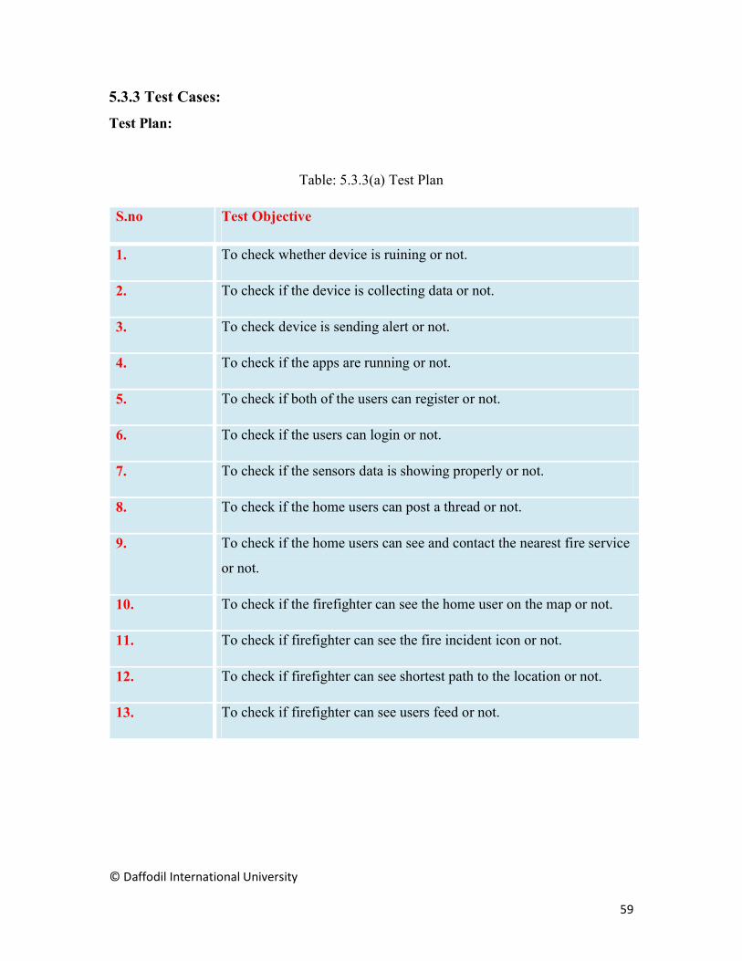
5.3.3 Test Cases:
Test Plan:
Table: 5.3.3(a) Test Plan
S.no Test Objective
1. To check whether device is ruining or not.
2. To check if the device is collecting data or not.
3. To check device is sending alert or not.
4. To check if the apps are running or not.
5. To check if both of the users can register or not.
6. To check if the users can login or not.
7. To check if the sensors data is showing properly or not.
8. To check if the home users can post a thread or not.
9. To check if the home users can see and contact the nearest fire service
or not.
10. To check if the firefighter can see the home user on the map or not.
11. To check if firefighter can see the fire incident icon or not.
12. To check if firefighter can see shortest path to the location or not.
13. To check if firefighter can see users feed or not.

© Daffodil International University
60
Test:
Table: 5.3.3(b) Device Testing
Test Case 1
Test Objective To check whether device is ruining or not.
Test Data Running the device.
Expected Result The device should powered up successfully and connected to
WIFI
Test Result The device powers up successfully and connects to WIFI
Conclusion Expected result matches actual result.
Table: 5.3.3(c) Sensor Testing
Test Case 2
Test Objective To check if the device is collecting data or not.
Test Data Collecting the sensors readings.
Expected Result The sensors should collect smoke, temperature and flame
data
Test Result The sensors successfully collects smoke, temperature and
flame data
Conclusion Expected result matches actual result.

© Daffodil International University
61
Table: 5.3.3(d) Alert Testing
Test Case 3
Test Objective To check device is sending alert or not.
Test Data Sending the Alert if fire occurs
Expected Result The users should receive alert if the smoke and temperature
crosses the threshold value.
Test Result The users successfully receives alert
Conclusion Expected result matches actual result.
Table: 5.3.3(e) Apps running
Test Case 4
Test Objective To check if the apps are running or not.
Test Data Running the apps.
Expected Result Main screen should display successfully.
Test Result Main screen appears correctly.
Conclusion Expected result matches actual result.

© Daffodil International University
62
Table: 5.3.3(f) Registration Testing
Test Case 5
Test Objective To check if both of the users can register or not.
Test Data Run program and fill-up the required fields.
Expected Result Success message should be shown.
Test Result Registered Successfully and Dashboard is loaded.
Conclusion Expected result matches actual result.
Table: 5.3.3(g) Login Testing
Test Case 6
Test Objective To check if the users can login or not.
Test Data Run program and give username and password
Expected Result Success message should be shown.
Test Result Login Successfully as a registered user
Conclusion Expected result matches actual result.

© Daffodil International University
63
Table: 5.3.3(h) Sensor Data Testing
Test Case 7
Test Objective To check if the sensors data is showing properly or not.
Test Data Viewing the smoke and temperature value
Expected Result The both App should show the correct sensor values.
Test Result The both App successfully showed the correct sensor values.
Conclusion Expected result matches actual result.
Table: 5.3.3(i) Threat Post Testing
Test Case 8
Test Objective To check if the home users can post a thread or not.
Test Data Take a photo from the app using cell phone camera and fill-
up the fields
Expected Result A new threat should be posted and Success message should
be shown.
Test Result A new threat successfully be posted and Success message
should be shown
Conclusion Expected result matches actual result.

© Daffodil International University
64
Table: 5.3.3(j) Contact Testing
Test Case 9
Test Objective To check if the home users can see and contact the nearest
fire service or not
Test Data Viewing the nearest fire station on the map and click the call
button
Expected Result User must see the nearest fire station and a call should start
on that fire station’s contact number.
Test Result User can see the nearest fire station and a call has been made
to that fire station’s contact number.
Conclusion Expected result matches actual result.
Table: 5.3.3(k) Firefighter Map Activity Testing
Test Case 10
Test Objective To check if the firefighter can see the home user on the map
or not.
Test Data Viewing the users on the map
Expected Result All the registered users must be shown in the map.
Test Result All the registered users properly shown in the map.
Conclusion Expected result matches actual result.
© Daffodil International University
65
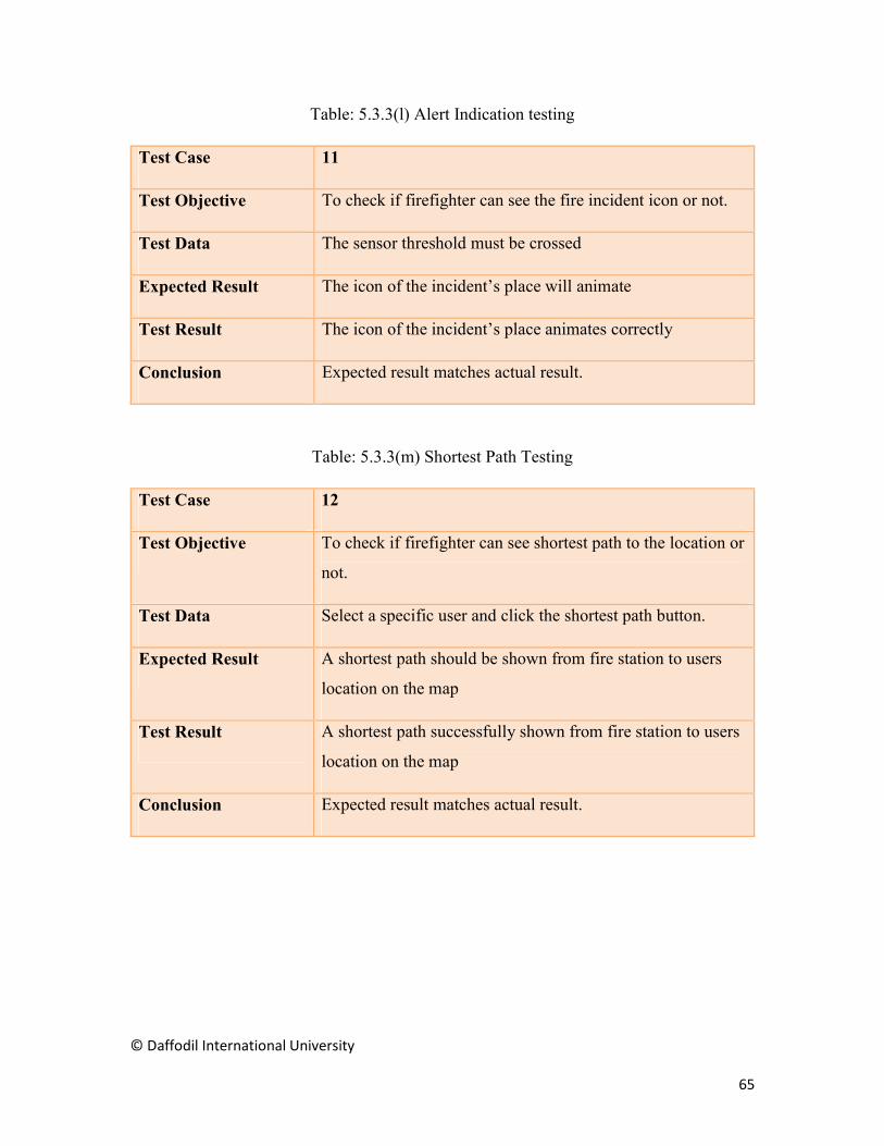
Table: 5.3.3(l) Alert Indication testing
Test Case 11
Test Objective To check if firefighter can see the fire incident icon or not.
Test Data The sensor threshold must be crossed
Expected Result The icon of the incident’s place will animate
Test Result The icon of the incident’s place animates correctly
Conclusion Expected result matches actual result.
Table: 5.3.3(m) Shortest Path Testing
Test Case 12
Test Objective To check if firefighter can see shortest path to the location or
not.
Test Data Select a specific user and click the shortest path button.
Expected Result A shortest path should be shown from fire station to users
location on the map
Test Result A shortest path successfully shown from fire station to users
location on the map
Conclusion Expected result matches actual result.

© Daffodil International University
66
Table: 5.3.3(n) Feed Testing
Test Case 13
Test Objective To check if firefighter can see users feed or not.
Test Data The threats must be posted by the users
Expected Result All posts should be showed properly.
Test Result All posts are properly visible.
Conclusion Expected result matches actual result.

© Daffodil International University
67
5.4 Test Results and Reports
Table: 5.4 Test Results
S.no Test Objective Result
1. To check whether device is ruining or not. Successful
2. To check if the device is collecting data or not. Successful
3. To check device is sending alert or not. Successful
4. To check if the apps are running or not. Successful
5. To check if both of the users can register or not. Successful
6. To check if the users can login or not. Successful
7. To check if the sensors data is showing properly or not. Successful
8. To check if the home users can post a thread or not. Successful
9. To check if the home users can see and contact the nearest fire
service or not.
Successful
10. To check if the firefighter can see the home user on the map or
not.
Successful
11. To check if firefighter can see the fire incident icon or not. Successful
12. To check if firefighter can see shortest path to the location or
not.
Successful
13. To check if firefighter can see users feed or not. Successful

© Daffodil International University
68
CHAPTER 6
CONCLUSION AND FUTURE SCOPE
6.1 Discussion and Conclusion
At last we can say that we have tried our best to complete all the tasks of our project. Our
main purpose was to made technology more human friendly and helpful for emergency
situation. We have tried to make our project as simple as possible for our user to use and
understand. IoT is a new concept of the technology and day by day it is becoming popular
and creating new scopes for future experiments. We had many other ideas for our final
project but we selected this idea because it’s unique at its genre. We also noticed that apps
are very popular nowadays and so we have tried to merge the apps to a small hardware to
build this automated system. We have separated our project in two different apps because
it makes the system more feasible. We have learned a lot while working on this project.
Hope that our project will serve its goal and have a great significance on the growing
technological world.
6.2 Scope for Further Developments
We have made our project as feasible as possible though there are some lacking. Some
parts of our project can be more improved. Future Studies and research can dig up more
features for our system. Let’s see some of the aspects that can be implemented in future
Fire Station Resource
We will add an option to keep the fire station’s information in details. There will be
information of how many heavy and lite vehicles a fire station contains. How many men
working under that station and what kinds of tools they have. This will help to understand
and keep track of a stations capabilities.
Handling Busy Status
In future we will built a mechanism to determine a fire station’s status. If a station is busy
with a task then even if another occurrence happens within its area the alert will be sent to

© Daffodil International University
69
next nearest fire station. This will help to make the system more responsive to cope up with
multiple fire incidents at same time.

© Daffodil International University
70
REFERENCES
[1] Md Saifudaullah Bin Bahrudin, Rosni Abu Kassim, “Development of Fire Alarm System using Raspberry Pi and Arduino Uno ", 2013 International Conference on Electrical, Electronics and System Engineering, 2013.
[2] Sarita Gupta, Ajay Mudgil, Prashant Bhardwaj and Mahendra Gupta, “Design and Development of Automatic Fire Alert System", 2016 8th International Conference on Computational Intelligence and Communication Networks (CICN), December 2013.
[3] Zhang Kun, Hu Shunbin and Li Jinfang, “Automatic Fire Alarm System Based on MCU ", 2010 International Conference on Electrical and Control Engineering, June 2010.
[4] Suresh S., Yuthika S. and G.Adithya Vardhini, “Home based Fire Monitoring and warning system", 2016 International Conference on ICT in Business Industry & Government (ICTBIG), November 2016.
[5] NodeMCU is both a Breadboard-Friendly ESP8266 Wi-Fi Board and a LUA based Firmware: https://www.cnx-software.com/2015/04/18/nodemcu-is-both-a-breadboard-friendly-esp8266-wi-fi-board-and-a-lua-based-firmware/, last accessed on 03-03- 2018.
[6] XML: https://en.wikipedia.org/wiki/XML/, last accessed on 06-03- 2018.
[7] Introduction to XML and Android Layouts: https://www.learnhowtoprogram.com/android/introduction-to-android/introduction-to-xml-and-android-layouts/, last accessed on 06-03- 2018.
[8] Layouts: https://developer.android.com/guide/topics/ui/declaring-layout.html /, last accessed on 06-03- 2018.
[09] Re: What is the language you type in the ArduinoIDE: https://forum.arduino.cc/index.php?topic=45492.0/, last accessed on 09-03- 2018.
[10] What Programming Language Do You Use with Arduino for Robotics Projects: https://www.intorobotics.com/what-programming-language-do-you-use-with-arduino-for-robotics-projects-the-arduino-language-c-or-c /, last accessed on 09-03- 2018.
[11] Firebase Realtime Database: https://firebase.google.com/docs/database/, last accessed on 10-03- 2018.
[12] What is Arduino: https://www.arduino.cc/en/Guide/Introduction?from=Main.GenuinoBrand/, last accessed on 15-03- 2018.
[13] WiFi Module - ESP8266: https://www.sparkfun.com/products/13678/, last accessed on 15-03- 2018.

© Daffodil International University
71
PLAGIARISM REPORT