Embed Size (px)
Citation preview
Advanced Computer Networks 263-3501-00
Exercise Session 2
Spring Semester 2014
© Oriana Riva, Department of Computer Science | ETH Zürich
1

Some announcements
• On course page, you can find – C tutorial I&II on course page under "Additional Material" – assignment*.pdf – assignment*_slides.pdf
• Send me emails with titles starting with “ACN14:”
• Ways to hand in your solutions – During exercise sessions – During lectures (to Patrick)
2

Signal propagation
• Path loss model
• Log-normal shadowing radio propagation
• When can a signal be correctly coded?
• How about reality?
– MIT Roofnet
3
Signal propagation
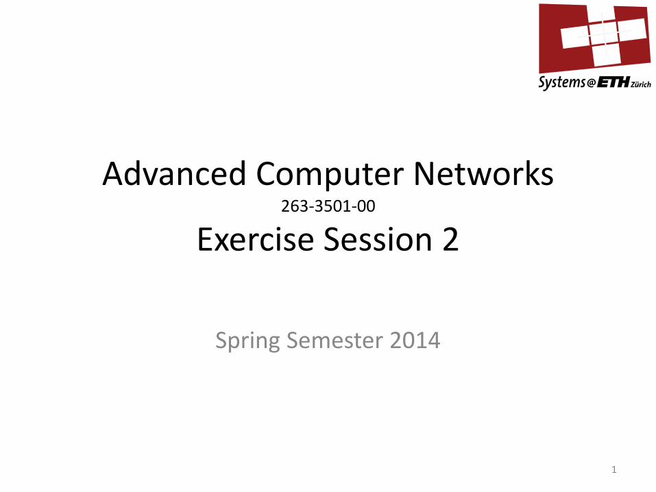
• Decibel (dB) – X1/X0 [dB] = 10 log10 (X1/X0)
• Attenuation [dB] = 10 log10 (transmitted power / received power)
• Theory: Path loss model – Receiving power is proportional to 1/da: – a=2,3,...8 called path loss exponent, depends on environment – : wavelength, depends on frequency – Attenuation:
– Or in dB for a=2:
4
𝑃𝑟𝑃𝑡
=λ
4Π𝑑
𝑎
λ
𝐿𝐿𝐿𝐿 =𝑃𝑡𝑃𝑟
=4Π𝑑λ
𝑎
𝐿𝐿𝐿𝐿𝑑𝑑 = 10log10𝑃𝑡𝑃𝑟
= 20log104Π𝑑λ
Log-normal shadowing radio propagation
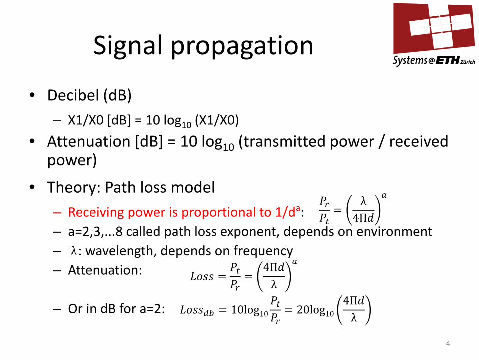
• The Log-normal shadowing model generalizes path loss model to account for effects like shadowing, scattering, etc.
• Attenuation at distance d (in dB):
– X[dB] is a Gaussian random variable with zero mean and standard deviation σ
– Value for σ depends on environment, typical values 2...8 – Might receive stronger power at larger distances (!)
5
𝑃𝑡𝑃𝑟
[𝑑𝑑] = 𝑎 ⋅ 10log104Π𝑑λ + 𝑋[𝑑𝑑]
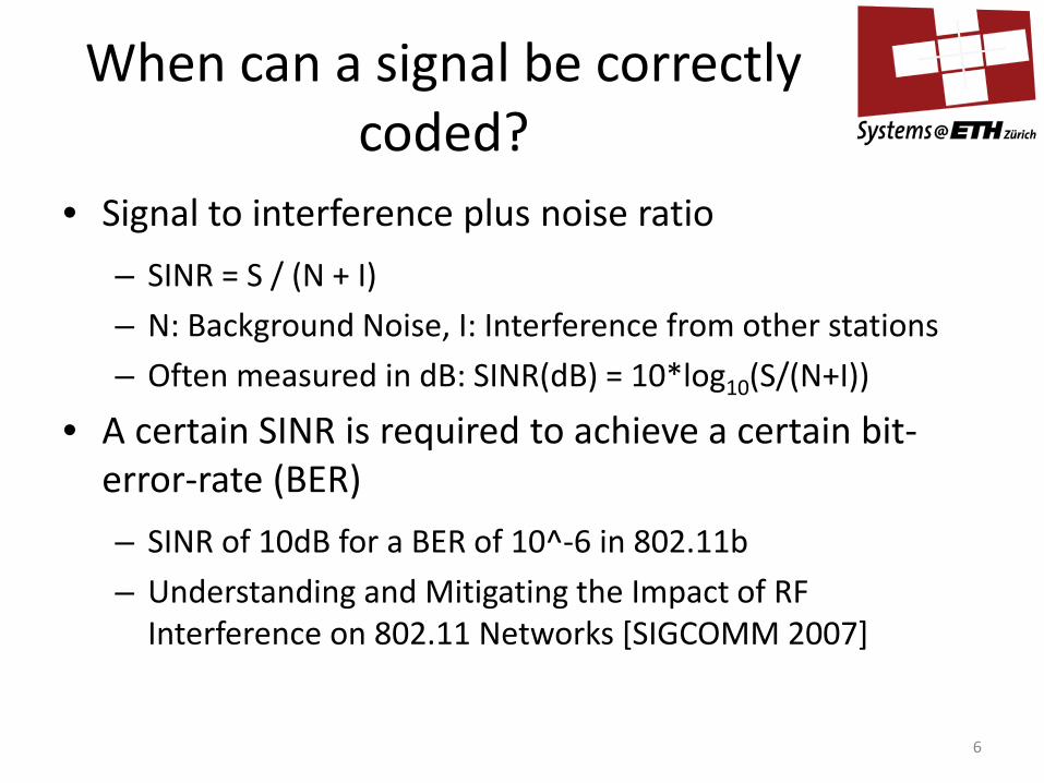
When can a signal be correctly coded?
• Signal to interference plus noise ratio
– SINR = S / (N + I)
– N: Background Noise, I: Interference from other stations
– Often measured in dB: SINR(dB) = 10*log10(S/(N+I))
• A certain SINR is required to achieve a certain bit-error-rate (BER)
– SINR of 10dB for a BER of 10^-6 in 802.11b
– Understanding and Mitigating the Impact of RF Interference on 802.11 Networks [SIGCOMM 2007]
6

Roofnet: Take Away
• Wireless links may behave very different from models (e.g., path loss and also log-normal shadowing)
– No good correlation of SINR and distance
– High SINR does not guarantee good delivery probability
• Predicting wireless performance is very difficult
7

Modulation in Wireless Networks
• Digital modulation – Convert digital signal into analog signal
• Analog modulation – Shift analog signal into the frequency band used by the
wireless network
• The general function of a sine wave: g(t)=A*sin(2*π*f*t+φ) – Amplitude A – Frequency f – Phase φ
8
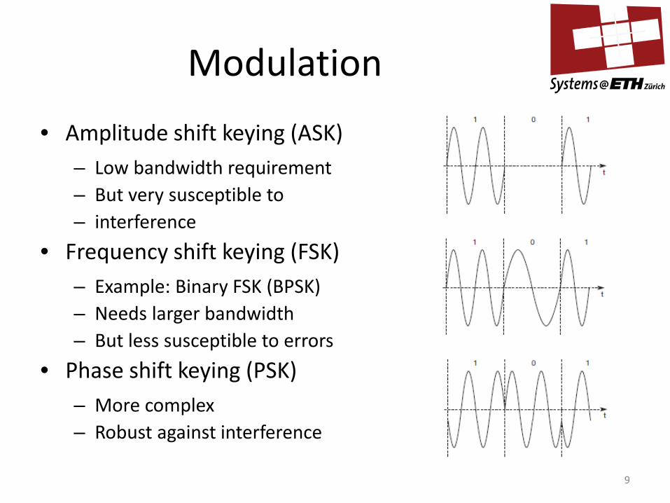
Modulation
• Amplitude shift keying (ASK) – Low bandwidth requirement – But very susceptible to – interference
• Frequency shift keying (FSK) – Example: Binary FSK (BPSK) – Needs larger bandwidth – But less susceptible to errors
• Phase shift keying (PSK) – More complex – Robust against interference
9

Spread Spectrum
• Spread the bandwidth needed to transmit data
• Provides resistance against narrowband interference
sender: -spread data (i) -new data requires broader band (ii)
channel: -interference adds to the signal
receiver: -de-spread the signal - filter out broadband noise -receive narrowband data
10
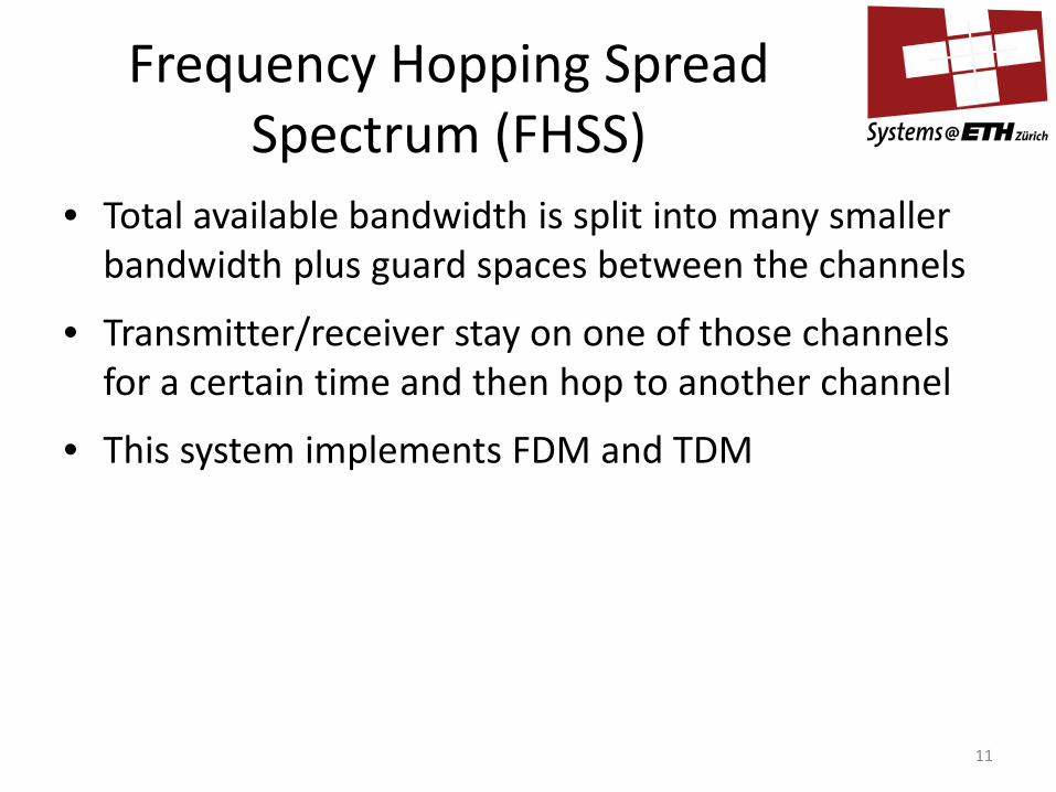
Frequency Hopping Spread Spectrum (FHSS)
• Total available bandwidth is split into many smaller bandwidth plus guard spaces between the channels
• Transmitter/receiver stay on one of those channels for a certain time and then hop to another channel
• This system implements FDM and TDM
11
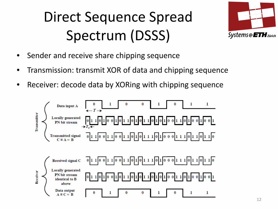
Direct Sequence Spread Spectrum (DSSS)
• Sender and receive share chipping sequence
• Transmission: transmit XOR of data and chipping sequence
• Receiver: decode data by XORing with chipping sequence
12

Direct Sequence Spread Spectrum
Why does this work?
• Assume data represented by -1, 1 (instead of 0, 1) – Using -1,1 allows us to use vector scalar product * – In practice DSSS systems use XOR and a 0,1 system
• B = Chipping sequence, B*B = 1, Spreading factor T/Tc
• Transmitting data: C=A*B,
• Receiving data: C*B=A*B*B=A
What if we have interference?
• Signal on the air: A*B + I
• Received data: A*B*B + I*B = A + I*B
13
Wideband signal which can be filtered out

Comparison FHSS and DSSS
• FHSS is good in case of frequency selective interference
• FHSS is simpler than DSSS
• FHSS uses only a portion of the bandwidth at any given time
• But DSSS are more robust to fading and multipath effects
14

Medium Access Control in Wireless Networks
• Why does CSMA/CD not work in wireless
– Signal strength decreases at least proportional to the square of the distance
– CS and CD is applied by sender, but collision happens at receiver
• Hidden Terminal Problem
• Exposed Terminal Problem
15

Multiplexing Wireless Transmissions
• SDM (Space Division Multiplexing) – Use cells to reuse frequencies, or, – use directional antennas (separate users by individual beams)
• FDM (Frequency Division Multiplexing) – Assign a certain frequency band to a transmission channel (refers to a
sender/receiver that want to exchange data) – Permanent (radio broadcast), slow hopping (GSM), fast hopping (Bluetooth)
• TDM (Time Division Multiplexing) – Separate different channels by time – Almost all wired MAC schemes make use of this (Ethernet, Token Ring, ATM)
• CDM (Code Division Multiplexing) – Codes with certain characteristics can be applied to the transmissions to separate
different users (just like DSSS)
16

Question 1
• What is path loss model for signal propagation?
• Why the log-normal shadowing model is more realistic compared to the pass loss model?
• What determines if a signal can be correctly decoded?
• Why the log-normal shadowing model is still not realistic enough?
• When you list a formula, explain the notations
17
Question 2
• What is spread spectrum technique?
• What are the main benefits of a spread spectrum system?
• How can spreading be achieved?
18

Question 3
• How does the spreading factor affect the bandwidth of the spread signal?
– Data sequence
– Chipping sequence
– What is the transmitted signal?
19

Question 4
• Paper reading
– The Design Philosophy of the DARPA Internet Protocols
• Questions
– What was the top level goal for the DARPA Internet Architecture?
– Another important goal: Internet communication must continue despite loss of networks or gateways
– Datagrams
20

Question 5
• Paper reading
– End-to-End Arguments in System Design
• Questions
– The end-to-end argument
– Some commonly used examples where the argument can be applied
– Three examples where the end-to-end argument is diluted
21