Embed Size (px)
Citation preview

1.
2.
3.
4.
5.
6.
The most accurate multivariable ABB has ever produced
Introduction This is a startup guide designed for typical installations only. Installations must be performed by personnel knowledgeable of the theory of gas measurement and the Totalflow® 266 MODBUS® Multivariable Transmitter. Installation personnel must also be knowledgeable of local and national codes as it applies to hazardous areas, communication wiring, and electrical wiring.
Read and understand the contents of this startup guide prior to beginning installation of the equipment. If you have questions that are not answered in this guide or other documentation listed in the following section, call your local Totalflow representative, or call the technical support number listed on the back page of this guide.
Although there may be alternate methods of installation, it is recommended that technicians perform the guide procedures in the presented order.
WARNING – Bodily injury. The startup guide does not address any requirements for installation of product(s) in Classified Hazardous Locations.
Startup guide
2600T series pressure transmitters 266 MODBUS® multivariable transmitter
2 | 2105328-001 rev. AC
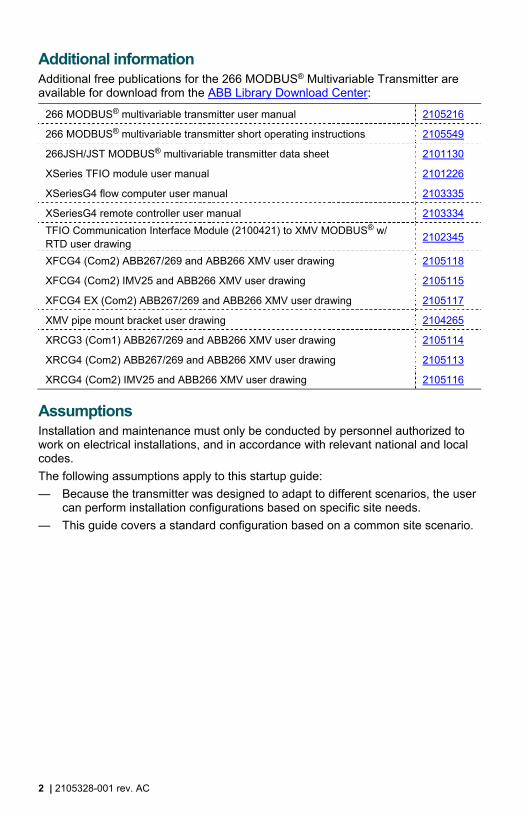
Additional information Additional free publications for the 266 MODBUS® Multivariable Transmitter are available for download from the ABB Library Download Center:
266 MODBUS® multivariable transmitter user manual 2105216
266 MODBUS® multivariable transmitter short operating instructions 2105549
266JSH/JST MODBUS® multivariable transmitter data sheet 2101130
XSeries TFIO module user manual 2101226
XSeriesG4 flow computer user manual 2103335
XSeriesG4 remote controller user manual 2103334
TFIO Communication Interface Module (2100421) to XMV MODBUS® w/ RTD user drawing
2102345
XFCG4 (Com2) ABB267/269 and ABB266 XMV user drawing 2105118
XFCG4 (Com2) IMV25 and ABB266 XMV user drawing 2105115
XFCG4 EX (Com2) ABB267/269 and ABB266 XMV user drawing 2105117
XMV pipe mount bracket user drawing 2104265
XRCG3 (Com1) ABB267/269 and ABB266 XMV user drawing 2105114
XRCG4 (Com2) ABB267/269 and ABB266 XMV user drawing 2105113
XRCG4 (Com2) IMV25 and ABB266 XMV user drawing 2105116
Assumptions Installation and maintenance must only be conducted by personnel authorized to work on electrical installations, and in accordance with relevant national and local codes.
The following assumptions apply to this startup guide:
— Because the transmitter was designed to adapt to different scenarios, the user can perform installation configurations based on specific site needs.
— This guide covers a standard configuration based on a common site scenario.

2105328-001 rev. AC | 3
1 Safety warning and note symbols
WARNING – Bodily injury. This symbol, in conjunction with the word "WARNING", indicates a potentially dangerous situation. Failure to observe this safety information may result in death or severe injury. The text may state the hazard, what to do or not do to avoid the hazard, and what the result would be if not followed.
WARNING – Bodily injury. This symbol, in conjunction with the word "WARNING", indicates a potential electrical hazard. Failure to observe this safety information will result in death or severe injury. The text may state the hazard, what to do or not do to avoid the hazard, and what the result would be if not followed.
NOTICE – Property damage. This symbol indicates a potential situation where data could be corrupted or normal operation could be effected if recommendations are not followed. The text may state the condition, how to avoid undesirable results, and what the result would be if not followed.
IMPORTANT NOTE: This symbol indicates operator tips, particularly useful information, important information about the product, or to clarify a concept. The signal words "IMPORTANT NOTE" do not indicate a dangerous or harmful situation.
1.1 Potential safety hazards The 266 MODBUS® multivariable transmitter equipment operates on 10.5 – 30 Vdc. Follow your company’s policies and procedures when installing any electrical and/or measurement equipment. Always were Personal Protective Equipment (PPE) per your company’s policies and procedures.
WARNING – Bodily injury. Read and follow instructions contained in this guide before and during equipment installation. Failure to do so could result in bodily injury or equipment damage.
Refer to the 266 MODBUS® multivariable user manual, part number 2105216, if the location of installation is in an area where there may be the potential of an explosive atmosphere. Installations of this type must meet the requirements of product certification, local and national electrical codes, and your company policy.

4 | 2105328-001 rev. AC
2 Unpacking and inspection
Inspect the shipping carton for damage.
2. Unpack the 266 MODBUS® multivariable transmitter. Ensure that you have received all items on the packing list.
3. Verify that the correct transmitter has been shipped by comparing the model number to the packing slip.
4. Inspect the 266 MODBUS® multivariable transmitter exterior for damage.
5. Unpack and inspect optional equipment, if purchased.
6. Contact your ABB representative to replace any missing, incorrect, or damaged parts.
IMPORTANT NOTE: If the shipping carton is damaged, keep it until the contents have been inspected for damage.

2105328-001 rev. AC | 5
3 Hardware specifications and installation
3.1 Hardware specifications The hardware specifications for the 266 MODBUS® multivariable transmitter are as follows:
— The transmitter measures static pressure, differential pressure, and process temperature in a gas, vapor, or liquid media.
— The transmitter is a 2-wire RS-485 MODBUS® device with two additional wires required for power.
— The transmitter has a permissible terminal voltage range of 10.5 – 30 Vdc.
— The current draw is 10 mA at 12 Vdc per 266 XMV.
— The transmitter can be set up to operate with XSeries (XFC/XRC) devices and should be wired to a communication port.
3.2 Mounting options The 266 MODBUS® multivariable transmitter can be direct-mounted or pipe-mounted to the meter run. Proceed to the installation instructions best suited to the equipment purchased and the installation site.
For direct mount, go to section 3.2.1, Direct mount installation.
For pipe mount, go to section 3.2.2, Pipe mount installation.
IMPORTANT NOTE: Before beginning, review the materials required for installation.

6 | 2105328-001 rev. AC
3.2.1 Direct mount installation The 266 MODBUS® multivariable transmitter can be direct-mounted either horizontally or vertically.
Materials:
— One (1) manifold (3 or 5 valve manifold TBD by technician)
— Two (2) stabilized manifold connectors (compatible with manifold)
To direct mount the transmitter:
1. Determine where the transmitter is to be placed on the meter run ensuring that the high side is upstream.
2. Install the stabilizer manifold connectors to the meter run orifice following the instructions supplied by the manufacturer (Figure 1 or Figure 2).
266 MODUS® multivariable
RTD
Manifold
Meter run
Figure 1: Horizontal assembly direct-mounted
266 MODBUS® multivariable transmitter
RTDMeter run
Manifold
Figure 2: Vertical assembly direct-mounted
3. Align the sealing rings and bolt holes between the transmitter flange and manifold, then bolt the transmitter to the manifold.
4. Secure the manifold assembly to the meter run.
The transmitter is now direct-mounted. Go to section 3.3, Leak test manifold and tubing connections.

2105328-001 rev. AC | 7
3.2.2 Pipe mount installation The following steps provide general instructions for pipe-mounting the horizontal flange transmitter using a vertical pipe mount kit.
Materials:
— One (1) pipe saddle with mounting hardware (size TBD by technician)
— One (1) 2" x 40" pipe (length may be extended if mounting a solar panel)
— One (1) enclosure mounting kit (includes instructions, brackets, U-bolts and fastening hardware)
To pipe mount the 266 MODBUS® multivariable transmitter assembly vertically:
1. Determine where the 266 MODBUS® multivariable transmitter is to be positioned on the mounting pipe.
IMPORTANT NOTE: Select a location that allows easy user access and is close to equipment.
2. Position the pipe saddle on the meter run and temporarily attach the saddle to the meter run pipe using the associated hardware (Figure 3). Do not tighten.
Mounting pipe
Meter runSaddle mounting
U-bolt
Leveling saddle pipe mount
Saddle leveling bolts
Figure 3: Pipe-mounted
3. Thread the mounting pipe into the saddle and tighten securely.
4. Level the mounting pipe:
a. Level the pipe and saddle so that it is perpendicular to the meter run and tighten the saddle mounting U-bolt.
b. Level the pipe side-to-side using the saddle leveling bolts (if available) on the mounting saddle.
5. Securely fasten the saddle mount using the provided U-bolt.
6. Secure the mounting bracket to the mounting pipe with two U-bolts, flat washers, split washers and bolts (Figure 4).

8 | 2105328-001 rev. AC
Mounting pipe
U-bolts(2 places)
Flat washer, split washer, and nut
(4 places)
Figure 4: Mounting bracket assembly

2105328-001 rev. AC | 9
7. Adjust the height of the mounting bracket to allow for the transmitter, manifold, and tubing (Figure 5).
266 XMV
Bracket
Meter run
Manifold
Figure 5: Horizontal flange transmitter, pipe-mounted
8. Attach the transmitter flange to the underside of the bracket, using four bolts.
9. Align the sealing rings and bolt holes between the manifold and the transmitter. Bolt the transmitter to the manifold.
10. Locate the tap valves on the meter run orifice and the corresponding high and low inputs on the installed manifold.
11. Measure, cut, and bend the tubing to ease installation of the fittings into the orifice tab vales and the manifold.
12. Install the nut and ferrule onto the tubing end.

10 | 2105328-001 rev. AC
13. Insert the ferrule into the fitting and slide the nut onto the ferrule; engage the nut threads, and tighten.
14. Repeat step 13 for each tubing connection point.
IMPORTANT NOTE: To rotate the housing and display, follow the instructions detailed in the 266 MODBUS® multivariable transmitter user manual.
The transmitter is now pipe-mounted. Go to section 3.3, Leak test manifold and tubing connections.
NOTICE – Property damage. To avoid damage to the stainless steel tubing, fittings, and valves, always use a backup wrench to stabilize and eliminate tension on both sides of the connection when tightening. Damaged connections my introduce leaks into the system resulting in inaccurate measurement.

2105328-001 rev. AC | 11
3.3 Leak test manifold and tubing connections Manifold and tubing connections must be leak-tested prior to power application. Connection leaks between the orifice tap valves, the manifold, and the transmitter can introduce measurement and calibration errors.
Materials:
— Liquid leak detector
— Pressure calibration device
DANGER – Serious damage to health/risk to life. Manifold and tubing connection leaks could create a build-up of explosive gases in the immediate vicinity. Power should not be applied before the tubing and connections are leak-free. If leaks are present, power should not be applied until the area is ventilated and explosive gases have dissipated.
To leak test the manifold and tubing connections:
1. Verify that the equalizer valves (Figure 6, items A and B) are open and the manifold vent valve is closed (item C).
HL
HL
HL
A B
C
Vent/Test Vent/Test
Tap valve connectionsTap valve connections
Manifold tubing connections
Manifold to flange connections
Process Process
Instrument
Figure legend: A) Low side equalizer valve B) High side equalizer valve C) Manifold vent valve H) High pressure side L) Low pressure side
Figure 6: Connections and manifold valve operation (for illustrative purposes only)
2. Apply pressure to the high side vent/test port based on the transducer range (100%).
3. Squirt liquid leak detector onto the following connections.
– High and low pressure tap valve connections
– High and low pressure manifold tubing connections
– Connection point between the flange and the manifold

12 | 2105328-001 rev. AC
4. Bubbles in the liquid indicate a loose or poor connection.
5. Using the appropriate size wrench, tighten any loose connections, then recheck with the liquid leak detector. Do not over tighten.
6. When all connections are leak-free, continue to 3.4, DIV 1 explosion-proof RTD installation for RTD installation.
2105328-001 rev. AC | 13
3.4 DIV 1 explosion-proof RTD installation The remote thermal detector (RTD) probe measures flowing gas temperature. The following procedure indicates how to install the RTD into the meter run.
IMPORTANT NOTE: To install a DIV 2 or general purpose RTD, follow the instructions detailed in the 266 MODBUS® multivariable transmitter user manual.
Materials:
— RTD probe (DIV 1), (probe length TBD by technician)
— Cable (cable length TBD by technician)
— Teflon® tape
— One (1) thermowell with ¾" NPT threads (depth TBD by technician)
— Nylon tie wraps
WARNING – Bodily injury. Conduit requirements for DIV 1 installations are not addressed in this procedure. To avoid creating a hazardous situation, ensure compliance with the applicable standards, regulations, and recommendations for installation in the country of use. RTD installation in classified DIV 1 areas should only be performed by technicians knowledgeable about explosion protection.
Explosion-proof and flame-proof installations require explosion-proof conduit and poured seals or flame-proof rated cable and cable glands, respectively.
To install the RTD in the meter run:
1. Install the thermowell into the meter run.
NOTICE – Property damage. If fluid is added to the thermowell to improve the thermal response to flowing temperature, consideration should be given to the type of fluid added regarding the ecological impact and freezing possibility in cold environements.
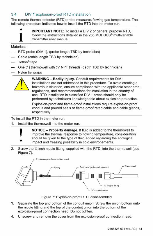
2. Screw the ½ inch nipple fitting, supplied with the RTD, into the thermowell (see Figure 7).
Figure 7: Explosion-proof RTD, disassembled
3. Separate the top and bottom of the conduit union. Screw the union bottom onto the nipple fitting and the top of the conduit union into the bottom of the explosion-proof connection head. Do not tighten.
4. Unscrew and remove the cover from the explosion-proof connection head.
Explosion-proof connection head
Spring
½” conduit union
Bottom of probe and element
½” nipple fitting
Thermowell

14 | 2105328-001 rev. AC
5. Insert the RTD probe through the opening in the connection head. Holding the probe from below, screw the spring clockwise down into the center of the wiring block until the top edge of the spring is flush with the top of the wiring block.
6. Insert the probe and head assembly through the bottom half of the union previously installed onto the thermowell. As union halves meet, the probe should encounter some resistance from the spring. As the probe contacts the bottom of the thermowell, the top of the probe should rise a maximum of ¾".
IMPORTANT NOTE: The probe should extend into the center 1/3 of the stream. If the probe assembly is too long (the top of the conduit union will not screw into the bottom half of the conduit union) or too short (no resistance is encountered when screwing the probe and head assembly into the bottom half of the union), then the nipple fitting may need to be replaced with one of a different length.
7. Align the RTD head to correspond with the wiring conduit previously installed and complete the connection.
8. Tighten all conduit and fittings to wrench tight.
9. Wire the RTD probe wiring to the wiring block located inside of the explosion-proof head assembly (see Figure 8).
Figure 8: RTD probe wiring to explosion-proof head wiring block
10. Install the conduit, wire, and cable gland RTD explosion-proof head to the transmitter.
White probe wire
Red probe wire
Red probe wire
White probe wire

2105328-001 rev. AC | 15
12. Connect the transmitter wiring ends to the RTD wiring block (see Figure 9).
White wire to transmitter
Black wire to transmitter
Black wire to transmitter
White wire to transmitter
Figure 9: RTD wiring to transmitter
13. Screw the RTD cover onto the explosion-proof housing assembly to complete the RTD installation.
Installation of the RTD is complete. Continue to section 4, Electrical and communication wiring.

16 | 2105328-001 rev. AC
4 Electrical and communication wiring
4.1 Transmitter protective conductor, ground, and integrated surge protection
The 266 MODBUS® multivariable transmitter operates in common mode voltages, between the signal lines and the housing, up to 250 Volts. If voltages of >150 Vdc are possible, the housing must contain a protective circuit (e.g. grounding, protective conductor) in order to fulfill the requirements of low-voltage guidelines and relevant EN 61010 rules for the installation of electrical components. A connection terminal is available for grounding (PE) on the transmitter exterior and inside the housing termination side. The grounding (PE) terminals are electrically interconnected through the housing body.
The transmitter terminal block includes transient suppression circuitry built in. The high current dissipation path for the integrated surge protection circuit is through the two terminal block mounting screws to the grounding (PE) connections.
IMPORTANT NOTE: The grounding (PE) should be kept as short as possible with a recommended wire size of 12AWG.
These instructions do not address cabling requirements for explosion-proof and flame-proof installations.
4.2 Transmitter wiring The RTD, power, and communication cables must be wired to the 266 MODBUS® multivariable transmitter termination block prior to connecting the power and communication cables to the XSeries device.
ABB strongly recommends the use of shielded 1.5 twisted pair or 2 twisted pair (with drain wire) cable for the communication interface. For a distance up to a maximum of 4000 ft. (1219 m), the wire size should be between 22 AWG (0.35 mm2) and 18 AWG (0.8 mm2).
For supply voltage connections, ABB recommends the use of a shielded twisted pair cable. For a distance up to a maximum of 4000 ft. (1219 m), the range of wire size could be between 18 AWG (0.8 mm2) and 14 AWG (2.1 mm2).
DANGER - Risk to life due to explosion. Explosion-proof and flame-proof installations require explosion-proof conduit and poured seals or flame-proof rated cable and cable glands, respectively.
1. Unscrew the transport screw plug from the cable entry and the rear housing cover from transmitter, if not already removed.
2. If a live temperature sensor (RTD) is installed in the meter run, wire the RTD sensor cable to the transmitter RTD terminals. Otherwise, continue to step 3.
a. Using a small screwdriver, loosen the terminal 1, 2, 3, and 4 screws (see Figure 10) and remove the resistor and jumper wires.
NOTES: For the purpose of temperature simulation, a 178 Ω resistor (206 °C / 402.8 °F) with 2 jumpers has been installed between the terminals for the temperature RTD connection. This resistor (including the jumpers in the case of 4-wire connections) must be removed before connecting the RTD. If a temperature RTD is not connected, the resistor must remain in place.

2105328-001 rev. AC | 17
RTD Simulation: 178 Ω resistor with 2 jumper wires
Figure 10: RTD Simulation wiring
a. Install the RTD to transmitter cable through transmitter housing access port.
b. Wire one (1) each white wire to terminal 1 and to terminal 2 (Figure 11).
c. Wire one (1) each black wire to terminal 3 and to terminal 4.
d. Wire RTD shield wire to grounding terminal.
Cable from RTD probe
Shield wire
WH
T
WH
T
BLK
BLK
Shield
Power +
Power -
Bus +
Bus -
Com
mu
nica
tion
NOTE: Wiring shown outside of transmitter cable entry ports for clarity
Figure 11: 266 MODBUS® multivariable transmitter wiring

18 | 2105328-001 rev. AC
4. Connect the communication (+) wire to the COMM (+) terminal and the communication (-) wire to COMM (-) terminal.
5. Connect the power (+) wire to the PWR (+) terminal and the power (-) wire to the PWR (-) terminal at the transmitter.
The transmitter wiring is now complete. Continue to section 4.3 for power and communication wiring from a host.
4.3 Host power supply and communication wiring For power supply and communication wiring to an unknown host, continue to section 4.3.1, Unknown host power supply and communication wiring, for communication wiring information.
For power supply and communication wiring to an XSeries host, go to section 4.3.2, Connect the transmitter to an XSeries host product for communication wiring instructions.
4.3.1 Unknown host power supply and communication wiring Figure 11, 266 MODBUS® multivariable transmitter wiring, on page 17 shows the transmitter wiring terminals.
1. Remove power from the transmitter if necessary, and follow the manufacturer’s instructions provided for communication wiring to the host.
2. When the wiring is complete, apply power to the host and the transmitter.
The transmitter is now operational and the communication wiring to the host is complete. If there is an issue with the transmitter power, go to section 7, Troubleshooting, on page 30 for information.
Go to section 6, Transmitter configuration for an unknown host, on page 27, to configure the transmitter.
4.3.2 Connect the transmitter to an XSeries host product The example in this basic configuration case illustrates the connections required to terminate the transmitter to an XSeries host. This includes RS-485 communication and power.
1. If necessary, disconnect power from the XSeries host and the transmitter.
2. Complete cabling and conduit from the transmitter to the XSeries host.
3. Inside of the XSeries host enclosure, connect the transmitter wiring as shown in Table 1 and the referenced wiring schematic.
Table 1: 266 MODBUS® multivariable transmitter-to-XSeries device connections
Device Wiring COM# Location VBATT GND Bus+ Bus-
XFCG4 Figure 12 2 J4 Pin 2 Pin 1 Pin 12 Pin 13
XRCG4 Figure 13 2 J6 Pin 1 Pin 2 Pin 9 Pin 7
microFLOG4 Figure 14 1 J10 Pin 1 Pin 2 Pin 6 Pin 7
TFIO CIM Figure 15 CIM TFIO J1-Pin 4 J1-Pin 3 J2-Pin 1 J2-Pin 2

2105328-001 rev. AC | 19
RS-485 Communications ModuleIn this configuration, COMM:2 may not be used to communicate with other devices. To attach other devices, such as other flow computers, use COMM:1.
266 MODBUS® multivariable transmitter
2 VBATT
1 GND
13 BUS-
12 BUS+
101413
219
21
109
21
J18
J11
3
1
J15
5
9 6
1
J5
1413
21
J2
J1
SD CARD
JTAG
USB A/B
BATT
I/O
DIS
PLA
Y
COMM:1COMM:2
CPU ENGINES2
14
13
2
1
J17
XA1
1
J3
XU1
J19
XA2
1
J12
3
1
XA3
J19
ON
OFF
CHARGER
RESET
ETHERNET
21
KEYPAD
S1
J6
J4
1
2
3
4
5
6
7
816
15
14
13
12
11
10
9
DIGITAL I/O
COMM
1
2
3
4
5
6
7
8
XFCG4 (2103328) Board
Note: Wiring shown outside of transmitter cable entry points for clarity
Figure 12: Wiring 266 MODBUS® multivariable transmitter to XFCG4 board

20 | 2105328-001 rev. AC
RS-485 Communications ModuleIn this configuration, COMM:2 may not be used to communicate with other devices. To attach other devices, such as other flow computers, use COMM:1.
7 BUS-
9 BUS+
1 VBATT2 GND
A
101413
219
21
109
21
J29
J7
3
1
J18
5
9 6
1
J17
1413
21
J13
J16
J6
SD CARD
JTAG
USB A/B
BATTI/O
DIS
PLA
Y
COMM:1COMM:2
CPU ENGINE
S2
14
13
2
1
J27
COMM:2
COMM:1
DIGITAL I/O
XA1
1
J15
XU1
J28
XA2
1
J10
3
1
XA3
J19
J8
S1
ON
CHARGER
RESET ETHERNET
1 3
J5
21
KE
YP
AD
1
2
3
4
5
6
7
8
1
2
3
4
5
6
7
8
9
1
2
3
4
5
6
1
2
3
4
5
6
9
XRCG4 (2103329) Board
Note: Wiring shown outside of transmitter cable entry points for clarity
266 MODBUS® multivariable transmitter
Figure 13: Wiring 266 MODBUS® multivariable transmitter to XRCG4 board

2105328-001 rev. AC | 21
1 VBATT2 GND
6 BUS+7 BUS-
COMM:2 communication is possible via optional I/O card.
Note: Wiring shown outside of transmitter cable entry points for clarity
S3
J17
RESET
J15
14
13
21
SECURITY
BAT
S2
LIT
H
EXTS1
ON
MMI
J2(to optional I/O Card)
CONTRASTUSB
OF
F
J12
J9
J18
R12
J10
COMM 1
DI
1J16
J4
J8
3
microFLOG4 (2104356) Board
266 MODBUS® multivariable transmitter
1
2
3
4
5
6
7
8
9
Figure 14: Wiring 266 MODBUS® multivariable transmitter to microFLOG4 board

22 | 2105328-001 rev. AC
J1
J21 2 3
6
7
5
0
4
1
2
3
J3
J4
RUNMODE
ACTIVITY
4
1 2 3 4
1234
1234
MODE- 00 NORMAL- 01 RESET
TF IO MODULECOMM INTERF ACE
2100421
JumpersJ1-1 to J2-1J1-2 to J2-2
Dip switch factory default address is set a 0. If another COMM INTERFACE TFIO is added, move that dip switch setting to 1. If more are added, use the next address in line for each.
Changing the address applies only to TFIOs of their own type, and not TFIOs of another type. TFIOs of another type would also start at 0 and add new address of their own.
TIP: While 0 is recommended for the first address, any address can be used.
J1 - 4 VBATT
J1 - 3 GND
J2 - 2 BUS -
J2 - 2 BUS +
Jumper to terminate RS-485 buss
266 MODBUS® multivariable transmitter
Note: Wiring shown outside of transmitter cable entry points for clarity
Figure 15: Wiring 266 MODBUS® multivariable transmitter to TFIO CIM
4. After completing the connections, apply power to the XSeries host and the transmitter.
5. Verify that both the XSeries host and the transmitter displays are active.
The transmitter is now operational and the communication wiring to the host is complete. If there is an issue with the transmitter power, go to section 7, Troubleshooting, on page 30 for information.
Go to section 5, XSeries host transmitter configuration, on page 23 to configure the XSeries host to communicate with the transmitter.
IMPORTANT NOTE: Figure 15 shows a direct connection between the 266 MODBUS® multivariable transmitter and a TFIO Communication Interface Module (CIM). The TFIO module communicates with the XSeries device in which it is installed.

2105328-001 rev. AC | 23
5 XSeries host transmitter configuration
NOTES: PCCU32 screen shots used in this guide may differ from actual displayed results. Of several possible causes, the primary factor may be a result of PCCU32 view settings. There are 3 levels of view settings and these are defined by ability: Basic, Advanced, and Expert. The defalut setting is Advanced.
ABB recommends keeping the default transmitter settings when interfacing with an XSeries device and using PCCU32 to configure the transmitter. Using the local Human Machine Interface (HMI) to configure the transmitter could create communication and configuration errors between the XSeries host and the transmitter. For setup options outside the scope of this guide, refer to the 266 MODBUS® multivariable transmitter user manual.
5.1 Add and setup the XMV Interface application in PCCU32 To setup and operate the 266 MODBUS® multivariable transmitter using an XSeries host, the configuration of the transmitter is best handled by using the PCCU32 software to connect to the XSeries host.
To begin configuration, add the transmitter application to the XSeries host and then configure the communication.
1. Launch the PCCU32 software program by double-clicking the desktop icon or selecting Start > Program > PCCU from the menu.
2. Connect the local communication cable to the XSeries host and click on the PCCU32 Entry icon.
3. To add the XMV Interface application:
a. Click on the station name located at the top node in the tree view on the left (Figure 16).
Figure 16: Add new application screen

24 | 2105328-001 rev. AC
a. Select the Applications tab.
b. Click Add App at the bottom of the PCCU32 screen.
c. Select XMV Interface from the application list. The slot number is chosen automatically (the default application slot is 41). Click OK.
d. Click Send to save.
4. Click Re-read to verify that the application has been added in the slot indicated.
5. Configure the XMV interface communication:
a. Select Communications > XMV Interface > Communications > Setup (Figure 17).
Figure 17: XMV interface communications setup screen
b. Verify the appropriate communication port settings are as shown.
6. Click Send after making any changes to the communication values.

2105328-001 rev. AC | 25
5.2 Configure the 266 MODBUS® multivariable transmitter 1. Select Communications > XMV Interface > XMV 1. The XMV 1 screen
displays.
2. Select the Setup tab to setup XMV 1.
3. To change the settings, click Disabled in the Scan field and click Send. PCCU32 scanning is disabled.
4. Verify the settings for each field are as follows (Table 2):
Table 2: XMV 1 setup settings
Field Setting Notes
Device Unit Registers
Differential Pressure: 41.205.0
Static Pressure: 41.205.1
Temperature: 41.205.2
These are the default registers for Differential Pressure, Static Pressure, and Temperature.
XMV Type ABB 266 CS
Scan Enabled Ensure that Scan is set to Enabled after entering all settings.
Device Units U.S. Customary This is the recommended setting for optimal use.
Baud Rate 9600 This is the recommended setting for optimal use and must match the setting of the transmitter.
Response Delay 50 This is the default setting.
MB Register 21 This is the required setting.
MB Address Select any unused address from 1 to 247
The default address is 247. See step 5 for instructions on changing MB Address.
Scroll Display Enabled This is the required setting for proper scroll display.
5. Change the MB Address (MODBUS® Address) through either the Old Address or Serial Number field.
a. To change the MB Address using the Old Address field:
i. Select the checkbox in the Old Address field (located in the Change Address box on the Setup screen).
ii. Type the old address of the transmitter in the Old Address field.
IMPORTANT NOTE: Use 0 as the global address if the old address is not known and there is only one 266 MODBUS® Multivariable Transmitter device on the bus.
iii. Type the new MB Address in the MB Address field.
b. To change the MB Address through the Serial Number field:
i. Select the checkbox in the Serial Number field. ii. Type the serial number of the transmitter in the Serial Number field.
IMPORTANT NOTE: The serial number of the device is on the tag attached to the top of the enclosure.
c. Type the new MB Address in the MB Address field.
26 | 2105328-001 rev. AC
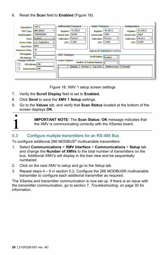
6. Reset the Scan field to Enabled (Figure 18).
Figure 18: XMV 1 setup screen settings
7. Verify the Scroll Display field is set to Enabled.
8. Click Send to save the XMV 1 Setup settings.
9. Go to the Values tab, and verify that Scan Status located at the bottom of the screen displays OK.
IMPORTANT NOTE: The Scan Status: OK message indicates that the XMV is communicating correctly with the XSeries board.
5.3 Configure multiple transmitters for an RS-485 Bus To configure additional 266 MODBUS® multivariable transmitters:
Select Communications > XMV Interface > Communications > Setup tab and change the Number of XMVs to the total number of transmitters on the bus. Additional XMV's will display in the tree view and be sequentially numbered.
2. Click on the next XMV to setup and go to the Setup tab.
3. Repeat steps 4 – 9 in section 5.2, Configure the 266 MODBUS® multivariable transmitter to configure each additional transmitter as required.
The XSeries and transmitter communication is now set up. If there is an issue with the transmitter communication, go to section 7, Troubleshooting, on page 30 for information.

2105328-001 rev. AC | 27
6 Transmitter configuration for an unknown host
IMPORTANT NOTE: The following information is based on the assumption that the transmitter will be configured using the onboard user interface. See section 3.2, Configuring the transmitter, in the 266 MODBUS® multivariable transmitter user manual for detailed instructions.
6.1 HMI menu navigation When using the local Human Machine Interface (HMI), the display screen and soft keys are used to move around the menu, identify selections, and perform actions (Figure 19)
4
2
1 3
5
23
1
4
5 LCD screen
4 Down soft key Scroll down the menu and select valuesfrom lists
3 Right soft key Perform action (Select, Exit, Edit, or Backvalues from lists
2 Up soft key Scroll up the menu and select values fromlists values from lists
1 Left soft key Perform action (Select), Exit, Edit, or Backvalues from lists
ID Soft key Functionality
Figure 19: HMI Navigation
6.2 Configuration To configure the transmitter using the HMI:
Press the right soft key to access the HMI menu. The first menu is Easy Setup.
2. Press the right soft key to enter the Easy Setup menu.
IMPORTANT NOTE: Once the Easy Setup procedure is started, it must be completed in one sitting.
28 | 2105328-001 rev. AC
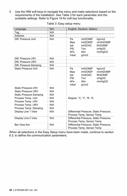
3. Use the HMI soft keys to navigate the menu and make selections based on the requirements of the installation. See Table 3 for each parameter and the available settings. Refer to Figure 19 for soft key functionality.
Table 3: Easy setup menu
Language N/A English, Deutsch, Italiano Tag N/A Address N/A Diff. Pressure Unit N/A Pa inH2O68F kg/cm2
Mpa inH2O60F mmH2O68F bar inH2O4C ftH2O68F PSI Torr inHgOC kPa Atm mmHgOC mbar g/cm2
Diff. Pressure LRV N/A Diff. Pressure URV N/A Diff. Pressure Damping N/A Static Pressure Unit N/A Pa inH2O68F kg/cm2
Mpa inH2O60F mmH2O68F bar inH2O4C ftH2O68F PSI Torr inHgOC kPa Atm mmHgOC mbar g/cm2
Static Pressure LRV N/A Static Pressure URV N/A Static Pressure Damping N/A Process Temp. Unit N/A Degree: °C, °F, °R, °K Process Temp. LRV N/A Process Temp. URV N/A Process Temp. Damping N/A Display Line 1 View N/A Differential Pressure, Static Pressure,
Process Temp, Sensor Temp Display Line 2 View N/A Differential Pressure, Static Pressure,
Process Temp, Sensor Temp Bar View line N/A Differential Pressure, Static Pressure,
Process Temp, Sensor Temp
When all selections in the Easy Setup menu have been made, continue to section 6.3, to define the communication parameters.

2105328-001 rev. AC | 29
6.3 Communication setup To configure the transmitter communication parameters, perform the following steps.
Press the right soft key to access the HMI menu.
2. Use the key pad to locate and select Communication. The last menu is Communication and may be accessed by pressing the up soft key.
3. View each parameter setting by selecting each submenu item and viewing the setting.
4. Edit each parameter shown in Table 12, if necessary, to configure communication for the site’s specific requirements.
Table 4: Communication parameters
Submenu 1 Selections TAG name Address Modbus address 1-247 Baud rate 1200 2400 4800
9600 19200 38400 Response Delay (ms) 50 ms (default) Parity None, Even, Odd Modbus Map Select ABB 266\267 Map
Rosemount 3095FB Map Invensys IMV25 Map
Modbus Reg. Offset Zero Based One Based
5. To edit a specific parameter, press Edit and change the parameter.
6. Locate the appropriate selection and select OK.
7. When finished viewing and editing the parameters, press the left soft key (Back) to exit back to the main screen.
The communication parameters are set and ready for communication.
The transmitter portion of communication is now set up. If there is an issue with the transmitter communication, continue to section 7, Troubleshooting, on page 30 for information. If there is an issue with the host portion of communication, refer to the manufacturer's documentation.

30 | 2105328-001 rev. AC
7 Troubleshooting
Detailed troubleshooting procedures are located in the 266 MODBUS® multivariable user manual. Use the flowchart in Figure 20 to identify the troubleshooting area, the specific procedure(s) to determine the cause, and the solution.
Figure 20: Flowchart for troubleshooting

2105328-001 rev. AC | 31
This page left intentionally blank

Contact us ABB Inc. Measurement & Analytics Main Office 7051 Industrial Blvd. Bartlesville, OK 74006 USA Tel: +1 918 338 4880 +1 800 442 3097 Fax: +1 918 338 4699 ABB Inc. Measurement & Analytics Sales Office 3700 W Sam Houston Pkwy South Suite 600 Houston, TX 77042 USA Tel: +1 713 587 8000 Fax: +1 713 266 4335
Note
We reserve the right to make technical changes or modify the contents of this document without prior notice. With regard to purchase orders, the agreed particulars shall prevail. ABB does not accept any responsibility whatsoever for potential errors or possible lack of information in this document.
The original US English version of this manual shall be deemed the only valid version. Translated versions, in any other language, shall be maintained as accurately as possible. Should any discrepancies exist, the US English version will be considered final. ABB is not liable for any errors and omissions in the translated materials. Any and all derivatives of, including translations thereof, shall remain the sole property of the Owner, regardless of any circumstances.
We reserve all rights in this document and in the subject matter and illustrations contained therein. Any reproduction, disclosure to third parties or utilization of its contents - in whole or in parts – is forbidden without prior written consent of ABB.
Copyright© 2015 ABB
All rights reserved
MODBUS® is a registered trademark of Modicon
Teflon® is a registered trademark of Dupont