Embed Size (px)
Citation preview

SCHWINNDo not return to store. Call toll free (800) 626-2811 for assistance and replacement parts.The owner’s manual contains safety, assembly, use, and maintenance instructions. The 26” Adult Tricycle must be assembled by an adult who has read and understands the instructions in this manual. Keep the packaging away from children and dispose all packaging before use.
26” Adult Tricycle


Contents
1 Introduction Safety Signal Words . . . . . . . . . . . . . . . . . . 2
2 Safety User Responsibility. . . . . . . . . . . . . . . . . . . 2 Protective Gear and Clothing . . . . . . . . . . . 3 Riding Safety . . . . . . . . . . . . . . . . . . . . . . . 4 Wet Weather . . . . . . . . . . . . . . . . . . . . . . . . 4 Night Riding . . . . . . . . . . . . . . . . . . . . . . . . 5
3 Parts. . . . . . . . . . . . . . . . . . . . . . . . . . . . . . . 6
4 Assembly. . . . . . . . . . . . . . . . . . . . . . . . . . . 8 Getting Organized . . . . . . . . . . . . . . . . . . . 8 Initial Set-up - Attach the Handlebars. . . . . 9 Attach the Rear Frame . . . . . . . . . . . . . . . 11 Attach the Secondary Chain. . . . . . . . . . . 12 Attach the Rear Wheels . . . . . . . . . . . . . . 13 Attach the Front Fender . . . . . . . . . . . . . . 15 Attach the Front Wheel . . . . . . . . . . . . . . . 17 Assemble the Front Brake . . . . . . . . . . . . 18
Rear Brake Adjustment . . . . . . . . . . . . . . 25 Brake Locking Buttons . . . . . . . . . . . . . . . 27 Attach the Rear Fenders . . . . . . . . . . . . . 28 Assemble the Wire Basket . . . . . . . . . . . . 29 Attach the Wire Basket . . . . . . . . . . . . . . . 30 Attach the Saddle . . . . . . . . . . . . . . . . . . . 31 Attach the Pedals . . . . . . . . . . . . . . . . . . . 32 Adjust the Handlebar . . . . . . . . . . . . . . . . 33 Adjust the Seat . . . . . . . . . . . . . . . . . . . . . 34
5 Use . . . . . . . . . . . . . . . . . . . . . . . . . . . . . . . 35 Pre-Ride Checklist . . . . . . . . . . . . . . . . . . 35
6 Maintenance and Troubleshooting . . . . . 40 Parts Maintenance . . . . . . . . . . . . . . . . . . 40 Hub Bearings . . . . . . . . . . . . . . . . . . . . . . 44 InflatingtheTireTube . . . . . . . . . . . . . . . . 45 Repairing a Flat Tire . . . . . . . . . . . . . . . . . 46
7 Warranty . . . . . . . . . . . . . . . . . . . . . . . . . . 47
8 Purchase Record . . . . . . . . . . . . . . . . . . . 50

1
This manual contains important information regarding safety, assembly, use, and maintenance of the tricycle but is not intended to be a complete or comprehensive manual covering all aspects concerning bicycle ownership. We recommend consulting a bicycle specialist if you have any doubts or concerns regarding your experience or ability to properly assemble and maintain the tricycle.
Our customer service department is dedicated to your satisfactionwithPacificCycleandit’sproducts.Ifyouhave questions or need advice regarding assembly, parts, performance, or returns, please contact the expertsatPacificCycle.
Toll free: 1-800-626-2811. Customer Service hours: 8 AM- 5 PM (Central Standard Time,CST) Monday thru Friday.
You may also reach us at:
Web: www.schwinnbikes.comEmail:[email protected]:PacificCycle 4902 Hammersley Road Madison, WI 53711 Do not return this item to the store . Please call Pacific Cycle customer service if you need assistance .
Introduction1

2
Safety2
Safety Signal WordsThe following safety signal words indicate a safety message. The symbol alerts you to potential hazards. Failure to follow the warning may result in damage to property, injury, or death.
! WARNING!Indicates a hazard or unsafe practice that will result in severe injury or death.
Failure to read, understand and follow the safety information in this manual may result in serious injury or death.
! CAUTION!Indicates a hazard or unsafe practice that could result in minor injury.
NOTICEIndicates a hazard unrelated to personal injury, such as property damage.
User Responsibility•All persons assembling, using, and maintaining
the tricycle must read and understand the safety warnings and operating instructions in this manual before using the tricycle.
• It is the responsibility of the user, or in the case of a child rider, an adult, to ensure the tricycle is in proper operating condition before each use. See the Safety Checklist in the Use section of this manual.
•A responsible adult must supervise the use of the tricycle by a child. You must ensure:
•Thechildiswearingtheproperprotectiveattire and approved bicycle helmet.
•Thechildisseatedsecurelyandthetricycleisproperlyfittedtothechild.
•Thechildunderstandsapplicablelawsand common sense rules of safe responsible bicycling.

3
Protective Gear and ClothingAlways wear proper attire when riding the tricycle, you should wear:
•Colors that are easily seen and, if possible, reflectiveclothing.
•Clothing appropriate for the weather conditions.
•Use of protective gear such as pads for the knees and elbows is highly recommended for children.
• Aproperlyfitted,ASTMorSNELLapproved,bicycle helmet shall be worn at all times by riders of the tricycle. For information regarding how to properlyfitahelmetvisit:http://www .nhtsa .gov/people/injury/pedbimot/bike/easystepsweb Note: Some states have helmet laws regarding children. Always follow local or state regulations regarding helmet use.
Do not wear:
• Loose clothing parts, strings, jewelry that may become entangled with moving parts on the tricycle or interfere with handling of the tricycle.
•Pants with loose pant legs. If necessary, always tuck pant legs into a sock or use a leg band to avoid the clothing becoming caught in the drive chain.
•Shoes with untied shoe laces.
Use of Reflector and Lights•Federal regulations require every bicycle over
16” to be equipped with front and rear wheel reflectorsaswellaspedalreflectors.
• Statesmayrequirespecificsafetydevices.Always follow state or local regulations regarding required safety devices.
• Alwayscheckthereflectorsareinplacebeforeusing the tricycle.
•To help enhance your visibility to automobile drivers use front and rear lights.
Riding Safety•Familiarize yourself with all the tricycle’s features
before riding. Practice gear shifts, braking, and the use of toe clips and straps, if installed.

4
•Always ride defensively in a predictable, straight line.Neverrideagainsttraffic.
•Concentrate on the path ahead. Avoid pot holes, gravel, wet road markings, oil, curbs, speed bumps, drain grates and other obstacles.
•Cross train tracks at a 90 degree angle or walk your bicycle across.
• Expecttheunexpected(e.g.openingcardoorsorcars backing out of concealed driveways).
•Take extra care at intersections and when preparing to pass other vehicles.
•Maintain a comfortable stopping distance from all other riders, vehicles and objects. Safe braking distances and forces are subject to the prevailing weather conditions. Do not lock up the brakes. Whenbraking,alwaysapplytherearbrakefirst,then the front. The front brake is more powerful and if it is not correctly applied, you may lose control and fall.
•Always use the correct hand signals to indicate turning or stopping.
• Obeythetrafficlaws(e.g.stoppingataredlightor stop sign, giving way to pedestrians).
•Wearproperridingattire,reflectiveifpossible,and avoid open toe shoes.
•Avoid wearing loose pants. If you are wearing loose pants, tuck the pant leg into a sock or use leg clips/elastic bands to prevent them from being caught in the drive chain.
•Don’t use items that may restrict your hearing.
•Don’t carry packages or passengers that will interfere with your visibility or control of the tricycle.
Wet Weather•Be aware of road conditions. Pot holes and
slippery surfaces such as line markings and train tracks all become more hazardous when wet.
•Decrease your riding speed, avoid sudden braking and sharp turns.
•Braking will require additional distance. Initiate braking slowly and earlier than usual.
•Wearreflectiveclothingandusesafetylightsforincreased visibility.

5
Night Riding•Riding at night is not recommended. Check with
local law or regulations regarding the use of lights for night riding.
• Ensurebicycleisequippedwithafullsetofcorrectlypositionedandcleanreflectors.
•Use a white light on the front and a red light ontherear.Ifpossible,uselightswithflashingcapability. Flashing lights enhance visibility.
• If using battery powered lights, make sure batteries are well charged.
•Wearreflectiveandlightcoloredclothing.
•Slow down and use familiar roads with street lighting.
•Ride at night only if necessary.

6
Before assembly check and see that all the parts are included. If parts are missing or damaged call customer service toll free at 1-800-626-2811 .
Parts3
secondary chain
front wheel
handlebar
pedals (2)
rear frame
rear fenders (2)
rear wheels (2)
main frame
rear brake
rear brake leverfront brake lever
front fenderwire basket
saddle
seat stem
plastic wheel caps (2)

7
Hardware4
Frame Assembly Hardware
Handlebar Hardware
4 nuts 4 washers 4 square bolts
stem wedge cap
Secondary Chain Hardwaresecondary chain
chain pinchain link platemaster link
Rear Wheel Axle Hardware
2 plastic caps 2 nuts 2 washers
Front Wheel Axle Hardware
2 nuts
Basket Hardware
8 washers4 bolts

! WARNING!
8
Assembly5
Improperly assembly of the tricycle may result in unexpected product performance and serious injury or death. Assemble the tricycle according to the instructions in this manual or have a professional bicycle mechanic assemble the tricycle.
Getting OrganizedThe following tools and items are needed for assembly:
•Phillips head screw driver (minimum four inch shaft)
• 6 mm, 10 mm Allen keys
•Adjustable wrench or 10 mm, 15 mm, and 17 mm open and box end wrenches
•Needle nose pliers with cable cutting ability
•Grease (Automotive or anti-slip copper grease)

9
Initial Set-up - Attach the HandlebarsParts: Handlebar, main frameHardware: The stem wedge bolt and binder bolt come attached to the handlebar. Stem wedge bolt cap. Tools: 6 mm allen wrench, grease
1 . Remove the cap covering the stem wedge bolt.
2 . Apply a light layer of grease to the stem and frame head tube.
3 . Insert the stem of the handlebar into the frame head tube until the Minimum Insertion mark is not visible. If necessary, unscrew the stem wedge bolt until there is play in the stem wedge.
NOTICEThe stem may break or damage may occur if the stem is not inserted the minimum amount. Insert the stem until the Minimum Insertion mark is not visible.
4 . Rotate the handle bar so it is square with the fork.
5 . Tighten the stem wedge bolt to lock the stem in place.
6 . Replace the cap onto the stem wedge bolt.
7 . Loosen the handlebar binder bolt and rotate the handlebar into the riding position.
8 . Using the 6 mm allen wrench, tighten the handlebar binder bolt until the handlebar is locked in place.
9 . Turn the tricyle assembly over so it rests on the handlebar and main frame.
9

10
6
binder bolt
stem wedge bolt
main frame
12
3
4
5
8
Stem
Minimum insertion mark

11
Attach the Rear FrameParts: rear frame, main frameHardware: 4 nuts, 4 square bolts, 4 washers, come
attached to the frame. Remove this hardware before you begin this procedure .
Tools: None required.
1 . Align the pronged end of the rear frame with the pronged end of the main frame, and slide the frames together.
2 . On one side, line up the square bolt with the slot and insert a bolt through both the rear frame hole and main frame slots.
3 . Repeat on the opposite side.
4 . Slide a washer onto each bolt and loosely tighten the nut.
5 . Adjust the position of the rear frame holes so the remaining square holes line up with the slots on the main frame drop-outs.
6 . Insert two bolts through the rear and main frame.
7 . Slide a washer onto each bolt and loosely tighten with the nut. Repeat on the opposite side.
Note: Do not tighten the bolts at this time. This will be done after the secondary chain is attached.
6
rear frame prongs
1main frame prongs
Theflatsideofthesquare bolt should be facing up.
Tip!
3
4
5
2
7
Side view of frame alignment

12
Attach the Secondary ChainParts: secondary chain, frame assemblyHardware: master link, chain link plate, chain pinTools: Needle Nose Pliers, 17 mm open and box end wrench.
1 . Wrap the secondary chain around the inner sprocket on the rear hub and drive sprocket on the rear axle.
2 . Adjust the position of the rear frame until the ends of the secondary chain meet each other, leaving one chain link length space in between the ends.
3 . To connect the two ends of the chain: a . Insert the pegs of the master link through both ends of each chain link. b . Place the chain link plate over the pegs of the master link. c . Snap the chain pin onto a peg of the master linksoitisflatagainsttheouterlinkplate. d . With the needle nose pliers, carefully slide the clip onto the link pins until it is locked.
4 . Pull the rear frame back so the secondary chain is taut and there is less than 5 mm of play up or down.
Important! Check the rear frame is square (perpendicular) to main frame. Failure to square the frames will affect performance of the tricycle.
5 . Ensurethesquareboltisintheslot.Firmlytightenthe four bolts holding the rear frame to the main frame.
inner sprocket
drive sprocket
1
a
b
52
Have a second person pulling the chain taut while tightening the bolts.
Tip!
3
4
c

! WARNING!
13
Attach the Rear Wheels
Failure to properly tighten the nuts holding the wheels onto the tricycle may result in poor riding performance, the tire falling off and serious injury or death. Always be sure the wheels are securely attached to the frame before using the tricycle.
Parts: Drive wheel, non-drive wheelHardware: 2 plastic caps, 2 locknuts, 2 washers. The locknuts come attached to the axle . Remove the locknuts before you begin this procedure .Tools: 17 mm open and box end wrench
See the facing page for diagrams of the following steps.
1 . Place the drive wheel (with a notched opening) on the axle.
2 . Place the washer on the axle.
3 . Place the locknut on the axle and tighten securely.
Note: The drive wheel hub has a notched opening that matches the notched axle.
4 . Screw the plastic caps on each end of the axles.
5 . To attach the non-drive wheel repeat steps one through four. Note: To prevent the axle from turning while attaching the non-drive wheel, it is important to hold the drive wheel while tightening the locknut on the non-drive wheel.

14
1
23
5
4

15
Attach the Front FenderParts: Front fender, main frameHardware: washer, long screw, small screw, contoured washer Tools: Phillips head screwdriver, adjustable pliers
See the facing page for diagrams of the following steps.
1 . Remove the fork protector (not shown).
2 . Disconnect the brake noodle from the brake carrier by:
a . Using a 5 mm allen wrench loosen the cable anchor bolt enough so the cable can move freely.
b . Lift the brake noodle and cable out of the brake carrier.
3 . Remove the hardware from the fork.
4 . Position the front fender so the attachment bar is on the outside of the main frame.
5 . Place a washer on the screw and slide it throughthe attachment bar, and the hole in the fork.
6 . Place the spacer on the end of the screw, making surethecontourofthespacerfitsthecontourof the fork.
7 . Place the washer and nut behind the spacer, and loosely tighten.
8 . Align the fender braces with the small hole in the fork and loosely screw the fender braces to the fork.

16
Note: The fender will be positionedandfirmlyfastenedafter the front tire is attached.
2 3
5
6
7
8
Decal should be on the outside of the frame.
Tip!
hex wrencha
cable anchor boltbrake noodle
brake carrier
b
4

! WARNING!
17
Attach the Front Wheel
Failure to properly tighten the nuts holding the wheels onto the tricycle may result in poor riding performance, the tire falling off and serious injury or death. Be sure the wheels are securely attached to the frame before using the tricycle.
Parts: Front wheel, main frame assemblyHardware: 2 large nutsTools: 15 mm open and box end wrench, Adjustable Pliers
1 . Place the front wheel into the fork openings. Be sure both sides of the axle rest on the metal and the wheel is centered.
2 . Place the nut on the axle and loosely tighten.
3 . Place the remaining nut on the opposite side and loosely tighten.
4 . Tighteneachnutuntilbotharefirmlyset, a minimum of 20 ft lbs (240 in-lb).
5 . Inspect the wheel for even rotation.
Before proceeding to the next step, lift and rotate the tricycle.
3 2
1
Tip!

! WARNING!
18
Assemble the Front Brake
Failure to properly set the brakes may result in the inability to stop the tricycle movement and cause serious injury or death. Be sure the brakes are functioning properly before using the tricycle.
Note: The tricycle is shipped with the brake cable attached to the brake lever. Follow these steps if there is a need to re-attach the brake cable to the brake lever:
1 . Rotate the cable adjustment barrel and cable nut until the slots are aligned with the slot on the brake lever body.
2 . Press the brake lever towards the grip.
3 . Slide the brake cable through the slots and place the cable head into the brake lever.
4 . Release the brake lever.
5 . Lightly pull on the cable, and rotate the cable nut and cable barrel so they are no longer aligned.
1
cable adjustment barrel slot cable nut slot
brake lever slot
2
brake lever
3
cable head
4
5
brake cable

19
Attach the Brake Cable to the Brake Carrier
1 . Squeeze the two brake arms together until the brake pads touch the wheel rim.
2 . With your opposite hand, pull the brake cable and insert the end of the noodle into the brake carrier.
Adjust the Brake Cable
Parts: Brake cable, brake armsTools: 5 mm allen wrench
1 . Using a 5 mm allen wrench loosen the cable anchor bolt enough so the cable can move freely.
2 . Pull on the cable to move the left brake arm towards the rim until there is approximately a 1/8” (3 mm) gap between the brake pad and rim.
3 . Move the right brake arm towards the rim until there is approximately a 1/8” (3 mm) gap between the brake pad and rim.
4 . Usingthe5mmallenwrench,firmlytightenthecable anchor bolt completely.
noodlebrake carrier
brake arm
brake cable
brake arm
1
2
wheel rim

20
Check for the brake pads for the following conditions: See pages 19 -22 to adjust and align the brake pads.
3
4
Brake pads are centered on the wheel rim.
Clearance between the brake pad and wheel rim is a 1/8” (3 mm) gap.
Brake pads are aligned (parallel) with the rim
1/8”
3
cable anchor bolt
1
2
1
2
21
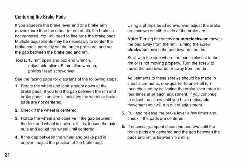
Centering the Brake Pads
If you squeeze the brake lever and one brake arm moves more than the other, (or not at all), the brake is notcentered.Youwillneedtofinetunethebrakepads.Multiple adjustments may be necessary to center the brake pads, correctly set the brake pressure, and set the gap between the brake pad and rim.
Tools: 15 mm open and box end wrench, adjustable pliers, 5 mm allen wrench, phillips Head screwdriver
See the facing page for diagrams of the following steps. 1 . Rotate the wheel and look straight down at the
brakepads.Ifyoufindthegapbetweentherimandbrake pads is uneven it indicates the wheel or brake pads are not centered.
2 . Check if the wheel is centered.
3 . Rotate the wheel and observe if the gap between the fork and wheel is uneven. If it is, loosen the axle nuts and adjust the wheel until centered.
4 . If the gap between the wheel and brake pad is uneven, adjust the position of the brake pad.
Using a phillips head screwdriver, adjust the brake arm screws on either side of the brake arm.
Note: Turning the screw counterclockwise moves the pad away from the rim. Turning the screw clockwise moves the pad towards the rim.
Start with the side where the pad is closest to the rim or is not moving properly. Turn the screw to move the pad towards or away from the rim. Adjustments to these screws should be made in small increments, one-quarter to one-half turn then checked by activating the brake lever three to four times after each adjustment. If you continue to adjust the screw until you have noticeable movement you will run out of adjustment.
5 . Pull and release the brake lever a few times and check if the pads are centered.
6 . If necessary, repeat steps one and two until the brake pads are centered and the gap between the pads and rim is between 1-2 mm.

22
Evenspacebetween wheel and fork
axle nut
Note: If you run out of adjustment capability on one side, adjust the screw on the opposite side. If you run out of adjustment capability on both screws do a minor adjustment to the brake cable. Adjustments should be made to each side as equally as possible to prevent running out of adjustment capability. See Adjust the Brake Cable) and repeat steps four through six.
5
1 Evenspacebetween brake pad and wheel
2 Wheel is centered
3
4
brake arm screw
brake arm screw
Brake pads are
centered on each side of
the wheel

23
Aligning the Brake Pads
Tools: 5 mm Allen wrench
Pad alignment should be done before centering. improper alignment can cause centering issues. For example the pad could be touching the tires or part of the pad may be contacting the rim .
1 . Check for proper brake pad alignment on the wheel rim. If necessary, adjust the position or rotation of the pads.
2 . Using a 5 mm Allen wrench, loosen the screw holding the pad.
3 . Move and rotate the pad so it is centered on the rim and parallel with the ground.
4 . After properly positioning the pad tighten the screw.
2allen wrench loosening brake pad screw
brake pad is properly centered on the wheel rim
3

24
Front Brake Adjustment Checks
1 . Squeeze the brake lever as hard as you can several times to determine the cable is securely attached and the brake pads return to the center position.
2 . Squeeze on the brake lever and check the brake cable tension allows the brake lever to travel about one-third of the way towards the handlebar when the brake pads make contact with the rim.
3 . Check that both brake pads move evenly when the brake lever is squeezed and retract completely when the brake lever is released.
4 . Rotate the wheel and check the gap between the brake pads and rim is 1-2 mm.
Squeeze the brake lever to check brake adjustments
Rotate the wheel to check for correct brake alignment, and proper gap between the rim and brake pad.

! WARNING!
25
Rear Brake Adjustment
Failure to properly set the brakes may result in the inability to stop the tricycle movement and cause serious injury or death. Always check the brakes are functioning properly before using the tricycle.
Lubricating the drum can cause faulty braking.
Tools: 10 mm wrench or adjustable wrench.
The tricycle is shipped with the rear brake assembled and connected. If the brake cable is not attached to the brake lever see Attach the Front Brakes for the steps to re-attach the cable and lever.
If the brake cable is disconnected at the brake arm, pull the brake cable taught and connect it to the brake arm by tightening the cable anchor bolt as described on page 17.
The rear brake is a band brake system. Follow the steps to adjust the rear brake:
NOTICE
1 . Loosen pinch bolt on pad control lever with a 10 mm open ended or adjustable wrench.
2 . Loosen the cable adjustment barrel on the brake lever two turns and tighten the adjustment barrel lock nut.
3 . Loosen the adjusting barrel bolt three full turns.
4. Push the pad control lever toward the front of the bike and hold it there with one hand
5 . Use the other hand to pull the brake cable tight making sure that the cable housing remains seated in the adjusting barrels.
6 . Retighten the pinch bolt on the pad control lever using 10 mm open ended or adjustable wrench.
7 . Press the brake lever until the brake band contacts the drum. This should occur when the brake lever is about one third of the way to the handle bar.
Important! Brake band will wear over time. Turn the adjusting barrel to compensate for brake band wear. Replace the brake band before it is completely worn.

26
cable adjustment barrel2
brake cable seated in the adjusting barrel bolt
adjusting barrel bolt
pad control lever
3
rear brake lever
rear brake shell
brake cable inner wire
5
brake band on drum
1pinch bolt
adjustment barrel lock nut
4
7
6

27
Brake Locking ButtonsBoth the rear and front brake handles are equipped with brake locking buttons. The purpose of the brake locking button is to keep your tricyle from rolling when you have it parked.
To lock the brakes:
1 . Squeeze the brake lever tight.
2 . While holding the brake lever closed, press down on the brake lever button.
3 . Release the brake lever while holding down on the brake lever button. The brake will now be in the locked position.
To unlock the brakes:
4 . Squeeze the brake lever tight and release. The brake should now be unlocked .
21
3
3

28
Attach the Rear FendersParts: Rear Fenders, rear frameTools: Phillips Head screwdriver (minimum 4” shaft)Hardware: 4 nuts, 4 screws, 8 washers The hardware comes attached to the frame . Remove the hardware before you begin this procedure .
1 . Positionthefendersotherearreflectorisfacingaway from the bike.
2 . Rotate the rear wheel until there is adequate space for the Phillips Head screwdriver to reach through the spokes to the fender slots.
3 . Align the slots on the fender with the slots on the rear frame.
4 . Insert a washer onto a screw.
5 . Insert the washer and screw through the aligned slots.
6 . Insert a washer and nut on the end of the screw.
7 . Hold the nut with the pliers, and tighten the screw, but not completely . Note: Be sure that the fender has adequate clearance from the wheels. It may be necessary to adjust the fender slightly to properly align with the wheels.
1
2
3
8 . Repeat steps one through six for the second slot.
9 . Firmly tighten both screws.
10. Repeat steps one through nine for the second fender.
4
5
6
29
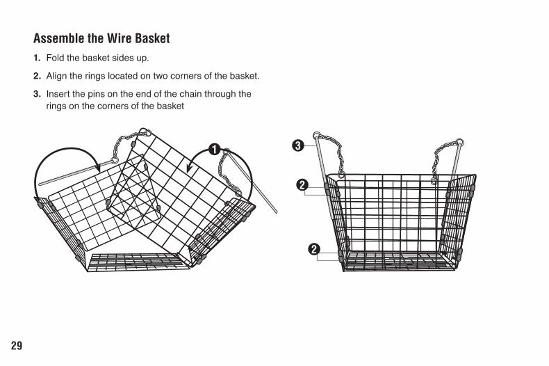
Assemble the Wire Basket1 . Fold the basket sides up.
2 . Align the rings located on two corners of the basket.
3 . Insert the pins on the end of the chain through the rings on the corners of the basket
1
2
3
2

30
Attach the Wire BasketParts: Wire basket, rear frameTools: Phillips Head screwdriverHardware: 4 screws, 8 washers The hardware comes attached to the frame . Remove the hardware before you begin this procedure .
1 . Place the wire basket on the rear frame and align the slots on the basket with the holes in the frame.
Note: The slots on the wire basket are positioned so the basket can only be attached one way. If the slots do not line up properly rotate the basket 180 degrees.
2 . Insert two washer onto the screw.
3 . Insert the screws and washer through the basket slots onto the rear frame.
4 . Repeat steps three and four for the remaining washers and screws.
1
2
3

31
Attach the Saddle
! WARNING!Insufficientlockingpressureontheseatstemmay result in the seat slipping, loss of control and serious injury or death. Be sure the seat is locked and capable of supporting the weight of the rider before using the tricycle.
Parts: Saddle, Saddle stemTools: 14 mm open and box end wrench, Adjustable Pliers
1 . Place the saddle on the saddle stem.
2 . Tighten the nuts on each side of the saddle stem until the saddle is securely attached to the stem.
3 . Release the quick release clamp.
4 . Place the seat stem into the frame seat tube until the Minimum Insertion mark is not visible.
5 . Turntheadjustingnutuntilthereissufficientpressure to hold the seat in place when the quick release lever is closed.
6 . Close the quick release clamp.
21
2
4
5
Minimum insertion mark 6

32
Attach the PedalsNOTICE: Attaching a pedal to the incorrect side can strip the pedal threads and cause irreparable damage. Visually match the R and L stickers on the pedal and crank arm before attaching the pedals.
Parts: Left and right pedals, crank armsTools: 15mm open and box end wrench, Adjustable Pliers
1 . Match the pedal marked R with the right-hand crank arm, and match the pedal marked L with the left- hand crank arm.
2 . Place the threaded pedal into the threaded hole on the crank arm.
4 . By hand, slowly turn the spindle toward the front of the bicycle. Clockwise for right side pedal, counterclockwise for left side pedal. Important! Stop if you feel resistance! This may be an indication the spindle is entering the hole at an angle. Remove the spindle and redo step four.
IMPORTANT
L
IMPORTANT
L
IMPORTANT
5 . If the spindle is entering the hole cleanly then use a 15 mm wrench or pliers to tighten completely.
6 . Repeatstepstwothroughfivefortheoppositepedal.
1
2
3The left pedal turns counter-clockwise and the right pedal turns clockwise.
Tip!

33
Adjust the Handlebar
Failuretofirmlytightenthehandlebarstemwedgebolt, handlebar binder bolt, seat stem, and bar end extension clamping bolts may cause a sudden shift of the handlebar or seat and result in loss of control, falling, serious injury or death. Be sure the stem wedge bolt, handlebar binder bolt, seat stem, and barendextensionclampingboltsarefirmlytightenedbefore using the tricycle. Adjust the handlebar height and angle so the rider is comfortable and has complete control.
Follow these steps to adjust the handlebar:
Tools: 6 mm allen wrench
1 . Remove the cap covering the stem wedge bolt.
2 . Unscrew the stem wedge bolt until the pressure on the stem wedge is released.
3 . Adjust the height of the stem, above the Minimum Insertion line, until the rider feels they have control of the tricycle and are comfortable.
! WARNING! 4 . Rotate the handle bar so it is square with the fork.
5 . Tighten the stem wedge bolt to lock the stem in place.
6 . Loosen the handlebar binder bolt and rotate the handlebar until the rider feels they have control of the tricycle and are comfortable.
7 . Tighten the handlebar binder bolt until the handlebar is locked in place.
minimum insertion mark3
binder bolt
stem wedge bolt
1
2
64

3
34
If necessary, adjust the seat height and angle so the rider is comfortable and has complete control.
Tools: 14mm open and box end wrench, Adjustable Pliers
1 . Release the quick release seat clamp.
2 . Adjust the height of the seat until the rider feels they have control of the tricycle and are comfortable.
3 . Lock the quick release seat clamp.
Adjust the Seat
Failure to insert the handlebar and seat stems beyond the “Minimum Insertion” line may cause the stem to break resulting in damage to the stem, loss of control, falling, serious injury or death. Insert the handlebar and seat stem into the frame until the Minimum Insertion Mark is not visible.
! WARNING!
1
2
Minimum insertion mark

35
! WARNING!
Use6
Failure to follow all local and state regulations and laws pertaining to bicycle use as well as the safety warnings in this manual may result in serious injury or death. Always follow all local and state regulations and laws pertaining to bicycle use, follow the safety warnings in this manual and use common sense when riding the tricycle. Always conduct a pre-ride check of the tricycle condition before riding.
Pre-Ride ChecklistUse the following checklist to ensure your tricycle is in proper working condition before riding the tricycle. Brakes:
The front and rear brakes work properly.
The brake shoe pads are not overly worn and are correctly positioned in relation to the rims.
The brake control cables are lubricated, correctly adjusted and display no obvious wear.
The brake control levers are lubricated and tightly secured to the handlebar.
front control levers
shoe pads
brake control cables

36
Wheels and Tires
The rims do not have dirt or grease on them.
The wheels are properly attached to the tricycle and the axle nuts are tight.
The wheel spokes are not loose or broken.
The wheel rotation is smooth and there is no side to side movement.
Thetiresareinflatedtowithintherecommended pressure as displayed on the tire sidewall.
The tires have tread and there are no bulges or excessive wear.
Steering
The handlebar and stem are correctly adjusted and tightened, and allow proper steering.
The handlebars are set correctly in relation to the forks and the direction of travel.
The handlebar binder bolt is tightened.
wheel rim spokestire
tire tread
stem
handlebar
binder bolt
fork

37
Chains
The chains are oiled, clean and run smoothly Note:Extramaintenanceisrequiredinwetordusty conditions.
Bearings
All bearings are lubricated, run freely and display no excess movement, grinding or rattling (Note: Check headset, wheel bearings, pedal bearings and bottom bracket bearings).
Cranks and Pedals
The pedals are securely tightened to the crank arms.
The crank arms are securely tightened to the axle and are not bent.
Frame and Fork
The frame and fork are not bent or brokenNote: If either are bent or broken, callcustomer service.
Accessories Thereflectorsaregoodshape,properlyplacedand not obscured.
Allotherfittingsonthebikeareproperlyandsecurely fastened, and functioning.
Therideriswearingaproperlyfittedhelmet(protective gear if necessary) and that clothing and loose items are properly constrained.
chains
pedal
crank arm

38
! WARNING!
Maintenance and Troubleshooting6
Failure to conduct maintenance on the tricycle may result in malfunction of a critical part and serious injury or death. Proper maintenance is critical to the performance and safe operation of the tricycle. The recommended intervals and need for lubrication and maintenance may vary depending on conditions the tricycle is exposed to. Always inspect the tricycle and conduct necessary maintenance before each use of the tricycle.
This section presents important information on maintenance and will assist you in determining the proper course of action to take if you do have a problem with the operation of the tricycle.
If you have questions regarding maintenance please call our customer service, toll free, at 1-800-626-2811 orseeaqualifiedbicyclemechanic.Donotcallthestore where the tricycle was purchased.

39
Component Lubricant MethodWeekly
Chains Chain lube or light oil Brush on or squirtBrake calipers Oil Three drops from oil canBrake levers Oil Two drops from oil can
EverySixMonthsFreewheel Oil Two drops from oil canBrake cables Lithium based grease Remove cable from casing. Grease entire length.
Wipe off excess lubrication from other surfaces.Brake lever and caliper pivot points
Light oil Two to three drops from oil can
Pedals: that cannot be disassembled
Light oil Two drops from oil can onto the inside bearings
YearlyBottom bracket Lithium based grease DisassemblePedals Lithium based grease DisassembleWheel bearings Lithium based grease DisassembleHeadset Lithium based grease DisassembleSeat stem Lithium based grease DisassemblePedals: that can be disassembled See bicycle mechanic for maintenance.
NOTE: The frequency of maintenance should increase with use in wet or dusty conditions. Do not over lubricate. Remove excess lubricant to prevent dirt build up. Never use a degreaser to lubricate your chains (WD-40™).
Lubrication Schedule

40
Parts Maintenance
Wheels
Frequency: Inspect and maintain before each use
Inspect Action Maintenance
Rims Inspect for dirt and grease Use a clean rag or wash with soapy water, rinse, and air dry.
Wheels Check the wheels are securely fastened to the tricycle and axle nuts are tight.
Adjust if necessary and tighten axle nuts.
Spin wheel and check rotation / alignment is true
See bicycle mechanic for repair.
Spokes Check for broken or loose spokes See bicycle mechanic for repair.Hub Bearings Lift each wheel and see if there is movement
side to sideSee “Hub Bearings” for more detail or bicycle mechanic for repair.

41
Inspect Action MaintenanceTireInflation Check tire pressure Inflatetiretothepressureindicatedonthe
tiresidewall.See“InflatingaTireTube”formoredetail.Ifthetireisflatsee“FixingaFlatTire” for more detail.
Check the bead is properly seated while inflatingorrefittingthetire.
Reduce air pressure in the tube and re-seat the bead.
Spin wheel and check rotation / alignment is smooth and even.
Loosen axle nut(s) and adjust until properly seated. If the Hub Bearings need repair see Hub Bearings for more detail or bicycle mechanic for repair.
Bead Seating Check for broken or loose spokes See bicycle mechanic for repair.Tread Inspectforsignsorexcessivewear,flatspots
or cuts and damage.Replace tire.
Valves Checkthatvalvecapsarefittedandfree of dirt.
Clean dirt from the valve.
Tires
Frequency: Inspect and maintain before each use
42
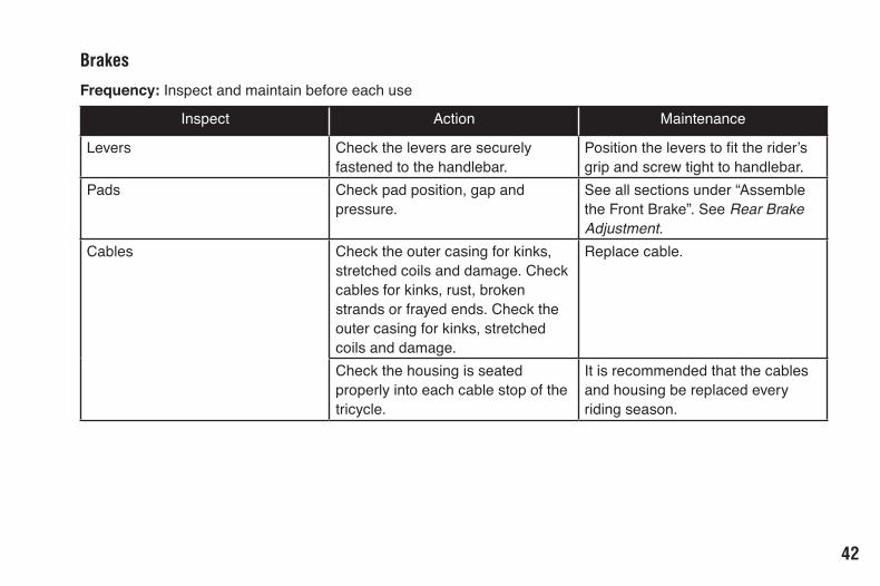
Inspect Action Maintenance
Levers Check the levers are securely fastened to the handlebar.
Positiontheleverstofittherider’sgrip and screw tight to handlebar.
Pads Check pad position, gap and pressure.
See all sections under “Assemble the Front Brake”. See Rear Brake Adjustment.
Cables Check the outer casing for kinks, stretched coils and damage. Check cables for kinks, rust, broken strands or frayed ends. Check the outer casing for kinks, stretched coils and damage.
Replace cable.
Check the housing is seated properly into each cable stop of the tricycle.
It is recommended that the cables and housing be replaced every riding season.
Brakes
Frequency: Inspect and maintain before each use

43
Inspect Action MaintenancePedals Everymonth,checkeachpedalissecurely
set and tighten into the crank arm.If necessary, re-set and tighten.
Before each ride, check each front and rear pedalreflectorsarecleanandinplace.
Clean or replace.
Pedal Bearings Everymonth,checkthepedalbearingsare properly adjusted. Move the pedal up and down, left and right. If looseness or roughness is detected adjustment, lubrication or replacement is required.
See bicycle mechanic for repair.
Chains Everyweek,checkthechainsareclean,properly lubricated, rust free, and is not stretched, broken, or have stiff links.
Everyweek,checkchaintensioniscorrecton both chains:
1. Set a straightedge against the bottom of the front chainwheel and rear sprocket.
2. Pull up on the bottom of the chain.
3. If movement is more than 10 mm adjust the position of the rear frame.
Lubricate if necessary. Replace if rusted, stretched, or broken.
Loosen bolts holding the rear frame and move it until the chain is taut and moves less than 10 mm. Check the rear frame is “square”tothemainframeandfirmlytightenthe bolts holding the rear frame.
Drivetrain (pedals, chains, chainwheel, crank set, freewheel)
Frequency: as noted

44
Inspect Action MaintenanceCrank Set Everymonth,checkthecrankset(crank
arms, chain rings, and bottom bracket axle and bearings) is correctly adjusted and tight. Remove the primary chain
Replace cable.
Hub BearingsHub bearings require special thin wrenches called “cone wrenches”. If you do not own these tools, do notattempthubbearingadjustments.Haveaqualifiedbicycle mechanic perform the adjustment if you have any doubts.
1 . Check to make sure neither locknut is loose.
2 . To adjust, remove wheel from bicycle and loosen the locknut on one side of the hub while holding the bearing cone on the same side with a cone wrench.
3 . Rotate the adjusting cone as needed to eliminate free play.
4 . Re-tighten the locknut while holding the adjusting cone in position.
5 . Re-check that the wheel can turn freely without excessive side play.
Drivetrain maintenance continued . . .

45
Inflating the Tire Tube
An unseated tire can rupture unexpectedly and cause serious injury or death. Be sure the tire is properly seatedwheninflatingthetube.
! WARNING!
! CAUTION!Overinflationorinflatingthetubetooquicklymayresultin the tire blowing off the rim and damage the tricycle or cause injury to the rider. Always use a hand pump to inflatethetube.Donotuseagasstationservicepumptoinflatethetube.
Follow these steps to inflate a tire:
1 . Remove the valve cap.
2 . Add air.
3 . Be sure the tire is evenly seated on the rim, both sides.
4 . Spin the wheel and check for high and low areas.
5 . Completeinflation.
6 . Be sure the tire is evenly seated on the rim, both sides. If not release some air and repeat steps three through six.
7 . Check for dirt in the valve cap or stem. If necessary, clean dirt from cap or stem.
8 . Securely replace the valve cap on the stem.

46
Repairing a Flat Tire
! WARNING!An unseated tire can rupture unexpectedly and cause serious injury or death. Be sure the tire is properly seatedwheninflatingthetube.
Follow these steps to fix a flat tire:
1 . Match tube size and tire size (see tire sidewall for size).
2 . Removewheelfrombicycle.Deflatetirecompletely.
3 . Squeeze the tire beads into the center of the rim.
4 . Opposite the valve, use a bicycle tire lever to pry the tire bead up and out of the rim. Repeat around the wheel until one bead is off the rim.
5 . Remove tube. Release second tire bead. Remove tire.
6 . Carefully inspect inside of the rim and tire for the causeoftheflat.
7 . Inflatethetube¼fullandplaceinsidetire.
8 . Insert the valve stem through valve stem hole in rim.
9 . Startatthevalvestemandinstallthefirstbeadontothe rim. Repeat for the second bead.
10.Slowlyinflatethetire,checkingthetireisseatedproperlyandnotpinchedasthetireisinflated.
11.Inflatetorecommendedpressure(seetiresidewall).

47
LIMITED WARRANTY AND POLICY ON REPLACEMENT PROCEDURES & RESPONSIBILITIESYour purchase includes the following warranty which is in lieu of all other express warranties. This warranty is extended only to the initial consumer purchaser. No warranty registration is required. This warranty gives you specificlegalrightsandyoumayhaveotherrightswhichvary from state to state.
FRAMESteel frames are guaranteed against faulty materials and workmanship for as long as the initial consumer purchaser has the bicycle, subject to the condition of the warranty listed below. If frame failure should occur due to faulty materials or workmanship during the guarantee period, the frame will be replaced. For frame replacement under this PacificLimitedWarranty,contactus,statingthenatureofthe failure, model number, date received and the name of the store from which the bike was received, at the address given on this page.
Warranty7
Frame must be returned for inspection at customer’s expense. Please note: the fork is not part of the frame. A lifetime warranty on your frame does not guarantee that the product will last forever. The length of the useful life cycle will vary depending on the type of bike, riding conditions and care the bicycle receives. Competition, jumping, downhill racing, trick riding, trial riding, riding in severe conditions or climates, riding with heavy loads or any other non-standard use can substantially shorten the useful product life cycle. Any one or a combination of these conditions may result in an unpredictable failure that is not covered by this warranty. All bicycles and frame sets should be periodically checked by an authorized dealer for indications of potential problems, inappropriate use or abuse. These are important safety checks and are very important to help prevent accidents, bodily injury to the rider and shortened useful product life cycle.
PARTSAll other parts of the unit except Normal Wear Parts are warranted against defective materials and workmanship for a period of 1 year from the date of purchase by the

48
initial consumer purchaser, subject to the Terms and Conditions of the warranty listed below. If failure of any part should occur due to faulty materials or workmanship during the warranty period, the part will be replaced. All warranty claims must be submitted to the address located on the back cover, and must be shipped prepaid and accompanied by proof of purchase. Any other warranty claims not included in this statement are void. This especially includes installation, assembly, and disassembly costs. This warranty does not cover paint damage, rust, or anymodificationsmadetothebicycle.NormalWearPartsaredefinedasgrips,tires,tubes,cables,brakeshoesandsaddle covering. These parts are warranted to be free from defects in material and workmanship as delivered with the product. Any claim for repair or replacement of Normal Wear Parts (grips, tubes, tires, cables, brake shoes and saddle covering) and missing parts must be made within thirty (30) days of the date of purchase. The warranty does not cover normal wear and tear, improper assembly or maintenance, or installation of parts or accessories not originally intended or compatible with the bicycle as sold. The warranty does not apply to damage or failure due to accident, abuse, misuse, neglect, or theft. Claims involving these issues will not be honored.
CONDITIONS OF WARRANTY1 . Your bicycle has been designed for general
transportation and recreational use, but has not been designed to withstand abuse associated with stunting and jumping. This warranty ceases when you rent, sell, or give away the bicycle, ride with more than one person, or use the bicycle for stunting or jumping.
2 . This warranty does not cover ordinary wear and tear or anything you break accidentally or deliberately.
3 . It is the responsibility of the individual consumer purchaser to assure that all parts included in the factory-sealed carton are properly installed, all functional parts are initially adjusted properly, and subsequent normal maintenance services and adjustments necessary to keep the bicycle in good operating condition are properly made. This warranty does not apply to damage due to improper installation of parts installation or any kind of power plant or internalcombustionengine,modificationoralterationofthe brakes, drive train or frame in any way or failure to properly maintain or adjust the bicycle.
NOTICE:Tricyclespecificationssubjecttochangewithoutnotice.
49
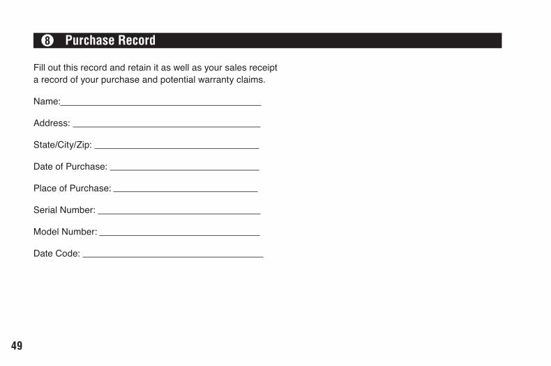
Fill out this record and retain it as well as your sales receipt a record of your purchase and potential warranty claims.
Name:
Address:
State/City/Zip:
Date of Purchase:
Place of Purchase:
Serial Number:
Model Number:
Date Code:
Purchase Record8


SCHWINNPacificCycle4902 Hammersley RoadMadison, WI 53711Service: 800-626-2811www.schwinn.com