Embed Size (px)
Citation preview

USER GUIDE251 POWERED ZONE CONTROLLER

Meridian 251 Powered Zone Controller User Guideii
Important safety instructionsRead the instructions.Keep these instructions.Follow all instructions.Do not use this apparatus near water.Clean only with a dry cloth.Install only in accordance with the manufacturer’s instructions.Refer all servicing to approved service personnel.
WARNING: TO REDUCE THE RISK OF FIRE OR ELECTRIC SHOCK, DO NOT EXPOSE THIS APPARATUS TO RAIN OR MOISTURE.
This apparatus has been designed with Class 1 construction and must be connected to a mains socket outlet with a protective earthing connection (the third grounding pin).
This apparatus does not include a power switch. The apparatus may be isolated from mains power either by unplugging the power connector from the rear of the unit, or by unplugging the connector at the opposing end of the power cord or cable from its supply outlet. As a result, either or both of these connectors should remain accessible.
•••••••
Safety warnings
WARNING! RISK OF ELECTRIC SHOCK – DO NOT OPEN
ATTENTION! NE PAS OUVRIR – RISQUE DE DÉCHARGE ÉLECTRIQUE
Caution: to reduce the risk of electric shock, do not remove cover. No user serviceable parts inside. Refer servicing to qualified service personnel.
The lightning flash with arrowhead symbol, within an equilateral triangle, is intended to alert the user to the presence of uninsulated “dangerous voltage” within the product’s enclosure that may be of sufficient magnitude to constitute a risk of electric shock to persons.
The exclamation point within an equilateral triangle is intended to alert the user to the presence of important operating and maintenance (servicing) instructions in the literature accompanying the appliance.

Meridian 251 Powered Zone Controller User Guide iii
Climate
The equipment has been designed for use in moderate climates and in domestic situations.
≤2000m Only use at an altitude not exceeding 2000m.
Safety warnings
Do not expose the unit to dripping or splashing.Do not place any object filled with liquid, such as a vase, on the unit.Do not place naked flame sources, such as lighted candles, on the unit.
To avoid overheating
Do not position the product in direct sunlight.Do not position the product near heat sources, such as a radiator.Do not position the product on a soft surface such as a carpet.Leave at least 10cm around the product to ensure sufficient ventilation.
••
•
••
•
•
To avoid interferenceDo not position the unit near strong electrical or magnetic radiation, such as near a power amplifier.
Radio interferenceFCC Warning: This equipment generates and can radiate radio frequency energy and if not installed and used correctly in accordance with our instructions may cause interference to radio communications or radio and television reception. It has been type-tested and complies with the limits set out in Subpart J, Part 15 of FCC rules for a Class B computing device. These limits are intended to provide reasonable protection against such interference in home installations.
EEC: This product has been designed and type-tested to comply with the limits set out in EN55032:2015 and EN55024:2010 + A1:2015.
Building codeDue consideration should be given to building and electrical codes when selecting speaker wiring. In the U.S.A. Class 2 wiring should be used.
•

Meridian 251 Powered Zone Controller User Guideiv
Copyright and acknowledgementsSales and service in the UKMeridian Audio Ltd, Latham Road, Huntingdon, Cambridgeshire, PE29 6YE, England.
Tel (01480) 445678 Fax (01480) 445686
Sales and service in the USAMAI, 351 Thornton Road, Suite 108, Lithia Springs, GA, 30122, United States.
Tel 404-344-7111 Fax 404-346-7111
Designed and manufactured in the UKMeridian Audio Ltd, Latham Road, Huntingdon, Cambridgeshire, PE29 6YE, England.
Visit us on the Webwww.meridian-audio.com
Copyright © 2017 Meridian Audio Ltd.
Part no: P88456
MHR: this product incorporates copyright protection technology covered by certain patent applications and intellectual property of Meridian Audio Ltd. This technology is provided for the express purpose of securely containing copyright audio within the Meridian System only. Reverse engineering or circumvention of this protection is strictly prohibited.
Manufactured under licence from MQA Limited. The MQA logo is a trade mark of MQA Limited. © MQA Limited 2017.
Boothroyd|Stuart Meridian, Meridian, and Sooloos are registered trademarks of Meridian Audio Ltd.
This guide was produced by: Human-Computer Interface Ltd, www.interface.co.uk
Product registrationRegister your Meridian 251 Powered Zone Controller at:
www.meridian-audio.com

Meridian 251 Powered Zone Controller User Guide v
ContentsIntroduction 1
Specifications 3
Unpacking 4
Applications 7
Configuring the 251 Powered Zone Controller 14
Controlling the 251 Powered Zone Controller 19
Index 20

Meridian 251 Powered Zone Controller User Guide 1
IntroductionThe Meridian 251 is a compact, networked, Powered Zone Controller designed to integrate a high quality audio switch and modern, power efficient amplifiers into an automated home audio system. It has analogue and digital stereo inputs as well as a Sooloos audio endpoint in order to meet the needs of a wide range of connectivity and installation requirements.
OutputsThe 251 Powered Zone Controller features high efficiency (>95%) Class D amplifiers which produce very little heat, allowing fanless operation. Two Phoenix connectors allow simple connection to passive loudspeakers via standard speaker cable. It also has a pair of unbalanced analogue outputs that can be used to drive a stereo power amplifier and passive loudspeakers, a pair of active loudspeakers, or one or two powered subwoofers.
InputsThe 251 provides a choice of audio input connections to cater for a range of installation requirements. These include a digital (co-ax/RCA) S/PDIF input, an optical (TOSLINK) input, and a Meridian SpeakerLink input, as well as an unbalanced analogue input.
The 251 also provides an Ethernet network socket to connect to a Meridian Sooloos System, Meridian’s music management platform.
Audio processingThe 251 Powered Zone Controller features high-quality audio processing. The digital inputs accept signals up to 192kHz, and the analogue inputs are converted to digital at 96kHz sampling. High-resolution files may also be replayed from a Meridian Sooloos system.
Signals are processed with Meridian’s exclusive apodising filter that ensures maximum audio quality with both phono and amplifier outputs driven by independent 192kHz/24 bit DACs.
The 251 Powered Zone Controller will also decode MQA (Master Quality Authenticated) audio streams. It can extract the finest of details from music and deliver the highest quality audio to all outputs. The front panel will indicate the MQA stream type using LEDs behind the MQA logo.
The 251 Powered Zone Controller can be configured to provide tone adjustments as well as balance and volume controls, for use with power amplifiers or active analogue speakers. The phono outputs can optionally be configured for fixed output, for connection to an external analogue preamplifier or a dedicated headphone amplifier.

Meridian 251 Powered Zone Controller User Guide2
Power supplyThe 251 uses a linear power supply, which provides isolation from the AC supply and offers both high sound quality and intrinsic durability. It is based on a massive low-noise toroidal power transformer, with an electronic trip for protection against short circuits or overheating.
System integrationThe 251 Powered Zone Controller is designed to be both configured and controlled via its Ethernet socket.
The 251 can be configured simply by entering the product’s IP address into a standard web browser; this then gives access to the range of setup and operational options.
The 251 is controlled using the Automation Protocol, which allows full control of all the runtime settings of the unit, including source selection, volume, and audio menus. This can be integrated into the automation system provided by the installer as well as accessed directly via a tablet or smartphone running our own application; see Controlling the 251 Powered Zone Controller, page 19.
The Trigger output is provided for direct control of external devices, such as enabling a power amplifier.
AccessoriesThe following accessories are available for the 251:
A rack tray for mounting the 251 in a standard 19" rack; see Installing 251 Powered Zone Controllers in a rack tray, page 12.A mount kit for mounting the 251 under a shelf, on a wall, or in a backbox; see Mounting a 251 Powered Zone Controller, page 13.A Meridian G12 remote eye to receive infra red signals.A Meridian MSR+ or AC200 remote to control the 251 via the G12.
•
•
••

Meridian 251 Powered Zone Controller User Guide
SpecificationsAudio outputs
2-channel loudspeaker outputs on terminal blocks supplied with mating connectors suitable for 12-24 AWG wire. Up to 100W per channel into 4Ω, or up to 65W per channel into 8Ω.2-channel unbalanced analogue output, driven by a 192kHz digital to analogue converter.
Audio inputs
One 2-channel unbalanced analogue input with adjustable sensitivity.One 2-channel digital coax input (RCA), 44.1kHz to 192kHz and up to 24-bit precision.One 2-channel Meridian SpeakerLink input, 44.1kHz to 192kHz and up to 24-bit precision.One 2-channel digital optical input (Toslink), 44.1kHz to 96kHz and up to 24-bit precision.One network input for connecting to a Meridian Sooloos System and IP control systems.
Control signals
One 12VDC/100mA trigger output configurable by source.One IR input, compatible with the Meridian G12 remote IR sensor.
•
•
•
•
•
•
•
••
Signal processing
The 251 uses Meridian’s proprietary DSP software to provide the following powerful features:
Apodising filter.Upsampling.FIFO and error correction.Resolution enhancement.MQA decoding and rendering.
Indicators
Front panel indicators for source selection, standby state, and MQA status.Rear panel indicator for power.
Physical
Dimensions: 203mm x 42mm x 221mm (8.0" x 1.65" x 8.7") (W x H x D without feet or connectors).Weight: 2.5kg (5.51lb).Stand-alone or rack-mounted versions.
Power
9W standby; 160W max.Factory set to: 100V AC, 115V AC, or 230V AC, 50-60Hz.
•••••
•
•
•
••
••

Meridian 251 Powered Zone Controller User Guide
UnpackingThe 251 Powered Zone Controller is supplied with:
A power cord.Four self-adhesive feet.Two Phoenix speaker connectors.Quick Start Guide
Please contact your retailer if the power cord has the wrong plug for your territory.
••••
The feet can be fixed to the base of the product, which is printed with circles as a guide. The feet will not be needed if you are mounting the unit on a rack tray. The rack tray is supplied with the screws required to mount the 251; see Installing 251 Powered Zone Controllers in a rack tray, page 12.
Back panelThe following diagram gives details of the back panel connections:
NetworkOutputs
IR In
TriggerOut
SpeakerLink In
Optical InAnalogue Out
Digital In
Right
Left
LeftRight Analogue In
Right
Left
Analogueinputs
Digital andoptical inputs
Triggeroutput
SpeakerLinkinput
Ethernetconnection
Loudspeakeroutputs
Analogueoutputs
Power
Powerindicator
IRinput

Meridian 251 Powered Zone Controller User Guide 5
Front-panel indicatorsThe currently selected source is indicated by one of five white indicators on the front panel.
In standby the leftmost indicator shows blue.
The rightmost indicator shows the MQA status: green (MQA) or blue (MQA studio).
Audio inputs
Use this input To connect to this
Analogue in (Radio, Tape) The analogue outputs of a source, such as a radio or tape deck.
Digital In (CD, USB) The digital output of a source such as a CD player.
SpeakerLink In (DVD, Disc)
The SpeakerLink output of a Meridian source, using a Meridian SpeakerLink lead.
Optical In (TV, Cable, Sat, PVR, Game)
The optical output of a source such as a satellite receiver.
Network (SLS) A Meridian Sooloos System.
The default source assignments are shown after the input name in the above table.
Audio outputs
Use this output To connect to this
Right +/– , Left +/–
Loudspeakers of between 4Ω and 8Ω, using Phoenix pluggable 2-way terminal blocks, 12AWG/20A.
Analogue Out The unbalanced analogue inputs of a preamplifier, power amplifier, or active subwoofers, using analogue phono leads.
Communications connections
Use this connection To connect to this
Trigger Out Equipment to be enabled by a DC signal, such as a power amplifier.
IR In A Meridian infra-red eye.

Meridian 251 Powered Zone Controller User Guide
Subwoofer optionsThe 251 Powered Zone Controller provides a range of options for using the loudspeaker outputs and analogue outputs to connect to the main left and right loudspeakers, and mono or stereo subwoofers. The following table shows some typical configurations, and the corresponding Audio output settings:
Loudspeaker outputs (amplifier)
Analogue outputs (phono) Audio output settings
Amplifier output Phono output Sub(s)
Full range main left/right channels.
Full range main left/right channels.
Left/Right Left/Right -
Full range main left/right channels.
One/two mono subwoofers. Left/Right Sub Mono
Full range main left/right channels.
Stereo left/right subwoofers. Left/Right Sub Stereo
In the Audio output section select L/R High Pass Filter if you want the subwoofer(s) to handle the bass instead of the main speakers (recommended), or Full Range if you want bass from both the subwoofers and main speakers.
In the Audio menus section use Sub Gain to adjust the relative level of the subwoofers, and set Crossover to the crossover frequency you want to use.

Meridian 251 Powered Zone Controller User Guide
ApplicationsMinimal system
LOUDSPEAKEROUT
NETWORK
Loudspeaker
+– +– +–
Loudspeaker
+–
251 Powered Zone Controller
Router
Sooloos network
This is a simple, standalone system replaying audio from a Sooloos system, using the Sooloos UI to control the volume.
Connect the loudspeaker outputs to the loudspeakers, using loudspeaker cables.
Connect the 251 to the LAN using an RJ45 cable.
•
•
Select the zone in the Sooloos UI and play music in the usual way.
Volume, mute and standby will be controlled from the Sooloos UI. To add further functionality download the Meridian App for the iPad, which allows control of all the 251 features; see Controlling the 251 Powered Zone Controller, page 19.
•

Meridian 251 Powered Zone Controller User Guide
Audio-visual system
NETWORK
OPTICALOUT
NETWORK
Television
Active subwoofer
Loudspeaker
+–
Loudspeaker
+–
LOUDSPEAKEROUT
ANALOGUEOUTPUTS
+– +–
251 Powered Zone Controller
Router
Sooloosnetwork
Wi-fi
DIGITALIN
Digitalsource

Meridian 251 Powered Zone Controller User Guide
This is a larger system with an active subwoofer, local sources, and more control options.
Connect the loudspeaker outputs to the main left and right loudspeakers, using loudspeaker cables.
Connect the analogue output to the analogue subwoofer, using a phono cable.
In the Audio output section set the Phono output option to Sub; see Audio output, page 15.
In the Audio menus section specify the crossover frequency using the Crossover option; see Audio menus, page 15.
Connect the TV to the Optical input socket.
Connect the 251 to the LAN using an RJ45 cable.
Optionally connect an analogue source using 50Ω RCA cables, and/or a digital source using a 75Ω RCA cable.
The system can be controlled via the Sooloos UI, the (optional) MSR+, or the Automation Interface, using the Meridian App for iOS; see Controlling the 251 Powered Zone Controller, page 19.
•
•
•
•
•
•
•

Meridian 251 Powered Zone Controller User Guide10
Distributed zone
ANALOGUEIN
NETWORKDIGITALIN
ANALOGUEOUT
NETWORK
Loudspeaker
+– +– +–
Loudspeaker
+–
LOUDSPEAKEROUT
251 Powered Zone Controller
Automation Matrix
Router
Wi-fi

Meridian 251 Powered Zone Controller User Guide 11
This layout is intended to play back audio in a single zone as part of a larger, whole-house, automation system. The 251 is located in a central rack along with the automation system’s audio matrix.
Connect the loudspeaker outputs to the main left and right loudspeakers, using loudspeaker cables.
Connect the audio matrix to the 251 analogue input using phono leads.
Connect the 251 to the LAN using an RJ45 cable.
The system can be controlled using a remote control for the automation system; it will have access to the 251’s Automation Interface. The controls that are presented to the user will depend on the UI chosen by the installer.
•
•
•

Meridian 251 Powered Zone Controller User Guide12
Installing 251 Powered Zone Controllers in a rack trayA 251 Rack Tray is available separately, to allow two 251s to be mounted in a standard 19" rack. The Rack Tray is supplied with the necessary screws.
The MAC address of each 251 is provided on the base of the unit, and we recommend that this is recorded on the tray as it is installed so that it can be identified in future. Adhesive labels
are supplied with each Rack Tray for this purpose.
Note that if only one 251 is being installed in a tray then the open side of the fascia can be blanked by one of the knock-outs included in the tray. Remove the knock-out from the tray and bend the two longer tabs to 90 degrees. Affix the two self-adhesive dots and slide the shorter tabs down between the fascia and the tray, resting the longer tabs on the top surface of the tray. Press the knock-out firmly against the back of the fascia to secure.
251 - Must be fittedwithout feet pads
Blanking plateFix to rear of front fasciaon the self-adhesive dots
Fold longer tabs upThis will support and positionblanking plate on tray
Cut and remove blankingplate from this position
Self-adhesive dotsFit to rear of front fasciaon either side of aperture
M3 x 6 countersunk screwsfitted in four positions tosecure 251 to tray

Meridian 251 Powered Zone Controller User Guide 1
Mounting a 251 Powered Zone ControllerA universal mount kit is available separately, to allow a 251 to be mounted on any flat surface, such as under a shelf, on a wall, or in a backbox.
The kit consists of two plates and four screws, allowing the 251 Powered Zone Controller to be mounted in either of two orientations, as shown in the following diagrams:

Meridian 251 Powered Zone Controller User Guide1
Configuring the 251 Powered Zone ControllerThe 251 contains a built-in web interface, allowing it to be configured via the Ethernet connection using a standard web browser.
Displaying the 251 configuration pageTo display the 251 configuration page
Connect the 251 to a network.
Identify the IP address assigned to the 251 (see below).
Type this address into the address bar of a standard web browser running on a computer or tablet on the same network.
You should then see the Meridian 251 configuration page. This allows you to see or change the 251 settings, or reset them to their defaults, and also gives access to an online version of this user guide.
Full details of each of the groups of settings are given in the following sections.
To store the settings
After changing any settings click the Store Settings button below the settings panels.
•
•
•
To restore the settings
The Restore factory settings panel allows you to restore one or more groups of settings to their factory defaults. Note that restoring the ethernet settings will enable DHCP, which may change the IP address of the 251, and you may have to find the new address as described below.
Discovering the IP address of the 251To discover the IP address of the 251 you can use any of the following methods:
The IP Control app (see IP Control app, page 19) will automatically discover the 251 and link directly to the 251 configuration page.
On a Sooloos network it can be found using the Sooloos Configuration Tool.
On a Touch:PC it can be found using the Device Manager.
Log in to the network router and view the list of attached devices.
Use a network IP scanner to ‘ping’ a list of addresses on the network.
•
•
•
•
•
Meridian 251 Powered Zone Controller User Guide 15
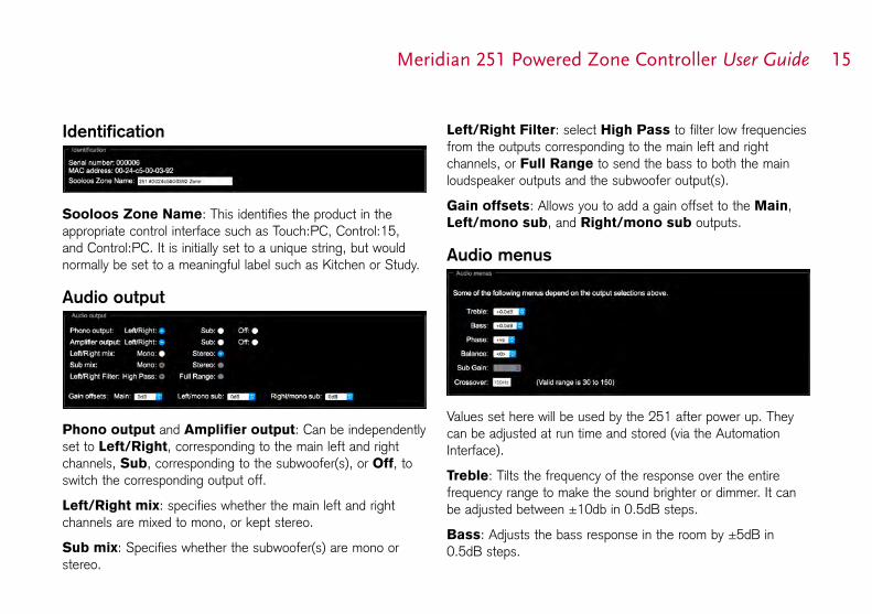
Identification
Sooloos Zone Name: This identifies the product in the appropriate control interface such as Touch:PC, Control:15, and Control:PC. It is initially set to a unique string, but would normally be set to a meaningful label such as Kitchen or Study.
Audio output
Phono output and Amplifier output: Can be independently set to Left/Right, corresponding to the main left and right channels, Sub, corresponding to the subwoofer(s), or Off, to switch the corresponding output off.
Left/Right mix: specifies whether the main left and right channels are mixed to mono, or kept stereo.
Sub mix: Specifies whether the subwoofer(s) are mono or stereo.
Left/Right Filter: select High Pass to filter low frequencies from the outputs corresponding to the main left and right channels, or Full Range to send the bass to both the main loudspeaker outputs and the subwoofer output(s).
Gain offsets: Allows you to add a gain offset to the Main, Left/mono sub, and Right/mono sub outputs.
Audio menus
Values set here will be used by the 251 after power up. They can be adjusted at run time and stored (via the Automation Interface).
Treble: Tilts the frequency of the response over the entire frequency range to make the sound brighter or dimmer. It can be adjusted between ±10db in 0.5dB steps.
Bass: Adjusts the bass response in the room by ±5dB in 0.5dB steps.

Meridian 251 Powered Zone Controller User Guide1
Phase: Changes the absolute phase of the signal, to compensate for signals which are out of phase, giving an unnatural-sounding bass.
Balance: Compensates for an off-centre listening position where 0 is central, 8 is in line with the corresponding main speaker, and 10 is fully to one side.
Note: Balance only affects the subwoofer outputs when they are set to stereo.
Sub Gain: Allows you to adjust the gain of the subwoofer(s).
Crossover: Allows you to adjust the crossover frequency of the subwoofer(s).
Startup
Start volume: Specifies the initial volume for the outputs. The start volume is set when the 251 is first powered up, and a few seconds after going into standby.
By default the 251 starts at volume 50 and retains the last volume setting when it enters and leaves standby.
Startup source: Specifies the source that the 251 will
start with if the user has a Source key on their chosen user interface.
State after power up: Specifies whether the 251 should start in standby or on when powered up.
Sources
Legend: A string of up to 5 characters which will be displayed on the Automation interface.
Audio input: Each of the 12 logical sources can be assigned to any of the audio inputs: Analogue, Digital, Optical, SpeakerLink, or Sooloos. Alternatively any source can be set to Last Valid, which changes the other settings but leaves the input unchanged, or Off, which makes the source unavailable.

Meridian 251 Powered Zone Controller User Guide 1
Sensitivity: For analogue inputs you can select one of five sensitivities: the maximum RMS voltage that can be input before clipping occurs in the ADC.
Trigger: Can be set to On, Off, or LV (Last Valid) to control the trigger output. Note that the trigger is always off in standby.
FIFO: The FIFO box would normally be checked, but can be unchecked for digital sources with a poor quality clock that the 251 is unable to reclock.
Validity: Some sources, such as the Meridian CD players, use the Validity flag in the S/PDIF audio stream to indicate that the audio should not be played. Setting this may reduce unwanted noises in some situations.
Lipsync: Allows you to delay the audio by up to 85msec so that it aligns correctly with a video signal that has been delayed by a scaler.
Comms Type: For Comms-connected systems, ensures that the appropriate set of commands is sent to the product. The following categories are available:
1C = CD player, 2C = Radio, 3C = DVD player, 4C = Sooloos
All others should be set to NC (No Comms).
Address: If there are two or more products of each type then the address should be 1A for the first, 2A for the second, etc.
Comms
System Address: If an installation contains multiple zones that are connected together with Meridian Comms, each one needs a different System Address if they are to have independent source selection and volume controls. If the installation uses LAN connections then this can be left at its default, 1A.
Product Address: If there are two or more Meridian sources in the same category on the same Comms-connected system then each unit must have a different Product Address. The setting does not apply to IP connected systems and should be left at its default, 1A.
IR mode: The IR mode is only relevant if a G12 has been connected to the 251. In this setup the installer should set the mode to Controller to ensure that the unit functions as the system controller.
IR receiver is currently: Shows the state of the IR receiver.

Meridian 251 Powered Zone Controller User Guide1
Ethernet
Allows you to change the Ethernet configuration. Note that incorrect settings may make the 251 unreachable via the web page.

Meridian 251 Powered Zone Controller User Guide 1
Controlling the 251 Powered Zone ControllerThe Meridian 251 can be controlled using the following options:
Via Meridian Comms from another product such as a Meridian CD Player.Via the Ethernet connection using the Sooloos system.Via the Ethernet connection using the Automation Interface.Via Infra Red, using the optional G12 remote IR sensor and either the MSR, MSR+, or AC200 remote controls.
IP Control appMeridian provide a free app for iOS called IP Control that uses the Automation Interface of the 251. Search for Meridian in the Apple App Store to download it.
Ethernet connectionA LAN connection is required to configure the 251 Powered Zone Controller. Also, various aspects of the update and support systems require that the LAN allows Link Local addressing and multicast transmission as well as UDP and TCP traffic (for the music stream and its control). Simple unmanaged switches will always pass this traffic but Wireless Access Points should be selected carefully and managed switches must be configured correctly to pass this traffic.
•
•••
Third-party IR inputsThe Meridian G12 IR sensor has the following pinout:
+12VIR signalGround
Third-party IR receivers with the same pinout may be compatible but their operation is not guaranteed.
Many home automation/control systems feature outputs suitable for feeding IR emitter devices (also referred to as “IR blasters”). These signals differ from those derived from infra–red receivers in that they are modulated with a carrier frequency. The 251 will automatically detect this and extract the underlying IR signal. Use only the Ring and Sleeve connections for these devices; the Tip (12V) should be left unconnected.
For details of the Automation Interface and the IR control codes see the Meridian website:
www.meridian-audio.com

Meridian 251 Powered Zone Controller User Guide20
IndexAAddress option 17
Amplifier output option 15
analogue inputs 5
analogue outputs 5
applications
audio-visual system 8
distributed zone 10
minimal system 7
audio-visual system 8
Audio input option 16
Audio menus panel 15
Audio output panel 15
Automation Interface 19
auxiliary output 4
Bback panel connections 4
Balance option 16
Bass option 15
CComms, connecting 5
Comms panel 17
Comms Type option 17
communications connections 5
configuration 14
controlling 19
Crossover option 16
Ddigital inputs 5
distributed zone 10
EEthernet connection 19
Ethernet panel 18
FFIFO option 17
front-panel indicators 5
Full Range option 15
GGain offsets option 15
IIdentification panel 15
indicators 5
inputs 5
installing in a rack tray 12
IP Control application 19
IR input 5

Meridian 251 Powered Zone Controller User Guide 21
IR mode option 17
IR sensor pinout 19
LLeft/Right Filter option 15
Left/Right mix option 15
Legend option 16
Lipsync option 17
loudspeaker outputs 4
MMAC address 12
minimal system 7
mounting 13
MQA status 5
Ooptical input 5
outputs 5
Ppanels
Audio menus 15
Audio output 15
Comms configuration 17
Ethernet configuration 17
Identification 15
Source configuration 16
Phase option 16
Phono output option 15
Product Address option 17
Rrack tray, installing in 12
registration iv
Ssafety warnings iii
Sensitivity option 17
Sooloos Zone Name option 15
Sources panel 16
SpeakerLink input 5
specifications 3
Startup panel 16
Startup source option 16
Start volume option 16
State after power up option 16
Sub Gain option 16
Sub mix option 15
System Address option 17
TTreble option 15
Trigger option 17
trigger outputs 5
VValidity option 17