Embed Size (px)
Citation preview

250 Series DIN Rail and Wall Mounted Relays
20
A.C. Current with Adjustable Time Delay250 series A.C. current protectors provide continuous surveillance of the monitoredcircuit. When the current moves outside the setpoint limit, the relay operates. Theprotector can be used to monitor over and under current conditions, load detection,and for monitoring electric heating systems. An illuminated LED indicates when therelay is energized. For 3 phase systems, the sequence of connection is not important.
Operation
A.C. current protectors provide continuous surveillance of the monitored circuit.These products offer user adjustable trip point (setpoint) and time delay settings. Thesetpoint adjustment range is between 40% and 120% of the nominal current. Inputcurrents can be via current transformers or direct up to 10A. An internal differentialsetting of 1% reduces nuisance tripping if the measured signal is noisy or unstable.When the measured current moves outside the setpoint limit, the relay will operate,giving an alarm or initiation signal. An adjustable time delay is provided to preventthe relay from tripping for a predetermined period to prevent nuisance tripping. Theunits draw their operating power from a separate auxiliary supply input. Singlephase and three phase products are available. Three phase products monitor thecurrent level for each phase, and are not phase sequence sensitive. Combined unitsoffer under and over current trips in one compact unit. Single function units are alsoavailable.
Over Current Models
When the monitored current exceeds the setpoint, the relay will energize and the redLED will illuminate to indicate the trip condition. The relay will automatically resetonce the monitored current falls below the setpoint minus the differential. Whenreset, the LED will extinguish and the relay de-energizes.
Under Current Models
When the monitored current falls below the setpoint, the relay will de-energize andthe red LED will extinguish to indicate the trip condition. The relay will automaticallyreset once the monitored current rises above the setpoint plus the differential. Whenreset, the LED will illuminate and the relay energizes.
Options
250 series protector relays offer various customized options to suit individualrequirements. Please consult factory.
• Adjustment ranges - different adjustment ranges are possible for the setpoint and differential controls.
• Relay operation - standard models are fail safe, but the relays can be customized to energize or de-energize on trip.
Product Codes
Relay Protection ANSI No. Catalog No.
Single phase Under current 40-120% 37 252-PAUSingle phase Over current 40-120% 51 252-PAOSingle phase Under and over current 37/51 253-PAD3 phase 3 or 4 wire Under current 40-120% 37 253-PAV3 phase 3 or 4 wire Over current 40-120% 51 253-PAP
Specify system voltage, system current, frequency and required options at time ofordering.
Features
Single and 3 phase options
Adjustable setpoint
Adjustable time delay
Internal differential
LED trip indication
Double pole relay contacts
Automatic reset
Benefits
Ideal for any electrical load detection
Over and under current monitoring
Suitable for electric heating systems
Ensures load current is within generatorcapacity
Detects broken drive belts on machinery
Nuisance tripping avoidance
Customized options
Applications
Marine panels
Switchgear
Distribution systems
Generator sets
Control panels
Process control
Motor protection
Transformers
Overload protection
Approvals
UL, CSA, BV and ABS
Provided by: K-Tech Inc. Ph:1 847 375 9524, Fx:1 847 375 9523www.K-Tech.com [email protected]

75 (2.9)
70 (
2.8)
112.5 (4.4)
35 (
1.37
)
RELEASE CLIP
60 (2.4)
2 FIXING HOLE'A' TO SUIT M4
2 FIXING HOLE'A' TO SUIT M4
50 (
1.96
)60
(2.
36)
55 (2.2)
70 (
2.8)
35 (
1.37
)
112 (4.4)
RELEASE CLIP
55 (2.2)
35 (
1.37
)
17.5 (0.68)
35 (1.37) 15.5
(0.6
)12 (0.5
)
2 HOLESØ 4.1
Input1
Input2
Input3
SupplyRelayContact Set 1
RelayContact Set 2
InputUnder RelayContact Set 1
Over RelayContact Set 1
Under RelayContact Set 2
Over RelayContact Set 2
Supply
Contact Set 1 Contact Set 2Relay
Input Supply
250 Series DIN Rail and Wall Mounted Relays
21
Specification – AC Current with Adjustable Time Delay
Nominal Input Current 1A or 5A from CT secondary.0.2A to 10A available on request
Nominal Frequency 50, 60 or 400HzInput Current Burden 0.5VA per phaseOverload 2 x rating continuously, 10 x rating for 3 secondsSet Point Repeatability >0.5% of full spanDifferential (Hysteresis) Preset at 1%. Values 1% to 10% available on requestTrip Level Adjustment 40 to 120%. Customized adjustment availableTime Delay Adjustable 0 to 10 secondsAC Auxiliary Supply Voltage 100V, 110V, 120V, 208V, 220V, 240V, 480V, ±20%DC Auxiliary Supply Voltage 12V, 24V, 48V, 110V or 125V, ±15%. Max ripple 15%Auxiliary Voltage Burden 4VA (max)Output Relay Double pole change overRelay Contact Rating AC: 240V 5A, non inductive
DC: 24V, 5A resistiveRelay Mechanical Life 0.2 million operations at rated loadsRelay Reset AutomaticOperating Temperature 0°C to +60°C (0°C to +40°C for UL models)Storage Temperature -20°C to + 70°CTemperature Co-efficient 0.05% per °CInterference Immunity Electrical stress surge withstand and non-
function to ANSI/IEEE C37 90aEnclosure Style DIN rail with wall mounting facilityMaterial Flame retardant polycarbonate/ABSEnclosure Integrity IP50Compliant With EMC, LVD, Safety Standard IEC 414
UL File No: E113067 recognized up to 600VCSA File No: LR52592 up to 300VBV File No: 2650H-07427-AO-PRSO BVABS File No: 93-LD 17806-X
Model 252 Dimensions 55mm (2.2") wide x 70mm (2.8") high x 112mm (4.4") deep
Model 253 Dimensions 75mm (2.9") wide x 70mm (2.8") high x 112mm (4.4") deep
Weight Model 252: 0.4Kg approx. Model 253: 0.6Kg approx.
Dimensions
Model 252
Model 253
Connections
252-PAU
252-PAO
253-PAD
253-PAP
253-PAV
Provided by: K-Tech Inc. Ph:1 847 375 9524, Fx:1 847 375 9523www.K-Tech.com [email protected]

250 Series DIN Rail and Wall Mounted Relays
22
A.C. Voltage with Adjustable Time DelayThe A.C. voltage protectors provide continuous surveillance of the monitored circuit.When the measured voltage moves outside the setpoint limit, the relay will operateafter the selected time delay, giving an alarm or initiation signal. Relays normallyenergize on overvolts and de-energize on undervolts. An illuminated LED indicateswhen the relay is energized.
Operation
A.C. voltage protectors offer user adjustable trip point (setpoint) and time delaysettings. The setpoint adjustment range is 25%, operating between 75% and 100% ofthe nominal supply for under voltage units, and between 100% and 125% for theover voltage units. The time delay setting adjustment range is typically 0 to 10seconds, although longer delays are available. As soon as the monitored signalmoves outside of the setpoint limit, the time delay is activated, after which a trip willoccur. The time delay prevents the relay from tripping for a predetermined period toprevent nuisance tripping.
The products also feature an internal differential (hysteresis) setting of 1% to reducenuisance tripping if the measured signal is noisy or unstable. The units draw theiroperating power from the measuring inputs, although a separate auxiliary supplyinput option is available on some models. Single phase and three phase products areavailable, three phase products monitor the voltage level for each phase, and are notphase sequence sensitive.
Over Voltage Models
When the monitored voltage exceeds the setpoint, the time delay is started. Whenthe time has elapsed, the relay will energize and the red LED will illuminate toindicate the trip condition. The relay will automatically reset once the monitoredvoltage falls below the setpoint minus the differential. When reset, the LED willextinguish and the relay de energizes. The time delay is not active when resetting.
Under Voltage Models
When the monitored voltage falls below the setpoint, the time delay is started. Whenthe time has elapsed, the relay will de-energize and the red LED will extinguish toindicate the trip condition. The relay will automatically reset once the monitoredvoltage rises above the setpoint plus the differential. When reset, the LED willilluminate and the relay energizes. The time delay is not active when resetting.
Options
250 series protector relays offer various customized options to suit individualrequirements.
Please consult factory.
• Adjustment ranges - different adjustment ranges are possible for the setpoint anddifferential controls.
• Separate auxiliary supply - sometimes required to maintain a time delay or energized relay when the monitored signal fails.
• Differential - internally fixed value between 1% and 15%.
• Relay operation - standard models are fail safe, but the relays can be customized to energize or de-energize on trip.
Product Codes
Relay Protection ANSI No. Catalog No.
Single phase Under voltage 75-100% 27 252-PVZSingle phase Over voltage 100-125% 59 252-PVH3 phase 3 wire Under voltage 75-100% 27 252-PVJ3 phase 3 wire Over voltage 100-125% 59 252-PVC3 phase 4 wire Under voltage 75-100% 27 252-PVX3 phase 4 wire Over voltage 100-125% 59 252-PVS
Specify system voltage, frequency and required options at time of ordering.
Features
Adjustable setpoint
Adjustable time delay
Internal differential
LED trip indication
Double pole relay contacts
Automatic reset
Benefits
Over and under voltage monitoring
Close voltage control
Start standby generators
Operation of mains failure units
Switching standby supplies
Protecting computer supplies
Monitors genset AVR and excitationsystems
Nuisance tripping avoidance
Customized options
Applications
Switchgear
Distribution systems
Generator sets
Control panels
Process control
Motor protection
Transformers
Overload protection
Approvals
UL and CSA
Provided by: K-Tech Inc. Ph:1 847 375 9524, Fx:1 847 375 9523www.K-Tech.com [email protected]
55 (2.2)
70 (
2.8)
35 (
1.37
)
112 (4.4)
RELEASE CLIP
55 (2.2)
35 (
1.37
)
17.5 (0.68)
35 (1.37) 15.5
(0.6
)12 (0.5
)
2 HOLESØ 4.1
250 Series DIN Rail and Wall Mounted Relays
23
Specification – AC Voltage with Adjustable Time Delay
Nominal Voltage 100V, 110V, 208V, 240V, 277V, 400V, 415V, 440Vor 480V
System Frequency 45/65Hz or 360/440HzVoltage Burden 0.3VAOverload 1.2 x rating continuously, 1.5 x rating for
10 x secondsSet Point Repeatability > 0.5% of full spanDifferential (Hysteresis) Preset at 1%.
Other values 1% to 10% to orderTrip Level Adjustment Under Voltage: 75 to 100%
Over Voltage: 100 to 125% of nominal input voltageTime Delay Adjustable up to 10 secondsAC Auxiliary Supply Voltage 100V, 110V, 120V, 208V, 220V, 240V, 480V, ±20%DC Auxiliary Supply Voltage 12V, 24V, 48V, 110V or 125V, ±15%. Max ripple 15%Auxiliary Voltage Burden 4VA (max)Output Relay Double pole change overRelay Contact Rating AC: 240V 5A, non inductive
DC: 24V, 5A resistiveRelay Mechanical Life 0.2 million operations at rated loadsRelay Reset AutomaticOperating Temperature 0°C to +60°C (0°C to +40°C for UL models)Storage Temperature -20°C to + 70°CTemperature Co-efficient 0.05% per °CInterference Immunity Electrical stress surge withstand and non-
function to ANSI/IEEE C37 90aEnclosure Style DIN rail with wall mounting facilityMaterial Flame retardant polycarbonate/ABSEnclosure Integrity IP50Compliant With EMC, LVD, Safety Standard IEC 414
UL File No: E113067 recognized up to 600VCSA File No: LR52592 up to 300V
Dimensions 55mm (2.2") wide x 70mm (2.8") high x 112mm (4.4") deep
Weight 0.4Kg approx.
Dimensions
Model 252
Connections
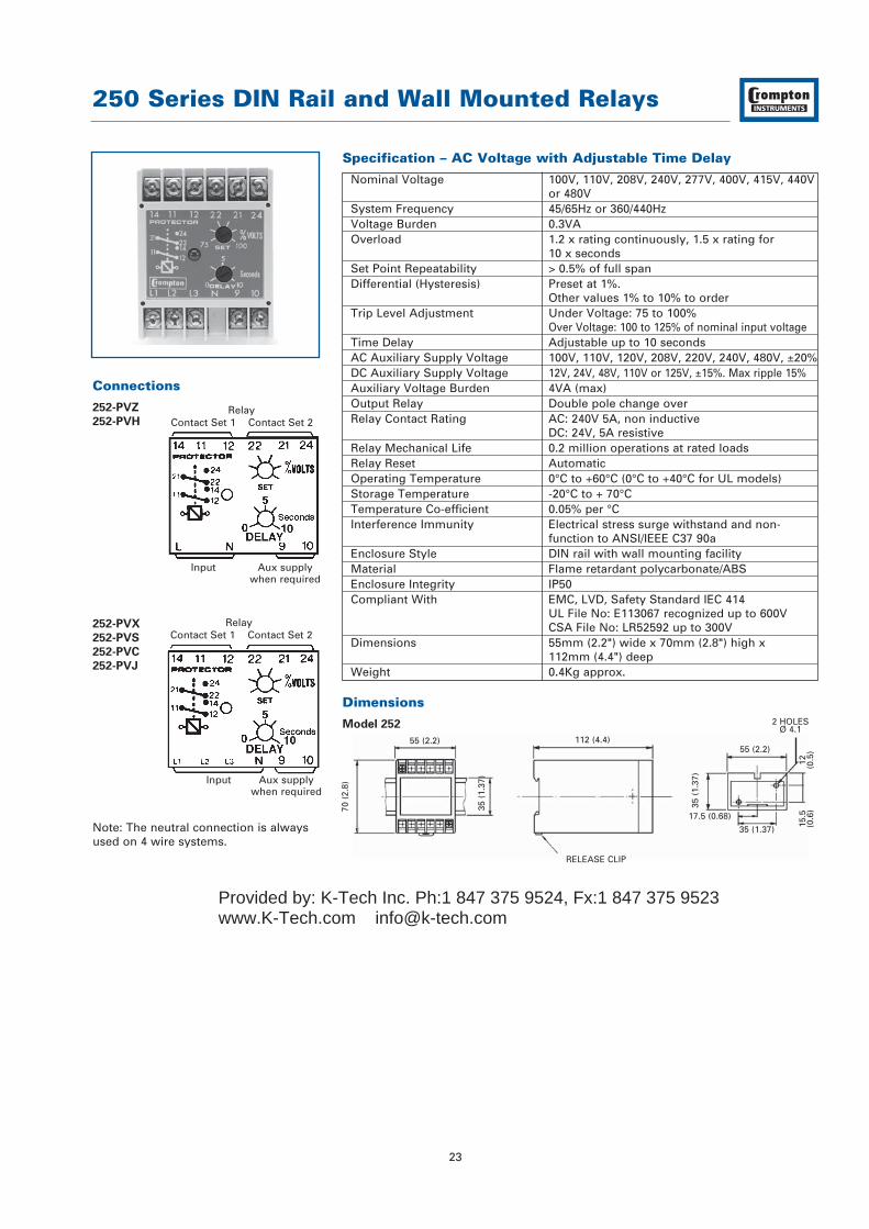
252-PVZ
252-PVH
252-PVX
252-PVS
252-PVC
252-PVJ
Note: The neutral connection is alwaysused on 4 wire systems.
RelayContact Set 1 Contact Set 2
Input Aux supplywhen required
RelayContact Set 1 Contact Set 2
Input Aux supplywhen required
Provided by: K-Tech Inc. Ph:1 847 375 9524, Fx:1 847 375 9523www.K-Tech.com [email protected]
250 Series DIN Rail and Wall Mounted Relays
24
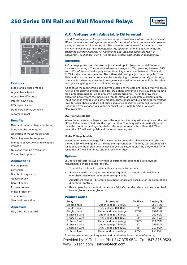
A.C. Voltage with Adjustable DifferentialThe A.C. voltage protectors provide continuous surveillance of the monitored circuit.When the measured voltage moves outside the setpoint limit, the relay will operategiving an alarm or initiation signal. The protector can be used for under and overvoltage detection, start standby generators, operation of mains failure units, andswitching standby supplies. An illuminated LED indicates when the relay isenergized. The 3 phase, 3 or 4 wire models, protect each phase independently.
Operation
A.C. voltage protectors offer user adjustable trip point (setpoint) and differential(hysteresis) settings. The setpoint adjustment range is 25%, operating between 75%and 100% of the nominal supply for under voltage units, and between 100% and125% for the over voltage units. The differential setting adjustment range is 1% to15%, and it can be used to reduce nuisance tripping if the measured signal is noisyor unstable. When the measured voltage moves outside the setpoint limit, the relaywill operate, giving an alarm or initiation signal.
As soon as the monitored signal moves outside of the setpoint limit, a trip will occur.A fixed time delay is available as a factory option, preventing the relay from trippingfor a predetermined period to prevent nuisance tripping. The units draw theiroperating power from the measuring inputs, although a separate auxiliary supplyinput option is available on some models. Three phase products monitor the voltagelevel for each phase, and are not phase sequence sensitive. Combined units offerunder and over voltage trips in one compact unit. Single function units are also available.
Over Voltage Models
When the monitored voltage exceeds the setpoint, the relay will energize and the redLED will illuminate to indicate the trip condition. The relay will automatically resetonce the monitored voltage falls below the setpoint minus the differential. Whenreset, the LED will extinguish and the relay de-energizes.
Under Voltage Models
When the monitored voltage falls below the setpoint, the relay will de-energize andthe red LED will extinguish to indicate the trip condition. The relay will automaticallyreset once the monitored voltage rises above the setpoint plus the differential. Whenreset, the LED will illuminate and the relay energizes.
Options
250 series protector relays offer various customized options to suit individualrequirements. Please consult factory.
• Time delay - internal fixed time delay before a trip occurs.
• Separate auxiliary supply - sometimes required to maintain a time delay or energized relay when the monitored signal fails.
• Adjustment ranges - different adjustment ranges are possible for the setpoint anddifferential controls.
• Relay operation - standard models are fail safe, but the relays can be customized to energize or de-energize on trip.
Product Codes
Relay Protection ANSI No. Catalog No.
Single phase Under voltage 75-100% 27 252-PVUSingle phase Over voltage 100-125% 59 252-PVOSingle phase Under and over voltage 27/59 253-PVB3 phase 3 wire Under voltage 75-100% 27 252-PVK3 phase 3 wire Over voltage 100-125% 59 252-PVA3 phase 3 wire Under and over voltage 27/59 253-PVM3 phase 4 wire Under voltage 75-100% 27 252-PVV3 phase 4 wire Over voltage 100-125% 59 252-PVP3 phase 4 wire Under and over voltage 27/59 253-PVE
Specify system voltage, frequency, and required options at time of ordering.
Features
Single and 3 phase models
Adjustable setpoint
Adjustable differential
Internal time delay
LED trip indication
Double pole relay contacts
Automatic reset
Benefits
Over and under voltage monitoring
Start standby generators
Operation of mains failure units
Switching standby supplies
Monitors genset AVR and excitationsystems
Nuisance tripping avoidance
Customized options
Applications
Marine panels
Switchgear
Distribution systems
Generator sets
Control panels
Process control
Motor protection
Transformers
Overload protection
Approvals
UL , CSA , BV and ABS
Provided by: K-Tech Inc. Ph:1 847 375 9524, Fx:1 847 375 9523www.K-Tech.com [email protected]
250 Series DIN Rail and Wall Mounted Relays
25
Connections
252-PVU
252-PVO
252-PVV
252-PVP
252-PVK
252-PVA
253-PVB
253-PVE
253-PVM
Note: The neutral connection is alwaysused on 4 wire systems.
3 Phase InputL N
Single PhaseInput
Auxsupplywhen
required
Contact Set 1 Contact Set 2Relay
Under RelayContact Set 1
Over RelayContact Set 1
Under RelayContact Set 2
Over RelayContact Set 2
Input
Input
Input
55 (2.2)
70 (
2.8)
35 (
1.37
)
112 (4.4)
RELEASE CLIP
55 (2.2)
35 (
1.37
)
17.5 (0.68)
35 (1.37) 15.5
(0.6
)12 (0.5
)
2 HOLESØ 4.1
75 (2.9)
70 (
2.8)
112.5 (4.4)
35 (
1.37
)
RELEASE CLIP
60 (2.4)
2 FIXING HOLE'A' TO SUIT M4
2 FIXING HOLE'A' TO SUIT M4
50 (
1.96
)60
(2.
36)
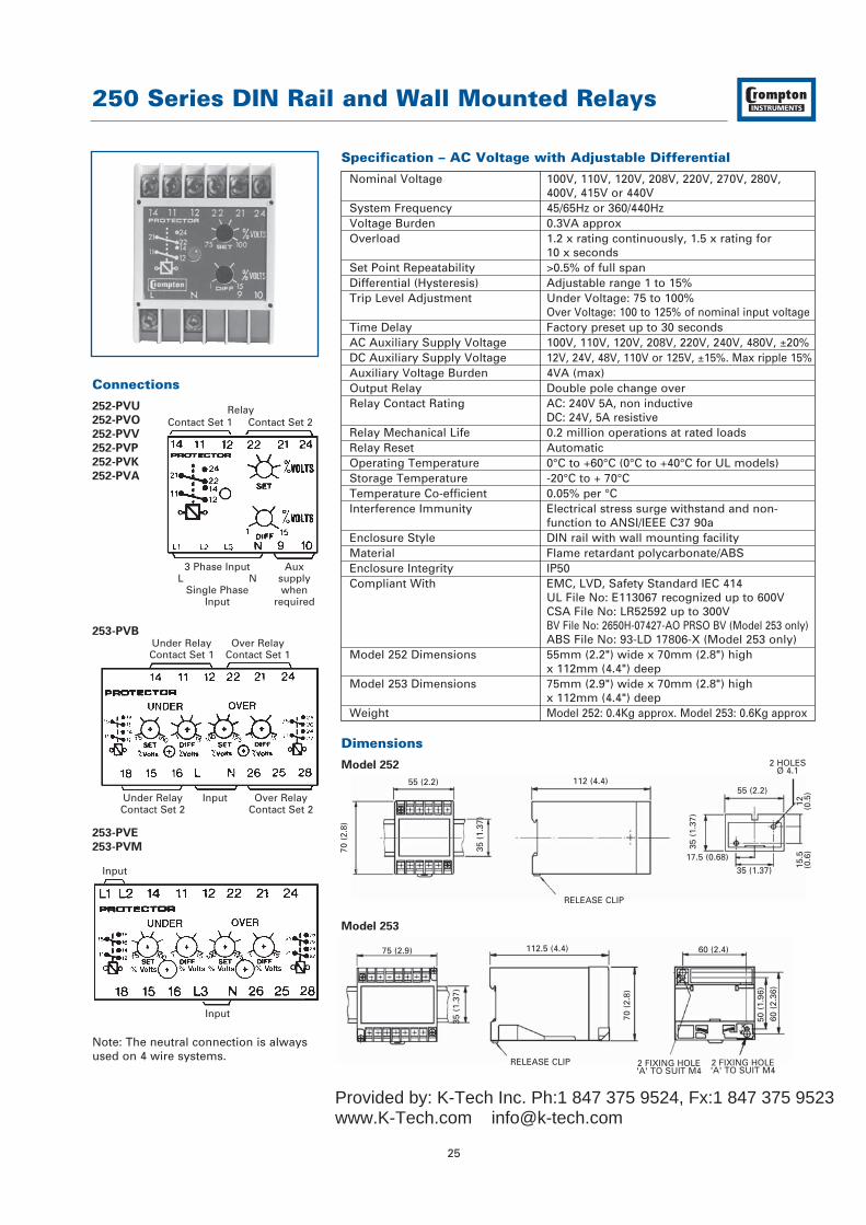
Specification – AC Voltage with Adjustable Differential
Nominal Voltage 100V, 110V, 120V, 208V, 220V, 270V, 280V,400V, 415V or 440V
System Frequency 45/65Hz or 360/440HzVoltage Burden 0.3VA approxOverload 1.2 x rating continuously, 1.5 x rating for
10 x secondsSet Point Repeatability >0.5% of full spanDifferential (Hysteresis) Adjustable range 1 to 15%Trip Level Adjustment Under Voltage: 75 to 100%
Over Voltage: 100 to 125% of nominal input voltageTime Delay Factory preset up to 30 secondsAC Auxiliary Supply Voltage 100V, 110V, 120V, 208V, 220V, 240V, 480V, ±20%DC Auxiliary Supply Voltage 12V, 24V, 48V, 110V or 125V, ±15%. Max ripple 15%Auxiliary Voltage Burden 4VA (max)Output Relay Double pole change overRelay Contact Rating AC: 240V 5A, non inductive
DC: 24V, 5A resistiveRelay Mechanical Life 0.2 million operations at rated loadsRelay Reset AutomaticOperating Temperature 0°C to +60°C (0°C to +40°C for UL models)Storage Temperature -20°C to + 70°CTemperature Co-efficient 0.05% per °CInterference Immunity Electrical stress surge withstand and non-
function to ANSI/IEEE C37 90aEnclosure Style DIN rail with wall mounting facilityMaterial Flame retardant polycarbonate/ABSEnclosure Integrity IP50Compliant With EMC, LVD, Safety Standard IEC 414
UL File No: E113067 recognized up to 600VCSA File No: LR52592 up to 300VBV File No: 2650H-07427-AO PRSO BV (Model 253 only)ABS File No: 93-LD 17806-X (Model 253 only)
Model 252 Dimensions 55mm (2.2") wide x 70mm (2.8") highx 112mm (4.4") deep
Model 253 Dimensions 75mm (2.9") wide x 70mm (2.8") highx 112mm (4.4") deep
Weight Model 252: 0.4Kg approx. Model 253: 0.6Kg approx
Dimensions
Model 252
Model 253
Provided by: K-Tech Inc. Ph:1 847 375 9524, Fx:1 847 375 9523www.K-Tech.com [email protected]

250 Series DIN Rail and Wall Mounted Relays
26
FrequencyCrompton frequency protectors give continuous surveillance of the monitored circuit.When the frequency moves outside the set point limit the relay will operate giving analarm, control or tripping signal. An illuminated LED indicates when the relay isenergized. Since speed is proportional to the frequency, this protector can be used tomonitor over and underspeed, and to protect mains supplies, computer supplies, andstandby supplies for Industrial, Hospital or Marine use.
Operation
Frequency protectors offer user adjustable frequency trip point (setpoint) anddifferential (hysteresis) settings. The setpoint adjustment range is centred around thenominal 50Hz, 60Hz or 400Hz system frequency. The differential setting adjustmentcan be used to reduce nuisance tripping if the measured signal is noisy or unstable.When the measured frequency moves outside the setpoint limit, the relay willoperate, giving an alarm or initiation signal. As soon as the monitored frequencymoves outside of the setpoint limit, a trip will occur. The units draw their operatingpower from the measuring inputs. Combined units offer under and over frequencytrips in one compact unit. Single function units are also available.
Over Frequency Models
When the monitored frequency exceeds the setpoint, the relay will energize and thered LED will illuminate to indicate the trip condition. The relay will automaticallyreset once the monitored frequency falls below the setpoint minus the differential.When reset, the LED will extinguish and the relay de-energizes.
Under Frequency Models
When the monitored frequency falls below the setpoint, the relay will de-energizeand the red LED will extinguish to indicate the trip condition. The relay willautomatically reset once the monitored frequency rises above the setpoint plus thedifferential. When reset, the LED will illuminate and the relay energizes.
Options
250 series protector relays offer various customized options to suit individualrequirements. Please consult factory.
• Adjustment ranges - different adjustment ranges are possible for the setpoint anddifferential controls.
• Time delay - internal fixed time delay before a trip occurs.
• Relay operation - standard models are fail safe, but the relays can be customized to energize or de-energize on trip.
Product Codes
Relay Protection ANSI No. Catalog No.
Single phase Under frequency 81U 252-PHUSingle phase Over frequency 81O 252-PHOSingle phase Under and over frequency 81O/U 253-PHD
Specify system voltage, frequency and required options at time of ordering.
Features
Adjustable setpoint
Adjustable differential
LED trip indication
Double pole relay contacts
Automatic reset
Benefits
Over and under frequency monitoring
Over and underspeed monitoring
Start standby generators
Operation of mains failure units
Switching standby supplies
Protection of control gear
Nuisance tripping avoidance
Customized options
Applications
Marine panels
Switchgear
Distribution systems
Generator sets
Control panels
Process control
Motor protection
Transformers
Overload protection
Approvals
UL, CSA, BV and ABS
Provided by: K-Tech Inc. Ph:1 847 375 9524, Fx:1 847 375 9523www.K-Tech.com [email protected]

55 (2.2)
70 (
2.8)
35 (
1.37
)
112 (4.4)
RELEASE CLIP
55 (2.2)
35 (
1.37
)
17.5 (0.68)
35 (1.37) 15.5
(0.6
)12 (0.5
)
2 HOLESØ 4.1
75 (2.9)
70 (
2.8)
112.5 (4.4)
35 (
1.37
)
RELEASE CLIP
60 (2.4)
2 FIXING HOLE'A' TO SUIT M4
2 FIXING HOLE'A' TO SUIT M4
50 (
1.96
)60
(2.
36)
250 Series DIN Rail and Wall Mounted Relays
27
Specification – Frequency
Nominal Voltage 100V, 110V, 120V, 208V, 220V, 230V, 240V, 277V, 380V, 400V, 415V, 440V or 480V ± 20%
System Frequency 40/60Hz, 50/70Hz or 360/440HzVoltage Burden 3VAOverloads 1.2 x rating continuously, 1.5 x rating for
10 x secondsSet Point Repeatability >0.5% of full spanDifferential (Hysteresis) 40/60Hz, 50/70Hz: Adjustable 0.1 to 3.0Hz
360/440Hz: Adjustable 10 to 30HzOutput Relay Double pole change overRelay Contact Rating AC: 240V 5A, non inductive
DC: 24V, 5A resistiveRelay Mechanical Life 0.2 million operations at rated loadsRelay Reset AutomaticOperating Temperature 0°C to +60°C (0°C to +40°C for UL models)Storage Temperature -20°C to + 70°CTemperature Co-efficient 0.05% per °CInterference Immunity Electrical stress surge withstand and
non-function to ANSI/IEEE C37 90aEnclosure Style DIN rail with wall mounting facilityMaterial Flame retardant polycarbonate/ABSEnclosure Integrity IP50Compliant With EMC, LVD, Safety Standard IEC 414
UL File No: E113067 recognized up to 600VCSA File No: LR52592 up to 400Hz 300VBV File No: 2650H-07427-AO PRSO BVABS File No: 93-LD 17806-X
Model 252 Dimensions 55mm (2.2") wide x 70mm (2.8") high x 112mm (4.4") deep
Model 253 Dimensions 75mm (2.9") wide x 70mm (2.8") high x 112mm (4.4") deep
Weight Model 252: 0.4Kg approx. Model 253: 0.6Kg approx
Dimensions
Model 252
Model 253
Connections
252-PHU
252-PHO
253-PHD
Output Relay
Contact Set 1 Contact Set 2
Input
Under RelayContact Set 1
Over RelayContact Set 1
Under RelayContact Set 2
Over RelayContact Set 2
Input
Provided by: K-Tech Inc. Ph:1 847 375 9524, Fx:1 847 375 9523www.K-Tech.com [email protected]

250 Series DIN Rail and Wall Mounted Relays
28
Combined Under/Over Voltage and FrequencyThe 250 series combined voltage & frequency protectors provide continuoussurveillance of the monitored circuit. When the voltage or frequency moves outsidethe set point limit the respective relay will operate giving an alarm, control ortripping signal. An illuminated LED indicates when the relay is energized. Thisprotector can be used to protect against over and underspeed and over and under voltage.
Operation
Combined voltage and frequency protectors provide the most popular relay functionsin one convenient package. The products offer user adjustable trip point (setpoint)for voltage and frequency, plus adjustable time delay settings. The setpointadjustment range is 25%, operating between 75% and 100% of the nominal supplyfor under voltage, and between 100% and 125% for over voltage. The frequencysetpoint adjustment range is centred around the nominal 50Hz, 60Hz or 400Hzsystem frequency. The time delay setting adjustment range is typically 0 to 10seconds, although longer delays are available.
As soon as the monitored signal moves outside of the setpoint limit, the time delayis activated, after which a trip will occur. The time delay prevents the relay fromtripping for predetermined period to prevent nuisance tripping. The products alsofeature an internal differential (hysteresis) setting of 1% to reduce nuisance tripping ifthe measured signal is noisy or unstable. The product is available for single phasesystems only, and draws its operating power from the measuring input.
Over Voltage and Frequency
When the monitored value exceeds the setpoint and the time delay has elapsed, therelay will energize and the red LED will illuminate to indicate the trip condition.
Under Voltage and Frequency
The relay will de-energize after the time delay has elapsed, and the red LED willextinguish to indicate the trip condition.
Options
250 series protector relays offer various customized options to suit individualrequirements. Please consult factory.
• Adjustment ranges - different adjustment ranges are possible for the setpoint andtime delay controls.
• Differential - internally fixed value between 1% and 15%.
• Relay operation - standard models are fail safe, but the relays can be customized to energize or de-energize on trip.
Product Codes
Relay Protection ANSI No. Catalog No.
Single phase Over and under voltage, 27/59, 256-PHVover and under frequency 81O/U
Specify system voltage, frequency and required options at time of ordering.
Features
Adjustable setpoint
Adjustable time delay
Internal differential
LED trip indication
Double pole relay contacts
Automatic reset
Benefits
Over and under voltage monitoring
Over and underspeed monitoring
Start standby generators
Operation of mains failure units
Switching standby supplies
Monitors genset AVR and excitationsystems
Nuisance tripping avoidance
Customized options
Applications
Switchgear
Distribution systems
Generator sets
Control panels
Process control
Motor protection
Transformers
Overload protection
Approvals
UL recognized
Provided by: K-Tech Inc. Ph:1 847 375 9524, Fx:1 847 375 9523www.K-Tech.com [email protected]

Under Voltage RelayContact Set 1
Over Voltage RelayContact Set 1
Under Frequency RelayContact Set 1
Over Frequency RelayContact Set 1
Contact Set 2 Contact Set 2Input
Contact Set 2 Contact Set 2
250 Series DIN Rail and Wall Mounted Relays
29
Specification – Combined Under/Over and Frequency
Nominal Voltage 100V, 110V, 120V, 208V, 220V, 270V, 280V, 400V, 415V or 440V
System Frequency 40/60Hz, 50/70Hz or 360/440HzFrequency Differential Preset at 0.1Hz (10Hz for 400Hz unit)Voltage Burden 3VAOverloads 1.2 x rating continuously, 1.5 x rating for
10 x secondsSet Point Repeatability >0.5% of full spanDifferential (Hysteresis) Fixed internally at 1%Trip Level Adjustment Over voltage: 100 to 125%
Under Voltage: 75 to 100% of nominal input voltageTime Delay Adjustable 1 to 30 secondsOutput Relay 4 independent double pole change overRelay Contact Rating AC: 240V 5A, non inductive
DC: 24V, 5A resistiveRelay Mechanical Life 0.2 million operations at rated loadsRelay Reset AutomaticOperating Temperature 0°C to +60°C (0°C to +40°C for UL models)Storage Temperature -20°C to + 70°CTemperature Co-efficient 0.05% per °CInterference Immunity Electrical stress surge withstand and non-
function to ANSI/IEEE C37 90aEnclosure Style DIN rail with wall mounting facilityMaterial Flame retardant polycarbonate/ABSEnclosure Integrity IP50Compliant With EMC, LVD, Safety Standard IEC 414
UL File No: E113067 recognized up to 600VDimensions 150mm (5.9") wide x 70mm (2.8") high
x 112mm (4.4") deepWeight 1.0Kg approx
Connections
256-PHV
Dimensions
Model 256150 (5.9)
70 (
2.8)
112.5 (4.4)
35 (
1.37
)
135 (5.3)
2 FIXING HOLE'A' TO SUIT M4
2 FIXING HOLE'A' TO SUIT M4
50 (
1.96
)
60 (
2.36
)
RELEASE CLIP
Provided by: K-Tech Inc. Ph:1 847 375 9524, Fx:1 847 375 9523www.K-Tech.com [email protected]

250 Series DIN Rail and Wall Mounted Relays
30
Phase Sequence and Phase FailureThe Crompton phase sequence and phase failure protector relays are designed tomonitor the correct phase rotation or sequence of three phase, 3 or 4 wire supplysystems and provide protection against incorrect phase sequence, loss of one phase,and under voltage.
Operation
Rotating machines are particularly vulnerable to incorrect phase sequence. Threephase motors can rotate in the wrong direction, potentially leading to physicaldamage or the risk of injury to personnel, yet voltage and current readings mayappear normal. If one phase is lost because of a blown fuse, electric motors cancontinue to operate (single phasing) which can result in severe electrical ormechanical damage. For permanent installations, this relay should be used tomonitor the incoming supply, protecting all equipment against incorrect connectionat initial installation or after maintenance work. Rotating machines that cannottolerate reverse rotation or pose significant risk to personnel under this conditionshould be individually protected with this relay. The possibility of incorrect supplyconnection is much more likely in portable equipment or marine applications.
The phase sequence and phase failure protectors continuously monitor the threephase supply. With the correct phase sequence applied, the front panel LED willilluminate and the output relay will be energized. An incorrect sequence or missingphase will de-energize the relay, and the LED will be extinguished. If the supplydrops below 85% of its nominal voltage, this condition will also cause a trip.
Note: If one phase is lost due to a blown fuse, some loads can re-generate themissing voltage. This relay can be used as a phase failure relay providing theregenerated voltage in the open phase is less than 70% of the nominal supplyvoltage. If there is the possibility of a higher regenerated voltage, the phase balancerelay 252-PSF should be used.
Product Codes
Relay Protection ANSI No. Catalog No.
3 phase 3 or 4 wire Phase sequence, 47 252-PVRunder voltage 85%
Specify system voltage, frequency and required options at time of ordering.
Features
Three phase, 3 or 4 wire
LED trip indication
Double pole relay contacts
Automatic reset
Benefits
Monitoring of correct phase rotation
Protection against incorrect phasesequence and loss of phase
Under voltage monitoring
Prevents reverse rotation of motordriven equipment
Ensures correct engine rotation
Protects portable electrical equipment
Applications
Marine panels
Switchgear
Distribution systems
Generator sets
Control panels
Process control
Motor protection
Transformers
Overload protection
Approvals
UL, CSA, BV and ABS
Provided by: K-Tech Inc. Ph:1 847 375 9524, Fx:1 847 375 9523www.K-Tech.com [email protected]

55 (2.2)
70 (
2.8)
35 (
1.37
)
112 (4.4)
RELEASE CLIP
55 (2.2)
35 (
1.37
)
17.5 (0.68)
35 (1.37) 15.5
(0.6
)12 (0.5
)
2 HOLESØ 4.1
Connections
252-PVR
Note: No neutral connection is required.
250 Series DIN Rail and Wall Mounted Relays
31
Specification – Phase Sequence and Phase Failure
Nominal Voltage 110V, 120V, 208V, 220V, 230V, 240V, 277V,380V, 400V, 415V, 440V or 480V
Nominal Frequency 50, 60 or 400HzVoltage Burden 3VA approx.Overload 1.2 x rating continuously, 1.5 x rating for 10 x
seconds to symmetricTrip Level Adjustment Preset at 85% of nominalAuxiliary Voltage Burden 4VA (max)Output Relay Double pole change overRelay Contact Rating AC: 240V 5A, non inductive
DC: 24V, 5A resistiveRelay Mechanical Life 0.2 million operations at rated loadsRelay Reset AutomaticOperating Temperature 0°C to +60°C (0°C to +40°C for UL models)Storage Temperature -20°C to + 70°CTemperature Co-efficient 0.05% per °CInterference Immunity Electrical stress surge withstand and non-
function to ANSI/IEEE C37 90aEnclosure Style DIN rail with wall mounting facilityMaterial Flame retardant polycarbonate/ABSEnclosure Integrity IP50Compliant With EMC, LVD, US Safety Standard IEC 414
UL File No: E113067 recognized up to 600VCSA File No: LR52592 up to 300VBV File No: 2650H-07427-AO PRSO BVABS File No; 93-LD 17806-X
Model 252 Dimensions 55mm (2.2") wide x 70mm (2.8") high x 112mm (4.4") deep
Weight 0.4Kg approx.
Dimensions
Model 252
Contact Set 1 Contact Set 2Relay
Input
Provided by: K-Tech Inc. Ph:1 847 375 9524, Fx:1 847 375 9523www.K-Tech.com [email protected]
250 Series DIN Rail and Wall Mounted Relays
32
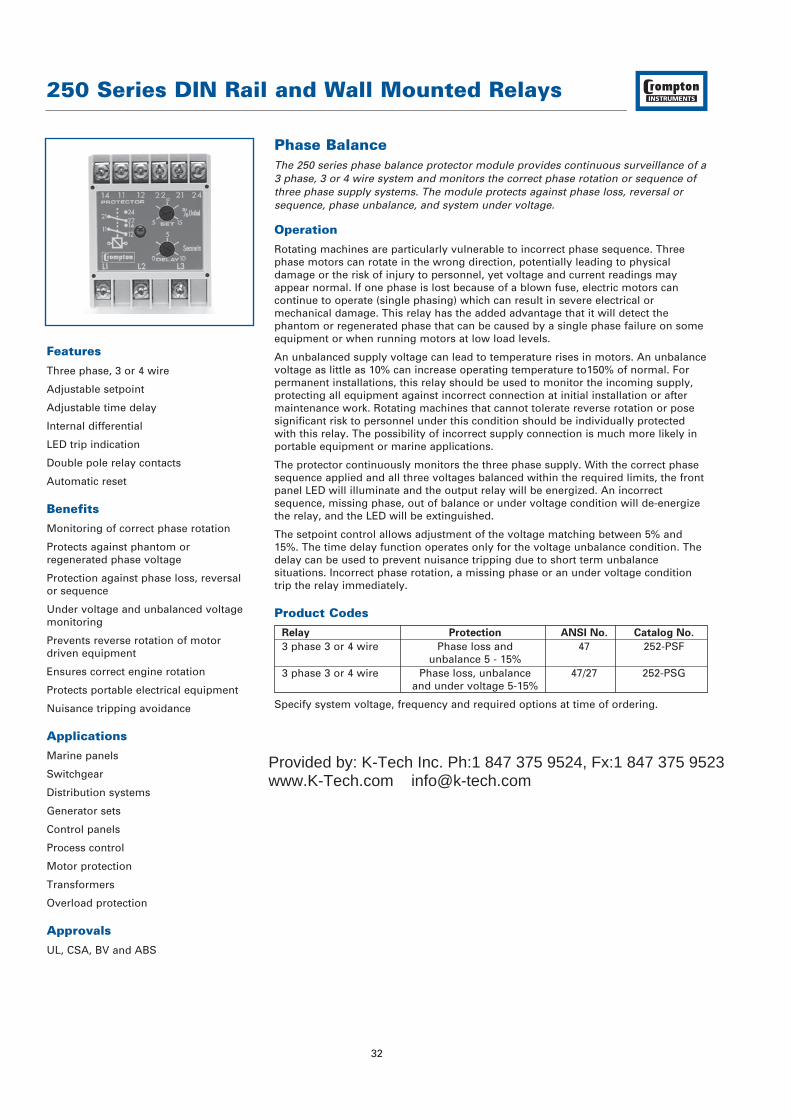
Phase BalanceThe 250 series phase balance protector module provides continuous surveillance of a3 phase, 3 or 4 wire system and monitors the correct phase rotation or sequence ofthree phase supply systems. The module protects against phase loss, reversal orsequence, phase unbalance, and system under voltage.
Operation
Rotating machines are particularly vulnerable to incorrect phase sequence. Threephase motors can rotate in the wrong direction, potentially leading to physicaldamage or the risk of injury to personnel, yet voltage and current readings mayappear normal. If one phase is lost because of a blown fuse, electric motors cancontinue to operate (single phasing) which can result in severe electrical ormechanical damage. This relay has the added advantage that it will detect thephantom or regenerated phase that can be caused by a single phase failure on someequipment or when running motors at low load levels.
An unbalanced supply voltage can lead to temperature rises in motors. An unbalancevoltage as little as 10% can increase operating temperature to150% of normal. Forpermanent installations, this relay should be used to monitor the incoming supply,protecting all equipment against incorrect connection at initial installation or aftermaintenance work. Rotating machines that cannot tolerate reverse rotation or posesignificant risk to personnel under this condition should be individually protectedwith this relay. The possibility of incorrect supply connection is much more likely inportable equipment or marine applications.
The protector continuously monitors the three phase supply. With the correct phasesequence applied and all three voltages balanced within the required limits, the frontpanel LED will illuminate and the output relay will be energized. An incorrectsequence, missing phase, out of balance or under voltage condition will de-energizethe relay, and the LED will be extinguished.
The setpoint control allows adjustment of the voltage matching between 5% and15%. The time delay function operates only for the voltage unbalance condition. Thedelay can be used to prevent nuisance tripping due to short term unbalancesituations. Incorrect phase rotation, a missing phase or an under voltage conditiontrip the relay immediately.
Product Codes
Relay Protection ANSI No. Catalog No.
3 phase 3 or 4 wire Phase loss and 47 252-PSFunbalance 5 - 15%
3 phase 3 or 4 wire Phase loss, unbalance 47/27 252-PSGand under voltage 5-15%
Specify system voltage, frequency and required options at time of ordering.
Features
Three phase, 3 or 4 wire
Adjustable setpoint
Adjustable time delay
Internal differential
LED trip indication
Double pole relay contacts
Automatic reset
Benefits
Monitoring of correct phase rotation
Protects against phantom orregenerated phase voltage
Protection against phase loss, reversalor sequence
Under voltage and unbalanced voltagemonitoring
Prevents reverse rotation of motordriven equipment
Ensures correct engine rotation
Protects portable electrical equipment
Nuisance tripping avoidance
Applications
Marine panels
Switchgear
Distribution systems
Generator sets
Control panels
Process control
Motor protection
Transformers
Overload protection
Approvals
UL, CSA, BV and ABS
Provided by: K-Tech Inc. Ph:1 847 375 9524, Fx:1 847 375 9523www.K-Tech.com [email protected]

Connections
252-PSF
252-PSG
Note: Neutral connection not required
250 Series DIN Rail and Wall Mounted Relays
33
Specification – Phase Balance
Nominal Voltage 110V, 120V, 208V, 220V, 230V, 240V, 277V,380V, 400V, 415V, 440V or 480V
System Frequency 50 or 60HzVoltage Burden 3VA approx.Overload 1.2 x rating continuously, 1.5 x rating for
10 x secondsSet Point Repeatability >0.5% of full spanUnder Voltage Setpoint Preset at 15% of nominal voltage. Other values
10 to 30% to order (Model 252-PSG only)Trip Level Adjustment Phase unbalance adjustable 5 to 15%Time Delay 10 seconds as standard. Up to 30 seconds availableAuxiliary Voltage Burden 4VA (max)Output Relay Double pole change overRelay Contact Rating AC: 240V 5A, non inductive
DC: 24V, 5A resistiveRelay Mechanical Life 0.2 million operations at rated loadsRelay Reset AutomaticOperating Temperature 0°C to +60°C (0°C to +40°C for UL models)Storage Temperature -20°C to + 70°CTemperature Co-efficient 0.05% per °CInterference Immunity Electrical stress surge withstand and non-
function to ANSI/IEEE C37 90aEnclosure Style DIN rail with wall mounting facilityMaterial Flame retardant polycarbonate/ABSEnclosure Integrity IP50Compliant With EMC, LVD, Safety Standard IEC 414
UL File No: E113067 recognized up to 600VCSA File No: LR52592 up to 600VBV File No: 2650H-07427-AO PRSO BVABS File No; 93-LD 17806-X
Model 252 Dimensions 55mm (2.2") wide x 70mm (2.8") high x 112mm (4.4") deep
Weight 0.4Kg approx.
Dimensions
Model 252
Contact Set 1 Contact Set 2Relay
Input
55 (2.2)
70 (
2.8)
35 (
1.37
)
112 (4.4)
RELEASE CLIP
55 (2.2)
35 (
1.37
)
17.5 (0.68)
35 (1.37) 15.5
(0.6
)12 (0.5
)
2 HOLESØ 4.1
Provided by: K-Tech Inc. Ph:1 847 375 9524, Fx:1 847 375 9523www.K-Tech.com [email protected]

250 Series DIN Rail and Wall Mounted Relays
34
Reverse Power (Current)The reverse power protector provides continuous surveillance for A.C. generatorsoperating in parallel or for boosting mains supplies. On site adjustment of the trippoint and time delay ensures accurate protection against ‘motoring’ in the event ofengine failure and prevents tripping from surges during synchronizing.
Operation
Reverse power protectors provide continuous surveillance of AC generators againstmotoring. Reverse power relays are used to detect the failure of the prime mover(engine) when active energy (Watts) flows into the generator causing rotation - theset will operate like an electric motor, which can cause significant mechanicaldamage. This relay offers an adjustable reverse power setpoint between 2% and 20%of nominal power, and time delay adjustment range of 0 to 20 seconds.
As soon as the reverse power level increases above the setpoint limit, the time delayis activated, after which a trip will occur. The time delay prevents the relay fromtripping for a predetermined period to prevent nuisance tripping. The products alsofeature an internal differential (hysteresis) setting of 1% to reduce nuisance tripping ifthe measured signal is noisy or unstable. These units are powered from themeasuring supply.
The protector relay approximates the power level in the system by measuringcurrent and power factor, but does not actually measure the system voltage. Whenthe reverse power level exceeds the setpoint, the time delay is started. When thetime has elapsed, the relay will energize and the red LED will illuminate to indicatethe trip condition. The relay will automatically reset once the power level falls below the setpoint minus the differential, the LED will extinguish and the relay de-energizes. The time delay is not active when resetting. The reverse power levelwill trip as expected at the calibrated point for unity power factor, however, thesystem power factor does affect the trip point calibration. The relay becomes moresensitive at lagging power factors, as almost all systems exhibit inductance. At leading power factors, this relay is less sensitive.
Setting Up
The “% set” potentiometer trimmer on the front label is calibrated as a percentage ofthe input current rating e.g. of 5A, and not of the forward kW. Adjust the “% set”trimmer to the required tripping value, 7.5% to 10% is normal. Setting accuracy canbe checked by reversing the current lead connections and, with forward power,measuring the trip point value on a suitable ammeter (reconnect leads oncompletion). Adjust the ‘Delay’ to the required time delay, 10 seconds is normally adequate.
Options
250 series protector relays offer various customized options to suit individualrequirements. Please consult factory.
• Adjustment ranges - different adjustment ranges are possible for the setpoint and time delay controls.
• Relay operation - standard models are fail safe, but the relays can be customized to de-energize on trip.
Product Codes
Relay Protection ANSI No. Catalog No.
Single phase or Reverse power 2 – 20% 32 256-PAS3 phase 4 wireSingle phase or 3 phase Reverse power 2 – 20% 32 256-PAQ4 wire push to test3 phase 3 wire push Reverse power 2 – 20% 32 256-PARto test3 phase 3 wire Reverse power 2 – 20% 32 256-PAT
Specify system voltage, frequency and required options at time of ordering.
Features
Three phase, 3 or 4 wire
Adjustable setpoint
Adjustable time delay
Internal differential
LED trip indication
Double pole relay contacts
Automatic reset
Benefits
Current and power factor measurement
Protects generators againsts ‘motoring’
Detects reverse power under faultconditions
Customized options
Nuisance tripping avoidance
Applications
Marine panels
Switchgear
Distribution systems
Generator sets
Control panels
Process control
Motor protection
Transformers
Overload protection
Approvals
UL, CSA, BV and ABS
Provided by: K-Tech Inc. Ph:1 847 375 9524, Fx:1 847 375 9523www.K-Tech.com [email protected]

Input VoltsSingle phase3 phase 4 wire
3 phase 3 wire
Contact Set 1 Contact Set 2Output Relay
Input Amps
250 Series DIN Rail and Wall Mounted Relays
35
Specification – Reverse Power (Current)
Nominal Voltage 100V, 110V, 120V, 220V, 230V, 240V, 277V, 380V, 400V, 415V, 440V or 480V
Nominal Current 5A or 2, 3, 4, 6, 8 and 10ASystem Frequency 50, 60 or 400HzBurden Voltage: 3VA maximum
Current: 2VA maximumCurrent Overload 2 x rating continuously, 10 x rating for 3 secondsVoltage Overload 1.2 x rating continuously, 1.5 x rating for
10 secondsMonitoring Range Power Factor: 0.5 inductive/unity/0.2 capacitive
Current: 20 to 100% of nominal inputSet Point Repeatability >0.5% of full spanDifferential (Hysteresis) Preset at 1%Trip Level Adjustment 2 to 20%. Customized adjustment available.Time Delay Adjustable 0 to 20 secondsAC Auxiliary Supply Voltage 100V, 110V, 120V, 208V, 220V, 240V, 480V, ±20%Auxiliary Voltage Burden 4VA (max)Output Relay Double pole change overRelay Contact Rating AC: 240V 5A, non inductive
DC: 24V, 5A resistiveRelay Mechanical Life 0.2 million operations at rated loadsRelay Reset AutomaticOperating Temperature 0°C to +60°C (0°C to +40°C for UL models)Storage Temperature -20°C to + 70°CTemperature Co-efficient 0.05% per °CInterference Immunity Electrical stress surge withstand and non-
function to ANSI/IEEE C37 90aEnclosure Style DIN rail with wall mounting facilityMaterial Flame retardant polycarbonate/ABSEnclosure Integrity IP50Compliant With EMC, LVD, Safety Standard IEC 414
UL File No: E113067 recognized up to 600VCSA File No: LR52592 up to 300VBV File No: 2650H-07427-AO PRSO BVABS File No; 93-LD 17806-X
Dimensions 150mm (5.9") wide x 70mm (2.8") high x 112mm (4.4") deep
Weight 1.0kg approx.
Connections
256-PAS
256-PAT
256-PAQ
256-PAR
Note: Only one CT connection is required, from the same phase as the voltageconnection to terminal 2.
Dimensions
Model 256150 (5.9)
70 (
2.8)
112.5 (4.4)
35 (
1.37
)
135 (5.3)
2 FIXING HOLE'A' TO SUIT M4
2 FIXING HOLE'A' TO SUIT M4
50 (
1.96
)
60 (
2.36
)
RELEASE CLIP
Provided by: K-Tech Inc. Ph:1 847 375 9524, Fx:1 847 375 9523www.K-Tech.com [email protected]

250 Series DIN Rail and Wall Mounted Relays
36
Synchro-Check (paralleling)The synchro-check relay can be used to assist in the semi-automatic paralleling oftwo AC power systems. The volt-free relay contacts change state when the voltagelevel, phase relationship and frequency are within the selected synchronizing limits.Connecting two electrical systems that are not closely matched can cause expensivedamage and disturbance to the electrical system. Using this relay will ensure thatdamage will not occur.
Operation
As part of a manual control system, the operator will make adjustments to thegenerator voltage (excitation) and frequency (engine speed) using a synchroscope orlamps, and will then attempt to manually close the breaker. This synchro checkprotector will qualify that the two systems are closely matched before permitting thebreaker to close. As part of an automatic synchronizing arrangement, this relay canbe used as an independent backup or checking device to ensure the two systems aresuitably matched before the breaker can close.
Model 256-PLL
The relay continuously monitors the voltage, phase displacement and frequency oftwo supplies. A single setpoint adjustment permits selection of suitable matching,and a red LED illuminates when the relay is energized, indicating that the twosupplies are well matched and it is safe to close the breaker.
Model- 256-PLD
This version operates in the same way as model 256-PLL, but includes an additionaldead bus detection function. If there is a requirement for a continuous supply oremergency power, then the generator can be connected without synchronizing, thusensuring continuity of supply. The absence of bus voltage will cause the relay toenergize.
Product Codes
Relay Protection ANSI No. Catalog No.
Single phase, or Phase angle and voltage 25 256-PLL3 phase 3 or 4 wire Single phase, or Phase angle and voltage 25 256-PLD3 phase 3 or 4 wire Dead bus
Specify system voltage, frequency and required options at time of ordering.
Features
Single phase or three phase, 3 or 4 wire
Live and dead bus versions
Adjustable setpoint
LED trip indication
Volt free relay contacts
Benefits
Monitors voltage phase displacementand frequency of 2 supplies
Frequency matching
Voltage matching
Phase angle matching
Synchronization of Gen-Bus and Bus-Bus
Monitors auto synchronizing systems
Assists in manual sychronization
Applications
Marine panels
Switchgear
Distribution systems
Generator sets
Co-generation
Control panels
Approvals
UL, BV and ABS
Provided by: K-Tech Inc. Ph:1 847 375 9524, Fx:1 847 375 9523www.K-Tech.com [email protected]

System
3 phase 4 wire3 phase 3 wire1 phase 2 wire
GeneratorConnections
1 2L1 NL1 L2L1 N
BusbarConnections
3 4L1 NL1 L2L1 N
NormallyOpen
Contacts
NormallyClosed
Contacts
250 Series DIN Rail and Wall Mounted Relays
37
Specification – Synchro-Check (paralleling)
Nominal Voltage 100V, 110V, 120V, 208V, 220V, 230V, 240V, 277V, 380V, 400V, 415V, 440V or 480V
System Frequency 45, 50, 55, 60 or 65HzBurden Bus: 2VA Generator: 4VAOverload -25 to +30% of the nominal voltageSet Point Repeatability >0.5% of full spanDifferential (Hysteresis) Preset at 1%. Values 1% to 10% available
on requestTrip Level 10 to 30% of the nominal voltage.
6° to 20° electrical adjustmentOutput Relay 1 pair NO (normally open),
1 pair NC (normally closed)2 pair NO and 2 pair NC available on request
Relay Contact Rating AC: 240V 5A, non inductive DC: 24V, 5A resistive
Relay Mechanical Life 0.2 million operations at rated loadsRelay Reset AutomaticOperating Temperature 0°C to +60°C (0°C to +40°C for UL models)Storage Temperature -20°C to + 70°CTemperature Co-efficient 0.05% per °CInterference Immunity Electrical stress surge withstand and non-
function to ANSI/IEEE C37 90aEnclosure Style DIN rail with wall mounting facilityMaterial Flame retardant polycarbonate/ABSEnclosure Integrity IP50Compliant With EMC, LVD, Safety Standard IEC 414
UL File No: E113067 recognized up to 600VBV File No: 2650H-07427-AO PRSO BVABS File No; 93-LD 17806-X
Dimensions 150mm (5.9") wide x 70mm (2.8") high x 112mm (4.4") deep
Weight 1.0kg approx.
Connections
256-PLL
256-PLD
Dimensions
Model 256150 (5.9)
70 (
2.8)
112.5 (4.4)
35 (
1.37
)
135 (5.3)
2 FIXING HOLE'A' TO SUIT M4
2 FIXING HOLE'A' TO SUIT M4
50 (
1.96
)
60 (
2.36
)
RELEASE CLIP
Provided by: K-Tech Inc. Ph:1 847 375 9524, Fx:1 847 375 9523www.K-Tech.com [email protected]
250 Series DIN Rail and Wall Mounted Relays
38
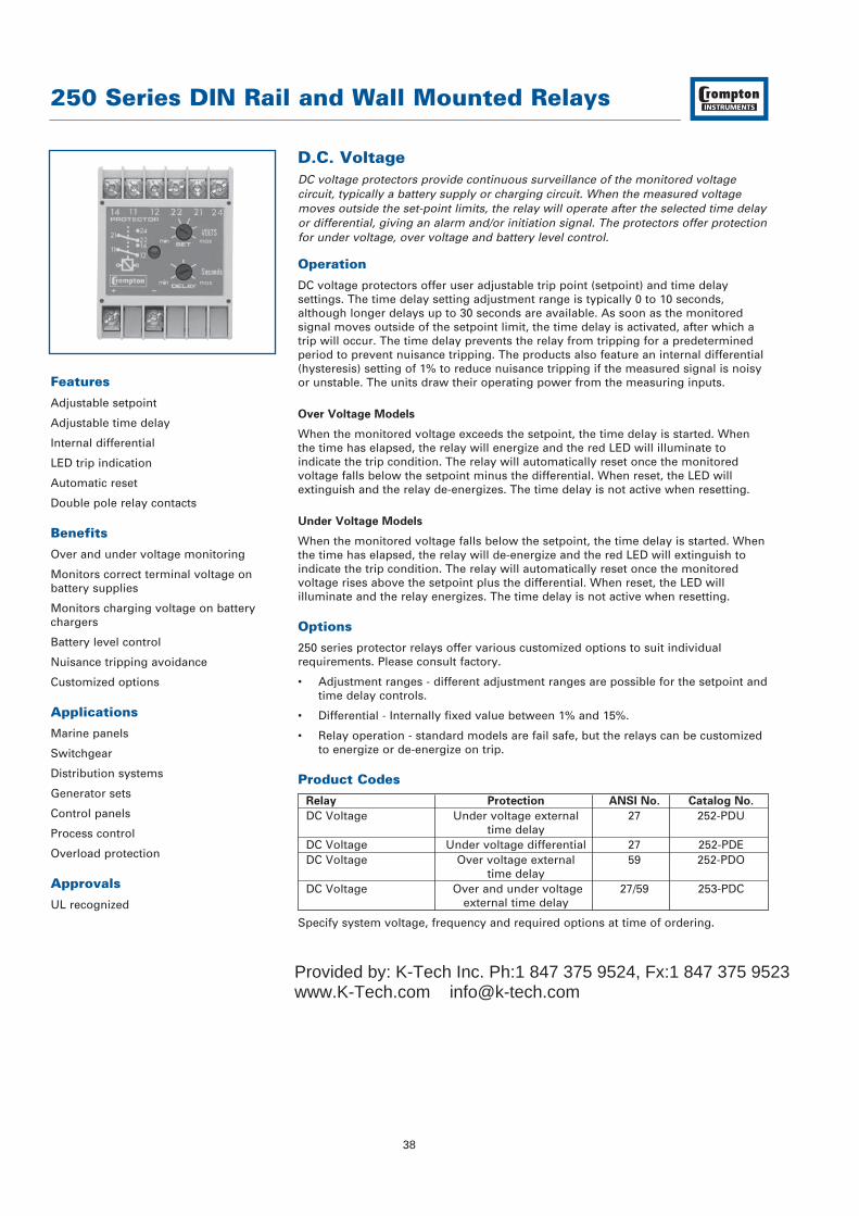
D.C. VoltageDC voltage protectors provide continuous surveillance of the monitored voltagecircuit, typically a battery supply or charging circuit. When the measured voltagemoves outside the set-point limits, the relay will operate after the selected time delayor differential, giving an alarm and/or initiation signal. The protectors offer protectionfor under voltage, over voltage and battery level control.
Operation
DC voltage protectors offer user adjustable trip point (setpoint) and time delaysettings. The time delay setting adjustment range is typically 0 to 10 seconds,although longer delays up to 30 seconds are available. As soon as the monitoredsignal moves outside of the setpoint limit, the time delay is activated, after which atrip will occur. The time delay prevents the relay from tripping for a predeterminedperiod to prevent nuisance tripping. The products also feature an internal differential(hysteresis) setting of 1% to reduce nuisance tripping if the measured signal is noisyor unstable. The units draw their operating power from the measuring inputs.
Over Voltage Models
When the monitored voltage exceeds the setpoint, the time delay is started. Whenthe time has elapsed, the relay will energize and the red LED will illuminate toindicate the trip condition. The relay will automatically reset once the monitoredvoltage falls below the setpoint minus the differential. When reset, the LED willextinguish and the relay de-energizes. The time delay is not active when resetting.
Under Voltage Models
When the monitored voltage falls below the setpoint, the time delay is started. Whenthe time has elapsed, the relay will de-energize and the red LED will extinguish toindicate the trip condition. The relay will automatically reset once the monitoredvoltage rises above the setpoint plus the differential. When reset, the LED willilluminate and the relay energizes. The time delay is not active when resetting.
Options
250 series protector relays offer various customized options to suit individualrequirements. Please consult factory.
• Adjustment ranges - different adjustment ranges are possible for the setpoint andtime delay controls.
• Differential - Internally fixed value between 1% and 15%.
• Relay operation - standard models are fail safe, but the relays can be customized to energize or de-energize on trip.
Product Codes
Relay Protection ANSI No. Catalog No.
DC Voltage Under voltage external 27 252-PDUtime delay
DC Voltage Under voltage differential 27 252-PDEDC Voltage Over voltage external 59 252-PDO
time delayDC Voltage Over and under voltage 27/59 253-PDC
external time delay
Specify system voltage, frequency and required options at time of ordering.
Features
Adjustable setpoint
Adjustable time delay
Internal differential
LED trip indication
Automatic reset
Double pole relay contacts
Benefits
Over and under voltage monitoring
Monitors correct terminal voltage onbattery supplies
Monitors charging voltage on batterychargers
Battery level control
Nuisance tripping avoidance
Customized options
Applications
Marine panels
Switchgear
Distribution systems
Generator sets
Control panels
Process control
Overload protection
Approvals
UL recognized
Provided by: K-Tech Inc. Ph:1 847 375 9524, Fx:1 847 375 9523www.K-Tech.com [email protected]

55 (2.2)
70 (
2.8)
35 (
1.37
)
112 (4.4)
RELEASE CLIP
55 (2.2)
35 (
1.37
)
17.5 (0.68)
35 (1.37) 15.5
(0.6
)12 (0.5
)
2 HOLESØ 4.1
75 (2.9)
70 (
2.8)
112.5 (4.4)
35 (
1.37
)
RELEASE CLIP
60 (2.4)
2 FIXING HOLE'A' TO SUIT M4
2 FIXING HOLE'A' TO SUIT M4
50 (
1.96
)60
(2.
36)
250 Series DIN Rail and Wall Mounted Relays
39
Specification – D.C. Voltage
Nominal Voltage 18 to 20V DC or 20 to 32V DCVoltage Burden <3VAOverload 1.2 x rating continuouslySet Point Repeatability >0.5% of full spanDifferential (Hysteresis) Models 252-PDU, 252-PDO & 253-PDC: Preset at 1%.
Values 1% to 15% available on requestModel 252-PDE: Adjustable 1 to 15%
Time Delay Adjustment Models 252-PDU, 252-PDO & 253-PDC: 0-10, 0-20, 0-30 secondsModel 252-PDE: Factory pre-set up to 30 seconds
AC Auxiliary Supply Voltage 100V, 110V, 120V, 208V, 220V, 240V, 480V, ±20%DC Auxiliary Supply Voltage 12V, 24V, 48V, 110V or 125V, ±15%. Max ripple 15%Auxiliary Voltage Burden 4VA (max)Output Relay Double pole change overRelay Contact Rating AC: 240V 5A, non inductive
DC: 24V, 5A resistiveRelay Mechanical Life 0.2 million operations at rated loadsRelay Reset AutomaticOperating Temperature 0°C to +60°C (0°C to +40°C for UL models)Storage Temperature -20°C to + 70°CTemperature Co-efficient 0.05% per °CInterference Immunity Electrical stress surge withstand and non-
function to ANSI/IEEE C37 90aEnclosure Style DIN rail with wall mounting facilityMaterial Flame retardant polycarbonate/ABSEnclosure Integrity IP50Compliant With EMC, LVD, Safety Standard IEC 414
UL File No: E113067 recognized up to 600VModel 252 Dimensions 55mm (2.2") wide x 70mm (2.8") high
x 112mm (4.4") deepModel 253 Dimensions 75mm (2.9") wide x 70mm (2.8") high
x 112mm (4.4") deepWeight Model 252: 0.4Kg approx.
Model 253: 0.6Kg approx
Dimensions
Model 252
Connections
Model 253
Connections
252-PDU
252-PDO
252-PDE
253-PDC
Contact Set 1 Contact Set 2Relay
Input
Auxsupplywhen
required
Input
Contact Set 1 Contact Set 2Relay
MonitoredValue
Under RelayContact Set 1
Over RelayContact Set 1
SupplyUnder RelayContact Set 2
Over RelayContact Set 2
Provided by: K-Tech Inc. Ph:1 847 375 9524, Fx:1 847 375 9523www.K-Tech.com [email protected]
250 Series DIN Rail and Wall Mounted Relays
40
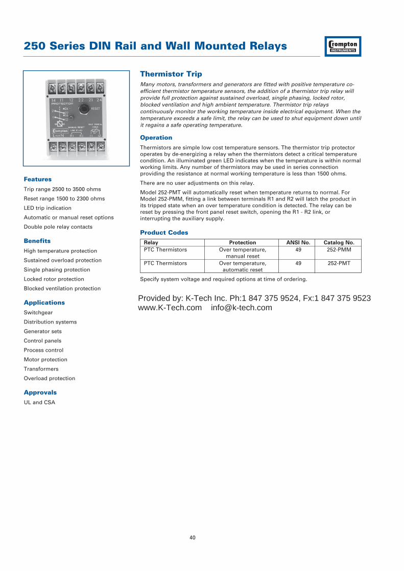
Thermistor TripMany motors, transformers and generators are fitted with positive temperature co-efficient thermistor temperature sensors, the addition of a thermistor trip relay willprovide full protection against sustained overload, single phasing, locked rotor,blocked ventilation and high ambient temperature. Thermistor trip relayscontinuously monitor the working temperature inside electrical equipment. When thetemperature exceeds a safe limit, the relay can be used to shut equipment down untilit regains a safe operating temperature.
Operation
Thermistors are simple low cost temperature sensors. The thermistor trip protectoroperates by de-energizing a relay when the thermistors detect a critical temperaturecondition. An illuminated green LED indicates when the temperature is within normalworking limits. Any number of thermistors may be used in series connectionproviding the resistance at normal working temperature is less than 1500 ohms.
There are no user adjustments on this relay.
Model 252-PMT will automatically reset when temperature returns to normal. ForModel 252-PMM, fitting a link between terminals R1 and R2 will latch the product inits tripped state when an over temperature condition is detected. The relay can bereset by pressing the front panel reset switch, opening the R1 - R2 link, orinterrupting the auxiliary supply.
Product Codes
Relay Protection ANSI No. Catalog No.
PTC Thermistors Over temperature, 49 252-PMMmanual reset
PTC Thermistors Over temperature, 49 252-PMTautomatic reset
Specify system voltage and required options at time of ordering.
Features
Trip range 2500 to 3500 ohms
Reset range 1500 to 2300 ohms
LED trip indication
Automatic or manual reset options
Double pole relay contacts
Benefits
High temperature protection
Sustained overload protection
Single phasing protection
Locked rotor protection
Blocked ventilation protection
Applications
Switchgear
Distribution systems
Generator sets
Control panels
Process control
Motor protection
Transformers
Overload protection
Approvals
UL and CSA
Provided by: K-Tech Inc. Ph:1 847 375 9524, Fx:1 847 375 9523www.K-Tech.com [email protected]

55 (2.2)
70 (
2.8)
35 (
1.37
)
112 (4.4)
RELEASE CLIP
55 (2.2)35
(1.
37)
17.5 (0.68)
35 (1.37) 15.5
(0.6
)12 (0.5
)
2 HOLESØ 4.1
250 Series DIN Rail and Wall Mounted Relays
41
Specification – Thermistor Trip
Nominal Voltage 110V, 120V, 220V, 230V or 240V AC ±20%.Input Positive temperature coefficient thermistors
(series connected 1500Ω at normal temperature)System Frequency 50/60HzVoltage Burden 2VA approxOverload 1.2 x rating continouslyTrip Level 2500 to 3500Ω reset 1500 to 2300ΩAC Auxiliary Supply Voltage 100V, 110V, 120V, 208V, 220V, 240V, 480V, ±20%DC Auxiliary Supply Voltage 12V, 24V, 48V, 110V or 125V, ±15%. Max ripple 15%Auxiliary Voltage Burden 4VA (max)Output Relay Double pole change overRelay Contact Rating AC: 240V 5A, non inductive
DC: 24V, 5A resistiveRelay Mechanical Life 0.2 million operations at rated loadsRelay Reset Model 252-PMT: Automatic
Model 252-PMM: ManualOperating Temperature 0°C to +60°C (0°C to +40°C for UL models)Storage Temperature -20°C to + 70°CTemperature Co-efficient 0.05% per °CInterference Immunity Electrical stress surge withstand and non-
function to ANSI/IEEE C37 90aEnclosure Style DIN rail with wall mounting facilityMaterial Flame retardant polycarbonate/ABSEnclosure Integrity IP50Compliant With EMC, LVD, Safety Standard IEC 414
UL File No: E113067 recognized up to 600VCSA File No: LR52592 up to 300V
Model 252 Dimensions 55mm (2.2") wide x 70mm (2.8") high x 112mm (4.4") deep
Weight 0.4Kg approx.
Dimensions
Model 252
Connections
252-PMT
252-PMM
Contact Set 1 Contact Set 2
Contact Set 1 Contact Set 2
Output Relay
Output Relay
Supply
SupplyThermistor
Connections
ThermistorConnections
Provided by: K-Tech Inc. Ph:1 847 375 9524, Fx:1 847 375 9523www.K-Tech.com [email protected]
250 Series DIN Rail and Wall Mounted Relays
42
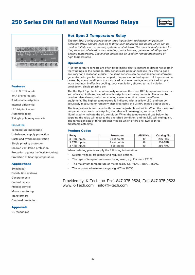
Hot Spot 3 Temperature RelayThe Hot Spot 3 relay accepts up to three inputs from resistance temperaturedetectors (RTD) and provides up to three user adjustable trip points which can beused to initiate alarms, cooling systems or shutdown. The relay is ideally suited forthe protection of electric motor windings, transformers, generator windings andbearing temperature. The analog output can be used for remote monitoring of high temperatures.
Operation
RTD temperature sensors are often fitted inside electric motors to detect hot spots inthe windings or the bearings. RTD sensors are popular because they offer a goodaccuracy for a reasonable price. The same sensors can be used inside transformers,generator sets, gas turbines or as part of a process control system. Hot spots can becaused by many conditions, such as overloads, over voltage, unbalanced supply,worn bearings, ineffective cooling, poor ventilation, shorted turns, insulationbreakdown, single phasing etc.
The Hot Spot 3 protector continuously monitors the three RTD temperature sensors,and offers up to three user adjustable setpoints and relay contacts. These can beused to raise alarms, switch on cooling systems or shut down the effectedequipment. The highest temperature is indicated with a yellow LED, and can beaccurately measured or remotely displayed using the 0/1mA analog output signal.
The temperature is compared with the user adjustable setpoints. When the measuredtemperature exceeds the setpoint, the relay will de-energize, and a red LEDilluminated to indicate the trip condition. When the temperature drops below thesetpoint, the relay will reset to the energized condition, and the LED will extinguish.The range consists of three product models which offers one, two or threeadjustable setpoints.
Product Codes
Relay Protection ANSI No. Catalog No.
3 RTD inputs 3 set points 49 256-PRA3 RTD inputs 2 set points 49 256-PRB3 RTD inputs 1 set point 49 256-PRC
When ordering please supply the following information:
• System voltage, frequency and required options.
• The type of temperature sensor being used, e.g. Platinum PT100.
• The maximum temperature or meter scale, e.g. 100% = 1mA = 150°C.
• The setpoint adjustment range, e.g. 0°C to 150°C.
Features
Up to 3 RTD inputs
1mA analog output
3 adjustable setpoints
Internal differential
LED trip indication
Automatic reset
3 single pole relay contacts
Benefits
Temperature monitoring
Unbalanced supply protection
Sustained overload protection
Single phasing protection
Blocked ventilation protection
Protection against ineffective cooling
Protection of bearing temperature
Applications
Switchgear
Distribution systems
Generator sets
Control panels
Process control
Motor monitoring
Transformers
Overload protection
Approvals
UL recognized
Provided by: K-Tech Inc. Ph:1 847 375 9524, Fx:1 847 375 9523www.K-Tech.com [email protected]

R.T.D. InputsRemote L.E.D.'s
if required
Indication
Output Relays Aux. Supply
250 Series DIN Rail and Wall Mounted Relays
43
Specification – Hot Spot 3 Temperature Relay
Input Up to 3 resistance temperature detectors (RTD).Either 10Ω copper or 100Ω platinum minimum span 100°C
Nominal Voltage AC: 110V, 120V, 220V, 230V, or 240V ± 20%DC: Consult Factory
System Frequency 50/60HzOverload 1.2 x rating continuouslySet Point Repeatability 0.5% of full spanDifferential (Hysteresis) Preset at 2% of rangeAC Auxiliary Supply Voltage 100V, 110V, 120V, 208V, 220V, 240V, 480V, ±20%DC Auxiliary Supply Voltage 12V, 24V, 48V, 110V or 125V, ±15%. Max ripple 15%Auxiliary Voltage Burden 4VA (max)Analog Output 1mA into 0/4kΩ loadOutput Relay Single pole change overRelay Contact Rating AC: 240V 5A, non inductive
DC: 24V, 5A resistiveRelay Mechanical Life 0.2 million operations at rated loadsRelay Reset AutomaticOperating Temperature 0°C to +60°C (0°C to +40°C for UL models)Storage Temperature -20°C to + 70°CTemperature Co-efficient 0.05% per °CInterference Immunity Electrical stress surge withstand and non-
function to ANSI/IEEE C37 90aEnclosure Style DIN rail with wall mounting facilityMaterial Flame retardant polycarbonate/ABSEnclosure Integrity IP50Compliant With EMC, LVD, Safety Standard IEC 414
UL File No: E113067 recognized up to 600VDimensions 150mm (5.9") wide x 70mm (2.8") high
x 112mm (4.4") deepWeight 1.0kg approx.
Connections
256-PRA
256-PRB
256-PRC
Dimensions
Model 256150 (5.9)
70 (
2.8)
112.5 (4.4)
35 (
1.37
)
135 (5.3)
2 FIXING HOLE'A' TO SUIT M4
2 FIXING HOLE'A' TO SUIT M4
50 (
1.96
)
60 (
2.36
)
RELEASE CLIP
Provided by: K-Tech Inc. Ph:1 847 375 9524, Fx:1 847 375 9523www.K-Tech.com [email protected]
250 Series DIN Rail and Wall Mounted Relays
44
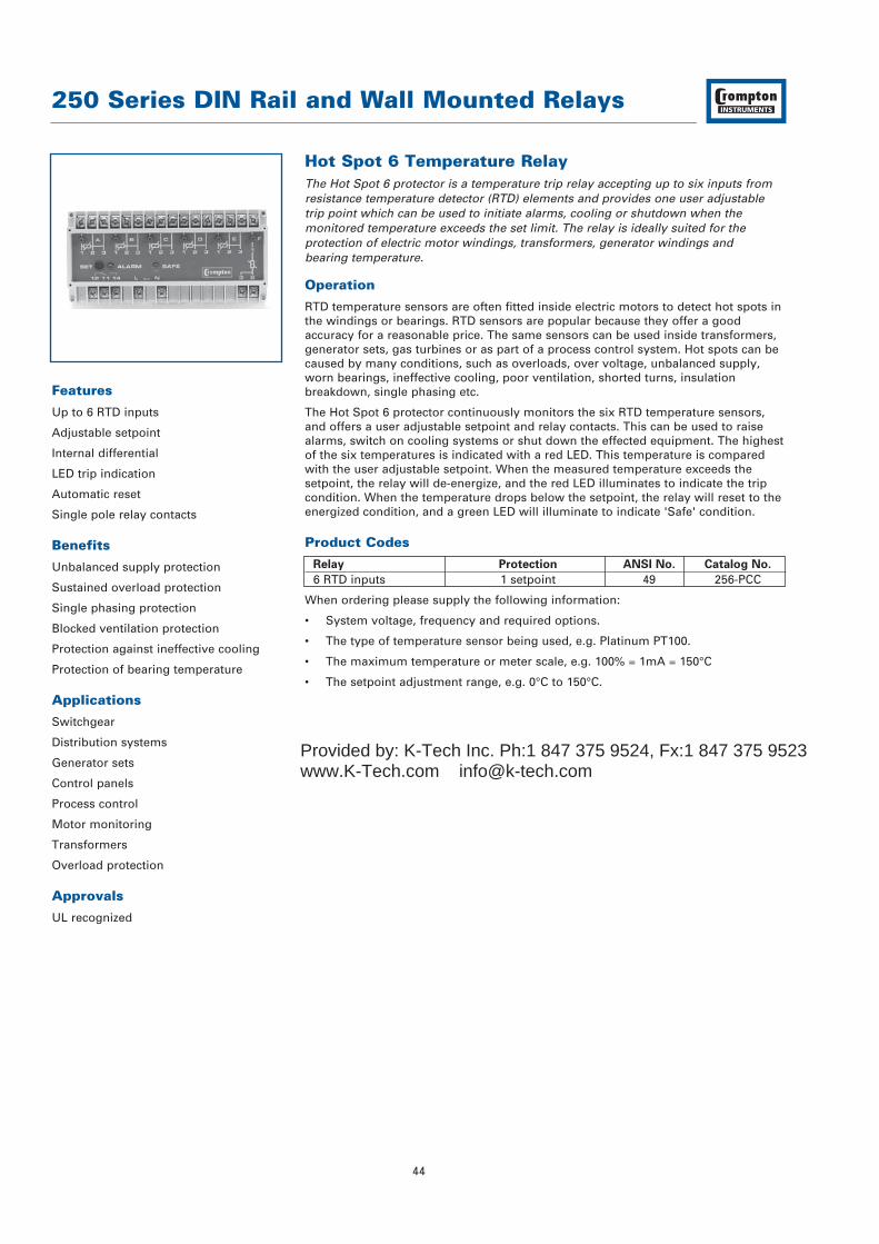
Hot Spot 6 Temperature RelayThe Hot Spot 6 protector is a temperature trip relay accepting up to six inputs fromresistance temperature detector (RTD) elements and provides one user adjustabletrip point which can be used to initiate alarms, cooling or shutdown when themonitored temperature exceeds the set limit. The relay is ideally suited for theprotection of electric motor windings, transformers, generator windings and bearing temperature.
Operation
RTD temperature sensors are often fitted inside electric motors to detect hot spots inthe windings or bearings. RTD sensors are popular because they offer a goodaccuracy for a reasonable price. The same sensors can be used inside transformers,generator sets, gas turbines or as part of a process control system. Hot spots can becaused by many conditions, such as overloads, over voltage, unbalanced supply,worn bearings, ineffective cooling, poor ventilation, shorted turns, insulationbreakdown, single phasing etc.
The Hot Spot 6 protector continuously monitors the six RTD temperature sensors,and offers a user adjustable setpoint and relay contacts. This can be used to raisealarms, switch on cooling systems or shut down the effected equipment. The highestof the six temperatures is indicated with a red LED. This temperature is comparedwith the user adjustable setpoint. When the measured temperature exceeds thesetpoint, the relay will de-energize, and the red LED illuminates to indicate the tripcondition. When the temperature drops below the setpoint, the relay will reset to theenergized condition, and a green LED will illuminate to indicate 'Safe' condition.
Product Codes
Relay Protection ANSI No. Catalog No.
6 RTD inputs 1 setpoint 49 256-PCC
When ordering please supply the following information:
• System voltage, frequency and required options.
• The type of temperature sensor being used, e.g. Platinum PT100.
• The maximum temperature or meter scale, e.g. 100% = 1mA = 150°C
• The setpoint adjustment range, e.g. 0°C to 150°C.
Features
Up to 6 RTD inputs
Adjustable setpoint
Internal differential
LED trip indication
Automatic reset
Single pole relay contacts
Benefits
Unbalanced supply protection
Sustained overload protection
Single phasing protection
Blocked ventilation protection
Protection against ineffective cooling
Protection of bearing temperature
Applications
Switchgear
Distribution systems
Generator sets
Control panels
Process control
Motor monitoring
Transformers
Overload protection
Approvals
UL recognized
Provided by: K-Tech Inc. Ph:1 847 375 9524, Fx:1 847 375 9523www.K-Tech.com [email protected]
250 Series DIN Rail and Wall Mounted Relays
45
Specification – Hot Spot 6 Temperature Relay
Input Up to 6 resistance temperature detectors (RTD).Either 10Ω copper or 100Ω platinum minimum span 100°C
Nominal Voltage AC: 110V, 120V, 220V, 230V, or 240V ± 20%DC: Consult Factory
System Frequency 50/60HzVoltage Burden 6VA maximumOverload 1.2 x rating continuouslySet Point Repeatability Within 1°CDifferential (Hysteresis) 4°C of nominalTrip Level Adjustment 100°C (eg: 50 to 150°C, 100 to 200°C etc)Time Delay Typically 250msAC Auxiliary Supply Voltage 100V, 110V, 120V, 208V, 220V, 240V, 480V, ±20%DC Auxiliary Supply Voltage 12V, 24V, 48V, 110V or 125V, ±15%. Max ripple 15%Auxiliary Voltage Burden 4VA (max)Output Relay Single pole change overRelay Contact Rating AC: 240V 5A, non inductive
DC: 24V, 5A resistiveRelay Mechanical Life 0.2 million operations at rated loadsRelay Reset AutomaticOperating Temperature 0°C to +60°C (0°C to +40°C for UL models)Storage Temperature -20°C to + 70°CTemperature Co-efficient 0.05% per °CInterference Immunity Electrical stress surge withstand and non-
function to ANSI/IEEE C37 90aEnclosure Style DIN rail with wall mounting facilityMaterial Flame retardant polycarbonate/ABSEnclosure Integrity IP50Compliant With EMC, LVD, Safety Standard IEC 414
UL File No: E113067 recognized up to 600VDimensions 150mm (5.9") wide x 70mm (2.8") high
x 112mm (4.4") deepWeight 1.0kg approx.
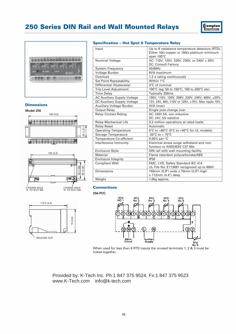
Connections
256-PCC
When used for less than 6 RTD inputs the unused terminals 1, 2 & 3 must belinked together.
Dimensions
Model 256150 (5.9)
70 (
2.8)
112.5 (4.4)
35 (
1.37
)
135 (5.3)
2 FIXING HOLE'A' TO SUIT M4
2 FIXING HOLE'A' TO SUIT M4
50 (
1.96
)
60 (
2.36
)
RELEASE CLIP
Provided by: K-Tech Inc. Ph:1 847 375 9524, Fx:1 847 375 9523www.K-Tech.com [email protected]

250 Series DIN Rail and Wall Mounted Relays
46
D.C. Millivolts / ThermocoupleThe 250 series millivolt protectors provide continuous surveillance of high DCcurrents when used with current shunts, or can be used to monitor temperatures inconjunction with thermocouples. The protector incorporates a user adjustable tripand time delay which can be set to initiate an alarm when the input exceeds thedesired level.
Operation
When used in conjunction with current shunts the millivolt protector can be used tomonitor battery charging currents, current drain or over/under current. Monitoring ofunder / over temperature and detection of hotspots can be achieved in applicationsusing thermocouples. All industry standard shunts, and all popular thermocouplesare supported.
The millivolt protector relays offer user adjustable trip point (setpoint) and time delaysettings. The time delay setting adjustment range is typically 0 to 10 seconds,although longer delays are available. As soon as the monitored signal moves outsideof the setpoint limit, the time delay is activated, after which a trip will occur. The timedelay prevents the relay from tripping for a predetermined period to preventnuisance tripping. These products also feature an internal differential (hysteresis)setting of 1% to reduce nuisance tripping if the measured signal is noisy or unstable.These units require an auxiliary power supply.
'Over' High Trip Models
When the monitored signal exceeds the setpoint, the time delay is started. When thetime has elapsed, the relay will energize and the red LED will illuminate to indicatethe trip condition. The relay will automatically reset once the monitored signal fallsbelow the setpoint minus the differential. When reset, the LED will extinguish andthe relay de-energizes. The time delay is not active when resetting.
'Under' Low Trip Models
When the monitored signal falls below the setpoint, the time delay is started. Whenthe time has elapsed, the relay will de-energize and the red LED will extinguish toindicate the trip condition. The relay will automatically reset once the monitoredsignal rises above the setpoint plus the differential. When reset, the LED willilluminate and the relay energizes. The time delay is not active when resetting.
Options
250 series protector relays offer various customized options to suit individualrequirements. Please consult factory.
• Adjustment ranges - different adjustment ranges are possible for the setpoint andtime delay controls.
• Differential - Internally fixed value between 1% and 15%.
• Relay operation - standard models are failsafe, but the relays can be customized to energize or de-energize on trip.
• Cold junction compensation available on request.
Product Codes
Relay Protection ANSI No. Catalog No.
DC Millivolt High trip 40 to 120% 74 252-PBTDC Millivolt Low trip 0 to 80% 74 252-PBSThermocouple Type J, K, R, S and T. 49 252-PTO
High trip 40 to 120%Thermocouple Type J, K, R, S and T. 49 252-PTU
Low trip 0 to 80%
For models 252-PBS and 252-PBT specify millivolt input, auxiliary voltage andrequired options at time of ordering.
For models 252-PTO and 252-PTU specify thermocouple type, nominal temperature,auxiliary voltage and required options at time of ordering.
Features
High and low trip models
Adjustable setpoint
Adjustable time delay
Internal differential
LED trip indication
Automatic reset
Double pole relay contacts
Supports all industry standard shuntsand popular thermocouples
Benefits
Under / Over temperature monitoring
Under / Over current monitoring
Monitoring of battery charging currentsand current drain
Detection of hotspots
Nuisance tripping avoidance
Customized options
Applications
Switchgear
Distribution systems
Generator sets
Control panels
Process control
Motor protection
Transformers
Overload protection
Approvals
UL and CSA
Provided by: K-Tech Inc. Ph:1 847 375 9524, Fx:1 847 375 9523www.K-Tech.com [email protected]

55 (2.2)
70 (
2.8)
35 (
1.37
)
112 (4.4)
RELEASE CLIP
55 (2.2)
35 (
1.37
)
17.5 (0.68)
35 (1.37) 15.5
(0.6
)12 (0.5
)
2 HOLESØ 4.1
250 Series DIN Rail and Wall Mounted Relays
47
Specification – DC Millivolts / Thermocouple
DC Input 10mV, 50mV, 60mV, 75mV, 100mV, 150mVInput Impedance 50KΩSource Impedance 100Ω maximumThermocouple Types J, K, R, S, T 10 to 50mVThermocouple TBP Thermocouple break protection upscale drive
as standardThermocouple CJC Cold junction compensation available on requestThermocouple Overload 10 x rating continuouslyNominal Frequency 50/60HzVoltage Burden 3VA maximumVoltage Overload 1.2 x rating continuously, 1.5 x rating for
10 secondsSet Point Repeatability >0.5% of full spanDifferential (Hysteresis) Preset at 1%.
Values 1% to 15% available on requestTrip Level Adjustment Low trip: 0 to 80%
High trip: 40 to 120%Time Delay Adjustable 0 to 10 secondsAC Auxiliary Supply Voltage 100V, 110V, 120V, 208V, 220V, 240V, 480V, ±20%DC Auxiliary Supply Voltage 12V, 24V, 48V, 110V or 125V, ±15%. Max ripple 15%Auxiliary Voltage Burden 4VA (max)Output Relay Double pole change overRelay Contact Rating AC: 240V 5A, non inductive
DC: 24V, 5A resistiveRelay Mechanical Life 0.2 million operations at rated loadsRelay Reset AutomaticOperating Temperature 0°C to +60°C (0°C to +40°C for UL models)Storage Temperature -20°C to + 70°CTemperature Co-efficient 0.05% per °CInterference Immunity Electrical stress surge withstand and non-
function to ANSI/IEEE C37 90aEnclosure Style DIN rail with wall mounting facilityMaterial Flame retardant polycarbonate/ABSEnclosure Integrity IP50Compliant With EMC, LVD, Safety Standard IEC 414
UL File No: E113067 recognized up to 600VCSA File No: LR52592 up to 150mV (252-PBS & 252-PBT only)
Dimensions 55mm (2.2") wide x 70mm (2.8") high x 112mm (4.4") deep
Weight 0.4Kg approx.
Dimensions
Model 252
Connections
252-PBT
252-PBS
252-PTU
252-PTOContact Set 1 Contact Set 2
Relay
MonitoredValue
Supply
Provided by: K-Tech Inc. Ph:1 847 375 9524, Fx:1 847 375 9523www.K-Tech.com [email protected]
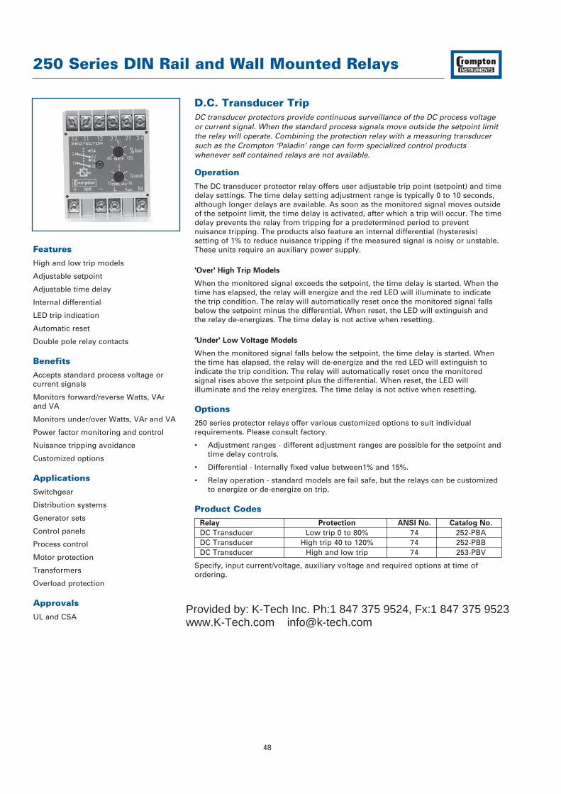
250 Series DIN Rail and Wall Mounted Relays
48
D.C. Transducer TripDC transducer protectors provide continuous surveillance of the DC process voltageor current signal. When the standard process signals move outside the setpoint limitthe relay will operate. Combining the protection relay with a measuring transducersuch as the Crompton ‘Paladin’ range can form specialized control productswhenever self contained relays are not available.
Operation
The DC transducer protector relay offers user adjustable trip point (setpoint) and timedelay settings. The time delay setting adjustment range is typically 0 to 10 seconds,although longer delays are available. As soon as the monitored signal moves outsideof the setpoint limit, the time delay is activated, after which a trip will occur. The timedelay prevents the relay from tripping for a predetermined period to preventnuisance tripping. The products also feature an internal differential (hysteresis)setting of 1% to reduce nuisance tripping if the measured signal is noisy or unstable.These units require an auxiliary power supply.
'Over' High Trip Models
When the monitored signal exceeds the setpoint, the time delay is started. When thetime has elapsed, the relay will energize and the red LED will illuminate to indicatethe trip condition. The relay will automatically reset once the monitored signal fallsbelow the setpoint minus the differential. When reset, the LED will extinguish andthe relay de-energizes. The time delay is not active when resetting.
'Under' Low Voltage Models
When the monitored signal falls below the setpoint, the time delay is started. Whenthe time has elapsed, the relay will de-energize and the red LED will extinguish toindicate the trip condition. The relay will automatically reset once the monitoredsignal rises above the setpoint plus the differential. When reset, the LED willilluminate and the relay energizes. The time delay is not active when resetting.
Options
250 series protector relays offer various customized options to suit individualrequirements. Please consult factory.
• Adjustment ranges - different adjustment ranges are possible for the setpoint andtime delay controls.
• Differential - Internally fixed value between1% and 15%.
• Relay operation - standard models are fail safe, but the relays can be customized to energize or de-energize on trip.
Product Codes
Relay Protection ANSI No. Catalog No.
DC Transducer Low trip 0 to 80% 74 252-PBADC Transducer High trip 40 to 120% 74 252-PBBDC Transducer High and low trip 74 253-PBV
Specify, input current/voltage, auxiliary voltage and required options at time ofordering.
Features
High and low trip models
Adjustable setpoint
Adjustable time delay
Internal differential
LED trip indication
Automatic reset
Double pole relay contacts
Benefits
Accepts standard process voltage orcurrent signals
Monitors forward/reverse Watts, VArand VA
Monitors under/over Watts, VAr and VA
Power factor monitoring and control
Nuisance tripping avoidance
Customized options
Applications
Switchgear
Distribution systems
Generator sets
Control panels
Process control
Motor protection
Transformers
Overload protection
Approvals
UL and CSAProvided by: K-Tech Inc. Ph:1 847 375 9524, Fx:1 847 375 9523www.K-Tech.com [email protected]

55 (2.2)
70 (
2.8)
35 (
1.37
)
112 (4.4)
RELEASE CLIP
55 (2.2)
35 (
1.37
)
17.5 (0.68)
35 (1.37) 15.5
(0.6
)12 (0.5
)
2 HOLESØ 4.1
75 (2.9)
70 (
2.8)
112.5 (4.4)
35 (
1.37
)
RELEASE CLIP
60 (2.4)
2 FIXING HOLE'A' TO SUIT M4
2 FIXING HOLE'A' TO SUIT M4
50 (
1.96
)60
(2.
36)
250 Series DIN Rail and Wall Mounted Relays
49
Specification – DC Transducer Trip
Nominal Input Current DC 0-1mA, 0-5mA, 0-10mA, 0-20mA, 4-20mA. Volt drop 1V
Nominal Input Voltage DC 1V to 50V, input resistance 10kΩ/VVoltage Burden 3VA maximumOverload 1.2 x rating continuously, 1.5 x rating for 10 secondsSet Point Repeatability >0.5% of full spanDifferential (Hysteresis) Preset at 1%.
Values 1% to 15% available on requestTrip Level Adjustment Low trip: 0 to 80%
High trip: 40 to 120%Time Delay Adjustable 0 to 10 secondsAC Auxiliary Supply Voltage 100V, 110V, 120V, 208V, 220V, 240V, 480V, ±20%DC Auxiliary Supply Voltage 12V, 24V, 48V, 110V or 125V, ±15%. Max ripple 15%Auxiliary Voltage Burden 4VA (max)Output Relay Double pole change overRelay Contact Rating AC: 240V 5A, non inductive
DC: 24V, 5A resistiveRelay Mechanical Life 0.2 million operations at rated loadsRelay Reset AutomaticOperating Temperature 0°C to +60°C (0°C to +40°C for UL models)Storage Temperature -20°C to + 70°CTemperature Co-efficient 0.05% per °CInterference Immunity Electrical stress surge withstand and non-
function to ANSI/IEEE C37 90aEnclosure Style DIN rail with wall mounting facilityMaterial Flame retardant polycarbonate/ABSEnclosure Integrity IP50Compliant With EMC, LVD, Safety Standard IEC 414
UL File No: E113067 recognized up to 600VCSA File No: LR52592 up to 240V AC
Model 252 Dimensions 55mm (2.2") wide x 70mm (2.8") high x 112mm (4.4") deep
Model 253 Dimensions 75mm (2.9") wide x 70mm (2.8") high x 112mm (4.4") deep
Weight Model 252: 0.4Kg approx. Model 253: 0.6Kg approx
Dimensions
Model 252
Model 253
Connections
252-PBB
252-PBA
253-PBV
Contact Set 1 Contact Set 2Relay
SupplyMonitoredValue
MonitoredValue
Under RelayContact Set 1
Over RelayContact Set 1
SupplyUnder RelayContact Set 2
Over RelayContact Set 2
Provided by: K-Tech Inc. Ph:1 847 375 9524, Fx:1 847 375 9523www.K-Tech.com [email protected]
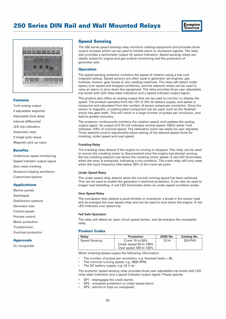
250 Series DIN Rail and Wall Mounted Relays
50
Features
1mA analog output
3 adjustable setpoints
Adjustable time delay
Internal differential
LED trip indication
Automatic reset
3 single pole relays
Magnetic pick up input
Benefits
Under/over speed monitoring
Speed indicator output signal
Zero reset cranking
Nuisance tripping avoidance
Customized options
Applications
Marine panels
Switchgear
Distribution systems
Generator sets
Control panels
Process control
Motor protection
Transformers
Overload protection
Approvals
UL recognized
Speed SensingThe 250 series speed sensing relay monitors rotating equipment and provides threeoutput contacts which can be used to initiate alarm or shutdown signals. The relayalso provides a tachometer output for speed indication. Speed sensing relays areideally suited for engine and gas turbine monitoring and the protection of generator sets.
Operation
The speed sensing protector monitors the speed of rotation using a low costmagnetic pickup. Speed sensors are often used in generator set engines, gasturbines, motors, gear boxes or any rotating machines. The relay will detect underspeed, over speed and stopped conditions, and the setpoint relays can be used toraise an alarm or shut down the equipment. The relay provides three user adjustabletrip levels with LED relay state indication and a speed indicator output signal.
The product also offers an analog output that can be used to monitor or display thespeed. The product operates from the 12V or 24V dc battery supply, and speed ismeasured and calculated from the number of sensor pulses per revolution. Since thesensor is magnetic, a rotating steel component can be used, such as the flywheelwhich has gear teeth. This will result in a large number of pulses per revolution, andlead to greater accuracy.
The protector continuously monitors the rotation speed, and updates the analogoutput signal. An output of 0.75 mA indicates normal speed (100%) while 1mAindicates 133% of nominal speed. The calibration point can easily be user adjusted.Three setpoint control adjustments allow setting of the desired speed limits forcranking, under speed and over speed.
Cranking Relay
The cranking relay detects if the engine is running or stopped. This relay can be usedto ensure the cranking motor is disconnected once the engine has started running.Set the cranking setpoint just above the cranking motor speed. A red LED illuminateswhen the relay is energized, indicating a trip condition. The crank relay will only resetwhen the input frequency falls below 20% of the crank set point.
Under Speed Relay
The under speed relay detects when the normal running speed has been achieved.This can be used to enable the generator's electrical protection. It can also be used totrigger load shedding. A red LED illuminates when an under speed condition exists.
Over Speed Relay
The overspeed relay detects a stuck throttle or overshoot, a break in the sensor loadwill de-energize the over speed relay and can be used to shut down the engine. A redLED indicates over speed trip.
Fail Safe Operation
The relay will detect an open circuit speed sensor, and de-energize the overspeedrelay.
Product Codes
Relay Protection ANSI No. Catalog No.
Speed Sensing Crank 10 to 50% 12/14 253-PH3Under speed 50 to 100%Over speed 100 to 130%
When ordering please supply the following information:
• The number of pulses per revolution, e.g. flywheel teeth = 30.• The nominal running speed, e.g. 3600 RPM.• The DC battery supply, e.g. 24 V dc.
The protector speed sensing relay provides three user adjustable trip levels with LEDrelay state indication and a speed indicator output signal. Please specify:
• SP1 - disengages the crank starter.• SP2 - energizes protection or under-speed alarm.• SP3 - alarms or trips on overspeed.
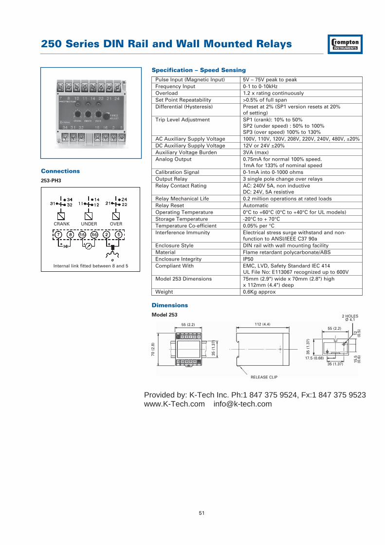
55 (2.2)
70 (
2.8)
35 (
1.37
)
112 (4.4)
RELEASE CLIP
55 (2.2)
35 (
1.37
)
17.5 (0.68)
35 (1.37) 15.5
(0.6
)12 (0.5
)
2 HOLESØ 4.1
250 Series DIN Rail and Wall Mounted Relays
51
Specification – Speed Sensing
Pulse Input (Magnetic Input) 5V – 75V peak to peakFrequency Input 0-1 to 0-10kHzOverload 1.2 x rating continuouslySet Point Repeatability >0.5% of full spanDifferential (Hysteresis) Preset at 2% (SP1 version resets at 20%
of setting)Trip Level Adjustment SP1 (crank): 10% to 50%
SP2 (under speed) : 50% to 100%SP3 (over speed) 100% to 130%
AC Auxiliary Supply Voltage 100V, 110V, 120V, 208V, 220V, 240V, 480V, ±20%DC Auxiliary Supply Voltage 12V or 24V ±20%Auxiliary Voltage Burden 3VA (max)Analog Output 0.75mA for normal 100% speed.
1mA for 133% of nominal speedCalibration Signal 0-1mA into 0-1000 ohmsOutput Relay 3 single pole change over relaysRelay Contact Rating AC: 240V 5A, non inductive
DC: 24V, 5A resistiveRelay Mechanical Life 0.2 million operations at rated loadsRelay Reset AutomaticOperating Temperature 0°C to +60°C (0°C to +40°C for UL models)Storage Temperature -20°C to + 70°CTemperature Co-efficient 0.05% per °CInterference Immunity Electrical stress surge withstand and non-
function to ANSI/IEEE C37 90aEnclosure Style DIN rail with wall mounting facilityMaterial Flame retardant polycarbonate/ABSEnclosure Integrity IP50Compliant With EMC, LVD, Safety Standard IEC 414
UL File No: E113067 recognized up to 600VModel 253 Dimensions 75mm (2.9") wide x 70mm (2.8") high
x 112mm (4.4") deepWeight 0.6Kg approx
Dimensions
Model 253
Connections
253-PH3
CRANK UNDER OVER
Internal link fitted between 8 and 5
Provided by: K-Tech Inc. Ph:1 847 375 9524, Fx:1 847 375 9523www.K-Tech.com [email protected]