Embed Size (px)
Citation preview
INTRODUCTION
Congratulations on your purchase of the ACE RC 2.4GHz 6CH Transmitter RF module system. This system was specifically-designed with the latest wireless and Thunder Tiger advanced-programming technology and can be installed on the most popular Futaba/JR/Hitec RF module-type radios. Installing the ACE RC 2.4GHz 6CH Transmitter RF module system is a simple plug-and-play setup, no modification required. Update your radio to the latest 2.4GHz radio system by incorporating ACE RC's advanced 2.4GHz intelligent frequency hopping spread spectrum (iFHSS) radio system. The RF module combo version includes the TRS601DD diversity and dual antenna receiver. Enjoy complete reliability & precise control on your current transmitter and model with the latest 2.4GHz technology.
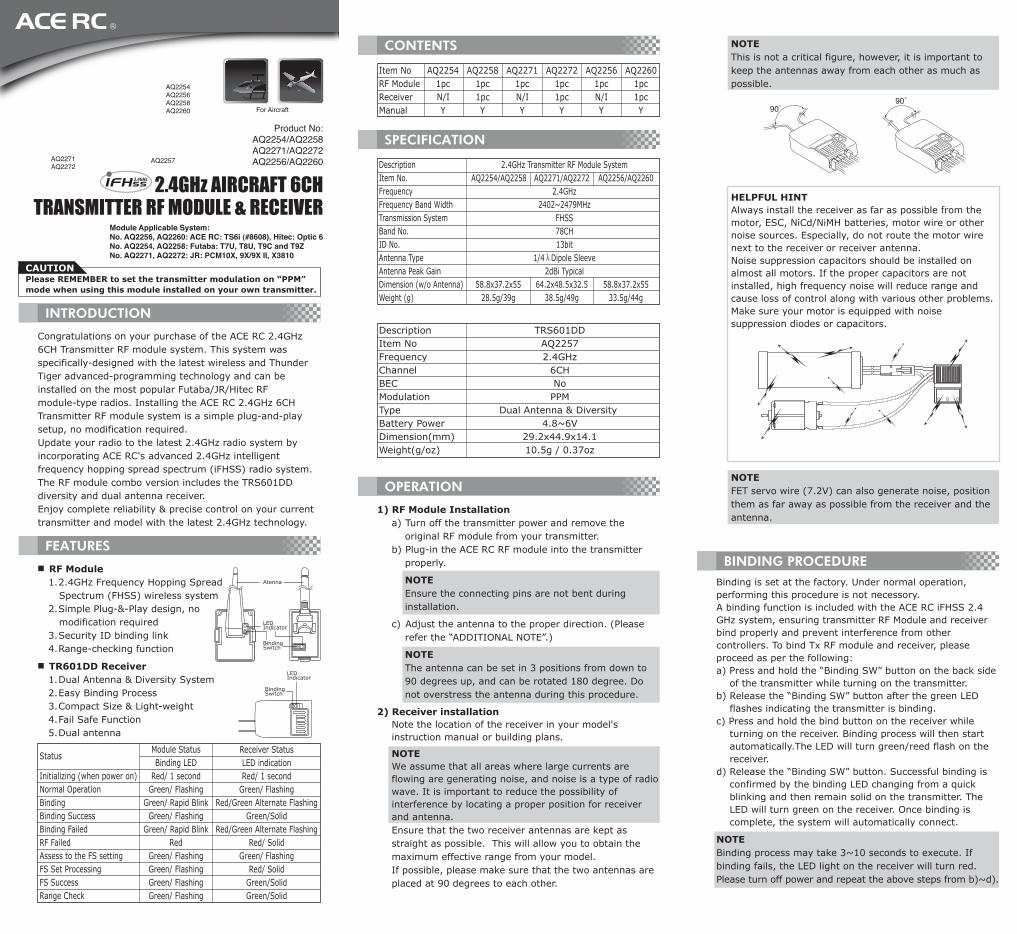
HELPFUL HINTAlways install the receiver as far as possible from the motor, ESC, NiCd/NiMH batteries, motor wire or other noise sources. Especially, do not route the motor wire next to the receiver or receiver antenna. Noise suppression capacitors should be installed on almost all motors. If the proper capacitors are not installed, high frequency noise will reduce range and cause loss of control along with various other problems. Make sure your motor is equipped with noise suppression diodes or capacitors.
FEATURES
■ RF Module1. 2.4GHz Frequency Hopping Spread
Spectrum (FHSS) wireless system2. Simple Plug-&-Play design, no
modification required3. Security ID binding link 4. Range-checking function
■ TR601DD Receiver1. Dual Antenna & Diversity System 2. Easy Binding Process3. Compact Size & Light-weight4. Fail Safe Function5. Dual antenna
CONTENTS
Item No AQ2254 AQ2258 AQ2271 AQ2272 AQ2256 AQ2260RF Module 1pc 1pc 1pc 1pc 1pc 1pcReceiver N/I 1pc N/I 1pc N/I 1pcManual Y Y Y Y Y Y
SPECIFICATION
DescriptionItem No.FrequencyFrequency Band WidthTransmission SystemBand No.ID No.Antenna TypeAntenna Peak GainDimension (w/o Antenna)Weight (g)
2.4GHz Transmitter RF Module SystemAQ2254/AQ2258 AQ2271/AQ2272 AQ2256/AQ2260
2.4GHz2402~2479MHz
FHSS78CH13bit
1/4λDipole Sleeve2dBi Typical
58.8x37.2x55 64.2x48.5x32.5 58.8x37.2x55 28.5g/39g 38.5g/49g 33.5g/44g
Description TRS601DDItem No AQ2257Frequency 2.4GHzChannel 6CHBEC NoModulation PPMType Dual Antenna & Diversity Battery Power 4.8~6VDimension(mm) 29.2x44.9x14.1Weight(g/oz) 10.5g / 0.37oz
NOTEFET servo wire (7.2V) can also generate noise, position them as far away as possible from the receiver and the antenna.
AQ2257AQ2271AQ2272
AQ2254AQ2256AQ2258AQ2260
OPERATION
1) RF Module Installationa) Turn off the transmitter power and remove the
original RF module from your transmitter.b) Plug-in the ACE RC RF module into the transmitter
properly.
NOTEEnsure the connecting pins are not bent during installation.
c) Adjust the antenna to the proper direction. (Please refer the “ADDITIONAL NOTE”.)
NOTEThe antenna can be set in 3 positions from down to 90 degrees up, and can be rotated 180 degree. Do not overstress the antenna during this procedure.
2) Receiver installationNote the location of the receiver in your model's instruction manual or building plans.
NOTEWe assume that all areas where large currents are flowing are generating noise, and noise is a type of radio wave. It is important to reduce the possibility of interference by locating a proper position for receiver and antenna.Ensure that the two receiver antennas are kept as straight as possible. This will allow you to obtain the maximum effective range from your model.If possible, please make sure that the two antennas are placed at 90 degrees to each other.
NOTEThis is not a critical figure, however, it is important to keep the antennas away from each other as much as possible.
90°90°
Product No:AQ2254/AQ2258AQ2271/AQ2272AQ2256/AQ2260
2.4GHz AIRCRAFT 6CHTRANSMITTER RF MODULE & RECEIVER
For Aircraft
Module Applicable System:No. AQ2256, AQ2260: ACE RC: TS6i (#8608), Hitec: Optic 6No. AQ2254, AQ2258: Futaba: T7U, T8U, T9C and T9Z No. AQ2271, AQ2272: JR: PCM10X, 9X/9X II, X3810
CAUTIONPlease REMEMBER to set the transmitter modulation on “PPM” mode when using this module installed on your own transmitter.
BINDING PROCEDUREBinding is set at the factory. Under normal operation, performing this procedure is not necessory.A binding function is included with the ACE RC iFHSS 2.4 GHz system, ensuring transmitter RF Module and receiver bind properly and prevent interference from other controllers. To bind Tx RF module and receiver, please proceed as per the following:a) Press and hold the “Binding SW” button on the back side
of the transmitter while turning on the transmitter.b) Release the “Binding SW” button after the green LED
flashes indicating the transmitter is binding.c) Press and hold the bind button on the receiver while
turning on the receiver. Binding process will then start automatically.The LED will turn green/reed flash on the receiver.
d) Release the “Binding SW” button. Successful binding is confirmed by the binding LED changing from a quick blinking and then remain solid on the transmitter. The LED will turn green on the receiver. Once binding is complete, the system will automatically connect.
NOTEBinding process may take 3~10 seconds to execute. If binding fails, the LED light on the receiver will turn red. Please turn off power and repeat the above steps from b)~d).
LEDIndicator
BindingSwitch
Atenna
LEDIndicator
BindingSwitch
Status
Initializing (when power on)Normal OperationBindingBinding SuccessBinding FailedRF FailedAssess to the FS settingFS Set ProcessingFS SuccessRange Check
Module StatusBinding LED
Red/ 1 secondGreen/ Flashing
Green/ Rapid BlinkGreen/ Flashing
Green/ Rapid BlinkRed
Green/ FlashingGreen/ FlashingGreen/ FlashingGreen/ Flashing
Receiver StatusLED indicationRed/ 1 second
Green/ FlashingRed/Green Alternate Flashing
Green/SolidRed/Green Alternate Flashing
Red/ SolidGreen/ Flashing
Red/ SolidGreen/SolidGreen/Solid
guarantee that interference will not occur in a particular installation. If this equipment does cause harmful interference to radio or television reception, which can be determined by turning the equipment off and on, the user is encouraged to try to correct the interference by one of the following measures:■ Reorient or relocate the receiving antenna.■ Increase the separation between the equipment and
receiver.■ Connect the equipment into an outlet on a circuit
different from that to which the receiver is connected.■ Consult the dealer or an experienced radio/TV technician
for help.
FCC CAUTIONTo assure continued compliance, any changes or modifications not expressly approved by the party responsible for compliance could void the user's authority to operate this equipment. (Example - use only shielded interface cables when connecting to computer or peripheral devices).This device complies with Part 15 of the FCC Rules. Operation is subject to the following two conditions:(1) This device may not cause harmful interference, and (2) This device must accept any interference received, including interference that may cause undesired operation.
FCC RADIATION EXPOSURE STATEMENTThis equipment complies with FCC RF radiation exposure limits set forth for an uncontrolled environment.This equipment should be installed and operated with a minimum distance of 20 centimeters between the radiator and your body. This transmitter must not be co-located or operating in conjunction with any other antenna or transmitter. The antennas used for this transmitter must be installed to provide a separation distance of at least 20 cmfrom all persons and must not be co-located or operating in conjunction with any other antenna or transmitter.
FCC INTERFERENCE STATEMENT
This equipment has been tested and found to comply with the limits for a Class B digital device, pursuant to Part 15 of the FCC Rules. These limits are designed to provide reasonable protection against harmful interference in a residential installation.This equipment generates, uses and can radiate radio frequency energy and, if not installed and used in accordance with the instructions, may cause harmful interference to radio communications. However, there is no
SERVICE
Thank you for purchasing the ACE RC 2.4GHz RF module. This RF module was produced by Thunder Tiger Corp., a guarantee for high quality, services, and hours of trouble-free operation. Thunder Tiger products are sold worldwide through authorized distributors supported directly by Thunder Tiger. To receive the latest product information and enjoy full technical support, please contact your nearest hobby shop or Thunder Tiger authorized distributor.
FCC ID: VEJTT-FHM2P4G-A13 (Item No. AQ2271 / AQ2272)
FCC ID: VEJTT-FHM2P4G-A12 (the other items)
*Futaba / JR / Hitec are registered Tradmarks.
Manufactured by
THUNDER TIGER CORP.http://www.thundertiger.com JC6202V2
CAUTIONOperating range may be significantly reduced with the transmitter antenna pointing directly at the model!
ACE RC 2.4GHz system features a built-in Pre-setting Failsafe function to automatically set a servo command if the receiver loses the signal from the transmitter due to interference. For safety, we strongly recommend to check the FAILSAFE function before flying.
Resetting FAILSAFEFAILSAFE settings can be reset by pressing the Binding Switch on your receiver (power on). First, ensure your radio system is bound properly and proceed as per the following:
FAILSAFE FUNCTION SETTING
ADDITIONAL NOTE
For best operating range, always ensure the largest section of your transmitter antenna faces the model.
A built-in range-check function on the transmitter RF module reduces signal strength for pre-flight range-check. When this function is activated, signal strength is weak. Use the weak signal strength for pre-flight range-check to confirm wireless radio control system is working properly. It is recommended to perform a range-check before every flight. “Range-Checking” procedure:a) Turn both transmitter and model power on and ensure
the system is functioning properly.b) Take the transmitter to a distance of about 20~30m
from the model.c) Press and hold the “Binding SW” button on the RF
module. Signal strength is now weak. Please do not release “Binding SW” at this stage.
d) Operate both left and right sticks to drive movement on the servos. Visually confirm that all movements are accurate and signal is interference-free.
e) Release “Binding SW” button. Signal reverses back to full strength and warning tone stops.
f) Model is ready to fly.
NOTENever activate the “Binding SW” button during flight. Flying under weak signal strength will result in signal loss and model crash.
RANGE CHECKING
a) Power on your transmitter & Receiver. Move and hold control sticks to preferred position should a failsafe situation occur (select any channels from CH1~CH6). Factory pre-settings are recommended, please refer to “Note”.
b) Press & hold the binding switch on the receiver for 2~4 seconds.
c) When the LED on the receiver starts blinking, release the binding switch then the LED turns to red for 2~4 seconds then turn back to green, indicating the function is successfully set.
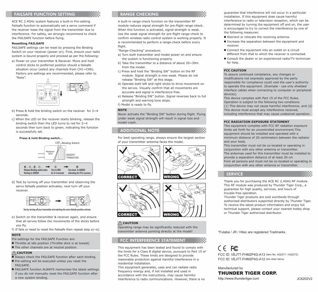
d) Test by turning off your transmitter and observing the servo failsafe position activates, next turn off your receiver.
e) Switch on the transmitter & receiver again, and ensure that all servos follow the movements of the sticks before you fly.
f) If fails or need to reset the Failsafe then repeat step a)~e).
NOTEPre-settings for the FAILSAFE Function are:■ Throttle at idle position (Throttle stick is at lowest)■ The other channels are at neutral position.
CAUTION■ Always check the FAILSAFE function after each binding. ■ Pre-setting will be executed unless you reset the
FAILSAFE. ■ FAILSAFE function ALWAYS memorizes the latest settings
if you do not manually reset the FAILSAFE function after a new system binding.
Test by turning off your transmitter and watching the servo failsafe position activate.
Press & hold Binding switch...
Release Binding switch whenflashing in GREEN
Turn to REDfor 2~4 seconds
Turn back to GREENindicating the FS is success
LED Binding Switch
AQ2257TRS601DD
Receiver6CH
WRONGCORRECT
WRONGCORRECT