Embed Size (px)
Citation preview

TTX
660
TM
Tactic’s TTX660 computer transmitter uses
the advanced 2.4GHz spread spectrum
SLT “Secure Link Technology” protocol for
solid, interference-free control of R/C
models. Ball-bearing gimbals, a wireless
trainer system, 30 model memories, and
advanced programming options are just
a few of the benefits which can be used
on models of all sizes. Tactic 2.4GHz
transmitters are compatible only with
Tactic brand receivers and those utiliz-
ing the SLT protocol.
2.4GHz 6-CHANNELCOMPUTER RADIOINSTRUCTION MANUAL
For safe operation and
best results, it’s
strongly recommended
to read this manual in
its entirety before use! Also read
and understand the instructions
included with the model. Damage
resulting from misuse or
modification will void your warranty.
™
Tactic’c’
the a
SLT “
solid
mod
train
adv
a fe
on
tran
Tac
ing
its en
and u
includ
resulti
modific
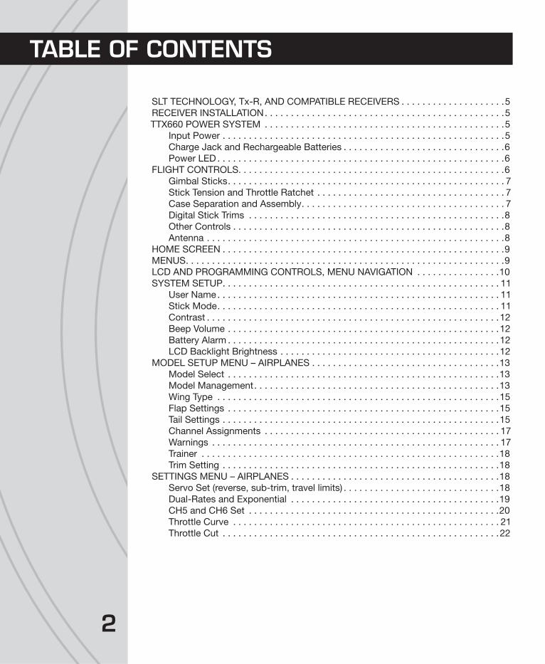
2
SLT TECHNOLOGY, Tx-R, AND COMPATIBLE RECEIVERS . . . . . . . . . . . . . . . . . . . .5
RECEIVER INSTALLATION. . . . . . . . . . . . . . . . . . . . . . . . . . . . . . . . . . . . . . . . . . . . . .5
TTX660 POWER SYSTEM . . . . . . . . . . . . . . . . . . . . . . . . . . . . . . . . . . . . . . . . . . . . . .5
Input Power . . . . . . . . . . . . . . . . . . . . . . . . . . . . . . . . . . . . . . . . . . . . . . . . . . . . . .5
Charge Jack and Rechargeable Batteries . . . . . . . . . . . . . . . . . . . . . . . . . . . . . . .6
Power LED . . . . . . . . . . . . . . . . . . . . . . . . . . . . . . . . . . . . . . . . . . . . . . . . . . . . . . .6
FLIGHT CONTROLS. . . . . . . . . . . . . . . . . . . . . . . . . . . . . . . . . . . . . . . . . . . . . . . . . . .6
Gimbal Sticks. . . . . . . . . . . . . . . . . . . . . . . . . . . . . . . . . . . . . . . . . . . . . . . . . . . . . 7
Stick Tension and Throttle Ratchet . . . . . . . . . . . . . . . . . . . . . . . . . . . . . . . . . . . . 7
Case Separation and Assembly. . . . . . . . . . . . . . . . . . . . . . . . . . . . . . . . . . . . . . . 7
Digital Stick Trims . . . . . . . . . . . . . . . . . . . . . . . . . . . . . . . . . . . . . . . . . . . . . . . . .8
Other Controls . . . . . . . . . . . . . . . . . . . . . . . . . . . . . . . . . . . . . . . . . . . . . . . . . . . .8
Antenna . . . . . . . . . . . . . . . . . . . . . . . . . . . . . . . . . . . . . . . . . . . . . . . . . . . . . . . . .8
HOME SCREEN . . . . . . . . . . . . . . . . . . . . . . . . . . . . . . . . . . . . . . . . . . . . . . . . . . . . . .9
MENUS. . . . . . . . . . . . . . . . . . . . . . . . . . . . . . . . . . . . . . . . . . . . . . . . . . . . . . . . . . . . .9
LCD AND PROGRAMMING CONTROLS, MENU NAVIGATION . . . . . . . . . . . . . . . .10
SYSTEM SETUP. . . . . . . . . . . . . . . . . . . . . . . . . . . . . . . . . . . . . . . . . . . . . . . . . . . . . 11
User Name. . . . . . . . . . . . . . . . . . . . . . . . . . . . . . . . . . . . . . . . . . . . . . . . . . . . . . 11
Stick Mode. . . . . . . . . . . . . . . . . . . . . . . . . . . . . . . . . . . . . . . . . . . . . . . . . . . . . . 11
Contrast . . . . . . . . . . . . . . . . . . . . . . . . . . . . . . . . . . . . . . . . . . . . . . . . . . . . . . . .12
Beep Volume . . . . . . . . . . . . . . . . . . . . . . . . . . . . . . . . . . . . . . . . . . . . . . . . . . . .12
Battery Alarm . . . . . . . . . . . . . . . . . . . . . . . . . . . . . . . . . . . . . . . . . . . . . . . . . . . .12
LCD Backlight Brightness . . . . . . . . . . . . . . . . . . . . . . . . . . . . . . . . . . . . . . . . . .12
MODEL SETUP MENU – AIRPLANES . . . . . . . . . . . . . . . . . . . . . . . . . . . . . . . . . . . .13
Model Select . . . . . . . . . . . . . . . . . . . . . . . . . . . . . . . . . . . . . . . . . . . . . . . . . . . .13
Model Management. . . . . . . . . . . . . . . . . . . . . . . . . . . . . . . . . . . . . . . . . . . . . . .13
Wing Type . . . . . . . . . . . . . . . . . . . . . . . . . . . . . . . . . . . . . . . . . . . . . . . . . . . . . .15
Flap Settings . . . . . . . . . . . . . . . . . . . . . . . . . . . . . . . . . . . . . . . . . . . . . . . . . . . .15
Tail Settings . . . . . . . . . . . . . . . . . . . . . . . . . . . . . . . . . . . . . . . . . . . . . . . . . . . . .15
Channel Assignments . . . . . . . . . . . . . . . . . . . . . . . . . . . . . . . . . . . . . . . . . . . . . 17
Warnings . . . . . . . . . . . . . . . . . . . . . . . . . . . . . . . . . . . . . . . . . . . . . . . . . . . . . . . 17
Trainer . . . . . . . . . . . . . . . . . . . . . . . . . . . . . . . . . . . . . . . . . . . . . . . . . . . . . . . . .18
Trim Setting . . . . . . . . . . . . . . . . . . . . . . . . . . . . . . . . . . . . . . . . . . . . . . . . . . . . .18
SETTINGS MENU – AIRPLANES . . . . . . . . . . . . . . . . . . . . . . . . . . . . . . . . . . . . . . . .18
Servo Set (reverse, sub-trim, travel limits) . . . . . . . . . . . . . . . . . . . . . . . . . . . . . .18
Dual-Rates and Exponential . . . . . . . . . . . . . . . . . . . . . . . . . . . . . . . . . . . . . . . .19
CH5 and CH6 Set . . . . . . . . . . . . . . . . . . . . . . . . . . . . . . . . . . . . . . . . . . . . . . . .20
Throttle Curve . . . . . . . . . . . . . . . . . . . . . . . . . . . . . . . . . . . . . . . . . . . . . . . . . . . 21
Throttle Cut . . . . . . . . . . . . . . . . . . . . . . . . . . . . . . . . . . . . . . . . . . . . . . . . . . . . .22
TABLE OF CONTENTS
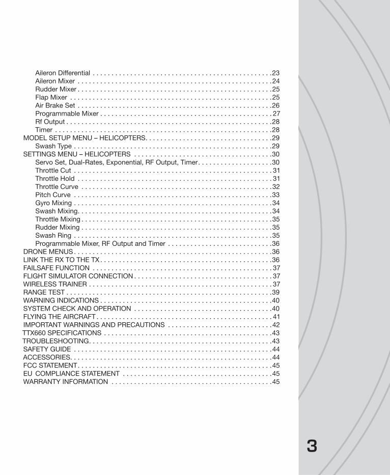
3
Aileron Differential . . . . . . . . . . . . . . . . . . . . . . . . . . . . . . . . . . . . . . . . . . . . . . . .23
Aileron Mixer . . . . . . . . . . . . . . . . . . . . . . . . . . . . . . . . . . . . . . . . . . . . . . . . . . . .24
Rudder Mixer . . . . . . . . . . . . . . . . . . . . . . . . . . . . . . . . . . . . . . . . . . . . . . . . . . . .25
Flap Mixer . . . . . . . . . . . . . . . . . . . . . . . . . . . . . . . . . . . . . . . . . . . . . . . . . . . . . .25
Air Brake Set . . . . . . . . . . . . . . . . . . . . . . . . . . . . . . . . . . . . . . . . . . . . . . . . . . . .26
Programmable Mixer . . . . . . . . . . . . . . . . . . . . . . . . . . . . . . . . . . . . . . . . . . . . . . 27
Rf Output . . . . . . . . . . . . . . . . . . . . . . . . . . . . . . . . . . . . . . . . . . . . . . . . . . . . . . .28
Timer . . . . . . . . . . . . . . . . . . . . . . . . . . . . . . . . . . . . . . . . . . . . . . . . . . . . . . . . . .28
MODEL SETUP MENU – HELICOPTERS. . . . . . . . . . . . . . . . . . . . . . . . . . . . . . . . . .29
Swash Type . . . . . . . . . . . . . . . . . . . . . . . . . . . . . . . . . . . . . . . . . . . . . . . . . . . . .29
SETTINGS MENU – HELICOPTERS . . . . . . . . . . . . . . . . . . . . . . . . . . . . . . . . . . . . .30
Servo Set, Dual-Rates, Exponential, RF Output, Timer. . . . . . . . . . . . . . . . . . . .30
Throttle Cut . . . . . . . . . . . . . . . . . . . . . . . . . . . . . . . . . . . . . . . . . . . . . . . . . . . . . 31
Throttle Hold . . . . . . . . . . . . . . . . . . . . . . . . . . . . . . . . . . . . . . . . . . . . . . . . . . . . 31
Throttle Curve . . . . . . . . . . . . . . . . . . . . . . . . . . . . . . . . . . . . . . . . . . . . . . . . . . .32
Pitch Curve . . . . . . . . . . . . . . . . . . . . . . . . . . . . . . . . . . . . . . . . . . . . . . . . . . . . .33
Gyro Mixing . . . . . . . . . . . . . . . . . . . . . . . . . . . . . . . . . . . . . . . . . . . . . . . . . . . . .34
Swash Mixing. . . . . . . . . . . . . . . . . . . . . . . . . . . . . . . . . . . . . . . . . . . . . . . . . . . .34
Throttle Mixing . . . . . . . . . . . . . . . . . . . . . . . . . . . . . . . . . . . . . . . . . . . . . . . . . . .35
Rudder Mixing . . . . . . . . . . . . . . . . . . . . . . . . . . . . . . . . . . . . . . . . . . . . . . . . . . .35
Swash Ring . . . . . . . . . . . . . . . . . . . . . . . . . . . . . . . . . . . . . . . . . . . . . . . . . . . . .35
Programmable Mixer, RF Output and Timer . . . . . . . . . . . . . . . . . . . . . . . . . . . .36
DRONE MENUS . . . . . . . . . . . . . . . . . . . . . . . . . . . . . . . . . . . . . . . . . . . . . . . . . . . . .36
LINK THE RX TO THE TX . . . . . . . . . . . . . . . . . . . . . . . . . . . . . . . . . . . . . . . . . . . . . .36
FAILSAFE FUNCTION . . . . . . . . . . . . . . . . . . . . . . . . . . . . . . . . . . . . . . . . . . . . . . . . 37
FLIGHT SIMULATOR CONNECTION . . . . . . . . . . . . . . . . . . . . . . . . . . . . . . . . . . . . . 37
WIRELESS TRAINER . . . . . . . . . . . . . . . . . . . . . . . . . . . . . . . . . . . . . . . . . . . . . . . . . 37
RANGE TEST . . . . . . . . . . . . . . . . . . . . . . . . . . . . . . . . . . . . . . . . . . . . . . . . . . . . . . .39
WARNING INDICATIONS . . . . . . . . . . . . . . . . . . . . . . . . . . . . . . . . . . . . . . . . . . . . . .40
SYSTEM CHECK AND OPERATION . . . . . . . . . . . . . . . . . . . . . . . . . . . . . . . . . . . . .40
FLYING THE AIRCRAFT . . . . . . . . . . . . . . . . . . . . . . . . . . . . . . . . . . . . . . . . . . . . . . . 41
IMPORTANT WARNINGS AND PRECAUTIONS . . . . . . . . . . . . . . . . . . . . . . . . . . . .42
TTX660 SPECIFICATIONS . . . . . . . . . . . . . . . . . . . . . . . . . . . . . . . . . . . . . . . . . . . . .43
TROUBLESHOOTING. . . . . . . . . . . . . . . . . . . . . . . . . . . . . . . . . . . . . . . . . . . . . . . . .43
SAFETY GUIDE . . . . . . . . . . . . . . . . . . . . . . . . . . . . . . . . . . . . . . . . . . . . . . . . . . . . .44
ACCESSORIES. . . . . . . . . . . . . . . . . . . . . . . . . . . . . . . . . . . . . . . . . . . . . . . . . . . . . .44
FCC STATEMENT. . . . . . . . . . . . . . . . . . . . . . . . . . . . . . . . . . . . . . . . . . . . . . . . . . . .45
EU COMPLIANCE STATEMENT . . . . . . . . . . . . . . . . . . . . . . . . . . . . . . . . . . . . . . . .45
WARRANTY INFORMATION . . . . . . . . . . . . . . . . . . . . . . . . . . . . . . . . . . . . . . . . . . .45
4
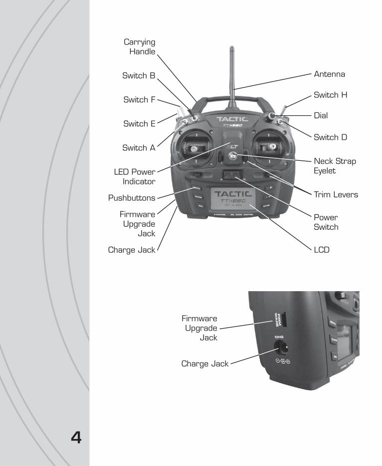
Neck StrapEyelet
PowerSwitch
Antenna
LED PowerIndicator
LCD
Pushbuttons
CarryingHandle
Switch A
Switch E
Switch F
Switch B
Switch D
Dial
Switch H
Charge Jack
FirmwareUpgrade
Jack
Trim Levers
Charge Jack
FirmwareUpgrade
Jack

5
Tactic’s custom SLT technology ensures that transmitters emit a strong, clear, frequency-
hopping 2.4GHz signal, and that your compatible receiver accepts no signal except
yours. Binding Tactic brand receivers is as simple as pushing
a button, which creates a locked-in, interference free link. The
TTX660 radio can store up to 30 models in memory, making it
perfect to control a full fl eet of models with the super-affordable
Tactic brand 2.4GHz receivers. The TTX660 is also compatible with non-Tactic brand
receivers which use the *SLT protocol, for the ultimate in convenience and fl exibility.
* Make sure optional receivers have the genuine SLT protocol before use with the TTX660.
The TTX660 is also compatible with all transmitter-ready
aircraft bearing the “Tx-R” logo. Such aircraft include
receivers having the SLT protocol.
Always mount the optional receiver, servos, switch harness, battery, electronic speed
control, etc. as explained in the manual included with such equipment and/or the model.
Keep the Rx and its antenna(s) as far away from the engine/motor, servos, and ESC and
other electronic items as much as possible. It may also be a good idea to mount the
Rx inside certain models using Velcro,® and wrap it in foam rubber to prevent damage
from strong vibrations or crash damage (except in extremely warm environments). It’s
best to have as few items surrounding the receiver’s antenna tips as possible inside the
model, to allow for the most obstruction-free signal path to the transmitter. Exposing the
receiver’s antenna tip outside the model is recommended if possible. For receivers with
two antennas, position the antennas at 90 degree angles with the tips resting at least 5
inches apart. If possible, allow one antenna to point vertically above the receiver itself.
INPUT POWERFour 1.5V “AA” alkaline cells (included) or 1.2V “AA” NiCd or NiMH cells supply power
to the TTX660. Do not mix cell types, or old and new cells, etc. Slide open the battery
door to fi nd the four “AA” cell battery holder. Insert all cells with the proper polarity as
shown inside the battery holder. Carefully tuck the wires and battery holder inside the
battery compartment so not to damage them when closing the battery door.
Alternatively, an assembled 4.8V NiCd or NiMH “AA” fl at pack can be installed. Remove
the alkaline cell holder from the battery compartment and carefully observe the polarity
SLT TECHNOLOGY, Tx-R,AND COMPATIBLE RECEIVERS
™
TM
RECEIVER INSTALLATION
TTX660 POWER SYSTEM

66
of the wires before disconnecting the plug from the Tx. Install the NiCd or NiMH
battery by fi rst inserting its connector into the jack in the battery compartment.
Battery voltage is shown on the LCD’s home screen for easy monitoring. A “LOW
BATTERY” warning will show when battery power drops to the voltage value shown in
the BATTERY ALARM screen as described on page 12.
WARNING! Never operate an R/C model with weak Tx batteries! Reduced
operational range and/or possible loss of control of the aircraft could
result. Never mix used and new alkaline batteries. Replace weak alkaline
batteries, or re-charge NiCd or NiMH batteries before attempting a fl ight!
A “Tx Batt.” timer in the TIMER menu described on page 28 can track the total amount
of time the transmitter has been operational.
See the ACCESSORIES section on page 44 for optional batteries and chargers available
at local hobby retailers.
CHARGE JACK AND CHARGING RECHARGEABLE BATTERIES
The charge jack should only be used for recharging optional NiCd or NiMH
batteries (charger not included). Do not try to recharge alkaline batteries.
Charge adapter leads for Futaba® brand transmitters are compatible, with
the center pin being positive polarity. The Tx power switch must be in the
OFF position to recharge batteries. Do not charge batteries at greater than
1 amp. Cycling of the Tx batteries can be accomplished through this jack. Misuse,
improper charging, or over-charging of rechargeable cells can result in damage to the
cells that could include cell rupture, explosion, or fi re!!
WARNING! Do not accidentally short circuit the terminals inside the charge
jack, as this can cause permanent damage to the radio’s charge circuitry
and battery and void the warranty.
POWER LEDThe blue LED illuminates when the power switch is turned on and ample voltage is
supplied by the battery. This LED will fl ash if battery voltage drops to the voltage set in
the BATTERY ALARM setting described on page 12.
Channels 1– 6 are fully proportional. Channels 5 and 6 can be controlled by a
non-proportional switch, dial, or slide lever, or mixed to channels 1– 4 for full
proportional control.
Aircraft control is accomplished through various electro-mechanical devices which are
manipulated by the pilot, such as the control sticks, toggle switches, dial, or slide levers.
In addition, the Tx can automatically manipulate the pilot’s control inputs electronically
to alter the control signals before they are delivered to the receiver (e.g. mixing two
TTX660 Charge Jack
FLIGHT CONTROLS

7
channels, applying differential reduction to a channel, etc.). Some electronic functions
can be turned on/off by the pilot during fl ight such as a timer. Other functions should
only be altered while the model is on the ground, such as changing travel limits or
reversing for a particular channel.
GIMBAL STICKSBall-bearing construction allows both sticks to provide the
ultimate in smooth, precise control. Stick length can be adjusted
for optimum feel and control. Each stick consists of a base and
a tip. To adjust, hold the base tightly, then loosen the tip by
turning it counter-clockwise. Adjust the stick tip to the desired
length. Tighten the stick by holding the tip in place and turning
the base counter-clockwise until it’s tight against the tip.
STICK TENSION AND THROTTLE RATCHETEach control stick can be adjusted for softer or stiffer movement tension. A ratchet is
also included for the throttle stick which can be adjusted for feel depending on personal
preference. Adjustment of either feature requires removal of the rear of the Tx case as
explained in the CASE SEPARATION AND ASSEMBLY section below.
CASE SEPARATION AND ASSEMBLYWARNING! Failure to follow these instructions for separating and
re-assembling the Tx case can result in permanent damage to the
transmitter, and void the warranty. Contact Hobby Services if you
do not feel comfortable that you can safely and accurately perform
these steps.
ALWAYS disconnect and remove the batteries from the battery compartment
FIRST. Failure to do so can result in permanent damage to the Tx.
Remove the six screws from the back of the Tx case. Carefully pull the case rear
away from the case front and note exactly how all wires are routed inside the case.
After adjustments are made as described in other sections of this manual, close the
case by fi rst carefully tucking all cables back inside as when the case was opened.
Align the case rear back onto the case front, making sure that no wires are pinched
between the case parts. Press the case halves together. Insert the screws back
into their positions and carefully tighten them until snug - making sure not to cross
the threads or over-tighten the screws. Re-connect the battery holder’s connector
to the socket inside the Tx. Insert the battery into the compartment, and carefully
tuck the wires inside the cavity so they do not become pinched when the door is
closed. Close the battery door.

8
● Stick Tension: Silver screws on the back of each gimbal are
used to adjust the stick tension, as shown at left. Turn the
screw clockwise to make stick tension more fi rm. Turn the
screw counter-clockwise to make stick tension more light.
● Throttle Ratchet: A silver ratchet bar is mounted across
the throttle gimbal. For airplane use, a more fi rm ratchet
feel might be desired for the throttle. In this case, turn the
adjustment screw clockwise. For helicopter use, less of a
ratchet feel might be desired. Turn this adjustment screw
counter-clockwise to achieve the desired feel.
DIGITAL STICK TRIMSThe trim controls for the four main channels are digital. Holding
the trim lever will cause the servo output to move repeatedly.
Trim positions are visible on the LCD’s home screen, and stored
into that respective memory. Changing the model memory will
also cause trim settings to change accordingly.
For aircraft with glow engines, the precise position of the trim
lever is helpful when determining the engine’s preferred idle
point. When the main throttle stick is above 50% full throttle,
it will not be possible to trim the throttle servo – even though
the indicator on the LCD will move.
The amount of servo movement for each increment of a digital
trim can be adjusted as desired, as explained in the TRIM
SETTING section on page 18.
OTHER CONTROLSEach control can be assigned to control one of a variety of functions as desired and
described throughout this manual. See page 4 for the location of all switches, which are
also marked on the Tx by letter. The factory default switch assignments are as follows:
ANTENNAThe strongest signals are emitted at a 45 degree angle from the sides of the antenna.
Rotate and fold the antenna so that it’s not pointing directly towards the model during
fl ight. Do not grab the antenna during operation as it may affect radio signal quality.
A 2-position Ch2 Elevator Dual-rate Timer Control B 2-position (No Setting) Gyro Gain C Dial (No Setting) (No Setting) D 2-position Ch1 Aileron Dual-rate Aileron, Elevator, and Rudder Dual-rates (All) E 3-position Ch4 Rudder Dual-rate Normal/Idle-up Control F 2-position, Momentary Trainer Throttle Cut H 2-position Throttle Cut Throttle Hold I Slide Lever (No Setting) (No Setting) J Slide Lever (No Setting) (No Setting)
Switch TypeDefault Function
AirplaneDefault Function
Helicopters
9
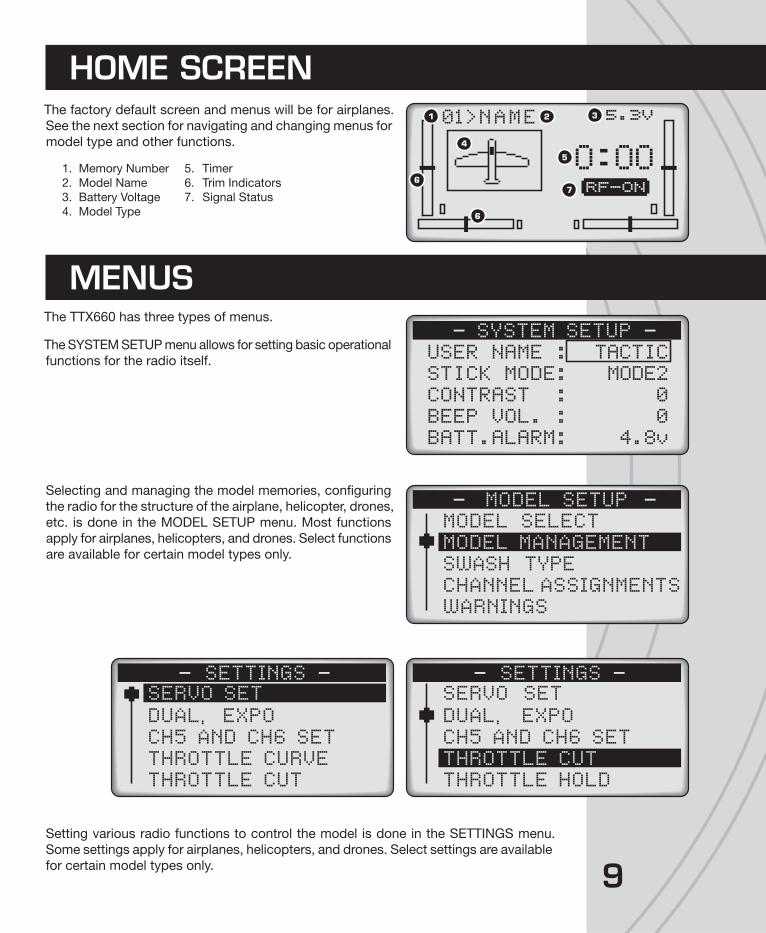
The factory default screen and menus will be for airplanes.
See the next section for navigating and changing menus for
model type and other functions.
1. Memory Number 5. Timer
2. Model Name 6. Trim Indicators
3. Battery Voltage 7. Signal Status
4. Model Type
The TTX660 has three types of menus.
The SYSTEM SETUP menu allows for setting basic operational
functions for the radio itself.
Selecting and managing the model memories, confi guring
the radio for the structure of the airplane, helicopter, drones,
etc. is done in the MODEL SETUP menu. Most functions
apply for airplanes, helicopters, and drones. Select functions
are available for certain model types only.
Setting various radio functions to control the model is done in the SETTINGS menu.
Some settings apply for airplanes, helicopters, and drones. Select settings are available
for certain model types only.
HOME SCREEN
>NAME0 1 5.3V
O OORF-ON
1 2 3
4
5
6
6
7
MENUS
USER NAME :STICK MODE:CONTRAST :BEEP VOL. :BATT.ALARM:
TACTICMODE2
00
4.8v
SYSTEM SETUP
MODEL SELECTMODEL MANAGEMENTSWASH TYPECHANNEL ASSIGNMENTSWARNINGS
MODEL SETUP
SERVO SETDUAL, EXPOCH5 AND CH6 SETTHROTTLE CURVETHROTTLE CUT
SETTINGSSERVO SETDUAL, EXPO
SETTINGS
CH5 AND CH6 SETTHROTTLE CUTTHROTTLE HOLD

10
The LCD contrast and brightness is adjustable for optimum viewing. Six pushbuttons
navigate the menus and settings. Single button pushes will result in a single incremental
adjustment on-screen. Holding a button for a short time will result in slow scrolling of
adjustments; continued holding will result in fast adjustments.
Left side buttons:
Press any time to see the servo position screen shown above. Indicators
for certain channels will change depending on model type, wing type, etc.
Moving any Tx control will graphically be shown on this screen. When
setting / adjusting mixes to determine if the mix is as desired, set the
mix and then view this screen. Move all controls to determine if the mix
moves each respective channel as needed.
Quickly resets certain values and settings back to factory defaults. Press
to backspace in the model and user name screens.
Jumps back to the previous screen, and removes certain pop-up messages
from the screen.
Right side buttons: adjustment of values on-screen
Moves the cursor up, and for increasing highlighted values/settings.
Moves the cursor down, and for decreasing highlighted values/settings.
To select or de-select a setting, or enter a screen. Press briefl y to access
the SETTINGS menu. Press and hold to access the MODEL SETUP menu.
LCD, PROGRAMMING CONTROLS,MENU NAVIGATION
1 0%AILE2ELEV3THRO4RUDD5AUX16AUX2
0%0 %0 %0 %0 %
1 0 %2 0%3 5 8 %4 0 %5 0 %6 5 8 %
-
-
-
-
AILEELEVTHRORUDDGYROPITC
11
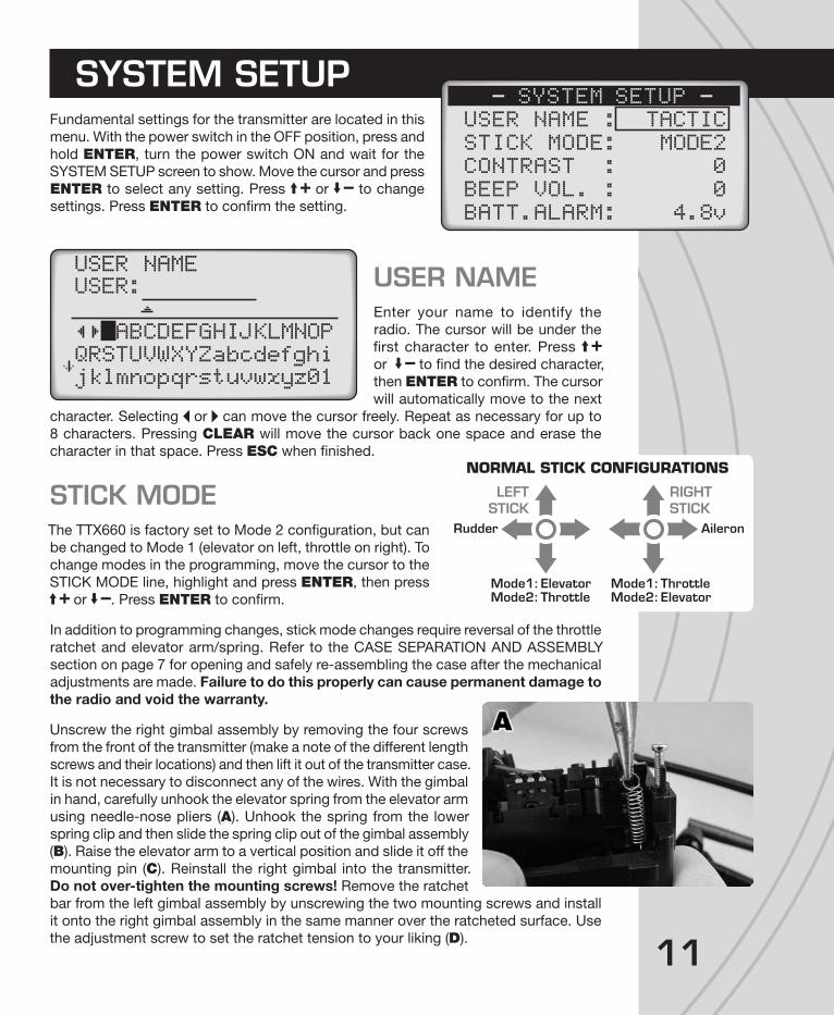
Fundamental settings for the transmitter are located in this
menu. With the power switch in the OFF position, press and
hold ENTER, turn the power switch ON and wait for the
SYSTEM SETUP screen to show. Move the cursor and press
ENTER to select any setting. Press or to change
settings. Press ENTER to confi rm the setting.
USER NAMEEnter your name to identify the
radio. The cursor will be under the
fi rst character to enter. Press
or to fi nd the desired character,
then ENTER to confi rm. The cursor
will automatically move to the next
character. Selecting or can move the cursor freely. Repeat as necessary for up to
8 characters. Pressing CLEAR will move the cursor back one space and erase the
character in that space. Press ESC when fi nished.
STICK MODEThe TTX660 is factory set to Mode 2 confi guration, but can
be changed to Mode 1 (elevator on left, throttle on right). To
change modes in the programming, move the cursor to the
STICK MODE line, highlight and press ENTER, then press
or . Press ENTER to confi rm.
In addition to programming changes, stick mode changes require reversal of the throttle
ratchet and elevator arm/spring. Refer to the CASE SEPARATION AND ASSEMBLY
section on page 7 for opening and safely re-assembling the case after the mechanical
adjustments are made. Failure to do this properly can cause permanent damage to
the radio and void the warranty.
Unscrew the right gimbal assembly by removing the four screws
from the front of the transmitter (make a note of the different length
screws and their locations) and then lift it out of the transmitter case.
It is not necessary to disconnect any of the wires. With the gimbal
in hand, carefully unhook the elevator spring from the elevator arm
using needle-nose pliers (A). Unhook the spring from the lower
spring clip and then slide the spring clip out of the gimbal assembly
(B). Raise the elevator arm to a vertical position and slide it off the
mounting pin (C). Reinstall the right gimbal into the transmitter.
Do not over-tighten the mounting screws! Remove the ratchet
bar from the left gimbal assembly by unscrewing the two mounting screws and install
it onto the right gimbal assembly in the same manner over the ratcheted surface. Use
the adjustment screw to set the ratchet tension to your liking (D).
SYSTEM SETUPUSER NAME :STICK MODE:CONTRAST :BEEP VOL. :BATT.ALARM:
TACTICMODE2
00
4.8v
SYSTEM SETUP
ABCDEFGHIJKLMNOPQRSTUVWXYZabcdefghijklmnopqrstuvwxyz01
USER NAMEUSER:
LEFTSTICK
Rudder
Mode1:ElevatorMode2: Throttle
Mode1: ThrottleMode2:Elevator
Aileron
RIGHTSTICK
NORMAL STICK CONFIGURATIONS

12
Unscrew the left gimbal assembly and lift it out of the transmitter
case. Slide the elevator arm onto the mounting pin in the left gimbal
in the same way you removed it from the right gimbal. NOTE: As you can see, the two gimbals are identical but installed
in the transmitter 180 degrees opposite each other. Insert the
spring clip you removed from the right gimbal into the slot of the
left gimbal beneath the tensioner screw. Reattach the spring you
removed from the right gimbal onto the left. Reinstall the left gimbal
assembly and tighten the spring tensioner screw to your liking.
Close the transmitter as explained in the CASE SEPARATION AND ASSEMBLY section.
CONTRASTAdjust the LCD’s contrast level for optimum viewing.
LCD BRIGHTNESSAdjust the intensity of the display’s blue backlight.
BEEP VOLUMEAdjust the loudness of the radio’s beeper as desired. This volume setting affects all
tones that are emitted from the radio including while making adjustments such as trim
adjustments, programming changes, etc. Beep volume for all alarms is not adjustable.
BATTERY ALARMAn alarm will sound and the display will show “LOW BATTERY” when the Tx battery’s
voltage drops to the level shown in this setting. Do NOT set this value too low, as the
radio could lose power very rapidly as the battery nears full discharge and cause a loss
of control of the model. Land the model immediately once this alarm has sounded!
Battery type
Nickel-Cadmium (NiCd)or Nickel-MetalHydride (NiMH)
4.00V 4.40V 4.00V
Alkaline 4.00V 4.00V 3.60V
Default Recommended Minimum
Once all functions in this menu are set, press ESC to return to the home screen.
13
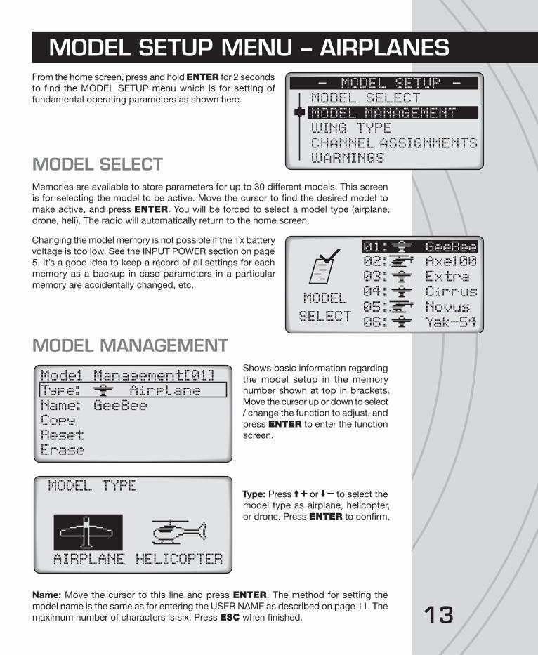
From the home screen, press and hold ENTER for 2 seconds
to fi nd the MODEL SETUP menu which is for setting of
fundamental operating parameters as shown here.
MODEL SELECTMemories are available to store parameters for up to 30 different models. This screen
is for selecting the model to be active. Move the cursor to fi nd the desired model to
make active, and press ENTER. You will be forced to select a model type (airplane,
drone, heli). The radio will automatically return to the home screen.
Changing the model memory is not possible if the Tx battery
voltage is too low. See the INPUT POWER section on page
5. It’s a good idea to keep a record of all settings for each
memory as a backup in case parameters in a particular
memory are accidentally changed, etc.
MODEL MANAGEMENTShows basic information regarding
the model setup in the memory
number shown at top in brackets.
Move the cursor up or down to select
/ change the function to adjust, and
press ENTER to enter the function
screen.
Type: Press or to select the
model type as airplane, helicopter,
or drone. Press ENTER to confi rm.
Name: Move the cursor to this line and press ENTER. The method for setting the
model name is the same as for entering the USER NAME as described on page 11. The
maximum number of characters is six. Press ESC when fi nished.
MODEL SETUP MENU – AIRPLANES
MODEL SELECTMODEL MANAGEMENTWING TYPECHANNEL ASSIGNMENTSWARNINGS
MODEL SETUP
02: Axe100
03: Extra
04: Cirrus
05: Novus
06: Yak-54
01: GeeBee
MODEL
SELECT
Mode1 Management[01]Type: Airplane
Name:CopyResetErase
GeeBee
MODEL TYPE
AIRPLANE HELICOPTER
14
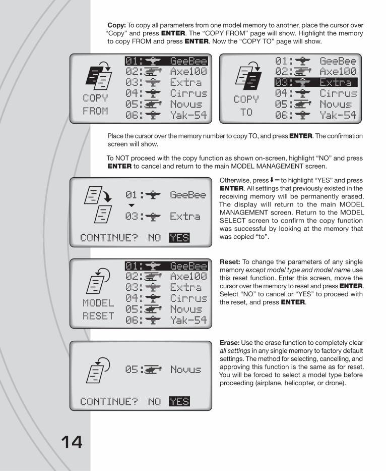
Copy: To copy all parameters from one model memory to another, place the cursor over
“Copy” and press ENTER. The “COPY FROM” page will show. Highlight the memory
to copy FROM and press ENTER. Now the “COPY TO” page will show.
Place the cursor over the memory number to copy TO, and press ENTER. The confi rmation
screen will show.
To NOT proceed with the copy function as shown on-screen, highlight “NO” and press
ENTER to cancel and return to the main MODEL MANAGEMENT screen.
Otherwise, press to highlight “YES” and press
ENTER. All settings that previously existed in the
receiving memory will be permanently erased.
The display will return to the main MODEL
MANAGEMENT screen. Return to the MODEL
SELECT screen to confi rm the copy function
was successful by looking at the memory that
was copied “to”.
Reset: To change the parameters of any single
memory except model type and model name use
this reset function. Enter this screen, move the
cursor over the memory to reset and press ENTER.
Select “NO” to cancel or “YES” to proceed with
the reset, and press ENTER.
Erase: Use the erase function to completely clear
all settings in any single memory to factory default
settings. The method for selecting, cancelling, and
approving this function is the same as for reset.
You will be forced to select a model type before
proceeding (airplane, helicopter, or drone).
02: Axe100
03: Extra
04: Cirrus
05: Novus
06: Yak-54
01: GeeBee
COPY
FROM
COPY
TO
02: Axe100
03: Extra
04: Cirrus
05: Novus
06: Yak-54
01: GeeBee
01: GeeBee
03: Extra
CONTINUE? NO YES
02: Axe100
03: Extra
04: Cirrus
05: Novus
06: Yak-54
01: GeeBee
MODEL
RESET
05: Novus
CONTINUE? NO YES
15
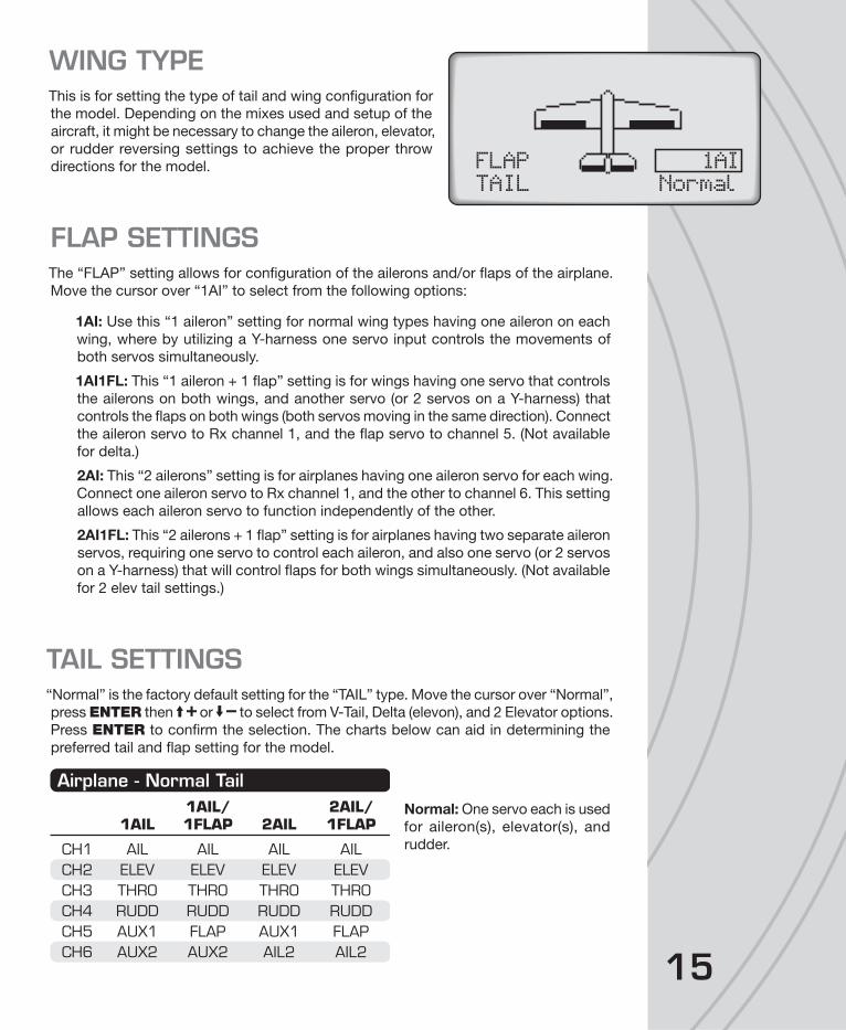
WING TYPEThis is for setting the type of tail and wing confi guration for
the model. Depending on the mixes used and setup of the
aircraft, it might be necessary to change the aileron, elevator,
or rudder reversing settings to achieve the proper throw
directions for the model.
FLAP SETTINGSThe “FLAP” setting allows for confi guration of the ailerons and/or fl aps of the airplane.
Move the cursor over “1AI” to select from the following options:
1AI: Use this “1 aileron” setting for normal wing types having one aileron on each
wing, where by utilizing a Y-harness one servo input controls the movements of
both servos simultaneously.
1AI1FL: This “1 aileron + 1 fl ap” setting is for wings having one servo that controls
the ailerons on both wings, and another servo (or 2 servos on a Y-harness) that
controls the fl aps on both wings (both servos moving in the same direction). Connect
the aileron servo to Rx channel 1, and the fl ap servo to channel 5. (Not available
for delta.)
2AI: This “2 ailerons” setting is for airplanes having one aileron servo for each wing.
Connect one aileron servo to Rx channel 1, and the other to channel 6. This setting
allows each aileron servo to function independently of the other.
2AI1FL: This “2 ailerons + 1 fl ap” setting is for airplanes having two separate aileron
servos, requiring one servo to control each aileron, and also one servo (or 2 servos
on a Y-harness) that will control fl aps for both wings simultaneously. (Not available
for 2 elev tail settings.)
TAIL SETTINGS“Normal” is the factory default setting for the “TAIL” type. Move the cursor over “Normal”,
press ENTER then or to select from V-Tail, Delta (elevon), and 2 Elevator options.
Press ENTER to confi rm the selection. The charts below can aid in determining the
preferred tail and fl ap setting for the model.
Normal: One servo each is used
for aileron(s), elevator(s), and
rudder.
1AINormal
FLAPTAIL
Airplane - Normal Tail 1AIL/ 2AIL/ 1AIL 1FLAP 2AIL 1FLAP
CH1 AIL AIL AIL AILCH2 ELEV ELEV ELEV ELEVCH3 THRO THRO THRO THROCH4 RUDD RUDD RUDD RUDDCH5 AUX1 FLAP AUX1 FLAPCH6 AUX2 AUX2 AIL2 AIL2
16
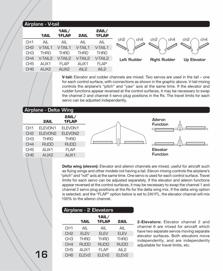
V-tail: Elevator and rudder channels are mixed. Two servos are used in the tail – one
for each control surface, with connections as shown in the graphic above. V-tail mixing
controls the airplane’s “pitch” and “yaw” axis at the same time. If the elevator and
rudder functions appear reversed at the control surfaces, it may be necessary to swap
the channel 2 and channel 4 servo plug positions in the Rx. The travel limits for each
servo can be adjusted independently.
Delta wing (elevon): Elevator and aileron channels are mixed, useful for aircraft such
as fl ying wings and other models not having a tail. Elevon mixing controls the airplane’s
“pitch” and “roll” axis at the same time. One servo is used for each control surface. Travel
limits for each servo can be adjusted separately. If the elevator and aileron functions
appear reversed at the control surfaces, it may be necessary to swap the channel 1 and
channel 2 servo plug positions at the Rx for the delta wing mix. If the delta wing option
is selected, and the “FLAP” option below is set to 2AI1FL, the elevator channel will mix
100% to the aileron channel.
2-Elevators: Elevator channel 2 and
channel 6 are mixed for aircraft which
have two separate servos moving separate
elevator surfaces. Both elevators move
independently, and are independently
adjustable for travel limits, etc.
Airplane - V-tail 1AIL/ 2AIL/ 1AIL 1FLAP 2AIL 1FLAP
CH1 AIL AIL AIL AILCH2 V-TAIL1 V-TAIL1 V-TAIL1 V-TAIL1CH3 THRO THRO THRO THROCH4 V-TAIL2 V-TAIL2 V-TAIL2 V-TAIL2CH5 AUX1 FLAP AUX1 FLAPCH6 AUX2 AUX2 AIL2 AIL2
Left Rudder
ch2 ch4 ch2 ch4
Right Rudder
ch2 ch4
Up Elevator
Airplane - Delta Wing 2AIL/ 2AIL 1FLAP
CH1 ELEVON1 ELEVON1CH2 ELEVON2 ELEVON2CH3 THRO THROCH4 RUDD RUDDCH5 AUX1 FLAPCH6 AUX2 AUX1
ElevatorFunction
AileronFunction
Airplane - 2 Elevators 1AIL/ 1AIL 1FLAP 2AIL
CH1 AIL AIL AILCH2 ELEV ELEV ELEVCH3 THRO THRO THROCH4 RUDD RUDD RUDDCH5 AUX1 FLAP AIL2CH6 ELEV2 ELEV2 ELEV2

17
CHANNEL ASSIGNMENTSThis function allows transmitter channels to be re-assigned to different channels before
being sent to the receiver. This can be useful for models having unusual confi gurations
or inaccessible receivers.
Some small electric fl ight models use only elevator, throttle,
and rudder channels (not aileron). Here, it’s often preferred
that the rudder be controlled with the opposite stick (right
stick for Mode 2 confi gurations). Such channel re-assignment
can be done in this screen.
Determine which Tx control input on the left (TXCH) should
control which output channel at the receiver as shown on
the right (OUTPUT). Move the box to the desired input control
on the left. Press ENTER then or to fi nd the output
channel as desired. Press ENTER when fi nished.
WARNINGSWarnings can be set to alert you of undesirable switch or
throttle positions when the radio power switch is fi rst turned
on. For example, if the throttle is at full when you turn on the
radio, you would see and hear an alarm. The alarms shown
can be set to ACT (active) or INH (inhibited).
THRO POS: The warning sounds
when the throttle stick is over 25%.
Clear the alarm by moving the stick
down. NOTE: If you are in heli mode,
and you have an Idle-up programmed,
this alarm will also sound to indicate
that you have an Idle up switch active.
THRO CUT: The warning will sound
when this switch is on. Turn off the
switch to clear the alarm.
THRO HOLD: The warning will sound
when this switch is on. Turn off the
switch to clear the alarm.
CHANNEL ASSIGNMENTSTXCH OUTPUT
CH1 Output1->
CH2 Output2->
CH3 Output3->
CH4 Output4->
WARNING SETTHRO POS:INHTHRO CUT:ACTTHROHOLD:ACT
5.1V>Oxo100E0 2
THR POS.
CONTINUE? YES

18
TRAINERThe process of linking transmitters for training purposes
is explained on page 37. When in training mode with the
TTX660 being used by the teacher, this radio can allow the
teacher to transfer control of all or only certain channels to
the student if desired.
Enter this screen. Press or to select a channel to
set. Press ENTER to toggle the setting. Repeat with other
channels as desired. Setting a channel to SLV means the student will have control of that
channel when the teacher pulls the trainer switch on the master radio. Those channels
which are set to MST will be controlled by the teacher at all times.
The teacher can select which switch will control the training function at the CTRL line
at bottom. The control positions for the trainer switch can also be selected as described
on page 20 (for the Control function). Press ESC to confi rm settings and return to the
MODEL SETUP menu.
TRIM SETTINGThe number of degrees a servo will rotate with each increment
of digital trim defl ection can be adjusted, from very small
up to large steps. Enter this screen, select the channel trim
to adjust ranging from “1” for the smallest steps to “20” for
the largest steps.
This menu is for setting servo control functions for airplane
use. Press ENTER briefl y to access this menu.
SERVO SETEnter this function to adjust any channel’s reversing, sub-
trim, or travel limit setting. The “Reverse” screen will show
fi rst. To move to the “Sub Trim” or “Travel” screen, place the
cursor over “Reverse”, press ENTER and then to fi nd
the desired screen. Press to return to Reverse.
Reverse: Sets the rotational direction
for a channel’s output relative to
the movement of the control stick.
Move the cursor to the channel to
adjust. Set to “NOR” normal or “REV”
reverse. Adjust all reversing settings
before making any other settings
or adjustments in the programming.
T R A I N E R
CTRL:
S L VM S T
1 2 3 4 5 6SF
TRIM SETTING
CH1
CH2
CH3
CH4
:
:
:
:
3
3
3
3
AILE
ELEV
THRO
RUDD
SETTINGS MENU – AIRPLANES
SERVO SETDUAL, EXPOCH5 AND CH6 SETTHROTTLE CURVETHROTTLE CUT
SETTINGS
SERVO SET: Reverse1 NOR2 REV3 NOR4 REV5 NOR
19
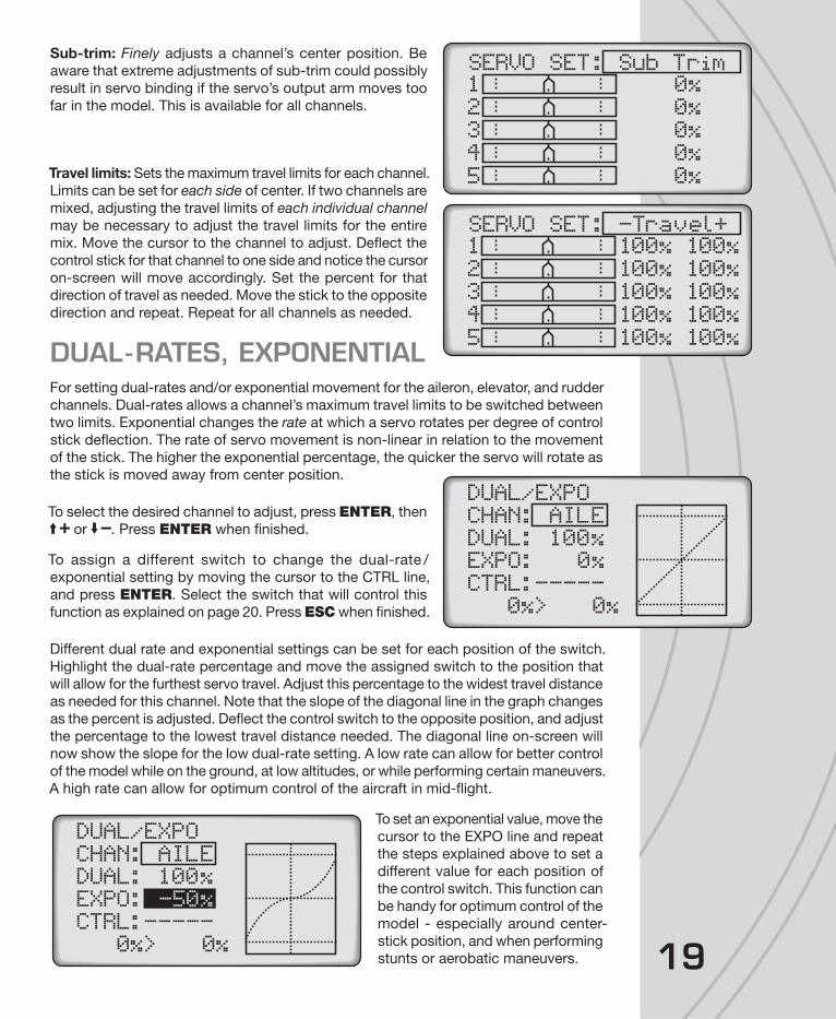
Sub-trim: Finely adjusts a channel’s center position. Be
aware that extreme adjustments of sub-trim could possibly
result in servo binding if the servo’s output arm moves too
far in the model. This is available for all channels.
Travel limits: Sets the maximum travel limits for each channel.
Limits can be set for each side of center. If two channels are
mixed, adjusting the travel limits of each individual channel
may be necessary to adjust the travel limits for the entire
mix. Move the cursor to the channel to adjust. Defl ect the
control stick for that channel to one side and notice the cursor
on-screen will move accordingly. Set the percent for that
direction of travel as needed. Move the stick to the opposite
direction and repeat. Repeat for all channels as needed.
DUAL-RATES, EXPONENTIALFor setting dual-rates and/or exponential movement for the aileron, elevator, and rudder
channels. Dual-rates allows a channel’s maximum travel limits to be switched between
two limits. Exponential changes the rate at which a servo rotates per degree of control
stick defl ection. The rate of servo movement is non-linear in relation to the movement
of the stick. The higher the exponential percentage, the quicker the servo will rotate as
the stick is moved away from center position.
To select the desired channel to adjust, press ENTER, then
or . Press ENTER when fi nished.
To assign a different switch to change the dual-rate /
exponential setting by moving the cursor to the CTRL line,
and press ENTER. Select the switch that will control this
function as explained on page 20. Press ESC when fi nished.
Different dual rate and exponential settings can be set for each position of the switch.
Highlight the dual-rate percentage and move the assigned switch to the position that
will allow for the furthest servo travel. Adjust this percentage to the widest travel distance
as needed for this channel. Note that the slope of the diagonal line in the graph changes
as the percent is adjusted. Defl ect the control switch to the opposite position, and adjust
the percentage to the lowest travel distance needed. The diagonal line on-screen will
now show the slope for the low dual-rate setting. A low rate can allow for better control
of the model while on the ground, at low altitudes, or while performing certain maneuvers.
A high rate can allow for optimum control of the aircraft in mid-fl ight.
To set an exponential value, move the
cursor to the EXPO line and repeat
the steps explained above to set a
different value for each position of
the control switch. This function can
be handy for optimum control of the
model - especially around center-
stick position, and when performing
stunts or aerobatic maneuvers.
SERVO SET: Sub Trim1 0%2 0%3 0%4 0%5 0%
SERVO SET: -Travel+1 100% 100%2 100% 100%3 100% 100%4 100% 100%5 100% 100%
DUAL/EXPOCHAN: AILEDUAL: 100%EXPO: 0%CTRL:-----
0%> 0%
DUAL/EXPOCHAN: AILEDUAL: 100%EXPO: -50%CTRL:-----
0%> 0%
20
Moving the control stick for the channel shown on-screen will change the position of
the vertical line in the graph. The point where the vertical line intersects the diagonal
line is shown at the bottom-left on the screen. The “x” (horizontal) coordinate is on the
left, and “y” (vertical) coordinate is on the right.
Repeat the above steps for the aileron, elevator, and rudder channels as desired.
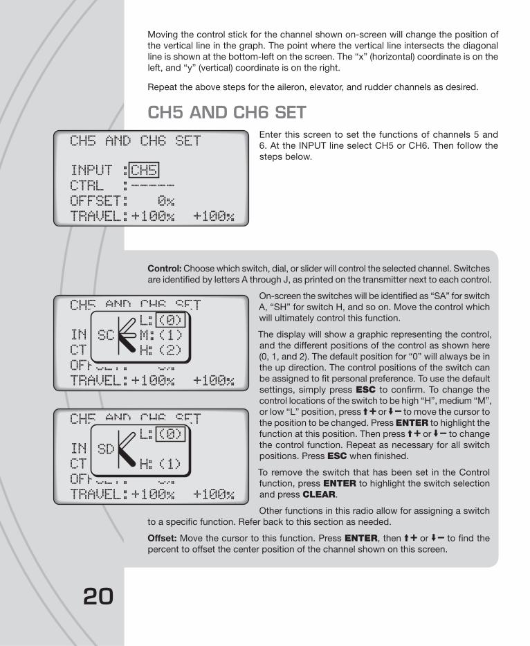
CH5 AND CH6 SETEnter this screen to set the functions of channels 5 and
6. At the INPUT line select CH5 or CH6. Then follow the
steps below.
Control: Choose which switch, dial, or slider will control the selected channel. Switches
are identifi ed by letters A through J, as printed on the transmitter next to each control.
On-screen the switches will be identifi ed as “SA” for switch
A, “SH” for switch H, and so on. Move the control which
will ultimately control this function.
The display will show a graphic representing the control,
and the different positions of the control as shown here
(0, 1, and 2). The default position for “0” will always be in
the up direction. The control positions of the switch can
be assigned to fi t personal preference. To use the default
settings, simply press ESC to confi rm. To change the
control locations of the switch to be high “H”, medium “M”,
or low “L” position, press or to move the cursor to
the position to be changed. Press ENTER to highlight the
function at this position. Then press or to change
the control function. Repeat as necessary for all switch
positions. Press ESC when fi nished.
To remove the switch that has been set in the Control
function, press ENTER to highlight the switch selection
and press CLEAR.
Other functions in this radio allow for assigning a switch
to a specifi c function. Refer back to this section as needed.
Offset: Move the cursor to this function. Press ENTER, then or to fi nd the
percent to offset the center position of the channel shown on this screen.
CH5 AND CH6 SET
INPUT :CH5
CTRL :-----
OFFSET: 0%
TRAVEL:+100% +100%
CH5 AND CH6 SET
INPUT :CH5
CTRL :
OFFSET: 0%
TRAVEL:+100% +100%
L:(0)
M:(1)SC
H:(2)
CH5 AND CH6 SET
INPUT :CH5
CTRL :
OFFSET: 0%
TRAVEL:+100% +100%
L:(0)
SD
H:(1)

21
Travel: To adjust the travel limits for a selected channel, defl ect the switch to one
position and adjust the maximum travel limit for this switch position, and then repeat
for the opposite switch position. Highlight either and press CLEAR to change back
to the default setting. Press ENTER when fi nished.
While the output channel is being operated normally, any movement of the input
channel will be mixed to – and also affect the movement of – the output channel.
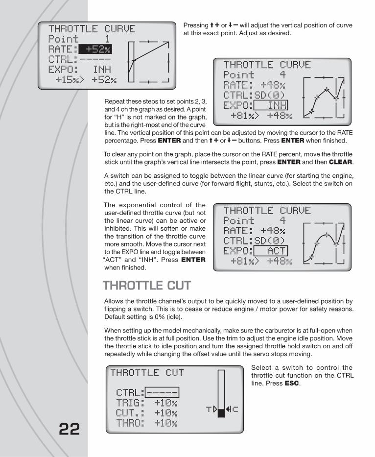
THROTTLE CURVEThe throttle’s output is normally linear in relation to movement
of the throttle stick. A non-linear relation between the two
– or curve - can allow for optimum power control in certain
models or for specifi c types of fl ying styles.
Make sure the model’s full throttle position can be achieved
when the throttle stick is at maximum defl ection. The throttle
trim must be able to minimize throttle control completely when the throttle is at minimum.
Enter this function. Up to six points can be placed on the throttle curve, as designated
next to “Point” on the graph. Points L (low) and H (high) are each limited to a fi xed range
on the curve. Points 1, 2, 3, and 4 can be set if desired with respect to the position of
the throttle stick.
As the throttle stick is advanced note the point where the vertical line (throttle position)
intersects the diagonal line (curve). The coordinates of this point are shown at the bottom.
The “x” (horizontal) coordinate is on the left, and the “y” (vertical) coordinate on the right.
To set points on the curve, start at the minimum throttle position which will be noted as
point “L”. A point for “L” is not marked on the graph, but is the left-most end of the
curve line. The vertical position of this point can be adjusted by moving the cursor to
the RATE percentage. Press ENTER and then or as desired. Press ENTER
when fi nished.
To set point 1 on the graph, advance
the throttle stick until * shows next
to “Point”. Find the desired throttle
stick position and press ENTER. A
+ symbol will be placed on the curve
to mark this point.
THROTTLE CURVEPoint LRATE: 0%CTRL:-----EXPO: INH
0%> 0%
THROTTLE CURVEPoint LRATE: 0%CTRL:-----EXPO: INH+12%> +12%
THROTTLE CURVEPoint LRATE: +24%CTRL:-----EXPO: INH+12%> +33%
THROTTLE CURVEPoint 1RATE: +35%CTRL:-----EXPO: INH+15%> +35%
22
Pressing or will adjust the vertical position of curve
at this exact point. Adjust as desired.
Repeat these steps to set points 2, 3,
and 4 on the graph as desired. A point
for “H” is not marked on the graph,
but is the right-most end of the curve
line. The vertical position of this point can be adjusted by moving the cursor to the RATE
percentage. Press ENTER and then or buttons. Press ENTER when fi nished.
To clear any point on the graph, place the cursor on the RATE percent, move the throttle
stick until the graph’s vertical line intersects the point, press ENTER and then CLEAR.
A switch can be assigned to toggle between the linear curve (for starting the engine,
etc.) and the user-defi ned curve (for forward fl ight, stunts, etc.). Select the switch on
the CTRL line.
The exponential control of the
user-defi ned throttle curve (but not
the linear curve) can be active or
inhibited. This will soften or make
the transition of the throttle curve
more smooth. Move the cursor next
to the EXPO line and toggle between
“ACT” and “INH”. Press ENTER
when fi nished.
THROTTLE CUTAllows the throttle channel’s output to be quickly moved to a user-defi ned position by
fl ipping a switch. This is to cease or reduce engine / motor power for safety reasons.
Default setting is 0% (idle).
When setting up the model mechanically, make sure the carburetor is at full-open when
the throttle stick is at full position. Use the trim to adjust the engine idle position. Move
the throttle stick to idle position and turn the assigned throttle hold switch on and off
repeatedly while changing the offset value until the servo stops moving.
Select a switch to control the
throttle cut function on the CTRL
line. Press ESC.
THROTTLE CURVEPoint 1RATE: +52%CTRL:-----EXPO: INH+15%> +52%
THROTTLE CURVEPoint 4RATE: +48%CTRL:SD(0)EXPO: INH+81%> +48%
THROTTLE CURVEPoint 4RATE: +48%CTRL:SD(0)EXPO: ACT+81%> +48%
THROTTLE CUT
::::
CTRLTRIGCUT.THRO
-----+10%+10%+10%
T C

23
The throttle cut function will only work when the throttle
stick position is below the trig point. To set this point, move
the cursor next to TRIG but do not press ENTER. Move
the throttle stick to the desired position that will trigger
the throttle channel to move to the cutoff position. The
graph will move accordingly as will the percent shown on
the THRO line at bottom. Press ENTER. The arrow on the
left will now move and mark this selected trigger position.
Move the cursor to the CUT
percentage, press ENTER and
adjust this cutoff value by pressing
and to the desired position for
the throttle channel’s output to move
to when the throttle cut function
is activated. This position will be
marked by the arrow on the right.
Press ENTER to confi rm this mark.
When the throttle cut switch is in the ON position and the throttle stick is positioned
above the trigger mark, reducing the throttle stick to the trigger mark will automatically
drop the throttle channel to the throttle cutoff mark. The throttle channel will remain in
this position. To regain full control of the throttle channel, move the control switch to
the OFF position.
NOTE: The method for setting the various following mixer screens is the same
for each mixer. Refer to the instructions for the DIFFERENTIAL mixer screen for
adjustment of all other mixer screens. Any difference in any one mixer screen will
be noted accordingly. Normal wing mixing is the factory default setting. Depending on
the mixes used and setup of the aircraft, it might be necessary to change the setting of
the aileron, elevator, or rudder reversing settings to achieve the proper throw directions
for the model.
AILERON DIFFERENTIALOnly available when 2AI and 2AI1FL wing types are selected, to help offset unwanted
yaw which can occur when ailerons are moved. One servo must be connected to
each aileron for this mix. Instead of equal linear movement between both ailerons, a
differential percentage can be assigned so that the defl ection of one aileron is at a lower
or higher rate than the opposite aileron. Certain applications may require a reduction in
the aileron differential rate when an airbrake is applied. This feature is useful for glider
and/or sailplane applications which use other settings to achieve “butterfl y” or “crow”
functionality.
Enter the DIFFERENTIAL function. There are two ways to control the mix. One is to
make the mix be active at all times. Another is to control the mix with an otherwise
unused switch.
THROTTLE CUT
::::
CTRLTRIGCUT.THRO
SB
+67%+10%+67%
T
C
THROTTLE CUT
::::
CTRLTRIGCUT.THRO
SB
+67%+33%+20%
T
C
24
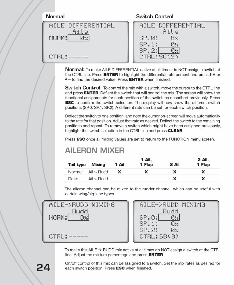
Normal: To make AILE DIFFERENTIAL active at all times do NOT assign a switch at
the CTRL line. Press ENTER to highlight the differential rate percent and press or
to fi nd the desired value. Press ENTER when fi nished.
Switch Control: To control the mix with a switch, move the cursor to the CTRL line
and press ENTER. Defl ect the switch that will control the mix. The screen will show the
functional assignments for each position of the switch as described previously. Press
ESC to confi rm the switch selection. The display will now show the different switch
positions (SP.0, SP.1, SP.2). A different rate can be set for each switch position.
Defl ect the switch to one position, and note the cursor on-screen will move automatically
to the rate for that position. Adjust that rate as desired. Defl ect the switch to the remaining
positions and repeat. To remove a switch which might have been assigned previously,
highlight the switch selection in the CTRL line and press CLEAR.
Press ESC once all mixing values are set to return to the FUNCTION menu screen.
AILERON MIXER
Normal Ail > Rudd X X X X
Delta Ail > Rudd X X
1 Ail, 2 Ail,Tail type Mixing 1 Ail 1 Flap 2 Ail 1 Flap
The aileron channel can be mixed to the rudder channel, which can be useful with
certain wing/airplane types.
To make this AILE RUDD mix active at all times do NOT assign a switch at the CTRL
line. Adjust the mixture percentage and press ENTER.
On/off control of this mix can be assigned to a switch. Set the mix rates as desired for
each switch position. Press ESC when fi nished.
AILE DIFFERENTIALAile
NORM: 0%
CTRL:_____
AILE DIFFERENTIALAile
SP.0: 0%SP.1: 0%SP.2: 0%CTRL:SC(2)
Normal Switch Control
AILE->RUDD MIXINGRudd
NORM: 0%
CTRL:-----
AILE->RUDD MIXINGRudd
SP.0: 0%SP.1: 0%SP.2: 0%CTRL:SB(0)

25
RUDDER MIXINGMixing the rudder channel to the aileron and/or elevator channels can be very useful
for trimming an airplane to be neutral when using the rudder.
Select the rudder channel to mix to the aileron or elevator channels as needed. This
mix can be active at all times by not selecting a switch on the CTRL line. Or, for on/off
control of this mix select a control switch at the bottom of the screen.
FLAP MIXER
Normal Flap > Ail X Flap > Ele X X Flap > Flap X
Delta Flap > Ail Flap > Flap X
1 Ail, 2 Ail,Tail type Mixing 1 Ail 1 Flap 2 Ail 1 Flap
This function allows fl aps to be set, adjusted, and mixed to the ailerons and/or elevator
channels. Mixes such as fl aperons, air brake, and spoilers can be achieved in the
FLAPMIXER. These settings or mixes can be assigned and activated by a two or three
position switch. Not available for 1AI or 2AI wing types. Different setup options are
available depending on the selected wing type, where the fl aps can be mixed to the
aileron, elevator, or back to the fl aps.
Normal Switch Control
RUDD->AILE MIXINGAile Elev
NORM: 0% 0%
CTRL:-----
RUDD->AILE MIXINGAile Elev
SP.0: 0% 0%SP.1: 0% 0%SP.2: 0% 0%CTRL:SE(0)
RUDD->ELEV MIXINGAile Elev
SP.0: 0% 0%SP.1: 0% 0%SP.2: 0% 0%CTRL:SE(1)
26
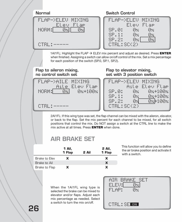
1AI1FL: Highlight the FLAP ELEV mix percent and adjust as desired. Press ENTER
when fi nished. Assigning a switch can allow on/off control of the mix. Set a mix percentage
for each position of the switch (SP.0, SP.1, SP.2).
2AI1FL: If this wing type was set, the fl ap channel can be mixed with the aileron, elevator,
or back to the fl ap. Set the mix percent for each channel to be mixed, for all switch
positions that control the mix. Do NOT assign a switch at the CTRL line to make the
mix active at all times. Press ENTER when done.
AIR BRAKE SETThis function will allow you to defi ne
the air brake position and activate it
with a switch.
When the 1AI1FL wing type is
selected the brake can be mixed to
elevator and/or fl aps. Adjust each
mix percentage as needed. Select
a switch to turn the mix on/off.
Normal Switch Control
FLAP->ELEV MIXING
CTRL:-----
FLAP->ELEV MIXINGElev Flap
NORM: 0% 0%Elev Flap
SP.0: 0% 0%SP.1: 0% 0%SP.2: 0% 0%CTRL:SC(2)
Flap to aileron mixing,no control switch set
Flap to elevator mixing,set with 3 position switch
FLAP->AILE MIXINGAile Elev Flap
NORM: 0% 0%+100%
CTRL:-----
FLAP->ELEV MIXINGAile Elev Flap
SP.0: 0% 0%+100%SP.1: 0% 0%+100%SP.2: 0% 0%+100%CTRL:SC(2)
1 Ail, 2 Ail, 1 Flap 2 Ail 1 Flap
Brake to Elev X XBrake to Ail XBrake to Flap X X
AIR BRAKE SET
ELEV: 0%FLAP: 0%
CTRL:SE

27
When the 2AI wing type is selected the brake can be mixed
to elevator and/or aileron. Adjust each mix percentage as
needed. Select a switch to turn the mix on/off.
When the 2AIL1FL wing type is
selected the brake can be mixed
with the elevator, aileron, or fl aps.
Adjust each mix percentage as
needed. Select a switch to turn the
mix on/off.
PROGRAMMABLE MIXERUp to four programmable mixes can be set, with one
channel being mixed to any one or more channels. Control
characteristics from the “input” channel will be passed to the
“output” channel(s), such as travel limits, exponential, etc.
The output channel will still be able to function independently
as if it were not mixed with another channel, but once an
adjustment is made to the input channel a resulting change
will be seen on the output channel as well. The mix level
can be adjusted by percent. A switch can be assigned to
turn this mix on/off.
Enter the mixer screen. Move the cursor to select which mix to set and press ENTER.
The top line will show the mix number, with the cursor over
the input channel, and the output channel to the right. Press
ENTER and or to highlight and set the input channel.
The rate of the input channel to mix with the output channel
can be adjusted for each the right and left side of the input
channel’s center position. With the cursor next to RATE L,
set the desired mix percentage. Repeat for RATE R. Note
the curve on the display’s graph will adjust according to the
percentages entered.
The amount of the input channel to be mixed can be offset by setting a percentage
next to “OFFSET”.
Assign a switch to control the mix in the CTRL line as explained earlier. Repeat the
above procedures for each of the four mixes that are to be confi gured.
AIR BRAKE SET
ELEV: 0%AILE: 0%
CTRL:SE
AIR BRAKE SET
ELEV: 0%AILE: 0%FLAP: 0%
CTRL:SE
PROGRAMMABLE MIXERMix1: --->--- --INHMix2: --->--- --INHMix3: --->--- --INHMix4: --->--- --INH
Mix1:--->---
::::
RATE LR
OFFSETCTRL
0%0%0%INH
28
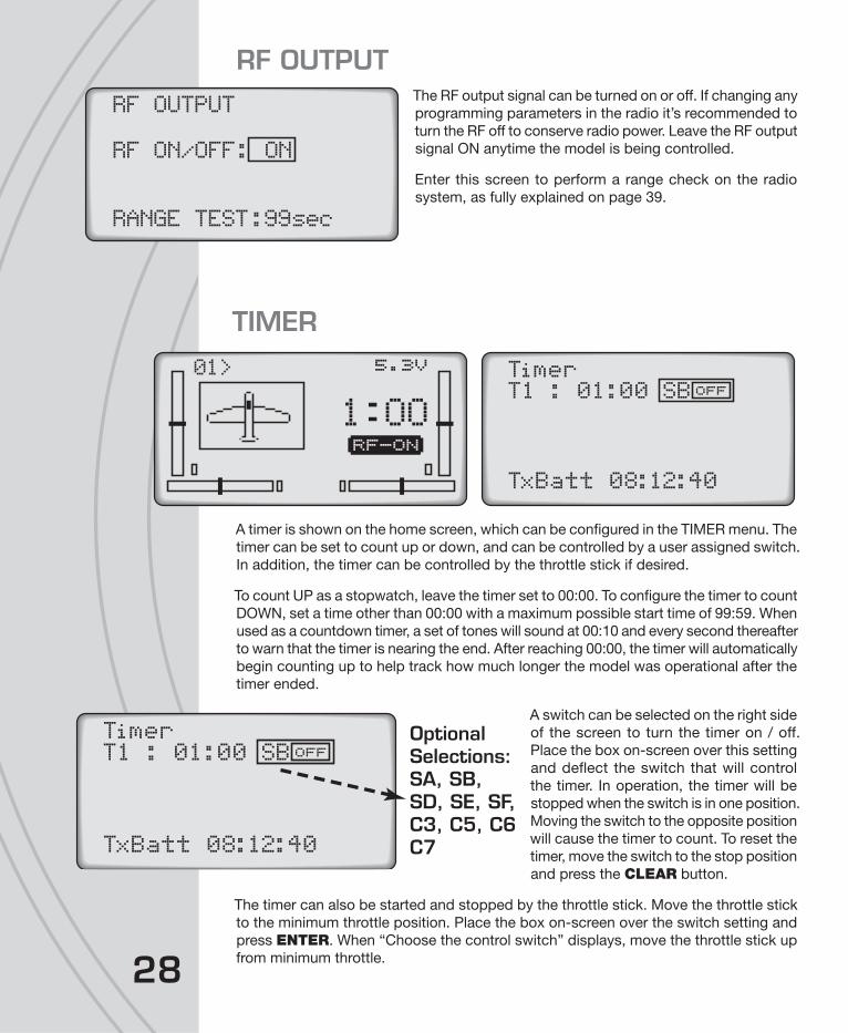
RF OUTPUTThe RF output signal can be turned on or off. If changing any
programming parameters in the radio it’s recommended to
turn the RF off to conserve radio power. Leave the RF output
signal ON anytime the model is being controlled.
Enter this screen to perform a range check on the radio
system, as fully explained on page 39.
TIMER
A timer is shown on the home screen, which can be confi gured in the TIMER menu. The
timer can be set to count up or down, and can be controlled by a user assigned switch.
In addition, the timer can be controlled by the throttle stick if desired.
To count UP as a stopwatch, leave the timer set to 00:00. To confi gure the timer to count
DOWN, set a time other than 00:00 with a maximum possible start time of 99:59. When
used as a countdown timer, a set of tones will sound at 00:10 and every second thereafter
to warn that the timer is nearing the end. After reaching 00:00, the timer will automatically
begin counting up to help track how much longer the model was operational after the
timer ended.
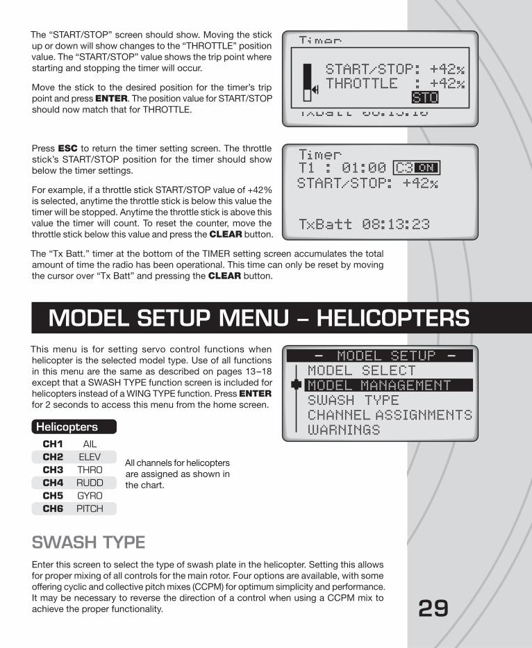
A switch can be selected on the right side
of the screen to turn the timer on / off.
Place the box on-screen over this setting
and defl ect the switch that will control
the timer. In operation, the timer will be
stopped when the switch is in one position.
Moving the switch to the opposite position
will cause the timer to count. To reset the
timer, move the switch to the stop position
and press the CLEAR button.
The timer can also be started and stopped by the throttle stick. Move the throttle stick
to the minimum throttle position. Place the box on-screen over the switch setting and
press ENTER. When “Choose the control switch” displays, move the throttle stick up
from minimum throttle.
RF OUTPUT
RF ON/OFF: ON
RANGE TEST:99sec
Timer:T1 01:00
TxBatt 08:12:40
SBOFF>0 1 5.3V
1 OORF-ON
29
The “START/STOP” screen should show. Moving the stick
up or down will show changes to the “THROTTLE” position
value. The “START/STOP” value shows the trip point where
starting and stopping the timer will occur.
Move the stick to the desired position for the timer’s trip
point and press ENTER. The position value for START/STOP
should now match that for THROTTLE.
Press ESC to return the timer setting screen. The throttle
stick’s START/STOP position for the timer should show
below the timer settings.
For example, if a throttle stick START/STOP value of +42%
is selected, anytime the throttle stick is below this value the
timer will be stopped. Anytime the throttle stick is above this
value the timer will count. To reset the counter, move the
throttle stick below this value and press the CLEAR button.
The “Tx Batt.” timer at the bottom of the TIMER setting screen accumulates the total
amount of time the radio has been operational. This time can only be reset by moving
the cursor over “Tx Batt” and pressing the CLEAR button.
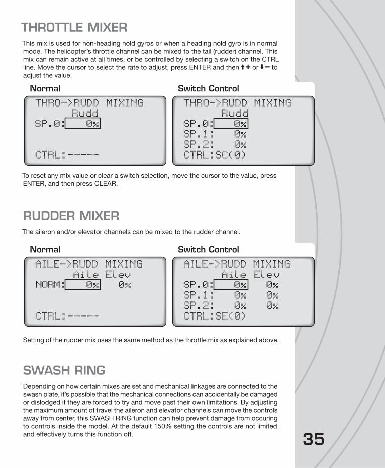
This menu is for setting servo control functions when
helicopter is the selected model type. Use of all functions
in this menu are the same as described on pages 13–18
except that a SWASH TYPE function screen is included for
helicopters instead of a WING TYPE function. Press ENTER
for 2 seconds to access this menu from the home screen.
All channels for helicopters
are assigned as shown in
the chart.
SWASH TYPEEnter this screen to select the type of swash plate in the helicopter. Setting this allows
for proper mixing of all controls for the main rotor. Four options are available, with some
offering cyclic and collective pitch mixes (CCPM) for optimum simplicity and performance.
It may be necessary to reverse the direction of a control when using a CCPM mix to
achieve the proper functionality.
Timer
TxBatt 08:13:10
START/STOP: +42%THROTTLE : +42%
STO
Timer
TxBatt 08:13:23
:T1
START/STOP: +42%
01:00 C3
MODEL SETUP MENU – HELICOPTERS
MODEL SELECTMODEL MANAGEMENTSWASH TYPECHANNEL ASSIGNMENTSWARNINGS
MODEL SETUP
HelicoptersCH1 AILCH2 ELEVCH3 THROCH4 RUDDCH5 GYROCH6 PITCH

30
1 Servo: Tilting of the swash plate is accomplished with
one servo for control of the elevator axis and one servo for
the aileron axis. Another servo directly controls collective
pitch. Selecting this swash type means that no swash
plate mixers are required or used. This is typically used
for fl ybarless systems.
2Sv(180): For CCPM with servos (aileron and pitch) connected
to the swash plate (180 degrees apart). Control of the elev-
axis happens as a result of a mechanical de-coupling rocker.
Through this pre-set mix, throttle (pitch) stick movement
causes both servos to move the plate up and down. Aileron
stick movement causes both servos to tilt the plate side-
to-side.
3Sv(120): For CCPM with three
servos connected to the symmetrical
swash plate at 120º angles from
each other. One pitch servo, one
elevator servo, and one aileron servo
are connected to the swash plate.
3Sv(140): “3-servo (140°)” for CCPM with three servos
connected to the swash plate. The connections are similar
to the 3Sv(120) but with slightly different geometry (two
servos are connected at 140º angles forward from the rear
of the swash plate).
Functions for helicopters are available to support models
with various fi xed mixes, programmable mix options, and
swash types. Press ENTER briefl y to access this menu.
SERVO SET, DUAL-RATES, EXPONENTIAL, RF OUTPUT, and TIMER
Setting of the SERVO SET, DUAL-RATES, EXPONENTIAL, RF OUTPUT, and
TIMER functions is the same as described for airplanes on pages 18–29. However,
SWASH TYPE
1 Servo
SWASH TYPE
2Sv(180)
SWASH TYPE
3Sv(120)
SWASH TYPE
3Sv(140)
SETTINGS MENU – HELICOPTERS
SERVO SETDUAL, EXPO
SETTINGS
CH5 AND CH6 SETTHROTTLE CUTTHROTTLE HOLD

31
if using a helicopter which has CCPM mixing, read the SWASH TYPE section on the
previous page before adjusting the reversing and travel limits settings.
THROTTLE CUTAllows the throttle channel’s output to be quickly moved to a user-defi ned position by
fl ipping a switch. This is to reduce engine / motor power for safety reasons.
When setting up the model mechanically, make sure the carburetor is at full-open when
the throttle stick is at full position. Use the trim to adjust the engine idle position. Move
the throttle stick to idle position and turn the assigned throttle hold switch on and off
repeatedly while changing the offset value until the servo stops moving.
Select a switch to control the throttle cut function on the
CTRL line. Press ESC.
The throttle cut function will only work
when the throttle stick position is
below the trig point. To set this point,
move the cursor next to TRIG but do not press ENTER. Move the throttle stick to the
desired position that will trigger the throttle channel to move to the cutoff position. The
graph will move accordingly as will the percent shown on the THRO line at bottom. Press
ENTER. The arrow on the left will now move and mark this selected trigger position.
Move the cursor to the CUT percentage, press ENTER
and adjust this cutoff value by pressing and to the
desired position for the throttle channel’s output to move
to when the throttle cut function is activated. This position
will be marked by the arrow on the right. Press ENTER to
confi rm this mark.
When the throttle cut switch is in the ON position and the
throttle stick is positioned above the trigger mark, reducing
the throttle stick to the trigger mark will automatically drop the
throttle channel to the throttle cutoff mark. The throttle channel will remain in this position.
To regain full control of the throttle channel, move the control switch to the OFF position.
THROTTLE HOLDThrottle hold allows full use of collective pitch while setting
the throttle at a user pre-determined position. This function
is often used for autorotation. The pilot can then release the
hold and regain full control of the throttle as needed.
The “CTRL” line is for setting the ability to turn this function
ON/OFF with a switch. Selecting “INH” inhibits this function
from operating.
THROTTLE CUT
::::
CTRLTRIGCUT.THRO
-----+10%+10%+10%
T CTHROTTLE CUT
::::
CTRLTRIGCUT.THRO
SB
+67%+10%+67%
T
C
THROTTLE CUT
::::
CTRLTRIGCUT.THRO
SB
+67%+33%+20%
T
C
THROTTLE HOLD
::
POS CTRL
+10%SH

32
To select a switch to turn throttle hold on or off during fl ight, set the Control fi eld to ON.
With the cursor next to CTRL, defl ect the switch that will control throttle hold. In one
position the control will be ON. Moving the switch to the opposition will turn the control OFF.
Move the cursor next to “Position” and set a percent of full throttle that the throttle
channel will defl ect to automatically when the control switch is moved to the ON position.
THROTTLE CURVEThe throttle’s output is normally linear in relation to movement
of the throttle stick. A non-linear relation between the
movement of the throttle stick and the throttle in the model
can allow for optimum control of power to the model (which
is also linked to the control of the pitch of the main rotor
blades). These non-linear control curves can be customized
for the particular model.
The idle-up function is used to optimize the throttle position
for all fl ight envelopes including aerobatic fl ight. Typically,
switch E is used as the idle-up control switch. This switch incorporates one “normal”
and two “up” functions within the three positions of the switch.
Position 1 = normal: Used for startup, take-off, landing, and typical fl ight profi les.
Position 2 = idle-up 1: Used for aerobatic fl ight
Position 3 = idle-up 2: Typically used as a secondary setup for aerobatic fl ight.
Make sure all mechanical linkages are connected exactly
as specifi ed in the helicopter’s instruction manual. Make
sure the model’s full throttle position can be achieved when
the throttle stick is at maximum defl ection. The throttle trim
must be able to minimize throttle control completely when
the throttle limiter is at idle position.
Enter this function. Up to four points can be placed on the
throttle curve, as designated next to “Point” on the graph.
Points L (low) and H (high) are each limited to a fi xed range
on the curve. Points 1, 2, 3, and 4 can be set if desired with
respect to the position of the throttle stick.
As the throttle stick is advanced
note the point where the vertical
line (throttle position) intersects
the diagonal line (curve). The
coordinates of this point are shown
at the bottom. The “x” (horizontal)
coordinate is on the left, and the
“y” (vertical) coordinate on the right.
THROTTLE CURVEPoint LRATE: 0%CTRL:-----EXPO: INH
0%> 0%
THROTTLE CURVEPoint LRATE: 0%CTRL:-----EXPO: INH+12%> +12%
THROTTLE CURVEPoint LRATE: +24%CTRL:-----EXPO: INH+12%> +33%
THROTTLE CURVEPoint 1RATE: +35%CTRL:-----EXPO: INH+15%> +35%

33
To set points on the curve, start at the minimum throttle
position which will be noted as point “L”. A point for “L” is
not marked on the graph, but is the left-most end of the curve
line. The vertical position of this point can be adjusted by
moving the cursor to the RATE percentage, pressing ENTER
and then or as desired. Press ENTER when fi nished.
To set point 1 on the graph, advance the throttle stick until *
shows next to “Point”. Find the desired throttle stick position
and press ENTER. A + symbol will be placed on the curve
to mark this point.
Pressing or will adjust the vertical position of curve at this exact point. Adjust
as desired.
Repeat these steps to set points 2, 3, and 4 on the graph as
desired. A point for “H” is not marked on the graph, but is
the right-most end of the curve line. The vertical position of
this point can be adjusted by moving the cursor to the RATE
percentage, pressing ENTER and then or buttons.
Press ENTER when fi nished.
To clear any point on the graph, place the cursor on the RATE
percent, move the throttle stick until the graph’s vertical line
intersects the point, press ENTER and then CLEAR.
Any switch can be assigned to toggle between curves (Normal / Idle Up / Idle Up 2).
Select the switch on the CTRL line.
The exponential control of the user-defi ned throttle curve can
be active or inhibited. This will soften or make the transition
of the throttle curve smoother. Move the cursor next to the
EXPO line and toggle between “ACT” and “INH”. Press
ENTER when fi nished.
PITCH CURVEThe method for setting the pitch
curve is the same as for the throttle
curve as explained above, by
moving the throttle stick and using
the same controls within the pitch
curve screen.
THROTTLE CURVEPoint 1RATE: +52%CTRL:-----EXPO: INH+15%> +52%
THROTTLE CURVEPoint 4RATE: +48%CTRL:SD(0)EXPO: INH+81%> +48%
THROTTLE CURVEPoint 4RATE: +48%CTRL:SD(0)EXPO: ACT+81%> +48%
PITCH CURVEPoint LRATE:-100%CTRL:-----EXPO: INH-77%> -77%

34
GYRO MIXERThis function is for setting and adjusting the sensitivity of an optional tail gyro. Enter
this screen.
To make the gyro mixing active at all times do NOT assign a switch at the CTRL line.
Press ENTER to highlight the normal mixing rate, and press or to fi nd the desired
value. Press ENTER when fi nished.
To control the mix with a switch, move the cursor to the CTRL line and press ENTER.
Defl ect the desired switch to control the mix. The screen will show the functional
assignments for each position of the switch (see page 20 for details). Press ESC to
confi rm the switch selection.
The display will now show the different switch positions (SP.0, SP.1, SP.2). A different gyro
mixing rate can be set for each switch position. Defl ect the switch to one position and
note the cursor on-screen will automatically move to the percentage for that position.
Adjust the rate as desired and press ENTER when fi nished. Defl ect the switch to the
remaining positions and repeat.
To clear a switch that was set to control the mix or hold, highlight the switch and press
CLEAR. A positive value equals “Heading Hold” while a negative value equals “Non-
Heading Hold.”
SWASH MIXERThis mix is not available when using
the “1 Servo” swash setting. This
function adjusts the mixture rate
of the pitch, aileron, and elevator
channels for the swash plate. Move
the cursor to the value to adjust, and
change as necessary.
Normal Switch Control
GYRO MIXINGNORM: 0%
CTRL:-----
GYRO MIXINGSP.0: 0%SP.1: 0%SP.2: 0%
CTRL:SE(2)
SWASH MIXINGPitc: +61%
Aile: +61%
Elev: +61%
35
THROTTLE MIXERThis mix is used for non-heading hold gyros or when a heading hold gyro is in normal
mode. The helicopter’s throttle channel can be mixed to the tail (rudder) channel. This
mix can remain active at all times, or be controlled by selecting a switch on the CTRL
line. Move the cursor to select the rate to adjust, press ENTER and then or to
adjust the value.
To reset any mix value or clear a switch selection, move the cursor to the value, press
ENTER, and then press CLEAR.
RUDDER MIXERThe aileron and/or elevator channels can be mixed to the rudder channel.
Setting of the rudder mix uses the same method as the throttle mix as explained above.
SWASH RINGDepending on how certain mixes are set and mechanical linkages are connected to the
swash plate, it’s possible that the mechanical connections can accidentally be damaged
or dislodged if they are forced to try and move past their own limitations. By adjusting
the maximum amount of travel the aileron and elevator channels can move the controls
away from center, this SWASH RING function can help prevent damage from occuring
to controls inside the model. At the default 150% setting the controls are not limited,
and effectively turns this function off.
Normal Switch Control
THRO->RUDD MIXINGRudd
SP.0: 0%
CTRL:-----
THRO->RUDD MIXINGRudd
SP.0: 0%SP.1: 0%SP.2: 0%CTRL:SC(0)
Normal Switch Control
AILE->RUDD MIXINGAile Elev
NORM: 0% 0%
CTRL:-----
AILE->RUDD MIXINGAile Elev
SP.0: 0% 0%SP.1: 0% 0%SP.2: 0% 0%CTRL:SE(0)
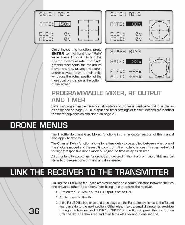
36
Once inside this function, press
ENTER to highlight the “Rate”
value. Press or to fi nd the
desired maximum rate. The circle
graphic represents the maximum
movement rate. Moving the aileron
and/or elevator stick to their limits
will cause the actual position of the
these controls to show at the bottom
of the screen.
PROGRAMMABLE MIXER, RF OUTPUT AND TIMERSetting of programmable mixes for helicopters and drones is identical to that for airplanes,
as described on page 27. RF output and timer settings of these functions are identical
to that for airplanes as explained on page 28.
The Throttle Hold and Gyro Mixing functions in the helicopter section of this manual
also apply to drones.
The Channel Delay function allows for a time delay to be applied between when one of
the sticks is moved and the resulting control in the model changes. This can be helpful
for highly responsive drone models. Adjust the time delay as desired.
All other functions/settings for drones are covered in the airplane menu of this manual.
Refer to those sections of this manual as needed.
Linking the TTX660 to the Tactic receiver ensures sole communication between the two,
and prevents other transmitters from being able to control the receiver.
1. Turn on the Tx. (Make sure RF Output is set to ON.)
2. Apply power to the Rx.
3. If the Rx LED fl ashes once and then stays on, the Rx is already linked to the Tx and
you can skip to the next section. Otherwise, insert a small diameter screwdriver
through the hole marked “LINK” or “BIND” on the Rx and press the pushbutton
until the Rx LED glows red and then turns off after about one second.
SWASH RING
RATE: 150%
ELEV:AILE:
0%0%
SWASH RING
RATE: 88%
ELEV:AILE:
0%0%
SWASH RING
RATE: 88%
ELEV:AILE:
-58%+65%
DRONE MENUS
LINK THE RECEIVER TO THE TRANSMITTER
37
4. Release the “LINK” or “BIND” button.
5. If the linking is successful, the Rx LED will fl ash once and then remain ON.
6. Test for proper Tx/Rx functionality before use. If the radio doesn’t appear to have
become properly linked, repeat steps 1–6 above and move the Tx at least three
feet away from the Rx.
The failsafe function is not controlled by the TTX660 transmitter itself, but rather by
the Tactic receiver. Tactic’s stand-alone 2.4GHz receivers have a failsafe feature which
engages in the event that the signal from the Tx somehow becomes interrupted. In such
a case, channels 1, 2, 4, 5, and 6 (all but CH3 throttle) will hold their last received position.
Throttle channel 3 can move to a pre-set position. The factory default failsafe position
for channel 3 is to move to 0% throttle. The throttle’s failsafe position can be manually
set to any other position if desired, as follows:
1. IMPORTANT: make sure the servo reverse settings for all servos are in the
correct position for the application.
2. Apply power to the Tx and Rx.
3a. If using an ESC: do NOT arm the ESC, or attempt to adjust the throttle’s failsafe
position if the ESC is armed. NOTE: If you’re using an ESC which has a signal
loss feature, its pre-set failsafe position will be irrelevant as the receiver’s failsafe
function will cease the throttle operation if the signal is lost.
3b. If using a combustion engine: do NOT attempt to adjust the throttle’s failsafe
position while the engine is operating.
4. Move the Tx throttle stick to the desired throttle failsafe position.
5. Press and hold the receiver’s “Link” button. The Rx’s LED should blink twice.
Release the Link button, and the LED should stay on continuously. The Tx and Rx
should now be linked, with the throttle failsafe in the new position as set above.
A 3.5 mm female headphone type jack is included for connecting the TTX660 transmitter
to a personal computer for use with fl ight simulators, such as RealFlight™. Refer to the
fl ight simulator product for appropriate adapter cables, proper confi guration and use.
Two Tactic brand transmitters with trainer capabilities can communicate with each
other by wireless means for teaching a student how to fl y (no trainer jack - no cable
required!). The TTX660 can be confi gured for wireless trainer function with any other
Tactic brand transmitter, but is not compatible with wireless trainer systems in other
brand transmitters. Once linked for training, make sure both transmitters are kept within
15 feet of each other at all times.
FAILSAFE FUNCTION
FLIGHT SIMULATOR USE
WIRELESS TRAINER

3838
IMPORTANT! Before fl ying the model in training situations it’s very
important to make sure all channel reverse settings and trim adjustments
on the teacher and student transmitters match! Otherwise, the model
could suddenly veer in an unwanted manner when the teacher’s trainer
switch is activated. Proper matching of the student and teacher’s Tx settings should
ensure that no unexpected movements occur when the trainer switch is pressed. This
is especially true of the throttle control!
Teacher’s radio: TTX660 Student’s radio: Tactic TTX410 or TTX610
1. Link the teacher’s TTX660 to the Rx inside the model, and then remove power
from the Rx.
2. In the TTX660 TRAINER screen described on page 18 select which channels
NOT to transfer to the student while training, and select a switch to control the
trainer function. Switch F is the recommended switch for training purposes.
3. Turn the teacher’s Tx off.
4. Pull the TTX660’s selected
trainer switch and hold it in
this position while turning
the power switch on. The
“searching” message should
show on-screen.
5. Move the student’s transmitter
to within 3 feet of the
teacher’s transmitter and turn
on the TTX410/610 power switch.
6. The TTX660’s “searching”
screen should disappear.
The teacher can release
the trainer switch. If the
TTX660 doesn’t identify the
signal from the student’s
radio a “NO SIGNAL”
message will show.
7. Once linked, move the
throttle stick on both transmitters to minimum. Turn the Rx power on and make
sure only those channels selected for transfer to the student are transferred
when the TTX660 selected trainer switch is defl ected. Ensure the teacher can
regain control of all channels when the selected trainer switch is released.
8. Perform a complete range check before fl ight.
9. When the training session has ended, with the model safely landed and power
removed from the model, simply turn the power switch for both transmitters to
the OFF position. This will terminate the wireless link between both transmitters.
Teacher’s radio: Tactic TTX410/610 Student’s radio: Tactic TTX660
1. Link the teacher’s TTX410/610 to the Rx. Remove power from the model, and
then turn the teacher’s Tx off.
2. Pull the TTX410/610 trainer switch and hold it in this position and turn the power
switch on.
5.0V>Axe100F0 2
O OOO OOSEARCHING
4.9V>Axe100F0 2
O OOO OONO SIGNAL

3. Move the student’s transmitter to within 3 feet of the teacher’s transmitter, turn
the power switch on and set the RF OUTPUT to ON.
4. The TTX410/610 LED should fl ash three times and then stay on to indicate the
bind was complete. Release the trainer switch.
5. Once linked, move the throttle stick on both transmitters to minimum. Turn the
Rx power on and make sure only those channels selected for transfer to the
student are transferred when the TTX660 trainer switch is defl ected. Ensure the
teacher can regain control of all channels when the trainer switch is released.
6. Perform a complete range check before fl ight.
7. When the training session has ended, with the model safely landed and power
removed from the model simply turn the power switch for both transmitters to
the OFF position. This will terminate the wireless link between both transmitters.
Teacher and student’s radio: TTX660
1. Link the teacher’s radio to the Rx.
2. In the teacher’s TRAINER screen described on page 18 select which channels
NOT to transfer to the student while training, and select a switch to control the
training function. Switch F is the recommended switch for training purposes.
Then turn the teacher’s Tx off.
3. Move the student’s transmitter to within 3 feet of the teacher’s transmitter.
4. Pull the teacher’s selected trainer switch and turn the power switch on. The
“searching” message should show on screen.
5. Turn the student’s radio on, and set the RF OUTPUT to ON.
6. The TTX660’s “searching” screen should disappear. The teacher can release the
TTX660 selected trainer switch. If the TTX660 doesn’t identify the signal from
the student’s radio a “NO SIGNAL” message will show.
7. Once linked, move the throttle stick on both transmitters to minimum. Turn the Rx
power on and make sure only those channels selected for transfer to the student are
transferred when the TTX660 selected trainer switch is defl ected. Ensure the teacher
can regain control of all channels when the selected trainer switch is released.
8. Perform a complete range check before fl ight.
9. When the training session has ended, with the model safely landed and power
removed from the model, simply turn the power switch for both transmitters to
the OFF position. This will terminate the wireless link between both transmitters.
Before each fl ight make sure to check the operating range
of the Tx / Rx set. The TTX660 includes a function that
automatically reduces its output power to prevent having
to walk a long distance to check the range.
1. Make sure the Tx throttle stick is at minimum position.
2. Enter the “RF OUTPUT” screen in the FUNCTION
menu, as described on page 28. Leave the “RF ON/
OFF” selection ON.
RANGE TEST
RF OUTPUT
RF ON/OFF: ON
RANGE TEST:99sec
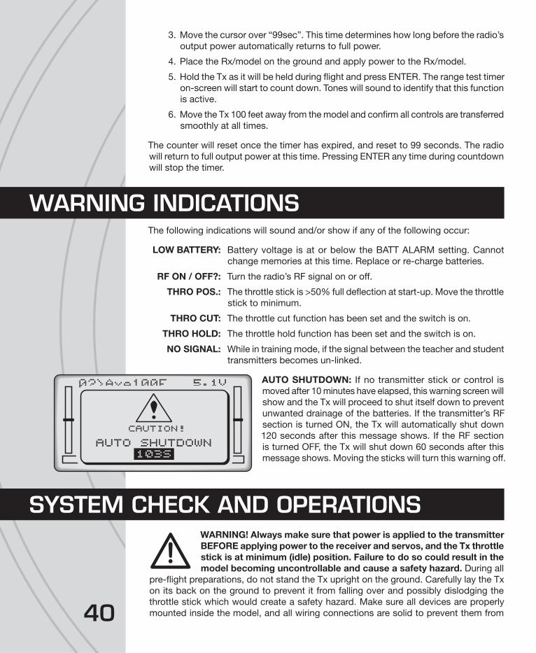
40
3. Move the cursor over “99sec”. This time determines how long before the radio’s
output power automatically returns to full power.
4. Place the Rx/model on the ground and apply power to the Rx/model.
5. Hold the Tx as it will be held during fl ight and press ENTER. The range test timer
on-screen will start to count down. Tones will sound to identify that this function
is active.
6. Move the Tx 100 feet away from the model and confi rm all controls are transferred
smoothly at all times.
The counter will reset once the timer has expired, and reset to 99 seconds. The radio
will return to full output power at this time. Pressing ENTER any time during countdown
will stop the timer.
The following indications will sound and/or show if any of the following occur:
LOW BATTERY: Battery voltage is at or below the BATT ALARM setting. Cannot
change memories at this time. Replace or re-charge batteries.
RF ON / OFF?: Turn the radio’s RF signal on or off.
THRO POS.: The throttle stick is >50% full defl ection at start-up. Move the throttle
stick to minimum.
THRO CUT: The throttle cut function has been set and the switch is on.
THRO HOLD: The throttle hold function has been set and the switch is on.
NO SIGNAL: While in training mode, if the signal between the teacher and student
transmitters becomes un-linked.
AUTO SHUTDOWN: If no transmitter stick or control is
moved after 10 minutes have elapsed, this warning screen will
show and the Tx will proceed to shut itself down to prevent
unwanted drainage of the batteries. If the transmitter’s RF
section is turned ON, the Tx will automatically shut down
120 seconds after this message shows. If the RF section
is turned OFF, the Tx will shut down 60 seconds after this
message shows. Moving the sticks will turn this warning off.
WARNING! Always make sure that power is applied to the transmitter
BEFORE applying power to the receiver and servos, and the Tx throttle
stick is at minimum (idle) position. Failure to do so could result in the
model becoming uncontrollable and cause a safety hazard. During all
pre-fl ight preparations, do not stand the Tx upright on the ground. Carefully lay the Tx
on its back on the ground to prevent it from falling over and possibly dislodging the
throttle stick which would create a safety hazard. Make sure all devices are properly
mounted inside the model, and all wiring connections are solid to prevent them from
WARNING INDICATIONS
5.1V>Axe100F0 2
AUTO SHUTDOWN103S
CAUTION!!
SYSTEM CHECK AND OPERATIONS

41
easily becoming dislodged during normal fl ight. It’s best to check the system with the
propeller removed from the aircraft.
1. Once all connections are made, check the general operation of the radio and
all other components before attempting a fl ight.
2. Move the Tx throttle stick to the minimum (idle) position.
3. Turn on the Tx, and then the Rx.
4. Make sure all controls are operating in the proper direction. If any servo is turning
in the wrong direction, change the reverse setting for that channel.
5. With both sticks at center position, move the trim levers for the aileron, elevator,
and rudder channels so each respective control surface is perfectly aligned with
the main surface. For example: when the aileron trim lever is at center, it’s best
that the trailing edge of the aileron is aligned with the trailing edge of the wing
itself (not above or below the wing’s trailing edge).
6. Make sure that movements of the throttle stick result in an equal adjustment of
the throttle in the model. Depending on whether the model is electric or glow
powered:
a. Electric: confi rm that when the throttle stick is at maximum position the electronic
speed control gives the appropriate indications (LED and/or audible indicators)
for full forward fl ight. And, when the throttle stick is at minimum position the
electronic speed control gives the appropriate indications for “off” or no motor
rotation.
b. Glow: confi rm that when the throttle stick is at maximum position the mechanical
linkage to the engine allows the engine to be at full throttle. And, when the
throttle stick is at minimum position and the throttle trim lever is moved to
minimum position, the engine stops completely.
7. Perform a range test as explained on page 39.
8. Anytime power is to be removed from the radio system, it’s important to shut
down power in the aircraft fi rst. Otherwise, the aircraft could become out of
control and cause a safety hazard! Move the throttle stick and throttle trim to
minimum position to stop the glow engine or shut down the ESC. Once the
propeller has stopped rotating, shut off the ON/OFF power switch in the model,
and disconnect the power battery from the ESC in electric airplanes. Then turn
off the power switch in the Tx.
1. Once all setup procedures have been confi rmed, and power has been removed
from the model and transmitter, prepare the model for fl ight.
IMPORTANT: Be very careful to stay clear from
moving propellers and blades!!
2. Make sure the glow engine fuel tank has an adequate amount of fuel, or power
batteries for electric models are fully charged.
3. Move the Tx throttle stick to the minimum position, and then turn on the Tx power
switch. Turn on the power switch in the model or connect the fl ight battery.
FLYING THE AIRCRAFT
42
4. During the fi rst fl ight, it might be necessary to re-trim the main channels to allow
the model to sustain smooth, even fl ight. If further adjustments are required on
the ground, make sure to turn off the engine or ESC/motor beforehand.
5. When the fl ight is completed, remove power from the system as described before.
Shut down power to the electronic speed control or glow engine fi rst, then the
receiver, and fi nally the transmitter.
● NEVER allow water or moisture to make contact with the electronic
components inside the transmitter, receiver, servos, switch harness, etc.!
This could lead to failure or improper functionality of components and
poor control of aircraft which could pose a safety hazard.
● NEVER operate R/C model aircraft near power lines, radio or cell phone towers, roads
or automobiles, buildings, or pedestrians. Be very careful in locations where many
R/C aircraft are being used simultaneously.
● NEVER operate R/C equipment if you are physically impaired as it could pose a safety
hazard to yourself or others in the area.
● NEVER allow small children to operate/control model R/C equipment without the
supervision of an adult.
● NEVER allow the transmitter’s throttle stick to accidentally be moved away from the
“off” or minimum position while the model’s engine/motor is moving.
● ALWAYS range check the radio system before use.
● ALWAYS make sure that all transmitter stick movements operate all servos properly
in the model. Check the proper operation of control surfaces before and after starting
the engine/motor.
● ALWAYS make sure the transmitter antenna is unfolded entirely so that it’s pointing
upright to ensure max. range and control of the aircraft.
● Do not store your radio equipment in extremely hot or cold locations, in direct sunlight,
or in locations with high humidity. Store R/C equipment in cool and dry locations.
● Do not allow chemicals to come in contact with any parts of the radio system.
Substances such as glow fuel, gasoline, CA glue, etc. could permanently damage
plastic parts of the radio system.
● If rechargeable batteries were installed in the transmitter, remove the batteries before
placing the radio in long-term storage.
IMPORTANT WARNINGS and PRECAUTIONS

43
Model types: airplane, helicopter, drone
Channels: 6
Frequencies: 2.403 – 2.480GHz
Protocol: Tactic SLT
Modulation: FHSS spread spectrum
Input power: 3.40 - 7.00V DC, four 1.5V alkaline or 1.2V NiCd/NiMH “AA”
single cells. Jack included for connecting optional 4.8V NiCd
or NiMH pack
Current consumption: approx. 100-120mA
Low voltage alarm: 3.20 - 5.60V adjustable
Memories: 30, with copy function
Stick modes: two
Trims: digital for aileron, elevator, throttle, rudder
Switch assignments: user selectable
Display: 128 x 64 graphing LCD, with adjustable contrast & blue backlight
Channel controls: reversing, end points, sub-trims, dual-rates, exponential
Timers: count-up stopwatch, count-down, fl ight timer
Trainer system: wireless, Tactic SLT compatible
RANGE IS SHORT: Interference – check Rx installation and servo connections. Low Tx
or Rx battery – replace the batteries or recharge if applicable. Transmitter antenna not
unfolded properly. Rx may need to be located to a different position in the model for
better reception. Crash damage – send the radio to Hobby Services for repair.
RUN TIME IS SHORT: Low Tx or Rx batteries – replace or recharge the batteries.
Obstructed servo linkages causing excess battery drain – free the linkages / pushrods.
Tx POWER SWITCH ON BUT SERVOS DO NOT FUNCTION: Tx or Rx batteries are
low – replace or recharge the batteries. Tx RF output is set to “OFF” – change to “ON”.
Rx switch is in the off position – turn on the ESC or switch harness. Switch harness or
ESC is connected incorrectly – check all connections and the ESC instruction manual.
Rx is not linked to the Tx properly – perform binding process again. Check Tx or Rx
battery polarity.
INTERFERENCE OR SERVOS GLITCHING: Out of range – operate the model more
closely to the transmitter. Outside radio interference from other electronic devices in
the area - check your local R/C club regarding local operation. Rx/antennas located
too closely to engine, motor, or servos or other moving mechanical parts which might
be creating unwanted electrical noise – relocate the Rx inside the model or relocate the
ESC. Align both Rx antennas at 90 degree angles from each other if possible/applicable.
CONTROL SURFACE MOVES IN THE WRONG DIRECTION: Reverse the control
direction of the channel in the radio’s programming.
ONLY ONE SERVO GLITCHES: Servo is bad – replace the servo or send to Hobby
Services for repair.
TTX660 SPECIFICATIONS
TROUBLESHOOTING

44
FAILSAFE NOT WORKING CORRECTLY: Receiver is not properly linked to the
transmitter – bind the Rx to the Tx and re-try. Check the channels which are programmed
for transferring from Tx to Rx in the transmitter’s programming. Contact Hobby Services
for further details.
WIRELESS TRAINING FUNCTION NOT BINDING: Check to see that another Tactic
2.4GHz system is not on in your area. The teacher’s and student’s transmitters were
not powered in the proper sequence or are positioned too far from each other. Carefully
follow the instructions on pages 37–39 for proper binding and operation for training.
RECHARGEABLE BATTERIES WON’T ACCEPT CHARGE THROUGH THE
TRANSMITTER: Check the charger for proper setup and operation. Make sure the
charge plug is inserted fully into the charge jack. Make sure the transmitter’s power switch
is in the OFF position. Make sure the cells are inserted inside the battery compartment
in the proper direction.
Contact Hobby Services for other problems.
The Academy of Model Aeronautics (AMA) has established a Membership Manual which
includes a description of the AMA’s function and mission, insurance benefi ts, the Model
Aircraft Safety Code, membership renewal information, and more. Model fl ying MUST
be done in accordance within AMA guidelines in order for AMA liability protection to
apply. See the website listed below, or contact the AMA for further details:
http://www.modelaircraft.org/fi les/Memanual.PDF
Academy of Model Aeronautics (765) 287-1256 – Business
5161 East Memorial Drive (765) 289-4248 – Fax
Muncie, Indiana 47302 (800) 435-9262 – Membership Services
http://www.modelaircraft.org
Practice good safety precautions at all times when fl ying model aircraft. The AMA can
assist in locating authorized local fl ying clubs and fi elds.
The Tactic TTX660 transmitter is intended for use with radio control model hobby
airplanes and helicopters. Use with non-hobby related products for non-hobby related
activities is not recommended or encouraged. Any alterations or modifi cations to any
parts of this product are not recommended. Tactic is not responsible for unauthorized
repairs or modifi cations. All unauthorized repairs will void the warranty.
TACL0624 Tactic TR624 6-Channel 2.4GHz Receiver
TACL0625 Tactic TR625 6Ch 2.4GHz SLT Rx w/Twin Antennas
TACM2001 Tactic Switch Harness with Charge Plug, Futaba J Plugs
TACM2020 4 Cell AA Battery Holder w/Fut J Connector
TACM2090 Servo Extension 6” (150mm) Futaba J
TACM2100 Tactic Adjustable Neck Strap
DTXP4704 Onyx AA Alkaline Battery (4)
HCAM6321 HydriMax™ Ultra 4.8V 2000mah Flat Rx AA NiMH Battery
See www.tacticrc.com for a full list of radio parts and accessories.
SAFETY GUIDE
ACCESSORIES

45
This device complies with part 15 of the FCC rules. Operation is subject to the following
two conditions.
(1) This device may not cause harmful interference.
(2) This device must accept any interference received, including
interference that may cause undesired operation.
FCC Rf Radiated Exposure Statement: The equipment complies with FCC Rf radiation
exposure limits set forth for an uncontrolled environment. This equipment should be
installed and operated with a minimum distance of 20 centimeters between the radiator
and your body.
NOTE: THE MANUFACTURER IS NOT RESPONSIBLE FOR ANY RADIO OR TV
INTERFERENCE CAUSED BY UNAUTHORIZED MODIFICATIONS TO THIS EQUIPMENT.
SUCH MODIFICATIONS COULD VOID THE USER’S AUTHORITY TO OPERATE THE
EQUIPMENT.
FCC ID: IYFTTX650
Instructions for Disposal of Waste Equipment by Private Users in the European Union: This symbol on the product or its packaging
indicates this product must not be disposed of with other household waste.
Instead, it is the user’s responsibility to dispose of their waste equipment by handing it
over to a designated collection point for the recycling of waste electrical and electronic
equipment. The separate collection and recycling of your waste equipment at the time
of disposal will help to conserve natural resources and ensure that it is recycled in a
manner that protects human health and the environment. For more information about
where you can drop off y our waste equipment for recycling, please contact your local
city offi ce, your household waste disposal service or location where you purchased
the product.
Declaration of Conformity:Product: Tactic TTX660 2.4GHz 6-Channel Tx
Item number: TACJ2660
Device class: 1
The objects of the declaration described here are in conformity with the requirements of
the specifi cations listed below, following the provisions of the European RED directive
2014/35/EU Low Voltage Directive:
EN 60950-1:2006
2006+A11:2009+A1:2010+A12:2011+A2:2013
FCC STATEMENT
CE COMPLIANCE FOR THE EU

46
The objects of the declaration described here are in conformity with the requirements of
the specifi cations listed below, following the provisions of the European RED directive
2014/53/EU:
EN 301 489-1 V2.1.1
EN 301 489-17 V2.2.1
EN 300 328 V2.1.1
Tacticc/o Hobbico, Inc.
2904 Research Road
Champaign, IL USA 61826
Tactic warrants this product to be free from defects in materials and workmanship for
a period of one (1) year from the date of purchase. During that period, Tactic will, at its
option, repair or replace without service charge any product deemed defective due to
those causes. You will be required to provide proof of purchase (invoice or receipt). This
warranty does not cover damage caused by abuse, misuse, alteration or accident. If
there is damage stemming from these causes within the stated warranty period, Tactic
will, at its option, repair or replace it for a service charge not greater than 50% of its
then current retail list price. Be sure to include your daytime telephone number in case
we need to contact you about your repair. This warranty gives you specifi c rights. You
may have other rights, which vary from state to state.
For service on your Tactic product, send it postpaid and insured to:
HOBBY SERVICES Tel: (217) 398-0007 (9:00am - 5:00pm CST, M-F)
3002 N. Apollo Dr., Suite 1 E-mail: [email protected]
Champaign, IL 61822
Entire contents © 2017, Hobbico., Inc. Made in China TACJ2660
● This product is suitable only for people of 14 years and older. This is not a toy!
● WARNING: CHOKING HAZARD - May contain small parts. Keep away from children
under 3 years. Please retain packaging for future reference.
● No part of this manual may be reproduced in any form without prior permission.
● The contents of this manual are subject to change without prior notice.
● Tactic is not responsible for the use of this product.
1-YEAR LIMITED WARRANTY

47

© 2017 Tactic® A Hobbico company. TACJ2660