Embed Size (px)
DESCRIPTION
Subsea pipelines buckling problems
Citation preview

Local buckling collapse of marine pipelines
Delft University of TechnologyFaculty of Mechanical, Maritime and Materials Engineering (3mE)Department of Maritime and Transportation Technology (M&TT) Section Offshore and Dredging Engineering
MSc thesisRuud SelkerApril 2013

This page is intentionally left blank.

A thesis submitted in partial fulfilment of therequirements for the degree of
Master of Science
in Offshore and Dredging EngineeringDelft University of Technology
Local buckling collapse of marine pipelines
Ruud Selker
April 10, 2013
Graduation committee
Prof. Dr. A.V. Metrikine Delft University of Technology (chairman)Prof. Dr. Ir. L.J. Sluys Delft University of TechnologyIr. J.S. Hoving Delft University of TechnologyDr. Ir. P. Liu INTECSEA

This page is intentionally left blank.

Abstract
To keep up with the growing demand for oil and gas, the oil and gas industryventures into deeper waters. This increases complexity of offshore projects. Fora deep water pipeline project, South Stream, a pipeline test program has beendeveloped. Part of this program is the investigation of the resistance of a pipelineagainst local buckling collapse due to external pressure. Response to externalpressure is a decisive factor in design of marine pipelines, especially for deepwater applications.
Local buckling of a pipeline is the buckling behaviour within the pipeline’scross section. Other types of buckling behaviour such as upheaval and lateralbuckling are not in the scope of this thesis. Buckling is defined as the state of astructure for which a relatively small increment in load leads to a relatively largeincrement in displacement. Generally this is reflected in a change in deformationshape and possibly a loss of stability.
A perturbation theory, first developed by Koiter [26], is applied to model thisbehaviour. The response of a structure that has initial geometric imperfectionsis obtained by using the response of an initially perfect structure, e.g. a straightbeam, a perfect ring or a cylinder. From the principle of minimum potentialenergy an equilibrium state can be obtained. For a certain load, the bifurcationload, multiple equilibrium configurations are possible. The nature of this equilib-rium state is investigated by expanding the load around this bifurcation load andexpanding the displacement functions around their fundamental solutions, interms of a bifurcation parameter. The value and sign of the post-bifurcation loadcoefficients determine the system’s initial post-bifurcation stability. Introductionof initial imperfections leads to modified post-bifurcation load coefficients. Byusing dimensionless identities, generality is enhanced. A linear-elastic materialmodel is applied to obtain the bifurcation behaviour.
System collapse can occur in the elastic domain for unstable initial post-buckling behaviour or in the plastic domain due to material yielding. However,it is likely that collapse of a system with (small) initial geometric imperfectionsoccurs due to an interaction of elastic and plastic buckling. Occurrence ofbuckling leads to relatively large displacements that induce material yielding.This can lead to loss of stiffness and introduces a possible collapse. Relativelythin walled rings and cylinders tend to collapse more in the elastic domain,while relatively thick walled rings and cylinders tend to collapse more in theplastic domain. This is due to the fact that thin walled structures require moredeformation to induce yielding than thick walled structures.
When performing a collapse test, end caps are attached to the pipelinespecimen. This is modelled by the introduction of boundary constraints. Endcaps are very stiff and are modelled as being rigid. Their influence on the

iv R. Selker (2013)
bifurcation and collapse behaviour of a cylinder is investigated. The constraintsintroduce boundary layer behaviour in the regions located close the end caps. Itis found that the end cap constraints increase the buckling load of the cylinderwith respect to an infinitely long cylinder (represented by a ring under planestrain condition). Besides, for relatively short cylinders, the buckling modeis altered. While a long cylinder prefers to collapse in an oval shape mode(described by 2 lobes), a short cylinder prefers to collapse in a buckling modedescribed by a higher number of lobes.
Because a collapse test is performed to estimate the collapse behaviour of areal life pipeline, it is required that the collapse shape that is observed in thetest matches the oval collapse shape of a long real life pipeline. This resultsto a minimum required length of a tested pipeline specimen. A relation forthe required length is obtained. An analytical method has been developed todetermine the buckling load and mode of a constrained cylinder.
Finally, the analytically obtained results have been verified using finiteelement analysis (FEA) and experimental results obtained from literature.

Acknowledgements
The research reported in this thesis in mainly performed at INTECSEA Delft,the sponsor company for this work.
First of all, I would like to thank the chairman of my graduation committee,Andrei Metrikine, for his guidance and support during the execution of thisresearch. My special thanks go out to Ping Liu, general manager of INTECSEADelft, for his guidance and giving me the opportunity to do my thesis work atINTECSEA. I also would like to thank the other members of my graduationcommittee, Bert Sluys and Jeroen Hoving.
Further, I would like to thank my father, Fred Selker, and my mother, GerdaSimons. They gave me a great childhood, where I had everything I needed. Theyprovided an inspiring and loving environment to grow up. I believe that thisis the foundation of the person I am today. During my studies they proved tobe of great support and never lost faith although it all took a bit longer thanstrictly necessary. I cannot wish for better parents.
One of the most important persons I would like to thank is my girlfriend,Xixi Zou, for her love and support, not only during my studies, but throughoutmy life. She makes it valuable.
Finally, I would like to thank my colleagues at INTECSEA, my roommatesand all other family and friends for their interest and support.

This page is intentionally left blank.
Contents
1 Introduction 11.1 Scope . . . . . . . . . . . . . . . . . . . . . . . . . . . . . . . . . 31.2 Objective . . . . . . . . . . . . . . . . . . . . . . . . . . . . . . . 41.3 Outline . . . . . . . . . . . . . . . . . . . . . . . . . . . . . . . . 5
2 Buckling theory 72.1 Introduction . . . . . . . . . . . . . . . . . . . . . . . . . . . . . . 72.2 Preliminaries . . . . . . . . . . . . . . . . . . . . . . . . . . . . . 82.3 Principle of minimum potential energy . . . . . . . . . . . . . . . 102.4 Bifurcation buckling . . . . . . . . . . . . . . . . . . . . . . . . . 112.5 Initial post-buckling behaviour . . . . . . . . . . . . . . . . . . . 132.6 Initial imperfections . . . . . . . . . . . . . . . . . . . . . . . . . 142.7 Bifurcation types . . . . . . . . . . . . . . . . . . . . . . . . . . . 16
3 Buckling of a ring 193.1 Assumptions . . . . . . . . . . . . . . . . . . . . . . . . . . . . . 193.2 Kinematics . . . . . . . . . . . . . . . . . . . . . . . . . . . . . . 193.3 Constitutive relations . . . . . . . . . . . . . . . . . . . . . . . . 233.4 Potential energy . . . . . . . . . . . . . . . . . . . . . . . . . . . 233.5 Dimensionless variables . . . . . . . . . . . . . . . . . . . . . . . 263.6 Frèchet derivatives of potential energy functional . . . . . . . . . 273.7 Equilibrium equations . . . . . . . . . . . . . . . . . . . . . . . . 283.8 Fundamental solution . . . . . . . . . . . . . . . . . . . . . . . . 293.9 Bifurcation solution . . . . . . . . . . . . . . . . . . . . . . . . . 293.10 Initial post-buckling . . . . . . . . . . . . . . . . . . . . . . . . . 343.11 Initial imperfections . . . . . . . . . . . . . . . . . . . . . . . . . 373.12 Results . . . . . . . . . . . . . . . . . . . . . . . . . . . . . . . . . 383.13 Influence initial imperfection for small load . . . . . . . . . . . . 383.14 Matching results . . . . . . . . . . . . . . . . . . . . . . . . . . . 413.15 Relation results to literature . . . . . . . . . . . . . . . . . . . . . 42
4 Buckling of a cylinder 474.1 Kinematics . . . . . . . . . . . . . . . . . . . . . . . . . . . . . . 474.2 Constitutive relations . . . . . . . . . . . . . . . . . . . . . . . . 494.3 Potential energy . . . . . . . . . . . . . . . . . . . . . . . . . . . 494.4 System of equations . . . . . . . . . . . . . . . . . . . . . . . . . 514.5 Boundary conditions . . . . . . . . . . . . . . . . . . . . . . . . . 534.6 Nondimensionalisation of system . . . . . . . . . . . . . . . . . . 55
viii R. Selker (2013)
4.7 Solution expansions and boundary layer . . . . . . . . . . . . . . 564.8 Fundamental solutions . . . . . . . . . . . . . . . . . . . . . . . . 594.9 Bifurcation solutions . . . . . . . . . . . . . . . . . . . . . . . . . 664.10 Bifurcation load . . . . . . . . . . . . . . . . . . . . . . . . . . . . 704.11 Comparison analytical bifurcation load with literature . . . . . . 724.12 Effect χ and γ on first change in bifurcation mode . . . . . . . . 794.13 Bifurcation amplitudes . . . . . . . . . . . . . . . . . . . . . . . . 804.14 Initial imperfections . . . . . . . . . . . . . . . . . . . . . . . . . 804.15 Combined elastic and plastic buckling . . . . . . . . . . . . . . . 81
5 Verification and discussion results 915.1 Introduction . . . . . . . . . . . . . . . . . . . . . . . . . . . . . . 915.2 Perfect ring initial post-bifurcation . . . . . . . . . . . . . . . . . 945.3 Imperfect ring initial post-bifurcation . . . . . . . . . . . . . . . 975.4 Collapse load of a ring . . . . . . . . . . . . . . . . . . . . . . . . 975.5 Bifurcation load of a cylinder . . . . . . . . . . . . . . . . . . . . 995.6 Collapse load of a cylinder . . . . . . . . . . . . . . . . . . . . . . 1025.7 First change in bifurcation mode . . . . . . . . . . . . . . . . . . 105
6 Conclusion and recommendations 1096.1 Conclusions of this research . . . . . . . . . . . . . . . . . . . . . 1096.2 Recommendations for further work . . . . . . . . . . . . . . . . . 110
A Profound analysis ring bifurcation 113A.1 Sanders shell . . . . . . . . . . . . . . . . . . . . . . . . . . . . . 113A.2 Donnell-Mushtari-Vlasov shell . . . . . . . . . . . . . . . . . . . . 117
B FEA results ring collapse 121
C APDL scripts 125C.1 Ring model . . . . . . . . . . . . . . . . . . . . . . . . . . . . . . 125C.2 Cylinder model . . . . . . . . . . . . . . . . . . . . . . . . . . . . 128
List of figures 134
List of tables 135
Bibliography 140
Contents

Nomenclature
a Arbitrary nonlinear function a placeholder.
a Arbitrary linear function a placeholder.
a Dimensionless identity. a is arbitrary placeholder.
a · b Dot (inner) product of vectors a and b.
a,b Derivative of arbitrary function a with respect to parameter b.
α Factor to account for end cap pressure.
β Factor to account for type of boundary constraints.
γ Ratio of radius and length ρ/L.
δ (Arbitrary) variation or Kronecker delta.
ε Small parameter.
ε Material strain.
εxx, εss, εxs Material strain components.
ζ Bifurcation parameter. Implies the amount of buckling modeincluded in the solution.
θ, η Dimensionless circumferential and axial coordinate.
κ Curvature.
λ Dimensionless load parameter. Defined differently in chapter 3and chapter 4.
λ1, λ2 Initial post-buckling load perturbation coefficients
λcol Dimensionless collapse load.
λc Dimensionless (classical) bifurcation load.
λp Dimensionless purely plastic collapse load.
ν Poisson’s ratio. In this thesis always equal to 0.3.
ξ Boundary layer coordinate at second boundary layer.
x R. Selker (2013)
ξ Boundary layer coordinate at first boundary layer.
ξ Imperfection size parameter. For oval shaped imperfectionequal to ovality.
ρ Radius.
σ Stress.
σij Cauchy stress tensor.
ϕ Rotation of middle surface/line.
χ Ratio of wall thickness and diameter t/2ρ.
Π Potential energy.
Ψ Additional potential energy due to initial imperfection.
e Middle surface/line strain.
f Arbitrary functional placeholder in chapter 2. Dimensionlessstress potential function otherwise.
fy Yield strength.
i, j, k Indices.
m Axial half wave number.
n Circumferential wave number.
sij Deviatoric stress tensor.
t Wall thickness.
u, v, w u denotes a generalised function in chapter 2. Axial, circum-ferential and radial deformation component otherwise.
x, s, z Axial, circumferential and radial coordinate.
D Fréchet derivative operator.
E Young’s or elasticity modulus. In this thesis always equal to210GPa.
F Stress potential function.
I1, I2, I3 Invariants of the Cauchy stress tensor.
J1, J2, J3 Invariants of the deviatoric stress tensor.
M Bending moment or stress couple.
Mxx,Mss,Mxs Stress couples.
N Normal force or stress resultant.
Nxx, Nss, Nxs Stress resultants.
Nomenclature
Local buckling collapse of marine pipelines xi
P Pressure.
Pc Bifurcation pressure.
Pp Purely plastic collapse pressure.
U,W Strain and external energy.
U∗ Strain energy density.
g Metric tensor.
ı, , k Orthonormal Cartesian base vectors.
k Curvature vector.
p, q Undeformed and deformed position vectors.
t, n, b Unit tangent, normal and binormal vectors.
u Generalised imperfection function.
u Placeholder for displacement function.
u Generalised imperfection shape function.
u Generalised displacement function for an imperfect system.
u Generalised displacement function for a perfect system.
Nomenclature

This page is intentionally left blank.
Chapter 1
Introduction
Demand for oil and gas increases worldwide. Consequently prices for oil andgas products are rising. Now projects that proved to be too expensive in thepast may become viable. The offshore oil and gas industry ventures into deeperwaters. This introduces mayor challenges; the environment is highly pressurisedand poorly accessible for installation, maintenance and repair activities.
When problems occur at such water depths, intervention has proven to bevery difficult. Hence in deep water it is very important that a design complieswith safety standards and its behaviour can be predicted accurately. INTECSEA,the sponsor company for this thesis work, is involved in the FEED-design (FrontEnd Engineering and Design) of a deep water pipeline project, South Stream.On behalf of this project a material testing program is developed and executed.This material testing program comprehends a collapse test program.
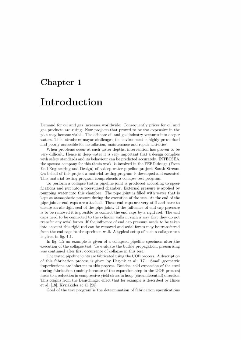
To perform a collapse test, a pipeline joint is produced according to speci-fications and put into a pressurised chamber. External pressure is applied bypumping water into this chamber. The pipe joint is filled with water that iskept at atmospheric pressure during the execution of the test. At the end of thepipe joints, end caps are attached. These end caps are very stiff and have toensure an air-tight seal of the pipe joint. If the influence of end cap pressureis to be removed it is possible to connect the end caps by a rigid rod. The endcaps need to be connected to the cylinder walls in such a way that they do nottransfer any axial forces. If the influence of end cap pressure needs to be takeninto account this rigid rod can be removed and axial forces may be transferredfrom the end caps to the specimen wall. A typical setup of such a collapse testis given in fig. 1.1.
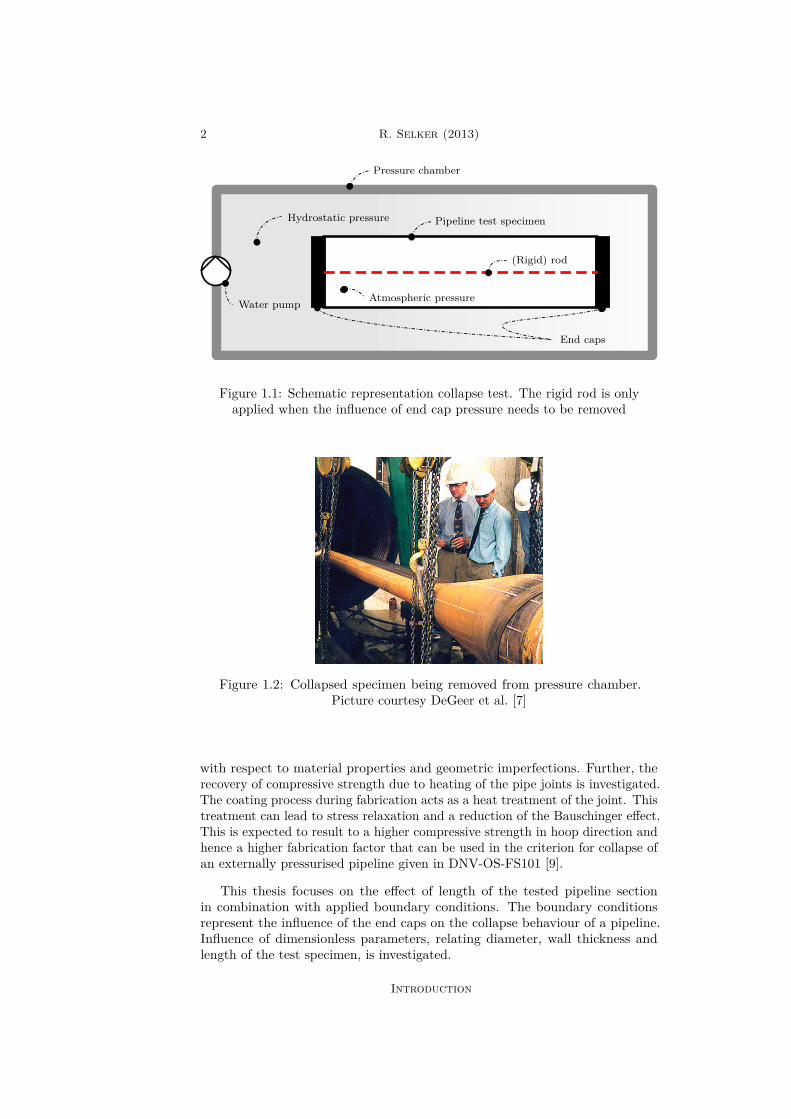
In fig. 1.2 an example is given of a collapsed pipeline specimen after theexecution of the collapse test. To evaluate the buckle propagation, pressurisingwas continued after first occurrence of collapse in this test.
The tested pipeline joints are fabricated using the UOE process. A descriptionof this fabrication process is given by Herynk et al. [17]. Small geometricimperfections are inherent to this process. Besides, cold expansion of the steelduring fabrication (mainly because of the expansion step in the UOE process)leads to a reduction in compressive yield stress in hoop (circumferential) direction.This origins from the Bauschinger effect that for example is described by Hineset al. [18], Kyriakides et al. [28].
Goal of the test program is the determination of fabrication specifications
2 R. Selker (2013)
Pressure chamber
Hydrostatic pressure
(Rigid) rod
Atmospheric pressure
End caps
Pipeline test specimen
Water pump
Figure 1.1: Schematic representation collapse test. The rigid rod is onlyapplied when the influence of end cap pressure needs to be removed
Figure 1.2: Collapsed specimen being removed from pressure chamber.Picture courtesy DeGeer et al. [7]
with respect to material properties and geometric imperfections. Further, therecovery of compressive strength due to heating of the pipe joints is investigated.The coating process during fabrication acts as a heat treatment of the joint. Thistreatment can lead to stress relaxation and a reduction of the Bauschinger effect.This is expected to result to a higher compressive strength in hoop direction andhence a higher fabrication factor that can be used in the criterion for collapse ofan externally pressurised pipeline given in DNV-OS-FS101 [9].
This thesis focuses on the effect of length of the tested pipeline sectionin combination with applied boundary conditions. The boundary conditionsrepresent the influence of the end caps on the collapse behaviour of a pipeline.Influence of dimensionless parameters, relating diameter, wall thickness andlength of the test specimen, is investigated.
Introduction

Local buckling collapse of marine pipelines 3
1.1 Scope
The scope of this thesis comprehends certain aspects of the local buckling collapsebehaviour of a pipeline section under external pressure. Local is referring to thebuckling behaviour occurring in the pipeline’s cross section. Global bucklingeffects such as upheaval and lateral buckling are not considered. Buckling ischaracterised for a relatively small increment in load resulting to a relativelylarge increment in deformation. In general, before the occurrence of buckling,the response of a structure to a load is more or less linear. This response isthe fundamental solution. After the occurrence of buckling, the response ischaracterised by a shape different from this fundamental shape.
The statement that buckling leads to structural failure, is not true by def-inition. However it may lead to, and is likely to initiate, structural failure.Depending on the properties of the structure, initial post-buckling behaviour iseither stable or unstable. For stable initial post-buckling behaviour, deformationscan only grow when the load is increased. For unstable initial post-bucklingbehaviour, deformations grow even though the load is not increased. In general,structural failure can be caused by a loss of stability. In terms of bucklingbehaviour this can be accomplished by unstable initial post-buckling behaviouror by plastic yielding leading to a reduction in stiffness and loss of stability.Deformations grow while the load is not increased necessarily. Plastic yieldingdue to occurring deformations is the reason that also stable initial post-bucklingbehaviour is likely to underlie collapse. It is possible that the stability of astructure is regained after first occurrence of initially unstable buckling. Anew equilibrium configuration is found. This behaviour is named snap-throughbehaviour.
The pipeline section is modelled is two ways. First, the pipeline is modelledas a ring. This is the representation of a pipeline of infinite length. Second,the pipeline is modelled as a cylinder. This allows including length effects andboundary conditions at the end cap locations.
Collapse of a pipeline origins from an unstable response to a critical load.Although for relatively thick pipelines prediction of collapse loads is sensitive toapplied material models, in this thesis only simple material models are considered.Material modelling is not the main interest. To obtain the collapse load it isnecessary to introduce a definition of collapse. Various collapse load definitionsare considered. A ring is analysed for occurrence of first yielding and for the fulldevelopment of a plastic hinge. A cylinder is analysed for the occurrence of firstyielding. Verification using finite element analysis is performed for occurrenceof first yielding and for loss of stability under application of an elastic-perfectlyplastic material model.
The elastic response of ring and cylinder representations of the pipeline jointis analysed. The adopted method is developed by Koiter [26] and described byBudiansky [5]. First, the response of a perfect structure is analysed. In this thesis,the adjective ‘perfect’ refers to the absence of initial geometric imperfections.The response of a perfect structure can be used to obtain the response of animperfect structure. Here the adjective ‘imperfect’ refers to the presence ofinitial geometric imperfections in the model.
A framework of small strains and moderate rotations is adopted. Potentialenergy functionals are composed using thin shell theory and the Kirchhoff-Love
Introduction
4 R. Selker (2013)
assumptions as given by for example Hoefakker [19], Ventsel and Krauthammer[47]. Equilibrium equations are obtained by minimising these potential energyfunctionals. The bifurcation load is defined as the load for which these equilibriumequations, for a perfect structure, lead to more than one possible solution. Thefirst deformation solution is always the fundamental solution, while the otherdeformation solutions are the bifurcation solutions. The total solution is acombination of these solutions. The bifurcation behaviour can be observed froma kink (bifurcation) in the load-deformation diagram. Introduction of geometricimperfections tends to smooth the transition between the pre-bifurcation andpost-bifurcation domain in this diagram.
For the ring model, the initial post-bifurcation behaviour is analysed, whilefor the cylinder model only the bifurcation point is analysed. It is assumed thatthe influence of an initial geometric imperfection on the buckling behaviour ofa cylinder is similar to that of a ring. To include the influence of boundaryconditions to the solutions of the cylinder model, boundary layer theory isapplied, as for example used by Shen and Chen [37, 38, 39], Sun and Chen[44]. Besides, regular and singular perturbation theory, as for example givenby Holmes [20], Verhulst [48], is applied to obtain estimate solutions for theboundary layer and regular domains. These solutions are combined to obtain thetotal solution. The bifurcation solution that accounts for boundary constraintsis obtained by the application of a Galerkin method.
In the cylinder model, the end caps are assumed to behave rigid. To connectthe end caps to the cylinder walls, two possible connection types are analysed:simply supported connections and clamped connections. Simply supported con-nections only constrain deformations, while clamped connections also constrainrotations. Analytical formulations are obtained and verified using finite elementanalysis later.
A pipeline specimen of certain length is used in a collapse test. To be ableto predict behaviour of such a pipeline in practice, results from this test needto be extrapolated. To be able to make predictions for the real life behaviourof a pipeline, it has to be ensured that the collapse mode observed in the testcorresponds to the collapse mode found in real life pipelines. Too short testspecimens possibly lead to higher collapse modes. A minimum test specimenlength is required to ensure an oval shaped collapse mode that is expected for arelatively long real life pipeline. End caps introduce additional stiffness to thesystem. It is expected that the buckling load obtained from tests is higher thanthe buckling load of real life pipeline. This overestimation of collapse pressureneeds to be accounted for when results are translated back to real life collapsepressure values.
1.2 ObjectiveFor this thesis several objectives have been formulated. The first objective isto obtain a clear understanding and give a mathematical description of themechanism of local buckling collapse behaviour of pipelines under external(hydrostatic) pressure.
The second objective is to describe the influence of several parameters on thebuckling load and buckling mode of a pipeline. The most important parametersare the diameter, wall thickness and length. The influence of end caps on the
Introduction
Local buckling collapse of marine pipelines 5
buckling of a pipeline has to be investigated.The final objective is to give a recommendation of the minimum joint length
to use in a collapse test program for a pipeline of certain specifications.
1.3 OutlineChapter 2 deals with general bifurcation and buckling theory. Koiter’s pertur-bation theory to obtain the (elastic) bifurcation and buckling behaviour of astructure is explained. In chapter 3 the bifurcation and buckling behaviour of aring is analysed. Chapter 4 deals with the bifurcation and buckling behaviour ofa externally pressurised cylinder constrained by end caps. In chapter 5 the resultsfrom chapters 3 and 4 are verified using finite element analyses. A quantitativeand qualitative discussion of these results is reported in this chapter. Interpreta-tion of the results, the conclusions from this study and the recommendations forfurther work are reported in chapter 6.
Introduction

This page is intentionally left blank.

Chapter 2
Buckling theory
2.1 Introduction
In this thesis the buckling and initial post-buckling behaviour of a pipeline modelis analysed. The adopted method is developed by Koiter [26] and modifiedby Budiansky [5]. The initial-post buckling behaviour of a perfect structurecan be used to determine the behaviour of a structure with initial geometricimperfections. The description of the adopted method in this chapter is largelybased on Budiansky [5].
Only statics are taken into account. All time dependent (dynamic) termsare neglected. Hence the principle of minimum potential energy is introduced.An equilibrium state of a structure can be found by minimising the potentialenergy functional of this structure. By minimising this functional, equilibriumequations can be obtained. The method described by Koiter and Budiansky isbased on perturbation theory. A solution to the minimisation of the potentialenergy functional or equilibrium equations is perturbed. This perturbation isexpressed as a power series in terms of a small parameter ζ, the bifurcationparameter. The first term in the expansion is the fundamental solution, thesolution to the linearised problem. Now ζ describes the amount of bifurcationmode included in the solution. Also the load is expanded around its critical loadvalue, the bifurcation load.
It is assumed that system, after application of the previous substitutions,needs to be satisfied for every order of ζ separately. This leads to an equilibriumsystem for each order of ζ. The consequence is that besides the fundamentalsystem, every system of equations is a system of linear differential equations.
Bifurcations from the fundamental solution path are the result of a singularityin the system. For a certain load, the bifurcation load, the system has multipleequilibrium solutions. This load is obtained from an Eigenvalue analysis. Analysisof the higher order load expansion terms gives the initial post-buckling behaviourof the system.
Initial imperfections are introduced by an additional potential energy func-tional. This functional is added to the potential energy functional of the perfectsystem. Consequently the additional potential functional should be equal to zeroif there are no deformations or initial imperfections. The functions describingthe initial imperfections are expanded around zero. Now the influence of initial

8 R. Selker (2013)
imperfections on the response of the structure can be analysed.
2.2 Preliminaries
2.2.1 The Fréchet derivative
Let f be a functional depending on the generalised function u. This dependencyis denoted by f [u]. f is called Fréchet differentiable at the point u if it can beapproximated by f [u+ εu1] and the following relation is satisfied [32]:
limε→0
∥∥∥∥Duf [u]u1 −f [u+ εu1]− f [u]
ε
∥∥∥∥ = 0 (2.1)
Here the Du-operator denotes the first order Fréchet derivative with respectto the function u. For any fixed u1 the following definition is obtained:
Duf [u]u1 ≡ limε→0
f [u+ εu1]− f [u]ε
(2.2)
This can be rewritten to:
Duf [u]u1 = ∂
∂εf [u+ εu1]
∣∣∣∣ε=0
(2.3)
The generalised form for higher order Fréchet derivatives denotes [5]:
Du...u︸ ︷︷ ︸n terms of u
f [u]ui1 . . . uin = ∂n
∂ε1 . . . ∂εnf [u+ ε1ui1 + . . .+ εnuin ]
∣∣∣∣ε1,...,εn=0
(2.4)
Where ij ∈ N and j = 1, 2, . . . , n.Now let a functional f [u] denote a function depending on multiple functions
e.g. v, w and so on. Then u represents the set of functions v, w, . . . andf [u] = f [v, w, . . .]. The Frèchet derivative of the functional f [u], denoted byDu...u, where the order of derivative is given by the amount of u-terms in thesubscript of the operator, is defined by:
Du...u︸ ︷︷ ︸n terms of u
f [u]ui1 . . .uin = ∂n
∂ε1 . . . ∂εnf[∗v,∗w, . . .
]∣∣∣∣ε1,...,εn=0
(2.5)
Where:
∗v = v + ε1vi1 + . . .+ εnvin (2.6a)∗w = w + ε1wi1 + . . .+ εnwin (2.6b)
Note that the uij represents a set vij , wij , . . .. To shorten the notation itis allowed to write Duuf [u]u1u1 as Duuf [u]u2
1 and so on.
Buckling theory

Local buckling collapse of marine pipelines 9
2.2.2 ExpansionsThe approximate value of a functional f [u+ δu] can be found using the powerseries expansion in terms of variations:
f [u+ δu] = f [u] + δf [u] + δ2f [u] + δ3f [u] + . . . (2.7)
It can also be approximated as a Taylor expansion terms of the Fréchetderivative of the functional:
f [u+ δu] = f [u] +Duf [u]δu+ 12!Duuf [u](δu)2 + 1
3!Duuuf [u](δu)3 + . . . (2.8)
The following is obtained for the generalised variation of a functional f :
δnf [u] = 1n! Du...u︸ ︷︷ ︸
n terms of u
f [u](δu)n (2.9)
For a functional depending on multiple functions, a generalised Taylor ex-pansion of f [u+ δu] is given by:
f [u+δu] = f [u]+Duf [u]δu+ 12!Duuf [u](δu)2+ 1
3!Duuuf [u](δu)3+. . . (2.10)
Let f [u] describe a functional f [v, w]. Now f [u] is expanded using a Taylorexpansion at u = u0. Introducing the notation Du...uf [u0] = Du...uf [u]|u=u0gives:
f [u] = f [u0] +Duf [u0] (u− u0) + 12!Duuf [u0] (u− u0)2 + . . . (2.11)
This expansion of f [u] can also be expressed as a multivariate Taylor expan-sion of f [v, w] at v = v0 and w = w0. If the expansion up to the second orderderivative are given it will read:
f [v, w] =f [v0, w0] +Dvf [v0, w0] (v − v0) +Dwf [v0, w0] (w − w0)+ 1
2Dvvf [v0, w0] (v − v0)2 +Dvwf [v0, w0] (v − v0) (w − w0)+ 1
2Dwwf [v0, w0] (w − w0)2 + . . .
(2.12)
By comparing eqs. (2.11) and (2.12) by using the statement f [u] = f [v, w],the following relations are obtained:
Duf [u0] (u− u0) = Dvf [v0, w0] (v − v0) +Dwf [v0, w0] (w − w0) (2.13a)Duuf [u0] (u− u0)2 = Dvvf [v0, w0] (v − v0)2
+ 2Dvwf [v0, w0] (v − v0) (w − w0)+Dwwf [v0, w0] (w − w0)2
(2.13b)
This can be verified using eqs. (2.4) and (2.5) for arbitrary functionals. Hencethe Taylor expansion given in eq. (2.11) is valid, also when u represents a set offunctions.
Analogous to eq. (2.9), the generalised variations of a functional f [u] nowreads:
δnf [u] = 1n! Du...u︸ ︷︷ ︸
n terms of u
f [u](δu)n (2.14)
Buckling theory
10 R. Selker (2013)
2.2.3 Energy functionalsThe potential energy of a perfect structure is denoted by functional Π[u]. Hereu is a generalised displacement field dependent on a load factor λ. Hence thepotential energy is denoted by Π[u(λ);λ]. The potential energy of a structure isthe sum of the strain energy due to the deformation of the structure and theapplied external energy (work) due to the loads.
Because a static analysis is performed, the kinetic energy is neglected. Henceall time dependent terms drop out of the equations. The potential energy of astructure with initial geometric imperfections is given by:
Π[u(λ); u;λ] = Π[u(λ);λ] + Ψ[u(λ); u;λ] (2.15)
Here Π[u(λ); u;λ] is the total potential energy of the structure with initialimperfections included. Π[u(λ);λ] is the potential energy functional of the perfectstructure. Hence Ψ[u(λ); u;λ] describes the additional potential energy of animperfect structure with respect to the potential energy of a perfect structure.u describes the initial imperfection field of the structure.
The following relations should be valid for Ψ[u(λ); u;λ]:
Ψ[u(λ); 0;λ] = 0 (2.16a)Ψ[0; u;λ] = 0 (2.16b)
If either the initial imperfection or the displacement is zero, the additionalpotential energy terms should be equal to zero.
2.3 Principle of minimum potential energyLet S be the action of a system on time interval t ∈ [t1, t2]. This action is definedby the following integral [46]:
S =∫ t2
t1
L[u(t); u(t); t]dt (2.17)
Where the Lagrangian L is defined by:
L[u(t), u(t), t] = K[u(t), t]−Π[u(t), t] (2.18)
The dot here denotes the first order derivative with respect to time t. udenotes the generalised displacement and hence u represents the generalisedvelocity. K is the kinetic energy, that depends on the velocity, and Π is thepotential energy functional, that depends on the displacement components ofthe system. The principle of stationary action or Hamilton’s principle [4] statesthat the dynamic system is in equilibrium if the action is stationary i.e. δS = 0.In general this will lead to minimising the action integral. Hamilton’s principlereads:
δS =∫ t2
t1
δL[u(t), u(t), t]dt = 0 (2.19)
The weak formulation of Hamilton’s principle is transformed to a strongerformulation by assuming that the equation above is fulfilled if its integrand isequal to zero. Hence the strong formulation of Hamilton’s principle reads:
δL[u(t), u(t), t] = δ (K[u(t), t]−Π[u(t), t]) = 0 (2.20)
Buckling theory
Local buckling collapse of marine pipelines 11
In this thesis only statics are taken into account. Dynamic effects areneglected. This allows for all time dependencies to be removed from the analysis.This leaves the principle of minimum potential energy:
δΠ[u] = 0 (2.21)
Note that in fact the obtained variational statement above represents theprinciple of stationary potential energy. The obtained equilibrium configurationcan represent a minimum, a maximum or a saddle point in potential energy.∀ ui ∈ u, δ2Π > 0 indicates a stable equilibrium state and hence a minimumin potential energy. The potential energy Π for a conservative system can bedescribed by:
Π = U +W (2.22)Where U denotes the strain energy of the elastic body andW is the (negative)
energy of the applied external forces (work) onto the system.
2.4 Bifurcation bucklingThe method described in this section is a short overview of Budiansky [5]. Let aprime denote the Frèchet derivative with respect to the displacement field u i.e.Π′[u]u1 ≡ DuΠ[u]u1, Π′′[u]u1 ≡ DuuΠ[u]u1 and so on.
Following the principle of minimum potential energy, the equilibrium state ofa system is obtained by setting the first variation of the potential energy to zero.By using δΠ = 0 and eq. (2.14), the following equilibrium equation is obtained:
Π′[u(λ);λ]δu = 0 (2.23)
The pre-buckling state of the system is described by u0(λ). This is alsoreferred to as the fundamental solution. If the system is perturbed from thisstate, the generalised displacement u can be determined using the small scalarperturbation factor ζ, where it is important to note that ζ 1:
u(λ) = u0(λ) + ζu1 + ζ2u2 + ζ3u3 + . . . (2.24)
Where
ζ = 〈u− u0,u1〉 =⟨ζu1 + ζ2u2 + ζ3u3 + . . . ,u1
⟩(2.25)
The 〈•〉 operator represents the bilinear inner product. If is assumed that〈u1,u1〉 = 1, it can be shown that
⟨ζ2u2 + ζ3u3 + . . . ,u1
⟩= 0. This implies
that u1 is orthogonal to u2, u3 and so on. Orthogonality of functions impliesindependence of the functions.
Introduce the notation:
Π(n)0 ≡ Π(n)[u(λ);λ]
∣∣∣u=u0
(2.26)
Where the superscripted (n)-term corresponds with the nth order Frèchetderivative with respect to u. The Taylor series expansion given in eq. (2.11) isperformed onto eq. (2.23). The following expansion is obtained:
Π′0δu+ Π′′0 (u− u0) δu+ 12Π′′′0 (u− u0)2
δu+ 16Π′′′′0 (u− u0)3
δu+ . . . = 0(2.27)
Buckling theory
12 R. Selker (2013)
The fundamental state u0 can be derived from the equation:
Π′0δu = 0 (2.28)
Application of the Euler-Lagrange equations on the system above leads toa system of differential equations. By solving this system, the fundamentalsolution is obtained.
It is allowed to set Π′0δu to zero because of eq. (2.23). Hence the term canbe dropped in eq. (2.27). Dropping this term and substituting eq. (2.24) intoeq. (2.27) leads to:
Π′′0(ζu1 + ζ2u2 + ζ3u3 + . . .
)δu+ 1
2Π′′′0(ζu1 + ζ2u2 + . . .
)2δu
+ 16Π′′′′0 (ζu1 + . . .)3
δu+ . . . = 0(2.29)
The load parameter λ is expanded at its critical state, the bifurcation loadλc, using the small perturbation parameter ζ:
λ = λc + ζλ1 + ζ2λ2 + ζ3λ3 + . . . (2.30)
Introduce the identities:
Π(n)c = Π(n)
0
∣∣∣λ=λc
(2.31a)
Π(n)c = ∂
∂λΠ(n)
0
∣∣∣∣λ=λc
(2.31b)
Π(n)c = ∂2
∂λ2 Π(n)0
∣∣∣∣λ=λc
(2.31c)
Now perturbing the equilibrium equation given in eq. (2.27) around λc leadsto: (
Π′′c + λ− λcΠ′′c + 12λ− λc2Π′′c + . . .
) (ζu1 + ζ2u2 + ζ3u3 + . . .
)δu
+ 12(Π′′′c + λ− λcΠ′′′c + . . .
) (ζu1 + ζ2u2 + . . .
)2δu
+ 16 (Π′′′′c + . . .) (ζu1 + . . .)3
δu+ . . . = 0(2.32)
From eq. (2.30) can be obtained that:
λ− λc = ζλ1 + ζ2λ2 + ζ3λ3 + . . . (2.33)
Substituting this relation into eq. (2.32) gives:(Π′′c + ζλ1 + ζ2λ2 + . . .Π′′c
+ 12ζλ1 + . . .2Π′′c + . . .
)(ζu1 + ζ2u2 + ζ3u3 + . . .
)δu
+ 12(Π′′′c + ζλ1 + . . .Π′′′c + . . .
) (ζu1 + ζ2u2 + . . .
)2δu
+ 16 (Π′′′′c + . . .) (ζu1 + . . .)3
δu+ . . . = 0
(2.34)
Rewriting this equation in terms of ζ gives:
ζΠ′′cu1δu+ ζ2 (Π′′cu2 + λ1Π′′cu1 + 12Π′′′c u2
1)δu
+ ζ3
(Π′′cu3 + λ1Π′′cu2 + λ2Π′′cu1 + 1
2λ21Π′′cu1
+Π′′′c u1u2 + 12λ1Π′′′c u2
1 + 16Π′′′′c u
31
)δu+O(ζ4) = 0
(2.35)
Buckling theory

Local buckling collapse of marine pipelines 13
In the equation above every single coefficient of a power of ζ must equal zero.The bifurcation equation is obtained by setting the coefficient of the first powerof ζ to zero. The differential equation to determine the bifurcation load λc andfirst order bifurcation shape u1 is given by:
Π′′cu1δu = 0 (2.36)
The solutions u1 to this system are only non-trivial if the load parameter λequals a critical bifurcation load parameter λc. A buckling shape u1 is obtainedby solving the system at the critical load. This solution will have an an arbitraryamplitude. It is chosen to assign a value to this amplitude based on letting thenorm of one of the buckling shape functions be equal to one. If this function nowis multiplied by a factor, then this factor will describe the amount of bucklingincluded in the solution.
The analysis in this section results in the following solutions: λc, u0 and u1.
2.5 Initial post-buckling behaviourThe initial post buckling behaviour describes the behaviour of the structure justafter occurrence of bifurcation buckling.
From eq. (2.35), besides the bifurcation equation, the following equations areobtained:
Π′′cu2δu+ λ1Π′′cu1δu+ 12Π′′′c u2
1δu = 0 (2.37a)Π′′cu3δu+ λ1Π′′cu2δu+ λ2Π′′cu1δu+ 1
2λ21Π′′cu1δu
+Π′′′c u1u2δu+ 12λ1Π′′′c u2
1δu+ 16Π′′′′c u
31δu = 0
(2.37b)
Now let δu = u1 in eq. (2.37a). Because of the bifurcation equation givenin eq. (2.36), the term Π′′cu1u2 = 0 and drops out. Subsequently λ1 can beobtained:
λ1 = −12Π′′′c u3
1
Π′′cu21
(2.38)
With λ1 being known, u2 can be determined using eq. (2.37a). Usingvariational calculus and the Euler-Lagrange equations, a system of differentialequations is obtained. The terms λ1Π′′cu1δu and 1
2Π′′′c u21δu in eq. (2.37a) relate
to constant terms in the system of equations.Note that the homogeneous part of this equation (Π′′cu2δu = 0) with respect
to u2 is corresponds to the bifurcation equation given in eq. (2.36) with respectto u1. In section 2.4 it is presumed that u2 is orthogonal to u1. Hence the partof the general solution corresponding to the solution to the homogeneous part ofthe differential equation has to drop out. Now the solution for u2 is obtained.
If in eq. (2.37b) u1 is substituted for δu, the term Π′′cu1u3 = 0 and dropsout due to eq. (2.36). Hence λ2 can be obtained using:
λ2 = −16Π′′′′c u
41 + Π′′′c u2
1u2 + λ1(Π′′cu1u2 + 1
2 Π′′′c u31 + 1
2λ1Π′′cu21)
Π′′cu21
(2.39)
Systematic improvements can be made to the results by extending thisanalysis. In this analysis it is assumed that results are sufficiently correct forexpansions up to order ζ2.
Buckling theory
14 R. Selker (2013)
2.6 Initial imperfectionsIn practice, structures are never perfect. If the perfect structure is subject to aninitial geometric imperfection, the analysis described previously can be modifiedto account for this effect. Assume that the imperfection does not cause anyresidual stresses in the structure and its shape can be described in a shapesimilar to the first order bifurcation shape u1.
A modified energy functional that accounts for both the perfect behaviourand the imperfect behaviour of the structure is given in eq. (2.15). Now let udescribe the initial imperfection, such that u = ξu, where the norm of (oneof the components of) u equals unity. Now ξ is a measure of the imperfectionamplitude. It can be considered analogous to the ovality used in the pipelineindustry.
The variational equilibrium equation given in eq. (2.23) is modified for theadapted energy functional Π. This leads to the new equilibrium equation for thesystem with initial geometric imperfections:
Π′[u(λ);λ]δu+ Ψ′[u(λ); u;λ]δu = 0 (2.40)
The Taylor expansion of this equation around the fundamental solution ofthe perfect system u = u0 reads:
Π′0δu+ Π′′0(u− u0)δu+ 12Π′′′0 (u− u0)2δu+ 1
6Π′′′′0 (u− u0)3δu
+ . . .+ Ψ′[u0(λ); u;λ]δu+ Ψ′′[u0(λ); u;λ](u− u0)δu+ . . . = 0(2.41)
Now the Fréchet derivative with respect to the initial imperfection u isintroduced and denoted by an asterisk in superscript. This derivative is generatedaccording to eq. (2.5). Let Ψ[u0(λ); 0;λ] = Ψ0. The following expansions areobtained:
Ψ′[u0(λ); u;λ] = Ψ′0 + Ψ′∗0 u+ 12Ψ′∗∗0 u2 + . . . (2.42a)
Ψ′′[u0(λ); u;λ] = Ψ′′0 + Ψ′′∗0 u+ . . . (2.42b)
From eq. (2.16) follows that Ψ′0 = Ψ′′0 = . . . = 0. Hence these expansions canbe rewritten:
Ψ′[u0(λ); u;λ] = Ψ′∗0 u+ 12Ψ′∗∗0 u2 + . . . (2.43a)
Ψ′′[u0(λ); u;λ] = Ψ′′∗0 u+ . . . (2.43b)
These relations are substituted into eq. (2.41) and the previously assumedrelation u = ξu is used. Π′0δu = 0 due to the equilibrium equation of the perfectsystem given in eq. (2.28). Solving this expression using the Euler-Lagrangeequations, gives the fundamental solution. Now for the remaining terms thefollowing relation is obtained:
Π′′0(u− u0)δu+ 12Π′′′0 (u− u0)2δu+ 1
6Π′′′′0 (u− u0)3δu+ . . .
+ ξΨ′∗0 uδu+ 12ξ
2Ψ′∗∗0 u2δu+ . . .+ ξΨ′′∗0 u(u− u0)δu+ . . . = 0(2.44)
This equation is expanded at its bifurcation load λ = λc. Here Ψ′′c = Ψ′′0 |λ=λcand so on, analogous to eq. (2.31). Further a dot above a functional represents
Buckling theory

Local buckling collapse of marine pipelines 15
the derivative with respect to λ such that Π′′c = ∂∂λΠ′′0
∣∣λ=λc
and so on. The newequation reads:
Π′′c (u− u0)δu+ (λ− λc)Π′′c (u− u0)δu+ 12 (λ− λc)2Π′′c (u− u0)δu+ . . .
+ 12Π′′′c (u− u0)2δu+ 1
2 (λ− λc)Π′′′c (u− u0)2δu+ . . .
+ 16Π′′′′c (u− u0)3δu+ . . .+ ξΨ′∗c uδu+ ξ(λ− λc)Ψ′∗c uδu+ . . .
+ 12ξ
2Ψ′∗∗c u2δu+ . . .+ ξΨ′′∗c u(u− u0)δu+ . . . = 0(2.45)
Now introduce the perturbation for u around the fundamental solution ofthe perfect structure u0 analogous to eq. (2.24). It will be shown that thisperturbation is valid. Further λ is perturbed around λc such that:
u = u0 + ζu1 + ζ2u2 + ζ3u3 + . . . (2.46a)λ = λc + ζλ1 + ζ2λ2 + ζ3λ3 + . . . (2.46b)
This leads to the following identities:
u− u0 = ζu1 + ζ2u2 + ζ3u3 + . . . (2.47a)λ− λc = ζλ1 + ζ2λ2 + ζ3λ3 + . . . (2.47b)
These identities are substituted into eq. (2.45). If now ζ is related to ξ byξ = αζγ , where α can be set to a value such that this relation is valid. Now thefollowing equilibrium equation is obtained:
Π′′c(ζu1 + ζ2u2 + ζ3u3 + . . .
)δu
+(ζλ1 + ζ2λ2 + . . .
)Π′′c(ζu1 + ζ2u2 + . . .
)δu
+ 12(ζλ1 + . . .
)2 Π′′c (ζu1 + . . .) δu+ . . .
+ 12Π′′′c
(ζu1 + ζ2u2 + . . .
)2δu
+ 12(ζλ1 + . . .
)Π′′′c (ζu1 + . . .)2
δu+ . . .
+ 16Π′′′′c (ζu1 + . . .)3
δu+ . . .
+ αζγΨ′∗c uδu+ αζγ(ζλ1 + . . .
)Ψ′∗c uδu+ . . .
+ αζγΨ′′∗c u (ζu1 + . . .) δu+ . . . = 0
(2.48)
For symmetric buckling it has to follow that λ1 = 0. If so, it is convenient tolet γ = 3 [5]. Now the following equilibrium is obtained:
ζΠ′′cu1δu+ ζ2 (Π′′c u2 + λ1Π′′cu1 + 12Π′′′c u2
1)δu
+ ζ3
(Π′′c u3 + λ1Π′′c u2 + λ2Π′′cu1 + 1
2 λ21Π′′cu1
+ Π′′′c u1u2 + 12 λ1Π′′′c u2
1 + 16Π′′′′c u
31 + αΨ′∗c u
)δu+O(ζ4) = 0
(2.49)
Where all coefficients of ζ, ζ2, . . . must vanish separately. Setting coefficientof ζ to zero results in the bifurcation equation of the perfect system given ineq. (2.36). This also validates the fact that u1 in the perfect system is equal tou1 in the system with initial geometric imperfections. Setting the coefficient ofζ2 to zero and substituting δu = u1 gives:
Π′′cu1u2 + λ1Π′′cu21 + 1
2Π′′′c u31 = 0 (2.50)
Buckling theory
16 R. Selker (2013)
The bifurcation equation results in Π′′cu1u2 = Π′′cu1δu = 0. The previousrelation between ξ and ζ removes α by using α = ξζ−γ = ξζ−3. Now λ1 can beobtained from:
λ1 = −12Π′′′c u3
1
Π′′cu21
= λ1 (2.51)
Now u2 is obtained by solving the following equation using the Euler-Lagrangeequations:
Π′′c u2δu+ λ1Π′′cu1δu+ 12Π′′′c u2
1δu = 0 (2.52)
It follows that u2 = u2. In a similar fashion as described above, λ2 can beobtained. The coefficient of ζ3 in eq. (2.49) is set to zero and the bifurcationequation is used to let Π′′cu1u3 = Π′′cu1δu = 0. The substitution δu = u1 isapplied. The expression for λ2 now reads:
λ2 = −16Π′′′′c u
41 + Π′′′c u2
1u2 + λ1(Π′′cu1u2 + 1
2 Π′′′c u31 + 1
2λ1Π′′cu21)
Π′′cu21
− ξΨ′∗c uu1
ζ3Π′′cu21
= λ2 −ξΨ′∗c uu1
ζ3Π′′cu21
(2.53)
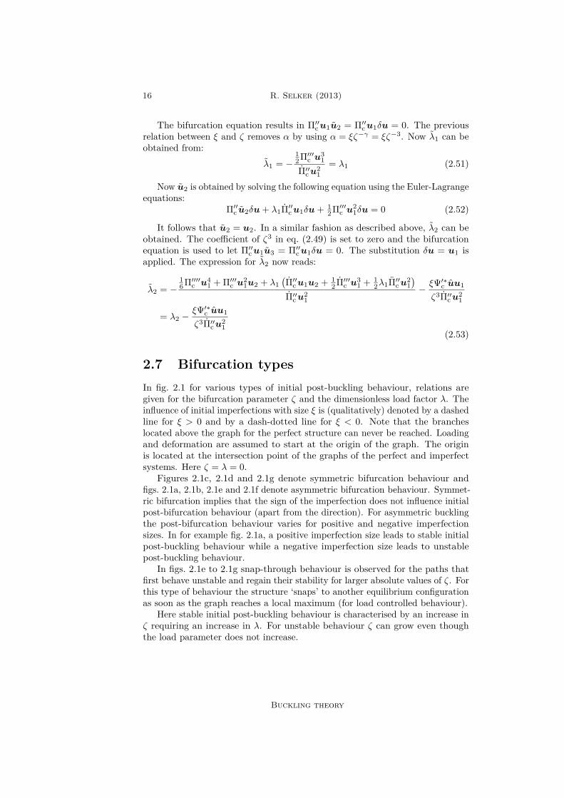
2.7 Bifurcation typesIn fig. 2.1 for various types of initial post-buckling behaviour, relations aregiven for the bifurcation parameter ζ and the dimensionless load factor λ. Theinfluence of initial imperfections with size ξ is (qualitatively) denoted by a dashedline for ξ > 0 and by a dash-dotted line for ξ < 0. Note that the brancheslocated above the graph for the perfect structure can never be reached. Loadingand deformation are assumed to start at the origin of the graph. The originis located at the intersection point of the graphs of the perfect and imperfectsystems. Here ζ = λ = 0.
Figures 2.1c, 2.1d and 2.1g denote symmetric bifurcation behaviour andfigs. 2.1a, 2.1b, 2.1e and 2.1f denote asymmetric bifurcation behaviour. Symmet-ric bifurcation implies that the sign of the imperfection does not influence initialpost-bifurcation behaviour (apart from the direction). For asymmetric bucklingthe post-bifurcation behaviour varies for positive and negative imperfectionsizes. In for example fig. 2.1a, a positive imperfection size leads to stable initialpost-buckling behaviour while a negative imperfection size leads to unstablepost-buckling behaviour.
In figs. 2.1e to 2.1g snap-through behaviour is observed for the paths thatfirst behave unstable and regain their stability for larger absolute values of ζ. Forthis type of behaviour the structure ‘snaps’ to another equilibrium configurationas soon as the graph reaches a local maximum (for load controlled behaviour).
Here stable initial post-buckling behaviour is characterised by an increase inζ requiring an increase in λ. For unstable behaviour ζ can grow even thoughthe load parameter does not increase.
Buckling theory
Local buckling collapse of marine pipelines 17
λ
ζ
ξ = 0ξ > 0ξ < 0
(a) λ1 > 0, λ2 = 0
λ
ζ
ξ = 0ξ > 0ξ < 0
(b) λ1 < 0, λ2 = 0
λ
ζ
ξ = 0ξ > 0ξ < 0
(c) λ1 = 0, λ2 > 0
λ
ζ
ξ = 0ξ > 0ξ < 0
(d) λ1 = 0, λ2 < 0
λ
ζ
ξ = 0ξ > 0ξ < 0
(e) λ1 < 0, λ2 > 0
λ
ζ
ξ = 0ξ > 0ξ < 0
(f) λ1 > 0, λ2 > 0
λ
ζ
ξ = 0ξ > 0ξ < 0
(g) λ1 = 0, λ2 < 0, λ3 = 0, λ4 > 0
Figure 2.1: Various types of initial post-bifurcation behaviour. Bifurcationpoint is at intersection of lines for ξ = 0
Buckling theory

This page is intentionally left blank.

Chapter 3
Buckling of a ring
In this chapter, the behaviour of a ring subjected to external hydrostatic pressurewill be analysed. Hydrostatic pressure is always directed perpendicular to thering’s circumferential direction and co-rotates during deformation.
3.1 AssumptionsIn order to derive the buckling behaviour of a perfectly circular ring, certainassumptions have to be made in modelling. The Kirchhoff-Love assumptions[19, 47] are adopted amongst others:
i Straight sections initially normal to the middle line remain straight duringdeformation.
ii Sections initially normal to the middle line remain normal to the middle lineduring deformation.
iii Thickness of the ring does not change during deformation.iv Transverse normal stresses are small compared to other stress components
and may be neglected.v The material model used is an isotropic linear elastic material model.vi The ring is modelled as a two dimensional model with one curvilinear
coordinate axis describing the middle line.vii Middle line strains are small.viii Middle line rotations are moderately small.
The bifurcation analysis is performed for an isotropic elastic material modelfollowing Hooke’s law. Further, the influence of gravity and buoyancy forcesin neglected. The structure is assumed to be homogeneous and the initial wallthickness is assumed to be constant.
3.2 Kinematics
Vector identities
Every material point on the middle line of an undeformed perfectly circular ringis described by the vector p. The ring is a plane object and hence its behaviour
20 R. Selker (2013)
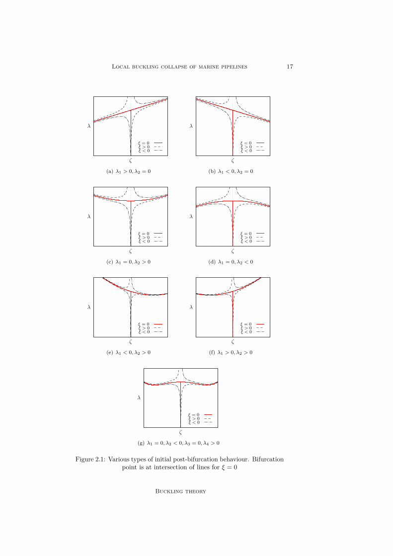
is analysed in a two dimensional coordinate system. The unit vectors describingthe (orthonormal) Cartesian coordinate system are ı along the x1-axis and along the x2-axis. The vector p is described in the Cartesian coordinate systemby the relation p = x1ı+ x2. The model of the ring is given in fig. 3.1.
Undeformed ring
Deformed ring
ϕ
x1
sp
wn
d
vt
t
ρ
ı
x2
q
t
Figure 3.1: Ring model
Now a two dimensional curvilinear coordinate system is introduced. Onecurvilinear axis describes the middle line of the perfect ring. This axis is alsoreferred to as the circumferential or hoop axis. The other describes the normalcomponent with respect to the former curvilinear axis. This axis is also referredto as the radial axis. The undeformed ring can by described fully by thecircumferential coordinate s ∈ [0, 2πρ] and the radial coordinate z ∈ [− 1
2 t,12 t].
Here ρ denotes the radius and t the wall thickness of the undeformed ring. Thevector p can be described in the Cartesian coordinate system by:
p = ρ
cos(sρ
)sin(sρ
) (3.1)
For every point along the curvilinear axis, a tangent unit vector t and anormal unit vector n (directed outward) are introduced. These unit vectors read:
t =p,s‖p,s‖
=
− sin(sρ
)cos(sρ
) (3.2a)
n = − t,s‖t,s‖
=
cos(sρ
)sin(sρ
) (3.2b)
Buckling of a ring
Local buckling collapse of marine pipelines 21
The minus sign in the definition of the normal vector origins from theconvention that the normal vector is directed outward with respect to the centreof curvature of the undeformed ring. If now a load is applied the system wantsto deform. A material point on the middle line which initial location is describedby the vector p translates according to the vector d = vt+ wn. Hence the newlocation of this material point is described by the sum of the initial positionvector p and the deformation vector d. This description of the location afterdeformation is denoted by the vector q such that:
q = p+ d =
(ρ+ w) cos(sρ
)− v sin
(sρ
)(ρ+ w) sin
(sρ
)+ v cos
(sρ
) (3.3)
The corresponding unit tangent vector of the deformed ring t can be obtainedusing:
t =q,s‖q,s‖
(3.4)
Curvature and rotation of the middle line
Now the curvature vector of the undeformed ring k and the curvature vector ofthe deformed ring k are defined by:
k = t,s = 1ρ
− cos(sρ
)− sin
(sρ
) (3.5a)
k = t,s (3.5b)
The curvature parameter κ is defined as the difference between the norms ofthe curvature vectors in the deformed and the undeformed configuration:
κ = ‖k‖−‖k‖ (3.6)
The post-deformation rotation ϕ of a material point on the middle line withrespect to the initial configuration can be found by subtracting the direction angleof the vector t from the direction angle of the vector t. In the two dimensionalCartesian coordinate system this results to:
ϕ = arctan(t · t · ı
)− arctan
(t · t · ı
)(3.7)
Strain of the middle line
The first fundamental form for the initial configuration of the ring in the s-z-coordinate system is given by:
(dp)2 = gss (ds)2 + gszdsdz + gzsdzds+ gzz (dz)2 (3.8)
Where dp denotes the infinitesimal arc length of the undeformed middle line.Now g denotes the metric tensor with respect to the undeformed middle linesuch that:
g =[gss gszgzs gzz
]=[p,s · p,s p,s · p,zp,z · p,s p,z · p,z
]=[1 00 0
](3.9)
Buckling of a ring
22 R. Selker (2013)
By combining eq. (3.8) and the metric given in eq. (3.9), the infinitesimalarc length of the undeformed middle line reads:
dp = ds (3.10)
Now the first fundamental form of the deformed configuration of the ring isgiven by:
(dq)2 = gss (ds)2 + gszdsdz + gzsdzds+ gzz (dz)2 (3.11)
Here dq denotes the infinitesimal arc length of the deformed middle line. gdenotes the metric tensor with respect to the deformed middle line. This metricreads:
g =[gss gszgzs gzz
]=[q,s · q,s q,s · q,zq,z · q,s q,z · q,z
]=[q,s · q,s 0
0 0
](3.12)
The definition of the norm of the vector q,s is given by the square root ofthe inner product of this vector with itself, such that ‖q,s‖=
√q,s · q,s. This
definition, the relation given in eq. (3.11) and the metric given in eq. (3.12) arecombined. Now it follows that:
dq = ‖q,s‖ds (3.13)
The strain in a material point on the middle line can be obtained from theinfinitesimal arc length of the initial middle line dp and the infinitesimal arclength of the deformed middle line dq such that:
e = dq − dpdp = ‖q,s‖−1 (3.14)
Approximated kinematic relations
If now the previously obtained kinematic relations for the middle line rotationϕ, curvature κ and strain e are approximated using a multivariate Taylor seriesapproximation with respect to the deformation functions and their derivatives,the following is obtained where h.o.t. stands for higher order terms:
ϕ = −w,s + 1ρv + h.o.t. (3.15a)
κ = −w,ss + 1ρv,s + h.o.t. (3.15b)
e = v,s + 1ρw + 1
2
(w,s − 1
ρv)2
+ h.o.t. (3.15c)
Sanders’ shell equations
In correspondence to the previously obtained kinematic relations, the kinematicrelations from Sanders [36] with respect to the middle line of a ring, describedby one curvilinear axis, read:
ϕ = −w,s + 1ρv (3.16a)
κ = ϕ,s (3.16b)e = v,s + 1
ρw + 12ϕ
2 (3.16c)
Buckling of a ring
Local buckling collapse of marine pipelines 23
In agreement with the description above, v(s) describes the tangent dis-placement component and w(s) describes the normal displacement component.Further ϕ(s) describes the rotation, κ(s) the curvature and e(s) the strain ofthe middle line of the ring. The underlined term in eq. (3.16) will drop outfor the Donnell-Mushtari-Vlasov (DMV) shell equations. Including these termswill give the Sanders shell equations. Rebel [34] states that application of theDMV equations is justified as long as the stresses arising from rotations are ofcomparable or smaller order than the stresses due to in plane stress resultants.At the occurrence of buckling the stress state changes from a pure plane stressregime to a more bending stress regime. Therefore it is assumed that the DMVequations should give a proper behaviour of the system close to first occurrenceof buckling.
Strain of a material point
By using the previously stated assumptions, the occurring strain in a materialpoint, ε(s, z), is obtained:
ε = e+ κz (3.17)
Where e = e(s) describes the middle surface strain and κ = κ(s) describesthe curvature.
3.3 Constitutive relationsThe fundamental constitutive equation used in this analysis is Hooke’s law.Hooke’s law relates occurring strains to occurring stresses. Its generalised formreads:
σij = cijklεkl (3.18)
Where Einstein’s summation convention needs to be applied. Here the tensorσ is the stress tensor, c is the stiffness tensor and ε is the strain tensor. For aring it is assumed that it is free to strain in the out of plane (axial) direction(plane stress). Radial stresses and strains are neglected. This results in the outof plane stresses to be equal to zero. Hence Hooke’s law for a ring can be writtenas:
σ = Eε (3.19)
Where E denotes Young’s modulus, also called the modulus of elasticity.This modulus is a material property. For the steels used in this thesis it is alwaysassumed that E = 210GPa if not stated otherwise.
3.4 Potential energy
Strain energy
The strain energy of an infinitesimal volume is given by the strain energy densityfunction. The generalised form of this function reads [35, 47]:
U∗ =∫ εij
0σijdεij (3.20)
Buckling of a ring
24 R. Selker (2013)
For the ring this strain energy density function can be simplified to:
U∗ =∫ ε
0σdε (3.21)
Now using Hooke’s law as given in eq. (3.19), the previous relation can berewritten to:
U∗ = 12Eε
2 (3.22)And by eq. (3.17) the strain energy density function reads:
U∗ = 12Ee
2 + Eκz + 12Eκ
2z2 (3.23)
The strain energy of the full system is obtained by integrating the strain energydensity function over the volume of the structure. Because only two dimensionsare analysed in the system, the strain energy per unit length is obtained. This isfound by integrating U∗ over the system area (domain) A = [− 1
2 t,12 t]× [0, 2πρ]:
U =∫∫
A
U∗dzds (3.24)
Substituting eq. (3.23) into the previous equation leads to the followingequation for the strain energy per unit length for the system:
U =∫ 2πρ
0
( 12Mκ+ 1
2Ne)
ds (3.25)
Where M denotes the stress couple and N denotes the stress resultant. Notethat the stress couple is directly related to the curvature and the stress resultantis directly related to the middle line strain. They are defined by:
M = 112Et
3κ (3.26a)N = Ete (3.26b)
External energy
If the system is loaded by an (radially directed) hydrostatic pressure, this meansthat the pressure is always directed perpendicular to to the ring middle line orthe cylinder middle surface. Hence the direction of the pressure depends on thedeformed state of the structure. A dead pressure will be directed perpendicularto the ring middle line or the cylinder middle surface of the undeformed system.This direction will not change with respect to the deformation of the system.
The applied external energy per unit length due to hydrostatic externalpressure can be obtained from the product of the enclosed volume change perunit length and the applied pressure. The enclosed volume change per unitlength in a ring is described by Dyau and Kyriakides [12], Kyriakides and Corona[27] and reads: ∫ 2πρ
0
(w + 1
2
1ρw
2 + wv,s − vw,s + 1ρv
2)
ds (3.27)
Hence the applied energy per unit length W due to external hydrostaticpressure reads:
W =∫ 2πρ
0P(w + 1
2
1ρw
2 + wv,s − vw,s + 1ρv
2)
ds (3.28)
Buckling of a ring
Local buckling collapse of marine pipelines 25
The external energy due to the hydrostatic pressure depends on both strainand rotation of the deformed structure. If dead pressure is assumed that does notdepend on rotations and strains due to deformations, the following is obtainedfor the applied energy per unit length:
Wdead =∫ 2πρ
0Pwds (3.29)
The result of this distinction in external energy is described by Kämmel[24]. The difference in results of bifurcation behaviour for hydrostatic anddead pressure is analysed later. The general analysis in this thesis is based onhydrostatic pressure, because this represents the real behaviour best.
Total potential energy perfect system
The total potential energy per unit length of the system reads:
Π = U +W (3.30)
Hence:
Π =∫ 2πρ
0
(12Mκ+ 1
2Ne+ Pw + 1
2
(1ρw
2 + wv,s − vw,s + 1ρv
2))
ds (3.31)
Total potential energy system with initial imperfections
Using the method as described for the perfect structure it is possible to obtain apotential energy functional for a ring with initial imperfections. It is assumedthat the initial geometric imperfection does not cause any residual stress.
It may be assumed that the initial imperfection can be described in theframework of the perfect ring analysis using the two functions v(s) and w(s).The former function describes a displacement in the direction of the unit tangentvector t and the latter describes a displacement in the direction of the normalunit vector n. Residual strains are only introduced by the additional displace-ment components v(s) and w(s). The total displacements with respect to theundeformed perfect ring are given by:
vtot = v + v (3.32a)wtot = w + w (3.32b)
The strain is given by the difference of the total strain εtot with respect tothe undeformed perfect ring and the strain due to the initial imperfection ε:
ε = εtot − ε (3.33)
Using eq. (3.17), the following identity is obtained for the initially imperfectstructure:
ε = (etot − e)− (κtot − κ) z (3.34)
Where etot follows from substituting the values vtot and wtot for v and w intoeq. (3.16). e is obtained by substituting v and w for v and w into the kinematicrelations. Obtaining κtot and κ is done in an analogous way.
Buckling of a ring
26 R. Selker (2013)
Following the same analysis as for the perfect ring, the following is obtainedfor the strain energy per unit length for the ring with initial imperfections:
U =∫ 2πρ
0
(124Et
3 κtot − κ2 + 12Et etot − e2
)ds (3.35)
The external energy per unit length for the system with initial imperfectionsis found by the additional change in volume per unit length with respect tothe additional displacements. Now this additional change is obtained by firstsubstituting v = vtot and w = wtot into eq. (3.27) and subtracting this equationagain, but now substituting v = v and w = w.
The applied external energy per unit length now reads:
W =∫ 2πρ
0P
wtot + 1
2
(1ρw
2tot + wtotvtot,s − vtotwtot,s + 1
ρv2tot
)−w + 1
2
(1ρ w
2 + wv,s − vw,s + 1ρ v
2) ds
(3.36)Now the total potential energy per unit length reads:
Π = U + W (3.37)
It is convenient to introduce a functional Ψ that describes the difference inpotential energy between the perfect and the imperfect system. This additionalpotential energy functional is defined by:
Π = Π + Ψ (3.38)
3.5 Dimensionless variablesThe following dimensionless variables are introduced:
χ = t
2ρ (3.39a)
λ = 4Pρ3
Et3(3.39b)
Here χ describes the ratio of the wall thickness and the diameter of the ring.λ is the load parameter. The coordinate s is transformed into the dimensionlesscoordinate θ = sρ−1. Hence θ ∈ [0, 2π]. Also the following dimensionlessidentities are introduced:
v(θ) = v(θ)ρ−1 (3.40a)w(θ) = w(θ)ρ−1 (3.40b)
κ = κρ (3.40c)
Π = 12ρEt3
Π (3.40d)
Here v and w are the dimensionless circumferential and radial deformationcomponents. κ is the dimensionless curvature and Π is the dimensionless potential
Buckling of a ring

Local buckling collapse of marine pipelines 27
energy functional. Further the dimensionless stress resultant N and stress coupleM is introduced:
M = κ = 12ρEt3
M (3.41a)
N = e = 1EtN (3.41b)
From now on in this chapter the tildes are omitted for the dimensionlessvariable notations. This leads to the following dimensionless potential energyfunctional:
Π =∫ 2π
0
( 12Mκ+ 3
2χ−2Ne+ 3λ
w + 1
2(w2 + wv,θ − vw,θ + v2)) dθ (3.42)
With:
ϕ = −w,θ + v (3.43a)M = κ = ϕ,θ (3.43b)N = e = v,θ + w + 1
2ϕ2 (3.43c)
To determine the dimensionless additional energy functional Ψ, all remainingidentities are multiplied by the same factor as their equivalent terms in theperfect system e.g. the term v is multiplied by the same coefficient as the termv and so on. Now the following dimensionless value for the additional energypotential functional per unit length is determined:
Ψ =∫ 2π
0
(32χ−2 2ϕϕN + ϕ2ϕ2
+ 3λww + 1
2 (wv,θ + wv,θ − vw,θ − vw,θ) + vv)dθ (3.44)
Where besides eq. (3.43):
ϕ = −w,θ + v (3.45)
3.6 Frèchet derivatives of potential energy func-tional
For the analysis performed in this section it is convenient to pre-calculate severalFrèchet derivatives of the potential energy functional given in eq. (3.42).
Here the u-term, as introduced in chapter 2, describes the two displacementfunctions v and w. The nth order Frèchet derivative of the potential energyfunctional Π in generalised form reads:
Π(n)u1u2 . . . un (3.46)
Now Π(n)ui1ui2 . . .uin , where i ∈ N, can be obtained by substituting u1 =ui1 , u2 = ui2 and so on in eq. (3.46). In this section the • denotes a placeholderof a linear term of v and w. The notation • denotes a placeholder of both linearand nonlinear terms of v and w. Using eq. (2.5), the following identities areobtained:
Π′u1 =∫ 2π
0
MM1 + 3χ−2NN1
+ 3λw1 + ww1 + vv1
+ 12 (v,θw1 + wv1,θ − w,θv1 − vw1,θ)
dθ (3.47a)
Buckling of a ring

28 R. Selker (2013)
Π′′u1u2 =∫ 2π
0
M1M2 + 3χ−2
N1N2 +Nϕ1ϕ2
+ 3λ
w1w2 + v1v2
+ 12 (w1v2,θ + v1,θw2 − v1w2,θ − w1,θv2)
dθ
(3.47b)
Π′′′u1u2u3 =∫ 2π
0
(3χ−2
N1ϕ2ϕ3 + ϕ1N2ϕ3 + ϕ1ϕ2N3
)dθ (3.47c)
Π′′′′u1u2u3u4 =∫ 2π
0
(9χ−2ϕ1ϕ2ϕ3ϕ4
)dθ (3.47d)
Where:
ϕi = −wi,θ + vi (3.48a)Mi = ϕi,θ (3.48b)Ni = vi,θ + wi + ϕϕi (3.48c)
3.7 Equilibrium equationsThe equilibrium equations can be obtained from eq. (2.23). An expression forΠ′δu can be obtained by substituting δu for u in eq. (3.47a). Now the followingvariational relation is obtained:
∫ 2π
0
MδM + 3χ−2NδN
+ 3λδw + wδw + vδv
+ 12 (v,θδw + wδv,θ − w,θδv − vδw,θ)
dθ = 0 (3.49)
Where the dimensionless constitutive relations given in eq. (3.43) are validand:
δϕ = −δw,θ + δv (3.50a)δM = δϕ,θ (3.50b)δN = δv,θ + δw + ϕδϕ (3.50c)
By using integration by parts, 3.49 can be rewritten to:
∫ 2π
0
−3χ−2N,θ −M,θ + 3χ−2Nϕ+ 3λϕ
δv
+−M,θθ + 3χ−2N + 3χ−2 (Nϕ),θ
+ 3λ (1 + v,θ + w)
δw
dθ = 0 (3.51)
Now it is assumed that in order for the previous integral to be zero, theintegrand has to be equal to zero. δv and δw are independent. Any continuousδv or δw is admissible. Therefore the coefficients of δv and δw have to matchzero separately. Equalling the coefficients to zero leads to the following systemof equilibrium equations:
3N,θ + χ2M,θ − 3Nϕ = 3λχ2ϕ (3.52a)χ2M,θθ − 3N − 3 (Nϕ),θ = 3λχ2 (1 + v,θ + w) (3.52b)
Buckling of a ring
Local buckling collapse of marine pipelines 29
Note that in eq. (3.52b) the coefficient of the pressure term (1 + v,θ + w) ≈1 + e. In a framework of small strain approximations this allows for the strainterm to be neglected with respect to unity. This can simplify the equilibriumequations to:
3N,θ + χ2M,θ − 3Nϕ = 3λχ2ϕ (3.53a)χ2M,θθ − 3N − 3 (Nϕ),θ = 3λχ2 (3.53b)
Note that it also would have been possible to find stationary values of thepotential energy by the application of the Euler-Lagrange equations on thepotential energy functional. Doing this will give exactly the same result asobtained in this section.
3.8 Fundamental solutionThe fundamental solution of the system can be obtained by analysing theequation Π′0δu = 0 as stated in eq. (2.28). By applying a method analogousto the method explained in section 3.7, a system of two equilibrium equationsis obtained. Now the strain term is dropped again with respect to unity. Thefollowing system of differential equations is obtained:
3N0,θ + χ2M0,θ − 3Nϕ0 = 3λχ2ϕ0 (3.54a)χ2M0,θθ − 3N0 − 3 (N0ϕ0),θ = 3λχ2 (3.54b)
Where:ϕ0 = −w0,θ + v0 (3.55a)M0 = ϕ0,θ (3.55b)N0 = v0,θ + w0 + 1
2ϕ20 (3.55c)
If now is assumed that v0(θ) and w0(θ) are constant with respect to θ, allderivative terms will drop out of the equilibrium equations. The following identityis obtained:
w0 + 12v
20 = −λχ2 (3.56)
For the fundamental solution it may be assumed that no rigid body rotationsoccur. This allows for letting v0 = 0. Hence the fundamental solution reads:
v0(θ) = 0 (3.57a)w0(θ) = −λχ2 (3.57b)
3.9 Bifurcation solutionThe bifurcation solution of the system is obtained by solving the generalisedequation Π′′cu1δu = 0 as obtained in eq. (2.36). Now using eq. (3.47b) andperforming the substitutions u1 for u1 and δu for u2. Set u → u0 and letλ→ λc. Putting the integral to zero leads to the following equation:
∫ 2π
0
M1δM + 3χ−2N1δN
+ 3λc
− ϕ1δϕ+ w1δw + v1δv
+ 12 (w1δv,θ + v1,θδw − v1δw,θ − w1,θδv)
dθ = 0 (3.58)
Buckling of a ring
30 R. Selker (2013)
Where eq. (3.50) is valid except for the relation for δN . Here the quadraticterm drops out, because the fundamental solution for the rotation ϕ0 equalszero. Now, in the equation above is also valid:
δN = δv,θ + δw (3.59a)ϕ1 = −w1,θ + v1 (3.59b)M1 = ϕ1,θ (3.59c)N1 = v1,θ + w1 (3.59d)
A similar method is applied as the method described in section 3.7. Applyingintegration by parts on the previous integral leads to the identity:
∫ 2π
0
−3χ−2N1,θ −M1,θ + 3λc
(ϕ1 − ϕ1
)δv
+−M1,θθ + 3χ−2N1 + 3λc (e1 − κ1)
δw
dθ = 0 (3.60)
Where:
e1 = N1 (3.61a)κ1 = ϕ1,θ (3.61b)
Setting the coefficients of δv and δw to zero separately, results in the followingsystem of linear ordinary differential equations:
3N1,θ + χ2M1,θ = 3λcχ2 (ϕ1 − ϕ1
)(3.62a)
χ2M1,θθ − 3N1 = 3λcχ2 (e1 − κ1) (3.62b)
The bifurcation buckling load parameter λc can be determined by performingan Eigenvalue analysis on the system above. After substituting this solutionback into the system of equations, a relation between the first order bucklingmodes v1(θ) and w1(θ) can be obtained. Note that by this obtained relation it isonly possible to obtain a first order buckling shape, not an exact configuration.
Now two functions are introduced to describe the first order displacementcomponents v1 and w1 (buckling shape). In appendix A it is shown that it isallowed to assume such a function shape. Note that by eqs. (A.24) and (A.35),the obtained solution allow for an arbitrary rotation of the buckling shape. Fora perfect ring this orientation does not have any influence on the buckling loadvalues and therefore is neglected.
The following first order buckling modes are assumed:
v1(θ) = V1 sin(nθ) (3.63a)w1(θ) = W1 cos(nθ) (3.63b)
Where n ∈ 2, 3, . . . denotes the circumferential wave number. Now substi-tute these shapes into the bifurcation equations given in eq. (3.62). The systemwill be solved for the case of the Sanders shell equations, where the underlinedterms are included, and the DMV shell equations, where the underlined termsare omitted.
Buckling of a ring

Local buckling collapse of marine pipelines 31
3.9.1 DMV shell equationsAfter substitution of the trial functions, given in eq. (3.63), in the bifurcationequations given in eq. (3.62) the following system is obtained:[
−3n2 −3n(λcχ
2 + 1)
−3n(λcχ
2 + 1)
3(n2 − 1
)λcχ
2 −(n4χ2 + 3
)] [ V1W1
]=[00
](3.64)
To obtain the buckling load parameter from the system above, the matrixmust be singular. This can be obtained by setting its determinant to zero. Theroots of this characteristic equation are:
λc;DMV = − 12
(n2 + 1±
√(n2 + 1)2 + 4
3χ2n4)χ−2 (3.65)
The only interesting root, leading to a positive value for λc, is:
λc;DMV = − 12
(n2 + 1−
√(n2 + 1)2 + 4
3χ2n4)χ−2 (3.66)
Because χ2 1, it is allowed to approximate λc at χ = 0 using the Taylorseries expansion:
λc;DMV = n4
3 (n2 + 1) +O(χ2) (3.67)
It is interesting to note that if in eq. (3.62) e1 is neglected with respect toκ1, the first term of the approximation of λc eq. (3.67) is obtained as a solution.This can be explained due to the fact that a framework of small strains andmoderately small rotations is adopted. This allows for dropping the strain termwith respect to the curvature term.
3.9.2 Sanders shell equationsNow the same analysis as explained in the previous section is performed for theSanders shell equations. The following system is obtained:[
−n2 (χ2 + 3)
−n(n2χ2 + 3
)−n(n2χ2 + 3
)3(n2 − 1
)λcχ
2 −(n4χ2 + 3
)] [ V1W1
]=[00
](3.68)
Setting the determinant of the matrix above to zero and solving this charac-teristic equation for λc leads to:
λc;Sanders = n2 − 13 + χ2 (3.69)
In the chosen framework it is assumed that χ2 1. This allows for thissmall term to be dropped with respect to unity. By taking the Taylor seriesapproximation of eq. (3.69) at χ = 0, the classical bifurcation buckling load plussome higher order terms are obtained and read:
λc;Sanders = 13(n2 − 1
)+O(χ2) (3.70)
Buckling of a ring
32 R. Selker (2013)
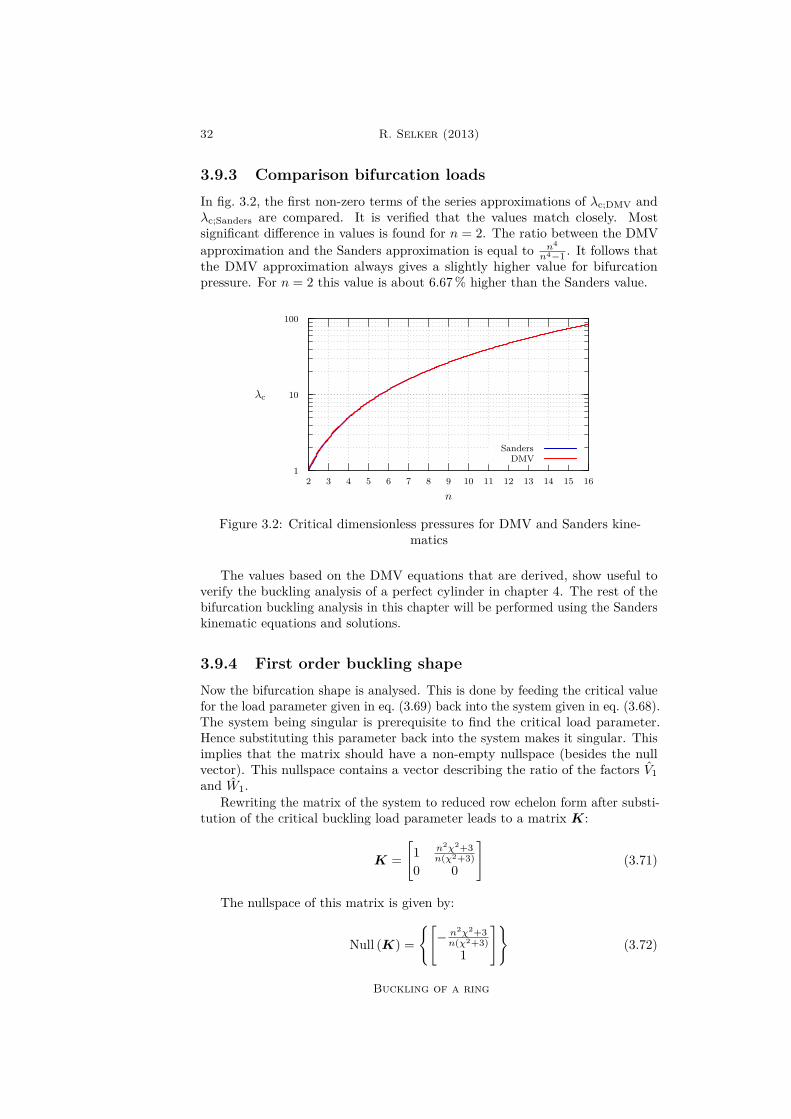
3.9.3 Comparison bifurcation loadsIn fig. 3.2, the first non-zero terms of the series approximations of λc;DMV andλc;Sanders are compared. It is verified that the values match closely. Mostsignificant difference in values is found for n = 2. The ratio between the DMVapproximation and the Sanders approximation is equal to n4
n4−1 . It follows thatthe DMV approximation always gives a slightly higher value for bifurcationpressure. For n = 2 this value is about 6.67% higher than the Sanders value.
1
10
100
2 3 4 5 6 7 8 9 10 11 12 13 14 15 16
λc
n
SandersDMV
Figure 3.2: Critical dimensionless pressures for DMV and Sanders kine-matics
The values based on the DMV equations that are derived, show useful toverify the buckling analysis of a perfect cylinder in chapter 4. The rest of thebifurcation buckling analysis in this chapter will be performed using the Sanderskinematic equations and solutions.
3.9.4 First order buckling shapeNow the bifurcation shape is analysed. This is done by feeding the critical valuefor the load parameter given in eq. (3.69) back into the system given in eq. (3.68).The system being singular is prerequisite to find the critical load parameter.Hence substituting this parameter back into the system makes it singular. Thisimplies that the matrix should have a non-empty nullspace (besides the nullvector). This nullspace contains a vector describing the ratio of the factors V1and W1.
Rewriting the matrix of the system to reduced row echelon form after substi-tution of the critical buckling load parameter leads to a matrix K:
K =[
1 n2χ2+3n(χ2+3)
0 0
](3.71)
The nullspace of this matrix is given by:
Null (K) =[− n2χ2+3n(χ2+3)
1
](3.72)
Buckling of a ring

Local buckling collapse of marine pipelines 33
This leads to V1 = − n2χ2+3n(χ2+3) and W1 = 1. It is allowed to put a shared multi-
plication factor in front of both parameters. Setting W1 = 1 is in correspondencewith Budiansky [5], because he states that a suitable value for the norm of thefirst order generalised displacement u1 is unity. This allows, in this case, thefactor ζ to be a good representation of the amount of buckling shape that isincluded into the system. Generally it is possible to satisfy this constraint foronly one displacement component. In this analysis this is done for w1.
The buckling shape that is obtained reads:
v1(θ) = − n2χ2 + 3n (χ2 + 3) sin(nθ) (3.73a)
w1(θ) = cos(nθ) (3.73b)Now assume that the norm ‖f‖ of a function f(u) on domain Ω ∈ [0, 2π] can
be obtained by the following relation:
‖f‖ = 1π
∫Ωf(u)2δu (3.74)
This definition for the norm of a function will satisfy ‖w1‖= 1. Note that ingeneral ‖v1‖6= 1.
3.9.5 Bifurcation load for dead pressureThe analysis can also be performed for dead pressure instead of hydrostatic pres-sure. Therefore the external energy functional given in eq. (3.28) is substitutedfor eq. (3.29). Sanders shell equations will give the same result as the DMV shellequations. If an analysis is performed analogous to the previous analysis for thehydrostatic pressure case, the bifurcation load for the system loaded by deadpressure can be determined.
The fundamental solution will match the fundamental solution given ineq. (3.57). This makes sense because no rotations occur for the fundamentalsolution. Further the first order strains in the hydrostatic pressure case wereneglected with respect to unity. Hence the result for the dead pressure case is asexpected.
Now the bifurcation equations are obtained for the dead pressure case. Per-forming the Eigenvalue analysis on this set of equations using the ansatzesintroduced in eq. (3.63) leads to the following bifurcation load parameter:
λc;dead = 13n
2 (3.75)If this is compared to the first term of eq. (3.70) it can be seen that the
difference in bifurcation load between the hydrostatic pressure case and the deadpressure case is significant for relatively small values for n.
The obtained results for λc;Sanders in eq. (3.70) and λc;dead in eq. (3.75)correspond to the first terms of the expansions obtained in Kämmel [24].
The buckling shape of the dead pressure load can be obtained by using thenullspace of the matrix used in the Eigenvalue analysis where the bifurcationload parameter λc;dead is substituted for the load parameter λ. This leads to thefirst order buckling shapes of:
v1(θ) = − 1n sin(nθ) (3.76a)
w1(θ) = cos(nθ) (3.76b)
Buckling of a ring

34 R. Selker (2013)
3.10 Initial post-bucklingTo be able to predict the behaviour of a system right after occurrence of bifurca-tion buckling, it will suffice to analyse the nature of the equilibrium around itsbifurcation point. The procedure as described in chapter 2 is followed to obtainthe initial post-buckling behaviour of a perfectly circular ring.
3.10.1 Post-buckling load parameter λ1
To obtain a value for λ1, eq. (2.38) is used. First an expression for Π′′′c u31 is
obtained. This can be done by making use of eq. (3.47c) and applying eqs. (2.26)and (2.31a). Now the following is obtained:
Π′′′c u31 =
∫ 2π
0
(9χ−2N1ϕ
21)
dθ (3.77)
Where:
ϕ1 = −w1,θ + v1 (3.78a)N1 = v1,θ + w1 (3.78b)
Substituting he first order buckling deformation functions given in eq. (3.73)gives:
Π′′′c u31 = 0 (3.79)
Now Π′′cu21 is obtained by making use of eq. (3.47b) and applying eqs. (2.26)
and (2.31b). This leads to:
Π′′cu21 =
∫ 2π
03(−ϕ2
1 + w21 + w1v1,θ − v1w1,θ + v2
1)
dθ (3.80)
Substituting the buckling solution given in eq. (3.73) gives:
Π′′cu21 = −3π
(n2 − 1
)(3.81)
λ1 is obtained by using eq. (2.38) and the previously obtained values:
λ1 = 0 (3.82)
Note that for symmetric buckling it is expected that λ1 = 0. Hence the resultmeets the expectations.
3.10.2 Second order buckling shapeThe second order buckling shape u2 is described by the displacement functionsv2(θ) and w2(θ). A system of linear ordinary differential equations can beobtained from eq. (2.37a). By using eq. (3.82) this reduces to:
Π′′cu2δu+ 12Π′′′c u2
1δu = 0 (3.83)
Now it is clear that the first term leads to the bifurcation equation given ineq. (2.36). The only difference is that the terms v1 and w1 have to be substitutedfor v2 and w2 respectively. The second term in eq. (3.83) in fact adds a term to
Buckling of a ring

Local buckling collapse of marine pipelines 35
each equation in the new bifurcation equation. By making use of eq. (3.47c) thefollowing identity is found:
Π′′′c u21δu =
∫ 2π
0
(6χ−2ϕ1 N1 − ϕ1,θ δv + 3χ−2
2 (N1ϕ1),θ + ϕ2
1
δw)
dθ(3.84)
Where:
ϕ1 = −w1,θ + v1 (3.85a)N1 = v1,θ + w1 (3.85b)
Substituting the bifurcation solution given in eq. (3.73) in eq. (3.84) leads to:
Π′′′c u21δu =
∫ 2π
0
−9λ2
cnχ2
(3 + χ2) sin (2nθ) δv
− 9λ2c
2n2χ2(
4χ2n2 + 3)
cos (2nθ)− 3δw
dθ (3.86)
Multiplying this with a factor 12 and summing it with eq. (3.60) where v1
and w1 are substituted by v2 and w2 gives description of eq. (3.83). If noweach coefficient of δv and δw is set to zero separately, the following system ofequations is obtained:
3N2,θ + χ2M2,θ = −9λ2c
2n(3 + χ2) sin (2nθ) (3.87a)
χ2M2,θθ − 3N2 − 3λcχ2 (e2 − κ2) = −9λ2
c4n2
(4χ2n2 + 3
)cos (2nθ)− 3
(3.87b)
Where:
ϕ2 = −w2,θ + v2 (3.88a)M2 = ϕ2,θ (3.88b)N2 = v2,θ + w2 (3.88c)
Further e2 = N2 and κ2 = ϕ2,θ. Solving the homogeneous part of the system,dropping the right-hand side of eq. (3.87), would lead to the first order bifurcationsolution. However in section 2.4 it stated that the first order buckling solutionneeds to be independent of the higher order solutions. Therefore the solution tothe homogeneous part of the differential equations has to be neglected.
To obtain a solution to the inhomogeneous system of differential equations, asolution is sought that is independent to the first order bifurcation solution. Asolution is for v2 and w2 is found if the following functions are assumed:
v2(θ) = V2 sin (2nθ) (3.89a)w2(θ) = W21 + W22 cos (2nθ) (3.89b)
By substituting these values into eq. (3.87) gives two equations. The first isa coefficient of sin (2nθ) set to zero and the second one is the sum of a coefficientof cos (2nθ) and a constant set to zero. Setting both coefficients and the constantterm to zero separately gives three equations. These can be solved for the three
Buckling of a ring
36 R. Selker (2013)
unknowns V2, W21 and W22 . Now the following solutions for the second orderbifurcation solutions v2 and w2 are obtained:
v2(θ) = 9λ2c
8n3 sin (2nθ) (3.90a)
w2(θ) = −9(3 + χ2)λ2
c4n2 (n2χ2 + 3) (3.90b)
3.10.3 Post-buckling load parameter λ2
To derive a value for λ2 eq. (2.39) is used. Because previously it is obtained thatλ1 = 0, the terms in the equation for λ2 related to λ1 will drop out. Hence theequation reduces to:
λ2 = −16Π′′′′c u
41 + Π′′′c u2
1u2
Π′′cu21
(3.91)
First Π′′′′c u41 is analysed. The substitutions u1 = u1, u2 = u1, u3 = u1 and
u4 = u1 are performed in eq. (3.47d). Now setting u→ u0 and λ→ λc leads tothe following identity:
Π′′′′c u41 =
∫ 2π
0
(9χ−2ϕ4
1)
dθ (3.92)
With:ϕ1 = −w1,θ + v1 (3.93)
Introducing the values for v1(θ) and w1(θ) in the identity above leads to:
Π′′′′c u41 = 27π
4χ2
(3λcn
)4(3.94)
Now the term Π′′′c u21u2 is analysed. To do so eq. (3.47c) is used. First the
substitutions u1 = u1, u2 = u1 and u3 = u2 are performed. Then let u→ u0and λ→ λc. The following is obtained:
Π′′′c u21u2 =
∫ 2π
0
(3χ−2 2N1ϕ1ϕ2 + ϕ2
1N2)
dθ (3.95)
With:
ϕ1 = −w1,θ + v1 (3.96a)N1 = v1,θ + w1 (3.96b)ϕ2 = −w2,θ + v2 (3.96c)N2 = v2,θ + w2 (3.96d)
The obtained values for v1(θ), w1(θ), v2(θ) and w2(θ) are introduced in thisrelation. Hence the following is determined:
Π′′′c u21u2 = −
π(3 + χ2) (n2χ2 + 9
)8 (n2χ2 + 3)χ2
(3λcn
)4(3.97)
Because Π′′cu21 is obtained in eq. (3.81), λ2 can be obtained from eq. (3.91).
Hence the expression for the post-buckling load parameter λ2 reads:
Buckling of a ring

Local buckling collapse of marine pipelines 37
λ2 =27(6n2 − 1
−n2χ2 + 3
) (n2 − 1
)28n4 (χ2 + 3)3 (n2χ2 + 3)
λc (3.98)
3.11 Initial imperfectionsBecause the previously obtained λ1 = 0, the analysis for an ring with initialimperfections is straight forward as described in section 2.6. Compared to theperfect ring analysis, the only parameter that needs to be adjusted is λ2. Theadjusted second order post-buckling load parameter is denoted by: λ2 and canbe obtained using eq. (2.53). This equation reads:
λ2 = λ2 −ξΨ′∗c uu1
ζ3Π′′cu21
(3.99)
It has to be assumed that the initial imperfection of the ring can be describedin the shape of the first order buckling mode given in eq. (3.73). Now a factor ξis introduced that denotes the imperfection of the ring. This scalar imperfectionparameter is also referred to as the ovality. The ovality is defined as:
ξ = ρmax − ρminρmax + ρmin
(3.100)
This ovality will be equal to the amplitude of the dimensionless imperfectionfunction w(θ). Dimensions in the imperfection function are removed by dividingby the mean radius. If the shape of the imperfection is described by v(θ) = v1(θ)and w(θ) = w1(θ). The following relations are valid:
v = ξv (3.101a)w = ξw (3.101b)
An energy functional Ψ[v(λ), w(λ); v, w;λ] containing the additional potentialenergy of the imperfect system with respect to the perfect system is derived ineq. (3.44). Now Ψ′∗c uu1 can be obtained and reads:
Ψ′∗c uu1 =∫ 2π
03λc
(−ϕ1ϕ+ w1w + 1
2 w1v,θ + wv1,θ − v1w,θ − vw1,θ+ v1v)
dθ(3.102)
Where:
ϕ1 = −w1,θ + v1 (3.103a)ϕ = −w,θ + v (3.103b)
Substituting eq. (3.73) and assuming the previously stated v = v1 and w = w1gives:
Ψ′∗c uu1 = −3π(n2 − 1
)λc (3.104)
Now λ2 is obtained by using eq. (3.99). Substituting eq. (3.81) leads to:
λ2 = λ2 −ξ
ζ3λc (3.105)
Buckling of a ring
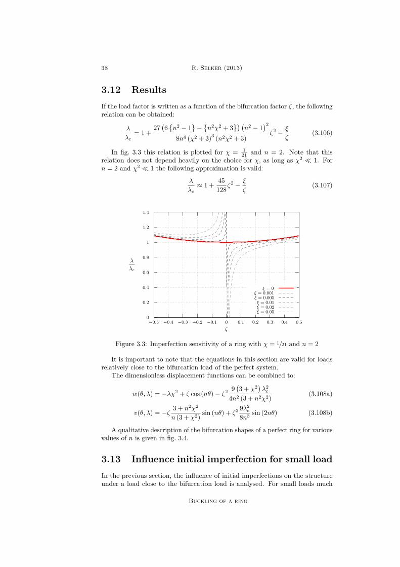
38 R. Selker (2013)
3.12 ResultsIf the load factor is written as a function of the bifurcation factor ζ, the followingrelation can be obtained:
λ
λc= 1 +
27(6n2 − 1
−n2χ2 + 3
) (n2 − 1
)28n4 (χ2 + 3)3 (n2χ2 + 3)
ζ2 − ξ
ζ(3.106)
In fig. 3.3 this relation is plotted for χ = 121 and n = 2. Note that this
relation does not depend heavily on the choice for χ, as long as χ2 1. Forn = 2 and χ2 1 the following approximation is valid:
λ
λc≈ 1 + 45
128ζ2 − ξ
ζ(3.107)
0
0.2
0.4
0.6
0.8
1
1.2
1.4
−0.5 −0.4 −0.3 −0.2 −0.1 0 0.1 0.2 0.3 0.4 0.5
λ
λc
ζ
ξ = 0ξ = 0.001ξ = 0.005ξ = 0.01ξ = 0.02ξ = 0.05
Figure 3.3: Imperfection sensitivity of a ring with χ = 1/21 and n = 2
It is important to note that the equations in this section are valid for loadsrelatively close to the bifurcation load of the perfect system.
The dimensionless displacement functions can be combined to:
w(θ, λ) = −λχ2 + ζ cos (nθ)− ζ2 9(3 + χ2)λ2
c4n2 (3 + n2χ2) (3.108a)
v(θ, λ) = −ζ 3 + n2χ2
n (3 + χ2) sin (nθ) + ζ2 9λ2c
8n3 sin (2nθ) (3.108b)
A qualitative description of the bifurcation shapes of a perfect ring for variousvalues of n is given in fig. 3.4.
3.13 Influence initial imperfection for small loadIn the previous section, the influence of initial imperfections on the structureunder a load close to the bifurcation load is analysed. For small loads much
Buckling of a ring

Local buckling collapse of marine pipelines 39
n = 2 n = 3 n = 4 n = 5
Figure 3.4: Initial and bifurcation shapes of a perfect ring for variousvalues of n.
smaller than the bifurcation load the results of this analysis are not reliable.To obtain the structural behaviour for small loads, the total potential energyfunctional per unit length Π of the structure with initial imperfections is used.
Equilibrium in the structure will occur when the potential energy functionalis stationary. Hence the first variation of this energy functional must be equalto zero. This can be satisfied by satisfying a set of equilibrium equations thatcan be obtained from applying the Euler-Lagrange equations with respect to vand w onto Π. Now the following set of equilibrium equations is obtained:
3N,θ + χ2M,θ − 3 (N + ϕϕ) (ϕ+ ϕ) + 3 (ϕϕ),θ = 3λχ2 (ϕ+ ϕ) (3.109a)χ2M,θθ − 3N − 3 (N + ϕϕ ϕ+ ϕ),θ − 3ϕϕ = 3λχ2 (1 + v,θ + w + v,θ + w)
(3.109b)
Where:
ϕ = −w,θ + v (3.110a)M = ϕ,θ (3.110b)N = v,θ + w + 1
2ϕ2 (3.110c)
ϕ = −w,θ + v (3.110d)
In eq. (3.109b), the coefficient of 3λχ2 at the right-hand side of the equationcan be simplified in the framework of small middle surface strains and smallinitial imperfections. It is allowed to drop the terms v,θ+w+ v,θ+w with respectto unity, because they their summation with unity approximates 1 + e + e ≈(1 + e) (1 + e) ≈ 1. Hence the system of equations is simplified to:
3N,θ + χ2M,θ − 3 (N + ϕϕ) (ϕ+ ϕ) + 3 (ϕϕ),θ = 3λχ2 (ϕ+ ϕ) (3.111a)χ2M,θθ − 3N − 3 (N + ϕϕ ϕ+ ϕ),θ − 3ϕϕ = 3λχ2 (3.111b)
Now the description for the imperfection is introduced again as the productof the ovality and a shape function that is described by the first order bifurcationmode shape given in eq. (3.73) such that eq. (3.101) is valid. The followingexpansion of the displacement components v and w in terms of the small ovalityterm ‖ξ‖ 1 is introduced:
v(θ) = v0 + ξv1 (3.112a)w(θ) = w0 + ξw1 (3.112b)
Buckling of a ring
40 R. Selker (2013)
The fundamental solutions v0 and w0 are obtained by substituting theseexpansions and the relations v = ξv and w = ξv into the simplified equilibriumequations given in eq. (3.111). Here v and w describe the imperfection shapefunctions. Setting the small ovality parameter ξ to zero and solving for constantfundamental solutions with respect to dimensionless coordinate θ leads to sameidentity as obtained in eq. (3.56). By constraining rigid ring rotations ordisplacements it is allowed to let v0 = 0 and hence exactly the same fundamentalsolutions are obtained as in eq. (3.57):
v0(θ) = 0 (3.113a)w0(θ) = −λχ2 (3.113b)
After obtaining this fundamental solution, the non-simplified equilibriumequations given in eq. (3.109) are used to determine v1 and w1. The expansionsgiven in eq. (3.112) are substituted into the system of equilibrium equations. Nowtake for the two equations the coefficient terms of the first power of ξ. Note thatin the analysis previously the same type of analysis is performed on which onlyfor the determination of the fundamental solution the equilibrium equations aresimplified. In fact this will give a residual term in the non-simplified equilibriumequation, but it can be verified that this term is insignificant to the solution ofto system. The following equilibrium equations are obtained for v1 and w1:
3N1,θ + χ2M1,θ = 0 (3.114a)χ2M1,θθ − 3N1 = 3λχ2 (e1 + e− κ1 − κ) (3.114b)
Where:
M1 = −w1,θθ + v1,θ (3.115a)N1 = v1,θ + w1 (3.115b)e1 = N1 (3.115c)κ1 = M1 (3.115d)e = v,θ + w (3.115e)κ = −w,θθ + v,θ (3.115f)
Now, as in eq. (3.63), the following functions are assumed for v1 and w1:
v1(θ) = V1 sin(nθ) (3.116a)w1(θ) = W1 cos(nθ) (3.116b)
Substituting these relations into eq. (3.114) will lead to two equations. Bysolving these equations, the following equations are obtained for v1 and w1:
v1(θ) = − λ
λc − λ
(n2χ2 + 3n (χ2 + 3)
)sin(nθ) (3.117a)
w1(θ) = λ
λc − λcos(nθ) (3.117b)
To be able to relate it to the method described previously the amount of firstorder buckling mode included is compared. Hence ζv1(θ) and ζw1 with v1 and
Buckling of a ring

Local buckling collapse of marine pipelines 41
w1 obtained in eq. (3.73) is related to ξv1 and ξw1 with v1 and w1 obtained ineq. (3.117). If is assumed that the two methods describe the same function foreither v or w the following relation is obtained between ζ and ξ:
ζ = λξ
λc − λ(3.118)
From this the relation is obtained:
λ
λc= 1− ξ
ζ + ξ(3.119)
In fig. 3.5 the bifurcation response of a ring is given for various wave numbersn describing the initial geometric imperfection.
n = 2 n = 3 n = 4 n = 5
Figure 3.5: Initial and bifurcation shapes of a ring with an initial imper-fection described by wave number n.
3.14 Matching resultsTo give a complete description of the relation of λ and ζ it is necessary to matchthe solution for small a load parameter given in eq. (3.119) and the solution forload parameters within close range of the bifurcation load given in eq. (3.106).In this section the inner solution will refer to the solution for a small load andthe outer solution will refer to the solution for loads close to the bifurcation load.
It must be assumed that the ovality is small such that ‖ξ‖ 1. The matchingof the two functions is analogous to matching functions in a boundary layer asdescribed by Howison [22]. Here the inner solution will describe the behaviourof the system at the boundary and the outer solution will describe its behaviourat further distance of this layer. Now assume that the inner solution is valid forζ = O(ξ) and the outer solution is valid for ζ O(ξ).
Outer solution
The outer solution is given by eq. (3.106). Because it is stated that this solutionis valid if ζ O(ξ), ξ may be dropped with respect to ζ. Hence the followingapproximation is valid for the outer solution:
λ
λc= 1 +
27(6n2 − 1
−n2χ2 + 3
) (n2 − 1
)28n4 (χ2 + 3)3 (n2χ2 + 3)
ζ2 (3.120)
The limit of this function for ζ → 0 is equal to one.
Buckling of a ring
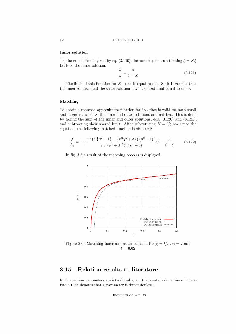
42 R. Selker (2013)
Inner solution
The inner solution is given by eq. (3.119). Introducing the substituting ζ = Xξleads to the inner solution:
λ
λc= X
1 +X(3.121)
The limit of this function for X →∞ is equal to one. So it is verified thatthe inner solution and the outer solution have a shared limit equal to unity.
Matching
To obtain a matched approximate function for λ/λc that is valid for both smalland larger values of λ, the inner and outer solutions are matched. This is doneby taking the sum of the inner and outer solutions, eqs. (3.120) and (3.121),and subtracting their shared limit. After substituting X = ζ/ξ back into theequation, the following matched function is obtained:
λ
λc= 1 +
27(6n2 − 1
−n2χ2 + 3
) (n2 − 1
)28n4 (χ2 + 3)3 (n2χ2 + 3)
ζ2 − ξ
ζ + ξ(3.122)
In fig. 3.6 a result of the matching process is displayed.
0
0.2
0.4
0.6
0.8
1
1.2
0 0.1 0.2 0.3 0.4 0.5
λ
λc
ζ
Matched solutionInner solutionOuter solution
Figure 3.6: Matching inner and outer solution for χ = 1/21, n = 2 andξ = 0.02
3.15 Relation results to literature
In this section parameters are introduced again that contain dimensions. There-fore a tilde denotes that a parameter is dimensionless.
Buckling of a ring
Local buckling collapse of marine pipelines 43
3.15.1 Timoshenko formulationTo obtain the Timoshenko equation [45] for collapse of a ring, it is assumed thatcollapse occurs at first yielding of the material. First yielding occurs when theouter fibre stress reaches the yield strength of the material fy. The occurringstrain can be obtained using eq. (3.17). Now the occurring stress can be obtainedfrom this strain and eq. (3.19). To be able to use the dimensionless form κ, thefollowing identity is used: κ = κρ−1. For the occurring stress the following isobtained:
σ = Ee+ Ez
ρκ (3.123)
The dimensionless kinematic relations given in eq. (3.43) are substituted intothis relation. For the displacement functions v and w, Timoshenko and Gere usethe ones obtained from the analysis for small λ as performed in section 3.13:
v(θ) = − λξ
λc − λ
(n2χ2 + 3n (χ2 + 3)
)sin(nθ) (3.124a)
w(θ) = λξ
λc − λcos(nθ)− λχ2 (3.124b)
Using these displacement functions, it follows that the maximum absolutestress value occurs for z = 1
2 t and θ = 12π. Because collapse is assumed to occur
at first yielding of the material, the collapse criterion is the extreme fibre stressto reach the (tensile or compressive) yield stress. If is assumed that both thecompressive and tensile yield stress have the same absolute value, first yieldingwill be reached in the compressive region. Hence the maximum stress is putequal to the compressive (negative sign) yield strength of the material. Rewritingthe equation to dimensional parameters will lead to the following criterion foroccurrence of collapse of a ring:
P 2 −(fyt
ρ+
1− ξ + 6ξ ρt
Pc
)P + fyt
ρPc = 0 (3.125)
Where:Pc =
E(n2 − 1
)12 + (t/ρ)2
(t
ρ
)3(3.126)
For ‖ξ‖ 1 and (t/ρ)2 1 it is allowed to simplify the collapse criterion tothe Timoshenko collapse criterion. When this second order polynomial is solvedfor P , the collapse load is obtained:
P 2 −(fyt
ρ+
1 + 6ξ ρt
Pc
)P + fyt
ρPc = 0 (3.127)
Where Pc is the classical buckling load for an elastic ring defined by:
Pc =E(n2 − 1
)12
(t
ρ
)3(3.128)
For an infinitely long cylinder it can be assumed that no strains occur in theout of plane direction of the ring. From Hooke’s law follows that the modulusof elasticity is adjusted by a factor
(1− ν2). In other words, a plane stress
Buckling of a ring

44 R. Selker (2013)
criterion is modified to a plane strain criterion. The classical buckling load foran infinitely long cylinder is given by:
Pc =E(n2 − 1
)12 (1− ν2)
(t
ρ
)3(3.129)
This relation is used in the Timoshenko collapse criterion given in eq. (3.127)to obtain the collapse criterion at first yielding for a long cylinder. It is convenientto rewrite this criterion into dimensionless form. First the dimensionless yieldstrength is introduced:
fy = fyEχ2 (3.130)
By making use of this identity, eq. (3.127) can be rewritten to the dimension-less Timoshenko criterion:
λ2 −(fy +
1 + 3ξ
χ
λc
)λ+ fyλc = 0 (3.131)
Solving this polynomial for λ results to the dimensionless collapse load. Hereλc is the dimensionless bifurcation load for a ring or a cylinder such that:
λc =
13(n2 − 1
), for a ring
n2 − 13 (1− ν2) , for a cylinder
(3.132a)
(3.132b)
3.15.2 DNV formulationThe DNV equation [9] is based on the same idea as the Timoshenko equation.Only now collapse is assumed after the full development of a plastic hinge. Thisplastic hinge is based on an elastic-perfectly plastic material model. The plastichinge is fully developed as soon as the stress reaches the yield strength in thefull cross section of the ring wall. The modulus of elasticity is assumed to beconstant until the criterion is satisfied. For the full development of the plastichinge the following criterion has to be satisfied:
‖M‖Mpl
+(N
Npl
)2= 1 (3.133)
Where:
Mpl = 14fyt
2 (3.134a)Npl = fyt (3.134b)
Collapse of the system is assumed for the load at which the criterion issatisfied at any location. Therefore the criterion is analysed for all coordinatesθ ∈ [0, 2π]. M and N can be obtained from eq. (3.41) and the dimensionlesskinematic relations given in eq. (3.43). The displacement relations for smallλ λc given in eq. (3.124) are used, as in the Timoshenko criterion, to obtainthe DNV collapse criterion.
Buckling of a ring

Local buckling collapse of marine pipelines 45
It can be verified that critical results are obtained for θ = 0. The followingidentities are obtained at this location:
M(0) = PPcξρ2
Pc − P(3.135a)
N(0) = − (1 + ξ)Pc − PPc − P
Pρ (3.135b)
Substituting these identities into the plastic hinge criterion leads to a newcollapse criterion. Further introduce a purely plastic yield pressure Pp = t
ρfy,which describes the pressure to induce yielding in a ring under compression only.The criterion becomes:
(P − Pc)(P 2 − P 2
p)
= 4PPcξ
(ρtPp + 1
2P
1 + ξ
2 (1− P/Pc)
)(3.136)
It should always be the case that P ≤ Pp and P < Pc. Further for practicalcases it is assumed that the ring is thin to moderately thin (‖ tρ‖ 1) and ‖ξ‖ 1.Now the criterion can be approximated by:
(P − Pc)(P 2 − P 2
p)
= 4PPcPpρt ξ (3.137)
This criterion matches the buckling collapse criterion of DNV [9] for a pipelineif the following identities are used:
Pp = tρfyαfab (3.138a)
Pc =E(n2 − 1
)12 (1− ν2)
(t
ρ
)3(3.138b)
With the classical elastic collapse pressure for an infinitely long cylinder Pc isobtained from eq. (3.129). Further αfab is a fabrication factor that accounts forthe reduction in compressive yield strength of the material due to the Bauschingereffect. The Bauschinger effect occurs due to cold bending of the plates duringthe fabrication process of the pipeline joints. To match with DNV regulations itis necessary to let n = 2.
For this criterion it is also convenient to rewrite it to dimensionless form. Inorder to do so the dimensionless plastic collapse load is introduced and reads:
λp = αfabfy (3.139)
Equation (3.137) can now be rewritten to its dimensionless form:
(λ− λc)(λ2 − λ2
p)
= 2λλcλpξ
χ(3.140)
Where λc is given by eq. (3.132).
Buckling of a ring

This page is intentionally left blank.
Chapter 4
Buckling of a cylinder
In the previous chapter the bifurcation and buckling behaviour of a ring isanalysed. A ring is the two dimensional model of a pipeline joint. A cylinderis the three dimensional model of a pipeline joint. Therefore a new curvilinearcoordinate axis is introduced, the axial axis. The axial coordinate is denoted byx and its dimensionless equivalent is denoted by η.
In this chapter Koiter’s perturbation theory is used to obtain the bifurcationbehaviour of the system. This theory is combined with boundary layer theory.A cylinder is found to have strong boundary layer behaviour when subjectto external pressure and certain boundary conditions i.e. clamped or simplysupported edges. It is assumed that between the boundary layers there is aregion for which the effect of the boundary conditions is insignificant, the regulardomain.
Assumptions as given in section 3.1 are adopted for the cylinder model. Onlyfor the cylinder model, an additional curvilinear axis is added; the axial axis.
4.1 KinematicsKinematic relations that are adopted for the cylinder analysis are similar to onesadopted for the ring analysis. Every material point of the perfect undeformedcylinder can be described by a vector p(x1, x2, x3) = x1ı+ x2+ x3k. The unitvectors in the Cartesian coordinate system are denoted by ı, and k respectively.
A curvilinear coordinate system is introduced. It is constructed using acircumferential coordinate s ∈ [0, 2πρ], an axial coordinate x ∈ [0, L] and a radialcoordinate z ∈ [− 1
2 t,12 t]. Here ρ denotes the mean radius of the cylinder, L is
the cylinder length and t is its wall thickness. For every admissible locationon the middle surface of the cylinder (z = 0), a local coordinate system isintroduced. This local coordinate system is described by a vector tangent tothe circumferential direction, t, a normal vector perpendicular to the middlesurface n and a binormal vector b, which in the chosen coordinate system istangent to the axial coordinate axis. The displacement of a material point onthe middle surface is denoted by the vector d = ub+ vt+ wn. The location ofa material point on the deformed middle surface now can be described by thevector q = p+ d. These identities are illustrated in fig. 4.1.
Kinematic relations as described by Sanders [36] are introduced. Rotations

48 R. Selker (2013)
Undeformed cylinder
Deformed material point
x1
s
p
wn
ub
vt
t
ρ
ı
x2
q
d
x
x3
k
z
Figure 4.1: Cylinder model
about the shell normal are neglected. Underlined terms are dropped to obtainthe nonlinear Donnell-Mushtari-Vlasov (DMV) equations. These equations proveto be useful for solving the problem for a cylinder analytically.
Rotations of the middle surface are given by:
ϕx = −w,x (4.1a)ϕs = −w,s + 1
ρv (4.1b)
Curvatures are given by:
κxx = ϕx,x (4.2a)κss = ϕs,s (4.2b)κxs = 1
2 (ϕs,x + ϕx,s) (4.2c)
Middle surface strains are given by:
exx = u,x + 12ϕ
2x (4.3a)
ess = v,s + 1ρw + 1
2ϕ2s (4.3b)
exs = 12 (v,x + u,s + ϕxϕs) (4.3c)
Buckling of a cylinder

Local buckling collapse of marine pipelines 49
Due to the assumptions stated in section 3.1, a relation between the middlesurface strain, curvature and the strain at an arbitrary material point of thecylinder can be determined using the following relation:
εij = eij + κijz (4.4)
The indices i, j ∈ x, s. Further εij = εji.
4.2 Constitutive relationsConstitutive relations are used to relate material strains to occurring stresses.Using these relations, the strain energy of the system can be determined. Unlessstated otherwise, the cylinder is assumed to behave perfectly elastic. The well-known constitutive description for an elastic material model is Hooke’s law. Itsgeneralised description is given in eq. (3.18). For a shell, a two dimensionalobject, this constitutive law is written as:σxx
σssσxs
= E
1− ν2
1 ν 0ν 1 00 0 1− ν
εxxεssεxs
(4.5)
This identity is combined with the kinematic relation given in eq. (4.4). Thefollowing relation is obtained for occurring stresses, middle surface strains andcurvatures:σxx
σssσxs
= E
1− ν2
1 ν 0ν 1 00 0 1− ν
exxessexs
+ Ez
1− ν2
1 ν 0ν 1 00 0 1− ν
κxxκssκxs
(4.6)
4.3 Potential energyTo obtain the system’s equilibrium configuration, its potential energy has to beminimised. This implies minimising an integral and can be accomplished byletting its first variation be equal to zero. Now the Euler-Lagrange equationsare applied to obtain a system of equilibrium equations. First a relation for thepotential energy functional has to be found. It consists of the sum of the strainenergy and the sum of all externally applied energy (work).
4.3.1 Strain energyThe strain energy of an infinitesimal volume is given in eq. (3.20). By combiningthis and eq. (4.4), the following is obtained for the strain energy density function:
U∗ = 12σxx (exx + κxxz) + 1
2σss (ess + κssz) + σxs (exs + κxsz) (4.7)
The strain energy of an infinitesimal area of shell is can be determined byintegrating the strain energy density function over the cylinder through-thicknesscoordinate z ∈ [− 1
2 t,12 t] and by using eq. (4.6).
∫ 12 t
− 12 tU∗dz = 1
2Nijeij + 12Mijκij (4.8)
Buckling of a cylinder

50 R. Selker (2013)
Here Einstein’s summation convention is applied for i, j ∈ x, s. Thestress couple Mij denotes the bending moment per unit length in ij-direction.The stress resultant Nij denotes the axial force per unit length in ij-direction.Using earlier assumptions these identities can be used to reversely calculate theoccurring stresses. The stress couples are given by:
Mxx = Et3
12 (1− ν2) (κxx + νκss) (4.9a)
Mss = Et3
12 (1− ν2) (κss + νκxx) (4.9b)
Mxs = Et3
12 (1 + ν)κxs (4.9c)
Here Et3
12(1−ν2) represents the flexural rigidity of the shell. The stress resultantsNij are given by:
Nxx = Et
1− ν2 (exx + νess) (4.10a)
Nss = Et
1− ν2 (ess + νexx) (4.10b)
Nxs = Et
1 + νexs (4.10c)
Where Et1−ν2 is the axial rigidity of the shell. The shell domain is described
by Ω = [0, L] × [0, 2πρ], where the axial coordinate is x ∈ [0, L] and the cir-cumferential coordinate is s ∈ [0, 2πρ]. The strain energy of the system can beobtained by integrating the strain energy per unit area as given in eq. (4.8) overthe shell domain Ω:
U =∫
Ω
12 (Nijeij +Mijκij) dΩ (4.11)
4.3.2 External energyThe external energy due to external pressure on the shell is adopted from Dyauand Kyriakides [12]. It is dependent on the change of volume enclosed by thecylinder shell and the applied pressure. The corresponding energy integralfunctional reads:
WP =∫
ΩP(w + 1
2
wu,x − w,xu+ 1
ρw2 + wv,s − vw,s + 1
ρv2)
dΩ (4.12)
If end caps are attached to the cylinder, they will be subject to the samehydrostatic pressure as the external pressure on the cylinder P . It is assumedthat the end caps do not rotate under application of load. Hence the end cappressure can be treated as a dead pressure: the pressure direction is constantand independent of deformations.
The general formulation for the external work of a force F is defined by F ·u,where u is the displacement of a point at which F is applied and the dot denotesthe inner product of the two vectors. The value of the stress resultant Nxx atthe boundaries, the locations of the end caps, can be obtained from the pressure
Buckling of a cylinder
Local buckling collapse of marine pipelines 51
and the ratio of the area and perimeter of an end cap: πρ2
2πρP = 12Pρ. The energy
corresponding to the work done by this end cap pressure reads:
WE =∫ 2πρ
0
12Pρ u(L)− u(0)ds
=∫ 2πρ
0
∫ L
0
12Pρu,xdxds
(4.13)
This can be rewritten such that the expression for the external energy dueto the end cap pressure on the shell edge reads:
WE =∫
Ω
12Pρu,xdΩ (4.14)
Note that this term drops out in the equilibrium equations and needs to beintroduced in the analysis using a boundary condition. The potential energy ofthe system can be obtained by combining the previously obtained relations suchthat:
Π = U +WP + αWE (4.15)
The factor α ∈ 0, 1 denotes whether to include the influence of the end-cappressure in the analysis.
4.4 System of equations
4.4.1 Equilibrium equationEquilibrium equations follow from minimising the potential energy functionalgiven in eq. (4.15). As obtained in eq. (2.23), this can be accomplished by settingits first variation to zero such that:
δΠ = Π′δu = 0 (4.16)
Making use of the Euler-Lagrange equations results in a system of threeequilibrium equations, one for each displacement component u, v and w:
Nxx,x +Nxs,s = Pϕx (4.17a)Nss,s +Nxs,x + 1
ρ (Mss,s +Mxs,x − ϕsNss − ϕxNxs) = Pϕs (4.17b)
Mxx,xx + 2Mxs,xs +Mss,ss − 1ρNss − (Nxxϕx +Nxsϕs),x
− (Nssϕs +Nxsϕx),s = P(
1 + u,x + v,s + 1ρw) (4.17c)
The underlined terms drop out for the DMV kinematic equations. In furtheranalysis the DMV approximations are used. A potential function F is introduced.This function is equivalent to the Airy-stress function, but is modified to accountfor the rotation of the pressure during deformation. This potential function isdefined by:
F,xx ≡ Nss + Pw (4.18a)F,ss ≡ Nxx + Pw (4.18b)
Buckling of a cylinder

52 R. Selker (2013)
F,xs ≡ −Nxs (4.18c)
Choosing a potential stress function in this form satisfies the first two equi-librium equations. However, two unknown functions, F and w, remain. To beable to solve this system, an additional equation is needed. This equation iscalled the compatibility condition.
4.4.2 Compatibility condition
To obtain the compatibility condition, the following identity is evaluated:
exx,ss + ess,xx − 2exs,xs (4.19)
Rewriting eq. (4.10) gives:
exx = 1Et
(Nxx − νNss) (4.20a)
ess = 1Et
(Nss − νNxx) (4.20b)
exs = 1 + ν
EtNxs (4.20c)
After combining eqs. (4.18) to (4.20), the following relation can be obtained:
exx,ss + ess,xx − 2exs,xs = 1Et∇4F − P 1− ν
Et∇2w (4.21)
Here ∇4 denotes the biharmonic operator and ∇2 is the Laplace operatorsuch that:
∇2 = ∂2
∂x2 + ∂2
∂s2 (4.22a)
∇4 = ∂4
∂x4 + 2 ∂4
∂x2∂s2 + ∂4
∂s4 (4.22b)
The following relation is determined using the DMV kinematic relations givenin section 4.1:
exx,ss + ess,xx − 2exs,xs = 1ρw,xx − L11 [w,w] (4.23)
Operator L11 denotes a bilinear operator such that:
L11 = ∂2
∂x2∂2
∂s2 − 2 ∂2
∂x∂s
∂2
∂x∂s+ ∂2
∂s2∂2
∂x2 (4.24)
Substituting eq. (4.23) into eq. (4.21) results in the compatibility equation:
(4.25)1Et∇4F − 1
ρw,xx + 12L11 [w,w]− P 1− ν
Et∇2w = 0
Buckling of a cylinder
Local buckling collapse of marine pipelines 53
4.4.3 System of equilibrium equationsNow that the compatibility equation is obtained, it is convenient to rewrite theequilibrium equation in terms of F and w. This is done by substituting eq. (4.18)into eq. (4.17c) and leads to the following equilibrium equation:
Et3
12 (1− ν2)∇4w + 1
ρF,xx − L11 [F,w] + P
1− w(
1ρ −∇
2w)
+Pu,x + v,s + 1
ρw + ϕ2x + ϕ2
s
= 0
(4.26)
Using eq. (4.3), the following identity can be obtained:
u,x + v,s + 1ρw + ϕ2
x + ϕ2s = exx + ess + 1
2ϕ2x + 1
2ϕ2s (4.27)
Because a framework of small strains and moderate rotations is adopted,linear strain terms and quadratic rotation terms can be neglected with respectto unity. Hence it is allowed to simplify eq. (4.26) to the equilibrium equation:
Et3
12 (1− ν2)∇4w + 1
ρF,xx − L11 [F,w] + P
1− w(
1ρ −∇
2w)
= 0 (4.28)
Combining this equilibrium equation and the previously obtained compatibil-ity condition gives the following system of equations that has to be satisfied fora cylinder under external hydrostatic pressure:
Et3
12 (1− ν2)∇4w + 1
ρF,xx − L11 [F,w] + P
1− w(
1ρ −∇
2w)
= 0 (4.29a)
1Et∇4F − 1
ρw,xx + 12L11 [w,w]− P 1− ν
Et∇2w = 0 (4.29b)
4.5 Boundary conditionsThe system can only be solved if certain boundary conditions are applied. Thebehaviour of the end caps attached to the cylinder boundaries is modelledthrough boundary conditions. One of both end caps is allowed to move in axialdirection rigidly. The other one is fully constrained. The end caps are assumedto behave completely rigid. Hence the radial deformation w is constrained atthe end caps, such that ∀x ∈ 0, L : w = 0.
Two possibilities for the connection between the ends caps and the cylinderwalls are investigated:
i Simply supported - Rotations are allowed, but the value of the stresscouple Mxx should be zero. This results to ∀x ∈ 0, L : w,xx = 0.
ii Clamped - Rotations are constrained at the boundaries. Hence a stresscouple with respect to the axial coordinate can exist at the boundaries, suchthat ∀x ∈ 0, L : w,x = 0.
Regardless of the support conditions described above, the end cap pressure isintroduced by the equilibrium of resultant forces in axial direction in the cylinderwall. Rotational rigid body constraints are assumed to be absent. Hence there
Buckling of a cylinder
54 R. Selker (2013)
should not be any resultant shear force at the end cap locations. Resultant forcescan be obtained by integrating the stress resultants over the circumference of thecylinder. Now axial and shear force equilibria at the boundaries are given by:
∀x ∈ 0, L :
∫ 2πρ
0Nxxds+ αPπρ2 = 0,∫ 2πρ
0Nxsds = 0
(4.30a)
(4.30b)
Using eq. (4.18), this condition can be rewritten to:
∀x ∈ 0, L :
∫ 2πρ
0F,ssds+ P
(απρ2 −
∫ 2πρ
0wds
)= 0,∫ 2πρ
0F,xsds = 0
(4.31a)
(4.31b)
Continuity of the stress resultant in axial direction is ensured by:
∀x ∈ [0, L] : Nxx|s=2πρ − Nxx|s=0 = 0 (4.32)
This is equivalent to:
∀x ∈ [0, L] :∫ 2πρ
0Nxx,sds = 0 (4.33)
Substitution of eq. (4.18) and rewriting to integral form leads to:
∀x ∈ [0, L] :∫ 2πρ
0(F,sss − Pw,s) ds = 0 (4.34)
The final constraint is the closed (or periodic) condition as given by Shenand Chen [37, 38, 39] and Sun and Chen [44]:
∀x ∈ [0, L] :∫ 2πρ
0v,sds (4.35)
This condition should be satisfied on all admissible x ∈ [0, L]. By makinguse of eqs. (4.3), (4.18) and (4.20), the closed condition can be written to:
∀x ∈ [0, L] :∫ 2πρ
0
1Et
(F,xx − νF,ss)− w(
1ρ + P (1− ν)
Et
)− 1
2w2,s
ds = 0
(4.36)The previous results in the following set of constraints for the cylinder
problem:
∀x ∈ 0, L :
w = 0,w,x = 0 or w,xx = 0,∫ 2πρ
0F,ssds+ P
(απρ2 −
∫ 2πρ
0wds
)= 0,∫ 2πρ
0F,xsds = 0
,
(4.37a)(4.37b)
(4.37c)
(4.37d)
Buckling of a cylinder

Local buckling collapse of marine pipelines 55
∀x ∈ [0, L] :∫ 2πρ
0(F,sss − Pw,s) ds = 0,∫ 2πρ
0
1Et
(F,xx − νF,ss)− w(
1ρ + P (1− ν)
Et
)− 1
2w2,s
ds = 0
(4.37e)
(4.37f)
Here eq. (4.37b) is the boundary condition that varies for a clamped and asimply supported cylinder.
4.6 Nondimensionalisation of systemTo be able to generalise the analysis’ results, it is convenient to rewrite thesystem to dimensionless form. By choosing dimensionless variables in a waysuch that the highest order derivative terms in either equilibrium equation aremultiplied by a small factor the system’s boundary layers can be analysed.
The following dimensionless variables are introduced:
η = x
L, θ = s
ρ, w = w
ρ, f = F
Etρ2 ,
λ =4Pρ3 (1− ν2)
Et3, γ = ρ
L, χ = t
2ρ
(4.38)
Here η ∈ [0, 1] and θ ∈ [0, 2π] describe the dimensionless domain of thecylinder. Using these dimensionless identities, eq. (4.29) can be rewritten toits dimensionless equivalent. The parameter small parameter χ in front of thehighest order derivative term in eq. (4.39) indicates that the system containsboundary layers. Until further notice dimensionless parameters will be used.From now on the tildes on top of the dimensionless variables are omitted. Thedimensionless system reads:
χ2∇4w + 3γ2 (1− ν2) f,ηη − L11 [w, f ]+3λχ2 1− w
(1−∇2w
)= 0
(4.39a)
∇4f − γ2 w,ηη − 12L11 [w,w]
− λχ2
1 + ν∇2w = 0 (4.39b)
Where ∇2 denotes the quadratic dimensionless Laplace operator, ∇4 denotesthe quadratic dimensionless biharmonic operator and L11 denotes a dimensionlessbilinear operator such that:
∇2 = γ2 ∂2
∂η2 + ∂2
∂θ2 (4.40a)
∇4 = γ4 ∂4
∂η4 + 2γ2 ∂4
∂η2∂θ2 + ∂2
∂θ2 (4.40b)
L11 = ∂2
∂η2∂2
∂θ2 − 2 ∂2
∂η∂θ
∂2
∂η∂θ+ ∂2
∂θ2∂2
∂η2 (4.40c)
This system is constrained by dimensionless boundary conditions. Theseboundary conditions can be obtained by introducing the dimensionless variables
Buckling of a cylinder
56 R. Selker (2013)
in eq. (4.37). The following dimensionless boundary conditions need to besatisfied for the cylinder problem:
∀η ∈ 0, 1 :
w = 0,w,η = 0 or w,ηη = 0,(
1− ν2) ∫ 2π
0f,θθdθ + λχ2
(απ −
∫ 2π
0wdθ
)= 0,∫ 2π
0f,ηθdθ = 0
,
(4.41a)(4.41b)
(4.41c)
(4.41d)
∀η ∈ [0, 1] :∫ 2π
0
(f,θθθ −
λχ2
1− ν2w,θ
)dθ = 0,∫ 2π
0
γ2f,ηη − νf,θθ − w
(1 + λχ2
1 + ν
)− 1
2w2,θ
dθ = 0
(4.41e)
(4.41f)
4.7 Solution expansions and boundary layer
4.7.1 ExpansionsIn the Koiter [26] method the solutions are expanded as a power series aboutits fundamental (pre-buckling) solution. The expansion is done in terms of aparameter ζ. The value of this parameter describes the amount of first orderbuckling mode that is included in the solution. Further the dimensionless loadparameter is expanded in a similar way. The series expansions read:
w = w0(λ) + ζw1 + ζ2w2 + . . . (4.42a)f = f0(λ) + ζf1 + ζ2f2 + . . . (4.42b)λ = λc + ζλ1 + ζ2λ2 + . . . (4.42c)
Alternatively the load parameter can be expanded in terms of the initialpost-buckling coefficients a and b, such that λ = λc
(1 + aζ + bζ2 + . . .
). This
expansion is related to eq. (4.42c) by the relations λ1 = aλc and λ2 = bλc. Forsymmetric buckling, where a = 0, the sign of buckling coefficient b will determinethe initial post-buckling stability of the system. In this thesis, the expansion asgiven in eq. (4.42c) is used.
Now w0(λ) and f0(λ) are expanded as a Taylor series about their fundamentalsolution for the critical buckling load w0(λc) and f0(λc). These series expansionsread:
w0(λ) = w0(λc) + (λ− λc)w0,λ(λc) + 12 (λ− λc)2
w0,λλ(λc) + . . . (4.43a)f0(λ) = f0(λc) + (λ− λc) f0,λ(λc) + 1
2 (λ− λc)2f0,λλ(λc) + . . . (4.43b)
Using eq. (4.42c) such that λ − λc = ζλ1 + ζ2λ2 + . . ., the Taylor seriesexpansions can be rewritten:
w0(λ) = w0(λc) + ζλ1w0,λ(λc) + ζ2 λ2w0,λ(λc) + 12λ
21w0,λλ(λc)
+ . . .
(4.44a)
Buckling of a cylinder

Local buckling collapse of marine pipelines 57
f0(λ) = f0(λc) + ζλ1f0,λ(λc) + ζ2 λ2f0,λ(λc) + 12λ
21f0,λλ(λc)
+ . . . (4.44b)
Substituting this in the power series expansions of w and f in eq. (4.42)results to the following expansions:
w = w0(λc) + ζ λ1w0,λ(λc) + w1+ ζ2 λ2w0,λ(λc) + 1
2λ21w0,λλ(λc) + w2
+ . . .
(4.45a)
f = f0(λc) + ζ λ1f0,λ(λc) + f1+ ζ2 λ2f0,λ(λc) + 1
2λ21f0,λλ(λc) + f2
+ . . .
(4.45b)
It is interesting to note that for symmetric buckling it is expected that λ1 = 0and hence the previous equations will be reduced to:
w = w0(λc) + ζw1 + ζ2 λ2w0,λ(λc) + w2+ . . . (4.46a)f = f0(λc) + ζf1 + ζ2 λ2f0,λ(λc) + f2+ . . . (4.46b)
4.7.2 Boundary layersBoundary layers (b.l.) are characterised by a rapidly varying response within asmall subdomain. In differential equations, an indication of the occurrence ofa boundary layer is a small factor or coefficient multiplying the highest orderderivative term.
Now assume that the various expansion orders as introduced in eq. (4.45)can be characterised by:
wj =
w
[i]j + w
[r]j , near η = 0
w[r]j , away from b.l.
w[r]j + w
[I]j , near η = 1
(4.47a)
fj =
f
[i]j + f
[r]j , near η = 0
f[r]j , away from b.l.
f[r]j + f
[I]j , near η = 1
(4.47b)
The [r]-superscript denotes the regular solution or outer solution. The [i]-superscript denotes boundary layer solution or inner solution near η = 0 withrespect to the regular solution. The [I]-superscript denotes the boundary layersolution near η = 1 with respect to the regular solution. Equation (4.47) is validfor all admissible j, such that the total solution for the jth order expansion canbe estimated by:
wj ≈ w[i]j + w
[r]j + w
[I]j (4.48a)
fj ≈ f [i]j + f
[r]j + f
[I]j (4.48b)
Note that eqs. (4.47) and (4.48) cannot be valid simultaneously if eitherboundary layer solution is not equal to zero. If the boundary layer solutionsvalues outside of their boundary layer domains is very small it is possible thateqs. (4.47) and (4.48) are almost satisfied. Hence the approximate relation ineq. (4.48).
Buckling of a cylinder

58 R. Selker (2013)
For separate analyses for the boundary layer and regular domains the relationsgiven in eq. (4.47) are used. For a graphical representation, see fig. 4.2. Thetotal solution of the system can be obtained by the approximation given ineq. (4.48). This results to a continuous solution that does not match theboundary constraints exactly because of some residual of the boundary layersolution on the other side of the cylinder.
w[r] + w[I] and f [r] + f [I]w[r] + w[i] and f [r] + f [i] w[r] and f [r]
η = 0 η = 1
Figure 4.2: Inner (boundary layer) and outer (regular) solutions
To perform the boundary layer analysis, the following boundary layer coordi-nates are introduced:
ξ = η√χ
and ξ = 1− η√χ
(4.49)
These coordinates rescale the axial coordinate near the boundaries. ξ denotesthe boundary layer coordinate near η = 0 and ξ denotes the boundary latercoordinate near η = 1. Dependencies on these boundary layer coordinates areadded to the solution functions. Hence w(η, θ) → w(η, θ, ξ, ξ) and f(η, θ) →f(η, θ, ξ, ξ). Note that w(η, θ) and f(η, θ) can be obtained reversely by usingeq. (4.49).
The dependencies for every jth order bifurcation solution as given in eq. (4.48)generally read:
wj(η, θ, ξ, ξ) ≈ w[i]j (θ, ξ) + w
[r]j (η, θ) + w
[I]j (θ, ξ) (4.50a)
fj(η, θ, ξ, ξ) ≈ f [i]j (θ, ξ) + f
[r]j (η, θ) + f
[I]j (θ, ξ) (4.50b)
The boundary layer solutions are constrained by boundary conditions atinfinity. These boundary conditions ensure that secular terms are removed suchthat:
limξ→∞
w[i] = 0 (4.51a)
limξ→∞
f [i] = 0 (4.51b)
limξ→∞
w[I] = 0 (4.51c)
limξ→∞
f [I] = 0 (4.51d)
Because of the boundary layer coordinates’ dependencies ξ(η) and ξ(η) onthe axial coordinate, the differential operators with respect to η need adjustment.
Buckling of a cylinder

Local buckling collapse of marine pipelines 59
These adjustments can be obtained by application of the chain rule. The followingadjustments are applied:
∂
∂η→ ∂
∂η+ ∂ξ
∂η
∂
∂ξ+ ∂ξ
∂η
∂
∂ξ(4.52a)
∂2
∂η2 →
(∂
∂η+ ∂ξ
∂η
∂
∂ξ+ ∂ξ
∂η
∂
∂ξ
)2
(4.52b)
∂4
∂η4 →
(∂
∂η+ ∂ξ
∂η
∂
∂ξ+ ∂ξ
∂η
∂
∂ξ
)4
(4.52c)
From eq. (4.49) follows:
∂ξ
∂η= 1√χ,∂ξ
∂η= − 1√χ
(4.53)
Hence eq. (4.52) can be written to:
∂
∂η→ ∂
∂η+ 1√χ
∂
∂ξ− 1√χ
∂
∂ξ(4.54a)
∂2
∂η2 →(∂
∂η+ 1√χ
∂
∂ξ− 1√χ
∂
∂ξ
)2(4.54b)
∂4
∂η4 →(∂
∂η+ 1√χ
∂
∂ξ− 1√χ
∂
∂ξ
)4(4.54c)
These modified operators are reflected in all operators containing derivativeterms with respect to axial coordinate η.
4.8 Fundamental solutionsThe fundamental solutions are the pre-buckling or -bifurcation solutions. Theydepend on the load parameter λ. For the cylinder problem, it is assumed that thefundamental solution describes an axisymmetric shape. Hence all dependenciesof w0 on coordinate θ are removed from the equations. Further it is assumed thatthe stress resultants in axial and circumferential directions are only dependenton the axial coordinate the i.e. θ-dependency is removed. Equation (4.45) issubstituted into eq. (4.39). After setting ζ to zero, the following system ofequations needs to be satisfied for the fundamental solutions w0(η) and f0(η, θ):
χ2γ4w0,ηηηη + 3γ2 (1− ν2) f0,ηη − w0,ηηf0,θθ+3λχ2 1− w0
(1− γ2w0,ηη
)= 0
(4.55a)
∇4f0 − γ2(
1 + λχ2
1 + ν
)w0,ηη = 0 (4.55b)
Additionally the following boundary conditions should be satisfied:
∀η ∈ 0, 1 :
Buckling of a cylinder

60 R. Selker (2013)
w0 = 0,w0,η = 0 or w0,ηη = 0,(
1− ν2) ∫ 2π
0f0,θθdθ + λπχ2 (α− 2w0) = 0,∫ 2π
0f0,ηθdθ = 0
,
(4.56a)(4.56b)
(4.56c)
(4.56d)
∀η ∈ [0, 1] :∫ 2π
0f0,θθθdθ = 0,∫ 2π
0
(γ2f0,ηη − νf0,θθ
)dθ − 2πw0
(1 + λχ2
1 + ν
)= 0
(4.56e)
(4.56f)
Where either the first order derivative w0,η = 0 or the second order derivativew0,ηη = 0 for clamped or simply supported boundaries respectively. By usingeq. (4.50), the fundamental solutions can be written as:
w0(η, ξ, ξ, λ) = w[i]0 (ξ, λ) + w
[r]0 (η, λ) + w
[I]0 (ξ, λ) (4.57a)
f0(η, θ, ξ, ξ, λ) = f[i]0 (θ, ˆξ, λ) + f
[r]0 (η, θ, λ) + f
[I]0 (θ, ξ, λ) (4.57b)
Note that, as mentioned earlier, by the introduction of the boundary layercoordinates, the differential operators need to be modified using eq. (4.54).
4.8.1 Regular fundamental solutionThe regular fundamental solution can be obtained by application of regularperturbation theory. The regular solution is expanded in terms of the smallparameter χ. Equation (4.57) is substituted in eq. (4.55). As given in eq. (4.47),for the subdomain beyond the boundary layers, only regular terms are taken intoaccount. This newly obtained system is referred to as the regular fundamentalsystem.
Introduce the following expansions:
w[r]0 (η, λ) =
∞∑j=2
χjw[r]0:j(η, λ) = χ2w
[r]0:2(η, λ) + χ3w
[r]0:3(η, λ) + . . . (4.58a)
f[r]0 (η, θ, λ) =
∞∑j=2
χjf[r]0:j(η, θ, λ) = χ2f
[r]0:2(η, θ, λ) + χ3f
[r]0:3(η, θ, λ) + . . . (4.58b)
These expansions are substituted in the regular fundamental system and itscorresponding boundary conditions. Every order of χ is treated separately. Thelowest order of χ in the system results to:
γ2 (1− ν2) f [r]0:2,ηη + λ = 0 (4.59a)
∇4f[r]0:2 − γ2w
[r]0:2,ηη = 0 (4.59b)
And the constraints:
∀η ∈ 0, 1 :
Buckling of a cylinder

Local buckling collapse of marine pipelines 61(1− ν2) ∫ 2π
0f
[r]0:2,θθdθ + αλπ = 0,∫ 2π
0f
[r]0:2,ηθdθ = 0
,(4.60a)
(4.60b)
∀η ∈ [0, 1] :∫ 2π
0f
[r]0:2,θθθdθ = 0,∫ 2π
0
(γ2f
[r]0:2,ηη − νf
[r]0:2,θθ
)dθ − 2πw[r]
0:2 = 0
(4.60c)
(4.60d)
Solving eq. (4.59a) by direct integration, leads to:
f[r]0:2(η, θ, λ) = −λη2
2γ2 (1− ν2) + f[r]0:2:1(θ, λ)η + f
[r]0:2:2(θ, λ) (4.61)
This newly obtained relation is substituted in eq. (4.60d). It follows thatw
[r]0:2(η, λ) should be expressed as a polynomial of first degree:
w[r]0:2(η, λ) = w
[r]0:2:1(λ)η + w
[r]0:2:2(λ) (4.62)
Now the coefficients of all possible powers of η in eq. (4.60d) are put to zeroseparately. This leads to the relations:∫ 2π
0f
[r]0:2:1,θθdθ = −2π
ν w[r]0:2:1 (4.63a)∫ 2π
0f
[r]0:2:2,θθdθ = −2π
ν
(w
[r]0:2:2 + λ
1− ν2
)(4.63b)
Introducing the previous substitutions in eq. (4.60a) and solving at eachboundary for w[r]
0:2:1 and w[r]0:2:2 leads to:
w[r]0:2(η, λ) = −
1− 12αν
1− ν2 λ (4.64)
Equation (4.61) is substituted into eq. (4.59b) and solved for each power ofη. Solution parts that do not contribute to the second order derivatives of thedimensionless potential stress function are neglected. They do not have physicalmeaning:
f[r]0:2:1(θ, λ) = 1
6f[r]0:2:1:1(λ)θ3 + 1
2f[r]0:2:1:2(λ)θ2 + f
[r]0:2:1:3(λ)θ (4.65a)
f[r]0:2:2(θ, λ) = 1
6f[r]0:2:2:1(λ)θ3 + 1
2f[r]0:2:2:2(λ)θ2 (4.65b)
The previous relations are substituted in eqs. (4.60b), (4.60c) and (4.63).These can be solved for the unknown functions with respect to λ given in theprevious equation such that:
f[r]0:2(η, θ, λ) = −λ
2 (1− ν2)
(η2
γ2 + αθ2
2
)(4.66)
Buckling of a cylinder

62 R. Selker (2013)
A similar analysis is performed for higher order expansions in eq. (4.58). Thisresults to the following regular fundamental solutions:
w[r]0 (η, λ) = −
(1− 1
2αν)λχ2
1− ν2 (4.67a)
f[r]0 (η, θ, λ) = −λχ2
1− ν2
(η2
2γ2 + αθ2
4
)−(
λχ2
1− ν2
)2(η2
2γ2 + θ2
2
)(1− 1
2αν)
(4.67b)
These solutions satisfy the regular fundamental system and the correspondingconstraints. These fundamental solutions represent a membrane stress state.The influence of the support conditions on the fundamental solutions, given ineqs. (4.56a) and (4.56b), is analysed by the implementation of a boundary layermethod.
4.8.2 Boundary layer fundamental solutionAt the boundaries the functions w0 and f0 are approximated using eq. (4.47).Using eq. (4.57), the following can be obtained for the solutions of the cylinderproblem in the boundary layer subdomains:
w0(η, ξ, ξ, λ) =w
[i]0 (ξ, λ) + w
[r]0 (η, λ) , near η = 0
w[r]0 (η, λ) + w
[I]0 (ξ, λ) , near η = 1
(4.68a)
f0(η, θ, ξ, ξ, λ) =f
[i]0 (θ, ξ, λ) + f
[r]0 (η, θ, λ) , near η = 0
f[r]0 (η, θ, λ) + f
[I]0 (θ, ξ, λ) , near η = 1
(4.68b)
First the boundary near η = 0 is analysed. This boundary layer is referredto as boundary layer 1 from now on. The boundary layer near η = 1 is denotedas boundary layer 2.
Boundary layer 1
The part of eq. (4.68) that is valid on boundary layer 1 is substituted intoeq. (4.55). The regular equilibrium equations are already satisfied in the previoussection. Hence the contribution of these equations can be removed from theboundary layer system. Due to nonlinearity of the system some coupling betweeninner and outer solutions exists. Taking advantage of eq. (4.67), the equilibriumequations for the boundary layer near η = 0 read:
χγ4w[i]0,ξξξξ + 3γ2 (1− ν2)f [i]
0,ξξ −(f
[i]0,θθ + f
[r]0,θθ
)w
[i]0,ξξ
−3λ
χ3w
[i]0 − γ2χ2
(w
[i]0 + w
[r]0
)w
[i]0,ξξ
= 0
(4.69a)
χ2∇4f[i]0 − γ2
(χ+ λχ3
1 + ν
)w
[i]0,ξξ = 0 (4.69b)
This is a system of nonlinear partial differential equations. It is constrainedby the following relations where, by eq. (4.49), for η = 0 : ξ = 0.
for η = 0 :
Buckling of a cylinder
Local buckling collapse of marine pipelines 63
w[i]0 + w
[r]0 = 0,
w[i]0,ξ +√χw[r]
0,η = 0 or w[i]0,ξξ + χw
[r]0,ηη = 0,(
1− ν2) ∫ 2π
0f
[i]0,θθdθ − 2πλχ2w
[i]0 = 0,∫ 2π
0f
[i]0,θξdθ = 0
,
(4.70a)
(4.70b)
(4.70c)
(4.70d)
∀η ∈ [0, 1] :∫ 2π
0f
[i]0,θθθdθ = 0,∫ 2π
0
(γ2f
[i]0,ξξ − νχf
[i]0,θθ
)dθ − 2πw[i]
0
(χ+ λχ3
1 + ν
)= 0
(4.70e)
(4.70f)
The approach to solve this system is to introduce a power series expansion forw
[i]0 and f [i]
0 . The expanded solutions are substituted in eq. (4.69). The systemsystem of differential equations needs to be satisfied for each order of the smallparameter χ separately. This method is called singular perturbation method.The difference of this method with regular perturbation method (as applied forthe regular fundamental solution) is the fact that now the axial coordinate isrescaled. This results in terms to be included in the analysis that would dropout in the regular analysis. Now the fundamental boundary layer solution isexpanded as:
w[i]0 (ξ, λ) =
∞∑j=2
χjw[i]0:j(ξ, λ) = χ2w
[i]0:2(ξ, λ) + χ3w
[i]0:3(ξ, λ) + . . . (4.71a)
f[i]0 (θ, ξ, λ) =
∞∑j=3
χjf[i]0:j(θ, ξ, λ) = χ3f
[i]0:3(θ, ξ, λ) + χ4f
[i]0:4(θ, ξ, λ) + . . . (4.71b)
Lower order expansions than the ones included above will result in trivialsolutions. Hence they are disregarded. The expansions are substituted ineq. (4.69). Every order of χ can be analysed separately. The lowest orderequations read:
γ2w[i]0:2,ξξξξ + 3
(1− ν2) f [i]
0:3,ξξ = 0 (4.72a)
w[i]0:2,ξξ − γ
2f[i]0:3,ξξξξ = 0 (4.72b)
And the corresponding constraints are:
for η = 0 :
w[i]0:2 + w
[r]0:2 = 0,
w[i]0:2,ξ = 0 or w[i]
0:2,ξξ = 0,∫ 2π
0f
[i]0:3,θθdθ = 0,∫ 2π
0f
[i]0:3,θξdθ = 0
,
(4.73a)
(4.73b)
(4.73c)
(4.73d)
Buckling of a cylinder

64 R. Selker (2013)
∀η ∈ [0, 1] : ∫ 2π
0f
[i]0:3,θθθdθ = 0,∫ 2π
0γ2f
[i]0:3,ξξdθ − 2πw[i]
0:2 = 0
(4.73e)
(4.73f)
Combining eq. (4.72) and neglecting integration constants leads to:
w[i]0:2,ξξξξξξ +
3(1− ν2)γ4 w
[i]0:2,ξξ = 0 (4.74)
Equation (4.74) is solved for w[i]0:1(ξ, λ). This differential has four complex
Eigenvalues and a repeated Eigenvalue valued zero. The following is obtainedfor the general solution:
w[i]0:2(ξ, λ) =
w
[i]0:2:1(λ) cos
(ψξ)
+ w[i]0:2:2(λ) sin
(ψξ)
exp(−ψξ
)+w
[i]0:2:3(λ) cos
(ψξ)
+ w[i]0:2:4(λ) sin
(ψξ)
exp(ψξ)
+w[i]0:2:5(λ)ξ + w
[i]0:2:6(λ)
(4.75)
Where:ψ = 1
γ4√
34 (1− ν2) (4.76)
For the boundary layer solution, secular terms (i.e. terms growing withoutbounds with respect to the axial coordinate) are neglected. This results to:
w[i]0:2(ξ, λ) =
w
[i]0:2:1(λ) cos
(ψξ)
+ w[i]0:2:2(λ) sin
(ψξ)
exp(−ψξ
)+ w
[i]0:2:6(λ)
(4.77)Substituting this solution into eq. (4.72a) and integrating twice with respect
to ξ leads to:
f[i]0:3(θ, ξ, λ) = 1√
3 (1− ν2)
w
[i]0:2:2(λ) cos
(ψξ)
− w[i]0:2:1(λ) sin
(ψξ) exp
(−ψξ
)+f [i]
0:3:1(θ, λ)ξ + f[i]0:3:2(θ, λ)
(4.78)
Using eq. (4.73), the following is obtained for the unknown function:
w[i]0:2:1(λ) =
1− 12αν
1− ν2 λ (4.79a)
w[i]0:2:2(λ) =
1− 12αν
1− ν2 βλ (4.79b)
w[i]0:2:6(λ) = 0 (4.79c)
Where β ∈ 0, 1 such that β = 0 for simply supported boundaries andβ = 1 for clamped boundaries. From the previously obtained functions and theassumption that for the fundamental solution, the stress resultants in axial and
Buckling of a cylinder
Local buckling collapse of marine pipelines 65
circumferential direction are independent of the circumferential coordinate θ, itis assumed:
∂2
∂ξ2f
[i]0:3(θ, ξ, λ) = g(ξ, λ) (4.80a)
∂2
∂θ2 f[i]0:3(θ, ξ, λ) = g(ξ, λ) (4.80b)
Where g(ξ, λ) and g(ξ, λ) are arbitrary functions introduced to denote de-pendencies. Equation (4.80a) is satisfied by eq. (4.78). Introducing eq. (4.78)gives into eq. (4.80b) leads to:
f[i]0:3:1(θ, λ) = 1
2f[i]0:3:1:1(λ)θ2 + f
[i]0:3:1:2(λ)θ + f
[i]0:3:1:3(λ) (4.81a)
f[i]0:3:2(θ, λ) = 1
2f[i]0:3:2:1(λ)θ2 + f
[i]0:3:2:2(λ)θ + f
[i]0:3:2:3(λ) (4.81b)
Because eq. (4.78) is a potential function, only derivative terms with respect tothe axial and circumferential coordinates from order two have physical meaning.Hence lower order derivatives can be disregarded. Further the term f
[i]0:3:1:1(λ)ξθ2
proves to be a secular term and hence is removed:
f[i]0:3(θ, ξ, λ) = 1√
3 (1− ν2)
w
[i]0:2:2(λ) cos
(ψξ)
− w[i]0:2:1(λ) sin
(ψξ) exp
(−ψξ
)+f [i]
0:3:1:2(λ)ξθ + 12f
[i]0:3:2:1(λ)θ2
(4.82)
The boundary conditions given in eq. (4.73) are only satisfied when f [i]0:3:1:2(λ) =
0 and f [i]0:3:1:3(λ) = 0. This results to the boundary layer solutions:
w[i]0:2(ξ, λ) =
λ(1− 1
2αν)
1− ν2
cos(ψξ)
+ β sin(ψξ)
exp(−ψξ
)(4.83a)
f[i]0:3(θ, ξ, λ) =
λ(1− 1
2αν)
√3 (1− ν2)
32
β cos
(ψξ)− sin
(ψξ)
exp(−ψξ
)(4.83b)
Substituting this relation in eq. (4.71) leads to:
w[i]0 (ξ, λ) =
λχ2 (1− 12αν
)1− ν2
cos(ψξ)
+ β sin(ψξ)
exp(−ψξ
)+O(χ3)
(4.84a)
f[i]0 (θ, ξ, λ) =
λχ3 (1− 12αν
)√
3 (1− ν2)32
β cos
(ψξ)− sin
(ψξ)
exp(−ψξ
)+O(χ4)
(4.84b)
Boundary layer 2
Similar to the analysis performed for boundary layer 1, an analysis is performedfor boundary layer 2. The part of eq. (4.68) valid on boundary layer 2 is
Buckling of a cylinder

66 R. Selker (2013)
substituted in eq. (4.55). The system that has to be satisfied for the boundarylayer near η = 1 reads:
χγ4w[I]0,ξξξξ + 3γ2 (1− ν2)f [I]
0,ξξ −(f
[I]0,θθ + f
[r]0,θθ
)w
[I]0,ξξ
−3λ
χ3w
[I]0 − γ2χ2
(w
[I]0 + w
[r]0
)w
[I]0,ξξ
= 0
(4.85a)
χ2∇4f[I]0 − γ2
(χ+ λχ3
1 + ν
)w
[I]0,ξξ = 0 (4.85b)
This system is equivalent to eq. (4.69). It is constrained by constraintsequivalent to eq. (4.73). Only the boundary location it moved to η = 1 andsimilarly by eq. (4.49), ξ = 0. The regular fundamental solution contributionsin the constraints are independent on coordinate η. Hence the fundamentalboundary layer solutions for boundary layer 2 are equivalent to the boundarylayer solutions for boundary layer 1 such that:
w[I]0 (ξ, λ) =
λχ2 (1− 12αν
)1− ν2
cos(ψξ)
+ β sin(ψξ)
exp(−ψξ
)+O(χ3)
(4.86a)
f[I]0 (θ, ξ, λ) =
λχ3 (1− 12αν
)√
3 (1− ν2)32
β cos
(ψξ)− sin
(ψξ)
exp(−ψξ
)+O(χ4)
(4.86b)
4.9 Bifurcation solutionsNow that the fundamental solutions are obtained, the first order perturbation ofthe system is analysed. As for the fundamental system, the expansions aroundthe critical fundamental solutions, eq. (4.45), are introduced into the equilibriumsystem and constraints given in eqs. (4.39) and (4.41). The equations andconstraints of order O(ζ) are evaluated as being the bifurcation system. Thisleads to the following bifurcation equations:
χ2∇4w1 + 3γ2 (1− ν2) f1,ηη − w0c,ηηf1,θθ − L11 [w1, f0c]+ 3λcχ
2 w1(γ2w0c,ηη − 1
)+ w0c∇2w1
+ λ1χ
2γ4w0c,ληηηη + 3λ1γ2 (1− ν2) f0c,ηη − w0c,ηηf0c,θθ,λ
+ 3λ1λcχ2 w0c
(γ2w0c,ηη − 1
),λ
+ 3λ1χ2 1 + w0c
(γ2w0c,ηη − 1
)= 0
(4.87a)
∇4f1 − γ2 w1,ηη − w0c,ηηw1,θθ −λcχ
2
1 + ν∇2w1
+ λ1∇4f0c,λ − λ1γ2w0c,ληη −
λ1χ2γ2
1 + νw0c,ηη + λcw0c,ληη = 0
(4.87b)
And the corresponding constraints read:
∀η ∈ 0, 1 :
Buckling of a cylinder

Local buckling collapse of marine pipelines 67
w1 + λ1w0c,λ = 0,w1,η + λ1w0c,λη = 0 or w1,ηη + λ1w0c,ληη = 0,∫ 2π
0
(f1,θθ −
λcχ2
1− ν2w1
)dθ + λ1
∫ 2π
0f0c,λθθdθ
+ λ1πχ2
1− ν2 (α− 2w0c − 2λcw0c,λ) = 0,∫ 2π
0f1,ηθdθ + λ1
∫ 2π
0f0c,ληθdθ = 0
,
(4.88a)(4.88b)
(4.88c)
(4.88d)
∀η ∈ [0, 1] :
∫ 2π
0
(f1,θθθ −
λcχ2
1− ν2w1,θ
)dθ + λ1
∫ 2π
0f0c,λθθθdθ = 0,∫ 2π
0
γ2f1,ηη − νf1,θθ − w1
(1 + λcχ
2
1 + ν
)dθ
+ λ1
∫ 2π
0
(γ2f0c,ληη − νf0c,λθθ
)dθ
− 2πλ1
w0c,λ
(1 + λcχ
2
1 + ν
)+ χ2
1 + νw0c
= 0
(4.88e)
(4.88f)
In the equations above, the c-subscript implies that the subscripted functionis evaluated for λ = λc. For example w0c = w0(η, λ)|λ=λc
= w0(η, λc), w0,λ =∂∂λw0(η, λ)
∣∣λ=λc
, etcetera.
4.9.1 Regular bifurcation solutionThe regular bifurcation solutions can be obtained by neglecting the boundarylayer solutions in both the fundamental part and the bifurcation part of thesolution. The previously obtained eq. (4.67) is substituted for the fundamentalsolution in eqs. (4.87) and (4.88). Only regular solutions are taken into accountand hence eqs. (4.88a) and (4.88b) can be neglected. This leads to:
χ2∇4w[r]1 + 3γ2 (1− ν2) f [r]
1,ηη
+ 3λcχ2(
12αγ
2w[r]1,ηη + w
[r]1,θθ − w
[r]1
)= 0
(4.89a)
∇4f[r]1 − γ2w
[r]1,ηη −
λcχ2
1 + ν∇2w
[r]1 = 0 (4.89b)
Now the following ansatzes are introduced for the regular bifurcation solutions:
w[r]1 (η, θ) = w
[r]1:1(n,m) sin (mπη) cos (nθ) (4.90a)
f[r]1 (η, θ) = f
[r]1:1(n,m) sin (mπη) cos (nθ) (4.90b)
Where m ∈ m ∈ N|m ≥ 1 and n ∈ n ∈ N|n ≥ 2 such that m is the halfwave number of the bifurcation mode in axial direction and n is the wave numberof the bifurcation mode in circumferential direction.
Buckling of a cylinder
68 R. Selker (2013)
The ansatzes comply with the constraints for the regular part of the bifurca-tion solution. Substitution of the ansatzes into eq. (4.89) results to the followinglinear system:−λc1− ν
(n2 + 1
2αm2 + 1
)+(n2 + m2)23 (1− ν)
−m2
n2 + m2
λc(n2 + m2)+ 1 + ν
χ2 m2 n2 + m2
χ2w
[r]1:1(n,m)1 + ν(
n2 + m2) f [r]1:1(n,m)
= 0
(4.91)Here m = πγm. The solutions of this system can only be non-trivial if the
system is singular. Singularity of the system follows from the determinant of thematrix being equal to zero. Hence:∣∣∣∣∣∣∣∣
−λc1− ν
(n2 + 1
2αm2 + 1
)+(n2 + m2)23 (1− ν)
−m2
n2 + m2
λc(n2 + m2)+ 1 + ν
χ2 m2 n2 + m2
∣∣∣∣∣∣∣∣ = 0 (4.92)
This leads to the critical value for the load parameter with respect to theregular solution only, denoted by λ[r]
c (n,m). This will be adapted later, to accountfor the boundary conditions and boundary layer solutions. Equation (4.92) issolved for λc. It is obtained that:
λ[r]c (n, m) =
13(n2 + m2)2 +
(1− ν2) m4
χ2 (n2 + m2)2
n2 + 12αm
2 + n2 + νm2
n2 + m2
(4.93)
Where m = πγm such that:
λ[r]c (n,m) =
13(n2 + π2γ2m2)2 +
(1− ν2)π4γ4m4
χ2 (n2 + π2γ2m2)2
n2 + 12απ
2γ2m2 + n2 + νπ2γ2m2
n2 + π2γ2m2
(4.94)
If only the regular part of the solution is analysed to obtain the bifurca-tion behaviour of the system, a relation between the undetermined coefficientsw
[r]1:1(n,m) and f [r]
1:1(n,m) can be obtained by determining the nullspace of thematrix given in eq. (4.91) after substitution of the critical load parameter givenabove. This results in an Eigenvector. Assuming that the amount of bifurcationmode included is given by the parameter ζ, w[r]
1:1(n,m) can be set to one. Thisresults to:
w[r]1:1(n, m) = 1 (4.95a)
f[r]1:1(n, m) = −
(n2 + m2)χ2
3 (1 + ν) +m2 (n2 + 1
2αm2 + 1
)(n2 + m2)2
n2 + 12αm
2 + n2 + νm2
n2 + m2
(4.95b)
Where again m = πγm, such that:
w[r]1:1(n,m) = 1 (4.96a)
Buckling of a cylinder
Local buckling collapse of marine pipelines 69
f[r]1:1(n,m) = −
(n2 + π2γ2m2)χ2
3 (1 + ν) +π2γ2m2 (n2 + 1
2απ2γ2m2 + 1
)(n2 + π2γ2m2)2
n2 + 12απ
2γ2m2 + n2 + νπ2γ2m2
n2 + π2γ2m2
(4.96b)
In further analysis, where the influence of the boundary conditions on thebifurcation load is analysed the values of these coefficient are assumed to beundetermined yet again such that:
w[r]1:1(n,m) = W (n,m) (4.97a)
f[r]1:1(n,m) = F (n,m) (4.97b)
4.9.2 Boundary layer bifurcation solutionThe bifurcation solution has to satisfy some constraints at the boundaries. Theregular solution does not satisfy all of these constraints. To be able to satisfythese constraints, the bifurcation equations need to be satisfied for a boundarylayer solution. As done for the fundamental boundary layer solutions, singularperturbation theory is applied to obtain the bifurcation boundary layer solutions.
The boundary layer bifurcation equations are obtained by substituting thecorresponding boundary layer solutions described by eqs. (4.47) and (4.50) intoeq. (4.87) and the constraints in eq. (4.88). Hereafter the regular bifurcationequations as obtained in eq. (4.89) and the regular parts of the constraints aresubtracted from this system. This is allowed because the regular bifurcationequations are satisfied separately.
Boundary layer 1
Now the following expansions are introduced:
w[i]1 (θ, ξ) = cos (nθ)
∞∑j=0
χjw[i]1:j(ξ) = cos (nθ)w[i]
1:0(ξ) + . . . (4.98a)
f[i]1 (θ, ξ) = cos (nθ)
∞∑j=1
χjf[i]1:j(ξ) = cos (nθ)χf [i]
1:1(ξ) + . . . (4.98b)
Using these expansions and neglecting all higher orders of χ leads to thesystem to be satisfied for the boundary layer bifurcation solutions:
γ2w[i]1:0,ξξξξ + 3
(1− ν2) f [i]
1:1,ξξ = 0 (4.99a)
w[i]1:0,ξξ − γ
2f[i]1:1,ξξξξ = 0 (4.99b)
This equation is equivalent to eq. (4.72). Hence it is assumed that the solutionof this equation is described by:
w[i]1:0(ξ) =
w
[i]1:0:1 cos
(ψξ)
+ w[i]1:0:2 sin
(ψξ)
exp(−ψξ
)(4.100a)
f[i]1:1(ξ) = 1√
3 (1− ν2)
w
[i]1:0:2 cos
(ψξ)− w[i]
1:0:1 sin(ψξ)
exp(−ψξ
)(4.100b)
Buckling of a cylinder

70 R. Selker (2013)
Now all higher order approximations of w[i]1 and f
[i]1 are neglected. Using
the constraints from eq. (4.88), the following is obtained for the undeterminedconstants:
w[i]1:0:1 = 0 (4.101a)
w[i]1:0:2 = −
βmπγ√χ 3
4 (1− ν2) 1
4W (n,m) (4.101b)
And further it is necessary that:
λ1 = 0 (4.102)
By combining the previously obtained relations, the following is obtained forthe boundary layer bifurcation solution for the boundary layer near η = 0:
w[i]1 (θ, ξ) = −W (n,m)
βmπγ√χ 3
4 (1− ν2) 1
4sin(ψξ)
cos (nθ) exp(−ψξ
)(4.103a)
f[i]1 (θ, ξ) = −W (n,m) 4βmπγχ
32
12 (1− ν2)34
cos(ψξ)
cos (nθ) exp(−ψξ
)(4.103b)
Boundary layer 2
The boundary layer bifurcation solution for the boundary layer near η = 1 isobtained using the same method as the solution for the other boundary layer.This results in almost the same result. Due to eq. (4.88b) the result variesslightly from eq. (4.103). The result reads:
w[I]1 (θ, ξ) = W (n,m)
(−1)mβmπγ√χ 34 (1− ν2)
14
sin(ψξ)
cos (nθ) exp(−ψξ
)(4.104a)
f[I]1 (θ, ξ) = W (n,m)4(−1)mβmπγχ
32
12 (1− ν2)34
cos(ψξ)
cos (nθ) exp(−ψξ
)(4.104b)
4.10 Bifurcation loadNow that the bifurcation shapes are obtained in terms of two undeterminedcoefficients w[r]
1:1(n,m) and f [r]1:1(n,m), it is possible to apply a Galerkin procedure
to obtain the bifurcation load that accounts for the boundary conditions of thesystem.
First the regular bifurcation equations given in eq. (4.89) are written inoperator form such that:
Lbif:1 [w, f ] = χ2∇4w + 3γ2 (1− ν2) f,ηη + 3λcχ2 ( 1
2αγ2w,ηη + w,θθ − w
)(4.105a)
Lbif:2 [w, f ] = ∇4f − γ2w,ηη −λcχ
2
1 + ν∇2w (4.105b)
Buckling of a cylinder

Local buckling collapse of marine pipelines 71
As done by Sun and Chen [44], it is assumed that the regular bifurcationequations need to be satisfied for the total bifurcation solutions. The adoptedweighting functions are the shapes of the regular bifurcation solutions, eq. (4.90),such that: ∫ 2π
0
∫ 1
0Lbif,1 [w1, f1] cos (nθ) sin (mπη) dηdθ = 0 (4.106a)∫ 2π
0
∫ 1
0Lbif,2 [w1, f1] cos (nθ) sin (mπη) dηdθ = 0 (4.106b)
It makes sense that a better approximation is obtained when (instead of onlythe regular equation) the total bifurcation equation is satisfied with respect tothe total bifurcation solution. In order to obtain a workable analytical solutiononly the regular parts of the bifurcation equations are used (combined withthe total bifurcation solution). This neglects the influence of the fundamentalboundary layer solutions. After evaluation of the integrals, the system can bewritten as: [
M] [W (n,m)F (n,m)
]= 0 (4.107)
This system includes a small exponential term that can be neglected. As longas γ is not too large this is allowed. The system above can only have non-trivialsolutions if matrix
[M]is singular i.e. its determinant is zero valued. From
this equation the bifurcation load is obtained that accounts for the boundaryconstraints. The bifurcation load for a perfect cylinder reads:
λc(n,m) = λ[r]c (n,m)
+ 13
γβm4 3(1− ν2)+ χ2m4 2n2 + m2
(n2 + m2)2(n2 + 1
2αm2 + n2 + νm2
n2 + m2
)√2χ
3(1− ν2)+ χ2m4
8 3 (1− ν2)14
− γβχ2m2
(4.108)
Note that also here m = πγm. Bifurcation will occur for the lowest possiblevalue of λc(n,m) for all admissible values of n and m. The relation for λ[r]
c (n,m)is given in eq. (4.94). It is interesting to note that for a very long cylinder thecritical load parameters approach the critical load for a ring (under plane straincondition) based on the DMV kinematics given in eq. (3.67).
limγ→0
λc(n,m) = limγ→0
λ[r]c (n,m) = n4
3 (n2 + 1) (4.109)
Keep in mind that the definitions for the dimensionless load factor for a ringin eq. (3.39) and for a cylinder in eq. (4.38) are slightly different. This differenceresults from plane stress that is assumed for a ring and plane strain that isassumed for an infinitely long cylinder.
As mentioned earlier, the bifurcation load and the corresponding bifurcationmode of a cylinder is determined by eq. (4.108). The bifurcation load is theminimum value for λc(n,m) for all admissible n and m. The correspondingvalues of n and m describe the bifurcation shape.
Buckling of a cylinder

72 R. Selker (2013)
In figs. 4.3 to 4.5 a qualitative description of the cylinder bifurcation loadwith respect to its bifurcation mode is given. A dark background colour denotesa high bifurcation load and a light background colour denotes a low bifurcationload. The minimum admissible bifurcation load is denoted by a red dot. Thisdescribes the likely bifurcation mode of an elastic cylinder.
It appears that higher values of γ result to higher values of n describing thebifurcation mode. Further clamped boundary conditions appear to lead to ahigher bifurcation mode than simply supported boundary conditions althoughthis influence is only significant for relatively short cylinders. Further do thinnercylinders tend to bifurcate in higher modes than thicker cylinders do.
These conclusions are supported by fig. 4.6. In these figures the change inbifurcation mode is reflected by a kink in the graph. For small values of γ thebifurcation mode is represented by n = 2. For shorter cylinder sections thebifurcation shapes are described by higher values of n. Further it appears thatthe end cap pressure tends to decrease the bifurcation load value, especially forrelatively short cylinders.
4.11 Comparison analytical bifurcation load withliterature
Previous work has been done to describe the bifurcation behaviour of a finitelength cylinder. Several relations for the critical bifurcation load of a simplysupported cylinder are compared to the relation obtained in eq. (4.108).
First, the relation obtained by Sturm [43] is evaluated. This relation issimilar to the relations obtained by von Mises [50, 51]. Second, the relation isevaluated that is obtained by Batdorf [3]. A similar relation is also reportedlater by NASA-SP-8007 [31] and Shen and Chen [37].
For simply supported cylinder edges (β = 0) various relations for the bifur-cation load are compared. In figs. 4.7 and 4.8 results are given for a relativelythick walled and a relatively thin walled cylinder respectively.
From these figures follows that the relation obtained by Batdorf [3] givesslightly higher critical values for the bifurcation pressure compared to the othertwo relations. Especially for relatively short cylinders (small values of γ) thisrelation is expected to over-predict the bifurcation load significantly. This canbe explained by the fact that Batdorf [3] uses Donnell’s equilibrium equationsas first obtained by Donnell [10] and does not account for the rotation of theload vector during deformation. This leads to an over-prediction of the criticalbifurcation pressure that is significant, specifically, for small values of γ.
The analytical solution for the bifurcation load of a simply supported cylinderobtained by Sturm [43] is found to be more or less in the range between theBatdorf relation and the relation obtained in this thesis. However Sturm [43]reports that the difference between the analytical bifurcation solutions for simplysupported and clamped cylinders is found to be up to 50%, even for relativelysmall values of γ. The solution for a clamped cylinder is found to be considerablyhigher than the results obtained through experiments.
For the relation for the bifurcation pressure of a cylinder obtained in this thesis,the difference in bifurcation pressure for simply supported and clamped cylindersis only significant for relatively large values of γ. This is in correspondence with
Buckling of a cylinder
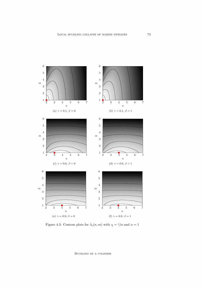
Local buckling collapse of marine pipelines 73
1
2
3
4
5
6
2 3 4 5 6 7
m
n
(a) γ = 0.1, β = 0
1
2
3
4
5
6
2 3 4 5 6 7
m
n
(b) γ = 0.1, β = 1
1
2
3
4
5
6
2 3 4 5 6 7
m
n
(c) γ = 0.6, β = 0
1
2
3
4
5
6
2 3 4 5 6 7
m
n
(d) γ = 0.6, β = 1
1
2
3
4
5
6
2 3 4 5 6 7
m
n
(e) γ = 0.9, β = 0
1
2
3
4
5
6
2 3 4 5 6 7
m
n
(f) γ = 0.9, β = 1
Figure 4.3: Contour plots for λc(n,m) with χ = 1/20 and α = 1
Buckling of a cylinder

74 R. Selker (2013)
1
2
3
4
5
6
2 3 4 5 6 7
m
n
(a) γ = 0.1, β = 0
1
2
3
4
5
6
2 3 4 5 6 7
m
n
(b) γ = 0.1, β = 1
1
2
3
4
5
6
2 3 4 5 6 7
m
n
(c) γ = 0.6, β = 0
1
2
3
4
5
6
2 3 4 5 6 7
m
n
(d) γ = 0.6, β = 1
1
2
3
4
5
6
2 3 4 5 6 7
m
n
(e) γ = 0.9, β = 0
1
2
3
4
5
6
2 3 4 5 6 7
m
n
(f) γ = 0.9, β = 1
Figure 4.4: Contour plots for λc(n,m) with χ = 1/40 and α = 1
Buckling of a cylinder
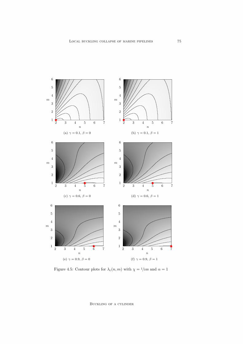
Local buckling collapse of marine pipelines 75
1
2
3
4
5
6
2 3 4 5 6 7
m
n
(a) γ = 0.1, β = 0
1
2
3
4
5
6
2 3 4 5 6 7
m
n
(b) γ = 0.1, β = 1
1
2
3
4
5
6
2 3 4 5 6 7
m
n
(c) γ = 0.6, β = 0
1
2
3
4
5
6
2 3 4 5 6 7
m
n
(d) γ = 0.6, β = 1
1
2
3
4
5
6
2 3 4 5 6 7
m
n
(e) γ = 0.9, β = 0
1
2
3
4
5
6
2 3 4 5 6 7
m
n
(f) γ = 0.9, β = 1
Figure 4.5: Contour plots for λc(n,m) with χ = 1/100 and α = 1
Buckling of a cylinder

76 R. Selker (2013)
02468
1012141618202224
0 0.1 0.2 0.3 0.4 0.5 0.6 0.7 0.8 0.9 1
λc
γ
α = 0, β = 0α = 1, β = 0α = 0, β = 1α = 1, β = 1
(a) χ = 1/20
02468
1012141618202224
0 0.1 0.2 0.3 0.4 0.5 0.6 0.7 0.8 0.9 1
λc
γ
α = 0, β = 0α = 1, β = 0α = 0, β = 1α = 1, β = 1
(b) χ = 1/40
02468
1012141618202224
0 0.1 0.2 0.3 0.4 0.5 0.6 0.7 0.8 0.9 1
λc
γ
α = 0, β = 0α = 1, β = 0α = 0, β = 1α = 1, β = 1
(c) χ = 1/100
Figure 4.6: Critical bifurcation loads for a cylinder
Buckling of a cylinder

Local buckling collapse of marine pipelines 77
0
1
2
3
4
5
6
7
8
9
0 0.1 0.2 0.3 0.4 0.5 0.6
λc
γ
SelkerBatdorf [3]Sturm [43]
(a) α = 0
0
1
2
3
4
5
6
7
8
9
0 0.1 0.2 0.3 0.4 0.5 0.6
λc
γ
SelkerBatdorf [3]Sturm [43]
(b) α = 1
Figure 4.7: Comparison critical bifurcation loads of an externally pres-surised cylinder for χ = 1/20 and β = 0
Buckling of a cylinder
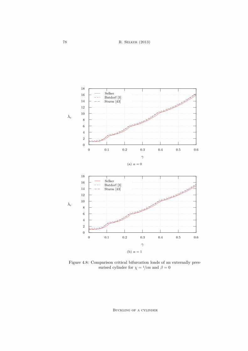
78 R. Selker (2013)
0
2
4
6
8
10
12
14
16
18
0 0.1 0.2 0.3 0.4 0.5 0.6
λc
γ
SelkerBatdorf [3]Sturm [43]
(a) α = 0
0
2
4
6
8
10
12
14
16
18
0 0.1 0.2 0.3 0.4 0.5 0.6
λc
γ
SelkerBatdorf [3]Sturm [43]
(b) α = 1
Figure 4.8: Comparison critical bifurcation loads of an externally pres-surised cylinder for χ = 1/100 and β = 0
Buckling of a cylinder
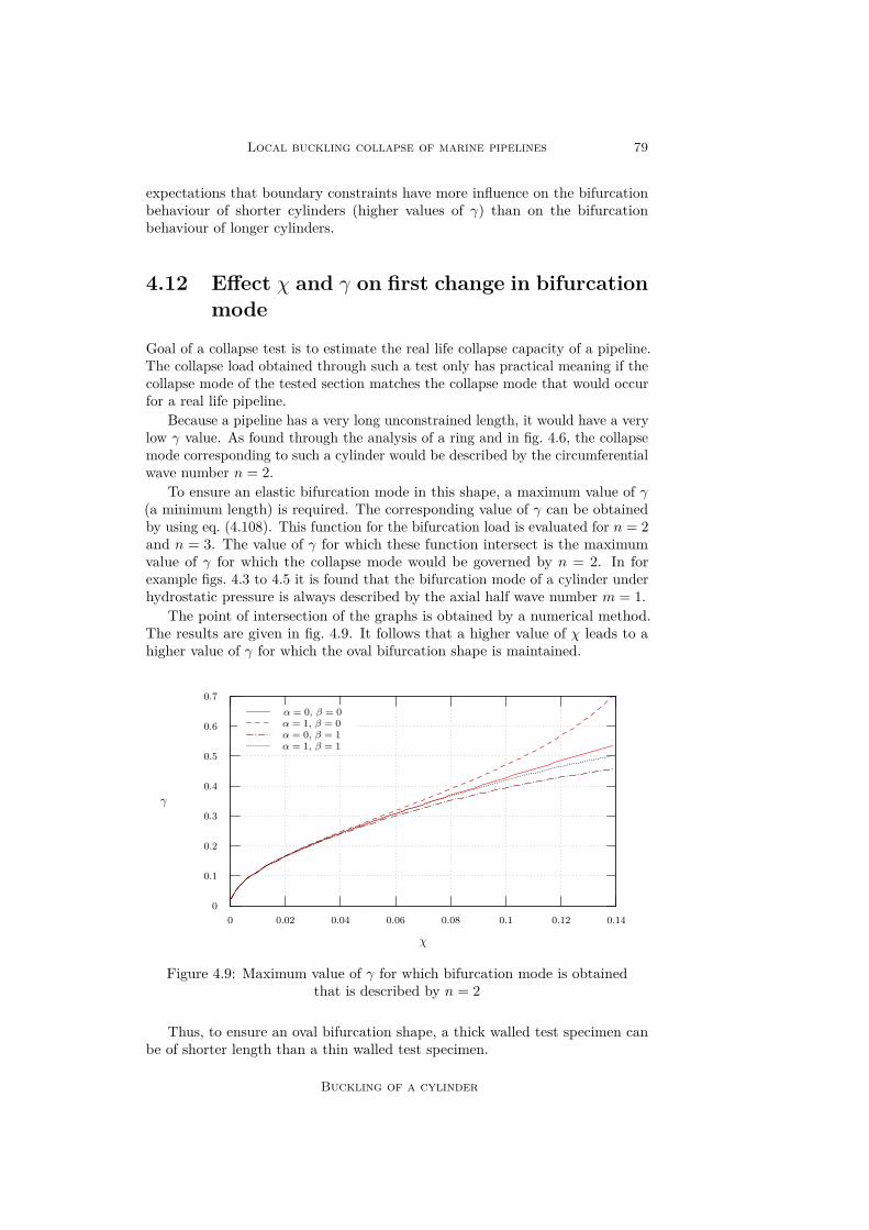
Local buckling collapse of marine pipelines 79
expectations that boundary constraints have more influence on the bifurcationbehaviour of shorter cylinders (higher values of γ) than on the bifurcationbehaviour of longer cylinders.
4.12 Effect χ and γ on first change in bifurcationmode
Goal of a collapse test is to estimate the real life collapse capacity of a pipeline.The collapse load obtained through such a test only has practical meaning if thecollapse mode of the tested section matches the collapse mode that would occurfor a real life pipeline.
Because a pipeline has a very long unconstrained length, it would have a verylow γ value. As found through the analysis of a ring and in fig. 4.6, the collapsemode corresponding to such a cylinder would be described by the circumferentialwave number n = 2.
To ensure an elastic bifurcation mode in this shape, a maximum value of γ(a minimum length) is required. The corresponding value of γ can be obtainedby using eq. (4.108). This function for the bifurcation load is evaluated for n = 2and n = 3. The value of γ for which these function intersect is the maximumvalue of γ for which the collapse mode would be governed by n = 2. In forexample figs. 4.3 to 4.5 it is found that the bifurcation mode of a cylinder underhydrostatic pressure is always described by the axial half wave number m = 1.
The point of intersection of the graphs is obtained by a numerical method.The results are given in fig. 4.9. It follows that a higher value of χ leads to ahigher value of γ for which the oval bifurcation shape is maintained.
0
0.1
0.2
0.3
0.4
0.5
0.6
0.7
0 0.02 0.04 0.06 0.08 0.1 0.12 0.14
γ
χ
α = 0, β = 0α = 1, β = 0α = 0, β = 1α = 1, β = 1
Figure 4.9: Maximum value of γ for which bifurcation mode is obtainedthat is described by n = 2
Thus, to ensure an oval bifurcation shape, a thick walled test specimen canbe of shorter length than a thin walled test specimen.
Buckling of a cylinder

80 R. Selker (2013)
4.13 Bifurcation amplitudes
The relation between the coefficients W (n,m) and F (n,m) can be obtained bysubstituting the newly obtained relation for λc back into eq. (4.107). The vectorcontained in the nullspace of this matrix not being the null vector, the Eigenvector,describes the relation between the coefficients. By letting W (n,m) = 1, thebifurcation parameter ζ describes the amount of bifurcation mode included inthe solution. From analysis of the Eigenvector now follows:
F (n, m) = f[r]1:1(n, m)
+
n2
χ2
2(n2 + m2)2 − n4
1 + ν+n2m2 (ν + n2 + 1
2αm2)
1− ν2
− 6
n2 + 1 + 1
2αm2
− 6γβχ32√
2m2
3 (1− ν2) + χ2m4 3 (1− ν2)34
4χ2 (1− ν)
(n2 + m2)2 − 1
2n4
+2χ2n2m2 (ν + n2 + 12αm
2)−12
(1− ν2) (1 + n2 + 1
2αm2)
3 (n2 + m2)2
(n2 + 1
2αm2 + n2 + νm2
n2 + m2
)√2
3(1− ν2)+ χ2m4
8γβχ32 m2 3 (1− ν2)
14− 1
(4.110)
Where f [r]1:1(n, m) is given in eq. (4.95) and m = πγm.
4.14 Initial imperfectionsA real life pipeline can never be free of initial geometric imperfections. Theseinitial imperfections need to be accounted for. It is assumed that the influenceof initial geometric imperfections on an externally pressurised ring, in theshape of the first order bifurcation mode, is similar to the influence of initialgeometric imperfections on an externally pressurised cylinder. The secondorder bifurcation terms of order O(ζ2) are neglected and hence the initial post-bifurcation behaviour is assumed to be neutral.
The relation for a pressurised ring given in eq. (3.122) is adjusted for acylinder such that:
λ
λc= 1− ξ
ζ + ξ= ζ
ζ + ξ(4.111)
Where ξ is obtained using eq. (3.100). It describes the amount of initialimperfection in the system according to:
w(η, θ) = ξ cos (nθ) sin (πmη) (4.112)
This denotes the amount of imperfection in radial direction included in thesystem. The shape of this function corresponds to the first order bifurcationsolution of the radial deformation component of a constrained cylinder. Byrewriting eq. (4.111), an expression for the bifurcation parameter ζ is found:
ζ = λξ
λc − λ(4.113)
Buckling of a cylinder

Local buckling collapse of marine pipelines 81
4.15 Combined elastic and plastic bucklingThe collapse pressure of a cylinder can be obtained by making use of thepreviously obtained dimensionless solutions. First these dimensionless solutionsare transformed into relations for the stress resultants Nxx, Nss and Nxs andstress couples Mxx, Mxx and Mxx.
From these relations and making use of the assumptions stated earlier, theCauchy stress tensor can be obtained for each material point of the cylinder.
The Von Mises yield criterion is adopted. Besides, it is assumed that bucklingoccurs at first yielding. Now it is possible to obtain a load that corresponds tothe occurrence of first yielding in the cylinder, the collapse load.
4.15.1 Von Mises yield criterionThe adopted yield criterion is the von Mises yield criterion. The x-axis ands-axis are assumed to be orthogonal. The Cauchy stress tensor can be writtenas:
σij =
σxx σxs σxzσsx σss σszσzx σzs σzz
(4.114)
The invariants of the Cauchy stress tensor are denoted by I. For the vonMises yield criterion it is assumed that the hydrostatic part of the stress tensordoes not affect yielding. The mean hydrostatic stress tensor is obtained byaveraging the coefficients at the main diagonal and multiplying this with theidentity tensor. This tensor can be written as 1
3σkkδij . Here δij denotes theidentity tensor or the Kronecker delta. Note that the first invariant of the Cauchystress tensor is given by I1 = σkk. Einstein’s summation convention is appliedwith respect to repeated indices.
The deviatoric stress tensor is defined as the difference between the Cauchystress tensor and the mean hydrostatic stress tensor such that:
sij = σij − 13σkkδij (4.115)
Or in matrix notation:
sij =
sxx sxs sxzssx sss sszszx szs szz
=
23σxx − 1
3σss − 13σzz σxs σxz
σsx23σss − 1
3σxx − 13σzz σsz
σzx σzs23σzz − 1
3σxx − 13σss
(4.116)
The invariant of the deviatoric stress tensor are denoted by J . They resultfrom the characteristic equation of the Eigenvalue analysis of this tensor. Thisrelates the square root of the J2 = 1
2sijsij invariant to the uniaxial yield strengthfy of the material. First yielding occurs for [11]:√
J2 = k (4.117)
Where k denotes the yield stress in pure shear [29]. Solving this equationfor pure uniaxial tension or pure uniaxial compression it is obtained that first
Buckling of a cylinder
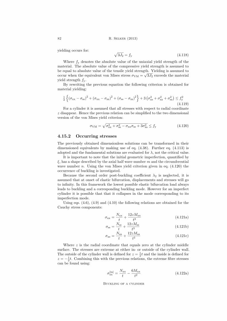
82 R. Selker (2013)
yielding occurs for: √3J2 = fy (4.118)
Where fy denotes the absolute value of the uniaxial yield strength of thematerial. The absolute value of the compressive yield strength is assumed tobe equal to absolute value of the tensile yield strength. Yielding is assumed tooccur when the equivalent von Mises stress σVM =
√3J2 exceeds the material
yield strength fy.By rewriting the previous equation the following criterion is obtained for
material yielding:
12
(σxx − σss)2 + (σxx − σzz)2 + (σss − σzz)2
+ 3
(σ2
xs + σ2xz + σ2
sz)≤ f2
y
(4.119)For a cylinder it is assumed that all stresses with respect to radial coordinate
z disappear. Hence the previous relation can be simplified to the two dimensionalversion of the von Mises yield criterion:
σVM =√σ2
xx + σ2ss − σxxσss + 3σ2
xs ≤ fy (4.120)
4.15.2 Occurring stressesThe previously obtained dimensionless solutions can be transformed in theirdimensioned equivalents by making use of eq. (4.38). Further eq. (4.113) isadopted and the fundamental solutions are evaluated for λ, not the critical value.
It is important to note that the initial geometric imperfection, quantified byξ, has a shape described by the axial half wave number m and the circumferentialwave number n. Using the von Mises yield criterion given in eq. (4.120) theoccurrence of buckling is investigated.
Because the second order post-buckling coefficient λ2 is neglected, it isassumed that at onset of elastic bifurcation, displacements and stresses will goto infinity. In this framework the lowest possible elastic bifurcation load alwaysleads to buckling and a corresponding buckling mode. However for an imperfectcylinder it is possible that that it collapses in the mode corresponding to itsimperfection mode.
Using eqs. (4.6), (4.9) and (4.10) the following relations are obtained for theCauchy stress components:
σxx = Nxxt
+ 12zMxxt3
(4.121a)
σss = Nsst
+ 12zMsst3
(4.121b)
σxs = Nxst
+ 12zMxst3
(4.121c)
Where z is the radial coordinate that equals zero at the cylinder middlesurface. The stresses are extreme at either in- or outside of the cylinder wall.The outside of the cylinder wall is defined for z = 1
2 t and the inside is defined forz = − 1
2 t. Combining this with the previous relations, the extreme fibre stressescan be found using:
σ[in]xx = Nxx
t− 6Mxx
t2(4.122a)
Buckling of a cylinder

Local buckling collapse of marine pipelines 83
σ[in]ss = Nss
t− 6Mss
t2(4.122b)
σ[in]xs = Nxs
t− 6Mxs
t2(4.122c)
σ[out]xx = Nxx
t+ 6Mxx
t2(4.122d)
σ[out]ss = Nss
t+ 6Mss
t2(4.122e)
σ[out]xs = Nxs
t+ 6Mxs
t2(4.122f)
The von Mises stresses at the cylinder inside and outside can be obtainedby substituting these relations in eq. (4.120). A plot of typical occurring vonMises stresses in a cylinder just before occurrence of collapse is given in fig. 4.10(simply supported end caps) and in fig. 4.11 (clamped end caps).
It follows that for a cylinder with clamped end caps high stress concentrationsoccur in the boundary layers. These however are not most likely not critical forcollapse behaviour, because yielding in the boundary layer domains probablyleads to a stress redistribution through the boundary layer domains. The stiffnessgained from the rigid end caps ensures this does not lead to collapse. High vonMises stresses in the regular domain can lead to collapse and are expected to begoverning in predicting collapse behaviour of a cylinder.
4.15.3 Purely plastic collapse resistanceAn upper value of the collapse pressure of a cylinder should be given by themaximum plastic capacity of a pipeline. The maximum plastic capacity is givenwhen deformation only occurs in the fundamental shape. This implies an absenceof bending influences. For this analysis it is assumed that the cylinder doesnot ‘feel’ its boundaries. The stress in circumferential direction can be obtainedfrom a simple force equilibrium in the cross section of the cylinder (thus a ring)giving:
σss = Pρ
t(4.123)
Now the plastic collapse capacity of a cylinder is investigated for an infinitelylong cylinder where the occurrence of axial strain is assumed to be zero (planestrain). Using Hooke’s law this results to an axial stress component of:
σxx = νPρ
t(4.124)
When either end cap is allowed to move in axial direction the stress in axialdirection is given by:
σxx = Pρα
2t (4.125)
Only the regular solution domain is taken into account to obtain the plasticcollapse resistance. Shear stresses are assumed to be absent. Collapse is definedwhen the equivalent von Mises stress in eq. (4.120) exceeds the uniaxial yieldstrength fy. This leads to the following plastic collapse loads Pp:
Pp = fyt
ρ√
1− ν + ν2, for infinitely long cylinder (4.126a)
Buckling of a cylinder
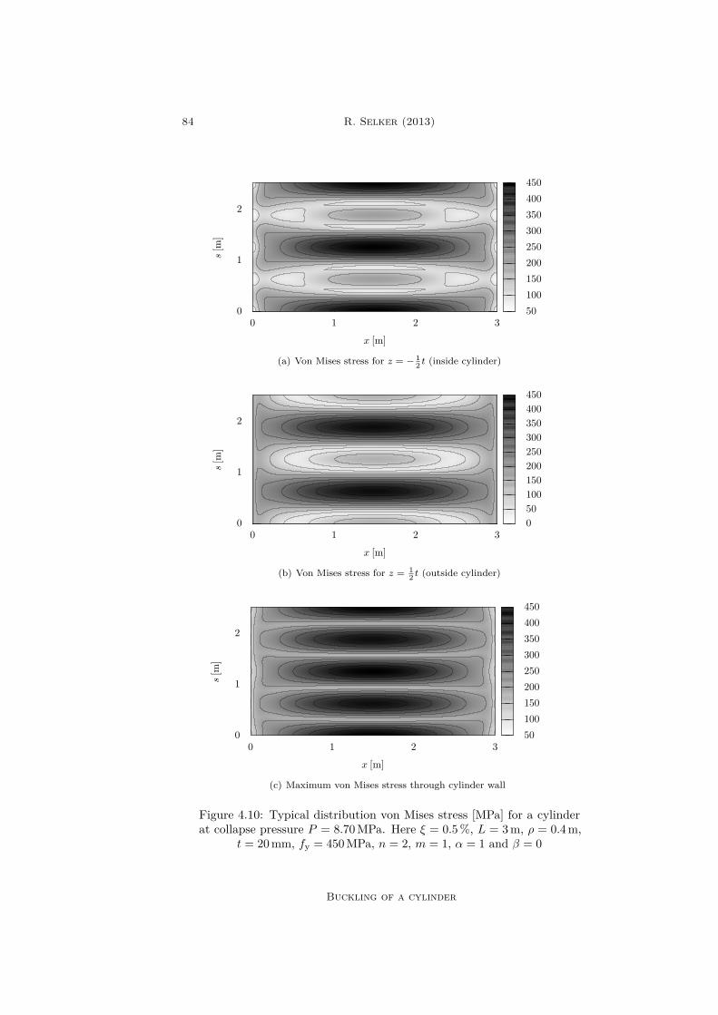
84 R. Selker (2013)
0
1
2
0 1 2 3
s[m
]
x [m]
50100150200250300350400450
(a) Von Mises stress for z = − 12 t (inside cylinder)
0
1
2
0 1 2 3
s[m
]
x [m]
050100150200250300350400450
(b) Von Mises stress for z = 12 t (outside cylinder)
0
1
2
0 1 2 3
s[m
]
x [m]
50100150200250300350400450
(c) Maximum von Mises stress through cylinder wall
Figure 4.10: Typical distribution von Mises stress [MPa] for a cylinderat collapse pressure P = 8.70MPa. Here ξ = 0.5%, L = 3m, ρ = 0.4m,
t = 20mm, fy = 450MPa, n = 2, m = 1, α = 1 and β = 0
Buckling of a cylinder

Local buckling collapse of marine pipelines 85
0
1
2
0 1 2 3
s[m
]
x [m]
0
100
200
300
400
500
600
(a) Von Mises stress for z = − 12 t (inside cylinder)
0
1
2
0 1 2 3
s[m
]
x [m]
050100150200250300350400450
(b) Von Mises stress for z = 12 t (outside cylinder)
0
1
2
0 1 2 3
s[m
]
x [m]
50100150200250300350400450500550600
(c) Maximum von Mises stress through cylinder wall
Figure 4.11: Typical distribution von Mises stress [MPa] for a cylinderat collapse pressure P = 8.73MPa. Here ξ = 0.5%, L = 3m, ρ = 0.4m,
t = 20mm, fy = 450MPa, n = 2, m = 1, α = 1 and β = 1
Buckling of a cylinder

86 R. Selker (2013)
Pp = fyt
ρ√
1− 12α+ 1
4α2
, otherwise (4.126b)
Using the dimensionless identities given in eq. (4.38) and the dimensionlessuniaxial yield strength given in eq. (3.130), these solutions for plastic collapseload can be written to their dimensionless equivalents λp:
λp = fy1− ν2
√1− ν + ν2
, for infinitely long cylinder (4.127a)
λp = fy1− ν2√
1− 12α+ 1
4α2
, otherwise (4.127b)
Dimensionless purely plastic collapse loads for various steel grades (given intable 5.1) are displayed in fig. 4.12.
0
2
4
6
8
10
12
14
16
18
20
0 0.01 0.02 0.03 0.04 0.05 0.06 0.07 0.08
λp
χ
Long cylinder, X42Long cylinder, X60Long cylinder, X70
α = 0, X42α = 0, X60α = 0, X70α = 1, X42α = 1, X60α = 1, X70
Figure 4.12: Dimensionless plastic collapse loads according to eq. (4.127)for various steel grades
From this figure follows that for thin walled cylinders (small χ-values), plasticcollapse loads are relatively high compared to thick walled cylinders. This effectpartly explains collapse of thin walled pipelines to occur more in the elasticregime, while collapse of thick walled pipelines is governed by their plasticbehaviour.
4.15.4 Combined elastic and plastic collapseTo predict the collapse load of a cylinder it is necessary to define the occurrenceof collapse. In this analytical cylinder model, collapse is defined to occur at firstmaterial yielding in the regular domain. Hence high von Mises stresses in theboundary layer domains are assumed not to lead to collapse. First yielding isassumed to occur for the first load for which the von Mises stress equals thematerial uniaxial yield strength.
Buckling of a cylinder
Local buckling collapse of marine pipelines 87
A formulation for the occurring equivalent stresses is obtained earlier. Atypical equivalent stress distribution for a simply supported cylinder is given infig. 4.10 and a typical distribution for a clamped cylinder is given in fig. 4.11.The maximum value of the occurring von Mises stress through the cylinderwall is obtained using an iterative procedure. For several grid points in thecylinder domain the occurring von Mises stresses are obtained. The grid is refinedaround the location that possesses the highest occurring stress. This is doneseveral times to obtain the location and value of the maximum von Mises stress.Now the von Mises criterion is checked. If yielding does not occur, the appliedpressure is increased. If it does occur, the applied pressure is decreased. Thisprocedure is repeated until the von Mises criterion for first yielding is satisfiedup to some threshold range. The corresponding load is reported as the collapseload belonging to the initial imperfection shape.
After obtaining the collapse load corresponding to the initial imperfectionshape and size, the elastic collapse load and mode shape is analysed. The cylinderis assumed to collapse at the lowest value of these two loads. The occurringcollapse mode shape is the mode corresponding to this load.
When the elastic collapse mode shape is equal to the mode shape of theinitial imperfection the structure will always collapse at a load lower than itselastic collapse load.
In chapter 5 results obtained using this method are compared to resultsobtained using finite element analysis. Some sample values for cylinders withχ = 1/20 and χ = 1/100 are given in tables 4.1 and 4.2. Collapse is investigatedfor some of the steel grades given in table 5.1. Initial imperfection shapes aretaken close to the preferred elastic bifurcation shape.
The results given in these tables suggest that although end cap pressure leadsto a lower bifurcation load it can lead to a higher collapse load. This is due tothe fact that the axial compressive stress resulting from this load reduces the vonMises stress due to pressure on the cylinder. It follows that this effect appearsfor relatively thick walled cylinder (high values of χ). For relatively thin walledcylinders (low values of χ), the reduction in bifurcation load is more significantthan the gain in collapse load due to end cap pressure.
It is generally true that clamped boundaries lead to higher collapse loadsthan simply supported boundaries when other parameters are kept constant.
Thick walled cylinders tend to collapse relatively close to their plastic collapseload, while thin walled cylinders tend to collapse more into the elastic deformationregime. As found in fig. 3.3, the loading path is first governed by a linear responseand later by a post-buckling response. If plasticity starts to develop in the pre-buckling (linear) part, for small values of ζ, the structure’s deformation shape atoccurrence of collapse is mainly described by the shape of the initial imperfection.If plasticity starts to develop after occurrence of buckling, for larger values ofζ, the structure’s deformation shape at occurrence of collapse will mainly begoverned by its bifurcation shape. In practice, the former is seen as plasticcollapse behaviour and the latter as elastic collapse behaviour.
Buckling of a cylinder

88 R. Selker (2013)
γ α βElastic Collapse
n λc n λcol X42 λcol X60 λcol X700.800 0 0 4 11.616 4 0.363 0.512 0.5990.800 1 0 4 9.778 4 0.366 0.515 0.6020.800 0 1 4 13.469 4 0.389 0.549 0.6430.800 1 1 4 11.338 4 0.377 0.532 0.6210.625 0 0 4 8.606 4 0.353 0.497 0.5800.625 1 0 3 7.495 4 0.370 0.520 0.6070.625 0 1 4 9.191 4 0.355 0.501 0.5850.625 1 1 4 8.248 4 0.364 0.512 0.5970.400 0 0 3 4.590 3 0.363 0.508 0.5910.400 1 0 3 4.250 3 0.385 0.537 0.6240.400 0 1 3 4.784 3 0.362 0.507 0.5900.400 1 1 3 4.431 3 0.384 0.536 0.6230.250 0 0 2 2.772 2 0.376 0.522 0.6050.250 1 0 2 2.608 2 0.408 0.565 0.6520.250 0 1 2 2.858 2 0.378 0.526 0.6100.250 1 1 2 2.689 2 0.412 0.570 0.6590.200 0 0 2 1.899 2 0.334 0.458 0.5270.200 1 0 2 1.826 2 0.365 0.498 0.5700.200 0 1 2 1.929 2 0.335 0.460 0.5300.200 1 1 2 1.855 2 0.367 0.500 0.5730.100 0 0 2 1.166 2 0.276 0.371 0.4200.100 1 0 2 1.155 2 0.295 0.392 0.4430.100 0 1 2 1.167 2 0.276 0.371 0.4200.100 1 1 2 1.156 2 0.296 0.393 0.4430.025 0 0 2 1.070 2 0.268 0.358 0.4050.025 1 0 2 1.070 2 0.285 0.376 0.4240.025 0 1 2 1.070 2 0.268 0.358 0.4050.025 1 1 2 1.070 2 0.285 0.376 0.424
Table 4.1: Collapse load at first yielding for χ = 1/20 and ξ = 0.01
Buckling of a cylinder

Local buckling collapse of marine pipelines 89
γ α βElastic Collapse
n λc n λcol X42 λcol X60 λcol X700.800 0 0 6 21.674 6 4.306 5.745 6.5060.800 1 0 6 19.965 6 4.073 5.403 6.0990.800 0 1 6 22.603 6 4.401 5.882 6.6650.800 1 1 6 20.821 6 4.152 5.517 6.2340.625 0 0 6 16.642 6 3.544 4.687 5.2790.625 1 0 5 15.808 6 3.534 4.644 5.2160.625 0 1 6 16.935 6 3.573 4.729 5.3320.625 1 1 6 16.095 6 3.576 4.697 5.2790.400 0 0 5 10.309 5 2.993 3.843 4.2660.400 1 0 5 9.953 5 3.012 3.843 4.2500.400 0 1 5 10.377 5 3.002 3.856 4.2820.400 1 1 5 10.071 5 3.023 3.859 3.8590.250 0 0 4 6.161 4 2.468 3.040 3.3050.250 1 0 4 6.051 4 2.486 3.043 3.2980.250 0 1 4 6.177 4 2.472 3.046 3.3100.250 1 1 4 6.067 4 2.490 3.048 3.3050.200 0 0 3 4.562 3 2.386 2.814 2.9980.200 1 0 3 4.474 3 2.403 2.809 2.9830.200 0 1 3 4.578 3 2.392 2.822 3.0060.200 1 1 3 4.489 3 2.408 2.817 2.9910.100 0 0 2 2.183 2 1.553 1.708 1.7680.100 1 0 2 2.161 2 1.556 1.702 1.7600.100 0 1 2 2.185 2 1.554 1.709 1.7690.100 1 1 2 2.163 2 1.557 1.704 1.7610.025 0 0 2 1.075 2 0.823 0.886 0.9100.025 1 0 2 1.074 2 0.824 0.886 0.9100.025 0 1 2 1.075 2 0.823 0.886 0.9100.025 1 1 2 1.074 2 0.824 0.886 0.910
Table 4.2: Collapse load at first yielding for χ = 1/100 and ξ = 0.01
Buckling of a cylinder

This page is intentionally left blank.

Chapter 5
Verification and discussionresults
5.1 IntroductionIn this chapter, previously obtained analytical results for the local bucklingcollapse behaviour of a pipeline, are compared to results from finite elementanalysis (FEA) and published experimental work.
To perform the FEA use is made of the commercial software code ANSYS 14.0.To be able to perform this analysis for a vast combination of input parametersAPDL-scripts (ANSYS parametric design language) are developed. Examples ofapplied scripts are given in appendix C. These will be explained later.
In FEA dimensions have to be introduced again. Reporting of the results inthis chapter is done in dimensionless identities however. Therefore the previouslyintroduced dimensionless identities are used to rewrite the results to theirdimensionless equivalents.
Two types of finite element models (FEM) are developed. A ring model isdeveloped to verify the results obtained in chapter 3 and a cylinder model isdeveloped to verify the results obtained in chapter 4. In FEA it can be difficultor even impossible to obtain the bifurcation behaviour of a perfect structure. If,for a perfect structure, no arbitrary perturbations from the fundamental solutionpath occur, this fundamental solution is likely to be the obtained equilibriumstate, even for loads beyond the bifurcation load (if numerical irregularities areinsignificant). To ensure that bifurcation behaviour is found, a small initialgeometric imperfection is introduced into the system. The response obtained fromthis imperfect system can be extrapolated to obtain the values corresponding tothe bifurcation behaviour of the perfect structure.
A large displacement analysis is performed (the geometric stiffness matrix isrecalculated after each load step) and depending on the analysis, the Newton-Raphson or the arc-length solver is used. Here the Newton-Raphson solver usesa load controlled algorithm, while the arc-length method uses a displacementcontrolled algorithm. This results to the fact that the arc-length solver is able tocapture unstable post-buckling behaviour, while the Newton-Raphson solver isonly capable to capture stable branches of the post-buckling behaviour solution.
Properties and information of the used elements and the performed FEA are

92 R. Selker (2013)
given in [1].
5.1.1 Ring modelTo model the ring representation of a pipeline, a system is developed usingBEAM188 elements. These elements in fact are three dimensional elements.Because only a two dimensional representation is required, the elements areconstrained in a fixed plane. The used beam elements follow Timoshenko beamtheory. In the analytical analysis Euler-Bernoulli beam theory is applied. Thedifference is that Timoshenko theory accounts for shear to occur within the beamcross section, while Euler-Bernoulli theory neglects this. As long as the ring canbe considered as relatively thin it can be assumed that the difference betweenthese theories is insignificant. For thicker rings the application of Timoshenkobeam theory is assumed to lead to slightly lower values for the bifurcation loadcompared to Euler-Bernoulli beam theory. This because including this sheareffectively reduces the beam stiffness.
The ring wall cross section is assumed to behave rigidly. This means that thewall thickness does not change under straining in the ring and hence the wallthickness is assumed to be constant during deformation. Hydrostatic pressure isapplied perpendicular to axial direction of the beam elements, directed towardsthe ring centre. It is assumed that this direction stays perpendicular duringdeformation. In fig. 5.1 the deformed and undeformed configuration of the finiteelement representation is given of a pressurised ring. Different elements aredisplayed in various colours.
X
Y
Z
Figure 5.1: Deformed and undeformed configuration of typical ring FEM
Initial geometric imperfections are introduced either by moving all ring nodesby a small random initial translation of the order of 0.1% of the ring meanradius ρ, or by introducing a small imperfection in a shape close to the firstorder bifurcation shape of the ring.
Verification and discussion results
Local buckling collapse of marine pipelines 93
The ring is constrained by the introduction of multi point constraints (MPC).This ensures that rigid body translations and rotations are prevented. All nodesthat are part of the ring are connected to a pilot node by a force-distributedconstraint. Influence of mesh and element sizes is investigated, but not reportedin this thesis. It is tried to use as few as possible elements, while the resultsare within close range of the structure modelled by significantly more elements.Further the buckling mode found from the analysis always has to be comparedto the imperfection mode introduced before application of load.
A typical APDL script for the analysis of a pressurised ring is given inappendix C.1.
5.1.2 Cylinder modelTo verify the relations obtained in chapter 4, it is necessary to include anadditional spatial dimension in the FEA. This is done by making use shellelements to describe a cylinder. The element types that are used are SHELL181elements. Contrary to the beam elements used for the ring model, these elementsaccount for change in wall thickness during deformation. It is assumed that thisinfluence is small.
The SHELL181 element is based on Mindlin-Reissner shell theory. This theorytakes into account transverse shear (deformations). The difference of this theoryand the applied theory in chapter 4 based on the Kirchhoff-Love assumptions,is analogous to the difference due to Timoshenko and Euler-Bernoulli beamtheory. For relatively thin cylinders the effect of this difference is assumed to beinsignificant and for relatively thick cylinders the effect is assumed to be small,but a slightly lower bifurcation load is expected due to including transverse shearin the FEA.
Hydrostatic pressure is applied to the cylinder walls. This pressure is directedperpendicular to the shell middle surface directed to the cylinder inside. Thepressure stays perpendicular to the shell middle surface during deformation.
In fig. 5.2 the deformed configuration of a typical finite element model(FEM) of a cylinder with end caps is displayed. The various elements can bedistinguished by the variation in colour.
The end caps are modelled by rigid surface MPC’s. The radial displacementcomponent is constrained and either simply supported or clamped cylinder wall-to-end cap connections are introduced by setting the corresponding options forthe MPC elements. The nodes connected by the MPC elements are constrainedin a rigid plane. These planes are connected to a pilot node at each end. One ofthe pilot nodes is constrained in all directions, while the other is only allowed tomove in axial direction. Hence no resulting axial force shall be transferred tothe pilot nodes (when end cap pressure is lacking).
Initial imperfections are introduced in a shape close to the first order regularbifurcation mode. Also for a cylinder, it is verified that the used mesh is fineenough such that further refinement of the mesh does not lead to a significantimprovement of the estimate solution. It is ensured that bifurcation occurs inthe mode that can be expected by the introduction of the imperfection mode.To obtain the lowest possible bifurcation load it is necessary to analyse variousinitial imperfection mode shapes.
A typical APDL script for the buckling analysis of a constrained cylinder isgiven in appendix C.2.
Verification and discussion results

94 R. Selker (2013)
X
Y
Z
Figure 5.2: Deformed configuration of typical cylinder FEM
5.1.3 Bifurcation parameterIt is convenient to report the results of FEA in dimensionless form. An importantparameter in the analytical results is the bifurcation parameter ζ. The value ofthis parameter can be obtained from the maximum radial deformation value.
The dimensionless radial deformation solution for a ring is given by eq. (3.108).The maximum absolute value for w is found by substituting cos (nθ) = −1 suchthat:
wmax = −λχ2 − ζ − ζ2 9(3 + χ2)λ2
c4n2 (3 + n2χ2) (5.1)
For a cylinder the same relation can be used, but it has to be noted thatλ is defined slightly different for a ring and a cylinder. The value of thebifurcation parameter can be obtained by solving the identity above for ζ usingthe assumption that ζ is positive. Note that wmax is negative when directedinwards and positive when directed outwards.
5.2 Perfect ring initial post-bifurcationTo obtain the initial post-bifurcation behaviour of a perfect ring using FEAis is necessary to introduce a small imperfection. For this analysis, a randomdisturbance of the node location of the order of 0.1% of the mean ring radius isintroduced. The smaller the imperfection size, the more the loading path shouldresemble to the loading path of a perfect ring and the clearer the kink in thegraph should be observed.
In figs. 5.3 and 5.4 the analytical result of the initial post-bifurcation behaviourof a ring is compared to the initial post-bifurcation behaviour obtained fromFEA for various typical values of χ. The results of several FEA runs have beengiven for which each run has a different random imperfection.
Verification and discussion results

Local buckling collapse of marine pipelines 95
0.8
0.85
0.9
0.95
1
1.05
1.1
0 0.02 0.04 0.06 0.08 0.1 0.12 0.14 0.16 0.18 0.2
λ
λc
ζ
Analytical resultsFEA, ρ = 0.4 m, run 1FEA, ρ = 0.4 m, run 2FEA, ρ = 0.4 m, run 3FEA, ρ = 0.4 m, run 4FEA, ρ = 0.4 m, run 5
(a) χ = 1/15
0.8
0.85
0.9
0.95
1
1.05
1.1
0 0.02 0.04 0.06 0.08 0.1 0.12 0.14 0.16 0.18 0.2
λ
λc
ζ
Analytical resultsFEA, ρ = 0.4 m, run 1FEA, ρ = 0.4 m, run 2FEA, ρ = 0.4 m, run 3FEA, ρ = 0.4 m, run 4FEA, ρ = 0.4 m, run 5
(b) χ = 1/20
0.8
0.85
0.9
0.95
1
1.05
1.1
0 0.02 0.04 0.06 0.08 0.1 0.12 0.14 0.16 0.18 0.2
λ
λc
ζ
Analytical resultsFEA, ρ = 0.4 m, run 1FEA, ρ = 0.4 m, run 2FEA, ρ = 0.4 m, run 3FEA, ρ = 0.4 m, run 4FEA, ρ = 0.4 m, run 5
(c) χ = 1/30
Figure 5.3: Amount of buckling mode with respect to load for perfect ring
Verification and discussion results

96 R. Selker (2013)
0.8
0.85
0.9
0.95
1
1.05
1.1
0 0.02 0.04 0.06 0.08 0.1 0.12 0.14 0.16 0.18 0.2
λ
λc
ζ
Analytical resultsFEA, ρ = 0.4 m, run 1FEA, ρ = 0.4 m, run 2FEA, ρ = 0.4 m, run 3FEA, ρ = 0.4 m, run 4FEA, ρ = 0.4 m, run 5
(a) χ = 1/40
0.8
0.85
0.9
0.95
1
1.05
1.1
0 0.02 0.04 0.06 0.08 0.1 0.12 0.14 0.16 0.18 0.2
λ
λc
ζ
Analytical resultsFEA, ρ = 0.4 m, run 1FEA, ρ = 0.4 m, run 2FEA, ρ = 0.4 m, run 3FEA, ρ = 0.4 m, run 4FEA, ρ = 0.4 m, run 5
(b) χ = 1/50
0.8
0.85
0.9
0.95
1
1.05
1.1
0 0.02 0.04 0.06 0.08 0.1 0.12 0.14 0.16 0.18 0.2
λ
λc
ζ
Analytical resultsFEA, ρ = 0.8 m, run 1FEA, ρ = 0.8 m, run 2FEA, ρ = 0.8 m, run 3FEA, ρ = 0.4 m, run 1FEA, ρ = 0.4 m, run 2FEA, ρ = 0.4 m, run 3FEA, ρ = 0.2 m, run 1FEA, ρ = 0.2 m, run 2FEA, ρ = 0.2 m, run 3
(c) χ = 1/100
Figure 5.4: Amount of buckling mode with respect to load for perfect ring
Verification and discussion results

Local buckling collapse of marine pipelines 97
The influence of initial imperfections in the FEA results is observed bysmoothing of the expected kink at ζ = 0 in the graph. The expected kink isthe bifurcation point. All buckling modes that are observed in this analysis aredescribed by the circumferential wave number n = 2. Further, it appears thatthe analytical results slightly under-predict the initial post-bifurcation stabilityfor a ring. The FEA results to higher loads than the analytical analysis, toobtain the same amount of bifurcation mode. The used values of λc are theanalytical values and for n = 2 it is valid that λc = 1. If the FEA results given infigs. 5.3 and 5.4 are extrapolated to remove the influence of initial imperfections,it can be concluded that the FEA leads to slightly higher bifurcation loads thanthe analytical analysis. Still, the results are consistent for various values of χ.It appears that the influence of χ is not significant. This corresponds to theapproximation that is obtained in eq. (3.107) that is valid for small values of χ2
with respect to unity.
5.3 Imperfect ring initial post-bifurcationNow the influence of the imperfection size ξ on the initial post-bifurcationbehaviour of a ring is investigated by FEA. Because in the previous section isverified that a perfect ring prefers to buckle in an oval shape in this sectionthe influence of an oval shaped imperfection is investigated. In fig. 5.5 thebifurcation parameter is plotted against the dimensionless load factor divided byits analytical bifurcation load. This is done for various imperfection sizes andvalues of χ.
From this figure appears that the analytical formulation is a close match tothe FEA results. For larger values of the bifurcation parameter ζ, the analyticaland FEA results start to deviate slightly. This is in correspondence with thedeviation between analytical and FEA results that is found for a perfect cylinderin figs. 5.3 and 5.4.
In fig. 5.5, the dimensionless solutions for various values of χ are very similar.
5.4 Collapse load of a ringThe API steel grades given in table 5.1 are used in the analysis of a ring. Theyield strength values used in calculations are the values in MPa.
Grade Yield strength[psi] [MPa]
X42 42,000 290X52 52,000 360X60 60,000 410X65 65,000 450X70 70,000 480
Table 5.1: API steel grades
Note that the API specification 5L uses slightly different values for the yieldstrength of X60 and X70 of 415MPa and 485MPa respectively.
Verification and discussion results

98 R. Selker (2013)
0
0.2
0.4
0.6
0.8
1
0 0.02 0.04 0.06 0.08 0.1 0.12 0.14 0.16 0.18 0.2
λ
λc
ζ
ξ = 0.001ξ = 0.002ξ = 0.005ξ = 0.01ξ = 0.02ξ = 0.05ξ = 0.1
(a) χ = 1/20
0
0.2
0.4
0.6
0.8
1
0 0.02 0.04 0.06 0.08 0.1 0.12 0.14 0.16 0.18 0.2
λ
λc
ζ
ξ = 0.001ξ = 0.002ξ = 0.005ξ = 0.01ξ = 0.02ξ = 0.05ξ = 0.1
(b) χ = 1/40
0
0.2
0.4
0.6
0.8
1
0 0.02 0.04 0.06 0.08 0.1 0.12 0.14 0.16 0.18 0.2
λ
λc
ζ
ξ = 0.001ξ = 0.002ξ = 0.005ξ = 0.01ξ = 0.02ξ = 0.05ξ = 0.1
(c) χ = 1/100
Figure 5.5: Amount of buckling mode with respect to load for ring withinitial imperfections. Lines are analytical results and points are FEA
results.
Verification and discussion results

Local buckling collapse of marine pipelines 99
The collapse load of a ring is analysed for two possible definitions. Thecollapse definitions are given in section 3.15. The first definition assumes collapseto occur at first material yielding and the second assumes it to occur at the fulldevelopment of a plastic hinge. The former is also referred to as the Timoshenkocriterion and the latter is referred to as the DNV criterion.
To obtain FEA results for the collapse at first yield, an elastic material isused and the response of the model is analysed. The load that corresponds tofirst material yielding is calculated and reported as the collapse load. To performFEA verification of the occurrence of collapse at the full development of a plastichinge, an elastic-perfectly plastic material model is introduced. Now the collapseload is defined as the maximum load for which the system is still stable. It islikely that the system collapses before the full development of a plastic hinge.
The collapse loads resulting from the criteria given in eqs. (3.131) and (3.140),combined with the FEA results, are given in figs. 5.6 and 5.7. Analytical resultsare plotted as lines and FEA results are plotted as points. Imperfection shapesin this analysis are characterised by the circumferential wave number n = 2.
It follows that rings with smaller χ-values collapse closer to their elasticbifurcation load. Further it appears that rings with relatively small imperfectionsizes collapse closer to their elastic bifurcation load than rings with largerimperfections. Besides, a higher yield strength of the applied material leads tohigher collapse loads, closer to the elastic bifurcation loads.
In industry practice one tends to say that thick walled rings and cylindershave a plastic collapse behaviour and thin walled cylinders have an elasticcollapse behaviour while in fact a single mechanism comes into play. Thickwalled cylinders (high values of χ) allow less deformation before plasticity setsin than thin walled cylinders (low values of χ). Hence they will collapse inthe deformation domain that is governed by the fundamental solution and theimperfection shape. Thin walled cylinders will collapse in the deformationdomain that is governed by the bifurcation shape.
An elastic-perfectly plastic ring is expected not to be able to develop a fullplastic hinge before loss of stability occurs. Besides, it is also not expected tolose stability at first yielding. Hence it is expected that FEA results for theelastic-perfectly plastic material model should be between the results for thecriterion of collapse at first yield and the criterion of collapse at full developmentof a plastic hinge. In figs. 5.6 and 5.7 this expectation is confirmed.
5.5 Bifurcation load of a cylinder
5.5.1 Comparison FEAThe analytical solutions for the bifurcation load of a cylinder, as given in fig. 4.6,are validated using FEA. The results are plotted in fig. 5.8. To obtain the criticalbifurcation load of a cylinder, a small initial imperfection is introduced in ashape described by the circumferential wave number n and the axial half-wavenumber m = 1. The cylinder is likely to buckle in the shape of the initialimperfection. Therefore imperfections with several circumferential wave numbersn are analysed. It is verified that the cylinder buckles in the shape of theimperfection. The bifurcation load is obtained by extrapolating the ζ − λ loadgraph of the imperfect cylinder to the perfect cylinder case. The shape leading
Verification and discussion results

100 R. Selker (2013)
0
0.2
0.4
0.6
0.8
1
0 0.02 0.04 0.06 0.08 0.1 0.12 0.14 0.16 0.18 0.2
λco
l
ξ
first yielding, χ = 1/100elastic-plastic, χ = 1/100first yielding, χ = 1/50elastic-plastic, χ = 1/50first yielding, χ = 1/30elastic-plastic, χ = 1/30first yielding, χ = 1/20elastic-plastic, χ = 1/20
(a) X42 steel grade
0
0.2
0.4
0.6
0.8
1
0 0.02 0.04 0.06 0.08 0.1 0.12 0.14 0.16 0.18 0.2
λco
l
ξ
first yielding, χ = 1/100elastic-plastic, χ = 1/100first yielding, χ = 1/50elastic-plastic, χ = 1/50first yielding, χ = 1/30elastic-plastic, χ = 1/30first yielding, χ = 1/20elastic-plastic, χ = 1/20
(b) X52 steel grade
0
0.2
0.4
0.6
0.8
1
0 0.02 0.04 0.06 0.08 0.1 0.12 0.14 0.16 0.18 0.2
λco
l
ξ
first yielding, χ = 1/100elastic-plastic, χ = 1/100first yielding, χ = 1/50elastic-plastic, χ = 1/50first yielding, χ = 1/30elastic-plastic, χ = 1/30first yielding, χ = 1/20elastic-plastic, χ = 1/20
(c) X60 steel grade
Figure 5.6: Influence initial imperfection size and steel grade on collapseload of a ring. Lines are analytical results and points are FEA results
Verification and discussion results
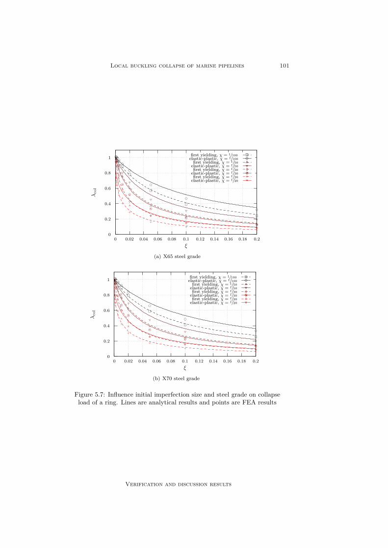
Local buckling collapse of marine pipelines 101
0
0.2
0.4
0.6
0.8
1
0 0.02 0.04 0.06 0.08 0.1 0.12 0.14 0.16 0.18 0.2
λco
l
ξ
first yielding, χ = 1/100elastic-plastic, χ = 1/100first yielding, χ = 1/50elastic-plastic, χ = 1/50first yielding, χ = 1/30elastic-plastic, χ = 1/30first yielding, χ = 1/20elastic-plastic, χ = 1/20
(a) X65 steel grade
0
0.2
0.4
0.6
0.8
1
0 0.02 0.04 0.06 0.08 0.1 0.12 0.14 0.16 0.18 0.2
λco
l
ξ
first yielding, χ = 1/100elastic-plastic, χ = 1/100first yielding, χ = 1/50elastic-plastic, χ = 1/50first yielding, χ = 1/30elastic-plastic, χ = 1/30first yielding, χ = 1/20elastic-plastic, χ = 1/20
(b) X70 steel grade
Figure 5.7: Influence initial imperfection size and steel grade on collapseload of a ring. Lines are analytical results and points are FEA results
Verification and discussion results
102 R. Selker (2013)
to the lowest possible bifurcation load is reported as the bifurcation shape andthe corresponding load as the critical bifurcation load.
It appears that higher values for the bifurcation loads are found for FEAresults compared to analytically obtained results. This could be explained by thefact that in the Galerkin procedure that is used to obtain the bifurcation loadin section 4.10, the boundary layer solution part of the fundamental solutionis neglected. So in fact more stiffness should be inherited from the boundariesthan is taken into account in the analytical formulation in eq. (4.108).
Besides, according to FEA the cylinder bifurcates in a higher mode than isobtained through the analytical formulation. This could also contribute to thereduced stiffness of the analytical model. One could say that the length of thecylinder analysed in the analytical model in fact is a little larger than expectedthrough the value of γ.
The trend of the analytical results and the FEA results corresponds. Theinfluence of the factors α and β also corresponds.
It must be noted that although long cylinders have a stable initial post-bifurcation load, from FEA appears that shorter cylinder develop a snap-throughbifurcation behaviour. First, stability is lost, but after increase of deformationsstability is regained. The structure ‘snaps’ to another equilibrium state. Whenplasticity is included it is very unlikely that the snap-through behaviour isobserved. Larger deformations lead to plasticity that probably leads to instabilitybefore the snap-through behaviour is observed.
5.5.2 Comparison experimental resultsFor a collapse test, the influence of pipeline properties on the collapse load of athin walled pipeline section has been experimentally investigated by Fairbairn[13], Windenburg and Trilling [52], Sturm [43]. In fig. 5.9, the results of theseexperiments are compared to the critical bifurcation load obtained by eq. (4.108).It is assumed that, for small initial imperfections, collapse occurs close to thecritical bifurcation load. Thin walled cylinders (small value of χ) are observedto collapse in the elastic domain. Hence the collapse load of a thin pipelinesection is expected to be a good measure of the corresponding bifurcation load.This is valid as long as the purely plastic collapse load is much higher than thebifurcation load.
From this figure follows that especially for relatively small critical loads, theexperimental and analytical results are close. For higher bifurcation loads it canbe expected that plastic yielding starts to come into play and hence a reductionof the collapse load should be observed. Further, it appears that for thinnercylinders (small values of χ), the analytical expression gives a better descriptionfor the collapse load than it does for thicker cylinders (higher values of χ).
5.6 Collapse load of a cylinderThe analytical collapse load of a cylinder is obtained using an iterative proceduredescribed in section 4.15.4. The load for which first yielding occurs in a cylinderis obtained through FEA by using an elastic model.
The response of this model is analysed. The load for which first yieldingoccurs in the regular domain, is reported as the collapse load. Results are given
Verification and discussion results

Local buckling collapse of marine pipelines 103
0
2
4
6
8
10
12
14
16
18
0 0.1 0.2 0.3 0.4 0.5 0.6 0.7 0.8 0.9 1
λc
γ
α = 0, β = 0α = 1, β = 0α = 0, β = 1α = 1, β = 1
(a) χ = 1/20
02468
10121416182022242628
0 0.1 0.2 0.3 0.4 0.5 0.6 0.7 0.8 0.9 1
λc
γ
α = 0, β = 0α = 1, β = 0α = 0, β = 1α = 1, β = 1
(b) χ = 1/100
Figure 5.8: Bifurcation loads of a constrained cylinder. Lines are analyticalsolution and points are FEA solutions. The circumferential wave numberof the bifurcation shape n can be distinguished by colour of the point,
such that n ∈ 2 , 3 , 4 , 5 , 6 , 7 , . . .
Verification and discussion results

104 R. Selker (2013)
0
20
40
60
80
100
120
0 0.5 1 1.5 2
λc
γ
α = 0α = 1
(a) χ = 0.002
0
10
20
30
40
50
60
70
80
0 0.5 1 1.5 2
λc
γ
α = 1
(b) χ = 0.003
0
10
20
30
40
50
60
70
0 0.5 1 1.5 2
λc
γ
α = 1
(c) χ = 0.004
0
5
10
15
20
25
30
35
0 0.2 0.4 0.6 0.8 1
λc
γ
α = 1
(d) χ = 0.005
0
5
10
15
20
25
30
0 0.2 0.4 0.6 0.8 1
λc
γ
α = 0α = 1
(e) χ = 0.007
02468
1012141618
0 0.1 0.2 0.3 0.4 0.5 0.6
λc
γ
α = 0α = 1
(f) χ = 0.01
Fairbairn [13] (α = 1)Windenburg and Trilling [52] (α = 1)Sturm [43] (α = 0)Sturm [43] (α = 1)
Figure 5.9: Comparison analytical bifurcation loads (β = 0) to experimen-tal results
Verification and discussion results

Local buckling collapse of marine pipelines 105
in tables 5.2 and 5.3.
α β γ n λcol FEA λcol analytical Relative differenceX42 X60 X70 X42 X60 X70 X42 X60 X42
0 0 0.025 2 0.293 0.379 0.427 0.268 0.358 0.405 −0.085 −0.055 −0.0531 0 0.025 2 0.307 0.404 0.451 0.285 0.376 0.424 −0.073 −0.069 −0.0610 1 0.025 2 0.294 0.379 0.428 0.268 0.358 0.405 −0.087 −0.057 −0.0551 1 0.025 2 0.310 0.404 0.455 0.285 0.376 0.424 −0.082 −0.069 −0.0690 0 0.100 2 0.335 0.452 0.512 0.276 0.371 0.420 −0.176 −0.180 −0.1791 0 0.100 2 0.344 0.471 0.526 0.295 0.392 0.443 −0.142 −0.167 −0.1590 1 0.100 2 0.337 0.454 0.514 0.276 0.371 0.420 −0.180 −0.184 −0.1831 1 0.100 2 0.345 0.472 0.528 0.296 0.393 0.443 −0.143 −0.168 −0.1600 0 0.250 3 0.356 0.503 0.580 0.323 0.449 0.521 −0.092 −0.107 −0.1031 0 0.250 3 0.373 0.523 0.599 0.349 0.483 0.559 −0.065 −0.076 −0.0670 1 0.250 3 0.359 0.507 0.585 0.323 0.450 0.521 −0.100 −0.113 −0.1081 1 0.250 3 0.376 0.527 0.604 0.350 0.485 0.561 −0.070 −0.079 −0.0710 0 0.556 4 0.357 0.504 0.591 0.350 0.492 0.574 −0.020 −0.026 −0.0281 0 0.556 4 0.374 0.529 0.620 0.371 0.521 0.607 −0.009 −0.016 −0.0210 1 0.556 4 0.364 0.514 0.602 0.347 0.488 0.570 −0.046 −0.050 −0.0531 1 0.556 4 0.376 0.532 0.623 0.362 0.508 0.593 −0.037 −0.044 −0.047
Table 5.2: Collapse load at first yielding for a cylinder with χ = 1/20 andξ = 0.01. Comparison analytical and FEA results
For all investigated cases the analytical results underestimate the collapseload with respect to the FEA verifications. For cylinders with very small valuesof γ the analytical results are a close match to the FEA results. For the cylinderwith χ = 1/100 its collapse behaviour is expected to be governed by its elasticcollapse load. It appears that the relative difference is the analytical results andthe FEA results are governed by the underestimation of the bifurcation loadas given in fig. 5.8. For the relatively thick walled cylinder, with χ = 1/20, itis expected that its collapse behaviour is governed by its plastic collapse loadgiven in eq. (4.127). The collapse loads are much smaller than the purely elasticcollapse loads and of order of the plastic collapse load. Results generally are ofcorrect order but there is a significant difference between analytical and FEAresults for some combinations of parameters.
5.7 First change in bifurcation modeIn section 4.12 a relation is obtained for χ and the maximum value of γ forwhich the oval shaped bifurcation mode occurs. The corresponding value of γ isobtained by determining the value of γ for which the relations of γ and λc forn = 2 and n = 3 intersect.
These results are verified using FEA. A small imperfection in the shapecharacterised by either n = 2 or n = 3 is introduced. The bifurcation load isobtained for several values of γ. The value of γ where these curves intersect isreported. This results to fig. 5.10.
From this figure follows that the analytical results over-predict the FEAresults. It appears that, in a collapse test to investigate collapse resistance of areal life pipeline, the maximum allowable value for γ should be lower than theanalytical results indicate. Hence the length of the tested specimen should bemore than the analytical results suggest.
Verification and discussion results
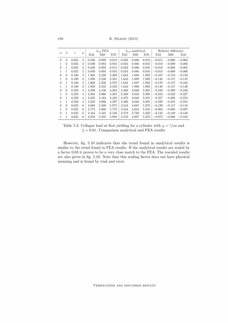
106 R. Selker (2013)
α β γ n λcol FEA λcol analytical Relative differenceX42 X60 X70 X42 X60 X70 X42 X60 X42
0 0 0.025 2 0.836 0.892 0.912 0.823 0.886 0.910 −0.015 −0.006 −0.0031 0 0.025 2 0.839 0.894 0.916 0.824 0.886 0.910 −0.018 −0.009 −0.0060 1 0.025 2 0.838 0.893 0.914 0.823 0.886 0.910 −0.018 −0.008 −0.0051 1 0.025 2 0.839 0.894 0.916 0.824 0.886 0.910 −0.018 −0.009 −0.0060 0 0.100 3 1.962 2.228 2.369 1.634 1.886 1.993 −0.167 −0.153 −0.1591 0 0.100 3 1.926 2.240 2.331 1.642 1.889 1.993 −0.148 −0.157 −0.1450 1 0.100 3 1.969 2.238 2.378 1.634 1.887 1.993 −0.170 −0.157 −0.1621 1 0.100 3 1.928 2.242 2.333 1.642 1.890 1.993 −0.148 −0.157 −0.1460 0 0.250 4 3.286 4.106 4.383 2.468 3.040 3.305 −0.249 −0.260 −0.2461 0 0.250 4 3.204 3.960 4.265 2.486 3.043 3.298 −0.224 −0.232 −0.2270 1 0.250 4 3.325 4.164 4.433 2.472 3.046 3.310 −0.257 −0.269 −0.2531 1 0.250 4 3.228 3.986 4.297 2.490 3.048 3.305 −0.229 −0.235 −0.2310 0 0.625 6 4.068 5.308 5.975 3.544 4.687 5.279 −0.129 −0.117 −0.1161 0 0.625 6 3.772 5.080 5.778 3.534 4.644 5.216 −0.063 −0.086 −0.0970 1 0.625 6 4.164 5.431 6.126 3.573 4.729 5.332 −0.142 −0.129 −0.1301 1 0.625 6 3.858 5.210 5.888 3.576 4.697 5.279 −0.073 −0.098 −0.103
Table 5.3: Collapse load at first yielding for a cylinder with χ = 1/100 andξ = 0.01. Comparison analytical and FEA results
However, fig. 5.10 indicates that the trend found in analytical results issimilar to the trend found in FEA results. If the analytical results are scaled bya factor 0.63 it proves to be a very close match to the FEA. The rescaled resultsare also given in fig. 5.10. Note that this scaling factor does not have physicalmeaning and is found by trial and error.
Verification and discussion results
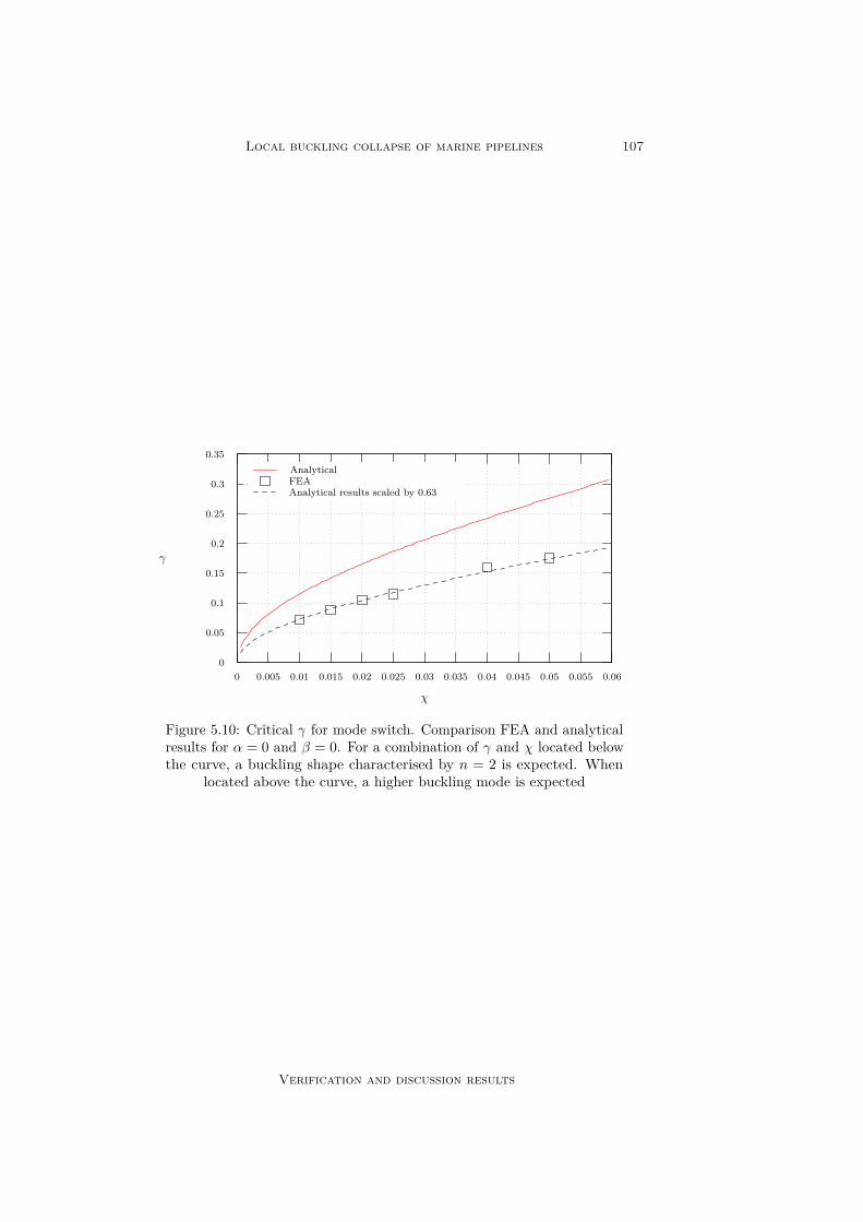
Local buckling collapse of marine pipelines 107
0
0.05
0.1
0.15
0.2
0.25
0.3
0.35
0 0.005 0.01 0.015 0.02 0.025 0.03 0.035 0.04 0.045 0.05 0.055 0.06
γ
χ
AnalyticalFEAAnalytical results scaled by 0.63
Figure 5.10: Critical γ for mode switch. Comparison FEA and analyticalresults for α = 0 and β = 0. For a combination of γ and χ located belowthe curve, a buckling shape characterised by n = 2 is expected. When
located above the curve, a higher buckling mode is expected
Verification and discussion results

This page is intentionally left blank.

Chapter 6
Conclusion andrecommendations
6.1 Conclusions of this researchIn this thesis an overview has been given of the local buckling collapse behaviourof a pipeline. First, the collapse behaviour of a ring has been analysed andlater, the collapse behaviour of a cylinder is investigated. For a ring the initialpost-buckling behaviour is analysed. This is found to be stable. FEA shows thatthis behaviour is even more stable than analytically obtained (higher value ofλ2).
It is found that the collapse behaviour of a pipeline is highly dependenton the value of χ, the ratio between wall thickness and diameter. Relativelythick walled pipelines tend to collapse in the plastic domain while relativelythin walled pipelines tend to collapse in the elastic domain. The plastic domainis defined as the domain for which buckling is not yet clearly observed at theonset of collapse. The fundamental solution governs the equilibrium solutionat the onset of collapse. The elastic domain is defined as the domain for whichthe occurrence of buckling can be observed at the onset of collapse. Now thebifurcation solution governs the equilibrium solution at the onset of collapse.
This difference can be explained by the fact that for thin pipelines the purelyplastic collapse load λp is much higher than the critical (elastic) load λc. Fora cylinder, the initial post-bifurcation behaviour is not investigated, but it isassumed to be neutral. The collapse load can never by higher than both λp andλc. This results to collapse in the elastic domain. For thick walled pipelines, itis likely that the critical load is much higher than the purely plastic collapseload. This results to collapse in the plastic domain.
A cylinder is analysed for various types of boundary constraints. The appli-cation of end cap pressure has been analysed through a factor α. For α = 0, endcap pressure is neglected and for α = 1 end cap pressure is taken into account.Further, two types of boundary constraints are analysed such that β = 0 for asimply supported connection of the end caps to the cylinder walls and β = 1 fora clamped connection.
It is found that including the end cap pressure leads to a reduction inbifurcation load and a possible reduction of the order of the bifurcation mode

110 R. Selker (2013)
shape. This is the case for relatively short cylinders in particular. For longcylinders, the influence of α on the bifurcation load is insignificant. However αproves to influence purely plastic buckling. Due to the introduction of an axialcompressive stress component, the equivalent von Mises stress in the pressurisedcylinder is reduced. In this thesis, collapse of a cylinder is defined using thevon Mises failure criterion. Hence the introduction of an axial stress component(due to hydrostatic pressure) leads to an increase in purely plastic collapse load.This is also valid for long cylinders. End cap pressure reduces the critical loadfor thin walled cylinders that tend to collapse in the elastic domain. For thickwalled cylinders, whose collapse is governed by the purely plastic collapse load,end cap pressure tends to increase collapse load.
A clamped cylinder has a slightly higher collapse load than a simply supportedcylinder. This is explained by the stiffness of the system being higher for aclamped cylinder than for a simply supported cylinder. Clamped cylinders tendto collapse in a higher (or equal) collapse mode shape than simply supportedcylinders. This is also caused by additional stiffness gained from clamped edgescompared to simply supported edges. The influence of these boundary conditionsis only significant for relatively short cylinders. For long cylinders this can beneglected.
The effect of cylinder length is modelled by introduction of dimensionlessparameter γ. Short cylinders will have higher collapse loads bounded by theirpurely plastic collapse load. The collapse mode shape of short cylinders isgenerally described by higher circumferential wave numbers than the collapsemode of longer cylinders. The effect of the length of a cylinder on the collapsemode is investigated. A critical value is determined for γ when the bifurcationmode shape switches its circumferential wave number from n = 2 to n = 3.The corresponding value of γ is of interest because this value corresponds tothe minimum required length of a pipeline section in a collapse test. A hybridrelation has been obtained by combining the analytical relation for this value ofthis critical value of γ and results obtained through FEA.
Analytically obtained values for bifurcation load λc prove to be lower thanvalues obtained through FEA. This can be explained by the fact that theboundary layer part of the fundamental solution is neglected when obtainingan analytical value for λc. Hence some stiffness resulting from the fundamentalsolution is lost. This results to a slightly lower value for the bifurcation loadrequired to bifurcate the system. This deviation in λc is found to reflect inthe collapse load analysis. Collapse loads for cylinders obtained by analyticalanalysis are lower compared to collapse loads obtained through FEA.
6.2 Recommendations for further workIn this thesis the influence of material properties is largely neglected. Onlybasic material models are taken into account such as an elastic and an elastic-perfectly plastic material model. Especially for thick walled pipelines it isexpected that the material modelling has a significant influence on the bifurcationbehaviour. Because thin walled cylinders tend to collapse in the elastic domain,this significance is expected to be much less.
The structure’s material properties are assumed to be homogeneous andisotropic. The influence of inhomogeneity and anisotropy is neglected. For
Conclusion and recommendations
Local buckling collapse of marine pipelines 111
pipelines manufactured by the UOE process, a significant reduction of compres-sive yield strength in hoop direction occurs due to the Bauschinger effect. Thisresults to material properties to become anisotropic. This can have a significantinfluence on the buckling behaviour of a (relatively thick) pipeline.
In this thesis, the wall thickness of a pipeline is assumed to be constant.Introducing wall thickness variations leads to local weak spots that could inducethe occurrence of buckling earlier than expected. The influence of such weakspots could be investigated.
From FEA it is found that constrained elastic cylinders develop snap-throughbehaviour after occurrence of buckling. This behaviour is only found for shortercylinders. Long cylinders tend to have a stable initial post-buckling behaviour.The initial post-buckling behaviour of cylinders could be investigated. This canlead to a threshold value for the length at which the post-buckling behaviourturns from stable to snap-through.
Shell theory is used to model the pipeline. Therefore the Kirchhoff assump-tions are introduced. For thick walled pipelines in particular, transverse shearstresses are expected to have a significant influence on the buckling behaviour ofa pipeline. Further the plane normal to the shell middle surface is not expectedto stay straight during deformations (due to shear). The influence of theseassumptions can be investigated.
In this thesis only the influence of external pressure on collapse behaviourof a pipeline is investigated. The critical scenario for a deep water pipelinewith respect to collapse, is likely to be the sag bend. Here bending strains areintroduced in the pipeline combined with high external pressure. It is importantto account for bending (strain) introduced in the system when developing adesign formulation.
The end caps attached to the pipeline specimen’s ends are modelled to befully rigid. The influence of adding some flexibility to these end caps can beinvestigated.
Conclusion and recommendations

This page is intentionally left blank.

Appendix A
Profound analysis ringbifurcation
In this appendix the derivation of the solution of the bifurcation equation of aring is given. The bifurcation equations are given in eq. (3.62) and read:
3N1,θ + χ2M1,θ = 3λcχ2 (ϕ1 − ϕ1
)(A.1a)
χ2M1,θθ − 3N1 = 3λcχ2 (e1 − κ1) (A.1b)
These are the bifurcation equations based on Sanders shell equations. Theunderlined terms are dropped for the DMV shell relations.
ϕ1 = −w1,θ + v1 (A.2a)M1 = κ1 = ϕ1,θ (A.2b)N1 = e1 = v1,θ + w (A.2c)
A.1 Sanders shell
A.1.1 General solution systemSubstituting eq. (A.2) into eq. (A.1) and rewriting the system leads to thefollowing equilibrium equations:
v1,θθθ +(1 + λcχ
2)w1,θθ + v1,θ +(1 + λcχ
2)w1 = 0 (A.3a)χ2w1,θθθ −
(3 + χ2) v1,θθ − 3w1,θ = 0 (A.3b)
General solutions to this system of differential equations can be obtained bysubstituting the following in the system above:
v1 = V1 exp (pθ) (A.4a)w1 = W1 exp (pθ) (A.4b)
This leads to the linear system:[ (1 + p2) p (
1 + p2) (1 + λcχ2)
−(3 + χ2) p2 (
p2χ2 − 3)p
] [V1W1
]=[00
](A.5)

114 R. Selker (2013)
This system has non-trivial solutions if and only if its determinant is equalto zero. This leads to the characteristic polynomial of sixth degree for p:
p6 +
2 + λc(3 + χ2) p4 +
1 + λc
(3 + χ2) p2 = 0 (A.6)
This characteristic equation has six solutions such that:
p2 ∈−1− λc
(3 + χ2) ,−1, 0
(A.7)
Hence:p ∈
ı√
Λ,−ı√
Λ, ı,−ı, 0, 0
(A.8)
Where:Λ = 1 + λc
(3 + χ2) (A.9)
Now for each Eigenvalue p, the corresponding Eigenvector µ is determined.This is done by substituting the Eigenvalue into the matrix of eq. (A.5). Thenullspace of the new matrix is obtained. It appears that the nullity of allnullspaces is one. Hence the corresponding Eigenvector is equal to the vectorcontained in the nullspace. The Eigenvalue p = 0 is a repeated Eigenvalue.Because the nullity of the corresponding Eigenspace is equal to one, it is necessaryto obtain a second independent Eigenvector corresponding with the repeatedEigenvalue. This can be done by performing the following substitution ineq. (A.3): [
v1w1
]=([
10
]θ +
[ρ1ρ2
])exp (pθ) (A.10)
Where p = 0 and[1, 0]>θ +
[ρ1, ρ2
]> represents the additional independentEigenvector. After the substitution and solving for ρ1 and ρ2, it is obtainedthat ρ1 is arbitrary and ρ2 = −
(1 + λc
3χ
)−1. It is chosen that ρ1 = 0. Now the
following Eigenvectors µ corresponding to the Eigenvalues given in eq. (A.8) areobtained:
µ ∈[
1 + λcχ2
−ı√
Λ
],
[1 + λcχ
2
ı√
Λ
],
[1−ı
],
[1ı
],
[10
],
[(1 + λcχ
2) θ−1
](A.11)
Now the general solution can be obtained by the superposition of all possiblesolutions: [
v1w1
]=
6∑i=1Ciµi exp (piθ) (A.12)
Using Euler’s formula the general solution can be rewritten to:
v1(θ) =C1(1 + λcχ
2) cos(√
Λθ)
+ C2(1 + λcχ
2) sin(√
Λθ)
+C3 cos (θ) + C4 sin (θ) + C5(1 + λcχ
2) θ + C6(A.13a)
w1(θ) = C1√
Λ sin(√
Λθ)− C2√
Λ cos(√
Λθ)
+ C3 sin (θ)− C4 cos (θ)− C5(A.13b)
Profound analysis ring bifurcation
Local buckling collapse of marine pipelines 115
A.1.2 Boundary conditionsNow that the general solutions are obtained, they can be used to obtain thesolution that satisfies the boundary conditions. The boundary conditions usedin this analysis constrain rigid body displacements and rotations and besidescontinuity needs to be ensured on θ = 0 and θ = 2π. The continuity conditionsfollow from the following three boundary conditions:
v(0) = v(2π) (A.14a)w(0) = w(2π) (A.14b)
w,θ(0) = w,θ(2π) (A.14c)
Rigid body constraints give two equations to fix the centre of gravity and oneequation to constrain the rigid body rotation. Because a homogeneous materialis assumed the centre of gravity coincides with the centre of area. Conventionsfrom figure 3.1 are used. The centre of are will be constrained along the x1 andthe x2-axis. The location of the centre of area along an axis can be obtainedby dividing the first moment of area (Sx1 or Sx2) along that axis by the totalarea. Because the location of the centre of area is set to x1 = 0 and x2 = 0 is issufficient to let the first moment of area in each direction be equal to zero:
Sx1 =∫A
(p+ d) · ı dA = 0 (A.15a)
Sx2 =∫A
(p+ d) · dA = 0 (A.15b)
Where A =[− 1
2 t,12 t]× [0, 2π] and dA = ρdzdθ. ı and are the unit vectors
in x1 and x2 direction respectively and the dot denotes the inner product of twovectors. It can be obtained that:
p+ dρ
= (1 + w)[cos (θ)sin (θ)
]+ v
[− sin (θ)cos (θ)
](A.16)
Here v and w represent the dimensionless displacement functions v(θ) andw(θ). Making the first moments of area dimensionless by dividing by ρ2t leadsto the following two boundary conditions that constrain the centre of area:∫ 2π
0(1 + w) cos (θ)− v sin (θ) dθ = 0 (A.17a)∫ 2π
0(1 + w) sin (θ) + v cos (θ) dθ = 0 (A.17b)
Only one more boundary condition is needed. This is the condition toconstrain the rigid body rotation. The only vector component that represents arotation is vt. No rigid body rotation occurs if:∫ 2π
0vdθ = 0 (A.18)
Reintroduction of the following expansions allows for rewriting the boundaryconditions for each order of expansion:
v = v0(λc) + ζv1 + ζ2v2 + . . . (A.19a)
Profound analysis ring bifurcation

116 R. Selker (2013)
w = w0(λc) + ζw1 + ζ2w2 + . . . (A.19b)
In these expansions v0(λc) and w0(λc) are the fundamental solutions asobtained in eq. (3.57) where λ → λc. Furthermore v1 and w1 are the generalsolutions as obtained in eq. (A.13). Now the boundary conditions correspondingto the fundamental solutions can be obtained by letting ζ = 0. It follows thatthe fundamental solution complies with the boundary conditions.
The boundary conditions constraining the first order solutions can be obtainedby dividing the boundary conditions by ζ and thereupon letting ζ = 0. Thisis equivalent to obtain the coefficient of the first power of ζ in the boundaryconditions. Now the following boundary conditions are obtained:
v1(0)− v1(2π) = 0 (A.20a)w1(0)− w1(2π) = 0 (A.20b)
w1,θ(0)− w1,θ(2π) = 0 (A.20c)∫ 2π
0w1 cos (θ)− v1 sin (θ) dθ = 0 (A.20d)∫ 2π
0w1 sin (θ) + v1 cos (θ) dθ = 0 (A.20e)∫ 2π
0v1dθ = 0 (A.20f)
A.1.3 Solution of systemBy substituting the general solution given in eq. (A.13) into the boundarycondition it is possible to write the boundary conditions as a system of a six-by-six coefficient matrix multiplied by a vector containing all C’s being equal tothe null vector. This homogeneous system has only non-trivial solutions if andonly if the determinant of the coefficient matrix is equal to zero. Solving thischaracteristic equation for λc under the assumption that λc is positive leads tothe following buckling load parameter:
λc;Sanders = n2 − 13 + χ2 (A.21)
This obtained value exactly corresponds to eq. (3.69). Now the system canbe solved for the unknown coefficients if this newly obtained value for λc issubstituted back into the system. This results in only C1 and C2 being non-zero.Besides, it is obtained that they have an arbitrary value. The general solutionthat complies with the boundary conditions now reads:
v1(θ) = C1 3+n2χ2
3+χ2 cos (nθ) + C2 3+n2χ2
3+χ2 sin (nθ) (A.22a)w1(θ) = C1n sin (nθ)− C2n cos (nθ) (A.22b)
These expressions can be rewritten based on the following trigonometricidentities:
A cos (nθ − ψ) = A cos (ψ) cos (nθ) +A sin (ψ) sin (nθ) (A.23a)A sin (nθ − ψ) = A cos (ψ) sin (nθ)−A sin (ψ) cos (nθ) (A.23b)
Profound analysis ring bifurcation

Local buckling collapse of marine pipelines 117
The new expressions for the first order solutions now read:
v1(θ) = −C 3+n2χ2
n(3+χ2) sin (nθ − ψ) (A.24a)w1(θ) = C cos (nθ − ψ) (A.24b)
Where C is an arbitrary amplitude parameter and ψ is an arbitrary phaseshift. Because of the symmetry of the structure the orientation does not influencethe buckling load parameter and hence a fixed value for ψ can be chosen for thebifurcation analysis. It must be kept in mind that although a fixed orientation isfound in chapters 3 and 4 due to the choice of an ansatz, the orientation shouldbe arbitrary. The amplitude parameter is arbitrary, because in the bifurcationanalysis only a shape is found.
If now is chosen that ψ = 0 and C = 1, exactly the solution as obtained ineq. (3.73) is found. For small values of χ the following approximations are valid:
λc = 13(n2 − 1
)(A.25a)
v1(θ) = − 1n
sin (nθ) (A.25b)
w1(θ) = cos (nθ) (A.25c)
A.2 Donnell-Mushtari-Vlasov shellSubstituting eq. (A.2) into eq. (A.1), dropping the underlined terms and rewritingleads to the following bifurcation equations based on the DMV shell equations:
v1,θθ +(1 + λcχ
2)w1,θ = 0 (A.26a)13χ
2w1,θθθθ + λcχ2w1,θθ +
(1 + λcχ
2) v1,θ +(1 + λcχ
2)w1 = 0 (A.26b)
To solve these equations, a similar method is applied as in the previoussection. In the system above, the identities given in eq. (A.4) are substituted.This leads to the system:[
p2 (1 + λcχ
2) p(1 + λcχ
2) p 1 + λcχ2 (p2 + 1
)+ 1
3χ2p4
] [V1W1
]=[00
](A.27)
This homogeneous system can only have non-trivial solutions if and only ifthe determinant of the matrix is equal to zero. This leads to a characteristicpolynomial of sixth order for p:
13χ
2p6 + λcχ2p4 − λcχ
2 (1 + λcχ2) p2 = 0 (A.28)
The roots of this polynomial are:
p ∈√−Λ1 + Λ2,−
√−Λ1 + Λ2, ı
√Λ1 + Λ2,−ı
√Λ1 + Λ2, 0, 0
(A.29)
Where:
Λ1 = 32λc (A.30a)
Profound analysis ring bifurcation
118 R. Selker (2013)
Λ2 =√
3λc + λ2c( 9
4 + 3χ2)
(A.30b)
It follows that Λ2 > Λ1. Hence all square roots in eq. (A.29) are realvalued. The Eigenvectors corresponding to the Eigenvalues can be obtainedby substituting the Eigenvalues into the matrix in eq. (A.27) and obtainingthe nullspace of the matrix. The Eigenvector is the vector contained in thisnullspace with exception of the null vector. The null vector is irrelevant. Notethat there is a shared Eigenvalue p = 0. Hence for one of the two occurrencesof this Eigenvalue the corresponding Eigenvector is adjusted corresponding themethod explained in the previous section. This leads to the following set ofEigenvectors corresponding to the Eigenvalues given in eq. (A.29).
µ ∈
[
1 + λcχ2
−√−Λ1 + Λ2
],
[1 + λcχ
2√−Λ1 + Λ2
],[
1 + λcχ2
−ı√
Λ1 + Λ2
],
[1 + λcχ
2
ı√
Λ1 + Λ2
],
[10
],
[θ−1
] (A.31)
The general solution for v1(θ) and w1(θ) can be composed using eq. (A.12).Using Euler’s formula and rewriting for the undetermined coefficients the follow-ing the general solution reads:
v1(θ) =
1 + λcχ2C1 cosh
(√−Λ1 + Λ2θ
)− C2 sinh
(√−Λ1 + Λ2θ
)+C3 cos
(√Λ1 + Λ2θ
)+ C4 sin
(√Λ1 + Λ2θ
)
+C5θ + C6(A.32a)
w1(θ) =
√−Λ1 + Λ2
−C1 sinh
(√−Λ1 + Λ2θ
)+ C2 cosh
(√−Λ1 + Λ2θ
)+√
Λ1 + Λ2
C3 sin
(√Λ1 + Λ2θ
)− C4 cos
(√Λ1 + Λ2θ
)− C5
(A.32b)
Now the boundary conditions given in eq. (A.20) are introduced again. Thegeneral solution above is substituted into these boundary conditions. The systemof boundary conditions is rewritten to a homogeneous linear system with respectto the indeterminate coefficients. This system can only have non-trivial solutionsif its determinant is equal to zero. Setting this determinant to zero leads toa characteristic equation. Obtaining the roots of this characteristic equationresults in several possible solutions for λc. The only root of interest, having apositive value is given by:
λc;DMV = − 12
(n2 + 1−
√(n2 + 1)2 + 4
3χ2n4)χ−2 (A.33)
This solution exactly matches eq. (3.65). This solution is substituted backinto the general solution. The boundary condition equations now can be solvedfor the six indeterminate coefficients. This results in all coefficients but C3 andC4 to be zero. The remaining two coefficients are free. Hence the general solutioncomplying with the boundary conditions reads:
v1(θ) = 12
√
(n2 + 1)2 + 43χ
2n4
−(n2 − 1
) C1 cos (nθ) + C2 sin (nθ) (A.34a)
Profound analysis ring bifurcation

Local buckling collapse of marine pipelines 119
w1(θ) = C1n sin (nθ)− C2n cos (nθ) (A.34b)
By using eq. (A.23), it is possible to rewrite the general solution to:
v1(θ) = −C 12n
√(n2 + 1)2 + 4
3χ2n4 −
(n2 − 1
)sin (nθ − ψ) (A.35a)
w1(θ) = C cos (nθ − ψ) (A.35b)
Here C is a free amplitude parameter and ψ is a free phase parameter. As inthe previous section a general solution can be described by setting C = 1 andψ = 0:
v1(θ) = − 12n
√(n2 + 1)2 + 4
3χ2n4 −
(n2 − 1
)sin (nθ) (A.36a)
w1(θ) = cos (nθ) (A.36b)
This corresponds with the ansatzes introduced in eq. (3.63). For small valuesof χ the following approximations are valid:
λc = n4
3 (n2 + 1) (A.37a)
v1(θ) = − 1n
sin (nθ) (A.37b)
w1(θ) = cos (nθ) (A.37c)
Profound analysis ring bifurcation

This page is intentionally left blank.

Appendix B
FEA results ring collapse
In this appendix results of the FEA for a ring are given for two different collapsecriteria. The results denoted in the tables are used in figs. 5.6 and 5.7. Note thatfor all analyses performed in this appendix an oval initial imperfection shape isapplied and consequently an oval shaped collapse mode is observed.
In tables B.1 to B.4 results are given for the collapse criterion that assumescollapse to occur for first yielding of the ring. This is also known as theTimoshenko criterion. In tables B.5 to B.8 results are given of FEA of a ringusing an elastic-perfectly plastic material model. These results are used to verifythe collapse criterion based on the full development of a plastic hinge (DNVcriterion).
ξλcol for steel grade
X42 X52 X60 X65 X700.001 0.996 1.001 1.003 1.006 1.0080.002 0.972 0.984 0.989 0.991 0.9940.005 0.910 0.931 0.943 0.950 0.9550.010 0.821 0.857 0.876 0.888 0.8980.020 0.682 0.734 0.763 0.782 0.7970.050 0.451 0.509 0.545 0.571 0.5900.100 0.288 0.338 0.370 0.394 0.4100.200 0.168 0.204 0.226 0.245 0.257
Table B.1: Collapse load at first yielding for χ = 1/100
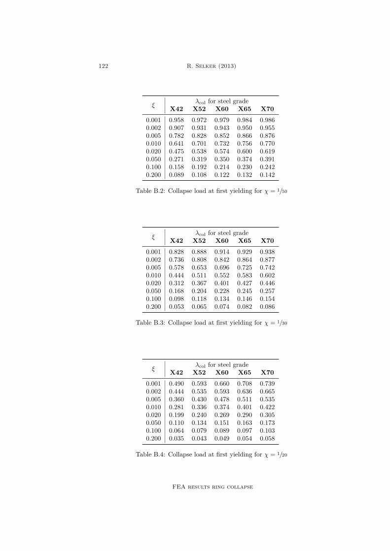
122 R. Selker (2013)
ξλcol for steel grade
X42 X52 X60 X65 X700.001 0.958 0.972 0.979 0.984 0.9860.002 0.907 0.931 0.943 0.950 0.9550.005 0.782 0.828 0.852 0.866 0.8760.010 0.641 0.701 0.732 0.756 0.7700.020 0.475 0.538 0.574 0.600 0.6190.050 0.271 0.319 0.350 0.374 0.3910.100 0.158 0.192 0.214 0.230 0.2420.200 0.089 0.108 0.122 0.132 0.142
Table B.2: Collapse load at first yielding for χ = 1/50
ξλcol for steel grade
X42 X52 X60 X65 X700.001 0.828 0.888 0.914 0.929 0.9380.002 0.736 0.808 0.842 0.864 0.8770.005 0.578 0.653 0.696 0.725 0.7420.010 0.444 0.511 0.552 0.583 0.6020.020 0.312 0.367 0.401 0.427 0.4460.050 0.168 0.204 0.228 0.245 0.2570.100 0.098 0.118 0.134 0.146 0.1540.200 0.053 0.065 0.074 0.082 0.086
Table B.3: Collapse load at first yielding for χ = 1/30
ξλcol for steel grade
X42 X52 X60 X65 X700.001 0.490 0.593 0.660 0.708 0.7390.002 0.444 0.535 0.593 0.636 0.6650.005 0.360 0.430 0.478 0.511 0.5350.010 0.281 0.336 0.374 0.401 0.4220.020 0.199 0.240 0.269 0.290 0.3050.050 0.110 0.134 0.151 0.163 0.1730.100 0.064 0.079 0.089 0.097 0.1030.200 0.035 0.043 0.049 0.054 0.058
Table B.4: Collapse load at first yielding for χ = 1/20
FEA results ring collapse
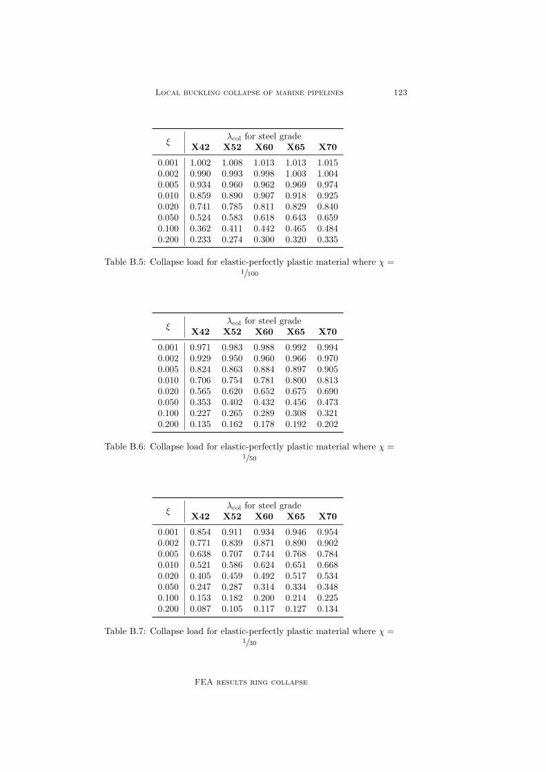
Local buckling collapse of marine pipelines 123
ξλcol for steel grade
X42 X52 X60 X65 X700.001 1.002 1.008 1.013 1.013 1.0150.002 0.990 0.993 0.998 1.003 1.0040.005 0.934 0.960 0.962 0.969 0.9740.010 0.859 0.890 0.907 0.918 0.9250.020 0.741 0.785 0.811 0.829 0.8400.050 0.524 0.583 0.618 0.643 0.6590.100 0.362 0.411 0.442 0.465 0.4840.200 0.233 0.274 0.300 0.320 0.335
Table B.5: Collapse load for elastic-perfectly plastic material where χ =1/100
ξλcol for steel grade
X42 X52 X60 X65 X700.001 0.971 0.983 0.988 0.992 0.9940.002 0.929 0.950 0.960 0.966 0.9700.005 0.824 0.863 0.884 0.897 0.9050.010 0.706 0.754 0.781 0.800 0.8130.020 0.565 0.620 0.652 0.675 0.6900.050 0.353 0.402 0.432 0.456 0.4730.100 0.227 0.265 0.289 0.308 0.3210.200 0.135 0.162 0.178 0.192 0.202
Table B.6: Collapse load for elastic-perfectly plastic material where χ =1/50
ξλcol for steel grade
X42 X52 X60 X65 X700.001 0.854 0.911 0.934 0.946 0.9540.002 0.771 0.839 0.871 0.890 0.9020.005 0.638 0.707 0.744 0.768 0.7840.010 0.521 0.586 0.624 0.651 0.6680.020 0.405 0.459 0.492 0.517 0.5340.050 0.247 0.287 0.314 0.334 0.3480.100 0.153 0.182 0.200 0.214 0.2250.200 0.087 0.105 0.117 0.127 0.134
Table B.7: Collapse load for elastic-perfectly plastic material where χ =1/30
FEA results ring collapse
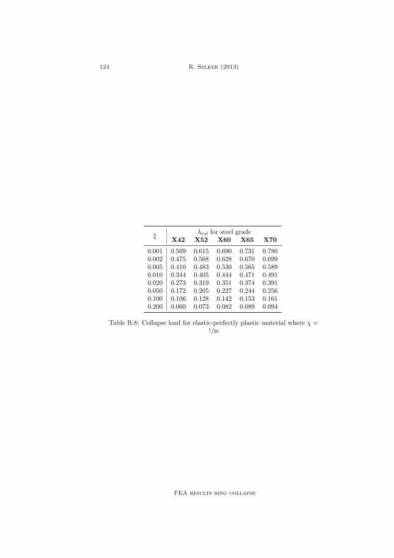
124 R. Selker (2013)
ξλcol for steel grade
X42 X52 X60 X65 X700.001 0.509 0.615 0.690 0.731 0.7800.002 0.475 0.568 0.628 0.670 0.6990.005 0.410 0.483 0.530 0.565 0.5890.010 0.344 0.405 0.444 0.471 0.4910.020 0.273 0.319 0.351 0.374 0.3910.050 0.172 0.205 0.227 0.244 0.2560.100 0.106 0.128 0.142 0.153 0.1610.200 0.060 0.073 0.082 0.089 0.094
Table B.8: Collapse load for elastic-perfectly plastic material where χ =1/20
FEA results ring collapse
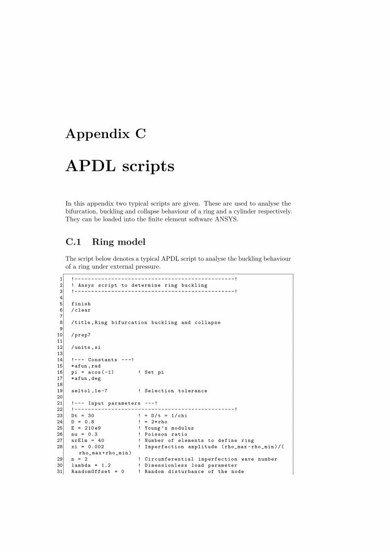
Appendix C
APDL scripts
In this appendix two typical scripts are given. These are used to analyse thebifurcation, buckling and collapse behaviour of a ring and a cylinder respectively.They can be loaded into the finite element software ANSYS.
C.1 Ring modelThe script below denotes a typical APDL script to analyse the buckling behaviourof a ring under external pressure.
1 !------------------------------------------------!2 ! Ansys script to determine ring buckling3 !------------------------------------------------!45 finish6 / clear78 /title ,Ring bifurcation buckling and collapse9
10 / prep71112 /units ,si1314 !--- Constants ---!15 *afun ,rad16 pi = acos ( -1) ! Set pi17 *afun ,deg1819 seltol ,1e -7 ! Selection tolerance2021 !--- Input parameters ---!22 !------------------------------------------------!23 Dt = 30 ! = D/t = 1/ chi24 D = 0.8 ! = 2* rho25 E = 210 e9 ! Young ’s modulus26 nu = 0.3 ! Poisson ratio27 nrElm = 40 ! Number of elements to define ring28 xi = 0.002 ! Imperfection amplitude (rho_max - rho_min )/(
rho_max + rho_min )29 n = 2 ! Circumferential imperfection wave number30 lambda = 1.2 ! Dimensionless load parameter31 RandomOffset = 0 ! Random disturbance of the node

126 R. Selker (2013)
32 YieldStress = 290 e6 ! Yield stress | X70 ~ 480 MPa | X65 ~ 450MPa | X60 ~ 410 MPa | X52 ~ 360 MPa | X42 ~ 290 MPa
33 SubSteps = 1000 ! Number of substeps34 !------------------------------------------------!3536 chi = 1/ Dt37 rho = D/238 t = 2* rho*chi39 I = t **3/1240 P = lambda *E/4*(t/rho)**34142 !--- Element properties ---!43 et ,1, beam18844 et ,2, targe169 ! Force based constraints45 et ,3, conta175 ! Pilot node element4647 ! keyopt , element #, keyopt #, keyopt value48 keyopt ,1 ,2 ,14950 keyopt ,2 ,2 ,1 ! Boundary conditions specified by user51 keyopt ,2 ,4 ,111 ! Constraints in all directions will be
passed from pilot node5253 keyopt ,3 ,2 ,2 ! MPC Contact algoritm54 keyopt ,3 ,4 ,1 ! Force - distributed constraint55 keyopt ,3 ,12 ,5 ! Always bonded behaviour of contact surface5657 r ,25859 !--- Sections ---!60 sectype ,1,beam ,rect61 secdata ,t ,1 ! Beam with height t and unit breadth626364 !--- Materials ---!65 mptemp ,_Dt1001 ,29866 mpdata ,ex ,1,,E67 mpdata ,prxy ,1,,nu6869 *if ,1,eq ,0, then ! Only run for elastic perfectly - plastic
analysis70 tb ,bkin ,1 ,1 ,2 ,0 ! Kinematic hardening71 tbtemp ,29872 tbdata ,1, YieldStress ,0 ! Yield stress | Tangent modulus73 * endif7475 dTheta = 360/ nrElm7677 !--- Nodes ---!78 n ,1 ,0 ,079 *do ,i,1, nrElm80 Theta = (i -1)* dTheta81 Wi = xi*rho*cos(n* Theta )82 Vi = -xi*rho/n*sin(n* Theta )83 X = rho*cos( Theta ) + Wi*cos( Theta ) + Vi*sin( Theta ) + RAND
( -1 ,1)* RandomOffset *rho84 Y = rho*sin( Theta ) + Wi*sin( Theta ) + Vi*cos( Theta ) + RAND
( -1 ,1)* RandomOffset *rho85 n,,X,Y86 * enddo87 nsel ,s,,,2, nrElm +188 csys ,1
APDL scripts

Local buckling collapse of marine pipelines 127
89 nrotat ,all90 csys ,091 allsel9293 !--- Elements ---!94 real ,195 type ,196 *do ,i,2, nrElm +197 *if ,i,eq , nrElm +1, then98 j = 299 *else
100 j = i + 1101 * endif102 e,i,j103 * enddo104105 !--- MPC ---!106 real ,2107108 type ,3109 allsel110 esurf111112 type ,2113 tshap ,pilo114 e ,1115116 !--- Boundary conditions ---!117 csys ,0118 d,1,ux ,0119 d,1,uy ,0120 d,1,rotz ,0121 d,all ,uz ,0122 d,all ,rotx ,0123 d,all ,roty ,0124125 !--- Loads and solver settings ---!126 /solu127128 antype ,0129 nlgeom ,1130 outres ,all ,all131 solcontrol ,on132133 ! Either Newton - Raphson or arc - length solver134 nropt ,full135 !arclen ,on ,25 ,1/1000 ! Default : 25 ,1/1000136137 nsubst ,SubSteps ,1e12 , SubSteps138139 esel ,s,type ,,1140 sfbeam ,all ,2,press ,-P141 allsel142143 time ,1144145 solve146147 finish
APDL scripts

128 R. Selker (2013)
C.2 Cylinder modelThe script below denotes a typical APDL script to analyse the buckling behaviourof a cylinder under external pressure constrained by end caps.
1 !------------------------------------------------!2 ! Ansys script to determine cylinder buckling3 !------------------------------------------------!45 finish6 / clear78 /title , Cylinder bifurcation buckling and collapse9
10 / prep71112 /units ,si1314 !--- Constants ---!15 *afun ,rad16 pi = acos ( -1) ! Set pi17 *afun ,deg1819 seltol ,1e -7 ! Selection tolerance2021 !--- Input parameters ---!22 !------------------------------------------------!23 Dt = 100 ! = D/t = 1/ chi24 LD = 20 ! = L/D = L/2/ rho = 1/2/ gamma => gamma = 1/2/
LD25 D = 0.8 ! = 2* rho26 E = 210 e9 ! Young ’s modulus27 nu = 0.3 ! Poisson ratio28 nrElm = 100 ! Number of elements through the
circumference29 xi = 0.01 ! Imperfection amplitude (rho_max - rho_min )/(
rho_max + rho_min )30 n = 2 ! Circumferential imperfection wave number31 m = 1 ! Axial half wave number imperfection32 lambda = 1.5 ! Dimensionless load parameter33 RandomOffset = 0e -3 ! Random disturbance of the node34 AspectRatio = 10 ! Element size in axial direction divided by
element size in circumferential direction35 YieldStress = 480 e6 ! Yield stress | X70 ~ 480 MPa | X65 ~ 450
MPa | X60 ~ 410 MPa | X52 ~ 360 MPa | X42 ~ 290 MPa36 SubSteps = 10 ! Number of substeps37 alpha = 1 ! Include end cap pressure for alpha =1 and
not include end cap pressure for alpha = 038 beta = 0 ! For beta = 0 simply supported and for beta
= 1 clamped39 !------------------------------------------------!4041 chi = 1/ Dt42 rho = D/243 L = D*LD44 t = 2* rho*chi45 P = lambda *E/4*(t/rho)**3/(1 - nu **2)46 AxialElementCnt = nint( nrElm *L/2/ pi/rho/ AspectRatio )47 Fec = P*pi*rho **2* alpha4849 !--- Element properties ---!50 et ,1, shell181
APDL scripts

Local buckling collapse of marine pipelines 129
51 et ,2, targe170 ! 3d target element for rigid mpc52 et ,3, conta175 ! Pilot node5354 !--- Keyoptions ---!55 keyopt ,2 ,2 ,1 ! Boundary conditions specified by user5657 *if ,beta ,eq ,0, then58 keyopt ,2 ,4 ,000111 ! Constraints in all directions will be
passed from pilot node exept for rotations59 *elseif ,beta ,eq ,1, then60 keyopt ,2 ,4 ,111111 ! Constraints in all directions will be
passed from pilot node61 *else62 /eof63 * endif6465 keyopt ,3 ,2 ,2 ! MPC Contact algoritm66 keyopt ,3 ,4 ,0 ! Rigid constraint ==> 0 | Force - distributed
constraint ==> 167 keyopt ,3 ,12 ,5 ! Always bonded behaviour of contact surface6869 !--- Sections ---!70 sectype ,, shell71 secdata ,t ! Shell thickness7273 r ,2 ! Real constant set for z=074 r ,3 ! Real constant set for z=L7576 !--- Materials ---!77 mptemp ,1 ,29878 mpdata ,ex ,1,,E79 mpdata ,prxy ,1,,nu808182 *if ,1,eq ,0, then ! Only run for elastic perfectly - plastic
analysis83 tb ,bkin ,1 ,1 ,2 ,0 ! Kinematic hardening84 tbtemp ,29885 tbdata ,1, YieldStress ,0 ! Yield stress | Tangent modulus86 * endif8788 dTheta = 360/ nrElm899091 !--- Nodes ---!92 n ,1 ,0 ,0 ,093 n,2,0,0,L9495 *do ,j,1, AxialElementCnt +196 *do ,i,2, nrElm +197 Z = (j -1)*L/ AxialElementCnt98 Theta = (i -1)* dTheta99 Wi = xi*rho*cos(n* Theta )*sin(pi*m*Z/L *360/2/ pi)
100 X = (rho+Wi)*cos( Theta )101 Y = (rho+Wi)*sin( Theta )102 XMod = X + RAND ( -1 ,1)* RandomOffset *rho*sin(pi*Z/L *360/2/ pi)103 YMod = Y + RAND ( -1 ,1)* RandomOffset *rho*sin(pi*Z/L *360/2/ pi)104 Zmod = Z + RAND ( -1 ,1)* RandomOffset *rho*sin(pi*Z/L *360/2/ pi)105 *if ,Z,eq ,L,then106 Xmod = rho*cos( Theta )107 Ymod = rho*sin( Theta )108 Zmod = Z
APDL scripts

130 R. Selker (2013)
109 * endif110 n,,Xmod ,Ymod ,Zmod111 * enddo112 * enddo113 nsel ,s,,,all114 nsel ,u,,,1,2115 csys ,1116 nrotat ,all117 csys ,0118 allsel119120121 !--- Elements ---!122 *do ,i,1, AxialElementCnt123 ElmAdd = (i -1)* nrElm124 *do ,j,3, nrElm +2125 *if ,j,eq , nrElm +2, then126 e,j+ElmAdd ,j+1- nrElm +ElmAdd ,j+1+ ElmAdd ,j+ nrElm + ElmAdd127 *else ,then128 e,j+ElmAdd ,j+1+ ElmAdd ,j+1+ nrElm +ElmAdd ,j+ nrElm + ElmAdd129 * endif130 * enddo131 * enddo132133 !--- MPC for z=0 ---!134 real ,2135136 type ,3137 nsel ,s,loc ,z ,0138 esurf139 allsel140141 type ,2142 tshap ,pilo143 e ,1144145 !--- MPC for z=L ---!146 real ,3147148 type ,3149 nsel ,s,loc ,z,L150 esurf151 allsel152153 type ,2154 tshap ,pilo155 e ,2156157 !--- Boundary conditions ---!158 csys ,0159 d,1,ux ,0160 d,1,uy ,0161 d,1,uz ,0162 d,1,rotx ,0163 d,1,roty ,0164 d,1,rotz ,0165166 d,2,ux ,0167 d,2,uy ,0168 d,2,rotx ,0169 d,2,roty ,0170 d,2,rotz ,0
APDL scripts

Local buckling collapse of marine pipelines 131
171172 !--- Loads and solver settings ---!173 /solu174175 antype ,0176 nlgeom ,1177 outres ,all ,all178 solcontrol ,on179180 ! Either Newton - Raphson or arc - length solver181 nropt ,full182 !arclen ,on ,25 ,1/1000 ! Default : 25 ,1/1000183184 nsubst ,SubSteps ,1e15 , SubSteps /4185186 esel ,s,type ,,1187 sfe ,all ,2,pres ,0,P ! Wall pressure188 allsel189190 *if ,Fec ,ne ,0, then ! End cap pressure191 f,1,fz ,Fec192 f,2,fz ,-Fec193 * endif194195 time ,1196197 solve198199 finish
APDL scripts

This page is intentionally left blank.
List of Figures
1.1 Schematic representation collapse test. The rigid rod is onlyapplied when the influence of end cap pressure needs to be removed 2
1.2 Collapsed specimen being removed from pressure chamber. Pic-ture courtesy DeGeer et al. [7] . . . . . . . . . . . . . . . . . . . 2
2.1 Various types of initial post-bifurcation behaviour. Bifurcationpoint is at intersection of lines for ξ = 0 . . . . . . . . . . . . . . 17
3.1 Ring model . . . . . . . . . . . . . . . . . . . . . . . . . . . . . . 203.2 Critical dimensionless pressures for DMV and Sanders kinematics 323.3 Imperfection sensitivity of a ring with χ = 1/21 and n = 2 . . . . 383.4 Initial and bifurcation shapes of a perfect ring for various values
of n. . . . . . . . . . . . . . . . . . . . . . . . . . . . . . . . . . . 393.5 Initial and bifurcation shapes of a ring with an initial imperfection
described by wave number n. . . . . . . . . . . . . . . . . . . . . 413.6 Matching inner and outer solution for χ = 1/21, n = 2 and ξ = 0.02 42
4.1 Cylinder model . . . . . . . . . . . . . . . . . . . . . . . . . . . . 484.2 Inner (boundary layer) and outer (regular) solutions . . . . . . . 584.3 Contour plots for λc(n,m) with χ = 1/20 and α = 1 . . . . . . . . 734.4 Contour plots for λc(n,m) with χ = 1/40 and α = 1 . . . . . . . . 744.5 Contour plots for λc(n,m) with χ = 1/100 and α = 1 . . . . . . . 754.6 Critical bifurcation loads for a cylinder . . . . . . . . . . . . . . . 764.7 Comparison critical bifurcation loads of an externally pressurised
cylinder for χ = 1/20 and β = 0 . . . . . . . . . . . . . . . . . . . 774.8 Comparison critical bifurcation loads of an externally pressurised
cylinder for χ = 1/100 and β = 0 . . . . . . . . . . . . . . . . . . . 784.9 Maximum value of γ for which bifurcation mode is obtained that
is described by n = 2 . . . . . . . . . . . . . . . . . . . . . . . . . 794.10 Typical distribution von Mises stress [MPa] for a cylinder at
collapse pressure P = 8.70MPa. Here ξ = 0.5%, L = 3m,ρ = 0.4m, t = 20mm, fy = 450MPa, n = 2, m = 1, α = 1 andβ = 0 . . . . . . . . . . . . . . . . . . . . . . . . . . . . . . . . . 84
4.11 Typical distribution von Mises stress [MPa] for a cylinder atcollapse pressure P = 8.73MPa. Here ξ = 0.5%, L = 3m,ρ = 0.4m, t = 20mm, fy = 450MPa, n = 2, m = 1, α = 1 andβ = 1 . . . . . . . . . . . . . . . . . . . . . . . . . . . . . . . . . 85
4.12 Dimensionless plastic collapse loads according to eq. (4.127) forvarious steel grades . . . . . . . . . . . . . . . . . . . . . . . . . . 86

134 R. Selker (2013)
5.1 Deformed and undeformed configuration of typical ring FEM . . 925.2 Deformed configuration of typical cylinder FEM . . . . . . . . . 945.3 Amount of buckling mode with respect to load for perfect ring . 955.4 Amount of buckling mode with respect to load for perfect ring . 965.5 Amount of buckling mode with respect to load for ring with initial
imperfections. Lines are analytical results and points are FEAresults. . . . . . . . . . . . . . . . . . . . . . . . . . . . . . . . . . 98
5.6 Influence initial imperfection size and steel grade on collapse loadof a ring. Lines are analytical results and points are FEA results 100
5.7 Influence initial imperfection size and steel grade on collapse loadof a ring. Lines are analytical results and points are FEA results 101
5.8 Bifurcation loads of a constrained cylinder. Lines are analyticalsolution and points are FEA solutions. The circumferential wavenumber of the bifurcation shape n can be distinguished by colourof the point, such that n ∈ 2 , 3 , 4 , 5 , 6 , 7 , . . . . . . . . . . . . 103
5.9 Comparison analytical bifurcation loads (β = 0) to experimentalresults . . . . . . . . . . . . . . . . . . . . . . . . . . . . . . . . . 104
5.10 Critical γ for mode switch. Comparison FEA and analyticalresults for α = 0 and β = 0. For a combination of γ and χlocated below the curve, a buckling shape characterised by n = 2is expected. When located above the curve, a higher bucklingmode is expected . . . . . . . . . . . . . . . . . . . . . . . . . . . 107
List of Figures

List of Tables
4.1 Collapse load at first yielding for χ = 1/20 and ξ = 0.01 . . . . . . 884.2 Collapse load at first yielding for χ = 1/100 and ξ = 0.01 . . . . . 89
5.1 API steel grades . . . . . . . . . . . . . . . . . . . . . . . . . . . 975.2 Collapse load at first yielding for a cylinder with χ = 1/20 and
ξ = 0.01. Comparison analytical and FEA results . . . . . . . . . 1055.3 Collapse load at first yielding for a cylinder with χ = 1/100 and
ξ = 0.01. Comparison analytical and FEA results . . . . . . . . . 106
B.1 Collapse load at first yielding for χ = 1/100 . . . . . . . . . . . . . 121B.2 Collapse load at first yielding for χ = 1/50 . . . . . . . . . . . . . 122B.3 Collapse load at first yielding for χ = 1/30 . . . . . . . . . . . . . 122B.4 Collapse load at first yielding for χ = 1/20 . . . . . . . . . . . . . 122B.5 Collapse load for elastic-perfectly plastic material where χ = 1/100 123B.6 Collapse load for elastic-perfectly plastic material where χ = 1/50 123B.7 Collapse load for elastic-perfectly plastic material where χ = 1/30 123B.8 Collapse load for elastic-perfectly plastic material where χ = 1/20 124

This page is intentionally left blank.

Bibliography
[1] ANSYS 14.0 Mechanical APDL documentation, 2011.
[2] E.L. Axelrad. On local buckling of thin shells. International Journal ofNon-Linear Mechanics, 20(4):249–259, 1985.
[3] S.B. Batdorf. A simplified method of elastic-stability analysis for thincylindrical shells. Technical Report 874, National Advisory Committee forAeronautics, 1947.
[4] A.J. Brizard. An introduction to Lagrangian mechanics. 2007.
[5] B. Budiansky. Theory of buckling and post-buckling behavior of elasticstructures. Advances in Applied Mechanics, 14:1–65, 1974.
[6] D.L. Clive. On the buckling and postbuckling of circular arches and rings.T.A.E. Report 133, Technion, Israel Institute of Technology, Department ofAeronautical Engineering, 1971.
[7] D.D. DeGeer, C.M. Timms, and V. Lobanov. Blue stream collapse testprogram. In Proceedings of the OMAE2005, Halkidiki, Greece, OMAE2005-67260, 2005.
[8] J.P. den Hartog. Advanced strength of materials. McGraw-Hill, dover edition,1952. ISBN 0-486-65407-9.
[9] Det Norske Veritas (DNV). DNV-OS-F101: Submarine pipeline systems.Industry standard, 2010.
[10] L.H. Donnell. Stability of thin-walled tubes under torsion. Technical Report479, National Advisory Committee for Aeronautics, 1935.
[11] D.C. Drucker and W. Prager. Soil mechanics and plastic analysis for limitdesign. Quarterly of Applied Mathematics, 10(2):157–165, 1952.
[12] J.Y. Dyau and S. Kyriakides. On the localization of collapse in cylindricalshells under external pressure. International Journal of Solids Structures,30(4):463–482, 1993.
[13] W. Fairbairn. On the resistance of tubes to collapse. Philosophical transac-tions of the Royal Society of London, 148:389–413, 1858.

138 R. Selker (2013)
[14] M. Fraldi and F. Guarracino. An improved formulation for the assessmentof the capacity load of circular rings and cylindrical shells under externalpressure. Part 1. Analytical derivation. Thin walled structures, 49:1054–1061,2011.
[15] F. Guarracino, M. Fraldi, R. Freeman, and S. Slater. Hydrostatic collapseof deepwater pipelines: a rigorous analytical approach. In Proceedings ofthe OTC2011, Houston, USA, OTC 21378, May 2011.
[16] F.B. He and Z.M. Yu. The initial postbuckling behavior of ring stiffenedshells under hydrostatic pressure. Applied Mathematics and Mechanics, 9(11):1013–1024, 1988.
[17] M.D. Herynk, S. Kyriakides, A. Onoufriou, and H.D. Yun. Effects of theuoe/uoc pipe manufacturing processes on pipe collapse pressure. CompositesEngineering, 49:533–553, 2007.
[18] J.R. Hines, C.M. Timms, and D.D. DeGeer. Thermal ageing effects onthickwalled line pipe. In Proceedings of the OMAE2007, Sand Diego, USA,OMAE2007-29661, 2007.
[19] J.H. Hoefakker. Theory review for cylindrical shells and parametric studyof chimneys and tanks. PhD thesis, Delft University of Technology, 2010.
[20] M.H. Holmes. Introduction to perturbation methods. Springer-Verlag, 1995.ISBN 0-387-94203-3.
[21] S. Houliara. Computational techniques in structural stability of thin-walledcylindrical shells. PhD thesis, University of Thessaly, 2008.
[22] S. Howison. Practical applied mathematics. Modelling, analysis, approxima-tion. 2004.
[23] G.T. Ju and S. Kyriakides. Bifurcation and localization instabilities incylindrical shells under bending. part 2. predictions. Technical report,University of Texas. Department of Aerospace Engineering and EngineeringMechanics, 1991.
[24] G. Kämmel. Der Einfluß der Längsdehnung auf die elastische Stabilitätgeschlossener Kreisringe. Acta Mechanica, 4(1):34–42, 1967.
[25] A. Kasagi and S. Sridharan. Buckling and postbuckling analysis of thick com-posite cylindrical shells under hydrostatic pressure. Composites Engineering,3(5):467–487, 1993.
[26] W.T. Koiter. Over de stabiliteit van het elastisch evenwicht. PhD thesis,Technische Hoogeschool Delft, 1945.
[27] S. Kyriakides and E. Corona. Mechanics of offshore pipelines. Volume 1:buckling and collapse. Elsevier, first edition, 2007. ISBN 978-0-08-046732-0.
[28] S. Kyriakides, U. Corona, and F.J. Fisher. On the effect of the uoe manu-facturing process on the collapse pressure of long tubes. In Proceedings ofthe OTC1991, Houston, USA, OTC 6758, May 1991.
Bibliography
Local buckling collapse of marine pipelines 139
[29] C. Liu, Y. Huang, and G. Stout. On the asymmetric yield surface of plasti-cally orthotropic materials: A phenomenological study. Acta Materialia, 45(6):2397–2406, 1997.
[30] A.V. Metrikine and M.V. Tochilin. Steady-state vibrations of an elasticring under a moving load. Journal of Sound and Vibration, 232(3):511–524,2000.
[31] National Aeronautic and Space Administration (NASA). NASA-SP-8007:Buckling of thin-walled circular cylinders. Technical report, 1968.
[32] E. Previato. Dictionary of applied math for engineers and scientists. CRCPress, 2002. ISBN 1-58488-053-8.
[33] S. Rabinowitz. How to find the square root of a complex number. Mathe-matics and Informatics Quarterly, 3:54–56, 1993.
[34] G. Rebel. Nonlinear theories for imperfect thin shells. application to cylin-drical shells. Technical Report LR-750, TU Delft, Faculteit der Luchtvaart-en Ruimtevaarttechniek, December 1993.
[35] J.N. Reddy. Energy principles and variational methods in applied mechanics.John Wiley & Sons, Inc., second edition, 2002. ISBN 0-471-17985-X.
[36] J.L. Sanders. Nonlinear theories for thin shells. Quarterly of AppliedMathematics, 21:21–36, 1963.
[37] H.S. Shen and T.Y. Chen. A boundary layer theory for the buckling ofthin cylindrical shells under external pressure. Applied Mathematics andMechanics, 9(6):557–571, 1988.
[38] H.S. Shen and T.Y. Chen. A boundary layer theory for the buckling of thincylindrical shells under axial compression. Advances in applied mathematicsand mechanics in China, 2:155–172, 1990.
[39] H.S. Shen and T.Y. Chen. Buckling and postbuckling behaviour of cylindricalshells under combined external pressure and axial compression. Thin-Walledstructures, 12:321–334, 1991.
[40] H.S. Shen and J.W. Zhang. Perturbation analysis for the postbuckling ofsimply supported rectangular plates under uniaxial compression. AppliedMathematics and Mechanics, 9(8):793–804, 1988.
[41] G.J. Smitses. Buckling and postbuckling of imperfect cylindrical shells: Areview. Applied Mechanics Reviews, 39(10):1517–1524, 1986.
[42] G.J. Smitses, I. Sheinman, and D. Shaw. Analysis of the nonlinear largedeformation behavior of composite cylindrical shells. Technical report, Geor-gia Institute of Technology. School of Engineering Science and Mechanics,1983.
[43] R.G. Sturm. A study of the collapsing pressure of thin-walled cylinders.University of Illinois bulletin, 39(12):819–825, 1941.
Bibliography
140 R. Selker (2013)
[44] H.H. Sun and T.Y. Chen. Koiter-boundary layer singular perturbationmethod for axial compressed stiffened cylindrical shells. Applied Mathematicsand Mechanics, 18(5):493–502, May 1997.
[45] S.P. Timoshenko and J.M. Gere. Theory of elastic stability. McGraw-Hill,second (international student) edition, 1963. ISBN 0-07-Y85821-7.
[46] D. Tong. Classical dynamics. University of Cambridge Part II MathematicalTripos. 2012. URL http://www.damtp.cam.ac.uk/user/tong/dynamics.html.
[47] E. Ventsel and T. Krauthammer. Thin plates and shells. Theory, analysisand applications. Marcel Dekker, Inc., 2001. ISBN 0-8247-0575-0.
[48] F. Verhulst. Methods and applications of singular perturbations. Boundarylayers and multiple timescale dynamics. Springer-Verlag, 2005. ISBN0-387-22966-3.
[49] R. von Mises. Mechanik der festen Körper im plastisch deformablen Zustand.Göttinger Nachrichten Math. Phys., 1:582–592, 1913.
[50] R. von Mises. The critical external pressure of cylindrical shells. Translatedand annotated by D.F. Windenburg. Zeitschrift des Vereines DeutscherIngenieurs, 58(19):750–755, 1914.
[51] R. von Mises. The critical external pressure of cylindrical tubes under uni-form radial and axial load. Translated and annotated by D.F. Windenburg.Stodola’s Festschrift, pages 418–430, 1929.
[52] D.F. Windenburg and C. Trilling. Collapse by instability of thin cylindricalshells under external pressure. Transactions of the ASME, 56(11):819–825,1934.
Bibliography


![Chapter Propagation Buckling of Subsea Pipelines and Pipe ...investigates the effect of corrosion in the propagation buckling of subsea pipelines. Buckle arrestors [1, 18], pipe-in-pipe](https://img.dokumen.tips/doc/110x75/6129eddf23d782008d4867f7/chapter-propagation-buckling-of-subsea-pipelines-and-pipe-investigates-the-effect.jpg)


