Embed Size (px)
Citation preview

7
NASA', Technical/
Paper2463
1985
Advanced SecondaryPower System forTransport Aircraft
! .
'-_" Anthony C. Hoffman,:_- Irving G. Hansen,_-' Raymond F. Beach,, Robert M. Plencner,
'_ gl;--: Robert P. Den er,Kent S. Jefferies, andRobert J. Frye
" Lewis Research Center
• " Cleveland, Ohio
N/ ANational Aeronaut,c,';
i and Spac(t Admm_!itrahon
Scientific and TechnicalInformation Branch *_
1985020632-TSA03
r
!i./
Summary result in a smaller capacity power system and a significant. , weight redaction,._. A study has indicated that a proposed new approach to Current transport aircraft engines have low to
secondary power on transport aircraft can result in a moderate bypass ratios: a large percentage of the massreliable, lighlwcight, and efficient system that can reduce airflow passes through the engine core. The amount ofaircraft empty weight by 10 percent and fuel consump- bleed air used to power the anti-icing and environmentaltion by 9 percent. The approach involves a totally new control systems is a fairly small percentage of the total
," concept for aircraft power systems that is derived largely core flow. However, the newer, more efficient enginesfrom space power technology, being developed for future transport aircrafthave a much
' A 200-passenger, twin-engine transport was selected as higher bypass ratio. This will greatly reduce, or eliminate,_. the baseline aircraft. A 20-kHz, 440-V, sine-wave power the engine bleed air available for anti-icing systems and
_.' distribution system concept was selected to provide all air-cycle environmental control systems.
3-i.( secondary power on the aircraft. Lower frequency power Because avionics, lighting, and the galley require_:_: would be synthesized from the 20 kHz to meet the load electricpower, it is the only type of power that can supply-.( requirements. An electrically powered flight control all of the aircraft loads. Therefore electromechanical
:_, system was integrated with the power system. The other actuators must be substituted for hydraulic ones and__i aircraft systems were replaced or modified to make them environmental control and icing protection must be
, compatible with the new power system. The system powered electrically instead of pneumatically.. :. weight reductions were calculated, and the aircraft was To determine the effect of an advanced power system-_ resized to take advantage of these weight reductions, on a transport aircraft, it was first necessary to select a-_ A total of 2950 kg (6500 Ib) was removed from the baseline aircraft. Then an advanced power system.. aircraft systems. When the aircraft was tesized for lower concept was identified that would satisfy all of the
system weight and no engine bleed, the total weight requirementsof the aircraft. Next an electrically powered' reduction was more than 7700 kg (17 000 Ib). The fuel flight control system was integrated with the secondary
reduction for the design mission was approximately power system. Then the ice protection system, the2270 kg (5000 lb), or 9 percent of mission fuel. environmental control system, and other miscellaneous• o
systems were modified to be compatible with the newpower system. The system weight reductions were
Introduction calculated, and the baseline aircraft was resized to takefull advantage of the weight reductions.
-. Present transport aircraft subsystems evolved during This report documents the conceptual design of thetile yearswhen fuel was relatively inexpensive. As a result advanced all-electric secondary power system and thetheir design was not optimized for minimum fuel resulting weight and fuel reductions made possible byconsumption, A transport aircraft normally uses three that design.types of secondary power: hydraulic, pneumatic, and The Boeing Commercial Aircraft Company was veryelectric. Each of these power systems must be sized to helpful in providing information on the aircraft and its
• handle its maximum load with some margin for safety, subsystems used as the baseline in this study. WithoutMany loads, such as flaps and landing gear, are their generous assistance the value of this study wouldintermittent and usually occur only at the beginning and have been substantially reduced.end of the flight. Anti-icing is hardly ever used on largetransport aircraft since they normally fly above icing
conditions. As a result, both the hydraulic and pneumatic Study Approachpower systems are underutilized during most of theflight. Using a single type of power for all aircraft The basic intent of this study was to evaluate thesecondary functions would allow load sharing. With load weight and fuel savings associated with a transport
_: sharing the duty cycle of the secondary power system aircraft configuration in which all secondary power is" could be optimized over the entire flight. This would supplied electrically. The first step in the study was to
.. !
1985020632-TSA04

clef'incaba.selineaircraftandengine,This baselinedesign intact in order to limit the ,study benel'ils to those,, wa,sthen modified by replacing the ba,selinesecondary as,sociatedwith the electric powersy,stem,_."+ power ,sy.stemwilh an advancedelectricpowergeneration The total weight saving,sfrom these modifications to
and di,stribulion ,sy,stem,For the purpo,sesof thi,sstudy the ba,selineaircrafl syslems was determined, Thethe baselinesecondarypower systemwasdefined as the airplane wa,sthen re,sized,for the same mi,ssionandgenerationand distribulion equipment for tile hydraulic payload, to lake advanlal,eof the reducedsystemsweighland eleclri¢ subsystemsand the distribution equipmenl and the removal of the cu_;tomerbleedfrom the engine,for the pneumatic ,sub,system.The advanced electric Both the baselineand modified aircraft were flown oversystem was designed to support all of the functions the design mission to determine fuel usage. The weightspreviously supplied by the baseline secondary power and fuel consumption for this rcsized "all electric"system, aircraft were then compared with those for the baseline
:+ With all secondary power being furnished by an aircraft.i electric power system, other aircraft systems had to be
modified to accept electric power. The flight control
'i/ system required the most substantial modifications. Thehydraulic flight control actuators, their associated Baseline Aircraft•_ servovalves, and the mechanical cables and pulleys (for 'II
control input signals) were eliminated from the baseline Aircraft Selection ,!!design. These components were replaced with electro- The baseline aircraft selected for this study was amechanical actuators, their associated load receivers, and 200-passenger, twin-engine transport, very similar to thea digital fly-by-wire control system. The actuators were Boeing 767. This aircraft was selected for four basic
_.. ; replaced on a one-for-one basis to keep the same level of reasons: passenger size, number of engines, technology ,!_-"i redundancy as the original flight control system. Also, level, and information availability.
' the eleetromechanical actuators were connected to the The 200-passenger size was selected to fill a gap left bysame mechanical structure as were the baseline actuators, previous studies (refs. 3 and 4), which 'nvestigated large
_: No attempt was made to optimize the aerodynamic and smallaireraft but did not study medt,m-sizeaircraft. "-_ design of the aircraft that might result from a modified Those studies indicated significant fuel savings for large
eleetromeehanic01 actuator installation. (350 and 500 passenger) aircraft using all-elect:it-._ +i
_ The baseline air.cycle environmental control system secondary power. However, for small (30 and 50(ECS) was the primary consumer of pneumatic power. It passenger) commuter aircraft, the fuel savings werewas replaced with an electric-motor-driven vapor-cycle negligible. It was not apparent from these studies whatsystem for temperature ,.ontroi and an engine-gearbox- the tuel saving would be for an intermediate-size aircraft,driven compressor for cabin pressurization. The other such as the 200-passenger transport selected for thispneumatic power user, the baseline anti-icing system, was study.
: replaced with an electroimpulse deicing :ystem (refs. 1 Because of the rising popularity of twin-engineand 2). transports they are becoming responsible for a larger
Besides the major systems a number of other aircraft portion of aircraft fuel consumption. This makes thesystems were changed or eliminated to accommodate the twin-engine configuration very important in a studynew electric secondary power system. The auxiliary concerned with reducing fuel consumption. Previouspower unit (APU) was removed since most of its studies were of three-engine configurations.functions could be performed by ground utility power. Since this study addresses a 1990's type of aircraft, itThe air starter was also eliminated since the starting would be desirable to have a baseline with 1990'sfunction in the new power system design is provided by technology throughout. However, just exactly what thethe power system generators operating as motors. The various technologies will be is open to speculation. Alsolanding gear, brakes, and thrust-reverser actuators were the weight and performance characteristics of the variousall changed from hydraulic to electric actuation, secondary systems on the aircraft would not be defined.
All of the electric loads in the baseline aircraft, such as Therefore, to have a baseline with accurate itfformationavionics, lighting, and small motors, were left unchanged available for the various systems, it was decided to selecteven though the advanced power system could provide the latest technology aircraft presently in production.weight reductions in such areas as avionics power The Boeing 767 was judged to meet this criterion.supplies. These reductions were considered too fine a Once the baseline aircraft was selected, consideration
_ detail for tile level of this study. The only digital data-bus was given to tile engine. The performance of the engine: I systems used in the advanced design were for the flight and its sensitivity to customer bleed and horsepower.. f controls and the power system control. Thc remainder of extraction would significantly affect tile study results.
the existing information transmission systems were left Therefore it was highly desirable to have an engine:+
.i ,i _'
=}'"_'i
!4_i,,- . +-:._._ _,_,, .:.... _,_'
"I985020632-TSA05
representative of 1990's technology, The NASA/General Net thrust, installed, kN fib) .................. 155,9 (35 040)Electric energy efficient engine (E3)(ref. 5)is the most Bypass ratio .................................................... 7.3advanced-technology, fuel-efficient transport engine for Overall pressure ratio .......................................... 29,r
' which engine test data are available. As a result it was Total engine airflow, kg/s fib/s) .................. 567(1250)selected as the engine for the baseline aircraft. Thrust specific fuci consumption (TSFC),
installed, k/N hr (Ib/lbf hr) ................... 0.0306 (0.30)
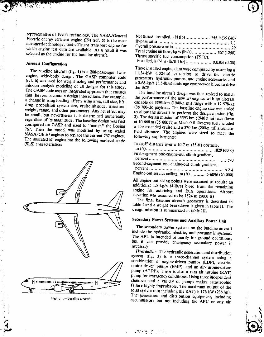
Aircraft Configuration These inslallcd engine data were computed by assuming aThe baselinc aircraft (fig. l) isa200-passenger, twin- l l.34-kW (152-hp) extraction to drive the electric
cngtnc, wide-body design. The GASP computer code generators, hydraulic pumps, and engine accessories and(ref. 6) was used for weight sizing and performance and a 0.68-kg/s (1.5-1b/s) midstagc compressor bleed to drivemission analysis modeling of all designs for this study, the ECS.The GASP code uses an integrated approach that ensures The baseline aircraft design was then resizcd to matchthat the results contain design interactions. For example, the performance of the new E3 engines with an aircraft
- a change in wing loading affects wing area, tail size, lift, capable of 3593-km (1940-n mi) range with a 17 578-kgdrag, propulsion system size, cruise altitude, structural (38 760-1b) payload. The baseline engine size was scaledweight, range, and other parameters. Any net effect may to allow the aircraft to perform the design mission (fig.be small, but nevertheless it Lsdetermined numerically 2). The design mission of 3593 km (1940 n mi) was flownregardless of its magnitude. The baseline design was first at 10 668 m (35 000 It) at Mach 0.8. Reserve fuel includedconfigured on GASP and sized to "match" the Boeing a l-hr extended cruise and a 370-km (200-u mi) alternate-767. Then the model was modified by using scaled field distance. The engines were sized to meet the
. NASA/GE E3 engines to replace the current 767 engines, following requirements:=_ The unsealed E3 engine has the following sea-level static
_'_: (SLS) characteristics: Takeoff distance over a 10.7-m (35-ft) obstacle,m fit) ................................................. 1829(6000)
First-segment one-engine-out climb gradient,- _- percent ......................................................... >0i, Second-segment on_-engine-out climb gradient,
percent ...................................................... >2.4s__ Engine-out service ceiling, m fit) .......... > 6096 (20 000)
All engine-out sizing points were assumed to require an_ additional 1.8-kg/s (4-1b/s) bleed from the remaining_ engine for anti-icing and ECS operations. Airport
elevation was assumed to be 1524 m (5000 ft)_°-_ The final baseline aircraft geometry is described in
table I and a weight breakdown is given in table II. Thedesign mission is summarized in table 111.
Secondary Power Systems and Auxiliary Power Unit
• The secondary power systems on the baseline aircraftinclude the hydraulic, electric, and pneumatic systems.The APU is intended primarily for ground operations,
• : but it can provide emergency secondary power ifnecessary.
Hydraullc._The hydraulic generation and distribution. system (fig. 3) is a three-channel system using a
combination of engine-driven pumps (EDP), electric-
_// motor-driven pumps (EMP), and an air-turbine-driven: _[ __ pump (ATDP). There is also a ram air turbine (RAT)
: pump for emergency conditions. Using three independent
: ..0..,,. oo..no.,.., . _, channels and a variety of pumps makes catastrophicfailure highly improbable, The maximum output of the
: total system (not including the RAT) is 176 kW (236 hp).The generation and distribution equipment, including
FIt_urcI.--Bascliacaircraft, accumulators but not including the APU or any airI
_rt _ ..-_::: r-_"
"1985020632-'1-9A06

. I
i !,
i iI I
' II
_- Still-airrange
Blocktime,fueld
' _[ L,.,i• _ o i I -_
' _-_I ._- 'i:_,,o /- \_
"i' /
t I
'_'_ ,_l /_ I_, __
1 I/
Domesticreserves :,
Figure 2.--Mission profile.
', i
,_' 4
1985020632-TSA07

TABLE I.--DESCRIPTION OI_"BASELINE AIRCRAFT
':." Tak_ofl'gross weight, kg {Ib)............................ 120601 (265 933)Sea-I_vclSlatlc thrat;Iper englac, kN (lb) ................. 201,6 (4.q319)Wing area, m2(ft_) ............................................. 270,6 (2012,6)Wing span, m fit) .................................................. 46,8 (153,7)Wing l/4-chord nweop,deg ....................................... 0,5S (31,5)Wlnlgaspect ratio ........................................................... 8, I IWing taper ratio ........................................................... 0,2('_7Wing thickness ratio, root ............................................... O,15IWing thickucs,_rails, tip ................................................. 0,103Wing mean 8couletrtc chord, In fit) ............................. 6,4 (21, l)Horizontal tall area, m_ (fP) .................................... S3,R(578.8)Horizontal Tailvolume coefficient ..................................... 0,898
Horizontal tail aspect ratio ............................................... 4,00Vertical tailarea, m2 fit-') .......................................... 64 (688,8)Vertical tall volume coefficient ......................................... 0,100Vc.'::cal tail aspect ratio ................................................... 0.67Body length, m (tt) .................................................. 46.3 (152)Body width, m (it) ...................................................... 5 (16,4) !iSeating abreast .................................................................. 7
!" Number of aisles ................................................................ 2
TABLE li,--WEIGHT BREAKDOWNFOR BASELINE AIRCRAFt
Weight
kg lb
• Propulsiongroup:- Primaryengines 8 788 19378
Engineinstallation 2 095 46202- Fuel system 539 1 188
Structures group: TABLE III._DESIGN MISSIONWing 15 402 33 963Horizontal tail I 468 3 237Vertical tail 2 082 4 590 Mission segment Segment fuel Jegment SegmentFuselage 15 579 34 352 usage range time,Landing gear 6 995 15425 minPrimary engine section 2 671 5 890 kg Ib km n mi
" t.]ight controls 1 874 4 132 Taxi 346 763 0 0 14Fixed useful load 8 029 17 705 Takeoff 153 338 1.9 I 1
Climb/acceleration 2 359 5 202 209 113 17Fixed equipment: Cruise 13 598 29 985 3122 1686 219Auxiliary power unit 676 ! 490 Descent/land 943 2 080 259 140 20Instrumen,_ 472 I 040
Total 17400 38 368 3593 1940 271Hydraulics I 295 2 855Electric 739 1 630Avionics 721 1 590Furnishings 7 914 17 450Air-conditioning 975 2 150Anti-iclng 186 410Pneumatics 35_ 780Airframe lights I i3 250
Opcratlng-.emptywctght 78 966 174 1251! Payload 17 578 38 760
Fuel 24 057 53 048' i Gross weight 120601 265 933
1985020632-TSA08

' AC altern_lngcurrentelectric-.. motor-drlvmlpump• ' APU auxtll_rypowerunit
ATI)Palr-turl_ln(_-drlwni}lJmpEDP enqlnJ_-drlvonpump[MP electric-mater-drivenpumpRATramairturklne
2"_4cm'_ls1_1,qallmini Z _34cm31s131(,laIn nl I '!
: 505cln'_ls(8gallmln) %t 505cmIsI8(lallmin) i '{l
i .
_,:_. gallmln) '_t I; . . ,.]System_: System_,' ' : 28_9cm'_ls(45gallmln) 505cm31s 505cm31s 27,_4cm31s 2839cm>ls J
, Primaryflightcontrolst (8gallmln) (8gal/mln) (37gal/mln) (_ i!
stabilizertrim Systeml}= Primaryflightcontrolstwheel3344cm_/s(5_gallmln} brakes 'Landinggearretrachtrailing- i
";" edgeflaps_leading-edgeslats_, inosegearsteerlngtwheelbrakes=stabilizertrimtprimaryflight
_. controls
Figure3,--Baselinehydraulicgenerationanddistributionsystem.
ducting, weighs 1295 kg (2855 lb). The utilization factor (780 lb). The pneumatic system is not normally rated withof this system at cruise is 0.19 (cruise power divided by a horsepower output. However, converting the bleed air,rated power). The utilization is low for most of the flight for both ECS and anti-icing, to an equivalent horsepower
: profile because the major power demand on this system is for an idle descent condition resulted in a rating ofthe raising and lowering of the landing gear, flaps, and 290 kW (389 hp). This was assumed to be the maximumslats, horsepower load for the bleed system.
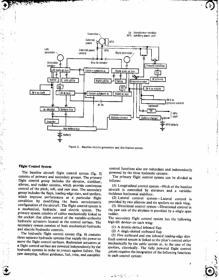
_ Electric,--The electric generation and distribution The total secondary power system is the sum of thesesystem (fig. 4) is basically a two-channel system with a three systems, Therefore the secondary power systemgenerator mounted on each engine. A battery serves as a weighs 2388 kg (5265 lb), its power output is 646 kWthird power source as well as emergency power. A third (865 hp), and its utilization factor at cruise is 0.42.generator is mounted on the APU for ground electric Auxiliary power unit.--The APU can provide bothpower and for flight backup if one of the two main compressed air and electric power. The air is used for
-, generators fails. The combined rated output of the two engine starting and ground ECS operation. The air canmain generators is 180kW (240 hp). The generation and also be used in emergency situations to power the ATDPdistribution system weighs 739 kg (1630 lb) not including and thus supply hydraulic power. The electric power is
• the APU, its generator, or any APU-associated used for ground operations and as an in-flight backnpequipment, should one of the two primary generators fail. The APU
Pneumatic.--The pneumatic distribution system is rated at 448 kW (600 hp) for ground operation and canconsists primarily of piping for the cowl and wing anti- provide the full 90 kVA of electric power at cruiseicing supply, the ECS air supply, the air starter supply, altitude. The APU total installed weight, including a
i and the APU source lines. The system weighs 354 kg dedicated battery for APU startup, is 676 kg (1490 Ib). \
;--!_"'_ _. _ :'_, %... ..
1985020632-TSA09
!
28V ac(leftl Loftdcbus Centerautolanddc J Rlqhtdcbus28Vac
roundservice)dctie (optional)
,i " APU•,, start
,.T.. APubatteryHotbatter_bus "_
_" .j..: ..=. Battery
T
Figure 4.-_Baseline electric generation and distribution system.
Flight Control System control functions also are redundant and independently
The baseline aircraft flight control system (fig. 5) powered by the three hydraulic systems.consists of primary and secondary groups. The primary The primary flight control system can be divided asflight control group includes the elevator, stabilizer, follows:aileron, and rudder systems, which provide continuous (1) Longitudinal control system--Pitch of the baselinecontrol of the pitch, roll, and yaw axes. The secondary aircraft is controlled by elevators and a variable-
. group includes the flaps, leading-edge slats, and spoilers, incidence horizontal stabilizer." which improve pert'ormance at a particular flight (2) Lateral control system--Lateral control is
condition by modifying the basic aerodynamic provided by two ailerons and six spoilers on each wing.• " configuration of the aircraft. The flight control system is (3) Directional control system--Directional control in" a mechanical, hydraulk: and electric system, The the yaw axis of the airplane is provided by a single span
primary system consists of cables mechanically linked to rudder.the cockpit that allow control of the variable-authority The secoLIdary flight control system has the tbllowinghydraulic actuators located at the control surface, The high-lift devices on each wing:
, secondary system consists of both mechanical/hydraulic (1) A double-sloth:d inboard flapand electric/hydraulic controls. (2) A singleo_lottedoutboard flap
The hydraulic flight control system (fig. 6) contains (3) Five outboard and one inboard leading-edge slatsthree separate hydraulic systemsthat supply the power to Each control system is linked to the pilot's control eithermove the flight control surfaces, Redundant actuators at mechanically by the cable system or, in the case of thea flight control surface are powered independently by the spoilers, electrically. The fully powered flight control
, hydraulic systems in order to protect against failure. The .,ystemrequires the integrationof the followipg functions: yaw damping, rollout guidance, feel, trim, and autopilot in each control system:
." 7 t '_
_"_ _,_-".x_.• _ .... _.._ ,. ,._
"1985020632-TSAlO

'(' ,'_,_ _/' Ouih_rdoih}ronv/'77
, '%\\ ///
i:2 ,
Flgurc5,--Basdlneflight controlsurfaces.
(I)Autopilot bleedairgoestoa pressure-regulatingvalveandistheni : i (2) Feel delivered to a spray pipe in the engine cowl, The wing
•"I (3) Trim centering leading-edge slats outboard of the engine are anti-iced in•-' (4) Position information the same fashion through a separate pressure-regulating
(5) Controlled surface displacement valve. Cross dueting allows one engine to anti-ice both:_ (6) Stall warning sides of the aircraft if necessary.: Some of these functions are obtained by using mechan-
ical linkages and controlled servoactuators linked to the Miscellaneousflight computers. Each subsystem is described in detailand in schematic diagrams in the appendix. The engines are started with an air turbine starter
mounted on the accessory gearbox. The air source can be
Environmental Control System from a ground cart, the APU, or the other engine. Thelanding gear actuators, nose wheel steering, brake
The environmental control system uses two air-cycle actuators, and engine thrust reversers are allmachines powered by engine bleed. Air is bled from the hydraulically powered.engine compressor either at an intermediate stage or atcompressor discharge. The bleed air passes through a fan
air precooler to reduce its temperature and is then fed to Advanced Systems to Replace Baseline_ the air-conditioning pack. The air is further cooled by
ram air in a heat exchanger and then fed to the air-cycle Sys|ems., machine. The conditioned air is mixed equally with
recirculated cabin air and is then ducted to the flight deck The primary system of interest in this study is the" and cabin. Under normal conditions, with both air- advanced electric power system that replaces the baselinei conditioning packs operating, the flow rate Is hydraulic, electric, and pneumatic systems. When the
approximatdy 0.28 m3/mln (10 ft3/mtn) per passenger, type of secondary power is changed as in this study, allIf one pack should fail, ttle remaining pack can be systems that draw energy from the secondary power
"' operated at 165 percent of normal flow. The cabin system must bc made compatible with the new powerpressure Is regulated by controlling the air outflow from system. For example, the flight control system, whichthe cabin through an outflow valve, previously used hydraulic actuators, now must be
converted to electric actuators. The baseline anti-icingsystem, which previously used engine bleed, now must be
Ant!-leing S-- ,.ystem converted to some type of electric system. The
-'. The same engine bleed air supply that powers the ECS environmental control system, which also previously used_ . also provides hot air for engine cowl and wing leading- engine bleed, now must be replaced with either an: :_ edge anti-icing. After passing through the precooler the electrically powered system or a combination electrically -_ •
i
8 _ "_
1985020632-TSA11

anddirec,lydriwn_y_,em,Antomh_.rofo,he.rl,emsa,._,._ __ _,__;__
u)u_! b_ addr_,_d ._uch_1_tile APU, hmdtn_ _em',._leerin_,brak¢,_,mid thrn:it rt.werser,The folin_tn_ l :_,se_ltt)ns describe Ille,_e rephleenlenl _yfil(:lll,fi _tnd
_LIh%',_lelll,_, I.
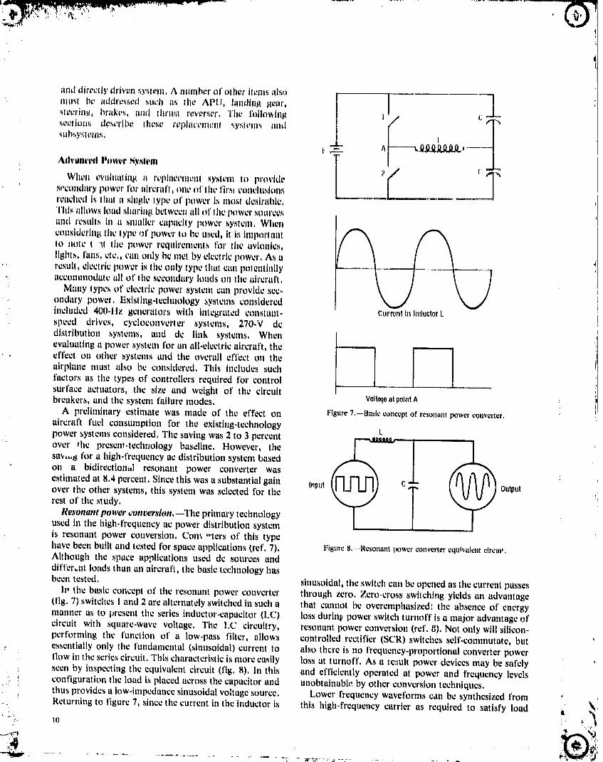
When twahmlinl_ s_ n:placfmet_l ,_y,_temto provide ;, cse¢ondat'y power l'or aircral'l_ one Ot'lhe l'lr_l¢oncltl_lontlu't_achcdis Iil1|1a single I.Vp¢of power in i!1o_Idesirable,This allows load sharh_8 between all of Ihe pt_wer sotu'c¢,_trod resells In a smaller capacity power sysl¢lll, WlIgllconsidering the lypc o1' power lu bcused, It 1,_tmporlant _"Nk _" _to 1tote t '_1the power requirements for the avionics,lights, I'an,_,tic,, cml only bc met by electric power, As aresult, clcctrtc power is the only type that can lmlenttally
-. accommodate all of 1he secondary loads on the ah'crai't, 1: Many lypes ot' electric power system carl provide sec-
ondary power, Existing-t_:chnology systems consideredtncluded 4OO.Hz generators with integrated eo_,_stant- currentInInducturkspeed drives, cycloconvcrler systems, 270.V dc
distribution systems, and dc link systems, When I
effect on other systems and the overall effect on theairplane tnust also be considered, This includes suchfactors as the types of controllers required for control .........surface actuators, the size and weight of the circuitbreakers, and the system failure modes, v01t_eatpointA
A preliminary estimate was made of the effect on Figure 7,--Basicconceptof resonantpowerconverter,
aircraft fuel consumption for the existing-technology Lpower systems considered, The saving was 2 to 3 percent /
sin,.,8 for a high-frequency ac distribution system basedon a bidirectional resonant power converter was
estimated at 8,4 percent, Since this was a substantial gain InpUt C OUtPUtover the other systems, this system was selected for the Trest of the study, /Resonant power ¢ont,ershm,--The primary technologyused in the high-frequency ac power distribution systemis resonant power conversion. Corn "ters of this typehave been built and tested for space applications (ref, 7), Figure 8.--Resonantpowerconverterequivalent clrcm_.Although the space applications used dc sources anddlft'er,.nt loads than an aircraft, the basic technology hasbeen tested, slnusoidal, the switch can be opened as the current passes
Iv the basic concept of the resonant power converter through zero. Zero-cross switching yields an advantage(fig. 7) switches 1and 2 are alternately switched in such a that cannot be overemphasized: the absence of energymanner as to present the series inductor-capacitor (LC) loss durlnt., power switch turnoff is a major advantage ofcircuit with square-wave voltage. The LC circuitry, resonant power conversion (tel 8), Not only will silicon-performing the function of a low-pass filter, allows controlled rectifier (SCR) switches self-commutate, but
: essentially only the t'undamental (sinusotdal) current to also there is no frequency-proportional converter powerflow in the series circuit. This characteristic is more easily Lossat turnoff. As a result power devices may be safely :seen by inspecting the equivalent circuit (fig, 8). In this and efficiently operated at power and frequency levels
' , configuration the load is placed across the capacitor and unobtainable by other conversion techniques..-_' r
thus provides a Low-impedancesinusoidal voltage source. Lower frequency waveforms can be synthesized from.!
Returning to figure 7, since the current in the inductor is this high-frequency carrier as required to satisfy load _,
.... i985020632...................................... -"-....... -TSA13

requireiTlel|t_, A b_lc circuitry _orlllOCllonIn nltnw thl_ Is i_nrlTl_dly reeol_ntzed .dwmtaBe._ hi' thrue-pha_(; p_w_,r_h_wn in flguro _, In lhi_ _'Ir_'mh _wilch p_dr_ I,I' _nd dhtrlhutlnn are=,Inwer cnndt_.'l(_r welghl _md con_Irmt2,2' ar_ oporated In _ii(211a mnnnor a'_ Io perform p(]w_,r d_livery, H()wl2w2r lhe_o aflVillllil,gV_ ilrO nut_iylleh=ul)oti_re_:llflertllnll nl' the 20-klll. _nllrt:o and lhll_ prnnomlt2(-,dIn thl_ applle=_llnrl, The r_2h_llvelyhl_h oper.,;ynth_si/e a lower l'requont:y Olllpl-ll, In lhi._ r_ip_;el lhe ItllnR voltaRe and lhe dl._Irlhllled power t_y_lenl lintll lhc¢in2lill operllle.,i ,_omewhal il_i it t.'unvenlh_nal ey(:io- lollll4rl;,tMh.'d-l)nwer (:(llldLll:lor wei_hl of lheillrerlll'l IoCOllVl.,l'l¢,r,Proper ,'iL_qlaoi|¢h|_l_of the swlleh l_lllr;=will M_o ollly a l'ew hllndred plHllld.% Th¢r,d'==relhu l_Olt_lllhd l'[ll'_lllnw rvver.w power flow l_y_21|Ol_l]Inl-;rt lowor l'roqtlt21|_,y weight redllvllntl I.__mIlll =nld¢(_iI_I t-,_=,_llylw ol'l._el hy lhe(Int:hMh1_ de)inlo lh_ 2(}-kll_ ,_our¢o, addt:d enmlde,,dly In _wllv.hlnl4 =rod l¢_rmhmllon_,, 'the,
The Inln,renl ,_ymmolry of lho hll;hol'requon_:yInv_r_d(m 2()..kll_ pow_'r syM_m Ira.',a pnwer l'r,_qn_,_n_'yof 40 kl I_:_ysli,n| I_¢lllu,,,,nu¢,d In the l&lh't:_'thmal ht|plemenlallon (bolh lht: positive, and ne_allve hall'_,:y¢l¢_._d,=,llv_,rpower),shown In l'lg01'¢ I0, |n lhl._ taonl'Igtll'lillon porl A _*_I|llt.'l Allhoti[,h lhl_; I_,nol Irnly "¢on._lllnl pow,.,l'," 40 kll/I_as a ,,,oureelind port B as a load, or v},'e ver,_a,Also hath well beyond the n_e_:hanit:all'req_iency t'e_p,m_eol' anyrlot,ts can a¢l its SOtll'_Cswilh other luad_ ¢Oltltt2t;It.,{.l[iCl'OSS ¢Ol|tt.'nlplaled load and will restlll hi vivltudly utlnslallllhe hlgh=frcqnt:ncy llnk, The ¢Irt:uhry illustratt:d In l'il_qnrc electric power d_21ivery,
I0 is l'or a dc or shtglc-pha,,,e at: sours:c, bul it can bc There arc many advm_tagt2sIo a_: slnusoidal power '!I_,xpanded for multlphasc sources, Tl,is ,.'onl'igu='atlon distribution, O1'prhnary itnl_ortauet: is lhe _;_scof curr_nllllustrales the Inlerl'ace between multilde pow_2rsources, limiting and l'_ult l'_roteclJon, As th_ a¢ source alway,spower generation and stot'ago, and power sources and returns to zero, switching dt:vieus do not have to interruptsystem loads (r_t'. 9). large _:urrent overloads. Another major advantage is that
Rational,, Ji)r final _'jwton selection,_The clectt'ic voltage levels can be passivt21y transforn_ed withoutdistribution system is a single-phase, sinusotdal wavuformdistortion. Finaily tht;singlecarricrfrequcncyalternating-curretlt, 440=V, 20.kH_ power system. This presents mlnimul I_robiotns in regard to electromagneticparticular configuration was selected tot' the following lnterl'crcnce since it can be easily Filtered or shielded.reasons: A single-phase system minimizes the switching For any level of electric power distril:',tion there existsand termination complexity involved in a fully redundant an optimum voltage level depending on the associatedmultiphase, multisource power distcibution system. The design t;onstraints. In general, however, power should be
transmitted at the highest practical voltage level tomlnimizc line losses. A voltage of 440 V ac was selected asproviding good transmission efficiency, requiring only
i_ L_e[__'_ normal it, sulatior, thickness, and allowing reasonable
t conductor spacin,,, This voltage is below coronaPortA initiation potentials at altitudes of less than 15 240 m
, I' (50 000 ft),p The hi,_h-frequency power dist, tbutiort, in this ease
Dlrectsyntheslsoflowftx'quency Clrcultsymmetry 20 kHz, has numerous advantages. A high operatingfrequency minimizes the weight of magnetic devices such
Figure 9,--Basic circuitry for wuvcform synthesis.
Port A Port B
i( (.,J
/Systemload
!_ Figure IO,--Bidin:clionul hl#_-frequen_:y pov,er Interface, _I
lJ
1985020632-TSA14

;' _ljtL-_e,= .... ,,,... __,..,t_Vv,v.,, ..... .,,,,,,,,v - _
: i _ •
as tran._formers, The fundamental operating frequency, he,ttin8, can use the 20-kHz power directly, The ECS, and in particular the power frequency, are above the drive motor requires a load receiver for startlnl_ and for
:_:. audio range, Thl._will provide a quiet power system, The varying motor speed, The flight control actuators require
IL energy available per cycle Is inversely proportional to the a separate load receiver for each actuator, Figure 15 Is a• .: operating frequency, and this minimizes the damage simplified schematic of the load receiver used to drive any
_:' _ occurring during electrical fmflts, With the interrupt three-pha_e motor (ECSor actuator) from the single-!=,,, occurring within one half-cycle, the total energy available phase distribution bus. The main and utility bus loads: in the power system is only about 10 J, The low energy that require lower voltages are supplied through step-
-: _ content also Improves personnel safely over conventional down transformers, Those loads requiring a frequencyo ,; power systems, Accidental encounters with this system, change are supplio.d by a standard-configuration load.-, _),hllcquite painful, would most probably not be fatal. A receiver,
!_ i 400-Hz power system would have 50t!mcs more available System operation,--Under typical conditions the.,:.... energy per cycle than an equivalent 20-kHz system, induction generators provide 440-V, 1200-Hz, three-<_: Finally a high-frequency power system allows lower phase power to the converters, The voltageand frequency_... frequency waveforms to be synthesized with a minimum vary as the engine speed varies, but the voltage is'_!: of distortion. Lower distortion waveforms result in mere regulated by controlling the slip frequency, Since this_; efficienl operation of electrical devices. Waveform type of regulation responds slowly, rapid regulation will
-:_. synthesis allows "load tailoring" of power with relatively be provided by controlling the relationship between the
:,, simple circuitry, which in turn easily implements such three converter phases, Figure 16 illustrates two phasori ,.. ' concepts as variable speed control of ac motors or true diagrams that have the same bus voltage. However, the
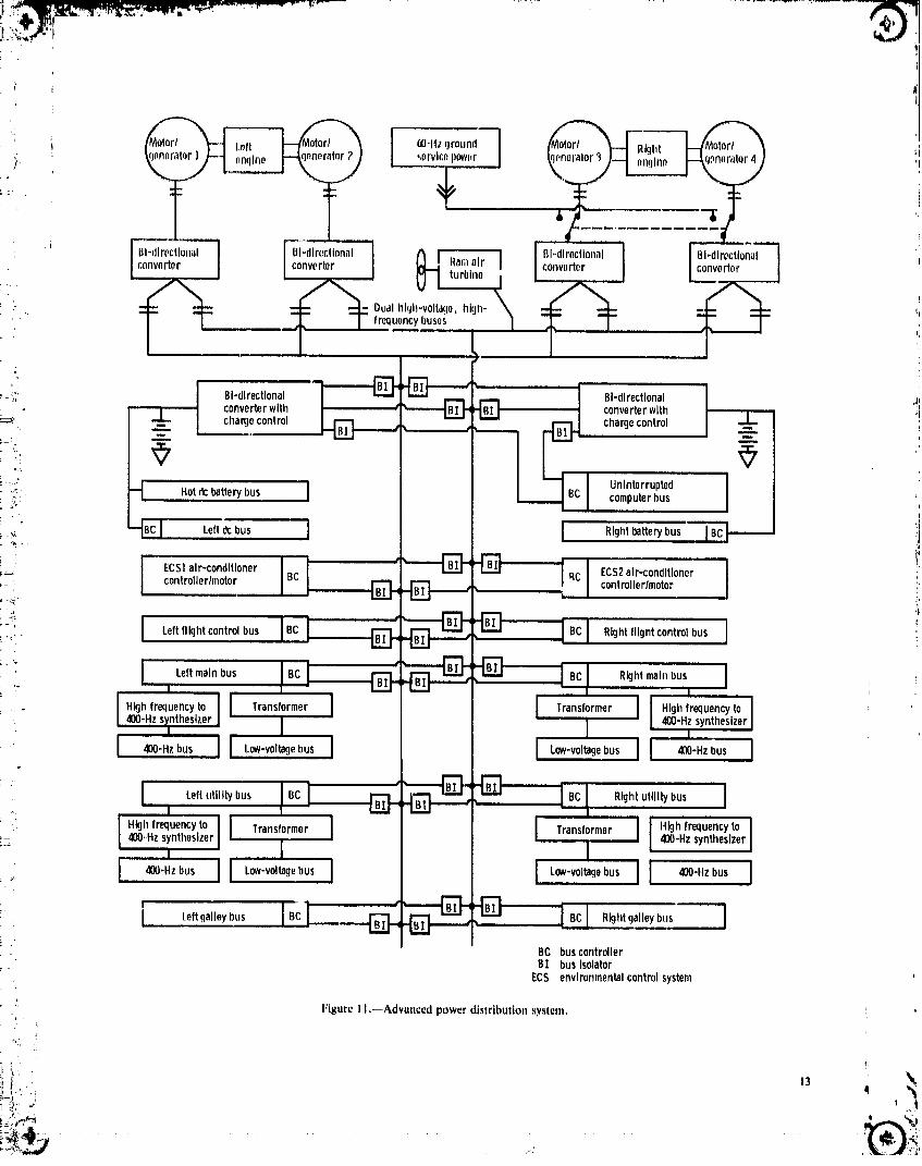
::!. harmonic (jerk free)actuator motion, phase voltages (A, _., and C) are approximately 25_-_'i i System deserlptlon.-..Using resonant power conver- percent larger in the !eft diagram than in the right
_,'.:, sion as the core technology, a power system diagram. The bus voltages are made equal by adjustingi-@'= was configured (fig. 11). The system has four motor/ the phase angles, with the higher phase voltages havingL_!;. generators, two mounted on the accessory gearbox of smaller angles and vice versa, It is anticipated that this
3;. each engine, These are 90-kVA, three-phase, 24 000-rpm, type of regulation can be made to respond within one_. _ 1200-Hz induction machines. The outputs of these cycle of the converter frequency, or approximately 50 #s.
i "i,.;_ generators are fed to three-phase bidirectional, resonant The fi'equency of the converter is controlled by its:i:_!: converters. Each phase of these converters has the resonant circuit and is therefore independent of the input_",_" configuration shown in figure 12. The outputs of the frequency. The result is a constant-frequency (20 kHz),_:-iii three phases are connected in series and tied to the constant-voltage (440 V), single-phase output to the
distribution bus. Although the generator speeds for the distribution bus. Since the power to the loads isi-_., two engines are different, the outputs of the converters synthesized by a load receiver, some latitude in the bus;"_' are synchronized so that all power sources can be voltage and frequency can be allowed. Under normal, _., paralleled, operation all tour converter outputs and both: _.i:. The power distributed is a 440-V, 20-kHz, single-phase distribution buses are paralleled.
sine wave. There are dual-redundant buses, each capable In most instances 20-kHz and 440-V power cannot be_-/. of carrying the entire load. All of the sources and all of used directly by the loads. Load receivers are used to
'! the loads have access to either bus, and under normal synthesize the output required by the load. Even though,=",,' conditions, the two buses are operated in parallel, the bus is single phase, a three-phase motor can be driven_':/:' Emergency power is provided by a ram air turbine from the receiver by using a simple set of switches (fig.i "'' (RAT) and two batteries. The RAT drives a 12-kVA 15). The power flow from the main distribution bus is
°_: generator, which feeds power through a resonant con- managed in half-cycle increments by the load receiverS, verter to the distribution bus. The two nickel cadmium switches, The pulses generate a sinusoidal energy pattern
_ : batteries are each rated at 1.5 kW-hr, The batteries also when the proper switching sequence is used. The patternL.., provide uninterruptable power for the computer bus in (fig. 17) represents a 21:1 frequency ratio and the
': case one or both of the main buses have a power maximum output voltage. All of the available pulses are: _. interruption, being used; and with two phases of the motor connected_.( The loads are fed from the main distribution bus to the bus at any time, the maximum number of pulses
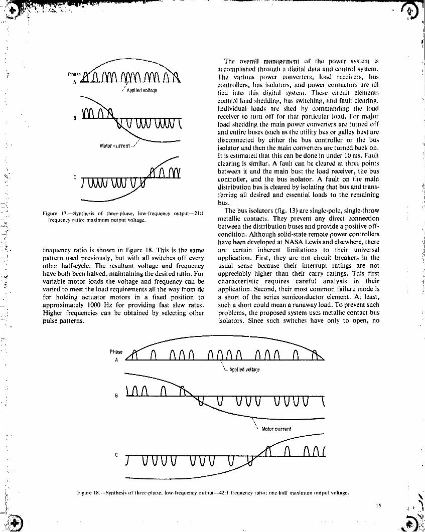
through isolators and controllers (fig. 13)to protect the per phase is two-thirds of the total. To maintain a_ bus from load faults. The amount of power conditioning constant voltage-to-frequency ratio into the motor, the: :'). varies considerably depending on the load (fig. 14). (The pulse pattern is varied by inserting blank spaces into the, _, ' bus isolators and controllers have been deleted in figure pattern, This is done by leaving all load receiver switches' _i. 14 for simplicity.)The galley, which may use induction off for one half-cycle. A pulse pattern with a 42:1
.!1
• _, !' It
1985020632-TSB01
_,_,_-_,,,,,r_ i o,_,_roun,I __i, ;nqln_ .
., ,,,.o+,,o,,+,,,I "°_°'rI /c°nvorterIonvor,o,.; . convertor _ turbine I gl'dlrecl,I°m_l I HI'directional
" [ _ I _ Dualhl<jh'v°lta+'l°'hlgl_"'_ :_"_frequencyI)uses ¢_
.-'. BI-dlrectlonal _ BI-dlrectlonal ]
converterwith -[_ converterwith '!I_.. -L cha_econtrol chargecontrol .1.. +i
'_=,_ UnInterrupted I•_ _ Hotdcbatterybus i• _,: computerbus I
'_ i 11 +__'_--_m,,,,!"_cl,C,,+,r-con°,,one_I: : controller/motor BC r'_'_ _ controller/motor_.
:i! [ LeftflIghtc°ntr°lbus Rightflightcontrolbus ] "I1
.. J Leftmainbus RightmainbusI
Highfrequencyto 1 Transformer Transformer I Highfrequencyto IL,.4OO-Hzsyntheszer] 400-Hzsynthesizer, i I ,
I Leftutilitybus Rightutilitybus Ii
_+; I"'_""_°_°"'°II=o.,synthesizerI TransformerI I Transf°rmerI I iH'ghfreq°en_'t°I®o-HzsynthesizerI
BC buscontrollerB1 busIsolator
ECS environmentalcontrolsystem
•_' Figure I I,--Advanced power distribution system
iiI... t3 ,
1985020632-TSB02

; Converter BusIsoator
• Gonerater....L._ I I (normall opon)
• Bn_Isolntor Power(normallyclosed) distribution
I)IISP.S
' : . . _
Bus_
r (ll_lrll)utlon Load.. bus receiver f
}:jFp,tlr(., J2,--(il,,llL,lUl(ir-t.'Oll',,_.,rlcrillll:l'¢Ullll¢t;liuIlfor lld%'LInccd,Sy__nl. =
|qgurc 13.--looudpowL.rb=z._in(_r¢onnoctionfor advml¢cd,_y._tcm.
: High-frequency,}, .-; high-voltageac
.' "-'I Flightcontrolbus I'' I I
;- ILo_ I Load I
- _;. Mot°r "_0_ Envl ronmental control V I receiver I receiveri_--_, s_stem II_d receive r 6 6
; _!,, /Actuator /Actuator
.... receiver r,celver II
' I I L°"'I' I
., Low_
IL°w-v°ltageII frequency frequencylILow.-vol_e; loads 1 loads loads I Imaos
.: [ Oa,ey u,]--' l=iBurc14.--Load power ¢ondilioninl_for advanced_y,_tcm.
, = Loadreceiver
:_i phasebus A _,s
!-.. _ r
: I_'igur_:16.--Regulation of bus volt=lee by controlling phil._e• " I"igtit¢ IS.--I._ati ieceiverfor three-phlL_eItllicl t'_r advliil_etlsyllelll, relatioltskil_.
• 1985020632-'1-SB03
t
°_'"__n___ The overall management of the power system is
accomplished through a cligilal dma trod coalrol system,
:¢ Pll_s! The various power converters, load receiver:_, bllq
controllers, bus isolalors, and power conlactors are tillI" Applledvolt;rio tied into this digilal .',ystcm. Thcsc circuil elcmenl_
" _ conlrol load shedding, btm switching, and I'ault clearing.
_,_ _'_ Individual loads are shed by commanding the loadreceiver to turn off for lha! particular load, For major
B _V _ Vk/l_l,lV _ _ _, loadsheddingthemain power convertersarcturnedoff_. and entire buses (such as the utility bus or galley bus) arc
disconnected by either the bus controller or the busMotorcurrent--" isolator and ltlen the main converters are turned back on. hi
It is estimated that this can be done in under 10 ms. Fault '!
_,_ clearing is similar. A fault can be cleared at three points i_." c /_ between it and the main bus: the load receiver, the bus• controller, and the bus isolator. A fault on the main !
.... distribution bus is cleared by isolating that bus and trans- ,!Iferring all desired and essential loads to the remaining '!
r, t
--. bus._ );.
- _". Figure 17.--Synthesis of three-phase, low-frequency output--21:l The bus isolators (fig. 13) are single-pole, single-throwfrequency ratio; maximum output voltage, metallic contacts. They prevent any direct connection
=_, between the distribution buses and provide a positive off-_ condition. Although solid-state remote power controllers '1
•. have been developed at NASA Lewis and elsewhere, there '.]__;_,
--,,_ frequency ratio is shown in figure 18. This is the same are certain inherent limitations to their universalpattern used previously, but with all switches off every application. First, they are not circuit breakers in theother half-cycle. The resultant voltage and frequency usual sense because their interrupt ratings are not
___ have both been halved, maintaining the desired ratio. For appreciably higher than their carry ratings. This first:_ variable motor loads the voltage and frequency can be characteristic requires careful analysis in their .,:
varied to meet the load requirements all the way from dc application. Second, their most commo_ failure mode isfor holding actuator motors in a fixed position to a short of the series semiconductor element. At least,approximately 1000 Hz for providing fast slew rates, such a short could mean a runaway load. To prevent suchHigher frequencies can be obtained by selecting other problems, the proposed system uses metallic contact buspulse patterns, isolators. Since such switches have only to open, no
,ase A A6AA AA
v. Appliedvoltage
: V VVV i
v_Motorcurrent
e
: I vvVV Vvv
t!.t Figure 18.---Synthes s of three-phase, low-frequency output--42:l frequencyratio; one-half maxintum output voltage. _.]
.. _ .,J._. _1
1985020632-TSB04

/
bounce time is involved, Also, as the contaet._ do not loads include all those loads required for normal flight" Interrupt current, they are relatively light, The._e operation (hut not convenience loads such as galley and
characteristics result in a rapid relay respon,_etime, EC'Sloads), The main and flight control buses (fig, 111The motor/gencralors and main power converlers are are a part of the essenlial loads, The major utility load is
used to start the engines, For a typical ground start, the environmental control system, Utilily buses (fig, 11)power is fed from a ground set, roe such as a three-pha _c, arc also inchlded In this category, The galley category440-V, 60-Hz utility line. The converters associated widl covers just the galley loads.the right engineconvert this power to single phase, 44_ ' Presenting the same load information graphically (fig.20 kHz, This power is fed over the main transmission b 19) shows that all loads can be accolnmodatcd with Ihrecto the converters for the left engine. Since the converters generators (one generator failed). With only two Boa-are bidirectional, they can control attd convert power _.rators (one engine out) the essential and utilily k)ads callflow in eitF,er direction. These converters provide bc accommodated at cruise. Even with only one gen-controlled-current power with a constant voltage-to- crater functioning, all essential loads can be powered,frequency ratio to the two machines, now acting as allowing normal flight control,motors. The motors thus provideaconstant torque to the The major transient loads (fig. 20) occur duringengine to bring it up to starting speed. Although both takeoff and approach. To maintain the load within the
• motors would normally be used for starting, one motor normal ratings of three generators requires load: _ has adquate power to start the engine, but with an shedding. For takeoff the galley load was shed to
associated increase in starting time. Also, other loads can aecommcdate the gear retraction load. However, thebe fed from the 20-kHz bus during the starting operation. $;alleywould not need to be on during this phase of the
[_: Since the power to the starters is current controlled, there flight. With the failure of one engine on takeoff the two, o_ should be no significant perturbations on the bus. Once remaining generators would provide sufficient power for
the left engine has been started, the power from its two the essential loads and full-speed retraction of gear,_-_: machines, now acting as generators, is fed in the opposite flaps, and slats.;z direction to start the right engine. The emergenc_, backup power system was sized to;_: System sizing.--There were two criteria for sizing the provide power to flight-critical loads if all generator
power system. First, all essential loads would be provided power were lost (both engines out). The one additional'_ by a single generator. This allows normal flight operation flight-critical load the.t is now powered electrically is the
:., even if one engine and one generator on the opposite flight control actuation. To provide continuous power. engine should fail. Second, all loads would be provided for the flight controls, a ram air turbine (RAT) drives a
by three generators. This allows aircraft dispatch with 12-kVA generator. This is essentially the same powerone generator failed. The steady-state loads for six phases rating as for the hydraulic pump on the baseline-aircraft
i'.: of the flight profile (table IV) were divided into three RAT that powered the baseline flight control actuators.
. . major categories: essential, utility, anti galley. Essential Short-term excursions above this power level were
TABLE IV.--MAXIMUM EXPECTED STEADY-STATE LOADS FOR ALL-ELECTRIC AIRCRAFT
": [Environment control system at hot-day, full-load conditions; galley at full power throughout tlight.I
..... t.oad category " Fli_ht_phase -'
Loading Engine Taxi Takeoff and Cruise Descent,starta climb hold, and land
kVA Power kVA Power kVA Power kVA Power i kVA Power kVA Powerfactor factor factor I'actor factor factor
, Essential (includes 29.7 0.92 31,1.1 0.91 56.5 0.91 80.3 0.91 80.3 0.91 74.9 0.91main bus and#light ccmtrols}
Utility (includes 133.5 .g5 ........... 129.1 .S5 130.4 .g5 87.2 .85 87.8 .85i -i environmental
control _ystemlGalley 37.0 1.0 .......... 50.8 .99 47.8 .99 57,8 .9_ 13.2 .95Total 195.7 .91 38.1 .91 233.3 .91 254.7 .91 222.4 .92 175.3 .89
i aEngine start loads are those in addi ion to the starter load.
1985020632-TSB05

/
"f Nu,b,r, ofgenorMors
-;" / / /- f / /'_/.,_JA
L100 ------
• , - - ,ssentl
o . II Takeoff [ , _escent,-LOadingI I and ] Crmse hold,and
:' ]l climb I land/ %
/
MartJ _ Taxi
Flgurc19.--All-clcctrlcaircraftloadprofile.
Advanced Aircraft Flight Control System
: 300 Nurr,ber0f With an all-electric secondary power system on the
9enerators
-_-_ 3 aircraft the flight control system must be modified to becompatible with this new power source. Electro-
2oo _ _ mechanical actuators (EMA) were selected as being the
--'.'" _ __ I--VL--_,7 ...... 2 most direct and simplest method of powering the flighti __ Utility "-Galley control surfaces. With EMA's the only logical control
_s_ signal system would be an electric system. A digital data-
$' 100-- t bus system was selected as being the most flexible, most:i \ \ noise-immune, and lightest ;;a_, to provide the control
e signals to the EMA's.0 _N,._'_'_',_'_'_"_ Several ground rules were established to define the
Gear' I FlapsandI I Gear scope of the flight control system effort. First, the:" retraction slats extension numberandlocationoftheflightcontrolsurfaceswould.3
remain the same as on the baseline aircraft. This wasFigure 20.--All-electric aircraft takeoff and approach load profile, done to minimize the differences between the aircraft
except for those directly associated with the new powersystem. Second, the redundancy levels for all flight
provided for by accumulators in the baseline-aircraft control elements would be the same or greater than in thehydraulic system. In the electrical system batteries are baseline system. This was done in an effort to make theused to accommodate these short-term excursions, advanced flight control system at least as reliable as the
.. in addition to the RAT two battery systems are baseline, although a reliability analysis was notprovided. Each of these batteries is approximately performed. Third, the baseline hydraulic actuators would
_ equivalent to the battery on the baseline aircraft. The be replaced with EMA's in the same locatioi; and with the:. battery power drain under emergency conditions is same attachment points. This was done to minimize": essentially the same as that for the baseline aircraft with differences between the baseline and advanced aircraft
the exception of control system surges. Therefore battery and also to limit the scope of this effort. Although EMA-power is expected to be available under emergency drivencontrol surfaces would very possibly be configuredconditions approximatelytwice as long as for the baseline differently than those with hydraulic actuators, that wasaircraft, judged to be beyond the main intent of this study.
._ The electric generation and distribution equipment for Thc flight control system defined in this study is simplythe adwmced power system weighs 1039 kg (2290 lb). a conceptual layout of a system. No system parameters,
" This includes the generators, main converters, such as data rates, were defined. The state of the• distribution buses, bus isolators, batteries, battery technology was assumed to be that which would be: _ converters, ram air turbine, power management system, available in the same time period as the power system _i
_ and some miscellaneous load receivers, technology, or about the mid-1990's, i'., b.
• t"t 'q
'"_"i 17 !! ;.
1985020632-TSB06
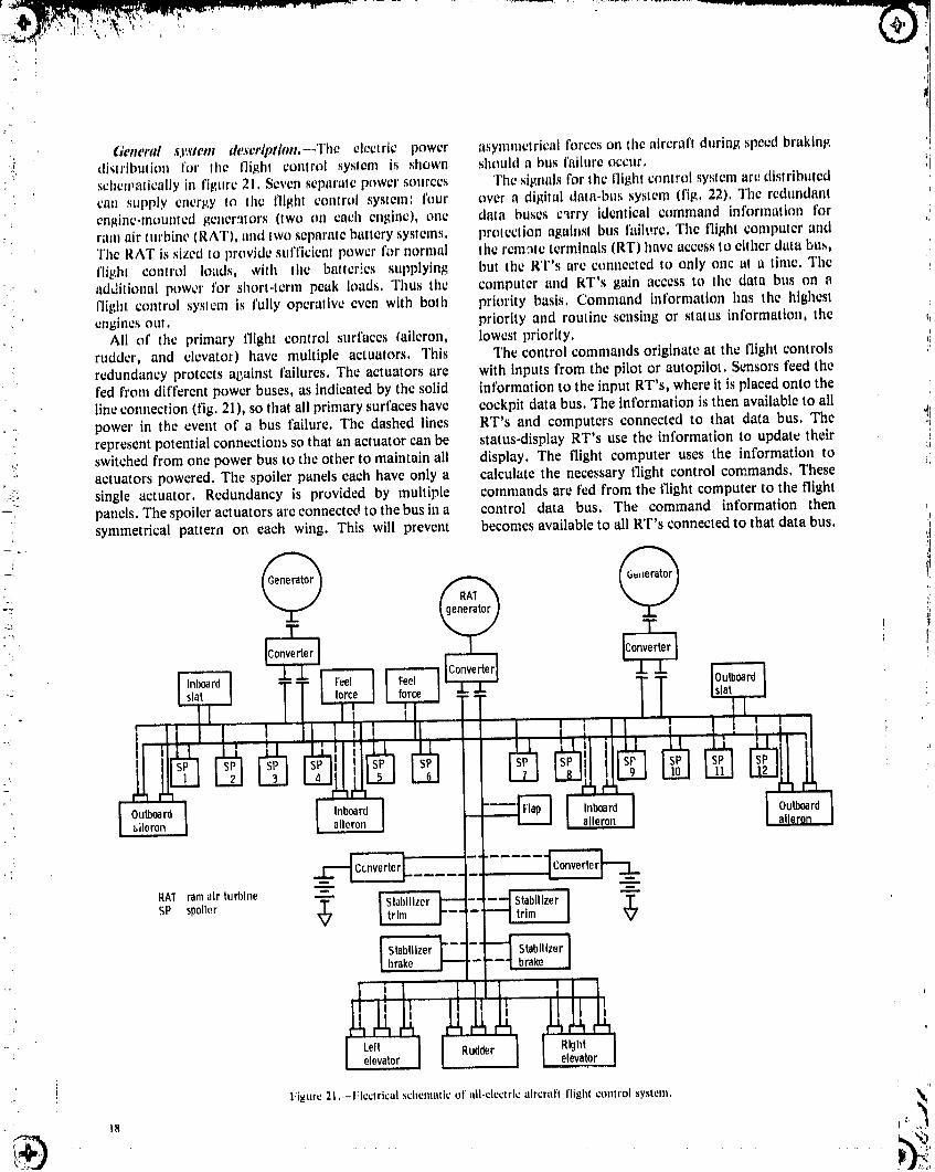
:, tleneral sj,_'tem de_'erlption,--The electric power asymmetrical forces on the aircraft during speed brakin/4:I, distribution for the tlight control system is shown should a bus failure occur,
" schewatically ill figure 21, Seven separate power sources The signals for the flight control system arc distributedcan supply energy to the flight control system: limr over a digital data-bus system (fig. 22). The redundant
: engine-mourned /_ener..ators(two on each engine), one data buses carry identical command informati_m for, ram air turbine (RAT), and two separate battery systems, prolcction attainst bus failure. The flight computer and
The RAT is sized to provide sufficien! power for normal Ihc rem.'_leterminals (RT) have access to either data bus,flight control loads, with the batteries supplying but the RT's are connected to only one at a time. Theadditional power for short-lerm peak loads. Thus the computer and RT's gain access to tile data bus on a
" flight control syslcm is fully operative even with both priority basis. Command information has the highest' engines out. priority and routine sensing or status information, the
: All of the primary flight control surfaces taileron, lowest priority.rudder, and elevator) have multiple actuators. This The control commands originate at the flight controls
: redundancy protects against failures. The actuators are with inputs from the pilot or autopilot. Sensors feed theted from different power buses, as indicated by the solid information to the input RT's, where it is placed onto theline connection (fig. 21), so that all primary surfaces have cockpit data bus. The information is then available to all
.... power in the event of a bus failure. The dashed lines RT's and computers connected to that data bus. The: represent potential connections so that an actuator can be status-display RT's use the information to update their..... switched from one power bus to ttle other to maintain all display. The flight computer uses the information to" actuators powered, The spoiler panels each have only a calculate the necessary flight control commands. These
:Ji! single actuator. Redundancy is provided by multiple commands are fed from the flight computer to the flight,: panels. The spoiler actuators are connected to the bus in a control data bus. The command information then, symmetrical pattern on each wing. This will prevent becomes available to all RT's connected to that data bus.
.-, @
l°u=°I [ :v,:::
-RAT ramair turbine
SP spoiler
I StabIlizer ['-'i- _
lhrake t'-"[-['--'l ,ra_e Ii i i Il i l I I I
Figure 21.--l/Icclrical schesnatic of all-clcclric aircraft flight control ,system.
- 18 _._,,_./'
1985020632-TSB07

i
Controla,ltllnformationinput I I Redundant L/
,, ._, ,, 0 tllqht control . . _ Dual-pownr_,u_, I-I databUS IteceIver 17
:" ?I' IL_J'' " .......=Ir'°°tr°' I-- -i
...."- ........... "..... Ir __2 L' i_ ii _
• F_el,orc_ dlsplay'*:'_;",=,h,,. L_I"'I_ fcl_tut('r W_dl_pl"Yflklhtrrdu'ld'mt,Ill, Status'l", IL Leadrecolvorfoedl)ack ]i
. Rod.attaint Figure 24,-.111ock diagrmn of actuator control.
_c_on re [llqld
conlroldatabt1,_
...... Detailed descrtpthm.--The flighl control system hasfour parts: longitudinal, lateral, directional, and high-lift
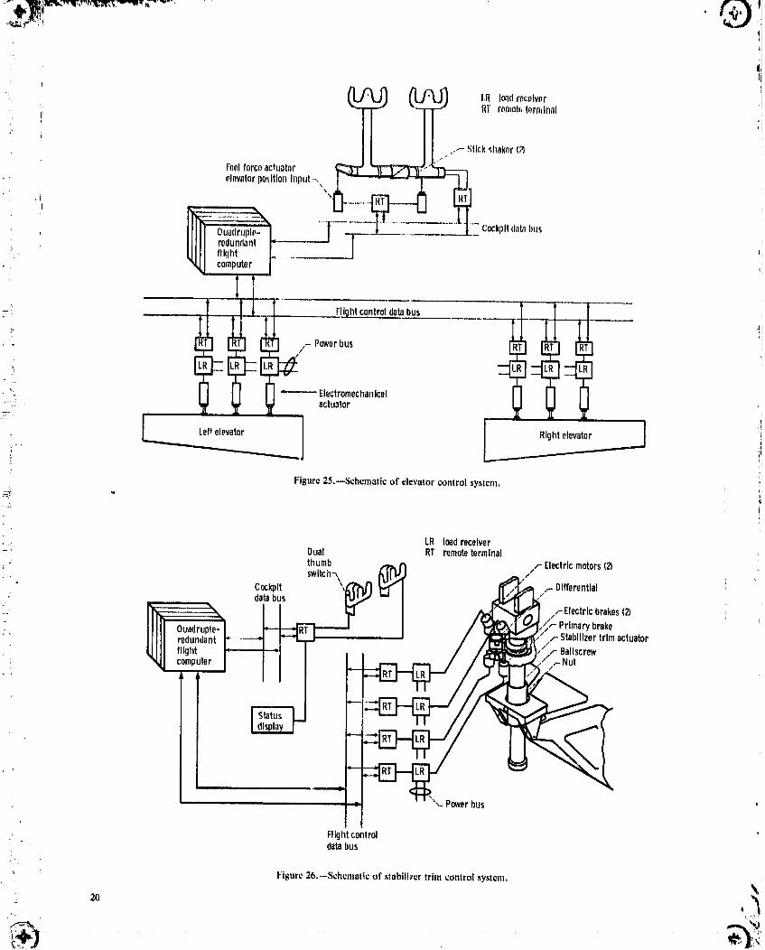
i c c cantrol. ._iactuator actuator actuator: Longitudinal ('o/tirol ._.w'tem:As with the baseline. Figure22.--Digitalflightcontroldatasystem, aircraft pitch is controlled by elevators and a variable-
incidence horizontal stabilizer (figs. 25 and 26). The rightand left elevators are each driven by three
RT's associated with commanded actuators accept the electromechanical actuators that receive their inputs from_, intbrmation and operate their actuators in accordance the flight control computer via the redundant digital bus.
i_': with the commands. The pilot's control col,line interfaces, through position: The function of the remote terminal (fig. 23) is to sensors, with the flight control computers, The actuators•. provide the data processing and control required by the are distributed on the left or right power bus but are
_ actuator. The bus transfer unit selects one of the two capable of switching to either bus if a fault or failure- redundant buses. Redundant actuators operate from occurs in its primary bus. The fully powered control
different buses so that both will not be affected by a bus system will require artificial "feel" forces to be provided:' interruption. The RT processes the command data and at the pilot's control column. These forces are provided
..-). provides the required output signals to operate the by electromechanical actuators that connect to the pilot'sactuator. The RT also routes information from the control column via mechanical linkages.actuators to the data bus so that the flight computer Longitudinal trim is provided by varying the angle ofobtains the necessary information from the actuators, incidence of the stabilizer. The stabilizer is trimmed in
A remote terminal interfaces with an actuator through manual or automatic mode through a dual-load-patha load receiver (fig. 24). The processed command signals ballscrew actuator powered by two electric motors via aare fed to a load receiver, which controls the power flow differential gearbox.to the actuator. Lateral control system: Lateral control, as with the
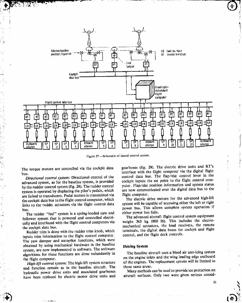
baseline system, is provided by two ailerons and six• spoilers on each wing (fig. 27). The pilot's control wheel
":, I, Redundantdatabus position isnow input to the flight control computer,via
" r _ the cockpit data bus, which interfaces with the flight
• Remote control bus,terminal The advanced system has the same number of actu-
ators and redundancy as the baseline system. There are,however, significant differences between the systems.
I Terminal H Mlcroprocessor[ The lateral central control actuators, which were used toencode/dec0de boost the control wheel forces and to input the autopilot
': _ control, have been eliminated. Thc flight control digital: data bus interfaces directly with the flight control: J interface ] computer, and all aileron and spoiler autopilot functions
IunltlHH_l,_lj computer.areimplemented in software in the flight controlThe artificial "feel" forces for the lateral control
Input/0utputp0rts system are obtained by using controlled torque motors
,, Figure 23.--Block diagram of remoteterminal, connected to the pilot's control wheel with cable linkages. %
, 19
.,1985020632-TSB08
___ LR Io.ldrecelvPr_ -- RT r_mot_Iormtnnl
,i
. .--- .'.;lick_hokor(?)
"2Foolforcoaceuntor
olov,_torpositionInput_'iI -
CockpitdatabusIIIII redundant i--
_ Lllll fllqhtNJJ computer I
t
l I IT F,!lghtcontroldatabus
-i: ! _f a_tu_tor
!i:
Figure 25.--Schematic of elevator control system.
LR loadreceiver-i Oual RT remoteterminal
/ thumb V _T /_Electrlcmotors(2)
: swltch_ t
Cockpit \'_'_1_ /,- Oifferentlal" databus
r_F_ _ ,/_t_1 ,,-Electricbrakes(2)
"" LL_ "11 _R / _]y_11,C_ Primarybrake
Ouadruple- _ / _/'/rStablllzer trimactuator:" redundantr----'l _ /
flight i= i ,] _ /,_;KL'-,,...e_,," r Ballscrew
oo,u,e,,I I - /
,ID
_-, ,.- Powerbus
FIIghtcontroldatabus
, Fisure 26.--Schematic of stabilizer trim control system. _'_'. 20
1985020632-TSB09
^llnronl_poll_r .• po,_ltlonInput(61--"t; LR loadreolvorRI romototorrnln_l
- fool_,orquo
CocRplt, databus
Ouadruplo-rodundantflIghicomputer
Flightcontroldatabus
Outboard Inboard: aileron aileron
:_-" Figure27.--Schematicof lateralcontrol system.,L
The torque motors are controlled via the cockpit data gearboxes (fig. 29). The electric drive units and RT's:: bus. interface with the flight computer via the digital flight
Directional control system: Directional control of the control data bus. The flap/slat control lever in theadvanced system, as for the baseline system, is provided cockpit inputs the set point to the flight control corn-by the rudder control system (fig. 28). The rudder control puter. Flap/slat position information and system statussystem is operated by displacing the pilot's pedals, which are now communicated over the digital data bus to theare linked to transducers. Pedal motion is transmitted via flight computer.the cockpit data bus to the flight control computer, which The electric drive motors for the advanced high-liftlinks to the rudde_ actuators via the flight control data system will be capable of accessing either the left or rightbus. power bus. This allows complete system operation if
: The rudder "feel" system is a spring-loaded cam and either power bus fails.:. follower system that is powered and controlled electri- The advanced aircraft flight control system equipment
cally and interfaced with the flight control computers via weighs 363 kg (800 lb). This includes the electro-the cockpit data bus. mechanical actuators, the load receivers, the remote
Rudder trim is done with the rudder trim knob, which terminals, the digital data buses for cockpit and flightinputs trim information to the flight control computer, control, and the flight deck controls.The yaw damper and autopilot functions, which were
obtained by using mecllanical hardware in the baseline Deicing Systemsystem, are now implemented in software. The softwarealgorithms for these functions are done redundantly in The baseline aircraft uses a bleed air anti-icing systemthe flight computer, on the engine inlets and the wing lead!ng edge outboard
High-lift control system: The high-lilt system structure of the engines. The replacement system will be limited to• and function remain as in the baseline aircraft, The those same areas,
hydraulic power drive units and associated gearboxes Many methods can be used to provide ice protection onhave been replaced by electric motor drive units and aircraft surfaces. Only two were given serious consid-
' _ _
1985020632-TSB10

,.:.,,ii
LR loadr,celvnrlit remoteh_rmlnal
--iI# /..- Ynwdamp
C_lqdt -- :: .....
dat, ht,_ _-_ __ ..-rrh,, ['oworbt,_: I O..dr.l,l,_IIII1" ,"
' - _"I rodtmdantIIIII.'-Aut°411l_t "
HI IIIU"
................=E31 "
,Rudder
,pedalI
Electrontectlanical ",,
il FIkjIlt actuatorpositionsensor-_t2--"------ J el forceactu_,tor controlrudderpositionInput databus
=_ Figure 28,--Schematicof rudd_2rcentre[ system,
, " FIIqhtcompuh.rs"./" _._..-ControlInput
t principle of suddenly, and elastically, deforming the..... metal skin of the airfoil, causing the ice to fraclure and
I, FIIghtcontroldat_at,s-1 subsequently be ejected from the surface. Electrostatic/
/",.ll ' energy is discharged into electromagnetic coils mounted' I . .,--EIt_trl¢driveunils(remoleterrain01, close to the aircraft skin. Electric energy is supplied at a,I II. ;' Ioadrecelver,andm0t0rl relatively low power level to a capacitor bank from a¢" / , ¢"
__ convenient power source and allowed to build up asubstantial charge. Upon discharging, the surge of/3-(/_" I II x,,_\ ._,sl_t_ electric energy from the capacitor creates a steep wave
_2_ '__ front inthecoil, and this results in the aircraft skin
moving away (repelling) rapidly within its elastic limit,Since the ice deposited on the airfoil is brittle, the sudden
.. movement of the aircraft skin causes the ice to fracture, explosively, and it is thereby ejected from the surface in
actuators /-'Drive_=_,t that area, In some instances a first impulse only fracturesthe ice deposit, which remains intact over the airfoill:lgurc 29.--Highdift control system,leading-edge surface. A subsequent impulse, however,successfully removes the ice fornmtions in the area, A
eration in this study: electrothermal anti-icing, and schematic of the aircraft's portsidc wing {fig. 30)electroimpulse deicing (EIDI). Electrothermal anti-icing illustrates the EIDI system configuration. The powercan provide protection at about one-tenth of the power source and controUing unit will be located in the fuselage;consumption used by a bleed air system. It is very the capacitor bank will be located in the wing about in thecompatible with an all-electric aircraft, particularly one middle of the overall length of the five slats outboard of
= with a high-frequency distribution bus, because induction the engine. A silicon-controlled rectifier will be used inheating is easily accomplished. Electroimpulse deicing conjunction with each coil,
. fief. 2) is even more energy efficient, with its power The five slats (fig. 31) arc the same in tcngth, aboutconsumption less than one-tenth of that for electro- 3.84 m (12.6 ft), but the leading-edge contour varies. :
: ' thermal. It is also very lightweight. As a result, it was EIDI tests copducted at NASA Lewis (rcf. 2) show that aselected as the ice protection system for this study, coil spacing of 0.61 m (24 in) or less is adequate for
,, ,;22 i
;(
_ _
1985020632-'1-$ B11

i
OF. POOR QUALITY .I ' I
I#,'_, ll.Clli
i'• " i Figure30,. ,',;ehcmalicof eluctroimpulsedeicingsystem,
: i • Deicingcoil.... Structuralrib i
'°i i II I ! ..:1
Figure 31,--Typical wing slat shuwing deicing coil locations. Center slat idepicted; typical of all slats (5 per wing). (Dimensions are in meters,)
deicing even under severe icing conditions. The tests alsoconcluded that one coil located rigt,t at the wing slatleading edge was just as effective as a pair of coils locatedjust a short distance away on upper and lower slatsurfaces. "lhe maximum distance between coils is about0.58 m (23 in) and there are eight coils for each slat Figure 32.--Typical i__stallatlon of electroimpulse deicing coll.(fig. 31). The other wing's deicing system will incorporateidentical components. Each wing requires 40 coils. The mean radius at the inlet to the nacelle, 1.07 m
: The installation of a coil in the leading edge of a wing (42.14 in), translates to a circumferential dimension ofslat is very simple (fig, 32). In designing a new aircraft the 6.73 m (265 in), or about 0.71 m (22 It). To locate ansupport beam would be made an integral part of the induction coil at intervals of about 0.46 m (18 in), 15coilsstructural design to minimize any weight penalty imposed will be required for each inlet. As with the wing EIDIby the EID! sy:_tem.In any case, the support system must system, it was assumed that a capacitor bank will bewithstand the forces generated by the electromagnetic located near the coils--in this case, within the nacellecoils without any significant deformation for the EIDI leading-edge area. The power system and control unit willsystem to work properly, be located in the fuselage, but only one such combination
The engine-nacelle configuration evolving from the will be required to service the EIDI units tbr both inlets.NASA/GE Energy Efficient Engine program (ref. 3)was Otherwise, the EIDI systems (wing and nacelle) areselected for use in this study of the all-electric aircraft, schematically similar.
* Although some slight sizing adjustments may bc needed The estimated weight for the ¢lcctroimpulsc deicing!_ to obtain the correct engine thrust requirements, they will system for both wings and both engine inlets is 95.2 kg
( be insignificant insofar as these deicing weight estimates (210 lb). This includes coils, mounting brackets, SCR's, I_• .'.' are concerned, capacitors, power supplies, control units, and wiring.
! 23 !!,_" i ,
1985020632-TSB12
The systempower eonsumptlan will be appraxtnmtely nystem, Ama re,_uit it was decided t_ drive file cabin _'1 kW ll' the rdrcr_ffl ts deicedevery 913_, pr_n_urlzatian compressor dlreclly from the enldne
a_.'ce'marygem'hnx, ;iF,nvironm_nlalConlrol ,Nyslt,m Tll_ replacem¢iltEC,Sh_stwa enl-;lne-drtv(,n¢ompr_s- "
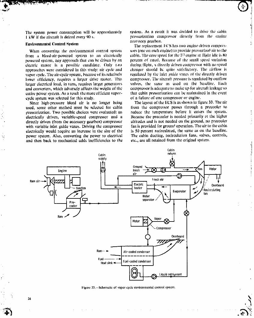
When ¢orwerllrlg the environmental control sysl_nJ _rs (oneoneachengine)to providept'esstlrize{Iair I{_thefrom +_ bleed-_lir-powcredsystem Io _lll electrically c+_btn,)'lie core._pecdfor the I_._engine_ttflight ldk, is flOpoweredsystem,fifty approachlhiil +tinbe driven hy nn percent of rllled, Il¢c,_lll_eof Ihe ,_nmllt+l+eedv_lrl+lliOllelectric meier Is [_ po._._lbl¢candidate, Only I,Vo dln+lngtll+thl, ,.tdlr+,ellydriven compre._sorwith I_o,_peedappro_lcheswereconsideredIn lht._study: air cycle and clmnger _h_uld bc quite ,_allP;f_lclory,The _;Irflow Isvaporcycle,The air-cycle,_yslem,becauseof lt,srelatively re,qulalcdby the l_+letguide v:ule_o1'the direclly drivenlower elTlcleucy, requires a larger drive me,or, 'rhiP+ compressor,Theah'crafl pressureis rep,uhttedI_youlflt_wlarger electricalload, in lurn, rctlUlreslarl_er8+l_cr£1lors valves, the same tl,_;used on lice bw,+eline,Eachand converters,whtch adverselyul'l'ectsthe wetl3h_o1'Ihe compressoris udeqtmleto makeup I'oraircrat'l leakagesoentirepowersystem,As aresultlhemoreefficientvapor- thalcabinpressurizationcanbcmainlaluedintheeventcycle system was selected for this study, el' a I'aihu'cof one compressor or engine,
Since high-pressure bleed air is no longer being The layout of the ECS Is as shoxsu in figure 33, The airused, some other method must be selected for cabin from the compressor pusses through a prceooler topressurization, Two possible choices were evaluated: an reduce the temperature betbre it enters the system, !i
"- electrically driven, variable-speed compressor and a Because the precooler is needed primarily t,t the higherdirectly driven (from the accessory gearbox) compressor altitudes and is not needed on the ground, no precoolerwhh variable inlet guide vanes. Driving the compressor fan is provided Ibr ground operation, The air to the cabinelectrically would require an increase in the size of the is 50 percent reeirculated, the same as on the baseline,
_: power system, Also, converting the power to electrical The cabin dueling, recirculation fans, valves, controls,and then back to mechanical adds inefficiencies to the etc., are all retained from the original system.
Cabin
Cabin return i!
supply _. _,
fresh -"'__, air
Overboard• i I _-'-a_ Gearbox ,
'__1_ _ . 1 Water Evaporator 'ReciroJlatlntJfanRam_ _
3ressor
Overboard
Ram---_ Ah'-cooledcondenser
FuelHeatsink Fuel-cooledcondenser
Figure 33,--Schematic of vapor-cycle environmental control system,
: _ 24
1985020632-TSB13

Cooling is provided byan electric-motor-drivenFreon te_tedby Goodyear Aermp;¢ceCarp,, the hr_king_yf;l¢;mcompressor,The motor _:anhe operated _ver a wide wasnl'_oChal]gedfrom hydrhulic to electric,_pecdrangeto =_c¢ommodacethe wrying load, A dualheal exchangerl_ used to ¢o))d_nsethe vapor, On lht:ground, fad is t1_¢¢1a_ the heal sink, The long F.rt)andcoolingperiod, are normally al the ,.tart of ll}e mt_nit_n I}escrlplion and Performance ofwhoathe tailks ¢onlain the matdn|m|iaulouni of fuel, At AII-Eleelrie Alrernfltile cad of d]_'ml,_lon lhe remainingfuel i_normallycooland the requiredcoolint_lime isshort, I}urlnl:_the flight 'l'h; all-dcclrl¢ air¢:r==flwar; d_slI_ncdfi_,' IIw sameportion of the mt,_sionram air h u,_edas the heal _;ink, payload alid ml,,_slonreq,+irenlenlsa_+was the baseline
Hot.day, full-load, ,sea.levelconditions require a aireralrt,However, the ba,.;llne hydraulic, pm_tu_ativ,44,8.kW (60-hp) drive tooter on the Freon compressor, and electricsy_lentswere replaced with _l_epreviouslyAt Ih¢ cruisealtitudeof 10668m (35 000 I't) the ntotor discussedal]-deetrl¢system,Swttehln_,Io the ali-ch:¢trt¢requirementdropsto 27,2 kW (36,5hp), Shouldone untt systemelhnin'ttedall of thecustomerbleedflow fl'onl thefail, operation of the remaining unit at 44,8 kW (60 hp) engines, However, the horsepower cxlraclion from theprovides the same 165 percent of rated as the original high,.pressure spool of the engine was increased frombaseline system. 111,9 kW 050 hp) to 194kW (260 hp) to account for the
The portion of the ECS that was replaced weighs higher electric powt', requirements. These d_angesapproximately 453.5 kg (1000 lb). This covers both resulted Ii1a 1.3 pCl'¢Cllliucreasv il_sea-level slalic thrustsystems and includes the engine-driven compressor.,,, at takeoff powc, and a 1.5 percent decrease in thrustprecoolers, refrigeration units, drive motors, load _peelt'ic fuel consumption (TSFC) at maximum cruisereceivers, and temperature controls, power.
The baseline flight control system was replaced with aOther System Changes digital fly-by-wire/electric power-by-wire system. The
An auxiliary power unit is included in current aircraft static stability requirement lbr the advanced all-electricto make them independent of ground carts for electric aircraft was assumed to be the same as that for the base-power when the mein engines are not running and for line aircraft. Therefore, although it would be possible topneumatic power to drive the ECS and to start the incorporate a stability augmentation system in theengines. The APU is also used as a backup electrical advanced flight control system, no such system wasgenerator, enabling the aircraft to be dispatched with an included in this study.unserviceable engine generator, and as a backup to the As discussed in the previous section, an APU was notelectric, pneumatic, and (through the ATDP) hydraulic included in the design. The hydraulic actuators in thesecondary power systems in flight, landing gear, brakes, and thrust re_.rsers were replaced
.- Whh the advanced all-electric system ground with electric actuators. Deicing was accomplished with anrequirements can be met at most airports by using advanced eleetroimpulse system, and the ECS was anconventimzal electric utility power. The advanced power electrically driven vapor-cycle system. Since the weight ofsystem has four primary sources of power: two the starter-generator was accounted for in the electricgenerators on each engine. As one generator is sufficient system, the starter weight was eliminated from the enginefor all essential loads, this system, even without an APU, installation weight,has more inherent reliability than the baseline secondary Net changes in the system weights befuve any resizingpower system, Therefore an APU was not used in this all- of the aircraft from those for the baseline airplane areelectric airplane configuration, For aircraft use in remote shown in table V, After applying the delta system weightlocations an APU can be included in the system, The of table V and modifying the engine performance toweight penalty would be less than the baseline APU account for the elimination of bleed and the increase inweight because the compressor to produce pneumatic horsepower extraction, the baseline-size aircraft andpower would not be required, engine were allowed to scale such that they once again
The baseline engines are started with air turbines met the baseline mission and payload. The reslzedmounted on the engine accessory gearbox. The engine geometry for the all-electric aircraft is given in table VI;starts are now provided by the electric generators and a weight breakdown, in table Vii. Note that all of theoperating as motors. Since they are no longer needed, the fixed-equipment weights were assumed to be invariantair atarters were removed, with aircraft weight. Theretbre applying the net change
The actuators for landing gear retraction, nose wheel listed in table V to any particular baseline fixed-steering, and thrust reversers were changed from equipment weight will result in the advanced systemhydraulic to electric. On the basis of the technology of an weight alter the aircraft is restzed. However, the weights
: all-electric braking system (ref. 10) being developed and of many of the other aircraft components were assumedi
2J _1
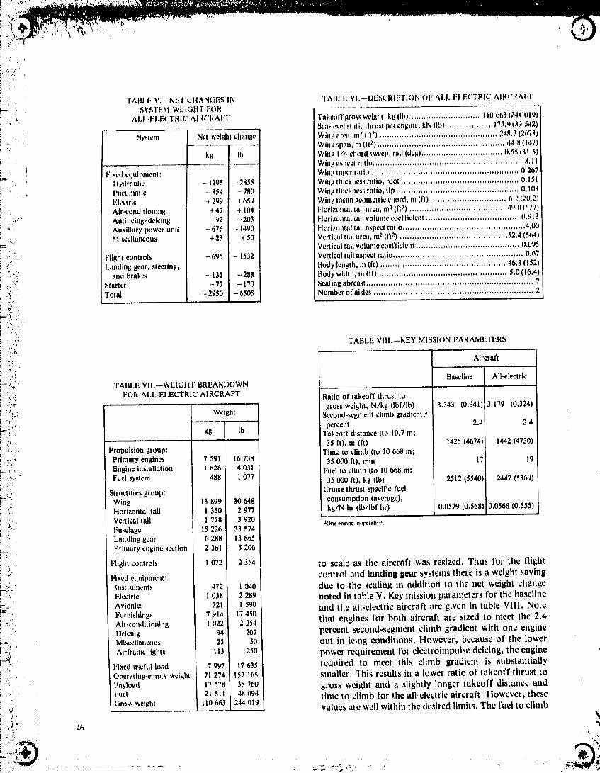
" ' TABI.E V,--NET CHANGES IN TABI E VI,--DESCRIPTION OF AI.I. rI.E('TRIC AIRCRAFT'-- SYSTEM WEIGHT F'OR! ; t ALI:EI.E('TRIC' AIRCRAFT Takcoffgrohs weight, kg (Ih) ............................. 110663 1244 trig)i Sea-level nlttticthrust per ell_tlle, RNfib)................... 175,tJ139542)! * Sy_len! Net welghi clmn_e Win_ llren, 111_ if[_) .............. 24H,3(26731
WInl_span,m (fl _) ................................................... 44,8(1471: kl_ I Ih Wing I/4-d]ord sweep,rod (dcl_)................................. 0,55(31,5)
i , Whh_aspect r,'lllO............................................................. H,IIiL Fixed equipment', Wing taper ratio ............................................................ 0,267i
, Hydraulic -. 1295 2855 WIn,qIhlckl=e,s.,iratio, root ................................................ O,151_ Pneuntatlc - 354 - 780 Winl_flflcknes:_ratio, tip .................................................. 0,103
Electric + 299 4 659 WIng mean i_eontetrlcchord, m (fit ............................... h, 2 (2(1,2)AIr.cundltlmtlng + 47 -_104 Horizontal tall area, m_(It2) ....................................... ,t,, 0 (577)
• :,' AIIIt.Icing/deicing -- 92 - 203 Horizontal tall volume coefficient ...................................... 0.913:" Auxiliary power nnli - 676 - 14q0 Horizontal tall aspect ratio .................................................. 4.00:.. I_llscdluneous + 23 _ .450 Vertical tall area, m2 (It2) ............................................ 52,4 (564)
Vertical tall volume cuefr, t:ient.......................................... 0,095i.i;"_ Flight controls -695 - 1532 Vertteal tall aspect ratio ..................................................... 0.67ii:_ Landing gear, steering, Body length, m (It) .................................................. 46.3 (152)o,
"_ andbrakes -.131 -288 Bodywidth,m (it)....................................................5.0(16.4)._.: S;nrter -77 - 170 Sealingabreast....................................................................7
i -_,_" Total - 2950 - 6505 Number of aisles ................................................................. 2
i u
. o:SI,• "...'_..> TABLE VIII.--KEY MISSION PARAMETERS
':.' Aircraft,_r ,,.
c"" Baseltne All-electric; ".... 'FABLE VII._WEIGHT BREAKDOWN
,.,,,:.; ! FOR ALL-ELECTRIC AIRCRAFT Ratio of takeoff thrust toi :x,' ....'. '_:" Weight gross weight, N/kg (Ibf/lb) 3,343 t0,341) 3.179 (0,324); .i:_:' ISecond-segment climb gradient:k ',¢
;..=e,_'. percent 2.4 2.4_=','i" kg I Takeoff distance (to 10.7 m:! ":'. 35 It), m fit) 1425 (4674) 1442 (4730)!-:",'. Propulsiongroup: Timetoclimb(toI0668m;i -::'; Primaryengines 7 591 16738":_ 35000ft).min 17 19
, . Engine installation ! 828 4 031 Fuel to climb (to I0 668 m;
:'.'.: Fuelsystem 488 1077 35000ft),kg(lb) 2512(5540) 2447(5369)t-._ Structures group: Cruise thrust specific fuel
wing s99 3064s consnn,ptton(average),,, Horizontal tall I 350 2 977 kg/N hr (lb/lbf hr) 0.0579 (0,568) 0,0566 (0,555)
i 'o Vertical tail 1 778 3 920 _ao,_ JllOl_traltvt_,._.,""" Fuselage 15 226 33 574! ' Landinggear 6 288 13865i=<: Primary engine section 2 361 5 206
Flight controls 1072 2364 tO scale as the aircraft was resized. Thus for the flighti ':it Fixed equlpntent: control and landing gear systems there is a weight savingi_:-i;' Instruments 472 I o40 due to the scaling in addition tothenet weight change! Electric l 038 2289 noted in table V. Key mission parameters for the baseline!=::_._ Avionics 721 I 590 and the all-electric aircraft are given in table VIII. Note- '" Furnishings 7 914 17450
_i,::. Air.conditioning 1 022 2 254 that engines for both aircraft are sized to meet the 2.4,:i Deicing 94 207 percentsecond-segmentclimbgradientwithoneengine
=:., Mlsccllancous 2_ S0 out in icing conditions. However, because of the lower__. • Airframelight'_ 113 250 power requirement for elcctroimpulse deicing, the engine) '" Fixedu'_cfulload 7997 17_35 required to meet this climb gradient is substantially
-,- Operating-empty weight 71274 157165 smaller. This results in a lower ratio of takeoff thrust to: Payload 17578 3)_760 gross weight and a slightly longertakeoff distance and
.' Fuel 21 811 48 094: timc to climb for the all-electric aircraft. However, these', Grossweight II0663 244019_ ........ valuesarewellwithinthedesiredlimits.Thefucltoclimb
, _ " 26
_;,':'?
1985020632-TSC01

was reduced sub.,itantiallyas a result of the lower aircraft The portion of the baseline flight control system that, weight and the improved TSFC obtained by eliminating was removed from the aircraft weighs 1057kg (2330 Ib),
bleed, The average cruise TSFC decreased 2.3 percent, This includes the hydraulic actuators, the servovalvcs,greater than the 1,5 percent decrease that resulted from and the mechanical control linkages. The advanced systemeliminating customer bleed, The additional TSFC that replaced the baseline systemweighsonly 363kg (8001b)improvement resulted from the lower ratio of takeoff and includes electromechanical actuators, load receivers,
" thrust to gross weight for the all-electric aircraft, redundant digital data buses, and remote terminals, TheConsequently the all-electric aircraft cruises at a higher net weight reduction for this change was 694 kg (! 530lb),power setting, resulting in a higher efficiency. The clectromechanical actuators can perform the same
function as hydraulic actuators with lower weight andwithout the sizing restrictions encountered with hydraulic
' Summary of Benefits actuators. The useof a digital data bus to provide control' and sensor information is a much lighter weight approach
Tile weights of the various aircraft systems, for both than cables, pulleys, bellcranks, etc, Also, with the use of: the baseline and advanced aircraft, are shown in figure a digital fly-by-wire system, many things previously• 34. The baseline power system, which includes the accoml:" had with hardware can be done with software.
hydraulic and electric generation and distribution This in_:l. '7_ such features as control surface damping• equipment and the pneumatic distribution equipment, and trim.
weighs 2388 kg (5265 Ib) and has a utilization factor at The replacement ECS at 460 kg (1014 lb) actuallycruise of 0.42. The advanced power system weighs only weighs more than the original system at 413 kg (910 lb).
- 1039 kg (2290 Ib) and has a cruise utilization factor of However, the basic benefit associated with the ECS is:.L, 0.62. This system change results in a weight reduction of elimination of customer bleed from the engine. Generally,d
;s_. 1349 kg (2975 ib). One of the reasons for this weight bleed is withdrawn from the engine compressor at only" reduction is that using a single type of power allows load two fixed ports, one for low and one for high engine
i_. sharing throughout the flight profile and this results in a power settings. The compressor stage for the high-power' smaller capacity system. However, the major reason that port is selected such that it will provide adequate pressure
' :' the replacement power system is so much lighter has to do for all but low power conditions. As a result the pressurewith the characteristics of that system. The high- is normally higher than needed. Also the air is of a higher
:_. frequency power distribution bus results in small energy temperature than desired. All of this excess energy is_- storage components and very simple, lightweight load wasted and contributes to higher than necessary fuel: " receivers. The failure protection scheme allows the use of consumption. The new system avoids this waste.
a distributed bus without the penalty of heavy solid-state The baseline bleed air anu-icing system, which consists" circuit breakers, mainly of pipes and valves, weighs 186 kg (410 lb). The
' 5xO_ I El_ectr
Pn_eumatlc
"=? 4 -- Ic
" // _ Baseline1_0--3 _ _ 1777] Advanced
--= z"
-- Hydraulic
Ic1 -- 500_
., Anti-Icing
o_ oiPower Flight Environmental Icing Nlscellaneoussystem control controlsystem (APU, landing
system gear,brakes,starter)
;, .'( Figure 34,--Weights of aircraft systems,
! :7
1985020632-TSC02

__#:,_,_,g_i-..,s.,;-,-_'_ -_-........,- .- .._. _ .......................
i!¢
electrolmpulse deicing system that replaced it weighs 94 t0000 -- £kg (207 ib). This weight difference Isnot verysignificant. _°xI°_-- FuelIbieod_E 0.0t'orcent i
• ;"; Also the fuel penalty for bleeding the engines during anti- Fuol(slzlntjt O fuelreduction j
,icing tends to be insignificant because bleeding is done so _r_ _ Structureandseldom. However, the engine must be sized to be able to 1_ = _p propulsionprovide that bleed when needed, even with one engine _ bloedoteoctsCinoperative. As a result, the engines and the aircraft are _ _g"
- _ Structureand lOPercentlarger and heavier than it'bleed for anti-icing did not have '_ E 5000 -- propulsionto be provided. The new deicing system reduces fuel :E_ 10 -- ,_ systemseffects wolghtreductlonBconsumption since the engines and aircraft can be ._ '_ /
smaller. _ _ l =
Additional weight was saved in a number o1' other 9 _ 2500 -- Systemwelght tireduction !iareas. The removal of the APU eliminated 676 kg (1490 A
• Ib). (If an APU were included in the advanced system, it 0 -- 0would add about 455 kg (1000 lb).) The air starters (77
kg; 170 lb) were also removed. The landing gear, steering, Figure 35.--Reduction in weight and fuel consumption from baseline, dbrakes, and thrust-reverser actuation were changed from for design mission, i=
, hydraulic to electric. This saved another 131 kg (288 lb). ;The total weight reduction in the aircraft systems was approximately 4.5 percent of baseline (block E). This
;,: 2950 kg (6505 lb). This weight reduction along with the yields a total gross weight saving of 10 140kg (22 360 lb).bleed elimination was factored into aircraft size for the In conclusion, the total benefit for a 200-passerger,
_. same mission (table IX). The engine thrust reduction twin-engine transport using energy-efficient engines it.a 9_ comes about because of the aircraft weight reduction and percent reduction in fuel consumption and a 10 percent _,
also because the all-electric version does not have to reduction in operating-empty weight.--': provide icing bleed during single-engine climbout. Note _.
: t
: that the percentage of reduction in fuel consumption does !not vary appreciably with mission length. (If an APU Conclusionswere included in the all-electric aircraft, the empty weight
_ would increase by about 910 kg (2000 lb) and the fuel This study showed that substantial benefits, in thesaving would decrease by about 0.6 percent.) form of reductions in aircraft weight and fuel
The reductions in weight and fuel consumption ate consumption, are possible through the integration of ansummarized in figure 35. Block A represents the 2950-kg advanced electric secondary power system into a(6505-1b) reduction in the aircraft secondary systems transport aircraft. The particular benefits achieved, 10directly attributed to advanced secondary power system percent reduction in aircraft empty weight and 9 percentapplication. When that is factored intotheentireaircraft, reduction in mission fuel, are valid for the aircraftits structure and propulsion system weight are reduced by selected for this study. Any medium or large transportan additional 2948 kg (6500 lb) (block B). The reduction aircraft using the same type of power system shouldin fta_:consumption associated with this weight saving achieve similar benefits. The benefits also depend on theamounts to approximately 4.5 percent of baseline (block type of engine selected, with higher bypast, ratio engines
: D). Another weight saving of approximately 1995 kg providing higher benefits because they are more sensitive(4000 lb) is associated with the propulsion and structure to bleed. The engine selected for this study, while an
': reduction for not having to bleed the engines (block C). engine of the future, is sufficiently near term that it isThe fuel saving associated with this weight reduction and expected to be in service at the time the power systemthe elimination of customer bleed from the engine is also technology would be available. Therefore the benefits
TABLE IX.--AIRCRAFT WEIGHT
Baseline All-electric Change,percent
•-i' kg Ib kg Ib
Empty weight 78 966 174 125 71 274 157 165 -9,74: Engine thrust 20 552 45 319 17932 39 542 - 12,75.... Toter fuel 24 057 S3048 21 811 4B094 = -9.34
. : Fuel consumption: i": ; 3590-kn1(1940-11mi) mission 17400 38 368 15859 34 971 -8.85 ;I: 740-kin (400-it mi) mission 4 949 10 912 4 515 9 958 -8.94
-- , ! 't
= ._; . ". ;7;, : .,: ..............
1985020632-T9C03

resulting from the engine bleed sensitivity are realistic, synthesized oat.nat of the load receiver provides theWith the engine trends in transport aircraft moving frequency variability necessary to meet this requirement.toward even higher bypass ratios, the benefits associated The ECS vapor-cycle compressor will bedriven by a largewith eliminating customer bleed will Increasebeyond the motor, almost equal in size to the power systemvalues achieved in this study, generators, These motors must be soft started to prevent
The benefits achieved in this study occurred in several large variations of the power bus voltage. The constant ,:systems within the aircraft. The most substantial weight voltagc-to-frequency ratio output of the load receiverreduction (1349 kg; 2975 Ib) was in the secondary power provides this soft-start capability, Therefore thesystem. The baseline power system was composed of secondary power system selected in this study doesthree separate systems: hydraulic, pneumatic, and provide the proper interface for motor loads,
':' electric. Each system powered its own loads. Their low The secondary power system characteristics arethekey.... utilization resulted in a fairly heavy secondary power to the benefits obtained in this study, The basic
system. However, the replacement system powered all the characteristics of the system are high.frequency (20 kHz)loads, and this allowed load sharing and better system sinusoidal p6.'Jer distribution with controlled energy ,_
: utilization. Also the technology used in the replacement flow. The high frequency results in lightweight magneticssystem provided a very lightweight system. The net result and other energy storage components. The sinusoidal l
' was a substantially lighter secondary power system, waveshape is well ordered and easily controlled with a !Another system showing a substantial weight reduction simple control system. Because of its single frequency" (694 kg; 1530 lb) was the flight control system. This electromagnetic interference protection is simple, t
!. - saving was obtained when the hydraulic actuators and Controlled energy flow allows the use of lightweight _!:- servovalves were replaced with electromeehanical actua- isolation and reconfiguration switches. All of these
!_:!i! tors and load receivers. The benefit is larger than might features result in a lightweight secondary power system, i: _:_'_ normally be expected because of the lightweight load The high-frequency waveform can easily synthesize loweri _ . receivers resulting from the type of electric power system frequencies when a lightweight load receiveris used. This ii
i=?-_, used. This is an instance where the secondary power provides the range of frequencies required by the flight
._. system has a beneficial effect on another aircraft system, control system actuators. The result is a lightweight flight i!i..,.... Eliminating engine bleed for powering the control system. The synthesized outputs can provide a
environmental control system (ECS) provided the largest constant voltage-to-frequency ratio for motor drives. !'i! _ single fuel saving of any change made in this study. The This allows the controlled starting of the engines and the _:
ECS is run by an electric-motor-driven vapor-cycle ECS drive motors. The result is an efficient system for..... system weighing only slightly more than the baseline bleed elimination. 'il. system. As a result the fuel saving was not even partially To determine the effect of an electric secondary power
!=:, offset by a weight increase. A major factor allowing this system on an aircraft, it must be integrated into the' lightweight ECS is the lightweight load receiver used to aircraft and all those systems with which it interfaces. ;
control the electric drive motor. This is another instance The power system can have a significant effect on otherwhere the secondary power system technology has a systems in the aircraft, such as the flight control andbeneficial effect on another system, environmental control systems. All of these systems in
The electric secondary power system must provide the turn affect the aircraft and engines, as can be seen by theproper interface for motor loads. Loads that were final results of this study.previously hydraulic and pneumatic will be driven almostexclusively with electric motors. The actuators in theflight control system are driven by _..any small motors. Lewis Research Center
, These motors must operate over a wide speed range in National Aeronautics and Space Administrationorder to respond to the flight control commands. The Cleveland, Ohio, January 25, 1985
i
i 29
'.,._ _'¢!
] 985020632-TSC04

Appendix--Baseline-Aircraft Flight Control
Longiludinal Control System actuator to drive the input to tile surface actuators and tobackdrive tile control column,
Single-span elevators (fig, 36) and a variable-incidence The horizontal trim control system varies the angle ofhorizontal stabilizer (fig. 37) control the pitch of the incidence of tile stabilizer to provide longitudinal trim,baseline aircraft. Three hydraulic actuators drive the The stabilizer is trimmed in manual or automatic mode,
, right and left elevators, Tile actuators receivetheir inputs by a dual-load-path ballscrew actuator powered by twofrom either tht;.autopilot or the control columns via the hydraulic motors via a differential gearbox. When trim iscable system. All three hydraulic systems power each not commanded, stabilizer position is maintained by acontrol surface to ensure continued operation of the primary thrust brake (a self-actuating mechanical brake '_elevator control system when two of the thre,: hydraulic that maintains stabilizer position in the absence of ,isystems are inoperative, hydraulic pressure) and two secondary hydraulic brakes.
The fully powered control system requires artificial The total stabilizer travel is minimized by using"feel" forces at the pilot/copilot's control column. A programmed elevator deflection with stabilizer angle.combination of mechanical and hydraulic springs In the manual mode both hydraulic modules and the _,contained in the feel unit provides these forces. The feel associated hydraulic motor and brake respond to trim '_
, computer programs hydraulic pressure for the feel unit commands. In the autopilot mode trim commands are• , actuators as a function of measured impact pressure and only transmitted to one of the two control modules when
stabilizer position. Switching on the autopilot the elevator command exceeds ±0.007rad (0.4deg) fromi - "¢,
:.--,- hydraulically actuates an autopilot-engage locking neutral for more than 5 s. In the autoland mode the:_' mechanism. The locking mechanism allows the autopilot remaining module is in a standby state; in the event the
• Warnln(j Stick shaker 121
!=_; electronics - [] [] []
Itydraullc systems; :,.: -
Automatic _- r..-: "1 ..._[_1_i -. lilt]hi control _ Force transducer (2_computer LoadIlmiter
Dynamic _ .P Cable tension _ ,,• pressure 1_ requlater (_
-'- Input 1_ _, 17 _ 5hearot,t
/- Asymmetry Ilmiter
/- Aulopilot," server3)
t
r-Prlm3ry
Slavecables7 I controlactuators(bl
._ l-eellcenlerh_j limit
'_ and stlckshaker Positiontransmitter 1_ _ l
• _ Feel override
," Neutral shill
: _ Rightelevator
/"System yround -J
_
Figure 36.--Schematic of baseline elevator control.
] 985020632-TSC05
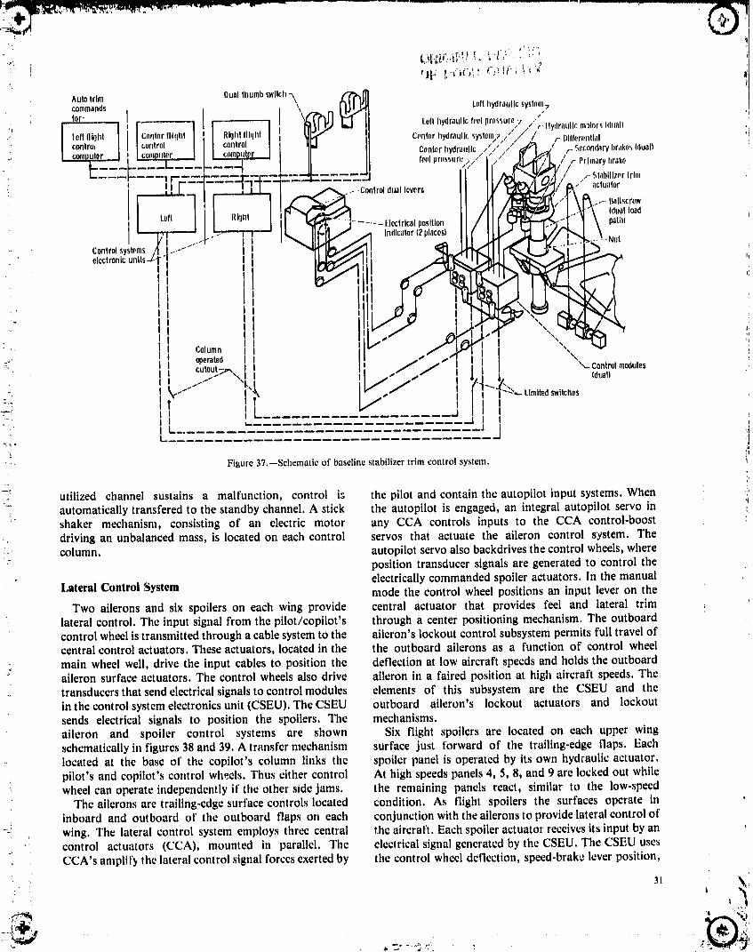
! I,, %%
I• Column I I
_.. operated I I ! "'"cutout;_,, , t [ ",- Controlmodules
I ,.,.J"'" ""[ I I L,_ I {duall
_': I I[ ,I I II __ ________..J I I•" I .... .I ,,i
' i!Figure 37.--Schematic of baseline stabilizer trim control system.
----__
•L utilized channel sustains a malfunction, control i_ the pilot and contain the autopilot input systems. When _'automatically transfered to the standby channel. A stick the autopilot is engaged, an integral autopilot servo in _shaker mechanism, consisting of an electric motor any CCA controls inputs to the CCA control-boost ',driving an unbalanced mass, is located on each control servos that actuate the aileron control system. Thecolumn, autopilot servo also backdrives the control wheels, where
position transducer signals are generated to control theelectrically commanded spoiler actuators. In the manual
Lateral Control System mode the control wheel positions an input lever on the
Two ailerons and six spoilers on each wing provide central actuator that provides feel and lateral trimlateral control. The input signal from the pilot/copilot's through a center positioning mechanism. The outboardcontrol wheel is transmittedthrough a cable system to the aileron's lockout control subsystem permits full travel ofcentral control actuators. These actuators, located in the the outboard ailerons as a function of control wheelmain wheel well, drive the input cables to position the deflection at low aircraft speeds and holds the outboardaileron surface actuators. The control wheels also drive aileron in a faired position at high aircraft speeds. Thetransducersthat send electrical signals to control modules elements of this subsystem are the CSEU and theinthe controlsystem electronics unit (CSEU). TheCSEU outboard aileron's lockout actuators and lockoutsends electrical signals to position the spoilers. The mechanisms.aileron and spoiler control systems are shown Six flight spoilers are located on each upper wingschematically in figures 38 and 39. A transfermechanism surface just forward of the trailing-edge flaps. Eachlocated at the base of the copilot's column links the spoiler panel is operated by its own hydraulic actuator.pilot's and copilot's control wheels. Thus either control At high speeds panels 4, 5, 8, and 9 are locked out while
' wheel can operate independently if the other side jams. the remaining panels react, similar to the low-speedThe ailerons are trailing-edge surface controls located condition. As flight spoilers the surfaces operate in
inboard and outboard of the outboard flaps on each conjunction with the ailerons to provide lateralcontrol of_i _ wing. The lateral control system employs three central the aircraft. Each spoiler actuator receives its input by an
' control actuators (CCA), mounted in parallel. The electrical signal generated by the CSEU. The CSEU usesi CCA's amplify the lateral control signal forces exerted by the control wheel deflection, speed-brak_ lever position,
.. ._ |
1985020632-T9C06
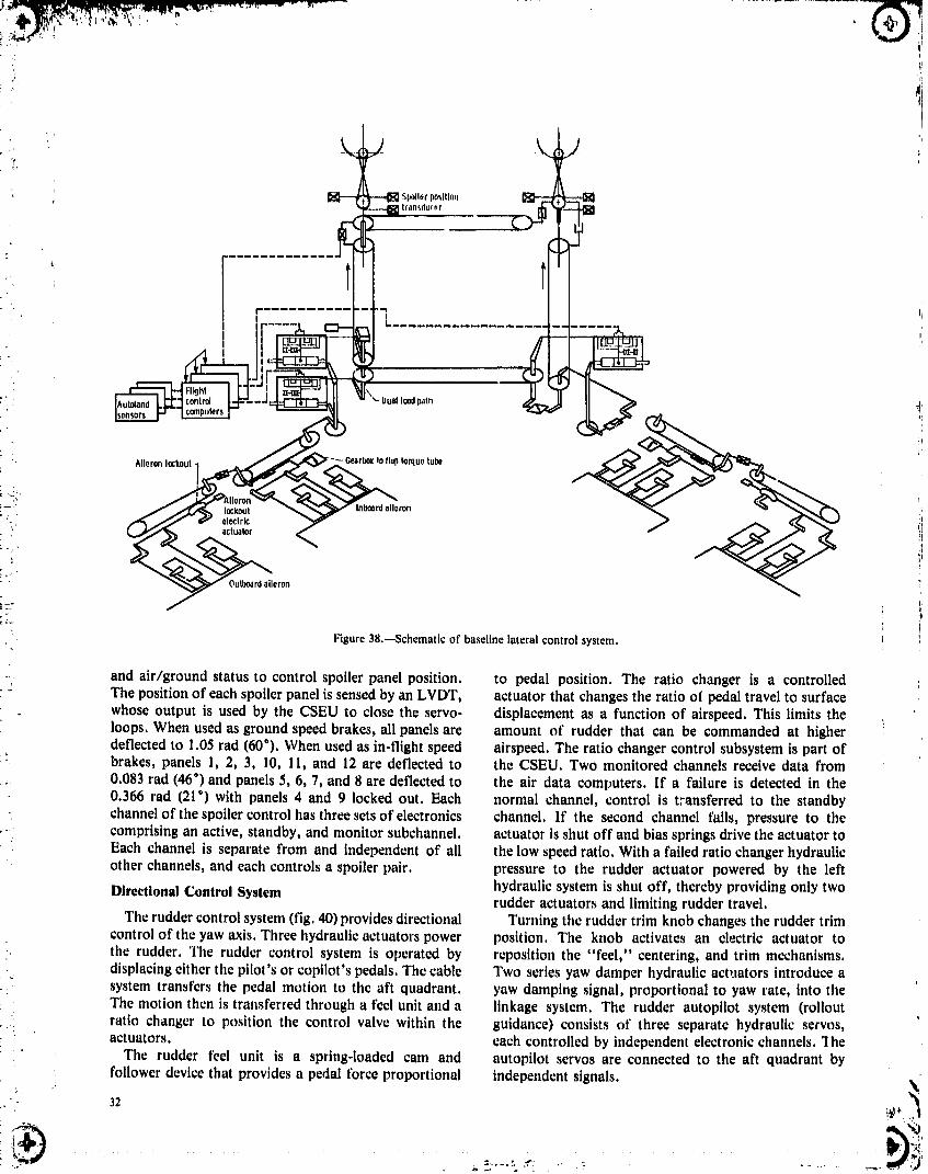
I
" r I
I -I '
"°ua' C !I
• Aileronlockout-] -Gearbox,oflaptorquetubeI
_:.
!-" _ lockout nbeardaileron
'_: electric. actuator
Outboardaileron
": Figure 38.--Schematic of baseline lateral control system.
- and air/ground status to control spoiler panel position, to pedal position. The ratio changer is a controlledThe position of each spoiler panel is sensed by an LVDT, actuator that changes tile ratio of pedal travel to surfacewhose output is used by the CSEU to close the servo- displacement as a function of airspeed. This limits theloops. When used as ground speed brakes, all panels are amount of rudder that can be commanded at higherdeflected to 1.05 rad (60°). When used as in-flight speed airspeed. The ratio changer control subsystem is part of
" brakes, panels 1, 2, 3, 10, 11, and 12 are deflected to the CSEU. Two monitored channels receive data from0.083 tad (46°) and panels 5, 6, 7, and 8 are deflected to the air data computers. If a failure is detected in the0.366 tad (21") with panels 4 and 9 locked out. Each normal channel, control is transferred to the standbychannel of the spoiler control has three sets of electronics channel. If the second channel fails, pressure to the
.... comprising an active, standby, and monitor subchannel, actuator is shut off and bias springs drive the actuator toEach channel is separate from and independent of all the low speed ratio. With a failed ratio changer hydraulicother channels, and each controls a spoiler pair. pressure to the rudder actuator powered by the left
Directional Control System hydraulic system is shut off, thereby providing only tworudderactuators and limiting rudder travel.
The ruddercontrol system (fig. 40) provides directional Turning the ruddertrim knob changes the ruddertrimcontrol of the yaw axis. Three hydraulic actuators power position. The knob activates an electric actuator to
. the rudder. The rudder control system is operated by reposition the "feel," centering, and trim mechanisms.displacing either the pilot's or copilot's pedals. The cable Two series yaw damper hydraulic actuators introduce asystem transfers the pedal motion to the aft quadrant, yaw damping signal, proportional to yaw rate, into theThe motion then is transferred through a feel unit and a linkage system. The rudder autopilot system (rolloutratio changer to position the control valve within the guidance) consists of three separate hydraulic servos,actuators, each controlled by independent electronic channels. 1he
The rudder feel unit is a spring-loaded cam and autopilot servos are connected to the aft quadrant by
• follower device that provides a pedal force proportional independent signals. N:
32 _
• _'
•,-- ,. _:......": ,'_ " ": ..... _. i,/
1985020632-TSC07


, ,:'
EHV olectrohydra.llcvalveL, C, R hydraulicsystems
':,. ILdt yawdampor[landratio /Ichanq.r F _
r / r Yawdam,lotserve/
Elnctrtctrim /i c Antibar,klashsprlnqactuator _ /
.. RItJII(yaw andposition \ / /damperand traflsmlttor- \ / /ratiochanger _ / /modulos
Rollout Iguldanc i
Rudder 'i
Trimswitch [] ,I.-,
"' Trimposition[___ _'" ,, '!]Indicator I / ,1
, SurfacepositionE]"--'_ I '_ /, indicator I _ Backupfulcrum /
Feeland (springdetent) /centering- !i• . Rudderpedal7 /- Pedaladjustment ,,, / ",.-Positiontransmitter ;
;_i._: J'._=/ Aftquadrant_, ratiochanger / i/ (mechanicalspring / LI
i: _ ,;/ _ loadedtolowspeed L Powercontrolactuator qActuatorff ratio) ij
; il
:"-- Figure40.--Schematlcof baselineruddercontrolsystem. I
": Hlgh-LlftControlSystem ,_ : controllever
/ Alternativecontrol",, ,_(_
inboard flap and a single-slotted outboard flap, plus five ,: c0ntr01cablesoutboard and one inboard three-position, leading-edge :":"slats on each wing. The trailing-edge flaps and theleading-edge slats provide high lift for takeoff and ,L[-[_ ,
IiiiiI' landing. During normal operation the center hydraulic Pmerdriveunit-,,\ I./- Powerdrlveunit:" system is the primary source of power. In the event of F ' '-
' ' electricmotors.hydraulicsystem failure the alternative power source is __' '=Each power drive unit (PDU) is a hydromechanical ,_$1ats
" Leftservomechanism that consists of a control valve module, _rd
a hydraulic motor, and a gear reduction unit. The PDU's ____-_.I __transmit power to the rotary actuators via torque tube[ v_,,," _._..._ Powerdriveunit -_ //' _'-_,,.'-._ "Ng"Idrive shafts and ancillary angle gearboxes. Alternative ::. _. :... >_..
flap/slat control is provided by an electric motor drive _=:" \_-Rotary Haps-* / -._actuatorsassembly for each PDU. The alternative control loops for (@i_, /I)rlve shaft
the backup electric motors are electromechanical closed *_P=""
loops with position sensors. Figure' 41.--Schematic of baseline high-lift control system,
I
I
! .(I,.
• , :,i 34 !
1985020632-TSC09

" : 35 ._,
l _ ]I',_.
1985020632-TSG10

....
Lii,_ "L
i
1, Report No, 12. Government Acea,_lon No, 3, ttaclplenl'_ Catalog No.
', " NASATP-P_463 I' 4, Tltl_ _nd 15gbtltln 5. FlapNrtD_ta
..i M_ly 19H5Advanced Secondary Power System for Transport
" _ aircraft 0,PmlormlngOrganl_'ntl_nCodn' 505-45-72
1, Author(n) ....... B, Porto,'mlng Organlzollon Report No,
' Anthony C. Hoffman, Irving G. Hansen,RaymondF. Beach, Robert M. Plencner, E-2434 _;Robert P. Dengler, Kent S. Jefferies, 10,WorkU,ltNo, '
-. t and Robert J. Frye"9.'Po'rformlng Organization Name _nd AddroeB
11, Contract or Grant No.
National Aeronautics and Space Administration _. Lewis Research Center: C1eve1and, 0hi o 44135 13. Type of Report and Period Covered
12. Sponsoring Agency Namo'and Address .... TechnicalPaper!,
_ NationalAeronauticsand Space Administration 14Spon,orI_gAo_n_yCo;_O-Washington,D.C. 20546
15. SupplementaryNo'tee'
- 16, Abstract
A concept for an advanced aircraft power system was identified that uses 20-kHz,_,__ 440-V, sine-wavepower distribution. This systemwas integratedwith an
electricallypoweredflightcontrolsystem and with other aircraftsystems:_ requiringsecondarypower. The resultingall-electricsecondarypower
configurationreducedthe empty weight of a modern 200-passenger,twin-enginetransportby lO percentand the missionfuel by 9 percent.
17_'KeyWord's (Sui_'ge_tedbyAuthor(e)) 18,_Dletrlbutlon'Statsmeilt .........
Aircraftpower Unclassified Unlimited
Secondarypower STAR Category07
, i
_,! 19, Security Class& (of this report) =20,Security Class#, (of this page) _2t, 14o,otl_aile'e 22. Price
,' Unclassified Unclassified 37 A03• j ............. rt '_
;_ For sale by the National Technloal Information Service, Springfield, Virginia 22161 NASA-I.angley, 1985 _,• '_ it "
i
1985020632-TSC 11