Embed Size (px)
Citation preview

2.4 GHz FlexPIFA Antenna, 100mm Datasheet
The information in this document is subject to change without notice. 330-0149-R3.4 Copyright © 2014-2017 LSR Page 1 of 31
2.4 GHz – 2.5 GHz FlexPIFA 2 dBi Antenna w/U.FL Cable, 100mm
ORDERING INFORMATION
Order Number Description
001-0014 2.4 GHz FlexPIFA Antenna w/U.FL Cable, 100mm
001-0022 2.4 GHz FlexPIFA Antenna w/MHF4L Cable, 100mm
001-0025 2.4 GHz FlexPIFA Antenna w/U.FL Cable, 100mm, LH
Table 1 Orderable Part Numbers
KEY FEATURES
▪ Can be installed on different non-conductive surfaces and thicknesses.
▪ Can be installed near metals or the human body.
▪ Can be installed on flat
or curved surfaces.
▪ Quick and easy Installation
▪ Adhesive holds to
surface during humidity exposure and hot/cold cycles.
▪ RoHS Compliant

2.4 GHz FlexPIFA Antenna, 100mm Datasheet
The information in this document is subject to change without notice. 330-0149-R3.4 Copyright © 2014-2017 LSR Page 2 of 31
SPECIFICATIONS
Specification Value
Peak Gain +2 dBi
Average Gain >-1.5 dBi
Impedance 50 ohms
Type Flexible Planar Inverted F Antenna (FlexPIFA)
Polarization Linear
VSWR < 2.0:1, 2400 - 2480 MHz
Frequency 2400 – 2480 MHz
Weight 1.13g
Size 40.1mm × 11mm × 2.5mm
Antenna Color Clear Yellow
Adhesive 3M 100MP
Operating Temp -40°C to +85°C
Connector Height MHF1 (U.FL): 2.5mm Max
MHF4L: 1.4mm Max
Table 2 Specifications

2.4 GHz FlexPIFA Antenna, 100mm Datasheet
The information in this document is subject to change without notice. 330-0149-R3.4 Copyright © 2014-2017 LSR Page 3 of 31
PHYSICAL DIMENSIONS (MM) (001-0014 & 001-0022)
Figure 1 Physical Dimensions

2.4 GHz FlexPIFA Antenna, 100mm Datasheet
The information in this document is subject to change without notice. 330-0149-R3.4 Copyright © 2014-2017 LSR Page 4 of 31
PHYSICAL DIMENSIONS (MM) (001-0025)
Figure 2 Physical Dimensions

2.4 GHz FlexPIFA Antenna, 100mm Datasheet
The information in this document is subject to change without notice. 330-0149-R3.4 Copyright © 2014-2017 LSR Page 5 of 31
TEST SETUP
Antenna measurements such as VSWR were measured with an Agilent E5071C Vector Network Analyzer. Radiation patterns were measured with a CMT Planar 804/1 Vector Network Analyzer in a Howland Company 3100 Chamber equivalent. Phase Center is 9 inches above the Phi positioner.
Flat surface measurements were done with the antenna centered on a 1.5 mm thick plate of Polycarbonate. Curved surface measurements were taken by placing the antenna on the inside and outside of different diameter PVC tubing.
Figure 3 Antenna Chamber

2.4 GHz FlexPIFA Antenna, 100mm Datasheet
The information in this document is subject to change without notice. 330-0149-R3.4 Copyright © 2014-2017 LSR Page 6 of 31
FLAT SURFACE ANTENNA MEASUREMENTS
VSWR
Figure 4 Antenna VSWR measured on a 1.5 mm thick plate of Polycarbonate

2.4 GHz FlexPIFA Antenna, 100mm Datasheet
The information in this document is subject to change without notice. 330-0149-R3.4 Copyright © 2014-2017 LSR Page 7 of 31
FLAT SURFACE ANTENNA RADIATION PERFORMANCE
FlexPIFA centered on a 1.5 mm thick plate of Polycarbonate
Antenna Measurement Set-Up:
Figure 5 Flat Surface Set-Up

2.4 GHz FlexPIFA Antenna, 100mm Datasheet
The information in this document is subject to change without notice.
330-0149-R3.4 Copyright © 2014-2017 LSR Page 8 of 31
Azimuthal Conical Cuts at 2400 MHz:
Figure 6 Vertical, Horizontal, and Total Gain Patterns
-30
-20
-10
0
10
30
210
60
240
90
270
120
300
150
330
180 0
Gain - Vertical Polarization at 2400.0 (MHz)
Gain Summary (dBi) at 2400.0 (MHz) min: -28.3 (dBi) max: +1.4 (dBi) avg: -5.5 (dBi)
0
15
30
45
60
75
90
105
120
135
150
165
Theta (deg)
-30
-20
-10
0
10
30
210
60
240
90
270
120
300
150
330
180 0
Gain - Horizontal Polarization at 2400.0 (MHz)
Gain Summary (dBi) at 2400.0 (MHz) min: -25.9 (dBi) max: -2.7 (dBi) avg: -8.0 (dBi)
0
15
30
45
60
75
90
105
120
135
150
165
Theta (deg)
-30
-20
-10
0
10
30
210
60
240
90
270
120
300
150
330
180 0
Gain - Total at 2400.0 (MHz)
Gain Summary (dBi) at 2400.0 (MHz) min: -13.3 (dBi) max: +1.9 (dBi) avg: -1.6 (dBi)
0
15
30
45
60
75
90
105
120
135
150
165
Theta (deg)

2.4 GHz FlexPIFA Antenna, 100mm Datasheet
The information in this document is subject to change without notice.
330-0149-R3.4 Copyright © 2014-2017 LSR Page 9 of 31
3D Plots at 2400 MHz:
Figure 7 Vertical, Horizontal, and Total Gain Plots

2.4 GHz FlexPIFA Antenna, 100mm Datasheet
The information in this document is subject to change without notice.
330-0149-R3.4 Copyright © 2014-2017 LSR Page 10 of 31
Azimuthal Conical Cuts at 2440 MHz:
Figure 8 Vertical, Horizontal, and Total Gain Patterns
-30
-20
-10
0
10
30
210
60
240
90
270
120
300
150
330
180 0
Gain - Vertical Polarization at 2440.0 (MHz)
Gain Summary (dBi) at 2440.0 (MHz) min: -22.5 (dBi) max: +1.3 (dBi) avg: -5.1 (dBi)
0
15
30
45
60
75
90
105
120
135
150
165
Theta (deg)
-30
-20
-10
0
10
30
210
60
240
90
270
120
300
150
330
180 0
Gain - Horizontal Polarization at 2440.0 (MHz)
Gain Summary (dBi) at 2440.0 (MHz) min: -29.9 (dBi) max: -2.8 (dBi) avg: -8.0 (dBi)
0
15
30
45
60
75
90
105
120
135
150
165
Theta (deg)
-30
-20
-10
0
10
30
210
60
240
90
270
120
300
150
330
180 0
Gain - Total at 2440.0 (MHz)
Gain Summary (dBi) at 2440.0 (MHz) min: -12.1 (dBi) max: +1.9 (dBi) avg: -1.5 (dBi)
0
15
30
45
60
75
90
105
120
135
150
165
Theta (deg)

2.4 GHz FlexPIFA Antenna, 100mm Datasheet
The information in this document is subject to change without notice.
330-0149-R3.4 Copyright © 2014-2017 LSR Page 11 of 31
3D Plots at 2440 MHz:
Figure 9 Vertical, Horizontal, and Total Gain Plots

2.4 GHz FlexPIFA Antenna, 100mm Datasheet
The information in this document is subject to change without notice.
330-0149-R3.4 Copyright © 2014-2017 LSR Page 12 of 31
Azimuthal Conical Cuts at 2480 MHz:
Figure 10 Vertical, Horizontal, and Total Gain Patterns
-30
-20
-10
0
10
30
210
60
240
90
270
120
300
150
330
180 0
Gain - Vertical Polarization at 2480.0 (MHz)
Gain Summary (dBi) at 2480.0 (MHz) min: -20.8 (dBi) max: +1.8 (dBi) avg: -4.8 (dBi)
0
15
30
45
60
75
90
105
120
135
150
165
Theta (deg)
-30
-20
-10
0
10
30
210
60
240
90
270
120
300
150
330
180 0
Gain - Horizontal Polarization at 2480.0 (MHz)
Gain Summary (dBi) at 2480.0 (MHz) min: -28.5 (dBi) max: -2.4 (dBi) avg: -7.8 (dBi)
0
15
30
45
60
75
90
105
120
135
150
165
Theta (deg)
-30
-20
-10
0
10
30
210
60
240
90
270
120
300
150
330
180 0
Gain - Total at 2480.0 (MHz)
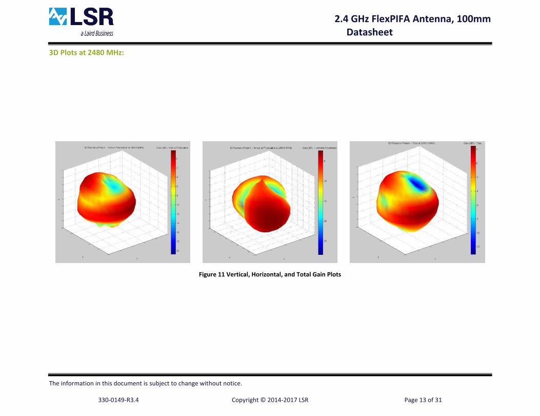
Gain Summary (dBi) at 2480.0 (MHz) min: -13.1 (dBi) max: +2.5 (dBi) avg: -1.1 (dBi)
0
15
30
45
60
75
90
105
120
135
150
165
Theta (deg)
2.4 GHz FlexPIFA Antenna, 100mm Datasheet
The information in this document is subject to change without notice.
330-0149-R3.4 Copyright © 2014-2017 LSR Page 13 of 31
3D Plots at 2480 MHz:
Figure 11 Vertical, Horizontal, and Total Gain Plots

2.4 GHz FlexPIFA Antenna, 100mm Datasheet
The information in this document is subject to change without notice. 330-0149-R3.4 Copyright © 2014-2017 LSR Page 14 of 31
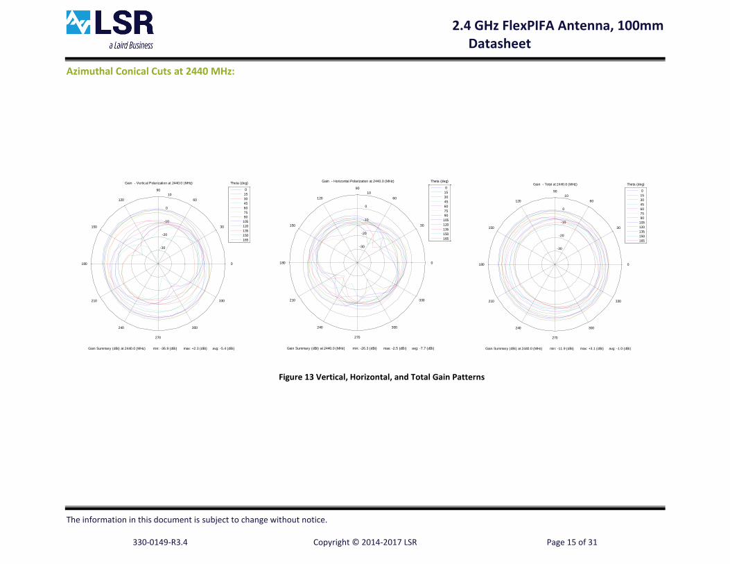
CURVED SURFACE ANTENNA RADIATION PERFORMANCE
Flex PIFA inside 51 mm Inner Diameter PVC tube.
Antenna Measurement Set-Up:
Figure 12 Concave Curve Set-Up
2.4 GHz FlexPIFA Antenna, 100mm Datasheet
The information in this document is subject to change without notice.
330-0149-R3.4 Copyright © 2014-2017 LSR Page 15 of 31
Azimuthal Conical Cuts at 2440 MHz:
Figure 13 Vertical, Horizontal, and Total Gain Patterns
-30
-20
-10
0
10
30
210
60
240
90
270
120
300
150
330
180 0
Gain - Vertical Polarization at 2440.0 (MHz)
Gain Summary (dBi) at 2440.0 (MHz) min: -36.9 (dBi) max: +2.3 (dBi) avg: -5.4 (dBi)
0
15
30
45
60
75
90
105
120
135
150
165
Theta (deg)
-30
-20
-10
0
10
30
210
60
240
90
270
120
300
150
330
180 0
Gain - Horizontal Polarization at 2440.0 (MHz)
Gain Summary (dBi) at 2440.0 (MHz) min: -26.3 (dBi) max: -2.5 (dBi) avg: -7.7 (dBi)
0
15
30
45
60
75
90
105
120
135
150
165
Theta (deg)
-30
-20
-10
0
10
30
210
60
240
90
270
120
300
150
330
180 0
Gain - Total at 2440.0 (MHz)
Gain Summary (dBi) at 2440.0 (MHz) min: -11.9 (dBi) max: +3.1 (dBi) avg: -1.0 (dBi)
0
15
30
45
60
75
90
105
120
135
150
165
Theta (deg)

2.4 GHz FlexPIFA Antenna, 100mm Datasheet
The information in this document is subject to change without notice.
330-0149-R3.4 Copyright © 2014-2017 LSR Page 16 of 31
3D Plots at 2440 MHz:
Figure 14 Vertical, Horizontal, and Total Gain Plots

2.4 GHz FlexPIFA Antenna, 100mm Datasheet
The information in this document is subject to change without notice. 330-0149-R3.4 Copyright © 2014-2017 LSR Page 17 of 31
Flex PIFA outside 60 mm Outer Diameter PVC tube.
Antenna Measurement Set-Up:
Figure 15 Convex Curve Set-Up

2.4 GHz FlexPIFA Antenna, 100mm Datasheet
The information in this document is subject to change without notice.
330-0149-R3.4 Copyright © 2014-2017 LSR Page 18 of 31
Azimuthal Conical Cuts at 2440 MHz:
Figure 16 Vertical, Horizontal, and Total Gain Patterns
-30
-20
-10
0
10
30
210
60
240
90
270
120
300
150
330
180 0
Gain - Vertical Polarization at 2440.0 (MHz)
Gain Summary (dBi) at 2440.0 (MHz) min: -28.2 (dBi) max: +2.9 (dBi) avg: -4.0 (dBi)
0
15
30
45
60
75
90
105
120
135
150
165
Theta (deg)
-30
-20
-10
0
10
30
210
60
240
90
270
120
300
150
330
180 0
Gain - Horizontal Polarization at 2440.0 (MHz)
Gain Summary (dBi) at 2440.0 (MHz) min: -33.0 (dBi) max: -3.0 (dBi) avg: -8.3 (dBi)
0
15
30
45
60
75
90
105
120
135
150
165
Theta (deg)
-30
-20
-10
0
10
30
210
60
240
90
270
120
300
150
330
180 0
Gain - Total at 2440.0 (MHz)
Gain Summary (dBi) at 2440.0 (MHz) min: -19.0 (dBi) max: +3.0 (dBi) avg: -1.4 (dBi)
0
15
30
45
60
75
90
105
120
135
150
165
Theta (deg)

2.4 GHz FlexPIFA Antenna, 100mm Datasheet
The information in this document is subject to change without notice.
330-0149-R3.4 Copyright © 2014-2017 LSR Page 19 of 31
3D Plots at 2440 MHz:
Figure 17 Vertical, Horizontal, and Total Gain Plots

2.4 GHz FlexPIFA Antenna, 100mm Datasheet
The information in this document is subject to change without notice. 330-0149-R3.4 Copyright © 2014-2017 LSR Page 20 of 31
OPTIMAL INSTALLATION GUIDE
Ground Plate
Main ElementFringing Fields
Strong E-Field Between Plates
Figure 18 E-Field Radiation from FlexPIFA, Taken from CST Simulation
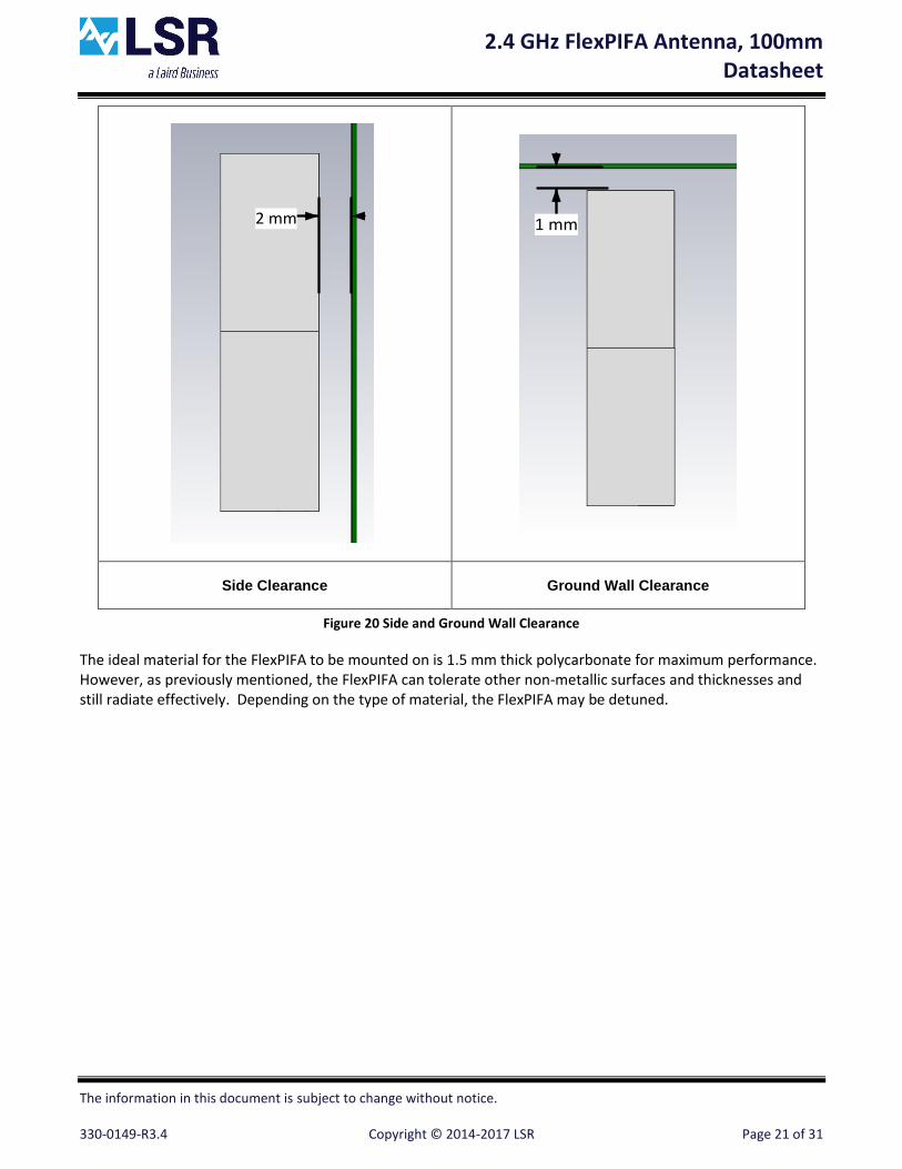
The main element should be kept clear of any non-metal objects (such as plastics) on top of it by at least 3 mm (see Figure 19). Similarly, the two long sides of the FlexPIFA should be kept clear of any non-metal object by at least 2 mm (See Figure 20). A 1 mm clearance should be observed from the ground wall to any non-metal object. Mounting the FlexPIFA in a situation that does not allow for these clearance recommendations may change the gain characteristics stated in the datasheet, which could impact overall range of the wireless system.
Figure 19 Top Clearance
2.4 GHz FlexPIFA Antenna, 100mm Datasheet
The information in this document is subject to change without notice. 330-0149-R3.4 Copyright © 2014-2017 LSR Page 21 of 31
2 mm
1 mm
Side Clearance Ground Wall Clearance
Figure 20 Side and Ground Wall Clearance
The ideal material for the FlexPIFA to be mounted on is 1.5 mm thick polycarbonate for maximum performance. However, as previously mentioned, the FlexPIFA can tolerate other non-metallic surfaces and thicknesses and still radiate effectively. Depending on the type of material, the FlexPIFA may be detuned.

2.4 GHz FlexPIFA Antenna, 100mm Datasheet
The information in this document is subject to change without notice. 330-0149-R3.4 Copyright © 2014-2017 LSR Page 22 of 31
The coaxial cable feeding the FlexPIFA should be routed away from the antenna. Do not run the coaxial cable over the top of the FlexPIFA or near the tip of the main element. The cable should be routed as shown in Figure 21.
Figure 21 Recommended Cable Routing

2.4 GHz FlexPIFA Antenna, 100mm Datasheet
The information in this document is subject to change without notice. 330-0149-R3.4 Copyright © 2014-2017 LSR Page 23 of 31
As with any antenna, care should be taken not to place conductive materials or objects near the antenna (except as described in the next section). The radiated fields from the antenna will induce currents on the surface of the metal; as a result those currents then produce their own radiation. These re-radiating fields from the metal will interfere with the fields radiating from the FlexPIFA (this is true for any antenna). Other objects, such as an LCD display, placed in close proximity to the antenna may not affect its tuning but it can distort the radiation pattern. Materials that absorb electromagnetic fields should be kept away from the antenna to maximize performance. Common things to keep in mind when placing the antenna:
Wire Routing
Speakers – these generate magnetic fields
Metal Chassis and Frames
Battery Location
Proximity to Human Body
Display Screen – these will absorb radiation
Paint – do not use metallic coating or flakes

2.4 GHz FlexPIFA Antenna, 100mm Datasheet
The information in this document is subject to change without notice. 330-0149-R3.4 Copyright © 2014-2017 LSR Page 24 of 31
Flex Limits of the FlexPIFA
One of the unique features of the FlexPIFA is its ability to flex. However, due to the adhesive there are limits as to how much the antenna can be flexed and remain secured to the device. The FlexPIFA should not be flexed in a convex position with a radius less than 16mm. Going smaller than this may result in the antenna peeling off the surface over time. Should a tighter radius of curvature be required, it is recommended you contact LSR for assistance.
Figure 22 Convex Mounted
The FlexPIFA should not be flexed in a concave position with a radius less than 25mm. In this scenario, the limiting factor is performance. The ground plate of the antenna is pressed closer to the main element. As previously discussed in the introduction of this application note, the fringing fields developing off the end of the element are responsible for most of the radiation. In a concave position with a radius of curvature less than 25mm, the fringing fields are adversely affected and gain suffers. If a tighter radius of curvature is required, it is recommended you contact LSR for assistance.

2.4 GHz FlexPIFA Antenna, 100mm Datasheet
The information in this document is subject to change without notice. 330-0149-R3.4 Copyright © 2014-2017 LSR Page 25 of 31
Figure 23 Concave Mounted
The FlexPIFA is not designed to be twisted or crumpled. The adhesive back should lay flush with the surface it is mounted on.

2.4 GHz FlexPIFA Antenna, 100mm Datasheet
The information in this document is subject to change without notice. 330-0149-R3.4 Copyright © 2014-2017 LSR Page 26 of 31
Mounting on Metal and Body Loaded Applications
The FlexPIFA can tolerate being mounted on conductive surfaces. There will be some detuning of the antenna, which translates into some gain reduction. Even though the FlexPIFA is optimized to work on non-metallic surfaces, it still radiates efficiently due to the fringing fields (Shown in Figure 18). The ground plate of the FlexPIFA carries the adhesive backing; placing the antenna onto a metal surface simply enlarges the size of the ground beneath the main element. Previously the fringing fields only interacted with the small ground of the FlexPIFA - however they are now interacting with the much larger ground. The fringing fields still develop and radiate, but the antenna will no longer tune as well to the 2.4 GHz frequency band. Consequently the VSWR increases and there is some loss in radiated power. If the FlexPIFA cannot meet your range requirements after being implemented on a metal surface, contact LSR Design Services for a custom antenna build to help meet your application needs.
Figure 24 FlexPIFA Mounted on Metal
Do not mount the FlexPIFA where metal is within 10 mm above the main element (see Figure 26). Not only will this severely limit the radiation pattern (mainly due to the re-radiation problem previously described) it will detune the antenna inside of this range. Similarly, the two long sides of the FlexPIFA should be kept clear of any metal object by at least 5 mm. These keep out requirements pertain to conductive materials only, and are different from those listed in the previous sections which apply to non-conductive materials. In general, it is good practice to always keep metals as far away from the antenna as possible.
For the best performance, a spacer should be placed between the FlexPIFA and the conductive surface (see Figure 25). The spacer should be 1.5 mm thick polycarbonate. This will significantly improve performance and tuning of the FlexPIFA on a metal surface. Other non-conductive materials such as ABS plastic can be used; however polycarbonate will provide the best results.

2.4 GHz FlexPIFA Antenna, 100mm Datasheet
The information in this document is subject to change without notice. 330-0149-R3.4 Copyright © 2014-2017 LSR Page 27 of 31
Figure 25 FlexPIFA Mounted on Metal Surface with 1.5mm Thick Polycarbonate Spacer
10 mm
Figure 26 Metal near Main Element
For body worn applications, the FlexPIFA can tolerate the presence of the human body. It is not recommended that the antenna be mounted directly on body tissue, this will detune the FlexPIFA. Additionally the human body is an excellent absorber of 2.4GHz RF signals. As a result of this, expect a reduction in range due to the presence of a body. In a body worn application, the ground plate of the FlexPIFA should be closest to the body tissue. The main element should be pointed away from the body. Additionally, for handheld devices the FlexPIFA should be mounted in a location where it will not be covered by the hand. If the antenna is mounted in a location where the main element will be covered or near a human body, ensure that there is at least a 10mm separation distance between the main element and the body as shown in Figure 26. Additionally, when the FlexPIFA is mounted very close to body tissue, use a spacer to create separation distance between the body tissue and ground plate. This will ensure maximum performance and prevent the antenna from detuning. As previously mentioned, the ideal spacer material is 1.5 mm thick polycarbonate.
2.4 GHz FlexPIFA Antenna, 100mm Datasheet
The information in this document is subject to change without notice. 330-0149-R3.4 Copyright © 2014-2017 LSR Page 28 of 31
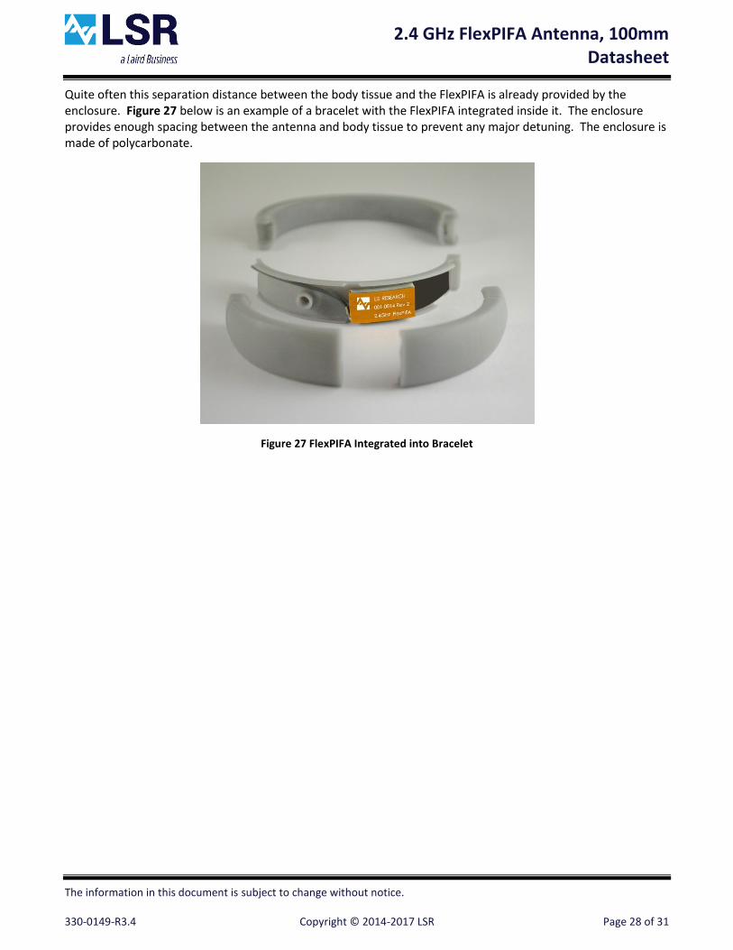
Quite often this separation distance between the body tissue and the FlexPIFA is already provided by the enclosure. Figure 27 below is an example of a bracelet with the FlexPIFA integrated inside it. The enclosure provides enough spacing between the antenna and body tissue to prevent any major detuning. The enclosure is made of polycarbonate.
Figure 27 FlexPIFA Integrated into Bracelet

2.4 GHz FlexPIFA Antenna, 100mm Datasheet
The information in this document is subject to change without notice. 330-0149-R3.4 Copyright © 2014-2017 LSR Page 29 of 31
PRODUCT REVISION HISTORY
001-0014 (U.FL Connector)
Rev 1: Pre-Production Release
Rev 2: Initial Release
Rev 3: Changed Exposed Area of Solder Pads (Improve Soldering), Applying UV Glue (Strengthen Cable Joint) and increased top length from 15.2mm to 16.6mm – Silkscreen Side of FPC (Improve Tuning)
Rev 4: Added U.S. Patent and Laird Logo to Silkscreen
2.4 GHz FlexPIFA Antenna, 100mm Datasheet
The information in this document is subject to change without notice. 330-0149-R3.4 Copyright © 2014-2017 LSR Page 30 of 31
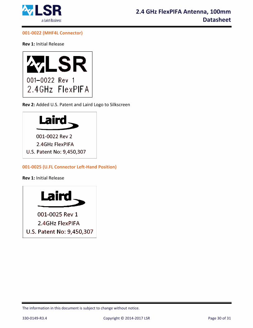
001-0022 (MHF4L Connector)
Rev 1: Initial Release
Rev 2: Added U.S. Patent and Laird Logo to Silkscreen
001-0025 (U.FL Connector Left-Hand Position)
Rev 1: Initial Release

2.4 GHz FlexPIFA Antenna, 100mm Datasheet
The information in this document is subject to change without notice. 330-0149-R3.4 Copyright © 2014-2017 LSR Page 31 of 31
CONTACTING LSR
Headquarters LS Research, LLC W66 N220 Commerce Court Cedarburg, WI 53012-2636 USA Tel: 1(262) 375-4400 Fax: 1(262) 375-4248
Website www.lsr.com
Technical Support forum.lsr.com
Sales Contact [email protected]
The information in this document is provided in connection with LS Research (hereafter referred to as “LSR”) products. No license, express or implied, by estoppel or otherwise, to any intellectual property right is granted by this document or in connection with the sale of LSR products. EXCEPT AS SET FORTH IN LSR’S TERMS AND CONDITIONS OF SALE LOCATED ON LSR’S WEB SITE, LSR ASSUMES NO LIABILITY WHATSOEVER AND DISCLAIMS ANY EXPRESS, IMPLIED OR STATUTORY WARRANTY RELATING TO ITS PRODUCTS INCLUDING, BUT NOT LIMITED TO, THE IMPLIED WARRANTY OF MERCHANTABILITY, FITNESS FOR A PARTICULAR PURPOSE, OR NON-INFRINGEMENT. IN NO EVENT SHALL LSR BE LIABLE FOR ANY DIRECT, INDIRECT, CONSEQUENTIAL, PUNITIVE, SPECIAL OR INCIDENTAL DAMAGES (INCLUDING, WITHOUT LIMITATION, DAMAGES FOR LOSS OF PROFITS, BUSINESS INTERRUPTION, OR LOSS OF INFORMATION) ARISING OUT OF THE USE OR INABILITY TO USE THIS DOCUMENT, EVEN IF LSR HAS BEEN ADVISED OF THE POSSIBILITY OF SUCH DAMAGES. LSR makes no representations or warranties with respect to the accuracy or completeness of the contents of this document and reserves the right to make changes to specifications and product descriptions at any time without notice. LSR does not make any commitment to update the information contained herein. Unless specifically provided otherwise, LSR products are not suitable for, and shall not be used in, automotive applications. LSR’s products are not intended, authorized, or warranted for use as components in applications intended to support or sustain life.