Embed Size (px)
Citation preview

Fundamentals of Power Electronics� Chapter 2: Principles of steady-state converter analysis�28�
2.4 �Cuk converter example�
+–
L1
C2 R
+
v2
–
C1 L
2
1 2
+ v1 –
i1
i2
Vg
+–
L1
C2 R
+
v2
–
C1 L
2
+ v1 –
i1
i2
D1
Q1
Vg
Cuk converter,
with ideal switch�
Cuk converter:
practical realization using MOSFET and
diode�

Fundamentals of Power Electronics� Chapter 2: Principles of steady-state converter analysis�29�
Analysis strategy�
+–
L1
C2 R
+
v2
–
C1 L
2
1 2
+ v1 –
i1
i2
Vg
i1(t) = I1 + i1 -ripple(t)
i2(t) = I2 + i2 -ripple(t)
v1(t) = V1 + v1 -ripple(t)
v2(t) = V2 + v2 -ripple(t)
This converter has two
inductor currents and two capacitor voltages, that
can be expressed as�
To solve the converter in
steady state, we want to find the dc components I1,
I2, V1, and V2, when the ripples are small.�
Strategy:�
•� Apply volt-second balance to each inductor voltage�
•� Apply charge balance to each capacitor current�
•� Simplify using the small ripple
approximation�
•� Solve the resulting four equations for the
four unknowns I1, I2, V1, and V2.�

Fundamentals of Power Electronics� Chapter 2: Principles of steady-state converter analysis�30�
Cuk converter circuitwith switch in positions 1 and 2�
+–
L1
C2 R
+
v2
–
C1
L2
i1
i2
–
v1
+
iC1 iC2
+ vL2 –+ vL1 –
Vg
+–
L1
C2 R
+
v2
–
C1
L2i
1i2
+
v1
–
iC1
iC2
+ vL2 –+ vL1 –
Vg
Switch in position 1:
MOSFET conducts�
Capacitor C1 releases
energy to output�
Switch in position 2:
diode conducts�
Capacitor C1 is
charged from input�

Fundamentals of Power Electronics� Chapter 2: Principles of steady-state converter analysis�31�
Waveforms during subinterval 1MOSFET conduction interval�
+–
L1
C2 R
+
v2
–
C1
L2
i1
i2
–
v1
+
iC1 iC2
+ vL2 –+ vL1 –
Vg
vL1 = Vg
vL2 = – v1 – v2
iC1 = i2
iC2 = i2 –v2
R
Inductor voltages and
capacitor currents:�
Small ripple approximation for subinterval 1:�
vL1 = Vg
vL2 = – V1 – V2
iC1 = I2
iC2 = I2 –V2
R

Fundamentals of Power Electronics� Chapter 2: Principles of steady-state converter analysis�32�
Waveforms during subinterval 2Diode conduction interval�
Inductor voltages and
capacitor currents:�
Small ripple approximation for subinterval 2:�
+–
L1
C2 R
+
v2
–
C1
L2i
1i2
+
v1
–
iC1
iC2
+ vL2 –+ vL1 –
Vg
vL1 = Vg – v1
vL2 = – v2
iC1 = i1
iC2 = i2 –v2
R
vL1 = Vg – V1
vL2 = – V2
iC1 = I1
iC2 = I2 –V2
R

Fundamentals of Power Electronics� Chapter 2: Principles of steady-state converter analysis�33�
Equate average values to zero�
The principles of inductor volt-second and capacitor charge balance
state that the average values of the periodic inductor voltage and capacitor current waveforms are zero, when the converter operates in
steady state. Hence, to determine the steady-state conditions in the converter, let us sketch the inductor voltage and capacitor current
waveforms, and equate their average values to zero.�
Waveforms:�
vL1(t)
Vg – V1
t
DTs
Vg
D'Ts
Inductor voltage vL1(t)�
vL1 = DVg + D'(Vg – V1) = 0
Volt-second balance on L1:�

Fundamentals of Power Electronics� Chapter 2: Principles of steady-state converter analysis�34�
Equate average values to zero�
vL2
(t)
– V1 – V
2
t
DTs
– V2
D'Ts
iC1(t)
I2
t
DTs
I1
D'Ts
Inductor L2 voltage�
Capacitor C1 current�vL2 = D( – V1 – V2) + D'( – V2) = 0
iC1 = DI2 + D'I1 = 0
Average the waveforms:�
Fundamentals of Power Electronics� Chapter 2: Principles of steady-state converter analysis�35�
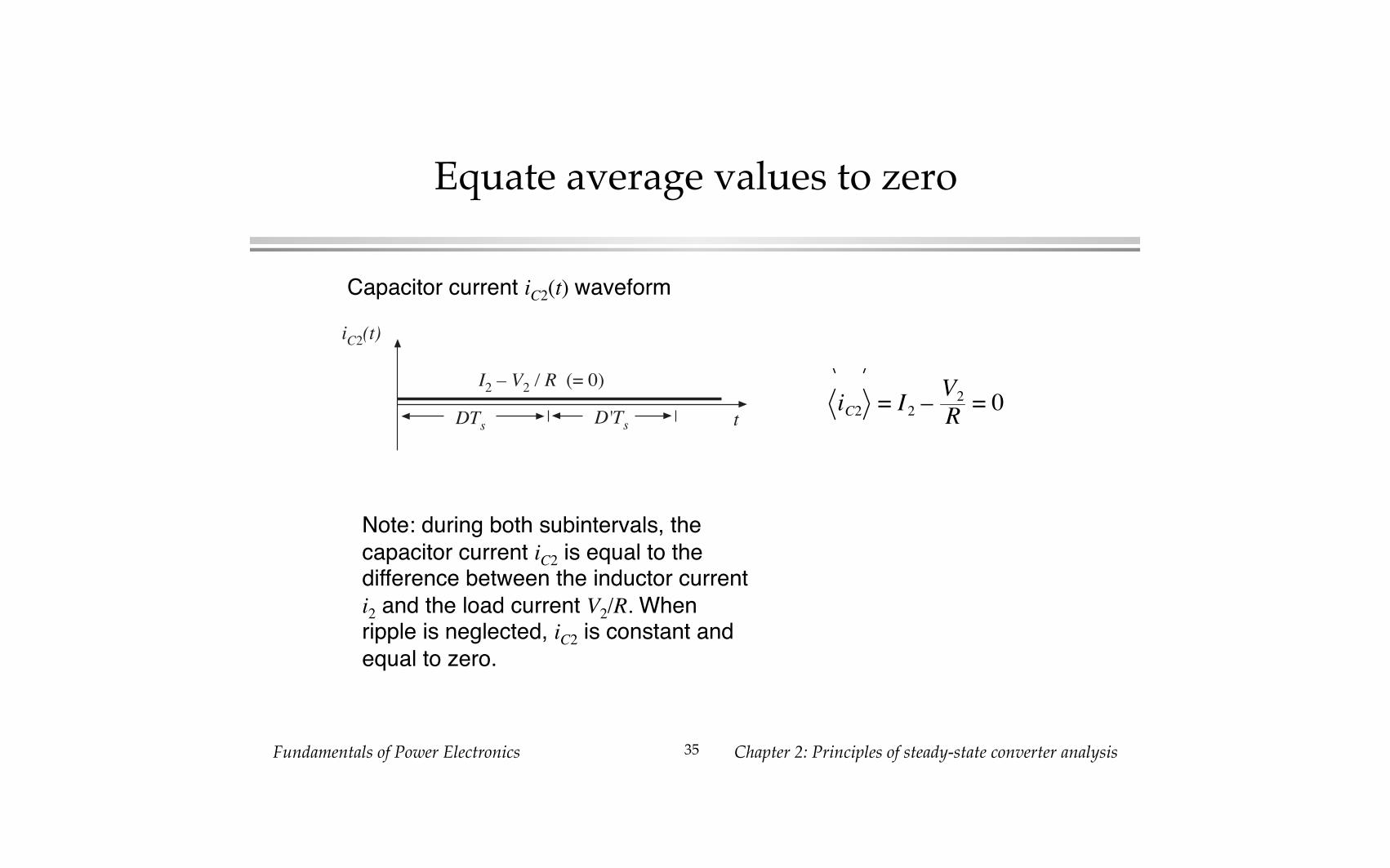
Equate average values to zero�
iC2
(t)
I2 – V
2 / R (= 0)
tDTs
D'Ts
Capacitor current iC2(t) waveform�
Note: during both subintervals, the
capacitor current iC2 is equal to the difference between the inductor current
i2 and the load current V2/R. When ripple is neglected, iC2 is constant and
equal to zero.�
iC2 = I2 –V2R= 0
Fundamentals of Power Electronics� Chapter 2: Principles of steady-state converter analysis�36�
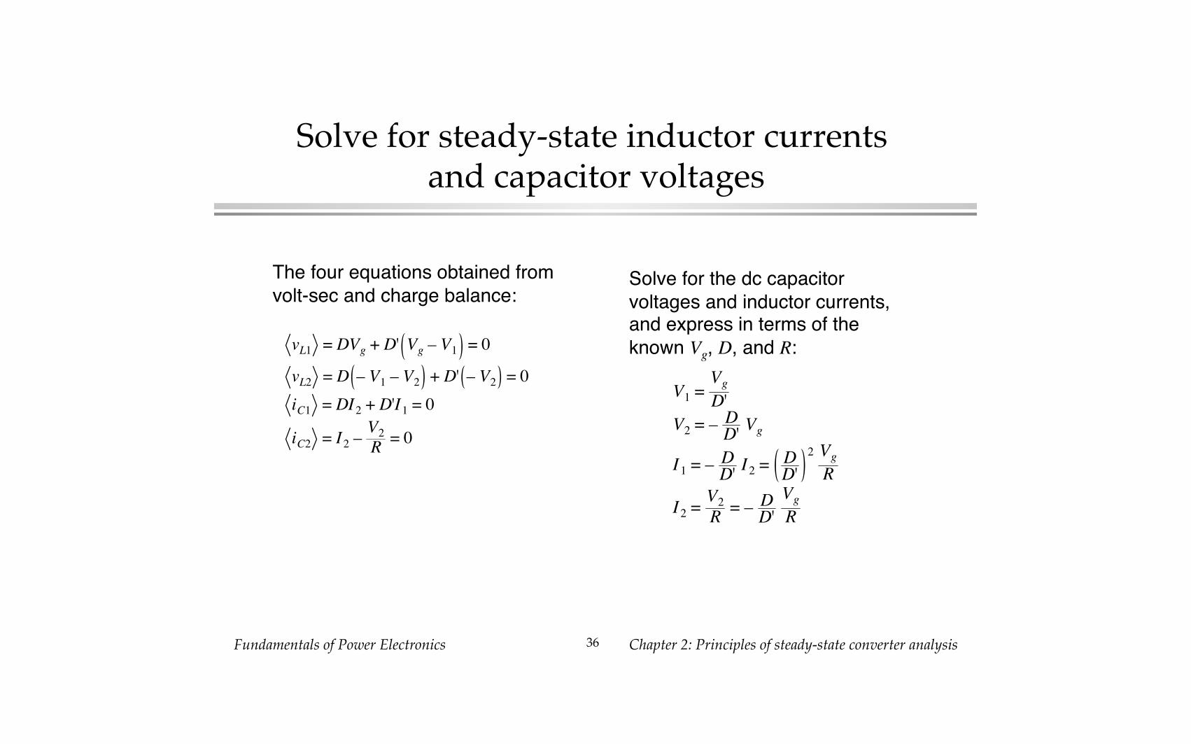
Solve for steady-state inductor currents and capacitor voltages�
V1=Vg
D'
V2= –
DD'Vg
I1= –
DD'I2=
DD'
2 VgR
I2=V2
R= –
DD'
VgR
vL1 = DVg + D' Vg – V1 = 0
vL2 = D – V1– V
2+ D' – V
2= 0
iC1 = DI2 + D'I1 = 0
iC2 = I2 –V2
R= 0
The four equations obtained from
volt-sec and charge balance:�Solve for the dc capacitor
voltages and inductor currents, and express in terms of the
known Vg, D, and R:�

Fundamentals of Power Electronics� Chapter 2: Principles of steady-state converter analysis�37�
Cuk converter conversion ratio M = V/Vg�
M(D)
D
-5
-4
-3
-2
-1
0
0 0.2 0.4 0.6 0.8 1
M(D) =V2Vg
= – D1 – D
Fundamentals of Power Electronics� Chapter 2: Principles of steady-state converter analysis�38�
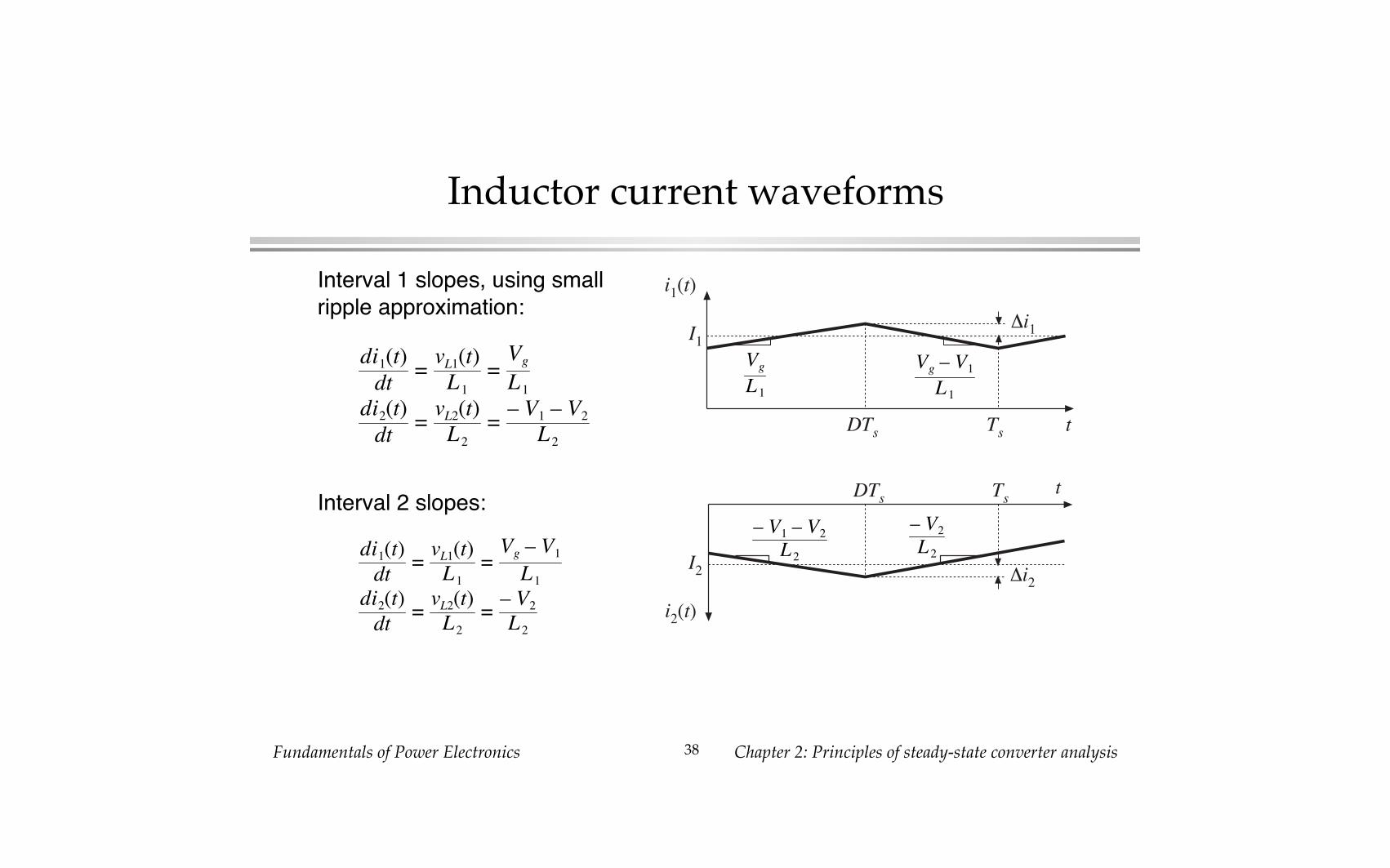
Inductor current waveforms�
di1(t)
dt=vL1(t)
L1=Vg
L1di2(t)
dt=vL2(t)
L2=– V1 – V2
L2
Interval 1 slopes, using small
ripple approximation:�
Interval 2 slopes:�
di1(t)
dt=vL1(t)
L1=Vg – V1L1
di2(t)
dt=vL2(t)
L2=– V2L2
i1(t)
tDTs Ts
I1
�i1
Vg – V1L 1
Vg
L 1
– V2L 2
– V1 – V2L 2
i2(t)
tDTs
Ts
I2 �i
2

Fundamentals of Power Electronics� Chapter 2: Principles of steady-state converter analysis�39�
Capacitor C1 waveform�
dv1(t)
dt=iC1(t)
C1
=I2C1
Subinterval 1:�
Subinterval 2:�
dv1(t)
dt=iC1(t)
C1
=I1C1
I1
C1
I2
C1
v1(t)
tDTs
Ts
V1
�v1

Fundamentals of Power Electronics� Chapter 2: Principles of steady-state converter analysis�40�
Ripple magnitudes�
�i1=VgDTs
2L1
�i2=V1+ V
2
2L2
DTs
�v1=– I
2DTs2C
1
Use dc converter solution to simplify:�
�i1=VgDTs2L
1
�i2=VgDTs2L
2
�v1=VgD
2Ts2D'RC
1
Analysis results�
Q: How large is the output voltage ripple?�

Fundamentals of Power Electronics� Chapter 2: Principles of steady-state converter analysis�41�
2.5� Estimating ripple in converterscontaining two-pole low-pass filters�
Buck converter example: Determine output voltage ripple�
Inductor current
waveform.�
What is the
capacitor current?�
+–
L
C R
+
vC(t)
–
1
2
iC(t) iR(t)iL(t)
Vg
– VL
Vg – V
L
iL(t)
t0 DTs Ts
IiL(0)
iL(DTs)�iL

Fundamentals of Power Electronics� Chapter 2: Principles of steady-state converter analysis�42�
Capacitor current and voltage, buck example�
Must not
neglect
inductor
current ripple!�
If the capacitor
voltage ripple is small, then
essentially all of the ac component
of inductor current
flows through the capacitor.�
iC(t)
vC(t)
t
t
Total chargeq
DTs D'Ts
Ts /2
V
�iL
�v
�v

Fundamentals of Power Electronics� Chapter 2: Principles of steady-state converter analysis�43�
Estimating capacitor voltage ripple �v�
q = C (2�v)
Current iC(t) is positive for half
of the switching period. This positive current causes the
capacitor voltage vC(t) to increase between its minimum
and maximum extrema.
During this time, the total charge q is deposited on the
capacitor plates, where�
(change in charge) =
C (change in voltage)
iC(t)
vC(t)
t
t
Total chargeq
DTs D'Ts
Ts /2
V
�iL
�v
�v

Fundamentals of Power Electronics� Chapter 2: Principles of steady-state converter analysis�44�
Estimating capacitor voltage ripple �v�
The total charge q is the area
of the triangle, as shown:�
q = 1
2�iL
Ts2
Eliminate q and solve for �v:�
�v =�i
LTs
8 C
Note: in practice, capacitor
equivalent series resistance (esr) further increases �v.�
iC(t)
vC(t)
t
t
Total chargeq
DTs D'Ts
Ts /2
V
�iL
�v
�v
Fundamentals of Power Electronics� Chapter 2: Principles of steady-state converter analysis�45�
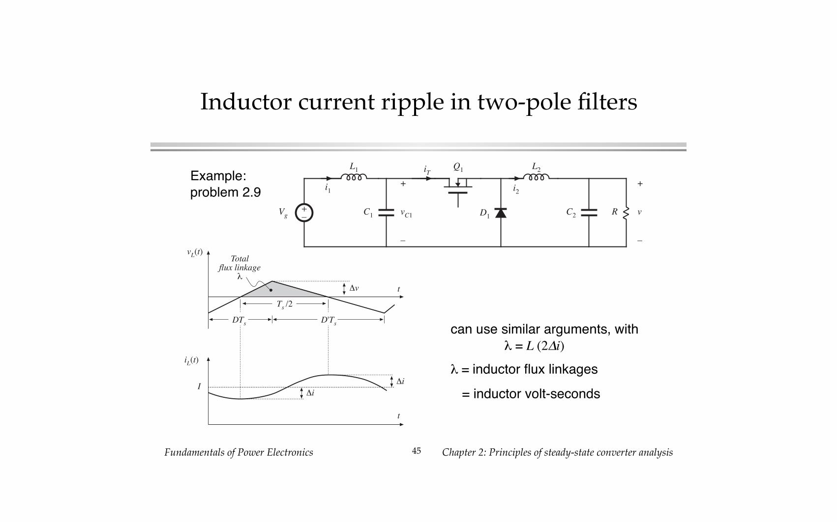
Inductor current ripple in two-pole filters�
Example:
problem 2.9�
can use similar arguments, with
� = L (2�i)�
� = inductor flux linkages�
= inductor volt-seconds�
R
+
v
–
+–
C2
L2
L1
C1
+
vC1
–
i1
iT
i2
D1
Q1
Vg
vL(t)
iL(t)
t
t
Totalflux linkage
�
DTs D'Ts
Ts /2
I
�v
�i
�i

Fundamentals of Power Electronics� Chapter 2: Principles of steady-state converter analysis�46�
2.6 �Summary of Key Points�
1. The dc component of a converter waveform is given by its average
value, or the integral over one switching period, divided by the switching period. Solution of a dc-dc converter to find its dc, or steady-
state, voltages and currents therefore involves averaging the waveforms.�
2. The linear ripple approximation greatly simplifies the analysis. In a well-
designed converter, the switching ripples in the inductor currents and
capacitor voltages are small compared to the respective dc components, and can be neglected.�
3. The principle of inductor volt-second balance allows determination of the
dc voltage components in any switching converter. In steady-state, the average voltage applied to an inductor must be zero.�

Fundamentals of Power Electronics� Chapter 2: Principles of steady-state converter analysis�47�
Summary of Chapter 2�
4. The principle of capacitor charge balance allows determination of the dc
components of the inductor currents in a switching converter. In steady-state, the average current applied to a capacitor must be zero.�
5. By knowledge of the slopes of the inductor current and capacitor voltage
waveforms, the ac switching ripple magnitudes may be computed. Inductance and capacitance values can then be chosen to obtain
desired ripple magnitudes.�
6. In converters containing multiple-pole filters, continuous (nonpulsating) voltages and currents are applied to one or more of the inductors or
capacitors. Computation of the ac switching ripple in these elements
can be done using capacitor charge and/or inductor flux-linkage arguments, without use of the small-ripple approximation.�
7. Converters capable of increasing (boost), decreasing (buck), and
inverting the voltage polarity (buck-boost and Cuk) have been described. Converter circuits are explored more fully in a later chapter.�