Embed Size (px)
Citation preview

1/19 www.ni.com
Back to Top
Back to Top
Back to Top
Technical Sales
(866) [email protected]
Last Revised: 2014-11-06 07:13:49.0
24-Bit, 204.8 kS/s Dynamic Signal Acquisition and GenerationNI 4461, NI 4462
2 or 4 simultaneously sampled analog inputs
2 simultaneously updated analog outputs (NI 4461 only)
118 dB dynamic range, 24-bit resolution
204.8 kS/s maximum sampling rate
92 kHz alias-free bandwidth
Input range from ±316 mV to 42.4 V
6 gain settings
AC/DC coupling
Antialiasing and anti-imaging protection
IEPE conditioning – software-configurable
Multimodule synchronization
OverviewThe National Instruments 4461 and 4462 are high-accuracy data acquisition devices specifically designed for sound and vibration applications. The devices include the hardwareand software needed to make precision measurements with microphones, accelerometers, and other transducers that have very large dynamic ranges. Common applications forthe NI 446x include audio test, automotive test, noise, vibration, and harshness (NVH) analysis, and machine condition monitoring (MCM). The NI 446x devices offer a completerange of functionality for sound and vibration monitoring and analysis applications. With either two inputs and two outputs, or four inputs, they are ideal for applications wheresimultaneous generation and acquisition of noise, vibration, and acoustic signals are required. You can synchronize the acquisition clock of your NI 446x with other instruments inyour system for mixed-signal applications. Both analog and digital triggering are available on an NI 446x.
Requirements and CompatibilityOS Information
Windows 2000/XP
Windows 7
Windows NT
Windows Vista
Driver Information
NI-DAQmx
Software Compatibility
LabVIEW
LabWindows/CVI
Measurement Studio
Comparison Tables
Product Bus AnalogInputs
InputResolution
SamplingRate Input Range Input Configuration Analog
OutputOutput
ResolutionUpdate
Rate
NI 4461PXI,PCI
2 24 bits 204.8 kS/s±316 mV to 42.4V
Differential/pseudodifferential 2 24 bits 204.8 kS/s
NI 4462PXI,PCI
4 24 bits 204.8 kS/s±316 mV to 42.4V
Differential/pseudodifferential 0 - -
| | Requirements and Compatibility Ordering Information Detailed SpecificationsFor user manuals and dimensional drawings, visit the product page resources tab on ni.com.

2/19 www.ni.com
Application and Technology
HardwareApplications
Audio Test
Noise, Vibration, and Harshness Test
Machine Condition Monitoring
Sound Power
Structural Vibration
Pass-by Noise
Analog Inputs
The analog input channels of NI 446x devices have 24-bit resolution ADCs that are simultaneously sampled at software-programmable rates for standard audio applications, suchas 44.1 kS/s (the standard rate used in CD players), 48.0 kS/s (the rate used in digital audio tape (DAT) recorders and other digital audio equipment), 96.0 kS/s, and 192 kS/s. AnNI 446x is well-suited for audio, sound, and vibration analysis applications.
The analog inputs offer programmable AC/DC coupling. A programmable gain amplifier stage on the inputs gives gain selection from -20 to +30 dB in 10 dB steps. Furthermore,to provide you with the quietest and highest-quality analog measurements, the input stage accepts differential or single-ended signal connections.
With 118 dB dynamic range and low noise and distortion, NI 446x devices can make very accurate frequency-domain measurements. They have excellent amplitude flatness of±0.1 dB within the frequency range of DC to 92 kHz, and have a typical THD of -107 dB.
Figure 1. These 24-bit delta-sigma converters deliver outstanding dynamic range.
Antialiasing
The analog inputs have both analog and digital filters implemented in hardware to prevent aliasing. Input signals are first passed through a fixed analog filter to remove anysignals with frequency components beyond the range of the ADCs. Then digital antialiasing filters automatically adjust their cutoff frequency to remove any frequency componentsabove half the programmed sampling rate.
Analog Outputs
NI 4461 devices have two channels of 24-bit resolution, high-fidelity analog output. A common application of the analog output is to stimulate a system under test while measuringthe frequency response with the analog inputs. The output conversions occur simultaneously at softwareprogrammable rates up to 204.8 kS/s. The analog output circuitry uses8-times oversampling interpolators with 64-times oversampling delta-sigma modulators to offer exceptional spectral purity. Software-programmable attenuation of 0, 20, or 40 dBis available on the output channels. NI 4461 devices have excellent amplitude flatness of ±0.1 dB within DC to 92 kHz, and a THD of -95 dB at 1 kHz. You can simultaneouslyacquire data on the input channels while updating the output channels.
Anti-Imaging
NI 4461 output channels have both analog and digital anti-imaging filters. These filters remove the unwanted out-of-band components generated when an analog signal isproduced from digital data. The digital filters limit the bandwidth of the output signal to half the original conversion rate, thereby rejecting images caused by the 8-timesoversampling process. The signals generated by the analog output circuitry are low-distortion, low-noise, flat-frequency analog signals.
Multimodule Synchronization
For applications requiring more channels, you can synchronize the operation of two or more NI 446x devices with less than 0.1 deg phase mismatch. Synchronization is achievedby sharing a digital trigger and clock between multiple modules. The NI-DAQmx driver software automatically handles the synchronization of multiple devices in a single task.
Triggering
NI 446x devices offer both analog and digital triggering for signal acquisition. The source of the trigger can come from any analog input channel, the external digital trigger input,the PXI trigger bus (PXI devices), or the RTSI bus (PCI devices). The external digital trigger is 5 VTTL/CMOS-compatible and is activated by a choice of rising or falling edge.Triggering is needed in applications that acquire transient signals. When performing structural analysis by striking a metal beam with a hammer, for instance, you measuretransient vibrations with accelerometers with acquisition triggered by the hammer impact.
Calibration

3/19 www.ni.com
National Instruments calibrates the offset voltage and gain accuracy of the analog inputs and outputs. An onboard precision voltage reference ensures that the gain and offsetremain stable and accurate. NIST-traceable and ISO 9002-certified calibration certificates are available on request.
Figure 2. With application software such as NI LabVIEW, you can conduct frequency-response, swept-sine, and other common audio measurements.
SoftwareNI Measurement Services Software
NI 446x devices use NI measurement services software, based on the NI-DAQmx driver, as the hardware and OS interface. You can build automated test systems or integrate anNI 446x with other hardware, including modular instruments and multifunction data acquisition (DAQ) products, through NI-DAQmx function calls. NI measurement servicessoftware also includes DAQ Assistant, an interactive guide that steps you through configuring, testing, and programming measurement tasks and generates the necessary codeautomatically for National Instruments LabVIEW, LabWindows/CVI, or Measurement Studio.
Analysis Software
LabVIEW Sound and Vibration Toolkit
NI 446x devices are well-suited for audio, acoustic, and vibration analysis applications. The LabVIEW Sound and Vibration Toolkit incorporates Express technology to make iteasier for you to perform sound and vibration measurement and analysis. The toolkit includes LabVIEW Express VIs for:
Fractional-octave analysis with weighting
Integrated vibration level
Weighted sound level
Zoom power spectrum
Peak search
Power in band
Power spectrum analysis
Frequency response
Limit testing
In addition, the LabVIEW Sound and Vibration Toolkit includes numerous VIs for audio measurements such as gain, phase, distortion, and swept-sine analysis. Swept-sine is apowerful analysis technique to measure frequency response. The toolkit also includes simple modular examples of all of these measurements, so you can quickly combine analogoutput, analog input, and data analysis to build a customized application. In addition, the existing signal generation is extended to include the tools and examples needed toprovide the excitation required by most audio, noise, and vibration measurements. For example, a library of 33 waveforms is included in this toolkit to get you up and running fast.This toolkit also optimizes LabVIEW to perform noise and vibration measurements. For example, all frequency measurements can perform zoom FFT analysis to offer improvedresolution in the frequency range of interest. With the built-in fractional-octave analysis, you can perform measurements with any number of bands at any sampling frequency. NI446x dynamic signal acquisition devices, combined with this toolkit, offer compliance with several standards for sound level measurements and octave analysis:
IEC 61260 : 1995, class 1
IEC 61672 : 2002, class 1
ANSI S1.11 – 2004, class 1
ANSI S1.4 – 1983
ANSI S1.42 – 1986
LabVIEW Order Analysis Toolkit
Order analysis is a tool for examining dynamic signals generated by mechanical systems that include rotating or reciprocating components. With order analysis you can dissectsound, vibration, and other dynamic signals into components that relate to physical elements of mechanical systems.
The LabVIEW Order Analysis Toolkit is ideal for machine monitoring, machine health, and machine efficiency applications. You can use the toolkit to perform the most commonanalyses required by MCM applications, including order tracking, slow-roll compensation, and vibration integration. With this toolkit, you can develop your application faster byusing built-in examples for order spectra, tachometer processing, and waterfall plots.
You can also apply order analysis to dynamic signals generated by mechanical systems that include rotating or reciprocating components, such as turbines, compressors, pumps,and engines. It is common to use order analysis in applications such as machine condition monitoring and noise, vibration, and harshness (NVH) testing. With the added capabilityfor online processing, you can easily create flexible applications for condition-based monitoring and predictive maintenance. The National Instruments 446x dynamic signalacquisition devices are ideal for acquiring sound and vibration signals to analyze with this toolkit.

4/19 www.ni.com
Back to Top
Back to Top
Back to Top
Ordering Information
For a complete list of accessories, visit the product page on ni.com.
Software Recommendations
NI LabVIEW Full DevelopmentSystem for Windows
Fully integrated graphical system designsoftware
Support for a wide range of measurementhardware, I/O, and buses
Custom, event-driven user interfaces formeasurement and control
Extensive signal processing, analysis, andmath functionality
Advanced compiler to ensurehigh-performance execution and codeoptimization
Includes SSP for professional technicalsupport, online training, and softwareupgrades
NI LabVIEW Real-TimeModule
Design deterministic real-time applicationswith LabVIEW graphical programming
Download to dedicated NI or third-partyhardware for reliable execution and a wideselection of I/O
Take advantage of built-in PID control, signalprocessing, and analysis functions
Automatically take advantage of multicoreCPUs or set processor affinity manually
Includes real-time OS, development anddebugging support, and board support
Purchase individually or as part of aLabVIEW suite
NI Sound and VibrationToolkit
Stand-alone configuration-based analysis anddata logging with the Sound and VibrationAssistant
AES17-compliant audio filter signalprocessing
Easy-to-use power spectrum, swept sine, andoctave analysis steps
Sound level with A-, B-, or C-weighting andvibration level with integration
Audio measurements including THD, SNR,SINAD, and swept-sine analysis
Universal File Format (UFF58) file I/O support

5/19 www.ni.com
Back to Top
Support and ServicesSystem Assurance Programs
NI system assurance programs are designed to make it even easier for you to own an NI system. These programs include configuration and deployment services for your NI PXI,CompactRIO, or Compact FieldPoint system. The NI Basic System Assurance Program provides a simple integration test and ensures that your system is delivered completelyassembled in one box. When you configure your system with the NI Standard System Assurance Program, you can select from available NI system driver sets and applicationdevelopment environments to create customized, reorderable software configurations. Your system arrives fully assembled and tested in one box with your software preinstalled.When you order your system with the standard program, you also receive system-specific documentation including a bill of materials, an integration test report, a recommendedmaintenance plan, and frequently asked question documents. Finally, the standard program reduces the total cost of owning an NI system by providing three years of warrantycoverage and calibration service. Use the online product advisors at ni.com/advisor to find a system assurance program to meet your needs.
Calibration
NI measurement hardware is calibrated to ensure measurement accuracy and verify that the device meets its published specifications. To ensure the ongoing accuracy of yourmeasurement hardware, NI offers basic or detailed recalibration service that provides ongoing ISO 9001 audit compliance and confidence in your measurements. To learn moreabout NI calibration services or to locate a qualified service center near you, contact your local sales office or visit ni.com/calibration.
Technical Support
Get answers to your technical questions using the following National Instruments resources.
Support - Visit ni.com/support to access the NI KnowledgeBase, example programs, and tutorials or to contact our applications engineers who are located in NI salesoffices around the world and speak the local language.
Discussion Forums - Visit forums.ni.com for a diverse set of discussion boards on topics you care about.
Online Community - Visit community.ni.com to find, contribute, or collaborate on customer-contributed technical content with users like you.
Repair
While you may never need your hardware repaired, NI understands that unexpected events may lead to necessary repairs. NI offers repair services performed by highly trainedtechnicians who quickly return your device with the guarantee that it will perform to factory specifications. For more information, visit ni.com/repair.
Training and Certifications
The NI training and certification program delivers the fastest, most certain route to increased proficiency and productivity using NI software and hardware. Training builds the skillsto more efficiently develop robust, maintainable applications, while certification validates your knowledge and ability.
Classroom training in cities worldwide - the most comprehensive hands-on training taught by engineers.
On-site training at your facility - an excellent option to train multiple employees at the same time.
Online instructor-led training - lower-cost, remote training if classroom or on-site courses are not possible.
Course kits - lowest-cost, self-paced training that you can use as reference guides.
Training memberships and training credits - to buy now and schedule training later.
Visit ni.com/training for more information.
Extended Warranty
NI offers options for extending the standard product warranty to meet the life-cycle requirements of your project. In addition, because NI understands that your requirements maychange, the extended warranty is flexible in length and easily renewed. For more information, visit ni.com/warranty.
OEM
NI offers design-in consulting and product integration assistance if you need NI products for OEM applications. For information about special pricing and services for OEMcustomers, visit ni.com/oem.
Alliance
Our Professional Services Team is comprised of NI applications engineers, NI Consulting Services, and a worldwide National Instruments Alliance Partner program of more than700 independent consultants and integrators. Services range from start-up assistance to turnkey system integration. Visit ni.com/alliance.
Detailed Specifications
This document lists specifications for the NI PCI/PXI-4461 and NI PCI/PXI-4462 (NI 446 ) Dynamic Signal Acquisition (DSA) devices. These specifications are typical at 25 °Cxunless otherwise stated. The operating range for the PXI-446 is 0 to 55 °C, and the operating range for the PCI-446 is 0 to 50 °C. All accuracies listed are valid for up to onex xyear from the time of the device external calibration. All specifications are subject to change without notice. Visit for the most current specifications and productni.com/manualsdocumentation.
Caution The inputs of this sensitive test and measurement product are not protected for electromagnetic interference for functional reasons. As a result, this productmay experience reduced measurement accuracy or other temporary performance degradation when cables are attached in an environment with electromagneticinterference present. Refer to the Declaration of Conformity (DoC) for this product for details of the standards applied to assess electromagnetic compatibilityperformance. To obtain the DoC, visit , search by model number or product line, and click the appropriate link in the Certification column.ni.com/certification
Analog Input
This section lists the NI 446x analog input (AI) specifications.
6/19 www.ni.com
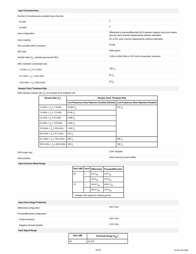
Input Characteristics
Number of simultaneously sampled input channels
NI 4461 2
NI 4462 4
Input configuration Differential or pseudodifferential (50 Ω between negative input and chassisground), each channel independently software selectable
Input coupling AC or DC, each channel independently software selectable
A/D converter (ADC) resolution 24 bits
ADC type Delta-sigma
Sample rates (ƒ ), samples-per-second (S/s)s 1 kS/s to 204.8 kS/s in 181.9 μS/s increments, maximum
ADC modulator oversample rate
1.0 kS/s ≤ ƒ ≤ 51.2 kS/ss 128 ƒs
51.2 kS/s < ƒ ≤ 102.4 kS/ss 64 ƒs
102.4 kS/s < ƒ ≤ 204.8 kS/ss 32 ƒs
Sample Clock Timebase Rate
Ratio between sample rate (ƒ ) and sample clock timebase rates
Sample Rate (ƒ )s Sample Clock Timebase Rate
Low-Frequency Alias Rejection Enabled (Default) Low-Frequency Alias Rejection Disabled
1.0 kS/s ≤ ƒ ≤ 1.6 kS/ss 16,384 ƒs 512 ƒs
1.6 kS/s < ƒ ≤ 3.2 kS/ss 8,192 ƒs
3.2 kS/s < ƒ ≤ 6.4 kS/ss 4,096 ƒs
6.4 kS/s < ƒ ≤ 12.8 kS/ss 2,048 ƒs
12.8 kS/s < ƒ ≤ 25.6 kS/ss 1,024 ƒs
25.6 kS/s < ƒ ≤ 51.2 kS/ss 512 ƒs
51.2 kS/s < ƒ ≤ 102.4 kS/ss 256 ƒs 256 ƒs
102.4 kS/s < ƒ ≤ 204.8 kS/ss 128 ƒs 128 ƒs
FIFO buffer size 2,047 samples
Data transfers Direct memory access (DMA)
Input Common Mode Range
Gain (dB) Input Differential* Pseudodifferential*
≥0 + ±12 Vpk ±12 Vpk
– ±12 Vpk ±10 Vpk
<0 + ±42.4 Vpk ±42.4 Vpk
– ±42.4 Vpk ±10 Vpk
* Voltages with respect to chassis ground
Input Overvoltage Protection
Differential configuration ±42.4 Vpk
Pseudodifferential configuration
Positive terminal ±42.4 Vpk
Negative terminal (shield) ±10.0 Vpk
Input Signal Range
Gain (dB) Full-Scale Range (V )pk*
30 ±0.316
7/19 www.ni.com
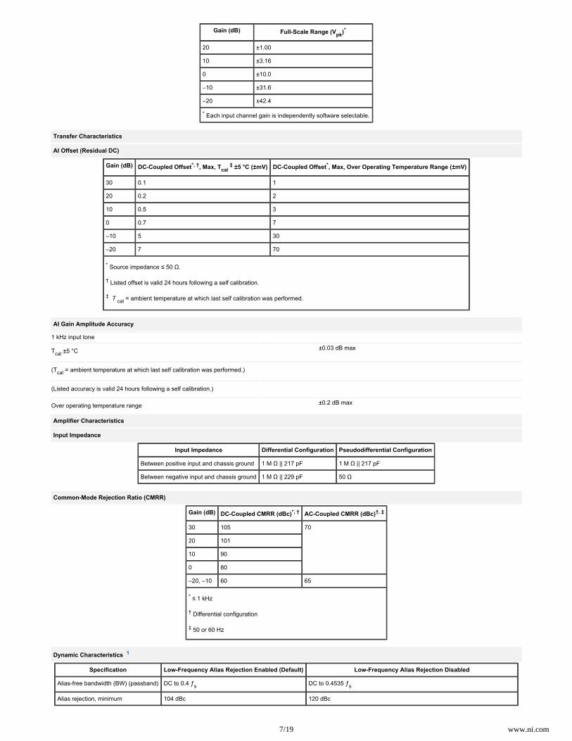
Gain (dB) Full-Scale Range (V )pk*
20 ±1.00
10 ±3.16
0 ±10.0
–10 ±31.6
–20 ±42.4
* Each input channel gain is independently software selectable.
Transfer Characteristics
AI Offset (Residual DC)
Gain (dB) DC-Coupled Offset , Max, T 5 °C ( mV)*, †cal
‡ ± ± DC-Coupled Offset , Max, Over Operating Temperature Range ( mV)* ±
30 0.1 1
20 0.2 2
10 0.5 3
0 0.7 7
–10 5 30
–20 7 70
* Source impedance ≤ 50 Ω.
† Listed offset is valid 24 hours following a self calibration.
‡ = ambient temperature at which last self calibration was performed. T cal
AI Gain Amplitude Accuracy
1 kHz input tone
T ±5 °Ccal ±0.03 dB max
(T = ambient temperature at which last self calibration was performed.)cal
(Listed accuracy is valid 24 hours following a self calibration.)
Over operating temperature range ±0.2 dB max
Amplifier Characteristics
Input Impedance
Input Impedance Differential Configuration Pseudodifferential Configuration
Between positive input and chassis ground 1 M Ω || 217 pF 1 M Ω || 217 pF
Between negative input and chassis ground 1 M Ω || 229 pF 50 Ω
Common-Mode Rejection Ratio (CMRR)
Gain (dB) DC-Coupled CMRR (dBc)*, † AC-Coupled CMRR (dBc)†, ‡
30 105 70
20 101
10 90
0 80
–20, –10 60 65
* ≤ 1 kHz
† Differential configuration
‡ 50 or 60 Hz
Dynamic Characteristics 1
Specification Low-Frequency Alias Rejection Enabled (Default) Low-Frequency Alias Rejection Disabled
Alias-free bandwidth (BW) (passband) DC to 0.4 ƒs DC to 0.4535 ƒs
Alias rejection, minimum 104 dBc 120 dBc

8/19 www.ni.com
Specification Low-Frequency Alias Rejection Enabled (Default) Low-Frequency Alias Rejection Disabled
Alias rejection by frequency Input frequency > 0.6 ƒs 0.5465 ƒ < input frequency < 127.4535 ƒ , where 1.0 kS/s ≤ ƒ ≤ 51.2 kS/ss s s
0.5465 ƒ < input frequency < 63.4535 ƒ , where 51.2 kS/s < ƒ ≤ 102.4 kS/ss s s
0.5465 ƒ < input frequency < 31.4535 ƒ , where 102.4 kS/s < ƒ ≤ 204.8 kS/ss s s
–3 dB BW 0.484 ƒs 0.491 ƒs
AC coupling
–3 dB cutoff frequency 3.4 Hz
–0.1 dB cutoff frequency 22.6 Hz
Magnitude Response of AC Coupling Circuit (1 Hz to 1 kHz)
Phase Response of AC Coupling Circuit (1 Hz to 1 kHz)
ADC Filter Delay
Low-Frequency Alias Rejection Enabled (Default) Low-Frequency Alias Rejection Disabled
Sample Rate (kS/s) Filter Delay (Samples) Sample Rate (kS/s) Filter Delay (Samples)
1.0 ≤ ƒ ≤ 1.6s 32.96875 1.0 ≤ ƒ ≤ 1.6s 63
1.6 < ƒ ≤ 3.2s 33.9375 1.6 < ƒ ≤ 3.2s
3.2 < ƒ ≤ 6.4s 35.875 3.2 < ƒ ≤ 6.4s
6.4 < ƒ ≤ 12.8s 39.75 6.4 < ƒ ≤ 12.8s
12.8 < ƒ ≤ 25.6s 47.5 12.8 < ƒ ≤ 25.6s
25.6 < ƒ ≤ 204.8s 63 25.6 < ƒ ≤ 204.8s
AI Flatness
Gain (dB) DC-Coupled Flatness (dB), Max (Typical)*
20 Hz to 20 kHz 20 Hz to 45 kHz 20 Hz to 92.2 kHz
0, 10, 20, 30 ±0.006 (±0.003) ±0.03 (±0.02) ±0.1 (±0.08)
–20, –10 ±0.2 (±0.1) ±0.6 (±0.33) ±1 (±0.55)

9/19 www.ni.com
Gain (dB) DC-Coupled Flatness (dB), Max (Typical)*
20 Hz to 20 kHz 20 Hz to 45 kHz 20 Hz to 92.2 kHz
* Relative to 1 kHz
AI Spectral Noise Density
AI spectral noise density (with EAR turned on) 8 nV/ at 30 dB gain, 1 kHz
AI Spectral Noise Density (30 dB Gain)
AI Idle Channel Noise
Sample Rate (kS/s) Idle Channel Noise*, †
dBVrms μVrms
1.0 kS/s ≤ ƒ < 51.2 kS/ss –118 dBVrms 1.3 μVrms
51.2 kS/s ≤ ƒ < 102.4 kS/ss –115 dBVrms 1.8 μVrms
102.4 kS/s ≤ ƒ ≤ 204.8 kS/ss –111 dBVrms 2.8 μVrms
* Source impedance ≤ 50 Ω
† 30 dB gain
AI Spurious Free Dynamic Range (SFDR)
Gain Setting (dB) SFDR (dBc)*, †, ‡
30 106
0, 10, 20 108
–20, –10 110
* ƒ = 204.8 kS/ss
† 1 kHz input tone, input amplitude is the lesser of –1 dBFS or 8.91 V .pk
‡ Measurement includes all harmonics.
SFDR 51.2 kS/s (–1 dBFS, 0 dB Gain, 1 kHz Sine Wave Input)

10/19 www.ni.com
SFDR 102.4 kS/s (–1 dBFS, 0 dB Gain, 1 kHz Sine Wave Input)
SFDR 204.8 kS/s (–1 dBFS, 0 dB Gain, 1 kHz Sine Wave Input)
AI Dynamic Range
Gain Setting (dB) Dynamic Range (dBFS) , Min (Typical)*
1 kS/s ≤ ƒ ≤ 51.2 kS/ss 51.2 kS/s < ƒ ≤ 102.4 kS/ss 102.4 kS/s < ƒ ≤ 204.8 kS/ss
30 103 (105) 100 (102) 96 (98)
20 111 (113) 108 (110) 104 (106)

11/19 www.ni.com
Gain Setting (dB) Dynamic Range (dBFS) , Min (Typical)*
1 kS/s ≤ ƒ ≤ 51.2 kS/ss 51.2 kS/s < ƒ ≤ 102.4 kS/ss 102.4 kS/s < ƒ ≤ 204.8 kS/ss
10 114 (117) 111 (114) 106 (110)
0 116 (118) 113 (114) 107 (110)
–10 107 (108) 104 (105) 101 (102)
–20 105 (107) 102 (104) 98 (101)
* 1 kHz input tone, –60 dBFS input amplitude
AI Total Harmonic Distortion (THD), Balanced Source
Gain (dB) THD (dBc)*, †
20 Hz to 20 kHz 20 Hz to 92.2 kHz
30 –100 –97
20 –109 –106
0, 10 –107 –104
–10 –108 –107
–20 –107 –106
* ƒ = 204.8 kS/s, 92.8 kHz BW, differential configurations
† Input amplitude is the lesser of –1 dBFS or 8.91 V .pk
AI THD, Unbalanced Source
Gain (dB) THD (dBc)*, †
20 Hz to 20 kHz 20 Hz to 92.2 kHz
30 –100 –93
20 –106 –94
10 –105 –92
0 –97 –87
–10 –90 –88
–20 –91 –89
* ƒ = 204.8 kS/s, 92.8 kHz BWs
† Input amplitude is the lesser of –1 dBFS or 8.91 V .pk
AI THD (Balanced Source with Differential Configuration, 204.8 kS/s, 0 dB Gain)
AI THD Plus Noise (THD+N), Balanced Source
Gain (dB) THD+N (dBc)*
51.2 kS/s, 20 Hz to 20 kHz† 204.8 kS/s, 20 Hz to 92.2 kHz‡
30 –103 –94
20 –107 –95
10 –108 –96
0 –107 –96

12/19 www.ni.com
Gain (dB) THD+N (dBc)*
51.2 kS/s, 20 Hz to 20 kHz† 204.8 kS/s, 20 Hz to 92.2 kHz‡
–10 –96 –91
–20 –94 –88
* Input amplitude is the lesser of –1 dBFS or 8.91 V , differential configuration.pk
† 23.2 kHz measurement BW
‡ 92.8 kHz measurement BW
AI THD+N, Unbalanced Source
Gain (dB) THD+N (dBc)*
51.2 kS/s, 20 Hz to 20 kHz† 204.8 kS/s, 20 Hz to 92.2 kHz‡
30 –103 –91
20 –107 –93
10 –108 –91
0 –104 –87
–10 –94 –86
–20 –93 –86
* Input amplitude is the lesser of –1 dBFS or 8.91 V .pk
† 23.2 kHz measurement BW
‡ 92.8 kHz measurement BW
AI Intermodulation Distortion (IMD)
Gain (dB) IMD (dBc)*
20, 30 –109
10 –107
0 –104
–20, –10 –111
* CCIF 14 kHz + 15 kHz, each tone amplitude is the lesser of –6 dBFS or 5 V .pk
Crosstalk, Input Channel Separation
Gain (dB) Crosstalk for Adjacent (Nonadjacent) Channels (dBc)*, †
1 kHz Signal 92.2 kHz
30 –130 (–140) –110 (–124)
0, 10, 20 –138 (–145) –110 (–124)
–20, –10 –96 (–124) –60 (–108)
* Source impedance ≤ 50 Ω
† Input amplitude is the lesser of –1 dBFS or 8.91 V .pk
AI Interchannel Gain Mismatch
Gain (dB) DC-Coupled Mismatch (dB)* AC-Coupled Mismatch (dB)*
20 Hz to 20 kHz 20 Hz to 92.2 kHz 20 Hz
30 0.004 0.008 0.004
0, 10, 20 0.003 0.003
–20, –10 0.04 0.25 0.006
* Identical channel configurations
AI Interchannel Phase Mismatch
13/19 www.ni.com
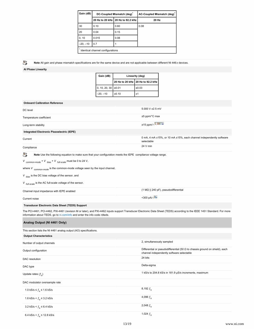
Gain (dB) DC-Coupled Mismatch (deg)* AC-Coupled Mismatch (deg)*
20 Hz to 20 kHz 20 Hz to 92.2 kHz 20 Hz
30 0.10 0.60 0.08
20 0.04 0.15
0, 10 0.015 0.08
–20, –10 0.7 1
* Identical channel configurations
Note All gain and phase mismatch specifications are for the same device and are not applicable between different NI 446 devices.x
AI Phase Linearity
Gain (dB) Linearity (deg)
20 Hz to 20 kHz 20 Hz to 92.2 kHz
0, 10, 20, 30 ±0.01 ±0.03
–20, –10 ±0.10 ±1
Onboard Calibration Reference
DC level 5.000 V ±2.5 mV
Temperature coefficient ±5 ppm/°C max
Long-term stability ±15 ppm/
Integrated Electronic Piezoelectric (IEPE)
Current 0 mA, 4 mA ±15%, or 10 mA ±15%, each channel independently softwareselectable
Compliance 24 V min
Note Use the following equation to make sure that your configuration meets the IEPE compliance voltage range.
V + + must be 0 to 24 V, common-mode V bias V full-scale
where is the common-mode voltage seen by the input channel,V common-mode
V is the DC bias voltage of the sensor, and bias
V is the AC full-scale voltage of the sensor. full-scale
Channel input impedance with IEPE enabled (1 MΩ || 240 pF), pseudodifferential
Current noise <300 pA/
Transducer Electronic Data Sheet (TEDS) Support
The PCI-4461, PCI-4462, PXI-4461 (revision M or later), and PXI-4462 inputs support Transducer Electronic Data Sheet (TEDS) according to the IEEE 1451 Standard. For moreinformation about TEDS, go to and enter the info code .ni.com/info rdteds
Analog Output (NI 4461 Only)
This section lists the NI 4461 analog output (AO) specifications.
Output Characteristics
Number of output channels 2, simultaneously sampled
Output configuration Differential or pseudodifferential (50 Ω to chassis ground on shield), eachchannel independently software selectable
DAC resolution 24 bits
DAC type Delta-sigma
Update rates (ƒ )s 1 kS/s to 204.8 kS/s in 181.9 μS/s increments, maximum
DAC modulator oversample rate
1.0 kS/s ≤ ƒ ≤ 1.6 kS/ss 8,192 ƒs
1.6 kS/s < ƒ ≤ 3.2 kS/ss 4,096 ƒs
3.2 kS/s < ƒ ≤ 6.4 kS/ss 2,048 ƒs
6.4 kS/s < ƒ ≤ 12.8 kS/ss 1,024 ƒs

14/19 www.ni.com
12.8 kS/s < ƒ ≤ 25.6 kS/ss 512 ƒs
25.6 kS/s < ƒ ≤ 51.2 kS/ss 256 ƒs
51.2 kS/s < ƒ ≤ 102.4 kS/ss 128 ƒs
102.4 kS/s < ƒ ≤ 204.8 kS/ss 64 ƒs
FIFO buffer size 1,023 samples
Data transfers DMA
Output Signal Range
Attenuation (dB) Full-Scale Range (V )pk*
40 ±0.1
20 ±1.0
0 ±10.0
* Each output channel range is independently software selectable.
Transfer Characteristics
AO Offset (Residual DC)
Attenuation (dB) Maximum Offset , T 5 °C ( mV)*cal ± † ± Maximum Offset, Over Operating Temperature Range ( mV)±
20, 40 1 2
0 1 10
* Listed offset is valid 24 hours following a self calibration.
† = ambient temperature at which last self calibration was performed.T cal
Gain (Amplitude Accuracy)
Specifications valid at any attenuation setting with a 1 kHz output signal.
T ±5 °Ccal ±0.04 dB max
(T = ambient temperature at which last self calibration was performed.)cal
(Listed accuracy is valid 24 hours following a self calibration.)
Over operating temperature range ±0.1 dB max
Voltage Output
Output coupling DC
Short circuit protection Indefinite protection between positive and negative
Minimum working load 600 Ω
Output Impedance
Output Impedance Differential Configuration Pseudodifferential Configuration
Between positive output and chassis ground 2.4 kΩ 70 Ω
Between negative output and chassis ground 2.4 kΩ 50 Ω
Between positive and negative outputs 22 Ω 22 Ω
Dynamic Characteristics 1
Image rejection 75 dB min < 768 kHz, 66 dB min > 768 kHz
–3 dB BW 0.487 ƒs
DAC filter delay (samples), for update rate
1.0 kS/s ≤ ƒ ≤ 1.6 kS/ss 36.6
1.6 kS/s < ƒ ≤ 3.2 kS/ss 36.8
3.2 kS/s < ƒ ≤ 6.4 kS/ss 37.4

15/19 www.ni.com
6.4 kS/s < ƒ ≤ 12.8 kS/ss 38.5
12.8 kS/s < ƒ ≤ 25.6 kS/ss 40.8
25.6 kS/s < ƒ ≤ 51.2 kS/ss 43.2
51.2 kS/s < ƒ ≤ 102.4 kS/ss 48.0
102.4 kS/s < ƒ ≤ 204.8 kS/ss 32.0
AO Flatness
All attenuation settings relative to 1 kHz
20 Hz to 20 kHz ±0.008 dB max
20 Hz to 92.1 kHz ±0.1 dB max
AO Idle Channel Noise
Attenuation (dB) Maximum Idle Channel Noise
102.5 kS/s (30 kHz BW)* 204.8 kS/s (80 kHz BW)* 204.8 kS/s (500 kHz BW)*
dB Vrms μ Vrms dB Vrms μ Vrms dB Vrms μ Vrms
40 –106 5 –101 9 –87 45
20 –106 5 –101 9 –86 50
0 –96 16 –93 23 –73 224
* Noise equivalent bandwidth
AO Spurious Free Dynamic Range (SFDR)
Attenuation (dB) SFDR (dBc)*, †, ‡
40 87
20 94
0 98
* ƒ = 204.8 kS/ss
† 1 kHz output frequency, –1 dBFS output amplitude
‡ Measurement includes all harmonics.
AO Dynamic Range
Attenuation (dB) Minimum Dynamic Range (dBFS)*
102.5 kS/s (30 kHz BW)† 204.8 kS/s (80 kHz BW)† 204.8 kS/s (500 kHz BW)†
40 83 78 64
20 103 98 83
0 113 110 90
* 1 kHz output frequency, –60 dBFS output amplitude
† Noise equivalent bandwidth
AO THD
Attenuation (dB) THD (dBc)*
102.5 kS/s, 20 Hz to 20 kHz† 204.8 kS/s, 20 Hz to 20 kHz‡ 204.8 kS/s, 20 Hz to 92.1 kHz‡
40 –99 –92 –92
20 –98 –95 –93
0 –97 –94 –83
* –1 dBFS output amplitude
† 30 kHz measurement BW
‡ 92.8 kHz measurement BW

16/19 www.ni.com
AO THD (204.8 kS/s, 0 dB Gain, 65,536 Samples, 92.8 kHz Measurement BW)
AO THD+N
Attenuation (dB) THD+N (dBc)*
102.5 kS/s, 20 Hz to 20 kHz† 204.8 kS/s, 20 Hz to 80 kHz‡ 204.8 kS/s, 20 Hz to 92.1 kHz**
40 –83 –76 –63
20 –98 –92 –79
0 –97 –86 –68
* –1 dBFS output amplitude
† 30 kHz measurement BW
‡ 80 kHz measurement BW
** 500 kHz measurement BW
AO Intermodulation Distortion (IMD)
Attenuation (dB) IMD (dBc)*
40 –99
20 –104
0 –104
* CCIF 14 kHz + 15 kHz, each tone amplitude is –6 dBFS.
Crosstalk, Output to Input Channel Separation
Gain (dB) Crosstalk (dBc)*, †
1 kHz Signal 92.1 kHz
30 –151 –118
20 –150 –118
10 –144 –115
0 –137 –111
–20, –10 –87 –51
* Source impedance ≤ 50 Ω
† Output amplitude is the lesser of –1 dBFS or 8.91 V .pk
Crosstalk, Output Channel Separation
All attenuation settings (0, 20, and 40 dB)
1 kHz signal No measurable crosstalk
92.1 kHz signal –110 dBc
AO Interchannel Gain Mismatch
All attenuation settings
20 Hz to 92.1 kHz 0.03 dB
AO Interchannel Phase Mismatch

17/19 www.ni.com
All attenuation settings
20 Hz to 20 kHz 0.1°
20 Hz to 92.1 kHz 0.2°
Note All gain and phase mismatch specifications are for the same device and are not applicable between different NI 446 devices.x
AO Phase Linearity
Attenuation (dB) Linearity (deg)
20 Hz to 20 kHz 20 Hz to 92.1 kHz
0 ±0.1 ±1.7
20 ± 0.1 ±1.6
40 ±0.1 ±1.8
Internal Frequency Timebase Characteristics
Accuracy ±20 ppm, over operating temperature range
Aging 8 ppm in first year; 5 ppm max/year after first year
Triggers
Analog trigger
Purpose Start trigger
Source
NI 4461 AI0 or AI1
NI 4462 AI0, AI1, AI2, or AI3
Level Full scale, programmable
Slope Positive (rising) or negative (falling), software selectable
Resolution 24 bits
Hysteresis Programmable
Digital Trigger
Purpose Start or reference trigger
Source PFI0, PXI_Trig<0..6>
Compatibility Transistor-transistor logic (5V TTL)
Polarity Rising or falling edge
Minimum pulse width 10 ns
General Specifications
This section lists general specification information for the NI 446x.
Bus Interface
PCI or PXI 3.3 V or 5 V signal environment
DMA channels
NI 4461 2, analog input and analog output
NI 4462 1, analog input
Synchronization
PXI
CLK_10 Multiple, full chassis
PXI_STAR Up to 14 devices per chassis
PCI
18/19 www.ni.com
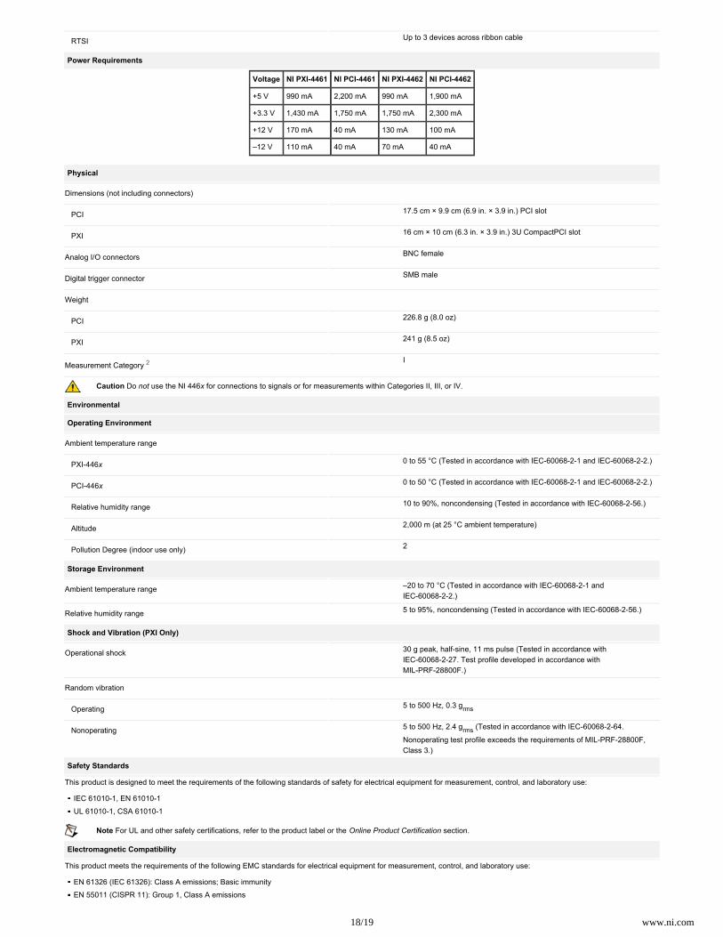
RTSI Up to 3 devices across ribbon cable
Power Requirements
Voltage NI PXI-4461 NI PCI-4461 NI PXI-4462 NI PCI-4462
+5 V 990 mA 2,200 mA 990 mA 1,900 mA
+3.3 V 1,430 mA 1,750 mA 1,750 mA 2,300 mA
+12 V 170 mA 40 mA 130 mA 100 mA
–12 V 110 mA 40 mA 70 mA 40 mA
Physical
Dimensions (not including connectors)
PCI 17.5 cm × 9.9 cm (6.9 in. × 3.9 in.) PCI slot
PXI 16 cm × 10 cm (6.3 in. × 3.9 in.) 3U CompactPCI slot
Analog I/O connectors BNC female
Digital trigger connector SMB male
Weight
PCI 226.8 g (8.0 oz)
PXI 241 g (8.5 oz)
Measurement Category 2 I
Caution Do use the NI 446 for connections to signals or for measurements within Categories II, III, or IV.not x
Environmental
Operating Environment
Ambient temperature range
PXI-446x 0 to 55 °C (Tested in accordance with IEC-60068-2-1 and IEC-60068-2-2.)
PCI-446x 0 to 50 °C (Tested in accordance with IEC-60068-2-1 and IEC-60068-2-2.)
Relative humidity range 10 to 90%, noncondensing (Tested in accordance with IEC-60068-2-56.)
Altitude 2,000 m (at 25 °C ambient temperature)
Pollution Degree (indoor use only) 2
Storage Environment
Ambient temperature range –20 to 70 °C (Tested in accordance with IEC-60068-2-1 andIEC-60068-2-2.)
Relative humidity range 5 to 95%, noncondensing (Tested in accordance with IEC-60068-2-56.)
Shock and Vibration (PXI Only)
Operational shock 30 g peak, half-sine, 11 ms pulse (Tested in accordance withIEC-60068-2-27. Test profile developed in accordance withMIL-PRF-28800F.)
Random vibration
Operating 5 to 500 Hz, 0.3 grms
Nonoperating 5 to 500 Hz, 2.4 g (Tested in accordance with IEC-60068-2-64.rmsNonoperating test profile exceeds the requirements of MIL-PRF-28800F,Class 3.)
Safety Standards
This product is designed to meet the requirements of the following standards of safety for electrical equipment for measurement, control, and laboratory use:
IEC 61010-1, EN 61010-1
UL 61010-1, CSA 61010-1
Note For UL and other safety certifications, refer to the product label or the section.Online Product Certification
Electromagnetic Compatibility
This product meets the requirements of the following EMC standards for electrical equipment for measurement, control, and laboratory use:
EN 61326 (IEC 61326): Class A emissions; Basic immunity
EN 55011 (CISPR 11): Group 1, Class A emissions
19/19 www.ni.com
Back to Top
AS/NZS CISPR 11: Group 1, Class A emissions
FCC 47 CFR Part 15B: Class A emissions
ICES-001: Class A emissions
Note For the standards applied to assess the EMC of this product, refer to the section.Online Product Certification
Note For EMC compliance, operate this product according to the documentation.
CE Compliance
This product meets the essential requirements of applicable European Directives, as amended for CE marking, as follows:
2006/95/EC; Low-Voltage Directive (safety)
2004/108/EC; Electromagnetic Compatibility Directive (EMC)
Online Product Certification
Refer to the product Declaration of Conformity (DoC) for additional regulatory compliance information. To obtain product certifications and the DoC for this product, visit , search by module number or product line, and click the appropriate link in the Certification column.ni.com/certification
Environmental Management
National Instruments is committed to designing and manufacturing products in an environmentally responsible manner. NI recognizes that eliminating certain hazardoussubstances from our products is beneficial not only to the environment but also to NI customers.
For additional environmental information, refer to the Web page at . This page contains the environmental regulations and directivesNI and the Environment ni.com/environmentwith which NI complies, as well as other environmental information not included in this document.
Waste Electrical and Electronic Equipment (WEEE)
EU Customers At the end of the product life cycle, all products be sent to a WEEE recycling center. For more information about WEEE recycling centers, NationalmustInstruments WEEE initiatives, and compliance with WEEE Directive 2002/96/EC on Waste Electrical and Electronic Equipment, visit .ni.com/environment/weee.htm
1 Test system equipped with an LCD monitor for AO noise and distortion measurements to avoid possible magnetic interference caused by CRT-based monitors.2 is also referred to as .Measurement Category Installation Category
©2010 National Instruments. All rights reserved. CVI, DIAdem, LabVIEW, Measurement Studio, National Instruments, National Instruments Alliance Partner, NI, ni.com, NI-DAQ, and SignalExpress are trademarks
of National Instruments. The mark LabWindows is used under a license from Microsoft Corporation. Windows is a registered trademark of Microsoft Corporation in the United States and other countries. Other
product and company names listed are trademarks or trade names of their respective companies. A National Instruments Alliance Partner is a business entity independent from National Instruments and has no
agency, partnership, or joint-venture relationship with National Instruments.
| | | | My Profile RSS Privacy Legal Contact NI © 2014 National Instruments Corporation. All rights reserved.


![California Department of · Web viewHave the structure depth, falsework depth and vertical clearance requirements been provided for in the profile design? [Index 204.8 and Table 204.8]](https://img.dokumen.tips/doc/110x75/5aa108c67f8b9ac67a8b4641/california-department-of-viewhave-the-structure-depth-falsework-depth-and-vertical.jpg)