Embed Size (px)
Citation preview
Beginning with AIX5L, IBM discontinued the publication of the Messages Guide andReference whitebook [SC23-4129]. This info is [only] available using a web applet:
http://www16.boulder.ibm.com/pseries/en_US/infocenter/base/errorsearch.htm
There are instances when this solution is simply insufficient. I have created this unofficialdocument in the spirit of the Messages Guide and Reference. Use it at your own risk. Allerrors are mine and mine alone.
AIX5L Messages Guide & Reference: LED Codes24-April-2003
Updates Avail: http://rainsux.dyndns.org Corrections: [email protected]
Copyright © 2003 IBM Corporation. All Rights Reserved.
file:///C|/sp2docs/Error-Codes/LEDs/ledsearch.htm
Display codes (LEDs)
This page provides descriptions for the numbers and characters that display on the operator panel and descriptions of the location codes used to identify a particular item. Information is available about the following codes:
● AIX Location Codes ● Location Codes for CHRP Model Architecture System Units ● Diagnostic Load Progress Indicators ● Operator Panel Display Numbers ● Physical Location Codes ● Location Codes for RSPC Model Architecture System Units
AIX Location Codes Top of page
Note: AIX logical location codes can still be seen and supported under various AIX commands and functions. However, the Diagnostic screens and menus display physical location codes for resources when running versions 5.2.0 and later. For these systems, refer to Physical Location Codes.
The basic formats of the AIX location codes are as follows:
● For non-SCSI devices/drives:
AB-CD-EF-GH
● For SCSI devices/drives:
AB-CD-EF-G,H
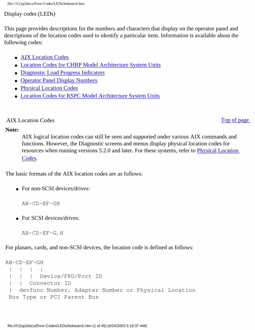
For planars, cards, and non-SCSI devices, the location code is defined as follows:
AB-CD-EF-GH | | | | | | | Device/FRU/Port ID | | Connector ID | devfunc Number, Adapter Number or Physical Location Bus Type or PCI Parent Bus
file:///C|/sp2docs/Error-Codes/LEDs/ledsearch.htm (1 of 45) [4/24/2003 5:18:37 AM]
file:///C|/sp2docs/Error-Codes/LEDs/ledsearch.htm
● The AB value identifies a bus type or PCI parent bus as assigned by the firmware. ● The CD value identifies adapter number, adapter's devfunc number, or physical location. The
devfunc number is defined as the PCI device number times 8, plus the function number. ● The EF value identifies a connector. ● The GH value identifies a port, address, device, or FRU.
Adapters and cards are identified only with AB-CD. The possible values for AB are:
00 Processor bus
01 ISA bus
02 EISA bus
03 MCA bus
04 PCI bus used in the case where the PCI bus cannot be identified
05 PCMCIA buses
xy For PCI adapters where x is equal to or greater than 1. The x and y are characters in the range of 0-9, A-H, J-N, P-Z (O, I, and lower case are omitted) and are equal to the parent bus's ibm, aix-loc Open Firmware Property.
The possible values for CD depend on the adapter or card are as follows:
● For pluggable PCI adapters/cards, CD is the device's devfunc number (PCI device number times 8, plus the function number). The C and D are characters in the range of 0-9, and A-F (hex numbers). This allows the location code to uniquely identify multiple adapters on individual PCI cards.
For pluggable ISA adapters, CD is equal to the order in which the ISA cards defined or configured, either by SMIT or the ISA Adapter Configuration Service Aid.
For integrated ISA adapters, CD is equal to a unique code identifying the ISA adapter. In most cases, this is equal to the adapter's physical location code. In cases where a physical location code is not available, CD is FF.
● EF is the connector ID. It is used to identify a connector on the adapter to which a resource is attached.
● GH is used to identify a port, device, or FRU. For example: ❍ For async devices, GH defines the port on the fanout box. The values are 00 to 15. ❍ For a diskette drive, H defines either diskette drive 1 or 2. G is always 0. ❍ For all other devices, GH is equal to 00.
For the integrated adapters, EF-GH is the same as the definition for the pluggable adapters. For example, the location code for a diskette drive is 01-D1-00-00. A second diskette drive is 01-D1-00-01.
file:///C|/sp2docs/Error-Codes/LEDs/ledsearch.htm (2 of 45) [4/24/2003 5:18:37 AM]

file:///C|/sp2docs/Error-Codes/LEDs/ledsearch.htm
For SCSI devices, the location code is defined as:
AB-CD-EF-G,H | | | | | | | | | Logical Unit address of the SCSI Device | | | Control Unit Address of the SCSI Device | | Connector ID | devfunc Number, Adapter Number or Physical Location Bus Type or PCI Parent Bus
Where:
● AB-CD-EF are the same as non-SCSI devices. ● G defines the control unit address of the device. Values of 0 to 15 are valid. ● H defines the logical unit address of the device. Values of 0 to 255 are valid.
There is also a bus location code that is generated as '00-xxxxxxxx' where xxxxxxxx is equivalent to the node's unit address. Refer to the system unit service guide for additional information.
Location Codes for CHRP Model Architecture System Units Top of page
Note: You need to know which system architecture the system unit on which you are working uses. If you are working with a RSPC model use the Location Codes for RSPC Model Architecture System Units. If you do not know which model you have, refer to Determining System Architecture in Diagnostic Information for Multiple Bus Systems before proceeding.
The (CHRP) system unit uses Physical Location Codes in conjunction with AIX Location Codes to provide mapping of the failing field replaceable units. The location codes are produced by the system unit's firmware and the AIX operating system.
Diagnostic Load Progress Indicators Top of page
file:///C|/sp2docs/Error-Codes/LEDs/ledsearch.htm (3 of 45) [4/24/2003 5:18:37 AM]
file:///C|/sp2docs/Error-Codes/LEDs/ledsearch.htm
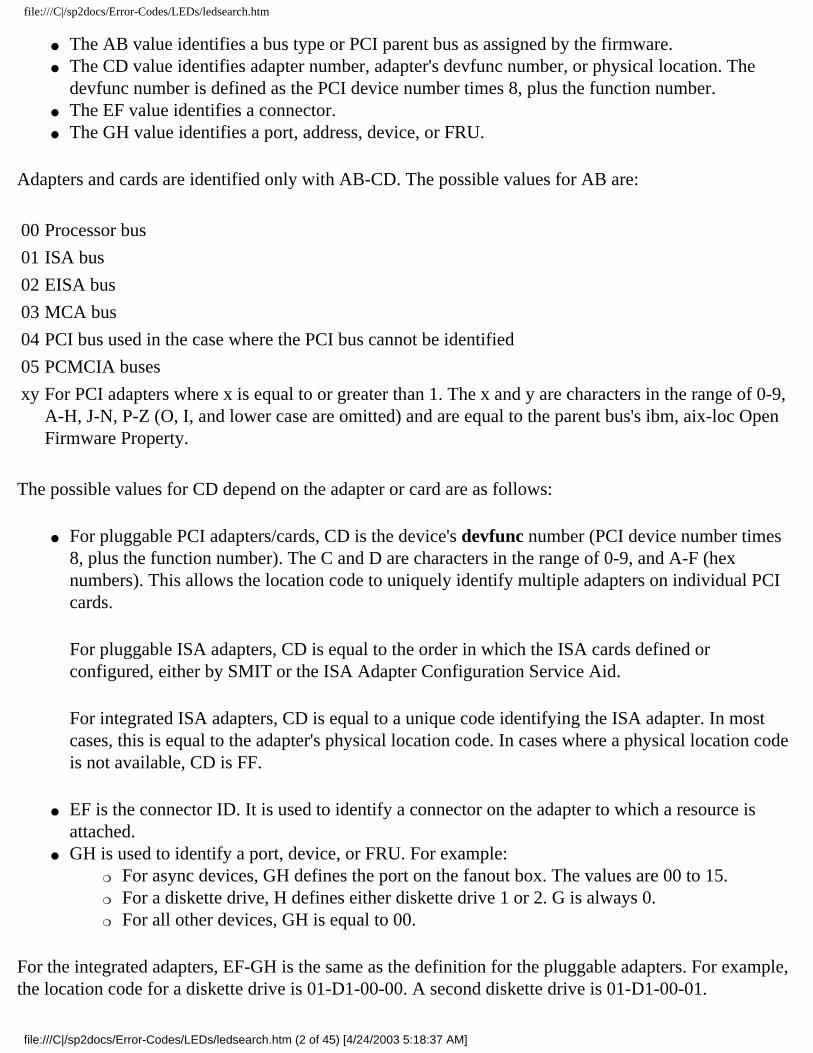
Note: Some systems might produce 4-digit codes. If the leftmost digit of a 4-digit code is 0, use the three rightmost digits.
c00 AIX Install/Maintenance loaded successfully.
c01 Insert the first diagnostic diskette.
c02 Diskettes inserted out of sequence.
c03 The wrong diskette is in diskette drive.
c04 The loading stopped with an irrecoverable error.
c05 A diskette error occurred.
c06 The rc.boot configuration shell script is unable to determine type of boot.
c07 Insert the next diagnostic diskette.
c08 RAM file system started incorrectly.
c09 The diskette drive is reading or writing a diskette.
c20 An unexpected halt occurred, and the system is configured to enter the kernel debug program instead of entering a system dump.
c21 The ifconfig command was unable to configure the network for the client network host.
c22
file:///C|/sp2docs/Error-Codes/LEDs/ledsearch.htm (4 of 45) [4/24/2003 5:18:37 AM]
file:///C|/sp2docs/Error-Codes/LEDs/ledsearch.htm
The tftp command was unable to read client's ClientHostName info file during a client network boot.
c24 Unable to read client's ClientHostName.info file during a client network boot.
c25 Client did not mount remote miniroot during network install.
c26 Client did not mount the /usr file system during the network boot.
c29 The system was unable to configure the network device.
c31 Select the console display for the diagnostics. To select No console display, set the key mode switch to Normal then to Service. The diagnostic programs then load and run the diagnostics automatically. If you continue to get the message, check the cables and make sure you are using the serial port.
c32 A directly attached display (HFT) was selected.
c33 A TTY terminal attached to serial ports S1 or S2 was selected.
c34 A file was selected. The console messages store in a file.
c35 No console found.
c40 Configuration files are being restored.
c41 Could not determine the boot type or device.
c42 Extracting data files from diskette.
file:///C|/sp2docs/Error-Codes/LEDs/ledsearch.htm (5 of 45) [4/24/2003 5:18:37 AM]
file:///C|/sp2docs/Error-Codes/LEDs/ledsearch.htm
c43 Cannot access the boot/install tape.
c44 Initializing installation database with target disk information.
c45 Cannot configure the console.
c46 Normal installation processing.
c47 Could not create a physical volume identifier (PVID) on disk.
c48 Prompting you for input.
c49 Could not create or form the JFS log.
c50 Creating root volume group on target disks.
c51 No paging devices were found.
c52 Changing from RAM environment to disk environment.
c53 Not enough space in the /tmp directory to do a preservation installation.
c54 Installing either BOS or additional packages.
c55 Could not remove the specified logical volume in a preservation installation.
c56 Running user-defined customization.
file:///C|/sp2docs/Error-Codes/LEDs/ledsearch.htm (6 of 45) [4/24/2003 5:18:37 AM]

file:///C|/sp2docs/Error-Codes/LEDs/ledsearch.htm
c57 Failure to restore BOS.
c58 Displaying message to turn the key.
c59 Could not copy either device special files, device ODM, or volume group information from RAM to disk.
c61 Failed to create the boot image.
c62 Loading platform dependent debug files.
c63 Loading platform dependent data files.
c64 Failed to load platform dependent data files.
c70 Problem Mounting diagnostic CD-ROM disc.
c99 Diagnostics have completed. This code is only used when there is no console.
Fxx (xx is any number) Refer to Firmware chapter of the service manual.
Dump Progress Indicators (Dump Status Codes)
The following dump progress indicators, or dump status codes, are part of a Type 102 message.
Note: When a lowercase c is listed, it displays in the lower half of the character position. Some systems produce 4-digit codes, the two leftmost positions can have a blanks or zeros. Use the two rightmost digits.
0c0 The dump completed successfully.
file:///C|/sp2docs/Error-Codes/LEDs/ledsearch.htm (7 of 45) [4/24/2003 5:18:37 AM]
file:///C|/sp2docs/Error-Codes/LEDs/ledsearch.htm
0c1 The dump failed due to an I/O error.
0c2 A dump, requested by the user, is started.
0c3 The dump is inhibited.
0c4 The dump device is not large enough.
0c5 The dump did not start, or the dump crashed.
0c6 Dumping to a secondary dump device.
0c7 Reserved.
0c8 The dump function is disabled.
0c9 A dump is in progress.
0cc Unknown dump failure
Crash Codes
Note: Some systems may produce 4-digit codes. If the leftmost digit of a 4-digit code is 0, use the three rightmost digits.
The crash codes that follow are part of a Type 102 message. These crash codes are grouped into three categories:
Category 1 Dump analysis is the appropriate first action in Problem Determination, begin the Problem
file:///C|/sp2docs/Error-Codes/LEDs/ledsearch.htm (8 of 45) [4/24/2003 5:18:37 AM]

file:///C|/sp2docs/Error-Codes/LEDs/ledsearch.htm
Determination process with software support.
Category 2 Dump analysis most likely will not aid in Problem Determination, begin the Problem Determination process with hardware support.
Category 3 Both software and hardware support may be needed in Problem Determination, go to MAP 0070: 888 Sequence in Operator Panel Display in Diagnostic Information for Multiple Bus Systemsto assist in problem isolation.
Category 1
300 Data storage interrupt from the processor.
32x Data storage interrupt because of an I/O exception from IOCC.
38x Data storage interrupt because of an I/O exception from SLA.
400 Instruction storage interrupt.
700 Program interrupt.
Category 2
200 Machine check because of a memory bus error.
201 Machine check because of a memory timeout.
202 Machine check because of a memory card failure.
203 Machine check because of a out of range address.
file:///C|/sp2docs/Error-Codes/LEDs/ledsearch.htm (9 of 45) [4/24/2003 5:18:37 AM]

file:///C|/sp2docs/Error-Codes/LEDs/ledsearch.htm
204 Machine check because of an attempt to write to ROS.
205 Machine check because of an uncorrectable address parity.
206 Machine check because of an uncorrectable ECC error.
207 Machine check because of an unidentified error.
208 Machine check due to an L2 uncorrectable ECC.
500 External interrupt because of a scrub memory bus error.
501 External interrupt because of an unidentified error.
51x External interrupt because of a DMA memory bus error.
52x External interrupt because of an IOCC channel check.
53x External interrupt from an IOCC bus timeout; x represents the IOCC number.
54x External interrupt because of an IOCC keyboard check.
800 Floating point is not available.
Category 3
000 Unexpected system interrupt.
558
file:///C|/sp2docs/Error-Codes/LEDs/ledsearch.htm (10 of 45) [4/24/2003 5:18:37 AM]
file:///C|/sp2docs/Error-Codes/LEDs/ledsearch.htm
There is not enough memory to continue the IPL.
600 AIX 4.3.3.3 and above: Alignment Interrupt. If pre-AIX 4.3.3.3: AIX has crashed because the Portability Assist Layer (PAL) for this machine type has detected a problem.
605 AIX has crashed because the Portability Assist Layer (PAL) for this machine type has detected a problem (AIX 4.3.3.3 and above).
Operator Panel Display Numbers Top of page
This page contains a list of the various numbers and characters that display in the operator panel display. There are three categories of numbers and characters. The first group tracks the progress of the configuration program. The second group tracks the progress of the diagnostics. The third group provides information about messages that follow an 888 sequence.
Configuration Program Indicators
The numbers in this list display on the operator panel as the system loads the operating system and prepares the hardware by loading software drivers.
Note: Some systems may produce 4-digit codes. If the leftmost digit of a 4-digit code is 0, use the three rightmost digits.
2E6 The PCI Differential Ultra SCSI adapter or the Universal PCI Differential Ultra SCSI adapter being configured.
2E7 Configuration method unable to determine if the SCSI adapter type is SE or DE type.
440 9.1GB Ultra SCSI Disk Drive being identified or configured.
441 18.2GB Ultra SCSI Disk Drive being identified or configured.
444 2-Port Multiprotocol PCI Adapter (ASIC) being identified or configured.
file:///C|/sp2docs/Error-Codes/LEDs/ledsearch.htm (11 of 45) [4/24/2003 5:18:37 AM]
file:///C|/sp2docs/Error-Codes/LEDs/ledsearch.htm
447 PCI 64-bit Fibre Channel Arbitrated Loop Adapter being configured.
500 Querying Standard I/O slot.
501 Querying card in Slot 1.
502 Querying card in Slot 2.
503 Querying card in Slot 3.
504 Querying card in Slot 4.
505 Querying card in Slot 5.
506 Querying card in Slot 6.
507 Querying card in Slot 7.
508 Querying card in Slot 8.
510 Starting device configuration.
511 Device configuration completed.
512 Restoring device configuration files from media.
513 Restoring basic operating system installation files from media.
file:///C|/sp2docs/Error-Codes/LEDs/ledsearch.htm (12 of 45) [4/24/2003 5:18:37 AM]

file:///C|/sp2docs/Error-Codes/LEDs/ledsearch.htm
516 Contacting server during network boot.
517 Mounting client remote file system during network IPL.
518 Remote mount of the root (/) and /usr file systems failed during network boot.
520 Bus configuration running.
521 /etc/init invoked cfgmgr with invalid options; /etc/inithas been corrupted or incorrectly modified (irrecoverable error).
522 The configuration manager has been invoked with conflicting options (irrecoverable error).
523 The configuration manager is unable to access the ODM database (irrecoverable error).
524 The configuration manager is unable to access the config.rules object in the ODM database (irrecoverable error).
525 The configuration manager is unable to get data from a customized device object in the ODM database (irrecoverable error).
526 The configuration manager is unable to get data from a customized device driver object in the ODM database ( irrecoverable error).
527 The configuration manager was invoked with the phase 1 flag; running phase 1 at this point is not permitted (irrecoverable error).
528 The configuration manager cannot find sequence rule, or no program name was specified in the ODM database (irrecoverable error).
file:///C|/sp2docs/Error-Codes/LEDs/ledsearch.htm (13 of 45) [4/24/2003 5:18:37 AM]

file:///C|/sp2docs/Error-Codes/LEDs/ledsearch.htm
529 The configuration manager is unable to update ODM data (irrecoverable error).
530 The program savebase returned an error.
531 The configuration manager is unable to access the PdAt object class (irrecoverable error).
532 There is not enough memory to continue (malloc failure); irrecoverable error.
533 The configuration manager could not find a configuration method for a device.
534 The configuration manager is unable to acquire database lock (irrecoverable error).
535 HIPPI diagnostics interface driver being configured.
536 The configuration manager encountered more than one sequence rule specified in the same phase (irrecoverable error).
537 The configuration manager encountered an error when invoking the program in the sequence rule.
538 The configuration manager is going to invoke a configuration method.
539 The configuration method has terminated, and control has returned to the configuration manager.
541 A DLT tape device is being configured.
549 Console could not be configured for the Copy a System Dump Menu.
551 IPL vary-on is running.
file:///C|/sp2docs/Error-Codes/LEDs/ledsearch.htm (14 of 45) [4/24/2003 5:18:37 AM]
file:///C|/sp2docs/Error-Codes/LEDs/ledsearch.htm
552 IPL vary-on failed.
553 IPL phase 1 is complete.
554 The boot device could not be opened or read, or unable to define NFS swap device during network boot.
555 An ODM error occurred when trying to vary-on the rootvg, or unable to create an NFS swap device during network boot.
556 Logical Volume Manager encountered error during IPL vary-on.
557 The root filesystem does not mount.
558 There is not enough memory to continue the system IPL.
559 Less than 2 M bytes of good memory are available to load the AIX kernel.
569 FCS SCSI protocol device is being configured (32 bits).
570 Virtual SCSI devices being configured.
571 HIPPI common function device driver being configured.
572 HIPPI IPI-3 master transport driver being configured.
573 HIPPI IPI-3 slave transport driver being configured.
file:///C|/sp2docs/Error-Codes/LEDs/ledsearch.htm (15 of 45) [4/24/2003 5:18:37 AM]

file:///C|/sp2docs/Error-Codes/LEDs/ledsearch.htm
574 HIPPI IPI-3 transport services user interface device driver being configured.
575 A 9570 disk-array driver being configured.
576 Generic async device driver being configured.
577 Generic SCSI device driver being configured.
578 Generic commo device driver being configured.
579 Device driver being configured for a generic device.
580 HIPPI TCPIP network interface driver being configured.
581 Configuring TCP/IP.
582 Configuring Token-Ring data link control.
583 Configuring an Ethernet data link control.
584 Configuring an IEEE Ethernet data link control.
585 Configuring an SDLC MPQP data link control.
586 Configuring a QLLC X.25 data link control.
587 Configuring a NETBIOS.
file:///C|/sp2docs/Error-Codes/LEDs/ledsearch.htm (16 of 45) [4/24/2003 5:18:37 AM]

file:///C|/sp2docs/Error-Codes/LEDs/ledsearch.htm
588 Configuring a Bisync Read-Write (BSCRW).
589 SCSI target mode device being configured.
590 Diskless remote paging device being configured.
591 Configuring an LVM device driver.
592 Configuring an HFT device driver.
593 Configuring SNA device drivers.
594 Asynchronous I/O being defined or configured.
595 X.31 pseudo-device being configured.
596 SNA DLC/LAPE pseudo-device being configured.
597 OCS software being configured.
598 OCS hosts being configured during system reboot.
599 Configuring FDDI data link control.
59B FCS SCSI protocol device being configured (64 bits).
5C0 Streams-based hardware drive being configured.
file:///C|/sp2docs/Error-Codes/LEDs/ledsearch.htm (17 of 45) [4/24/2003 5:18:37 AM]

file:///C|/sp2docs/Error-Codes/LEDs/ledsearch.htm
5C1 Streams-based X.25 protocol being configured.
5C2 Streams-based X.25 COMIO emulator driver being configured
5C3 Streams-based X.25 TCP/IP interface driver being configured.
5C4 FCS adapter device driver being configured.
5C5 SCB network device driver for FCS being configured.
5C6 AIX SNA channel being configured.
600 Starting network boot portion of /sbin/rc.boot.
602 Configuring network parent devices.
603 /usr/lib/methods/defsys, /usr/lib/methods/cfgsys, or /usr/lib/methods/cfgbus failed.
604 Configuring physical network boot device.
605 Configuration of physical network boot device failed.
606 Running /usr/sbin/ifconfig on logical network boot device.
607 /usr/sbin/ifconfig failed.
608 Attempting to retrieve the client.info file with tftp.Note that a flashing 608 indicates multiple attempt(s) to retrieve the client_info file are occurring.
file:///C|/sp2docs/Error-Codes/LEDs/ledsearch.htm (18 of 45) [4/24/2003 5:18:37 AM]
file:///C|/sp2docs/Error-Codes/LEDs/ledsearch.htm
609 The client.info file does not exist or it is zero length.
60B 18.2GB 68-pin LVD SCSI Disk Drive being configured.
610 Attempting remote mount of NFS file system.
611 Remote mount of the NFS file system failed.
612 Accessing remote files; unconfiguring network boot device.
614 Configuring local paging devices.
615 Configuration of a local paging device failed.
616 Converting from diskless to dataless configuration.
617 Diskless to dataless configuration failed.
618 Configuring remote (NFS) paging devices.
619 Configuration of a remote (NFS) paging device failed.
61B 36.4GB 80-pin LVD SCSI Disk Drive being configured.
61D 36.4GB 80-pin LVD SCSI Disk Drive being configured.
61E 18.2GB 68-pin LVD SCSI Disk Drive being configured.
file:///C|/sp2docs/Error-Codes/LEDs/ledsearch.htm (19 of 45) [4/24/2003 5:18:37 AM]

file:///C|/sp2docs/Error-Codes/LEDs/ledsearch.htm
620 Updating special device files and ODM in permanent filesystem with data from boot RAM filesystem.
621 9.1 GB LVD 80-pin SCSI Drive being configured.
622 Boot process configuring for operating system installation.
62D 9.1GB 68-pin LVD SCSI Disk Drive being configured.
62E 9.1GB 68-pin LVD SCSI Disk Drive being configured.
636 TURBROWAYS 622 Mbps PCI MMF ATM Adapter.
637 Dual Channel PCI-2 Ultra2 SCSI Adapter being configured.
638 4.5GB Ultra SCSI Single Ended Disk Drive being configured.
639 9.1GB 10K RPM Ultra SCSI Disk Drive (68-pin).
63A See 62D.
63B 9.1GB 80-pin LVD SCSI Disk Drive being configured.
63C See 60B.
63D 18.2GB 80-pin LVD SCSI Disk Drive being configured.
63E
file:///C|/sp2docs/Error-Codes/LEDs/ledsearch.htm (20 of 45) [4/24/2003 5:18:37 AM]

file:///C|/sp2docs/Error-Codes/LEDs/ledsearch.htm
36.4GB 68-pin LVD SCSI Disk Drive being configured.
63F See 61B.
640 9.1GB 10K RPM Ultra SCSI Disk Drive (80-pin).
646 High-Speed Token-Ring PCI Adapter being configured.
64A See 62E.
64B 9.1GB 80-pin LVD SCSI Disk Drive being configured.
64C See 61E.
64D 18.2 GB LVD 80-pin Drive/Carrier being configured.
64E 36.4GB 68-pin LVD SCSI Disk Drive being configured.
64F See 61D.
650 IBM SCSD disk drive being configured.
653 18.2GB Ultra-SCSI 16-bit Disk Drive being configured.
655 GXT130P Graphics adapter being configured.
657 GXT2000P graphics adapter being configured.
658
file:///C|/sp2docs/Error-Codes/LEDs/ledsearch.htm (21 of 45) [4/24/2003 5:18:37 AM]

file:///C|/sp2docs/Error-Codes/LEDs/ledsearch.htm
PCI Fibre Channel Disk Subsystem Controller being identified or configured.
659 2102 Fibre Channel Disk Subsystem Controller Drawer being identified or configured.
660 2102 Fibre Channel Disk Array being identified or configured.
662 Ultra2 Integrated SCSI controller.
663 The ARTIC960RxD Digital Trunk Quad PCI Adapter or the ARTIC960RxF Digital Trunk Resource Adapter being configured.
664 32x (MAX) SCSI-2 CD-ROM drive being configured.
667 PCI 3-Channel Ultra2 SCSI RAID Adapter being configured.
669 PCI Gigabit Ethernet Adapter being configured.
66C 10/100/1000 Base-T EthernetPCI Adapter.
66D PCI 4-Channel Ultra-3 SCSI RAID Adapter.
66E 4.7 GB DVD-RAM drive.
674 ESCON(R) Channel PCI Adapter being configured.
677 PCI 32-bit Fibre Channel Arbitrated Loop Adapter being configured.
67B PCI Cryptographic Coprocessor being configured.
file:///C|/sp2docs/Error-Codes/LEDs/ledsearch.htm (22 of 45) [4/24/2003 5:18:37 AM]

file:///C|/sp2docs/Error-Codes/LEDs/ledsearch.htm
682 20x (MAX) SCSI-2 CD-ROM Drive being configured.
689 4.5GB Ultra SCSI Single Ended Disk Drive being configured.
68C 20 GB 4-mm Tape Drive being configured.
68E POWER GXT6000P PCI Graphics Adapter.
690 9.1GB Ultra SCSI Single Ended Disk Drive being configured.
69b 64-bit/66MHz PCI ATM 155 MMF PCI adapter being configured.
69d 64-bit/66MHz PCI ATM 155 UTP PCI adapter being configured.
6CC SSA disk drive being configured.
700 A 1.1 GB 8-bit SCSI disk drive being identified or configured.
701 A 1.1 GB 16-bit SCSI disk drive being identified or configured.
702 A 1.1 GB 16-bit differential SCSI disk drive being identified or configured.
703 A 2.2 GB 8-bit SCSI disk drive being identified or configured.
704 A 2.2 GB 16-bit SCSI disk drive being identified or configured.
705 The configuration method for the 2.2 GB 16-bit differential SCSI disk drive is being run. If an irrecoverable error occurs, the system halts.
file:///C|/sp2docs/Error-Codes/LEDs/ledsearch.htm (23 of 45) [4/24/2003 5:18:37 AM]
file:///C|/sp2docs/Error-Codes/LEDs/ledsearch.htm
706 A 4.5 GB 16-bit SCSI disk drive being identified or configured.
707 A 4.5 GB 16-bit differential SCSI disk drive being identified or configured.
708 A L2 cache being identified or configured.
710 POWER GXT150M graphics adapter being identified or configured.
711 Unknown adapter being identified or configured.
712 Graphics slot bus configuration is executing.
713 The IBM ARTIC960 device being configured.
714 A video capture adapter being configured.
715 The Ultramedia Services audio adapter being configured. (this number displays briefly on the panel).
717 TP Ethernet Adapter being configured.
718 GXT500 Graphics Adapter being configured.
720 Unknown read/write optical drive type being configured.
721 Unknown disk or SCSI device being identified or configured.
722
file:///C|/sp2docs/Error-Codes/LEDs/ledsearch.htm (24 of 45) [4/24/2003 5:18:37 AM]

file:///C|/sp2docs/Error-Codes/LEDs/ledsearch.htm
Unknown disk being identified or configured.
723 Unknown CD-ROM being identified or configured.
724 Unknown tape drive being identified or configured.
725 Unknown display adapter being identified or configured.
726 Unknown input device being identified or configured.
727 Unknown async device being identified or configured.
728 Parallel printer being identified or configured.
729 Unknown parallel device being identified or configured.
730 Unknown diskette drive being identified or configured.
731 PTY being identified or configured.
732 Unknown SCSI initiator type being configured.
733 7GB 8 mm tape drive being configured.
734 4x SCSI-2 640 MB CD-ROM Drive being configured.
736 Quiet Touch keyboard and speaker cable being configured.
741
file:///C|/sp2docs/Error-Codes/LEDs/ledsearch.htm (25 of 45) [4/24/2003 5:18:37 AM]

file:///C|/sp2docs/Error-Codes/LEDs/ledsearch.htm
1080 MB SCSI Disk Drive being configured.
745 16GB 4 mm Tape Auto Loader being configured.
746 SCSI-2 Fast/Wide PCI Adapter being configured.
747 SCSI-2 Differential Fast/Wide PCI Adapter being configured.
749 7331 Model 205 Tape Library being configured.
751 SCSI 32-bit SE F/W RAID Adapter being configured.
754 1.1GB 16-bit SCSI disk drive being configured.
755 2.2GB 16-bit SCSI disk drive being configured.
756 4.5GB 16-bit SCSI disk drive being configured.
757 External 13GB 1.5M/s 1/4 inch tape being configured.
763 SP Switch MX Adapter being configured.
764 SP System Attachment Adapter being configured.
772 4.5GB SCSI F/W Disk Drive being configured.
773 9.1GB SCSI F/W Disk Drive being configured.
774
file:///C|/sp2docs/Error-Codes/LEDs/ledsearch.htm (26 of 45) [4/24/2003 5:18:37 AM]
file:///C|/sp2docs/Error-Codes/LEDs/ledsearch.htm
9.1GB External SCSI Disk Drive being configured.
776 PCI Token-Ring Adapter being identified or configured.
777 10/100 Ethernet Tx PCI Adapter being identified or configured.
778 POWER GXT3000P 3D PCI Graphics adapter being configured.
77B 4-Port 10/100 Ethernet Tx PCI Adapter being identified or configured.
77c A 1.0 GB 16-bit SCSI disk drive being identified or configured.
783 4 mm DDS-2 Tape Autoloader being configured.
789 2.6 GB External Optical Drive being configured.
78B POWER GXT4000P PCI Graphics Adapter.
78C PCI bus configuration executing.
78D GXT300P 2D Graphics adapter being configured.
790 Multi-bus Integrated Ethernet Adapter being identified or configured.
797 TURBOWAYS(R) 155 UTP/STP ATM Adapter being identified or configured.
798 Video streamer adapter being identified or configured.
799
file:///C|/sp2docs/Error-Codes/LEDs/ledsearch.htm (27 of 45) [4/24/2003 5:18:37 AM]

file:///C|/sp2docs/Error-Codes/LEDs/ledsearch.htm
2-Port Multiprotocol PCI adapter being identified or configured.
79c ISA bus configuration executing.
7C0 CPU/System Interface being configured.
7C1 Business Audio Subsystem being identified or configured.
7cc PCMCIA bus configuration executing.
800 TURBOWAYS 155 MMF ATM Adapter being identified or configured.
803 7336 Tape Library robotics being configured.
804 8x Speed SCSI-2 CD-ROM Drive being configured.
806 POWER GXT800 PCI Graphics adapter being configured.
807 SCSI Device Enclosure being configured.
80c SSA 4-Port Adapter being identified or configured.
811 Processor complex being identified or configured.
812 Memory being identified or configured.
813 Battery for time-of-day, NVRAM, and so on being identified or configured, or system I/O control logic being identified or configured.
file:///C|/sp2docs/Error-Codes/LEDs/ledsearch.htm (28 of 45) [4/24/2003 5:18:37 AM]
file:///C|/sp2docs/Error-Codes/LEDs/ledsearch.htm
814 NVRAM being identified or configured.
815 Floating-point processor test.
816 Operator panel logic being identified or configured.
817 Time-of-day logic being identified or configured.
819 Graphics input device adapter being identified or configured.
821 Standard keyboard adapter being identified or configured.
823 Standard mouse adapter being identified or configured.
824 Standard tablet adapter being identified or configured.
825 Standard speaker adapter being identified or configured.
826 Serial Port 1 adapter being identified or configured.
827 Parallel port adapter being identified or configured.
828 Standard diskette adapter being identified or configured.
831 3151 adapter being identified or configured, or Serial Port 2 being identified or configured.
834 64-port async controller being identified or configured.
file:///C|/sp2docs/Error-Codes/LEDs/ledsearch.htm (29 of 45) [4/24/2003 5:18:37 AM]

file:///C|/sp2docs/Error-Codes/LEDs/ledsearch.htm
835 16-port async concentrator being identified or configured.
836 128-port async controller being identified or configured.
837 16-port remote async node being identified or configured.
838 Network Terminal Accelerator Adapter being identified or configured.
839 7318 Serial Communications Server being configured.
840 PCI Single-Ended Ultra SCSI Adapter being configured.
841 8-port async adapter (EIA-232) being identified or configured.
842 8-port async adapter (EIA-422A) being identified or configured.
843 8-port async adapter (MIL-STD 188) being identified or configured.
844 7135 RAIDiant Array disk drive subsystem controller being identified or configured.
845 7135 RAIDiant Array disk drive subsystem drawer being identified or configured.
846 RAIDiant Array SCSI 1.3GB Disk Drive being configured.
847 16-port serial adapter (EIA-232) being identified or configured.
848 16-port serial adapter (EIA-422) being identified or configured.
file:///C|/sp2docs/Error-Codes/LEDs/ledsearch.htm (30 of 45) [4/24/2003 5:18:37 AM]

file:///C|/sp2docs/Error-Codes/LEDs/ledsearch.htm
849 X.25 Interface Coprocessor/2 adapter being identified or configured.
850 Token-Ring network adapter being identified or configured.
851 T1/J1 Portmaster(R) adapter being identified or configured.
852 Ethernet adapter being identified or configured.
854 3270 Host Connection Program/6000 connection being identified or configured.
855 Portmaster Adapter/A being identified or configured.
857 FSLA adapter being identified or configured.
858 5085/5086/5088 adapter being identified or configured.
859 FDDI adapter being identified or configured.
85c Token-Ring High-Performance LAN adapter being identified or configured.
861 Optical adapter being identified or configured.
862 Block Multiplexer Channel Adapter being identified or configured.
865 ESCON Channel Adapter or emulator being identified or configured.
866 SCSI adapter being identified or configured.
file:///C|/sp2docs/Error-Codes/LEDs/ledsearch.htm (31 of 45) [4/24/2003 5:18:37 AM]

file:///C|/sp2docs/Error-Codes/LEDs/ledsearch.htm
867 Async expansion adapter being identified or configured.
868 SCSI adapter being identified or configured.
869 SCSI adapter being identified or configured.
870 Serial disk drive adapter being identified or configured.
871 Graphics subsystem adapter being identified or configured.
872 Grayscale graphics adapter being identified or configured.
874 Color graphics adapter being identified or configured.
875 Vendor generic communication adapter being configured.
876 8-bit color graphics processor being identified or configured.
877 POWER Gt3(TM)/POWER Gt4(TM) being identified or configured.
878 POWER Gt4 graphics processor card being configured.
879 24-bit color graphics card, MEV2 being configured.
880 POWER Gt1(TM) adapter being identified or configured.
887 Integrated Ethernet adapter being identified or configured.
file:///C|/sp2docs/Error-Codes/LEDs/ledsearch.htm (32 of 45) [4/24/2003 5:18:37 AM]

file:///C|/sp2docs/Error-Codes/LEDs/ledsearch.htm
889 SCSI adapter being identified or configured.
890 SCSI-2 Differential Fast/Wide and Single-Ended Fast/Wide Adapter/A being configured.
891 Vendor SCSI adapter being identified or configured.
892 Vendor display adapter being identified or configured.
893 Vendor LAN adapter being identified or configured.
894 Vendor async/communications adapter being identified or configured.
895 Vendor IEEE 488 adapter being identified or configured.
896 Vendor VME bus adapter being identified or configured.
897 S/370(TM) Channel Emulator adapter being identified or configured.
898 POWER Gt1x(TM) graphics adapter being identified or configured.
899 3490 attached tape drive being identified or configured.
89c A multimedia SCSI CD-ROM being identified or configured.
900 GXT110P Graphics Adapter being identified or configured.
901 Vendor SCSI device being identified or configured.
file:///C|/sp2docs/Error-Codes/LEDs/ledsearch.htm (33 of 45) [4/24/2003 5:18:37 AM]

file:///C|/sp2docs/Error-Codes/LEDs/ledsearch.htm
902 Vendor display device being identified or configured.
903 Vendor async device being identified or configured.
904 Vendor parallel device being identified or configured.
905 Vendor other device being identified or configured.
908 POWER GXT1000 Graphics subsystem being identified or configured.
910 1/4GB Fiber Channel/266 Standard Adapter being identified or configured.
911 Fiber Channel/1063 Adapter Short Wave being configured.
912 2.0GB SCSI-2 differential disk drive being identified or configured.
913 1.0GB differential disk drive being identified or configured.
914 5GB 8 mm differential tape drive being identified or configured.
915 4GB 4 mm tape drive being identified or configured.
916 Non-SCSI vendor tape adapter being identified or configured.
917 A 2.0 GB 16-bit differential SCSI disk drive being identified or configured.
918 A 2 GB 16-bit single-ended SCSI disk drive being identified or configured.
file:///C|/sp2docs/Error-Codes/LEDs/ledsearch.htm (34 of 45) [4/24/2003 5:18:37 AM]
file:///C|/sp2docs/Error-Codes/LEDs/ledsearch.htm
920 Bridge Box being identified or configured.
921 101 keyboard being identified or configured.
922 102 keyboard being identified or configured.
923 Kanji keyboard being identified or configured.
924 Two-button mouse being identified or configured.
925 Three-button mouse being identified or configured.
926 5083 tablet being identified or configured.
927 5083 tablet being identified or configured.
928 Standard speaker being identified or configured.
929 Dials being identified or configured.
930 Lighted program function keys (LPFK) being identified or configured.
931 IP router being identified or configured.
933 Async planar being identified or configured.
934 Async expansion drawer being identified or configured.
file:///C|/sp2docs/Error-Codes/LEDs/ledsearch.htm (35 of 45) [4/24/2003 5:18:37 AM]

file:///C|/sp2docs/Error-Codes/LEDs/ledsearch.htm
935 3.5-inch diskette drive being identified or configured.
936 5.25-inch diskette drive being identified or configured.
937 An HIPPI adapter being configured.
938 Serial HIPPI PCI adapter being configured.
942 POWER GXT 100 graphics adapter being identified or configured.
943 A 3480 or 3490 control unit attached to a System/370 Channel Emulator/A adapter are being identified or configured.
944 100MB ATM adapter being identified or configured.
945 1.0GB SCSI differential disk drive being identified or configured.
946 Serial port 3 adapter being identified or configured.
947 A 730MB SCSI disk drive being configured.
948 Portable disk drive being identified or configured.
949 Unknown direct bus-attach device being identified or configured.
950 Missing SCSI device being identified or configured.
951 670MB SCSI disk drive being identified or configured.
file:///C|/sp2docs/Error-Codes/LEDs/ledsearch.htm (36 of 45) [4/24/2003 5:18:37 AM]
file:///C|/sp2docs/Error-Codes/LEDs/ledsearch.htm
952 355MB SCSI disk drive being identified or configured.
953 320MB SCSI disk drive being identified or configured.
954 400MB SCSI disk drive being identified or configured.
955 857MB SCSI disk drive being identified or configured.
956 670MB SCSI disk drive electronics card being identified or configured.
957 120 MB DBA disk drive being identified or configured.
958 160 MB DBA disk drive being identified or configured.
959 160 MB SCSI disk drive being identified or configured.
960 1.37GB SCSI disk drive being identified or configured.
964 Internal 20 GB 8 mm tape drive identified or configured.
968 1.0 GB SCSI disk drive being identified or configured.
970 Half-inch, 9-track tape drive being identified or configured.
971 150 MB 1/4-inch tape drive being identified or configured.
972 2.3 GB 8 mm SCSI tape drive being identified or configured.
file:///C|/sp2docs/Error-Codes/LEDs/ledsearch.htm (37 of 45) [4/24/2003 5:18:37 AM]

file:///C|/sp2docs/Error-Codes/LEDs/ledsearch.htm
973 Other SCSI tape drive being identified or configured.
974 CD-ROM drive being identified or configured.
975 An optical disk drive being identified or configured.
977 M-Audio Capture and Playback Adapter being identified or configured.
981 540MB SCSI-2 single-ended disk drive being identified or configured.
984 1GB 8-bit disk drive being identified or configured.
985 M-Video Capture Adapter being identified or configured.
986 2.4GB SCSI disk drive being identified or configured.
987 An Enhanced SCSI CD-ROM drive being identified or configured.
989 200MB SCSI disk drive being identified or configured.
990 2.0GB SCSI-2 single-ended disk drive being identified or configured.
991 525MB 1/4-inch cartridge tape drive being identified or configured.
994 5 GB 8 mm tape drive being identified or configured.
995 1.2GB 1/4 inch cartridge tape drive being identified or configured.
file:///C|/sp2docs/Error-Codes/LEDs/ledsearch.htm (38 of 45) [4/24/2003 5:18:37 AM]
file:///C|/sp2docs/Error-Codes/LEDs/ledsearch.htm
996 A single-port, multiprotocol communications adapter being identified or configured.
997 FDDI adapter being identified or configured.
998 2.0 GB 4 mm tape drive being identified or configured.
999 7137 or 3514 Disk Array Subsystem being configured.
D46 Token-Ring cable
D81 T2 Ethernet Adapter being configured.
2530 10/100 Mbps Ethernet PCI Adapter II being configured.
Physical Location Codes Top of page
Note: Diagnostic Versions 5.2.0 and later display physical location codes for all resources. Diagnostic versions earlier than 5.2.0 show a mixture of physical location codes and AIX location codes.
As an example, under diagnostics version 5.2.0 might display a resource as:
ent0 P2/E1 IBM 10/100 Mbps Ethernet PCI adapter
The P2/E1 is the physical location code indicating an Ethernet port built into the P2 planar.
whereas, in versions prior to 5.2.0, the resource might be shown as:
ent0 10-60 IBM 10/100 Mbps Ethernet PCI adapter
The 10-60 is an AIX location code indicating a PCI parent bus of 10, and a devfunc number of 60 (for more information , see AIX Location Codes).
These physical location codes can appear in many places while running diagnostics; for instance,
file:///C|/sp2docs/Error-Codes/LEDs/ledsearch.htm (39 of 45) [4/24/2003 5:18:37 AM]
file:///C|/sp2docs/Error-Codes/LEDs/ledsearch.htm
within resource menus, SRNs, or specific service aids.
Physical location codes provide a mapping of logical functions in a platform (or expansion sites for logical functions, such as connectors or ports) to their specific locations within the physical structure of the platform.
Location Code Format
The format for the location code is a string of alphanumeric characters separated by a dash (-), slash (/), pound sign (#), or period (.). The base location is all of the information before the slash (/) or pound sign (#). It identifies a device that is connected or plugged into the parent. Extended location information follows the slash (/). It identifies a device that is part of the parent, a connector, or a cable. Cable information follows the pound sign (#). It identifies a cable that is connected to the parent. The following are examples:
● P1 identifies system planar P1. ● U1-P1 also identifies system planar P1 in a rack or drawer unit. ● P2 identifies an I/O planar (including all integrated I/O devices). ● P1-C1 identifies a CPU card C1 plugged into planar P1. ● P1-M2 identifies a memory card or SIMM M2 plugged into planar P1. ● P2/K1 identifies a keyboard port controller (with connector) connected to planar P2. ● P1-K1 identifies a keyboard attached to connector K1 on planar P1. ● P1/S1 identifies serial port 1 controller on planar P1, the connector for serial port 1, or the cable
attached to connector S1. ● P1-I2/E3 identifies; Ethernet controller 3 on the card plugged into slot 2 (I2) on planar P1, the
connector for Ethernet controller 3, or the cable attached to Ethernet controller 3. ● P1-I2#E3 identifies; the cable attached to Ethernet controller 3 plugged into slot 2 (I2) on planar
P1.
The period (.) is used to identify sub-locations such as memory DIMMs on a base memory card or a specific SCSI address. The following are examples:
● P1-M1.4 identifies DIMM 4 on memory card 1 on planar 1. ● U1-P1-M2.12 identifies DIMM 12 on memory card in slot 2 on the system planar. ● P1-C1.1 identifies CPU 1 on CPU card 1 on planar 1. ● P2/Z1-A3.1 identifies a SCSI device with a SCSI address of LUN 1 at SCSI ID 3 attached to SCSI
bus 1 from planar 2. ● P1-I2#E3.2 identifies the second cable in a series of cables attached to Ethernet controller 3 in slot
2 (I2) on planar 1.
Depending on the AIX and firmware levels, AIX Diagnostics may include extended location information when identifying a planar or card. The extended location information or cable information is always
file:///C|/sp2docs/Error-Codes/LEDs/ledsearch.htm (40 of 45) [4/24/2003 5:18:37 AM]

file:///C|/sp2docs/Error-Codes/LEDs/ledsearch.htm
included when identifying a cable or connector. Location codes with extended location information that display without a description identifying the devices, always identify the cable attached to the port.
Physical Location Code Standard Prefixes
The following table lists the assigned values for the location type prefixes. In most cases, the prefix value assignments were chosen to provide some mnemonic characteristic, so that they would be easier to remember. The underlined characters in the description field are intended to illustrate this mnemonic relationship.
Description Prefix Value (n=instance #)
Rack or drawer unit Un
Drawer unit mounted in a rack Un.n (U0.n if rack cannot be sensed by firmware)
Single enclosure platform (No enclosure location code)
Planar (backplane, system, I/O) Pn
Planar riser card, extender Pn.n
Power/voltage supply, voltage regulator, backup battery Vn
Fan/sensor Fn
LED/LCD operator panelorLogical device address n relative to adapter port
Ln
CPU/cache card (or pluggable module if on planar) Cn
CPU/cache module on CPU card (if pluggable) Cn.n
Memory card or SIMM/DIMM on planar Mn
Memory SIMM/DIMM on memory card Mn.n
Other extra-function base system cards (for example, service processor) Xn
I/O adapter In
Pluggable modules or daughter cards on I/O adapter In.n
Device in Bay n Dn
Ports/Connectors:
Graphics/video connector Gn
Keyboard/keyboard connector Kn
file:///C|/sp2docs/Error-Codes/LEDs/ledsearch.htm (41 of 45) [4/24/2003 5:18:37 AM]

file:///C|/sp2docs/Error-Codes/LEDs/ledsearch.htm
Mouse/mouse connector On
Serial port Sn
Parallel port Rn
Ethernet connector En
Token Ring connector Tn
SCSI (pronounced scuzzy) connector Zn
Other I/O ports or connectors Qn
SCSI device addresses (including SSA (Serial Storage Architecture))
Primary address (SCSI control unit ID) An
Primary and secondary address (SCSI ID and LUN (Logical Unit Number)) An.n
SCSI device location in SCSI Enclosure Services (SES)
SCSI bank Bn
SCSI bank and bay Bn.n
Undefined prefixes (reserved) H, J, N, Y
Unique device address, this address remains constant independent of which port the device is attached to.
Wn
Location Codes for RSPC Model Architecture System Units Top of page
Notes:
1. RSPC systems are only supported with AIX or Diagnostic versions below 5.2.0 2. You need to know which system architecture the system unit on which you are working uses. If
you are working with a CHRP model, use the Location Codes for CHRP Model Architecture System Units. If you do not know which model you have, refer to Determining System Architecture in Diagnostic Information for Multiple Bus Systems before proceeding.
Because the same diagnostic programs are used on all system units, a location code is used to physically locate a failing device or unit. The location code is displayed along with the service request number (SRN) when the diagnostic programs isolate a failure. If the location code is not known, you can run the Display Previous Diagnostic Results service aid to display the results of the last time the diagnostic programs were run.
The basic format of the system unit's location code is:
AB-CD-EF-GH non-SCSI
file:///C|/sp2docs/Error-Codes/LEDs/ledsearch.htm (42 of 45) [4/24/2003 5:18:37 AM]
file:///C|/sp2docs/Error-Codes/LEDs/ledsearch.htm
AB-CD-EF-G,H SCSI
For planars, cards, and non-SCSI devices, the location code is defined as follows:
AB-CD-EF-GH | | | | | | | Device/FRU/Port ID | | Connector ID | Slot or Adapter Number Bus Type
● AB identifies a bus type. ● CD identifies a slot or adapter number. ● EF is the connector identifier, used to identify the adapter connector to which a resource is
attached. ● GH identifies a port, address, memory module, device, or FRU. GH has several meanings
depending upon the resource type, they are as follows: ❍ For memory cards, GH defines a memory module. Values for GH are 1 through 16.
For systems that have memory modules that plug directly into the system planar, the location code is 00-00-00-GH where GH is the memory module slot. For systems that have memory cards with memory modules, the location code is 00-CD-EF-GH, where CD is the card slot and GH is the memory module slot.
❍ For L2 caches, GH defines the cache. Values for GH are 1 through 16. ❍ For PCMCIA devices, GH defines the PCMCIA. Values for GH are 1 through 16. ❍ For async devices, GH defines the port on the fanout box. Values are 00 to 15. ❍ For a diskette drive, H defines which diskette drive 1 or 2. G is always 0. ❍ For all other devices, GH is equal to 00.
For integrated adapters, EF-GH is the same as the definition for a pluggable adapter. For example, the location code for a diskette drive is 01-A0-00-00. A second diskette drive is 01-A0-00-01.
For SCSI, the location code is defined as follows:
AB-CD-EF-G,H | | | | | | | | | Logical Unit Address of SCSI Device | | | Control Unit Address of SCSI Device | | Connector ID | Slot or Adapter Number Bus Type
file:///C|/sp2docs/Error-Codes/LEDs/ledsearch.htm (43 of 45) [4/24/2003 5:18:37 AM]
file:///C|/sp2docs/Error-Codes/LEDs/ledsearch.htm
Where:
● AB-CD-EF are the same as non-SCSI devices. ● G defines the control unit address of the device. Values of 0 to 15 are valid. ● H defines the logical unit address of the device. Values of 0 to 255 are valid.
Adapters and cards are identified with only AB-CD. The possible values for AB are as follows:
00 for processor bus 01 for ISA buses 04 for PCI buses 05 for PCMCIA buses (not supported on 7024)
The possible values for CD depend on the adapter or card.
For pluggable adapters or cards, this is a two-digit slot number in the range from 01 to 99. However, in the case of ISA cards these numbers do not actually correspond to the physical slot numbers. They simply are based on the order in which the ISA cards are defined or configured, either by SMIT or the ISA Adapter Configuration Service Aid.
For integrated adapters, the first character (C) is a letter in the range from A to Z. This letter is based on the order in which the integrated adapters are defined in residual data. This ensures unique location codes for the integrated adapters. The second character (D) is set to 0.
Refer to the following RSPC location code examples:
Processor-PCI bus 00-00 PCI busMemory module in system planar 00-00-00-01Memory module in card 00-0A-00-01Integrated PCI adapters 04-A0 ISA bus (Integrated PCI-ISA bridge) 04-B0 Secondary PCI bus (Integrated PCI-PCI bridge) 04-C0 Integrated PCI SCSI controllerNon-integrated PCI adapters 04-01 Any PCI card in slot 1 04-02 Any PCI card in slot 2Integrated ISA adapters 01-A0 Diskette adapter 01-B0 Parallel port adapter 01-C0 Serial port 1 adapter
file:///C|/sp2docs/Error-Codes/LEDs/ledsearch.htm (44 of 45) [4/24/2003 5:18:37 AM]

file:///C|/sp2docs/Error-Codes/LEDs/ledsearch.htm
01-D0 Serial port 2 adapter 01-E0 Keyboard adapter 01-F0 Mouse adapterNon-integrated ISA adapters 01-01 First ISA card defined/configured 01-02 Second ISA card defined/configured 01-03 Third ISA card defined/configured 01-04 Fourth ISA card defined/configuredDevice attached to SCSI controller 04-C0-01-4,0 Device attached to Integrated PCI SCSI controller
file:///C|/sp2docs/Error-Codes/LEDs/ledsearch.htm (45 of 45) [4/24/2003 5:18:37 AM]

http://majik.austin.ibm.com/pseries/en_US/infocenter/base/ledsearch.htm
Display codes (LEDs)
This page provides descriptions for the numbers and characters that display on the operator panel and descriptions of the location codes used to identify a particular item. Information is available about the following codes:
● AIX Location Codes● Location Codes for CHRP Model Architecture System Units● Diagnostic Load Progress Indicators● Operator Panel Display Numbers● Physical Location Codes● Location Codes for RSPC Model Architecture System Units
AIX Location Codes Top of page
Note:AIX logical location codes can still be seen and supported under various AIX commands and functions. However, the Diagnostic screens and menus display physical location codes for resources when running versions 5.2.0 and later. For these systems, refer to Physical Location Codes.
The basic formats of the AIX location codes are as follows:
● For non-SCSI devices/drives:
AB-CD-EF-GH
● For SCSI devices/drives:
AB-CD-EF-G,H
For planars, cards, and non-SCSI devices, the location code is defined as follows:
AB-CD-EF-GH | | | | | | | Device/FRU/Port ID | | Connector ID | devfunc Number, Adapter Number or Physical Location Bus Type or PCI Parent Bus
http://majik.austin.ibm.com/pseries/en_US/infocenter/base/ledsearch.htm (1 of 45) [4/24/2003 5:18:42 AM]

http://majik.austin.ibm.com/pseries/en_US/infocenter/base/ledsearch.htm
● The AB value identifies a bus type or PCI parent bus as assigned by the firmware. ● The CD value identifies adapter number, adapter's devfunc number, or physical location. The
devfunc number is defined as the PCI device number times 8, plus the function number. ● The EF value identifies a connector. ● The GH value identifies a port, address, device, or FRU.
Adapters and cards are identified only with AB-CD. The possible values for AB are:
00 Processor bus
01 ISA bus
02 EISA bus
03 MCA bus
04 PCI bus used in the case where the PCI bus cannot be identified
05 PCMCIA buses
xy For PCI adapters where x is equal to or greater than 1. The x and y are characters in the range of 0-9, A-H, J-N, P-Z (O, I, and lower case are omitted) and are equal to the parent bus's ibm, aix-loc Open Firmware Property.
The possible values for CD depend on the adapter or card are as follows:
● For pluggable PCI adapters/cards, CD is the device's devfunc number (PCI device number times 8, plus the function number). The C and D are characters in the range of 0-9, and A-F (hex numbers). This allows the location code to uniquely identify multiple adapters on individual PCI cards.
For pluggable ISA adapters, CD is equal to the order in which the ISA cards defined or configured, either by SMIT or the ISA Adapter Configuration Service Aid.
For integrated ISA adapters, CD is equal to a unique code identifying the ISA adapter. In most cases, this is equal to the adapter's physical location code. In cases where a physical location code is not available, CD is FF.
● EF is the connector ID. It is used to identify a connector on the adapter to which a resource is attached.
● GH is used to identify a port, device, or FRU. For example: ❍ For async devices, GH defines the port on the fanout box. The values are 00 to 15. ❍ For a diskette drive, H defines either diskette drive 1 or 2. G is always 0. ❍ For all other devices, GH is equal to 00.
For the integrated adapters, EF-GH is the same as the definition for the pluggable adapters. For example, the location code for a diskette drive is 01-D1-00-00. A second diskette drive is 01-D1-00-01.
http://majik.austin.ibm.com/pseries/en_US/infocenter/base/ledsearch.htm (2 of 45) [4/24/2003 5:18:42 AM]

http://majik.austin.ibm.com/pseries/en_US/infocenter/base/ledsearch.htm
For SCSI devices, the location code is defined as:
AB-CD-EF-G,H | | | | | | | | | Logical Unit address of the SCSI Device | | | Control Unit Address of the SCSI Device | | Connector ID | devfunc Number, Adapter Number or Physical Location Bus Type or PCI Parent Bus
Where:
● AB-CD-EF are the same as non-SCSI devices. ● G defines the control unit address of the device. Values of 0 to 15 are valid. ● H defines the logical unit address of the device. Values of 0 to 255 are valid.
There is also a bus location code that is generated as '00-xxxxxxxx' where xxxxxxxx is equivalent to the node's unit address. Refer to the system unit service guide for additional information.
Location Codes for CHRP Model Architecture System Units Top of page
Note:You need to know which system architecture the system unit on which you are working uses. If you are working with a RSPC model use the Location Codes for RSPC Model Architecture System Units. If you do not know which model you have, refer to Determining System Architecture in Diagnostic Information for Multiple Bus Systems before proceeding.
The (CHRP) system unit uses Physical Location Codes in conjunction with AIX Location Codes to provide mapping of the failing field replaceable units. The location codes are produced by the system unit's firmware and the AIX operating system.
Diagnostic Load Progress Indicators Top of page
http://majik.austin.ibm.com/pseries/en_US/infocenter/base/ledsearch.htm (3 of 45) [4/24/2003 5:18:42 AM]

http://majik.austin.ibm.com/pseries/en_US/infocenter/base/ledsearch.htm
Note:Some systems might produce 4-digit codes. If the leftmost digit of a 4-digit code is 0, use the three rightmost digits.
c00 AIX Install/Maintenance loaded successfully.
c01 Insert the first diagnostic diskette.
c02 Diskettes inserted out of sequence.
c03 The wrong diskette is in diskette drive.
c04 The loading stopped with an irrecoverable error.
c05 A diskette error occurred.
c06 The rc.boot configuration shell script is unable to determine type of boot.
c07 Insert the next diagnostic diskette.
c08 RAM file system started incorrectly.
c09 The diskette drive is reading or writing a diskette.
c20 An unexpected halt occurred, and the system is configured to enter the kernel debug program instead of entering a system dump.
c21 The ifconfig command was unable to configure the network for the client network host.
c22
http://majik.austin.ibm.com/pseries/en_US/infocenter/base/ledsearch.htm (4 of 45) [4/24/2003 5:18:42 AM]
http://majik.austin.ibm.com/pseries/en_US/infocenter/base/ledsearch.htm
The tftp command was unable to read client's ClientHostName info file during a client network boot.
c24 Unable to read client's ClientHostName.info file during a client network boot.
c25 Client did not mount remote miniroot during network install.
c26 Client did not mount the /usr file system during the network boot.
c29 The system was unable to configure the network device.
c31 Select the console display for the diagnostics. To select No console display, set the key mode switch to Normal then to Service. The diagnostic programs then load and run the diagnostics automatically. If you continue to get the message, check the cables and make sure you are using the serial port.
c32 A directly attached display (HFT) was selected.
c33 A TTY terminal attached to serial ports S1 or S2 was selected.
c34 A file was selected. The console messages store in a file.
c35 No console found.
c40 Configuration files are being restored.
c41 Could not determine the boot type or device.
c42 Extracting data files from diskette.
http://majik.austin.ibm.com/pseries/en_US/infocenter/base/ledsearch.htm (5 of 45) [4/24/2003 5:18:42 AM]

http://majik.austin.ibm.com/pseries/en_US/infocenter/base/ledsearch.htm
c43 Cannot access the boot/install tape.
c44 Initializing installation database with target disk information.
c45 Cannot configure the console.
c46 Normal installation processing.
c47 Could not create a physical volume identifier (PVID) on disk.
c48 Prompting you for input.
c49 Could not create or form the JFS log.
c50 Creating root volume group on target disks.
c51 No paging devices were found.
c52 Changing from RAM environment to disk environment.
c53 Not enough space in the /tmp directory to do a preservation installation.
c54 Installing either BOS or additional packages.
c55 Could not remove the specified logical volume in a preservation installation.
c56 Running user-defined customization.
http://majik.austin.ibm.com/pseries/en_US/infocenter/base/ledsearch.htm (6 of 45) [4/24/2003 5:18:42 AM]

http://majik.austin.ibm.com/pseries/en_US/infocenter/base/ledsearch.htm
c57 Failure to restore BOS.
c58 Displaying message to turn the key.
c59 Could not copy either device special files, device ODM, or volume group information from RAM to disk.
c61 Failed to create the boot image.
c62 Loading platform dependent debug files.
c63 Loading platform dependent data files.
c64 Failed to load platform dependent data files.
c70 Problem Mounting diagnostic CD-ROM disc.
c99 Diagnostics have completed. This code is only used when there is no console.
Fxx (xx is any number) Refer to Firmware chapter of the service manual.
Dump Progress Indicators (Dump Status Codes)
The following dump progress indicators, or dump status codes, are part of a Type 102 message.
Note:When a lowercase c is listed, it displays in the lower half of the character position. Some systems produce 4-digit codes, the two leftmost positions can have a blanks or zeros. Use the two rightmost digits.
0c0 The dump completed successfully.
http://majik.austin.ibm.com/pseries/en_US/infocenter/base/ledsearch.htm (7 of 45) [4/24/2003 5:18:42 AM]

http://majik.austin.ibm.com/pseries/en_US/infocenter/base/ledsearch.htm
0c1 The dump failed due to an I/O error.
0c2 A dump, requested by the user, is started.
0c3 The dump is inhibited.
0c4 The dump device is not large enough.
0c5 The dump did not start, or the dump crashed.
0c6 Dumping to a secondary dump device.
0c7 Reserved.
0c8 The dump function is disabled.
0c9 A dump is in progress.
0cc Unknown dump failure
Crash Codes
Note:Some systems may produce 4-digit codes. If the leftmost digit of a 4-digit code is 0, use the three rightmost digits.
The crash codes that follow are part of a Type 102 message. These crash codes are grouped into three categories:
Category 1 Dump analysis is the appropriate first action in Problem Determination, begin the Problem
http://majik.austin.ibm.com/pseries/en_US/infocenter/base/ledsearch.htm (8 of 45) [4/24/2003 5:18:42 AM]

http://majik.austin.ibm.com/pseries/en_US/infocenter/base/ledsearch.htm
Determination process with software support.
Category 2 Dump analysis most likely will not aid in Problem Determination, begin the Problem Determination process with hardware support.
Category 3 Both software and hardware support may be needed in Problem Determination, go to MAP 0070: 888 Sequence in Operator Panel Display in Diagnostic Information for Multiple Bus Systemsto assist in problem isolation.
Category 1
300 Data storage interrupt from the processor.
32x Data storage interrupt because of an I/O exception from IOCC.
38x Data storage interrupt because of an I/O exception from SLA.
400 Instruction storage interrupt.
700 Program interrupt.
Category 2
200 Machine check because of a memory bus error.
201 Machine check because of a memory timeout.
202 Machine check because of a memory card failure.
203 Machine check because of a out of range address.
http://majik.austin.ibm.com/pseries/en_US/infocenter/base/ledsearch.htm (9 of 45) [4/24/2003 5:18:42 AM]
http://majik.austin.ibm.com/pseries/en_US/infocenter/base/ledsearch.htm
204 Machine check because of an attempt to write to ROS.
205 Machine check because of an uncorrectable address parity.
206 Machine check because of an uncorrectable ECC error.
207 Machine check because of an unidentified error.
208 Machine check due to an L2 uncorrectable ECC.
500 External interrupt because of a scrub memory bus error.
501 External interrupt because of an unidentified error.
51x External interrupt because of a DMA memory bus error.
52x External interrupt because of an IOCC channel check.
53x External interrupt from an IOCC bus timeout; x represents the IOCC number.
54x External interrupt because of an IOCC keyboard check.
800 Floating point is not available.
Category 3
000 Unexpected system interrupt.
558
http://majik.austin.ibm.com/pseries/en_US/infocenter/base/ledsearch.htm (10 of 45) [4/24/2003 5:18:42 AM]

http://majik.austin.ibm.com/pseries/en_US/infocenter/base/ledsearch.htm
There is not enough memory to continue the IPL.
600 AIX 4.3.3.3 and above: Alignment Interrupt. If pre-AIX 4.3.3.3: AIX has crashed because the Portability Assist Layer (PAL) for this machine type has detected a problem.
605 AIX has crashed because the Portability Assist Layer (PAL) for this machine type has detected a problem (AIX 4.3.3.3 and above).
Operator Panel Display Numbers Top of page
This page contains a list of the various numbers and characters that display in the operator panel display. There are three categories of numbers and characters. The first group tracks the progress of the configuration program. The second group tracks the progress of the diagnostics. The third group provides information about messages that follow an 888 sequence.
Configuration Program Indicators
The numbers in this list display on the operator panel as the system loads the operating system and prepares the hardware by loading software drivers.
Note:Some systems may produce 4-digit codes. If the leftmost digit of a 4-digit code is 0, use the three rightmost digits.
2E6 The PCI Differential Ultra SCSI adapter or the Universal PCI Differential Ultra SCSI adapter being configured.
2E7 Configuration method unable to determine if the SCSI adapter type is SE or DE type.
440 9.1GB Ultra SCSI Disk Drive being identified or configured.
441 18.2GB Ultra SCSI Disk Drive being identified or configured.
444 2-Port Multiprotocol PCI Adapter (ASIC) being identified or configured.
http://majik.austin.ibm.com/pseries/en_US/infocenter/base/ledsearch.htm (11 of 45) [4/24/2003 5:18:42 AM]

http://majik.austin.ibm.com/pseries/en_US/infocenter/base/ledsearch.htm
447 PCI 64-bit Fibre Channel Arbitrated Loop Adapter being configured.
500 Querying Standard I/O slot.
501 Querying card in Slot 1.
502 Querying card in Slot 2.
503 Querying card in Slot 3.
504 Querying card in Slot 4.
505 Querying card in Slot 5.
506 Querying card in Slot 6.
507 Querying card in Slot 7.
508 Querying card in Slot 8.
510 Starting device configuration.
511 Device configuration completed.
512 Restoring device configuration files from media.
513 Restoring basic operating system installation files from media.
http://majik.austin.ibm.com/pseries/en_US/infocenter/base/ledsearch.htm (12 of 45) [4/24/2003 5:18:42 AM]

http://majik.austin.ibm.com/pseries/en_US/infocenter/base/ledsearch.htm
516 Contacting server during network boot.
517 Mounting client remote file system during network IPL.
518 Remote mount of the root (/) and /usr file systems failed during network boot.
520 Bus configuration running.
521 /etc/init invoked cfgmgr with invalid options; /etc/inithas been corrupted or incorrectly modified (irrecoverable error).
522 The configuration manager has been invoked with conflicting options (irrecoverable error).
523 The configuration manager is unable to access the ODM database (irrecoverable error).
524 The configuration manager is unable to access the config.rules object in the ODM database (irrecoverable error).
525 The configuration manager is unable to get data from a customized device object in the ODM database (irrecoverable error).
526 The configuration manager is unable to get data from a customized device driver object in the ODM database ( irrecoverable error).
527 The configuration manager was invoked with the phase 1 flag; running phase 1 at this point is not permitted (irrecoverable error).
528 The configuration manager cannot find sequence rule, or no program name was specified in the ODM database (irrecoverable error).
http://majik.austin.ibm.com/pseries/en_US/infocenter/base/ledsearch.htm (13 of 45) [4/24/2003 5:18:42 AM]
http://majik.austin.ibm.com/pseries/en_US/infocenter/base/ledsearch.htm
529 The configuration manager is unable to update ODM data (irrecoverable error).
530 The program savebase returned an error.
531 The configuration manager is unable to access the PdAt object class (irrecoverable error).
532 There is not enough memory to continue (malloc failure); irrecoverable error.
533 The configuration manager could not find a configuration method for a device.
534 The configuration manager is unable to acquire database lock (irrecoverable error).
535 HIPPI diagnostics interface driver being configured.
536 The configuration manager encountered more than one sequence rule specified in the same phase (irrecoverable error).
537 The configuration manager encountered an error when invoking the program in the sequence rule.
538 The configuration manager is going to invoke a configuration method.
539 The configuration method has terminated, and control has returned to the configuration manager.
541 A DLT tape device is being configured.
549 Console could not be configured for the Copy a System Dump Menu.
551 IPL vary-on is running.
http://majik.austin.ibm.com/pseries/en_US/infocenter/base/ledsearch.htm (14 of 45) [4/24/2003 5:18:42 AM]
http://majik.austin.ibm.com/pseries/en_US/infocenter/base/ledsearch.htm
552 IPL vary-on failed.
553 IPL phase 1 is complete.
554 The boot device could not be opened or read, or unable to define NFS swap device during network boot.
555 An ODM error occurred when trying to vary-on the rootvg, or unable to create an NFS swap device during network boot.
556 Logical Volume Manager encountered error during IPL vary-on.
557 The root filesystem does not mount.
558 There is not enough memory to continue the system IPL.
559 Less than 2 M bytes of good memory are available to load the AIX kernel.
569 FCS SCSI protocol device is being configured (32 bits).
570 Virtual SCSI devices being configured.
571 HIPPI common function device driver being configured.
572 HIPPI IPI-3 master transport driver being configured.
573 HIPPI IPI-3 slave transport driver being configured.
http://majik.austin.ibm.com/pseries/en_US/infocenter/base/ledsearch.htm (15 of 45) [4/24/2003 5:18:42 AM]

http://majik.austin.ibm.com/pseries/en_US/infocenter/base/ledsearch.htm
574 HIPPI IPI-3 transport services user interface device driver being configured.
575 A 9570 disk-array driver being configured.
576 Generic async device driver being configured.
577 Generic SCSI device driver being configured.
578 Generic commo device driver being configured.
579 Device driver being configured for a generic device.
580 HIPPI TCPIP network interface driver being configured.
581 Configuring TCP/IP.
582 Configuring Token-Ring data link control.
583 Configuring an Ethernet data link control.
584 Configuring an IEEE Ethernet data link control.
585 Configuring an SDLC MPQP data link control.
586 Configuring a QLLC X.25 data link control.
587 Configuring a NETBIOS.
http://majik.austin.ibm.com/pseries/en_US/infocenter/base/ledsearch.htm (16 of 45) [4/24/2003 5:18:42 AM]

http://majik.austin.ibm.com/pseries/en_US/infocenter/base/ledsearch.htm
588 Configuring a Bisync Read-Write (BSCRW).
589 SCSI target mode device being configured.
590 Diskless remote paging device being configured.
591 Configuring an LVM device driver.
592 Configuring an HFT device driver.
593 Configuring SNA device drivers.
594 Asynchronous I/O being defined or configured.
595 X.31 pseudo-device being configured.
596 SNA DLC/LAPE pseudo-device being configured.
597 OCS software being configured.
598 OCS hosts being configured during system reboot.
599 Configuring FDDI data link control.
59B FCS SCSI protocol device being configured (64 bits).
5C0 Streams-based hardware drive being configured.
http://majik.austin.ibm.com/pseries/en_US/infocenter/base/ledsearch.htm (17 of 45) [4/24/2003 5:18:42 AM]

http://majik.austin.ibm.com/pseries/en_US/infocenter/base/ledsearch.htm
5C1 Streams-based X.25 protocol being configured.
5C2 Streams-based X.25 COMIO emulator driver being configured
5C3 Streams-based X.25 TCP/IP interface driver being configured.
5C4 FCS adapter device driver being configured.
5C5 SCB network device driver for FCS being configured.
5C6 AIX SNA channel being configured.
600 Starting network boot portion of /sbin/rc.boot.
602 Configuring network parent devices.
603 /usr/lib/methods/defsys, /usr/lib/methods/cfgsys, or /usr/lib/methods/cfgbus failed.
604 Configuring physical network boot device.
605 Configuration of physical network boot device failed.
606 Running /usr/sbin/ifconfig on logical network boot device.
607 /usr/sbin/ifconfig failed.
608 Attempting to retrieve the client.info file with tftp.Note that a flashing 608 indicates multiple attempt(s) to retrieve the client_info file are occurring.
http://majik.austin.ibm.com/pseries/en_US/infocenter/base/ledsearch.htm (18 of 45) [4/24/2003 5:18:42 AM]

http://majik.austin.ibm.com/pseries/en_US/infocenter/base/ledsearch.htm
609 The client.info file does not exist or it is zero length.
60B 18.2GB 68-pin LVD SCSI Disk Drive being configured.
610 Attempting remote mount of NFS file system.
611 Remote mount of the NFS file system failed.
612 Accessing remote files; unconfiguring network boot device.
614 Configuring local paging devices.
615 Configuration of a local paging device failed.
616 Converting from diskless to dataless configuration.
617 Diskless to dataless configuration failed.
618 Configuring remote (NFS) paging devices.
619 Configuration of a remote (NFS) paging device failed.
61B 36.4GB 80-pin LVD SCSI Disk Drive being configured.
61D 36.4GB 80-pin LVD SCSI Disk Drive being configured.
61E 18.2GB 68-pin LVD SCSI Disk Drive being configured.
http://majik.austin.ibm.com/pseries/en_US/infocenter/base/ledsearch.htm (19 of 45) [4/24/2003 5:18:42 AM]
http://majik.austin.ibm.com/pseries/en_US/infocenter/base/ledsearch.htm
620 Updating special device files and ODM in permanent filesystem with data from boot RAM filesystem.
621 9.1 GB LVD 80-pin SCSI Drive being configured.
622 Boot process configuring for operating system installation.
62D 9.1GB 68-pin LVD SCSI Disk Drive being configured.
62E 9.1GB 68-pin LVD SCSI Disk Drive being configured.
636 TURBROWAYS 622 Mbps PCI MMF ATM Adapter.
637 Dual Channel PCI-2 Ultra2 SCSI Adapter being configured.
638 4.5GB Ultra SCSI Single Ended Disk Drive being configured.
639 9.1GB 10K RPM Ultra SCSI Disk Drive (68-pin).
63A See 62D.
63B 9.1GB 80-pin LVD SCSI Disk Drive being configured.
63C See 60B.
63D 18.2GB 80-pin LVD SCSI Disk Drive being configured.
63E
http://majik.austin.ibm.com/pseries/en_US/infocenter/base/ledsearch.htm (20 of 45) [4/24/2003 5:18:42 AM]
http://majik.austin.ibm.com/pseries/en_US/infocenter/base/ledsearch.htm
36.4GB 68-pin LVD SCSI Disk Drive being configured.
63F See 61B.
640 9.1GB 10K RPM Ultra SCSI Disk Drive (80-pin).
646 High-Speed Token-Ring PCI Adapter being configured.
64A See 62E.
64B 9.1GB 80-pin LVD SCSI Disk Drive being configured.
64C See 61E.
64D 18.2 GB LVD 80-pin Drive/Carrier being configured.
64E 36.4GB 68-pin LVD SCSI Disk Drive being configured.
64F See 61D.
650 IBM SCSD disk drive being configured.
653 18.2GB Ultra-SCSI 16-bit Disk Drive being configured.
655 GXT130P Graphics adapter being configured.
657 GXT2000P graphics adapter being configured.
658
http://majik.austin.ibm.com/pseries/en_US/infocenter/base/ledsearch.htm (21 of 45) [4/24/2003 5:18:42 AM]

http://majik.austin.ibm.com/pseries/en_US/infocenter/base/ledsearch.htm
PCI Fibre Channel Disk Subsystem Controller being identified or configured.
659 2102 Fibre Channel Disk Subsystem Controller Drawer being identified or configured.
660 2102 Fibre Channel Disk Array being identified or configured.
662 Ultra2 Integrated SCSI controller.
663 The ARTIC960RxD Digital Trunk Quad PCI Adapter or the ARTIC960RxF Digital Trunk Resource Adapter being configured.
664 32x (MAX) SCSI-2 CD-ROM drive being configured.
667 PCI 3-Channel Ultra2 SCSI RAID Adapter being configured.
669 PCI Gigabit Ethernet Adapter being configured.
66C 10/100/1000 Base-T EthernetPCI Adapter.
66D PCI 4-Channel Ultra-3 SCSI RAID Adapter.
66E 4.7 GB DVD-RAM drive.
674 ESCON(R) Channel PCI Adapter being configured.
677 PCI 32-bit Fibre Channel Arbitrated Loop Adapter being configured.
67B PCI Cryptographic Coprocessor being configured.
http://majik.austin.ibm.com/pseries/en_US/infocenter/base/ledsearch.htm (22 of 45) [4/24/2003 5:18:42 AM]

http://majik.austin.ibm.com/pseries/en_US/infocenter/base/ledsearch.htm
682 20x (MAX) SCSI-2 CD-ROM Drive being configured.
689 4.5GB Ultra SCSI Single Ended Disk Drive being configured.
68C 20 GB 4-mm Tape Drive being configured.
68E POWER GXT6000P PCI Graphics Adapter.
690 9.1GB Ultra SCSI Single Ended Disk Drive being configured.
69b 64-bit/66MHz PCI ATM 155 MMF PCI adapter being configured.
69d 64-bit/66MHz PCI ATM 155 UTP PCI adapter being configured.
6CC SSA disk drive being configured.
700 A 1.1 GB 8-bit SCSI disk drive being identified or configured.
701 A 1.1 GB 16-bit SCSI disk drive being identified or configured.
702 A 1.1 GB 16-bit differential SCSI disk drive being identified or configured.
703 A 2.2 GB 8-bit SCSI disk drive being identified or configured.
704 A 2.2 GB 16-bit SCSI disk drive being identified or configured.
705 The configuration method for the 2.2 GB 16-bit differential SCSI disk drive is being run. If an irrecoverable error occurs, the system halts.
http://majik.austin.ibm.com/pseries/en_US/infocenter/base/ledsearch.htm (23 of 45) [4/24/2003 5:18:42 AM]

http://majik.austin.ibm.com/pseries/en_US/infocenter/base/ledsearch.htm
706 A 4.5 GB 16-bit SCSI disk drive being identified or configured.
707 A 4.5 GB 16-bit differential SCSI disk drive being identified or configured.
708 A L2 cache being identified or configured.
710 POWER GXT150M graphics adapter being identified or configured.
711 Unknown adapter being identified or configured.
712 Graphics slot bus configuration is executing.
713 The IBM ARTIC960 device being configured.
714 A video capture adapter being configured.
715 The Ultramedia Services audio adapter being configured. (this number displays briefly on the panel).
717 TP Ethernet Adapter being configured.
718 GXT500 Graphics Adapter being configured.
720 Unknown read/write optical drive type being configured.
721 Unknown disk or SCSI device being identified or configured.
722
http://majik.austin.ibm.com/pseries/en_US/infocenter/base/ledsearch.htm (24 of 45) [4/24/2003 5:18:42 AM]
http://majik.austin.ibm.com/pseries/en_US/infocenter/base/ledsearch.htm
Unknown disk being identified or configured.
723 Unknown CD-ROM being identified or configured.
724 Unknown tape drive being identified or configured.
725 Unknown display adapter being identified or configured.
726 Unknown input device being identified or configured.
727 Unknown async device being identified or configured.
728 Parallel printer being identified or configured.
729 Unknown parallel device being identified or configured.
730 Unknown diskette drive being identified or configured.
731 PTY being identified or configured.
732 Unknown SCSI initiator type being configured.
733 7GB 8 mm tape drive being configured.
734 4x SCSI-2 640 MB CD-ROM Drive being configured.
736 Quiet Touch keyboard and speaker cable being configured.
741
http://majik.austin.ibm.com/pseries/en_US/infocenter/base/ledsearch.htm (25 of 45) [4/24/2003 5:18:42 AM]

http://majik.austin.ibm.com/pseries/en_US/infocenter/base/ledsearch.htm
1080 MB SCSI Disk Drive being configured.
745 16GB 4 mm Tape Auto Loader being configured.
746 SCSI-2 Fast/Wide PCI Adapter being configured.
747 SCSI-2 Differential Fast/Wide PCI Adapter being configured.
749 7331 Model 205 Tape Library being configured.
751 SCSI 32-bit SE F/W RAID Adapter being configured.
754 1.1GB 16-bit SCSI disk drive being configured.
755 2.2GB 16-bit SCSI disk drive being configured.
756 4.5GB 16-bit SCSI disk drive being configured.
757 External 13GB 1.5M/s 1/4 inch tape being configured.
763 SP Switch MX Adapter being configured.
764 SP System Attachment Adapter being configured.
772 4.5GB SCSI F/W Disk Drive being configured.
773 9.1GB SCSI F/W Disk Drive being configured.
774
http://majik.austin.ibm.com/pseries/en_US/infocenter/base/ledsearch.htm (26 of 45) [4/24/2003 5:18:42 AM]

http://majik.austin.ibm.com/pseries/en_US/infocenter/base/ledsearch.htm
9.1GB External SCSI Disk Drive being configured.
776 PCI Token-Ring Adapter being identified or configured.
777 10/100 Ethernet Tx PCI Adapter being identified or configured.
778 POWER GXT3000P 3D PCI Graphics adapter being configured.
77B 4-Port 10/100 Ethernet Tx PCI Adapter being identified or configured.
77c A 1.0 GB 16-bit SCSI disk drive being identified or configured.
783 4 mm DDS-2 Tape Autoloader being configured.
789 2.6 GB External Optical Drive being configured.
78B POWER GXT4000P PCI Graphics Adapter.
78C PCI bus configuration executing.
78D GXT300P 2D Graphics adapter being configured.
790 Multi-bus Integrated Ethernet Adapter being identified or configured.
797 TURBOWAYS(R) 155 UTP/STP ATM Adapter being identified or configured.
798 Video streamer adapter being identified or configured.
799
http://majik.austin.ibm.com/pseries/en_US/infocenter/base/ledsearch.htm (27 of 45) [4/24/2003 5:18:42 AM]

http://majik.austin.ibm.com/pseries/en_US/infocenter/base/ledsearch.htm
2-Port Multiprotocol PCI adapter being identified or configured.
79c ISA bus configuration executing.
7C0 CPU/System Interface being configured.
7C1 Business Audio Subsystem being identified or configured.
7cc PCMCIA bus configuration executing.
800 TURBOWAYS 155 MMF ATM Adapter being identified or configured.
803 7336 Tape Library robotics being configured.
804 8x Speed SCSI-2 CD-ROM Drive being configured.
806 POWER GXT800 PCI Graphics adapter being configured.
807 SCSI Device Enclosure being configured.
80c SSA 4-Port Adapter being identified or configured.
811 Processor complex being identified or configured.
812 Memory being identified or configured.
813 Battery for time-of-day, NVRAM, and so on being identified or configured, or system I/O control logic being identified or configured.
http://majik.austin.ibm.com/pseries/en_US/infocenter/base/ledsearch.htm (28 of 45) [4/24/2003 5:18:42 AM]
http://majik.austin.ibm.com/pseries/en_US/infocenter/base/ledsearch.htm
814 NVRAM being identified or configured.
815 Floating-point processor test.
816 Operator panel logic being identified or configured.
817 Time-of-day logic being identified or configured.
819 Graphics input device adapter being identified or configured.
821 Standard keyboard adapter being identified or configured.
823 Standard mouse adapter being identified or configured.
824 Standard tablet adapter being identified or configured.
825 Standard speaker adapter being identified or configured.
826 Serial Port 1 adapter being identified or configured.
827 Parallel port adapter being identified or configured.
828 Standard diskette adapter being identified or configured.
831 3151 adapter being identified or configured, or Serial Port 2 being identified or configured.
834 64-port async controller being identified or configured.
http://majik.austin.ibm.com/pseries/en_US/infocenter/base/ledsearch.htm (29 of 45) [4/24/2003 5:18:42 AM]
http://majik.austin.ibm.com/pseries/en_US/infocenter/base/ledsearch.htm
835 16-port async concentrator being identified or configured.
836 128-port async controller being identified or configured.
837 16-port remote async node being identified or configured.
838 Network Terminal Accelerator Adapter being identified or configured.
839 7318 Serial Communications Server being configured.
840 PCI Single-Ended Ultra SCSI Adapter being configured.
841 8-port async adapter (EIA-232) being identified or configured.
842 8-port async adapter (EIA-422A) being identified or configured.
843 8-port async adapter (MIL-STD 188) being identified or configured.
844 7135 RAIDiant Array disk drive subsystem controller being identified or configured.
845 7135 RAIDiant Array disk drive subsystem drawer being identified or configured.
846 RAIDiant Array SCSI 1.3GB Disk Drive being configured.
847 16-port serial adapter (EIA-232) being identified or configured.
848 16-port serial adapter (EIA-422) being identified or configured.
http://majik.austin.ibm.com/pseries/en_US/infocenter/base/ledsearch.htm (30 of 45) [4/24/2003 5:18:42 AM]
http://majik.austin.ibm.com/pseries/en_US/infocenter/base/ledsearch.htm
849 X.25 Interface Coprocessor/2 adapter being identified or configured.
850 Token-Ring network adapter being identified or configured.
851 T1/J1 Portmaster(R) adapter being identified or configured.
852 Ethernet adapter being identified or configured.
854 3270 Host Connection Program/6000 connection being identified or configured.
855 Portmaster Adapter/A being identified or configured.
857 FSLA adapter being identified or configured.
858 5085/5086/5088 adapter being identified or configured.
859 FDDI adapter being identified or configured.
85c Token-Ring High-Performance LAN adapter being identified or configured.
861 Optical adapter being identified or configured.
862 Block Multiplexer Channel Adapter being identified or configured.
865 ESCON Channel Adapter or emulator being identified or configured.
866 SCSI adapter being identified or configured.
http://majik.austin.ibm.com/pseries/en_US/infocenter/base/ledsearch.htm (31 of 45) [4/24/2003 5:18:42 AM]
http://majik.austin.ibm.com/pseries/en_US/infocenter/base/ledsearch.htm
867 Async expansion adapter being identified or configured.
868 SCSI adapter being identified or configured.
869 SCSI adapter being identified or configured.
870 Serial disk drive adapter being identified or configured.
871 Graphics subsystem adapter being identified or configured.
872 Grayscale graphics adapter being identified or configured.
874 Color graphics adapter being identified or configured.
875 Vendor generic communication adapter being configured.
876 8-bit color graphics processor being identified or configured.
877 POWER Gt3(TM)/POWER Gt4(TM) being identified or configured.
878 POWER Gt4 graphics processor card being configured.
879 24-bit color graphics card, MEV2 being configured.
880 POWER Gt1(TM) adapter being identified or configured.
887 Integrated Ethernet adapter being identified or configured.
http://majik.austin.ibm.com/pseries/en_US/infocenter/base/ledsearch.htm (32 of 45) [4/24/2003 5:18:42 AM]

http://majik.austin.ibm.com/pseries/en_US/infocenter/base/ledsearch.htm
889 SCSI adapter being identified or configured.
890 SCSI-2 Differential Fast/Wide and Single-Ended Fast/Wide Adapter/A being configured.
891 Vendor SCSI adapter being identified or configured.
892 Vendor display adapter being identified or configured.
893 Vendor LAN adapter being identified or configured.
894 Vendor async/communications adapter being identified or configured.
895 Vendor IEEE 488 adapter being identified or configured.
896 Vendor VME bus adapter being identified or configured.
897 S/370(TM) Channel Emulator adapter being identified or configured.
898 POWER Gt1x(TM) graphics adapter being identified or configured.
899 3490 attached tape drive being identified or configured.
89c A multimedia SCSI CD-ROM being identified or configured.
900 GXT110P Graphics Adapter being identified or configured.
901 Vendor SCSI device being identified or configured.
http://majik.austin.ibm.com/pseries/en_US/infocenter/base/ledsearch.htm (33 of 45) [4/24/2003 5:18:42 AM]
http://majik.austin.ibm.com/pseries/en_US/infocenter/base/ledsearch.htm
902 Vendor display device being identified or configured.
903 Vendor async device being identified or configured.
904 Vendor parallel device being identified or configured.
905 Vendor other device being identified or configured.
908 POWER GXT1000 Graphics subsystem being identified or configured.
910 1/4GB Fiber Channel/266 Standard Adapter being identified or configured.
911 Fiber Channel/1063 Adapter Short Wave being configured.
912 2.0GB SCSI-2 differential disk drive being identified or configured.
913 1.0GB differential disk drive being identified or configured.
914 5GB 8 mm differential tape drive being identified or configured.
915 4GB 4 mm tape drive being identified or configured.
916 Non-SCSI vendor tape adapter being identified or configured.
917 A 2.0 GB 16-bit differential SCSI disk drive being identified or configured.
918 A 2 GB 16-bit single-ended SCSI disk drive being identified or configured.
http://majik.austin.ibm.com/pseries/en_US/infocenter/base/ledsearch.htm (34 of 45) [4/24/2003 5:18:42 AM]

http://majik.austin.ibm.com/pseries/en_US/infocenter/base/ledsearch.htm
920 Bridge Box being identified or configured.
921 101 keyboard being identified or configured.
922 102 keyboard being identified or configured.
923 Kanji keyboard being identified or configured.
924 Two-button mouse being identified or configured.
925 Three-button mouse being identified or configured.
926 5083 tablet being identified or configured.
927 5083 tablet being identified or configured.
928 Standard speaker being identified or configured.
929 Dials being identified or configured.
930 Lighted program function keys (LPFK) being identified or configured.
931 IP router being identified or configured.
933 Async planar being identified or configured.
934 Async expansion drawer being identified or configured.
http://majik.austin.ibm.com/pseries/en_US/infocenter/base/ledsearch.htm (35 of 45) [4/24/2003 5:18:42 AM]

http://majik.austin.ibm.com/pseries/en_US/infocenter/base/ledsearch.htm
935 3.5-inch diskette drive being identified or configured.
936 5.25-inch diskette drive being identified or configured.
937 An HIPPI adapter being configured.
938 Serial HIPPI PCI adapter being configured.
942 POWER GXT 100 graphics adapter being identified or configured.
943 A 3480 or 3490 control unit attached to a System/370 Channel Emulator/A adapter are being identified or configured.
944 100MB ATM adapter being identified or configured.
945 1.0GB SCSI differential disk drive being identified or configured.
946 Serial port 3 adapter being identified or configured.
947 A 730MB SCSI disk drive being configured.
948 Portable disk drive being identified or configured.
949 Unknown direct bus-attach device being identified or configured.
950 Missing SCSI device being identified or configured.
951 670MB SCSI disk drive being identified or configured.
http://majik.austin.ibm.com/pseries/en_US/infocenter/base/ledsearch.htm (36 of 45) [4/24/2003 5:18:42 AM]
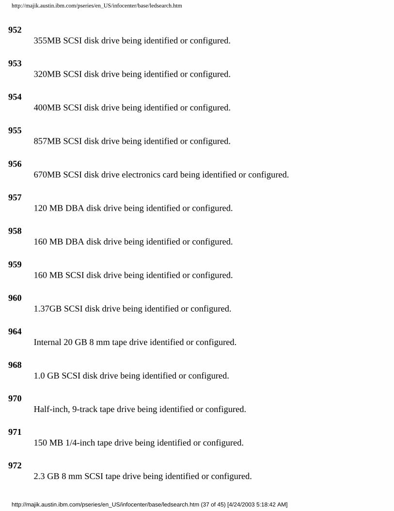
http://majik.austin.ibm.com/pseries/en_US/infocenter/base/ledsearch.htm
952 355MB SCSI disk drive being identified or configured.
953 320MB SCSI disk drive being identified or configured.
954 400MB SCSI disk drive being identified or configured.
955 857MB SCSI disk drive being identified or configured.
956 670MB SCSI disk drive electronics card being identified or configured.
957 120 MB DBA disk drive being identified or configured.
958 160 MB DBA disk drive being identified or configured.
959 160 MB SCSI disk drive being identified or configured.
960 1.37GB SCSI disk drive being identified or configured.
964 Internal 20 GB 8 mm tape drive identified or configured.
968 1.0 GB SCSI disk drive being identified or configured.
970 Half-inch, 9-track tape drive being identified or configured.
971 150 MB 1/4-inch tape drive being identified or configured.
972 2.3 GB 8 mm SCSI tape drive being identified or configured.
http://majik.austin.ibm.com/pseries/en_US/infocenter/base/ledsearch.htm (37 of 45) [4/24/2003 5:18:42 AM]

http://majik.austin.ibm.com/pseries/en_US/infocenter/base/ledsearch.htm
973 Other SCSI tape drive being identified or configured.
974 CD-ROM drive being identified or configured.
975 An optical disk drive being identified or configured.
977 M-Audio Capture and Playback Adapter being identified or configured.
981 540MB SCSI-2 single-ended disk drive being identified or configured.
984 1GB 8-bit disk drive being identified or configured.
985 M-Video Capture Adapter being identified or configured.
986 2.4GB SCSI disk drive being identified or configured.
987 An Enhanced SCSI CD-ROM drive being identified or configured.
989 200MB SCSI disk drive being identified or configured.
990 2.0GB SCSI-2 single-ended disk drive being identified or configured.
991 525MB 1/4-inch cartridge tape drive being identified or configured.
994 5 GB 8 mm tape drive being identified or configured.
995 1.2GB 1/4 inch cartridge tape drive being identified or configured.
http://majik.austin.ibm.com/pseries/en_US/infocenter/base/ledsearch.htm (38 of 45) [4/24/2003 5:18:42 AM]
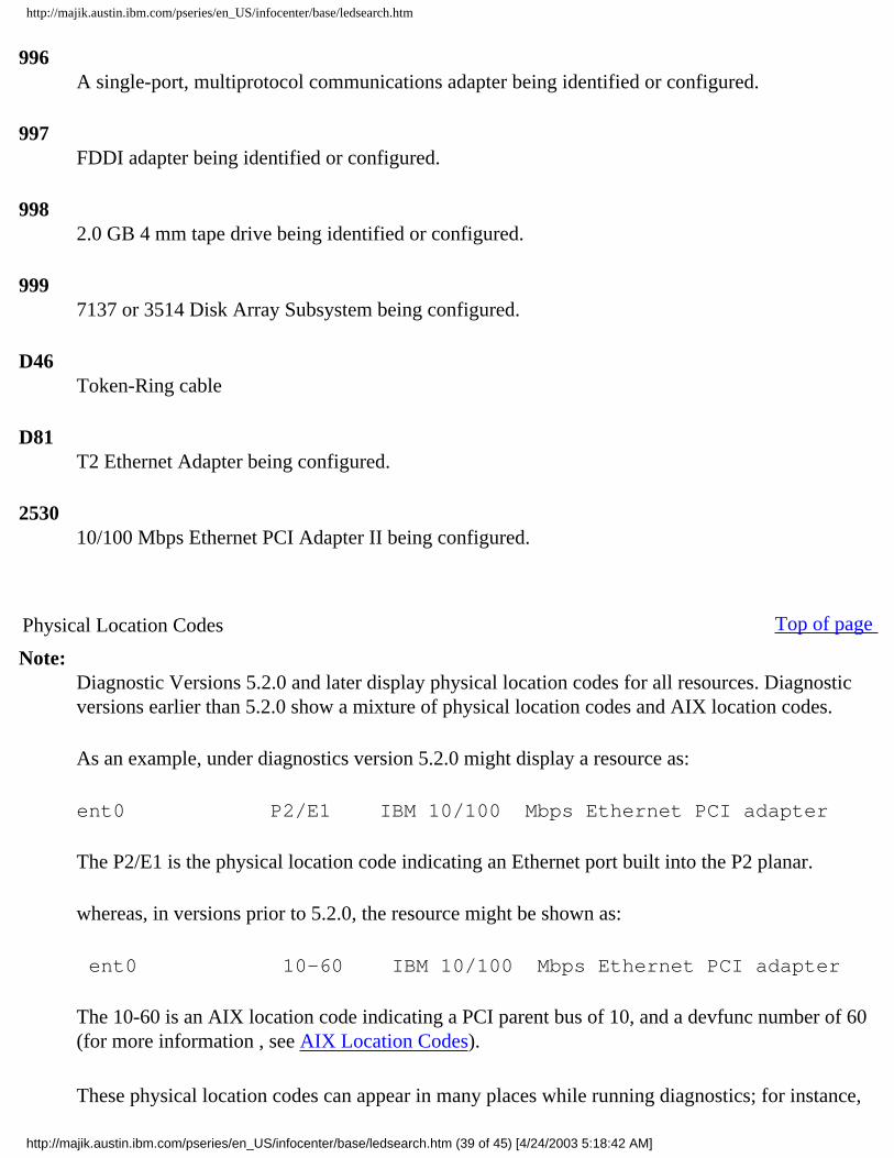
http://majik.austin.ibm.com/pseries/en_US/infocenter/base/ledsearch.htm
996 A single-port, multiprotocol communications adapter being identified or configured.
997 FDDI adapter being identified or configured.
998 2.0 GB 4 mm tape drive being identified or configured.
999 7137 or 3514 Disk Array Subsystem being configured.
D46 Token-Ring cable
D81 T2 Ethernet Adapter being configured.
2530 10/100 Mbps Ethernet PCI Adapter II being configured.
Physical Location Codes Top of page
Note:Diagnostic Versions 5.2.0 and later display physical location codes for all resources. Diagnostic versions earlier than 5.2.0 show a mixture of physical location codes and AIX location codes.
As an example, under diagnostics version 5.2.0 might display a resource as:
ent0 P2/E1 IBM 10/100 Mbps Ethernet PCI adapter
The P2/E1 is the physical location code indicating an Ethernet port built into the P2 planar.
whereas, in versions prior to 5.2.0, the resource might be shown as:
ent0 10-60 IBM 10/100 Mbps Ethernet PCI adapter
The 10-60 is an AIX location code indicating a PCI parent bus of 10, and a devfunc number of 60 (for more information , see AIX Location Codes).
These physical location codes can appear in many places while running diagnostics; for instance,
http://majik.austin.ibm.com/pseries/en_US/infocenter/base/ledsearch.htm (39 of 45) [4/24/2003 5:18:42 AM]

http://majik.austin.ibm.com/pseries/en_US/infocenter/base/ledsearch.htm
within resource menus, SRNs, or specific service aids.
Physical location codes provide a mapping of logical functions in a platform (or expansion sites for logical functions, such as connectors or ports) to their specific locations within the physical structure of the platform.
Location Code Format
The format for the location code is a string of alphanumeric characters separated by a dash (-), slash (/), pound sign (#), or period (.). The base location is all of the information before the slash (/) or pound sign (#). It identifies a device that is connected or plugged into the parent. Extended location information follows the slash (/). It identifies a device that is part of the parent, a connector, or a cable. Cable information follows the pound sign (#). It identifies a cable that is connected to the parent. The following are examples:
● P1 identifies system planar P1. ● U1-P1 also identifies system planar P1 in a rack or drawer unit. ● P2 identifies an I/O planar (including all integrated I/O devices). ● P1-C1 identifies a CPU card C1 plugged into planar P1. ● P1-M2 identifies a memory card or SIMM M2 plugged into planar P1. ● P2/K1 identifies a keyboard port controller (with connector) connected to planar P2. ● P1-K1 identifies a keyboard attached to connector K1 on planar P1. ● P1/S1 identifies serial port 1 controller on planar P1, the connector for serial port 1, or the cable
attached to connector S1. ● P1-I2/E3 identifies; Ethernet controller 3 on the card plugged into slot 2 (I2) on planar P1, the
connector for Ethernet controller 3, or the cable attached to Ethernet controller 3. ● P1-I2#E3 identifies; the cable attached to Ethernet controller 3 plugged into slot 2 (I2) on planar
P1.
The period (.) is used to identify sub-locations such as memory DIMMs on a base memory card or a specific SCSI address. The following are examples:
● P1-M1.4 identifies DIMM 4 on memory card 1 on planar 1. ● U1-P1-M2.12 identifies DIMM 12 on memory card in slot 2 on the system planar. ● P1-C1.1 identifies CPU 1 on CPU card 1 on planar 1. ● P2/Z1-A3.1 identifies a SCSI device with a SCSI address of LUN 1 at SCSI ID 3 attached to SCSI
bus 1 from planar 2. ● P1-I2#E3.2 identifies the second cable in a series of cables attached to Ethernet controller 3 in slot
2 (I2) on planar 1.
Depending on the AIX and firmware levels, AIX Diagnostics may include extended location information when identifying a planar or card. The extended location information or cable information is always
http://majik.austin.ibm.com/pseries/en_US/infocenter/base/ledsearch.htm (40 of 45) [4/24/2003 5:18:42 AM]
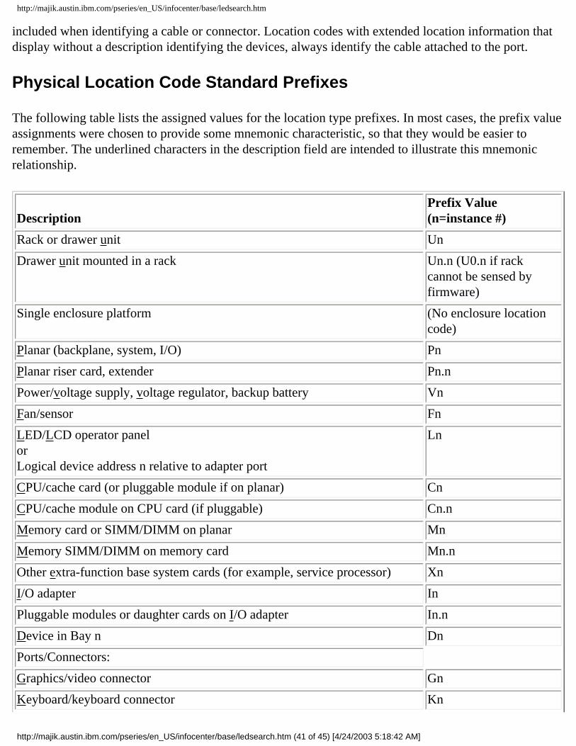
http://majik.austin.ibm.com/pseries/en_US/infocenter/base/ledsearch.htm
included when identifying a cable or connector. Location codes with extended location information that display without a description identifying the devices, always identify the cable attached to the port.
Physical Location Code Standard Prefixes
The following table lists the assigned values for the location type prefixes. In most cases, the prefix value assignments were chosen to provide some mnemonic characteristic, so that they would be easier to remember. The underlined characters in the description field are intended to illustrate this mnemonic relationship.
Description Prefix Value (n=instance #)
Rack or drawer unit Un
Drawer unit mounted in a rack Un.n (U0.n if rack cannot be sensed by firmware)
Single enclosure platform (No enclosure location code)
Planar (backplane, system, I/O) Pn
Planar riser card, extender Pn.n
Power/voltage supply, voltage regulator, backup battery Vn
Fan/sensor Fn
LED/LCD operator panelorLogical device address n relative to adapter port
Ln
CPU/cache card (or pluggable module if on planar) Cn
CPU/cache module on CPU card (if pluggable) Cn.n
Memory card or SIMM/DIMM on planar Mn
Memory SIMM/DIMM on memory card Mn.n
Other extra-function base system cards (for example, service processor) Xn
I/O adapter In
Pluggable modules or daughter cards on I/O adapter In.n
Device in Bay n Dn
Ports/Connectors:
Graphics/video connector Gn
Keyboard/keyboard connector Kn
http://majik.austin.ibm.com/pseries/en_US/infocenter/base/ledsearch.htm (41 of 45) [4/24/2003 5:18:42 AM]
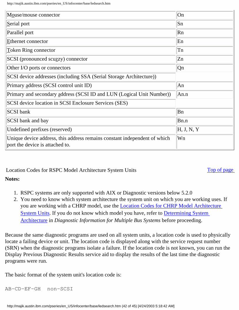
http://majik.austin.ibm.com/pseries/en_US/infocenter/base/ledsearch.htm
Mouse/mouse connector On
Serial port Sn
Parallel port Rn
Ethernet connector En
Token Ring connector Tn
SCSI (pronounced scuzzy) connector Zn
Other I/O ports or connectors Qn
SCSI device addresses (including SSA (Serial Storage Architecture))
Primary address (SCSI control unit ID) An
Primary and secondary address (SCSI ID and LUN (Logical Unit Number)) An.n
SCSI device location in SCSI Enclosure Services (SES)
SCSI bank Bn
SCSI bank and bay Bn.n
Undefined prefixes (reserved) H, J, N, Y
Unique device address, this address remains constant independent of which port the device is attached to.
Wn
Location Codes for RSPC Model Architecture System Units Top of page
Notes:
1. RSPC systems are only supported with AIX or Diagnostic versions below 5.2.0 2. You need to know which system architecture the system unit on which you are working uses. If
you are working with a CHRP model, use the Location Codes for CHRP Model Architecture System Units. If you do not know which model you have, refer to Determining System Architecture in Diagnostic Information for Multiple Bus Systems before proceeding.
Because the same diagnostic programs are used on all system units, a location code is used to physically locate a failing device or unit. The location code is displayed along with the service request number (SRN) when the diagnostic programs isolate a failure. If the location code is not known, you can run the Display Previous Diagnostic Results service aid to display the results of the last time the diagnostic programs were run.
The basic format of the system unit's location code is:
AB-CD-EF-GH non-SCSI
http://majik.austin.ibm.com/pseries/en_US/infocenter/base/ledsearch.htm (42 of 45) [4/24/2003 5:18:42 AM]

http://majik.austin.ibm.com/pseries/en_US/infocenter/base/ledsearch.htm
AB-CD-EF-G,H SCSI
For planars, cards, and non-SCSI devices, the location code is defined as follows:
AB-CD-EF-GH | | | | | | | Device/FRU/Port ID | | Connector ID | Slot or Adapter Number Bus Type
● AB identifies a bus type. ● CD identifies a slot or adapter number. ● EF is the connector identifier, used to identify the adapter connector to which a resource is
attached. ● GH identifies a port, address, memory module, device, or FRU. GH has several meanings
depending upon the resource type, they are as follows: ❍ For memory cards, GH defines a memory module. Values for GH are 1 through 16.
For systems that have memory modules that plug directly into the system planar, the location code is 00-00-00-GH where GH is the memory module slot. For systems that have memory cards with memory modules, the location code is 00-CD-EF-GH, where CD is the card slot and GH is the memory module slot.
❍ For L2 caches, GH defines the cache. Values for GH are 1 through 16. ❍ For PCMCIA devices, GH defines the PCMCIA. Values for GH are 1 through 16. ❍ For async devices, GH defines the port on the fanout box. Values are 00 to 15. ❍ For a diskette drive, H defines which diskette drive 1 or 2. G is always 0. ❍ For all other devices, GH is equal to 00.
For integrated adapters, EF-GH is the same as the definition for a pluggable adapter. For example, the location code for a diskette drive is 01-A0-00-00. A second diskette drive is 01-A0-00-01.
For SCSI, the location code is defined as follows:
AB-CD-EF-G,H | | | | | | | | | Logical Unit Address of SCSI Device | | | Control Unit Address of SCSI Device | | Connector ID | Slot or Adapter Number Bus Type
Where:
http://majik.austin.ibm.com/pseries/en_US/infocenter/base/ledsearch.htm (43 of 45) [4/24/2003 5:18:42 AM]

http://majik.austin.ibm.com/pseries/en_US/infocenter/base/ledsearch.htm
● AB-CD-EF are the same as non-SCSI devices. ● G defines the control unit address of the device. Values of 0 to 15 are valid. ● H defines the logical unit address of the device. Values of 0 to 255 are valid.
Adapters and cards are identified with only AB-CD. The possible values for AB are as follows:
00 for processor bus 01 for ISA buses 04 for PCI buses 05 for PCMCIA buses (not supported on 7024)
The possible values for CD depend on the adapter or card.
For pluggable adapters or cards, this is a two-digit slot number in the range from 01 to 99. However, in the case of ISA cards these numbers do not actually correspond to the physical slot numbers. They simply are based on the order in which the ISA cards are defined or configured, either by SMIT or the ISA Adapter Configuration Service Aid.
For integrated adapters, the first character (C) is a letter in the range from A to Z. This letter is based on the order in which the integrated adapters are defined in residual data. This ensures unique location codes for the integrated adapters. The second character (D) is set to 0.
Refer to the following RSPC location code examples:
Processor-PCI bus 00-00 PCI busMemory module in system planar 00-00-00-01Memory module in card 00-0A-00-01Integrated PCI adapters 04-A0 ISA bus (Integrated PCI-ISA bridge) 04-B0 Secondary PCI bus (Integrated PCI-PCI bridge) 04-C0 Integrated PCI SCSI controllerNon-integrated PCI adapters 04-01 Any PCI card in slot 1 04-02 Any PCI card in slot 2Integrated ISA adapters 01-A0 Diskette adapter 01-B0 Parallel port adapter 01-C0 Serial port 1 adapter 01-D0 Serial port 2 adapter
http://majik.austin.ibm.com/pseries/en_US/infocenter/base/ledsearch.htm (44 of 45) [4/24/2003 5:18:42 AM]

http://majik.austin.ibm.com/pseries/en_US/infocenter/base/ledsearch.htm
01-E0 Keyboard adapter 01-F0 Mouse adapterNon-integrated ISA adapters 01-01 First ISA card defined/configured 01-02 Second ISA card defined/configured 01-03 Third ISA card defined/configured 01-04 Fourth ISA card defined/configuredDevice attached to SCSI controller 04-C0-01-4,0 Device attached to Integrated PCI SCSI controller
http://majik.austin.ibm.com/pseries/en_US/infocenter/base/ledsearch.htm (45 of 45) [4/24/2003 5:18:42 AM]
RS/6000Eserver pSeries
Diagnostic Information for Multiple BusSystems
Version 5.2.0.0
SA38-0509-17
���

Eighteenth Edition (December 2002)
Before using this information and the product it supports, read the information in Appendix F, “Notices” on page 697.
A reader’s comment form is provided at the back of this publication. If the form has been removed, address commentsto Information Development, Department H6DS-905-6C006, 11501 Burnet Road, Austin, Texas 78758-3493. To sendcomments electronically, use this commercial internet address: [email protected]. Any information that yousupply may be used without incurring any obligation to you.
© International Business Machines Corporation 1995, 2002. All rights reserved. Note to U.S. Government Users,Restricted Rights -- Use, duplication, or disclosure restricted by GSA ADP Schedule Contract with IBM Corp.

Contents
About This Book . . . . . . . . . . . . . . . . . . . . . . . ixWho Should Use This Book . . . . . . . . . . . . . . . . . . . . ixHow to Use This Book . . . . . . . . . . . . . . . . . . . . . ixISO 9000 . . . . . . . . . . . . . . . . . . . . . . . . . . ixRelated Publications . . . . . . . . . . . . . . . . . . . . . . xTrademarks . . . . . . . . . . . . . . . . . . . . . . . . . xCSU/SSR Feature Installation . . . . . . . . . . . . . . . . . . . xi
Chapter 1. Service Hints . . . . . . . . . . . . . . . . . . . . 1Using the Maintenance Analysis Procedures . . . . . . . . . . . . . . 1About Slow Boot . . . . . . . . . . . . . . . . . . . . . . . 2Multiple SRN or Error Code Reporting and Handling . . . . . . . . . . . . 2General SCSI Configuration Checks . . . . . . . . . . . . . . . . . 3High Availability or Multiple SCSI System Checks . . . . . . . . . . . . . 3SCSI-2 Single-Ended Adapter PTC Failure Isolation Procedure . . . . . . . . 4External SCSI-2 Single-Ended Bus PTC Isolation Procedure . . . . . . . . . 5Internal SCSI-2 Single-Ended Bus PTC Isolation Procedure . . . . . . . . . 7SCSI-2 Differential Adapter PTC Failure Isolation Procedure . . . . . . . . . 9External SCSI-2 Differential Adapter Bus PTC Isolation Procedure . . . . . . . 10Dual-Channel Ultra SCSI Adapter PTC Failure Isolation Procedure . . . . . . 1364-bit PCI-X Dual Channel SCSI Adapter PTC Failure Isolation Procedure . . . . 13
Chapter 2. Start of Call MAP . . . . . . . . . . . . . . . . . . . 15
Chapter 3. Fast Path MAP . . . . . . . . . . . . . . . . . . . 1718Fast Path Table . . . . . . . . . . . . . . . . . . . . . . . 19
Chapter 4. MAP 0020: Problem Determination Procedure . . . . . . . . 29Purpose of This MAP. . . . . . . . . . . . . . . . . . . . . . 29
Chapter 5. MAP 0025: SCSI RAID Problem Determination Procedure . . . . 41Purpose of This MAP. . . . . . . . . . . . . . . . . . . . . . 41
Chapter 6. MAP 0030: Additional Problem Determination. . . . . . . . . 45Purpose of This MAP. . . . . . . . . . . . . . . . . . . . . . 45
Chapter 7. MAP 0040: Intermittent Problem Isolation . . . . . . . . . . 47Purpose of This MAP. . . . . . . . . . . . . . . . . . . . . . 47
Chapter 8. MAP 0050: SCSI Bus Problems . . . . . . . . . . . . . . 51Purpose of This MAP. . . . . . . . . . . . . . . . . . . . . . 51
Chapter 9. MAP 0070: 888 Sequence in Operator Panel Display . . . . . . 59Purpose of This MAP. . . . . . . . . . . . . . . . . . . . . . 59
Chapter 10. MAP 0080: System Bus Problem Isolation . . . . . . . . . 63
iii

Purpose of This MAP. . . . . . . . . . . . . . . . . . . . . . 63
Chapter 11. MAP 0210: General Problem Resolution . . . . . . . . . . 67Purpose of This MAP. . . . . . . . . . . . . . . . . . . . . . 67
Chapter 12. MAP 0220: Hot-Swap FRU Problem Resolution . . . . . . . . 77Purpose of This MAP. . . . . . . . . . . . . . . . . . . . . . 77
Chapter 13. MAP 0230: Platform Error Problem Resolution . . . . . . . . 83Purpose of This MAP. . . . . . . . . . . . . . . . . . . . . . 83
Chapter 14. MAP 0235: System Array Self-Repair Problem Resolution . . . . 91Purpose of This MAP. . . . . . . . . . . . . . . . . . . . . . 91
Chapter 15. MAP 0240: Memory Problem Resolution . . . . . . . . . . 93Purpose of This MAP. . . . . . . . . . . . . . . . . . . . . . 93
Chapter 16. MAP 0250: Unexpected System Halts During Diagnostics . . . . 9797
Chapter 17. MAP 0260: System Hangs During Resource Configuration . . . . 99Purpose of This MAP. . . . . . . . . . . . . . . . . . . . . . 99
Chapter 18. MAP 0270: SCSI RAID Problem Resolution and Verification . . . 103Purpose of This MAP . . . . . . . . . . . . . . . . . . . . . 103
Chapter 19. MAP 0280: Boot Problem Resolution . . . . . . . . . . . 111Purpose of This MAP . . . . . . . . . . . . . . . . . . . . . 111
Chapter 20. MAP 0285: Multipath I/O (MPIO) Problem Resolution . . . . . 113Purpose of This MAP . . . . . . . . . . . . . . . . . . . . . 113
Chapter 21. MAP 0290: Missing Resource Problem Resolution . . . . . . 117Purpose of This MAP . . . . . . . . . . . . . . . . . . . . . 117
Chapter 22. MAP 0291: Missing Device or Bus Problem Resolution . . . . 121Purpose of This MAP . . . . . . . . . . . . . . . . . . . . . 121
Chapter 23. MAP 0410: Repair Checkout . . . . . . . . . . . . . . 125Purpose of This MAP . . . . . . . . . . . . . . . . . . . . . 125
Chapter 24. MAP 0420: System Checkout. . . . . . . . . . . . . . 133Purpose of This MAP . . . . . . . . . . . . . . . . . . . . . 133
Chapter 25. Installation Checkout . . . . . . . . . . . . . . . . 135Installation Checkout Procedure. . . . . . . . . . . . . . . . . . 135
Chapter 26. General Diagnostic Information . . . . . . . . . . . . . 139AIX Operating System Message Files . . . . . . . . . . . . . . . . 139Microcode . . . . . . . . . . . . . . . . . . . . . . . . . 139
iv Diagnostic Information for Multiple Bus Systems
CEREADME File . . . . . . . . . . . . . . . . . . . . . . . 140CE Login . . . . . . . . . . . . . . . . . . . . . . . . . 141Automatic Diagnostic Tests . . . . . . . . . . . . . . . . . . . 141CPU and Memory Testing and Error Log Analysis . . . . . . . . . . . . 143Diagnostic Programs . . . . . . . . . . . . . . . . . . . . . 144Periodic Diagnostics . . . . . . . . . . . . . . . . . . . . . 147Automatic Error Log Analysis (diagela) . . . . . . . . . . . . . . . 148Log Repair Action . . . . . . . . . . . . . . . . . . . . . . 150System Fault Indicator and System Identify Indicator . . . . . . . . . . . 150Testing the Line Printer . . . . . . . . . . . . . . . . . . . . 151Array Bit Steering . . . . . . . . . . . . . . . . . . . . . . 151Running Diagnostics on the Native Serial Port on a Full Machine Partition with a
HMC Attached. . . . . . . . . . . . . . . . . . . . . . . 151Enhanced I/O Error Handling. . . . . . . . . . . . . . . . . . . 152
Chapter 27. Using Standalone and Online Diagnostics . . . . . . . . . 153Standalone and Online Diagnostics Operating Considerations . . . . . . . . 153Online Diagnostics Mode of Operation . . . . . . . . . . . . . . . 160Standalone Diagnostic Operation . . . . . . . . . . . . . . . . . 163General Information about Multiple Systems. . . . . . . . . . . . . . 164Determining System Architecture . . . . . . . . . . . . . . . . . 165High-Availability SCSI . . . . . . . . . . . . . . . . . . . . . 166Diagnostic Summary . . . . . . . . . . . . . . . . . . . . . 166Diagnostics Tasks and Resources . . . . . . . . . . . . . . . . . 167SCSI RAID Descriptions and Diagnostic Procedures . . . . . . . . . . . 169
Chapter 28. Introduction to Tasks and Service Aids . . . . . . . . . . 175Tasks . . . . . . . . . . . . . . . . . . . . . . . . . . 176Add Resource to Resource List . . . . . . . . . . . . . . . . . . 177AIX Shell Prompt . . . . . . . . . . . . . . . . . . . . . . 177Analyze Adapter Internal Log. . . . . . . . . . . . . . . . . . . 177Backup and Restore Media . . . . . . . . . . . . . . . . . . . 178Certify Media . . . . . . . . . . . . . . . . . . . . . . . . 179Change Hardware Vital Product Data . . . . . . . . . . . . . . . . 182Configure Dials and LPF Keys . . . . . . . . . . . . . . . . . . 182Configure ISA Adapter . . . . . . . . . . . . . . . . . . . . . 182Configure Reboot Policy . . . . . . . . . . . . . . . . . . . . 183Configure Remote Maintenance Policy . . . . . . . . . . . . . . . 184Configure Ring Indicate Power-On Policy. . . . . . . . . . . . . . . 186Configure Ring Indicate Power On . . . . . . . . . . . . . . . . . 186Configure Scan Dump Policy . . . . . . . . . . . . . . . . . . . 187Configure Service Processor . . . . . . . . . . . . . . . . . . . 187Configure Surveillance Policy . . . . . . . . . . . . . . . . . . 191Create Customized Configuration Diskette . . . . . . . . . . . . . . 191Delete Resource from Resource List . . . . . . . . . . . . . . . . 192Disk Maintenance . . . . . . . . . . . . . . . . . . . . . . 192Display Configuration and Resource List . . . . . . . . . . . . . . . 193Display Firmware Device Node Information . . . . . . . . . . . . . . 193Display Hardware Error Report . . . . . . . . . . . . . . . . . . 193Display Hardware Vital Product Data . . . . . . . . . . . . . . . . 194
Contents v

Display Machine Check Error Log . . . . . . . . . . . . . . . . . 194Display Microcode Level . . . . . . . . . . . . . . . . . . . . 194Display or Change Bootlist . . . . . . . . . . . . . . . . . . . 194Display or Change Diagnostic Run-Time Options . . . . . . . . . . . . 195Display Previous Diagnostic Results . . . . . . . . . . . . . . . . 197Display Resource Attributes . . . . . . . . . . . . . . . . . . . 197Display Service Hints . . . . . . . . . . . . . . . . . . . . . 197Display Software Product Data . . . . . . . . . . . . . . . . . . 198Display System Environmental Sensors . . . . . . . . . . . . . . . 198Display Test Patterns . . . . . . . . . . . . . . . . . . . . . 200Display USB Devices . . . . . . . . . . . . . . . . . . . . . 200Download Microcode . . . . . . . . . . . . . . . . . . . . . 200Fault Indicators . . . . . . . . . . . . . . . . . . . . . . . 203Fibre Channel RAID Service Aids . . . . . . . . . . . . . . . . . 204Flash SK-NET FDDI Firmware . . . . . . . . . . . . . . . . . . 204Format Media . . . . . . . . . . . . . . . . . . . . . . . . 205Gather System Information . . . . . . . . . . . . . . . . . . . 207Generic Microcode Download . . . . . . . . . . . . . . . . . . 207Hot Plug Task . . . . . . . . . . . . . . . . . . . . . . . . 207Identify Indicators . . . . . . . . . . . . . . . . . . . . . . 211Identify and System Attention Indicators . . . . . . . . . . . . . . . 211Local Area Network Analyzer . . . . . . . . . . . . . . . . . . . 212Log Repair Action . . . . . . . . . . . . . . . . . . . . . . 212Periodic Diagnostics . . . . . . . . . . . . . . . . . . . . . 213PCI RAID Physical Disk Identify . . . . . . . . . . . . . . . . . . 213Process Supplemental Media . . . . . . . . . . . . . . . . . . 213Run Diagnostics . . . . . . . . . . . . . . . . . . . . . . . 214Run Error Log Analysis . . . . . . . . . . . . . . . . . . . . 214Run Exercisers . . . . . . . . . . . . . . . . . . . . . . . 214Save or Restore Hardware Management Policies . . . . . . . . . . . . 217Save or Restore Service Processor Configuration . . . . . . . . . . . . 217SCSI Bus Analyzer . . . . . . . . . . . . . . . . . . . . . . 218SCSD Tape Drive Service Aid . . . . . . . . . . . . . . . . . . 219Spare Sector Availability . . . . . . . . . . . . . . . . . . . . 220SSA Service Aid . . . . . . . . . . . . . . . . . . . . . . . 220System Fault Indicator . . . . . . . . . . . . . . . . . . . . . 220System Identify Indicator . . . . . . . . . . . . . . . . . . . . 220Update Disk-Based Diagnostics . . . . . . . . . . . . . . . . . . 220Update System or Service Processor Flash . . . . . . . . . . . . . . 221Update System Flash . . . . . . . . . . . . . . . . . . . . . 2227135 RAIDiant Array Service Aid . . . . . . . . . . . . . . . . . 2237318 Serial Communications Network Server Service Aid . . . . . . . . . 224
Chapter 29. Diagnostics Numbers and Location Codes . . . . . . . . . 225Operator Panel Display Numbers . . . . . . . . . . . . . . . . . 225Diagnostic Load Progress Indicators . . . . . . . . . . . . . . . . 238Location Codes for RSPC Model Architecture System Units . . . . . . . . 242Location Codes for CHRP Model Architecture System Units . . . . . . . . 244Physical Location Codes . . . . . . . . . . . . . . . . . . . . 244AIX Location Codes. . . . . . . . . . . . . . . . . . . . . . 248
vi Diagnostic Information for Multiple Bus Systems

Chapter 30. Using the SRN List . . . . . . . . . . . . . . . . . 251Service Request Number . . . . . . . . . . . . . . . . . . . . 251Using the Service Request Number List . . . . . . . . . . . . . . . 252Service Request Number Lists . . . . . . . . . . . . . . . . . . 252
Chapter 31. Five-Digit SRNs 10104 through SSA03 . . . . . . . . . . 255Service Request Number List . . . . . . . . . . . . . . . . . . 255
Chapter 32. SRNs 101-000 through 6C9-600 . . . . . . . . . . . . . 267
Chapter 33. SRNs 700-102 through 89c-302 . . . . . . . . . . . . . 377
Chapter 34. SRNs 900-001 through xxxxxxx . . . . . . . . . . . . . 461
Chapter 35. SRNs A00-(x)xxx through A1D-(x)xxx . . . . . . . . . . . 535
Chapter 36. SRNs 2520-101 through 25C1-(x)xxx . . . . . . . . . . . 555
Chapter 37. Failing Function Codes (FFCs) . . . . . . . . . . . . . 563Description of the Failing Function Code List . . . . . . . . . . . . . 563Machine Types . . . . . . . . . . . . . . . . . . . . . . . 564Failing Function Code List . . . . . . . . . . . . . . . . . . . 566
Chapter 38. FRU Cross-References . . . . . . . . . . . . . . . . 651Using the FRU Name Cross-Reference List . . . . . . . . . . . . . . 651
Appendix A. Wrap Plugs. . . . . . . . . . . . . . . . . . . . 659
Appendix B. Test Media . . . . . . . . . . . . . . . . . . . . 661
Appendix C. System Memory Reference . . . . . . . . . . . . . . 663System Unit Memory Combinations . . . . . . . . . . . . . . . . 663
Appendix D. General Attributes Required When Using a TTY Terminal . . . 667Additional Communication Attributes . . . . . . . . . . . . . . . . 668Additional Keyboard Attributes . . . . . . . . . . . . . . . . . . 669Additional Printer Attributes . . . . . . . . . . . . . . . . . . . 669
Appendix E. CHRP Error Log Structure . . . . . . . . . . . . . . 671CHRP Error Logs in AIX . . . . . . . . . . . . . . . . . . . . 671Versions of the Error Log Format . . . . . . . . . . . . . . . . . 673RTAS Error Return Format Fixed Part (All Versions) . . . . . . . . . . . 673Extended Error Log Formats . . . . . . . . . . . . . . . . . . . 675Version 2 Extension of CHRP Error Log Format . . . . . . . . . . . . 685RTAS General Extended Error Log Format, Version 3 . . . . . . . . . . 688Extended Log Debug Data . . . . . . . . . . . . . . . . . . . 696
Appendix F. Notices . . . . . . . . . . . . . . . . . . . . . 697
Contents vii

Index . . . . . . . . . . . . . . . . . . . . . . . . . . 699
viii Diagnostic Information for Multiple Bus Systems
About This Book
The diagnostic information contained in this book is common to all multiple bus systemunits. Any information or diagnostic procedure that is specific to a certain system unit ordevice is in the service guide for that system unit or device.
Who Should Use This BookThis book is used for problem isolation and service procedures by a servicerepresentative specifically trained on the system unit being serviced.
This book combines operating instructions for hardware diagnostic programs withMaintenance Analysis Procedures (MAPs), corresponding Service Request Numbers(SRNs) and three-digit display codes. The SRNs are, in turn, keyed to failing functioncodes (FFCs) and corresponding part numbers for specific machine types.
How to Use This BookThis book has a version number in the title. Always use the book version that is equalto or greater than the first two digits of your diagnostics version level. For example, ifyour CD-ROM version is 2.2 or 2.25, use version 2.2 or higher of this diagnosticsinformation manual.
If you are analyzing a system problem, start with Chapter 2, “Start of Call MAP” onpage 15.
The SRN lists in Chapters 28-32 direct you to the correct failing function. Across-reference by name, (such as adapter or device) to Failing Function Code can befound in Chapter 38, “FRU Cross-References” on page 651.
Refer to Chapter 25, “Installation Checkout” on page 135 if you are checking the systemunit or device after installation.
ISO 9000ISO 9000 registered quality systems were used in the development and manufacturingof this product.
A reader’s comment form is provided at the back of this publication. If the form hasbeen removed, address comments to Information Development, DepartmentH6DS-905-6C006, 11501 Burnet Road, Austin, Texas 78758-3493. To send commentselectronically, use this commercial internet address: [email protected]. Anyinformation that you supply may be used without incurring any obligation to you.
ix

Related PublicationsThe following books are used to isolate a problem in the system.
v Adapters, Devices, and Cable Information for Multiple Bus Systems containsinformation about common device, adapter, and cabling of the system unit.
v Site and Hardware Planning Information is a planning and site preparation guide.
v Installation Guide contains the instructions for installing the operating system.
v RS/6000 SP System Service Guide contains the service procedures that are specificto RS/6000 SP systems.
v If you are servicing a clustered Eserver, go to the Start of Call MAP 100 in theClustered Eserver Installation and Service Guide.
v The service documentation for the system units or devices contains the serviceprocedures that are specific to that device or system unit. The service documentationcontains the following:
– Reference information such as data flow, cable diagrams, and specifications
– System unit or device-specific Maintenance Analysis Procedures (MAPs), such asthe power MAP
– Removal and replacement procedures
– The system unit or device installation procedures
– Parts diagrams and parts lists.
TrademarksThe following terms are trademarks of International Business Machines Corporation inthe United States, other countries, or both:
v AIX
v Eserver
v ESCON
v IBM
v LANStreamer
v Portmaster
v POWER Gt1
v POWER Gt3
v POWER Gt4
v pSeries
v RETAIN
v RS/6000
v S/370
v SP
v TURBOWAYS
Other company, product, and service names may be trademarks or service marks ofothers.
x Diagnostic Information for Multiple Bus Systems

CSU/SSR Feature InstallationAttention: The following information indicates which features on varioussystems/models are intended to be installed by the customer and which features are tobe installed by a System Service Representative (SSR) as part of a MiscellaneousEquipment Specification (MES). This information is for systems/models available as ofthe edition date.
Notes:
1. CSU = Customer Set-Up.
2. SSR = System Service Representative.
3. For a description of Feature Codes, see the Feature Code Descriptions below thefollowing table.
4. The 7013 Model J30 was announced as CSU. U.S. practice has been for SSRinstallation.
5. The 7014 rack is SSR installable. However, the system units that are installed intothe 7014 may be CSU. Check the matrix below to verify which system units shouldbe installed by the SSR or are CSU.
Machine Type Model System CSU 1 Features/Options 2
SSR Installation Customer Installation
7006 (All) Yes All Features None
7007 (All) Yes All Features None
7008 (All) Yes All Features None
7009 (All) Yes All Features None
7010 (All) Yes All Features None
7011 (All) Yes All Features None
7012 (All) Yes All Features None
7013 (All) 3 No All Features None
7015 (All) No All Features None
7017 (All) No All Features None
7024 (All) Yes FC 6309 All Other Features
7025 (All) Yes FC 2856, 6309, 6549 All Other Features
7026 (All except B80) No All Other Features FC 2901, 2908, 2909,2911, 2913, 3071, 3072,3074, 3078, 3079, 3083
7026 (B80) Yes FC 4361, 4362, 4363 All Other Features
7027 (All) No All Other Features All Features
7028 (All) Yes All Features All Features
7040 (All) No All Features None
7043 (All) Yes FC 2856 & 6309 All Other Features
7044 (All) Yes FC 2856 & 6309 c.AllOther Features
Preface xi

Machine Type Model System CSU 1 Features/Options 2
SSR Installation Customer Installation
7046 (All) Yes FC 2856 & 6309 All Other Features
7236 (All) No All Features None
7248 (All) Yes FC 2856 All Other Features
7316 (All) No All Features None
7317 (All) No All Features None
7318 (All) No All Features None
7319 (All) No All Features None
Feature Code Feature Code Description2616 Internal CD-ROM 2/4X/Tray Loading, 600KB/s2856 PCI/Short/32bit/3.3 or 5V, 7250 Attach Adapter2901 4.5GB F/W Ultra SCSI DASD Module2908 9.1GB Ultra SCSI DASD Module2909 18.2GB Ultra SCSI DASD Module2911 9.1GB F/W Ultra SCSI DASD Module2913 9.1GB F/W Ultra Module, 1″ High3071 4.5GB SSA DASD Module, 1″ High3072 9.1GB SSA DASD Module, 1.6″ High3074 9.1GB SSA DASD Module, Hot Swap3078 9.1GB SSA DASD Module, 10K3079 9.1GB SSA DASD Module, 10K3080 4.5GB F/W SCSI DASD Module3083 2.2GB F/W SCSI DASD Module3084 4.5GB F/W SCSI DASD Module3090 9.1GB F/W SCSI DASD Module3133 Cable SCSI, 3M, to F/W MC SCSI Adapter (SE OR Diff)3134 Cable SCSI, 6M, to F/W MC SCSI Adapter (SE OR Diff)3137 Cable SCSI/DIFF, 12M, to F/W MC SCSI Adapter3138 Cable SCSI/DIFF, 18M, to F/W MC SCSI Adapter4361 1-Way 375MHz POWER3-II Processor Card4362 2-Way 375MHz POWER3-II Processor Card4363 2-Way 375MHz POWER3-II Processor Card (8MB L2/Processor)6142 Internal 4mm 4/8GB Tape6147 8mm 5/10GB VDAT Tape6153 4mm Tape Drive + Autoloader, Horizontal6294 Optional AC Power Supply for 7027 SCSI Drawers6295 Optional bifurcated (Y-cable) Power Cord for 7027 SCSI Drawers6309 Digital Trunk Quad Adapter, PCI/Long/32Bit/5V6549 Additional Power Supply for 2nd and 3rd 6-Pks on Model F40
xii Diagnostic Information for Multiple Bus Systems
Chapter 1. Service Hints
Most hardware errors in the AIX error log contain sysplanar0 as the resource name.The resource name identifies the resource that detected the error; it does not indicatethat the resource is faulty or should be replaced. Use the resource name to determinethe appropriate diagnostic to analyze the error.
Using the Maintenance Analysis ProceduresSome MAPs or procedures may ask whether the system is running one or more logicalpartition (LPAR) versus running a full machine partition. If you are not certain about thesystem configuration, ask the customer. If the system does not have an HMC(Hardware Management Console), then it is running a full machine partition (however, asystem with an HMC may be running one or more logical partitions or running a fullmachine partition).
On a partitioned system, some service aids may only be run in a partition that is set upwith service authority. To set up a partition with service authority, ask the systemadministrator to refer to the Hardware Management Console Installation and OperationsGuide.
The maintenance analysis procedures (MAPs) provide the service representative astep-by-step procedure to analyze a problem with the system hardware. Hardwareprocedures are intended for use by a service representative trained on the system unitbeing serviced.
Some of the devices that are supported by the diagnostic programs also have their ownmaintenance documentation. You may want to use the maintenance documentation forthat device before running the diagnostics for the system. Sometimes the maintenancepackage for an attached device allows the customer to continue operating the systemwhile that device is being diagnosed. You can use the diagnostic programs to check theadapter to which that device is attached.
Begin all problem analysis with Chapter 2, “Start of Call MAP” on page 15.
MAPs may direct you to run diagnostics. Information on how to run the diagnostics, invarious modes, is in Chapter 26, “General Diagnostic Information” on page 139. TheseMAPs may direct you to other MAPs or to other service information. Be prepared torecord code numbers and other data while using these MAPs.
Some adapters may show a different SRN than expected if the adapter cannot beconfigured. If the SRN or FFC are listed by onscreen diagnostics, use that informationfirst. Otherwise, use the part number that is on the adapter.
SRN and Failing Function Code (FFC) DiscrepanciesSRNs listed in this book may not list the same FFCs and FRUs as reported byonscreen diagnostics. If the FRUs listed in this book do not solve the problem, check ifany other FRUs are listed by onscreen diagnostics, and if so, try them.
1

About Slow BootSome systems support a service mode fast or slow boot. If you suspect a problem inthe base system or can’t otherwise localize the defect, do a slow-mode boot in servicemode.
This can be specified using the System Power Control Menu on the service processormain menu. A fast-mode boot skips much of the built-in diagnostic testing. A slow-modeboot may yield a new 8-character error code on the operator panel and new errors inthe service processor error log. If a new error code is reported, use it in subsequentsteps to continue problem analysis.
Multiple SRN or Error Code Reporting and HandlingThe AIX® Diagnostics can generate SRNs using hardware tests or from error loganalysis. The diagnostics also report platform-unique 8-digit error codes detected andlogged during POST, and device-unique error codes generated by the devicediagnostics.
When you run the diagnostics, more than one SRN or error code may be reported. Thismay occur when there are multiple entries in the error log or when the diagnostic testsdetect multiple hardware problems. If additional SRNs are reported from a PreviousDiagnostics Results screen, they should be processed before processing any SRNsfrom a problem reporting screen.
The SRNs are normally displayed in the order in which the devices are tested and theerror log entries analyzed. Error log entries logged against a single device type aredisplayed in descending order with the newest entry first.
SRNs with a source code of F do not provide maximum isolation. Online diagnosticsmust run in Advanced and Problem Determination Mode to obtain maximum isolation.SRNs with a source code of G are the result of an error log entry.
Handle multiple SRNs and error codes in the following order:
1. 8-digit Error Codes. Multiple 8-digit error codes may not be listed in the correctorder. See the ″Error Code to FRU Index″ in the system service guide to identifythose error codes that require special handling.
2. SRNs in the range of A01-xxx to A1D-xxx.
3. SRNs with a source code other than F or G.
4. SRNs with a source code of F. Online diagnostics must be run in Advanced andProblem Determination Mode to obtain maximum isolation.
5. SRNs with a source code of G.
Note: The priority for multiple SRNs with a source of G is determined by the timestamp of the failure. Follow the action for the SRN with the earliest timestamp first.
6. Device SRNs and error codes (5-digit SRNs).
2 Diagnostic Information for Multiple Bus Systems
If there are multiple SRNs within a group, it does not matter which SRN is handled first.
General SCSI Configuration ChecksThe following steps apply to all types of SCSI problems:
1. Verify that all SCSI devices on the SCSI bus have a unique address.
2. Verify that all cables are connected securely and that there is proper termination atboth ends of the SCSI bus.
3. Verify that the cabling configuration does not exceed the maximum cable length forthe adapter in use. Refer to Adapters, Devices, and Cable Information for MultipleBus Systems for more details on SCSI cabling.
4. Verify that the adapters and devices that you are working with are at the appropriatemicrocode levels for the customer situation. Contact your service support if youneed assistance with microcode issues.
5. If there are multiple SCSI adapters on the SCSI bus, verify that the customer isusing the appropriate software (such as HACMP or HANFS) to support such anarrangement. If the correct software is not in use, some SCSI errors should beexpected when multiple adapters attempt to access the same SCSI device. Also,each adapter should have a unique address.
High Availability or Multiple SCSI System ChecksIf you have a high-availability configuration, or if more than one system is attached tothe same SCSI bus, do the following:
1. Verify that the adapters and devices have unique SCSI addresses. The defaultSCSI adapter address is always 7. If you have more than one adapter on the bus,change the address of at least one adapter. This can be done by using SMIT (SMITDevices > SCSI Adapter > Change/Show characteristics of an adapter). You mustmake the changes to the database only, then reboot the system in order for thechange to take effect.
Note: Diagnostics defaults to using ID 7 (it is recommended that this ID not beused in high availability configurations).
2. If RAID devices such as the 7135 or 7137 are attached, be sure to run the properdiagnostics for the device. If problems occur, contact your service support structurefor assistance. If the diagnostics are run incorrectly on these devices, misleadingSRNs can result.
3. Diagnostics cannot be run against OEM devices; doing so results in misleadingSRNs.
4. Verify that all cables are connected securely and that both ends of the SCSI bus isterminated correctly.
5. Verify that the cabling configuration does not exceed the maximum cable length forthe adapter in use. Refer to the SCSI Cabling section in the Adapters, Devices, andCable Information for Multiple Bus Systems for more details on SCSI cabling issues.
6. Verify that adapter and devices are at the appropriate microcode levels for thecustomer situation. Contact your service support structure if you need assistancewith microcode issues.
Chapter 1. Service Hints 3

SCSI-2 Single-Ended Adapter PTC Failure Isolation ProcedureBefore replacing a SCSI-2 single-ended adapter, use these procedures to determine if ashort-circuit condition exists on the SCSI bus. The same positive temperature coefficient(PTC) resistor is used for both the internal and external buses. The PTC protects theSCSI bus from high currents due to shorts on the cable, terminator, or device. It isunlikely that the PTC can be tripped by a defective adapter. Unless instructed to do soby these procedures, do not replace the adapter because of a tripped PTC resistor.
A fault (short-circuit) causes an increase in PTC resistance and temperature. Theincrease in resistance causes the PTC to halt current flow. The PTC returns to a lowresistive and low temperature state when the fault is removed from the SCSI bus orwhen the system is turned off. Wait 5 minutes for the PTC resistor to fully cool, thenretest.
These procedures determine if the PTC resistor is still tripped and then determine ifthere is a short somewhere on the SCSI bus.
Determining Where to StartUse the following to determine the adapter configuration and select the properprocedure:
v If there are external cables attached to the adapter, start with the ″External Bus PTCIsolation Procedure″ for your type adapter. The procedures are found in this chapter.
v If there are no external cables attached, start with the “Internal SCSI-2 Single-EndedBus PTC Isolation Procedure” on page 7.
v If there is a combination of external and internal cables start with the ″External BusPTC Isolation Procedure″ for your type adapter. The procedures are found in thischapter. If this procedure does not resolve the problem, continue with the ″InternalBus PTC Isolation Procedure″ for your type adapter. The procedures are found in thischapter.
4 Diagnostic Information for Multiple Bus Systems

External SCSI-2 Single-Ended Bus PTC Isolation ProcedureIsolate the external SCSI bus PTC fault with the following procedure:
Note: The external bus is of single-ended design.
1. Ensure the system power and all externally attached device power is turnedoff. All testing is accomplished with the power off.
2. Disconnect any internal and external cables from the adapter and remove theadapter from the system.
3. Verify with a digital Ohmmeter that the internal PTC resistor, labeled Z1,(refer to the illustration after Internal SCSI-2 Single-Ended Bus PTC IsolationProcedure, step 3 on page 7) is cool and in a low resistance state, typicallyless than 1/2 Ohm. Measuring across, be sure to probe both sides of thePTC where the solder joints and board come together. The polarity of thetest leads is not important. If necessary, allow the PTC resistor to cool andmeasure again.
4. This step determines if there is a short on the adapter. Locate Capacitor C1and measure the resistance across it by using the following procedure:
a. Connect the positive lead to the side of the capacitor where the + isindicated on the board near C1. Be sure to probe at the solder jointwhere the capacitor and board come together.
b. Connect the negative lead to the opposite side of the capacitor marked″GND.″ Be sure to probe at the solder joint where the capacitor andboard come together.
c. If there is no short present, then the resistance reading is high, typicallyhundreds of Ohms.
Note: Because this is a measurement across unpowered silicon devices, thereading is a function of the Ohmmeter used.
v If there is a fault, the resistance reading is low, typically below 10 Ohms.Because there are no cables attached, the fault is on the adapter. Replacethe adapter.
Note: Some multi-function meters label the leads specifically for voltagemeasurements. When using this type of meter to measureresistance, the plus lead and negative lead my not be labeledcorrectly. If you are not sure that your meter leads accurately reflectthe polarity for measuring resistance, repeat this step with the leadsreversed. If the short circuit is not indicated with the leads reversed,the SCSI bus is not faulted (shorted).
v If the resistance measured was high, proceed to the next step.
5. Reattach the external cable to the adapter, then do the following:
a. Measure across C1 as previously described.
b. If the resistance is still high, in this case above 10 Ohms, then there is noapparent cause for a PTC failure from this bus. If there are internalcables attached continue to the “Internal SCSI-2 Single-Ended Bus PTCIsolation Procedure” on page 7.
Chapter 1. Service Hints 5

c. If the resistance is less than 10 Ohms, there is a possibility of a fault onthe external SCSI bus. Troubleshoot the external SCSI bus bydisconnecting devices and terminators. Measure across C1 to determineif the fault has been removed. Replace the failing component. Go toChapter 23, “MAP 0410: Repair Checkout” on page 125.
External SCSI-2 Single-Ended Bus Probable Tripped PTC CausesThe following list provides some suggestions of things to check when the PTC istripped:
v A shorted terminator or cable. Check for bent pins on each connector and removableterminator.
v Intermittent PTC failures can be caused by improperly seated cable connectors.Reseat the connector and flex the cable in an attempt to duplicate the fault conditionacross C1.
v Plugging or unplugging a cable or terminator while the system is turned on (hotplugging).
v A shorted device.
v Differential devices or terminators are attached to the single-ended SCSI bus.
Note: The SCSI-2 Fast/Wide and Ultra PCI Adapters use an onboard electronicterminator on the external SCSI bus. When power is removed from theadapter, as in the case of this procedure, the terminator goes to a highimpedance state and the resistance measured cannot be verified, other than itis high. Some external terminators use an electronic terminator, which alsogoes to a high impedance state when power is removed. Therefore, thisprocedure is designed to find a short or low resistance fault as opposed to thepresence of a terminator or a missing terminator.
6 Diagnostic Information for Multiple Bus Systems

Internal SCSI-2 Single-Ended Bus PTC Isolation ProcedureIsolate the internal SCSI bus PTC resistor fault with the following procedure:
Note: The internal bus is single-ended.
1. Ensure that system power and all externally attached device power is turned off.
2. Disconnect any internal and external cables from the adapter then remove theadapter from the system.
3. Verify with a digital Ohmmeter, that the internal PTC resistor, labeled Z1, is cool andin a low resistance state, typically less than 1/2 Ohm. Measuring across, be sure toprobe both sides of the PTC where the solder joints and board come together. Thepolarity of the test leads is not important. If necessary, allow the PTC to cool andmeasure again. Refer to the following illustration.
Note: Only the probe tips are touching the solder joints. Do not allow the probes totouch any other part of the component.
Chapter 1. Service Hints 7
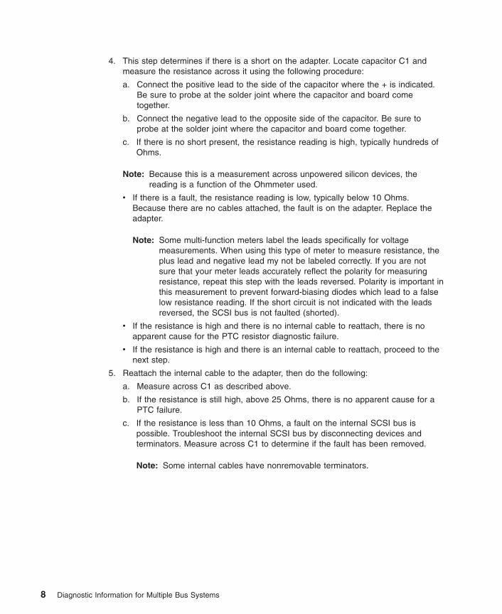
4. This step determines if there is a short on the adapter. Locate capacitor C1 andmeasure the resistance across it using the following procedure:
a. Connect the positive lead to the side of the capacitor where the + is indicated.Be sure to probe at the solder joint where the capacitor and board cometogether.
b. Connect the negative lead to the opposite side of the capacitor. Be sure toprobe at the solder joint where the capacitor and board come together.
c. If there is no short present, the resistance reading is high, typically hundreds ofOhms.
Note: Because this is a measurement across unpowered silicon devices, thereading is a function of the Ohmmeter used.
v If there is a fault, the resistance reading is low, typically below 10 Ohms.Because there are no cables attached, the fault is on the adapter. Replace theadapter.
Note: Some multi-function meters label the leads specifically for voltagemeasurements. When using this type of meter to measure resistance, theplus lead and negative lead my not be labeled correctly. If you are notsure that your meter leads accurately reflect the polarity for measuringresistance, repeat this step with the leads reversed. Polarity is important inthis measurement to prevent forward-biasing diodes which lead to a falselow resistance reading. If the short circuit is not indicated with the leadsreversed, the SCSI bus is not faulted (shorted).
v If the resistance is high and there is no internal cable to reattach, there is noapparent cause for the PTC resistor diagnostic failure.
v If the resistance is high and there is an internal cable to reattach, proceed to thenext step.
5. Reattach the internal cable to the adapter, then do the following:
a. Measure across C1 as described above.
b. If the resistance is still high, above 25 Ohms, there is no apparent cause for aPTC failure.
c. If the resistance is less than 10 Ohms, a fault on the internal SCSI bus ispossible. Troubleshoot the internal SCSI bus by disconnecting devices andterminators. Measure across C1 to determine if the fault has been removed.
Note: Some internal cables have nonremovable terminators.
8 Diagnostic Information for Multiple Bus Systems

Internal SCSI-2 Single-Ended Bus Probable Tripped PTC Resistor CausesThe following list provides some suggestions of things to check when the PTC istripped:
v A shorted terminator or cable. Check for bent pins on each connector and removableterminator.
v Intermittent PTC failures can be caused by incorrectly seated cable connectors.Reseat the connector and flex the cable in an attempt to duplicate the fault conditionacross C1.
v A shorted device.
v On some systems, the terminator is fixed to the internal cable and cannot beremoved. If all devices are removed from the cable and the resistance is still low,then the cable should be replaced.
Note: The SCSI-2 Fast/Wide and Ultra PCI adapters use an onboard electronicterminator on the internal SCSI bus. When power is removed from theadapter, as in the case of this procedure, the terminator goes to a highimpedance state and the resistance measured cannot be verified, other than itis high. Some internal terminators use an electronic terminator, which alsogoes to a high impedance state when power is removed. Therefore, thisprocedure is designed to find a short or low resistance fault as opposed to thepresence of a terminator or a missing terminator.
SCSI-2 Differential Adapter PTC Failure Isolation ProcedureUse this procedure when SRN xxx-240 or xxx-800 has been indicated.
The differential adapter can be identified by the 4-B or 4-L on the external bracket plate.
Before replacing a SCSI-2 differential adapter, use these procedures to determine if ashort-circuit condition exists on the SCSI Bus. The PTC protects the SCSI bus fromhigh currents due to shorts on the cable, terminator, or device. It is unlikely that thePTC can be tripped by a defective adapter. Unless instructed to do so by theseprocedures, do not replace the adapter because of a tripped PTC resistor.
A fault (short-circuit) causes an increase in PTC resistance and temperature. Theincrease in resistance causes the PTC to halt current flow. The PTC returns to a lowresistive and low temperature state when the fault is removed from the SCSI bus orwhen the system is turned off. Wait 5 minutes for the PTC resistor to fully cool, thenretest.
These procedures determine if the PTC resistor is still tripped and then determine ifthere is a short somewhere on the SCSI bus.
Chapter 1. Service Hints 9

External SCSI-2 Differential Adapter Bus PTC Isolation ProcedureIsolate the external SCSI bus PTC fault with the following procedure:
Notes:
1. Only the probe tips are touching the solder joints. Do not allow the probes to touchany other part of the component.
2. The external bus is differential.
1. Ensure that system power and all externally attached device power is turned off.
2. Check to ensure all devices are marked SCSI Differential and that the terminator onthe end of the SCSI bus is also marked differential. If not, you may have asingle-ended SCSI device or terminator on the differential SCSI bus. Single-endeddevices do not work on a differential SCSI bus and may cause a PTC type error tobe reported. The entire SCSI bus may appear to be intermittent. After ensuring thesystem is completely differential, continue.
3. Disconnect the external cables from the adapter and remove the adapter from thesystem.
4. Verify with a digital Ohmmeter that the internal PTC resistor, labeled Z1, (refer tothe illustration on page “External SCSI-2 Differential Adapter Bus PTC IsolationProcedure”) is cool and in a low resistance state, typically less than 1/2 Ohm.Measuring across, be sure to probe both sides of the PTC resistor where the solderjoints and board come together. The polarity of the test leads is not important. Ifnecessary, allow the PTC resistor to cool and measure again.
10 Diagnostic Information for Multiple Bus Systems
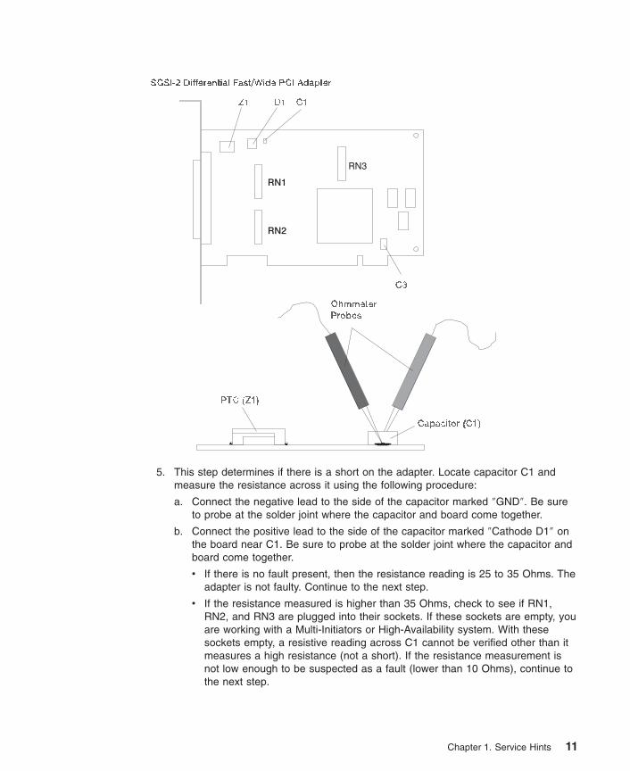
5. This step determines if there is a short on the adapter. Locate capacitor C1 andmeasure the resistance across it using the following procedure:
a. Connect the negative lead to the side of the capacitor marked ″GND″. Be sureto probe at the solder joint where the capacitor and board come together.
b. Connect the positive lead to the side of the capacitor marked ″Cathode D1″ onthe board near C1. Be sure to probe at the solder joint where the capacitor andboard come together.
v If there is no fault present, then the resistance reading is 25 to 35 Ohms. Theadapter is not faulty. Continue to the next step.
v If the resistance measured is higher than 35 Ohms, check to see if RN1,RN2, and RN3 are plugged into their sockets. If these sockets are empty, youare working with a Multi-Initiators or High-Availability system. With thesesockets empty, a resistive reading across C1 cannot be verified other than itmeasures a high resistance (not a short). If the resistance measurement isnot low enough to be suspected as a fault (lower than 10 Ohms), continue tothe next step.
Chapter 1. Service Hints 11

v If the resistance is high and there is no external cable to reattach, there is noapparent cause for the PTC diagnostic failure.
v If the resistance reading is low, typically below 10 Ohms, there is a fault.Because there are no cables attached, the fault is on the adapter. Replacethe adapter.
v If the resistance measured was high and there is an external cable toreattach, proceed to the next step.
6. Reattach the external cable to the adapter.
a. Measure across C1 as previously described.
b. If the resistance is between 10 to 20 Ohms, there is no apparent cause for aPTC resistor failure.
c. If the resistance is less than 10 Ohms, there is a possibility of a fault on theexternal SCSI bus. Troubleshoot the external SCSI bus by disconnectingdevices and terminators. Measure across C1 to determine if the fault has beenremoved.
SCSI-2 Differential Adapter Probable Tripped PTC CausesThe following list provides some suggestions of things to check when the PTC istripped:
v A shorted terminator or cable. Check for bent pins on each connector and removableterminator.
v Intermittent PTC failures can be caused by incorrectly seated cable connectors.Reseat the connector and flex the cable in an attempt to duplicate the fault conditionacross C1.
v Plugging or unplugging a cable or terminator while the system is turned on(hot-plugging).
v A shorted device.
v Single-ended devices are attached to the differential SCSI bus.
12 Diagnostic Information for Multiple Bus Systems

Dual-Channel Ultra SCSI Adapter PTC Failure Isolation ProcedureUse the following procedures if diagnostics testing indicates a potential positivetemperature coefficient (PTC) resistor fault or the TERMPWR Shorted LED is lit.
This procedure is used for SRNs 637-240 and 637-800 on the Dual-Channel Ultra SCSIAdapter. If the TERMPWR Shorted LED is lit, use this procedure to help isolate thesource of the problem on the failing channel.
1. Identify the adapter by its label of 4-R on the external bracket. Then, determine ifthe failure is on channel A or channel B.
2. The same PTC is used for both the internal and external buses. The PTC protectsthe SCSI bus from high currents due to shorts on the cable, terminator, or device. Itis unlikely that the PTC can be tripped by a defective adapter. A fault (short-circuit)causes an increase in PTC resistance and temperature. The increase in resistancecauses the PTC to halt current flow. The PTC returns to a low resistive and lowtemperature state when the fault is removed from the SCSI bus or when the systemis turned off.
Wait 5 minutes for the PTC resistor to fully cool, then retest.
3. If this same error persists, or the TERMPWR Shorted LED is lit, replace thecomponents of the failing channel in the following order (wait five minutes betweensteps):
a. If the failure is on the external cable, replace the following:
1) Cable
2) Device
3) Attached subsystem
4) Adapter
b. If the failure is on the internal cable, replace the following:
1) Cable
2) Device
3) Backplane
4) Adapter
c. If the failure persists, verify that the parts exchanged are in the correct channel(internal or external, A or B).
If the errors are still occurring, continue isolating the problem by going to “Step0050-9” on page 53.
64-bit PCI-X Dual Channel SCSI Adapter PTC Failure Isolation ProcedureUse the following procedures if diagnostics testing indicates a potential self-resettingthermal fuse problem. This procedure is used for SRN 2524-702 on the integrateddual-channel SCSI adapter in a 7039/651 system.
1. Identify the adapter as the one embedded in the system board. Then, determine ifthe failure is on channel 0 or channel 1.
2. The thermal fuse protects the SCSI bus from high currents due to shorts on theterminator, cable, or device. It is unlikely that the thermal fuse can be tripped by a
Chapter 1. Service Hints 13
defective adapter. A fault (short-circuit) causes an increase in resistance andtemperature of the thermal fuse. The increase in temperature causes the thermalfuse to halt current flow. The thermal fuse returns to a low resistive and lowtemperature state when the fault is removed from the SCSI bus or when the systemis turned off.
Wait 10 seconds for the thermal fuse to reset itself and recover, then retest.
3. If the same error persists, replace the components of the failing channel in thefollowing order. Wait 10 seconds for the thermal fuse to reset itself between steps.
a. Cable
b. Device
c. DASD backplane (if present)
d. System board (adapter)
4. If the failure persists, verify that the parts exchanged are in the correct channel (0or 1). If the errors are still occurring, continue isolating the problem by going to“Step 0050-9” on page 53.
14 Diagnostic Information for Multiple Bus Systems

Chapter 2. Start of Call MAP
This MAP is the starting point for a service call.
If you are servicing an SP system, go to the Start of Call MAP 100 in the RS/6000 SPSystem Service Guide.
If you are servicing a clustered Eserver, go to the Start of Call MAP 100 in theClustered Eserver Installation and Service Guide.
Note: Do not run the diagnostics until you are instructed to do so.
1. If this system has a Hardware Management Console (HMC) with Service FocalPoint (SFP) or has one or more partitions running operating systems other than AIX,go to the ″Quick Entry MAP for Systems with Service Focal Point″ in the systemservice guide. Otherwise, go to step 2.
2. The Fast Path MAP in Chapter 3 is provided to help you quickly resolve a problem.Use the Fast Path MAP when you know or have been provided with a symptom.
Use the following table to help determine your next step.
Symptom Action
You do not have a problem or symptom, butyou want to generate one.
Go to Chapter 4, “MAP 0020: ProblemDetermination Procedure” on page 29 in thismanual.
You have been provided with a problem orsymptom.
Go to Chapter 3, “Fast Path MAP” on page 17in this manual.
Note: Some of the devices that are supported by the diagnostic programs also havetheir own maintenance documentation. You may want to use the maintenancedocumentation for that device before running the diagnostics for the system.Sometimes the maintenance package for the attached device allows thecustomer to continue operating the system while that device is being diagnosed.You can use the diagnostic programs to check the adapter to which that deviceis attached.
15

16 Diagnostic Information for Multiple Bus Systems

Chapter 3. Fast Path MAP
In most cases, these procedures direct you to run the Online Diagnostics. If the OnlineDiagnostics are not installed, the Standalone Diagnostics should be used.
Notes:
1. If the actions listed for a specific symptom do not resolve the problem, go toChapter 4, “MAP 0020: Problem Determination Procedure” on page 29.
2. If you replace a part, use Chapter 23, “MAP 0410: Repair Checkout” on page 125 toverify the fix.
3. If you are directed to the system unit’s service guide, use the MAPs in the serviceguide to complete the repair. If none of the MAPs in the service guide have youverify the fix, return to this book and use Chapter 23, “MAP 0410: Repair Checkout”on page 125.
4. If you are servicing an SP system, go to the Start of Call MAP 100 in the SPSystem Service Guide.
5. If you are servicing a clustered Eserver, go to the Start of Call MAP 100 in theClustered Eserver Installation and Service Guide.
6. If the system you are servicing has a Hardware Management Console (HMC) withService Focal Point (SFP), the various codes that may display are all listed as errorcodes by the SFP. The table below should be used to interpret the field listed as″Error code″ by the SFP:
SFP NameNumber of Digits inerror code
Characteristic Interpretation
error code any contains a ″-″ SRN
error code 5 does not contain ″-″ SRN
error code 6 does not contain ″-″ error code
error code 8 does not contain ″-″ error code
When possible, run the Online Diagnostics in Service Mode unless you are directedotherwise.
17
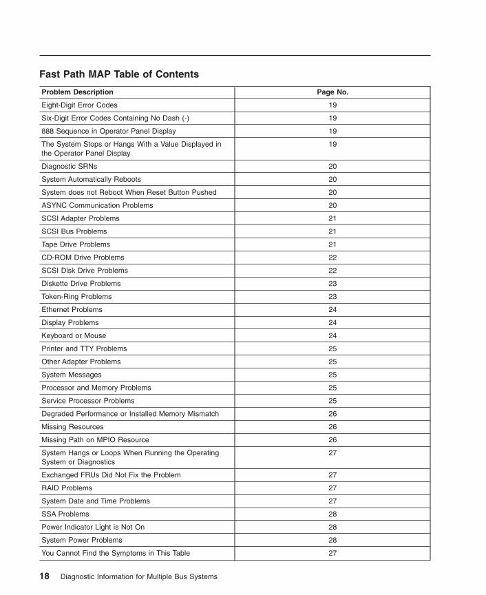
Fast Path MAP Table of Contents
Problem Description Page No.
Eight-Digit Error Codes 19
Six-Digit Error Codes Containing No Dash (-) 19
888 Sequence in Operator Panel Display 19
The System Stops or Hangs With a Value Displayed inthe Operator Panel Display
19
Diagnostic SRNs 20
System Automatically Reboots 20
System does not Reboot When Reset Button Pushed 20
ASYNC Communication Problems 20
SCSI Adapter Problems 21
SCSI Bus Problems 21
Tape Drive Problems 21
CD-ROM Drive Problems 22
SCSI Disk Drive Problems 22
Diskette Drive Problems 23
Token-Ring Problems 23
Ethernet Problems 24
Display Problems 24
Keyboard or Mouse 24
Printer and TTY Problems 25
Other Adapter Problems 25
System Messages 25
Processor and Memory Problems 25
Service Processor Problems 25
Degraded Performance or Installed Memory Mismatch 26
Missing Resources 26
Missing Path on MPIO Resource 26
System Hangs or Loops When Running the OperatingSystem or Diagnostics
27
Exchanged FRUs Did Not Fix the Problem 27
RAID Problems 27
System Date and Time Problems 27
SSA Problems 28
Power Indicator Light is Not On 28
System Power Problems 28
You Cannot Find the Symptoms in This Table 27
18 Diagnostic Information for Multiple Bus Systems

Fast Path Table
Symptoms What You Should Do
Eight-Digit Error Codes
You have an eight-digit error code. Go to the ″Error Code to FRU Index″ in theservice guide, read the notes on the first page,and do the listed action for the eight-digit errorcode.Note: If the repair for this code does notinvolve replacing a FRU (for instance, if you runan AIX command that fixes the problem or ifyou change a hot-pluggable FRU), then run theLog Repair Action option on resourcesysplanar0 from the Task Selection menuunder Online Diagnostics to update the AIXerror log.
Six-Digit Error Codes Containing No Dash (-)
You have a six-digit error code (like an SRN)containing no dash (-) between the third andfourth digit.
Go to the ″Error Code to FRU Index″ in theservice guide, read the notes at the beginningof this section, and do the listed action for thesix-digit error code.
888 Sequence in Operator Panel Display
An 888 sequence in the operator panel display. Go to Chapter 9, “MAP 0070: 888 Sequence inOperator Panel Display” on page 59.
The System Stops or Hangs With a Value Displayed in the Operator Panel Display
The operator panel display alternates betweentwo codes that begin with the letter E.
Go to the Entry MAP in the service guide.
The system stopped with a 4-digit code thatbegins with a digit other than 0 (zero) or 2 (two)displayed in the operator panel display.
Go to the Entry MAP in the service guide.
The system stopped with a 4-digit code thatbegins with 0 (zero) displayed in the operatorpanel display.
Record SRN 101-xxx (where xxx is the lastthree digits of the code displayed). Find theSRN in the SRN chapters and do the indicatedaction.
The system stopped with a 4-digit code thatbegins with a 2 (two) displayed in the operatorpanel display.
Record SRN 101-xxxx (where xxxx is the fourdigits of code displayed). The physical locationcode, AIX location code, or device namedisplays on system units with a multiple-lineoperator panel display if AIX 4.3.3 or later isinstalled. If a physical location code or an AIXlocation code is displayed, record it, then findthe SRN in the SRN chapters and do theindicated action.
The system stopped with a 3-digit code thatbegins with either A or F displayed in theoperator panel display.
Go to the Entry MAP in the service guide.
Chapter 3. Fast Path MAP 19
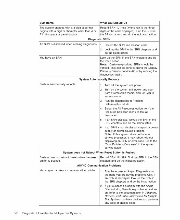
Symptoms What You Should Do
The system stopped with a 3-digit code thatbegins with a digit or character other than A orF in the operator panel display.
Record SRN 101-xxx (where xxx is the threedigits of the code displayed). Find the SRN inthe SRN chapters and do the indicated action.
Diagnostic SRNs
An SRN is displayed when running diagnostics. 1. Record the SRN and location code.
2. Look up the SRN in the SRN chapters anddo the listed action.
You have an SRN. Look up the SRN in the SRN chapters and dothe listed action.Note: Customer-provided SRNs should beverified. This can be done by using the DisplayPrevious Results Service Aid or by running thediagnostics again.
System Automatically Reboots
System automatically reboots. 1. Turn off the system unit power.
2. Turn on the system unit power and bootfrom a removable media, disk, or LAN inservice mode.
3. Run the diagnostics in ProblemDetermination Mode.
4. Select the All Resources option from theResource Selection menu to test allresources.
5. If an SRN displays, lookup the SRN in theSRN chapters and do the action listed.
6. If an SRN is not displayed, suspect a powersupply or power source problem.Note: If this system does not have aservice processor, it may reboot withoutdisplaying an SRN or error code. Go to the″Boot Problems/Concerns″ in the systemservice guide.
System does not Reboot When Reset Button is Pushed
System does not reboot (reset) when the resetbutton is pushed.
Record SRN 111-999. Find the SRN in the SRNchapters and do the indicated action.
ASYNC Communication Problems
You suspect an Async communication problem. 1. Run the Advanced Async Diagnostics onthe ports you are having problems with. Ifan SRN is displayed, look up the SRN inthe SRN chapters and do the listed action.
2. If you suspect a problem with the AsyncConcentrator, Remote Async Node, and soon, refer to the documentation in Adapters,Devices, and Cable Information for MultipleBus Systems on these devices and performany tests or checks listed.
20 Diagnostic Information for Multiple Bus Systems

Symptoms What You Should Do
SCSI Adapter Problems
You suspect a SCSI adapter problem.
SCSI Adapter Diagnostics can only be run on aSCSI adapter that was not used for booting.The POST tests any SCSI Adapter beforeattempting to use it for booting. If the systemwas able to boot using a SCSI adapter, thenthe adapter is most likely good.
SCSI adapters problems are also logged intothe error log and are analyzed when the OnlineSCSI Diagnostics are run in ProblemDetermination Mode. Problems are reported ifthe number of errors is above definedthresholds.
1. Run the Online SCSI Adapter Diagnostic inProblem Determination Mode. If an SRN isdisplayed, look up the SRN in the SRNchapters and do the listed action.
2. Use Chapter 8, “MAP 0050: SCSI BusProblems” on page 51.Note: If you cannot load diagnostics(standalone or online) go to MAP 1540 inthe service guide.
SCSI Bus Problems
You suspect a SCSI bus problem. 1. Use Chapter 8, “MAP 0050: SCSI BusProblems” on page 51.
2. Use the SCSI Bus Service Aid to exerciseand test the SCSI Bus.
Tape Drive Problems
You suspect a tape drive problem. 1. Refer to the tape drive documentation andclean the tape drive.
2. Refer to the tape documentation and do anylisted problem determination procedures.
3. Run the Online Advanced Tape Diagnosticsin Problem Determination Mode. If an SRNis displayed, look up the SRN in the SRNchapters and do the listed action.
4. Use the Backup/Restore Media Service Aidto exercise and test the drive and media.
5. Use Chapter 8, “MAP 0050: SCSI BusProblems” on page 51.
6. Use the SCSI Bus Service Aid to exerciseand test the SCSI bus.
7. Refer to the device section of Adapters,Devices, and Cable Information for MultipleBus Systems for additional information andChapter 4, “MAP 0020: ProblemDetermination Procedure” on page 29 of thismanual for problem determinationprocedures.
Note: Information on tape cleaning andtape-problem determination is normally either inthe tape drive operator guide or the systemoperator guide.
Chapter 3. Fast Path MAP 21

Symptoms What You Should Do
CD-ROM Drive Problems
You suspect a CD-ROM drive problem. 1. Refer to the CD-ROM documentation anddo any listed problem determinationprocedures.
2. Before servicing a CD-ROM Drive ensurethat it is not in use and that the powerconnector is correctly attached to the drive.If the load or unload operation does notfunction, replace the CD-ROM drive.
3. Run the Online Advanced CD-ROMDiagnostics in Problem DeterminationMode. If an SRN is displayed, look up theSRN in the SRN chapters and do the listedaction.
4. If the problem is with a SCSI CD-ROMdrive, use Chapter 8, “MAP 0050: SCSI BusProblems” on page 51.
5. If the problem is with a SCSI CD-ROMdrive, use the SCSI Bus Service Aid toexercise and test the SCSI Bus.
6. Refer to the device section of Adapters,Devices, and Cable Information for MultipleBus Systems for additional information andChapter 4, “MAP 0020: ProblemDetermination Procedure” on page 29 of thismanual for problem determinationprocedures.
Note: Information on CD-ROM problemdetermination is usually in the CD-ROM driveoperator guide or the system user’s guide.
SCSI Disk Drive Problems
22 Diagnostic Information for Multiple Bus Systems

Symptoms What You Should Do
You suspect a disk drive problem.
Disk problems are logged in the error log andare analyzed when the Online Disk Diagnosticsare run in Problem Determination Mode.Problems are reported if the number of errors isabove defined thresholds.
If the diagnostics are booted from a disk, thenthe diagnostics can only be run on those drivesthat are not part of the root volume group.However, error log analysis is run if thesedrives are selected. To run the disk diagnostictests on disks that are part of the root volumegroup, the Standalone Diagnostics must beused.
1. Run the Online Advanced Disk Diagnosticsin Problem Determination Mode. If an SRNis displayed, look up the SRN in the SRNchapters and do the listed action.
2. Run Standalone Disk Diagnostics. If anSRN is displayed, look up the SRN in theSRN chapters and do the listed action.
3. Use the Certify Disk Service Aid to verifythat the disk can be read.
4. Use Chapter 8, “MAP 0050: SCSI BusProblems” on page 51.
5. Use the SCSI Bus Service Aid to exerciseand test the SCSI Bus.
6. Refer to the device section of Adapters,Devices, and Cable Information for MultipleBus Systems for additional information andChapter 4, “MAP 0020: ProblemDetermination Procedure” on page 29 of thismanual for problem determinationprocedures.
Identify LED does not function on the driveplugged into the SES or SAF-TE backplane.
Use the Identify a Device attached to a SESDevice Service aid listed under “SCSI HotSwap Manager” on page 210 on the suspectdrive LED. If the drive LED does not blink whenput into the identify state, use FFC 2D00 andSRN source code ″B″ and go to Chapter 11,“MAP 0210: General Problem Resolution” onpage 67.
Activity LED does not function on the driveplugged into the SES or SAF-TE backplane.
Use the Certify Media Service aid (see“CertifyMedia” on page 179) on the drive in the slotcontaining the suspect activity LED. If theactivity LED does not intermittently blink whenrunning certify, use FFC 2D00 and SRN sourcecode ″B″ and go to Chapter 11, “MAP 0210:General Problem Resolution” on page 67.
Diskette Drive Problems
You suspect a diskette drive problem. 1. Run the diskette drive diagnostics. If anSRN is displayed, look up the SRN in theSRN chapters and do the listed action.
2. Use the Diskette Media Service Aid to testthe diskette media.
3. Use the Backup/Restore Media Service Aidto exercise and test the drive and media.
Token-Ring Problems
Chapter 3. Fast Path MAP 23
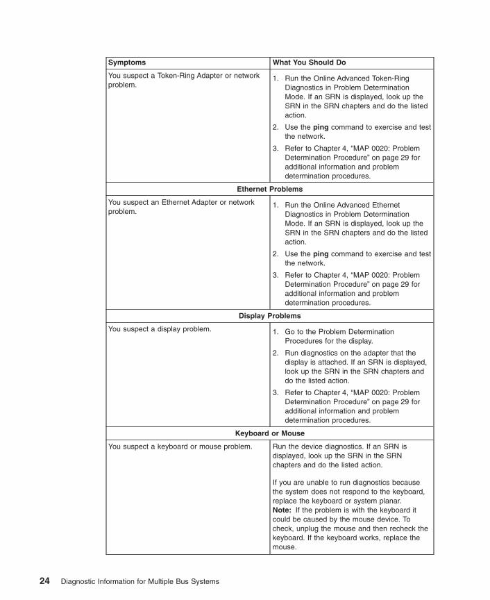
Symptoms What You Should Do
You suspect a Token-Ring Adapter or networkproblem.
1. Run the Online Advanced Token-RingDiagnostics in Problem DeterminationMode. If an SRN is displayed, look up theSRN in the SRN chapters and do the listedaction.
2. Use the ping command to exercise and testthe network.
3. Refer to Chapter 4, “MAP 0020: ProblemDetermination Procedure” on page 29 foradditional information and problemdetermination procedures.
Ethernet Problems
You suspect an Ethernet Adapter or networkproblem.
1. Run the Online Advanced EthernetDiagnostics in Problem DeterminationMode. If an SRN is displayed, look up theSRN in the SRN chapters and do the listedaction.
2. Use the ping command to exercise and testthe network.
3. Refer to Chapter 4, “MAP 0020: ProblemDetermination Procedure” on page 29 foradditional information and problemdetermination procedures.
Display Problems
You suspect a display problem. 1. Go to the Problem DeterminationProcedures for the display.
2. Run diagnostics on the adapter that thedisplay is attached. If an SRN is displayed,look up the SRN in the SRN chapters anddo the listed action.
3. Refer to Chapter 4, “MAP 0020: ProblemDetermination Procedure” on page 29 foradditional information and problemdetermination procedures.
Keyboard or Mouse
You suspect a keyboard or mouse problem. Run the device diagnostics. If an SRN isdisplayed, look up the SRN in the SRNchapters and do the listed action.
If you are unable to run diagnostics becausethe system does not respond to the keyboard,replace the keyboard or system planar.Note: If the problem is with the keyboard itcould be caused by the mouse device. Tocheck, unplug the mouse and then recheck thekeyboard. If the keyboard works, replace themouse.
24 Diagnostic Information for Multiple Bus Systems

Symptoms What You Should Do
Printer and TTY Problems
You suspect a TTY terminal or printer problem. 1. Go to problem determination procedures forthe printer or terminal.
2. Check the port that the device is attachedto by running diagnostics on the port. If anSRN is displayed, look up the SRN in theSRN chapters and do the listed action.
3. Use the ″Testing the Line Printer″ procedurein Chapter 26, “General DiagnosticInformation” on page 139 to test theconnection to the printer. If a problemexists, replace the following in the orderlisted:
a. Device cable
b. Port the printer or terminal is connectedto.
Other Adapter Problems
You suspect a problem on another adapter thatis not listed above.
1. Run the Online Advanced Diagnostics inProblem Determination on the adapter yoususpect. If an SRN is displayed, look up theSRN in the SRN chapters and do the listedaction.
2. Refer to Chapter 4, “MAP 0020: ProblemDetermination Procedure” on page 29 foradditional information and problemdetermination procedures.
System Messages
A System Message is displayed. 1. If the message describes the cause of theproblem, attempt to correct it.
2. Look for another symptom to use.
Processor and Memory Problems
You suspect a memory problem.
Memory tests are only done during POST. Onlyproblems that prevent the system from bootingare reported during POST. All other problemsare logged and analyzed when the sysplanar0option under the Advanced DiagnosticsSelection menu is run.
System Crashes are logged in the AIX ErrorLog. The sysplanar0 option under theAdvanced Diagnostic Selection menu is run inProblem Determination Mode to analyze theerror.
1. Power off the system.
2. Turn on the system unit power and load theOnline Diagnostics in Service Mode.
3. Run either the sysplanar0 or the Memoryoption under the Advanced Diagnostics inProblem Determination Mode.
4. If an SRN is displayed, record the SRN andlocation code.
5. Look up the SRN in the SRN chapters anddo the listed action.
Service Processor Problems
Chapter 3. Fast Path MAP 25

Symptoms What You Should Do
v Modem does not dial out or answer callsusing Service Processor functions.
v Service Processor menus do not display ordisplay incorrectly on a TTY terminal.
v Cannot input to the Service Processormenus using a TTY keyboard.
Remove the Service Processor and then runadvanced diagnostics on the built-in serialports. If an SRN is reported, lookup the SRNand do the indicated action. If no SRN isreported, replace the Service Processor. If theproblem remains after replacing the ServiceProcessor, replace the system planar.
Degraded Performance or Installed Memory Mismatch
Degraded Performance or Installed MemoryMismatch
Degraded Performance can be caused bymemory problems that cause a reduction in thesize of available memory. To verify that thesystem detected the full complement ofinstalled memory use one of the followingmethods based on the level of AIX being used.
v AIX 4.2.1 and Higher
From the Task Selection Menu select the’Display Resource Attribute’. From theResource Selection menu select one of thelisted memory resources. Verify the amountof memory listed matches the amountactually installed.
v All Other AIX Versions
Use the Display or Change ConfigurationService Aid to verify that all installed memoryis being detected. The Display Vital ProductData (VPD) option shows the amount ofmemory that is installed.
If an installed memory module or card doesnot appear or appears as the wrong size,replace it. If the problem is not corrected,replace the card or board that contains themissing memory.
Missing Resources
Missing Resources Note: ISA resources must be configured beforethey appear in the configuration. The ISAAdapter Configuration Service Aid is used toconfigure ISA adapter for StandaloneDiagnostics. SMIT can be used to configureduring Online Diagnostics.
Use the ’Display or Change Configuration orVital Product Data (VPD) Service Aid’ to verifythat the resource was configured.
If an installed resource does not appear, checkthat it is installed correctly. If you do not find aproblem, go to Chapter 4, “MAP 0020: ProblemDetermination Procedure” on page 29.
Missing Path on MPIO Resource
26 Diagnostic Information for Multiple Bus Systems

Symptoms What You Should Do
Missing Path on MPIO Resource If a path is missing on an MPIO resource,shown as the letter P in front of the resource inthe resource listing, go to Chapter 4, “MAP0020: Problem Determination Procedure” onpage 29.
System Hangs or Loops When Running the OS or Diagnostics
The system hangs in the same application. Suspect the application. To check the system:
1. Power off the system.
2. Turn on the system unit power and load theOnline Diagnostics in Service Mode.
3. Select the All Resources option from theResource Selection menu to test allresources.
4. If an SRN is displayed at anytime, recordthe SRN and location code.
5. Look up the SRN in the SRN chapters anddo the listed action.
The system hangs in different applications. 1. Power off the system.
2. Turn on system unit power and load theOnline Diagnostics in Service Mode.
3. Select the All Resources option from theResource Selection menu to test allresources.
4. If an SRN is displayed at anytime, recordthe SRN and location code.
5. Look up the SRN in the SRN chapters anddo the listed action.
The system hangs when running diagnostics. Replace the resource that is being tested.
You Cannot Find the Symptom in This Table
All other problems. Go to Chapter 4, “MAP 0020: ProblemDetermination Procedure” on page 29.
Exchanged FRUs Did Not Fix the Problem
A FRU or FRUs you exchanged did not fix theproblem.
Go to Chapter 6, “MAP 0030: AdditionalProblem Determination” on page 45.
RAID Problems
You suspect a problem with a RAID. A potential problem with a RAID adapter exists.Run diagnostics on the RAID adapter. Refer tothe RAID Adapters User’s Guide andMaintenance Information or the service guidefor the RAID.
System Date and Time Problems
Chapter 3. Fast Path MAP 27

Symptoms What You Should Do
v The system does not retain the calendardate after the system has been booted.
v The system does not retain the time of dayafter the system has been booted.Note: It is normal for the system time of dayto gain or lose a few seconds each month.
1. Run the sysplanar0 option under theAdvanced Diagnostics in ProblemDetermination mode. If an SRN is reported,record the SRN and location codeinformation and do the indicated action forthe SRN.
2. Replace the TOD (NVRAM) battery. If thisdoes not fix the problem, replace thesystem planar.
SSA Problems
You suspect an SSA problem. A potential problem with an SSA adapter exists.Run diagnostics on the SSA adapter. If thesystem has external SSA drives, refer to theSSA Adapters User’s Guide and MaintenanceInformation or the service guide for your disksubsystem. If the system has internal SSAdrives, go to the SSA MAP in either the systemunit’s service guide or user’s guide.
Power Indicator Light is Not On
A drawer power indicator is not on. Refer to the Entry MAP section of theMaintenance Analysis Procedures (MAPs) inthe system service manual.
System Power Problem
The system does not power on. Go to the Entry MAP in the service guide.
The system powers on when it should not. Go to the Entry MAP in the service guide.
28 Diagnostic Information for Multiple Bus Systems

Chapter 4. MAP 0020: Problem Determination Procedure
Purpose of This MAPUse this MAP to get a service request number (SRN) if the customer or a previousMAP provided none.
If you are unable to power the system on, refer to the MAP 1520 in the system’sservice guide.
Note: If another system connects to this system, refer to Chapter 27, “UsingStandalone and Online Diagnostics” on page 153 for pertinent information beforeproceeding further.
Step 0020-1Visually check the system for obvious problems such as unplugged power cables orexternal devices that are powered off.
Did you find an obvious problem?
NO Go to “Step 0020-2”.
YES Fix the problem; then go to Chapter 23, “MAP 0410: Repair Checkout” onpage 125.
Step 0020-2Are the Online Diagnostics installed?
Note: If you are uncertain how to answer the above question, answer it yes.
NO If the operating system is running, perform its shutdown procedure. Get help ifneeded. Go to “Step 0020-4” on page 30.
YES Go to “Step 0020-3” on page 30.
29

Step 0020-3
Note: When possible, run Online Diagnostics in Service Mode. Online diagnosticsperform additional functions, compared to Standalone Diagnostics.
Run Online Diagnostics in Concurrent Mode when the customer does not let youpower-off the system unit. To run Online Diagnostics in Service Mode, go to substep 5.If the system unit is already running in the service mode and you want to run onlinediagnostics, proceed to the question in this MAP, otherwise do substeps 1 through 4.
1. Log in with root authority or use CE login. If necessary, ask the customer for thepassword.
2. Enter the diag -a command to check for missing resources.
a. If you see a command line prompt, proceed to substep 3 below.
b. If the DIAGNOSTIC SELECTION menu is displayed, with the letter M shown nextto any resource, select that resource, then press Commit (F7 key). Follow anyinstructions displayed. If you are prompted with a message Do you want toreview the previously displayed error select Yes and press Enter. If an SRNdisplays, record it, and go to “Step 0020-15” on page 39. If there is no SRN, goto substep 3 below.
c. If MISSING RESOURCE menu is displayed, follow any instructions displayed. Ifyou are prompted with a message Do you want to review the previouslydisplayed error select Yes and press Enter. If an SRN displays, record it, andgo to “Step 0020-15” on page 39. If there is no SRN, go to substep 3 below.
3. Enter the diag command.
4. Go to “Step 0020-5” on page 32.
5. If the operating system is running, perform its shut down procedure (get help ifneeded).
6. Turn off the system unit power and wait 45 seconds before proceeding.
7. Turn on the system unit power.
8. Load the Online Diagnostics in Service Mode (if needed, refer to the service guide).
9. Wait until the Diagnostic Operating Instructions display or the system appears tohave stopped.
Are the Diagnostic Operating Instructions Displayed?
NO Go to “Step 0020-16” on page 40.
YES Go to “Step 0020-5” on page 32.
Step 0020-41. Turn off the system unit power and wait 45 seconds before proceeding.
2. Turn on the system unit power. If the system supports Slow boot (See “About SlowBoot” on page 2), do a slow boot on the system. If the system does not supportslow boot, do a normal boot
3. Load the Standalone Diagnostics in Service Mode. Refer to the system unit serviceguide if needed.
30 Diagnostic Information for Multiple Bus Systems

4. Wait until the Diagnostic Operating Instructions display or the system appears tohave stopped.
Are the Diagnostic Operating Instructions Displayed?
NO Go to “Step 0020-16” on page 40.
YES Go to “Step 0020-5” on page 32.
Chapter 4. MAP 0020: Problem Determination Procedure 31
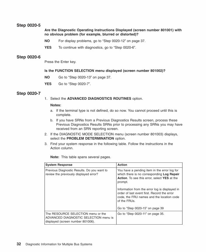
Step 0020-5Are the Diagnostic Operating Instructions Displayed (screen number 801001) withno obvious problem (for example, blurred or distorted)?
NO For display problems, go to “Step 0020-12” on page 37.
YES To continue with diagnostics, go to “Step 0020-6”.
Step 0020-6Press the Enter key.
Is the FUNCTION SELECTION menu displayed (screen number 801002)?
NO Go to “Step 0020-13” on page 37.
YES Go to “Step 0020-7”.
Step 0020-71. Select the ADVANCED DIAGNOSTICS ROUTINES option.
Notes:
a. If the terminal type is not defined, do so now. You cannot proceed until this iscomplete.
b. If you have SRNs from a Previous Diagnostics Results screen, process thesePrevious Diagnostics Results SRNs prior to processing any SRNs you may havereceived from an SRN reporting screen.
2. If the DIAGNOSTIC MODE SELECTION menu (screen number 801003) displays,select the PROBLEM DETERMINATION option.
3. Find your system response in the following table. Follow the instructions in theAction column.
Note: This table spans several pages.
System Response Action
Previous Diagnostic Results. Do you want toreview the previously displayed error?
You have a pending item in the error log forwhich there is no corresponding Log RepairAction. To see this error, select YES at theprompt.
Information from the error log is displayed inorder of last event first. Record the errorcode, the FRU names and the location codeof the FRUs.
Go to “Step 0020-15” on page 39
The RESOURCE SELECTION menu or theADVANCED DIAGNOSTIC SELECTION menu isdisplayed (screen number 801006).
Go to “Step 0020-11” on page 35.
32 Diagnostic Information for Multiple Bus Systems
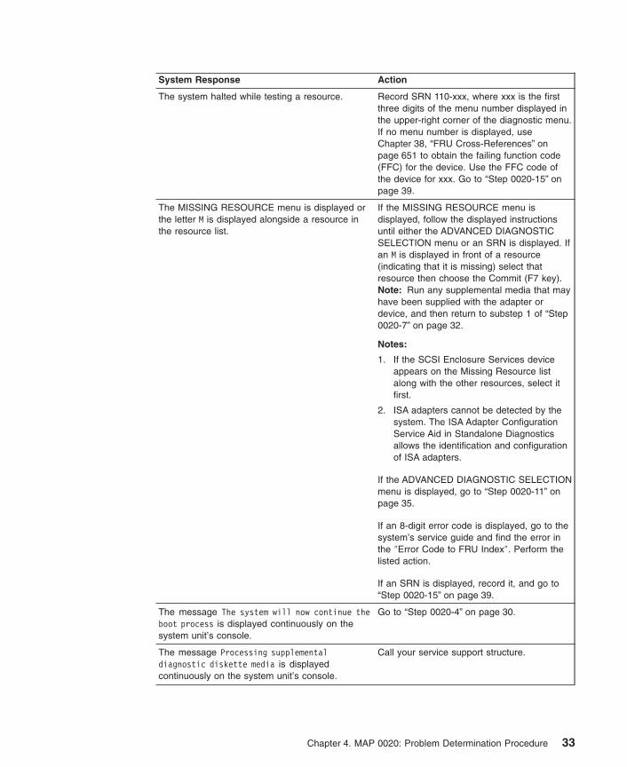
System Response Action
The system halted while testing a resource. Record SRN 110-xxx, where xxx is the firstthree digits of the menu number displayed inthe upper-right corner of the diagnostic menu.If no menu number is displayed, useChapter 38, “FRU Cross-References” onpage 651 to obtain the failing function code(FFC) for the device. Use the FFC code ofthe device for xxx. Go to “Step 0020-15” onpage 39.
The MISSING RESOURCE menu is displayed orthe letter M is displayed alongside a resource inthe resource list.
If the MISSING RESOURCE menu isdisplayed, follow the displayed instructionsuntil either the ADVANCED DIAGNOSTICSELECTION menu or an SRN is displayed. Ifan M is displayed in front of a resource(indicating that it is missing) select thatresource then choose the Commit (F7 key).Note: Run any supplemental media that mayhave been supplied with the adapter ordevice, and then return to substep 1 of “Step0020-7” on page 32.
Notes:
1. If the SCSI Enclosure Services deviceappears on the Missing Resource listalong with the other resources, select itfirst.
2. ISA adapters cannot be detected by thesystem. The ISA Adapter ConfigurationService Aid in Standalone Diagnosticsallows the identification and configurationof ISA adapters.
If the ADVANCED DIAGNOSTIC SELECTIONmenu is displayed, go to “Step 0020-11” onpage 35.
If an 8-digit error code is displayed, go to thesystem’s service guide and find the error inthe ″Error Code to FRU Index″. Perform thelisted action.
If an SRN is displayed, record it, and go to“Step 0020-15” on page 39.
The message The system will now continue theboot process is displayed continuously on thesystem unit’s console.
Go to “Step 0020-4” on page 30.
The message Processing supplementaldiagnostic diskette media is displayedcontinuously on the system unit’s console.
Call your service support structure.
Chapter 4. MAP 0020: Problem Determination Procedure 33

System Response Action
The diagnostics begin testing a resource.Note: If the Problem Determination Option wasselected from the DIAGNOSTIC MODESELECTION menu, and if a recent error hasbeen logged in the error log, the diagnosticsautomatically begin testing the resource.
Follow the displayed instructions.
If the No Trouble Found screen is displayed,press Enter.
If another resource is tested, repeat this step.
If the ADVANCED DIAGNOSTIC SELECTIONmenu is displayed, go to “Step 0020-11” onpage 35.
If an SRN is displayed, record it, and go to“Step 0020-15” on page 39. If an eight-digiterror code is displayed, record it and go tothe system unit’s service guide and find theerror in the ″Error Code to FRU Index″.Perform the listed action.
The system did not respond to selecting theAdvanced Diagnostics option.
Go to “Step 0020-13” on page 37.
A system unit with a beeper did not beep whilebooting.
Record SRN 111-947 and then go to “Step0020-15” on page 39.
The system unit emits a continuous sound fromthe beeper.
Record SRN 111-947 and then go to “Step0020-15” on page 39.
An SRN, or six-digit error code containing nodash (-), or an eight-digit error code is displayed.
Record the error code, the FRU names, andthe location code for the FRUs. If an SRN isdisplayed, go to “Step 0020-15” on page 39.If a six-digit error code containing no dash (-)or an 8-digit error code is displayed, go toeither the system’s or subsystem’s serviceguide and find the error in the ″Error Code toFRU Index″. Perform the listed action.
The system stopped with a 3-digit or 4-digit codedisplayed in the operator panel display.
Record SRN 101-xxx (where xxx is therightmost three digits of the displayed code).Go to “Step 0020-15” on page 39.
An 888 message is displayed in the operatorpanel display.Note: The 888 may or may not be flashing.
Go to Chapter 9, “MAP 0070: 888 Sequencein Operator Panel Display” on page 59.
Step 0020-8On the DIAGNOSTIC SELECTION or ADVANCED DIAGNOSTIC SELECTION menu,look through the list of resources to make sure that all adapters and SCSI devices arelisted including any new resources.
Notes:
1. Resources attached to serial and parallel ports may not appear in the resource list.
2. ISA adapters cannot be detected by the system. The ISA Adapter ConfigurationService Aid in Standalone Diagnostics allows the identification and configuration ofISA adapters.
34 Diagnostic Information for Multiple Bus Systems

3. If running diagnostics in a partition within a partitioned system, resources assignedto other partitions will not be displayed on the resource list.
Did you find the all the adapters or devices on the list?
NO Go to “Step 0020-9”.
YES Go to “Step 0020-11”.
Step 0020-9Is the new device or adapter an exact replacement for a previous one installed atsame location?
NO Go to “Step 0020-10”.
YES The replacement device or adapter may be defective. If possible, try installingit in an alternate location if one is available; if it works in that location, thensuspect that the location where it failed to appear has a defective slot;schedule time to replace the hardware that supports that slot. If it does notwork in alternate location, suspect a bad replacement adapter or device. If youare still unable to detect the device or adapter, contact your service supportstructure.
Step 0020-10Is the operating system software to support this new adapter or device installed?
NO Load the operating system software.
YES The replacement device or adapter may be defective. If possible, try installingit in an alternate location if one is available; if it works in that location, thensuspect that the location where it failed to appear has a defective slot;schedule time to replace the hardware that supports that slot. If it does notwork in alternate location, suspect a bad replacement adapter or device. If youare still unable to detect the device or adapter, contact your service supportstructure.
Step 0020-11Select and run the diagnostic test problem determination or system verification on oneof the following:
v The resources with which the customer is having problems. If the resource is notshown on the DIAGNOSTIC SELECTION menu, then run diagnostics on its parent(the adapter or controller to which the resource is attached).
v The resources you suspect are causing a problem.
v All resources.
Note: When choosing All Resources, interactive tests are not done. If no problem isfound running All Resources you should choose each of the individualresouces on the selection menu to run diagnostics tests on to do theinteractive tests
Chapter 4. MAP 0020: Problem Determination Procedure 35

Find the response in the following table or follow the directions on the test resultsscreen.
Diagnostic Response Action
An SRN, six-digit error code containing no dash(-), or an eight-digit error code is displayed on thescreen.
Record the error code, the FRU names, andthe location code for the FRUs. If an SRN isdisplayed, go to “Step 0020-15” on page 39.If a six-digit error code containing no dash (-)or an 8-digit error code is displayed, go toeither the system’s or subsystem’s serviceguide and find the error in the ″Error Code toFRU Index.″ Perform the listed action.
The TESTING COMPLETE menu and the Notrouble was found message are displayed, andyou have not tested all of the resources.
Press Enter and continue testing otherresources.
The TESTING COMPLETE menu and the Notrouble was found message are displayed, andyou have tested all of the resources.
Go to “Step 0020-14” on page 38.Note: If you have not run the sysplanar test,do so before going to “Step 0020-14” onpage 38.
The system halted while testing a resource. Record SRN 110-xxx, where xxx is the firstthree digits of the menu number displayed inthe upper-right corner of the diagnostic menuscreen. If no menu number is displayed, useChapter 38, “FRU Cross-References” onpage 651 to obtain the failing function code(FFC) for the device. Use the FFC code ofthe device for xxx.
Go to “Step 0020-15” on page 39.
When running the Online Diagnostics, an installeddevice does not appear in the test list.Note: If the missing device is an ISA adapter ora device connected to an ISA adapter, the deviceis not listed until you configure it.
Ensure that the diagnostic support for thedevice was installed. The DisplayConfiguration service aid can be used todetermine whether diagnostic support isinstalled for the device.
Record SRN 110-101. Go to “Step 0020-15”on page 39.
Note: Supplemental diskettes may berequired if service aids are run fromStandalone Diagnostics.
The IBM ARTIC960 Quad T1/E1 Adapterdiagnostics displays a message indicating that theinterface board (PMC) is either not installed or ismalfunctioning.
Install a PMC board if not already installed.
When running Online Diagnostics on any ofthe IBM ARTIC960 family of adapters and themessage indicates that the PMC (daughterboard) is not installed, but it is installed, dothe following:
v Reseat the PMC board, then rundiagnostics.
v If the response is the same, replace thePMC and then go to Chapter 23, “MAP0410: Repair Checkout” on page 125.
36 Diagnostic Information for Multiple Bus Systems

Diagnostic Response Action
The symptom was not found in the table. Go back to the Chapter 2, “Start of Call MAP”on page 15.
Step 0020-12The following step analyzes a console display problem.
Find your type of console display in the following table. Follow the instructions given inthe Action column.
Type of Console Display Action
TTY-type terminal Be sure the TTY terminal attributes are set correctly. See ″Runningthe Diagnostic Programs from a TTY Terminal″ in Chapter 27, “UsingStandalone and Online Diagnostics” on page 153.
If you did not find a problem with the attributes, go to thedocumentation for this type of TTY terminal, and continue problemdetermination. If you do not find the problem, record SRN 111-259;then go the “Step 0020-15” on page 39.
Graphics display Go to the documentation for this type of graphics display, andcontinue problem determination. If you do not find the problem,record SRN 111-82c; then go to “Step 0020-15” on page 39.
HMC (HardwareManagement Console)
Go to MAP 1540 of the HMC Maintenance Guide. If HMC tests findno problem, there may be a problem with the communicationbetween the HMC and the managed system. If the HMCcommunicates with the managed system through a networkinterface, verify whether the network interface is functional. If theHMC communicates with the managed system through the HMCinterface, check the cable between the HMC and the managedsystem, if it is not causing the problem, suspect a configurationproblem of the HMC communications setup.″
Step 0020-13There is a problem with the keyboard.
Find the type of keyboard you are using in the following table. Follow the instructionsgiven in the Action column.
Keyboard Type Action
Type 101 keyboard (U.S.). Identify by the size ofthe Enter key. The Enter key is in only onehorizontal row of keys.
Record SRN 111-736, then go to “Step0020-15” on page 39.
Type 102 keyboard (W.T.). Identify by the size ofthe Enter key. The Enter key extends into twohorizontal rows.
Record SRN 111-922; then go to “Step0020-15” on page 39.
Kanji-type keyboard. (Identify by the Japanesecharacters.)
Record SRN 111-923; then go to “Step0020-15” on page 39.
Chapter 4. MAP 0020: Problem Determination Procedure 37

Keyboard Type Action
TTY terminal keyboard Go to the documentation for this type of TTYterminal and continue problem determination.
HMC (Hardware Management Console) Go to MAP 1540 of the HMC MaintenanceGuide. If HMC tests find no problem, theremay be a problem with the communicationbetween the HMC and the managed system.If the HMC communicates with the managedsystem through a network interface, verifywhether the network interface is functional. Ifthe HMC communicates with the managedsystem through the HMC interface, check thecable between the HMC and the managedsystem, if it is not causing the problem,suspect a configuration problem of the HMCcommunications setup.″
Step 0020-14The diagnostics did not detect a problem.
If the problem is related to either the system unit or the I/O expansion box, refer to theservice guide for that unit.
If the problem is related to an external resource, use the problem determinationprocedures, if available, for that resource.
If a problem occurs when running Online Diagnostics but not when running theStandalone Diagnostics, suspect a software problem.
Check for the presence of supplemental diagnostic material, such as diskettes ordocumentation.
This is possibly a problem with software or intermittent hardware. If you think that youhave an intermittent hardware problem, go to Chapter 7, “MAP 0040: IntermittentProblem Isolation” on page 47.
38 Diagnostic Information for Multiple Bus Systems
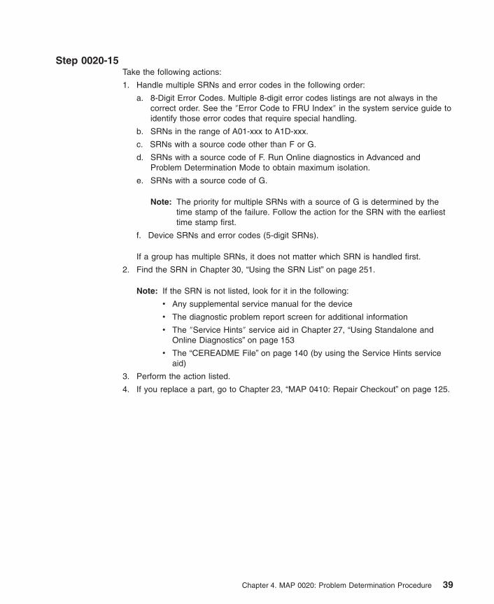
Step 0020-15Take the following actions:
1. Handle multiple SRNs and error codes in the following order:
a. 8-Digit Error Codes. Multiple 8-digit error codes listings are not always in thecorrect order. See the ″Error Code to FRU Index″ in the system service guide toidentify those error codes that require special handling.
b. SRNs in the range of A01-xxx to A1D-xxx.
c. SRNs with a source code other than F or G.
d. SRNs with a source code of F. Run Online diagnostics in Advanced andProblem Determination Mode to obtain maximum isolation.
e. SRNs with a source code of G.
Note: The priority for multiple SRNs with a source of G is determined by thetime stamp of the failure. Follow the action for the SRN with the earliesttime stamp first.
f. Device SRNs and error codes (5-digit SRNs).
If a group has multiple SRNs, it does not matter which SRN is handled first.
2. Find the SRN in Chapter 30, “Using the SRN List” on page 251.
Note: If the SRN is not listed, look for it in the following:
v Any supplemental service manual for the device
v The diagnostic problem report screen for additional information
v The ″Service Hints″ service aid in Chapter 27, “Using Standalone andOnline Diagnostics” on page 153
v The “CEREADME File” on page 140 (by using the Service Hints serviceaid)
3. Perform the action listed.
4. If you replace a part, go to Chapter 23, “MAP 0410: Repair Checkout” on page 125.
Chapter 4. MAP 0020: Problem Determination Procedure 39
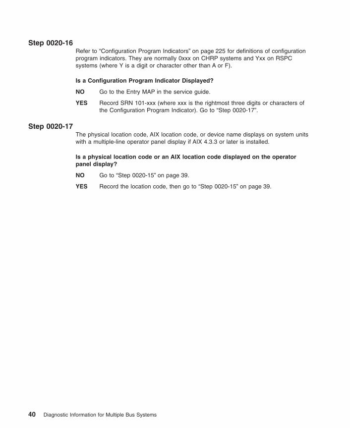
Step 0020-16Refer to “Configuration Program Indicators” on page 225 for definitions of configurationprogram indicators. They are normally 0xxx on CHRP systems and Yxx on RSPCsystems (where Y is a digit or character other than A or F).
Is a Configuration Program Indicator Displayed?
NO Go to the Entry MAP in the service guide.
YES Record SRN 101-xxx (where xxx is the rightmost three digits or characters ofthe Configuration Program Indicator). Go to “Step 0020-17”.
Step 0020-17The physical location code, AIX location code, or device name displays on system unitswith a multiple-line operator panel display if AIX 4.3.3 or later is installed.
Is a physical location code or an AIX location code displayed on the operatorpanel display?
NO Go to “Step 0020-15” on page 39.
YES Record the location code, then go to “Step 0020-15” on page 39.
40 Diagnostic Information for Multiple Bus Systems

Chapter 5. MAP 0025: SCSI RAID Problem Determination Procedure
Purpose of This MAPTo determine if there is a problem with the SCSI RAID subsystem.
Step 0025-1Determining the Status of the SCSI RAID Subsystem.
Ask the customer to determine the status of the RAID subsystem. Below is an exampleof this procedure:
1. Login as root (if not already root).
2. Type smit pdam.
3. Select List PCI SCSI RAID Arrays.
4. Select the adapter associated with the RAID upon which you want to do problemdetermination.
5. Press Enter.
Is the status of the RAID Array listed as optimal?
NO Go to “Step 0025-2”.
YES Fix the problem; then go to “Step 0025-12” on page 44.
Step 0025-2Is the status of the RAID Array listed as Degraded?
NO Go to “Step 0025-3”.
YES Make a note of the failing drive Channel and ID, and go to Chapter 18, “MAP0270: SCSI RAID Problem Resolution and Verification” on page 103 to replacethe drive on that channel.
Step 0025-3Is the status of the RAID Array listed as Reconstructing?
NO Go to “Step 0025-5” on page 42.
YES Go to “Step 0025-4”.
Step 0025-4Is the RAID Array reconstructing but no percentage is shown?
NO Wait for the RAID Array to complete reconstructing, then go to “Step 0025-12”on page 44.
YES Go to “Step 0025-5” on page 42.
41

Step 0025-5Is the status of the RAID Array listed as Defined?
NO Go to “Step 0025-11” on page 43.
YES Go to “Step 0025-6”.
Step 0025-6Ask the customer to determine the status of the RAID adapter. For example, type:
lsdev -C -l scraidX
where X is the number of the corresponding RAID adapter.
Is the result of this command that adapter is listed in Defined state?
NO Go to “Step 0025-11” on page 43.
YES Go to “Step 0025-7”.
Step 0025-7Ask the customer to remove the adapter and reconfigure it. For example, to remove theadapter type:
rmdev -l scraidX
and to reconfigure the adapter, type:
cfgmgr -l scraidX
where X is the number of the corresponding RAID adapter.
Did the adapter become Available?
NO Go to “Step 0025-10” on page 43.
YES Go to “Step 0025-8”.
Step 0025-8Ask the customer to configure the defined disk array. An example of this procedure:
1. Type smitty pdam
2. Select Configure a Defined PCI SCSI Disk Array.
3. Select the defined array that you want to make available.
4. A message displays indicating the outcome of the procedure. Make a note of themessage.
5. Press PF10 to exit.
Did the procedure fail?
NO Go to “Step 0025-9” on page 43.
YES Go to “Step 0025-10” on page 43.
42 Diagnostic Information for Multiple Bus Systems
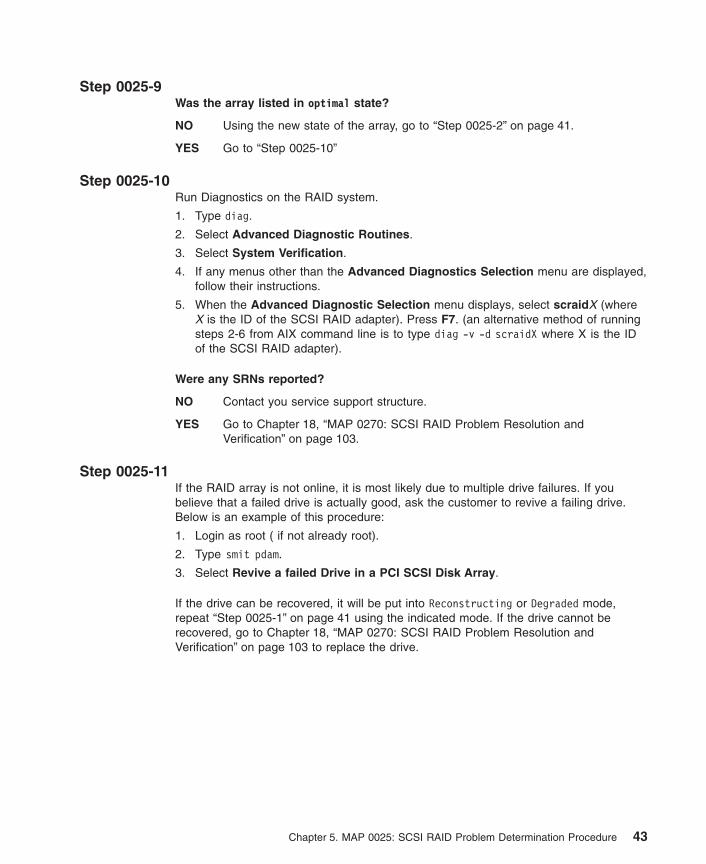
Step 0025-9Was the array listed in optimal state?
NO Using the new state of the array, go to “Step 0025-2” on page 41.
YES Go to “Step 0025-10”
Step 0025-10Run Diagnostics on the RAID system.
1. Type diag.
2. Select Advanced Diagnostic Routines.
3. Select System Verification.
4. If any menus other than the Advanced Diagnostics Selection menu are displayed,follow their instructions.
5. When the Advanced Diagnostic Selection menu displays, select scraidX (whereX is the ID of the SCSI RAID adapter). Press F7. (an alternative method of runningsteps 2-6 from AIX command line is to type diag -v -d scraidX where X is the IDof the SCSI RAID adapter).
Were any SRNs reported?
NO Contact you service support structure.
YES Go to Chapter 18, “MAP 0270: SCSI RAID Problem Resolution andVerification” on page 103.
Step 0025-11If the RAID array is not online, it is most likely due to multiple drive failures. If youbelieve that a failed drive is actually good, ask the customer to revive a failing drive.Below is an example of this procedure:
1. Login as root ( if not already root).
2. Type smit pdam.
3. Select Revive a failed Drive in a PCI SCSI Disk Array.
If the drive can be recovered, it will be put into Reconstructing or Degraded mode,repeat “Step 0025-1” on page 41 using the indicated mode. If the drive cannot berecovered, go to Chapter 18, “MAP 0270: SCSI RAID Problem Resolution andVerification” on page 103 to replace the drive.
Chapter 5. MAP 0025: SCSI RAID Problem Determination Procedure 43

Step 0025-121. Select Advanced Diagnostic Routines.
2. Select Problem Determination.
3. If any menus other than the Advanced Diagnostics Selection menu are displayed,follow their instructions.
4. When the Advanced Diagnostic Selection menu displays, select scraidX (whereX is the ID of the SCSI RAID adapter). Press F7. (an alternative method of runningsubsteps 2-6 from the AIX command line is to type diag -d scraidX where X is theID of the SCSI RAID adapter).
If the resource is in use and you do not wish to take it offline, select Testing ShouldStop. This will show information about the RAID subsystem including the address of thefailing disk drives used by that SCSI RAID channel and ID.
Note: Problem determination will not be performed unless the device is NOT in use.
Were any SRNs reported?
NO Go to “Step 0025-13”.
YES Go to Chapter 18, “MAP 0270: SCSI RAID Problem Resolution andVerification” on page 103.
Step 0025-131. Type diag
2. Select Task Selection
3. Select Analyze Adapter Internal Log
Are there any Hard or Media errors reported on specific drives?
NO Go to “Step 0025-14”.
YES Go to Chapter 18, “MAP 0270: SCSI RAID Problem Resolution andVerification” on page 103 to replace drives with media errors one at a time.
CAUTION:Only for the 4-Channel PCI SCSI RAID adapter, drives will be decoded aschannels 0-3 rather than channels 1-4. So if an error is indicated onchannel 1 ID 4, the error is really on channel 2 ID 4.
Step 0025-14Are there other RAID problems?
NO No RAID problems were found. Exit this MAP.
YES Contact your service support structure.
44 Diagnostic Information for Multiple Bus Systems
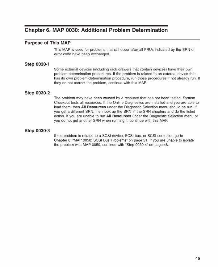
Chapter 6. MAP 0030: Additional Problem Determination
Purpose of This MAPThis MAP is used for problems that still occur after all FRUs indicated by the SRN orerror code have been exchanged.
Step 0030-1Some external devices (including rack drawers that contain devices) have their ownproblem-determination procedures. If the problem is related to an external device thathas its own problem-determination procedure, run those procedures if not already run. Ifthey do not correct the problem, continue with this MAP.
Step 0030-2The problem may have been caused by a resource that has not been tested. SystemCheckout tests all resources. If the Online Diagnostics are installed and you are able toload them, then All Resources under the Diagnostic Selection menu should be run. Ifyou get a different SRN, then look up the SRN in the SRN chapters and do the listedaction. If you are unable to run All Resources under the Diagnostic Selection menu oryou do not get another SRN when running it, continue with this MAP.
Step 0030-3If the problem is related to a SCSI device, SCSI bus, or SCSI controller, go toChapter 8, “MAP 0050: SCSI Bus Problems” on page 51. If you are unable to isolatethe problem with MAP 0050, continue with “Step 0030-4” on page 46.
45

Step 0030-41. Find the resource(s) that are identified by the SRN or error code in the following
table.
2. Perform the first action listed for the resource.
3. If you exchange a FRU or change a switch setting, test the resource again.
4. If the action does not correct the problem, perform the next action until all actionshave been tried. If an action says to exchange a FRU that you have alreadyexchanged, go to the next action. If an action corrects the problem, go toChapter 23, “MAP 0410: Repair Checkout” on page 125.
5. If you perform all of the actions and do not correct the problem, check the ServiceHints service aid for information. If the service aid does not help, call your servicesupport structure.
Failing Resource Repair Action
SCSI Device Exchange the SCSI Controller. Replace the powersupply.
Pluggable SCSI or IDE Controller Exchange the planar into which the adapter is plugged.
Keyboard, tablet, mouse, dials, LPFK,diskette drive
Check the cable attaching the device to its adapter. Ifyou do not find a problem, exchange the device’sadapter.
Pluggable adapters, CPU cards, andcontrollers
Determine whether the adapter contains any attachedFRUs such as fuses, DRAMs, and crossover cables.
1. Check or exchange any attached FRU on theresource.
2. If the adapter is plugged into a riser card, check orexchange the riser card.
3. Exchange the planar into which the adapter isplugged.
Note: To check for other FRUs, find the resource inChapter 38, “FRU Cross-References” on page 651; thengo to the FFC listed.
System and I/O planars Contact your service support structure.
Built-In serial ports Replace the Service Processor if present.
A device attached to the system by acable and an adapter.
1. Replace the adapter for the device.
2. Replace the cable to the device.
IDE Device Replace the cable between the IDE controller and thedevice. If the IDE controller is packaged on a planar,replace that planar, otherwise replace the adaptercontaining the IDE controller.
46 Diagnostic Information for Multiple Bus Systems

Chapter 7. MAP 0040: Intermittent Problem Isolation
Purpose of This MAPThis MAP provides a structured way of analyzing intermittent problems. It consists oftwo tables: Hardware Symptoms and Software Symptoms.
Because software or hardware can cause intermittent problems, consider all symptomsrelevant to your problem.
How to Use This MAPThis MAP contains information about causes of intermittent symptoms. In the followingtables, find your symptoms, and read the list of things to check.
When you exchange a FRU, go to Chapter 23, “MAP 0410: Repair Checkout” onpage 125 to check out the system.
Hardware Symptoms
Note: This table spans several pages.
Symptom of HardwareProblem
Things to Check For
Any hardware log entry in theerror log.
Use the Hardware Error Report service aid to view the error logand check for:
v Multiple errors on devices attached to the same SCSI bus.
v Multiple errors on devices attached to the same async adapter.
v Multiple errors on internally installed devices only.
Contact your service support structure for assistance with errorreport interpretation.
Hardware-caused systemcrashes
v The connections on the CPU planar or CPU card
v Memory modules for correct connections
v Connections to the system planar.
v Cooling fans operational
v The environment for a too-high or too-low operatingtemperature.
v Vibration: proximity to heavy equipment.
v If available, run the system memory test from the SystemManagement Services menu to check for intermittent memoryproblems.
47

Symptom of HardwareProblem
Things to Check For
System unit powers off a fewseconds after powering On.
v Fan speed. Some fans contain a speed-sensing circuit. If oneof these fans is slow, the power supply powers the system unitoff.
v Correct voltage at the outlet into which the system unit isplugged.
v Loose power cables and fan connectors, both internal andexternal.
System unit powers off afterrunning for more than a fewseconds.
v Excessive temperature in the power supply area.
v Loose cable connectors on the power distribution cables.
v Fans turning at full speed after the system power has been onfor more than a few seconds.
Only internally installeddevices are failing.
Check the following items that are common to more than onedevice:
v Ground connections on all of the disk drives and other types ofdrives installed.
v Loose connections on the power cables to the planars, drives,fans, and battery.
v System unit cooling. Is the input air temperature within limits?Are all the fans running at full speed? Are any of the ventareas blocked?
v Signal cables to the diskette drives, and the power supply.
v SCSI device signal cables for loose connectors andterminators.
v Loose SCSI device address jumpers.
v Possible contamination of any device that has a cleaningprocedure. See the operator guide for cleaning instructions.
v Excessive static electricity.
v Correct voltage at the system unit power outlet
48 Diagnostic Information for Multiple Bus Systems
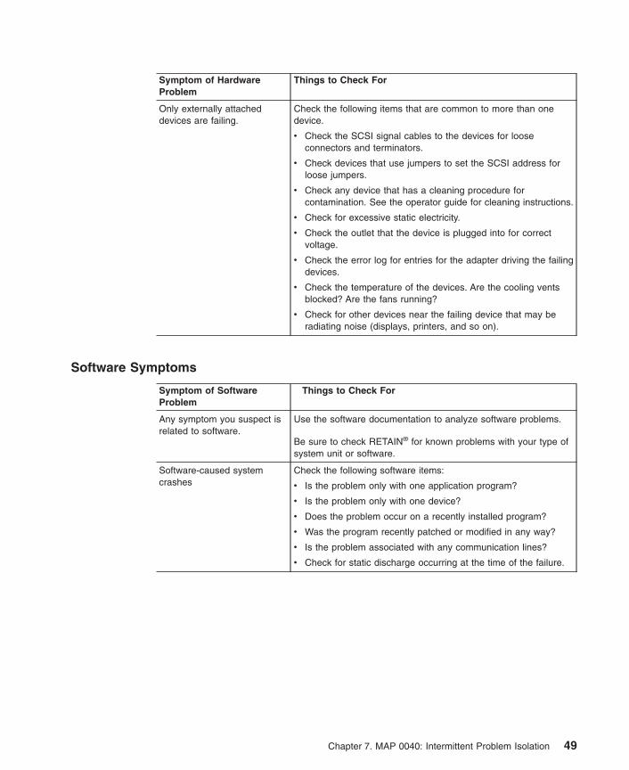
Symptom of HardwareProblem
Things to Check For
Only externally attacheddevices are failing.
Check the following items that are common to more than onedevice.
v Check the SCSI signal cables to the devices for looseconnectors and terminators.
v Check devices that use jumpers to set the SCSI address forloose jumpers.
v Check any device that has a cleaning procedure forcontamination. See the operator guide for cleaning instructions.
v Check for excessive static electricity.
v Check the outlet that the device is plugged into for correctvoltage.
v Check the error log for entries for the adapter driving the failingdevices.
v Check the temperature of the devices. Are the cooling ventsblocked? Are the fans running?
v Check for other devices near the failing device that may beradiating noise (displays, printers, and so on).
Software Symptoms
Symptom of SoftwareProblem
Things to Check For
Any symptom you suspect isrelated to software.
Use the software documentation to analyze software problems.
Be sure to check RETAIN® for known problems with your type ofsystem unit or software.
Software-caused systemcrashes
Check the following software items:
v Is the problem only with one application program?
v Is the problem only with one device?
v Does the problem occur on a recently installed program?
v Was the program recently patched or modified in any way?
v Is the problem associated with any communication lines?
v Check for static discharge occurring at the time of the failure.
Chapter 7. MAP 0040: Intermittent Problem Isolation 49

50 Diagnostic Information for Multiple Bus Systems

Chapter 8. MAP 0050: SCSI Bus Problems
Purpose of This MAPUse this MAP to analyze problems with a SCSI bus.
For additional information about this adapter, see the Adapters, Devices, and CableInformation for Multiple Bus Systems.
Considerationsv Remove power from the system before connecting and disconnecting cables or
devices to prevent hardware damage or erroneous diagnostic results.
v Also, use this MAP for SCSI adapters that are built into system boards or I/O boards.Replace the system board or I/O board when the procedure calls for replacing theadapter.
v If the failure is a terminator power failure (SRNs xxx-226, xxx-240, xxx-800), alwaysallow five minutes for the PTC to cool.
v The differential version of the adapter has socket-type terminators to supporthigh-availability. If this is the adapter’s configuration, the terminators would havebeen removed from the adapter. MAP steps requiring the removal of the cable fromthe adapter are inapplicable, since an adapter that is not terminated always failsdiagnostics. Proper SCSI diagnostics require proper termination. If the configurationinvolves a Y-cable, leave it, with the appropriate terminator, attached to the adapter.Or, place an external differential terminator on the external port.
v If the system uses shared DASD or high-availability configuration, be sure that theother system sharing the devices is not using those devices. For additionalinformation concerning high-availability configurations, see Chapter 1, “Service Hints”on page 1.
v For intermittent problems that cannot be resolved with this MAP, refer to Chapter 1,“Service Hints” on page 1.
v If the SCSI bus is attached to a RAID subsystem, refer to the RAID subsystemdocumentation for any problem determination.
Follow the steps in this MAP to isolate a SCSI bus problem.
Step 0050-1Have recent changes been made to the SCSI configuration?
NO Go to “Step 0050-2” on page 52.
YES Go to “Step 0050-5” on page 52.
51

Step 0050-2Are there any hot-swap devices controlled by the adapter?
NO Go to “Step 0050-3”.
YES Go to “Step 0050-11” on page 54.
Step 0050-3Are there any devices other than hot-swappable devices controlled by theadapter?
NO Go to “Step 0050-4”.
YES Go to “Step 0050-13” on page 54.
Step 0050-4Is an enclosure or drawer that supports hot-swap devices controlled by theadapter?
NO Go to “Step 0050-22” on page 57.
YES Go to “Step 0050-15” on page 55.
Step 0050-5This step handles cases where recent changes have been made to the SCSIconfiguration.
Using the first three digits of the SRN, refer to the FFC listing and determine if theadapter is single-ended or differential.
Is the adapter a single-ended adapter?
NO Go to “Step 0050-6”.
YES Go to “Step 0050-7” on page 53.
Step 0050-6The adapter’s termination jumper settings may be incorrect. Power off the system, andinspect Jumper J7. Refer to the ″SCSI Cabling″ section of the Adapters, Devices, andCable Information for Multiple Bus Systems for the correct jumper settings.
Are the jumpers correct?
NO Go to “Step 0050-8” on page 53.
YES Go to “Step 0050-9” on page 53.
52 Diagnostic Information for Multiple Bus Systems

Step 0050-7If the adapter is not being used in a high-availability configuration, be sure socketsRN1, RN2, and RN3 are populated.
If the adapter is being used in a high-availability configuration, be sure sockets RN1,RN2, and RN3 are not populated.
Go to “Step 0050-9”.
Step 0050-81. Correct the jumper settings and reinstall the adapter and all cables.
2. Power on the system, and run diagnostics in system verification mode on theadapter.
Did the diagnostic pass?
NO Go to “Step 0050-9”.
YES Go to Chapter 23, “MAP 0410: Repair Checkout” on page 125.
Step 0050-9Check for the following problems:
v Address conflicts between devices.
v Cabling problems such as; configurations that exceed the maximum cable lengths,missing termination, or excessive termination.
Refer to the Adapters, Devices, and Cable Information for Multiple Bus Systems formore details about supported SCSI cabling.
Did you find a problem?
NO Go to “Step 0050-2” on page 52.
YES Go to “Step 0050-10”.
Step 0050-101. Correct the problem.
2. Power on the system, and run diagnostics in system verification mode on theadapter.
Did a failure occur?
NO Go to Chapter 23, “MAP 0410: Repair Checkout” on page 125.
YES Go to “Step 0050-2” on page 52.
Chapter 8. MAP 0050: SCSI Bus Problems 53

Step 0050-11This step determines if a hot-swap device is causing the failure.
1. Power off the system.
2. Disconnect all hot-swap devices attached to the adapter.
3. Power on the system, and boot the system in the same mode that you were inwhen you received the symptom that led you to this MAP.
4. If the Missing Options menu displays, select the The resource has been turnedoff, but should remain in the system configuration option for all the devices thatwere disconnected.
5. Run the diagnostics in system verification mode on the adapter.
Did a failure occur?
NO Go to “Step 0050-12”.
YES Go to “Step 0050-3” on page 52.
Step 0050-12Power off the system. Reconnect the hot-swap devices one at time. After reconnectingeach device, follow this procedure:
1. Power on the system.
2. Rerun the diagnostics on the adapter.
3. If the adapter fails, the problem may be with the last device reconnected. Performthese substeps:
a. Follow repair procedures for that last device.
b. Rerun diagnostics on the adapter.
c. If diagnostics fail, replace the SES backplane corresponding to the slot for thedevice.
d. Rerun diagnostics.
e. If diagnostics fail, replace the last device.
f. Rerun diagnostics on the adapter.
g. If diagnostics pass, go to Chapter 23, “MAP 0410: Repair Checkout” onpage 125. Otherwise, contact your support center.
Note: A device problem can cause other devices attached to the same SCSIadapter to go into the Defined state. Ask the system administrator tomake sure that all devices attached to the same SCSI adapter as thedevice that you replaced are in the Available state.
4. If no errors occur, the problem could be intermittent. Make a record of the problem.Running the diagnostics for each device on the bus may provide additionalinformation.
Step 0050-13This step determines if a device other than a hot-swappable device is causing thefailure. Follow these steps:
54 Diagnostic Information for Multiple Bus Systems
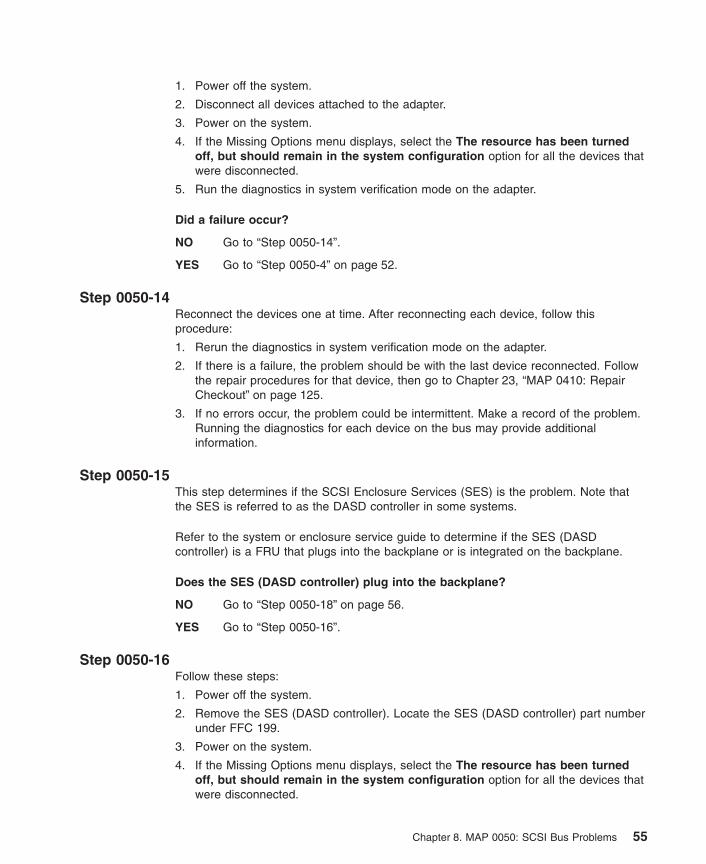
1. Power off the system.
2. Disconnect all devices attached to the adapter.
3. Power on the system.
4. If the Missing Options menu displays, select the The resource has been turnedoff, but should remain in the system configuration option for all the devices thatwere disconnected.
5. Run the diagnostics in system verification mode on the adapter.
Did a failure occur?
NO Go to “Step 0050-14”.
YES Go to “Step 0050-4” on page 52.
Step 0050-14Reconnect the devices one at time. After reconnecting each device, follow thisprocedure:
1. Rerun the diagnostics in system verification mode on the adapter.
2. If there is a failure, the problem should be with the last device reconnected. Followthe repair procedures for that device, then go to Chapter 23, “MAP 0410: RepairCheckout” on page 125.
3. If no errors occur, the problem could be intermittent. Make a record of the problem.Running the diagnostics for each device on the bus may provide additionalinformation.
Step 0050-15This step determines if the SCSI Enclosure Services (SES) is the problem. Note thatthe SES is referred to as the DASD controller in some systems.
Refer to the system or enclosure service guide to determine if the SES (DASDcontroller) is a FRU that plugs into the backplane or is integrated on the backplane.
Does the SES (DASD controller) plug into the backplane?
NO Go to “Step 0050-18” on page 56.
YES Go to “Step 0050-16”.
Step 0050-16Follow these steps:
1. Power off the system.
2. Remove the SES (DASD controller). Locate the SES (DASD controller) part numberunder FFC 199.
3. Power on the system.
4. If the Missing Options menu displays, select the The resource has been turnedoff, but should remain in the system configuration option for all the devices thatwere disconnected.
Chapter 8. MAP 0050: SCSI Bus Problems 55

5. Run the diagnostics in system verification mode on the adapter.
Did a failure occur?
NO Go to “Step 0050-17”.
YES Go to “Step 0050-18”.
Step 0050-17Follow these steps:
1. Power off the system.
2. Replace the SES (DASD controller).
3. Go to Chapter 23, “MAP 0410: Repair Checkout” on page 125.
Step 0050-18Follow these steps:
1. Power off the system.
2. Disconnect all cables attached to the adapter. For SCSI differential adapters in ahigh-availability configuration, see “Considerations” on page 51.
3. Power on the system.
4. If the Missing Options menu displays, select the The resource has been turnedoff, but should remain in the system configuration option for all the devices thatwere disconnected.
5. Run the diagnostics in system verification mode on the adapter.
Did a failure occur?
NO Go to “Step 0050-19”.
YES Replace the adapter, then go to Chapter 23, “MAP 0410: Repair Checkout” onpage 125.
Step 0050-19Follow these steps:
1. Power off the system.
2. Reconnect the cables to the adapter.
Does the SES (DASD controller) plug into the backplane?
NO Go to “Step 0050-20”.
YES Go to “Step 0050-21” on page 57.
Step 0050-20Follow these steps:
1. Replace the SES (DASD controller). Locate the SES (DASD controller) part numberunder FFC 199.
2. Power on the system.
56 Diagnostic Information for Multiple Bus Systems
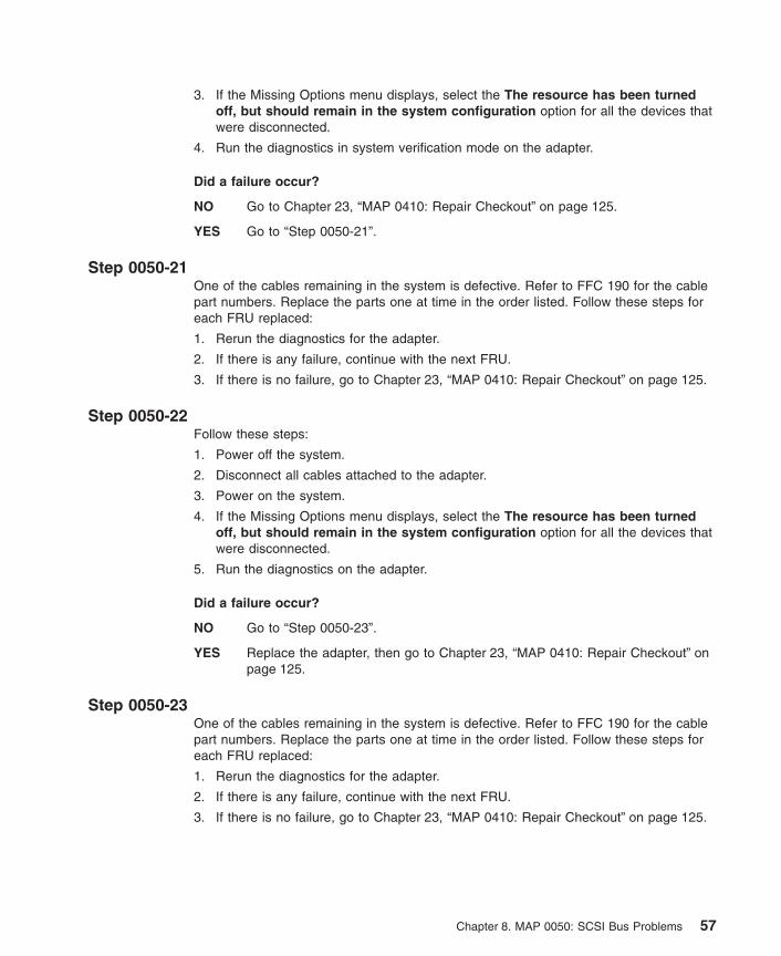
3. If the Missing Options menu displays, select the The resource has been turnedoff, but should remain in the system configuration option for all the devices thatwere disconnected.
4. Run the diagnostics in system verification mode on the adapter.
Did a failure occur?
NO Go to Chapter 23, “MAP 0410: Repair Checkout” on page 125.
YES Go to “Step 0050-21”.
Step 0050-21One of the cables remaining in the system is defective. Refer to FFC 190 for the cablepart numbers. Replace the parts one at time in the order listed. Follow these steps foreach FRU replaced:
1. Rerun the diagnostics for the adapter.
2. If there is any failure, continue with the next FRU.
3. If there is no failure, go to Chapter 23, “MAP 0410: Repair Checkout” on page 125.
Step 0050-22Follow these steps:
1. Power off the system.
2. Disconnect all cables attached to the adapter.
3. Power on the system.
4. If the Missing Options menu displays, select the The resource has been turnedoff, but should remain in the system configuration option for all the devices thatwere disconnected.
5. Run the diagnostics on the adapter.
Did a failure occur?
NO Go to “Step 0050-23”.
YES Replace the adapter, then go to Chapter 23, “MAP 0410: Repair Checkout” onpage 125.
Step 0050-23One of the cables remaining in the system is defective. Refer to FFC 190 for the cablepart numbers. Replace the parts one at time in the order listed. Follow these steps foreach FRU replaced:
1. Rerun the diagnostics for the adapter.
2. If there is any failure, continue with the next FRU.
3. If there is no failure, go to Chapter 23, “MAP 0410: Repair Checkout” on page 125.
Chapter 8. MAP 0050: SCSI Bus Problems 57

58 Diagnostic Information for Multiple Bus Systems
Chapter 9. MAP 0070: 888 Sequence in Operator Panel Display
Purpose of This MAPAn 888 sequence in operator panel display suggests that either a hardware or softwareproblem has been detected and a diagnostic message is ready to be read.
Note: The 888 may or may not be flashing on the operator panel display.
Step 0070-1Perform the following steps to record the information contained in the 888 sequencemessage.
1. Wait until the 888 sequence displays.
2. Record, in sequence, every code displayed after the 888. On systems with a 3-digitor a 4-digit operator panel, you may need to press the system’s ″reset″ button toview the additional digits after the 888. Stop recording when the 888 digits reappear.
3. Go to “Step 0070-2”.
Step 0070-2Using the first code that you recorded, use the following list to determine the next stepto use.
Type 102 Go to “Step 0070-3”.
Type 103 Go to “Step 0070-4” on page 60.
Step 0070-3A Type 102 message generates when a software or hardware error occurs duringsystem execution of an application. Use the following information to determine thecontent of the type 102 message. Descriptions of the crash codes and the dump statuscodes are in Chapter 29, “Diagnostics Numbers and Location Codes” on page 225.
The message readout sequence is:102 = Message typeRRR = Crash code (the three-digit code that immediately follows the 102)SSS = Dump status code (the three-digit code that immediately follows the Crash code).
Record the Crash code and the Dump Status from the message you recorded in “Step0070-1”. For an explanation of the Dump Status or the Crash Codes, see Chapter 29,“Diagnostics Numbers and Location Codes” on page 225.
59
Are there additional codes following the Dump Status?
No Go to “Step 0070-5”.
YES The message also has a type 103 message included in it. Go to “Step 0070-4”to decipher the SRN and field replaceable unit (FRU) information in the Type103 message.
Note: Type 102 messages have no associated SRNs.
Step 0070-4A Type 103 message generates upon hardware error detection. Use the following stepsand information you recorded in “Step 0070-1” on page 59 to determine the content ofthe Type 103 message.
The message readout sequence is:
103 = Message type(x)xxx (y)yyy = SRN(where (x)xxx = the three- or four-digit code following the 103 and (y)yyy is the three- orfour-digit code following the (x)xxx code).
1. Record the SRN and FRU location codes from the recorded message.
2. Find the SRN in the Service Request Number List and do the indicated action.
Note: The only way to recover from an 888 type of halt is to turn off the system unit.
Step 0070-5Perform the following steps:
1. Turn off the system unit power.
2. Turn on the system unit power, and load the online diagnostics in service mode.
3. Wait until one of the following conditions occurs:
v You are able to load the diagnostics to the point where the Diagnostic ModeSelection menu displays.
v The system stops with an 888 sequence.
v The system appears hung.
Is the Diagnostic Mode Selection menu displayed?
No Go to Entry MAP in the system unit service guide.
Yes Go to “Step 0070-6” on page 61.
60 Diagnostic Information for Multiple Bus Systems

Step 0070-6Run the All Resources options under Advanced Diagnostics in Problem DeterminationMode.
Was an SRN reported by the diagnostics?
No This is possibly a software-related 888 sequence. Follow the procedure forreporting a software problem.
Yes Record the SRN and its location code information. Find the SRN in the SRNListing and do the indicated action.
Chapter 9. MAP 0070: 888 Sequence in Operator Panel Display 61

62 Diagnostic Information for Multiple Bus Systems

Chapter 10. MAP 0080: System Bus Problem Isolation
Purpose of This MAPUse this MAP to analyze a bus problem that does not prevent the system from booting.
Note: Some devices installed in the system may require the loading of supplementaldiskettes for diagnostic support.
Step 0080-11. Perform a system shutdown and then, if necessary, turn off the system unit power.
2. Locate the diagnostic CD-ROM disc.
3. Turn on the system unit power, and then load the diagnostic CD-ROM disc into theCD-ROM drive.
4. Load the Standalone Diagnostics.
5. Wait until the ″Please Define the System Console″ screen displays or all systemactivity appears to have stopped.
Is the ″Please Define the System Console″ screen displayed?
No The symptom has changed. Use MAP 1540 in the system unit’s service guide.
Yes Go to “Step 0080-2”.
Step 0080-2Follow the displayed instructions until the Installed Resources menu displays.
Are all of the installed PCI adapters listed on the Installed Resources menu?
No Go to “Step 0080-3” on page 64 and make a note of all PCI adapters not listedand their locations.
Yes You may have an intermittent problem. If you think that you have anintermittent problem, go to Chapter 7, “MAP 0040: Intermittent ProblemIsolation” on page 47.
63

Step 0080-31. Perform a system shutdown, and then, if necessary, turn off the system unit power.
2. Remove all but one of the PCI adapters that was not listed on the InstalledResources menu.
Note: If only one adapter is present, do not remove it.
3. Turn on the system unit power, and load standalone diagnostics from the CD-ROM.
4. Wait until the ″Please define the System Console″ screen displays or all systemactivity appears to have stopped.
Is the ″Please Define the System Console″ screen displayed?
No The symptom has changed. Use MAP 1540 in the system unit’s service guide.
Yes Go to “Step 0080-4”.
Step 0080-4Follow the displayed instructions until the Installed Resources menu displays.
Is the adapter that you did not remove shown as an installed resource?
No Record SRN 111-78C and make a note of the adapter you just installed. Lookup the SRN in the SRN listings and perform the indicated action.
Yes Go to “Step 0080-5”.
Step 0080-5Have you installed all of the removed adapters?
No Go to “Step 0080-6”.
Yes Call your service support structure.
Step 0080-61. Perform a system shutdown and then, if necessary, turn off the system unit power.
2. Install one of the remaining removed adapters into its original location.
3. Turn on the system unit power, and load Standalone Diagnostics from the CD-ROM.
4. Wait until the ″Please Define the System Console″ screen displays or all systemactivity appears to stop.
Is the ″Please Define the System Console″ screen displayed?
No The symptom has changed. Use MAP 1540 in the system unit’s service guide.
Yes Go to “Step 0080-7” on page 65.
64 Diagnostic Information for Multiple Bus Systems

Step 0080-7Follow the displayed instructions until the Installed Resources menu displays.
Is the adapter that you just installed shown as an installed resource?
No Record SRN 111-78C and make a note of the adapter you just installed. Lookup the SRN in the SRN listings and perform the indicated action.
Yes Go to “Step 0080-5” on page 64.
Chapter 10. MAP 0080: System Bus Problem Isolation 65

66 Diagnostic Information for Multiple Bus Systems

Chapter 11. MAP 0210: General Problem Resolution
Purpose of This MAPUse this MAP to exchange the FRUs in the order of their failure probability.
Step 0210-1Read the following information before proceeding.
v Version 4.3.3 and later diagnostics display the part number and the physical locationcode, if available, on the Problem Report screen. The parts are listed inprobability-of-failure order.
v Part numbers display if they are available from vital product data (VPD). If the partnumber displays, use it in place of the part number in the FFC List. In some cases,the part number provided by the VPD may be incorrect. In that case, use the partnumber in the FFC list.
v When identifying the location of a planar or a plug-in card, the physical location codemay contain the failing FRU’s extended location information. For additionalinformation, see “Location Codes for RSPC Model Architecture System Units” onpage 242, “Location Codes for CHRP Model Architecture System Units” on page 244,or the system unit’s service guide.
Go to “Step 0210-2”.
Step 0210-2Find the failing function codes in the “Failing Function Code List” on page 566, and ifnot already recorded, record the FRU part number and description of each FRU.
Do you want to exchange this FRU as a hot-plug FRU?
NO Go to “Step 0210-3”.
YES Go to Chapter 12, “MAP 0220: Hot-Swap FRU Problem Resolution” onpage 77.
Step 0210-31. Referring to “Service Request Number Lists” on page 252, record the SRN source
code and the failing function codes in the order of their listing, if not alreadyrecorded.
2. Find the failing function codes in the ″Failing Function Code List,″ refer toChapter 37, “Failing Function Codes (FFCs)” on page 563, and if not alreadyrecorded, record the part number and description for each FRU.
3. If the operating system is running, perform the operating system’s shutdownprocedure (get help if needed).
4. Turn off the system power.
67

Exchange one of the FRUs (normally the first one listed).
To verify the repair, find the SRN source code that you recorded in the following table.Go to the step indicated in the Action column.
SRN Source Code Action
A Go to “Step 0210-8” on page 70.
B Go to “Step 0210-8” on page 70.
C Go to “Step 0210-4”.
D Go to “Step 0210-8” on page 70.
E Go to “Step 0210-8” on page 70.
F Go to “Step 0210-8” on page 70.
G Go to “Step 0210-14” on page 72.
H Go to “Step 0210-19” on page 73.
Step 0210-4The following steps handle the problems when the system does not detect a resource.
Note: Use the following substeps for the SRNs having source code: C.
1. Turn on the system power.
2. Load Online Diagnostics in Service Mode (refer to the system’s service guide ifneeded).
3. Wait until the diagnostics are loaded or the system appears to stop.
Were you able to load the diagnostics?
NO The symptom has changed. Check for loose cards, cables, and obviousproblems. If you do not find a problem, go to the system unit’s service guide.
YES Go to “Step 0210-5” on page 69.
68 Diagnostic Information for Multiple Bus Systems

Step 0210-51. Press Enter.
2. Select the Advanced Diagnostics option.
Note: If the terminal type is not defined, you are prompted to define it. You cannotcontinue until this is done.
3. When the DIAGNOSTIC MODE SELECTION menu displays, select SystemVerification.
Is the MISSING RESOURCE menu displayed?
NO This completes the repair. Go to Chapter 23, “MAP 0410: Repair Checkout” onpage 125.
YES Go to “Step 0210-6”.
Step 0210-6Look at the failing function codes and the FRU part numbers you recorded for this SRN.
Have you exchanged all the FRUs that correspond to the failing function codes?
NO Go to “Step 0210-7”.
YES The SRN did not identify the failing FRU. Go to Chapter 6, “MAP 0030:Additional Problem Determination” on page 45.
Step 0210-71. After performing a shutdown of the operating system, turn off the system unit power.
2. Remove the new FRU and install the original FRU.
3. Exchange the next FRU in the list.
4. Turn on the system unit power.
5. Load the Online Diagnostics in Service Mode. Refer to the system unit serviceguide if needed.
6. Wait until the diagnostics are loaded or the system appears to stop.
Were you able to load the diagnostics?
NO The symptom has changed. Check for loose cards, cables, and obviousproblems. If you do not find a problem, go to the system’s service guide.
YES Go to “Step 0210-5”, and repeat the steps.
Chapter 11. MAP 0210: General Problem Resolution 69

Step 0210-8
Note: Run Online Diagnostics, if possible. If the system planar or battery has beenreplaced and you are loading diagnostics from a server over a network, it maybe necessary for the customer to set the network boot information. The systemtime and date information should also be set when the repair is completed.
1. Turn on the system power.
2. Load either the Online or Standalone Diagnostics in Service Mode. Refer to thesystem’s service guide if needed.
3. Wait until the diagnostics are loaded or the system appears to stop.
Were you able to load the diagnostics?
NO The symptom has changed. Check for loose cards, cables, and obviousproblems. If you do not find a problem, go to Chapter 4, “MAP 0020: ProblemDetermination Procedure” on page 29 and get a new SRN.
YES Go to “Step 0210-9”.
Step 0210-91. Press Enter.
2. Select the Advanced Diagnostics Routines option.
Note: If the terminal type is not defined, you are prompted to define it. You cannotcontinue until this is done.
3. If the MISSING RESOURCES menu displays, skip the next step and answer thequestion below. If it does not display, proceed to the next substep.
4. When the DIAGNOSTIC MODE SELECTION menu displays, select the SystemVerification option.
Is the ADVANCED DIAGNOSTIC SELECTION menu displayed?
NO Go to “Step 0210-15” on page 73.
YES Go to “Step 0210-10” on page 71.
70 Diagnostic Information for Multiple Bus Systems

Step 0210-10Select and run the diagnostics for the FRU you exchanged, and any attached devicesto the FRU exchange. If the FRU you exchanged does not appear on the resourceselection screen, select sysplanar0.
Note: The RESOURCE REPAIR ACTION menu allows a repair action to be logged forthe resource being tested. This prevents Error Log Analysis from reportingproblems on FRUs that have been replaced. If the RESOURCE REPAIRACTION menu displays, perform the following:
1. Select the resource that has been replaced from the menu.
2. After all selections have been made, select Commit (F7 key).
Did the FRU pass the test?
NO Go to “Step 0210-11”.
YES This completes the repair. Go to Chapter 23, “MAP 0410: Repair Checkout” onpage 125.
Step 0210-11Look at the failing function codes and FRU part numbers you recorded for this SRN.
Have you exchanged all the FRUs that correspond to the failing function codes?
NO Go to “Step 0210-12”.
YES The SRN did not identify the failing FRU. Go to Chapter 6, “MAP 0030:Additional Problem Determination” on page 45.
Step 0210-121. After performing a shutdown of the operating system, turn off the system unit power.
2. Remove the new FRU and install the original FRU.
3. Exchange the next FRU in the list.
4. Turn on the system unit power.
5. Load either the Online or Standalone Diagnostics in Service Mode. Refer to thesystem’s service guide if needed.
6. Wait until the diagnostics are loaded or the system appears to stop.
Were you able to load the diagnostics?
NO The symptom has changed. Check for loose cards, cables, and obviousproblems. If you do not find a problem, go to the system’s service guide.
YES Go to “Step 0210-13” on page 72.
Chapter 11. MAP 0210: General Problem Resolution 71

Step 0210-131. Press Enter.
2. Select the Advanced Diagnostics Routines option.
3. If the MISSING RESOURCES menu displays, skip the rest of these steps andanswer the question below. If it does not display, proceed to the next substep.
4. When the DIAGNOSTIC MODE SELECTION menu displays, select the SystemVerification option.
Note: If the terminal type is not defined, you are prompted to define it. You cannotcontinue until this is done.
Is the ADVANCED DIAGNOSTIC SELECTION menu displayed?
NO Go to “Step 0210-15” on page 73.
YES Go to “Step 0210-10” on page 71.
Step 0210-14Every time the Problem Determination option is selected from the Diagnostics ModeSelection menu, the error log for the preceding time period is analyzed, and problemsare assigned the SRN source: G. Although a FRU may have already been replaced,based on that error log analysis, repeated selection of the Problem Determinationoption continues to reflect the same error for a period of time. The System Verificationoption does not perform error analysis. Ensure that the indicated failing FRU has notbeen replaced in the previous week.
Has the FRU called out by this SRN been replaced within the past week?
NO Go to “Step 0210-8” on page 70.
YES Disregard this SRN. If the Problem Determination option needs to be run,use the operating system’s errclear command to delete the error log entry forthe replaced resource. If more information is needed, see the operating systemCommands Reference. Go to Chapter 4, “MAP 0020: Problem DeterminationProcedure” on page 29.
72 Diagnostic Information for Multiple Bus Systems

Step 0210-15Is the Missing Resource menu displayed?
NO The symptom has changed. Check for loose cards, cables, and obviousproblems. If you do not find a problem, go to the Chapter 4, “MAP 0020:Problem Determination Procedure” on page 29 and get a new SRN.
YES Go to “Step 0210-16”.
Step 0210-16Was on of the missing resources attached to SES, SAF-TE, or DASD backplane?
NO Go to “Step 0210-18”.
YES Go to “Step 0210-17”.
Step 0210-17A defective backplane may cause phantom devices to appear at specific SCSIaddresses. Look through the configuration of SCSI devices attached to the backplaneyou replaced and verify that the devices shown are actually present in the configuration.If you find any extra SCSI devices that are not present in the system, remove themfrom the configuration (check with the system administrator to verify the actualconfiguration of SCSI devices that should be attached to the backplane).
Rerun diagnostics choosing the Advanced Diagnostics Routines option.
Do you still have missing resources attached to SES, SAF-TE, or DASDbackplane?
NO Go to “Step 0210-24” on page 75.
YES Go to “Step 0210-18”.
Step 0210-18Follow the displayed instructions. When you finish processing the missing resources,answer the following:
Did you get an SRN?
NO Go to “Step 0210-24” on page 75.
YES Go to “Step 0210-23” on page 75.
Step 0210-19The following steps handle the problem when the machine stops with an 888 sequencedisplayed in the operator panel display while it is loading diagnostics.
1. Power on the system and load the Online Diagnostics in Service Mode (refer to thesystem’s service guide if needed).
2. Wait until one of the following conditions occurs and answer the question.
v The machine stops for at least three minutes with a steady number in theoperator panel display.
Chapter 11. MAP 0210: General Problem Resolution 73

v An 888 sequence displays in the operator panel display.
v The operator panel display is blank.
v The DIAGNOSTIC OPERATING INSTRUCTIONS displays.
Did the system stop with an 888 sequence in the operator panel display?
NO This completes the repair. Go to Chapter 23, “MAP 0410: Repair Checkout” onpage 125.
YES Go to “Step 0210-20”.
Step 0210-201. Read out the message in the operator panel display. If needed see Chapter 9, “MAP
0070: 888 Sequence in Operator Panel Display” on page 59.
2. Find and record the SRN in the message.
3. Find and record the location codes for the FRUs in the message.
Are the SRN and the location codes the same as the SRN you were analyzing?
NO Go to “Step 0210-1” on page 67 and analyze the new SRN.
YES Go to “Step 0210-21”.
Step 0210-21Look at the failing function codes and FRU part numbers you recorded for this SRN.
Have you exchanged all the FRUs that correspond to the failing function codes?
NO Go to “Step 0210-22” on page 75.
YES The SRN did not identify the failing FRU. Go to Chapter 6, “MAP 0030:Additional Problem Determination” on page 45.
74 Diagnostic Information for Multiple Bus Systems

Step 0210-221. Set the power switch on the system unit to Off.
2. Remove the new FRU and install the original FRU.
3. Replace FRU parts in the order the FFCs are listed.
4. Power on the system.
5. Load the Online Diagnostics in Service Mode (refer to the system’s service guide ifneeded).
6. Wait until one of the following conditions occurs and answer the question.
v The machine stops for at least three minutes with a steady number in theoperator panel display.
v An 888 sequence displays in the operator panel display.
v The operator panel display is blank.
v The DIAGNOSTIC OPERATING INSTRUCTIONS displays.
Did the system stop with an 888 sequence in the operator panel display?
NO This completes the repair. Go to Chapter 23, “MAP 0410: Repair Checkout” onpage 125.
YES Go to “Step 0210-21” on page 74.
Step 0210-23Is the SRN the Same as the Original SRN?
NO The symptom has changed. Check for loose cards, cables, and obviousproblems. If you do not find a problem, go to the Chapter 4, “MAP 0020:Problem Determination Procedure” on page 29 and get a new SRN.
YES Go to “Step 0210-24”.
Step 0210-241. Exit the Missing Resources menu.
2. When the DIAGNOSTIC MODE SELECTION menu displays, select the SystemVerification option.
3. Go to “Step 0210-10” on page 71.
Chapter 11. MAP 0210: General Problem Resolution 75

76 Diagnostic Information for Multiple Bus Systems

Chapter 12. MAP 0220: Hot-Swap FRU Problem Resolution
Purpose of This MAPUse this MAP to exchange hot-swappable FRUs.
Note: The FRU you want to hot plug might have a defect on it that can cause thehot-plug operation to fail. If, after following the hot- plug procedure, you continueto get an error message that indicates that the hot-plug operation has failed,schedule a time for deferred maintenance when the system containing the FRUcan be powered down. Then go to MAP 210, “Step 0210-2” on page 67 andanswer NO to the question Do you want to exchange this FRU as a hot-plugFRU?.
Attention: If the FRU is a disk drive or an adapter, ask the system administrator toperform any steps necessary to prepare the device for removal.
Step 0220-11. If the system displayed a FRU part number on the screen, use that part number to
exchange the FRU.
If there is no FRU part number displayed on the screen, refer to the SRN listing.Record the SRN source code and the failing function codes in the order listed.
2. Find the failing function codes in the FFC listing, and record the FRU part numberand description of each FRU.
3. Refer to the removal and replacements procedures in your system’s service guideor the PCI Adapter Placement Reference Guide to determine if the FRU ishot-swappable.
Does this system unit support hot-swapping of the first FRU listed?
NO Go to MAP 0210.
YES Go to “Step 0220-2”.
Step 0220-2Is the FRU a hot-swap power supply or fan?
NO Go to “Step 0220-4” on page 78.
YES Go to “Step 0220-3”.
Step 0220-3
Note: Refer to the system unit’s service guide for removal and replacementprocedures.
1. Remove the old FRU.
2. Install the new FRU.
3. Enter the diag command.
77
Go to “Step 0220-14” on page 81.
Step 0220-4Is the FRU a hot-plug PCI adapter?
NO Go to “Step 0220-5”.
YES Go to “Step 0220-12” on page 80.
Step 0220-5Is the FRU a SCSI hot-plug device?
NO Go to “Step 0220-11” on page 79.
YES Go to “Step 0220-6”.
Step 0220-6Is the hot-plug drive located within a system unit?
NO Go to “Step 0220-8”.
YES Go to “Step 0220-7”.
Step 0220-7Refer to the system’s service guide in the ″Removing Hot-Plug SCSI Disk Drives″section under ″Removal and Replacement Procedures″ for information about replacinghot-plug SCSI Disk Drives.
Go to “Step 0220-13” on page 80.
Step 0220-8Does the hot-plug drive’s enclosure have a system guide with procedures forRemoving and Replacing SCSI Disk drives?
NO Go to “Step 0220-9”.
YES If a hot-plug procedure exists, use that procedure to remove the old hot-plugSCSI disk drive and replace it with a new hot-plug SCSI disk drive. Otherwise,if no hot-plug procedure exists, use the existing procedure to remove the oldSCSI disk drive and replace it with a new SCSI disk drive. Go to “Step0220-13” on page 80.
Step 0220-91. Ask the customer to back up the data on the drive that you intend to replace onto
another drive.
2. Verify that the disk drive is in the Defined state. The amber LED on the hot-plugdisk drive should be off.
Is the hot-plug disk drive’s amber LED unlit?
NO Ask the customer to remove the hot-plug disk drive from the operating systemconfiguration (refer them to System Management guide for more information).
78 Diagnostic Information for Multiple Bus Systems

YES Go to “Step 0220-10”.
Step 0220-10Using the Hot-Plug Task service aid described in Chapter 28, “Introduction to Tasks andService Aids” on page 175, replace the hot-plug drive using the following procedure:
1. Use the List the SES Devices option to show the configuration of the hot-plugslots. Identify the slot number of the adapter for the FRU you want to replace.
2. Select the REPLACE/REMOVE a Device Attached to an SES Device option.
3. Select the slot which contains the SCSI hot-plug drive you wish to replace. PressEnter. You will see a fast blinking green light on the front on the hot-plug driveindicating that it is ready for removal.
Note: Refer to service guide for the system unit or enclosure that contains thehot-plug drive for removal and replacement procedures.
4. Remove the old hot-plug drive.
5. Install the new hot-plug drive. Once the hot-plug drive is in place, press Enter.
6. Press the exit key. Wait while configuration is done on the drive, until you see the″hot-plug task″ on the service aid menu.
Go to “Step 0220-15” on page 81.
Step 0220-11Using the Hot Plug Task service aid described in Chapter 28, “Introduction to Tasks andService Aids” on page 175, replace the hot-plug drive using the hot plug RAID serviceaid:
Note: The drive you wish to replace must be either a SPARE or FAILED drive. Otherwise,the drive would not be listed as an IDENTIFY AND REMOVE RESOURCESselection within the RAID HOT PLUG DEVICES screen. In that case you mustask the customer to put the drive into FAILED state. Refer them to the SystemManagement Guide for more information. Ask the customer to back up the dataon the drive that you intend to replace.
1. Select the RAID HOT PLUG DEVICES option within the HOT PLUG TASK underDIAGNOSTIC SERVICE AIDS.
2. Select the RAID adapter that is connected to the RAID array containing the RAIDdrive you wish to remove, then select COMMIT.
3. Choose the IDENTIFY option in the IDENTIFY AND REMOVE RESOURCES menu.
4. Select the physical disk which you wish to remove from the RAID array and pressEnter.
5. The disk will go into the IDENTIFY state, indicated by a flashing light on the drive.Verify that it is the physical drive you wish to remove, then press Enter.
6. At the IDENTIFY AND REMOVE RESOURCES menu, choose the REMOVE optionand press Enter.
7. A list of the physical disks in the system which may be removed will be displayed. Ifthe physical disk you wish to remove is listed, select it and press Enter. Thephysical disk will go into the REMOVE state, as indicted by the LED on the drive. If the
Chapter 12. MAP 0220: Hot-Swap FRU Problem Resolution 79
physical disk you wish to remove is not listed, it is not a SPARE or FAILED drive. Askthe customer to put the drive in the FAILED state before you can proceed to removeit. Refer the customer to the System Management Guide for more information.
8. Refer to service guide for the system unit or enclosure that contains the physicaldrive for removal and replacement procedures for the following substeps:
a. Remove the old hot-plug RAID drive.
b. Install the new hot-plug RAID drive. Once the hot-plug drive is in place, pressEnter. The drive will exit the REMOVE state, and will go to the NORMAL state onceyou exit diagnostics.
Note: There are no elective tests to run on a RAID drive itself under diagnostics(the drives are tested by the RAID adapter).
9. This completes the repair. Return the system to the customer. Ask the customer toadd the physical disk drive to the original configuration within the RAID. Refer themto system management guide for more information.
Step 0220-121. Remove the old adapter FRU and install the new adapter FRU. Refer to the
″Replacing a Hot-Pluggable PCI Adapter″ section within the ″Removal andReplacement Procedures″ section of the system service guide.
2. Enter the diag command.
3. Go to the FUNCTION SELECTION menu, and select the Advanced DiagnosticsRoutines option.
4. When the DIAGNOSTIC MODE SELECTION menu displays, select the SystemVerification option.
5. Go to “Step 0220-14” on page 81.
Step 0220-131. If not already running diagnostics, enter the diag command.
Note: If you are already running service mode diagnostics and have just performedthe Configure Added/Replaced Devices task (under the SCSI Hot Swapmanager of the Hot Plug Task service aid), you must use the F3 key toreturn to the DIAGNOSTIC OPERATING INSTRUCTIONS menu beforeproceeding with the next step, or else the drive might not appear on theresource list.
2. Go to the FUNCTION SELECTION menu, and select the Advanced DiagnosticsRoutines option.
3. When the DIAGNOSTIC MODE SELECTION menu displays, select the SystemVerification option.
Does the hot-plug SCSI disk drive you just replaced appear on the resource list?
NO Verify that you have correctly followed the procedures for replacing hot-plugSCSI disk drives in the system service guide. If the disk drive still does not
80 Diagnostic Information for Multiple Bus Systems

appear in the resource list, go to Chapter 11, “MAP 0210: General ProblemResolution” on page 67 to replace the resource that the hot-plug SCSI diskdrive is plugged in to.
YES Go to “Step 0220-14”.
Step 0220-14Run the diagnostic test on the FRU you just replaced.
Did the diagnostics run with no trouble found?
NO Go to “Step 0220-15”.
YES Go to Chapter 23, “MAP 0410: Repair Checkout” on page 125. Beforereturning the system to the customer, if a hot-plug disk has been removed, askthe customer to add the hot-plug disk drive to the operating systemconfiguration. Refer to system management guide for more information.″
Step 0220-151. Use the Log Repair Action option in the TASK SELECTION menu to update the
AIX error log. If the repair action was reseating a cable or adapter, select theresource associated with your repair action. If it is not displayed on the resource list,select sysplanar0.
Note: On systems with a Fault Indicator LED, this changes the Fault Indicator LEDfrom the ″Fault″ state to the ″Normal″ state.
2. While in diagnostics, go to the FUNCTION SELECTION menu. Select theAdvanced Diagnostics Routines option.
3. When the DIAGNOSTIC MODE SELECTION menu displays, select the SystemVerification option. Run the diagnostic test on the FRU you just replaced, orsysplanar0.
Did the diagnostics run with no trouble found?
NO Go to “Step 0220-16” on page 82.
YES If you changed the Service Processor or Network settings, restore the settingsto the value they had prior to servicing the system. If you performed service ona RAID subsystem involving changing of the RAID adapter cache card orchanging the configuration on RAID disks, ask the customer to run PCI SCSIDisk Array Manager using smitty to resolve the PCI SCSI RAID Adapterconfiguration. The following is an example of how the customer would resolvethe configuration:
1. At the AIX command line, type smitty pdam.
2. On the ″PCI SCSI Disk Array Manager″ screen, select RECOVERYOPTIONS.
3. If a previous configuration exists on the replacement adapter, this must becleared. Select Clear PCI SCSI RAID Adapter Configuration. Press F3.
4. On the ″Recovery Options″ screen, select RESOLVE PCI SCSI RAIDADAPTER CONFIGURATION.
Chapter 12. MAP 0220: Hot-Swap FRU Problem Resolution 81

5. On the ″Resolve PCI SCSI RAID Adapter Configuration″ screen, selectACCEPT CONFIGURATION on DRIVES.
6. On the PCI SCSI RAID Adapter selection menu, select the adapter thatyou changed.
7. On the next screen, press Enter.
8. When you get the ″Are You Sure?″ selection menu, press Enter tocontinue.
9. You should get an OK status message when the recovery is complete. Ifyou get a Failed status message, verify that you are doing recovery on thecorrect adapter, then do this complete procedure. When you complete therecovery, exit smitty to return to the AIX command line.
Go to Chapter 23, “MAP 0410: Repair Checkout” on page 125.
Step 0220-16Does the original problem persist?
NO If a FRU was replaced, run the Log Repair Action service aid under the OnlineDiagnostics for the resource that was replaced. If the resource associated withyour action is not displayed on the Resource List, select sysplanar0. If stepswere taken to make the device ready for removal, inform the SystemAdministrator of the steps required to return the system to the original state.Go to Chapter 23, “MAP 0410: Repair Checkout” on page 125.
YES Go to “Step 0220-17”.
Step 0220-17Have you exchanged all the FRUs that correspond to the failing function codes?
NO Go to “Step 0220-18”.
YES The SRN did not identify the failing FRU. Schedule a time to run diagnostics inservice mode. If the same SRN is reported in service mode, go to Chapter 6,“MAP 0030: Additional Problem Determination” on page 45.
Step 0220-18
Note: Before proceeding, remove the FRU you just replaced and install the originalFRU in its place.
Does the system unit support hot-swapping of the next FRU listed?
NO Go to Chapter 11, “MAP 0210: General Problem Resolution” on page 67.
YES The SRN did not identify the failing FRU. Schedule a time to run diagnostics inservice mode. If the same SRN is reported in service mode, go to “Step0220-14” on page 81.
82 Diagnostic Information for Multiple Bus Systems

Chapter 13. MAP 0230: Platform Error Problem Resolution
Purpose of This MAPUse this MAP to resolve problems reported by SRNs A00-000 to A1F-FFF.
Step 0230-11. The last character of the SRN is bit-encoded as follows:
8 4 2 1| | | || | | Replace all FRUs listed| | Hot-swap is supported| Software or Firmware could be the causeReserved
2. Refer to the last character in the SRN. A 4, 5, 6, or 7 indicates a possible softwareor firmware problem.
Does the last character indicate a possible software or firmware problem?
NO Go to “Step 0230-4” on page 84.
YES Go to “Step 0230-2”.
Step 0230-2Ask the customer if any software or firmware has been installed recently.
Has any software or firmware been installed recently?
NO Go to “Step 0230-4” on page 84.
YES Go to “Step 0230-3”.
Step 0230-3Suspect the new software or firmware.
Check with your support center for any known problems with the new software orfirmware.
Are there any known problems with the software or firmware?
NO Go to “Step 0230-4” on page 84.
YES Obtain and follow the procedure to correct the software problem. Thiscompletes the repair.
83

Step 0230-4Were any FRUs or location code reported with the SRN?
NO Go to “Step 0230-5”.
YES Go to “Step 0230-9”.
Step 0230-5Run the diagnostics in problem determination mode on sysplanar0.
Were there any FRUs reported with the SRN?
NO Go to “Step 0230-6”.
YES Go to “Step 0230-9”.
Step 0230-6Did the system display: ″Previous Diagnostic Results - Do you want to review thepreviously displayed error?″
NO Go to “Step 0230-7”.
YES You have a pending item in the error log for which there is no correspondingLog Repair Action. To see this error, select YES at the prompt. Informationfrom the error log displays in order of last event first. Record the error code,the FRU names and the location code of the FRUs. Go to “Step 0230-7”.
Step 0230-7Were there any other SRNs that begin with an A00 to A1F reported?
NO Go to “Step 0230-8”.
YES Go to “Step 0230-1” on page 83 and use the new SRN.
Step 0230-8Attempt to boot the system on slow boot mode.
If the system boots, run the diagnostics in problem determination mode on sysplanar0
Were any new error codes or SRNs reported?
NO Call your support center.
YES Follow the procedure for the new error code or SRN.
Step 0230-91. Obtain the list of physical location codes and FRU numbers that were listed on the
Problem Report Screen. The list can be obtained by running the sysplanar0diagnostics or using the Display Previous Diagnostic Results task.
2. Record the physical location codes and FRU numbers.
3. Refer to the last character in the SRN. A 2, 3, 6, or 7 indicates that hot-swap ispossible.
84 Diagnostic Information for Multiple Bus Systems

Does the last character indicate that hot-swap is possible?
NO Go to “Step 0230-10”.
YES Go to “Step 0230-14” on page 88.
Step 0230-10
Note: If necessary, refer to the section under ″Reference Information″ in the systemservice guide ″Powering the system on and off″ for information on system shutdown and powering the system on and off.
1. If the operating system is running, perform the operating system’s shutdownprocedure.
2. Turn off power to the system.
3. Refer to the last character in the SRN. A 1, 3, 5, or 7 indicates that all FRUs listedon the Problem Report Screen need to be replaced. For SRNs ending with anyother character, exchange one FRU at a time, in the order listed.
Note: Use the appropriate procedure under ″Removal and ReplacementProcedures″ in the system service guide to replace any FRUs indicated.
4. Turn on power to the system.
Note: In substep 16 on page 86, you will be asked to run exercisers. On apartitioned system, if the FRU you replaced contains resources that may beallocated to different partitions (for example, if the FRU is an MCMcontaining multiple processors, where the processors may be assigned todifferent partitions) you may wish to also run exercisers on those otherpartitions containing these resources in addition to running them in thepartition that reported the SRN. If you run exercisers in those otherpartitions, you will need to repeat substeps 5 through 18 on page 86 of thisMAP step for each partition in which you run exercisers.
5. Load Online Diagnostics in service mode (see the system’s service guide ifneeded).
Note: If the Diagnostics Operating Instructions do not display or you are unable toselect the Task Selection option, check for loose cards, cables, andobvious problems. If you do not find a problem, go to Chapter 4, “MAP0020: Problem Determination Procedure” on page 29 and get a new SRN.
6. Wait until the Diagnostics Operating Instructions are displayed or the systemappears to stop.
7. Press Enter.
8. Select Diagnostic Routines at the function selection menu.
9. Select System Verification.
10. If a missing options exist, particularly if it is related to the device that was replaced,resolve the missing options before proceeding
11. Select the Task Selection option.
12. Select the Log Repair Action option.
Chapter 13. MAP 0230: Platform Error Problem Resolution 85

13. Log a repair action for each replaced resource.
14. If the resource associated with your repair action is not displayed on the resourcelist, select sysplanar0.
15. Return to the Task Selection Menu.
16. If the FRU that was replaced was memory, select Run Exercisers and run theshort exerciser on all the resources, otherwise proceed “Step 0230-15” on page 89.
17. After the exercisers are complete, return to the Task Selection menu.
18. Select Run Error Log Analysis and run analysis on all the resources.
Was a problem reported?
NO The repair is complete. Go to Chapter 23, “MAP 0410: Repair Checkout” onpage 125.
YES Go to “Step 0230-11”.
Step 0230-11Is the problem the same as the original problem?
NO The symptom has changed. Check for loose cards, cables, and obviousproblems. If you do not find a problem, go to Chapter 4, “MAP 0020: ProblemDetermination Procedure” on page 29 and get a new SRN.
YES Go to “Step 0230-12”.
Step 0230-12Look at the physical location codes and FRU part numbers you recorded.
Have you exchanged all the FRUs that were listed?
NO Go to “Step 0230-13” on page 87.
YES The SRN did not identify the failing FRU. Call your support person forassistance.
86 Diagnostic Information for Multiple Bus Systems
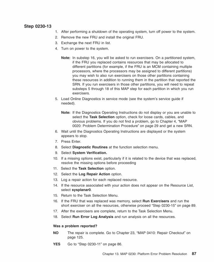
Step 0230-131. After performing a shutdown of the operating system, turn off power to the system.
2. Remove the new FRU and install the original FRU.
3. Exchange the next FRU in list.
4. Turn on power to the system.
Note: In substep 16, you will be asked to run exercisers. On a partitioned system,if the FRU you replaced contains resources that may be allocated todifferent partitions (for example, if the FRU is an MCM containing multipleprocessors, where the processors may be assigned to different partitions)you may wish to also run exercisers on those other partitions containingthese resources in addition to running them in the partition that reported theSRN. If you run exercisers in those other partitions, you will need to repeatsubsteps 5 through 18 of this MAP step for each partition in which you runexercisers.
5. Load Online Diagnostics in service mode (see the system’s service guide ifneeded).
Note: If the Diagnostics Operating Instructions do not display or you are unable toselect the Task Selection option, check for loose cards, cables, andobvious problems. If you do not find a problem, go to Chapter 4, “MAP0020: Problem Determination Procedure” on page 29 and get a new SRN.
6. Wait until the Diagnostics Operating Instructions are displayed or the systemappears to stop.
7. Press Enter.
8. Select Diagnostic Routines at the function selection menu.
9. Select System Verification.
10. If a missing options exist, particularly if it is related to the device that was replaced,resolve the missing options before proceeding
11. Select the Task Selection option.
12. Select the Log Repair Action option.
13. Log a repair action for each replaced resource.
14. If the resource associated with your action does not appear on the Resource List,select sysplanar0.
15. Return to the Task Selection Menu.
16. If the FRU that was replaced was memory, select Run Exercisers and run theshort exerciser on all the resources, otherwise proceed “Step 0230-15” on page 89.
17. After the exercisers are complete, return to the Task Selection Menu.
18. Select Run Error Log Analysis and run analysis on all the resources.
Was a problem reported?
NO The repair is complete. Go to Chapter 23, “MAP 0410: Repair Checkout” onpage 125.
YES Go to “Step 0230-11” on page 86.
Chapter 13. MAP 0230: Platform Error Problem Resolution 87

Step 0230-14The FRUs can be hot-swapped. If you do not want to use the hot-swap, go to “Step0230-10” on page 85.
Note: See the hot-swap procedures in the ″Removal and Replacement″ section of yoursystem unit’s service guide.
1. Refer to the last character in the SRN. A 1, 3, 5, or 7 indicates that all FRUs listedon the Problem Report Screen must be replaced. For SRNs ending with any othercharacter, exchange one FRU at a time, in the order listed.
Note: In substep 9, you will be asked to run exercisers. On a partitioned system, ifthe FRU you replaced contains resources that may be allocated to differentpartitions (for example, if the FRU is an MCM containing multipleprocessors, where the processors may be assigned to different partitions)you may wish to also run exercisers on those other partitions containingthese resources in addition to running them in the partition that reported theSRN. If you run exercisers in those other partitions, you will need to repeatsubsteps 2 through 10 of this MAP step for each partition in which you runexercisers.
2. If available, use the CE Login and enter the diag command.
Note: If CE Login is not available, have the system administrator enter superusermode and then enter the diag command.
3. After the Diagnostics Operating Instructions display, press Enter.
4. Select the Task Selection option.
5. Select the Log Repair Action option.
6. If the resource associated with your action is not displayed on the Resource List,select sysplanar0.
7. Log a repair action for each replaced resource.
8. Return to the Task Selection menu.
9. Select Run Exercisers and run the short exerciser on all resources.
10. Use the Log Repair Action option in the Task Selection menu to update the AIXerror log. If the repair action was reseating a cable or adapter, select the resourceassociated with your repair action. If it is not displayed on the resource list, selectsysplanar0.
Note: On systems with a Fault Indicator LED, this changes the Fault IndicatorLED from the ″fault″ state to the ″normal″ state.
Was a problem reported?
NO The repair is completed. Return the system to the customer.
YES Go to “Step 0230-15” on page 89.
88 Diagnostic Information for Multiple Bus Systems
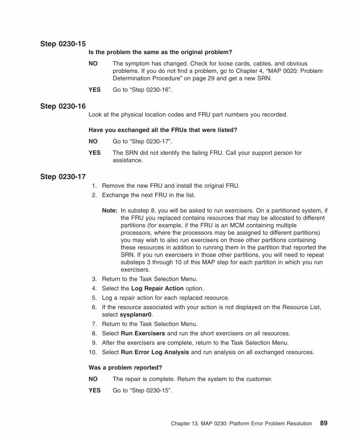
Step 0230-15Is the problem the same as the original problem?
NO The symptom has changed. Check for loose cards, cables, and obviousproblems. If you do not find a problem, go to Chapter 4, “MAP 0020: ProblemDetermination Procedure” on page 29 and get a new SRN.
YES Go to “Step 0230-16”.
Step 0230-16Look at the physical location codes and FRU part numbers you recorded.
Have you exchanged all the FRUs that were listed?
NO Go to “Step 0230-17”.
YES The SRN did not identify the failing FRU. Call your support person forassistance.
Step 0230-171. Remove the new FRU and install the original FRU.
2. Exchange the next FRU in the list.
Note: In substep 8, you will be asked to run exercisers. On a partitioned system, ifthe FRU you replaced contains resources that may be allocated to differentpartitions (for example, if the FRU is an MCM containing multipleprocessors, where the processors may be assigned to different partitions)you may wish to also run exercisers on those other partitions containingthese resources in addition to running them in the partition that reported theSRN. If you run exercisers in those other partitions, you will need to repeatsubsteps 3 through 10 of this MAP step for each partition in which you runexercisers.
3. Return to the Task Selection Menu.
4. Select the Log Repair Action option.
5. Log a repair action for each replaced resource.
6. If the resource associated with your action is not displayed on the Resource List,select sysplanar0.
7. Return to the Task Selection Menu.
8. Select Run Exercisers and run the short exercisers on all resources.
9. After the exercisers are complete, return to the Task Selection Menu.
10. Select Run Error Log Analysis and run analysis on all exchanged resources.
Was a problem reported?
NO The repair is complete. Return the system to the customer.
YES Go to “Step 0230-15”.
Chapter 13. MAP 0230: Platform Error Problem Resolution 89

90 Diagnostic Information for Multiple Bus Systems

Chapter 14. MAP 0235: System Array Self-Repair ProblemResolution
Purpose of This MAPUse this MAP to resolve problems reported by SRNS A11-560 to A11-580.
Note: The following steps may require that the system be rebooted to invoke Array bitsteering, so you may wish to schedule deferred maintenance with the systemadministrator to arrange a convenient time to reboot their system.
Step 0235-1Was the SRN A11-560?
NO Go to “Step 0235-3”.
YES Go to “Step 0235-2”.
Step 0235-2Logged in as root or using CE Login, at the AIX command line type diag then pressenter. Use the Log Repair Action option in the TASK SELECTION menu to update theAIX error log. Select sysplanar0.
Note: On systems with fault indicator LED, this changes the fault indicator LED fromthe FAULT state to the NORMAL state.
Were there any other errors on the resource reporting the array bit steeringproblem?
NO Go to “Step 0235-4” on page 92.
YES Resolve those errors before proceeding.
Step 0235-3Logged in as root or using CE Login, at the AIX command line type diag then pressenter. Use the Log Repair Action option in the TASK SELECTION menu to update theAIX error log. Select procx, where x is the processor number of the processor numberof the processor that reported the error.
Note: On systems with fault indicator LED, this changes the fault indicator LED fromthe FAULT state to the NORMAL state.
Were there any other errors on procx?
NO Go to “Step 0235-4” on page 92.
YES Resolve those errors before proceeding.
91

Step 0235-4Schedule deferred Maintenance with the customer. When it is possible, reboot thesystem to invoke Array Bit steering
Go to “Step 0235-5”.
Step 0235-5After the system has been rebooted, log in as root or use CE Login. At the AIXcommand line, run diagnostics in problem determination mode to determine if the arraybit steering was able to correct the problem.
If diagnostics are not run (for instance, if the system returns to Resource Selectionmenu after running diagnostics in problem determination mode) or there is no problemon the resource that originally reported the problem, then array bit steering was able tocorrect the problem. Exit this MAP and go to Chapter 23, “MAP 0410: Repair Checkout”on page 125.
If a problem is reported, use the SRN to resolve the problem. Go to the Chapter 3,“Fast Path MAP” on page 17 with this symptom.
92 Diagnostic Information for Multiple Bus Systems

Chapter 15. MAP 0240: Memory Problem Resolution
Purpose of This MAPThis MAP handles memory problems.
Step 0240-11. If the system displayed a FRU part number on the screen, use that part number to
exchange the FRU.
If there was no FRU part number displayed on the screen, find your SRN in the“Service Request Number List” on page 255.
2. Record the SRN source code and the failing function codes in the order of theirlisting.
3. Find the function codes in the “Failing Function Code List” on page 566 and recordthe part number and description for each FRU.
4. If the operating system is running, perform the operating system’s shutdownprocedure (get help if needed).
5. Turn off the system power.
Exchange the first FRU listed.
Notes:
1. If more than one memory module is listed, replace all the listed memory modulessimultaneously.
2. If the SRN table lists multiple FRUs, (other than memory modules) exchange theFRUs one at a time based on the order listed. If an exchanged FRU does not fix theproblem, reinstall the original FRU, and then replace the next FRU listed whendirected by the MAPs.
Go to “Step 0240-2”.
Step 0240-21. Turn off the system power.
2. Load either the Online or Standalone Diagnostics in Service Mode (refer to thesystem’s service guide if needed).
3. Wait until the diagnostics are loaded or the system appears to stop.
Were you able to load the diagnostics?
NO The symptom has changed. Check for loose cards, cables, and obviousproblems. If you do not find a problem, go to the system unit’s service guide.
YES Go to “Step 0240-3” on page 94.
93
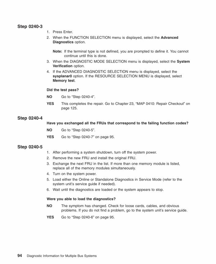
Step 0240-31. Press Enter.
2. When the FUNCTION SELECTION menu is displayed, select the AdvancedDiagnostics option.
Note: If the terminal type is not defined, you are prompted to define it. You cannotcontinue until this is done.
3. When the DIAGNOSTIC MODE SELECTION menu is displayed, select the SystemVerification option.
4. If the ADVANCED DIAGNOSTIC SELECTION menu is displayed, select thesysplanar0 option. If the RESOURCE SELECTION MENU is displayed, selectMemory test.
Did the test pass?
NO Go to “Step 0240-4”.
YES This completes the repair. Go to Chapter 23, “MAP 0410: Repair Checkout” onpage 125.
Step 0240-4Have you exchanged all the FRUs that correspond to the failing function codes?
NO Go to “Step 0240-5”.
YES Go to “Step 0240-7” on page 95.
Step 0240-51. After performing a system shutdown, turn off the system power.
2. Remove the new FRU and install the original FRU.
3. Exchange the next FRU in the list. If more than one memory module is listed,replace all of the memory modules simultaneously.
4. Turn on the system power.
5. Load either the Online or Standalone Diagnostics in Service Mode (refer to thesystem unit’s service guide if needed).
6. Wait until the diagnostics are loaded or the system appears to stop.
Were you able to load the diagnostics?
NO The symptom has changed. Check for loose cards, cables, and obviousproblems. If you do not find a problem, go to the system unit’s service guide.
YES Go to “Step 0240-6” on page 95.
94 Diagnostic Information for Multiple Bus Systems
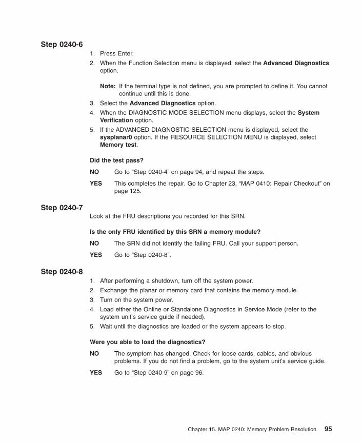
Step 0240-61. Press Enter.
2. When the Function Selection menu is displayed, select the Advanced Diagnosticsoption.
Note: If the terminal type is not defined, you are prompted to define it. You cannotcontinue until this is done.
3. Select the Advanced Diagnostics option.
4. When the DIAGNOSTIC MODE SELECTION menu displays, select the SystemVerification option.
5. If the ADVANCED DIAGNOSTIC SELECTION menu is displayed, select thesysplanar0 option. If the RESOURCE SELECTION MENU is displayed, selectMemory test.
Did the test pass?
NO Go to “Step 0240-4” on page 94, and repeat the steps.
YES This completes the repair. Go to Chapter 23, “MAP 0410: Repair Checkout” onpage 125.
Step 0240-7Look at the FRU descriptions you recorded for this SRN.
Is the only FRU identified by this SRN a memory module?
NO The SRN did not identify the failing FRU. Call your support person.
YES Go to “Step 0240-8”.
Step 0240-81. After performing a shutdown, turn off the system power.
2. Exchange the planar or memory card that contains the memory module.
3. Turn on the system power.
4. Load either the Online or Standalone Diagnostics in Service Mode (refer to thesystem unit’s service guide if needed).
5. Wait until the diagnostics are loaded or the system appears to stop.
Were you able to load the diagnostics?
NO The symptom has changed. Check for loose cards, cables, and obviousproblems. If you do not find a problem, go to the system unit’s service guide.
YES Go to “Step 0240-9” on page 96.
Chapter 15. MAP 0240: Memory Problem Resolution 95

Step 0240-91. Press Enter.
2. When the Function Selection menu is displayed, select the Advanced Diagnosticoption.
Note: If the terminal type is not defined, you are prompted to define it. You cannotcontinue until this is done.
3. When the DIAGNOSTIC MODE SELECTION menu is displayed, select the SystemVerification option.
4. If the ADVANCED DIAGNOSTIC SELECTION menu is displayed, select thesysplanar0 option. If the RESOURCE SELECTION MENU is displayed, selectMemory test.
Did the test pass?
NO The SRN did not identify the failing FRU. Call your support person.
YES This completes the repair. Go to Chapter 23, “MAP 0410: Repair Checkout” onpage 125.
96 Diagnostic Information for Multiple Bus Systems

Chapter 16. MAP 0250: Unexpected System Halts DuringDiagnostics
Purpose of This MAPThis MAP handles unexpected system halts that occur while running the diagnosticprograms. Go to “Step 0250-1”.
Step 0250-1The last three or four digits of the SRN following the dash (-) match a failing functioncode number. Refer to “Failing Function Code List” on page 566 and find the failingfunction code that matches the last three digits of your SRN. Record the FRU partnumber and description.
Does this system unit contain only one of this kind of FRU?
NO Go to “Step 0250-2”.
YES Go to “Step 0250-3”.
Step 0250-2One of the multiple FRUs of this kind is defective.
Remove this kind of FRU one at a time. Test the system unit after each FRU isremoved. When the test is successful or all FRUs of this kind have been removed.
Were you able to identify a failing FRU?
NO Contact your service support structure.
YES Go to “Step 0250-3”.
Step 0250-31. Turn off the system unit power.
2. Exchange the FRU identified in “Step 0250-2” or the FRU identified by the last threeor four digits of the SRN following the dash (-).
3. Turn on the system power.
4. Load either the Online or Standalone Diagnostics in Service Mode (refer to thesystem unit’s service guide if needed).
5. Wait until the diagnostics are loaded or the system appears to stop.
97

Were you able to load the diagnostics?
NO The symptom changed. Check for loose cards, cables, and obvious problems.If you do not find a problem, go to the system unit’s service guide.
YES Go to “Step 0250-4”.
Step 0250-41. Press Enter.
2. When the FUNCTION SELECTION menu is displayed, select the AdvancedDiagnostics option.
Note: If the terminal type is not defined, you are prompted to define it. You cannotcontinue until this is done.
3. When the DIAGNOSTIC MODE SELECTION menu is displayed, select the SystemVerification option.
Did the ADVANCED DIAGNOSTIC SELECTION menu display?
NO The symptom changed. Check for loose cards, cables, and obvious problems.If you do not find a problem, go to Chapter 4, “MAP 0020: ProblemDetermination Procedure” on page 29 and get a new SRN.
YES Go to “Step 0250-5”.
Step 0250-5Run diagnostics on the FRU that you exchanged.
Did the FRU pass the test?
NO Contact your support person.
YES This completes the repair. Go to Chapter 23, “MAP 0410: Repair Checkout” onpage 125.
98 Diagnostic Information for Multiple Bus Systems
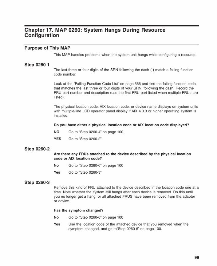
Chapter 17. MAP 0260: System Hangs During ResourceConfiguration
Purpose of This MAPThis MAP handles problems when the system unit hangs while configuring a resource.
Step 0260-1The last three or four digits of the SRN following the dash (-) match a failing functioncode number.
Look at the “Failing Function Code List” on page 566 and find the failing function codethat matches the last three or four digits of your SRN, following the dash. Record theFRU part number and description (use the first FRU part listed when multiple FRUs arelisted).
The physical location code, AIX location code, or device name displays on system unitswith multiple-line LCD operator panel display if AIX 4.3.3 or higher operating system isinstalled.
Do you have either a physical location code or AIX location code displayed?
NO Go to “Step 0260-4” on page 100.
YES Go to “Step 0260-2”.
Step 0260-2Are there any FRUs attached to the device described by the physical locationcode or AIX location code?
No Go to “Step 0260-6” on page 100
Yes Go to “Step 0260-3”
Step 0260-3Remove this kind of FRU attached to the device described in the location code one at atime. Note whether the system still hangs after each device is removed. Do this untilyou no longer get a hang, or all attached FRUS have been removed from the adapteror device.
Has the symptom changed?
No Go to “Step 0260-6” on page 100
Yes Use the location code of the attached device that you removed when thesymptom changed, and go to“Step 0260-6” on page 100.
99

Step 0260-4Does your system unit contain only one of this kind of FRU?
NO Go to “Step 0260-5”.
YES Go to “Step 0260-6”.
Step 0260-5One of the FRUs of this kind is defective.
Remove this kind of FRU one at a time. Test the system unit after each FRU isremoved. When the test completes successfully or when you have removed all of theFRUs of this kind.
Were you able to identify a failing FRU?
NO Go to MAP 1540 in the service guide for this system unit.
YES Go to “Step 0260-6”.
Step 0260-61. Turn off the system unit.
2. Exchange the FRU identified by the location code or “Step 0260-5”.
Is this system capable of running online diagnostics in Service Mode?
NO Go to “Step 0260-7”.
YES Go to “Step 0260-8”.
Step 0260-71. Turn on the system unit.
2. Load the Standalone diagnostics (if needed, refer to the Service Guide).
3. Wait until the Diagnostic Operating Instructions display or the system appears tohave stopped.
Are the DIAGNOSTIC OPERATING INSTRUCTIONS displayed?
NO Go to “Step 0260-9” on page 101.
YES Go to Chapter 23, “MAP 0410: Repair Checkout” on page 125.
Step 0260-81. Turn on the system unit.
2. Load the Online Diagnostics in Service Mode (if needed, refer to the ServiceGuide).
3. Wait until the Diagnostic Operating Instructions display or the system appears tohave stopped.
Are the DIAGNOSTIC OPERATING INSTRUCTIONS displayed?
100 Diagnostic Information for Multiple Bus Systems

NO Go to “Step 0260-9”.
YES Go to Chapter 23, “MAP 0410: Repair Checkout” on page 125.
Step 0260-9Look at the operator panel display.
Is the number displayed the same as the last three or four digits after the dash (-)of your SRN?
NO The symptom changed. Check for loose cards, cables, and obvious problems.If you do not find a problem, go to Chapter 4, “MAP 0020: ProblemDetermination Procedure” on page 29 and get a new SRN.
YES Go to “Step 0260-10”.
Step 0260-10Was the FRU you exchanged an adapter or a planar?
NO Go to “Step 0260-11”.
YES Go to MAP 1540 in the service guide for this system unit.
Step 0260-11Was the FRU you exchanged a device?
NO Go to MAP 1540 in the service guide for this system unit.
YES Go to “Step 0260-12”.
Step 0260-12The adapter for the device may be causing the problem.
1. Turn off the system unit.
2. Exchange the adapter for the device.
Note: If the AIX operating system is not used on the system, start diagnostics froman alternate source.
3. Turn on the system unit. If c31 is displayed, follow the displayed instructions toselect a console display.
4. Load the Online Diagnostics in Service Mode (if needed, refer to the service guide).
5. Wait until the DIAGNOSTIC OPERATING INSTRUCTIONS display or the systemappears to have stopped.
Are the DIAGNOSTIC OPERATING INSTRUCTIONS displayed?
NO Go to MAP 1540 in the service guide for this system unit.
YES Go to Chapter 23, “MAP 0410: Repair Checkout” on page 125.
Chapter 17. MAP 0260: System Hangs During Resource Configuration 101

102 Diagnostic Information for Multiple Bus Systems

Chapter 18. MAP 0270: SCSI RAID Problem Resolution andVerification
Purpose of This MAPUse this MAP to Resolve SCSI RAID Adapter, Cache, or drive problems.
Note: This MAP assumes that the RAID adapter and drive microcode is at the correctlevel. To check microcode level, see “SCSI RAID Descriptions and DiagnosticProcedures” on page 169.
Attention: If the FRU is a disk drive or an adapter, ask the system administrator toperform any steps necessary to prepare the device for removal.
Step 0270-11. If the system displayed a FRU part number on the screen, use that part number. If
there is no FRU part number displayed on the screen, refer to the SRN listing.Record the SRN source code and the failing function codes in the order listed.
2. Find the failing function codes in the FFC listing, and record the FRU part numberand description of each FRU.
Go to “Step 0270-2”.
Step 0270-2Is the FRU a RAID drive?
NO Go to “Step 0270-6” on page 106.
YES Go to “Step 0270-3” on page 104.
103

Step 0270-3If the RAID drive you want to replace is not already in the failed state, then ask thecustomer to run the PCI SCSI Disk Array Manager using smit to fail the drive that youwish to replace. An example of this procedure is:
1. Login as root.
2. Type smit pdam.
3. Select Fail a Drive in a PCI SCSI Disk Array.
4. Select the appropriate disk array by placing the cursor over that array and pressEnter.
5. Select the appropriate drive to fail based on the Channel and ID called out indiagnostics.
6. The Fail a Drive screen will appear. Verify that you are failing the correct drive bylooking at the Channel ID row. Press Enter when verified correct. Press Enter again.
7. Press F10 and type smit pdam
8. Select ″Change/Show PCI SCSI RAID Drive Status -> Remove a Failed Drive
9. Select the drive that just failed.
Go to “Step 0270-4”.
Step 0270-4Using the Hot Plug Task service aid described in “Hot Plug Task” on page 207, replacethe RAID drive using the RAID HOT PLUG DEVICES service aid:
Note: The drive you wish to replace must be either a SPARE or FAILED drive.Otherwise, the drive would not be listed as an IDENTIFY AND REMOVERESOURCES selection within the RAID HOT PLUG DEVICES screen. In thatcase you must ask the customer to put the drive into FAILED state. Refer themto the System Management Guide for more information.
1. Select the RAID HOT PLUG DEVICES option within the HOT PLUG TASK underDIAGNOSTIC SERVICE AIDS.
2. Select the RAID adapter that is connected to the RAID array containing the RAIDdrive you wish to remove, then select COMMIT.
3. Choose the IDENTIFY option in the IDENTIFY AND REMOVE RESOURCES menu.
4. Select the physical disk which you wish to remove from the RAID array and pressEnter.
5. The disk will go into the IDENTIFY state, indicated by a flashing light on the drive.Verify that it is the physical drive you wish to remove, then press Enter.
6. At the IDENTIFY AND REMOVE RESOURCES menu, choose the REMOVE optionand press Enter.
7. A list of the physical disks in the system which may be removed will be displayed. Ifthe physical disk you wish to remove is listed, select it and press Enter. Thephysical disk will go into the REMOVE state, as indicted by the LED on the drive. Ifthe physical disk you wish to remove is not listed, it is not a SPARE or FAILED
104 Diagnostic Information for Multiple Bus Systems

drive. Ask the customer to put the drive in the FAILED state before you can proceedto remove it. Refer the customer to the System Management Guide for moreinformation.
8. Refer to Service Guide for the system unit or enclosure that contains the physicaldrive for removal and replacement procedures for the following substeps:
a. Remove the old hot-plug RAID drive.
b. Install the new hot-plug RAID drive. Once the hot-plug drive is in place, pressEnter. The drive will exit the REMOVE state, and will go to the NORMAL stateonce you exit diagnostics.
Note: There are no elective tests to run on a RAID drive itself under diagnostics(the drives are tested by the RAID adapter).
Go to “Step 0270-5”.
Step 0270-5If the RAID did not begin reconstructing automatically, then perform the steps thatfollow.
Adding a Disk to the RAID array and Reconstructing:
Ask the customer to run the PCI SCSI Disk Array Manager using smit. An example ofthis procedure is:
1. Login as root.
2. Type smit pdam.
3. Select Change/Show PCI SCSI RAID Drive Status.
4. Select Add a Spare Drive.
5. Select the appropriate adapter.
6. Select the Channel and ID of the drive which was replaced.
7. Press Enter when verified.
8. Press F3 until you are back at the Change/Show PCI SCSI RAID Drive Statusscreen.
9. Select Add a Hot Spare.
10. Select the drive you just added as a spare.
11. If there was no hot spare previously installed in the array, then the array will beginreconstructing immediately. Reconstruction time will vary based on the size of theRAID array. Allow 1-2 hours for completion.
To check the progress of the reconstruction:
1. Login as root.
2. Type smit pdam.
3. Select List PCI SCSI RAID Arrays.
4. Choose the array containing the drive you replaced.
Chapter 18. MAP 0270: SCSI RAID Problem Resolution and Verification 105

If the state of the RAID Array is reconstructing then it is in process ofreconstructing. If it is optimal, then reconstruction has completed.
5. Press F10 to exit.
Go to “Step 0270-17” on page 109.
Step 0270-6Is the FRU a RAID adapter base card, RAID adapter cache card, or RAID adapterbattery?
NO Go to “Step 0270-15” on page 108.
YES Go to “Step 0270-7”.
Step 0270-7Do you want to change the FRU using a hotplug operation?
No Power down the system, and remove the RAID adapter, if necessary refer tothe Removal and Replacement Procedures section of the system ServiceGuide. Go to “Step 0270-8”.
Yes Remove the RAID adapter, if necessary refer to the Replacing aHot-Pluggable PCI Adapter within the Removal and Replacement Proceduressection of the system Service Guide. Go to “Step 0270-8”.
Step 0270-8Is the FRU you want to replace a RAID adapter cache card or RAID adapterbattery?
NO Go to “Step 0270-10”.
YES Go to “Step 0270-9”.
Step 0270-9Replace the FRU onto the existing base card.
Go to “Step 0270-11” on page 107.
Step 0270-10After physically removing the base card from the system, remove any other good FRUs(RAID cache card or cache battery) from the RAID base card adapter. Plug these FRUson to the replacement RAID base card adapter FRU.
Go to “Step 0270-11” on page 107.
106 Diagnostic Information for Multiple Bus Systems

Step 0270-11Did you change the FRU using a hotplug operation?
No Install the RAID adapter assembly into the system, if necessary, refer to theRemoval and Replacement Procedures section of the system Service Guide.Power up the system and login to AIX. Go to “Step 0270-12”.
Yes Install the RAID adapter assembly into the system. If needed, refer to theReplacing a Hot-Pluggable PCI Adapter section within the Removal andReplacement Procedures section of the system Service Guide. Go to “Step0270-12”.
Step 0270-12Was the replacement FRU a RAID base card?
No NO Go to “Step 0270-14” on page 108.
Yes Go to “Step 0270-13”.
Step 0270-13Attention: Prior to cabling the SCSI RAID adapter to the subsystem check forpre-existing configurations on the replacement SCSI RAID Base Card. The replacementbase card can overwrite your system’s configuration data if it already has aconfiguration written to it! Check it before cabling up the SCSI RAID Subsystem Array.
Ask to customer to check for pre-existing configuration on the SCSI RAID Base Card.Below is an example of this procedure:
1. Login as root (if not already root).
2. Type smit pdam.
3. Select List PCI SCSI RAID Arrays.
4. If no RAID Arrays are listed, then there are no preexisting configurations on thebase card.
5. Press F10 key to exit
If a pre-existing configuration exists on the base card, ask the customer to run the PCISCSI Disk Array Manager using smitty.
1. Login as root (if not already root)
2. Type smit pdam from the AIX Command prompt (if not already in the RAIDmanager)
3. Select Recovery Options
4. Select Clear PCI SCSI RAID Adapter Configuration. Select the adapter which youjust installed. Press Enter″ to confirm.
5. Return to the Recovery Options menu (if not already there). Select Resolve PCISCSI RAID Adapter Configuration. Select Accept Configuration on Drives.Select the adapter which you just installed. Press Enter to confirm. Theconfiguration on the new adapter should now match the configuration existent onthe drives.
6. Press F10 to exit
Chapter 18. MAP 0270: SCSI RAID Problem Resolution and Verification 107

You may now proceed to cable up the RAID system array.
Go to “Step 0270-16”.
Step 0270-14Ask the customer to resynchronize the RAID Array configuration. Below is an exampleof this procedure:
1. Log in as root (if not already root).
2. Type smit pdam.
3. Select Recovery Options.
4. Select Resolve PCI SCSI RAID Adapter Configuration.
5. Select Retry Current Configuration.
6. Select the appropriate scraid adapter.
7. A message will be displayed as to the success of the operation.
8. Press F10 to exit.
Go to “Step 0270-16”.
Step 0270-15Other RAID FRUs require that the system be shut down prior to replacement.
1. If the operating system is running, perform the operating system shutdownprocedure (get help if needed).
2. Turn off the system power.
3. Replace the FRU indicated by the FFC.
Go to “Step 0270-16”.
Step 0270-16Run the diagnostics in system verification mode on the RAID subsystem.
Did the diagnostics run with no trouble found?
No Go to “Step 0270-18” on page 109.
Yes Go to “Step 0270-17” on page 109.
108 Diagnostic Information for Multiple Bus Systems
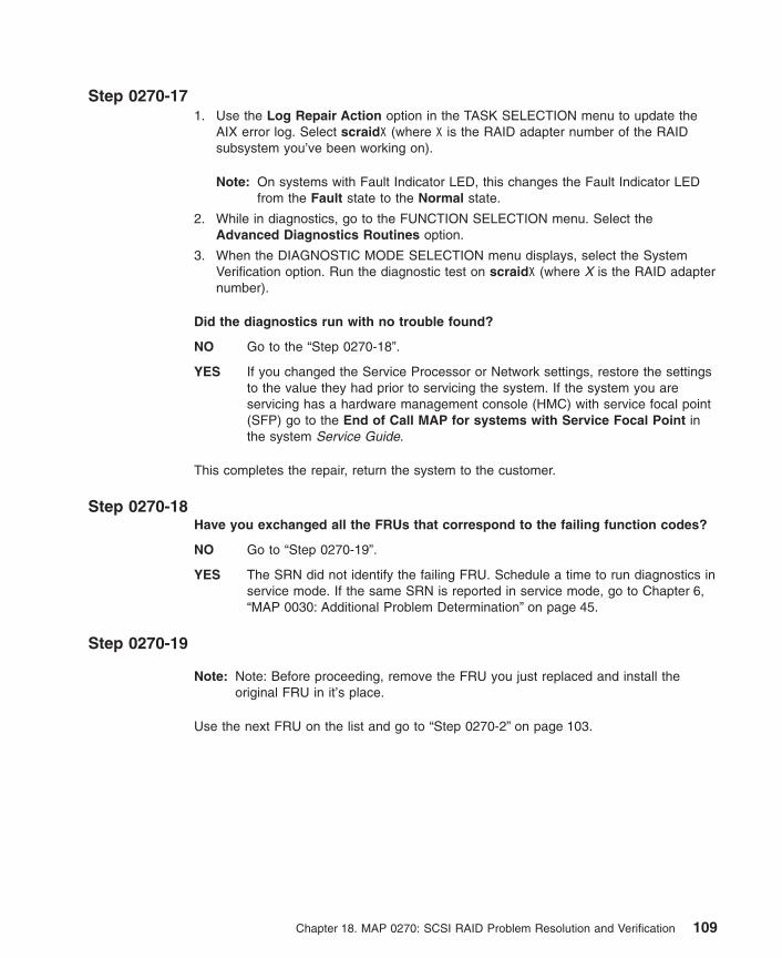
Step 0270-171. Use the Log Repair Action option in the TASK SELECTION menu to update the
AIX error log. Select scraidX (where X is the RAID adapter number of the RAIDsubsystem you’ve been working on).
Note: On systems with Fault Indicator LED, this changes the Fault Indicator LEDfrom the Fault state to the Normal state.
2. While in diagnostics, go to the FUNCTION SELECTION menu. Select theAdvanced Diagnostics Routines option.
3. When the DIAGNOSTIC MODE SELECTION menu displays, select the SystemVerification option. Run the diagnostic test on scraidX (where X is the RAID adapternumber).
Did the diagnostics run with no trouble found?
NO Go to the “Step 0270-18”.
YES If you changed the Service Processor or Network settings, restore the settingsto the value they had prior to servicing the system. If the system you areservicing has a hardware management console (HMC) with service focal point(SFP) go to the End of Call MAP for systems with Service Focal Point inthe system Service Guide.
This completes the repair, return the system to the customer.
Step 0270-18Have you exchanged all the FRUs that correspond to the failing function codes?
NO Go to “Step 0270-19”.
YES The SRN did not identify the failing FRU. Schedule a time to run diagnostics inservice mode. If the same SRN is reported in service mode, go to Chapter 6,“MAP 0030: Additional Problem Determination” on page 45.
Step 0270-19
Note: Note: Before proceeding, remove the FRU you just replaced and install theoriginal FRU in it’s place.
Use the next FRU on the list and go to “Step 0270-2” on page 103.
Chapter 18. MAP 0270: SCSI RAID Problem Resolution and Verification 109

110 Diagnostic Information for Multiple Bus Systems

Chapter 19. MAP 0280: Boot Problem Resolution
Purpose of This MAPUse this MAP to handle problems caused during booting of the system unit.
Entry Table
Entry 1 Go to “Step 0280-1”.
Entry 2 Go to “Step 0280-2”.
Entry 3 Go to “Step 0280-3” on page 112.
Step 0280-1The system fails to respond to keyboard entries.
This problem is most likely caused by a faulty keyboard, keyboard adapter, or keyboardcable.
Try the FRUs in the order listed below: (Test each FRU by retrying the failingoperation.)
1. Keyboard
2. Keyboard adapter (normally located on the system board)
3. Keyboard cable (if not included with the keyboard)
Were you able to resolve the problem?
No Go to Chapter 6, “MAP 0030: Additional Problem Determination” on page 45.
Yes Go to Chapter 23, “MAP 0410: Repair Checkout” on page 125.
Step 0280-21. Some systems have a graphic adapter POST. Check your system guide for
information about graphic adapter POSTs. If a graphic adapter POST is supportedand it indicates a failure, follow the procedures in the system guide to resolve theproblem.
2. If a graphic adapter POST is supported and it does not indicate a failure, suspectthe display or display cable.
3. If the system does not have a graphic adapter POST, go to the display problemdetermination procedures. If you do not find a problem, replace the graphicsadapter.
Were you able to resolve the problem?
No Go to Chapter 6, “MAP 0030: Additional Problem Determination” on page 45.
Yes Go to Chapter 23, “MAP 0410: Repair Checkout” on page 125.
111

Step 0280-3Go to the problem determination procedure for the terminal. If you do not find aproblem, suspect the serial port adapter or terminal cable.
Were you able to resolve the problem?
No Call your support person.
Yes Go to Chapter 23, “MAP 0410: Repair Checkout” on page 125.
112 Diagnostic Information for Multiple Bus Systems

Chapter 20. MAP 0285: Multipath I/O (MPIO) Problem Resolution
Purpose of This MAPUse this MAP to handle SRN A23-001 to check the path from adapter to device.
Note: Not all devices support MPIO. Before proceeding with this MAP, make sure thatthe devices on both ends of the missing path support MPIO.
Step 0285-1Look at the problem report screen for the missing path. After the resource name andFRU, the next column identifies the missing path between resources (for example,scsi0 -> hdisk1). This indicates the missing path between the two resources, scsi0(the parent resource) and hdisk1 (the child resource).
Is the cabling present between the two resouces?
No Go to “Step 0285-2”.
Yes Go to “Step 0285-4” on page 114.
Step 0285-21. Power off the system.
2. Connect the proper cable between the two resources.
3. Power on the system, rebooting AIX.
4. At the AIX command line, type smitty mpio.
5. Choose MPIO Path Management.
6. Select Enable Paths.
7. Select Enable Paths for a Device.
8. In the Device Name selection, choose the name of the child device (the device atthe end of the path).
9. In the Paths to Enable selection, select the missing path (between the parent andchild device).
10. Press Enter.
Did the smitty menu complete with no errors?
No Go to “Step 0285-4” on page 114.
Yes Go to “Step 0285-3” on page 114.
113

Step 0285-3To verify that the device path is present, rerun diag -a.
When the resource list displays, select the child resource that had the missing path. Ifthe letter P is shown in front of the resource, you still have a path problem. If no letter Pis shown in front of the resource or if the system returns to the command prompt or youget a message without the resource list being displayed, then the problem has beenresolved.
Do you still have a path problem?
No Go to Chapter 23, “MAP 0410: Repair Checkout” on page 125.
Yes Go to “Step 0285-4”.
Step 0285-41. Power off the system.
2. Reseat the cables between the two devices that have the missing path.
3. Power on the system, rebooting AIX.
4. At the AIX command line, type smitty mpio.
5. Choose MPIO Path Management.
6. Select Enable Paths.
7. Select Enable Paths for a Device.
8. In the Device Name selection, choose the name of the child device (the device atthe end of the path).
9. In the Paths to Enable selection, select the missing path (between the parent andchild device).
10. Press enter.
Did the smitty menu complete with no errors?
No Go to “Step 0285-6” on page 115.
Yes Go to “Step 0285-5”.
Step 0285-5To verify that the device path is present, rerun diag -a..
When the resource list displays, select the child resource that had the missing path. Ifthe letter P is shown in front of the resource, you still have a path problem. If no letter Pis shown in front of the resource or if the system returns to the command prompt or youget a message without the resource list being displayed, then the problem has beenresolved.
Do you still have a path problem?
No Go to Chapter 23, “MAP 0410: Repair Checkout” on page 125.
Yes Go to “Step 0285-6” on page 115.
114 Diagnostic Information for Multiple Bus Systems

Step 0285-6You may have a problem with the driver interface or connector on either the parent orchild device.
1. Power off the system.
2. Remove the cables to the parent device.
3. Replace the parent device.
4. Reattach the cables to the parent device.
5. Power on the system, rebooting AIX.
6. At the AIX command line, type smitty mpio.
7. Choose MPIO Path Management.
8. Select Enable Paths.
9. Select Enable Paths for a Device.
10. In the Device Name selection, choose the name of the child device (the device atthe end of the path).
11. In the Paths to Enable selection, select the missing path (between the parent andchild device).
12. Press enter.
Did the smitty menu complete with no errors?
No Go to “Step 0285-8”.
Yes Go to “Step 0285-7”.
Step 0285-7To verify that the device path is present, rerun diag -a.
When the resource list displays, select the child resource that had the missing path. Ifthe letter P is shown in front of the resource, you still have a path problem. If no letter Pis shown in front of the resource or if the system returns to the command prompt or youget a message without the resource list being displayed, then the problem has beenresolved.
Do you still have a path problem?
No Go to Chapter 23, “MAP 0410: Repair Checkout” on page 125.
Yes Go to “Step 0285-8”.
Step 0285-8You may have a problem with the driver interface or connector on the child device.
1. Power off the system.
2. Remove the cables to the child device.
3. Replace the child device.
4. Reattach the cables to the child device.
5. Power on the system, rebooting AIX.
Chapter 20. MAP 0285: Multipath I/O (MPIO) Problem Resolution 115

6. At the AIX command line, type smitty mpio.
7. Choose MPIO Path Management.
8. Select Enable Paths.
9. Select Enable Paths for a Device.
10. In the Device Name selection, choose the name of the child device (the device atthe end of the path).
11. In the Paths to Enable selection, select the missing path (between the parent andchild device).
12. Press enter.
Did the smitty menu complete with no errors?
No Neither the cabling, nor the parent, nor the child seem to be causing theproblem. Contact your service support.
Yes Go to “Step 0285-9”.
Step 0285-9Rerun diag -a to verify that the device path is present.
When the resource list displays, select the child resource that had the missing path. Ifthe letter P is shown in front of the resource, you still have a path problem. If no letter Pis shown in front of the resource or if the system returns to the command prompt or youget a message without the resource list being displayed, then the problem has beenresolved.
Do you still have a path problem?
No Go to Chapter 23, “MAP 0410: Repair Checkout” on page 125.
Yes Neither the cabling, nor the parent, nor the child seem to be causing theproblem. Contact your service support.
116 Diagnostic Information for Multiple Bus Systems
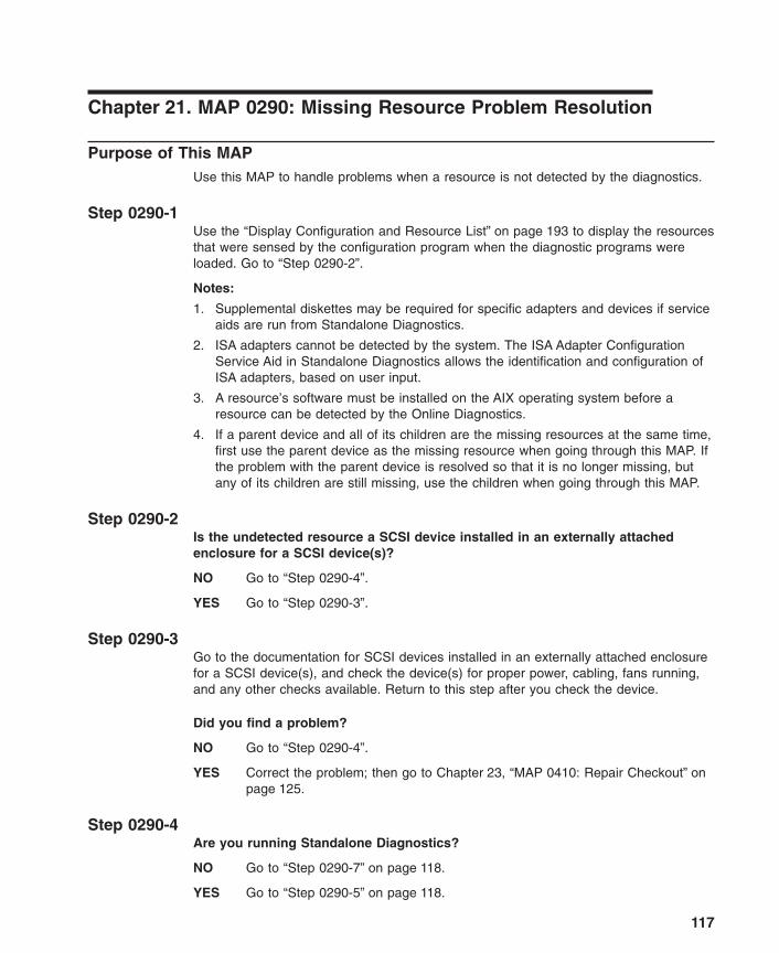
Chapter 21. MAP 0290: Missing Resource Problem Resolution
Purpose of This MAPUse this MAP to handle problems when a resource is not detected by the diagnostics.
Step 0290-1Use the “Display Configuration and Resource List” on page 193 to display the resourcesthat were sensed by the configuration program when the diagnostic programs wereloaded. Go to “Step 0290-2”.
Notes:
1. Supplemental diskettes may be required for specific adapters and devices if serviceaids are run from Standalone Diagnostics.
2. ISA adapters cannot be detected by the system. The ISA Adapter ConfigurationService Aid in Standalone Diagnostics allows the identification and configuration ofISA adapters, based on user input.
3. A resource’s software must be installed on the AIX operating system before aresource can be detected by the Online Diagnostics.
4. If a parent device and all of its children are the missing resources at the same time,first use the parent device as the missing resource when going through this MAP. Ifthe problem with the parent device is resolved so that it is no longer missing, butany of its children are still missing, use the children when going through this MAP.
Step 0290-2Is the undetected resource a SCSI device installed in an externally attachedenclosure for a SCSI device(s)?
NO Go to “Step 0290-4”.
YES Go to “Step 0290-3”.
Step 0290-3Go to the documentation for SCSI devices installed in an externally attached enclosurefor a SCSI device(s), and check the device(s) for proper power, cabling, fans running,and any other checks available. Return to this step after you check the device.
Did you find a problem?
NO Go to “Step 0290-4”.
YES Correct the problem; then go to Chapter 23, “MAP 0410: Repair Checkout” onpage 125.
Step 0290-4Are you running Standalone Diagnostics?
NO Go to “Step 0290-7” on page 118.
YES Go to “Step 0290-5” on page 118.
117

Step 0290-5Are multiple devices missing that are connected to the same adapter? (If theadapter itself is also missing, answer ″No″ to this question.)
NO Go to “Step 0290-7”.
YES Suspect a problem with the device adapter. Run diagnostics on the deviceadapter then go to “Step 0290-6”.
Step 0290-6Did the diagnostics detect a problem with the adapter?
NO Go to “Step 0290-8”.
YES Record the SRN then find the SRN in the SRN List and do the listed action.
Step 0290-7Take the following steps:
1. Exchange the undetected resource.
2. Use the “Display Configuration and Resource List” on page 193 to display theresources sensed by the configuration program.
Is the resource listed?
NO Go to Chapter 6, “MAP 0030: Additional Problem Determination” on page 45.
YES Go to Chapter 23, “MAP 0410: Repair Checkout” on page 125.
Step 0290-8Are the missing devices attached to a backplane?
NO Go to “Step 0290-7”.
YES Exchange the backplane then go to “Step 0290-9”.
Note: Before exchanging the backplane check that all cables connected to thebackplane are properly seated and that all cables and connectors are ingood working condition. If a problem is found, correct it, and then go toChapter 23, “MAP 0410: Repair Checkout” on page 125.
Step 0290-9Load the standalone diagnostics; then use the list of resources in the DIAGNOSTICSELECTION to determine if devices that were previously missing now appear on theresource list.
Are the previously missing devices now listed on the resource list?
NO Go to “Step 0290-10” on page 119.
YES Go to Chapter 23, “MAP 0410: Repair Checkout” on page 125.
118 Diagnostic Information for Multiple Bus Systems

Step 0290-10Is the missing resource (or resources) on a SCSI bus?
NO Go to “Step 0290-7” on page 118.
YES Go to Chapter 6, “MAP 0030: Additional Problem Determination” on page 45.
Chapter 21. MAP 0290: Missing Resource Problem Resolution 119

120 Diagnostic Information for Multiple Bus Systems
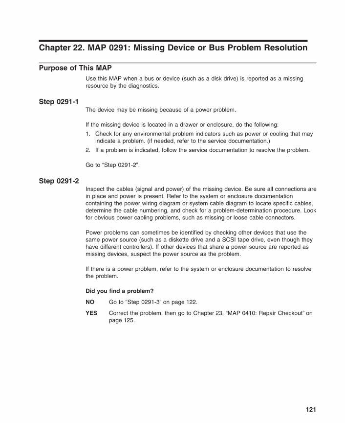
Chapter 22. MAP 0291: Missing Device or Bus Problem Resolution
Purpose of This MAPUse this MAP when a bus or device (such as a disk drive) is reported as a missingresource by the diagnostics.
Step 0291-1The device may be missing because of a power problem.
If the missing device is located in a drawer or enclosure, do the following:
1. Check for any environmental problem indicators such as power or cooling that mayindicate a problem. (if needed, refer to the service documentation.)
2. If a problem is indicated, follow the service documentation to resolve the problem.
Go to “Step 0291-2”.
Step 0291-2Inspect the cables (signal and power) of the missing device. Be sure all connections arein place and power is present. Refer to the system or enclosure documentationcontaining the power wiring diagram or system cable diagram to locate specific cables,determine the cable numbering, and check for a problem-determination procedure. Lookfor obvious power cabling problems, such as missing or loose cable connectors.
Power problems can sometimes be identified by checking other devices that use thesame power source (such as a diskette drive and a SCSI tape drive, even though theyhave different controllers). If other devices that share a power source are reported asmissing devices, suspect the power source as the problem.
If there is a power problem, refer to the system or enclosure documentation to resolvethe problem.
Did you find a problem?
NO Go to “Step 0291-3” on page 122.
YES Correct the problem, then go to Chapter 23, “MAP 0410: Repair Checkout” onpage 125.
121

Step 0291-3Is the missing device a SCSI device installed in a SCSI Enclosure Services (AIXresource SESx) or SAF-TE (AIX resource SAFTEx device?
NO Go to “Step 0210-1” on page 67.
YES Go to “Step 0291-4”.
Step 0291-4Run the Advanced Diagnostics in Problem Determination mode on the SCSI EnclosureServices or SAF-TE device.
Note: A no trouble found result from the diagnostics indicates that you did not get adifferent SRN.
Did you get a different SRN than when you ran the diagnostics previously?
NO Go to “Step 0291-5”.
YES Take the following action:
1. Find the SRN in Chapter 30, “Using the SRN List” on page 251.
Note: If the SRN is not listed a Service Request Number Lists, look foradditional information in the following:
v Any supplemental service manual for the device.
v The diagnostic Problem Report screen.
v The Service Hints service aid in Chapter 27, “Using Standalone andOnline Diagnostics” on page 153.
2. Perform the action listed.
Step 0291-5Power off the system. Disconnect all hot-swap devices attached to the adapter.Reconnect the hot-swap devices one at time. After reconnecting each device, do thefollowing:
1. Power on the system and boot the system in the same mode that you were in whenyou received the symptom that led you to this MAP.
2. At AIX command prompt, run missing options (diag -a).
3. Verify whether the device you just added to the system is missing from the systemconfiguration, or if additional devices have been made missing, the problem may bewith the last device reconnected. Perform these substeps:
a. If the device you just added to the system shows as missing, or if additionaldevices were made missing, replace the last device.
b. Rerun missing options (diag -a)
c. If devices are no longer missing, go to Chapter 23, “MAP 0410: RepairCheckout” on page 125. Otherwise, contact your support center.
Note: A device problem can cause other devices attached to the same SCSIadapter to go into the Defined state. Ask the system administrator to
122 Diagnostic Information for Multiple Bus Systems

make sure that all devices attached to the same SCSI adapter as thedevice that you replaced are in the Available state.
4. If no devices were missing, the problem could be intermittent. Make a record of theproblem. Running the diagnostics for each device on the bus may provide additionalinformation. If you have not replaced FFCs B88, 190, and 152 go to “Step 0210-1”on page 67, using FFCs (in order): B88, 190, and 152.
Did you get a different SRN than when you ran the diagnostics previously?
NO Go to “Step 0291-5” on page 122.
YES Take the following action:
1. Find the SRN in Chapter 30, “Using the SRN List” on page 251.
Note: If the SRN is not listed a Service Request Number Lists, look foradditional information in the following:
v Any supplemental service manual for the device.
v The diagnostic Problem Report screen.
v The Service Hints service aid in Chapter 27, “Using Standalone andOnline Diagnostics” on page 153.
2. Perform the action listed.
Chapter 22. MAP 0291: Missing Device or Bus Problem Resolution 123

124 Diagnostic Information for Multiple Bus Systems

Chapter 23. MAP 0410: Repair Checkout
Purpose of This MAPThis MAP is used to check out the system after a repair is completed.
Note: Only use Standalone Diagnostics for repair checkout when no other diagnosticsare available on the system. Standalone Diagnostics do not log repair actions.
If you are servicing an SP system, go to the End of Call MAP in the SP System ServiceGuide.
If you are servicing a clustered Eserver, go to the End of Call MAP in the ClusteredEserver Installation and Service Guide.
Step 0410-1Did you use a hot-swap operation to change the FRU?
NO Go to “Step 0410-2”.
YES Go to “Step 0410-6” on page 126.
Step 0410-2
Note: If the system planar or battery has been replaced and you are loadingdiagnostics from a server over a network, it may be necessary for the customerto set the network boot information for this system before diagnostics can beloaded. The system time and date information should also be set when therepair is completed.
Do you have cards, adapters, cables, devices, or any other FRUs that wereremoved during problem analysis that you want to put back into the system?
NO Go to “Step 0410-4” on page 126.
YES Go to “Step 0410-3”.
Step 0410-31. After performing a system shutdown, turn off the system power and unplug all
power cords (cables) from electrical outlets.
2. Install all of the cards, adapters, cables, devices, and any other FRUs that wereremoved during problem analysis.
Go to “Step 0410-4” on page 126.
125
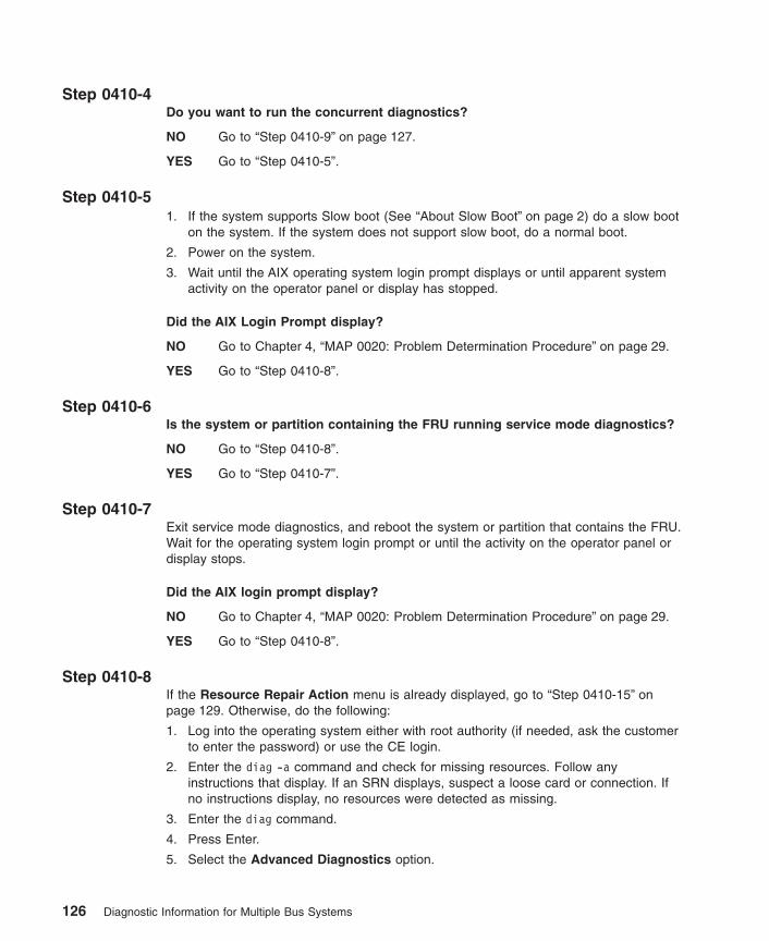
Step 0410-4Do you want to run the concurrent diagnostics?
NO Go to “Step 0410-9” on page 127.
YES Go to “Step 0410-5”.
Step 0410-51. If the system supports Slow boot (See “About Slow Boot” on page 2) do a slow boot
on the system. If the system does not support slow boot, do a normal boot.
2. Power on the system.
3. Wait until the AIX operating system login prompt displays or until apparent systemactivity on the operator panel or display has stopped.
Did the AIX Login Prompt display?
NO Go to Chapter 4, “MAP 0020: Problem Determination Procedure” on page 29.
YES Go to “Step 0410-8”.
Step 0410-6Is the system or partition containing the FRU running service mode diagnostics?
NO Go to “Step 0410-8”.
YES Go to “Step 0410-7”.
Step 0410-7Exit service mode diagnostics, and reboot the system or partition that contains the FRU.Wait for the operating system login prompt or until the activity on the operator panel ordisplay stops.
Did the AIX login prompt display?
NO Go to Chapter 4, “MAP 0020: Problem Determination Procedure” on page 29.
YES Go to “Step 0410-8”.
Step 0410-8If the Resource Repair Action menu is already displayed, go to “Step 0410-15” onpage 129. Otherwise, do the following:
1. Log into the operating system either with root authority (if needed, ask the customerto enter the password) or use the CE login.
2. Enter the diag -a command and check for missing resources. Follow anyinstructions that display. If an SRN displays, suspect a loose card or connection. Ifno instructions display, no resources were detected as missing.
3. Enter the diag command.
4. Press Enter.
5. Select the Advanced Diagnostics option.
126 Diagnostic Information for Multiple Bus Systems

6. When the DIAGNOSTIC MODE SELECTION menu displays, select SystemVerification.
7. When the ADVANCED DIAGNOSTIC SELECTION menu displays, select the AllResources option or test the FRUs you exchanged, and any devices that areattached to the FRU(s) you exchanged, by selecting the diagnostics for theindividual FRU(s).
Did the RESOURCE REPAIR ACTION menu (801015) display?
NO Go to “Step 0410-14” on page 129.
YES Go to “Step 0410-15” on page 129.
Step 0410-9
Note: If you are uncertain, answer Yes to the following question.
Are the Online Diagnostics Installed on the system?
NO If the operating system is running, do the Shutdown Procedure to stop it (gethelp if needed). Go to “Step 0410-10”.
YES Go to “Step 0410-11”.
Step 0410-101. Load the Standalone diagnostics.
2. Wait until the diagnostics are loaded or the system appears to stop.
3. Press Enter.
4. Select the Advanced Diagnostics option.
Note: If the terminal type is not defined. You are prompted to define it. You cannotcontinue until this is done.
5. When the DIAGNOSTIC MODE SELECTION menu displays, choose SystemVerification. On the DIAGNOSTIC SELECTION menu, test the FRUs youexchanged by selecting the diagnostics for the individual FRUs. If the resourceassociated with your action is not displayed on the Resource List, select planar0.
Did the TESTING COMPLETE, no trouble was found menu (801010) display?
NO There is still a problem. Go to Chapter 4, “MAP 0020: Problem DeterminationProcedure” on page 29.
YES Go to “Step 0410-17” on page 130.
Step 0410-11
Note: If you are already in Service Mode, go to “Step 0410-12” on page 128.
1. Power on the system (if it is not already powered on).
2. Load the Online Diagnostics in Service Mode (refer to the system unit’s serviceguide if needed).
Chapter 23. MAP 0410: Repair Checkout 127

3. Wait until the Diagnostic Operating Instructions display or the system appears tostop.
Are the Diagnostic Operating Instructions Displayed?
NO Go to Chapter 4, “MAP 0020: Problem Determination Procedure” on page 29.
YES Go to “Step 0410-12”.
Step 0410-121. Press Enter.
2. Select the Task Selection option.
Note: If the terminal type is not defined. You are prompted to define it. You cannotcontinue until this is done.
3. Select the Log Repair Action option.
4. Select the resource associated with the repair action. If the repair action wasreseating a cable or adapter, select the resource associated with that repair action.If the resource associated with your repair action is not displayed on the ResourceList, select sysplanar0.
5. Press commit after you have made your selection.
6. Press the key for the previous menu two times to get to the Function Selectionmenu.
7. Select the Advanced Diagnostics Routines option.
8. If the DIAGNOSTIC MODE SELECTION menu displays, select the SystemVerification option.
Is the ADVANCED DIAGNOSTIC SELECTION menu displayed?
NO Go to Step 1 of Chapter 4, “MAP 0020: Problem Determination Procedure” onpage 29.
YES Go to “Step 0410-13”.
Step 0410-13Test the FRUs you exchanged, and any devices that are attached to the FRU(s), byselecting the individual FRUs.
Note: If the resource associated with your action is not displayed on the Resource List,select sysplanar0.
Did the RESOURCE REPAIR ACTION menu (801015) display?
NO Go to “Step 0410-14” on page 129.
YES Go to “Step 0410-15” on page 129.
128 Diagnostic Information for Multiple Bus Systems
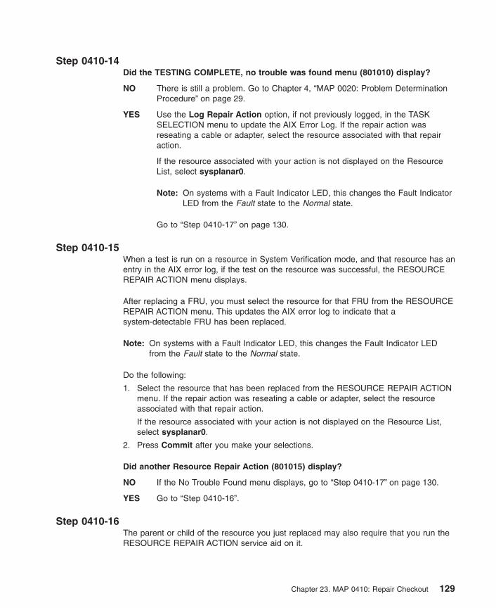
Step 0410-14Did the TESTING COMPLETE, no trouble was found menu (801010) display?
NO There is still a problem. Go to Chapter 4, “MAP 0020: Problem DeterminationProcedure” on page 29.
YES Use the Log Repair Action option, if not previously logged, in the TASKSELECTION menu to update the AIX Error Log. If the repair action wasreseating a cable or adapter, select the resource associated with that repairaction.
If the resource associated with your action is not displayed on the ResourceList, select sysplanar0.
Note: On systems with a Fault Indicator LED, this changes the Fault IndicatorLED from the Fault state to the Normal state.
Go to “Step 0410-17” on page 130.
Step 0410-15When a test is run on a resource in System Verification mode, and that resource has anentry in the AIX error log, if the test on the resource was successful, the RESOURCEREPAIR ACTION menu displays.
After replacing a FRU, you must select the resource for that FRU from the RESOURCEREPAIR ACTION menu. This updates the AIX error log to indicate that asystem-detectable FRU has been replaced.
Note: On systems with a Fault Indicator LED, this changes the Fault Indicator LEDfrom the Fault state to the Normal state.
Do the following:
1. Select the resource that has been replaced from the RESOURCE REPAIR ACTIONmenu. If the repair action was reseating a cable or adapter, select the resourceassociated with that repair action.
If the resource associated with your action is not displayed on the Resource List,select sysplanar0.
2. Press Commit after you make your selections.
Did another Resource Repair Action (801015) display?
NO If the No Trouble Found menu displays, go to “Step 0410-17” on page 130.
YES Go to “Step 0410-16”.
Step 0410-16The parent or child of the resource you just replaced may also require that you run theRESOURCE REPAIR ACTION service aid on it.
Chapter 23. MAP 0410: Repair Checkout 129

When a test is run on a resource in System Verification mode, and that resource has anentry in the AIX error log, if the test on the resource was successful, the RESOURCEREPAIR ACTION menu displays.
After replacing that FRU, you must select the resource for that FRU from theRESOURCE REPAIR ACTION menu. This updates the AIX error log to indicate that asystem-detectable FRU has been replaced.
Note: On systems with a Fault Indicator LED, this changes the Fault Indicator LEDfrom the FAULT state to the NORMAL state.
Do the following:
1. From the RESOURCE REPAIR ACTION menu, select the parent or child of theresource that has been replaced . If the repair action was reseating a cable oradapter, select the resource associated with that repair action. If the resourceassociated with your action is not displayed on the Resource List, selectsysplanar0.
2. Press COMMIT after you make your selections.
3. If the No Trouble Found menu displays, go to “Step 0410-17”.
Step 0410-17If you changed the Service Processor or Network settings, as instructed in previousMAPs, restore the settings to the value they had prior to servicing the system. If youperformed service on a RAID subsystem involving changing of the RAID adapter cachecard or changing the configuration on RAID disks, ask the customer to run the PCISCSI Disk Array Manager using smitty. Use the Recovery Options selection to resolvethe RAID configuration. To do this, perform the following:
1. At the AIX command line, type smitty pdam.
2. On the PCI SCSI Disk Array Manager screen, select Recovery Options.
3. If a previous configuration exists on the replacement adapter, this must be cleared.Select Clear PCI SCSI RAID Adapter Configuration. Press F3.
4. On the Recovery Options screen, select Resolve PCI SCSI RAID AdapterConfiguration.
5. On the Resolve PCI SCSI RAID Adapter Configuration screen, select AcceptConfiguration on Drives.
6. On the PCI SCSI RAID Adapter selection menu, select the adapter that youchanged.
7. On the next screen, press Enter.
8. When you get the Are You Sure selection menu, press Enter to continue.
9. You should get an OK status message when the recovery is complete. If you get aFailed status message, verify that you selected the correct adapter, then repeat thisprocedure again. When recovery is complete, exit smitty to return to the AIXcommand line.
Go to step “Step 0410-18” on page 131.
130 Diagnostic Information for Multiple Bus Systems
Step 0410-18If the system you are servicing has a Hardware Management Console (HMC), withService Focal Point (SFP) go to the ″End of call MAP for Systems with Service FocalPoint″ in the system service guide
This completes the repair, return the system to the customer.
Chapter 23. MAP 0410: Repair Checkout 131

132 Diagnostic Information for Multiple Bus Systems

Chapter 24. MAP 0420: System Checkout
Purpose of This MAPUse this MAP to verify that the system is working correctly.
Step 0420-11. If the operating system is running, perform the operating system’s shutdown
procedure (get help if needed).
2. Power off the system.
3. Power on the system.
4. Load either the Online or Standalone Diagnostics in Service Mode (refer to thesystem unit’s service guide if necessary).
5. Wait until the diagnostics are loaded or the system appears to stop.
Were you able to load the diagnostics?
NO There is a problem. Go to the system unit’s service guide.
YES Go to “Step 0420-2”.
Step 0420-21. Press Enter.
2. When the FUNCTION SELECTION menu displays, select Advanced Diagnostics.
3. When the DIAGNOSTIC MODE SELECTION menu displays, select the SystemVerification option.
Note: If the terminal type is not defined, you are prompted to define it. You cannotcontinue until this is done.
4. On the DIAGNOSTIC SELECTION or ADVANCED DIAGNOSTIC SELECTIONmenu, look through the list of resources to make sure that all adapters and SCSIdevices are listed including any new resources.
Notes:
a. Resources attached to serial and parallel ports may not appear in the resourcelist.
b. ISA adapters cannot be detected by the system. The ISA Adapter ConfigurationService Aid in Standalone Diagnostics allows the identification and configurationof ISA adapters.
c. If running diagnostics in a partition within a partitioned system, resourcesassigned to other partitions are displayed on the resource list.
Did you find all the adapters or devices on the list?
No Go to “Step 0420-3” on page 134.
Yes Go to “Step 0420-5” on page 134.
133

Step 0420-3Is the new device or adapter an exact replacement for a previous one installed atsame location?
No Go to “Step 0420-4”.
Yes The replacement device or adapter may be defective. If possible, try installingit in an alternate location if one is available. If it works in that location, suspectthat the location where it failed to appear has a defective slot; schedule time toreplace the hardware that supports that slot. If it does not work in an alternatelocation, suspect a bad replacement adapter or device. If you are still unable todetect the device or adapter, contact your service support structure.
Step 0420-4Is the operating system software to support this new adapter or device installed?
No Load the operating system software.
Yes The replacement device or adapter may be defective. If possible, try installingit in an alternate location if one is available. If it works in that location, suspectthat the location where it failed to appear has a defective slot; schedule time toreplace the hardware that supports that slot. If it does not work in an alternatelocation, suspect a bad replacement adapter or device. If you are still unable todetect the device or adapter, contact your service support structure.
Step 0420-51. The MISSING RESOURCE menu only displays when a resource was removed or
moved. If the MISSING RESOURCE menu is displayed, follow the instructions.
2. If the ADVANCED DIAGNOSTIC SELECTION menu displays, select the SystemVerification option, then use the All Resources option to test the system or selectthe individual tests you want to run. If the RESOURCE SELECTION menu isdisplayed, select the All Resources option to test the system or select each testyou want to run.
Did the test pass?
NO There is a problem. Go to Chapter 4, “MAP 0020: Problem DeterminationProcedure” on page 29.
YES This completes the system checkout.
134 Diagnostic Information for Multiple Bus Systems
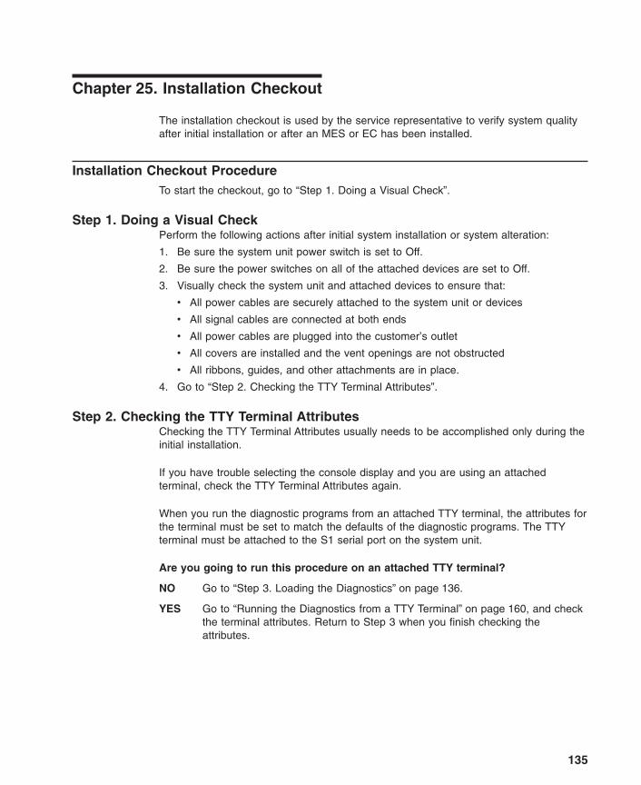
Chapter 25. Installation Checkout
The installation checkout is used by the service representative to verify system qualityafter initial installation or after an MES or EC has been installed.
Installation Checkout ProcedureTo start the checkout, go to “Step 1. Doing a Visual Check”.
Step 1. Doing a Visual CheckPerform the following actions after initial system installation or system alteration:
1. Be sure the system unit power switch is set to Off.
2. Be sure the power switches on all of the attached devices are set to Off.
3. Visually check the system unit and attached devices to ensure that:
v All power cables are securely attached to the system unit or devices
v All signal cables are connected at both ends
v All power cables are plugged into the customer’s outlet
v All covers are installed and the vent openings are not obstructed
v All ribbons, guides, and other attachments are in place.
4. Go to “Step 2. Checking the TTY Terminal Attributes”.
Step 2. Checking the TTY Terminal AttributesChecking the TTY Terminal Attributes usually needs to be accomplished only during theinitial installation.
If you have trouble selecting the console display and you are using an attachedterminal, check the TTY Terminal Attributes again.
When you run the diagnostic programs from an attached TTY terminal, the attributes forthe terminal must be set to match the defaults of the diagnostic programs. The TTYterminal must be attached to the S1 serial port on the system unit.
Are you going to run this procedure on an attached TTY terminal?
NO Go to “Step 3. Loading the Diagnostics” on page 136.
YES Go to “Running the Diagnostics from a TTY Terminal” on page 160, and checkthe terminal attributes. Return to Step 3 when you finish checking theattributes.
135

Step 3. Loading the DiagnosticsThe diagnostics can be run from a CD-ROM disc, from a locally attached disk, or froma server if the AIX operating system is installed on the system. If you are not surewhether the AIX operating system is installed, you can check by turning the system uniton. If the System Management Service menu displays, the AIX operating system is notinstalled.
If the AIX operating system is installed, the diagnostic programs load from a locallyattached disk or from a server. If the AIX operating system is not installed, diagnosticscan be loaded from the diagnostic CD-ROM disc.
The following procedure attempts to load the diagnostics from a disk or from a server. Ifthey cannot be loaded from a disk or server, the diagnostic CD-ROM disc is used toload and run the checkout.
1. Set the power switches on all of the attached devices to On.
2. Set the power switch on the system unit to On.
Note: After the first icon displays on the system console, press F6 if you are usinga directly attached console, or press 6 on a TTY console.
3. If the System Management Services menu displays, the AIX operating system is notinstalled. Do the following:
a. Insert the diagnostic CD-ROM disc into the CD-ROM drive.
b. Power off the system unit, wait 45 seconds and then power on the system unit.
Note: After the first icon displays on the system console, press F6 if you areusing a directly attached console, or press 6 on a TTY console.
c. If the system stops with an eight-digit error code displayed or stops with an iconor icons displayed, a problem was detected.
Check for loose cables or cards. If you do not find a problem, go to Chapter 4,“MAP 0020: Problem Determination Procedure” on page 29.
4. When the diagnostic programs load correctly, the DIAGNOSTIC OPERATINGINSTRUCTIONS display.
Did the DIAGNOSTIC OPERATING INSTRUCTIONS display?
NO Go to Chapter 4, “MAP 0020: Problem Determination Procedure” on page 29.
YES Go to “Step 4. Checking for the Correct Resources” on page 137.
136 Diagnostic Information for Multiple Bus Systems
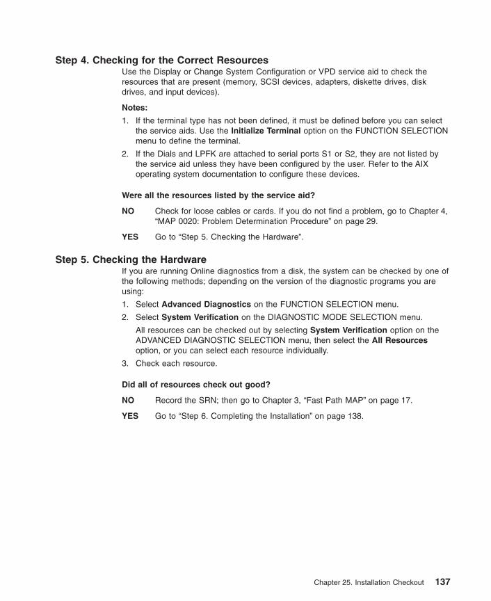
Step 4. Checking for the Correct ResourcesUse the Display or Change System Configuration or VPD service aid to check theresources that are present (memory, SCSI devices, adapters, diskette drives, diskdrives, and input devices).
Notes:
1. If the terminal type has not been defined, it must be defined before you can selectthe service aids. Use the Initialize Terminal option on the FUNCTION SELECTIONmenu to define the terminal.
2. If the Dials and LPFK are attached to serial ports S1 or S2, they are not listed bythe service aid unless they have been configured by the user. Refer to the AIXoperating system documentation to configure these devices.
Were all the resources listed by the service aid?
NO Check for loose cables or cards. If you do not find a problem, go to Chapter 4,“MAP 0020: Problem Determination Procedure” on page 29.
YES Go to “Step 5. Checking the Hardware”.
Step 5. Checking the HardwareIf you are running Online diagnostics from a disk, the system can be checked by one ofthe following methods; depending on the version of the diagnostic programs you areusing:
1. Select Advanced Diagnostics on the FUNCTION SELECTION menu.
2. Select System Verification on the DIAGNOSTIC MODE SELECTION menu.
All resources can be checked out by selecting System Verification option on theADVANCED DIAGNOSTIC SELECTION menu, then select the All Resourcesoption, or you can select each resource individually.
3. Check each resource.
Did all of resources check out good?
NO Record the SRN; then go to Chapter 3, “Fast Path MAP” on page 17.
YES Go to “Step 6. Completing the Installation” on page 138.
Chapter 25. Installation Checkout 137

Step 6. Completing the InstallationSome of the following steps only apply to an initial installation. These steps areprovided as reminders in completing the installation or finishing an MES or EC activity.
1. If present, remove the CD-ROM diagnostic disc from the appropriate drive, andstore it in the binder with the operator guides.
2. Give the keys to the customer and explain the importance of keeping the reordertag for the keys in a safe place.
3. Keep a copy of the following:
v SCSI Address Record from System Records appendix in the User’s Guide.
v Machine History card for each system unit and device.
Microcode must be installed during system installation or after the AIX operating systemis installed. If the system is using the AIX operating system, all microcode is preinstalledon the boot disk for all adapters and devices that were shipped with the system.
Microcode is shipped on microcode diskettes, option diskettes and on the boot disk. Forthe AIX operating system, runtime microcode maintenance can be selected from theSMIT INSTALLATION AND MAINTENANCE MENU or from the Diagnostic Service Aid.The adfutil -m (command and flag) is normally used to install microcode shipped onoption diskettes.
If the system is using another type of operating system, that operating system shouldinclude microcode installation instructions.
If you have the X.25 Interface Coprocessor, the microcode for them is normally notshipped with the AIX operating system. The microcode for these adapters must beinstalled before the adapters can be used. The X.25 Interface Coprocessor microcodeis shipped on an option diskette.
Contact the person that is going to install the software or turn the system over to thecustomer.
If needed, go to the AIX operating system Installation Kit to install and configure the AIXoperating system.
138 Diagnostic Information for Multiple Bus Systems

Chapter 26. General Diagnostic Information
Information in this section is common to all system units. Any service information ordiagnostic procedure that is specific to a certain system unit or device is in the operatorguide or service guide for that system unit or device.
AIX Operating System Message FilesEnglish is the default language displayed by the diagnostic programs when run fromdisk. If you want to run the diagnostic programs in a language other than English youmust install on the system the AIX operating system message locale fileset for thedesired language you want displayed.
MicrocodeThere are several types of microcode used by the system:v System firmware microcodev Service processor microcodev Adapter microcodev Device microcode
AIX diagnostic tasks provide the capability to display microcode levels as well as installmicrocode for system firmware and service processor. These same functions are alsoavailable for many adapters and devices.
To determine the level of microcode for system firmware, service processor, adapter, ordevice, use the Display Microcode Level task. This task presents a list of resourcesthat are currently installed and supported by this task. The AIX lsmcode command canalso be used to display microcode levels. For additional information, refer to “DisplayMicrocode Level” on page 194. For adapters and devices not supported by this task,refer to the manufacturer’s instructions to determine the microcode level.
Use the Update System or Service Processor Flash task to update a system’sfirmware or service processor for CHRP platform systems. Use the Update SystemFlash task to update the system’s firmware for RSPC platform systems. Following themicrocode installation, the system automatically reboots to complete the update.Microcode images can be installed from disk, diskette, or NIM server. For additionalinformation, refer to “Update System or Service Processor Flash” on page 221 or the“Update System Flash” on page 222.
Use the Microcode Download task to install microcode for adapters or devices. Thistask presents a list of resources that are currently installed and supported by this task.Microcode images can be installed from disk, diskette, or NIM server. Refer to the“Download Microcode” on page 200 for additional information. For adapters and deviceswith microcode that can be updated but are not supported by this task, refer to themanufacturer’s instructions.
139

For systems not using AIX, these tasks can be used via the standalone CD or NIMserver. Otherwise refer to the corresponding documentation for the operating system oninstalling microcode.
CEREADME FileA CEREADME (CE readme) file is available on all diagnostic media. This file maycontain information such as:
v Errata information for the service guides
v Service hints for problems
v Diagnostic information that may not be included in service guides
v Other pertinent (usually release-specific) information
The CEREADME file is helpful in describing differences in diagnostics between thecurrent version and the preceding version.
You can view the CEREADME file by using the Service Hints service aid after thediagnostics are loaded. Also, you can read the file directly from the disk using the AIXpg command to display /usr/lpp/diagnostics/CEREADME. The CEREADME file canbe copied or printed using the normal commands. For information about using theservice hints, refer to “Display Service Hints” on page 197.
Printing the CEREADME File from DiskYou can print the CEREADME file from disk using the cat command. The path to thisfile is as follows: /usr/lpp/diagnostics/CEREADME
A copy of this file should be printed and stored with the Service Information. lp0 isnormally the printer attached to the parallel port. If a printer is attached to the parallelport and is considered as lp0, the command for printing the file is as follows:
cat /usr/lpp/diagnostics/CEREADME > /dev/lp0
Printing the CEREADME File from a Source other than DiskThe CEREADME file cannot be printed while diagnostics are being executed from asource other than from the disk. The file can be printed on a system when the AIXoperating system is running in a normal user environment. The procedure involvescopying the file from the diagnostic media to a temporary file on disk, printing the file,and then deleting the file from disk. Check for directory /tmp/diag. To determine if thisdirectory already exists, enter:
cd /tmp/diag
If the directory does not exist, the message /tmp/diag: not found displays. Do notattempt to print the CEREADME file if this message is not displayed. To print theCEREADME file, choose the appropriate section below and follow the steps listed.
Printing the CEREADME File from CD-ROMInsert the diagnostic CD-ROM disc into the CD-ROM drive, and then enter the followingcommands:
140 Diagnostic Information for Multiple Bus Systems

mkdir /tmp/diagmount -o ro -v cdrfs /dev/cd0 /tmp/diagcd /tmp/diag/usr/lpp/diagnosticscat CEREADME > /dev/lp0cd /tmpunmount /dev/cd0
The CEREADME file prints on lp0, which is the printer normally attached to the parallelport. If this file is not the same as the CEREADME file on the disk, a copy of this fileshould be printed and stored with the Service Information.
CE LoginCE login enables a user to perform operating system commands that are required toservice the system without being logged in as a root user. CE login must have a role ofRunDiagnostics and a primary group of system. This enables the user to:
v Run the diagnostics including the service aids, such as hot plug tasks, certify, format,and so forth.
v Run all the operating system commands run by system group users.
v Configure and unconfigure devices that are not busy.
In addition, CE login can have shutdown group enabled to allow:
v Use of the Update System Microcode service aid.
v Use of shutdown and reboot operations.
To use CE login, ask the customer to create a unique user name and configure thesecharacteristics for that name. (Refer to the Users and Groups section of the AIX 5LVersion 5.1 System Management Guide: Operating System and Devices.) After this isset up, you will need to obtain the user name and password from the customer to log inwith these capabilities. The recommended CE login user name is qserv.
Automatic Diagnostic TestsAll automatic diagnostic tests run after the system unit is turned on and before the AIXoperating system is loaded.
The automatic diagnostic tests display event indicators to track test progress. If a teststops, the indicator for that test remains displayed to identify the unsuccessful test.
Built-In Self-Test
Note: This set of programs is not supported on all system units.
The Built-In Self-Test (BIST) programs run first after the system unit is turned on. Theseprograms test the central electronics complex.
Chapter 26. General Diagnostic Information 141

Power-On Self-TestThe Power-On Self-Test (POST) programs check the devices needed to accomplish aninitial program load. The POST also checks the memory, and portions of the centralelectronics complex, common interrupt handler, and the direct memory access (DMA)handler.
142 Diagnostic Information for Multiple Bus Systems

Configuration ProgramThe configuration program determines what features, adapters, and devices are presenton the system. The configuration program, which is part of the AIX operating system,builds a configuration list that is used by the diagnostic programs to control which testsare run during system checkout.
The configuration program displays numbers between 500 and 999 in the operator paneldisplay. Refer to Chapter 29, “Diagnostics Numbers and Location Codes” on page 225for a listing of program actions associated with displayed numbers.
Devices attached to serial and parallel ports are not configured. The Dials and LightedProgram Function Keys (LPFKs) can be tested from Online Diagnostics after they aremanually configured. No other device attached to the serial and parallel ports issupported by the diagnostics.
CPU and Memory Testing and Error Log AnalysisExcept for the floating-point tests, all CPU and memory testing on the system units aredone by POST and BIST. Memory is tested entirely by the POST. The POST providesan error-free memory MAP. If POST cannot find enough good memory to boot, it haltsand displays an error message. If POST finds enough good memory, the memoryproblems are logged and the system continues to boot.
If any memory errors were logged, they are reported by the Base System or MemoryDiagnostics, which must be run to analyze the POST results. Normally, most memoryproblems that are detected by the POST are isolated to a single FRU.
The CPU and memory cannot be tested after the AIX based diagnostics are loaded;however, they are monitored for correct operation by various checkers such asCheckstop or Machine Check. If one of these checks intermittently occurs, it is loggedinto the error log.
Single-bit memory errors are corrected by ECC (Error Checking and Correction) onsystems equipped with ECC memory.
Chapter 26. General Diagnostic Information 143

Diagnostic ProgramsThis section provides overview of the various diagnostic programs.
Diagnostic ControllerThe diagnostic controller runs as an application program on the AIX operating system.The diagnostic controller carries out the following functions:
v Displays diagnostic menus
v Checks availability of needed resources
v Checks error log entries under certain conditions
v Loads diagnostic application programs
v Loads task and service aid programs
v Displays test results
To test an adapter or device, select the device or adapter from the Diagnostic Selectionmenu. The diagnostic controller then loads the diagnostic application program for theselected device or adapter.
The diagnostic application program loads and runs test units to check the functions ofthe device or adapter.
The diagnostic controller checks the results of the tests done by the diagnosticapplication and determines the action needed to continue the testing.
The amount of testing that the diagnostic application does depends on the mode(service, maintenance, or concurrent) under which the diagnostic programs are running.
Error Log AnalysisWhen you select Diagnostics or Advanced Diagnostics, the Diagnostic Selectionmenu displays (other menus may display before this menu). This menu allows you toselect the purpose for running diagnostics.
When you select the Problem Determination option, the diagnostic programs read andanalyze the contents of the error log.
Note: Most hardware errors in the operating system error log contain sysplanar0 as theresource name. The resource name identifies the resource that detected theerror, it does not indicate that the resource is faulty or should be replaced. Usethe resource name to determine the appropriate diagnostic to analyze the error.
If the error log contains recent errors (approximately the last 7 days), the diagnosticprograms automatically select the diagnostic application program to test the loggedfunction.
If there are no recent errors logged or the diagnostic application program runs withoutdetecting an error, the Diagnostic Selection menu is displayed. This menu allows you toselect a resource for testing.
144 Diagnostic Information for Multiple Bus Systems
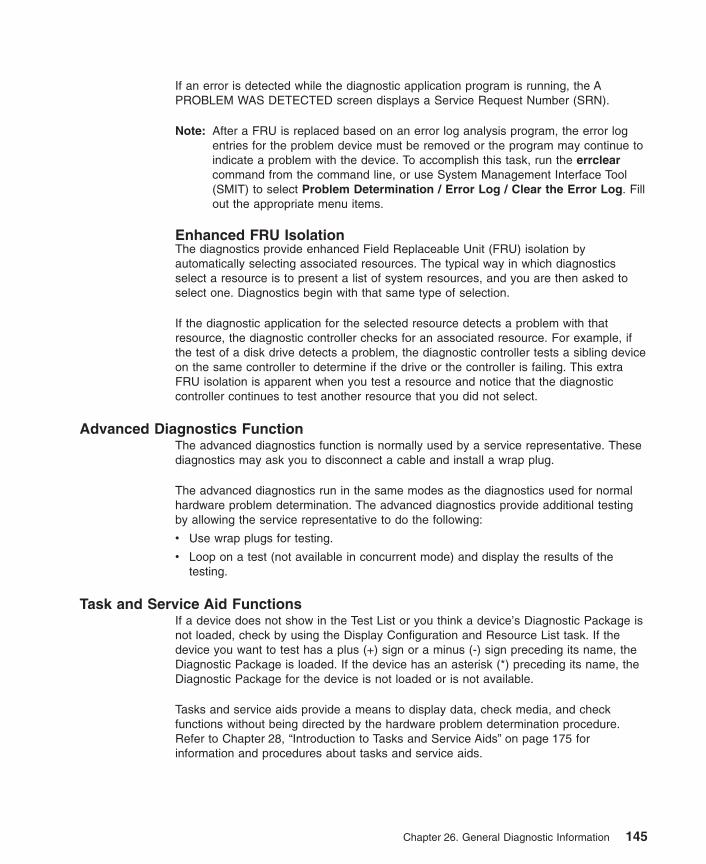
If an error is detected while the diagnostic application program is running, the APROBLEM WAS DETECTED screen displays a Service Request Number (SRN).
Note: After a FRU is replaced based on an error log analysis program, the error logentries for the problem device must be removed or the program may continue toindicate a problem with the device. To accomplish this task, run the errclearcommand from the command line, or use System Management Interface Tool(SMIT) to select Problem Determination / Error Log / Clear the Error Log. Fillout the appropriate menu items.
Enhanced FRU IsolationThe diagnostics provide enhanced Field Replaceable Unit (FRU) isolation byautomatically selecting associated resources. The typical way in which diagnosticsselect a resource is to present a list of system resources, and you are then asked toselect one. Diagnostics begin with that same type of selection.
If the diagnostic application for the selected resource detects a problem with thatresource, the diagnostic controller checks for an associated resource. For example, ifthe test of a disk drive detects a problem, the diagnostic controller tests a sibling deviceon the same controller to determine if the drive or the controller is failing. This extraFRU isolation is apparent when you test a resource and notice that the diagnosticcontroller continues to test another resource that you did not select.
Advanced Diagnostics FunctionThe advanced diagnostics function is normally used by a service representative. Thesediagnostics may ask you to disconnect a cable and install a wrap plug.
The advanced diagnostics run in the same modes as the diagnostics used for normalhardware problem determination. The advanced diagnostics provide additional testingby allowing the service representative to do the following:
v Use wrap plugs for testing.
v Loop on a test (not available in concurrent mode) and display the results of thetesting.
Task and Service Aid FunctionsIf a device does not show in the Test List or you think a device’s Diagnostic Package isnot loaded, check by using the Display Configuration and Resource List task. If thedevice you want to test has a plus (+) sign or a minus (-) sign preceding its name, theDiagnostic Package is loaded. If the device has an asterisk (*) preceding its name, theDiagnostic Package for the device is not loaded or is not available.
Tasks and service aids provide a means to display data, check media, and checkfunctions without being directed by the hardware problem determination procedure.Refer to Chapter 28, “Introduction to Tasks and Service Aids” on page 175 forinformation and procedures about tasks and service aids.
Chapter 26. General Diagnostic Information 145

System Checkout
The system checkout program uses the configuration list generated by the configurationprocedure to determine which devices and features to test. These tests run withoutinteraction. To use system checkout, select All Resources on the Resource Selectionmenu.
Missing Options DIMBS DescriptionIn diagnostics version earlier than 5.2.0, missing devices are presented on a MissingResource screen. This happens as a result or running diag -a or by booting onlinediagnostics in service mode.
In diagnostics version 5.2.0 and later, missing devices are identified on the DiagnosticSelection screen by an uppercase M preceding the name of the device that is missing.The Diagnostic Selection menu is displayed anytime you run the Diagnostic Routines orthe Advanced Diagnostics Routines. The Diagnostic Selection menu can also beentered by running diag -a when there are missing devices or missing paths to adevice.
When a missing device is selected for processing, the Missing Resource menu will askwhether the device has been turned off, removed from the system, moved to a differentphysical location, or if it is still present.
When a single device is missing, the fault is probably with that device. When multipledevices with a common parent are missing, the fault is most likely related to a problemwith the parent device.
The diagnostic procedure may include testing the device’s parent, analyzing whichdevices are missing, and any manual procedures that are required to isolate theproblem.
Missing Path Resolution for MPIO ResourcesDiagnostics also identifies a Multipath I/O device that has multiple configured paths, allof which are missing as a missing device. If some, but not all, paths to a multipath I/Odevice are missing, then diagnostics identifies those paths as missing. In such aninstance, an uppercase P displays in front of the multipath I/O device.
When a device with missing paths is selected from the Diagnostic Selection menu, theMissing Path Selection menu displays showing the missing paths for the device. Themenu requests the user to select a missing path for processing. If the device has onlyone missing path, then the selection menu is bypassed. In either case, a menu isdisplayed showing the selected missing path and other available paths to the device(which may be missing or available). The menu asks if the missing path has beenremoved, has not been removed, or should be ignored. The procedures are as follows:
v If the Path Has Been Removed option is selected, diagnostics removes the pathfrom the data base.
v If the Path Has Not Been Removed option is selected, diagnostics determines whythe path is missing.
146 Diagnostic Information for Multiple Bus Systems

v If the Run Diagnostics on the Selected Device option is selected, diagnostics runson the device and does not change the system configuration.
Periodic DiagnosticsPeriodic testing of the processors is enabled by default. Problems are reported by amessage to the system console, and either a serviceable event sent to the ServiceFocal Point for a system with an HMC (hardware management console) or to an e-mailmessage sent to all users in the system group.
Periodic diagnostics are controlled by the periodic diagnostic service aid. The periodicdiagnostic service aid allows a hardware resource to be tested once a day. If theresource cannot be tested because it is busy, error log analysis is performed ifsupported on the resource. In diagnostics version 5.1.0.15 and later, periodicdiagnostics only supports testing of processors. Disk drives and system planars are nolonger supported by periodic diagnostics because testing is not supported in concurrentdiagnostics and coverage is provided by automatic error log analysis.
Processors that are dynamically removed from the system are also removed from theperiodic test list. Processors that are dynamically added are automatically added to theperiodic test list.
Periodic Diagnostic RemindersPeriodic diagnostic reminders are notifications about failed or deconfigured resourcesthat are reported by firmware to the operating system. Periodic diagnostic remindermode is run following a successful system boot and then every Tuesday at 8 a.m. Onlythe resources in the periodic test list are tested for failed or deconfigured status. Addingor removing a resource from the periodic test list enables or disables the periodicdiagnostic reminder for that resource.
In diagnostics version 5.1.0.15 and later, periodic diagnostic reminder mode is only runfor processors. Periodic diagnostic reminder mode for processors also performs testingon the processors. Problems are reported by a message to the system console, andeither a serviceable event sent to the Service Focal Point for a system with an HMC oran e-mail message sent to all users in the system group.
Chapter 26. General Diagnostic Information 147

Automatic Error Log Analysis (diagela)Automatic Error Log Analysis (diagela) provides the capability to perform error loganalysis when a permanent hardware error is logged, by enabling the diagela programon all platforms.
The diagela program determines if the error should be analyzed by the diagnostics. Ifthe error should be analyzed, a diagnostic application is invoked and the error isanalyzed. No testing is done if the diagnostics determine that the error requires aservice action. Instead it sends a message to your console, and either the ServiceFocal Point for systems with a HMC, or to all system groups. The message contains theSRN.
Running diagnostics in this mode is similar to using the diag -c -e -d Device command.
Notification can also be customized by adding a stanza to the PDiagAtt object class.The following example illustrates how a customer’s program can be invoked in place ofthe normal mail message, or in addition to sending the message to the Service FocalPoint when there is a HMC:
PDiagAtt:DClass = " "DSClass = " "DType = " "attribute = "diag_notify"value = "/usr/bin/customer_notify_ program $1 $2 $3 $4 $5"rep = "s"
If DClass, DSClass, and DType are blank, then the customer_notify_program appliesfor all devices. Filling in the DClass, DSClass, and DType with specifics causes thecustomer_notify_program to be invoked only for that device type.
After the above stanza is added to the ODM data base, problems are displayed on thesystem console and the program specified in the value field of the diag_notifypredefined attribute is invoked. The following keyword is expanded automatically asarguments to the notify program:
v $1 the keyword diag_notify
v $2 the resource name that reported the problem
v $3 the Service Request Number
v $4 the device type
v $5 the error label from the error log entry
148 Diagnostic Information for Multiple Bus Systems
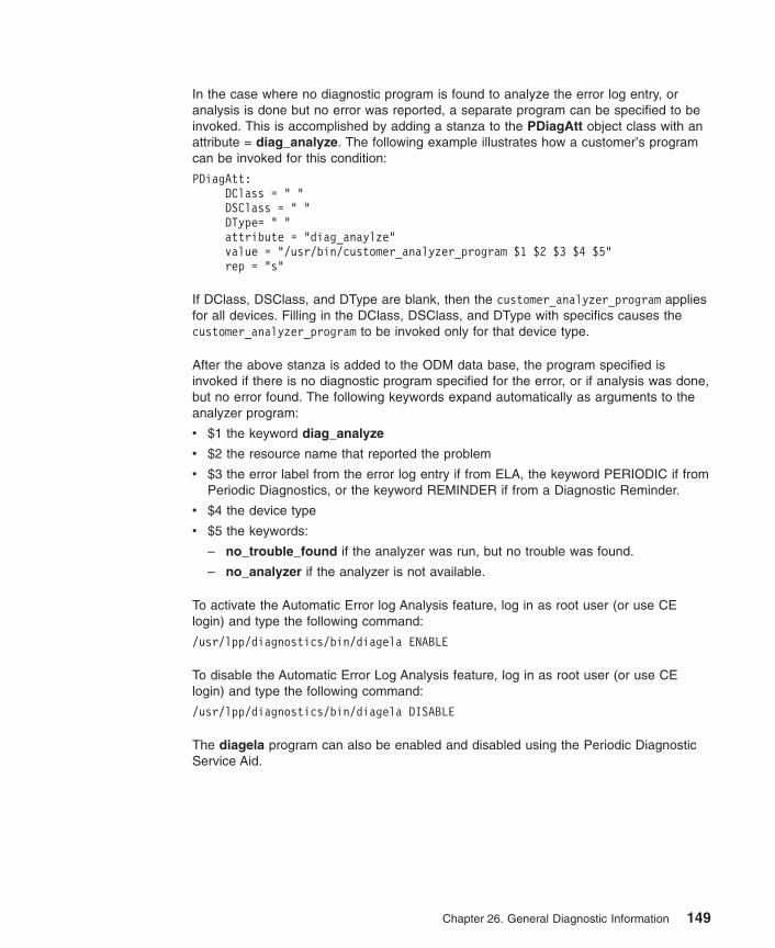
In the case where no diagnostic program is found to analyze the error log entry, oranalysis is done but no error was reported, a separate program can be specified to beinvoked. This is accomplished by adding a stanza to the PDiagAtt object class with anattribute = diag_analyze. The following example illustrates how a customer’s programcan be invoked for this condition:
PDiagAtt:DClass = " "DSClass = " "DType= " "attribute = "diag_anaylze"value = "/usr/bin/customer_analyzer_program $1 $2 $3 $4 $5"rep = "s"
If DClass, DSClass, and DType are blank, then the customer_analyzer_program appliesfor all devices. Filling in the DClass, DSClass, and DType with specifics causes thecustomer_analyzer_program to be invoked only for that device type.
After the above stanza is added to the ODM data base, the program specified isinvoked if there is no diagnostic program specified for the error, or if analysis was done,but no error found. The following keywords expand automatically as arguments to theanalyzer program:
v $1 the keyword diag_analyze
v $2 the resource name that reported the problem
v $3 the error label from the error log entry if from ELA, the keyword PERIODIC if fromPeriodic Diagnostics, or the keyword REMINDER if from a Diagnostic Reminder.
v $4 the device type
v $5 the keywords:
– no_trouble_found if the analyzer was run, but no trouble was found.
– no_analyzer if the analyzer is not available.
To activate the Automatic Error log Analysis feature, log in as root user (or use CElogin) and type the following command:
/usr/lpp/diagnostics/bin/diagela ENABLE
To disable the Automatic Error Log Analysis feature, log in as root user (or use CElogin) and type the following command:
/usr/lpp/diagnostics/bin/diagela DISABLE
The diagela program can also be enabled and disabled using the Periodic DiagnosticService Aid.
Chapter 26. General Diagnostic Information 149

Log Repair ActionThe diagnostics perform error log analysis on most resources. The default time for errorlog analysis is seven days; however, this time can be changed from 1 to 60 days usingthe Display or Change Diagnostic Run Time Options task. To prevent false problemsfrom being reported when error log analysis is run, repair actions need to be loggedwhenever a FRU is replaced. A repair action can be logged by using the Log RepairAction task or by running advanced diagnostics in System Verification mode.
The Log Repair Action task lists all resources. Replaced resources can be selectedfrom the list, and when commit (F7 key) is selected, a repair action is logged for eachselected resource.
System Fault Indicator and System Identify IndicatorSome systems support the System Identify Indicator and/or the System Fault Indicator.
The System Identify Indicator is used to help physically identify a particular system in aroom. The System Fault Indicator is used to help physically identify a particular systemthat has a fault condition.
On a system that supports System Fault Indicator, the indicator is set to Fault conditionwhen a fault is detected. After the problem with the system is fixed, the system faultindicator should be set back to Normal. This is done by using the Log Repair Actiontask. For additional information, see “Log Repair Action”.
Note: This action keeps the System Fault Indicator from being set to the Fault statedue to a previous error, that has already been serviced, in the error log.
Both of these indicator functions can be managed by using the System Identify Indicatorand System Fault Indicator Tasks. See “System Fault Indicator” on page 220 or “SystemIdentify Indicator” on page 220 for additional information.
150 Diagnostic Information for Multiple Bus Systems

Testing the Line PrinterThe following is a simple procedure for determining if a printer attached to your systemis responding correctly. The AIX operating system should be up and running in yournormal environment.
To determine what printers are available, enter the following:
lsdev -C -c printer
This command displays a list of printers currently defined on the system. Only thoseprinters that are in the available state can be used (for example, those printers markedas defined cannot be used). Ensure that a printer is actually connected at the locationthat was specified in the output of the command.
To begin printing, enter the following:
cat /usr/lpp/diagnostics/CEREADME > /dev/lpx
Note: In the above step, you must substitute for x the value obtained from the lsdevcommand.
In the above example, the contents of the CEREADME file will print.
Array Bit SteeringAn advanced feature of many systems is Array Bit Steering. The processors in thesesystems have internal cache arrays with extra memory capacity that can be configuredto correct certain types of array faults.
This reconfiguration can be used to correct arrays for faults detected at IPL or run time.In the case of a fault detected during run time, the recoverable fault is reported with a″Repair Disposition Pending Reboot″ indicator set. This allows diagnostics to call out aService Request Number that identifies the array and directs the ServiceRepresentative to a MAP for problem resolution that uses array bit steering. If the arraybit steering cannot be used for the reported fault, then the FRU with that array isreplaced.
Running Diagnostics on the Native Serial Port on a Full Machine Partition with aHMC Attached
For a Full Machine Partition, the output of the S1 serial port is redirected, or wrapped tothe virtual console window. When the S1 serial port is wrapped, the output of anycommand is directed from the S1 serial port to the virtual console terminal. If you closethe virtual console window on the managed system, normal function is restored to theS1 serial port.
The implication of this is that the serial port wrap diagnostics may fail with a false SRNif the virtual console window on the managed system is not closed. Another method toprevent the false SRN is to unplug the HMC from its port before running the wrap tests.
Chapter 26. General Diagnostic Information 151

After running diagnostics on the serial port, make sure that the S1 serial port is enabledfor login (AIX command chdev -l ’tty’x -a login=’enable’ where x is the ttynumber corresponding to the S1 serial port).
Enhanced I/O Error HandlingEnhanced I/O Error Handling (EEH) is an error recovery strategy for errors that canoccur during I/O operations on the PCI bus. Not all systems support EEH; if you get anSRN involving an EEH error, follow the action listed.
152 Diagnostic Information for Multiple Bus Systems

Chapter 27. Using Standalone and Online Diagnostics
The diagnostics consist of Standalone Diagnostics and Online Diagnostics. TheStandalone Diagnostics must be booted before they are run. If booted, they have noaccess to the AIX Error Log or the AIX Configuration Data.
Online Diagnostics, when installed, are resident with AIX on the disk or server. Theycan be booted in single user mode (called service mode), run in maintenance mode(called maintenance mode), or run concurrently (called concurrent mode) with otherapplications. They have access to the AIX Error Log and the AIX Configuration Data.
Attention: If this system unit is attached to another system, be sure you isolate thissystem unit before stopping the operating system or running diagnostic programs.Some system-cabling changes (such as installing wrap plugs or removing a device fromthe configuration) may require action by the operator of the attached system beforemaking the cabling changes on this system.
Attention: The AIX operating system must be installed in order to run OnlineDiagnostics. If the AIX operating system is not installed, use the standalone diagnosticprocedures.
Standalone and Online Diagnostics Operating ConsiderationsBefore you use the diagnostics, consider the following items:
v Standalone diagnostics at version 5.2.0.0 or later cannot be run on RSPC systems.
v Support for some devices has been withdrawn from AIX 5.2.0.0 and later. For a list ofdevices for which support has been withdrawn, refer to the AIX 5.2 release notes. Todiagnose a device that no longer is supported in AIX 5.2.0, either move the device toa system running an AIX level earlier than 5.2.0 or use standalone diagnostics earlierthan 5.2.0.
v Standalone diagnostics can run on systems configured for running either a fullmachine partition or one or more logical partitions. When running on a logicallypartitioned system, the device from which you are booting standalone diagnosticsmust be made available to the partition dedicated to running standalone diagnostics.This may require moving the device from the partition that currently contains the bootdevice (for example, CD-ROM or network adapter connected to the NIM server thathas a standalone diagnostic image) to the partition used to run standalonediagnostics. If you move devices, reboot both partitions. For more information, see“Standalone Diagnostic Operation” on page 163.
v When running diagnostics on an LPAR partition, diagnostics only works with theresources that were assigned to that partition; you should run diagnostics in thepartition containing the resource that you wish to test.
v Run Online Diagnostics in Service Mode when possible, unless otherwise directed.The Online Diagnostics perform additional functions, compared to StandaloneDiagnostics. The AIX error log and certain SMIT functions are only available whendiagnostics are run from the disk drive.
153
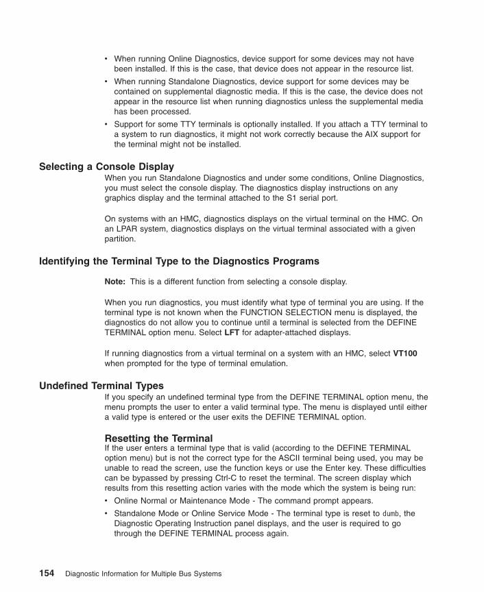
v When running Online Diagnostics, device support for some devices may not havebeen installed. If this is the case, that device does not appear in the resource list.
v When running Standalone Diagnostics, device support for some devices may becontained on supplemental diagnostic media. If this is the case, the device does notappear in the resource list when running diagnostics unless the supplemental mediahas been processed.
v Support for some TTY terminals is optionally installed. If you attach a TTY terminal toa system to run diagnostics, it might not work correctly because the AIX support forthe terminal might not be installed.
Selecting a Console DisplayWhen you run Standalone Diagnostics and under some conditions, Online Diagnostics,you must select the console display. The diagnostics display instructions on anygraphics display and the terminal attached to the S1 serial port.
On systems with an HMC, diagnostics displays on the virtual terminal on the HMC. Onan LPAR system, diagnostics displays on the virtual terminal associated with a givenpartition.
Identifying the Terminal Type to the Diagnostics Programs
Note: This is a different function from selecting a console display.
When you run diagnostics, you must identify what type of terminal you are using. If theterminal type is not known when the FUNCTION SELECTION menu is displayed, thediagnostics do not allow you to continue until a terminal is selected from the DEFINETERMINAL option menu. Select LFT for adapter-attached displays.
If running diagnostics from a virtual terminal on a system with an HMC, select VT100when prompted for the type of terminal emulation.
Undefined Terminal TypesIf you specify an undefined terminal type from the DEFINE TERMINAL option menu, themenu prompts the user to enter a valid terminal type. The menu is displayed until eithera valid type is entered or the user exits the DEFINE TERMINAL option.
Resetting the TerminalIf the user enters a terminal type that is valid (according to the DEFINE TERMINALoption menu) but is not the correct type for the ASCII terminal being used, you may beunable to read the screen, use the function keys or use the Enter key. These difficultiescan be bypassed by pressing Ctrl-C to reset the terminal. The screen display whichresults from this resetting action varies with the mode which the system is being run:
v Online Normal or Maintenance Mode - The command prompt appears.
v Standalone Mode or Online Service Mode - The terminal type is reset to dumb, theDiagnostic Operating Instruction panel displays, and the user is required to gothrough the DEFINE TERMINAL process again.
154 Diagnostic Information for Multiple Bus Systems
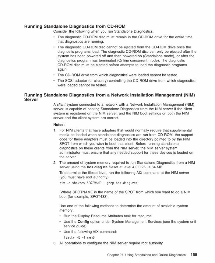
Running Standalone Diagnostics from CD-ROMConsider the following when you run Standalone Diagnostics:
v The diagnostic CD-ROM disc must remain in the CD-ROM drive for the entire timethat diagnostics are running.
v The diagnostic CD-ROM disc cannot be ejected from the CD-ROM drive once thediagnostic programs load. The diagnostic CD-ROM disc can only be ejected after thesystem has been powered off and then powered on (Standalone mode), or after thediagnostics program has terminated (Online concurrent mode). The diagnosticCD-ROM disc must be ejected before attempts to load the diagnostic programsagain.
v The CD-ROM drive from which diagnostics were loaded cannot be tested.
v The SCSI adapter (or circuitry) controlling the CD-ROM drive from which diagnosticswere loaded cannot be tested.
Running Standalone Diagnostics from a Network Installation Management (NIM)Server
A client system connected to a network with a Network Installation Management (NIM)server, is capable of booting Standalone Diagnostics from the NIM server if the clientsystem is registered on the NIM server, and the NIM boot settings on both the NIMserver and the client system are correct.
Notes:
1. For NIM clients that have adapters that would normally require that supplementalmedia be loaded when standalone diagnostics are run from CD-ROM, the supportcode for these adapters must be loaded into the directory pointed to by the NIMSPOT from which you wish to boot that client. Before running standalonediagnostics on these clients from the NIM server, the NIM server systemadministrator must ensure that any needed support for these devices is loaded onthe server.
2. The amount of system memory required to run Standalone Diagnostics from a NIMserver using the bos.diag.rte fileset at level 4.3.3.25, is 64 MB.
To determine the fileset level, run the following AIX command at the NIM server(you must have root authority):
nim -o showres SPOTNAME | grep bos.diag.rte
(Where SPOTNAME is the name of the SPOT from which you want to do a NIMboot (for example, SPOT433).
Use one of the following methods to determine the amount of available systemmemory:
v Run the Display Resource Attributes task for resource.
v Use the Config option under System Management Services (see the system unitservice guide).
v Use the following AIX command:
lsattr -E -l mem0
3. All operations to configure the NIM server require root authority.
Chapter 27. Using Standalone and Online Diagnostics 155
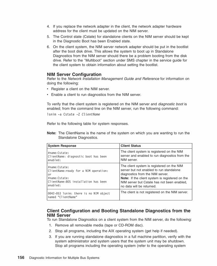
4. If you replace the network adapter in the client, the network adapter hardwareaddress for the client must be updated on the NIM server.
5. The Control state (Cstate) for standalone clients on the NIM server should be keptin the Diagnostic Boot has been Enabled state.
6. On the client system, the NIM server network adapter should be put in the bootlistafter the boot disk drive. This allows the system to boot up in StandaloneDiagnostics from the NIM server should there be a problem booting from the diskdrive. Refer to the ″Multiboot″ section under SMS chapter in the service guide forthe client system to obtain information about setting the bootlist.
NIM Server ConfigurationRefer to the Network Installation Management Guide and Reference for information ondoing the following:
v Register a client on the NIM server.
v Enable a client to run diagnostics from the NIM server.
To verify that the client system is registered on the NIM server and diagnostic boot isenabled; from the command line on the NIM server, run the following command:
lsnim -a Cstate -Z ClientName
Refer to the following table for system responses.
Note: The ClientName is the name of the system on which you are wanting to run theStandalone Diagnostics.
System Response Client Status
#name:Cstate:ClientName: diagnostic boot has beenenabled:
The client system is registered on the NIMserver and enabled to run diagnostics from theNIM server.
#name:Cstate:ClientName:ready for a NIM operation:or#name:Cstate:ClientName:BOS installation has beenenabled:
The client system is registered on the NIMserver but not enabled to run standalonediagnostics from the NIM server.Note: If the client system is registered on theNIM server but Cstate has not been enabled,no data will be returned.
0042-053 lsnim: there is no NIM objectnamed "ClientName"
The client is not registered on the NIM server.
Client Configuration and Booting Standalone Diagnostics from theNIM ServerTo run Standalone Diagnostics on a client system from the NIM server, do the following:
1. Remove all removable media (tape or CD-ROM disc).
2. Stop all programs, including the AIX operating system (get help if needed).
3. If you are running standalone diagnostics in a full machine partition, verify with thesystem administrator and system users that the system unit may be shutdown.Stop all programs including the operating system (refer to the operating system
156 Diagnostic Information for Multiple Bus Systems
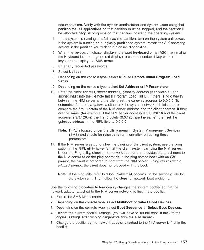
documentation). Verify with the system administrator and system users using thatpartition that all applications on that partition must be stopped, and the partition illbe rebooted. Stop all programs on that partition including the operating system.
4. If the system is running in a full machine partition, turn on the system unit power.If the system is running on a logically partitioned system, restart the AIX operatingsystem in the partition you wish to run online diagnostics.
5. When the keyboard indicator displays (the word keyboard on an ASCII terminal orthe Keyboard icon on a graphical display), press the number 1 key on thekeyboard to display the SMS menu.
6. Enter any requested passwords.
7. Select Utilities.
8. Depending on the console type, select RIPL or Remote Initial Program LoadSetup.
9. Depending on the console type, select Set Address or IP Parameters.
10. Enter the client address, server address, gateway address (if applicable), andsubnet mask into the Remote Initial Program Load (RIPL). If there is no gatewaybetween the NIM server and the client, set the gateway address to 0.0.0.0. Todetermine if there is a gateway, either ask the system network administrator orcompare the first 3 octets of the NIM server address and the client address. If theyare the same, (for example, if the NIM server address is 9.3.126.16 and the clientaddress is 9.3.126.42, the first 3 octets (9.3.126) are the same), then set thegateway address in the RIPL field to 0.0.0.0.
Note: RIPL is located under the Utility menu in System Management Services(SMS) and should be referred to for information on setting theseparameters.
11. If the NIM server is setup to allow the pinging of the client system, use the pingoption in the RIPL utility to verify that the client system can ping the NIM server.Under the Ping utility, choose the network adapter that provides the attachment tothe NIM server to do the ping operation. If the ping comes back with an OKprompt, the client is prepared to boot from the NIM server. If ping returns with aFAILED prompt, the client does not proceed with the boot.
Note: If the ping fails, refer to ″Boot Problems/Concerns″ in the service guide forthe system unit. Then follow the steps for network boot problems.
Use the following procedure to temporarily changes the system bootlist so that thenetwork adapter attached to the NIM server network, is first in the bootlist:
1. Exit to the SMS Main screen.
2. Depending on the console type, select Multiboot or Select Boot Devices.
3. Depending on the console type, select Boot Sequence or Select Boot Devices.
4. Record the current bootlist settings. (You will have to set the bootlist back to theoriginal settings after running diagnostics from the NIM server.)
5. Change the bootlist so the network adapter attached to the NIM server is first in thebootlist.
Chapter 27. Using Standalone and Online Diagnostics 157

6. Exit completely from SMS. The system should start loading packets while doing abootp from the network.
Follow the instructions on the screen to select the system console.
If Diagnostics Operating Instructions Version x.x.x is displays, Standalone Diagnosticshas loaded successfully. If the AIX login prompt displays, Standalone Diagnostics didnot load. Check the following items:
v The bootlist on the client might be incorrect.
v Cstate on the NIM server might be incorrect.
v There might be network problems preventing you from connecting to the NIM server.
Verify the settings and the status of the network. If you continue to have problems, referto ″Boot Problems/Concerns″ in the service guide for the system unit. Then follow thesteps for network boot problems.
After running diagnostics, reboot the system and use SMS to change the bootlistsequence back to the original settings.
Locking and Unlocking the Electronic Service AgentIf the system is setup with a Electronic Service Agent, you must lock out the ElectronicService Agent before running diagnostics. This prevents the Electronic Service Agentfrom using the diagnostics while you are running them. Use the following commands tolock out the Electronic Service Agent:
cd /usr/lpp/servdirls /usr/lpp/servdir/servdir.lck
If a file named servdir.lck is listed, the Electronic Service Agent is already locked out. Ifit is not listed, use the following command to create the file:
/usr/lpp/servdir/servdir.lck
Use the following command to check that the servdir.lck file was created (if the file ispresent the Electronic Service Agent is locked out):
/usr/lpp/servdir/servdir.lck
Use the following commands to unlock the Electronic Service Agent:
/usr/lpp/servdir/servdir.analyze resetrm /usr/lpp/servdir/servdir.lck
Use the following command to check that the servdir.lck file was deleted (the fileshould not be present):
ls /usr/lpp/servdir/servdir.lck
If the file is listed, the Electronic Service Agent is still locked out.
158 Diagnostic Information for Multiple Bus Systems
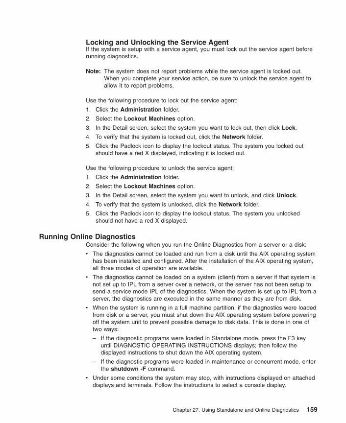
Locking and Unlocking the Service AgentIf the system is setup with a service agent, you must lock out the service agent beforerunning diagnostics.
Note: The system does not report problems while the service agent is locked out.When you complete your service action, be sure to unlock the service agent toallow it to report problems.
Use the following procedure to lock out the service agent:
1. Click the Administration folder.
2. Select the Lockout Machines option.
3. In the Detail screen, select the system you want to lock out, then click Lock.
4. To verify that the system is locked out, click the Network folder.
5. Click the Padlock icon to display the lockout status. The system you locked outshould have a red X displayed, indicating it is locked out.
Use the following procedure to unlock the service agent:
1. Click the Administration folder.
2. Select the Lockout Machines option.
3. In the Detail screen, select the system you want to unlock, and click Unlock.
4. To verify that the system is unlocked, click the Network folder.
5. Click the Padlock icon to display the lockout status. The system you unlockedshould not have a red X displayed.
Running Online DiagnosticsConsider the following when you run the Online Diagnostics from a server or a disk:
v The diagnostics cannot be loaded and run from a disk until the AIX operating systemhas been installed and configured. After the installation of the AIX operating system,all three modes of operation are available.
v The diagnostics cannot be loaded on a system (client) from a server if that system isnot set up to IPL from a server over a network, or the server has not been setup tosend a service mode IPL of the diagnostics. When the system is set up to IPL from aserver, the diagnostics are executed in the same manner as they are from disk.
v When the system is running in a full machine partition, if the diagnostics were loadedfrom disk or a server, you must shut down the AIX operating system before poweringoff the system unit to prevent possible damage to disk data. This is done in one oftwo ways:
– If the diagnostic programs were loaded in Standalone mode, press the F3 keyuntil DIAGNOSTIC OPERATING INSTRUCTIONS displays; then follow thedisplayed instructions to shut down the AIX operating system.
– If the diagnostic programs were loaded in maintenance or concurrent mode, enterthe shutdown -F command.
v Under some conditions the system may stop, with instructions displayed on attacheddisplays and terminals. Follow the instructions to select a console display.
Chapter 27. Using Standalone and Online Diagnostics 159
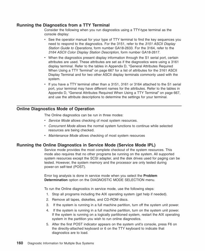
Running the Diagnostics from a TTY TerminalConsider the following when you run diagnostics using a TTY-type terminal as theconsole display:
v See the operator manual for your type of TTY terminal to find the key sequences youneed to respond to the diagnostics. For the 3151, refer to the 3151 ASCII DisplayStation Guide to Operations, form number GA18-2633. For the 3164, refer to the3164 ASCII Color Display Station Description, form number GA18-2617.
v When the diagnostics present display information through the S1 serial port, certainattributes are used. These attributes are set as if the diagnostics were using a 3161display terminal. Refer to the tables in Appendix D, “General Attributes RequiredWhen Using a TTY Terminal” on page 667 for a list of attributes for the 3161 ASCIIDisplay Terminal and for two other ASCII display terminals commonly used with thesystem.
v If you have a TTY terminal other than a 3151, 3161 or 3164 attached to the S1 serialport, your terminal may have different names for the attributes. Refer to the tables inAppendix D, “General Attributes Required When Using a TTY Terminal” on page 667,and use the attribute descriptions to determine the settings for your terminal.
Online Diagnostics Mode of OperationThe Online diagnostics can be run in three modes:
v Service Mode allows checking of most system resources.
v Concurrent Mode allows the normal system functions to continue while selectedresources are being checked.
v Maintenance Mode allows checking of most system resources
Running the Online Diagnostics in Service Mode (Service Mode IPL)Service mode provides the most complete checkout of the system resources. Thismode also requires that no other programs be running on the system. All supportedsystem resources except the SCSI adapter, and the disk drives used for paging can betested. However, the system memory and the processor are only tested duringpower-on self-test (POST).
Error log analysis is done in service mode when you select the ProblemDetermination option on the DIAGNOSTIC MODE SELECTION menu.
To run the Online diagnostics in service mode, use the following steps:
1. Stop all programs including the AIX operating system (get help if needed).
2. Remove all tapes, diskettes, and CD-ROM discs.
3. If the system is running in a full machine partition, turn off the system unit power.
4. If the system is running in a full machine partition, turn on the system unit power.If the system is running on a logically partitioned system, restart the AIX operatingsystem in the partition you wish to run online diagnostics.
5. After the first POST indicator appears on the system unit’s console, press F6 onthe directly-attached keyboard or 6 on the TTY keyboard to indicate thatdiagnostics are to load.
160 Diagnostic Information for Multiple Bus Systems
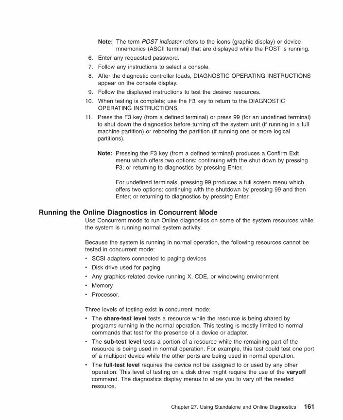
Note: The term POST indicator refers to the icons (graphic display) or devicemnemonics (ASCII terminal) that are displayed while the POST is running.
6. Enter any requested password.
7. Follow any instructions to select a console.
8. After the diagnostic controller loads, DIAGNOSTIC OPERATING INSTRUCTIONSappear on the console display.
9. Follow the displayed instructions to test the desired resources.
10. When testing is complete; use the F3 key to return to the DIAGNOSTICOPERATING INSTRUCTIONS.
11. Press the F3 key (from a defined terminal) or press 99 (for an undefined terminal)to shut down the diagnostics before turning off the system unit (if running in a fullmachine partition) or rebooting the partition (if running one or more logicalpartitions).
Note: Pressing the F3 key (from a defined terminal) produces a Confirm Exitmenu which offers two options: continuing with the shut down by pressingF3; or returning to diagnostics by pressing Enter.
For undefined terminals, pressing 99 produces a full screen menu whichoffers two options: continuing with the shutdown by pressing 99 and thenEnter; or returning to diagnostics by pressing Enter.
Running the Online Diagnostics in Concurrent ModeUse Concurrent mode to run Online diagnostics on some of the system resources whilethe system is running normal system activity.
Because the system is running in normal operation, the following resources cannot betested in concurrent mode:
v SCSI adapters connected to paging devices
v Disk drive used for paging
v Any graphics-related device running X, CDE, or windowing environment
v Memory
v Processor.
Three levels of testing exist in concurrent mode:
v The share-test level tests a resource while the resource is being shared byprograms running in the normal operation. This testing is mostly limited to normalcommands that test for the presence of a device or adapter.
v The sub-test level tests a portion of a resource while the remaining part of theresource is being used in normal operation. For example, this test could test one portof a multiport device while the other ports are being used in normal operation.
v The full-test level requires the device not be assigned to or used by any otheroperation. This level of testing on a disk drive might require the use of the varyoffcommand. The diagnostics display menus to allow you to vary off the neededresource.
Chapter 27. Using Standalone and Online Diagnostics 161

Error log analysis is done in concurrent mode when you select the ProblemDetermination option on the DIAGNOSTIC MODE SELECTION menu.
To run the Online diagnostics in concurrent mode you must be logged onto the AIXoperating system and have proper authority to issue the commands (if needed, gethelp).
The diag command loads the diagnostic controller and displays the Online diagnosticmenus.
To run Online diagnostics in concurrent mode, use the following steps:
v Log on to the AIX operating system as root or use CE login.
v Enter the diag command.
v When the DIAGNOSTIC OPERATING INSTRUCTIONS display, follow theinstructions to test the desired resources.
v When testing is complete, use the F3 key to return to the DIAGNOSTIC OPERATINGINSTRUCTIONS. Press the F3 key again to return to the operating system prompt.Be sure to vary on any resource you had varied to off.
v Press the Ctrl-D key sequence to log off from root or superuser.
Running the Online Diagnostics in Maintenance ModeMaintenance mode runs the Online diagnostics using the customer’s version of the AIXoperating system. This mode requires that all activity on the operating system bestopped so the Online diagnostics have most of the resources available to check. All ofthe system resources except the SCSI adapters, memory, processor, and the disk driveused for paging can be checked.
Error log analysis is done in maintenance mode when you select the ProblemDetermination option on the DIAGNOSTIC MODE SELECTION menu.
The shutdown -m command is used to stop all activity on the AIX operating systemand put the operating system into maintenance mode. The diag command is then usedto invoke the diagnostic controller so you can run the diagnostics. After the diagnosticcontroller is loaded, follow the normal diagnostic instructions.
To run the Online diagnostics in maintenance mode, you must be logged in to thecustomer’s version of the AIX operating system as root or superuser and use theshutdown -m and diag commands. Use the following steps to run the Onlinediagnostics in maintenance mode:
1. Stop all programs except the AIX operating system (get help if needed).
2. Log in to the AIX operating system as root or superuser.
3. Enter the shutdown -m command.
4. When a message indicates the system is in maintenance mode, enter the diagcommand.
Note: It may be necessary to set TERM type again.
162 Diagnostic Information for Multiple Bus Systems

5. When DIAGNOSTIC OPERATING INSTRUCTIONS display, follow the displayedinstructions to test the desired resources.
6. When testing is complete, use the F3 key to return to DIAGNOSTIC OPERATINGINSTRUCTIONS. Then press the F3 key again to return to the AIX operatingsystem prompt.
7. Press Ctrl-D to log off from root or superuser.
Standalone Diagnostic OperationUse Standalone Diagnostics to test the system when the Online Diagnostics are notinstalled and as a method of testing the disk drives and other resources that can not betested by the Online Diagnostics.
Note: Error Log Analysis is not done by the Standalone Diagnostics. If running from thediagnostic CD-ROM disc, the CD-ROM drive and the SCSI controller thatcontrols it cannot be tested by the Standalone Diagnostics.
LPAR Considerations for Standalone Diagnosticsv To run standalone diagnostics on an full machine partition, you must reboot the
whole system. However, for an LPAR system, you may boot standalone diagnosticsin a given partition or on the entire system (which is same procedure as on an fullmachine partition).
v For an LPAR partition, before running standalone diagnostics on a given partition, theuser must move the device from the location where standalone diagnostics is booted(the CD-ROM drive or the network adapter connected to the NIM server in the caseof NIM boot of standalone diagnostics), to the partition that will run standalonediagnostics. Devices on an LPAR system are moved on a slot basis. If the CD-ROMdrive is moved from one partition to another, all SCSI devices on the same SCSIadapter card to which the CD-ROM drive is attached must also be moved to thesame partition. It is recommended that you attach few SCSI devices to the sameSCSI controller card to prevent moving them, along with the CD-ROM drive, betweenpartitions.
v A reboot is required on the partition containing this device and on the moved device,but the system itself is not powered off in order to boot standalone diagnostics in anLPAR partition.
Running the Standalone Diagnostics from CD-ROMTo run Standalone Diagnostics in service mode, use the following steps:
1. If you are running standalone diagnostics in a full machine partition, verify with thesystem administrator and system users that the system unit may be shut down.Stop all programs including the AIX operating system (Refer to the AIX operatingsystem documentation for information on the shutdown command). If you arerunning standalone diagnostics in an LPAR partition, make the CD-ROM driveavailable to the partition used to run standalone diagnostics (refer to the HardwareManagement Console for Operations Guide for more information). Verify with thesystem administrator and system users using that partition that all applications onthat partition must be stopped, and the partition will be rebooted. Stop all programson that partition, including the operating system.
Chapter 27. Using Standalone and Online Diagnostics 163
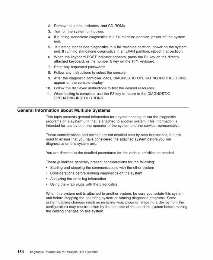
2. Remove all tapes, diskettes, and CD-ROMs.
3. Turn off the system unit power.
4. If running standalone diagnostics in a full machine partition, power off the systemunit.
5. If running standalone diagnostics in a full machine partition, power on the systemunit. If running standalone diagnostics in an LPAR partition, reboot that partition.
6. When the keyboard POST indicator appears, press the F5 key on the directlyattached keyboard, or the number 5 key on the TTY keyboard.
7. Enter any requested passwords.
8. Follow any instructions to select the console.
9. After the diagnostic controller loads, DIAGNOSTIC OPERATING INSTRUCTIONSappear on the console display.
10. Follow the displayed instructions to test the desired resources.
11. When testing is complete, use the F3 key to return to the DIAGNOSTICOPERATING INSTRUCTIONS.
General Information about Multiple SystemsThis topic presents general information for anyone needing to run the diagnosticprograms on a system unit that is attached to another system. This information isintended for use by both the operator of the system and the service representative.
These considerations and actions are not detailed step-by-step instructions, but areused to ensure that you have considered the attached system before you rundiagnostics on this system unit.
You are directed to the detailed procedures for the various activities as needed.
These guidelines generally present considerations for the following:
v Starting and stopping the communications with the other system
v Considerations before running diagnostics on the system
v Analyzing the error log information
v Using the wrap plugs with the diagnostics
When this system unit is attached to another system, be sure you isolate this systemunit before stopping the operating system or running diagnostic programs. Somesystem-cabling changes (such as installing wrap plugs or removing a device from theconfiguration) may require action by the operator of the attached system before makingthe cabling changes on this system.
164 Diagnostic Information for Multiple Bus Systems
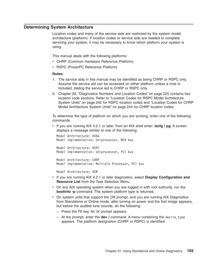
Determining System ArchitectureLocation codes and many of the service aids are restricted by the system modelarchitecture (platform). If location codes or service aids are needed to completeservicing your system, it may be necessary to know which platform your system isusing.
This manual deals with the following platforms:
v CHRP (Common Hardware Reference Platform)
v RSPC (PowerPC Reference Platform)
Notes:
1. The service aids in this manual may be identified as being CHRP or RSPC only.Assume the service aid can be accessed on either platform unless a note isincluded, stating the service aid is CHRP or RSPC only.
2. Chapter 29, “Diagnostics Numbers and Location Codes” on page 225 contains twolocation code sections. Refer to “Location Codes for RSPC Model ArchitectureSystem Units” on page 242 for RSPC location codes and “Location Codes for CHRPModel Architecture System Units” on page 244 for CHRP location codes.
To determine the type of platform on which you are working, enter one of the followingcommands.
v If you are running AIX 4.2.1 or later; from an AIX shell enter: lscfg | pg. A screendisplays a message similar to one of the following:
Model Architecture: RS6kModel Implementation: Uniprocessor, MCA bus
Model Architecture: RSPCModel Implementation: Uniprocessor, PCI bus
Model Architecture: CHRPModel Implementation: Multiple Processor, PCI bus
Model Architecture: OEM
v If you are running AIX 4.2.1 or later diagnostics, select Display Configuration andResource List from the Task Selection Menu.
v On any AIX operating system when you are logged in with root authority, run thebootinfo -p command. The system platform type is returned.
v On system units that support the OK prompt, and you are running AIX Diagnosticsfrom Standalone or Online mode, after turning on power and the first image appears,but before the audible tone sounds, do the following:
– Press the F8 key. An OK prompt appears.
– At the prompt, enter the dev / command. A menu containing the device_typeappears. The platform designation (CHRP or RSPC) is identified.
Chapter 27. Using Standalone and Online Diagnostics 165

High-Availability SCSIA high-availability SCSI configuration consists of two system units or CPU drawersconnected to a common set of SCSI devices. The configuration provides highavailability because either system unit or CPU drawer can continue to access thecommon devices while the other system is unavailable.
The actions needed to isolate a particular system unit or device from the configurationdepends on the software controlling the systems and devices. Therefore, be sure youuse the software documentation to prepare the configuration before turning off a systemunit or device.
High-Availability CablingFor additional cabling information, refer to Adapters, Devices, and Cable Information forMultiple Bus Systems.
Diagnostic SummaryThe following topics provide summary type information about some features of thediagnostics.
Memory and Processor Testingv Memory and Fixed-Point Processors are only tested during POST.
v A complete memory test is run during POST.
v The POST only halts and reports problems that prevent the system from booting.
v All other problems are logged for later analysis by the Sysplanar and MemoryDiagnostics.
Sysplanar and Memory Diagnosticsv Analyzes POST and firmware errors that were detected during IPL, but did not
prevent the system from booting.
v Performs error log analysis if the diagnostics are running online in problemdetermination mode or error log analysis mode.
Error Log Analysisv Error Log Analysis is analysis of the AIX Error Log entries.
v Error Log Analysis is part of the diagnostic applications. The analysis is started byselecting a device from the DIAGNOSTIC SELECTION menu; then using the diagcommand or selecting the Run Error Log Analysis task.
v Error Log Analysis is only performed when running online diagnostics.
v Error Log Analysisis not performed when running diagnostics from removable media.
v Error Log Analysis only reports problems if the errors have reached definedthresholds. Thresholds can be from 1 to 100 depending on the error.
v Permanent errors do not necessarily mean a part should be replaced.
v Automatic Error Log Analysis (diagela) provides the capability to do error loganalysis whenever a permanent hardware error is logged.
166 Diagnostic Information for Multiple Bus Systems
Diagnostic ModesThe Diagnostic Modes consist of Problem Determination Mode and System VerificationMode.
v Problem Determination Mode runs all tests unless the resource is being used. If aresource is being used, a screen appears informing the user that the resource needsto be made available for testing. If a problem is not found, then Error Log Analysis isperformed.
v In Problem Determination Mode, Error Log Analysis is performed even if a resourceis being used.
v System Verification Mode does not perform Error Log Analysis. Run this mode whenyou are doing a repair verification.
Diagnostics Tasks and ResourcesTasks are operations that can be performed on a resource. Running Diagnostics,Displaying VPD, or Formatting a Device, are examples of tasks. Service aids are alsoconsidered tasks. Tasks and service aids are further described in Chapter 28,“Introduction to Tasks and Service Aids” on page 175.
Resources are devices used by the system unit. Diskette drive and CD-ROM drive areexamples of resources.
The FUNCTION SELECTION menu contains two selections allowing either allresources, or all tasks to be displayed. When task selection is made and a task hasbeen selected, a list of supporting resources displays. Alternatively, when resourceselection is made, and a resource or group of resources are selected, a list of commontasks displays. Also, to aid with backward compatibility, the FUNCTION SELECTIONmenu contains Diagnostic routines and Advanced Diagnostic routines selection.
The Display or Change Diagnostic Run Time Options task can be used to set advancedmode diagnostics, looping capability, and error log analysis (ELA) mode when runningdiagnostics from the Task Selection menu.
Chapter 27. Using Standalone and Online Diagnostics 167
diag Command Line OptionsThe following describe the Version 4.2 and later diagnostic command line options:
diag [[-a] | [-s[-c]] [-E Days] [-e] |[-d Device] [-v] [-c] [-e] [-A]] |[-B[-c]] | [-T taskname] |-S] testsuite]
Flags
The diag command line flags are as follows:
-a Processes any change in the hardware configuration by asking if missingresources have been remove, turned off, and so on.
-A Specifies Advanced mode. You must also specify a device with the -d flag.
-B Instructs the diagnostics to run the base system test. Error log analysis is alsodone on areas in the base system that supports error log analysis.
-c Indicates that the machine will not be attended. No questions are asked.Results are written to standard output. Must also use an option flag (-d, -B, -s)that specifies a device to be tested.
-d DeviceSpecifies the device to run diagnostics on.
-E DaysSpecifies the number of days to use when searching the error log during RunError Log Analysis. The flag works with any other flag.
-e Performs error log analysis if supported on the selected device. No tests areperformed. May be used with the -d flag, otherwise the resource selectionmenu is displayed. If used with the -v flag, the -v flag takes precedence andthe -e flag is ignored.
-S testsuiteIndicates a particular Test Suite of devices to test:
1. Base System
2. I/O Devices
3. Async Devices
4. Graphic Devices
5. SCSI Devices
6. Storage Devices
7. Commo Devices
8. Multimedia Devices
-s Runs diagnostics on all resources.
-T tasknameFastpath to specific task to run. Current fastpath tasks are the following:
v format - Format Media Task
v certify - Certify Media Task
168 Diagnostic Information for Multiple Bus Systems

v download - Download Microcode Task
v disp_mcode - Display Microcode Level Task
v chkspares - Spare Sector Availability Task
v identify - PCI RAID Physical Disk Identify Task
Note: Tasks are platform and device dependent. Some tasks may not beavailable on the system.
-v Runs diagnostics in System Verification Mode, no error log analysis performed.The default is Problem Determination mode that tests the device and runserror log analysis. If used with the -e flag, the -v flag takes precedence and the-e flag is ignored. Must be used with the -d flag to specify a device to rundiagnostics on.
Default execution mode is non-advanced mode.
SCSI RAID Descriptions and Diagnostic Procedures
Viewing the Existing Firmware Level Installed on a SCSI RAID AdapterBelow is an example of the steps one might perform to check the microcode level onthe RAID adapter:
1. Log in as root (if not already root).
2. Type lsdev -C | grep scraid. This lists all the SCSI RAID adapters installed ordefined to the system.
3. Identify the number (for example, scraid0) of the card for which you wish to checkthe microcode level.
4. Type lscfg -vl scraidX (where X is the number of the RAID adapter from above).
5. Look at the Loadable Microcode Level field, compare it to the desired level.
Updating the Firmware on a SCSI RAID Target AdapterThis procedure assumes that you have obtained the SCSI RAID adapter microcode youwish to download, and it is located either on a diskette, or in the /etc/microcodedirectory of the system containing the RAID adapter you want to update. This sectiondescribes the method for transferring the new firmware into the target adapter. Eachflash update should complete within one minute.
Attention: Do not power off the target server at any time before the flash processcompletes. If power is removed or the system is reset while flash_update is being run,irrecoverable failures may occur. This could require return of the adapter for exchange.
Diagnostic menu procedure:1. Log in as root or use CE login (if not already logged in).2. Type diag3. Select Task Selection -> Download Microcode4. When Resource Selection menu displays select scraidX, (Where X is the ID of the
desired adapter) and press F7.
Chapter 27. Using Standalone and Online Diagnostics 169

5. When Display Microcode Level menu displays select Adapter.6. When Install Microcode menu displays select Functional Microcode.7. If the current microcode level on the adapter is below the level you want to install
select Latest Level (that is, 4.20.18 is currently on the adapter and you wish toinstall 4.70.11).
or
If the current microcode level on the adapter is greater than the level you wish toinstall select Previous Level (that is, 3.70.01 is currently on the adapter and youwish to install 3.12.01).
8. Select where the microcode is located either, /etc/microcode directory or diskette.
Command Line procedure:
Use one of the two procedures listed, depending on which level of microcode you wantto install relative to the existing level it has:
Note: You must be logged in as root’ or use CE login to perform these commands.
v If the current microcode level on the adapter is below the level you wish to installuse the following command:
diag -c -d scraidX -T"download"
Where X is the ID of the desired adapter, for example, 4.20.18 is currently on theadapter and you wish to install 4.70.11.
v If the current microcode level on the adapter is greater than the level you wish toinstall use the following command:
diag -c -d scraidX -T"download -P"
Where X is the ID of the desired adapter, for example 3.70.01 is currently on theadapter and you wish to install 3.12.01.
After following either the Diagnostic Menu or the Command Line procedure, youshould receive a confirmation that microcode has been updated. If you do not, thenmake sure the adapter is not in use and repeat the appropriate diagnostic step shownabove.
To confirm the new installed level of firmware on the adapter, use the “Viewing theExisting Firmware Level Installed on a SCSI RAID Adapter” on page 169 procedure.
Displaying the VPD Information of a Disk Drive in a SCSI RAID Subsystem.You may use any of three ways to display the VPD information of a drive in a SCSIRAID.
Diagnostics VPD Display:
The first way is through diagnostics. However, this cannot be performed concurrentlywith normal RAID operation. The RAID volume group must be varied off to run fromdiagnostic menus or diagnostics from the command line. A command the customer
170 Diagnostic Information for Multiple Bus Systems

(logged in as root) might use to vary off the volume group is: varyoffvgRAID_volumegroup (where RAID_volumegroup is the volume group containing theRAID drive you wish to test).
Note: The underlying filesystems may need to be unmounted before varying off thevolume group can complete successfully.
Diagnostic Menu method:
1. Log in as root or use CE login.
2. Type diag.
3. Select Task Selection -> PCI Physical Disk Identify.
4. When the Resource Selection menu displays select scraidX, (Where X is the ID ofthe desired adapter) Press F7.
5. Look at the ROS and RAM code levels. This is drive microcode level.
6. Ask the customer (logged on as root) to type varyonvg RAID_volumegroup whereRAID_volumegroup is the name of the volumegroup you previously varied off. Anyfilesystem unmounted will have to be remounted.
Command Line method:
Logged in as root or use CE login, type in the command:
diag -cd scraidX -T"identify"
Where X is replaced by the number of the desired adapter. A list containing the VPDinformation of all the drives in the RAID subsystem will be displayed on the screen.
Look at the ROS and RAM code levels. This is drive microcode level. Compare this tothe desired level.
When you are done, ask customer (logged on as root) to vary on the volume groupusing command:
varyonvg RAID_volumegroup
where RAID_volumegroup is the name of the volumegroup you previously varied off. Anyfilesystem unmounted will have to be remounted.
Note: For either of these two methods, if you see the error message: An adapterconfiguration error was detected.... Run the Disk Array Manager toresolve the adapter configuration error.
1. Log in as root (if not already root).
2. Type smit pdam.
3. Select Recovery Options -> Resolve PCI SCSI RAID Adapter Configuration ->Display/Accept Configuration Changes .
4. Select the appropriate SCSI RAID adapter containing the drive.
5. Select YES for the Display only option.
Chapter 27. Using Standalone and Online Diagnostics 171

Attention: The following steps will change the array’s configuration. If you have anydoubts, do not proceed.
6. If the proposed changes to the array configuration match what is desired, press F3and Select NO for Display Only.
7. If the proposed changes to the array configuration do not match what is desired, ifnot, press F10 to exit.
SCSI RAID Manager VPD Display method:
The third way to display VPD is through the scraidmgr. This can be performed whilethe RAID array is operational.
From the AIX command prompt, ask the customer to:
1. Log in as root (if not already root).
2. Type smit pdam.
3. Select Change/Show PCI RAID Drive Status -> Display VPD Information.
4. Select the appropriate RAID adapter.
5. Select the drives from that adapter one at a time.
6. Look at the ROS and RAM code levels. This is drive microcode level. Compare thisto the level you need on the adapter.
Updating the Microcode on a Disk in a SCSI RAID SubsystemOnce you have downloaded the desired microcode, follow the readme and place themicrocode image in the /etc/microcode directory or on a diskette. With the RAIDvolume group varied off, you can flash the drives through the following process:
Note: The underlying filesystems may need to be unmounted before varying off thevolume group can complete successfully. Then, the volume group containing thedisk must be varied off. A command the customer (logged in as root) might useto vary off the volume group is:
varyoffvg RAID_volumegroup
Where RAID_volumegroup is the volume group containing the RAID drive youwish to test. When you are done, ask customer (logged on as root) to vary onthe volume group using command:
varyonvg RAID_volumegroup
Where RAID_volumegroup is the name of the volume group you previously variedoff. Any filesystem unmounted will have to be remounted.
Diagnostic Menu Method
1. Log in as root or use CE login
2. Type diag.
3. Select Task Selection -> Download Microcode.
172 Diagnostic Information for Multiple Bus Systems

4. When Resource Selection menu displays select scraidX, (Where X is the ID of thedesired adapter) and press F7.
5. When Install Microcode menu displays select Physical Disks.
6. Select each drive for which microcode is to be flashed by pressing Enter on thosedrives. Or, select All drives to update every drive. Press F7 to commit.
v If the current microcode level on the drive is below the level you wish to installselect Latest Level (for example, S9HA is currently on the drive and you wish toinstall S9RA).
v If the current microcode level on the drive is greater than the level you wish toinstall select Previous Level (for example, S9RA is currently on the drive andyou wish to install S9HA).
Note: Microcode levels are consecutive going from 0-9 then A-Z. So, level S9HAwould be a later level than S96F.
7. Select the location where the microcode image is stored (from above).
v On system’s /etc/microcode directory
v On a diskette
8. A message will be displayed if download was successful or failed.
Command Line Method:
Log in as root or use CE login, then type the command:
diag -c -d scraidX -T "download {-l chID | -A} [-D] [-P]
where:
-A all disk drives
-D Microcode is on diskette (default to /etc/microcode directory)
-I RAID disk drive-physical disk channel/ID (example 27)
-P Download the previous level of microcode (default to latest level)
For example, the command:
diag -c -d scraid0 -T"download -l 28"
downloads microcode from /etc/microcode to the drive with channel/ID 28.
Displaying and Updating the Microcode on an External Enclosure (2104) orBackplane in a SCSI RAID Subsystem
Note: Microcode download for backplanes only works if a 4-Channel PCI SCSI RAIDadapter is installed with at least level 50 of the diagnostics device driver(devices.pci.14102e00.diag.4.3.3.50). Obtain microcode for the externalenclosure or backplane on a diskette or in the /etc/microcode directory on thesystem.
Chapter 27. Using Standalone and Online Diagnostics 173

Note: The RAID volume group must be varied off in order to display and update thebackplane microcode.
A command the customer (logged in as root) might use to vary off the volume group is:
varyoffvg RAID_volumegroup
where RAID_volumegroup is the volume group containing the RAID drive you wish totest.
Note: The underlying filesystems may need to be unmounted before varying off thevolume group can complete successfully.
Diagnostic Menus
When you are done, ask customer (logged in as root) to vary on the volume groupusing the command: ″
varyonvg [RAID_volumegroup]
where RAID_volumegroup is the name of the volume group you previously varied off.
Any file system unmounted will have to be remounted.
To update enclosure microcode using Diagnostic Menus:
1. Log in as root or use CE login.
2. Type diag.
3. Select Task Selection -> Download Microcode.
4. Select the appropriate scraid adapter attached to the enclosure.
5. Select Backplanes.
6. A list of all the backplanes attached to the adapter will be displayed. Press Enter toselect the appropriate backplane(s) or to select all backplanes. Press F7 to commit.
7. Select Latest Level if updating to a higher level of microcode Previous Level ifupdating to a lower level of microcode.
8. A message will be displayed noting whether the microcode download wassuccessful or it failed.
174 Diagnostic Information for Multiple Bus Systems

Chapter 28. Introduction to Tasks and Service Aids
The AIX Diagnostic Package contains programs that are called Tasks. Tasks can bethought of as performing a specific function on a resource; for example, runningdiagnostics or performing a service aid on a resource. This chapter describes the Tasksavailable in AIX Diagnostics Version 4.2 and later.
Note: Many of these programs work on all system model architectures. Someprograms are only accessible from Online Diagnostics in Service or Concurrentmode, while others might be accessible only from Standalone Diagnostics. Stillother programs might only be supported on a particular system architecture,such as CHRP (Common Hardware Reference Platform) or RSPC (PowerPCReference Platform). Refer to “Determining System Architecture” on page 165 toidentify the platform type of your system unit.
Note: If the system is running on a logically partitioned system, the following tasks mayonly be executed in a partition with service authority:
v Configure Reboot Policy
v Configure Remote Maintenance Policy
v Configure Ring Indicate Power On
v Configure Ring Indicate Power-On Policy
v Update System or Service Processor Flash
v Save or Restore Hardware Management Policies
v Configure Scan Dump Policy
To perform one of these tasks, use the Task Selection option from the FUNCTIONSELECTION menu.
After a task is selected, a resource menu may be presented showing all resourcessupported by the task.
A fast path method is also available to perform a task by using the diag command andthe -T flag. By using the fast path, the user can bypass most of the introductory menusto access a particular task. The user is presented with a list of resources available tosupport the specified task. The fast path tasks are as follows:v Certify - Certifies mediav Chkspares - Checks for the availability of spare sectorsv Download - Downloads microcode to an adapter or devicev Disp_mcode - Displays current level of microcodev Format - Formats mediav Identify - Identifies the PCI RAID physical disksv IdentifyRemove - Identifies and removes devices (Hot Plug)
To run these tasks directly from the command line, specify the resource and othertask-unique flags. Use the descriptions in this chapter to understand which flags areneeded for a given task.
175
TasksThe following tasks are described in this chapter:v Add Resource to Resource Listv AIX Shell Promptv Analyze Adapter Internal Logv Backup and Restore Mediav Certify Mediav Change Hardware Vital Product Datav Configure Dials and LPF Keysv Configure ISA Adaptersv Configure Reboot Policyv Configure Remote Maintenance Policyv Configure Ring Indicate Power Onv Configure Ring Indicate Power-On Policyv Configure Service Processor (RSPC)v Configure Scan Dump Policyv Configure Surveillance Policyv Create Customized Configuration Diskettev Delete Resource from Resource Listv Disk Maintenancev Display Configuration and Resource Listv Display Firmware Device Node Informationv Display Hardware Error Reportv Display Hardware Vital Product Datav Display Machine Check Error Logv Display Microcode Levelv Display or Change Bootlistv Display or Change Diagnostic Run Time Optionsv Display Previous Diagnostic Resultsv Display Resource Attributesv Display Service Hintsv Display Software Product Datav Display System Environmental Sensorsv Display Test Patternsv Display USB Devicesv Download Microcodev Fibre Channel RAID Service Aidsv Flash SK-NET FDDI Firmwarev Format Mediav Gather System Informationv Generic Microcode Downloadv Hot Plug Taskv Local Area Network Analyzerv Log Repair Actionv Periodic Diagnosticsv PCI RAID Physical Disk Identifyv Process Supplemental Mediav Run Diagnosticsv Run Error Log Analysis
176 Diagnostic Information for Multiple Bus Systems

v Run Exercisersv Save or Restore Hardware Management Policiesv Save or Restore Service Processor Configurationv SCSI Bus Analyzerv SCSD Tape Drive Service Aidv Spare Sector Availabilityv SSA Service Aidv System Fault Indicatorv System Identify Indicatorv Update Disk-Based Diagnosticsv Update System or Service Processor Flashv Update System Flashv 7135 RAIDiant Array Service Aidsv 7318 Serial Communication Network Server
Add Resource to Resource ListUse this task to add resources back to the resource list.
Note: Only resources that were previously detected by the diagnostics and deletedfrom the Diagnostic Test List are listed. If no resources are available to beadded, then none are listed.
AIX Shell Prompt
Note: Use this service aid in Online Service Mode only.
This service aid allows access to the AIX command line. To use this service aid, theuser must know the root password (when a root password has been established).
Note: Do not use this task to install code or to change the configuration of the system.This task is intended to view files, configuration records, and data. Using thisservice aid to change the system configuration or install code can produceunexplained system problems after exiting the diagnostics.
Analyze Adapter Internal LogThe PCI RAID adapter has an internal log that logs information about the adapter andthe disk drives attached to the adapter. Whenever data is logged in the internal log, thedevice driver copies the entries to the AIX system error log and clears the internal log.
The Analyze Adapter Internal Log service aid analyzes these entries in the AIX systemerror log. The service aid displays the errors and the associated service actions. Entriesthat do not require any service actions are ignored.
When running this service aid, a menu is presented to enter the start time, the endtime, and the file name. The start time and end time have the following format:[mmddHHMMyy]. (where mm is the month (1-12), dd is the date (1-31) HH is the hour
Chapter 28. Introduction to Tasks and Service Aids 177
(00-23) MM is the minute (00-59), and yy is the last two digits of the year (00-99). Thefile name is the location where the user wants to store the output data.
To invoke the service aid task from the command line, type:
diag -c -d devicename -T "adapela [-s start date -e end date]
Flag Description
-c Specifies not console mode.
-d devicename Specifies the device whose internal log youwant to analyze (for example, SCRAID0)
-s start date Specifies all errors after this date are analyzed.
-e end date Specifies all errors before this date areanalyzed.
-T Specifies the Analyze Adapter Internal Log task
Note: To specify a file name from the command line, use the redirection operator at theend of the command to specify where the output of the command is to be sent,for example > filename (where filename is the name and location where theuser wants to store the output data (for example, /tmp/adaptlog).
Backup and Restore MediaThis service aid allows verification of backup media and devices. It presents a menu oftape and diskette devices available for testing and prompts for selecting the desireddevice. It then presents a menu of available backup formats and prompts for selectingthe desired format. The supported formats are tar, backup, and cpio. After the deviceand format are selected, the service aid backs up a known file to the selected device,restores that file to /tmp, and compares the original file to the restored file. The restoredfile remains in /tmp to allow for visual comparison. All errors are reported.
178 Diagnostic Information for Multiple Bus Systems

Certify MediaThis task allows the selection of diskette, DVD-RAM media or hard files to be certified.Normally, this is done for the following two conditions:
v To determine the condition of the drive and media.
v To verify that the media is error free after a Format Service Aid has been run on themedia.
Normally, one would run certify if after running diagnostics on a drive and its media, noproblem is found, but one still suspects that a problem still does exist.
Hard files can be connected either to a SCSI adapter (non-RAID) or a PCI SCSI RAIDadapter. The usage and criteria for a hard file connected to a non-RAID SCSI adapterare different from those for a hard file connected to a PCI SCSI RAID adapter.
Certify may be used in the following ways:
v Certify Diskette
This selection enables you to verify the data written on a diskette. When you selectthis service aid, a menu asks you to select the type of diskette being verified. Theprogram then reads all of the ID and data fields on the diskette one time anddisplays the total number of bad sectors found.
v Certify DVD-RAM media
This selection reads all of the ID and data fields. It checks for bad data and countsall errors encountered. If an unrecovered error occurs, or recovered errors exceedthe threshold value, the data on the media should be transferred to other media andthe original media should be discarded.
The Certify service aid will display the following information:
– Capacity in bytes
– Number of Data Errors Not Recovered
– Number of Equipment Check Errors
– Number of Recovered Errors
If the drive is reset during a certify operation, the operation is restarted.
If the drive is reset again, the certify operation is terminated and the user is asked torun diagnostics on the drive.
This task can be run directly from the AIX command line. See the following commandsyntax: diag -c -d -T certify
Flag Description-c No console mode-d Specifies a device-T Specifies the certify task
v Certify Hardfile Attached to a Non-RAID SCSI Adapter
This selection reads all of the ID and data fields. It checks for bad data and countsall errors encountered. If there are unrecovered data errors that do not exceed thethreshold value, then the hard file needs to be formatted and certified. If the
Chapter 28. Introduction to Tasks and Service Aids 179

unrecovered data errors, recovered data errors, recovered and unrecoveredequipment errors exceed the threshold values, the disk needs to be replaced.
It also makes 2000 random seeks after the read certify of the surface completes. If adisk timeouts before finishing the random seeks, then the disk needs to be replaced.The random seeks also count all errors encountered.
The Certify service aid will display the following information:
– Drive capacity in megabytes.
– Number of Data Errors Recovered.
– Number of Data Errors Not Recovered.
– Number of Equipment Checks Recovered.
– Number of Equipment Checks Not Recovered.
This task can be run directly from the AIX command line. See the following commandsyntax: diag -c -d deviceName -T "certify"
Flag Description-c No console mode-d Specifies a device-T Specifies the certify task
v Format and/or Erase Hardfile Attached to a Non-RAID SCSI Adapter
Attention: The following commands WILL change the content of the hardfile. Besure to backup data prior to running the command, and take care in choosing thehardfile upon which you run this task.
– Hardfile Format
Writes all of the disk. The pattern written on the disk is device-dependant; forexample, some drives may write all 0s, while some may write the hexadecimalnumber 5F. No bad block reassignment occurs.
– Hardfile Format and Certify
Performs the same function as Hardfile Format. After the format is completed,Certify is run. Certify then reassigns all bad blocks encountered.
– Hardfile Erase Disk
This option can be used to overwrite (remove) all data currently stored inuser-accessible blocks of the disk. The Erase Disk option writes one or morepatterns to the disk. An additional option allows data in a selectable block to beread and displayed on the system console.
To use the Erase Disk option, specify the number (0-3) of patterns to be written.The patterns are written serially; that is, the first pattern is written to all blocks.Then the next pattern is written to all blocks, overlaying the previous pattern. Arandom pattern is written by selecting the Write Random Pattern option.
Note: The Erase Disk service aid has not been certified as meeting theDepartment of Defense or any other organization’s security guidelines.
Use the following steps to overwrite the data on the drive:
1. Use the Erase Disk selection to overwrite the data on the drive.
180 Diagnostic Information for Multiple Bus Systems

2. Do a format without certify.
3. Run a second pass of the Erase Disk selection.
For a newly installed drive, you can ensure that all blocks on the drive areoverwritten with your pattern if you use the following procedure:
1. Format the drive.
2. Check the defect MAP by running the Erase Disk selection.
Note: If you use Format and Certify option, there may be some blocks whichget placed into the grown defect MAP.
3. If there are bad blocks in the defect MAP, record the information presentedand ensure that this information is kept with the drive. This data is used laterwhen the drive is to be overwritten.
4. Use you drive as you would normally.
5. When the drive is no longer needed and is to be erased, run the same versionof the Erase Disk selection which was used in step 2.
Note: Using the same version of the service aid is only critical if any badblocks were found in step 3.
6. Compare the bad blocks which were recorded for the drive in step 3 withthose that now appear in the grown defect MAP.
Note: If there are differences between the saved data and the newly obtaineddata, then all sectors on this drive cannot be overwritten. The new badblocks are not overwritten.
7. If the bad block list is the same, continue running the service aid to overwritethe disk with the chosen pattern(s).
This task can be run directly from the AIX command line. See the commandsyntax: diag -c -d deviceName -T "format [-s* fmtcert | erase -a {read |write}] [-F]*
Flag Descriptionfmtcert Formats and certifies the disk.erase Overwrites the data on the disk.* Available in no-console mode only.-F Force the disk erasure even if all blocks cannot be erased due to errors
accessing the grown defect map.
Note: The Erase Disk option in command line mode uses default values. Toselectively read or write, use the diag command in console mode.
v Certify Hardfile attached to a PCI SCSI RAID Adapter
This selection is used to certify physical disks attached to a PCI SCSI RAID adapter.Certify reads the entire disk and checks for recovered errors, unrecovered errors,and reassigned errors. If these errors exceed the threshold values, the user isprompted to replace the physical disk.
Chapter 28. Introduction to Tasks and Service Aids 181

This task can be run directly from the AIX command line. See the following commandsyntax: diag -c -d RAIDadapterName -T "certify {-l chID | -A}"
Flag Description-c No console mode-d Specifies the RAID adapter to which the disk is attached-T Specifies the certify task and its parameters-I Specifies physical Disk channel/ID (example: -l 27)-A All disks
Change Hardware Vital Product DataUse this service aid to display the Display/Alter VPD Selection Menu. The menu lists allresources installed on the system. When a resource is selected, a menu displays thatlists all the VPD for that resource.
Note: The user cannot alter the VPD for a specific resource unless it is notmachine-readable.
Configure Dials and LPF Keys
Note: The Dials and LPF Keys service aid is not supported in standalone mode(CD-ROM and NIM) on systems with 32 MB or less memory. If you haveproblems in standalone mode, use the hardfile-based diagnostics.
This service aid provides a tool for configuring and removing dials and LPF keys to theasynchronous serial ports.
This selection invokes the SMIT utility to allow Dials and LPF keys configuration. A TTYmust be in the available state on the async port before the Dials and LPF keys can beconfigured on the port. The task allows an async adapter to be configured, then a TTYport defined on the adapter. Dials and LPF keys can then be defined on the port.
Before configuring Dials or LPF keys on a serial port, you must remove all definedTTYs. To determine if there are any defined TTYs, select List All Defined TTYs. Onceall defined TTYs have been removed, then add a new TTY and configure the Dials orLPF keys.
Configure ISA AdapterThis task uses SMIT to identify and configure ISA adapters on systems that have anISA bus and adapters.
Diagnostic support for ISA adapters not shown in the list may be supported from asupplemental diskette. You can use the Process Supplemental Media task to add ISAadapter support from a supplemental diskette.
182 Diagnostic Information for Multiple Bus Systems

Whenever an ISA adapter is installed, this service aid must be run and the adapterconfigured before the adapter can be tested. You must also run this service aid toremove an ISA adapter from the system whenever an ISA adapter is physicallyremoved from the system.
If diagnostics are run on an ISA adapter that has been removed from the system, thediagnostics fail because the system cannot detect the ISA adapter.
Configure Reboot Policy
Note: This service aid runs on CHRP system units only.
This service aid controls how the system tries to recover from a system crash.
Use this service aid to display and change the following settings for the Reboot Policy.
Note: Because of system capability, some of the following settings might not bedisplayed by this service aid.
v Maximum Number of Reboot Attempts
Enter a number that is 0 or greater.
Note: A value of 0 indicates ’do not attempt to reboot’ to a crashed system.
This number is the maximum number of consecutive attempts to reboot the system.The term reboot, in the context of this service aid, is used to describe bringingsystem hardware back up from scratch; for example, from a system reset orpower-on.
When the reboot process completes successfully, the reboot attempts count is resetto 0, and a restart begins. The term restart, in the context of this service aid, is usedto describe the operating system activation process. Restart always follows asuccessful reboot.
When a restart fails, and a restart policy is enabled, the system attempts to rebootfor the maximum number of attempts.
v Use the O/S Defined Restart Policy (1=Yes, 0=No)
When ’Use the O/S Defined Restart Policy’ is set to Yes, the system attempts toreboot from a crash if the operating system has an enabled Defined Restart orReboot Policy.
When ’Use the O/S Defined Restart Policy’ is set to No, or the operating systemrestart policy is undefined, then the restart policy is determined by the ’SupplementalRestart Policy’.
v Enable Supplemental Restart Policy (1=Yes, 0=No)
The ’Supplemental Restart Policy’, if enabled, is used when the O/S Defined RestartPolicy is undefined, or is set to False.
Chapter 28. Introduction to Tasks and Service Aids 183

When surveillance detects operating system inactivity during restart, an enabled’Supplemental Restart Policy’ causes a system reset and the reboot process begins.
v Call-Out Before Restart (on/off)
When enabled, Call-Out Before Restart allows the system to call out (on a serial portthat is enabled for call-out) when an operating system restart is initiated. Such callscan be valuable if the number of these events becomes excessive, thus signallingbigger problems.
v Enable Unattended Start Mode (1=Yes, 0=No)
When enabled, ’Unattended Start Mode’ allows the system to recover from the lossof ac power.
If the system was powered-on when the ac loss occurred, the system reboots whenpower is restored. If the system was powered-off when the ac loss occurred, thesystem remains off when power is restored.
You can access this service aid directly from the AIX command line, by typing:/usr/lpp/diagnostics/bin/uspchrp -b
Configure Remote Maintenance Policy
Note: This service aid runs on CHRP system units only.
The Remote Maintenance Policy includes modem configurations and phone numbers touse for remote maintenance support.
Use this service aid to display and change the following settings for the RemoteMaintenance Policy.
Note: Because of system capability, some of the following settings might not bedisplayed by this service aid.
v Configuration File for Modem on serial port 1 (S1) Configuration File for Modem onserial port 2 (S2).
Enter the name of a modem configuration file to load on either S1 or S2. The modemconfiguration files are located in the directory /usr/share/modems. If a modem file isalready loaded, it is indicated by Modem file currently loaded.
v Modem file currently loaded on S1 Modem file currently loaded on S2
This is the name of the file that is currently loaded on serial port 1 or serial port 2.
Note: These settings are only shown when a modem file is loaded for a serial port.
v Call In Authorized on S1 (on/off) Call In Authorized on S2 (on/off)
Call In allows the Service Processor to receive a call from a remote terminal.
v Call Out Authorized on S1 (on/off) Call Out Authorized on S2 (on/off)
Call Out allows the Service Processor to place calls for maintenance.
v S1 Line Speed S2 Line Speed
A list of line speeds is available by using List on the screen.
184 Diagnostic Information for Multiple Bus Systems
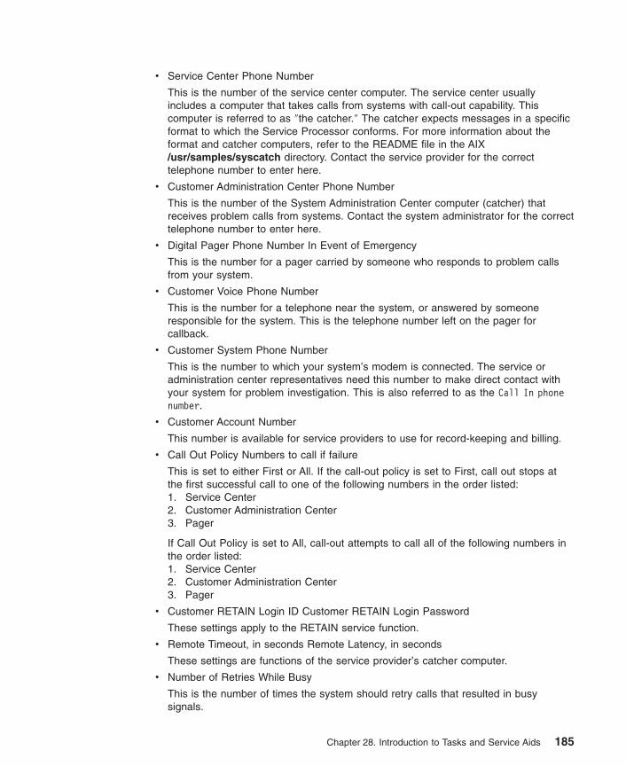
v Service Center Phone Number
This is the number of the service center computer. The service center usuallyincludes a computer that takes calls from systems with call-out capability. Thiscomputer is referred to as ″the catcher.″ The catcher expects messages in a specificformat to which the Service Processor conforms. For more information about theformat and catcher computers, refer to the README file in the AIX/usr/samples/syscatch directory. Contact the service provider for the correcttelephone number to enter here.
v Customer Administration Center Phone Number
This is the number of the System Administration Center computer (catcher) thatreceives problem calls from systems. Contact the system administrator for the correcttelephone number to enter here.
v Digital Pager Phone Number In Event of Emergency
This is the number for a pager carried by someone who responds to problem callsfrom your system.
v Customer Voice Phone Number
This is the number for a telephone near the system, or answered by someoneresponsible for the system. This is the telephone number left on the pager forcallback.
v Customer System Phone Number
This is the number to which your system’s modem is connected. The service oradministration center representatives need this number to make direct contact withyour system for problem investigation. This is also referred to as the Call In phonenumber.
v Customer Account Number
This number is available for service providers to use for record-keeping and billing.
v Call Out Policy Numbers to call if failure
This is set to either First or All. If the call-out policy is set to First, call out stops atthe first successful call to one of the following numbers in the order listed:1. Service Center2. Customer Administration Center3. Pager
If Call Out Policy is set to All, call-out attempts to call all of the following numbers inthe order listed:1. Service Center2. Customer Administration Center3. Pager
v Customer RETAIN Login ID Customer RETAIN Login Password
These settings apply to the RETAIN service function.
v Remote Timeout, in seconds Remote Latency, in seconds
These settings are functions of the service provider’s catcher computer.
v Number of Retries While Busy
This is the number of times the system should retry calls that resulted in busysignals.
Chapter 28. Introduction to Tasks and Service Aids 185

v System Name (System Administrator Aid)
This is the name given to the system and is used when reporting problem messages.
Note: Knowing the system name aids the support team in quickly identifying thelocation, configuration, history, and so on of your system.
You can access this service aid directly from the AIX command line, by typing:/usr/lpp/diagnostics/bin/uspchrp -m
Configure Ring Indicate Power-On Policy
Note: This service aid runs on CHRP system units only.
This service aid allows the user to power-on a system by telephone from a remotelocation. If the system is powered off, and Ring Indicate Power On is enabled, thesystem powers on at a predetermined number of rings. If the system is already on, noaction is taken. In either case, the telephone call is not answered, and the callerreceives no feedback that the system has powered on.
Use this service aid to display and change the following settings for the Ring IndicatePower-On Policy:
Note: Because of system capability, some of the following settings might not bedisplayed by this service aid.
v Power On Via Ring Indicate (on/off)v Number of Rings Before Power On
You can access this service aid directly from the AIX command line, by typing:/usr/lpp/diagnostics/bin/uspchrp -r
Configure Ring Indicate Power On
Note: This service aid runs on RSPC system units only.
This service aid allows the user to display and change the NVRAM settings for the RingIndicate Power On capability of the service processor.
The settings allows the user to:v Enable or disable power-on from Ring Indicatev Read or set the number of rings before power-on
186 Diagnostic Information for Multiple Bus Systems

Configure Scan Dump Policy
Note: This function works only on CHRP systems and only under diagnostics 5.1.0.35or later.
Configure Scan Dump Policy allows the user to set or view the scan dump policy (scandump control and size) in NVRAM. Scan Dump data is a set of chip data that theservice processor gathers after a system malfunction. It consists of chip scan rings, chiptrace arrays, and Scan COM (SCOM) registers. This data is stored in the scan-logpartition of the system’s Nonvolatile Random Access Memory (NVRAM).
Use this service aid to display and change the following settings for the Scan DumpPolicy at run time:
v Scan Dump Control (how often the dump is taken)
and
v Scan Dump Size (size and content of the dump)
The Scan Dump Control (SDC) settings are:
v As Needed: This setting allows the platform firmware to determine whether a scandump is performed. This is the default setting for the dump policy.
v Always: This setting overrides the firmware recommendations and always performs adump after a system failure.
The Scan Dump Size (SDS) settings are:
v As Requested - Dump content is determined by the platform firmware.
v Minimum - Dump content collected provides the minimum debug information. Theintent is to allow the platform to reboot as quickly as possible.
v Optimum - Dump content collected provides a moderate amount of debuginformation.
v Complete - Dump data provides the most complete error coverage at the expense ofreboot speed.
You can access this task directly from the AIX command line by typing:
/usr/lpp/diagnostics/bin/uspchrp -d
Configure Service Processor
Note: This service aid runs on RSPC system units only.
This service aid allows you to display and change the NVRAM settings for the serviceprocessor.
This service aid supports the following functions:v Surveillance Setup
Chapter 28. Introduction to Tasks and Service Aids 187

v Modem Configurationv Call in or call out Setupv Site specific call in or call out setupv Reboot or restart policy setup
Surveillance Setup
Note: Surveillance is only supported for systems running in full machine partition.
This selection allows you to display and change the NVRAM settings for thesurveillance capability of the service processor.
The settings allow you to:v Enable or disable surveillancev Set the surveillance time interval, in minutesv Set the surveillance delay, in minutes
The current settings are read from NVRAM and displayed on the screen. Any changesmade to the data shown are written to NVRAM.
Modem ConfigurationUse this selection when setting the NVRAM for a modem attached to any of the ServiceProcessor’s serial ports. The user inputs the file name of a modem configuration fileand the serial port number. The formatted modem configuration file is read, convertedfor NVRAM, and then loaded into NVRAM. Refer to the Service Processor Installationand User’s Guide for more information.
Call In/Out SetupThis selection allows the user to display and change the NVRAM settings for the CallIn/Call Out capability of the service processor.
The settings allow the user to:v Enable or disable call in on either serial portv Enable or disable call out on either serial portv Set the line speed on either serial port
Site Specific Call In/Out SetupThis selection allows you to display and change the NVRAM settings that aresite-specific for the call-in or call-out capability of the service processor.
The site-specific NVRAM settings allow you to set the following:v Phone number for the service centerv Phone number for the customer administration centerv Phone number for a digital pagerv Phone number for the customer system to call inv Phone number for the customer voice phonev Customer account numberv Call-out policy
188 Diagnostic Information for Multiple Bus Systems

v Customer RETAIN IDv Customer RETAIN passwordv Remote timeout valuev Remote latency valuev Number of retries while busyv System name
The current settings are read from NVRAM and displayed on the screen. Any changesmade to the data shown are written to NVRAM.
Reboot/Restart Policy SetupThis selection controls how the system tries to recover from a system crash.
Use this service aid to display and change the following settings for the Reboot PolicySetup.
v Maximum Number of Reboot Attempts
Enter a number that is 0 or greater.
Note: A value of 0 indicates ″do not attempt to reboot″ to a crashed system.
This number is the maximum number of consecutive attempts allowed to reboot thesystem. The term reboot, when used in context of this service aid, describes thesystem hardware being brought back up from scratch. Examples would be a systemreset or turning on the power.
When the maximum number of reboot attempts is exceeded, the system calls out ifthat function has been enabled.
When the reboot process completes successfully, the reboot-attempts count is resetto 0, and a restart begins. The term restart, when used in context of this service aid,describes the operating system activation process. Restart always follows asuccessful reboot.
When a restart fails, and a restart policy is enabled, the system attempts to rebootfor the maximum number of reboot attempts.
v Enable Restart Policy (1=Yes, 0=No)
When the service processor detects operating system inactivity, an enabled ″RestartPolicy″ causes a system reset, and the reboot process begins.
v Call-Out Before Restart (on/off)
When enabled, ″Call-Out Before Restart″ allows the system to call out (on a serialport that is enabled for call-out) when an operating system restart is initiated. Suchcall-outs can be valuable if the number becomes excessive, thus signalling biggerproblems.
v Enable Unattended Start Mode (1=Yes, 0=No)
When enabled, ″Unattended Start Mode″ allows the system to recover from the lossof ac power.
Chapter 28. Introduction to Tasks and Service Aids 189

If the system was powered-on when the ac loss occurred, the system reboots whenpower is restored. If the system was powered-off when the ac loss occurred, thesystem remains off when power is restored.
190 Diagnostic Information for Multiple Bus Systems

Configure Surveillance Policy
Note: This service aid runs on CHRP system units only. This service aid is onlysupported for systems running in full machine partition.
This service aid monitors the system for hang conditions; that is, hardware or softwarefailures that cause operating system inactivity. When enabled, and surveillance detectsoperating system inactivity, a call is placed to report the failure.
Use this service aid to display and change the following settings for the SurveillancePolicy:
Note: Because of system capability, some of the following settings might not bedisplayed by this service aid:
v Surveillance (on/off)v Surveillance Time Interval
This is the maximum time between heartbeats from the operating system.v Surveillance Time Delay
This is the time to delay between when the operating system is in control and whento begin operating system surveillance.
v Changes are to Take Effect Immediately
Set this to Yes if the changes made to the settings in this menu are to take placeimmediately. Otherwise the changes take effect beginning with the next system boot.
You can access this service aid directly from the AIX command line, by typing:/usr/lpp/diagnostics/bin/uspchrp -s
Create Customized Configuration DisketteThis selection invokes the Diagnostic Package Utility Service Aid, which allows the userto create a standalone diagnostic package configuration diskette.
The Standalone Diagnostic Package Configuration Diskette allows the following to bechanged from the console:
v Default refresh rate for a low function terminal (LFT)
The refresh rate used by the standalone diagnostic package is 60 Hz. If the display’srefresh rate is 77 Hz, set the refresh rate to 77.
v Different async terminal console
You can create a console configuration file that allows a terminal attached to anyRS232 or RS422 adapter to be selected as a console device. The default device isan RS232 TTY device attached to the first standard serial port (S1).
Chapter 28. Introduction to Tasks and Service Aids 191
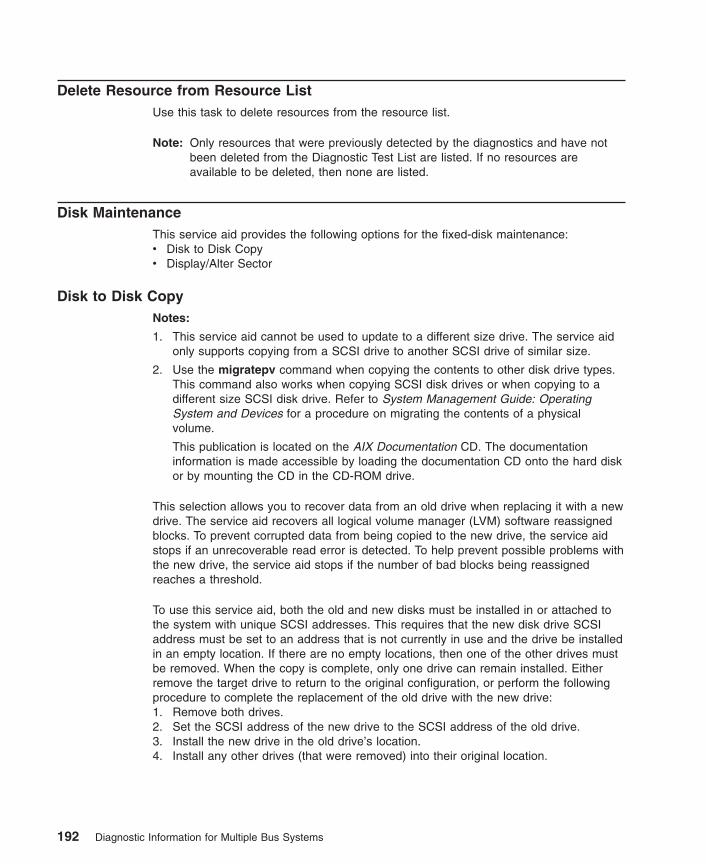
Delete Resource from Resource ListUse this task to delete resources from the resource list.
Note: Only resources that were previously detected by the diagnostics and have notbeen deleted from the Diagnostic Test List are listed. If no resources areavailable to be deleted, then none are listed.
Disk MaintenanceThis service aid provides the following options for the fixed-disk maintenance:v Disk to Disk Copyv Display/Alter Sector
Disk to Disk CopyNotes:
1. This service aid cannot be used to update to a different size drive. The service aidonly supports copying from a SCSI drive to another SCSI drive of similar size.
2. Use the migratepv command when copying the contents to other disk drive types.This command also works when copying SCSI disk drives or when copying to adifferent size SCSI disk drive. Refer to System Management Guide: OperatingSystem and Devices for a procedure on migrating the contents of a physicalvolume.
This publication is located on the AIX Documentation CD. The documentationinformation is made accessible by loading the documentation CD onto the hard diskor by mounting the CD in the CD-ROM drive.
This selection allows you to recover data from an old drive when replacing it with a newdrive. The service aid recovers all logical volume manager (LVM) software reassignedblocks. To prevent corrupted data from being copied to the new drive, the service aidstops if an unrecoverable read error is detected. To help prevent possible problems withthe new drive, the service aid stops if the number of bad blocks being reassignedreaches a threshold.
To use this service aid, both the old and new disks must be installed in or attached tothe system with unique SCSI addresses. This requires that the new disk drive SCSIaddress must be set to an address that is not currently in use and the drive be installedin an empty location. If there are no empty locations, then one of the other drives mustbe removed. When the copy is complete, only one drive can remain installed. Eitherremove the target drive to return to the original configuration, or perform the followingprocedure to complete the replacement of the old drive with the new drive:1. Remove both drives.2. Set the SCSI address of the new drive to the SCSI address of the old drive.3. Install the new drive in the old drive’s location.4. Install any other drives (that were removed) into their original location.
192 Diagnostic Information for Multiple Bus Systems

To prevent problems that can occur when running this service aid from disk, it issuggested that this service aid be run, when possible, from the diagnostics that areloaded from removable media.
Display/Alter Sector
Note: Use caution when you use this service aid because inappropriate modification tosome disk sectors can result in the total loss of all data on the disk.
This selection allows the user to display and alter information on a disk sector. Sectorsare addressed by their decimal sector number. Data is displayed both in hex and inASCII. To prevent corrupted data from being incorrectly corrected, the service aid doesnot display information that cannot be read correctly.
Display Configuration and Resource ListIf a device is not included in the Test List or if you think a Diagnostic Package for adevice is not loaded, check by using the Display Configuration and Resource List task.If the device you want to test has a plus (+) sign or a minus (-) sign preceding its name,the Diagnostic Package is loaded. If the device has an asterisk (*) preceding its name,the Diagnostic Package for the device is not loaded or is not available.
This service aid displays the item header only for all installed resources. Use thisservice aid when there is no need to see the vital product data (VPD). (No VPD isdisplayed.)
Display Firmware Device Node Information
Note: This service aid runs on CHRP system units only.
This task displays the firmware device node information that appears on CHRPplatforms. This service aid is intended to gather more information about individual orparticular devices on the system. The format of the output data may differ depending onwhich level of the AIX operating system is installed.
Display Hardware Error ReportThis service aid uses the errpt command to view the hardware error log.
The Display Error Summary and Display Error Detail selection provide the same type ofreport as the errpt command. The Display Error Analysis Summary and Display ErrorAnalysis Detail selection provide additional analysis.
Chapter 28. Introduction to Tasks and Service Aids 193

Display Hardware Vital Product DataThis service aid displays all installed resources, along with any VPD for thoseresources. Use this service aid when you want to look at the VPD for a specificresource.
Display Machine Check Error Log
Note: The Machine Check Error Log Service Aid is available only on StandaloneDiagnostics.
When a machine check occurs, information is collected and logged in an NVRAM errorlog before the system unit shuts down. This information is logged in the AIX error logand cleared from NVRAM when the system is rebooted from the hard disk, LAN, orstandalone media. When booting from Standalone Diagnostics, this service aid convertsthe logged information into a readable format that can be used to isolate the problem.When booting from the hard disk or LAN, the information can be viewed from the AIXerror log using the Hardware Error Report Service Aid. In either case, the information isanalyzed when the sysplanar0 diagnostics are running in Problem DeterminationMode.
Display Microcode LevelThis task is used to display the microcode or firmware levels of currently installedresources. When the sys0 resource is selected, the task displays the levels of both thesystem firmware and service processor firmware. sys0 may not be available in allcases.
You can display the current level of the microcode on an adapter, the system, or adevice by using the AIX diag command. See the following command syntax: diag -c-d device -T "disp_mcode"
Flag Description-c No console mode.-d Used to specify a device.-T Use the disp_mcode option to display microcode.
The AIX lsmcode command serves as a command line interface to the ″DisplayMicrocode Level″ task. For information on the lsmcode command, refer to the AIXCommands Reference manual.
Display or Change BootlistThis service aid allows the bootlist to be displayed, altered, or erased.
The system attempts to perform an IPL from the first device in the list. If the device isnot a valid IPL device or if the IPL fails, the system proceeds in turn to the otherdevices in the list to attempt an IPL.
194 Diagnostic Information for Multiple Bus Systems

Display or Change Diagnostic Run-Time OptionsThe Display or Change Diagnostic Run-Time Options task allows the diagnosticrun-time options to be set.
Note: The run-time options are used only when selecting the Run Diagnostic task.
The run-time options are:
v Display Diagnostic Mode Selection Menus
This option allows the user to turn on or off displaying the DIAGNOSTIC MODESELECTION MENU (the default is on).
v Run Tests Multiple Times
This option allows the user to turn on or off, or specify a loop count, for diagnosticloop mode (the default is off).
Note: This option is only displayed when you run the Online Diagnostics in ServiceMode.
v Include Advanced Diagnostics
This option allows the user to turn on or off including the Advanced Diagnostics (thedefault is off).
v Include Error Log Analysis (not available in diagnostics 5.2.0 or later)
This option allows the user to turn on or off including the Error Log Analysis (ELA)(the default is off).
v Number of Days Used to Search Error Log
This option allows the user to select the number of days for which to search the AIXerror log for errors when running the Error Log Analysis. The default is seven days,but it can be changed from one to sixty days.
v Display Progress Indicators
This option allows the user to turn on or off the progress indicators when running theDiagnostic Applications. The progress indicators are in a popup box at the bottom ofthe screen which indicate that the test being run (the default is on).
v Diagnostic Event Logging
This option allows the user to turn on or off logging information to the DiagnosticEvent Log (the default is on).
v Diagnostic Event Log File Size
This option allows the user to select the maximum size of the Diagnostic Event Log.The default size for the Diagnostic Event Log is 100 KB. The size can be increasedin 100 KB increments to a maximum of 1 MB.
Use the diaggetrto command to display one or more diagnostic run-time options. Usethe following AIX command line syntax:
/usr/lpp/diagnostics/bin/diaggetrto [-a] [-d] [-l] [-m] [-n] [-p] [-s]
Use the diagsetrto command to change one or more diagnostic run-time options. Usethe following AIX command line syntax:
Chapter 28. Introduction to Tasks and Service Aids 195
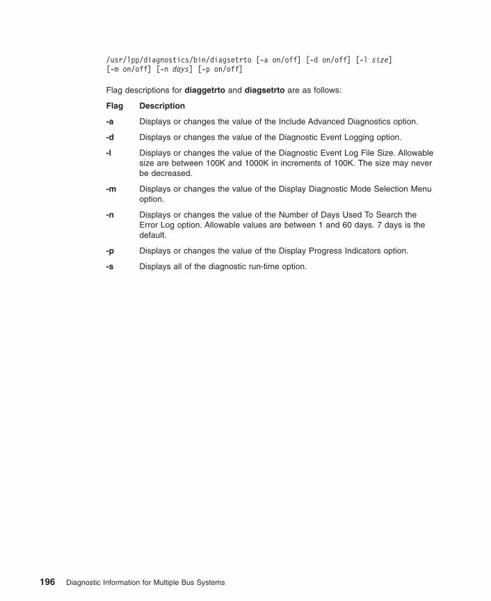
/usr/lpp/diagnostics/bin/diagsetrto [-a on/off] [-d on/off] [-l size][-m on/off] [-n days] [-p on/off]
Flag descriptions for diaggetrto and diagsetrto are as follows:
Flag Description
-a Displays or changes the value of the Include Advanced Diagnostics option.
-d Displays or changes the value of the Diagnostic Event Logging option.
-l Displays or changes the value of the Diagnostic Event Log File Size. Allowablesize are between 100K and 1000K in increments of 100K. The size may neverbe decreased.
-m Displays or changes the value of the Display Diagnostic Mode Selection Menuoption.
-n Displays or changes the value of the Number of Days Used To Search theError Log option. Allowable values are between 1 and 60 days. 7 days is thedefault.
-p Displays or changes the value of the Display Progress Indicators option.
-s Displays all of the diagnostic run-time option.
196 Diagnostic Information for Multiple Bus Systems

Display Previous Diagnostic Results
Note: This service aid is not available when you load the diagnostics from a sourceother than a hard disk drive or a network.
This service aid allows a service representative to display results from a previousdiagnostic session. When the Display Previous Diagnostic Results option is selected,the user can view up to 25 no trouble found (NTF) and service request number (SRN)results.
This service aid displays Diagnostic Event Log information. You can display theDiagnostic Event Log in a short version or a long version. The Diagnostic Event Logcontains information about events logged by a diagnostic session.
This service aid displays the information in reverse chronological order. If moreinformation is available than can be displayed on one screen, use the Page Down andPage Up keys to scroll through the information.
This information is not from the AIX operating system error log. This information isstored in the /var/adm/ras directory.
You can run the command from the AIX command line by typing:/usr/lpp/diagnostics/bin/diagrpt [[-o] | [-s mmddyy] | [-a] | [-r]]
Flag Description-o Displays the last diagnostic results file stored in the
/etc/lpp/diagnostics/data directory-s mmddyy Displays all diagnostic result files logged since the date specified-a Displays the long version of the Diagnostic Event Log-r Displays the short version of the Diagnostic Event Log
Display Resource AttributesThis task displays the Customized Device Attributes associated with a selectedresource. This task is similar to running the lsattr -E -l resource command.
Display Service HintsThis service aid reads and displays the information in the CEREADME file from thediagnostics media. This file contains information that is not contained in the publicationsfor this version of the diagnostics. The file also contains information about using thisparticular version of diagnostics.
Use the arrow keys to scroll through the information in the file.
Chapter 28. Introduction to Tasks and Service Aids 197
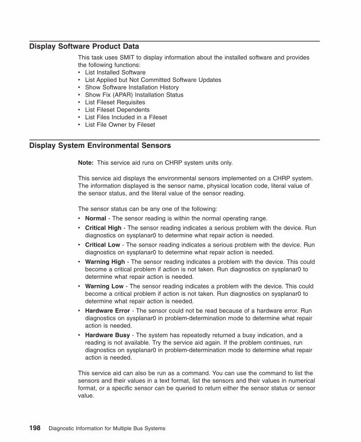
Display Software Product DataThis task uses SMIT to display information about the installed software and providesthe following functions:v List Installed Softwarev List Applied but Not Committed Software Updatesv Show Software Installation Historyv Show Fix (APAR) Installation Statusv List Fileset Requisitesv List Fileset Dependentsv List Files Included in a Filesetv List File Owner by Fileset
Display System Environmental Sensors
Note: This service aid runs on CHRP system units only.
This service aid displays the environmental sensors implemented on a CHRP system.The information displayed is the sensor name, physical location code, literal value ofthe sensor status, and the literal value of the sensor reading.
The sensor status can be any one of the following:
v Normal - The sensor reading is within the normal operating range.
v Critical High - The sensor reading indicates a serious problem with the device. Rundiagnostics on sysplanar0 to determine what repair action is needed.
v Critical Low - The sensor reading indicates a serious problem with the device. Rundiagnostics on sysplanar0 to determine what repair action is needed.
v Warning High - The sensor reading indicates a problem with the device. This couldbecome a critical problem if action is not taken. Run diagnostics on sysplanar0 todetermine what repair action is needed.
v Warning Low - The sensor reading indicates a problem with the device. This couldbecome a critical problem if action is not taken. Run diagnostics on sysplanar0 todetermine what repair action is needed.
v Hardware Error - The sensor could not be read because of a hardware error. Rundiagnostics on sysplanar0 in problem-determination mode to determine what repairaction is needed.
v Hardware Busy - The system has repeatedly returned a busy indication, and areading is not available. Try the service aid again. If the problem continues, rundiagnostics on sysplanar0 in problem-determination mode to determine what repairaction is needed.
This service aid can also be run as a command. You can use the command to list thesensors and their values in a text format, list the sensors and their values in numericalformat, or a specific sensor can be queried to return either the sensor status or sensorvalue.
198 Diagnostic Information for Multiple Bus Systems

Run the command by entering one of the following:/usr/lpp/diagnostics/bin/uesensor -l | -a /usr/lpp/diagnostics/bin/uesensor -ttoken -i index [-v]
Flag Description-l List the sensors and their values in a text format.-a List the sensors and their values in a numerical format. For each sensor, the
following numerical values are displayed as: token index status measuredvalue location code
-t tokenSpecifies the sensor token to query.
-i indexSpecifies the sensor index to query.
-v Indicates to return the sensor measured value. The sensor status is returnedby default.
ExamplesThe following are examples from this command:
1. Display a list of the environmental sensors: /usr/lpp/diagnostics/bin/uesensor -l
Sensor = Fan SpeedStatus = NormalValue = 2436 RPMLocation Code = F1Sensor = Power SupplyStatus = NormalValue = Present and operationalLocation Code = V1Sensor = Power SupplyStatus = Critical lowValue = Present and not operationalLocation Code = V2
2. Display a list of the environmental sensors in a numerical list:/usr/lpp/diagnostics/bin/uesensor -a
3 0 11 87 P19001 0 11 2345 F19004 0 11 2 V19004 1 9 2 V2
3. Return the status of sensor 9004, index 1: /usr/lpp/diagnostics/bin/uesensor -t9004 -i 1
9
4. Return the value of sensor 9004, index 1: /usr/lpp/diagnostics/bin/uesensor -t9004 -i 1 -v
2
Chapter 28. Introduction to Tasks and Service Aids 199

Display Test PatternsThis service aid provides a means of adjusting system display units by providing testpatterns that can be displayed. The user works through a series of menus to select thedisplay type and test pattern. After the selections are made, the test pattern displays.
Display USB DevicesThe following are the main functions of this service aid:
v Display a list of USB controllers on an adapter.
v Display a list of USB devices that are connected to the selected controller.
To run the USB devices service aid, go to the diagnostics ″TASKS SELECTION″ menu,select ″Display USB Devices″. From the controller list that displayed on the screen,select one of the items that begins with ″OHCDX″, where ″X″ is a number. A list ofdevices attached to the controller displays.
Download MicrocodeThis service aid provides a way to copy microcode to an adapter or device. The serviceaid presents a list of adapters and devices that use microcode. After the adapter ordevice is selected, the service aid provides menus to guide you in checking the currentlevel and downloading the needed microcode.
This task can be run directly from the AIX command line. See the following sections forinstructions on downloading to a particular type adapter or device.
Download Microcode to PCI SCSI RAID AdapterSee the following command syntax for a PCI SCSI RAID Adapter:diag -c -d RAIDadapterName -T "download [-B] [-D] [-P]"
Flag Description-B Download boot block microcode (default to functional microcode)-D Microcode is on diskette (default to /etc/microcode directory)-P Download the previous level of microcode (default to latest level)
Download Microcode to a PCI-X Dual Channel AdapterMicrocode installation occurs while the adapter and attached drives are available foruse. Before installation of the microcode, ensure that there is a current backup of thesystem available and it is recommended that the installation be scheduled during anon-peak production time period.
Notes:
1. If the source is /etc/microcode, the image must be stored in the /etc/microcodedirectory on the system. If the system is booted from a NIM server, the image mustbe stored in the usr/lib/microcode directory of the SPOT the client is booted from.
2. If the source is diskette, the diskette must be in a backup format and the imagestored in the /etc/microcode directory.
200 Diagnostic Information for Multiple Bus Systems

See the following command syntax for a PCI-X Adapter:
diag -c -d device_name -T "download [-s {/etc/microcode|diskette}][-l {latest|previous}] [-f]"
Flag Description
-c No console mode. Run without user interaction.
-d Device name is the name of the adapter.
-f Force the installation even if the current level of microcode is not on thesource.
-l Level of microcode to install. The default is latest.
-s Source of the new microcode image. The default is /etc/microcode.
-T Use the download option to download microcode.
Download Microcode to Disk Drive Attached to a PCI SCSI RAID AdapterSee the following command syntax for a disk drive attached to a PCI SCSI RAIDAdapter:diag -c -d RAIDadapterName -T "download {-l chID | -A} [-D] [-P]"
Flag Description-A All disk drives-D Microcode is on diskette (default to /etc/microcode directory)-l RAID disk drive-physical disk channel/ID (example 27)-P Download the previous level of microcode (default to latest level)
Download Microcode to a Fiber Channel AdapterMicrocode installation occurs while the adapter and attached drives are available foruse. Before installation of the microcode, ensure that a current backup of the system isavailable. It is recommended that the installation be scheduled during a non-peakproduction time period.
Notes:
1. If the source is /etc/microcode, the image must be stored in the /etc/microcodedirectory on the system. If the system is booted from a NIM server, the image mustbe stored in the usr/lib/microcode directory of the SPOT the client is booted from.
2. If the source is diskette, the diskette must be in backup format and the image storedin the /etc/microcode directory.
See the following command syntax for a Fiber Channel Adapter.diag -c -d device_name -T "download [-s {/etc/microcode|diskette}] [-l{latest|previous}] [-f]"
Flag Description-c No console mode. Run without user interaction.-d Device name is the name of the adapter.-T Use the download option to download microcode.-s Source of the new microcode image. Default is /etc/microcode.-l Level of microcode to install. The default is latest.
Chapter 28. Introduction to Tasks and Service Aids 201

-f Force the installation even if the current level of microcode is not on thesource.
Download Microcode to DVD-RAM Attached to a PCI SCSI AdapterSee the following command syntax for a DVD-RAM attached to a PCI SCSI Adapter:
diag [-c] -d cdX -T "download [-s {/etc/microcode|diskette}][-l {latest|previous}] [-f]"
Flag Description-c No console mode. Run without user interactioncdX Device selected, for example, cd0.-s Source of the new microcode. The default is /etc/microcode.-l Level of microcode image to be installed. Latest in default-f Install the microcode on the device even if the current level is unavailable on
the source.
Download Microcode to Disk Attached to PCI SCSI AdapterSee following command syntax for a disk drive attached to a PCI SCSI adapter:
diag [-c] -d hdiskX -T "download [-s {/etc/microcode|diskette}][-l {latest|previous}] [-f]"
Flag Description-c No console mode. Run without user interaction-d hdiskX
Selected device, for example, hdisk0.-T download
Download microcode task.-s Source of the new microcode. The default is /etc/microcode.-l Level of microcode image to be installed. Latest in default-f Install the microcode on the device even if the current level is unavailable on
the source.
202 Diagnostic Information for Multiple Bus Systems

Download Microcode to Other DevicesSee the following command syntax:diag -c -d device_name -T "download [-s diskette] [-l previous] [-F]"
Flag Description-F Force the download microcode even if the current level is unavailable on the
source.-l Microcode level. Latest is default.-s Source of the new microcode. The default is /etc/microcode. Default source
device is disk.
Fault Indicators
Note: Prior to Diagnostics version 5.1.0.35, this task was also known as the SystemFault Indicator task.
This task is used to display or reset the Fault Indicators on the systems that supportthis function. This task may also be used to set the Fault Indicators for testingpurposes, but the Indicators are not set back to normal when you exit this task.
The Fault Indicators are used to identify a fault with the system. These indicators maybe set automatically by hardware, firmware, or diagnostics when a fault is detected inthe system.
The Fault Indicators are turned off when a Log Repair Action is performed. After aserviceable event is complete, do a System Verification to verify the fix. Also do a LogRepair Action if the test on the resource was good, and that resource had an entry inthe error log. If the serviceable event was not a result of an error log entry, use the LogRepair Action Task to turn off the system fault indicator.
For additional information concerning the use of these indicators, refer to the systemguide.
Note: The AIX command does not allow you to set the fault indicators to the Faultstate.
Use the following command syntax:
/usr/lpp/diagnostics/bin/usysfault [-s normal] [-l location code]
Flag Description-s normal Sets the Fault Indicator to the normal state.-l location code Identifies the resource by physical location code.
When the command is used without the -s flag, the current state of the indicator isdisplayed as normal or attention.
When teh command is used without the -l flag, the Primary Enclosure resource is used.
Chapter 28. Introduction to Tasks and Service Aids 203

Use the -l flag only in systems that have more than one fault indicator.
Note: See also the “Identify and System Attention Indicators” on page 211. Somesystems that do not support Fault Indicators have a similar System AttentionIndicator.
Fibre Channel RAID Service AidsThe Fibre Channel RAID service aids contain the following functions:
Certify LUNThis selection reads and checks each block of data in the logical unit number(LUN). If excessive errors are encountered, the user is notified.
You can run this task from the AIX command line. Use the following fastpathcommand: diag -T "certify"
Certify Spare Physical DiskThis selection allows the user to certify (check integrity of the data) drives thatare designated as spares.
You can run this task from the AIX command line. Use the following fastpathcommand: diag -T "certify"
Format Physical DiskThis selection is used to format a selected disk drive.
You can run this task from the AIX command line. Use the following fastpathcommand: diag -T "format"
Array Controller Microcode DownloadThis selection allows the microcode on the Fibre Channel RAID controller to beupdated when required.
You can run this task from the AIX command line. Use the following fastpathcommand: diag -T "download"
Physical Disk Microcode DownloadThis selection is used to update the microcode on any of the disk drives in thearray.
You can run this task from the AIX command line. Use the following fastpathcommand: diag -T "download"
Update EEPROMThis selection is used to update the contents of the electronically erasableprogrammable read-only memory (EEPROM) on a selected controller.
Replace ControllerUse this selection when it is necessary to replace a controller in the array.
Flash SK-NET FDDI FirmwareThis task allows the Flash firmware on the SysKonnect SK-NET FDDI adapter to beupdated.
204 Diagnostic Information for Multiple Bus Systems

Format MediaThis task allows the selection of diskettes, hardfiles, or optical media to be formatted.Each selection is described below.
Hardfile Attached to SCSI Adapter (non-RAID)v Hardfile Format
Writes all of the disk. The pattern written on the disk is device-dependent; forexample some drives may write all 0s, while some may write the hexadecimalnumber 5F. No bad block reassignment occurs
v Hardfile Format and Certify
Performs the same function as Hardfile Format. After the format is completed, Certifyis run. Certify then reassigns all bad blocks encountered.
v Hardfile Erase Disk
This option can be used to overwrite (remove) all data currently stored inuser-accessible blocks of the disk. The Erase Disk option writes one or morepatterns to the disk. An additional option allows data in a selectable block to be readand displayed on the system console.
To use the Erase Disk option, specify the number (0-3) of patterns to be written. Thepatterns are written serially; that is, the first pattern is written to all blocks. Then thenext pattern is written to all blocks, overlaying the previous pattern. A random patternis written by selecting the Write Random Pattern? option.
Note: The Erase Disk service aid has not been certified as meeting the Departmentof Defense or any other organization’s security guidelines.
Use the following steps to overwrite the data on the drive:1. Use the Erase Disk selection to overwrite the data on the drive.2. Do a format without certify.3. Run a second pass of the Erase Disk selection.
For a newly installed drive, you can ensure that all blocks on the drive areoverwritten with your pattern if you use the following procedure:
1. Format the drive.
2. Check the defect MAP by running the Erase Disk selection.
Note: If you use the Format and Certify option, there may be some blockswhich get placed into the grown defect MAP.
3. If there are bad blocks in the defect MAP, record the information presented andensure that this information is kept with the drive. This data is used later whenthe drive is to be overwritten.
4. Use the drive as you would normally.
5. When the drive is no longer needed and is to be erased, run the same version ofthe Erase Disk selection which was used in step 2.
Note: Using the same version of the service aid is only critical if any bad blockswere found in step 3.
Chapter 28. Introduction to Tasks and Service Aids 205
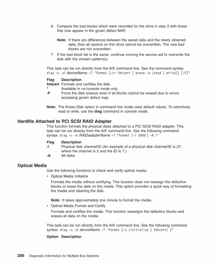
6. Compare the bad blocks which were recorded for the drive in step 3 with thosethat now appear in the grown defect MAP.
Note: If there are differences between the saved data and the newly obtaineddata, then all sectors on this drive cannot be overwritten. The new badblocks are not overwritten.
7. If the bad block list is the same, continue running the service aid to overwrite thedisk with the chosen pattern(s).
This task can be run directly from the AIX command line. See the command syntax:diag -c -d deviceName -T "format [-s* fmtcert | erase -a {read | write}] [-F]"
Flag Descriptionfmtcert Formats and certifies the disk.* Available in no-console mode only.-F Force the disk erasure even if all blocks cannot be erased due to errors
accessing grown defect map.
Note: The Erase Disk option in command line mode uses default values. To selectivelyread or write, use the diag command in console mode.
Hardfile Attached to PCI SCSI RAID AdapterThis function formats the physical disks attached to a PCI SCSI RAID adapter. Thistask can be run directly from the AIX command line. See the following commandsyntax: diag -c -d RAIDadapterName -T "format {-l chId | -A }"
Flag Description-l Physical disk channel/ID (An example of a physical disk channel/ID is 27,
where the channel is 2 and the ID is 7.)-A All disks
Optical MediaUse the following functions to check and verify optical media:
v Optical Media Initialize
Formats the media without certifying. This function does not reassign the defectiveblocks or erase the data on the media. This option provides a quick way of formattingthe media and cleaning the disk.
Note: It takes approximately one minute to format the media.
v Optical Media Format and Certify
Formats and certifies the media. This function reassigns the defective blocks anderases all data on the media.
This task can be run directly from the AIX command line. See the following commandsyntax: diag -c -d deviceName -T "format [-s {initialize | fmtcert} ]"
Option Description
206 Diagnostic Information for Multiple Bus Systems
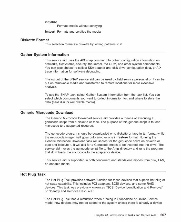
initializeFormats media without certifying
fmtcert Formats and certifies the media
Diskette FormatThis selection formats a diskette by writing patterns to it.
Gather System InformationThis service aid uses the AIX snap command to collect configuration information onnetworks, filesystems, security, the kernel, the ODM, and other system components.You can also choose to collect SSA adapter and disk drive configuration data, or AIXtrace information for software debugging.
The output of the SNAP service aid can be used by field service personnel or it can beput on removable media and transferred to remote locations for more extensiveanalysis.
To use the SNAP task, select Gather System Information from the task list. You canselect which components you want to collect information for, and where to store thedata (hard disk or removable media).
Generic Microcode DownloadThe Generic Microcode Download service aid provides a means of executing agenucode script from a diskette or tape. The purpose of this generic script is to loadmicrocode to a supported resource.
The genucode program should be downloaded onto diskette or tape in tar format whilethe microcode image itself goes onto another one in restore format. Running theGeneric Microcode Download task will search for the genucode script on diskette ortape and execute it. It will ask for a Genucode media to be inserted into the drive. Theservice aid moves the genucode script file to the /tmp directory and runs the programthat downloads the microcode to the adapter or device.
This service aid is supported in both concurrent and standalone modes from disk, LAN,or loadable media.
Hot Plug TaskThe Hot Plug Task provides software function for those devices that support hot-plug orhot-swap capability. This includes PCI adapters, SCSI devices, and some RAIDdevices. This task was previously known as ″SCSI Device Identification and Removal″or ″Identify and Remove Resource.″
The Hot Plug Task has a restriction when running in Standalone or Online Servicemode; new devices may not be added to the system unless there is already a device
Chapter 28. Introduction to Tasks and Service Aids 207

with the same FRU part number installed in the system. This restriction is in placebecause the device software package for the new device cannot be installed inStandalone or Online Service mode.
Depending on the environment and the software packages installed, selecting this taskdisplays the following three subtasks:v PCI Hot Plug Managerv SCSI Hot Swap Managerv RAID Hot Plug Devices
To run the Hot Plug Task directly from the command line, type the following: diag-T"identifyRemove"
If you are running the diagnostics in Online Concurrent mode, run the Missing OptionsResolution Procedure immediately after removing any device.
If the Missing Options Resolution Procedure runs with no menus or prompts, thendevice configuration is complete. Otherwise, work through the missing options menu tocomplete device configuration (in diagnostics prior to version 5.2.0) or (in diagnosticsversion 5.2.0 and later) select the device that has an uppercase M shown in front of it inthe resource list for missing options processing to be done on that resource.
PCI Hot Plug ManagerThe PCI Hot Plug Manager task is a SMIT menu that allows you to identify, add,remove, or replace PCI adapters that are hot-pluggable. The following functions areavailable under this task:v List PCI Hot Plug Slotsv Add a PCI Hot Plug Adapterv Replace/Remove a PCI Hot Plug Adapterv Identify a PCI Hot Plug Slotv Unconfigure Devicesv Configure Devicesv Install/Configure Devices Added After IPL
The List PCI Hot Plug Slots function lists all PCI hot-plug slots. Empty slots andpopulated slots are listed. Populated slot information includes the connected logicaldevice. The slot name consists of the physical location code and the description of thephysical characteristics for the slot.
The Add a PCI Hot Plug Adapter function is used to prepare a slot for the addition ofa new adapter. The function lists all the empty slots that support hot plug. When a slotis selected, the visual indicator for the slot blinks at the Identify rate. After the slotlocation is confirmed, the visual indicator for the specified PCI slot is set to the Actionstate. This means the power for the PCI slot is off and the new adapter can be pluggedin.
The Replace/Remove a PCI Hot Plug Adapter function is used to prepare a slot foradapter exchange. The function lists all the PCI slots that support hot plug and areoccupied. The list includes the slot’s physical location code and the device name of the
208 Diagnostic Information for Multiple Bus Systems

resource installed in the slot. The adapter must be in the Defined state before it can beprepared for hot-plug removal. When a slot is selected, the visual indicator for the slotis set to the Identify state. After the slot location is confirmed, the visual indicator for thespecified PCI slot is set to the Action state. This means the power for the PCI slot, is offand the adapter can be removed or replaced.
The Identify a PCI Hot Plug Slot function is used to help identify the location of a PCIhot-plug adapter. The function lists all the PCI slots that are occupied or empty andsupport hot plug. When a slot is selected for identification, the visual indicator for theslot is set to the Identify state.
The Unconfigure Devices function attempts to put the selected device, in the PCIhot-plug slot, into the Defined state. This action must be done before any attemptedhot-plug function. If the unconfigure function fails, it is possible that the device is still inuse by another application. In this case, the customer or system administrator must benotified to quiesce the device.
The Configure Devices function allows a newly added adapter to be configured intothe system for use. This function should also be done when a new adapter is added tothe system.
The Install/Configure Devices Added After IPL function attempts to install thenecessary software packages for any newly added devices. The software installationmedia or packages are required for this function.
Standalone Diagnostics has restrictions on using the PCI Hot-Plug Manager. Forexample:
v Adapters that are replaced must be exactly the same FRU part number as theadapter being replaced.
v New adapters cannot be added unless a device of the same FRU part numberalready exists in the system, because the configuration information for the newadapter is not known after the Standalone Diagnostics are booted.
v The following functions are not available from the Standalone Diagnostics and willnot display in the list:– Add a PCI Hot Plug Adapter– Configure Devices– Install/Configure Devices Added After IPL
You can run this task directly from the command line by typing the following command:diag -d device -T"identifyRemove"
However, note that some devices support both the PCI Hot-Plug task and the RAIDHot-Plug Devices task. If this is the case for the device specified, then the Hot PlugTask displays instead of the PCI Hot Plug Manager menu.
More detailed information concerning PCI Hot-Plug Manager can be found in the AIXOperating System, System Management Guide.
Chapter 28. Introduction to Tasks and Service Aids 209

SCSI Hot Swap ManagerThis task was known as ″SCSI Device Identification and Removal″ or ″Identify andRemove Resources″ in previous releases. This task allows the user to identify, add,remove, and replace a SCSI device in a system unit that uses a SCSI EnclosureServices (SES) device. The following functions are available:v List the SES Devicesv Identify a Device Attached to an SES Devicev Attach a Device to an SES Devicev Replace/Remove a Device Attached to an SES Devicev Configure Added/Replaced Devices
The List the SES Devices function lists all the SCSI hot-swap slots and their contents.Status information about each slot is also available. The status information availableincludes the slot number, device name, whether the slot is populated and configured,and location.
The Identify a Device Attached to an SES Device function is used to help identify thelocation of a device attached to a SES device. This function lists all the slots thatsupport hot swap that are occupied or empty. When a slot is selected for identification,the visual indicator for the slot is set to the Identify state.
The Attach a Device to an SES Device function lists all empty hot-swap slots that areavailable for the insertion of a new device. After a slot is selected, the power isremoved. If available, the visual indicator for the selected slot is set to the Removestate. After the device is added, the visual indicator for the selected slot is set to theNormal state, and power is restored.
The Replace/Remove a Device Attached to an SES Device function lists allpopulated hot-swap slots that are available for removal or replacement of the devices.After a slot is selected, the device populating that slot is Unconfigured; then the poweris removed from that slot. If the Unconfigure operation fails, it is possible that the deviceis in use by another application. In this case, the customer or system administrator mustbe notified to quiesce the device. If the Unconfigure operation is successful, the visualindicator for the selected slot is set to the Remove state. After the device is removed orreplaced, the visual indicator, if available for the selected slot, is set to the Normal state,and power is restored.
Note: Be sure that no other host is using the device before you remove it.
210 Diagnostic Information for Multiple Bus Systems
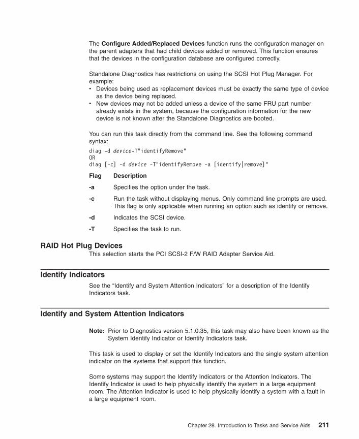
The Configure Added/Replaced Devices function runs the configuration manager onthe parent adapters that had child devices added or removed. This function ensuresthat the devices in the configuration database are configured correctly.
Standalone Diagnostics has restrictions on using the SCSI Hot Plug Manager. Forexample:v Devices being used as replacement devices must be exactly the same type of device
as the device being replaced.v New devices may not be added unless a device of the same FRU part number
already exists in the system, because the configuration information for the newdevice is not known after the Standalone Diagnostics are booted.
You can run this task directly from the command line. See the following commandsyntax:
diag -d device-T"identifyRemove"ORdiag [-c] -d device -T"identifyRemove -a [identify|remove]"
Flag Description
-a Specifies the option under the task.
-c Run the task without displaying menus. Only command line prompts are used.This flag is only applicable when running an option such as identify or remove.
-d Indicates the SCSI device.
-T Specifies the task to run.
RAID Hot Plug DevicesThis selection starts the PCI SCSI-2 F/W RAID Adapter Service Aid.
Identify IndicatorsSee the “Identify and System Attention Indicators” for a description of the IdentifyIndicators task.
Identify and System Attention Indicators
Note: Prior to Diagnostics version 5.1.0.35, this task may also have been known as theSystem Identify Indicator or Identify Indicators task.
This task is used to display or set the Identify Indicators and the single system attentionindicator on the systems that support this function.
Some systems may support the Identify Indicators or the Attention Indicators. TheIdentify Indicator is used to help physically identify the system in a large equipmentroom. The Attention Indicator is used to help physically identify a system with a fault ina large equipment room.
Chapter 28. Introduction to Tasks and Service Aids 211

When a fault has been detected on a system that supports the Attention Indicator, theIndicator is set to an Attention condition. After the failing system has been identified andthe problem fixed, the Attention Indicator changes back to normal. This should be doneby the Log Repair Action Task.
Note: It is important to run the Log Repair Action function. This action keeps the FaultIndicator from going back to the Fault state due to a previous error in the errorlog that has already been serviced.
For additional information concerning the use of this indicator, refer to the system guide.
This task can also be run directly from the command line by typing
/usr/lpp/diagnostics/bin/usysident [-s {normal | identify}] [-l location code]
Flag Description-s {normal | identify} Sets the state of the System Identify Indicator to
either normal or identify.-l location code Identifies the resource by physical location code.
When this command is used without the -l flag, the Primary Enclosure resource is used.
Use the -l flag only in systems that have more than one Identify and System attentionindicator.
When this command is used without -s flag, the current state of the identify indicator isdisplayed.
For more information on the tasks, see Chapter 28, “Introduction to Tasks and ServiceAids” on page 175.
Local Area Network AnalyzerThis selection is used to exercise the LAN communications adapters (Token-Ring,Ethernet, and (FDDI) Fiber Distributed Data Interface). The following services areavailable:
v Connectivity testing between two network stations. Data is transferred between thetwo stations, requiring the user to provide the Internet addresses of both stations.
v Monitoring ring (Token-Ring only). The ring is monitored for a specified period oftime. Soft and hard errors are analyzed.
Log Repair ActionThe Log Repair Action task logs a repair action in the AIX Error Log. A Repair Actionlog indicates that a FRU has been replaced, and error log analysis should not be donefor any errors logged before the repair action. The Log Repair Action task lists allresources. Replaced resources can be selected from the list, and when commit (F7key) is selected, a repair action is logged for each selected resource. For moreinformation see, “Log Repair Action” on page 150.
212 Diagnostic Information for Multiple Bus Systems

Periodic DiagnosticsThis selection provides a tool for configuring periodic diagnostics and automatic errorlog analysis. You can select a hardware resource to be tested once a day, at auser-specified time.
Hardware errors logged against a resource can also be monitored by enablingautomatic error log analysis. This allows error log analysis to be performed every time ahardware error is put into the error log. If a problem is detected, a message is posted tothe system console and either sent to the Service Focal Point when there is anattached HMC, or a mail message to the users belonging to the system groupcontaining information about the failure, such as the service request number.
The service aid provides the following functions:
v Add or delete a resource to the periodic test list
v Modify the time to test a resource
v Display the periodic test list
v Modify the error notification mailing list
v Disable or enable automatic error log analysis
PCI RAID Physical Disk IdentifyThis selection identifies physical disks connected to a PCI SCSI-2 F/W RAID adapter.
You can run this task directly from the AIX command line. See the following commandsyntax: diag -c -d pci RAID adapter -T identify
Process Supplemental MediaDiagnostic Supplemental Media contains all the necessary diagnostic programs andfiles required to test a particular resource. The supplemental media is normally releasedand shipped with the resource as indicated on the diskette label. DiagnosticSupplemental Media must be used when the device support has not been incorporatedinto the latest diagnostic CD-ROM.
This task processes the Diagnostic Supplemental Media. Insert the supplemental mediawhen you are prompted; then press Enter. After processing has completed, go to theResource Selection list to find the resource to test.
Notes:
1. This task is supported in Standalone Diagnostics only.
2. Process and test one resource at a time. Run diagnostics after each supplementalmedia is processed. (for example; If you need to process two supplemental mediayou need to run diagnostic twice. Once after each supplement media is processed.)
Chapter 28. Introduction to Tasks and Service Aids 213
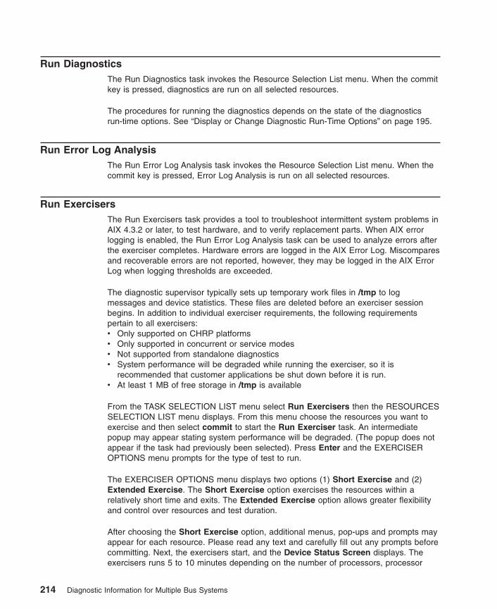
Run DiagnosticsThe Run Diagnostics task invokes the Resource Selection List menu. When the commitkey is pressed, diagnostics are run on all selected resources.
The procedures for running the diagnostics depends on the state of the diagnosticsrun-time options. See “Display or Change Diagnostic Run-Time Options” on page 195.
Run Error Log AnalysisThe Run Error Log Analysis task invokes the Resource Selection List menu. When thecommit key is pressed, Error Log Analysis is run on all selected resources.
Run ExercisersThe Run Exercisers task provides a tool to troubleshoot intermittent system problems inAIX 4.3.2 or later, to test hardware, and to verify replacement parts. When AIX errorlogging is enabled, the Run Error Log Analysis task can be used to analyze errors afterthe exerciser completes. Hardware errors are logged in the AIX Error Log. Miscomparesand recoverable errors are not reported, however, they may be logged in the AIX ErrorLog when logging thresholds are exceeded.
The diagnostic supervisor typically sets up temporary work files in /tmp to logmessages and device statistics. These files are deleted before an exerciser sessionbegins. In addition to individual exerciser requirements, the following requirementspertain to all exercisers:v Only supported on CHRP platformsv Only supported in concurrent or service modesv Not supported from standalone diagnosticsv System performance will be degraded while running the exerciser, so it is
recommended that customer applications be shut down before it is run.v At least 1 MB of free storage in /tmp is available
From the TASK SELECTION LIST menu select Run Exercisers then the RESOURCESSELECTION LIST menu displays. From this menu choose the resources you want toexercise and then select commit to start the Run Exerciser task. An intermediatepopup may appear stating system performance will be degraded. (The popup does notappear if the task had previously been selected). Press Enter and the EXERCISEROPTIONS menu prompts for the type of test to run.
The EXERCISER OPTIONS menu displays two options (1) Short Exercise and (2)Extended Exercise. The Short Exercise option exercises the resources within arelatively short time and exits. The Extended Exercise option allows greater flexibilityand control over resources and test duration.
After choosing the Short Exercise option, additional menus, pop-ups and prompts mayappear for each resource. Please read any text and carefully fill out any prompts beforecommitting. Next, the exercisers start, and the Device Status Screen displays. Theexercisers runs 5 to 10 minutes depending on the number of processors, processor
214 Diagnostic Information for Multiple Bus Systems

speed, memory size, and I/O configuration. After choosing the Extended Exerciseoption, additional menus, pop-ups and prompts may appear for each resource. Pleaseread any text and carefully fill out any prompts before committing. Following, theSystem Exerciser Main Menu displays. From this menu the exercisers can beactivated through option 1 Short Exercise where they will continuously run until halted(option 2, Extended Exercise) or exited (option x). See also the help text for informationon how to use other available options.
When the task completes any errors that were encountered are displayed for review.Finally, an Exerciser Complete popup displays. To continue, press the Enter key.Following, you will be taken back to the TASK SELECTION LIST menu. If miscompareerrors were encountered, run diagnostics on the resource. If the problem is not reportedthen contact your service support structure. If any other errors were encountered, selectand run the Error Log Analysis task. If Error Log Analysis does not report a problemthen contact your service support structure.
Exerciser Commands (CMD)Use the following commands as needed in the exerciser menus and reports. Not allcommands are available in each menu or report.
CMD Descriptiona Acknowledge an errorb Back one pagec Toggle between cycle count and last errore View the AIX error logf Page forward one pageq Return to Main Menur Refresh screens Enable or disable beep on errorx Exit system exerciser
AbbreviationsThe following list describes abbreviations used in the exerciser reports.
Acronym DescriptionCOE Continue on error (use number to select).CP Device has run the specified number of cycles and is not running.DD The exerciser has been terminated by a signal.ER Device has stopped with an error.HG The device is hung.HOE Halt on error (use number to select).RN Device is running.ST Device is stopped.
Chapter 28. Introduction to Tasks and Service Aids 215

Memory ExerciserThe memory exerciser is labeled mem0. The exerciser requests as many memory buffersas possible from AIX. The exerciser fills these buffers with specified bit patterns andthen compares them to the original bit patterns. If memory is removed as a result ofDynamic Reconfiguration, the exerciser terminates.
On systems with multiple processors, a process is started for each processor. The freememory space is split evenly between the available processors, thus reducing the timerequired to exercise all of the memory.
Running this service aid requires 128 KB of free space in /etc/lpp/diagnostics/data.
Tape ExerciserThe tape exerciser is labeled rmtx, where x is the number of a specific device. Theexerciser performs read, write, and compare operations using known data patterns. Atape device and Test Diagnostic Cartridge are required to run this exerciser. The actualTest Diagnostics Cartridge depends upon the specific tape device being tested. Theexerciser automatically rewinds the tape. Test Requirements are:v Tape devicev Test Diagnostic Cartridge; (P/N depends upon tape device)
Diskette ExerciserThe diskette exerciser is labeled fdx, where x is the number of a specific device. Theexerciser performs read, write, and compare operations using known data patterns. Ascratch diskette is required to run this exerciser, data on the scratch diskette isdestroyed. Test requirements are:v Diskette devicev Scratch diskette (data on diskette is destroyed)
CD-ROM ExerciserThe CD-ROM exerciser is labeled cdx, where x is the number of a specific device. Theexerciser performs read and compare operations using known data patterns. ACD-ROM device and a Test Disc is required to run this exerciser. Test requirements are:v CD-ROM devicev Test Disc P/N 81F8902
Floating Point ExerciserThe floating point exerciser is labeled procx, where x is the number of the processorcontaining the floating point unit. The exerciser performs load/store and arithmeticoperations using floating point registers and instructions. The floating point instructionsare executed using static values and the outcome of the operation is compared with theexpected result. Any mismatch results in an error condition. If the processor is in use bythe exerciser and is removed as a result of dynamic logical partitioning, the exerciserterminates.
216 Diagnostic Information for Multiple Bus Systems

Save or Restore Hardware Management Policies
Note: This service aid runs on CHRP system units only.
Use this service aid to save or restore the settings from Ring Indicate Power-On Policy,Surveillance Policy, Remote Maintenance Policy and Reboot Policy. The followingoptions are available:
v Save Hardware Management Policies
This selection writes all of the settings for the hardware-management policies to thefollowing file: /etc/lpp/diagnostics/data/hmpolicies
v Restore Hardware Management Policies
This selection restores all of the settings for the hardware-management policies fromthe contents of the following file: /etc/lpp/diagnostics/data/hmpolicies
You can access this service aid directly from the AIX command line, by typing:/usr/lpp/diagnostics/bin/uspchrp -a
Save or Restore Service Processor Configuration
Note: This service aid runs on RSPC system units only.
Use this service aid to save or restore the Service Processor Configuration to or from afile. The Service Processor Configuration includes the Ring Indicator Power-OnConfiguration. The following options are available:
v Save Service Processor Configuration
This selection writes all of the settings for the Ring Indicate Power On and theService Processor to the following file: /etc/lpp/diagnostics/data/spconfig
v Restore Service Processor Configuration
This selection restores all of the settings for the Ring Indicate Power On and theService Processor from the following file: /etc/lpp/diagnostics/data/spconfig
Chapter 28. Introduction to Tasks and Service Aids 217

SCSI Bus AnalyzerThis service aid allows you to diagnose a SCSI bus problem in a freelance mode.
To use this service aid, the user should understand how a SCSI bus works. Use thisservice aid when the diagnostics cannot communicate with anything on the SCSI busand cannot isolate the problem. Normally the procedure for finding a problem on theSCSI bus with this service aid is to start with a single device attached, ensure that it isworking, then start adding additional devices and cables to the bus, ensuring that eachone works. This service aid works with any valid SCSI bus configuration.
The SCSI Bus Service Aid transmits a SCSI Inquiry command to a selectable SCSIAddress. The service aid then waits for a response. If no response is received within adefined amount of time, the service aid displays a timeout message. If an error occursor a response is received, the service aid then displays one of the following messages:
v The service aid transmitted a SCSI Inquiry Command and received a validresponse back without any errors being detected.
v The service aid transmitted a SCSI Inquiry Command and did not receive anyresponse or error status back.
v The service aid transmitted a SCSI Inquiry Command and the adapter indicateda SCSI bus error.
v The service aid transmitted a SCSI Inquiry Command and an adapter erroroccurred.
v The service aid transmitted a SCSI Inquiry Command and a check conditionoccur.
When the SCSI Bus Service Aid is started a description of the service aid displays.
Pressing the Enter key displays the Adapter Selection menu. Use this menu to enter theaddress to transmit the SCSI Inquiry Command.
When the adapter is selected, the SCSI Bus Address Selection menu displays. Use thismenu to enter the address to transmit the SCSI Inquiry Command.
After the address is selected, the SCSI Bus Test Run menu displays. Use this menu totransmit the SCSI Inquiry Command by pressing Enter. The service aid then indicatesthe status of the transmission. When the transmission is completed, the results of thetransmission displays.
Notes:
1. A Check Condition can be returned when the bus or device is working correctly.
2. AIX does not allow the command to be sent if the device is in use by anotherprocess.
218 Diagnostic Information for Multiple Bus Systems

SCSD Tape Drive Service AidThis service aid allows you to obtain the status or maintenance information from aSCSD tape drive. Not all models of SCSD tape drive are supported.
The service aid provides the following options:
v Display time since a tape drive was last cleaned. The time since the drive was lastcleaned displays on the screen, as well as a message regarding whether the drive isrecommended to be cleaned.
v Copy a tape drive’s trace table. The trace table of the tape drive is written todiskettes or a file. The diskettes must be formatted for DOS. Writing the trace tablemay require several diskettes. The actual number of diskettes is determined by thesize of the trace table. Label the diskettes as follows:
TRACEx.DAT (where x is a sequential diskette number). The complete trace tableconsists of the sequential concatenation of all the diskette data files.
When the trace table is written to a disk file, the service aid prompts for a file name.The default name is: /tmp/TRACE.x, where x is the AIX name of the SCSD tapedrive being tested.
v Display or copy a tape drive’s log sense information. The service aid providesoptions to display the log sense information to the screen, to copy it to a DOSformatted diskette, or to copy it to a file. The file name LOGSENSE.DAT is usedwhen the log sense data is written to the diskette. The service aid prompts for a filename when you have selected that the log sense data is to be copied to a file.
This service aid can be run directly from the AIX command line. See the followingcommand syntax (path is /usr/lpp/diagnostics/bin/utape):
utape [-h | -?] [-d device] [-n | -l | -t]ORutape -c -d device [-v] {-n | {-l | -t} { -D | -f [ filename]}}
Flag Description
-c Run the service aid without displaying menus. The return code indicatessuccess or failure. The output is suppressed except for the usage statementand the numeric value for hours since cleaning (if -n and -D flags are used).
-D Copy data to diskette.
-f Copy data to the file name given after this flag or to a default file name if noname is specified.
-h, -? Display a usage statement and/or return code. If the -c flag is present, only thereturn code displays to indicate the service aid did not run. If the -c is notused, a usage statement displays and the service aid exits.
-l Display or copy log sense information.
-n Display time since drive was last cleaned.
-t Copy trace table.
-v Verbose mode. If the -c flag is present, the information displays on the screen.If the -n flag is present, the information about tape-head cleaning is printed.
Chapter 28. Introduction to Tasks and Service Aids 219

Spare Sector AvailabilityThis selection checks the number of spare sectors available on the optical disk. Thespare sectors are used to reassign when defective sectors are encountered duringnormal usage or during a format and certify operation. Low availability of spare sectorsindicates that the disk needs to be backed up and replaced. Formatting the disk doesnot improve the availability of spare sectors.
You can run this task directly from the AIX command line. See the following commandsyntax: diag -c -d deviceName -T chkspares
SSA Service AidThis service aid provides tools for diagnosing and resolving problems on SSA-attacheddevices. The following tools are provided:
v Set Service Mode
v Link Verification
v Configuration Verification
v Format and Certify Disk
System Fault IndicatorFor a description of the System Fault Indicator task, see “Fault Indicators” on page 203.
System Identify IndicatorFor a description of the System Fault Indicator task, see “Identify and System AttentionIndicators” on page 211.
Update Disk-Based DiagnosticsThis service aid allows fixes (APARs) to be applied.
This task invokes the SMIT Update Software by Fix (APAR) task. The task allows theinput device and APARs to be selected. You can install any APAR using this task.
220 Diagnostic Information for Multiple Bus Systems

Update System or Service Processor Flash
Attention: If the system is running on a logically partitioned system, ask the customeror system administrator if a service partition has been designated.
v If it has, ask the customer or system administrator to shut down all of the partitionsexcept the one with service authority. The firmware update can then be done usingthe service aid or the AIX command line in that partition.
v If a service partition has not been designated, the system must be shut down. If thefirmware update image is available on backup diskettes, the firmware update canthen be done from the service processor menus as a privileged user. If the firmwareupdate image is in a file on the system, reboot the system in a full machine partitionand use the following normal firmware update procedures.
If the system is already in a full machine partition, use the following normal firmwareupdate procedures:
Note: This service aid runs on CHRP system units only.
This selection updates the system or service processor flash for CHRP system units.Some systems may have separate images for system and service processor firmware;newer systems have a combined image that contains both in one image.
Look for additional update and recovery instructions with the update kit. You need toknow the fully qualified path and file name of the flash update image file provided in thekit. If the update image file is on a diskette, the service aid can list the files on thediskette for selection. The diskette must be a valid backup format diskette.
Refer to the update instructions with the kit, or the service guide for the system unit todetermine the current level of the system unit or service processor flash memory.
When this service aid is run from online diagnostics, the flash update image file iscopied to the /var file system. It is recommended that the source of the microcode thatyou want to download be put into the /etc/microcode directory on the system. If thereis not enough space in the /var file system for the new flash update image file, an erroris reported. If this error occurs, exit the service aid, increase the size of the /var filesystem, and retry the service aid. After the file is copied, a screen requests confirmationbefore continuing with the flash update. When you continue the update flash, thesystem reboots using the shutdown -u command. The system does not return to thediagnostics, and the current flash image is not saved. After the reboot, you can removethe /var/update_flash_image file.
When this service aid is run from standalone diagnostics, the flash update image file iscopied to the file system from diskette or from the NIM server. Using a diskette, theuser must provide the image on backup format diskette because the user does nothave access to remote file systems or any other files that are on the system. If usingthe NIM server, the microcode image must first be copied onto the NIM server in the/usr/lib/microcode directory pointed to the NIM SPOT (from which you plan to havethe NIM client boot standalone diagnostics) prior to performing the NIM boot of
Chapter 28. Introduction to Tasks and Service Aids 221

diagnostics. Next, a NIM check operation must be run on the SPOT containing themicrocode image on the NIM server. After performing the NIM boot of diagnostics onecan use this service aid to update the microcode from the NIM server by choosing the/usr/lib/microcode directory when prompted for the source of the microcode that youwant to update. If not enough space is available, an error is reported, stating additionalsystem memory is needed. After the file is copied, a screen requests confirmationbefore continuing with the flash update. When you continue with the update, the systemreboots using the reboot -u command. You may receive a Caution: some process(es)wouldn’t die message during the reboot process, you can ignore this message. Thecurrent flash image is not saved.
You can use the update_flash command in place of this service aid. The command islocated in the /usr/lpp/diagnostics/bin directory. The command syntax is as follows:
update_flash [-q] -f file_nameupdate_flash [-q] -D device_name -f file_nameupdate_flash [-q] -D update_flash [-q] -D device_name -l
Flag Description
-D Specifies that the flash update image file is on diskette. The device_namevariable specifies the diskette drive. The default device_name is /dev/fd0.
-f Flash update image file source. The file_name variable specifies the fullyqualified path of the flash update image file.
-l Lists the files on a diskette, from which the user can choose a flash updateimage file.
-q Forces the update_flash command to update the flash EPROM and rebootthe system without asking for confirmation.
Attention: The update_flash command reboots the entire system. Do not use thiscommand if more than one user is logged on to the system.
Update System Flash
Note: This service aid runs on RSPC system units only and is not supported on AIX5.2 or later.
This selection updates the system flash for RSPC systems. The user provides a validbinary image either on a diskette or with a qualified path name. The diskettes can be inDOS or backup format.
The flash update image is copied to the /var file system. If not enough space isavailable in the file system for the flash update image file, an error is reported. If thiserror occurs, increase the file size of the /var file system. The current flash image is notsaved. The command automatically removes the /var/update_flash_image file.
After user confirmation, the command reboots the system twice to complete the flashupdate.
222 Diagnostic Information for Multiple Bus Systems

7135 RAIDiant Array Service AidThe 7135 RAIDiant Array service aids contain the following functions:
v Certify LUN
Reads and checks each block of data in the logical unit number (LUN). If excessiveerrors are encountered, the user is notified.
v Certify Spare Physical Disk
Allows the user to certify (check the integrity of the data) on drives designated asspares.
v Format Physical Disk
Formats a selected disk drive.
v Array Controller Microcode Download
Allows the microcode on the 7135 controller to be updated when required.
v Physical Disk Microcode Download
Updates the microcode on any of the disk drives in the array.
v Update EEPROM
Updates the contents of the EEPROM on a selected controller.
v Replace Controller
Replaces a controller in the array.
Chapter 28. Introduction to Tasks and Service Aids 223

Command ExamplesUse this command syntax to download the adapter microcode:diag -c -d deviceName -T "download [-B][-D][-P]"
Flag Description-B Download boot block microcode (default to functional microcode)-D Microcode is on diskette (default to /etc/microcode directory)-P Download the previous level of microcode (default to latest level)
Use this command syntax to download physical disk microcode:diag -c -d deviceName -T "download -l ChId [-D][-P]"
Flag Description-D Microcode is on diskette (default to /etc/microcode directory)-l Physical disk channel/ID (for example, 27)-P Download the previous level of microcode (default to latest level)
Use this command syntax to format a physical disk:diag -c -d deviceName -T "format -l ChId″
Flag Description-l Physical disk channel/ID (for example, 27)
Use this command syntax to certify a physical disk:diag -c -d deviceName -T "certify -l ChId″
Flag Description-l Physical disk channel/ID (for example, 23)
Use this command syntax to identify a physical disk:diag -c -d deviceName -T "identify"
7318 Serial Communications Network Server Service AidThis service aid provides a tool for diagnosing terminal server problems.
224 Diagnostic Information for Multiple Bus Systems
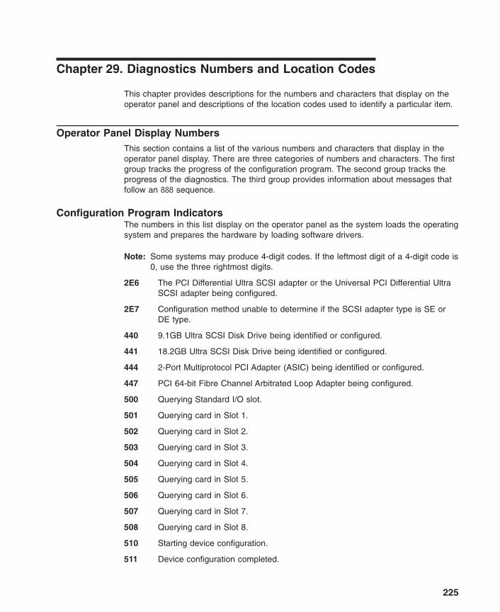
Chapter 29. Diagnostics Numbers and Location Codes
This chapter provides descriptions for the numbers and characters that display on theoperator panel and descriptions of the location codes used to identify a particular item.
Operator Panel Display NumbersThis section contains a list of the various numbers and characters that display in theoperator panel display. There are three categories of numbers and characters. The firstgroup tracks the progress of the configuration program. The second group tracks theprogress of the diagnostics. The third group provides information about messages thatfollow an 888 sequence.
Configuration Program IndicatorsThe numbers in this list display on the operator panel as the system loads the operatingsystem and prepares the hardware by loading software drivers.
Note: Some systems may produce 4-digit codes. If the leftmost digit of a 4-digit code is0, use the three rightmost digits.
2E6 The PCI Differential Ultra SCSI adapter or the Universal PCI Differential UltraSCSI adapter being configured.
2E7 Configuration method unable to determine if the SCSI adapter type is SE orDE type.
440 9.1GB Ultra SCSI Disk Drive being identified or configured.
441 18.2GB Ultra SCSI Disk Drive being identified or configured.
444 2-Port Multiprotocol PCI Adapter (ASIC) being identified or configured.
447 PCI 64-bit Fibre Channel Arbitrated Loop Adapter being configured.
500 Querying Standard I/O slot.
501 Querying card in Slot 1.
502 Querying card in Slot 2.
503 Querying card in Slot 3.
504 Querying card in Slot 4.
505 Querying card in Slot 5.
506 Querying card in Slot 6.
507 Querying card in Slot 7.
508 Querying card in Slot 8.
510 Starting device configuration.
511 Device configuration completed.
225

512 Restoring device configuration files from media.
513 Restoring basic operating system installation files from media.
516 Contacting server during network boot.
517 Mounting client remote file system during network IPL.
518 Remote mount of the root (/) and /usr file systems failed during network boot.
520 Bus configuration running.
521 /etc/init invoked cfgmgr with invalid options; /etc/inithas been corrupted orincorrectly modified (irrecoverable error).
522 The configuration manager has been invoked with conflicting options(irrecoverable error).
523 The configuration manager is unable to access the ODM database(irrecoverable error).
524 The configuration manager is unable to access the config.rules object in theODM database (irrecoverable error).
525 The configuration manager is unable to get data from a customized deviceobject in the ODM database (irrecoverable error).
526 The configuration manager is unable to get data from a customized devicedriver object in the ODM database ( irrecoverable error).
527 The configuration manager was invoked with the phase 1 flag; running phase 1at this point is not permitted (irrecoverable error).
528 The configuration manager cannot find sequence rule, or no program namewas specified in the ODM database (irrecoverable error).
529 The configuration manager is unable to update ODM data (irrecoverable error).
530 The program savebase returned an error.
531 The configuration manager is unable to access the PdAt object class(irrecoverable error).
532 There is not enough memory to continue (malloc failure); irrecoverable error.
533 The configuration manager could not find a configuration method for a device.
534 The configuration manager is unable to acquire database lock (irrecoverableerror).
535 HIPPI diagnostics interface driver being configured.
536 The configuration manager encountered more than one sequence rulespecified in the same phase (irrecoverable error).
537 The configuration manager encountered an error when invoking the program inthe sequence rule.
538 The configuration manager is going to invoke a configuration method.
226 Diagnostic Information for Multiple Bus Systems

539 The configuration method has terminated, and control has returned to theconfiguration manager.
541 A DLT tape device is being configured.
549 Console could not be configured for the Copy a System Dump Menu.
551 IPL vary-on is running.
552 IPL vary-on failed.
553 IPL phase 1 is complete.
554 The boot device could not be opened or read, or unable to define NFS swapdevice during network boot.
555 An ODM error occurred when trying to vary-on the rootvg, or unable to createan NFS swap device during network boot.
556 Logical Volume Manager encountered error during IPL vary-on.
557 The root filesystem does not mount.
558 There is not enough memory to continue the system IPL.
559 Less than 2 M bytes of good memory are available to load the AIX kernel.
569 FCS SCSI protocol device is being configured (32 bits).
570 Virtual SCSI devices being configured.
571 HIPPI common function device driver being configured.
572 HIPPI IPI-3 master transport driver being configured.
573 HIPPI IPI-3 slave transport driver being configured.
574 HIPPI IPI-3 transport services user interface device driver being configured.
575 A 9570 disk-array driver being configured.
576 Generic async device driver being configured.
577 Generic SCSI device driver being configured.
578 Generic commo device driver being configured.
579 Device driver being configured for a generic device.
580 HIPPI TCPIP network interface driver being configured.
581 Configuring TCP/IP.
582 Configuring Token-Ring data link control.
583 Configuring an Ethernet data link control.
584 Configuring an IEEE Ethernet data link control.
585 Configuring an SDLC MPQP data link control.
586 Configuring a QLLC X.25 data link control.
587 Configuring a NETBIOS.
Chapter 29. Diagnostics Numbers and Location Codes 227

588 Configuring a Bisync Read-Write (BSCRW).
589 SCSI target mode device being configured.
590 Diskless remote paging device being configured.
591 Configuring an LVM device driver.
592 Configuring an HFT device driver.
593 Configuring SNA device drivers.
594 Asynchronous I/O being defined or configured.
595 X.31 pseudo-device being configured.
596 SNA DLC/LAPE pseudo-device being configured.
597 OCS software being configured.
598 OCS hosts being configured during system reboot.
599 Configuring FDDI data link control.
59B FCS SCSI protocol device being configured (64 bits).
5C0 Streams-based hardware drive being configured.
5C1 Streams-based X.25 protocol being configured.
5C2 Streams-based X.25 COMIO emulator driver being configured
5C3 Streams-based X.25 TCP/IP interface driver being configured.
5C4 FCS adapter device driver being configured.
5C5 SCB network device driver for FCS being configured.
5C6 AIX SNA channel being configured.
600 Starting network boot portion of /sbin/rc.boot.
602 Configuring network parent devices.
603 /usr/lib/methods/defsys, /usr/lib/methods/cfgsys, or/usr/lib/methods/cfgbus failed.
604 Configuring physical network boot device.
605 Configuration of physical network boot device failed.
606 Running /usr/sbin/ifconfig on logical network boot device.
607 /usr/sbin/ifconfig failed.
608 Attempting to retrieve the client.info file with tftp.Note that a flashing 608indicates multiple attempt(s) to retrieve the client_info file are occurring.
609 The client.info file does not exist or it is zero length.
60B 18.2GB 68-pin LVD SCSI Disk Drive being configured.
610 Attempting remote mount of NFS file system.
228 Diagnostic Information for Multiple Bus Systems

611 Remote mount of the NFS file system failed.
612 Accessing remote files; unconfiguring network boot device.
614 Configuring local paging devices.
615 Configuration of a local paging device failed.
616 Converting from diskless to dataless configuration.
617 Diskless to dataless configuration failed.
618 Configuring remote (NFS) paging devices.
619 Configuration of a remote (NFS) paging device failed.
61B 36.4GB 80-pin LVD SCSI Disk Drive being configured.
61D 36.4GB 80-pin LVD SCSI Disk Drive being configured.
61E 18.2GB 68-pin LVD SCSI Disk Drive being configured.
620 Updating special device files and ODM in permanent filesystem with data fromboot RAM filesystem.
621 9.1 GB LVD 80-pin SCSI Drive being configured.
622 Boot process configuring for operating system installation.
62D 9.1GB 68-pin LVD SCSI Disk Drive being configured.
62E 9.1GB 68-pin LVD SCSI Disk Drive being configured.
636 TURBROWAYS 622 Mbps PCI MMF ATM Adapter.
637 Dual Channel PCI-2 Ultra2 SCSI Adapter being configured.
638 4.5GB Ultra SCSI Single Ended Disk Drive being configured.
639 9.1GB 10K RPM Ultra SCSI Disk Drive (68-pin).
63A See 62D.
63B 9.1GB 80-pin LVD SCSI Disk Drive being configured.
63C See 60B.
63D 18.2GB 80-pin LVD SCSI Disk Drive being configured.
63E 36.4GB 68-pin LVD SCSI Disk Drive being configured.
63F See 61B.
640 9.1GB 10K RPM Ultra SCSI Disk Drive (80-pin).
646 High-Speed Token-Ring PCI Adapter being configured.
64A See 62E.
64B 9.1GB 80-pin LVD SCSI Disk Drive being configured.
64C See 61E.
64D 18.2 GB LVD 80-pin Drive/Carrier being configured.
Chapter 29. Diagnostics Numbers and Location Codes 229

64E 36.4GB 68-pin LVD SCSI Disk Drive being configured.
64F See 61D.
650 IBM SCSD disk drive being configured.
653 18.2GB Ultra-SCSI 16-bit Disk Drive being configured.
655 GXT130P Graphics adapter being configured.
657 GXT2000P graphics adapter being configured.
658 PCI Fibre Channel Disk Subsystem Controller being identified or configured.
659 2102 Fibre Channel Disk Subsystem Controller Drawer being identified orconfigured.
660 2102 Fibre Channel Disk Array being identified or configured.
662 Ultra2 Integrated SCSI controller.
663 The ARTIC960RxD Digital Trunk Quad PCI Adapter or the ARTIC960RxFDigital Trunk Resource Adapter being configured.
664 32x (MAX) SCSI-2 CD-ROM drive being configured.
667 PCI 3-Channel Ultra2 SCSI RAID Adapter being configured.
669 PCI Gigabit Ethernet Adapter being configured.
66C 10/100/1000 Base-T EthernetPCI Adapter.
66D PCI 4-Channel Ultra-3 SCSI RAID Adapter.
66E 4.7 GB DVD-RAM drive.
674 ESCON® Channel PCI Adapter being configured.
677 PCI 32-bit Fibre Channel Arbitrated Loop Adapter being configured.
67B PCI Cryptographic Coprocessor being configured.
682 20x (MAX) SCSI-2 CD-ROM Drive being configured.
689 4.5GB Ultra SCSI Single Ended Disk Drive being configured.
68C 20 GB 4-mm Tape Drive being configured.
68E POWER GXT6000P PCI Graphics Adapter.
690 9.1GB Ultra SCSI Single Ended Disk Drive being configured.
69b 64-bit/66MHz PCI ATM 155 MMF PCI adapter being configured.
69d 64-bit/66MHz PCI ATM 155 UTP PCI adapter being configured.
6CC SSA disk drive being configured.
700 A 1.1 GB 8-bit SCSI disk drive being identified or configured.
701 A 1.1 GB 16-bit SCSI disk drive being identified or configured.
702 A 1.1 GB 16-bit differential SCSI disk drive being identified or configured.
230 Diagnostic Information for Multiple Bus Systems

703 A 2.2 GB 8-bit SCSI disk drive being identified or configured.
704 A 2.2 GB 16-bit SCSI disk drive being identified or configured.
705 The configuration method for the 2.2 GB 16-bit differential SCSI disk drive isbeing run. If an irrecoverable error occurs, the system halts.
706 A 4.5 GB 16-bit SCSI disk drive being identified or configured.
707 A 4.5 GB 16-bit differential SCSI disk drive being identified or configured.
708 A L2 cache being identified or configured.
710 POWER GXT150M graphics adapter being identified or configured.
711 Unknown adapter being identified or configured.
712 Graphics slot bus configuration is executing.
713 The IBM ARTIC960 device being configured.
714 A video capture adapter being configured.
715 The Ultramedia Services audio adapter being configured. (this number displaysbriefly on the panel).
717 TP Ethernet Adapter being configured.
718 GXT500 Graphics Adapter being configured.
720 Unknown read/write optical drive type being configured.
721 Unknown disk or SCSI device being identified or configured.
722 Unknown disk being identified or configured.
723 Unknown CD-ROM being identified or configured.
724 Unknown tape drive being identified or configured.
725 Unknown display adapter being identified or configured.
726 Unknown input device being identified or configured.
727 Unknown async device being identified or configured.
728 Parallel printer being identified or configured.
729 Unknown parallel device being identified or configured.
730 Unknown diskette drive being identified or configured.
731 PTY being identified or configured.
732 Unknown SCSI initiator type being configured.
733 7GB 8 mm tape drive being configured.
734 4x SCSI-2 640 MB CD-ROM Drive being configured.
736 Quiet Touch keyboard and speaker cable being configured.
741 1080 MB SCSI Disk Drive being configured.
Chapter 29. Diagnostics Numbers and Location Codes 231

745 16GB 4 mm Tape Auto Loader being configured.
746 SCSI-2 Fast/Wide PCI Adapter being configured.
747 SCSI-2 Differential Fast/Wide PCI Adapter being configured.
749 7331 Model 205 Tape Library being configured.
751 SCSI 32-bit SE F/W RAID Adapter being configured.
754 1.1GB 16-bit SCSI disk drive being configured.
755 2.2GB 16-bit SCSI disk drive being configured.
756 4.5GB 16-bit SCSI disk drive being configured.
757 External 13GB 1.5M/s 1/4 inch tape being configured.
763 SP Switch MX Adapter being configured.
764 SP System Attachment Adapter being configured.
772 4.5GB SCSI F/W Disk Drive being configured.
773 9.1GB SCSI F/W Disk Drive being configured.
774 9.1GB External SCSI Disk Drive being configured.
776 PCI Token-Ring Adapter being identified or configured.
777 10/100 Ethernet Tx PCI Adapter being identified or configured.
778 POWER GXT3000P 3D PCI Graphics adapter being configured.
77B 4-Port 10/100 Ethernet Tx PCI Adapter being identified or configured.
77c A 1.0 GB 16-bit SCSI disk drive being identified or configured.
783 4 mm DDS-2 Tape Autoloader being configured.
789 2.6 GB External Optical Drive being configured.
78B POWER GXT4000P PCI Graphics Adapter.
78C PCI bus configuration executing.
78D GXT300P 2D Graphics adapter being configured.
790 Multi-bus Integrated Ethernet Adapter being identified or configured.
797 TURBOWAYS® 155 UTP/STP ATM Adapter being identified or configured.
798 Video streamer adapter being identified or configured.
799 2-Port Multiprotocol PCI adapter being identified or configured.
79c ISA bus configuration executing.
7C0 CPU/System Interface being configured.
7C1 Business Audio Subsystem being identified or configured.
7cc PCMCIA bus configuration executing.
800 TURBOWAYS 155 MMF ATM Adapter being identified or configured.
232 Diagnostic Information for Multiple Bus Systems

803 7336 Tape Library robotics being configured.
804 8x Speed SCSI-2 CD-ROM Drive being configured.
806 POWER GXT800 PCI Graphics adapter being configured.
807 SCSI Device Enclosure being configured.
80c SSA 4-Port Adapter being identified or configured.
811 Processor complex being identified or configured.
812 Memory being identified or configured.
813 Battery for time-of-day, NVRAM, and so on being identified or configured, orsystem I/O control logic being identified or configured.
814 NVRAM being identified or configured.
815 Floating-point processor test.
816 Operator panel logic being identified or configured.
817 Time-of-day logic being identified or configured.
819 Graphics input device adapter being identified or configured.
821 Standard keyboard adapter being identified or configured.
823 Standard mouse adapter being identified or configured.
824 Standard tablet adapter being identified or configured.
825 Standard speaker adapter being identified or configured.
826 Serial Port 1 adapter being identified or configured.
827 Parallel port adapter being identified or configured.
828 Standard diskette adapter being identified or configured.
831 3151 adapter being identified or configured, or Serial Port 2 being identified orconfigured.
834 64-port async controller being identified or configured.
835 16-port async concentrator being identified or configured.
836 128-port async controller being identified or configured.
837 16-port remote async node being identified or configured.
838 Network Terminal Accelerator Adapter being identified or configured.
839 7318 Serial Communications Server being configured.
840 PCI Single-Ended Ultra SCSI Adapter being configured.
841 8-port async adapter (EIA-232) being identified or configured.
842 8-port async adapter (EIA-422A) being identified or configured.
843 8-port async adapter (MIL-STD 188) being identified or configured.
Chapter 29. Diagnostics Numbers and Location Codes 233

844 7135 RAIDiant Array disk drive subsystem controller being identified orconfigured.
845 7135 RAIDiant Array disk drive subsystem drawer being identified orconfigured.
846 RAIDiant Array SCSI 1.3GB Disk Drive being configured.
847 16-port serial adapter (EIA-232) being identified or configured.
848 16-port serial adapter (EIA-422) being identified or configured.
849 X.25 Interface Coprocessor/2 adapter being identified or configured.
850 Token-Ring network adapter being identified or configured.
851 T1/J1 Portmaster® adapter being identified or configured.
852 Ethernet adapter being identified or configured.
854 3270 Host Connection Program/6000 connection being identified or configured.
855 Portmaster Adapter/A being identified or configured.
857 FSLA adapter being identified or configured.
858 5085/5086/5088 adapter being identified or configured.
859 FDDI adapter being identified or configured.
85c Token-Ring High-Performance LAN adapter being identified or configured.
861 Optical adapter being identified or configured.
862 Block Multiplexer Channel Adapter being identified or configured.
865 ESCON Channel Adapter or emulator being identified or configured.
866 SCSI adapter being identified or configured.
867 Async expansion adapter being identified or configured.
868 SCSI adapter being identified or configured.
869 SCSI adapter being identified or configured.
870 Serial disk drive adapter being identified or configured.
871 Graphics subsystem adapter being identified or configured.
872 Grayscale graphics adapter being identified or configured.
874 Color graphics adapter being identified or configured.
875 Vendor generic communication adapter being configured.
876 8-bit color graphics processor being identified or configured.
877 POWER Gt3™/POWER Gt4™ being identified or configured.
878 POWER Gt4 graphics processor card being configured.
879 24-bit color graphics card, MEV2 being configured.
234 Diagnostic Information for Multiple Bus Systems

880 POWER Gt1™ adapter being identified or configured.
887 Integrated Ethernet adapter being identified or configured.
889 SCSI adapter being identified or configured.
890 SCSI-2 Differential Fast/Wide and Single-Ended Fast/Wide Adapter/A beingconfigured.
891 Vendor SCSI adapter being identified or configured.
892 Vendor display adapter being identified or configured.
893 Vendor LAN adapter being identified or configured.
894 Vendor async/communications adapter being identified or configured.
895 Vendor IEEE 488 adapter being identified or configured.
896 Vendor VME bus adapter being identified or configured.
897 S/370™ Channel Emulator adapter being identified or configured.
898 POWER Gt1x™ graphics adapter being identified or configured.
899 3490 attached tape drive being identified or configured.
89c A multimedia SCSI CD-ROM being identified or configured.
900 GXT110P Graphics Adapter being identified or configured.
901 Vendor SCSI device being identified or configured.
902 Vendor display device being identified or configured.
903 Vendor async device being identified or configured.
904 Vendor parallel device being identified or configured.
905 Vendor other device being identified or configured.
908 POWER GXT1000 Graphics subsystem being identified or configured.
910 1/4GB Fiber Channel/266 Standard Adapter being identified or configured.
911 Fiber Channel/1063 Adapter Short Wave being configured.
912 2.0GB SCSI-2 differential disk drive being identified or configured.
913 1.0GB differential disk drive being identified or configured.
914 5GB 8 mm differential tape drive being identified or configured.
915 4GB 4 mm tape drive being identified or configured.
916 Non-SCSI vendor tape adapter being identified or configured.
917 A 2.0 GB 16-bit differential SCSI disk drive being identified or configured.
918 A 2 GB 16-bit single-ended SCSI disk drive being identified or configured.
920 Bridge Box being identified or configured.
921 101 keyboard being identified or configured.
Chapter 29. Diagnostics Numbers and Location Codes 235
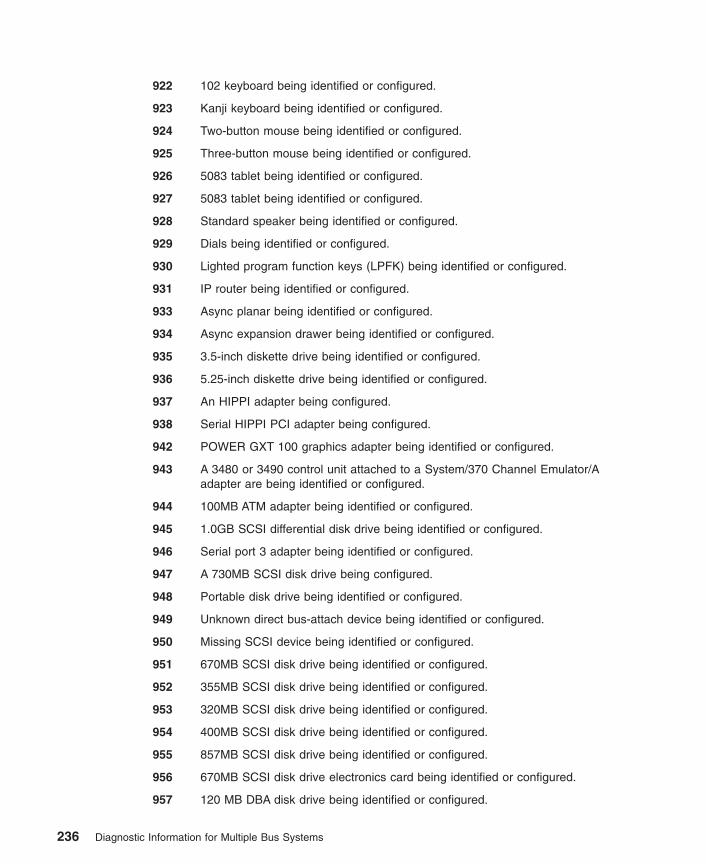
922 102 keyboard being identified or configured.
923 Kanji keyboard being identified or configured.
924 Two-button mouse being identified or configured.
925 Three-button mouse being identified or configured.
926 5083 tablet being identified or configured.
927 5083 tablet being identified or configured.
928 Standard speaker being identified or configured.
929 Dials being identified or configured.
930 Lighted program function keys (LPFK) being identified or configured.
931 IP router being identified or configured.
933 Async planar being identified or configured.
934 Async expansion drawer being identified or configured.
935 3.5-inch diskette drive being identified or configured.
936 5.25-inch diskette drive being identified or configured.
937 An HIPPI adapter being configured.
938 Serial HIPPI PCI adapter being configured.
942 POWER GXT 100 graphics adapter being identified or configured.
943 A 3480 or 3490 control unit attached to a System/370 Channel Emulator/Aadapter are being identified or configured.
944 100MB ATM adapter being identified or configured.
945 1.0GB SCSI differential disk drive being identified or configured.
946 Serial port 3 adapter being identified or configured.
947 A 730MB SCSI disk drive being configured.
948 Portable disk drive being identified or configured.
949 Unknown direct bus-attach device being identified or configured.
950 Missing SCSI device being identified or configured.
951 670MB SCSI disk drive being identified or configured.
952 355MB SCSI disk drive being identified or configured.
953 320MB SCSI disk drive being identified or configured.
954 400MB SCSI disk drive being identified or configured.
955 857MB SCSI disk drive being identified or configured.
956 670MB SCSI disk drive electronics card being identified or configured.
957 120 MB DBA disk drive being identified or configured.
236 Diagnostic Information for Multiple Bus Systems

958 160 MB DBA disk drive being identified or configured.
959 160 MB SCSI disk drive being identified or configured.
960 1.37GB SCSI disk drive being identified or configured.
964 Internal 20 GB 8 mm tape drive identified or configured.
968 1.0 GB SCSI disk drive being identified or configured.
970 Half-inch, 9-track tape drive being identified or configured.
971 150 MB 1/4-inch tape drive being identified or configured.
972 2.3 GB 8 mm SCSI tape drive being identified or configured.
973 Other SCSI tape drive being identified or configured.
974 CD-ROM drive being identified or configured.
975 An optical disk drive being identified or configured.
977 M-Audio Capture and Playback Adapter being identified or configured.
981 540MB SCSI-2 single-ended disk drive being identified or configured.
984 1GB 8-bit disk drive being identified or configured.
985 M-Video Capture Adapter being identified or configured.
986 2.4GB SCSI disk drive being identified or configured.
987 An Enhanced SCSI CD-ROM drive being identified or configured.
989 200MB SCSI disk drive being identified or configured.
990 2.0GB SCSI-2 single-ended disk drive being identified or configured.
991 525MB 1/4-inch cartridge tape drive being identified or configured.
994 5 GB 8 mm tape drive being identified or configured.
995 1.2GB 1/4 inch cartridge tape drive being identified or configured.
996 A single-port, multiprotocol communications adapter being identified orconfigured.
997 FDDI adapter being identified or configured.
998 2.0 GB 4 mm tape drive being identified or configured.
999 7137 or 3514 Disk Array Subsystem being configured.
D46 Token-Ring cable
D81 T2 Ethernet Adapter being configured.
2530 10/100 Mbps Ethernet PCI Adapter II being configured.
Chapter 29. Diagnostics Numbers and Location Codes 237

Diagnostic Load Progress Indicators
Note: Some systems may produce 4-digit codes. If the leftmost digit of a 4-digit code is0, use the three rightmost digits.
c00 AIX Install/Maintenance loaded successfully.
c01 Insert the first diagnostic diskette.
c02 Diskettes inserted out of sequence.
c03 The wrong diskette is in diskette drive.
c04 The loading stopped with an irrecoverable error.
c05 A diskette error occurred.
c06 The rc.boot configuration shell script is unable to determine type of boot.
c07 Insert the next diagnostic diskette.
c08 RAM file system started incorrectly.
c09 The diskette drive is reading or writing a diskette.
c20 An unexpected halt occurred, and the system is configured to enter the kerneldebug program instead of entering a system dump.
c21 The ifconfig command was unable to configure the network for the clientnetwork host.
c22 The tftp command was unable to read client’s ClientHostName info file duringa client network boot.
c24 Unable to read client’s ClientHostName.info file during a client network boot.
c25 Client did not mount remote miniroot during network install.
c26 Client did not mount the /usr file system during the network boot.
c29 The system was unable to configure the network device.
c31 Select the console display for the diagnostics. To select No console display,set the key mode switch to Normal then to Service. The diagnostic programsthen load and run the diagnostics automatically. If you continue to get themessage, check the cables and make sure you are using the serial port.
c32 A directly attached display (HFT) was selected.
c33 A TTY terminal attached to serial ports S1 or S2 was selected.
c34 A file was selected. The console messages store in a file.
c35 No console found.
c40 Configuration files are being restored.
c41 Could not determine the boot type or device.
c42 Extracting data files from diskette.
238 Diagnostic Information for Multiple Bus Systems

c43 Cannot access the boot/install tape.
c44 Initializing installation database with target disk information.
c45 Cannot configure the console.
c46 Normal installation processing.
c47 Could not create a physical volume identifier (PVID) on disk.
c48 Prompting you for input.
c49 Could not create or form the JFS log.
c50 Creating root volume group on target disks.
c51 No paging devices were found.
c52 Changing from RAM environment to disk environment.
c53 Not enough space in the /tmp directory to do a preservation installation.
c54 Installing either BOS or additional packages.
c55 Could not remove the specified logical volume in a preservation installation.
c56 Running user-defined customization.
c57 Failure to restore BOS.
c58 Displaying message to turn the key.
c59 Could not copy either device special files, device ODM, or volume groupinformation from RAM to disk.
c61 Failed to create the boot image.
c62 Loading platform dependent debug files.
c63 Loading platform dependent data files.
c64 Failed to load platform dependent data files.
c70 Problem Mounting diagnostic CD-ROM disc.
c99 Diagnostics have completed. This code is only used when there is no console.
Fxx (xx is any number) Refer to Firmware chapter of the service manual.
Dump Progress Indicators (Dump Status Codes)The following dump progress indicators, or dump status codes, are part of a Type 102message.
Note: When a lowercase c is listed, it displays in the lower half of the characterposition. Some systems produce 4-digit codes, the two leftmost positions canhave a blanks or zeros. Use the two rightmost digits.
0c0 The dump completed successfully.
0c1 The dump failed due to an I/O error.
0c2 A dump, requested by the user, is started.
Chapter 29. Diagnostics Numbers and Location Codes 239
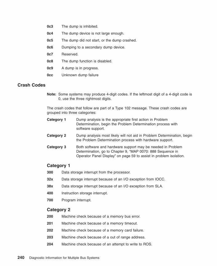
0c3 The dump is inhibited.
0c4 The dump device is not large enough.
0c5 The dump did not start, or the dump crashed.
0c6 Dumping to a secondary dump device.
0c7 Reserved.
0c8 The dump function is disabled.
0c9 A dump is in progress.
0cc Unknown dump failure
Crash Codes
Note: Some systems may produce 4-digit codes. If the leftmost digit of a 4-digit code is0, use the three rightmost digits.
The crash codes that follow are part of a Type 102 message. These crash codes aregrouped into three categories:
Category 1 Dump analysis is the appropriate first action in ProblemDetermination, begin the Problem Determination process withsoftware support.
Category 2 Dump analysis most likely will not aid in Problem Determination, beginthe Problem Determination process with hardware support.
Category 3 Both software and hardware support may be needed in ProblemDetermination, go to Chapter 9, “MAP 0070: 888 Sequence inOperator Panel Display” on page 59 to assist in problem isolation.
Category 1300 Data storage interrupt from the processor.
32x Data storage interrupt because of an I/O exception from IOCC.
38x Data storage interrupt because of an I/O exception from SLA.
400 Instruction storage interrupt.
700 Program interrupt.
Category 2200 Machine check because of a memory bus error.
201 Machine check because of a memory timeout.
202 Machine check because of a memory card failure.
203 Machine check because of a out of range address.
204 Machine check because of an attempt to write to ROS.
240 Diagnostic Information for Multiple Bus Systems

205 Machine check because of an uncorrectable address parity.
206 Machine check because of an uncorrectable ECC error.
207 Machine check because of an unidentified error.
208 Machine check due to an L2 uncorrectable ECC.
500 External interrupt because of a scrub memory bus error.
501 External interrupt because of an unidentified error.
51x External interrupt because of a DMA memory bus error.
52x External interrupt because of an IOCC channel check.
53x External interrupt from an IOCC bus timeout; x represents the IOCC number.
54x External interrupt because of an IOCC keyboard check.
800 Floating point is not available.
Category 3000 Unexpected system interrupt.
558 There is not enough memory to continue the IPL.
600 AIX 4.3.3.3 and above: Alignment Interrupt. If pre-AIX 4.3.3.3: AIX has crashedbecause the Portability Assist Layer (PAL) for this machine type has detected aproblem.
605 AIX has crashed because the Portability Assist Layer (PAL) for this machinetype has detected a problem (AIX 4.3.3.3 and above).
Chapter 29. Diagnostics Numbers and Location Codes 241
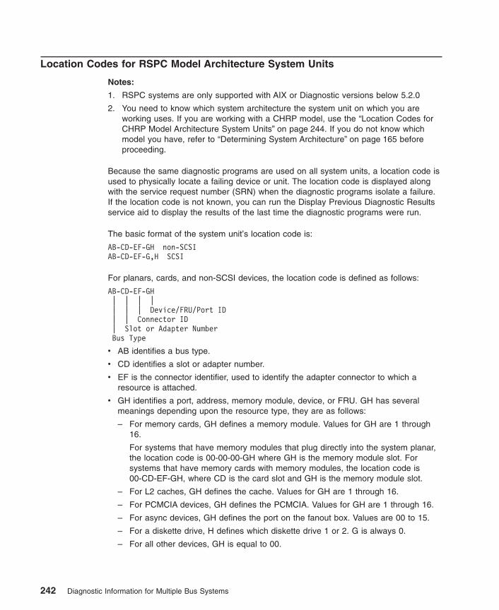
Location Codes for RSPC Model Architecture System Units
Notes:
1. RSPC systems are only supported with AIX or Diagnostic versions below 5.2.0
2. You need to know which system architecture the system unit on which you areworking uses. If you are working with a CHRP model, use the “Location Codes forCHRP Model Architecture System Units” on page 244. If you do not know whichmodel you have, refer to “Determining System Architecture” on page 165 beforeproceeding.
Because the same diagnostic programs are used on all system units, a location code isused to physically locate a failing device or unit. The location code is displayed alongwith the service request number (SRN) when the diagnostic programs isolate a failure.If the location code is not known, you can run the Display Previous Diagnostic Resultsservice aid to display the results of the last time the diagnostic programs were run.
The basic format of the system unit’s location code is:
AB-CD-EF-GH non-SCSIAB-CD-EF-G,H SCSI
For planars, cards, and non-SCSI devices, the location code is defined as follows:
AB-CD-EF-GH| | | || | | Device/FRU/Port ID| | Connector ID| Slot or Adapter NumberBus Type
v AB identifies a bus type.
v CD identifies a slot or adapter number.
v EF is the connector identifier, used to identify the adapter connector to which aresource is attached.
v GH identifies a port, address, memory module, device, or FRU. GH has severalmeanings depending upon the resource type, they are as follows:
– For memory cards, GH defines a memory module. Values for GH are 1 through16.
For systems that have memory modules that plug directly into the system planar,the location code is 00-00-00-GH where GH is the memory module slot. Forsystems that have memory cards with memory modules, the location code is00-CD-EF-GH, where CD is the card slot and GH is the memory module slot.
– For L2 caches, GH defines the cache. Values for GH are 1 through 16.
– For PCMCIA devices, GH defines the PCMCIA. Values for GH are 1 through 16.
– For async devices, GH defines the port on the fanout box. Values are 00 to 15.
– For a diskette drive, H defines which diskette drive 1 or 2. G is always 0.
– For all other devices, GH is equal to 00.
242 Diagnostic Information for Multiple Bus Systems

For integrated adapters, EF-GH is the same as the definition for a pluggable adapter.For example, the location code for a diskette drive is 01-A0-00-00. A second diskettedrive is 01-A0-00-01.
For SCSI, the location code is defined as follows:
AB-CD-EF-G,H| | | | || | | | Logical Unit Address of SCSI Device| | | Control Unit Address of SCSI Device| | Connector ID| Slot or Adapter NumberBus Type
Where:
v AB-CD-EF are the same as non-SCSI devices.
v G defines the control unit address of the device. Values of 0 to 15 are valid.
v H defines the logical unit address of the device. Values of 0 to 255 are valid.
Adapters and cards are identified with only AB-CD. The possible values for AB are asfollows:
00 for processor bus01 for ISA buses04 for PCI buses05 for PCMCIA buses (not supported on 7024)
The possible values for CD depend on the adapter or card.
For pluggable adapters or cards, this is a two-digit slot number in the range from 01 to99. However, in the case of ISA cards these numbers do not actually correspond to thephysical slot numbers. They simply are based on the order in which the ISA cards aredefined or configured, either by SMIT or the ISA Adapter Configuration Service Aid.
For integrated adapters, the first character (C) is a letter in the range from A to Z. Thisletter is based on the order in which the integrated adapters are defined in residualdata. This ensures unique location codes for the integrated adapters. The secondcharacter (D) is set to 0.
Refer to the following examples:
RSPC Location Code ExamplesProcessor-PCI bus00-00 PCI busMemory module in system planar00-00-00-01Memory module in card00-0A-00-01Integrated PCI adapters04-A0 ISA bus (Integrated PCI-ISA bridge)04-B0 Secondary PCI bus (Integrated PCI-PCI bridge)
Chapter 29. Diagnostics Numbers and Location Codes 243

04-C0 Integrated PCI SCSI controllerNon-integrated PCI adapters04-01 Any PCI card in slot 104-02 Any PCI card in slot 2Integrated ISA adapters01-A0 Diskette adapter01-B0 Parallel port adapter01-C0 Serial port 1 adapter01-D0 Serial port 2 adapter01-E0 Keyboard adapter01-F0 Mouse adapterNon-integrated ISA adapters01-01 First ISA card defined/configured01-02 Second ISA card defined/configured01-03 Third ISA card defined/configured01-04 Fourth ISA card defined/configuredDevice attached to SCSI controller04-C0-01-4,0 Device attached to Integrated PCI SCSI controller
Location Codes for CHRP Model Architecture System Units
Note: You need to know which system architecture the system unit on which you areworking uses. If you are working with a RSPC model use the “Location Codesfor RSPC Model Architecture System Units” on page 242. If you do not knowwhich model you have, refer to “Determining System Architecture” on page 165before proceeding.
The (CHRP) system unit uses Physical Location Codes in conjunction with AIX LocationCodes to provide mapping of the failing field replaceable units. The location codes areproduced by the system unit’s firmware and the AIX operating system.
Physical Location Codes
Note: Diagnostic Versions 5.2.0 and later display physical location codes for allresources. Diagnostic versions earlier than 5.2.0 show a mixture of physicallocation codes and AIX location codes.
As an example, under diagnostics version 5.2.0 might display a resource as:
ent0 P2/E1 IBM 10/100 Mbps Ethernet PCI adapter
The P2/E1 is the physical location code indicating an Ethernet port built into theP2 planar.
whereas, in versions prior to 5.2.0, the resource might be shown as:
ent0 10-60 IBM 10/100 Mbps Ethernet PCI adapter
The 10-60 is an AIX location code indicating a PCI parent bus of 10, and adevfunc number of 60 (for more information , see “AIX Location Codes” onpage 248).
244 Diagnostic Information for Multiple Bus Systems
These physical location codes can appear in many places while runningdiagnostics; for instance, within resource menus, SRNs, or specific service aids.
Physical location codes provide a mapping of logical functions in a platform (orexpansion sites for logical functions, such as connectors or ports) to their specificlocations within the physical structure of the platform.
Location Code FormatThe format for the location code is a string of alphanumeric characters separated by adash (-), slash (/), pound sign (#), or period (.). The base location is all of theinformation before the slash (/) or pound sign (#). It identifies a device that is connectedor plugged into the parent. Extended location information follows the slash (/). Itidentifies a device that is part of the parent, a connector, or a cable. Cable informationfollows the pound sign (#). It identifies a cable that is connected to the parent. Thefollowing are examples:
v P1 identifies system planar P1.
v U1-P1 also identifies system planar P1 in a rack or drawer unit.
v P2 identifies an I/O planar (including all integrated I/O devices).
v P1-C1 identifies a CPU card C1 plugged into planar P1.
v P1-M2 identifies a memory card or SIMM M2 plugged into planar P1.
v P2/K1 identifies a keyboard port controller (with connector) connected to planar P2.
v P1-K1 identifies a keyboard attached to connector K1 on planar P1.
v P1/S1 identifies serial port 1 controller on planar P1, the connector for serial port 1,or the cable attached to connector S1.
v P1-I2/E3 identifies; Ethernet controller 3 on the card plugged into slot 2 (I2) on planarP1, the connector for Ethernet controller 3, or the cable attached to Ethernetcontroller 3.
v P1-I2#E3 identifies; the cable attached to Ethernet controller 3 plugged into slot 2 (I2)on planar P1.
The period (.) is used to identify sub-locations such as memory DIMMs on a basememory card or a specific SCSI address. The following are examples:
v P1-M1.4 identifies DIMM 4 on memory card 1 on planar 1.
v U1-P1-M2.12 identifies DIMM 12 on memory card in slot 2 on the system planar.
v P1-C1.1 identifies CPU 1 on CPU card 1 on planar 1.
v P2/Z1-A3.1 identifies a SCSI device with a SCSI address of LUN 1 at SCSI ID 3attached to SCSI bus 1 from planar 2.
v P1-I2#E3.2 identifies the second cable in a series of cables attached to Ethernetcontroller 3 in slot 2 (I2) on planar 1.
Depending on the AIX and firmware levels, AIX Diagnostics may include extendedlocation information when identifying a planar or card. The extended locationinformation or cable information is always included when identifying a cable orconnector. Location codes with extended location information that display without adescription identifying the devices, always identify the cable attached to the port.
Chapter 29. Diagnostics Numbers and Location Codes 245

Physical Location Code Standard PrefixesTable 1 lists the assigned values for the location type prefixes. In most cases, the prefixvalue assignments were chosen to provide some mnemonic characteristic, so that theywould be easier to remember. The underlined characters in the description field areintended to illustrate this mnemonic relationship.
Table 1. Location Code Prefix Values
Description Prefix Value(n=instance #)
Rack or drawer unit Un
Drawer unit mounted in a rack Un.n (U0.n if rackcannot be sensed byfirmware)
Single enclosure platform (No enclosure locationcode)
Planar (backplane, system, I/O) Pn
Planar riser card, extender Pn.n
Power/voltage supply, voltage regulator, backup battery Vn
Fan/sensor Fn
LED/LCD operator panelorLogical device address n relative to adapter port
Ln
CPU/cache card (or pluggable module if on planar) Cn
CPU/cache module on CPU card (if pluggable) Cn.n
Memory card or SIMM/DIMM on planar Mn
Memory SIMM/DIMM on memory card Mn.n
Other extra-function base system cards (for example, serviceprocessor)
Xn
I/O adapter In
Pluggable modules or daughter cards on I/O adapter In.n
Device in Bay n Dn
Ports/Connectors:
Graphics/video connector Gn
Keyboard/keyboard connector Kn
Mouse/mouse connector On
Serial port Sn
Parallel port Rn
Ethernet connector En
Token Ring connector Tn
SCSI (pronounced scuzzy) connector Zn
Other I/O ports or connectors Qn
SCSI device addresses (including SSA (Serial Storage Architecture))
246 Diagnostic Information for Multiple Bus Systems

Table 1. Location Code Prefix Values (continued)
Description Prefix Value(n=instance #)
Primary address (SCSI control unit ID) An
Primary and secondary address (SCSI ID and LUN (Logical UnitNumber))
An.n
SCSI device location in SCSI Enclosure Services (SES)
SCSI bank Bn
SCSI bank and bay Bn.n
Undefined prefixes (reserved) H, J, N, Y
Unique device address, this address remains constant independent ofwhich port the device is attached to.
Wn
Chapter 29. Diagnostics Numbers and Location Codes 247
AIX Location Codes
Note: AIX logical location codes may still seen and supported under various AIXcommands and functions. However, the Diagnostic screens and menus displayphysical location codes for resources when running versions 5.2.0 and later. Forsystems with 5.2.0 or later, refer to “Physical Location Codes” on page 244.
The basic formats of the AIX location codes are as follows:
v For non-SCSI devices/drives:
AB-CD-EF-GH
v For SCSI devices/drives:
AB-CD-EF-G,H
For planars, cards, and non-SCSI devices, the location code is defined as follows:
AB-CD-EF-GH| | | || | | Device/FRU/Port ID| | Connector ID| devfunc Number, Adapter Number or Physical LocationBus Type or PCI Parent Bus
v The AB value identifies a bus type or PCI parent bus as assigned by the firmware.
v The CD value identifies adapter number, adapter’s devfunc number, or physicallocation. The devfunc number is defined as the PCI device number times 8, plus thefunction number.
v The EF value identifies a connector.
v The GH value identifies a port, address, device, or FRU.
Adapters and cards are identified only with AB-CD. The possible values for AB are:
00 Processor bus01 ISA bus02 EISA bus03 MCA bus04 PCI bus used in the case where the PCI bus cannot be identified05 PCMCIA busesxy For PCI adapters where x is equal to or greater than 1. The x and y are characters in
the range of 0-9, A-H, J-N, P-Z (O, I, and lower case are omitted) and are equal to theparent bus’s ibm, aix-loc Open Firmware Property.
248 Diagnostic Information for Multiple Bus Systems
The possible values for CD depend on the adapter or card are as follows:
v For pluggable PCI adapters/cards, CD is the device’s devfunc number (PCI devicenumber times 8, plus the function number). The C and D are characters in the rangeof 0-9, and A-F (hex numbers). This allows the location code to uniquely identifymultiple adapters on individual PCI cards.
For pluggable ISA adapters, CD is equal to the order in which the ISA cards definedor configured, either by SMIT or the ISA Adapter Configuration Service Aid.
For integrated ISA adapters, CD is equal to a unique code identifying the ISAadapter. In most cases, this is equal to the adapter’s physical location code. In caseswhere a physical location code is not available, CD is FF.
v EF is the connector ID. It is used to identify a connector on the adapter to which aresource is attached.
v GH is used to identify a port, device, or FRU. For example:
– For async devices, GH defines the port on the fanout box. The values are 00 to15.
– For a diskette drive, H defines either diskette drive 1 or 2. G is always 0.
– For all other devices, GH is equal to 00.
For the integrated adapters, EF-GH is the same as the definition for the pluggableadapters. For example, the location code for a diskette drive is 01-D1-00-00. A seconddiskette drive is 01-D1-00-01.
For SCSI devices, the location code is defined as:
AB-CD-EF-G,H| | | | || | | | Logical Unit address of the SCSI Device| | | Control Unit Address of the SCSI Device| | Connector ID| devfunc Number, Adapter Number or Physical LocationBus Type or PCI Parent Bus
Where:
v AB-CD-EF are the same as non-SCSI devices.
v G defines the control unit address of the device. Values of 0 to 15 are valid.
v H defines the logical unit address of the device. Values of 0 to 255 are valid.
There is also a bus location code that is generated as ’00-xxxxxxxx’ where xxxxxxxx isequivalent to the node’s unit address. Refer to the system unit service guide foradditional information.
Chapter 29. Diagnostics Numbers and Location Codes 249

250 Diagnostic Information for Multiple Bus Systems
Chapter 30. Using the SRN List
The service request number (SRN) list is in numerical sequence.
The SRNs listed in the following chapters are for all systems and devices for which thisversion of the diagnostic programs can produce an SRN. Use the table “ServiceRequest Number Lists” on page 252 to select the correct chapter for your SRN.
The columns in the table are defined as follows:
Service Request NumberUsually a six-digit number (9333 uses four digits) representing a specific failure of aspecific function.
Source of SRN (SRN Src.)SRN source codes identify the program or procedure that produced the SRN:
A The SRN is from a steady number in the operator panel display.
B The SRN is from a MAP callout.
C The SRN was due to a missing resource at configuration time.
D The SRN is from a diagnostic test after complete isolation testing.
E The SRN is from a POST failure.
F The SRN is from a diagnostic test after partial isolation testing.
G The SRN is from the Error Log Analysis program.
H The SRN is from a diagnostic message after an 888 sequence.
J The SRN is from built-in ROM diagnostics.
K The SRN is from off-line diagnostics.
Failing Function CodesThese numbers represent functional areas of the system unit. The “Failing FunctionCode List” on page 566 identifies the FRU that contains this function for each specificsystem unit.
Description and ActionThis column lists a brief description of the failure that this SRN represents. It alsocontains instructions as to what to do to continue the problem analysis.
Note: If you are servicing an SP system, do not do the Action listed. Instead, alwaysreturn to the SP System Service Guide.
If you are servicing a clustered Eserver, do not do the Action listed. Instead,always return to the Clustered Eserver Installation and Service Guide.
251

Using the Service Request Number ListThe service request number list is in numerical sequence by the SRN. Use the list asfollows:
1. Find your SRN in the table.
2. Record the code letter for the Source of SRN (the SRN Src. column).
3. Record the failing function codes in the order listed.
4. Perform the action shown in the Description and Action column.
Notes:
a. If you cannot find SRN information in the ″Service Request Number List,″ checkfor the existence of supplemental material supporting the device for which theSRN was generated.
b. x in an SRN represents any digit or character.
c. If your SRN is not listed, check to see if xxx or xxxx has been used. The -xxx or-xxxx should always be the last SRN identified within a specific prefix. Anexample would be 950-xxxx. The xxxx is the last digit within the 950 prefix.
d. If you are servicing a SP system, do not do the Action listed. Instead, alwaysreturn to the SP Hardware Manual.
e. If you are servicing a clustered Eserver, do not do the Action listed. Instead,always return to the Clustered Eserver Installation and Service Guide.
5. When replacing a FRU, use Chapter 23, “MAP 0410: Repair Checkout” on page 125to verify the fix.
Service Request Number ListsThe following five chapters contain the Service Request Number (SRN) Lists. Thechapters are divided into number ranges.
Note: There may be 7 or 8 digit SRNs within each range. If the SRN contains 3 digitsbefore the dash, then select the chapter that contains the first 3 digits, followedby the dash, of the SRN you wish to locate. For example, if the SRN is802-xxxx, you would go to Chapter 33, “SRNs 700-102 through 89c-302”,because this SRN falls between the number range of 700-102 and 89c-302.However, if your SRN contains 4 digits before the dash, then select the chapterthat contains the first 4 digits, followed by the dash, of the SRN you wish tolocate. For example, if the SRN is 2570–603, you would go to Chapter 36,“SRNs 2520-101 through 25C1-(x)xxx”, because this SRN falls between thenumber range of 2520-(x)xxx and 2590-(x)xxx.
The following table identifies each SRN chapter range and the page number on which itbegins:
Chapter Title Page Number
Chapter 31, “Five-Digit SRNs 10104 through SSA03” 255
Chapter 32, “SRNs 101-000 through 6C9-600” 267
252 Diagnostic Information for Multiple Bus Systems

Chapter Title Page Number
Chapter 33, “SRNs 700-102 through 89c-302” 377
Chapter 34, “SRNs 900-001 through xxxxxxx” 461
Chapter 35, “SRNs A00-(x)xxx through A1D-(x)xxx” 535
Chapter 36, “SRNs 2520-101 through 25C1-(x)xxx” 555
Chapter 30. Using the SRN List 253

254 Diagnostic Information for Multiple Bus Systems

Chapter 31. Five-Digit SRNs 10104 through SSA03
Service Request Number ListReplace FRU parts in the order by which the ″Failing Function Codes″ are listed.
Abbreviation in Table Definition
PAAP Adapter port number
AA SSA Address
ServiceRequestNumber
SRNSrc.
FailingFunction
Codes
Description and Action (Unless otherwise indicated,use Chapter 11, “MAP 0210: General ProblemResolution” on page 67.)
10104 Description: Format in progress. Action: Refer to theSRN table in the Service Guide for the unit containingthe disk drive.
10112 Description: Format Degraded. A format operation endedbefore it completed. Action: Refer to the SRN table inthe Service Guide for the unit containing the disk drive.
1xxxx Description: Disk drive module error. Action: Refer to theSRN table in the Service Guide for the unit containingthe disk drive.
Note: In this SRN, an x represents a digit 0 through F.
20PAA Description: An open SSA loop was detected. Action:Refer to the SRN table in the Service Guide for the unitcontaining the disk drive and the User’s Guide andMaintenance Information for the SSA adapter.
21PAA to29PAA
Description: An SSA Threshold Exceeded link error wasdetected. Action: Refer to the SRN table in the User’sGuide and Maintenance Information for the SSA adapter.
2A002 Description: Async code 02 was received. Probably, asoftware error occurred. Action: Refer to the SRN tablein the Service Guide for the unit containing the disk driveand the User’s Guide and Maintenance Information forthe SSA adapter.
2A003 Description: Async code 03 was received. Probably, asoftware error occurred. Action: Refer to the SRN tablein the Service Guide for the unit containing the disk driveand the User’s Guide and Maintenance Information forthe SSA adapter.
2A004 Description: Async code 04 was received. Probably, asoftware error occurred. Action: Refer to the SRN tablein the Service Guide for the unit containing the disk driveand the User’s Guide and Maintenance Information forthe SSA adapter.
255

ServiceRequestNumber
SRNSrc.
FailingFunction
Codes
Description and Action (Unless otherwise indicated,use Chapter 11, “MAP 0210: General ProblemResolution” on page 67.)
2A005 Description: Async code 05 was received. This codeindicates that a disk drive module detected the loss ofredundant power or cooling. Action: Refer to the SRNtable in the Service Guide for the unit containing the diskdrive.
2A006 Description: Async code 06 was received. This codeindicates that a disk drive module detected the loss ofredundant power or cooling. Action: Refer to the SRNtable in the Service Guide for the unit containing the diskdrive.
2A106 Description: Async code 06 was received. This codeindicates that multiple disk drive modules detected lossof redundant power or cooling. Action: Refer to the SRNtable in the Service Guide for the unit containing the diskdrive.
2A206 Description: A disk drive module detected that one of itsSSA links failed the POST. Action: Refer to the SRNtable in the Service Guide for the unit containing the diskdrive.
2FFFF Description: An async code that is not valid wasreceived. Action: Refer to the SRN table in the ServiceGuide for the unit containing the disk drive and theUser’s Guide and Maintenance Information for the SSAadapter.
300C0 Description: A disk drive module detected the loss ofredundant power or cooling. Action: Refer to the SRNtable in the Service Guide for the unit containing the diskdrive.
301C0 Description: Multiple disk drive modules detected theloss of redundant power or cooling. Action: Refer to theSRN table in the Service Guide for the unit containingthe disk drive.
303FE Description: A disk drive Microcode Error was detected.Action: Refer to the SRN table in the Service Guide forthe unit containing the disk drive and the User’s Guideand Maintenance Information for the SSA adapter.
303FF Description: An SCSI status that is not valid wasreceived. Action: Refer to the SRN table in the ServiceGuide for the unit containing the disk drive and theUser’s Guide and Maintenance Information for the SSAadapter.
31000 Description: The disk drive was reset by the adapter.The disk drive might be going to fail. Action: Refer to theSRN table in the Service Guide for the unit containingthe disk drive.
256 Diagnostic Information for Multiple Bus Systems
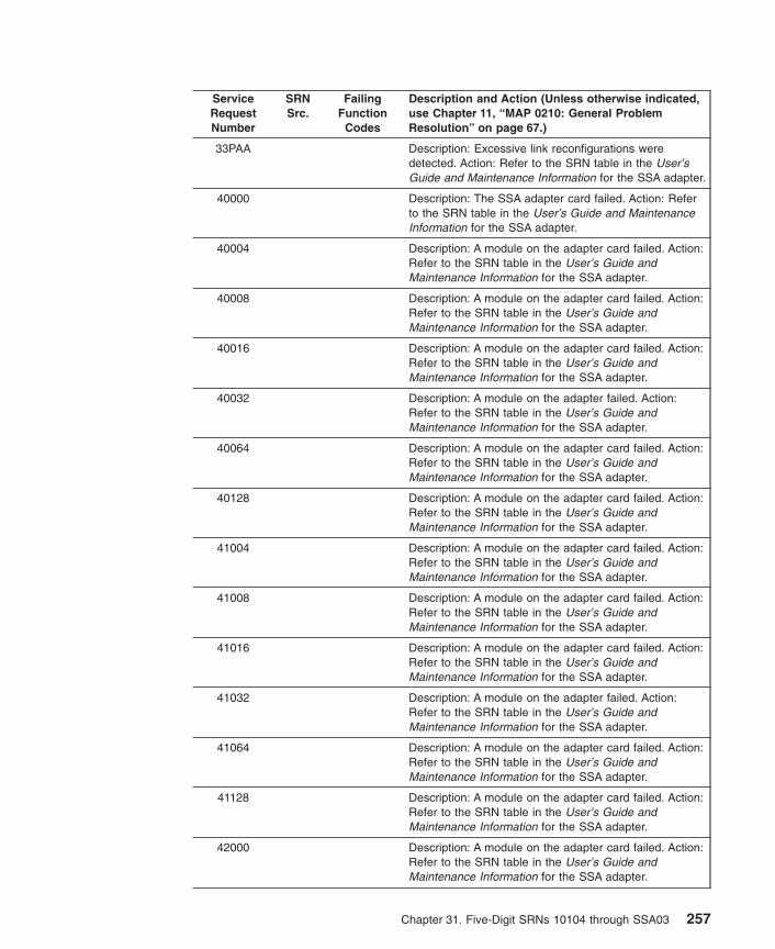
ServiceRequestNumber
SRNSrc.
FailingFunction
Codes
Description and Action (Unless otherwise indicated,use Chapter 11, “MAP 0210: General ProblemResolution” on page 67.)
33PAA Description: Excessive link reconfigurations weredetected. Action: Refer to the SRN table in the User’sGuide and Maintenance Information for the SSA adapter.
40000 Description: The SSA adapter card failed. Action: Referto the SRN table in the User’s Guide and MaintenanceInformation for the SSA adapter.
40004 Description: A module on the adapter card failed. Action:Refer to the SRN table in the User’s Guide andMaintenance Information for the SSA adapter.
40008 Description: A module on the adapter card failed. Action:Refer to the SRN table in the User’s Guide andMaintenance Information for the SSA adapter.
40016 Description: A module on the adapter card failed. Action:Refer to the SRN table in the User’s Guide andMaintenance Information for the SSA adapter.
40032 Description: A module on the adapter failed. Action:Refer to the SRN table in the User’s Guide andMaintenance Information for the SSA adapter.
40064 Description: A module on the adapter card failed. Action:Refer to the SRN table in the User’s Guide andMaintenance Information for the SSA adapter.
40128 Description: A module on the adapter card failed. Action:Refer to the SRN table in the User’s Guide andMaintenance Information for the SSA adapter.
41004 Description: A module on the adapter card failed. Action:Refer to the SRN table in the User’s Guide andMaintenance Information for the SSA adapter.
41008 Description: A module on the adapter card failed. Action:Refer to the SRN table in the User’s Guide andMaintenance Information for the SSA adapter.
41016 Description: A module on the adapter card failed. Action:Refer to the SRN table in the User’s Guide andMaintenance Information for the SSA adapter.
41032 Description: A module on the adapter failed. Action:Refer to the SRN table in the User’s Guide andMaintenance Information for the SSA adapter.
41064 Description: A module on the adapter card failed. Action:Refer to the SRN table in the User’s Guide andMaintenance Information for the SSA adapter.
41128 Description: A module on the adapter card failed. Action:Refer to the SRN table in the User’s Guide andMaintenance Information for the SSA adapter.
42000 Description: A module on the adapter card failed. Action:Refer to the SRN table in the User’s Guide andMaintenance Information for the SSA adapter.
Chapter 31. Five-Digit SRNs 10104 through SSA03 257

ServiceRequestNumber
SRNSrc.
FailingFunction
Codes
Description and Action (Unless otherwise indicated,use Chapter 11, “MAP 0210: General ProblemResolution” on page 67.)
42200 Description: Other adapters on the SSA loop are usinglevels of microcode that are not compatible. Action:Refer to the SRN table in the User’s Guide andMaintenance Information for the SSA adapter.
42500 Description: An SSA adapter detected a failure in itsfast-write cache. Action: Refer to the SRN table in theUser’s Guide and Maintenance Information for the SSAadapter.
42510 Description: Not enough DRAM available to run an SSAfast-write cache. Action: Refer to the SRN table in theUser’s Guide and Maintenance Information for the SSAadapter.
42515 Description: An SSA adapter is attempting to use itsfast-write cache, but a fast-write cache card is notinstalled. Action: Refer to the SRN table in the User’sGuide and Maintenance Information for the SSA adapter.
42520 Description: An SSA fast-write cache failure wasdetected. Action: Refer to the SRN table in the User’sGuide and Maintenance Information for the SSA adapter.
42521 Description: An SSA fast-write cache option card failurewas detected. Action: Refer to the SRN table in theUser’s Guide and Maintenance Information for the SSAadapter.
42522 Description: An SSA fast-write cache option card failurewas detected. Action: Refer to the SRN table in theUser’s Guide and Maintenance Information for the SSAadapter.
42523 Description: A incorrect version number was detected inthe fast-write cache option card. Action: Refer to theSRN table in the User’s Guide and MaintenanceInformation for the SSA adapter.
42524 Description: A fast-write disk drive (or drives) containsunsynchronized data, but the fast-write cache optioncard cannot be detected. Action: Refer to the SRN tablein the User’s Guide and Maintenance Information for theSSA adapter.
42525 Description: A fast-write problem occurred. Action: Referto the SRN table in the User’s Guide and MaintenanceInformation for the SSA adapter.
42526 Description: This adapter does not support the SSAFast-Write Cache Option. Action: Refer to the SRN tablein the User’s Guide and Maintenance Information for theSSA adapter.
42527 Description: A dormant SSA fast-write cache entry exists.Action: Refer to the SRN table in the User’s Guide andMaintenance Information for the SSA adapter.
258 Diagnostic Information for Multiple Bus Systems

ServiceRequestNumber
SRNSrc.
FailingFunction
Codes
Description and Action (Unless otherwise indicated,use Chapter 11, “MAP 0210: General ProblemResolution” on page 67.)
42528 Description: A fast-write SSA disk drive has beendetected that was previously unsynchronized, but hassince been configured on a different adapter. Action:Refer to the SRN table in the User’s Guide andMaintenance Information for the SSA adapter.
42529 Description: The fast-write cache is disabled. The batteryis charging. Action: Refer to the SRN table in the User’sGuide and Maintenance Information for the SSA adapter.
4252A Description: The supply voltage to the fast-write cacheoption card is low. The card has switched toSelf-Refresh mode. Action: Refer to the SRN table in theUser’s Guide and Maintenance Information for the SSAadapter.
4252B Description: The battery to the fast-write cache optioncard no longer has the power to maintain data. Action:Refer to the SRN table in the User’s Guide andMaintenance Information for the SSA adapter.
4252C Description: The battery to the fast-write cache optioncard needs to be exchanged for a new one. Action:Refer to the SRN table in the User’s Guide andMaintenance Information for the SSA adapter.
42540 Description: Two-way fast-write cache is configured tooperate only when both caches are available. Onecache, however, is not available. Action: Refer to theSRN table in the User’s Guide and MaintenanceInformation for the SSA adapter.
43PAA Description: An SSA device on the loop is preventing thecompletion of the loop configuration. Action: Refer to theSRN table in the Service Guide for the unit containingthe disk drive or to the User’s Guide and MaintenanceInformation for the SSA adapter.
44PAA Description: A disk drive module has a Failed status.Action: Refer to the SRN table in the Service Guide forthe unit containing the disk drive or to the User’s Guideand Maintenance Information for the SSA adapter.
45PAA Description: The SSA adapter has detected an openSSA loop. Action: Refer to the SRN table in the ServiceGuide for the unit containing the disk drive or to theUser’s Guide and Maintenance Information for the SSAadapter.
46000 Description: A RAID array is in the Off-Line statebecause more than one disk drive is not available.Action: Refer to the SRN table in the User’s Guide andMaintenance Information for the SSA adapter.
Chapter 31. Five-Digit SRNs 10104 through SSA03 259

ServiceRequestNumber
SRNSrc.
FailingFunction
Codes
Description and Action (Unless otherwise indicated,use Chapter 11, “MAP 0210: General ProblemResolution” on page 67.)
46500 Description: A member disk drive is missing from a SSAarray or the original SSA adapter is not available. Action:Refer to the SRN table in the User’s Guide andMaintenance Information for the SSA adapter.
47000 Description: An attempt was made to store in the SSAadapter the details of more than 32 RAID arrays. Action:Refer to the SRN table in the User’s Guide andMaintenance Information for the SSA adapter.
47500 Description: Part of the RAID array data might havebeen lost. Action: Refer to the SRN table in the User’sGuide and Maintenance Information for the SSA adapter.
48000 Description: The SSA adapter detected a linkconfiguration that is not valid. Action: Refer to the SRNtable in the User’s Guide and Maintenance Informationfor the SSA adapter.
48500 Description: The array filter detected a link configurationthat is not valid. Action: Refer to the SRN table in theUser’s Guide and Maintenance Information for the SSAadapter.
48600 Description: One member disk drive of an array is not onthe SSA loop that contains the other member disk drivesof the array. Action: Refer to the SRN table in the User’sGuide and Maintenance Information for the SSA adapter.
48700 Description: Two or more member disk drives of an SSAarray are on different loops. Action: Refer to the SRNtable in the User’s Guide and Maintenance Informationfor the SSA adapter.
48750 Description: An array is in the Off-Line state because theprimary or secondary half of the array is not present.Action: Refer to the SRN table in the User’s Guide andMaintenance Information for the SSA adapter.
48755 Description: The SSA adapter is unknown to the array.Action: Refer to the SRN table in the User’s Guide andMaintenance Information for the SSA adapter.
48760 Description: An array is in the Off-Line state because thesplit/join procedure was not performed correctly. Action:Refer to the SRN table in the User’s Guide andMaintenance Information for the SSA adapter.
48800 Description: The Invalid-Strip table is full. Action: Referto the SRN table in the User’s Guide and MaintenanceInformation for the SSA adapter.
48900 Description: An SSA array is not available; amultiple-device error occurred. Action: Refer to the SRNtable in the User’s Guide and Maintenance Informationfor the SSA adapter.
260 Diagnostic Information for Multiple Bus Systems

ServiceRequestNumber
SRNSrc.
FailingFunction
Codes
Description and Action (Unless otherwise indicated,use Chapter 11, “MAP 0210: General ProblemResolution” on page 67.)
48950 Description: A disk drive caused an Array-Build operationto fail. Action: Refer to the SRN table in the User’sGuide and Maintenance Information for the SSA adapter.
49000 Description: A RAID array is in the Degraded state.Action: Refer to the SRN table in the User’s Guide andMaintenance Information for the SSA adapter.
49100 Description: A RAID array is in the Exposed state.Action: Refer to the SRN table in the User’s Guide andMaintenance Information for the SSA adapter.
49500 Description: No hot-spare disk drives are available for anarray that is configured for hot-spare disk drives. Action:Refer to the SRN table in the User’s Guide andMaintenance Information for the SSA adapter.
49510 Description: Hot-spare configuration is not synchronized.Action: Refer to the SRN table in the User’s Guide andMaintenance Information for the SSA adapter.
49520 Description: Hot-spare tuning has been lost. Action:Refer to the SRN table in the User’s Guide andMaintenance Information for the SSA adapter.
49530 Description: The number of disk drives that remain in ahot-spare pool is less than the specified number. Action:Refer to the SRN table in the User’s Guide andMaintenance Information for the SSA adapter.
49540 Description: Adapters that do not support hot-sparepools were detected. Action: Refer to the SRN table inthe User’s Guide and Maintenance Information for theSSA adapter.
49700 Description: The parity for the RAID array is notcomplete. Action: Refer to the SRN table in the User’sGuide and Maintenance Information for the SSA adapter.
49800 Description: A different adapter was detected on eachloop. Action: Refer to the SRN table in the User’s Guideand Maintenance Information for the SSA adapter.
4A100 Description: The adapter cannot initialize an SSA diskdrive. Action: Refer to the SRN table in the User’s Guideand Maintenance Information for the SSA adapter.
4BPAA Description: An SSA disk drive at PAA cannot beconfigured, because its UID cannot be read. Action:Refer to the SRN table in the User’s Guide andMaintenance Information for the SSA adapter.
50000 Description: The SSA adapter failed to respond to thedevice driver. Action: Refer to the SRN table in theUser’s Guide and Maintenance Information for the SSAadapter.
Chapter 31. Five-Digit SRNs 10104 through SSA03 261

ServiceRequestNumber
SRNSrc.
FailingFunction
Codes
Description and Action (Unless otherwise indicated,use Chapter 11, “MAP 0210: General ProblemResolution” on page 67.)
50001 Description: A Data Parity error occurred. Action: Referto the SRN table in the User’s Guide and MaintenanceInformation for the SSA adapter.
50002 Description: An SSA adapter DMA error occurred. Action:Refer to the SRN table in the User’s Guide andMaintenance Information for the SSA adapter.
50004 Description: A Channel Check occurred. Action: Refer tothe SRN table in the User’s Guide and MaintenanceInformation for the SSA adapter.
50005 Description: A software error occurred. Action: Refer tothe SRN table in the User’s Guide and MaintenanceInformation for the SSA adapter.
50006 Description: A Channel Check occurred. Action: Refer tothe SRN table in the User’s Guide and MaintenanceInformation for the SSA adapter.
50007 Description: The IOCC detected an internal error. Action:Refer to the SRN table in the User’s Guide andMaintenance Information for the SSA adapter.
50008 Description: Unable to read or write the POS registers orPCI configuration space. Action: Refer to the SRN tablein the User’s Guide and Maintenance Information for theSSA adapter.
50010 Description: An SSA adapter or device-driver protocolerror occurred. Action: Refer to the SRN table in theUser’s Guide and Maintenance Information for the SSAadapter.
50012 Description: The SSA adapter microcode hung. Action:Refer to the SRN table in the User’s Guide andMaintenance Information for the SSA adapter.
50013 Description: The SSA adapter card failed. Action: Referto the SRN table in the User’s Guide and MaintenanceInformation for the SSA adapter.
50100 Description: An attempt was made to log an erroragainst a pdisk that is not available to the using system.Action: Refer to the SRN table in the User’s Guide andMaintenance Information for the SSA adapter.
50200 Description: Duplicate SSA cluster number detected.Action: Refer to the SRN table in the User’s Guide andMaintenance Information for the SSA adapter.
50411 Description: SSA adapter detected a SS_SIC_CLASS1error. Action: Refer to the SRN table in the User’s Guideand Maintenance Information for the SSA adapter.
50422 Description: SSA adapter detected a SS_TIMEOUTerror. Action: Refer to the SRN table in the User’s Guideand Maintenance Information for the SSA adapter.
262 Diagnostic Information for Multiple Bus Systems

ServiceRequestNumber
SRNSrc.
FailingFunction
Codes
Description and Action (Unless otherwise indicated,use Chapter 11, “MAP 0210: General ProblemResolution” on page 67.)
50425 Description: SSA adapter detected aSS_LINK_CONFIG_FAILED error. Action: Refer to theSRN table in the User’s Guide and MaintenanceInformation for the SSA adapter.
504xx Description: The SSA adapter microcode hung. Action:Refer to the SRN table in the User’s Guide andMaintenance Information for the SSA adapter.
60000 Description: The SSA adapter is missing from theexpected configuration. Action: Refer to the SRN table inthe User’s Guide and Maintenance Information for theSSA adapter.
60200 Description: The SSA unit cannot be turned on. Action:Refer to the SRN table in the User’s Guide andMaintenance Information for the SSA adapter or if thesystem service guide contains integrated SSA (without adistinct model type from the system unit itself), use theSRN table in the system unit’s service guide to find thisSRN and do the action indicated there.
60210 Description: A disk drive module has its Check light On.Action: Refer to the SRN table in the User’s Guide andMaintenance Information for the SSA adapter or if thesystem service guide contains integrated SSA (without adistinct model type from the system unit itself), use theSRN table in the system unit’s service guide to find thisSRN and do the action indicated there.
60220 Description: A fan-and-power-supply assembly has itsCheck light On. Action: Refer to the SRN table in theUser’s Guide and Maintenance Information for the SSAadapter or if the system service guide containsintegrated SSA (without a distinct model type from thesystem unit itself), use the SRN table in the systemunit’s service guide to find this SRN and do the actionindicated there.
60230 Description: The SSA unit has an unexpected Checklight On. Action: Refer to the SRN table in the User’sGuide and Maintenance Information for the SSA adapteror if the system service guide contains integrated SSA(without a distinct model type from the system unit itself),use the SRN table in the system unit’s service guide tofind this SRN and do the action indicated there.
60240 Description: An SSA configuration problem occurred.Action: Refer to the SRN table in the User’s Guide andMaintenance Information for the SSA adapter or if thesystem service guide contains integrated SSA (without adistinct model type from the system unit itself), use theSRN table in the system unit’s service guide to find thisSRN and do the action indicated there.
Chapter 31. Five-Digit SRNs 10104 through SSA03 263
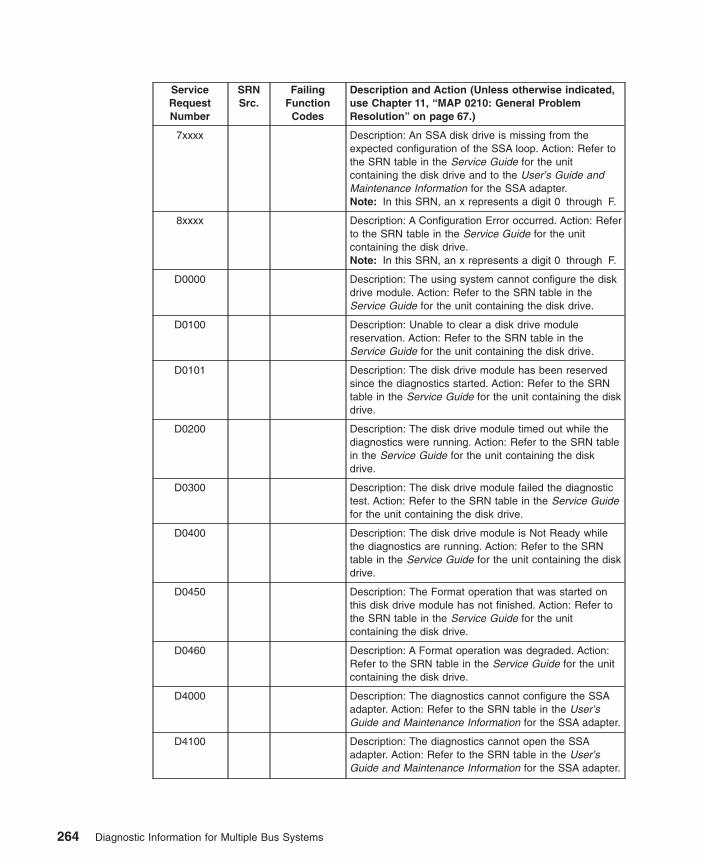
ServiceRequestNumber
SRNSrc.
FailingFunction
Codes
Description and Action (Unless otherwise indicated,use Chapter 11, “MAP 0210: General ProblemResolution” on page 67.)
7xxxx Description: An SSA disk drive is missing from theexpected configuration of the SSA loop. Action: Refer tothe SRN table in the Service Guide for the unitcontaining the disk drive and to the User’s Guide andMaintenance Information for the SSA adapter.Note: In this SRN, an x represents a digit 0 through F.
8xxxx Description: A Configuration Error occurred. Action: Referto the SRN table in the Service Guide for the unitcontaining the disk drive.Note: In this SRN, an x represents a digit 0 through F.
D0000 Description: The using system cannot configure the diskdrive module. Action: Refer to the SRN table in theService Guide for the unit containing the disk drive.
D0100 Description: Unable to clear a disk drive modulereservation. Action: Refer to the SRN table in theService Guide for the unit containing the disk drive.
D0101 Description: The disk drive module has been reservedsince the diagnostics started. Action: Refer to the SRNtable in the Service Guide for the unit containing the diskdrive.
D0200 Description: The disk drive module timed out while thediagnostics were running. Action: Refer to the SRN tablein the Service Guide for the unit containing the diskdrive.
D0300 Description: The disk drive module failed the diagnostictest. Action: Refer to the SRN table in the Service Guidefor the unit containing the disk drive.
D0400 Description: The disk drive module is Not Ready whilethe diagnostics are running. Action: Refer to the SRNtable in the Service Guide for the unit containing the diskdrive.
D0450 Description: The Format operation that was started onthis disk drive module has not finished. Action: Refer tothe SRN table in the Service Guide for the unitcontaining the disk drive.
D0460 Description: A Format operation was degraded. Action:Refer to the SRN table in the Service Guide for the unitcontaining the disk drive.
D4000 Description: The diagnostics cannot configure the SSAadapter. Action: Refer to the SRN table in the User’sGuide and Maintenance Information for the SSA adapter.
D4100 Description: The diagnostics cannot open the SSAadapter. Action: Refer to the SRN table in the User’sGuide and Maintenance Information for the SSA adapter.
264 Diagnostic Information for Multiple Bus Systems

ServiceRequestNumber
SRNSrc.
FailingFunction
Codes
Description and Action (Unless otherwise indicated,use Chapter 11, “MAP 0210: General ProblemResolution” on page 67.)
D4300 Description: The diagnostics have detected an SSAadapter POST failure. Action: Refer to the SRN table inthe User’s Guide and Maintenance Information for theSSA adapter.
D44xx Description: The diagnostics detected that the SSAadapter has corrupted microcode, but cannot downloada new version of the microcode. Action: Refer to theSRN table in the User’s Guide and MaintenanceInformation for the SSA adapter.Note: In this SRN, an X represents a digit 0 through F.
D6PAA Description: A high-speed SSA link is running at lowspeed. Action: Refer to the SRN table in the User’sGuide and Maintenance Information for the SSA adapter.
DFFFF Note: The description and action for this SRN are validonly if you ran the diagnostics on the SSA attachment.Description: A command or parameter that was sent orreceived is not valid. Action: Refer to the SRN table inthe Service Guide for the unit containing the disk driveand to the User’s Guide and Maintenance Information forthe SSA adapter.
SSA01 Description: There is not enough using-system memoryavailable for this service aid to continue. Action: Refer tothe SRN table in the User’s Guide and MaintenanceInformation for the SSA adapter.
SSA02 Description: An unknown error occurred. Action: Refer tothe SRN table in the User’s Guide and MaintenanceInformation for the SSA adapter.
SSA03 Description: The service aid was unable to open ahdisk. Action: Refer to the SRN table in the User’sGuide and Maintenance Information for the SSA adapter.
Chapter 31. Five-Digit SRNs 10104 through SSA03 265

266 Diagnostic Information for Multiple Bus Systems
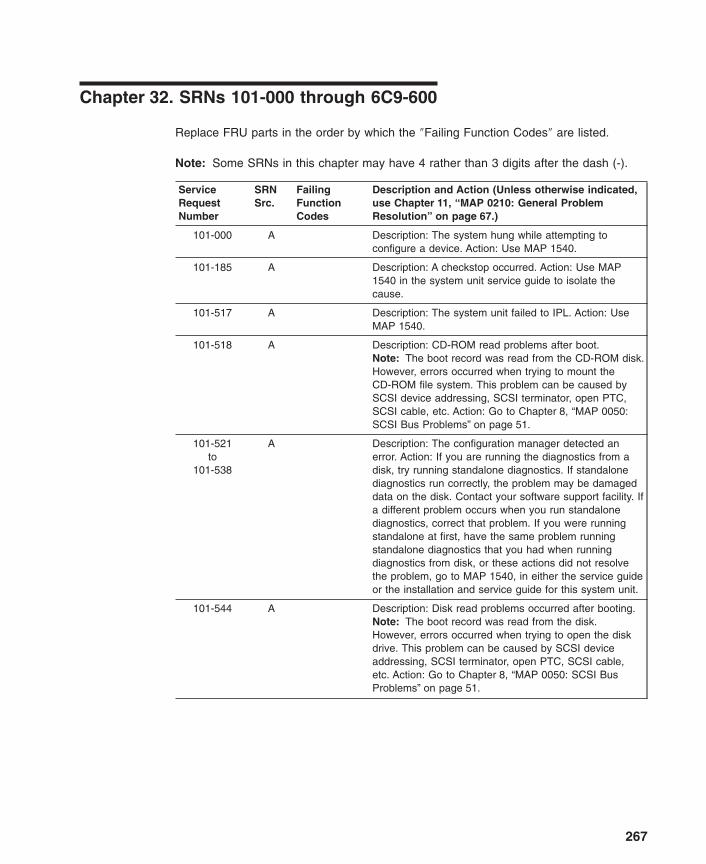
Chapter 32. SRNs 101-000 through 6C9-600
Replace FRU parts in the order by which the ″Failing Function Codes″ are listed.
Note: Some SRNs in this chapter may have 4 rather than 3 digits after the dash (-).
ServiceRequestNumber
SRNSrc.
FailingFunctionCodes
Description and Action (Unless otherwise indicated,use Chapter 11, “MAP 0210: General ProblemResolution” on page 67.)
101-000 A Description: The system hung while attempting toconfigure a device. Action: Use MAP 1540.
101-185 A Description: A checkstop occurred. Action: Use MAP1540 in the system unit service guide to isolate thecause.
101-517 A Description: The system unit failed to IPL. Action: UseMAP 1540.
101-518 A Description: CD-ROM read problems after boot.Note: The boot record was read from the CD-ROM disk.However, errors occurred when trying to mount theCD-ROM file system. This problem can be caused bySCSI device addressing, SCSI terminator, open PTC,SCSI cable, etc. Action: Go to Chapter 8, “MAP 0050:SCSI Bus Problems” on page 51.
101-521to
101-538
A Description: The configuration manager detected anerror. Action: If you are running the diagnostics from adisk, try running standalone diagnostics. If standalonediagnostics run correctly, the problem may be damageddata on the disk. Contact your software support facility. Ifa different problem occurs when you run standalonediagnostics, correct that problem. If you were runningstandalone at first, have the same problem runningstandalone diagnostics that you had when runningdiagnostics from disk, or these actions did not resolvethe problem, go to MAP 1540, in either the service guideor the installation and service guide for this system unit.
101-544 A Description: Disk read problems occurred after booting.Note: The boot record was read from the disk.However, errors occurred when trying to open the diskdrive. This problem can be caused by SCSI deviceaddressing, SCSI terminator, open PTC, SCSI cable,etc. Action: Go to Chapter 8, “MAP 0050: SCSI BusProblems” on page 51.
267
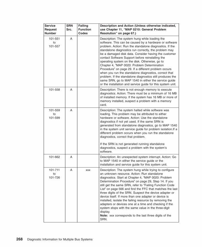
ServiceRequestNumber
SRNSrc.
FailingFunctionCodes
Description and Action (Unless otherwise indicated,use Chapter 11, “MAP 0210: General ProblemResolution” on page 67.)
101-551to
101-557
A Description: The system hung while loading thesoftware. This can be caused by a hardware or softwareproblem. Action: Run the standalone diagnostics. If thestandalone diagnostics run correctly, the problem maybe a damaged disk data. Consider having the customercontact Software Support before reinstalling theoperating system on the disk. Otherwise, go toChapter 4, “MAP 0020: Problem DeterminationProcedure” on page 29. If a different problem occurswhen you run the standalone diagnostics, correct thatproblem. If the standalone diagnostics still produces thesame SRN, go to MAP 1540 in either the service guideor the installation and service guide for this system unit.
101-558 A Description: There is not enough memory to executediagnostics. Action: There must be a minimum of 16 MBof installed memory. If the system has 16 MB or more ofmemory installed, suspect a problem with a memorycard.
101-559to
101-599
A Description: The system halted while software wasloading. This problem may be attributed to eitherhardware or software. Action: Use the standalonediagnostics if not yet used. If the same SRN isgenerated from standalone diagnostics, go to MAP 1540in the system unit service guide for problem isolation.If adifferent problem occurs when you run the standalonediagnostics, correct that problem.
If the SRN is not generated running standalonediagnostics, suspect a problem with the system’ssoftware.
101-662 A Description: An unexpected system interrupt. Action: Goto MAP 1540 in either the service guide or theinstallation and service guide for this system unit.
101-711to
101-726
A xxx Description: The system hung while trying to configurean unknown resource. Action: Run standalonediagnostics. Start at Chapter 4, “MAP 0020: ProblemDetermination Procedure” on page 29, Step 14. If youstill get the same SRN, refer to “Failing Function CodeList” on page 566 and find the FFC that matches the lastthree digits of the SRN. Suspect the device adapter ordevice itself. If more than one adapter or device isinstalled, isolate the failing resource by removing theadapters or devices one at a time and checking if thesystem stops with the same value in the three-digitdisplay.Note: xxx corresponds to the last three digits of theSRN.
268 Diagnostic Information for Multiple Bus Systems

ServiceRequestNumber
SRNSrc.
FailingFunctionCodes
Description and Action (Unless otherwise indicated,use Chapter 11, “MAP 0210: General ProblemResolution” on page 67.)
101-727 A Description: The system hung while trying to configurean asynchronous adapter. Action: Use MAP 1540 in theinstallation and service guide for this system unit.Suspect a problem with one of the async adapters.
101-7C1 A 7C1 Description: The system unit halted while configuring anaudio subsystem.
101-80c A 80c Description: A potential problem with an SSA deviceexists. If the system has external SSA devices refer tothe SSA Adapters User’s Guide and MaintenanceInformation. If the system has internal SSA devices, goto the SSA MAP in either the system unit’s service guideor user’s guide.
101-840 A Description: An unexpected system interrupt. Action: Goto MAP 1540 in either the service guide or theinstallation and service guide for this system unit.Suspect either a SCSI adapter or integrated SCSI if soequipped.
101-888 A 210227E10
Description: The system does not IPL.
101-c32 D Description: The system hung while indicating that adirect-attached display was selected as the console.Action: Go to MAP 1540 in either the service guide orthe installation and service guide for this system unit.Suspect the graphics adapter being used for the displayconsole first.
101-c33 D Description: The system hung while indicating that aTTY terminal is the system console. Action: Go to MAP1540 in either the service guide or the installation andservice guide for this system unit. Suspect the graphicsadapter being used for the display console first.
101-c70 A Description: A problem was encountered mounting theCD-ROM. Action: Use MAP 1540 in the service guide orthe installation and service guide for the system unit.
101-2004 A Description: Maximum memory size of partition is toolarge with respect to the current partition memory size.Action: Specify a maximum memory size for the partitionno larger than 64 times the starting memory size of thepartition.
101-xxxx A xxxxE10
Description: The system hung while configuring aresource. The last three or four digits after the dash (-)identify the failing function code for the resource beingconfigured. Action: Use Chapter 17, “MAP 0260: SystemHangs During Resource Configuration” on page 99.
103-151 D 151 Description: The time-of-day battery failed.
Chapter 32. SRNs 101-000 through 6C9-600 269

ServiceRequestNumber
SRNSrc.
FailingFunctionCodes
Description and Action (Unless otherwise indicated,use Chapter 11, “MAP 0210: General ProblemResolution” on page 67.)
109-200 B Description: The system crashed while being run by thecustomer. Action: Use Chapter 4, “MAP 0020: ProblemDetermination Procedure” on page 29, and get a newSRN.
110-101 C Description: The diagnostics did not detect an installedresource. Action: If this SRN appeared when runningconcurrent diagnostics, then run concurrent using thediag -a command, otherwise use Chapter 21, “MAP0290: Missing Resource Problem Resolution” onpage 117.
110-908 D 908C33C36
Description: The system halted while diagnostics wereexecuting.
110-921to
110-926
D xxx812
Description: The system halted while diagnostics wereexecuting.Note: xxx corresponds to the last three digits of theSRN.
110-935 D 935812
Description: The system halted while diagnostics wereexecuting.
110-946 D 946221
Description: The system halted while diagnostics wereexecuting.
110-xxxx D xxxx221
Description: The system halted while diagnostics wereexecuting.Note: xxxx corresponds to the last three or four digits ofthe SRN following the dash (-). If your 110 SRN is notlisted, substitute the last three or four digits of the SRNfor xxxx, then proceed to the FFC table using thesubstituted digits as your FFC.
111-107 B Description: A machine check occurred. Action: Go toChapter 4, “MAP 0020: Problem DeterminationProcedure” on page 29.
111-108 B Description: An encoded SRN was displayed. Action: Goto Chapter 4, “MAP 0020: Problem DeterminationProcedure” on page 29.
111-121 B Description: There is a display problem. Action: Doproblem determination on the display.
111-259 B Description: Cannot display readable information on theterminal. Action: Use Chapter 19, “MAP 0280: BootProblem Resolution” on page 111 Entry 3.
111-725 B 725 Description: Cannot display readable information on thedisplay.Note: Suspect the display adapter attached to theconsole display. Action: Use Chapter 19, “MAP 0280:Boot Problem Resolution” on page 111.
270 Diagnostic Information for Multiple Bus Systems
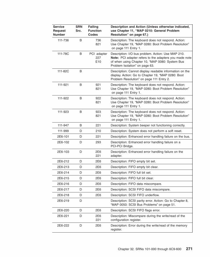
ServiceRequestNumber
SRNSrc.
FailingFunctionCodes
Description and Action (Unless otherwise indicated,use Chapter 11, “MAP 0210: General ProblemResolution” on page 67.)
111-736 B 736821
Description: The keyboard does not respond. Action:Use Chapter 19, “MAP 0280: Boot Problem Resolution”on page 111 Entry 1.
111-78C B PCI adapter227E10
Description: I/O bus problem. Action: Use MAP 210.Note: PCI adapter refers to the adapters you made noteof when using Chapter 10, “MAP 0080: System BusProblem Isolation” on page 63.
111-82C B Description: Cannot display readable information on thedisplay. Action: Go to Chapter 19, “MAP 0280: BootProblem Resolution” on page 111 Entry 2.
111-921 B 921821
Description: The keyboard does not respond. Action:Use Chapter 19, “MAP 0280: Boot Problem Resolution”on page 111 Entry 1.
111-922 B 922821
Description: The keyboard does not respond. Action:Use Chapter 19, “MAP 0280: Boot Problem Resolution”on page 111 Entry 1.
111-923 B 923821
Description: The keyboard does not respond. Action:Use Chapter 19, “MAP 0280: Boot Problem Resolution”on page 111 Entry 1.
111-947 B 221 Description: System beeper not functioning correctly.
111-999 D 210 Description: System does not perform a soft reset.
2E6-101 D 221 Description: Enhanced error handling failure on the bus.
2E6-102 D 293 Description: Enhanced error handling failure on aPCI-PCI Bridge.
2E6-103 D 2E6221
Description: Enhanced error handling failure on theadapter.
2E6-212 D 2E6 Description: FIFO empty bit set.
2E6-213 D 2E6 Description: FIFO empty bit clear.
2E6-214 D 2E6 Description: FIFO full bit set.
2E6-215 D 2E6 Description: FIFO full bit clear.
2E6-216 D 2E6 Description: FIFO data miscompare.
2E6-217 D 2E6 Description: SCSI FIFO data miscompare.
2E6-218 D 2E6 Description: SCSI FIFO underflow.
2E6-219 D Description: SCSI parity error. Action: Go to Chapter 8,“MAP 0050: SCSI Bus Problems” on page 51.
2E6-220 D 2E6 Description: SCSI FIFO flags error.
2E6-221 D 2E6221
Description: Miscompare during the write/read of theconfiguration register.
2E6-222 D 2E6 Description: Error during the write/read of the memoryregister.
Chapter 32. SRNs 101-000 through 6C9-600 271

ServiceRequestNumber
SRNSrc.
FailingFunctionCodes
Description and Action (Unless otherwise indicated,use Chapter 11, “MAP 0210: General ProblemResolution” on page 67.)
2E6-223 D 2E6 Description: Miscompare during the write/read of thememory I/O register. Action: Go to Chapter 8, “MAP0050: SCSI Bus Problems” on page 51.
2E6-224 D 2E6221
Description: SCSI configuration register read or writeerror.
2E6-225 D 2E6 Description: Adapter POST failed.
2E6-226 D Description: SCSI wrap or PTC failure. Action: Go toChapter 8, “MAP 0050: SCSI Bus Problems” on page 51.
2E6-227 D 2E6221
Description: SCSI adapter test failure.
2E6-230 D Description: Arbitration test failed. Action: Go toChapter 8, “MAP 0050: SCSI Bus Problems” on page 51.
2E6-231 D Description: Function could not complete. Action: Go toChapter 8, “MAP 0050: SCSI Bus Problems” on page 51.
2E6-232 D Description: SCSI bus data miscompare. Action: Go toChapter 8, “MAP 0050: SCSI Bus Problems” on page 51.
2E6-240 D Description: No terminal power. Action: Go to Chapter 8,“MAP 0050: SCSI Bus Problems” on page 51.
2E6-242 D Description: SCSI bus problem. Action: Go to Chapter 8,“MAP 0050: SCSI Bus Problems” on page 51.
2E6-301 D 2E6221
Description: The parent device open failed.
2E6-701 G 2E6 Description: Error log analysis indicates a PCI SCSIadapter failure.
2E6-801 G Description: Error log analysis indicates a terminatorproblem. Action: Run the diagnostics on the adapter inSystem Verification mode. If an SRN is reported, use theSRN to resolve the problem. If an SRN is not reported,use the SCSI service hints in “General SCSIConfiguration Checks” on page 3 to resolve the problem.
2E6-802 G Description: Error log analysis indicates that multipleattempts to reset the SCSI bus have timed out. Action:Run the diagnostics on the adapter in SystemVerification mode. If an SRN is reported, use the SRN toresolve the problem. If an SRN is not reported, use theSCSI service hints in “General SCSI ConfigurationChecks” on page 3 to resolve the problem.
2E6-803 G Description: Error log analysis indicates that multipleSCSI bus errors have occurred. Action: Run thediagnostics on the adapter in System Verification mode.If an SRN is reported, use the SRN to resolve theproblem. If an SRN is not reported, use the SCSI servicehints in “General SCSI Configuration Checks” on page 3to resolve the problem.
272 Diagnostic Information for Multiple Bus Systems
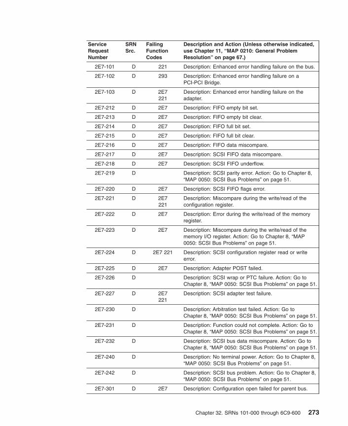
ServiceRequestNumber
SRNSrc.
FailingFunctionCodes
Description and Action (Unless otherwise indicated,use Chapter 11, “MAP 0210: General ProblemResolution” on page 67.)
2E7-101 D 221 Description: Enhanced error handling failure on the bus.
2E7-102 D 293 Description: Enhanced error handling failure on aPCI-PCI Bridge.
2E7-103 D 2E7221
Description: Enhanced error handling failure on theadapter.
2E7-212 D 2E7 Description: FIFO empty bit set.
2E7-213 D 2E7 Description: FIFO empty bit clear.
2E7-214 D 2E7 Description: FIFO full bit set.
2E7-215 D 2E7 Description: FIFO full bit clear.
2E7-216 D 2E7 Description: FIFO data miscompare.
2E7-217 D 2E7 Description: SCSI FIFO data miscompare.
2E7-218 D 2E7 Description: SCSI FIFO underflow.
2E7-219 D Description: SCSI parity error. Action: Go to Chapter 8,“MAP 0050: SCSI Bus Problems” on page 51.
2E7-220 D 2E7 Description: SCSI FIFO flags error.
2E7-221 D 2E7221
Description: Miscompare during the write/read of theconfiguration register.
2E7-222 D 2E7 Description: Error during the write/read of the memoryregister.
2E7-223 D 2E7 Description: Miscompare during the write/read of thememory I/O register. Action: Go to Chapter 8, “MAP0050: SCSI Bus Problems” on page 51.
2E7-224 D 2E7 221 Description: SCSI configuration register read or writeerror.
2E7-225 D 2E7 Description: Adapter POST failed.
2E7-226 D Description: SCSI wrap or PTC failure. Action: Go toChapter 8, “MAP 0050: SCSI Bus Problems” on page 51.
2E7-227 D 2E7221
Description: SCSI adapter test failure.
2E7-230 D Description: Arbitration test failed. Action: Go toChapter 8, “MAP 0050: SCSI Bus Problems” on page 51.
2E7-231 D Description: Function could not complete. Action: Go toChapter 8, “MAP 0050: SCSI Bus Problems” on page 51.
2E7-232 D Description: SCSI bus data miscompare. Action: Go toChapter 8, “MAP 0050: SCSI Bus Problems” on page 51.
2E7-240 D Description: No terminal power. Action: Go to Chapter 8,“MAP 0050: SCSI Bus Problems” on page 51.
2E7-242 D Description: SCSI bus problem. Action: Go to Chapter 8,“MAP 0050: SCSI Bus Problems” on page 51.
2E7-301 D 2E7 Description: Configuration open failed for parent bus.
Chapter 32. SRNs 101-000 through 6C9-600 273

ServiceRequestNumber
SRNSrc.
FailingFunctionCodes
Description and Action (Unless otherwise indicated,use Chapter 11, “MAP 0210: General ProblemResolution” on page 67.)
2E7-701 G 2E7 Description: Error log analysis indicates a PCI SCSIadapter failure.
2E7-801 G Description: Error log analysis indicates a terminatorproblem. Action: Run the diagnostics on the adapter inSystem Verification mode. If an SRN is reported, use theSRN to resolve the problem. If an SRN is not reported,use the SCSI service hints in “General SCSIConfiguration Checks” on page 3 to resolve the problem.
2E7-802 G Description: Error log analysis indicates that multipleattempts to reset the SCSI bus have timed out. Action:Run the diagnostics on the adapter in SystemVerification mode. If an SRN is reported, use the SRN toresolve the problem. If an SRN is not reported, use theSCSI service hints in “General SCSI ConfigurationChecks” on page 3 to resolve the problem.
2E7-803 G Description: Error log analysis indicates that multipleSCSI bus errors have occurred. Action: Run thediagnostics on the adapter in System Verification mode.If an SRN is reported, use the SRN to resolve theproblem. If an SRN is not reported, use the SCSI servicehints in “General SCSI Configuration Checks” on page 3to resolve the problem.
2EF-101 E 751 Description: Post indicates an adapter failure.
440-102 D 440 Description: An unrecoverable media error occurred.
440-104 D 440 Description: The motor failed to restart.
440-105 D 440 Description: The drive did not become ready.
440-106 D 440 Description: The electronics card test failed.
440-108 D 440 Description: The bus test failed.
440-110 D 440 Description: The media format is corrupted.
440-112 D 440 Description: The diagnostic test failed.
440-114 D 440 Description: An unrecoverable hardware error.
440-116 D Description: A protocol error. Action: Check the levels ofthe device, adapter, diagnostic software, and applicationsoftware to be sure they are all compatible. If you do notfind a problem, call your support person.
440-117 D 440 Description: A write-protect error occurred.
440-118 D 440B88
Description: A SCSI command time-out occurred.
440-120 D 440 Description: A SCSI busy or command error.
440-122 D 440 Description: A SCSI reservation conflict error.
440-124 D 440 Description: A SCSI check condition error occurred.
440-126 D 440B88
Description: A software error was caused by a hardwarefailure.
274 Diagnostic Information for Multiple Bus Systems

ServiceRequestNumber
SRNSrc.
FailingFunctionCodes
Description and Action (Unless otherwise indicated,use Chapter 11, “MAP 0210: General ProblemResolution” on page 67.)
440-128 G 440 Description: The error log analysis indicates a hardwarefailure.
440-129 G 190440B88
software
Description: Error log analysis indicates a SCSI busproblem.
440-130 G 440 Description: Error log analysis indicates a problemreported by the disk drive’s self-monitoring function.
440-132 D 440 Description: A disk drive hardware error occurred.
440-134 D B88software
Description: The adapter failed to configure.
440-135 D 440B88
software
Description: The device failed to configure.
440-136 D 440 Description: The certify operation failed.
440-137 D 440B88190
Description: Unit attention condition has occurred on theSend Diagnostic command.
440-138 D 440 Description: Error log analysis indicates that the diskdrive is operating at a higher than recommendedtemperature. Action: Check to be sure none of the airpassages in the system covers are blocked, that noother system environmental warnings are occurring.Otherwise, go to MAP 210.
441-102 D 441 Description: An unrecoverable media error occurred.
441-104 D 441 Description: The motor failed to restart.
441-105 D 441 Description: The drive did not become ready.
441-106 D 441 Description: The electronics card test failed.
441-108 D 441 Description: The bus test failed.
441-110 D 441 Description: The media format is corrupted.
441-112 D 441 Description: The diagnostic test failed.
441-114 D 441 Description: An unrecoverable hardware error.
441-116 D Description: A protocol error. Action: Check the levels ofthe device, adapter, diagnostic software, and applicationsoftware to be sure they are all compatible. If you do notfind a problem, call your support person.
441-117 D 441 Description: A write-protect error occurred.
441-118 D 441B88
Description: A SCSI command time-out occurred.
441-120 D 441 Description: A SCSI busy or command error.
441-122 D 441 Description: A SCSI reservation conflict error.
441-124 D 441 Description: A SCSI check condition error occurred.
Chapter 32. SRNs 101-000 through 6C9-600 275

ServiceRequestNumber
SRNSrc.
FailingFunctionCodes
Description and Action (Unless otherwise indicated,use Chapter 11, “MAP 0210: General ProblemResolution” on page 67.)
441-126 D 441B88
Description: A software error was caused by a hardwarefailure.
441-128 G 441 Description: The error log analysis indicates a hardwarefailure.
441-129 G 190441B88
software
Description: Error log analysis indicates a SCSI busproblem.
441-130 G 441 Description: Error log analysis indicates a problemreported by the disk drive’s self-monitoring function.
441-132 D 441 Description: A disk drive hardware error occurred.
441-134 D B88software
Description: The adapter failed to configure.
441-135 D 441B88
software
Description: The device failed to configure.
441-136 D 441 Description: The certify operation failed.
441-137 D 441B88190
Description: Unit attention condition has occurred on theSend Diagnostic command.
441-138 D 441 Description: Error log analysis indicates that the diskdrive is operating at a higher than recommendedtemperature. Action: Check to be sure none of the airpassages in the system covers are blocked, that noother system environmental warnings are occurring.Otherwise, go to MAP 210.
442-102 D 442 Description: An unrecoverable media error occurred.
442-104 D 442 Description: The motor failed to restart.
442-105 D 442 Description: The drive did not become ready.
442-106 D 442 Description: The electronics card test failed.
442-108 D 442 Description: The bus test failed.
442-110 D 442 Description: The media format is corrupted.
442-112 D 442 Description: The diagnostic test failed.
442-114 D 442 Description: An unrecoverable hardware error.
442-116 D Description: A protocol error. Action: Check the levels ofthe device, adapter, diagnostic software, and applicationsoftware to be sure they are all compatible. If you do notfind a problem, call your support person.
442-117 D 442 Description: A write-protect error occurred.
442-118 D 442B88
Description: A SCSI command time-out occurred.
442-120 D 442 Description: A SCSI busy or command error.
276 Diagnostic Information for Multiple Bus Systems

ServiceRequestNumber
SRNSrc.
FailingFunctionCodes
Description and Action (Unless otherwise indicated,use Chapter 11, “MAP 0210: General ProblemResolution” on page 67.)
442-122 D 442 Description: A SCSI reservation conflict error.
442-124 D 442 Description: A SCSI check condition error occurred.
442-126 D 442B88
Description: A software error was caused by a hardwarefailure.
442-128 G 442 Description: The error log analysis indicates a hardwarefailure.
442-129 G 190442B88
software
Description: Error log analysis indicates a SCSI busproblem.
442-130 G 442 Description: Error log analysis indicates a problemreported by the disk drive’s self-monitoring function.
442-132 D 442 Description: A disk drive hardware error occurred.
442-134 D B88software
Description: The adapter failed to configure.
442-135 D 442B88
software
Description: The device failed to configure.
442-136 D 442 Description: The certify operation failed.
442-137 D 442B88190
Description: Unit attention condition has occurred on theSend Diagnostic command.
443-102 D 443 Description: An unrecoverable media error occurred.
443-104 D 443 Description: The motor failed to restart.
443-105 D 443 Description: The drive did not become ready.
443-106 D 443 Description: The electronics card test failed.
443-108 D 443 Description: The bus test failed.
443-110 D 443 Description: The media format is corrupted.
443-112 D 443 Description: The diagnostic test failed.
443-114 D 443 Description: An unrecoverable hardware error.
443-116 D Description: A protocol error. Action: Check the levels ofthe device, adapter, diagnostic software, and applicationsoftware to be sure they are all compatible. If you do notfind a problem, call your support person.
443-117 D 443 Description: A write-protect error occurred.
443-118 D 443B88
Description: A SCSI command time-out occurred.
443-120 D 443 Description: A SCSI busy or command error.
443-122 D 443 Description: A SCSI reservation conflict error.
443-124 D 443 Description: A SCSI check condition error occurred.
Chapter 32. SRNs 101-000 through 6C9-600 277

ServiceRequestNumber
SRNSrc.
FailingFunctionCodes
Description and Action (Unless otherwise indicated,use Chapter 11, “MAP 0210: General ProblemResolution” on page 67.)
443-126 D 443B88
Description: A software error was caused by a hardwarefailure.
443-128 G 443 Description: The error log analysis indicates a hardwarefailure.
443-129 G 190443B88
software
Description: Error log analysis indicates a SCSI busproblem.
443-130 G 443 Description: Error log analysis indicates a problemreported by the disk drive’s self-monitoring function.
443-132 D 443 Description: A disk drive hardware error occurred.
443-134 D B88software
Description: The adapter failed to configure.
443-135 D 443B88
software
Description: The device failed to configure.
443-136 D 443 Description: The certify operation failed.
443-137 D 443B88190
Description: Unit attention condition has occurred on theSend Diagnostic command.
444-101 D 2C3444
Description: External wrap test failed on port 0.
444-102 D 2C3444
Description: External wrap test failed on port 1.
444-103 D 227 Description: Enhanced error handling failure on bus.
444-104 D 227 Description: Enhanced error handling failure on Eadschip.
444-105 D 444 Description: Enhanced error handling failure on adapter.
444-106 D 776646
Description: Enhanced error handling failure on bus.
444-107 D 776646
Description: EEH failure on Eads chip.
444-108 D 776646
Description: Enhanced error handling failure on adapter.
444-201 D 444227
Description: Internal adapter test failed.
444-202 D 444227
Description: External wrap test failed on port 0.
444-203 D 444227
Description: External wrap test failed on port 1.
444-204 D 2C3444
Description: External wrap test failed on port 0.
278 Diagnostic Information for Multiple Bus Systems

ServiceRequestNumber
SRNSrc.
FailingFunctionCodes
Description and Action (Unless otherwise indicated,use Chapter 11, “MAP 0210: General ProblemResolution” on page 67.)
444-205 D 2C3444
Description: External wrap test failed on port 1.
444-206 D 2C3444
software
Description: External wrap test failed on port 0.
444-207 D 2C3444
software
Description: External wrap test failed on port 1.
444-208 D 444227
Description: Enhanced error handling failure opening theadapter.
444-301 D 444227
software
Description: Internal adapter test failed.
444-302 D 444227
software
Description: External wrap test failed on port 0.
444-303 D 444227
software
Description: External wrap test failed on port 1.
444-304 D 2C3444
software
Description: External wrap test failed on port 0.
444-305 D 2C3444
software
Description: External wrap test failed on port 1.
444-700 D 444software
Description: Error log analysis indicates a hardwareproblem.
444-701 D 444227
Description: Error log analysis indicates that this adapterhas failed to initialize due to EEH errors.
447-101 D 447 Description: The Fibre Channel Adapter configurationfailed.
447-102 D 447 Description: The Reset test failed.
447-103 D 447 Description: The Register test failed.
447-104 D 447 Description: The SRAM test failed.
447-105 D 447 Description: The Internal Wrap test failed.
447-106 D 447 Description: The Gigabaud Link Module (GLM) WrapTest Failure.
447-107 D 447 Description: The External Wrap test failed.
447-108 D 221 Description: Enhanced Error Handling Failure on bus.
447-109 D 221 Description: Enhanced Error Handling Failure on EADschip.
Chapter 32. SRNs 101-000 through 6C9-600 279

ServiceRequestNumber
SRNSrc.
FailingFunctionCodes
Description and Action (Unless otherwise indicated,use Chapter 11, “MAP 0210: General ProblemResolution” on page 67.)
447-110 D 447 Description: Enhanced Error Handling Failure onadapter.
447-201 D 447221
Description: The Configuration Register test failed.
447-202 D 447221
Description: The Interrupt test failed.
447-203 D 447221
Description: The PCI Wrap test failed.
447-204 D 447221
Description: The DMA test failed.
447-205 D 447221
Description: I/O error on a read/write operation.
447-701 G 447221
Description: Error log analysis indicates that an error hasoccurred with the adapter.
447-703 G 447 Description: Error log analysis indicates that an unknownadapter error has occurred.
447-704 G 447 Description: Error log analysis indicates that an adaptererror has occurred.
453-102 D 453 Description: An unrecoverable media error occurred.
453-104 D 453 Description: The motor failed to restart.
453-105 D 453 Description: The drive did not become ready.
453-106 D 453 Description: The electronics card test failed.
453-108 D 453 Description: The bus test failed.
453-110 D 453 Description: The media format is corrupted.
453-112 D 453 Description: The diagnostic test failed.
453-114 D 453 Description: An unrecoverable hardware error.
453-116 D Description: A protocol error. Action: Check the levels ofthe device, adapter, diagnostic software, and applicationsoftware to be sure they are all compatible. If you do notfind a problem, call your support person.
453-117 D 453 Description: A write-protect error occurred.
453-118 D 453B88
Description: A SCSI command time-out occurred.
453-120 D 453 Description: A SCSI busy or command error.
453-122 D 453 Description: A SCSI reservation conflict error.
453-124 D 453 Description: A SCSI check condition error occurred.
453-126 D 453B88
Description: A software error was caused by a hardwarefailure.
453-128 G 453 Description: The error log analysis indicates a hardwarefailure.
280 Diagnostic Information for Multiple Bus Systems
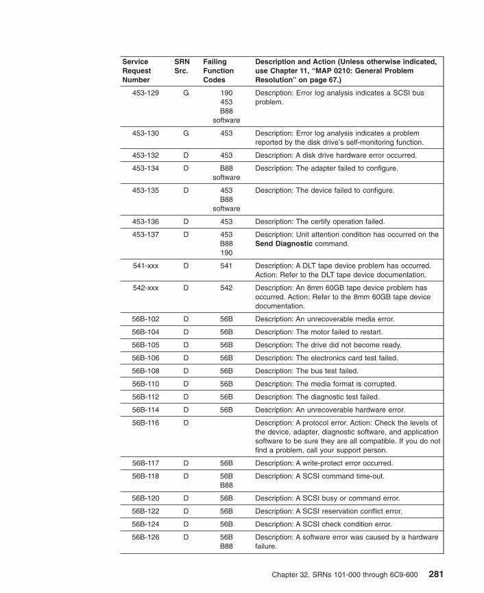
ServiceRequestNumber
SRNSrc.
FailingFunctionCodes
Description and Action (Unless otherwise indicated,use Chapter 11, “MAP 0210: General ProblemResolution” on page 67.)
453-129 G 190453B88
software
Description: Error log analysis indicates a SCSI busproblem.
453-130 G 453 Description: Error log analysis indicates a problemreported by the disk drive’s self-monitoring function.
453-132 D 453 Description: A disk drive hardware error occurred.
453-134 D B88software
Description: The adapter failed to configure.
453-135 D 453B88
software
Description: The device failed to configure.
453-136 D 453 Description: The certify operation failed.
453-137 D 453B88190
Description: Unit attention condition has occurred on theSend Diagnostic command.
541-xxx D 541 Description: A DLT tape device problem has occurred.Action: Refer to the DLT tape device documentation.
542-xxx D 542 Description: An 8mm 60GB tape device problem hasoccurred. Action: Refer to the 8mm 60GB tape devicedocumentation.
56B-102 D 56B Description: An unrecoverable media error.
56B-104 D 56B Description: The motor failed to restart.
56B-105 D 56B Description: The drive did not become ready.
56B-106 D 56B Description: The electronics card test failed.
56B-108 D 56B Description: The bus test failed.
56B-110 D 56B Description: The media format is corrupted.
56B-112 D 56B Description: The diagnostic test failed.
56B-114 D 56B Description: An unrecoverable hardware error.
56B-116 D Description: A protocol error. Action: Check the levels ofthe device, adapter, diagnostic software, and applicationsoftware to be sure they are all compatible. If you do notfind a problem, call your support person.
56B-117 D 56B Description: A write-protect error occurred.
56B-118 D 56BB88
Description: A SCSI command time-out.
56B-120 D 56B Description: A SCSI busy or command error.
56B-122 D 56B Description: A SCSI reservation conflict error.
56B-124 D 56B Description: A SCSI check condition error.
56B-126 D 56BB88
Description: A software error was caused by a hardwarefailure.
Chapter 32. SRNs 101-000 through 6C9-600 281

ServiceRequestNumber
SRNSrc.
FailingFunctionCodes
Description and Action (Unless otherwise indicated,use Chapter 11, “MAP 0210: General ProblemResolution” on page 67.)
56B-128 G 56B Description: The error log analysis indicates a hardwarefailure.
56B-129 G 19056BB88
software
Description: Error log analysis indicates a SCSI busproblem.
56B-130 G 56B Description: Error log analysis indicates a problemreported by the disk drive’s self-monitoring function.
56B-132 D 56B Description: A disk drive hardware error occurred.
56B-134 D B88software
Description: The adapter failed to configure.
56B-135 D 56BB88
software
Description: The device failed to configure.
56B-136 D 56B Description: The certify operation failed.
56B-137 D 56BB88190
Description: Unit attention condition has occurred on theSend Diagnostic command.
56B-138 D 56B Description: Error log analysis indicates that the diskdrive is operating at a higher than recommendedtemperature. Action: Check to be sure none of the airpassages in the system covers are blocked, that noother system environmental warnings are occurring.Otherwise, go to MAP 210.
56D-102 D 56D Description: An unrecoverable media error.
56D-104 D 56D Description: The motor failed to restart.
56D-105 D 56D Description: The drive did not become ready.
56D-106 D 56D Description: The electronics card test failed.
56D-108 D 56D Description: The bus test failed.
56D-110 D 56D Description: The media format is corrupted.
56D-112 D 56D Description: The diagnostic test failed.
56D-114 D 56D Description: An unrecoverable hardware error.
56D-116 D Description: A protocol error. Action: Check the levels ofthe device, adapter, diagnostic software, and applicationsoftware to be sure they are all compatible. If you do notfind a problem, call your support person.
56D-117 D 56D Description: A write-protect error occurred.
56D-118 D 56DB88
Description: A SCSI command time-out.
56D-120 D 56D Description: A SCSI busy or command error.
56D-122 D 56D Description: A SCSI reservation conflict error.
56D-124 D 56D Description: A SCSI check condition error.
282 Diagnostic Information for Multiple Bus Systems

ServiceRequestNumber
SRNSrc.
FailingFunctionCodes
Description and Action (Unless otherwise indicated,use Chapter 11, “MAP 0210: General ProblemResolution” on page 67.)
56D-126 D 56DB88
Description: A software error was caused by a hardwarefailure.
56D-128 G 56D Description: The error log analysis indicates a hardwarefailure.
56D-129 G 19056DB88
software
Description: Error log analysis indicates a SCSI busproblem.
56D-130 G 56D Description: Error log analysis indicates a problemreported by the disk drive’s self-monitoring function.
56D-132 D 56D Description: A disk drive hardware error occurred.
56D-134 D B88software
Description: The adapter failed to configure.
56D-135 D 56DB88
software
Description: The device failed to configure.
56D-136 D 56D Description: The certify operation failed.
56D-137 D 56DB88190
Description: Unit attention condition has occurred on theSend Diagnostic command.
56D-138 D 56D Description: Error log analysis indicates that the diskdrive is operating at a higher than recommendedtemperature. Action: Check to be sure none of the airpassages in the system covers are blocked, that noother system environmental warnings are occurring.Otherwise, go to MAP 210.
57B-102 D 57B Description: An unrecoverable media error.
57B-104 D 57B Description: The motor failed to restart.
57B-105 D 57B Description: The drive did not become ready.
57B-106 D 57B Description: The electronics card test failed.
57B-108 D 57B Description: The bus test failed.
57B-110 D 57B Description: The media format is corrupted.
57B-112 D 57B Description: The diagnostic test failed.
57B-114 D 57B Description: An unrecoverable hardware error.
57B-116 D Description: A protocol error. Action: Check the levels ofthe device, adapter, diagnostic software, and applicationsoftware to be sure they are all compatible. If you do notfind a problem, call your support person.
57B-117 D 57B Description: A write-protect error occurred.
57B-118 D 57BB88
Description: A SCSI command time-out.
57B-120 D 57B Description: A SCSI busy or command error.
Chapter 32. SRNs 101-000 through 6C9-600 283
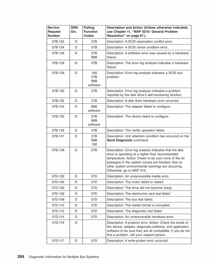
ServiceRequestNumber
SRNSrc.
FailingFunctionCodes
Description and Action (Unless otherwise indicated,use Chapter 11, “MAP 0210: General ProblemResolution” on page 67.)
57B-122 D 57B Description: A SCSI reservation conflict error.
57B-124 D 57B Description: A SCSI check condition error.
57B-126 D 57BB88
Description: A software error was caused by a hardwarefailure.
57B-128 G 57B Description: The error log analysis indicates a hardwarefailure.
57B-129 G 19057BB88
software
Description: Error log analysis indicates a SCSI busproblem.
57B-130 G 57B Description: Error log analysis indicates a problemreported by the disk drive’s self-monitoring function.
57B-132 D 57B Description: A disk drive hardware error occurred.
57B-134 D B88software
Description: The adapter failed to configure.
57B-135 D 57BB88
software
Description: The device failed to configure.
57B-136 D 57B Description: The certify operation failed.
57B-137 D 57BB88190
Description: Unit attention condition has occurred on theSend Diagnostic command.
57B-138 D 57B Description: Error log analysis indicates that the diskdrive is operating at a higher than recommendedtemperature. Action: Check to be sure none of the airpassages in the system covers are blocked, that noother system environmental warnings are occurring.Otherwise, go to MAP 210.
57D-102 D 57D Description: An unrecoverable media error.
57D-104 D 57D Description: The motor failed to restart.
57D-105 D 57D Description: The drive did not become ready.
57D-106 D 57D Description: The electronics card test failed.
57D-108 D 57D Description: The bus test failed.
57D-110 D 57D Description: The media format is corrupted.
57D-112 D 57D Description: The diagnostic test failed.
57D-114 D 57D Description: An unrecoverable hardware error.
57D-116 D Description: A protocol error. Action: Check the levels ofthe device, adapter, diagnostic software, and applicationsoftware to be sure they are all compatible. If you do notfind a problem, call your support person.
57D-117 D 57D Description: A write-protect error occurred.
284 Diagnostic Information for Multiple Bus Systems

ServiceRequestNumber
SRNSrc.
FailingFunctionCodes
Description and Action (Unless otherwise indicated,use Chapter 11, “MAP 0210: General ProblemResolution” on page 67.)
57D-118 D 57DB88
Description: A SCSI command time-out.
57D-120 D 57D Description: A SCSI busy or command error.
57D-122 D 57D Description: A SCSI reservation conflict error.
57D-124 D 57D Description: A SCSI check condition error.
57D-126 D 57DB88
Description: A software error was caused by a hardwarefailure.
57D-128 G 57D Description: The error log analysis indicates a hardwarefailure.
57D-129 G 19057DB88
software
Description: Error log analysis indicates a SCSI busproblem.
57D-130 G 57D Description: Error log analysis indicates a problemreported by the disk drive’s self-monitoring function.
57D-132 D 57D Description: A disk drive hardware error occurred.
57D-134 D B88software
Description: The adapter failed to configure.
57D-135 D 57DB88
software
Description: The device failed to configure.
57D-136 D 57D Description: The certify operation failed.
57D-137 D 57DB88190
Description: Unit attention condition has occurred on theSend Diagnostic command.
57D-138 D 57D Description: Error log analysis indicates that the diskdrive is operating at a higher than recommendedtemperature. Action: Check to be sure none of the airpassages in the system covers are blocked, that noother system environmental warnings are occurring.Otherwise, go to MAP 210.
58B-102 D 58B Description: An unrecoverable media error.
58B-104 D 58B Description: The motor failed to restart.
58B-105 D 58B Description: The drive did not become ready.
58B-106 D 58B Description: The electronics card test failed.
58B-108 D 58B Description: The bus test failed.
58B-110 D 58B Description: The media format is corrupted.
58B-112 D 58B Description: The diagnostic test failed.
58B-114 D 58B Description: An unrecoverable hardware error.
Chapter 32. SRNs 101-000 through 6C9-600 285

ServiceRequestNumber
SRNSrc.
FailingFunctionCodes
Description and Action (Unless otherwise indicated,use Chapter 11, “MAP 0210: General ProblemResolution” on page 67.)
58B-116 D Description: A protocol error. Action: Check the levels ofthe device, adapter, diagnostic software, and applicationsoftware to be sure they are all compatible. If you do notfind a problem, call your support person.
58B-117 D 58B Description: A write-protect error occurred.
58B-118 D 58BB88
Description: A SCSI command time-out.
58B-120 D 58B Description: A SCSI busy or command error.
58B-122 D 58B Description: A SCSI reservation conflict error.
58B-124 D 58B Description: A SCSI check condition error.
58B-126 D 58BB88
Description: A software error was caused by a hardwarefailure.
58B-128 G 58B Description: The error log analysis indicates a hardwarefailure.
58B-129 G 19058BB88
software
Description: Error log analysis indicates a SCSI busproblem.
58B-130 G 58B Description: Error log analysis indicates a problemreported by the disk drive’s self-monitoring function.
58B-132 D 58B Description: A disk drive hardware error occurred.
58B-134 D B88software
Description: The adapter failed to configure.
58B-135 D 58BB88
software
Description: The device failed to configure.
58B-136 D 58B Description: The certify operation failed.
58B-137 D 58BB88190
Description: Unit attention condition has occurred on theSend Diagnostic command.
58B-138 D 58B Description: Error log analysis indicates that the diskdrive is operating at a higher than recommendedtemperature. Action: Check to be sure none of the airpassages in the system covers are blocked, that noother system environmental warnings are occurring.Otherwise, go to MAP 210.
58D-102 D 58D Description: An unrecoverable media error.
58D-104 D 58D Description: The motor failed to restart.
58D-105 D 58D Description: The drive did not become ready.
58D-106 D 58D Description: The electronics card test failed.
58D-108 D 58D Description: The bus test failed.
58D-110 D 58D Description: The media format is corrupted.
286 Diagnostic Information for Multiple Bus Systems

ServiceRequestNumber
SRNSrc.
FailingFunctionCodes
Description and Action (Unless otherwise indicated,use Chapter 11, “MAP 0210: General ProblemResolution” on page 67.)
58D-112 D 58D Description: The diagnostic test failed.
58D-114 D 58D Description: An unrecoverable hardware error.
58D-116 D Description: A protocol error. Action: Check the levels ofthe device, adapter, diagnostic software, and applicationsoftware to be sure they are all compatible. If you do notfind a problem, call your support person.
58D-117 D 58D Description: A write-protect error occurred.
58D-118 D 58DB88
Description: A SCSI command time-out.
58D-120 D 58D Description: A SCSI busy or command error.
58D-122 D 58D Description: A SCSI reservation conflict error.
58D-124 D 58D Description: A SCSI check condition error.
58D-126 D 58DB88
Description: A software error was caused by a hardwarefailure.
58D-128 G 58D Description: The error log analysis indicates a hardwarefailure.
58D-129 G 19058DB88
software
Description: Error log analysis indicates a SCSI busproblem.
58D-130 G 58D Description: Error log analysis indicates a problemreported by the disk drive’s self-monitoring function.
58D-132 D 58D Description: A disk drive hardware error occurred.
58D-134 D B88software
Description: The adapter failed to configure.
58D-135 D 58DB88
software
Description: The device failed to configure.
58D-136 D 58D Description: The certify operation failed.
58D-137 D 58DB88190
Description: Unit attention condition has occurred on theSend Diagnostic command.
58D-138 D 58D Description: Error log analysis indicates that the diskdrive is operating at a higher than recommendedtemperature. Action: Check to be sure none of the airpassages in the system covers are blocked, that noother system environmental warnings are occurring.Otherwise, go to MAP 210.
59B-102 D 59B Description: An unrecoverable media error.
59B-104 D 59B Description: The motor failed to restart.
59B-105 D 59B Description: The drive did not become ready.
59B-106 D 59B Description: The electronics card test failed.
Chapter 32. SRNs 101-000 through 6C9-600 287
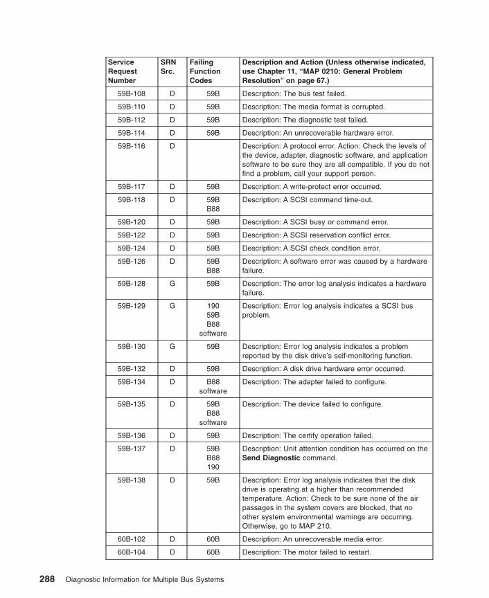
ServiceRequestNumber
SRNSrc.
FailingFunctionCodes
Description and Action (Unless otherwise indicated,use Chapter 11, “MAP 0210: General ProblemResolution” on page 67.)
59B-108 D 59B Description: The bus test failed.
59B-110 D 59B Description: The media format is corrupted.
59B-112 D 59B Description: The diagnostic test failed.
59B-114 D 59B Description: An unrecoverable hardware error.
59B-116 D Description: A protocol error. Action: Check the levels ofthe device, adapter, diagnostic software, and applicationsoftware to be sure they are all compatible. If you do notfind a problem, call your support person.
59B-117 D 59B Description: A write-protect error occurred.
59B-118 D 59BB88
Description: A SCSI command time-out.
59B-120 D 59B Description: A SCSI busy or command error.
59B-122 D 59B Description: A SCSI reservation conflict error.
59B-124 D 59B Description: A SCSI check condition error.
59B-126 D 59BB88
Description: A software error was caused by a hardwarefailure.
59B-128 G 59B Description: The error log analysis indicates a hardwarefailure.
59B-129 G 19059BB88
software
Description: Error log analysis indicates a SCSI busproblem.
59B-130 G 59B Description: Error log analysis indicates a problemreported by the disk drive’s self-monitoring function.
59B-132 D 59B Description: A disk drive hardware error occurred.
59B-134 D B88software
Description: The adapter failed to configure.
59B-135 D 59BB88
software
Description: The device failed to configure.
59B-136 D 59B Description: The certify operation failed.
59B-137 D 59BB88190
Description: Unit attention condition has occurred on theSend Diagnostic command.
59B-138 D 59B Description: Error log analysis indicates that the diskdrive is operating at a higher than recommendedtemperature. Action: Check to be sure none of the airpassages in the system covers are blocked, that noother system environmental warnings are occurring.Otherwise, go to MAP 210.
60B-102 D 60B Description: An unrecoverable media error.
60B-104 D 60B Description: The motor failed to restart.
288 Diagnostic Information for Multiple Bus Systems
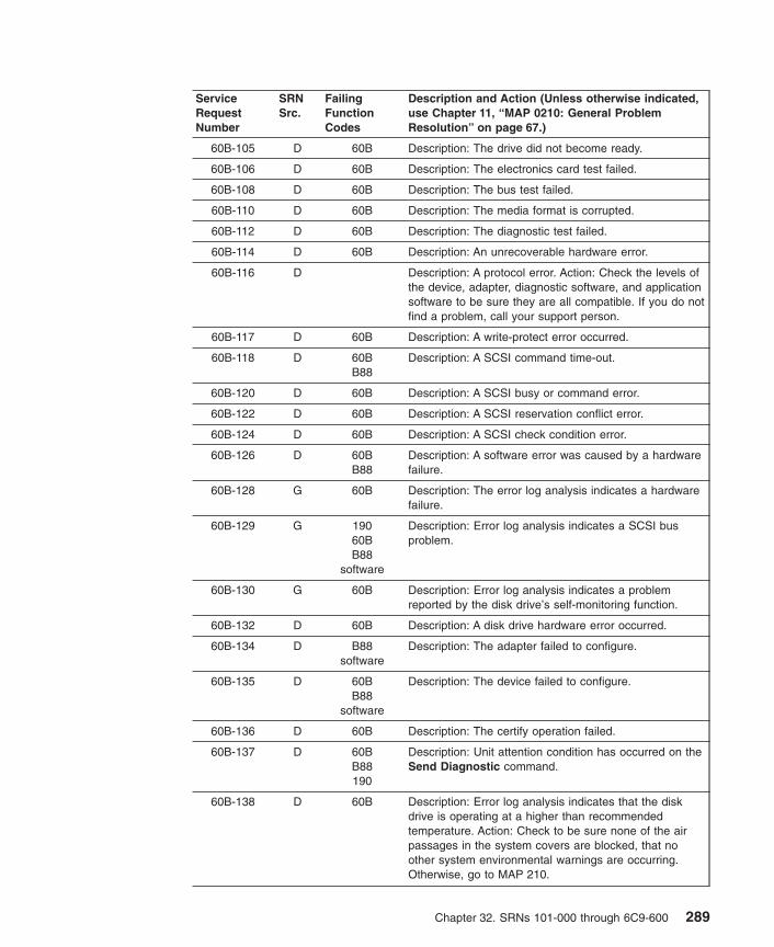
ServiceRequestNumber
SRNSrc.
FailingFunctionCodes
Description and Action (Unless otherwise indicated,use Chapter 11, “MAP 0210: General ProblemResolution” on page 67.)
60B-105 D 60B Description: The drive did not become ready.
60B-106 D 60B Description: The electronics card test failed.
60B-108 D 60B Description: The bus test failed.
60B-110 D 60B Description: The media format is corrupted.
60B-112 D 60B Description: The diagnostic test failed.
60B-114 D 60B Description: An unrecoverable hardware error.
60B-116 D Description: A protocol error. Action: Check the levels ofthe device, adapter, diagnostic software, and applicationsoftware to be sure they are all compatible. If you do notfind a problem, call your support person.
60B-117 D 60B Description: A write-protect error occurred.
60B-118 D 60BB88
Description: A SCSI command time-out.
60B-120 D 60B Description: A SCSI busy or command error.
60B-122 D 60B Description: A SCSI reservation conflict error.
60B-124 D 60B Description: A SCSI check condition error.
60B-126 D 60BB88
Description: A software error was caused by a hardwarefailure.
60B-128 G 60B Description: The error log analysis indicates a hardwarefailure.
60B-129 G 19060BB88
software
Description: Error log analysis indicates a SCSI busproblem.
60B-130 G 60B Description: Error log analysis indicates a problemreported by the disk drive’s self-monitoring function.
60B-132 D 60B Description: A disk drive hardware error occurred.
60B-134 D B88software
Description: The adapter failed to configure.
60B-135 D 60BB88
software
Description: The device failed to configure.
60B-136 D 60B Description: The certify operation failed.
60B-137 D 60BB88190
Description: Unit attention condition has occurred on theSend Diagnostic command.
60B-138 D 60B Description: Error log analysis indicates that the diskdrive is operating at a higher than recommendedtemperature. Action: Check to be sure none of the airpassages in the system covers are blocked, that noother system environmental warnings are occurring.Otherwise, go to MAP 210.
Chapter 32. SRNs 101-000 through 6C9-600 289

ServiceRequestNumber
SRNSrc.
FailingFunctionCodes
Description and Action (Unless otherwise indicated,use Chapter 11, “MAP 0210: General ProblemResolution” on page 67.)
601-102 D 601 Description: An unrecoverable media error.
601-104 D 601 Description: The motor failed to restart.
601-105 D 601 Description: The drive did not become ready.
601-106 D 601 Description: The electronics card test failed.
601-108 D 601 Description: The bus test failed.
601-110 D 601 Description: The media format is corrupted.
601-112 D 601 Description: The diagnostic test failed.
601-114 D 601 Description: An unrecoverable hardware error.
601-116 D Description: A protocol error. Action: Check the levels ofthe device, adapter, diagnostic software, and applicationsoftware to be sure they are all compatible. If you do notfind a problem, call your support person.
601-117 D 601 Description: A write-protect error occurred.
601-118 D 601B88
Description: A SCSI command time-out.
601-120 D 601 Description: A SCSI busy or command error.
601-122 D 601 Description: A SCSI reservation conflict error.
601-124 D 601 Description: A SCSI check condition error.
601-126 D 601B88
Description: A software error was caused by a hardwarefailure.
601-128 G 601 Description: The error log analysis indicates a hardwarefailure.
601-129 G 190601B88
software
Description: Error log analysis indicates a SCSI busproblem.
601-130 G 601 Description: Error log analysis indicates a problemreported by the disk drive’s self-monitoring function.
601-132 D 601 Description: A disk drive hardware error occurred.
601-134 D B88software
Description: The adapter failed to configure.
601-135 D 601B88
software
Description: The device failed to configure.
601-136 D 601 Description: The certify operation failed.
601-137 D 601B88190
Description: Unit attention condition has occurred on theSend Diagnostic command.
290 Diagnostic Information for Multiple Bus Systems
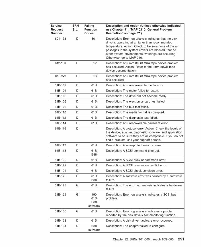
ServiceRequestNumber
SRNSrc.
FailingFunctionCodes
Description and Action (Unless otherwise indicated,use Chapter 11, “MAP 0210: General ProblemResolution” on page 67.)
601-138 D 601 Description: Error log analysis indicates that the diskdrive is operating at a higher than recommendedtemperature. Action: Check to be sure none of the airpassages in the system covers are blocked, that noother system environmental warnings are occurring.Otherwise, go to MAP 210.
612-130 D 612 Description: An 8mm 80GB VXA tape device problemhas occurred. Action: Refer to the 8mm 80GB tapedevice documentation.
613-xxx D 613 Description: An 8mm 80GB VXA tape device problemhas occurred.
61B-102 D 61B Description: An unrecoverable media error.
61B-104 D 61B Description: The motor failed to restart.
61B-105 D 61B Description: The drive did not become ready.
61B-106 D 61B Description: The electronics card test failed.
61B-108 D 61B Description: The bus test failed.
61B-110 D 61B Description: The media format is corrupted.
61B-112 D 61B Description: The diagnostic test failed.
61B-114 D 61B Description: An unrecoverable hardware error.
61B-116 D Description: A protocol error. Action: Check the levels ofthe device, adapter, diagnostic software, and applicationsoftware to be sure they are all compatible. If you do notfind a problem, call your support person.
61B-117 D 61B Description: A write-protect error occurred.
61B-118 D 61BB88
Description: A SCSI command time-out.
61B-120 D 61B Description: A SCSI busy or command error.
61B-122 D 61B Description: A SCSI reservation conflict error.
61B-124 D 61B Description: A SCSI check condition error.
61B-126 D 61BB88
Description: A software error was caused by a hardwarefailure.
61B-128 G 61B Description: The error log analysis indicates a hardwarefailure.
61B-129 G 19061BB88
software
Description: Error log analysis indicates a SCSI busproblem.
61B-130 G 61B Description: Error log analysis indicates a problemreported by the disk drive’s self-monitoring function.
61B-132 D 61B Description: A disk drive hardware error occurred.
61B-134 D B88software
Description: The adapter failed to configure.
Chapter 32. SRNs 101-000 through 6C9-600 291

ServiceRequestNumber
SRNSrc.
FailingFunctionCodes
Description and Action (Unless otherwise indicated,use Chapter 11, “MAP 0210: General ProblemResolution” on page 67.)
61B-135 D 61BB88
software
Description: The device failed to configure.
61B-136 D 61B Description: The certify operation failed.
61B-137 D 61BB88190
Description: Unit attention condition has occurred on theSend Diagnostic command.
61B-138 D 61B Description: Error log analysis indicates that the diskdrive is operating at a higher than recommendedtemperature. Action: Check to be sure none of the airpassages in the system covers are blocked, that noother system environmental warnings are occurring.Otherwise, go to MAP 210.
61D-098 J 61DB88
Description: Disk drive indicates an error.
61D-099 J 61DB88
Description: Disk drive not found.
61D-102 D 61D Description: An unrecoverable media error.
61D-104 D 61D Description: The motor failed to restart.
61D-105 D 61D Description: The drive did not become ready.
61D-106 D 61D Description: The electronics card test failed.
61D-108 D 61D Description: The bus test failed.
61D-110 D 61D Description: The media format is corrupted.
61D-112 D 61D Description: The diagnostic test failed.
61D-114 D 61D Description: An unrecoverable hardware error.
61D-116 D Description: A protocol error. Action: Check the levels ofthe device, adapter, diagnostic software, and applicationsoftware to be sure they are all compatible. If you do notfind a problem, call your support person.
61D-117 D 61D Description: A write-protect error occurred.
61D-118 D 61DB88
Description: A SCSI command time-out.
61D-120 D 61D Description: A SCSI busy or command error.
61D-122 D 61D Description: A SCSI reservation conflict error.
61D-124 D 61D Description: A SCSI check condition error.
61D-126 D 61DB88
Description: A software error was caused by a hardwarefailure.
61D-128 G 61D Description: The error log analysis indicates a hardwarefailure.
292 Diagnostic Information for Multiple Bus Systems

ServiceRequestNumber
SRNSrc.
FailingFunctionCodes
Description and Action (Unless otherwise indicated,use Chapter 11, “MAP 0210: General ProblemResolution” on page 67.)
61D-129 G 19061DB88
software
Description: Error log analysis indicates a SCSI busproblem.
61D-130 G 61D Description: Error log analysis indicates a problemreported by the disk drive’s self-monitoring function.
61D-132 D 61D Description: A disk drive hardware error occurred.
61D-134 D B88software
Description: The adapter failed to configure.
61D-135 D 61DB88
software
Description: The device failed to configure.
61D-136 D 61D Description: The certify operation failed.
61D-137 D 61DB88190
Description: Unit attention condition has occurred on theSend Diagnostic command.
61D-138 D 61D Description: Error log analysis indicates that the diskdrive is operating at a higher than recommendedtemperature. Action: Check to be sure none of the airpassages in the system covers are blocked, that noother system environmental warnings are occurring.Otherwise, go to MAP 210.
61E-102 D 61E Description: An unrecoverable media error.
61E-104 D 61E Description: The motor failed to restart.
61E-105 D 61E Description: The drive did not become ready.
61E-106 D 61E Description: The electronics card test failed.
61E-108 D 61E Description: The bus test failed.
61E-110 D 61E Description: The media format is corrupted.
61E-112 D 61E Description: The diagnostic test failed.
61E-114 D 61E Description: An unrecoverable hardware error.
61E-116 D Description: A protocol error. Action: Check the levels ofthe device, adapter, diagnostic software, and applicationsoftware to be sure they are all compatible. If you do notfind a problem, call your support person.
61E-117 D 61E Description: A write-protect error occurred.
61E-118 D 61EB88
Description: A SCSI command time-out.
61E-120 D 61E Description: A SCSI busy or command error.
61E-122 D 61E Description: A SCSI reservation conflict error.
61E-124 D 61E Description: A SCSI check condition error.
61E-126 D 61EB88
Description: A software error was caused by a hardwarefailure.
Chapter 32. SRNs 101-000 through 6C9-600 293

ServiceRequestNumber
SRNSrc.
FailingFunctionCodes
Description and Action (Unless otherwise indicated,use Chapter 11, “MAP 0210: General ProblemResolution” on page 67.)
61E-128 G 61E Description: The error log analysis indicates a hardwarefailure.
61E-129 G 19061EB88
software
Description: Error log analysis indicates a SCSI busproblem.
61E-130 G 61E Description: Error log analysis indicates a problemreported by the disk drive’s self-monitoring function.
61E-132 D 61E Description: A disk drive hardware error occurred.
61E-134 D B88software
Description: The adapter failed to configure.
61E-135 D 61EB88
software
Description: The device failed to configure.
61E-136 D 61E Description: The certify operation failed.
61E-137 D 61EB88190
Description: Unit attention condition has occurred on theSend Diagnostic command.
61E-138 D 61E Description: Error log analysis indicates that the diskdrive is operating at a higher than recommendedtemperature. Action: Check to be sure none of the airpassages in the system covers are blocked, that noother system environmental warnings are occurring.Otherwise, go to MAP 210.
621-102 D 621 Description: An unrecoverable media error.
621-104 D 621 Description: The motor failed to restart.
621-105 D 621 Description: The drive did not become ready.
621-106 D 621 Description: The electronics card test failed.
621-108 D 621 Description: The bus test failed.
621-110 D 621 Description: The media format is corrupted.
621-112 D 621 Description: The diagnostic test failed.
621-114 D 621 Description: An unrecoverable hardware error.
621-116 D Description: A protocol error. Action: Check the levels ofthe device, adapter, diagnostic software, and applicationsoftware to be sure they are all compatible. If you do notfind a problem, call your support person.
621-117 D 621 Description: A write-protect error occurred.
621-118 D 621B88
Description: A SCSI command time-out.
621-120 D 621 Description: A SCSI busy or command error.
621-122 D 621 Description: A SCSI reservation conflict error.
621-124 D 621 Description: A SCSI check condition error.
294 Diagnostic Information for Multiple Bus Systems

ServiceRequestNumber
SRNSrc.
FailingFunctionCodes
Description and Action (Unless otherwise indicated,use Chapter 11, “MAP 0210: General ProblemResolution” on page 67.)
621-126 D 621B88
Description: A software error was caused by a hardwarefailure.
621-128 G 621 Description: The error log analysis indicates a hardwarefailure.
621-129 G 190621B88
software
Description: Error log analysis indicates a SCSI busproblem.
621-130 G 621 Description: Error log analysis indicates a problemreported by the disk drive’s self-monitoring function.
621-132 D 621 Description: A disk drive hardware error occurred.
621-134 D B88software
Description: The adapter failed to configure.
621-135 D 621B88
software
Description: The device failed to configure.
621-136 D 621 Description: The certify operation failed.
621-137 D 621B88190
Description: Unit attention condition has occurred on theSend Diagnostic command.
621-138 D 621 Description: Error log analysis indicates that the diskdrive is operating at a higher than recommendedtemperature. Action: Check to be sure none of the airpassages in the system covers are blocked, that noother system environmental warnings are occurring.Otherwise, go to MAP 210.
623-102 D 623 Description: An unrecoverable media error.
623-104 D 623 Description: The motor failed to restart.
623-105 D 623 Description: The drive did not become ready.
623-106 D 623 Description: The electronics card test failed.
623-108 D 623 Description: The bus test failed.
623-110 D 623 Description: The media format is corrupted.
623-112 D 623 Description: The diagnostic test failed.
623-114 D 623 Description: An unrecoverable hardware error.
623-116 D Description: A protocol error. Action: Check the levels ofthe device, adapter, diagnostic software, and applicationsoftware to be sure they are all compatible. If you do notfind a problem, call your support person.
623-117 D 623 Description: A write-protect error occurred.
623-118 D 623B88
Description: A SCSI command time-out.
623-120 D 623 Description: A SCSI busy or command error.
Chapter 32. SRNs 101-000 through 6C9-600 295

ServiceRequestNumber
SRNSrc.
FailingFunctionCodes
Description and Action (Unless otherwise indicated,use Chapter 11, “MAP 0210: General ProblemResolution” on page 67.)
623-122 D 623 Description: A SCSI reservation conflict error.
623-124 D 623 Description: A SCSI check condition error.
623-126 D 623B88
Description: A software error was caused by a hardwarefailure.
623-128 G 623 Description: The error log analysis indicates a hardwarefailure.
623-129 G 190623B88
software
Description: Error log analysis indicates a SCSI busproblem.
623-130 G 623 Description: Error log analysis indicates a problemreported by the disk drive’s self-monitoring function.
623-132 D 623 Description: A disk drive hardware error occurred.
623-134 D B88software
Description: The adapter failed to configure.
623-135 D 623B88
software
Description: The device failed to configure.
623-136 D 623 Description: The certify operation failed.
623-137 D 623B88190
Description: Unit attention condition has occurred on theSend Diagnostic command.
623-138 D 623 Description: Error log analysis indicates that the diskdrive is operating at a higher than recommendedtemperature. Action: Check to be sure none of the airpassages in the system covers are blocked, that noother system environmental warnings are occurring.Otherwise, go to MAP 210.
624-102 D 624 Description: An unrecoverable media error.
624-104 D 624 Description: The motor failed to restart.
624-105 D 624 Description: The drive did not become ready.
624-106 D 624 Description: The electronics card test failed.
624-108 D 624 Description: The bus test failed.
624-110 D 624 Description: The media format is corrupted.
624-112 D 624 Description: The diagnostic test failed.
624-114 D 624 Description: An unrecoverable hardware error.
624-116 D Description: A protocol error. Action: Check the levels ofthe device, adapter, diagnostic software, and applicationsoftware to be sure they are all compatible. If you do notfind a problem, call your support person.
624-117 D 624 Description: A write-protect error occurred.
296 Diagnostic Information for Multiple Bus Systems

ServiceRequestNumber
SRNSrc.
FailingFunctionCodes
Description and Action (Unless otherwise indicated,use Chapter 11, “MAP 0210: General ProblemResolution” on page 67.)
624-118 D 624B88
Description: A SCSI command time-out.
624-120 D 624 Description: A SCSI busy or command error.
624-122 D 624 Description: A SCSI reservation conflict error.
624-124 D 624 Description: A SCSI check condition error.
624-126 D 624B88
Description: A software error was caused by a hardwarefailure.
624-128 G 624 Description: The error log analysis indicates a hardwarefailure.
624-129 G 190624B88
software
Description: Error log analysis indicates a SCSI busproblem.
624-130 G 624 Description: Error log analysis indicates a problemreported by the disk drive’s self-monitoring function.
624-132 D 624 Description: A disk drive hardware error occurred.
624-134 D B88software
Description: The adapter failed to configure.
624-135 D 624B88
software
Description: The device failed to configure.
624-136 D 624 Description: The certify operation failed.
624-137 D 624B88190
Description: Unit attention condition has occurred on theSend Diagnostic command.
624-138 D 624 Description: Error log analysis indicates that the diskdrive is operating at a higher than recommendedtemperature. Action: Check to be sure none of the airpassages in the system covers are blocked, that noother system environmental warnings are occurring.Otherwise, go to MAP 210.
62D-102 D 62D Description: An unrecoverable media error.
62D-104 D 62D Description: The motor failed to restart.
62D-105 D 62D Description: The drive did not become ready.
62D-106 D 62D Description: The electronics card test failed.
62D-108 D 62D Description: The bus test failed.
62D-110 D 62D Description: The media format is corrupted.
62D-112 D 62D Description: The diagnostic test failed.
62D-114 D 62D Description: An unrecoverable hardware error.
Chapter 32. SRNs 101-000 through 6C9-600 297

ServiceRequestNumber
SRNSrc.
FailingFunctionCodes
Description and Action (Unless otherwise indicated,use Chapter 11, “MAP 0210: General ProblemResolution” on page 67.)
62D-116 D Description: A protocol error. Action: Check the levels ofthe device, adapter, diagnostic software, and applicationsoftware to be sure they are all compatible. If you do notfind a problem, call your support person.
62D-117 D 62D Description: A write-protect error occurred.
62D-118 D 62DB88
Description: A SCSI command time-out.
62D-120 D 62D Description: A SCSI busy or command error.
62D-122 D 62D Description: A SCSI reservation conflict error.
62D-124 D 62D Description: A SCSI check condition error.
62D-126 D 62DB88
Description: A software error was caused by a hardwarefailure.
62D-128 G 62D Description: The error log analysis indicates a hardwarefailure.
62D-129 G 19062DB88
software
Description: Error log analysis indicates a SCSI busproblem.
62D-130 G 62D Description: Error log analysis indicates a problemreported by the disk drive’s self-monitoring function.
62D-132 D 62D Description: A disk drive hardware error occurred.
62D-134 D B88software
Description: The adapter failed to configure.
62D-135 D 62DB88
software
Description: The device failed to configure.
62D-136 D 62D Description: The certify operation failed.
62D-137 D 62DB88190
Description: Unit attention condition has occurred on theSend Diagnostic command.
62D-138 D 62D Description: Error log analysis indicates that the diskdrive is operating at a higher than recommendedtemperature. Action: Check to be sure none of the airpassages in the system covers are blocked, that noother system environmental warnings are occurring.Otherwise, go to MAP 210.
62E-102 D 62E Description: An unrecoverable media error.
62E-104 D 62E Description: The motor failed to restart.
62E-105 D 62E Description: The drive did not become ready.
62E-106 D 62E Description: The electronics card test failed.
62E-108 D 62E Description: The bus test failed.
62E-110 D 62E Description: The media format is corrupted.
298 Diagnostic Information for Multiple Bus Systems

ServiceRequestNumber
SRNSrc.
FailingFunctionCodes
Description and Action (Unless otherwise indicated,use Chapter 11, “MAP 0210: General ProblemResolution” on page 67.)
62E-112 D 62E Description: The diagnostic test failed.
62E-114 D 62E Description: An unrecoverable hardware error.
62E-116 D Description: A protocol error. Action: Check the levels ofthe device, adapter, diagnostic software, and applicationsoftware to be sure they are all compatible. If you do notfind a problem, call your support person.
62E-117 D 62E Description: A write-protect error occurred.
62E-118 D 62EB88
Description: A SCSI command time-out.
62E-120 D 62E Description: A SCSI busy or command error.
62E-122 D 62E Description: A SCSI reservation conflict error.
62E-124 D 62E Description: A SCSI check condition error.
62E-126 D 62EB88
Description: A software error was caused by a hardwarefailure.
62E-128 G 62E Description: The error log analysis indicates a hardwarefailure.
62E-129 G 19062EB88
software
Description: Error log analysis indicates a SCSI busproblem.
62E-130 G 62E Description: Error log analysis indicates a problemreported by the disk drive’s self-monitoring function.
62E-132 D 62E Description: A disk drive hardware error occurred.
62E-134 D B88software
Description: The adapter failed to configure.
62E-135 D 62EB88
software
Description: The device failed to configure.
62E-136 D 62E Description: The certify operation failed.
62E-137 D 62EB88190
Description: Unit attention condition has occurred on theSend Diagnostic command.
62E-138 D 62E Description: Error log analysis indicates that the diskdrive is operating at a higher than recommendedtemperature. Action: Check to be sure none of the airpassages in the system covers are blocked, that noother system environmental warnings are occurring.Otherwise, go to MAP 210.
636-101 D 636 Description: EPROM test failure.
636-102 D 636 Description: Adapter SDRAM failure.
636-103 D 636 Description: Adapter checksum failure.
636-104 D 636 Description: Adapter memory test failure.
Chapter 32. SRNs 101-000 through 6C9-600 299
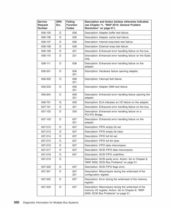
ServiceRequestNumber
SRNSrc.
FailingFunctionCodes
Description and Action (Unless otherwise indicated,use Chapter 11, “MAP 0210: General ProblemResolution” on page 67.)
636-105 D 636 Description: Adapter buffer test failure.
636-106 D 636 Description: Adapter cache test failure.
636-107 D 636 Description: Internal loop-back test failure.
636-108 D 636 Description: External wrap test failure.
636-109 D 221 Description: Enhanced error handling failure on the bus.
636-110 D 221 Description: Enhanced error handling failure on the Eadschip.
636-111 D 636 Description: Enhanced error handling failure on theadapter.
636-201 D 636221
Description: Hardware failure opening adapter.
636-202 D 636221
Description: Interrupt test failure.
636-203 D 636221
Description: Adapter DMA test failure.
636-204 D 636221
Description: Enhanced error handling failure opening theadapter.
636-701 G 636 Description: ELA indicates an I/O failure on the adapter.
637-101 D 221 Description: Enhanced error handling failure on the bus.
637-102 D 293 Description: Enhanced error handling failure on aPCI-PCI Bridge.
637-103 D 637221
Description: Enhanced error handling failure on theadapter.
637-212 D 637 Description: FIFO empty bit set.
637-213 D 637 Description: FIFO empty bit clear.
637-214 D 637 Description: FIFO full bit set.
637-215 D 637 Description: FIFO full bit clear.
637-216 D 637 Description: FIFO data miscompare.
637-217 D 637 Description: SCSI FIFO data miscompare.
637-218 D 637 Description: SCSI FIFO underflow.
637-219 D Description: SCSI parity error. Action: Go to Chapter 8,“MAP 0050: SCSI Bus Problems” on page 51.
637-220 D 637 Description: SCSI FIFO flags error.
637-221 D 637221
Description: Miscompare during the write/read of theconfiguration register.
637-222 D 637 Description: Error during the write/read of the memoryregister.
637-223 D 637 Description: Miscompare during the write/read of thememory I/O register. Action: Go to Chapter 8, “MAP0050: SCSI Bus Problems” on page 51.
300 Diagnostic Information for Multiple Bus Systems

ServiceRequestNumber
SRNSrc.
FailingFunctionCodes
Description and Action (Unless otherwise indicated,use Chapter 11, “MAP 0210: General ProblemResolution” on page 67.)
637-224 D 637221
Description: SCSI configuration register read or writeerror.
637-225 D 637 Description: Adapter POST failed.
637-226 D Description: SCSI wrap or PTC failure. Action: Go toChapter 8, “MAP 0050: SCSI Bus Problems” on page 51.
637-227 D 637221
Description: SCSI adapter test failure.
637-230 D Description: Arbitration test failed. Action: Go toChapter 8, “MAP 0050: SCSI Bus Problems” on page 51.
637-231 D Description: Function could not complete. Action: Go toChapter 8, “MAP 0050: SCSI Bus Problems” on page 51.
637-232 D Description: SCSI bus data miscompare. Action: Go toChapter 8, “MAP 0050: SCSI Bus Problems” on page 51.
637-240 D Description: No terminal power. Action: Go to Chapter 8,“MAP 0050: SCSI Bus Problems” on page 51.
637-242 D Description: SCSI bus problem. Action: Go to Chapter 8,“MAP 0050: SCSI Bus Problems” on page 51.
637-301 D 637221
Description: The parent device open failed.
637-701 G 637 Description: Error log analysis indicates a PCI SCSIadapter failure.
637-801 G Description: Error log analysis indicates a terminatorproblem. Action: Run the diagnostics on the adapter inSystem Verification mode. If an SRN is reported, use theSRN to resolve the problem. If an SRN is not reported,use the SCSI service hints in “General SCSIConfiguration Checks” on page 3 to resolve the problem.
637-802 G Description: Error log analysis indicates that multipleattempts to reset the SCSI bus have timed out. Action:Run the diagnostics on the adapter in SystemVerification mode. If an SRN is reported, use the SRN toresolve the problem. If an SRN is not reported, use theSCSI service hints in “General SCSI ConfigurationChecks” on page 3 to resolve the problem.
637-803 G Description: Error log analysis indicates that multipleSCSI bus errors have occurred. Action: Run thediagnostics on the adapter in System Verification mode.If an SRN is reported, use the SRN to resolve theproblem. If an SRN is not reported, use the SCSI servicehints in “General SCSI Configuration Checks” on page 3to resolve the problem.
638-102 D 638 Description: An unrecoverable media error occurred.
638-104 D 638 Description: The motor failed to restart.
638-105 D 638 Description: The drive did not become ready.
Chapter 32. SRNs 101-000 through 6C9-600 301

ServiceRequestNumber
SRNSrc.
FailingFunctionCodes
Description and Action (Unless otherwise indicated,use Chapter 11, “MAP 0210: General ProblemResolution” on page 67.)
638-106 D 638 Description: The electronics card test failed.
638-108 D 638 Description: The bus test failed.
638-110 D 638 Description: The media format is corrupted.
638-112 D 638 Description: The diagnostic test failed.
638-114 D 638 Description: An unrecoverable hardware error.
638-116 D Description: A protocol error. Action: Check the levels ofthe device, adapter, diagnostic software, and applicationsoftware to be sure they are all compatible. If you do notfind a problem, call your support person.
638-117 D 638 Description: A write-protect error occurred.
638-118 D 638B88
Description: A SCSI command time-out occurred.
638-120 D 638 Description: A SCSI busy or command error.
638-122 D 638 Description: A SCSI reservation conflict error.
638-124 D 638 Description: A SCSI check condition error occurred.
638-126 D 638B88
Description: A software error was caused by a hardwarefailure.
638-128 G 638 Description: The error log analysis indicates a hardwarefailure.
638-129 G 190638B88
software
Description: Error log analysis indicates a SCSI busproblem.
638-130 G 638 Description: Error log analysis indicates a problemreported by the disk drive’s self-monitoring function.
638-132 D 638 Description: A disk drive hardware error occurred.
638-134 D B88software
Description: The adapter failed to configure.
638-135 D 638B88
software
Description: The device failed to configure.
638-136 D 638 Description: The certify operation failed.
638-137 D 638B88190
Description: Unit attention condition has occurred on theSend Diagnostic command.
639-102 D 639 Description: An unrecoverable media error occurred.
639-104 D 639 Description: The motor failed to restart.
639-105 D 639 Description: The drive did not become ready.
639-106 D 639 Description: The electronics card test failed.
639-108 D 639 Description: The bus test failed.
302 Diagnostic Information for Multiple Bus Systems

ServiceRequestNumber
SRNSrc.
FailingFunctionCodes
Description and Action (Unless otherwise indicated,use Chapter 11, “MAP 0210: General ProblemResolution” on page 67.)
639-110 D 639 Description: The media format is corrupted.
639-112 D 639 Description: The diagnostic test failed.
639-114 D 639 Description: An unrecoverable hardware error.
639-116 D Description: A protocol error. Action: Check the levels ofthe device, adapter, diagnostic software, and applicationsoftware to be sure they are all compatible. If you do notfind a problem, call your support person.
639-117 D 639 Description: A write-protect error occurred.
639-118 D 639B88
Description: A SCSI command time-out occurred.
639-120 D 639 Description: A SCSI busy or command error.
639-122 D 639 Description: A SCSI reservation conflict error.
639-124 D 639 Description: A SCSI check condition error occurred.
639-126 D 639B88
Description: A software error was caused by a hardwarefailure.
639-128 G 639 Description: The error log analysis indicates a hardwarefailure.
639-129 G 190639B88
software
Description: Error log analysis indicates a SCSI busproblem.
639-130 G 639 Description: Error log analysis indicates a problemreported by the disk drive’s self-monitoring function.
639-132 D 639 Description: A disk drive hardware error occurred.
639-134 D B88software
Description: The adapter failed to configure.
639-135 D 639B88
software
Description: The device failed to configure.
639-136 D 639 Description: The certify operation failed.
639-137 D 639B88190
Description: Unit attention condition has occurred on theSend Diagnostic command.
639-138 D 639 Description: Error log analysis indicates that the diskdrive is operating at a higher than recommendedtemperature. Action: Check to be sure none of the airpassages in the system covers are blocked, that noother system environmental warnings are occurring.Otherwise, go to MAP 210.
63A-xxx D Description: Use the SRN value 62D-xxx.
63B-102 D 63B Description: An unrecoverable media error.
63B-104 D 63B Description: The motor failed to restart.
Chapter 32. SRNs 101-000 through 6C9-600 303
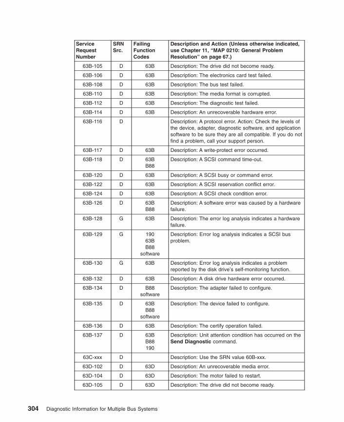
ServiceRequestNumber
SRNSrc.
FailingFunctionCodes
Description and Action (Unless otherwise indicated,use Chapter 11, “MAP 0210: General ProblemResolution” on page 67.)
63B-105 D 63B Description: The drive did not become ready.
63B-106 D 63B Description: The electronics card test failed.
63B-108 D 63B Description: The bus test failed.
63B-110 D 63B Description: The media format is corrupted.
63B-112 D 63B Description: The diagnostic test failed.
63B-114 D 63B Description: An unrecoverable hardware error.
63B-116 D Description: A protocol error. Action: Check the levels ofthe device, adapter, diagnostic software, and applicationsoftware to be sure they are all compatible. If you do notfind a problem, call your support person.
63B-117 D 63B Description: A write-protect error occurred.
63B-118 D 63BB88
Description: A SCSI command time-out.
63B-120 D 63B Description: A SCSI busy or command error.
63B-122 D 63B Description: A SCSI reservation conflict error.
63B-124 D 63B Description: A SCSI check condition error.
63B-126 D 63BB88
Description: A software error was caused by a hardwarefailure.
63B-128 G 63B Description: The error log analysis indicates a hardwarefailure.
63B-129 G 19063BB88
software
Description: Error log analysis indicates a SCSI busproblem.
63B-130 G 63B Description: Error log analysis indicates a problemreported by the disk drive’s self-monitoring function.
63B-132 D 63B Description: A disk drive hardware error occurred.
63B-134 D B88software
Description: The adapter failed to configure.
63B-135 D 63BB88
software
Description: The device failed to configure.
63B-136 D 63B Description: The certify operation failed.
63B-137 D 63BB88190
Description: Unit attention condition has occurred on theSend Diagnostic command.
63C-xxx D Description: Use the SRN value 60B-xxx.
63D-102 D 63D Description: An unrecoverable media error.
63D-104 D 63D Description: The motor failed to restart.
63D-105 D 63D Description: The drive did not become ready.
304 Diagnostic Information for Multiple Bus Systems
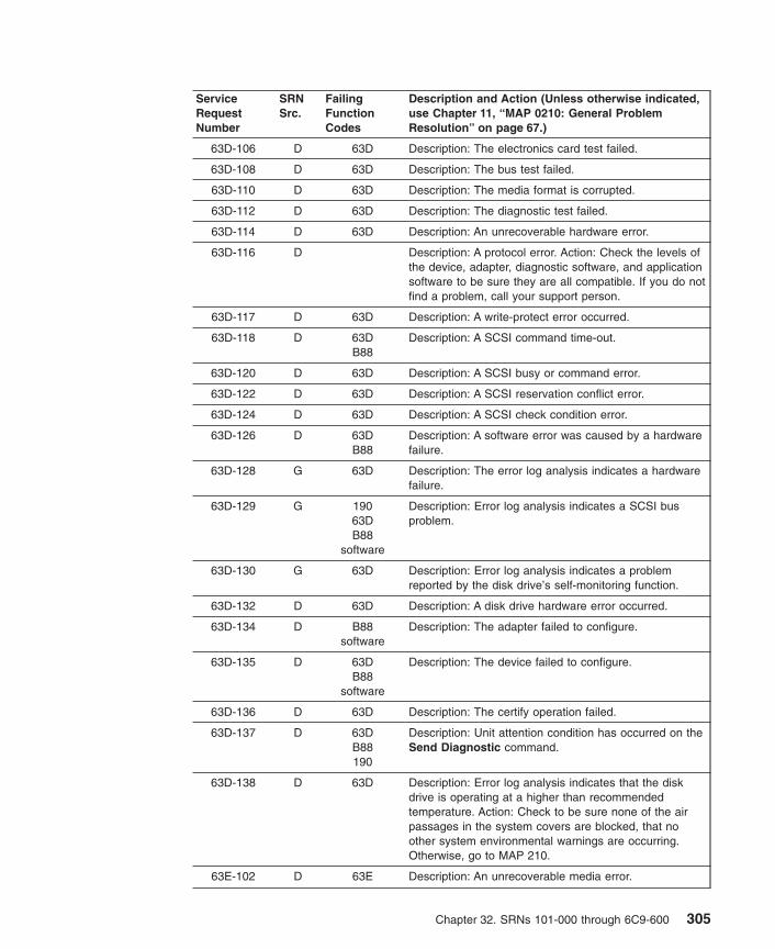
ServiceRequestNumber
SRNSrc.
FailingFunctionCodes
Description and Action (Unless otherwise indicated,use Chapter 11, “MAP 0210: General ProblemResolution” on page 67.)
63D-106 D 63D Description: The electronics card test failed.
63D-108 D 63D Description: The bus test failed.
63D-110 D 63D Description: The media format is corrupted.
63D-112 D 63D Description: The diagnostic test failed.
63D-114 D 63D Description: An unrecoverable hardware error.
63D-116 D Description: A protocol error. Action: Check the levels ofthe device, adapter, diagnostic software, and applicationsoftware to be sure they are all compatible. If you do notfind a problem, call your support person.
63D-117 D 63D Description: A write-protect error occurred.
63D-118 D 63DB88
Description: A SCSI command time-out.
63D-120 D 63D Description: A SCSI busy or command error.
63D-122 D 63D Description: A SCSI reservation conflict error.
63D-124 D 63D Description: A SCSI check condition error.
63D-126 D 63DB88
Description: A software error was caused by a hardwarefailure.
63D-128 G 63D Description: The error log analysis indicates a hardwarefailure.
63D-129 G 19063DB88
software
Description: Error log analysis indicates a SCSI busproblem.
63D-130 G 63D Description: Error log analysis indicates a problemreported by the disk drive’s self-monitoring function.
63D-132 D 63D Description: A disk drive hardware error occurred.
63D-134 D B88software
Description: The adapter failed to configure.
63D-135 D 63DB88
software
Description: The device failed to configure.
63D-136 D 63D Description: The certify operation failed.
63D-137 D 63DB88190
Description: Unit attention condition has occurred on theSend Diagnostic command.
63D-138 D 63D Description: Error log analysis indicates that the diskdrive is operating at a higher than recommendedtemperature. Action: Check to be sure none of the airpassages in the system covers are blocked, that noother system environmental warnings are occurring.Otherwise, go to MAP 210.
63E-102 D 63E Description: An unrecoverable media error.
Chapter 32. SRNs 101-000 through 6C9-600 305

ServiceRequestNumber
SRNSrc.
FailingFunctionCodes
Description and Action (Unless otherwise indicated,use Chapter 11, “MAP 0210: General ProblemResolution” on page 67.)
63E-104 D 63E Description: The motor failed to restart.
63E-105 D 63E Description: The drive did not become ready.
63E-106 D 63E Description: The electronics card test failed.
63E-108 D 63E Description: The bus test failed.
63E-110 D 63E Description: The media format is corrupted.
63E-112 D 63E Description: The diagnostic test failed.
63E-114 D 63E Description: An unrecoverable hardware error.
63E-116 D Description: A protocol error. Action: Check the levels ofthe device, adapter, diagnostic software, and applicationsoftware to be sure they are all compatible. If you do notfind a problem, call your support person.
63E-117 D 63E Description: A write-protect error occurred.
63E-118 D 63EB88
Description: A SCSI command time-out.
63E-120 D 63E Description: A SCSI busy or command error.
63E-122 D 63E Description: A SCSI reservation conflict error.
63E-124 D 63E Description: A SCSI check condition error.
63E-126 D 63EB88
Description: A software error was caused by a hardwarefailure.
63E-128 G 63E Description: The error log analysis indicates a hardwarefailure.
63E-129 G 19063EB88
software
Description: Error log analysis indicates a SCSI busproblem.
63E-130 G 63E Description: Error log analysis indicates a problemreported by the disk drive’s self-monitoring function.
63E-132 D 63E Description: A disk drive hardware error occurred.
63E-134 D B88software
Description: The adapter failed to configure.
63E-135 D 63EB88
software
Description: The device failed to configure.
63E-136 D 63E Description: The certify operation failed.
63E-137 D 63EB88190
Description: Unit attention condition has occurred on theSend Diagnostic command.
306 Diagnostic Information for Multiple Bus Systems

ServiceRequestNumber
SRNSrc.
FailingFunctionCodes
Description and Action (Unless otherwise indicated,use Chapter 11, “MAP 0210: General ProblemResolution” on page 67.)
63E-138 D 63E Description: Error log analysis indicates that the diskdrive is operating at a higher than recommendedtemperature. Action: Check to be sure none of the airpassages in the system covers are blocked, that noother system environmental warnings are occurring.Otherwise, go to MAP 210.
63F-xxx D Description: Use the SRN value 61B-xxx.
640-102 D 640B88
Description: An unrecoverable media error occurred.
640-104 D 640 Description: The motor failed to restart.
640-105 D 640 Description: The drive did not become ready.
640-106 D 640 Description: The electronics card test failed.
640-108 D 640 Description: The bus test failed.
640-110 D 640 Description: The media format is corrupted.
640-112 D 640 Description: The diagnostic test failed.
640-114 D 640 Description: An unrecoverable hardware error.
640-116 D Description: A protocol error. Action: Check the levels ofthe device, adapter, diagnostic software, and applicationsoftware to be sure they are all compatible. If you do notfind a problem, call your support person.
640-117 D 640 Description: A write-protect error occurred.
640-118 D 640B88
Description: A SCSI command time-out occurred.
640-120 D 640 Description: A SCSI busy or command error.
640-122 D 640 Description: A SCSI reservation conflict error.
640-124 D 640 Description: A SCSI check condition error occurred.
640-126 D 640B88
Description: A software error was caused by a hardwarefailure.
640-128 G 640 Description: The error log analysis indicates a hardwarefailure.
640-129 G 190640B88
software
Description: Error log analysis indicates a SCSI busproblem.
640-130 G 640 Description: Error log analysis indicates a problemreported by the disk drive’s self-monitoring function.
640-132 D 640 Description: A disk drive hardware error occurred.
640-133 D 640 Description: Use the subsystem guide to complete thediagnostics.
640-134 D B88software
Description: The adapter failed to configure.
Chapter 32. SRNs 101-000 through 6C9-600 307
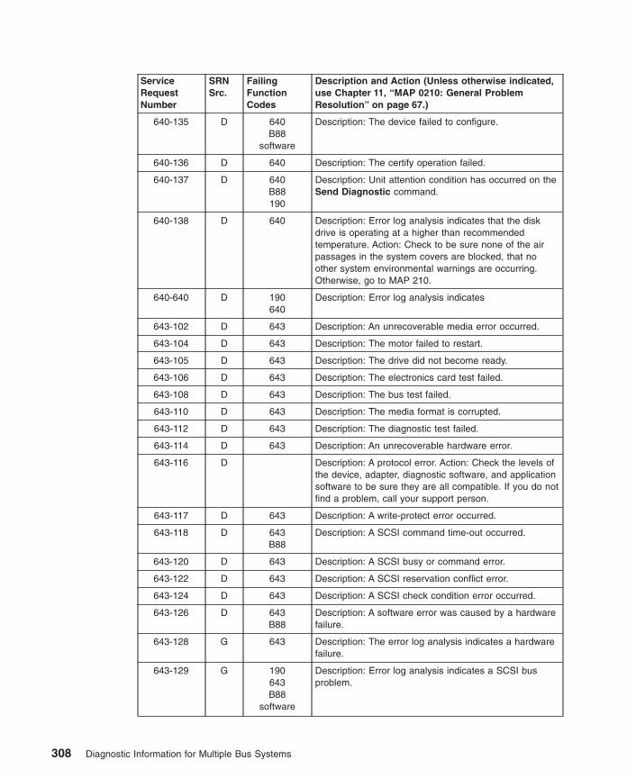
ServiceRequestNumber
SRNSrc.
FailingFunctionCodes
Description and Action (Unless otherwise indicated,use Chapter 11, “MAP 0210: General ProblemResolution” on page 67.)
640-135 D 640B88
software
Description: The device failed to configure.
640-136 D 640 Description: The certify operation failed.
640-137 D 640B88190
Description: Unit attention condition has occurred on theSend Diagnostic command.
640-138 D 640 Description: Error log analysis indicates that the diskdrive is operating at a higher than recommendedtemperature. Action: Check to be sure none of the airpassages in the system covers are blocked, that noother system environmental warnings are occurring.Otherwise, go to MAP 210.
640-640 D 190640
Description: Error log analysis indicates
643-102 D 643 Description: An unrecoverable media error occurred.
643-104 D 643 Description: The motor failed to restart.
643-105 D 643 Description: The drive did not become ready.
643-106 D 643 Description: The electronics card test failed.
643-108 D 643 Description: The bus test failed.
643-110 D 643 Description: The media format is corrupted.
643-112 D 643 Description: The diagnostic test failed.
643-114 D 643 Description: An unrecoverable hardware error.
643-116 D Description: A protocol error. Action: Check the levels ofthe device, adapter, diagnostic software, and applicationsoftware to be sure they are all compatible. If you do notfind a problem, call your support person.
643-117 D 643 Description: A write-protect error occurred.
643-118 D 643B88
Description: A SCSI command time-out occurred.
643-120 D 643 Description: A SCSI busy or command error.
643-122 D 643 Description: A SCSI reservation conflict error.
643-124 D 643 Description: A SCSI check condition error occurred.
643-126 D 643B88
Description: A software error was caused by a hardwarefailure.
643-128 G 643 Description: The error log analysis indicates a hardwarefailure.
643-129 G 190643B88
software
Description: Error log analysis indicates a SCSI busproblem.
308 Diagnostic Information for Multiple Bus Systems

ServiceRequestNumber
SRNSrc.
FailingFunctionCodes
Description and Action (Unless otherwise indicated,use Chapter 11, “MAP 0210: General ProblemResolution” on page 67.)
643-130 G 643 Description: Error log analysis indicates a problemreported by the disk drive’s self-monitoring function.
643-132 D 643 Description: A disk drive hardware error occurred.
643-134 D B88software
Description: The adapter failed to configure.
643-135 D 643B88
software
Description: The device failed to configure.
643-136 D 643 Description: The certify operation failed.
643-137 D 643B88190
Description: Unit attention condition has occurred on theSend Diagnostic command.
644-102 D 644 Description: An unrecoverable media error occurred.
644-104 D 644 Description: The motor failed to restart.
644-105 D 644 Description: The drive did not become ready.
644-106 D 644 Description: The electronics card test failed.
644-108 D 644 Description: The bus test failed.
644-110 D 644 Description: The media format is corrupted.
644-112 D 644 Description: The diagnostic test failed.
644-114 D 644 Description: An unrecoverable hardware error.
644-116 D Description: A protocol error. Action: Check the levels ofthe device, adapter, diagnostic software, and applicationsoftware to be sure they are all compatible. If you do notfind a problem, call your support person.
644-117 D 644 Description: A write-protect error occurred.
644-118 D 644B88
Description: A SCSI command time-out occurred.
644-120 D 644 Description: A SCSI busy or command error.
644-122 D 644 Description: A SCSI reservation conflict error.
644-124 D 644 Description: A SCSI check condition error occurred.
644-126 D 644B88
Description: A software error was caused by a hardwarefailure.
644-128 G 644 Description: The error log analysis indicates a hardwarefailure.
644-129 G 190644B88
software
Description: Error log analysis indicates a SCSI busproblem.
644-130 G 644 Description: Error log analysis indicates a problemreported by the disk drive’s self-monitoring function.
644-132 D 644 Description: A disk drive hardware error occurred.
Chapter 32. SRNs 101-000 through 6C9-600 309

ServiceRequestNumber
SRNSrc.
FailingFunctionCodes
Description and Action (Unless otherwise indicated,use Chapter 11, “MAP 0210: General ProblemResolution” on page 67.)
644-134 D B88software
Description: The adapter failed to configure.
644-135 D 644B88
software
Description: The device failed to configure.
644-136 D 644 Description: The certify operation failed.
644-137 D 644B88190
Description: Unit attention condition has occurred on theSend Diagnostic command.
646-101 D D46 Description: External Test Failure.
646-102 D 240 Description: External Test Failure.
646-103 D 646 Description: I/O Test Failure.
646-104 D 646221
Description: Adapter On-card Test Failure.
646-105 D 646 Description: Wrap Test Failure.
646-106 D 646 Description: Enhanced Error Handling failure on bus.
646-107 D 646 Description: EEH failure on Eads chip.
646-108 D 646 Description: Enhanced Error Handling failure on adapter.
646-201 D 646221
Description: Configuration Register Test Failure.
646-202 D 646221
Description: Wrap Test Failure.
646-204 F D46240
Description: External Test Failure.
646-205 F D46646
Description: External Test Failure. Action: Run advanceddiagnostics with wrap test for this resource to obtain acorrect problem resolution.
646-206 F 240646
Description: External Test Failure. Action: Run advanceddiagnostics with wrap test for this resource to obtain acorrect problem resolution.
646-302 F 240D46221
Description: External Test Failure. Action: Run advanceddiagnostics with wrap test for this resource to obtain acorrect problem resolution.
646-303 F D46646221
Description: External Test Failure. Action: Run advanceddiagnostics with wrap test for this resource to obtain acorrect problem resolution.
646-401 F 240D46646221
Description: External Test Failure. Action: Run advanceddiagnostics with wrap test for this resource to obtain acorrect problem resolution.
646-701 G 646 Description: Error log analysis indicates that an adaptererror has occurred.
310 Diagnostic Information for Multiple Bus Systems

ServiceRequestNumber
SRNSrc.
FailingFunctionCodes
Description and Action (Unless otherwise indicated,use Chapter 11, “MAP 0210: General ProblemResolution” on page 67.)
646-702 G 646 Description: Error log analysis indicates that an adaptercheck has occurred.
646-703 G 646221
Description: Error log analysis indicates that a DMAfailure has occurred.
646-704 G 646221
Description: Error log analysis indicates that a PCI Buserror has occurred.
646-705 G 646221
Description: Error log analysis indicates that aProgrammed I/O error has occurred.
646-706 G 646 Description: ELA indicates a command write failureoccurred.
646-707 G 646 Description: ELA indicates an internal adapter error hasoccurred.
64A-xxx D Description: Use the SRN value 62E-xxx.
64B-102 D 64B Description: An unrecoverable media error.
64B-104 D 64B Description: The motor failed to restart.
64B-105 D 64B Description: The drive did not become ready.
64B-106 D 64B Description: The electronics card test failed.
64B-108 D 64B Description: The bus test failed.
64B-110 D 64B Description: The media format is corrupted.
64B-112 D 64B Description: The diagnostic test failed.
64B-114 D 64B Description: An unrecoverable hardware error.
64B-116 D Description: A protocol error. Action: Check the levels ofthe device, adapter, diagnostic software, and applicationsoftware to be sure they are all compatible. If you do notfind a problem, call your support person.
64B-117 D 64B Description: A write-protect error occurred.
64B-118 D 64BB88
Description: A SCSI command time-out.
64B-120 D 64B Description: A SCSI busy or command error.
64B-122 D 64B Description: A SCSI reservation conflict error.
64B-124 D 64B Description: A SCSI check condition error.
64B-126 D 64BB88
Description: A software error was caused by a hardwarefailure.
64B-128 G 64B Description: The error log analysis indicates a hardwarefailure.
64B-129 G 19064BB88
software
Description: Error log analysis indicates a SCSI busproblem.
64B-130 G 64B Description: Error log analysis indicates a problemreported by the disk drive’s self-monitoring function.
Chapter 32. SRNs 101-000 through 6C9-600 311
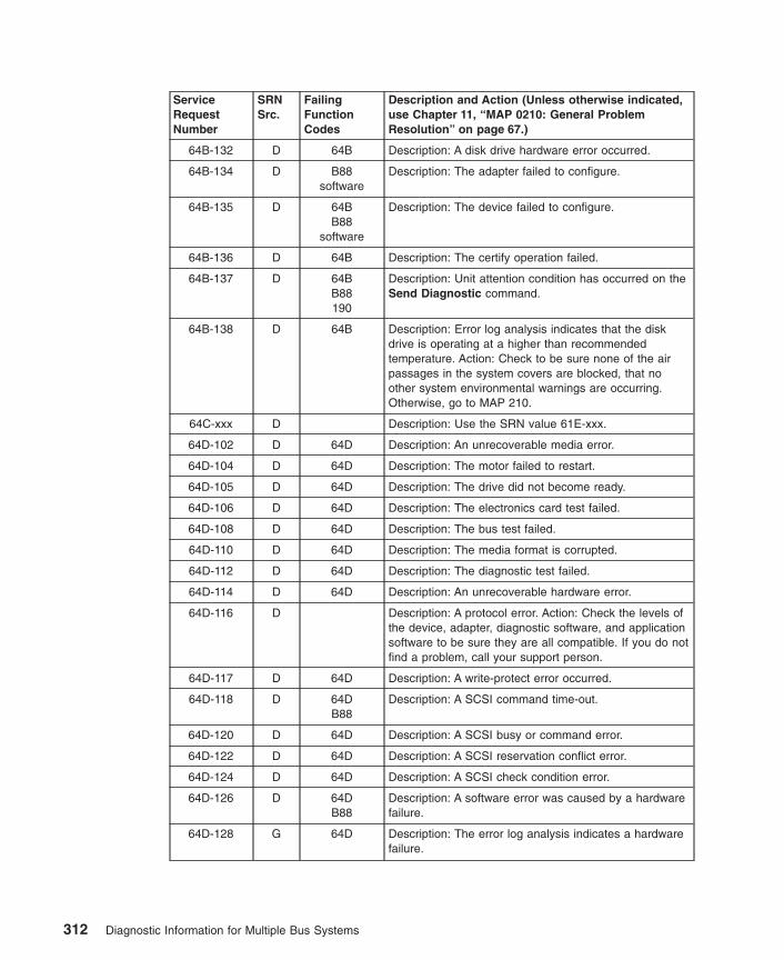
ServiceRequestNumber
SRNSrc.
FailingFunctionCodes
Description and Action (Unless otherwise indicated,use Chapter 11, “MAP 0210: General ProblemResolution” on page 67.)
64B-132 D 64B Description: A disk drive hardware error occurred.
64B-134 D B88software
Description: The adapter failed to configure.
64B-135 D 64BB88
software
Description: The device failed to configure.
64B-136 D 64B Description: The certify operation failed.
64B-137 D 64BB88190
Description: Unit attention condition has occurred on theSend Diagnostic command.
64B-138 D 64B Description: Error log analysis indicates that the diskdrive is operating at a higher than recommendedtemperature. Action: Check to be sure none of the airpassages in the system covers are blocked, that noother system environmental warnings are occurring.Otherwise, go to MAP 210.
64C-xxx D Description: Use the SRN value 61E-xxx.
64D-102 D 64D Description: An unrecoverable media error.
64D-104 D 64D Description: The motor failed to restart.
64D-105 D 64D Description: The drive did not become ready.
64D-106 D 64D Description: The electronics card test failed.
64D-108 D 64D Description: The bus test failed.
64D-110 D 64D Description: The media format is corrupted.
64D-112 D 64D Description: The diagnostic test failed.
64D-114 D 64D Description: An unrecoverable hardware error.
64D-116 D Description: A protocol error. Action: Check the levels ofthe device, adapter, diagnostic software, and applicationsoftware to be sure they are all compatible. If you do notfind a problem, call your support person.
64D-117 D 64D Description: A write-protect error occurred.
64D-118 D 64DB88
Description: A SCSI command time-out.
64D-120 D 64D Description: A SCSI busy or command error.
64D-122 D 64D Description: A SCSI reservation conflict error.
64D-124 D 64D Description: A SCSI check condition error.
64D-126 D 64DB88
Description: A software error was caused by a hardwarefailure.
64D-128 G 64D Description: The error log analysis indicates a hardwarefailure.
312 Diagnostic Information for Multiple Bus Systems
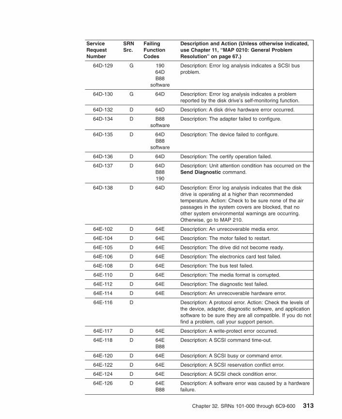
ServiceRequestNumber
SRNSrc.
FailingFunctionCodes
Description and Action (Unless otherwise indicated,use Chapter 11, “MAP 0210: General ProblemResolution” on page 67.)
64D-129 G 19064DB88
software
Description: Error log analysis indicates a SCSI busproblem.
64D-130 G 64D Description: Error log analysis indicates a problemreported by the disk drive’s self-monitoring function.
64D-132 D 64D Description: A disk drive hardware error occurred.
64D-134 D B88software
Description: The adapter failed to configure.
64D-135 D 64DB88
software
Description: The device failed to configure.
64D-136 D 64D Description: The certify operation failed.
64D-137 D 64DB88190
Description: Unit attention condition has occurred on theSend Diagnostic command.
64D-138 D 64D Description: Error log analysis indicates that the diskdrive is operating at a higher than recommendedtemperature. Action: Check to be sure none of the airpassages in the system covers are blocked, that noother system environmental warnings are occurring.Otherwise, go to MAP 210.
64E-102 D 64E Description: An unrecoverable media error.
64E-104 D 64E Description: The motor failed to restart.
64E-105 D 64E Description: The drive did not become ready.
64E-106 D 64E Description: The electronics card test failed.
64E-108 D 64E Description: The bus test failed.
64E-110 D 64E Description: The media format is corrupted.
64E-112 D 64E Description: The diagnostic test failed.
64E-114 D 64E Description: An unrecoverable hardware error.
64E-116 D Description: A protocol error. Action: Check the levels ofthe device, adapter, diagnostic software, and applicationsoftware to be sure they are all compatible. If you do notfind a problem, call your support person.
64E-117 D 64E Description: A write-protect error occurred.
64E-118 D 64EB88
Description: A SCSI command time-out.
64E-120 D 64E Description: A SCSI busy or command error.
64E-122 D 64E Description: A SCSI reservation conflict error.
64E-124 D 64E Description: A SCSI check condition error.
64E-126 D 64EB88
Description: A software error was caused by a hardwarefailure.
Chapter 32. SRNs 101-000 through 6C9-600 313

ServiceRequestNumber
SRNSrc.
FailingFunctionCodes
Description and Action (Unless otherwise indicated,use Chapter 11, “MAP 0210: General ProblemResolution” on page 67.)
64E-128 G 64E Description: The error log analysis indicates a hardwarefailure.
64E-129 G 19064EB88
software
Description: Error log analysis indicates a SCSI busproblem.
64E-130 G 64E Description: Error log analysis indicates a problemreported by the disk drive’s self-monitoring function.
64E-132 D 64E Description: A disk drive hardware error occurred.
64E-134 D B88software
Description: The adapter failed to configure.
64E-135 D 64EB88
software
Description: The device failed to configure.
64E-136 D 64E Description: The certify operation failed.
64E-137 D 64EB88190
Description: Unit attention condition has occurred on theSend Diagnostic command.
64E-138 D 64E Description: Error log analysis indicates that the diskdrive is operating at a higher than recommendedtemperature. Action: Check to be sure none of the airpassages in the system covers are blocked, that noother system environmental warnings are occurring.Otherwise, go to MAP 210.
64F-xxx D Description: Use the SRN value 61D-xxx.
650-xxx D 650 Description: Disk drive configuration failed.
651-140 D 165221
Description: Display Character test failed.
651-150 D 1662E0
Description: Sensor indicates a fan has failed. Action:Use Chapter 12, “MAP 0220: Hot-Swap FRU ProblemResolution” on page 77.
651-151 D 1522E2
Description: Sensor indicates a voltage is outside thenormal range. Action: Use MAP 1520.
651-152 D 2E1 Description: Sensor indicates an abnormally high internaltemperature. Action: Verify that:
1. The room ambient temperature is within the systemoperating environment.
2. There is unrestricted air flow around the system.
3. All system covers are closed.
4. There are no fan failures.
If none of these problems exist, then proceed withChapter 12, “MAP 0220: Hot-Swap FRU ProblemResolution” on page 77.
314 Diagnostic Information for Multiple Bus Systems

ServiceRequestNumber
SRNSrc.
FailingFunctionCodes
Description and Action (Unless otherwise indicated,use Chapter 11, “MAP 0210: General ProblemResolution” on page 67.)
651-153 D 152E19
Description: Sensor indicates a power supply has failed.Action: Use Chapter 12, “MAP 0220: Hot-Swap FRUProblem Resolution” on page 77.
651-159 D Description: Sensor indicates a FRU has failed. Action:Use MAP 210. Instead of failing function codes, use thephysical location code(s) from the diagnostic problemreport screen to determine the FRUs.
651-160 D 1662E0
Description: Sensor indicates a fan is turning too slowly.Action: Use Chapter 12, “MAP 0220: Hot-Swap FRUProblem Resolution” on page 77.
651-161 D 1522E2
Description: Sensor indicates a voltage is outside thenormal range. Action: Use MAP 1520.
651-162 D 2E1 Description: Sensor indicates an abnormally high internaltemperature. Action: Verify that:
1. The room ambient temperature is within the systemoperating environment.
2. There is unrestricted air flow around the system.
3. All system covers are closed.
4. There are no fan failures.
If none of these problems exist, then proceed withChapter 12, “MAP 0220: Hot-Swap FRU ProblemResolution” on page 77.
651-163 D 152E19
Description: Sensor indicates a power supply has failed.Action: Use Chapter 12, “MAP 0220: Hot-Swap FRUProblem Resolution” on page 77.
651-169 D Description: Sensor indicates a FRU has failed. Action:Use MAP 210. Instead of failing function codes, use thephysical location code(s) from the diagnostic problemreport screen to determine the FRUs.
651-170 D Description: Sensor status not available. Action: Contactyour support person.
651-171 D Description: Sensor status not available Action: Contactyour support person.
651-600 G Description: Uncorrectable memory or unsupportedmemory. Action: Examine the memory modules anddetermine if they are supported types. If the modules aresupported, then replace the appropriate memorymodule(s).
651-601 G Description: Missing or bad memory Action: If theinstalled memory matches the reported memory size,then replace the memory: otherwise, add the missingmemory.
Chapter 32. SRNs 101-000 through 6C9-600 315
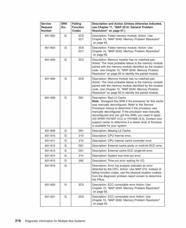
ServiceRequestNumber
SRNSrc.
FailingFunctionCodes
Description and Action (Unless otherwise indicated,use Chapter 11, “MAP 0210: General ProblemResolution” on page 67.)
651-602 G 2C52C7
Description: Failed memory module. Action: UseChapter 15, “MAP 0240: Memory Problem Resolution”on page 93.
651-603 G 2C62C7
Description: Failed memory module. Action: UseChapter 15, “MAP 0240: Memory Problem Resolution”on page 93.
651-604 G 2C5 Description: Memory module has no matched pair.Action: The most probable failure is the memory modulepaired with the memory module identified by the locationcode. Use Chapter 15, “MAP 0240: Memory ProblemResolution” on page 93 to identify the paired module.
651-605 G 2C6 Description: Memory module has no matched pair.Action: The most probable failure is the memory modulepaired with the memory module identified by the locationcode. Use Chapter 15, “MAP 0240: Memory ProblemResolution” on page 93 to identify the paired module.
651-608 G D01 Description: Bad L2 Cache.Note: Disregard this SRN if the processor for this cachewas manually deconfigured. Refer to the ServiceProcessor menus to determine if the processor wasmanually deconfigured. If the processor was manuallydeconfigured and you got this SRN, you need to applyAIX APAR IY01637 (4.2) or IY01606 (4.3). Contact yoursupport center to determine if a newer level of firmwareis available for your system.
651-609 G D01 Description: Missing L2 Cache.
651-610 G 210 Description: CPU internal error.
651-611 G 210 Description: CPU internal cache controller error.
651-612 G D01 Description: External cache parity or multi-bit ECC error.
651-613 G D01 Description: External cache ECC single-bit error.
651-614 G 214 Description: System bus time-out error.
651-615 G 292 Description: Time-out error waiting for I/O.
651-619 G Description: Error log analysis indicates an errordetected by the CPU. Action: Use MAP 210. Instead offailing function codes, use the physical location code(s)from the diagnostic problem report screen to determinethe FRUs.
651-620 G 2C5 Description: ECC correctable error Action: UseChapter 15, “MAP 0240: Memory Problem Resolution”on page 93.
651-621 G 2C6 Description: ECC correctable error Action: UseChapter 15, “MAP 0240: Memory Problem Resolution”on page 93.
316 Diagnostic Information for Multiple Bus Systems

ServiceRequestNumber
SRNSrc.
FailingFunctionCodes
Description and Action (Unless otherwise indicated,use Chapter 11, “MAP 0210: General ProblemResolution” on page 67.)
651-622 G 2C5 Description: Correctable error threshold exceededAction: Use Chapter 15, “MAP 0240: Memory ProblemResolution” on page 93.
651-623 G 2C6 Description: Correctable error threshold exceededAction: Use Chapter 15, “MAP 0240: Memory ProblemResolution” on page 93.
651-624 G 214 Description: Memory Control Subsystem internal error.
651-625 G 214 Description: Memory address error (invalid address oraccess attempt).
651-626 G 214 Description: Memory Data error (Bad data going tomemory).
651-627 G 214 Description: System bus time-out error.
651-628 G 210 Description: System bus protocol/transfer error.
651-629 G Description: Error log analysis indicates an errordetected by the memory controller. Action: Use MAP210. Instead of failing function codes, use the physicallocation code(s) from the diagnostic problem reportscreen to determine the FRUs.
651-630 G 307 Description: I/O Expansion Bus Parity Error.
651-631 G 307 Description: I/O Expansion Bus Time-out Error.
651-632 G 306307308
Description: Internal Device Error.
651-633 G 307306
Description: I/O Expansion Unit not in an operating state.
651-634 G 307 Description: Internal Device Error.
651-639 G Description: Error log analysis indicates an errordetected by the I/O. Action: Use MAP 210. Instead offailing function codes, use the physical location code(s)from the diagnostic problem report screen to determinethe FRUs.
651-640 G 2D5 Description: I/O general bus error.
651-641 G 2D6 Description: Secondary I/O general bus error.
651-642 G 2D3 Description: Internal Service Processor memory error.
651-643 G 2D3 Description: Internal Service Processor firmware error.
651-644 G 2D3 Description: Other internal Service Processor hardwareerror.
651-650 G E17 Description: ECC correctable error. Action: UseChapter 15, “MAP 0240: Memory Problem Resolution”on page 93.
Chapter 32. SRNs 101-000 through 6C9-600 317
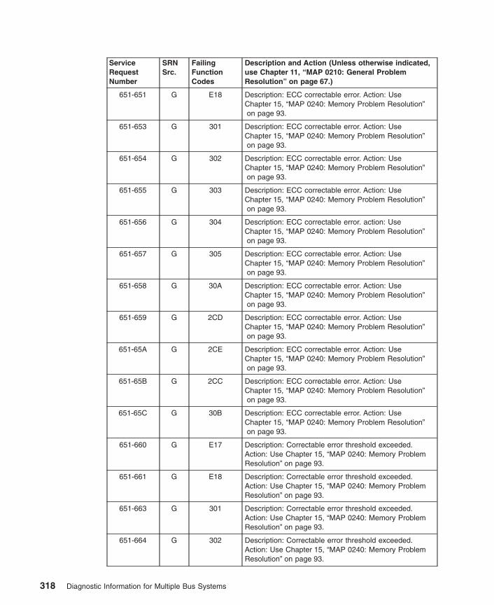
ServiceRequestNumber
SRNSrc.
FailingFunctionCodes
Description and Action (Unless otherwise indicated,use Chapter 11, “MAP 0210: General ProblemResolution” on page 67.)
651-651 G E18 Description: ECC correctable error. Action: UseChapter 15, “MAP 0240: Memory Problem Resolution”on page 93.
651-653 G 301 Description: ECC correctable error. Action: UseChapter 15, “MAP 0240: Memory Problem Resolution”on page 93.
651-654 G 302 Description: ECC correctable error. Action: UseChapter 15, “MAP 0240: Memory Problem Resolution”on page 93.
651-655 G 303 Description: ECC correctable error. Action: UseChapter 15, “MAP 0240: Memory Problem Resolution”on page 93.
651-656 G 304 Description: ECC correctable error. action: UseChapter 15, “MAP 0240: Memory Problem Resolution”on page 93.
651-657 G 305 Description: ECC correctable error. Action: UseChapter 15, “MAP 0240: Memory Problem Resolution”on page 93.
651-658 G 30A Description: ECC correctable error. Action: UseChapter 15, “MAP 0240: Memory Problem Resolution”on page 93.
651-659 G 2CD Description: ECC correctable error. Action: UseChapter 15, “MAP 0240: Memory Problem Resolution”on page 93.
651-65A G 2CE Description: ECC correctable error. Action: UseChapter 15, “MAP 0240: Memory Problem Resolution”on page 93.
651-65B G 2CC Description: ECC correctable error. Action: UseChapter 15, “MAP 0240: Memory Problem Resolution”on page 93.
651-65C G 30B Description: ECC correctable error. Action: UseChapter 15, “MAP 0240: Memory Problem Resolution”on page 93.
651-660 G E17 Description: Correctable error threshold exceeded.Action: Use Chapter 15, “MAP 0240: Memory ProblemResolution” on page 93.
651-661 G E18 Description: Correctable error threshold exceeded.Action: Use Chapter 15, “MAP 0240: Memory ProblemResolution” on page 93.
651-663 G 301 Description: Correctable error threshold exceeded.Action: Use Chapter 15, “MAP 0240: Memory ProblemResolution” on page 93.
651-664 G 302 Description: Correctable error threshold exceeded.Action: Use Chapter 15, “MAP 0240: Memory ProblemResolution” on page 93.
318 Diagnostic Information for Multiple Bus Systems

ServiceRequestNumber
SRNSrc.
FailingFunctionCodes
Description and Action (Unless otherwise indicated,use Chapter 11, “MAP 0210: General ProblemResolution” on page 67.)
651-665 G 303 Description: Correctable error threshold exceeded.Action: Use Chapter 15, “MAP 0240: Memory ProblemResolution” on page 93.
651-666 G 304 Description: Correctable error threshold exceeded.Action: Use Chapter 15, “MAP 0240: Memory ProblemResolution” on page 93.
651-667 G 305 Description: Correctable error threshold exceeded.Action: Use Chapter 15, “MAP 0240: Memory ProblemResolution” on page 93.
651-668 G 30A Description: Correctable error threshold exceeded.Action: Use Chapter 15, “MAP 0240: Memory ProblemResolution” on page 93.
651-669 G 2CD Description: Correctable error threshold exceeded.Action: Use Chapter 15, “MAP 0240: Memory ProblemResolution” on page 93.
651-66A G 2CE Description: Correctable error threshold exceeded.Action: Use Chapter 15, “MAP 0240: Memory ProblemResolution” on page 93.
651-66B G 2CC Description: Correctable error threshold exceeded.Action: Use Chapter 15, “MAP 0240: Memory ProblemResolution” on page 93.
651-66C G 30B Description: Correctable error threshold exceeded.Action: Use Chapter 15, “MAP 0240: Memory ProblemResolution” on page 93.
651-670 G E172C7
Description: Failed memory module. Action: UseChapter 15, “MAP 0240: Memory Problem Resolution”on page 93.
651-671 G E182C7
Description: Failed memory module. Action: UseChapter 15, “MAP 0240: Memory Problem Resolution”on page 93.
651-673 G 301 Description: Failed memory module. Action: UseChapter 15, “MAP 0240: Memory Problem Resolution”on page 93.
651-674 G 302 Description: Failed memory module. Action: UseChapter 15, “MAP 0240: Memory Problem Resolution”on page 93.
651-675 G 303 Description: Failed memory module. Action: UseChapter 15, “MAP 0240: Memory Problem Resolution”on page 93.
651-676 G 304 Description: Failed memory module. Action: UseChapter 15, “MAP 0240: Memory Problem Resolution”on page 93.
651-677 G 305 Description: Failed memory module. Action: UseChapter 15, “MAP 0240: Memory Problem Resolution”on page 93.
Chapter 32. SRNs 101-000 through 6C9-600 319

ServiceRequestNumber
SRNSrc.
FailingFunctionCodes
Description and Action (Unless otherwise indicated,use Chapter 11, “MAP 0210: General ProblemResolution” on page 67.)
651-678 G 30A Description: Failed memory module. Action: UseChapter 15, “MAP 0240: Memory Problem Resolution”on page 93.
651-679 G 2CD Description: Failed memory module. Action: UseChapter 15, “MAP 0240: Memory Problem Resolution”on page 93.
651-67A G 2CE Description: Failed memory module. Action: UseChapter 15, “MAP 0240: Memory Problem Resolution”on page 93.
651-67B G 2CC Description: Failed memory module. Action: UseChapter 15, “MAP 0240: Memory Problem Resolution”on page 93.
651-67C G 30B Description: Failed memory module. Action: UseChapter 15, “MAP 0240: Memory Problem Resolution”on page 93.
651-680 G E17 Description: Memory module has no matched pair.Action: The most probable failure is the memory modulepaired with the memory module identified by the locationcode. Use Chapter 15, “MAP 0240: Memory ProblemResolution” on page 93 to identify the paired module.
651-681 G E18 Description: Memory module has no matched pair.Action: The most probable failure is the memory modulepaired with the memory module identified by the locationcode. Use Chapter 15, “MAP 0240: Memory ProblemResolution” on page 93 to identify the paired module.
651-683 G 301 Description: Memory module has no matched pair.Action: The most probable failure is the memory modulepaired with the memory module identified by the locationcode. Use Chapter 15, “MAP 0240: Memory ProblemResolution” on page 93 to identify the paired module.
651-684 G 302 Description: Memory module has no matched pair.Action: The most probable failure is the memory modulepaired with the memory module identified by the locationcode. Use Chapter 15, “MAP 0240: Memory ProblemResolution” on page 93 to identify the paired module.
651-685 G 303 Description: Memory module has no matched pair.Action: The most probable failure is the memory modulepaired with the memory module identified by the locationcode. Use Chapter 15, “MAP 0240: Memory ProblemResolution” on page 93 to identify the paired module.
651-686 G 304 Description: Memory module has no matched pair.Action: The most probable failure is the memory modulepaired with the memory module identified by the locationcode. Use Chapter 15, “MAP 0240: Memory ProblemResolution” on page 93 to identify the paired module.
320 Diagnostic Information for Multiple Bus Systems
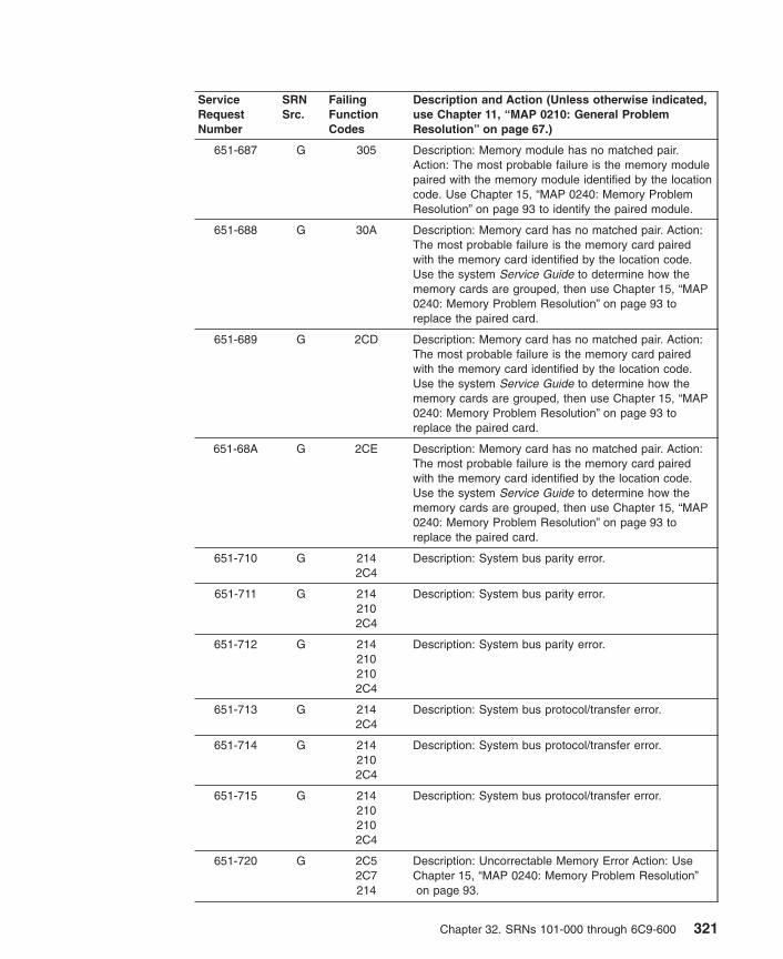
ServiceRequestNumber
SRNSrc.
FailingFunctionCodes
Description and Action (Unless otherwise indicated,use Chapter 11, “MAP 0210: General ProblemResolution” on page 67.)
651-687 G 305 Description: Memory module has no matched pair.Action: The most probable failure is the memory modulepaired with the memory module identified by the locationcode. Use Chapter 15, “MAP 0240: Memory ProblemResolution” on page 93 to identify the paired module.
651-688 G 30A Description: Memory card has no matched pair. Action:The most probable failure is the memory card pairedwith the memory card identified by the location code.Use the system Service Guide to determine how thememory cards are grouped, then use Chapter 15, “MAP0240: Memory Problem Resolution” on page 93 toreplace the paired card.
651-689 G 2CD Description: Memory card has no matched pair. Action:The most probable failure is the memory card pairedwith the memory card identified by the location code.Use the system Service Guide to determine how thememory cards are grouped, then use Chapter 15, “MAP0240: Memory Problem Resolution” on page 93 toreplace the paired card.
651-68A G 2CE Description: Memory card has no matched pair. Action:The most probable failure is the memory card pairedwith the memory card identified by the location code.Use the system Service Guide to determine how thememory cards are grouped, then use Chapter 15, “MAP0240: Memory Problem Resolution” on page 93 toreplace the paired card.
651-710 G 2142C4
Description: System bus parity error.
651-711 G 2142102C4
Description: System bus parity error.
651-712 G 2142102102C4
Description: System bus parity error.
651-713 G 2142C4
Description: System bus protocol/transfer error.
651-714 G 2142102C4
Description: System bus protocol/transfer error.
651-715 G 2142102102C4
Description: System bus protocol/transfer error.
651-720 G 2C52C7214
Description: Uncorrectable Memory Error Action: UseChapter 15, “MAP 0240: Memory Problem Resolution”on page 93.
Chapter 32. SRNs 101-000 through 6C9-600 321

ServiceRequestNumber
SRNSrc.
FailingFunctionCodes
Description and Action (Unless otherwise indicated,use Chapter 11, “MAP 0210: General ProblemResolution” on page 67.)
651-721 G 2C62C7214
Description: Uncorrectable Memory Error Action: UseChapter 15, “MAP 0240: Memory Problem Resolution”on page 93.
651-722 G 2102C4214
Description: System bus parity error.
651-723 G 2102C4214
Description: System bus protocol/transfer error.
651-724 G 2922C8214763
Description: I/O Host Bridge time-out error.
651-725 G 2922C8214763
Description: I/O Host Bridge address/data parity error.
651-726 G Software Description: I/O Host Bridge timeout caused by software.Action: This error is caused by a software or operatingsystem attempt to access an invalid memory address.Contact software support for assistance.
651-730 G Description: I/O error on the ISA bus. Action: Refer tothe Error Code to FRU Index in the system unit’s serviceguide.
651-731 G 2C8292763
Description: Intermediate or System Bus Address ParityError.
651-732 G 2C8292763
Description: Intermediate or System Bus Data ParityError.
651-733 G 2142C8292
Description: Intermediate or System Bus Address ParityError.
651-734 G 2142C8292
Description: Intermediate or System Bus Data ParityError.
651-735 G 2D2292
Description: Intermediate or System Bus Time-out Error.
651-736 G 2D2292214
Description: Intermediate or System Bus Time-out Error.
322 Diagnostic Information for Multiple Bus Systems
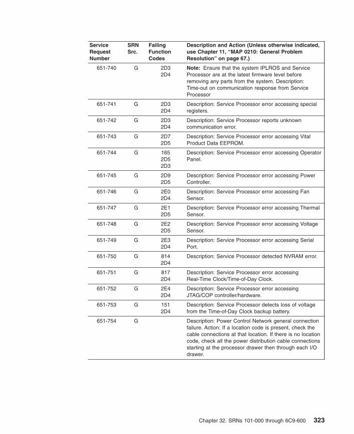
ServiceRequestNumber
SRNSrc.
FailingFunctionCodes
Description and Action (Unless otherwise indicated,use Chapter 11, “MAP 0210: General ProblemResolution” on page 67.)
651-740 G 2D32D4
Note: Ensure that the system IPLROS and ServiceProcessor are at the latest firmware level beforeremoving any parts from the system. Description:Time-out on communication response from ServiceProcessor
651-741 G 2D32D4
Description: Service Processor error accessing specialregisters.
651-742 G 2D32D4
Description: Service Processor reports unknowncommunication error.
651-743 G 2D72D5
Description: Service Processor error accessing VitalProduct Data EEPROM.
651-744 G 1652D52D3
Description: Service Processor error accessing OperatorPanel.
651-745 G 2D92D5
Description: Service Processor error accessing PowerController.
651-746 G 2E02D4
Description: Service Processor error accessing FanSensor.
651-747 G 2E12D5
Description: Service Processor error accessing ThermalSensor.
651-748 G 2E22D5
Description: Service Processor error accessing VoltageSensor.
651-749 G 2E32D4
Description: Service Processor error accessing SerialPort.
651-750 G 8142D4
Description: Service Processor detected NVRAM error.
651-751 G 8172D4
Description: Service Processor error accessingReal-Time Clock/Time-of-Day Clock.
651-752 G 2E42D4
Description: Service Processor error accessingJTAG/COP controller/hardware.
651-753 G 1512D4
Description: Service Processor detects loss of voltagefrom the Time-of-Day Clock backup battery.
651-754 G Description: Power Control Network general connectionfailure. Action: If a location code is present, check thecable connections at that location. If there is no locationcode, check all the power distribution cable connectionsstarting at the processor drawer then through each I/Odrawer.
Chapter 32. SRNs 101-000 through 6C9-600 323

ServiceRequestNumber
SRNSrc.
FailingFunctionCodes
Description and Action (Unless otherwise indicated,use Chapter 11, “MAP 0210: General ProblemResolution” on page 67.)
651-760 G softwarehardware
Description: Service Processor detected a surveillancetime-out. Action: A surveillance time-out is caused bylack of response from the operating system. The mostlikely cause is a software or operating system failure.Verify that the problem is not related to hardware byrunning diagnostics, in Problem Determination Mode, onall resources which have not already been run. Also, thesystem administrator should look for other symptomsthat would indicate a software or operating systemproblem. Contact the software support structure forassistance in needed.
651-770 G 2C8292306
Description: Intermediate or System Bus Address ParityError.
651-771 G 2C8292306
Description: Intermediate or System Bus Data ParityError.
651-772 G 2D2292306
Description: Intermediate or System Bus Time-out Error.
651-773 G 227 Description: Intermediate or System Bus Data ParityError.
651-780 G E172C7214
Description: Uncorrectable Memory Error. Action: UseChapter 15, “MAP 0240: Memory Problem Resolution”on page 93.
651-781 G E182C7214
Description: Uncorrectable Memory Error. Action: UseChapter 15, “MAP 0240: Memory Problem Resolution”on page 93.
651-783 G 301214
Description: Uncorrectable Memory Error. Action: UseChapter 15, “MAP 0240: Memory Problem Resolution”on page 93.
651-784 G 302214
Description: Uncorrectable Memory Error. Action: UseChapter 15, “MAP 0240: Memory Problem Resolution”on page 93.
651-785 G 303214
Description: Uncorrectable Memory Error. Action: UseChapter 15, “MAP 0240: Memory Problem Resolution”on page 93.
651-786 G 304214
Description: Uncorrectable Memory Error. Action: UseChapter 15, “MAP 0240: Memory Problem Resolution”on page 93.
651-787 G 305214
Description: Uncorrectable Memory Error. Action: UseChapter 15, “MAP 0240: Memory Problem Resolution”on page 93.
651-788 G 30A214
Description: Uncorrectable Memory Error. Action: UseChapter 15, “MAP 0240: Memory Problem Resolution”on page 93.
324 Diagnostic Information for Multiple Bus Systems

ServiceRequestNumber
SRNSrc.
FailingFunctionCodes
Description and Action (Unless otherwise indicated,use Chapter 11, “MAP 0210: General ProblemResolution” on page 67.)
651-789 G 2CD214
Description: Uncorrectable Memory Error. Action: UseChapter 15, “MAP 0240: Memory Problem Resolution”on page 93.
651-78A G 2CE214
Description: Uncorrectable Memory Error. Action: UseChapter 15, “MAP 0240: Memory Problem Resolution”on page 93.
651-78B G 2CC214
Description: Uncorrectable Memory Error. Action: UseChapter 15, “MAP 0240: Memory Problem Resolution”on page 93.
651-78C G 30B214
Description: Uncorrectable Memory Error. Action: UseChapter 15, “MAP 0240: Memory Problem Resolution”on page 93.
651-800 G 1662E0
Description: Fan is turning slower than expected.
651-801 G 1662E0
Description: Fan stop was detected. Action: Verify thefollowing:
v nothing is obstructing the fan rotation
v the fan power connection is tight
v the fan speed sensing cable is tight
If the fan still is not turning replace the fan. If the fan isturning, replace the fan sensor FRU.
651-802 G Description: Fan failure. Action: Use MAP 210. Insteadof failing function codes, use the physical locationcode(s) from the diagnostic problem report screen todetermine the FRUs.
651-809 G Description: Power fault warning due to unspecifiedcause. Action: Use MAP 210. Instead of failing functioncodes, use the physical location code(s) from thediagnostic problem report screen to determine the FRUs.
651-810 G 1522E2
Description: Over voltage condition was detected Action:Shut the system down and do the following beforereplacing any FRUs.
1. Visually inspect the power cables and reseat theconnectors.
2. Run the following command diag -Avd sysplanar0.When the Resource Repair Action menu displays,select sysplanar0.
Chapter 32. SRNs 101-000 through 6C9-600 325

ServiceRequestNumber
SRNSrc.
FailingFunctionCodes
Description and Action (Unless otherwise indicated,use Chapter 11, “MAP 0210: General ProblemResolution” on page 67.)
651-811 G 1522E2
Description: Under voltage condition was detectedAction: Shut the system down and do the followingbefore replacing any FRUs.
1. Visually inspect the power cables and reseat theconnectors.
2. Run the following command diag -Avd sysplanar0.When the Resource Repair Action menu displays,select sysplanar0.
651-812 G 152 Description: System shutdown due to:
1. Loss of AC power
2. Power button was pushed without proper systemshutdown
3. Power supply failure.
Action: If reasons 1 and 2 can be excludes, then replacethe power supply FRU.
651-813 G Description: System shutdown due to loss of AC Powerto the site. Action: System resumed normal operation, noaction required.
651-814 G 152 Description: CEC Rack shutdown due to one of thefollowing:
1. Loss of AC power to the CEC Rack
2. Open or disconnected SPCN cable between racks
3. AC module, Bulk power, regulator or SPCN cardfailure.
Action: If 1 and 2 can be excluded and the problem canbe re-created, try the power supply related FRUs one ata time to isolate the problem.
651-815 G 287289
Description: I/O Rack shutdown due to one of thefollowing:
1. Loss of AC power to the I/O Rack
2. Open or disconnected SPCN cable between racks
3. Power supply failure.
Action: If 1 and 2 can be excluded, then replace thepower supply FRU.
651-816 G 287 Description: Power fault due to internal power supplyfailure.
651-817 G 289 Description: Power fault due to internal power supplyfailure.
651-818 G Description: Power fault due to manual activation ofpower-off request. Action: Resume normal operation.
326 Diagnostic Information for Multiple Bus Systems

ServiceRequestNumber
SRNSrc.
FailingFunctionCodes
Description and Action (Unless otherwise indicated,use Chapter 11, “MAP 0210: General ProblemResolution” on page 67.)
651-819 G 152 Description: Power fault due to internal power supplyfailure.
651-820 G 2E1 Description: An over temperature condition was detectedAction: Verify the following:
v the room ambient temperature is within the systemoperating environment
v there is unrestricted air flow around the system
v all system covers are closed
If all conditions are met, then replace the temperaturesensor FRU.
651-821 G 2E1 Description: System shutdown due to an over maximumtemperature condition being reached. Action: Verify thefollowing:
v The room ambient temperature is within the systemoperating environment.
v There is unrestricted air flow around the system.
v All system covers are closed.
If all conditions are met, then replace the temperaturesensor FRU.
651-822 G 1662E1
Description: System shutdown due to over temperaturecondition and fan failure. Use the physical FRUlocation(s) as the probable cause(s). Action: Use thephysical location codes to replace the FRUs that areidentified on the diagnostics problem report screen.
651-823 G Description: System shutdown due to fan failure. Action:Use MAP 210. Instead of failing function codes, use thephysical location code(s) from the diagnostic problemreport screen to determine the FRUs.
651-824 G Description: System shutdown due to power faultwarning with an unspecified cause. Action: Use MAP210. Instead of failing function codes, use the physicallocation code(s) from the diagnostic problem reportscreen to determine the FRUs. If no physical locationcodes are reported, the shutdown was caused by usingthe power off button or there was a loss of power to thesystem.
651-830 G 1662E0
Description: Sensor detected a fan failure. Action: UseChapter 12, “MAP 0220: Hot-Swap FRU ProblemResolution” on page 77.
651-831 G 1522E2
Description: Sensor detected a voltage outside of thenormal range. Action: Use MAP 1520.
Chapter 32. SRNs 101-000 through 6C9-600 327

ServiceRequestNumber
SRNSrc.
FailingFunctionCodes
Description and Action (Unless otherwise indicated,use Chapter 11, “MAP 0210: General ProblemResolution” on page 67.)
651-832 G 2E1 Description: Sensor detected an abnormally high internaltemperature. Action: Verify that:
1. The room ambient temperature is within the systemoperating environment.
2. There is unrestricted air flow around the system.
3. All system covers are closed.
4. There are no fan failures.
If none of these problems exist, then proceed withChapter 12, “MAP 0220: Hot-Swap FRU ProblemResolution” on page 77.
651-833 G 152E19
Description: Sensor detected a power supply failure.Action: Use Chapter 12, “MAP 0220: Hot-Swap FRUProblem Resolution” on page 77.
651-839 G Description: Sensor detected a FRU that has failed.Action: Use MAP 210. Instead of failing function codes,use the physical location code(s) from the diagnosticproblem report screen to determine the FRUs.
651-840 G 1662E0
Description: Sensor detected a fan failure. Action: UseChapter 12, “MAP 0220: Hot-Swap FRU ProblemResolution” on page 77.
651-841 G 1522E2
Description: Sensor detected a voltage outside of thenormal range. Action: Use MAP 1520.
651-842 G 2E1 Description: Sensor detected an abnormally high internaltemperature. Action: Verify that:
1. The room ambient temperature is within the systemoperating environment.
2. There is unrestricted air flow around the system.
3. All system covers are closed.
4. There are no fan failures.
If none of these problems exist, then proceed withChapter 12, “MAP 0220: Hot-Swap FRU ProblemResolution” on page 77.
651-843 G 152E19
Description: Sensor detected a power supply failure.Action: Use Chapter 12, “MAP 0220: Hot-Swap FRUProblem Resolution” on page 77.
651-849 G Description: Sensor detected a FRU that has failed.Action: Use MAP 210. Instead of failing function codes,use the physical location code(s) from the diagnosticproblem report screen to determine the FRUs.
328 Diagnostic Information for Multiple Bus Systems
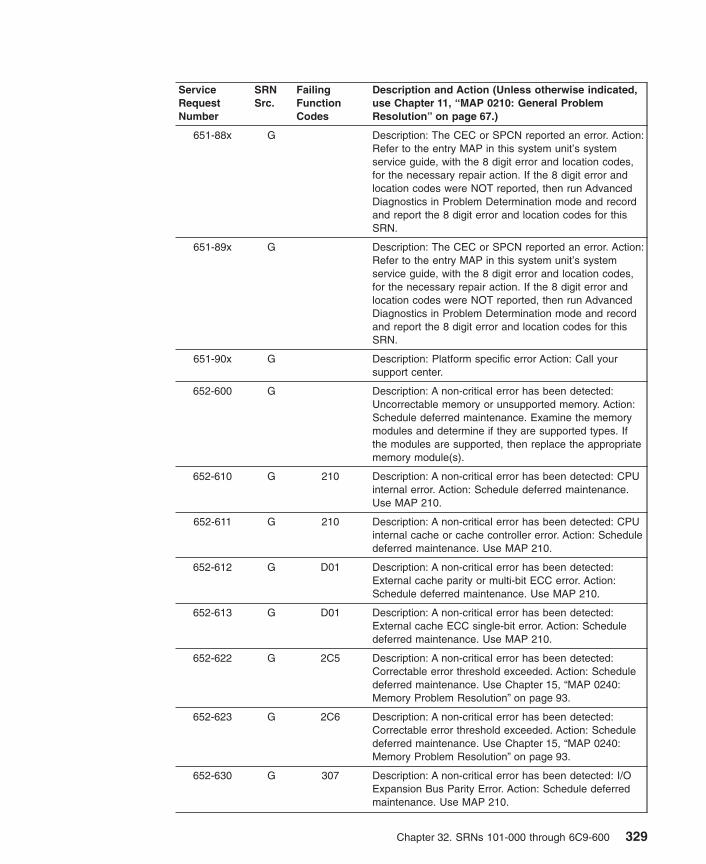
ServiceRequestNumber
SRNSrc.
FailingFunctionCodes
Description and Action (Unless otherwise indicated,use Chapter 11, “MAP 0210: General ProblemResolution” on page 67.)
651-88x G Description: The CEC or SPCN reported an error. Action:Refer to the entry MAP in this system unit’s systemservice guide, with the 8 digit error and location codes,for the necessary repair action. If the 8 digit error andlocation codes were NOT reported, then run AdvancedDiagnostics in Problem Determination mode and recordand report the 8 digit error and location codes for thisSRN.
651-89x G Description: The CEC or SPCN reported an error. Action:Refer to the entry MAP in this system unit’s systemservice guide, with the 8 digit error and location codes,for the necessary repair action. If the 8 digit error andlocation codes were NOT reported, then run AdvancedDiagnostics in Problem Determination mode and recordand report the 8 digit error and location codes for thisSRN.
651-90x G Description: Platform specific error Action: Call yoursupport center.
652-600 G Description: A non-critical error has been detected:Uncorrectable memory or unsupported memory. Action:Schedule deferred maintenance. Examine the memorymodules and determine if they are supported types. Ifthe modules are supported, then replace the appropriatememory module(s).
652-610 G 210 Description: A non-critical error has been detected: CPUinternal error. Action: Schedule deferred maintenance.Use MAP 210.
652-611 G 210 Description: A non-critical error has been detected: CPUinternal cache or cache controller error. Action: Scheduledeferred maintenance. Use MAP 210.
652-612 G D01 Description: A non-critical error has been detected:External cache parity or multi-bit ECC error. Action:Schedule deferred maintenance. Use MAP 210.
652-613 G D01 Description: A non-critical error has been detected:External cache ECC single-bit error. Action: Scheduledeferred maintenance. Use MAP 210.
652-622 G 2C5 Description: A non-critical error has been detected:Correctable error threshold exceeded. Action: Scheduledeferred maintenance. Use Chapter 15, “MAP 0240:Memory Problem Resolution” on page 93.
652-623 G 2C6 Description: A non-critical error has been detected:Correctable error threshold exceeded. Action: Scheduledeferred maintenance. Use Chapter 15, “MAP 0240:Memory Problem Resolution” on page 93.
652-630 G 307 Description: A non-critical error has been detected: I/OExpansion Bus Parity Error. Action: Schedule deferredmaintenance. Use MAP 210.
Chapter 32. SRNs 101-000 through 6C9-600 329

ServiceRequestNumber
SRNSrc.
FailingFunctionCodes
Description and Action (Unless otherwise indicated,use Chapter 11, “MAP 0210: General ProblemResolution” on page 67.)
652-631 G 307 Description: A non-critical error has been detected: I/OExpansion Bus Time-out Error. Action: Schedule deferredmaintenance. Use MAP 210.
652-632 G 306307308
Description: A non-critical error has been detected: I/OExpansion Bus Connection Failure. Action: Scheduledeferred maintenance. Use MAP 210.
652-633 G 307306
Description: A non-critical error has been detected: I/OExpansion Unit not in an operating state. Action:Schedule deferred maintenance. Use MAP 210.
652-634 G 307 Description: A non-critical error has been detected:Internal Device Error. Action: Schedule deferredmaintenance. Use MAP 210.
652-660 G E17 Description: A non-critical error has been detected:Correctable error threshold exceeded. Action: Scheduledeferred maintenance. Use Chapter 15, “MAP 0240:Memory Problem Resolution” on page 93.
652-661 G E18 Description: A non-critical error has been detected:Correctable error threshold exceeded. Action: Scheduledeferred maintenance. Use Chapter 15, “MAP 0240:Memory Problem Resolution” on page 93.
652-663 G 301 Description: A non-critical error has been detected:Correctable error threshold exceeded. Action: Scheduledeferred maintenance. Use Chapter 15, “MAP 0240:Memory Problem Resolution” on page 93.
652-664 G 302 Description: A non-critical error has been detected:Correctable error threshold exceeded. Action: Scheduledeferred maintenance. Use Chapter 15, “MAP 0240:Memory Problem Resolution” on page 93.
652-665 G 303 Description: A non-critical error has been detected:Correctable error threshold exceeded. Action: Scheduledeferred maintenance. Use Chapter 15, “MAP 0240:Memory Problem Resolution” on page 93.
652-666 G 304 Description: A non-critical error has been detected:Correctable error threshold exceeded. Action: Scheduledeferred maintenance. Use Chapter 15, “MAP 0240:Memory Problem Resolution” on page 93.
652-667 G 305 Description: A non-critical error has been detected:Correctable error threshold exceeded. Action: Scheduledeferred maintenance. Use Chapter 15, “MAP 0240:Memory Problem Resolution” on page 93.
652-668 G 30A Description: A non-critical error has been detected:Correctable error threshold exceeded. Action: Scheduledeferred maintenance. Use Chapter 15, “MAP 0240:Memory Problem Resolution” on page 93.
330 Diagnostic Information for Multiple Bus Systems

ServiceRequestNumber
SRNSrc.
FailingFunctionCodes
Description and Action (Unless otherwise indicated,use Chapter 11, “MAP 0210: General ProblemResolution” on page 67.)
652-669 G 2CD Description: A non-critical error has been detected:Correctable error threshold exceeded. Action: Scheduledeferred maintenance. Use Chapter 15, “MAP 0240:Memory Problem Resolution” on page 93.
652-66A G 2CE Description: A non-critical error has been detected:Correctable error threshold exceeded. Action: Scheduledeferred maintenance. Use Chapter 15, “MAP 0240:Memory Problem Resolution” on page 93.
652-66B G 2CC Description: A non-critical error has been detected:Correctable error threshold exceeded. Action: Scheduledeferred maintenance. Use Chapter 15, “MAP 0240:Memory Problem Resolution” on page 93.
652-66C G 30B Description: A non-critical error has been detected.Correctable error threshold exceeded. Action: Scheduledeferred maintenance. Use Chapter 15, “MAP 0240:Memory Problem Resolution” on page 93.
652-731 G 2C8292
Description: A non-critical error has been detected:Intermediate or System Bus Address Parity Error. Action:Schedule deferred maintenance. Use MAP 210.
652-732 G 2C8292
Description: A non-critical error has been detected:Intermediate or System Bus Data Parity Error. Action:Schedule deferred maintenance. Use MAP 210.
652-733 G 2142C8292
Description: A non-critical error has been detected:Intermediate or System Bus Address Parity Error. Action:Schedule deferred maintenance. Use MAP 210.
652-734 G 2142C8292
Description: A non-critical error has been detected:Intermediate or System Bus Data Parity Error. Action:Schedule deferred maintenance. Use MAP 210.
652-735 G 2D2292
Description: A non-critical error has been detected:Intermediate or System Bus Time-out Error. Action:Schedule deferred maintenance. Use MAP 210.
652-736 G 2D2292214
Description: A non-critical error has been detected:Intermediate or System Bus Time-out Error. Action:Schedule deferred maintenance. Use MAP 210.
652-770 G 2C8292306
Description: A non-critical error has been detected:Intermediate System Bus Address Parity Error. Action:Schedule deferred maintenance. Use MAP 210.
652-771 G 2C8292306
Description: A non-critical error has been detected:Intermediate or System Bus Data Parity Error. Action:Schedule deferred maintenance. Use MAP 210.
652-772 G 2D2292306
Description: A non-critical error has been detected:Intermediate or System Bus Time-out Error. Action:Schedule deferred maintenance. Use MAP 210.
Chapter 32. SRNs 101-000 through 6C9-600 331

ServiceRequestNumber
SRNSrc.
FailingFunctionCodes
Description and Action (Unless otherwise indicated,use Chapter 11, “MAP 0210: General ProblemResolution” on page 67.)
652-773 G 227 Description: A non-critical error has been detected:Intermediate or System Bus Data Parity Error. Action:Schedule deferred maintenance. Use MAP 210.
652-810 G 152 Description: Non-critical power problem, loss ofredundant supply. Use the physical FRU location(s) asthe probable cause(s). Action: Schedule maintenance.Use the physical location codes to replace the FRUs thatare identified on the diagnostics problem report screen.
652-819 G Description: Power fault due to internal redundant powersupply failure.
652-820 G 166 Description: Non-critical cooling problem, loss ofredundant fan. Use the physical FRU location(s) as theprobable cause(s). Action: Schedule maintenance. Usethe physical location codes to replace the FRUs that areidentified on the diagnostics problem report screen.
652-830 G 1662E0
Description: Sensor detected a redundant fan failure.Action: Use Chapter 12, “MAP 0220: Hot-Swap FRUProblem Resolution” on page 77.
652-833 G 152E19
Description: Sensor detected a redundant power supplyfailure. Action: Use Chapter 12, “MAP 0220: Hot-SwapFRU Problem Resolution” on page 77.
652-839 G Description: Sensor detected a redundant FRU failure.Action: Use MAP 210. Instead of failing functioncodes,use the physical location code(s) from thediagnostic problem report screen to determine the FRUs.
652-88x G Description: The CEC or SPCN reported a non-criticalerror. Action: Schedule deferred maintenance. Refer tothe entry MAP in this system unit’s system serviceguide, with the 8 digit error and location codes, for thenecessary repair action. If the 8 digit error and locationcodes were NOT reported, then run AdvancedDiagnostics in Problem Determination mode and recordand report the 8 digit error and location codes for thisSRN.
652-89x G Description: The CEC or SPCN reported a non-criticalerror. Action: Schedule deferred maintenance. Refer tothe entry MAP in this system unit’s system serviceguide, with the 8 digit error and location codes, for thenecessary repair action. If the 8 digit error and locationcodes were NOT reported, then run AdvancedDiagnostics in Problem Determination mode and recordand report the 8 digit error and location codes for thisSRN.
653-102 D 653 Description: An unrecoverable media error occurred.
653-104 D 653 Description: The motor failed to restart.
653-105 D 653 Description: The drive did not become ready.
332 Diagnostic Information for Multiple Bus Systems

ServiceRequestNumber
SRNSrc.
FailingFunctionCodes
Description and Action (Unless otherwise indicated,use Chapter 11, “MAP 0210: General ProblemResolution” on page 67.)
653-106 D 653 Description: The electronics card test failed.
653-108 D 653 Description: The bus test failed.
653-110 D 653 Description: The media format is corrupted.
653-112 D 653 Description: The diagnostic test failed.
653-114 D 653 Description: An unrecoverable hardware error.
653-116 D Description: A protocol error. Action: Check the levels ofthe device, adapter, diagnostic software, and applicationsoftware to be sure they are all compatible. If you do notfind a problem, call your support person.
653-117 D 653 Description: A write-protect error occurred.
653-118 D 653B88
Description: A SCSI command time-out occurred.
653-120 D 653 Description: A SCSI busy or command error.
653-122 D 653 Description: A SCSI reservation conflict error.
653-124 D 653 Description: A SCSI check condition error occurred.
653-126 D 653B88
Description: A software error was caused by a hardwarefailure.
653-128 G 653 Description: The error log analysis indicates a hardwarefailure.
653-129 G 190653B88
software
Description: Error log analysis indicates a SCSI busproblem.
653-130 G 653 Description: Error log analysis indicates a problemreported by the disk drive’s self-monitoring function.
653-132 D 653 Description: A disk drive hardware error occurred.
653-134 D B88software
Description: The adapter failed to configure.
653-135 D 653B88
software
Description: The device failed to configure.
653-136 D 653 Description: The certify operation failed.
653-137 D 653B88190
Description: Unit attention condition has occurred on theSend Diagnostic command.
655-001 D 655221
Monitor/Cable
Description: Adapter problem.
655-002 D 655Monitor/Cable
Description: Display problem.
Chapter 32. SRNs 101-000 through 6C9-600 333
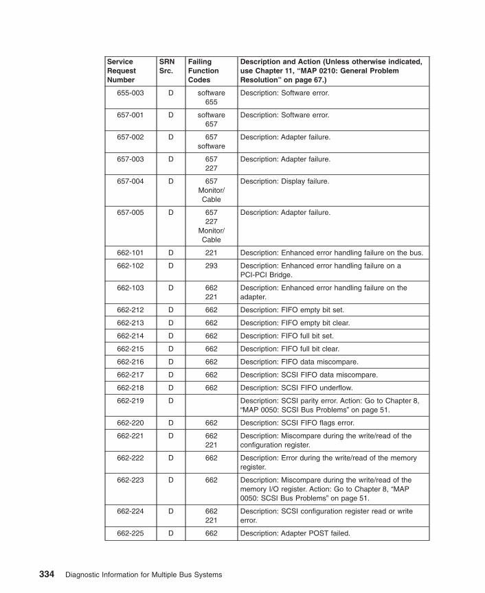
ServiceRequestNumber
SRNSrc.
FailingFunctionCodes
Description and Action (Unless otherwise indicated,use Chapter 11, “MAP 0210: General ProblemResolution” on page 67.)
655-003 D software655
Description: Software error.
657-001 D software657
Description: Software error.
657-002 D 657software
Description: Adapter failure.
657-003 D 657227
Description: Adapter failure.
657-004 D 657Monitor/Cable
Description: Display failure.
657-005 D 657227
Monitor/Cable
Description: Adapter failure.
662-101 D 221 Description: Enhanced error handling failure on the bus.
662-102 D 293 Description: Enhanced error handling failure on aPCI-PCI Bridge.
662-103 D 662221
Description: Enhanced error handling failure on theadapter.
662-212 D 662 Description: FIFO empty bit set.
662-213 D 662 Description: FIFO empty bit clear.
662-214 D 662 Description: FIFO full bit set.
662-215 D 662 Description: FIFO full bit clear.
662-216 D 662 Description: FIFO data miscompare.
662-217 D 662 Description: SCSI FIFO data miscompare.
662-218 D 662 Description: SCSI FIFO underflow.
662-219 D Description: SCSI parity error. Action: Go to Chapter 8,“MAP 0050: SCSI Bus Problems” on page 51.
662-220 D 662 Description: SCSI FIFO flags error.
662-221 D 662221
Description: Miscompare during the write/read of theconfiguration register.
662-222 D 662 Description: Error during the write/read of the memoryregister.
662-223 D 662 Description: Miscompare during the write/read of thememory I/O register. Action: Go to Chapter 8, “MAP0050: SCSI Bus Problems” on page 51.
662-224 D 662221
Description: SCSI configuration register read or writeerror.
662-225 D 662 Description: Adapter POST failed.
334 Diagnostic Information for Multiple Bus Systems

ServiceRequestNumber
SRNSrc.
FailingFunctionCodes
Description and Action (Unless otherwise indicated,use Chapter 11, “MAP 0210: General ProblemResolution” on page 67.)
662-226 D Description: SCSI wrap or PTC failure. Action: Go toChapter 8, “MAP 0050: SCSI Bus Problems” on page 51.
662-227 D 662221
Description: SCSI adapter test failure.
662-230 D Description: Arbitration test failed. Action: Go toChapter 8, “MAP 0050: SCSI Bus Problems” on page 51.
662-231 D Description: Function could not complete. Action: Go toChapter 8, “MAP 0050: SCSI Bus Problems” on page 51.
662-232 D Description: SCSI bus data miscompare. Action: Go toChapter 8, “MAP 0050: SCSI Bus Problems” on page 51.
662-240 D Description: No terminal power. Action: Go to Chapter 8,“MAP 0050: SCSI Bus Problems” on page 51.
662-242 D Description: SCSI bus problem. Action: Go to Chapter 8,“MAP 0050: SCSI Bus Problems” on page 51.
662-301 D 662221
Description: The parent device open failed.
662-701 G 662 Description: Error log analysis indicates a PCI SCSIadapter failure.
662-801 G Description: Error log analysis indicates a terminatorproblem. Action: Run the diagnostics on the adapter inSystem Verification mode. If an SRN is reported, use theSRN to resolve the problem. If an SRN is not reported,use the SCSI service hints in “General SCSIConfiguration Checks” on page 3 to resolve the problem.
662-802 G Description: Error log analysis indicates that multipleattempts to reset the SCSI bus have timed out. Action:Run the diagnostics on the adapter in SystemVerification mode. If an SRN is reported, use the SRN toresolve the problem. If an SRN is not reported, use theSCSI service hints in “General SCSI ConfigurationChecks” on page 3 to resolve the problem.
662-803 G Description: Error log analysis indicates that multipleSCSI bus errors have occurred. Action: Run thediagnostics on the adapter in System Verification mode.If an SRN is reported, use the SRN to resolve theproblem. If an SRN is not reported, use the SCSI servicehints in “General SCSI Configuration Checks” on page 3to resolve the problem.
663-101 D 663C94C95
Description: IBM ARTIC960RxD or RxF PCI AdapterCentral Processing Unit test failure.
663-102 D 663C94C95
Description: IBM ARTIC960RxD or RxF PCI AdapterTimer test failure.
Chapter 32. SRNs 101-000 through 6C9-600 335
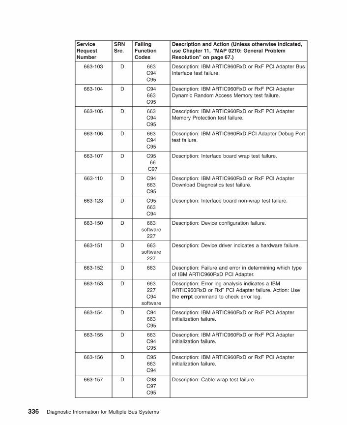
ServiceRequestNumber
SRNSrc.
FailingFunctionCodes
Description and Action (Unless otherwise indicated,use Chapter 11, “MAP 0210: General ProblemResolution” on page 67.)
663-103 D 663C94C95
Description: IBM ARTIC960RxD or RxF PCI Adapter BusInterface test failure.
663-104 D C94663C95
Description: IBM ARTIC960RxD or RxF PCI AdapterDynamic Random Access Memory test failure.
663-105 D 663C94C95
Description: IBM ARTIC960RxD or RxF PCI AdapterMemory Protection test failure.
663-106 D 663C94C95
Description: IBM ARTIC960RxD PCI Adapter Debug Porttest failure.
663-107 D C9566
C97
Description: Interface board wrap test failure.
663-110 D C94663C95
Description: IBM ARTIC960RxD or RxF PCI AdapterDownload Diagnostics test failure.
663-123 D C95663C94
Description: Interface board non-wrap test failure.
663-150 D 663software
227
Description: Device configuration failure.
663-151 D 663software
227
Description: Device driver indicates a hardware failure.
663-152 D 663 Description: Failure and error in determining which typeof IBM ARTIC960RxD PCI Adapter.
663-153 D 663227C94
software
Description: Error log analysis indicates a IBMARTIC960RxD or RxF PCI Adapter failure. Action: Usethe errpt command to check error log.
663-154 D C94663C95
Description: IBM ARTIC960RxD or RxF PCI Adapterinitialization failure.
663-155 D 663C94C95
Description: IBM ARTIC960RxD or RxF PCI Adapterinitialization failure.
663-156 D C95663C94
Description: IBM ARTIC960RxD or RxF PCI Adapterinitialization failure.
663-157 D C98C97C95
Description: Cable wrap test failure.
336 Diagnostic Information for Multiple Bus Systems
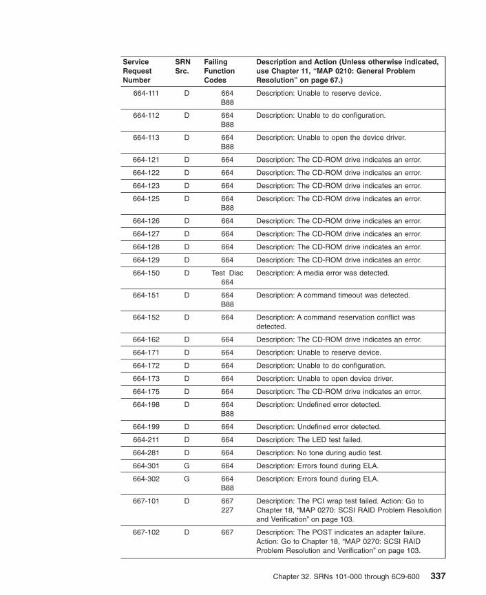
ServiceRequestNumber
SRNSrc.
FailingFunctionCodes
Description and Action (Unless otherwise indicated,use Chapter 11, “MAP 0210: General ProblemResolution” on page 67.)
664-111 D 664B88
Description: Unable to reserve device.
664-112 D 664B88
Description: Unable to do configuration.
664-113 D 664B88
Description: Unable to open the device driver.
664-121 D 664 Description: The CD-ROM drive indicates an error.
664-122 D 664 Description: The CD-ROM drive indicates an error.
664-123 D 664 Description: The CD-ROM drive indicates an error.
664-125 D 664B88
Description: The CD-ROM drive indicates an error.
664-126 D 664 Description: The CD-ROM drive indicates an error.
664-127 D 664 Description: The CD-ROM drive indicates an error.
664-128 D 664 Description: The CD-ROM drive indicates an error.
664-129 D 664 Description: The CD-ROM drive indicates an error.
664-150 D Test Disc664
Description: A media error was detected.
664-151 D 664B88
Description: A command timeout was detected.
664-152 D 664 Description: A command reservation conflict wasdetected.
664-162 D 664 Description: The CD-ROM drive indicates an error.
664-171 D 664 Description: Unable to reserve device.
664-172 D 664 Description: Unable to do configuration.
664-173 D 664 Description: Unable to open device driver.
664-175 D 664 Description: The CD-ROM drive indicates an error.
664-198 D 664B88
Description: Undefined error detected.
664-199 D 664 Description: Undefined error detected.
664-211 D 664 Description: The LED test failed.
664-281 D 664 Description: No tone during audio test.
664-301 G 664 Description: Errors found during ELA.
664-302 G 664B88
Description: Errors found during ELA.
667-101 D 667227
Description: The PCI wrap test failed. Action: Go toChapter 18, “MAP 0270: SCSI RAID Problem Resolutionand Verification” on page 103.
667-102 D 667 Description: The POST indicates an adapter failure.Action: Go to Chapter 18, “MAP 0270: SCSI RAIDProblem Resolution and Verification” on page 103.
Chapter 32. SRNs 101-000 through 6C9-600 337

ServiceRequestNumber
SRNSrc.
FailingFunctionCodes
Description and Action (Unless otherwise indicated,use Chapter 11, “MAP 0210: General ProblemResolution” on page 67.)
667-103 D 667 Description: The POST indicates an adapter channelfailure. Action: Go to Chapter 18, “MAP 0270: SCSIRAID Problem Resolution and Verification” on page 103.
667-104 D 190 Description: The POST indicates a defective cable.
667-105 D B3A Description: The POST indicates a defective backplaneor external enclosure.
667-106 D 722 Description: The POST indicates the last disk drivereconnected caused a channel failure. Action: Go toChapter 18, “MAP 0270: SCSI RAID Problem Resolutionand Verification” on page 103.
667-108 D 221 Description: Enhanced error handling failure on bus.
667-109 D 667 Description: The NVRAM test indicates an adapterfailure. Action: Go to Chapter 18, “MAP 0270: SCSIRAID Problem Resolution and Verification” on page 103.
667-110 D 722 Description: The disk reported a Predictive FailureAnalysis error (PFA). Action: Go to Chapter 18, “MAP0270: SCSI RAID Problem Resolution and Verification”on page 103.
667-111 D 722 Description: The disk drive has been failed by theadapter. Action: Go to Chapter 18, “MAP 0270: SCSIRAID Problem Resolution and Verification” on page 103.
667-112 G 722 Description: ELA indicates that the disk reported a harddata error. Action: Go to Chapter 18, “MAP 0270: SCSIRAID Problem Resolution and Verification” on page 103.
667-113 G 722 Description: ELA indicates that the disk reported a hardequipment error. Action: Go to Chapter 18, “MAP 0270:SCSI RAID Problem Resolution and Verification” onpage 103.
667-114 G E29 Description: ELA indicates a cache failure. Action: Go toChapter 18, “MAP 0270: SCSI RAID Problem Resolutionand Verification” on page 103.
667-115 G E30 Description: ELA indicates that the cache battery iseither low on power or has failed. Action: Go toChapter 18, “MAP 0270: SCSI RAID Problem Resolutionand Verification” on page 103.
667-116 D 667 Description: Failed to disable data scrub. Action: Go toChapter 18, “MAP 0270: SCSI RAID Problem Resolutionand Verification” on page 103.
667-117 D E29 Description: POST indicates cache failure. Action: Go toChapter 18, “MAP 0270: SCSI RAID Problem Resolutionand Verification” on page 103.
667-118 D E29 Description: NVRAM test indicates cache failure. Action:Go to Chapter 18, “MAP 0270: SCSI RAID ProblemResolution and Verification” on page 103.
338 Diagnostic Information for Multiple Bus Systems

ServiceRequestNumber
SRNSrc.
FailingFunctionCodes
Description and Action (Unless otherwise indicated,use Chapter 11, “MAP 0210: General ProblemResolution” on page 67.)
667-119 D E29 Description: NVRAM test indicates that write cache ismissing. Action: Go to Chapter 18, “MAP 0270: SCSIRAID Problem Resolution and Verification” on page 103.
667-120 D E29 Description: NVRAM test indicates that cache size isinvalid. Action: Go to Chapter 18, “MAP 0270: SCSIRAID Problem Resolution and Verification” on page 103.
667-121 D E30 Description: Adapter test indicates that the cache batteryis low on power. Action: Go to Chapter 18, “MAP 0270:SCSI RAID Problem Resolution and Verification” onpage 103.
667-122 D E30 Description: Adapter test indicates cache battery failure.Action: Go to Chapter 18, “MAP 0270: SCSI RAIDProblem Resolution and Verification” on page 103.
667-123 D 667 Description: ELA indicates an adapter failure. Action: Goto Chapter 18, “MAP 0270: SCSI RAID ProblemResolution and Verification” on page 103.
667-124 D 221 Description: Enhanced error handling failure on PCI-PCIBridge.
667-125 D 667221
Description: Enhanced error handling failure on adapter.
667-400 F 667190B3A722
Description: POST indicates a channel failure. Action:Go to Chapter 18, “MAP 0270: SCSI RAID ProblemResolution and Verification” on page 103.
667-701 G 667221
Description: Error Log Analysis indicates an EEH error.
669-101 D 221 Description: Enhanced error handling failure on bus.
669-102 D 221 Description: Enhanced error handling failure on Eadschip.
669-103 D 669 Description: Enhanced error handling failure on adapter.
669-201 D 669
221
Description: Configuration register test failure. Action:Before going to MAP 210, look at the label on theadapter. If the label is A-A, use SRN 66C-201 instead.
669-202 D 669 Description: I/O register test failure.
669-203 D 669 Description: Adapter memory test failure.
669-204 D 669 Description: Adapter initialization test failure.
669-205 D 669 Description: Internal loopback test failure.
669-206 D 669 Description: External wrap test failure (1000 Mbps).
669-701 G 669 Description: Error Log Analysis indicates that this devicefailed to initialize because it is not the IBM version of thisadapter. AIX operating system cannot configure thisnon-IBM version of the adapter.
Chapter 32. SRNs 101-000 through 6C9-600 339

ServiceRequestNumber
SRNSrc.
FailingFunctionCodes
Description and Action (Unless otherwise indicated,use Chapter 11, “MAP 0210: General ProblemResolution” on page 67.)
669-702 G 669 Description: Error Log Analysis indicates that this devicefailed to initialize due to a problem with the EEPROM onthe adapter.
669-703 G 669 Description: Error Log Analysis indicates that this devicehas failed to initialize due to a self-test failure.
669-704 G 669 Description: Error Log Analysis indicates that this devicehas failed to initialize due to firmware download error.
66C-101 D 221 Description: Enhanced error handling failure on bus.
66C-102 D 221 Description: Enhanced error handling failure on Eadschip.
66C-103 D 66C Description: Enhanced error handling failure on adapter.
66C-201 D 66C221
Description: Configuration register test failure.
66C-202 D 66C Description: I/O register test failure.
66C-203 D 66C Description: Adapter memory test failure.
66C-204 D 66C Description: Adapter initialization test failure.
66C-205 D 66C Description: Internal loopback test failure.
66C-206 D 66C Description: External wrap test failure (1000 Mbps).
66C-207 D 66C Description: External wrap test failure (10 Mbps).
66C-208 D 66C Description: External wrap test failure (100 Mbps).
66C-702 G 66C Description: Error Log Analysis indicates that this devicefailed to initialize due to a problem with the EEPROM onthe adapter.
66C-703 G 66C Description: Error Log Analysis indicates that this devicehas failed to initialize due to a self-test failure.
66C-704 G 66C Description: Error Log Analysis indicates that this devicehas failed to initialize due to firmware download error.
66D-101 D 66D227
Description: The PCI wrap test failed. Action: Go toChapter 18, “MAP 0270: SCSI RAID Problem Resolutionand Verification” on page 103.
66D-102 D 66DE2A
Description: The POST indicates an adapter failure.Action: Go to Chapter 18, “MAP 0270: SCSI RAIDProblem Resolution and Verification” on page 103.
66D-103 D 66D Description: The POST indicates an adapter channelfailure. Action: Go to Chapter 18, “MAP 0270: SCSIRAID Problem Resolution and Verification” on page 103.
66D-104 D 190 Description: The POST indicates a defective cable.
66D-105 D B3A Description: The POST indicates a defective backplaneor external enclosure.
340 Diagnostic Information for Multiple Bus Systems

ServiceRequestNumber
SRNSrc.
FailingFunctionCodes
Description and Action (Unless otherwise indicated,use Chapter 11, “MAP 0210: General ProblemResolution” on page 67.)
66D-106 D 722 Description: The POST indicates the last disk drivereconnected caused a channel failure. Action: Go toChapter 18, “MAP 0270: SCSI RAID Problem Resolutionand Verification” on page 103.
66D-108 D 221 Description: Enhanced error handling failure on bus.
66D-109 D 66D Description: The test indicates an adapter failure. Action:Go to Chapter 18, “MAP 0270: SCSI RAID ProblemResolution and Verification” on page 103.
66D-110 D 722 Description: The disk reported a Predictive FailureAnalysis error (PFA). Action: Go to Chapter 18, “MAP0270: SCSI RAID Problem Resolution and Verification”on page 103.
66D-111 D 722 Description: The disk drive has been failed by theadapter. Action: Go to Chapter 18, “MAP 0270: SCSIRAID Problem Resolution and Verification” on page 103.
66D-112 G 722 Description: ELA indicates that the disk reported a harddata error. Action: Go to Chapter 18, “MAP 0270: SCSIRAID Problem Resolution and Verification” on page 103.
66D-113 G 722 Description: ELA indicates that the disk reported a hardequipment error. Action: Go to Chapter 18, “MAP 0270:SCSI RAID Problem Resolution and Verification” onpage 103.
66D-114 G E2A Description: ELA indicates a cache failure. Action: Go toChapter 18, “MAP 0270: SCSI RAID Problem Resolutionand Verification” on page 103.
66D-115 G E3A Description: ELA indicates that the cache battery iseither low on power or has failed. Action: Go toChapter 18, “MAP 0270: SCSI RAID Problem Resolutionand Verification” on page 103.
66D-116 D 66D Description: Failed to disable data scrub. Action: Go toChapter 18, “MAP 0270: SCSI RAID Problem Resolutionand Verification” on page 103.
66D-117 D E2A Description: POST indicates cache failure. Action: Go toChapter 18, “MAP 0270: SCSI RAID Problem Resolutionand Verification” on page 103.
66D-118 D E2A Description: Adapter test indicates a cache failure.Action: Go to Chapter 18, “MAP 0270: SCSI RAIDProblem Resolution and Verification” on page 103.
66D-119 D E2A Description: Adapter test indicates that write cache ismissing. Action: Go to Chapter 18, “MAP 0270: SCSIRAID Problem Resolution and Verification” on page 103.
66D-120 D E2A Description: Adapter test indicates that cache size isinvalid. Action: Go to Chapter 18, “MAP 0270: SCSIRAID Problem Resolution and Verification” on page 103.
Chapter 32. SRNs 101-000 through 6C9-600 341

ServiceRequestNumber
SRNSrc.
FailingFunctionCodes
Description and Action (Unless otherwise indicated,use Chapter 11, “MAP 0210: General ProblemResolution” on page 67.)
66D-121 D E3A Description: Adapter test indicates that the cache batteryis low on power. Action: Go to Chapter 18, “MAP 0270:SCSI RAID Problem Resolution and Verification” onpage 103.
66D-122 D E3A Description: Adapter test indicates cache battery failure.Action: Go to Chapter 18, “MAP 0270: SCSI RAIDProblem Resolution and Verification” on page 103.
66D-123 D 66D Description: ELA indicates an adapter failure. Action: Goto Chapter 18, “MAP 0270: SCSI RAID ProblemResolution and Verification” on page 103.
66D-124 D 221 Description: Enhanced error handling failure on PCI-PCIBridge.
66D-125 D 66D221
Description: Enhanced error handling failure on adapter.
66D-400 F 66D190B3A722
Description: The POST test indicates a channel failure.Action: Go to Chapter 18, “MAP 0270: SCSI RAIDProblem Resolution and Verification” on page 103.
66D-701 G 66D221
Description: Error Log Analysis indicates an EEH error.
66E-100 D 66E Description: Unable to configure the parent device.
66E-102 D 66E Description: SCSI command Inquiry has failed. Unableto get Additional Vital Product Data.
66E-103 D 66E Description: SCSI command Reserve has failed.
66E-104 D 66E Description: SCSI command Mode Sense has failed.
66E-105 D 66E Description: SCSI command Mode Select has failed.
66E-106 D 66E Description: SCSI command Allow Media Removal hasfailed.
66E-107 D 66E Description: SCSI command Prevent Media Removalhas failed.
66E-108 D 66E Description: SCSI command Start Stop Unit has failed.
66E-109 D 66E Description: SCSI command Test Unit Ready has failed.
66E-10A D 66E Description: SCSI command Send Diagnostic hasfailed.
66E-10B D 66E Description: SCSI command Release has failed.
66E-10F D 66E Description: Undetermined hardware error has occurred.
66E-200 D 66EB88
Description: Unable to configure the device.
66E-201 D media66E
Description: DVD-RAM drive is unable to eject the tray.Action: Verify that no external object prevents the drivefrom ejecting the tray. Verify that no media is stuckinside the drive. Otherwise, use MAP-0210.
342 Diagnostic Information for Multiple Bus Systems

ServiceRequestNumber
SRNSrc.
FailingFunctionCodes
Description and Action (Unless otherwise indicated,use Chapter 11, “MAP 0210: General ProblemResolution” on page 67.)
66E-202 D media66E
Description: DVD-RAM drive is unable to load the tray.Action: Verify that no external object prevents the drivefrom loading the tray. Verify that the Test Media isinserted properly in the tray. Otherwise, use MAP-0210.
66E-203 D media66E
Description: DVD-RAM drive is unable to detect the TestMedia. Action: Verify that the Test Media is insertedproperly. Clean the drive. Run the test with another TestMedia. Otherwise , use MAP-0210.
66E-204 D 66EB88
Description: A SCSI reservation conflict has occurred.
66E-205 D media66E
Description: The Random Write/Read/Compare Testhas detected a medium error while testing the DVD-RAMTest Media. Action: Run Diagnostic on this drive withanother DVD-RAM Test Media. Use MAP-0210.
66E-206 D 66Emedia
Description: The Random Write/Read/Compare Testhas detected a hardware error while testing theDVD-RAM Test Media. Action: Run Diagnostic on thisdrive with another DVD-RAM Test Media. UseMAP-0210.
66E-207 D media66E
Description: The Random Read Test has detected amedium error while testing the CD-ROM Test Media.Action: Run Diagnostic on this drive with anotherCD-ROM Test Media. Use MAP-0210.
66E-208 D 66Emedia
Description: The Random Read Test has detected ahardware error while testing the CD-ROM Test Media.Action: Run Diagnostic on this drive with anotherCD-ROM Test Media.Use MAP-0210.
66E-209 D media66E
Description: DVD-RAM drive is unable to determine themedia type. Action: Verify that the proper Test Media isinserted. Clean the drive. Run Diagnostic on this drivewith another Test Media. Use MAP-0210.
66E-20A D media66E
Description: DVD-RAM drive has faultywrite-protect-detection mechanism. Action: Verify that theDVD-RAM Test Media is not write-protected. RunDiagnostic on this drive with another DVD-RAM TestMedia. Use MAP-0210.
66E-20B D media66E
Description: DVD-RAM drive has detected a media error.Action: Verify that the DVD-RAM Test Media is insertedproperly. Run Diagnostic on this drive with anotherDVD-RAM Test Media. If the test fails with the new testmedia, use MAP-0210 to replace thre defectiveDVD-ROM drive.
66E-300 D 66EB88190
Description: SCSI command timeout has occurred.
Chapter 32. SRNs 101-000 through 6C9-600 343

ServiceRequestNumber
SRNSrc.
FailingFunctionCodes
Description and Action (Unless otherwise indicated,use Chapter 11, “MAP 0210: General ProblemResolution” on page 67.)
66E-301 D B8819066E
Description: Description: Unit Attention has occurred.
66E-700 G 66E Description: ELA indicates an irrecoverable hardwareerror.
66E-701 G 66E Description: ELA indicates an undetermined hardwareerror.
670-102to
670-114
D 670 Description: 18.2GB Differential SCSI disk drive problem.
670-116 D Description: A protocol error. Action: Check the levels ofthe device, adapter, diagnostic software, and applicationsoftware to be sure they are all compatible. If you do notfind a problem, call your support person.
670-117 D 670 Description: A write-protect error occurred.
670-118 D 670B88
Description: A SCSI command time-out.
670-120to
670-124
D 670 Description: A SCSI error.
670-126 D 670B88
Description: A software error was caused by a hardwarefailure.
670-128 G 670 Description: The error log analysis indicates a hardwarefailure.
670-129 G 190670B88
software
Description: Error log analysis indicates a SCSI busproblem.
670-130 G 670 Description: Error log analysis indicates a problemreported by the disk drive’s self-monitoring function.
670-132 D 670 Description: A disk drive hardware error occurred.
670-134 D B88software
Description: The adapter failed to configure.
670-135 D 670B88
software
Description: The device failed to configure.
670-136 D 670 Description: The certify operation failed.
670-137 D 670B88190
Description: Unit attention condition has occurred on theSend Diagnostic command.
671-102to
671-114
D 671 Description: 18.2GB Differential SCSI disk drive problem.
344 Diagnostic Information for Multiple Bus Systems
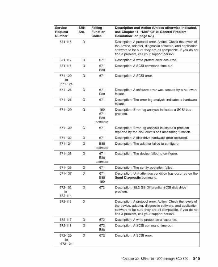
ServiceRequestNumber
SRNSrc.
FailingFunctionCodes
Description and Action (Unless otherwise indicated,use Chapter 11, “MAP 0210: General ProblemResolution” on page 67.)
671-116 D Description: A protocol error. Action: Check the levels ofthe device, adapter, diagnostic software, and applicationsoftware to be sure they are all compatible. If you do notfind a problem, call your support person.
671-117 D 671 Description: A write-protect error occurred.
671-118 D 671B88
Description: A SCSI command time-out.
671-120to
671-124
D 671 Description: A SCSI error.
671-126 D 671B88
Description: A software error was caused by a hardwarefailure.
671-128 G 671 Description: The error log analysis indicates a hardwarefailure.
671-129 G 190671B88
software
Description: Error log analysis indicates a SCSI busproblem.
671-130 G 671 Description: Error log analysis indicates a problemreported by the disk drive’s self-monitoring function.
671-132 D 671 Description: A disk drive hardware error occurred.
671-134 D B88software
Description: The adapter failed to configure.
671-135 D 671B88
software
Description: The device failed to configure.
671-136 D 671 Description: The certify operation failed.
671-137 D 671B88190
Description: Unit attention condition has occurred on theSend Diagnostic command.
672-102to
672-114
D 672 Description: 18.2 GB Differential SCSI disk driveproblem.
672-116 D Description: A protocol error. Action: Check the levels ofthe device, adapter, diagnostic software, and applicationsoftware to be sure they are all compatible. If you do notfind a problem, call your support person.
672-117 D 672 Description: A write-protect error occurred.
672-118 D 672B88
Description: A SCSI command time-out.
672-120to
672-124
D 672 Description: A SCSI error.
Chapter 32. SRNs 101-000 through 6C9-600 345

ServiceRequestNumber
SRNSrc.
FailingFunctionCodes
Description and Action (Unless otherwise indicated,use Chapter 11, “MAP 0210: General ProblemResolution” on page 67.)
672-126 D 672B88 Description: A software error was caused by a hardwarefailure.
672-128 G 672 Description: The error log analysis indicates a hardwarefailure.
672-129 G 190672B88
software
Description: Error log analysis indicates a SCSI busproblem.
672-130 G 672 Description: Error log analysis indicates a problemreported by the disk drive’s self-monitoring function.
672-132 D 672 Description: A disk drive hardware error occurred.
672-134 D B88software
Description: The adapter failed to configure.
672-135 D 672B88
software
Description: The device failed to configure.
672-136 D 672 Description: The certify operation failed.
672-137 D 672B88190
Description: Unit attention condition has occurred on theSend Diagnostic command.
673-102to
673-114
D 673 Description: 18.2GB Differential SCSI disk drive problem.
673-116 D Description: A protocol error. Action: Check the levels ofthe device, adapter, diagnostic software, and applicationsoftware to be sure they are all compatible. If you do notfind a problem, call your support person.
673-117 D 673 Description: A write-protect error occurred.
673-118 D 673B88
Description: A SCSI command time-out.
673-120to
673-124
D 673 Description: A SCSI error.
673-126 D 673B88 Description: A software error was caused by a hardwarefailure.
673-128 G 673 Description: The error log analysis indicates a hardwarefailure.
673-129 G 190673B88
software
Description: Error log analysis indicates a SCSI busproblem.
673-130 G 673 Description: Error log analysis indicates a problemreported by the disk drive’s self-monitoring function.
346 Diagnostic Information for Multiple Bus Systems

ServiceRequestNumber
SRNSrc.
FailingFunctionCodes
Description and Action (Unless otherwise indicated,use Chapter 11, “MAP 0210: General ProblemResolution” on page 67.)
673-132 D 673 Description: A disk drive hardware error occurred.
673-134 D B88software
Description: The adapter failed to configure.
673-135 D 673B88
software
Description: The device failed to configure.
673-136 D 673 Description: The certify operation failed.
673-137 D 673B88190
Description: Unit attention condition has occurred on theSend Diagnostic command.
674-101 D 674C94C95
Description: IBM ARTIC960Rx PCI Adapter CentralProcessing Unit (CPU) test failure.
674-102 D 674C94C95
Description: IBM ARTIC960Rx PCI Adapter Timer testfailure.
674-103 D 674C94C95
Description: IBM ARTIC960Rx PCI Adapter Bus Interfacetest failure.
674-104 D C94674C95
Description: IBM ARTIC960Rx PCI Adapter DynamicRandom Access Memory (DRAM) test failure.
674-105 D 674C94C95
Description: IBM ARTIC960Rx PCI Adapter MemoryProtection test failure.
674-106 D 674C94C95
Description: IBM ARTIC960Rx PCI Adapter Debug Porttest failure.
674-107 D C95674C97
Description: Interface board wrap test failure.
674-110 D C94674C95
Description: IBM ARTIC960Rx PCI Adapter DownloadDiagnostics test failure.
674-123 D C95C97
Description: Interface board non-wrap test failure.
674-150 D 674software
227
Description: Device configuration failure.
674-151 D 674software
227
Description: Device driver indicates a hardware failure.
674-152 D 674 Description: Failure and error in determining which typeof IBM ARTIC960Rx PCI Adapter.
Chapter 32. SRNs 101-000 through 6C9-600 347

ServiceRequestNumber
SRNSrc.
FailingFunctionCodes
Description and Action (Unless otherwise indicated,use Chapter 11, “MAP 0210: General ProblemResolution” on page 67.)
674-153 D 674227C94
software
Description: Error log analysis indicates a IBMARTIC960Rx PCI Adapter failure. Action: Use the errptcommand to check error log.
674-154 D C94674C95
Description: IBM ARTIC960Rx PCI Adapter initializationfailure.
674-155 D 674C94C95
Description: IBM ARTIC960Rx PCI Adapter initializationfailure.
674-156 D C95674C94
Description: IBM ARTIC960Rx PCI Adapter initializationfailure.
674-157 D C97C95
Description: Cable wrap test failure.
675-101 D 675C94C95
Description: IBM ARTIC960Hx Adapter CentralProcessing Unit (CPU) test failure.
675-102 D 675C94C95
Description: IBM ARTIC960Hx Adapter Timer test failure.
675-103 D 675C94C95
Description: IBM ARTIC960Hx Adapter Bus Interface testfailure.
675-104 D C94675C95
Description: IBM ARTIC960Hx Adapter DynamicRandom Access Memory (DRAM) test failure.
675-105 D 675C94C95
Description: IBM ARTIC960Hx Adapter MemoryProtection test failure.
675-106 D 675C94C95
Description: IBM ARTIC960Hx Adapter Debug Port testfailure.
675-107 D C95675C97
Description: Interface board wrap test failure.
675-110 D C94675C95
Description: IBM ARTIC960Hx Adapter DownloadDiagnostics test failure.
675-123 D C95675C94
Description: Interface board non-wrap test failure.
675-150 D 675software
227
Description: Device configuration failure.
348 Diagnostic Information for Multiple Bus Systems

ServiceRequestNumber
SRNSrc.
FailingFunctionCodes
Description and Action (Unless otherwise indicated,use Chapter 11, “MAP 0210: General ProblemResolution” on page 67.)
675-151 D 675software
227
Description: Device driver indicates a hardware failure.
675-152 D 675 Description: Failure and error in determining which typeof IBM ARTIC960Hx Adapter.
675-153 D 675227C94
software
Description: Error log analysis indicates a IBMARTIC960Hx Adapter failure. Action: Use the errptcommand to check error log.
675-154 D C94675C95
Description: IBM ARTIC960Hx Adapter initializationfailure.
675-155 D 675C94C95
Description: IBM ARTIC960Hx Adapter initializationfailure.
675-156 D C95675C94
Description: IBM ARTIC960Hx Adapter initializationfailure.
675-157 D C98C97C95
Description: Cable wrap test failure.
677-101 D 677 Description: The Fibre Channel Adapter configurationfailed.
677-102 D 677 Description: The Reset test failed.
677-103 D 677 Description: The Register test failed.
677-104 D 677 Description: The SRAM test failed.
677-105 D 677 Description: The Internal Wrap test failed.
677-106 D 677 Description: The Gigabaud Link Module (GLM) WrapTest Failure.
677-107 D 677 Description: The External Wrap test failed.
677-108 D 221 Description: Enhanced Error Handling Failure on bus.
677-109 D 221 Description: Enhanced Error Handling Failure on EADschip.
677-110 D 677 Description: Enhanced Error Handling Failure onadapter.
677-201 D 677221
Description: The Configuration Register test failed.
677-202 D 677221
Description: The Interrupt test failed.
677-203 D 677221
Description: The PCI Wrap test failed.
Chapter 32. SRNs 101-000 through 6C9-600 349

ServiceRequestNumber
SRNSrc.
FailingFunctionCodes
Description and Action (Unless otherwise indicated,use Chapter 11, “MAP 0210: General ProblemResolution” on page 67.)
677-204 D 677221
Description: The DMA test failed.
677-205 D 677221
Description: I/O error on a read/write operation.
677-701 G 677221
Description: Error log analysis indicates that an error hasoccurred with the adapter.
677-703 G 677 Description: Error log analysis indicates that an unknownadapter error has occurred.
677-704 G 677 Description: Error log analysis indicates that an adaptererror has occured.
678-098 J 678 Description: Tape drive indicates an error.
678-099 J 678B88
Description: Tape drive not found.
678-101 D 678 Description: Timeout while attempting to communicatewith SCSI device.
678-102 D 678 Description: The SCSI device indicates busy.
678-103 D 678 Description: The SCSI device indicates a reservationconflict.
678-104 D 678 Description: The SCSI device indicates a checkcondition.
678-105 D 678 Description: An error is detected in request sense data.
678-107 D 678 Description: Sense data from the SCSI drive hasunexpected data.
678-110 D 678 Description: The Reserve command failed.
678-111 D 678 Description: Invalid condition from the drive after areserve.
678-112 D 678 Description: The write-protect sensor test failed.
678-113 D 678 Description: Invalid condition from drive after a requestsense.
678-114 D 678 Description: Timeout while attempting to communicatewith the SCSI device.
678-120 D 678 Description: The Inquiry command failed.
678-130 D 678media
Description: The Load command failed.
678-134 D B88software
Description: The adapter failed to configure.
678-135 D 678media
Description: The Unload command failed.
678-140 D 678 Description: The Mode Select command failed.
678-150 D 678media
Description: The Test Unit Ready command failed.
350 Diagnostic Information for Multiple Bus Systems

ServiceRequestNumber
SRNSrc.
FailingFunctionCodes
Description and Action (Unless otherwise indicated,use Chapter 11, “MAP 0210: General ProblemResolution” on page 67.)
678-160 D 678media
Description: The Send Diagnostic command failed.
678-161 D 678B88
Description: Invalid condition from the drive after areserve.
678-163 D 678B88
Description: Invalid condition from the drive after arequest sense.
678-164 D 678B88
Description: Timeout while attempting to communicatewith the SCSI device.
678-165 D 678B88276
Description: Write, Read and Compare Test failed.
678-166 D 678B88
software
Description: Unable to configure the device.
678-167 D 678B88
Description: An unexpected SCSI error occurred.
678-168 D B88software
Description: The adapter failed to configure.
678-169 D 678media
Description: The Send Diagnostic command failed.
678-170 D 678B88
media
Description: The Read, Write and Compare test failed.
678-180 D 678media
Description: The Load command failed.
678-185 D 678media
Description: The Unload command failed.
678-190 D 678 Description: The Mode Select command failed.
678-200 D 678media
Description: The Test Unit Ready command failed.
678-201 G 678B88
Description: Error diagnosed from error log analysis.
678-210 D 678B88
Description: The device configuration failed.
678-211 D 678B88
Description: The device open failed.
678-220 D 678 Description: The Release command failed.
678-230 D 678 Description: The Request Sense command failed.
678-240 D 678 Description: The Openx command failed.
678-260 D 678 Description: The device configuration failed.
678-261 D 678 Description: The device open failed.
Chapter 32. SRNs 101-000 through 6C9-600 351

ServiceRequestNumber
SRNSrc.
FailingFunctionCodes
Description and Action (Unless otherwise indicated,use Chapter 11, “MAP 0210: General ProblemResolution” on page 67.)
678-300 D 678software
Description: The device configuration failed.
678-310 D B88678
software
Description: SCSI adapter configuration failed.
678-320 G 678media
Description: Error log analysis indicates a failure.
678-411to
678-423
D 678B88
software
Description: A reservation conflict occurred.
678-511to
678-523
D 678B88
Description: The drive returned bad or non-extendedsense data.
678-611to
678-623
D 678B88
software
Description: An adapter or bus I/O error occurred.
678-711to
678-723
D 678B88
software
Description: A device timeout error occurred.
679-102 D 679 Description: An unrecoverable media error occurred.
679-104 D 679 Description: The motor failed to restart.
679-105 D 679 Description: The drive did not become ready.
679-106 D 679 Description: The electronics card test failed.
679-108 D 679 Description: The bus test failed.
679-110 D 679 Description: The media format is corrupted.
679-112 D 679 Description: The diagnostic test failed.
679-114 D 679 Description: An unrecoverable hardware error.
679-116 D Description: A protocol error. Action: Check the levels ofthe device, adapter, diagnostic software, and applicationsoftware to be sure they are all compatible. If you do notfind a problem, call your support person.
679-117 D 679 Description: A write-protect error occurred.
679-118 D 679B88
Description: A SCSI command time-out occurred.
679-120 D 679 Description: A SCSI busy or command error.
679-122 D 679 Description: A SCSI reservation conflict error.
679-124 D 679 Description: A SCSI check condition error occurred.
679-126 D 679B88
Description: A software error was caused by a hardwarefailure.
679-128 G 679 Description: The error log analysis indicates a hardwarefailure.
352 Diagnostic Information for Multiple Bus Systems

ServiceRequestNumber
SRNSrc.
FailingFunctionCodes
Description and Action (Unless otherwise indicated,use Chapter 11, “MAP 0210: General ProblemResolution” on page 67.)
679-129 G 190679B88
software
Description: Error log analysis indicates a SCSI busproblem.
679-130 G 679 Description: Error log analysis indicates a problemreported by the disk drive’s self-monitoring function.
679-132 D 679 Description: A disk drive hardware error occurred.
679-134 D B88software
Description: The adapter failed to configure.
679-135 D 679B88
software
Description: The device failed to configure.
679-136 D 679 Description: The certify operation failed.
679-137 D 679B88190
Description: Unit attention condition has occurred on theSend Diagnostic command.
67B-100 D 67B Description: POST failed: Catastrophic error detected.
67B-601 G 11A Description: ELA indicates a low battery warning.
67B-602 G 67B Description: ELA indicates a mesh violation - tamper.
67B-603 G 67B Description: ELA indicates the coprocessor is held in areset condition.
67B-604 G 67B Description: ELA indicates a +3, +5, or +12 Vover-voltage condition.
67B-605 G 67B Description: ELA indicates an out-of-temperaturespecification.
67B-606 G 67B Description: ELA indicates a X-ray or dead batterycondition.
67B-607 G 67B Description: ELA indicates: Intrusion latch..
67E-001 D 67E221
Monitor/Cable
Description: Adapter problem.
67E-002 D 67EMonitor/Cable
Description: Display problem.
67E-003 D software67E
Description: Software error.
67E-004 D 67EMonitor/Cable
Description: The monitor test failed.
681-102 D 681 Description: An unrecoverable media error occurred.
681-104 D 681 Description: The motor failed to restart.
Chapter 32. SRNs 101-000 through 6C9-600 353

ServiceRequestNumber
SRNSrc.
FailingFunctionCodes
Description and Action (Unless otherwise indicated,use Chapter 11, “MAP 0210: General ProblemResolution” on page 67.)
681-105 D 681 Description: The drive did not become ready.
681-106 D 681 Description: The electronics card test failed.
681-108 D 681 Description: The bus test failed.
681-110 D 681 Description: The media format is corrupted.
681-112 D 681 Description: The diagnostic test failed.
681-114 D 681 Description: An unrecoverable hardware error.
681-116 D Description: A protocol error. Action: Check the levels ofthe device, adapter, diagnostic software, and applicationsoftware to be sure they are all compatible. If you do notfind a problem, call your support person.
681-117 D 681 Description: A write-protect error occurred.
681-118 D 681B88
Description: A SCSI command time-out occurred.
681-120 D 681 Description: A SCSI busy or command error.
681-122 D 681 Description: A SCSI reservation conflict error.
681-124 D 681 Description: A SCSI check condition error occurred.
681-126 D 681B88
Description: A software error was caused by a hardwarefailure.
681-128 G 681 Description: The error log analysis indicates a hardwarefailure.
681-129 G 190681B88
software
Description: Error log analysis indicates a SCSI busproblem.
681-130 G 681 Description: Error log analysis indicates a problemreported by the disk drive’s self-monitoring function.
681-132 D 681 Description: A disk drive hardware error occurred.
681-134 D B88software
Description: The adapter failed to configure.
681-135 D 681B88
software
Description: The device failed to configure.
681-136 D 681 Description: The certify operation failed.
681-137 D 681B88190
Description: Unit attention condition has occurred on theSend Diagnostic command.
681-138 D 681 Description: Error log analysis indicates that the diskdrive is operating at a higher than recommendedtemperature. Action: Check to be sure none of the airpassages in the system covers are blocked, that noother system environmental warnings are occurring.Otherwise, use MAP 210.
354 Diagnostic Information for Multiple Bus Systems

ServiceRequestNumber
SRNSrc.
FailingFunctionCodes
Description and Action (Unless otherwise indicated,use Chapter 11, “MAP 0210: General ProblemResolution” on page 67.)
682-111 D 682B88
Description: Unable to reserve device.
682-112 D 682B88
Description: Unable to do configuration.
682-113 D 682B88
Description: Unable to open the device driver.
682-121 D 682 Description: The CD-ROM drive indicates an error.
682-122 D 682 Description: The CD-ROM drive indicates an error.
682-123 D 682 Description: The CD-ROM drive indicates an error.
682-125 D 682B88
Description: The CD-ROM drive indicates an error.
682-126 D 682 Description: The CD-ROM drive indicates an error.
682-127 D 682 Description: The CD-ROM drive indicates an error.
682-128 D 682 Description: The CD-ROM drive indicates an error.
682-129 D 682 Description: The CD-ROM drive indicates an error.
682-150 D Test Disc682
Description: A media error was detected.
682-151 D 682B88
Description: A command timeout was detected.
682-152 D 682 Description: A command reservation conflict wasdetected.
682-162 D 682 Description: The CD-ROM drive indicates an error.
682-171 D 682 Description: Unable to reserve device.
682-172 D 682 Description: Unable to do configuration.
682-173 D 682 Description: Unable to open device driver.
682-175 D 682 Description: The CD-ROM drive indicates an error.
682-198 D 682B88
Description: Undefined error detected.
682-199 D 682 Description: Undefined error detected.
682-211 D 682 Description: The LED test failed.
682-281 D 682 Description: No tone during audio test.
682-301 G 682 Description: Errors found during ELA.
682-302 G 682B88
Description: Errors found during ELA.
683-128 G 683 Description: Error Log Analysis Indicates hardwarefailure VSS2105 Model B09.
685-001 D 685Monitor/
cable
Description: RGB_SCREEN_USER_FAIL
Chapter 32. SRNs 101-000 through 6C9-600 355

ServiceRequestNumber
SRNSrc.
FailingFunctionCodes
Description and Action (Unless otherwise indicated,use Chapter 11, “MAP 0210: General ProblemResolution” on page 67.)
685-040 D 685227
Monitor/cable
Description: STATUS_POLL_TIMEOUT_ERROR
685-041 D 685227
Monitor/cable
Description: CRC_POLL_TIMEOUT_ERROR
685-060 D software685
Description: SVC_AIDS_INPUT_ERROR
685-081 D software685
Description: LOOP_COUNT_WAS_ZERO
685-082 D software685
Description: INVALID_TU_NUMBER
685-0B0 D software685
Description: ROM test failed.
685-0B1 D software685
Description: ROM test failed.
685-0D0 D softwar685
Description: INTERNAL_ERROR_DATA_SIZE_0
685-0D1 D software685
Description: INTERNAL_ERROR_DATA_SIZE_1
685-0D2 D software685
Description: INTERNAL_ERROR_DATA_SIZE_2
685-0D3 D software685
Description: INTERNAL_ERROR_DATA_SIZE_3
685-0D5 D software685
Description: ODM INIT FAILED
685-0D6 D software685
Description: ODM_OBJECT_SEARCH_FAILED
685-0D8 D software685
Description: ODM_GET_OBJECT_FAILED
685-0D9 D software685
Description: ODM_TERM_FAILED
685-0DB D software685
Description: ILLEGAL_RESOLUTION_SPECIFIED
685-0E5 D software685
Description:AIXGSC_MGA_START_INTERRUPT_FAILED
685-0E6 D software685
Description:AIXGSC_MGA_STOP_INTERRUPT_FAILED
685-0E7 D software685
Description: MDD_OPEN_BUS_FAILED
356 Diagnostic Information for Multiple Bus Systems
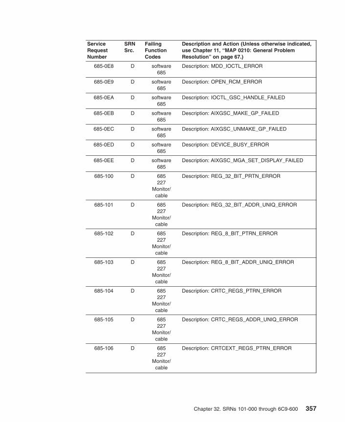
ServiceRequestNumber
SRNSrc.
FailingFunctionCodes
Description and Action (Unless otherwise indicated,use Chapter 11, “MAP 0210: General ProblemResolution” on page 67.)
685-0E8 D software685
Description: MDD_IOCTL_ERROR
685-0E9 D software685
Description: OPEN_RCM_ERROR
685-0EA D software685
Description: IOCTL_GSC_HANDLE_FAILED
685-0EB D software685
Description: AIXGSC_MAKE_GP_FAILED
685-0EC D software685
Description: AIXGSC_UNMAKE_GP_FAILED
685-0ED D software685
Description: DEVICE_BUSY_ERROR
685-0EE D software685
Description: AIXGSC_MGA_SET_DISPLAY_FAILED
685-100 D 685227
Monitor/cable
Description: REG_32_BIT_PRTN_ERROR
685-101 D 685227
Monitor/cable
Description: REG_32_BIT_ADDR_UNIQ_ERROR
685-102 D 685227
Monitor/cable
Description: REG_8_BIT_PTRN_ERROR
685-103 D 685227
Monitor/cable
Description: REG_8_BIT_ADDR_UNIQ_ERROR
685-104 D 685227
Monitor/cable
Description: CRTC_REGS_PTRN_ERROR
685-105 D 685227
Monitor/cable
Description: CRTC_REGS_ADDR_UNIQ_ERROR
685-106 D 685227
Monitor/cable
Description: CRTCEXT_REGS_PTRN_ERROR
Chapter 32. SRNs 101-000 through 6C9-600 357

ServiceRequestNumber
SRNSrc.
FailingFunctionCodes
Description and Action (Unless otherwise indicated,use Chapter 11, “MAP 0210: General ProblemResolution” on page 67.)
685-107 D 685227
Monitor/cable
Description: CRTCEXT_REGS_ADDR_UNIQ_ERROR
685-108 D 685227
Monitor/cable
Description: RAMDAC_REGS_PTRN_ERROR
685-109 D 685227
Monitor/cable
Description: RAMDAC_REGS_ADDR_UNIQ_ERROR
685-10A D 685227
Monitor/cable
Description: PALETTE_REGS_PTRN_ERROR
685-10B D 685227
Monitor/cable
Description: PALETTE_REGS_ADDR_UNIQ_ERROR
685-200 D 685227
Description: ROM test failed.
685-201 D 685227
Description: ROM test failed.
685-202 D 685227
Description: ROM test failed.
685-203 D 685227
Description: ROM test failed.
685-204 D 685227
Description: ROM test failed.
685-205 D 685227
Description: ROM test failed.
685-206 D 685227
Description: ROM test failed.
685-207 D 685227
Description: ROM test failed.
685-208 D 685227
Description: ROM test failed.
685-209 D 685227
Description: ROM test failed.
685-20B D 685227
Description: ROM test failed.
358 Diagnostic Information for Multiple Bus Systems

ServiceRequestNumber
SRNSrc.
FailingFunctionCodes
Description and Action (Unless otherwise indicated,use Chapter 11, “MAP 0210: General ProblemResolution” on page 67.)
685-400 D 685227
Monitor/cable
Description: SGRAM_RED_SCREEN_ERROR
685-401 D 685227
Monitor/cable
Description: SGRAM_GREEN_SCREEN_ERROR
685-402 D 685227
Monitor/cable
Description: SGRAM_BLUE_SCREEN_ERROR
685-403 D 685227
Monitor/cable
Description: SGRAM_WHITE_SCREEN_ERROR
685-404 D 685227
Monitor/cable
Description:SGRAM_INCREMENTING_SCREEN_ERROR
685-500 D 685227
Monitor/cable
Description: BLIT_TEST_ERROR_640 x 480
685-501 D 685227
Monitor/cable
Description: BLIT_TEST_ERROR_800 x 600
685-502 D 685227
Monitor/cable
Description: BLIT_TEST_ERROR_1024 x 768
685-503 D 685227
Monitor/cable
Description: BLIT_TEST_ERROR_1280 x 1024
685-504 D software685
Description: INTERNAL_ERROR_DATA_SIZE_4
685-600 D 685227
Monitor/cable
Description: DRAW_TEST_ERROR_640 x 480_A
685-601 D 685227
Monitor/cable
Description: DRAW_TEST_ERROR_800 x 600_A
Chapter 32. SRNs 101-000 through 6C9-600 359
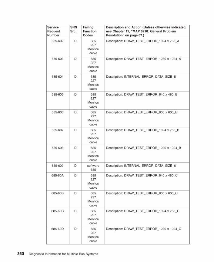
ServiceRequestNumber
SRNSrc.
FailingFunctionCodes
Description and Action (Unless otherwise indicated,use Chapter 11, “MAP 0210: General ProblemResolution” on page 67.)
685-602 D 685227
Monitor/cable
Description: DRAW_TEST_ERROR_1024 x 768_A
685-603 D 685227
Monitor/cable
Description: DRAW_TEST_ERROR_1280 x 1024_A
685-604 D 685227
Monitor/cable
Description: INTERNAL_ERROR_DATA_SIZE_5
685-605 D 685227
Monitor/cable
Description: DRAW_TEST_ERROR_640 x 480_B
685-606 D 685227
Monitor/cable
Description: DRAW_TEST_ERROR_800 x 600_B
685-607 D 685227
Monitor/cable
Description: DRAW_TEST_ERROR_1024 x 768_B
685-608 D 685227
Monitor/cable
Description: DRAW_TEST_ERROR_1280 x 1024_B
685-609 D software685
Description: INTERNAL_ERROR_DATA_SIZE_6
685-60A D 685227
Monitor/cable
Description: DRAW_TEST_ERROR_640 x 480_C
685-60B D 685227
Monitor/cable
Description: DRAW_TEST_ERROR_800 x 600_C
685-60C D 685227
Monitor/cable
Description: DRAW_TEST_ERROR_1024 x 768_C
685-60D D 685227
Monitor/cable
Description: DRAW_TEST_ERROR_1280 x 1024_C
360 Diagnostic Information for Multiple Bus Systems

ServiceRequestNumber
SRNSrc.
FailingFunctionCodes
Description and Action (Unless otherwise indicated,use Chapter 11, “MAP 0210: General ProblemResolution” on page 67.)
685-60E D software685
Description: INTERNAL_ERROR_DATA_SIZE_7
686-114 D 686 Description: The register verification test failed.
686-124 D 686 Description: The adapter RAM verification test failed.
686-152 D 686D57
Description: The data wrap communication test failed.
686-153 D 686 Description: The modem control line test failed.
686-252 D 686 Description: The data wrap communication test failed.
686-253 D 686 Description: The modem control line test failed.
686-501 D 686 Description: Adapter Reset failed
686-511 D 686 Description: Adapter to host memory test failed (byte tagtest).
686-512 D 686 Description: Adapter to host memory test failed (word tagtest).
686-513 D 686 Description: Adapter to host memory test failed (bytepattern test).
686-514 D 686 Description: Adapter to host memory test failed (wordpattern test).
686-521 D 686 Description: Adapter BIOS POST CPU failed.
686-522 D 686 Description: Adapter BIOS POST Checksum failed.
686-523 D 686 Description: Adapter BIOS POST Timer failed.
686-524 D 686 Description: Adapter BIOS POST RAM failed.
686-526 D 686 Description: Adapter BIOS POST Async Ports failed.
686-527 D 686 Description: Adapter BIOS test failed.
686-528 D 686 Description: Adapter BIOS Reset failed.
686-529 D 686 Description: Adapter BIOS Download failed.
686-531 D 686 Description: Adapter BIOS Command failed.
686-533 D 686 Description: Adapter BIOS Timer test failed.
686-534 D 686 Description: Adapter BIOS RAM test failed.
686-541 D 686 Description: Port async internal loopback test failed(general).
686-542 D 686 Description: Port async internal loopback test failed (noresponse from the port).
686-551 D 686 Description: Port async external loopback test failed(general).
686-552 D 686 Description: Port async external loopback test failed(data signals).
686-553 D 686 Description: Port async external loopback test failed(control signals).
Chapter 32. SRNs 101-000 through 6C9-600 361

ServiceRequestNumber
SRNSrc.
FailingFunctionCodes
Description and Action (Unless otherwise indicated,use Chapter 11, “MAP 0210: General ProblemResolution” on page 67.)
686-554 D 686 Description: Port async external loopback test failed(modem signals).
686-555 D 686 Description: Port async external loopback test failed (noresponse from port).
686-901to
686-920
D software686
Description: An unexpected error occurred that can beattributed to software or hardware. Action: Rundiagnostics from a source other than from the disk or anetwork. If the same error occurs or if the original SRNwas not obtained from disk or a network baseddiagnostics, use MAP 210 with a FFC of 686; otherwise,suspect a software problem.
686-921 D 686software
Description: The adapter failed to configure.
686-922to
686-924
D software686
Description: An unexpected error occurred that can beattributed to software or hardware. Action: Rundiagnostics from a source other than from the disk or anetwork. If the same error occurs or if the original SRNwas not obtained from disk or a network baseddiagnostics, use MAP 210 with a FFC of 686; otherwise,suspect a software problem.
686-925 D 686 Description: The adapter failed to configure software
686-926to
686-950
D software686
Description: An unexpected error occurred that can beattributed to software or hardware. Action: Rundiagnostics from a source other than from the disk or anetwork. If the same error occurs or if the original SRNwas not obtained from disk or a network baseddiagnostics, use MAP 210 with a FFC of 686; otherwise,suspect a software problem.
687-111 D 687 Description: The controller register test failed.
687-114 D 687 Description: The register verification test failed.
687-124 D 687 Description: The adapter RAM verification test failed.
687-144 D 687 Description: The sync line test failed.
687-152 D 837684687152
Description: The data wrap communication test failed.
687-153 D 687 Description: The modem control line test failed.
687-244 D 687 Description: The sync line test failed.
687-252 D 687 Description: The data wrap communication test failed.
687-253 D 687 Description: The modem control line test failed.
687-501 D 687 Description: Adapter Reset failed.
687-502 D 687 Description: Adapter Fuse failed.
362 Diagnostic Information for Multiple Bus Systems

ServiceRequestNumber
SRNSrc.
FailingFunctionCodes
Description and Action (Unless otherwise indicated,use Chapter 11, “MAP 0210: General ProblemResolution” on page 67.)
687-511 D 687 Description: Adapter to host memory test failed (byte tagtest).
687-512 D 687 Description: Adapter to host memory test failed (word tagtest).
687-513 D 687 Description: Adapter to host memory test failed (bytepattern test).
687-514 D 687 Description: Adapter to host memory test failed (wordpattern test).
687-521 D 687 Description: Adapter BIOS POST CPU failed.
687-522 D 687 Description: Adapter BIOS POST Checksum failed.
687-523 D 687 Description: Adapter BIOS POST Timer failed.
687-524 D 687 Description: Adapter BIOS POST RAM failed.
687-525 D 687 Description: Adapter BIOS POST Sync Line failed.
687-527 D 687 Description: Adapter BIOS test failed.
687-528 D 687 Description: Adapter BIOS Reset failed.
687-529 D 687 Description: Adapter BIOS Download failed.
687-531 D 687 Description: Adapter BIOS Command failed.
687-533 D 687 Description: Adapter BIOS Timer test failed.
687-534 D 687 Description: Adapter BIOS RAM test failed.
687-541 D 687 Description: Port sync internal loopback test failed.
687-551 D 687 Description: Port sync external loopback test failed.
687-600 D 837 Description: 232RAN status test failed.
687-700 D 684 Description: 422RAN status test failed.
687-901to
687-920
D software687
Description: An unexpected error occurred that can beattributed to software or hardware. Action: Rundiagnostics from a source other than from the disk or anetwork. If the same error occurs or if the original SRNwas not obtained from disk or a network baseddiagnostics, use MAP 210 with a FFC of 687; otherwise,suspect a software problem.
687-921 D software687
Description: The adapter failed to configure.
687-922to
687-924
D software687
Description: An unexpected error occurred that can beattributed to software or hardware. Action: Rundiagnostics from a source other than from the disk or anetwork. If the same error occurs or if the original SRNwas not obtained from disk or a network baseddiagnostics, use MAP 210 with a FFC of 687; otherwise,suspect a software problem.
687-925 D 687software
Description: The adapter failed to configure.
Chapter 32. SRNs 101-000 through 6C9-600 363

ServiceRequestNumber
SRNSrc.
FailingFunctionCodes
Description and Action (Unless otherwise indicated,use Chapter 11, “MAP 0210: General ProblemResolution” on page 67.)
687-926to
687-950
D software687
Description: An unexpected error occurred that can beattributed to software or hardware. Action: Rundiagnostics from a source other than from the disk or anetwork. If the same error occurs or if the original SRNwas not obtained from disk or a network baseddiagnostics, use MAP 210 with a FFC of 687; otherwise,suspect a software problem.
689-102 D 689 Description: An unrecoverable media error occurred.
689-104 D 689 Description: The motor failed to restart.
689-105 D 689 Description: The drive did not become ready.
689-106 D 689 Description: The electronics card test failed.
689-108 D 689 Description: The bus test failed.
689-110 D 689 Description: The media format is corrupted.
689-112 D 689 Description: The diagnostic test failed.
689-114 D 689 Description: An unrecoverable hardware error.
689-116 D Description: A protocol error. Action: Check the levels ofthe device, adapter, diagnostic software, and applicationsoftware to be sure they are all compatible. If you do notfind a problem, call your support person.
689-117 D 689 Description: A write-protect error occurred.
689-118 D 689B88
Description: A SCSI command time-out occurred.
689-120 D 689 Description: A SCSI busy or command error.
689-122 D 689 Description: A SCSI reservation conflict error.
689-124 D 689 Description: A SCSI check condition error occurred.
689-126 D 689B88
Description: A software error was caused by a hardwarefailure.
689-128 G 689 Description: The error log analysis indicates a hardwarefailure.
689-129 G 190689B88
software
Description: Error log analysis indicates a SCSI busproblem.
689-130 G 689 Description: Error log analysis indicates a problemreported by the disk drive’s self-monitoring function.
689-132 D 689 Description: A disk drive hardware error occurred.
689-134 D B88software
Description: The adapter failed to configure.
689-135 D 689B88
software
Description: The device failed to configure.
689-136 D 689 Description: The certify operation failed.
364 Diagnostic Information for Multiple Bus Systems

ServiceRequestNumber
SRNSrc.
FailingFunctionCodes
Description and Action (Unless otherwise indicated,use Chapter 11, “MAP 0210: General ProblemResolution” on page 67.)
689-137 D 689B88190
Description: Unit attention condition has occurred on theSend Diagnostic command.
68C-101 D 68C Description: Timeout while attempting to communicatewith SCSI device.
68C-102 D 68C Description: The SCSI device indicates busy.
68C-103 D 68C Description: The SCSI device indicates a reservationconflict.
68C-104 D 68C Description: The SCSI device indicates a checkcondition.
68C-105 D 68C Description: An error is detected in request sense data.
68C-107 D 68C Description: Sense data from the SCSI drive hasunexpected data.
68C-110 D 68C Description: The Reserve command failed.
68C-111 D 68C Description: Invalid condition from the drive after areserve.
68C-112 D 68C Description: The write-protect sensor test failed.
68C-113 D 68C Description: Invalid condition from drive after a requestsense.
68C-114 D 68C Description: Timeout while attempting to communicatewith the SCSI device.
68C-120 D 68C Description: The Inquiry command failed.
68C-130 D 68Cmedia
Description: The Load command failed.
68C-134 D B88software
Description: The adapter failed to configure.
68C-135 D 68Cmedia
Description: The Unload command failed.
68C-140 D 68C Description: The Mode Select command failed.
68C-150 D 68Cmedia
Description: The Test Unit Ready command failed.
68C-160 D 68Cmedia
Description: The Send Diagnostic command failed.
68C-161 D 68CB88
Description: Invalid condition from the drive after areserve.
68C-163 D 68CB88
Description: Invalid condition from the drive after arequest sense.
68C-164 D 68CB88
Description: Timeout while attempting to communicatewith the SCSI device.
68C-165 D 68CB88276
Description: Write, Read and Compare Test failed.
Chapter 32. SRNs 101-000 through 6C9-600 365

ServiceRequestNumber
SRNSrc.
FailingFunctionCodes
Description and Action (Unless otherwise indicated,use Chapter 11, “MAP 0210: General ProblemResolution” on page 67.)
68C-166 D 68CB88
software
Description: Unable to configure the device.
68C-167 D 68CB88
Description: An unexpected SCSI error occurred.
68C-168 D B88software
Description: The adapter failed to configure.
68C-169 D 68Cmedia
Description: The Send Diagnostic command failed.
68C-170 D 68CB88
media
Description: The Read, Write and Compare test failed.
68C-180 D 68Cmedia
Description: The Load command failed.
68C-185 D 68Cmedia
Description: The Unload command failed.
68C-190 D 68C Description: The Mode Select command failed.
68C-200 D 68Cmedia
Description: The Test Unit Ready command failed.
68C-201 G 68CB88
Description: Error diagnosed from error log analysis.
68C-210 D 68CB88
Description: The device configuration failed.
68C-211 D 68CB88
Description: The device open failed.
68C-220 D 68C Description: The Release command failed.
68C-230 D 68C Description: The Request Sense command failed.
68C-240 D 68C Description: The Openx command failed.
68C-260 D 68C Description: The device configuration failed.
68C-261 D 68C Description: The device open failed.
68C-300 D 68Csoftware
Description: The device configuration failed.
68C-310 D B8868C
software
Description: SCSI adapter configuration failed.
68C-320 G 68Cmedia
Description: Error log analysis indicates a failure.
68C-411to
68C-423
D 68CB88
software
Description: A reservation conflict occurred.
366 Diagnostic Information for Multiple Bus Systems

ServiceRequestNumber
SRNSrc.
FailingFunctionCodes
Description and Action (Unless otherwise indicated,use Chapter 11, “MAP 0210: General ProblemResolution” on page 67.)
68C-511to
68C-523
D 68CB88
Description: The drive returned bad or non-extendedsense data.
68C-611to
68C-623
D 68CB88
software
Description: An adapter or bus I/O error occurred.
68C-711to
68C-723
D 68CB88
software
Description: A device timeout error occurred.
68E-001 D Software68E
Description: Software error.
68E-002 D 68ESoftware
Description: Adapter failure.
68E-003 D 68E227
Description: Adapter failure.
68E-004 D 68EMonitor/Cable
Description: Display failure.
68E-005 D 68E227
Monitor/Cable
Description: Adapter failure.
690-102 D 690 Description: An unrecoverable media error occurred.
690-104 D 690 Description: The motor failed to restart.
690-105 D 690 Description: The drive did not become ready.
690-106 D 690 Description: The electronics card test failed.
690-108 D 690 Description: The bus test failed.
690-110 D 690 Description: The media format is corrupted.
690-112 D 690 Description: The diagnostic test failed.
690-114 D 690 Description: An unrecoverable hardware error.
690-116 D Description: A protocol error. Action: Check the levels ofthe device, adapter, diagnostic software, and applicationsoftware to be sure they are all compatible. If you do notfind a problem, call your support person.
690-117 D 690 Description: A write-protect error occurred.
690-118 D 690B88
Description: A SCSI command time-out occurred.
690-120 D 690 Description: A SCSI busy or command error.
690-122 D 690 Description: A SCSI reservation conflict error.
690-124 D 690 Description: A SCSI check condition error occurred.
690-126 D 690B88
Description: A software error was caused by a hardwarefailure.
Chapter 32. SRNs 101-000 through 6C9-600 367

ServiceRequestNumber
SRNSrc.
FailingFunctionCodes
Description and Action (Unless otherwise indicated,use Chapter 11, “MAP 0210: General ProblemResolution” on page 67.)
690-128 G 690 Description: The error log analysis indicates a hardwarefailure.
690-129 G 190690B88
software
Description: Error log analysis indicates a SCSI busproblem.
690-130 G 690 Description: Error log analysis indicates a problemreported by the disk drive’s self-monitoring function.
690-132 D 690 Description: A disk drive hardware error occurred.
690-134 D B88software
Description: The adapter failed to configure.
690-135 D 690B88
software
Description: The device failed to configure.
690-136 D 690 Description: The certify operation failed.
690-137 D 690B88190
Description: Unit attention condition has occurred on theSend Diagnostic command.
691-200 D 691227
Description: The ATM 25Mbps Adapter open test failed.
691-202 D 691227
Description: The ATM 25Mbps Adapter register testfailed.
691-203 D 691227
Description: The ATM 25Mbps Adapter memory testfailed.
691-204 D 691227
Description: The ATM 25Mbps Adapter NVRAM testfailed.
691-205 D 691227
Description: The ATM 25Mbps Adapter interrupt testfailed.
691-206 D 691227
Description: The ATM 25Mbps Adapter wrap test failed.
691-210 D 691227
Description: The ATM 25Mbps Adapter close test failed.
691-220 D 691227
Description: The ATM 25Mbps Adapter was not found.Action: Re-install the ATM 25Mbps Adapter and re-runthe test. If the error continues, use MAP 210.
691-300 D Wrap Plug691227
Description: The ATM 25Mbps Adapter wrap test failed.Action: Re-install the wrap plug and re-run the test. If theerror continues, use MAP 210.
691-700 G 691227
Description: Error log analysis reported a hardware error.
692-110 D 692 Description: The Reserve command failed.
692-120 D 692 Description: The Inquiry command failed.
368 Diagnostic Information for Multiple Bus Systems

ServiceRequestNumber
SRNSrc.
FailingFunctionCodes
Description and Action (Unless otherwise indicated,use Chapter 11, “MAP 0210: General ProblemResolution” on page 67.)
692-130 D 692media
Description: The Load command failed.
692-135 D 692media
Description: The Unload command failed.
692-140 D 692 Description: The Mode Select command failed.
692-150 D 692media
Description: The Test Unit Ready command failed.
692-160 D 692media
Description: The Send Diagnostic command failed.
692-169 D 692media
Description: The Send Diagnostic command failed.
692-170 D 692B88
media
Description: The Read, Write and Compare test failed.
692-180 D 692media
Description: The Load command failed.
692-185 D 692media
Description: The Unload command failed.
692-190 D 692 Description: The Mode Select command failed.
692-200 D 692media
Description: The Test Unit Ready command failed.
692-210 D 692B88
Description: The device configuration failed.
692-220 D 692 Description: The Release command failed.
692-230 D 692 Description: The Request Sense command failed.
692-240 D 692 Description: The Openx command failed.
692-300 D 692software
Description: The device configuration failed.
692-310 D B88692
software
Description: SCSI adapter configuration failed.
692-320 G 692media
Description: Error log analysis indicates a failure.
692-411to
692-423
D 692B88
software
Description: A reservation conflict occurred.
692-511to
692-523
D 692B88
Description: The drive returned bad or non-extendedsense data.
692-611to
692-623
D 692B88
software
Description: An adapter or bus I/O error occurred.
Chapter 32. SRNs 101-000 through 6C9-600 369

ServiceRequestNumber
SRNSrc.
FailingFunctionCodes
Description and Action (Unless otherwise indicated,use Chapter 11, “MAP 0210: General ProblemResolution” on page 67.)
692-711to
692-723
D 692B88
software
Description: A device timeout error occurred.
693-100 D 693227
Description: Adapter open failed.
693-101 D 693227
Description: Adapter config register test failed.
693-102 D 693227
Description: Adapter reset failed.
693-103 D 693227
Description: Adapter I/O register test failed.
693-104 D 693227
Description: Adapter microcode download test failed.
693-105 D 693227
Description: Adapter internal wrap test failed.
693-106 D 693227
Description: Adapter close failed.
697-100 D 697software
227
Description: Charm memory write failure.
697-101 D 697software
227
Description: Charm memory read failure.
697-102 D 697software
227
Description: PCI configuration register write failure.
697-103 D 697software
227
Description: Charm software reset failure.
697-104 D 697software
227
Description: Packet memory error.
697-105 D 697software
227
Description: Control memory failure.
697-106 D 697 Description: Link-R detected bad parity.
697-107 D 697 Description: Suni detected bad parity.
697-108 D 697 Description: Suni initialization failure.
697-109 D Wrap Plug697
Description: Loss of light detected in Link test. Action:Check wrap plug installation.
697-10B D Wrap Plug697
Description: External Loopback failed Action: Checkwrap plug installation.
370 Diagnostic Information for Multiple Bus Systems

ServiceRequestNumber
SRNSrc.
FailingFunctionCodes
Description and Action (Unless otherwise indicated,use Chapter 11, “MAP 0210: General ProblemResolution” on page 67.)
697-10C D 697software
227
Description: Internal Loopback failed.
697-10D D 697227
software
Description: DMS failed.
697-121 D 697 Description: Adapter memory test failure.
697-122 D 697 Description: Adapter checksum failure.
697-123 D 697 Description: Internal wrap test failure
697-124 D 697 Description: External wrap test failure
697-125 D 221 Description: Enhanced Error Handling failure on bus
697-126 D 221 Description: Enhanced Error Handling failure on EADSchip
697-127 D 697 Description: Enhanced Error Handling failure on adapter
697-1FF D 697software
227
Description: EPROM checksum failed
697-200 D software697227
Description: Klog error
697-201 D software697227
Description: ASL error
697-202 D software697227
Description: ODM Initialization error
697-203 D software697227
Description: Diagnostic configuration failure.
697-205 D software697227
Description: Error in diag open.
697-206 D software697227
Description: Error in releasing adapter
697-221 D 697221
Description: Hardware failure opening the adapter
697-222 D 697221
Description: Enhanced Error Handling failure opening theadapter
697-223 D 697221
Description: Interrupt test failure
697-224 D 697221
Description: Adapter DMA test failure
Chapter 32. SRNs 101-000 through 6C9-600 371
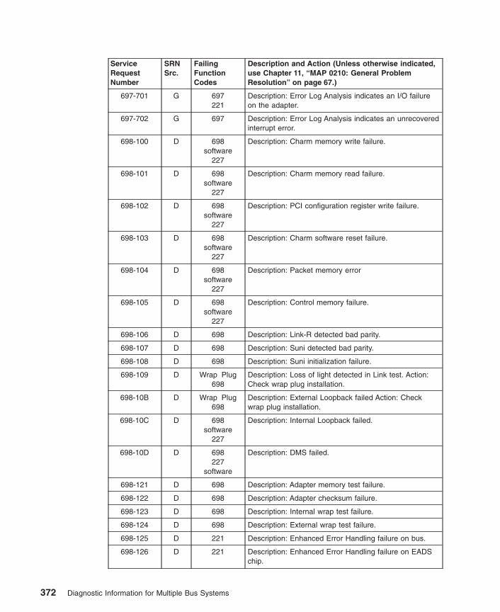
ServiceRequestNumber
SRNSrc.
FailingFunctionCodes
Description and Action (Unless otherwise indicated,use Chapter 11, “MAP 0210: General ProblemResolution” on page 67.)
697-701 G 697221
Description: Error Log Analysis indicates an I/O failureon the adapter.
697-702 G 697 Description: Error Log Analysis indicates an unrecoveredinterrupt error.
698-100 D 698software
227
Description: Charm memory write failure.
698-101 D 698software
227
Description: Charm memory read failure.
698-102 D 698software
227
Description: PCI configuration register write failure.
698-103 D 698software
227
Description: Charm software reset failure.
698-104 D 698software
227
Description: Packet memory error
698-105 D 698software
227
Description: Control memory failure.
698-106 D 698 Description: Link-R detected bad parity.
698-107 D 698 Description: Suni detected bad parity.
698-108 D 698 Description: Suni initialization failure.
698-109 D Wrap Plug698
Description: Loss of light detected in Link test. Action:Check wrap plug installation.
698-10B D Wrap Plug698
Description: External Loopback failed Action: Checkwrap plug installation.
698-10C D 698software
227
Description: Internal Loopback failed.
698-10D D 698227
software
Description: DMS failed.
698-121 D 698 Description: Adapter memory test failure.
698-122 D 698 Description: Adapter checksum failure.
698-123 D 698 Description: Internal wrap test failure.
698-124 D 698 Description: External wrap test failure.
698-125 D 221 Description: Enhanced Error Handling failure on bus.
698-126 D 221 Description: Enhanced Error Handling failure on EADSchip.
372 Diagnostic Information for Multiple Bus Systems

ServiceRequestNumber
SRNSrc.
FailingFunctionCodes
Description and Action (Unless otherwise indicated,use Chapter 11, “MAP 0210: General ProblemResolution” on page 67.)
698-127 D 698 Description: Enhanced Error Handling failure on adapter.
698-1FF D 698software
227
Description: EPROM checksum failed.
698-200 D software698227
Description: Klog error.
698-201 D software698227
Description: ASL error.
698-202 D software698227
Description: ODM Initialization error.
698-203 D software698227
Description: Diagnostic configuration failure.
698-205 D software698227
Description: Error in diag open.
698-206 D software698227
Description: Error in releasing adapter.
698-221 D 698221
Description: Hardware failure opening the adapter.
698-222 D 698221
Description: Enhanced Error Handling failure opening theadapter.
698-223 D 698221
Description: Interrupt test failure.
698-224 D 698221
Description: Adapter DMA test failure.
698-701 G 698221
Description: Error Log Analysis indicates an I/O failureon the adapter.
698-702 G 698 Description: Error Log Analysis indicates an unrecoveredinterrupt error.
699-100 D 699 Description: An error was found on the adapter
699-110 G 699 Description: Error Log analysis indicates a hardwareerror.
699-120 D 699 Description: Adapter hardware has caused a softwarefailure.
69b-101 D 69b Description: EPROM test failure.
69b-102 D 69b Description: Adapter SDRAM failure.
69b-103 D 69b Description: Adapter checksum failure.
Chapter 32. SRNs 101-000 through 6C9-600 373

ServiceRequestNumber
SRNSrc.
FailingFunctionCodes
Description and Action (Unless otherwise indicated,use Chapter 11, “MAP 0210: General ProblemResolution” on page 67.)
69b-104 D 69b Description: Adapter memory test failure.
69b-105 D 69b Description: Adapter buffer test failure.
69b-106 D 69b Description: Adapter cache test failure.
69b-107 D 69b Description: Internal loopback test failure.
69b-108 D 69b Description: External wrap test failure.
69b-109 D 221 Description: Enhanced Error Handling failure on bus.
69b-110 D 221 Description: Enhanced Error Handling failure on Eadschip.
69b-111 D 69b Description: Enhanced Error Handling failure on adapter.
69b-201 D 69b221
Description: Hardware failure opening adapter.
69b-202 D 69b221
Description: Interrupt test failure.
69b-203 D 69b221
Description: Adapter DMA test failure.
69b-204 D 69b221
Description: Enhanced error handling failure opening theadapter.
69b-701 G 69b Description: Error Log Analysis indicates an I/O failureon the adapter.
69d-101 D 69d Description: EPROM test failure.
69d-102 D 69d Description: Adapter SDRAM failure.
69d-103 D 69d Description: Adapter checksum failure.
69d-104 D 69d Description: Adapter memory test failure.
69d-105 D 69d Description: Adapter buffer test failure.
69d-106 D 69d Description: Adapter cache test failure.
69d-107 D 69d Description: Internal loopback test failure.
69d-108 D 69d Description: External wrap test failure.
69d-109 D 221 Description: Enhanced Error Handling failure on bus.
69d-110 D 221 Description: Enhanced Error Handling failure on Eadschip.
69d-111 D 69d Description: Enhanced Error Handling failure on adapter.
69d-201 D 69d221
Description: Hardware failure opening adapter.
69d-202 D 69d221
Description: Interrupt test failure.
69d-203 D 69d221
Description: Adapter DMA test failure.
69d-204 D 69d221
Description: Enhanced error handling failure opening theadapter.
374 Diagnostic Information for Multiple Bus Systems

ServiceRequestNumber
SRNSrc.
FailingFunctionCodes
Description and Action (Unless otherwise indicated,use Chapter 11, “MAP 0210: General ProblemResolution” on page 67.)
69d-701 G 69d Description: Error Log Analysis indicates an I/O failureon the adapter.
6C9-100 D B88 Description: Unable to configure the parent device.
6C9-101 D 6C9 Description: Unable to open the device.
6C9-102 D 6C9 Description: SCSI command Reserve failed.
6C9-103 D 6C9 Description: SCSI command Inquiry has failed. Unableto get Additional Vital Product Data.
6C9-104 D 6C9 Description: SCSI command Mode Sense has failed.
6C9-105 D 6C9 Description: SCSI command Mode Select has failed.
6C9-106 D 6C9 Description: SCSI command Allow Media Removal hasfailed.
6C9-107 D 6C9 Description: SCSI command Prevent Media Removalhas failed.
6C9-108 D 6C9 Description: SCSI command Start Stop Unit has failed.
6C9-109 D 6C9 Description: SCSI command Test Unit Ready has failed.
6C9-10A D 6C9 Description: SCSI command Send Diagnostic hasfailed.
6C9-10E D 6C9 Description: SCSI command Release has failed.
6C9-10F D 6C9 Description: Undetermined hardware error has occurred.
6C9-200 D 6C9B88
Description: Unable to configure the device
6C9-201 D 6C9 Description: The Read Media Test has detected datamiscompare. Action:
1. Run Diagnostic on this drive with another TestMedia.
2. Use Chapter 11, “MAP 0210: General ProblemResolution” on page 67.
6C9-202 D 6C9 Description: DVD-ROM drive has detected a media error.Action:
1. Verify that the Test Media is inserted properly .
2. Run Diagnostic on this drive with another TestMedia.
3. Use Chapter 11, “MAP 0210: General ProblemResolution” on page 67.
6C9-203 D 6C9B88
Description: A SCSI reservation conflict has occurred.
6C9-300 D 6C9B88190
Description: SCSI command timeout has occurred.
Chapter 32. SRNs 101-000 through 6C9-600 375

ServiceRequestNumber
SRNSrc.
FailingFunctionCodes
Description and Action (Unless otherwise indicated,use Chapter 11, “MAP 0210: General ProblemResolution” on page 67.)
6C9-301 D 6C9B88190
Description: Unit Attention has occurred.
6C9-600 G 6C9 Description: ELA indicates an unrecoverable hardwareerror.
376 Diagnostic Information for Multiple Bus Systems
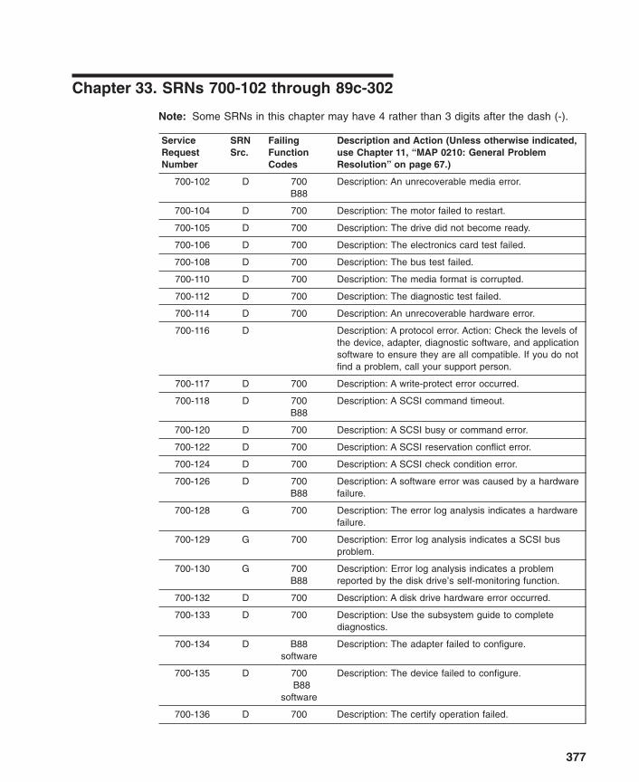
Chapter 33. SRNs 700-102 through 89c-302
Note: Some SRNs in this chapter may have 4 rather than 3 digits after the dash (-).
ServiceRequestNumber
SRNSrc.
FailingFunctionCodes
Description and Action (Unless otherwise indicated,use Chapter 11, “MAP 0210: General ProblemResolution” on page 67.)
700-102 D 700B88
Description: An unrecoverable media error.
700-104 D 700 Description: The motor failed to restart.
700-105 D 700 Description: The drive did not become ready.
700-106 D 700 Description: The electronics card test failed.
700-108 D 700 Description: The bus test failed.
700-110 D 700 Description: The media format is corrupted.
700-112 D 700 Description: The diagnostic test failed.
700-114 D 700 Description: An unrecoverable hardware error.
700-116 D Description: A protocol error. Action: Check the levels ofthe device, adapter, diagnostic software, and applicationsoftware to ensure they are all compatible. If you do notfind a problem, call your support person.
700-117 D 700 Description: A write-protect error occurred.
700-118 D 700B88
Description: A SCSI command timeout.
700-120 D 700 Description: A SCSI busy or command error.
700-122 D 700 Description: A SCSI reservation conflict error.
700-124 D 700 Description: A SCSI check condition error.
700-126 D 700B88
Description: A software error was caused by a hardwarefailure.
700-128 G 700 Description: The error log analysis indicates a hardwarefailure.
700-129 G 700 Description: Error log analysis indicates a SCSI busproblem.
700-130 G 700B88
Description: Error log analysis indicates a problemreported by the disk drive’s self-monitoring function.
700-132 D 700 Description: A disk drive hardware error occurred.
700-133 D 700 Description: Use the subsystem guide to completediagnostics.
700-134 D B88software
Description: The adapter failed to configure.
700-135 D 700B88
software
Description: The device failed to configure.
700-136 D 700 Description: The certify operation failed.
377

ServiceRequestNumber
SRNSrc.
FailingFunctionCodes
Description and Action (Unless otherwise indicated,use Chapter 11, “MAP 0210: General ProblemResolution” on page 67.)
700-137 D 700B88190
Description: Unit attention condition has occurred on theSend Diagnostic command.
700-138 D 190 Description: Error log indicates that the disk is operatingat higher than recommended temperatures.
700-139 D 700 Description: Error configuring or opening device. Action:Use Chapter 11, “MAP 0210: General ProblemResolution” on page 67.
700-640 G 640 Description: Error Log Analysis indicates a path error.
701-102 D 701B88
Description: An unrecoverable media error.
701-104 D 701 Description: The motor failed to restart.
701-105 D 701 Description: The drive did not become ready.
701-106 D 701 Description: The electronics card test failed.
701-108 D 701 Description: The bus test failed.
701-110 D 701 Description: The media format is corrupted.
701-112 D 701 Description: The diagnostic test failed.
701-114 D 701 Description: An unrecoverable hardware error.
701-116 D Description: A protocol error. Action: Check the levels ofthe device, adapter, diagnostic software, and applicationsoftware to ensure they are all compatible. If you do notfind a problem, call your support person.
701-117 D 701 Description: A write-protect error occurred.
701-118 D 701B88
Description: A SCSI command timeout.
701-120 D 701 Description: A SCSI busy or command error.
701-122 D 701 Description: A SCSI reservation conflict error.
701-124 D 701 Description: A SCSI check condition error.
701-126 D 701B88
Description: A software error was caused by a hardwarefailure.
701-128 G 701 Description: The error log analysis indicates a hardwarefailure.
701-129 G 701 Description: Error log analysis indicates a SCSI busproblem.
701-130 G 701B88
Description: Error log analysis indicates a problemreported by the disk drive’s self-monitoring function.
701-132 D 701 Description: A disk drive hardware error occurred.
701-133 D 701 Description: Use the subsystem guide to completediagnostics.
701-134 D B88software
Description: The adapter failed to configure.
378 Diagnostic Information for Multiple Bus Systems

ServiceRequestNumber
SRNSrc.
FailingFunctionCodes
Description and Action (Unless otherwise indicated,use Chapter 11, “MAP 0210: General ProblemResolution” on page 67.)
701-135 D 701B88
software
Description: The device failed to configure.
701-136 D 701 Description: The certify operation failed.
701-137 D 701B88190
Description: Unit attention condition has occurred on theSend Diagnostic command.
701-138 D 190 Description: Error log indicates that the disk is operatingat higher than recommended temperatures.
701-139 D 701 Description: Error configuring or opening device. Action:Use Chapter 11, “MAP 0210: General ProblemResolution” on page 67.
701-640 G 640 Description: Error Log Analysis indicates a path error.
702-102 D 702B88
Description: An unrecoverable media error.
702-104 D 702 Description: The motor failed to restart.
702-105 D 702 Description: The drive did not become ready.
702-106 D 702 Description: The electronics card test failed.
702-108 D 702 Description: The bus test failed.
702-110 D 702 Description: The media format is corrupted.
702-112 D 702 Description: The diagnostic test failed.
702-114 D 702 Description: An unrecoverable hardware error.
702-116 D Description: A protocol error. Action: Check the levels ofthe device, adapter, diagnostic software, and applicationsoftware to ensure they are all compatible. If you do notfind a problem, call your support person.
702-117 D 702 Description: A write-protect error occurred.
702-118 D 702B88
Description: A SCSI command timeout.
702-120 D 702 Description: A SCSI busy or command error.
702-122 D 702 Description: A SCSI reservation conflict error.
702-124 D 702 Description: A SCSI check condition error.
702-126 D 702B88
Description: A software error was caused by a hardwarefailure.
702-128 G 702 Description: The error log analysis indicates a hardwarefailure.
702-129 G 702 Description: Error log analysis indicates a SCSI busproblem.
702-130 G 702B88
Description: Error log analysis indicates a problemreported by the disk drive’s self-monitoring function.
702-132 D 702 Description: A disk drive hardware error occurred.
Chapter 33. SRNs 700-102 through 89c-302 379
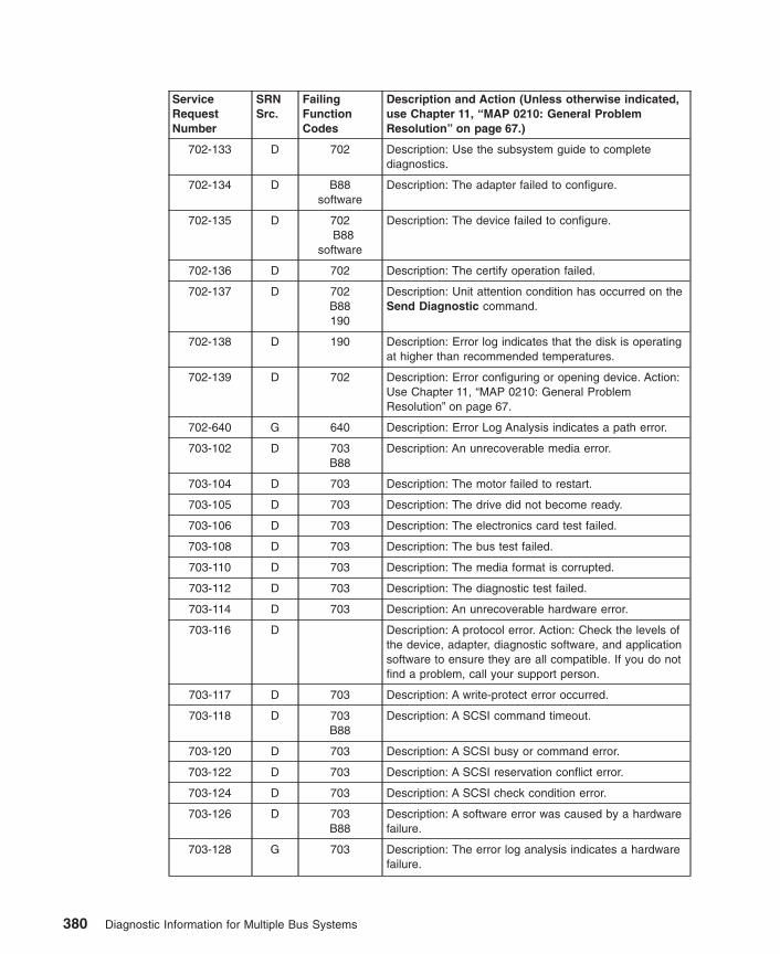
ServiceRequestNumber
SRNSrc.
FailingFunctionCodes
Description and Action (Unless otherwise indicated,use Chapter 11, “MAP 0210: General ProblemResolution” on page 67.)
702-133 D 702 Description: Use the subsystem guide to completediagnostics.
702-134 D B88software
Description: The adapter failed to configure.
702-135 D 702B88
software
Description: The device failed to configure.
702-136 D 702 Description: The certify operation failed.
702-137 D 702B88190
Description: Unit attention condition has occurred on theSend Diagnostic command.
702-138 D 190 Description: Error log indicates that the disk is operatingat higher than recommended temperatures.
702-139 D 702 Description: Error configuring or opening device. Action:Use Chapter 11, “MAP 0210: General ProblemResolution” on page 67.
702-640 G 640 Description: Error Log Analysis indicates a path error.
703-102 D 703B88
Description: An unrecoverable media error.
703-104 D 703 Description: The motor failed to restart.
703-105 D 703 Description: The drive did not become ready.
703-106 D 703 Description: The electronics card test failed.
703-108 D 703 Description: The bus test failed.
703-110 D 703 Description: The media format is corrupted.
703-112 D 703 Description: The diagnostic test failed.
703-114 D 703 Description: An unrecoverable hardware error.
703-116 D Description: A protocol error. Action: Check the levels ofthe device, adapter, diagnostic software, and applicationsoftware to ensure they are all compatible. If you do notfind a problem, call your support person.
703-117 D 703 Description: A write-protect error occurred.
703-118 D 703B88
Description: A SCSI command timeout.
703-120 D 703 Description: A SCSI busy or command error.
703-122 D 703 Description: A SCSI reservation conflict error.
703-124 D 703 Description: A SCSI check condition error.
703-126 D 703B88
Description: A software error was caused by a hardwarefailure.
703-128 G 703 Description: The error log analysis indicates a hardwarefailure.
380 Diagnostic Information for Multiple Bus Systems
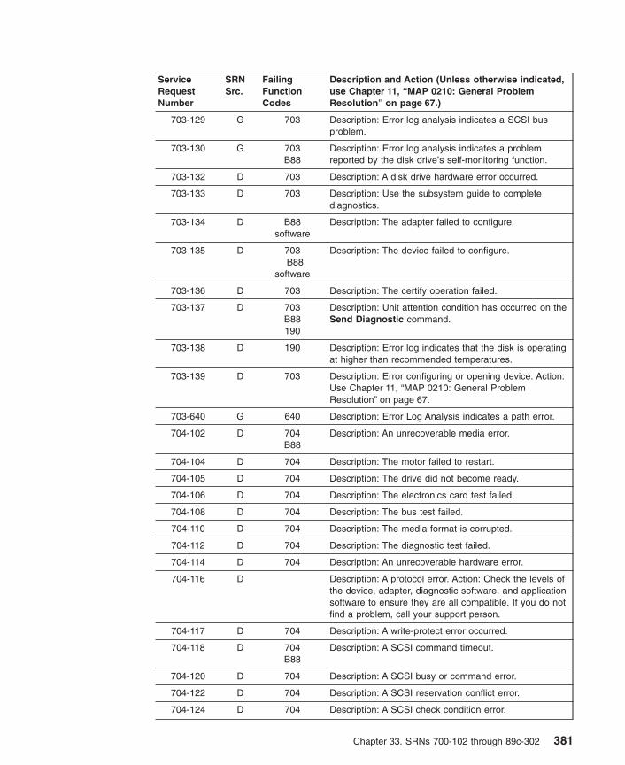
ServiceRequestNumber
SRNSrc.
FailingFunctionCodes
Description and Action (Unless otherwise indicated,use Chapter 11, “MAP 0210: General ProblemResolution” on page 67.)
703-129 G 703 Description: Error log analysis indicates a SCSI busproblem.
703-130 G 703B88
Description: Error log analysis indicates a problemreported by the disk drive’s self-monitoring function.
703-132 D 703 Description: A disk drive hardware error occurred.
703-133 D 703 Description: Use the subsystem guide to completediagnostics.
703-134 D B88software
Description: The adapter failed to configure.
703-135 D 703B88
software
Description: The device failed to configure.
703-136 D 703 Description: The certify operation failed.
703-137 D 703B88190
Description: Unit attention condition has occurred on theSend Diagnostic command.
703-138 D 190 Description: Error log indicates that the disk is operatingat higher than recommended temperatures.
703-139 D 703 Description: Error configuring or opening device. Action:Use Chapter 11, “MAP 0210: General ProblemResolution” on page 67.
703-640 G 640 Description: Error Log Analysis indicates a path error.
704-102 D 704B88
Description: An unrecoverable media error.
704-104 D 704 Description: The motor failed to restart.
704-105 D 704 Description: The drive did not become ready.
704-106 D 704 Description: The electronics card test failed.
704-108 D 704 Description: The bus test failed.
704-110 D 704 Description: The media format is corrupted.
704-112 D 704 Description: The diagnostic test failed.
704-114 D 704 Description: An unrecoverable hardware error.
704-116 D Description: A protocol error. Action: Check the levels ofthe device, adapter, diagnostic software, and applicationsoftware to ensure they are all compatible. If you do notfind a problem, call your support person.
704-117 D 704 Description: A write-protect error occurred.
704-118 D 704B88
Description: A SCSI command timeout.
704-120 D 704 Description: A SCSI busy or command error.
704-122 D 704 Description: A SCSI reservation conflict error.
704-124 D 704 Description: A SCSI check condition error.
Chapter 33. SRNs 700-102 through 89c-302 381
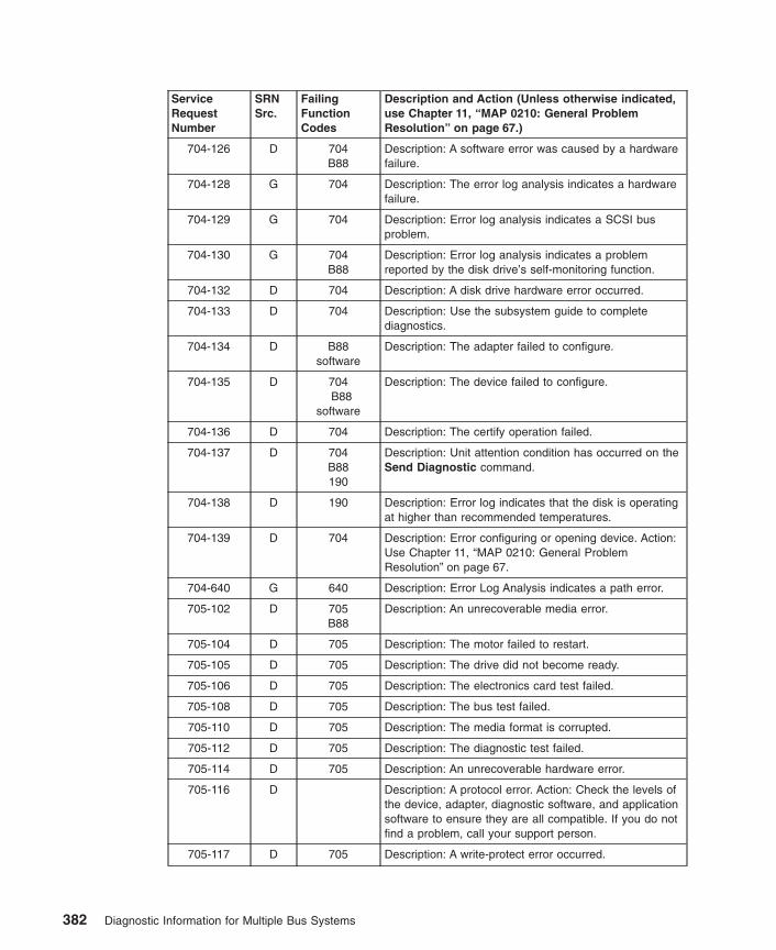
ServiceRequestNumber
SRNSrc.
FailingFunctionCodes
Description and Action (Unless otherwise indicated,use Chapter 11, “MAP 0210: General ProblemResolution” on page 67.)
704-126 D 704B88
Description: A software error was caused by a hardwarefailure.
704-128 G 704 Description: The error log analysis indicates a hardwarefailure.
704-129 G 704 Description: Error log analysis indicates a SCSI busproblem.
704-130 G 704B88
Description: Error log analysis indicates a problemreported by the disk drive’s self-monitoring function.
704-132 D 704 Description: A disk drive hardware error occurred.
704-133 D 704 Description: Use the subsystem guide to completediagnostics.
704-134 D B88software
Description: The adapter failed to configure.
704-135 D 704B88
software
Description: The device failed to configure.
704-136 D 704 Description: The certify operation failed.
704-137 D 704B88190
Description: Unit attention condition has occurred on theSend Diagnostic command.
704-138 D 190 Description: Error log indicates that the disk is operatingat higher than recommended temperatures.
704-139 D 704 Description: Error configuring or opening device. Action:Use Chapter 11, “MAP 0210: General ProblemResolution” on page 67.
704-640 G 640 Description: Error Log Analysis indicates a path error.
705-102 D 705B88
Description: An unrecoverable media error.
705-104 D 705 Description: The motor failed to restart.
705-105 D 705 Description: The drive did not become ready.
705-106 D 705 Description: The electronics card test failed.
705-108 D 705 Description: The bus test failed.
705-110 D 705 Description: The media format is corrupted.
705-112 D 705 Description: The diagnostic test failed.
705-114 D 705 Description: An unrecoverable hardware error.
705-116 D Description: A protocol error. Action: Check the levels ofthe device, adapter, diagnostic software, and applicationsoftware to ensure they are all compatible. If you do notfind a problem, call your support person.
705-117 D 705 Description: A write-protect error occurred.
382 Diagnostic Information for Multiple Bus Systems

ServiceRequestNumber
SRNSrc.
FailingFunctionCodes
Description and Action (Unless otherwise indicated,use Chapter 11, “MAP 0210: General ProblemResolution” on page 67.)
705-118 D 705B88
Description: A SCSI command timeout.
705-120 D 705 Description: A SCSI busy or command error.
705-122 D 705 Description: A SCSI reservation conflict error.
705-124 D 705 Description: A SCSI check condition error.
705-126 D 705B88
Description: A software error was caused by a hardwarefailure.
705-128 G 705 Description: The error log analysis indicates a hardwarefailure.
705-129 G 705 Description: Error log analysis indicates a SCSI busproblem.
705-130 G 705B88
Description: Error log analysis indicates a problemreported by the disk drive’s self-monitoring function.
705-132 D 705 Description: A disk drive hardware error occurred.
705-133 D 705 Description: Use the subsystem guide to completediagnostics.
705-134 D B88software
Description: The adapter failed to configure.
705-135 D 705B88
software
Description: The device failed to configure.
705-136 D 705 Description: The certify operation failed.
705-137 D 705B88190
Description: Unit attention condition has occurred on theSend Diagnostic command.
705-138 D 190 Description: Error log indicates that the disk is operatingat higher than recommended temperatures.
705-139 D 705 Description: Error configuring or opening device. Action:Use Chapter 11, “MAP 0210: General ProblemResolution” on page 67.
705-640 G 640 Description: Error Log Analysis indicates a path error.
706-102 D 706B88
Description: An unrecoverable media error.
706-104 D 706 Description: The motor failed to restart.
706-105 D 706 Description: The drive did not become ready.
706-106 D 706 Description: The electronics card test failed.
706-108 D 706 Description: The bus test failed.
706-110 D 706 Description: The media format is corrupted.
706-112 D 706 Description: The diagnostic test failed.
706-114 D 706 Description: An unrecoverable hardware error.
Chapter 33. SRNs 700-102 through 89c-302 383
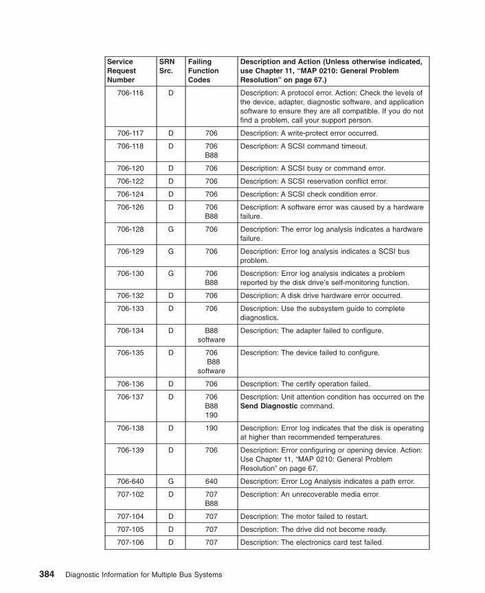
ServiceRequestNumber
SRNSrc.
FailingFunctionCodes
Description and Action (Unless otherwise indicated,use Chapter 11, “MAP 0210: General ProblemResolution” on page 67.)
706-116 D Description: A protocol error. Action: Check the levels ofthe device, adapter, diagnostic software, and applicationsoftware to ensure they are all compatible. If you do notfind a problem, call your support person.
706-117 D 706 Description: A write-protect error occurred.
706-118 D 706B88
Description: A SCSI command timeout.
706-120 D 706 Description: A SCSI busy or command error.
706-122 D 706 Description: A SCSI reservation conflict error.
706-124 D 706 Description: A SCSI check condition error.
706-126 D 706B88
Description: A software error was caused by a hardwarefailure.
706-128 G 706 Description: The error log analysis indicates a hardwarefailure.
706-129 G 706 Description: Error log analysis indicates a SCSI busproblem.
706-130 G 706B88
Description: Error log analysis indicates a problemreported by the disk drive’s self-monitoring function.
706-132 D 706 Description: A disk drive hardware error occurred.
706-133 D 706 Description: Use the subsystem guide to completediagnostics.
706-134 D B88software
Description: The adapter failed to configure.
706-135 D 706B88
software
Description: The device failed to configure.
706-136 D 706 Description: The certify operation failed.
706-137 D 706B88190
Description: Unit attention condition has occurred on theSend Diagnostic command.
706-138 D 190 Description: Error log indicates that the disk is operatingat higher than recommended temperatures.
706-139 D 706 Description: Error configuring or opening device. Action:Use Chapter 11, “MAP 0210: General ProblemResolution” on page 67.
706-640 G 640 Description: Error Log Analysis indicates a path error.
707-102 D 707B88
Description: An unrecoverable media error.
707-104 D 707 Description: The motor failed to restart.
707-105 D 707 Description: The drive did not become ready.
707-106 D 707 Description: The electronics card test failed.
384 Diagnostic Information for Multiple Bus Systems

ServiceRequestNumber
SRNSrc.
FailingFunctionCodes
Description and Action (Unless otherwise indicated,use Chapter 11, “MAP 0210: General ProblemResolution” on page 67.)
707-108 D 707 Description: The bus test failed.
707-110 D 707 Description: The media format is corrupted.
707-112 D 707 Description: The diagnostic test failed.
707-114 D 707 Description: An unrecoverable hardware error.
707-116 D Description: A protocol error. Action: Check the levels ofthe device, adapter, diagnostic software, and applicationsoftware to ensure they are all compatible. If you do notfind a problem, call your support person.
707-117 D 707 Description: A write-protect error occurred.
707-118 D 707B88
Description: A SCSI command timeout.
707-120 D 707 Description: A SCSI busy or command error.
707-122 D 707 Description: A SCSI reservation conflict error.
707-124 D 707 Description: A SCSI check condition error.
707-126 D 707B88
Description: A software error was caused by a hardwarefailure.
707-128 G 707 Description: The error log analysis indicates a hardwarefailure.
707-129 G 707 Description: Error log analysis indicates a SCSI busproblem.
707-130 G 707B88
Description: Error log analysis indicates a problemreported by the disk drive’s self-monitoring function.
707-132 D 707 Description: A disk drive hardware error occurred.
707-133 D 707 Description: Use the subsystem guide to completediagnostics.
707-134 D B88software
Description: The adapter failed to configure.
707-135 D 707B88
software
Description: The device failed to configure.
707-136 D 707 Description: The certify operation failed.
707-137 D 707B88190
Description: Unit attention condition has occurred on theSend Diagnostic command.
707-138 D 190 Description: Error log indicates that the disk is operatingat higher than recommended temperatures.
707-139 D 707 Description: Error configuring or opening device. Action:Use Chapter 11, “MAP 0210: General ProblemResolution” on page 67.
707-640 G 640 Description: Error Log Analysis indicates a path error.
Chapter 33. SRNs 700-102 through 89c-302 385
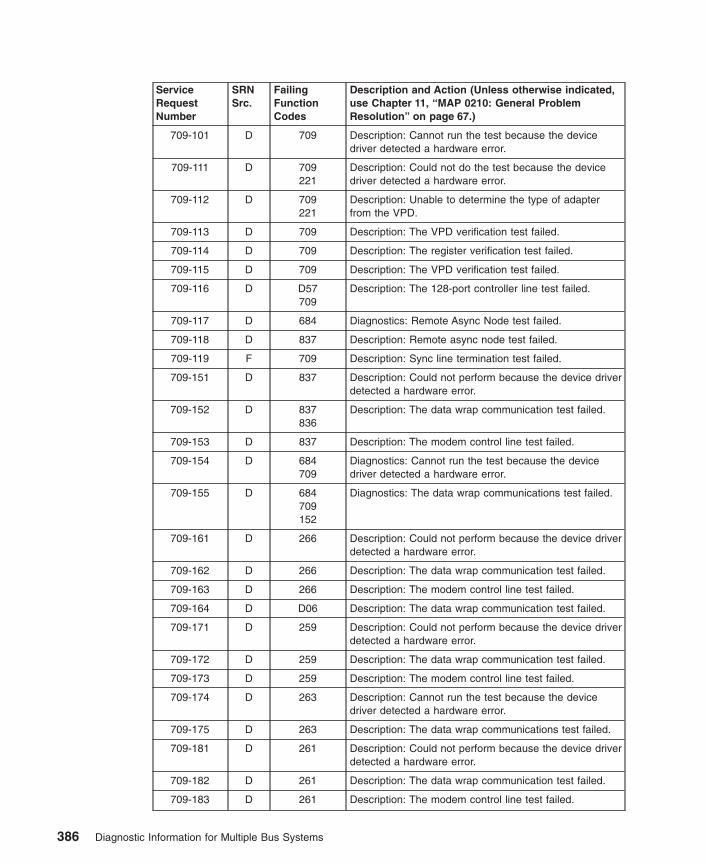
ServiceRequestNumber
SRNSrc.
FailingFunctionCodes
Description and Action (Unless otherwise indicated,use Chapter 11, “MAP 0210: General ProblemResolution” on page 67.)
709-101 D 709 Description: Cannot run the test because the devicedriver detected a hardware error.
709-111 D 709221
Description: Could not do the test because the devicedriver detected a hardware error.
709-112 D 709221
Description: Unable to determine the type of adapterfrom the VPD.
709-113 D 709 Description: The VPD verification test failed.
709-114 D 709 Description: The register verification test failed.
709-115 D 709 Description: The VPD verification test failed.
709-116 D D57709
Description: The 128-port controller line test failed.
709-117 D 684 Diagnostics: Remote Async Node test failed.
709-118 D 837 Description: Remote async node test failed.
709-119 F 709 Description: Sync line termination test failed.
709-151 D 837 Description: Could not perform because the device driverdetected a hardware error.
709-152 D 837836
Description: The data wrap communication test failed.
709-153 D 837 Description: The modem control line test failed.
709-154 D 684709
Diagnostics: Cannot run the test because the devicedriver detected a hardware error.
709-155 D 684709152
Diagnostics: The data wrap communications test failed.
709-161 D 266 Description: Could not perform because the device driverdetected a hardware error.
709-162 D 266 Description: The data wrap communication test failed.
709-163 D 266 Description: The modem control line test failed.
709-164 D D06 Description: The data wrap communication test failed.
709-171 D 259 Description: Could not perform because the device driverdetected a hardware error.
709-172 D 259 Description: The data wrap communication test failed.
709-173 D 259 Description: The modem control line test failed.
709-174 D 263 Description: Cannot run the test because the devicedriver detected a hardware error.
709-175 D 263 Description: The data wrap communications test failed.
709-181 D 261 Description: Could not perform because the device driverdetected a hardware error.
709-182 D 261 Description: The data wrap communication test failed.
709-183 D 261 Description: The modem control line test failed.
386 Diagnostic Information for Multiple Bus Systems

ServiceRequestNumber
SRNSrc.
FailingFunctionCodes
Description and Action (Unless otherwise indicated,use Chapter 11, “MAP 0210: General ProblemResolution” on page 67.)
709-251 D 709837
Description: Could not perform because the device driverdetected a hardware error.
709-252 D 709837
Description: The data wrap communication test failed.
709-253 D 709837
Description: The modem control line test failed.
709-254 D 709684
Diagnostics: Cannot run the test because the devicedriver detected a hardware error while running theRemote Async Node wrap test.
709-255 D 709684
Diagnostics: The data wrap communications test failedwhile running the Remote Async Node wrap test.
709-271 D 709837
Description: Could not perform because the device driverdetected a hardware error.
709-272 D 709837
Description: The data wrap communication test failed.
709-273 D 709837
Description: The modem control line test failed.
709-274 D 709684
Diagnostics: Cannot run the test because the devicedriver detected a hardware error while running thePrinter/Terminal cable wrap test.
709-275 D 709684
Diagnostics: The data wrap communications test failedwhile running the Printer/Terminal cable wrap test.
709-281 D 709837
Description: Could not perform because the device driverdetected a hardware error.
709-282 D 709837
Description: The data wrap communication test failed.
709-283 D 709837
Description: The modem control line test failed.
709-481 D D56 Description: Could not do the test because the devicedriver detected a hardware error.
709-482 D D56 Description: The data wrap communication test failed.
709-483 D D56 Description: The modem control line test failed.
709-901to
709-920
D software709
Description: An unexpected error occurred that can beattributed to software or hardware. Action: Rundiagnostics from a source other than from the disk or anetwork. If the same error occurs or if the original SRNwas not obtained from disk or a network baseddiagnostics, use MAP 210 with a FFC of 709; otherwise,suspect a software problem.
709-921 D 709software
Description: The adapter failed to configure.
Chapter 33. SRNs 700-102 through 89c-302 387

ServiceRequestNumber
SRNSrc.
FailingFunctionCodes
Description and Action (Unless otherwise indicated,use Chapter 11, “MAP 0210: General ProblemResolution” on page 67.)
709-922to
709-924
D software709
Description: An unexpected error occurred that can beattributed to software or hardware. Action: Rundiagnostics from a source other than from the disk or anetwork. If the same error occurs or if the original SRNwas not obtained from disk or a network baseddiagnostics, use MAP 210 with a FFC of 709; otherwise,suspect a software problem.
709-925 D 709software
Description: The adapter failed to configure.
709-926to
709-943
D software709
Description: An unexpected error occurred that can beattributed to software or hardware. Action: Rundiagnostics from a source other than from the disk or anetwork. If the same error occurs or if the original SRNwas not obtained from disk or a network baseddiagnostics, use MAP 210 with a FFC of 709; otherwise,suspect a software problem.
721-102 D 721B88
Description: An unrecoverable media error.
721-104 D 721 Description: The motor failed to restart.
721-105 D 721 Description: The drive did not become ready.
721-106 D 721 Description: The electronics card test failed.
721-108 D 721 Description: The bus test failed.
721-110 D 721 Description: The media format is corrupted.
721-112 D 721 Description: The diagnostic test failed.
721-114 D 721 Description: An unrecoverable hardware error.
721-116 D Description: A protocol error. Action: Check the levels ofthe device, adapter, diagnostic software, and applicationsoftware to ensure they are all compatible. If you do notfind a problem, call your support person.
721-117 D 721 Description: A write-protect error occurred.
721-118 D 721B88
Description: A SCSI command timeout.
721-120 D 721 Description: A SCSI busy or command error.
721-122 D 721 Description: A SCSI reservation conflict error.
721-124 D 721 Description: A SCSI check condition error.
721-126 D 721B88
Description: A software error was caused by a hardwarefailure.
721-128 G 721 Description: The error log analysis indicates a hardwarefailure.
721-129 G 721 Description: Error log analysis indicates a SCSI busproblem.
388 Diagnostic Information for Multiple Bus Systems

ServiceRequestNumber
SRNSrc.
FailingFunctionCodes
Description and Action (Unless otherwise indicated,use Chapter 11, “MAP 0210: General ProblemResolution” on page 67.)
721-130 G 721B88
Description: Error log analysis indicates a problemreported by the disk drive’s self-monitoring function.
721-132 D 721 Description: A disk drive hardware error occurred.
721-133 D 721 Description: Use the subsystem guide to completediagnostics.
721-134 D B88software
Description: The adapter failed to configure.
721-135 D 721B88
software
Description: The device failed to configure.
721-136 D 721 Description: The certify operation failed.
721-137 D 721B88190
Description: Unit attention condition has occurred on theSend Diagnostic command.
721-138 D 190 Description: Error log indicates that the disk is operatingat higher than recommended temperatures.
721-139 D 721 Description: Error configuring or opening device. Action:Use Chapter 11, “MAP 0210: General ProblemResolution” on page 67.
721-640 G 640 Description: Error Log Analysis indicates a path error.
722-xxx D 722 Description: Unknown disk drive type is failing.
723-xxx D 723 Description: Unknown CD-ROM type is failing.
724-xxx D 724 Description: Unknown tape drive failure.
733-110to
733-120
D 733 Description: The Reserve command failed, or theInquiry command failed.
733-130to
733-135
D 733media
Description: The Load command failed, or the Unloadcommand failed.
733-140 D 733 Description: The Mode Select command failed.
733-150to
733-169
D 733media
Description: The Test Unit Ready command failed, orthe Send Diagnostic command failed.
733-170 D 733B88
media
Description: The Read, Write and Compare test failed.
733-180to
733-185
D 733media
Description: The Load command failed, or the Unloadcommand failed.
733-190 D 733 Description: The Mode Select command failed.
733-200 D 733media
Description: The Test Unit Ready command failed.
Chapter 33. SRNs 700-102 through 89c-302 389

ServiceRequestNumber
SRNSrc.
FailingFunctionCodes
Description and Action (Unless otherwise indicated,use Chapter 11, “MAP 0210: General ProblemResolution” on page 67.)
733-210 D 733B88
Description: The device configuration failed.
733-220to
733-240
D 733 Description: 140 GB 8 mm tape drive failed.
733-300 D 733software
Description: The device configuration failed.
733-310 D B88733
software
Description: SCSI adapter configuration failed.
733-320 G 733media
Description: Error log analysis indicates a failure.
733-411to
733-423
D 733B88
software
Description: A reservation conflict occurred.
733-511to
733-523
D 733B88
Description: The drive returned bad or non-extendedsense data.
733-611to
733-723
D 733B88
software
Description: An adapter, device, or bus I/O erroroccurred.
734-111 D 734B88
Description: Unable to reserve device.
734-112 D 734B88
Description: Unable to do configuration.
734-113 D 734B88
Description: Unable to open the device driver.
734-121 D 734 Description: The CD-ROM drive indicates an error.
734-122 D 734 Description: The CD-ROM drive indicates an error.
734-123 D 734 Description: The CD-ROM drive indicates an error.
734-125 D 734B88
Description: The CD-ROM drive indicates an error.
734-126 D 734 Description: The CD-ROM drive indicates an error.
734-127 D 734 Description: The CD-ROM drive indicates an error.
734-128 D 734 Description: The CD-ROM drive indicates an error.
734-129 D 734 Description: The CD-ROM drive indicates an error.
734-150 D Test Disc734
Description: A media error was detected.
734-151 D 734B88
Description: A command timeout was detected.
734-152 D 734 Description: A command reservation conflict wasdetected.
390 Diagnostic Information for Multiple Bus Systems

ServiceRequestNumber
SRNSrc.
FailingFunctionCodes
Description and Action (Unless otherwise indicated,use Chapter 11, “MAP 0210: General ProblemResolution” on page 67.)
734-162 D 734 Description: The CD-ROM drive indicates an error.
734-171 D 734 Description: Unable to reserve device.
734-172 D 734 Description: Unable to do configuration.
734-173 D 734 Description: Unable to open device driver.
734-175 D 734 Description: The CD-ROM drive indicates an error.
734-198 D 734B88
Description: Undefined error detected.
734-199 D 734 Description: Undefined error detected.
734-211 D 734 Description: The LED test failed.
734-281 D 734 Description: No tone during audio test.
734-301 G 734 Description: Errors found during ELA.
734-302 G 734B88
Description: Errors found during ELA.
736-101 D 821 Description: An unexpected adapter error occurred.
736-102 D 736821
Description: An unexpected device or adapter erroroccurred.
736-103 D 736821
Description: The keyboard reset failed.
736-104 D 736 Description: Unknown keyboard.
736-105 D 736821
Description: The keyboard light-on test failed.
736-106 D 736821
Description: The keyboard light-off test failed.
736-201 D 821 Description: An unexpected adapter error occurred.
736-202 D 736821
Description: An unexpected device or adapter erroroccurred.
736-203 D 736821
Description: The read keyboard ID test failed.
736-204 D 736 Description: The keyboard layout ID test failed.
736-205 D 736821
Description: The keyboard echo test failed.
736-206 D 736821
Description: The select scan code set test failed.
736-301 D 821 Description: An unexpected adapter error occurred.
736-302 D 736821
Description: An unexpected device or adapter erroroccurred.
736-303 D 736 Description: An error occurred in turning on the lamps.
736-304 D 736 Description: An error occurred in turning off the lamps.
736-401 D 821 Description: An unexpected adapter error occurred.
Chapter 33. SRNs 700-102 through 89c-302 391

ServiceRequestNumber
SRNSrc.
FailingFunctionCodes
Description and Action (Unless otherwise indicated,use Chapter 11, “MAP 0210: General ProblemResolution” on page 67.)
736-402 D 736821
Description: An unexpected device or adapter erroroccurred.
736-403 D 736 Description: Unable to recognize the keyboard.
736-404 D 736821
Description: The keyboard is failing.
736-701 D 736821
Description: Error configuring the device.
736-901 G 821 Description: The error log analysis indicates an adapterfailure.
736-902 G 736821
Description: The error log analysis indicates a devicefailure.
736-903 G 736821
Description: The error log analysis indicates an unknownfailure.
741-102to
741-114
D 741 Description: SCSI disk drive problems.
741-116 D Description: A protocol error. Action: Check the levels ofthe device, adapter, diagnostic software, and applicationsoftware to be sure they are all compatible. If you do notfind a problem, call your support person.
741-117 D 741 Description: A write-protect error occurred.
741-118 D 741B88
Description: A SCSI command timeout.
741-120to
741-124
D 741 Description: SCSI disk drive problems.
741-126 D 741B88
Description: A software error was caused by a hardwarefailure.
741-128 G 741 Description: The error log analysis indicates a hardwarefailure.
741-129 G 190741B88
software
Description: Error log analysis indicates a SCSI busproblem.
741-130 G 741 Description: Error log analysis indicates a problemreported by the disk drive’s self-monitoring function.
741-132 D 741 Description: A disk drive hardware error occurred.
741-134 D B88software
Description: The adapter failed to configure.
741-135 D 741B88
software
Description: The device failed to configure.
392 Diagnostic Information for Multiple Bus Systems
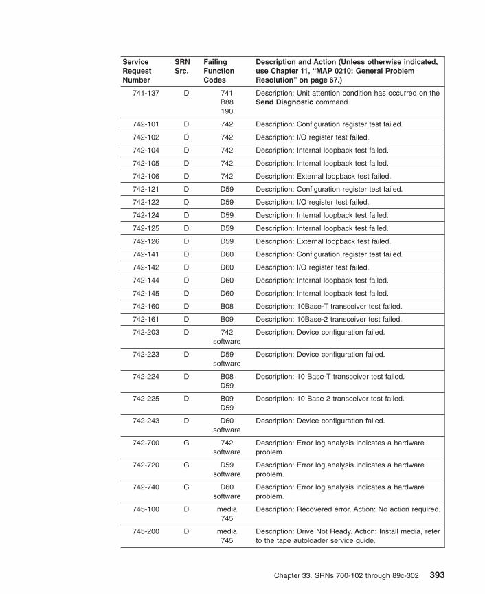
ServiceRequestNumber
SRNSrc.
FailingFunctionCodes
Description and Action (Unless otherwise indicated,use Chapter 11, “MAP 0210: General ProblemResolution” on page 67.)
741-137 D 741B88190
Description: Unit attention condition has occurred on theSend Diagnostic command.
742-101 D 742 Description: Configuration register test failed.
742-102 D 742 Description: I/O register test failed.
742-104 D 742 Description: Internal loopback test failed.
742-105 D 742 Description: Internal loopback test failed.
742-106 D 742 Description: External loopback test failed.
742-121 D D59 Description: Configuration register test failed.
742-122 D D59 Description: I/O register test failed.
742-124 D D59 Description: Internal loopback test failed.
742-125 D D59 Description: Internal loopback test failed.
742-126 D D59 Description: External loopback test failed.
742-141 D D60 Description: Configuration register test failed.
742-142 D D60 Description: I/O register test failed.
742-144 D D60 Description: Internal loopback test failed.
742-145 D D60 Description: Internal loopback test failed.
742-160 D B08 Description: 10Base-T transceiver test failed.
742-161 D B09 Description: 10Base-2 transceiver test failed.
742-203 D 742software
Description: Device configuration failed.
742-223 D D59software
Description: Device configuration failed.
742-224 D B08D59
Description: 10 Base-T transceiver test failed.
742-225 D B09D59
Description: 10 Base-2 transceiver test failed.
742-243 D D60software
Description: Device configuration failed.
742-700 G 742software
Description: Error log analysis indicates a hardwareproblem.
742-720 G D59software
Description: Error log analysis indicates a hardwareproblem.
742-740 G D60software
Description: Error log analysis indicates a hardwareproblem.
745-100 D media745
Description: Recovered error. Action: No action required.
745-200 D media745
Description: Drive Not Ready. Action: Install media, referto the tape autoloader service guide.
Chapter 33. SRNs 700-102 through 89c-302 393

ServiceRequestNumber
SRNSrc.
FailingFunctionCodes
Description and Action (Unless otherwise indicated,use Chapter 11, “MAP 0210: General ProblemResolution” on page 67.)
745-300to
745-350
D media745
Description: 4mm Tape Auto Loader problem. Action:Replace media, clean drive, refer to the tape autoloaderservice guide.
745-400 D 745magazine
media
Description: General Hardware Failure. Action: Replacemedia, clean drive, refer to the tape autoloader serviceguide.
745-410to
745-435
D 745media
Description: Internal Hardware Failure Action: Replacedrive, refer to the tape autoloader service guide.
745-440 D 745SCSI
Adapter
Description: SCSI Hardware Failure. Action: Replacedrive, refer to the tape autoloader service guide.
745-441to
745-443
D 745media
Description: 4mm Tape Auto Loader problem. Action:Replace drive, refer to the tape autoloader service guide.
745-444 D 745environ-
mentmedia
Description: Humidity too High Action: Lower humidity,replace media, refer to the tape autoloader serviceguide.
745-445 D clean mediadrive
Description: Drive Requires Cleaning Action: Clean drive,replace media, refer to the tape autoloader serviceguide.
745-460 to745-465
D 745magazine
media
Description: Magazine Movement Failure Action: Checkmagazine and media, clean rollers, refer to the tapeautoloader service guide.
745-470to
745-475
D 745magazine
media
Description: Media Insert/Eject Failure Action: Checkclean magazine and media, clean rollers, refer to thetape autoloader service guide.
745-480to
745-485
D 745magazine
media
Description: Drawer Open/Close Failure Action: Checkmagazine and media, refer to the tape autoloaderservice guide.
745-500 D 745system
Description: Illegal request to drive Action: Softwareconflict, refer to the tape autoloader service guide.
745-600 D 745system
Description: Unit Attention Action: Software conflict,media changed, refer to the tape autoloader serviceguide.
745-700 D 745media
Description: Not Writeable Action: Check media forwrite-protect, refer to the tape autoloader service guide.
745-800 D 745media
Description: Blank Media Action: Check media, refer tothe tape autoloader service guide.
745-B00 D 745SCSI
Adapter
Description: SCSI Interface Failure Action: Check SCSIinterface, refer to the tape autoloader service guide.
394 Diagnostic Information for Multiple Bus Systems

ServiceRequestNumber
SRNSrc.
FailingFunctionCodes
Description and Action (Unless otherwise indicated,use Chapter 11, “MAP 0210: General ProblemResolution” on page 67.)
745-D00 D 745media
Description: Tape Full Action: Check replace media, referto the tape autoloader service guide.
746-101 D 221 Description: Enhanced error handling failure on the bus.
746-102 D 293 Description: Enhanced error handling failure on aPCI-PCI Bridge.
746-103 D 746221
Description: Enhanced error handling failure on theadapter.
746-212 D 746 Description: FIFO empty bit set.
746-213 D 746 Description: FIFO empty bit clear.
746-214 D 746 Description: FIFO full bit set.
746-215 D 746 Description: FIFO full bit clear.
746-216 D 746 Description: FIFO data miscompare.
746-217 D 746 Description: SCSI FIFO data miscompare.
746-218 D 746 Description: SCSI FIFO underflow.
746-219 D Description: SCSI parity error. Action: Go to Chapter 8,“MAP 0050: SCSI Bus Problems” on page 51.
746-220 D 746 Description: SCSI FIFO flags error.
746-221 D 746221
Description: Miscompare during the write/read of theconfiguration register.
746-222 D 746 Description: Error during the write/read of the memoryregister.
746-223 D 746 Description: Miscompare during the write/read of thememory I/O register. Action: Go to Chapter 8, “MAP0050: SCSI Bus Problems” on page 51.
746-224 D 746221
Description: SCSI configuration register read or writeerror.
746-225 D 746 Description: Adapter POST failed.
746-226 D Description: SCSI wrap or PTC failure. Action: Go toChapter 8, “MAP 0050: SCSI Bus Problems” on page 51.
746-227 D 746221
Description: SCSI adapter test failure.
746-230 D Description: Arbitration test failed. Action: Go toChapter 8, “MAP 0050: SCSI Bus Problems” on page 51.
746-231 D Description: Function could not complete. Action: Go toChapter 8, “MAP 0050: SCSI Bus Problems” on page 51.
746-232 D Description: SCSI bus data miscompare. Action: Go toChapter 8, “MAP 0050: SCSI Bus Problems” on page 51.
746-240 D Description: No terminal power. Action: Go to Chapter 8,“MAP 0050: SCSI Bus Problems” on page 51.
746-242 D Description: SCSI bus error. Action: Go to Chapter 8,“MAP 0050: SCSI Bus Problems” on page 51.
Chapter 33. SRNs 700-102 through 89c-302 395

ServiceRequestNumber
SRNSrc.
FailingFunctionCodes
Description and Action (Unless otherwise indicated,use Chapter 11, “MAP 0210: General ProblemResolution” on page 67.)
746-301 D 746221
Description: The parent device open failed.
746-701 G 746 Description: Error log analysis indicates a PCI SCSIadapter failure.
746-801 G Description: Error log analysis indicates a terminatorproblem. Action: Run the diagnostics on the adapter inSystem Verification mode. If an SRN is reported, use theSRN to resolve the problem. If an SRN is not reported,use the SCSI service hints in “General SCSIConfiguration Checks” on page 3 to resolve the problem.
746-802 G Description: Error log analysis indicates that multipleattempts to reset the SCSI bus have timed out. Action:Run the diagnostics on the adapter in SystemVerification mode. If an SRN is reported, use the SRN toresolve the problem. If an SRN is not reported, use theSCSI service hints in “General SCSI ConfigurationChecks” on page 3 to resolve the problem.
746-803 G Description: Error log analysis indicates that multipleSCSI bus errors have occurred. Action: Run thediagnostics on the adapter in System Verification mode.If an SRN is reported, use the SRN to resolve theproblem. If an SRN is not reported, use the SCSI servicehints in “General SCSI Configuration Checks” on page 3to resolve the problem.
747-101 D 221 Description: Enhanced error handling failure on the bus.
747-102 D 293 Description: Enhanced error handling failure on aPCI-PCI Bridge.
747-103 D 747221
Description: Enhanced error handling failure on theadapter.
747-212 D 747 Description: FIFO empty bit set.
747-213 D 747 Description: FIFO empty bit clear.
747-214 D 747 Description: FIFO full bit set.
747-215 D 747 Description: FIFO full bit clear.
747-216 D 747 Description: FIFO data miscompare.
747-217 D 747 Description: SCSI FIFO data miscompare.
747-218 D 747 Description: SCSI FIFO underflow.
747-219 D Description: SCSI parity error. Action: Go to Chapter 8,“MAP 0050: SCSI Bus Problems” on page 51.
747-220 D 747 Description: SCSI FIFO flags error.
747-221 D 747221
Description: Miscompare during the write/read of theconfiguration register.
747-222 D 747 Description: Error during the write/read of the memoryregister.
396 Diagnostic Information for Multiple Bus Systems

ServiceRequestNumber
SRNSrc.
FailingFunctionCodes
Description and Action (Unless otherwise indicated,use Chapter 11, “MAP 0210: General ProblemResolution” on page 67.)
747-223 D 747 Description: Miscompare during the write/read of thememory I/O register. Action: Go to Chapter 8, “MAP0050: SCSI Bus Problems” on page 51.
747-224 D 747221
Description: SCSI configuration register read or writeerror.
747-225 D 747 Description: Adapter POST failed.
747-226 D Description: SCSI wrap or PTC failure. Action: Go toChapter 8, “MAP 0050: SCSI Bus Problems” on page 51.
747-227 D 747221
Description: SCSI adapter test failure.
747-230 D Description: Arbitration test failed. Action: Go toChapter 8, “MAP 0050: SCSI Bus Problems” on page 51.
747-231 D Description: Function could not complete. Action: Go toChapter 8, “MAP 0050: SCSI Bus Problems” on page 51.
747-232 D Description: SCSI bus data miscompare. Action: Go toChapter 8, “MAP 0050: SCSI Bus Problems” on page 51.
747-240 D Description: No terminal power. Action: Go to Chapter 8,“MAP 0050: SCSI Bus Problems” on page 51.
747-242 D Description: SCSI bus error. Action: Go to Chapter 8,“MAP 0050: SCSI Bus Problems” on page 51.
747-301 D 747221
Description: The parent device open failed.
747-701 G 747 Description: Error log analysis indicates a PCI SCSIadapter failure.
747-801 G Description: Error log analysis indicates a terminatorproblem. Action: Run the diagnostics on the adapter inSystem Verification mode. If an SRN is reported, use theSRN to resolve the problem. If an SRN is not reported,use the SCSI service hints in “General SCSIConfiguration Checks” on page 3 to resolve the problem.
747-802 G Description: Error log analysis indicates that multipleattempts to reset the SCSI bus have timed out. Action:Run the diagnostics on the adapter in SystemVerification mode. If an SRN is reported, use the SRN toresolve the problem. If an SRN is not reported, use theSCSI service hints in “General SCSI ConfigurationChecks” on page 3 to resolve the problem.
747-803 G Description: Error log analysis indicates that multipleSCSI bus errors have occurred. Action: Run thediagnostics on the adapter in System Verification mode.If an SRN is reported, use the SRN to resolve theproblem. If an SRN is not reported, use the SCSI servicehints in “General SCSI Configuration Checks” on page 3to resolve the problem.
Chapter 33. SRNs 700-102 through 89c-302 397

ServiceRequestNumber
SRNSrc.
FailingFunctionCodes
Description and Action (Unless otherwise indicated,use Chapter 11, “MAP 0210: General ProblemResolution” on page 67.)
749-xxx D 749 Description: 7331 Model 205 Tape Library. Refer toservice documentation for this device.
750-100 D 750 Description: The adapter open test failed.
750-200 D 750221
Description: Config register test failed.
750-201 D 750221
Description: I/O register test failed.
750-202 D 750221
Description: Adapter self-test failed.
750-300 D 256750221
Description: The connect test failed.
750-301 D 256750221
Description: Token-ring internal wrap test failure.
750-302 D 256750221
Description: Token-ring external wrap failure.
750-303 D 256750221
Description: Token-ring initialization test failure.
750-400 D 240256750221
Description: The connect test failed.
750-401 D 240256750221
Token-ring internal wrap test failure.
750-402 D 240256750221
Token-ring external wrap test failure.
750-403 D 240256750221
Token-ring initialization test failure.
750-700 G 750221
Description: Error Log analysis indicated a hardwarefailure.
751-101 D 751227
Description: The PCI wrap test failed. Action: Go toChapter 18, “MAP 0270: SCSI RAID Problem Resolutionand Verification” on page 103.
398 Diagnostic Information for Multiple Bus Systems

ServiceRequestNumber
SRNSrc.
FailingFunctionCodes
Description and Action (Unless otherwise indicated,use Chapter 11, “MAP 0210: General ProblemResolution” on page 67.)
751-102 D 751 Description: The POST indicates an adapter failure.Action: Go to Chapter 18, “MAP 0270: SCSI RAIDProblem Resolution and Verification” on page 103.
751-103 D 751 Description: The POST indicates an adapter channelfailure. Action: Go to Chapter 18, “MAP 0270: SCSIRAID Problem Resolution and Verification” on page 103.
751-104 D 190 Description: The POST indicates a defective cable.
751-105 D B3A Description: The POST indicates a defective backplaneor external enclosure.
751-106 D 722 Description: The POST indicates a disk failure. Action:Go to Chapter 18, “MAP 0270: SCSI RAID ProblemResolution and Verification” on page 103.
751-108 D 221 Description: Enhanced error handling failure on the bus.
751-109 D 751 Description: The NVRAM test indicates an adapterfailure.Action: Go to Chapter 18, “MAP 0270: SCSI RAIDProblem Resolution and Verification” on page 103.
751-110 D 722 Description: The disk reported a Predictive FailureAnalysis error (PFA). Action: Go to Chapter 18, “MAP0270: SCSI RAID Problem Resolution and Verification”on page 103.
751-111 D 722 Description: The disk drive has been failed by theadapter. Action: Go to Chapter 18, “MAP 0270: SCSIRAID Problem Resolution and Verification” on page 103.
751-112 G 722 Description: ELA indicates that the disk reported a harddata error. Action: Go to Chapter 18, “MAP 0270: SCSIRAID Problem Resolution and Verification” on page 103.
751-113 G 722 Description: ELA indicates that the disk reported a hardequipment error. Action: Go to Chapter 18, “MAP 0270:SCSI RAID Problem Resolution and Verification” onpage 103.
751-114 G E29 Description: ELA indicates a cache failure. Action: Go toChapter 18, “MAP 0270: SCSI RAID Problem Resolutionand Verification” on page 103.
751-115 G E30 Description: ELA indicates that the cache battery iseither low on power or has failed. Action: Go toChapter 18, “MAP 0270: SCSI RAID Problem Resolutionand Verification” on page 103.
751-116 D 751 Description: Failed to disable data scrub.
751-117 D E29 Description: POST indicates cache failure
751-118 D E29 Description: NVRAM test indicates cache failure.
751-119 D E29 Description: NVRAM test indicates that write cache ismissing. Action: Go to Chapter 18, “MAP 0270: SCSIRAID Problem Resolution and Verification” on page 103.
Chapter 33. SRNs 700-102 through 89c-302 399

ServiceRequestNumber
SRNSrc.
FailingFunctionCodes
Description and Action (Unless otherwise indicated,use Chapter 11, “MAP 0210: General ProblemResolution” on page 67.)
751-120 D E29 Description: NVRAM test indicates that cache size isinvalid. Action: Go to Chapter 18, “MAP 0270: SCSIRAID Problem Resolution and Verification” on page 103.
751-121 D E30 Description: NVRAM test indicates that the cache batteryis low on power. Action: Go to Chapter 18, “MAP 0270:SCSI RAID Problem Resolution and Verification” onpage 103.
751-122 D E30 Description: NVRAM test indicates cache battery failure.Action: Go to Chapter 18, “MAP 0270: SCSI RAIDProblem Resolution and Verification” on page 103.
751-123 D 751 Description: ELA indicates an adapter failure. Action: Goto Chapter 18, “MAP 0270: SCSI RAID ProblemResolution and Verification” on page 103.
751-124 D 221 Description: Enhanced error handling failure on PCI-PCIBridge.
751-125 D 751221
Description: Enhanced error handling failure on adapter.
751-400 F 751190B3A722
Description: POST indicates a channel failure. Action:Go to Chapter 18, “MAP 0270: SCSI RAID ProblemResolution and Verification” on page 103.
751-701 G 751221
Description: Error Log Analysis indicates an EEH error.
757-110 D 757 Description: The Reserve command failed.
757-120 D 757 Description: The Inquiry command failed.
757-130 D 757media
Description: The Load command failed.
757-135 D 757media
Description: The Unload command failed.
757-140 D 757 Description: The Mode Select command failed.
757-150 D 757media
Description: The Test Unit Ready command failed.
757-160 D 757media
Description: The Send Diagnostic command failed.
757-169 D 757media
Description: The Send Diagnostic command failed.
757-170 D 757B88
media
Description: The Read, Write and Compare test failed.
757-180 D 757media
Description: The Load command failed.
757-185 D 757media
Description: The Unload command failed.
400 Diagnostic Information for Multiple Bus Systems

ServiceRequestNumber
SRNSrc.
FailingFunctionCodes
Description and Action (Unless otherwise indicated,use Chapter 11, “MAP 0210: General ProblemResolution” on page 67.)
757-190 D 757 Description: The Mode Select command failed.
757-200 D 757media
Description: The Test Unit Ready command failed.
757-210 D 757B88
Description: The device configuration failed.
757-220 D 757 Description: The Release command failed.
757-230 D 757 Description: The Request Sense command failed.
757-240 D 757 Description: The Openx command failed.
757-300 D 757software
Description: The device configuration failed.
757-310 D B88757
software
Description: SCSI adapter configuration failed.
757-320 D 757media
Description: Error log analysis indicates a failure.
757-411 to757-423
D 757B88
software
Description: A reservation conflict occurred.
757-511to
757-523
D 757B88
Description: The drive returned bad or non-extendedsense data.
757-611to
757-623
D 757B88
software
Description: An adapter or bus I/O error occurred.
757-711to
757-723
D 757B88
software
Description: A device timeout error occurred.
759-102 D 759B88
Description: An unrecoverable media error.
759-104 D 759 Description: The motor failed to restart.
759-105 D 759 Description: The drive did not become ready.
759-106 D 759 Description: The electronics card test failed.
759-108 D 759 Description: The bus test failed.
759-110 D 759 Description: The media format is corrupted.
759-112 D 759 Description: The diagnostic test failed.
759-114 D 759 Description: An unrecoverable hardware error.
759-116 D Description: A protocol error. Action: Check the levels ofthe device, adapter, diagnostic software, and applicationsoftware to ensure they are all compatible. If you do notfind a problem, call your support person.
759-117 D 759 Description: A write-protect error occurred.
Chapter 33. SRNs 700-102 through 89c-302 401

ServiceRequestNumber
SRNSrc.
FailingFunctionCodes
Description and Action (Unless otherwise indicated,use Chapter 11, “MAP 0210: General ProblemResolution” on page 67.)
759-118 D 759B88
Description: A SCSI command timeout.
759-120 D 759 Description: A SCSI busy or command error.
759-122 D 759 Description: A SCSI reservation conflict error.
759-124 D 759 Description: A SCSI check condition error.
759-126 D 759B88
Description: A software error was caused by a hardwarefailure.
759-128 G 759 Description: The error log analysis indicates a hardwarefailure.
759-129 G 759 Description: Error log analysis indicates a SCSI busproblem.
759-130 G 759B88
Description: Error log analysis indicates a problemreported by the disk drive’s self-monitoring function.
759-132 D 759 Description: A disk drive hardware error occurred.
759-133 D 759 Description: Use the subsystem guide to completediagnostics.
759-134 D B88software
Description: The adapter failed to configure.
759-135 D 759B88
software
Description: The device failed to configure.
759-136 D 759 Description: The certify operation failed.
759-137 D 759B88190
Description: Unit attention condition has occurred on theSend Diagnostic command.
759-138 D 190 Description: Error log indicates that the disk is operatingat higher than recommended temperatures.
759-139 D 759 Description: Error configuring or opening device. Action:Use Chapter 11, “MAP 0210: General ProblemResolution” on page 67.
759-640 G 640 Description: Error Log Analysis indicates a path error.
763-1xx D 763software
221
Description: Problem detected with a device or devicedata corrupted.Note: You may need to reinstall ssp.css software.
763-200to
763-299
D ext clock763
wrap plug
Description: Problem detected with the external clock(SP switch).
Notes:
1. Refer to your SP Maintenance Information manualfor the external clock FRU part number.
2. The wrap plug FRU part number is listed under the763 FFC.
402 Diagnostic Information for Multiple Bus Systems

ServiceRequestNumber
SRNSrc.
FailingFunctionCodes
Description and Action (Unless otherwise indicated,use Chapter 11, “MAP 0210: General ProblemResolution” on page 67.)
763-2A0to
763-2A9
D 763 Description: Problem detected with the internal clock.
763-3xx D 763221
Description: Problem detected with the POS registers.
763-4xx D 763software
Description: TBIC test failed.
763-5xx D 763 Description: SRAM test failed.
763-6xx D 763 Description: Microprocessor test failed.
763-7xx D 763 Description: Interrupt test failed.
763-8xx D 763 Description: FIFO test failed.
763-9xx D 763221
Switch-cable
Description: DMA engine test failed.Note: Refer to your SP Maintenance Informationmanual for the switch cable FRU part number.
763-Ax3 D 763terminator
Description: Card wrap test failed.Note: The terminator FRU part number is listed underthe 763 FFC.
763-Ax4 D Switch-cable
wrap plug
Description: Card wrap test failed.
Notes:
1. Refer to your SP Maintenance Information manualfor the switch cable FRU part number.
2. The wrap plug FRU part number is listed under the763 FFC.
763-xx2 D 763 Description: Bad adapter card. (except for SRN 763-282)Action: Replace the SP Switch MX Adapter.
764-1xx D 764software
221
Description: Problem detected with a device or devicedata corrupted.Note: You may need to reinstall ssp.css software.
764-200 to764-299
D ext clock764
wrap plug
Description: Problem detected with the external clock(SP switch).
Notes:
1. Refer to your SP Maintenance Information manualfor the external clock FRU part number.
2. The wrap plug FRU part number is listed under the763 FFC.
764-2A0to
764-2A9
D 764 Description: Problem detected with the internal clock.
764-3xx D 764221
Description: Problem detected with the POS registers.
Chapter 33. SRNs 700-102 through 89c-302 403

ServiceRequestNumber
SRNSrc.
FailingFunctionCodes
Description and Action (Unless otherwise indicated,use Chapter 11, “MAP 0210: General ProblemResolution” on page 67.)
764-4xx D 764software
Description: TBIC test failed.
764-5xx D 764 Description: SRAM test failed.
764-6xx D 764 Description: Microprocessor test failed.
764-7xx D 764 Description: Interrupt test failed.
764-8xx D 764 Description: FIFO test failed.
764-9xx D 764221
switch-cable
Description: DMA engine test failed.Note: Refer to your SP Maintenance Informationmanual for the switch cable FRU part number.
764-Ax3 D 764terminator
Description: Card wrap test failed.Note: The terminator FRU part number is listed underthe 763 FFC.
764-Ax4 D Switch-cable
wrap plug
Description: Card wrap test failed.
Notes:
1. Refer to your SP Maintenance Information manualfor the switch cable FRU part number.
2. The wrap plug FRU part number is listed under the763 FFC.
764-xx2 D 764 Description: Bad adapter card. (except for SRN 764-282)Action: Replace the SP Switch MX Adapter.
772-102 D 772 Description: An unrecoverable media error.
772-104 D 772 Description: The motor failed to restart.
772-105 D 772 Description: The drive did not become ready.
772-106 D 772 Description: The electronics card test failed.
772-108 D 772 Description: The bus test failed.
772-110 D 772 Description: The media format is corrupted.
772-112 D 772 Description: The diagnostic test failed.
772-114 D 772 Description: An unrecoverable hardware error.
772-116 D Description: A protocol error. Action: Check the levels ofthe device, adapter, diagnostic software, and applicationsoftware to be sure they are all compatible. If you do notfind a problem, call your support person.
772-117 D 772 Description: A write-protect error occurred.
772-118 D 772B88
Description: A SCSI command time-out.
772-120 D 772 Description: A SCSI busy or command error.
772-122 D 772 Description: A SCSI reservation conflict error.
772-124 D 772 Description: A SCSI check condition error.
404 Diagnostic Information for Multiple Bus Systems

ServiceRequestNumber
SRNSrc.
FailingFunctionCodes
Description and Action (Unless otherwise indicated,use Chapter 11, “MAP 0210: General ProblemResolution” on page 67.)
772-126 D 772B88
Description: A software error was caused by a hardwarefailure.
772-128 G 772 Description: The error log analysis indicates a hardwarefailure.
772-129 G 190772B88
software
Description: Error log analysis indicates a SCSI busproblem.
772-130 G 772 Description: Error log analysis indicates a problemreported by the disk drive’s self-monitoring function.
772-132 D 772 Description: A disk drive hardware error occurred.
772-134 D B88software
Description: The adapter failed to configure.
772-135 D 772B88
software
Description: The device failed to configure.
772-136 D 772 Description: The certify operation failed.
772-137 D 772B88190
Description: Unit attention condition has occurred on theSend Diagnostic command.
773-102 D 773 Description: An unrecoverable media error.
773-104 D 773 Description: The motor failed to restart.
773-105 D 773 Description: The drive did not become ready.
773-106 D 773 Description: The electronics card test failed.
773-108 D 773 Description: The bus test failed.
773-110 D 773 Description: The media format is corrupted.
773-112 D 773 Description: The diagnostic test failed.
773-114 D 773 Description: An unrecoverable hardware error.
773-116 D Description: A protocol error. Action: Check the levels ofthe device, adapter, diagnostic software, and applicationsoftware to be sure they are all compatible. If you do notfind a problem, call your support person.
773-117 D 773 Description: A write-protect error occurred.
773-118 D 773B88
Description: A SCSI command time-out.
773-120 D 773 Description: A SCSI busy or command error.
773-122 D 773 Description: A SCSI reservation conflict error.
773-124 D 773 Description: A SCSI check condition error.
773-126 D 773B88
Description: A software error was caused by a hardwarefailure.
Chapter 33. SRNs 700-102 through 89c-302 405

ServiceRequestNumber
SRNSrc.
FailingFunctionCodes
Description and Action (Unless otherwise indicated,use Chapter 11, “MAP 0210: General ProblemResolution” on page 67.)
773-128 G 773 Description: The error log analysis indicates a hardwarefailure.
773-129 G 190773B88
software
Description: Error log analysis indicates a SCSI busproblem.
773-130 G 773 Description: Error log analysis indicates a problemreported by the disk drive’s self-monitoring function.
773-132 D 773 Description: A disk drive hardware error occurred.
773-134 D B88software
Description: The adapter failed to configure.
773-135 D 773B88
software
Description: The device failed to configure.
773-136 D 773 Description: The certify operation failed.
773-137 D 773B88190
Description: Unit attention condition has occurred on theSend Diagnostic command.
774-102 D 774 Description: An unrecoverable media error.
774-104 D 774 Description: The motor failed to restart.
774-105 D 774 Description: The drive did not become ready.
774-106 D 774 Description: The electronics card test failed.
774-108 D 774 Description: The bus test failed.
774-110 D 774 Description: The media format is corrupted.
774-112 D 774 Description: The diagnostic test failed.
774-114 D 774 Description: An unrecoverable hardware error.
774-116 D Description: A protocol error. Action: Check the levels ofthe device, adapter, diagnostic software, and applicationsoftware to be sure they are all compatible. If you do notfind a problem, call your support person.
774-117 D 774 Description: A write-protect error occurred.
774-118 D 774B88
Description: A SCSI command time-out.
774-120 D 774 Description: A SCSI busy or command error.
774-122 D 774 Description: A SCSI reservation conflict error.
774-124 D 774 Description: A SCSI check condition error.
774-126 D 774B88
Description: A software error was caused by a hardwarefailure.
774-128 G 774 Description: The error log analysis indicates a hardwarefailure.
406 Diagnostic Information for Multiple Bus Systems

ServiceRequestNumber
SRNSrc.
FailingFunctionCodes
Description and Action (Unless otherwise indicated,use Chapter 11, “MAP 0210: General ProblemResolution” on page 67.)
774-129 G 190774B88
software
Description: Error log analysis indicates a SCSI busproblem.
774-130 G 774 Description: Error log analysis indicates a problemreported by the disk drive’s self-monitoring function.
774-132 D 774 Description: A disk drive hardware error occurred.
774-134 D B88software
Description: The adapter failed to configure.
774-135 D 774B88
software
Description: The device failed to configure.
774-136 D 774 Description: The certify operation failed.
774-137 D 774B88190
Description: Unit attention condition has occurred on theSend Diagnostic command.
775-001 D 775227
Monitor
Description: ″NO″ to color panel.
775-002 D 775Monitor
Description: ″NO″ to cursor panel.
775-007 D Info code Description: The EMC_SCROLLING_17_H_TEST failed.
775-009 D Info code Description: The EMC_SCROLLING_21_H_TEST failed.
775-064 D 775227
Description: TRIO64V+_TIMEOUT
775-101 D 775227
Description: Color miscompare.
775-102 D 775227
Description: Clipping error.
775-103 D 775227
Description: Rectangle fill test failed.
775-128 D software775
Description: MALLOC_ERROR
775-161 D software Description: Loop count value in rules file is zero.
775-191 D 775227
Description: Red screen error.
775-193 D 775227
Description: Green screen error.
775-1FF D 775227
Description: Rectangle fill test failed.
775-201 D 775227
Description: Color miscompare.
Chapter 33. SRNs 700-102 through 89c-302 407

ServiceRequestNumber
SRNSrc.
FailingFunctionCodes
Description and Action (Unless otherwise indicated,use Chapter 11, “MAP 0210: General ProblemResolution” on page 67.)
775-202 D 775227
Description: Clipping error.
775-203 D 775227
Description: Image transfer across Plane Test failed.
775-211 D software Description: INTERNAL_ERROR_DATA_SIZE
775-212 D software Description: INTERNAL_ERROR_NO_ACCESS
775-215 D 775227
Description: Black screen error
775-217 D 775227
Description: 9 x 7 Cross hatch grid failed.
775-233 D software Description: OPEN_RCM_ERROR
775-234 D software Description: IOCTL_GSC_HANDLE_FAILED
775-235 D software Description: AIXGSC_MAKE_GP_FAILED
775-236 D software Description: AIXGSC_UNMAKE_GP_FAILED
775-237 D software Description: DEVICE_BUSY_ERROR
775-241 D Info code Description: The SCROLLING_17_H_TEST failed.
775-263 D Info code Description: The EMC_SCROLLING_21_H_TEST failed
775-2FF D 775227
Description: Image transfer across Plane Test failed.
775-301 D 775227
Description: A write of ″0x00″ to the palette registerfailed.
775-302 D 775227
Description: A write of ″0x15″ to the palette registerfailed.
775-303 D 775227
Description: A write of ″0x2A″ to the palette registerfailed.
775-304 D 775227
Description: A write of ″0x3F″ to the palette registerfailed.
775-305 D 775227
Description: The test of the palette registers failed.
775-3FF D 775227
Description: The test of the palette registers failed.
775-401 D 775227
Description: Frame buffer base address inconsistent.
775-402 D 775227
Description: VRAM inaccessible.
775-403 D 775227
Description: Miscompare found in VRAM.
775-404 D 775227
Description: The test of the VRAM failed.
775-447 D 775227
Description: Green screen error.
408 Diagnostic Information for Multiple Bus Systems

ServiceRequestNumber
SRNSrc.
FailingFunctionCodes
Description and Action (Unless otherwise indicated,use Chapter 11, “MAP 0210: General ProblemResolution” on page 67.)
775-449 D 775227
Description: Blue Screen error.
775-471 D 775227
Description: 9 x 7 Cross hatch grid failed.
775-473 D 775227
Description: 11 x 9 Cross hatch grid failed.
775-495 D Info code Description: The SCROLLING_17_H_TEST failed.
775-497 D Info code Description: The SCROLLING_21_H_TEST failed.
775-4FF D 775227
Description: The test of the VRAM failed.
775-501 D 775227
Description: Color miscompare.
775-502 D 775227
Description: Clipping error.
775-503 D 775227
Description: Direct Frame Buffer test failed.
775-5FF D 775227
Description: Direct Frame Buffer test failed.
775-601 D 775227
Description: Video Stream Register test failed.
775-602 D 775227
Description: Video Stream hardware test failed.
775-6FF D 775227
Description: Video Stream hardware test failed.
775-701 D 775227
Description: 0 Degree Short Stroke Draw failed.
775-702 D 775227
Description: 45 Degree Short Stroke Draw failed.
775-703 D 775227
Description: Blue Screen error, or 90 Degree ShortStroke Draw failed.
775-704 D 775227
Description: 135 Degree Short Stroke Draw failed.
775-705 D 775227
Description: White screen error, or 180 Degree ShortStroke Draw failed.
775-706 D 775227
Description: 225 Degree Short Stroke Draw failed.
775-707 D 775227
Description: 270 Degree Short Stroke Draw failed.
775-708 D 775227
Description: 315 Degree Short Stroke Draw failed
775-709 D 775227
Description: Short Stroke Vector Function test failed.
Chapter 33. SRNs 700-102 through 89c-302 409
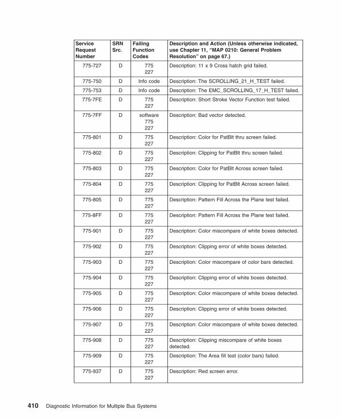
ServiceRequestNumber
SRNSrc.
FailingFunctionCodes
Description and Action (Unless otherwise indicated,use Chapter 11, “MAP 0210: General ProblemResolution” on page 67.)
775-727 D 775227
Description: 11 x 9 Cross hatch grid failed.
775-750 D Info code Description: The SCROLLING_21_H_TEST failed.
775-753 D Info code Description: The EMC_SCROLLING_17_H_TEST failed.
775-7FE D 775227
Description: Short Stroke Vector Function test failed.
775-7FF D software775227
Description: Bad vector detected.
775-801 D 775227
Description: Color for PatBlt thru screen failed.
775-802 D 775227
Description: Clipping for PatBlt thru screen failed.
775-803 D 775227
Description: Color for PatBlt Across screen failed.
775-804 D 775227
Description: Clipping for PatBlt Across screen failed.
775-805 D 775227
Description: Pattern Fill Across the Plane test failed.
775-8FF D 775227
Description: Pattern Fill Across the Plane test failed.
775-901 D 775227
Description: Color miscompare of white boxes detected.
775-902 D 775227
Description: Clipping error of white boxes detected.
775-903 D 775227
Description: Color miscompare of color bars detected.
775-904 D 775227
Description: Clipping error of white boxes detected.
775-905 D 775227
Description: Color miscompare of white boxes detected.
775-906 D 775227
Description: Clipping error of white boxes detected.
775-907 D 775227
Description: Color miscompare of white boxes detected.
775-908 D 775227
Description: Clipping miscompare of white boxesdetected.
775-909 D 775227
Description: The Area fill test (color bars) failed.
775-937 D 775227
Description: Red screen error.
410 Diagnostic Information for Multiple Bus Systems

ServiceRequestNumber
SRNSrc.
FailingFunctionCodes
Description and Action (Unless otherwise indicated,use Chapter 11, “MAP 0210: General ProblemResolution” on page 67.)
775-959 D 775227
Description: White screen error.
775-961 D 775227
Description: Black screen error.
775-9FF D 775227
Description: The Area fill test (color bars) failed.
775-A01 D 775227
Description: Color miscompare of horizontal top line.
775-A02 D 775227
Description: Clipping error of horizontal top line.
775-A03 D 775227
Description: Color miscompare of vertical right line.
775-A04 D 775227
Description: Clipping error of vertical right line.
775-A05 D 775227
Description: Color miscompare of horizontal bottom line.
775-A06 D 775227
Description: Clipping error of horizontal bottom line.
775-A07 D 775227
Description: Color miscompare of vertical left line.
775-A08 D 775227
Description: Clipping error of vertical left line.
775-A09 D 775227
Description: Color miscompare of horizontal center line.
775-A0A D 775227
Description: Clipping error of horizontal center line.
775-A0B D 775227
Description: Color miscompare of vertical center line.
775-A0C D 775227
Description: Clipping error of vertical center line.
775-A0D D 775227
Description: Reserved
775-A0F D 775227
Description: Reserved
775-A10 D 775227
Description: Color miscompare of textured top line.
775-A11 D 775227
Description: Clipping error of textured top line.
775-A12 D 775227
Description: Line Drawing Function test failed.
775-AFF D 775227
Description: Line Drawing Function test failed.
Chapter 33. SRNs 700-102 through 89c-302 411
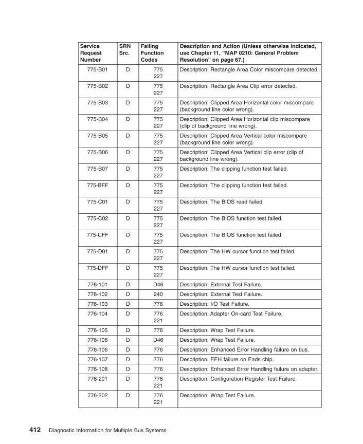
ServiceRequestNumber
SRNSrc.
FailingFunctionCodes
Description and Action (Unless otherwise indicated,use Chapter 11, “MAP 0210: General ProblemResolution” on page 67.)
775-B01 D 775227
Description: Rectangle Area Color miscompare detected.
775-B02 D 775227
Description: Rectangle Area Clip error detected.
775-B03 D 775227
Description: Clipped Area Horizontal color miscompare(background line color wrong).
775-B04 D 775227
Description: Clipped Area Horizontal clip miscompare(clip of background line wrong).
775-B05 D 775227
Description: Clipped Area Vertical color miscompare(background line color wrong).
775-B06 D 775227
Description: Clipped Area Vertical clip error (clip ofbackground line wrong).
775-B07 D 775227
Description: The clipping function test failed.
775-BFF D 775227
Description: The clipping function test failed.
775-C01 D 775227
Description: The BIOS read failed.
775-C02 D 775227
Description: The BIOS function test failed.
775-CFF D 775227
Description: The BIOS function test failed.
775-D01 D 775227
Description: The HW cursor function test failed.
775-DFF D 775227
Description: The HW cursor function test failed.
776-101 D D46 Description: External Test Failure.
776-102 D 240 Description: External Test Failure.
776-103 D 776 Description: I/O Test Failure.
776-104 D 776221
Description: Adapter On-card Test Failure.
776-105 D 776 Description: Wrap Test Failure.
776-106 D D46 Description: Wrap Test Failure.
776-106 D 776 Description: Enhanced Error Handling failure on bus.
776-107 D 776 Description: EEH failure on Eads chip.
776-108 D 776 Description: Enhanced Error Handling failure on adapter.
776-201 D 776221
Description: Configuration Register Test Failure.
776-202 D 776221
Description: Wrap Test Failure.
412 Diagnostic Information for Multiple Bus Systems

ServiceRequestNumber
SRNSrc.
FailingFunctionCodes
Description and Action (Unless otherwise indicated,use Chapter 11, “MAP 0210: General ProblemResolution” on page 67.)
776-203 D D46776
Description: Wrap Test Failure.
776-204 D 776221
Description: Connect Test Failure.
776-205 F D46776
Description: External Test Failure. Action: Runadvanced diagnostics with wrap test for this resource toobtain correct problem isolation.
776-206 D 776221
Description: Wrap Test Failure.
776-301 D D46240776
Description: External Test Failure.
776-302 F D46776221
Description: External Test Failure. Action: Runadvanced diagnostics with wrap test for this resource toobtain correct problem isolation.
776-303 F 240D46776
Description: External Test Failure. Action: Runadvanced diagnostics with wrap test for this resource toobtain correct problem isolation.
776-304 D D46776221
Description: Connect Wrap Test Failure.
776-305 D D46776221
Description: Wrap Test Failure.
776-306 D D46776221
Description: Wrap Test Failure.
776-401 F 240D46776221
Description: External Test Failure. Action: Runadvanced diagnostics with wrap test for this resource toobtain correct problem isolation.
776-404 D 240D46776221
Description: Connect Test Failure.
776-405 D 240D46776221
Description: Wrap Test Failure.
776-406 D 240D46776221
Description: Wrap Test Failure.
Chapter 33. SRNs 700-102 through 89c-302 413

ServiceRequestNumber
SRNSrc.
FailingFunctionCodes
Description and Action (Unless otherwise indicated,use Chapter 11, “MAP 0210: General ProblemResolution” on page 67.)
776-414 F 240D46776221
Description: Connect Test Failure. This failure occurs ifnot connected to a functional Token-Ring network.Action: Run advanced diagnostics for this resource toobtain correct problem isolation.
776-415 F 240D46776221
Description: Wrap Test Failure. This failure occurs if notconnected to a functional Token-Ring network. Action:Run advanced diagnostics for this resource to obtaincorrect problem isolation.
776-416 F 240D46776221
Description: Wrap Test Failure. This failure occurs if notconnected to a functional Token-Ring network. Action:Run advanced diagnostics for this resource to obtaincorrect problem isolation.
776-701 G 776 Description: ELA indicates an adapter error occurred.
776-702 G 776221
Description: ELA indicates an adapter check occurred.
776-703 G 776221
Description: ELA indicates a DMA failure occurred.
776-704 G 776221
Description: ELA indicates a PCI bus failure occurred.
776-705 G 776221
Description: ELA indicates a Programmed I/O failureoccurred.
776-706 G 776 Description: ELA indicates a command write failureoccurred.
776-707 G 776 Description: ELA indicates an internal adapter error hasoccurred.
777-101 D 777 Description: Configuration Register Test Failure.
777-102 D 777 Description: I/O Test Failure.
777-103 D 777 Description: Adapter initialization test failure.
777-104 D 777 Description: Internal wrap test failure.
777-105 D 777 Description: External wrap (10 Mbps) test failure.
777-106 D 777 Description: External wrap (100 Mbps) test failure.
777-107 D 221 Description: Enhanced Error Handling failure on bus.
777-108 D 221 Description: Enhanced Error Handling logic failure.
777-110 D 777 Description: Enhanced Error Handling failure on adapter.
777-201 D 777221
Description: Configuration Register Test Failure.
777-202 D 777221
Description: I/O Test Failure.
777-203 D 777221
Description: Adapter initialization test failure.
777-204 D 777221
Description: Internal wrap test failure.
414 Diagnostic Information for Multiple Bus Systems

ServiceRequestNumber
SRNSrc.
FailingFunctionCodes
Description and Action (Unless otherwise indicated,use Chapter 11, “MAP 0210: General ProblemResolution” on page 67.)
777-205 D 777221
Description: Internal wrap test failure.
777-206 D 777221
Description: External wrap (10 Mbps) test failure.
777-207 D 777221
Description: Internal wrap test failure.
777-208 D 777221
Description: External wrap (100 Mbps) test failure.
777-701 G 777221
Description: Error log analysis indicates that the adapteris not responding to initialization commands.
777-702 G 777221
Description: Error Log Analysis indicates that the devicedriver has detected a PIO error which it was unable tocorrect.
777-703 G 777221
Description: Error log analysis indicates that the adapterhas been shut down due to an unrecoverable error.
777-704 G 777221
Description: Error Log Analysis indicates a problem withthe EEPROM on the adapter
777-707 G 777221
Description: Error Log Analysis indicates that thisadapter has failed to initialize due to EEH errors.
778-002 D software778
Description: Software error.
778-004 D software778
Description: Software error.
778-009 D software778
Description: Software error.
778-011 D software778
Description: Software error.
778-017 D software778
Description: Software error.
778-019 D 778software
Description: Adapter failure.
778-030 D 778221
Description: Adapter failure.
778-032 D software778
Description: Software error.
778-033 D software778
Description: Software error.
778-035 D 778software
Description: Adapter failure.
778-036to
778-072
D software778
Description: Software error.
Chapter 33. SRNs 700-102 through 89c-302 415

ServiceRequestNumber
SRNSrc.
FailingFunctionCodes
Description and Action (Unless otherwise indicated,use Chapter 11, “MAP 0210: General ProblemResolution” on page 67.)
778-073 D 778221
Description: Adapter failure.
778-075 D software778
Description: Software error.
778-076 D 778software
Description: Software error.
778-301to
778-D02
D 778221
Description: Adapter failure.
778-E01 D software778
Description: Software error.
778-E02to
778-1401
D 778221
Description: Adapter failure.
778-1402 D software778
Description: Software error.
778-1403to
778-1405
D 778221
Description: Adapter failure.
778-1500 D 778software
Description: Adapter failure.
778-1600to
778-1604
D 778902
Description: Adapter failure.
778-2501to
778-2508
D 778221
Description: Adapter error.
778-2509to
778-2511
D software778
Description: Software error.
778-2601to
778-2602
D 778221
Description: Adapter error.
778-2603 D software778
Description: Software error.
77B-101 D 77B Description: Configuration Register Test Failure.
77B-102 D 77B Description: I/O Test Failure.
77B-103 D 77B Description: Adapter initialization test failure.
77B-104 D 77B Description: Internal wrap test failure.
77B-105 D 77B Description: External wrap (10 Mbps) test failure.
77B-106 D 77B Description: External wrap (100 Mbps) test failure.
77B-110 D 77B Description: Enhanced Error handling failure.
416 Diagnostic Information for Multiple Bus Systems

ServiceRequestNumber
SRNSrc.
FailingFunctionCodes
Description and Action (Unless otherwise indicated,use Chapter 11, “MAP 0210: General ProblemResolution” on page 67.)
77B-701 G 77B Description: Error log analysis indicates that the adapteris not responding to initialization commands.
77B-702 G 77B Description: Error Log Analysis indicates that the devicedriver has detected a PIO error which it was unable tocorrect.
77B-703 G 77B Description: Error log analysis indicates that the adapterhas been shut down due to an unrecoverable error.
77B-704 G 77B Description: Error Log Analysis indicates a problem withthe EEPROM on the adapter
77B-705 G 77B Description: Error Log Analysis indicates a non-criticalproblem with the VPD and the EEPROM on the adapterAction: Schedule deferred maintenance.
77C-102 D 77C Description: An unrecoverable media error.
77C-104 D 77C Description: The motor failed to restart.
77C-105 D 77C Description: The drive did not become ready.
77C-106 D 77C Description: The electronics card test failed.
77C-108 D 77C Description: The bus test failed.
77C-110 D 77C Description: The media format is corrupted.
77C-112 D 77C Description: The diagnostic test failed.
77C-114 D 77C Description: An unrecoverable hardware error.
77C-116 D Description: A protocol error. Action: Check the levels ofthe device, adapter, diagnostic software, and applicationsoftware to be sure they are all compatible. If you do notfind a problem, call your support person.
77C-117 D 77C Description: A write-protect error occurred.
77C-118 D 77CB88
Description: A SCSI command time-out.
77C-120 D 77C Description: A SCSI busy or command error.
77C-122 D 77C Description: A SCSI reservation conflict error.
77C-124 D 77C Description: A SCSI check condition error.
77C-126 D 77CB88
Description: A software error was caused by a hardwarefailure.
77C-128 G 77C Description: The error log analysis indicates a hardwarefailure.
77C-129 G 77C Description: Error log analysis indicates a SCSI busproblem.
77C-130 G 77CB88
Description: Error log analysis indicates a problemreported by the disk drive’s self-monitoring function.
77C-132 D 77C Description: A disk drive hardware error occurred.
77C-133 D 77C Description: Use the subsystem guide to complete thediagnostics.
Chapter 33. SRNs 700-102 through 89c-302 417

ServiceRequestNumber
SRNSrc.
FailingFunctionCodes
Description and Action (Unless otherwise indicated,use Chapter 11, “MAP 0210: General ProblemResolution” on page 67.)
77C-134 D B88software
Description: The adapter failed to configure.
77C-137 D 77CB88190
Description: Unit attention condition has occurred on theSend Diagnostic command.
77C-138 D 190 Description: Error log indicates that the disk is operatingat higher than recommended temperatures.
77C-139 D 77C Description: Error configuring or opening device. Action:Use Chapter 11, “MAP 0210: General ProblemResolution” on page 67.
77C-640 G 640 Description: Error Log Analysis indicates a path error.
780-101 D 780227
Description: Adapter logic test failure.
780-102 D 780 Description: Adapter logic test failure.
780-109 D 780 Description: Adapter channel Input/Output test failure.
780-113 D 780 Description: Adapter Serial Communication Controller(SCC) test failure.
780-114 D 780227
Description: Adapter logic test failure.
780-120 D 780227
software
Description: Adapter could not be detected or configured.
780-140 D 271780
Description: An error was found with the X.21 interfaceadapter cable.
780-150 D 272780
Description: An error was found with the X.24 interfaceadapter cable.
780-160 D 273780
Description: An error was found with the X.35 interfaceadapter cable.
780-170 D 780 Description: The adapter hardware failed.
780-180 D 780 Description: The adapter hardware failed.
780-190 D 780 Description: The adapter hardware failed.
780-210 D 780185
Description: An error was found on the adapter.
780-211 D 780227
Description: The adapter card POST test failed.
780-230 D 780 Description: The adapter card hardware failed.
780-232 D 849227
Description: The adapter card hardware failed.
780-240 D 780 Description: The adapter card hardware failed.
780-250 D 185780
Description: An error was found on the adapter.
418 Diagnostic Information for Multiple Bus Systems
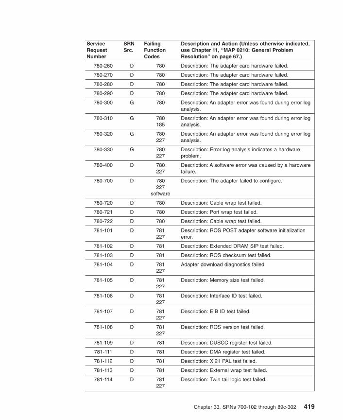
ServiceRequestNumber
SRNSrc.
FailingFunctionCodes
Description and Action (Unless otherwise indicated,use Chapter 11, “MAP 0210: General ProblemResolution” on page 67.)
780-260 D 780 Description: The adapter card hardware failed.
780-270 D 780 Description: The adapter card hardware failed.
780-280 D 780 Description: The adapter card hardware failed.
780-290 D 780 Description: The adapter card hardware failed.
780-300 G 780 Description: An adapter error was found during error loganalysis.
780-310 G 780185
Description: An adapter error was found during error loganalysis.
780-320 G 780227
Description: An adapter error was found during error loganalysis.
780-330 G 780227
Description: Error log analysis indicates a hardwareproblem.
780-400 D 780227
Description: A software error was caused by a hardwarefailure.
780-700 D 780227
software
Description: The adapter failed to configure.
780-720 D 780 Description: Cable wrap test failed.
780-721 D 780 Description: Port wrap test failed.
780-722 D 780 Description: Cable wrap test failed.
781-101 D 781227
Description: ROS POST adapter software initializationerror.
781-102 D 781 Description: Extended DRAM SIP test failed.
781-103 D 781 Description: ROS checksum test failed.
781-104 D 781227
Adapter download diagnostics failed
781-105 D 781227
Description: Memory size test failed.
781-106 D 781227
Description: Interface ID test failed.
781-107 D 781227
Description: EIB ID test failed.
781-108 D 781227
Description: ROS version test failed.
781-109 D 781 Description: DUSCC register test failed.
781-111 D 781 Description: DMA register test failed.
781-112 D 781 Description: X.21 PAL test failed.
781-113 D 781 Description: External wrap test failed.
781-114 D 781227
Description: Twin tail logic test failed.
Chapter 33. SRNs 700-102 through 89c-302 419

ServiceRequestNumber
SRNSrc.
FailingFunctionCodes
Description and Action (Unless otherwise indicated,use Chapter 11, “MAP 0210: General ProblemResolution” on page 67.)
781-116 D 254 Description: The RS-232 cable wrap test failed.
781-117 D 253 Description: The RS-422A cable wrap test failed.
781-118 D 257 Description: The V.35 cable wrap test failed.
781-119 D 260 Description: The X.21 cable wrap test failed.
781-120 D 781227
software
Description: The adapter was not detected or could notbe configured. test failed.
781-121 D 781227
software
Description: The 4-port jumper cable assembly wrap testfailed.
781-200 G 781 Description: The error log analysis indicates the adapterfailed.
781-221 G 781227
Description: The error log analysis indicates the adapterhardware failed.
781-231 D 855 227 Description: No interface card detected.
781-501 D B77B69227
Description: The power-on self-test (POST) failed.
781-502 D B77 Description: The memory module failed.
781-503 D 781227
Description: Adapter hardware failure.
781-504 D B69 Description: Adapter hardware failure.
781-505 D B71B69
Description: Adapter hardware failure.
781-506 D B72B69
Description: Adapter hardware failure.
781-507 D B73B69
Description: Adapter hardware failure.
781-508 D B74B69
Description: Adapter hardware failure.
781-516 D B77B69
Description: Adapter Test Failure.
781-517 D B69B77
Description: Adapter Test Failure.
781-720 D 258781
4-port multiprotocol cable
783-110 D 783 Description: The Reserve command failed.
783-120 D 783 Description: The Inquiry command failed.
783-130 D 783media
Description: The Load command failed.
420 Diagnostic Information for Multiple Bus Systems

ServiceRequestNumber
SRNSrc.
FailingFunctionCodes
Description and Action (Unless otherwise indicated,use Chapter 11, “MAP 0210: General ProblemResolution” on page 67.)
783-135 D 783media
Description: The Unload command failed.
783-140 D 783 Description: The Mode Select command failed.
783-150 D 783media
Description: The Test Unit Ready command failed.
783-160 D 783media
Description: The Send Diagnostic command failed.
783-169 D 783media
Description: The Send Diagnostic command failed.
783-170 D 783B88
media
Description: The Read, Write and Compare test failed.
783-180 D 783media
Description: The Load command failed.
783-185 D 783media
Description: The Unload command failed.
783-190 D 783 Description: The Mode Select command failed.
783-200 D 783media
Description: The Test Unit Ready command failed.
783-210 D 783B88
Description: The device configuration failed.
783-220 D 783 Description: The Release command failed.
783-230 D 783 Description: The Request Sense command failed.
783-240 D 783 Description: The Openx command failed.
783-300 D 783software
Description: The device configuration failed.
783-310 D B88783
software
Description: SCSI adapter configuration failed.
783-320 G 783media
Description: Error log analysis indicates a failure.
783-411to
783-423
D 783B88
software
Description: A reservation conflict occurred.
783-511to
783-523
D 783B88
Description: The drive returned bad or non-extendedsense data.
783-611to
783-623
D 783B88
software
Description: An adapter or bus I/O error occurred.
Chapter 33. SRNs 700-102 through 89c-302 421

ServiceRequestNumber
SRNSrc.
FailingFunctionCodes
Description and Action (Unless otherwise indicated,use Chapter 11, “MAP 0210: General ProblemResolution” on page 67.)
783-711to
783-723
D 783B88
software
Description: A device timeout error occurred.
784-102 D 784 Description: An unrecoverable media error.
784-104 D 784 Description: The motor failed to restart.
784-105 D 784 Description: The drive did not become ready.
784-106 D 784 Description: The electronics card test failed.
784-108 D 784 Description: The bus test failed.
784-110 D 784 Description: The media format is corrupted.
784-112 D 784 Description: The diagnostic test failed.
784-114 D 784 Description: An unrecoverable hardware error.
784-116 D Description: A protocol error. Action: Check the levels ofthe device, adapter, diagnostic software, and applicationsoftware to be sure they are all compatible. If you do notfind a problem, call your support person.
784-117 D 784 Description: A write-protect error occurred.
784-118 D 784B88
Description: A SCSI command time-out.
784-120 D 784 Description: A SCSI busy or command error.
784-122 D 784 Description: A SCSI reservation conflict error.
784-124 D 784 Description: A SCSI check condition error.
784-126 D 784B88
Description: A software error was caused by a hardwarefailure.
784-128 G 784 Description: The error log analysis indicates a hardwarefailure.
784-129 G 190784B88
software
Description: Error log analysis indicates a SCSI busproblem.
784-130 G 784 Description: Error log analysis indicates a problemreported by the disk drive’s self-monitoring function.
784-132 D 784 Description: A disk drive hardware error occurred.
784-134 D B88software
Description: The adapter failed to configure.
784-135 D 784B88
software
Description: The device failed to configure.
784-136 D 784 Description: The certify operation failed.
784-137 D 784B88190
Description: Unit attention condition has occurred on theSend Diagnostic command.
422 Diagnostic Information for Multiple Bus Systems

ServiceRequestNumber
SRNSrc.
FailingFunctionCodes
Description and Action (Unless otherwise indicated,use Chapter 11, “MAP 0210: General ProblemResolution” on page 67.)
785-111 D 785227
Could not do the test because the device driver detecteda hardware error.
785-114 D 785 The register verification test failed.
785-121 D 785227
Could not do the test because the device driver detecteda hardware error.
785-122 D 785227
The data wrap communication test failed.
785-123 D 785227
The modem control line test failed.
785-124 D 785 The memory test failed.
785-151 D 785D57
Could not do the test because the device driver detecteda hardware error.
785-152 D 785D57
The data wrap communication test failed.
785-153 D 785D57
The modem control line test failed.
785-171 D 259 Could not do the test because the device driver detecteda hardware error.
785-172 D 259 The data wrap communication test failed.
785-173 D 259 The modem control line test failed.
785-181 D 261 Could not do the test because the device driver detecteda hardware error.
785-182 D 261 The data wrap communication test failed.
785-183 D 261 The modem control line test failed.
785-251 D 785D57
Could not perform because the device driver detected ahardware error.
785-252 D 785D57
The data wrap communication test failed.
785-253 D 785D57
The modem control line test failed.
785-271 D 785D57
Could not perform because the device driver detected ahardware error.
785-272 D 785D57
The data wrap communication test failed.
785-273 D 785D57
The modem control line test failed.
785-281 D 785D57
Could not perform because the device driver detected ahardware error.
785-282 D 785D57
The data wrap communication test failed.
Chapter 33. SRNs 700-102 through 89c-302 423

ServiceRequestNumber
SRNSrc.
FailingFunctionCodes
Description and Action (Unless otherwise indicated,use Chapter 11, “MAP 0210: General ProblemResolution” on page 67.)
785-283 D 785D57
The modem control line test failed.
785-481 D D57 Could not do the test because the device driver detecteda hardware error.
785-482 D D57 The data wrap communication test failed.
785-483 D D57 The modem control line test failed.
785-901to
785-920
D software785
Description: An unexpected error occurred that can beattributed to software or hardware. Action: Rundiagnostics from a source other than from the disk or anetwork. If the same error occurs or if the original SRNwas not obtained from disk or a network baseddiagnostics, use MAP 210 with a FFC of 785; otherwise,suspect a software problem.
785-921 D 785software
Description: The adapter failed to configure.
785-922to
785-924
D software785
Description: An unexpected error occurred that can beattributed to software or hardware. Action: Rundiagnostics from a source other than from the disk or anetwork. If the same error occurs or if the original SRNwas not obtained from disk or a network baseddiagnostics, use MAP 210 with a FFC of 785; otherwise,suspect a software problem.
785-925 D 785software
Description: The adapter failed to configure.
785-926to
785-943
D software785
Description: An unexpected error occurred that can beattributed to software or hardware. Action: Rundiagnostics from a source other than from the disk or anetwork. If the same error occurs or if the original SRNwas not obtained from disk or a network baseddiagnostics, use MAP 210 with a FFC of 785; otherwise,suspect a software problem.
786-200 D 786D96227
Description: Initiation failed.Note: You must determine which of the first two FFCs isinstalled in the system unit.
786-210 D 786227
Description: The adapter test failed.
786-211 D D96227
Description: The adapter test failed.
786-220 D 786Cable
Monitor
Description: The display test failed.
786-221 D D96Cable
Monitor
Description: The display test failed.
424 Diagnostic Information for Multiple Bus Systems
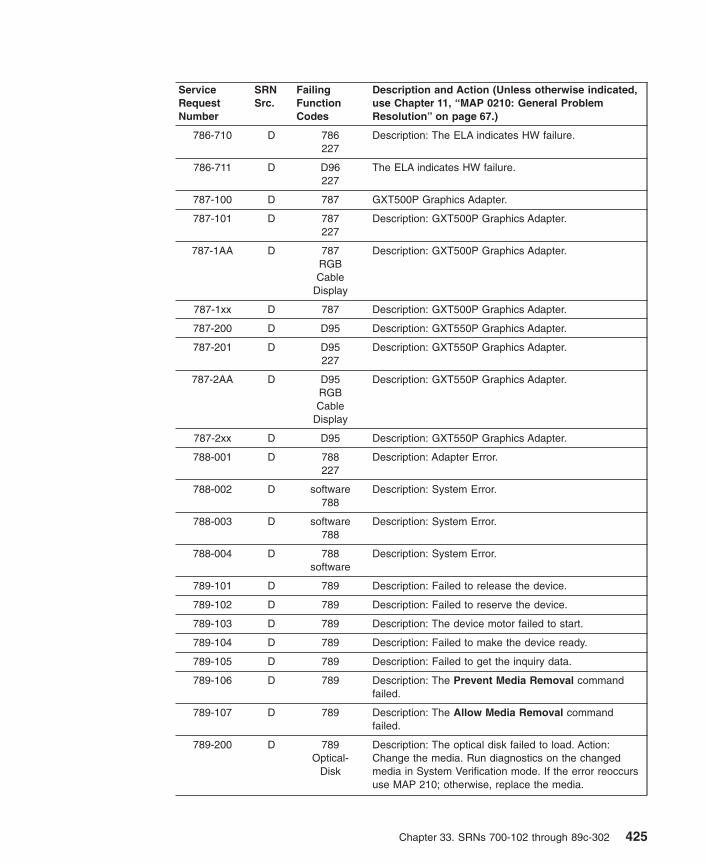
ServiceRequestNumber
SRNSrc.
FailingFunctionCodes
Description and Action (Unless otherwise indicated,use Chapter 11, “MAP 0210: General ProblemResolution” on page 67.)
786-710 D 786227
Description: The ELA indicates HW failure.
786-711 D D96227
The ELA indicates HW failure.
787-100 D 787 GXT500P Graphics Adapter.
787-101 D 787227
Description: GXT500P Graphics Adapter.
787-1AA D 787RGBCable
Display
Description: GXT500P Graphics Adapter.
787-1xx D 787 Description: GXT500P Graphics Adapter.
787-200 D D95 Description: GXT550P Graphics Adapter.
787-201 D D95227
Description: GXT550P Graphics Adapter.
787-2AA D D95RGBCable
Display
Description: GXT550P Graphics Adapter.
787-2xx D D95 Description: GXT550P Graphics Adapter.
788-001 D 788227
Description: Adapter Error.
788-002 D software788
Description: System Error.
788-003 D software788
Description: System Error.
788-004 D 788software
Description: System Error.
789-101 D 789 Description: Failed to release the device.
789-102 D 789 Description: Failed to reserve the device.
789-103 D 789 Description: The device motor failed to start.
789-104 D 789 Description: Failed to make the device ready.
789-105 D 789 Description: Failed to get the inquiry data.
789-106 D 789 Description: The Prevent Media Removal commandfailed.
789-107 D 789 Description: The Allow Media Removal commandfailed.
789-200 D 789Optical-
Disk
Description: The optical disk failed to load. Action:Change the media. Run diagnostics on the changedmedia in System Verification mode. If the error reoccursuse MAP 210; otherwise, replace the media.
Chapter 33. SRNs 700-102 through 89c-302 425

ServiceRequestNumber
SRNSrc.
FailingFunctionCodes
Description and Action (Unless otherwise indicated,use Chapter 11, “MAP 0210: General ProblemResolution” on page 67.)
789-201 D 789Optical-
Disk
Description: Failed to unload the optical disk. Action:Change the media. Run diagnostics on the changedmedia in System Verification mode. If the errors reoccuruse MAP 210; otherwise, replace the media.
789-202 D 789Optical-
Disk
Description: The diagnostic test failed. Action: Changethe media. Run diagnostics on the changed media inSystem Verification mode. If errors do not reoccur,replace the media; otherwise, run the drive cleaningprocedures if applicable and rerun the diagnostics. Iferrors reoccur, or the drive does not support the cleaningprocedures use MAP 210.
789-204 D 789B88
Description: The device failed to configure.
789-205 D 789Optical-
Disk
Description: The Test Unit Ready command failed.Action: Change the media. Run diagnostics on thechanged media in System Verification mode. If the errorreoccurs, use MAP 210; otherwise, replace the media.
789-206 D 789Optical-
Disk
Description: The random write, read and compare testfailed. Action: Change the media. Run diagnostics on thechanged media in System Verification mode. If the errorsdo not reoccur, replace the media; otherwise, run thedrive cleaning procedures if applicable, and rerundiagnostics. If the errors reoccur, or the drive does notsupport cleaning procedures, use MAP 210.
789-207 D 789Optical-
Disk
Description: A hardware error occurred. Action: Changethe media. Run diagnostics on the changed media inSystem Verification mode. If the errors do not reoccur,replace the media; otherwise, run the drive cleaningprocedures if applicable, and rerun diagnostics. If theerrors reoccur, or the drive does not support cleaningprocedures, use MAP 210.
789-208 D 789Optical-
Disk
Description: The Mode Sense command failed. Action:Change the media. Run diagnostics on the changedmedia in System Verification mode. If the errors do notreoccur, replace the media; otherwise, run the drivecleaning procedures if applicable, and rerun diagnostics.If the errors reoccur, or the drive does not supportcleaning procedures, use MAP 210.
789-209 D 789Optical-
Disk
Description: The Mode Select command failed. Action:Change the media. Run diagnostics on the changedmedia in System Verification mode. If the errors do notreoccur, replace the media; otherwise, run the drivecleaning procedures if applicable, and rerun diagnostics.If the errors reoccur, or the drive does not supportcleaning procedures, use MAP 210.
426 Diagnostic Information for Multiple Bus Systems

ServiceRequestNumber
SRNSrc.
FailingFunctionCodes
Description and Action (Unless otherwise indicated,use Chapter 11, “MAP 0210: General ProblemResolution” on page 67.)
789-300 D 789B88
software
Description: A SCSI reservation conflict has occurred.
789-400 D 789B88
Cablessoftware
Description: A SCSI command time out has occurred.
789-401 D Optical-Disk190B88
software
Description: An unknown error has occurred.
789-402 D Optical-Disk190B88
software
Description: Unit attention condition has occurred.
789-600 G Optical-Disk
Description: ELA indicates that the spare sectors on thedisk are exhausted. Action: Backup the media andreplace it.Note: Use the time when the error occurred and the″Spare Sector Availability″ service aid to identify the diskthat has the error.
789-700 G 789Optical-
Disk
Description: The ELA indicates an equipment error.Action: Run diagnostics in System Verification mode toisolate the problem. If errors are reported, use MAP 210;otherwise, the error is due to faulty media. Backup themedia and then replace it.Note: Use the time when the error occurred to identifythe faulty media.
789-701 G Optical-Disk789
Description: ELA indicates an irrecoverable data error.Action: Run diagnostics in System Verification mode toisolate the problem. If errors are reported, use MAP 210;otherwise, the error is due to faulty media. Backup themedia and then replace it.Note: Use the time when the error occurred to identifythe faulty media.
789-702 G 789B88
Cables
Description: ELA indicates that the adapter detected anerror. Action: Use the 7209 Installation and ServiceGuide. If the unit checks out to be good, use MAP 210.
78B-001 D Software78B
Description: Software error.
78B-002 D 78BSoftware
Description: Adapter failure.
78B-003 D 78B227
Description: Adapter failure.
Chapter 33. SRNs 700-102 through 89c-302 427
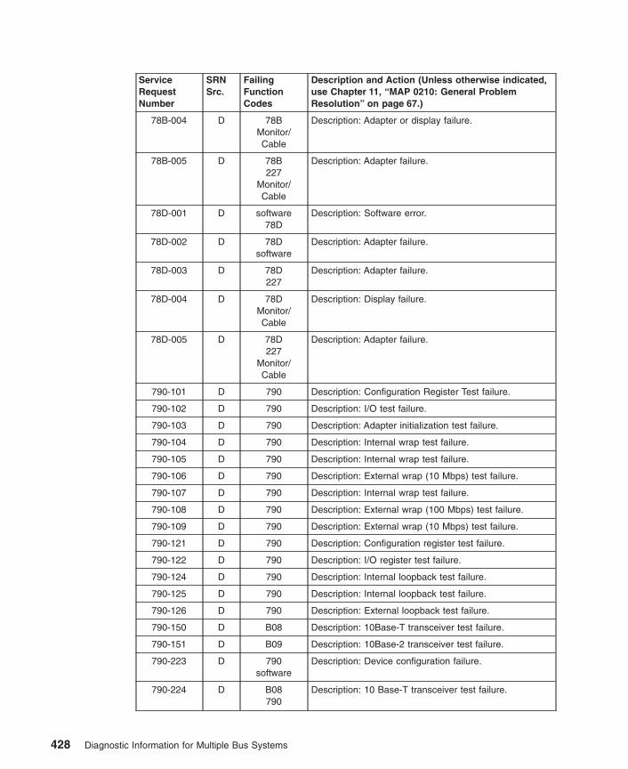
ServiceRequestNumber
SRNSrc.
FailingFunctionCodes
Description and Action (Unless otherwise indicated,use Chapter 11, “MAP 0210: General ProblemResolution” on page 67.)
78B-004 D 78BMonitor/Cable
Description: Adapter or display failure.
78B-005 D 78B227
Monitor/Cable
Description: Adapter failure.
78D-001 D software78D
Description: Software error.
78D-002 D 78Dsoftware
Description: Adapter failure.
78D-003 D 78D227
Description: Adapter failure.
78D-004 D 78DMonitor/Cable
Description: Display failure.
78D-005 D 78D227
Monitor/Cable
Description: Adapter failure.
790-101 D 790 Description: Configuration Register Test failure.
790-102 D 790 Description: I/O test failure.
790-103 D 790 Description: Adapter initialization test failure.
790-104 D 790 Description: Internal wrap test failure.
790-105 D 790 Description: Internal wrap test failure.
790-106 D 790 Description: External wrap (10 Mbps) test failure.
790-107 D 790 Description: Internal wrap test failure.
790-108 D 790 Description: External wrap (100 Mbps) test failure.
790-109 D 790 Description: External wrap (10 Mbps) test failure.
790-121 D 790 Description: Configuration register test failure.
790-122 D 790 Description: I/O register test failure.
790-124 D 790 Description: Internal loopback test failure.
790-125 D 790 Description: Internal loopback test failure.
790-126 D 790 Description: External loopback test failure.
790-150 D B08 Description: 10Base-T transceiver test failure.
790-151 D B09 Description: 10Base-2 transceiver test failure.
790-223 D 790software
Description: Device configuration failure.
790-224 D B08790
Description: 10 Base-T transceiver test failure.
428 Diagnostic Information for Multiple Bus Systems

ServiceRequestNumber
SRNSrc.
FailingFunctionCodes
Description and Action (Unless otherwise indicated,use Chapter 11, “MAP 0210: General ProblemResolution” on page 67.)
790-225 D B09790
Description: 10 Base-2 transceiver test failure.
790-250 D B08790
Description: 10 Base-T transceiver test failure.
790-251 D B09790
Description: 10 Base-2 transceiver test failure.
790-701 G 790 Description: Error Log Analysis indicates that the adapteris not responding to initialization commands.
790-702 G 790 Description: Error Log Analysis indicates that the devicedriver has detected a PIO error which it was unable tocorrect.
790-703 G 790 Description: Error Log Analysis indicates that the adapterhas been shutdown due to an unrecoverable error.
790-704 G 790 Description: Error Log Analysis indicates a problem withEEPROM on the adapter.
790-720 G 790software
Description: Error log analysis indicates a hardwareproblem.
791-102 D 791 Description: An unrecoverable media error occurred.
791-104 D 791 Description: The motor failed to restart.
791-105 D 791 Description: The drive did not become ready.
791-106 D 791 Description: The electronics card test failed.
791-108 D 791 Description: The bus test failed.
791-110 D 791 Description: The media format is corrupted.
791-112 D 791 Description: The diagnostic test failed.
791-114 D 791 Description: An unrecoverable hardware error.
791-116 D Description: A protocol error. Action: Check the levels ofthe device, adapter, diagnostic software, and applicationsoftware to be sure they are all compatible. If you do notfind a problem, call your support person.
791-117 D 791 Description: A write-protect error occurred.
791-118 D 791B88
Description: A SCSI command time-out occurred.
791-120 D 791 Description: A SCSI busy or command error.
791-122 D 791 Description: A SCSI reservation conflict error.
791-124 D 791 Description: A SCSI check condition error occurred.
791-126 D 791B88
Description: A software error was caused by a hardwarefailure.
791-128 G 791 Description: The error log analysis indicates a hardwarefailure.
Chapter 33. SRNs 700-102 through 89c-302 429

ServiceRequestNumber
SRNSrc.
FailingFunctionCodes
Description and Action (Unless otherwise indicated,use Chapter 11, “MAP 0210: General ProblemResolution” on page 67.)
791-129 G 190791B88
software
Description: Error log analysis indicates a SCSI busproblem.
791-130 G 791 Description: Error log analysis indicates a problemreported by the disk drive’s self-monitoring function.
791-132 D 791 Description: A disk drive hardware error occurred.
791-134 D B88software
Description: The adapter failed to configure.
791-135 D 791B88
software
Description: The device failed to configure.
791-136 D 791 Description: The certify operation failed.
791-137 D 791B88190
Description: Unit attention condition has occurred on theSend Diagnostic command.
792-102 D 792 Description: An unrecoverable media error occurred.
792-104 D 792 Description: The motor failed to restart.
792-105 D 792 Description: The drive did not become ready.
792-106 D 792 Description: The electronics card test failed.
792-108 D 792 Description: The bus test failed.
792-110 D 792 Description: The media format is corrupted.
792-112 D 792 Description: The diagnostic test failed.
792-114 D 792 Description: An unrecoverable hardware error.
792-116 D Description: A protocol error. Action: Check the levels ofthe device, adapter, diagnostic software, and applicationsoftware to be sure they are all compatible. If you do notfind a problem, call your support person.
792-117 D 792 Description: A write-protect error occurred.
792-118 D 792B88
Description: A SCSI command time-out occurred.
792-120 D 792 Description: A SCSI busy or command error.
792-122 D 792 Description: A SCSI reservation conflict error.
792-124 D 792 Description: A SCSI check condition error occurred.
792-126 D 792B88
Description: A software error was caused by a hardwarefailure.
792-128 G 792 Description: The error log analysis indicates a hardwarefailure.
430 Diagnostic Information for Multiple Bus Systems

ServiceRequestNumber
SRNSrc.
FailingFunctionCodes
Description and Action (Unless otherwise indicated,use Chapter 11, “MAP 0210: General ProblemResolution” on page 67.)
792-129 G 190792B88
software
Description: Error log analysis indicates a SCSI busproblem.
792-130 G 792 Description: Error log analysis indicates a problemreported by the disk drive’s self-monitoring function.
792-132 D 792 Description: A disk drive hardware error occurred.
792-134 D B88software
Description: The adapter failed to configure.
792-135 D 792B88
software
Description: The device failed to configure.
792-136 D 792 Description: The certify operation failed.
792-137 D 792B88190
Description: Unit attention condition has occurred on theSend Diagnostic command.
793-102 D 793 Description: An unrecoverable media error occurred.
793-104 D 793 Description: The motor failed to restart.
793-105 D 793 Description: The drive did not become ready.
793-106 D 793 Description: The electronics card test failed.
793-108 D 793 Description: The bus test failed.
793-110 D 793 Description: The media format is corrupted.
793-112 D 793 Description: The diagnostic test failed.
793-114 D 793 Description: An unrecoverable hardware error.
793-116 D Description: A protocol error. Action: Check the levels ofthe device, adapter, diagnostic software, and applicationsoftware to be sure they are all compatible. If you do notfind a problem, call your support person.
793-117 D 793 Description: A write-protect error occurred.
793-118 D 793B88
Description: A SCSI command time-out occurred.
793-120 D 793 Description: A SCSI busy or command error.
793-122 D 793 Description: A SCSI reservation conflict error.
793-124 D 793 Description: A SCSI check condition error occurred.
793-126 D 793B88
Description: A software error was caused by a hardwarefailure.
793-128 G 793 Description: The error log analysis indicates a hardwarefailure.
Chapter 33. SRNs 700-102 through 89c-302 431

ServiceRequestNumber
SRNSrc.
FailingFunctionCodes
Description and Action (Unless otherwise indicated,use Chapter 11, “MAP 0210: General ProblemResolution” on page 67.)
793-129 G 190793B88
software
Description: Error log analysis indicates a SCSI busproblem.
793-130 G 793 Description: Error log analysis indicates a problemreported by the disk drive’s self-monitoring function.
793-132 D 793 Description: A disk drive hardware error occurred.
793-134 D B88software
Description: The adapter failed to configure.
793-135 D 793B88
software
Description: The device failed to configure.
793-136 D 793 Description: The certify operation failed.
793-137 D 793B88190
Description: Unit attention condition has occurred on theSend Diagnostic command.
795-201 D 795 Description: Config register test failure.
795-202 D 795 Description: PROM check test failure.
795-203 D 795 Description: Timer and IRQ test failure.
795-204 D 795 Description: Adapter RAM check failure.
795-205 D 795227
Description: ASIC test failure.
795-206 D 795 Description: High memory (ISA) test failure.
795-207 D 795 Description: RAM check via DMA test failure.
795-208 D 795 Description: FORMAC register test failure.
795-209 D 795221
Description: PLC1 test failure.
795-210 D 795227
Description: PLC2 test failure.
795-211 D 795 Description: FORMAC Ring_Op test failure.
795-212 D 795 Description: Send long frame test failure.
795-213 D 795 Description: Restricted Token Monitor test failure.
795-214 D 795227
Description: Receive queue handling test failure.
795-215 D 795221
Description: FORMAC loopback test failure.
795-216 D 795221
Description: FORMAC loopback with master access testfailure.
795-217 D 795 Description: DMA measurement test failure.
795-218 D 795 Description: Special test failure.
432 Diagnostic Information for Multiple Bus Systems
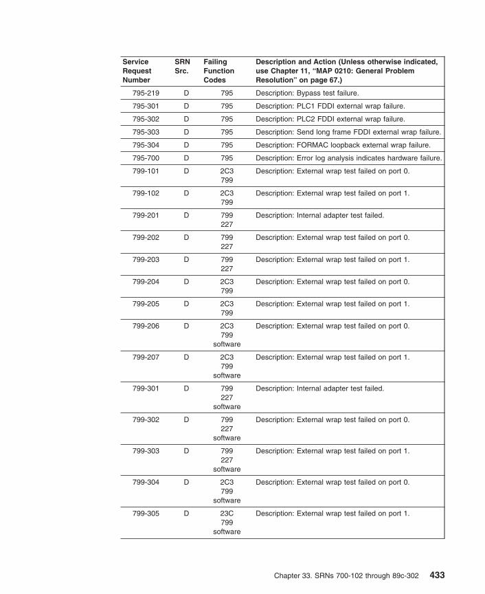
ServiceRequestNumber
SRNSrc.
FailingFunctionCodes
Description and Action (Unless otherwise indicated,use Chapter 11, “MAP 0210: General ProblemResolution” on page 67.)
795-219 D 795 Description: Bypass test failure.
795-301 D 795 Description: PLC1 FDDI external wrap failure.
795-302 D 795 Description: PLC2 FDDI external wrap failure.
795-303 D 795 Description: Send long frame FDDI external wrap failure.
795-304 D 795 Description: FORMAC loopback external wrap failure.
795-700 D 795 Description: Error log analysis indicates hardware failure.
799-101 D 2C3799
Description: External wrap test failed on port 0.
799-102 D 2C3799
Description: External wrap test failed on port 1.
799-201 D 799227
Description: Internal adapter test failed.
799-202 D 799227
Description: External wrap test failed on port 0.
799-203 D 799227
Description: External wrap test failed on port 1.
799-204 D 2C3799
Description: External wrap test failed on port 0.
799-205 D 2C3799
Description: External wrap test failed on port 1.
799-206 D 2C3799
software
Description: External wrap test failed on port 0.
799-207 D 2C3799
software
Description: External wrap test failed on port 1.
799-301 D 799227
software
Description: Internal adapter test failed.
799-302 D 799227
software
Description: External wrap test failed on port 0.
799-303 D 799227
software
Description: External wrap test failed on port 1.
799-304 D 2C3799
software
Description: External wrap test failed on port 0.
799-305 D 23C799
software
Description: External wrap test failed on port 1.
Chapter 33. SRNs 700-102 through 89c-302 433

ServiceRequestNumber
SRNSrc.
FailingFunctionCodes
Description and Action (Unless otherwise indicated,use Chapter 11, “MAP 0210: General ProblemResolution” on page 67.)
799-700 D 799software
Description: Error log analysis indicates a hardwareproblem.
7C1-101 D 7C1software
Description: Audio Subsystem failed.
7C1-102 D 7C1 Description: CS4232 failed.
7C1-103 D 7C1 Description: Clock control failed.
7C1-107 D 7C1 Description: SoundBlaster interface failed.
7C1-108 D 7C1 Description: Loop back failed.
7C1-109 D 7C1 Description: CODEC ID invalid.
7C1-117 D D97 Description: Internal speaker failed.
801-xxxx C xxxxE10227
Description: No LED value could be determined for themissing resource.Note: Note: To obtain the FFC substitute the last threeor four digits of the SRN following the dash (-) for xxxx.(The substituted xxxx is the FFC)
802-655 C 655 Description: A resource was not detected that waspreviously installed.
802-657 C 657 Description: A resource was not detected that waspreviously installed.
802-684 C 684687
Description: A potential problem with the RS422concentrator exists.
802-787 C 787D95
Description: The diagnostics did not detect an installedresource.
802-78C C 78C Description: A system bus problem exists. Action: UseChapter 10, “MAP 0080: System Bus Problem Isolation”on page 63.
802-78D C 78D Description: A resource was not detected that waspreviously installed.
802-80c C 80c Description: A potential problem with a SSA adapterexists. If the system has external SSA drives refer to theSSA Adapters User’s Guide and MaintenanceInformation or the service guide for your disk subsystem.If the system has internal SSA drives, go to the SSAMAP in either the system unit’s service guide or user’sguide.
802-837 C 837687E10227
Description: A potential problem with the EnhancedRemote Async Node exists.
802-xxxx C xxxxE10227
Description: The diagnostics did not detect an installedresource.Note: To obtain the FFC substitute the last three or fourdigits of the SRN following the dash (-) for xxxx. (Thesubstituted xxxx is the FFC.)
434 Diagnostic Information for Multiple Bus Systems

ServiceRequestNumber
SRNSrc.
FailingFunctionCodes
Description and Action (Unless otherwise indicated,use Chapter 11, “MAP 0210: General ProblemResolution” on page 67.)
803-xxxx D xxxx Description: A software error occurred while running thediagnostics which could be caused by either hardware orsoftware.Note: This SRN can also occur if file the system is full,particularly in the / , /var, or /tmp directories (verifyusing the df command at the AIX prompt, make sure%Used is 90% or less for each file system).Action: Runstandalone diagnostics. If you get a different SRN, use itin place of the original SRN. If you get the same SRN,use the last three or four digits of the 803-xxx(x) as theFFC and go to MAP 210. If you get no error from thestandalone diagnostics, you may have a problem withthe software, contact your support center.Note: xxxx corresponds to the last three or four digits ofthe SRN. If your 803-xxx(x) SRN is not listed, substitutethe last three or four digits of the SRN after the dash (-)for xxx(x), then proceed to the FFC table using thesubstituted digits as your FFC.
804-111 D 804B88
Description: Unable to reserve device.
804-112 D 804B88
Description: Unable to do configuration.
804-113 D 804B88
Description: Unable to open the device driver.
804-121 D 804 Description: The CD-ROM drive indicates an error.
804-122 D 804 Description: The CD-ROM drive indicates an error.
804-123 D 804 Description: The CD-ROM drive indicates an error.
804-125 D 804B88
Description: The CD-ROM drive indicates an error.
804-126 D 804 Description: The CD-ROM drive indicates an error.
804-127 D 804 Description: The CD-ROM drive indicates an error.
804-128 D 804 Description: The CD-ROM drive indicates an error.
804-129 D 804 Description: The CD-ROM drive indicates an error.
804-150 D Test Disc804
Description: A media error was detected.
804-151 D 804B88
Description: A command timeout was detected.
804-152 D 804 Description: A command reservation conflict wasdetected.
804-162 D 804 Description: The CD-ROM drive indicates an error.
804-171 D 804 Description: Unable to reserve device.
804-172 D 804 Description: Unable to do configuration.
804-173 D 804 Description: Unable to open device driver.
Chapter 33. SRNs 700-102 through 89c-302 435
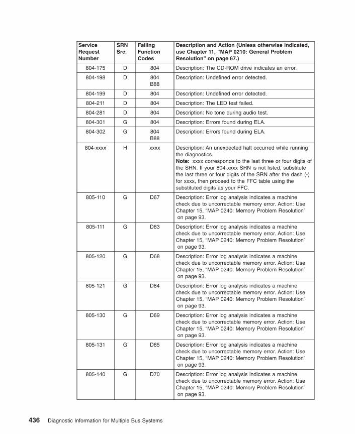
ServiceRequestNumber
SRNSrc.
FailingFunctionCodes
Description and Action (Unless otherwise indicated,use Chapter 11, “MAP 0210: General ProblemResolution” on page 67.)
804-175 D 804 Description: The CD-ROM drive indicates an error.
804-198 D 804B88
Description: Undefined error detected.
804-199 D 804 Description: Undefined error detected.
804-211 D 804 Description: The LED test failed.
804-281 D 804 Description: No tone during audio test.
804-301 G 804 Description: Errors found during ELA.
804-302 G 804B88
Description: Errors found during ELA.
804-xxxx H xxxx Description: An unexpected halt occurred while runningthe diagnostics.Note: xxxx corresponds to the last three or four digits ofthe SRN. If your 804-xxxx SRN is not listed, substitutethe last three or four digits of the SRN after the dash (-)for xxxx, then proceed to the FFC table using thesubstituted digits as your FFC.
805-110 G D67 Description: Error log analysis indicates a machinecheck due to uncorrectable memory error. Action: UseChapter 15, “MAP 0240: Memory Problem Resolution”on page 93.
805-111 G D83 Description: Error log analysis indicates a machinecheck due to uncorrectable memory error. Action: UseChapter 15, “MAP 0240: Memory Problem Resolution”on page 93.
805-120 G D68 Description: Error log analysis indicates a machinecheck due to uncorrectable memory error. Action: UseChapter 15, “MAP 0240: Memory Problem Resolution”on page 93.
805-121 G D84 Description: Error log analysis indicates a machinecheck due to uncorrectable memory error. Action: UseChapter 15, “MAP 0240: Memory Problem Resolution”on page 93.
805-130 G D69 Description: Error log analysis indicates a machinecheck due to uncorrectable memory error. Action: UseChapter 15, “MAP 0240: Memory Problem Resolution”on page 93.
805-131 G D85 Description: Error log analysis indicates a machinecheck due to uncorrectable memory error. Action: UseChapter 15, “MAP 0240: Memory Problem Resolution”on page 93.
805-140 G D70 Description: Error log analysis indicates a machinecheck due to uncorrectable memory error. Action: UseChapter 15, “MAP 0240: Memory Problem Resolution”on page 93.
436 Diagnostic Information for Multiple Bus Systems

ServiceRequestNumber
SRNSrc.
FailingFunctionCodes
Description and Action (Unless otherwise indicated,use Chapter 11, “MAP 0210: General ProblemResolution” on page 67.)
805-141 G D86 Description: Error log analysis indicates a machinecheck due to uncorrectable memory error. Action: UseChapter 15, “MAP 0240: Memory Problem Resolution”on page 93.
805-150 G E11 Description: Error log analysis indicates a machinecheck due to uncorrectable memory error. Action: UseChapter 15, “MAP 0240: Memory Problem Resolution”on page 93.
805-151 G E14 Description: Error log analysis indicates a machinecheck due to uncorrectable memory error. Action: UseChapter 15, “MAP 0240: Memory Problem Resolution”on page 93.
805-210 G D71 Description: Error log analysis indicates a machinecheck due to uncorrectable memory error. Action: UseChapter 15, “MAP 0240: Memory Problem Resolution”on page 93.
805-211 G D87 Description: Error log analysis indicates a machinecheck due to uncorrectable memory error. Action: UseChapter 15, “MAP 0240: Memory Problem Resolution”on page 93.
805-220 G D72 Description: Error log analysis indicates a machinecheck due to uncorrectable memory error. Action: UseChapter 15, “MAP 0240: Memory Problem Resolution”on page 93.
805-221 G D88 Description: Error log analysis indicates a machinecheck due to uncorrectable memory error. Action: UseChapter 15, “MAP 0240: Memory Problem Resolution”on page 93.
805-230 G D73 Description: Error log analysis indicates a machinecheck due to uncorrectable memory error. Action: UseChapter 15, “MAP 0240: Memory Problem Resolution”on page 93.
805-231 G D89 Description: Error log analysis indicates a machinecheck due to uncorrectable memory error. Action: UseChapter 15, “MAP 0240: Memory Problem Resolution”on page 93.
805-240 G D74 Description: Error log analysis indicates a machinecheck due to uncorrectable memory error. Action: UseChapter 15, “MAP 0240: Memory Problem Resolution”on page 93.
805-241 G D90 Description: Error log analysis indicates a machinecheck due to uncorrectable memory error. Action: UseChapter 15, “MAP 0240: Memory Problem Resolution”on page 93.
Chapter 33. SRNs 700-102 through 89c-302 437

ServiceRequestNumber
SRNSrc.
FailingFunctionCodes
Description and Action (Unless otherwise indicated,use Chapter 11, “MAP 0210: General ProblemResolution” on page 67.)
805-250 G E12 Description: Error log analysis indicates a machinecheck due to uncorrectable memory error. Action: UseChapter 15, “MAP 0240: Memory Problem Resolution”on page 93.
805-251 G E15 Description: Error log analysis indicates a machinecheck due to uncorrectable memory error. Action: UseChapter 15, “MAP 0240: Memory Problem Resolution”on page 93.
805-310 G D75 Description: Error log analysis indicates a machinecheck due to uncorrectable memory error. Action: UseChapter 15, “MAP 0240: Memory Problem Resolution”on page 93.
805-311 G D91 Description: Error log analysis indicates a machinecheck due to uncorrectable memory error. Action: UseChapter 15, “MAP 0240: Memory Problem Resolution”on page 93.
805-320 G D76 Description: Error log analysis indicates a machinecheck due to uncorrectable memory error. Action: UseChapter 15, “MAP 0240: Memory Problem Resolution”on page 93.
805-321 G D92 Description: Error log analysis indicates a machinecheck due to uncorrectable memory error. Action: UseChapter 15, “MAP 0240: Memory Problem Resolution”on page 93.
805-331 G D93 Description: Error log analysis indicates a machinecheck due to uncorrectable memory error. Action: UseChapter 15, “MAP 0240: Memory Problem Resolution”on page 93.
805-340 G D78 Description: Error log analysis indicates a machinecheck due to uncorrectable memory error. Action: UseChapter 15, “MAP 0240: Memory Problem Resolution”on page 93.
805-341 G D94 Description: Error log analysis indicates a machinecheck due to uncorrectable memory error. Action: UseChapter 15, “MAP 0240: Memory Problem Resolution”on page 93.
805-350 G E13 Description: Error log analysis indicates a machinecheck due to uncorrectable memory error. Action: UseChapter 15, “MAP 0240: Memory Problem Resolution”on page 93.
805-351 G E16 Description: Error log analysis indicates a machinecheck due to uncorrectable memory error. Action: UseChapter 15, “MAP 0240: Memory Problem Resolution”on page 93.
438 Diagnostic Information for Multiple Bus Systems

ServiceRequestNumber
SRNSrc.
FailingFunctionCodes
Description and Action (Unless otherwise indicated,use Chapter 11, “MAP 0210: General ProblemResolution” on page 67.)
805-600 G Description: Error log analysis indicates a machinecheck due to uncorrectable memory error orunsupported memory. Action: Examine the memorymodules and determine if they are supported types. Ifthe modules are supported, then replace the appropriatememory module(s). Use Chapter 15, “MAP 0240:Memory Problem Resolution” on page 93.
805-601 G 210 Description: Error log analysis indicates a machinecheck due to CPU internal cache error.
805-602 G 214D01
Description: Error log analysis indicates a machinecheck due to CPU address/data bus parity error.
805-603 G 210214D01
Description: Error log analysis indicates a machinecheck due to CPU bus transfer error.
805-604 G 210D01
Description: Error log analysis indicates a machinecheck due to CPU address/data bus parity error.
805-605 G 210 Description: Error log analysis indicates a machinecheck due to CPU bus transfer error.
805-606 G 214 Description: Error log analysis indicates a machinecheck due to memory controller internal error.
805-607 G 210214
Description: Error log analysis indicates a machinecheck due to memory address error.
805-608 G 214217
Description: Error log analysis indicates a machinecheck due to a Flash ROM error.
805-609 G D01 Description: Error log analysis indicates a machinecheck due to a L2 parity error.
805-610 G Description: Error log analysis indicates a machinecheck due to ISA device error, but the device could notbe identified. Action: Run diagnostics on the ISA devices.
805-611 G Description: Error log analysis indicates a machinecheck due to EISA/ISA bus time out error, but the devicecould not be identified. Action: Run diagnostics on theISA devices. If multiple devices fail, use FFC 295.
805-612 G 214 Description: Error log analysis indicates a machinecheck due to an Illegal L2 copy-back operation.
805-616 G software Description: Error log analysis indicates a machinecheck due to software.
805-617 G Description: Error log analysis indicates a machinecheck of unknown origin. Action: If the problem ispersistent, contact your service support structure.
805-618 G Description: Error log analysis indicates multipleinstances of machine check of unknown origin. Action: Ifthe problem is persistent, contact your service supportstructure.
Chapter 33. SRNs 700-102 through 89c-302 439

ServiceRequestNumber
SRNSrc.
FailingFunctionCodes
Description and Action (Unless otherwise indicated,use Chapter 11, “MAP 0210: General ProblemResolution” on page 67.)
805-619 G 221 Description: Error log analysis indicates a machinecheck due to an unidentified source on the I/Osubsystem. Action: Use MAP 210.
805-621 G 292 Description: Error log analysis indicates a machinecheck due to Integrated PCI device does not respond.
805-622 G 293 Description: Error log analysis indicates a machinecheck due to Integrated PCI device does not respond.
805-623 G 294 Description: Error log analysis indicates a machinecheck due to Integrated PCI device does not respond.
805-624 G 295 Description: Error log analysis indicates a machinecheck due to Integrated PCI device does not respond.
805-625 G 868 Description: Error log analysis indicates a machinecheck due to Integrated PCI device does not respond.
805-631 G 292 Description: Error log analysis indicates a machinecheck due to Internal error from PCI device.
805-632 G 293 Description: Error log analysis indicates a machinecheck due to Internal error from PCI device.
805-633 G 294 Description: Error log analysis indicates a machinecheck due to Internal error from PCI device.
805-634 G 295 Description: Error log analysis indicates a machinecheck due to Internal error from PCI device.
805-635 G 868 Description: Error log analysis indicates a machinecheck due to Internal error from PCI device.
805-640 G 2E8214
Description: Error log analysis indicates a machinecheck due to a system bus error.
805-641 G 2E8210
Description: Error log analysis indicates a machinecheck due to a processor bus error.
805-642 G 2E8 Description: Error log analysis indicates a machinecheck due to a directory parity error.
805-643 G 2E8 Description: Error log analysis indicates a machinecheck due to a cache paradox.
805-644 G 2E8 Description: Error log analysis indicates a machinecheck due to an internal error.
805-645 G 2E8 Description: Error log analysis indicates a machinecheck due to a detected L2 hit signal.
805-646 G 2E8214
Description: Error log analysis indicates a machinecheck due to an address/data bus parity error.
805-649 G software Description: Error log analysis indicates a machinecheck due to a disabled I/O address space. Action: RunStandalone Diagnostics on all devices. Use any SRNreported. If no other SRN is reported, suspect a softwareproblem.
440 Diagnostic Information for Multiple Bus Systems

ServiceRequestNumber
SRNSrc.
FailingFunctionCodes
Description and Action (Unless otherwise indicated,use Chapter 11, “MAP 0210: General ProblemResolution” on page 67.)
805-801 G 166221
Description: Slow fan or defective thermal sensor. Action:1) Check spacing around system enclosure, 2) check forobstructions to cooling air flow, 3) check that all fans canrotate freely, and spin with power applied. If reasons 1, 2and 3 can be ruled out, then replace the listed FRUs.
805-802 G 152210
Description: Over/Under voltage condition. Action: CheckAC line voltage per the Power MAP in your serviceguide. If the AC line voltage is correct replace the listedFRUs.
805-803 G 2E1210
Description: System shutdown due to non-critical overtemperature condition. Action: 1) check for obstructionsto cooling air flow, 2) check for accumulated dust on theCPU and planar. If reasons 1 and 2 can be ruled out,then replace the listed FRUs.
805-804 G 1662E1152
Description: System shutdown due to critical overtemperature condition. Action: Check to ensure fans areconnected. If fans are connected, then replace the listedFRUs.
805-805 G 152 Description: System shutdown due to loss of AC power.Action: Check the voltage range switch, if present, onthe power supply and ensure that it is set to match theAC input voltage. If the range switch is set correctly or isnot present refer to ″MAP 1520: Power″ in the ServiceGuide for your system.
805-807 G 166 Description: System shutdown due to an inoperative fan.Action: Check to ensure fans are connected. If fans areconnected replace the listed FRU.
805-811 D 166 Description: Slow fan or defective thermal sensor. Action:
1. Check spacing around system enclosure
2. Check for obstructions to cooling air flow
3. Check that all fans rotate freely, and spin whenpower is applied.
If reasons 1, 2, and 3 can be ruled out, then replace thelisted FRUs.
805-812 D 152210
Description: Over/Under voltage condition. Action: Checkthe AC line voltage per the Power MAP in your serviceguide. If the AC line voltage is correct replace the listedFRUs.
805-813 D 2E1210
Description: System shutdown due to non-critical overtemperature condition. Action:
1. Check for obstructions to cooling air flow.
2. Check for accumulated dust on the CPU and planar.
If reasons 1 and 2 can be ruled out, then replace thelisted FRUs.
Chapter 33. SRNs 700-102 through 89c-302 441

ServiceRequestNumber
SRNSrc.
FailingFunctionCodes
Description and Action (Unless otherwise indicated,use Chapter 11, “MAP 0210: General ProblemResolution” on page 67.)
806-001thu
806-017
D 806 Description: GXT800P Graphics Adapter.
806-018 D 806 Description: GXT800P Graphics Adapter Monitor/DisplayCable.
806-100 D 806 Description: GXT800P Graphics Adapter.
806-505 D 806298
Description: GXT800P Graphics Adapter GXT800P BaseMemory in slot 0, 1, 2, 3, or 4.
806-515 D 806297
Description: GXT800P Graphics Adapter GXT800P Baseand Texture Memory in slot 0, 1, 2, 3, or 4.
806-619 G 221 Description: Error log analysis indicates a machinecheck due to an unidentified source on the I/Osubsystem.
806-700 D 298 Description: GXT800P Base Memory in slot 0.
806-701 D 298 Description: GXT800P Base Memory in slot 1.
806-702 D 298 Description: GXT800P Base Memory in slot 2.
806-703 D 298 Description: GXT800P Base Memory in slot 3.
806-704 D 298 Description: GXT800P Base Memory in slot 4.
806-710 D 297 Description: GXT800P Base and Texture Memory in slot0.
806-711 D 297 Description: GXT800P Base and Texture Memory in slot1.
806-712 D 297 Description: GXT800P Base and Texture Memory in slot2.
806-713 D 297 Description: GXT800P Base and Texture Memory in slot3.
806-714 D 297 Description: GXT800P Base and Texture Memory in slot4.
806-e00 D 298 Description: GXT800P Base Memory in slot 0.
806-e01 D 298 Description: GXT800P Base Memory in slot 1.
806-e02 D 298 Description: GXT800P Base Memory in slot 2.
806-e03 D 298 Description: GXT800P Base Memory in slot 3.
806-e04 D 298 Description: GXT800P Base Memory in slot 4.
806-e10 D 297 Description: GXT800P Base and Texture Memory in slot0.
806-e11 D 297 Description: GXT800P Base and Texture Memory in slot1.
806-e12 D 297 Description: GXT800P Base and Texture Memory in slot2.
806-e13 D 297 Description: GXT800P Base and Texture Memory in slot3.
442 Diagnostic Information for Multiple Bus Systems
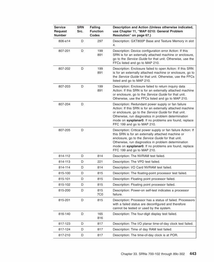
ServiceRequestNumber
SRNSrc.
FailingFunctionCodes
Description and Action (Unless otherwise indicated,use Chapter 11, “MAP 0210: General ProblemResolution” on page 67.)
806-e14 D 297 Description: GXT800P Base and Texture Memory in slot4.
807-201 D 199891
Description: Device configuration error Action: If thisSRN is for an externally attached machine or enclosure,go to the Service Guide for that unit. Otherwise, use theFFCs listed and go to MAP 210.
807-202 D 199891
Description: Enclosure failed to open Action: If this SRNis for an externally attached machine or enclosure, go tothe Service Guide for that unit. Otherwise, use the FFCslisted and go to MAP 210.
807-203 D 199891
Description: Enclosure failed to return inquiry dataAction: If this SRN is for an externally attached machineor enclosure, go to the Service Guide for that unit.Otherwise, use the FFCs listed and go to MAP 210.
807-204 D Description: Redundant power supply or fan failureAction: If this SRN is for an externally attached machineor enclosure, go to the Service Guide for that unit.Otherwise, run diagnostics in problem determinationmode on sysplanar0. If no problems are found, replaceFFC 199 and go to MAP 210.
807-205 D Description: Critical power supply or fan failure Action: Ifthis SRN is for an externally attached machine orenclosure, go to the Service Guide for that unit.Otherwise, run diagnostics in problem determinationmode on sysplanar0. If no problems are found, replaceFFC 199 and go to MAP 210.
814-112 D 814 Description: The NVRAM test failed.
814-113 D 221 Description: The VPD test failed.
814-114 D 814 Description: I/O Card NVRAM test failed.
815-100 D 815 Description: The floating-point processor test failed.
815-101 D 815 Description: Floating point processor failed.
815-102 D 815 Description: Floating point processor failed.
815-200 D 8157C0
Description: Power-on self-test indicates a processorfailure.
815-201 D 815 Description: Processor has a status of failed. Processorswith a failed status are deconfigured and thereforecannot be tested or used by the system.
816-140 D 165816
Description: The four-digit display test failed.
817-123 D 817 Description: The I/O planar time-of-day clock test failed.
817-124 D 817 Description: Time of day RAM test failed.
817-210 D 817 Description: The time-of-day clock is at POR.
Chapter 33. SRNs 700-102 through 89c-302 443
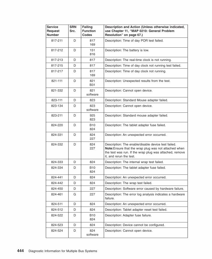
ServiceRequestNumber
SRNSrc.
FailingFunctionCodes
Description and Action (Unless otherwise indicated,use Chapter 11, “MAP 0210: General ProblemResolution” on page 67.)
817-211 D 817169
Description: Time of day POR test failed.
817-212 D 151816
Description: The battery is low.
817-213 D 817 Description: The real-time clock is not running.
817-215 D 817 Description: Time of day clock not running test failed.
817-217 D 817169
Description: Time of day clock not running.
821-111 D 821B31
Description: Unexpected results from the test.
821-332 D 821software
Description: Cannot open device.
823-111 D 823 Description: Standard Mouse adapter failed.
823-134 D 823software
Description: Cannot open device.
823-211 D 925823
Description: Standard mouse adapter failed.
824-220 D B10824
Description: The tablet adapter fuse failed.
824-331 D 824227
Description: An unexpected error occurred.
824-332 D 824227
Description: The enable/disable device test failed.Note:Ensure that the wrap plug was not attached whenthe test was run. If the wrap plug was attached, removeit, and rerun the test.
824-333 D 824 Description: The internal wrap test failed.
824-334 D B10824
Description: The tablet adapter fuse failed.
824-441 D 824 Description: An unexpected error occurred.
824-442 D 824 Description: The wrap test failed.
824-450 D 227 Description: Software error caused by hardware failure.
824-461 G 227 Description: The error log analysis indicates a hardwarefailure.
824-511 D 824 Description: An unexpected error occurred.
824-512 D 824 Description: Tablet adapter reset test failed.
824-522 D B10824
Description: Adapter fuse failure.
824-523 D 824 Description: Device cannot be configured.
824-524 D 824software
Description: Cannot open device.
444 Diagnostic Information for Multiple Bus Systems
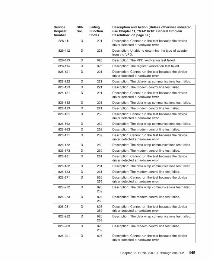
ServiceRequestNumber
SRNSrc.
FailingFunctionCodes
Description and Action (Unless otherwise indicated,use Chapter 11, “MAP 0210: General ProblemResolution” on page 67.)
826-111 D 221 Description: Cannot run the test because the devicedriver detected a hardware error.
826-112 D 221 Description: Unable to determine the type of adapterfrom the VPD.
826-113 D 826 Description: The VPD verification test failed.
826-114 D 826 Description: The register verification test failed.
826-121 D 221 Description: Cannot run the test because the devicedriver detected a hardware error.
826-122 D 221 Description: The data-wrap communications test failed.
826-123 D 221 Description: The modem control line test failed.
826-131 D 221 Description: Cannot run the test because the devicedriver detected a hardware error.
826-132 D 221 Description: The data wrap communications test failed.
826-133 D 221 Description: The modem control line test failed.
826-161 D 252 Description: Cannot run the test because the devicedriver detected a hardware error.
826-162 D 252 Description: The data wrap communications test failed.
826-163 D 252 Description: The modem control line test failed.
826-171 D 259 Description: Cannot run the test because the devicedriver detected a hardware error.
826-172 D 259 Description: The data wrap communications test failed.
826-173 D 259 Description: The modem control line test failed.
826-181 D 261 Description: Cannot run the test because the devicedriver detected a hardware error.
826-182 D 261 Description: The data wrap communications test failed.
826-183 D 261 Description: The modem control line test failed.
826-271 D 826259
Description: Cannot run the test because the devicedriver detected a hardware error.
826-272 D 826259
Description: The data wrap communications test failed.
826-273 D 826259
Description: The modem control line test failed.
826-281 D 826259
Description: Cannot run the test because the devicedriver detected a hardware error.
826-282 D 826259
Description: The data wrap communications test failed.
826-283 D 826259
Description: The modem control line test failed.
826-321 D 826 Description: Cannot run the test because the devicedriver detected a hardware error.
Chapter 33. SRNs 700-102 through 89c-302 445

ServiceRequestNumber
SRNSrc.
FailingFunctionCodes
Description and Action (Unless otherwise indicated,use Chapter 11, “MAP 0210: General ProblemResolution” on page 67.)
826-322 D 826 Description: The data wrap communications test failed.
826-323 D 826 Description: The modem control line test failed.
826-331 D 826 Description: Cannot run the test because the devicedriver detected a hardware error.
826-332 D 826 Description: The data wrap communications test failed.
826-333 D 826 Description: The modem control line test failed.
826-371 D 826 Description: Cannot run the test because the devicedriver detected a hardware error.
826-372 D 826 Description: The data wrap communications test failed.
826-373 D 826 Description: The modem control line test failed.
826-381 D 826 Description: Could not do the test because the devicedriver detected a hardware error.
826-382 D 826 Description: The data wrap communication test failed.
826-383 D 826 Description: The modem control line test failed.
826-481 D D56 Description: Could not do the test because the devicedriver detected a hardware error.
826-482 D D56 Description: The data wrap communication test failed.
826-483 D D56 Description: The modem control line test failed.
826-581 D 826D56
Description: Could not do the test because the devicedriver detected a hardware error.
826-582 D 826D56
Description: The data wrap communication test failed.
826-583 D 826D56
Description: The modem control line test failed.
826-901to
826-920
D software826
Description: An unexpected error occurred that can beattributed to software or hardware. Action: Rundiagnostics from a source other than from the disk or anetwork. If the same error occurs or if the original SRNwas not obtained from disk or a network baseddiagnostics, use MAP 210 with a FFC of 826; otherwise,suspect a software problem.
826-921 D 826software
Description: The adapter failed to configure.
826-922to
826-924
D software826
Description: An unexpected error occurred that can beattributed to software or hardware. Action: Rundiagnostics from a source other than from the disk or anetwork. If the same error occurs or if the original SRNwas not obtained from disk or a network baseddiagnostics, use MAP 210 with a FFC of 826; otherwise,suspect a software problem.
826-925 D 826software
Description: The adapter failed to configure.
446 Diagnostic Information for Multiple Bus Systems

ServiceRequestNumber
SRNSrc.
FailingFunctionCodes
Description and Action (Unless otherwise indicated,use Chapter 11, “MAP 0210: General ProblemResolution” on page 67.)
826-926to
826-943
D software826
Description: An unexpected error occurred that can beattributed to software or hardware. Action: Rundiagnostics from a source other than from the disk or anetwork. If the same error occurs or if the original SRNwas not obtained from disk or a network baseddiagnostics, use MAP 210 with a FFC of 826; otherwise,suspect a software problem.
827-112 D 221 Description: The parallel port data register write/read testfailed.
827-121 D 827 Description: Cannot run the test because the devicedriver detected a hardware error.
827-122 D 827 Description: The parallel port data register write/read testfailed.
827-123 D 827 Description: The parallel port control register write/readtest failed.
827-124 D 827 Description: The parallel port data register read testfailed.
827-125 D 827 Description: The parallel port control register read testfailed.
827-126 D 827 Description: The parallel port control register read testfailed.
827-131 D 827 Description: Cannot run the test because the devicedriver detected a hardware error.
827-132 D 827 Description: The control port register direction bit (write)test with BIDI enabled failed.
827-133 D 827 Description: The control port register direction bit (read)test with BIDI enabled failed.
827-141 D 827 Description: Cannot run the test because the devicedriver detected a hardware error.
827-142 D 827 Description: The parallel port control register write/readtest with BIDI enabled failed.
827-151 D 221 Description: Cannot run the test because the devicedriver detected a hardware error.
827-152 D 827 Description: The parallel port status register read testfailed.
827-161 D 827 Description: Cannot run the test because the devicedriver detected a hardware error.
827-162 D 221 Description: The parallel port interrupt test failed.
827-163 D 221 Description: The parallel port interrupt test failed.
827-201 D 827 Description: The extend control register of the parallelport failed a read/write test.
827-202 D 827 Description: Input/output to the FIFO (without interrupts)failed.
Chapter 33. SRNs 700-102 through 89c-302 447

ServiceRequestNumber
SRNSrc.
FailingFunctionCodes
Description and Action (Unless otherwise indicated,use Chapter 11, “MAP 0210: General ProblemResolution” on page 67.)
827-203 D 827 Description: Input/output to the FIFO (with interrupts)failed.
827-204 D 827 Description: Direct memory access to the FIFO failed.
828-501 D 828 Description: The diskette adapter test failed.
82C-102 D 82C Description: Adapter test failed.
82C-104 D 82C725
Description: Display test failed.
830-111 D 830227
Description: Could not do the test because the devicedriver detected a hardware error.
830-114 D 830 Description: The register verification test failed.
830-121 D 830227
Description: Could not do the test because the devicedriver detected a hardware problem.
830-122 D 830227
Description: The data wrap communication test failed.
830-123 D 830227
Description: The modem control line test failed.
830-124 D 830 Description: The memory test failed.
830-151 D B54830
Description: Could not do the test because the devicedriver detected a hardware error.
830-152 D B54830
Description: The data wrap communication test failed.
830-153 D D54830
Description: The modem control line test failed.
830-171 D 259 Description: Could not run the test because the devicedriver detected a hardware error.
830-172 D 259 The data wrap communication test failed.
830-173 D 259 Description: The modem control line test failed.
830-181 D 261 Description: Could not do the test because the devicedriver detected a hardware error.
830-182 D 261 Description: The data wrap communication test failed.
830-183 D 261 Description: Interposer Wrap test failed.
830-251 D 830D57
Description: Could not perform because the device driverdetected a hardware error.
830-252 D 830B54
Description: The data wrap communication test failed.
830-253 D 830B54
Description: The modem control line test failed.
830-271 D 830B54
Description: Could not perform because the device driverdetected a hardware error.
830-272 D 830B54
Description: The data wrap communication test failed.
448 Diagnostic Information for Multiple Bus Systems
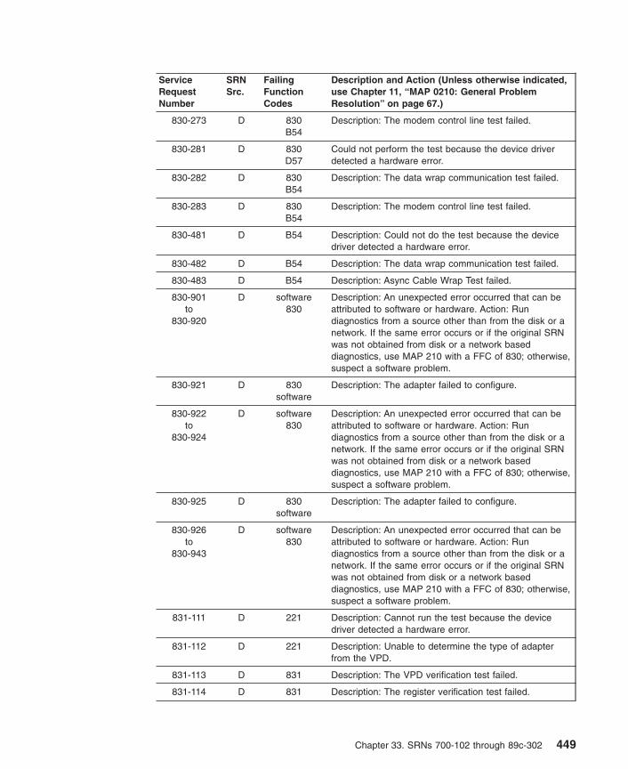
ServiceRequestNumber
SRNSrc.
FailingFunctionCodes
Description and Action (Unless otherwise indicated,use Chapter 11, “MAP 0210: General ProblemResolution” on page 67.)
830-273 D 830B54
Description: The modem control line test failed.
830-281 D 830D57
Could not perform the test because the device driverdetected a hardware error.
830-282 D 830B54
Description: The data wrap communication test failed.
830-283 D 830B54
Description: The modem control line test failed.
830-481 D B54 Description: Could not do the test because the devicedriver detected a hardware error.
830-482 D B54 Description: The data wrap communication test failed.
830-483 D B54 Description: Async Cable Wrap Test failed.
830-901to
830-920
D software830
Description: An unexpected error occurred that can beattributed to software or hardware. Action: Rundiagnostics from a source other than from the disk or anetwork. If the same error occurs or if the original SRNwas not obtained from disk or a network baseddiagnostics, use MAP 210 with a FFC of 830; otherwise,suspect a software problem.
830-921 D 830software
Description: The adapter failed to configure.
830-922to
830-924
D software830
Description: An unexpected error occurred that can beattributed to software or hardware. Action: Rundiagnostics from a source other than from the disk or anetwork. If the same error occurs or if the original SRNwas not obtained from disk or a network baseddiagnostics, use MAP 210 with a FFC of 830; otherwise,suspect a software problem.
830-925 D 830software
Description: The adapter failed to configure.
830-926to
830-943
D software830
Description: An unexpected error occurred that can beattributed to software or hardware. Action: Rundiagnostics from a source other than from the disk or anetwork. If the same error occurs or if the original SRNwas not obtained from disk or a network baseddiagnostics, use MAP 210 with a FFC of 830; otherwise,suspect a software problem.
831-111 D 221 Description: Cannot run the test because the devicedriver detected a hardware error.
831-112 D 221 Description: Unable to determine the type of adapterfrom the VPD.
831-113 D 831 Description: The VPD verification test failed.
831-114 D 831 Description: The register verification test failed.
Chapter 33. SRNs 700-102 through 89c-302 449

ServiceRequestNumber
SRNSrc.
FailingFunctionCodes
Description and Action (Unless otherwise indicated,use Chapter 11, “MAP 0210: General ProblemResolution” on page 67.)
831-121 D 221 Description: Cannot run the test because the devicedriver detected a hardware error.
831-122 D 221 Description: The data wrap communications test failed.
831-123 D 221 Description: The modem control line test failed.
831-131 D 221 Description: Cannot run the test because the devicedriver detected a hardware error.
831-132 D 221 Description: The data wrap communications test failed.
831-133 D 221 Description: The modem control line test failed.
831-161 D 252 Description: Cannot run the test because the devicedriver detected a hardware error.
831-162 D 252 Description: The data wrap communications test failed.
831-163 D 252 Description: The modem control line test failed.
831-164 D 221252
Description: Cannot run the test because the devicedriver detected a hardware error.
831-165 D 221252
Description: The data wrap communications test failed.
831-166 D 221252
Description: The modem control line test failed.
831-171 D 259 Description: Cannot run the test because the devicedriver detected a hardware error.
831-172 D 259 Description: The data wrap communications test failed.
831-173 D 259 Description: The modem control line test failed.
831-181 D 261 Description: Cannot run the test because the devicedriver detected a hardware error.
831-182 D 261 Description: The data wrap communications test failed.
831-183 D 261 Description: The modem control line test failed.
831-271 D 831259
Description: Cannot run the test because the devicedriver detected a hardware error.
831-272 D 831259
Description: The data wrap communication test failed.
831-273 D 831259
Description: The modem control line test failed.
831-281 D 831259
Description: Cannot run the test because the devicedriver detected a hardware error.
831-282 D 831259
Description: The data wrap communications test failed.
831-283 D 831259
Description: The modem control line test failed.
831-321 D 831 Description: Cannot run the test because the devicedriver detected a hardware error.
450 Diagnostic Information for Multiple Bus Systems

ServiceRequestNumber
SRNSrc.
FailingFunctionCodes
Description and Action (Unless otherwise indicated,use Chapter 11, “MAP 0210: General ProblemResolution” on page 67.)
831-322 D 831 Description: The data wrap communications test failed.
831-323 D 831 Description: The modem control line test failed.
831-331 D 831 Description: Cannot run the test because the devicedriver detected a hardware error.
831-332 D 831 Description: The data wrap communications test failed.
831-333 D 831 Description: The modem control line test failed.
831-371 D 831 Description: Cannot run the test because the devicedriver detected a hardware error.
831-372 D 831 Description: The data wrap communications test failed.
831-373 D 831 Description: The modem control line test failed.
831-381 D 831 Description: Cannot run the test because the devicedriver detected a hardware error.
831-382 D 831 Description: The data wrap communications test failed.
831-383 D 831 Description: The modem control line test failed.
831-481 D D56 Description: Could not do the test because the devicedriver detected a hardware error.
831-482 D D56 Description: The data wrap communication test failed.
831-483 D D56 Description: The modem control line test failed.
831-581 D 831D56
Description: Could not do the test because the devicedriver detected a hardware error.
831-582 D 831D56
Description: The data wrap communication test failed.
831-583 D 831D56
Description: The modem control line test failed.
831-901to
831-920
D software831
Description: An unexpected error occurred that can beattributed to software or hardware. Action: Rundiagnostics from a source other than from the disk or anetwork. If the same error occurs or if the original SRNwas not obtained from disk or a network baseddiagnostics, use MAP 210 with a FFC of 831; otherwise,suspect a software problem.
831-921 D 831software
Description: The adapter failed to configure.
831-922to
831-924
D software831
Description: An unexpected error occurred that can beattributed to software or hardware. Action: Rundiagnostics from a source other than from the disk or anetwork. If the same error occurs or if the original SRNwas not obtained from disk or a network baseddiagnostics, use MAP 210 with a FFC of 831; otherwise,suspect a software problem.
831-925 D 831software
Description: The adapter failed to configure.
Chapter 33. SRNs 700-102 through 89c-302 451

ServiceRequestNumber
SRNSrc.
FailingFunctionCodes
Description and Action (Unless otherwise indicated,use Chapter 11, “MAP 0210: General ProblemResolution” on page 67.)
831-926to
831-943
D software831
Description: An unexpected error occurred that can beattributed to software or hardware. Action: Rundiagnostics from a source other than from the disk or anetwork. If the same error occurs or if the original SRNwas not obtained from disk or a network baseddiagnostics, use MAP 210 with a FFC of 831; otherwise,suspect a software problem.
832-xxxx G xxxx Description: I/O bridge/device internal errorNote: xxxx represents the last 3 or 4 digits of the SRNafter the dash (-).
833-xxxx G xxxx2962C9
Description: PCI device address parity error, PCI devicedata parity error, or PCI device abort error. Thediagnostics screen indicates the actual error.Note: xxxx represents the last 3 or 4 digits of the SRNafter the dash (-).
836-101 D 836 Description: Cannot run the test because the devicedriver detected a hardware error.
836-111 D 836227
Description: Cannot run test because the device driverdetected a hardware error.
836-112 D 836227
Description: Unable to determine the type of adapterfrom the VPD.
836-113 D 836 Description: The VPD verification test failed.
836-114 D 836 Description: The register verification test failed.
836-115 D 836 Description: The VPD verification test failed.
836-116 D B54836
Description: The 128-port controller line test failed.
836-117 D 684 Description: Remote Async Node test failed.
836-118 D 837 Description: Remote async node test failed.
836-119 F 836 Description: Sync line termination test failed.
836-151 D 837 Description: Cannot run the test because the devicedriver detected a hardware error.
836-152 D 837 Description: The data wrap communications test failed.
836-153 D 837 Description: The modem control line test failed.
836-154 D 684836
Description: Cannot run the test because the devicedriver detected a hardware error.
836-155 D 684836152
Description: The data wrap communications test failed.
836-161 D C22 Description: Cannot run the test because the devicedriver detected a hardware error.
836-162 D C22 Description: The data wrap communications test failed.
836-163 D C22 Description: The modem control line test failed.
452 Diagnostic Information for Multiple Bus Systems

ServiceRequestNumber
SRNSrc.
FailingFunctionCodes
Description and Action (Unless otherwise indicated,use Chapter 11, “MAP 0210: General ProblemResolution” on page 67.)
836-164 D D06 Description: The data wrap communication test failed.
836-171 D 259 Description: Cannot run the test because the devicedriver detected a hardware error.
836-172 D 259 Description: The data wrap communications test failed.
836-173 D 259 Description: The modem control line test failed.
836-174 D 263 Description: Cannot run the test because the devicedriver detected a hardware error while running thePrinter/Terminal cable wrap test.
836-175 D 263 Description: The data wrap communications test failedwhile running the Printer/Terminal cable wrap test.
836-181 D 261 Description: Cannot run the test because the devicedriver detected a hardware error.
836-182 D 261 Description: The data wrap communications test failed.
836-183 D 261 Description: The modem control line test failed.
836-251 D 836837
Description: Cannot run the test because the devicedriver detected a hardware error.
836-252 D 836837
Description: The data wrap communications test failed.
836-253 D 836837
Description: The modem control line test failed.
836-254 D 836837
Description: Cannot run the test because the devicedriver detected a hardware error while running theRemote Async Node wrap test.
836-255 D 836684
Description: The data wrap communications test failedwhile running the Remote Async Node wrap test.
836-271 D 836837
Description: Cannot run the test because the devicedriver detected a hardware error.
836-272 D 836837
Description: The data wrap communications test failed.
836-273 D 836837
Description: The modem control line test failed.
836-274 D 836684
Description: Cannot run the test because the devicedriver detected a hardware error while running thePrinter/Terminal cable wrap test.
836-275 D 836684
Description: The data wrap communications test failedwhile running the Printer/Terminal cable wrap test.
836-281 D 836837
Description: Cannot run the test because the devicedriver detected a hardware error.
836-282 D 836837
Description: The data wrap communication test failed.
836-283 D 836837
Description: The modem control line test failed.
Chapter 33. SRNs 700-102 through 89c-302 453

ServiceRequestNumber
SRNSrc.
FailingFunctionCodes
Description and Action (Unless otherwise indicated,use Chapter 11, “MAP 0210: General ProblemResolution” on page 67.)
836-481 D D56 Description: Could not do the test because the devicedriver detected a hardware error.
836-482 D D56 Description: The data wrap communication test failed.
836-483 D D56 Description: The modem control line test failed.
836-901to
836-920
D software836
Description: An unexpected error occurred that can beattributed to software or hardware. Action: Rundiagnostics from a source other than from the disk or anetwork. If the same error occurs or if the original SRNwas not obtained from disk or a network baseddiagnostics, use MAP 210 with a FFC of 836; otherwise,suspect a software problem.
836-921 D 836software
Description: The adapter failed to configure.
836-922to
836-924
D software836
Description: An unexpected error occurred that can beattributed to software or hardware. Action: Rundiagnostics from a source other than from the disk or anetwork. If the same error occurs or if the original SRNwas not obtained from disk or a network baseddiagnostics, use MAP 210 with a FFC of 836; otherwise,suspect a software problem.
836-925 D 836software
Description: The adapter failed to configure.
836-926to
836-943
D software836
Description: An unexpected error occurred that can beattributed to software or hardware. Action: Rundiagnostics from a source other than from the disk or anetwork. If the same error occurs or if the original SRNwas not obtained from disk or a network baseddiagnostics, use MAP 210 with a FFC of 836; otherwise,suspect a software problem.
840-101 D 221 Description: Enhanced error handling failure on the bus.
840-102 D 293 Description: Enhanced error handling failure on aPCI-PCI Bridge.
840-103 D 840221
Description: Enhanced error handling failure on theadapter.
840-212 D 840 Description: FIFO empty bit set.
840-213 D 840 Description: FIFO empty bit clear.
840-214 D 840 Description: FIFO full bit set.
840-215 D 840 Description: FIFO full bit clear.
840-216 D 840 Description: FIFO data miscompare.
840-217 D 840 Description: SCSI FIFO data miscompare.
840-218 D 840 Description: SCSI FIFO underflow.
840-219 D Description: SCSI parity error. Action: Go to Chapter 8,“MAP 0050: SCSI Bus Problems” on page 51.
454 Diagnostic Information for Multiple Bus Systems

ServiceRequestNumber
SRNSrc.
FailingFunctionCodes
Description and Action (Unless otherwise indicated,use Chapter 11, “MAP 0210: General ProblemResolution” on page 67.)
840-220 D 840 Description: SCSI FIFO flags error.
840-221 D 840221
Description: Miscompare during the write/read of theconfiguration register.
840-222 D 840 Description: Error during the write/read of the memoryregister.
840-223 D 840 Description: Miscompare during the write/read of thememory I/O register. Action: Go to Chapter 8, “MAP0050: SCSI Bus Problems” on page 51.
840-224 D 840221
Description: SCSI configuration register read or writeerror.
840-225 D 840 Description: Adapter POST failed.
840-226 D Description: SCSI wrap or PTC failure. Action: Go toChapter 8, “MAP 0050: SCSI Bus Problems” on page 51.
840-227 D 840221
Description: SCSI adapter test failure.
840-230 D Description: Arbitration test failed. Action: Go toChapter 8, “MAP 0050: SCSI Bus Problems” on page 51.
840-231 D Description: Function could not complete. Action: Go toChapter 8, “MAP 0050: SCSI Bus Problems” on page 51.
840-232 D Description: SCSI bus data miscompare. Action: Go toChapter 8, “MAP 0050: SCSI Bus Problems” on page 51.
840-240 D Description: No terminal power. Action: Go to Chapter 8,“MAP 0050: SCSI Bus Problems” on page 51.
840-242 D Description: SCSI bus error. Action: Go to Chapter 8,“MAP 0050: SCSI Bus Problems” on page 51.
840-301 D 840221
Description: The parent device open failed.
840-701 G 840 Description: Error log analysis indicates a PCI SCSIadapter failure.
840-801 G Description: Error log analysis indicates a terminatorproblem. Action: Run the diagnostics on the adapter inSystem Verification mode. If an SRN is reported, use theSRN to resolve the problem. If an SRN is not reported,use the SCSI service hints in “General SCSIConfiguration Checks” on page 3 to resolve the problem.
840-802 G Description: Error log analysis indicates that multipleattempts to reset the SCSI bus have timed out. Action:Run the diagnostics on the adapter in SystemVerification mode. If an SRN is reported, use the SRN toresolve the problem. If an SRN is not reported, use theSCSI service hints in “General SCSI ConfigurationChecks” on page 3 to resolve the problem.
Chapter 33. SRNs 700-102 through 89c-302 455

ServiceRequestNumber
SRNSrc.
FailingFunctionCodes
Description and Action (Unless otherwise indicated,use Chapter 11, “MAP 0210: General ProblemResolution” on page 67.)
840-803 G Description: Error log analysis indicates that multipleSCSI bus errors have occurred. Action: Run thediagnostics on the adapter in System Verification mode.If an SRN is reported, use the SRN to resolve theproblem. If an SRN is not reported, use the SCSI servicehints in “General SCSI Configuration Checks” on page 3to resolve the problem.
844-xxxseries
D 844 Description: A 7135 controller problem is indicated.Action: Use 7135 documentation.
845-xxxseries
D 845 Description: A 7135 DASD drawer problem is indicated.Action: Use 7135 documentation.
846-xxxseries
D 846 Description: A 7135 DASD drawer problem is indicated.Action: Use 7135 documentation.
868-101 D 221 Description: Enhanced error handling failure on the bus.
868-102 D 293 Description: Enhanced error handling failure on aPCI-PCI Bridge.
868-103 D 868221
Description: Enhanced error handling failure on theadapter.
868-110 D 221 Description: The adapter diagnostic subcommand testfailed.
868-130 D 279 Description: The adapter fuse test failed.
868-140 D 868 Description: The wrap test failed.
868-150 D 868 Description: The BCR registers write/read test failed.
868-160 D 868 Description: The POS registers write/read test failed.
868-170 D 868 Description: The internal/external reset test failed.
868-180 D 279868
Description: The adapter command timed out.Note: Check the fuse before replacing.
868-190 D 221 Description: A software error was caused by a hardwarefailure.
868-191 G 868 Description: Analysis of the error log indicates a problemwith the hardware.
868-192 G 221 Description: Analysis of the error log indicates a problemwith the hardware.
868-193 G 279 Description: Analysis of the error log indicates a problemwith the hardware.
868-194 G 868 Description: Analysis of the error log indicates a problemwith the hardware.
868-200 D 868 Description: ROM CRC error.
868-201 D 868 Description: Adapter RAM error.
868-202 D 868 Description: The control logic failed.
868-203 D 868 Description: The control logic failed.
456 Diagnostic Information for Multiple Bus Systems

ServiceRequestNumber
SRNSrc.
FailingFunctionCodes
Description and Action (Unless otherwise indicated,use Chapter 11, “MAP 0210: General ProblemResolution” on page 67.)
868-204 D 868 Description: The control logic failed.
868-205 D 868 Description: The control logic failed.
868-206 D 868 Description: Diagnostics completed with a previous error.
868-211 D 279868
software
Description: The device failed to configure.
868-212 D 868 Description: FIFO empty bit set.
868-213 D 868 Description: FIFO empty bit clear.
868-214 D 868 Description: FIFO full bit set.
868-215 D 868 Description: FIFO full bit clear.
868-216 D 868 Description: FIFO data miscompare.
868-217 D 868 Description: SCSI FIFO data miscompare.
868-218 D 868 Description: SCSI FIFO underflow.
868-219 D Description: SCSI parity error. Action: Go to Chapter 8,“MAP 0050: SCSI Bus Problems” on page 51.
868-220 D 868 Description: SCSI FIFO flags error.
868-221 D 868221
Description: Miscompare during the write/read of theconfiguration register.
868-222 D 868 Description: Error during the write/read of the memoryregister.
868-223 D 868 Description: Miscompare during the write/read of thememory I/O register. Action: Go to Chapter 8, “MAP0050: SCSI Bus Problems” on page 51.
868-224 D 868221
Description: SCSI configuration register read or writeerror.
868-225 D 868 Description: Adapter POST failed.
868-226 D Description: SCSI wrap or PTC failure. Action: Go toChapter 8, “MAP 0050: SCSI Bus Problems” on page 51.
868-227 D 868221
Description: SCSI adapter test failure.
868-230 D Description: Arbitration test failed. Action: Go toChapter 8, “MAP 0050: SCSI Bus Problems” on page 51.
868-231 D Description: Function could not complete. Action: Go toChapter 8, “MAP 0050: SCSI Bus Problems” on page 51.
868-232 D Description: SCSI bus data miscompare. Action: Go toChapter 8, “MAP 0050: SCSI Bus Problems” on page 51.
868-240 D Description: No terminal power. Action: Go to Chapter 8,“MAP 0050: SCSI Bus Problems” on page 51.
868-242 D Description: SCSI bus error. Action: Go to Chapter 8,“MAP 0050: SCSI Bus Problems” on page 51.
Chapter 33. SRNs 700-102 through 89c-302 457

ServiceRequestNumber
SRNSrc.
FailingFunctionCodes
Description and Action (Unless otherwise indicated,use Chapter 11, “MAP 0210: General ProblemResolution” on page 67.)
868-301 D 868221
Description: Configuration open failed for parent bus.
868-701 G 868 Description: Error log analysis indicates a PCI SCSIadapter failure.
868-801 G Description: Error log analysis indicates a terminatorproblem. Action: Run the diagnostics on the adapter inSystem Verification mode. If an SRN is reported, use theSRN to resolve the problem. If an SRN is not reported,use the SCSI service hints in “General SCSIConfiguration Checks” on page 3 to resolve the problem.
868-802 G Description: Error log analysis indicates that multipleattempts to reset the SCSI bus have timed out. Action:Run the diagnostics on the adapter in SystemVerification mode. If an SRN is reported, use the SRN toresolve the problem. If an SRN is not reported, use theSCSI service hints in “General SCSI ConfigurationChecks” on page 3 to resolve the problem.
868-803 G Description: Error log analysis indicates that multipleSCSI bus errors have occurred. Action: Run thediagnostics on the adapter in System Verification mode.If an SRN is reported, use the SRN to resolve theproblem. If an SRN is not reported, use the SCSI servicehints in “General SCSI Configuration Checks” on page 3to resolve the problem.
887-101 D 887 Description: POS register test failed.
887-102 D 887 Description: I/O register test failed.
887-103 D 887 Description: Local RAM test failed.
887-104 D 887 Description: Vital Product Data (VPD) failed.
887-105 D 887 Description: LAN coprocessor internal tests failed.
887-106 D 887 Description: Internal loopback test failed.
887-107 D 887 Description: External loopback test failed.
887-108 D 887 Description: External loopback test failed.
887-109 D 887 Description: External loopback parity tests failed.
887-110 D 887 Description: External loopback fairness test failed.
887-111 D 887 Description: External loopback fairness and parity testsfailed.
887-112 D 887 Description: External loopback (twisted pair) test failed.
887-113 D 887 Description: External loopback (twisted pair) parity testfailed.
887-114 D 887 Description: Ethernet loopback (twisted pair) fairness testfailed.
887-115 D 887 Description: External loopback (twisted pair) fairness andparity tests failed.
458 Diagnostic Information for Multiple Bus Systems

ServiceRequestNumber
SRNSrc.
FailingFunctionCodes
Description and Action (Unless otherwise indicated,use Chapter 11, “MAP 0210: General ProblemResolution” on page 67.)
887-116 D 887 Description: Twisted pair wrap data failed.
887-117 D 887software
Description: Device configuration fails.
887-118 D 887 Description: Device driver indicates a hardware problem.
887-120 D 887 Description: Device driver indicates a hardware problem.
887-121 D B08 Description: Ethernet transceiver test failed.
887-122 B09 Description: Ethernet 10 Base-2 transceiver test failed.
887-123 D 887 Description: Internal loopback test failed.
887-124 G 887software
Description: Error log indicates a hardware problem.
887-125 G 887 Description: Fuse test failed.
887-202 D 887 Description: Vital product data test failed.
887-203 D 887 Description: Vital product data test failed.
887-209 D 887 Description: RJ-45 converter test failed.
887-304 D 887 Description: Coprocessor internal test failed.
887-305 D 887 Description: Internal loopback test failed.
887-306 D 887 Description: Internal loopback test failed.
887-307 D 887 Description: External loopback test failed.
887-319 D 887software
Description: Device driver indicates a hardware failure.
887-400 D 887 Description: Fuse test failed.
887-401 D 887 Description: Circuit breaker for Ethernet test failed.
887-402 D B09887
Description: Ethernet 10 Base-2 transceiver test failed.
887-403 D B08887
Description: Ethernet 10 Base-T transceiver test failed.
887-404 D C29887
Description: RJ-45 converter test failed.
887-405 F Ethernet-network
887
Description: Rerun diagnostics in advanced mode foraccurate problem determination.
89c-111 D 89cB88
Description: Unable to reserve device.
89c-112 D 89cB88
Description: Unable to do configuration.
89c-113 D 89cB88
Description: Unable to open the device driver.
89c-121 D 89c Description: The CD-ROM drive indicates an error.
89c-122 D 89c Description: The CD-ROM drive indicates an error.
Chapter 33. SRNs 700-102 through 89c-302 459

ServiceRequestNumber
SRNSrc.
FailingFunctionCodes
Description and Action (Unless otherwise indicated,use Chapter 11, “MAP 0210: General ProblemResolution” on page 67.)
89c-123 D 89c Description: The CD-ROM drive indicates an error.
89c-125 D 89cB88
Description: The CD-ROM drive indicates an error.
89c-126 D 89c Description: The CD-ROM drive indicates an error.
89c-127 D 89c Description: The CD-ROM drive indicates an error.
89c-128 D 89c Description: The CD-ROM drive indicates an error.
89c-129 D 89c Description: The CD-ROM drive indicates an error.
89c-150 D Test-Disc89c
Description: A media error was detected.
89c-151 D 89cD88
Description: A command timeout was detected.
89c-152 D 89c Description: A command reservation conflict wasdetected.
89c-162 D 89c Description: The CD-ROM drive indicates an error.
89c-171 D 89c Description: Unable to reserve device.
89c-172 D 89c Description: Unable to do configuration.
89c-173 D 89c Description: Unable to open device driver.
89c-175 D 89c Description: The CD-ROM drive indicates an error.
89c-198 D 89cB88
Description: Undefined error detected.
89c-199 D 89c Description: Undefined error detected.
89c-211 D 89c Description: The LED test failed.
89c-281 D 89c Description: No tone during audio test.
89c-301 G 89c Description: Errors found during ELA.
89c-302 G 89cB88
Description: Errors found during ELA.
460 Diagnostic Information for Multiple Bus Systems

Chapter 34. SRNs 900-001 through xxxxxxx
Note: Some SRNs in this chapter may have 4 rather than 3 digits after the dash (-).
ServiceRequestNumber
SRNSrc.
FailingFunctionCodes
Description and Action (Unless otherwise indicated,use Chapter 11, “MAP 0210: General ProblemResolution” on page 67.)
900-001 D 900227
Monitor
Description: ″NO″ to color panel.
900-002 D 900Monitor
Description: ″NO″ to cursor panel.
900-007 D Info code Description: The EMC_SCROLLING_17_H_TEST failed.
900-009 D Info code Description: The EMC_SCROLLING_21_H_TEST failed.
900-064 D 900227
Description: TRIO64V+_TIMEOUT.
900-101 D 900227
Description: Color miscompare.
900-102 D 900227
Description: Clipping error.
900-103 D 900227
Description: Rectangle fill test failed.
900-128 D software900
Description: MALLOC_ERROR.
900-161 D software Description: Loop count value in rules file is zero.
900-191 D 900227
Description: Red screen error.
900-193 D 900227
Description: Green screen error.
900-1FF D 900227
Description: Rectangle fill test failed.
900-201 D 900227
Description: Color miscompare.
900-202 D 900227
Description: Clipping error.
900-203 D 900227
Description: Image transfer across Plane Test failed.
900-211 D software Description: INTERNAL_ERROR_DATA_SIZE.
900-212 D software Description: INTERNAL_ERROR_NO_ACCESS.
900-215 D 900227
Description: Black screen error.
900-217 D 900227
Description: 9 x 7 Cross hatch grid failed.
900-233 D software Description: OPEN_RCM_ERROR.
461

ServiceRequestNumber
SRNSrc.
FailingFunctionCodes
Description and Action (Unless otherwise indicated,use Chapter 11, “MAP 0210: General ProblemResolution” on page 67.)
900-234 D software Description: IOCTL_GSC_HANDLE_FAILED.
900-235 D software Description: AIXGSC_MAKE_GP_FAILED.
900-236 D software Description: AIXGSC_UNMAKE_GP_FAILED.
900-237 D software Description: DEVICE_BUSY_ERROR.
900-241 D Info code Description: The SCROLLING_17_H_TEST failed.
900-263 D Info code Description: The EMC_SCROLLING_21_H_TEST failed.
900-2FF D 900227
Description: Image transfer across Plane Test failed.
900-301 D 900227
Description: A write of ″0x00″ to the palette registerfailed.
900-302 D 900227
Description: A write of ″0x15″ to the palette registerfailed.
900-303 D 900227
Description: A write of ″0x2A″ to the palette registerfailed.
900-304 D 900227
Description: A write of ″0x3F″ to the palette registerfailed.
900-305 D 900227
Description: The test of the palette registers failed.
900-3FF D 900227
Description: The test of the palette registers failed.
900-401 D 900227
Description: Frame buffer base address inconsistent.
900-402 D 900227
Description: VRAM inaccessible.
900-403 D 900227
Description: Miscompare found in VRAM.
900-404 D 900227
Description: The test of the VRAM failed.
900-447 D 900227
Description: Green screen error.
900-449 D 900227
Description: Blue Screen error.
900-471 D 900227
Description: 9 x 7 Cross hatch grid failed.
900-473 D 900227
Description: 11 x 9 Cross hatch grid failed.
900-495 D Info code Description: The SCROLLING_17_H_TEST failed.
900-497 D Info code Description: The SCROLLING_21_H_TEST failed.
900-4FF D 900227
Description: The test of the VRAM failed.
462 Diagnostic Information for Multiple Bus Systems

ServiceRequestNumber
SRNSrc.
FailingFunctionCodes
Description and Action (Unless otherwise indicated,use Chapter 11, “MAP 0210: General ProblemResolution” on page 67.)
900-501 D 900227
Description: Color miscompare.
900-502 D 900227
Description: Clipping error.
900-503 D 900227
Description: Direct Frame Buffer test failed.
900-5FF D 900227
Description: Direct Frame Buffer test failed.
900-601 D 900227
Description: Video Stream Register test failed.
900-602 D 900227
Description: Video Stream hardware test failed.
900-6FF D 900227
Description: Video Stream hardware test failed.
900-701 D 900227
Description: 0 Degree Short Stroke Draw failed.
900-702 D 900227
Description: 45 Degree Short Stroke Draw failed.
900-703 D 900227
Description: Blue Screen error, or 90 Degree ShortStroke Draw failed.
900-704 D 900227
Description: 135 Degree Short Stroke Draw failed.
900-705 D 900227
Description: White screen error, or 180 Degree ShortStroke Draw failed.
900-706 D 900227
Description: 225 Degree Short Stroke Draw failed.
900-707 D 900227
Description: 270 Degree Short Stroke Draw failed.
900-708 D 900227
Description: 315 Degree Short Stroke Draw failed.
900-709 D 900227
Description: Short Stroke Vector Function test failed.
900-727 D 900227
Description: 11 x 9 Cross hatch grid failed.
900-750 D Info code Description: The SCROLLING_21_H_TEST failed.
900-753 D Info code Description: The EMC_SCROLLING_17_H_TEST failed.
900-7FE D 900227
Description: Short Stroke Vector Function test failed.
900-7FF D software900227
Description: Bad vector detected.
Chapter 34. SRNs 900-001 through xxxxxxx 463
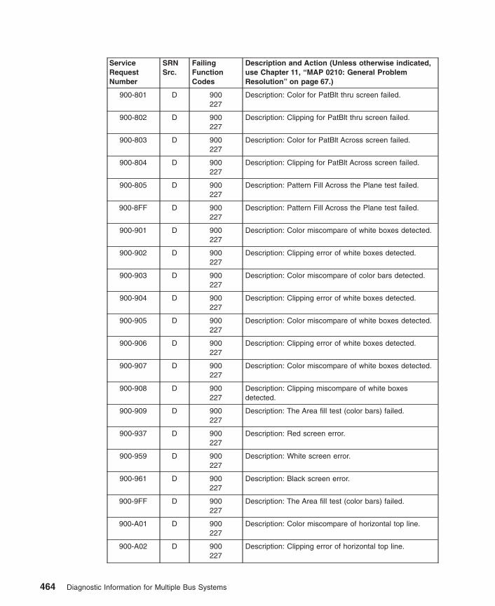
ServiceRequestNumber
SRNSrc.
FailingFunctionCodes
Description and Action (Unless otherwise indicated,use Chapter 11, “MAP 0210: General ProblemResolution” on page 67.)
900-801 D 900227
Description: Color for PatBlt thru screen failed.
900-802 D 900227
Description: Clipping for PatBlt thru screen failed.
900-803 D 900227
Description: Color for PatBlt Across screen failed.
900-804 D 900227
Description: Clipping for PatBlt Across screen failed.
900-805 D 900227
Description: Pattern Fill Across the Plane test failed.
900-8FF D 900227
Description: Pattern Fill Across the Plane test failed.
900-901 D 900227
Description: Color miscompare of white boxes detected.
900-902 D 900227
Description: Clipping error of white boxes detected.
900-903 D 900227
Description: Color miscompare of color bars detected.
900-904 D 900227
Description: Clipping error of white boxes detected.
900-905 D 900227
Description: Color miscompare of white boxes detected.
900-906 D 900227
Description: Clipping error of white boxes detected.
900-907 D 900227
Description: Color miscompare of white boxes detected.
900-908 D 900227
Description: Clipping miscompare of white boxesdetected.
900-909 D 900227
Description: The Area fill test (color bars) failed.
900-937 D 900227
Description: Red screen error.
900-959 D 900227
Description: White screen error.
900-961 D 900227
Description: Black screen error.
900-9FF D 900227
Description: The Area fill test (color bars) failed.
900-A01 D 900227
Description: Color miscompare of horizontal top line.
900-A02 D 900227
Description: Clipping error of horizontal top line.
464 Diagnostic Information for Multiple Bus Systems

ServiceRequestNumber
SRNSrc.
FailingFunctionCodes
Description and Action (Unless otherwise indicated,use Chapter 11, “MAP 0210: General ProblemResolution” on page 67.)
900-A03 D 900227
Description: Color miscompare of vertical right line.
900-A04 D 900227
Description: Clipping error of vertical right line.
900-A05 D 900227
Description: Color miscompare of horizontal bottom line.
900-A06 D 900227
Description: Clipping error of horizontal bottom line.
900-A07 D 900227
Description: Color miscompare of vertical left line.
900-A08 D 900227
Description: Clipping error of vertical left line.
900-A09 D 900227
Description: Color miscompare of horizontal center line.
900-A0A D 900227
Description: Clipping error of horizontal center line.
900-A0B D 900227
Description: Color miscompare of vertical center line.
900-A0C D 900227
Description: Clipping error of vertical center line.
900-A0D D 900227
Description: Reserved.
900-A0F D 900227
Description: Reserved.
900-A10 D 900227
Description: Color miscompare of textured top line.
900-A11 D 900227
Description: Clipping error of textured top line.
900-A12 D 900227
Description: Line Drawing Function test failed.
900-AFF D 900227
Description: Line Drawing Function test failed.
900-B01 D 900227
Description: Rectangle Area Color miscompare detected.
900-B02 D 900227
Description: Rectangle Area Clip error detected.
900-B03 D 900227
Description: Clipped Area Horizontal color miscompare(background line color wrong).
900-B04 D 900227
Description: Clipped Area Horizontal clip miscompare(clip of background line wrong).
900-B05 D 900227
Description: Clipped Area Vertical color miscompare(background line color wrong).
Chapter 34. SRNs 900-001 through xxxxxxx 465
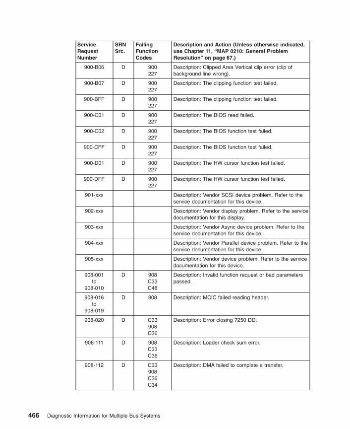
ServiceRequestNumber
SRNSrc.
FailingFunctionCodes
Description and Action (Unless otherwise indicated,use Chapter 11, “MAP 0210: General ProblemResolution” on page 67.)
900-B06 D 900227
Description: Clipped Area Vertical clip error (clip ofbackground line wrong).
900-B07 D 900227
Description: The clipping function test failed.
900-BFF D 900227
Description: The clipping function test failed.
900-C01 D 900227
Description: The BIOS read failed.
900-C02 D 900227
Description: The BIOS function test failed.
900-CFF D 900227
Description: The BIOS function test failed.
900-D01 D 900227
Description: The HW cursor function test failed.
900-DFF D 900227
Description: The HW cursor function test failed.
901-xxx Description: Vendor SCSI device problem. Refer to theservice documentation for this device.
902-xxx Description: Vendor display problem. Refer to the servicedocumentation for this display.
903-xxx Description: Vendor Async device problem. Refer to theservice documentation for this device.
904-xxx Description: Vendor Parallel device problem. Refer to theservice documentation for this device.
905-xxx Description: Vendor device problem. Refer to the servicedocumentation for this device.
908-001to
908-010
D 908C33C48
Description: Invalid function request or bad parameterspassed.
908-016to
908-019
D 908 Description: MCIC failed reading header.
908-020 D C33908C36
Description: Error closing 7250 DD.
908-111 D 908C33C36
Description: Loader check sum error.
908-112 D C33908C36C34
Description: DMA failed to complete a transfer.
466 Diagnostic Information for Multiple Bus Systems

ServiceRequestNumber
SRNSrc.
FailingFunctionCodes
Description and Action (Unless otherwise indicated,use Chapter 11, “MAP 0210: General ProblemResolution” on page 67.)
908-113 D 908C33C36
Description: Errors in loading ASCII registers.
908-114to
908-118
D C33908C36
Description: Errors in loading ASCII registers.
908-120to
908-150
D 908C33C36
Description: DMA transfer or PFCA data error.
908-151to
908-158
D 908 Description: SPAN board error.
908-160 D 908C33
SystemC36
Description: 7250 is not available.
908-200to
908-254
D C33908C36
Description: GPSS board failure.
908-255 D C33C34908C48
Description: CP NMI bus timeout interrupt error.
908-256to
908-454
D C33908C36
Description: GPSS board failure.
908-455 D C33908C34C48
Description: CP NMI bus timeout interrupt error.
908-456to
908-699
D C33908C36
Description: GPSS board failure.
908-700to
908-766
D C34C33C48
Description: BLT or RATTLER error.
908-767to
908-769
D C35C34C44
Description: VOO feature error.
908-770to
908-799
D C34C33C48
Description: RSS BIST failure.
908-800 D C46D66
Description: Base 16M CHAP0 SIMM bad.
Chapter 34. SRNs 900-001 through xxxxxxx 467
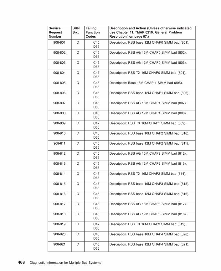
ServiceRequestNumber
SRNSrc.
FailingFunctionCodes
Description and Action (Unless otherwise indicated,use Chapter 11, “MAP 0210: General ProblemResolution” on page 67.)
908-801 D C45D66
Description: RSS base 12M CHAP0 SIMM bad (801).
908-802 D C46D66
Description: RSS AG 16M CHAP0 SIMM bad (802).
908-803 D C45D66
Description: RSS AG 12M CHAP0 SIMM bad (803).
908-804 D C47D66
Description: RSS TX 16M CHAP0 SIMM bad (804).
908-805 D C46D66
Description: Base 16M CHAP 1 SIMM bad (805).
908-806 D C45D66
Description: RSS base 12M CHAP1 SIMM bad (806).
908-807 D C46D66
Description: RSS AG 16M CHAP1 SIMM bad (807).
908-808 D C45D66
Description: RSS AG 12M CHAP1 SIMM bad (808).
908-809 D C47D66
Description: RSS TX 16M CHAP1 SIMM bad (809).
908-810 D C46D66
Description: RSS base 16M CHAP2 SIMM bad (810).
908-811 D C45D66
Description: RSS base 12M CHAP2 SIMM bad (811).
908-812 D C46D66
Description: RSS AG 16M CHAP2 SIMM bad (812).
908-813 D C45D66
Description: RSS AG 12M CHAP2 SIMM bad (813).
908-814 D C47D66
Description: RSS TX 16M CHAP2 SIMM bad (814).
908-815 D C46D66
Description: RSS base 16M CHAP3 SIMM bad (815).
908-816 D C45D66
Description: RSS base 12M CHAP3 SIMM bad (816).
908-817 D C46D66
Description: RSS AG 16M CHAP3 SIMM bad (817).
908-818 D C45D66
Description: RSS AG 12M CHAP3 SIMM bad (818).
908-819 D C47D66
Description: RSS TX 16M CHAP3 SIMM bad (819).
908-820 D C46D66
Description: RSS base 16M CHAP4 SIMM bad (820).
908-821 D C45D66
Description: RSS base 12M CHAP4 SIMM bad (821).
468 Diagnostic Information for Multiple Bus Systems
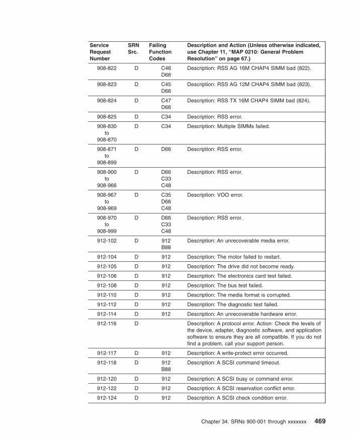
ServiceRequestNumber
SRNSrc.
FailingFunctionCodes
Description and Action (Unless otherwise indicated,use Chapter 11, “MAP 0210: General ProblemResolution” on page 67.)
908-822 D C46D66
Description: RSS AG 16M CHAP4 SIMM bad (822).
908-823 D C45D66
Description: RSS AG 12M CHAP4 SIMM bad (823).
908-824 D C47D66
Description: RSS TX 16M CHAP4 SIMM bad (824).
908-825 D C34 Description: RSS error.
908-830to
908-870
D C34 Description: Multiple SIMMs failed.
908-871to
908-899
D D66 Description: RSS error.
908-900to
908-966
D D66C33C48
Description: RSS error.
908-967to
908-969
D C35D66C48
Description: VOO error.
908-970to
908-999
D D66C33C48
Description: RSS error.
912-102 D 912B88
Description: An unrecoverable media error.
912-104 D 912 Description: The motor failed to restart.
912-105 D 912 Description: The drive did not become ready.
912-106 D 912 Description: The electronics card test failed.
912-108 D 912 Description: The bus test failed.
912-110 D 912 Description: The media format is corrupted.
912-112 D 912 Description: The diagnostic test failed.
912-114 D 912 Description: An unrecoverable hardware error.
912-116 D Description: A protocol error. Action: Check the levels ofthe device, adapter, diagnostic software, and applicationsoftware to ensure they are all compatible. If you do notfind a problem, call your support person.
912-117 D 912 Description: A write-protect error occurred.
912-118 D 912B88
Description: A SCSI command timeout.
912-120 D 912 Description: A SCSI busy or command error.
912-122 D 912 Description: A SCSI reservation conflict error.
912-124 D 912 Description: A SCSI check condition error.
Chapter 34. SRNs 900-001 through xxxxxxx 469
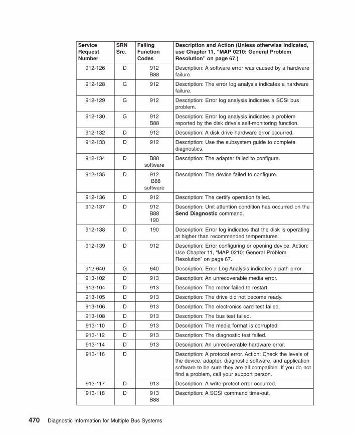
ServiceRequestNumber
SRNSrc.
FailingFunctionCodes
Description and Action (Unless otherwise indicated,use Chapter 11, “MAP 0210: General ProblemResolution” on page 67.)
912-126 D 912B88
Description: A software error was caused by a hardwarefailure.
912-128 G 912 Description: The error log analysis indicates a hardwarefailure.
912-129 G 912 Description: Error log analysis indicates a SCSI busproblem.
912-130 G 912B88
Description: Error log analysis indicates a problemreported by the disk drive’s self-monitoring function.
912-132 D 912 Description: A disk drive hardware error occurred.
912-133 D 912 Description: Use the subsystem guide to completediagnostics.
912-134 D B88software
Description: The adapter failed to configure.
912-135 D 912B88
software
Description: The device failed to configure.
912-136 D 912 Description: The certify operation failed.
912-137 D 912B88190
Description: Unit attention condition has occurred on theSend Diagnostic command.
912-138 D 190 Description: Error log indicates that the disk is operatingat higher than recommended temperatures.
912-139 D 912 Description: Error configuring or opening device. Action:Use Chapter 11, “MAP 0210: General ProblemResolution” on page 67.
912-640 G 640 Description: Error Log Analysis indicates a path error.
913-102 D 913 Description: An unrecoverable media error.
913-104 D 913 Description: The motor failed to restart.
913-105 D 913 Description: The drive did not become ready.
913-106 D 913 Description: The electronics card test failed.
913-108 D 913 Description: The bus test failed.
913-110 D 913 Description: The media format is corrupted.
913-112 D 913 Description: The diagnostic test failed.
913-114 D 913 Description: An unrecoverable hardware error.
913-116 D Description: A protocol error. Action: Check the levels ofthe device, adapter, diagnostic software, and applicationsoftware to be sure they are all compatible. If you do notfind a problem, call your support person.
913-117 D 913 Description: A write-protect error occurred.
913-118 D 913B88
Description: A SCSI command time-out.
470 Diagnostic Information for Multiple Bus Systems

ServiceRequestNumber
SRNSrc.
FailingFunctionCodes
Description and Action (Unless otherwise indicated,use Chapter 11, “MAP 0210: General ProblemResolution” on page 67.)
913-120 D 913 Description: A SCSI busy or command error.
913-122 D 913 Description: A SCSI reservation conflict error.
913-124 D 913 Description: A SCSI check condition error.
913-126 D 913B88
Description: A software error was caused by a hardwarefailure.
913-128 G 913 Description: The error log analysis indicates a hardwarefailure.
913-129 G 913 Description: Error log analysis indicates a SCSI busproblem.
913-130 G 913B88
Description: Error log analysis indicates a problemreported by the disk drive’s self-monitoring function.
913-132 D 913 Description: A disk drive hardware error occurred.
913-133 D 913 Description: Use the subsystem guide to complete thediagnostics.
913-134 D B88software
Description: The adapter failed to configure.
913-137 D 913B88190
Description: Unit attention condition has occurred on theSend Diagnostic command.
913-138 D 190 Description: Error log indicates that the disk is operatingat higher than recommended temperatures.
913-139 D 913 Description: Error configuring or opening device. Action:Use Chapter 11, “MAP 0210: General ProblemResolution” on page 67.
913-640 G 640 Description: Error Log Analysis indicates a path error.
914-110 D 914 Description: The Reserve command failed.
914-120 D 914 Description: The Inquiry command failed.
914-130 D 914media
Description: The Load command failed.
914-135 D 914media
Description: The Unload command failed.
914-140 D 914 Description: The Mode Select command failed.
914-150 D 914media
Description: The Test Unit Ready command failed.
914-160 D 914media
Description: The Send Diagnostic command failed.
914-170 D 914B88
media
Description: The Read, Write and Compare test failed.
914-180 D 914media
Description: The Load command failed.
Chapter 34. SRNs 900-001 through xxxxxxx 471
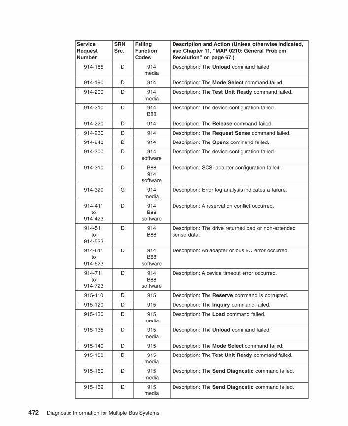
ServiceRequestNumber
SRNSrc.
FailingFunctionCodes
Description and Action (Unless otherwise indicated,use Chapter 11, “MAP 0210: General ProblemResolution” on page 67.)
914-185 D 914media
Description: The Unload command failed.
914-190 D 914 Description: The Mode Select command failed.
914-200 D 914media
Description: The Test Unit Ready command failed.
914-210 D 914B88
Description: The device configuration failed.
914-220 D 914 Description: The Release command failed.
914-230 D 914 Description: The Request Sense command failed.
914-240 D 914 Description: The Openx command failed.
914-300 D 914software
Description: The device configuration failed.
914-310 D B88914
software
Description: SCSI adapter configuration failed.
914-320 G 914media
Description: Error log analysis indicates a failure.
914-411to
914-423
D 914B88
software
Description: A reservation conflict occurred.
914-511to
914-523
D 914B88
Description: The drive returned bad or non-extendedsense data.
914-611to
914-623
D 914B88
software
Description: An adapter or bus I/O error occurred.
914-711to
914-723
D 914B88
software
Description: A device timeout error occurred.
915-110 D 915 Description: The Reserve command is corrupted.
915-120 D 915 Description: The Inquiry command failed.
915-130 D 915media
Description: The Load command failed.
915-135 D 915media
Description: The Unload command failed.
915-140 D 915 Description: The Mode Select command failed.
915-150 D 915media
Description: The Test Unit Ready command failed.
915-160 D 915media
Description: The Send Diagnostic command failed.
915-169 D 915media
Description: The Send Diagnostic command failed.
472 Diagnostic Information for Multiple Bus Systems

ServiceRequestNumber
SRNSrc.
FailingFunctionCodes
Description and Action (Unless otherwise indicated,use Chapter 11, “MAP 0210: General ProblemResolution” on page 67.)
915-170 D 915B88
media
Description: The Read, Write and Compare test failed.
915-180 D 915media
Description: The Load command failed.
915-185 D 915media
Description: The Unload command failed.
915-190 D 915 Description: The Mode Select command failed.
915-200 D 915media
Description: The Test Unit Ready command failed.
915-210 D 915B88
Description: The device configuration failed.
915-220 D 915 Description: The Replace command failed.
915-230 D 915 Description: The Request Sense command failed.
915-240 D 915 Description: The Openx command failed.
915-300 D 915software
Description: The device configuration failed.
915-310 D B88915
software
Description: SCSI adapter configuration failed.
915-320 G 915media
Description: Error log analysis indicates a failure.
915-411to
915-423
D 915B88
software
Description: A reservation conflict occurred.
915-511to
915-523
D 915B88
Description: The drive returned bad or non-extendedsense data.
915-611to
915-623
D 915B88
software
Description: An adapter or bus I/O error occurred.
915-711to
915-723
D 915B88
software
Description: A device timeout error occurred.
917-102 D 917B88
Description: An unrecoverable media error.
917-104 D 917 Description: The motor failed to restart.
917-105 D 917 Description: The drive did not become ready.
917-106 D 917 Description: The electronics card test failed.
917-108 D 917 Description: The bus test failed.
917-110 D 917 Description: The media format is corrupted.
917-112 D 917 Description: The diagnostic test failed.
Chapter 34. SRNs 900-001 through xxxxxxx 473
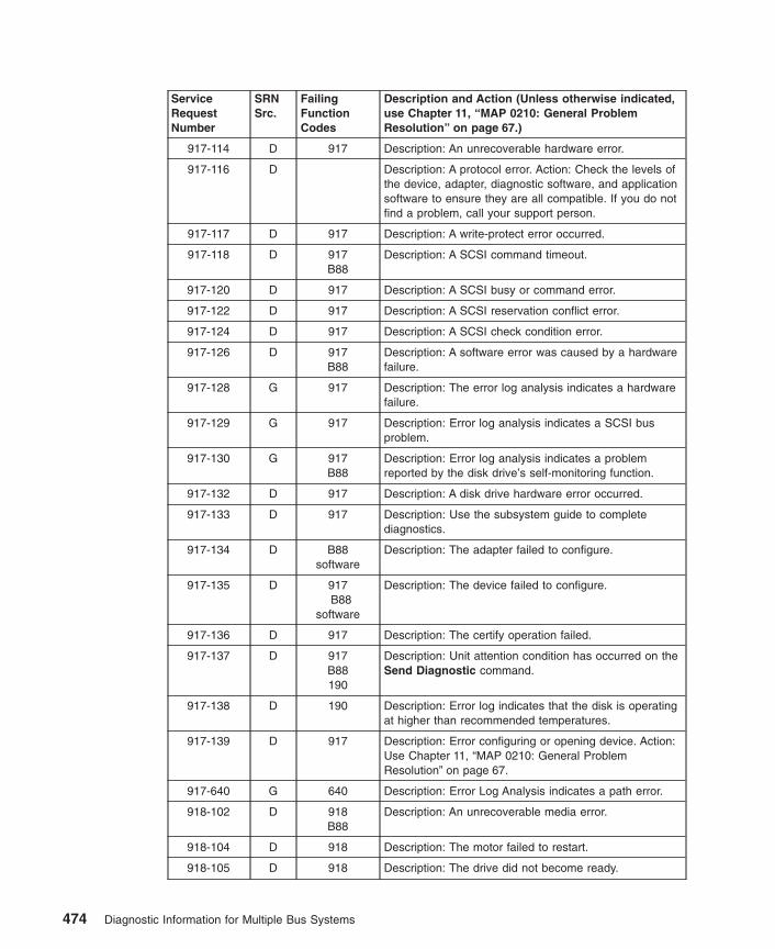
ServiceRequestNumber
SRNSrc.
FailingFunctionCodes
Description and Action (Unless otherwise indicated,use Chapter 11, “MAP 0210: General ProblemResolution” on page 67.)
917-114 D 917 Description: An unrecoverable hardware error.
917-116 D Description: A protocol error. Action: Check the levels ofthe device, adapter, diagnostic software, and applicationsoftware to ensure they are all compatible. If you do notfind a problem, call your support person.
917-117 D 917 Description: A write-protect error occurred.
917-118 D 917B88
Description: A SCSI command timeout.
917-120 D 917 Description: A SCSI busy or command error.
917-122 D 917 Description: A SCSI reservation conflict error.
917-124 D 917 Description: A SCSI check condition error.
917-126 D 917B88
Description: A software error was caused by a hardwarefailure.
917-128 G 917 Description: The error log analysis indicates a hardwarefailure.
917-129 G 917 Description: Error log analysis indicates a SCSI busproblem.
917-130 G 917B88
Description: Error log analysis indicates a problemreported by the disk drive’s self-monitoring function.
917-132 D 917 Description: A disk drive hardware error occurred.
917-133 D 917 Description: Use the subsystem guide to completediagnostics.
917-134 D B88software
Description: The adapter failed to configure.
917-135 D 917B88
software
Description: The device failed to configure.
917-136 D 917 Description: The certify operation failed.
917-137 D 917B88190
Description: Unit attention condition has occurred on theSend Diagnostic command.
917-138 D 190 Description: Error log indicates that the disk is operatingat higher than recommended temperatures.
917-139 D 917 Description: Error configuring or opening device. Action:Use Chapter 11, “MAP 0210: General ProblemResolution” on page 67.
917-640 G 640 Description: Error Log Analysis indicates a path error.
918-102 D 918B88
Description: An unrecoverable media error.
918-104 D 918 Description: The motor failed to restart.
918-105 D 918 Description: The drive did not become ready.
474 Diagnostic Information for Multiple Bus Systems

ServiceRequestNumber
SRNSrc.
FailingFunctionCodes
Description and Action (Unless otherwise indicated,use Chapter 11, “MAP 0210: General ProblemResolution” on page 67.)
918-106 D 918 Description: The electronics card test failed.
918-108 D 918 Description: The bus test failed.
918-110 D 918 Description: The media format is corrupted.
918-112 D 918 Description: The diagnostic test failed.
918-114 D 918 Description: An unrecoverable hardware error.
918-116 D Description: A protocol error. Action: Check the levels ofthe device, adapter, diagnostic software, and applicationsoftware to ensure they are all compatible. If you do notfind a problem, call your support person.
918-117 D 918 Description: A write-protect error occurred.
918-118 D 918B88
Description: A SCSI command timeout.
918-120 D 918 Description: A SCSI busy or command error.
918-122 D 918 Description: A SCSI reservation conflict error.
918-124 D 918 Description: A SCSI check condition error.
918-126 D 918B88
Description: A software error was caused by a hardwarefailure.
918-128 G 918 Description: The error log analysis indicates a hardwarefailure.
918-129 G 918 Description: Error log analysis indicates a SCSI busproblem.
918-130 G 918B88
Description: Error log analysis indicates a problemreported by the disk drive’s self-monitoring function.
918-132 D 918 Description: A disk drive hardware error occurred.
918-133 D 918 Description: Use the subsystem guide to completediagnostics.
918-134 D B88software
Description: The adapter failed to configure.
918-135 D 918B88
software
Description: The device failed to configure.
918-136 D 918 Description: The certify operation failed.
918-137 D 918B88190
Description: Unit attention condition has occurred on theSend Diagnostic command.
918-138 D 190 Description: Error log indicates that the disk is operatingat higher than recommended temperatures.
918-139 D 918 Description: Error configuring or opening device. Action:Use Chapter 11, “MAP 0210: General ProblemResolution” on page 67.
918-640 G 640 Description: Error Log Analysis indicates a path error.
Chapter 34. SRNs 900-001 through xxxxxxx 475

ServiceRequestNumber
SRNSrc.
FailingFunctionCodes
Description and Action (Unless otherwise indicated,use Chapter 11, “MAP 0210: General ProblemResolution” on page 67.)
921-101 D 821 Description: An unexpected adapter error occurred.
921-102 D 921821
Description: An unexpected device or adapter erroroccurred.
921-103 D 921821
Description: The keyboard reset failed.
921-104 D 921 Description: Unknown keyboard.
921-105 D 921821
Description: The keyboard light-on test failed.
921-106 D 921821
Description: The keyboard light-off test failed.
921-201 D 821 Description: An unexpected adapter error occurred.
921-202 D 921821
Description: An unexpected device or adapter erroroccurred.
921-203 D 921821
Description: The read keyboard ID test failed.
921-204 D 921 Description: The keyboard layout ID test failed.
921-205 D 921821
Description: The keyboard echo test failed.
921-206 D 921821
Description: The select scan code set test failed.
921-301 D 821 Description: An unexpected adapter error occurred.
921-302 D 921821
Description: An unexpected device or adapter erroroccurred.
921-303 D 921 Description: An error occurred in turning on the lamps.
921-304 D 921 Description: An error occurred in turning off the lamps.
921-401 D 821 Description: An unexpected adapter error occurred.
921-402 D 921821
Description: An unexpected device or adapter erroroccurred.
921-403 D 921 Description: Unable to recognize the keyboard.
921-404 D 921821
Description: The keyboard is failing.
921-501 D 821 Description: An unexpected adapter error occurred.
921-502 D 921821
Description: An unexpected device or adapter erroroccurred.
921-503 D 921 Description: The auto-click cannot be disabled.
921-504 D 921 Description: The auto-click cannot be enabled.
921-505 D 921 Description: Unable to recognize the keyboard.
921-601 D 821 Description: An unexpected adapter error occurred.
921-602 D 921821
Description: An unexpected device or adapter erroroccurred.
476 Diagnostic Information for Multiple Bus Systems
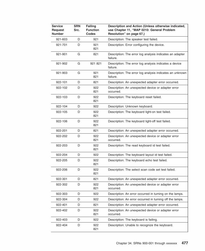
ServiceRequestNumber
SRNSrc.
FailingFunctionCodes
Description and Action (Unless otherwise indicated,use Chapter 11, “MAP 0210: General ProblemResolution” on page 67.)
921-603 D 921 Description: The speaker test failed.
921-701 D 921821
Description: Error configuring the device.
921-901 G 821 Description: The error log analysis indicates an adapterfailure.
921-902 G 921 821 Description: The error log analysis indicates a devicefailure.
921-903 G 921821
Description: The error log analysis indicates an unknownfailure.
922-101 D 821 Description: An unexpected adapter error occurred.
922-102 D 922821
Description: An unexpected device or adapter erroroccurred.
922-103 D 922821
Description: The keyboard reset failed.
922-104 D 922 Description: Unknown keyboard.
922-105 D 922821
Description: The keyboard light-on test failed.
922-106 D 922821
Description: The keyboard light-off test failed.
922-201 D 821 Description: An unexpected adapter error occurred.
922-202 D 922821
Description: An unexpected device or adapter erroroccurred.
922-203 D 922821
Description: The read keyboard id test failed.
922-204 D 922 Description: The keyboard layout id test failed.
922-205 D 922821
Description: The keyboard echo test failed.
922-206 D 922821
Description: The select scan code set test failed.
922-301 D 821 Description: An unexpected adapter error occurred.
922-302 D 922821
Description: An unexpected device or adapter erroroccurred.
922-303 D 922 Description: An error occurred in turning on the lamps.
922-304 D 922 Description: An error occurred in turning off the lamps.
922-401 D 821 Description: An unexpected adapter error occurred.
922-402 D 922821
Description: An unexpected device or adapter erroroccurred.
922-403 D 922 Description: The keyboard is failing.
922-404 D 922821
Description: Unable to recognize the keyboard.
Chapter 34. SRNs 900-001 through xxxxxxx 477

ServiceRequestNumber
SRNSrc.
FailingFunctionCodes
Description and Action (Unless otherwise indicated,use Chapter 11, “MAP 0210: General ProblemResolution” on page 67.)
922-501 D 821 Description: An unexpected adapter error occurred.
922-502 D 922821
Description: An unexpected device or adapter erroroccurred.
922-503 D 921 Description: The auto-click cannot be disabled.
922-504 D 922 Description: The auto-click cannot be enabled.
922-505 D 922 Description: Unable to recognize the keyboard.
922-601 D 821 Description: An unexpected adapter error occurred.
922-602 D 922821
Description: An unexpected device or adapter erroroccurred.
922-603 D 922 Description: The speaker test failed.
922-701 D 922821
Description: Error configuring the device.
922-901 G 821 Description: The error log indicates an adapter failed.
922-902 G 922821
Description: The error log indicates a device failed.
922-903 G 922821
Description: The error log analysis indicates an unknownfailure.
923-101 D 821 Description: An unexpected adapter error occurred.
923-102 D 923821
Description: An unexpected device or adapter erroroccurred.
923-103 D 923821
Description: The keyboard reset failed.
923-104 D 923 Description: Unknown keyboard.
923-105 D 923821
Description: The keyboard light-on test failed.
923-106 D 923821
Description: The keyboard light-off test failed.
923-201 D 821 Description: An unexpected adapter error occurred.
923-202 D 923821
Description: An unexpected device or adapter erroroccurred.
923-203 D 923821
Description: The read keyboard id test failed.
923-204 D 923 Description: The keyboard layout id test failed.
923-205 D 923821
Description: The keyboard echo test failed.
923-206 D 923821
Description: The select scan code set test failed.
923-301 D 821 Description: An unexpected adapter error occurred.
923-302 D 923821
Description: An unexpected device or adapter erroroccurred.
478 Diagnostic Information for Multiple Bus Systems

ServiceRequestNumber
SRNSrc.
FailingFunctionCodes
Description and Action (Unless otherwise indicated,use Chapter 11, “MAP 0210: General ProblemResolution” on page 67.)
923-303 D 923 Description: An error occurred in turning on the lamps.
923-304 D 923 Description: An error occurred in turning off the lamps.
923-401 D 821 Description: An unexpected adapter error occurred.
923-402 D 923821
Description: An unexpected device or adapter erroroccurred.
923-403 D 923 Description: The keyboard is failing.
923-404 D 923821
Description: Unable to recognize the keyboard.
923-501 D 821 Description: An unexpected adapter error occurred.
923-502 D 923821
Description: An unexpected device or adapter erroroccurred.
923-503 D 923 Description: The auto-click cannot be disabled.
923-504 D 923 Description: The auto-click cannot be enabled.
923-505 D 923 Description: Unable to recognize the keyboard.
923-601 D 821 Description: An unexpected adapter error occurred.
923-602 D 923821
Description: An unexpected device or adapter erroroccurred.
923-603 D 923 Description: The speaker test failed.
922-701 D 923821
Description: Error configuring the device.
923-901 G 821 Description: The error log indicates an adapter failed.
923-902 G 923821
Description: The error log analysis indicates a devicefailure.
923-903 G 923821
Description: The error log analysis indicates an unknownfailure.
925-111 D 925823
Description: An unexpected device error occurred.
925-112 D 925823
Description: The device disable test failed.
925-113 D 925 Description: Could not reset the device.
925-114 D 925823
Description: The Read Status command failed.
925-115 D 925 Description: The device test failed.
925-116 D 925 Description: Unknown Mouse type.
925-117 D 925823
Description: Mouse wrap mode failed.
925-118 D 925823
Description: Error setting mouse parameters.
Chapter 34. SRNs 900-001 through xxxxxxx 479

ServiceRequestNumber
SRNSrc.
FailingFunctionCodes
Description and Action (Unless otherwise indicated,use Chapter 11, “MAP 0210: General ProblemResolution” on page 67.)
925-121to
925-171
D 925 Description: The device test failed.
925-200 D 925823
Description: A software error was caused by a hardwarefailure.
925-300 G 925 Description: The error log analysis indicates a hardwarefailure.
925-301 G 925823
Description: The error log analysis indicates a hardwarefailure.
926-104 D 926159
Description: Input device cable is not attached.
926-111 D 824 Description: Adapter error.
926-112to
926-115
D 926824
Description: Device, adapter or tablet reset failed.
926-116 D 159 Description: The input device cable is not attached.
926-119 D 188 Description: The input device cable is not attached.
926-121 D 824 Description: Adapter error.
926-131 D 824926
Description: Adapter error.
926-132to
926-135
D 926 Description: Device or adapter error.
926-141 D 824926
Description: Adapter error.
926-142to
926-161
D 926 Description: Device or adapter error.
926-162 D 159926
Description: Device or adapter error.
926-163 D 159926
Description: Error in turning off input device LED.
926-164 D 159926
Description: Error in turning off input device LED.
926-165 D 159 Description: The input device cable is not attached.
926-166 D 188926
Description: Device or adapter error.
926-167 D 188926
Description: Error in turning off input device LED.
926-168 D 188926
Description: Error in turning on input device LED.
926-169 D 188 Description: The input device cable is not attached.
480 Diagnostic Information for Multiple Bus Systems
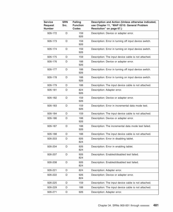
ServiceRequestNumber
SRNSrc.
FailingFunctionCodes
Description and Action (Unless otherwise indicated,use Chapter 11, “MAP 0210: General ProblemResolution” on page 67.)
926-172 D 159926
Description: Device or adapter error.
926-173 D 159926
Description: Error in turning off input device switch.
926-174 D 159926
Description: Error in turning on input device switch.
926-175 D 159 Description: The input device cable is not attached.
926-176 D 188926
Description: Device or adapter error.
926-177 D 188926
Description: Error in turning off input device switch.
926-178 D 188926
Description: Error in turning on input device switch.
926-179 D 188 Description: The input device cable is not attached.
926-181 D 824926
Description: Adapter error.
926-182 D 159926
Description: Device or adapter error.
926-183 D 159926
Description: Error in incremental data mode test.
926-184 D 159 Description: The input device cable is not attached.
926-186 D 188926
Description: Device or adapter error.
926-187 D 188926
Description: The incremental data mode test failed.
926-188 D 188 Description: The input device cable is not attached.
926-203 D 926824
Description: Error in disabling tablet.
926-204 D 926824
Description: Error in enabling tablet.
926-207 D 926824
Description: Enabled/disabled test failed.
926-208 D 926824
Description: Enabled/disabled test failed.
926-221 D 824 Description: Adapter error.
926-222 D 926824
Description: Device or adapter error.
926-225 D 159 Description: The input device cable is not attached.
926-229 D 188 Description: The input device cable is not attached.
926-271 D 926 Description: Adapter error.
Chapter 34. SRNs 900-001 through xxxxxxx 481

ServiceRequestNumber
SRNSrc.
FailingFunctionCodes
Description and Action (Unless otherwise indicated,use Chapter 11, “MAP 0210: General ProblemResolution” on page 67.)
926-272 D 159926
Description: Device or adapter error.
926-273 D 159 Description: Error in input device switch test.
926-274 D 159 Description: The input device cable is not attached.
926-276 D 188926
Description: Device or adapter error.
926-277 D 188926
Description: Error in input device switch test.
926-278 D 188 Description: Input device cable is not attached.
926-281 D 824926
Description: Adapter error.
926-282 D 159926
Description: Device or adapter error.
926-283 D 159926
Description: Error in incremental data mode test.
926-284 D 159 Description: The input device cable is not attached.
926-286 D 188926
Description: Device or adapter error.
926-287 D 188926
Description: Error in incremental data mode test.
926-288 D 188 Description: The input device cable is not attached.
927-104 D 927159
Description: The input device cable is not attached.
927-111 D 824 Description: Adapter error.
927-112 D 927824
Description: Device or adapter error.
927-113 D 927824
Description: Tablet reset failed.
927-114 D 927824
Description: The read configuration test failed.
927-115 D 927824
Description: The read status test failed.
927-116 D 159 Description: The input device cable is not attached.
927-119 D 188 Description: The input device cable is not attached.
927-121 D 824 Description: Adapter error.
927-122 D 927824
Description: Device or adapter error.
927-125 D 927824
Description: The input device cable is not attached.
927-131 D 824927
Description: Adapter error.
482 Diagnostic Information for Multiple Bus Systems

ServiceRequestNumber
SRNSrc.
FailingFunctionCodes
Description and Action (Unless otherwise indicated,use Chapter 11, “MAP 0210: General ProblemResolution” on page 67.)
927-132 D 927 Description: Device or adapter error.
927-133 D 927 Description: The set conversion mode test failed.
927-134 D 927 Description: The set resolution test failed.
927-135 D 927 Description: The read status test failed.
927-141 D 824927
Description: Adapter error.
927-142 D 927 Description: Device or adapter error.
927-143 D 927 Description: Error in tablet indicator.
927-161 D 927 Description: Adapter error.
927-162 D 159927
Description: Device or adapter error.
927-163 D 159927
Description: Error in turning off input device LED.
927-164 D 159927
Description: Error in turning on input device LED.
927-165 D 159 Description: The input device cable is not attached.
927-166 D 188927
Description: Device or adapter error.
927-167 D 188927
Description: Error in turning off input device LED.
927-168 D 188927
Description: Error in turning on input device LED.
927-169 D 188 Description: The input device cable is not attached.
927-171 D 927 Description: Adapter error.
927-172 D 159927
Description: Device or adapter error.
927-173 D 159927
Description: Error in turning off input device switch.
927-174 D 159927
Description: Error in turning on input device switch.
927-175 D 159 Description: The input device cable is not attached.
927-176 D 188927
Description: Device or adapter error.
927-177 D 188927
Description: Error in turning off input device switch.
927-178 D 188927
Description: Error in turning on input device switch.
927-179 D 188 Description: The input device cable is not attached.
927-181 D 824927
Description: Adapter error.
Chapter 34. SRNs 900-001 through xxxxxxx 483

ServiceRequestNumber
SRNSrc.
FailingFunctionCodes
Description and Action (Unless otherwise indicated,use Chapter 11, “MAP 0210: General ProblemResolution” on page 67.)
927-182 D 159927
Description: Device or adapter error.
927-183 D 159927
Description: Error in incremental data mode test.
927-184 D 159 Description: The input device cable is not attached.
927-186 D 188927
Description: Device or adapter error.
927-187 D 188927
Description: Error in incremental data mode test.
927-188 D 188 Description: The input device cable is not attached.
927-203 D 927824
Description: Error in disabling tablet.
927-204 D 927824
Description: Error in enabling tablet.
927-221 D 824 Description: Adapter error.
927-222 D 927824
Description: Device or adapter error.
927-225 D 159 Description: The input device cable is not attached.
927-229 D 188 Description: The input device cable is not attached.
927-271 D 927 Description: Adapter error.
927-272 D 159927
Description: Device or adapter error.
927-273 D 159927
Description: Error in input device switch test.
927-274 D 159 Description: The input device cable is not attached.
927-276 D 188927
Description: Device or adapter error.
927-277 D 188927
Description: Error in input device switch test.
927-278 D 188 Description: The input device cable is not attached.
927-281 D 824927
Description: Adapter error.
927-282 D 159927
Description: Device or adapter error.
927-283 D 159927
Description: Error in incremental data mode test.
927-284 D 159 Description: The input device cable is not attached.
927-286 D 188927
Description: Device or adapter error.
927-287 D 188927
Description: Error in incremental data mode test.
484 Diagnostic Information for Multiple Bus Systems

ServiceRequestNumber
SRNSrc.
FailingFunctionCodes
Description and Action (Unless otherwise indicated,use Chapter 11, “MAP 0210: General ProblemResolution” on page 67.)
927-288 D 188 Description: The input device cable is not attached.
929-201 D 929 Description: Failed to register input ring.
929-202 D 929 Description: Unable to read event from the device.
929-203 D 929 Description: Unable to communicate with the device.
929-204 D 929 Description: Cannot set the device granularity.
929-210 D 929 Description: Device or adapter failure.
929-212 D 929 Description: Cannot set the device to HIGH granularity.
929-213 D 929 Description: Cannot set the device to LOW granularity.
929-299 D software929
Description: Error unconfiguring the device.
929-301 D software929
Description: Error configuring the device.
930-201 D 930 Description: Device or adapter failure.
930-210 G 930 Description: Unable to turn the lights on.
930-220 G 930 Description: Unable to turn the lights off hardwarefailure.
930-230 D 930 Description: Unable to turn the lights off.
930-241 D 930 Description: Unable to turn a single light-on.
930-242 D 930 Description: Device or adapter failure.
930-243 D 930 Description: Device or adapter failure.
930-261 D 930 Description: Cable test failed.
930-262 D 930 Description: Cable test failed.
930-299 D software930
Description: Error unconfiguring the device.
930-301 D software930
Description: Error configuring the device.
935-101to
935-102
D 935828
Description: The diskette-drive select or deselect testfailed.
935-103to
935-107
D 935828
Description: The diskette failed.
935-108 D 935 Description: The diskette read test failed.
935-109to
935-110
D 935828
Description: The read/write on the diskette drive failed.
935-111to
935-114
D 935 Description: A diskette drive test failed.
Chapter 34. SRNs 900-001 through xxxxxxx 485
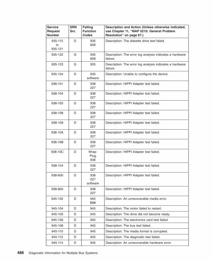
ServiceRequestNumber
SRNSrc.
FailingFunctionCodes
Description and Action (Unless otherwise indicated,use Chapter 11, “MAP 0210: General ProblemResolution” on page 67.)
935-115to
935-121
D 935828
Description: The diskette drive test failed.
935-122 G 935828
Description: The error log analysis indicates a hardwarefailure.
935-123 G 935 Description: The error log analysis indicates a hardwarefailure.
935-124 D 935software
Description: Unable to configure the device.
938-101 D 938227
Description: HIPPI Adapter test failed.
938-104 D 938227
Description: HIPPI Adapter test failed.
938-105 D 938227
Description: HIPPI Adapter test failed.
938-108 D 938227
Description: HIPPI Adapter test failed.
938-109 D 938227
Description: HIPPI Adapter test failed.
938-10A D 938227
Description: HIPPI Adapter test failed.
938-10B D 938227
Description: HIPPI Adapter test failed.
938-10C D Wrap-Plug938
Description: HIPPI Adapter test failed.
938-124 D 938227
Description: HIPPI Adapter test failed.
938-600 D 938227
software
Description: HIPPI Adapter test failed.
938-800 D 938227
Description: HIPPI Adapter test failed.
945-102 D 945B88
Description: An unrecoverable media error.
945-104 D 945 Description: The motor failed to restart.
945-105 D 945 Description: The drive did not become ready.
945-106 D 945 Description: The electronics card test failed.
945-108 D 945 Description: The bus test failed.
945-110 D 945 Description: The media format is corrupted.
945-112 D 945 Description: The diagnostic test failed.
945-114 D 945 Description: An unrecoverable hardware error.
486 Diagnostic Information for Multiple Bus Systems

ServiceRequestNumber
SRNSrc.
FailingFunctionCodes
Description and Action (Unless otherwise indicated,use Chapter 11, “MAP 0210: General ProblemResolution” on page 67.)
945-116 D Description: A protocol error. Action: Check the levels ofthe device, adapter, diagnostic software, and applicationsoftware to ensure they are all compatible. If you do notfind a problem, call your support person.
945-117 D 945 Description: A write-protect error occurred.
945-118 D 945B88
Description: A SCSI command timeout.
945-120 D 945 Description: A SCSI busy or command error.
945-122 D 945 Description: A SCSI reservation conflict error.
945-124 D 945 Description: A SCSI check condition error.
945-126 D 945B88
Description: A software error was caused by a hardwarefailure.
945-128 G 945 Description: The error log analysis indicates a hardwarefailure.
945-129 G 945 Description: Error log analysis indicates a SCSI busproblem.
945-130 G 945B88
Description: Error log analysis indicates a problemreported by the disk drive’s self-monitoring function.
945-132 D 945 Description: A disk drive hardware error occurred.
945-133 D 945 Description: Use the subsystem guide to completediagnostics.
945-134 D B88software
Description: The adapter failed to configure.
945-135 D 945B88
software
Description: The device failed to configure.
945-136 D 945 Description: The certify operation failed.
945-137 D 945B88190
Description: Unit attention condition has occurred on theSend Diagnostic command.
945-138 D 190 Description: Error log indicates that the disk is operatingat higher than recommended temperatures.
945-139 D 945 Description: Error configuring or opening device. Action:Use Chapter 11, “MAP 0210: General ProblemResolution” on page 67.
945-640 G 640 Description: Error Log Analysis indicates a path error.
946-111 D 946227
Description: Cannot run the test because the devicedriver detected a hardware error.
946-114 D 946 Description: The register verification test failed.
946-121 D 946227
Description: Cannot run the test because the devicedriver detected a hardware error.
Chapter 34. SRNs 900-001 through xxxxxxx 487

ServiceRequestNumber
SRNSrc.
FailingFunctionCodes
Description and Action (Unless otherwise indicated,use Chapter 11, “MAP 0210: General ProblemResolution” on page 67.)
946-122 D 946227
Description: The data wrap communications test failed.
946-123 D 946227
Description: The modem control line test failed.
946-131 D 946 Description: Cannot run the test because the devicedriver detected a hardware error.
946-132 D 946227
Description: The data wrap communications test failed.
946-133 D 946 Description: The modem control line test failed.
946-161 D 252 Description: Could not do the test because the devicedriver detected a hardware error.
946-162 D 252 Description: The data wrap communication test failed.
946-163 D 252 Description: The modem control line test failed.
946-171 D 259 Description: Cannot run the test because the devicedriver detected a hardware error.
946-172 D 259 Description: The data wrap communications test failed.
946-173 D 259 Description: The modem control line test failed.
946-181 D 261 Description: Cannot run the test because the devicedriver detected a hardware error.
946-182 D 261 Description: The data wrap communications test failed.
946-183 D 261 Description: The modem control line test failed.
946-271 D 946259
Description: Cannot run the test because the devicedriver detected a hardware error.
946-272 D 946259
Description: The data wrap communication test failed.
946-273 D 946259
Description: The modem control line test failed.
946-281 D 946261
Description: Cannot run the test because the devicedriver detected a hardware error.
946-282 D 946261
Description: The data wrap communications test failed.
946-283 D 946261
Description: The modem control line test failed.
946-321 D 946 Description: Cannot run the test because the devicedriver detected a hardware error.
946-322 D 946 Description: The data wrap communications test failed.
946-323 D 946 Description: The modem control line test failed.
946-331 D 946 Description: Cannot run the test because the devicedriver detected a hardware error.
946-332 D 946 Description: The data wrap communications test failed.
488 Diagnostic Information for Multiple Bus Systems

ServiceRequestNumber
SRNSrc.
FailingFunctionCodes
Description and Action (Unless otherwise indicated,use Chapter 11, “MAP 0210: General ProblemResolution” on page 67.)
946-333 D 946 Description: The modem control line test failed.
946-371 D 946 Description: Cannot run the test because the devicedriver detected a hardware error.
946-372 D 946 Description: The data wrap communications test failed.
946-373 D 946 Description: The modem control line test failed.
946-381 D 946 Description: Cannot run the test because the devicedriver detected a hardware error.
946-382 D 946 Description: The data wrap communications test failed.
946-383 D 946 Description: The modem control line test failed.
946-481 D D56 Description: Could not do the test because the devicedriver detected a hardware error.
946-482 D D56 Description: The data wrap communication test failed.
946-483 D D56 Description: The modem control line test failed.
946-581 D 946D56
Description: Could not do the test because the devicedriver detected a hardware error.
946-582 D 946D56
Description: The data wrap communication test failed.
946-583 D 946D56
Description: The modem control line test failed.
946-901to
946-920
D software946
Description: An unexpected error occurred that can beattributed to software or hardware. Action: Rundiagnostics from a source other than from the disk or anetwork. If the same error occurs or if the original SRNwas not obtained from disk or a network baseddiagnostics, use MAP 210 with a FFC of 946; otherwise,suspect a software problem.
946-921 D 946software
Description: The adapter failed to configure.
946-922to
946-924
D software946
Description: An unexpected error occurred that can beattributed to software or hardware. Action: Rundiagnostics from a source other than from the disk or anetwork. If the same error occurs or if the original SRNwas not obtained from disk or a network baseddiagnostics, use MAP 210 with a FFC of 946; otherwise,suspect a software problem.
946-925 D 946software
Description: The adapter failed to configure.
946-926to
946-943
D software946
Description: An unexpected error occurred that can beattributed to software or hardware. Action: Rundiagnostics from a source other than from the disk or anetwork. If the same error occurs or if the original SRNwas not obtained from disk or a network baseddiagnostics, use MAP 210 with a FFC of 946; otherwise,suspect a software problem.
Chapter 34. SRNs 900-001 through xxxxxxx 489

ServiceRequestNumber
SRNSrc.
FailingFunctionCodes
Description and Action (Unless otherwise indicated,use Chapter 11, “MAP 0210: General ProblemResolution” on page 67.)
947-102 D 947B88
Description: An unrecoverable media error.
947-104 D 947 Description: The motor failed to restart.
947-105 D 947 Description: The drive did not become ready.
947-106 D 947 Description: The electronics card test failed.
947-108 D 947 Description: The bus test failed.
947-110 D 947 Description: The media format is corrupted.
947-112 D 947 Description: The diagnostic test failed.
947-114 D 947 Description: An unrecoverable hardware error.
947-116 D Description: A protocol error. Action: Check the levels ofthe device, adapter, diagnostic software, and applicationsoftware to ensure they are all compatible. If you do notfind a problem, call your support person.
947-117 D 947 Description: A write-protect error occurred.
947-118 D 947B88
Description: A SCSI command timeout.
947-120 D 947 Description: A SCSI busy or command error.
947-122 D 947 Description: A SCSI reservation conflict error.
947-124 D 947 Description: A SCSI check condition error.
947-126 D 947B88
Description: A software error was caused by a hardwarefailure.
947-128 G 947 Description: The error log analysis indicates a hardwarefailure.
947-129 G 947 Description: Error log analysis indicates a SCSI busproblem.
947-130 G 947B88
Description: Error log analysis indicates a problemreported by the disk drive’s self-monitoring function.
947-132 D 947 Description: A disk drive hardware error occurred.
947-133 D 947 Description: Use the subsystem guide to completediagnostics.
947-134 D B88software
Description: The adapter failed to configure.
947-135 D 947B88
software
Description: The device failed to configure.
947-136 D 947 Description: The certify operation failed.
947-137 D 947B88190
Description: Unit attention condition has occurred on theSend Diagnostic command.
947-138 D 190 Description: Error log indicates that the disk is operatingat higher than recommended temperatures.
490 Diagnostic Information for Multiple Bus Systems
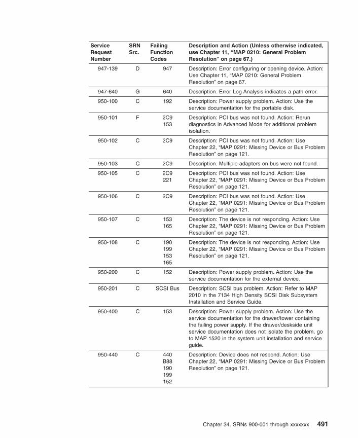
ServiceRequestNumber
SRNSrc.
FailingFunctionCodes
Description and Action (Unless otherwise indicated,use Chapter 11, “MAP 0210: General ProblemResolution” on page 67.)
947-139 D 947 Description: Error configuring or opening device. Action:Use Chapter 11, “MAP 0210: General ProblemResolution” on page 67.
947-640 G 640 Description: Error Log Analysis indicates a path error.
950-100 C 192 Description: Power supply problem. Action: Use theservice documentation for the portable disk.
950-101 F 2C9153
Description: PCI bus was not found. Action: Rerundiagnostics in Advanced Mode for additional problemisolation.
950-102 C 2C9 Description: PCI bus was not found. Action: UseChapter 22, “MAP 0291: Missing Device or Bus ProblemResolution” on page 121.
950-103 C 2C9 Description: Multiple adapters on bus were not found.
950-105 C 2C9221
Description: PCI bus was not found. Action: UseChapter 22, “MAP 0291: Missing Device or Bus ProblemResolution” on page 121.
950-106 C 2C9 Description: PCI bus was not found. Action: UseChapter 22, “MAP 0291: Missing Device or Bus ProblemResolution” on page 121.
950-107 C 153165
Description: The device is not responding. Action: UseChapter 22, “MAP 0291: Missing Device or Bus ProblemResolution” on page 121.
950-108 C 190199153165
Description: The device is not responding. Action: UseChapter 22, “MAP 0291: Missing Device or Bus ProblemResolution” on page 121.
950-200 C 152 Description: Power supply problem. Action: Use theservice documentation for the external device.
950-201 C SCSI Bus Description: SCSI bus problem. Action: Refer to MAP2010 in the 7134 High Density SCSI Disk SubsystemInstallation and Service Guide.
950-400 C 153 Description: Power supply problem. Action: Use theservice documentation for the drawer/tower containingthe failing power supply. If the drawer/deskside unitservice documentation does not isolate the problem, goto MAP 1520 in the system unit installation and serviceguide.
950-440 C 440B88190199152
Description: Device does not respond. Action: UseChapter 22, “MAP 0291: Missing Device or Bus ProblemResolution” on page 121.
Chapter 34. SRNs 900-001 through xxxxxxx 491

ServiceRequestNumber
SRNSrc.
FailingFunctionCodes
Description and Action (Unless otherwise indicated,use Chapter 11, “MAP 0210: General ProblemResolution” on page 67.)
950-441 C 440B88190199152
Description: Device does not respond. Action: UseChapter 22, “MAP 0291: Missing Device or Bus ProblemResolution” on page 121.
950-442 C 440B88190199152
Description: Device does not respond. Action: UseChapter 22, “MAP 0291: Missing Device or Bus ProblemResolution” on page 121.
950-443 C 440B88190199152
Description: Device does not respond. Action: UseChapter 22, “MAP 0291: Missing Device or Bus ProblemResolution” on page 121.
950-500 C 152 Description: Power supply problem. Action: Use theservice documentation for the system unit, rack, ordrawer that contains the missing device.
950-56D C 58DB88190152
Description: The device is not responding. Action: UseChapter 22, “MAP 0291: Missing Device or Bus ProblemResolution” on page 121.
950-58D C 58DB88190152
Description: The device is not responding. Action: UseChapter 22, “MAP 0291: Missing Device or Bus ProblemResolution” on page 121.
950-61D C 61DB88190152
Description: The device is not responding. Action: UseChapter 22, “MAP 0291: Missing Device or Bus ProblemResolution” on page 121.
950-638 C 638B88277190152
Description: The SCSI device is not responding. Action:Use Chapter 22, “MAP 0291: Missing Device or BusProblem Resolution” on page 121.
950-639 C 639B88190152
Description: The device is not responding. Action: UseChapter 22, “MAP 0291: Missing Device or Bus ProblemResolution” on page 121.
950-63A C 63AB88190152
Description: Device does not respond. Action: UseChapter 22, “MAP 0291: Missing Device or Bus ProblemResolution” on page 121.
950-63B C 63BB88190152
Description: Device does not respond. Action: UseChapter 22, “MAP 0291: Missing Device or Bus ProblemResolution” on page 121.
492 Diagnostic Information for Multiple Bus Systems

ServiceRequestNumber
SRNSrc.
FailingFunctionCodes
Description and Action (Unless otherwise indicated,use Chapter 11, “MAP 0210: General ProblemResolution” on page 67.)
950-63C C 63CB88190152
Description: Device does not respond. Action: UseChapter 22, “MAP 0291: Missing Device or Bus ProblemResolution” on page 121.
950-63D C 63DB88190152
Description: Device does not respond. Action: UseChapter 22, “MAP 0291: Missing Device or Bus ProblemResolution” on page 121.
950-63E C 63EB88277190152
Description: Device does not respond. Action: UseChapter 22, “MAP 0291: Missing Device or Bus ProblemResolution” on page 121.
950-63F C 63FB88190152
Description: Device does not respond. Action: UseChapter 22, “MAP 0291: Missing Device or Bus ProblemResolution” on page 121.
950-640 C 640B88190152
Description: The device is not responding. Action: UseChapter 22, “MAP 0291: Missing Device or Bus ProblemResolution” on page 121.
950-664 C 664B88190152
Description: The device is not responding. Action: UseChapter 22, “MAP 0291: Missing Device or Bus ProblemResolution” on page 121.
950-678 C 678B88190152
Description: The SCSI Tape Drive is not responding.Action: Use Chapter 22, “MAP 0291: Missing Device orBus Problem Resolution” on page 121.
950-679 C 679B88190152
Description: The SCSI Disk Drive is not responding.Action: Use Chapter 22, “MAP 0291: Missing Device orBus Problem Resolution” on page 121.
950-681 C 6812E7190152
Description: The SCSI Disk Drive is not responding.Action: Use Chapter 22, “MAP 0291: Missing Device orBus Problem Resolution” on page 121.
950-700 C 700B88190152
Description: The device is not responding. Action: UseChapter 22, “MAP 0291: Missing Device or Bus ProblemResolution” on page 121.
950-701 C 701B88190152
Description: The device is not responding. Action: UseChapter 22, “MAP 0291: Missing Device or Bus ProblemResolution” on page 121.
Chapter 34. SRNs 900-001 through xxxxxxx 493
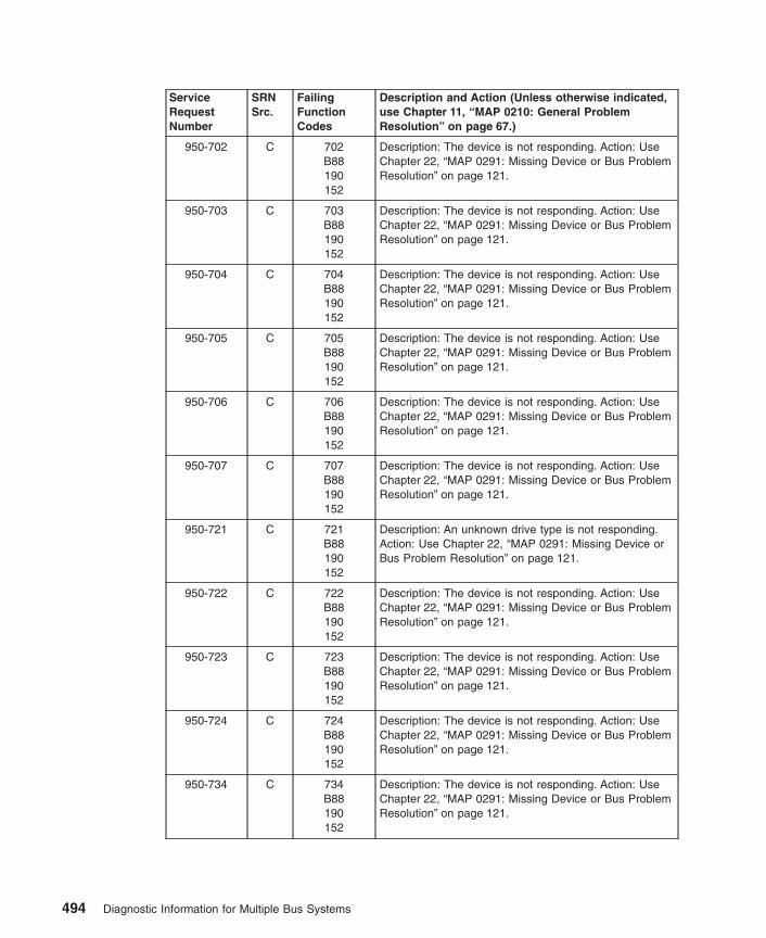
ServiceRequestNumber
SRNSrc.
FailingFunctionCodes
Description and Action (Unless otherwise indicated,use Chapter 11, “MAP 0210: General ProblemResolution” on page 67.)
950-702 C 702B88190152
Description: The device is not responding. Action: UseChapter 22, “MAP 0291: Missing Device or Bus ProblemResolution” on page 121.
950-703 C 703B88190152
Description: The device is not responding. Action: UseChapter 22, “MAP 0291: Missing Device or Bus ProblemResolution” on page 121.
950-704 C 704B88190152
Description: The device is not responding. Action: UseChapter 22, “MAP 0291: Missing Device or Bus ProblemResolution” on page 121.
950-705 C 705B88190152
Description: The device is not responding. Action: UseChapter 22, “MAP 0291: Missing Device or Bus ProblemResolution” on page 121.
950-706 C 706B88190152
Description: The device is not responding. Action: UseChapter 22, “MAP 0291: Missing Device or Bus ProblemResolution” on page 121.
950-707 C 707B88190152
Description: The device is not responding. Action: UseChapter 22, “MAP 0291: Missing Device or Bus ProblemResolution” on page 121.
950-721 C 721B88190152
Description: An unknown drive type is not responding.Action: Use Chapter 22, “MAP 0291: Missing Device orBus Problem Resolution” on page 121.
950-722 C 722B88190152
Description: The device is not responding. Action: UseChapter 22, “MAP 0291: Missing Device or Bus ProblemResolution” on page 121.
950-723 C 723B88190152
Description: The device is not responding. Action: UseChapter 22, “MAP 0291: Missing Device or Bus ProblemResolution” on page 121.
950-724 C 724B88190152
Description: The device is not responding. Action: UseChapter 22, “MAP 0291: Missing Device or Bus ProblemResolution” on page 121.
950-734 C 734B88190152
Description: The device is not responding. Action: UseChapter 22, “MAP 0291: Missing Device or Bus ProblemResolution” on page 121.
494 Diagnostic Information for Multiple Bus Systems
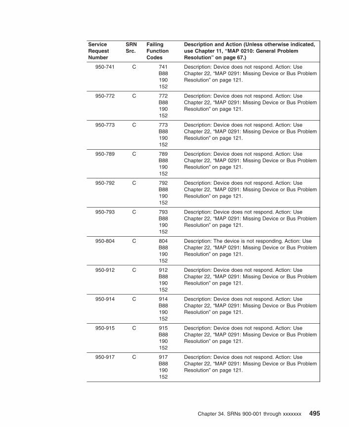
ServiceRequestNumber
SRNSrc.
FailingFunctionCodes
Description and Action (Unless otherwise indicated,use Chapter 11, “MAP 0210: General ProblemResolution” on page 67.)
950-741 C 741B88190152
Description: Device does not respond. Action: UseChapter 22, “MAP 0291: Missing Device or Bus ProblemResolution” on page 121.
950-772 C 772B88190152
Description: Device does not respond. Action: UseChapter 22, “MAP 0291: Missing Device or Bus ProblemResolution” on page 121.
950-773 C 773B88190152
Description: Device does not respond. Action: UseChapter 22, “MAP 0291: Missing Device or Bus ProblemResolution” on page 121.
950-789 C 789B88190152
Description: Device does not respond. Action: UseChapter 22, “MAP 0291: Missing Device or Bus ProblemResolution” on page 121.
950-792 C 792B88190152
Description: Device does not respond. Action: UseChapter 22, “MAP 0291: Missing Device or Bus ProblemResolution” on page 121.
950-793 C 793B88190152
Description: Device does not respond. Action: UseChapter 22, “MAP 0291: Missing Device or Bus ProblemResolution” on page 121.
950-804 C 804B88190152
Description: The device is not responding. Action: UseChapter 22, “MAP 0291: Missing Device or Bus ProblemResolution” on page 121.
950-912 C 912B88190152
Description: Device does not respond. Action: UseChapter 22, “MAP 0291: Missing Device or Bus ProblemResolution” on page 121.
950-914 C 914B88190152
Description: Device does not respond. Action: UseChapter 22, “MAP 0291: Missing Device or Bus ProblemResolution” on page 121.
950-915 C 915B88190152
Description: Device does not respond. Action: UseChapter 22, “MAP 0291: Missing Device or Bus ProblemResolution” on page 121.
950-917 C 917B88190152
Description: Device does not respond. Action: UseChapter 22, “MAP 0291: Missing Device or Bus ProblemResolution” on page 121.
Chapter 34. SRNs 900-001 through xxxxxxx 495

ServiceRequestNumber
SRNSrc.
FailingFunctionCodes
Description and Action (Unless otherwise indicated,use Chapter 11, “MAP 0210: General ProblemResolution” on page 67.)
950-918 C 918B88190152
Description: Device does not respond. Action: UseChapter 22, “MAP 0291: Missing Device or Bus ProblemResolution” on page 121.
950-935 C 935B88190152
Description: Device does not respond. Action: UseChapter 22, “MAP 0291: Missing Device or Bus ProblemResolution” on page 121.
950-936 C 936B88190152
Description: Device does not respond. Action: UseChapter 22, “MAP 0291: Missing Device or Bus ProblemResolution” on page 121.
950-951 C 951B88190152
Description: Device does not respond. Action: UseChapter 22, “MAP 0291: Missing Device or Bus ProblemResolution” on page 121.
950-952 C 952B88190152
Description: Device does not respond. Action: UseChapter 22, “MAP 0291: Missing Device or Bus ProblemResolution” on page 121.
950-953 C 953B88190152
Description: Device does not respond. Action: UseChapter 22, “MAP 0291: Missing Device or Bus ProblemResolution” on page 121.
950-954 C 954B88190152
Description: Device does not respond. Action: UseChapter 22, “MAP 0291: Missing Device or Bus ProblemResolution” on page 121.
950-955 C 955B88190141152
Description: Device does not respond. Action: UseChapter 22, “MAP 0291: Missing Device or Bus ProblemResolution” on page 121.
950-956 C 956B88190152
Description: Device does not respond. Action: UseChapter 22, “MAP 0291: Missing Device or Bus ProblemResolution” on page 121.
950-959 C 959B88190152
Description: Device does not respond. Action: UseChapter 22, “MAP 0291: Missing Device or Bus ProblemResolution” on page 121.
950-960 C 960B88190152
Description: Device does not respond. Action: UseChapter 22, “MAP 0291: Missing Device or Bus ProblemResolution” on page 121.
496 Diagnostic Information for Multiple Bus Systems

ServiceRequestNumber
SRNSrc.
FailingFunctionCodes
Description and Action (Unless otherwise indicated,use Chapter 11, “MAP 0210: General ProblemResolution” on page 67.)
950-964 C 964B88190152
Description: The SCSI Tape Drive is not responding.Action: Use Chapter 22, “MAP 0291: Missing Device orBus Problem Resolution” on page 121.
950-968 C 968B88190152
Description: Device does not respond. Action: UseChapter 22, “MAP 0291: Missing Device or Bus ProblemResolution” on page 121.
950-970 C 970B88190152
Description: Device does not respond. Action: UseChapter 22, “MAP 0291: Missing Device or Bus ProblemResolution” on page 121.
950-971 C 971B88190152
Description: Device does not respond. Action: UseChapter 22, “MAP 0291: Missing Device or Bus ProblemResolution” on page 121.
950-972 C 972B88190152
Description: Device does not respond. Action: UseChapter 22, “MAP 0291: Missing Device or Bus ProblemResolution” on page 121.
950-974 C 974B88190152
Description: Device does not respond. Action: UseChapter 22, “MAP 0291: Missing Device or Bus ProblemResolution” on page 121.
950-981 C 981B88190152
Description: Device does not respond. Action: UseChapter 22, “MAP 0291: Missing Device or Bus ProblemResolution” on page 121.
950-984 C 984B88190152
Description: Device does not respond. Action: UseChapter 22, “MAP 0291: Missing Device or Bus ProblemResolution” on page 121.
950-986 C 986B88190152
Description: Device does not respond. Action: UseChapter 22, “MAP 0291: Missing Device or Bus ProblemResolution” on page 121.
950-987 C 987B88190152
Description: Device does not respond. Action: UseChapter 22, “MAP 0291: Missing Device or Bus ProblemResolution” on page 121.
950-989 C 989B88190152
Description: Device does not respond. Action: UseChapter 22, “MAP 0291: Missing Device or Bus ProblemResolution” on page 121.
Chapter 34. SRNs 900-001 through xxxxxxx 497

ServiceRequestNumber
SRNSrc.
FailingFunctionCodes
Description and Action (Unless otherwise indicated,use Chapter 11, “MAP 0210: General ProblemResolution” on page 67.)
950-990 C 990B88190152
Description: Device does not respond. Action: UseChapter 22, “MAP 0291: Missing Device or Bus ProblemResolution” on page 121.
950-991 C 991B88190152
Description: Device does not respond. Action: UseChapter 22, “MAP 0291: Missing Device or Bus ProblemResolution” on page 121.
950-994 C 994B88190152
Description: Device does not respond. Action: UseChapter 22, “MAP 0291: Missing Device or Bus ProblemResolution” on page 121.
950-995 C 995B88190152
Description: Device does not respond. Action: UseChapter 22, “MAP 0291: Missing Device or Bus ProblemResolution” on page 121.
950-998 C 998B88190152
Description: Device does not respond. Action: UseChapter 22, “MAP 0291: Missing Device or Bus ProblemResolution” on page 121.
950-xxxx C xxxxB88190152
Description: The device does not respond. Action: UseChapter 22, “MAP 0291: Missing Device or Bus ProblemResolution” on page 121.Note: xxxx corresponds to the last three or four digits ofthe SRN after the dash (-). If your 950-xxxx SRN is notlisted, substitute the last three or four digits of the SRNfor xxxx.
951-102 D 951B88
Description: An unrecoverable media error.
951-104 D 951 Description: The motor failed to restart.
951-105 D 951 Description: The drive did not become ready.
951-106 D 951 Description: The electronics card test failed.
951-108 D 951 Description: The bus test failed.
951-110 D 951 Description: The media format is corrupted.
951-112 D 951 Description: The diagnostic test failed.
951-114 D 951 Description: An unrecoverable hardware error.
951-116 D Description: A protocol error. Action: Check the levels ofthe device, adapter, diagnostic software, and applicationsoftware to ensure they are all compatible. If you do notfind a problem, call your support person.
951-117 D 951 Description: A write-protect error occurred.
951-118 D 951B88
Description: A SCSI command timeout.
951-120 D 951 Description: A SCSI busy or command error.
498 Diagnostic Information for Multiple Bus Systems
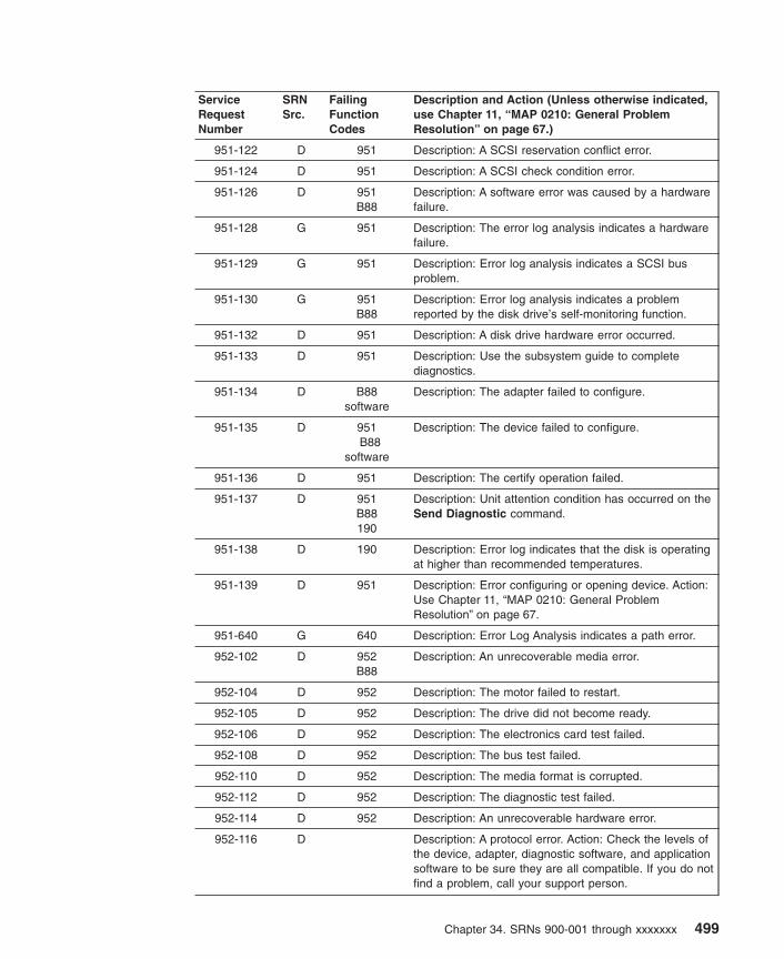
ServiceRequestNumber
SRNSrc.
FailingFunctionCodes
Description and Action (Unless otherwise indicated,use Chapter 11, “MAP 0210: General ProblemResolution” on page 67.)
951-122 D 951 Description: A SCSI reservation conflict error.
951-124 D 951 Description: A SCSI check condition error.
951-126 D 951B88
Description: A software error was caused by a hardwarefailure.
951-128 G 951 Description: The error log analysis indicates a hardwarefailure.
951-129 G 951 Description: Error log analysis indicates a SCSI busproblem.
951-130 G 951B88
Description: Error log analysis indicates a problemreported by the disk drive’s self-monitoring function.
951-132 D 951 Description: A disk drive hardware error occurred.
951-133 D 951 Description: Use the subsystem guide to completediagnostics.
951-134 D B88software
Description: The adapter failed to configure.
951-135 D 951B88
software
Description: The device failed to configure.
951-136 D 951 Description: The certify operation failed.
951-137 D 951B88190
Description: Unit attention condition has occurred on theSend Diagnostic command.
951-138 D 190 Description: Error log indicates that the disk is operatingat higher than recommended temperatures.
951-139 D 951 Description: Error configuring or opening device. Action:Use Chapter 11, “MAP 0210: General ProblemResolution” on page 67.
951-640 G 640 Description: Error Log Analysis indicates a path error.
952-102 D 952B88
Description: An unrecoverable media error.
952-104 D 952 Description: The motor failed to restart.
952-105 D 952 Description: The drive did not become ready.
952-106 D 952 Description: The electronics card test failed.
952-108 D 952 Description: The bus test failed.
952-110 D 952 Description: The media format is corrupted.
952-112 D 952 Description: The diagnostic test failed.
952-114 D 952 Description: An unrecoverable hardware error.
952-116 D Description: A protocol error. Action: Check the levels ofthe device, adapter, diagnostic software, and applicationsoftware to be sure they are all compatible. If you do notfind a problem, call your support person.
Chapter 34. SRNs 900-001 through xxxxxxx 499
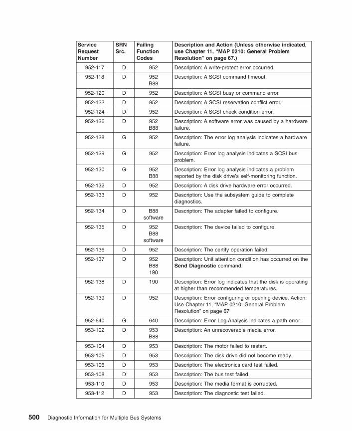
ServiceRequestNumber
SRNSrc.
FailingFunctionCodes
Description and Action (Unless otherwise indicated,use Chapter 11, “MAP 0210: General ProblemResolution” on page 67.)
952-117 D 952 Description: A write-protect error occurred.
952-118 D 952B88
Description: A SCSI command timeout.
952-120 D 952 Description: A SCSI busy or command error.
952-122 D 952 Description: A SCSI reservation conflict error.
952-124 D 952 Description: A SCSI check condition error.
952-126 D 952B88
Description: A software error was caused by a hardwarefailure.
952-128 G 952 Description: The error log analysis indicates a hardwarefailure.
952-129 G 952 Description: Error log analysis indicates a SCSI busproblem.
952-130 G 952B88
Description: Error log analysis indicates a problemreported by the disk drive’s self-monitoring function.
952-132 D 952 Description: A disk drive hardware error occurred.
952-133 D 952 Description: Use the subsystem guide to completediagnostics.
952-134 D B88software
Description: The adapter failed to configure.
952-135 D 952B88
software
Description: The device failed to configure.
952-136 D 952 Description: The certify operation failed.
952-137 D 952B88190
Description: Unit attention condition has occurred on theSend Diagnostic command.
952-138 D 190 Description: Error log indicates that the disk is operatingat higher than recommended temperatures.
952-139 D 952 Description: Error configuring or opening device. Action:Use Chapter 11, “MAP 0210: General ProblemResolution” on page 67
952-640 G 640 Description: Error Log Analysis indicates a path error.
953-102 D 953B88
Description: An unrecoverable media error.
953-104 D 953 Description: The motor failed to restart.
953-105 D 953 Description: The disk drive did not become ready.
953-106 D 953 Description: The electronics card test failed.
953-108 D 953 Description: The bus test failed.
953-110 D 953 Description: The media format is corrupted.
953-112 D 953 Description: The diagnostic test failed.
500 Diagnostic Information for Multiple Bus Systems

ServiceRequestNumber
SRNSrc.
FailingFunctionCodes
Description and Action (Unless otherwise indicated,use Chapter 11, “MAP 0210: General ProblemResolution” on page 67.)
953-114 D 953 Description: An unrecoverable hardware error.
953-116 D Description: A protocol error. Action: Check the levels ofthe device, adapter, diagnostic software, and applicationsoftware to be sure they are all compatible. If you do notfind a problem, call your support person.
953-117 D 953 Description: A write-protect error.
953-118 D 953B88
Description: A SCSI command timeout.
953-120 D 953 Description: A SCSI busy or command error.
953-122 D 953 Description: A SCSI reservation conflict error.
953-124 D 953 Description: A SCSI check condition error.
953-126 D 953B88
Description: A software error was caused by a hardwarefailure.
953-128 G 953 Description: The error log analysis indicates a hardwarefailure.
953-129 G 953 Description: Error log analysis indicates a SCSI busproblem.
953-130 G 953B88
Description: Error log analysis indicates a problemreported by the disk drive’s self-monitoring function.
953-132 D 953 Description: A disk drive hardware error occurred.
953-133 D 953 Description: Use the subsystem guide to completediagnostics.
953-134 D B88software
Description: The adapter failed to configure.
953-135 D 953B88
software
Description: The device failed to configure.
953-136 D 953 Description: The certify operation failed.
953-137 D 953B88190
Description: Unit attention condition has occurred on theSend Diagnostic command.
953-138 D 190 Description: Error log indicates that the disk is operatingat higher than recommended temperatures.
953-139 D 953 Description: Error configuring or opening device. Action:Use Chapter 11, “MAP 0210: General ProblemResolution” on page 67
953-640 G 640 Description: Error Log Analysis indicates a path error.
954-102 D 954B88
Description: An unrecoverable media error.
954-104 D 954 Description: Motor failed to restart.
954-105 D 954 Description: The disk drive did not become ready.
Chapter 34. SRNs 900-001 through xxxxxxx 501

ServiceRequestNumber
SRNSrc.
FailingFunctionCodes
Description and Action (Unless otherwise indicated,use Chapter 11, “MAP 0210: General ProblemResolution” on page 67.)
954-106 D 954 Description: Electronics card failure.
954-108 D 954 Description: Bus failure.
954-110 D 954 Description: The media format is corrupted.
954-112 D 954 Description: Diagnostic failure.
954-114 D 954 Description: An unrecoverable hardware error.
954-116 D Description: A protocol error was detected. Action: Checkthe levels of the device, adapter, diagnostic software,and application software, ensure that they are allcompatible. If you do not find a problem, call yoursupport person.
954-117 D 954 Description: write-protect error.
954-118 D 954B88
Description: SCSI command timeout.
954-120 D 954 Description: SCSI busy/command error.
954-122 D 954 Description: SCSI reservation conflict error.
954-124 D 954 Description: SCSI check condition error.
954-126 D 954B88
Description: Software error caused by hardware failure.
954-128 G 954 Description: Error log analysis indicates hardware failure.
954-129 G 954 Description: Error log analysis indicates a SCSI busproblem.
954-130 G 954B88
Description: Error log analysis indicates a problemreported by the disk drive’s self-monitoring function.
954-132 D 954 Description: A disk drive hardware error occurred.
954-133 D 954 Description: Use the subsystem guide to complete thediagnostics.
954-134 D B88software
Description: The adapter failed to configure.
954-135 D 954B88
software
Description: The device failed to configure.
954-136 D 954 Description: The certify operation failed.
954-137 D 954B88190
Description: Unit attention condition has occurred on theSend Diagnostic command.
954-138 D 190 Description: Error log indicates that the disk is operatingat higher than recommended temperatures.
954-139 D 954 Description: Error configuring or opening device. Action:Use Chapter 11, “MAP 0210: General ProblemResolution” on page 67.
954-640 G 640 Description: Error Log Analysis indicates a path error.
502 Diagnostic Information for Multiple Bus Systems

ServiceRequestNumber
SRNSrc.
FailingFunctionCodes
Description and Action (Unless otherwise indicated,use Chapter 11, “MAP 0210: General ProblemResolution” on page 67.)
955-102 D 955B88
Description: A media error was encountered.
955-104 D 955 Description: The motor failed to restart. Action: Fordevices installed in a drawer/deskside unit, use thedrawer/deskside unit documentation. Refer to″Drawer/Deskside Unit Documentation″ under Hints inChapter 1. For other locations, go to MAP 0210. If theelectronics card has been exchanged, exchange theadapter first. If the drawer/deskside unit documentationdoes not isolate the problem, go to MAP 0210.
955-105 D 955B88
Description: The disk drive did not become ready.
955-106 D 955 Description: The electronics card failed.
955-108 D 955 Description: The bus test failed.
955-110 D 955 Description: The media format is corrupted.
955-112 D 955 Description: The diagnostic test failed.
955-114 D 955 Description: An unrecoverable hardware error.
955-116 D Description: A protocol error. Action: Check the levels ofthe device, adapter, diagnostic software, and applicationsoftware to be sure they are all compatible. If you do notfind a problem, call your support person.
955-117 D Description: A write-protect error occurred.
955-118 D 955B88
Description: A SCSI command timeout.
955-120 D 955B88
Description: A SCSI busy or command error.
955-122 D 955 Description: A SCSI reservation conflict error.
955-124 D 955 Description: A SCSI check condition error.
955-126 D 955B88
Description: A software error was caused by a hardwarefailure.
955-128 G 955 Description: The error log analysis indicates a hardwarefailure.
955-129 G 955 Description: Error log analysis indicates a SCSI busproblem.
955-130 G 955B88
Description: Error log analysis indicates a problemreported by the disk drive’s self-monitoring function.
955-132 D 955 Description: A disk drive hardware error occurred.
955-133 D 955 Description: Use the subsystem guide to complete thediagnostics.
955-134 D B88software
Description: The adapter failed to configure.
Chapter 34. SRNs 900-001 through xxxxxxx 503

ServiceRequestNumber
SRNSrc.
FailingFunctionCodes
Description and Action (Unless otherwise indicated,use Chapter 11, “MAP 0210: General ProblemResolution” on page 67.)
955-135 D 955B88
software
Description: The device failed to configure.
955-136 D 955 Description: The certify operation failed.
955-137 D 955B88190
Description: Unit attention condition has occurred on theSend Diagnostic command.
955-138 D 190 Description: Error log indicates that the disk is operatingat higher than recommended temperatures.
955-139 D 955 Description: Error configuring or opening device. Action:Use Chapter 11, “MAP 0210: General ProblemResolution” on page 67.
955-640 G 640 Description: Error Log Analysis indicates a path error.
956-102 D 956 Description: An unrecoverable media error.
956-104 D 956 Description: The motor failed to restart.
956-105 D 956 Description: The drive did not become ready.
956-106 D 956 Description: The electronics card test failed.
956-108 D 956 Description: The bus test failed.
956-110 D 956 Description: The media format is corrupted.
956-112 D 956 Description: The diagnostic test failed.
956-114 D 956 Description: An unrecoverable hardware error.
956-116 D Description: A protocol error. Action: Check the levels ofthe device, adapter, diagnostic software, and applicationsoftware to be sure they are all compatible. If you do notfind a problem, call your support person.
956-117 D 956 Description: A write-protect error occurred.
956-118 D 956B88
Description: A SCSI command time-out.
956-120 D 956 Description: A SCSI busy or command error.
956-122 D 956 Description: A SCSI reservation conflict error.
956-124 D 956 Description: A SCSI check condition error.
956-126 D 956B88
Description: A software error was caused by a hardwarefailure.
956-128 G 956 Description: The error log analysis indicates a hardwarefailure.
956-130 G 956B88
Description: The error log analysis indicates a hardwarefailure.
956-132 D 956 Description: A disk drive hardware error occurred.
956-134 D B88software
Description: The adapter failed to configure.
504 Diagnostic Information for Multiple Bus Systems

ServiceRequestNumber
SRNSrc.
FailingFunctionCodes
Description and Action (Unless otherwise indicated,use Chapter 11, “MAP 0210: General ProblemResolution” on page 67.)
956-136 D 956 Description: The certify operation failed.
957-102 D 957B88
Description: Non-recoverable medium error.
957-104 D 957 Description: Motor failed to restart.
957-105 D 957 Description: The drive did not become ready.
957-106 D 957 Description: Electronics card failure.
957-108 D 957 Description: Bus failure.
957-110 D 957 Description: The media format is corrupted.
957-112 D 957 Description: Diagnostic failure.
957-114 D 957 Description: Non-recoverable hardware error.
957-116 D Description: A protocol error was detected. Action: Checkthe levels of the device, adapter, diagnostic andapplication software, and ensure they are all compatible.If you do not find a problem, call your support person.
957-117 D 957 Description: write-protect error.
957-118 D 957B88
Description: SCSI command timeout.
957-120 D 957 Description: SCSI busy/command error.
957-122 D 957 Description: SCSI reservation conflict error.
957-124 D 957 Description: SCSI check condition error.
957-126 D 957B88
Description: Software error caused by hardware failure.
957-128 G 957 Description: Error log analysis indicates hardware failure.
957-129 G 957 Description: Error log analysis indicates a SCSI busproblem.
957-130 G 957B88
Description: Error log analysis indicates a problemreported by the disk drive’s self-monitoring function.
957-132 D 957 Description: A Disk Drive hardware error occurred.
957-133 D 957 Description: Use the subsystem guide to completediagnostics.
957-134 D B88software
Description: The adapter failed to configure.
957-135 D 957B88
software
Description: The device failed to configure.
957-136 D 957 Description: The certify operation failed.
957-137 D 957B88190
Description: Unit attention condition has occurred on theSend Diagnostic command.
Chapter 34. SRNs 900-001 through xxxxxxx 505

ServiceRequestNumber
SRNSrc.
FailingFunctionCodes
Description and Action (Unless otherwise indicated,use Chapter 11, “MAP 0210: General ProblemResolution” on page 67.)
957-138 D 190 Description: Error log indicates that the disk is operatingat higher than recommended temperatures.
957-139 D 957 Description: Error configuring or opening a device.
957-640 G 190957
Description: Error log analysis indicates a path error.
959-102 D 959 Description: Non-recoverable medium error.
959-104 D 959 Description: Motor failed to restart.
959-105 D 959 Description: The drive did not become ready.
959-106 D 959 Description: Electronics card failure.
959-108 D 959 Description: Bus failure.
959-110 D 959 Description: The media format is corrupted.
959-112 D 959 Description: Diagnostic failure.
959-114 D 959 Description: Non-recoverable hardware error.
959-116 D Description: A protocol error was detected. Action: Checkthe levels of the device, adapter, diagnostic andapplication software, and ensure they are all compatible.If you do not find a problem, call your support person.
959-117 D 959 Description: write-protect error.
959-118 D 959B88
Description: SCSI command timeout.
959-120 D 959 Description: SCSI busy/command error.
959-122 D 959 Description: SCSI reservation conflict error.
959-124 D 959 Description: SCSI check condition error.
959-126 D 959B88
Description: Software error caused by hardware failure.
959-128 G 959 Description: Error log analysis indicates hardware failure.
959-129 G 190959B88
software
Description: Error log analysis indicates a SCSI busproblem.
959-130 G 959 Description: Error log analysis indicates a problemreported by the disk drive’s self-monitoring function.
959-134 D B88software
Description: The adapter failed to configure.
959-135 D 959B88
software
Description: The device failed to configure.
959-136 D 959 Description: The certify operation failed.
959-137 D 959B88190
Description: Unit attention condition has occurred on theSend Diagnostic command.
506 Diagnostic Information for Multiple Bus Systems

ServiceRequestNumber
SRNSrc.
FailingFunctionCodes
Description and Action (Unless otherwise indicated,use Chapter 11, “MAP 0210: General ProblemResolution” on page 67.)
960-102 D 960B88
Description: An unrecoverable media error.
960-104 D 960 Description: The motor failed to restart.
960-105 D 960 Description: The drive did not become ready.
960-106 D 960 Description: The electronics card test failed.
960-108 D 960 Description: The bus test failed.
960-110 D 960 Description: The media format is corrupted.
960-112 D 960 Description: The diagnostic test failed.
960-114 D 960 Description: An unrecoverable hardware error.
960-116 D Description: A protocol error. Action: Check the levels ofthe device, adapter, diagnostic software, and applicationsoftware to ensure they are all compatible. If you do notfind a problem, call your support person.
960-117 D 960 Description: A write-protect error occurred.
960-118 D 960B88
Description: A SCSI command timeout.
960-120 D 960 Description: A SCSI busy or command error.
960-122 D 960 Description: A SCSI reservation conflict error.
960-124 D 960 Description: A SCSI check condition error.
960-126 D 960B88
Description: A software error was caused by a hardwarefailure.
960-128 G 960 Description: The error log analysis indicates a hardwarefailure.
960-129 G 960 Description: Error log analysis indicates a SCSI busproblem.
960-130 G 960B88
Description: Error log analysis indicates a problemreported by the disk drive’s self-monitoring function.
960-132 D 960 Description: A disk drive hardware error occurred.
960-133 D 960 Description: Use the subsystem guide to completediagnostics.
960-134 D B88software
Description: The adapter failed to configure.
960-135 D 960B88
software
Description: The device failed to configure.
960-136 D 960 Description: The certify operation failed.
960-137 D 960B88190
Description: Unit attention condition has occurred on theSend Diagnostic command.
960-138 D 190 Description: Error log indicates that the disk is operatingat higher than recommended temperatures.
Chapter 34. SRNs 900-001 through xxxxxxx 507

ServiceRequestNumber
SRNSrc.
FailingFunctionCodes
Description and Action (Unless otherwise indicated,use Chapter 11, “MAP 0210: General ProblemResolution” on page 67.)
960-139 D 960 Description: Error configuring or opening device. Action:Use Chapter 11, “MAP 0210: General ProblemResolution” on page 67.
960-640 G 640 Description: Error Log Analysis indicates a path error.
964-101 D 964 Description: Timeout while attempting to communicatewith SCSI device.
964-102 D 964 Description: The SCSI device indicates busy.
964-103 D 964 Description: The SCSI device indicates a reservationconflict.
964-104 D 964 Description: The SCSI device indicates a checkcondition.
964-105 D 964 Description: An error is detected in request sense data.
964-107 D 964 Description: Sense data from the SCSI drive hasunexpected data.
964-110 D 964 Description: The Reserve command failed.
964-111 D 964 Description: Invalid condition from the drive after areserve.
964-112 D 964 Description: The write-protect sensor test failed.
964-113 D 964 Description: Invalid condition from drive after a requestsense.
964-114 D 964 Description: Timeout while attempting to communicatewith the SCSI device.
964-120 D 964 Description: The Inquiry command failed.
964-130 D 964media
Description: The Load command failed.
964-134 D B88software
Description: The adapter failed to configure.
964-135 D 964media
Description: The Unload command failed.
964-140 D 964 Description: The Mode Select command failed.
964-150 D 964media
Description: The Test Unit Ready command failed.
964-160 D 964media
Description: The Send Diagnostic command failed.
964-161 D 964B88
Description: Invalid condition from the drive after areserve.
964-163 D 964B88
Description: Invalid condition from the drive after arequest sense.
964-164 D 964B88
Description: Timeout while attempting to communicatewith the SCSI device.
508 Diagnostic Information for Multiple Bus Systems

ServiceRequestNumber
SRNSrc.
FailingFunctionCodes
Description and Action (Unless otherwise indicated,use Chapter 11, “MAP 0210: General ProblemResolution” on page 67.)
964-165 D 964B88276
Description: Write, Read and Compare Test failed.
964-166 D 964B88
software
Description: Unable to configure the device.
964-167 D 964B88
Description: An unexpected SCSI error occurred.
964-168 D B88software
Description: The adapter failed to configure.
964-169 D 964media
Description: The Send Diagnostic command failed.
964-170 D 964B88
media
Description: The Read, Write and Compare test failed.
964-180 D 964media
Description: The Load command failed.
964-185 D 964media
Description: The Unload command failed.
964-190 D 964 Description: The Mode Select command failed.
964-200 D 964media
Description: The Test Unit Ready command failed.
964-201 G 964B88
Description: Error diagnosed from error log analysis.
964-210 D 964B88
Description: The device configuration failed.
964-211 D 964B88
Description: The device open failed.
964-220 D 964 Description: The Release command failed.
964-230 D 964 Description: The Request Sense command failed.
964-240 D 964 Description: The Openx command failed.
964-260 D 964 Description: The device configuration failed.
964-261 D 964 Description: The device open failed.
964-300 D 964software
Description: The device configuration failed.
964-310 D B88964
software
Description: SCSI adapter configuration failed.
964-320 G 964media
Description: Error log analysis indicates a failure.
Chapter 34. SRNs 900-001 through xxxxxxx 509

ServiceRequestNumber
SRNSrc.
FailingFunctionCodes
Description and Action (Unless otherwise indicated,use Chapter 11, “MAP 0210: General ProblemResolution” on page 67.)
964-411to
964-423
D 964B88
software
Description: A reservation conflict occurred.
964-511to
964-523
D 964B88
Description: The drive returned bad or non-extendedsense data.
964-611 to964-623
D 964B88
software
Description: An adapter or bus I/O error occurred.
964-711 to964-723
D 964B88
software
Description: A device timeout error occurred.
966-101 D 966 Error in non-interactive tests.
966-103 D 966 The test pattern failed.
966-201 D 966190
Description: Error in non-interactive tests on card.
966-203 D 966190
Description: The test pattern failed.
966-205 D 966190
Description: Test pattern failed.
966-207 D 966190
Description: Test pattern failed.
966-208 D 190 Description: Error in non-interactive test on card.
966-209 D 190 Description: Test pattern failed.
966-211 D 190 Test pattern failed.
966-213 D 190 Test pattern failed.
966-304 D E22725966
Video error in interactive test.
966-306 D E23725966
Audio error in interactive test.
966-310 D E22725
Video error in interactive test.
966-312 D E22725
Audio error in interactive test.
966-400 D 152190E24166
Error in non-interactive tests.
966-402 D 190E23E22
Test pattern failed.
510 Diagnostic Information for Multiple Bus Systems

ServiceRequestNumber
SRNSrc.
FailingFunctionCodes
Description and Action (Unless otherwise indicated,use Chapter 11, “MAP 0210: General ProblemResolution” on page 67.)
968-102 D 968B88
Description: An unrecoverable media error.
968-104 D 968 Description: The motor failed to restart.
968-105 D 968 Description: The drive did not become ready.
968-106 D 968 Description: The electronics card test failed.
968-108 D 968 Description: The bus test failed.
968-110 D 968 Description: The media format is corrupted.
968-112 D 968 Description: The diagnostic test failed.
968-114 D 968 Description: An unrecoverable hardware error.
968-116 D Description: A protocol error. Action: Check the levels ofthe device, adapter, diagnostic software, and applicationsoftware to be sure they are all compatible. If you do notfind a problem, call your support person.
968-117 D 968 Description: A write-protect error occurred.
968-118 D 968B88
Description: A SCSI command time-out.
968-120 D 968 Description: A SCSI busy or command error.
968-122 D 968 Description: A SCSI reservation conflict error.
968-124 D 968 Description: A SCSI check condition error.
968-126 D 968B88
Description: A software error was caused by a hardwarefailure.
968-128 G 968 Description: The error log analysis indicates a hardwarefailure.
968-129 G 968 Description: Error log analysis indicates a SCSI busproblem.
968-130 G 968B88
Description: Error log analysis indicates a problemreported by the disk drive’s self-monitoring function.
968-132 D 968 Description: A disk drive hardware error occurred.
968-133 D 968 Description: Use the subsystem guide to complete thediagnostics.
968-134 D B88software
Description: The adapter failed to configure.
968-135 D 968B88
software
Description: The device failed to configure.
968-136 D 968 Description: The certify operation failed.
968-137 D 968B88190
Description: Unit attention condition has occurred on theSend Diagnostic command.
968-138 D 190 Description: Error log indicates that the disk is operatingat higher than recommended temperatures.
Chapter 34. SRNs 900-001 through xxxxxxx 511
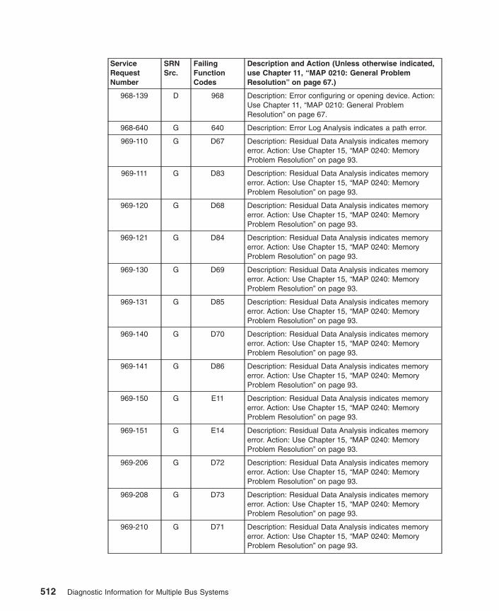
ServiceRequestNumber
SRNSrc.
FailingFunctionCodes
Description and Action (Unless otherwise indicated,use Chapter 11, “MAP 0210: General ProblemResolution” on page 67.)
968-139 D 968 Description: Error configuring or opening device. Action:Use Chapter 11, “MAP 0210: General ProblemResolution” on page 67.
968-640 G 640 Description: Error Log Analysis indicates a path error.
969-110 G D67 Description: Residual Data Analysis indicates memoryerror. Action: Use Chapter 15, “MAP 0240: MemoryProblem Resolution” on page 93.
969-111 G D83 Description: Residual Data Analysis indicates memoryerror. Action: Use Chapter 15, “MAP 0240: MemoryProblem Resolution” on page 93.
969-120 G D68 Description: Residual Data Analysis indicates memoryerror. Action: Use Chapter 15, “MAP 0240: MemoryProblem Resolution” on page 93.
969-121 G D84 Description: Residual Data Analysis indicates memoryerror. Action: Use Chapter 15, “MAP 0240: MemoryProblem Resolution” on page 93.
969-130 G D69 Description: Residual Data Analysis indicates memoryerror. Action: Use Chapter 15, “MAP 0240: MemoryProblem Resolution” on page 93.
969-131 G D85 Description: Residual Data Analysis indicates memoryerror. Action: Use Chapter 15, “MAP 0240: MemoryProblem Resolution” on page 93.
969-140 G D70 Description: Residual Data Analysis indicates memoryerror. Action: Use Chapter 15, “MAP 0240: MemoryProblem Resolution” on page 93.
969-141 G D86 Description: Residual Data Analysis indicates memoryerror. Action: Use Chapter 15, “MAP 0240: MemoryProblem Resolution” on page 93.
969-150 G E11 Description: Residual Data Analysis indicates memoryerror. Action: Use Chapter 15, “MAP 0240: MemoryProblem Resolution” on page 93.
969-151 G E14 Description: Residual Data Analysis indicates memoryerror. Action: Use Chapter 15, “MAP 0240: MemoryProblem Resolution” on page 93.
969-206 G D72 Description: Residual Data Analysis indicates memoryerror. Action: Use Chapter 15, “MAP 0240: MemoryProblem Resolution” on page 93.
969-208 G D73 Description: Residual Data Analysis indicates memoryerror. Action: Use Chapter 15, “MAP 0240: MemoryProblem Resolution” on page 93.
969-210 G D71 Description: Residual Data Analysis indicates memoryerror. Action: Use Chapter 15, “MAP 0240: MemoryProblem Resolution” on page 93.
512 Diagnostic Information for Multiple Bus Systems

ServiceRequestNumber
SRNSrc.
FailingFunctionCodes
Description and Action (Unless otherwise indicated,use Chapter 11, “MAP 0210: General ProblemResolution” on page 67.)
969-211 G D87 Description: Residual Data Analysis indicates memoryerror. Action: Use Chapter 15, “MAP 0240: MemoryProblem Resolution” on page 93.
969-212 G E12 Description: Residual Data Analysis indicates memoryerror.
969-220 G D72 Description: Residual Data Analysis indicates memoryerror. Action: Use Chapter 15, “MAP 0240: MemoryProblem Resolution” on page 93.
969-221 G D88 Description: Residual Data Analysis indicates memoryerror. Action: Use Chapter 15, “MAP 0240: MemoryProblem Resolution” on page 93.
969-230 G D73 Description: Residual Data Analysis indicates memoryerror. Action: Use Chapter 15, “MAP 0240: MemoryProblem Resolution” on page 93.
969-231 G D89 Description: Residual Data Analysis indicates memoryerror. Action: Use Chapter 15, “MAP 0240: MemoryProblem Resolution” on page 93.
969-240 G D74 Description: Residual Data Analysis indicates memoryerror. Action: Use Chapter 15, “MAP 0240: MemoryProblem Resolution” on page 93.
969-241 G D90 Description: Residual Data Analysis indicates memoryerror. Action: Use Chapter 15, “MAP 0240: MemoryProblem Resolution” on page 93.
969-250 G E12 Description: Residual Data Analysis indicates memoryerror. Action: Use Chapter 15, “MAP 0240: MemoryProblem Resolution” on page 93.
969-251 G E15 Description: Residual Data Analysis indicates memoryerror. Action: Use Chapter 15, “MAP 0240: MemoryProblem Resolution” on page 93.
969-310 G D75 Description: Residual Data Analysis indicates memoryerror. Action: Use Chapter 15, “MAP 0240: MemoryProblem Resolution” on page 93.
969-311 G D91 Description: Residual Data Analysis indicates memoryerror. Action: Use Chapter 15, “MAP 0240: MemoryProblem Resolution” on page 93.
969-320 G D76 Description: Residual Data Analysis indicates memoryerror. Action: Use Chapter 15, “MAP 0240: MemoryProblem Resolution” on page 93.
969-321 G D92 Description: Residual Data Analysis indicates memoryerror. Action: Use Chapter 15, “MAP 0240: MemoryProblem Resolution” on page 93.
969-330 G D77 Description: Residual Data Analysis indicates memoryerror. Action: Use Chapter 15, “MAP 0240: MemoryProblem Resolution” on page 93.
Chapter 34. SRNs 900-001 through xxxxxxx 513

ServiceRequestNumber
SRNSrc.
FailingFunctionCodes
Description and Action (Unless otherwise indicated,use Chapter 11, “MAP 0210: General ProblemResolution” on page 67.)
969-331 G D93 Description: Residual Data Analysis indicates memoryerror. Action: Use Chapter 15, “MAP 0240: MemoryProblem Resolution” on page 93.
969-340 G D78 Description: Residual Data Analysis indicates memoryerror. Action: Use Chapter 15, “MAP 0240: MemoryProblem Resolution” on page 93.
969-341 G D94 Description: Residual Data Analysis indicates memoryerror. Action: Use Chapter 15, “MAP 0240: MemoryProblem Resolution” on page 93.
969-350 G E13 Description: Residual Data Analysis indicates memoryerror. Action: Use Chapter 15, “MAP 0240: MemoryProblem Resolution” on page 93.
969-351 G E16 Description: Residual Data Analysis indicates memoryerror. Action: Use Chapter 15, “MAP 0240: MemoryProblem Resolution” on page 93.
969-600 G Description: Residual Data Analysis indicates memoryerror or unsupported memory. Action: Examine thememory modules and determine if they are supportedtypes. If the modules are supported, then replace theappropriate memory module(s). Use Chapter 15, “MAP0240: Memory Problem Resolution” on page 93.
969-701 D 814 Description: NVRAM test failed.
969-702 D 151 Description: Time of Day Battery test failed.
969-703 D 817 Description: Time of Day Chip test failed.
969-800 G 221 Description: Memory problems indicate System Planarfailure.
969-900 G D01 Description: L2 cache test failed.
970-101 D 970 Description: Timeout while attempting to communicatewith SCSI device.
970-102 D 970 Description: The SCSI device indicates busy.
970-103 D 970 Description: The SCSI device indicates a reservationconflict.
970-104 D 970 Description: The SCSI device indicates a checkcondition.
970-105 D 970 Description: An error is detected in request sense data.
970-107 D 970 Description: Sense data from the SCSI drive hasunexpected data.
970-110 D 970 Description: The Reserve command failed.
970-111 D 970 Description: Invalid condition from the drive after areserve.
970-112 D 970 Description: The write-protect sensor test failed.
514 Diagnostic Information for Multiple Bus Systems

ServiceRequestNumber
SRNSrc.
FailingFunctionCodes
Description and Action (Unless otherwise indicated,use Chapter 11, “MAP 0210: General ProblemResolution” on page 67.)
970-113 D 970 Description: Invalid condition from drive after a requestsense.
970-114 D 970 Description: Timeout while attempting to communicatewith the SCSI device.
970-120 D 970 Description: The Inquiry command failed.
970-130 D 970media
Description: The Load command failed.
970-134 D B88software
Description: The adapter failed to configure.
970-135 D 970media
Description: The Unload command failed.
970-140 D 970 Description: The Mode Select command failed.
970-150 D 970media
Description: The Test Unit Ready command failed.
970-160 D 970media
Description: The Send Diagnostic command failed.
970-161 D 970B88
Description: Invalid condition from the drive after areserve.
970-163 D 970B88
Description: Invalid condition from the drive after arequest sense.
970-164 D 970B88
Description: Timeout while attempting to communicatewith the SCSI device.
970-165 D 970B88276
Description: Write, Read and Compare Test failed.
970-166 D 970B88
software
Description: Unable to configure the device.
970-167 D 970B88
Description: An unexpected SCSI error occurred.
970-168 D B88software
Description: The adapter failed to configure.
970-169 D 970media
Description: The Send Diagnostic command failed.
970-170 D 970B88
media
Description: The Read, Write and Compare test failed.
970-180 D 970media
Description: The Load command failed.
970-185 D 970media
Description: The Unload command failed.
970-190 D 970 Description: The Mode Select command failed.
Chapter 34. SRNs 900-001 through xxxxxxx 515

ServiceRequestNumber
SRNSrc.
FailingFunctionCodes
Description and Action (Unless otherwise indicated,use Chapter 11, “MAP 0210: General ProblemResolution” on page 67.)
970-200 D 970media
Description: The Test Unit Ready command failed.
970-201 G 970B88
Description: Error diagnosed from error log analysis.
970-210 D 970B88
Description: The device configuration failed.
970-211 D 970B88
Description: The device open failed.
970-220 D 970 Description: The Release command failed.
970-230 D 970 Description: The Request Sense command failed.
970-240 D 970 Description: The Openx command failed.
970-260 D 970 Description: The device configuration failed.
970-261 D 970 Description: The device open failed.
970-300 D 970software
Description: The device configuration failed.
970-310 D B88970
software
Description: SCSI adapter configuration failed.
970-320 G 970media
Description: Error log analysis indicates a failure.
970-411to
970-423
D 970B88
software
Description: A reservation conflict occurred.
970-511to
970-523
D 970B88
Description: The drive returned bad or non-extendedsense data.
970-57D D 57D Description: The resource does not respond.
970-611to
970-623
D 970B88
software
Description: An adapter or bus I/O error occurred.
970-711to
970-723
D 970B88
software
Description: A device timeout error occurred.
971-101 D 971 Description: Timeout while attempting to communicatewith SCSI device.
971-102 D 971 Description: The SCSI device indicates busy.
971-103 D 971 Description: The SCSI device is indicating a reservationconflict.
971-104 D 971 Description: The SCSI device indicates a checkcondition.
971-105 D 971 Description: Sense data from the SCSI device shows anerror.
516 Diagnostic Information for Multiple Bus Systems
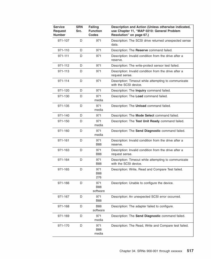
ServiceRequestNumber
SRNSrc.
FailingFunctionCodes
Description and Action (Unless otherwise indicated,use Chapter 11, “MAP 0210: General ProblemResolution” on page 67.)
971-107 D 971 Description: The SCSI drive returned unexpected sensedata.
971-110 D 971 Description: The Reserve command failed.
971-111 D 971 Description: Invalid condition from the drive after areserve.
971-112 D 971 Description: The write-protect sensor test failed.
971-113 D 971 Description: Invalid condition from the drive after arequest sense.
971-114 D 971 Description: Timeout while attempting to communicatewith the SCSI device.
971-120 D 971 Description: The Inquiry command failed.
971-130 D 971media
Description: The Load command failed.
971-135 D 971media
Description: The Unload command failed.
971-140 D 971 Description: The Mode Select command failed.
971-150 D 971media
Description: The Test Unit Ready command failed.
971-160 D 971media
Description: The Send Diagnostic command failed.
971-161 D 971B88
Description: Invalid condition from the drive after areserve.
971-163 D 971B88
Description: Invalid condition from the drive after arequest sense.
971-164 D 971B88
Description: Timeout while attempting to communicatewith the SCSI device.
971-165 D 971B88276
Description: Write, Read and Compare Test failed.
971-166 D 971B88
software
Description: Unable to configure the device.
971-167 D 971B88
Description: An unexpected SCSI error occurred.
971-168 D B88software
Description: The adapter failed to configure.
971-169 D 971media
Description: The Send Diagnostic command failed.
971-170 D 971B88
media
Description: The Read, Write and Compare test failed.
Chapter 34. SRNs 900-001 through xxxxxxx 517

ServiceRequestNumber
SRNSrc.
FailingFunctionCodes
Description and Action (Unless otherwise indicated,use Chapter 11, “MAP 0210: General ProblemResolution” on page 67.)
971-180 D 971media
Description: The Load command failed.
971-185 D 971media
Description: The Unload command failed.
971-190 D 971 Description: The Mode Select command failed.
971-200 D 971media
Description: The Test Unit Ready command failed.
971-201 G 971B88
Description: An error is diagnosed from the error loganalysis.
971-210 D 971B88
Description: The device configuration failed.
971-211 D 971B88
Description: The device open test failed.
971-220 D 971 Description: The Release command failed.
971-230 D 971 Description: The Request Sense command failed.
971-240 D 971 Description: The Openx command failed.
971-260 D 971 Description: The device configuration failed.
971-261 D 971 Description: The device open test failed.
971-300 D 971software
Description: The device configuration failed.
971-310 D B88971
software
Description: SCSI adapter configuration failed.
971-320 G 971media
Description: Error log analysis indicates a failure.
971-411to
971-423
D 971B88
software
Description: A reservation conflict occurred.
971-511to
971-523
D 971B88
Description: The drive returned bad or non-extendedsense data.
971-611to
971-623
D 971software
Description: An adapter or bus I/O error occurred.
971-711to
971-723
D 971B88
software
Description: A device timeout error occurred.
972-101 D 972 Description: Timeout while attempting to communicatewith SCSI device.
972-102 D 972 Description: The SCSI device indicates busy.
972-103 D 972 Description: The SCSI device indicates a reservationconflict.
518 Diagnostic Information for Multiple Bus Systems
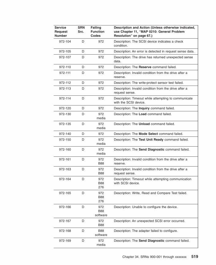
ServiceRequestNumber
SRNSrc.
FailingFunctionCodes
Description and Action (Unless otherwise indicated,use Chapter 11, “MAP 0210: General ProblemResolution” on page 67.)
972-104 D 972 Description: The SCSI device indicates a checkcondition.
972-105 D 972 Description: An error is detected in request sense data.
972-107 D 972 Description: The drive has returned unexpected sensedata.
972-110 D 972 Description: The Reserve command failed.
972-111 D 972 Description: Invalid condition from the drive after areserve.
972-112 D 972 Description: The write-protect sensor test failed.
972-113 D 972 Description: Invalid condition from the drive after arequest sense.
972-114 D 972 Description: Timeout while attempting to communicatewith the SCSI device.
972-120 D 972 Description: The Inquiry command failed.
972-130 D 972media
Description: The Load command failed.
972-135 D 972media
Description: The Unload command failed.
972-140 D 972 Description: The Mode Select command failed.
972-150 D 972media
Description: The Test Unit Ready command failed.
972-160 D 972media
Description: The Send Diagnostic command failed.
972-161 D 972B88
Description: Invalid condition from the drive after areserve.
972-163 D 972B88
Description: Invalid condition from the drive after arequest sense.
972-164 D 972B88276
Description: Timeout while attempting communicationwith SCSI device.
972-165 D 972B88276
Description: Write, Read and Compare Test failed.
972-166 D 972B88
software
Description: Unable to configure the device.
972-167 D 972B88
Description: An unexpected SCSI error occurred.
972-168 D B88software
Description: The adapter failed to configure.
972-169 D 972media
Description: The Send Diagnostic command failed.
Chapter 34. SRNs 900-001 through xxxxxxx 519

ServiceRequestNumber
SRNSrc.
FailingFunctionCodes
Description and Action (Unless otherwise indicated,use Chapter 11, “MAP 0210: General ProblemResolution” on page 67.)
972-170 D 972B88
media
Description: The Read, Write and Compare test failed.
972-180 D 972media
Description: The Load command failed.
972-185 D 972media
Description: The Unload command failed.
972-190 D 972 Description: The Mode Select command failed.
972-200 D 972media
Description: The Test Unit Ready command failed.
972-201 G 972B88
Description: An error is diagnosed from the error loganalysis.
972-210 D 972B88
Description: The device configuration failed.
972-211 D 972B88
Description: The device open test failed.
972-220 D 972 Description: The Release command failed.
972-230 D 972 Description: The Request Sense command failed.
972-240 D 972 Description: The Openx command failed.
972-260 D 972 Description: The device configuration test failed.
972-261 D 972 Description: The device open test failed.
972-300 D 972software
Description: The device configuration failed.
972-310 D B88972
software
Description: SCSI adapter configuration failed.
972-320 G 972media
Description: Error log analysis indicates a failure.
972-411 to972-423
D 972B88
software
Description: A reservation conflict occurred.
972-511 to972-523
D 972B88
Description: The drive returned bad or non-extendedsense data.
972-611to
972-623
D 972B88
software
Description: An adapter or bus I/O error occurred.
972-711to
972-723
D 972B88
software
Description: A device timeout error occurred.
973-110 D 973 Description: The Reserve command failed.
973-120 D 973 Description: The Inquiry command failed.
520 Diagnostic Information for Multiple Bus Systems

ServiceRequestNumber
SRNSrc.
FailingFunctionCodes
Description and Action (Unless otherwise indicated,use Chapter 11, “MAP 0210: General ProblemResolution” on page 67.)
973-130 D 973media
Description: The Load command failed.
973-135 D 973media
Description: The Unload command failed.
973-140 D 973 Description: The Mode Select command failed.
973-150 D 973media
Description: The Test Unit Ready command failed.
973-160 D 973media
Description: The Send Diagnostic command failed.
973-169 D 973media
Description: The Send Diagnostic command failed.
973-170 D 973B88
media
Description: The Read, Write and Compare test failed.
973-180 D 973media
Description: The Load command failed.
973-185 D 973media
Description: The Unload command failed.
973-190 D 973 Description: The Mode Select command failed.
973-200 D 973media
Description: The Test Unit Ready command failed.
973-210 D 973B88
Description: The device configuration failed.
973-220 D 973 Description: The Release command failed.
973-230 D 973 Description: The Request Sense command failed.
973-240 D 973 Description: The Openx command failed.
973-300 D 973software
Description: The device configuration failed.
973-310 D B88973
software
Description: SCSI adapter configuration failed.
973-320 G 973media
Description: Error log analysis indicates a failure.
973-411to
973-423
D 973B88
software
Description: A reservation conflict occurred.
973-511to
973-523
D 973B88
Description: The drive returned bad or non-extendedsense data.
973-611to
973-623
D 973B88
software
Description: An adapter or bus I/O error occurred.
Chapter 34. SRNs 900-001 through xxxxxxx 521

ServiceRequestNumber
SRNSrc.
FailingFunctionCodes
Description and Action (Unless otherwise indicated,use Chapter 11, “MAP 0210: General ProblemResolution” on page 67.)
973-711to
973-723
D 973B88
software
Description: A device timeout error occurred.
974-111 D 974B88
Description: Unable to reserve device.
974-112 D 974B88
Description: Unable to do configuration.
974-113 D 974B88
Description: Unable to open the device driver.
974-121 D 974 Description: The CD-ROM drive indicates an error.
974-122 D 974 Description: The CD-ROM drive indicates an error.
974-123 D 974 Description: The CD-ROM drive indicates an error.
974-125 D 974B88
Description: The CD-ROM drive indicates an error.
974-126 D 974 Description: The CD-ROM drive indicates an error.
974-127 D 974 Description: The CD-ROM drive indicates an error.
974-128 D 974 Description: The CD-ROM drive indicates an error.
974-129 D 974 Description: The CD-ROM drive indicates an error.
974-150 D Test-Disc974
Description: A media error was detected.
974-151 D 974D88
Description: A command timeout was detected.
974-152 D 974 Description: A command reservation conflict wasdetected.
974-162 D 974 Description: The CD-ROM drive indicates an error.
974-171 D 974 Description: Unable to reserve device.
974-172 D 974 Description: Unable to do configuration.
974-173 D 974 Description: Unable to open device driver.
974-175 D 974 Description: The CD-ROM drive indicates an error.
974-198 D 974B88
Description: Undefined error detected.
974-199 D 974 Description: Undefined error detected.
974-211 D 974 Description: The LED test failed.
974-281 D 974 Description: No tone during audio test.
974-301 G 974 Description: Errors found during ELA.
974-302 G 974B88
Description: Errors log analysis indicates hardwarefailure.
981-102 D 981B88
Description: An unrecoverable media error.
522 Diagnostic Information for Multiple Bus Systems

ServiceRequestNumber
SRNSrc.
FailingFunctionCodes
Description and Action (Unless otherwise indicated,use Chapter 11, “MAP 0210: General ProblemResolution” on page 67.)
981-104 D 981 Description: The motor failed to restart.
981-105 D 981 Description: The drive did not become ready.
981-106 D 981 Description: The electronics card test failed.
981-108 D 981 Description: The bus test failed.
981-110 D 981 Description: The media format is corrupted.
981-112 D 981 Description: The diagnostic test failed.
981-114 D 981 Description: An unrecoverable hardware error.
981-116 D Description: A protocol error. Action: Check the levels ofthe device, adapter, diagnostic software, and applicationsoftware to be sure they are all compatible. If you do notfind a problem, call your support person.
981-117 D 981 Description: A write-protect error occurred.
981-118 D 981B88
Description: A SCSI command time-out.
981-120 D 981 Description: A SCSI busy or command error.
981-122 D 981 Description: A SCSI reservation conflict error.
981-124 D 981 Description: A SCSI check condition error.
981-126 D 981B88
Description: A software error was caused by a hardwarefailure.
981-128 G 981 Description: The error log analysis indicates a hardwarefailure.
981-129 G 981 Description: Error log analysis indicates a SCSI busproblem.
981-130 G 981B88
Description: Error log analysis indicates a problemreported by the disk drive’s self-monitoring function.
981-132 D 981 Description: A disk drive hardware error occurred.
981-133 D 981 Description: Use the subsystem guide to completediagnostics.
981-134 D B88software
Description: The adapter failed to configure.
981-135 D 981B88
software
Description: The device failed to configure.
981-136 D 981 Description: The certify operation failed.
981-137 D 981B88190
Description: Unit attention condition has occurred on theSend Diagnostic command.
981-138 D 190 Description: Error log indicates that the disk is operatingat higher than recommended temperatures.
Chapter 34. SRNs 900-001 through xxxxxxx 523
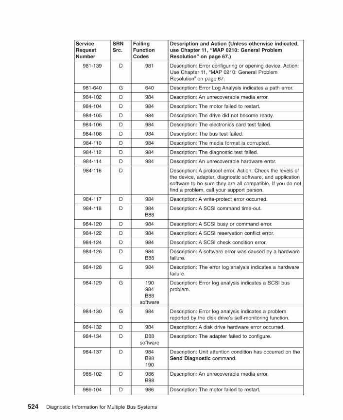
ServiceRequestNumber
SRNSrc.
FailingFunctionCodes
Description and Action (Unless otherwise indicated,use Chapter 11, “MAP 0210: General ProblemResolution” on page 67.)
981-139 D 981 Description: Error configuring or opening device. Action:Use Chapter 11, “MAP 0210: General ProblemResolution” on page 67.
981-640 G 640 Description: Error Log Analysis indicates a path error.
984-102 D 984 Description: An unrecoverable media error.
984-104 D 984 Description: The motor failed to restart.
984-105 D 984 Description: The drive did not become ready.
984-106 D 984 Description: The electronics card test failed.
984-108 D 984 Description: The bus test failed.
984-110 D 984 Description: The media format is corrupted.
984-112 D 984 Description: The diagnostic test failed.
984-114 D 984 Description: An unrecoverable hardware error.
984-116 D Description: A protocol error. Action: Check the levels ofthe device, adapter, diagnostic software, and applicationsoftware to be sure they are all compatible. If you do notfind a problem, call your support person.
984-117 D 984 Description: A write-protect error occurred.
984-118 D 984B88
Description: A SCSI command time-out.
984-120 D 984 Description: A SCSI busy or command error.
984-122 D 984 Description: A SCSI reservation conflict error.
984-124 D 984 Description: A SCSI check condition error.
984-126 D 984B88
Description: A software error was caused by a hardwarefailure.
984-128 G 984 Description: The error log analysis indicates a hardwarefailure.
984-129 G 190984B88
software
Description: Error log analysis indicates a SCSI busproblem.
984-130 G 984 Description: Error log analysis indicates a problemreported by the disk drive’s self-monitoring function.
984-132 D 984 Description: A disk drive hardware error occurred.
984-134 D B88software
Description: The adapter failed to configure.
984-137 D 984B88190
Description: Unit attention condition has occurred on theSend Diagnostic command.
986-102 D 986B88
Description: An unrecoverable media error.
986-104 D 986 Description: The motor failed to restart.
524 Diagnostic Information for Multiple Bus Systems

ServiceRequestNumber
SRNSrc.
FailingFunctionCodes
Description and Action (Unless otherwise indicated,use Chapter 11, “MAP 0210: General ProblemResolution” on page 67.)
986-105 D 986 Description: The drive did not become ready.
986-106 D 986 Description: The electronics card test failed.
986-108 D 986 Description: The bus test failed.
986-110 D 986 Description: The media format is corrupted.
986-112 D 986 Description: The diagnostic test failed.
986-114 D 986 Description: An unrecoverable hardware error.
986-116 D Description: A protocol error. Action: Check the levels ofthe device, adapter, diagnostic software, and applicationsoftware to ensure they are all compatible. If you do notfind a problem, call your support person.
986-117 D 986 Description: A write-protect error occurred.
986-118 D 986B88
Description: A SCSI command timeout.
986-120 D 986 Description: A SCSI busy or command error.
986-122 D 986 Description: A SCSI reservation conflict error.
986-124 D 986 Description: A SCSI check condition error.
986-126 D 986B88
Description: A software error was caused by a hardwarefailure.
986-128 G 986 Description: The error log analysis indicates a hardwarefailure.
986-129 G 986 Description: Error log analysis indicates a SCSI busproblem.
986-130 G 986B88
Description: Error log analysis indicates a problemreported by the disk drive’s self-monitoring function.
986-132 D 986 Description: A disk drive hardware error occurred.
986-133 D 986 Description: Use the subsystem guide to completediagnostics.
986-134 D B88software
Description: The adapter failed to configure.
986-135 D 986B88
software
Description: The device failed to configure.
986-136 D 986 Description: The certify operation failed.
986-137 D 986B88190
Description: Unit attention condition has occurred on theSend Diagnostic command.
986-138 D 190 Description: Error log indicates that the disk is operatingat higher than recommended temperatures.
986-139 D 986 Description: Error configuring or opening device. Action:Use Chapter 11, “MAP 0210: General ProblemResolution” on page 67.
Chapter 34. SRNs 900-001 through xxxxxxx 525

ServiceRequestNumber
SRNSrc.
FailingFunctionCodes
Description and Action (Unless otherwise indicated,use Chapter 11, “MAP 0210: General ProblemResolution” on page 67.)
986-640 G 640 Description: Error Log Analysis indicates a path error.
987-111 D 987B88
Description: Unable to reserve device.
987-112 D 987B88
Description: Unable to do configuration.
987-113 D 987B88
Description: Unable to open the device driver.
987-121 D 987 Description: The CD-ROM drive indicates an error.
987-122 D 987 Description: The CD-ROM drive indicates an error.
987-123 D 987 Description: The CD-ROM drive indicates an error.
987-125 D 987B88
Description: The CD-ROM drive indicates an error.
987-126 D 987 Description: The CD-ROM drive indicates an error.
987-127 D 987 Description: The CD-ROM drive indicates an error.
987-128 D 987 Description: The CD-ROM drive indicates an error.
987-129 D 987 Description: The CD-ROM drive indicates an error.
987-150 D Test-Disc987
Description: A media error was detected.
987-151 D 987B88
Description: A command timeout was detected.
987-152 D 987 Description: A command reservation conflict wasdetected.
987-162 D 987 Description: The CD-ROM drive indicates an error.
987-171 D 987 Description: Unable to reserve device.
987-172 D 987 Description: Unable to do configuration.
987-173 D 987 Description: Unable to open device driver.
987-175 D 987 Description: The CD-ROM drive indicates an error.
987-198 D 987B88
Description: Undefined error detected.
987-199 D 987 Description: Undefined error detected.
987-211 D 987 Description: The LED test failed.
987-281 D 987 Description: No tone during audio test.
987-301 G 987 Description: Errors found during ELA.
987-302 G 987B88
Description: Errors found during ELA.
989-102 D 989B88
Description: An unrecoverable media error
989-104 D 989 Description: The motor failed to restart.
526 Diagnostic Information for Multiple Bus Systems

ServiceRequestNumber
SRNSrc.
FailingFunctionCodes
Description and Action (Unless otherwise indicated,use Chapter 11, “MAP 0210: General ProblemResolution” on page 67.)
989-105 D 989 Description: The drive did not become ready.
989-106 D 989 Description: The electronics card test failed.
989-108 D 989 Description: The bus test failed.
989-110 D 989 Description: The media format is corrupted.
989-112 D 989 Description: The diagnostic test failed.
989-114 D 989 Description: A non-recoverable hardware error.
989-116 D Description: A protocol error. Action: Check the levels ofthe device, adapter, diagnostic software, and applicationsoftware to be sure they are all compatible. If you do notfind a problem, call your support person.
989-117 D 989 Description: A write-protect error occurred.
989-118 D 989B88
Description: A SCSI command time-out.
989-120 D 989 Description: A SCSI busy or command error.
989-122 D 989 Description: A SCSI reservation conflict error.
989-124 D 989 Description: A SCSI check condition error.
989-126 D 989B88
Description: A software error was caused by a hardwarefailure.
989-128 G 989 Description: The error log analysis indicates a hardwarefailure.
989-129 G 989 Description: Error log analysis indicates a SCSI busproblem.
989-130 G 989B88
Description: Error log analysis indicates a problemreported by the disk drive’s self-monitoring function.
989-132 D 989 Description: A disk drive hardware error occurred.
989-133 D 989 Description: Use the subsystem guide to complete thediagnostics.
989-134 D B88software
Description: The adapter failed to configure.
989-135 D 989B88
software
Description: The device failed to configure.
989-136 D 989 Description: The certify operation failed.
989-137 D 989B88190
Description: Unit attention condition has occurred on theSend Diagnostic command.
989-138 D 190 Description: Error log indicates that the disk is operatingat higher than recommended temperatures.
989-139 D 989 Description: Error configuring or opening device. Action:Use Chapter 11, “MAP 0210: General ProblemResolution” on page 67
Chapter 34. SRNs 900-001 through xxxxxxx 527

ServiceRequestNumber
SRNSrc.
FailingFunctionCodes
Description and Action (Unless otherwise indicated,use Chapter 11, “MAP 0210: General ProblemResolution” on page 67.)
989-640 G 640 Description: Error Log Analysis indicates a path error.
990-102 D 990B88
Description: An unrecoverable media error.
990-104 D 990 Description: The motor failed to restart.
990-105 D 990 Description: The drive did not become ready.
990-106 D 990 Description: The electronics card test failed.
990-108 D 990 Description: The bus test failed.
990-110 D 990 Description: The media format is corrupted.
990-112 D 990 Description: The diagnostic test failed.
990-114 D 990 Description: An unrecoverable hardware error.
990-116 D Description: A protocol error. Action: Check the levels ofthe device, adapter, diagnostic software, and applicationsoftware to ensure they are all compatible. If you do notfind a problem, call your support person.
990-117 D 990 Description: A write-protect error occurred.
990-118 D 990B88
Description: A SCSI command timeout.
990-120 D 990 Description: A SCSI busy or command error.
990-122 D 990 Description: A SCSI reservation conflict error.
990-124 D 990 Description: A SCSI check condition error.
990-126 D 990B88
Description: A software error was caused by a hardwarefailure.
990-128 G 990 Description: The error log analysis indicates a hardwarefailure.
990-129 G 990 Description: Error log analysis indicates a SCSI busproblem.
990-130 G 990B88
Description: Error log analysis indicates a problemreported by the disk drive’s self-monitoring function.
990-132 D 990 Description: A disk drive hardware error occurred.
990-133 D 990 Description: Use the subsystem guide to completediagnostics.
990-134 D B88software
Description: The adapter failed to configure.
990-135 D 990B88
software
Description: The device failed to configure.
990-136 D 990 Description: The certify operation failed.
990-137 D 990B88190
Description: Unit attention condition has occurred on theSend Diagnostic command.
528 Diagnostic Information for Multiple Bus Systems

ServiceRequestNumber
SRNSrc.
FailingFunctionCodes
Description and Action (Unless otherwise indicated,use Chapter 11, “MAP 0210: General ProblemResolution” on page 67.)
990-138 D 190 Description: Error log indicates that the disk is operatingat higher than recommended temperatures.
990-139 D 990 Description: Error configuring or opening device. Action:Use Chapter 11, “MAP 0210: General ProblemResolution” on page 67.
990-640 G 640 Description: Error Log Analysis indicates a path error.
991-101 D 991 Description: Timeout while attempting to communicatewith SCSI device.
991-102 D 991 Description: The SCSI device indicates busy.
991-103 D 991 Description: The SCSI device is indicating a reservationconflict.
991-104 D 991 Description: The SCSI device indicates a checkcondition.
991-105 D 991 Description: Sense data from the SCSI device shows anerror.
991-107 D 991 Description: The SCSI drive returned unexpected sensedata.
991-110 D 991 Description: The Reserve command failed.
991-111 D 991 Description: Invalid condition from the drive after areserve.
991-112 D 991 Description: The write-protect sensor test failed.
991-113 D 991 Description: Invalid condition from the drive after arequest sense.
991-114 D 991 Description: Timeout while attempting to communicatewith the SCSI device.
991-120 D 991 Description: The Inquiry command failed.
991-130 D 991media
Description: The Load command failed.
991-135 D 991media
Description: The Unload command failed.
991-140 D 991 Description: The Mode Select command failed.
991-150 D 991media
Description: The Test Unit Ready command failed.
991-160 D 991media
Description: The Send Diagnostic command failed.
991-161 D 991B88
Description: Invalid condition from the drive after areserve.
991-163 D 991B88
Description: Invalid condition from the drive after arequest sense.
991-164 D 991B88
Description: Timeout while attempting to communicatewith the SCSI device.
Chapter 34. SRNs 900-001 through xxxxxxx 529

ServiceRequestNumber
SRNSrc.
FailingFunctionCodes
Description and Action (Unless otherwise indicated,use Chapter 11, “MAP 0210: General ProblemResolution” on page 67.)
991-165 D 991B88276
Description: Write, Read and Compare Test failed.
991-166 D 991B88
software
Description: The device failed to configure.
991-167 D 991B88
Description: An unexpected SCSI error occurred.
991-168 D B88software
Description: The adapter failed to configure.
991-169 D 991media
Description: The Send Diagnostic command failed.
991-170 D 991B88
media
Description: The Read, Write and Compare test failed.
991-180 D 991media
Description: The Load command failed.
991-185 D 991media
Description: The Unload command failed.
991-190 D 991 Description: The Mode Select command failed.
991-200 D 991media
Description: The Test Unit Ready command failed.
991-201 G 991B88
Description: An error is diagnosed from the error loganalysis.
991-210 D 991B88
Description: The device configuration failed.
991-211 D 991B88
Description: The device open test failed.
991-220 D 991 Description: The Release command failed.
991-230 D 991 Description: The Request Sense command failed.
991-240 D 991 Description: The Openx command failed.
991-260 D 991 Description: The device configuration failed.
991-261 D 991 Description: The device open test failed.
991-300 D 991software
Description: The device configuration failed.
991-310 D B88991
software
Description: SCSI adapter configuration failed.
991-320 G 991media
Description: Error log analysis indicates a failure.
530 Diagnostic Information for Multiple Bus Systems

ServiceRequestNumber
SRNSrc.
FailingFunctionCodes
Description and Action (Unless otherwise indicated,use Chapter 11, “MAP 0210: General ProblemResolution” on page 67.)
991-411to
991-423
D 991B88
software
Description: A reservation conflict occurred.
991-511to
991-523
D 991B88
Description: The drive returned bad or non-extendedsense data.
991-611to
991-623
D 991B88
software
Description: An adapter or bus I/O error occurred.
991-711to
991-723
D 991B88
software
Description: A device timeout error occurred.
994-110 D 994 Description: The Reserve command failed.
994-120 D 994 Description: The Inquiry command failed.
994-130 D 994media
Description: The Load command failed.
994-135 D 994media
Description: The Unload command failed.
994-140 D 994 Description: The Mode Select command failed.
994-150 D 994media
Description: The Test Unit Ready command failed.
994-160 D 994media
Description: The Send Diagnostic command failed.
994-169 D 994media
Description: The Send Diagnostic command failed.
994-170 D 994B88
media
Description: The Read, Write and Compare test failed.
994-180 D 994media
Description: The Load command failed.
994-185 D 994media
Description: The Unload command failed.
994-190 D 994 Description: The Mode Select command failed.
994-200 D 994media
Description: The Test Unit Ready command failed.
994-210 D 994B88
Description: The device configuration failed.
994-220 D 994 Description: The Release command failed.
994-230 D 994 Description: The Request Sense command failed.
994-240 D 994 Description: The Openx command failed.
994-300 D 994software
Description: The device configuration failed.
Chapter 34. SRNs 900-001 through xxxxxxx 531
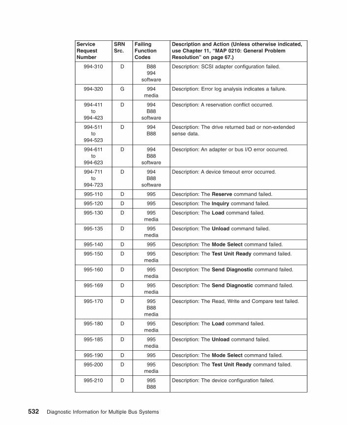
ServiceRequestNumber
SRNSrc.
FailingFunctionCodes
Description and Action (Unless otherwise indicated,use Chapter 11, “MAP 0210: General ProblemResolution” on page 67.)
994-310 D B88994
software
Description: SCSI adapter configuration failed.
994-320 G 994media
Description: Error log analysis indicates a failure.
994-411to
994-423
D 994B88
software
Description: A reservation conflict occurred.
994-511to
994-523
D 994B88
Description: The drive returned bad or non-extendedsense data.
994-611to
994-623
D 994B88
software
Description: An adapter or bus I/O error occurred.
994-711to
994-723
D 994B88
software
Description: A device timeout error occurred.
995-110 D 995 Description: The Reserve command failed.
995-120 D 995 Description: The Inquiry command failed.
995-130 D 995media
Description: The Load command failed.
995-135 D 995media
Description: The Unload command failed.
995-140 D 995 Description: The Mode Select command failed.
995-150 D 995media
Description: The Test Unit Ready command failed.
995-160 D 995media
Description: The Send Diagnostic command failed.
995-169 D 995media
Description: The Send Diagnostic command failed.
995-170 D 995B88
media
Description: The Read, Write and Compare test failed.
995-180 D 995media
Description: The Load command failed.
995-185 D 995media
Description: The Unload command failed.
995-190 D 995 Description: The Mode Select command failed.
995-200 D 995media
Description: The Test Unit Ready command failed.
995-210 D 995B88
Description: The device configuration failed.
532 Diagnostic Information for Multiple Bus Systems

ServiceRequestNumber
SRNSrc.
FailingFunctionCodes
Description and Action (Unless otherwise indicated,use Chapter 11, “MAP 0210: General ProblemResolution” on page 67.)
995-220 D 995 Description: The Release command failed.
995-230 D 995 Description: The Request Sense command failed.
995-240 D 995 Description: The Openx command failed.
995-300 D 995software
Description: The device configuration failed.
995-310 D B88995
software
Description: SCSI adapter configuration failed.
995-320 G 995media
Description: Error log analysis indicates a failure.
995-411to
995-423
D 995B88
software
Description: A reservation conflict occurred.
995-511to
995-523
D 995B88
Description: The drive returned bad or non-extendedsense data.
995-611to
995-623
D 995B88
software
Description: An adapter or bus I/O error occurred.
995-711to
995-723
D 995B88
software
Description: A device timeout error occurred.
998-110 D 998 Description: The Reserve command failed.
998-120 D 998 Description: The Inquiry command failed.
998-130 D 998media
Description: The Load command failed.
998-135 D 998media
Description: The Unload command failed.
998-140 D 998 Description: The Mode Select command failed.
998-150 D 998media
Description: The Test Unit Ready command failed.
998-160 D 998media
Description: The Send Diagnostic command failed.
998-169 D 998media
Description: The Send Diagnostic command failed.
998-170 D 998B88
media
Description: The Read, Write and Compare test failed.
998-180 D 998media
Description: The Load command failed.
998-185 D 998media
Description: The Unload command failed.
Chapter 34. SRNs 900-001 through xxxxxxx 533

ServiceRequestNumber
SRNSrc.
FailingFunctionCodes
Description and Action (Unless otherwise indicated,use Chapter 11, “MAP 0210: General ProblemResolution” on page 67.)
998-190 D 998 Description: The Mode Select command failed.
998-200 D 998media
Description: The Test Unit Ready command failed.
998-210 D 998B88
Description: The device configuration failed.
998-220 D 998 Description: The Release command failed.
998-230 D 998 Description: The Request Sense command failed.
998-240 D 995 Description: The Openx command failed.
998-300 D 995software
Description: The device configuration failed.
998-310 D B88995
software
Description: SCSI adapter configuration failed.
998-320 G 995media
Description: Error log analysis indicates a failure.
998-411to
998-423
D 998B88
software
Description: A reservation conflict occurred.
998-511to
998-523
D 998B88
Description: The drive returned bad or non-extendedsense data.
998-611to
998-623
D 998B88
software
Description: An adapter or bus I/O error occurred.
998-711to
998-723
D 998B88
software
Description: A device timeout error occurred.
999-xxxseries
D 999 Description: A 7137 or 3514 disk array subsystemproblem is indicated. Action: Use 7137 or 3514documentation.
9CC-1xx G Description: I/O Error on PCI bus. Action: Refer to theBus SRN to FRU Reference Table in the system unit’sservice guide.Note: xx represents the last 2 digits of the SRN.
9CC-xxx G xxx2C9
Description: I/O Bus Data, Address Parity Error, orTime-out error.Note: xxx represents the last 3 digits of the SRN.
xxxxxx G none Description: You have a six-digit error code (like anSRN) containing no dash (-) between the third and fourthdigits. Action: Use the ″Error Code to FRU Index″ in theservice guide.
xxxxxxxx G none Description: Refer to the Error Code to FRU Index in thesystem unit’s service guide. Action: Use the ″Error Codeto FRU Index″ in the service guide.
534 Diagnostic Information for Multiple Bus Systems
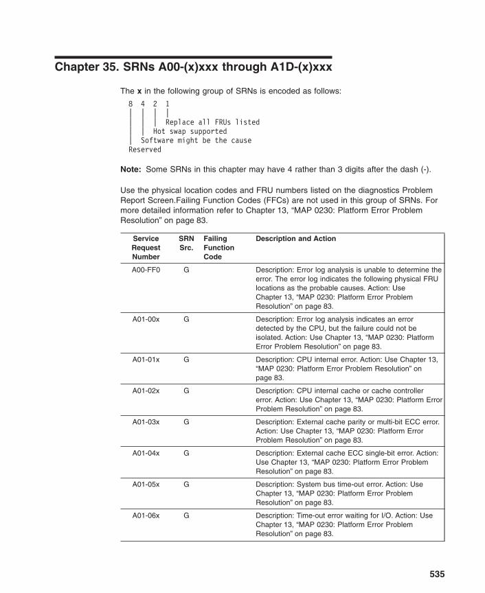
Chapter 35. SRNs A00-(x)xxx through A1D-(x)xxx
The x in the following group of SRNs is encoded as follows:
8 4 2 1| | | || | | Replace all FRUs listed| | Hot swap supported| Software might be the causeReserved
Note: Some SRNs in this chapter may have 4 rather than 3 digits after the dash (-).
Use the physical location codes and FRU numbers listed on the diagnostics ProblemReport Screen.Failing Function Codes (FFCs) are not used in this group of SRNs. Formore detailed information refer to Chapter 13, “MAP 0230: Platform Error ProblemResolution” on page 83.
ServiceRequestNumber
SRNSrc.
FailingFunctionCode
Description and Action
A00-FF0 G Description: Error log analysis is unable to determine theerror. The error log indicates the following physical FRUlocations as the probable causes. Action: UseChapter 13, “MAP 0230: Platform Error ProblemResolution” on page 83.
A01-00x G Description: Error log analysis indicates an errordetected by the CPU, but the failure could not beisolated. Action: Use Chapter 13, “MAP 0230: PlatformError Problem Resolution” on page 83.
A01-01x G Description: CPU internal error. Action: Use Chapter 13,“MAP 0230: Platform Error Problem Resolution” onpage 83.
A01-02x G Description: CPU internal cache or cache controllererror. Action: Use Chapter 13, “MAP 0230: Platform ErrorProblem Resolution” on page 83.
A01-03x G Description: External cache parity or multi-bit ECC error.Action: Use Chapter 13, “MAP 0230: Platform ErrorProblem Resolution” on page 83.
A01-04x G Description: External cache ECC single-bit error. Action:Use Chapter 13, “MAP 0230: Platform Error ProblemResolution” on page 83.
A01-05x G Description: System bus time-out error. Action: UseChapter 13, “MAP 0230: Platform Error ProblemResolution” on page 83.
A01-06x G Description: Time-out error waiting for I/O. Action: UseChapter 13, “MAP 0230: Platform Error ProblemResolution” on page 83.
535

ServiceRequestNumber
SRNSrc.
FailingFunctionCode
Description and Action
A01-07x G Description: System bus parity error. Action: UseChapter 13, “MAP 0230: Platform Error ProblemResolution” on page 83.
A01-08x G Description: System bus protocol/transfer error. Action:Use Chapter 13, “MAP 0230: Platform Error ProblemResolution” on page 83.
A02-00x G Description: Error log analysis indicates an errordetected by the memory controller, but the failure couldnot be isolated. Action: Use Chapter 13, “MAP 0230:Platform Error Problem Resolution” on page 83.
A02-01x G Description: Uncorrectable Memory Error. Action: UseChapter 13, “MAP 0230: Platform Error ProblemResolution” on page 83.
A02-02x G Description: ECC correctable error. Action: UseChapter 13, “MAP 0230: Platform Error ProblemResolution” on page 83.
A02-03x G Description: Correctable error threshold exceeded.Action: Use Chapter 13, “MAP 0230: Platform ErrorProblem Resolution” on page 83.
A02-04x G Description: Memory Control subsystem internal error.Action: Use Chapter 13, “MAP 0230: Platform ErrorProblem Resolution” on page 83.
A02-05x G Description: Memory Address Error (invalid address oraccess attempt). Action: Use Chapter 13, “MAP 0230:Platform Error Problem Resolution” on page 83.
A02-06x G Description: Memory Data error (Bad data going tomemory). Action: Use Chapter 13, “MAP 0230: PlatformError Problem Resolution” on page 83.
A02-07x G Description: Memory bus/switch internal error. Action:Use Chapter 13, “MAP 0230: Platform Error ProblemResolution” on page 83.
A02-08x G Description: Memory time-out error. Action: UseChapter 13, “MAP 0230: Platform Error ProblemResolution” on page 83.
A02-09x G Description: System bus parity error. Action: UseChapter 13, “MAP 0230: Platform Error ProblemResolution” on page 83.
A02-10x G Description: System bus time-out error. Action: UseChapter 13, “MAP 0230: Platform Error ProblemResolution” on page 83.
A02-11x G Description: System bus protocol/transfer error. Action:Use Chapter 13, “MAP 0230: Platform Error ProblemResolution” on page 83.
536 Diagnostic Information for Multiple Bus Systems
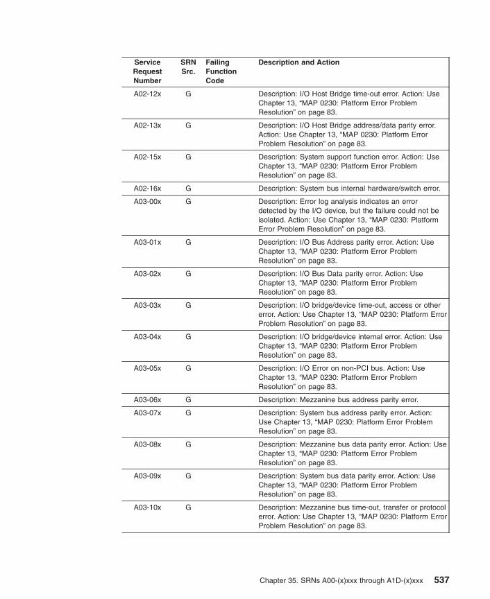
ServiceRequestNumber
SRNSrc.
FailingFunctionCode
Description and Action
A02-12x G Description: I/O Host Bridge time-out error. Action: UseChapter 13, “MAP 0230: Platform Error ProblemResolution” on page 83.
A02-13x G Description: I/O Host Bridge address/data parity error.Action: Use Chapter 13, “MAP 0230: Platform ErrorProblem Resolution” on page 83.
A02-15x G Description: System support function error. Action: UseChapter 13, “MAP 0230: Platform Error ProblemResolution” on page 83.
A02-16x G Description: System bus internal hardware/switch error.
A03-00x G Description: Error log analysis indicates an errordetected by the I/O device, but the failure could not beisolated. Action: Use Chapter 13, “MAP 0230: PlatformError Problem Resolution” on page 83.
A03-01x G Description: I/O Bus Address parity error. Action: UseChapter 13, “MAP 0230: Platform Error ProblemResolution” on page 83.
A03-02x G Description: I/O Bus Data parity error. Action: UseChapter 13, “MAP 0230: Platform Error ProblemResolution” on page 83.
A03-03x G Description: I/O bridge/device time-out, access or othererror. Action: Use Chapter 13, “MAP 0230: Platform ErrorProblem Resolution” on page 83.
A03-04x G Description: I/O bridge/device internal error. Action: UseChapter 13, “MAP 0230: Platform Error ProblemResolution” on page 83.
A03-05x G Description: I/O Error on non-PCI bus. Action: UseChapter 13, “MAP 0230: Platform Error ProblemResolution” on page 83.
A03-06x G Description: Mezzanine bus address parity error.
A03-07x G Description: System bus address parity error. Action:Use Chapter 13, “MAP 0230: Platform Error ProblemResolution” on page 83.
A03-08x G Description: Mezzanine bus data parity error. Action: UseChapter 13, “MAP 0230: Platform Error ProblemResolution” on page 83.
A03-09x G Description: System bus data parity error. Action: UseChapter 13, “MAP 0230: Platform Error ProblemResolution” on page 83.
A03-10x G Description: Mezzanine bus time-out, transfer or protocolerror. Action: Use Chapter 13, “MAP 0230: Platform ErrorProblem Resolution” on page 83.
Chapter 35. SRNs A00-(x)xxx through A1D-(x)xxx 537
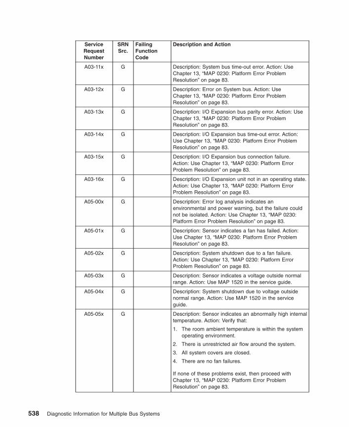
ServiceRequestNumber
SRNSrc.
FailingFunctionCode
Description and Action
A03-11x G Description: System bus time-out error. Action: UseChapter 13, “MAP 0230: Platform Error ProblemResolution” on page 83.
A03-12x G Description: Error on System bus. Action: UseChapter 13, “MAP 0230: Platform Error ProblemResolution” on page 83.
A03-13x G Description: I/O Expansion bus parity error. Action: UseChapter 13, “MAP 0230: Platform Error ProblemResolution” on page 83.
A03-14x G Description: I/O Expansion bus time-out error. Action:Use Chapter 13, “MAP 0230: Platform Error ProblemResolution” on page 83.
A03-15x G Description: I/O Expansion bus connection failure.Action: Use Chapter 13, “MAP 0230: Platform ErrorProblem Resolution” on page 83.
A03-16x G Description: I/O Expansion unit not in an operating state.Action: Use Chapter 13, “MAP 0230: Platform ErrorProblem Resolution” on page 83.
A05-00x G Description: Error log analysis indicates anenvironmental and power warning, but the failure couldnot be isolated. Action: Use Chapter 13, “MAP 0230:Platform Error Problem Resolution” on page 83.
A05-01x G Description: Sensor indicates a fan has failed. Action:Use Chapter 13, “MAP 0230: Platform Error ProblemResolution” on page 83.
A05-02x G Description: System shutdown due to a fan failure.Action: Use Chapter 13, “MAP 0230: Platform ErrorProblem Resolution” on page 83.
A05-03x G Description: Sensor indicates a voltage outside normalrange. Action: Use MAP 1520 in the service guide.
A05-04x G Description: System shutdown due to voltage outsidenormal range. Action: Use MAP 1520 in the serviceguide.
A05-05x G Description: Sensor indicates an abnormally high internaltemperature. Action: Verify that:
1. The room ambient temperature is within the systemoperating environment.
2. There is unrestricted air flow around the system.
3. All system covers are closed.
4. There are no fan failures.
If none of these problems exist, then proceed withChapter 13, “MAP 0230: Platform Error ProblemResolution” on page 83.
538 Diagnostic Information for Multiple Bus Systems

ServiceRequestNumber
SRNSrc.
FailingFunctionCode
Description and Action
A05-06x G Description: System shutdown due to abnormally highinternal temperature. Action: Verify that:
1. The room ambient temperature is within the systemoperating environment.
2. There is unrestricted air flow around the system.
3. All system covers are closed.
4. There are no fan failures.
If none of these problems exist, then proceed withChapter 13, “MAP 0230: Platform Error ProblemResolution” on page 83.
A05-07x G Description: Sensor indicates a power supply has failed.Action: Use Chapter 13, “MAP 0230: Platform ErrorProblem Resolution” on page 83.
A05-08x G Description: System shutdown due to power supplyfailure. Action: Use Chapter 13, “MAP 0230: PlatformError Problem Resolution” on page 83.
A05-09x G Description: Sensor detected a FRU that has failed.Action: Use Chapter 13, “MAP 0230: Platform ErrorProblem Resolution” on page 83.
A05-10x G Description: System shutdown due to FRU that hasfailed. Action: Use Chapter 13, “MAP 0230: PlatformError Problem Resolution” on page 83.
A05-14x G Description: System shutdown due to power fault with anunspecified cause. Action: Use Chapter 13, “MAP 0230:Platform Error Problem Resolution” on page 83.
A05-16x G Description: System shutdown due to internal powersupply failure. Action: Use Chapter 13, “MAP 0230:Platform Error Problem Resolution” on page 83.
A05-19x G Description: System shutdown due to Fan failure. Action:Use Chapter 13, “MAP 0230: Platform Error ProblemResolution” on page 83.
A05-21x G Description: System shutdown due to Over temperaturecondition. Action: Verify the following:
v The room ambient temperature is within the systemoperating environment.
v There is unrestricted air flow around the system.
v All system covers are closed.
If all conditions are met, then use Chapter 13, “MAP0230: Platform Error Problem Resolution” on page 83.
A05-22x G Description: System shutdown due to over temperatureand fan failure. Action: Use Chapter 13, “MAP 0230:Platform Error Problem Resolution” on page 83.
Chapter 35. SRNs A00-(x)xxx through A1D-(x)xxx 539
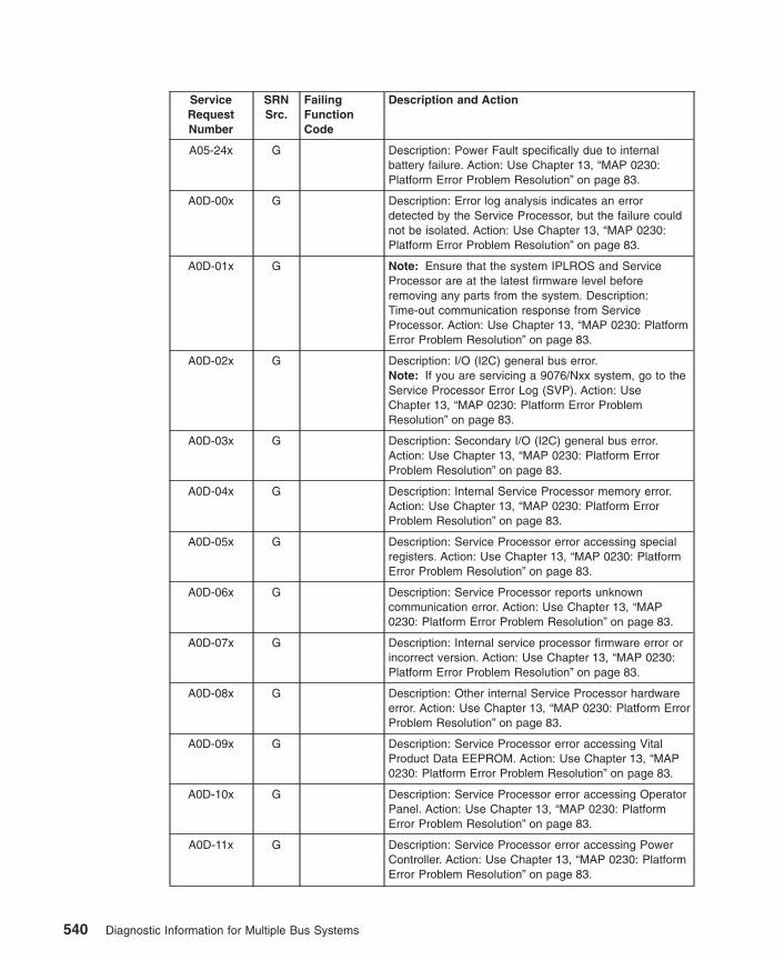
ServiceRequestNumber
SRNSrc.
FailingFunctionCode
Description and Action
A05-24x G Description: Power Fault specifically due to internalbattery failure. Action: Use Chapter 13, “MAP 0230:Platform Error Problem Resolution” on page 83.
A0D-00x G Description: Error log analysis indicates an errordetected by the Service Processor, but the failure couldnot be isolated. Action: Use Chapter 13, “MAP 0230:Platform Error Problem Resolution” on page 83.
A0D-01x G Note: Ensure that the system IPLROS and ServiceProcessor are at the latest firmware level beforeremoving any parts from the system. Description:Time-out communication response from ServiceProcessor. Action: Use Chapter 13, “MAP 0230: PlatformError Problem Resolution” on page 83.
A0D-02x G Description: I/O (I2C) general bus error.Note: If you are servicing a 9076/Nxx system, go to theService Processor Error Log (SVP). Action: UseChapter 13, “MAP 0230: Platform Error ProblemResolution” on page 83.
A0D-03x G Description: Secondary I/O (I2C) general bus error.Action: Use Chapter 13, “MAP 0230: Platform ErrorProblem Resolution” on page 83.
A0D-04x G Description: Internal Service Processor memory error.Action: Use Chapter 13, “MAP 0230: Platform ErrorProblem Resolution” on page 83.
A0D-05x G Description: Service Processor error accessing specialregisters. Action: Use Chapter 13, “MAP 0230: PlatformError Problem Resolution” on page 83.
A0D-06x G Description: Service Processor reports unknowncommunication error. Action: Use Chapter 13, “MAP0230: Platform Error Problem Resolution” on page 83.
A0D-07x G Description: Internal service processor firmware error orincorrect version. Action: Use Chapter 13, “MAP 0230:Platform Error Problem Resolution” on page 83.
A0D-08x G Description: Other internal Service Processor hardwareerror. Action: Use Chapter 13, “MAP 0230: Platform ErrorProblem Resolution” on page 83.
A0D-09x G Description: Service Processor error accessing VitalProduct Data EEPROM. Action: Use Chapter 13, “MAP0230: Platform Error Problem Resolution” on page 83.
A0D-10x G Description: Service Processor error accessing OperatorPanel. Action: Use Chapter 13, “MAP 0230: PlatformError Problem Resolution” on page 83.
A0D-11x G Description: Service Processor error accessing PowerController. Action: Use Chapter 13, “MAP 0230: PlatformError Problem Resolution” on page 83.
540 Diagnostic Information for Multiple Bus Systems

ServiceRequestNumber
SRNSrc.
FailingFunctionCode
Description and Action
A0D-12x G Description: Service Processor error accessing FanSensor. Action: Use Chapter 13, “MAP 0230: PlatformError Problem Resolution” on page 83.
A0D-13x G Description: Service Processor error accessing ThermalSensor.Note: If you are servicing a 9076/Nxx system, go to theService Processor Error Log (SVP).Action: UseChapter 13, “MAP 0230: Platform Error ProblemResolution” on page 83.
A0D-14x G Description: Service Processor error accessing VoltageSensor.Note: If you are servicing a 9076/Nxx system, go to theService Processor Error Log (SVP).Action: UseChapter 13, “MAP 0230: Platform Error ProblemResolution” on page 83.
A0D-17x G Description: Service Processor error accessing serialport. Action: Use Chapter 13, “MAP 0230: Platform ErrorProblem Resolution” on page 83.
A0D-18x G Description: Service Processor detected NVRAM error.Action: Use Chapter 13, “MAP 0230: Platform ErrorProblem Resolution” on page 83.
A0D-19x G Description: Service Processor error accessing RealTime Clock/Time-of-Day Clock. Action: Use Chapter 13,“MAP 0230: Platform Error Problem Resolution” onpage 83.
A0D-20x G Description: Service Processor error accessing scancontroller/hardware. Action: Use Chapter 13, “MAP 0230:Platform Error Problem Resolution” on page 83.
A0D-21x G Description: Service Processor detect error withTime-of-Day Clock backup battery. Action: UseChapter 13, “MAP 0230: Platform Error ProblemResolution” on page 83.
A0D-23x G Description: Loss of heart beat from Service Processor.Action: Use Chapter 13, “MAP 0230: Platform ErrorProblem Resolution” on page 83.
A0D-24x G Description: Service Processor detected a surveillancetime-out. Action: Use Chapter 13, “MAP 0230: PlatformError Problem Resolution” on page 83.
A0D-25x G Description: Power Control Network general connectionfailure. Action: Use Chapter 13, “MAP 0230: PlatformError Problem Resolution” on page 83.
A0D-26x G Description: Power Control Network node failure. Action:Use Chapter 13, “MAP 0230: Platform Error ProblemResolution” on page 83.
Chapter 35. SRNs A00-(x)xxx through A1D-(x)xxx 541

ServiceRequestNumber
SRNSrc.
FailingFunctionCode
Description and Action
A0D-29x G Description: Service Processor error accessing PowerControl Network. Action: Use Chapter 13, “MAP 0230:Platform Error Problem Resolution” on page 83.
A0D-30x G Description: Non-supported hardware. Action: UseChapter 13, “MAP 0230: Platform Error ProblemResolution” on page 83.
A0D-31x G Description: Error detected while handling anattention/interrupt from the system hardware. Action: UseChapter 13, “MAP 0230: Platform Error ProblemResolution” on page 83.
A0D-33x G Description: Array of Logic Built in Self Test Error. Action:Use Chapter 13, “MAP 0230: Platform Error ProblemResolution” on page 83.
A0D-34x G Description: Wire Test Error. Action: Use Chapter 13,“MAP 0230: Platform Error Problem Resolution” onpage 83.
A0D-35x G Description: Mainstore or Cache IPL Diagnostic Error.Action: Use Chapter 13, “MAP 0230: Platform ErrorProblem Resolution” on page 83.
A0D-36x G Description: Other IPL Diagnostic Error. Action: UseChapter 13, “MAP 0230: Platform Error ProblemResolution” on page 83.
A0D-37x G Description: Clock or PLL Error. Action: Use Chapter 13,“MAP 0230: Platform Error Problem Resolution” onpage 83.
A0D-38x G Description: Hardware Scan or Initialization Error. Action:Use Chapter 13, “MAP 0230: Platform Error ProblemResolution” on page 83.
A0D-39x G Description: Chip ID Verification Error. Action: UseChapter 13, “MAP 0230: Platform Error ProblemResolution” on page 83.
A0D-40x G Description: FRU Presence/Detect Error (Mis-Plugged).Action: UseChapter 13, “MAP 0230: Platform ErrorProblem Resolution” on page 83.
A10-100 E Description: The resource is unavailable due to an error.System is operating in degraded mode. Action: UseChapter 13, “MAP 0230: Platform Error ProblemResolution” on page 83.
A10-200 E Description: The resource was marked failed by theplatform. The system is operating in degraded mode.Action: Schedule maintenance. Use Chapter 13, “MAP0230: Platform Error Problem Resolution” on page 83.
542 Diagnostic Information for Multiple Bus Systems
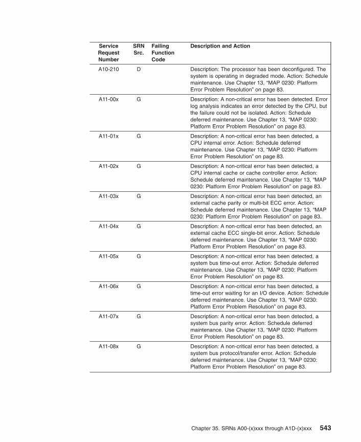
ServiceRequestNumber
SRNSrc.
FailingFunctionCode
Description and Action
A10-210 D Description: The processor has been deconfigured. Thesystem is operating in degraded mode. Action: Schedulemaintenance. Use Chapter 13, “MAP 0230: PlatformError Problem Resolution” on page 83.
A11-00x G Description: A non-critical error has been detected. Errorlog analysis indicates an error detected by the CPU, butthe failure could not be isolated. Action: Scheduledeferred maintenance. Use Chapter 13, “MAP 0230:Platform Error Problem Resolution” on page 83.
A11-01x G Description: A non-critical error has been detected, aCPU internal error. Action: Schedule deferredmaintenance. Use Chapter 13, “MAP 0230: PlatformError Problem Resolution” on page 83.
A11-02x G Description: A non-critical error has been detected, aCPU internal cache or cache controller error. Action:Schedule deferred maintenance. Use Chapter 13, “MAP0230: Platform Error Problem Resolution” on page 83.
A11-03x G Description: A non-critical error has been detected, anexternal cache parity or multi-bit ECC error. Action:Schedule deferred maintenance. Use Chapter 13, “MAP0230: Platform Error Problem Resolution” on page 83.
A11-04x G Description: A non-critical error has been detected, anexternal cache ECC single-bit error. Action: Scheduledeferred maintenance. Use Chapter 13, “MAP 0230:Platform Error Problem Resolution” on page 83.
A11-05x G Description: A non-critical error has been detected, asystem bus time-out error. Action: Schedule deferredmaintenance. Use Chapter 13, “MAP 0230: PlatformError Problem Resolution” on page 83.
A11-06x G Description: A non-critical error has been detected, atime-out error waiting for an I/O device. Action: Scheduledeferred maintenance. Use Chapter 13, “MAP 0230:Platform Error Problem Resolution” on page 83.
A11-07x G Description: A non-critical error has been detected, asystem bus parity error. Action: Schedule deferredmaintenance. Use Chapter 13, “MAP 0230: PlatformError Problem Resolution” on page 83.
A11-08x G Description: A non-critical error has been detected, asystem bus protocol/transfer error. Action: Scheduledeferred maintenance. Use Chapter 13, “MAP 0230:Platform Error Problem Resolution” on page 83.
Chapter 35. SRNs A00-(x)xxx through A1D-(x)xxx 543

ServiceRequestNumber
SRNSrc.
FailingFunctionCode
Description and Action
A11-50x G Description: Recoverable errors on resource indicate atrend toward an unrecoverable error. However, theresource could not be deconfigured and is still in use.The system is operating with the potential for anunrecoverable error. Action: If repair is not immediatelyavailable, reboot and the resource will be deconfigured.Then operations can continue in a degraded mode. Torepair use Chapter 13, “MAP 0230: Platform ErrorProblem Resolution” on page 83.
A11-510 G Description: Resource has been deconfigured and is nolonger in use due to a trend toward an unrecoverableerror. Action: The system is operating in a degradedmode. Schedule maintenance. To repair use Chapter 13,“MAP 0230: Platform Error Problem Resolution” onpage 83.
A11-520 G Description: Recoverable errors on resource indicate atrend toward an unrecoverable error. However, theresource could not be deconfigured and is still in use.The system is operating with the potential for anunrecoverable error. Action: Try removing the processesfrom the failing processor and retry the deconfiguration,use the ha_star -C command. An alternative is reboot,and the processor will be deconfigured. Then the systemcan continue in a degraded mode. To repair useChapter 13, “MAP 0230: Platform Error ProblemResolution” on page 83.
A11-530 G Description: Recoverable errors on resource indicate atrend toward an unrecoverable error. However, theresource could not be deconfigured and is still in use.The system is operating with the potential for anunrecoverable error. Run-time processor deconfigurationcan be enabled to deconfigure the processor. Action: Toenable run-time processor deconfiguration, use thechdev -a cpuguard=enable -l sys0 command. Then toretry the deconfiguration, use the ha_star -C command.An alternative is reboot, and the processor will bedeconfigured. Then the system can continue in adegraded mode. To repair use Chapter 13, “MAP 0230:Platform Error Problem Resolution” on page 83.
A11-540 G Description: Recoverable errors on resource indicate atrend toward an unrecoverable error. However, theresource could not be deconfigured and is still in use.The system is operating with the potential for anunrecoverable error. Action: If repair is not immediatelyavailable, reboot and the resource will be deconfigured.Then operations can continue in a degraded mode. Torepair use Chapter 13, “MAP 0230: Platform ErrorProblem Resolution” on page 83.
544 Diagnostic Information for Multiple Bus Systems
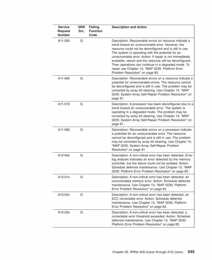
ServiceRequestNumber
SRNSrc.
FailingFunctionCode
Description and Action
A11-550 G Description: Recoverable errors on resource indicate atrend toward an unrecoverable error. However, theresource could not be deconfigured and is still in use.The system is operating with the potential for anunrecoverable error. Action: If repair is not immediatelyavailable, reboot and the resource will be deconfigured.Then operations can continue in a degraded mode. Torepair use Chapter 13, “MAP 0230: Platform ErrorProblem Resolution” on page 83.
A11-560 G Description: Recoverable errors on a resource indicate apotential for unrecoverable errors. The resource cannotbe deconfigured and is still in use. The problem may becorrected by array bit steering. Use Chapter 14, “MAP0235: System Array Self-Repair Problem Resolution” onpage 91.
A11-570 G Description: A processor has been deconfigured due to atrend toward an unrecoverable error. The system isoperating in a degraded mode. The problem may becorrected by array bit steering. Use Chapter 14, “MAP0235: System Array Self-Repair Problem Resolution” onpage 91.
A11-580 G Description: Recoverable errors on a processor indicatea potential for an unrecoverable error. The resourcecannot be deconfigured and is still in use. The problemmay be corrected by array bit steering. Use Chapter 14,“MAP 0235: System Array Self-Repair ProblemResolution” on page 91.
A12-00x G Description: A non-critical error has been detected. Errorlog analysis indicates an error detected by the memorycontroller, but the failure could not be isolated. Action:Schedule deferred maintenance. Use Chapter 13, “MAP0230: Platform Error Problem Resolution” on page 83.
A12-01x G Description: A non-critical error has been detected, anuncorrectable memory error. Action: Schedule deferredmaintenance. Use Chapter 13, “MAP 0230: PlatformError Problem Resolution” on page 83.
A12-02x G Description: A non-critical error has been detected, anECC correctable error. Action: Schedule deferredmaintenance. Use Chapter 13, “MAP 0230: PlatformError Problem Resolution” on page 83.
A12-03x G Description: A non-critical error has been detected, acorrectable error threshold exceeded. Action: Scheduledeferred maintenance. Use Chapter 13, “MAP 0230:Platform Error Problem Resolution” on page 83.
Chapter 35. SRNs A00-(x)xxx through A1D-(x)xxx 545

ServiceRequestNumber
SRNSrc.
FailingFunctionCode
Description and Action
A12-04x G Description: A non-critical error has been detected, amemory control subsystem internal error. Action:Schedule deferred maintenance. Use Chapter 13, “MAP0230: Platform Error Problem Resolution” on page 83.
A12-05x G Description: A non-critical error has been detected, amemory address error (invalid address or accessattempt). Action: Schedule deferred maintenance. UseChapter 13, “MAP 0230: Platform Error ProblemResolution” on page 83.
A12-06x G Description: A non-critical error has been detected, amemory data error (bad data going to memory). Action:Schedule deferred maintenance. Use Chapter 13, “MAP0230: Platform Error Problem Resolution” on page 83.
A12-07x G Description: A non-critical error has been detected, amemory bus/switch internal error. Action: Scheduledeferred maintenance. Use Chapter 13, “MAP 0230:Platform Error Problem Resolution” on page 83.
A12-08x G Description: A non-critical error has been detected, amemory time-out error. Action: Schedule deferredmaintenance. Use Chapter 13, “MAP 0230: PlatformError Problem Resolution” on page 83.
A12-09x G Description: A non-critical error has been detected, asystem bus parity error. Action: Schedule deferredmaintenance. Use Chapter 13, “MAP 0230: PlatformError Problem Resolution” on page 83.
A12-10x G Description: A non-critical error has been detected, asystem bus time-out error. Action: Schedule deferredmaintenance. Use Chapter 13, “MAP 0230: PlatformError Problem Resolution” on page 83.
A12-11x G Description: A non-critical error has been detected, asystem bus protocol/transfer error. Action: Scheduledeferred maintenance. Use Chapter 13, “MAP 0230:Platform Error Problem Resolution” on page 83.
A12-12x G Description: A non-critical error has been detected, anI/O host bridge time-out error. Action: Schedule deferredmaintenance. Use Chapter 13, “MAP 0230: PlatformError Problem Resolution” on page 83.
A12-13x G Description: A non-critical error has been detected, a I/Ohost bridge address/data parity error. Action: Scheduledeferred maintenance. Use Chapter 13, “MAP 0230:Platform Error Problem Resolution” on page 83.
A12-15x G Description: A non-critical error has been detected, asystem support function error. Action: Schedule deferredmaintenance. Use Chapter 13, “MAP 0230: PlatformError Problem Resolution” on page 83.
546 Diagnostic Information for Multiple Bus Systems

ServiceRequestNumber
SRNSrc.
FailingFunctionCode
Description and Action
A12-16x G Description: A non-critical error has been detected, asystem bus internal hardware/switch error. Action:Schedule deferred maintenance. Use Chapter 13, “MAP0230: Platform Error Problem Resolution” on page 83.
A12-50x G Description: Recoverable errors on resource indicate atrend toward an unrecoverable error. However, theresource could not be deconfigured and is still in use.The system is operating with the potential for anunrecoverable error. Action: If repair is not immediatelyavailable, reboot and the resource will be deconfigured.Then operations can continue in a degraded mode. Torepair use Chapter 13, “MAP 0230: Platform ErrorProblem Resolution” on page 83.
A13-00x G Description: A non-critical error has been detected, aerror log analysis indicates an error detected by the I/Odevice, but the failure could not be isolated. Action:Schedule deferred maintenance. Use Chapter 13, “MAP0230: Platform Error Problem Resolution” on page 83.
A13-01x G Description: A non-critical error has been detected, anI/O bus address parity error. Action: Schedule deferredmaintenance. Use Chapter 13, “MAP 0230: PlatformError Problem Resolution” on page 83.
A13-02x G Description: A non-critical error has been detected, anI/O bus data parity error. Action: Schedule deferredmaintenance. Use Chapter 13, “MAP 0230: PlatformError Problem Resolution” on page 83.
A13-03x G Description: A non-critical error has been detected, anI/O bus time-out, access or other error. Action: Scheduledeferred maintenance. Use Chapter 13, “MAP 0230:Platform Error Problem Resolution” on page 83.
A13-04x G Description: A non-critical error has been detected, anI/O bridge/device internal error. Action: Scheduledeferred maintenance. Use Chapter 13, “MAP 0230:Platform Error Problem Resolution” on page 83.
A13-05x G Description: A non-critical error has been detected, anI/O error on non-PCI bus. Action: Schedule deferredmaintenance. Use Chapter 13, “MAP 0230: PlatformError Problem Resolution” on page 83.
A13-06x G Description: A non-critical error has been detected, amezzanine bus address parity error. Action: Scheduledeferred maintenance. Use Chapter 13, “MAP 0230:Platform Error Problem Resolution” on page 83.
A13-07x G Description: A non-critical error has been detected, asystem bus address parity error. Action: Scheduledeferred maintenance. Use Chapter 13, “MAP 0230:Platform Error Problem Resolution” on page 83.
Chapter 35. SRNs A00-(x)xxx through A1D-(x)xxx 547
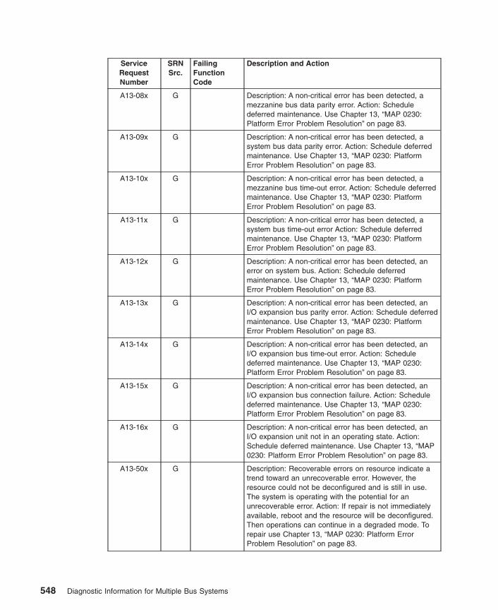
ServiceRequestNumber
SRNSrc.
FailingFunctionCode
Description and Action
A13-08x G Description: A non-critical error has been detected, amezzanine bus data parity error. Action: Scheduledeferred maintenance. Use Chapter 13, “MAP 0230:Platform Error Problem Resolution” on page 83.
A13-09x G Description: A non-critical error has been detected, asystem bus data parity error. Action: Schedule deferredmaintenance. Use Chapter 13, “MAP 0230: PlatformError Problem Resolution” on page 83.
A13-10x G Description: A non-critical error has been detected, amezzanine bus time-out error. Action: Schedule deferredmaintenance. Use Chapter 13, “MAP 0230: PlatformError Problem Resolution” on page 83.
A13-11x G Description: A non-critical error has been detected, asystem bus time-out error Action: Schedule deferredmaintenance. Use Chapter 13, “MAP 0230: PlatformError Problem Resolution” on page 83.
A13-12x G Description: A non-critical error has been detected, anerror on system bus. Action: Schedule deferredmaintenance. Use Chapter 13, “MAP 0230: PlatformError Problem Resolution” on page 83.
A13-13x G Description: A non-critical error has been detected, anI/O expansion bus parity error. Action: Schedule deferredmaintenance. Use Chapter 13, “MAP 0230: PlatformError Problem Resolution” on page 83.
A13-14x G Description: A non-critical error has been detected, anI/O expansion bus time-out error. Action: Scheduledeferred maintenance. Use Chapter 13, “MAP 0230:Platform Error Problem Resolution” on page 83.
A13-15x G Description: A non-critical error has been detected, anI/O expansion bus connection failure. Action: Scheduledeferred maintenance. Use Chapter 13, “MAP 0230:Platform Error Problem Resolution” on page 83.
A13-16x G Description: A non-critical error has been detected, anI/O expansion unit not in an operating state. Action:Schedule deferred maintenance. Use Chapter 13, “MAP0230: Platform Error Problem Resolution” on page 83.
A13-50x G Description: Recoverable errors on resource indicate atrend toward an unrecoverable error. However, theresource could not be deconfigured and is still in use.The system is operating with the potential for anunrecoverable error. Action: If repair is not immediatelyavailable, reboot and the resource will be deconfigured.Then operations can continue in a degraded mode. Torepair use Chapter 13, “MAP 0230: Platform ErrorProblem Resolution” on page 83.
548 Diagnostic Information for Multiple Bus Systems

ServiceRequestNumber
SRNSrc.
FailingFunctionCode
Description and Action
A15-01x G Description: Sensor indicates a fan is turning too slowly.Action: Schedule deferred maintenance. Use Chapter 13,“MAP 0230: Platform Error Problem Resolution” onpage 83.
A15-03x G Description: Sensor indicates a voltage outside normalrange. Action: Schedule deferred maintenance. UseChapter 13, “MAP 0230: Platform Error ProblemResolution” on page 83.
A15-05x G Description: Sensor indicates an abnormally high internaltemperature. Action: Verify that:
1. The room ambient temperature is within the systemoperating environment.
2. There is unrestricted air flow around the system.
3. All system covers are closed.
4. There are no fan failures.
If none of these problems exist, then proceed withChapter 13, “MAP 0230: Platform Error ProblemResolution” on page 83.
A15-07x G Description: Sensor indicates a power supply has failed.Action: Schedule deferred maintenance. Use Chapter 13,“MAP 0230: Platform Error Problem Resolution” onpage 83.
A15-09x G Description: Sensor indicates a FRU has failed. Action:Schedule deferred maintenance. Use Chapter 13, “MAP0230: Platform Error Problem Resolution” on page 83.
A15-11x G Description: Sensor detected a redundant fan failure.Action: Schedule deferred maintenance. Use Chapter 13,“MAP 0230: Platform Error Problem Resolution” onpage 83.
A15-12x G Description: Sensor detected redundant power supplyfailure. Action: Schedule deferred maintenance. UseChapter 13, “MAP 0230: Platform Error ProblemResolution” on page 83.
A15-13x G Description: Sensor detected a redundant FRU that hasfailed. Action: Schedule deferred maintenance. UseChapter 13, “MAP 0230: Platform Error ProblemResolution” on page 83.
A15-14x G Description: Power fault due to unspecified cause.Action: Schedule deferred maintenance. Use Chapter 13,“MAP 0230: Platform Error Problem Resolution” onpage 83.
A15-16x G Description: Internal power supply failure. Action:Schedule deferred maintenance. Use Chapter 13, “MAP0230: Platform Error Problem Resolution” on page 83.
Chapter 35. SRNs A00-(x)xxx through A1D-(x)xxx 549

ServiceRequestNumber
SRNSrc.
FailingFunctionCode
Description and Action
A15-17x G Description: Internal redundant power supply failure.Action: Schedule deferred maintenance. Use Chapter 13,“MAP 0230: Platform Error Problem Resolution” onpage 83.
A15-19x G Description: Fan failure. Action: Schedule deferredmaintenance. Use Chapter 13, “MAP 0230: PlatformError Problem Resolution” on page 83.
A15-20x G Description: Non-critical cooling problem, loss ofredundant fan. Action: Schedule deferred maintenance.Use Chapter 13, “MAP 0230: Platform Error ProblemResolution” on page 83.
A15-21x G Description: Over temperature condition. Action: Verifythe following:
v The room ambient temperature is within the systemoperating environment.
v There is unrestricted air flow around the system.
v All system covers are closed.
If all conditions are met, then use Chapter 13, “MAP0230: Platform Error Problem Resolution” on page 83.
A15-22x G Description: Fan failure and Over temperature condition.Action: Schedule deferred maintenance. Use Chapter 13,“MAP 0230: Platform Error Problem Resolution” onpage 83.
A15-23x G Description: Non-critical power problem, loss ofredundant power supply. Action: Schedule deferredmaintenance. Use Chapter 13, “MAP 0230: PlatformError Problem Resolution” on page 83.
A15-24x G Description: Power Fault specifically due to internalbattery failure. Action: Schedule deferred maintainence.Use Chapter 13, “MAP 0230: Platform Error ProblemResolution” on page 83.
A15-50x G Description: Recoverable errors on resource indicate atrend toward an unrecoverable error. However, theresource could not be deconfigured and is still in use.The system is operating with the potential for anunrecoverable error. Action: If repair is not immediatelyavailable, reboot and the resource will be deconfigured.Then operations can continue in a degraded mode. Torepair use Chapter 13, “MAP 0230: Platform ErrorProblem Resolution” on page 83.
A1D-00x G Description: A non-critical error has been detected. Errorlog analysis indicates an error detected by the ServiceProcessor, but the failure could not be isolated. Action:Schedule deferred maintenance. Use Chapter 13, “MAP0230: Platform Error Problem Resolution” on page 83.
550 Diagnostic Information for Multiple Bus Systems

ServiceRequestNumber
SRNSrc.
FailingFunctionCode
Description and Action
A1D-01x G Note: Ensure that the system IPLROS and ServiceProcessor are at the latest firmware level beforeremoving any parts from the system. Description: Anon-critical error has been detected. Time Outcommunication response from Service Processor Action:Schedule deferred maintenance. Use Chapter 13, “MAP0230: Platform Error Problem Resolution” on page 83.
A1D-02x G Description: A non-critical error has been detected, anI/O (I2C) general bus error. Action: Schedule deferredmaintenance. Use Chapter 13, “MAP 0230: PlatformError Problem Resolution” on page 83.
A1D-03x G Description: A non-critical error has been detected, asecondary I/O (I2C) general bus error. Action: Scheduledeferred maintenance. Use Chapter 13, “MAP 0230:Platform Error Problem Resolution” on page 83.
A1D-04x G Description: A non-critical error has been detected, aninternal service processor memory error. Action:Schedule deferred maintenance. Use Chapter 13, “MAP0230: Platform Error Problem Resolution” on page 83.
A1D-05x G Description: A non-critical error has been detected, aservice processor error accessing special registers.Action: Schedule deferred maintenance. Use Chapter 13,“MAP 0230: Platform Error Problem Resolution” onpage 83.
A1D-06x G Description: A non-critical error has been detected, aservice processor reports unknown communication error.Action: Schedule deferred maintenance. Use Chapter 13,“MAP 0230: Platform Error Problem Resolution” onpage 83.
A1D-07x G Description: A non-critical error has been detected,:Internal service processor firmware error or incorrectversion. Action: Schedule deferred maintenance. UseChapter 13, “MAP 0230: Platform Error ProblemResolution” on page 83.
A1D-08x G Description: A non-critical error has been detected, another internal service processor hardware error. Action:Schedule deferred maintenance. Use Chapter 13, “MAP0230: Platform Error Problem Resolution” on page 83.
A1D-09x G Description: A non-critical error has been detected, aservice processor error accessing vital product dataEEPROM. Action: Schedule deferred maintenance. UseChapter 13, “MAP 0230: Platform Error ProblemResolution” on page 83.
A1D-10x G Description: A non-critical error has been detected, aservice processor error accessing operator panel. Action:Schedule deferred maintenance. Use Chapter 13, “MAP0230: Platform Error Problem Resolution” on page 83.
Chapter 35. SRNs A00-(x)xxx through A1D-(x)xxx 551

ServiceRequestNumber
SRNSrc.
FailingFunctionCode
Description and Action
A1D-11x G Description: A non-critical error has been detected, aservice processor error accessing power controller.Action: Schedule deferred maintenance. Use Chapter 13,“MAP 0230: Platform Error Problem Resolution” onpage 83.
A1D-12x G Description: A non-critical error has been detected, aservice processor error accessing fan sensor. Action:Schedule deferred maintenance. Use Chapter 13, “MAP0230: Platform Error Problem Resolution” on page 83.
A1D-13x G Description: A non-critical error has been detected, aservice processor error accessing a thermal sensor.Action: Schedule deferred maintenance. Use Chapter 13,“MAP 0230: Platform Error Problem Resolution” onpage 83.
A1D-14x G Description: A non-critical error has been detected, aservice processor error accessing voltage sensor. Action:Schedule deferred maintenance. Use Chapter 13, “MAP0230: Platform Error Problem Resolution” on page 83.
A1D-17x G Description: A non-critical error has been detected, aservice processor error accessing serial port. Action:Schedule deferred maintenance. Use Chapter 13, “MAP0230: Platform Error Problem Resolution” on page 83.
A1D-18x G Description: A non-critical error has been detected, aservice processor detected NVRAM error. Action:Schedule deferred maintenance. Use Chapter 13, “MAP0230: Platform Error Problem Resolution” on page 83.
A1D-19x G Description: A non-critical error has been detected, aservice processor error accessing real timeclock/time-of-day clock. Action: Schedule deferredmaintenance. Use Chapter 13, “MAP 0230: PlatformError Problem Resolution” on page 83.
A1D-20x G Description: A non-critical error has been detected:Service processor error accessing scancontroller/hardware. Action: Schedule deferredmaintenance. Use Chapter 13, “MAP 0230: PlatformError Problem Resolution” on page 83.
A1D-21x G Description: A non-critical error has been detected, aservice processor detected error with time-of-day clockbackup battery. Action: Schedule deferred maintenance.Use Chapter 13, “MAP 0230: Platform Error ProblemResolution” on page 83.
A1D-23x G Description: A non-critical error has been detected: Lossof heart beat from Service Processor. Action: Scheduledeferred maintenance. Use Chapter 13, “MAP 0230:Platform Error Problem Resolution” on page 83.
552 Diagnostic Information for Multiple Bus Systems

ServiceRequestNumber
SRNSrc.
FailingFunctionCode
Description and Action
A1D-24x G Description: A non-critical error has been detected, aservice processor detected a surveillance time-out.Action: Schedule deferred maintenance. Use Chapter 13,“MAP 0230: Platform Error Problem Resolution” onpage 83.
A1D-25x G Description: A non-critical error has been detected, apower control network general connection failure. Action:Schedule deferred maintenance. Use Chapter 13, “MAP0230: Platform Error Problem Resolution” on page 83.
A1D-26x G Description: A non-critical error has been detected, apower control network node failure. Action: Scheduledeferred maintenance. Use Chapter 13, “MAP 0230:Platform Error Problem Resolution” on page 83.
A1D-29x G Description: A non-critical error has been detected, aservice process error accessing power control network.Action: Schedule deferred maintenance. Use Chapter 13,“MAP 0230: Platform Error Problem Resolution” onpage 83.
A1D-30x G Description: A non-critical error has been detected:Non-supported hardware. Action: Schedule deferredmaintenance. Use Chapter 13, “MAP 0230: PlatformError Problem Resolution” on page 83.
A1D-31x G Description: A non-critical error has been detected: Errordetected while handling an attention/interrupt from thesystem hardware. Use Chapter 13, “MAP 0230: PlatformError Problem Resolution” on page 83.
A1D-33x G Description: A non-critical error has been detected: Arrayof Logic Built in Self Test Error. Action: Scheduledeferred maintenance. Use Chapter 13, “MAP 0230:Platform Error Problem Resolution” on page 83.
A1D-34x G Description: A non-critical error has been detected: WireTest Error. Action: Schedule deferred maintenance. UseChapter 13, “MAP 0230: Platform Error ProblemResolution” on page 83.
A1D-35x G Description: A non-critical error has been detected:Mainstore or Cache IPL Diagnostic Error. Action:Schedule deferred maintenance. Use Chapter 13, “MAP0230: Platform Error Problem Resolution” on page 83.
A1D-36x G Description: A non-critical error has been detected: OtherIPL Diagnostic Error. Action: Schedule deferredmaintenance. Use Chapter 13, “MAP 0230: PlatformError Problem Resolution” on page 83.
A1D-37x G Description: A non-critical error has been detected: Clockor PLL Error. Action: Schedule deferred maintenance.Use Chapter 13, “MAP 0230: Platform Error ProblemResolution” on page 83.
Chapter 35. SRNs A00-(x)xxx through A1D-(x)xxx 553
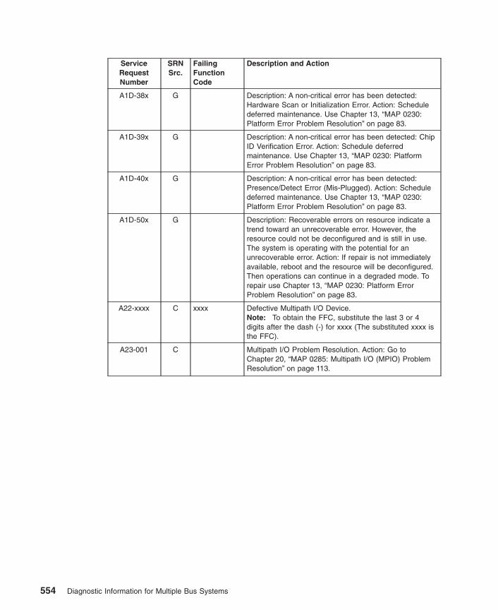
ServiceRequestNumber
SRNSrc.
FailingFunctionCode
Description and Action
A1D-38x G Description: A non-critical error has been detected:Hardware Scan or Initialization Error. Action: Scheduledeferred maintenance. Use Chapter 13, “MAP 0230:Platform Error Problem Resolution” on page 83.
A1D-39x G Description: A non-critical error has been detected: ChipID Verification Error. Action: Schedule deferredmaintenance. Use Chapter 13, “MAP 0230: PlatformError Problem Resolution” on page 83.
A1D-40x G Description: A non-critical error has been detected:Presence/Detect Error (Mis-Plugged). Action: Scheduledeferred maintenance. Use Chapter 13, “MAP 0230:Platform Error Problem Resolution” on page 83.
A1D-50x G Description: Recoverable errors on resource indicate atrend toward an unrecoverable error. However, theresource could not be deconfigured and is still in use.The system is operating with the potential for anunrecoverable error. Action: If repair is not immediatelyavailable, reboot and the resource will be deconfigured.Then operations can continue in a degraded mode. Torepair use Chapter 13, “MAP 0230: Platform ErrorProblem Resolution” on page 83.
A22-xxxx C xxxx Defective Multipath I/O Device.Note: To obtain the FFC, substitute the last 3 or 4digits after the dash (-) for xxxx (The substituted xxxx isthe FFC).
A23-001 C Multipath I/O Problem Resolution. Action: Go toChapter 20, “MAP 0285: Multipath I/O (MPIO) ProblemResolution” on page 113.
554 Diagnostic Information for Multiple Bus Systems

Chapter 36. SRNs 2520-101 through 25C1-(x)xxx
Replace FRU parts in the order by which the ″Failing Function Codes″ are listed.
ServiceRequestNumber
SRNSrc.
FailingFunctionCodes
Description and Action (Unless otherwise indicated,use Chapter 11, “MAP 0210: General ProblemResolution” on page 67.)
2520-101 D 221 Description: Enhanced error handling failure on the bus.
2520-102 D 293 Description: Enhanced error handling failure on aPCI-PCI Bridge.
2520-103 D 2520221
Description: Enhanced error handling failure on theadapter.
2520-212 D 2520 Description: FIFO empty bit set.
2520-213 D 2520 Description: FIFO empty bit clear.
2520-214 D 2520 Description: FIFO full bit set.
2520-215 D 2520 Description: FIFO full bit clear.
2520-216 D 2520 Description: FIFO data miscompare.
2520-217 D 2520 Description: SCSI FIFO data miscompare.
2520-218 D 2520 Description: SCSI FIFO underflow.
2520-219 D Description: SCSI parity error. Action: Go to Chapter 8,“MAP 0050: SCSI Bus Problems” on page 51.
2520-220 D 2520 Description: SCSI FIFO flags error.
2520-221 D 2520293
Description: Miscompare during the write/read ofconfiguration register.
2520-222 D 2520 Description: Error during the write/read of the memoryregister.
2520-223 D 2520 Description: Miscompare during the write/read of thememory I/O.
2520-224 D 2520221
Description: SCSI configuration read or write error.
2520-226 D 2520 Description: SCSI wrap or PTC error.
2520-227 D 2520221
Description: SCSI adapter interrupt test failure.
2520-230 D Description: Arbitration test failed. Action: Use Chapter 8,“MAP 0050: SCSI Bus Problems” on page 51.
2520-231 D Description: Function could not complete. Action: UseChapter 8, “MAP 0050: SCSI Bus Problems” on page 51.
2520-232 D Description: SCSI bus data miscompare. Action: UseChapter 8, “MAP 0050: SCSI Bus Problems” on page 51.
2520-240 D Description: No terminal power. Action: Use Chapter 8,“MAP 0050: SCSI Bus Problems” on page 51.
2520-242 D Description: SCSI bus error. Action: Use Chapter 8,“MAP 0050: SCSI Bus Problems” on page 51.
555
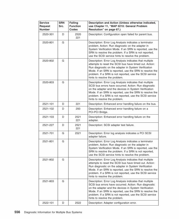
ServiceRequestNumber
SRNSrc.
FailingFunctionCodes
Description and Action (Unless otherwise indicated,use Chapter 11, “MAP 0210: General ProblemResolution” on page 67.)
2520-301 D 2520221
Description: Configuration open failed for parent bus.
2520-801 G Description: Error Log Analysis indicates a terminatorproblem. Action: Run diagnostic on the adapter inSystem Verification Mode. If an SRN is reported, use theSRN to resolve the problem. If a SRN is not reported,use the SCSI service hints to resolve the problem.
2520-802 G Description: Error Log Analysis indicates that multipleattempts to reset the SCSI bus have timed out. Action:Run diagnostic on the adapter in System VerificationMode. If an SRN is reported, use the SRN to resolve theproblem. If a SRN is not reported, use the SCSI servicehints to resolve the problem.
2520-803 G Description: Error Log Analysis indicates that multipleSCSI bus errors have occurred. Action: Run diagnosticon the adapter and the devices in System VerificationMode. If an SRN is reported, use the SRN to resolve theproblem. If a SRN is not reported, use the SCSI servicehints to resolve the problem.
2521-101 D 221 Description: Enhanced error handling failure on the bus.
2521-102 D 293 Description: Enhanced error handling failure on aPCI-PCI Bridge.
2521-103 D 2521221
Description: Enhanced error handling failure on theadapter.
2521-227 D 2521221
Description: SCSI adapter test failure.
2521-701 G 2521 Description: Error log analysis indicates a PCI SCSIadapter failure.
2521-801 G Description: Error Log Analysis indicates a terminatorproblem. Action: Run diagnostic on the adapter inSystem Verification Mode. If an SRN is reported, use theSRN to resolve the problem. If a SRN is not reported,use the SCSI service hints to resolve the problem.
2521-802 G Description: Error Log Analysis indicates that multipleattempts to reset the SCSI bus have timed out. Action:Run diagnostic on the adapter in System VerificationMode. If an SRN is reported, use the SRN to resolve theproblem. If a SRN is not reported, use the SCSI servicehints to resolve the problem.
2521-803 G Description: Error Log Analysis indicates that multipleSCSI bus errors have occurred. Action: Run diagnosticon the adapter and the devices in System VerificationMode. If an SRN is reported, use the SRN to resolve theproblem. If a SRN is not reported, use the SCSI servicehints to resolve the problem.
2522-101 D 2522 Description: Adapter configuration error.
556 Diagnostic Information for Multiple Bus Systems

ServiceRequestNumber
SRNSrc.
FailingFunctionCodes
Description and Action (Unless otherwise indicated,use Chapter 11, “MAP 0210: General ProblemResolution” on page 67.)
2522-701 G 2522 Description: Error Log Analysis indicates adapterhardware error.
2522-702 G Description: Error Log Analysis indicates SCSI deviceerror. Action: Use Chapter 8, “MAP 0050: SCSI BusProblems” on page 51.
2522-703 G 2522221
Description: Error Log Analysis indicates hardwaresystem error due to EEH reset problem.
2522-704 G 2522221
Description: Error Log Analysis indicates hardwaresystem error from EEH event.
2522-705 G 2522221
Description: Error Log Analysis indicates PCI bus error.
2522-706 G 2522 Description: Error Log Analysis indicates adapterhardware error.
2522-707 G 2522221
Description: Error Log Analysis indicates PCI bus error.
2522-708 G 2522 Description: Error Log Analysis indicates adapter registertimeout error.
2524-101 D 2524 Description: Adapter configuration error.
2524-701 G 2524 Description: Error Log Analysis indicates adapterhardware error.
2524-702 G Description: Error Log Analysis indicates SCSI deviceerror. Action: Use Chapter 8, “MAP 0050: SCSI BusProblems” on page 51.
2524-703 G 2524221
Description: Error Log Analysis indicates hardwaresystem error due to EEH reset problem.
2524-704 G 2524221
Description: Error Log Analysis indicates hardwaresystem error from EEH event.
2524-705 G 2524221
Description: Error Log Analysis indicates PCI bus error.
2524-706 G 2524 Description: Error Log Analysis indicates adapterhardware error.
2524-707 G 2524221
Description: Error Log Analysis indicates PCI bus error.
2524-708 G 2524 Description: Error Log Analysis indicates adapter registertimeout error.
2530-101 D 221 Description: Enhanced Error Handling failure on bus.
2530-102 D 221 Description: Enhanced Error Handling logic failure.
2530-103 D 2530 Description: Enhanced Error Handling failure on adapter.
2530-104 D 2530 Description: Port command test failure.
2530-105 D 2530 Description: CU command test failure.
2530-106 D 2530 Description: External wrap test failure.
Chapter 36. SRNs 2520-101 through 25C1-(x)xxx 557
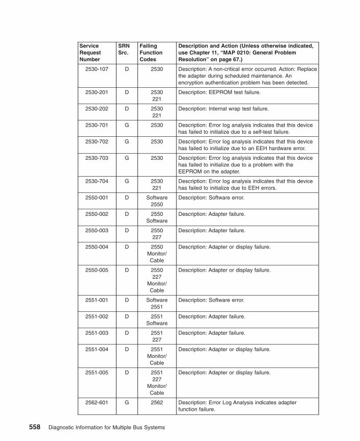
ServiceRequestNumber
SRNSrc.
FailingFunctionCodes
Description and Action (Unless otherwise indicated,use Chapter 11, “MAP 0210: General ProblemResolution” on page 67.)
2530-107 D 2530 Description: A non-critical error occurred. Action: Replacethe adapter during scheduled maintenance. Anencryption authentication problem has been detected.
2530-201 D 2530221
Description: EEPROM test failure.
2530-202 D 2530221
Description: Internal wrap test failure.
2530-701 G 2530 Description: Error log analysis indicates that this devicehas failed to initialize due to a self-test failure.
2530-702 G 2530 Description: Error log analysis indicates that this devicehas failed to initialize due to an EEH hardware error.
2530-703 G 2530 Description: Error log analysis indicates that this devicehas failed to initialize due to a problem with theEEPROM on the adapter.
2530-704 G 2530221
Description: Error log analysis indicates that this devicehas failed to initialize due to EEH errors.
2550-001 D Software2550
Description: Software error.
2550-002 D 2550Software
Description: Adapter failure.
2550-003 D 2550227
Description: Adapter failure.
2550-004 D 2550Monitor/Cable
Description: Adapter or display failure.
2550-005 D 2550227
Monitor/Cable
Description: Adapter or display failure.
2551-001 D Software2551
Description: Software error.
2551-002 D 2551Software
Description: Adapter failure.
2551-003 D 2551227
Description: Adapter failure.
2551-004 D 2551Monitor/Cable
Description: Adapter or display failure.
2551-005 D 2551227
Monitor/Cable
Description: Adapter or display failure.
2562-601 G 2562 Description: Error Log Analysis indicates adapterfunction failure.
558 Diagnostic Information for Multiple Bus Systems

ServiceRequestNumber
SRNSrc.
FailingFunctionCodes
Description and Action (Unless otherwise indicated,use Chapter 11, “MAP 0210: General ProblemResolution” on page 67.)
2570-101 D 2570 Description: DES test failed.
2570-102 D 2570 Description: RSA test failed.
2570-103 D 2570 Description: MAC test failed.
2570-104 D 2570 Description: DES and SHA test failed.
2570-105 D 2570 Description: DES to SHA test failed.
2570-106 D 221 Description: Enhanced Error Handling Circuitry failure.
2570-107 D 221 Description: Enhanced Error Handling failure on bus.
2570-108 D 221 Description: Enhanced Error Handling failure on adapter.
2570-201 D 2570221
Description: Register test failed.
2570-601 G 2570 Description: ELA indicates hardware failure has ocurred.
2570-602 G 2570 Description: ELA indicates hardware timeout hasocurred.
2570-603 G 2570 Description: ELA indicates hardware failure and timeouthas ocurred.
2590-101 D 2590 Description: Unable to open CD-ROM device driver.
2590-201 D 25A0 Description: Unable to configure adapter.
2590-202 D 259025A0media
Description: Unable to configure the device.
2590-203 D 25A0 Description: Unable to open IDE adapter driver.
2590-204 D media2590
Description: The Inquire command failed.
2590-205 D 2590media
Description: The Read Sense Data command failed.
2590-206 D 2590 Description: The Test Unit Ready command failed.
2590-207 D media2590
Description: The test media is bad or missing.
2590-208 D 2590media
Description: The CD-ROM Play Audio command failed.
2590-209 D 2590 Description: No tone during audio test.
2590-210 D 2590 Description: The Prevent Media Removal or AllowMedia Removal command failed.
2590-211 D 2590 Description: CD-ROM drive indicates an error.
2591-101 D 2591 Description: Unable to open DVD-ROM device driver.
2591-201 D 25A0 Description: Unable to configure adapter.
2591-202 D 259125A0media
Description: Unable to configure the device.
Chapter 36. SRNs 2520-101 through 25C1-(x)xxx 559

ServiceRequestNumber
SRNSrc.
FailingFunctionCodes
Description and Action (Unless otherwise indicated,use Chapter 11, “MAP 0210: General ProblemResolution” on page 67.)
2591-203 D 25A0 Description: Unable to open IDE adapter driver.
2591-204 D media2591
Description: The Inquire command failed.
2591-205 D 2591media
Description: The Read Sense Data command failed.
2591-206 D 2591 Description: The Test Unit Ready command failed.
2591-207 D media2591
Description: The test media is bad or missing.
2591-208 D 2591media
Description: The DVD-ROM Play Audio commandfailed.
2591-209 D 2591 Description: No tone during audio test.
2591-210 D 2591 Description: The Prevent Media Removal or AllowMedia Removal command failed.
2591-211 D 2591 Description: DVD-ROM drive indicates an error.
25C0-101 D 221 Enhanced Error Handling Failure on bus.
25C0-102 D 293 Enhanced Error Handling Logic Failure.
25C0-103 D 25C0221
Enhanced Error Handling Failure while testing adapter.
25C0-104 D 25C0 Internal wrap test failure (10 Mbps).
25C0-105 D 25C0 Internal wrap test failure (100 Mbps).
25C0-106 D 25C0 Internal wrap test failure (1000 Mbps).
25C0-107 D 25C0 External wrap test failure (10 Mbps).
25C0-108 D 25C0 External wrap test failure (100 Mbps).
25C0-201 D 25C0221
Registers test failure.
25C0-701 G 25C0 Failure to initialize due to a self-test failure.
25C0-702 G 25C0221
Failure to recover from an EEH event.
25C0-703 G 25C0 Failure to initialize due to a problem while reading theEEPROM on the adapter.
25C0-704 G 25C0221
Device has attempted error recover.
25C1-101 D 221 Enhanced Error Handling Failure on bus.
25C1-102 D 293 Enhanced Error Handling Logic Failure.
25C1-103 D 25C1221
Enhanced Error Handling Failure while testing adapter.
25C1-104 D 25C1 Internal wrap test failure (10 Mbps).
25C1-105 D 25C1 Internal wrap test failure (100 Mbps).
25C1-106 D 25C1 Internal wrap test failure (1000 Mbps).
560 Diagnostic Information for Multiple Bus Systems
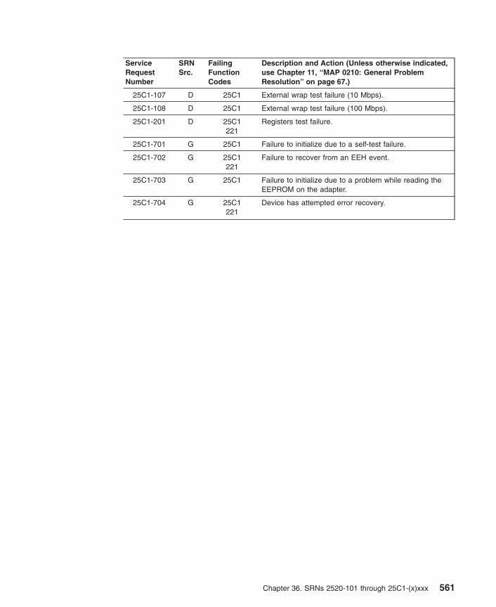
ServiceRequestNumber
SRNSrc.
FailingFunctionCodes
Description and Action (Unless otherwise indicated,use Chapter 11, “MAP 0210: General ProblemResolution” on page 67.)
25C1-107 D 25C1 External wrap test failure (10 Mbps).
25C1-108 D 25C1 External wrap test failure (100 Mbps).
25C1-201 D 25C1221
Registers test failure.
25C1-701 G 25C1 Failure to initialize due to a self-test failure.
25C1-702 G 25C1221
Failure to recover from an EEH event.
25C1-703 G 25C1 Failure to initialize due to a problem while reading theEEPROM on the adapter.
25C1-704 G 25C1221
Device has attempted error recovery.
Chapter 36. SRNs 2520-101 through 25C1-(x)xxx 561

562 Diagnostic Information for Multiple Bus Systems

Chapter 37. Failing Function Codes (FFCs)
Failing function codes represent functions within the system unit.
Note: When replacing a FRU, use Chapter 23, “MAP 0410: Repair Checkout” onpage 125 To verify the fix.
Description of the Failing Function Code ListThe failing function codes are listed in numerical sequence.
A function may not be physically packaged on the same FRU in different system units.When this condition exists, the FRU part number for each type of system unit is listed.
List Column Heading Term DefinitionsThe columns in the failing function code list are as follows:
Failing Function CodeThe failing function code number from the SRN list in Chapter 17, “MAP 0260: SystemHangs During Resource Configuration” on page 99.
Machine Type/ModelThis column is used when the failing function is on a FRU which differs by machinetype and model. Use the part number for the type system unit you are servicing.
See “Machine Types” on page 564 for the names of the machine types.
Note: Although the machine cover logo may depict the model number as four digits,the service and parts ordering system requires three-digit numbers. For example,if the cover logo depicts model number xxxx, service and parts documentationmay refer to that model as xxx.
Part NumberThis column contains the part number of the FRU that contains the failing function. Usethe part number for the type of system unit you are servicing.
Description and NotesThis column contains the description of the FRU and any usage notes. The FRUdescription may be different in different system units. Use the one for the type ofsystem unit you are servicing.
563
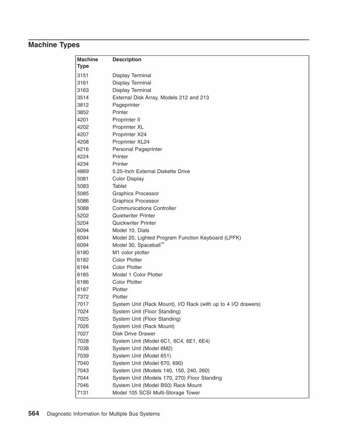
Machine Types
MachineType
Description
3151 Display Terminal3161 Display Terminal3163 Display Terminal3514 External Disk Array, Models 212 and 2133812 Pageprinter3852 Printer4201 Proprinter II4202 Proprinter XL4207 Proprinter X244208 Proprinter XL244216 Personal Pageprinter4224 Printer4234 Printer4869 5.25-Inch External Diskette Drive5081 Color Display5083 Tablet5085 Graphics Processor5086 Graphics Processor5088 Communications Controller5202 Quietwriter Printer5204 Quickwriter Printer6094 Model 10, Dials6094 Model 20, Lighted Program Function Keyboard (LPFK)6094 Model 30, Spaceball™
6180 M1 color plotter6182 Color Plotter6184 Color Plotter6185 Model 1 Color Plotter6186 Color Plotter6187 Plotter7372 Plotter7017 System Unit (Rack Mount), I/O Rack (with up to 4 I/O drawers)7024 System Unit (Floor Standing)7025 System Unit (Floor Standing)7026 System Unit (Rack Mount)7027 Disk Drive Drawer7028 System Unit (Model 6C1, 6C4, 6E1, 6E4)7038 System Unit (Model 6M2)7039 System Unit (Model 651)7040 System Unit (Model 670, 690)7043 System Unit (Models 140, 150, 240, 260)7044 System Unit (Models 170, 270) Floor Standing7046 System Unit (Model B50) Rack Mount7131 Model 105 SCSI Multi-Storage Tower
564 Diagnostic Information for Multiple Bus Systems

MachineType
Description
7134 High Density SCSI Disk Subsystem, Model 010.7137 Disk Array Subsystem Models 412, 413, and 4147135 RAIDiant Array SCSI Disk Drive Subsystem, Models 010 and 1107203 External Portable Disk Drive7204 External Disk Drive Model 3207206 2.0 GB or 4.0 GB External 4 mm Tape Drive
24/48 GB DDS-2 4 mm Autotape Loader7207 150 MB, 525 MB or 1.2 GB External 1/4-Inch Cartridge Tape Drive7208 2.3 GB or 5.0 GB External 8 mm Tape Drive7210 External CD-ROM Drive7235 POWERgraphics GTO graphics subsystem7250 POWERgraphics Accelerator7311 I/O Drawer (Models D10, D20)7317 System Unit, (Telco Rack Mounted)7331 Model 205 8 mm Tape Library7332 Model 005 4 mm Tape Library8508 Monochrome Display9076 SMP Thin/Wide Node9076 Power3 SMP Thin/Wide Node9076 Power3 SMP High Node9112 System Unit (Model 265)9333 High-Performance Disk Drive Subsystem Models 010 and 0119333 High-Performance Disk Drive Subsystem Models 500 and 5019334 SCSI Expansion Unit Model 010 (Single-Ended), Model 011 (Differential)9334 SCSI Expansion Unit Model 500 (Single-Ended), Model 501 (Differential)9348 1/2-Inch 9-Track Tape Drive
Chapter 37. Failing Function Codes (FFCs) 565
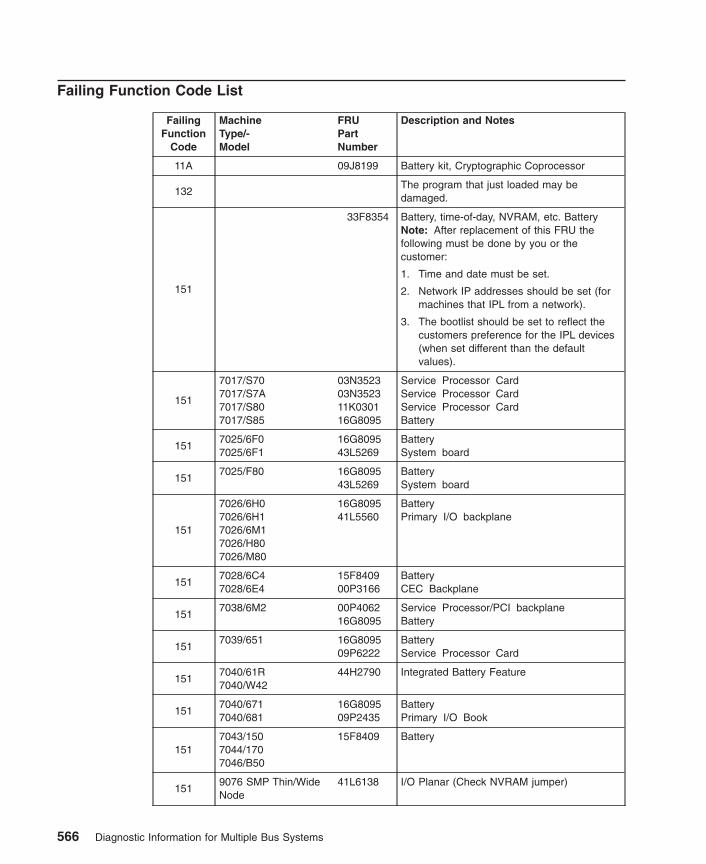
Failing Function Code List
FailingFunction
Code
MachineType/-Model
FRUPartNumber
Description and Notes
11A 09J8199 Battery kit, Cryptographic Coprocessor
132The program that just loaded may bedamaged.
151
33F8354 Battery, time-of-day, NVRAM, etc. BatteryNote: After replacement of this FRU thefollowing must be done by you or thecustomer:
1. Time and date must be set.
2. Network IP addresses should be set (formachines that IPL from a network).
3. The bootlist should be set to reflect thecustomers preference for the IPL devices(when set different than the defaultvalues).
151
7017/S707017/S7A7017/S807017/S85
03N352303N352311K030116G8095
Service Processor CardService Processor CardService Processor CardBattery
1517025/6F07025/6F1
16G809543L5269
BatterySystem board
1517025/F80 16G8095
43L5269BatterySystem board
151
7026/6H07026/6H17026/6M17026/H807026/M80
16G809541L5560
BatteryPrimary I/O backplane
1517028/6C47028/6E4
15F840900P3166
BatteryCEC Backplane
1517038/6M2 00P4062
16G8095Service Processor/PCI backplaneBattery
1517039/651 16G8095
09P6222BatteryService Processor Card
1517040/61R7040/W42
44H2790 Integrated Battery Feature
1517040/6717040/681
16G809509P2435
BatteryPrimary I/O Book
1517043/1507044/1707046/B50
15F8409 Battery
1519076 SMP Thin/WideNode
41L6138 I/O Planar (Check NVRAM jumper)
566 Diagnostic Information for Multiple Bus Systems

FailingFunction
Code
MachineType/-Model
FRUPartNumber
Description and Notes
1519076/ Power3 SMPThin/Wide Node
03N286603N3368
I/O planar (200 MHz)I/O planar (375 Mhz)(Check NVRAM jumper)
1519076/ Power3 SMPHigh Node
11K0571 NIO PlanarNote: There is no battery for this model.
152
7017/S70 21H703021H696121H776321H710093H375393H373493H368207L665807L6656
System Power Supply problemAC Bulk Power SupplySPCN cardProgrammable regulator assemblyMemory regulator assemblyAC box, Domestic (U.S.) single phaseAC box, World Trade, single phaseAC box, World Trade, two phaseBulk Power Supply (-48 Vdc)DC box (-48 Vdc)
152
7017/S7A 21H703021H696121H776321H710093H375393H373493H368297H946508L1336
AC Bulk Power SupplySPCN cardProgrammable regulator assemblyMemory regulator assemblyAC box, Domestic (U.S.) single phaseAC box, World Trade, single phaseAC box, World Trade, two phasePower distribution boardI/O Drawer Power Supply
152
7017/S807017/S85 21H7719
21H696121H776321H360393H375393H373493H3682
21H700004N6092
97H946508L1336
System RackAC Bulk Power SupplySPCN CardProgrammable Regulator assemblyCPM Regulator assemblyAC Box, Domestic (U.S.) Single PhaseAC Box, World Trade, Single PhaseAC Box, World Trade, Two PhaseWith dual line cord feature:
AC Box, Single phaseConcurrent maintenance card
I/O RackPower Distribution BoardI/O Drawer Power Supply
152 7024 93H3504 Power Supply
1527025/6F07025/6F1
24L1400 Power supply
152 7025/F30 40H5428 Power Supply (474 watts)
152
7025/F307025/F40
12J5701 Optional Power SupplyNote: If your are replacing the power supplybecause of receiving SRNs 950-700 thru950-998, replace the optional power supplyfirst.
Chapter 37. Failing Function Codes (FFCs) 567

FailingFunction
Code
MachineType/-Model
FRUPartNumber
Description and Notes
152 7025/F40 07L7476 Power Supply (575 watts)
152 7025/F50 93H9789 Power Supply
152 7025/F80 24L1400 Power supply
152
7026/6H07026/6H1
11K080241L540411K081241L541303N2829
CEC drawer ac power supplyCEC drawer dc power supplyI/O drawer ac power supplyI/O drawer dc power supplyCooling unit (filler)
152
7026/6M1 24L072844L004511K081203N2829
CEC drawer ac power supplyCEC drawer dc power supplyI/O drawer ac power supplyCooling unit (filler)
1527026/B80 00P2342
00P2344Power supply, acPower supply, dc
1527026/H10
93H8714 System Power Supply problemPower Supply
152
7026/H50 93H955108L133697H9464
Power Distribution BoardPower SupplyPower Supply(-48 Vdc)Note: Replace the Power Distribution Boardbefore replacing the power supply.
152
7026/H70 08L038894H104141L4881
Power Distribution BoardPower SupplyPower Supply(-48 Vdc)Note: Replace the Power Distribution Boardbefore replacing the power supply.
152
7026/H80 11K080241L540411K081241L541303N2829
CEC drawer ac power supplyCEC drawer dc power supplyI/O drawer ac power supplyI/O drawer dc power supplyCooling unit (filler)
152
7026/M80 24L072844L004511K081203N2829
CEC drawer ac power supplyCEC drawer dc power supplyI/O drawer ac power supplyCooling unit (filler)
1527028/6C17028/6E1
24P6867 Power supply
1527028/6C47028/6E4
09P5894 AC Power Supply
152 7038/6M2 21P4437 AC Power Supply
1527039/651 44P2134
09P6222Distributed Converter Assembly (DCA)Service Processor Card
568 Diagnostic Information for Multiple Bus Systems

FailingFunction
Code
MachineType/-Model
FRUPartNumber
Description and Notes
152
7040/6717040/681
11P154311P154411P154511P154611P154711P154811P154911P155011P155111P155211P1540
Distributed Converter Assembly (DCA1) P00Distributed Converter Assembly (DCA1) P01Distributed Converter Assembly (DCA2) P00Distributed Converter Assembly (DCA2) P01Distributed Converter Assembly (DCA3) P00Distributed Converter Assembly (DCA3) P01Distributed Converter Assembly (DCA4) P00Distributed Converter Assembly (DCA4) P01Distributed Converter Assembly (DCA5) P00Distributed Converter Assembly (DCA5) P01Capacitor Card
152 7040/61D 11P3582 Distributed Converter Assembly
152
7040/61R7040/W42
31L860911P159812K098111P420544H2790
Bulk Power Regulator (BPR)Bulk Power Controller (BPC)Bulk Power Distribution (BPD)Bulk Power Enclousure (BPE)Integrated Battery Feature (IBF)
1527043/1407043/1507043/240
40H756640H7563
PFC Power Supply (Japan Only)Non-PFC Power Supply (Other Countries)
152 7043/260 97H9337 Power supply
152 7043/270 24L1968 Power Supply
152 7044/170 41L5215 Power Supply
152 7044/270 24L1968 Power Supply
152 7046/B50 24L2659 Power supply
152 7203 00G2960 Bridge Box Power Supply
152 7204/001 46G3934 Bridge Box Power Supply
1527204 Models, 112,113, 114, 139, 317,325, 339
59H3760 Bridge Box Power Supply
1527204 Models 010, 215,315
8191380 Bridge Box Power Supply
152 7206/001 46G3934 Bridge Box Power Supply
152 7206/002 8191380 Bridge Box Power Supply
152 7207 Models 001, 011 00G2960 Bridge Box Power Supply
152 7207/012 46G3934 Bridge Box Power Supply
152 7207/315 59H3760 Bridge Box Power Supply
152 7208/001 00G2960 Bridge Box Power Supply
152
7208/0117208/0347208/3417208/342
46G393459H376059H283559H2836
Bridge Box Power Supply
Chapter 37. Failing Function Codes (FFCs) 569
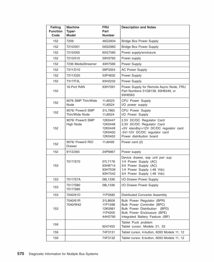
FailingFunction
Code
MachineType/-Model
FRUPartNumber
Description and Notes
152 7209 46G3934 Bridge Box Power Supply
152 7210/001 00G2960 Bridge Box Power Supply
152 7210/005 65G7585 Power supply/enclosure
152 7210/010 59H3760 Power supply
152 7236 MediaStreamer 40H7566 Power Supply
152 7311/D10 09P3354 AC Power Supply
152 7311/D20 53P4832 Power Supply
152 7317/F3L 93H2232 Power Supply
15216-Port RAN 93H7091 Power Supply for Remote Async Node, FRU
Part Numbers 51G8139, 93H6549, or93H6563
1529076 SMP Thin/WideNode
11J652311J6524
CPU Power SupplyI/O power supply
1529076/ Power3 SMPThin/Wide Node
31L786511J6524
CPU Power SupplyI/O Power Supply
152
9076/ Power3 SMPHigh Node
12K044712K044812K044912K045012K0452
2.5V DC/DC Regulator Card3.3V DC/DC Regulator Card+5V standby/+12V DC/DC regulator card-5V/-12V DC/DC regulator cardPower distribution board
1529076/ Power3 RIODrawer
11J6495 Power card (2)
152 9112/265 24P6867 Power supply
1537017/S70 07L7178
93H871493H753993H7542
Device drawer, exp unit pwr sup1/4 Power Supply (AC)3/4 Power Supply (AC)1/4 Power Supply (-48 Vdc)3/4 Power Supply (-48 Vdc)
153 7017/S7A 08L1336 I/O Drawer Power Supply
1537017/S807017/S85
08L1336 I/O Drawer Power Supply
153 7040/61D 11P3582 Distributed Converter Assembly
153
7040/61R7040/W42
31L860911P159812K098111P420544H2790
Bulk Power Regulator (BPR)Bulk Power Controller (BPC)Bulk Power Distribution (BPD)Bulk Power Enclousure (BPE)Integrated Battery Feature (IBF)
1596247455
Tablet Puck problemTablet cursor, Models 21, 22
159 74F3131 Tablet cursor, 4-button, 6093 Models 11, 12
159 74F3132 Tablet cursor, 6-button, 6093 Models 11, 12
570 Diagnostic Information for Multiple Bus Systems
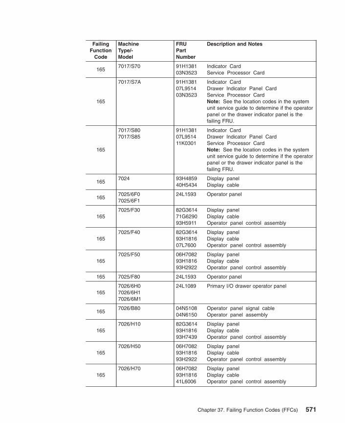
FailingFunction
Code
MachineType/-Model
FRUPartNumber
Description and Notes
1657017/S70 91H1381
03N3523Indicator CardService Processor Card
165
7017/S7A 91H138107L951403N3523
Indicator CardDrawer Indicator Panel CardService Processor CardNote: See the location codes in the systemunit service guide to determine if the operatorpanel or the drawer indicator panel is thefailing FRU.
165
7017/S807017/S85
91H138107L951411K0301
Indicator CardDrawer Indicator Panel CardService Processor CardNote: See the location codes in the systemunit service guide to determine if the operatorpanel or the drawer indicator panel is thefailing FRU.
1657024 93H4859
40H5434Display panelDisplay cable
1657025/6F07025/6F1
24L1593 Operator panel
1657025/F30 82G3614
71G629093H5911
Display panelDisplay cableOperator panel control assembly
1657025/F40 82G3614
93H181607L7600
Display panelDisplay cableOperator panel control assembly
1657025/F50 06H7082
93H181693H2922
Display panelDisplay cableOperator panel control assembly
165 7025/F80 24L1593 Operator panel
1657026/6H07026/6H17026/6M1
24L1089 Primary I/O drawer operator panel
1657026/B80 04N5108
04N6150Operator panel signal cableOperator panel assembly
1657026/H10 82G3614
93H181693H7439
Display panelDisplay cableOperator panel control assembly
1657026/H50 06H7082
93H181693H2922
Display panelDisplay cableOperator panel control assembly
1657026/H70 06H7082
93H181641L6006
Display panelDisplay cableOperator panel control assembly
Chapter 37. Failing Function Codes (FFCs) 571

FailingFunction
Code
MachineType/-Model
FRUPartNumber
Description and Notes
1657026/H807026/M80
24L1089 Primary I/O drawer operator panel
1657028/6C17028/6E1
21P665021P7166
Operator panel cableOperator panel assembly
1657028/6C47028/6E4
00P3210 Operator Panel
165 7038/6M2 53P4103 Operator Panel
1657040/6717040/681
24L1089 Operator Panel
1657043/1407043/1507043/240
73H3766Operator Panel problemOperator panel circuit assembly
1657043/2607043/270
97H932897H944207L7234
Operator panel signal cableOperator panel audio cableOperator panel assembly
165 7044/170 41L6173 Operator Panel
1657044/270 97H9328
97H944207L7234
Operator panel signal cableOperator panel audio cableOperator panel assembly
165 7046/B50 07L9101 Operator panel
1657317/F3L 82G3614
71G629073H0895
Display panelDisplay cableOperator panel control assembly
1659076 SMP Thin/WideNode
11J4000 Supervisor Card
1659076/ Power3 SMPThin/Wide Node
11J4000 Supervisor Card
1659112/265 21P6650
21P7166Operator panel cableOperator panel assembly
166 7017/S70 21H695940H4878
Fan Assembly or Blower problemSystem rack blower3-Fan assembly
1667017/S7A 21H6959
41L626993H8868
System rack blowerI/O drawer blowerDASD Fan Assembly
166
7017/S807017/S85 21H6959
41L626993H8868
System RackSystem rack blower
I/O RackI/O drawer blowerDASD Fan Assembly
166 7024 06H2647 Fan
572 Diagnostic Information for Multiple Bus Systems

FailingFunction
Code
MachineType/-Model
FRUPartNumber
Description and Notes
1667025/6F07025/6F1
24L1730 Fan
166 7025/F30 39H9898 Fan
1667025/F40 40H1424
40H142340H1433
Fan 1 and 3Fan 2Fan 4
1667025/F50 40H1424
40H143373H3577
Fan 3Fan 2 and 4Fan 1 CPU
166 7025/F80 24L1730 Fan
166
7026/6H07026/6H1
41L531541L544803N282941L5448
CEC drawer fanCEC drawer fanCooling unit (filler)I/O drawer fan
1667026/6M1 04N3345
03N282941L5448
CEC drawer fanCooling unit (filler)I/O drawer fan
1667026/B80 04N5124
04N5121Front fans 1 and 2Rear fans 3 and 4
166 7026/H10 40H4878 3-Fan hot-plug assembly
1667026/H50 93H8868
41L626993H8570
Fan 1, 2, 3, 4Blower Fan 5, 6Fan 7 CPU
166
7026/H70 93H886841L626941L532908L0530
Fan 1, 2, 3, 4Blower Fan 5, 6Fan 7 CPUI/O Blower 8
166
7026/H80 41L531541L544803N282941L5448
CEC drawer fanCEC drawer fanCooling unit (filler)I/O drawer fan
1667026/M80 04N3345
03N282941L5448
CEC drawer fanCooling unit (filler)I/O drawer fan
1667028/6C17028/6E1
21P679809N751521P6811
Processor FanBlower AssemblyRear Fan Assembly
1667028/6C47028/6E4
09P586509P5866
Processor Fan 1 and 2PCI Fan 3 and 4
166 7039/651 44P0807 Fan Assembly
1667040/61R7040/W42
11P1787 Bulk Power Fan
1667038/6M2 21P4491
21P4490Drawer FanProcessor Fan
Chapter 37. Failing Function Codes (FFCs) 573
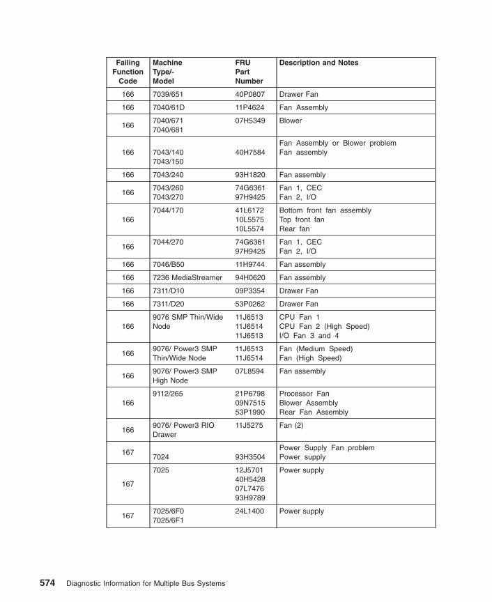
FailingFunction
Code
MachineType/-Model
FRUPartNumber
Description and Notes
166 7039/651 40P0807 Drawer Fan
166 7040/61D 11P4624 Fan Assembly
1667040/6717040/681
07H5349 Blower
166 7043/1407043/150
40H7584Fan Assembly or Blower problemFan assembly
166 7043/240 93H1820 Fan assembly
1667043/2607043/270
74G636197H9425
Fan 1, CECFan 2, I/O
1667044/170 41L6172
10L557510L5574
Bottom front fan assemblyTop front fanRear fan
1667044/270 74G6361
97H9425Fan 1, CECFan 2, I/O
166 7046/B50 11H9744 Fan assembly
166 7236 MediaStreamer 94H0620 Fan assembly
166 7311/D10 09P3354 Drawer Fan
166 7311/D20 53P0262 Drawer Fan
1669076 SMP Thin/WideNode
11J651311J651411J6513
CPU Fan 1CPU Fan 2 (High Speed)I/O Fan 3 and 4
1669076/ Power3 SMPThin/Wide Node
11J651311J6514
Fan (Medium Speed)Fan (High Speed)
1669076/ Power3 SMPHigh Node
07L8594 Fan assembly
1669112/265 21P6798
09N751553P1990
Processor FanBlower AssemblyRear Fan Assembly
1669076/ Power3 RIODrawer
11J5275 Fan (2)
1677024 93H3504
Power Supply Fan problemPower supply
167
7025 12J570140H542807L747693H9789
Power supply
1677025/6F07025/6F1
24L1400 Power supply
574 Diagnostic Information for Multiple Bus Systems

FailingFunction
Code
MachineType/-Model
FRUPartNumber
Description and Notes
167
7025/F307025/F407025/F50
12J570140H542807L747693H9789
Power supply
167 7025/F80 24L1400 Power supply
167 7026/H50 93H8868 Power supply
1677028/6C47028/6E4
09P5894 AC Power Supply
1677040/61R7040/W42
11P1787 Bulk Power Fan
1677043/1407043/1507043/240
40H756640H7563
PFC Power Supply (Japan Only)Non-PFC Power Supply (All OtherCountries)
167 7043/260 97H9337 Power supply
167 7043/270 24L1968 Power Supply
167 7044/170 41L5215 Power Supply
167 7044/270 24L1968 Power Supply
167 7046/B50 24L2659 Power supply
1679076 SMP Thin/WideNode
11J651311J651411J6513
CPU Fan 1CPU Fan 2 (High Speed)I/O Fan 3 and 4
1679076/ Power3 SMPThin/Wide Node
11J651311J6514
Fan (Medium Speed)Fan (High Speed)
169Operator Panel Logic problemNote: If the type/model and FRU informationis not listed here, refer to FFC 221..
1817024 11H8073
Diskette drive cable problemCable, diskette drive signal
1817025/6F07025/6F1
24L177123L2922
Cable, diskette drive signalCable, diskette drive power
181 7025/F30 11H8162 Cable, diskette drive signal
1817025/F407025/F50
73H1894 Cable, diskette drive signal
1817025/F80 24L1771
23L2922Cable, diskette drive signalCable, diskette drive power
181 7026/H10 73H1894 Cable, diskette drive signal
181 7026/H50 73H1894 Cable, diskette drive signal
181 7026/H70 73H1894 Cable, diskette drive signal
1817028/6C47028/6E4
09P586309P5864
Cable, Diskette 34-pinCable, Diskette Power 4-pin
Chapter 37. Failing Function Codes (FFCs) 575
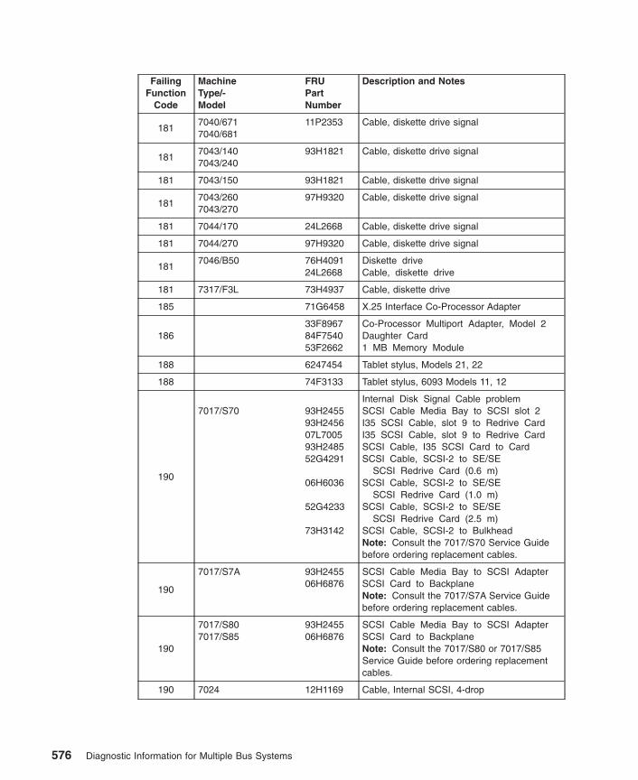
FailingFunction
Code
MachineType/-Model
FRUPartNumber
Description and Notes
1817040/6717040/681
11P2353 Cable, diskette drive signal
1817043/1407043/240
93H1821 Cable, diskette drive signal
181 7043/150 93H1821 Cable, diskette drive signal
1817043/2607043/270
97H9320 Cable, diskette drive signal
181 7044/170 24L2668 Cable, diskette drive signal
181 7044/270 97H9320 Cable, diskette drive signal
1817046/B50 76H4091
24L2668Diskette driveCable, diskette drive
181 7317/F3L 73H4937 Cable, diskette drive
185 71G6458 X.25 Interface Co-Processor Adapter
18633F896784F754053F2662
Co-Processor Multiport Adapter, Model 2Daughter Card1 MB Memory Module
188 6247454 Tablet stylus, Models 21, 22
188 74F3133 Tablet stylus, 6093 Models 11, 12
190
7017/S70 93H245593H245607L700593H248552G4291
06H6036
52G4233
73H3142
Internal Disk Signal Cable problemSCSI Cable Media Bay to SCSI slot 2I35 SCSI Cable, slot 9 to Redrive CardI35 SCSI Cable, slot 9 to Redrive CardSCSI Cable, I35 SCSI Card to CardSCSI Cable, SCSI-2 to SE/SE
SCSI Redrive Card (0.6 m)SCSI Cable, SCSI-2 to SE/SE
SCSI Redrive Card (1.0 m)SCSI Cable, SCSI-2 to SE/SE
SCSI Redrive Card (2.5 m)SCSI Cable, SCSI-2 to BulkheadNote: Consult the 7017/S70 Service Guidebefore ordering replacement cables.
190
7017/S7A 93H245506H6876
SCSI Cable Media Bay to SCSI AdapterSCSI Card to BackplaneNote: Consult the 7017/S7A Service Guidebefore ordering replacement cables.
190
7017/S807017/S85
93H245506H6876
SCSI Cable Media Bay to SCSI AdapterSCSI Card to BackplaneNote: Consult the 7017/S80 or 7017/S85Service Guide before ordering replacementcables.
190 7024 12H1169 Cable, Internal SCSI, 4-drop
576 Diagnostic Information for Multiple Bus Systems

FailingFunction
Code
MachineType/-Model
FRUPartNumber
Description and Notes
190
7025/6F07025/6F1
04N426500P235804N227304N455504N5589
Internal SCSI cable, 4-dropSCSI cable, short (8 inches)SCSI cable, long (44 inches)SCSI two-pack backplaneSCSI six-pack backplane
190 7025/F30 73H3596 Cable, Internal SCSI, 4-drop
190 7025/F40 93H3490 Cable, Internal SCSI, 4-drop
190 7025/F50 73H3596 Cable, Internal SCSI, 4-drop
190
7025/F80 04N426500P235804N227304N455504N5589
Internal SCSI cable, 4-dropSCSI cable, short (8 inches)SCSI cable, long (44 inches)SCSI two-pack backplaneSCSI six-pack backplane
1907026/6H07026/6H17026/6M1
41L5519 I/O drawer internal SCSI cable
190 7026/B80 21P3951 Cable, internal SCSI
190 7026/H10 73H3596 Cable, Internal SCSI, 4-drop
190
7026/H50 93H961352G429152G423306H6876
Cable, Internal SCSI, 4-dropCable, SCSI-2Cable, SCSICable, SCSI
1907026/H807026/M80
41L5519 I/O drawer internal SCSI cable
1907026/H70 93H9613
52G429152G4233
Cable, Internal SCSI, 4-dropCable, SCSI-2Cable, SCSI
1907028/6C17028/6E1
21P6655 Cable, internal SCSI
1907028/6C47028/6E4
09P588909P589509P5888
Cable, SCSI 68-pinCable, SCSI 50-pinCable, DASD Power 5-pin
190 7038/6M2 21P5205 SCSI Cable, media/DASD
190 7039/651 44P2165 DASD Ribbon Cable
190
7040/6717040/681
11P2349
11P2350
SCSI Cable for Media Subsystem RearComponentSCSI Cable for Media Subsystem FrontComponent
190 7043/1407043/150
73H0435Internal Disk Signal Cable problemCable, Internal SCSI, 4-drop
190 7043/240 40H7572 Cable, Internal SCSI, 4-drop
190 7043/240 93H6151 Ultra SCSI Cable assembly (optional)
Chapter 37. Failing Function Codes (FFCs) 577
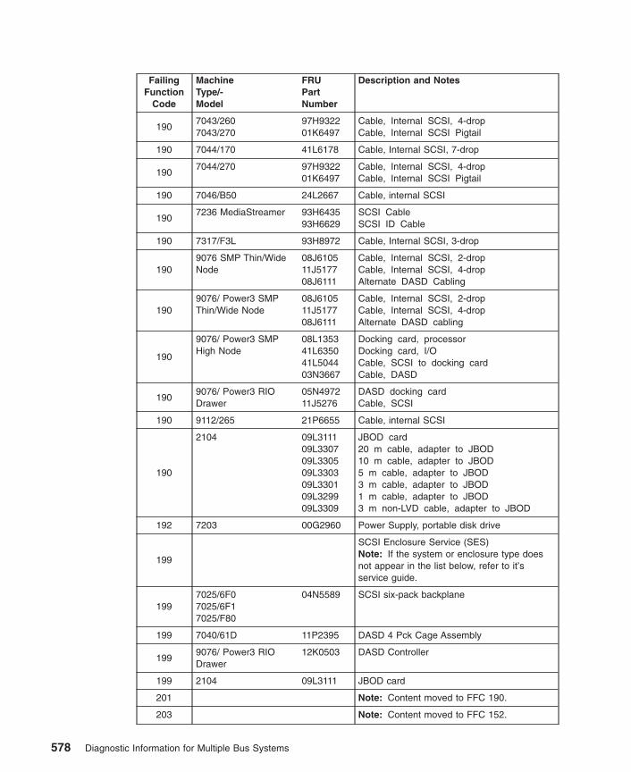
FailingFunction
Code
MachineType/-Model
FRUPartNumber
Description and Notes
1907043/2607043/270
97H932201K6497
Cable, Internal SCSI, 4-dropCable, Internal SCSI Pigtail
190 7044/170 41L6178 Cable, Internal SCSI, 7-drop
1907044/270 97H9322
01K6497Cable, Internal SCSI, 4-dropCable, Internal SCSI Pigtail
190 7046/B50 24L2667 Cable, internal SCSI
1907236 MediaStreamer 93H6435
93H6629SCSI CableSCSI ID Cable
190 7317/F3L 93H8972 Cable, Internal SCSI, 3-drop
1909076 SMP Thin/WideNode
08J610511J517708J6111
Cable, Internal SCSI, 2-dropCable, Internal SCSI, 4-dropAlternate DASD Cabling
1909076/ Power3 SMPThin/Wide Node
08J610511J517708J6111
Cable, Internal SCSI, 2-dropCable, Internal SCSI, 4-dropAlternate DASD cabling
190
9076/ Power3 SMPHigh Node
08L135341L635041L504403N3667
Docking card, processorDocking card, I/OCable, SCSI to docking cardCable, DASD
1909076/ Power3 RIODrawer
05N497211J5276
DASD docking cardCable, SCSI
190 9112/265 21P6655 Cable, internal SCSI
190
2104 09L311109L330709L330509L330309L330109L329909L3309
JBOD card20 m cable, adapter to JBOD10 m cable, adapter to JBOD5 m cable, adapter to JBOD3 m cable, adapter to JBOD1 m cable, adapter to JBOD3 m non-LVD cable, adapter to JBOD
192 7203 00G2960 Power Supply, portable disk drive
199
SCSI Enclosure Service (SES)Note: If the system or enclosure type doesnot appear in the list below, refer to it’sservice guide.
1997025/6F07025/6F17025/F80
04N5589 SCSI six-pack backplane
199 7040/61D 11P2395 DASD 4 Pck Cage Assembly
1999076/ Power3 RIODrawer
12K0503 DASD Controller
199 2104 09L3111 JBOD card
201 Note: Content moved to FFC 190.
203 Note: Content moved to FFC 152.
578 Diagnostic Information for Multiple Bus Systems

FailingFunction
Code
MachineType/-Model
FRUPartNumber
Description and Notes
210 7017/S70 90H969490H9662
Fixed Point Processor problemProcessor Card (4x) (Type 2) (120 MHz)Processor Card (4x) (Type 1) (120 MHz)
2107017/S7A 08L1474
08L1473Processor Card (Type 2) (262 MHz)Processor Card (Type 1) (262 MHz)
2107017/S80 23L7434
23L7447Processor Card (Type 1 RH)Processor Card (Type 2 LH)
2107017/S85 21P4511
21P4517Processor Card (Type 1 RH)Processor Card (Type 2 LH)
2107024/E20 40H6616
03N3989CPU card (100 MHz)CPU card (233 MHz)
2107024/E30 73H3614
93H243103N3989
CPU card (133 MHz)CPU card (166 MHz)CPU card (233 MHz)
210
7025/6F0 04N535309P652423L778509P652523L779453P1301
1-way processor card (600 MHz)1-way processor card (750 MHz)2-way processor card (600 MHz)2-way processor card (750 MHz)4-way processor card (600 MHz)4-way processor card (750 MHz)
210
7025/6F1 04N535309P652423L778509P652523L779453P130123L779953P1334
1-way processor card (600 MHz)1-way processor card (750 MHz)2-way processor card (600 MHz)2-way processor card (750 MHz)4-way processor card (600 MHz)4-way processor card (750 MHz)6-way processor card (668 MHz)6-way processor card (750 MHz)
2107025/F30 73H3614
93H243103N3989
CPU card (133 MHz)CPU card (166 MHz)CPU card (233 MHz)
2107025/F40 11H7517
41L6111CPU card (166 MHz)CPU card (233 MHz)
210
7025/F50 93H267973H476893H901893H8945
166 MHz CPU card (1 way)166 MHz CPU card (2 way)332 MHz CPU card (1 way)332 MHz CPU card (2 way)
210
7025/F80 04N476521P475121P476021P4774
1-way processor card (450 MHz)2-way processor card (450 MHz)4-way processor card (450 MHz)6-way processor card (500 MHz)
Chapter 37. Failing Function Codes (FFCs) 579

FailingFunction
Code
MachineType/-Model
FRUPartNumber
Description and Notes
210
7026/6H0 04N535309P652423L778509P652523L779453P1301
1-way processor card (600 MHz)1-way processor card (750 MHz)2-way processor card (600 MHz)2-way processor card (750 MHz)4-way processor card (600 MHz)4-way processor card (750MHz)
210
7026/6H1 04N535309P652423L778509P652523L779453P130123L779953P1334
1-way processor card (600 MHz)1-way processor card (750 MHz)2-way processor card (600 MHz)2-way processor card (750 MHz)4-way processor card (600 MHz)4-way processor card (750 MHz)6-way processor card (668 MHz)6-way processor card (750 MHz)
2107026/6M1 04N6698
21P638121P6383
2-way processor card (500 MHz)2-way processor card (750 MHz)4-way processor card (750 MHz)
210
7026/B80 09P039909P0143
09P0406
09P4478
Processor card (375 Mhz, one-way)Processor card (375 Mhz, two-way,8 M L2)Processor card (375 Mhz, two-way,4 M L2)
Processor Card (450 Mhz, two-way)
2107026/H107026/H10
11H7517 CPU card (166 MHz)
2107026/H50 93H9018
93H8945CPU card (332 MHz one-way)CPU card (332 MHz two-way)
2107026/H70
94H101394H1008
Fixed Point Processor problemCPU card (332 MHz one-way)CPU card (332 MHz two-way)
210
7026/H80 04N476521P475121P476021P4774
1-way processor card (450 MHz)2-way processor card (450 MHz)4-way processor card (450 MHz)6-way processor card (500 MHz)
2107026/M80 04N6930
04N69312-way processor card4-way processor card
2107028/6C17028/6E1
09P549509P366609P3669
333 MHZ Processor card375 MHz Processor card450 MHz Processor Card
2107028/6C47028/6E4
00P297400P2977
Processor Card, 1.0 GHz 1-wayProcessor Card, 1.0 GHz 2-way
210 7038/6M2 53P4953 4-way Processor Board
2107039/651 44P1542
44P15441.3 GHz 4-way MCM with VPD Card1.1 GHz 8-way MCM with VPD Card
580 Diagnostic Information for Multiple Bus Systems
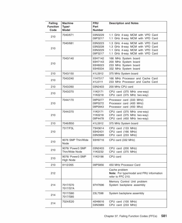
FailingFunction
Code
MachineType/-Model
FRUPartNumber
Description and Notes
2107040/671 03N3229
09P32171.1 GHz 4-way MCM with VPD Card1.1 GHz 8-way MCM with VPD Card
210
7040/681 03N322303N322803N322909P3217
1.3 GHz 4-way MCM with VPD Card1.3 GHz 8-way MCM with VPD Card1.1 GHz 4-way MCM with VPD Card1.1 GHz 8-way MCM with VPD Card
210
7043/140 93H714293H714393H602393H9334
166 MHz System board200 MHz System board233 MHz System board332 MHz System board
210 7043/150 41L5912 375 MHz System board
2107043/240 11H7517
41L6111166 MHz Processor and Cache Card233 MHz Processor and Cache Card
210 7043/260 03N2403 200 MHz CPU card
2107043/270 11K0171
11K0218CPU card (375 MHz one-way)CPU card (375 MHz two-way)
2107044/170 09P0277
09P027209P0943
Processor card (333 MHz)Processor card (400 MHz)Processor card (450 Mhz)
2107044/270 11K0171
11K021809P4478
CPU card (375 MHz one-way)CPU card (375 MHz two-way)CPU card (450 MHz two-way)
210 7046/B50 41L5912 375 MHz System board
2107317/F3L 73H3614
93H243103N3989
CPU card (133 MHz)CPU card (166 MHz)CPU card (233 MHz)
2109076 SMP Thin/WideNode
93H9716 CPU card (332 MHz)
2109076/ Power3 SMPThin/Wide Node
03N240311K0232
CPU card (200 MHz)CPU card (375 MHz)
2109076/ Power3 SMPHigh Node
11K0198 CPU card
210 9112/265 09P5856 450 MHz Processor Card
212Cache problemNote: For type/model and FRU informationrefer to FFC 210.
214 7017/S707017/S7A
97H7696Memory Control Unit problemSystem backplane assembly
2147017/S807017/S85
23L7598 System backplane assembly
2147024/E20 40H6616
03N3989CPU card (100 MHz)CPU card (233 MHz)
Chapter 37. Failing Function Codes (FFCs) 581

FailingFunction
Code
MachineType/-Model
FRUPartNumber
Description and Notes
2147024/E30 73H3614
93H243103N3989
CPU card (133 MHz)CPU card (166 MHz)CPU card (233 MHz)
214
7025/6F0 04N535309P652423L778509P652523L779453P1301
1-way processor card (600 MHz)1-way processor card (750 MHz)2-way processor card (600 MHz)2-way processor card (750 MHz)4-way processor card (600 MHz)4-way processor card (750 MHz)
214
7025/6F1 04N535309P652423L778509P652523L779453P130123L779953P1334
1-way processor card (600 MHz)1-way processor card (750 MHz)2-way processor card (600 MHz)2-way processor card (750 MHz)4-way processor card (600 MHz)4-way processor card (750 MHz)6-way processor card (668 MHz)6-way processor card (750 MHz)
2147025/F30 73H3614
93H243103N3989
CPU card (133 MHz)CPU card (166 MHz)CPU card (233 MHz)
2147025/F40 11H7517
93H5163CPU card (166 MHz)CPU card (233 MHz)
214 7025/F50 07L9718 System board
214
7025/F80 04N476521P475121P476021P4774
1-way processor card (450 MHz)2-way processor card (450 MHz)4-way processor card (450 MHz)6-way processor card (500 MHz)
214
7026/6H0 04N535309P652423L778509P652523L779453P1301
1-way processor card (600 MHz)1-way processor card (750 MHz)2-way processor card (600 MHz)2-way processor card (750 MHz)4-way processor card (600 MHz)4-way processor card (750 MHz)
214
7026/6H1 04N535309P652423L778509P652523L779453P130123L779953P1334
1-way processor card (600 MHz)1-way processor card (750 MHz)2-way processor card (600 MHz)2-way processor card (750 MHz)4-way processor card (600 MHz)4-way processor card (750 MHz)6-way processor card (668 MHz)6-way processor card (750 MHz)
214 7026/6M1 04N3524 CEC drawer backplane
214 7026/B80 08L0988 System board
214 7026/H10 11H7517 CPU card (166 MHz)
214 7026/H50 07L9718 System board
582 Diagnostic Information for Multiple Bus Systems

FailingFunction
Code
MachineType/-Model
FRUPartNumber
Description and Notes
214 7026/H70 08L0988 System board
214
7026/H80 04N476521P475121P476021P4774
1-way processor card (450 Mhz)2-way processor card (450 Mhz)4-way processor card (450 Mhz)6-way processor card (500 Mhz)
214 7026/M80 04N3023 CEC drawer backplane
2147028/6C17028/6E1
09P2420 System board
2147028/6C47028/6E4
00P297400P2977
Processor Card, 1.0 GHz 1-wayProcessor Card. 1.0 GHz 2-way
214 7038/6M2 09P3876 System Backplane
214 7039/651 00P4603 System Backplane
2147040/6717040/681
11P3046 System Backplane
214
7043/140 93H714293H714393H602393H9334
166 MHz System board200 MHz System board233 MHz System board332 MHz System board
214 7043/150 41L5912 375 MHz System board
2147043/240 11H7517
41L6111166 MHz Processor and Cache Card233 MHz Processor and Cache Card
2147043/260 08L1303
Memory Control Unit ProblemSystem board
214 7043/270 08L0988 System board
2147044/170 41L572
09P0037System board, class ASystem board, class B
214 7044/270 08L0988 System board
214 7046/B50 41L5912 375 MHz System board
214
7317/F3L73H361493H243103N3989
Memory Control Unit problemCPU card (133 MHz)CPU card (166 MHz)CPU card (233 MHz)
2149076 SMP Thin/WideNode
07L971841L613893H3316
CPU chassis system boardCPU chassis I/O planarI/O chassis connection card
214
9076/ Power3 SMPThin/Wide Node
08L130308L098803N286603N336807L8531
CPU chassis, system board (200 MHz)CPU chassis, system board (375 MHz)CPU chassis, I/O planar (200 MHz)CPU chassis, I/O planar (375 MHz)I/O expansion card
2149076/ Power3 SMPHigh Node
03N4184 System Planar
Chapter 37. Failing Function Codes (FFCs) 583
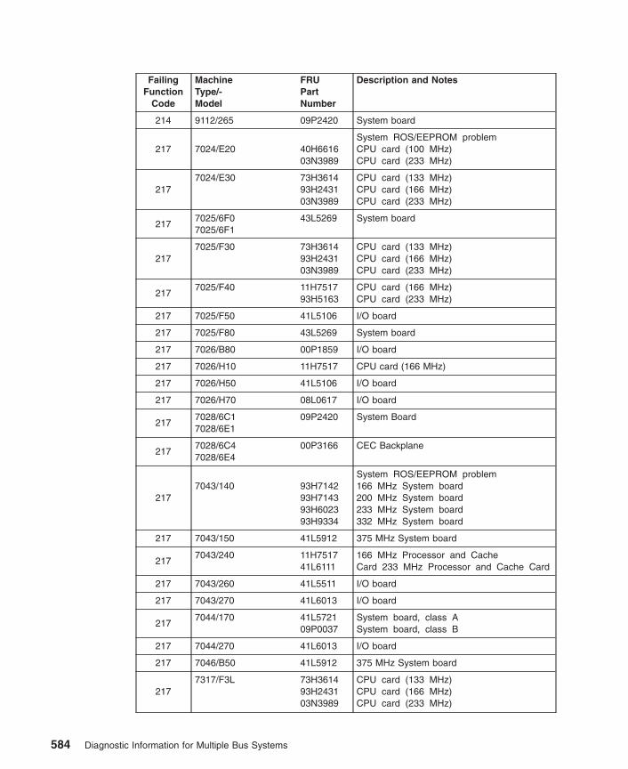
FailingFunction
Code
MachineType/-Model
FRUPartNumber
Description and Notes
214 9112/265 09P2420 System board
217 7024/E20 40H661603N3989
System ROS/EEPROM problemCPU card (100 MHz)CPU card (233 MHz)
2177024/E30 73H3614
93H243103N3989
CPU card (133 MHz)CPU card (166 MHz)CPU card (233 MHz)
2177025/6F07025/6F1
43L5269 System board
2177025/F30 73H3614
93H243103N3989
CPU card (133 MHz)CPU card (166 MHz)CPU card (233 MHz)
2177025/F40 11H7517
93H5163CPU card (166 MHz)CPU card (233 MHz)
217 7025/F50 41L5106 I/O board
217 7025/F80 43L5269 System board
217 7026/B80 00P1859 I/O board
217 7026/H10 11H7517 CPU card (166 MHz)
217 7026/H50 41L5106 I/O board
217 7026/H70 08L0617 I/O board
2177028/6C17028/6E1
09P2420 System Board
2177028/6C47028/6E4
00P3166 CEC Backplane
2177043/140 93H7142
93H714393H602393H9334
System ROS/EEPROM problem166 MHz System board200 MHz System board233 MHz System board332 MHz System board
217 7043/150 41L5912 375 MHz System board
2177043/240 11H7517
41L6111166 MHz Processor and CacheCard 233 MHz Processor and Cache Card
217 7043/260 41L5511 I/O board
217 7043/270 41L6013 I/O board
2177044/170 41L5721
09P0037System board, class ASystem board, class B
217 7044/270 41L6013 I/O board
217 7046/B50 41L5912 375 MHz System board
2177317/F3L 73H3614
93H243103N3989
CPU card (133 MHz)CPU card (166 MHz)CPU card (233 MHz)
584 Diagnostic Information for Multiple Bus Systems

FailingFunction
Code
MachineType/-Model
FRUPartNumber
Description and Notes
2179076 SMP Thin/WideNode
41L6138 I/O planar
2179076/ Power3 SMPThin/Wide Node
03N286603N3368
I/O planar (200 MHz)I/O planar (375 Mhz)
217 9112/265 09P2420 System Board
219
Common Memory Logic problem Refer toAppendix C, “System Memory Reference” onpage 663 for memory card and memorymodule FRU part numbers.Note: If more than a pair of memorymodules from the same memory card arereported missing, replace the FRU that thememory modules plug into first. Otherwise,replace the memory module at the physicallocation code that is reported.
2217017/S70 94H1268
System I/O Control Logic problemI/O planar
221 7017/S7A 08L0103 I/O planar
2217017/S807017/S85
08L1438 I/O planar
221 7024 93H4808 System board
2217025/6F07025/6F1
43L5269 System board
221 7025/F30 93H8371 System board
221 7025/F40 93H8652 System board
221 7025/F50 41L5106 I/O board
221 7025/F80 43L5269 System board
2217026/6H07026/6H17026/6M1
41L556041L5661
Primary I/O drawer backplaneSecondary I/O drawer backplane
221 7026/B80 00P1859 I/O board
221 7026/H10 93H8652 System board
221 7026/H50 41L5106 I/O board
221 7026/H70 03N2797 I/O board
2217026/H807026/M80
41L556041L5661
Primary I/O drawer backplaneSecondary I/O drawer backplane
2217028/6C17028/6E1
09P2420 System Board
2217028/6C47028/6E4
00P316609P2702
CEC BackplanePCI Riser Card
221 7038/6M2 00P4062 Service Processor/PCI Backplane
221 7039/651 00P4603 System Backplane
Chapter 37. Failing Function Codes (FFCs) 585
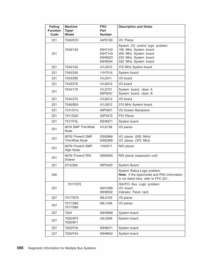
FailingFunction
Code
MachineType/-Model
FRUPartNumber
Description and Notes
221 7040/61D 44P0199 I/O Planar
2217043/140 93H7142
93H714393H602393H9334
System I/O control logic problem166 MHz System board200 MHz System board233 MHz System board332 MHz System board
221 7043/150 41L5912 375 MHz System board
221 7043/240 11H7516 System board
221 7043/260 41L5511 I/O board
221 7043/270 41L6013 I/O board
2217044/170 41L5721
09P0037System board, class ASystem board, class B
221 7044/270 41L6013 I/O board
221 7046/B50 41L5912 375 MHz System board
221 7311/D10 09P5921 I/O Drawer Backplane
221 7311/D20 53P3472 PCI Planar
221 7317/F3L 93H8371 System board
2219076 SMP Thin/WideNode
41L6138 I/O planar
2219076/ Power3 SMPThin/Wide Node
03N286603N3368
I/O planar (200 MHz)I/O planar (375 Mhz)
2219076/ Power3 SMPHigh Node
11K0571 NIO planar
2219076/ Power3 RIODrawer
05N5005 RIO planar (expansion unit)
221 9112/265 09P2420 System Board
226System Status Logic problemNote: If the type/model and FRU informationis not listed here, refer to FFC 221..
2277017/S70
94H126893H8502
ISA/PCI Bus Logic problemI/O boardIndicator Panel card
227 7017/S7A 08L0103 I/O planar
2277017/S807017/S85
08L1438 I/O planar
227 7024 93H4808 System board
2277025/6F07025/6F1
43L5269 System board
227 7025/F30 93H8371 System board
227 7025/F40 93H8652 System board
586 Diagnostic Information for Multiple Bus Systems
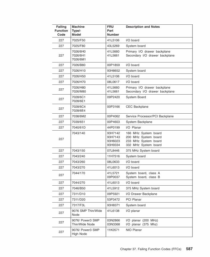
FailingFunction
Code
MachineType/-Model
FRUPartNumber
Description and Notes
227 7025/F50 41L5106 I/O board
227 7025/F80 43L5269 System board
2277026/6H07026/6H17026/6M1
41L566041L5661
Primary I/O drawer backplaneSecondary I/O drawer backplane
227 7026/B80 00P1859 I/O board
227 7026/H10 93H8652 System board
227 7026/H50 41L5106 I/O board
227 7026/H70 08L0617 I/O board
2277026/H807026/M80
41L566041L5661
Primary I/O drawer backplaneSecondary I/O drawer backplane
2277028/6C17028/6E1
09P2420 System Board
2277028/6C47028/6E4
00P3166 CEC Backplane
227 7038/6M2 00P4062 Service Processor/PCI Backplane
227 7039/651 00P4603 System Backplane
227 7040/61D 44P0199 I/O Planar
227
7043/140 93H714293H714393H602393H9334
166 MHz System board200 MHz System board233 MHz System board332 MHz System board
227 7043/150 07L8446 375 MHz System board
227 7043/240 11H7516 System board
227 7043/260 08L0633 I/O board
227 7043/270 41L6013 I/O board
2277044/170 41L5721
09P0037System board, class ASystem board, class B
227 7044/270 41L6013 I/O board
227 7046/B50 41L5912 375 MHz System board
227 7311/D10 09P5921 I/O Drawer Backplane
227 7311/D20 53P3472 PCI Planar
227 7317/F3L 93H8371 System board
2279076 SMP Thin/WideNode
41L6138 I/O planar
2279076/ Power3 SMPThin/Wide Node
03N286603N3368
I/O planar (200 MHz)I/O planar (375 Mhz)
2279076/ Power3 SMPHigh Node
11K0571 NIO Planar
Chapter 37. Failing Function Codes (FFCs) 587
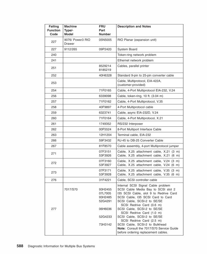
FailingFunction
Code
MachineType/-Model
FRUPartNumber
Description and Notes
2279076/ Power3 RIODrawer
05N5005 RIO Planar (expansion unit)
227 9112/265 09P2420 System Board
240 Token-ring network problem
241 Ethernet network problem
25185292148185219
Cables, parallel printer
252 40H6328 Standard 9-pin to 25-pin converter cable
253Cable, Multiprotocol, EIA-422A,(customer-provided)
254 71F0165 Cable, 4-Port Multiprotocol EIA-232, V.24
256 6339098 Cable, token-ring, 10 ft. (3.04 m)
257 71F0162 Cable, 4-Port Multiprotocol, V.35
258 40F9897 4-Port Multiprotocol cable
259 6323741 Cable, async EIA-232D, V.24
260 71F0164 Cable, 4-Port Multiprotocol, X.21
261 1749352 RS/232 Interposer
262 00F5524 8-Port Multiport Interface Cable
263 12H1204 Terminal cable, EIA-232
266 59F3432 RJ-45 to DB-25 Converter Cable
267 81F8570 Cable assembly, 4-port Multiprotocol jumper
27107F315153F3926
Cable, X.25 attachment cable, X.21 (3 m)Cable, X.25 attachment cable, X.21 (6 m)
27207F316053F3927
Cable, X.25 attachment cable, V.24 (3 m)Cable, X.25 attachment cable, V.24 (6 m)
27307F317153F3928
Cable, X.25 attachment cable, V.35 (3 m)Cable, X.25 attachment cable, V.35 (6 m)
276 31F4221 Cable, SCSI controller cable
277
7017/S70 93H245507L700593H248552G4291
06H6036
52G4233
73H3142
Internal SCSI Signal Cable problemSCSI Cable Media Bay to SCSI slot 2I35 SCSI Cable, slot 9 to Redrive CardSCSI Cable, I35 SCSI Card to CardSCSI Cable, SCSI-2 to SE/SE
SCSI Redrive Card (0.6 m)SCSI Cable, SCSI-2 to SE/SE
SCSI Redrive Card (1.0 m)SCSI Cable, SCSI-2 to SE/SE
SCSI Redrive Card (2.5 m)SCSI Cable, SCSI-2 to BulkheadNote: Consult the 7017/S70 Service Guidebefore ordering replacement cables.
588 Diagnostic Information for Multiple Bus Systems
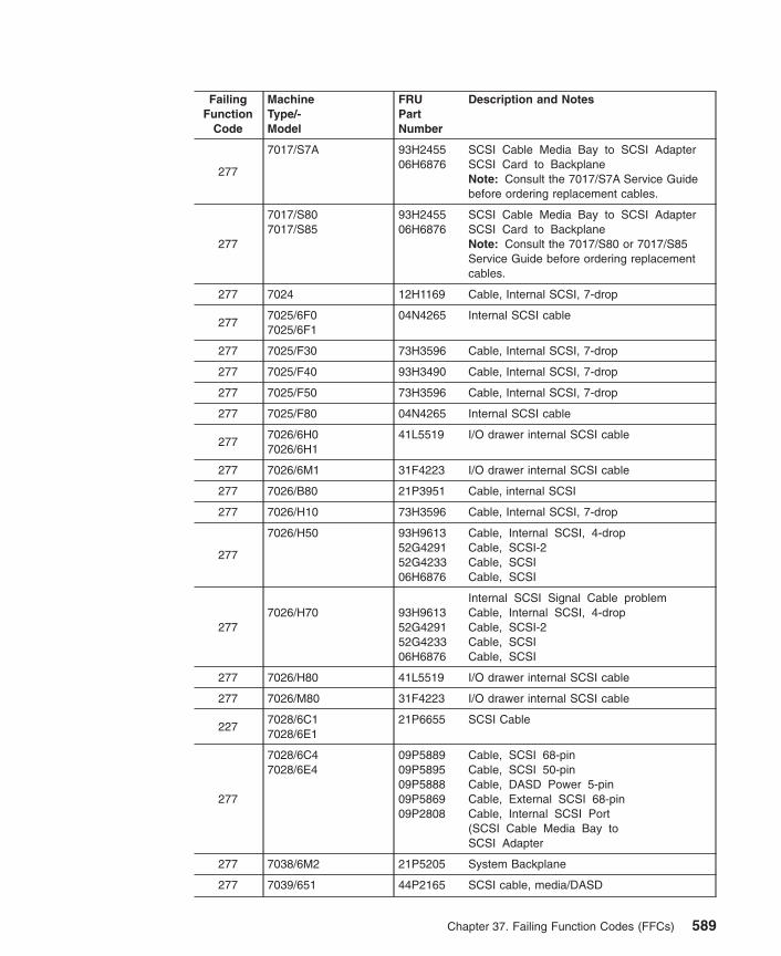
FailingFunction
Code
MachineType/-Model
FRUPartNumber
Description and Notes
277
7017/S7A 93H245506H6876
SCSI Cable Media Bay to SCSI AdapterSCSI Card to BackplaneNote: Consult the 7017/S7A Service Guidebefore ordering replacement cables.
277
7017/S807017/S85
93H245506H6876
SCSI Cable Media Bay to SCSI AdapterSCSI Card to BackplaneNote: Consult the 7017/S80 or 7017/S85Service Guide before ordering replacementcables.
277 7024 12H1169 Cable, Internal SCSI, 7-drop
2777025/6F07025/6F1
04N4265 Internal SCSI cable
277 7025/F30 73H3596 Cable, Internal SCSI, 7-drop
277 7025/F40 93H3490 Cable, Internal SCSI, 7-drop
277 7025/F50 73H3596 Cable, Internal SCSI, 7-drop
277 7025/F80 04N4265 Internal SCSI cable
2777026/6H07026/6H1
41L5519 I/O drawer internal SCSI cable
277 7026/6M1 31F4223 I/O drawer internal SCSI cable
277 7026/B80 21P3951 Cable, internal SCSI
277 7026/H10 73H3596 Cable, Internal SCSI, 7-drop
277
7026/H50 93H961352G429152G423306H6876
Cable, Internal SCSI, 4-dropCable, SCSI-2Cable, SCSICable, SCSI
2777026/H70 93H9613
52G429152G423306H6876
Internal SCSI Signal Cable problemCable, Internal SCSI, 4-dropCable, SCSI-2Cable, SCSICable, SCSI
277 7026/H80 41L5519 I/O drawer internal SCSI cable
277 7026/M80 31F4223 I/O drawer internal SCSI cable
2277028/6C17028/6E1
21P6655 SCSI Cable
277
7028/6C47028/6E4
09P588909P589509P588809P586909P2808
Cable, SCSI 68-pinCable, SCSI 50-pinCable, DASD Power 5-pinCable, External SCSI 68-pinCable, Internal SCSI Port(SCSI Cable Media Bay toSCSI Adapter
277 7038/6M2 21P5205 System Backplane
277 7039/651 44P2165 SCSI cable, media/DASD
Chapter 37. Failing Function Codes (FFCs) 589

FailingFunction
Code
MachineType/-Model
FRUPartNumber
Description and Notes
277
7040 11P2349
11P2350
SCSI Cable for Media SubsystemsFront ComponentSCSI Cable for Media SubsystemsRear Component
2777043/1407043/150
73H0435 Cable, Internal SCSI, 4-drop
277 7043/240 40H7572 Cable, Internal SCSI, 4-drop
277 7043/240 93H6151 Ultra SCSI Cable assembly (optional)
2777043/2607043/270
97H932201K6497
Cable, Internal SCSI, 4-dropCable, Internal SCSI Pigtail
277 7044/170 41L6178 Cable, Internal SCSI, 7-drop
2777044/270 97H9322
01K6497Cable, Internal SCSI, 4-dropCable, Internal SCSI Pigtail
277 7046/B50 24L2667 Cable, internal SCSI
2777236MediaStreamer
93H643593H6629
SCSI CableSCSI ID Cable
277 7317/F3L 93H8972 Cable Internal SCSI, 3-drop
277
Generic SCSI Cable (external)Note: For FRU part number refer to thesystem unit’s service guide. If the cable isafter market refer to it’s servicedocumentation.
2779076 SMP Thin/WideNode
08J610511J517708J6111
Cable, Internal SCSI, 2-dropCable, Internal SCSI, 4-dropAlternate DASD Cabling
2779076/ Power3 SMPThin/Wide Node
08J610511J517708J6111
Cable, Internal SCSI, 2-dropCable, Internal SCSI, 4-dropAlternate DASD Cabling
277 9112/265 21P6655 SCSI Cable
279
PTC resistor has been trippedNote: Refer to the PTC Tripping section in“SCSI-2 Single-Ended Adapter PTC FailureIsolation Procedure” on page 4 of this manual.
282 7017/S70 97H7696 System Backplane Assembly
282 7017/S7A 97H7696 System Backplane Assembly
2827017/S807017/S85
23L7598 System Backplane Assembly
2827025/6F07025/6F17025/F80
04N4555 SCSI backplane
2827026/6H07026/6H17026/H80
43L5274 CEC drawer backplane
590 Diagnostic Information for Multiple Bus Systems

FailingFunction
Code
MachineType/-Model
FRUPartNumber
Description and Notes
282 7026/M80 04N3023 CEC drawer backplane
282 7026/6M1 04N3524 CEC drawer backplane
282 7038/6M2 00P3876 System Backplane
282 7039/651 00P4603 System Backplane
2827040/6717040/681
11P3046 System Backplane
287 7017/S70 93H8714 I/O Drawer 3/4 Power Supply
287 7017/S7A 08L1336 I/O Drawer power supply
2877017/S807017/S85
08L1336 I/O Drawer power supply
287
7026/6H07026/6H17026/6M17026/H807026/M80
11K0812 I/O drawer power supply
287 7040/61D 11P3582 I/O Drawer DCA
287 7311/D10 09P3354 AC Power Supply
287 7311/D20 53P4832 Power Supply
2879076/ Power3 RIODrawer
12K044631L8752
Power SupplySupervisor Card
289 7017/S70 07L7178 I/O Drawer 1/4 Power Supply
289 7017/S7A 08L1336 I/O Drawer Power supply
2897017/S807017/S85
08L1336 I/O Drawer Power supply
289
7026/6H07026/6H17026/6M17026/H807026/M80
11K0812 I/O drawer power supply
289 7040/61D 11P3582 I/O Drawer DCA
289 7311/D10 09P3354 AC Power Supply
289 7311/D20 53P4832 Power Supply
2899076/ Power3 RIODrawer
12K044631L8752
Power CardSupervisor Card
2927017/S70 94H1268
Host - PCI Bridge problemI/O planar
292 7017/S7A 08L0103 I/O planar
2927017/S807017/S85
08L1438 I/O planar
2927024/E20 40H6616
03N3989CPU card (100 MHz)CPU card (233 MHz)
Chapter 37. Failing Function Codes (FFCs) 591

FailingFunction
Code
MachineType/-Model
FRUPartNumber
Description and Notes
2927024/E30 73H3614
93H243103N3989
CPU card (133 MHz)CPU card (166 MHz)CPU card (233 MHz)
2927025/6F07025/6F1
43L5269 System board
2927025/F30 73H3614
93H243103N3989
CPU card (133 MHz)CPU card (166 MHz)CPU card (233 MHz)
2927025/F40 11H7517
41L6111CPU card (166 MHz)CPU card (233 MHz)
292 7025/F50 41L5106 I/O board
292 7025/F80 43L5269 System board
2927026/6H07026/6H17026/6M1
04N6228 RIO adapter
292 7026/B80 00P1859 I/O board
292 7026/H10 11H7517 CPU card (166 MHz)
292 7026/H50 41L5106 I/0 board
2927026/H70 08L0617
Host - PCI Bridge problemI/O planar
292 7026/H80 04N6228 RIO adapter
292 7026/M80 04N3687 CEC RIO adapter
2927028/6C47028/6E4
00P3166 CEC Backplane
292 7038/6M2 00P4062 Service Processor/PCI Backplane
292 7039/651 00P4603 System Backplane
292 7040/61D 44P0199 !/O Planar
2927028/6C17028/6E1
09P2420 System Board
292
7043/140 93H714293H714393H602393H9334
166 MHz System board200 MHz System board233 MHz System board332 MHz System board
292 7043/150 41L5912 375 MHz System board
2927043/240 11H7517
41L6111166 MHz Processor and Cache Card233 MHz Processor and Cache Card
292 7043/260 41L5511 I/O board
292 7043/270 41L6013 I/O board
2927044/170 41L5721
09P0037System board, class ASystem board, class B
292 7044/270 41L6013 I/O board
592 Diagnostic Information for Multiple Bus Systems

FailingFunction
Code
MachineType/-Model
FRUPartNumber
Description and Notes
292 7046/B50 41L5912 375 MHz System board
292 7311/D10 09P5912 I/O Drawer Backplane
292 7311/D20 53P3472 PCI Planar
2927317/F3L 73H3614
93H243103N3989
CPU card (133 MHz)CPU card (166 MHz)CPU card (233 MHz)
2929076 SMP Thin/WideNode
07L971841L613893H3316
CPU chassis system boardCPU chassis I/O planarI/O chassis connection card
292
9076/ Power3 SMPThin/Wide Node
08L130308L098803N286603N3368
CPU chassis, system board (200 MHz)CPU chassis, system board (375 MHz)CPU chassis, I/O planar (200 MHz)CPU chassis, I/O planar (375 Mhz)
292 9112/265 09P2420 System Board
293PCI - PCI Bridge problemNote: If the type/model and FRU informationis not listed here, refer to FFC 221..
294MPIC Interrupt Controller problemNote: If the type/model and FRU informationis not listed here, refer to FFC 221..
295 PCI - ISA Bridge problemNote: If the type/model and FRU informationis not listed here, refer to FFC 221..
296PCI Device or Adapter problem The FRU canonly be identified by it’s location codereported by diagnostics.
29793H6055 Texture memory module for the GXT800P
Graphics Adapter
29893H6057 Base memory module for the GXT800P
Graphics Adapter
2C3
93H526393H526493H526593H5267
2-Port Multiprotocol adapter cable V.242-Port Multiprotocol adapter cable V.352-Port Multiprotocol adapter cable V.362-Port Multiprotocol adapter cable X.21
2C47017/S70
97H7696System Bus Connector problemSystem Backplane Assembly
2C4 7017/S7A 97H7696 System Backplane Assembly
2C47017/S807017/S85
23L7598 System Backplane Assembly
2C47025/6F07025/6F1
43L5269 System board
2C4 7025/F50 07L9718 System board
2C4 7025/F80 43L5269 System board
Chapter 37. Failing Function Codes (FFCs) 593

FailingFunction
Code
MachineType/-Model
FRUPartNumber
Description and Notes
2C47026/6H07026/6H1
43L5274 CEC drawer backplane
2C4 7026/6M1 04N3524 CEC drawer backplane
2C4 7026/B80 08L988 System board
2C4 7026/H50 07L9718 System board
2C4 7026/H70 08L0988 System board
2C4 7026/H80 43L5274 CEC drawer backplane
2C4 7026/M80 04N3023 CEC drawer backplane
2C47028/6C17028/6E1
09P2420 System Board
2C47028/6C47028/6E4
00P3166 CEC Backplane
2C4 7038/6M2 09P3876 System Backplane
2C4 7039/651 00P4603 System Backplane
2C47040/6717040/681
11P3046 System Backplane
2C4 7043/260 08L1303 System board
2C4 7043/270 08L0988 System board
2C47044/170 41L5721
09P0037System board, class ASystem board, class B
2C4 7044/270 08L0988 System board
2C49076 SMP Thin/WideNode
07L9718 CPU chassis system board
2C49076/ Power3 SMPThin/Wide Node
08L130308L0988
CPU chassis, system board (200 MHz)CPU chassis, system board (375 MHz)
2C4 9112/265 09P2420 System Board
2C57017/S70 19H0289
32 MB Memory Module problem32 MB Memory Module
2C5 7025/F50 07L7729 32 MB Memory Module
2C5 7026/H50 07L7729 32 MB Memory Module
2C5 7026/H70 07L7729 32 MB Memory Module
2C5 7043/260 42H2773 32 MB Memory Module
594 Diagnostic Information for Multiple Bus Systems

FailingFunction
Code
MachineType/-Model
FRUPartNumber
Description and Notes
2C6
7025/6F07025/6F1
07L772993H470207L903010L5417
07L9758
09P0335
32 MB memory module128 MB memory module256 MB memory module512 MB memory module F/C 4131(Cannot be mixed with F/C 4100 in aquad or in a pair if memory DIMMs areinstalled on a 1 way CPU card)512 MB memory module F/C 4100(Cannot be mixed with F/C 4131 in aquad or in a pair if memory DIMMs areinstalled on a 1 way CPU card)1 GB memory module
2C6 7025/F5093H4702
128 MB Memory Module problem128 MB Memory Module
2C6
7025/F80 07L772993H470207L903010L5417
07L9758
32 MB memory module128 MB memory module256 MB memory module512 MB memory module F/C 4131(Cannot be mixed with F/C 4100 in aquad or in a pair if memory DIMMs areinstalled on a 1 way CPU card)512 MB memory module F/C 4100(Cannot be mixed with F/C 4131 in aquad or in a pair if memory DIMMs areinstalled on a 1 way CPU card)
2C6
7026/6H07026/6H1
07L772993H470207L903010L5417
07L9758
09P0335
32 MB memory module128 MB memory module256 MB memory module512 MB memory module F/C 4131(Cannot be mixed with F/C 4100 ina quad or in a pair if memoryDIMMs are installed in a1 way CPU card)512 MB memory module F/C 4100(Cannot be mixed with F/C 4131 ina quad or in a pair if memoryDIMMs are installed in a1 way CPU card)1 GB memory module
2C6
7026/6M1 07L772993H470207L903010L5417
07L9758
09P0466
32 MB memory module128 MB memory module256 MB memory module512 MB memory module F/C 4131(Cannot be mixed with F/C 4100 inan octal)512 MB memory module F/C 4100(Cannot be mixed with F/C 4131 inan octal)1 GB Memory module
Chapter 37. Failing Function Codes (FFCs) 595

FailingFunction
Code
MachineType/-Model
FRUPartNumber
Description and Notes
2C6 7026/B80 93H4702 128 MB Memory Module
2C6 7026/H50 93H4702 128 MB Memory Module
2C6 7026/H70 93H4702 128 MB Memory Module
2C6
7026/H80 07L772993H470207L903010L5417
07L9758
09P0335
32 MB memory module128 MB memory module256 MB memory module512 MB memory module F/C 4131(Cannot be mixed with F/C 4100 ina quad or in a pair if memoryDIMMs are installed in a1 way CPU card)512 MB memory module F/C 4100(Cannot be mixed with F/C 4131 ina quad or in a pair if memoryDIMMs are installed in a1 way CPU card)1 GB memory module
2C6
7026/M80 07L772993H470207L903010L5417
07L9758
32 MB memory module128 MB memory module256 MB memory module512 MB memory module F/C 4131(Cannot be mixed with F/C 4100 inan octal)512 MB memory module F/C 4100(Cannot be mixed with F/C 4131 inan octal)
2C67028/6C17028/6E1
93H470209P055009P0491
128 MB DIMM256 MB DIMM512 MB DIMM
2C67038/6M2 53P3226
53P323053P3232
512 MB Memory Module1 GB Memory Module2 GB Memory Module
2C67043/2607043/270
93H4702 128 MB Memory Module
2C6
7044/170 93H470207L903009P055007L975809P0491
128 MB Memory Module256 MB Memory Module256 MB Memory Module512 MB Memory Module512 MB Memory Module
2C6 7044/270 93H4702 128 MB Memory Module
2C69076/ Power3 SMPHigh Node
93H4702 128 MB Memory Module
2C6 9112/26509P055009P0491
256 MB DIMM512 MB DIMM
596 Diagnostic Information for Multiple Bus Systems
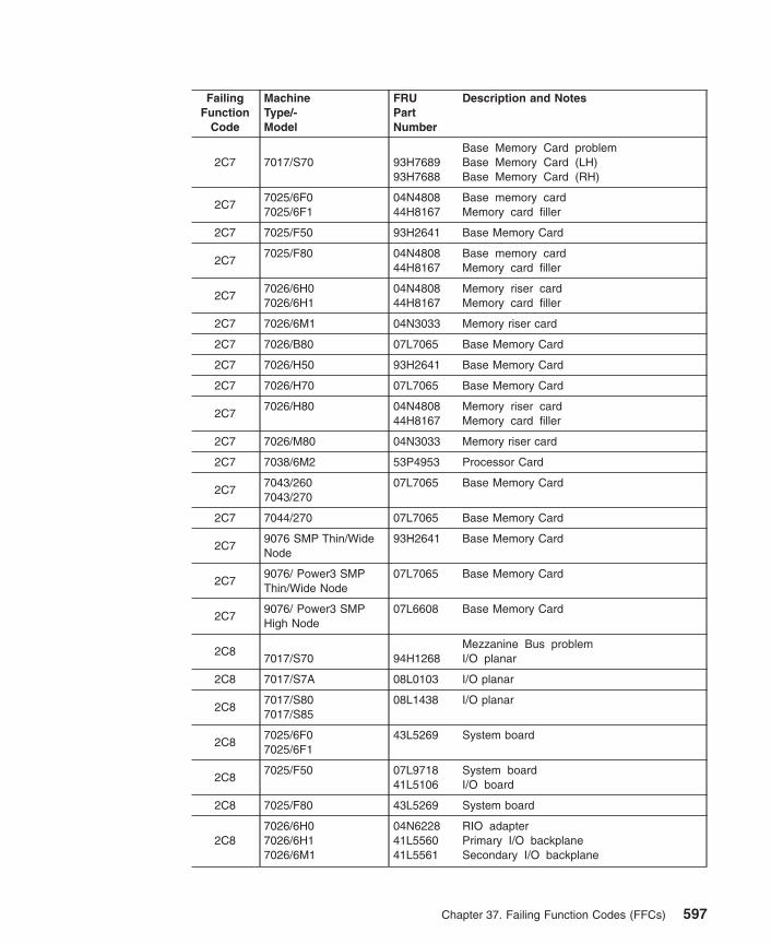
FailingFunction
Code
MachineType/-Model
FRUPartNumber
Description and Notes
2C7 7017/S70 93H768993H7688
Base Memory Card problemBase Memory Card (LH)Base Memory Card (RH)
2C77025/6F07025/6F1
04N480844H8167
Base memory cardMemory card filler
2C7 7025/F50 93H2641 Base Memory Card
2C77025/F80 04N4808
44H8167Base memory cardMemory card filler
2C77026/6H07026/6H1
04N480844H8167
Memory riser cardMemory card filler
2C7 7026/6M1 04N3033 Memory riser card
2C7 7026/B80 07L7065 Base Memory Card
2C7 7026/H50 93H2641 Base Memory Card
2C7 7026/H70 07L7065 Base Memory Card
2C77026/H80 04N4808
44H8167Memory riser cardMemory card filler
2C7 7026/M80 04N3033 Memory riser card
2C7 7038/6M2 53P4953 Processor Card
2C77043/2607043/270
07L7065 Base Memory Card
2C7 7044/270 07L7065 Base Memory Card
2C79076 SMP Thin/WideNode
93H2641 Base Memory Card
2C79076/ Power3 SMPThin/Wide Node
07L7065 Base Memory Card
2C79076/ Power3 SMPHigh Node
07L6608 Base Memory Card
2C87017/S70 94H1268
Mezzanine Bus problemI/O planar
2C8 7017/S7A 08L0103 I/O planar
2C87017/S807017/S85
08L1438 I/O planar
2C87025/6F07025/6F1
43L5269 System board
2C87025/F50 07L9718
41L5106System boardI/O board
2C8 7025/F80 43L5269 System board
2C87026/6H07026/6H17026/6M1
04N622841L556041L5561
RIO adapterPrimary I/O backplaneSecondary I/O backplane
Chapter 37. Failing Function Codes (FFCs) 597

FailingFunction
Code
MachineType/-Model
FRUPartNumber
Description and Notes
2C87026/B80 08L0988
00P1859System boardI/O board
2C87026/H50 07L9718
1L5106System boardI/O board
2C87026/H70 08L0988
03N2797System boardI/O board
2C87026/H80 04N6228
41L556041L5561
RIO adapterPrimary I/O backplaneSecondary I/O backplane
2C87026/M80 04N6228
41L556041L5561
RIO adapterPrimary I/O backplaneSecondary I/O backplane
2C87028/6C17028/6E1
09P2420 System Board
2C87028/6C47028/6E4
00P316609P2702
CEC BackplanePCI Riser Card
2C8 7038/6M2 00P4062 Service Processor/PCI Backplane
2C8 7039/651 00P4603 System Backplane
2C8 7040/61D 11P2623 I/O Planar
2C87043/260 08L1303
03N2443System boardI/O board
2C87043/270 08L0988
41L6013System boardI/O board
2C87044/270 08L0988
41L6013System boardI/O board
2C8 7311/D10 09P5921 I/O Drawer Backplane
2C8 7311/D20 53P3472 PCI Planar
2C8
9076 SMP Thin/WideNode
07L971841L613893H331631L7766
CPU chassis system boardCPU chassis I/O planarI/O Chassis connection cardSP Switch MX
2C8
9076/ Power3 SMPThin/Wide Node
08L130308L098803N286603N336807L853131L7766
CPU chassis, system board (200 MHz)CPU chassis, system board (375 MHz)CPU chassis, I/O planar (200 MHz)CPU chassis, I/O planar (375 MHz)I/O Expansion CardSP Switch MX
2C8 9112/265 09P2420 System Board
2C97017/S70 94H1268
PCI Bus problemI/O planar
2C9 7017/S7A 08L0103 I/O planar
598 Diagnostic Information for Multiple Bus Systems
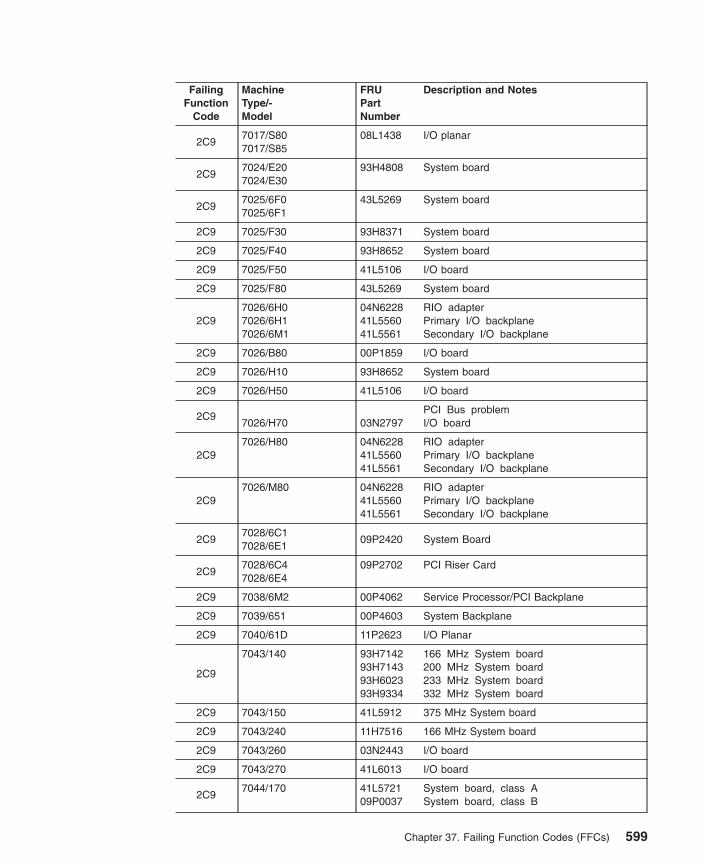
FailingFunction
Code
MachineType/-Model
FRUPartNumber
Description and Notes
2C97017/S807017/S85
08L1438 I/O planar
2C97024/E207024/E30
93H4808 System board
2C97025/6F07025/6F1
43L5269 System board
2C9 7025/F30 93H8371 System board
2C9 7025/F40 93H8652 System board
2C9 7025/F50 41L5106 I/O board
2C9 7025/F80 43L5269 System board
2C97026/6H07026/6H17026/6M1
04N622841L556041L5561
RIO adapterPrimary I/O backplaneSecondary I/O backplane
2C9 7026/B80 00P1859 I/O board
2C9 7026/H10 93H8652 System board
2C9 7026/H50 41L5106 I/O board
2C97026/H70 03N2797
PCI Bus problemI/O board
2C97026/H80 04N6228
41L556041L5561
RIO adapterPrimary I/O backplaneSecondary I/O backplane
2C97026/M80 04N6228
41L556041L5561
RIO adapterPrimary I/O backplaneSecondary I/O backplane
2C97028/6C17028/6E1
09P2420 System Board
2C97028/6C47028/6E4
09P2702 PCI Riser Card
2C9 7038/6M2 00P4062 Service Processor/PCI Backplane
2C9 7039/651 00P4603 System Backplane
2C9 7040/61D 11P2623 I/O Planar
2C9
7043/140 93H714293H714393H602393H9334
166 MHz System board200 MHz System board233 MHz System board332 MHz System board
2C9 7043/150 41L5912 375 MHz System board
2C9 7043/240 11H7516 166 MHz System board
2C9 7043/260 03N2443 I/O board
2C9 7043/270 41L6013 I/O board
2C97044/170 41L5721
09P0037System board, class ASystem board, class B
Chapter 37. Failing Function Codes (FFCs) 599
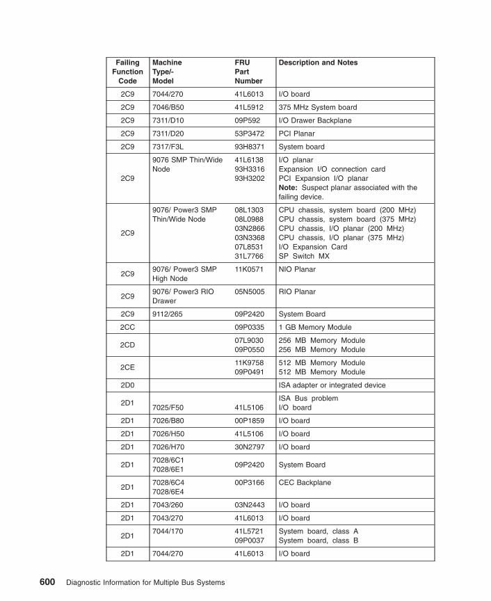
FailingFunction
Code
MachineType/-Model
FRUPartNumber
Description and Notes
2C9 7044/270 41L6013 I/O board
2C9 7046/B50 41L5912 375 MHz System board
2C9 7311/D10 09P592 I/O Drawer Backplane
2C9 7311/D20 53P3472 PCI Planar
2C9 7317/F3L 93H8371 System board
2C9
9076 SMP Thin/WideNode
41L613893H331693H3202
I/O planarExpansion I/O connection cardPCI Expansion I/O planarNote: Suspect planar associated with thefailing device.
2C9
9076/ Power3 SMPThin/Wide Node
08L130308L098803N286603N336807L853131L7766
CPU chassis, system board (200 MHz)CPU chassis, system board (375 MHz)CPU chassis, I/O planar (200 MHz)CPU chassis, I/O planar (375 MHz)I/O Expansion CardSP Switch MX
2C99076/ Power3 SMPHigh Node
11K0571 NIO Planar
2C99076/ Power3 RIODrawer
05N5005 RIO Planar
2C9 9112/265 09P2420 System Board
2CC 09P0335 1 GB Memory Module
2CD07L903009P0550
256 MB Memory Module256 MB Memory Module
2CE11K975809P0491
512 MB Memory Module512 MB Memory Module
2D0 ISA adapter or integrated device
2D17025/F50 41L5106
ISA Bus problemI/O board
2D1 7026/B80 00P1859 I/O board
2D1 7026/H50 41L5106 I/O board
2D1 7026/H70 30N2797 I/O board
2D17028/6C17028/6E1
09P2420 System Board
2D17028/6C47028/6E4
00P3166 CEC Backplane
2D1 7043/260 03N2443 I/O board
2D1 7043/270 41L6013 I/O board
2D17044/170 41L5721
09P0037System board, class ASystem board, class B
2D1 7044/270 41L6013 I/O board
600 Diagnostic Information for Multiple Bus Systems

FailingFunction
Code
MachineType/-Model
FRUPartNumber
Description and Notes
2D1 9112/265 09P2420 System Board
2D27017/S70 94H1268
Mezzanine Bus Arbiter problemI/O planar
2D2 7017/S7A 08L0103 I/O planar
2D27017/S807017/S85
08L1438 I/O planar
2D27025/6F07025/6F1
43L5269 System board
2D2 7025/F50 41L5106 I/O board
2D2 7025/F80 43L5269 System board
2D27026/6H07026/6H17026/6M1
04N622841L556041L5561
RIO adapterPrimary I/O backplaneSecondary I/O backplane
2D2 7026/B80 00P1859 I/O board
2D2 7026/H50 41L5106 I/O board
2D2 7026/H70 03N2797 I/O board
2D27026/H80 04N6228
41L556041L5561
RIO adapterPrimary I/O backplaneSecondary I/O backplane
2D27026/M80 04N6228
41L556041L5561
RIO adapterPrimary I/O backplaneSecondary I/O backplane
2D27028/6C17028/6E1
09P2420 System Board
2D27028/6C47028/6E4
09P2702 PCI Riser Card
2D2 7038/6M2 00P4062 Service Processor/PCI Backplane
2D2 7039/651 00P4603 System Backplane
2D2 7040/61D 11P2623 I/O Planar
2D2 7043/260 03N2443 I/O board
2D2 7043/270 41L6013 I/O board
2D27044/170 41L5721
09P0037System board, class ASystem board, class B
2D2 7044/270 41L6013 I/O board
2D2 7311/D10 09P5921 I/O Drawer Backplane
2D2 7311/D20 53P3472 PCI Planar
2D29076 SMP Thin/WideNode
07L9718 CPU chassis system board
2D29076/ Power3 SMPThin/Wide Node
08L130308L0988
System board (200 MHz)System board (375 MHz)
Chapter 37. Failing Function Codes (FFCs) 601

FailingFunction
Code
MachineType/-Model
FRUPartNumber
Description and Notes
2D29076/ Power3 SMPHigh Node
11K0571 NIO planar
2D29076/ Power3 RIODrawer
05N5005 RIO planar
2D2 9112/265 09P2420 System Board
2D3 7017/S7003N3523 Service processor card problem
Service Processor Card
2D3 7017/S7A 03N3523 Service Processor Card
2D37017/S807017/S85
11K0301 Service Processor Card
2D37025/6F07025/6F1
43L5269 System board
2D3
7025/F50 08L0442 Service ProcessorNote: The Service Processor can faildiagnostics if the firmware levels between thesystem and service processor are notcompatible. Check the levels of the systemand service processor firmware. Compatiblelevels are listed in update packagedocumentation and in RETAIN. If the firmwarelevels are compatible and the problempersists, then replace the Service Processorcard.
2D3 7025/F80 43L5269 System board
2D37026/6H07026/6H17026/6M1
41L5560 Primary I/O drawer backplane
2D3 7026/B80 00P1859 I/O board
2D3
7026/H50 08L0449 Service ProcessorNote: The Service Processor can faildiagnostics if the firmware levels between thesystem and service processor are notcompatible. Check the levels of the systemand service processor firmware. Compatiblelevels are listed in update packagedocumentation and in RETAIN. If the firmwarelevels are compatible and the problempersists, then replace the Service Processorcard.
2D3 7026/H70 03N2797 I/O board
2D37026/H807026/M80
41L5560 Primary I/O drawer backplane
2D37028/6C17028/6E1
09P2420 System Board
602 Diagnostic Information for Multiple Bus Systems

FailingFunction
Code
MachineType/-Model
FRUPartNumber
Description and Notes
2D37028/6C47028/6E4
00P3166 CEC Backplane
2D3 7038/6M2 00P4062 Service Processor/PCI Backplane
2D3 7039/651 09P6222 Service Processor Card
2D3 7039/651 00P4603 System Backplane
2D37040/6717040/681
09P2435 Primary I/O Book
2D3 7043/260 03N2443 I/O board
2D3 7043/270 41L6013 I/O board
2D37044/170 41L5721
09P0037System board, class ASystem board, class B
2D3 7044/270 41L6013 I/O board
2D3
9076 SMP Thin/WideNode
08L0442 Service ProcessorNote: The Service Processor can faildiagnostics if the firmware levels between thesystem and service processor are notcompatible. Check the levels of the systemand service processor firmware. Compatiblelevels are listed in update packagedocumentation and in RETAIN. If the firmwarelevels are compatible and the problempersists, then replace the Service Processorcard.
2D39076/ Power3 SMPThin/Wide Node
03N286603N3368
I/O planar (200 MHz)I/O planar (375 Mhz)
2D39076/ Power3 SMPHigh Node
11K0571 NIO planar
2D3 9112/265 09P2420 System Board
2D47017/S70 94H1268
System/SP Interface Logic problemI/O planar
2D4 7017/S7A 08L0103 I/O planar
2D47017/S807017/S85
08L1438 I/O planar
2D47025/6F07025/6F1
43L5269 System board
2D4 7025/F50 41L5106 I/O board
2D4 7025/F80 43L5269 System board
2D47026/6H07026/6H17026/6M1
41L5560 Primary I/O drawer backplane
2D4 7026/B80 00P1859 I/O board
2D4 7026/H50 41L5106 I/O board
Chapter 37. Failing Function Codes (FFCs) 603

FailingFunction
Code
MachineType/-Model
FRUPartNumber
Description and Notes
2D4 7026/H70 03N2797 I/O board
2D47026/H807026/M80
41L5560 Primary I/O drawer backplane
2D47028/6C17028/6E1
09P2420 System Board
2D47028/6C47028/6E4
00P3166 CEC Backplane
2D4 7038/6M2 00P4062 Service Processor/PCI Backplane
2D4 7039/651 09P6222 Service Processor Card
2D4 7039/651 09P6222 Service Processor Card
2D47040/6717040/681
09P2435 Primary I/O Book
2D4 7043/260 08L0633 I/O board
2D4 7043/270 41L6013 I/O board
2D47044/170 41L5721
09P0037System board, class ASystem board, class B
2D4 7044/270 41L6013 I/O board
2D49076 SMP Thin/WideNode
41L6138 I/O planar
2D49076/ Power3 SMPThin/Wide Node
03N286603N3368
I/O planar (200 MHz)/O planar (375 Mhz)
2D49076/ Power3 SMPHigh Node
11K0571 NIO planar
2D4 9112/265 09P2420 System Board
2D5 7017/S70 03N352394H1268
SP Primary I/O bus problemService Processor CardI/O planar
2D57017/S7A 03N3523
08L0103Service Processor CardI/O planar
2D57017/S807017/S85
11K030108L1438
Service Processor CardI/O planar
2D57025/6F07025/6F1
43L5269 System board
2D57025/F50 41L5106
08L0442I/O boardService Processor
2D5 7025/F80 43L5269 System board
2D57026/6H07026/6H17026/6M1
41L5560 Primary I/O drawer backplane
2D5 7026/B80 00P1859 I/O board
604 Diagnostic Information for Multiple Bus Systems

FailingFunction
Code
MachineType/-Model
FRUPartNumber
Description and Notes
2D57026/H50 41L5106
08L0449I/O boardService Processor
2D5 7026/H70 03N2797 I/O board
2D57026/H807026/M80
41L5560 Primary I/O drawer backplane
2D57028/6C17028/6E1
09P2420 System Board
2D57028/6C47028/6E4
00P3166 CEC Backplane
2D5 7038/6M2 00P4062 Service Processor/PCI Backplane
2D5 7039/651 09P6222 Service Processor Card
2D5 7039/651 09P6222 Service Processor Card
2D57040/6717040/681
09P2435 Primary I/O Book
2D5 7043/260 03N2443 I/O board
2D5 7043/270 41L6013 I/O board
2D57044/170 41L5721
09P0037System board, class ASystem board, class B
2D5 7044/270 41L6013 I/O board
2D59076 SMP Thin/WideNode
41L6138 I/O planar
2D59076/ Power3 SMPThin/Wide Node
03N286603N3368
I/O planar (200 MHz)I/O planar (375 Mhz)
2D59076/ Power3 SMPHigh Node
11K057103N418407L6608
NIO planarSystem planarBase memory card
2D5 9112/265 09P2420 System Board
2D6 7017/S70 03N3523 Service Processor Card
2D6 7017/S7A 03N3523 Service Processor Card
2D67017/S807017/S85
11K0301 Service Processor Card
2D67025/6F07025/6F1
43L5269 System board
2D6 7025/F80 43L5269 System board
2D6
7026/6H07026/6H17026/6M17026/H807026/M80
41L5560 Primary I/O drawer backplane
2D67028/6C47028/6E4
00P3166 CEC Backplane
Chapter 37. Failing Function Codes (FFCs) 605
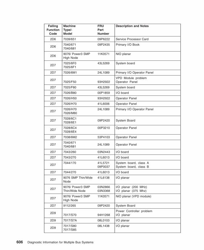
FailingFunction
Code
MachineType/-Model
FRUPartNumber
Description and Notes
2D6 7039/651 09P6222 Service Processor Card
2D67040/6717040/681
09P2435 Primary I/O Book
2D69076/ Power3 SMPHigh Node
11K0571 NIO planar
2D77025/6F07025/6F1
43L5269 System board
2D7 7026/6M1 24L1089 Primary I/O Operator Panel
2D77025/F50 93H2922
VPD Module problemOperator Panel
2D7 7025/F80 43L5269 System board
2D7 7026/B80 00P1859 I/O board
2D7 7026/H50 93H2922 Operator Panel
2D7 7026/H70 41L6006 Operator Panel
2D77026/H707026/M80
24L1089 Primary I/O Operator Panel
2D77028/6C17028/6E1
09P2420 System Board
2D77028/6C47028/6E4
00P3210 Operator Panel
2D7 7038/6M2 53P4103 Operator Panel
2D77040/6717040/681
24L1089 Operator Panel
2D7 7043/260 03N2443 I/O board
2D7 7043/270 41L6013 I/O board
2D77044/170 41L5721
09P0037System board, class ASystem board, class B
2D7 7044/270 41L6013 I/O board
2D79076 SMP Thin/WideNode
41L6138 I/O planar
2D79076/ Power3 SMPThin/Wide Node
03N286603N3368
I/O planar (200 MHz)I/O planar (375 Mhz)
2D79076/ Power3 SMPHigh Node
11K0571 NIO planar (VPD module)
2D7 9112/265 09P2420 System Board
2D97017/S70 94H1268
Power Controller problemI/O planar
2D9 7017/S7A 08L0103 I/O planar
2D97017/S807017/S85
08L1438 I/O planar
606 Diagnostic Information for Multiple Bus Systems
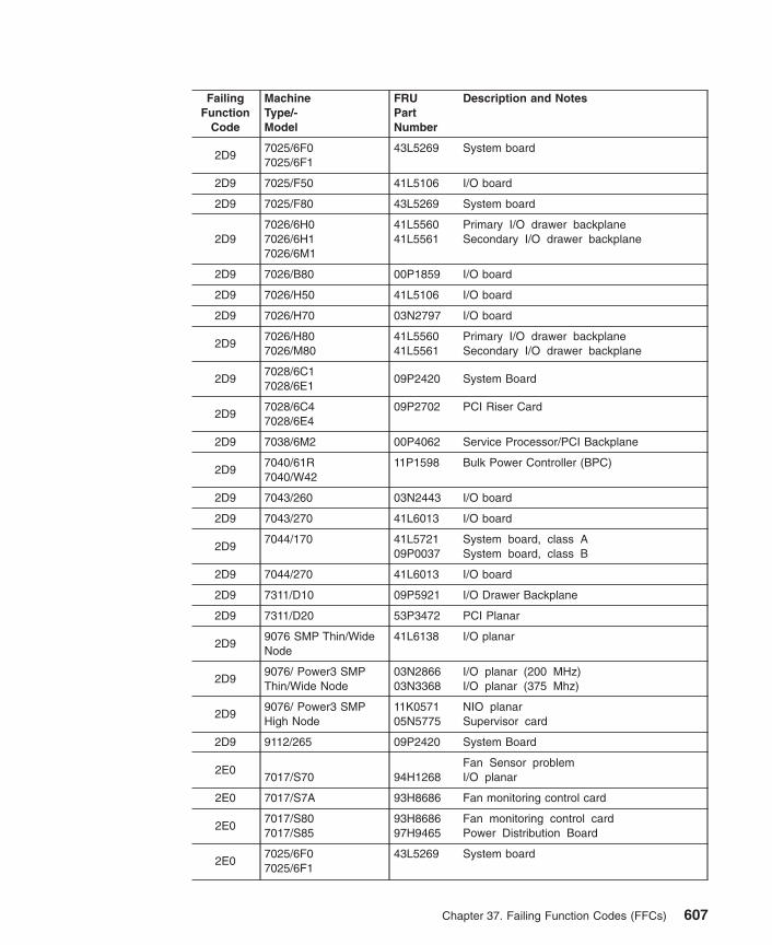
FailingFunction
Code
MachineType/-Model
FRUPartNumber
Description and Notes
2D97025/6F07025/6F1
43L5269 System board
2D9 7025/F50 41L5106 I/O board
2D9 7025/F80 43L5269 System board
2D97026/6H07026/6H17026/6M1
41L556041L5561
Primary I/O drawer backplaneSecondary I/O drawer backplane
2D9 7026/B80 00P1859 I/O board
2D9 7026/H50 41L5106 I/O board
2D9 7026/H70 03N2797 I/O board
2D97026/H807026/M80
41L556041L5561
Primary I/O drawer backplaneSecondary I/O drawer backplane
2D97028/6C17028/6E1
09P2420 System Board
2D97028/6C47028/6E4
09P2702 PCI Riser Card
2D9 7038/6M2 00P4062 Service Processor/PCI Backplane
2D97040/61R7040/W42
11P1598 Bulk Power Controller (BPC)
2D9 7043/260 03N2443 I/O board
2D9 7043/270 41L6013 I/O board
2D97044/170 41L5721
09P0037System board, class ASystem board, class B
2D9 7044/270 41L6013 I/O board
2D9 7311/D10 09P5921 I/O Drawer Backplane
2D9 7311/D20 53P3472 PCI Planar
2D99076 SMP Thin/WideNode
41L6138 I/O planar
2D99076/ Power3 SMPThin/Wide Node
03N286603N3368
I/O planar (200 MHz)I/O planar (375 Mhz)
2D99076/ Power3 SMPHigh Node
11K057105N5775
NIO planarSupervisor card
2D9 9112/265 09P2420 System Board
2E07017/S70 94H1268
Fan Sensor problemI/O planar
2E0 7017/S7A 93H8686 Fan monitoring control card
2E07017/S807017/S85
93H868697H9465
Fan monitoring control cardPower Distribution Board
2E07025/6F07025/6F1
43L5269 System board
Chapter 37. Failing Function Codes (FFCs) 607

FailingFunction
Code
MachineType/-Model
FRUPartNumber
Description and Notes
2E0 7025/F50 41L5106 I/O board
2E0 7025/F80 43L5269 System board
2E07026/6H07026/6H17026/6M1
11K110741L541541L5560
SPCN fan control cardPower distribution boardPrimary I/O backplane
2E0 7026/B80 00P1859 I/O board
2E0 7026/H50 93H8686 Fan Monitoring Control Card
2E0 7026/H70 93H8686 Fan Monitoring Control Card
2E07026/H807026/M80
11K110741L541541L5560
SPCN fan control cardPower distribution boardPrimary I/O backplane
2E07028/6C17028/6E1
09P2420 System Board
2E07028/6C47028/6E4
00P3166 CEC Backplane
2E0 7038/6M2 00P4062 Service Processor/PCI Backplane
2E0 7039/651 09P6222 Service Processor Card
2E07040/61R7040/W42
11P1598 Bulk Power Controller (BPC)
2E07040/6717040/681
09P2435 Primary I/O Book
2E0 7043/260 03N0633 I/O board
2E0 7043/270 41L6013 I/O board
2E07044/170 41L5721
09P0037System board, class ASystem board, class B
2E0 7044/270 41L6013 I/O board
2E0 7311/D10 09P5921 I/O Drawer Backplane
2E0 7311/D20 53P3472 PCI Planar
2E09076 SMP Thin/WideNode
41L6138 I/O planar
2E09076/ Power3 SMPThin/Wide Node
03N286603N3368
I/O planar (200 MHz)I/O planar (375 Mhz)
2E09076/ Power3 SMPHigh Node
12K0451 Fan control card
2E09076/ Power3 RIODrawer
31L875205N5005
Supervisor cardRIO planar
2E0 9112/265 09P2420 System Board
2E17017/S70 94H1268
Thermal Sensor problemI/O planar
2E1 7017/S7A 08L0103 I/O planar
608 Diagnostic Information for Multiple Bus Systems

FailingFunction
Code
MachineType/-Model
FRUPartNumber
Description and Notes
2E17017/S807017/S85
08L1438 I/O planar
2E1 7024 93H4808 System board
2E17025/6F07025/6F1
43L5269 System board
2E1 7025/F30 93H8371 System board
2E1 7025/F40 93H8652 System board
2E1 7025/F50 41L5106 I/O board
2E1 7025/F80 43L5269 System board
2E1
7026/6H07026/6H17026/6M1
41L556041L556124L108924L0955
Primary I/O backplaneSecondary I/O backplanePrimary I/O drawer operator panelSecondary I/O drawer operator panel
2E1 7026/B80 00P1859 I/O board
2E1 7026/H10 93H8652 System board
2E1 7026/H50 41L5106 I/O board
2E1 7026/H70 03N2797 I/O board
2E1
7026/H807026/M80
41L556041L556124L108924L0955
Primary I/O backplaneSecondary I/O backplanePrimary I/O drawer operator panelSecondary I/O drawer operator panel
2E17028/6C17028/6E1
09P2420 System Board
2E17028/6C47028/6E4
00P3210 Operator Panel
2E1 7038/6M2 53P4103 Operator Panel
2E1 7039/651 00P4603 System Backplane
2E1 7040/61D 11P2623 I/O Planar
2E17043/140 93H7142
93H714393H602393H9334
Thermal Sensor problem166 MHz System board200 MHz System board233 MHz System board332 MHz System board
2E1 7043/150 41L5912 375 MHz system board
2E1 7043/240 11H7516 System board
2E1 7043/260 03N2443 I/O board
2E1 7043/270 41L6013 I/O board
2E17044/170 41L5721
09P0037System board, class ASystem board, class B
2E1 7044/270 41L6013 I/O board
Chapter 37. Failing Function Codes (FFCs) 609

FailingFunction
Code
MachineType/-Model
FRUPartNumber
Description and Notes
2E1 7046/B50 41L5912 375 MHz System board
2E1 7311/D10 09P5921 I/O Drawer Backplane
2E1 7311/D20 53P3472 PCI Planar
2E1 7317/F3L 93H8371 System board
2E19076 SMP Thin/WideNode
41L6138 I/O planar
2E19076/ Power3 SMPThin/Wide Node
03N286603N3368
I/O planar (200 MHz)I/O planar (375 Mhz)
2E19076/ Power3 SMPHigh Node
03N418411K0571
System planar (inlet)NIO planar (outlet)
2E19076/ Power3 RIODrawer
12K044605N500531L8752
Power SupplyRIO planar (midrange)Supervisor card
2E1 9112/265 09P2420 System Board
2E27017/S70 94H1268
Voltage Sensor problemI/O planar
2E2 7017/S7A 08L0103 I/O planar
2E27017/S807017/S85
08L1438 I/O planar
2E27025/6F07025/6F1
43L5269 System board
2E2 7025/F50 41L5106 I/O board
2E2 7025/F80 43L5269 System board
2E27026/6H07026/6H17026/6M1
41L5415 Power distribution board
2E2 7026/B80 00P1859 I/O board
2E2 7026/H50 41L5106 I/O board
2E2 7026/H70 03N2797 I/O board
2E27026/H807026/M80
41L5415 Power distribution board
2E27028/6C17028/6E1
09P2420 System Board
2E27028/6C47028/6E4
00P3166 CEC Backplane
2E2 7038/6M2 00P4062 Service Processor/PCI Backplane
2E2 7039/651 00P4603 Service Backplane
2E2 7040/61D 11P2623 I/O Planar
2E2 7043/260 03N2443 I/O board
2E2 7043/270 41L6013 I/O board
610 Diagnostic Information for Multiple Bus Systems

FailingFunction
Code
MachineType/-Model
FRUPartNumber
Description and Notes
2E27044/170 41L5721
09P0037System board, class ASystem board, class B
2E2 7044/270 41L6013 I/O board
2E2 7311/D10 09P5921 I/O Drawer Backplane
2E2 7311/D20 53P3472 PCI Planar
2E29076 SMP Thin/WideNode
41L613846H9165
I/O planarI/O Expansion Interposer Card
2E29076/ Power3 SMPThin/Wide Node
03N286603N336846H9165
I/O planar (200 MHz)I/O planar (375 Mhz)I/O Expansion Interposer Card
2E29076/ Power3 SMPHigh Node
11K057103N418411K0198
NIO Planar 3.3V, +5V, 5SB, +12V, -12VSystem Planar 2.5V, 3.3VCPU Card 1.8V, 2.5V
2E29076/ Power3 RIODrawer
05N5005 RIO planar
2E2 9112/265 09P2420 System Board
2E37017/S70 03N3523
Serial Port Controller problemService Processor Card
2E3 7017/S7A 03N3523 Service Processor Card
2E37017/S807017/S85
11K0301 Service Processor Card
2E37025/6F07025/6F1
43L5269 System board
2E3 7025/F50 41L5106 I/O board
2E3 7025/F80 43L5269 System board
2E37026/6H07026/6H17026/6M1
41L5560 Primary I/O drawer backplane
2E3 7026/B80 00P1859 I/O board
2E3 7026/H50 41L5106 I/O board
2E3 7026/H70 03N2797 I/O board
2E37026/H807026/M80
41L5560 Primary I/O drawer backplane
2E37028/6C17028/6E1
09P2420 System Board
2E37028/6C47028/6E4
00P3166 CEC Backplane
2E3 7038/6M2 00P4062 Service Processor/PCI Backplane
2E3 7039/651 09P6222 Service Processor Card
2E37040/6717040/681
09P2435 Primary I/O Book
Chapter 37. Failing Function Codes (FFCs) 611

FailingFunction
Code
MachineType/-Model
FRUPartNumber
Description and Notes
2E3 7043/260 03N2443 I/O board
2E3 7043/270 41L6013 I/O board
2E37044/170 41L5721
09P0037System board, class ASystem board, class B
2E3 7044/270 41L6013 I/O board
2E39076 SMP Thin/WideNode
41L613811J400011J5197
I/O planarSupervisor cardPower/supervisor interposer cable
2E3
9076/ Power3 SMPThin/Wide Node
03N286603N336811J400011J5197
I/O planar (200 MHz)I/O planar (375 MHz)Supervisor cardPower/supervisor interposer cable
2E39076/ Power3 SMPHigh Node
11K0571 NIO planar
2E3 9112/265 09P2420 System Board
2E47017/S70 03N3523
JTAG/COP Controller problemService Processor Card
2E4 7017/S7A 03N3523 Service Processor Card
2E47017/S807017/S85
11K0301 Service Processor Card
2E47025/6F07025/6F1
43L5269 System board
2E4 7025/F50 41L5106 I/O board
2E4 7025/F80 43L5269 System board
2E47026/6H07026/6H17026/6M1
41L5560 Primary I/O drawer backplane
2E4 7026/B80 00P1859 I/O board
2E4 7026/H50 41L5106 I/O board
2E4 7026/H70 03N2797 I/O board
2E47026/H807026/M80
41L5560 Primary I/O drawer backplane
2E47028/6C17028/6E1
09P2420 System Board
2E47028/6C47028/6E4
00P3166 CEC Backplane
2E2 7038/6M2 00P4062 Service Processor/PCI Backplane
2E4 7039/651 09P6222 Service Processor Card
2E47040/6717040/681
09P2435 Primary I/O Book
2E4 7043/260 03N2443 I/O board
612 Diagnostic Information for Multiple Bus Systems

FailingFunction
Code
MachineType/-Model
FRUPartNumber
Description and Notes
2E4 7043/270 41L6013 I/O board
2E47044/170 41L5721
09P0037System board, class ASystem board, class B
2E4 7044/270 41L6013 I/O board
2E49076 SMP Thin/WideNode
41L6138 I/O planar
2E49076/ Power3 SMPThin/Wide Node
03N286603N3368
I/O planar (200 MHz)I/O planar (375 Mhz)
2E49076/ Power3 SMPHigh Node
11K057103N4184
NIO Planar (JTAG)System Planar
2E4 9112/265 09P2420 System Board
2E6 40H6595 PCI Differential Ultra SCSI Adapter (4-L)
2E6
7017/S807017/S857028/6C17028/6E17028/6C47028/6E47040/61D7043/2707044/1707044/2707046/B50
11K0671 PCI Universal Differential Ultra SCSI Adapter(4-U)
2E6 7311/D10 09P5921 I/O Drawer Backplane
2E6 7311/D20 53P3472 PCI Planar
2E7 Generic PCI SCSI Adapter
2E87025/6F0 04N5353
23L778523L7794
1-way processor card (600 MHz)2-way processor card (667 MHz)4-way processor card (667 MHz)
2E8
7025/6F1 04N535323L778523L779423L7799
1-way processor card (600 MHz)2-way processor card (667 MHz)4-way processor card (667 MHz)6-way processor card (667 MHz)
2E8 7025/F40 11H7517 166 MHz Processor and Cache card
2E8
7025/F80 04N476503P006203P007003P0085
1-way processor card2-way processor card4-way processor card6-way processor card
2E87026/6M1 04N6698
21P638121P6383
2-way processor card (500 MHz)2-way processor card (750 MHz)4-way processor card (750 MHz)
Chapter 37. Failing Function Codes (FFCs) 613
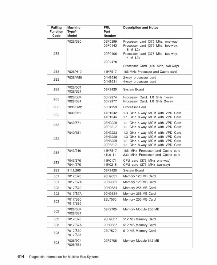
FailingFunction
Code
MachineType/-Model
FRUPartNumber
Description and Notes
2E8
7026/B80 09P039909P0143
09P0406
09P4478
Processor card (375 Mhz, one-way)Processor card (375 Mhz, two-way,
8 M L2)Processor card (375 Mhz, two-way,
4 M L2)
Processor Card (450 Mhz, two-way)
2E8 7026/H10 11H7517 166 MHz Processor and Cache card
2E87026/M80 04N6930
04N69312-way processor card4-way processor card
2E87028/6C17028/6E1
09P2420 System Board
2E87028/6C47028/6E4
00P297400P2977
Processor Card, 1.0 GHz 1-wayProcessor Card, 1.0 GHz 2-way
2E8 7038/6M2 53P4953 Processor Card
2E87039/651 44P1542
44P15441.3 GHz 4-way MCM with VPD Card1.1 GHz 8-way MCM with VPD Card
2E87040/671 03N3229
09P32171.1 GHz 4-way MCM with VPD Card1.1 GHz 8-way MCM with VPD Card
2E8
7040/681 03N322303N322803N322909P3217
1.3 GHz 4-way MCM with VPD Card1.3 GHz 8-way MCM with VPD Card1.1 GHz 4-way MCM with VPD Card1.1 GHz 8-way MCM with VPD Card
2E87043/240 11H7517
41L6111166 MHz Processor and Cache card233 MHz Processor and Cache card
2E87043/2707044/270
11K017111K0218
CPU card (375 MHz one-way)CPU card (375 MHz two-way)
2E8 9112/265 09P2420 System Board
301 7017/S70 90H9831 Memory 128 MB Card
301 7017/S7A 90H9831 Memory 128 MB Card
302 7017/S70 90H9834 Memory 256 MB Card
302 7017/S7A 90H9834 Memory 256 MB Card
3027017/S807017/S85
23L7566 Memory 256 MB Card
3027028/6C47028/6E4
09P2705 Memory Module 256 MB
303 7017/S70 90H9837 512 MB Memory Card
303 7017/S7A 90H9837 512 MB Memory Card
3037017/S807017/S85
23L7570 512 MB Memory Card
3037028/6C47028/6E4
09P2706 Memory Module 512 MB
614 Diagnostic Information for Multiple Bus Systems

FailingFunction
Code
MachineType/-Model
FRUPartNumber
Description and Notes
304 7017/S70 97H6226 1 GB Memory Card
304 7017/S7A 97H6226 1 GB Memory Card
304
7017/S807017/S85
23L757704N4994
1 GB Memory CardNote: 23Lxxxx and 04Nxxxx memory cardscannot be mixed. Replace bad FRUs withFRUs that have the same part number.
3047028/6C47028/6E4
09P2707 Memory Module 1GB
305 7017/S7A 97H6244 2 GB Memory Card
305
7017/S807017/S85
23L758904N5004
2 GB Memory CardNote: 23Lxxxx and 04Nxxxx memory cardscannot be mixed. Replace bad FRUs withFRUs that have the same part number.
3057028/6C47028/6E4
53P3232 Memory Module 2GB
3067017/S70 90H9795
21H764321H7377
Remote I/O cable (2 meter)Remote I/O cable (6 meter)Remote I/O cable (15 meter)
3067017/S7A 90H9795
21H764321H7377
Remote I/O cable (2 meter)Remote I/O cable (6 meter)Remote I/O cable (15 meter)
3067017/S807017/S85
90H979521H764321H7377
Remote I/O cable (2 meter)Remote I/O cable (6 meter)Remote I/O cable (15 meter)
306
7026/6H07026/6H17026/6M17026/H807026/M80
44L000597H749004N7014
Remote I/O cable (3 meter)Remote I/O cable (6 meter)Remote I/O cable (15 meter)
3067038/6M2 09P2631
09P263209P2633
Remote I/O-G Cable ( 1 meter)Remote I/O-G Cable (4 meter)Remote I/O-G Cable (10 meter)
3067039/651 09P2631
09P263209P2633
Remote I/O-G Cable (1 meter)Remote I/O-G Cable (4 meter)Remote I/O-G Cable (10 meter)
3067039/6517040/6717040/681
23L308044H887344H9137
Remote I/O Cable 3-MeterRemote I/O Cable 6-MeterRemote I/O Cable 15-Meter
3069076/ Power3 SMPHigh Node
90H979521H7377
Remote I/O cable (2 meter)Remote I/O cable (15 meter)
3077017/S70 94H1268
Expansion Unit Logic problemI/O planar
307 7017/S7A 08L0103 I/O planar
Chapter 37. Failing Function Codes (FFCs) 615

FailingFunction
Code
MachineType/-Model
FRUPartNumber
Description and Notes
3077017/S807017/S85
08L1438 I/O planar
307
7026/6H07026/6H17026/6M17026/H807026/M80
41L556041L5561
Primary I/O backplaneSecondary I/O backplane
3077028/6C47028/6E4
00P3166 CEC Backplane
307 7040/61D 11P2623 I/O Planar
307 7311/D10 09P5921 I/O Drawer Backplane
307 7311/D20 53P3472 PCI Planar
3087017/S70 97H7696
I/O Bridge problemSystem backplane Assembly
308 7017/S7A 97H7696 System Backplane Assembly
3087017/S807017/S85
23L7598 System Backplane Assembly
3087025/6F07025/6F1
43L5269 System board
308 7025/F80 43L5269 System board
3087026/6H07026/6H1
43L5274 CEC backplane
308 7026/6M1 04N3867 CEC RIO adapter card
308 7026/H80 43L5274 CEC backplane
308 7026/M80 04N3867 CEC RIO adapter card
3087028/6C47028/6E4
00P3166 CEC Backplane
308 7038/6M2 00P4062 Service Processor/PCI Backplane
308 7039/651 09P6222 Service Processor Card
3087040/6717040/681
11P2623 Primary I/O Book
30A
23L759504N5011
4 GB Memory CardNote: 23Lxxxx and 04Nxxxx memory cardscannot be mixed. Replace bad FRUs withFRUs that have the same part number.
30B 04N5531 8 GB Memory Card
440 25L3101 9.1 GB Ultra SCSI Disk Drive only
440 7046/B50 03N3873 9.1 GB Ultra SCSI Disk Drive and Carrier
441 25L3100 18.2 GB Ultra SCSI Disk Drive only
441 7046/B50 03N3874 18.2 GB Ultra SCSI Disk Drive and Carrier
616 Diagnostic Information for Multiple Bus Systems
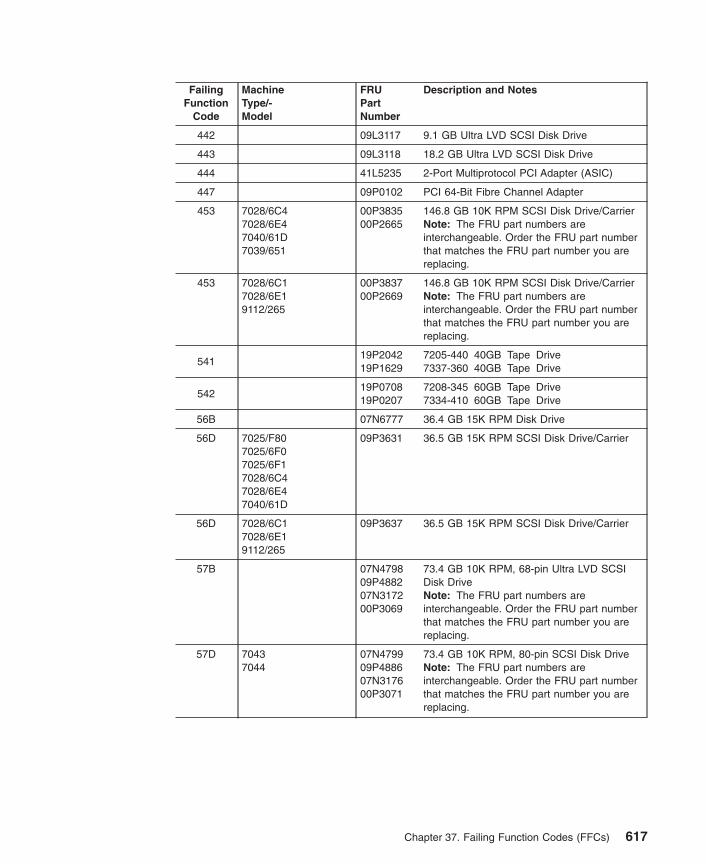
FailingFunction
Code
MachineType/-Model
FRUPartNumber
Description and Notes
442 09L3117 9.1 GB Ultra LVD SCSI Disk Drive
443 09L3118 18.2 GB Ultra LVD SCSI Disk Drive
444 41L5235 2-Port Multiprotocol PCI Adapter (ASIC)
447 09P0102 PCI 64-Bit Fibre Channel Adapter
453 7028/6C47028/6E47040/61D7039/651
00P383500P2665
146.8 GB 10K RPM SCSI Disk Drive/CarrierNote: The FRU part numbers areinterchangeable. Order the FRU part numberthat matches the FRU part number you arereplacing.
453 7028/6C17028/6E19112/265
00P383700P2669
146.8 GB 10K RPM SCSI Disk Drive/CarrierNote: The FRU part numbers areinterchangeable. Order the FRU part numberthat matches the FRU part number you arereplacing.
54119P204219P1629
7205-440 40GB Tape Drive7337-360 40GB Tape Drive
54219P070819P0207
7208-345 60GB Tape Drive7334-410 60GB Tape Drive
56B 07N6777 36.4 GB 15K RPM Disk Drive
56D 7025/F807025/6F07025/6F17028/6C47028/6E47040/61D
09P3631 36.5 GB 15K RPM SCSI Disk Drive/Carrier
56D 7028/6C17028/6E19112/265
09P3637 36.5 GB 15K RPM SCSI Disk Drive/Carrier
57B 07N479809P488207N317200P3069
73.4 GB 10K RPM, 68-pin Ultra LVD SCSIDisk DriveNote: The FRU part numbers areinterchangeable. Order the FRU part numberthat matches the FRU part number you arereplacing.
57D 70437044
07N479909P488607N317600P3071
73.4 GB 10K RPM, 80-pin SCSI Disk DriveNote: The FRU part numbers areinterchangeable. Order the FRU part numberthat matches the FRU part number you arereplacing.
Chapter 37. Failing Function Codes (FFCs) 617

FailingFunction
Code
MachineType/-Model
FRUPartNumber
Description and Notes
57D 7025/F807025/6F07025/6F17026/B807028/6C47028/6E47039/6517040/61D7046/B50
09P392409P488800P383300P3072
73.4GB 10K RPM SCSI Disk Drive/CarrierNote: The FRU part numbers areinterchangeable. Order the FRU part numberthat matches the FRU part number you arereplacing.
57D 7028/6C17028/6E19112/265
09P392809P4890
73.4 GB 10K RPM SCSI Disk Drive/CarrierNote: The FRU part numbers areinterchangeable. Order the FRU part numberthat matches the FRU part number you arereplacing.
58B 09P392109P4874
9.1 GB 10K RPM SCSI Disk Drive/CarrierNote: The FRU part numbers areinterchangeable. Order the FRU part numberthat matches the FRU part number you arereplacing.
58D 7025/F807025/6F07025/6F17026/B807028/6C47028/6E47040/61D7046/B507039/651
09P392209P443500P382900P3064
18.2 GB 10K RPM SCSI Disk Drive/CarrierNote: The FRU part numbers areinterchangeable. Order the FRU part numberthat matches the FRU part number you arereplacing.
58D 21047028/6C17028/6E19112/265
09P382309P4437
18.2 GB 10K RPM SCSI Disk Drive/CarrierNote: The FRU part numbers areinterchangeable. Order the FRU part numberthat matches the FRU part number you arereplacing.
59B 7025/F807025/6F07025/6F17026/B807039/6517040/61D7046/B50
09P392309P444500P383100P3068
36.4GB 10K RPM SCSI Disk Drive/CarrierNote: The FRU part numbers areinterchangeable. Order the FRU part numberthat matches the FRU part number you arereplacing.
59B 21047028/6C17028/6C47028/6E19112/265
09P382609P4447
36.4GB 10K RPM SCSI Disk Drive/CarrierNote: The FRU part numbers areinterchangeable. Order the FRU part numberthat matches the FRU part number you arereplacing.
60107N367503N387331L8768
9.1 GB LVD 68-pin SCSI Disk Drive9.1 GB LVD 68-pin Drive/Carrier (U2)9.1 GB LVD 68-pin Drive/Carrier (SP)
618 Diagnostic Information for Multiple Bus Systems

FailingFunction
Code
MachineType/-Model
FRUPartNumber
Description and Notes
60B
70437044
07N481309P442907P317400P3061
18.2 GB LVD 10K RPM, 68-pin SCSI DiskDriveNote: The FRU part numbers areinterchangeable. Order the FRU part numberthat matches the FRU part number you arereplacing.
613 19P4898 8mm 80GB VXA tape device
61B
07N483309P444307N317700P3067
36.4 GB 10K RPM, 80-pin SCSI Disk DriveNote: The FRU part numbers areinterchangeable. Order the FRU part numberthat matches the FRU part number you arereplacing.
61B7028/6C17028/6E19112/265
09P3826 36.4 GB 10K RPM, SCSI Disk Drive/Carrier
61D 00P1519 36.4 GB 10K RPM Drive/Carrier
61E 00P1511 18.2 GB 10K RPM Drive/Carrier
621 03N3301 9.1 GB LVD 80-pin Drive/Carrier (U2)
62307N367403N387431L8770
18.2 GB LVD 68-pin SCSI Disk Drive18.2 GB LVD 68-pin Drive/Carrier (U2)18.2 GB LVD 68-pin Drive/Carrier (SP)
624 03N3302 18.2 GB LVD 80-pin Drive/Carrier (U2)
62D
07N482309P4868
9.1 GB 10K RPM, 68-pin SCSI Disk DriveNote: The FRU part numbers areinterchangeable. Order the FRU part numberthat matches the FRU part number you arereplacing.
62E 00P1508 9.1 GB 10K RPM Drive/Carrier
63697H7782 TURBOWAYS 622 Mbps PCI MMF ATM
Adapter
637 03N3606 Dual Channel PCI-2 Ultra2 SCSI Adapter
638 22L0027 4.5 GB 16 bit Ultra SCSI SE Disk Drive
639
34L223208L115506H938906H76911147429
9.1 GB Ultra SCSI Disk Drive (68-pin)SpacerTrayID cableScrew
63A See 62D.
63B 07N4853 9.1 GB 10K RPM, 80-pin SCSI Disk Drive
63C See 60B.
Chapter 37. Failing Function Codes (FFCs) 619

FailingFunction
Code
MachineType/-Model
FRUPartNumber
Description and Notes
63D
70437044
07N484309P443307N317800P3063
18.2 GB 10K RPM, 80-pin SCSI Disk DriveNote: The FRU part numbers areinterchangeable. Order the FRU part numberthat matches the FRU part number you arereplacing.
63D7028/6C17028/6E19112/265
09P3823 18.2 GB 10K RPM, SCSI Disk Drive/Carrier
63E
07N480309P443907N317300P3065
36.4 GB 10K RPM, 68-pin SCSI Disk DriveNote: The FRU part numbers areinterchangeable. Order the FRU part numberthat matches the FRU part number you arereplacing.
63F See 61B.
64034L223344H464444H4266
9.1 GB Ultra SCSI Disk Drive (80-pin)TrayScrew
643 09L3116 18.2 GB Ultra LVD SCSI Disk Drive
644 09L3339 36.2 GB Ultra LVD SCSI Disk Drive
646 03N3554 High-Speed Token-Ring PCI Adapter
64A See 62E.
64B 00P1517 9.1 GB LVD 80-pin Drive/Carrier
64C See 61E.
64D 00P1520 18.2 GB LVD 80-pin Drive/Carrier
64E 00P1514 36.4 GB 10K RPM Drive/Carrier
64F See 61D.
650
Unknown disk drive.Note: This FFC indicates that the disk drivecould not properly configure. Refer to the diskdrive FRU part number.
653 59H6923 18.2 GB Ultra-SCSI 16-bit disk drive
655 11K0313 GXT130P PCI Graphics Adapter
657 07L7495 GXT2000P 3D Graphics Adapter PCI
6627025/6F07025/6F1
43L5269 System board
662 7025/F80 43L5269 System board
662 7026/B80 00P1859 I/O board
662 7026/H50 41L5106 I/O board, Integrated Ultra2 SCSI
662 7026/H70 03N2797 I/O board, Integrated Ultra2 SCSI
6627028/6C17028/6E1
09P2420 System Board
620 Diagnostic Information for Multiple Bus Systems

FailingFunction
Code
MachineType/-Model
FRUPartNumber
Description and Notes
662 7043/260 08L0633 I/O board, Integrated Ultra2 SCSI
662 7043/270 41L6013 I/O board
6627044/170 41L5721
09P0037System board, class ASystem board, class B
662 7044/270 41L6013 I/O board
662 9112/265 09P2420 System Board
663
87H3734
47L885109J8829
IBM ARTIC960RxD PCI Adapter(base card)IBM ARTIC960RxF AdapterIBM ARTIC960 Quad T1/E1 Adapter(daughter card)
664 04N2967 SCSI-2 CD-ROM Drive
667 01K7396 PCI 3-Channel Ultra2 SCSI RAID Adapter
669 41L6396 PCI Gigabit Ethernet Adapter
66C 00P1690 10/100/1000 Base-T Ethernet PCI Adapter
66D37L6892 PCI 4-Channel Ultra3 SCSI RAID Adapter
(Base card only)
66E 04N5967 4.7 GB DVD-RAM drive, Black Bezel
66E 04N5968 4.7 GB DVD-RAM drive, White Bezel
67431L756739H8084
ESCON Channel PCI Adapter AssemblyIBM ARTIC960Rx PCI Base Adapter
673 59H6925 18.2GB Differential SCSI Disk Drive
675 87H3427 IBM ARTIC960Hx PCI Base Adapter
677 09P1173 PCI 32-Bit Fibre Channel Adapter
678 59H3879 12 GB 4 mm SCSI Tape Drive
679 83H7105 4.5 GB SCSI Disk Drive
67B 10J0593 PCI Cryptographic Coprocessor Card
67E 09P3209 GXT135P PCI Graphics Adapter
681 59H6926 9.1 GB Ultra-SCSI 16-bit drive
682 93H8055 20X (MAX) SCSI-2 CD-ROM Drive
683 2105 - All Models
68493H6563
93H7091
Enhanced Remote AsynchronousNode, 16-Port RS-422
Power supply, remote async node
685 93H2534 GXT120P 2D Video Accelerator Adapter PCI
686 93H6541 8-Port Asynchronous EIA-232/RS-422 Adapter
687 93H6545 128-Port Asynchronous Controller
Chapter 37. Failing Function Codes (FFCs) 621

FailingFunction
Code
MachineType/-Model
FRUPartNumber
Description and Notes
6897317/F3L 83H7105
93H90054.5 GB 16 bit Ultra SCSI SE Disk Drive4.5 GB 16 bit Ultra SCSI SE Disk Drive
assembly
68C 19P0802 20 GB 4-mm Tape Drive
68E 00P2368 POWER GXT6000P Graphics Adapter
690 76H2698 9.1 GB 16 bit Ultra SCSI SE Disk Drive
691 93H5513 TURBOWAYS 25 ATM PCI Adapter
692
59H312159H356959H356959H357059H3570
7205-311 35 GB DLT Tape Drive3447-105 35 GB DLT Tape Drive3447-106 35 GB DLT Tape Drive7337-305 35 GB DLT Tape Drive7337-306 35 GB DLT Tape Drive
69393H5839 Eicon ISDN DIVA PRO 2.0 PCI S/T Adapter
for PowerPC System
69721H3890 TURBOWAYS 155 PCI MMF ATM Adapter (1
MB)
69821H7977 TURBOWAYS 155 PCI UTP ATM Adapter (1
MB)
69994H0385 3Com Fast EtherLink XL PCI 10/100 Ethernet
for PowerPC Microprocessor-based Systems
69B 21P4106 64-bit/66MHz PCI ATM MMF Adapter
69D 21P4112 64-bit/66MHz PCI ATM 155 UTP Adapter
6C9 53P2799 SCSI DVD-ROM Drive
6CC
59H6259
21H8734
05J6446
4.5 GB SSA drive (DCHC/DGHC)in a blue-handled carrier9.1 GB 1.6-inch SSA drive (DCHC)in a blue-handled carrier9.1 GB 1.0-inch SSA drive (DGHC)in a blue-handled carrier
6CC
7025/F407025/F507026/H507026/H70
03N2837
09P0618
9.1 GB SSA Drive 10K RPM in a Blue HandleCarrier
6CC
7025/F807025/6F07025/6F1
03N4139
09P0620
9.1 GB SSA 10KRPM drivein a F80 carrier18.2 GB SSA 10K RPM drivein a F80 carrier
6CC
7025/F807025/6F07025/6F1
09P4943
09P4944
09P4946
9.1 GB SSA 10K RPM drivein a U3 carrier18.2 GB SSA 10K RPM drivein a U3 carrier36.4 GB SSA 10K RPM drivein a U3 carrier
622 Diagnostic Information for Multiple Bus Systems

FailingFunction
Code
MachineType/-Model
FRUPartNumber
Description and Notes
6CC
9076 System 12K0576
09P0622
09P0624
9.1 GB SSA 10K RPM drivein an SP carrier18.2 GB SSA 10K drivein an SP carrier36.4 GB SSA 10K RPM drivein an SP carrier
700 74G6995 1.1 GB 8-bit SE Disk Drive Assembly
701
74G700606H863106H769127H0380
1.1 GB 16-bit SE Disk Drive AssemblyTray Assembly4 Position ID CableElectronics Card Assembly
70274G700974G7015
1.1 GB 16-bit DE Disk Drive AssemblyElectronics Card Assembly
70374G699674G6998
2.2 GB 8-bit SE Disk DriveElectronics card assembly
704
74G882474G700706H863106H769127H0380
2.2 GB 16-bit SE Disk Drive Assembly2.2 GB 16-bit SE Disk Drive UnitTray Assembly4 Position ID CableElectronics Card Assembly
70574G701074G7015
2.2 GB 16-bit DE Disk Drive AssemblyElectronics Card Assembly
706
74G700874G882506H863106H769127H0380
4.5 GB 16-bit SE Disk Drive4.5 GB 16-bit SE Disk Drive AssemblyTray Assembly4 Position ID CableElectronics Card Assembly
70774G701174G7015
4.5 GB 16-bit DE Disk Drive AssemblyElectronics Card Assembly
709
702470257026/B807026/H507043/1407043/2407043/2707044/2707317/F3L
73H3384 128-Port ISA Adapter
711 Unknown adapter
713 87H3427 IBM ARTIC960Hx PCI Base Adapter
721 Unknown SCSI device
722 Unknown disk drive
723 Unknown CD-ROM drive
724 Unknown tape drive
Chapter 37. Failing Function Codes (FFCs) 623
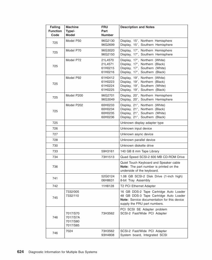
FailingFunction
Code
MachineType/-Model
FRUPartNumber
Description and Notes
725Model P50 96G2130
96G2699Display, 15″, Northern HemisphereDisplay, 15″, Southern Hemisphere
725Model P70 96G3020
96G2150Display, 17″, Northern HemisphereDisplay, 17″, Southern Hemisphere
725
Model P72 21L457021L457161H021561H0216
Display, 17″, Northern (White)Display, 17″, Northern (Black)Display, 17″, Southern (White)Display, 17″, Southern (Black)
725
Model P92 61H041261H022361H022461H0225
Display, 19″, Northern (White)Display, 19″, Northern (Black)Display, 19″, Southern (White)Display, 19″, Southern (Black)
725Model P200 96G2701
96G3049Display, 20″, Northern HemisphereDisplay, 20″, Southern Hemisphere
725
Model P202 60H023360H023460H023560H0236
Display, 21″, Northern (White)Display, 21″, Northern (Black)Display, 21″, Southern (White)Display, 21″, Southern (Black)
725 Unknown display adapter type
726 Unknown input device
727 Unknown async device
728 Unknown parallel device
730 Unknown diskette drive
733 59H3161 140 GB 8 mm Tape Library
734 73H1513 Quad Speed SCSI-2 600 MB CD-ROM Drive
736Quiet Touch Keyboard and Speaker cableNote: The part number is printed on theunderside of the keyboard.
74152G012406H8631
1.08 GB SCSI-2 Disk Drive (1-inch high)8-bit Tray Assembly
742 11H8128 T2 PCI Ethernet Adapter
745
7332/0057332/110
16 GB DDS-2 Tape Cartridge Auto Loader48 GB DDS-3 Tape Cartridge Auto LoaderNote: Service documentation for this devicesupply the FRU part numbers.
7467017/S707017/S7A7017/S807017/S85
73H3562PCI SCSI SE Adapter problemSCSI-2 Fast/Wide PCI Adapter
7467024 73H3562
93H4808SCSI-2 Fast/Wide PCI AdapterSystem board, Integrated SCSI
624 Diagnostic Information for Multiple Bus Systems

FailingFunction
Code
MachineType/-Model
FRUPartNumber
Description and Notes
7467025/F30 73H3562
93H8371SCSI-2 Fast/Wide PCI AdapterSystem board, Integrated SCSI
7467025/F40 73H3562
93H8652SCSI-2 Fast/Wide PCI AdapterSystem board, Integrated SCSI
7467025/F50 73H3562
07L6594SCSI-2 Fast/Wide PCI AdapterI/O board, Integrated SCSI
7467026/B807026/H10
73H356293H8652
SCSI-2 Fast/Wide PCI AdapterSystem board, Integrated SCSI
7467026/H50 73H3562
07L6594SCSI-2 Fast/Wide PCI AdapterI/O board, Integrated SCSI
746
7043/14073H356293H714293H714393H602393H9334
PCI SCSI SE Adapter problemSCSI-2 Fast/Wide PCI AdapterSystem board 166 MHz, Integrated SCSISystem board 200 MHz, Integrated SCSISystem board 233 MHz, Integrated SCSISystem board 332 MHz, Integrated SCSI
746 7043/150 07L8446 375 MHz System board
7467043/240 73H3562
11H7516SCSI-2 Fast/Wide PCI AdapterSystem board, Integrated SCSI
7467043/260 73H3562
08L0633SCSI-2 Fast/Wide PCI AdapterI/O board
7467043/270 41L6013
73H3562I/O boardSCSI-2 Fast/Wide PCI Adapter
7467044/170 41L5721
09P003773H3562
System board, class A, Integrated SCSISystem board, class B, Integrated SCSISCSI-2 Fast/Wide PCI Adapter
7467044/270 41L6013
73H3562I/O boardSCSI-2 Fast/Wide PCI Adapter
746 7046/B50 41L5912 375 MHz System board
7469076 SMP Thin/WideNode
73H356241L6138
SCSI-2 Fast/Wide PCI AdapterI/O board, Integrated SCSI
7469076/ Power3 SMPThin/Wide Node
73H356203N286603N3368
SCSI-2 Fast/Wide PCI AdapterI/O planar (200 MHz), integrated SCSII/O planar (375 Mhz), integrated SCSI
747 93H8407 SCSI-2 Differential Fast/Wide PCI Adapter
7497331/205 7331 Model 205 8 mm Tape Library
Note: For FRU numbers, refer to the servicedocumentation for this device.
74A7024 93H4808
Integrated SCSI-2 F/W SE problemSystem board, Integrated SCSI
74A 7025/F30 93H8371 System board, Integrated SCSI
74A 7025/F40 93H8652 System board, Integrated SCSI
Chapter 37. Failing Function Codes (FFCs) 625

FailingFunction
Code
MachineType/-Model
FRUPartNumber
Description and Notes
74A 7025/F50 41L5106 I/O board, Integrated SCSI
74A7026/B80 00P1859
73H3384I/O boardSCSI-2 Fast/Wide PCI Adapter
74A 7026/H10 93H8652 System board, Integrated SCSI
74A 7026/H50 41L5106 I/O board, Integrated SCSI
74A 7026/H70 03N2797 I/O board, Integrated SCSI
74A
7043/140 73H356293H714293H714393H602393H9334
PCI SCSI SE Adapter problemSCSI-2 Fast/Wide PCI AdapterSystem board 166 MHz, Integrated SCSISystem board 200 MHz, Integrated SCSISystem board 233 MHz, Integrated SCSISystem board 332 MHz, Integrated SCSI
74A 7043/150 07L8446 375 MHz System board
74A7043/240 73H3562
11H7516SCSI-2 Fast/Wide PCI AdapterSystem board, Integrated SCSI
74A7043/260 73H3562
08L0633SCSI-2 Fast/Wide PCI AdapterI/O board
74A7043/270 41L6013
73H3562I/O boardSCSI-2 Fast/Wide PCI Adapter
74A7044/170 41L5721
00P185973H3562
System board, class A, Integrated SCSISystem board, class B, Integrated SCSISCSI-2 Fast/Wide PCI Adapter
74A7044/270 41L6013
73H3562I/O boardSCSI-2 Fast/Wide PCI Adapter
74A 7046/B50 41L5912 375 MHz System board
74A9076 SMP Thin/WideNode
73H356241L6138
SCSI-2 Fast/Wide PCI AdapterI/O board, Integrated SCSI
74A9076/ Power3 SMPThin/Wide Node
73H356203N286603N3368
SCSI-2 Fast/Wide PCI AdapterI/O planar (200 MHz), integrated SCSII/O planar (375 Mhz), integrated SCSI
750 04H8098 Auto LANStreamer® Token-Ring PCI Adapter
751
08L131906H603652G423340H7351
SCSI 32-bit SE F/W RAID AdapterSCSI RAID Cable (1.0 m)SCSI RAID Cable (2.5 m)SCSI RAID Cable (6.0 m)
757 87G4858 SCSI 13 GB 1/4-Inch Tape Drive
759 87G8976 1080 MB Disk Drive
76331L784746H968877G0818
SP Switch MX AdapterWrap PlugTerminator
626 Diagnostic Information for Multiple Bus Systems

FailingFunction
Code
MachineType/-Model
FRUPartNumber
Description and Notes
76408L039846H968877G0818
SP System Attachment AdapterWrap PlugTerminator
772 83H7105 4.5 GB 16 bit SCSI F/W Disk Drive
773 76H2698 9.1 GB 16 bit SCSI F/W Disk Drive
774 7204/339 27H1677 9.1 GB External SCSI DE Disk Drive
775 93H5107 MVP Power Graphics Adapter
776 93H6594 PCI Token-Ring Adapter
777 94H0823 10/100 Base-TX Ethernet PCI Adapter
778 24L0030 POWER GXT3000P 3D Graphics Adapter PCI
77B03N395209P1421
4-Port 10/100 Ethernet Tx PCI Adapter4-Port 10/100 Ethernet Tx PCI Adapter(new chip)
780 40H1937 X.25 Interface Co-Processor Adapter
781
84F7540
33F8967
Co-Processor Multiport Adapter,Model 2 Daughter
Co-Processor Multiport Adapter,Model 2 (Base)
Note: Replace the daughter card beforereplacing the base card.
783
76H0473
76H0474
41H8714
24/48 GB DDS-2 4 mm TapeAutoloader (vertical orientation)
24/48 GB DDS-2 4 mm TapeAutoloader (horizontal orientation)
Tape Magazine
78493H715193H7152
2.1 GB 8-bit SCSI-2 Disk Drive2.1 GB 16-bit SCSI-2 Disk Drive
785 40H6632 8-port ISA Async EIA-232/RS-422 Adapter
78693H6264 GXT250P High Performance Graphics
Adapter
78693H6267 GXT255P High Performance Graphics
Adapter
787 94H0028 GXT500P Graphics Adapter
788 07L9009 Ultimedia® Video Capture Adapter
789 7209/003 50G0212 External 2.6 GB Rewritable Optical Disk Drive
78B 00P2429 POWER GXT4000P Graphics Adapter
78D 03N4169 GXT300P 2D Graphics Adapter
790Multi-bus Integrated Ethernet Adapter problemNote: If the type/model and FRU informationis not listed here, refer to FFC 221..
Chapter 37. Failing Function Codes (FFCs) 627
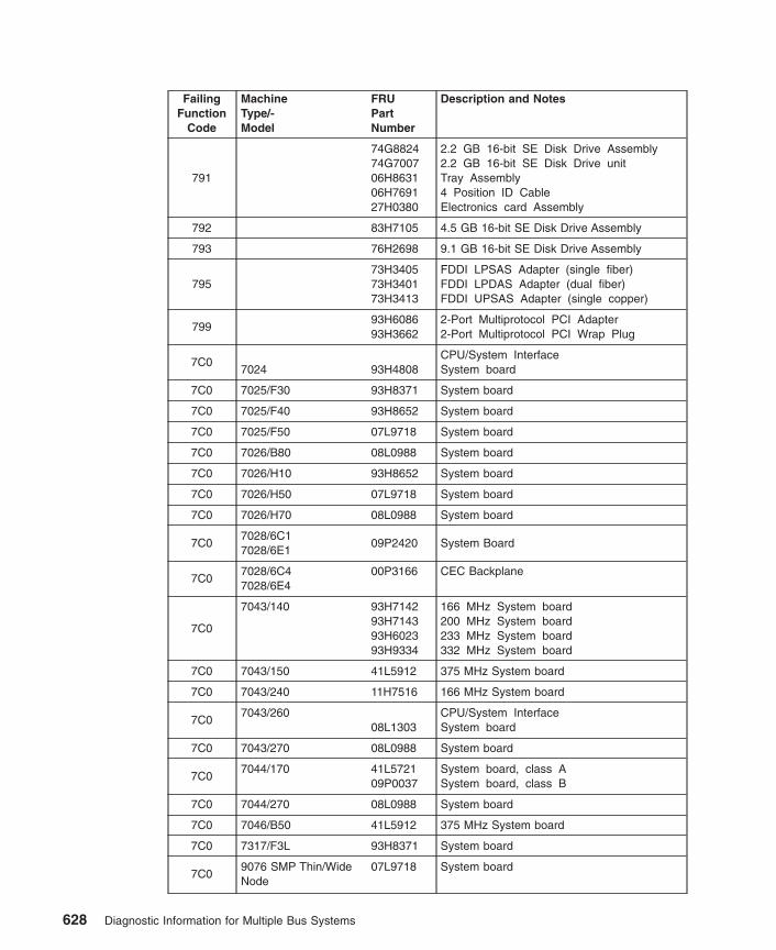
FailingFunction
Code
MachineType/-Model
FRUPartNumber
Description and Notes
791
74G882474G700706H863106H769127H0380
2.2 GB 16-bit SE Disk Drive Assembly2.2 GB 16-bit SE Disk Drive unitTray Assembly4 Position ID CableElectronics card Assembly
792 83H7105 4.5 GB 16-bit SE Disk Drive Assembly
793 76H2698 9.1 GB 16-bit SE Disk Drive Assembly
79573H340573H340173H3413
FDDI LPSAS Adapter (single fiber)FDDI LPDAS Adapter (dual fiber)FDDI UPSAS Adapter (single copper)
79993H608693H3662
2-Port Multiprotocol PCI Adapter2-Port Multiprotocol PCI Wrap Plug
7C07024 93H4808
CPU/System InterfaceSystem board
7C0 7025/F30 93H8371 System board
7C0 7025/F40 93H8652 System board
7C0 7025/F50 07L9718 System board
7C0 7026/B80 08L0988 System board
7C0 7026/H10 93H8652 System board
7C0 7026/H50 07L9718 System board
7C0 7026/H70 08L0988 System board
7C07028/6C17028/6E1
09P2420 System Board
7C07028/6C47028/6E4
00P3166 CEC Backplane
7C0
7043/140 93H714293H714393H602393H9334
166 MHz System board200 MHz System board233 MHz System board332 MHz System board
7C0 7043/150 41L5912 375 MHz System board
7C0 7043/240 11H7516 166 MHz System board
7C07043/260
08L1303CPU/System InterfaceSystem board
7C0 7043/270 08L0988 System board
7C07044/170 41L5721
09P0037System board, class ASystem board, class B
7C0 7044/270 08L0988 System board
7C0 7046/B50 41L5912 375 MHz System board
7C0 7317/F3L 93H8371 System board
7C09076 SMP Thin/WideNode
07L9718 System board
628 Diagnostic Information for Multiple Bus Systems

FailingFunction
Code
MachineType/-Model
FRUPartNumber
Description and Notes
7C09076/ Power3 SMPThin/Wide Node
08L130308L0988
System board (200 MHz)System board (375 MHz)
7C0 9112/265 09P2420 System Board
7C17024 93H4808
Business Audio Subsystem problemSystem board
7C1 7025/F30 93H8371 System board
7C1 7025/F40 93H8652 System board
7C1 7025/F50 07L9718 System board
7C17026/B80 00P1859
04N6150I/O boardOperator panel assembly
7C1 7026/H10 93H8652 System board
7C1 7026/H50 07L9718 System board
7C1 7026/H70 08L0988 System board
7C17028/6C17028/6E1
09P242021P7166
System BoardOperator Panel
7C17028/6C47028/6E4
00P316600P3210
CEC BackplaneOperator Panel
7C1
7043/140 93H714293H714393H602393H9334
166 MHz System board200 MHz System board233 MHz System board332 MHz System board
7C1 7043/150 41L5912 375 MHz System board
7C1 7043/240 11H7516 166 MHz System board
7C1 7043/260 08L1303 System board
7C17043/270 41L6013
07L7234I/O boardOperator panel
7C17044/170 41L5721
09P0037System board, class ASystem board, class B
7C17044/270 41L6013
07L7234I/O boardOperator panel
7C1 7046/B50 41L5912 375 MHz System board
7C1 7317/F3L 93H8371 System board
7C1 9112/26509P242021P7166
System BoardOperator Panel
804 73H2601 8X Speed SCSI-2 CD-ROM Drive
806 07L7113 GXT800P Graphics Adapter
807 SCSI Device Enclosure
80cSSA Adapter problem refer to the SSAAdapters: User’s Guide and MaintenanceInformation.
Chapter 37. Failing Function Codes (FFCs) 629

FailingFunction
Code
MachineType/-Model
FRUPartNumber
Description and Notes
811 Processor Complex being identified.
812Common Standard Adapter Logic problemNote: For type/model and FRU informationrefer to FFC 227.
8147025/6F07025/6F1
43L5269 System board
814 7025/F80 43L5269 System board
814
7026/6H07026/6H17026/6M17026/H807026/M80
41L5560 Primary drawer I/O backplane
814
7017/S70 03N3523 Service Processor Card problem ServiceProcessor CardNote: Unless listed, refer to FFC 221 fortype/model and FRU information.
8147017/S7A 03N3523 Service Processor Card
Note: Unless listed, refer to FFC 221 fortype/model and FRU information.
8147017/S807017/S85
11K0301 Service Processor CardNote: Unless listed, refer to FFC 221 fortype/model and FRU information.
8147028/6C47028/6E4
00P3166 CEC Backplane
814 7038/6M2 00P4062 Service Processor/PCI Backplane
814 7039/651 09P6222 Service Processor Card
8147040/6717040/681
09P2435 Primary I/O Book
8149076/ Power3 SMPHigh Node
11K0571 NIO Planar
815Floating Point Processor problemNote: For type/model and FRU informationrefer to FFC 210.
8159076/ Power3 SMPHigh Node
Note: If the type/model and FRU informationis not listed here, refer to FFC 221..
816Operator Panel Logic problemNote: If the type/model and FRU informationis not listed here, refer to FFC 221..
816 7038/6M2 00P4062 Service Processor/PCI Backplane
816 7039/651 09P6222 Service Processor Card
8167040/6717040/681
09P2435 Primary I/O Book
630 Diagnostic Information for Multiple Bus Systems

FailingFunction
Code
MachineType/-Model
FRUPartNumber
Description and Notes
8177025/6F07025/6F1
43L5269 System board
817 7025/F80 43L5269 System board
817
7026/6H07026/6H17026/6M17026/H807026/M80
41L5560 Primary drawer I/O backplane
817
7017/S7003N3523
Time of Day Logic problemService Processor CardNote: Unless listed refer to FFC 221 fortype/model and FRU information.
8177017/S7A 03N3523 Service Processor Card
Note: Unless listed refer to FFC 221 fortype/model and FRU information.
8177017/S807017/S85
11K0301 Service Processor CardNote: Unless listed refer to FFC 221 fortype/model and FRU information.
8177028/6C47028/6E4
00P3166 CEC Backplane
817 7038/6M2 00P4062 Service Processor/PCI Backplane
817 7039/651 09P6222 Service Processor Card
8177040/6717040/681
09P2435 Primary I/O Book
8179076/ Power3 SMPHigh Node
11K0571 NIO Planar
820Interprocessor related testing problemNote: For type/model and FRU information, ifnot listed here, refer to FFC 221.
821Standard Keyboard Adapter problemNote: If the type/model and FRU informationis not listed here, refer to FFC 221..
823Standard Mouse Adapter problemNote: For type/model and FRU information, ifnot listed here, refer to FFC 221.
8239076/ Power3 SMPHigh Node
11K0571 NIO Planar
824Standard Tablet Adapter problemNote: For type/model and FRU information, ifnot listed here, refer to FFC 221.
8249076/ Power3 SMPHigh Node
11K0571 NIO Planar
8259076/ Power3 SMPHigh Node
11K0571 NIO Planar
Chapter 37. Failing Function Codes (FFCs) 631

FailingFunction
Code
MachineType/-Model
FRUPartNumber
Description and Notes
826Serial Port 1 Adapter problemNote: For type/model and FRU information, ifnot listed here, refer to FFC 221.
826 7038/6M2 00P4062 Service Processor/PCI Backplane
826 7039/651 09P6222 Service Processor Card
8267040/6717040/681
09P2435 Primary I/O Book
8269076 SMP Thin/WideNode
11J400011J519741L6138
Supervisor CardPower/supervisor interposer cableI/O planar
826
9076/ Power3 SMPThin/Wide Node
11J400011J614703N286603N3368
Supervisor CardPower/supervisor interposer cableI/O planar (200 MHz)I/O planar (375 MHz)
8269076/ Power3 SMPHigh Node
11K0571 NIO Planar
827Built-in Parallel Port Adapter problemNote: For type/model and FRU information, ifnot listed here, refer to FFC 221.
8279076/ Power3 SMPHigh Node
11K0571 NIO Planar
828Standard Diskette Adapter problemNote: For type/model and FRU information, ifnot listed here, refer to FFC 221.
828 7038/6M2 00P4062 Service Processor/PCI Backplane
828 7039/651 09P6222 Service Processor Card
8287040/6717040/681
09P2435 Primary I/O Book
8289076/ Power3 SMPHigh Node
11K0571 NIO Planar
82C 11H6095 S15 Graphics PCI Adapter
830 11H5969 8-Port ISA adapter
831Serial Port 2 Adapter problemNote: If the type/model and FRU informationis not listed here, refer to FFC 221..
8319076/ Power3 SMPHigh Node
11K0571 NIO Planar
836 73H3384 128-Port Async Controller
837
88G384293H6549
40H258993H7091
Remote Async Node, 16-port EIA-232Enhanced Remote Async Node,16-port EIA-232Rack Mounted Node, 16-port EIA-232Power Supply, Remote Async Node
632 Diagnostic Information for Multiple Bus Systems
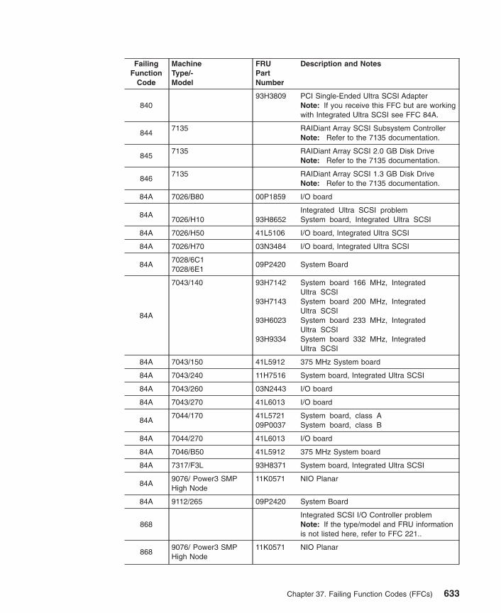
FailingFunction
Code
MachineType/-Model
FRUPartNumber
Description and Notes
84093H3809 PCI Single-Ended Ultra SCSI Adapter
Note: If you receive this FFC but are workingwith Integrated Ultra SCSI see FFC 84A.
8447135 RAIDiant Array SCSI Subsystem Controller
Note: Refer to the 7135 documentation.
8457135 RAIDiant Array SCSI 2.0 GB Disk Drive
Note: Refer to the 7135 documentation.
8467135 RAIDiant Array SCSI 1.3 GB Disk Drive
Note: Refer to the 7135 documentation.
84A 7026/B80 00P1859 I/O board
84A7026/H10 93H8652
Integrated Ultra SCSI problemSystem board, Integrated Ultra SCSI
84A 7026/H50 41L5106 I/O board, Integrated Ultra SCSI
84A 7026/H70 03N3484 I/O board, Integrated Ultra SCSI
84A7028/6C17028/6E1
09P2420 System Board
84A
7043/140 93H7142
93H7143
93H6023
93H9334
System board 166 MHz, IntegratedUltra SCSISystem board 200 MHz, IntegratedUltra SCSISystem board 233 MHz, IntegratedUltra SCSISystem board 332 MHz, IntegratedUltra SCSI
84A 7043/150 41L5912 375 MHz System board
84A 7043/240 11H7516 System board, Integrated Ultra SCSI
84A 7043/260 03N2443 I/O board
84A 7043/270 41L6013 I/O board
84A7044/170 41L5721
09P0037System board, class ASystem board, class B
84A 7044/270 41L6013 I/O board
84A 7046/B50 41L5912 375 MHz System board
84A 7317/F3L 93H8371 System board, Integrated Ultra SCSI
84A9076/ Power3 SMPHigh Node
11K0571 NIO Planar
84A 9112/265 09P2420 System Board
868Integrated SCSI I/O Controller problemNote: If the type/model and FRU informationis not listed here, refer to FFC 221..
8689076/ Power3 SMPHigh Node
11K0571 NIO Planar
Chapter 37. Failing Function Codes (FFCs) 633
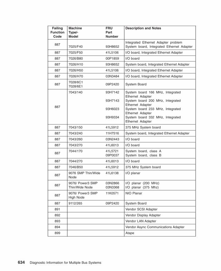
FailingFunction
Code
MachineType/-Model
FRUPartNumber
Description and Notes
8877025/F40 93H8652
Integrated Ethernet Adapter problemSystem board, Integrated Ethernet Adapter
887 7025/F50 41L5106 I/O board, Integrated Ethernet Adapter
887 7026/B80 00P1859 I/O board
887 7026/H10 93H8652 System board, Integrated Ethernet Adapter
887 7026/H50 41L5106 I/O board, Integrated Ethernet Adapter
887 7026/H70 03N3484 I/O board, Integrated Ethernet Adapter
8877028/6C17028/6E1
09P2420 System Board
887
7043/140 93H7142
93H7143
93H6023
93H9334
System board 166 MHz, IntegratedEthernet AdapterSystem board 200 MHz, IntegratedEthernet AdapterSystem board 233 MHz, IntegratedEthernet AdapterSystem board 332 MHz, IntegratedEthernet Adapter
887 7043/150 41L5912 375 MHz System board
887 7043/240 11H7516 System board, Integrated Ethernet Adapter
887 7043/260 03N2443 I/O board
887 7043/270 41L6013 I/O board
8877044/170 41L5721
09P0037System board, class ASystem board, class B
887 7044/270 41L6013 I/O board
887 7046/B50 41L5912 375 MHz System board
8879076 SMP Thin/WideNode
41L6138 I/O planar
8879076/ Power3 SMPThin/Wide Node
03N286603N3368
I/O planar (200 MHz)I/O planar (375 Mhz)
8879076/ Power3 SMPHigh Node
11K0571 NIO Planar
887 9112/265 09P2420 System Board
891 Vendor SCSI Adapter
892 Vendor Display Adapter
893 Vendor LAN Adapter
894 Vendor Async Communications Adapter
899 Atape
634 Diagnostic Information for Multiple Bus Systems
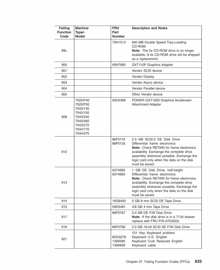
FailingFunction
Code
MachineType/-Model
FRUPartNumber
Description and Notes
89c
73H1513 600 MB Double Speed Tray-LoadingCD-ROMNote: The 2x CD-ROM drive is no longeravailable. A 4x CD-ROM drive will be shippedas a replacement.
900 93H7983 GXT110P Graphics Adapter
901 Vendor SCSI device
902 Vendor Display
903 Vendor Async device
904 Vendor Parallel device
905 Other Vendor device
908
7025/F407025/F507043/1407043/1507043/2407043/2607043/2707044/1707044/270
93H2399 POWER GXT1000 Graphics AcceleratorAttachment Adapter
912
86F011986F0125
2.0 GB SCSI-2 DE Disk DriveDifferential frame electronicsNote: Check RETAIN for frame electronicsavailability. Exchange the complete driveassembly whenever possible. Exchange thelogic card only when the data on the diskmust be saved.
913
63746826374683
1 GB DE Disk Drive, half-heightDifferential frame electronicsNote: Check RETAIN for frame electronicsavailability. Exchange the complete driveassembly whenever possible. Exchange thelogic card only when the data on the diskmust be saved.
914 16G8492 5 GB 8 mm SCSI DE Tape Drive
915 59H3481 4/8 GB 4 mm Tape Drive
91786F0767 2.0 GB DE F/W Disk Drive
Note: If the disk drive is in a 7134 drawerreplace with FRU P/N 67G3022.
918 86F0766 2.0 GB 16-bit SCSI SE F/W Disk Drive
92182G327813920901394609
101 Key Keyboard problemKeyboard U.S. EnglishKeyboard Cost Reduced EnglishKeyboard cable
Chapter 37. Failing Function Codes (FFCs) 635
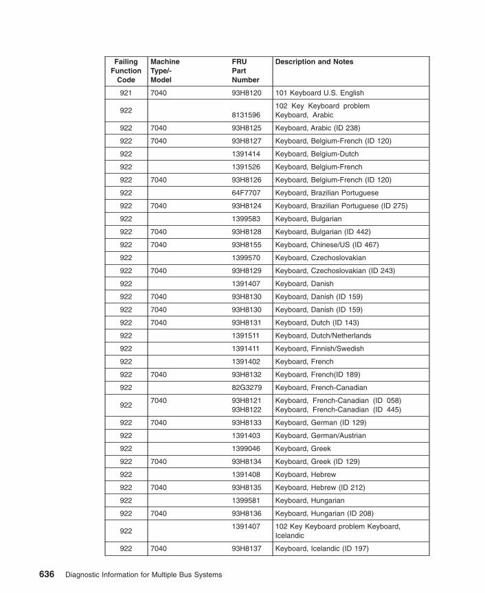
FailingFunction
Code
MachineType/-Model
FRUPartNumber
Description and Notes
921 7040 93H8120 101 Keyboard U.S. English
9228131596
102 Key Keyboard problemKeyboard, Arabic
922 7040 93H8125 Keyboard, Arabic (ID 238)
922 7040 93H8127 Keyboard, Belgium-French (ID 120)
922 1391414 Keyboard, Belgium-Dutch
922 1391526 Keyboard, Belgium-French
922 7040 93H8126 Keyboard, Belgium-French (ID 120)
922 64F7707 Keyboard, Brazilian Portuguese
922 7040 93H8124 Keyboard, Brazilian Portuguese (ID 275)
922 1399583 Keyboard, Bulgarian
922 7040 93H8128 Keyboard, Bulgarian (ID 442)
922 7040 93H8155 Keyboard, Chinese/US (ID 467)
922 1399570 Keyboard, Czechoslovakian
922 7040 93H8129 Keyboard, Czechoslovakian (ID 243)
922 1391407 Keyboard, Danish
922 7040 93H8130 Keyboard, Danish (ID 159)
922 7040 93H8130 Keyboard, Danish (ID 159)
922 7040 93H8131 Keyboard, Dutch (ID 143)
922 1391511 Keyboard, Dutch/Netherlands
922 1391411 Keyboard, Finnish/Swedish
922 1391402 Keyboard, French
922 7040 93H8132 Keyboard, French(ID 189)
922 82G3279 Keyboard, French-Canadian
9227040 93H8121
93H8122Keyboard, French-Canadian (ID 058)Keyboard, French-Canadian (ID 445)
922 7040 93H8133 Keyboard, German (ID 129)
922 1391403 Keyboard, German/Austrian
922 1399046 Keyboard, Greek
922 7040 93H8134 Keyboard, Greek (ID 129)
922 1391408 Keyboard, Hebrew
922 7040 93H8135 Keyboard, Hebrew (ID 212)
922 1399581 Keyboard, Hungarian
922 7040 93H8136 Keyboard, Hungarian (ID 208)
9221391407 102 Key Keyboard problem Keyboard,
Icelandic
922 7040 93H8137 Keyboard, Icelandic (ID 197)
636 Diagnostic Information for Multiple Bus Systems

FailingFunction
Code
MachineType/-Model
FRUPartNumber
Description and Notes
922 1393395 Keyboard, Italian
922 7040 93H8138 Keyboard, Italian (ID 142)
922 7040 93H8156 Keyboard, Korea (ID 413)
922 82G3292 Keyboard, Latin American (Spanish)
922 7040 93H8152 Keyboard, Latvia (ID 234)
922 1391409 Keyboard, Norwegian
922 7040 93H8139 Keyboard, Norwegian (ID 155)
922 1391410 Keyboard, Portuguese
922 1399580 Keyboard, Polish
922 7040 93H8140 Keyboard, Polish (ID 214)
922 7040 93H8141 Keyboard, Portuguese (ID 163)
922 1399582 Keyboard, Romania
922 7040 93H8142 Keyboard, Romania (ID 446)
922 1399579 Russian
922 7040 93H8143 Keyboard, Russian (ID 443)
922 7040 93H8144 Keyboard, Serbian (ID 118)
922 1399571 Keyboard, Slovak
922 7040 93H8145 Keyboard, Slovak (ID 245)
922 1391405 Keyboard, Spanish
9227040 93H8123
93H8146Keyboard, Spanish (ID 171)Keyboard, Spanish (ID 172)
922 7040 93H8147 Keyboard, Sweden/Finland (ID 153)
922 1395881 Keyboard, Swiss-French
922 7040 93H8148 Keyboard, Swiss French/German (ID 150)
922 1395882 Keyboard, Swiss-German
922 7040 93H8157 Keyboard, Thailand (ID 191)
922 1393286 Keyboard, Turkish (ID 179)
922 7040 93H8149 Keyboard, Turkish (ID 179)
922 8125409 Keyboard, Turkish (ID 440)
922 7040 93H8150 Keyboard, Turkish (ID 440)
922 1391406 Keyboard, U.K. English
922 7040 93H8151 Keyboard, Turkish (ID 166)
922 7040 93H8153 Keyboard, US English ISO9995 (ID 103P)
922 06H3048 Keyboard, U.S. OEM
922 7040 93H8154 Keyboard, 106 Japan (ID 194)
922 1394609 Keyboard cable
Chapter 37. Failing Function Codes (FFCs) 637

FailingFunction
Code
MachineType/-Model
FRUPartNumber
Description and Notes
923
139209079F016766G050706H528602G7353
106 keys International Keyboard problemKeyboard, ChineseKeyboard, Japanese-KanjiJapanese, EnhancedKeyboard, KoreanKeyboard, Taiwanese
925 93H9113 3-Button Mouse
925 7040 76H5084 3–Button Mouse
926624745074F3130
Tablet, 5083 Model 21Tablet, 6093 Model 11
927624745274F314093H7714
Tablet, 5083 Model 22Tablet, 6093 Model 12Tablet, 6093 Model 21
92939F822739F8302
Dials, 6094 Model 10Cable, Serial Attachment, Power
93039F8226
39F8302
Lighted Program Function Keyboard(LPFK), 6094 Model 20
Cable, Serial Attachment, Power
935
70247025704373177026
7040/6717040/68170447017/S707017/S7A7017/S807017/S85
93F236176H409107L7814
1.44 MB 3.5-inch White Diskette Drive1.44 MB 3.5-inch Black Diskette Drive1.44 MB 3.5-inch Diskette Drive
938
Serial HIPPI PCI Adapter
Notes:
1. Use the number printed above the barcode to order this part.
2. The FRU part number of the wrap plugused with this adapter is 21H3547.
946Standard Serial Port 3 Adapter problemNote: For type/model and FRU information, ifnot listed here, refer to FFC 221.
946 7039/651 09P6222 Service Processor Card
9467040/6717040/681
09P2435 Primary I/O Book
9469076/ Power3 SMPHigh Node
11K0571 NIO Planar
638 Diagnostic Information for Multiple Bus Systems

FailingFunction
Code
MachineType/-Model
FRUPartNumber
Description and Notes
947 84G3491 1000 MB, 16-bit Disk Drive
950 Unknown SCSI device is missing.
951
53F34296373521
670 MB SCSI Disk DriveLogic CardNote: Exchange the complete drivewhenever possible. If extreme data savingmeasures are necessary, exchange the logiccard.
952
53F34276373521
355 MB SCSI Disk DriveLogic CardNote: Exchange the complete drivewhenever possible. If extreme data savingmeasures are necessary, exchange the logiccard.
953
93X096193X0901
320 MB SCSI Disk DriveLogic Card and Frame assemblyNote: Exchange the complete drivewhenever possible. Exchange the logic cardonly when the data on the disk must besaved.
954
00G194873F8994
400 MB SCSI Disk DriveLogic Card and Frame assemblyNote: Exchange the complete drivewhenever possible. Exchange the logic cardonly when the data on the disk must besaved.
955 45G9502 857 MB SCSI Disk Drive
956 6373521 355/670 MB Logic Card.
960
52G006131G9756
1.37 GB SCSI Disk Drive AssemblyLogic cardNote: Logic card stocking is limited, specialordering is required. Check RETAIN for logiccard availability. Exchange the complete driveassembly when possible. Exchange the logiccard when the data on the disk must besaved.
962 3161 Use device documentation.
963 3163 Use device documentation.
964
59H2839
59H4120
59H2835
59H2842
20 GB 8 mm SE SCSI Tape Drive(internal,white)
20 GB 8 mm SE SCSI Tape Drive(internal, black)
20 GB 8 mm Diff SCSI Tape Drive(external/white)
400 GB 8 mm Diff Tape Autoloader(No LCD in Bezel/white)
Chapter 37. Failing Function Codes (FFCs) 639

FailingFunction
Code
MachineType/-Model
FRUPartNumber
Description and Notes
966 93H2136 Media Streamer Audio/Video Decoder Adapter
968
55F990255F9909
1 GB SCSI SE Disk DriveSingle-Ended Frame ElectronicsNote: Check RETAIN for frame electronicsavailability. Exchange the complete driveassembly when possible. Exchange the logiccard when the data on the disk must besaved.
9709348 1/2-inch 9-Track Tape Drive Use device
documentation
971 16G8423 150 MB 1/4-Inch Tape Drive
972 16G8421 2.3 GB 8 mm Tape Drive
973 Other SCSI Tape Drive
974 88G3929 CD-ROM Drive (Type A or Type B bezel)
980 4216 Use the device documentation
981 51G8237 540 MB SCSI-2 Single-Ended Disk Drive
982 3852 Use the device documentation
983 4201 Use the device documentation
984 45G9467 1 GB 8-bit Disk Drive
986 36G0454 2.4 GB SCSI Disk Drive
987 73H1513 600 MB CD-ROM-2 Disk Drive
989 43G1842 200 MB SCSI Disk Drive
990 86F0118 2.0 GB SCSI-2 SE Disk Drive
991 46G2700 525 MB 1/4-Inch SCSI Tape Drive
992 5202 Use the device documentation
993 5204 Use the device documentation
994 59H3159 5/10 GB 8 mm Internal Tape Drive
995 21H5155 1.2 GB 1/4-inch Cartridge Tape Drive
998 8191193 2.0 GB 4 mm SCSI Tape Drive
9993514 7137 Disk Array Subsystems
Note: Refer to the 3514 or 7137documentation
B08 02G7431 Ethernet 10 Base Twisted-pair Transceiver
B0902G7437 Ethernet/ISO 8802.3 Transceiver (formerly
IEEE 802.3)
640 Diagnostic Information for Multiple Bus Systems

FailingFunction
Code
MachineType/-Model
FRUPartNumber
Description and Notes
B10
System board PTC (thermal fuse)Note: If a thermal fuse has opened, it shouldreset within ten minutes after turning thepower off. If the thermal fuse does not reset,a faulty device may be drawing excessivepower through the fuse.
B31 Unknown keyboard type
B3AUnidentifiable backplane tied to a SCSI RAIDadapter
B54
43G0936
43G0937
128-Port Async Controller Cable,0.2 m (9 in.)
128-Port Async Controller Cable,4.6 m (15 ft.)
B6933F8967 Co-Processor Multiport Adapter, Model 2 (0
MB)
B7153F2612 8-Port EIA-232-D Multiport, Model 2 Interface
Card
B7253F2615 8-Port EIA-422-A Multiport, Model 2 Interface
Card
B73 72F0164 6-Port V.35 Multiport, Model 2 Interface Card
B74 04G5500 6-Port V.21 Multiport, Model 2 Interface Card
B77 53F2662 Co-Processor 1 MB Memory Module
B81 40F9897 Co-Processor Multiport Interface Cable
B82 71F0162 Co-Processor Multiport V.35 Cable
B83 71F0164 Co-Processor Multiport X.21 Cable
Chapter 37. Failing Function Codes (FFCs) 641
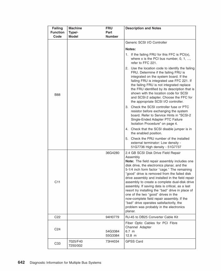
FailingFunction
Code
MachineType/-Model
FRUPartNumber
Description and Notes
B88
Generic SCSI I/O Controller
Notes:
1. If the failing FRU for this FFC is PCI(x),where x is the PCI bus number, 0, 1, ...,refer to FFC 221.
2. Use the location code to identify the failingFRU. Determine if the failing FRU isintegrated on the system board. If thefailing FRU is integrated use FFC 221. Ifthe failing FRU is not integrated replacethe FRU identified by its description that isshown with the location code for SCSIand SCSI-2 adapter. Choose the FFC forthe appropriate SCSI I/O controller.
3. Check the SCSI controller fuse or PTCresistor before exchanging the systemboard. Refer to Service Hints in “SCSI-2Single-Ended Adapter PTC FailureIsolation Procedure” on page 4.
4. Check that the SCSI disable jumper is inthe enabled position.
5. Check the FRU number of the installedexternal terminator: Low density -51G7736 High density - 51G7737
C11
36G4280 2.4 GB SCSI Disk Drive Field RepairAssemblyNote: The field repair assembly includes onedisk drive, the electronics planar, and the5-1/4 inch form factor ″cage.″ The remaining″good″ drive is removed from the failed diskdrive assembly and installed in the field repairassembly to create a complete dual-disk driveassembly. If saving data is critical, as a lastresort try installing the ″bad″ drive in place ofone of the two ″good″ drives in thenow-complete field repair assembly. If the″bad″ drive operates satisfactorily, theproblem was probably in the electronicsplanar.
C22 94H0779 RJ-45 to DB25 Converter Cable Kit
C2454G338455G3384
Fiber Optic Cables for PCI FibreChannel Adapter6.7 m12.8 m
C337025/F407250/002
73H4034 GPSS Card
642 Diagnostic Information for Multiple Bus Systems

FailingFunction
Code
MachineType/-Model
FRUPartNumber
Description and Notes
C347025/F407250/002
11H8490 RSS Card (without memory sockets)
C357025/F407250/002
65G4887 VOO Card
C367025/F407250/002
65G4892 Attachment Adapter Cable
C447025/F407250/002
65G4894 VOO/RSS Crossover Cable
C45
7025/F40(Base and AG
memory)7250/002
65G4889 12M VRAM Memory Module
C46
7025/F40(Base and AG
memory)7250/002
65G4890 16M VRAM Memory Module
C477025/F40(TX Memory)7250/002
65G4891 16M DRAM Memory Module
C487025/F407250/002
65G4893 RSS/GPSS Crossover Card
C9468X635687H3621
IBM ARTIC960 4 MB Memory ModuleIBM ARTIC960 8 MB Memory Module
C95
87H3413
87H3428
87H370109J8829
51H8702
IBM ARTIC960 4-Port Selectableinterface Board
IBM ARTIC960 4-Port T1/E1interface Card
IBM ARTIC960Hx DSP interface cardIBM ARTIC960 Quad T1/E1
interface cardIBM ARITC960 PCI Adapter
interface Board
C97
87H3502
87H3311
5605670
IBM ARTIC960 4-Port T1/E1 InterfaceCard Wrap Plug
IBM ARTIC960 4-Port Selectable InterfaceBoard Wrap Plug
ESCON Wrap PlugNote: A wrap plug is shipped with eachadapter and cable.
Chapter 37. Failing Function Codes (FFCs) 643

FailingFunction
Code
MachineType/-Model
FRUPartNumber
Description and Notes
C98
87H3405
87H3396
87H3408
87H3399
87H3402
87H351887H3515
IBM ARTIC960 4-Port SelectableEIA-232 Cable
IBM ARTIC960 4-Port SelectableRS-449 Cable
IBM ARTIC960 4-Port SelectableX.21 Cable
IBM ARTIC960 4-Port SelectableV.35 Cable
IBM ARTIC960 4-Port SelectableEIA-530 Cable
IBM ARTIC960 4-Port T1 RJ-45 CableIBM ARTIC960 4-Port E1 RJ-45 CableNote: A wrap plug is shipped with eachadapter and cable.
D01 7017/S70 90H969490H9662
Generic L2 Cache problemProcessor Card (4x) (Type 2)Processor Card (4x) (Type 1)
D017017/S7A 08L1474
08L1473Processor Card (type 2) (262 MHz)Processor Card (type 1) (262 MHz)
D01 7017/S80 23L743423L7447
Processor Card (Type 1 RH)Processor Card (Type 2 LH)
D017017/S85 21P4511
21P4517Processor Card (Type 1 RH)Processor Card (Type 2 LH)
D017024/E20 40H6616
03N3989CPU Card (100 MHz)CPU Card (233 MHz)
D017024/E30 73H3614
93H243103N3989
CPU Card (133 MHz)CPU Card (166 MHz)CPU Card (233 MHz)
D01
7025/6F0 04N535309P652423L778509P652523L779453P1301
1-way processor card (600 MHz)1-way processor card (750 MHz)2-way processor card (600 MHz)2-way processor card (750 MHz)4-way processor card (600 MHz)4-way processor card (750 MHz)
D01
7025/6F1 04N535309P652423L778509P652523L779453P130123L779953P1334
1-way processor card (600 MHz)1-way processor card (750 MHz)2-way processor card (600 MHz)2-way processor card (750 MHz)4-way processor card (600 MHz)4-way processor card (750 MHz)6-way processor card (668 MHz)6-way processor card (750 MHz)
D017025/F30 73H3614
93H243103N3989
CPU Card (133 MHz)CPU Card (166 MHz)CPU Card (233 MHz)
D017025/F40 11H7517
93H5163CPU Card (166 MHz)CPU Card (233 MHz)
644 Diagnostic Information for Multiple Bus Systems

FailingFunction
Code
MachineType/-Model
FRUPartNumber
Description and Notes
D01
7025/F50 93H267973H476893H901893H8945
166 MHz CPU Card (1 way)166 MHz CPU Card (2 way)332 MHz CPU Card (1 way)332 MHz CPU Card (2 way)
D01
7025/F80 04N476521P475121P476021P4774
1-way processor card (450 Mhz)2-way processor card (450 Mhz)4-way processor card (450 Mhz)6-way processor card (500 Mhz)
D01
7026/6H0 04N535309P652423L778509P652523L779453P1301
1-way processor card (600 Mhz)1-way processor card (750 MHz)2-way processor card (600 Mhz)2-way processor card (750 MHz)4-way processor card (600 Mhz)4-way processor card (750 MHz)
D01
7026/6H1 04N535309P652423L778509P652523L779453P130123L779953P1334
1-way processor card (600 Mhz)1-way processor card (750 MHz)2-way processor card (600 Mhz)2-way processor card (750 MHz)4-way processor card (600 Mhz)4-way processor card (750 MHz)6-way processor card (688 MHz)6-way processor card (750 MHz)
D017026/6M1 04N6698
21P638121P6383
2-way processor card (500 Mhz)2-way processor card (750 Mhz)4-way processor card (750 Mhz)
D01
7026/B80 09P039909P0143
09P0406
09P4478
Processor card (375 Mhz, one-way)Processor card (375 Mhz, two-way,
8 M L2)Processor card (375 Mhz, two-way,
4 M L2)
Processor Card (450 Mhz, two-way)
D01 7026/H10 11H7517 166 MHz Processor and Cache Card
D017026/H50 93H9018
93H8945CPU Card (1 way)CPU Card (2 way)
D01 7026/H70 94H101394H1008
Generic L2 Cache problemCPU Card (1 way)CPU Card (2 way)
D01
7026/H80 04N476521P475121P476021P4774
1-way 450 Mhz processor card2-way 450 Mhz processor card4-way 450 Mhz processor card6-way 500 Mhz processor card
D017026/M80 04N6930
04N69312-way processor card4-way processor card
D017028/6C47028/6E4
00P297400P2977
Processor Card, 1.0 GHz 1-wayProcessor Card, 1.0 GHz 2-way
Chapter 37. Failing Function Codes (FFCs) 645

FailingFunction
Code
MachineType/-Model
FRUPartNumber
Description and Notes
D017039/651 44P1523
44P152444P1525
1.3 GHz 4-way MCM Core 01.3 GHz 4-way MCM Core 11.1 GHz 8-way MCM
D01 7038/6M2 53P4953 Processor Card (standard)
D017039/651 44P1542
44P15441.3 GHz 4-way MCM with VPD Card1.1GHz 8-way MCM with VPD Card
D017040/671 03N3229
09P32171.1 GHz 4-way MCM with VPD Card1.1 GHz 8-way MCM with VPD Card
D01
7040/681 03N322303N322803N322909P3217
1.3 GHz 4-way MCM with VPD Card1.3 GHz 8-way MCM with VPD Card1.1 GHz 4-way MCM with VPD Card1.1 GHz 8-way MCM with VPD Card
D017043/140 75H5462
75H5463512KB L2 Cache1 MB L2 Cache
D01 7043/150 07L8446 System Board
D017043/240 11H7517
93H5163166 MHz Processor and Cache Card233 MHz Processor and Cache Card
D01 7043/260 08L1013 200 MHz CPU Card
D017043/270 11K0171
11K0218CPU card (375 MHz one-way)CPU card (375 MHz two-way)
D017044/170 09P0277
09P027209P0943
Processor card (333 MHz)Processor card (400 MHz)Processor card (450 Mhz)
D017044/270 11K0171
11K021809P4478
CPU card (375 MHz one-way)CPU card (375 MHz two-way)CPU card (450 MHz two-way)
D01 7046/B50 41L5912 375 MHz System board
D017317/F3L 73H3614
93H243103N3989
CPU Card (133 MHz)CPU Card (166 MHz)CPU Card (233 MHz)
D019076 SMP Thin/WideNode
93H9716 CPU card (332 MHz)
D019076/ Power3 SMPThin/Wide Node
03N240311K0232
CPU card (200 MHz)CPU card (375 MHz)
D019076/ Power3 SMPHigh Node
11K0198 CPU card
D0688G3650 64 Port to 128 Port Converter Kit (four to a
pack)Note: Converter part number is 88G3651
D077044/170 09P0277
09P027209P0943
Processor card (333 Mhz)Processor card (400 Mhz)Processor card (450 Mhz)
D08 7134 88G5722 DC Fan assembly
646 Diagnostic Information for Multiple Bus Systems

FailingFunction
Code
MachineType/-Model
FRUPartNumber
Description and Notes
D46 6339098 Token-Ring 9-pin D-Shell cable, 3m (10 ft.)
D4660G1063 Token-Ring RJ-45 STP cable, 3m (10 ft.)
Note: Not used with the High-SpeedToken-Ring PCI adapter
D46
93H8894 RJ-45 to 9-pin D-Shell Token-Ring ConversioncableNote: Not used with the High-SpeedToken-Ring PCI adapter
D46OEMCable
Standard UTP RJ-45 cable
D50 Content moved to FFC 190.
D56 12H1204 EIA-232E Printer/ Terminal Serial Cable
D5707L9822 8-Port Multiport Interface Cable ISA Async
Adapter
D59 93H7766 TP PCI Ethernet Adapter
D60 93H1902 T2 PCI Ethernet Adapter
D60 93H7766 TP PCI Ethernet Adapter
D66 7250 11H4436 RSS Card (with memory sockets)
D67 8 MB, ECC, 50 nsec Memory Module
D68 16 MB, ECC, 50 nsec Memory Module
D69 32 MB, ECC, 50 nsec Memory Module
D70 64 MB, ECC, 50 nsec Memory Module
D71 42H2771 8 MB, ECC, 60 nsec Memory Module
D72 42H2772 16 MB, ECC, 60 nsec Memory Module
D73 42H2773 32 MB, ECC, 60 nsec Memory Module
D747025/F407043/1407043/240
42H2774 64 MB, ECC, 60 nsec Memory Module
D74 7043/140 93H6823 128 MB, ECC, 60 nsec Memory Module
D74 7043/240 93H6822 128 MB, ECC, 60 nsec Memory Module
D747043/150 07L9302
07L930407L9306
64 MB, ECC Memory Module128 MB, ECC Memory Module256 MB, ECC Memory Module
D747046/B50 19L1809
29L3302128 MB, ECC Memory Module256 MB, ECC Memory Module
D75 65G4615 8 MB, ECC, 70 nsec Memory Module
D76 16 MB, ECC, 70 nsec Memory Module
D77 32 MB, ECC, 70 nsec Memory Module
D78 39H9837 64 MB, ECC, 70 nsec Memory Module
Chapter 37. Failing Function Codes (FFCs) 647

FailingFunction
Code
MachineType/-Model
FRUPartNumber
Description and Notes
D83 8 MB, Parity, 50 nsec Memory Module
D84 16 MB, Parity, 50 nsec Memory Module
D85 32 MB, Parity, 50 nsec Memory Module
D86 64 MB, Parity, 50 nsec Memory Module
D87 8 MB, Parity, 60 nsec Memory Module
D88 16 MB, Parity, 60 nsec Memory Module
D89 32 MB, Parity, 60 nsec Memory Module
D90 64 MB, Parity, 60 nsec Memory Module
D91 8 MB, Parity, 70 nsec Memory Module
D92 16 MB, Parity, 70 nsec Memory Module
D93 65G4617 32 MB, Parity, 70 nsec Memory Module
D94 39H9837 64 MB, ECC, 70 nsec Memory Module
D95
7043/1407043/1507025/F407043/240
94H0029 GXT550P Graphics Adapter
D9693H6267 GXT255P High Performance PCI Graphics
Adapter
D97 93H7439 Operator Panel/Speaker Assembly
E107043/1407043/150
73H4532 Riser Card
E10 7043/240 73H3712 Riser Card
E10 7046/B50 23L8117 Riser Card
E10 Models not listed Refer to FFC 227
E11 128 MB, ECC, 50 nsec Memory Module
E12
7025/F407025/F507026/H107026/H507317/F3L
93H6821 128 MB, ECC, 60 nsec Memory Module
E12 7043/140 93H6823 128 MB, ECC, 60 nsec Memory Module
E12 7043/240 93H6822 128 MB, ECC, 60 nsec Memory Module
E129076 SMP Thin/WideNode
93H4702 128 MB, ECC, 60 nsec Memory Module
E129076/ Power3 SMPThin/Wide Node
93H4702 128 MB, ECC, 60 nsec Memory Module
E13 128 MB, ECC, 70 nsec Memory Module
E14 128 MB, Parity, 50 nsec Memory Module
E15 128 MB, Parity, 60 nsec Memory Module
648 Diagnostic Information for Multiple Bus Systems

FailingFunction
Code
MachineType/-Model
FRUPartNumber
Description and Notes
E16 128 MB, Parity, 70 nsec Memory Module
E17 7017/S70 19H0288 Memory 16 MB Memory Module
E18 7017/S70 35H8751 Memory 64 MB Memory Module
E197026/H50 07L6594
Power Supply Sensor FailedI/O planar
E19 7026/H70 08L0617 I/O planar
E197028/6C47028/6E4
09P589400P3166
AC Power SupplyCEC Backplane
E199076 SMP Thin/WideNode
41L6138 I/O planar
E199076/ Power3 SMPThin/Wide Node
03N286603N3368
I/O planar (200 MHz)I/O planar (375 Mhz)
E199076/ Power3 SMPHigh Node
11K019803N418411K0571
CPU CardSystem PlanarNIO Planar
E199076/ Power3 RIODrawer
31L875212K044605N5005
Supervisor CardPower SupplyRIO planar
E1A7017/S807017/S85
23L759504N5011
4 GB Memory Card
E2A37L690219K0561
128 MB Cache, U.S. (includes battery)128 MB Cache, Japan (includes battery)
E3A37L690300N9561
128 MB Cache battery, U.S.128 MB Cache battery, Japan
E22 Video Cable (generic)
E23 Audio Cable (generic)
E24 7236 94H0623 Resistor Assembly
E26 7026/H50 93H9551 Power Distribution Card
E26 7026/H70 08L0388 Power Distribution Card
E2921H8979 32 MB Cache (Located on the LVD SCSI
RAID Adapter) (includes battery)
E3044H8429 32 MB Cache Battery (Located on the LVD
SCSI RAID Adapter)
Exx9076/ Power3 SMPThin/Wide Node
(xx represents any character) Refer to theFirmware Checkpoint Three-Digit Error Codesection of the service manual.
Fxx7024 7025 (xx represents any character) Refer to the
Firmware Checkpoint Three-Digit Error Codesection of the service manual.
2520 09P2544 Dual-Channel Ultra3 SCSI PCI Adapter
Chapter 37. Failing Function Codes (FFCs) 649

FailingFunction
Code
MachineType/-Model
FRUPartNumber
Description and Notes
2522
xxxxxx 64-bit PCI-X Dual Channel SCSI AdapterNote: Use the location code to identify thefailing FRU. Determine if the failing FRU isintegrated on the systeh board. If the failingFRU is integrated use FFC 221. If the failingFRU is not integrated replace the FRUidentified here.
2530 09P3196 10/100 Mbps Ethernet PCI Adapter II
2550 09P3425 POWER GXT4500P Graphics Adapter
2551 09P3391 POWER GXT6500P Graphics Adapter
2562 09P2470 Keyboard/Mouse PCI Attachment Card
2570 11P1856 IBM Cryptographic Accelerator PCI Adapter
2590 24P360524P3603
48x IDE CDROM DriveBlack BezelWhite Bezel
2591 53P2735 IDE 16/48X DVD-ROM
25C0 00P3055 IBM Gigabit-SX Ethernet PCI-X Adapter
25C1 00P3056 IBM 10/100/1000 Base-TX PCI-X Adapter
2D00SES/SAF-TE LED ProblemNote: If type/model and FRU information isnot listed here, refer to FFC 199.
2D007028/6C47028/6E4
09P589500P2983
Cable, DASD 50 pinsDASD backplane
650 Diagnostic Information for Multiple Bus Systems

Chapter 38. FRU Cross-References
The FRU Cross-references enable the service technician to determine FRU numbers ifthe part name is known or to determine a FRU description if the FRU number is known.
Using the FRU Name Cross-Reference ListThe following procedure is used to find a FRU part number when the FRU name isknown. FRU names are listed in alphabetic order.
1. Find your FRU name in the FRU name column.
2. Record the failing function code for the FRU.
3. Go to the “Failing Function Code List” on page 566 to find the FRU part number anddescription.
FRU Name Cross-Reference List
Description and NotesFailing
FunctionCode
Adapter, 10/100 MB Base-TX Ethernet PCI 777
Adapter, 2-Port Multiprotocol PCI (ASIC) 444
Adapter, 2-Port Multiprotocol PCI 799
Adapter, 3Com Fast EtherLink XL PCI 10/100 Ethernet for PowerPCMicroprocessor-Based Systems
699
Adapter, 4-Port 10/100 Ethernet Tx PCI Adapter 77b
Adapter, 8-Port RS232 ISA Adapter 830
Adapter, 8-Port ISA Async EIA-232/RS-422 Adapter 785
Adapter, 8-Port PCI Asynchronous EIA-232/RS-422 Adapter 686
Adapter, IBM ARTIC960Hx Adapter 675
Adapter, IBM ARTIC960Rx Adapter 674
Adapter, IBM ARTIC960RxD Quad Digital Trunk PCI Adapter, IBM Artic960RxFDigital Trunk Resource
663
Adapter, Auto LANStreamer Token-Ring PCI 750
Adapter, Auto LANStreamer Token-Ring PCI 776
Adapter, PCI High-Speed Token-Ring 646
Adapter, Built-in Parallel Port 827
Adapter, Co-Processor Multiport Adapter, Model 2 781
Adapter, Crytographic 4755 992
Adapter, ESCON Channel PCI Adapter 674
Adapter, Ethernet 962
Adapter, 10/100 Mbps Ethernet PCI Adapter II 2530
Adapter, Gigabit-SX Ethernet PCI-X Adapter 25C0
651

Description and NotesFailing
FunctionCode
Adapter, FDDI (vendor logoed) 795
Adapter, 10/100/1000 Base-TX PCI-X Adapter 25C1
Adapter, GXT110P Graphics Adapter 900
Adapter, GXT120P Graphics Adapter 685
Adapter, GXT130P Graphics Adapter 655
Adapter, GXT135P Graphics Adapter 67E
Adapter, GXT250P PCI Graphics Adapter 786
Adapter, GXT255P High Performance PCI Graphics Adapter D96
Adapter, GXT300P Graphics Adapter 78D
Adapter, GXT500P Graphics 787
Adapter, GXT550P Graphics D95
Adapter, GXT800P Graphics (Base Card) 806
Adapter, GXT800P Graphics (Base DIMM) 298
Adapter, GXT800P Graphics (Texture DIMM) 297
Adapter, GXT1000 Graphics Attachment (SPAN) 908
Adapter, GXT2000P Graphics 657
Adapter, GXT3000P 3D PCI Graphics Adapter 778
Adapter, GXT4000P 3D PCI Graphics Adapter 78b
Adapter, GXT4500P 3D PCI Graphics Adapter 2550
Adapter, GXT6000P 3D PCI Graphics Adapter 68E
Adapter, GXT6500P 3D PCI Graphics Adapter 2551
Adapter, Serial HIPPI PCI 938
Adapter, Integrated Ethernet System Planar 887
Adapter, ISDN Basic Rate Interface 693
Adapter, Media Streamer Audio/Video Decoder 966
Adapter, Multibus Integrated Ethernet 790
Adapter, MVP Power Graphics 775
Adapter, PCI Gigabit Fibre Channel 677
Adapter, PCI 2-Gigabit Fibre Channel 447
Adapter, PCI Differential Ultra SCSI (wide/fast-20) (4-L) 2E6
Adapter, PCI Dual-Channel Ultra3 SCSI (4-Y) 2520
Adapter, PCI Gigabit Ethernet 669
Adapter, PCI IBM Cryptographic Accelerator 2570
Adapter, Universal PCI Differential Ultra SCSI (4-U) 2E6
Adapter, Dual-Channel PCI-2 to Ultra2 SCSI (4-R) 637
Adapter, Integrated Ultra2 SCSI 84A
652 Diagnostic Information for Multiple Bus Systems

Description and NotesFailing
FunctionCode
Adapter, SCSI-2 Fast/Wide PCI (4-A, 4_A) 746
Adapter, SCSI-2 Differential Fast/Wide PCI (4-B, 4_B) 747
Adapter, PCI 3-Channel Ultra2 SCSI RAID (4-T) (also, see FFC E30 and E29) 667
Adapter, PCI 4-Channel Ultra3 SCSI RAID (4-X) (also, see FFC E3A and E2A) 66D
Adapter, SCSI 32-bit SE Fast/Wide Raid (4-H) 751
Adapter, PCI Single-Ended Ultra SCSI (wide/fast-20) (4-K) 840
Adapter, T2 PCI Ethernet D60742
Adapter, SP Switch MX 763
Adapter, TB3-PCI Adapter 764
Adapter, TP PCI Ethernet D59
Adapter, TURBOWAYS 25 ATM PCI 691
Adapter, 64-bit/66 MHz PCI ATM MMF 69b
Adapter, 64-bit/66 MHz PCI ATM 155 UTP 69d
Adapter, TURBOWAYS 155 PCI MMF ATM (1MB) 697
Adapter, TURBOWAYS 155 PCI UTP ATM (1MB) 698
Adapter, Ultimedia Video Capture Adapter 788
Adapter, Unknown (vendor supplied) 711
Adapter, X.25 Interface Co-Processor 780
Adapter, XGA graphics 983
Battery, Time-of-Day and NVRAM 151
Battery, Cache (also, see FFC 667) E30
Battery, Cache (also, see FFC 66D) E3A
Cable, 2-Port Multiprotocol V.24, V.35, V.36, and X.21 2C3
Cable, 4-Port Multiprotocol jumper 267
Cable, Async EIA - 232D, V.24 259
Cable, IBM ARTIC960 Adapter C98
Cable, Audio (generic) E23
Cable, Diskette Drive Signal 181
Cable, EIA-232E Printer/Terminal Serial D56
Cable, Fiber optic for FC-AL adapter C24
Cable, Multiport Interface Cable for 8-port Async ISA Adapter D57
Cable, Multiprotocol - EIA-422A 253
Cable, Parallel Printer 251
Cable, Power, Serial Attachment, Dials/6094 929
Cable, SCSI Controller 276
Chapter 38. FRU Cross-References 653

Description and NotesFailing
FunctionCode
Cable, SCSI Internal (by machine type) 277
Cable, SCSI Generic (External) 277
Cable, SCSI Internal Disk Drive 190
Cable, Signal, Serial Attachment, Dials6094 270
Cable, Terminal Cable, EIA-422A 263
SCSI Device/SCSI Cable/SCSI Terminator 190
Cable, Token Ring 256
Cable, Type 3 Media Filter Token Ring .254m (10inch) or Auto Token-RingLANstreamer MC 32 Standard Token Ring
D46
Cable, Video (generic) E22
CD-ROM drive, 20x (MAX) SCSI-2 Drive 682
CD-ROM drive, 32x (MAX) SCSI-2 Drive 664
CD-ROM drive, 48x (MAX) IDE Drive 2590
CD-ROM drive, 600 MB Double Speed Tray-Loading, Type C Bezel 89c
CD-ROM drive, 8x Speed SCSI-2 Drive 804
CD-ROM drive, External 2.6 GB Rewritable Optical Disk 789
CD-ROM drive, Quad Speed SCSI-2 640 MB Drive 734
CD-ROM drive, Type A or B Bezel 974
CD-ROM-2 drive, Type B Bezel (Unload button has a white underside) 987
Controller, 128-Port Aysnc Controller 709
Controller, 128-Port PCI Asynchronous 687
Controller, SCSI I/O B88
CPU card 210
Disk Drive Assembly, 200 MB SCSI, 3.5 inch 989
Disk Drive Assembly, 320 MB SCSI 953
Disk Drive Assembly, 320 MB SCSI, logic card and frame 953
Disk Drive Assembly, 355 MB SCSI 952
Disk Drive Assembly, 355 MB SCSI, logic card and frame 952
Disk Drive Assembly, 400 MB SCSI 954
Disk Drive Assembly, 400 MB SCSI, logic card and frame 954
Disk Drive Assembly, 540 MB SCSI-2 (1-inch height) 981
Disk Drive Assembly, 857 MB SCSI, logic card and frame 955
Disk Drive Assembly, 1.0 GB SCSI (1-inch height) 984
Disk Drive Assembly, 1 GB SCSI, Single-Ended 968
Disk Drive Assembly, 1.08 GB SCSI-2 (1-inch height) 741
Disk Drive Assembly, 1.1 GB 8-bit Single-Ended 700
654 Diagnostic Information for Multiple Bus Systems

Description and NotesFailing
FunctionCode
Disk Drive Assembly, 1.1 GB 16-bit Single-Ended 701
Disk Drive Assembly, 1.1 GB 16-bit Differential 702
Disk Drive Assembly, 1.37 GB SCSI 960
Disk Drive Assembly, 1.37 GB SCSI, Logic Card 960
Disk Drive Assembly, 2.0 GB SCSI-2, Differential 912
Disk Drive Assembly, 2.0 GB SCSI-2, Differential Fast/Wide 917
Disk Drive Assembly, 2.0 GB SCSI-2, Single-Ended Fast/Wide 918
Disk Drive Assembly, 2.0 GB SCSI-2, Single-Ended 990
Disk Drive Assembly, 2.1 GB 16 bit SCSI 784
Disk Drive Assembly, 2.2 GB 8-bit Single-Ended 703
Disk Drive Assembly, 2.2 GB 16-bit Single-Ended 704
Disk Drive Assembly, 2.2 GB 16-bit Differential 705
Disk Drive Assembly, 2.2 GB 16-bit Single-Ended 791
Disk Drive Assembly, 2.4 GB SCSI 986
Disk Drive Assembly, 4.5 GB 16-bit Single-Ended 706
Disk Drive Assembly, 4.5 GB 16-bit Differential 707
Disk Drive Assembly, 4.5 GB 16-bit Single-Ended 772
Disk Drive Assembly, 4.5 GB 16-bit Single-Ended 792
Disk Drive Assembly, 4.5 GB Ultra SCSI Single-Ended 638
Disk Drive Assembly, 4.5 GB Ultra SCSI Single-Ended 689
Disk Drive Assembly, 4.5 GB SCSD Single-Ended 679
Disk Drive Assembly, 4.7 GB DVD-RAM drive 66E
Disk Drive Assembly, 9.1 GB Ultra SCSI Single-Ended 690
Disk Drive Assembly, 9.1 GB 16-bit Single-Ended 773
Disk Drive Assembly, 9.1 GB 16-bit Single-Ended 793
Disk Drive Assembly, 9.1 GB 68-pin LVD SCSI 63A64A601
Disk Drive Assembly, 9.1 GB 80-pin LVD SCSI 63B64B621
Disk Drive Assembly, 9.1 GB Ultra-SCSI 16-bit 681
Disk Drive Assembly, 9.1 GB Ultra SCSI (68-pin) 440
Disk Drive Assembly, 9.1 GB 10K RPM Ultra SCSI (68-pin) 639
Disk Drive Assembly, 9.1 GB 10K RPM Ultra SCSI (80-pin) 640
Disk Drive Assembly, 18.2 GB 68-pin LVD SCSI 63C64C623
Chapter 38. FRU Cross-References 655

Description and NotesFailing
FunctionCode
Disk Drive Assembly, 18.2 GB 80-pin LVD SCSI 63D64D624
Disk Drive Assembly, 18.2 GB Ultra-SCSI 16-bit 653
Disk Drive Assembly, 18.2 GB Ultra SCSI (68-pin) 441
Disk Drive Assembly, 36.4 GB 68-pin LVD SCSI 63E64E
Disk Drive Assembly, 36.4 GB 80-pin LVD SCSI 63F64F
Disk Drive Assembly, 9.1 GB Differential 774
Disk Drive Assemblies, SSA type 6CC
Diskette Drive, 3.5-inch 935
Display Unit, 725
Fan Assemblies 166167
File Server 993
Fuse, SCSI I/O Controller 279
Interface board, IBM ARTIC960 Adapter C95
Interposer, RS232 Printer/Terminal 261
Keyboard, 5085/5086 931
Keyboard, Kanji 923
Keyboard, PS/2 736
Keyboard U.S. 921
Keyboard, WT 922
Lighted Program Function Keyboard (6094, model 20) 930
Logic Card, 355/670 MB 956
Memory Modules 2C6
Memory Base Cards (Risers) 2C7
Memory Module, IBM ARTIC960 C94
Memory Module, 1 GB 2CC
Memory Module, 256 MB 2CD
Memory Module, 512 MB 2CE
Memory, 32 MB Cache (includes battery FFC E30) (also, see FFC 667) E29
Memory, 128 MB Cache (includes battery FFC E3A) (also, see FFC 66D) E2A
Module, ROM 217
Mouse, 3-Button 925
Network Interface, Switching 980
656 Diagnostic Information for Multiple Bus Systems

Description and NotesFailing
FunctionCode
Power Supplies 152
Power Supply, Portable Disk Drive 192
RAN, 16-Port EIA-232 837
RAN, 16-Port RS-422 684
Resistor Assembly for 7236 E24
Riser Card, Operator Panel, SCSI 812
SSA disk drives 6CC
Stylus, Tablet 188
System Board 221
System Board, Integrated Ultra2 SCSI 662
Tablet Cursor 159
Tablet, 5083/21 or 6093/11 926
Tablet, 5083/22 or 6093/12, 21, 22 927
Tape, Atape 899
Tape Drive, 150 MB 1/4 inch 971
Tape Drive, 525 MB 1/4 inch 991
Tape Drive, 1.2 GB 1/4 inch 995
Tape Drive, 2.0 GB 4 mm 998
Tape Drive, 2.3 GB 8 mm 972
Tape Drive, 4 GB 4 mm 915
Tape Drive, 5 GB 8 mm Single-Ended 994
Tape Drive, 5 GB 8 mm Differential 914
Tape Drive, 12 GB 4 mm SCSI 678
Tape Drive, 13 GB 1/4 inch 757
Tape Drive, 16 GB 4 mm Tape Autoloader 745
Tape Drive, 20 GB 8 mm SCSI 964
Tape Drive, 24/48 GB 4 mm DDS-2 Tape Autoloader 783
Tape Drive, 35 GB DLT7000 692
Tape Drive, 40 GB DLT8000 451
Tape Drive, 48 GB 4 mm Tape Autoloader 745
Tape Drive, 60 GB 452
Tape Drive, 140 GB 8 mm 733
Tape Drive, 400 GB 8 mm SCSI Autoloader 964
Tape Drive, 9348 1/2-Inch 9-Track 970
Tape Library, 7331 Model 205 749
Terminator, SCSI card edge 232
Chapter 38. FRU Cross-References 657

Description and NotesFailing
FunctionCode
Terminator, SCSI pass-through and cable assembly 277
Terminator, SCSI Controller (external) 233
Transceiver, Ethernet, Twisted Pair B08
Transceiver, Ethernet, ISO 8802/3 (formerly IEEE 802.3) B09
Wrap plug, IBM ARTIC960 Adapter Interface Board C97
3514 External Disk Array, Models 212, and 213 999
3852 Graphics Visualization Server 982
2105 Model B09 683
658 Diagnostic Information for Multiple Bus Systems

Appendix A. Wrap PlugsAdapter Name Connector Type, Port Name,
or CablePart
Number
2-Port Multiprotocol PCI Adapter Wrap Plug 93H3662
8-Port EIA-232/RS-422A Asynchronous ISAAdapter
25-position D-shell 6298964
16-Port EIA-232 Remote Async Node RJ-450.2m (9 inch) controller cable4.6m (15 feet) controller cableRJ-45 to DB-25 converter cableCable kit (provides four RJ-45to DB-25 cable)Terminator
43G092843G093643G093751G861043G0938
43G0926
Auto LANstreamer Token-Ring PCI Adapter Token-Ring Port 6165899
Built-in Serial Adapter Serial Ports S1 & S29-pin to 25-pin Converter Cable25-pin D-shell
629896564502426298964
Built-in Parallel Printer Adapter Parallel Printer Port 71F0690
Co-Processor Multiport Adapter, Model 2 78-PositionX.21V.35EIA-232DEIA-422A
40F990240F990440F990040F990353F3886
ESCON Adapter ESCON Wrap Plug 5605670
10/100 Mbps Ethernet PCI Adapter II10/100 Ethernet Tx PCI Adapter4-Port 10/100 Base-TX Ethernet PCI
Adapter
Twisted Pair Wrap Plug 00G2380
10/100/1000 Base-TX PCI-X Adapter Twisted Pair wrap plug 00G2380
Ethernet T2 PCI Adapter Transceiver Wrap Plugs:ThinTwisted Pair
02G743300G2380
Ethernet T5 PCI Adapter Transceiver Wrap Plugs:ThinTwisted Pair15-Position D-ShellBNC, 25-ohm terminator
02G743300G238070F962570F9626
Ethernet PCI Adapter Adapter wrap plugs:Twisted PairDIX 15-pin connectors (2)
BNC wrap plugs (3)
00G238071F116770F962571F116870F962602G7433
Gigabit Ethernet Adapter Twisted Pair Wrap Plug 00P1689
Gigabit-SX Ethernet PCI-X Adapter Fiber optic wrap plug 11P3847
659
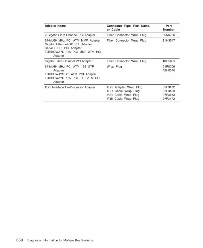
Adapter Name Connector Type, Port Name,or Cable
PartNumber
2-Gigabit Fibre Channel PCI Adapter Fiber Connector Wrap Plug 05N6768
64-bit/66 MHz PCI ATM MMF AdapterGigabit Ethernet-SX PCI AdapterSerial HIPPI PCI AdapterTURBOWAYS 155 PCI MMF ATM PCI
Adapter
Fiber Connector Wrap Plug 21H3547
Gigabit Fibre Channel PCI Adapter Fiber Connector Wrap Plug 16G5609
64-bit/66 MHz PCI ATM 155 UTPAdapter
TURBOWAYS 25 ATM PCI AdapterTURBOWAYS 155 PCI UTP ATM PCI
Adapter
Wrap Plug 21P800942H0540
X.25 Interface Co-Processor Adapter X.25 Adapter Wrap PlugX.21 Cable Wrap PlugV.24 Cable Wrap PlugV.35 Cable Wrap Plug
07F313207F315307F316307F3173
660 Diagnostic Information for Multiple Bus Systems

Appendix B. Test MediaDevice Media or Supplies Part
Number
4 GB 4 mm tape drive Tape/media kitKit includes:- 4 mm Cleaning Tape Cartridge- 4 mm 2GB Data Tape Cartridge- 4 mm 4GB Data Tape Cartridge4 mm Diagnostic Cartridge
8191149
21F876321F875881911608191146
5 GB 8 mm Tape Drive Tape/Media kitKit includes:- 8 mm Cleaning Tape Cartridge- 8 mm Blank Data Tape Cartridge- 8 mm Test Tape CartridgePackage of five 8 mm Blank Tapes
59F3907
21F859321F859521F857721F8595
1/4-inch Cartridge Tape Drive 1/4 inch Head Cleaning Kit150 MB Data Tape Cartridge (5-pack)525 MB Data Tape Cartridge (5-pack)1.2 GB Data Tape Cartridge (5-pack)1.2 GB 1/4 inch Test Tape Cartridge
21F857021F858821F858721F873221F8734
3-1/2 inch Diskette Drive 3-1/2 inch 1.0 MB Blank Diskette3-1/2 inch 1.0 MB Diagnostic TestDiskette3-1/2 inch 2.0 MB Blank Diskette3-1/2 inch 2.0 MB Diagnostic TestDiskette
640409571F1247
640407871F1248
CD-ROM Drive, Bezel type C Test Disc 81F8902
RISC System/6000 Diagnostic Package Diagnostic and Tests on CD-ROM 40H340140H3394
Supplemental Diagnostic Diskette Description PartNumber
10/100 Ethernet Tx PCI Adapter 93H1843
Eicon ISDN DIV A Pro 2.0 PCI S/T Adapter (Order through the kit FRU PartNumber)
41L5794
IBM ARTIC960Hx 4-port Selectable PCI Adapter IBM ARTIC960Hx 4-port T1/E1Adapter IBM ARTIC960Hx 4-port DSP Resource Adapter
07L9046
SSA Multi-Initiator/RAID EL Adapter 96H9868
661

662 Diagnostic Information for Multiple Bus Systems

Appendix C. System Memory Reference
System Unit Memory Combinations
Type and Model System MemoryConfigurationType/Size (Min./Max.)
Base MemoryCard FRUNumber
MemoryModule Size
(Bytes)
MemoryModule FRU
Number
Card Pairs
7013/S707015/S707017/S70
(512 MB/16 GB) 93H767(RH)
93H7689(LH)
16 MB32 MB64 MB
19H028819H028935H8751
Yes
7013/S7A7015/S7A7017/S7A
(512 MB/32 GB)R1 Memory Cards
90H983190H983497H6204
90H983797H6213
97H622697H6244
128 MB256 MB256 MB(64 MB)512 MB512 MB(64 MB)1024 MB2048 MB
N/A Quads
7013/S807015/S807017/S807017/S85
(1G B/64 GB) 23L756623L757023L757723L758923L7595
256 MB512 MB
1024 MB2048 MB4096 MB
N/A Quads
7024/E207024/E30
(16 MB/1 GB)System Board
N/A 8 MB16 MB32 MB64 MB128 MB
65G461519H028865G461739H983773H3451
No
7025/F30 (16 MB/1 GB)System Board
N/A 8 MB16 MB32 MB64 MB128 MB
65G461519H028865G461739H983773H3451
No
7025/F40 (16 MB/1 GB)System Board
N/A 8 MB16 MB32 MB64 MB128 MB
42H277142H277242H277342H277493H6821
No
7025/F50 (64 MB/1 GB) 93H2641 32 MB128 MB
93H470093H4702
Yes
7025/6F07025/6F17025/F80
(256 MB/16 GB) 04N4808 32 MB128 MB256 MB512 MB
1 GB
07L772993H470207L903010L541709P0335
Quads
663

Type and Model System MemoryConfigurationType/Size (Min./Max.)
Base MemoryCard FRUNumber
MemoryModule Size
(Bytes)
MemoryModule FRU
Number
Card Pairs
7026/B80 System board(256 MB/16 GB)
07L7065 128 MB256 MB512 MB
93H47009P055009P0491
Yes*
7026/H10 (16 MB/1 GB) N/A 16 MB32 MB
64M128M
42H477242H277342H277493H6821
No
7026/H50 (64 MB/1 GB) 93H2641 32 MB128 MB
93H470093H4702
Yes
7026/H70 (64 MB/8 GB) 93H2641 32 MB128 MB256 MB
93H470093H470207L9030
Yes
7026/6H07026/6H1
(256 MB/16 GB) 04N4808 32 MB128 MB256 MB512 MB
1 GB
07L772993H470207L903010L541709P0335
Quads
7026/6M1 (1 GB/32 GB) 04N3033 128 MB256 MB512 MB
1 GB
93H470207L903010L541709P0335
Group of 8
7026/H80 (256 MB/16 GB) 04N4808 32 MB128 MB256 MB512 MB
1 GB
07L772993H470207L903010L541709P0335
Quads
7026/M80 (1 GB/32 GB) 04N3033 128 MB256 MB512 MB
93H470207L903010L5417
Group of 8
7028/6C17028/6E1
(512 MB/ 8 GB with allprocessors)
N/A 512 MB 09P0491 Yes
7028/6C47028/6E4
(I GB/16GB) N/A 256 MB512 MB
1 GB2 GB
09P270509P270609P270753P3232
Quads
7038/6M2 (1 GB/64 GB) On Processor Card09P6257
512MB1 GB4 GB
53P322653P323053P3232
Quads
7039/651 (4 GB/32 GB) 09P292709P2882
4 GB8 GB
N/AN/A
NoNo
7040/671 (4 GB/128 GB) Inner 53P1013Inner 53P0374Inner 53P0378Inner 53P0382
4 GB8 GB
16 GB32 GB
N/A No
664 Diagnostic Information for Multiple Bus Systems

Type and Model System MemoryConfigurationType/Size (Min./Max.)
Base MemoryCard FRUNumber
MemoryModule Size
(Bytes)
MemoryModule FRU
Number
Card Pairs
7040/681 (8 GB/256 GB) Inner 53P1013Outer 53P1018Inner 53P0374Outer 53P0386Inner 53P0378Outer 53P0390Inner 53P0382Outer 53P0394
4 GB4 GB8 GB8 GB
16 GB16 GB32 GB32 GB
N/A No
7043/140 (32 MB/768 MB)System Board
N/A 16 MB32 MB64 MB128 MB
42H277242H277342H277493H6823
No
7043/150 (128 MB/1 GB)System board
N/A 64 MB128 MB256 MB
19L180819L180929L3302
No
7043/240 (32 MB/1 GB)System Board
N/A 8 MB16 MB32 MB64 MB128 MB
42H277142H277242H277342H277493H6822
No
7043/260 (256 MB/4 GB) 07L7065 32 MB128 MB
07L772993H4702
Yes
7043/270 (256 MB/8 GB) 07L7065 128 MB256 MB
93H470207L9030
Yes
7044/170 (256 MB/2 GB)System Board
N/A 128 MB256 MB256 MB512 MB512 MB
93H470207L903009P055007L975809P0491
Yes
7044/270 (256 MB/8 GB) 07L7065 128 MB256 MB
93H470207L9030
Yes
7046/B50 (128 MB/1 GB) N/A 64 MB128 MB256 MB
19L180819L180929L3302
Yes
7317/F3L (16 MB/1 GB)System Board
N/A 8 MB16 MB32 MB64 MB128 MB
65G461519H028865G461739H983773H3451
No
9076 SMP Thin/WideNode
(256 MB/3 GB) 93H2641 128 MB 93H4702 Yes
9076/ Power3 SMPThin/Wide Node
(256 MB/8 GB) 07L7065 128 MB256 MB
93H470207L9030
Yes
9076/ Power3 SMPHigh Node
(1 GB/16 GB) 07L6608 128 MB 93H4702 Group of 8
Appendix C. System Memory Reference 665

Type and Model System MemoryConfigurationType/Size (Min./Max.)
Base MemoryCard FRUNumber
MemoryModule Size
(Bytes)
MemoryModule FRU
Number
Card Pairs
9112/265 (512 MB/ 8 GB withother processors)
N/A 512 MB 09P0491 Yes
Note: * = Can be replaced individually with exact same part number, otherwise replace in pairs.
666 Diagnostic Information for Multiple Bus Systems

Appendix D. General Attributes Required When Using a TTYTerminal
The following general attributes are the default settings for the diagnostic programs. Besure your terminal is set to these attributes.
Note: These attributes should be set before the diagnostic programs are loaded.
Refer to the following table.
General Setup Attributes 3151 /11 /31/41 Settings
3151 /51 /61Settings
3161 /3164Settings
Description
Machine mode IBM 3151 IBM 3151 PC IBM 3161 orIBM 3164
The diagnostic programs are set toemulate use of the 3161 ASCII DisplayTerminal. If your terminal can emulate a5085, 3161 or 3164 terminal, use thefollowing attribute settings. Otherwise,refer to your operator’s manual, comparethe follow attribute descriptions withthose of your terminal, and set yourattributes accordingly.
Generated Code Set ASCII
Screen Normal Normal Uses the EIA-232 interface protocol.
Row and Column 24 x 80 24 x 80 Uses the EIA-232 interface protocol.
Scroll Jump Jump Jump When the last character on the bottomline is entered, the screen moves downone line.
Auto LF Off Off Off For the ″On″ setting, pressing the Returnkey moves the cursor to the firstcharacter position of the next line. Forthe ″Off″ setting, pressing the Return keymoves the cursor to the first characterposition of the current line. The CR andLF characters are generated by the Newline setting.
CRT saver Off Off 10 The ″10″ setting causes the displayscreen to go blank if there is no activityfor 10 minutes. When the system unitsends data or a key is pressed, thescreen contents are displayed again.
Line wrap On On On The cursor moves to the first characterposition of the next line in the page afterit reaches the last character position ofthe current line in the page.
Forcing insert Off Off
Tab Field Field Field The column tab stops are ignored, andthe tab operation depends on the fieldattribute character positions.
667
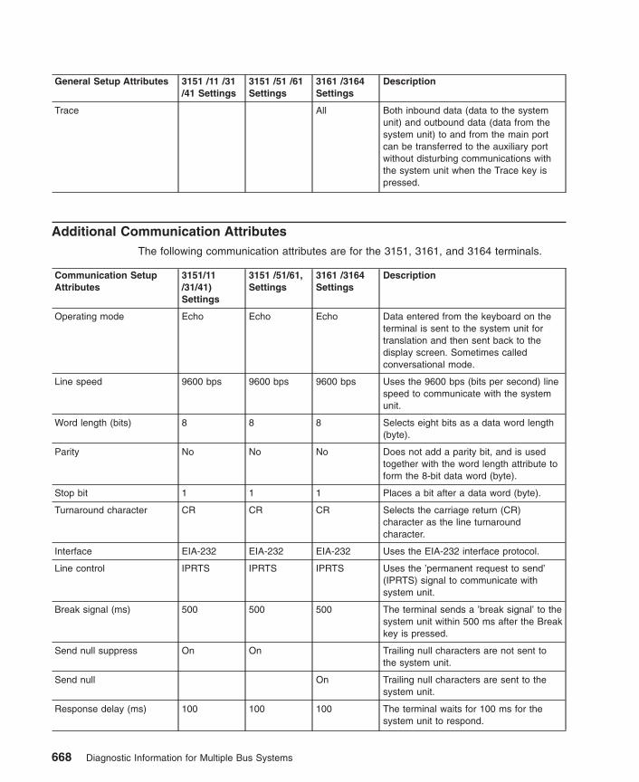
General Setup Attributes 3151 /11 /31/41 Settings
3151 /51 /61Settings
3161 /3164Settings
Description
Trace All Both inbound data (data to the systemunit) and outbound data (data from thesystem unit) to and from the main portcan be transferred to the auxiliary portwithout disturbing communications withthe system unit when the Trace key ispressed.
Additional Communication AttributesThe following communication attributes are for the 3151, 3161, and 3164 terminals.
Communication SetupAttributes
3151/11/31/41)Settings
3151 /51/61,Settings
3161 /3164Settings
Description
Operating mode Echo Echo Echo Data entered from the keyboard on theterminal is sent to the system unit fortranslation and then sent back to thedisplay screen. Sometimes calledconversational mode.
Line speed 9600 bps 9600 bps 9600 bps Uses the 9600 bps (bits per second) linespeed to communicate with the systemunit.
Word length (bits) 8 8 8 Selects eight bits as a data word length(byte).
Parity No No No Does not add a parity bit, and is usedtogether with the word length attribute toform the 8-bit data word (byte).
Stop bit 1 1 1 Places a bit after a data word (byte).
Turnaround character CR CR CR Selects the carriage return (CR)character as the line turnaroundcharacter.
Interface EIA-232 EIA-232 EIA-232 Uses the EIA-232 interface protocol.
Line control IPRTS IPRTS IPRTS Uses the ’permanent request to send’(IPRTS) signal to communicate withsystem unit.
Break signal (ms) 500 500 500 The terminal sends a ’break signal’ to thesystem unit within 500 ms after the Breakkey is pressed.
Send null suppress On On Trailing null characters are not sent tothe system unit.
Send null On Trailing null characters are sent to thesystem unit.
Response delay (ms) 100 100 100 The terminal waits for 100 ms for thesystem unit to respond.
668 Diagnostic Information for Multiple Bus Systems

Additional Keyboard AttributesThe following keyboard attributes are for the keyboard attached to the 3151, 3161, and3164 terminals.
Keyboard SetupAttributes
3151/11/31/41Settings
3151 /51/61Settings
3161 /3164Settings
Description
Enter Return Return Return The Enter key functions as the Returnkey.
Return New line New line New line The cursor moves to the next line whenthe Return key is pressed.
New line CR CR CR The Return key generates the carriagereturn (CR) and the line feed (LF)characters. The line turnaround occursafter the CR and LF characters aregenerated.
Send Page Page Page The contents of the current page aresent to the system unit when the Sendkey is pressed.
Insert character Space Space Space A blank character is inserted when theInsert key is pressed.
Additional Printer AttributesThe following printer attributes are for a printer attached to the 3151, 3161, and 3164terminals.
Printer Setup Attributes 3151/11/31/41Settings
3151 /51/61Settings
3161 /3164Settings
Description
Line speed 9600 9600 9600 Uses 19200 or 9600 bps (bits persecond) line speed to communicate withthe system unit.
Word length (bits) 8 8 8 Selects eight bits as a data word length(byte).
Parity Even Even No
Stop bit 1 1 1 Places a bit after a data word (byte).
Characters ALL ALL
Line end CR-LF
Print View- port
Print EOL Off
Print null Off
Appendix D. General Attributes Required When Using a TTY Terminal 669

670 Diagnostic Information for Multiple Bus Systems
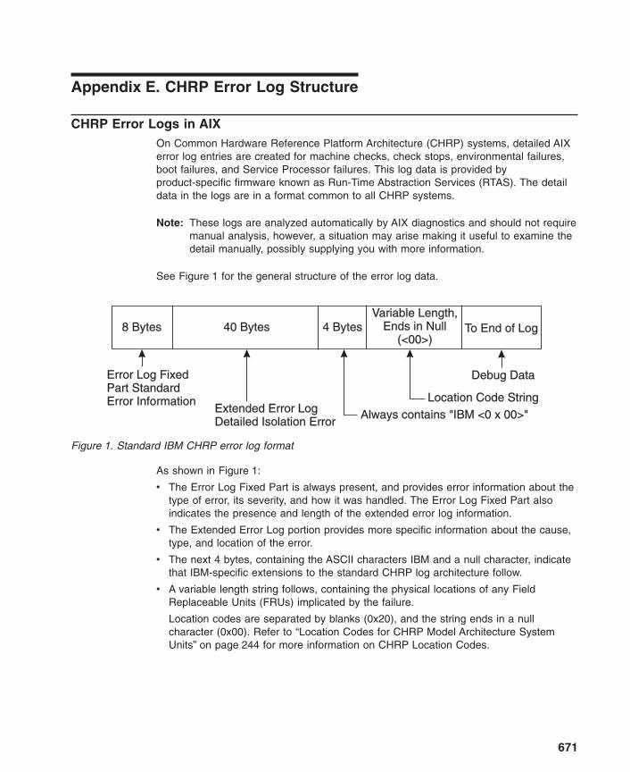
Appendix E. CHRP Error Log Structure
CHRP Error Logs in AIXOn Common Hardware Reference Platform Architecture (CHRP) systems, detailed AIXerror log entries are created for machine checks, check stops, environmental failures,boot failures, and Service Processor failures. This log data is provided byproduct-specific firmware known as Run-Time Abstraction Services (RTAS). The detaildata in the logs are in a format common to all CHRP systems.
Note: These logs are analyzed automatically by AIX diagnostics and should not requiremanual analysis, however, a situation may arise making it useful to examine thedetail manually, possibly supplying you with more information.
See Figure 1 for the general structure of the error log data.
As shown in Figure 1:
v The Error Log Fixed Part is always present, and provides error information about thetype of error, its severity, and how it was handled. The Error Log Fixed Part alsoindicates the presence and length of the extended error log information.
v The Extended Error Log portion provides more specific information about the cause,type, and location of the error.
v The next 4 bytes, containing the ASCII characters IBM and a null character, indicatethat IBM-specific extensions to the standard CHRP log architecture follow.
v A variable length string follows, containing the physical locations of any FieldReplaceable Units (FRUs) implicated by the failure.
Location codes are separated by blanks (0x20), and the string ends in a nullcharacter (0x00). Refer to “Location Codes for CHRP Model Architecture SystemUnits” on page 244 for more information on CHRP Location Codes.
8 Bytes 40 Bytes 4 Bytes
Error Log FixedPart StandardError Information
Error Log FixedPart StandardError Information
Extended Error LogDetailed Isolation ErrorExtended Error LogDetailed Isolation Error
Always contains "IBM <0 x 00>"Location Code String
Debug Data
Variable Length,Ends in Null
(<00>)
Variable Length,Ends in Null
(<00>)To End of Log
Figure 1. Standard IBM CHRP error log format
671

v Other data may follow after the location codes, but it is unarchitected engineeringdebug information that varies from system to system.
More detailed information on each portion of the log format is available in later sectionsof this chapter. Refer also to “Location Codes for CHRP Model Architecture SystemUnits” on page 244 for more information on CHRP Location Codes.
Figure 2 illustrates how the Detail Data is decoded.
LABEL:IDENTIFIER:
Date/Time:Sequence NumberMachine Id:Node Id:Class:Type:Resource Name:Resource Class:Resource Type:Location:
DescriptionUNDETERMINED ERROR
Failure CausesUNDETERMINED
Recommended ActionsRUN SYSTEM DIAGNOSTICS
Detail DataPROBLEM DATA
LABEL:IDENTIFIER:
Date/Time:Sequence NumberMachine Id:Node Id:Class:Type:Resource Name:Resource Class:Resource Type:Location:
DescriptionUNDETERMINED ERROR
Failure CausesUNDETERMINED
Recommended ActionsRUN SYSTEM DIAGNOSTICS
Detail DataPROBLEM DATA
SCAN_ERROR_CHRPBFE4C025
Thu Feb 20 18:14:38140000000004C00localhostHPERMsysplanar0planarsysplanar_rspc00-00
SCAN_ERROR_CHRPBFE4C025
Thu Feb 20 18:14:38140000000004C00localhostHPERMsysplanar0planarsysplanar_rspc00-00
Fixed Part (8 bytes)
Extended Error Log (40 bytes)
"IBM <0x00>" (4 bytes)
Location Codes (variable):
"P1-C1 P1<0x00>"
Location Codes (variable):
"P1-C1 P1<0x00>"
Debug Data Records
0144
0000
0008
0008
0000
0000
0000
0144
0000
0008
0008
0000
0000
0000
1000
0000
5331
4832
0000
0000
0000
1000
0000
5331
4832
0000
0000
0000
0000
0000
0000
0000
0000
0000
0000
0000
0000
0000
0000
0000
0000
0000
006A
0000
0300
0000
0000
0000
0000
006A
0000
0300
0000
0000
0000
0000
C600
0000
0008
0008
0000
0000
C600
0000
0008
0008
0000
0000
9108
0000
5332
4833
0000
0000
9108
0000
5332
4833
0000
0000
0014
0000
0000
0000
0000
0000
0014
0000
0000
0000
0000
0000
3700
0000
007F
0000
0000
0000
3700
0000
007F
0000
0000
0000
1997
4942
0008
0002
0000
0000
1997
4942
0008
0002
0000
0000
0221
4D00
4D31
0000
0000
0000
0221
4D00
4D31
0000
0000
0000
0200
5031
1000
0000
0000
0000
0200
5031
1000
0000
0000
0000
0000
2D43
0000
0000
0000
0000
0000
2D43
0000
0000
0000
0000
0000
3120
0008
0000
0000
0000
0000
3120
0008
0000
0000
0000
0000
5031
4831
0000
0000
0000
0000
5031
4831
0000
0000
0000
0000
0000
0000
0000
0000
0000
0000
0000
0000
0000
0000
0000
0000
0000
0000
0000
0000
0000
0000
0000
0000
0000
0000
0000
Figure 2. Example AIX error log with CHRP Detail Data
672 Diagnostic Information for Multiple Bus Systems

Versions of the Error Log FormatThere are several versions of the error log formats. Use byte 0 to determine which errorlog format table to use.
RTAS Error Return Format Fixed Part (All Versions)The summary portion of the error return is designed to fit into a single 32-bit integer.When used as a data return format in memory, an optional Length field and ExtendedError Log data may follow the summary. The fixed part contains a Presence flag whichidentifies whether an extended report is present.
Note: In Table 2, the location of each field within the integer is included in parenthesesafter its name. Numerical field values are indicated in decimal unless notedotherwise.
Table 2. RTAS Error Return Format (Fixed Part, All Versions)
Bit Field Name (bitnumbers)
Description, Values
Version (0:7) A distinct value used to identify the architectural version of message.Current version = (1)
Severity (8:10) Severity level of error/event being reported:
v FATAL (5)
v ERROR (4)
v ERROR_SYNC (3)
v WARNING (2)
v EVENT (1)
v NO_ERROR (0)
v reserved for future use (6-7)
RTAS Disposition(11:12)
Degree of recovery which RTAS has performed prior to return after anerror (value is FULLY_RECOVERED if no error is being reported):
v FULLY_RECOVERED(0)Note: Cannot be used when Severity is FATAL.
v LIMITED_RECOVERY(1)
v NOT_RECOVERED(2)
v reserved for future use (3)
Optional_Part_Presence(13)
Indicates if an Extended Error Log follows this 32-bit quantity inmemory:
v PRESENT (1): The optional Extended Error Log is present.
v NOT_PRESENT (0): The optional Extended Error Log is not present.
Reserved (14:15) Reserved for future use (0:3)
Appendix E. CHRP Error Log Structure 673
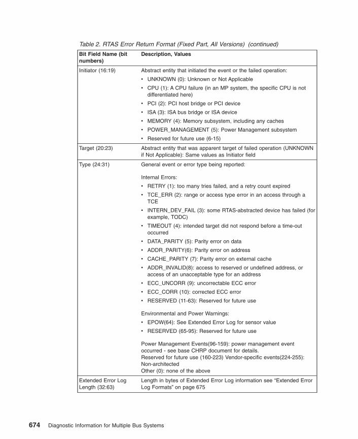
Table 2. RTAS Error Return Format (Fixed Part, All Versions) (continued)
Bit Field Name (bitnumbers)
Description, Values
Initiator (16:19) Abstract entity that initiated the event or the failed operation:
v UNKNOWN (0): Unknown or Not Applicable
v CPU (1): A CPU failure (in an MP system, the specific CPU is notdifferentiated here)
v PCI (2): PCI host bridge or PCI device
v ISA (3): ISA bus bridge or ISA device
v MEMORY (4): Memory subsystem, including any caches
v POWER_MANAGEMENT (5): Power Management subsystem
v Reserved for future use (6-15)
Target (20:23) Abstract entity that was apparent target of failed operation (UNKNOWNif Not Applicable): Same values as Initiator field
Type (24:31) General event or error type being reported:
Internal Errors:
v RETRY (1): too many tries failed, and a retry count expired
v TCE_ERR (2): range or access type error in an access through aTCE
v INTERN_DEV_FAIL (3): some RTAS-abstracted device has failed (forexample, TODC)
v TIMEOUT (4): intended target did not respond before a time-outoccurred
v DATA_PARITY (5): Parity error on data
v ADDR_PARITY(6): Parity error on address
v CACHE_PARITY (7): Parity error on external cache
v ADDR_INVALID(8): access to reserved or undefined address, oraccess of an unacceptable type for an address
v ECC_UNCORR (9): uncorrectable ECC error
v ECC_CORR (10): corrected ECC error
v RESERVED (11-63): Reserved for future use
Environmental and Power Warnings:
v EPOW(64): See Extended Error Log for sensor value
v RESERVED (65-95): Reserved for future use
Power Management Events(96-159): power management eventoccurred - see base CHRP document for details.Reserved for future use (160-223) Vendor-specific events(224-255):Non-architectedOther (0): none of the above
Extended Error LogLength (32:63)
Length in bytes of Extended Error Log information see “Extended ErrorLog Formats” on page 675
674 Diagnostic Information for Multiple Bus Systems

Extended Error Log FormatsThe following tables define an extended error log format by which the RTAS canoptionally return detailed information to the software about a hardware error condition.For CHRP products, this extended data is usually provided.
Figure 3 and Table 3 on page 676 shows the general layout for the extended error logformat, while Table 4 on page 678 through Table 10 on page 682 show the detailedlayout of bytes 12 through 39. The detail area format is determined by bits 4:7 of byte2, which indicate the error log type.
Product-unique data (location codes and debug information) is added to the end of theextended error log buffer (starting at byte 40) for capture and logging.
Note: The following log formats are designed to support the representation of integervalues in either the Big-Endian (AIX, Apple) or Little-Endian (Intel) formats. ForAIX, this is always Big-Endian format, which means there is no byte swapping,and bits run from 0 (high-order, leftmost) to 7 (low-order, rightmost).
Vendor IDVendor ID
Vendor IDVendor ID
44
40
12
16
0
12
IBM SpecificExtensions
IBM SpecificExtensions
Detail DataDetail Data
Header
Detailed Error Log FormatsDetailed Error Log Formats
CPU, Memory, I/O, POST,EPOW, Power ManagementCPU, Memory, I/O, POST,EPOW, Power Management
IBMSpecific
IBMSpecific
(Service Processor)(Service Processor)
General ExtendedError Log FormatGeneral ExtendedError Log Format
Figure 3. Layout of extended error log format from RTAS
Appendix E. CHRP Error Log Structure 675

RTAS General Extended Error Log Format, Versions 1, 2
Table 3. RTAS General Extended Error Log Format, Versions 1, 2
Byte Bit(s) Description
0 0 1 = Log Valid
1 1 = Unrecoverable Error
2 1 = Recoverable (correctable or successfully retried) Error
3 1 = Unrecoverable Error, Bypassed - Degraded operation (forexample, Single CPU taken off-line, bad cache bypassed)
4 1 = Predictive Error - Error is recoverable, but indicates atrend toward unrecoverable failure (for example, correctableECC error threshold)
5 1 = New Log (always 1 for data returned from RTAS)
6 1 = Addresses/Numbers are Big-Endian format, 0 =Little-EndianNote: This bit is always set to the Endian mode in whichRTAS was initialized.
7 Reserved
1 0:7 Reserved
2 0 Set to 1 - (Indicates log is in PowerPC format)
1:2 Reserved
3 1 = No failing address was available for recording within thelog’s Detailed Log Data, so the address field is invalid
4:7 Log format indicator, defines format used for bytes 12-39:
v (0) Reserved
v (1) CPU-detected failure, see Table 4 on page 678
v (2) Memory-detected failure, see Table 5 on page 678
v (3) I/O-detected failure, see Table 6 on page 679 or Table 12on page 685 (V2)
v (4) Power-On Self Test (POST) failure, see Table 7 onpage 680
v (5) Environmental and Power Warning, see Table 8 onpage 681 or Table 13 on page 687 (V2)
v (6) Power Management Event (see base CHRP documentfor description)
v (7-11) Reserved
v (12-15) Reserved for Vendor-specific
v (13) IBM Service Processor errors, see Table 10 onpage 682
676 Diagnostic Information for Multiple Bus Systems

Table 3. RTAS General Extended Error Log Format, Versions 1, 2 (continued)
Byte Bit(s) Description
3 0:3 Reserved
4 1 = Error is residual information from a failure which occurredprior to the last boot (for example, stored information about amachine check that crashed the system before RTAS couldreport it to the OS)
5 1 = Error detected during IPL process (If neither bit 5 nor bit 7is on, the error occurred after control was passed to theoperating system)
6 1 = Configuration changed since last boot.
7 1 = Error detected prior to IPL (in POST or firmware extendeddiagnostics)
4-7 Note: Time and Date are based upon the same values and time base as theRTAS Time-of-Day functions.
Time of most recent error in BCD format:
HHMMSS00, where HH=00-23, MM=00-59, SS=00-59
8-11 Date of most recent error in BCD format:
YYYYMMDD, where YYYY=1995-future, MM=01-12, DD=01-31
12-39 Detailed log data (See Detail log formats, Table 4 on page 678 through Table 10on page 682)
Note: Time and Date values included in the CHRP Extended Error Log format (bytes4-11) are recorded in Universal Time Coordinated (UTC) which essentially isGreenwich Mean Time. UTC is also the way time is reported from the Time ofDay clock hardware. Be aware that UTC time is NOT the same as local time thatis usually presented by the operating system. The system has built-in functionsto manage time differences and takes into account special cases such asDaylight Savings Time. For example, you may see an AIX error log with an AIXtime stamp of 12:00 pm, containing a CHRP error log in the Detail Data wherethe encoded time stamp is 5:00 pm. This difference is actually the differencebetween local time and UTC time.
Appendix E. CHRP Error Log Structure 677

CPU-Detected Errors, Versions 1, 2
Table 4. Error Log Detail for CPU-Detected Errors, Versions 1, 2
Byte Bit(s) Description
12 0 1 = CPU internal Error, other than cacheNote: If failure cannot be isolated, these bits may all be 0
1 1 = CPU internal cache error
2 1 = External (L2) cache parity or multi-bit ECC error
3 1 = External (L2) cache ECC single-bit error
4 1 = Time-out error, waiting for memory controller
5 1 = Time-out error, waiting for I/O
6 1 = Address/Data parity error on Processor Bus
7 1 = Transfer error on Processor Bus
13 Physical CPU ID number
14-15 Identifier number of sender of data/address parity error, or element which timedout
16-23 64-bit Memory Address for cache error (High-order bytes =0 if 32-bitaddressing)
24-39 Reserved
Memory Controller-Detected Errors, Versions 1,2
Table 5. Error Log Detail for Memory Controller-Detected Errors, Versions 1, 2
Byte Bit(s) Description
12 0 1 = Uncorrectable Memory Error (parity or multiple bit ECC)Note: If failure cannot be isolated, these bits may all be 0
1 1 = ECC correctable error
2 1 = Correctable error threshold exceeded
3 1 = Memory Controller internal error
4 1 = Memory Address (Bad address going to memory)
5 1 = Memory Data error (Bad data going to memory)
6 1 = Memory bus/switch internal error
7 1 = Memory time-out error
13 0 1 = Processor Bus parity error, detected by Memory Controller
1 1 = Processor time-out error, detected by Memory Controller
2 1 = Processor bus Transfer error
3 1 = I/O Host Bridge time-out error, detected by MemoryController
4 1 = I/O Host Bridge address/data parity error, detected byMemory Controller
5:7 Reserved
678 Diagnostic Information for Multiple Bus Systems

Table 5. Error Log Detail for Memory Controller-Detected Errors, Versions 1,2 (continued)
Byte Bit(s) Description
14 Physical Memory Controller number which detected error (0 if only onecontroller)
15 Physical Memory Controller number which caused error (0 if only single memorycontroller, or if the error source is in main memory, not another memorycontroller)
16-23 64-bit Memory Address (High-order bytes =0 if only 32-bit address)
24-25 Syndrome bits (included if single-bit correctable error)
26 Memory Card Number (0 if on system board)
27 Reserved
28-31 0:31 Memory sub-elements (for example, SIMMs/DIMMs) implicatedon this card (or system board), 1 bit per sub-element
32-33 Identifier number of sender of data/address parity error, or element which timedout.
34-39 Reserved
I/O-Detected Errors, Version 1
Table 6. Error Log Detail for I/O-Detected Errors, Version 1
Byte Bit(s) Description
12 0 1 = I/O Bus Address Parity ErrorNote: If failure cannot be isolated, these bits may all be 0
1 1 = I/O Bus Data Parity Error
2 1 = I/O Bus Time-out Error
3 1 = I/O Device Internal Error
4 1 = Signaling device is a PCI to non-PCI bridge chip,indicating an error on the secondary bus, for example, ISAIOCHK#.
5 1 = Mezzanine/Processor Bus Address Parity Error
6 1 = Mezzanine/Processor Bus Data Parity Error
7 1 = Mezzanine/Processor Bus Time-out Error
13 0 1 = Bridge is connected to Processor Bus
1 1 = Bridge is connected to Memory Controller via MezzanineBus
2:7 Reserved
14 PCI Bus ID of the device signaling the error
15 0:4 PCI Device ID of the device signaling the error
5:7 PCI Function ID of the device signaling the error
16-17 PCI Device ID of the device signaling the error (from configuration register)
18-19 PCI Vendor ID of the device signaling the error (from configuration register)
Appendix E. CHRP Error Log Structure 679
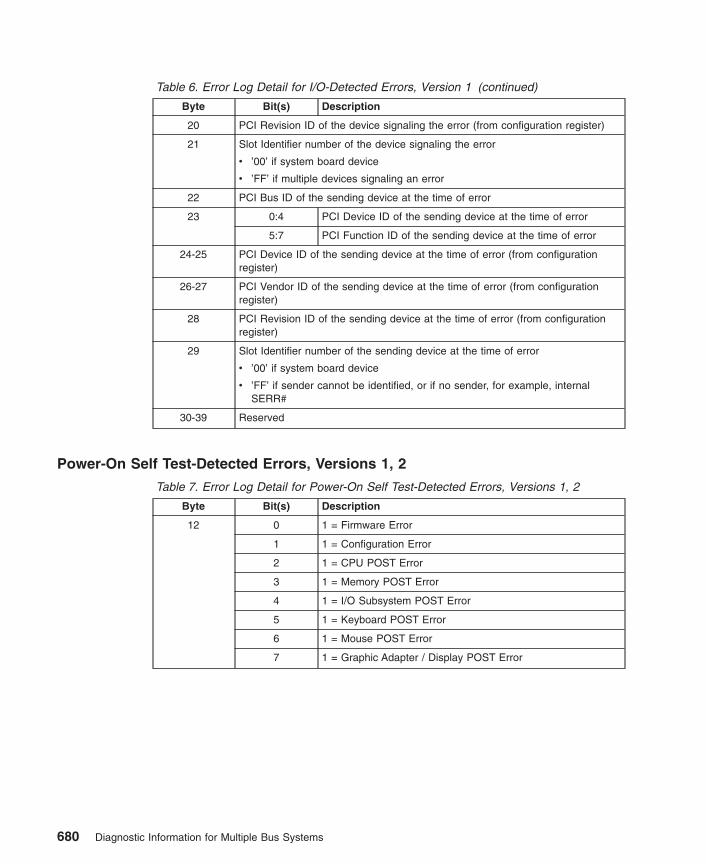
Table 6. Error Log Detail for I/O-Detected Errors, Version 1 (continued)
Byte Bit(s) Description
20 PCI Revision ID of the device signaling the error (from configuration register)
21 Slot Identifier number of the device signaling the error
v ’00’ if system board device
v ’FF’ if multiple devices signaling an error
22 PCI Bus ID of the sending device at the time of error
23 0:4 PCI Device ID of the sending device at the time of error
5:7 PCI Function ID of the sending device at the time of error
24-25 PCI Device ID of the sending device at the time of error (from configurationregister)
26-27 PCI Vendor ID of the sending device at the time of error (from configurationregister)
28 PCI Revision ID of the sending device at the time of error (from configurationregister)
29 Slot Identifier number of the sending device at the time of error
v ’00’ if system board device
v ’FF’ if sender cannot be identified, or if no sender, for example, internalSERR#
30-39 Reserved
Power-On Self Test-Detected Errors, Versions 1, 2
Table 7. Error Log Detail for Power-On Self Test-Detected Errors, Versions 1, 2
Byte Bit(s) Description
12 0 1 = Firmware Error
1 1 = Configuration Error
2 1 = CPU POST Error
3 1 = Memory POST Error
4 1 = I/O Subsystem POST Error
5 1 = Keyboard POST Error
6 1 = Mouse POST Error
7 1 = Graphic Adapter / Display POST Error
680 Diagnostic Information for Multiple Bus Systems

Table 7. Error Log Detail for Power-On Self Test-Detected Errors, Versions 1,2 (continued)
Byte Bit(s) Description
13 0 1 = Diskette Initial Program Load (IPL) Error
1 1 = Drive Controller IPL Error (SCSI, IDE, etc.)
2 1 = CD-ROM IPL Error
3 1 = Hard disk IPL Error
4 1 = Network IPL Error
5 1 = Other IPL Device Error (Tape, Flash Card, etc.)
6 Reserved
7 1 = Self-test error in firmware extended diagnostics
14-25 Device Name (Open Firmware Device for which self-test failed. Name truncatedif longer than 12 bytes.)
26-29 POST Error Code
30-31 Firmware Revision Level
32-39 Location Name (platform-specific identifier which points to specific instance offailing device)
Environmental and Power Warnings Events, Version 1
Table 8. Event Log Detail for Environmental and Power Warnings Events, Version 1
Byte Bit(s) Description
12-15 EPOW Sensor Value (low-order 4 bits contain the action code)
16-39 Reserved
Power Management Events, Versions 1, 2
Table 9. Event Log Detail for Power Management Events, Versions 1, 2
Byte Bit(s) Description
12-15 Integer identifier of the source of the power management event (productspecific)
16-39 Reserved
Appendix E. CHRP Error Log Structure 681

Service Processor Errors, Versions 1, 2
Table 10. IBM-specific Error Log Detail for Service Processor Errors, Versions 1, 2
Byte Bit(s) Description
12-15 Contains ASCII characters IBM<null> to indicate that this is an IBM-unique logformat
16 0 1 = Time-out on communication response from serviceprocessor
1 1 = I/O (I2C) general bus error
2 1 = Secondary I/O (I2C) general bus error
3 1 = Internal service processor memory error
4 1 = Service processor error accessing special registers
5 1 = Service processor reports unknown communication error
6 1 = Internal service processor firmware error
7 1 = Other internal service processor hardware error
17 0 1 = Service processor error accessing Vital Product DataEEPROM
1 1 = Service processor error accessing Operator Panel
2 1 = Service processor error accessing Power Controller
3 1 = Service processor error accessing Fan Sensor
4 1 = Service processor error accessing Thermal Sensor
5 1 = Service processor error accessing Voltage Sensor
6:7 Reserved
18 0 1 = Service processor error accessing serial port
1 1 = Service processor error accessing NVRAM
2 1 = Service processor error accessing Real-Time Clock /Time-of-day clock
3 1 = Service processor error accessing JTAG/COPcontroller/hardware
4 1 = Service processor or RTAS detects loss of voltage fromthe TOD backup battery
5:6 Reserved
7 1 = Service processor caused a reboot of the system due tosurveillance time-out
19 Reserved
20:23 Sensor Token, if failing device is a sensor defined in the Open Firmware devicetree (otherwise = 0)Note: If 64-bit system, only contains least significant 4 bytes
24:27 Sensor Index, if failing device is a sensor defined in the Open Firmware devicetree (otherwise = 0)Note: If 64-bit system, only contains least significant 4 bytes
28-39 Reserved
682 Diagnostic Information for Multiple Bus Systems
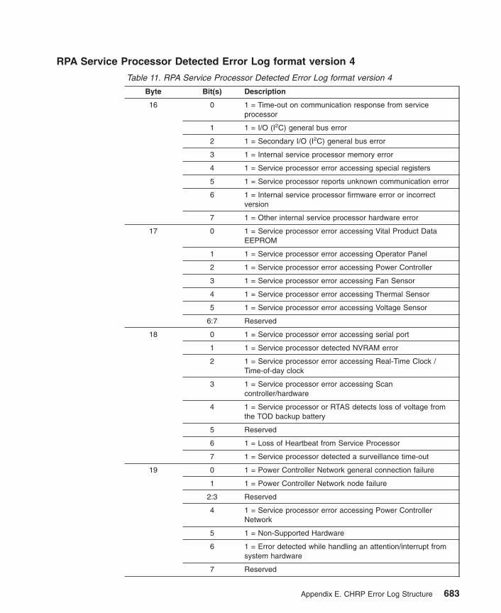
RPA Service Processor Detected Error Log format version 4
Table 11. RPA Service Processor Detected Error Log format version 4
Byte Bit(s) Description
16 0 1 = Time-out on communication response from serviceprocessor
1 1 = I/O (I2C) general bus error
2 1 = Secondary I/O (I2C) general bus error
3 1 = Internal service processor memory error
4 1 = Service processor error accessing special registers
5 1 = Service processor reports unknown communication error
6 1 = Internal service processor firmware error or incorrectversion
7 1 = Other internal service processor hardware error
17 0 1 = Service processor error accessing Vital Product DataEEPROM
1 1 = Service processor error accessing Operator Panel
2 1 = Service processor error accessing Power Controller
3 1 = Service processor error accessing Fan Sensor
4 1 = Service processor error accessing Thermal Sensor
5 1 = Service processor error accessing Voltage Sensor
6:7 Reserved
18 0 1 = Service processor error accessing serial port
1 1 = Service processor detected NVRAM error
2 1 = Service processor error accessing Real-Time Clock /Time-of-day clock
3 1 = Service processor error accessing Scancontroller/hardware
4 1 = Service processor or RTAS detects loss of voltage fromthe TOD backup battery
5 Reserved
6 1 = Loss of Heartbeat from Service Processor
7 1 = Service processor detected a surveillance time-out
19 0 1 = Power Controller Network general connection failure
1 1 = Power Controller Network node failure
2:3 Reserved
4 1 = Service processor error accessing Power ControllerNetwork
5 1 = Non-Supported Hardware
6 1 = Error detected while handling an attention/interrupt fromsystem hardware
7 Reserved
Appendix E. CHRP Error Log Structure 683

Table 11. RPA Service Processor Detected Error Log format version 4 (continued)
Byte Bit(s) Description
22:23 Sensor Token
24:27 Sensor Index
28 0 1 = Array or Logic Built In Self Test Error
1 1 = Wire Test Error
2 1 = Mainstore or Cache IPL Diagnostic ErrorReserved
3 1 = Other IPL Diagnostic Error
4 1 = Clock or PLL Error
5 1 = Hardware Scan or Initialization Error
6 1 = Chip ID Verification Error
7 FRU Presence/Detect Error (Mis-plugged)
29:39 Reserved
684 Diagnostic Information for Multiple Bus Systems

Version 2 Extension of CHRP Error Log FormatSince the original definition of the CHRP error log format, most additional requirementsfor error reporting have been for new, unique types of errors that could be supportedthrough vendor-specific log formats. However, there are also some areas covered bythe original definition where it has become apparent that more information is needed.Examples of this include support of problem reporting for I/O expansion units, andextended reporting of the causes of EPOW conditions. The log format definition inCHRP provides a version number, which is the first byte in the returned buffer (byte 0 ofthe fixed-part information), and is defined in base CHRP to have a value of 1. Theextension described here uses that version number to create a Version 2 of the errorlog format. This version defines new fields within certain log areas that were reserved inVersion 1, but does not change the meaning of any of the existing fields from Version 1,so that backward compatibility is preserved.
I/O Detected Errors, Version 2
Table 12. Error Log Detail for I/O-Detected Errors, Version 2
Byte Bit(s) Description
12 0 1 = I/O Bus Address Parity ErrorNote: If failure cannot be isolated, these bits may all be 0
1 1 = I/O Bus Data Parity Error
2 1 = I/O Bus Time-out Error
3 1 = I/O Device Internal Error
4 1 = Signaling device is a PCI to non-PCI bridge chip,indicating an error on the secondary bus, for example, ISAIOCHK#
5 1 = Mezzanine/Processor Bus Address Parity Error
6 1 = Mezzanine/Processor Bus Data Parity Error
7 1 = Mezzanine/Processor Bus Time-out Error
13 0 1 = Bridge is connected to Processor Bus
1 1 = Bridge is connected to Memory Controller via MezzanineBus
2 1 = Bridge is connected to I/O Expansion Bus
3 1 = Error on Processor Bus detected by I/O Expansion BuscontrollerNote: When this bit = 1, bits 5:7 of byte 12 indicate the typeof processor bus error.
4 1 = I/O Expansion Bus Parity Error
5 1 = I/O Expansion Bus Time-out Error
6 1 = I/O Expansion Bus Connection Failure
7 1 = I/O Expansion Unit not in an operating state (powereddown, off-line)
14 PCI Bus ID of the device signaling the error
Appendix E. CHRP Error Log Structure 685
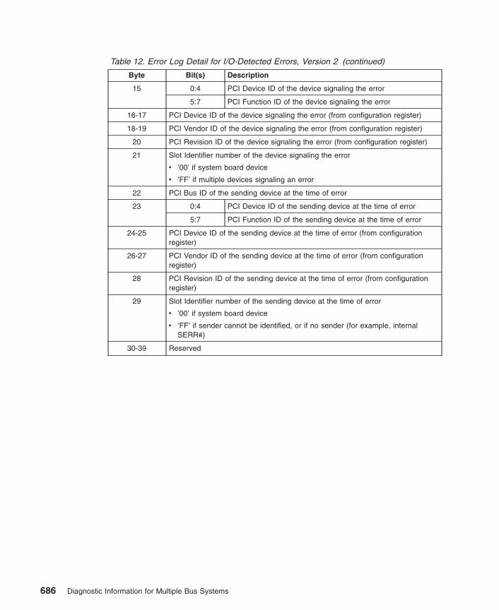
Table 12. Error Log Detail for I/O-Detected Errors, Version 2 (continued)
Byte Bit(s) Description
15 0:4 PCI Device ID of the device signaling the error
5:7 PCI Function ID of the device signaling the error
16-17 PCI Device ID of the device signaling the error (from configuration register)
18-19 PCI Vendor ID of the device signaling the error (from configuration register)
20 PCI Revision ID of the device signaling the error (from configuration register)
21 Slot Identifier number of the device signaling the error
v ’00’ if system board device
v ’FF’ if multiple devices signaling an error
22 PCI Bus ID of the sending device at the time of error
23 0:4 PCI Device ID of the sending device at the time of error
5:7 PCI Function ID of the sending device at the time of error
24-25 PCI Device ID of the sending device at the time of error (from configurationregister)
26-27 PCI Vendor ID of the sending device at the time of error (from configurationregister)
28 PCI Revision ID of the sending device at the time of error (from configurationregister)
29 Slot Identifier number of the sending device at the time of error
v ’00’ if system board device
v ’FF’ if sender cannot be identified, or if no sender (for example, internalSERR#)
30-39 Reserved
686 Diagnostic Information for Multiple Bus Systems

Environmental and Power Warnings Event Log, Version 2
Table 13. Detail for Environmental and Power Warnings Event Log, Version 2
Byte Bit(s) Description
12-15 EPOW Sensor Value (low-order 4 bits contain the action code)
16 0 1 = EPOW detected by a defined sensor (see bytes 20-35)
1 1 = EPOW caused by a power fault (see byte 17)
2 1 = EPOW caused by fan failure
3 1 = EPOW caused by over-temperature condition
4 1 = EPOW warning due to loss of redundancy (For example,single failure in a group of N+1 power supplies, fans, etc.)
5:7 Reserved
17 0 1 = General EPOW power fault due to an unspecified cause
1 1 = EPOW power fault specifically due to loss of power source
2 1 = EPOW power fault specifically due to internal powersupply failure
3 1 = EPOW power fault specifically due to manual activation ofpower-off switch
4:7 Reserved
18-19 Reserved
20-23 Token number of specific sensor causing the EPOW condition (If noCHRP-defined sensor caused the EPOW condition, this and the followingvalues are set to 0. For example, a power loss condition currently does nothave a defined CHRP sensor token.)
24-27 Index number of specific sensor causing the EPOW condition
28-31 Sensor value
32-35 Sensor status (Status return value that would be returned from aget-sensor-state call)
36-39 Reserved
Appendix E. CHRP Error Log Structure 687
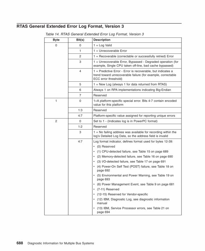
RTAS General Extended Error Log Format, Version 3
Table 14. RTAS General Extended Error Log Format, Version 3
Byte Bit(s) Description
0 0 1 = Log Valid
1 1 = Unrecoverable Error
2 1 = Recoverable (correctable or successfully retried) Error
3 1 = Unrecoverable Error, Bypassed - Degraded operation (forexample, Single CPU taken off-line, bad cache bypassed)
4 1 = Predictive Error - Error is recoverable, but indicates atrend toward unrecoverable failure (for example, correctableECC error threshold)
5 1 = New Log (always 1 for data returned from RTAS)
6 Always 1 on RPA implementations indicating Big-Endian
7 Reserved
1 0 1=A platform-specific special error. Bits 4-7 contain encodedvalue for this platform
1:3 Reserved
4:7 Platform-specific value assigned for reporting unique errors
2 0 Set to 1 - (Indicates log is in PowerPC format)
1:2 Reserved
3 1 = No failing address was available for recording within thelog’s Detailed Log Data, so the address field is invalid
4:7 Log format indicator, defines format used for bytes 12-39:
v (0) Reserved
v (1) CPU-detected failure, see Table 15 on page 689
v (2) Memory-detected failure, see Table 16 on page 690
v (3) I/O-detected failure, see Table 17 on page 691
v (4) Power-On Self Test (POST) failure, see Table 18 onpage 692
v (5) Environmental and Power Warning, see Table 19 onpage 693
v (6) Power Management Event, see Table 9 on page 681
v (7-11) Reserved
v (12-15) Reserved for Vendor-specific
v (12) IBM, Diagnostic Log, see diagnostic informationmanual
v (13) IBM, Service Processor errors, see Table 21 onpage 694
688 Diagnostic Information for Multiple Bus Systems
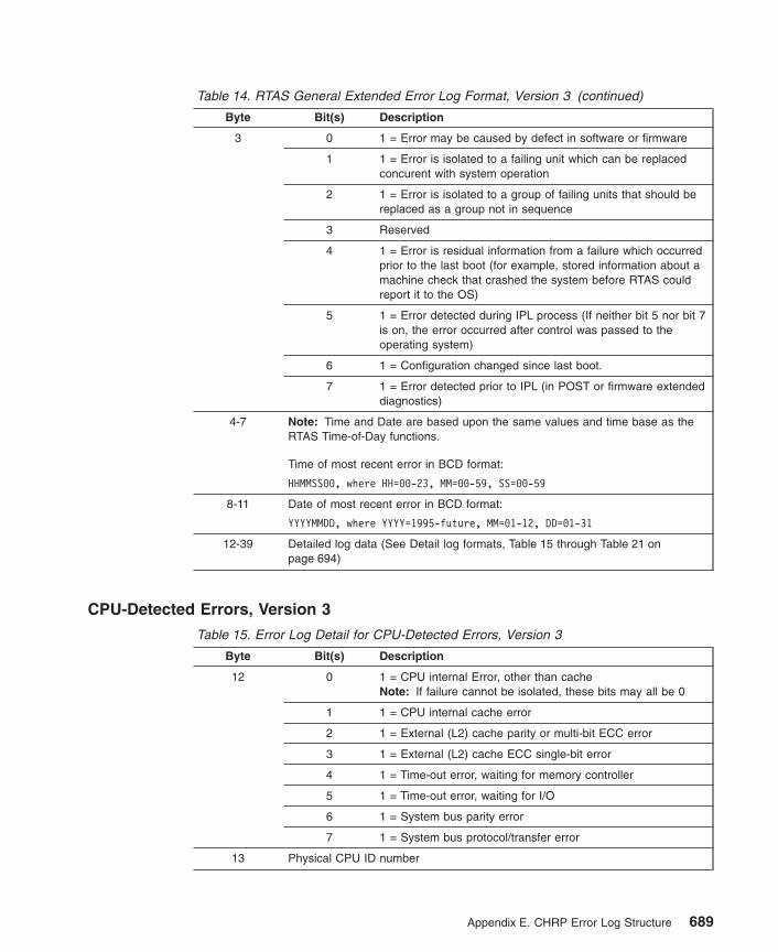
Table 14. RTAS General Extended Error Log Format, Version 3 (continued)
Byte Bit(s) Description
3 0 1 = Error may be caused by defect in software or firmware
1 1 = Error is isolated to a failing unit which can be replacedconcurent with system operation
2 1 = Error is isolated to a group of failing units that should bereplaced as a group not in sequence
3 Reserved
4 1 = Error is residual information from a failure which occurredprior to the last boot (for example, stored information about amachine check that crashed the system before RTAS couldreport it to the OS)
5 1 = Error detected during IPL process (If neither bit 5 nor bit 7is on, the error occurred after control was passed to theoperating system)
6 1 = Configuration changed since last boot.
7 1 = Error detected prior to IPL (in POST or firmware extendeddiagnostics)
4-7 Note: Time and Date are based upon the same values and time base as theRTAS Time-of-Day functions.
Time of most recent error in BCD format:
HHMMSS00, where HH=00-23, MM=00-59, SS=00-59
8-11 Date of most recent error in BCD format:
YYYYMMDD, where YYYY=1995-future, MM=01-12, DD=01-31
12-39 Detailed log data (See Detail log formats, Table 15 through Table 21 onpage 694)
CPU-Detected Errors, Version 3
Table 15. Error Log Detail for CPU-Detected Errors, Version 3
Byte Bit(s) Description
12 0 1 = CPU internal Error, other than cacheNote: If failure cannot be isolated, these bits may all be 0
1 1 = CPU internal cache error
2 1 = External (L2) cache parity or multi-bit ECC error
3 1 = External (L2) cache ECC single-bit error
4 1 = Time-out error, waiting for memory controller
5 1 = Time-out error, waiting for I/O
6 1 = System bus parity error
7 1 = System bus protocol/transfer error
13 Physical CPU ID number
Appendix E. CHRP Error Log Structure 689

Table 15. Error Log Detail for CPU-Detected Errors, Version 3 (continued)
Byte Bit(s) Description
14-15 Identifier number of sender of data/address parity error, or element which timedout
16-23 64-bit Memory Address for cache error (High-order bytes =0 if 32-bitaddressing)
24-39 Reserved
Memory Controller- and System Core-Detected Errors, Version 3
Table 16. Error Log Detail for Memory Controller-Detected Errors, Version 3
Byte Bit(s) Description
12 0 1 = Uncorrectable Memory Error (parity or multiple bit ECC)Note: If failure cannot be isolated, these bits may all be 0
1 1 = ECC correctable error
2 1 = Correctable error threshold exceeded
3 1 = Memory Controller internal error
4 1 = Memory Address (Bad address going to memory)
5 1 = Memory Data error (Bad data going to memory)
6 1 = Memory bus/switch internal error
7 1 = Memory time-out error
13 0 1 = System Bus parity error, detected by Memory Controller
1 1 = System time-out error, detected by Memory Controller
2 1 = System bus protocol/transfer error
3 1 = I/O Host Bridge time-out error, detected by MemoryController
4 1 = I/O Host Bridge address/data parity error, detected byMemory Controller
5 Reserved
6 1 = System support function error
7 1 = System bus internal hardware/switch error
14 Physical Memory Controller number which detected error (0 if only onecontroller)
15 Physical Memory Controller number which caused error (0 if only single memorycontroller, or if the error source is in main memory, not another memorycontroller)
16-23 64-bit Memory Address (High-order bytes =0 if only 32-bit address)
24-25 Syndrome bits (included if single-bit correctable error)
26 Memory Card Number (0 if on system board)
27 Reserved
690 Diagnostic Information for Multiple Bus Systems

Table 16. Error Log Detail for Memory Controller-Detected Errors, Version3 (continued)
Byte Bit(s) Description
28-31 0:31 Memory sub-elements (for example, SIMMs/DIMMs) implicatedon this card (or system board), 1 bit per sub-element
32-33 Identifier number of sender of data/address parity error, or element which timedout.
34-39 Reserved
I/O-Detected Errors, Version 3
Table 17. Error Log Detail for I/O-Detected Errors, Version 3
Byte Bit(s) Description
12 0 1 = I/O Bus Address Parity ErrorNote: If failure cannot be isolated, these bits may all be 0
1 1 = I/O Bus Data Parity Error
2 1 = I/O Bus Time-out Error
3 1 = I/O Device Internal Error
4 1 = Signaling device is a PCI to non-PCI bridge chip,indicating an error on the secondary bus, for example, ISAIOCHK#.
5 1 = Mezzanine/System Bus Address Parity Error
6 1 = Mezzanine/System Bus Data Parity Error
7 1 = Mezzanine/System Bus Time-out Error
13 0 1 = Bridge is connected to System Bus
1 1 = Bridge is connected to Memory Controller via MezzanineBus
2 1 = Bridge is connected to I/O expansion bus
3 1 = Error on system bus detected by I/O controller (Note:When this bit =1, bits 5:7 of byte 12 indicate the type ofsystem bus error
4 1 = I/O expansion bus parity error
5 1 = I/O expansion bus time-out, access, or other error
6 1 = I/O expansion bus connection failure
7 1 = I/O expansion unit not in an operating state(powered-down or off-line)
14 PCI Bus ID of the device signaling the error
15 0:4 PCI Device ID of the device signaling the error
5:7 PCI Function ID of the device signaling the error
16-17 PCI Device ID of the device signaling the error (from configuration register)
18-19 PCI Vendor ID of the device signaling the error (from configuration register)
20 PCI Revision ID of the device signaling the error (from configuration register)
Appendix E. CHRP Error Log Structure 691

Table 17. Error Log Detail for I/O-Detected Errors, Version 3 (continued)
Byte Bit(s) Description
21 Slot Identifier number of the device signaling the error
v ’00’ if system board device
v ’FF’ if multiple devices signaling an error
22 PCI Bus ID of the sending device at the time of error
23 0:4 PCI Device ID of the sending device at the time of error
5:7 PCI Function ID of the sending device at the time of error
24-25 PCI Device ID of the sending device at the time of error (from configurationregister)
26-27 PCI Vendor ID of the sending device at the time of error (from configurationregister)
28 PCI Revision ID of the sending device at the time of error (from configurationregister)
29 Slot Identifier number of the sending device at the time of error
v ’00’ if system board device
v ’FF’ if sender cannot be identified, or if no sender, for example, internalSERR#
30-39 Reserved
Power-On Self Test-Detected Errors, Version 3
Table 18. Error Log Detail for Power-On Self Test-Detected Errors, Version 3
Byte Bit(s) Description
12 0 1 = Firmware Error
1 1 = Configuration Error
2 1 = CPU POST Error
3 1 = Memory POST Error
4 1 = I/O Subsystem POST Error
5 1 = Keyboard POST Error
6 1 = Mouse POST Error
7 1 = Graphic Adapter / Display POST Error
13 0 1 = Diskette Initial Program Load (IPL) Error
1 1 = Drive Controller IPL Error (SCSI, IDE, etc.)
2 1 = CD-ROM IPL Error
3 1 = Hard disk IPL Error
4 1 = Network IPL Error
5 1 = Other IPL Device Error (Tape, Flash Card, etc.)
6 Reserved
7 1 = Self-test error in firmware extended diagnostics
692 Diagnostic Information for Multiple Bus Systems
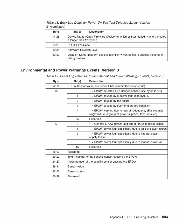
Table 18. Error Log Detail for Power-On Self Test-Detected Errors, Version3 (continued)
Byte Bit(s) Description
14-25 Device Name (Open Firmware Device for which self-test failed. Name truncatedif longer than 12 bytes.)
26-29 POST Error Code
30-31 Firmware Revision Level
32-39 Location Name (platform-specific identifier which points to specific instance offailing device)
Environmental and Power Warnings Events, Version 3
Table 19. Event Log Detail for Environmental and Power Warnings Events, Version 3
Byte Bit(s) Description
12-15 EPOW Sensor Value (low-order 4 bits contain the action code)
16 0 1 = EPOW detected by a defined sensor (see bytes 20:35)
1 1 = EPOW caused by a power fault (see byte 17)
2 1 = EPOW caused by fan failure
3 1 = EPOW caused by over-temperature condition
4 1 = EPOW warning due to loss of redundancy (For example,single failure in group of power supplies, fans, or such)
5:7 Reserved
17 0 1 = General EPOW power fault due to an unspecified cause
1 1 = EPOW power fault specifically due to loss of power source
2 1 = EPOW power fault specifically due to internal powersupply failure
3 1 = EPOW power fault specifically due to manual power off
4:7 Reserved
18-19 Reserved
20-23 Token number of the specific sensor causing the EPOW
24-27 Index number of the specific sensor causing the EPOW
28-31 Sensor value
32-35 Sensor status
36-39 Reserved
Appendix E. CHRP Error Log Structure 693

Power Management Events, Version 3
Table 20. Event Log Detail for Power Management Events, Version 3
Byte Bit(s) Description
12-15 Integer identifier of the source of the power management event (productspecific)
16-39 Reserved
Service Processor Errors, Version 3
Table 21. IBM-specific Error Log Detail for Service Processor Errors, Version 3
Byte Bit(s) Description
12-15 Contains ASCII characters IBM<null> to indicate that this is an IBM-unique logformat
16 0 1 = Time-out on communication response from serviceprocessor
1 1 = I/O (I2C) general bus error
2 1 = Secondary I/O (I2C) general bus error
3 1 = Internal service processor memory error
4 1 = Service processor error accessing special registers
5 1 = Service processor reports unknown communication error
6 1 = Internal service processor firmware error
7 1 = Other internal service processor hardware error
17 0 1 = Service processor error accessing Vital Product DataEEPROM
1 1 = Service processor error accessing Operator Panel
2 1 = Service processor error accessing Power Controller
3 1 = Service processor error accessing Fan Sensor
4 1 = Service processor error accessing Thermal Sensor
5 1 = Service processor error accessing Voltage Sensor
6:7 Reserved
18 0 1 = Service processor error accessing serial port
1 1 = Service processor error accessing NVRAM
2 1 = Service processor error accessing Real-Time Clock /Time-of-day clock
3 1 = Service processor error accessing JTAG/COPcontroller/hardware
4 1 = Service processor or RTAS detects loss of voltage fromthe TOD backup battery
5:6 Reserved
7 1 = Service processor detected a surveillance time-out
694 Diagnostic Information for Multiple Bus Systems

Table 21. IBM-specific Error Log Detail for Service Processor Errors, Version3 (continued)
Byte Bit(s) Description
19 0 1 = Power control network general connection failure
1 1 = Power control network node failure
2:3 Reserved
4 1 = Service processor error accessing power control network
5:7 Reserved
20:23 Sensor Token, if failing device is a sensor defined in the Open Firmware devicetree (otherwise = 0)Note: If 64-bit system, only contains least significant 4 bytes
24:27 Sensor Index, if failing device is a sensor defined in the Open Firmware devicetree (otherwise = 0)Note: If 64-bit system, only contains least significant 4 bytes
28-39 Reserved
Appendix E. CHRP Error Log Structure 695
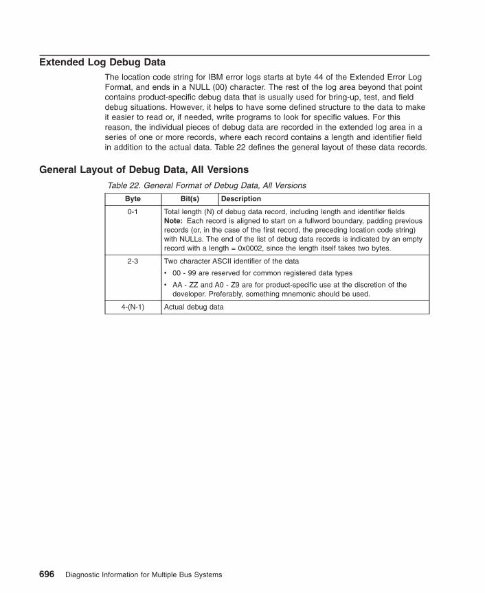
Extended Log Debug DataThe location code string for IBM error logs starts at byte 44 of the Extended Error LogFormat, and ends in a NULL (00) character. The rest of the log area beyond that pointcontains product-specific debug data that is usually used for bring-up, test, and fielddebug situations. However, it helps to have some defined structure to the data to makeit easier to read or, if needed, write programs to look for specific values. For thisreason, the individual pieces of debug data are recorded in the extended log area in aseries of one or more records, where each record contains a length and identifier fieldin addition to the actual data. Table 22 defines the general layout of these data records.
General Layout of Debug Data, All Versions
Table 22. General Format of Debug Data, All Versions
Byte Bit(s) Description
0-1 Total length (N) of debug data record, including length and identifier fieldsNote: Each record is aligned to start on a fullword boundary, padding previousrecords (or, in the case of the first record, the preceding location code string)with NULLs. The end of the list of debug data records is indicated by an emptyrecord with a length = 0x0002, since the length itself takes two bytes.
2-3 Two character ASCII identifier of the data
v 00 - 99 are reserved for common registered data types
v AA - ZZ and A0 - Z9 are for product-specific use at the discretion of thedeveloper. Preferably, something mnemonic should be used.
4-(N-1) Actual debug data
696 Diagnostic Information for Multiple Bus Systems
Appendix F. Notices
This information was developed for products and services offered in the U.S.A.
The manufacturer may not offer the products, services, or features discussed in thisdocument in other countries. Consult the manufacturer’s representative for informationon the products and services currently available in your area. Any reference to themanufacturer’s product, program, or service is not intended to state or imply that onlythat product, program, or service may be used. Any functionally equivalent product,program, or service that does not infringe any intellectual property right of themanufacturer may be used instead. However, it is the user’s responsibility to evaluateand verify the operation of any product, program, or service.
The manufacturer may have patents or pending patent applications covering subjectmatter described in this document. The furnishing of this document does not give youany license to these patents. You can send license inquiries, in writing, to themanufacturer.
The following paragraph does not apply to the United Kingdom or any countrywhere such provisions are inconsistent with local law: THIS MANUAL ISPROVIDED ″AS IS″ WITHOUT WARRANTY OF ANY KIND, EITHER EXPRESSED ORIMPLIED, INCLUDING, BUT NOT LIMITED TO, THE IMPLIED WARRANTIES OFNON-INFRINGEMENT, MERCHANTABILITY OR FITNESS FOR A PARTICULARPURPOSE. Some states do not allow disclaimer of express or implied warranties incertain transactions; therefore, this statement may not apply to you.
This information could include technical inaccuracies or typographical errors. Changesare periodically made to the information herein; these changes will be incorporated innew editions of the publication. The manufacturer may make improvements and/orchanges in the product(s) and/or the program(s) described in this publication at anytime without notice.
Information concerning products made by other than the manufacturer was obtainedfrom the suppliers of those products, their published announcements, or other publiclyavailable sources. The manufacturer has not tested those products and cannot confirmthe accuracy of performance, compatibility or any other claims related to products madeby other than the manufacturer. Questions on the capabilities of products made by otherthan the manufacturer should be addressed to the suppliers of those products.
697

698 Diagnostic Information for Multiple Bus Systems
Index
Numerics7135 RAIDiant array 2237318 server service aid 224888 sequence 59
dump progress indicators 239
Aabout this book ixAIX operating system message file 139alter/display bootlist 194attributes required for TTY terminal 667audience description ixautomatic diagnostic tests 141
Bboot problem resolution, MAP 0280 111, 113
CCE login 141CEREADME file 140change diagnostic run-time 195CHRP error log structure 671common system information 139configuration program 143configuration program indicators 225configure scan dump policy 187CPU tests 143crash codes 240CSU feature installation xi
Ddetermining system architecture 165diagdetrto command 195diaggetrto command 195diagnostic run-time
change 195display 195
diagnosticsadvanced diagnostics function 145AIX location codes 248applications descriptions 144automatic error log analysis 148CHRP location codes 244command line options 168controller description 144high-availability systems 166load progress indicators 238multiple systems 164NIM standalone diagnostics 155numbers and codes 225online diagnostics modes of operation 160online diagnostics service mode 160
diagnostics (continued)operating considerations 153periodic diagnostics 147physical location codes 244RSPC location codes 242sources for programs 153standalone 153standalone diagnostics 163standard prefixes 246system checkout option 146task and service aid functions 145tasks and resources 167TTY terminal attributes 667
display diagnostic run-time 195display fault indicators 203display identify indicators 211display/alter bootlist 194dummy
crash codes 240from CD-ROM 140from source other than disk 140
dump progress indicators 239
Eerror log analysis 143
Ffailing function codes
description of list 563failing function code list 566
fast path MAP 17fault indicators 203feature installation xifibre channel RAID service aids 204flash SK-NET FDDI firmware 204FRU cross reference
definition 651list 651using the list 651
full machine partition 1standalone diagnostics 153
full machine partition standalone diagnostics 163
Ggeneral diagnostic information 139general problem resolution, MAP 0210 67
Hhardware management console 1high-availability system diagnostics 166hot swap FRU problem resolution, MAP 0220 77
699
II/O
multipath 146identify indicators 211indicators
fault 203installation checkout procedure 135intermittent problem isolation, MAP 0040 47
Llocal area network service aid 212location code standard prefixes 246location codes 242, 244, 248log repair action service aid 212logical partition 1LPAR 1
standalone diagnostics 163
Mmachine types 564MAPs
fast path 17MAP 0020, problem determination procedure 29MAP 0025, SCSI RAID problem determination
procedure 41MAP 0030, additional problem determination 45MAP 0040, intermittent problem isolation 47MAP 0050, SCSI bus problems 51MAP 0070, 888 sequence 59MAP 0080, system bus problem isolation 63MAP 0210, general problem resolution 67MAP 0220, hot-swap FRU problem resolution 77MAP 0230, platform error problem resolution 83MAP 0235, system array self-repair problem
resolution 91MAP 0240, memory problem resolution 93MAP 0250, unexpected system halts during
diagnostics 97MAP 0260, system hangs during resource
configuration 99MAP 0270, SCSI RAID Problem Resolution and
Verification 103MAP 0280, boot problem resolution 111, 113MAP 0290, missing resource problem
resolution 117MAP 0291, missing device problem resolution 121MAP 0410, repair checkout 125MAP 0420, system checkout 133service hints 1Slow Boot 2start of call 15using the maintenance analysis procedures 1
memory problem resolution, MAP 0240 93memory testing 143microcode 139
missing device problem resolution, MAP 0291 121missing path resolution 146missing resource problem resolution, MAP 0290 117mpio 146multipath I/O 146multiple systems diagnostics 164
Nnetwork service aid 212NIM standalone diagnostics 155
Ooperator panel display numbers 225
Ppartitioned system 1platform error problem resolution, MAP 0230 83printing
from disk 140problem determination procedure 45problem determination procedure, MAP 0020 29problem determination procedure, SCSI RAID , MAP
0025 41
Rrelated publications xrepair checkout, MAP 0410 125repair log service aid 212reset fault indicators 203run exercisers 214
Sscan dump policy 187SCSI
bus analyzer 218configuration checks 3high availability 3high-availability diagnostics 166multiple SCSI system checks 3
SCSI bus problems, MAP 0050 51SCSI RAID Problem Resolution and Verification, MAP
0270 103service aids
7135 RAIDiant array 2237318 service aid 224add resource 177analyze adapter internal log 177backup/restore media 178callin/out setup 188CE login 141certify media 179change hardware VPD 182configure dials and LPF Keys 182configure ISA adapter 182configure reboot policy 183configure remote maintenance policy 184
700 Diagnostic Information for Multiple Bus Systems

service aids (continued)configure ring indicate 186configure service processor 187configure surveillance policy 191create customized configuration diskette 191delete resource 192disk to disk copy 192disk-based diagnostic 220display configuration and resource list 193display firmware device node information 193display hardware error report 193display hardware VPD 194display microcode level 200display or change diagnostic run-time options 195display previous diagnostic results 197display resource attributes 197display service hints 197display software product data 198display system environmental sensors 198display test patterns 200display USB Devices 200display/alter bootlist 194display/alter sector 193download microcode 200fibre channel RAID service aids 204flash SK-NET FDDI firmware 204format media 205generic microcode download 207high availability 3introduction 175local area network 212log repair action 212machine check error log 194modem configuration 188multiple SCSI system checks 3multiple SRNs or error codes 2PCI RAID physical disk identify 213periodic diagnostics 213process supplemental media 213ring indicate power on policy 186run diagnostics 214run error log analysis 214run exercisers 214save or restore hardware management policies 217save or restore service processor configuration 217SCSD tape drive 219SCSI bus analyzer 218spare sector availability 220SSA service aid 220surveillance setup 188update system flash 222update system or service processor flash 221
service hints 1service request number (SRN)
700-102 through 89c-302 377
service request number (SRN) (continued)900-001 through xxxxxxx 461description of SRN list 251how to use the SRN list 252multiple SRNs or error codes 2SRN list 255SRNs 101 through 6C9 267SRNs 2520 through 25C1 555SRNs A01 through A1D 535
set identify indicators 211Slow Boot 2Slow-Mode Boot 2source codes 251SRN codes 255SRN codes 101-000 thru 6C9-600 267SRN codes 2520-(x)xxx thru 25C1-(x)xxx 555SRN codes 700-102 thru 89C-302 377SRN codes 900-001 thru xxxxxxx 461SRNs A01-(x)xxx through A1D-(x)xxx 535SSA service aid 220standalone diagnostics 153
full machine partition 163LPAR 163LPAR considerations 163
start of call MAP 15system architecture determination 165system array self-repair problem resolution , MAP
0235 91system attention indicators 211system bus problem isolation, MAP 0080 63system checkout, MAP 0420 133system configuration program 143system hangs during resource configuration, MAP
0260 99system memory reference 663
Ttest media 661testing the line printer 151trademarks xTTY terminal attributes required for diagnostics
general 667
Uunexpected system halts during diagnostics, MAP
0250 97update system flash 222using online diagnostics 153
Wwrap plugs 659
Index 701

702 Diagnostic Information for Multiple Bus Systems
Readers’ Comments — We’d Like to Hear from You
RS/6000Eserver pSeriesDiagnostic Information for Multiple Bus SystemsVersion 5.2.0.0
Publication No. SA38-0509-17
Overall, how satisfied are you with the information in this book?
Very Satisfied Satisfied Neutral Dissatisfied Very
Dissatisfied
Overall satisfaction h h h h h
How satisfied are you that the information in this book is:
Very Satisfied Satisfied Neutral Dissatisfied Very
Dissatisfied
Accurate h h h h h
Complete h h h h h
Easy to find h h h h h
Easy to understand h h h h h
Well organized h h h h h
Applicable to your tasks h h h h h
Please tell us how we can improve this book:
Thank you for your responses. May we contact you? h Yes h No
When you send comments to IBM, you grant IBM a nonexclusive right to use or distribute your comments in any
way it believes appropriate without incurring any obligation to you.
Name Address
Company or Organization
Phone No.

Readers’ Comments — We’d Like to Hear from YouSA38-0509-17
SA38-0509-17
����Cut or FoldAlong Line
Cut or FoldAlong Line
Fold and Tape Please do not staple Fold and Tape
Fold and Tape Please do not staple Fold and Tape
NO POSTAGENECESSARYIF MAILED IN THEUNITED STATES
BUSINESS REPLY MAILFIRST-CLASS MAIL PERMIT NO. 40 ARMONK, NEW YORK
POSTAGE WILL BE PAID BY ADDRESSEE
Information DevelopmentDepartment H6DS-905-6C00611501Burnet RoadAustin, TX 78758-3493
_ _ _ _ _ _ _ _ _ _ _ _ _ _ _ _ _ _ _ _ _ _ _ _ _ _ _ _ _ _ _ _ _ _ _ _ _ _ _ _ _ _ _ _ _ _ _ _ _ _ _ _ _ _ _ _ _ _ _ _ _ _ _ _ _ _ _ _ _ _ _ _ _ _ _ _ _
_ _ _ _ _ _ _ _ _ _ _ _ _ _ _ _ _ _ _ _ _ _ _ _ _ _ _ _ _ _ _ _ _ _ _ _ _ _ _ _ _ _ _ _ _ _ _ _ _ _ _ _ _ _ _ _ _ _ _ _ _ _ _ _ _ _ _ _ _ _ _ _ _ _ _ _ _
__
__
__
__
__
__
__
__
__
__
__
__
__
__
__
__
__
__
__
__
__
__
__
__
__
__
__
__
__
__
__
__
__
__
__
__
__
__
__
__
_


����
Printed in U.S.A.
December 2002
SA38-0509-17
Spin
ein
form
atio
n:
��
�R
S/60
00Eserver
pSer
ies
Dia
gnos
ticIn
form
atio
nfo
rM
ultip
leBu
sSy
stem
sVe
rsio
n5.
2.0.
0SA
38-0
509-
17


![APPENDIX A CONTROLLED HS CODES LIST · CONTROLLED HS CODES LIST APPENDIX A APR 2020 A - 2 Items Under Import Control [cont’d] 2) SFA (Fresh Fruits & Vegetable) Licensing and Permits](https://img.dokumen.tips/doc/110x75/5f0a661a7e708231d42b7177/appendix-a-controlled-hs-codes-list-controlled-hs-codes-list-appendix-a-apr-2020.jpg)


