Embed Size (px)
Citation preview

Copyright © 2006, TWI LtdWorld Centre for Materials Joining Technology
CSWIP 3.1 Welding InspectionCSWIP 3.1 Welding Inspection
TWI Training & Examination TWI Training & Examination ServicesServices
Destructive TestingDestructive Testing
Course Reference WIS 5Course Reference WIS 5Course notes section reference 4Course notes section reference 4

Copyright © 2006, TWI LtdWorld Centre for Materials Joining Technology
The destruction of a welded The destruction of a welded unit or by cutting out selected unit or by cutting out selected specimens from the weld specimens from the weld is is carried out to check the carried out to check the mechanical properties of the mechanical properties of the joint materials. They can be joint materials. They can be produced to:produced to:
What is Destructive Testing ?What is Destructive Testing ?
Destructive Testing DefinitionsDestructive Testing Definitions
• Approve welding procedures (BS EN 288)Approve welding procedures (BS EN 288)
• Approve welders (BS EN 287)Approve welders (BS EN 287)
• Production quality controlProduction quality control

Copyright © 2006, TWI LtdWorld Centre for Materials Joining Technology
Destructive TestsDestructive Tests
Destructive tests include:Destructive tests include:
•tensile testtensile test
•bend testbend test
•impact testimpact test
•hardness testhardness test
•metallographic examinationmetallographic examination

Copyright © 2006, TWI LtdWorld Centre for Materials Joining Technology
Quantitative and Qualitative TestsQuantitative and Qualitative Tests
Quantitative Tests:Quantitative Tests:
For measuring a ‘quantity’ For measuring a ‘quantity’ ( a mechanical property )( a mechanical property )
• Mechanical tests Mechanical tests - tensile test- tensile test
- hardness test- hardness test
- Charpy V-notch test (& CTOD)- Charpy V-notch test (& CTOD)
Qualitative Tests:Qualitative Tests:
For assessing joint ‘quality’ For assessing joint ‘quality’ (good fusion & free from defects)(good fusion & free from defects)
• Qualitative testsQualitative tests - bend tests- bend tests
- macro examination- macro examination
- fillet fracture & nick-break tests- fillet fracture & nick-break tests

Copyright © 2006, TWI LtdWorld Centre for Materials Joining Technology
Qualitative and Quantitative TestsQualitative and Quantitative Tests
The following mechanical tests have units and are termedThe following mechanical tests have units and are termedquantitativequantitative tests to tests to measure Mechanical Propertiesmeasure Mechanical Properties
• Tensile tests (Transverse Welded Joint, All Weld Metal)Tensile tests (Transverse Welded Joint, All Weld Metal)
• Toughness testing (Charpy, Izod, CTOD) Toughness testing (Charpy, Izod, CTOD)
• Hardness tests (Brinell, Rockwell, Vickers)Hardness tests (Brinell, Rockwell, Vickers)
The following mechanical tests have no units and are termedThe following mechanical tests have no units and are termed
qualitativequalitative tests for tests for assessing joint qualityassessing joint quality• Macro testingMacro testing• Bend testingBend testing• Fillet weld fracture testingFillet weld fracture testing• Butt weld nick-break testingButt weld nick-break testing

Copyright © 2006, TWI LtdWorld Centre for Materials Joining Technology
• Malleability
• Ductility• Toughness• Hardness
• Tensile Strength
Ability of a material to withstand deformation under static compressive loading without rupture
DefinitionsDefinitionsMechanical Properties of metalsMechanical Properties of metals are related to the amount of are related to the amount of deformation which metals can withstand under different deformation which metals can withstand under different circumstances of force application.circumstances of force application.

Copyright © 2006, TWI LtdWorld Centre for Materials Joining Technology
• Malleability
• Ductility• Toughness• Hardness
• Tensile Strength
Ability of a material undergo plastic deformation under static tensile loading without rupture. Measurable elongation and reduction in cross section area
DefinitionsDefinitionsMechanical Properties of metalsMechanical Properties of metals are related to the amount of are related to the amount of deformation which metals can withstand under different deformation which metals can withstand under different circumstances of force application.circumstances of force application.

Copyright © 2006, TWI LtdWorld Centre for Materials Joining Technology
• Malleability
• Ductility• Toughness• Hardness
• Tensile Strength
Ability of a material to withstand bending or the application of shear stresses by impact loading without fracture.
DefinitionsDefinitionsMechanical Properties of metalsMechanical Properties of metals are related to the amount of are related to the amount of deformation which metals can withstand under different deformation which metals can withstand under different circumstances of force application.circumstances of force application.

Copyright © 2006, TWI LtdWorld Centre for Materials Joining Technology
• Malleability
• Ductility
• Toughness
• Hardness
• Tensile Strength
Measurement of a materials surface resistance to indentation from another material by static load
DefinitionsDefinitionsMechanical Properties of metalsMechanical Properties of metals are related to the amount of are related to the amount of deformation which metals can withstand under different deformation which metals can withstand under different circumstances of force application.circumstances of force application.

Copyright © 2006, TWI LtdWorld Centre for Materials Joining Technology
• Malleability
• Ductility
• Toughness
• Hardness
• Tensile Strength
Measurement of the maximum force required to fracture a materials bar of unit cross-sectional area in tension
DefinitionsDefinitionsMechanical Properties of metalsMechanical Properties of metals are related to the amount of are related to the amount of deformation which metals can withstand under different deformation which metals can withstand under different circumstances of force application.circumstances of force application.

Copyright © 2006, TWI LtdWorld Centre for Materials Joining Technology
Tensile SpecimensTensile Specimens
Fracture Fillet Fracture Fillet SpecimenSpecimen
CTOD SpecimenCTOD Specimen
Charpy SpecimenCharpy Specimen
Bend Test Bend Test SpecimenSpecimen
Mechanical Test SamplesMechanical Test Samples
Copyright © 2006, TWI LtdWorld Centre for Materials Joining Technology
Destructive TestingDestructive Testing
Typical Positions for Test Typical Positions for Test PiecesPieces
Specimen Type PositionSpecimen Type Position
•Macro + HardnessMacro + Hardness 5 5
•Transverse TensileTransverse Tensile 2, 4 2, 4
•Bend TestsBend Tests 2, 4 2, 4
•Charpy Impact TestsCharpy Impact Tests 3 3
•Additional TestsAdditional Tests 3 3
WELDING PROCEDURE QUALIFICATION TESTINGWELDING PROCEDURE QUALIFICATION TESTING
22
33
44
55
top of fixed pipetop of fixed pipe

Copyright © 2006, TWI LtdWorld Centre for Materials Joining Technology
Mechanical TestingMechanical Testing
Hardness TestingHardness Testing

Copyright © 2006, TWI LtdWorld Centre for Materials Joining Technology
Hardness TestingHardness TestingDefinition
• Measurement of resistance of a material against penetration of an indenter under a constant load
• There is a direct correlation between UTS and hardness
Hardness tests:
• Brinell
• Vickers
• Rockwell

Copyright © 2006, TWI LtdWorld Centre for Materials Joining Technology
Hardness TestingHardness Testing
Objectives:Objectives:
• measuring hardness in different areas of a welded jointmeasuring hardness in different areas of a welded joint
• assessing resistance toward brittle fracture, cold cracking assessing resistance toward brittle fracture, cold cracking and corrosion sensitivity in Hand corrosion sensitivity in H22SS
Information to be supplied on the test report:Information to be supplied on the test report:
• material typematerial type
• location of indentationlocation of indentation
• type of hardness test and load applied on the indentertype of hardness test and load applied on the indenter
• hardness valuehardness value
Copyright © 2006, TWI LtdWorld Centre for Materials Joining Technology
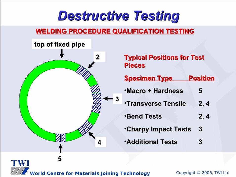
Hardness TestingHardness Testing
Hardness Test Methods Typical DesignationsHardness Test Methods Typical Designations
VickersVickers 240 HV10240 HV10
RockwellRockwell Rc 22Rc 22
BrinellBrinell 200 BHN-W200 BHN-W
usually the hardest regionusually the hardest region
1.5 to 3mm1.5 to 3mm
HAZHAZ
fusion line fusion line or or fusion fusion
boundaryboundary
Copyright © 2006, TWI LtdWorld Centre for Materials Joining Technology
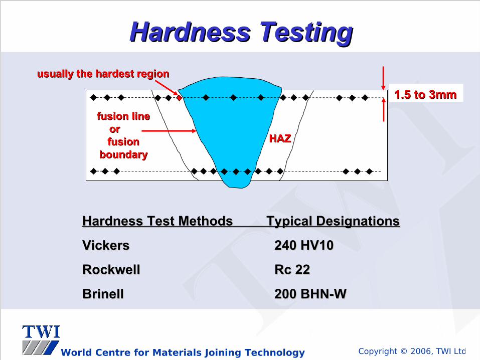
Vickers Hardness TestVickers Hardness Test
Typical location of the indentationsTypical location of the indentations
Butt weld from one side only
Butt weld from both side

Copyright © 2006, TWI LtdWorld Centre for Materials Joining Technology
Vickers hardness tests:
• indentation body is a square based diamond pyramid (136º included angle)
• the average diagonal (d) of the impression is converted to a hardness number from a table
• it is measured in HV5, HV10 or HV025Adjustable Adjustable shuttersshuttersIndentationIndentationDiamond Diamond
indentorindentor
Vickers Hardness TestVickers Hardness Test

Copyright © 2006, TWI LtdWorld Centre for Materials Joining Technology
Vickers Hardness Test MachineVickers Hardness Test Machine

Copyright © 2006, TWI LtdWorld Centre for Materials Joining Technology
• Hardened steel ball of given diameter is subjected for a given time to a given load
• Load divided by area of indentation gives Brinell hardness in kg/mm2
• More suitable for on site hardness testing
Brinell Hardness TestBrinell Hardness Test
30KN30KN
Ø=10mm steel ball

Copyright © 2006, TWI LtdWorld Centre for Materials Joining Technology
Rockwell Hardness TestRockwell Hardness Test
1KN1KN
Ø=1.6mm steel ball
Rockwell BRockwell B Rockwell CRockwell C
1.5KN1.5KN
120°Diamond Cone

Copyright © 2006, TWI LtdWorld Centre for Materials Joining Technology
Schlerescope Hardness TestSchlerescope Hardness Test
• dynamic and very portable hardness testdynamic and very portable hardness test
• accuracy depends on the the condition of the test/support accuracy depends on the the condition of the test/support surfaces and the support of the test piece during the testsurfaces and the support of the test piece during the test
• for more details, see ASTM E448for more details, see ASTM E448

Copyright © 2006, TWI LtdWorld Centre for Materials Joining Technology
Mechanical TestingMechanical Testing
Impact TestingImpact Testing

Copyright © 2006, TWI LtdWorld Centre for Materials Joining Technology
Charpy V-Notch Impact TestCharpy V-Notch Impact Test
Objectives:Objectives:• measuring impact strength in different weld joint areasmeasuring impact strength in different weld joint areas• assessing resistance toward brittle fractureassessing resistance toward brittle fracture
Information to be supplied on the test report:Information to be supplied on the test report:• Material typeMaterial type• Notch typeNotch type• Specimen sizeSpecimen size• Test temperatureTest temperature• Notch locationNotch location• Impact Strength ValueImpact Strength Value

Copyright © 2006, TWI LtdWorld Centre for Materials Joining Technology
Charpy V-Notch Impact Charpy V-Notch Impact TestTest
Specimen Pendulum(striker)
Anvil (support)

Copyright © 2006, TWI LtdWorld Centre for Materials Joining Technology
Charpy V-notch impact test specimenCharpy V-notch impact test specimen
Specimen dimensions according ASTM E23
ASTM: American Society of Testing MaterialsASTM: American Society of Testing Materials

Copyright © 2006, TWI LtdWorld Centre for Materials Joining Technology
10 mm10 mm8
mm
8 m
m2
mm
2 m
m22.522.5oo
Machined Machined notchnotch
100% Ductile100% DuctileMachined Machined
notchnotch
Large reduction Large reduction in area, shear in area, shear lipslips
Fracture surface Fracture surface 100% bright 100% bright crystalline brittle crystalline brittle fracturefracture
Randomly torn, Randomly torn, dull gray fracture dull gray fracture surfacesurface
Charpy Impact TestCharpy Impact Test
100% Brittle100% Brittle

Copyright © 2006, TWI LtdWorld Centre for Materials Joining Technology
- 50- 50 00- 20- 20 - 10- 10- 40- 40 - 30- 30
Ductile fractureDuctile fracture
Ductile/BrittleDuctile/Brittletransition transition pointpoint
47 Joules47 Joules
28 Joules28 Joules
Testing temperatureTesting temperature - Degrees Degrees CentigradeCentigrade
Temperature rangeTemperature range
Transition rangeTransition range
Brittle fractureBrittle fracture
Ductile / Brittle Transition Ductile / Brittle Transition CurveCurve
Three specimens are normally tested at each temperatureThree specimens are normally tested at each temperature
Energy absorbedEnergy absorbed

Copyright © 2006, TWI LtdWorld Centre for Materials Joining Technology
- 50- 50 00- 20- 20 - 10- 10- 40- 40 - 30- 30
Ductile fractureDuctile fracture
Ductile/BrittleDuctile/Brittletransition transition pointpoint
47 Joules47 Joules
28 Joules28 Joules
Testing temperatureTesting temperature - Degrees Degrees CentigradeCentigrade
Temperature rangeTemperature range
Transition rangeTransition range
Brittle fractureBrittle fracture
Ductile / Brittle Transition Ductile / Brittle Transition CurveCurve
Mn < 1.6 % increases Mn < 1.6 % increases toughness in steels*toughness in steels*
Three specimens are normally tested at each temperatureThree specimens are normally tested at each temperature
Energy absorbedEnergy absorbed

Copyright © 2006, TWI LtdWorld Centre for Materials Joining Technology
Impact Energy Joules
Room TemperatureRoom Temperature -20-20ooC TemperatureC Temperature
1.1. 197 Joules197 Joules
2.2. 191 191 JoulesJoules
3.3. 186 186 JoulesJoules
1.1. 49 49 JoulesJoules
2.2. 53 53 JoulesJoules
3.3. 51 51 JoulesJoules
Average =Average = 191 191 JoulesJoules Average =Average = 51 51 JoulesJoules
The test results show the specimens carried out at room The test results show the specimens carried out at room temperature absorb more energy than the specimens carried temperature absorb more energy than the specimens carried out at -20out at -20ooCC
Comparison Charpy Impact Test Comparison Charpy Impact Test ResultsResults

Copyright © 2006, TWI LtdWorld Centre for Materials Joining Technology
Charpy Impact TestCharpy Impact Test
Reporting resultsReporting results
• Location and orientation of notch Location and orientation of notch
• Testing temperatureTesting temperature
• Energy absorbed in joulesEnergy absorbed in joules
• Description of fracture (brittle or ductile)Description of fracture (brittle or ductile)
• Location of any defects presentLocation of any defects present
• Dimensions of specimenDimensions of specimen

Copyright © 2006, TWI LtdWorld Centre for Materials Joining Technology
Mechanical TestingMechanical Testing
Tensile TestingTensile Testing

Copyright © 2006, TWI LtdWorld Centre for Materials Joining Technology
Tensile TestingTensile Testing

Copyright © 2006, TWI LtdWorld Centre for Materials Joining Technology
UTS Tensile testUTS Tensile test

Copyright © 2006, TWI LtdWorld Centre for Materials Joining Technology
Tensile TestsTensile Tests
Different tensile tests:Different tensile tests:
• Transverse tensile.Transverse tensile.
• All-weld metal tensile testAll-weld metal tensile test
• Cruciform tensile testCruciform tensile test
• Short tensile test (through thickness test)Short tensile test (through thickness test)

Copyright © 2006, TWI LtdWorld Centre for Materials Joining Technology
All-Weld Metal Tensile All-Weld Metal Tensile SpecimenSpecimen
Transverse Tensile Transverse Tensile SpecimenSpecimen
Tensile TestTensile Test

Copyright © 2006, TWI LtdWorld Centre for Materials Joining Technology
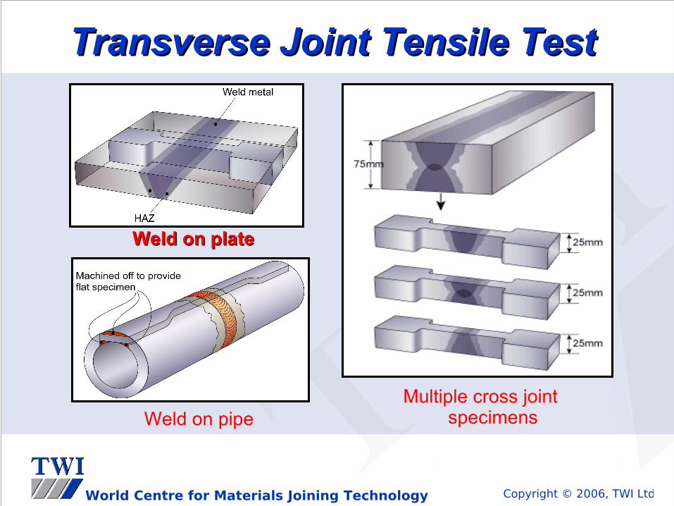
Transverse Joint Tensile TestTransverse Joint Tensile Test
Objective:Objective:
Measuring the overall strength of the weld jointMeasuring the overall strength of the weld joint
Information to be supplied on the test report:Information to be supplied on the test report:• material typematerial type• specimen typespecimen type• specimen size (see QW-462.1) specimen size (see QW-462.1) • UTSUTS• location of final rupturelocation of final rupture
Copyright © 2006, TWI LtdWorld Centre for Materials Joining Technology
Transverse Joint Tensile Test Transverse Joint Tensile Test
Weld on plateWeld on plate
Multiple cross joint specimensWeld on pipe

Copyright © 2006, TWI LtdWorld Centre for Materials Joining Technology
Maximum load applied = 220 kN.Maximum load applied = 220 kN.
Least cross sectional area = 25 mm X 12 mmLeast cross sectional area = 25 mm X 12 mm
UTS = UTS = Maximum load appliedMaximum load applied Least c.s.a.Least c.s.a.
UTS = UTS = 220 000 220 000 25mm X 12mm25mm X 12mm
UTS = 733.33 N/mmUTS = 733.33 N/mm22
Transverse Tensile TestTransverse Tensile Test

Copyright © 2006, TWI LtdWorld Centre for Materials Joining Technology
Reporting results:
• Type of specimen e.g. reduced section
• Whether weld reinforcement is removed
• Dimensions of test specimen
• The ultimate tensile strength in N/mm2, p.s.i or Mpa
• Location of fracture.
• Location and type of any flaws present if any
Transverse Tensile TestTransverse Tensile Test

Copyright © 2006, TWI LtdWorld Centre for Materials Joining Technology
Tensile test piece cut along weld specimen.Tensile test piece cut along weld specimen.
Direction of the test *Direction of the test *
BS 709 / BS EN 10002BS 709 / BS EN 10002
All Weld Metal Tensile TestingAll Weld Metal Tensile Testing
All Weld Metal Tensile TestAll Weld Metal Tensile Test

Copyright © 2006, TWI LtdWorld Centre for Materials Joining Technology
Gauge lengthGauge length
Increased gauge length Increased gauge length
Object of test:Object of test:
Ultimate tensile strength.Ultimate tensile strength.
Yield strength.Yield strength.
Elongation %(ductility).Elongation %(ductility).
All-Weld Metal Tensile TestAll-Weld Metal Tensile Test

Copyright © 2006, TWI LtdWorld Centre for Materials Joining Technology
2 marks are made2 marks are made
During the test, Yield & Tensile strength are recordedDuring the test, Yield & Tensile strength are recorded
The specimen is joined and the marks are re-measuredThe specimen is joined and the marks are re-measured
A measurement of 75mm will give Elongation of 50 %A measurement of 75mm will give Elongation of 50 %
All-Weld Metal Tensile TestAll-Weld Metal Tensile Test
Gauge length 50mmGauge length 50mm
Increased gauge length 75mm Increased gauge length 75mm
Copyright © 2006, TWI LtdWorld Centre for Materials Joining Technology
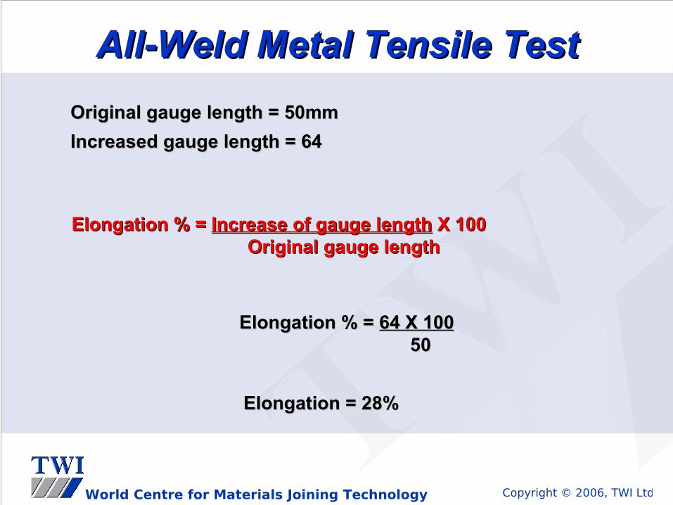
Original gauge length = 50mmOriginal gauge length = 50mm
Increased gauge length = 64Increased gauge length = 64
Elongation % = Elongation % = Increase of gauge lengthIncrease of gauge length X 100 X 100 Original gauge lengthOriginal gauge length
Elongation % = Elongation % = 64 X 10064 X 100 5050
Elongation = 28%Elongation = 28%
All-Weld Metal Tensile TestAll-Weld Metal Tensile Test

Copyright © 2006, TWI LtdWorld Centre for Materials Joining Technology
All-Weld Metal Tensile TestAll-Weld Metal Tensile TestReporting results:Reporting results:
• Type of specimen e.g. reduced section Type of specimen e.g. reduced section
• Dimensions of test specimenDimensions of test specimen
• The u.t.s, yield strength in N/mmThe u.t.s, yield strength in N/mm22, p.s.i or Mpa, p.s.i or Mpa
• Elongation %Elongation %
• Location and type of any flaws present if anyLocation and type of any flaws present if any

Copyright © 2006, TWI LtdWorld Centre for Materials Joining Technology
STRA (Short Transverse Reduction Area)STRA (Short Transverse Reduction Area)

Copyright © 2006, TWI LtdWorld Centre for Materials Joining Technology
STRA testSTRA test
Original CSA
Reduced CSA

Copyright © 2006, TWI LtdWorld Centre for Materials Joining Technology
STRA testSTRA test
20
15
10
STRA % Reduction of CSA

Copyright © 2006, TWI LtdWorld Centre for Materials Joining Technology
Mechanical TestingMechanical Testing
Macro / Micro ExaminationMacro / Micro Examination

Copyright © 2006, TWI LtdWorld Centre for Materials Joining Technology
Macro PreparationMacro PreparationPurposePurpose
To examine the weld cross-section to give assurance that: -To examine the weld cross-section to give assurance that: -
• The weld has been made in accordance with the WPSThe weld has been made in accordance with the WPS
• The weld is free from defectsThe weld is free from defects
Specimen PreparationSpecimen Preparation
• Full thickness slice taken from the weld Full thickness slice taken from the weld (typically ~10mm thick)(typically ~10mm thick)
• Width of slice sufficient to show all the weld and HAZ on both sides Width of slice sufficient to show all the weld and HAZ on both sides plus some unaffected base materialplus some unaffected base material
• One face ground to a progressively fine finish One face ground to a progressively fine finish (grit sizes 120 to ~ 400)(grit sizes 120 to ~ 400)
• Prepared face heavily etched to show all weld runs & all HAZPrepared face heavily etched to show all weld runs & all HAZ
• Prepared face examined at up to x10 Prepared face examined at up to x10 (& usually photographed for records)(& usually photographed for records)
• Prepared face may also be used for a hardness surveyPrepared face may also be used for a hardness survey

Copyright © 2006, TWI LtdWorld Centre for Materials Joining Technology
Micro PreparationMicro PreparationPurposePurpose
To examine a particular region of the weld or HAZ in order to:-To examine a particular region of the weld or HAZ in order to:-
• To examine the microstructureTo examine the microstructure
• Identify the nature of a crack or other imperfectionIdentify the nature of a crack or other imperfection
Specimen PreparationSpecimen Preparation
• A small piece is cut from the region of interestA small piece is cut from the region of interest (typically up to ~ 20mm x 20mm)(typically up to ~ 20mm x 20mm)
• The piece is mounted in plastic mould and the surface of interest The piece is mounted in plastic mould and the surface of interest prepared by progressive grinding (to grit size 600 or 800)prepared by progressive grinding (to grit size 600 or 800)
• Surface polished on diamond impregnated cloths to a mirror finishSurface polished on diamond impregnated cloths to a mirror finish
• Prepared face may be examined in as-polished condition & then lightly Prepared face may be examined in as-polished condition & then lightly etchedetched
• Prepared face examined under the microscope at up to ~ x 600Prepared face examined under the microscope at up to ~ x 600

Copyright © 2006, TWI LtdWorld Centre for Materials Joining Technology
Macro / Micro ExaminationMacro / Micro ExaminationObject:Object:
• Macro / microscopic examinations are used to give a visual Macro / microscopic examinations are used to give a visual evaluation of a cross-section of a welded joint evaluation of a cross-section of a welded joint
• Carried out on full thickness specimensCarried out on full thickness specimens
• The width of the specimen should include HAZ, weld and The width of the specimen should include HAZ, weld and parent plateparent plate
• They maybe cut from a stop/start area on a welders approval They maybe cut from a stop/start area on a welders approval testtest
Copyright © 2006, TWI LtdWorld Centre for Materials Joining Technology
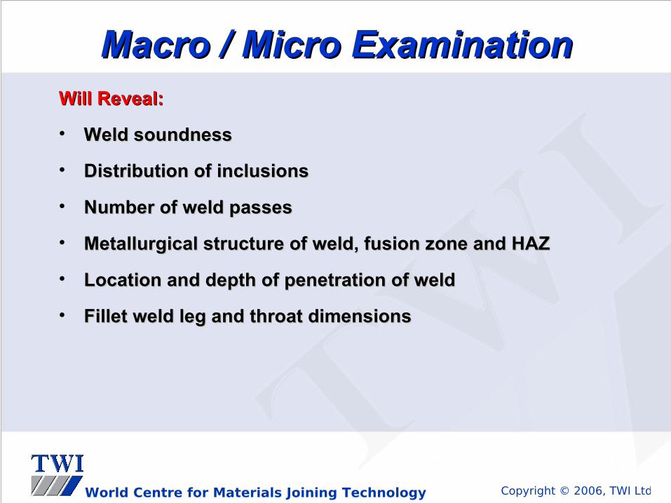
Macro / Micro ExaminationMacro / Micro ExaminationWillWill Reveal:Reveal:
• Weld soundnessWeld soundness
• Distribution of inclusionsDistribution of inclusions
• Number of weld passesNumber of weld passes
• Metallurgical structure of weld, fusion zone and HAZMetallurgical structure of weld, fusion zone and HAZ
• Location and depth of penetration of weldLocation and depth of penetration of weld
• Fillet weld leg and throat dimensionsFillet weld leg and throat dimensions
Copyright © 2006, TWI LtdWorld Centre for Materials Joining Technology
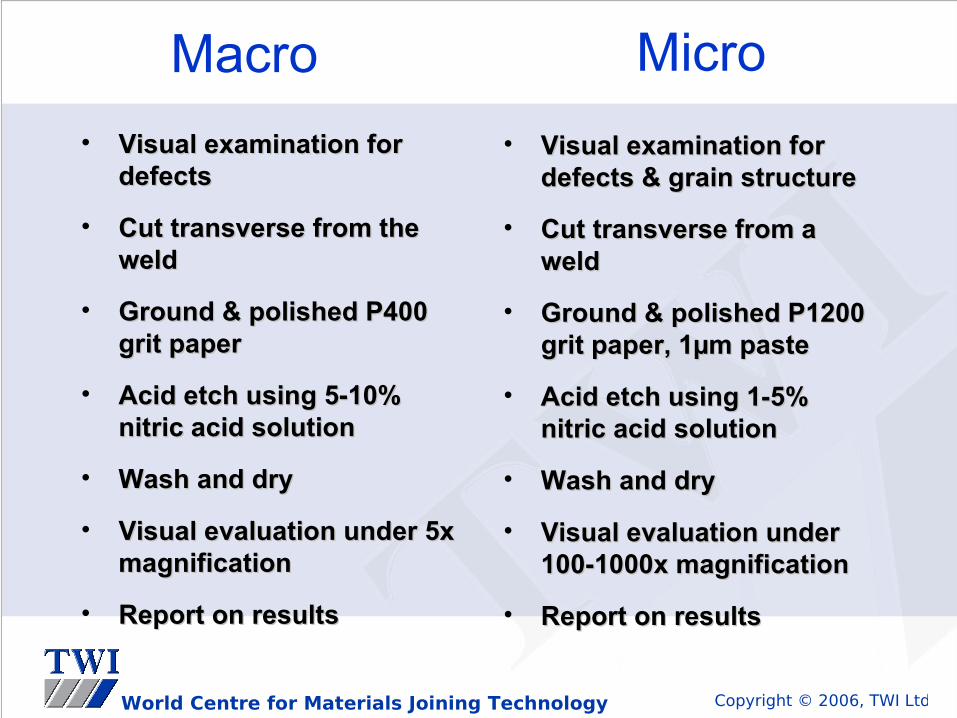
• Visual examination for Visual examination for defectsdefects
• Cut transverse from the Cut transverse from the weldweld
• Ground & polished P400 Ground & polished P400 grit papergrit paper
• Acid etch using 5-10% Acid etch using 5-10% nitric acid solutionnitric acid solution
• Wash and dryWash and dry
• Visual evaluation under 5x Visual evaluation under 5x magnificationmagnification
• Report on resultsReport on results
• Visual examination for Visual examination for defects & grain structuredefects & grain structure
• Cut transverse from a Cut transverse from a weldweld
• Ground & polished P1200 Ground & polished P1200 grit paper, 1µm pastegrit paper, 1µm paste
• Acid etch using 1-5% Acid etch using 1-5% nitric acid solutionnitric acid solution
• Wash and dryWash and dry
• Visual evaluation under Visual evaluation under 100-1000x magnification100-1000x magnification
• Report on resultsReport on results
Macro Micro

Copyright © 2006, TWI LtdWorld Centre for Materials Joining Technology
Metallographic ExaminationMetallographic Examination
Macro examinationMacro examination Micro examinationMicro examination

Copyright © 2006, TWI LtdWorld Centre for Materials Joining Technology
Metallographic Metallographic examinationexamination
Objectives:Objectives:
• detecting weld defects (macro)detecting weld defects (macro)
• measuring grain size (micro)measuring grain size (micro)
• detecting brittle structures, precipitates, etcdetecting brittle structures, precipitates, etc
• assessing resistance toward brittle fracture, cold cracking assessing resistance toward brittle fracture, cold cracking and corrosion sensitivityand corrosion sensitivity
Information to be supplied on the test report:Information to be supplied on the test report:
• material typematerial type
• etching solutionetching solution
• magnificationmagnification
• grain sizegrain size
• location of examined arealocation of examined area
• weld imperfections (macro)weld imperfections (macro)
• phase, constituents, precipitates (micro)phase, constituents, precipitates (micro)

Copyright © 2006, TWI LtdWorld Centre for Materials Joining Technology
Mechanical TestingMechanical Testing
Bend TestingBend Testing

Copyright © 2006, TWI LtdWorld Centre for Materials Joining Technology
Object of test:
• To determine the soundness of the weld zone. Bend testing can also be used to give an assessment of weld zone ductility.
There are three ways to perform a bend test:
Root bendRoot bend
Face bendFace bend
Side bendSide bend
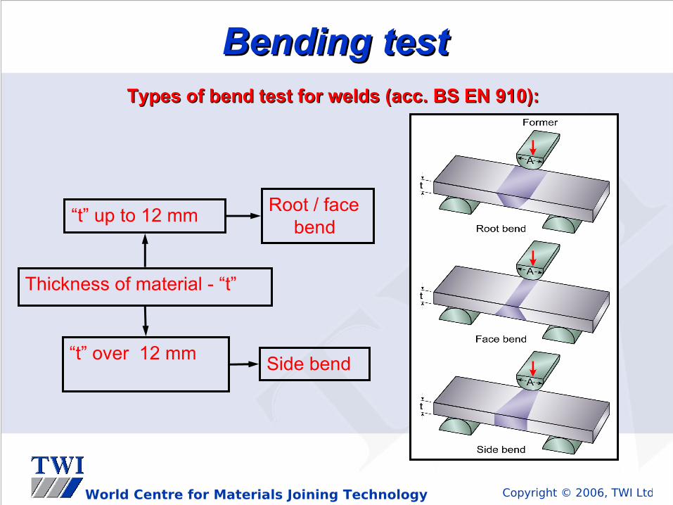
Side bend tests are normally carried out on welds over 12mm Side bend tests are normally carried out on welds over 12mm in thicknessin thickness
Bend TestsBend Tests
Copyright © 2006, TWI LtdWorld Centre for Materials Joining Technology
Bending testBending testTypes of bend test for welds (acc. BS EN 910):Types of bend test for welds (acc. BS EN 910):
Thickness of material - “t”
“t” up to 12 mm
“t” over 12 mm
Root / face bend
Side bend
Copyright © 2006, TWI LtdWorld Centre for Materials Joining Technology
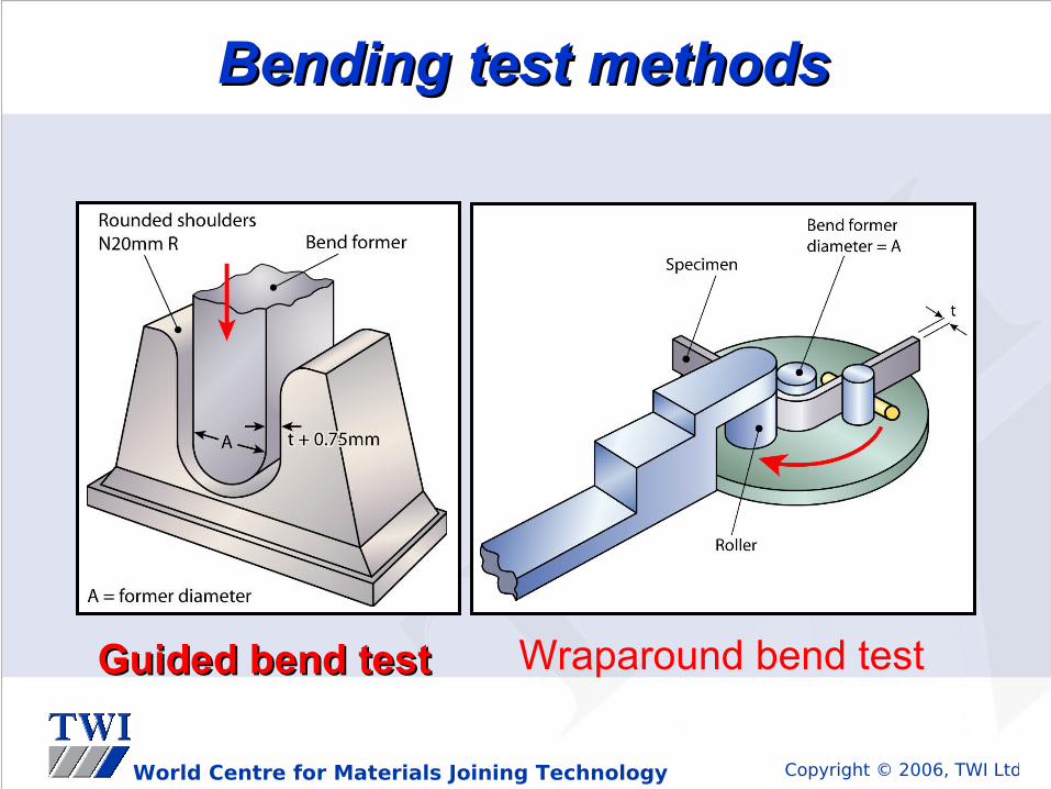
Bending test methodsBending test methods
Guided bend testGuided bend test Wraparound bend test

Copyright © 2006, TWI LtdWorld Centre for Materials Joining Technology
Defect Defect indicationindicationGenerally this Generally this specimen specimen would be would be unacceptable unacceptable
Face bendFace bendSide bendSide bend
Root bendRoot bend
Acceptance forAcceptance forminor ruptures on minor ruptures on tension surfacetension surfacedepends upon code depends upon code requirements requirements
Bend TestingBend Testing

Copyright © 2006, TWI LtdWorld Centre for Materials Joining Technology
Bend TestsBend Tests
Reporting results: Reporting results:
• Thickness and dimensions of specimenThickness and dimensions of specimen
• Direction of bend (root, face or side)Direction of bend (root, face or side)
• Angle of bend (90Angle of bend (90oo, 120, 120oo, 180, 180oo))
• Diameter of former. (typical 4T)Diameter of former. (typical 4T)
• Appearance of joint after bending e.g. type and location of Appearance of joint after bending e.g. type and location of any flaws.any flaws.

Copyright © 2006, TWI LtdWorld Centre for Materials Joining Technology
Mechanical TestingMechanical Testing
Fillet Weld Fracture TestingFillet Weld Fracture Testing

Copyright © 2006, TWI LtdWorld Centre for Materials Joining Technology
Fillet Weld Fracture TestsFillet Weld Fracture TestsObject of test:Object of test:
• To break open the joint through the weld to permit examination To break open the joint through the weld to permit examination of the fracture surfacesof the fracture surfaces
• Specimens are cut to the required lengthSpecimens are cut to the required length
• A saw cut approximately 2mm in depth is A saw cut approximately 2mm in depth is applied along the applied along the fillet welds lengthfillet welds length
• Fracture is usually made by striking the specimen with a single Fracture is usually made by striking the specimen with a single hammer blowhammer blow
• Visual inspection for defectsVisual inspection for defects

Copyright © 2006, TWI LtdWorld Centre for Materials Joining Technology
Fracture should break weld saw cut to root Fracture should break weld saw cut to root
2mm 2mm NotchNotch
HammerHammer
Fillet Weld Fracture TestsFillet Weld Fracture Tests
Copyright © 2006, TWI LtdWorld Centre for Materials Joining Technology
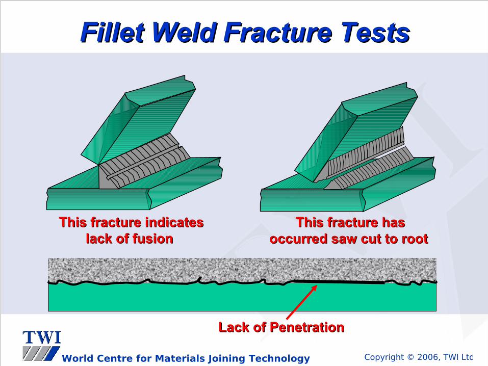
This fracture indicates This fracture indicates lack of fusion lack of fusion
This fracture has This fracture has occurred saw cut to root occurred saw cut to root
Fillet Weld Fracture TestsFillet Weld Fracture Tests
Lack of PenetrationLack of Penetration

Copyright © 2006, TWI LtdWorld Centre for Materials Joining Technology
Fillet Weld Fracture TestsFillet Weld Fracture TestsReporting results:Reporting results:
• Thickness of parent material Thickness of parent material
• Throat thickness and leg lengthsThroat thickness and leg lengths
• Location of fractureLocation of fracture
• Appearance of joint after fractureAppearance of joint after fracture
• Depth of penetrationDepth of penetration
• Defects present on fracture surfacesDefects present on fracture surfaces
Copyright © 2006, TWI LtdWorld Centre for Materials Joining Technology
Mechanical TestingMechanical Testing
Nick-Break TestingNick-Break Testing

Copyright © 2006, TWI LtdWorld Centre for Materials Joining Technology
Nick-Break TestNick-Break Test
Object of test:Object of test:
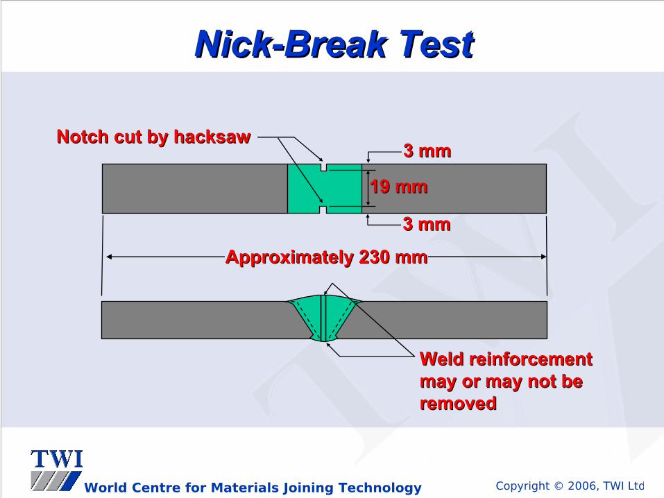
• To permit evaluation of any weld defects across the fracture To permit evaluation of any weld defects across the fracture surface of a butt weld.surface of a butt weld.
• Specimens are cut transverse to the weldSpecimens are cut transverse to the weld
• A saw cut approximately 2mm in depth is applied along the A saw cut approximately 2mm in depth is applied along the welds root and capwelds root and cap
• Fracture is usually made by striking the specimen with a Fracture is usually made by striking the specimen with a single hammer blowsingle hammer blow
• Visual inspection for defectsVisual inspection for defects
Copyright © 2006, TWI LtdWorld Centre for Materials Joining Technology
Approximately 230 mmApproximately 230 mm
19 mm19 mm
3 mm3 mm
3 mm3 mm
Notch cut by hacksawNotch cut by hacksaw
Weld reinforcement Weld reinforcement may or may not be may or may not be removedremoved
Nick-Break TestNick-Break Test

Copyright © 2006, TWI LtdWorld Centre for Materials Joining Technology
Nick Break TestNick Break Test
Inclusions on fracture Inclusions on fracture lineline
Lack of root penetration Lack of root penetration or fusionor fusion
Alternative nick-break test Alternative nick-break test specimen, notch applied all specimen, notch applied all way around the specimen way around the specimen

Copyright © 2006, TWI LtdWorld Centre for Materials Joining Technology
Nick-Break TestNick-Break TestReporting results: Reporting results:
• Thickness of parent material Thickness of parent material
• Width of specimenWidth of specimen
• Location of fractureLocation of fracture
• Appearance of joint after fractureAppearance of joint after fracture
• Depth of penetrationDepth of penetration
• Defects present on fracture surfacesDefects present on fracture surfaces

Copyright © 2006, TWI LtdWorld Centre for Materials Joining Technology
We test welds to establish minimum levels of mechanical properties, and soundness of the welded joint
We divide tests into Qualitative & Quantitative methods:
Qualitative: (Have no units)
Macro tests
Bend tests
Fillet weld fracture tests
Butt Nick break tests
Quantitative: (Have units)
Hardness (VPN & BHN)
Toughness (Joules & ft.lbs)
Strength (N/mm2 & PSI, MPa)
Ductility / Elongation (E%)
Summary of Mechanical TestingSummary of Mechanical Testing

Copyright © 2006, TWI LtdWorld Centre for Materials Joining Technology
Hydrostatic testHydrostatic test
Is an under pressure leakage proof test
Vessel configuration:
• the test should be done after any stress relief
• components that will not stand the pressure test (e.g. flexible pipes, diaphragms) must be removed
• the ambient temperature MUST be above 0°C (preferably 15÷20°C)

Copyright © 2006, TWI LtdWorld Centre for Materials Joining Technology
Hydrostatic TestHydrostatic Test
Test procedure: • blank off all openings with solid flanges• use correct nuts and bolts, NOT “G” clamps• two pressure gauges on independent tapping points should be
used• for safety purposes bleed all the air out• pumping should be done slowly (no dynamic pressure stresses)• test pressure - see relevant standards (PD 5500, ASME VIII).
Usually 150% design pressure• hold the pressure for minimum 30 minutes

Copyright © 2006, TWI LtdWorld Centre for Materials Joining Technology
Hydrostatic test Hydrostatic test What to look for:
• leaks (check particularly around seams and nozzle welds!)
• dry off any condensation with a compressed air-line
• watch the gauges for pressure drop
• check for distortion of flange faces, etc

Copyright © 2006, TWI LtdWorld Centre for Materials Joining Technology
Any QuestionsAny Questions
??Mechanical TestingMechanical Testing

Copyright © 2006, TWI LtdWorld Centre for Materials Joining Technology
QuestionsQuestionsMechanical TestingMechanical Testing
QU 1.QU 1. What mechanical properties can be measured in the all-What mechanical properties can be measured in the all-weld metal tensile testweld metal tensile test
QU 2.QU 2. What is the purpose of a charpy V-notch test and what What is the purpose of a charpy V-notch test and what units are the test results give in.units are the test results give in.
QU 3.QU 3. Give a brief description of the following testsGive a brief description of the following tests
a.a. Bend testBend test
b.b. Nick-break testNick-break test
c.c. Macro.Macro.
QU 4.QU 4. From a transverse tensile test the following information is From a transverse tensile test the following information is known, calculate the ultimate tensile strengthknown, calculate the ultimate tensile strength
Maximum load applied 235 KNMaximum load applied 235 KN
Least cross sectional area 25.20mm x 17.52mmLeast cross sectional area 25.20mm x 17.52mm

Copyright © 2006, TWI LtdWorld Centre for Materials Joining Technology
WELDING TECHNOLOGYWELDING TECHNOLOGY
QuestionQuestionHow are the mechanical properties of Carbon & Carbon-How are the mechanical properties of Carbon & Carbon-Manganese steel weld joints influenced by the welding parameters Manganese steel weld joints influenced by the welding parameters used - current, voltage & travel speed ?used - current, voltage & travel speed ?
(assuming that sound welds are produced)(assuming that sound welds are produced)
AnswerAnswerStrength Strength - does not change very much over a wide - does not change very much over a wide
range of welding conditions range of welding conditions
Toughness Toughness - high heat input tends to reduce toughness in - high heat input tends to reduce toughness in weld & HAZ weld & HAZ
Hardness Hardness - low heat input tends to increase HAZ hardness- low heat input tends to increase HAZ hardness
Copyright © 2006, TWI LtdWorld Centre for Materials Joining Technology
Welding TechnologyWelding Technology
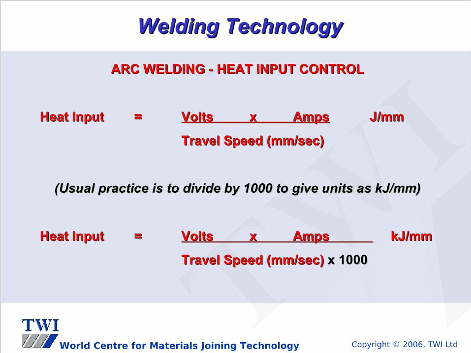
ARC WELDING - HEAT INPUT CONTROLARC WELDING - HEAT INPUT CONTROL
Heat InputHeat Input == Volts x AmpsVolts x Amps J/mmJ/mm
Travel Speed (mm/sec)Travel Speed (mm/sec)
(Usual practice is to divide by 1000 to give units as kJ/mm)(Usual practice is to divide by 1000 to give units as kJ/mm)
Heat InputHeat Input == Volts x Amps Volts x Amps kJ/mm kJ/mm
Travel Speed (mm/sec)Travel Speed (mm/sec) x 1000x 1000

Copyright © 2006, TWI LtdWorld Centre for Materials Joining Technology
Welding Positions Welding Positions (to EN Standards)(to EN Standards)
PA (flat)PA (flat)
PB (horiz.- vert.)PB (horiz.- vert.)
PE (overhead)PE (overhead)
PCPC
PDPDPF (vert.-up)PF (vert.-up)
PG (vert.- down)PG (vert.- down)

Copyright © 2006, TWI LtdWorld Centre for Materials Joining Technology
Welding Positions Welding Positions (to EN Standards)(to EN Standards)
45°45°
H-L045H-L045 vertical-up progressionvertical-up progression
J-L045J-L045 vertical-down progressionvertical-down progression

Copyright © 2006, TWI LtdWorld Centre for Materials Joining Technology
Welding PositionsWelding Positions
Question:Question:
How does welding position influence heat input ?How does welding position influence heat input ?
Answer:Answer:
• Highest heat input usually associated with vertical-up Highest heat input usually associated with vertical-up welding (PF or 3G with uphill progression) because of welding (PF or 3G with uphill progression) because of relatively low travel speedrelatively low travel speed
• Lowest heat input usually associated with vertical-down Lowest heat input usually associated with vertical-down welding (PG or 3G or 5G with downhill progression) because welding (PG or 3G or 5G with downhill progression) because of relatively high-speed travelof relatively high-speed travel

Copyright © 2006, TWI LtdWorld Centre for Materials Joining Technology
Welding TechnologyWelding Technology
THE HEAT AFFECTED ZONE (HAZ)THE HEAT AFFECTED ZONE (HAZ)
tempered zonetempered zone
grain growth zonegrain growth zone
recrystallised zonerecrystallised zone
partially transformed zonepartially transformed zone
Max
imu
m
Tem
pe r
atu
resolid-liquid transitionsolid-liquid transition zonezonesolid solid
weld weld metalmetal
unaffected basematerial

Copyright © 2006, TWI LtdWorld Centre for Materials Joining Technology
Welding TechnologyWelding Technology
High & Low Heat Input WeldingHigh & Low Heat Input Welding
High heat input - small number of large weld beadsHigh heat input - small number of large weld beads
large % of ‘as-cast’ large % of ‘as-cast’ microstructure in microstructure in
weld metalweld metal
wide HAZwide HAZ
Low heat input - large number of small weld beadsLow heat input - large number of small weld beads
large % of ‘refined’ large % of ‘refined’ microstructure in microstructure in
weld metalweld metal
narrow HAZnarrow HAZ

Copyright © 2006, TWI LtdWorld Centre for Materials Joining Technology
Welding TechnologyWelding Technology
design temperatureImpact Test TemperatureImpact Test Temperature
good toughnessgood toughnessin steel atin steel at
design temp.design temp.
Charpy V-Charpy V-notch notch
Toughness Toughness (Joules)(Joules)
unweldedfine grained
steel
Copyright © 2006, TWI LtdWorld Centre for Materials Joining Technology
Welding TechnologyWelding Technology
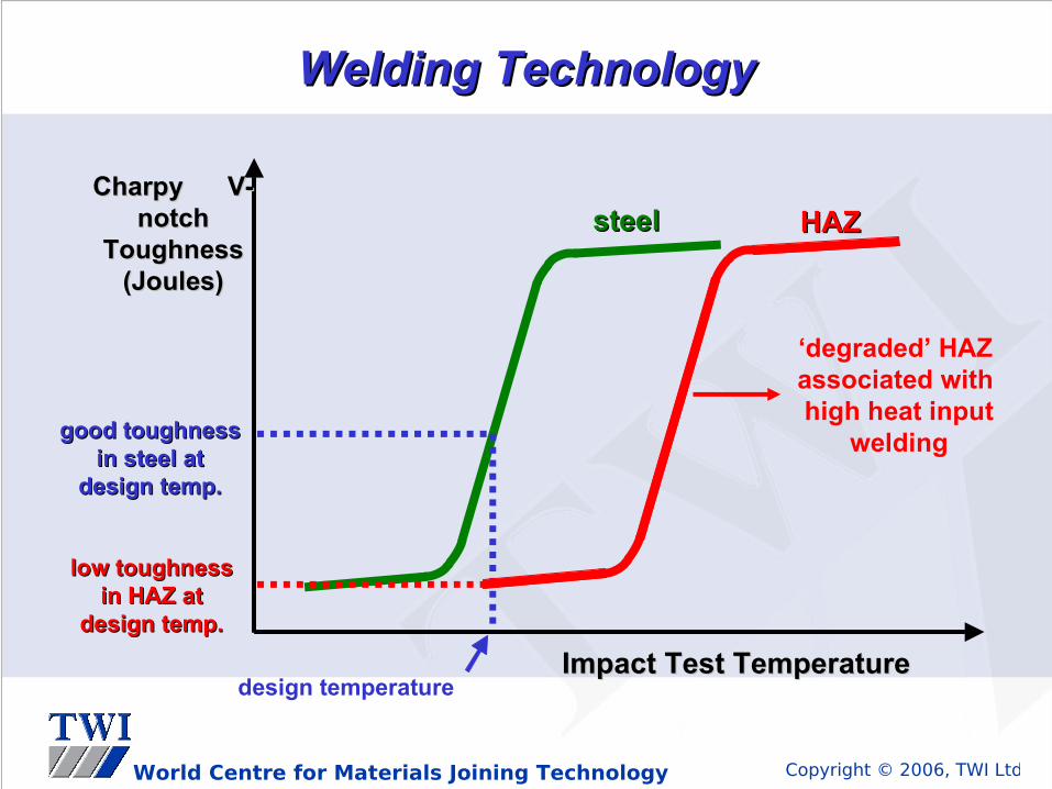
design temperatureImpact Test TemperatureImpact Test Temperature
good toughnessgood toughnessin steel atin steel at
design temp.design temp.
Charpy V-Charpy V-notch notch
Toughness Toughness (Joules)(Joules)
low toughnesslow toughnessin HAZ atin HAZ at
design temp.design temp.
‘degraded’ HAZassociated with high heat input
welding
steelsteel HAZHAZ

Copyright © 2006, TWI LtdWorld Centre for Materials Joining Technology
Welding TechnologyWelding Technology
HAZ HARDNESSHAZ HARDNESS
Cooling Rate of HAZ (°C / h)Cooling Rate of HAZ (°C / h)
HAZ HAZ HardnessHardness
Carbon-Manganese SteelsCarbon-Manganese Steels
high heat-input - high heat-input - lower hardnesslower hardness
low heat-input low heat-input higher hardnesshigher hardness
moderate heat input - moderate heat input - moderate hardnessmoderate hardness

Copyright © 2006, TWI LtdWorld Centre for Materials Joining Technology
Welding TechnologyWelding Technology
Low Alloy SteelsLow Alloy Steels(higher Cr-Mo types)(higher Cr-Mo types)
HAZ HARDNESSHAZ HARDNESS
Cooling Rate of HAZ (°C / h)Cooling Rate of HAZ (°C / h)
HAZ HAZ HardnessHardness
HAZ will harden even when HAZ will harden even when heat input is relatively highheat input is relatively high

Copyright © 2006, TWI LtdWorld Centre for Materials Joining Technology
Fracture MechanismsFracture Mechanisms

Copyright © 2006, TWI LtdWorld Centre for Materials Joining Technology
•Ductile Fracture
•Brittle Fracture
•Fatigue Fracture
In-Service FractureIn-Service Fracture

Copyright © 2006, TWI LtdWorld Centre for Materials Joining Technology
Fracture MechanismsFracture Mechanisms
Ductile FractureDuctile Fracture

Copyright © 2006, TWI LtdWorld Centre for Materials Joining Technology
Ductile FractureDuctile Fracture
Ductile (overload) fracture appears when yielding and Ductile (overload) fracture appears when yielding and deformation precedes failuredeformation precedes failure

Copyright © 2006, TWI LtdWorld Centre for Materials Joining Technology
• it is the result of overloadingit is the result of overloading
• evidence of gross yielding or plastic deformationevidence of gross yielding or plastic deformation
• the fracture surface is rough and tornthe fracture surface is rough and torn
• the surface shows 45° shear lips or have surfaces inclined the surface shows 45° shear lips or have surfaces inclined at 45° to the load direction (because maximum shear plane at 45° to the load direction (because maximum shear plane is at 45° to the load!)is at 45° to the load!)
Ductile FractureDuctile Fracture
Ductile fracture distinguish features:Ductile fracture distinguish features:

Copyright © 2006, TWI LtdWorld Centre for Materials Joining Technology
Fracture MechanismsFracture Mechanisms
Brittle FractureBrittle Fracture

Copyright © 2006, TWI LtdWorld Centre for Materials Joining Technology
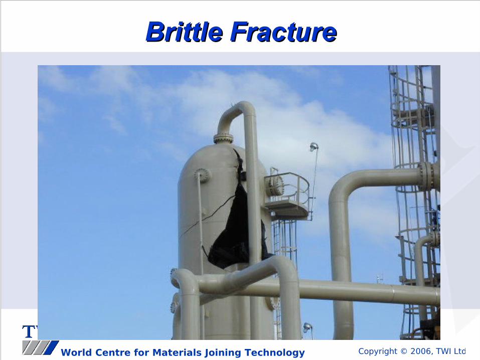
It is a fast, unstable type of fracture.It is a fast, unstable type of fracture.
Brittle FractureBrittle Fracture
Brittle fractureBrittle fracture

Copyright © 2006, TWI LtdWorld Centre for Materials Joining Technology
Brittle FractureBrittle Fracture
It is a fast, unstable type of fracture.It is a fast, unstable type of fracture.
Brittle fractureBrittle fracture
Copyright © 2006, TWI LtdWorld Centre for Materials Joining Technology
Brittle FractureBrittle Fracture

Copyright © 2006, TWI LtdWorld Centre for Materials Joining Technology
Brittle FractureBrittle Fracture

Copyright © 2006, TWI LtdWorld Centre for Materials Joining Technology
Brittle FractureBrittle Fracture

Copyright © 2006, TWI LtdWorld Centre for Materials Joining Technology
Effect of a notch on tensile ductilityEffect of a notch on tensile ductility
d d
A notch also adversely affect fatigue strength!
Courtesy of Douglas E. Williams, P.E., Welding Handbook, Vol.1,Ninth Edition,reprinted by permission of the American Welding Society
Brittle FractureBrittle Fracture

Copyright © 2006, TWI LtdWorld Centre for Materials Joining Technology
Brittle fracture distinguish features:Brittle fracture distinguish features:
• There is little or no plastic deformation before failureThere is little or no plastic deformation before failure
• The crack surface may show chevron marks pointing back The crack surface may show chevron marks pointing back to the initiation pointto the initiation point
• In case of impact fracture, the surface is rough but not torn In case of impact fracture, the surface is rough but not torn and will usually have a crystalline appearanceand will usually have a crystalline appearance
• The surface is normally perpendicular to the loadThe surface is normally perpendicular to the load
Brittle FractureBrittle Fracture

Copyright © 2006, TWI LtdWorld Centre for Materials Joining Technology
Brittle FractureBrittle FractureFactors affecting brittle fracture:
• Temperature (transition curve, convergence of YS and UTS as the temperature is reduced)
• Crystalline structure (b.c.c. vs. f.c.c.)
• Material toughness
• Residual stress
• Strain rate (YS increase but UTS remain constant)
• Material thickness (restrain due to surrounding material)
• Stress concentrations/weld defects
Copyright © 2006, TWI LtdWorld Centre for Materials Joining Technology
Brittle FractureBrittle Fracture
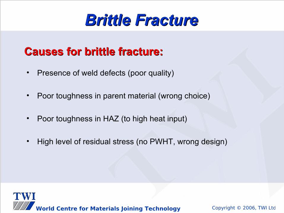
Causes for brittle fracture:Causes for brittle fracture:
• Presence of weld defects (poor quality)
• Poor toughness in parent material (wrong choice)
• Poor toughness in HAZ (to high heat input)
• High level of residual stress (no PWHT, wrong design)
Copyright © 2006, TWI LtdWorld Centre for Materials Joining Technology
Fracture MechanismsFracture Mechanisms
Fatigue FractureFatigue Fracture

Copyright © 2006, TWI LtdWorld Centre for Materials Joining Technology
Fatigue FractureFatigue FractureIf a material is subjected to a static load, final If a material is subjected to a static load, final rupture is preceded by very large strains.rupture is preceded by very large strains.
If the same material is subjected to cyclic loads, If the same material is subjected to cyclic loads, failure may occur:failure may occur:
• At stress well below elastic limitAt stress well below elastic limit
• With little or no plastic deformationWith little or no plastic deformation

Copyright © 2006, TWI LtdWorld Centre for Materials Joining Technology
Fatigue cracking at the Fatigue cracking at the weld toeweld toe
Fatigue FractureFatigue Fracture

Copyright © 2006, TWI LtdWorld Centre for Materials Joining Technology
Products liable to Fatigue Products liable to Fatigue FailureFailure
AerospaceAerospacePressure VesselsPressure Vessels
Piping systemsPiping systems Oil/Gas platformsOil/Gas platforms

Copyright © 2006, TWI LtdWorld Centre for Materials Joining Technology
Products liable to Fatigue Products liable to Fatigue FailureFailure
Lifting equipmentLifting equipment
Engineering plantEngineering plant
Overhead CranesOverhead Cranes
Rotating equipmentRotating equipment

Copyright © 2006, TWI LtdWorld Centre for Materials Joining Technology
Location: Location: Any stress concentration areaAny stress concentration area
Steel Type: Steel Type: All steel typesAll steel types
Susceptible Microstructure: Susceptible Microstructure: All grain structuresAll grain structures
Fatigue FractureFatigue Fracture

Copyright © 2006, TWI LtdWorld Centre for Materials Joining Technology
• Fatigue cracks occur under cyclic stress conditions
• Fracture normally occurs at a change in section, notch and weld defects i.e stress concentration area
• All materials are susceptible to fatigue cracking
• Fatigue cracking starts at a specific point referred to as a initiation point
• The fracture surface is smooth in appearance sometimes displaying beach markings
• The final mode of failure may be brittle or ductile or a combination of both
Fatigue FractureFatigue Fracture

Copyright © 2006, TWI LtdWorld Centre for Materials Joining Technology
• Toe grinding, profile grinding.
• The elimination of poor profiles
• The elimination of partial penetration welds and weld defects
• Operating conditions under the materials endurance limits
• The elimination of notch effects e.g. mechanical damage cap/root undercut
• The selection of the correct material for the service conditions of the component
Precautions against Fatigue Cracks
Fatigue FractureFatigue Fracture

Copyright © 2006, TWI LtdWorld Centre for Materials Joining Technology
Fatigue fracture occurs in structures subject to repeated Fatigue fracture occurs in structures subject to repeated application of tensile stress. application of tensile stress.
Crack growth is slow (in same cases, crack may grow into an Crack growth is slow (in same cases, crack may grow into an area of low stress and stop without failure).area of low stress and stop without failure).
Fatigue FractureFatigue Fracture

Copyright © 2006, TWI LtdWorld Centre for Materials Joining Technology
Initiation points / weld defectsInitiation points / weld defects
Fatigue fracture surface Fatigue fracture surface
smooth in appearancesmooth in appearanceSecondary mode of failure Secondary mode of failure ductile fracture rough fibrous ductile fracture rough fibrous appearance appearance
Fatigue FractureFatigue Fracture
Copyright © 2006, TWI LtdWorld Centre for Materials Joining Technology
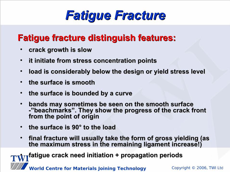
• crack growth is slowcrack growth is slow
• it initiate from stress concentration pointsit initiate from stress concentration points
• load is considerably below the design or yield stress level load is considerably below the design or yield stress level
• the surface is smooththe surface is smooth
• the surface is bounded by a curvethe surface is bounded by a curve
• bands may sometimes be seen on the smooth surface bands may sometimes be seen on the smooth surface -”beachmarks”. They show the progress of the crack front -”beachmarks”. They show the progress of the crack front from the point of originfrom the point of origin
• the surface is 90° to the loadthe surface is 90° to the load
• final fracture will usually take the form of gross yielding (as final fracture will usually take the form of gross yielding (as the maximum stress in the remaining ligament increase!)the maximum stress in the remaining ligament increase!)
• fatigue crack need initiation + propagation periodsfatigue crack need initiation + propagation periods
Fatigue FractureFatigue Fracture
Fatigue fracture distinguish features:Fatigue fracture distinguish features:
Copyright © 2006, TWI LtdWorld Centre for Materials Joining Technology
Fracture MechanismsFracture Mechanisms
Creep PhenomenonCreep Phenomenon

Copyright © 2006, TWI LtdWorld Centre for Materials Joining Technology
Creep is defined as a slow deformation under constant load at Creep is defined as a slow deformation under constant load at elevated temperatures.elevated temperatures.
Can occur in materials which are operated for extensive periods at Can occur in materials which are operated for extensive periods at high temperatures.high temperatures.
The reason for creep fracture is the flow (or plastic deformation) of The reason for creep fracture is the flow (or plastic deformation) of metals when held for long periods of time at stresses well bellow metals when held for long periods of time at stresses well bellow their normal yield strength.their normal yield strength.
Creep FailureCreep Failure
Creep fractureCreep fracture

Copyright © 2006, TWI LtdWorld Centre for Materials Joining Technology
Creep FailureCreep Failure
• Creep is a time-temperature dependant phenomenonCreep is a time-temperature dependant phenomenon
• Section under stress continue to deform even if the load is Section under stress continue to deform even if the load is maintained constantmaintained constant
• Creep is most likely when operating near the recrystallization Creep is most likely when operating near the recrystallization temperature of that materialtemperature of that material
• Usually appear in case of process plant equipment, due to Usually appear in case of process plant equipment, due to heating and cooling cyclesheating and cooling cycles
Creep failure distinguish features:Creep failure distinguish features:

Copyright © 2006, TWI LtdWorld Centre for Materials Joining Technology
Any QuestionsAny Questions
??