Embed Size (px)
Citation preview
2.3.7 Construction Documents — Drawings
2.3 Management of the Project2.3 Management of the Project
2.3.7 Construction Documents — Drawings
2.3.7
Canadian Handbook of
Practice for Architects
Canadian Handbook of
Practice for Architects

2.3.
7
Introduction
Purpose of Drawings
Planning the Production of Working Drawings
CAD Standards
Drawing Information
Organization of Drawings
Scales
List of Drawings, Numbering, and Sizes
Title Block
Notes, Symbols, and Dimensions
Coordination of Drawings
Revisions to the Drawings
Engineering Drawings
Structural Drawings
Mechanical and Electrical Drawings
Coordination of Engineering Drawings
Definitions
References
Appendix A – Digital Copyright and Architects
Licence Agreement
Copyright Notice
Disclaimer
Checklist: Internal Review of Drawings
Checklist: Life Safety Information to Include on Drawings
Checklist: Information to Include on Drawings for Small Part 9 Buildings
Chart: National Building Code Data Matrix

Construction Documents — Drawings Chapter 2.3.7 Volume 2
Canadian Handbook of Practice for Architects January 2009 �
Introduction
Construction documents include the drawings and specifications. These documents guide and direct the contractor and the sub-contractors in the preparation of their price or bid, and in carrying out their "work" on a project. For this reason, drawings are frequently called "working drawings." As part of the construction contract, the working drawings take on a legal significance for which architects must assume responsibility.
This chapter discusses the production of working drawings. Refer to Chapter 2.3.5, Schematic Design, and to Chapter 2.3.6, Design Development, for information about preliminary design drawings that are prepared prior to the working drawings. Chapter 2.3.8, Construction Documents — Specifications, discusses the specifications that accompany and complement working drawings.
Architects should obtain client approval of the design development documents before beginning the construction documents. A formal approval should be received in writing to ensure that the client understands the importance of this decision and the expense of producing the construction documents. The project architect should explain to the client that any changes requested while working drawings are being prepared will entail delays (and costs). Any type of change can have a "ripple" effect on a number of different drawings, including engineering working drawings.
Purpose of Drawings
Drawings are a means of communicating information in a two-dimensional format using lines, graphic symbols, and text. Buildings are sometimes designed and documented as three-dimensional models using Building Information Modeling (BIM) which can produce both two-
dimensional and three-dimensional drawings for construction purposes. Both types of drawings drawings describe the relationships between building components (sometimes referred to as building assemblies) and the following characteristics:
• location of the component;• name or identification;• size and dimension;• shape and form;• details or diagrams of connections
for the building assembly.
Many different individuals and organizations use drawings for a variety of purposes. The primary users are the contractor, sub-contractors, consultants, the client or owner, and the architect — the parties that are bound to one another to design or construct a building. Other users include:
• Authorities Having Jurisdiction;• product manufacturers and suppliers;• financial institutions;• tenants and end users of the building;• facility managers and maintenance personnel;• other construction industry professionals.
The working drawings are used by:
• bidders:• to prepare bids;• to obtain bids from their sub-contractors
and suppliers;
• selected contractor(s):• to form part of the documents
for a contract with the client;• to guide them in carrying out the work;
• Authorities Having Jurisdiction:• to verify that the project conforms
to existing regulations;• to plan for the provision of utilities
and services;
Construction Documents — Drawings
Volume 2 Chapter 2.3.7 Construction Documents — Drawings
2 January 2009 Canadian Handbook of Practice for Architects
• architects and other consultants:• to obtain bids or prices for construction
procurement;• to communicate project particulars to
clients in order to obtain approval;• to prepare “Class A” cost estimates;• to review the work on site and to
determine general conformity with the intent of the construction documents;
• clients:• to confirm that the project will meet
their particular requirements; • to approve this part of the bid package;• to form part of the documents for the
contract with the contractor.
Planning the Production of Working Drawings
The preparation of working drawings is the project phase that demands the most of the architect’s time and resources. It is essential to plan the production to ensure that proper, coordinated documents are produced within the budget of fees allocated for this purpose.
The project architect or project manager is usually the individual responsible for planning the production of working drawings. When scheduling the work, the project architect must consider:
• the available production budget;• the available human resources;• the firm’s physical resources and computer
systems (hardware and software);• the time frame for production of the working
drawings;• the resources available to the consultants.
The project architect must therefore:
• determine what drawings and information must be produced;
• calculate how much time is needed to produce each drawing;
• assign tasks;• set the project schedule;• manage and coordinate the work with
all team members.
The project architect in charge of producing the complete set of working drawings coordinates the work of the design team (engineers and other consultants). Usually management and coordination of engineers and other consultants is a part of the architect’s services and responsibilities; however, occasionally it is contracted to others.
At the start of the construction documents phase, the project architect should meet with the entire consultant team in order to agree on:
• the production schedule;• standards for preparing and presenting
the drawings;• protocols for the exchange of information
or electronic file transfer (if this has not already been agreed upon in a previous phase);
• financial arrangements for the reproduction and use of all drawings and other instruments of service;
• general coordination methods.
Using traditional two-dimensional drawings, the project architect should provide the team with basic floor plans so that each discipline can develop its own drawings. Engineers should regularly forward their drawings to the project architect to allow time for revision and coordination. Using Building Information Modeling (BIM), the architect must determine how to manage the data and whether to share the particular model, or, to provide two-dimensional CAD files to outside team members.
For smaller projects, the engineers may only produce notes and information which will be included on the architectural drawings. In these circumstances, it is necessary to clearly establish responsibility for the appropriate part of the design and arrange for engineers to append their seal and signature to the drawings.
The “Checklist for the Management of the Architectural Project” in Chapter 2.3.1, Management of the Project, can assist in planning the production of working drawings.
Construction Documents — Drawings Chapter 2.3.7 Volume 2
Canadian Handbook of Practice for Architects January 2009 3
CAD Standards
CAD (Computer-Aided Drawing) has replaced manual drafting as the primary method for producing working drawings.
Production techniques may vary within the same office, depending on the human and physical resources available and the nature of the project. Some clients require that drawings be prepared using certain standards.
Standards define the size and style of fonts, dimensions, lines, and hatching or other ways to represent materials. They also suggest various ways to create borders and title blocks, standard details, symbols, etc.
It is especially important to establish a standard system for naming and giving attributes to layers in order to facilitate the development of working drawings and make them user-friendly for consultants and others. Some clients will require electronic files of the working drawings (or record drawings) for the future management of their building. Therefore, architects must often use the client’s layering system or other drawing standards.
Some institutions, such as Public Works and Government Services Canada (PWGSC) and large health and educational institutions, have created their own drawing standards. It is important to obtain these standards at the start of the project.
It is important, at the start of the project, to establish protocols for the creation and transfer of electronic information.
The United States National CAD Standard is a consensus standard incorporating industry publications. It is comprised of interrelated standards, guidelines and tools for uniformly organizing and presenting drawing information. It is the only comprehensive standard for facility planning, design, construction and operation drawings. NCS v4.0 is comprised of the National Institute of Building Sciences' Foreword, Administration, and Plotting Guidelines modules, the American Institute of Architect's CAD Layer Guidelines module, and the Construction Specification Institute's Uniform Drawing System modules.
The UDS™ is a guideline which includes the following modules:
• Drawing Set Organization (numbering system and sequence for drawings, etc.);
• Sheet Organization (system for numbering drawings, details and organizing sheets);
• Schedules (format, heading terminology, and organization);
• Drafting Conventions;• Symbols;• Terms and Abbreviations;• Layers (see note below);• Notations;• Code Conventions (probably not relevant
to Canada).
The Uniform Drawing System™ has adopted the AIA CAD Layer Guidelines which were originally developed and published by the AIA.
Building Information Modeling or BIM
Many architecture practices in Canada have implemented BIM or are considering this fundamental change in the way building designs are conceived, completed and delivered.
BIM is “the creation and use of coordinated, consistent, computable information about a building project in design that yields reliable digital representations of the building – representations used for design decision-making, production of high-quality construction documents, performance predictions, cost-estimating and construction planning, and, eventually, for managing and operating the facility.”
While BIM’s benefits may be numerous, many architectural practices are cautious about the amount of time and financial investment required to change from current practices.
Some of the possible advantages of switching from 2D CAD to BIM include:
• BIM works the way some designers think by using the common language of building elements (wall, door, floor, etc.);
• Document coordination may be enhanced and simplified. A single building information model allows consistent and coordinated views and details to be selected easily for sheet layout and printing;
Volume 2 Chapter 2.3.7 Construction Documents — Drawings
� January 2009 Canadian Handbook of Practice for Architects
• 3D visualization can assist the entire project team in understanding the building form, and identifying challenges and opportunities in the design. Clients and lay people appreciate the visual imagery of 3D modeling and increasingly expect it. BIM software allows for visual output, ranging from simple grey scale 3D representations, cut-away 3D sections, to photorealistic renderings from a single building information model without the need for specialized software or skills;
• Collaboration with other architects, designers and consultants may be simplified with the interoperable platform of BIM software;
• BIM models can be exported to common two-dimensional drawing formats (such as .dwg or .dxf), and to spreadsheets to create schedules (invaluable for costing, material take-offs, etc.)
In addition, Building Information Models have great potential for expanding architectural practice through their various embedded analysis tools. As sustainable design becomes fundamental to many architects, the ability of BIM to embed energy modeling within the program or to export data to similar analysis programs becomes an advantage over traditional 2D or 3D software programs. Similarly, the parametric qualities of BIM objects allow designers to quickly do quantity take-offs for costing; areas for leasing and functional programming, and to create custom schedules for virtually all building components including doors, equipment, millwork and finishes. There is an emerging potential for Building Information Models to be used for facilities management and therefore an opportunity for architectural firms to diversify their services.
Building Information Modeling does present unique challenges for the profession including the development of new internal office protocols; the "ownership" of the model; and the need for new forms of agreement.
Drawing Information
The amount and type of information that must be provided on the working drawings are a function of:
• the complexity of the project;• the type of construction project delivery,
including the bid and type of construction contract.
When the project involves restoration, renovation or an addition to an existing building, drawings should clearly indicate the limits of the work, existing elements, and conditions prevailing at the junction of existing and new construction components.
The form of project delivery has an impact on the working drawings.
For projects involving a public bid call or using a project delivery method with a stipulated price contract, drawings should be complete and comprehensively detailed to avoid requests for contract changes by the contractor (whose identity is not known when the drawings are prepared). If, on the other hand, the contractor has already been chosen and has previously worked on similar projects with the architect and the client, the drawings may not have to be so detailed. With some forms of contract and project delivery methods, construction documents may be supplied as the work progresses.
When the project is being carried out as a construction management contract and is divided into separate bid packages, with a bid call for each, there may be several deadlines for the production of working drawings. In such cases, timely and thorough coordination of all documents is essential to avoid overlapping or conflicting requirements. Bid packages, including the working drawings, should correspond to clearly defined and self-contained elements, such as:
• Bid Package No. 1 — Demolition;• Bid Package No. 2 — Excavation, Foundation,
and Structural Framing;• Bid Package No. 3 — Building Envelope
and Mechanical and Electrical Services;• Bid Package No. 4 — Interior Finishes.
On a project involving the use of new or unusual construction procedures, the drawings should furnish the corresponding details.
In all cases, the final set of working drawings, together with the Project Manual (Specifications, Contract Forms and Contract Conditions, and
Construction Documents — Drawings Chapter 2.3.7 Volume 2
Canadian Handbook of Practice for Architects January 2009 �
Bidding Information), should provide sufficient information needed to:
• prepare bids or accurate construction cost estimates (quantity and type of materials and their application);
• obtain the building permit and other approvals from Authorities Having Jurisdiction;
• construct the project.
Organization of Drawings
To produce working drawings, one must first create a list of information required, including a preliminary list of drawings. Drawings and documents prepared during the design development phase may be used to determine which construction details must be drawn. This list also enables the project architect to ascertain which elements require additional research or information from the client or consultants. The format of all drawings, including those of the engineers and consultants, should be consistent.
Refer also to the CSA Standard B78.3-M1977 (R1991), Building Drawings, for information on preparing drawings.
Scales
In the past, it was necessary to determine and decide on a scale for each working drawing. Today, most computer software is not scale-dependent; however, it is important to determine the scale for any hard (paper) copy. Generally speaking, the smallest scale in which information can be clearly presented is chosen. Hard copies that are reduced for distribution must still be legible. A graphic scale should be indicated on these documents.
List of Drawings, Numbering, and Sizes
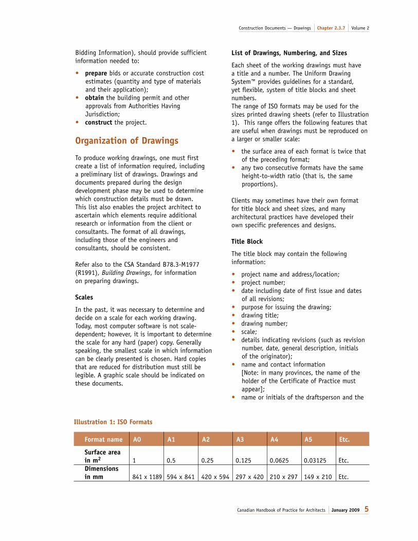
Each sheet of the working drawings must have a title and a number. The Uniform Drawing System™ provides guidelines for a standard, yet flexible, system of title blocks and sheet numbers.The range of ISO formats may be used for the sizes printed drawing sheets (refer to Illustration 1). This range offers the following features that are useful when drawings must be reproduced on a larger or smaller scale:
• the surface area of each format is twice that of the preceding format;
• any two consecutive formats have the same height-to-width ratio (that is, the same proportions).
Clients may sometimes have their own format for title block and sheet sizes, and many architectural practices have developed their own specific preferences and designs.
Title Block
The title block may contain the following information:
• project name and address/location;• project number;• date including date of first issue and dates
of all revisions;• purpose for issuing the drawing;• drawing title;• drawing number;• scale;• details indicating revisions (such as revision
number, date, general description, initials of the originator);
• name and contact information [Note: in many provinces, the name of the
holder of the Certificate of Practice must appear];
• name or initials of the draftsperson and the
Format name A0 A� A2 A3 A� A� Etc.
Surface area in m2 1 0.5 0.25 0.125 0.0625 0.03125 Etc. Dimensions in mm 841 x 1189 594 x 841 420 x 594 297 x 420 210 x 297 149 x 210 Etc.
Illustration �: ISO Formats
Volume 2 Chapter 2.3.7 Construction Documents — Drawings
� January 2009 Canadian Handbook of Practice for Architects
individual checking the drawing;• a location for applying the professional seal
and signature.[Note: refer to the regulations of the provincial associations of architects for regulations on applying the professional seal. See also the chart, “Comparison of Provincial Requirements/Guidelines regarding the Application of Seals,” in Chapter 1.1.5, The Organization of the Profession in Canada.]
Usually, the drawing (either in the title block or elsewhere) includes the following information:
• key plan, indicating the relationship of partial plans to the overall plan, orientation, etc.;
• the electronic file name; • dates and notations indicating the purpose
for issuing the drawing (such as “Issued for Bid” and “Not for Construction”);
• notice of copyright.
Refer to Appendix A of this chapter for more information on copyright.
Refer also to Section 5.2, “Drawing Notations”, in Chapter 2.4, Sample Forms for the Management of the Project.
Depending on the type of project and the contractual arrangement with the consultants, as well as the requirements of the professional liability insurer, the title block includes the name, address, telephone, and fax numbers of engineers or other consultants. Also, the architect should confirm the requirements of the provincial association.
Notes, Symbols, and Dimensions
Notes, symbols, abbreviations, dimensions, and references to other drawings should be expressed in the same way on all the drawings, using recognized conventions.
Notes on the drawings should be kept to the minimum necessary to understand the architect’s intentions. (References to standards and instructions about the execution of the work should be included in the specifications, noton the drawings.) Standard symbols should be used to show structural grids on the plans, as well as references to elevations, sections, details, and enlarged plans. References to
sectional views, windows, and details are usually indicated on the elevations. References to details are usually indicated on the cross-sections and wall sections.
If a material is identified on the drawings by a generally accepted symbol, a defined symbol or a generic name, no further descriptive notes are necessary. Too many notes obscure the drawings, increase search time to find information, and promote inconsistency and duplication. Repetitive items such as doors, windows, and interior finishes should only provide a reference to identify the material or components. Schedules — such as room finish, door, and window schedules — should be used to simplify and clarify repetitive information.
Drawings identify a material or product only by a generic name, and illustrate its approximate shape, dimensions, and location.
Generally speaking, plans indicate the length and width of buildings as well as the width and thickness of walls, whereas elevations and vertical sections indicate height. Drawings should include all of the plans, elevations, sections, and details necessary to carry out the work.
The method of dimensioning should correspond to the sequence of construction. For example, new elements that are to be added should be identified in relation to previously constructed elements such as the structural system or existing walls.
If the total of a set of dimensions must add up to a given dimension, it may be necessary to give an approximate value for one dimension or even to omit one of the less critical dimensions.
Refer to the Checklist: Internal Review of Drawings at the end of this chapter for a detailed list of information that is recommended to be included on all plans and drawings.
Coordination of Drawings
The project architect needs to be fully aware of the progress of the drawings. Therefore, at intervals appropriate to the project’s complexity, the project architect may:
Construction Documents — Drawings Chapter 2.3.7 Volume 2
Canadian Handbook of Practice for Architects January 2009 7
• arrange internal and external coordination meetings;
• review and revise drawings as they are being developed.
It is particularly important to plan regular meetings and to exchange information with project engineers on an ongoing basis. The project architect usually notes and documents the following:
• decisions;• suggested changes;• new requirements from the design team.
Coordination of the drawings with specifications is also necessary. In particular, the drawings and the specifications should use the same generic terms to avoid ambiguity and therefore reduce the risk of disputes during the execution of the work. Standard construction contracts (such as General Conditions 1.1 of CCDC 2) indicate that the specifications govern, or take priority over, the drawings in case of discrepancies between the drawings and specifications. CCDC 2, GC 1.1.7 also indicates that “drawings of a larger scale shall govern over those of smaller scale of the same date” and that “later dated documents shall govern over earlier documents of the same type”.
Client-supplied equipment must also be coordinated. Client changes to the program or modifications to the layout can have far-reaching consequences at this stage and the architect should be remunerated accordingly. If the architect is engaged to manage and coordinate the consultants, then the project architect will arrange for each confirmed changeto be:
• communicated to the various engineers and consultants;
• integrated into the working drawings and other construction documents.
The best tool is a checklist which outlines all the steps in producing and coordinating a complete set of construction documents. Some examples of checklists are found in the following publications:
• REDICHECK Interdisciplinary Coordination; • Cross Check: Integrating Building Systems
and Working Drawings.
Depending on the scale and complexity of the project, the architect may carry out the following review procedures:
• conduct interim and final reviews before completing the working drawings;
• ensure that the client reviews the drawings and specifications;
• ask a senior architect in the practice who is not associated with the project to check the drawings;
• require different individuals to conduct partial reviews (for example, dimensions, details, notes);
• check all dimensions twice; • ensure that the specification writer conducts
a final review of the working drawings.
Refer also to Chapter 2.1.9, Risk Management and Professional Liability, which provides tips for checking drawings.
Revisions to the Drawings
In practice, changes to certain design elements may be necessary as the construction details are reviewed, developed, and coordinated with the details and specifications of engineers and other consultants.
To ensure proper coordination, the project architect may:
• obtain information from the client about special technical needs related to the project (for example, medical equipment);
• inform the client about significant changes (and submit alternative solutions, if possible and appropriate);
• make the client aware of the importance of making decisions and giving approvals quickly.
The engineers and other consultants should also be advised of any modifications or design changes.
To identify revisions, the title block of each revision of the drawings should indicate the date, the reason for the revision, and the nature of the changes.
Volume 2 Chapter 2.3.7 Construction Documents — Drawings
� January 2009 Canadian Handbook of Practice for Architects
Engineering Drawings
Structural Drawings
During the preliminary design phases of the project, the architect and the structural engineer should have already determined the structural framing system. During the construction documents phase, the structural engineer prepares:• detailed calculations of all structural
elements;• plans and details; • structural sections of the specifications
(usually Divisions 03, 05, and 06);• a final construction cost estimate of the
structural components.
Mechanical and Electrical Drawings
Depending on the nature of the project, mechanical drawings are for the trades of heating, ventilation, and air conditioning (HVAC); plumbing and drainage; and specialty trades (such as sprinklers, gas piping). The mechanical engineer usually prepares a separate set of drawings for each trade.
During the construction documents phase, the mechanical and electrical engineers should prepare:
• detailed calculations;• plans, details, and schematic diagrams;• mechanical and electrical sections of the
specifications (Divisions 21 to 29 inclusive);• a final construction cost estimate of the
mechanical and electrical components.
Coordination of Engineering Drawings
If the architect is retained to manage and coordinate the project team, one of the architect’s most important tasks during the production of the drawings is the coordination of the engineering drawings (and drawings from other specialists). Coordination is not to be confused with designing and documenting the technical content contained in the engineering drawings which is the responsibility of each respective engineer. The architect will check that all relevant information is on the appropriate drawing and that the design of one discipline includes the necessary work to accommodate the work designed by another engineer. For example,
problems due to the interference of conflicting elements such as ductwork, light fixtures, piping, and the structural framing system must be resolved.
Sharing all necessary information with the engineering consultants as soon as it is available helps to minimize coordination problems. Regular coordination meetings or “interdisciplinary coordination reviews” are also essential for ongoing information exchange and to collectively solve any coordination issues. The earlier that these meetings are held during the production of the drawings, the more “willing” each professional is to accept ideas and revisions from other members of the consulting team. Consultants are less willing to make significant changes to the drawings at a later stage in their production. Any design changes, and the reason for the design changes, should be immediately distributed to all engineers. Using a checklist can be helpful in identifying all elements which require coordination.
Frequently, one of the engineering disciplines is required to redesign or relocate an element. The architect, as manager and coordinator, must decide how and which discipline will make the necessary adjustments. When coordinating and revising the design of one of the engineers, the architect should consider the following questions:
• Which solution would the client prefer?• Is the architectural concept and design
maintained?• Which is the most efficient and economical
approach?• Are there other alternatives?
With proper interdisciplinary coordination, all those affected by the construction project benefit as a result of fewer Change Orders, requests for time extensions, and liability claims.

Construction Documents — Drawings Chapter 2.3.7 Volume 2
Canadian Handbook of Practice for Architects January 2009 9
Definitions
Attribute: Data (such as a door number or column) attached to an entity, block or symbol within a CAD drawing.
BIM or Building Information Model: A Building Information Model (BIM) is a digital representation of physical and functional characteristics of a facility. As such it serves as a shared knowledge resource for information about a facility forming a reliable basis for decisions during its life-cycle from inception onward. A basic premise of BIM is collaboration by different stakeholders at different phases of the life cycle of a facility to insert, extract, update, or modify information in the BIM to support and reflect the roles of that stakeholder. The BIM is a shared digital representation founded on open standards for interoperability. from the National Building Information Model Standards (NBIMS) Committee
Construction Documents: The working drawings and the specifications. (When combined with the contract and contract conditions, these documents form the contract documents.)
Coordinate: to bring (parts, movements, etc.) into proper relation, cause to function together in proper order. (adapted from the Oxford Concise Dictionary)
Coordination: the arrangement and direction of work of others by a person (e.g. supervisor) or entity (e.g. general contractor) in a special manner to minimize conflicts, delays, interferences, etc., among such others. from Carson’s Construction Dictionary - Law and Usage in Canada.
Drawing: Graphic information, which may also contain text, organized on a two-dimensional surface for the purpose of conveying data about a specific portion of a project.
Layer: A group of functionally similar bits of information that can be manipulated or displayed as a unit and possessing common attributes; a property of a CAD drawing used for classifying information in order to control visibility and manipulation; sometimes called a “level.”
Schedule: Tabulated information on a range of similar items, such as a “Door Schedule” or “Room Finish Schedule.”
References
Canadian Standards Association (CSA). Toronto, Ont. CSA Standard B78.3-M1977(R1991), Building Drawings. 1977. CSA Standard B78.5-93, Computer-Aided Design Drafting (Buildings). 1993.
Demkin, Joseph A., executive editor. The Architect’s Handbook of Professional Practice. The American Institute of Architects. Hoboken, New Jersey: John Wiley & Sons, Inc. 2008.
Guthrie, Pat. Cross-Check: Integrating Building Systems and Working Drawings. New York, NY: McGraw-Hill, 1998.
Nigro, William T. REDICHECK Interdisciplinary Coordination. Third Edition. Peachtree City, GA: The REDICHECK Firm, February 1992.
Ontario Association of Architects, Practice Bulletin 45, Coordination of Consultants, April 1988. To be updated and re-issued as a “Practice Tip”. Sanders, Ken. Digital Architect: A Common-sense Guide to Using Computer Technology in Design Practice. New York, NY: John Wiley & Sons, Inc., 1996.
The Royal Architectural Institute of Canada: Building Information Modeling (BIM) Practice Builder. 2007.www.raic.org/practice/bim/bim-practice-builder_e.pdf
United States National CAD Standard, version 4, 2008www.buildingsmartalliance.org/ncs

Volume 2 Chapter 2.3.7 Construction Documents — Drawings
�0 January 2009 Canadian Handbook of Practice for Architects
The IssuePeople who produce material in digital form often think that “www” stands for the Wild Wild Web. They ask themselves whether freedom on the Internet means the freedom to use the creative works of others, without asking permission, or paying the copyright holder. With a few computer commands, anyone can copy electronic information and transmit it quickly and easily. The challenge facing architects is how to ensure payment for the use of their work when digital technology has made copying and distribution so fast and easy.
The Right to Control CopyingCopyright in Canada is set out in the federal Copyright Act. Because the Copyright Act is a federal statute, it applies throughout Canada. Under copyright law, unless there is permission or a licence from the owner, generally speaking, it is illegal to copy, reproduce, publish, or transmit copyright protected material. This is the law in the print world. It is also the law in the digital world. Although that is the law, the application of copyright in a digital environment is not always easy.
Why is Copyright Important to Architectural Practice in a Digital Environment?Architects must be concerned about people using their work without permission or paying the appropriate fee. The legal term for unauthorized use is “copyright infringement.” Digital technology has made copyright infringement a whole lot easier. People have long been able to photocopy plans and texts, tape-recorded music and television shows. Such “leakage”, as copyright lawyers call it, has always existed. However, with digital technology, this leakage threatens to turn into a flood. For example, plans digitized into a computer file can be copied and distributed by e-mail in minutes, a dozen, or even a hundred times. Digital technology makes unauthorized copying of material protected by copyright fast and very easy. This is why knowing how the copyright law protects architects is especially important in a digital environment.
Architectural Works Are Protected by CopyrightThe Copyright Act protects architectural works in a category of material called “artistic works.” Artistic works are defined to include drawings, charts, plans, photographs, works of artistic craftsmanship (such as models) and architectural works. An “architectural work” is defined to mean “any building or structure or any model of a building or structure.” As a result, the building is protected by copyright, as well as the various drawings, sketches, designs and models produced as part of the project.
Architects Own the Copyright in their WorksUnder the Copyright Act an architect is an “author.” Under a general rule, the first owner of copyright in a work is its author. Therefore, architects, as authors of plans, drawings, specifications, addenda and so on, are the owners of the copyright in those artistic works. There are a number of special ownership rules, one of which provides that where an author is employed, and the work is made as part of that employment, the “employer” instead of the “author” is the first owner of the copyright. The rules on ownership can be changed by agreement. For example an architect can agree that copyright will belong to the client. The copyright law requires that the agreement, or contract, be in writing.
Note: When an architectural practice engages an independent contractor (sometimes erroneously referred to as a “contract employee”), there should be agreement on the issue of copyright ownership in order to avoid future problems.
Appendix A — Digital Copyright and ArchitectsWanda Noel, Barrister and Solicitor

Construction Documents — Drawings Chapter 2.3.7 Volume 2
Canadian Handbook of Practice for Architects January 2009 ��
Owning a Copy Does Not Include Owning CopyrightOwnership of a physical object does not include ownership of copyright. For example, ownership of a set of plans does not mean that a client also owns the copyright in them. The plans can be owned by the client, but activities restricted by the copyright law (such as making a copy, posting the plans on a web site, or constructing a second building from the plans) still apply. The client is entitled to the use of the “instruments of service” (usually the drawings and specifications), but only on the condition that the client has paid for the services represented by the instruments of service, and then only for the purpose intended. Just because the client physically owns the plans does not mean the plans can be copied, used on a web site or used to construct another building. The legitimate needs of clients should be dealt with in a written agreement with the agreed-upon uses of the copyright protected material clearly defined.
How long does Copyright Last?Ownership of physical property, such as a car or piece of land, continues until the property is sold, consumed, or given away. Copyright is different because it ends after periods of time set in the Copyright Act. Under a general rule, copyright subsists for the life of the author of the work, the remainder of the calendar year in which the author dies, plus an additional 50 years. Where an architectural work has more than one author, copyright subsists for the life of the author who dies last, for the remainder of the calendar year of that author’s death, plus an additional 50 years. When copyright ends a work is said to fall into the “public domain”. Everyone is free to use a public domain work without permission or paying royalties (including digital use).
What Rights Does a Copyright Owner Have?The copyright law provides a number of legal rights. These rights permit copyright owners to control when, where, by whom and at what cost their creations can be used. There are two different kinds of rights: moral rights and economic rights.
Right of ReproductionOne of the most important economic rights an architect has under the Copyright Act is the sole and exclusive right to reproduce a work, or a substantial part of it, in any material form. An example of how this applies in an on-line setting is downloading. In copyright terms, downloading is making a copy. Downloaded copies are reproductions under the copyright law and require the authorization of the copyright owner. As the author, an architect has the exclusive legal right to copy specifications, drawings and addenda and is the only person who can authorize anyone else to do so.
Paper, electronic, or three dimensional models are copies in material form. Although unauthorized use is not a new concern, the ease of copying electronic documents is a major issue for architects in the digital context. However, if someone wants to use drawings without authorization or payment, they will do so whether the copy is in paper or digital form.
Right of PublicationAnother right provided is the exclusive right to publish the work for the first time. The decision of whether and when to publish plans belongs to the copyright owner.

Volume 2 Chapter 2.3.7 Construction Documents — Drawings
�2 January 2009 Canadian Handbook of Practice for Architects
Right of AdaptationAnother right is to adapt a work from one form to another. An example which clearly illustrates this right is adapting a novel to make a movie. Architects, like novelists, have the legal right to control adaptations of their works from one form to another. For example, an architect has the right to control adaptation of plans or drawings to serve a new purpose.
Right of Electronic DistributionArchitects also have the right to control communication of their work to the public by telecommunication. This right is important for anyone using on-line distribution. When a work is transmitted on-line what happens in copyright terms is a communication to the public by telecommunication. Only the copyright owner has the legal right to communicate to the public by telecommunication, or to authorize anyone else to do so. If anyone wants to transmit an architectural work on-line, such as a client or a contractor, then they have to get the authorization of the copyright owner. For example, virtual or electronic plans rooms cannot operate unless the authorization of the copyright owner in the electronic documents is first obtained. If authorization is not obtained, an infringement will occur. When an architect owns the copyright, he controls the electronic use.
What is Copyright Infringement?“Infringement” is the legal word for breach or violation of the rules in the copyright law. Infringement occurs when someone, without permission, does something only the copyright owner has the right to do, or to authorize. For example, only the copyright owner has the right to make a copy. When someone makes a copy, they infringe copyright because they do something only the copyright owner has a right to do.
There are consequences for breaking any law. For example, the consequence for jay walking is a ticket and for murder a jail term. Infringement of copyright law is no different. The most common consequence for copyright infringement is a court order that money be paid by a defendant as compensation for damages caused by an unauthorized use of a copyright work. There are many cases where architects have been awarded money to compensate them for the financial loss caused by the unauthorized use of their work. Another common consequence is an injunction (court order to stop infringing).
Copyright NoticesCopyright protection in Canada is automatic. Under the Copyright Act there is no need to register copyright in order to be protected, although there is a voluntary registration system administered by the Canadian Intellectual Property Office at Industry Canada. A copyright registration certificate entitles the registrant to presumptions on ownership and authorship which are useful in enforcing copyright against third parties.
In Canada, it is not necessary to mark a work with a notice of copyright in order for it to be protected. However, a work must be marked for it to be protected in some other countries. An international agreement called the Universal Copyright Convention provides for marking with a small “c” in a circle, the name of the copyright owner and the year of first publication. An example is “© John Doe Architect, 2001.” Even though marking is not mandatory in Canada, it serves as a reminder to others that copyright exists in a work and gives the name of the copyright owner.

Construction Documents — Drawings Chapter 2.3.7 Volume 2
Canadian Handbook of Practice for Architects January 2009 �3
Trademarks and PatentsThere are five types of intellectual property: copyright; patents; trademarks; industrial designs; and integrated circuit topographies. A trade mark is a word, a symbol, a design, or a combination of these, which traders use to distinguish their wares and services from those of their competitors. Trademarks are owned by, and come to represent not only actual wares or services but the reputation of the trader. Architects often have trademark rights since almost everyone that operates a business uses a trademark of one kind or another to identify his or her wares or services.
A patent gives an inventor the right to exclude others from making, selling or using an invention for a maximum of 20 years. In exchange, the inventor provides a full description of the invention so that all Canadians can benefit from the advance represented by the invention. As a general rule, patent protection is not relevant to architectural practice.
Some Practical Suggestions� The practical enforcement of copyright in an online environment has many aspects. It involves the control of files and material sent via e-mail, removable media, and by downloading from host sites on the Internet. These are the general methods of transferring files between individuals, and usually lack any sort of control at either the base level, or in the distribution itself.
While it is important to explore and implement some type of copyright strategy, it is equally important to note that the single largest contributing factor to copyright infringement is general public attitude. The public’s attitude toward the digital world, and particularly the Internet, is that it is essentially a “free” domain. Great resistance is offered to any person or group attempting to institute a pay-for-use system on the Internet. The recent Napster case is an example. Acquiring easily copied digital material is simply not perceived as “theft” by a vast majority of Internet users.
In this environment, control over copyright material becomes the responsibility of the copyright owner. Copyright laws exist, but unless infringement is blatant or causes enormous economic harm, as in the Napster case, enforcement will generally not occur. Infringement is rarely wildly obvious or causes the millions of dollars in economic harm that occurred in the Napster case.
From a practical perspective, there are several technological ways to minimize copyright infringement:
• a digital drawing can be bound or its layers grouped into a single layer which minimizes the usefulness of the drawing file.
• use of software, such as Adobe Acrobat, creates a graphic file that is printable and viewable, but has no direct CAD usefulness.
• files or material available for download from a web, ftp, or other accessible public site should be password-protected.
• include text in an e-mail message, with any removable media, and within the file itself, warning the user that the content of the file is protected by copyright and that copying is prohibited unless permission is obtained.
This list is by no means comprehensive, but outlines some simple steps. None of these steps wholly, or even in large part, will stop copyright infringement. However, awareness of the fact of infringement may, in the long run, prove to be of the greatest value to architects in protecting their work.
1 Liberally adapted with permission from an article by Chris Gowling, Kasian Kennedy Architecture Interior Design and Planning.

Volume 2 Chapter 2.3.7 Construction Documents — Drawings
�� January 2009 Canadian Handbook of Practice for Architects
The following documents and forms are attached:
Licence Agreement – an agreement form to be completed and used when the architect intends to permit limited use of his or her documents. The architect should ensure appropriate compensation for such a licence.
Copyright Notice –sample wording to be applied to all electronic documents.
Disclaimer –sample wording to be applied to all electronic documents.
The purpose of these forms is to assist the architect in the overall control and management of electronic documents and in the protection of the architect’s copyright.

Construction Documents — Drawings Chapter 2.3.7 Volume 2
Canadian Handbook of Practice for Architects January 2009 ��
Licence Agreement
Between:
_______________________________ (the Architect)
and
___________________________________ (the User)
WHEREAS the User has requested from the Architect, and the Architect has agreed to supply to the User, _________________________________
____________________________________________
____________________________________________(specify electronic document(s) e.g. specifications, drawings and addenda) hereafter the “electronic documents.”
Therefore, the Architect and the User agree as follows:
1. The Architect retains all rights of ownership, including copyright, in the electronic documents.
2. The User agrees not to forward to others, transmit, download or reproduce the electronic documents in any format, whether print or electronic, except as expressly permitted under this agreement.
3. The Architect retains physical copies of the materials contained in the electronic documents. Where there is a conflict between the electronic documents and the physical copies, the physical copies shall govern.
4. The User agrees not to modify or alter the electronic documents in any way.
5. The User agrees not to use or reuse the electronic documents in any manner except as expressly permitted by this agreement.
6. The User agrees not to resell, trade, or distribute the electronic documents without cost.
7. The User agrees to review all the documents related to the User’s work. If the User does not review a complete set of documents, the User agrees that the risks and consequences of any review are the sole responsibility of the User.
8. The Architect authorizes to User to
________________________________________
________________________________________ (specify uses: eg. to prepare shop drawings, to apply for a building permit, for construction, for tender purposes, to prepare engineering drawings, for renovations or additions etc.)
9. The User agrees that the Architect is not responsible, or liable, in any way for the use of the electronic documents by the User or by anyone receiving the electronic documents from the User, other than the use(s) authorized under this agreement.
10. The Architect expressly disclaims all representations and warranties of any kind, express or implied, in connection with the electronic drawings.
11. Except for any liability which cannot by law be excluded or limited, the Architect shall not be liable to anyone for any direct or indirect damages arising from any errors or omissions, completeness of the electronic documents, misuse of the electronic documents, any errors in its computer system, in the software used therewith, or in the electronic files, or for any lost profits, special or consequential damages for any claim arising out of the use of, or inability to use, the electronic files.
12. The User agrees that use of the electronic documents is at the User’s own risk. The User agrees to indemnify and save harmless the Architect, his/her employees, agents and consultants from and against all claims, losses, demands, costs and expenses (including legal fees), damages or recoveries (including any amounts paid in settlement) arising by reason of, caused by, or alleged to be caused by, the User’s reliance on the electronic document.
By proceeding to open this file the User agrees to be bound by the terms of this agreement.
Logo or Name of Architectural Practice

Volume 2 Chapter 2.3.7 Construction Documents — Drawings
�� January 2009 Canadian Handbook of Practice for Architects
Copyright Notice
Disclaimer
Copyright in this electronic document belongs to ______________________________. This electronic document may not be forwarded to others, transmitted, downloaded or reproduced in any format, whether print or electronic, without the express, written permission of the copyright owner.
Use of this electronic document is at the User’s own risk. The User shall indemnify and save harmless the Architect, his/her employees, agents and consultants from and against all claims, losses, demands, costs and expenses (including legal fees), damages or recoveries (including any amounts paid in settlement) arising by reason of, caused, or alleged to be caused, by the User’s reliance on this electronic document.
Construction Documents — Drawings Chapter 2.3.7 Volume 2
Canadian Handbook of Practice for Architects January 2009 �CH-39
�
Checklist: Internal Review of Drawings
NotesRefer to the recommended checking procedure on page 9 in Chapter 2.1.9 Risk Management and Professional Liability, which should be followed rigorously. The primary purpose of this Checklist is Quality Assurance. Checking should commence early in the preparation of working drawings and continue throughout their development. Adjust review process to suit the type/size of project.
Refer also to Checklist: Life Safety Information to Include on Drawings which deals with Building Code issues, most of which are not repeated here. Life Safety issues should be applied during the design stages and verified early in the review process.
This Checklist is arranged under the titles of the drawings on which the information to be reviewed would normally be placed. Depending on scope/complexity of project, architectural plans may include:
Site Plan may be divided into separate drawings, each showing selected informationLandscaping Plan may be prepared by landscape architectExit Analysis Plan(s) information may be shown on Key Plan(s) for smaller buildingsKey Plan(s) small scale location/reference plan(s) showing each floor level in its entirety; see belowFoundation Plan required if building has no basementFloor Plan(s) larger scale general information plans; may be a segment, only, of its floor level; see belowRoof Plan see belowReflected Ceiling Plan(s) may be a segment, only, of its floor level; see belowDetailed Plan(s) of specific areas, as required
Refer also to the outline of drawing information found in Chapter 2.3.7 Construction Documents - Drawings: follow recommendations on page 7 for Notes, Symbols and Dimensions.
As a general principle, notes and dimensions should be placed in the most significant location in the documents and not repeated elsewhere, in order to minimize the risk of unrevised, and probably contradictory, information being left on other drawings.
This Checklist is limited to information which is shown/detailed on drawings. Some cross-references to specifications are provided, where appropriate. Items which are the primary responsibility of the appropriate consulting engineers are noted under relevant drawing titles as a reminder to the architect to review them and verify that there are no conflicts between architectural and engineering drawings.
Comments, clarifications or recommendations are in italicsUse of a forward slash (/) signifies and or or
❑
❑
❑
❑
❑
❑
❑
❑
❑
January 2009 Canadian Handbook of Practice for Architects
Volume 2 Chapter 2.3.7 Construction Documents — Drawings
CH-39
2
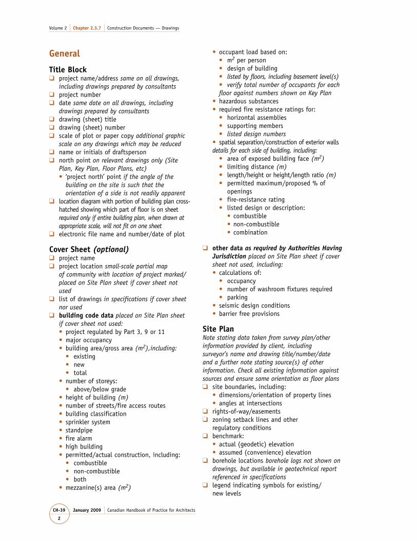
General
Title Block❑ project name/address same on all drawings,
including drawings prepared by consultants❑ project number❑ date same date on all drawings, including
drawings prepared by consultants❑ drawing (sheet) title❑ drawing (sheet) number❑ scale of plot or paper copy additional graphic
scale on any drawings which may be reduced❑ name or initials of draftsperson❑ north point on relevant drawings only (Site
Plan, Key Plan, Floor Plans, etc) • ‘project north’ point if the angle of the
building on the site is such that the orientation of a side is not readily apparent
❑ location diagram with portion of building plan cross-hatched showing which part of floor is on sheet required only if entire building plan, when drawn at appropriate scale, will not fit on one sheet
❑ electronic file name and number/date of plot
Cover Sheet (optional)❑ project name❑ project location small-scale partial map
of community with location of project marked/placed on Site Plan sheet if cover sheet not used
❑ list of drawings in specifications if cover sheet nor used
❑ building code data placed on Site Plan sheet if cover sheet not used:
• project regulated by Part 3, 9 or 11 • major occupancy • building area/gross area (m2),including: • existing • new • total • number of storeys: • above/below grade • height of building (m) • number of streets/fire access routes • building classification • sprinkler system • standpipe • fire alarm • high building • permitted/actual construction, including: • combustible • non-combustible • both • mezzanine(s) area (m2)
• occupant load based on: • m2 per person • design of building • listed by floors, including basement level(s) • verify total number of occupants for each
floor against numbers shown on Key Plan • hazardous substances • required fire resistance ratings for: • horizontal assemblies • supporting members • listed design numbers • spatial separation/construction of exterior walls
details for each side of building, including: • area of exposed building face (m2) • limiting distance (m) • length/height or height/length ratio (m) • permitted maximum/proposed % of
openings • fire-resistance rating • listed design or description: • combustible • non-combustible • combination
❑ other data as required by Authorities Having Jurisdiction placed on Site Plan sheet if cover sheet not used, including:
• calculations of: • occupancy • number of washroom fixtures required • parking • seismic design conditions • barrier free provisions
Site PlanNote stating data taken from survey plan/otherinformation provided by client, includingsurveyor’s name and drawing title/number/dateand a further note stating source(s) of otherinformation. Check all existing information against sources and ensure same orientation as floor plans❑ site boundaries, including: • dimensions/orientation of property lines • angles at intersections❑ rights-of-way/easements❑ zoning setback lines and other
regulatory conditions❑ benchmark: • actual (geodetic) elevation • assumed (convenience) elevation❑ borehole locations borehole logs not shown on
drawings, but available in geotechnical report referenced in specifications
❑ legend indicating symbols for existing/ new levels
Construction Documents — Drawings Chapter 2.3.7 Volume 2
Canadian Handbook of Practice for Architects January 2009 �CH-39
3
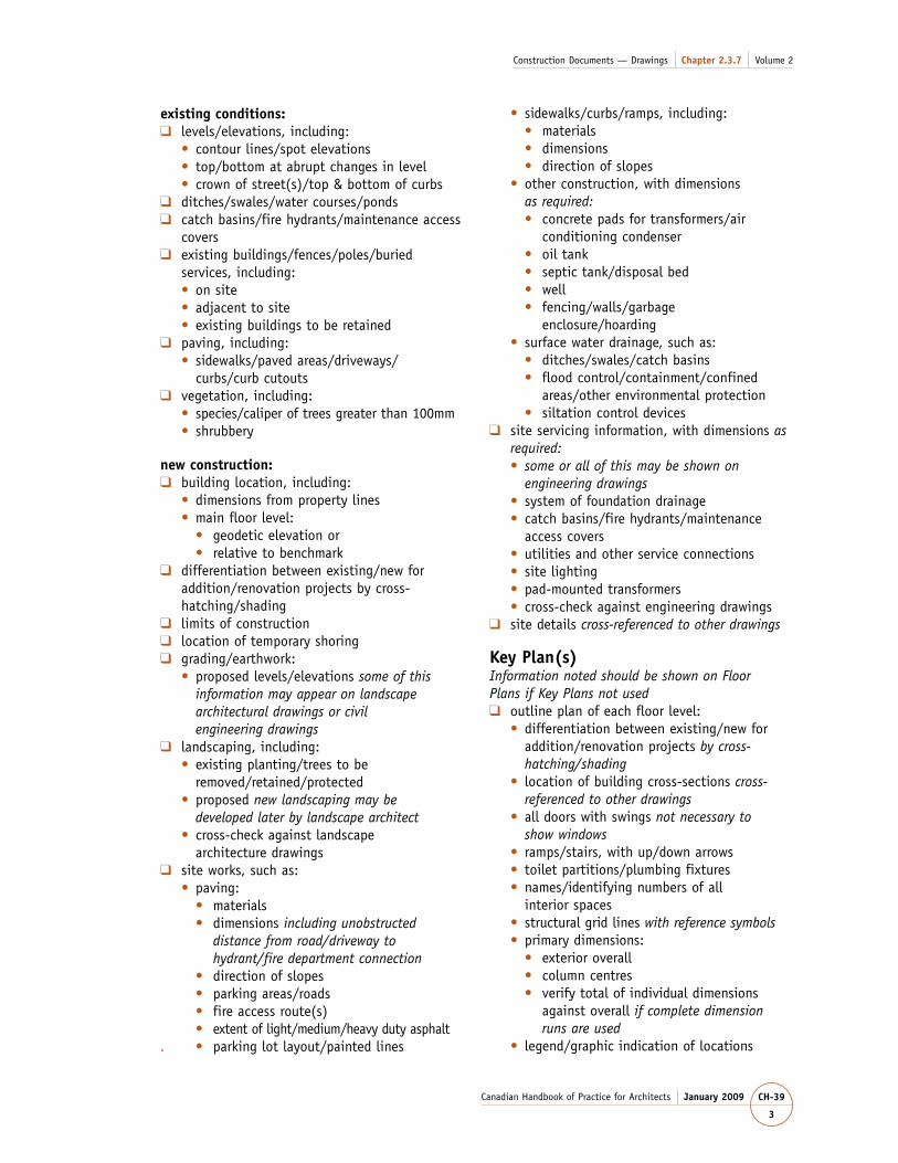
existing conditions:❑ levels/elevations, including: • contour lines/spot elevations • top/bottom at abrupt changes in level • crown of street(s)/top & bottom of curbs❑ ditches/swales/water courses/ponds❑ catch basins/fire hydrants/maintenance access
covers❑ existing buildings/fences/poles/buried
services, including: • on site • adjacent to site • existing buildings to be retained❑ paving, including: • sidewalks/paved areas/driveways/
curbs/curb cutouts❑ vegetation, including: • species/caliper of trees greater than 100mm • shrubbery
new construction:❑ building location, including: • dimensions from property lines • main floor level: • geodetic elevation or • relative to benchmark❑ differentiation between existing/new for
addition/renovation projects by cross-hatching/shading
❑ limits of construction❑ location of temporary shoring❑ grading/earthwork: • proposed levels/elevations some of this
information may appear on landscape architectural drawings or civil engineering drawings
❑ landscaping, including: • existing planting/trees to be
removed/retained/protected • proposed new landscaping may be
developed later by landscape architect • cross-check against landscape
architecture drawings❑ site works, such as: • paving: • materials • dimensions including unobstructed
distance from road/driveway to hydrant/fire department connection
• direction of slopes • parking areas/roads • fire access route(s) • extent of light/medium/heavy duty asphalt. • parking lot layout/painted lines
• sidewalks/curbs/ramps, including: • materials • dimensions • direction of slopes • other construction, with dimensions
as required: • concrete pads for transformers/air
conditioning condenser • oil tank • septic tank/disposal bed • well • fencing/walls/garbage
enclosure/hoarding • surface water drainage, such as: • ditches/swales/catch basins • flood control/containment/confined
areas/other environmental protection • siltation control devices❑ site servicing information, with dimensions as
required: • some or all of this may be shown on
engineering drawings • system of foundation drainage • catch basins/fire hydrants/maintenance
access covers • utilities and other service connections • site lighting • pad-mounted transformers • cross-check against engineering drawings❑ site details cross-referenced to other drawings
Key Plan(s)Information noted should be shown on Floor Plans if Key Plans not used❑ outline plan of each floor level: • differentiation between existing/new for
addition/renovation projects by cross- hatching/shading
• location of building cross-sections cross- referenced to other drawings
• all doors with swings not necessary to show windows
• ramps/stairs, with up/down arrows • toilet partitions/plumbing fixtures • names/identifying numbers of all
interior spaces • structural grid lines with reference symbols • primary dimensions: • exterior overall • column centres • verify total of individual dimensions
against overall if complete dimension runs are used
• legend/graphic indication of locations

January 2009 Canadian Handbook of Practice for Architects
Volume 2 Chapter 2.3.7 Construction Documents — Drawings
CH-39
�
and fire-resistance ratings of all firewalls/fire separations
• number of occupants indicated, assigned to each:
• exit stair/ramp/exit door to exterior • horizontal exit • exit door from hazardous rooms/high
occupant load areas when occupant load exceeds prescribed number
• door dividing corridor leading to an exit • cross-check total number of occupants
for each floor against occupant loads listed in building code data
Demolition Plans for renovation projects❑ outline plan of each level showing work to be: • demolished • underpinned/shored • renovated • retained❑ specific items numbered/dotted/cross-
hatched/shaded with legend(s) describing work required
Floor PlansIncorporate all items noted under Key Plans ifKey Plans not used❑ outline plan of each level: use same
orientation for all floor plans and match line when floor plan divided into segments shown on separate drawing sheets
❑ differentiation between existing/new for addition/renovation projects by cross-hatching/shading
❑ locations of plan details/interior wall elevations cross-referenced to other drawings/
ensure all conditions requiring clarification are detailed
❑ structural grid lines with reference symbols❑ expansion joints: • locations • uninterrupted throughout entire building❑ exterior walls/interior partitions/walls: • partial-height partitions/walls
differentiated/noted❑ floor slopes/depressions/trenches❑ location of changes in flooring materials❑ doors with swings/windows/other openings: • door sizes/types/fire protection ratings if
door schedule not used • door numbers cross-referenced to
door schedule • cross-check openings against elevations
❑ piers/columns❑ dotted footings to walls/piers/columns on
basement or foundation plan❑ names/identifying numbers of all
interior spaces❑ ramps/stairs, with up/down arrows❑ toilet partitions/plumbing fixtures❑ dimensions: • overall wall thicknesses not necessary
to dimension each element in walls if wall assembly types identified by reference numbers
• partitions • locations of windows/doors/other openings
showing overall dimensions as required • verify total of individual dimensions
against overall if complete dimension runs are used
• cross-check against other plans/details at different scales refer also to Notes
• cabinetwork if interior elevations not used❑ wall components delineated: • masonry wythes/cavity • insulated metal wall systems • EIFS/drywall/cladding to stud walls • no cross-hatching of each element if wall
assembly types identified by reference numbers❑ wall assembly types identified by reference numbers: • W1, W2, etc. for exterior walls; P1, P2, etc.
for interior partitions • schedule giving thickness/material of each
component of each wall type preferably on same drawing
• cross-check that terminology/abbreviations used for materials same as in specifications
• every wall identified by appropriate reference number❑ outlines of cabinetwork❑ other work: • concrete bases for mechanical/electrical
equipment • manufactured items: • panel folding doors • washroom accessories • prefabricated shelving❑ engineer-designed items: • dimensions only to items requiring
precise locations • structural: • columns
Construction Documents — Drawings Chapter 2.3.7 Volume 2
Canadian Handbook of Practice for Architects January 2009 �CH-39
�
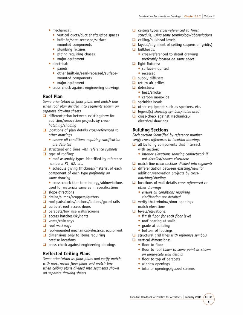
• mechanical: • vertical ducts/duct shafts/pipe spaces • built-in/semi-recessed/surface
mounted components • plumbing fixtures • piping requiring chases • major equipment • electrical: • panels • other built-in/semi-recessed/surface-
mounted components • major equipment • cross-check against engineering drawings
Roof PlanSame orientation as floor plans and match line when roof plan divided into segments shown onseparate drawing sheets❑ differentiation between existing/new for
addition/renovation projects by cross- hatching/shading
❑ locations of plan details cross-referenced to other drawings
• ensure all conditions requiring clarification are detailed
❑ structural grid lines with reference symbols❑ type of roofing: • roof assembly types identified by reference
numbers: R1, R2, etc. • schedule giving thickness/material of each
component of each type preferably on same drawing
• cross-check that terminology/abbreviations used for materials same as in specifications
❑ slope directions❑ drains/sumps/scuppers/gutters❑ roof pads/curbs/anchors/ladders/guard rails❑ curbs at roof access doors❑ parapets/low rise walls/screens❑ access hatches/skylights❑ vents/chimneys❑ roof walkways❑ roof-mounted mechanical/electrical equipment❑ dimensions only to items requiring
precise locations❑ cross-check against engineering drawings
Reflected Ceiling PlansSame orientation as floor plans and verify matchwith most recent floor plans and match line when ceiling plans divided into segments shown on separate drawing sheets
❑ ceiling types cross-referenced to finish schedule, using same terminology/abbreviations
❑ ceiling/bulkhead levels❑ layout/alignment of ceiling suspension grid(s)❑ bulkheads: • cross-referenced to detail drawings
preferably located on same sheet❑ light fixtures: • surface-mounted • recessed❑ supply diffusers❑ return air grilles❑ detectors: • heat/smoke • carbon monoxide❑ sprinkler heads❑ other equipment such as speakers, etc.❑ legend(s) showing symbols/notes used❑ cross-check against mechanical/
electrical drawings
Building SectionsEach section identified by reference number verify cross-references to location drawings❑ all building components that intersect
with section: • interior elevations showing cabinetwork if
not detailed/shown elsewhere❑ match line when sections divided into segments❑ differentiation between existing/new for
addition/renovation projects by cross- hatching/shading
❑ locations of wall details cross-referenced to other drawings
• ensure all conditions requiring clarification are detailed
❑ verify that window/door openings match elevations
❑ levels/elevations: • finish floor for each floor level • roof bearing at walls • grade at building • bottom of footings❑ structural grid lines with reference symbols❑ vertical dimensions: • floor to floor • floor to roof taken to same point as shown
on large-scale wall details • floor to top of parapets • window openings • interior openings/glazed screens

January 2009 Canadian Handbook of Practice for Architects
Volume 2 Chapter 2.3.7 Construction Documents — Drawings
CH-39
6
❑ legend/graphic indication of locations and fire-resistance ratings of all firewalls/ fire separations:
• firewalls continuous from ground to/ through roof:
• may terminate at underside of reinforced concrete roof slab
• parapet height as required by fire- resistance rating of firewall
• wall fire separations continuous elements from floor up through ceiling space to underside of structure above including exceptions where fire-resistance rating waived, but walls still required to be constructed as fire separations (when separation falls under steel joists/beams, continuity maintained by rated enclosure of joists/sprayed fireproofing on beams or other means)
• floor/roof assembly fire separations❑ wall/roof assembly types identified by
reference numbers cross-referenced to drawings where schedules placed
❑ structural: • footings • special foundations usually shown
only partially • joists/beams/lintels/rafters/roof trusses • in section • in elevation if beyond❑ heating/ventilating/air conditioning: • main horizontal ducts • major equipment: in elevation if beyond❑ cross-check against engineering drawings
ElevationsIf building form is complex, parts of elevationidentified by letter or number on location diagram in title block and match line when elevations divided into segments❑ all building faces: • below-grade foundation walls/
footings dotted • line of grade at building face❑ differentiation between existing/new for
addition/renovation projects❑ locations of: • wall details • plan details - only if required to
augment/clarify notations on Key Plan/Floor Plans/Building Sections
❑ cross-referenced to other drawings • ensure all conditions requiring
clarification are detailed
❑ verify that window/door openings match building sections
❑ openings/penetrations: • doors/windows/grilles/vents/fire
fighting access panels • dimensions to intermediate mullions for
door frames/windows or • reference numbers for each door
frame/window type cross-referenced to drawings where large-scale elevations placed
❑ attachments: • light fixtures/receptacles/siamese
connections/signage/downspouts/ flagpoles/etc.
❑ structural grid lines with reference symbols❑ locations of interior/hidden levels: • floors • finish floor level/elevation for each
floor level • flat roofs behind parapets❑ vertical dimensions: • to doors/windows/other important items
requiring location • floor to floor or floor to roof when not
shown on Building Sections❑ exterior construction materials: • graphically/notations -cross-check that
terminology/abbreviations used for materials same as in specifications
• masonry control joints • expansion joints❑ roof-mounted mechanical equipment which
affects appearance of building❑ cross-check against engineering drawings
Detailswall sections❑ each section identified by reference
number/scale verify cross-references to location drawings
❑ all building components that intersect with section shown:
• cross-hatching/symbols to indicate materials, plus notations, including location/material of air/vapour barriers or
• wall/roof assembly types identified by reference numbers cross-referenced to drawings where schedules placed
• section continuous from footing to roof • typical window or door condition • verify that window/door openings
match building sections • fire stops in concealed spaces
Construction Documents — Drawings Chapter 2.3.7 Volume 2
Canadian Handbook of Practice for Architects January 2009 �CH-39
7
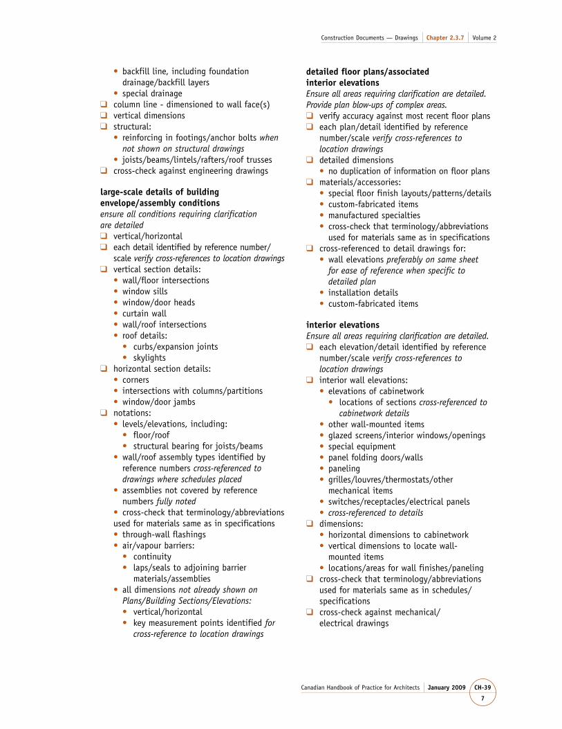
• backfill line, including foundation drainage/backfill layers
• special drainage❑ column line - dimensioned to wall face(s)❑ vertical dimensions❑ structural: • reinforcing in footings/anchor bolts when
not shown on structural drawings • joists/beams/lintels/rafters/roof trusses❑ cross-check against engineering drawings
large-scale details of buildingenvelope/assembly conditionsensure all conditions requiring clarification are detailed ❑ vertical/horizontal❑ each detail identified by reference number/
scale verify cross-references to location drawings❑ vertical section details: • wall/floor intersections • window sills • window/door heads • curtain wall • wall/roof intersections • roof details: • curbs/expansion joints • skylights❑ horizontal section details: • corners • intersections with columns/partitions • window/door jambs❑ notations: • levels/elevations, including: • floor/roof • structural bearing for joists/beams • wall/roof assembly types identified by
reference numbers cross-referenced to drawings where schedules placed
• assemblies not covered by reference numbers fully noted
• cross-check that terminology/abbreviations used for materials same as in specifications
• through-wall flashings • air/vapour barriers: • continuity • laps/seals to adjoining barrier
materials/assemblies • all dimensions not already shown on
Plans/Building Sections/Elevations: • vertical/horizontal • key measurement points identified for
cross-reference to location drawings
detailed floor plans/associated interior elevationsEnsure all areas requiring clarification are detailed. Provide plan blow-ups of complex areas.❑ verify accuracy against most recent floor plans❑ each plan/detail identified by reference
number/scale verify cross-references to location drawings
❑ detailed dimensions • no duplication of information on floor plans❑ materials/accessories: • special floor finish layouts/patterns/details • custom-fabricated items • manufactured specialties • cross-check that terminology/abbreviations
used for materials same as in specifications❑ cross-referenced to detail drawings for: • wall elevations preferably on same sheet
for ease of reference when specific to detailed plan
• installation details • custom-fabricated items
interior elevationsEnsure all areas requiring clarification are detailed.❑ each elevation/detail identified by reference
number/scale verify cross-references to location drawings
❑ interior wall elevations: • elevations of cabinetwork • locations of sections cross-referenced to
cabinetwork details • other wall-mounted items • glazed screens/interior windows/openings • special equipment • panel folding doors/walls • paneling • grilles/louvres/thermostats/other
mechanical items • switches/receptacles/electrical panels • cross-referenced to details❑ dimensions: • horizontal dimensions to cabinetwork • vertical dimensions to locate wall-
mounted items • locations/areas for wall finishes/paneling❑ cross-check that terminology/abbreviations
used for materials same as in schedules/specifications
❑ cross-check against mechanical/ electrical drawings
January 2009 Canadian Handbook of Practice for Architects
Volume 2 Chapter 2.3.7 Construction Documents — Drawings
CH-39
�
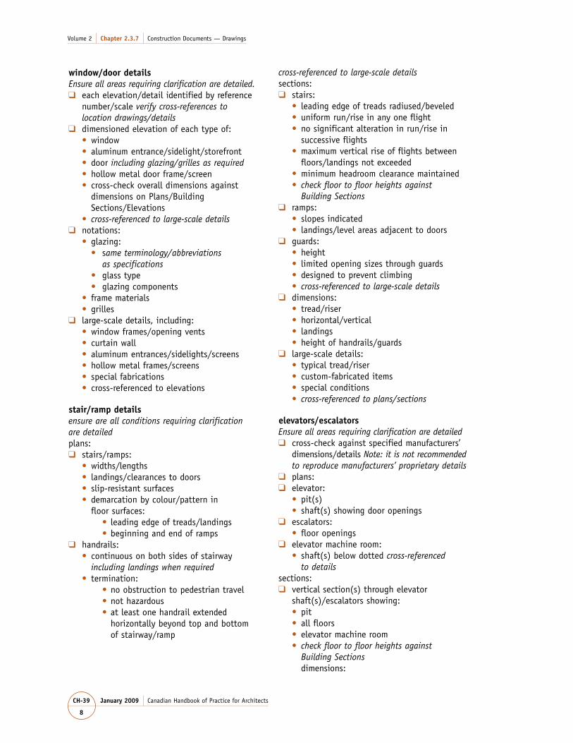
window/door detailsEnsure all areas requiring clarification are detailed.❑ each elevation/detail identified by reference
number/scale verify cross-references to location drawings/details
❑ dimensioned elevation of each type of: • window • aluminum entrance/sidelight/storefront • door including glazing/grilles as required • hollow metal door frame/screen • cross-check overall dimensions against
dimensions on Plans/Building Sections/Elevations
• cross-referenced to large-scale details❑ notations: • glazing: • same terminology/abbreviations
as specifications • glass type • glazing components • frame materials • grilles❑ large-scale details, including: • window frames/opening vents • curtain wall • aluminum entrances/sidelights/screens • hollow metal frames/screens • special fabrications • cross-referenced to elevations
stair/ramp details ensure are all conditions requiring clarificationare detailedplans:❑ stairs/ramps: • widths/lengths • landings/clearances to doors • slip-resistant surfaces • demarcation by colour/pattern in
floor surfaces: • leading edge of treads/landings • beginning and end of ramps❑ handrails: • continuous on both sides of stairway
including landings when required • termination: • no obstruction to pedestrian travel • not hazardous • at least one handrail extended
horizontally beyond top and bottom of stairway/ramp
cross-referenced to large-scale detailssections:❑ stairs: • leading edge of treads radiused/beveled • uniform run/rise in any one flight • no significant alteration in run/rise in
successive flights • maximum vertical rise of flights between
floors/landings not exceeded • minimum headroom clearance maintained • check floor to floor heights against
Building Sections❑ ramps: • slopes indicated • landings/level areas adjacent to doors❑ guards: • height • limited opening sizes through guards • designed to prevent climbing • cross-referenced to large-scale details ❑ dimensions: • tread/riser • horizontal/vertical • landings • height of handrails/guards❑ large-scale details: • typical tread/riser • custom-fabricated items • special conditions • cross-referenced to plans/sections
elevators/escalatorsEnsure all areas requiring clarification are detailed ❑ cross-check against specified manufacturers’
dimensions/details Note: it is not recommended to reproduce manufacturers’ proprietary details
❑ plans:❑ elevator: • pit(s) • shaft(s) showing door openings❑ escalators: • floor openings❑ elevator machine room: • shaft(s) below dotted cross-referenced
to detailssections:❑ vertical section(s) through elevator
shaft(s)/escalators showing: • pit • all floors • elevator machine room • check floor to floor heights against
Building Sections dimensions:
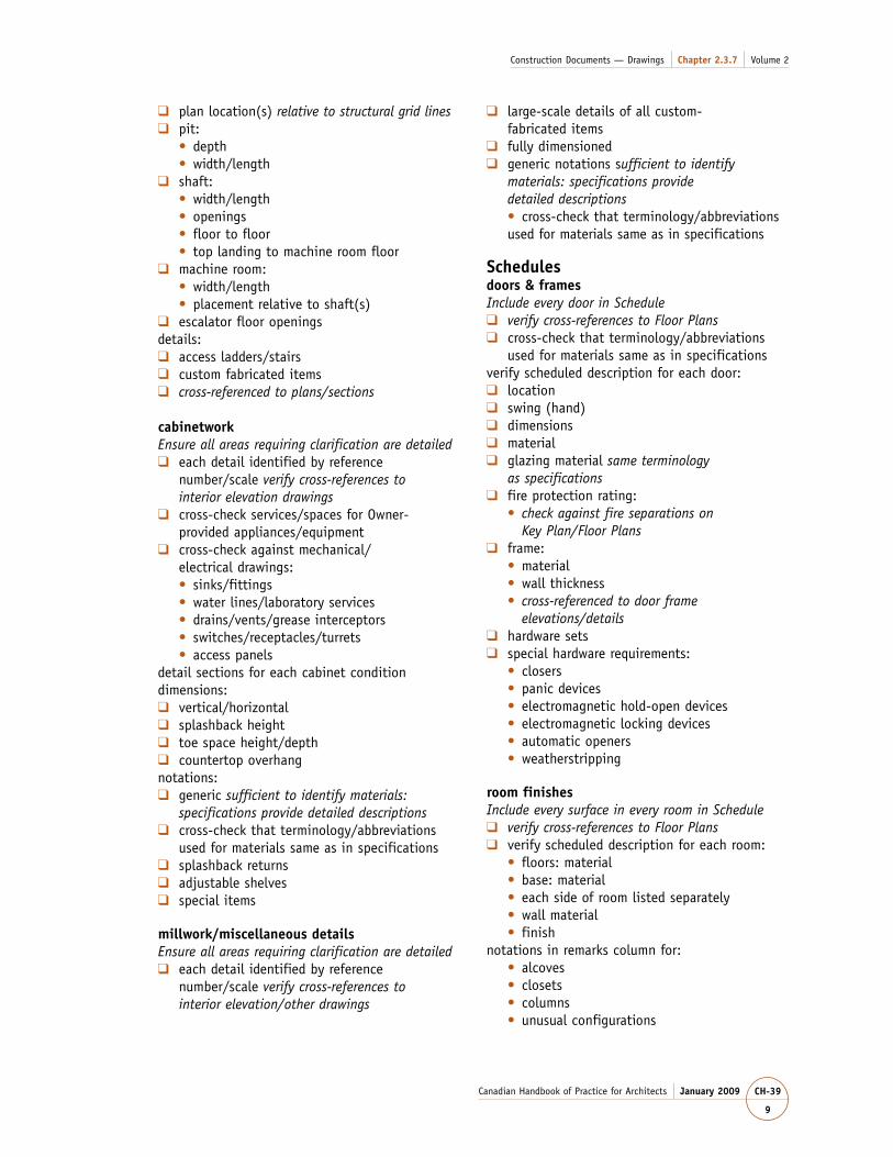
Construction Documents — Drawings Chapter 2.3.7 Volume 2
Canadian Handbook of Practice for Architects January 2009 �CH-39
9
❑ plan location(s) relative to structural grid lines❑ pit: • depth • width/length❑ shaft: • width/length • openings • floor to floor • top landing to machine room floor❑ machine room: • width/length • placement relative to shaft(s)❑ escalator floor openings details:❑ access ladders/stairs❑ custom fabricated items❑ cross-referenced to plans/sections
cabinetworkEnsure all areas requiring clarification are detailed ❑ each detail identified by reference
number/scale verify cross-references to interior elevation drawings
❑ cross-check services/spaces for Owner- provided appliances/equipment
❑ cross-check against mechanical/ electrical drawings:
• sinks/fittings • water lines/laboratory services • drains/vents/grease interceptors • switches/receptacles/turrets • access panelsdetail sections for each cabinet condition dimensions:❑ vertical/horizontal❑ splashback height❑ toe space height/depth❑ countertop overhang notations:❑ generic sufficient to identify materials:
specifications provide detailed descriptions❑ cross-check that terminology/abbreviations
used for materials same as in specifications❑ splashback returns❑ adjustable shelves❑ special items
millwork/miscellaneous detailsEnsure all areas requiring clarification are detailed ❑ each detail identified by reference
number/scale verify cross-references to interior elevation/other drawings
❑ large-scale details of all custom- fabricated items
❑ fully dimensioned❑ generic notations sufficient to identify
materials: specifications provide detailed descriptions
• cross-check that terminology/abbreviations used for materials same as in specifications
Schedulesdoors & framesInclude every door in Schedule ❑ verify cross-references to Floor Plans ❑ cross-check that terminology/abbreviations
used for materials same as in specificationsverify scheduled description for each door:❑ location❑ swing (hand)❑ dimensions❑ material❑ glazing material same terminology
as specifications❑ fire protection rating: • check against fire separations on
Key Plan/Floor Plans❑ frame: • material • wall thickness • cross-referenced to door frame
elevations/details❑ hardware sets❑ special hardware requirements: • closers • panic devices • electromagnetic hold-open devices • electromagnetic locking devices • automatic openers • weatherstripping
room finishesInclude every surface in every room in Schedule❑ verify cross-references to Floor Plans❑ verify scheduled description for each room: • floors: material • base: material • each side of room listed separately • wall material • finishnotations in remarks column for: • alcoves • closets • columns • unusual configurations
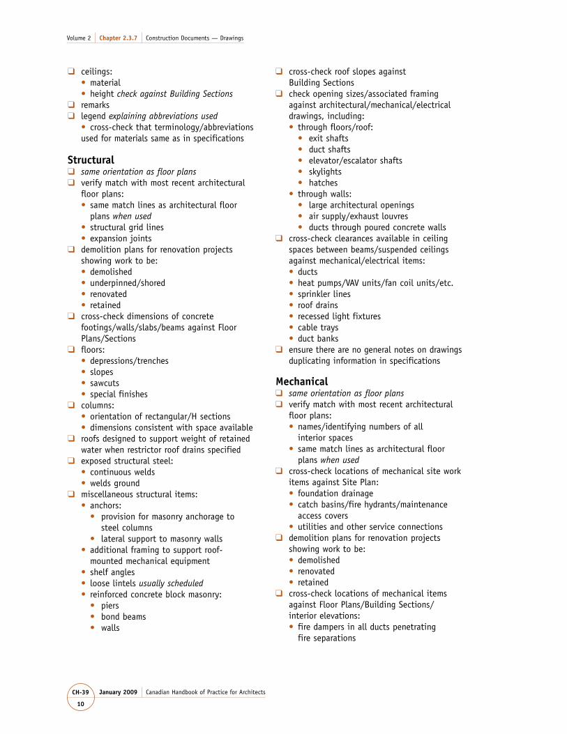
January 2009 Canadian Handbook of Practice for Architects
Volume 2 Chapter 2.3.7 Construction Documents — Drawings
CH-39
�0
❑ ceilings: • material • height check against Building Sections❑ remarks❑ legend explaining abbreviations used • cross-check that terminology/abbreviations
used for materials same as in specifications
Structural❑ same orientation as floor plans❑ verify match with most recent architectural
floor plans: • same match lines as architectural floor
plans when used • structural grid lines • expansion joints❑ demolition plans for renovation projects
showing work to be: • demolished • underpinned/shored • renovated • retained❑ cross-check dimensions of concrete
footings/walls/slabs/beams against Floor Plans/Sections
❑ floors: • depressions/trenches • slopes • sawcuts • special finishes❑ columns: • orientation of rectangular/H sections • dimensions consistent with space available❑ roofs designed to support weight of retained
water when restrictor roof drains specified❑ exposed structural steel: • continuous welds • welds ground❑ miscellaneous structural items: • anchors: • provision for masonry anchorage to
steel columns • lateral support to masonry walls • additional framing to support roof-
mounted mechanical equipment • shelf angles • loose lintels usually scheduled • reinforced concrete block masonry: • piers • bond beams • walls
❑ cross-check roof slopes against Building Sections
❑ check opening sizes/associated framing against architectural/mechanical/electrical drawings, including:
• through floors/roof: • exit shafts • duct shafts • elevator/escalator shafts • skylights • hatches • through walls: • large architectural openings • air supply/exhaust louvres • ducts through poured concrete walls❑ cross-check clearances available in ceiling
spaces between beams/suspended ceilings against mechanical/electrical items:
• ducts • heat pumps/VAV units/fan coil units/etc. • sprinkler lines • roof drains • recessed light fixtures • cable trays • duct banks❑ ensure there are no general notes on drawings
duplicating information in specifications
Mechanical❑ same orientation as floor plans❑ verify match with most recent architectural
floor plans: • names/identifying numbers of all
interior spaces • same match lines as architectural floor
plans when used❑ cross-check locations of mechanical site work
items against Site Plan: • foundation drainage • catch basins/fire hydrants/maintenance
access covers • utilities and other service connections❑ demolition plans for renovation projects
showing work to be: • demolished • renovated • retained❑ cross-check locations of mechanical items
against Floor Plans/Building Sections/ interior elevations:
• fire dampers in all ducts penetrating fire separations
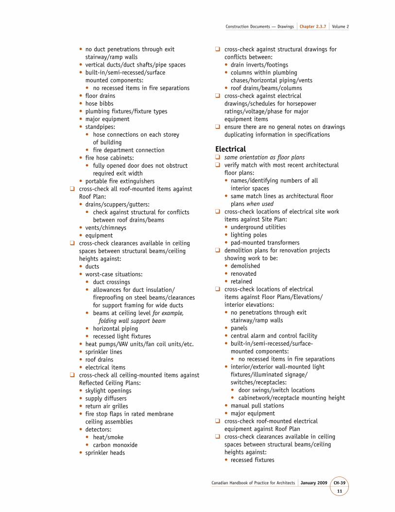
Construction Documents — Drawings Chapter 2.3.7 Volume 2
Canadian Handbook of Practice for Architects January 2009 �CH-39
��
• no duct penetrations through exit stairway/ramp walls
• vertical ducts/duct shafts/pipe spaces • built-in/semi-recessed/surface
mounted components: • no recessed items in fire separations • floor drains • hose bibbs • plumbing fixtures/fixture types • major equipment • standpipes: • hose connections on each storey
of building • fire department connection • fire hose cabinets: • fully opened door does not obstruct
required exit width • portable fire extinguishers❑ cross-check all roof-mounted items against
Roof Plan: • drains/scuppers/gutters: • check against structural for conflicts
between roof drains/beams • vents/chimneys • equipment❑ cross-check clearances available in ceiling
spaces between structural beams/ceiling heights against:
• ducts • worst-case situations: • duct crossings • allowances for duct insulation/
fireproofing on steel beams/clearances for support framing for wide ducts
• beams at ceiling level for example, folding wall support beam
• horizontal piping • recessed light fixtures • heat pumps/VAV units/fan coil units/etc. • sprinkler lines • roof drains • electrical items❑ cross-check all ceiling-mounted items against Reflected Ceiling Plans: • skylight openings • supply diffusers • return air grilles • fire stop flaps in rated membrane
ceiling assemblies • detectors: • heat/smoke • carbon monoxide • sprinkler heads
❑ cross-check against structural drawings for conflicts between:
• drain inverts/footings • columns within plumbing
chases/horizontal piping/vents • roof drains/beams/columns❑ cross-check against electrical
drawings/schedules for horsepower ratings/voltage/phase for major equipment items
❑ ensure there are no general notes on drawings duplicating information in specifications
Electrical❑ same orientation as floor plans❑ verify match with most recent architectural
floor plans: • names/identifying numbers of all
interior spaces • same match lines as architectural floor
plans when used❑ cross-check locations of electrical site work
items against Site Plan: • underground utilities • lighting poles • pad-mounted transformers❑ demolition plans for renovation projects
showing work to be: • demolished • renovated • retained❑ cross-check locations of electrical
items against Floor Plans/Elevations/ interior elevations:
• no penetrations through exit stairway/ramp walls
• panels • central alarm and control facility • built-in/semi-recessed/surface-
mounted components: • no recessed items in fire separations • interior/exterior wall-mounted light
fixtures/illuminated signage/ switches/receptacles:
• door swings/switch locations • cabinetwork/receptacle mounting height • manual pull stations • major equipment❑ cross-check roof-mounted electrical
equipment against Roof Plan❑ cross-check clearances available in ceiling
spaces between structural beams/ceiling heights against:
• recessed fixtures

January 2009 Canadian Handbook of Practice for Architects
Volume 2 Chapter 2.3.7 Construction Documents — Drawings
CH-39
�2
• cable trays • duct banks • mechanical items❑ cross-check all ceiling-mounted items against
Reflected Ceiling Plans: • skylight openings • mechanical items • light fixtures: • surface-mounted • recessed • check fixture types against
electrical specifications • exit • detectors: • heat/smoke • carbon monoxide • exit signs: • visible from exit approach • over exit doors • additional signs to indicate direction
of egress • alarm signals: • audible devices located to be clearly
audible throughout floor area served • visual devices located to be visible
throughout floor area served❑ cross-check against mechanical drawings/
schedules for horsepower ratings/voltage/ phase for major equipment items
❑ ensure there are no general notes on drawings duplicating information in specifications
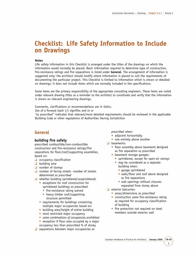
Construction Documents — Drawings Chapter 2.3.7 Volume 2
Canadian Handbook of Practice for Architects January 2009 �CH-�0
�
General
building fire safetyprescribed combustible/non-combustible construction and fire-resistance ratings/fire separations for floor/roof/supporting assemblies, based on:❑ occupancy classification❑ building area❑ number of storeys❑ number of facing streets -number of streets
determined as prescribed❑ whether building sprinklered/unsprinklered: • exceptions for roof construction for
sprinklered buildings as prescribed: • fire-resistance rating waived • heavy timber roof/supporting
structure permitted • requirements for buildings containing
multiple major occupancies based on: • building area/height of entire building • most restricted major occupancy • some combinations of occupancies prohibited • exception if floor area occupied by a major
occupancy less than prescribed % of storey❑ separations between major occupancies as
prescribed when: • adjacent horizontally • one entirely above another❑ basements: • floor assembly above basement designed
as fire separation as prescribed • basement storage garages: • sprinklered, except for open-air storeys • may be considered as a separate
building when: • garage sprinklered • walls/floor and roof above designed
as fire separations • wall openings without closures
separated from storey above❑ exterior balconies: • areas/dimensions as prescribed • construction same fire-resistance rating
as required for occupancy classification of building
• fire protection not required on steel members outside exterior wall
Checklist: Life Safety Information to Include on DrawingsNotesLife safety information in this Checklist is arranged under the titles of the drawings on which the information would normally be placed. Basic information required to determine type of construction, fire-resistance ratings and fire separations is listed under General. The arrangement of information is suggested only; the architect should modify where information is placed to suit the requirements of documenting the particular project. This Checklist is limited to information which is shown or detailed on drawings; it does not include items which are normally included in the specifications.
Some items are the primary responsibility of the appropriate consulting engineers. These items are noted under relevant drawing titles as a reminder to the architect to coordinate and verify that the information is shown on relevant engineering drawings.
Comments, clarifications or recommendations are in italics.Use of a forward slash (/) signifies and or or“as prescribed” indicates that relevant/more detailed requirements should be reviewed in the applicable Building Code or other regulations of Authorities Having Jurisdiction

January 2009 Canadian Handbook of Practice for Architects
Volume 2 Chapter 2.3.7 Construction Documents — Drawings
CH-�0
2
building code data may be placed on Site Plan or cover sheet: [Ontario architects refer to OAA Practice Bulletin A.9, April 2002]❑ project regulated by Part 3, 9 or 11❑ major occupancy❑ building area/gross area (m2): • existing • new • total❑ number of storeys: above/below grade❑ height of building (m)❑ number of streets/fire access routes❑ building classification❑ sprinkler system as proposed❑ standpipe as required❑ fire alarm as required❑ high building❑ permitted/actual construction: • combustible • non-combustible • both❑ mezzanine(s) area (m2)❑ occupant load based on: • m2 per person • design of building • list by floors, including basement level(s)❑ hazardous substances❑ required fire resistance ratings • horizontal assemblies • supporting members • indicate listed design numbers❑ spatial separation/construction of exterior walls
provide details for each side of building, including: • area of exposed building face (m2) • limiting distance (m) • length/height or height/length ratio (m) • permitted maximum/proposed % of openings • fire-resistance rating • listed design or description • combustible • non-combustible • combination
Site Plan❑ access for fire fighting: access route(s) to
principal entrance/each building face having access openings for fire fighting:
• within prescribed unobstructed distance from hydrant/fire department connection
• required for buildings over 3 storeys in height or greater than prescribed building area
❑ access route(s) designed to: • prescribed clear width/radius/overhead
clearance/gradient • support expected loading • have turnaround facilities • be connected with a public thoroughfare❑ water supply: • hydrants within prescribed distance from
every side of building required to face a street • provision of adequate supplemental water
supply for fire fighting if municipal supply inadequate or unavailable
❑ above ground electrical conductors: • conform to prescribed clearances
from building
Key Plan(s) recommendedShow information on Floor Plans if Key Plans not usedIndicate locations and fire-resistance ratings of all:❑ firewalls❑ fire separations required between public
corridors and adjacent suites/floor areas, between adjoining suites or enclosing:
• in assembly occupancies: • hazardous classrooms: fire separation
required for perimeter walls only around a group of hazardous classrooms/complementary ancillary rooms as prescribed
• seating areas/stages and ancillary spaces as prescribed
• library book storage rooms not normally accessible to the public
• in care/detention occupancies: • sleeping rooms as prescribed: fire separation required for perimeter
walls only around a group of intercommunicating rooms having fewer than prescribed number
of occupants • between fire compartments including
those used for horizontal exiting • compartments from which it is
impractical to move patients in an emergency
• contained use areas as prescribed • in residential occupancies:
• between suites • storage rooms not within suites
as prescribed
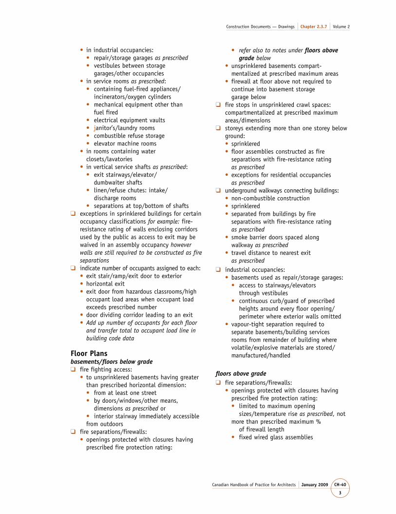
Construction Documents — Drawings Chapter 2.3.7 Volume 2
Canadian Handbook of Practice for Architects January 2009 �CH-�0
3
• in industrial occupancies: • repair/storage garages as prescribed • vestibules between storage
garages/other occupancies • in service rooms as prescribed: • containing fuel-fired appliances/
incinerators/oxygen cylinders • mechanical equipment other than
fuel fired • electrical equipment vaults • janitor’s/laundry rooms • combustible refuse storage • elevator machine rooms • in rooms containing water
closets/lavatories • in vertical service shafts as prescribed: • exit stairways/elevator/
dumbwaiter shafts • linen/refuse chutes: intake/
discharge rooms • separations at top/bottom of shafts❑ exceptions in sprinklered buildings for certain
occupancy classifications for example: fire-resistance rating of walls enclosing corridors used by the public as access to exit may be waived in an assembly occupancy however walls are still required to be constructed as fire separations
❑ indicate number of occupants assigned to each: • exit stair/ramp/exit door to exterior • horizontal exit • exit door from hazardous classrooms/high
occupant load areas when occupant load exceeds prescribed number
• door dividing corridor leading to an exit • Add up number of occupants for each floor
and transfer total to occupant load line in building code data
Floor Plansbasements/floors below grade❑ fire fighting access: • to unsprinklered basements having greater
than prescribed horizontal dimension: • from at least one street • by doors/windows/other means,
dimensions as prescribed or • interior stairway immediately accessible
from outdoors❑ fire separations/firewalls: • openings protected with closures having
prescribed fire protection rating:
• refer also to notes under floors above grade below
• unsprinklered basements compart- mentalized at prescribed maximum areas
• firewall at floor above not required to continue into basement storage garage below
❑ fire stops in unsprinklered crawl spaces: compartmentalized at prescribed maximum areas/dimensions❑ storeys extending more than one storey below
ground: • sprinklered • floor assemblies constructed as fire
separations with fire-resistance rating as prescribed
• exceptions for residential occupancies as prescribed
❑ underground walkways connecting buildings: • non-combustible construction • sprinklered • separated from buildings by fire
separations with fire-resistance rating as prescribed
• smoke barrier doors spaced along walkway as prescribed
• travel distance to nearest exit as prescribed
❑ industrial occupancies: • basements used as repair/storage garages: • access to stairways/elevators
through vestibules • continuous curb/guard of prescribed
heights around every floor opening/ perimeter where exterior walls omitted
• vapour-tight separation required to separate basements/building services rooms from remainder of building where volatile/explosive materials are stored/ manufactured/handled
floors above grade❑ fire separations/firewalls: • openings protected with closures having
prescribed fire protection rating: • limited to maximum opening
sizes/temperature rise as prescribed, not more than prescribed maximum % of firewall length
• fixed wired glass assemblies
January 2009 Canadian Handbook of Practice for Architects
Volume 2 Chapter 2.3.7 Construction Documents — Drawings
CH-�0
�
• glass block reinforced in each horizontal joint
• no glass block/ fixed wired glass assemblies permitted as closures to openings in firewalls
• enclosure having same fire-resistance rating as surrounding construction forexhaust piping from emergency power systems
❑ exit stairways: used for exiting only: • except as access to a floor area • service rooms/spaces or certain
ancillary rooms not permitted to open into exit stairway
fire separation: • same fire-resistance rating as
surrounding construction • without any penetrations except
as prescribed • additional requirements for separation
between scissor/contiguous stairs: • smoke tight • no interconnecting doors between
contiguous stairs❑ spatial separation/exposure protection of
exterior walls: • limiting distance as prescribed defines: • measurement of exposed building face • required construction/fire-resistance
rating of building face • permitted area of unprotected openings • in unsprinklered buildings requiring
prescribed spatial separation: • unprotected openings in exterior walls
which are parallel or at less than 135° and in different fire compartments
• additional protection required for: • exit door/stair/ramp exposed to an
opening in an adjacent wall at less than 135° and closer than prescribed distances, horizontally and vertically
• exit door in one fire compartment exposed to an opening closer than prescribed horizontal distance in exterior wall of another fire compartment when wall is at less than 135°
• openings protected with closures: • fixed wired glass assemblies • glass block reinforced in each
horizontal joint
❑ covered walkways/vehicular passageways between buildings:
• separated from buildings by fire separations with prescribed ratings
• noncombustible construction when connected to a building of noncombustible construction, except:
• heavy timber construction permitted for ground level walkway when not less than prescribed % of perimeter is open to the outdoors
❑ mezzanines/openings through floor assemblies:
• mezzanines permitted to be open/ unprotected in prescribed occupancies:
• when conforming to dimensions/ visibility as prescribed
• interconnected spaces: • conforming to: • configuration/fire separations/
sprinklering as prescribed • additional provisions for exiting/fire
separations for portions of interconnected space having floor level more than prescribed distance above grade
• access to exit not permitted through interconnected space from floor area outside the space
• requirements waived/modified: • when space sprinklered • for certain prescribed occupancies • when building height not more
than prescribed number of storeys❑ passage of smoke into exit stairshafts/
elevator shafts opening into interconnected space limited:
• when building over prescribed height, by building design
• when interconnected space over prescribed height, by vestibules having:
• prescribed fire separation/distance between entrance/exit doors
• mechanical air supply or • vent opening to outdoors❑ passage of smoke from interconnected
space through access openings into sleeping rooms in care/treatment occupancies restricted by vestibules having mechanical air supply
❑ unprotected openings permitted for: • stairs/escalators/inclined moving walks
in prescribed occupancies when entire building sprinklered

Construction Documents — Drawings Chapter 2.3.7 Volume 2
Canadian Handbook of Practice for Architects January 2009 �CH-�0
�
• vehicular ramps in storage garages • openings required for a
manufacturing process❑ protection at edges of open floors in
industrial buildings: • toe-board to prevent tools/other
objects fallingMeans of egress:❑ applies also to basements/floors below grade❑ minimum two exits required from each
occupied floor area except: • floor areas in buildings not more than
two storeys in height may be served by one exit provided floor area/travel distance not more than as prescribed
❑ capacity based on occupant load of area served:
• determine required widths of corridors/doorways/ramps/stairs by multiplying occupant load by prescribed factors based on occupancy classification
• no obstruction restricting width to less than prescribed unless unobstructed alternative available nearby/clearly visible
❑ no mirrors permitted in/adjacent to exits that would confuse direction of exit
❑ each suite provided with doorway: • opening to exterior/public corridor
having two opposite directions of exit • exceptions for residential
occupancies as prescribed • width based on occupant load❑ at least two egress doorways required from: • hazardous suites/rooms/classrooms
exceeding prescribed area • suites/rooms/mezzanines: • having greater than prescribed
occupant load • exceeding prescribed area/
travel distance • requirements modified for
sprinklered spaces • occupied roof having greater than
prescribed occupant load • rooftop enclosure/service space
exceeding prescribed area/ travel distance
• least distance between doorways as prescribed
• when more than one exit from a floor area is required, every exit shall contribute not more than half required exit width
❑ means of egress required from every:
• podium/terrace/platform/contained open space/occupied roof/ rooftop enclosure
❑ travel distances to nearest exit not more than prescribed distance based on occupancy classification, measured from:
• any point in floor area along path of travel to exit or
• any point in fire compartment to door into adjoining fire compartment or
• egress door into corridor/exterior passageway from suite/room, provided suite/room separated from remainder of floor by a fire separation having:
• prescribed fire-resistance rating or • no fire-resistance rating if
building sprinklered • modifications as permitted for
sprinklered buildings❑ corridors: • prescribed minimum widths based on
occupancy classification: • hazardous obstructions into corridor
width prohibited • minimum ceiling height as prescribed • occupancies in corridor as prescribed: • located so as not to reduce
prescribed unobstructed width • combined area of all occupancies
not more than maximum prescribed % of corridor area
• dead end corridors permitted only as prescribed
❑ aisles/seating in assembly occupancies as prescribed
❑ exits through lobbies • one exit may lead through
lobby provided: • distance of lobby floor above
grade/travel distance to outdoors not more than prescribed
• fire separation maintained between lobby and exit
• lobby not within an interconnected space as prescribed
• exceptions/modifications for sprinklered buildings as prescribed
❑ horizontal exits: • restrictions as prescribed • sufficient floor area on each side to
accommodate occupants of both floor areas calculated as prescribed

January 2009 Canadian Handbook of Practice for Architects
Volume 2 Chapter 2.3.7 Construction Documents — Drawings
CH-�0
�
• ramps used for any difference in level between connected floor areas:
• slope as prescribed • stairs not permitted❑ doors: • swing on vertical axis • swing: in direction of egress for: • rooms having greater than
prescribed occupant load • hazardous rooms: except doors from
boiler/incinerator rooms swing inward when opening into
corridor/any room in assembly occupancy
• pair of doors in a corridor providing access to exit in both directions:
• swing in opposite directions with door on right hand side swinging in
direction of travel to exit • minimum clear opening width for single
leaf door/active leaf of multiple doors as prescribed
• transparent doors/sidelights: • safety/wired glass • doors designed/constructed to be
clearly identifiable • sidelights protected with barriers/guards❑ sliding doors: • required to swing on a vertical axis in
direction of egress when pressure applied: • not applicable for certain
occupancy classifications❑ revolving doors: • collapsible in emergency • hinged doors with equivalent exiting
capacity adjacent • permitted as exit from ground floor
level only • located not less than prescribed
distance from foot of any stairway • maximum permitted capacity • exceptions for electrically operated
revolving doors as prescribedhigh buildings:❑ additional provisions as required by
Building Code/Authorities Having Jurisdiction for buildings over prescribed heights/occupant load
❑ building designed so that smoke from fire will not reach:
• floor areas above lowest exit storey • any exit stair
• fire fighters’ elevator shaft • connected building❑ requirements waived/modified when: • building sprinklered • stairways vented to outdoors as prescribed • smoke from below lowest exit storey
prevented from moving into upper storeys • capability to shut off circulation fans at
central alarm and control facility • residential buildings have: • lower than prescribed building
height/occupancy • exterior balcony for each suite • prescribed areas of refuge❑ emergency access to floor areas from exit stairs: • no locking devices on doors giving access
to prescribed floor areas except when other access provisions are available as prescribed
• at least one other exit must be accessible through unlocked doors within floor area
❑ means of venting each floor area by: • openable windows/wall panels/smoke
shafts or • building exhaust system,
if building sprinklered
Roof Plan as required❑ fire fighting access:❑ to roof with lower than prescribed slope on a
building over 3 storeys in height: • by stairway or • by hatch of prescribed dimensions with
fixed ladder • with prescribed clearances around roof
signs or other obstructions❑ spatial separation/exposure protection of exterior walls in unsprinklered buildings: • skylights in roof adjoining an exterior
wall having unprotected openings closer than prescribed distances, horizontally and vertically
• combustible skylights permitted in non- combustible construction:
• extent contingent on flame-spread ratings as prescribed
Reflected Ceiling Plans❑ fire separations: • fire stop flaps in rated membrane
ceiling assemblies • delineate % of total ceiling areas for finishes
which may exceed flame-spread rating/smoke developed classification as prescribed
Construction Documents — Drawings Chapter 2.3.7 Volume 2
Canadian Handbook of Practice for Architects January 2009 �CH-�0
7
❑ fire detection systems: • fire detectors/smoke and heat detectors
installed in all prescribed rooms • fire and heat detectors not required in
sprinklered floor areas
Building Sections❑ Indicate locations and fire-resistance ratings
of all: • required fire separations/firewalls • floor/roof assemblies as prescribed • over basements (fire separation not
required over crawl spaces as prescribed) • mezzanines considered as a storey • portion of roof supporting an occupancy • rated membrane ceiling assemblies • loadbearing walls/columns❑ permitted combustible components in non-
combustible construction: • combustible roofing materials as prescribed • combustible flooring/interior finish:
maximum thickness as prescribed • combustible elements in partitions • protection required of foamed plastic in
walls/ceilings/vertical service spaces even in permitted combustible construction
❑ vertical fire separations continuous elements: • from wall to wall • from floor up through ceiling space to
underside of structure above (when separation falls under steel joists/beams, continuity maintained by rated enclosure of joists/sprayed fireproofing on beams or other means)
• smoke-tight joints around entire perimeter • service penetrations fire stopped except as
noted below for horizontal service spaces • openings protected with closures having
prescribed fire-protection ratings: • fire dampers • combustible components abutting/
supported by non-combustible fire separation designed so that their collapse under fire conditions will not cause collapse of fire separation
❑ horizontal service spaces: includes ceiling/duct/crawl/attic or roof spaces • no closure required at vertical fire
separation, provided construction enclosing ceiling/plenum space has equivalent fire-resistance rating to that of vertical separation as prescribed except
• not permitted when vertical fire separation encloses a vertical shaft
• materials within horizontal service spaces: • conform to flame spread ratings/smoke
developed classification as prescribed • supports for ceiling membrane
non- combustible with melting point as prescribed
• access panels required as prescribed❑ firewalls continuous from ground to/
through roof: • may terminate at underside of reinforced
concrete roof slab under certain provisions • parapet height contingent on required fire-
resistance rating of firewall as prescribed • not required in basement storage garage
below firewall • connected/supported members/pipes/ducts
designed so that their collapse will not cause collapse of firewall
• no combustible projections on exterior of building permitted within prescribed distance either side of end of firewall
❑ spatial separation/exposure protection of exterior walls:
• additional protection required for: • foamed plastic insulation in walls over
three storeys high as prescribed • structural members outside exterior face
of building closer than prescribed distance from property line
• soffits of common attic/roof spaces spanning more than two residential occupancy suites or two sleeping rooms, except when:
• spaces separated into compartments by fire stopping
• eave overhangs separated from remainder of attic/roof space by fire stopping
• suites/rooms are sprinklered • vertically separated openings in
prescribed mercantile/ industrial occupancies
❑ fire stops in concealed spaces: • in ceiling/flooring systems: • to separate spaces into prescribed
maximum areas • in roofs/balconies/canopies: • to compartmentalize unsprinklered
spaces at prescribed maximum areas/dimensions
• contingent on flame-spread rating of construction materials

January 2009 Canadian Handbook of Practice for Architects
Volume 2 Chapter 2.3.7 Construction Documents — Drawings
CH-�0
�
Elevations❑ fire fighting access: • to every unsprinklered above grade storey
within prescribed distance above grade by at least one unobstructed window or access panel of prescribed dimensions:
• for each section of prescribed wall length • on each wall required to face a street • window glazed with plain glass or • access panel readily openable from
both inside and outside • to unsprinklered basements having greater
than prescribed horizontal dimension: • refer to Floor Plans - basements❑ spatial separation/exposure protection of
exterior walls • determine permitted maximum area of
unprotected openings in an exterior wall for applicable limiting distance:
• for unsprinklered/sprinklered buildings as prescribed
• convert area of unprotected openings to % of wall area for inclusion in building code data summary
• maximum area of unprotected openings doubled if openings glazed with:
• fixed wired glass assemblies • glass block reinforced in each
horizontal joint • exceptions for walls of open-air storage
garage having greater than prescribed minimum limiting distance
high buildings:❑ means of venting each floor area by openable
windows/wall panels
Wall Sections❑ permitted combustible components in non-
combustible construction: • minor combustible components as prescribed • combustible material in metal roof deck
assembly protected by: • gypsum board • thermal barrier • no protection required if
building sprinklered • combustible vertical glazing/sash/frames: • usually limited to first/first & second storeys • extent contingent on flame-spread ratings • exceptions if sprinklers installed
as prescribed • combustible components in exterior walls
as prescribed • combustible insulation protection:
• locations/protection contingent on flame- spread ratings
• combustible elements in canopies/mezzanines:
• protection of wall openings above marquees for unsprinklered buildings as prescribed
❑ fire stops in concealed spaces: • between concealed spaces in interior
wall/ceiling/crawl spaces and concealed spaces in exterior walls and attic/roof spaces
• in wall assemblies: • at every floor/ceiling level • at prescribed maximum horizontal/
vertical dimensions • exceptions as permitted
Detailsinterior elevations:❑ delineate % of total wall areas for finishes
which may exceed flame-spread rating/smoke developed classification as prescribed
• flame-spread ratings modified in corridors as prescribed
❑ modifications/exceptions for sprinklered buildings as prescribed
fire stops in concealed spaces❑ between concealed vertical and horizontal
spaces in ceiling coves/dropped ceilings/soffits or between stair stringers:
• where flame-spread rating of exposed construction materials greater than permitted
stairs/ramps❑ widths determined by occupant load
as prescribed❑ slip-resistant surfaces❑ demarcation by colour/pattern when
publicly accessible: • leading edge of treads/landings • beginning and end of ramps❑ warning signs marking: • part of exit stair/ramp continuing past
exterior exit door to basement • that exit stair in high building does not
lead to exit at roof❑ floor numbering on each side of doors
to exit shafts❑ stairs: • leading edge of treads: • radiused/beveled • at right angles to direction of exit
travel when publicly accessible • tread/riser dimensions as prescribed

Construction Documents — Drawings Chapter 2.3.7 Volume 2
Canadian Handbook of Practice for Architects January 2009 �CH-�0
9
• run/rise in any one flight uniform • no significant alteration in run/rise in
successive flights in any stair system • curved stairs permitted as prescribed • maximum vertical rise of flights between
floors/landings as prescribed • minimum three risers except as prescribed • minimum headroom clearance measured
vertically from landing/stair nosing as prescribed
• landing dimensions/clearances as prescribed • clearances between doors/risers as prescribed • exterior fire escape stairs permitted only for
existing buildings as prescribed❑ ramps: • slopes as prescribed • landings/level areas adjacent to doors
as prescribed❑ handrails: • number required determined by width of
stairway/ramp • height as prescribed • continuously graspable as prescribed • minimum clearance between handrail/wall
as prescribed • continuous on both sides of stairway,
including landings as prescribed for certain occupancy classifications
• termination: • not to obstruct pedestrian travel/create
a hazard • at least one handrail extended horizontally
beyond top and bottom of stairway/ramp❑ guards: • height as prescribed • openings through guard limited to sizes
which would prevent/permit passage of spheres of prescribed diameters based on occupancy classification
• designed to prevent climbing • exceptions as prescribedelevators: fire alarm requirements based on occupancy classification/occupant load of building:❑ elevators equipped with automatic
emergency recall: • manual in sprinklered high buildings: • key box/key switches in recall level
lobby/central alarm and control facility • identify recall level lobby to which
elevator(s) return automatically upon fire alarm actuation in unsprinklered buildings
high buildings:❑ at least one elevator equipped for emergency
operation/use by fire fighters: • with prescribed minimum size/load capacity • protected by vestibule Schedules❑ doors & frames: • minimum headroom clearance as prescribed • maximum reduction of headroom by door
closer/other device as prescribed • doors in fire separations labeled: • fire protection ratings as prescribed • 20 minute closure ratings permitted
as prescribed❑ door hardware: • latches as prescribed: • roller catches permitted in care
facilities as prescribed • self-closing devices • door stops as prescribed❑ weatherstripping to retard passage of
smoke as prescribed❑ exit doors: • readily operable without keys/special devices: • except in secure areas as prescribed • no automatic locking except for doors into
hotel rooms • hardware mounted not higher than
prescribed distance above floor • closers/electromagnetic hold-open devices
as prescribed • electromagnetic locking devices permitted
except for certain prescribed occupancies❑ wall/partition/roof types: • note fire-resistance ratings when applicable: • ULC references or equivalents
Structural❑ heavy timber in combustible construction having
prescribed maximum fire-resistance rating: • minimum dimensions as prescribed • avoid thin sections/sharp projections • self-releasing hangers where supported by
masonry walls❑ fire-retardant treated wood: • schedule/indicate locations • roof system supported by: • fire-retardant treated wood • heavy timber • non-combustible • combination of the above❑ stair/ramp handrails:
January 2009 Canadian Handbook of Practice for Architects
Volume 2 Chapter 2.3.7 Construction Documents — Drawings
CH-�0
�0
• designed to withstand nonconcurrent loading values as prescribed
❑ anchor systems on building exterior: • for maintenance/window washing
Mechanical ❑ permitted combustible components in non-
combustible construction: • extent contingent on flame-spread
rating/smoke developed classification • exceptions if building sprinklered • ducts/piping/plumbing fixtures❑ fire separations/firewalls: • fire dampers having prescribed fire
protection rating in ducts penetrating fire separations
• fire stop flaps in rated membrane ceiling assemblies
• no ducts connecting storage garage/dwelling units permitted
• no penetrations through electrical vault fire separations except:
• essential pipes/ducts as prescribed • ventilation duct/opening to outdoors❑ means of egress: • no penetrations through exit
stairway/ramp walls except: • standpipe/sprinkler piping • noncombustible piping serving exit only • venting near bottom of stair shafts in
sprinklered high buildings as prescribed • use as a plenum not permitted • fuel-fired appliances not permitted: • in corridors serving as an access to exit • under any exits❑ carbon monoxide detectors: • required as prescribed❑ interconnected spaces: • smoke control following activation of
sprinkler system/smoke detectors: • automatic activation of air
handling equipment • other measures as prescribed❑ fire control systems: • requirement based on occupancy
classification/occupant load of building • smoke control: • air handling system designed to limit
circulation of smoke between: • storeys • suites within a storey • fire compartments
• automatic sprinkler system: • required for certain occupancy
classifications as prescribed • designed to required NFPA standard • protected from freezing if located in
unheated area • fire department connection located
within prescribed unobstructed distance from hydrant
• sprinklers required in: • rooms/closets immediately below
roof assembly for which fire resistance rating waived
• service spaces as prescribed • for buildings having fewer than
prescribed number of sprinklers, water supply for sprinklers may be connected to domestic water system as prescribed
• combustible sprinkler piping may be permitted in residential/light hazard occupancies, provided piping separated from areas served by ceiling/walls/soffits of prescribed construction
• standpipes/fire hose cabinets required for buildings:
• over prescribed heights • unsprinklered buildings of any
height having: • prescribed occupancies • larger than prescribed areas • fire department connection • hose connections: • on each storey of building • size as prescribed for building
height/area • hose cabinets: • size to accommodate fire
extinguisher in addition to prescribed hose/all accessories
• locate cabinets where: • prescribed • fully opened door will not
obstruct required exit width • cabinets not required in
industrial buildings • portable fire extinguishers: • required in all buildings: • exceptions within dwelling units
may be granted by Authorities Having Jurisdiction
❑ buildings where impurities/contaminates have potential to create fire/explosion hazard:
Construction Documents — Drawings Chapter 2.3.7 Volume 2
Canadian Handbook of Practice for Architects January 2009 �CH-�0
��
• appropriate exhaust ventilation system • explosion relief devices/vents/other
protective measureshigh buildings:❑ means of venting each floor area by building
exhaust system, if building sprinklered Electrical ❑ combustible construction: • protection of wires/cables/raceways
as prescribed❑ permitted combustible components in non-
combustible construction: • extent contingent on vertical char/flame-
spread ratings as prescribed • wires/cables/raceways❑ means of egress: • no penetrations through exit
stairway/ramp walls except: • totally enclosed wires/cables,
noncombustible raceways serving exit only❑ interconnected spaces: • smoke control following activation of
sprinkler system/smoke detectors: • emergency power available, supplied
by emergency generator/separate power supply
❑ fire alarm and detection systems: • requirement based on occupancy
classification/occupant load of building • central alarm and control facility installed
close to building entrance facing street or fire department access route
• fire detectors/smoke and heat detectors installed in all prescribed rooms:
• fire and heat detectors not required in sprinklered floor areas
• in unsprinklered buildings, provide smoke detectors designed as part of the building fire alarm system:
• in each elevator lobby on each storey • in recall level lobby to divert
elevator on automatic emergency recall to an identified alternate floor level
• manual pull stations at prescribed locations • alarm signals: • audible signal devices: • located to be clearly audible
throughout floor area served • visual signal devices: • provided in areas:
• occupied by persons with hearing impairment
• having high ambient noise levels • used for special care/treatment • located to be visible throughout
floor area served • smoke alarms installed in: • each storey/mezzanine of a
dwelling unit • each sleeping room not within a
dwelling unit❑ emergency lighting/power: • exit signs: • visible from exit approach • over exit doors as prescribed • additional signs as required to indicate
direction of egress • minimum prescribed illumination level in: • exits/corridors • various occupancies as prescribed • emergency power for: • emergency lighting • fire alarm system • building services, including: • elevators/smoke control/venting in
high buildings • water supply for fire fighting
where supply is dependent on electrical power supplied to building
• not required for water supply to standpipe system
high buildings:❑ central alarm/control facility: • readily accessible to fire fighters at
entrance level • voice communication system❑ electrical conductors supplying
emergency equipment: • protected by rated separations • meeting fire endurance tests
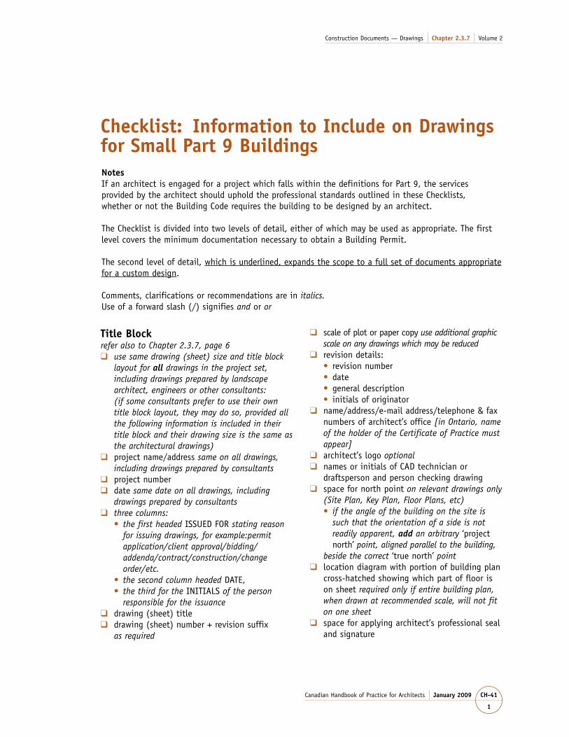
Construction Documents — Drawings Chapter 2.3.7 Volume 2
Canadian Handbook of Practice for Architects January 2009 �CH-��
�
Title Blockrefer also to Chapter 2.3.7, page 6❑ use same drawing (sheet) size and title block
layout for all drawings in the project set, including drawings prepared by landscape architect, engineers or other consultants:
(if some consultants prefer to use their own title block layout, they may do so, provided all the following information is included in their title block and their drawing size is the same as the architectural drawings)
❑ project name/address same on all drawings, including drawings prepared by consultants
❑ project number❑ date same date on all drawings, including
drawings prepared by consultants❑ three columns: • the first headed ISSUED FOR stating reason
for issuing drawings, for example:permit application/client approval/bidding/ addenda/contract/construction/change order/etc.
• the second column headed DATE, • the third for the INITIALS of the person
responsible for the issuance❑ drawing (sheet) title❑ drawing (sheet) number + revision suffix
as required
❑ scale of plot or paper copy use additional graphic scale on any drawings which may be reduced
❑ revision details: • revision number • date • general description • initials of originator❑ name/address/e-mail address/telephone & fax
numbers of architect’s office [in Ontario, name of the holder of the Certificate of Practice must appear]
❑ architect’s logo optional❑ names or initials of CAD technician or
draftsperson and person checking drawing❑ space for north point on relevant drawings only
(Site Plan, Key Plan, Floor Plans, etc) • if the angle of the building on the site is
such that the orientation of a side is not readily apparent, add an arbitrary ‘project north’ point, aligned parallel to the building, beside the correct ‘true north’ point
❑ location diagram with portion of building plan cross-hatched showing which part of floor is on sheet required only if entire building plan, when drawn at recommended scale, will not fit on one sheet
❑ space for applying architect’s professional seal and signature
Checklist: Information to Include on Drawings for Small Part 9 BuildingsNotesIf an architect is engaged for a project which falls within the definitions for Part 9, the services provided by the architect should uphold the professional standards outlined in these Checklists, whether or not the Building Code requires the building to be designed by an architect.
The Checklist is divided into two levels of detail, either of which may be used as appropriate. The first level covers the minimum documentation necessary to obtain a Building Permit.
The second level of detail, which is underlined, expands the scope to a full set of documents appropriate for a custom design.
Comments, clarifications or recommendations are in italics.Use of a forward slash (/) signifies and or or

January 2009 Canadian Handbook of Practice for Architects
Volume 2 Chapter 2.3.7 Construction Documents — Drawings
CH-��
2
(NOTE: on small projects, it may be convenient to include components designed by an engineer (e.g. structural elements; heating system; electrical circuitry) on an architectural drawing which is sealed and signed by the architect; in this event, the engineer’s professional seal must also be applied to each relevant drawing (preferably placed adjacent to the components designed by the engineer), with a notation identifying which items the engineer is responsible for)❑ title block on separate drawings for engineering
disciplines should be similar in content and format except that architect’s logo, professional seal, name and other information are omitted and replaced by corresponding logo, professional seal, name and other information for engineer(s) subject to:
• contractual arrangement with consultants • requirements of provincial association • professional liability insurer❑ notice of copyright (refer to chapter 2.3.7
Supplement No. 1, September 1999)❑ electronic file name and number/date of plot
placed consistently at very bottom or top of title block
Cover Sheet (optional)❑ project name❑ project location small-scale partial map
of community with location of project marked/placed on Site Plan sheet if cover sheet not used
❑ architect’s name, logo❑ list of drawings in specifications or first sheet
if cover sheet not used
Site Planscale: as large as feasible within selected sheet size❑ note stating data taken from survey plan/other
information provided by client (refer to Chapter 2.3.4, Checklist CH-42):
• give surveyor’s name and drawing title/number/date
• note stating source(s) of other information • same building orientation as floor plans❑ project location small-scale partial map of
community with location of project marked❑ site boundaries: • dimensions/orientation of property lines • angles at intersections❑ rights-of-way/easements
❑ zoning setback lines if required by Authorities Having Jurisdiction
❑ benchmark, noting its: • actual (geodetic) elevation • assumed (convenience) elevation used for
specific project/usually designated 100m❑ existing conditions: • levels/elevations: • contour lines/spot elevations • indicate top/bottom at abrupt changes
in level • crown of street(s)/top & bottom of curbs • ditches/swales/water courses/ponds • catch basins/fire hydrants/maintenance
access covers • existing buildings/fences/poles/
buried services: • on site • adjacent to site • differentiation between existing/new
for addition/renovation projects • paving: • sidewalks/paved areas/
driveways/curbs/curb cutouts • vegetation: • species/caliper of trees greater
than 100mm • shrubbery❑ borehole locations as required; borehole logs
not shown on drawings, but available in geotechnical report referenced in specifications
❑ outline of building on site: • located horizontally from property lines • main floor level: • geodetic elevation or • relative to bench mark❑ grading/earthwork: • proposed levels/elevations some of this
information may appear on landscape architectural drawings or civil engineering drawings
❑ landscaping: • existing planting/trees to be
removed/retained/protected • proposed new landscaping may be
developed later by landscape architect❑ site works: • paving: • light/medium/heavy duty asphalt
indicate extent of each • parking areas/roads

Construction Documents — Drawings Chapter 2.3.7 Volume 2
Canadian Handbook of Practice for Architects January 2009 �CH-��
3
• parking lot layout/painted lines • fire access route(s) • interlocking • other • sidewalks/curbs/ramps • concrete pads for transformers/air
conditioning condenser as required • oil tank as required • surface water drainage: • ditches/swales/catch basins • flood control/containment/confined
areas/other environmental protection as required
• siltation control devices as required by Authorities Having Jurisdiction
• septic tank/disposal bed as required • well as required • proposed levels/elevations • fencing/walls/garbage enclosure/hoarding❑ site servicing information: • some or all of this may be shown on
engineering drawings • system of foundation drainage • catch basins/fire hydrants/maintenance
access covers • utilities and other service connections❑ zoning and building code data (refer to OAA
Practice Bulletin A.9, April 2002)❑ site details as required
Key Plan recommendedrecommended scale: 1:200❑ outline plan of each floor level to show entire
building layout on one drawing sheet: • differentiation between existing/new for
addition/renovation projects by cross- hatching/shading
• no hatching or detail • all doors with swings not necessary to
show windows • ramps/stairs, with up/down arrows • toilet partitions/plumbing fixtures • names/numbers of all interior spaces • finish floor level/elevation for each floor level❑ structural grid lines as required❑ primary dimensions: • overall • column centres as required❑ fire separations and ratings as required❑ exits as required❑ exit calculations as required
❑ location of building sections, cross referenced to other drawings
❑ zoning and building code data if not on Site Plan sheet
❑ any other general information Floor Plansrecommended scales: 1:100, 1:50decision on appropriate scale depends on complexity of plan information to be provided. If larger scale is selected, plan blow-ups of complex areas may not be required. Incorporate all items noted under Key Plans if Key Plans not used. Ensure same orientation for all floor plans.❑ differentiation between existing/new for
addition/renovation projects by cross-hatching/shading
❑ outline plan of each floor of entire building, including basement or foundation plan if building has no basement showing:
• scope of demolition work as required • all exterior walls/interior partitions • doors with swings/windows/other
openings -door sizes/types or provide door schedule
• basement walls/piers/columns • outline of wall/pier/column footings
dotted on basement or foundation plan • names of all interior spaces if Key Plan
not used • identifying number of each space
as required❑ finish floor level/elevation for each floor level❑ ramps/stairs, with up/down arrows❑ plumbing fixtures/toilet partitions as required❑ detailed plan of each floor level: depending on scale selected, it may be
necessary to divide each floor into segments shown on separate drawing sheets; (in this case, indicate match line between segments of plan on each sheet)
❑ delineate wall components: • masonry wythes/cavity • insulated metal wall systems • EIFS/drywall/cladding to stud walls • (not necessary to cross-hatch each
element if wall types identified by reference numbers as below)
❑ identify wall assembly types by reference numbers:
• W1, W2, etc. for exterior walls; P1, P2, etc. for interior partitions
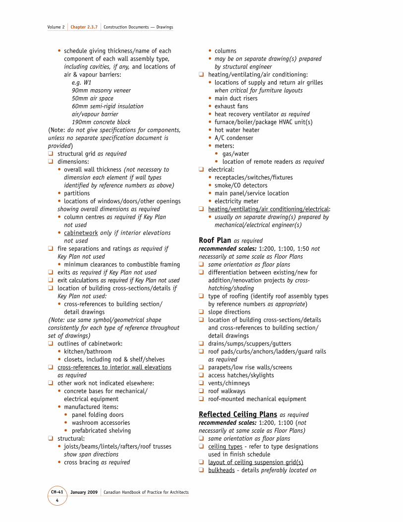
January 2009 Canadian Handbook of Practice for Architects
Volume 2 Chapter 2.3.7 Construction Documents — Drawings
CH-��
�
• schedule giving thickness/name of each component of each wall assembly type, including cavities, if any, and locations of air & vapour barriers:
e.g. W1 90mm masonry veneer 50mm air space 60mm semi-rigid insulation air/vapour barrier 190mm concrete block(Note: do not give specifications for components, unless no separate specification document is provided)❑ structural grid as required❑ dimensions: • overall wall thickness (not necessary to
dimension each element if wall types identified by reference numbers as above)
• partitions • locations of windows/doors/other openings
showing overall dimensions as required • column centres as required if Key Plan
not used • cabinetwork only if interior elevations
not used❑ fire separations and ratings as required if
Key Plan not used • minimum clearances to combustible framing❑ exits as required if Key Plan not used❑ exit calculations as required if Key Plan not used❑ location of building cross-sections/details if
Key Plan not used: • cross-references to building section/
detail drawings(Note: use same symbol/geometrical shape consistently for each type of reference throughout set of drawings)❑ outlines of cabinetwork: • kitchen/bathroom • closets, including rod & shelf/shelves❑ cross-references to interior wall elevations
as required❑ other work not indicated elsewhere: • concrete bases for mechanical/
electrical equipment • manufactured items: • panel folding doors • washroom accessories • prefabricated shelving❑ structural: • joists/beams/lintels/rafters/roof trusses
show span directions • cross bracing as required
• columns • may be on separate drawing(s) prepared
by structural engineer❑ heating/ventilating/air conditioning: • locations of supply and return air grilles
when critical for furniture layouts • main duct risers • exhaust fans • heat recovery ventilator as required • furnace/boiler/package HVAC unit(s) • hot water heater • A/C condenser • meters: • gas/water • location of remote readers as required❑ electrical: • receptacles/switches/fixtures • smoke/CO detectors • main panel/service location • electricity meter ❑ heating/ventilating/air conditioning/electrical: • usually on separate drawing(s) prepared by
mechanical/electrical engineer(s) Roof Plan as requiredrecommended scales: 1:200, 1:100, 1:50 not necessarily at same scale as Floor Plans❑ same orientation as floor plans❑ differentiation between existing/new for
addition/renovation projects by cross-hatching/shading
❑ type of roofing (identify roof assembly types by reference numbers as appropriate)
❑ slope directions❑ location of building cross-sections/details
and cross-references to building section/detail drawings
❑ drains/sumps/scuppers/gutters❑ roof pads/curbs/anchors/ladders/guard rails
as required❑ parapets/low rise walls/screens❑ access hatches/skylights❑ vents/chimneys❑ roof walkways❑ roof-mounted mechanical equipment Reflected Ceiling Plans as requiredrecommended scales: 1:200, 1:100 (not necessarily at same scale as Floor Plans)❑ same orientation as floor plans❑ ceiling types - refer to type designations
used in finish schedule❑ layout of ceiling suspension grid(s)❑ bulkheads - details preferably located on

Construction Documents — Drawings Chapter 2.3.7 Volume 2
Canadian Handbook of Practice for Architects January 2009 �CH-��
�
same sheet❑ cross-references to detail drawings
as required❑ light fixtures❑ supply diffusers❑ return air grilles❑ heat/smoke detectors as required❑ carbon monoxide detectors as required❑ legend showing symbols used Building Sectionsrecommended scales: 1:100, 1:50❑ show all building components that intersect
with section - may include interior elevations showing cabinetwork (kitchen/bathroom/etc.)
❑ differentiation between existing/new for addition/renovation projects by cross-hatching/shading
❑ wall assembly types only if required to augment/clarify notations on floor plans; refer to Floor Plans
❑ levels/elevations: • finish floor for each floor level • roof bearing at walls as required • grade at building • bottom of footings❑ structural grid lines as required❑ vertical dimensions: • floor to floor • floor to roof as required • window openings❑ fire separations and ratings as required❑ cross-references to detail drawings - use same
symbol/geometrical shape consistently for each type of reference throughout set of drawings
❑ structural: • footings • joists/beams/lintels/rafters/roof trusses
only if required to augment/clarify notations on Floor Plans
• in section • in elevation if beyond❑ heating/ventilating/air conditioning: • main horizontal ducts • major equipment Elevationsrecommended scales: 1:100, 1:50❑ all building faces: • include below-grade foundation
walls/footings dotted
• line of grade at building face (if building form is complex, identify parts
of elevation by letter or number on location diagram in title block)
❑ differentiation between existing/new for addition/renovation projects
❑ openings - doors/windows/grilles/vents❑ attachments - light fixtures
/receptacles/signage/downspouts/flagpoles/ etc. as required
❑ structural grid lines as required❑ exterior construction materials: • graphically/notations • masonry control joints❑ locations of interior/hidden levels: • floors • finish floor level/elevation
for each floor level • flat roofs behind parapets❑ vertical dimensions: • to doors/windows/other important items
requiring location • floor to floor or floor to roof only if not
shown on Building Sections❑ location of building cross-sections/details only
if required to augment/clarify notations on Floor Plans
❑ cross-references to building section/detail drawings as required
Wall Sectionsrecommended scale: 1:20One or more vertical wall sections may be sufficient to describe/locate all components of typical wall construction; if basic information required for Building Permit cannot be shown adequately by building and wall sections, use large-scale details to show assemblies (refer to Details)❑ Show all building components that intersect
with section: • section continuous from footing to roof • incorporate typical window or
door condition • indicate location/material of air/
vapour barriers • backfill line showing foundation
drainage/backfill layers • special drainage as required❑ column line as required - dimensioned
to wall face(s)❑ vertical dimensions

January 2009 Canadian Handbook of Practice for Architects
Volume 2 Chapter 2.3.7 Construction Documents — Drawings
CH-��
�
❑ cross-hatching/symbols to indicate materials, plus notations alternative: identify wall assembly types by reference numbers (refer to Floor Plans)
❑ structural: • footings/reinforcing • anchor bolts • joists/beams/lintels/rafters/roof trusses
Detailed Floor Plansrecommended scales: 1:50, 1:20plan blow-ups of complex areas, as required❑ bathrooms/washrooms❑ kitchens❑ special floor finish layouts/patterns/details❑ cross-references to detail drawings
as required Detailslarge-scale details of all building envelope/assembly conditions:recommended scales: 1:10, 1:5❑ vertical section details, arranged according to
relative positions in wall typically: • wall/floor intersections • window sills • window/door heads • wall/roof intersections • wall assembly type reference numbers❑ horizontal section details typically: • corners • intersections with columns/partitions • window/door jambs❑ notations: • floor/roof levels/elevations on vertical
section details • typical assemblies not covered by
reference numbers • through-wall flashings • air/vapour barriers • dimensions not already shown on
plans/elevations/building sections
other details:small-scale key drawings of assemblies (stairs/cabinets/etc.) cross-referenced to large-scale details on same or adjacent sheetsrecommended scales: 1:50, 1:20, 1:10, 1:5, 1:1 as required❑ door/window elevations: • hollow metal door/sidelight/window
frames • aluminum entrance/sidelight/store front
frames • window types • door types❑ interior wall elevations: • elevations of cabinetwork typically
showing horizontal dimensions • other wall-mounted items❑ stairs/handrails/guards❑ fireplace(s)❑ outdoor decks/stairs/rails/trellises❑ cabinetwork/millwork - fully dimensioned,
large-scale sectional details❑ large scale sectional details as required: • wood/aluminum window frame components • hollow metal frames Schedules as required❑ wall types refer to Floor Plans • exterior walls • interior partitions❑ roof types refer to Roof Plan❑ doors and door frames❑ windows❑ lintels❑ hardware❑ room finishes❑ colour❑ planting

Construction Documents — Drawings Chapter 2.3.7 Volume 2
Canadian Handbook of Practice for Architects January 2009 �CH-�2
�
Chart: National Building Code Data MatrixIntroduction
The purpose of the matrix is to provide a standardized system for including building code - related data on a set of drawings that are submitted for building permit application. Numbers in the matrix are the relevant National Building Code (NBC) references. The matrix may be modified to suit the references in various provincial building codes. The Ontario Association of Architects (OAA) has a similar matrix available to be used with the Ontario Building Code.
It is important to put this matrix in a prominent location on the drawings which will:
• expedite the building official’s review of the application;
• inform others (contractors, trades, consultants, etc.) about applicable NBC related issues.
Additional information such as exiting widths and routes, fire separations and other data is generally shown on separate drawings, as necessary.
Procedure
1. Establish a system in your practice that facilitates retrieval of the information to be shown on the application for building permit;
2. Ascertain this information through a code analysis in the early design stages of a project and reconfirm it throughout the design development and construction documents (drawing) stages;
3. Consider using the NBC Data Matrix as a standard format which can be adapted as required to meet the specific requirements of each project. It may be preferable to provide more than one matrix for complex projects (for example: underground parking garage - Part 3, townhouses - Part 9, on same site);
4. Assign a location for NBC Data Matrix on the drawings as an office standard (one of the first or top drawing sheets is best);
5. Add exit capacity calculations confirming that exit capacity exceeds occupant load on the same drawing sheet as the NBC Data Matrix, or separately, as appropriate. Always verify reference numbers against the latest NBC revisions;
6. Coordinate with structural, mechanical and electrical engineering consultants and share data with them based on your code analysis;
7. Instruct them to include NBC related data pertinent to their disciplines on their drawings. The building code data should be:• prepared specifically for the project;• in a similar format;• in accordance with the standards of their
profession.
If the NBC Data Matrix is included in a project manual (rather than on the drawings), ensure that building name and address, project number and date of issuance are inserted at the top of the matrix.
Completing the Matrix
Matrix presents elements selected from the detailed code analysis and provides a quick overview to the municipal building officials of the key NBC factors governing the design of the project.
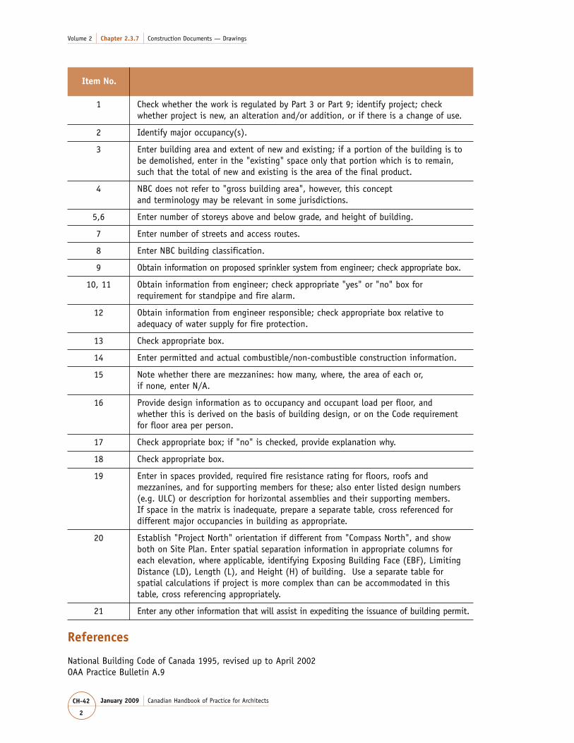
January 2009 Canadian Handbook of Practice for Architects
Volume 2 Chapter 2.3.7 Construction Documents — Drawings
CH-�2
2
Item No.
1 Check whether the work is regulated by Part 3 or Part 9; identify project; check whether project is new, an alteration and/or addition, or if there is a change of use.
2 Identify major occupancy(s).
3 Enter building area and extent of new and existing; if a portion of the building is to be demolished, enter in the "existing" space only that portion which is to remain, such that the total of new and existing is the area of the final product.
4 NBC does not refer to "gross building area", however, this concept and terminology may be relevant in some jurisdictions.
5,6 Enter number of storeys above and below grade, and height of building.
7 Enter number of streets and access routes.
8 Enter NBC building classification.
9 Obtain information on proposed sprinkler system from engineer; check appropriate box.
10, 11 Obtain information from engineer; check appropriate "yes" or "no" box for requirement for standpipe and fire alarm.
12 Obtain information from engineer responsible; check appropriate box relative to adequacy of water supply for fire protection.
13 Check appropriate box.
14 Enter permitted and actual combustible/non-combustible construction information.
15 Note whether there are mezzanines: how many, where, the area of each or, if none, enter N/A.
16 Provide design information as to occupancy and occupant load per floor, and whether this is derived on the basis of building design, or on the Code requirement for floor area per person.
17 Check appropriate box; if "no" is checked, provide explanation why.
18 Check appropriate box.
19 Enter in spaces provided, required fire resistance rating for floors, roofs and mezzanines, and for supporting members for these; also enter listed design numbers (e.g. ULC) or description for horizontal assemblies and their supporting members. If space in the matrix is inadequate, prepare a separate table, cross referenced for different major occupancies in building as appropriate.
20 Establish "Project North" orientation if different from "Compass North", and show both on Site Plan. Enter spatial separation information in appropriate columns for each elevation, where applicable, identifying Exposing Building Face (EBF), Limiting Distance (LD), Length (L), and Height (H) of building. Use a separate table for spatial calculations if project is more complex than can be accommodated in this table, cross referencing appropriately.
21 Enter any other information that will assist in expediting the issuance of building permit.
References
National Building Code of Canada 1995, revised up to April 2002OAA Practice Bulletin A.9

Construction Documents — Drawings Chapter 2.3.7 Volume 2
Canadian Handbook of Practice for Architects January 2009 �CH-�2
3
1 Project Description: ❑ Change of Use ❑ New ❑ Part 3 ❑ Part 9 ❑ Addition 2.1.3.1 ❑ Alteration 9.10.1.3
2 Major Occupancy(s) 3.1.2.1.(1) 9.10.2
3 Building Area (m2) Existing ______ New ______ Total ______ 1.1.3.2 1.1.3.2
4 Gross Area Existing ______ New ______ Total ______
5 Number of Storeys Above grade ______ Below grade _______ 3.2.1.1 & 1.1.3.2 2.1.3.1
6 Height of Building (m) 2.1.3.1
7 Number of Streets/Access Routes 3.2.2.10 & 3.2.5.5
8 Building Classification 3.2.2.20-.83 9.10.4
9 Sprinkler System Proposed ❑ entire building 3.2.2.20-.83 9.10.8.2 ❑ basement only 3.2.1.5 ❑ in lieu of roof rating 3.2.2.17 ❑ not required
10 Standpipe required ❑ Yes ❑ No 3.2.5.8
11 Fire Alarm required ❑ Yes ❑ No 3.2.4 9.10.17.2
12 Water Service/Supply is Adequate ❑ Yes ❑ No 3.2.5.7
13 High Building ❑ Yes ❑ No 3.2.6
14 Permitted Construction ❑ Combustible ❑ Non-combustible ❑ Both 3.2.2.20-.83 9.10.6 Actual Construction ❑ Combustible ❑ Non-combustible ❑ Both
15 Mezzanine(s) Area (m2) 3.2.1.1.(3)-(8) 9.10.4.1
16 Occupant load based on ❑ m2/person ❑ design of building 3.1.1.6 9.9.1.3 Basement: Occupancy _____ Load ____ persons 1st Floor Occupancy _____ Load ____ persons 2nd Floor Occupancy _____ Load ____ persons 3rd Floor Occupancy _____ Load ____ persons
17 Barrier-free Design ❑ Yes ❑ No(Explain) 3.8 9.5.2
18 Hazardous Substances ❑ Yes ❑ No 3.3.1.2.(1) & 9.10.1.3.(4) 3.3.1.19(1)
19 Required Horizontal Assemblies Listed Design No. 3.2.2.20-.83 & 9.10.8 Fire FRR (Hours) or Description (SG-2) 3.2.1.4 9.10.9 Resistance Floors __________ Hours Rating Roof ___________ Hours (FRR) Mezzanine ______ Hours FRR of Supporting Listed Design No. Members Or Description (SG-2) Floors __________ Hours Roof ___________ Hours Mezzanine ______ Hours
20 Spatial Separation – Construction of Exterior Walls 3.2.3 9.10.14
Wall Area of L.D. L/H Permitted Proposed FRR Listed Comb. Comb. Constr. Non-comb. EBF (m2) (m) or Max. % of % of (Hours) Design or Const Nonc. Constr. H/L Openings Openings Description Cladding North South East West For Additional Walls, add additional rows
21 Other
Item National Building Code Data Matrix Parts 3 & 9 NBC Reference