Embed Size (px)
Citation preview

GENERATOR SET5.5 HP - RECOIL START - 2200W/2400W RATED
Model 91213
OPERATING INSTRUCTIONS
Generators
3491 Mission Oaks Blvd., Camarillo, CA 93011Visit our Web site at http://www.harborfreight.com
Copyright© 2004 by Harbor Freight Tools®. All rights reserved. Noportion of this manual or any artwork contained herein may be reproduced inany shape or form without the express written consent of Harbor Freight Tools.
For technical questions and replacement parts, please call 1-800-444-3353
TO PREVENT SERIOUS INJURY OR DEATH,READ AND UNDERSTAND ALL WARNINGS
AND INSTRUCTIONS BEFORE USE.

SKU 91213 PAGE 2
PRODUCT SPECIFICATIONS
.
Item Description VAC Electrical Requirements
115 Volts @ 19 AMPs Current Output 60 Hz Continuous/Rated W attage: 2,200 Peak W attage: 2,400 Two 115 VAC, 3-Prong Grounding Outlets One 19 AMP Circuit Breaker
VDC Electrical Requirements
12 VDC @ 10 AMPs Current Output
Voltmeter Equipped 0-150 Volts / 50 Volt Increments Display Lights Red (Run) Generator Type Brushless / Revolving Field / Self Exciting
Two Pole / Single Phase Gasoline Engine 5.5 HP / Unleaded Gasoline Powered
Recoil Start / 4-Cycle / OHV Air Cooled 163 CC Displacement / 3600 RPM 0.63 Quart (0.6 Liter) O il Capacity EPA Approved
Fuel Tank Capacity 3.96 Gallons (15 Liters) / Includes Fuel Gauge Estimated Run Time 11.8 Continuous Running Hours W eight 103.6 Pounds
This product requires oil and fuel to be added before starting.Attempting to start the engine without oil WILL ruin the engine andvoid the warranty.
Caution: This generator is not intended to power sensitive electronicequipment without the addition of an appropriate line conditioner(sold separately).
SAVE THIS MANUAL
You will need this manual for the safety warnings and precautions, operating,inspection, maintenance and cleaning procedures, parts list and assembly diagram.Keep your invoice with this manual. Write the invoice number on the inside of the frontcover. Keep this manual and invoice in a safe and dry place for future reference.

SKU 91213 PAGE 3
WORK AREA
1. Keep your work area clean and well lit. Cluttered benches and dark areas inviteaccidents.
2. Do not operate power tools in explosive atmospheres, such as in the pres-ence of flammable liquids, gases, or dust. Generators create sparks which mayignite the dust or fumes.
3. Keep bystanders, children, and visitors away while operating a generator.Provide barriers or shields as needed.
ELECTRICAL SAFETY
4. Grounded tools must be plugged into an outlet properly installed and groundedin accordance with all codes and ordinances. Never remove the groundingprong or modify the plug in any way. Do not use any adapter plugs. Checkwith a qualified electrician if you are in doubt as to whether the outlet is prop-erly grounded. If the tools should electrically malfunction or break down, ground-ing provides a low resistance path to carry electricity away from the user.
5. Double insulated tools are equipped with a polarized plug (one blade is widerthan the other). This plug will fit in a polarized outlet only one way. If the plugdoes not fit fully in the outlet, reverse the plug. If it still does not fit, contact a qualified electrician to install a polarized outlet. Do not change the plug inany way. Double insulation eliminates the need for the three wire groundedpower cord and grounded power supply system.
GENERAL SAFETY RULES
WARNING!
READ AND UNDERSTAND ALL INSTRUCTIONSFailure to follow all instructions listed below may result in
electric shock, fire, and/or serious injury.SAVE THESE INSTRUCTIONS
UNPACKING
When unpacking, check to make sure all the parts shown on the Parts Lists onpages 18 and 20 are included. If any parts are missing or broken, please call HarborFreight Tools at the number shown on the cover of this manual as soon as possible.
SKU 91213 PAGE 4
6. Avoid body contact with grounded surfaces such as pipes, radiators, ranges,and refrigerators. There is an increased risk of electric shock if your body isgrounded.
7. Do not expose power tools to rain or wet conditions. Water entering agenerator will increase the risk of electric shock.
8. Do not abuse the Power Cords. Never use a Power Cord to carry tools orpull the Plug from an outlet. Keep Power Cords away from heat, oil, sharpedges, or moving parts. Replace damaged Power Cords immediately. Dam-aged Power Cords increase the risk of electric shock.
9. When operating a power tool outside, use an outdoor extension cordmarked “W-A” or “W”. These extension cords are rated for outdoor use, andreduce the risk of electric shock.
PERSONAL SAFETY
10. Stay alert. Watch what you are doing, and use common sense when oper-ating a generator. Do not use a generator while tired or under the influ-ence of drugs, alcohol, or medication. A moment of inattention while operat-ing generators may result in serious personal injury.
11. Dress properly. Do not wear loose clothing or jewelry. Contain long hair.Keep your hair, clothing, and gloves away from moving parts. Looseclothes, jewelry, or long hair can be caught in moving parts.
12. Avoid accidental starting. Make sure the Power Switch is in its “OFF”position, and disconnect the Spark Plug Wire when not in use.
13. Remove adjusting keys or wrenches before turning the generator on. Awrench or a key that is left attached to a rotating part of the generator may resultin personal injury.
14. Do not overreach. Keep proper footing and balance at all times.
15. Use safety equipment. Always wear eye protection. Wear ANSI approvedsafety impact eye goggles. Dust mask, non-skid safety shoes, hard hat, orhearing protection must be used for appropriate conditions.
16. Do not force the generator. Use the correct generator for your application.The correct generator will do the job better and safer at the rate for which it isdesigned.

SKU 91213 PAGE 5
17. Do not use the generator if the Power Switch does not turn it on or off. Anygenerator that cannot be controlled with the Power Switch is dangerous and mustbe replaced.
GENERATOR USE AND CARE
18. Make sure the Power Switch is in its “OFF” position and disconnect thespark plug wire before making any adjustments, changing accessories, orstoring the generator. Such preventive safety measures reduce the risk ofstarting the generator accidentally.
19. Store idle generators out of reach of children and other untrained persons.Generators are dangerous in the hands of untrained users.
20. Maintain generators with care. Do not use a damaged generator. Tag dam-aged generators “Do not use” until repaired.
21. Check for misalignment or binding of moving parts, breakage of parts, andany other condition that may affect the generator’s operation. If damaged,have the generator serviced before using. Many accidents are caused bypoorly maintained generators.
22. Use only accessories that are recommended by the manufacturer for yourmodel. Accessories that may be suitable for one generator may become hazard-ous when used on another generator.
SERVICE
23. Maintain labels and nameplates on the Generator and Engine. These carryimportant information. If unreadable or missing, contact Harbor Freight Tools fora replacement.
24. Generator service must be performed only by qualified repair personnel.Service or maintenance performed by unqualified personnel could result in a riskof injury.
25. When servicing a generator, use only identical replacement parts. Followinstructions in the “Inspection, Maintenance, And Cleaning” section of thismanual. Use of unauthorized parts or failure to follow maintenance instructionsmay create a risk of electric shock or injury.

SKU 91213 PAGE 6
HEART PACEMAKER PRECAUTION
SPECIFIC PRODUCT WARNINGS AND PRECAUTIONS
1. WARNING! People with pacemakers should consult their physician(s)before using this product. Electromagnetic fields in close proximity to a heartpacemaker could cause interference to or failure of the pacemaker.
INSTALLATION PRECAUTIONS
1. Ensure installation meets all applicable safety, and local and national electricalcodes. Have installation performed by a qualified, licensed electrician and bui ld-ing contractor.
2. All electrical work, including the earth-ground connection, should be completed bya licensed electrician.
3. Any separate fuel storage Generator supply facility must be built or installed in fullcompliance with all relevant local, state, and federal regulations.
4. If the generator is installed indoors, exhaust fumes must be piped out of thebuilding using leak-free, heat-resistant piping. Use the Generator only inwell ventilated outdoor areas. Carbon monoxide fumes are a colorless,odorless gas that, if inhaled, can cause serious injury or death. Pipesand silencer should not use any flammable materials, nor should they beinstalled near the same. Generator exhaust fumes must be within legal lim-its.
5. If the generator is installed outdoors, it must be weatherproofed and should be sound-proofed. It should not be run outdoors without protection to the Generator and wir-ing conduit.
6. Never lift the Generator using the engine or alternator lifting lugs. Connect liftingequipment to the Frame of the Generator.
7. Before lifting the Generator, ensure the lift rigging and supporting structure are ingood condition, and are rated to lift such a load.
8. Keep all personnel away from the suspended generator while relocating.
9. The supporting floor/ground surface should be level, and strong enough to safelyhold the weight of the Generator. If the floor/ground surface is not level, strong crossmembers should be placed under the full length of the Generator Frame at its lowside.

SKU 91213 PAGE 7
1. Gasoline fuel and fumes are flammable, and potentially explosive. Use properfuel storage and handling procedures. Always have multiple ABC class fireextinguishers nearby.
2. Keep the Generator and surrounding area clean at all times.
3. When spills of fuel or oil occur, they must be cleaned up immediately. Dispose offluids and cleaning materials as per any local, state, or federal codes and regula-tions. Store oil rags in a covered metal container.
4. Never store fuel or other flammable materials near the Generator.
5. Do not smoke, or allow sparks, flames or other sources of ignition around theEngine and Fuel Tank. Fuel vapors are explosive.
6. Keep grounded conductive objects, such as tools, away from exposed, liveelectrical parts and connections to avoid sparking or arcing. These events couldignite fumes or vapors.
7. Do not refill the Fuel Tank while the Engine is running or while the Engine is stillhot. Do not operate the Generator with known leaks in the fuel system.
8. Excessive buildup of unburned fuel gases in the exhaust system can create apotentially explosive condition. This buildup can occur after repeated failed startattempts, valve testing, or hot engine shutdown. If this occurs, open exhaustsystem drain plugs, if equipped, and allow the gases to dissipate before attempt-ing to restart the Generator.
9. Use only engine manufacturer recommended fuel and oil.
10. For trailer installation, the Generator should be mounted on the center point of thetrailer, over the wheels.
11. Install sound and weather proofing only when it is not raining or snowing to avoidtrapping moisture within the Generator’s area.
FIRE AND EXPLOSION PRECAUTIONS

SKU 91213 PAGE 8
MECHANICAL PRECAUTIONS
1. ALWAYS make sure the Power Switch is in its “OFF” position. Disconnect thespark plug wire, and allow the Engine to completely cool before carrying outmaintenance.
2. Check for damaged parts. Before using the Generator, any part that appearsdamaged should be carefully checked to determine that it will operate properlyand perform its intended function. Check for alignment and binding of movingparts, any broken parts or mounting fixtures, and any other condition that mayaffect proper operation. Any part that is damaged should be properly repaired orreplaced by a qualified technician.
3. The Generator is designed with guards for protection from moving parts. In anycase, care must still be taken to protect personnel and equipment from othermechanical hazards when working around the generator.
4. Do not operate the Generator with safety guards removed. While the Generatoris running, do not attempt to reach around the safety guards for maintenance orany other reason.
5. Keep hands, arms, long hair, loose clothing, and jewelry away from moving parts.Be aware that when engine parts are moving fast they cannot be seen clearly.
6. Keep access doors on enclosures closed and locked when access is not re-quired.
7. When working on or around the Generator always wear protective clothing in-cluding ANSI approved safety gloves, safety eye goggles, and safety hat.
8. Do not alter or adjust any part of the Generator that is assembled and suppliedby the manufacturer.
9. Always follow and complete scheduled Engine and Generator maintenance.
CHEMICAL PRECAUTIONS
1. Avoid contact with hot fuel, oil, exhaust fumes, and solid surfaces.
2. Avoid body contact with fuels, oils, and lubricants used in the Generator. Ifswallowed, seek medical treatment immediately. Do not induce vomiting if fuel isswallowed. For skin contact, immediately wash with soap and water. For eyecontact, immediately flush eyes with clean water.
SKU 91213 PAGE 9
NOISE PRECAUTIONS
1. Prolonged exposure to noise levels above 85 dBA is hazardous to hearing.Always wear ANSI approved ear protection when operating or working aroundthe Generator when it is running.
ELECTRICAL PRECAUTIONS
1. All connections and conduits from the Generator to the load must only be in-stalled by trained and licensed electricians, and in compliance with all relevantlocal, state, and federal electrical codes and standards, and other regulationswhere applicable.
2. The Generator must be earth-grounded in accordance with all relevant electricalcodes and standards before operation.
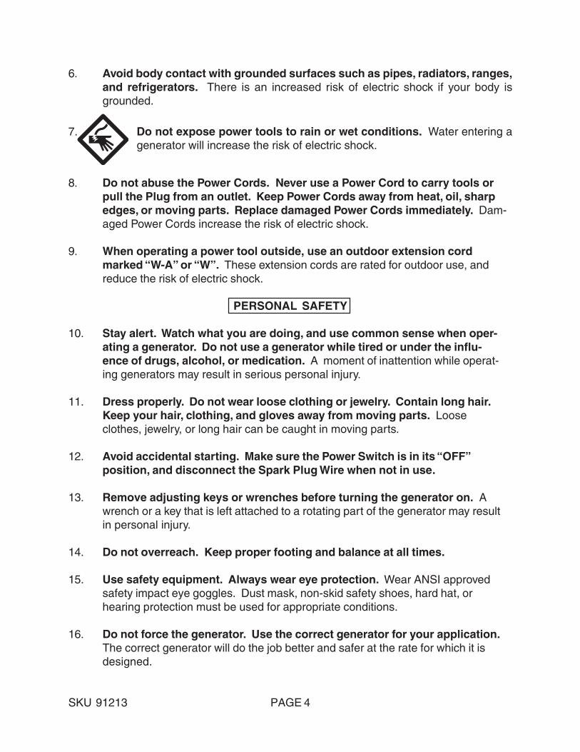
3. If an extension cord (not included) is used, make sure to use only UL approvedcords having the correct gauge and length. (See Figure A.)
REQUIRED MINIMUM EXTENSION CORD GAUGE – 120 VOLTNAMEPLATE
AMPERES(At Full Load)
EXTENSION CORD LENGTH
0 - 25Feet
25 - 50Feet
50 -100Feet
100 – 150Feet
150– 200Feet
0 - 5 16 16 16 12 125.1 - 8 16 16 14 10 -
8.1 - 12 14 14 12 - -12.1 - 15 12 12 10 - -15.1 - 20 10 10 10 - -
FIGURE A
®
4. Do not attempt to connect or disconnect load connections while standing inwater, or on wet or soggy ground.
5. Do not touch electrically energized parts of the Generator and interconnectingcables or conductors with any part of the body, or with any non-insulatedconductive object.
6. Connect the generator only to a load or electrical system (115 volt) that is com-patible with the electrical characteristics and rated capacities of the Generator.
7. Before servicing equipment powered by the Generator, disconnect the equipmentfrom its power input.

SKU 91213 PAGE 10
8. Keep all electrical equipment clean and dry. Replace any wiring where the insu-lation is cracked, cut, abraded or otherwise degraded. Replace terminals thatare worn, discolored, or corroded. Keep terminals clean and tight.
9. Insulate all connections and disconnected wires.
10. Guard against electric shock. Prevent body contact with grounded surfaces suchas pipes, radiators, ranges, and refrigerator enclosures.
11. Use only Class BC or Class ABC fire extinguishers on electrical fires.
INSTALLATION
1. NOTE: Prior to powering tools and equipment, make sure the Generator’s ratedvoltage, wattage, and amperage capacity (115V - 20AMPs) is adequate to supplyall electrical loads that the unit will power. If powering exceeds the Generator’scapacity, it may be necessary to group one or more of the tools and/or equipmentfor connection to a separate Generator.
2. Electrical and other permits may be required for the installation of emergencypower systems. Investigate the local building and electrical codes before install-ing this unit. Installation must be completed by licensed contractors.
3. WARNING! The Generator weighs 103.6 pounds. Use care and the properlifting or hoisting equipment when moving it to the installation location. Alwaysconnect hoist lines to the Frame (41) of the Generator.
GENERAL LOCATION
1. It is recommended to locate and install the Generator outdoors where cooling airis readily available.
2. Install the Generator so that the air inlets and outlets are not blocked by obstruc-tions such as bushes, trees, or snow drifts. Locating it in the path of heavy windsor snowdrifts may require the placement of a barrier for protection. The air inlet,in normal weather conditions, should face the prevailing wind direction.
3. Install the Generator on a concrete slab or other area where rain drainage orflood waters can not reach it.
4. Generator placement should allow four feet of access to all sides for mainte-nance.

SKU 91213 PAGE 11
5. Place the Generator as close as possible to the electrical tools and equipmentbeing powered to reduce the length of extension cords.
6. If the Generator in located indoors the Engine exhaust must be ventilated to theoutdoors using leak-proof, heat resistant, flexible, metal, flex tubing.
GENERATOR SUPPORT AND MOUNTING
1. Mount the Generator on a concrete slab capable of supporting the weight of theGenerator. The slab must extend on all sides beyond the Frame (41) by at leastone foot. Contact a cement contractor for slab specifications if necessary. Attachthe Frame to the concrete slab using 3/8” diameter expansion anchor bolts (notsupplied).
GROUNDING THE GENERATOR
1. NOTE: It is recommended that only a trained and licensed electrician performthis procedure.
OPERATING INSTRUCTIONS
NOTE: For additional references to the parts listed in the following pages, refer to theAssembly Diagrams on pages 19 and 21.
Pre-Start Checks:
1. Check to make sure the Engine’s Power Switch (2) is in its “OFF” position.(See Figure B, next page.)
2. Connect a #6 AWG grounding wire (not included) from the Ground Connector (8)on the Generator to a grounding rod (not included) that has been driven at least24 inches deep into the earth. The grounding rod must be an earth-driven cop-per or brass rod (electrode) which can adequately ground the Generator.(See Figure B, next page.)
2. IMPORTANT! Prior to first using the Generator, the Engine MUST be filledwith approximately 3/4 (0.63) quart of a high quality SAE 10W-30 gradeengine oil. To do so, unscrew and remove the Engine’s Oil Dipstick (65A) lo-cated at the bottom of the Engine Crankcase. Fill the Engine’s Crankcase untilthe oil level is level with the upper marked line on the Dipstick. Then, screw theDipstick back into the Oil Fill Hole. (See Figure C, next page.)

SKU 91213 PAGE 12
GROUND CONNECTOR(8)
#6AWGGROUNDING WIRE(NOT INCLUDED)
GROUNDING ROD(NOT INCLUDED)
FIGURE B
OIL DIPSTICK(65A)
FIGURE C
FUEL TANK(30)
FUEL TANK CAP(33)
FUEL GAUGE (34)
ENGINEPOWERSWITCH
(2)

SKU 91213 PAGE 13
3. Before the first use, remove the Fuel Tank Cap (33) and fill the Fuel Tank (30) withunleaded gasoline. Then, replace the Fuel Tank Cap. Thereafter, check theEngine’s Fuel Gauge (34) for the amount of unleaded gasoline in the Fuel Tank. Ifnecessary, refill the Fuel Tank with unleaded gasoline. (See Figure C.)
To Start The Engine:
1. Make sure the electrical powered tools/equipment that will be used is notplugged in to the Generator.
2. Turn the 115 volt AC Circuit Breaker (5) to its “ON” position. (See Figure D.)
3. Turn on the Fuel Valve (40). (See Figure E.)
4. Close the Choke Lever (21A) to about 1/8” clearance. (See Figure E.)
OFF
ON
CIRCUIT BREAKER(5)
FIGURE D
OFF
ON
CLOSED OPEN
FUEL VALVE (40)
CHOKE LEVER(21A)
FIGURE E
REV 03/06
SKU 91213 PAGE 14
FUEL TANK (32)
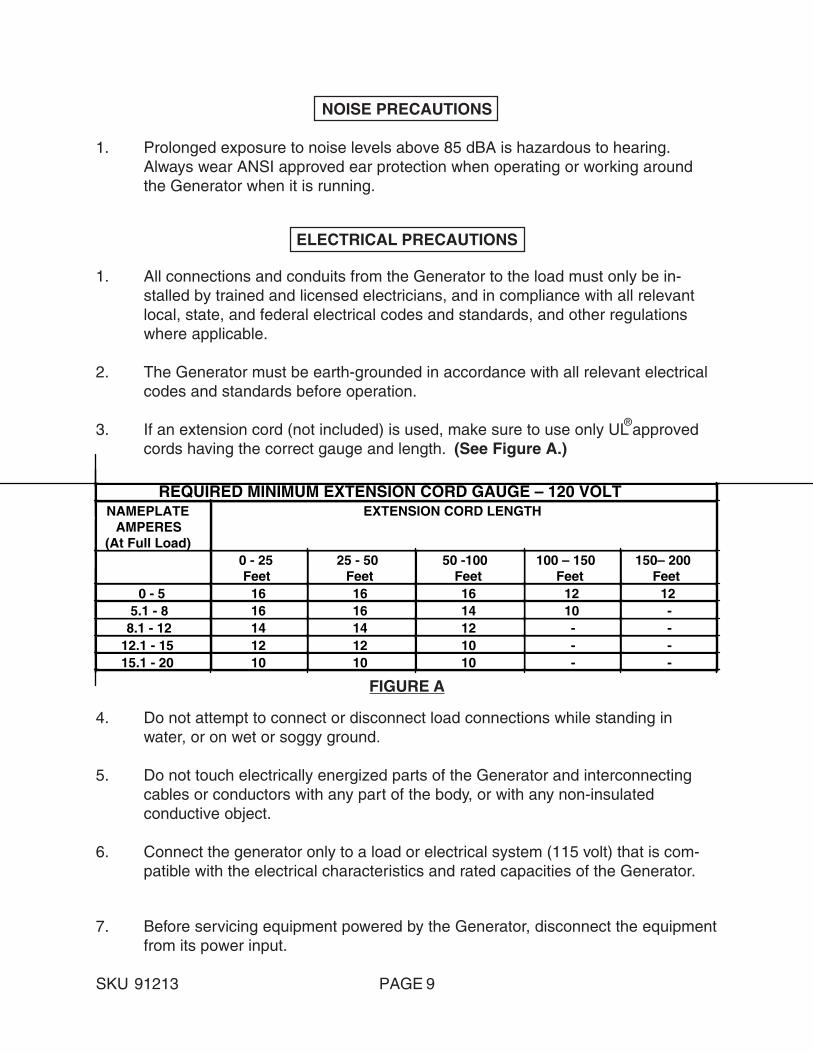
5. Turn the Engine Power Switch (2) to its “ON” position. (See Figure F.)
ENGINEPOWERSWITCH
(2)
ON
OFF
FIGURE F
6. Hold the Start Handle (41A) loosely and pull it slowly several times to allow thegasoline to flow into the Engine’s carburetor. Then hold the Start Handle firmlyand pull the rope hard and fast. Pull the rope all the way out, using two hands ifnecessary. If necessary pull the rope several times until the Engine starts.(See Figure G.)
7. Allow the Engine to run for several seconds. Then, open the Choke Lever (21A)all the way. (See Figure E.)
FIGURE G
STARTHANDLE
(41A)
120 VOLTDUEL
OUTLETS(6)
SKU 91213 PAGE 15
Powering 120 Volt AC Tools And Equipment:
1. Prior to powering tools and equipment, make sure the Generator’s rated voltage,and amperage capacity (115VAC/20 AMPs) is adequate to supply all electricalloads that the unit will power. If powering exceeds the Generator’s capacity, itmay be necessary to group one or more of the tools and/or equipment for con-nection to a separate generator.
2. Once the Generator is running, simply connect the Power Cords of 115 volt ACpowered tools and equipment into the 115 volt AC Duel Outlets (6).(See Figure G.)
3. NOTE: The Generator features an AC Non-Fuse Circuit Breaker (5) to protect theAC circuit in case of an overload. Should an overload occur the Breaker will “trip”to its “OFF” position, causing the Generator to automatically shut down. In thiscase, refer to Step #1 above in this section. Then, reset the circuitry system byturning the Circuit Breaker to its “ON” position. Restart the Generator and con-tinue powering the remaining tools and equipment. (See Figure D.)
4. When finished using the Generator, turn the Engine Power Switch (2) to its“OFF” position. Turn the Fuel Valve (40) to its “OFF” position. Then, discon-nect all electrical powered tools and equipment from the Generator’s 115 volt ACDuel Outlets (6). (See Figures E, F, and G.)
5. After the Engine and Generator have completely cooled, store the Generator in asafe, clean, dry location (if not already installed in one).
Powering 12 Volt DC Tools And Equipment:
1. Prior to powering a tool or equipment, make sure the Generator’s rated voltage,and amperage capacity (12VDC/10 AMPs) is adequate to supply all electricalloads that the unit will power. If powering exceeds the Generator’s capacity, itmay be necessary to group one or more of the tools and/or equipment for con-nection to a separate generator.
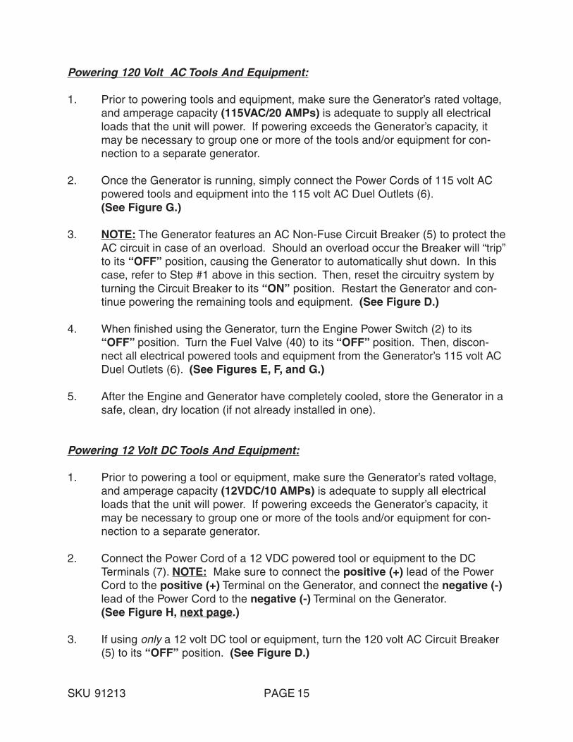
2. Connect the Power Cord of a 12 VDC powered tool or equipment to the DCTerminals (7). NOTE: Make sure to connect the positive (+) lead of the PowerCord to the positive (+) Terminal on the Generator, and connect the negative (-)lead of the Power Cord to the negative (-) Terminal on the Generator.(See Figure H, next page.)
3. If using only a 12 volt DC tool or equipment, turn the 120 volt AC Circuit Breaker(5) to its “OFF” position. (See Figure D.)
SKU 91213 PAGE 16
7. NOTE: The Generator features a 10 AMP DC Fuse (9) to protect the DC circuit incase of an overload. Should an overload occur the Fuse will burn out, causingthe Generator to automatically shut down. In this case, refer to Step #1 in thissection. Then, reset the circuitry system by replacing the burnt Fuse with a new10 AMP DC Fuse. Restart the Generator and continue powering the remainingtool or equipment. (See Figure H.)
4. Start and run the Engine as previously discussed in this manual.
5. When finished using the Generator, turn the Engine Power Switch (2) to its“OFF” position. Turn the Fuel Valve (40) to its “OFF” position. Then, discon-nect the electrical powered tool or equipment from the Generator’s DC Terminals(7). (See Figure H.)
6. After the Engine and Generator have completely cooled, store the Generator in asafe, clean, dry location (if not already installed in one).
10 AMPDC FUSE
(9)
POSITIVE (+) DC TERMINAL (7)
NEGATIVE (-) DC TERMINAL (7)
FIGURE H
INSPECTION, CLEANING, AND MAINTENANCE
1. CAUTION! Always make sure the Engine Power Switch (2) is in its “OFF”position. Disconnect the spark plug wire from the engine. And allow suffi-cient time for the Engine and Generator to completely cool before perform-ing any inspection, maintenance, or cleaning.
2. Before each use, inspect the general condition of the Generator. Check forloose screws, misalignment or binding of moving parts, cracked or broken parts,

SKU 91213 PAGE 17
damaged electrical wiring, and any other condition that may affect its safe opera-tion. If abnormal noise or vibration occurs, have the problem corrected beforefurther use. Do not use damaged equipment.
3. Before each use, check to make sure the Engine’s oil level is adequate. If nec-essary, fill the Engine’s Crankcase until the oil level is even with the Oil Fill Hole.
4. Before each use, With a soft brush, cloth, or vacuum, remove all debris from theGenerator. Then, use a premium quality, lightweight machine oil to lubricate allmoving parts.
5. Every 20 hours of use, drain the old Engine oil and replace with approximately3/4 (0.63) quart of a high quality SAE 10W-30 grade engine oil.
6. Every 300 hours of use, have a qualified, certified technician perform thoroughmaintenance on the Generator and its Engine.
PLEASE READ THE FOLLOWING CAREFULLY
THE MANUFACTURER AND/OR DISTRIBUTOR HAS PROVIDED THE PARTS LIST AND ASSEMBLYDIAGRAM IN THIS MANUAL AS A REFERENCE TOOL ONLY. NEITHER THE MANUFACTURER ORDISTRIBUTOR MAKES ANY REPRESENTATION OR WARRANTY OF ANY KIND TO THE BUYERTHAT HE OR SHE IS QUALIFIED TO MAKE ANY REPAIRS TO THE PRODUCT, OR THAT HE OR SHEIS QUALIFIED TO REPLACE ANY PARTS OF THE PRODUCT. IN FACT, THE MANUFACTUER AND/OR DISTRIBUTOR EXPRESSLY STATES THAT ALL REPAIRS AND PARTS REPLACEMENTS SHOULDBE UNDERTAKEN BY CERTIFIED AND LICENSED TECHNICIANS, AND NOT BY THE BUYER. THEBUYER ASSUMES ALL RISK AND LIABILITY ARISING OUT OF HIS OR HER REPAIRS TO THEORIGINAL PRODUCT OR REPLACEMENT PARTS THERETO, OR ARISING OUT OF HIS OR HERINSTALLATION OF REPLACEMENT PARTS THERETO.

SKU 91213 PAGE 18
PARTS LIST
NOTE: Some parts are listed and shown for illustration purposes only, and are notavailable individually as replacement parts.
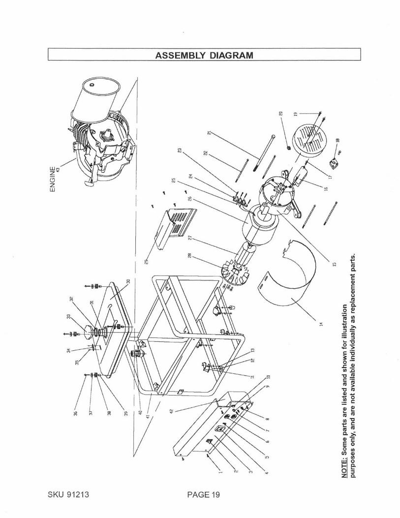
Part # Description Qty. Part # Description Qty. 1 Bolt (M6 x 12) w/Lock Washer 9 22 Bolt (M6 x 152) 4 2 Engine Power Switch 1 23 Bolt (M5 x 20) 4 3 Control Panel 1 24 Connection Board 1 4 Voltmeter 1 25 Nut (M5) 4 5 Circuit Breaker 1 26 Stator 1 6 Outlet 2 27 Rotor 1 7 DC Terminal 2 28 Cooling Fan 1 8 Ground Connector 1 29 Heat Insulation Board 1 9 DC Fuse 1 30 Fuel Tank 1 10 Pilot Light 1 31 Fuel Filter 1 11 Shock Absorber 4 32 Seal Ring 1 12 Shock Absorber Foot 4 33 Fuel Tank Cap 1 13 Lock Washer Nut 4 34 Fuel Gauge 1 14 Stator Cover 1 35 Bolt (M6 x 12) 2 15 Alternator Back Cover 1 36 Lock Washer Bolt (M6x12) 4 16 Capacitor 1 37 Spacer 4 17 Bolt (M5 x16) 4 38 Rub Washer 4 18 Rectifier 1 39 Bush 4 19 Bolt (M5x16) 3 40 Fuel Valve 1 20 Cable Sheath 1 41 Frame 1 21 Bolt (M8 x 224) 1 42 Switch Box Cover 1 43 Engine 1
SKU 91213 PAGE 19

SKU 91213 PAGE 20
PARTS LIST - CONTINUED
Part # Description Qty. Part # Description Qty.1A Muffler 1 42A Starting Case Assy. 12A Cylinder Head Bolt 4 43A Spiral Spring 13A Cylinder Head Cover Bolt 4 44A Starting Wheel 14A Cylinder Head Cover 1 45A Circlip 15A Lock Nut 2 46A Starting Ratchet 26A Adjusting Screw 2 47A Friction Plate Screw 17A Rocker Arm 3 48A Cover 18A Rocker Arm Bolt 2 49A Starter Pulley 19A Valve Push Rod Guiding Board 1 50A Cooling Fan 110A Valve Push Rod 2 51A Flywheel Magneto 111A Cylinder Head 1 52A Cylinder Block 112A Carburetor Shield 1 53A Speed Control Lever 113A Carburetor Packing I 1 54A Governor Arm 114A Carburetor Assembly 1 55A Governor Spring 115A Air Cleaner Case 1 56A Governor Support 116A Air Cleaner Seal 1 57A Bolt (M6 x 15) 217A Bolt (M6) 4 58A Oil Alert Nut 118A Air Cleaner Cover 1 59A Plug (M10 x 15) 219A Air Cleaner Element 1 60A Plug Washer 220A Air Cleaner Separator 1 61A Oil Alert 121A Choke Lever 1 62A Bolt (M6) 222A Carburetor Packing II 1 63A Crankshaft 123A Stud Bolt (M6 x 109) 2 64A Crankshaft Gear 124A Intake Valve 1 65A Oil Dipstick 225A Exhaust Valve 1 66A Oil Dipstick Seal Ring 226A Cylinder Head Gasket 1 67A Gear Casing 127A Exhaust Pipe Stud 2 68A Bolt (M8 x 35) 628A Spark Plug 1 69A Gear Case Packing 229A Valve Guide 2 70A Bearing 230A Valve Spring 2 71A Camshaft Assy. 131A Rocker Shaft Circlip 2 72A Locating Pin 432A Anti-Wear Valve Stem Protector 2 73A Oil Seal 233A Cylinder Head Cover Packing 1 74A Connecting Rod Bolt 234A Governor Spring 1 75A Connecting Rod Cap 135A Bolt 1 76A Connecting Rod 136A High Tension Line 1 77A Piston 137A Ignition Coil 1 78A Compression Ring I 138A Nut (Special 14mm) 1 79A Compression Ring II 139A Starter Ratchet Spring 2 80A Oil Scraper Ring 140A Start Rope 1 81A Piston Pin 141A Start Handle 1 82A Piston Pin Circlip 2
NOTE: Some parts are listed and shown for illustration purposes only, and are notavailable individually as replacement parts.

SKU 91213 PAGE 21
ASSEMBLY DIAGRAM - CONTINUED
78A 79A 80A
77A 76A 75A74A
1A
2A
3A
4A 5A
6A
7A8A
9A
10A11A
12A 13A
14A
15A 16A 17A
18A
19A
20A
21A22A
23A 24A
25A26A
27A
28A
29A
30A
31A32A33A
36A37A 38A
39A
40A 41A 42A
43A
44A45A46A47A
48A
49A50A51A52A53A
54A55A56A57A
17A35A
68A67A66A65A
64A63A
62A61A60A59A
58A
73A72A 71A
70A 69A
NOTE: Some parts are listed and shown for illustration purposes only, and are notavailable individually as replacement parts.

SKU 91213 PAGE 22
WIRING DIAGRAM