Embed Size (px)
Citation preview
Pneumatic Control Devices
Pneumatic Control Devices
2.1 INTRODUCTION
Chapter 1 dealt with the hndarnentals of control circuits. This chapter and the three following will consider various types of control devices: pneumatic, electric, electronic, and fluidic. Succeeding chapters will discuss the use of these devices in control systems.
No attempt will be made here to provide an exhaustive catalog of control instruments. Rather, some basic principles of operation will be considered. With this as background, it will' then be possible for the reader to evaluate a catalog description of a control device with a reasonable degree of understanding.
For simplicity, the chapters that follow classifl control devices by energy type: pneumatic, electric, electronic, and fluidic. This presentation is followed by a discussion of flow control devices (valves and dampers), as these devices are essentially independent of the actuator.
Schematic diagrams are used, which avoid details that are peculiar to individual manufacturer. Details are available from manufacturers' service manuals.
2.2 PNEUMATIC CONTROL DEVICES
Pneumatic controls are powered by compressed air, usually 15 to 20 psig pressure although higher pressures are occasionally used for
18 Control Systems for Heating, Ventilating and Air Conditioning
operating very large valves or dampers. Pneumatic devices are inherently modulating, as air pressure can be modulated with infinite variation over the control range. Because of their simplicity and low cost, pneumatic controls are frequently found on commercial and industrial installations where more than eight or ten devices are used. If only a few control components are needed, electronic or electric controls may be less costly than pneumatic controls because an air compressor and pneumatic piping are not required.
Available pneumatic devices include sensors, controllers, actuators, relays and transducers, which are described in the paragraphs that follow. The principles discussed form the basis of most manufacturers' designs. Of course, each has variations.
2.2.1 Definitions
Except for the first two the following definitions are peculiar to pneumatic devices.
Direct-acting: A controller is direct-acting when an increase in the level of the sensor signal (temperature, pressure, etc.) results in an increase in the level of the controller output (in a pneumatic system this would be an increase in output air pressure).
Reverse-acting is the opposite of direct-acting; that is, an increase in the level of the sensor signal results in a decrease in the level of the controller output.
SCFM: standard cubic feet per minute. This refers to air at standard atmospheric pressure of 14.7 psia and a temperature of 70 OF. For ease of comparison most air compressors are rated in SCFM.
psia: pounds per square inch, absolute pressure.
&: pounds per square inch, gage.
Pneumatic Control Devices 19
SCIM: standard cubic inches per minute. This is similar to SCFM, but SCIM is usually used to describe pneumatic device air consumption. One SCFM equals 1728 (123) SCIM.
Manufacturers, in their literature, will often use the terms sensitivity or proportional band. These terms are synonymous with "gain."
Other terms such as bleed, non-bleed, and submaster, are defined with the device description.
2.2.2 Bleed-Type Controllers
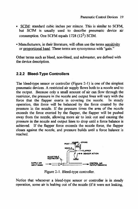
The bleed-type sensor or controller (Figure 2-1) is one of the simplest pneumatic devices. A restricted air supply flows both to a nozzle and to the output. Because only a small amount of air can flow through the restrictor, the pressure in the nozzle and output lines will vary with the force that the flapper exerts in covering the nozzle. In steady operation, this force will be balanced by the force created by the pressure in the nozzle. If the pressure times the area of the nozzle exceeds the force exerted by the flapper, the flapper will be pushed away from the nozzle, allowing more air to leak out and causing the pressure in the nozzle and output lines to drop until a force balance is achieved. If the flapper force exceeds the nozzle force, the flapper closes against the nozzle, and pressure builds until a force balance is reached.
NOZf LE FLAPPER
I t4-b SENSOR ACTION
Figure 2- 1. Bleed-type controller.
Notice that whenever a bleed-type sensor or controller is in steady operation, some air is leaking out of the nozzle (if it were not leaking,

20 Control Systems for Heating, Ventilating and Air Conditioning
pressure would be building until leakage began to occur); hence the designation as a bleed-type controller.
Bleed-type controllers and sensors may be direct- or reverse-acting, depending on the sensor linkage. They are inherently proportional. The output signal may go directly to an actuator, or it may be used as input to a relay-controller, or pilot positioner to be described later.
2.2.3 Relay-Type Controllers
Relay-type controllers may be either non-bleed or pilot-operated bleed- type. The non-bleed controller uses air only when exhausting or filling the line to the controlled device.
Figure 2-2 is a schematic diagram of a non-bleed controller. A positive movement fiom the sensor (increase in temperature or pressure) will cause an inward movement of the diaphragm and a downward movement on the right end of the lever, which raises the other end of the lever and allows the supply air valve to open. This increases the output pressure and the pressure in the valve chamber. As the chamber pressure increases, it acts on the diaphragm to offset the pressure fiom the sensor, so that when equilibrium is attained, the supply valve closes and the balanced pressure becomes the output to the controlled device.
Figure 2-2. Non-bleed controller.
A fbrther positive sensor movement will cause a rebalancing at some higher output pressure. A negative sensor movement will decrease the
Pneumatic Control Devices 2 1
pressure on the right end of the lever, allowing the exhaust valve to open until the chamber and sensor pressures are again in balance. A simple reversal of the linkage will change the controller to reverse- acting.
The bleed-type piloted controller uses a reduced-airflow bleed-type pilot circuit combined with an amplifjring non-bleed relay to produce a sensitive, fast-acting control device. The controller can be adjusted to produce a large change in output for a small change in pilot pressure, and can be provided with negative feedback for proportional action or positive feedback for two-position action.
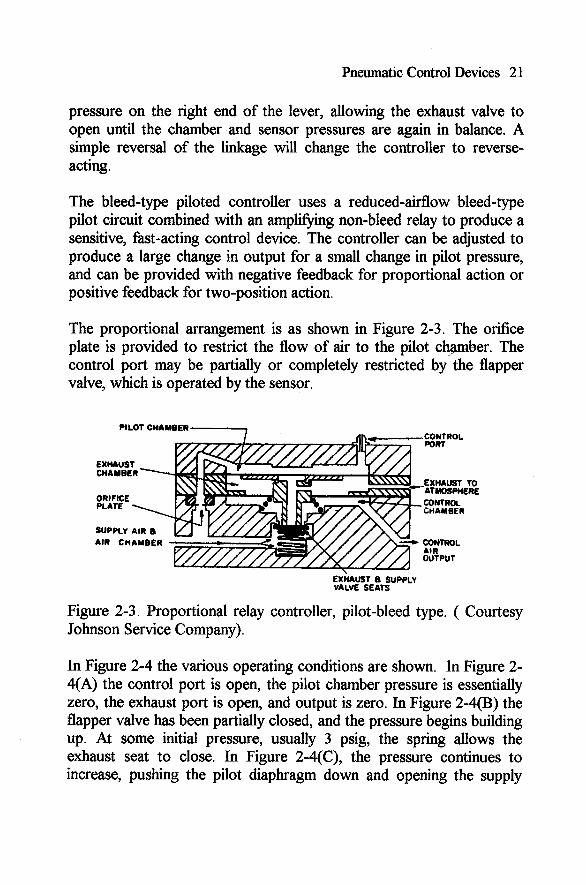
The proportional arrangement is as shown in Figure 2-3. The orifice plate is provided to restrict the flow of air to the pilot chwber. The control port may be partially or completely restricted by the flapper valve, which is operated by the sensor.
ORIFICE PLATE 1
SUPPLY AIR a AIR CHAMBER
-CONTROL PORT
CONTROL AIR OUTPUT
EX~AUST a SUPPLY VALVE SEATS
Figure 2-3. Proportional relay controller, pilot-bleed type. ( Courtesy Johnson Service Company).
In Figure 2-4 the various operating conditions are shown. In Figure 2- 4(A) the control port is open, the pilot chamber pressure is essentially zero, the exhaust port is open, and output is zero. In Figure 2-4(B) the flapper valve has been partially closed, and the pressure begins building up. At some initial pressure, usually 3 psig, the spring allows the exhaust seat to close. In Figure 2-4(C), the pressure continues to increase, pushing the pilot diaphragm down and opening the supply

22 Control Systems for Heating, Ventilating and Air Conditioning
valve. Air flows into the control chamber and to the output line. As the pressure in the control chamber increases, the pilot pressure is opposed (Figure 2-4(D)) (negative feedback) until the pressures balance and the supply valve closes.
Controllers of this type are provided with a broad sensitivity (gain) adjustment. For example, the gain of a temperature controller may be adjusted from as little as 1 psi per degree to as much as 10 psi per degree. (The latter probably would result in an unstable control loop.)
The mounting of the sensing element determines whether the controller is direct- or reverse-acting. Some devices may be changed in the field; others are fixed and cannot be changed.
A similar two-position controller is shown in Figure 2-5. Notice the important differences in valve and spring arrangement.
Figure 2-6 shows the operation: In Figure 2-6(A) the control port is open, and spring pressure holds the supply port open and exhaust port closed. This is a reverse-acting controller. As the control port is partially closed, pilot pressure increases, forcing the pilot diaphragm down and closing the supply valve ( ~ i ~ u r e 2-6(B)). A fbrther increase in pilot pressure opens the exhaust valve, causing a decrease in pressure in the control chamber. This decreases the force opposing the pilot pressure (positive feedback) and allows the exhaust valve to open completely and remain open until pilot pressure is reduced (Figure 2- W ) ) .

Pneumatic Control Devices 23
SUPPLY A11
Figun 2 4 Operation of proportional relay. (Courmy Johnson Service Company) (A) When the control port is open, the exhaust valve between the control and exhaust chambers is open. ~YIIW, air in the control chamber is at zero gage or atmospheric pressure. The supply valve is held closed by a spring end supply pressure. (B) When the sensing element moves closer to the control port, pressure begins to increase in the pilot chamber. At 3 prig, pilot pressure overcomes the force of the opposing spring and closes the exhaust seat. (C) As pilot pressure continues to increase, it forces the pilot diaphragm down and opens the supply port. This al- lows supply air to flow to the control line.

24 Control Systems for Heating, Ventilating and Air Conditioning
Figure 2-4 (Continued) (D) Pressure now increases in the control chamber, and acts against the control diaphragm to oppose pilot pressure. When the total of forces in each direction is equal, the supply valve is closed and the controller is balanced.
PILOT /CHAMBER
EXHAUST VALVE
SPRING VALVE
EXHAUST TO *ATMOSPHERE
CONTROL AIR ' OUTPUT
F i 2-5 -0-position relay controller. pilot-bleed type. (Corcrfcsy Johnson Service Com- PMY)

Pneumatic Control Devices 25
OUTPUT ..r
Figure 2-6 Operation of a two-position relay. (Courresy Johnson Sewice Company.) (A) When the control port is open. supply air flows through the supply chamber and out the con- tml chamber and the cartrolled devices Spring and air pressure combine to hold the supply ball valve open and tht exhaust valve closed. (B) As the control port is closed by the element. pressure in the pilot dumber increases When pilot pressure is greater than the opposing farces, the pilot diaphragm move seating the supply ball valve (C) Further movement of the pibt diiphragm opens tbe exhaust ball valve, so that control air is exhausted. This action re- duces the forces opposing the pilot pressure (positive feedback) and causes the exhaust valve to open fully and remain open until pilot pressure is reduced (by opening the control port). The sequence is then nversed.

26 Control Systems for Heating, Ventilating and Air Conditioning
2.2.4 sensor-controller Systems
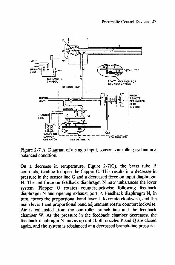
The principles represented by the forces and linkages shown above are found in sensor-controller systems used extensively in HVAC control practice. Single or dual sensor inputs may be used. A single-input sensor-controller is shown in Figures 2-7(A), 2-7(B), and 2-7(C). The system operates as follows:
In the balanced condition, Figure 2-7(A), the following conditions exist:
The input diaphragm H force acting on the main lever I (which pivots about J) is balanced by the force of the set point adjustment T and the feedback force from diaphragm N, which acts through the proportional-band lever L and adjustment K.
Exhaust nozzle F and main nozzle Q are both closed. In this condition, the pressure in the controller branch-line is at a value proportional to the requirements at the sensor.
On an increase in temperature, Figure 2-7(B), the brass tube B expands, tending to close flapper C against the nozzle V. This results in an increased pressure in the sensor-line G and a force on the input diaphragm H, which rotates the main lever I clockwise. The proportional band adjustment K rotates the proportional band lever I counterclockwise about fixed pivot M. Feedback diaphragm N is forced up, and flapper 0 rotates about nozzle P opening nozzle Q. Main air enters the feedback chamber W, increasing the branch-line pressure. As the pressure in the feedback chamber increases, the feedback diaphragm N is forced down until both nozzles P and Q are closed again, and the system is rebalanced at an increased branch-line pressure.
Pneumatic Control Devices 27
OPERATOR SEE DETAIL "A"
FROM .REMOTE 'CPA SWlT (3 TO 13 PSIGI
'CH
Figure 2-7 A. Diagram of a single-input, sensor-controlling system in a balanced condition.
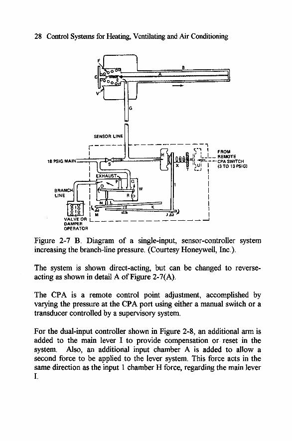
On a decrease in temperature, Figure 2-7(C), the brass tube B contracts, tending to open the flapper C. This results in a decrease in pressure in the sensor line G and a decreased force on input diaphragm H. The net force on feedback diaphragm N now unbalances the lever system. Flapper 0 rotates counterclockwise following feedback diaphragm N and opening exhaust port P. Feedback diaphragm N, in turn, forces the proportional band lever L to rotate clockwise, and the main lever I and proportional band adjustment rotate counterclockwise. Air is exhausted from the controller branch line and the feedback chamber W. As the pressure in the feedback chamber decreases, the feedback diaphragm N moves up until both nozzles P and Q are closed again, and the system is rebalanced at a decreased branch-line pressure.
28 Control Systems for Heating, Ventilating and Air Conditioning
SENSOR LINE n FROM REMOTE CPA SWITCH (3 TO 13 PSlGl
DAMPE.7 OPERATOR
Figure 2-7 B. Diagram of a single-input, sensor-controller system increasing the branch-line pressure. (Courtesy Honeywell, Inc.).
The system is shown direct-acting, but can be changed to reverse- acting as shown in detail A of Figure 2-7(A).
The CPA is a remote control point adjustment, accomplished by varying the pressure at the CPA port using either a manual switch or a transducer controlled by a supervisory system.
For the dual-input controller shown in Figure 2-8, an additional arm is added to the main lever I to provide compensation or reset in the system. Also, an additional input chamber A is added to allow a second force to be applied to the lever system. This force acts in the same direction as the input 1 chamber H force, regarding the main lever I.

Pneumatic Control Devices 29
SENSOR LINE n
DAMPER
FROM REMOTE
' CPA SWITCH 13 TO 13 PSIG)
OPERATOR
Figure 2-7 C. Diagram of a single-input, sensor-controller system decreasing the branch-line pressure. (Courtesy Honeywell, Inc.).
In a typical application, compensation may be provided with this dual- input controller by using two remotely located sensors. To reset hot water, for example, the input 1 sensor is in the supply water discharge and the input 2 sensor is in the outdoor air. A drop in outdoor-air temperature reduces the input diaphragm A force. This has a similar effect on the main lever to that of increasing the set point adjustment spring X force. In other words, the drop in outdoor-air temperature raises the control point of the system. By setting the authority adjustment B, the relative effect of the input diaphragm A force may be varied, compared to the effect of the input diaphragm H force.

30 Control Systems for Heating, Ventilathg and Air Conditioning
HOT-WATER TEMPERATURE SENSOR
n
Figure 2-8. Diagram of a dual-input, sensor-controller, hot-water reset system with remote control point adjustment. (Courtesy Honeywell, Inc.).
An increase in the compensating medium temperature causes an increase in the input diaphragm A force. The resultant force acting on the main lever I through the authority lever C causes the main lever I to rotate clockwise about the pivot point J, effectively lowering the set point.
These examples show temperature sensors, but any kind of variable may be sensed -humidity, pressure, flow, and so on - with no change in the controller. The control differential and the authority of primary and reset sensors may be adjusted over a fairly wide range at the controller. The dual-input controller of Figure 2-8 can also be used with a single sensor, with or without the CPA. If the single sensor is connected to both sensor input ports the effect is to reset the set point when the normal proportional offset is present. The result is less offset fkom the

Pneumatic Control Devices 3 1
original set point, similar to the integral fbnction. This is called "proportional with reset."
Some of the most modern pneumatic controllers use stacked diaphragms to implement force balances similar to those described above. Figure 2-9 shows a proportional plus integral sensor and controller system. We will illustrate how the system works by an example.
REMOTE CONTROL POINT ADJUSTMENT
OPTION
Figure 2-9. Single-input PI sensor-controller system (Courtesy of Honeywell, Inc.)
Suppose that the pressures in each chamber, PI, P2, P3, and P4 are initially equal at 9 psig. In this condition the air coming in through the nozzle into chamber 4 escapes through the capacity amplifier exhaust port or to the branch-line device.
32 Control Systems for Heating, Ventilating and Air Conditioning
Now suppose that the sensor pressure P2 suddenly increases to 10 psig. This will provide an additional downward acting force on the diaphragm assembly, closing the nozzle. The output pressure will build up causing the pressure P4 to build up. Assuming that pressure P1 changes slowly and that the diaphragm separating chambers 2 and 3 is twice the area of the other diaphragms, the pressure P4 would increase to 1 1 psig before the system reaches a temporary balance. The force balance is:
However, part of the output pressure is fed back to chamber 1 . If we assume that the proportional band potentiometer blends one-third of the output pressure to two-thirds of the integral module pressure to achieve P1 and that the integral module pressure changes slowly, then the force balance is:
(113) P4 + (213) x 9 + 2 P2 = P4 + 2 P3 or P4 = 12 psig
Now if the sensor chamber pressure remains at 10 psig, the output pressure P4 will cause the diaphragm separating V1 from V2 in the integral module to close the exhaust port in the integral module, resulting in a buildup of pressure from the integral module to P1. This will increase the pressure in P1 and result in a further increase in output pressure. However, an increase in output pressure should be having the effect of driving the sensed variable (the controlled variable) toward the set point. Let us assume that as the output pressure goes toward 13 psig, the sensor pressure finally returns to 9 psig. This new equilibrium condition has the pressures in P1 and P4 at 13 psig while the pressures in chambers 2 and 3 are equal at 9 psig. Notice that it is only when P2 and P3 are equal that the output pressure stops changing. Notice further how the integral action can lead to a new steady state output pressure while forcing the controlled variable to be equal to the set point.
Pneumatic Control Devices 33
2.2.5 Sensing Elements
Controllers can be operated in response to various stimuli, such as temperature, pressure or humidity. A brief discussion of the more common sensing elements follows.
2.2.5.1 TemperatureSensing Elements
These elements include bimetal elements, vapor-filled bellows, and liquid-, gas- or refrigerant-filled bulb and capillary sensors.
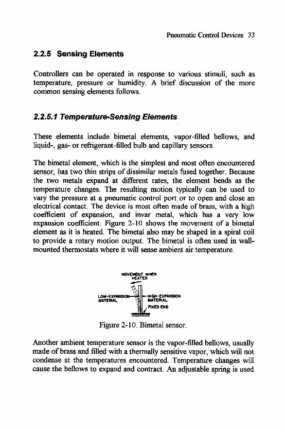
The bimetal element, which is the simplest and most ofken encountered sensor, has two thin strips of dissimilar metals fbsed together. Because the two metals expand at different rates, the element bends as the temperature changes. The resulting motion typically can be used to vary the pressure at a pneumatic control port or to open and close an electrical contact. The device is most often made of brass, with a high coefficient of expansion, and invar metal, which has a very low expansion coefficient. Figure 2- 10 shows the movement of a bimetal element as it is heated. The bimetal also may be shaped in a spiral coil to provide a rotary motion output. The bimetal is often used in wall- mounted thermostats where it will sense ambient air temperature.
MOVEMENT WHEN HEATED #
P -
!$ Low-EYRHISMN-L,b nlGM-EXPI\NSION MAEUIAL 'I:,; C ~ n ~ ~ ~ ~
Figure 2- 10. Bimetal sensor.
Another ambient temperature sensor is the vapor-filled bellows, usually made of brass and filled with a thermally sensitive vapor, which will not condense at the temperatures encountered. Temperature changes will cause the bellows to expand and contract. An adjustable spring is used

34 Control Systems for Heating, Ventilating and Air Conditioning
to control set point and limit expansion. The resulting movement can be used directly or through a linkage.
Bulb and capillary elements are used where temperatures must be measured in ducts, pipes, tanks, or similar locations remote from the controller. There are three essential parts of this device: bulb, capillary, and diaphragm operating head. The fill may be a liquid, gas, or refrigerant, depending on the temperature range desired. Expansion of the fluid in the heated bulb exerts a pressure that is transmitted by the capillary to the diaphragm and there translated into movement (Figure 2-1 1).
C CAPILLARY TUBE
Figure 2-1 1. Bulb and capillary sensor.
The sensing bulb may be only a few inches long, as used in a pipe or a tank, or it may be as long as 20 feet when used to sense average air temperature in a duct of large cross section.
Special long bulbs are used for freeze protection. Refrigerant is used in this type of bulb, as the refrigerant will condense at freezing temperatures, causing a sharp decrease in pressure if any part of the bulb is exposed to low temperature.
Temperature-compensated capillary tubes are used to avoid side effects from the ambient temperature around the capillary. Capillaries may be as long as 25 or 30 feet.
2.2.5.2 Pressure Sensing Elements
These elements include diaphragms, bellows, and bourdon tubes.

Pneumatic Control Devices 35
The diaphragm is a flexible plate, sealed in a container so that fluid cannot leak past it. A force applied to one side will cause it to move or flex. A spring usually operates to control the movement and return the diaphragm to its initial position when the force is removed. Some diaphragm materials will spring back to the original shape without help. A variety of materials are used to cope with the various temperatures, pressures, and fluids encountered.
A bellows is a diaphragm that is joined to the container by a series of convolutions (folds) so that a greater degree of movement may be obtained (Figure 2-12). The bellows may be completely sealed, as in a temperature-sensitive unit, or it may have a connection for sensing pressure, either internally or externally. The bellows acts like a spring, returning to its original shape when the external force is removed. Frequently a separate spring is added for adjustment and to increase reaction speed.
Figure 2- 12. Bellows sensor.
The bourdon tube (Figure 2-13), widely used in pressure gages and other pressure instruments, has a flattened tube bent into circular or spiral form. One end is connected to the pressure source, and the other end is free to move. As pressure is increased, the tube tends to straighten out, and this movement may be used, through an appropriate linkage, to position an indicator or actuate a controller.
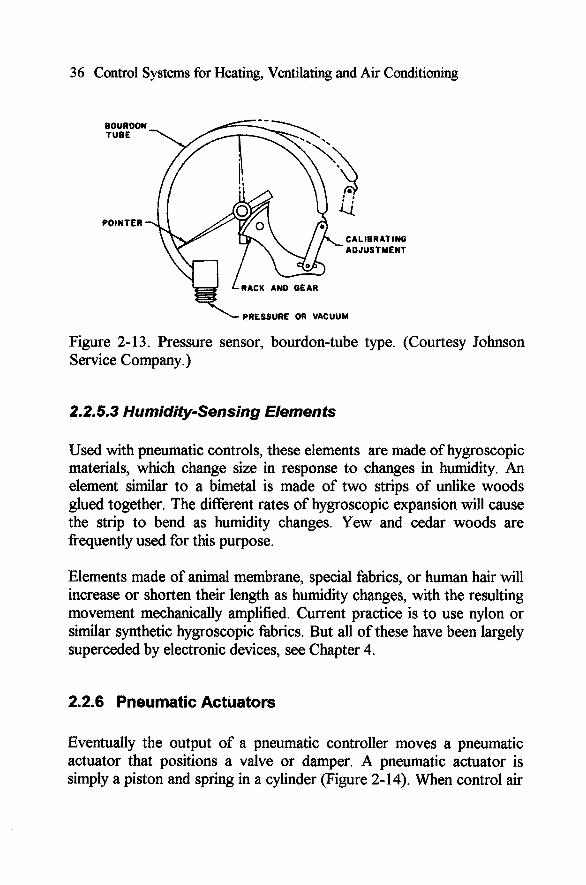
36 Control Systems for Heating, Ventilating and Air Conditioning
\- PRESSURE OR VACUUM
Figure 2- 13. Pressure sensor, bourdon-tube type. (Courtesy Johnson Service Company.)
2.2.5.3 Humidity-Sensing Elements
Used with pneumatic controls, these elements are made of hygroscopic materials, which change size in response to changes in humidity. An element similar to a bimetal is made of two strips of unlike woods glued together. The different rates of hygroscopic expansion will cause the strip to bend as humidity changes. Yew and cedar woods are frequently used for this purpose.
Elements made of animal membrane, special fabrics, or human hair will increase or shorten their length as humidity changes, with the resulting movement mechanically amplified. Current practice is to use nylon or similar synthetic hygroscopic fabrics. But all of these have been largely superceded by electronic devices, see Chapter 4.
2.2.6 Pneumatic Actuators
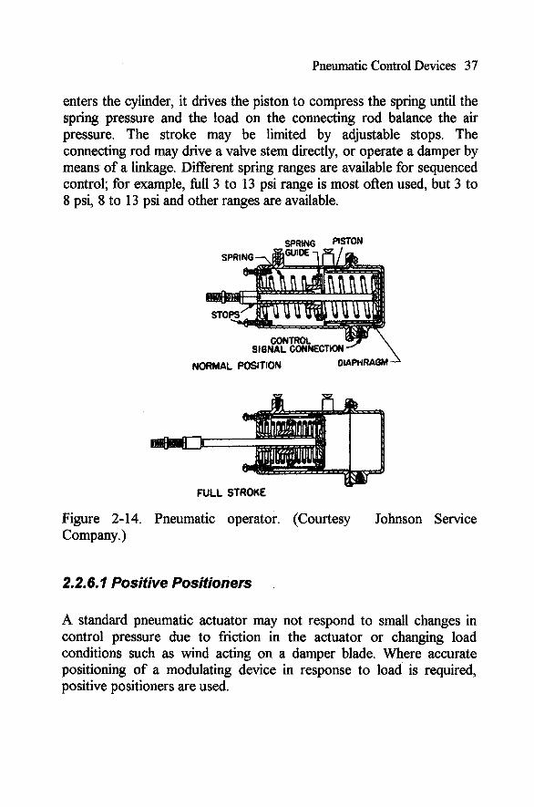
Eventually the output of a pneumatic controller moves a pneumatic actuator that positions a valve or damper. A pneumatic actuator is simply a piston and spring in a cylinder (Figure 2-14). When control air
Pneumatic Control Devices 37
enters the cylinder, it drives the piston to compress the spring until the spring pressure and the load on the connecting rod balance the air pressure. The stroke may be limited by adjustable stops. The connecting rod may drive a valve stem directly, or operate a damper by means of a linkage. Different spring ranges are available for sequenced control; for example, full 3 to 13 psi range is most often used, but 3 to 8 psi, 8 to 13 psi and other ranges are available.
NOFtMAL POSITION CMAP~RAGM L
U
FULL STROKE
Figure 2-14. Pneumatic operator. (Courtesy Johnson Service Company.)
2.2.6. I Positive Positioners
A standard pneumatic actuator may not respond to small changes in control pressure due to friction in the actuator or changing load conditions such as wind acting on a damper blade. Where accurate positioning of a modulating device in response to load is required, positive positioners are used.
38 Control Systems for Heating, Ventilating and Air Conditioning
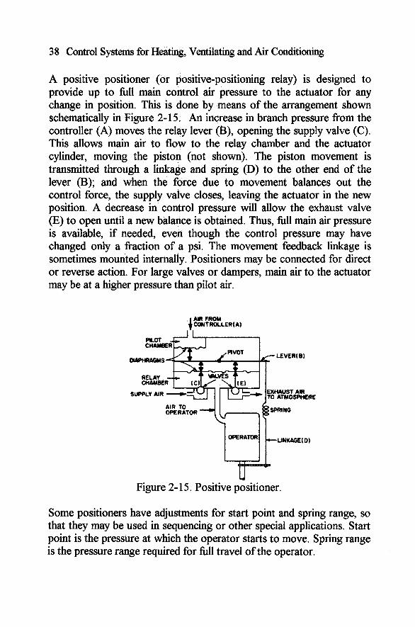
A positive positioner (or positive-positioning relay) is designed to provide up to full main control air pressure to the actuator for any change in position. This is done by means of the arrangement shown schematically in Figure 2-15. An increase in branch pressure from the controller (A) moves the relay lever (B), opening the supply valve (C). This allows main air to flow to the relay chamber and the actuator cylinder, moving the piston (not shown). The piston movement is transmitted through a linkage and spring (D) to the other end of the lever (B); and when the force due to movement balances out the control force, the supply valve closes, leaving the actuator in the new position. A decrease in control pressure will allow the exhaust valve (E) to open until a new balance is obtained. Thus, full main air pressure is available, if needed, eveh though the control pressure may have changed only a fraction of a psi. The movement feedback linkage is sometimes mounted internally. Positioners may be connected for direct or reverse action. For large valves or dampers, main air to the actuator may be at a higher pressure than pilot air.
AIR FROM CONTROLLER( A)
LEVER( B)
RELAY
41
Figure 2- 15. Positive positioner.
Some positioners have adjustments for start point and spring range, so that they may be used in sequencing or other special applications. Start point is the pressure at which the operator starts to move. Spring range is the pressure range required for full travel of the operator.

Pneumatic Control Devices 39
2.2.7 Relays
In pneumatic control jargon, a relay is a device that takes a signal from a controller, changes it in some way, and relays it to another controller or actuator.
Many different types of pneumatic relays are manufactured. Mostly they use some variation of the non-bleed controller shown in Figure 2- 2. A pressure signal fiom another controller or relay replaces the force due to temperature or pressure change. Thus there may be a reversing relay (Figure 2-16) in which a direct-acting control input pressure may be changed to a reverse-acting output. The output of this and other relays also may be amplified or reduced with respect to input, so that one input to several relays may produce a sequence of varied outputs.
VALM CHWER CONTROL AIR ' OUTWT
Figure 2- 16. Reversing relay.
To illustrate sequencing, envision a controller with a 6 to 9 psi output over the desired control range. It is desired to operate three valves so that one goes from fully open to fully closed with a 3 to 8 psi signal, a second goes fiom closed to open with a 5 to 10 psi signal, and a third has a control range of 8 to 1 3 psi from closed to open. These are to operate in sequence over the 6 to 9 psi control range. The first valve

40 Control Systems for Heating, Ventilating and Air Conditioning
would use a relay that produced a 3 to 8 psi output from a 6 to 7 psi control input, the second relay would provide a 5 to 9 psi output over a 7 to 8 psi input and the third would provide an 8 to 13 psi output over the remaining 8 to 9 psi input change.
Another type of relay will produce an output proportional to the difference between two inputs (Figure 2- 17), and yet another produces an output equal to the higher (or lower) of two pressures (Figure 2- 18). Two-position relays use the principles illustrated in Figures 2-5 and 2-6.
AlR FROM
VALVE CHAMBE
SUPPLY AIR
EXHAUST AIR TO ATMOSPHERE
Figure 2-17. Relay: output is proportional to the difference between two signals.
The so-called discriminator relay will accept many input signals-from six or seven to twenty, depending on the manufacturer-and select and pass on the highest or lowest of the inputs. Some models will output both the highest and the lowest. These relays are widely used in multiple-zone HVAC systems for energy conservation. (See Chapter 7.)
An averaging relay will output the average of two to four input signals.
A switching relay is used to divert control signals in response to a secondary variable, typically outside air temperature. It is essentially a two-way valve. (See Figure 2-1 9.) With the switching signal above the
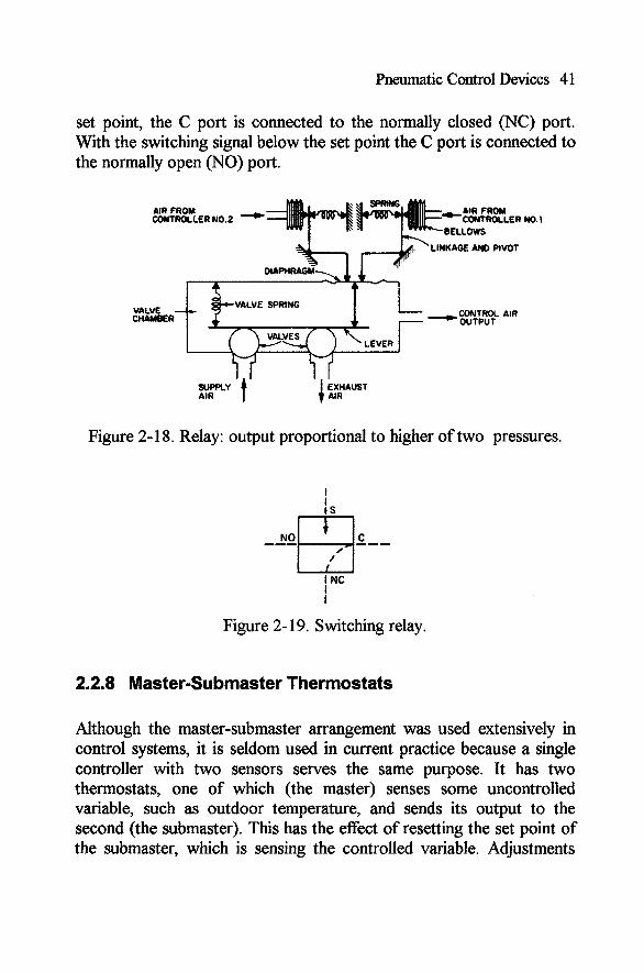
Pneumatic Control Devices 4 1
set point, the C port is connected to the normally closed (NC) port. With the switching signal below the set point the C port is connected to the normally open (NO) port.
AIR FROM CONTROLLER N0.2 - CONTROLLER NO. I
LINKAGE AND PIVOT
VALVE CHAMBER -CONTROL AIR
AIR
Figure 2-1 8. Relay: output proportional to higher of two pressures.
Figure 2- 19. Switching relay.
2.2.8 Master-Submaster Thermostats
Although the master-submaster arrangement was used extensively in control systems, it is seldom used in current practice because a single controller with two sensors serves the same purpose. It has two thermostats, one of which (the master) senses some uncontrolled variable, such as outdoor temperature, and sends its output to the second (the submaster). This has the effect of resetting the set point of the submaster, which is sensing the controlled variable. Adjustments
42 Control Systems for Heating, Ventilating and Air Conditioning
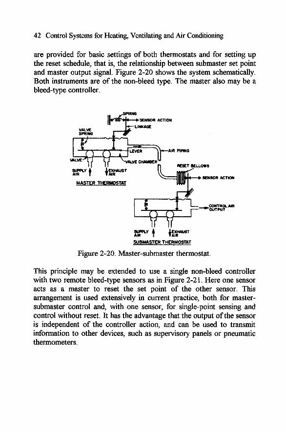
are provided for basic settings of both thermostats and for setting up the reset schedule, that is, the relationship between submaster set point and master output signal. Figure 2-20 shows the system schematically. Both instruments are of the non-bleed type. The master also may be a bleed-type controller.
VALVE SPRING
AIR PIPING
VMv€ OUMBER RESET BELLOWS
SENSOR MASTER THERMOSTAT
ACTION
PY t SUBMASTER THERMOSTAT
Figure 2-20. Master-submaster thermostat.
This principle may be extended to use a single non-bleed controller with two remote bleed-type sensors as in Figure 2-21. Here one sensor acts as a master to reset the set point of the other sensor. This arrangement is used extensively in current practice, both for master- submaster control and, with one sensor, for single-point sensing and control without reset. It has the advantage that the output of the sensor is independent of the controller action, and can be used to transmit information to other devices, such as supervisory panels or pneumatic thermometers.

REMOTE SENSOR fl
Pneumatic Control Devices 43
*
AIR
,SUPRY
PIWNG AIR
REMOTE SENSOR
VUM CHAMBER
SOPPLY IEXIUUST AIR AIR
CONTROLLER
Figure 2-21 Controller with two remote sensors.
2.2.9 Dual-Temperature Thermostats
This classification includes day-night and summer-winter thermostats. Two related temperature settings may be made and the transfer from one to the other is made by changing the supply air pressure. The settings cannot overlap, and there is a built-in differential,-adjustable or fixed, depending on the instrument.
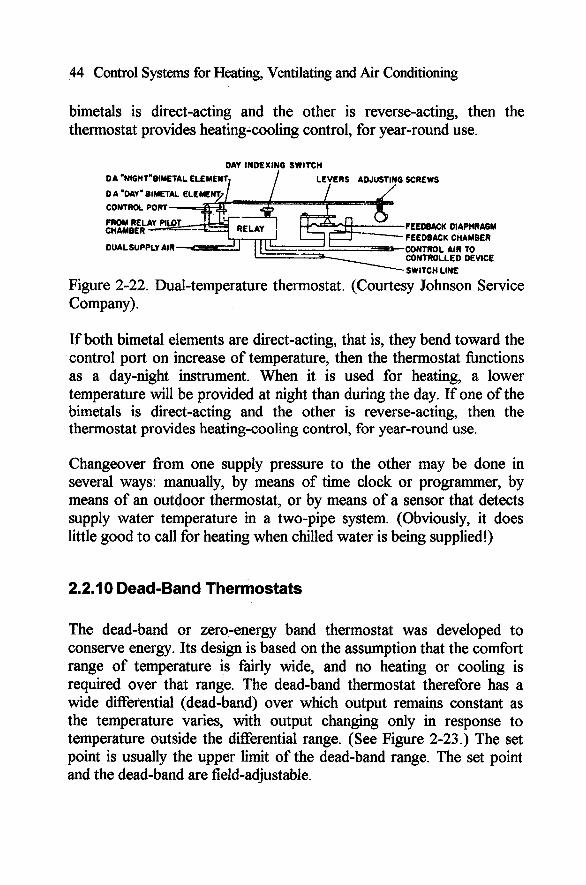
A typical unit with two bimetal sensors is shown in Figure 2-22. The piloting relay is similar to those discussed previously. Two control ports are provided, and the bimetals are adjusted to close one port sooner than the other. The port in use is determined by a diaphragm- operated transfer mechanism that is actuated by changing the main air supply pressure, typically from 15 to 20 psi.
If both bimetal elements are direct-acting, that is, they bend toward the control port on increase of temperature, then the thermostat knctions as a day-night instrument. When it is used for heating, a lower temperature will be provided at night than during the day. If one of the
44 Control Systems for Heating, Ventilating and Air Conditioning
bimetals is direct-acting and the other is reverse-acting, then the thermostat provides heating-cooling control, for year-round use.
DAY INDEXING SWITCH
DA *NIGHT'BUETAL ELEME ERS ADJUSTING SCREWS
FEEDBACK DIAPHRAGM FEEDBACK CHAMBER
DUALSUPPLY AIR CONTROL AIR TO CONTROLLED DEVICE SWITCH LINE
Figure 2-22. Dual-temperature thermostat. (Courtesy Johnson Service Company).
If both bimetal elements are direct-acting, that is, they bend toward the control port on increase of temperature, then the thermostat functions as a day-night instrument. When it is used for heating, a lower temperature will be provided at night than during the day. If one of the bimetals is direct-acting and the other is reverse-acting, then the thermostat provides heating-cooling control, for year-round use.
Changeover from one supply pressure to the other may be done in several ways: manually, by means of time clock or programmer, by means of an outdoor thermostat, or by means of a sensor that detects supply water temperature in a two-pipe system. (Obviously, it does little good to call for heating when chilled water is being supplied!)
2.2.1 0 Dead-Band Thermostats
The dead-band or zero-energy band thermostat was developed to conserve enerm. Its design is based on the assumption that the comfort range of temperature is fairly wide, and no heating or cooling is required over that range. The dead-band thermostat therefore has a wide differential (dead-band) over which output remains constant as the temperature varies, with output changing only in response to temperature outside the differential range. (See Figure 2-23.) The set point is usually the upper limit of the dead-band range. The set point and the dead-band are field-adjustable.

Pneumatic Control Devices 45
Figure 2-23. Dead-band thermostat performance.
2.2.1 I Transducers
Broadly defined, a transducer is a device for transforming one form of energy to another. Because a pneumatic control system frequently must interface with electrical or electronic devices, transducers are necessary. They may be two-position or modulating.
The PE (Pneumatic-Electric) relay is simply a pressure switch that is adjusted to open or close an electrical contact at some value of the control pressure. Sequenced PE relays are frequently used for capacity control of refrigeration systems, for two-speed fan control, and similar functions.
The EP (Electric-Pneumatic) relay is a solenoid air valve, usually three- way to supply or exhaust air to or from the pneumatic control circuit. A three-way valve also may be used to change supply pressure (by changing from one supply source to another).
Modulating transducers change a modulating air signal to a variable voltage output, in either the electric or the electronic range; or a variable electric or electronic signal may produce a varying air pressure output. These deviceswill be discussed Chapter 3.

46 Control Systems for Heating, Ventilating and Air Conditioning
2.2.12 Manually Operated Pneumatic Switches
Manual switches are used extensively in pneumatic control systems. A simple two-position switch, shown in Figure 2-24, may be used to switch from one signal (A) to another (B). More commonly, control air is provided at port A, and port B is open to vent the line from AB when desired.
A more complex two-position switch is shown in Figure 2-25. In one position ports 1 and 2 are connected, as are ports 3 and 4. In the other position port 1 is connected to port 4 and port 2 to port 3.
Figure 2-26 shows a gradual switch that is used to provide a fixed output pressure (using control supply air as input). It is an adjustable pressure-reducing valve, whose primary hnction is to provide a minimum signal for a damper, valve, or speed controller. It is also used for set point adjustment in sensor-controller systems.
Figure 2-24. Manual switch; 2-position.
Figure 2-25. Manual switch; 2-position, 4 ports.
- Figure 2-26. Hand "gradual" switch.
Pneumatic Control Devices 47
CONTROL CABINETS
With any control system that includes more than three or four devices it is desirable to provide a control cabinet in which all the controllers, relays, switches and indicating devices for the system will be mounted Control manufacturers supply standard cabinet sizes, up to about 36 by 48 inches and the cabinets usually are customized for the system. Indicating devices and switches are mounted on the door so that the cabinet may be closed and locked during normal operation.
Indicating devices may show the status, temperature, humidity, and control pressure at various points, as well as HVAC system static pressures, filter pressure drops, and even air flow rates. Pilot lights may be added to show the motor and safety control status.
Although a control cabinet adds some cost, it is extremely usehl for monitoring system operation and for trouble shooting. Without some kind of status information it is very difficult to figure out what actually is happening in the system.
2.4 AIR SUPPLY
The air supply for a pneumatic control system must be carefully designed. It is of the utmost importance that the air be clean and dry, free from oil, dirt, and moisture. Thus it is essential to use air dryers, oil separators, and high-efficiency filters. Even small amounts of dirt, oil, or water can plug the very small air passages in modern commercial pneumatic devices, rendering them useless. See Figure 2-27.
Air consumption can be estimated from use factors for the components provided by the control manufacturer. Good practice requires that the compressor have a capacity at least twice the estimated consumption. In comparing compressor ratings it should be noted that displacement and capacity are different. Capacity will be from 60% to 80% of displacement.

48 Control Systems for Heating, Ventilating and Air Conditioning
FILTERS
PRESSURE SWITCH
\ - PRESSURE REDUCING
AUTOMATIC VALVE
LOWER PRESSURE
HIGHER PRESSURE
Figure 2-27. Compressed air supply.
If the system is very large, it is preferable to have two compressors to improve reliability. Generally air is compressed to 60 to 80 psig, and passes through dryers, filters, and a pressure-reducing valve. It is very important that the air be dry and clean, to minimize maintenance on the components.
2.4.1 Air Compressors
Compressors usually are reciprocating-type, single-stage, air-cooled. Typically they range in size from 1 hp to 10 hp, and the smaller units are mounted directly on the receiver tank. Motors are started and stopped by a pressure switch on the receiver, set for 60 to 80 psig with about a 10 psi differential. When two compressors are used, the receivers are crossconnected and a single pressure switch with an alternator controls both motors. The alternator is a sequencing device that provides for running a different motor on each start-stop cycle, thus equalizing motor running time.
Pneumatic Control Devices 49
2.4.2 Dryers and Filters
Two methods of drying are used. Refrigerated air dryers cool the air sufficiently to condense out the excess moisture that is then removed automatically through a trap, which is similar to a steam trap.
Chemical dryers are also used, with silica gel as the agent. For small systems an in-line unit may be used, and the chemical must be replaced at regular intervals. For large systems a double unit may be used, with one section being regenerated while the other is in use.
Oil may be removed in a coalescing filter, especially designed for oil mist entrapment and removal. The remaining oil and dirt may be removed in a three-micron high efficiency filter.
2.4.3 Pressure-Reducing Valves
The control manufacturer can and does supply the pressure reducing valves as part of the pneumatic control system. If a dual-pressure system is used, then two reducing valves will be used, in series, as in Figure 2-27.
2.4.4 Air Piping and Accessories
Air distribution piping systems often use soft copper tubing with soldered fittings. Compression fittings may be used at equipment connections. Branch piping is commonly 114 inch outside diameter.
Improvements in nylon-reinforced plastic tubing have led to acceptance of this material in many if not most recent pneumatic control projects. Specifications should call for a pressure test of the piping system at 30 psi.
Air gages are a necessity for adjusting, calibrating, and maintaining the control elements. Gages should be provided at main and branch

50 Control Systems for Heating, Ventilating and Air Conditioning
connections to each controller and relay and at the branch connection to each controlled device. In this manner the status of the component is readily determined.
http://www.springer.com/978-0-387-30521-9