Embed Size (px)
Citation preview

22. IGNITION SYSTEM (After '05)
COMPONENT LOCATION 22-2
SYSTEM DIAGRAM 22-2
IGNITION TIMING 22-9
IGNITION COIL •22-10
SERVICE INFORMATION 22-3 ICM (IGNITION CONTROL MODULE) 22-10
TROUBLESHOOTING 22-4 THROTTLE POSITION SENSOR 22-10
IGNITION SYSTEM INSPECTION 22-6 CLOSED THROTTLE POSITION DETECTIONSYSTEM 22-12
22-1

IGNITION SYSTEM (After '05)
COMPONENT LOCATIONIGNITION SWITCH
ENGINE STOP SWITCH
FAN/IGNITION CONTROLMODULE (ICM)
THROTTLE LEVER SWITCH
SPARK PLUG
CARBURETOR SWITCH
IGNITION COIL
THROTTLE POSITION
SENSOR
ALTERNATOR(EXCITER COIL)
IGNITION PULSEGENERATOR
SYSTEM DIAGRAM
FAN/IGNITION CONTROL MODULE
TRX450ER 6PTRX450R 4P
ENGINE STOPSWITCH
Bl : BLACKY : YELLOW8u:SLUEG :GREENR :BEOW : WHITEP :PINKLg : LIGHT GREENGr : GRAY
1 1u
1LJ
1 (?1 r THROTTLE* POSITION
v SENSORTHROTTLELEVERSWITCH
CARBURETORSWITCH
ENGINECOOLANTTEMPERATURE(ECT)SENSOR
ALTERNATOR
22-2

IGNITION SYSTEM (After '05)
SERVICE INFORMATIONGENERAL• Some electrical components may be damaged if terminals or connectors are connected or disconnected while the igni-
tion switch is turned to ON and current is present.• When servicing the ignition system, always follow the steps in the troubleshooting table on page 22-4.• The ignition timing cannot be adjusted since the ignition control module (ICM) is factory preset.• The ICM may be damaged if dropped. Also, if the connector is disconnected when current is flowing, the excessive volt-
age may damage the ICM. Always turn the ignition switch to OFF before servicing.• A faulty ignition system is often related to poor connections. Check those connections before proceeding.• Make sure the battery is adequately charged. Using the starter motor with a weak battery results in a slower engine
cranking speed as well as no spark at the spark plug (TRX450ER only).• Use spark plug with the correct heat range. Using spark plug with an incorrect heat range can damage the engine.• For ignition pulse generator removal/installation, see page 21-11.• For ignition switch inspection, see page 24-7.• For engine stop switch inspection, see page 24-7.
SPECIFICATIONS
ITEMSpark plug Standard
For extended high speed ridingSpark plug gapIgnition coil primary peak voltageExciter coilpeak voltage
HighLow
Ignition pulse generator peak voltageIgnition timing ("F"mark)Throttle position sensor resistance (20°C/68°F)
SPECIFICATIONSIFR7L11 (NGK), VK22PRZ11 (DENSO)IFR8H11 (NGK), VK24PRZ11 (DENSO)
1.0-1.1 mm (0.039-0.043 in)100 V minimum45 V minimum15 V minimum0.7 V minimum
11.4° BTDC at idle4-6 kn
TORQUE VALUE
Timing hole capThrottle position sensorscrew
9.8 N-m (1.0 kgfm, 7 Ibf-ft)3.4 N-m (0.3 kgfm, 2.5 Ibf-ft) Apply locking agent to the threads
TOOLS
IgnitionMate peak voltage testerMTP07-0286 (U.S.A. only)
Peak voltage adaptor07HGJ-0020100
(not available in U.S.A.) with com-mercially available digitalmultimeter (impedance 10 MO/DCVminimum)
22-3
IGNITION SYSTEM (After '05)
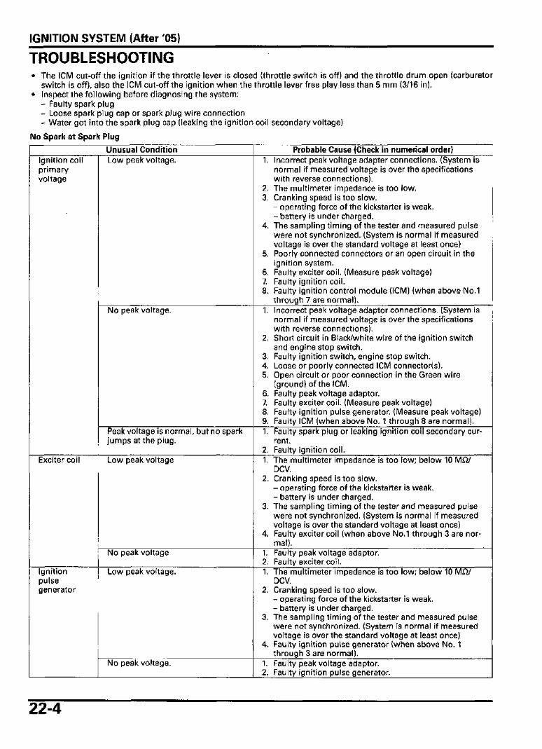
TROUBLESHOOTING• The ICM cut-off the ignition if the throttle lever is closed (throttle switch is off) and the throttle drum open (carburetor
switch is off), also the ICM cut-off the ignition when the throttle lever free play less than 5 mm (3/16 in).• Inspect the following before diagnosing the system:
- Faulty spark plug- Loose spark plug cap or spark plug wire connection- Water got into the spark plug cap (leaking the ignition coil secondary voltage)
No Spark at Spark Plug
Unusual ConditionIgnition coilprimaryvoltage
Exciter coil
Ignitionpulsegenerator
Low peak voltage.
No peak voltage.
Peak voltage is normal, but no sparkjumps at the plug.
Low peak voltage
No peak voltage
Low peak voltage.
No peak voltage.
Probable Cause (Check in numerical order)1. Incorrect peak voltage adapter connections. (System is
normal if measured voltage is over the specificationswith reverse connections).
2. The multimeter impedance is too low.3. Cranking speed is too slow.
- operating force of the kickstarter is weak.- battery is under charged.
4. The sampling timing of the tester and measured pulsewere not synchronized. (System is normal if measuredvoltage is over the standard voltage at least once)
5. Poorly connected connectors or an open circuit in theignition system.
6. Faulty exciter coil. (Measure peak voltage)7. Faulty ignition coil.8. Faulty ignition control module (ICM) (when above No.1
through 7 are normal).
1. Incorrect peak voltage adaptor connections. (System isnormal if measured voltage is over the specificationswith reverse connections).
2. Short circuit in Black/white wire of the ignition switchand engine stop switch.
3. Faulty ignition switch, engine stop switch.4. Loose or poorly connected ICM connector(s).5. Open circuit or poor connection in the Green wire
(ground) of the ICM.6. Faulty peak voltage adaptor.7. Faulty exciter coil. (Measure peak voltage)8. Faulty ignition pulse generator. (Measure peak voltage)9. Faulty ICM (when above No. 1 through 8 are normal).1. Faulty spark plug or leaking ignition coil secondary cur-
rent.2. Faulty ignition coil.1. The multimeter impedance is too low; below 10 MQ/
DCV.2. Cranking speed is too slow.
- operating force of the kickstarter is weak.- battery is under charged.
3. The sampling timing of the tester and measured pulsewere not synchronized. (System is normal if measuredvoltage is over the standard voltage at least once)
4. Faulty exciter coil (when above No.1 through 3 are nor-mal).
1. Faulty peak voltage adaptor.2. Faulty exciter coil.1. The multimeter impedance is too low; below 10 Mi i /
DCV.2. Cranking speed is too slow.
- operating force of the kickstarter is weak.- battery is under charged.
3. The sampling timing of the tester and measured pulsewere not synchronized. (System is normal if measuredvoltage is over the standard voltage at least once)
4. Faulty ignition pulse generator (when above No. 1through 3 are normal).
1. Faulty peak voltage adaptor.2. Faulty ignition pulse generator.
22-4

IGNITION SYSTEM (After '05)Engine does not start• Throttle cable stick• Faulty throttle lever switch• Faulty carburetor switch
22-5
IGNITION SYSTEM (After '05)
IGNITION SYSTEM INSPECTIONNOTE:• If there is no spark at the plug, check all connec-
tions for loose or poor contact before measuringthe peak voltage.
• Use the recommended digital multimeter or acommercially available digital multimeter withan impedance of 10 Mii/DCV minimum.
• The display value differs depending upon theinternal impedance of the multimeter.
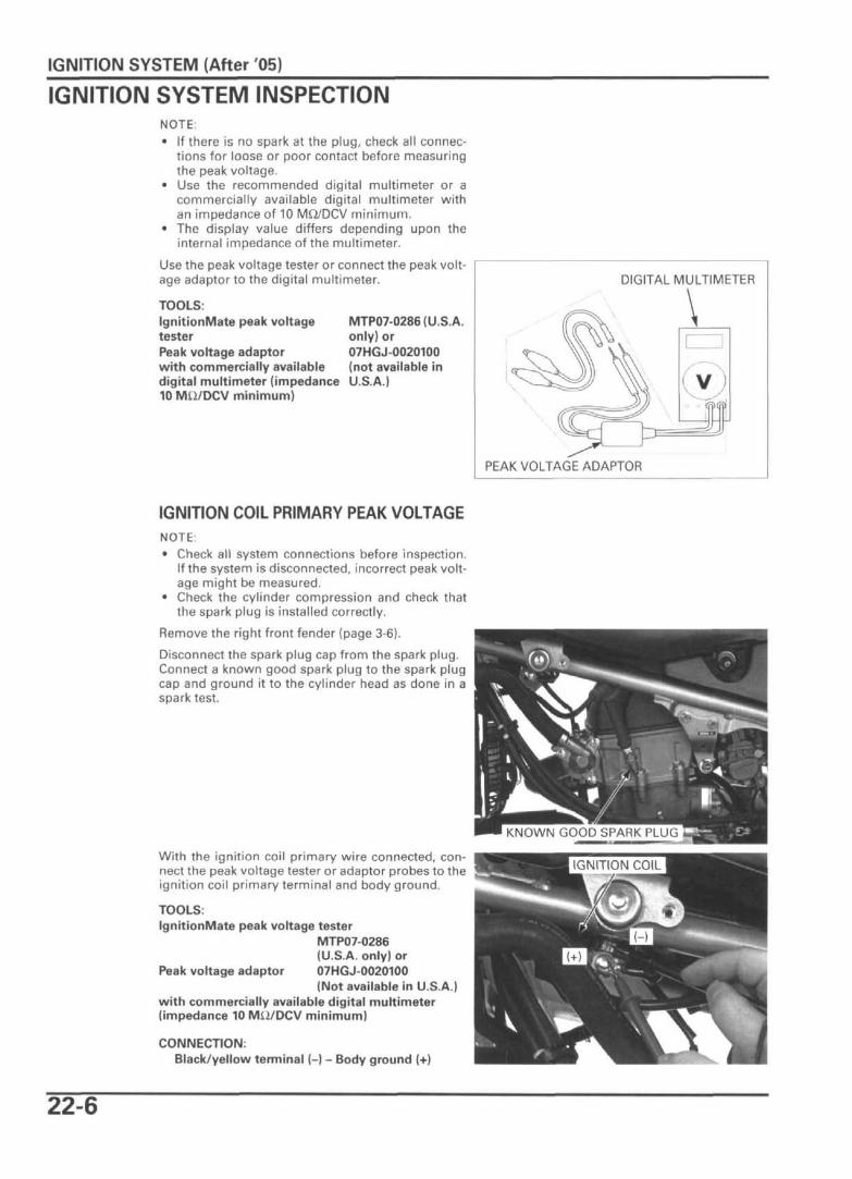
Use the peak voltage tester or connect the peak volt-age adaptor to the digital multimeter.
TOOLS:IgnitionMate peak voltagetesterPeak voltage adaptorwith commercially availabledigital multimeter (impedance10 Mii/DCV minimum)
MTP07-0286 (U.S.A.only) or07HGJ-0020100(not available inU.S.A.)
DIGITAL MULTIMETER
PEAK VOLTAGE ADAPTOR
IGNITION COIL PRIMARY PEAK VOLTAGENOTE:• Check all system connections before inspection.
If the system is disconnected, incorrect peak volt-age might be measured.
• Check the cylinder compression and check thatthe spark plug is installed correctly.
Remove the right front fender (page 3-6).
Disconnect the spark plug cap from the spark plug.Connect a known good spark plug to the spark plugcap and ground it to the cylinder head as done in aspark test.
With the ignition coil primary wire connected, con-nect the peak voltage tester or adaptor probes to theignition coil primary terminal and body ground.
TOOLS:IgnitionMate peak voltage tester
MTP07-0286(U.S.A. only) or
Peak voltage adaptor 07HGJ-0020100(Not available in U.S.A.)
with commercially available digital multimeter(impedance 10 MS2/DCV minimum)
CONNECTION:Black/yellow terminal (-) - Body ground (+)
KNOWN GOOD SPARK PLUG
IGNITION COIL
22-6

IGNITION SYSTEM (After '05)
Shift the transmission into neutral.Turn the ignition switch to "ON".Crank the engine with starter motor (TRX450ER) orkickstarter (TRX450R) and read ignition coil primarypeak voltage.
PEAK VOLTAGE: 100 V minimum
If the peak voltage is lower than the standard value,follow the checks described in the troubleshootingchart (page 22-4).
ALTERNATOR EXCITER COIL PEAKVOLTAGENOTE:• Check the cylinder compression and check that
the spark plug is installed correctly.
Disconnect the 6P black connector from the ignitioncontrol module (ICM).Connect the peak voltage tester or adaptor probesto the exciter coil wire terminals of the 6P black con-nector.
TOOLS:IgnitionMate peak voltage tester
MTP07-0286(U.S.A. only) or
Peak voltage adaptor 07HGJ-0020100(Not available in U.S.A.)
with commercially available digital multimeter(impedance 10 MU/DCV minimum)
CONNECTIONS:High: Black/red terminal (+) - White terminal (-)Low: Blue terminal (+) - White terminal (-)
Shift the transmission into neutral.
Crank the engine with starter motor (TRX450ER) orkickstarter (TRX450R) and read the exciter coil peakvoltage.
PEAK VOLTAGE: High: 45 V minimumLow: 15 V minimum
If the peak voltage measured at the ICM connector isabnormal, measure the peak voltage at the alterna-tor exciter coil 5P connector.
Remove the right front fender (page 3-6).
Disconnect the alternator exciter coil 5P connectorand connect the tester probes to the wire terminalsof the exciter coil side 5P connector.
CONNECTIONS:High: Black/red terminal (+) - White terminal (-)Low: Blue terminal (+) - White terminal (-)
In the same manner as at the ICM connector, mea-sure the peak voltage and compare it to the voltagemeasured at the ICM connector.
• If the peak voltage measured at the ICM is abnor-mal and the one measured at the alternatorexciter coil is normal, the wire harness has anopen or short circuit, or loose connection.
• If both peak voltages are abnormal, follow thechecks described in the troubleshooting chart(page 22-4).
6P CONNECTOR
EXCITER COIL 5P CONNECTOR
22-7

IGNITION SYSTEM (After 05)
TRX450ER:
TRX450R:
IGNITION PULSE GENERATOR PEAKVOLTAGENOTE:• Check the cylinder compression and check that
the spark plug is installed correctly.
Disconnect the 8P and 6P black connector from theICM.Connect the peak voltage tester or adaptor probesto the ignition pulse generator wire terminals of the8P and 6P black connector.
TOOLS:IgnitionMate peak voltage tester
MTP07-0286(U.S.A. only) or
Peak voltage adaptor 07HGJ-0020100(Not available in U.S.A.)
with commercially available digital multimeter(impedance 10 MS2/DCV minimum)
CONNECTION:Blue/yellow terminal (+) - Green/white terminal (-)
Shift the transmission into neutral.
Crank the engine with the starter motor and read theignition pulse generator peak voltage.
Crank the engine with the kickstarter and read theignition pulse generator peak voltage.
PEAK VOLTAGE: 0.7 V minimum
If the peak voltage measured at the ICM connector isabnormal, measure the peak voltage at the ignitionpulse generator connector.
Remove the right front fender (page 3-6).
Disconnect the ignition pulse generator 2P blackconnector and connect the tester probes to the Blue/yellow (+) and Green (-) wire terminals of the igni-tion pulse generator side 2P black connector.In the same manner as at the ICM connector, mea-sure the peak voltage and compare it to the voltagemeasured at the ICM connector.
• If the peak voltage measured at the ICM is abnor-mal and the one measured at the ignition pulsegenerator is normal, the wire harness has anopen or short circuit, or loose connection.
• If both peak voltages are abnormal, follow thechecks described in the troubleshooting chart(page 22-4).
8P CONNECTOR
IGNITION PULSE GENERATOR 2P CONNECTOR
22-8

IGNITION SYSTEM (After '05)
IGNITION TIMINGWarm up the engine.
Stop the engine and remove the timing hole cap.
Read the Connect a timing light to the spark plug wire.manufacturer's ^ g n d | e t
instructions for
timing light IDLE SPEED: 1,700 ± 100 rpmopera f/on.
The ignition timing is correct if the "F" mark on theflywheel aligns with the index mark on the leftcrankcase cover.
Coat a new O-ring with oil and install it onto the tim-ing hole cap.Apply grease to the timing hole cap threads andseating surface.Install the timing hole cap and tighten it.
TORQUE: 9.8 N m (1.0 kgf-m, 7 Ibfft)
22-9

IGNITION SYSTEM (After '05)
IGNITION COILREMOVAL/INSTALLATIONRemove the right front fender (page 3-6).
Remove the spark plug cap from the spark plug.
Disconnect the primary wire connector.Remove the bolts, ground terminal and ignition coil.
Installation is in the reverse order of removal.
ICM (IGNITION CONTROL MODULE)REMOVAL/INSTALLATIONRemove the top cover (page 3-5).
Disconnect the ICM 4P, 8P and 6P black connectors.Remove the ICM from the holder.
Installation is in the reverse order of removal.
THROTTLE POSITION SENSORINSPECTIONDisconnect the throttle position sensor 3P blackconnector.Measure the resistance between the Pink andGreen/yellow wire terminal of the sensor side con-nector.
STANDARD: 4 - 6 kQ at 20°C (68°F)
Check that the resistance between the Light greenand Green/yellow wire terminals varies with thethrottle position while operating the throttle lever.
From fully closed position to fully open position:Resistance increases
From fully open position to fully closed position:Resistance decreases THROTTLE POSITION SENSOR CONNECTOR |
22-10

IGNITION SYSTEM (After '05)
REPLACEMENTRemove the carburetor from the engine (page 8-7).
Remove the screw, throttle position sensor and 0-ring.
Install a new O-ring and the throttle position sensorby aligning the tabs of the throttle position sensorwith the flat side of the shaft as shown.
Apply locking agent to the screw threads andloosely install the screw.
Measure the resistance between the Pink andGreen/yellow wire terminal of the sensor side con-nector.
STANDARD: 4 - 6 kQ. at 20°C (68°F)
Calculated the throttle position sensor resistance atidle speed using the equation below.Ax(0.13-0.15) = B
A: Pink and Green/yellow wire terminals resistance.B:Throttle position sensor (Light green - Green/yel-low) resistance at idle speed.
(Ex.)If the Pink and Green/yellow wire terminal resis-tance is 5kQ, then throttle position sensor (Lightgreen - Green/yellow) resistance at idle speed is :5ki2 x (0.13 - 0.15) = 650 - 750 Q.
I THROTTLE POSITION SENSOR
Align
THROTTLE POSITION SENSOR
\
22-11

IGNITION SYSTEM (After '05)
Adjust the throttle position sensor position so theresistance between the terminals (Light green -Green/yellow) is calculated, and tighten the screw tothe specified torque.
TORQUE: 3.4 Nm (0.3 kgfm, 2.5 Ibfft)
Install the removed parts in the reverse order ofremoval.
CLOSED THROTTLE POSITIONDETECTION SYSTEM
OUTLINE (OPERATING PRINCIPLE)The closed throttle position detection system is anignition cut-off system that will prevent the enginefrom running at any speed beyond idle while thethrottle lever is fully closed.
Both the throttle lever and carburetor throttle drumhave a position switch to detect their fully closedposition.
If the throttle drum "sticks" in an open position (car-buretor switch OFF) and the throttle lever is fullyclosed (throttle lever switch OFF) the ICM will cut offthe ignition to prevent engine damage or an acci-dent.
Based upon the throttle lever and the throttle drumpositions, and their corresponding switch status,the ICM will stop the engine from running (see fol-lowing chart).
Throttle LeverPositionClosedOpen
ClosedOpen
Throttle LeverSwitch Status
OFFONOFFON
Throttle DrumPosition
OpenOpen
ClosedClosed
CarburetorSwitch Status
OFFOFFONON
Ignition Status
OFF (fail mode)ON (cruise, accelerate)
ON (starting, idle)ON (initial takeup of throttle
lever free play)
22-12

IGNITION SYSTEM (After '05)
OPERATION INSPECTIONIf the engine does not start, check for the following.
Remove the throttle housing cover (page 17-9).Remove the throttle drum cover (page 8-7).
Operate the throttle lever and check for smoothoperation of the throttle drum in all steering posi-tion. If the throttle drum operation is not smooth,lubricate or replace the throttle cable.
Check the throttle lever free play (page 4-6).
NOTICEThe ICM will cut-off the ignition when the throttlelever free play is adjusted to less than 5 mm (7/32in). If the engine does not start, check the throttlelever free play and readjust it.
If the throttle drum operation is normal and theengine still does not start, check the throttle leverswitch and carburetor switch (page 22-13).
THROTTLE CABLE H THROTTLE LEVERSWITCH
THROTTLE DRUM
SYSTEM INSPECTIONCheck the throttle cable operation.
THROTTLE LEVER SWITCH
Remove the front fender (page 3-6).
Disconnect the ICM 4P black connector.Check for continuity between the terminals of theconnector.
TERMINALS:Gray/red terminal (+) - Green terminal (-)
There should be no continuity when the throttlelever is fully closed and continuity when the throttlelever is open.
If the throttle lever switch operation is incorrect, dis-connect the throttle lever switch 2P green connectorand check for continuity between the terminals ofthe switch side.
THROTTLE LEVER CLOSED:THROTTLE LEVER OPEN:
NO CONTINUITYCONTINUITY
If the throttle lever switch operation is still incorrect,replace the throttle lever switch assembly (page 17-9).If the throttle lever switch is OK, check for open orshort circuit in wire harness.If both the throttle lever switch and wire harness arenormal, replace the ICM and inspect again.
(THROTTLE LEVER SWITCH2P CONNECTOR
22-13

IGNITION SYSTEM (After '05)
CARBURETOR SWITCH
Remove the top cover (page 3-5).Remove the rear fender (page 3-7).
Disconnect the ICM 4P black connector.Check for continuity between the terminals of theconnector.
TERMINALS.Pink/black terminal (+) - Green terminal (-)
There should be continuity when the throttle drumis fully closed and no continuity when the throttledrum is open.
If the carburetor switch operation is incorrect, dis-connect the carburetor switch 2P natural connectorand check for continuity between the terminals ofthe switch side.
THROTTLE DRUM CLOSED:THROTTLE DRUM OPEN:
CONTINUITYNO CONTINUITY
If the carburetor switch operation is still incorrect,replace the carburetor switch assembly (page 8-11).If the carburetor switch is OK, check for open orshort circuit in wire harness.If both the carburetor switch and wire harness arenormal, replace the ICM and inspect again. CARBURETOR SWITCH
CONNECTOR
22-14