Embed Size (px)
Citation preview

2.1 2.2 2.3
Stainless SteelApplication Material Group
www.dormertools.com
For details on the full Dormer product range, please order a copy of our current tooling catalogue.
For correct tool selection and operation, please also refer to our Product Selector CD.
Further useful technical information can be found in our brand new 2005 Technical Handbook.
Dormer ToolsShireoaks Road Worksop, S80 3HBUK
T: +44 (0)1909 534700F: +44 (0)1909 [email protected]
© DORMER 2006All rights reserved under the “Dormer” registered trademark. Although every effort has been made to ensure the accuracy of the information contained herein, no responsibility for loss or damage occasioned to any person acting from action as a result of any material in this publication can be accepted by the editors, publishers or product manufacturers.
2
BS
SSU
SAU
NS
JIS
2.1
303
S21
416
S37
2301
, 231
2, 2
314
2346
, 238
030
3, 4
1643
0FS
3030
0, S
4160
0S
4302
0S
US
304L
, SU
S43
0F
2.2
304
S15
, 321
S17
31
6 S
, 320
S12
2310
, 233
3, 2
337
2343
, 235
3, 2
377
304,
321
, 316
S30
400,
S32
100
S31
600
SU
S30
4, S
US
321
2.3
317
S16
, 316
S16
2324
, 238
7, 2
570
409,
430
, 436
S40
900,
S43
00,
S43
600
SU
S29
, SU
S33
SU
S43
HB
EN
DIN
2.1
<250
<850
EN
10
088-
3 - X
14C
rMoS
171.
4305
, 1.4
104
X10
CrN
iS18
9,
X12
CrM
oS17
2.2
<250
<850
EN
10
088-
2,0
-3
- 1.4
301+
AT
1.43
01, 1
.454
1,
1.45
71X
5CrN
i89,
X
10C
rNiM
oTi1
810
2.3
<300
<100
0E
N 1
0 08
8-3
- 1.4
460
1.44
60, 1
.451
2,
1.45
82X
BC
rNiM
o275
, X
4CrN
iMoN
6257
Gen
eral
Info
rmat
ion
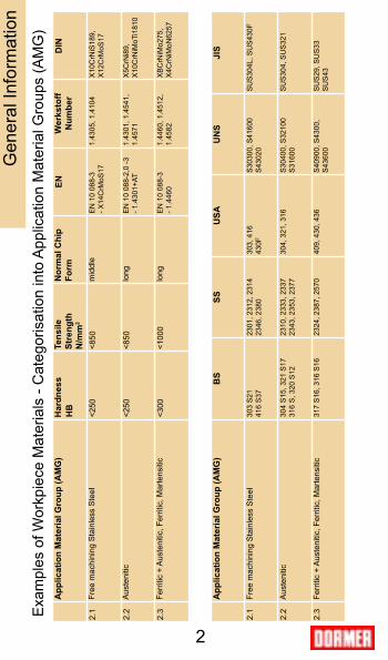
Exa
mpl
es o
f Wor
kpie
ce M
ater
ials
- C
ateg
oris
atio
n in
to A
pplic
atio
n M
ater
ial G
roup
s (A
MG
)A
pplic
atio
n M
ater
ial G
roup
(AM
G)
Har
dnes
s Te
nsile
St
reng
th
N/m
m2
Nor
mal
Chi
p Fo
rmW
erks
toff
Num
ber
Free
mac
hini
ng S
tain
less
Ste
elm
iddl
e
Aus
teni
ticlo
ng
Ferr
itic
+ A
uste
nitic
, Fer
ritic
, Mar
tens
itic
long
App
licat
ion
Mat
eria
l Gro
up (A
MG
)
Free
mac
hini
ng S
tain
less
Ste
el
Aus
teni
tic
Ferr
itic
+ A
uste
nitic
, Fer
ritic
, Mar
tens
itic

3
Contents
Classification of workpiece materials 2Application Material Groups 4Introduction to Stainless Steels 5Machinability of Stainless Steels 5 Hints when machining Stainless Steels 6AMG 2.1 7AMG 2.2 8AMG 2.3 9General Hints on Drilling 10Drill Feed Chart 11Drill Selection 12General Hints on Tapping 14Drill diameters for cutting taps 15Tap Selection 16General Hints on Milling 18Milling parameters 19Applications 20Milling Feed Charts 20Milling Cutters Selection 24Table of cutting speeds 26
Gen
eral
Info
rmat
ion

4
Application Material Groups
Application Material Groups (“AMGs”) are designed to assist in the selection of the optimum cutting tool for a particular application.
Dormer classifies materials into 10 major Application Material Groups. Each major group is divided into sub-groups on the basis of material properties, such as hardness and strength, and chip formation. This booklet concentrates on sub-groups 2.1 – 2.3 – Stainless Steels.
Examples of national designations within each sub-group are shown on page 2.
This booklet contains a selection of tools that are rated “excellent” for machining Stainless Steels. Please see the Dormer catalogue or Product Selector for the full range, or contact your local Dormer representative or Technical Helpdesk if you need further advice.
Gen
eral
Info
rmat
ion

5
Introduction to Stainless Steels
Stainless steels are alloyed steels used primarily because of their corrosion resistance. Their main alloying element is chromium (Cr). The chromium in the stainless steel forms an ultra-thin oxide film on the surface. As a general rule, corrosion resistance and resistance to oxidation increase in line with chromium content. Other alloying elements, such as nickel and molybdenum, are added to change the structure, increase corrosion resistance and improve strength.
Why are Stainless Steels seen as difficult to machine?
• Most stainless steel materials work harden during deformation, i.e. the process of producing a chip. The work hardening decreases rapidly with an increasing distance from the surface. Hardness values close to the machined surface can increase by up to 100% of the original hardness value if using the incorrect tool.
• Stainless steels are poor heat conductors, which leads to high cutting edge temperatures compared to a steel, in for example, AMG 1.3 with similar levels of hardness.
• High toughness leads to high torque, which in turn results in a high work load for a tap or drill. When combined with the effects of work hardening and poor heat conductivity, the cutting tool has to perform in a relatively hostile environment.
• The materials have a tendency to smear the surface of the cutting tool.
• Chip breaking and swarf management problems, due to the high toughness of the stainless steel.
Gen
eral
Info
rmat
ion

6
Important when machining Stainless Steels
• For drilling operations, use ADX or CDX drills with internal coolant capability. This will counter the work hardening that occurs when machining Stainless Steel. With internal cooling, the work hardening is kept to a minimum, about 10%.
• High feed rates transfer more heat away from the machining area. This is a very important consideration for a trouble-free machining operation.
• When it comes to choosing the correct cutting speed, always start in the lower region of Dormer recommendations. This is due to the fact that different material batches may require different cutting speeds. Also keep in mind that for deeper holes, cutting speed should be reduced by 10-20%, for the chosen application.
• When threading in DUPLEX or in high alloyed stainless steel, keep the cutting speed in the lower region of Dormer recommendations.
• Use preferably a neat cutting oil. If an emulsion is the only option for the operation, a minimum 8% concentration is recommended.
• First choice should always be a coated tool since they have a greater tendency to resist built-up edges.
• Avoid using tools with worn cutting edges, since this will increase work hardening.
Gen
eral
Info
rmat
ion
7
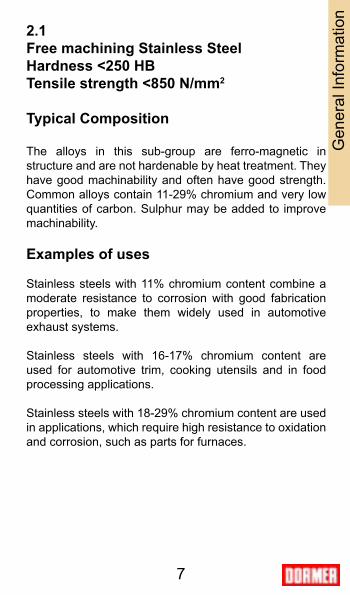
2.1 Free machining Stainless SteelHardness <250 HBTensile strength <850 N/mm2
Typical Composition
The alloys in this sub-group are ferro-magnetic in structure and are not hardenable by heat treatment. They have good machinability and often have good strength. Common alloys contain 11-29% chromium and very low quantities of carbon. Sulphur may be added to improve machinability.
Examples of uses
Stainless steels with 11% chromium content combine a moderate resistance to corrosion with good fabrication properties, to make them widely used in automotive exhaust systems.
Stainless steels with 16-17% chromium content are used for automotive trim, cooking utensils and in food processing applications.
Stainless steels with 18-29% chromium content are used in applications, which require high resistance to oxidation and corrosion, such as parts for furnaces.
Gen
eral
Info
rmat
ion
8
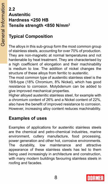
2.2Austenitic Hardness <250 HBTensile strength <850 N/mm2
Typical Composition
The alloys in this sub-group form the most common group of stainless steels, accounting for over 70% of production. They are non-magnetic at normal temperatures and not hardenable by heat treatment. They are characterised by a high coefficient of elongation and their machinability is medium to low. The addition of nickel changes the structure of these alloys from ferritic to austenitic. The most common type of austenitic stainless steel is the 18/8-type (18% Chromium, 8% Nickel), which has good resistance to corrosion. Molybdenum can be added to give improved mechanical properties. Higher alloyed austenitic stainless steel, for example with a chromium content of 26% and a Nickel content of 22%, also have the benefit of improved resistance to corrosion. However, increasing alloy content reduces machinability.
Examples of uses
Examples of applications for austenitic stainless steels are the chemical and petro-chemical industries, marine environment, cutlery manufacture, food processing, power generation and other hot, corrosive environments. The durability, low maintenance and attractive appearance of these stainless steels has led to them being used increasingly in architecture and construction, with many modern buildings favouring stainless steels in roofing and facades.
Gen
eral
Info
rmat
ion

9
2.3 Ferritic + Austenitic/Duplex, Martensitic and Precipitation Hardening Stainless Steels Hardness <300 HB Tensile strength <1000 N/mm2
Ferritic + Austenitic/DuplexThe structure of these stainless steels is a hybrid of the structures of Ferritic and Austenitic, giving them high corrosion resistance and a balanced micro-structure with approximately equal proportions of ferrite and austenite. They have a higher yield strength and tensile strength than stainless steels in groups 2.1 and 2.2. They are often used for dynamically stressed machine parts, such as suction rolls for paper machines. They also find application in the oil, gas and petrochemical industries, as well as offshore industry. They contain relatively high chromium levels (18-28%) and moderate amounts of nickel (4.5–8%) and have low machinability.
MartensiticMartensitic stainless steels are magnetic and hardenable, retaining good mechanical properties. Typically they contain 12–14% chromium with a moderate carbon content. Their main applications are in cutlery manufacture, aerospace and general engineering. Most grades in the annealed (softened) condition are relatively easy-to-machine, but grades with nickel and higher carbon levels have low machinability.
Precipitation hardening stainless steelsThese possess the highest strength of all stainless steel groups and are obtained by heat treatment. Like stainless steels in 2.1, they are difficult to machine.
Gen
eral
Info
rmat
ion

10
General Hints on Drilling
1. Select the most appropriate drill for the application, bearing in mind the material to be machined, the capability of the machine tool and the coolant to be used.
2. Flexibility within the component and machine tool spindle can cause damage to the drill as well as the component and machine - ensure maximum stability at all times. This can be improved by selecting the shortest possible drill for the application.
3. Tool holding is an important aspect of the drilling operation and the drill cannot be allowed to slip or move in the tool holder.
4. The use of suitable coolants and lubricants are recommended as required by the particular drilling operation. When using coolants and lubricants, ensure a copious supply, especially at the drill point.
5. Swarf evacuation whilst drilling is essential in ensuring the correct drilling procedure. Never allow the swarf to become stationary in the flute.
6. When regrinding a drill, always makes sure that the correct point geometry is produced and that any wear has been removed.
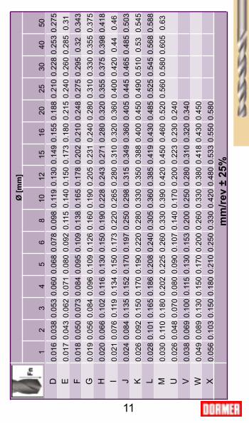
Ø [m
m]
12
34
56
810
1215
1620
2530
4050
D0.
016
0.03
80.
053
0.06
00.
068
0.07
80.
098
0.11
90.
130
0.14
90.
155
0.18
80.
210
0.22
80.
253
0.27
5E
0.01
70.
043
0.06
20.
071
0.08
00.
092
0.11
50.
140
0.15
00.
173
0.18
00.
215
0.24
00.
260
0.28
50.
31F
0.01
80.
050
0.07
30.
084
0.09
50.
109
0.13
80.
165
0.17
80.
202
0.21
00.
248
0.27
50.
295
0.32
0.34
3G
0.01
90.
056
0.08
40.
096
0.10
90.
126
0.16
00.
190
0.20
50.
231
0.24
00.
280
0.31
00.
330
0.35
50.
375
H0.
020
0.06
60.
102
0.11
60.
130
0.15
00.
190
0.22
80.
243
0.27
10.
280
0.32
00.
355
0.37
50.
398
0.41
8I
0.02
10.
076
0.11
90.
134
0.15
00.
173
0.22
00.
265
0.28
00.
310
0.32
00.
360
0.40
00.
420
0.44
0.46
J0.
024
0.08
40.
135
0.15
20.
170
0.19
70.
250
0.29
80.
315
0.34
90.
360
0.40
50.
445
0.46
50.
485
0.50
3K
0.02
60.
092
0.15
00.
170
0.19
00.
220
0.28
00.
330
0.35
00.
388
0.40
00.
450
0.49
00.
510
0.53
0.54
5L
0.02
80.
101
0.16
50.
186
0.20
80.
240
0.30
50.
360
0.38
50.
419
0.43
00.
485
0.52
50.
545
0.56
80.
588
M0.
030
0.11
00.
180
0.20
20.
225
0.26
00.
330
0.39
00.
420
0.45
00.
460
0.52
00.
560
0.58
00.
605
0.63
U0.
026
0.04
80.
070
0.08
00.
090
0.10
70.
140
0.17
00.
200
0.22
30.
230
0.24
0V
0.03
80.
069
0.10
00.
115
0.13
00.
153
0.20
00.
250
0.28
00.
310
0.32
00.
340
W0.
049
0.08
90.
130
0.15
00.
170
0.20
00.
260
0.33
00.
380
0.41
80.
430
0.45
0X
0.05
60.
103
0.15
00.
180
0.21
00.
250
0.33
00.
420
0.48
00.
533
0.55
00.
580
11
mm
/rev
± 25
%
2.12.22.3
12
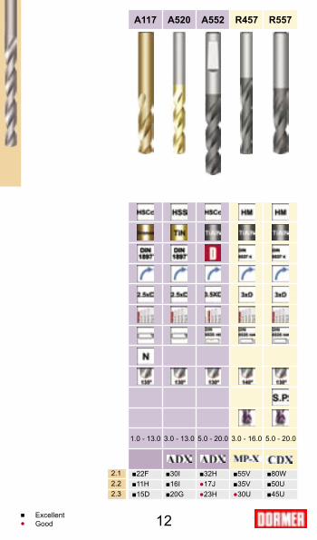
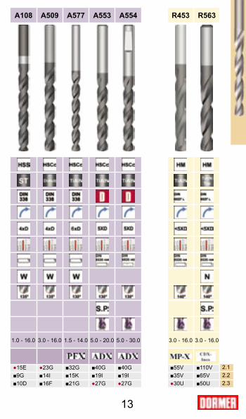
A117 A520 A552 R457 R557 A108 A509 A577 A553 A554 R453 R563
1.0 - 13.0 3.0 - 13.0 5.0 - 20.0 3.0 - 16.0 5.0 - 20.0 1.0 - 16.0 3.0 - 16.0 1.5 - 14.0 5.0 - 20.0 5.0 - 30.0 3.0 - 16.0 3.0 - 16.0
■22F ■30I ■32H ■55V ■80W ●15E ●23G ■32G ■40G ■40G ■55V ■110V■11H ■16I ●17J ■35V ■50U ■9G ■14I ■15K ■19I ■19I ■35V ■65V■15D ■20G ●23H ●30U ■45U ■10D ■16F ■21G ●27G ●27G ●30U ■50U
■ ●
ExcellentGood
13
A117 A520 A552 R457 R557 A108 A509 A577 A553 A554 R453 R563
1.0 - 13.0 3.0 - 13.0 5.0 - 20.0 3.0 - 16.0 5.0 - 20.0 1.0 - 16.0 3.0 - 16.0 1.5 - 14.0 5.0 - 20.0 5.0 - 30.0 3.0 - 16.0 3.0 - 16.0
■22F ■30I ■32H ■55V ■80W ●15E ●23G ■32G ■40G ■40G ■55V ■110V■11H ■16I ●17J ■35V ■50U ■9G ■14I ■15K ■19I ■19I ■35V ■65V■15D ■20G ●23H ●30U ■45U ■10D ■16F ■21G ●27G ●27G ●30U ■50U
2.12.22.3
14
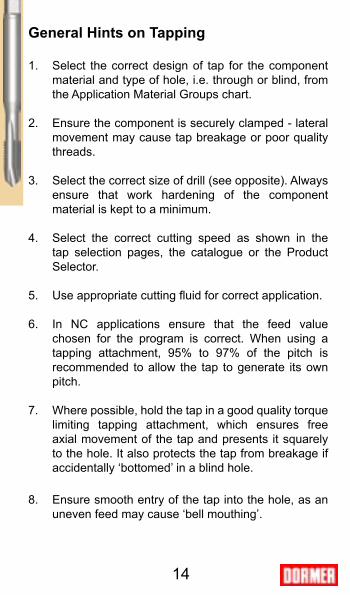
General Hints on Tapping
1. Select the correct design of tap for the component material and type of hole, i.e. through or blind, from the Application Material Groups chart.
2. Ensure the component is securely clamped - lateral movement may cause tap breakage or poor quality threads.
3. Select the correct size of drill (see opposite). Always ensure that work hardening of the component material is kept to a minimum.
4. Select the correct cutting speed as shown in the tap selection pages, the catalogue or the Product Selector.
5. Use appropriate cutting fluid for correct application.
6. In NC applications ensure that the feed value chosen for the program is correct. When using a tapping attachment, 95% to 97% of the pitch is recommended to allow the tap to generate its own pitch.
7. Where possible, hold the tap in a good quality torque limiting tapping attachment, which ensures free axial movement of the tap and presents it squarely to the hole. It also protects the tap from breakage if accidentally ‘bottomed’ in a blind hole.
8. Ensure smooth entry of the tap into the hole, as an uneven feed may cause ‘bell mouthing’.

M mm mm mm1.6 0.35 1.321 1.25 3/641.8 0.35 1.521 1.45 542 0.4 1.679 1.6 1/162.2 0.45 1.833 1.75 502.5 0.45 2.138 2.05 463 0.5 2.599 2.5 403.5 0.6 3.010 2.9 334 0.7 3.422 3.3 304.5 0.75 3.878 3.8 275 0.8 4.334 4.2 196 1 5.153 5 97 1 6.153 6 15/648 1.25 6.912 6.8 H9 1.25 7.912 7.8 5/1610 1.5 8.676 8.5 Q11 1.5 9.676 9.5 3/812 1.75 10.441 10.3 Y14 2 12.210 12 15/3216 2 14.210 14 35/6418 2.5 15.744 15.5 39/6420 2.5 17.744 17.5 11/1622 2.5 19.744 19.5 49/6424 3 21.252 21 53/6427 3 24.252 24 61/6430 3.5 26.771 26.5 1.3/64
15
D = Dnom- P
M mm mm
4 0.70 3.405 0.80 4.306 1.00 5.108 1.25 6.9010 1.50 8.7012 1.75 10.4014 2.00 12.2516 2.00 14.25
Drill diameter can be calculated from:
METRIC COARSE THREAD
RECOMMENDED DIAMETERS WHEN USING DORMER ADX AND CDX DRILLS
The above table for drill diameters refer to ordinary standard drills. Modern drills such as Dormer ADX and CDX produce a smaller and more accurate hole which makes it necessary to increase the diameter of the drill in order to avoid breakage of the tap.Please see the small table to the left.
D = Drill diameter (mm)
Dnom = Tap nominal diameter (mm)
P = Tap pitch (mm)
METRIC COARSE THREAD FOR ADX/CDX
Max. DRILL DRILLInternal
Pitch Diam. Diam. Diam.inch
TAP DRILLPitch Diameter
Drill Diameters for Cutting Taps - Recommendation tables
2.12.22.3
DIN
16
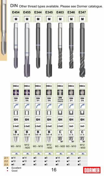
E454 E455 E344 E345 E403 E346 E347
M3 - M10 M12 - M20 M3 - M10 M12
- M30 M3 - M20 M3 - M10 M12 - M30
■14 ■14 ■8 ■8 ■14 ■8 ■8■10 ■10 ■7 ■7 ■10 ■7 ■7■6 ■6 ■5 ■5 ■6 ■5 ■5
■ ●
ExcellentGood
Other thread types available. Please see Dormer catalogue.

E045 E046 E047 E048
M3 - M20 M3 - M20 M3 - M20 M3 - M20
■8 ■14 ■8 ■14■7 ■10 ■7 ■10■5 ■6 ■5 ■6
ISO
2.12.22.3
17

18
General Hints on Milling
1. Where possible, use climb milling (down milling) for longer tool life. Climb milling allows easier chip disposal, less wear, improved surface finish and lower power requirements compared to conventional milling (up milling).
2. Always use a cutter in good condition.
3. Use well-maintained machine tools with sufficient power.
4. Use correct clamping system according to working operation and type of tool.
5. Check for damage or wear on the tool shank or in the holder itself.
6. Use the shortest cutters recommended for your application and work as close to the machine head as possible.
7. For optimum productivity, use coated or Solid Carbide cutters.
19
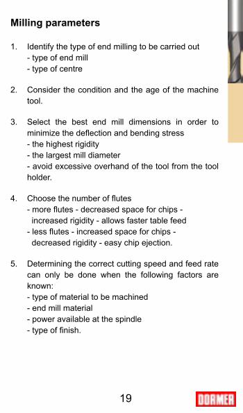
Milling parameters
1. Identify the type of end milling to be carried out - type of end mill - type of centre
2. Consider the condition and the age of the machine tool.
3. Select the best end mill dimensions in order to minimize the deflection and bending stress
- the highest rigidity - the largest mill diameter - avoid excessive overhand of the tool from the tool
holder.
4. Choose the number of flutes - more flutes - decreased space for chips - increased rigidity - allows faster table feed - less flutes - increased space for chips - decreased rigidity - easy chip ejection.
5. Determining the correct cutting speed and feed rate can only be done when the following factors are known:
- type of material to be machined - end mill material - power available at the spindle - type of finish.

20
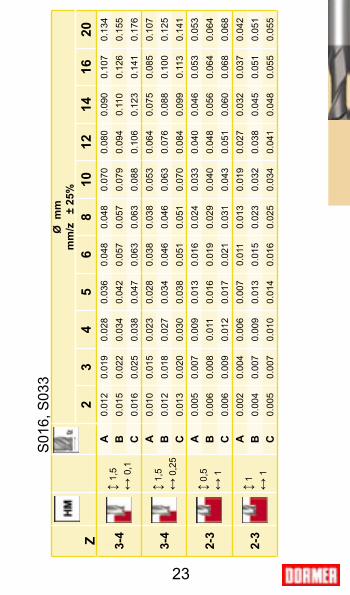
For details on how to use the feed charts in the tables which follow, please see below.
Slotting Roughing
Ball nose Finishing
Application

Ø m
mm
m/z
± 2
5%1
23
45
68
1012
1416
1820
2225
2830
3236
40↕
0,5D
↔ D
E0,
007
0,01
20,
018
0,02
40,
035
0,04
20,
063
0,08
70,
105
0,12
20,
140
0,14
10,
140
0,14
40,
153
0,17
10,
157
0,16
80,
157
0,17
5
F0,
007
0,00
90,
013
0,01
80,
021
0,02
50,
033
0,04
10,
050
0,05
50,
064
0,07
20,
079
0,07
90,
085
0,08
50,
085
0,08
50,
085
0,08
5
↕ D
↔ 0
,8D
K0,
035
0,04
70,
065
0,07
90,
092
0,10
50,
088
0,09
80,
097
0,11
00,
110
0,11
00,
110
0,11
50,
118
L0,
010
0,01
30,
017
0,02
00,
025
0,02
80,
030
0,03
20,
033
0,03
40,
036
0,03
80,
039
0,04
00,
042
↕ 1,
5D↔
0,2
5DN
0,00
70,
011
0,01
60,
021
0,02
80,
037
0,05
10,
062
0,07
20,
082
0,09
30,
103
0,08
10,
093
0,07
70,
082
0,08
70,
099
0,09
6
Q0,
009
0,01
40,
021
0,02
60,
036
0,04
80,
066
0,07
90,
092
0,10
60,
089
0,09
90,
098
0,11
10,
111
0,11
90,
127
0,14
30,
139
R0,
012
0,01
60,
020
0,02
50,
029
0,03
80,
047
0,05
60,
065
0,07
30,
083
0,09
20,
092
0,09
20,
092
0,09
20,
104
0,10
40,
108
↕ 1,
5D↔
0,1
DX
0,01
20,
017
0,02
60,
033
0,04
50,
059
0,08
20,
099
0,11
50,
132
0,11
10,
124
0,12
20,
139
0,13
90,
148
0,15
80,
178
0,17
3
Y0,
015
0,02
00,
025
0,03
10,
036
0,04
70,
059
0,07
00,
081
0,09
20,
104
0,11
50,
115
0,11
50,
115
0,11
50,
130
0,13
00,
136
21

Z
Ø m
m
m
m/z
±
25%
>0,5
0.6
0.8
12
34
56
810
1214
1618
20
>4
↕ 1,
5↔
0,0
5
A0.
015
0.02
00.
025
0.03
00.
035
0.04
00.
050
0.06
0
B0.
045
0.05
00.
060
0.07
50.
080
0.09
00.
100
0.11
0
C0.
065
0.07
50.
090
0.11
00.
120
0.13
00.
150
0.17
0
3-4
↕ 1,
5↔
0,1
A0.
010
0.02
00.
030
0.04
00.
045
0.05
00.
060
0.07
50.
080
0.09
00.
100
0.12
0
B0.
015
0.03
00.
040
0.05
50.
065
0.07
50.
090
0.11
00.
120
0.13
00.
150
0.17
0
C0.
015
0.03
00.
040
0.05
50.
085
0.10
00.
120
0.14
00.
150
0.17
00.
200
0.22
0
3-4
↕ 1
↔ 0
,5
A0.
001
0.00
30.
005
0.00
80.
010
0.01
30.
020
0.02
70.
035
0.04
00.
050
0.05
50.
060
B0.
002
0.00
40.
008
0.01
20.
015
0.02
00.
030
0.04
00.
050
0.06
00.
070
0.08
00.
090
C0.
003
0.00
50.
010
0.01
50.
020
0.02
50.
040
0.05
00.
065
0.08
00.
090
0.10
50.
120
2-3
↕ 0,
5↔
1
A0.
001
0.00
10.
002
0.00
20.
005
0.00
90.
013
0.01
70.
020
0.02
30.
035
0.04
00.
050
0.05
50.
060
0.07
0
B0.
001
0.00
20.
003
0.00
30.
007
0.01
30.
020
0.02
50.
030
0.03
50.
050
0.06
00.
070
0.08
00.
090
0.10
0
C0.
002
0.00
30.
004
0.00
40.
009
0.01
70.
025
0.03
30.
040
0.04
50.
065
0.08
00.
090
0.10
50.
120
0.13
0
3-4
↕ 0,
5↔
1
↕ 1
↔ 0
,5
B0.
035
0.04
00.
055
0.06
50.
080
0.09
00.
100
0.11
0
S31
1, S
308,
S31
2, S
259
22
Z
Ø m
m
m
m/z
±
25%
23
45
68
1012
1416
20
3-4
↕ 1,
5↔
0,1
A0.
012
0.01
90.
028
0.03
60.
048
0.04
80.
070
0.08
00.
090
0.10
70.
134
B0.
015
0.02
20.
034
0.04
20.
057
0.05
70.
079
0.09
40.
110
0.12
60.
155
C0.
016
0.02
50.
038
0.04
70.
063
0.06
30.
088
0.10
60.
123
0.14
10.
176
3-4
↕ 1,
5↔
0,2
5
A0.
010
0.01
50.
023
0.02
80.
038
0.03
80.
053
0.06
40.
075
0.08
50.
107
B0.
012
0.01
80.
027
0.03
40.
046
0.04
60.
063
0.07
60.
088
0.10
00.
125
C0.
013
0.02
00.
030
0.03
80.
051
0.05
10.
070
0.08
40.
099
0.11
30.
141
2-3
↕ 0,
5↔
1
A0.
005
0.00
70.
009
0.01
30.
016
0.02
40.
033
0.04
00.
046
0.05
30.
053
B0.
006
0.00
80.
011
0.01
60.
019
0.02
90.
040
0.04
80.
056
0.06
40.
064
C0.
006
0.00
90.
012
0.01
70.
021
0.03
10.
043
0.05
10.
060
0.06
80.
068
2-3
↕ 1
↔ 1
A0.
002
0.00
40.
006
0.00
70.
011
0.01
30.
019
0.02
70.
032
0.03
70.
042
B0.
004
0.00
70.
009
0.01
30.
015
0.02
30.
032
0.03
80.
045
0.05
10.
051
C0.
005
0.00
70.
010
0.01
40.
016
0.02
50.
034
0.04
10.
048
0.05
50.
055
S01
6, S
033
23
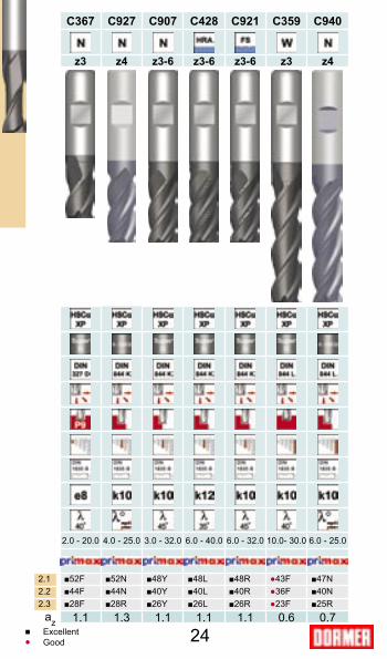
2.12.22.3
24
C367 C927 C907 C428 C921 C359 C940
z3 z4 z3-6 z3-6 z3-6 z3 z4
2.0 - 20.0 4.0 - 25.0 3.0 - 32.0 6.0 - 40.0 6.0 - 32.0 10.0- 30.0 6.0 - 25.0
■52F ■52N ■48Y ■48L ■48R ●43F ■47N■44F ■44N ■40Y ■40L ■40R ●36F ■40N■28F ■28R ■26Y ■26L ■26R ●23F ■25R
1.1 1.3 1.1 1.1 1.1 0.6 0.7■ ●
azExcellentGood

2.12.22.3
25
S033 S016 S311 S308 S312 S259
z3 z3 z3 z3 z4-5 z4-5
2.0 - 20.0 2.0 - 20.0 4.0 - 20.0 10.0- 20.0 2.0 - 20.0 6.0 - 20.0
●73A ●73A ■81A ■69A ■115A ■100A●56A ●56A ■54A ●46A ■76A ■66A●44A ●44A ■54A ●46A ■76A ■66A
1 0.3 1 1 1 1 az
58
1015
2025
3040
5060
7080
9010
011
015
0
1626
3250
6682
9813
016
519
723
026
229
633
036
249
5
mm
1,00
1592
2546
3138
4775
6366
7958
9549
1273
215
916
1909
922
282
2546
528
648
3183
135
014
4774
71,
5010
6116
9821
2231
8342
4453
0563
6684
8810
610
1273
214
854
1697
719
099
2122
123
343
3183
12,
0079
612
7315
9223
8731
8339
7947
7563
6679
5895
4911
141
1273
214
324
1591
617
507
2387
32,
5063
710
1912
7319
1025
4631
8338
2050
9363
6676
3989
1310
186
1145
912
732
1400
619
099
3,00
531
849
1061
1592
2122
2653
3183
4244
5305
6366
7427
8488
9549
1061
011
671
1591
63,
181 /
850
080
110
0115
0120
0225
0230
0340
0450
0560
0670
0780
0890
0910
010
1101
115
015
3,50
455
728
909
1364
1819
2274
2728
3638
4547
5457
6366
7176
8185
9095
1000
413
642
4,00
398
637
796
1194
1592
1989
2387
3183
3979
4775
5570
6366
7162
7958
8754
1193
74,
5035
456
670
710
6114
1517
6821
2228
2935
3742
4449
5156
5963
6670
7477
8110
610
4,76
3 /16
334
535
669
1003
1337
1672
2006
2675
3344
4012
4681
5350
6018
6687
7356
1003
15,
0031
850
963
795
512
7315
9219
1025
4631
8338
2044
5650
9357
3063
6670
0395
496,
0026
542
453
179
610
6113
2615
9221
2226
5331
8337
1442
4447
7553
0558
3679
586,
351 /
425
140
150
175
210
0312
5315
0420
0525
0630
0835
0940
1045
1150
1355
1475
197,
0022
736
445
568
290
911
3713
6418
1922
7427
2831
8336
3840
9345
4750
0268
217,
945 /
1620
032
140
160
180
210
0212
0316
0420
0424
0528
0632
0736
0840
0944
1060
138,
0019
931
839
859
779
699
511
9415
9219
8923
8727
8531
8335
8139
7943
7759
689,
0017
728
335
453
170
788
410
6114
1517
6821
2224
7628
2931
8335
3738
9053
059,
533 /
816
726
733
450
166
883
510
0213
3616
7020
0423
3826
7230
0633
4036
7450
1010
,00
159
255
318
477
637
796
955
1273
1592
1910
2228
2546
2865
3183
3501
4775
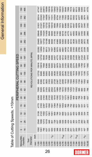
26
Gen
eral
Info
rmat
ion
Tabl
e of
Cut
ting
Spe
eds,
<10
mm PE
RIP
HE
RA
L C
UTT
ING
SP
EE
D
RE
VO
LUTI
ON
S P
ER
MIN
UTE
(RP
M)
Met
res/
Min
.Fe
et/M
in.
Tool
D
iam
eter in
ch
58
1015
2025
3040
5060
7080
9010
011
015
0
1626
3250
6682
9813
016
519
723
026
229
633
036
249
5
mm
11,1
17 /
1614
322
928
743
057
371
686
011
4614
3317
1920
0622
9225
7928
6531
5242
9812
,00
133
212
265
398
531
663
796
1061
1326
1592
1857
2122
2387
2653
2918
3979
12,7
01 /
212
520
125
137
650
162
775
210
0312
5315
0417
5420
0522
5625
0627
5737
6014
,00
114
182
227
341
455
568
682
909
1137
1364
1592
1819
2046
2274
2501
3410
14,2
99 /
1611
117
822
333
444
655
766
889
111
1413
3715
5917
8220
0522
2824
5033
4115
,00
106
170
212
318
424
531
637
849
1061
1273
1485
1698
1910
2122
2334
3183
15,8
85 /
810
016
020
030
140
150
160
180
210
0212
0314
0316
0418
0420
0422
0530
0716
,00
9915
919
929
839
849
759
779
699
511
9413
9315
9217
9019
8921
8829
8417
,46
11/ 1
691
146
182
273
365
456
547
729
912
1094
1276
1458
1641
1823
2005
2735
18,0
088
141
177
265
354
442
531
707
884
1061
1238
1415
1592
1768
1945
2653
19,0
53 /
484
134
167
251
334
418
501
668
835
1003
1170
1337
1504
1671
1838
2506
20,0
080
127
159
239
318
398
477
637
796
955
1114
1273
1432
1592
1751
2387
24,0
066
106
133
199
265
332
398
531
663
796
928
1061
1194
1326
1459
1989
25,0
064
102
127
191
255
318
382
509
637
764
891
1019
1146
1273
1401
1910
27,0
059
9411
817
723
629
535
447
258
970
782
594
310
6111
7912
9717
6830
,00
5385
106
159
212
265
318
424
531
637
743
849
955
1061
1167
1592
32,0
050
8099
149
199
249
298
398
497
597
696
796
895
995
1094
1492
36,0
044
7188
133
177
221
265
354
442
531
619
707
796
884
973
1326
40,0
040
6480
119
159
199
239
318
398
477
557
637
716
796
875
1194
50,0
032
5164
9512
715
919
125
531
838
244
650
957
363
770
095
5
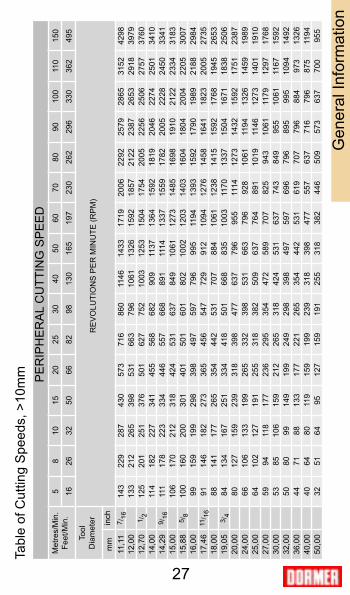
27
Gen
eral
Info
rmat
ion
Tabl
e of
Cut
ting
Spe
eds,
>10
mm PE
RIP
HE
RA
L C
UTT
ING
SP
EE
D
RE
VO
LUTI
ON
S P
ER
MIN
UTE
(RP
M)
Met
res/
Min
.Fe
et/M
in.
Tool
D
iam
eter in
ch