Embed Size (px)
Citation preview

Date
21.11.2017
Automation Specification
Autoliv
FLA Vårgårda - Sweden Created by
Ross Sandlin
Joakim Gustafsson
Version
1.1
Festo AG & Co. KG 2 21.11.2017
1 Table of Contents
1 Table of Contents .................................................................................................................................................................................................. 2 2 Dokument management information ..................................................................................................................................................................... 4 3 Contact persons at Autoliv and Festo ..................................................................................................................................................................... 5
3.1 Autoliv ......................................................................................................................................................................................................... 5 3.2 Festo ............................................................................................................................................................................................................ 6
4 Actuators .............................................................................................................................................................................................................. 7 4.1 What should always be used where possible: .............................................................................................................................................. 7
4.1.1 How it can be used: ................................................................................................................................................................................. 7 4.1.2 Why it should be used: ............................................................................................................................................................................ 7
4.2 Linear Motion ............................................................................................................................................................................................... 8 4.2.1 Compact Cylinders - Pneumatic ............................................................................................................................................................... 8 4.2.2 Round Cylinders - Pneumatic ................................................................................................................................................................... 8 4.2.3 Standard Cylinders - Pneumatic ............................................................................................................................................................... 9 4.2.4 Guided Drives - Pneumatic ...................................................................................................................................................................... 9 4.2.5 Linear Drives - Pneumatic ...................................................................................................................................................................... 10 4.2.6 Stopper- / Bellow Cylinders ................................................................................................................................................................... 11
4.3 Shock Absorbers ........................................................................................................................................................................................ 11 5 Gripping- , Vacuum- and Handling Technology .................................................................................................................................................... 12
5.1.1 Bello Grippers ....................................................................................................................................................................................... 12 5.2 Vacuum Technology ................................................................................................................................................................................... 13
5.2.1 Vacuum accessories .............................................................................................................................................................................. 13 5.3 Handling Technology.................................................................................................................................................................................. 14
5.3.1 Separating ............................................................................................................................................................................................ 14 5.3.2 Handling Modules - High Speed Pick and Place ..................................................................................................................................... 14
6 Safety - Related Pneumatics ................................................................................................................................................................................ 15 6.1 Aeration / De-aeration ............................................................................................................................................................................... 15 6.2 Safety valves for presses ........................................................................................................................................................................... 16
7 Valve- and Control Technology ............................................................................................................................................................................ 17 7.1 What should always be used where possible: ............................................................................................................................................ 17
7.1.1 How it can be used: ............................................................................................................................................................................... 17 7.1.2 Why it should be used: .......................................................................................................................................................................... 17
7.2 What should never be used: ....................................................................................................................................................................... 18 7.2.1 Why it should never be used: ................................................................................................................................................................ 18
7.3 Universal Directional Control Valves ........................................................................................................................................................... 19 7.4 Universal Directional Control Valves for sub-base or manifold mounting .................................................................................................... 19 7.5 Proportional - Pressure Regulators ............................................................................................................................................................. 19 7.6 Hand Lever Valves ...................................................................................................................................................................................... 20 7.7 Valve terminals .......................................................................................................................................................................................... 20 7.8 Automation Platform .................................................................................................................................................................................. 21 7.9 Valves on robot .......................................................................................................................................................................................... 21
8 Proximity Sensors and Piston Position Sensing ................................................................................................................................................... 22 8.1 Proximity Sensors ...................................................................................................................................................................................... 22
8.1.1 Electronic Contactless Switching ........................................................................................................................................................... 22 8.2 Position Transmitter ................................................................................................................................................................................... 22
9 Sensors ............................................................................................................................................................................................................... 23 9.1 Pressure- / Vacuum Sensors ...................................................................................................................................................................... 23 9.2 Fork Light Barriers ...................................................................................................................................................................................... 23
10 Electrical connector technology ........................................................................................................................................................................... 24 10.1 Cable ......................................................................................................................................................................................................... 24
11 Compressed Air Preparation ................................................................................................................................................................................ 25 11.1 What should always be used where possible: ............................................................................................................................................ 25
11.1.1 How it can be used: .......................................................................................................................................................................... 25 11.1.2 Why it should be used: ..................................................................................................................................................................... 25

Festo AG & Co. KG 3 21.11.2017
11.2 What should always be used where possible: ............................................................................................................................................ 26 11.2.1 How it can be used: .......................................................................................................................................................................... 26 11.2.2 Why it should be used: ..................................................................................................................................................................... 26
11.3 What should always be used where possible: ............................................................................................................................................ 27 11.3.1 How it can be used: .......................................................................................................................................................................... 27 11.3.2 Why it should be used: ..................................................................................................................................................................... 27
11.4 What should always be used where possible: ............................................................................................................................................ 28 11.4.1 How it can be used: .......................................................................................................................................................................... 28 11.4.2 Why it should be used: ..................................................................................................................................................................... 28
11.5 What should always be used where possible: ............................................................................................................................................ 29 11.5.1 How it can be used: .......................................................................................................................................................................... 29 11.5.2 Why it should be used: ..................................................................................................................................................................... 29
11.6 MS-Series .................................................................................................................................................................................................. 30 11.6.1 Service unit – Configurable Combinations ......................................................................................................................................... 30 11.6.2 Energy efficiency module .................................................................................................................................................................. 30 11.6.3 On- Off Valves manual ...................................................................................................................................................................... 30 11.6.4 On- Off Valves Electric ....................................................................................................................................................................... 31 11.6.5 Start-up Exhaust Valves pneumatic ................................................................................................................................................... 31 11.6.6 Pressure Regulators .......................................................................................................................................................................... 32 11.6.7 Pressure Regulators – manifold style ................................................................................................................................................ 32 11.6.8 Precision Pressure Regulators .......................................................................................................................................................... 32 11.6.9 Precision Pressure Regulators – manifold style ................................................................................................................................. 32 11.6.10 Branching Modules ........................................................................................................................................................................... 33 11.6.11 Distributor Blocks ............................................................................................................................................................................. 33 11.6.12 Filters 40 - 5 µm ................................................................................................................................................................................ 33 11.6.13 Filter - Regulator Units 40 - 5 µm ....................................................................................................................................................... 33 11.6.14 Fine and Micro Filters 1 - 0,01 µm ...................................................................................................................................................... 34 11.6.15 Flow Sensors .................................................................................................................................................................................... 34 11.6.16 Soft-Start / Quick Exhaust Valve MS6-SV (Cat. 4, PLe & SIL 3 Safety Component) ............................................................................. 35
12 Service Units – Details ......................................................................................................................................................................................... 36 12.1 Service units G 1/2" ................................................................................................................................................................................... 36
13 Tubing, Fittings, Accessoires ............................................................................................................................................................................... 38 13.1 Tubing ....................................................................................................................................................................................................... 38 13.2 Pneumatic fittings system .......................................................................................................................................................................... 39 13.3 Functional Fittings ...................................................................................................................................................................................... 39 13.4 General Accessoirs ..................................................................................................................................................................................... 41 13.5 Pneumatic fittings system .......................................................................................................................................................................... 41
14 Festo Discontinued Products / old program generation ....................................................................................................................................... 42 14.1 Information ................................................................................................................................................................................................ 42 14.2 Pneumatic drives ....................................................................................................................................................................................... 42 14.3 Actuators Process Automation ................................................................................................................................................................... 46 14.4 Proximity Sensors / Sensors ...................................................................................................................................................................... 46 14.5 Pressure- / Vacuum Sensor ........................................................................................................................................................................ 46 14.6 Electrical drives .......................................................................................................................................................................................... 47 14.7 Vacuum technology.................................................................................................................................................................................... 47 14.8 Valves ........................................................................................................................................................................................................ 49 14.9 Valve terminals .......................................................................................................................................................................................... 50 14.10 Pneumatical connections ....................................................................................................................................................................... 51
Festo AG & Co. KG 4 21.11.2017
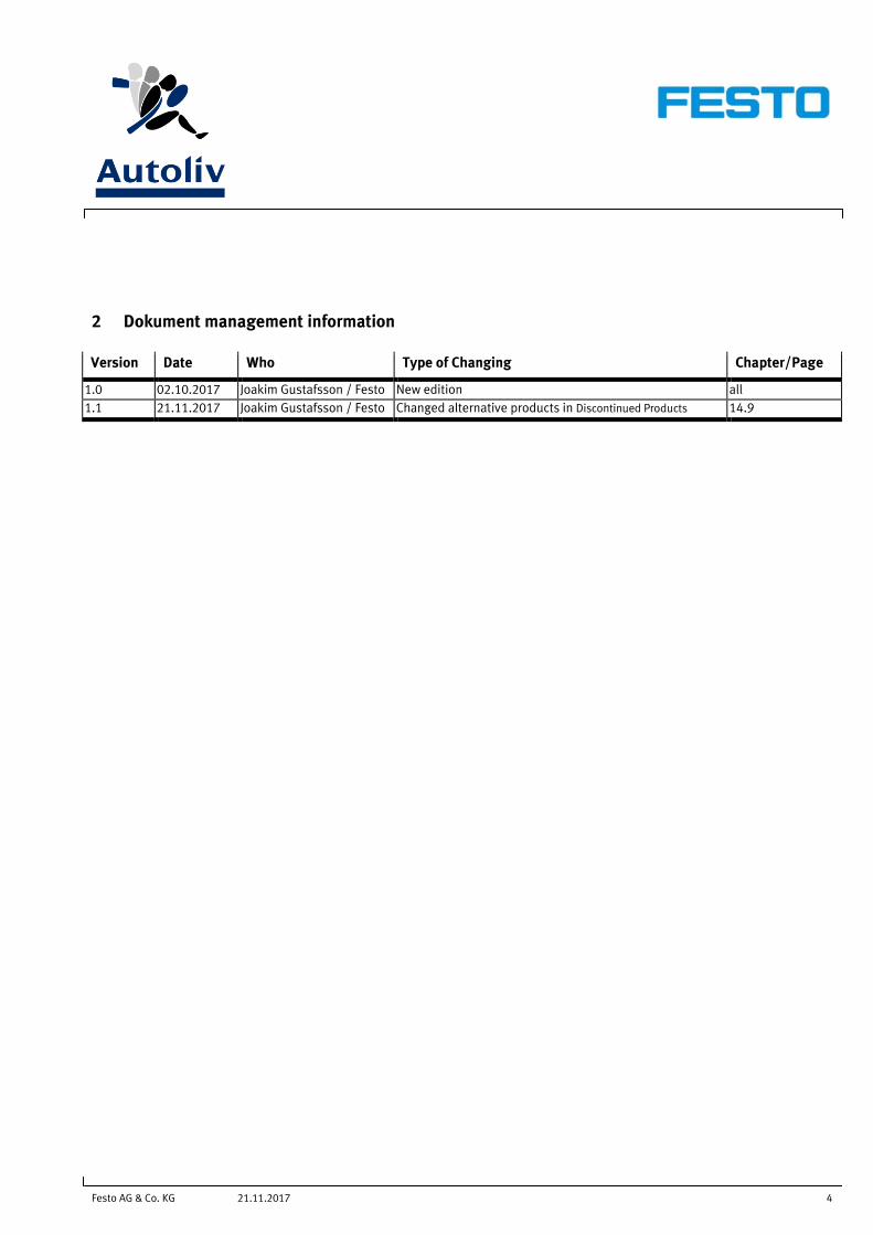
2 Dokument management information
Version Date Who Type of Changing Chapter/Page
1.0 02.10.2017 Joakim Gustafsson / Festo New edition all
1.1 21.11.2017 Joakim Gustafsson / Festo Changed alternative products in Discontinued Products 14.9
Festo AG & Co. KG 5 21.11.2017
3 Contact persons at Autoliv and Festo
3.1 Autoliv
Anders Ohlson
Autoliv Sverige AB Inflator
Gjuterigatan 1
447 37 Vårgårda, Sweden
Tel: +46 (0)322 667556
E-Mail: [email protected]
Johan Källberg
Autoliv Sverige AB Inflator
Gjuterigatan 1
447 37 Vårgårda, Sweden
Tel: +46 (0)322 667442
E-Mail: [email protected]
Festo AG & Co. KG 6 21.11.2017
3.2 Festo
International
Global Key Account Manager Autoliv
Javier Alcazar
Festo AG & Co. KG
Ruiter Str. 82
73734 Esslingen, Germany
Tel: +49(711)347-47224
Mobile: +49(162)2977183
E-Mail: [email protected]
Sweden
Industry Segment Manager Automotive
Joakim Gustafsson
Festo AB
Tel: +46 (40) 6990643
Mobil: +46 (70) 5562326
Email: [email protected]
System Sales Engineer
Gunnar Nordenström
Festo AB
Tel: +46 (40) 6990677
Mobil: +46 (70) 3833825
Email: [email protected]
Festo AG & Co. KG 7 21.11.2017
4 Actuators
4.1 What should always be used where possible:
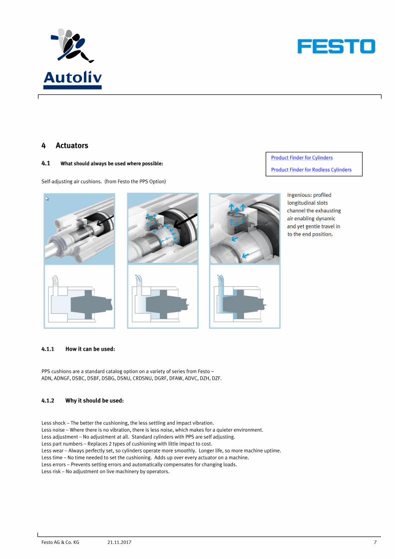
Self-adjusting air cushions. (from Festo the PPS Option)
4.1.1 How it can be used:
PPS cushions are a standard catalog option on a variety of series from Festo –
ADN, ADNGF, DSBC, DSBF, DSBG, DSNU, CRDSNU, DGRF, DFAW, ADVC, DZH, DZF.
4.1.2 Why it should be used:
Less shock – The better the cushioning, the less settling and impact vibration.
Less noise – Where there is no vibration, there is less noise, which makes for a quieter environment.
Less adjustment – No adjustment at all. Standard cylinders with PPS are self adjusting.
Less part numbers – Replaces 2 types of cushioning with little impact to cost.
Less wear – Always perfectly set, so cylinders operate more smoothly. Longer life, so more machine uptime.
Less time – No time needed to set the cushioning. Adds up over every actuator on a machine.
Less errors – Prevents setting errors and automatically compensates for changing loads.
Less risk – No adjustment on live machinery by operators.
Product Finder for Cylinders Product Finder for Rodless Cylinders

Festo AG & Co. KG 8 21.11.2017
4.2 Linear Motion
4.2.1 Compact Cylinders - Pneumatic
Name Remarks Engineering Tool Picture /
Online link Comment Documentation
Standard cylinders
ADN
Diameter 12, 16, 20, 25, 32, 40, 50, 63, 80, 100, 125 mm
Stroke length 1 ... 500 mm
Force 51 ... 7363 N
Double-acting
Position sensing
Fixed cushioning
Female thread
Male thread
Replacement of
ADVU
Choose Cushioning
PPS
Product features
ADN
Compact cylinder
ADNGF, metric
Diameter 12, 16, 20, 25, 32, 40, 50, 63, 80, 100 mm
Stroke length 1 ... 400 mm
Force 68 to 4712 N
Position sensing
Fixed cushioning.
Replacement of
ADVUL
ADNGF
4.2.2 Round Cylinders - Pneumatic
Name Remarks Engineering Tool Picture /
Online link Comment Documentation
Standard cylinder DSNU,
metric
Diameter 8, 10, 12, 16, 20, 25, 32, 40, 50, 63mm
Stroke length 1 ... 500 mm
Force 19 ... 1870 N
Double acting
Position sensing
Fixed/ adjustable/ self-adjusting cushioning (PPS)
Female thread
Male thread
Mounting flange.
Configurable
PPS available
DSNU

Festo AG & Co. KG 9 21.11.2017
4.2.3 Standard Cylinders - Pneumatic
Name Remarks Engineering Tool Picture /
Online link Comment Documentation
Standard cylinder
DSBC, metric
ISO 15552
Diameter 32, 40, 50, 63, 80, 100, 125 mm
Stroke length 10 ... 2800 mm
Force 483 ... 7363 N
Double acting
Position sensing
Fixed/ adjustable cushioning
Male thread/ Numerous variants
PPS available
Standard profile with 2 sensor slots
Replacement of
DNC / DNCB
DSBC
Animation
4.2.4 Guided Drives - Pneumatic
Name Remarks Engineering Tool Picture /
Online link Comment Documentation
Mini slide DGSL, metric Size 4, 6, 8, 10, 12, 16, 20, 25
Diameter 6, 8, 10, 12, 16, 20, 25, 32 mm
Stroke length 10 ... 200 mm
Force 17 ... 483 N
Position sensing
Fixed/ adjustable cushioning
Ball bearing cage guide
Configurable
DGSL
Animation
Guided drives
DFM-B, metric
Diameter 12, 16, 20, 25, 32, 40, 50, 63, 80, 100 mm
Stroke length 10 ... 400 mm
Force 51 ... 4712 N
Position sensing
Fixed/ adjustable cushioning
Plain bearing guide
Recirculating ball bearing guide
Variants available
Please choose
“Generation” –
“B-series” in the
configuration-
guide
Configurable
DFM
Animation
Festo AG & Co. KG 10 21.11.2017
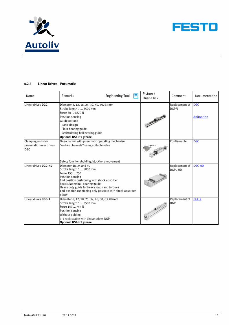
4.2.5 Linear Drives - Pneumatic
Name Remarks Engineering Tool Picture /
Online link Comment Documentation
Linear drives DGC
Diameter 8, 12, 18, 25, 32, 40, 50, 63 mm
Stroke length 1 ... 8500 mm
Force 30 ... 1870 N
Position sensing
Guide options
- Basic design
- Plain-bearing guide
- Recirculating ball bearing guide
Optional NSF-H1 grease
Replacement of
DGP/L
DGC
Animation
Clamping units for
pneumatic linear drives
DGC
One-channel with pneumatic operating mechanism
“on two channels” using suitable valve
Safety function :holding, blocking a movement
Configurable DGC
Linear drives DGC-HD
Diameter 18, 25 and 40 Stroke length 1 ... 5000 mm
Force 153 ... 754 Position sensing End position cushioning with shock absorber Recirculating ball bearing guide Heavy duty guide for heavy loads and torques End-position cushioning only possible with shock absorber
YSRW
Replacement of
DGPL-HD
DGC-HD
Linear drives DGC-K
Diameter 8, 12, 18, 25, 32, 40, 50, 63, 80 mm
Stroke length 1 ... 8500 mm Force 153 ... 754 N
Position sensing
Without guiding
1:1 replaceable with Linear drives DGP Optional NSF-H1 grease
Replacement of
DGP
DGC K
Festo AG & Co. KG 11 21.11.2017
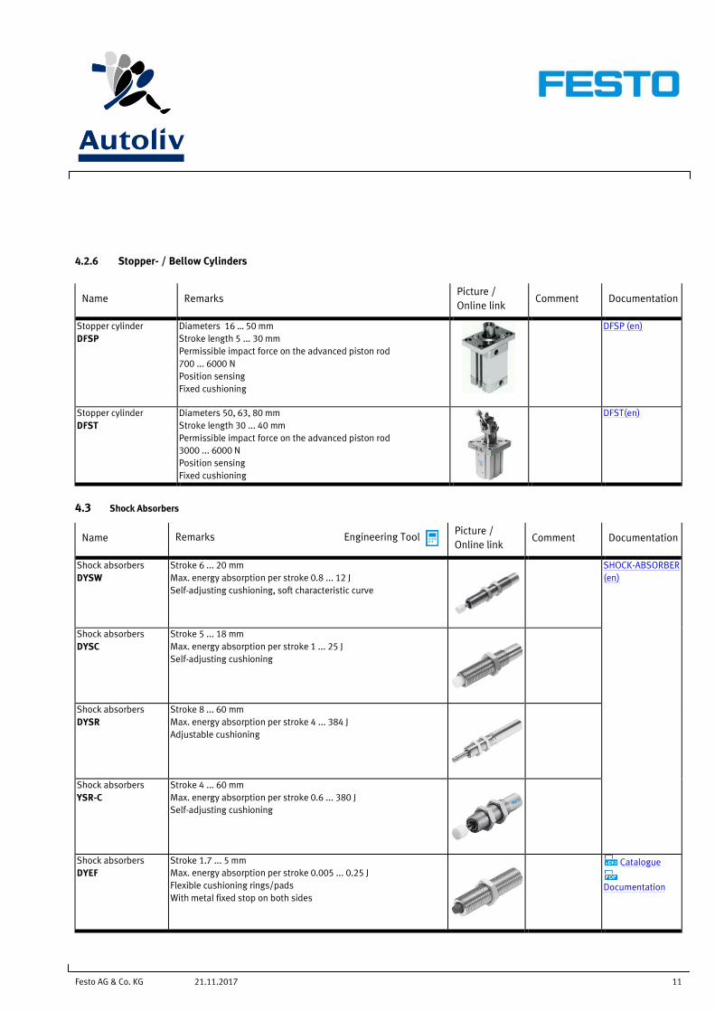
4.2.6 Stopper- / Bellow Cylinders
Name Remarks Picture /
Online link Comment Documentation
Stopper cylinder
DFSP
Diameters 16 … 50 mm
Stroke length 5 ... 30 mm
Permissible impact force on the advanced piston rod
700 ... 6000 N
Position sensing
Fixed cushioning
DFSP (en)
Stopper cylinder
DFST
Diameters 50, 63, 80 mm
Stroke length 30 ... 40 mm
Permissible impact force on the advanced piston rod
3000 ... 6000 N
Position sensing
Fixed cushioning
DFST(en)
4.3 Shock Absorbers
Name Remarks Engineering Tool Picture /
Online link Comment Documentation
Shock absorbers
DYSW
Stroke 6 ... 20 mm
Max. energy absorption per stroke 0.8 ... 12 J
Self-adjusting cushioning, soft characteristic curve
SHOCK-ABSORBER
(en)
Shock absorbers
DYSC
Stroke 5 ... 18 mm
Max. energy absorption per stroke 1 ... 25 J
Self-adjusting cushioning
Shock absorbers
DYSR
Stroke 8 ... 60 mm
Max. energy absorption per stroke 4 ... 384 J
Adjustable cushioning
Shock absorbers
YSR-C
Stroke 4 ... 60 mm
Max. energy absorption per stroke 0.6 ... 380 J
Self-adjusting cushioning
Shock absorbers
DYEF
Stroke 1.7 ... 5 mm
Max. energy absorption per stroke 0.005 ... 0.25 J
Flexible cushioning rings/pads
With metal fixed stop on both sides
Catalogue
Documentation

Festo AG & Co. KG 12 21.11.2017
5 Gripping- , Vacuum- and Handling Technology
5.1.1 Bello Grippers
Name Remarks Picture /
Online link Comment
Documentatio
n
Bellows Gripper
DHEB
Size 8 ... 63 mm
Stroke, bellows: 3.5 ... 25 mm
Min. diameter to be gripped: 8 ... 66 mm
Max. diameter to be gripped: 11 ... 85 mm
DHEB (en)
Animation
Festo AG & Co. KG 13 21.11.2017
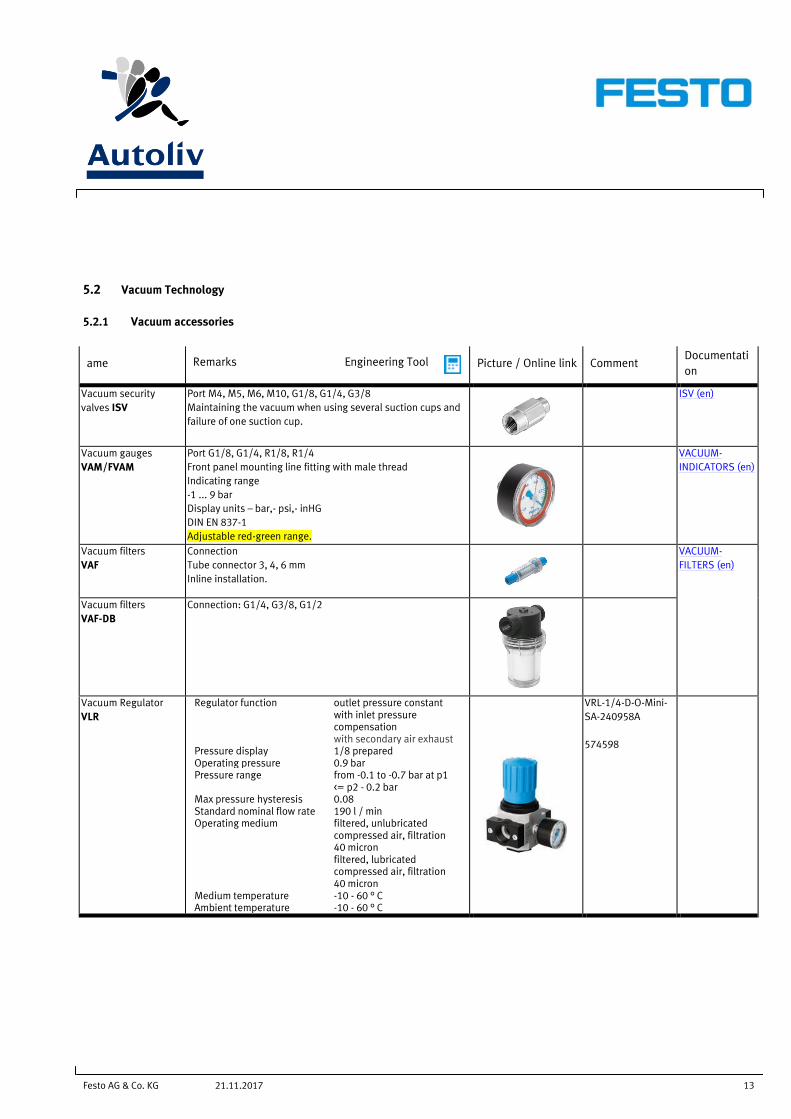
5.2 Vacuum Technology
5.2.1 Vacuum accessories
ame Remarks Engineering Tool Picture / Online link Comment Documentati
on
Vacuum security
valves ISV
Port M4, M5, M6, M10, G1/8, G1/4, G3/8
Maintaining the vacuum when using several suction cups and
failure of one suction cup.
ISV (en)
Vacuum gauges
VAM/FVAM
Port G1/8, G1/4, R1/8, R1/4
Front panel mounting line fitting with male thread
Indicating range
-1 ... 9 bar
Display units – bar,- psi,- inHG
DIN EN 837-1
Adjustable red-green range.
VACUUM-
INDICATORS (en)
Vacuum filters
VAF
Connection
Tube connector 3, 4, 6 mm
Inline installation.
VACUUM-
FILTERS (en)
Vacuum filters
VAF-DB
Connection: G1/4, G3/8, G1/2
Vacuum Regulator
VLR
Regulator function outlet pressure constant with inlet pressure compensation with secondary air exhaust
Pressure display 1/8 prepared Operating pressure 0.9 bar Pressure range from -0.1 to -0.7 bar at p1
<= p2 - 0.2 bar Max pressure hysteresis 0.08 Standard nominal flow rate 190 l / min Operating medium filtered, unlubricated
compressed air, filtration 40 micron filtered, lubricated compressed air, filtration 40 micron
Medium temperature -10 - 60 ° C Ambient temperature -10 - 60 ° C
VRL-1/4-D-O-Mini-
SA-240958A
574598
Festo AG & Co. KG 14 21.11.2017
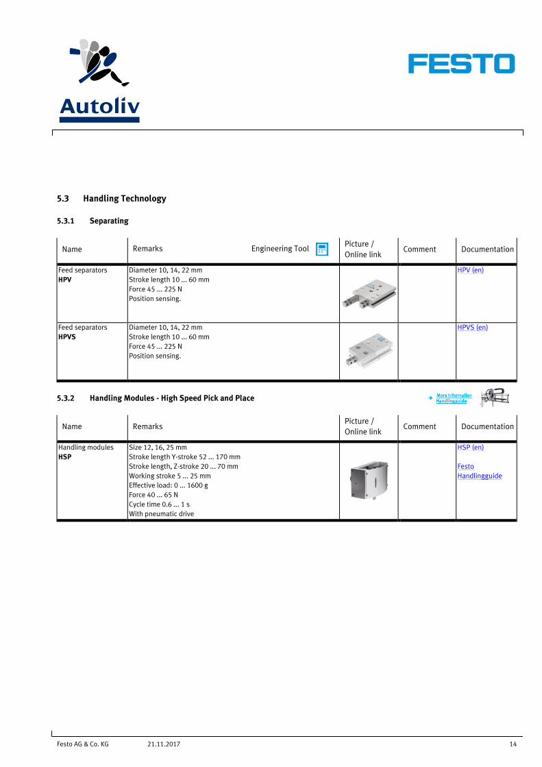
5.3 Handling Technology
5.3.1 Separating
Name Remarks Engineering Tool Picture /
Online link Comment Documentation
Feed separators
HPV
Diameter 10, 14, 22 mm
Stroke length 10 ... 60 mm
Force 45 ... 225 N
Position sensing.
HPV (en)
Feed separators
HPVS
Diameter 10, 14, 22 mm
Stroke length 10 ... 60 mm
Force 45 ... 225 N
Position sensing.
HPVS (en)
5.3.2 Handling Modules - High Speed Pick and Place
Name Remarks Picture /
Online link Comment Documentation
Handling modules
HSP
Size 12, 16, 25 mm
Stroke length Y-stroke 52 ... 170 mm
Stroke length, Z-stroke 20 ... 70 mm
Working stroke 5 ... 25 mm
Effective load: 0 ... 1600 g
Force 40 ... 65 N
Cycle time 0.6 ... 1 s
With pneumatic drive
HSP (en)
Festo
Handlingguide
Festo AG & Co. KG 15 21.11.2017
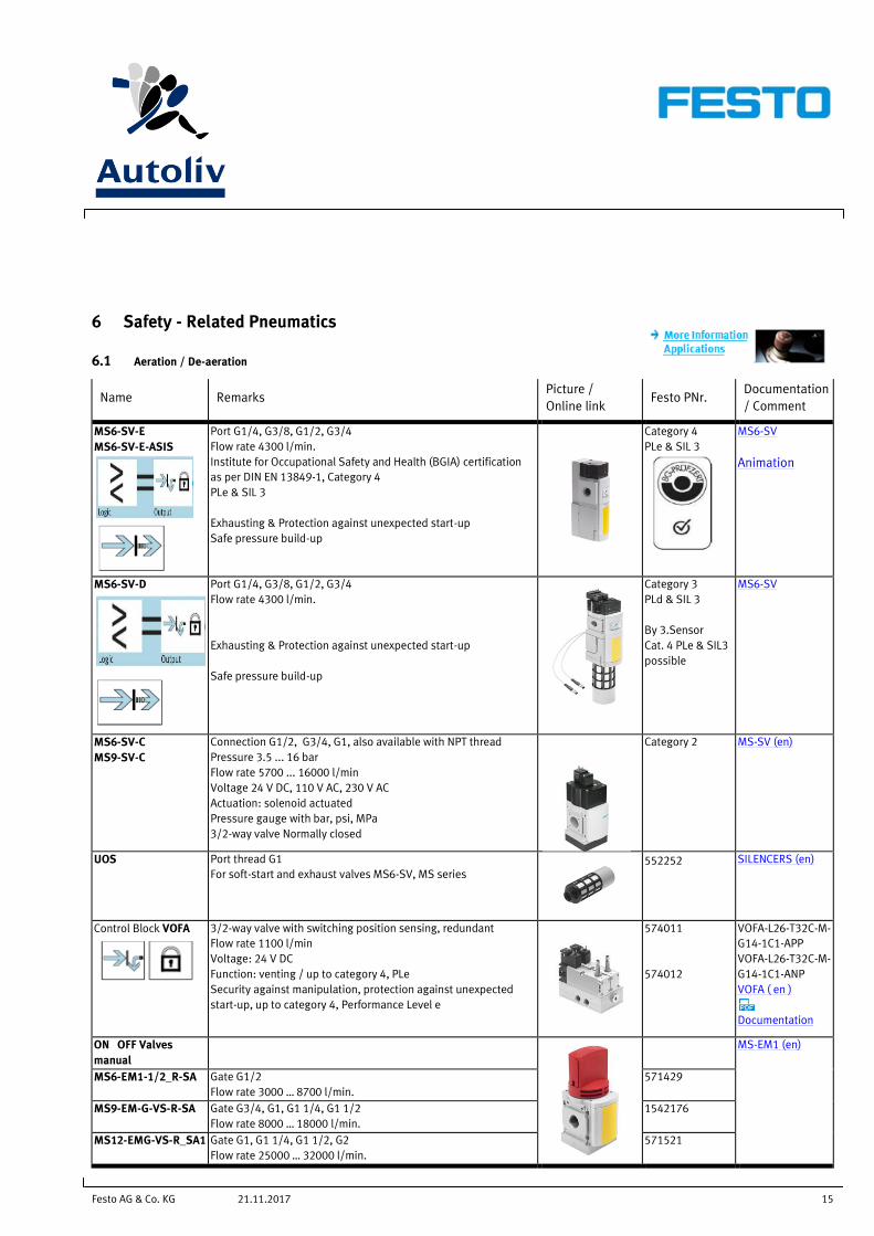
6 Safety - Related Pneumatics
6.1 Aeration / De-aeration
Name Remarks Picture /
Online link Festo PNr.
Documentation
/ Comment
MS6-SV-E
MS6-SV-E-ASIS
Port G1/4, G3/8, G1/2, G3/4
Flow rate 4300 l/min.
Institute for Occupational Safety and Health (BGIA) certification
as per DIN EN 13849-1, Category 4
PLe & SIL 3
Exhausting & Protection against unexpected start-up
Safe pressure build-up
Category 4
PLe & SIL 3
MS6-SV
Animation
MS6-SV-D
Port G1/4, G3/8, G1/2, G3/4
Flow rate 4300 l/min.
Exhausting & Protection against unexpected start-up
Safe pressure build-up
Category 3
PLd & SIL 3
By 3.Sensor
Cat. 4 PLe & SIL3
possible
MS6-SV
MS6-SV-C
MS9-SV-C
Connection G1/2, G3/4, G1, also available with NPT thread
Pressure 3.5 ... 16 bar
Flow rate 5700 ... 16000 l/min
Voltage 24 V DC, 110 V AC, 230 V AC
Actuation: solenoid actuated
Pressure gauge with bar, psi, MPa
3/2-way valve Normally closed
Category 2 MS-SV (en)
UOS
Port thread G1
For soft-start and exhaust valves MS6-SV, MS series
552252 SILENCERS (en)
Control Block VOFA
3/2-way valve with switching position sensing, redundant
Flow rate 1100 l/min
Voltage: 24 V DC
Function: venting / up to category 4, PLe
Security against manipulation, protection against unexpected
start-up, up to category 4, Performance Level e
574011
574012
VOFA-L26-T32C-M-
G14-1C1-APP
VOFA-L26-T32C-M-
G14-1C1-ANP
VOFA ( en )
Documentation
ON OFF Valves
manual
MS-EM1 (en)
MS6-EM1-1/2_R-SA Gate G1/2
Flow rate 3000 … 8700 l/min.
571429
MS9-EM-G-VS-R-SA Gate G3/4, G1, G1 1/4, G1 1/2
Flow rate 8000 … 18000 l/min.
1542176
MS12-EMG-VS-R_SA1 Gate G1, G1 1/4, G1 1/2, G2
Flow rate 25000 … 32000 l/min.
571521
Festo AG & Co. KG 16 21.11.2017
6.2 Safety valves for presses
Name Remarks Picture /
Online link
Festo PNr. Documentation
/ Comment
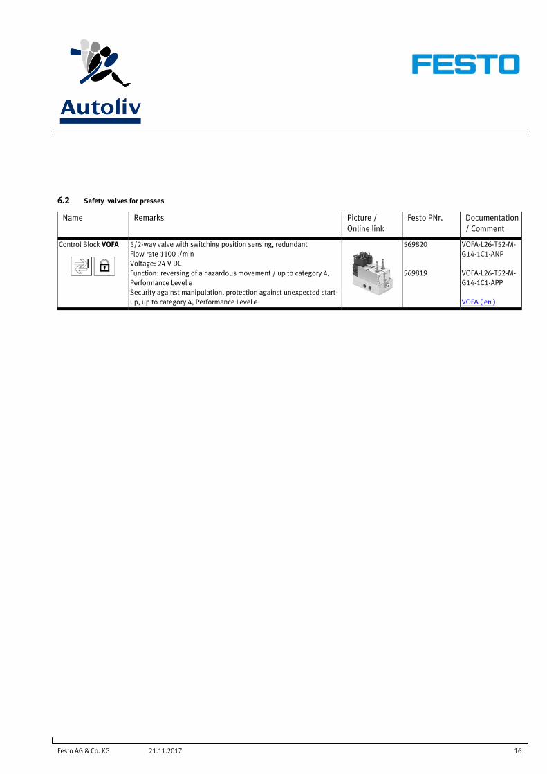
Control Block VOFA
5/2-way valve with switching position sensing, redundant
Flow rate 1100 l/min
Voltage: 24 V DC
Function: reversing of a hazardous movement / up to category 4,
Performance Level e
Security against manipulation, protection against unexpected start-
up, up to category 4, Performance Level e
569820
569819
VOFA-L26-T52-M-
G14-1C1-ANP
VOFA-L26-T52-M-
G14-1C1-APP
VOFA ( en )
Festo AG & Co. KG 17 21.11.2017
7 Valve- and Control Technology
7.1 What should always be used where possible:
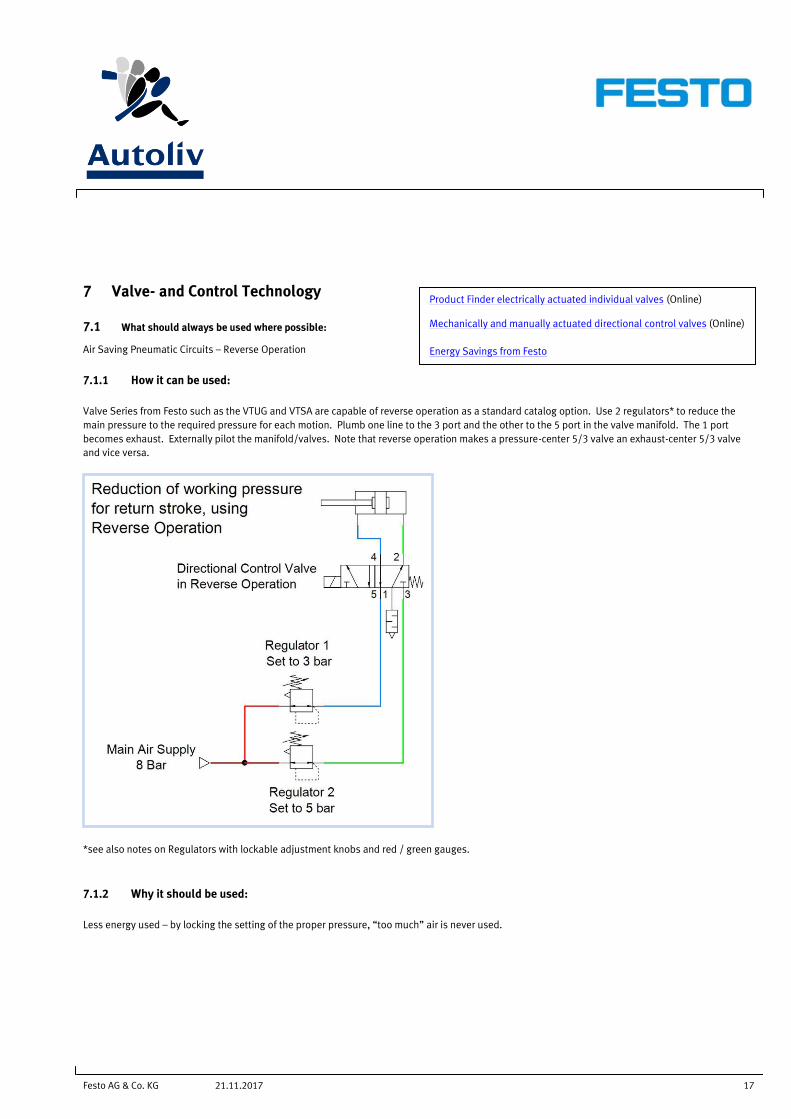
Air Saving Pneumatic Circuits – Reverse Operation
7.1.1 How it can be used:
Valve Series from Festo such as the VTUG and VTSA are capable of reverse operation as a standard catalog option. Use 2 regulators* to reduce the
main pressure to the required pressure for each motion. Plumb one line to the 3 port and the other to the 5 port in the valve manifold. The 1 port
becomes exhaust. Externally pilot the manifold/valves. Note that reverse operation makes a pressure-center 5/3 valve an exhaust-center 5/3 valve
and vice versa.
*see also notes on Regulators with lockable adjustment knobs and red / green gauges.
7.1.2 Why it should be used:
Less energy used – by locking the setting of the proper pressure, “too much” air is never used.
Product Finder electrically actuated individual valves (Online) Mechanically and manually actuated directional control valves (Online)
Energy Savings from Festo
Festo AG & Co. KG 18 21.11.2017
7.2 What should never be used:
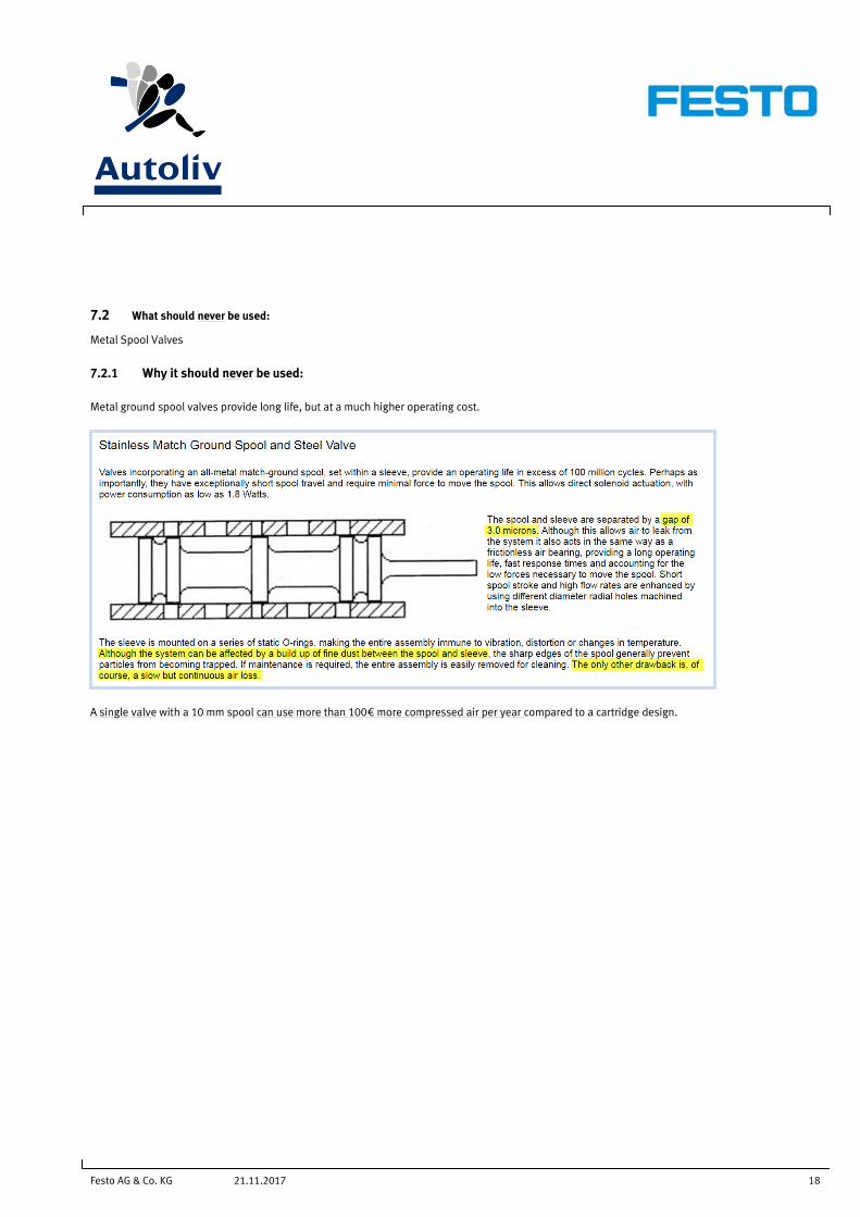
Metal Spool Valves
7.2.1 Why it should never be used:
Metal ground spool valves provide long life, but at a much higher operating cost.
A single valve with a 10 mm spool can use more than 100€ more compressed air per year compared to a cartridge design.
Festo AG & Co. KG 19 21.11.2017
7.3 Universal Directional Control Valves
Name Remarks Picture / Online
link Comment Documentation
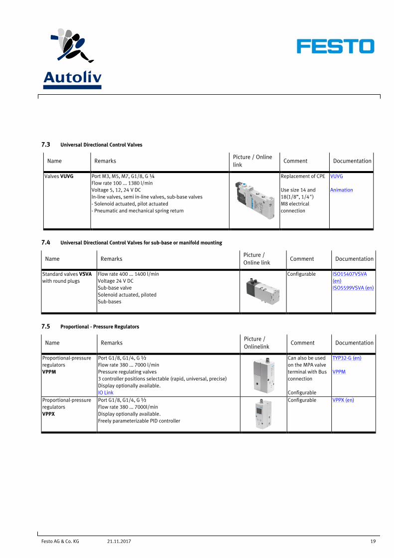
Valves VUVG Port M3, M5, M7, G1/8, G ¼
Flow rate 100 ... 1380 l/min
Voltage 5, 12, 24 V DC
In-line valves, semi in-line valves, sub-base valves
- Solenoid actuated, pilot actuated
- Pneumatic and mechanical spring return
Replacement of CPE
Use size 14 and
18(1/8”, 1/4")
M8 electrical
connection
VUVG
Animation
7.4 Universal Directional Control Valves for sub-base or manifold mounting
Name Remarks Picture /
Online link Comment Documentation
Standard valves VSVA
with round plugs
Flow rate 400 ... 1400 l/min
Voltage 24 V DC
Sub-base valve
Solenoid actuated, piloted
Sub-bases
Configurable ISO15407VSVA
(en)
ISO5599VSVA (en)
7.5 Proportional - Pressure Regulators
Name Remarks Picture /
Onlinelink Comment Documentation
Proportional-pressure
regulators
VPPM
Port G1/8, G1/4, G ½
Flow rate 380 ... 7000 l/min
Pressure regulating valves
3 controller positions selectable (rapid, universal, precise)
Display optionally available.
IO Link
Can also be used
on the MPA valve
terminal with Bus
connection
Configurable
TYP32-G (en)
VPPM
Proportional-pressure
regulators
VPPX
Port G1/8, G1/4, G ½
Flow rate 380 ... 7000l/min
Display optionally available.
Freely parameterizable PID controller
Configurable VPPX (en)
Festo AG & Co. KG 20 21.11.2017
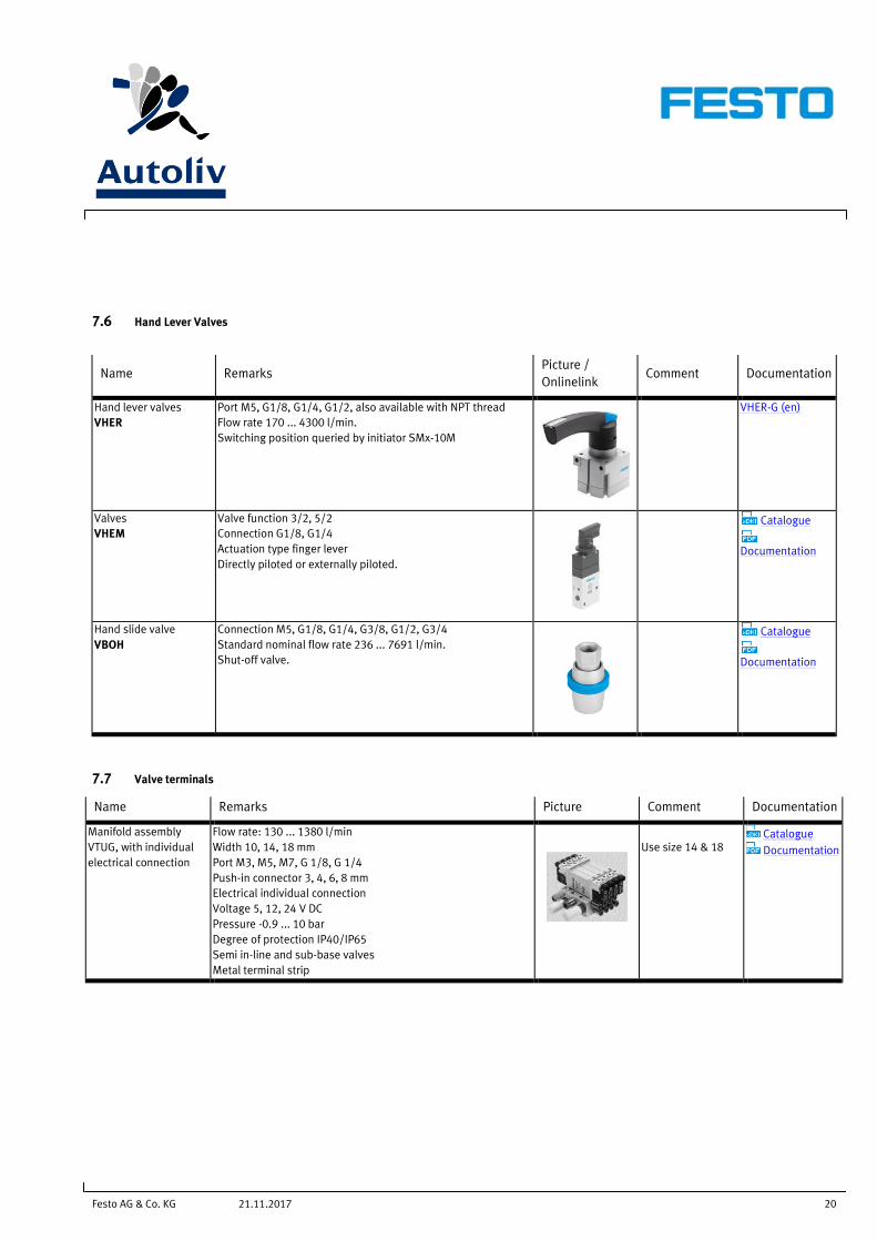
7.6 Hand Lever Valves
Name Remarks Picture /
Onlinelink Comment Documentation
Hand lever valves
VHER
Port M5, G1/8, G1/4, G1/2, also available with NPT thread
Flow rate 170 ... 4300 l/min.
Switching position queried by initiator SMx-10M
VHER-G (en)
Valves
VHEM
Valve function 3/2, 5/2
Connection G1/8, G1/4
Actuation type finger lever
Directly piloted or externally piloted.
Catalogue
Documentation
Hand slide valve
VBOH
Connection M5, G1/8, G1/4, G3/8, G1/2, G3/4
Standard nominal flow rate 236 ... 7691 l/min.
Shut-off valve.
Catalogue
Documentation
7.7 Valve terminals
Name Remarks Picture Comment Documentation
Manifold assembly
VTUG, with individual
electrical connection
Flow rate: 130 ... 1380 l/min
Width 10, 14, 18 mm
Port M3, M5, M7, G 1/8, G 1/4
Push-in connector 3, 4, 6, 8 mm
Electrical individual connection
Voltage 5, 12, 24 V DC
Pressure -0.9 ... 10 bar
Degree of protection IP40/IP65
Semi in-line and sub-base valves
Metal terminal strip
Use size 14 & 18 Catalogue
Documentation

Festo AG & Co. KG 21 21.11.2017
7.8 Automation Platform
Name Remarks Picture / Online link Comment Documentation
Valve terminal
MPA-S
with CPX - terminal
Controlled via fieldbus or control block
Max. 64 valve positions/max. 128 solenoid coils
- Digital inputs/outputs
- Analogue inputs/outputs
- Parameterisation of inputs and outputs
- Integrated convenient diagnostics system
- Preventive maintenance
IO Link
Configurable CPX (en)
MPA-S
Electrical terminal
CPX
Operating mode
- Stand-alone
- with valve terminal type 45 VTSA-F ,Type 44 VTSA
- with valve terminal type 32 MPA , type 34 MPA-L
-Input/output modules/Digital/Analogue
IO Link
Configurable CPX
Animation
7.9 Valves on robot
If use of single valves on robots use combination as described below:
Valves VUVG-B14-X-ZT-F-1R8L, where X replaces valve type
Sub base VABM-L1-14W-G14-X, where X replaces number of valve positions

Festo AG & Co. KG 22 21.11.2017
8 Proximity Sensors and Piston Position Sensing
8.1 Proximity Sensors
8.1.1 Electronic Contactless Switching
Name Remarks Picture / Online
link Comment Documentation
SMT-8M-A-PS-24V-E-
0,3-M8D
Use 574334
Voltage 5...30 V DC, 230 V AC
Cable length 0,3, 2,5, 5, 7,5, 0,2 ... 10 m
Connection plug M5, M8, M12
Electric
- Non-contacting PNP
SMX8 (en)
Standard slot
size 8
574334
fits 48 drives
Configurable
SMT-10M-PS-24V-E-0,3-
L-M8D
Use 551375
Voltage 24V DC, Cable length 0,3 m
Connection plug , M8,
Electric
- Non-contacting PNP
Standard slot
size 10
551375
Configurable
SMX10 (en)
8.2 Position Transmitter
Name Remarks Picture /
Online link Comment Documentation
SDAT-MHS Parth measurement range 50,80,100,125,160mm
Analog 4-20 mA
IO-Link
Programming options:
Cylinder switch functions
Window comparator, hysteresis comparator , NO/NC
Repetition accuracy 0,1 mm
Displacement resolution 0,05mm
IO Link
For T-slot
Insertable in the
slot from above
Electrical
connection
4-pin, M8x1
Firstly use 50mm,
1531265
SDAT (en)
Festo AG & Co. KG 23 21.11.2017
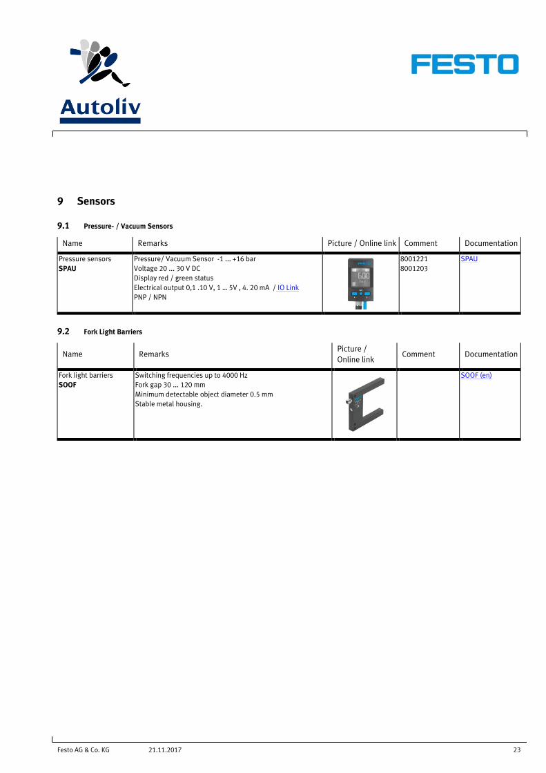
9 Sensors
9.1 Pressure- / Vacuum Sensors
Name Remarks Picture / Online link Comment Documentation
Pressure sensors
SPAU
Pressure/ Vacuum Sensor -1 ... +16 bar
Voltage 20 ... 30 V DC
Display red / green status
Electrical output 0,1 .10 V, 1 … 5V , 4. 20 mA / IO Link
PNP / NPN
8001221
8001203
SPAU
9.2 Fork Light Barriers
Name Remarks Picture /
Online link Comment Documentation
Fork light barriers
SOOF
Switching frequencies up to 4000 Hz
Fork gap 30 ... 120 mm
Minimum detectable object diameter 0.5 mm
Stable metal housing.
SOOF (en)

Festo AG & Co. KG 24 21.11.2017
10 Electrical connector technology
10.1 Cable
Name Remarks Picture /
Online link Comment Documentation
NEBU The modular cable system offers unlimited possible
combinations of plugs, plug sockets, cable lengths and
qualities
Adapted to all devices with M8 and M12 plugs, such as:
- Proximity sensors
- Position transmitters
- Pressure switches, pressure sensor
Configurable NEBU-M12 (en)
NEBU-SIM (en)
NEDU
Y-connecting cable
For connecting 2 sensors to an
input socket with double allocation
NEDU(en)
NEBV Cable with socket for connecting valves with the input and
output modules of the CPX system
Cable length 0.5 ... 10 m.
NEBV-B2W3P (en)
NEBV-C1W3P (en)
NEBV-H1G2 (en)
NEBV-HSG2 (en)
NEBV-S1G25 (en)
NEBV-S1W37 (en)
VPPM (en)
Festo AG & Co. KG 25 21.11.2017
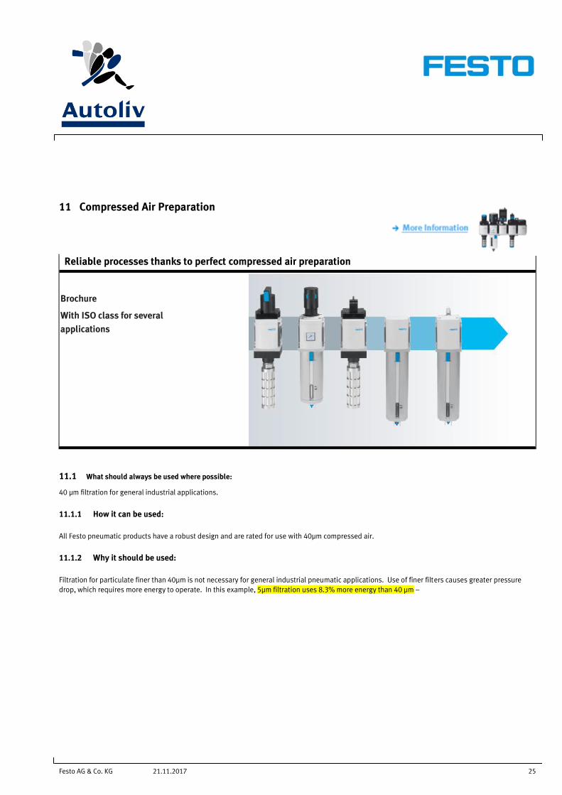
11 Compressed Air Preparation
Reliable processes thanks to perfect compressed air preparation
Brochure
With ISO class for several
applications
11.1 What should always be used where possible:
40 µm filtration for general industrial applications.
11.1.1 How it can be used:
All Festo pneumatic products have a robust design and are rated for use with 40µm compressed air.
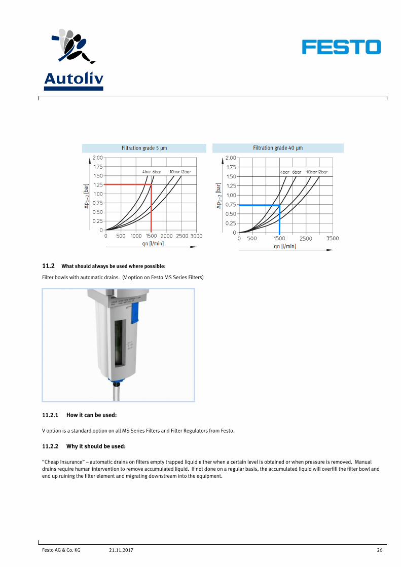
11.1.2 Why it should be used:
Filtration for particulate finer than 40µm is not necessary for general industrial pneumatic applications. Use of finer filters causes greater pressure
drop, which requires more energy to operate. In this example, 5µm filtration uses 8.3% more energy than 40 µm –
Festo AG & Co. KG 26 21.11.2017
11.2 What should always be used where possible:
Filter bowls with automatic drains. (V option on Festo MS Series Filters)
11.2.1 How it can be used:
V option is a standard option on all MS Series Filters and Filter Regulators from Festo.
11.2.2 Why it should be used:
“Cheap Insurance” – automatic drains on filters empty trapped liquid either when a certain level is obtained or when pressure is removed. Manual
drains require human intervention to remove accumulated liquid. If not done on a regular basis, the accumulated liquid will overfill the filter bowl and
end up ruining the filter element and migrating downstream into the equipment.
Festo AG & Co. KG 27 21.11.2017
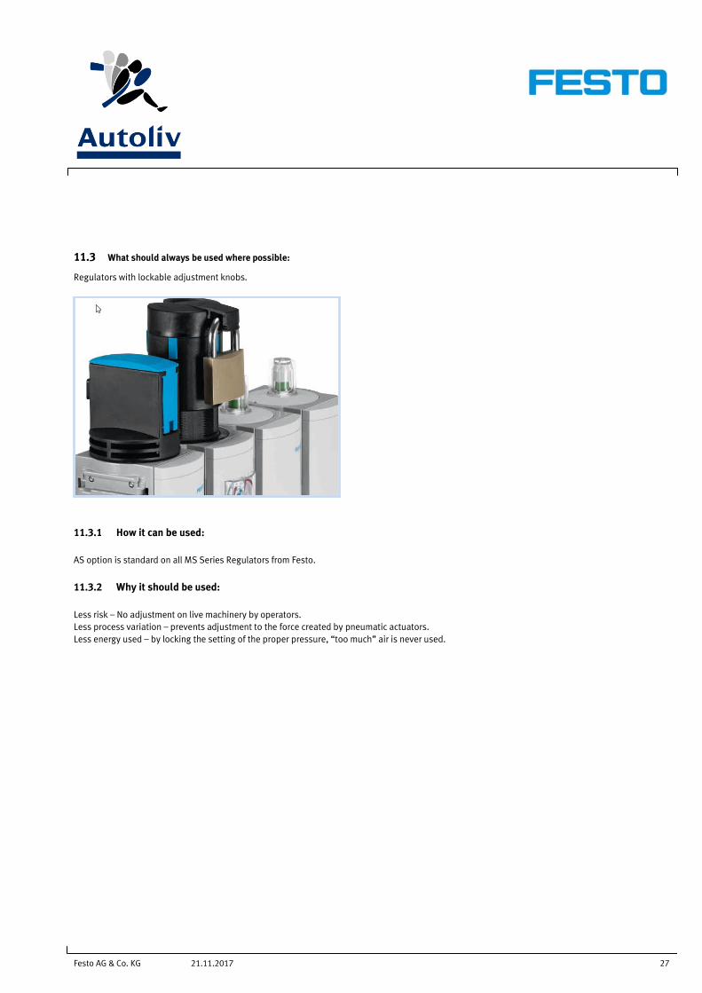
11.3 What should always be used where possible:
Regulators with lockable adjustment knobs.
11.3.1 How it can be used:
AS option is standard on all MS Series Regulators from Festo.
11.3.2 Why it should be used:
Less risk – No adjustment on live machinery by operators.
Less process variation – prevents adjustment to the force created by pneumatic actuators.
Less energy used – by locking the setting of the proper pressure, “too much” air is never used.

Festo AG & Co. KG 28 21.11.2017
11.4 What should always be used where possible:
Red / Green Gauges
11.4.1 How it can be used:
RG option is a standard option on all MS Series Regulators and Filter Regulators from Festo.
11.4.2 Why it should be used:
Contributes towards the “visual factory” – A combination of signs, charts and other visual representations of information that enable the quick
dissemination of data within a lean manufacturing process. The visual factory attempts to reduce the time and resources required to communicate the
same information verbally or in written form, as both are viewed as a "waste" within the framework of a lean manufacturing process.
Festo AG & Co. KG 29 21.11.2017
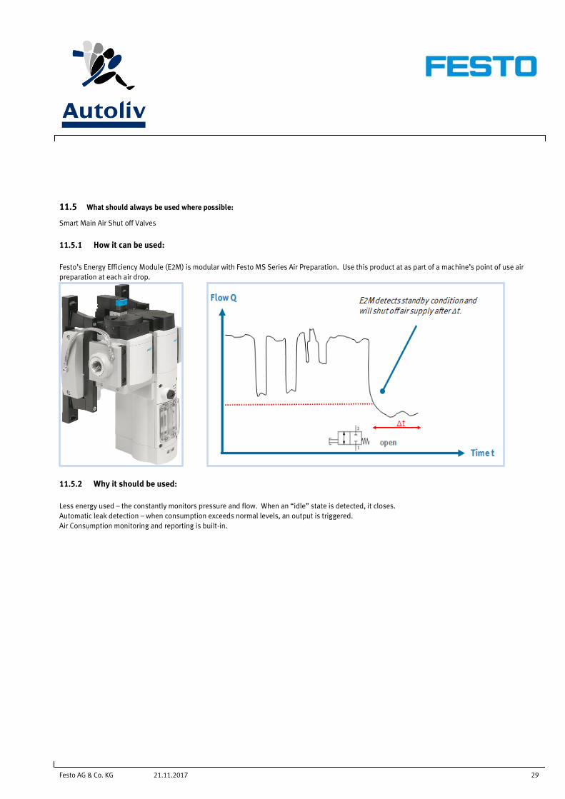
11.5 What should always be used where possible:
Smart Main Air Shut off Valves
11.5.1 How it can be used:
Festo’s Energy Efficiency Module (E2M) is modular with Festo MS Series Air Preparation. Use this product at as part of a machine’s point of use air
preparation at each air drop.
11.5.2 Why it should be used:
Less energy used – the constantly monitors pressure and flow. When an “idle” state is detected, it closes.
Automatic leak detection – when consumption exceeds normal levels, an output is triggered.
Air Consumption monitoring and reporting is built-in.

Festo AG & Co. KG 30 21.11.2017
11.6 MS-Series
11.6.1 Service unit – Configurable Combinations
Name Remarks Engineering Tool Picture /
Online link Festo PNr. Documentation
MSB-4 Gate G1/8, G1/4, G3/8
Flow rate 550 ... 1500 l/min.
531029
Configurable
MSB-FRC (en)
MS-COMBINATION
(en)
MS-CONFIG-
COMBINATION
(en)
MSB-6 Gate G1/4, G3/8, G1/2, G3/4
Flow rate 1900 ... 5100 l/min.
531030
Configurable
MSB-9 Gate G3/4, G1, G1 1/4, G1 1/2
Flow rate 1400 … 18000 l/min.
552938
Configurable
11.6.2 Energy efficiency module
Name Remarks Picture /
Onlinelink Comment
Documentati
on
Energy efficiency
module
MS6E-E2M
Automatic shut-off when flow rate is not achieved
User-controlled shut-off and pressurising
Recording of measurement data:
Output pressure, pressure change, flow, air
consumption
Limit monitoring:
- Pressure, upper limit value , pressure change,
flow
Fieldbus connection
MSE6 (en)
Animation
Multimedia
11.6.3 On- Off Valves manual
Name Remarks Picture /
Onlinelink Festo PNr. Documentation
MS4-EM1
Modular Kit
Gate G1/8, G1/4, G3/8
Flow rate 1200 … 2200 l/min.
541266 MS-EM1 (en)
MS6-EM1
Modular Kit
Gate G1/4, G3/8, G1/2, G3/4
Flow rate 3000 … 8700 l/min.
541279
MS9-EM1
Modular Kit
Gate G3/4, G1, G1 1/4, G1 1/2
Flow rate 8000 … 18000 l/min.
562178
MS12-EM1
Modular Kit
Gate G1, G1 1/4, G1 1/2, G2
Flow rate 25000 … 32000 l/min.
535031
Engineering tool for air preparation
Festo Air Consumption Tool
Festo AG & Co. KG 31 21.11.2017
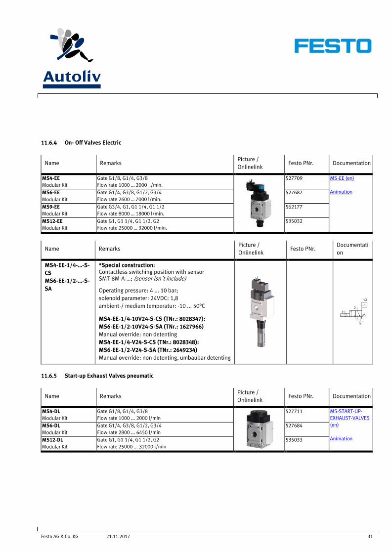
11.6.4 On- Off Valves Electric
Name Remarks Picture /
Onlinelink Festo PNr. Documentation
MS4-EE
Modular Kit
Gate G1/8, G1/4, G3/8
Flow rate 1000 … 2000 l/min.
527709 MS-EE (en)
Animation MS6-EE
Modular Kit
Gate G1/4, G3/8, G1/2, G3/4
Flow rate 2600 … 7000 l/min.
527682
MS9-EE
Modular Kit
Gate G3/4, G1, G1 1/4, G1 1/2
Flow rate 8000 … 18000 l/min.
562177
MS12-EE
Modular Kit
Gate G1, G1 1/4, G1 1/2, G2
Flow rate 25000 … 32000 l/min.
535032
Name Remarks Picture /
Onlinelink Festo PNr.
Documentati
on
MS4-EE-1/4-…-S-
CS
MS6-EE-1/2-…-S-
SA
*Special construction: Contactless switching position with sensor SMT-8M-A-…; (sensor isn´t include)
Operating pressure: 4 ... 10 bar;
solenoid parameter: 24VDC: 1,8
ambient-/ medium temperatur: -10 ... 50°C
MS4-EE-1/4-10V24-S-CS (TNr.: 8028347):
MS6-EE-1/2-10V24-S-SA (TNr.: 1627966)
Manual override: non detenting
MS4-EE-1/4-V24-S-CS (TNr.: 8028348):
MS6-EE-1/2-V24-S-SA (TNr.: 2649234)
Manual override: non detenting, umbaubar detenting
11.6.5 Start-up Exhaust Valves pneumatic
Name Remarks Picture /
Onlinelink Festo PNr. Documentation
MS4-DL
Modular Kit
Gate G1/8, G1/4, G3/8
Flow rate 1000 ... 2000 l/min
527711 MS-START-UP-
EXHAUST-VALVES
(en)
Animation
MS6-DL
Modular Kit
Gate G1/4, G3/8, G1/2, G3/4
Flow rate 2800 ... 6450 l/min
527684
MS12-DL
Modular Kit
Gate G1, G1 1/4, G1 1/2, G2
Flow rate 25000 ... 32000 l/min
535033
Festo AG & Co. KG 32 21.11.2017
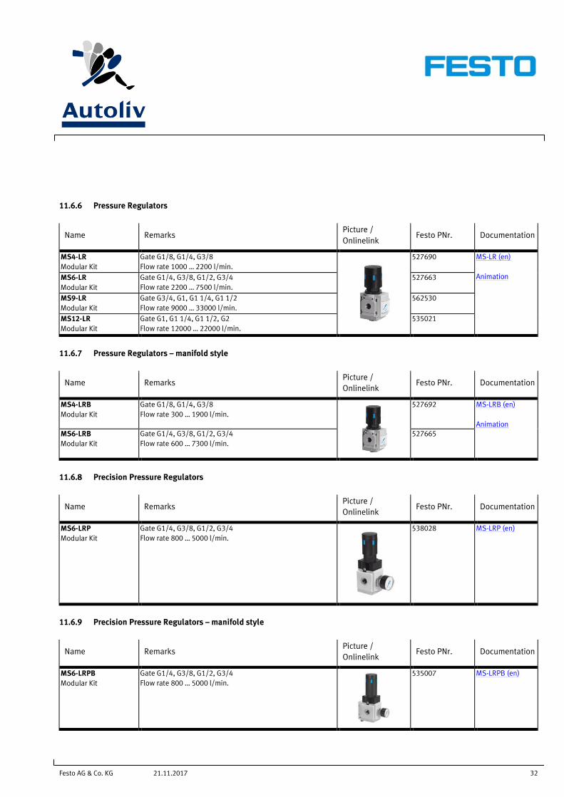
11.6.6 Pressure Regulators
Name Remarks Picture /
Onlinelink Festo PNr. Documentation
MS4-LR
Modular Kit
Gate G1/8, G1/4, G3/8
Flow rate 1000 … 2200 l/min.
527690 MS-LR (en)
Animation MS6-LR
Modular Kit
Gate G1/4, G3/8, G1/2, G3/4
Flow rate 2200 … 7500 l/min.
527663
MS9-LR
Modular Kit
Gate G3/4, G1, G1 1/4, G1 1/2
Flow rate 9000 … 33000 l/min.
562530
MS12-LR
Modular Kit
Gate G1, G1 1/4, G1 1/2, G2
Flow rate 12000 … 22000 l/min.
535021
11.6.7 Pressure Regulators – manifold style
Name Remarks Picture /
Onlinelink Festo PNr. Documentation
MS4-LRB
Modular Kit
Gate G1/8, G1/4, G3/8
Flow rate 300 … 1900 l/min.
527692 MS-LRB (en)
Animation
MS6-LRB
Modular Kit
Gate G1/4, G3/8, G1/2, G3/4
Flow rate 600 … 7300 l/min.
527665
11.6.8 Precision Pressure Regulators
Name Remarks Picture /
Onlinelink Festo PNr. Documentation
MS6-LRP
Modular Kit
Gate G1/4, G3/8, G1/2, G3/4
Flow rate 800 … 5000 l/min.
538028
MS-LRP (en)
11.6.9 Precision Pressure Regulators – manifold style
Name Remarks Picture /
Onlinelink Festo PNr. Documentation
MS6-LRPB
Modular Kit
Gate G1/4, G3/8, G1/2, G3/4
Flow rate 800 … 5000 l/min.
535007
MS-LRPB (en)
Festo AG & Co. KG 33 21.11.2017
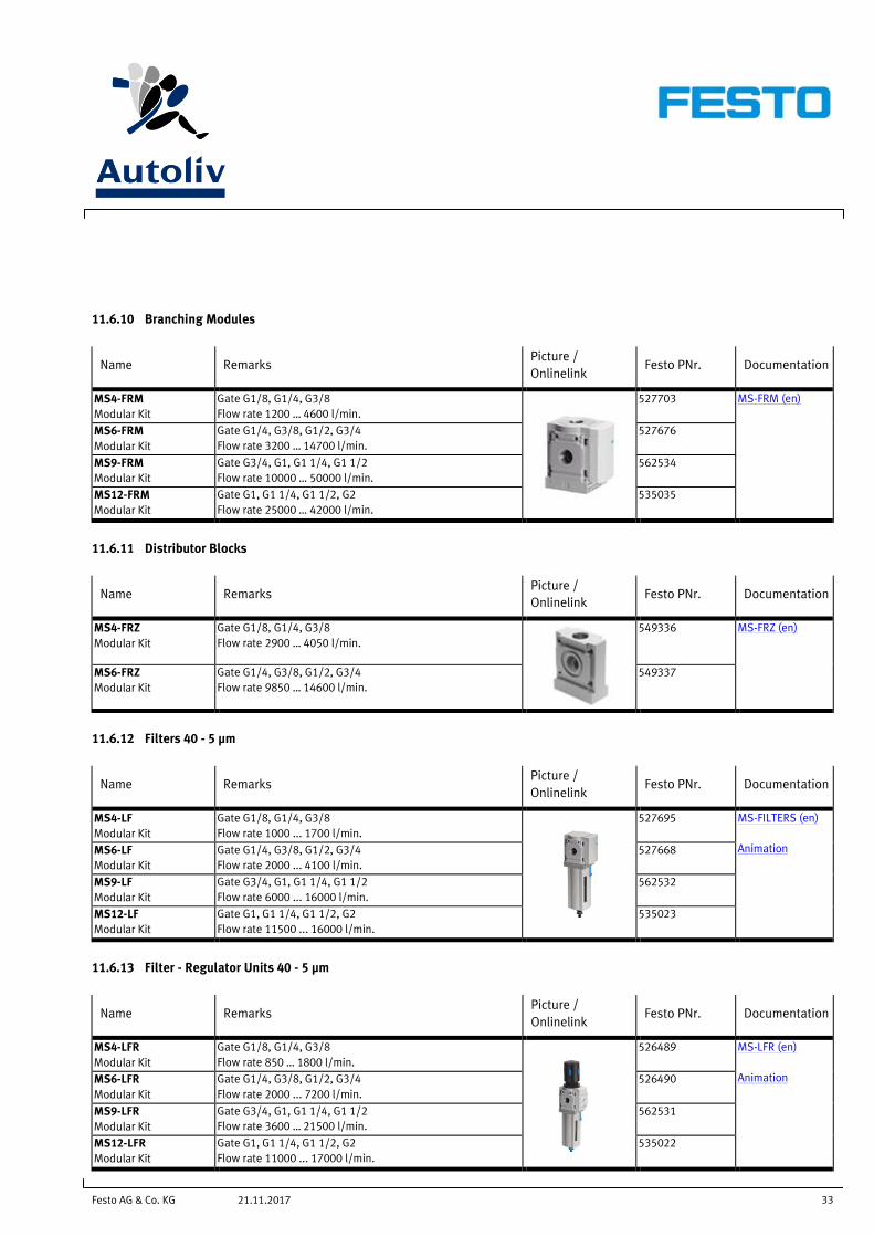
11.6.10 Branching Modules
Name Remarks Picture /
Onlinelink Festo PNr. Documentation
MS4-FRM
Modular Kit
Gate G1/8, G1/4, G3/8
Flow rate 1200 … 4600 l/min.
527703 MS-FRM (en)
MS6-FRM
Modular Kit
Gate G1/4, G3/8, G1/2, G3/4
Flow rate 3200 … 14700 l/min.
527676
MS9-FRM
Modular Kit
Gate G3/4, G1, G1 1/4, G1 1/2
Flow rate 10000 … 50000 l/min.
562534
MS12-FRM
Modular Kit
Gate G1, G1 1/4, G1 1/2, G2
Flow rate 25000 … 42000 l/min.
535035
11.6.11 Distributor Blocks
Name Remarks Picture /
Onlinelink Festo PNr. Documentation
MS4-FRZ
Modular Kit
Gate G1/8, G1/4, G3/8
Flow rate 2900 … 4050 l/min.
549336 MS-FRZ (en)
MS6-FRZ
Modular Kit
Gate G1/4, G3/8, G1/2, G3/4
Flow rate 9850 … 14600 l/min.
549337
11.6.12 Filters 40 - 5 µm
Name Remarks Picture /
Onlinelink Festo PNr. Documentation
MS4-LF
Modular Kit
Gate G1/8, G1/4, G3/8
Flow rate 1000 ... 1700 l/min.
527695 MS-FILTERS (en)
Animation MS6-LF
Modular Kit
Gate G1/4, G3/8, G1/2, G3/4
Flow rate 2000 ... 4100 l/min.
527668
MS9-LF
Modular Kit
Gate G3/4, G1, G1 1/4, G1 1/2
Flow rate 6000 ... 16000 l/min.
562532
MS12-LF
Modular Kit
Gate G1, G1 1/4, G1 1/2, G2
Flow rate 11500 ... 16000 l/min.
535023
11.6.13 Filter - Regulator Units 40 - 5 µm
Name Remarks Picture /
Onlinelink Festo PNr. Documentation
MS4-LFR
Modular Kit
Gate G1/8, G1/4, G3/8
Flow rate 850 … 1800 l/min.
526489 MS-LFR (en)
Animation MS6-LFR
Modular Kit
Gate G1/4, G3/8, G1/2, G3/4
Flow rate 2000 ... 7200 l/min.
526490
MS9-LFR
Modular Kit
Gate G3/4, G1, G1 1/4, G1 1/2
Flow rate 3600 … 21500 l/min.
562531
MS12-LFR
Modular Kit
Gate G1, G1 1/4, G1 1/2, G2
Flow rate 11000 ... 17000 l/min.
535022

Festo AG & Co. KG 34 21.11.2017
11.6.14 Fine and Micro Filters 1 - 0,01 µm
Name Remarks Picture /
Onlinelink Festo PNr. Documentation
MS4-LFM
Modular Kit
Gate G1/8, G1/4, G3/8
Flow rate 120 … 180 l/min.
527697 MS-LFM (en)
Animation MS6-LFM
Modular Kit
Gate G1/4, G3/8, G1/2, G3/4
Flow rate 160 … 1470 l/min.
527670
MS9-LFM
Modular Kit
Gate G3/4, G1, G1 1/4, G1 1/2
Flow rate 325 … 10000 l/min.
552940
MS12-LFM
Modular Kit
Gate G1, G1 1/4, G1 1/2, G2
Flow rate 500 … 50000 l/min.
535042
11.6.15 Flow Sensors
Name Remarks Picture /
Onlinelink Festo PNr. Documentation
Flow Sensor
SFAM
Flow measuring ranges SFAM -62
- 10 … 1000 l/min
- 30 … 3000 l/min
- 50 … 5000 l/min
Flow measuring ranges SFAM -90
- 50 … 5000 l/min
- 100 … 10000 l/min
- 150 … 15000 l/min
Switching output: 2x NPN, 2x PNP
Analogue output: 0 … 10V, 4 … 20mA
Display with highly luminous LED for optimised visualisation
Compatible and can be integrated in MS6 orMS9 series service units.
SFAM (en)
Animation
Festo AG & Co. KG 35 21.11.2017
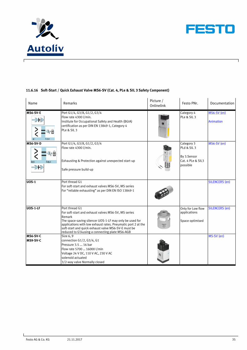
11.6.16 Soft-Start / Quick Exhaust Valve MS6-SV (Cat. 4, PLe & SIL 3 Safety Component)
Name Remarks Picture /
Onlinelink Festo PNr. Documentation
MS6-SV-E
Port G1/4, G3/8, G1/2, G3/4
Flow rate 4300 l/min.
Institute for Occupational Safety and Health (BGIA)
certification as per DIN EN 13849-1, Category 4
PLe & SIL 3
Category 4
PLe & SIL 3
MS6-SV (en)
Animation
MS6-SV-D
Port G1/4, G3/8, G1/2, G3/4
Flow rate 4300 l/min.
Exhausting & Protection against unexpected start-up
Safe pressure build-up
Category 3
PLd & SIL 3
By 3.Sensor
Cat. 4 PLe & SIL3
possible
MS6-SV (en)
UOS-1 Port thread G1
For soft-start and exhaust valves MS6-SV, MS series
For “reliable exhausting” as per DIN EN ISO 13849-1
SILENCERS (en)
UOS-1-LF Port thread G1
For soft-start and exhaust valves MS6-SV, MS series
Remark The space-saving silencer UOS-1-LF may only be used for applications with low exhaust rates. Pneumatic port 2 at the soft-start and quick exhaust valve MS6-SV-E must be reduced to G¼using a connecting plate MS6-AGB
Only for Low flow applications
Space optimised
SILENCERS (en)
MS6-SV-C
MS9-SV-C
Size 6, 9
connection G1/2, G3/4, G1
Pressure 3.5 ... 16 bar
Flow rate 5700 … 16000 l/min
Voltage 24 V DC, 110 V AC, 230 V AC
solenoid actuated
3/2-way valve Normally closed
MS-SV (en)

Festo AG & Co. KG 36 21.11.2017
12 Service Units – Details
12.1 Service units G 1/2"
Performance Level C Service unit combination with on-off valve with silencer and filter regulator 0,5-12 bar, 40μm, plastic bowl with manual condensate drain, branch module and soft-start/exhaust valve with pressure sensor. This service unit has Performance Level C. Order code: Combine MSB6-1/2:C4:J1:F1-WP+MS6-SV-1/2-C-10V24P-S-AD1+MS6-MV
Performance Level D Service unit combination with on-off valve with silencer and filter regulator 0,5-12 bar, 40μm, plastic bowl with manual condensate drain and soft-start/exhaust valve. This service unit has Performance Level D. Order code: Combine MSB6-1/2:C4:J1:F1-WP+ MS6-SV-1/2-D-10V24P-2M12-SO-AD1 +MS6-MV
Festo AG & Co. KG 37 21.11.2017
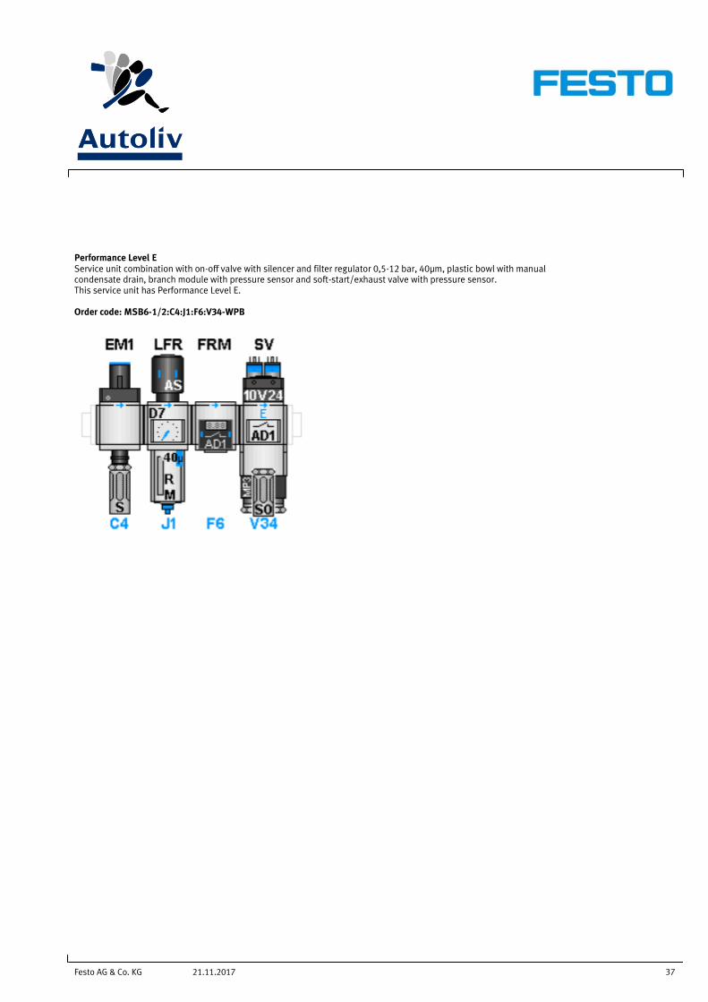
Performance Level E Service unit combination with on-off valve with silencer and filter regulator 0,5-12 bar, 40μm, plastic bowl with manual condensate drain, branch module with pressure sensor and soft-start/exhaust valve with pressure sensor. This service unit has Performance Level E. Order code: MSB6-1/2:C4:J1:F6:V34-WPB

Festo AG & Co. KG 38 21.11.2017
13 Tubing, Fittings, Accessoires
13.1 Tubing
Name Remarks Engineering
Tools
Picture /
Onlinelink Comment Documentation
PUN, PUN-DUO Outside diameter: 3 ... 16 mm
Internal diameter: 2.1 ... 11 mm
Temperature-dependent operating pressure: -0.95 ... 10
bar
Ambient temperature: -35 ... 60° C
Operating medium
- Compressed air
- Vacuum
For standard
applications
OD-TUBING (en)
PUN-V0 Outside diameter: 4 ... 16 mm
Internal diameter: 2 ... 11 mm
Temperature-dependent operating pressure: -0.95 ... 10
bar
Ambient temperature: -35 ... 60° C
Operating medium
- Compressed air
- Vacuum
For welding
applications use
PUN-V0-C
OD-TUBING (en)
PAN-MF Outside diameter: 4 ... 16 mm
Internal diameter: 2.5 ... 12 mm
Temperature-dependent operating pressure: -0.95 ... 31
bar
Ambient temperature: -60 ... 100° C
Operating medium
- Compressed air
- Vacuum
- Mineral oil
OD-TUBING (en)
PUN-S, PUN-S-DUO Outside diameter 4 ... 12 mm
Internal diameter 2.6 ... 8 mm
Working length 0.5 ... 6 m
Temperature-dependent operating pressure -0.95 ... 10
bar
Operating medium
- Compressed air
- Vacuum
High resistance to UV radiation and stress cracks
SPIRAL-TUBING
(en)
Festo AG & Co. KG 39 21.11.2017
13.2 Pneumatic fittings system
Name Remarks Picture /
Onlinelink Comment Documentation
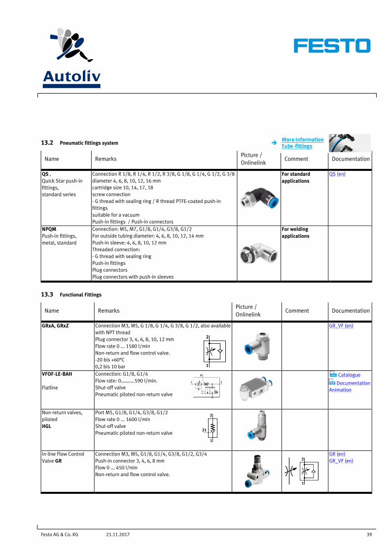
QS ,
Quick Star push-in
fittings,
standard series
Connection R 1/8, R 1/4, R 1/2, R 3/8, G 1/8, G 1/4, G 1/2, G 3/8
diameter 4, 6, 8, 10, 12, 16 mm
cartridge size 10, 14, 17, 18
screw connection
- G thread with sealing ring / R thread PTFE-coated push-in
fittings
suitable for a vacuum
Push-in fittings / Push-in connectors
For standard
applications
QS (en)
NPQM
Push-in fittings,
metal, standard
Connection: M5, M7, G1/8, G1/4, G3/8, G1/2
For outside tubing diameter: 4, 6, 8, 10, 12, 14 mm
Push-in sleeve: 4, 6, 8, 10, 12 mm
Threaded connection:
- G thread with sealing ring
Push-in fittings
Plug connectors
Plug connectors with push-in sleeves
For welding
applications
13.3 Functional Fittings
Name Remarks Picture /
Onlinelink Comment Documentation
GRxA, GRxZ Connection M3, M5, G 1/8, G 1/4, G 3/8, G 1/2, also available
with NPT thread
Plug connector 3, 4, 6, 8, 10, 12 mm
Flow rate 0 ... 1580 l/min
Non-return and flow control valve.
-20 bis +60°C
0,2 bis 10 bar
GR_VF (en)
VFOF-LE-BAH
Flatline
Connection: G1/8, G1/4
Flow rate: 0………..590 l/min.
Shut-off valve
Pneumatic piloted non-return valve
Catalogue
Documentation
Animation
Non-return valves,
piloted
HGL
Port M5, G1/8, G1/4, G3/8, G1/2
Flow rate 0 ... 1600 l/min
Shut-off valve
Pneumatic piloted non-return valve
In-line Flow Control
Valve GR
Connection M3, M5, G1/8, G1/4, G3/8, G1/2, G3/4
Push-in connector 3, 4, 6, 8 mm
Flow 0 ... 450 l/min
Non-return and flow control valve.
GR (en)
GR_VF (en)
Festo AG & Co. KG 40 21.11.2017
Name Remarks Picture /
Onlinelink Comment Documentation
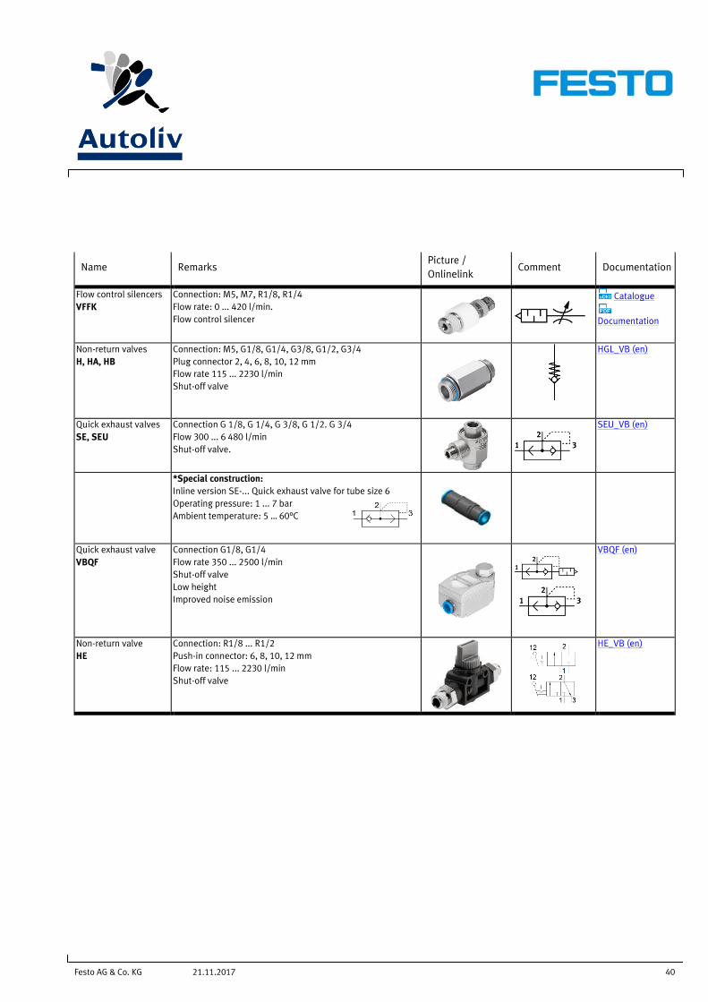
Flow control silencers
VFFK
Connection: M5, M7, R1/8, R1/4
Flow rate: 0 ... 420 l/min.
Flow control silencer
Catalogue
Documentation
Non-return valves
H, HA, HB
Connection: M5, G1/8, G1/4, G3/8, G1/2, G3/4
Plug connector 2, 4, 6, 8, 10, 12 mm
Flow rate 115 ... 2230 l/min
Shut-off valve
HGL_VB (en)
Quick exhaust valves
SE, SEU
Connection G 1/8, G 1/4, G 3/8, G 1/2. G 3/4
Flow 300 ... 6 480 l/min
Shut-off valve.
SEU_VB (en)
*Special construction:
Inline version SE-... Quick exhaust valve for tube size 6
Operating pressure: 1 ... 7 bar
Ambient temperature: 5 … 60°C
Quick exhaust valve
VBQF
Connection G1/8, G1/4
Flow rate 350 ... 2500 l/min
Shut-off valve
Low height
Improved noise emission
VBQF (en)
Non-return valve
HE
Connection: R1/8 ... R1/2
Push-in connector: 6, 8, 10, 12 mm
Flow rate: 115 ... 2230 l/min
Shut-off valve
HE_VB (en)
Festo AG & Co. KG 41 21.11.2017
13.4 General Accessoirs
Name Remarks Picture /
Onlinelink Comment Documentation
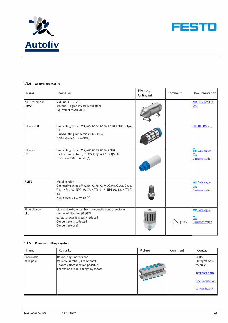
Air – Reservoirs
CRVZS
Volume: 0.1 ... 20 l
Material: High-alloy stainless steel
Equivalent to AD 2000.
AIR-RESERVOIRS
(en)
Silencers U Connecting thread M3, M5, G1/2, G1/4, G1/8, G3/8, G3/4,
G1
Barbed fitting connection PK-3, PK-4
Noise level 65 ... 84 dB(A)
SILENCERS (en)
Silencer
UC
Connecting thread M5, M7, G1/8, G1/4, G3/8
push-in connector QS 3, QS 4, QS 6, QS 8, QS 10
Noise level 58 ... 68 dB(A)
Catalogue
Documentation
AMTE Metal version
Connecting thread M3, M5, G1/8, G1/4, G3/8, G1/2, G3/4,
G1, UNF10-32, NPT1/8-27, NPT1/4-18, NPT3/8-18, NPT1/2-
14
Noise level 71 ... 95 dB(A).
Catalogue
Documentation
Filter silencer
LFU
cleans all exhaust air from pneumatic control systems
degree of filtration 99,99%
exhaust noise is greatly reduced
Condensate is collected
Condensate drain
Catalogue
Documentation
13.5 Pneumatic fittings system
Name Remarks Picture Comment Contact
Pneumatic
multipole
Round, angular versions
Variable number /size of ports
Toolless disconnection possible
For example: tool change by robots
Festo
„Integrations-
technik“
Technic Centre
Documentation

Festo AG & Co. KG 42 21.11.2017
14 Festo Discontinued Products / old program generation
14.1 Information
On the following pages Festo discontinued products are marked.
They may not be used in the future. Some of these products are no longer available as well.
Also given are products of the "old" program generation. With these products, successor products are listed, that
offer technical as well as pricing advantages.
All new constructions should have ONLY the NEW program generation from Festo in use!
14.2 Pneumatic drives
Festo AG & Co. KG 43 21.11.2017
Name Picture (Old
Product)
Documen
tation
Alternative
Product
Picture New
Product
Docume
ntation Remarks New Product
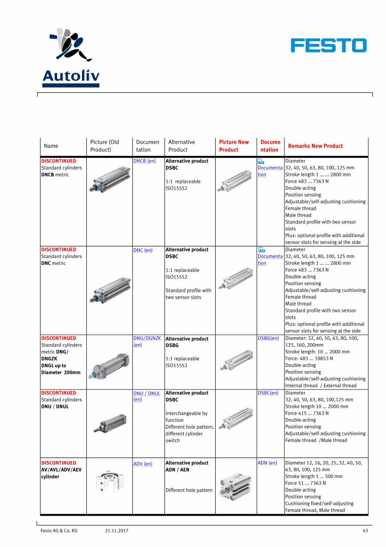
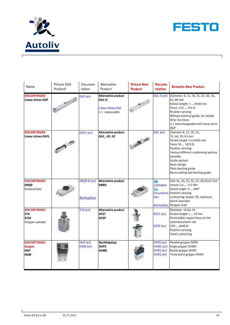
DISCONTINUED
Standard cylinders
DNCB metric
DNCB (en)
Alternative product
DSBC
1:1 replaceable
ISO15552
Documenta
tion
Diameter
32, 40, 50, 63, 80, 100, 125 mm
Stroke length 1 ... ... 2800 mm
Force 483 ... 7363 N
Double-acting
Position sensing
Adjustable/self-adjusting cushioning
Female thread
Male thread
Standard profile with two sensor
slots
Plus: optional profile with additional
sensor slots for sensing at the side
DISCONTINUED
Standard cylinders
DNC metric
DNC (en) Alternative product
DSBC
1:1 replaceable
ISO15552
Standard profile with
two sensor slots
Documenta
tion
Diameter
32, 40, 50, 63, 80, 100, 125 mm
Stroke length 1 ... ... 2800 mm
Force 483 ... 7363 N
Double-acting
Position sensing
Adjustable/self-adjusting cushioning
Female thread
Male thread
Standard profile with two sensor
slots
Plus: optional profile with additional
sensor slots for sensing at the side
DISCONTINUED
Standard cylinders
metric DNG/
DNGZK
DNGL up to
Diameter 200mm
DNG/DGNZK
(en) Alternative product
DSBG
1:1 replaceable
ISO15552
DSBG(en)
Diameter: 32, 40, 50, 63, 80, 100,
125, 160, 200mm
Stroke length: 10 ... 2000 mm
Force: 483 ... 18853 N
Double-acting
Position sensing
Adjustable/self-adjusting cushioning
Internal thread / External thread
DISCONTINUED
Standard cylinders
DNU / DNUL
DNU / DNUL (en)
Alternative product
DSBC
Interchangeable by
function
Different hole pattern,
different cylinder
switch
DSBC(en)
Diameter
32, 40, 50, 63, 80, 100,125 mm
Stroke length 10 ... 2000 mm
Force 415 ... 7363 N
Double-acting
Position sensing
Adjustable/self-adjusting cushioning
Female thread /Male thread
DISCONTINUED
AV/AVL/ADV/AEV
cylinder
ADV (en)
Alternative product
ADN / AEN
Different hole pattern
ADN (en)
Diameter 12, 16, 20, 25, 32, 40, 50,
63, 80, 100, 125 mm
Stroke length 1 ... 500 mm
Force 51 ... 7363 N
Double-acting
Position sensing
Cushioning fixed/self-adjusting
Female thread, Male thread
Festo AG & Co. KG 44 21.11.2017
Name Picture (Old
Product)
Documen
tation
Alternative
Product
Picture New
Product
Docume
ntation Remarks New Product
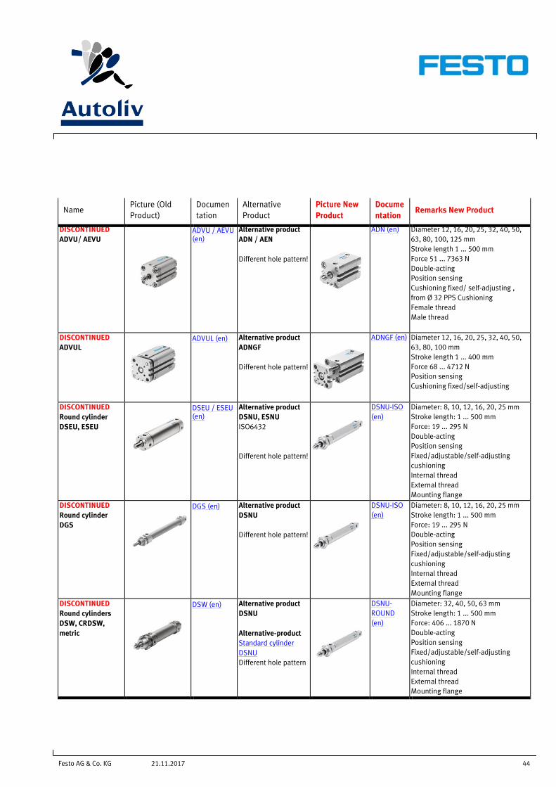
DISCONTINUED
ADVU/ AEVU
ADVU / AEVU (en)
Alternative product
ADN / AEN
Different hole pattern!
ADN (en) Diameter 12, 16, 20, 25, 32, 40, 50,
63, 80, 100, 125 mm
Stroke length 1 ... 500 mm
Force 51 ... 7363 N
Double-acting
Position sensing
Cushioning fixed/ self-adjusting ,
from Ø 32 PPS Cushioning
Female thread
Male thread
DISCONTINUED
ADVUL
ADVUL (en) Alternative product
ADNGF
Different hole pattern!
ADNGF (en) Diameter 12, 16, 20, 25, 32, 40, 50,
63, 80, 100 mm
Stroke length 1 ... 400 mm
Force 68 ... 4712 N
Position sensing
Cushioning fixed/self-adjusting
DISCONTINUED
Round cylinder
DSEU, ESEU
DSEU / ESEU (en)
Alternative product
DSNU, ESNU
ISO6432
Different hole pattern!
DSNU-ISO
(en)
Diameter: 8, 10, 12, 16, 20, 25 mm
Stroke length: 1 ... 500 mm
Force: 19 ... 295 N
Double-acting
Position sensing
Fixed/adjustable/self-adjusting
cushioning
Internal thread
External thread
Mounting flange
DISCONTINUED
Round cylinder
DGS
DGS (en) Alternative product
DSNU
Different hole pattern!
DSNU-ISO
(en)
Diameter: 8, 10, 12, 16, 20, 25 mm
Stroke length: 1 ... 500 mm
Force: 19 ... 295 N
Double-acting
Position sensing
Fixed/adjustable/self-adjusting
cushioning
Internal thread
External thread
Mounting flange
DISCONTINUED
Round cylinders
DSW, CRDSW,
metric
DSW (en) Alternative product
DSNU
Alternative-product
Standard cylinder
DSNU
Different hole pattern
DSNU-
ROUND
(en)
Diameter: 32, 40, 50, 63 mm
Stroke length: 1 ... 500 mm
Force: 406 ... 1870 N
Double-acting
Position sensing
Fixed/adjustable/self-adjusting
cushioning
Internal thread
External thread
Mounting flange
Festo AG & Co. KG 45 21.11.2017
Name Picture (Old
Product)
Documen
tation
Alternative
Product
Picture New
Product
Docume
ntation Remarks New Product
DISCONTINUED
Linear drives DGP
DGP (en)
Alternative product
DGC-K
Linear drives DGC
1:1 replaceable
DGC-K (en)
Diameter: 8, 12, 18, 25, 32, 40, 50,
63, 80 mm
Stroke length: 1 ... 8500 mm
Force: 153 ... 754 N
Position sensing
Without external guide, for simple
drive functions
1:1 interchangeable with linear drive
DGP
DISCONTINUED
Linear drives DGPL
DGPL (en) Alternative product
DGC...KF, GF
DGC (en) Diameter 8, 12, 18, 25,
32, 40, 50, 63 mm
Stroke length 1 to 8500 mm
Force 30 ... 1870 N
Position sensing
Various different cushioning options
possible
Guide options
Basic design
Plain-bearing guide
Recirculating ball bearing guide
DISCONTINUED
DRQD
Drehantriebe
DRQD-B (en)
Animation
Alternative product
DRRD
Catalogue
Documenta
tion
Animation
Size 16, 20, 25, 32, 35, 40,50,63 mm
torque 1,6 ... 112 Nm
Swivel angle 0 ... 180°
Position sensing
cushioning: elastic (P), hydraulic
shock absorber
flanged shaft
DISCONTINUED
STA
STAF
Stopper cylinder
STA (en)
Alternative product
DFST
DFSP
DFST (en)
DFSP (en)
Diameter 16 bis 50
Stroke length 5 ... 30 mm
Permissible impact force on the
extended piston rod
700 ... 6000 N
Position sensing
Fixed cushioning
DISCONTINUED
Gripper
HGP
HGW
HGP (en)
HGW (en)
Nachfolgetyp
DHPS
DHWS
DHPS (en)
DHWS (en)
DHRS (en)
DHDS (en)
Parallel gripper DHPS
Angle gripper DHWS
Radial gripper DHRS
Three-point gripper DHDS

Festo AG & Co. KG 46 21.11.2017
14.3 Actuators Process Automation
Name Picture (Old
Product)
Docume
ntation Alternative Product
Picture New
Product
Docume
ntation Remarks New Product
DISCONTINUED
DRE/DRD
Alternative product
DFPB/
DAPS
DFPB (en)
Single-acting / double-acting
DFPB: rack and pinion
DAPS: scotch yoke mechanism
DISCONTINUED
ASDPL
Alternative product
DDPC
Catalogue
Documenta
tion
Documenta
tion
ASDLP Displacement encoder for DLP
actuators
DDPC standard cylinders with
integrated displacement encoder
Diameter 80, 100 mm
Stroke length 10 ... 2000 mm
Force 2721 ... 4712 N
Displacement encoder, intern
proximity sensor
Fixed cushioning / Male thread
14.4 Proximity Sensors / Sensors
Name Picture (Old
Product)
Docume
ntation Alternative Product
Picture New
Product
Docume
ntation Remarks New Product
DISCONTINUED
Proximity Sensor
SME-8
(reed contact)
SME-8 (en) Alternative product
SME-8M
Reed contact
SME-8M
(en)
Voltage 0 ... 250V DC, 230 V AC
Cable length
0.3, 2.5, 5, 7.5, 0.2 ... 10 m
Plug connection M8, M12
Electrical / Via reed contact.
DISCONTINUED
Proximity Sensor
SMT-8
(Non contacting
PNP, NPN)
SMT-8 (en) Alternative product
SMT-8M-A
Non contacting
SMT-8M-A
(en)
Voltage 5 ... 30 V DC
Cable length 0.1 ... 30 m
Plug connection M8, M12
Electrical
Contactless PNP, NPN.
Short design
ATEX certification
DISCONTINUED
Proximity Sensor
SMT-8M
(Non contacting
PNP, NPN)
Alternative product
SMT-8M-A
Non contacting
SMT-8M-A
(en)
Voltage 5 ... 30 V DC
Cable length 0.1 ... 30 m
Plug connection M8, M12
Electrical
Contactless PNP, NPN.
Short design
ATEX certification
14.5 Pressure- / Vacuum Sensor
Festo AG & Co. KG 47 21.11.2017
Name Picture (Old
Product)
Docume
ntation Alternative Product
Picture New
Product
Docume
ntation Remarks New Product
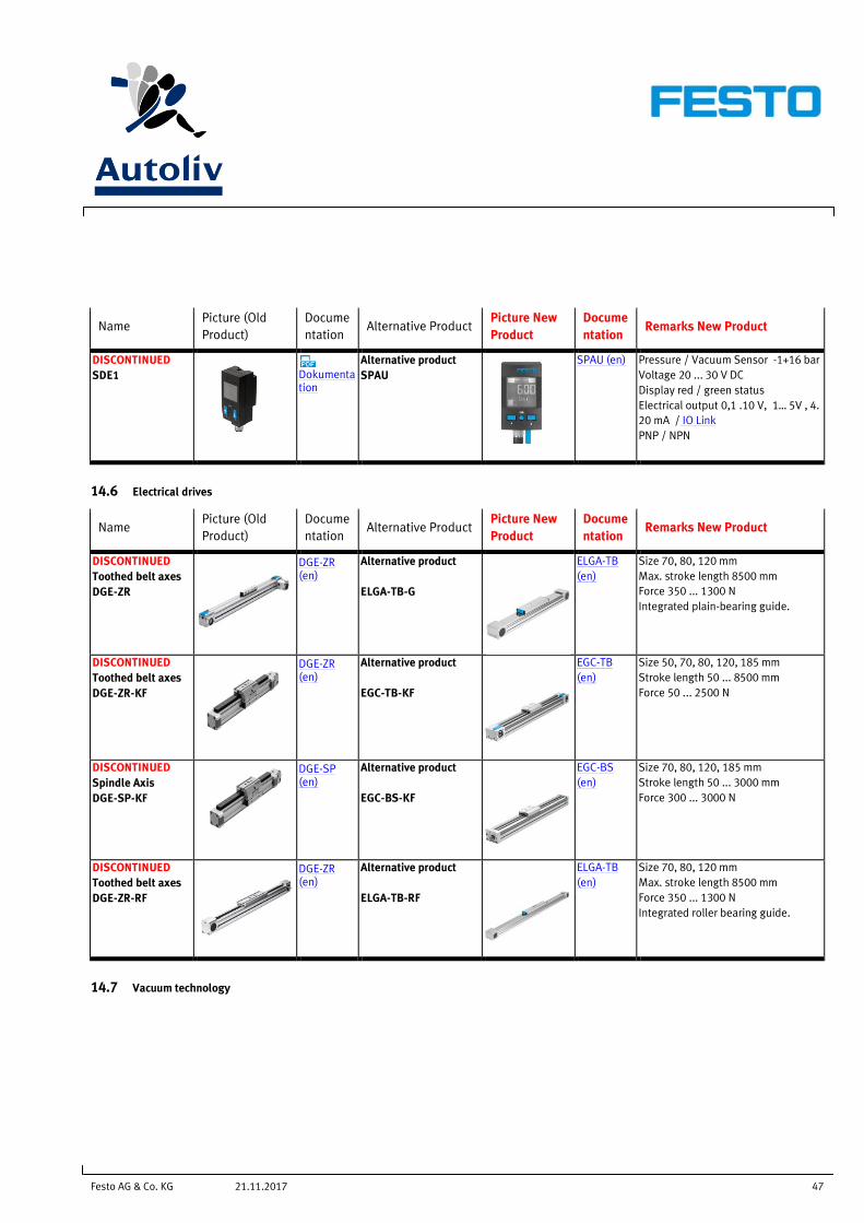
DISCONTINUED
SDE1
Dokumentation
Alternative product
SPAU
SPAU (en)
Pressure / Vacuum Sensor -1+16 bar
Voltage 20 ... 30 V DC
Display red / green status
Electrical output 0,1 .10 V, 1… 5V , 4.
20 mA / IO Link
PNP / NPN
14.6 Electrical drives
Name Picture (Old
Product)
Docume
ntation Alternative Product
Picture New
Product
Docume
ntation Remarks New Product
DISCONTINUED
Toothed belt axes
DGE-ZR
DGE-ZR (en)
Alternative product
ELGA-TB-G
ELGA-TB
(en)
Size 70, 80, 120 mm
Max. stroke length 8500 mm
Force 350 ... 1300 N
Integrated plain-bearing guide.
DISCONTINUED
Toothed belt axes
DGE-ZR-KF
DGE-ZR (en)
Alternative product
EGC-TB-KF
EGC-TB
(en)
Size 50, 70, 80, 120, 185 mm
Stroke length 50 ... 8500 mm
Force 50 ... 2500 N
DISCONTINUED
Spindle Axis
DGE-SP-KF
DGE-SP (en)
Alternative product
EGC-BS-KF
EGC-BS
(en)
Size 70, 80, 120, 185 mm
Stroke length 50 ... 3000 mm
Force 300 ... 3000 N
DISCONTINUED
Toothed belt axes
DGE-ZR-RF
DGE-ZR (en)
Alternative product
ELGA-TB-RF
ELGA-TB
(en)
Size 70, 80, 120 mm
Max. stroke length 8500 mm
Force 350 ... 1300 N
Integrated roller bearing guide.
14.7 Vacuum technology
Festo AG & Co. KG 48 21.11.2017
Name Picture (Old
Product)
Docume
ntation Alternative Product
Picture New
Product
Docume
ntation Remarks New Product
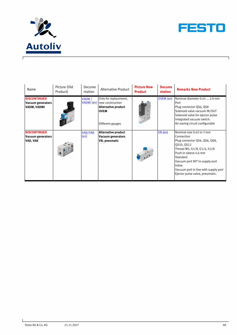
DISCONTINUED
Vacuum generators
VADM, VADMI
VADM / VADMI (en)
Only for replacement,
new construction
Alternative product
OVEM
Different gauges
OVEM (en)
Nominal diameter 0.45 ... 2.0 mm
Port
Plug connector QS6, QS8
Solenoid valve vacuum IN/OUT
Solenoid valve for ejector pulse
Integrated vacuum switch.
Air-saving circuit configurable
DISCONTINUED
Vacuum generators
VAD, VAK
VAD/VAK (en)
Alternative product
Vacuum generators
VN, pneumatic
VN (en) Nominal size 0.45 to 3 mm
Connection
Plug connector QS4, QS6, QS8,
QS10, QS12
Thread M5, G1/8, G1/4, G3/8
Push-in sleeve 4.6 mm
Standard
Vacuum port 90° to supply port
Inline
Vacuum port in line with supply port
Ejector pulse valve, pneumatic.
Festo AG & Co. KG 49 21.11.2017
14.8 Valves
Name Picture (Old
Product)
Docume
ntation Alternative Product
Picture New
Product
Docume
ntation Remarks New Product
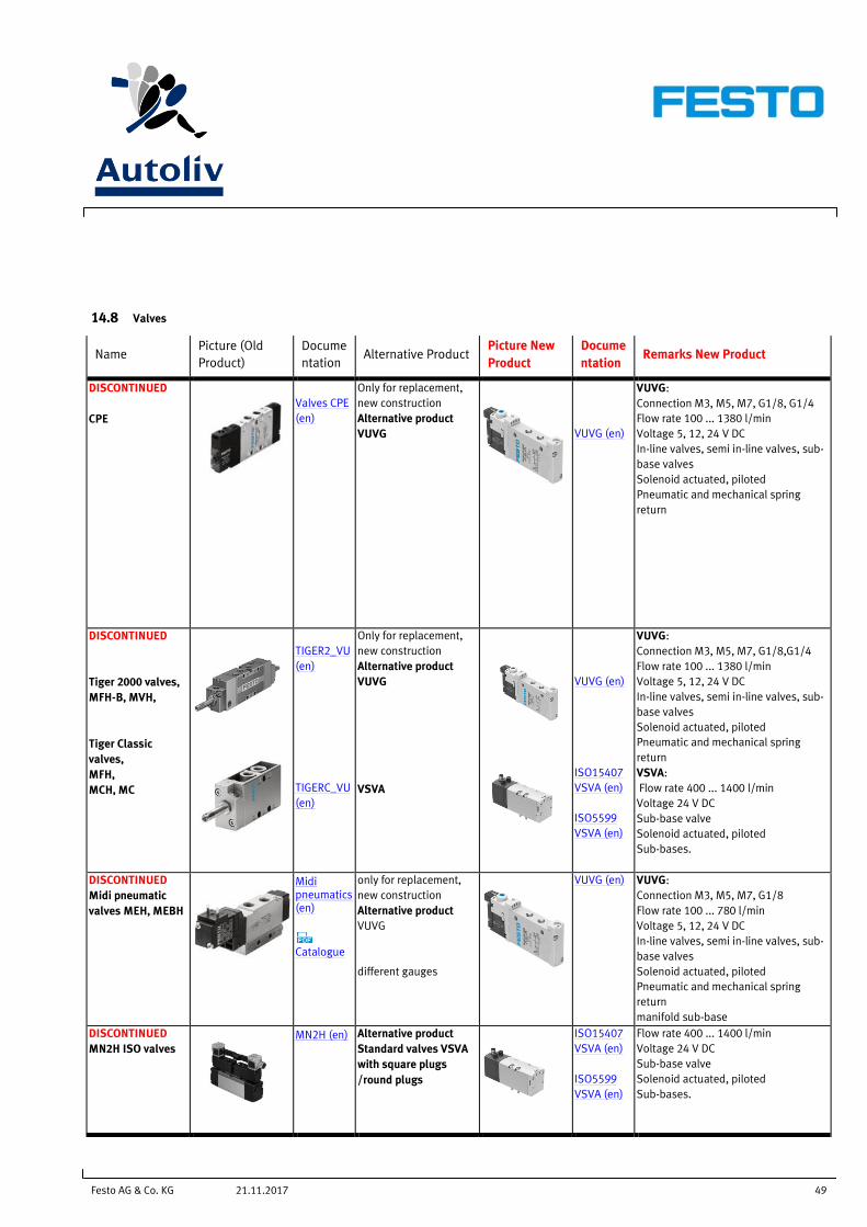
DISCONTINUED
CPE
Valves CPE
(en)
Only for replacement,
new construction
Alternative product
VUVG
VUVG (en)
VUVG:
Connection M3, M5, M7, G1/8, G1/4
Flow rate 100 ... 1380 l/min
Voltage 5, 12, 24 V DC
In-line valves, semi in-line valves, sub-
base valves
Solenoid actuated, piloted
Pneumatic and mechanical spring
return
DISCONTINUED
Tiger 2000 valves,
MFH-B, MVH,
Tiger Classic
valves,
MFH,
MCH, MC
TIGER2_VU
(en)
TIGERC_VU
(en)
Only for replacement,
new construction
Alternative product
VUVG
VSVA
VUVG (en)
ISO15407
VSVA (en)
ISO5599
VSVA (en)
VUVG:
Connection M3, M5, M7, G1/8,G1/4
Flow rate 100 ... 1380 l/min
Voltage 5, 12, 24 V DC
In-line valves, semi in-line valves, sub-
base valves
Solenoid actuated, piloted
Pneumatic and mechanical spring
return
VSVA:
Flow rate 400 ... 1400 l/min
Voltage 24 V DC
Sub-base valve
Solenoid actuated, piloted
Sub-bases.
DISCONTINUED
Midi pneumatic
valves MEH, MEBH
Midi pneumatics (en)
Catalogue
only for replacement,
new construction
Alternative product
VUVG
different gauges
VUVG (en)
VUVG:
Connection M3, M5, M7, G1/8
Flow rate 100 ... 780 l/min
Voltage 5, 12, 24 V DC
In-line valves, semi in-line valves, sub-
base valves
Solenoid actuated, piloted
Pneumatic and mechanical spring
return
manifold sub-base
DISCONTINUED
MN2H ISO valves
MN2H (en) Alternative product
Standard valves VSVA
with square plugs
/round plugs
ISO15407
VSVA (en)
ISO5599
VSVA (en)
Flow rate 400 ... 1400 l/min
Voltage 24 V DC
Sub-base valve
Solenoid actuated, piloted
Sub-bases.
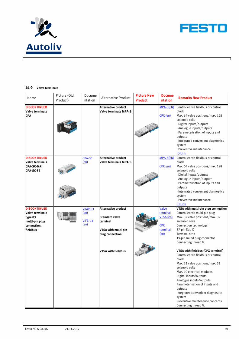
Festo AG & Co. KG 50 21.11.2017
14.9 Valve terminals
Name Picture (Old
Product)
Docume
ntation Alternative Product
Picture New
Product
Docume
ntation Remarks New Product
DISCONTINUED
Valve terminals
CPA
Alternative product
Valve terminals MPA-S
MPA-S(EN)
CPX (en)
Controlled via fieldbus or control
block
Max. 64 valve positions/max. 128
solenoid coils
- Digital inputs/outputs
- Analogue inputs/outputs
- Parameterisation of inputs and
outputs
- Integrated convenient diagnostics
system
- Preventive maintenance
IO Link
DISCONTINUED
Valve terminals
CPA-SC-MP,
CPA-SC-FB
CPA-SC (en)
Alternative product
Valve terminals MPA-S
MPA-S(EN)
CPX (en)
Controlled via fieldbus or control
block
Max. 64 valve positions/max. 128
solenoid coils
- Digital inputs/outputs
- Analogue inputs/outputs
- Parameterisation of inputs and
outputs
- Integrated convenient diagnostics
system
- Preventive maintenance
IO Link
DISCONTINUED
Valve terminals
type 03
multi-pin plug
connection,
fieldbus
VIMP-03 (en)
VIFB-03 (en)
Alternative product
Standard valve
terminal
VTSA with multi-pin
plug connection
VTSA with fieldbus
Valve
terminal
VTSA (en)
CPX
terminal
(en)
VTSA with multi-pin plug connection
Controlled via multi-pin plug
Max. 32 valve positions/max. 32
solenoid coils
Connection technology:
37-pin Sub-D
Terminal strip
19-pin round plug connector
Connecting thread G.
VTSA with fieldbus (CPX terminal)
Controlled via fieldbus or control
block
Max. 32 valve positions/max. 32
solenoid coils
Max. 10 electrical modules
Digital inputs/outputs
Analogue inputs/outputs
Parameterisation of inputs and
outputs
Integrated convenient diagnostics
system
Preventive maintenance concepts
Connecting thread G.
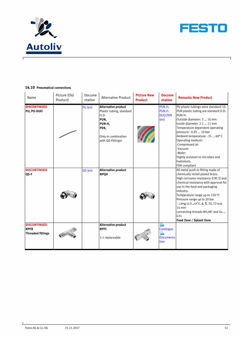
Festo AG & Co. KG 51 21.11.2017
14.10 Pneumatical connections
Name Picture (Old
Product)
Docume
ntation Alternative Product
Picture New
Product
Docume
ntation Remarks New Product
DISCONTINUED
PU, PU-DUO
PU (en) Alternative product
Plastic tubing, standard
O.D.
PUN,
PUN-H,
PEN,
Only in combination
with QS-Fittings!
PUN-H,
PUN-H-
DUO,PEN
(en)
PU plastic tubings were standard I.D.
PUN plastic tubing are standard O.D.
PUN-H:
Outside diameter: 3 ... 16 mm
Inside diameter: 2.1 ... 11 mm
Temperature dependent operating
pressure: -0.95 ... 10 bar
Ambient temperature: -35 ... 60° C
Operating medium:
-Compressed air
-Vacuum
-Water
Highly resistant to microbes and
hydrolysis.
FDA compliant
DISCONTINUED
QS-F
QS (en) Alternative product
NPQH
All metal push-in fitting made of
chemically nickel-plated brass.
High corrosion resistance (CRC3) and
chemical resistance with approval for
use in the food and packaging
industry.
Temperature range up to 150 °C
Pressure range up to 20 bar
14 mm
connecting threads M5,M7 and Gx …
G½
Food Zone / Splash Zone
DISCONTINUED
NPFB
Threaded fittings
Alternative product
NPFC
1:1 replaceable
Catalogue
Documenta
tion


![typoscript [AK] – 21.11.2017 – Seite 3 – 4. Korrektur ...€¦ · 395834000/1 – 11191 – Schnell-Schubert_Gott im Livestream typoscript [AK] – 21.11.2017 – Seite 9 –](https://img.dokumen.tips/doc/110x75/605e46f4ee9b7272dd57beac/typoscript-ak-a-21112017-a-seite-3-a-4-korrektur-3958340001-a.jpg)