Embed Size (px)
Citation preview

Vorne Industries
2100SB V2 SeriesMulti-Line Message Display
User's Manual
1445 Industrial Drive · Itasca, IL 60143-1849 · (708) 875-3600 · Telefax (708) 875-36091445 Industrial Drive • Itasca, IL 60143-1849 • (630) 875-3600 • Telefax (630) 875-3609

COPYRIGHT© 1995, VORNE INDUSTRIES, INC. All rights reserved.
Information is subject to change without notice.
TRADEMARK ACKNOWLEDGMENTSIBM is a registered trademark of International Business Machines, Inc.Belden is a registered trademark of Cooper Industries, Inc.
Vorne Industries, Inc.1445 Industrial DriveItasca, IL 60143-1849Phone: (630) 875-3600Fax: (630) 875-3609
Printed in the U.S.A.
2100SB Series Display User's Manual

Table Of Contents
1 Introduction . . . . . . . . . . . . . . . . . . . . . . . . . . . . . . . . . . . . . . . . . . . . . . . . . . . . .Page 1
1.1 General . . . . . . . . . . . . . . . . . . . . . . . . . . . . . . . . . . . . . . . . . . . . . . . . . . . . . . . . . . . . . . . . . . .Page 11.2 2100SB Serial Buffered Display . . . . . . . . . . . . . . . . . . . . . . . . . . . . . . . . . . . . . . . . . . . . .Page 1
2140 Two Line Display . . . . . . . . . . . . . . . . . . . . . . . . . . . . . . . . . . . . . . . . . . . . . . . . . . . .Page 1 Figure 1 2140 Front Panel . . . . . . . . . . . . . . . . . . . . . . . . . . . . . . . . . . . . . . . . . . .Page 1
2180 Four Line Display . . . . . . . . . . . . . . . . . . . . . . . . . . . . . . . . . . . . . . . . . . . . . . . . . . . .Page 2 Figure 2 2180 Front Panel . . . . . . . . . . . . . . . . . . . . . . . . . . . . . . . . . . . . . . . . . . .Page 2
Table A Model Summary Table . . . . . . . . . . . . . . . . . . . . . . . . . . . . . . . . . . . . . . . . . . . . .Page 2
2 Features . . . . . . . . . . . . . . . . . . . . . . . . . . . . . . . . . . . . . . . . . . . . . . . . . . . . . . . .Page 3
2.1 Vacuum Fluorescent Display (VFD) . . . . . . . . . . . . . . . . . . . . . . . . . . . . . . . . . . . . . . . . . .Page 32.2 E2PROM Memory . . . . . . . . . . . . . . . . . . . . . . . . . . . . . . . . . . . . . . . . . . . . . . . . . . . . . . . . .Page 32.3 Scripts . . . . . . . . . . . . . . . . . . . . . . . . . . . . . . . . . . . . . . . . . . . . . . . . . . . . . . . . . . . . . . . . . . . .Page 32.4 Tasks . . . . . . . . . . . . . . . . . . . . . . . . . . . . . . . . . . . . . . . . . . . . . . . . . . . . . . . . . . . . . . . . . . . . .Page 32.5 Power Supply Options . . . . . . . . . . . . . . . . . . . . . . . . . . . . . . . . . . . . . . . . . . . . . . . . . . . . . .Page 32.6 Relay Output . . . . . . . . . . . . . . . . . . . . . . . . . . . . . . . . . . . . . . . . . . . . . . . . . . . . . . . . . . . . . .Page 4
Table B Relay Terminal Connections . . . . . . . . . . . . . . . . . . . . . . . . . . . . . . . . . . . .Page 42.7 Serial Ports . . . . . . . . . . . . . . . . . . . . . . . . . . . . . . . . . . . . . . . . . . . . . . . . . . . . . . . . . . . . . . . .Page 4
Communications Setup Selections . . . . . . . . . . . . . . . . . . . . . . . . . . . . . . . . . . . . . . . . . . .Page 4 Configurations . . . . . . . . . . . . . . . . . . . . . . . . . . . . . . . . . . . . . . . . . . . . . . . . . . . . . . . . . . . .Page 4
2.8 Back Panel . . . . . . . . . . . . . . . . . . . . . . . . . . . . . . . . . . . . . . . . . . . . . . . . . . . . . . . . . . . . . . . .Page 5 Figure 3 2100SB-120 VAC Back Panel . . . . . . . . . . . . . . . . . . . . . . . . . . . . . . .Page 5 Figure 4 2100SB-24 VDC Back Panel . . . . . . . . . . . . . . . . . . . . . . . . . . . . . . . .Page 5
3 Setup . . . . . . . . . . . . . . . . . . . . . . . . . . . . . . . . . . . . . . . . . . . . . . . . . . . . . . . . . .Page 7
3.1 Powering The Display . . . . . . . . . . . . . . . . . . . . . . . . . . . . . . . . . . . . . . . . . . . . . . . . . . . . . .Page 7 Table C Power Connections . . . . . . . . . . . . . . . . . . . . . . . . . . . . . . . . . . . . . . . . . . . .Page 7
3.2 Setup Mode . . . . . . . . . . . . . . . . . . . . . . . . . . . . . . . . . . . . . . . . . . . . . . . . . . . . . . . . . . . . . . .Page 7 Entering Setup Mode (SETUP Feature) . . . . . . . . . . . . . . . . . . . . . . . . . . . . . . . . . . . . . .Page 7
Figure 5 SETUP Circuit Wiring Diagram . . . . . . . . . . . . . . . . . . . . . . . . . . . . . .Page 8 Using The Front Panel Menu Keys . . . . . . . . . . . . . . . . . . . . . . . . . . . . . . . . . . . . . . . . . .Page 8
3.3 2100SB Setup Options . . . . . . . . . . . . . . . . . . . . . . . . . . . . . . . . . . . . . . . . . . . . . . . . . . . . .Page 8 General Setup . . . . . . . . . . . . . . . . . . . . . . . . . . . . . . . . . . . . . . . . . . . . . . . . . . . . . . . . . . . . .Page 8 Serial Port Setup . . . . . . . . . . . . . . . . . . . . . . . . . . . . . . . . . . . . . . . . . . . . . . . . . . . . . . . . . .Page 9 Parallel Port Setup: Not used on the 2100SB. . . . . . . . . . . . . . . . . . . . . . . . . . . . . . . . .Page 10 Load Default Setup . . . . . . . . . . . . . . . . . . . . . . . . . . . . . . . . . . . . . . . . . . . . . . . . . . . . . . . .Page 10 Test Mode . . . . . . . . . . . . . . . . . . . . . . . . . . . . . . . . . . . . . . . . . . . . . . . . . . . . . . . . . . . . . . . .Page 10
Figure 6 Loop Test Wiring Diagram . . . . . . . . . . . . . . . . . . . . . . . . . . . . . . . . . .Page 10 Enter Program Mode: Not used on the 2100SB. . . . . . . . . . . . . . . . . . . . . . . . . . . . . . .Page 11
2100SB Series Display User's Manual i

Exiting Setup Mode . . . . . . . . . . . . . . . . . . . . . . . . . . . . . . . . . . . . . . . . . . . . . . . . . . . . . . .Page 11 Exit: Save Changes . . . . . . . . . . . . . . . . . . . . . . . . . . . . . . . . . . . . . . . . . . . . . . . . . . . . . . . .Page 11 Quit: Ignore Changes . . . . . . . . . . . . . . . . . . . . . . . . . . . . . . . . . . . . . . . . . . . . . . . . . . . . . .Page 11
4 Scripts . . . . . . . . . . . . . . . . . . . . . . . . . . . . . . . . . . . . . . . . . . . . . . . . . . . . . . . . .Page 13
4.1 Building Scripts . . . . . . . . . . . . . . . . . . . . . . . . . . . . . . . . . . . . . . . . . . . . . . . . . . . . . . . . . . . .Page 13 Tasks . . . . . . . . . . . . . . . . . . . . . . . . . . . . . . . . . . . . . . . . . . . . . . . . . . . . . . . . . . . . . . . . . . . .Page 13 Simple Packet Protocol . . . . . . . . . . . . . . . . . . . . . . . . . . . . . . . . . . . . . . . . . . . . . . . . . . . .Page 13 Displaying Literal Text . . . . . . . . . . . . . . . . . . . . . . . . . . . . . . . . . . . . . . . . . . . . . . . . . . . . .Page 15 Using Control Characters . . . . . . . . . . . . . . . . . . . . . . . . . . . . . . . . . . . . . . . . . . . . . . . . . . .Page 16
Figure 7 Control Characters . . . . . . . . . . . . . . . . . . . . . . . . . . . . . . . . . . . . . . . . .Page 16 Command Strings . . . . . . . . . . . . . . . . . . . . . . . . . . . . . . . . . . . . . . . . . . . . . . . . . . . . . . . . .Page 17
Figure 8 Stack Handling . . . . . . . . . . . . . . . . . . . . . . . . . . . . . . . . . . . . . . . . . . . . .Page 18 Figure 9 Standard 2100 Display Escape Sequences . . . . . . . . . . . . . . . . . . . . .Page 19
Simple Examples To Try . . . . . . . . . . . . . . . . . . . . . . . . . . . . . . . . . . . . . . . . . . . . . . . . . . .Page 19 Advanced Example Application Preface . . . . . . . . . . . . . . . . . . . . . . . . . . . . . . . . . . . . . .Page 20 Advanced Example Application . . . . . . . . . . . . . . . . . . . . . . . . . . . . . . . . . . . . . . . . . . . . .Page 21 Literal Control Characters . . . . . . . . . . . . . . . . . . . . . . . . . . . . . . . . . . . . . . . . . . . . . . . . . .Page 24
Table D Literal Control Characters . . . . . . . . . . . . . . . . . . . . . . . . . . . . . . . . . . . . . .Page 254.2 Blink . . . . . . . . . . . . . . . . . . . . . . . . . . . . . . . . . . . . . . . . . . . . . . . . . . . . . . . . . . . . . . . . . . . . .Page 264.3 Cursor . . . . . . . . . . . . . . . . . . . . . . . . . . . . . . . . . . . . . . . . . . . . . . . . . . . . . . . . . . . . . . . . . . . .Page 274.4 Erase . . . . . . . . . . . . . . . . . . . . . . . . . . . . . . . . . . . . . . . . . . . . . . . . . . . . . . . . . . . . . . . . . . . . .Page 284.5 Erase2eol . . . . . . . . . . . . . . . . . . . . . . . . . . . . . . . . . . . . . . . . . . . . . . . . . . . . . . . . . . . . . . . . .Page 294.6 Font . . . . . . . . . . . . . . . . . . . . . . . . . . . . . . . . . . . . . . . . . . . . . . . . . . . . . . . . . . . . . . . . . . . . . .Page 304.7 Goto . . . . . . . . . . . . . . . . . . . . . . . . . . . . . . . . . . . . . . . . . . . . . . . . . . . . . . . . . . . . . . . . . . . . .Page 314.8 Keypress Script . . . . . . . . . . . . . . . . . . . . . . . . . . . . . . . . . . . . . . . . . . . . . . . . . . . . . . . . . . . .Page 324.9 Lock . . . . . . . . . . . . . . . . . . . . . . . . . . . . . . . . . . . . . . . . . . . . . . . . . . . . . . . . . . . . . . . . . . . . .Page 334.10 Marker . . . . . . . . . . . . . . . . . . . . . . . . . . . . . . . . . . . . . . . . . . . . . . . . . . . . . . . . . . . . . . . . . .Page 344.11 Output . . . . . . . . . . . . . . . . . . . . . . . . . . . . . . . . . . . . . . . . . . . . . . . . . . . . . . . . . . . . . . . . . . .Page 354.12 Relay . . . . . . . . . . . . . . . . . . . . . . . . . . . . . . . . . . . . . . . . . . . . . . . . . . . . . . . . . . . . . . . . . . . .Page 364.13 Repeat . . . . . . . . . . . . . . . . . . . . . . . . . . . . . . . . . . . . . . . . . . . . . . . . . . . . . . . . . . . . . . . . . . .Page 374.14 Scroll . . . . . . . . . . . . . . . . . . . . . . . . . . . . . . . . . . . . . . . . . . . . . . . . . . . . . . . . . . . . . . . . . . . .Page 384.15 Wait . . . . . . . . . . . . . . . . . . . . . . . . . . . . . . . . . . . . . . . . . . . . . . . . . . . . . . . . . . . . . . . . . . . . .Page 40
5 Serial Port Operation . . . . . . . . . . . . . . . . . . . . . . . . . . . . . . . . . . . . . . . . . . . . . .Page 41
5.1 Communicating To A Single Display . . . . . . . . . . . . . . . . . . . . . . . . . . . . . . . . . . . . . . . . .Page 41 Wiring To A Single Display . . . . . . . . . . . . . . . . . . . . . . . . . . . . . . . . . . . . . . . . . . . . . . . . .Page 41
Table E RS422 Serial Port Terminal Strip . . . . . . . . . . . . . . . . . . . . . . . . . . . . . . . .Page 41 Table F RS232 Serial Port female DB9 Connector . . . . . . . . . . . . . . . . . . . . . . . .Page 41 Figure 10 Single Unit - RS232 Diagram . . . . . . . . . . . . . . . . . . . . . . . . . . . . . . . . . .Page 42 Figure 11 Single Unit - RS422 Diagram . . . . . . . . . . . . . . . . . . . . . . . . . . . . . . . . . .Page 42
5.2 Communicating To Multiple Units . . . . . . . . . . . . . . . . . . . . . . . . . . . . . . . . . . . . . . . . . . .Page 43 Understanding An RS422 Network . . . . . . . . . . . . . . . . . . . . . . . . . . . . . . . . . . . . . . . . . .Page 43 Wiring An RS422 Network . . . . . . . . . . . . . . . . . . . . . . . . . . . . . . . . . . . . . . . . . . . . . . . . .Page 43
Figure 12 RS422 Multidrop Wiring . . . . . . . . . . . . . . . . . . . . . . . . . . . . . . . . . . .Page 43 Figure 13 RS232 Converter . . . . . . . . . . . . . . . . . . . . . . . . . . . . . . . . . . . . . . . . . .Page 44 Figure 14 RS232 Converter Wiring . . . . . . . . . . . . . . . . . . . . . . . . . . . . . . . . . . .Page 45
Addressing Multiple Units . . . . . . . . . . . . . . . . . . . . . . . . . . . . . . . . . . . . . . . . . . . . . . . . . .Page 46
Table Of Contents
2100SB Series Display User's Manual ii

5.3 Terminal Emulation . . . . . . . . . . . . . . . . . . . . . . . . . . . . . . . . . . . . . . . . . . . . . . . . . . . . . . . .Page 47 VT102 Compatible . . . . . . . . . . . . . . . . . . . . . . . . . . . . . . . . . . . . . . . . . . . . . . . . . . . . . . . .Page 47 2100 Series Slave . . . . . . . . . . . . . . . . . . . . . . . . . . . . . . . . . . . . . . . . . . . . . . . . . . . . . . . . . .Page 48
Appendix A - Glossary . . . . . . . . . . . . . . . . . . . . . . . . . . . . . . . . . . . . . . . . . . . . . . .Page 49
Appendix B - Specifications . . . . . . . . . . . . . . . . . . . . . . . . . . . . . . . . . . . . . . . . . . .Page 55
Communication Interface . . . . . . . . . . . . . . . . . . . . . . . . . . . . . . . . . . . . . . . . . . . . . . . . . . .Page 55 Vacuum Fluorescent Display . . . . . . . . . . . . . . . . . . . . . . . . . . . . . . . . . . . . . . . . . . . . . . . .Page 55 Physical And Electrical . . . . . . . . . . . . . . . . . . . . . . . . . . . . . . . . . . . . . . . . . . . . . . . . . . . . .Page 55 Dimensions . . . . . . . . . . . . . . . . . . . . . . . . . . . . . . . . . . . . . . . . . . . . . . . . . . . . . . . . . . . . . . .Page 56 Mounting Information . . . . . . . . . . . . . . . . . . . . . . . . . . . . . . . . . . . . . . . . . . . . . . . . . . . . . .Page 56
Appendix C - Character Sets . . . . . . . . . . . . . . . . . . . . . . . . . . . . . . . . . . . . . . . . . .Page 57
Font 1 IBM® Character Set . . . . . . . . . . . . . . . . . . . . . . . . . . . . . . . . . . . . . . . . . . . . . . . .Page 57 Font 2 JIS8 (Katakana) Character Set . . . . . . . . . . . . . . . . . . . . . . . . . . . . . . . . . . . . . . . .Page 59 Font 3 Slavic (Latin II) Character Set . . . . . . . . . . . . . . . . . . . . . . . . . . . . . . . . . . . . . . . .Page 61
Appendix D - Typical RS232 Pinouts . . . . . . . . . . . . . . . . . . . . . . . . . . . . . . . . . . . .Page 63
Index . . . . . . . . . . . . . . . . . . . . . . . . . . . . . . . . . . . . . . . . . . . . . . . . . . . . . . . . . . . .Page 65
Table Of Contents
2100SB Series Display User's Manual iii

1 Introduction
1.1 GeneralVorne 2100SB Series Displays are panel mountable, vacuum fluorescent message displaysdesigned to interface with most PLC's and industrial computers. Three sealed front panelbuttons and an on-screen menu allow easy application set up, while a locking setup featureprevents inadvertent change or loss of setup selections. Units are available with a choice ofdisplay sizes and power supplies to meet the requirements of a wide variety of applications.
1.2 2100SB Serial Buffered DisplayThe 2100SB Display is available with two or four lines of 5x7 dot matrix characters.
2140 Two Line DisplayThe 2140 configuration, shown in Figure 1, displays 40 characters in two lines of 20characters. The characters of a 2140 are each 11mm in height.
Figure 12140 Front Panel
Vorne IndustriesF1 F2 F3
2140
2100SB Series Display User's Manual Page 1

2180 Four Line DisplayThe 2180 configuration, shown in Figure 2, displays 80 characters in four lines of 20characters. The characters of a 2180 are each 9mm in height.
Figure 22180 Front Panel
Vorne Industries
F1
F2
F3
2180
Table A Model Summary Table
Model 2140SB 2 Lines of 11 mm CharactersModel 2180SB 4 Lines of 9 mm Characters
2100SB Series Display User's Manual Page 2

2 Features
2.1 Vacuum Fluorescent Display (VFD)VFD technology provides superior brightness, viewing angle, and spectral qualities. Thenatural color emitted by the VFD is a blue-green peaking at a wavelength of 505 nanometers.The VFD tube has a rated life of 50,000 hours (almost six years of continuous operation).Rated life is defined as the length of time before the average dot brightness will reach one-halfof its original brightness due to fatigue of the display phosphors.
Note: To maximize the life of the display, it is important to avoid keeping the same messagefixed on the display for extended periods (hours). If default messages like "ALL SYSTEMSGO" or "MACHINE RUNNING" are used, it is suggested that they scroll to preventimprinting the message on the display phosphors.
2.2 E2PROM MemoryThis memory is used to store the information entered during setup. Setup data needs to beentered only once. Individual setup items may be modified at any time by entering the setupmode and making the desired changes, and then choosing the Save Changes option upon exit.This memory is retained in the absence of power with no need for a battery.
2.3 ScriptsThe 2100 Series displays interpret scripts received from a host device with a serial port suchas a PLC or a DOS based computer. Scripts are used to define the text to be displayed, tospecify how the text is to be presented, to control the relay, and to define the operation of thefront panel function keys. Scripts may contain literal text, control characters, and commandstrings. Scripts can be transmitted serially in a Simple Packet Protocol. A detailed discussionof scripts and the Simple Packet Protocol is contained in Chapter 4.
2.4 TasksThe 2100 Series displays have the ability to perform up to four different functions or tasks atthe same time; each script is assigned a task number 0 - 3. An example of the usefulness ofmultitasking is the ability to separately control operation of the relay output, scroll a messageon the display, and send serial text to an external device - all at the same time. Furtherinformation on tasks is contained in Chapter 4.
2.5 Power Supply OptionsDisplays are available with either a 24 volt DC power supply or a 120 volt AC (± 15%)50-60 Hz power supply. Both supplies are fused and have a typical operating power of20VA.
2100SB Series Display User's Manual Page 3

2.6 Relay OutputA software controllable SPDT relay output is available for annunciator purposes. Relayconnections are wired to pins D, E, and F on the terminal strip located on the rear of the 2100Display (this terminal strip is marked A - F). Refer to the back panel diagrams at the end ofthis chapter (Figures 3 & 4). The relay is rated for 120 VAC at 1 Amp.
Table B Relay Terminal Connections
Terminal ConnectionsD Relay Output (Normally Closed)E Relay Output (Common)F Relay Output (Normally Open)
Warning: Use the relay for annunciation only. Do not use the relay for control applications !
2.7 Serial PortsAll serial communications to a 2100 Display are through opto-isolated serial ports. The RS232port is accessible via the DB9 connector on the back of the unit. RS422 connections arewired to the 6 pin terminal strip labeled "RS422" located on the back of the unit.
Communications Setup SelectionsCommunication parameters for each 2100 Display must be selected during setup. Choicesinclude data bits, baud rate, unit address, and group address. Refer to Section 3.3 and 5.2 forspecific details.
Configurations2100 Displays can be configured for a serial network, permitting centralized control using asingle computer or PLC. Messages and commands can be sent to individual units, a group ofunits, or to all units.
Features
2100SB Series Display User's Manual Page 4
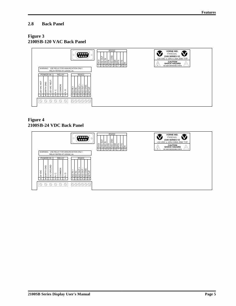
2.8 Back Panel
Figure 32100SB-120 VAC Back Panel
Figure 42100SB-24 VDC Back Panel
422
IN +
422
IN -
422
OU
T +
422
OU
T -
ISO
-GN
D.
SE
TUP
RS422
2 3 4 5 61
POWER IN
120
VA
C H
OT
A
EA
RTH
GN
D.
B
120
VA
C N
EU
T.
C
N. C
.
D
CO
MM
ON
E
N. O
.
F
RELAY
5 4 3 2 1
9 8 7 6
VORNE IND.ITASCA, IL
CAUTIONSHOCK HAZARD
120 VAC ± 15% 0.16A 20W TYP2100 SERIES V2
NO USER SERVICEABLE PARTS! D
CD
232
OU
T
232
IN
DTR
ISO
-GN
D.
DS
R
RS232
2 3 4 5 61
RTS
CTS
RI
7 8 9 WARNING: USE RELAY FOR ANNUNCIATION ONLY.
RELAY RATED AT 120VAC 1A. 4
22 IN
+
422
IN -
422
OU
T +
422
OU
T -
ISO
-GN
D.
SE
TUP
RS422
2 3 4 5 61
POWER IN
24
VD
C
A
EA
RTH
GN
D.
B
DC
GR
OU
ND
C
N. C
.
D
CO
MM
ON
E
N. O
.
F
RELAY
5 4 3 2 1
9 8 7 6
VORNE IND.ITASCA, IL
CAUTIONSHOCK HAZARD
+24 VDC ± 10% 0.80A 20W TYP2100 SERIES V2
NO USER SERVICEABLE PARTS! D
CD
232
OU
T
232
IN
DTR
ISO
-GN
D.
DS
R
RS232
2 3 4 5 61
RTS
CTS
RI
7 8 9 WARNING: USE RELAY FOR ANNUNCIATION ONLY.
RELAY RATED AT 120VAC 1A.
Features
2100SB Series Display User's Manual Page 5

Features
2100SB Series Display User's Manual Page 6
3 Setup
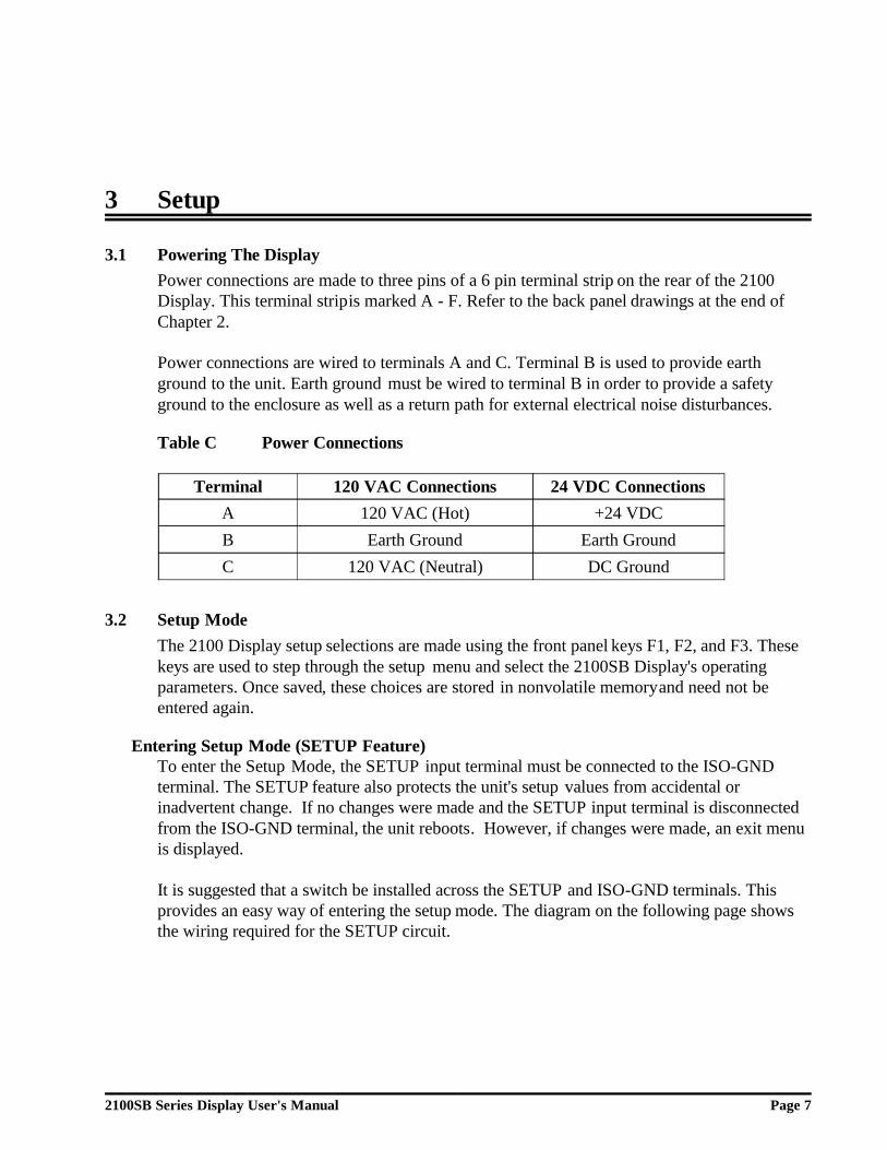
3.1 Powering The DisplayPower connections are made to three pins of a 6 pin terminal strip on the rear of the 2100Display. This terminal strip is marked A - F. Refer to the back panel drawings at the end ofChapter 2.
Power connections are wired to terminals A and C. Terminal B is used to provide earthground to the unit. Earth ground must be wired to terminal B in order to provide a safetyground to the enclosure as well as a return path for external electrical noise disturbances.
Table C Power Connections
Terminal 120 VAC Connections 24 VDC ConnectionsA 120 VAC (Hot) +24 VDCB Earth Ground Earth GroundC 120 VAC (Neutral) DC Ground
3.2 Setup ModeThe 2100 Display setup selections are made using the front panel keys F1, F2, and F3. Thesekeys are used to step through the setup menu and select the 2100SB Display's operatingparameters. Once saved, these choices are stored in nonvolatile memory and need not beentered again.
Entering Setup Mode (SETUP Feature)To enter the Setup Mode, the SETUP input terminal must be connected to the ISO-GNDterminal. The SETUP feature also protects the unit's setup values from accidental orinadvertent change. If no changes were made and the SETUP input terminal is disconnectedfrom the ISO-GND terminal, the unit reboots. However, if changes were made, an exit menuis displayed.
It is suggested that a switch be installed across the SETUP and ISO-GND terminals. Thisprovides an easy way of entering the setup mode. The diagram on the following page showsthe wiring required for the SETUP circuit.
2100SB Series Display User's Manual Page 7

Figure 5SETUP Circuit Wiring Diagram
Using the Front Panel Menu KeysAs long as the unit is in the Setup mode, the title of the active setup menu will be displayed onthe first line of the display. The second line will display the menu choice for the current setupparameter. When in the Setup mode, the F1 key is used to move to the previous menu choiceand the F2 key is used to move to the next menu choice.
The F3 key is used to select the currently displayed choice. If the current setup selection is anumeric value, the F1 key will decrement the current value each time it is pressed and the F2key will increment the current value when it is pressed. If the current selection is not a numericvalue, F1 and F2 will index through the available choices.
Note: Holding down a key will cause it to repeat.
The unit is shipped from the factory with default settings loaded into memory. If the valueshave been changed, the default settings can be reloaded by entering the setup mode andselecting Load Default Setup.
3.3 2100SB Setup OptionsWhen the 2100SB is placed in the Setup mode, the Choose an Option menu will bedisplayed. The options are: General Setup, Serial Port Setup, Parallel Port Setup, LoadDefault Setup, Test Mode, and Enter Program Mode. Parallel Port Setup and EnterProgram Mode are not used on the 2100SB Displays.
General SetupAlternate Escape: /ESC, FS, GS, RS, US, ENQ, ACK, BEL, DC2, DC4, NAK, SYN, CAN,EM, SUB/ Default = ESCThe ESC character is the default command identifier. This selection permits an additionalcharacter to be selected as a valid command identifier. This is required if the host does notpermit literal ESC characters to be used. Regardless of this selection, the ESC character willalways be recognized as a valid command identifier.
422
IN +
422
IN -
422
OU
T +
422
OU
T -
ISO
-GN
D.
SE
TUP
1 2 3 4 5 6
RS422
Setup
2100SB Series Display User's Manual Page 8
Vertical Scroll: /Yes, No/ Default = YesThe vertical scroll feature allows messages that are received to be displayed without the needto use cursor control . On a 2140, the first 20 characters received are displayed on line one.The following 20 characters are displayed on line two. Any additional characters received willforce the data on line one to be replaced by the data on line two. Any subsequent characterswill be displayed on line two. On 2180 units, vertical scrolling occurs when the 81st characteris received. This is typically most useful in Terminal mode, particularly when the host device isnot programmable. Refer to Section 5.3, Terminal Emulation, for details.
If the vertical scroll is not used, any fixed message with more characters than the display iscapable of showing will be truncated. To display additional text, the unit must receive aCursor command or Form Feed.
Boot Message: /Boot, None/ Default = BootThis parameter is used to determine the boot message that will be displayed when the unit ispowered up.
If None is selected, the display will power-up, briefly display one diagnostic screen, and thengo blank.
If Boot is selected, the display will power-up, display one diagnostic screen, and then displayinformational screens for approximately 8 seconds. During this time the unit will accept inputdata, but will not display the data until all of the informational screens have been displayed.
Terminal Mode: /Disabled, VT-102 Compatible, 2100 Series Slave/ Default = DisabledThis selection is available to place the 2100 Display into one of the two Terminal Emulationmodes. Refer to Section 5.3 for details.
Data Stream Port: Not used on the 2100SB.
Stream Data Type: Not used on the 2100SB.
ExitThis selection will return to the Choose an Option menu.
Serial Port SetupUnit Address: /000 - 255/ Default = 000Each 2100 Display can be assigned a unique address. This permits the host to communicatewith individual units in a network. Addresses can be assigned from 000 to 255.
Group Address: /0 - 8/ Default = 0Each 2100 Display can be assigned a group address. Refer to Section 5.2, Communicating ToMultiple Units, for details.
Baud Rate: /300, 600, 1200, 2400, 4800, 9600, 19.2K, 38.4K, 76.8K/ Default = 19.2KThe baud rate between the host and the 2100 Display must be specified. The same baud ratewill also be used for serial output functions.
Setup
2100SB Series Display User's Manual Page 9

Number of Data Bits: /7, 8/ Default = 8The number of serial data bits must be selected. Parity bits are ignored.
Line Terminator: /CR, LF/ Default = CRThe line terminator selection option is for use with the Simple Packet Protocol format of serialcommunication. Refer to Section 4.1, Building Scripts, for details.
ExitThis selection will return to the Choose an Option menu.
Parallel Port Setup: Not used on the 2100SB.
Load Default SetupThis selection will load the default setup settings. Remember, no change is saved unless "SaveChanges" is also selected. This allows you to load and view the default settings without losingyour old settings. Just choose "Ignore Changes" when you exit the setup mode and your oldsettings will be unchanged.
Test ModeShow ConfigurationThis test will display the boot informational screens. These information screens display theChecksum Test Result, Electronic ID, Memory Size, Model, Firmware Version, AlternateEscape Character, Baud Rate, Data Bits, and Unit Address for the unit.
Serial Port TestThis selection will perform a loop test on the serial ports. A loop test will be performed usingthe port that has a loop-back connector installed. Only one loop-back connector should beinstalled at any given time. Refer to the diagrams below. Make the appropriate connectionsfor the desired test, then run the test. The test will be performed and the results displayed. Ifno loop-back connector is installed, the test will fail. Pressing any key will exit the test.Figure 6 shows the correct connections for either the RS232 loop test or the RS422 loop test.
Figure 6Loop Test Wiring Diagram
RS232 LOOP TESTWIRING
23
79
RS422 LOOP TESTWIRING
1 2 3 4 5 6
Setup
2100SB Series Display User's Manual Page 10

Relay TestPressing F1 will turn the relay ON. Pressing F2 will turn it OFF. Pressing the F3 key will exitthe test.
Display TestThis test will automatically cycle test characters on the display. Pressing F1 will pause on thecurrent set of characters. Pressing the F2 key will jump to the next set of characters. Pressingthe F3 key will exit the test.
Parallel Port Test: Not used on the 2100SB.
ExitThis selection will return to the Choose an Option menu.
Enter Program Mode: Not used on the 2100SB.
Exiting Setup ModeTo exit the setup mode, disconnect the setup terminal from the ISO-GND terminal. If nochanges were made while in the setup mode, the unit will reboot. Otherwise, this will result ina "Setup Has Changed!" prompt screen and menu.
Exit: Save ChangesPressing the F3 key will save the current settings, exit setup, and reboot. Pressing either theF1 or F2 key will cycle to the "Ignore Changes" option.
Quit: Ignore ChangesPressing the F3 key will exit setup without saving the changes and reboot. Pressing either theF1 or F2 key will cycle to the "Save Changes" option.
Setup
2100SB Series Display User's Manual Page 11

Setup
2100SB Series Display User's Manual Page 12

4 Scripts
4.1 Building ScriptsThe 2100 series displays are controlled using an ASCII-text command language. The languagesupports not only standard functions like text display, cursor control, blinking, and scrolling,but also a wide variety of advanced functions which are controlled through various commandsequences. When a sequence of text and commands are collected together to be run as a unit,the collection is called a "script." When a script is transmitted serially, it is referred to as aserial buffer script.
TasksSome operations, such as displaying static text, are simple and when executed require nofurther attention. However, some operations require constant attention from the 2100SB'smicroprocessor. One example of such an operation, is scrolling a message. It would be verylimiting if, while scrolling text on line 1 of the display, nothing else could be done with thedisplay without terminating the text on line 1. To prevent this type of limiting operation, the2100SB is capable of executing up to four tasks at the same time. The four tasks can displaytext or perform any and all escape sequences that are available to a single task. Each scriptmust be designated with a task number from zero to three.
Simple Packet ProtocolSimple Packet Protocol is the serial communication format which is used to send a SerialBuffer Script to a 2100SB unit for execution.
2100SB Series Display User's Manual Page 13

Format: <SOH>TypeAddress;Task:script<TERM>
<SOH> The ASCII Start of Header character (decimal value 1) must begin everytransmission.
Type This element specifies whether the Serial Buffer Script is for an individual unitaddress or for a group address.
S For individual unit address.s For group address.
Address This element specifies the actual unit or group address. If none is specified, thedefault is Address 0.
0 - 255 Valid unit address.0 - 255 Valid group address (Refer to Section 5.2, Group Addressing).
; The ASCII Semicolon character (decimal value 59).
Task This element specifies the Task number to which the script should beassigned. If none is specified, the default is Task 0.
0 - 3 Valid task numbers.
: The ASCII Colon character (decimal value 58).
script This element is the actual message script which can contain literal text, controlcharacters, and command strings. The control characters <SOH>,<CR> and<LF> cannot be used in this part of the packet.
<TERM> This element specifies the terminating character that marks the end of the packet. This character must match the Line Terminator selected in the setup menu. Refer to Section 3.3 for setup details. Valid Line Terminator choices are:
<CR> ASCII Carriage Return character (decimal value 13).<LF> ASCII Line Feed character (decimal value 10).
Scripts
2100SB Series Display User's Manual Page 14

Example Serial Buffer Script
<SOH>S24;1:<FF><ESC>S Test Message<CR>
The example packet would send the script:
<FF><ESC>S Test Message
to a 2100 display set to address 24 and the script would be assigned to Task 1. The scriptinstructs the 2100 display to clear the screen and scroll the text " Test Message" on the firstline.
In many cases the header (the part of the packet before the script) of the Simple PacketProtocol can have the form:
<SOH>S:
This form simply defaults to an individual address of zero and task zero.
Displaying Literal TextThe most basic script for a 2100 series display involves the printing of literal text on the VFDdisplay. The script for this function is formed exactly as it is to be displayed. For example, todisplay the phrase "Hello, world!", the script would be composed of the text within the doublequotes. The cursor will be left in the character position immediately following the displayedtext.
Script #1:Hello, world!
If a second script "Bad results." immediately follows the first script, it would start at theposition immediately after the first phrase where the cursor was left.
Script #1: Hello, world!Script #2: Bad results.
The 2100 display treats incoming scripts much like a terminal. Characters will be placed oneafter the other on the screen until the end of the display is reached. When the end of thedisplay is reached, one of two possible results can occur. If the display has been configuredthrough a setup menu option to scroll vertically, then all characters on the screen will move upone line when the next character is received. The bottom line of the display will be erased andadditional characters will be placed on the display starting at the leftmost position of thebottom line. If the setup option for vertical scrolling is not active, any characters received pastthe end of the screen are simply not displayed.
Scripts
2100SB Series Display User's Manual Page 15
Hello, world!
Hello, world!Bad results.

Using Control CharactersControl characters can be used to control how scripts appear on the display. These controlcharacters are treated as special functions by the display. They allow a script to clear thescreen and move the cursor around the screen simply by including them as part of the scripttext. Figure 7 gives a list of available control characters. Since control characters are notdisplayable on most terminals or computers, a control character in this manual will always bedepicted as a code name abbreviation enclosed between angle brackets. For example, theASCII Form Feed character, decimal value 12, will be shown as <FF> for reference purposesonly. The real script must contain the actual ASCII code (see Literal Control Characterslater in this section).
Figure 7Control Characters
Code Name Abbr. FunctionBackspace <BS> Move the cursor back (left) one position.
Horizontal Tab <HT> Move the cursor to the next tab stop. Stops are set at character columns 8 and 16.
Vertical Tab <VT> Move the cursor to the leftmost position of the next line.
Form Feed <FF> Clear the display and move the cursor to the leftmost position of the top line.
Line Feed <LF> Move the cursor down one line. This character can only be used if <CR> is the selected line terminator.
Carriage Return <CR> Move the cursor to the leftmost position of the current line. This character can only be used if <LF> is the selected line terminator.
End of Transmission <EOT> Marks the end of a scrolled portion of text.
Control characters can be used to modify the previous example. Inserting the Form Feedcharacter at the beginning of the scripts clears any previous message and starts the new text atline one, character one.
Script #1: <FF>Hello, world!
Script #2:<FF>Good results.
Scripts
2100SB Series Display User's Manual Page 16
Hello, world!
Good results.

Command StringsThe combination of literal text and the control characters shown in Figure 7 illustrate how agreat variety of text can be displayed on the 2100. Additional features such as blinking anddifferent fonts require an additional control character, <ESC>. The <ESC> character, decimalvalue 27, is used by the 2100 to mark the beginning of a special display command. Allextended functions are built using escape command sequences.
All escape command strings must begin with the <ESC> character and end with an upper orlower case letter. The letter is the part of the sequence which describes its function. Sincethere are 26 letters in the alphabet and both upper and lower case letters are used, there are 52possible commands available. The 2100 uses far less than 52, making it possible to let theletter have meaning to the user. For example, the letter 'B' is used to end the Blink commandand 'C' refers to the Cursor command.
Between the <ESC> character and the command letter is the argument list for the command.It is the argument list which allows the cursor command to move to a specific location orchoose whether blink should be on or off. An individual argument is a number in the range -32768 to +32767. A semicolon is placed between adjacent arguments to separate them. Thearguments are arranged in a reverse ordered list called a stack. As the display reads the escapesequence, it must separate the arguments.
The display considers an argument to begin when it finds a digit, '0' through '9', or a '+', or a '-'. The end of the argument is assumed to be the first non-digit found. If the sequence iscorrectly formatted, all arguments will end with a semicolon or the actual command letter forthe function.
Once the display has found an entire argument, it is placed on the stack, as shown in Figure 8.The arguments wait on the stack until the display finds a command letter. When the commandletter is found, the display begins removing arguments from the top of the stack to use in thecommand. The very first argument removed from the stack will always be the argumentimmediately preceding the command letter. If an argument list is shorter than the numberrequired for a command, then attempting to get an argument from the stack will result in azero value argument. Please note the shortcut arguments used in Figure 8. They are used toconserve script space. Extra spaces preceding an argument are ignored. This accommodatesserial systems which insert a leading space for any positive number printed.
Scripts
2100SB Series Display User's Manual Page 17

Figure 8Stack Handling
Sequence Stack After Sequence Has Been Read
<ESC>C Top: 0 Note: No argumentDefaults to zero
<ESC>2;3C Top:Bottom:
+3+2
<ESC>2;-3;5C Top:Next:Bottom:
+5-3+2
<ESC>-;;+C Top:Next:Bottom:
+10-1
'+' is a shortcut for +1No argument = 0'-' is a shortcut for -1
<ESC>536;-;3;0;+;C Top:Next:Next:Next:Next:Bottom:
0+10
+3-1
+536
No argument = 0'+' is a shortcut for +1
'-' is a shortcut for -1
Each command letter determines the number of arguments required and the valid values thatcan be assigned. For example, the Cursor command (command letter C) expects to find twoarguments on the stack. The top of the stack is always considered to be the column positionand the next argument is always the line position.
For the first sequence in Figure 8, <ESC>C, the column to move to is zero. The Cursorcommand expects two arguments to be present in the script. The missing argument will begiven the value of zero. In this case, the result should be to move the cursor to column zero,line zero. Since zero is not a valid value, the value "zero" will be replaced with the value"one". The actual result of this script would be to move the cursor to column one, line one.
In the third sequence, the column value is five. The line value "-3" is negative. For negativeline values, the result will be no line cursor movement. Therefore, the result of this sequencewould be to move the cursor to column five of the current line. The Cursor command onlyexpects two arguments and the third sequence has more than two arguments. When morearguments are present than expected, the extra arguments will be discarded.
Virtually every feature of the 2100 display can be accessed with some kind of escapesequence, allowing scripts to have complete control of the 2100 display unit. Escapesequences fall into two broad categories: Display Attribute Control and Script Flow Control.Display Attribute controls are used to determine the appearance of the displayed text. ScriptFlow controls are used to control the order in which it is processed. Figure 9 summarizes thestandard 2100 series escape sequences.
Scripts
2100SB Series Display User's Manual Page 18

Figure 9Standard 2100 Display Escape Sequences
CommandCommand Letter Type DescriptionBlink B Display Control blinking of characters.Cursor C Display Set the next display write position.Erase E Display Erase the specified line.Erase2eol e Display Erase from the specified position to the end of the
line. Cursor remains at the specified location.Font F Display Choose a character set .Goto G Flow Loop back to a script marker.Keypress s Flow Send key press value out the serial port.Lock l Flow Make a task ignore new scripts, or undo the same.Marker X Flow Mark the return place for the Goto command.Output O Display Set display or serial port as output .Relay r Display Turn the relay output on or off.Repeat R Display Print the next character x times.Scroll S Flow/Display Set scrolling for the current line.Wait W Flow Stop script execution for a while.
Simple Examples To TryThis example assumes that Line Terminator is set to <CR> in setup and the unit address is setto 0. Refer to Sections 4.2, 4.3, and 4.14 for more information on the Scroll, Cursor, andBlink commands used below.Let's display message "Status OK!" on line 1 of the display.
<SOH>S0;0: Status OK! <CR>
Now let's clear the display and leave the cursor on column 1 of line 1.<SOH>S0;0:<FF><CR>
Now, let's scroll the message "Status OK!" on line 1 of the display.<SOH>S0;0:<ESC>28;SStatus OK! <CR>
Scrolling requires a task of its own. What happens if we end the task?To find out, let's send a dummy message to task 0. This will end the old task 0.
<SOH>S0;0:<CR>The previous command will end the scrolling task, but leave the text on the display wherever it was at the moment the new script was executed.
Clear the display again.<SOH>S0;0:<FF><CR>
Now, let's blink the text "WARNING!" on line 2 of display starting at column 6.<SOH>S0;0:<ESC>2;6C<ESC>128;+BWARNING!<CR>
Clear the display again.<SOH>S0;0:<FF><CR>
We're done!
Scripts
2100SB Series Display User's Manual Page 19
Advanced Example Application PrefaceThe commands in Figure 9 with the addition of display text and control characters are thebasic building blocks of all scripts. Consider an example application where a PLC ismonitoring the status of a machine and a number of its hoppers. The hoppers require manualfilling on an irregular basis. When the PLC detects a low level on a hopper, we would like toalert the operator, inform him or her of the hopper number that needs filling, and receive aresponse indicating that the message was received. Otherwise, after a delay, we will alert thesupervisor at another location.
To accomplish this we can use two Vorne 2100SB series displays. We decide to use 2180SBdisplays since they will give us the ability to simultaneously display up to four lines of text.This will give us the most flexibility for future needs. One display is mounted near theoperator station and set to address 1. The other display is located near the supervisor and setto address 2. The displays and the PLC are wired in a multidrop configuration (see section 5.2for more information on multidrop configuration).
The PLC will control the displays by sending scripts over the serial communication lines. Therelay outputs on the 2100SB displays are connected to large annunciator lights. For ourexample, the PLC will send commands to the operator's 2100SB to display a message (informthe operator) , turn on the strobed relay output (flashing annunciator light), and start thekeypress script (check for a response). When a key is pressed, the 2100 display will transmitthe keypress back to the PLC. Upon receiving the keypress acknowledgment from the 2100display, the PLC will send new commands to that 2100SB, which display a new message, turnoff the relay, and stop the keypress script. After a set time, if there is no response, the PLCwill alert the supervisor by sending a message to the supervisor's 2100SB, and turning on hisor her annunciator light. In this case, when a key is finally pressed on the operator's 2100SB,we will remove the alert status at the supervisor's 2100SB.
Take a minute to review the Serial Buffer Scripts information earlier in this section. Then asyou review the scripts in this example, refer to the complete explanations of the commands insections 4.2 to 4.14. The 'references' lines give a brief description of the action and a list ofcommands used. The line following each 'references' line displays the actual commands andsyntax. The example assumes that the terminator selected in setup is CR.
Let's get started!
Scripts
2100SB Series Display User's Manual Page 20
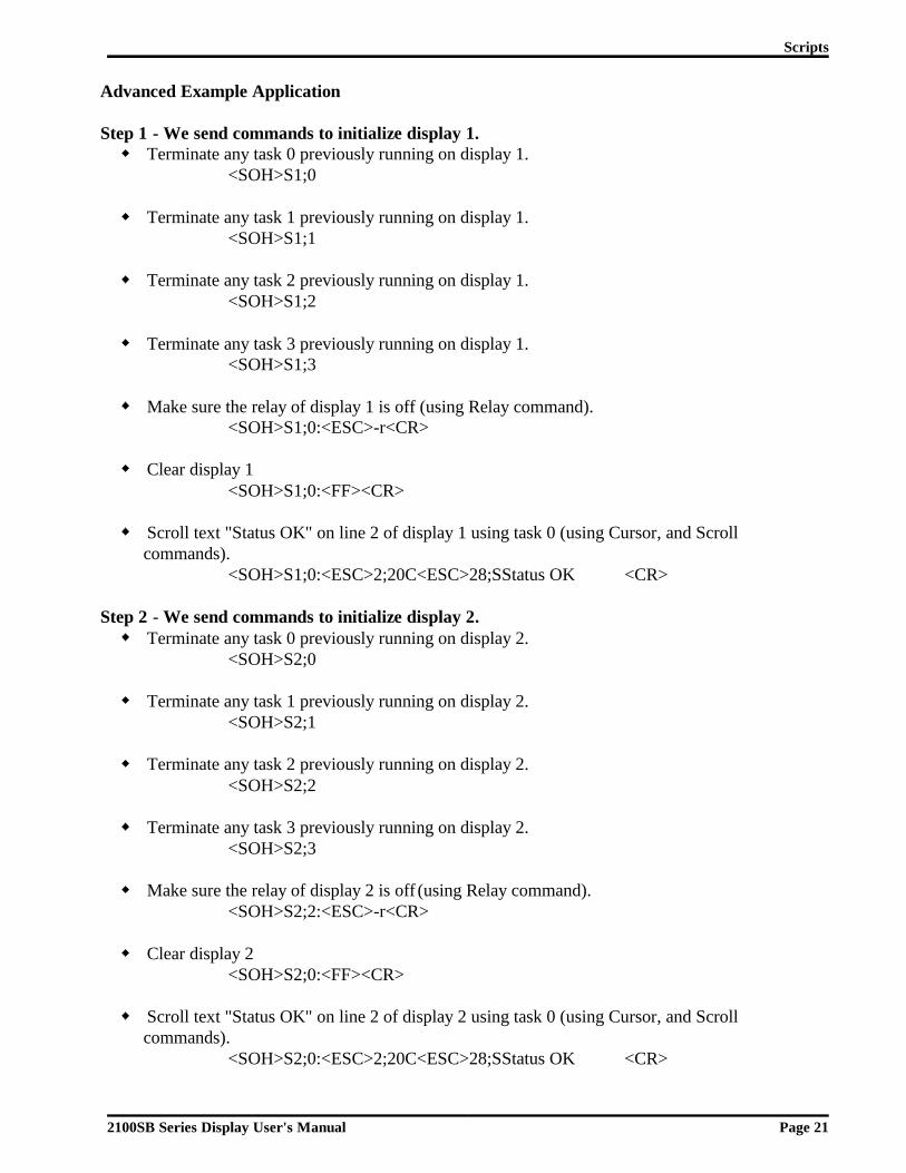
Advanced Example Application
Step 1 - We send commands to initialize display 1. Terminate any task 0 previously running on display 1.
<SOH>S1;0
Terminate any task 1 previously running on display 1.<SOH>S1;1
Terminate any task 2 previously running on display 1.<SOH>S1;2
Terminate any task 3 previously running on display 1.<SOH>S1;3
Make sure the relay of display 1 is off (using Relay command).<SOH>S1;0:<ESC>-r<CR>
Clear display 1<SOH>S1;0:<FF><CR>
Scroll text "Status OK" on line 2 of display 1 using task 0 (using Cursor, and Scrollcommands).
<SOH>S1;0:<ESC>2;20C<ESC>28;SStatus OK <CR>
Step 2 - We send commands to initialize display 2. Terminate any task 0 previously running on display 2.
<SOH>S2;0
Terminate any task 1 previously running on display 2.<SOH>S2;1
Terminate any task 2 previously running on display 2.<SOH>S2;2
Terminate any task 3 previously running on display 2.<SOH>S2;3
Make sure the relay of display 2 is off (using Relay command).<SOH>S2;2:<ESC>-r<CR>
Clear display 2<SOH>S2;0:<FF><CR>
Scroll text "Status OK" on line 2 of display 2 using task 0 (using Cursor, and Scrollcommands).
<SOH>S2;0:<ESC>2;20C<ESC>28;SStatus OK <CR>
Scripts
2100SB Series Display User's Manual Page 21

Step 3 - The PLC detects a low level in hopper #9, and sends a warning notice to the operator. Erase line 2 of display 1 using task 0 (using Erase command). Note that this script will alsoend scrolling for task 0, and leave the cursor on line 2 of the display.
<SOH>S1;0:<ESC>2E<CR>
Blink text "WARNING!" starting at column 6 on line 1 of display 1 using task 0 (using Cursorand Blink commands).
<SOH>S1;0:<ESC>1;6C<ESC>128;+BWARNING!<ESC>-B<CR>
Display text "Hopper #9 LOW!" on line 3 and "Press F1 to confirm" on line 4 of display 1using task 0 (using Cursor command).
<SOH>S1;0:<ESC>3;4CHopper #9 LOW!<ESC>4;1CPress F1 to confirm<CR>
Cycle relay on display 1 using task 1 (using Relay, Wait, and Goto commands). <SOH>S1;1:<ESC>+r<ESC>0;10W<ESC>-r<ESC>0;10W<ESC>G<CR>
Start the Keypress Script on display 1 to check for a keypress (using Keypress script). Notethat this script always uses task 3.
<SOH>S1;3:<ESC>-1s<CR>
Step 4 - The PLC starts a timer.
Scenario A - The Operator Responds.
Scenario A (Step 5) - If the operator responds by pressing the F1 key before the timeout, thePLC will receive the ASCII character "1" from the keypress script, and will send a newmessage to the operator.
Erase line 4 of display 1 using task 0 (using Erase command).<SOH>S1;0:<ESC>4E<CR>
Display text "Thank You" on line 4 of display 1 using task 0 (using Cursor command).<SOH>S1;0:<ESC>4;5CThank You<CR>
Stop the Keypress Script on display 1. Note that running anything in task 3 will halt the script.<SOH>S1;3:<CR>
Scenario A (Step 6) -The operator fills hopper #9 and the PLC no longer detects a low level onhopper #9. The PLC removes the warning status to the operator.
Turn relay of display 1 off using task 1 (using Relay command).<SOH>S1;1:<ESC>-r<CR>
Clear display 1.<SOH>S1;0:<FF><CR>
Scroll message "Status OK" on line 2 of display 1 using task 0 (using Cursor and Scrollcommands).
<SOH>S1;0:<ESC>2;20C<ESC>28;SStatus OK <CR>
Scripts
2100SB Series Display User's Manual Page 22

Scenario B - The Operator Does Not Respond.
Scenario B (Step 5) - If the operator does not respond by pressing the F1 key before thetimeout, the PLC will not receive the ASCII character "1" from the keypress script, and willsend a warning status to the supervisor .
Erase line 2 of display 2 using task 0 (using Erase command). Note that this script will alsoend scrolling for task 0, and leave the cursor on line 2 of the display.
<SOH>S2;0:<ESC>2E<CR>
Blink text "WARNING!" starting at column 6 on line 1 of display 2 using task 0 (using Cursorand Blink commands).
<SOH>S2;0:<ESC>1;6C<ESC>128;+BWARNING!<ESC>-B<CR>
Display text "Hopper #9 LOW!" on line 3 of display 2 using task 0 (using Cursor command).<SOH>S2;0:<ESC>3;4CHopper #9 LOW!
Cycle relay on display 2 using task 1 (using Relay, Wait, and Goto commands). <SOH>S2;1:<ESC>+r<ESC>0;10W<ESC>-r<ESC>0;10W<ESC>G<CR>
We're all done!
The scripts in the previous example were presented in a straightforward and elementary manner. Inmany instances the scripts can be combined and simplified to reduce the overall program length andnumber of transmissions required, but care must be taken to account for all tasks that are running.
For example the following script:
<SOH>S1;0:<ESC>2E<ESC>1;6C<ESC>128;+BWARNING!<ESC>-B<ESC>3;4CHopper #9 LOW!<ESC>4;1CPress F1 to confirm<CR>
would end scrolling, erase line 2, blink message "WARNING!" starting at column 6 on line 1, displaymessage "Hopper #9 LOW! on line 3, and display message "Press F1 to confirm" on line 4 of display1 - all using task 0. This results in a smaller program and fewer required transmissions than thefollowing scripts that were used:
<SOH>S1;0:<ESC>2E<CR><SOH>S1;0:<ESC>1;6C<ESC>128;+BWARNING!<ESC>-B<CR><SOH>S1;0:<ESC>3;4CHopper #9 LOW!<ESC>4;1CPress F1 to confirm<CR>
Scripts
2100SB Series Display User's Manual Page 23

When writing scripts keep in mind:
Running a script in a task will terminate the previous script running in that task.
A task that writes static data to the display (including blinked characters) terminates as soon asthe data is written. None the less, the information will be displayed until it is erased oroverwritten.
Scrolling text requires a separate task as long as the scrolling continues. Erasing a displayusing <SOH>S2;0:<FF><CR> which is executed using task 0 would not stop any scrolling textusing tasks 1, 2, or 3.
Also, remember multiple scripts can often be combined into one.
Literal Control CharactersLiteral Control Representation format is used if you want to display the character associatedwith the ASCII control characters or if you want to transmit the control characters to aperipheral device, using the Output command. The following table shows the controlcharacters, their literal control representations, and the associated displayable characters. Onlythe combinations listed in Table D on the following page will be converted; all othercombinations will be displayed unchanged.
For example, if you wanted to display: C I love my 2100 C
You would type: #C I love my 2100 #C
Scripts
2100SB Series Display User's Manual Page 24

Table D Literal Control Characters
Control Character
Hex/ASCIIValue
Decimal Value Literal ControlRepresentation
Character
<NUL> 0 0 #@ @<SOH> 1 1 #A A<STX> 2 2 #B B<ETX> 3 3 #C C<EOT> 4 4 #D D<ENQ> 5 5 #E E<ACK> 6 6 #F F<BEL> 7 7 #G G<BS> 8 8 #H H<HT> 9 9 #I I<LF> 0A 10 #J J<VT> 0B 11 #K K<FF> 0C 12 #L L<CR> 0D 13 #M M<SO> 0E 14 #N N<SI> 0F 15 #O O<DLE> 10 16 #P P<DC1> 11 17 #Q Q<DC2> 12 18 #R R<DC3> 13 19 #S S<DC4> 14 20 #T T<NAK> 15 21 #U U<SYN> 16 22 #V V<ETB> 17 23 #W W<CAN> 18 24 #X X<EM> 19 25 #Y Y<SUB> 1A 26 #Z Z<ESC> 1B 27 #[ [<FS> 1C 28 #\ \<GS> 1D 29 #] ]<RS> 1E 30 #^ ^<US> 1F 31 #_ _a # character 23 35 ## #<DEL> 7F 127 #? `
Scripts
2100SB Series Display User's Manual Page 25

4.2 BlinkThe Blink command is used to make displayed characters blink at a specified rate. The text tobe blinked must be bracketed on each side by a Blink command string.
Format: <ESC>rate;switchB
rate This argument is used to specify the blinking rate. The range of values is 1through 255. The fastest rate is 1 and 255 is the slowest rate. If zero is entered,the rate that was used in the last Blink command will be chosen. The 2100Display is initialized with a default blink rate of 20. The blink rate is a globalsetting. Therefore, display characters with the blinking attribute will blink atwhatever rate was most recently selected.
<ESC>128;+B is a midrange blink rate<ESC>1;+B is the fastest blink rate<ESC>255;+B is the slowest blink rate
switch This argument is used to turn blinking on, off, or to toggle the current setting.Toggle is useful for terminating Blink in a script.
+ Blink on (+ is a shortcut for +1).
- Blink off (- is a shortcut for -1).
0 Toggle from previous state. If the first Blink command starts text blinking, the second Blink command can have zero entered for this argument which would toggle the Blink command from start blinking to stop blinking. The defaultvalue is 0.
B The upper-case letter B is used to invoke the Blink command.
Example (assumes the line terminator is set to <CR>):
<SOH>s:<ESC>+B Blinking<ESC>B Not<CR>
In this example, two Blink command strings are included. The first command string turns onthe blink effect and the second command string terminates the blink effect. The word"Blinking" will blink at the previously selected or default blink rate. The word "Not" will notblink.
Scripts
2100SB Series Display User's Manual Page 26

4.3 CursorThe Cursor command is used to explicitly specify the position where the next character willbe displayed. Two arguments are associated with this command.
Format: <ESC>line;columnC
line This argument is used to specify the line on which the next character will beplaced. The range of values for this argument is 1 or 2 for the 2140 or 1 thru 4for the 2180. Zero, no number, or a number greater than the maximum numberof lines on the display, default to 1. Negative values will result in no line cursormovement.
column This argument is used to specify the column position where the next characterwill be placed. The range of values for this argument is 1 thru 20. One is the leftmost column and 20 is the right most column. Zero, no number, or numbersgreater than 20 default to one. Negative values will result in no column cursormovement.
C The upper-case letter C is used to invoke the Cursor command.
Example (assumes the line terminator is set to <CR>):
<SOH>s:<ESC>CM<CR>
In this example, the letter "M" will be placed in the first column of the first line.
Example (assumes the line terminator is set to <CR>):
<SOH>s:<ESC>2;15CT<CR>
In this example, the letter "T" will be placed in the fifteenth column of the second line.
Scripts
2100SB Series Display User's Manual Page 27

4.4 EraseThe Erase command clears the specified line and leaves the cursor at the first column of theline. One argument is required for this command.
Format: <ESC>lineE
line This argument specifies the line to erase. Line numbers are 1 or 2 for 2140units, and 1 thru 4 for 2180 units. The default is the current line if no line isspecified.
E The upper-case letter E is used to invoke the Erase command.
Example (assumes the line terminator is set to <CR>):
<SOH>s:<ESC>2E<CR>
In this example, the contents of the second line would be erased and the cursor would beplaced in the first column of the second line.
Scripts
2100SB Series Display User's Manual Page 28

4.5 Erase2eolThe erase2eol command clears the line from the specified location to the end of that line. Thiscommand is useful when writing over existing text that might be longer than the new text. Theformat allows the user to define the line and column position from which to erase, but it ispossible, and frequently more useful, to simply erase from the current position with no cursormovement. After an erase2eol command has been executed, the cursor is left at the positionfrom which the erase2eol command took effect.
Format: <ESC>line;columne
line This argument specifies the line on which to erase. Valid arguments are 1 or 2for 2140 units and 1 through 4 for 2180 units. Zero, no number, or a numbergreater than the maximum number of lines on the display, default to 1.Negative values will result in no line cursor movement.
column This argument specifies the column position from which to erase, inclusive.The range of values for this argument is 1 thru 20. Out of range values ornegative numbers will result in no column cursor movement.
e The lower-case letter e is used to invoke the erase2eol command.
Example (assumes the line terminator is set to <CR>):
<SOH>s:<ESC>2;1CNew Text<ESC>-;-e<CR>
In this example, the Cursor command is used to move to line 2, column 1, where "New Text"is written. The erase2eol command will clear the line from the character position following"New Text" (the current cursor position) to the end of the line. The cursor will remain at theposition following "New Text". Note that the example makes use of the fact that usingnegative values for the arguments result in no cursor movement. Also, note that a shortcut isused in this example where "-" is substituted for "-1" in the erase2eol command.
Scripts
2100SB Series Display User's Manual Page 29

4.6 FontThe Font command is used to select the character set that will be displayed on the 2100Display. Available fonts include the full 256 character IBM® set, the JIS8 (Katakana)character set and the Slavic (Latin II) character set. One argument is required for thiscommand. The IBM® character set is the default character set. Note that the bottom "page"of 128 characters is the same for all three fonts. It is the upper "page" of 128 characters thatvaries between fonts. Refer to Appendix C - Character Sets.
The Font command is specific to a task. When a font selection is made, it remains in effect forsubsequent messages (of the same task) unless explicitly changed.
Format: <ESC>fontF
font This argument specifies the character set to be used following the Fontcommand. Available values for this argument are 1, 2 and 3. The default is 1.
1 Selects the full 256 character IBM® set.
2 Selects the JIS8 (Katakana) character set.
3 Selects the Slavic (Latin II) character set. Consult the factory for details on the Slavic character set, or refer to DOS code page 852.
F The upper-case letter F is used to invoke the Font command.
Example (assumes the line terminator is set to <CR>):
<SOH>s:<ESC>2F<CR>
In this example, the Katakana character set will be used for the text following the Fontcommand entry.
Scripts
2100SB Series Display User's Manual Page 30

4.7 GotoThe Goto command is used to repeat the preceding text and commands the number of timesspecified by the arguments. The repeated portion of the script would be from the specifiedMarker command. Refer to the description of the Marker command, Section 4.10. Twoarguments are required for this command.
Note: Nested Goto commands referenced to the same marker are not recommendedbecause it results in an infinite loop.
Note: If a marker command is not included in a script containing a Goto command, theGoto command will loop to the beginning of the script.
Format: <ESC>marker;repeatG
marker The Marker command has a matching argument so that the loop is from themarker location to the Goto command. Valid values for this argument are 0 and1. The default value is zero.
repeat This argument specifies the number of times to repeat the preceding part of thescript before the display will move on to process the rest of the script. Therange of values for this argument is 0 through 255. Zero will cause repeatinguntil a new script of the same task is received (also called an infinite goto). Thedefault value is zero.
G The upper-case letter G is used to invoke the Goto command.
Example (assumes the line terminator is set to <CR>):
<SOH>s:<FF>Repeat again<ESC>X<VT>and again<ESC>3G!!!!<CR>
This script executed on a 2180 display will clear the display, write "Repeat again" on the firstline and then repeat three times the process of moving to the next line and writing "and again".Finally, the unit will write "!!!!" following the last repeated text. Note that the Marker forthe Goto in the example script is the <ESC>X. The resulting message would appear as:
Repeat againand againand againand again!!!!
Scripts
2100SB Series Display User's Manual Page 31

4.8 Keypress ScriptThe Keypress script is not actually a command, but rather a predefined script included inpermanent 2100SB memory. The script simplifies the use of the front panel keys. TheKeypress script always uses task 3. Therefore, running any other script in task 3 willterminate the Keypress script.
Format: <ESC>-1s
-1 This argument specifies the predefined Keypress script.
s The lower-case letter s is used to invoke the Keypress script.
Example (assumes the line terminator is set to <CR>):
<SOH>S1:<ESC>-1s<CR>
This script will cause any keys pressed on the 2100 series display with address 1 to betransmitted back to the host. The following chart describes the relationship between keyspressed and characters transmitted.
F1 Transmits the character "1" (ASCII 31) decimal value = 49F2 Transmits the character "2" (ASCII 32) decimal value = 50F3 Transmits the character "3" (ASCII 33) decimal value = 51
Note: Since there is no active serial communication handshaking, care should be taken whenexecuting the Keypress script on a networked display. Anytime this script is executing, the2100SB will immediately transmit a character every time a key is pressed.
Scripts
2100SB Series Display User's Manual Page 32

4.9 LockThe lock command is used to control message display. When the lock mode is enabled, thecurrent script must complete before another script using the same task can be executed. If thelock mode is disabled, the current script will be terminated upon receiving a new script. Thelock command is specific to a task. One argument is required for this command.
Note: Scripts with infinite Scroll, or infinite Goto commands should not be used in the lockmode. The script will never be completed and the subsequent scripts will not beexecuted.
If the current script is locked and executing when a new script is sent, up to 8 new scripts of256 characters can be queued.
Format: <ESC>switchl
switch This argument is used to enable or disable the lock mode. The default value iszero.
+ Enable lock mode (+ is a shortcut for +1).
- Disable lock mode (- is a shortcut for -1).
0 Toggle from previous state.
l The lower-case letter l is used to invoke the lock command.
Example (assumes the line terminator is set to <CR>):
<SOH>s:<FF><ESC>+lPriority Message<ESC>200W<ESC>-l<CR>
This script clears the screen and displays "Priority Message", then waits for 20 seconds beforeunlocking the script. The script cannot be interrupted until it is unlocked. Refer to Section4.15 for details on using the Wait command.
Scripts
2100SB Series Display User's Manual Page 33

4.10 MarkerThe Marker command is used to specify the beginning point of a Goto loop. One argument isrequired for this command.
Format: <ESC>markerX
marker This is the matching argument to the marker value in the Goto command sothat the loop is from the Marker location to the Goto command location. Validvalues for this argument are 0 and 1. If no value is entered or if the value isgreater than 1, the value will default to zero.
X The upper-case letter X is used to invoke the Marker command.
Example (assumes the line terminator is set to <CR>):
<SOH>s:I feel <ESC>1XGREAT! <ESC>1;2G<CR>
This example would display as:
I feel GREAT! GREAT!
Scripts
2100SB Series Display User's Manual Page 34

4.11 OutputThe Output command is used to direct characters to the serial port or to the display screen.This command requires one argument. The Output command is specific to a task, andtherefore only affects routing of text for the task referenced in the script.
Format: <ESC>routeO
route This argument specifies the desired routing of the text. The value for thisparameter must be 0 thru 5.
0 Direct the text following the command string to the screen of the 2100Display. This is the default setting.
1 Direct the text following the command string to the serial port. The textwill be directed to the RS232 port output (pin 2) and the RS422 portoutput (pins 3 and 4). The baud rate and data bits for the output are thesame as the input settings which are selected during setup.
2 Dual output (0 and 1 simultaneously).
3 Reserved for system use.
4 Reserved for system use.
5 Reserved for system use.
O The upper-case letter O is used to invoke the Output command.
Example (assumes the line terminator is set to <CR>):
<SOH>s:<FF>Done<ESC>1O#M#JBatch #24 Done#M#J<ESC>0O<CR>
This script clears the screen and writes "Done" on the display screen and transmits out of theserial port:
<CR><LF>Batch #24 Done<CR><LF>
to a peripheral device, perhaps a line printer, computer or another Vorne display. Finally, aclosing Output command is used so that subsequent scripts (of the same task number) aredirected to the display screen. Otherwise, subsequent scripts (of the same task) would also bedirected to the serial port. Note that the transmitted <CR> and <LF> characters are enteredvia their Literal Control Representation formats.
Note: Any commands embedded in the text that are intended for the peripheral must be inthe Literal Control Representation format. Refer to the Literal Control Character s -Table D.
Scripts
2100SB Series Display User's Manual Page 35

4.12 RelayThe relay command is used to control the SPDT relay on the 2100 Display. This relay is ratedfor 120 VAC 1A. The relay command combined with the Wait command can control therelay with delay and duration timing as shown in the example below. One argument is requiredfor this command.
Format: <ESC>switchr
switch + Turns the relay on (+ is a shortcut for +1).
- Turns the relay off (- is a shortcut for -1).
0 Toggles the relay from its previous state. Zero is the default value.
r The lower-case letter r is used to invoke the relay command.
Example (assumes the line terminator is set to <CR>):
<SOH>s:<ESC>+r<ESC>10W<ESC>-r<ESC>20W<ESC>+r<ESC>10W<ESC>-r<CR>
This example would turn on the relay for one second, then turn off the relay for two seconds,turn it back on for one second and then off again. Remember, in order for the relay script tocontinue cycling the relay, it must be running in its own uninterrupted task. Refer to thedescription of the Waitcommand for further explanation of its operation.
Warning: Use the relay for annunciation only! Do not use the relay for control applications.
Scripts
2100SB Series Display User's Manual Page 36

4.13 RepeatThe Repeat command allows the character following the command string to be repeated aspecified number of times. This can be used to insert multiple blank characters when scrollingor reduce the size of scripts with many repeating characters. One argument is required for thiscommand.
Format: <ESC>countR
count This argument specifies the number of times the character following thecommand string is to be repeated. The range of values is 1 to 255. Zero andone produce one character. The default value is zero.
R The upper-case letter R is used to invoke the Repeat command.
Example (assumes the line terminator is set to <CR>):
<SOH>s:<ESC>8R-Vorne<ESC>7R-<CR>
In this example, eight dashes would be displayed, then the word "Vorne" followed by sevenmore dashes.
--------Vorne-------
Scripts
2100SB Series Display User's Manual Page 37

4.14 ScrollThe Scroll command is used to scroll characters, from right to left, on the current line. Thetext to be scrolled must be preceded by the Scroll command and terminated by either an<EOT> character (decimal value 04) or the end of the script. Regardless of the columnposition of the cursor, scrolling text will always begin at the rightmost character of the currentline and scroll to the left, pushing any existing text off the line ahead of it. The two possiblearguments for the Scroll command allow the user to specify the speed of the scrolled messageand how many times the text should scroll.
Format: <ESC>rate;repeatS
rate This argument specifies the scroll rate. The number represents the time in 0.2second increments required for a character to scroll across the 20 characterline. The range of acceptable values is 1 through 255. Thus a character cantake from 0.2 to 51 seconds to travel across the line. A value of zero or nonumber selects the previous rate, or, if no previous rate is available, selects thedefault rate of 20.
repeat This argument specifies the number of times the scrolling text should repeat.Acceptable values are from 1 through 255, and represent the actual number ofrepeats. A value of zero or no number will cause the text to scroll continuouslyuntil it is explicitly cleared or a new script of the same task is received by thedisplay (also called an infinite scroll).
S The upper-case letter S is used to invoke the Scroll command.
Example (assumes the line terminator is set to <CR>):
<SOH>s:<ESC>50;0S_ _ _ _ scrolling text<EOT><CR>
('_' indicates a space character)
This example script would cause the text
to continuously scroll across the current line. The four spaces provide a break betweenconsecutive scrolls. The scroll speed would be such that it would take ten seconds for acharacter to move completely across the line. The scrolling would continue until the line isexplicitly cleared or another script takes control of the line.
The user should note that, when scrolling repetitively, consecutive scrolls will immediatelyfollow the previous one. For this reason, space characters should be inserted preceding orfollowing the scrolled text to provide a break between repetitions, as shown in the precedingexample. It should also be noted that the scrolling will come to a halt on the last repetition
scrolling text
Scripts
2100SB Series Display User's Manual Page 38

once the last character of the scrolled text (including any spaces) has appeared at the far rightof the line. If it is desired to have the visible text scroll all the way off the line on the lastrepetition, the user should either pad the text with 20 trailing spaces, or use another Scrollcommand that simply scrolls 20 spaces onto the line. The first method will insert 20 spacesbetween each consecutive scroll. The second technique will allow the user to use fewer spacesbetween the repeated text and still scroll off the last repetition.
Example (assumes the line terminator is set to <CR>):
<SOH>s:<ESC>2;1C<ESC>7S_ _ _ _ _example two<EOT><ESC>1S<ESC>20R_<CR>
('_' indicates a space character)
This example script would cursor to line 2 and scroll the text
seven times at the previously specified or default rate. After the text has scrolled on to the linefor the seventh time, the unit is finished processing the first Scroll command. If the scriptended here, the display would end up showing:
However, there is another Scroll command which will scroll on twenty space characters. Thiswill have the effect of scrolling off the existing text left over from the first Scroll command.The second Scroll command specifies the same rate as the first Scroll command and sincethere is no delay, the leftover text from the first scroll will simply keep moving to the left as itis scrolled off by the twenty spaces. Note the use of the Repeat command as a shortcut totyping twenty space characters.
example two
two example two
Scripts
2100SB Series Display User's Manual Page 39
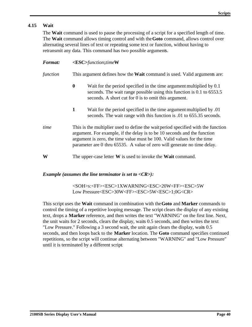
4.15 WaitThe Wait command is used to pause the processing of a script for a specified length of time.The Wait command allows timing control and with the Goto command, allows control overalternating several lines of text or repeating some text or function, without having toretransmit any data. This command has two possible arguments.
Format: <ESC>function;timeW
function This argument defines how the Wait command is used. Valid arguments are:
0 Wait for the period specified in the time argument multiplied by 0.1 seconds. The wait range possible using this function is 0.1 to 6553.5 seconds. A short cut for 0 is to omit this argument.
1 Wait for the period specified in the time argument multiplied by .01 seconds. The wait range with this function is .01 to 655.35 seconds.
time This is the multiplier used to define the wait period specified with the functionargument. For example, if the delay is to be 10 seconds and the functionargument is zero, the time value must be 100. Valid values for the timeparameter are 0 thru 65535. A value of zero will generate no time delay.
W The upper-case letter W is used to invoke the Wait command.
Example (assumes the line terminator is set to <CR>):
<SOH>s:<FF><ESC>1XWARNING<ESC>20W<FF><ESC>5WLow Pressure<ESC>30W<FF><ESC>5W<ESC>1;0G<CR>
This script uses the Wait command in combination with the Goto and Marker commands tocontrol the timing of a repetitive looping message. The script clears the display of any existingtext, drops a Marker reference, and then writes the text "WARNING" on the first line. Next,the unit waits for 2 seconds, clears the display, waits 0.5 seconds, and then writes the text"Low Pressure." Following a 3 second wait, the unit again clears the display, waits 0.5seconds, and then loops back to the Marker location. The Goto command specifies continuedrepetitions, so the script will continue alternating between "WARNING" and "Low Pressure"until it is terminated by a different script.
Scripts
2100SB Series Display User's Manual Page 40

5 Serial Port Operation
5.1 Communicating To A Single DisplayCommunications from the host can be sent to a single 2100 Display in either RS232 or RS422.
Wiring to a Single DisplayConnections to the serial port are made to either the RS232 connector or the RS422connector on the rear of the unit. The serial port is comprised of an RS422 communicationsport and a built-in RS232 to RS422 converter. The host must communicate with the 2100SBeither via the RS232 converter port or the RS422 port. Only one port can be used at anygiven time. The following tables identify all of the serial port connections for the 2100Display.
Table E RS422 Serial Port Terminal StripTerminal # Lead Designation
1 RS422 IN+2 RS422 IN-3 RS422 OUT+4 RS422 OUT-5 ISO-GND6 SETUP
Table F RS232 Serial Port Female DB9 Connector
Terminal # Lead Designation1 (DCD) Data Carrier Detect2 (TD) RS232 OUT3 (RD) RS232 IN4 (DTR) Data Terminal Ready5 (GND) ISO-GND6 (DSR) Data Set Ready7 (RTS) Request To Send8 (CTS) Clear To Send9 (RI) Ring Indicator
Note: RTS and CTS are internally connected.DSR, DTR, and DCD are internally connected.RI is driven active.
Note: All ISO-GND terminals are internally connected.
2100SB Series Display User's Manual Page 41

The following diagrams show wiring examples for connecting the host to a single 2100Display using RS232 or RS422 data types. For RS232 communications, the onlyconnections absolutely necessary are the ones shown for pin 2 (232 OUT), pin 3 (232 IN),pin 5 (SIGNAL GROUND), and pin 7 (RTS). All other RS232 connections are onlynecessary for programs or equipment that require the use of handshaking signals.
Figure 10Single Unit - RS232 Diagram
Note: A standard straight through PC modem cable can be wired from the host to the2100SB.
Note: The maximum recommended cable length for RS232 communications is 50 feet.
Figure 11Single Unit - RS422 Diagram
* Terminator resistor (typically 120 ohm, 1/4 W). Refer to Section 5.2 Communicating toMultiple Units, Wiring an RS422 Network, for details.
Note: The maximum recommended cable length for RS422 communications is 4000 feet.
DC
D 2
32 O
UT
232
IN D
TR
ISO
-GN
D.
DS
R
1 2 3 4 5 6
RS232
RT
S C
TS
RI
7 8 9
DCDRS232 RDRS232 TDDTRSIGNAL GROUNDDSRRTSCTSRI
PLC
HOST DEVICE
422
IN +
422
IN -
422
OU
T +
422
OU
T -
ISO
-GN
D.
1 2 3 4 5
RS422
SE
TU
P
6
RS422 TRANSMIT +RS422 TRANSMIT -RS422 RECEIVE +RS422 RECEIVE -SIGNAL GROUND
PLC
HOST DEVICE
*
* **
Serial Port Operation
2100SB Series Display User's Manual Page 42

5.2 Communicating To Multiple UnitsUnderstanding An RS422 Network
Units may be configured in a multidrop network where the host RS422 signal is connecteddirectly to multiple 2100 display units. A maximum of 32 display units or 4000 feet of cablemay be connected to a single host output in a multidrop configuration.
RS422 MultidropThis configuration is used when the host output is RS422. The RS422 output from thehost is wired in parallel to all of the 2100 Display units in the network.
Wiring An RS422 NetworkTerminatingThe network wiring must be terminated correctly at both the beginning (the host in thedrawing below) and at the last 2100 ending the network. In reality, the host can be connectedanywhere on the network. The terminating resistors must still be installed at both ends of thenetwork. If the host is connected at the center of the network, terminating resistors would berequired on the two end 2100's. In this case, no terminating resistors would be required at thehost. The purpose of the terminating resistors is to prevent reflection problems. Theresistance value of the terminating resistors should match the characteristic impedance of thecable. A typical value for this is 120 ohm.
RS422 MultidropThe diagram below shows the required 120 ohm resistors (assuming that the host is at one endof the network) and illustrates the proper wiring for an RS422 multidrop network. RS422multidrop is the basic network configuration for 2100 display units.
Figure 12RS422 Multidrop Wiring
Serial Port Operation
2100SB Series Display User's Manual Page 43
RS422 TRANSMIT +RS422 TRANSMIT -RS422 RECEIVE +RS422 RECEIVE -SIGNAL GROUND
PLC
HOST DEVICE
422
IN +
422
IN -
422
OU
T +
422
OU
T -
ISO
-GN
D.
1 2 3 4 5
RS422
SE
TU
P
6
422 IN + 422 IN - 422 OUT + 422 OUT - ISO-GND.
12
34
5
RS
422
SETUP6
*
** This diagram is for applications where the hostis a PLC or computer that will use RS422 tocommunicate to a network of 2100's.
* Terminating resistors are requiredat both ends of the RS422 network.
* All resistors shown are 120 ohm 1/4 W.

RS232 ConverterAll 2100 Display units have a built-in data converter that can be used to convert the hostRS232 data to RS422. This allows the host to communicate via RS232. The converter unitthen retransmits the data out its RS422 port to all other units on the network.
RS232 to RS422 ConversionThis configuration is used when a host RS232 output is converted to RS422 by one of the2100 units for use in a multiple display network. The host is wired to a 2100 Display'sRS232 converter port. Then, the RS422 output from that 2100 Display unit is wired inparallel to all of the other 2100 Display units in the network. The RS422 portion of thewiring in the network is the same for all network configurations. The following diagramshows the internal RS232 to RS422 converter of a 2100 Display.
Figure 13RS232 Converter
Note: Note that the maximum recommended cable length for RS232 communications is 50feet. For best results, the shortest cable possible should be used.
TerminatingAs discussed earlier, RS422 multidrop network wiring must be terminated correctly at both ends of the network. When the RS232 to RS422 converter is used, the host communicates toa 2100SB using RS232. No terminating resistors are required on the RS232 communicationlines. However, terminating resistors are still required on the RS422 portion of the network.Again, the purpose of the terminating resistors is to prevent reflection problems. Theresistance value of the terminating resistors should match the characteristic impedance of thecable. A typical value for this is 120 ohm.
Serial Port Operation
2100SB Series Display User's Manual Page 44
2100Microprocessor
23
7
5
RS232 CONVERTERPORT
RS422 SERIALPORT
89
1
6
4
1 RS422 IN +
2 RS422 IN -
3 RS422 OUT +
4 RS422 OUT -
5 ISO-GND
RS232 EN

The diagram below shows the required 120 ohm resistors and illustrates the proper wiring fora network configuration where the host RS232 output is converted to RS422 (the first unit inthe drawing below). Note that after the conversion, the subsequent units are wired in thestandard RS422 multidrop configuration. As in the straight RS422 multidrop network, thehost can use any 2100 on the network as a converter unit . The terminating resistors must stillbe installed at both ends of the RS422 network. If the host is connected to a unit at the centerof the network, terminating resistors would still be required on the two end 2100's. In thiscase, no terminating resistors would be required at the converter unit. Remember, the RS422portion of the wiring in the network is the same for all network configurations.
Just a reminder, for RS232 communications, the only connections absolutely necessary arethe ones shown for pin 2 (232 OUT), pin 3 (232 IN), pin 5 (SIGNAL GROUND), and pin 7(RTS). RTS is the enable line for the converter. All other RS232 connections are onlynecessary for programs or equipment that require the use of handshaking signals.
Note: RTS and CTS are internally connected. DSR, DTR, and DCD are internally connected.RI is driven active.
Note: All ISO-GND terminals are internally connected.
Figure 14RS232 Converter Wiring
Serial Port Operation
2100SB Series Display User's Manual Page 45
422
IN +
422
IN -
422
OU
T +
422
OU
T -
ISO
-GN
D.
1 2 3 4 5
RS422
SE
TU
P6
*
*
422 IN + 422 IN - 422 OUT + 422 OUT - ISO-GND.
12
34
5
RS
422
SETUP6
422 IN + 422 IN - 422 OUT + 422 OUT - ISO-GND.
12
34
5
RS
422
SETUP6
DB9 Connector Screw Terminal
DC
D 2
32 O
UT
232
IN D
TR
ISO
-GN
D.
DS
R
1 2 3 4 5 6
RS232
RT
S C
TS
RI
7 8 9
DCDRS232 RDRS232 TDDTRSIGNAL GROUNDDSRRTSCTSRI
PLC
HOST DEVICE
* This diagram is for applications where the hostis a PLC or computer that will use RS232 tocommunicate to a network of 2100's.
* Terminating resistors are requiredat both ends of the RS422 network.
* All resistors shown are 120 ohm 1/4 W.

Recommended RS422 CablesSince the impedance of the cable and terminator resistance need to match, a cable with acharacteristic impedance of 120 ohms should be used. One recommended cable forinterconnecting units is Belden® #89730 for plenum installations or #9730 for conduitinstallations (or equivalent). Both types have three twisted pairs of 24 AWG stranded tinnedcopper wire with each pair individually shielded. The characteristic impedance of the cable is100 ohms. This type of cable provides good overall performance for a relatively low cost.
Two of the twisted pairs are used for data transmission, one pair is used for data coming fromthe host and one pair is used for data going to the host . In each of the two pairs, one wire isused for the non-inverting data line and the other wire is used for the inverting data line. Bothwires on the third pair are used to connect ISO-GND from 2100 to 2100 and to the host . Theshield wires are used to protect the data lines from noise and should be connected on only oneend of each cable to earth ground.
Recommended RS232 CableA standard male-to-female DB9 straight through modem cable is all that is required to connecta Vorne 2100 style RS232 connector to an IBM/AT style RS232 connector. Again, note thatthe maximum recommended cable length for RS232 communications is 50 feet. For bestresults, the shortest cable possible should be used.
Addressing Multiple UnitsThe RS422 network uses addressing to allow the host to communicate with specific individualdisplays or groups of displays in the network. Each unit in a network may be assigned a unitaddress and a group address. The unit address and group address are selected during setup.(Refer to Section 3.3 for details on setup.)
Unit AddressingUnit addresses can have a value in the range of 000 to 255. If a serial transmission is directedto a specific unit address, only the 2100 units set to that address will display the message.More than one display may use the same unit address, but the best way to send a transmissionto multiple units is to use group addressing.
Group AddressingGroup addresses can have a value from 0 to 8. The group address represents a bit position inan 8 bit binary number, as shown:
Referring to the above relationship, to communicate with only group 7 the host wouldtransmit 64 as a group address. To communicate with only group 4, the host would transmit 8as a group address. This arrangement allows the host to direct a message to any combinationof groups. For example, to transmit to groups 6, 4 and 3, add together 32 + 8 + 4 and transmit44 as the group address. Each display will interpret the transmitted group address anddetermine if it is being addressed. A transmitted group address of 0 is a broadcast to all units.
12345678
1248163264128
Bit Position(Group Number)
Decimal Equivalent ofa "1" in that Position
Serial Port Operation
2100SB Series Display User's Manual Page 46

5.3 Terminal EmulationVT102 Compatible
Enabling the setup function "Terminal Mode - VT102 Compatible" will cause the 2100 seriesdisplay to operate in Terminal Emulation mode (refer to Section 3.3 for details on setup).When in Terminal Emulation mode, the 2100 series display emulates an ANSI / VT102terminal. Refer to the ANSI terminal document for complete information. The followingcommands are supported:
BS BackspaceCAN CancelCR Carriage ReturnCUB Cursor BackwardCUD Cursor DownCUF Cursor ForwardCUP Cursor PositionCUU Cursor UpDCH Delete CharacterDECLL LED Control (Used for Relay Control)DL Delete LineED Erase in DisplayEL Erase in LineESC Introducer Control CharacterFF Form FeedHT Horizontal TabulationHVP Horizontal and Vertical PositioningICH Insert CharacterIL Insert LineLF Line FeedMC Media CopyNUL NULRCP Restore Cursor PositionRM Reset ModeSCP Store Cursor PositionSGR Select Graphic RenditionSM Set ModeVT Vertical Tabulation
Note: All other commands will be ignored.
Serial Port Operation
2100SB Series Display User's Manual Page 47

2100 Series SlaveEnabling the setup function "Terminal Mode - 2100 Series Slave" will cause the 2100 seriesdisplay to operate in Slave mode (refer to Section 3.3 for details on setup). When in Slavemode, the 2100 series display mirrors the operation of a Vorne 2100PC display. Vorne2100PC displays have all the functionality of 2100SB displays plus canned messagecapability. In a multidrop network, when a canned message, using the HOST MODE optionof the OUTPUT_DEVICE command, is called up on a 2100PC, the same tasks, commands,etc. will be executed on 2100 displays set to slave mode.
Note: When setting up a 2100PC for slave operation care must be taken in writing scripts.It is possible in complex scripting applications to "overrun" the slave display sincethere is a limited communication "bandwidth".
Serial Port Operation
2100SB Series Display User's Manual Page 48

Appendix A - Glossary
Address A unique identification number assigned to a 2100 Display.
Alternate Escape An alternative command identifier. This can be the first characterin a command string sent to the 2100 Display, if it was selectedduring setup. It should be noted that <ESC> is always recognizedas the command identifier. Selecting an Alternate Escape allowsthe user to use an alternate character to identify a command, but<ESC> is still recognized as well.
ANSI American National Standards Institute.
Argument Parameter for a function.
ASCII American Standard Code for Information Interchange.
Backspace Backspace control character (decimal value 8), used in scripts orin Terminal Emulation mode to move the cursor left one position.
Baud Rate The data transfer rate between the host unit and the units in theserial network.
Blink The Blink command is used to make displayed characters turnoff and on at a specified rate. The Blink command code characteris B.
<BS> Represents the Backspace control character. See Backspace.
Carriage Return Carriage Return control character (decimal value 13), used inTerminal Emulation mode to move the cursor to the beginning ofthe current line. Carriage Return is one of the two choices for theterminator of the Simple Packet Protocol and should not be usedin serial buffer scripts.
Command Character A single alphabetical character used to invoke a command. A command character must be part of a command string. SeeCommand String.
2100SB Series Display User's Manual Page 49

Command String The basic structure for issuing commands to the 2100 Display. Acommand string must have an Escape or Alternate Escape controlcharacter, arguments (when required), and a single alphabeticalcommand character.
Conduit A tube or trough in which insulated wires and cables are passed.
Control Character Any one of several ASCII control characters, typically notdisplayed, which has a special meaning to the 2100 unit. Variouscontrol characters can be used in serial scripts or TerminalEmulation mode to move the cursor, clear the display, terminatean effect, identify a command string, and begin or end the SimplePacket Protocol format.
<CR> Represents the Carriage Return control character. See CarriageReturn.
Cursor The Cursor command is used to specify the position where thenext character will be displayed. The Cursor command characteris C.
E2PROM or EEPROM Electrically Erasable Programmable Read Only Memory. Thememory in the 2100 Display that is used to store setupinformation.
End of Transmission End of Transmission control character (decimal value 4), used inscripts to terminate the Scroll command (mark the end of a stringof characters that are to be scrolled.)
<EOT> Represents the End of Transmission control character. See Endof Transmission.
Erase The Erase command is used to clear a specified line and place thecursor at the first column of the line. The Erase commandcharacter is E.
Erase2eol The erase2eol command is used to clear a display line from thespecified location to the end of the line. The erase2eol commandcharacter is e.
<ESC> Represents the Escape control character. See Escape.
Escape The Escape control character (decimal value 27), used as the firstcharacter in all command strings, unless an Alternate Escapecharacter is selected in setup. In that case, the 2100 unit willrecognize either the Escape or the chosen Alternate Escapecharacter as the command identifier.
Appendix A - Glossary
2100SB Series Display User's Manual Page 50

<FF> Represents the Form Feed control character. See Form Feed.
Font The Font command is used to specify the character set to beshown on the 2100 Display. The Font command character is F.
Form Feed Form Feed control character (decimal value 12), used in serialscripts to clear the display and move the cursor to the beginningof the first line.
Goto The Goto command is used to repeat the preceding text andcommands a specified number of times. The Goto commandcharacter is G.
Horizontal Tab Horizontal Tab control character (decimal value 9), used in serialscripts or in Terminal Emulation mode to move the cursor to thenext tab stop.
Host Any device that initiates serial communication with a 2100 SeriesDisplay Unit.
<HT> Represents the Horizontal Tab control character. See HorizontalTab.
Keypress Script The Keypress script is a predefined script included in permanent2100SB memory. The script simplifies the use of the front panelkeys.
<LF> Represents the Line Feed control character. See Line feed.
Line Feed Line Feed control character (decimal value 10), used in TerminalEmulation mode to move the cursor down one line in the samecolumn. Line Feed is one of the two choices for the terminator ofthe Simple Packet Protocol and should not be used in serialbuffer scripts.
Lock The lock command is used to determine if a new message will bedisplayed before the current message has completed its run. Thelock command character is l. The lock command is specific to atask.
Marker The Marker command is used to specify the location to where aGoto command can loop. The Marker command character is X.
Multidrop A serial network configuration where the communications fromthe host are transmitted to more than one 2100 Display withoutbeing repeated. The 2100 Displays are wired in parallel.
Appendix A - Glossary
2100SB Series Display User's Manual Page 51

Multitasking The ability of the 2100 display unit to separately perform up tofour different functions at the same time.
Output The Output command is used to direct data to the serial port.The Output command character is O.
PLC Programmable Logic Controller.
RAM Random Access Memory. Memory used during run time to storedata.
Relay The relay command is used to control the SPDT relay in the2100 Display. The relay command character is r.
Repeat The Repeat command allows the character following thecommand string to be repeated a specified number of times. TheRepeat command character is R.
Script A sequentially ordered string of commands, literal text, andcontrol characters which instructs a 2100 unit to perform afunction.
Scroll The Scroll command is used to scroll characters horizontallyfrom right to left. The Scroll command character is S.
Setup An electrical mechanism to prevent accidental change of setupdata in the 2100 Display. Setup data may be viewed or changedwhen the SETUP terminal is connected to ISO-GND. Setup datamay not be changed when the SETUP terminal is not connectedto ISO-GND.
Simple Packet Protocol The standard serial communication format which is used to senda Serial Buffer Script to a 2100SB unit.
<SOH> Represents the Start of Header control character. See Start ofHeader.
SPDT Single Pole Double Throw.
Start of Header Start of Header control character (decimal value 1), is used as thefirst character of the Simple Packet Protocol format of serialcommunication.
Task A task is a function performed by the 2100 display. Up to fourtasks can be performed at the same time. A function can includebut is not limited to scrolling text, controlling the relay,displaying text, internal timing, etc.
Appendix A - Glossary
2100SB Series Display User's Manual Page 52
Vertical Tab Vertical Tab control character (decimal value 11), used in serialscripts to move the cursor to the beginning of the next line.
VFD Vacuum Fluorescent Display. The 2100 Display uses VFDtechnology to create visible characters.
<VT> Represents the Vertical Tab control character. See Vertical Tab.
Wait The Wait command is used to pause during the processing of ascript for a specified length of time. The Wait commandcharacter is W.
Appendix A - Glossary
2100SB Series Display User's Manual Page 53

Appendix A - Glossary
2100SB Series Display User's Manual Page 54

Appendix B - Specifications
Communication Interface
• RS232 Serial Port - DB9 Connector• RS422 Serial Port - Screw Terminal
Vacuum Fluorescent Display• Wavelength - Peak at 505 nanometers
• Rated Life - 50,000 hours (when average dot brightness reaches ½ of original brightness)
• Character HeightModel 2140 - 11 mmModel 2180 - 9 mm
Physical and ElectricalPower Supply Options . . . . . . . . . . . . . 120 VAC ±15% (50 - 60 Hz), 0.16A, 20 Watts
24 VDC ±10%, 0.8A, 20 WattsOperating Temperature Range . . . . . 0° - 50° C Storage Temperature Range . . . . . . . -20° to +70° CRelative Humidity . . . . . . . . . . . . . . . . . 0 - 95% Relative Humidity, Non-condensingWeight . . . . . . . . . . . . . . . . . . . . . . . . . . . . Approx. 6.5 lbs.
Annunciator RelayType . . . . . . . . . . . . . . . . . . . . . . . . . . . . . . Single Pole Double ThrowRating . . . . . . . . . . . . . . . . . . . . . . . . . . . . 120 VAC @1A
2100SB Series Display User's Manual Page 55

DimensionsFront Panel and Depth
Mounting InformationThe 2100 Display mounts in the user's panel through a rectangular cutout and is secured withfour 10/32 hex nuts to threaded studs located at the corners of the bezel.
12.0"(304.8 mm)
4.5"(114.3 mm)
4.9"(124.5 mm)
Mounting holes require clearance for 10-32 threaded standoffs, 7/32nds (5.6mm) diameter.
11.5"(292.1 mm)
11.25"(285.8 mm)
4.0"(101.6 mm)
.125"(3.1 mm)
.125"(3.1 mm)
3.75"(95.2 mm)Panel Cutout
2100SB Series Display User's Manual Page 56

Appendix C - Character Sets
The full IBM®, J1S8 (Katakana), Slavic (Latin II) and Cyrillic character sets areavailable on the 2100 Display. All fonts share the first 128 characters (00h to 7Fh).
Common Character Set�
000h �
1610h �
3220h �
4830h �
6440h #
8050h 3
9660h C
11270h S
101h �
1711h �
3321h �
4931h �
6541h $
8151h 4
9761h D
11371h T
202h �
1812h �
3422h �
5032h �
6642h %
8252h 5
9862h E
11472h U
303h �
1913h �
3523h �
5133h �
6743h &
8353h 6
9963h F
11573h V
404h �
2014h �
3624h �
5234h �
6844h '
8454h 7
10064h G
11674h W
505h
2115h �
3725h �
5335h �
6945h (
8555h 8
10165h H
11775h X
606h
2216h �
3826h
5436h �
7046h )
8656h 9
10266h I
11876h Y
707h �
2317h �
3927h
5537h �
7147h *
8757h :
10367h J
11977h Z
808h �
2418h �
4028h �
5638h �
7248h +
8858h ;
10468h K
12078h [
909h
2519h �
4129h �
5739h �
7349h ,
8959h <
10569h L
12179h \
100Ah �
261Ah �
422Ah
583Ah �
744Ah -
905Ah =
1066Ah M
1227Ah ]
110Bh �
271Bh �
432Bh �
593Bh �
754Bh .
915Bh >
1076Bh N
1237Bh ^
120Ch �
281Ch
442Ch �
603Ch �
764Ch /
925Ch ?
1086Ch O
1247Ch _
130Dh �
291Dh !
452Dh �
613Dh
774Dh 0
935Dh @
1096Dh P
1257Dh `
140Eh �
301Eh "
462Eh 6
623Eh !
784Eh 1
945Eh A
1106Eh Q
1267Eh a
150Fh �
311Fh #
472Fh �
633Fh "
794Fh 2
955Fh B
1116Fh R
1277Fh $
2100SB Series Display User’s Manual Page 57

Font 1 IBM® Character Set
12880h %
14490h *
160A0h 5
176B0h �
192C0h �
208D0h ª
224E0h º
240F0h Ê
12981h &
14591h m
161A1h {
177B1h �
193C1h �
209D1h «
225E1h »
241F1h Ë
13082h b
14692h n
162A2h |
178B2h �
194C2h �
210D2h ¬
226E2h ¼
242F2h Ì
13183h c
14793h o
163A3h }
179B3h �
195C3h �
211D3h
227E3h ½
243F3h Í
13284h d
14894h p
164A4h ~
180B4h �
196C4h �
212D4h ®
228E4h ¾
244F4h Î
13385h e
14995h q
165A5h �
181B5h �
197C5h �
213D5h ¯
229E5h ¿
245F5h Ï
13486h f
15096h r
166A6h �
182B6h �
198C6h
214D6h °
230E6h À
246F6h Ð
13587h g
15197h s
167A7h �
183B7h �
199C7h ¡
215D7h ±
231E7h Á
247F7h Ñ
13688h h
15298h t
168A8h �
184B8h �
200C8h ¢
216D8h ²
232E8h Â
248F8h Ò
13789h i
15399h u
169A9h �
185B9h �
201C9h £
217D9h ³
233E9h Ã
249F9h Ó
1388Ah j
1549Ah v
170AAh �
186BAh �
202CAh ¤
218DAh ´
234EAh Ä
250FAh Ô
1398Bh k
1559Bh w
171ABh �
187BBh �
203CBh ¥
219DBh µ
235EBh Å
251FBh Õ
1408Ch l
1569Ch x
172ACh �
188BCh �
204CCh ¦
220DCh ¶
236ECh Æ
252FCh Ö
1418Dh '
1579Dh +
173ADh �
189BDh �
205CDh §
221DDh ·
237EDh Ç
253FDh ×
1428Eh (
1589Eh ,
174AEh �
190BEh �
206CEh ¨
222DEh ¸
238EEh È
254FEh Ø
1438Fh )
1599Fh y
175AFh �
191BFh �
207CFh ©
223DFh ¹
239EFh É
255FFh Ù
Appendix C - Character Sets
2100SB Series Display User’s Manual Page 58

Font 2 JIS8 (Katakana) Character Set
12880h .
14490h 2
160A0h
176B0h �
192C0h �
208D0h ª
224E0h º
240F0h Ê
12981h /
14591h m
161A1h {
177B1h �
193C1h �
209D1h «
225E1h »
241F1h Ë
13082h b
14692h n
162A2h |
178B2h �
194C2h �
210D2h ¬
226E2h ¼
242F2h Ì
13183h c
14793h o
163A3h }
179B3h �
195C3h �
211D3h
227E3h ½
243F3h Í
13284h d
14894h p
164A4h ~
180B4h �
196C4h �
212D4h ®
228E4h ¾
244F4h Î
13385h e
14995h q
165A5h �
181B5h �
197C5h �
213D5h ¯
229E5h ¿
245F5h Ï
13486h f
15096h r
166A6h �
182B6h �
198C6h
214D6h °
230E6h À
246F6h Ð
13587h g
15197h s
167A7h �
183B7h �
199C7h ¡
215D7h ±
231E7h Á
247F7h Ñ
13688h h
15298h t
168A8h �
184B8h �
200C8h ¢
216D8h ²
232E8h Â
248F8h Ò
13789h i
15399h u
169A9h �
185B9h �
201C9h £
217D9h ³
233E9h Ã
249F9h Ó
1388Ah j
1549Ah v
170AAh �
186BAh �
202CAh ¤
218DAh ´
234EAh Ä
250FAh Ô
1398Bh k
1559Bh w
171ABh �
187BBh �
203CBh ¥
219DBh µ
235EBh Å
251FBh Õ
1408Ch l
1569Ch x
172ACh �
188BCh �
204CCh ¦
220DCh ¶
236ECh Æ
252FCh Ö
1418Dh 0
1579Dh 3
173ADh �
189BDh �
205CDh §
221DDh ·
237EDh Ç
253FDh ×
1428Eh 0
1589Eh 4
174AEh �
190BEh �
206CEh ¨
222DEh ¸
238EEh È
254FEh Ø
1438Fh 1
1599Fh y
175AFh �
191BFh �
207CFh ©
223DFh ¹
239EFh É
255FFh Ù
Appendix C - Character Sets
2100SB Series Display User’s Manual Page 59

Font 3 Slavic (Latin II) Character Set
12880h %
14490h :
160A0h 5
176B0h �
192C0h �
208D0h ª
224E0h º
240F0h Ê
12981h &
14591h m
161A1h {
177B1h �
193C1h �
209D1h «
225E1h »
241F1h Ë
13082h b
14692h n
162A2h |
178B2h �
194C2h �
210D2h ¬
226E2h ¼
242F2h Ì
13183h c
14793h o
163A3h }
179B3h �
195C3h �
211D3h
227E3h ½
243F3h Í
13284h d
14894h p
164A4h ~
180B4h �
196C4h �
212D4h ®
228E4h ¾
244F4h Î
13385h e
14995h q
165A5h �
181B5h �
197C5h �
213D5h ¯
229E5h ¿
245F5h Ï
13486h f
15096h r
166A6h �
182B6h �
198C6h
214D6h °
230E6h À
246F6h Ð
13587h g
15197h s
167A7h �
183B7h �
199C7h ¡
215D7h ±
231E7h Á
247F7h Ñ
13688h h
15298h t
168A8h �
184B8h �
200C8h ¢
216D8h ²
232E8h Â
248F8h Ò
13789h i
15399h u
169A9h �
185B9h �
201C9h £
217D9h ³
233E9h Ã
249F9h Ó
1388Ah j
1549Ah v
170AAh
186BAh �
202CAh ¤
218DAh ´
234EAh Ä
250FAh Ô
1398Bh k
1559Bh w
171ABh �
187BBh �
203CBh ¥
219DBh µ
235EBh Å
251FBh Õ
1408Ch l
1569Ch x
172ACh �
188BCh �
204CCh ¦
220DCh ¶
236ECh Æ
252FCh Ö
1418Dh 7
1579Dh ;
173ADh �
189BDh �
205CDh §
221DDh ·
237EDh Ç
253FDh ×
1428Eh 8
1589Eh <
174AEh �
190BEh �
206CEh ¨
222DEh ¸
238EEh È
254FEh Ø
1438Fh 9
1599Fh y
175AFh �
191BFh �
207CFh ©
223DFh ¹
239EFh É
255FFh
Appendix C - Character Sets
2100SB Series Display User’s Manual Page 60

Font 4 Cyrillic Character Set
160A0h
12981h
13082h
12880h
13183h
13284h
13385h
13486h
13587h
1438Fh
1428Eh
1418Dh
1408Ch
1398Bh
1388Ah
13789h
13688h
14490h
14591h
14692h
14793h
14894h
14995h
15096h
15197h
1599Fh
167A7h
175AFh
183B7h
1589Eh
166A6h
174AEh
182B6h
1579Dh
1569Ch
1559Bh
1549Ah
15399h
15298h
161A1h
162A2h
163A3h
164A4h
165A5h
173ADh
172ACh
171ABh
170AAh
169A9h
168A8h
176B0h
177B1h
178B2h
179B3h
180B4h
181B5h
191BFh
199C7h
207CFh
215D7h
223DFh
231E7h
239EFh
247F7h
190BEh
198C6h
206CEh
214D6h
222DEh
230E6h
238EEh
246F6h
255FFh
254FEh
189BDh
188BCh
187BBh
186BAh
185B9h
184B8h
192C0h
193C1h
194C2h
195C3h
196C4h
197C5h
205CDh
204CCh
203CBh
202CAh
201C9h
200C8h
208D0h
209D1h
210D2h
211D3h
212D4h
213D5h
221DDh
220DCh
219DBh
218DAh
217D9h
216D8h
224E0h
225E1h
226E2h
227E3h
228E4h
229E5h
237EDh
236ECh
235EBh
234EAh
233E9h
232E8h
240F0h
241F1h
242F2h
243F3h
244F4h
245F5h
253FDh
252FCh
251FBh
250FAh
249F9h
248F8h
Appendix C - Character Sets
2100SB Series Display User’s Manual Page 61

Appendix C - Character Sets
2100SB Series Display User’s Manual Page 62

Appendix D - Typical RS232 Pinouts
(TD) Transmitted Data (DTE)(RD) Received Data (DCE)
Signal Ground (Common Return) (Common)
RS232 Interface ReferenceDB25 Male
Pin Numbers
(RTS) Request To Send (DTE)
(DSR) Data Set Ready (DCE)
(DTR) Data Terminal Ready (DTE)
1
2
3
4
5
6
7
8
9
10
11
12
13
14
15
16
17
18
19
20
21
22
23
24
25
(CTS) Clear To Send (DCE)
(DCD) Data Carrier Detect (DCE)
(RI) Ring Indicator (DCE)
DTE
2100SB Series Display User's Manual Page 63

Note: A standard straight through PC modem cable is all that is required toconnect a Vorne 2100 style connector to an IBM/AT® style connector.
IBM/AT® Style RS232 InterfaceDB9 Male
Pin Numbers
(TD) Transmitted Data (DTE)
Signal Ground (Common Return) (Common)
(RD) Received Data (DCE)
(DTR) Data Terminal Ready (DTE)
(DSR) Data Set Ready (DCE)(RTS) Request To Send (DTE)
1
2
3
4
5
6
7
8
9
(DCD) Data Carrier Detect (DCE)
(CTS) Clear To Send (DCE)(RI) Ring Indicator (DCE)
DTE
Vorne 2100 Style RS232 InterfaceDB9 FemalePin Numbers
(RD) Received Data (DCE)(TD) Transmitted Data (DTE)
(DTR) Data Terminal Ready (DTE)Signal Ground (Common Return) (Common)5
4
3
2
1
9
8
7
6(DCD) Data Carrier Detect (DCE)
(RTS) Request To Send (DTE)
(DSR) Data Set Ready (DCE)
(RI) Ring Indicator (DCE)
(CTS) Clear To Send (DCE)
DCE
2100SB Series Display User's Manual Page 64

AAddress, 4, 9, 46, 49Alternate Escape, 8, 49ANSI / VT102 Terminal, 9, 47Argument, 17, 18ASCII, 13, 14, 16, 24, 25, 32, 49
BBack Panel, 4, 5, 7Backspace, 16, 47, 49Baud Rate, 4, 9, 49Blink, 13, 19, 26, 49Boot, 9
CCarriage Return, 10, 14, 16, 47, 49Character Height, 2, 55Character Set, 57Characteristic Impedance, 46Column Position, 18, 27, 29, 38Command Character, 49Command Identifier, 8Command String, 17, 50Commands, 1, 19Communication Interface, 55Conduit, 50Control Characters, 16, 17, 20, 24,25, 35, 50Cursor, 13, 15, 16, 17, 18, 19, 27, 28,29, 38, 39, 50
Cursor Command, 9, 27Cursor Control, 9, 13
DData Bits, 4, 10DB9 Connector, 4, 41, 64Default Settings, 8, 10Diagnostic Screen, 9Dimensions, 56Display Attribute Control, 18Display Escape Sequences, Table, 19DOS, 1DSR & RTS, 41, 45
EE2PROM Memory, 3, 50Earth Ground, 7End Of Transmission, 16, 38, 50Erase, 19, 28, 29, 50Erase2eol, 19, 29, 50ESC Character, 8, 17Escape, 17, 50
Command Sequence, 17Command Strings, 17
Example Application, 20
FFont, 19, 30, 51Form Feed, 9, 16, 51Four Line Display, 2Front Panel, 1, 2, 7, 8Front Panel Keys, 7, 8
GGoto, 19, 31, 33, 34, 40, 51Group Address, 9, 14, 46
HHorizontal Tab, 16, 51Host, 8, 9, 41, 42, 43, 44, 45, 46, 51
IISO-GND, 7, 41
KKeypress Script, 19, 20, 22, 23, 32,51
LLine Feed, 10, 14, 16, 51Literal Control Character, 24, 25, 35Literal Text, 15, 17Lock, 19, 33, 51Loop Test, 10
MMarker, 19, 31, 34, 40, 51Memory, 3, 7, 8Model Summary, Table, 2Mounting, 56Multidrop, 43, 44, 45, 51Multitasking, 52
NNetwork, 43, 44, 45, 46
OOperating Temperature, 55Output, 19, 24, 35, 52
PParameters, 4, 7, 8PLC, 1, 52Power Connections, 7Power Supply, 1, 3, 55
RRAM, 52Rated Life, 3, 55Reflection Problems, 44Relative Humidity, 55Relay, 19, 36, 52, 55
Output, 4Terminal, Connections, 4
Repeat, 19, 31, 37, 38, 39, 40, 52RS232, 4
Cable, 46Converter, 44, 45Converter Wiring, 45Pinouts, 63, 64Port, 35, 41Serial Port DB9 Connector, 41
RS422, 4Cable, 46Multidrop, 43, 44Multidrop Wiring, 43Port, 35, 41Serial Port Terminal Strip, 41
2100SB Series Display User's Manual Page 65
Index

SScript, 3, 13, 15, 16, 17, 19, 20, 52Script Flow Control, 18Scroll, 3, 9, 19, 33, 38, 52Serial Buffer Script, 13Serial Port, 4, 41Setup, 3, 7, 8, 52
Circuit Wiring, 8Simple Packet Protocol, 10, 13, 14,52SPDT, 4, 52Specifications, 55Stack, 17, 18Start Of Header, 14, 52Storage Temperature, 55Studs, 56
TTask, 3, 14, 52Terminal Emulation, 9, 47Terminal Mode, 9Terminal Strip, 4, 7, 41Terminating Character, 14Terminator Resistor, 42, 44Twisted Pair, 46Two Line Display, 1
UUnit Address, 9, 14, 46
VVacuum Fluorescent, 1, 3Vertical Scroll, 9Vertical Tab, 16, 53VFD, 53
WWait, 19, 33, 36, 40, 53Wavelength, 3, 55Weight, 55Wiring Examples, 42
Index
2100SB Series Display User's Manual Page 66

A0046R00
Vorne Industries, Inc.1445 Industrial DriveItasca, IL 60143-1849Phone: (630) 875-3600Fax: (630) 875-3609